
Modelling, design and analysis of a testing rig for composite materials
11
-
Upload
independent -
Category
Documents
-
view
1 -
download
0
Transcript of Modelling, design and analysis of a testing rig for composite materials


MODELLING, DESIGN AND ANALYSIS
OF A TESTING RIG FOR COMPOSITE MATERIALS
Gianni Caligiana(1)
, Alfredo Liverani(2)
, Stefano Pippa(3)
,
Università di Bologna
Facoltà di Ingegneria, DIEM
(1)[email protected] (2)[email protected]
SOMMARIO
I materiali compositi vengono impiegati in maniera sempre più diffusa in quasi tutti i settori industriali
(automobilistico, aerospaziale, elettronico, elettrico, navale, sportivo, ecc.). Dato che, in questo caso, il
progetto del materiale procede di pari passo con quello del componente, la ricerca di strumenti atti ad
ottenere caratterizzazioni meccaniche affidabili riveste notevole interesse a livello internazionale (§ 1). Il
lavoro si occupa della modellazione, progettazione, ottimizzazione ed analis i agli elementi finiti di un
dispositivo originale, in grado di garantire accurato allineamento del treno di carico, per prove di fatica a
trazione e compressione su simulacri in materiale composito. Tale attività si colloca all’interno di un più
ampio piano di ricerca in svolgimento presso il DIEM. Il modello solido dell’attrezzatura è stato ottenuto
mediante modellatore solido 3D, Solid Edge. La verifica dell’apparecchiatura è stata eseguita utilizzando
programmi ad elementi finiti commerciali (Ansys e Nastran). Un prototipo del dispositivo è stato
realizzato e messo a punto presso i laboratori del DIEM. La trattazione dettagliata delle prove preliminari
sul prototipo strumentato e delle prove a fatica condotte su simulacri in materiale composito esulano dagli
scopi del presente lavoro e sono riportate altrove [Caligiana et alii, 2003]. Nell’ambito del procedimento
automatico CAD-CAE-CAM, è prevista la realizzazione di un secondo prototipo, alleggerito, presso i
laboratori del DIEM nella Facoltà di Ingegneria di Forlì-Cesena.
Parole chiave: CAx, ottimizzazione, progettazione, materiali compositi, fatica.
ABSTRACT
Composite materials are increasingly utilized in many conventional and unconventional applications in
mechanical and industrial fields. Extensive research is performed in this area, especially at international
level (§ 1). Both design of component and design of material develop in a parallel way, so reliable
composite characterisation represents a fundamental objective to be achieved. Aims of this paper are
design, modelling, meshing, finite element analysis and optimization of a novel experimental apparatus
for testing composite material samples subjected to tension and compression fatigue. Equipment can
account for accurate loading train alignment. 3D model is obtained through Solid Edge modeller.
Verification by Finite element method (FEM) has been performed with commercial packages (Ansys and
Nastran). A prototype for the testing rig has been developed in DIEM laboratories. The calibration of the
instrumented apparatus and the subsequent experimental test plan are extensively described elsewhere
[Caligiana et alii, 2003]. Production of a lighter version for the device is on plan, by starting from 3D
solid model, through a CAM procedure, ending with the utilization of a numerically controlled machine
tool in Forlì and Cesena Engineering Faculty laboratories.
Key words : CAx, optimization, design, composite materials, fatigue testing.
XIII ADM - XV INGEGRAF
International Conference on
TOOLS AND METHODS EVOLUTION IN
ENGINEERING DESIGN
Cassino, June 3rd, 2003
Napoli, June 4th and June 6th, 2003 Salerno, June 5th, 2003

1. Introduction
Composite materials [Talreja and Manson, 2000; Reinhart, 1998; Caligiana and Cesari, 2002] are broadly utilized, especially in the automotive and aerospace applications,
where high strength and stiffness are required together with reduced weight. Mechanical characterization is particularly important for composite materials, because, in this field,
design of component evolves in tight connection with design of material itself. In recent years, a lot of research has been carried out to design and calibrate testing equipment able to properly load, in the most reliable and repetitive manner, specimens
and components in composite materials [ASTM, 1995; Adams and Welsh, 1997; Berg and Adams, 1989; Carlsson et alii, 2000]. Almost the whole work reported in literature
does not seem to face and solve efficiently the problem of loading train alignment in push-pull fatigue testing, with the exception of ASTM D 3039 standards, which deals just with alignment verification. Furthermore, the largest part of the authors considers,
separately, either push or pull testing rigs. Paper can be considered as a further result of one of the leading directions in which the
composite materials research activity, already well advanced inside the Department, has been evolved. Aim of the work is the development of a testing rig for push-pull fatigue, able to allow faithful alignment of the loading train. A previous attempt, following this
path [Orazi and Minak, 2001], has been made, resulting in an easily usable and handy apparatus with the main awkward consisting in the limited ranges of feasible thickness
(1,5-2,5 mm) and loading capacity (up to 40 kN, in fatigue). The latter effort, described here, deals with a novel testing equipment very flexible, in that it is able to grip up to 50 millimetre wide specimens and, owing to the use of a sliding guide for the grips, (§ 2), it
has, theoretically, no upper geometrical limit to the sample thickness (up to almost 80 millimetre). Actually, upper boundary to the thickness is only due to bolt length (§ 3)
and to the upper capability of the hydraulic ram (250 kN in fatigue), which is also the allowable fatigue loading assumed during testing equipment design. Also specimen length can vary from a minimum of 120 mm up to more than 300 mm.
The testing apparatus has been dimensioned by a preliminary standard design, modelled through a 3D modeller (Solid Edge), analysed, verified and optimized by FEM
commercial packages. A prototype of the apparatus has been made in Department laboratories and utilized for experimental calibration, verification and, finally, for the DIEM push-pull fatigue testing plan on composite materials (samples of T300 carbon
fibre reinforced epoxy matrix composite material), [Caligiana et alii, 2003].
2. Fixture configuration
Testing rig is composed of four grips (Fig. 1), roughly shaped as rectangular parallelepipeds. The two lower grips can slide inside a guide built directly on the lower crosshead of the fixture (Fig. 2).
A guide column is provided in each lower grip (Fig. 3) to allow proper precision sliding clearance in the corresponding bushing forced in the upper grip. Specimen is hold
between the two couple of upper and lower grips through high strength bolts (Fig. 4). The distance between two couple of grips can be varied as it depends on the length of the bolts utilized. This characteristic allows the arrangement of a wide spread of
specimen thicknesses, giving high flexibility in the utilization of the apparatus. Just during assemblage, upper grips are sustained against gravity and are assured against
twist, with respects to the lower ones, by suitable designed “horse-shoes” (Fig. 2 and Fig. 5), avoiding undesirable torque to be applied to the specimen before test.
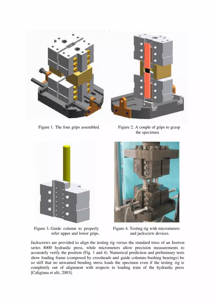
Figure 1. The four grips assembled. Figure 2. A couple of grips to grasp
the specimen.
Figure 3. Guide column to properly Figure 4. Testing rig with micrometers refer upper and lower grips. and jackscrew devices.
Jackscrews are provided to align the testing rig versus the standard truss of an Instron
series 8000 hydraulic press, while micrometers allow precision measurements to accurately verify the position (Fig. 1 and 4). Numerical prediction and preliminary tests
show loading frame (composed by crossheads and guide columns-bushing bearings) be so stiff that no unwanted bending stress loads the specimen even if the testing rig is completely out of alignment with respects to loading train of the hydraulic press
[Caligiana et alii, 2003].

3. Design and 3D CAD modelling of the apparatus
First of all, a conventional design is performed to define the rough shape for the main testing frame components [Cicchetti, 2002]. The whole loading capacity (250 kN) of an
Instron series 8000 testing machine is considered as design load. All the components can support this load, in fatigue, with a safety factor generally higher than 3. Grips have
been made with a quenched and tempered 35CrMn5 steel slab, while crossheads are obtained from a 320 millimetre diameter bar of an UNI 39NICRMo3 steel, quenched and tempered.
Figure 5. Exploded view of the assembly obtained by Solid Edge 3D modeller.
Bolts and screws are much more stressed than the other components, so a strength class 10.9 is utilized for them. Twelve 160 millimetre long M14 bolts (six for the upper and
six for the lower grips) are actually utilized to properly transfer design loading, while gripping a specimen for push-pull fatigue tests of parallelepiped standard shape [ASTM,
1995]. Twenty 80 millimetre long M14 tap screws are utilized to hold the whole frame to the crossheads (ten screws for the upper and ten screws for the lower crosshead). Finally, two M48 screw fasteners connect the lower and upper crossheads to the frame

of the Instron hydraulic press (in series, respectively, downwards, with the jack, and upwards, with the loading cell). The apparatus can perform tests on standard samples made with conventional or
composite materials. Theoretically up to 50 millimetre wide and up to 80 millimetre thick samples can be hosted in the loading frame, by purely geometrical considerations.
In practice, many of the possible combinations exceed hydraulic press loading capacity. If, as example, a composite material made by an epoxy matrix reinforced with unidirectional carbon fibre is assumed, a 50 millimetre wide specimen can have
thickness up to about 4 millimetres, while a 20 millimetre wide sample can reach thickness up to about 10 millimetres.
Testing rig has been completely designed by utilizing 3D Solid Edge modeller [CAD In site, 2000; Craig, 2001; Ricks, 1999]. An exploded view of the whole assembly is shown in Fig. 5. Technical drawings for assembly and components of the apparatus
Figure 6. Technical drawing of the assembly obtained by Solid Edge 3D modeller.
have been derived directly by the 3D solid model (Fig. 6 and 7). Several refinements must be manually performed to account for the actual design and
drawing standards [UNI M1, 2002], showing how some careful considerations should, perhaps, be made about standards. Updating or, probably, relaxation of some old standard specifications could be suggested to make easier modeller usage.
Proper dimensional and geometric tolerance chain has been considered to ensure the right grasping of the specimen inside the testing apparatus [Foster, 1986; Wilson, 1996].
A check is performed to verify the influence of the accumulation of production imperfections allowed by limiting tolerance values [Cicchetti, 2002]. For example, an evaluation has been made for the undesired torque resulting in the specimen during
assemblage, owing to maximum permitted fitting clearance of “horse shoes” in the corresponding seats on the upper and lower grips (Fig. 5).
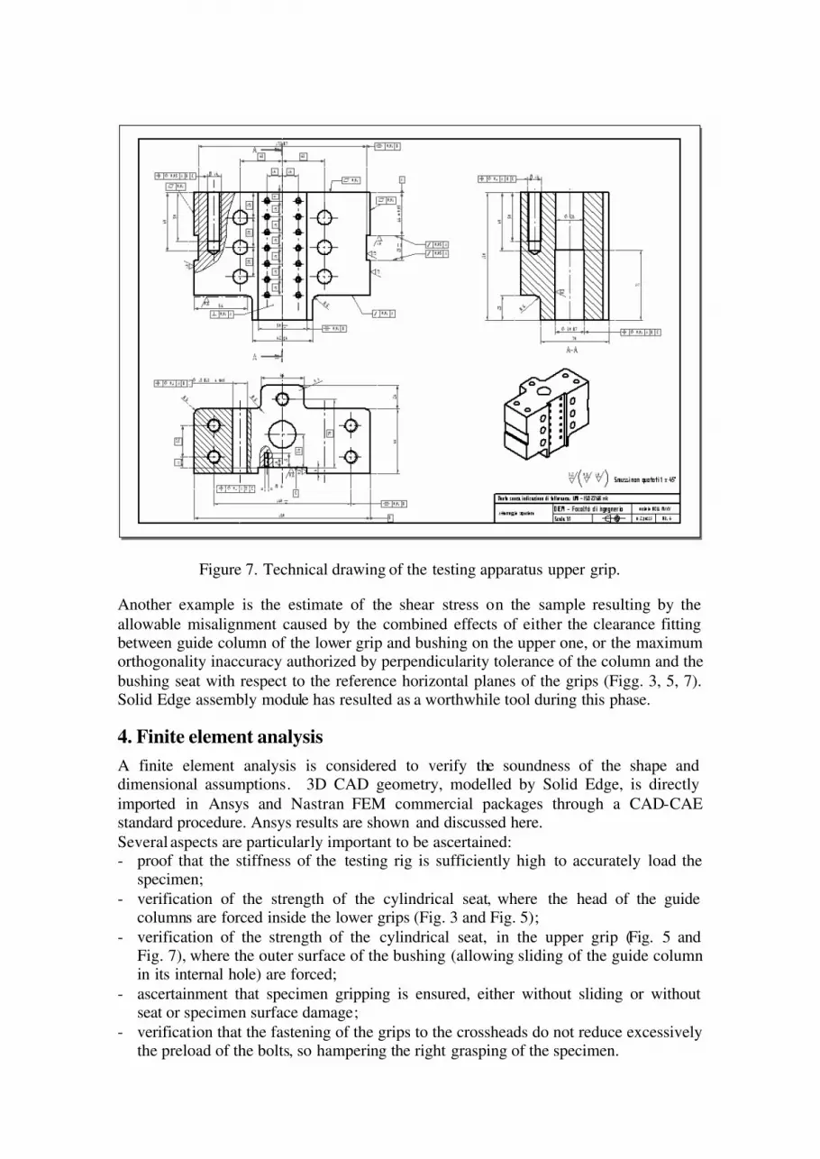
Figure 7. Technical drawing of the testing apparatus upper grip.
Another example is the estimate of the shear stress on the sample resulting by the
allowable misalignment caused by the combined effects of either the clearance fitting between guide column of the lower grip and bushing on the upper one, or the maximum orthogonality inaccuracy authorized by perpendicularity tolerance of the column and the
bushing seat with respect to the reference horizontal planes of the grips (Figg. 3, 5, 7). Solid Edge assembly module has resulted as a worthwhile tool during this phase.
4. Finite element analysis
A finite element analysis is considered to verify the soundness of the shape and dimensional assumptions. 3D CAD geometry, modelled by Solid Edge, is directly
imported in Ansys and Nastran FEM commercial packages through a CAD-CAE standard procedure. Ansys results are shown and discussed here.
Several aspects are particularly important to be ascertained: - proof that the stiffness of the testing rig is sufficiently high to accurately load the
specimen;
- verification of the strength of the cylindrical seat, where the head of the guide columns are forced inside the lower grips (Fig. 3 and Fig. 5);
- verification of the strength of the cylindrical seat, in the upper grip (Fig. 5 and Fig. 7), where the outer surface of the bushing (allowing sliding of the guide column in its internal hole) are forced;
- ascertainment that specimen gripping is ensured, either without sliding or without seat or specimen surface damage;
- verification that the fastening of the grips to the crossheads do not reduce excessively the preload of the bolts, so hampering the right grasping of the specimen.

Axial loading
iInterference fit
Threaded
fasteners
XZ and YZ symmetry
The analysis of the lower gripping assembly (Fig. 8) is shown in the followings. In Fig. 9, the finite element mesh utilized for the analysis is shown [Pippa et alii, 2003]. Tetrahedral 10 node isoparametric finite elements are utilized.
Figure 8. Lower gripping assembly Figure 9. Finite element mesh of the lower grip.
Some simplification (Fig. 9) are assumed to improve numerical calculation and to
reduce model burden, like exploitation of symmetry planes for loadings and constraints, or removal of all fillets (this is on behalf of safe ty, because absence of fillets arises local stress).
Furthermore: - design axial loading of 250 kN (z direction) is applied, as a pressure load, on
simulated sample cross section; - bolt fasteners are modelled by beam elements, suitably linked to the mesh, with a
prefixed strain reproducing the bolt preload;
- interference fitting of the guide column inside lower grip cylindrical seat is simulated through a cylindrical solid subjected to temperature dilation equal to
interference itself (of about 59 microns); to circumvent unwanted axial expansion, suitably chosen orthotropic thermal characteristics are assumed for the material constituting the solid cylinder;
- tap bolts connecting the grip to the lower crosshead are modelled through constraints, applied on the blind hole external circumference, which restrict
movements in the bolt z-direction, while allowing displacements in the plane parallel to the bolt head (xy plane); this assumption agrees roughly with the well known experimental results evidencing that only the first three threads of tap screws
seems to support about the whole loading in screw fasteners. In Fig. 10, stresses in y direction (perpendicular to the specimen surface of Fig. 2) are
evidenced. Compression stresses of about 200 MPa are calculated in the gripping seat for the specimen, showing that loading transfer to the sample seems to occur, without sliding, during almost all the fatigue loading cycles usually applied. Still higher load
transfer could be allowed by utilizing upper strength class for bolts gripping the specimen. Experimental results (reported and discussed in [Caligiana et alii, 2003])
show these FEM predictions still underestimating the actual grip performance.

High tensile stresses (but still tolerable, also because of their static nature) can be found on the interference fit cylindrical seat for the head of the guide column. Maximum values are reached on an xz plane through the column seat axis. Similar stress values
(not reported here [Cicchetti, 2002]) can be found, for the x-direction, in an yz plane through the column seat axis. This is in perfect agreement with the imposed constraint
symmetry planes (in yz symmetry plane, y component of this kind of stress must reach values almost equal to zero, as rightly shown in Fig. 10).
Figure 10. Map of stresses in the lower grip along y direction.
In Fig. 11, von Mises equivalent stresses are recorded, confirming that all the apparatus
has very low stresses everywhere, with the exception of the cylindrical seat for the interference fit with column heads and of the plane seat for specimen gripping. Also strains are extremely low as compared with those acting on the specimen, proving the
high apparatus stiffness, see for details Cicchetti, 2002). Very high values can be found also near the holes of the bolt (but these are not at all meaningful, because due to modelled local constraints, which do not exactly correspond to the actual situation of
the effectively more distributed constraints).
5. Conclusion and future developments.
Design, CAD 3D modelling, meshing and finite element analysis are performed for a novel fatigue testing frame, for composite material samples, which allows a large range
of suitable specimen thicknesses and ensures reliable alignment of the loading train. After a standard rough preliminary dimensioning, shape optimization is performed with the aim of Solid Edge 3D modeller. The geometrical model has been imported and
adapted (meshing) for finite element verification [Pippa et alii, 2003]. Analysis has been performed through commercial packages (Ansys and Nastran). Manual fatigue
dimensioning (allowing a safety factor higher than 3) of main apparatus components is confirmed by finite element analysis. Furthermore, FEM analysis shows the possibility
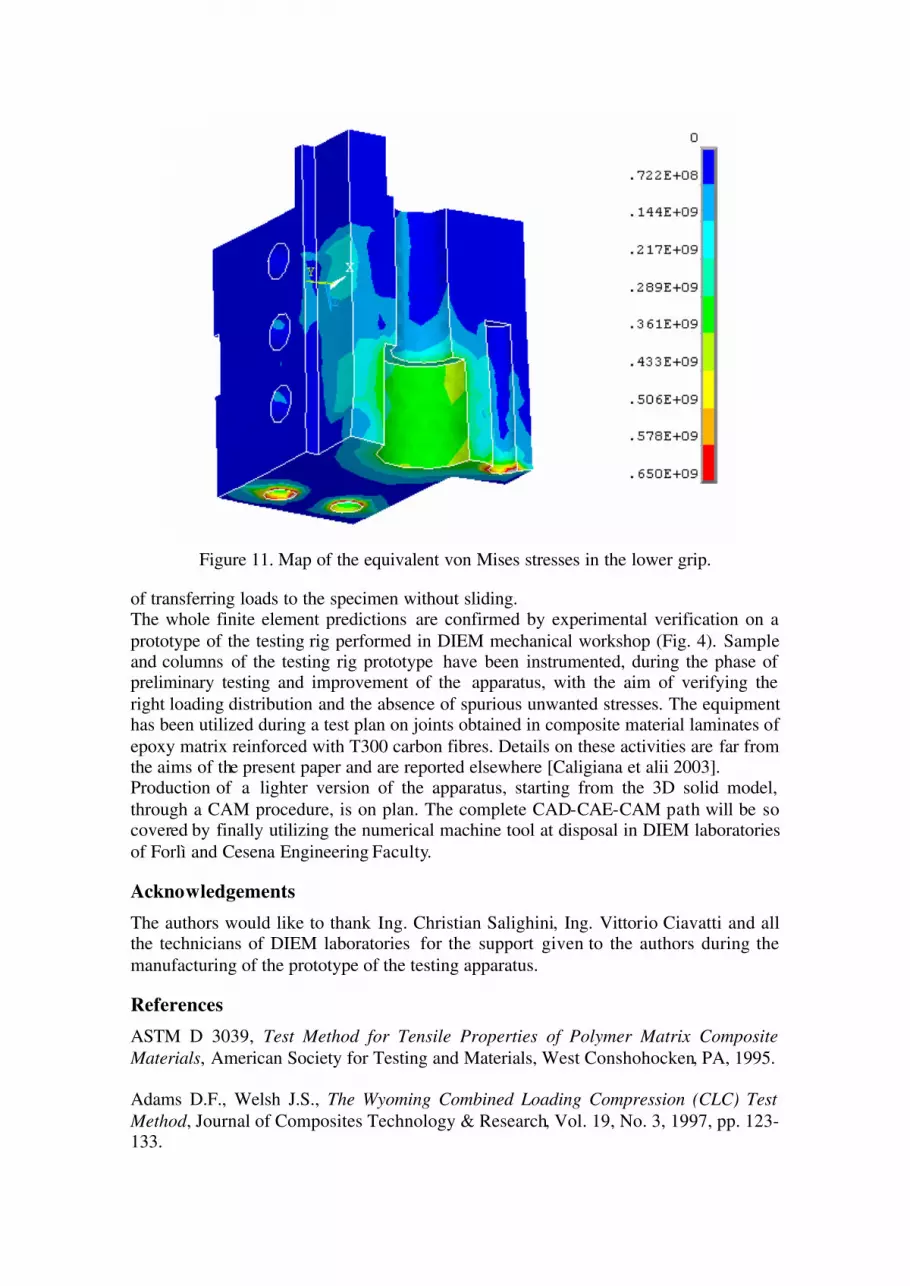
Figure 11. Map of the equivalent von Mises stresses in the lower grip.
of transferring loads to the specimen without sliding. The whole finite element predictions are confirmed by experimental verification on a
prototype of the testing rig performed in DIEM mechanical workshop (Fig. 4). Sample and columns of the testing rig prototype have been instrumented, during the phase of preliminary testing and improvement of the apparatus, with the aim of verifying the
right loading distribution and the absence of spurious unwanted stresses. The equipment has been utilized during a test plan on joints obtained in composite material laminates of
epoxy matrix reinforced with T300 carbon fibres. Details on these activities are far from the aims of the present paper and are reported elsewhere [Caligiana et alii 2003]. Production of a lighter version of the apparatus, starting from the 3D solid model,
through a CAM procedure, is on plan. The complete CAD-CAE-CAM path will be so covered by finally utilizing the numerical machine tool at disposal in DIEM laboratories
of Forlì and Cesena Engineering Faculty.
Acknowledgements
The authors would like to thank Ing. Christian Salighini, Ing. Vittorio Ciavatti and all the technicians of DIEM laboratories for the support given to the authors during the
manufacturing of the prototype of the testing apparatus.
References
ASTM D 3039, Test Method for Tensile Properties of Polymer Matrix Composite
Materials, American Society for Testing and Materials, West Conshohocken, PA, 1995. Adams D.F., Welsh J.S., The Wyoming Combined Loading Compression (CLC) Test
Method, Journal of Composites Technology & Research, Vol. 19, No. 3, 1997, pp. 123-133.

Berg J.S., Adams D.F., An Evaluation of Composite Material Compression Test
Methods, Journal of Composites Technology & Research, Vol. 11, No. 2, 1989, pp. 41-46.
CAD In Site for Solid Edge, Part Modeling Fundamentals, Distance Engineering, Inc.,
CD-Rom, 2000. Caligiana G., Cesari F., I materiali compositi, Pitagora Editrice, Bologna, 2002.
Caligiana G., Minak G., Ghezzo F., Cicchetti M., Dispositivo per prove di fatica su
materiali compositi: progetto, messa a punto e risultati sperimentali, submitted to 32nd National Conference of the Italian Association for Stress Analysis, Salerno, 2003.
Carlsson L., Crane R.L., Uchino K., Comprehensive Composite Materials, Test
Methods, Nondestructive Evaluation, and Smart Materials, Vol. 5, A. Kelly and C.
Zweben Editors, Elsevier, 2000. Cicchetti M., Progettazione, Analisi MEF e messa a punto sperimenatale di una
attrezzatura per prove di fatica su materiali compositi, Butcher degree Thesis, Bologna, 2002.
Craig J., Engineering and technical Drawing using Solid Edge, Schroff Development Corporation Publ., Saint Louis, Missouri, USA, 2001, ISBN 1-58503-039-2.
Orazi L., Minak G., Progettazione e messa a punto di un sistema per l’effettuazione di
prove di fatica in trazione-compressione su provini in materiale composito, XXX
Convegno Nazionale AIAS, Alghero (SS), 2001.
Pippa S., Caligiana G., Cesari F., Development of a Parametric surface mesher for multi-patch surfaces of BREP solids, submitted to XIII ADM International Conference on Tools and Methods Evolution in Engineering Design.
Reinhart T.J. et alii, Composites, Engineering Materia ls Handbook, Vol. 1, ASM
International, Metal Park, OH 44073, 1998. Ricks J., Solid Edge, Modelling Made Easy, Mell Johnson Publ., Birmingham, UK,
1999, ISBN 1-930324-01-4.
Talreja R., Manson, J-A.E., Comprehensive Composite Materials, Polymer matrix
composites, Vol. 2, A. Kelly and C. Zweben Editors, Elsevier, 2000.
UNI M1, Norme per il disegno tecnico, Norme generali, Vol. I, and Meccanica e settori
correlati, Vol. II, Ente Nazionale Italiano di Unificazione, Milano, 2002.
Foster L.W., Geo-metrics, The metric application of the geometric tolerancing
techniques, Addison-Wesley Publ.Co., Minneapolis, Minnesota, USA, 1986.
Wilson B.A., Design Dimensioning and Tolerancing, The Goodheart-Willcox Co.,
Tinley Park, Illinois, USA, 1996.


![Testing Testing [Read-Only] - Czone - East Sussex](https://static.fdokumen.com/doc/165x107/6327b2a26d480576770d6757/testing-testing-read-only-czone-east-sussex.jpg)