Modelling and implementation of fuzzy systems based on VHDL
15
Modelling and implementation of fuzzy systems based on VHDL A. Barriga a, * , S. Sa ´nchez-Solano a , P. Brox a , A. Cabrera b , I. Baturone a a Instituto de Microelectro ´ nica de Sevilla, Centro Nacional de Microelectro ´ nica, Edificio CICA, Avda. Reina Mercedes s/n, 41012 Sevilla, Spain b Instituto Superior Polite ´cnico Jose ´ Antonio Echeverrı ´a (CUJAE), Calle 127 s/n, Marianao, Ciudad de La Habana, Cuba Received 1 January 2004; received in revised form 1 May 2005; accepted 1 June 2005 Available online 27 September 2005 Abstract The number of electronic applications using fuzzy logic-based solutions has increased consider- ably in the last few years. Concurrently, new CAD tools that explore different implementation tech- nologies for this type of systems have been developed. In this paper we illustrate a fuzzy logic system design strategy based on a high level description. Employing this high level description, the knowl- edge base is translated to a format in appearance close to the natural language with the particularity that it uses a hardware description language (VHDL) directly synthesizable on an FPGA circuit. In addition, we analyze different approaches for FPGA implementations of fuzzy systems in order to characterize them in terms of area and speed. Among them, the use of specific processing architec- tures implemented on FPGAs presents as main advantages a good ‘‘cost-performance’’ ratio and an acceptably short development time. The different synthesis facilities provided by the Xfuzzy design environment for the implementation of programmable fuzzy systems, which take advantage of the available resources in the current FPGA families, are also analyzed in this paper. Ó 2005 Elsevier Inc. All rights reserved. Keywords: VHDL modelling; High level description; FPGAs implementation; Hardware implementation; Fuzzy systems implementation 0888-613X/$ - see front matter Ó 2005 Elsevier Inc. All rights reserved. doi:10.1016/j.ijar.2005.06.018 * Corresponding author. Tel.: +34 9550 56666; fax: +34 9550 56686. E-mail address: [email protected] (A. Barriga). International Journal of Approximate Reasoning 41 (2006) 164–178 www.elsevier.com/locate/ijar
-
Upload
independent -
Category
Documents
-
view
2 -
download
0
Transcript of Modelling and implementation of fuzzy systems based on VHDL
International Journal of Approximate Reasoning41 (2006) 164–178
www.elsevier.com/locate/ijar
Modelling and implementation of fuzzysystems based on VHDL
A. Barriga a,*, S. Sanchez-Solano a, P. Brox a,A. Cabrera b, I. Baturone a
a Instituto de Microelectronica de Sevilla, Centro Nacional de Microelectronica, Edificio CICA,
Avda. Reina Mercedes s/n, 41012 Sevilla, Spainb Instituto Superior Politecnico Jose Antonio Echeverrıa (CUJAE), Calle 127 s/n, Marianao,
Ciudad de La Habana, Cuba
Received 1 January 2004; received in revised form 1 May 2005; accepted 1 June 2005Available online 27 September 2005
Abstract
The number of electronic applications using fuzzy logic-based solutions has increased consider-ably in the last few years. Concurrently, new CAD tools that explore different implementation tech-nologies for this type of systems have been developed. In this paper we illustrate a fuzzy logic systemdesign strategy based on a high level description. Employing this high level description, the knowl-edge base is translated to a format in appearance close to the natural language with the particularitythat it uses a hardware description language (VHDL) directly synthesizable on an FPGA circuit. Inaddition, we analyze different approaches for FPGA implementations of fuzzy systems in order tocharacterize them in terms of area and speed. Among them, the use of specific processing architec-tures implemented on FPGAs presents as main advantages a good ‘‘cost-performance’’ ratio and anacceptably short development time. The different synthesis facilities provided by the Xfuzzy designenvironment for the implementation of programmable fuzzy systems, which take advantage of theavailable resources in the current FPGA families, are also analyzed in this paper.� 2005 Elsevier Inc. All rights reserved.
Keywords: VHDL modelling; High level description; FPGAs implementation; Hardware implementation; Fuzzysystems implementation
0888-613X/$ - see front matter � 2005 Elsevier Inc. All rights reserved.
doi:10.1016/j.ijar.2005.06.018
* Corresponding author. Tel.: +34 9550 56666; fax: +34 9550 56686.E-mail address: [email protected] (A. Barriga).

A. Barriga et al. / Internat. J. Approx. Reason. 41 (2006) 164–178 165
1. Introduction
Natural language uncertainty and the approximate reasoning mechanism of the humanbrain can be modeled through the use of fuzzy logic. The knowledge base of a fuzzy systemis described by a set of rules as in an expert system. However, the rule computation is per-formed numerically as in a neural network. This double view (symbolic description andanalytic processing) means that fuzzy logic is useful for modeling those systems in whichit is difficult to achieve a mathematical behavior [1].
The number of applications using fuzzy logic techniques to solve control and decision-making problems has increased considerably in the last years [2]. As a consequence,multiple solutions for the implementation of fuzzy algorithms resorting to either standardprocessor or specific hardware approaches have been proposed and reported. The applica-bility of these solutions depends on both the problem complexity (expressed as the numberof input and output variables, and rules) and the temporal restrictions (which establish therequired inference speed). Standard microcontroller solutions provide flexibility to definethe knowledge base, to select the fuzzy operators, and to choose the inference algorithms.However, they become inadequate for problems demanding high inference speeds, smallsizes, and low power consumptions. In this case specific hardware solutions must beadopted [3,4]. Example of such applications are those related to portable embedded sys-tems or applications with strong real-time requirements.
The two main factors that limit the realization of an electronic system are its complexityand its development time. The use of computer aided design environments including syn-thesis tools eases the design process and reduces the time-to-market of the final product.The use of specific processing architectures implemented on FPGAs provides an excellentrelation ‘‘cost-performance’’ and an extremely short development cycle [5].
Concerning the design flow of a fuzzy system, two different levels may be considered.The algorithmic level specifies the functional behavior of the system. The objective withinthis level is to define the shape of the membership functions, the implication mechanism,the rulebase, and the defuzzification strategy that better achieve the proposed system task.At the circuit level, the designer has to select an efficient system architecture, design therequired building blocks, and verify the temporal behavior of the system. Thus, a designmethodology for fuzzy system has to cover the different design stages, from system spec-ification up to the implementation and testing of the circuit. To accomplish this task someauthors have proposed the use of VHDL as a language to describe and model the systemat high level [6,7] and the employment of specific architectures of fuzzy processor [8,9].
The design methodology used in this paper is based on the fuzzy system developmentenvironment Xfuzzy [10,11]. The tools included in this environment share a fuzzy systemdescription language (XFL3 [12]) for the rule base and structure specification. Xfuzzy in-cludes tools that make the description of fuzzy system easier. There are also simulationtools and learning tools for adjusting the system parameters. The realization of the systemcan be achieved by using the synthesis tools, both software (C, C++ and Java) or hard-ware synthesis.
The aim of this paper is to depict a fuzzy logic modeling style based on two strategies:behavioral modeling using VHDL, and structural VHDL based on a specific architec-ture of fuzzy processor [13]. We will also show a fuzzy logic design flow for FPGA imple-mentations which relies on the combined use of specific tools for the development of fuzzylogic based systems [14], and generic simulation and synthesis tools for VLSI design.
166 A. Barriga et al. / Internat. J. Approx. Reason. 41 (2006) 164–178
Finally, the different description styles and FPGA implementation options are analyzed inorder to take advantage of the resources of the devices available in the market at themoment.
2. VHDL system modelling
In this section a method for the description of fuzzy system is proposed based on thedescription of the structure of the fuzzy system in an easy way (linguistic variables, rulebase, fuzzy operators). The premise implies that the fuzzy system description must be syn-thesizable because we are interested in hardware realizations. Thus VHDL will be used asthe working platform for the systems. But VHDL language imposes some limitations,compared with the flexibility and expressiveness of other fuzzy logic oriented languages(such as XFL3 [12]). On the other hand, it is necessary to adapt the characteristics ofthe system (types of membership functions, inference algorithms, defuzzification mecha-nisms) to its hardware implementation.
To achieve a behavioral modeling, a VHDL description style will be used in which thesystem structure description (fuzzy sets, rule base) and the operator description (connec-tives, fuzzy operations) are defined separately. This makes it possible to describe indepen-dently both the fuzzy system structure and the processing algorithm. The descriptionformat makes it possible the use of linguistic hedges in order to compact the rules definingthe system behavior.
2.1. Rulebase
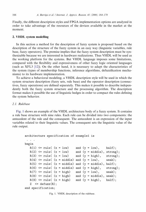
Fig. 1 shows an example of the VHDL architecture body of a fuzzy system. It containsa rule base structure with nine rules. Each rule can be divided into two components: theantecedent of the rule and the consequent. The antecedent is an expression of the inputvariables related to their linguistic values. The consequent sets the linguistic value of therule output.
Fig. 1. VHDL description of the rulebase.
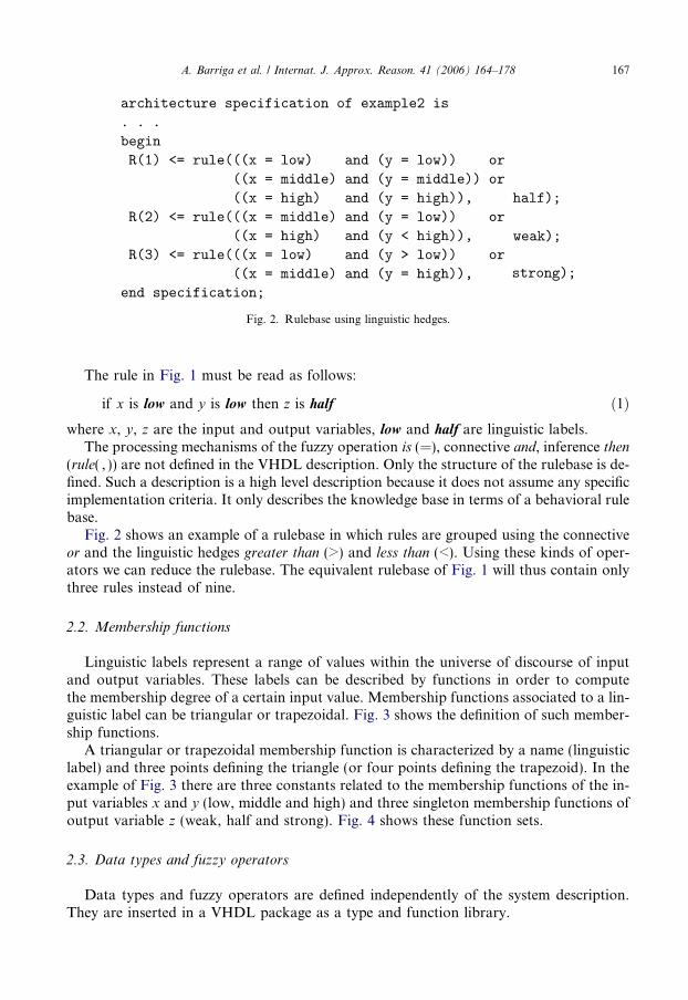
Fig. 2. Rulebase using linguistic hedges.
A. Barriga et al. / Internat. J. Approx. Reason. 41 (2006) 164–178 167
The rule in Fig. 1 must be read as follows:
if x is low and y is low then z is half ð1Þwhere x, y, z are the input and output variables, low and half are linguistic labels.
The processing mechanisms of the fuzzy operation is (=), connective and, inference then(rule( , )) are not defined in the VHDL description. Only the structure of the rulebase is de-fined. Such a description is a high level description because it does not assume any specificimplementation criteria. It only describes the knowledge base in terms of a behavioral rulebase.
Fig. 2 shows an example of a rulebase in which rules are grouped using the connectiveor and the linguistic hedges greater than (>) and less than (<). Using these kinds of oper-ators we can reduce the rulebase. The equivalent rulebase of Fig. 1 will thus contain onlythree rules instead of nine.
2.2. Membership functions
Linguistic labels represent a range of values within the universe of discourse of inputand output variables. These labels can be described by functions in order to computethe membership degree of a certain input value. Membership functions associated to a lin-guistic label can be triangular or trapezoidal. Fig. 3 shows the definition of such member-ship functions.
A triangular or trapezoidal membership function is characterized by a name (linguisticlabel) and three points defining the triangle (or four points defining the trapezoid). In theexample of Fig. 3 there are three constants related to the membership functions of the in-put variables x and y (low, middle and high) and three singleton membership functions ofoutput variable z (weak, half and strong). Fig. 4 shows these function sets.
2.3. Data types and fuzzy operators
Data types and fuzzy operators are defined independently of the system description.They are inserted in a VHDL package as a type and function library.
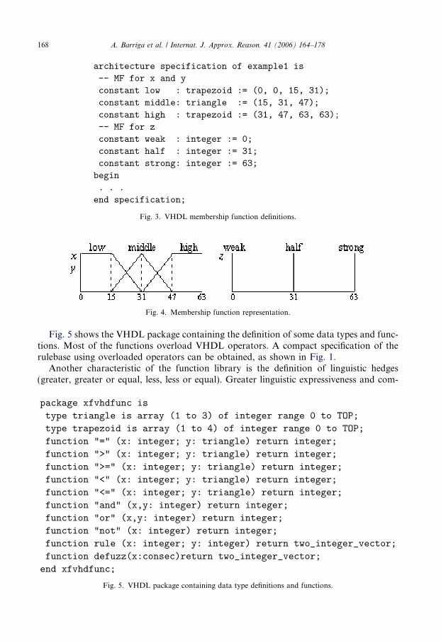
Fig. 3. VHDL membership function definitions.
Fig. 4. Membership function representation.
168 A. Barriga et al. / Internat. J. Approx. Reason. 41 (2006) 164–178
Fig. 5 shows the VHDL package containing the definition of some data types and func-tions. Most of the functions overload VHDL operators. A compact specification of therulebase using overloaded operators can be obtained, as shown in Fig. 1.
Another characteristic of the function library is the definition of linguistic hedges(greater, greater or equal, less, less or equal). Greater linguistic expressiveness and com-
Fig. 5. VHDL package containing data type definitions and functions.
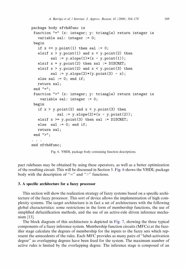
Fig. 6. VHDL package body containing function descriptions.
A. Barriga et al. / Internat. J. Approx. Reason. 41 (2006) 164–178 169
pact rulebases may be obtained by using these operators, as well as a better optimizationof the resulting circuit. This will be discussed in Section 5. Fig. 6 shows the VHDL packagebody with the description of ‘‘=’’ and ‘‘>’’ functions.
3. A specific architecture for a fuzzy processor
This section will show the realization strategy of fuzzy systems based on a specific archi-tecture of the fuzzy processor. This sort of device allows the implementation of high com-plexity systems. The target architecture is in fact a set of architectures with the followingglobal characteristics: some restrictions in the form of membership functions, the use ofsimplified defuzzification methods, and the use of an active-rule driven inference mecha-nism [13].
The block diagram of this architecture is depicted in Fig. 7, showing the three typicalcomponents of a fuzzy inference system. Membership function circuits (MFCs) at the fuzz-ifier stage calculate the degrees of membership for the inputs to the fuzzy sets which rep-resent the antecedents of the rules. Each MFC provides as many pairs of ‘‘label-activationdegree’’ as overlapping degrees have been fixed for the system. The maximum number ofactive rules is limited by the overlapping degree. The inference stage is composed of an
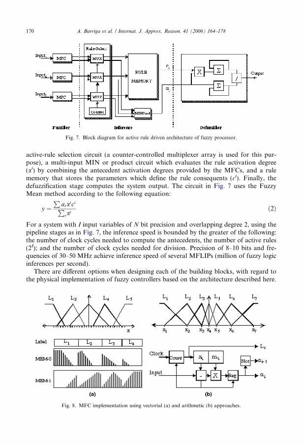
Fig. 7. Block diagram for active rule driven architecture of fuzzy processor.
170 A. Barriga et al. / Internat. J. Approx. Reason. 41 (2006) 164–178
active-rule selection circuit (a counter-controlled multiplexer array is used for this pur-pose), a multi-input MIN or product circuit which evaluates the rule activation degree(ai) by combining the antecedent activation degrees provided by the MFCs, and a rulememory that stores the parameters which define the rule consequents (ci). Finally, thedefuzzification stage computes the system output. The circuit in Fig. 7 uses the FuzzyMean method according to the following equation:
y ¼P
araiciP
rai
ð2Þ
For a system with I input variables of N bit precision and overlapping degree 2, using thepipeline stages as in Fig. 7, the inference speed is bounded by the greater of the following:the number of clock cycles needed to compute the antecedents, the number of active rules(2I); and the number of clock cycles needed for division. Precision of 8–10 bits and fre-quencies of 30–50 MHz achieve inference speed of several MFLIPs (million of fuzzy logicinferences per second).
There are different options when designing each of the building blocks, with regard tothe physical implementation of fuzzy controllers based on the architecture described here.
Fig. 8. MFC implementation using vectorial (a) and arithmetic (b) approaches.
A. Barriga et al. / Internat. J. Approx. Reason. 41 (2006) 164–178 171
MFCs can be implemented resorting to either a vectorial or arithmetic approach. At thevectorial approach, the system inputs address the antecedent memories which store themembership degree. The size of each memory is 2N words of (2 * D + log2F) bits, whereD is the number of bits used to store the antecedent activation levels and F is the numberof antecedents used in the rules (Fig. 8(a)). Memory-based MFCs allow a definition ofunrestricted membership shapes, but arithmetic approaches provide, in general, better re-sults in terms of silicon area.
The block diagram of the arithmetic MFC is depicted in Fig. 8(b). The circuit produces aset of triangular membership functions using the breakpoints and slopes. Breakpoints andslopes defining membership functions are stored in register banks. The memory size is log2Fwords of I * (N + P) bits, where N and P are the number of bits of breakpoints and slopes,respectively. An advantage of this circuit is the fact that the membership functions are nor-malized in the sense that its summation is 1. This characteristic allows the division in thedefuzzification stage to be suppressed when using the product as the antecedent connective.
Both antecedent memories and the rule memory at the inference stage can be imple-mented by a RAM, in order to improve the controller programmability, or by means ofa ROM or a combinational circuit to reduce the area consumption.
The choice among these design options depends on the application domain of the fuzzysystem. RAM implementations of MFCs and the rulebase may be a good alternative for ageneral-purpose programmable fuzzy system. Conversely, the use of ROM or combina-tional blocks to store the knowledge base is better suited when the system specificationsare well-established, or when the programmability is directly achieved by the implementa-tion technique (as in the case of FPGAs). When FPGA programming technology is basedon RAM, as with Xilinx devices, the functionality can be changed by writing a newconfiguration on the FPGA. This characteristic of intrinsic programmability makes itpossible, among other things, to update the knowledge base of the fuzzy system indepen-dently of the use of ROM or combinational blocks to store the values of the antecedentsand consequents. The availability of automatic design tools makes it possible to obtain theFPGA configuration file straightforwardly and quickly from the high level specificationsof the system.
When the change in the knowledge base must be concurrent with the operation of thesystem itself (for example, for adaptive systems) it is necessary to use RAM memory.Combinational basic blocks of certain FPGAs are formed by small memories which actlike look-up tables able to implement any function of a specific number of inputs. Thesememories can be combined to form RAM-distributed blocks. Additionally, some familiesof FPGAs such as the Spartan2E of Xilinx make available specific memory blocks whichadmit different configurations. The design tools provided by the manufacturer make itpossible to infer the use of memory from generic VHDL descriptions and to select the typeof memory to use in the implementation stage.
4. Fuzzy system design using Xfuzzy
Xfuzzy is a development environment that eases the specification, verification and syn-thesis of fuzzy inference systems. The tools integrated into the environment are based onthe XFL3 specification language [12]. A set of common functions, called the XFL library,performs the parsing and semantic analysis of XFL specifications and stores them using anabstract syntax tree. This format is used inside the environment when handling system

Fig. 9. Fuzzy system design flow.
172 A. Barriga et al. / Internat. J. Approx. Reason. 41 (2006) 164–178
descriptions. The design flow for hardware implementation of fuzzy systems is illustratedin Fig. 9. The starting point of the synthesis process is a behavioral description of the sys-tem using the specification language XFL. The verification process is carried out with thehelp of the simulation and learning tools provided by the environment.
Once the system specification is validated, the next step is the synthesis stage. The syn-thesis tool, called xfvhdl, translates the XFL specification into a VHDL descriptionaccording to the realization strategy (behavioral or structural). In the case of behavioralstrategy, xfvhdl gives a system description according to the description style shown in Sec-tion 2. It includes a package containing the type and function definitions shown in Fig. 5.In the case of specific architecture, xfvhdl employs a cell library containing the parameter-ized VHDL description for the basic building blocks. There are two kinds of blocks: datapath building blocks (implementing the inference algorithm) and control blocks (control-ling the memory write/read operations and the signals which control the operation sched-uling). The code used in the description of the cell library is compatible with the restrictedVHDL implementations of most synthesis tools.
The validation of the VHDL description is performed by simulation (simulatorModel-Sim of Mentor Graphics). The logic synthesis stage (XST of Xilinx or FPGA Compiler 2
and FPGA Express of Synopsys) then creates the circuit description of the fuzzy system.In order to accelerate the development of those two design stages, xfvhdl provides twoadditional outputs: a testbench file to ease the simulation of the fuzzy system and a com-mand script file to drive the synthesis and Xilinx FPGA implementation.
The following architectural options are defined by the user when xfvhdl is run: architec-tural options (memory-based MFCs or arithmetic MFCs), knowledge base (predefined
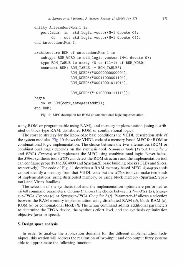
Fig. 10. MFC description for ROM or combinational logic implementation.
A. Barriga et al. / Internat. J. Approx. Reason. 41 (2006) 164–178 173
using ROM or programmable using RAM), and memory implementation (using distrib-uted or block-type RAM, distributed ROM or combinational logic).
The storage strategy for the knowledge base conditions the VHDL description style ofthe system modules. Fig. 10 shows the VHDL code of a memory-based MFC for ROM orcombinational logic implementation. The choice between the two alternatives (ROM orcombinational logic) depends on the synthesis tool. Synopsys tools (FPGA Compiler 2and FPGA Express) will implement the MFC using combinational logic. Nevertheless,the Xilinx synthesis tool (XST) can detect the ROM structure and the implementation toolcan configure properly the XC4000 and Spartan2E basic building blocks (CLBs and Slices,respectively). The code of Fig. 11 describes a RAM memory-based MFC. Synopsys toolscannot identify a memory from that VHDL code but the Xilinx tool can make two kindsof implementations: using distributed memory, or using block memory (Spartan2, Spar-tan3 and Virtex families).
The selection of the synthesis tool and the implementation options are performed asxfvhdl command parameters. Option-C allows the choice between Xilinx-XST (x), Synop-sys-FPGA Express (e) or Synopsys-FPGA Compiler 2 (f). Parameter-M allows a selectionbetween the RAM memory implementation using distributed RAM (d), block RAM (b),ROM (o) or combinational block (l). The xfvhdl command admits additional parametersto determine the FPGA device, the synthesis effort level, and the synthesis optimizationobjective (area or speed).
5. Design space analysis
In order to analyze the application domains for the different implementation tech-niques, this section will address the realization of two-input and one-output fuzzy systemsable to approximate the following function:

Fig. 11. MFC description for RAM implementation.
174 A. Barriga et al. / Internat. J. Approx. Reason. 41 (2006) 164–178
z ¼ 1
1þ e10ðx�yÞ ð3Þ
Two sets of realizations have been analyzed. A first set is related to the implementation ofthe behavioral VHDL model proposed in Section 2. The second one considers the use ofthe specific fuzzy architecture described in Section 3. Different rulebases with 3, 5, 7, and 9membership functions (MF) for the input variables and 3, 5, and 7 membership functionsfor the output have been considered. All the systems have been implemented for precisionsranging from 5 to 10 bits for input variables, membership degree and slopes.
5.1. Implementation results from behavioral VHDL
Surfaces in Fig. 12 show the functions approximated by the different rulebases. Theseresults allow us to compare realizations of systems with different complexity and precision.Initial rulebases were adjusted with the tuning facilities provided by Xfuzzy, thus obtain-ing plain rulebases with 9, 25, 49, and 81 rules, respectively. Then, the number of outputmembership was reduced by means of the clustering techniques offered by the simplifica-

Fig. 12. Function surface (Eq. (3)) using 3, 5, 7 and 9 membership functions for antecedents.
A. Barriga et al. / Internat. J. Approx. Reason. 41 (2006) 164–178 175
tion tools of Xfuzzy. Finally, the rulebases were compacted using the connectives and lin-guistic hedges available in the XFL3 language. All the systems have been implemented onXilinx FPGAs (4000 and Spartan2E family devices).
Fig. 13 shows some implementation results on Spartan2E devices. Comparing the ob-tained values shows a reduction in terms of hardware resources and maximum delay whenthe rule number is compacted using the connective or and linguistic hedges. The reason isthat in this case the aggregation rule stage is simpler because the aggregation is imple-mented summing the outputs in parallel by means of a combinational circuit.
As a conclusion, simplified systems provide better implementation results in terms ofarea and speed. Such systems have a more compact rulebase which allows for the optimi-zation of the output stage of the circuit (rule aggregation and defuzzifier). One can thusconclude that one of the main design criteria for fuzzy system implementation is the reduc-tion of the rulebase.
Fig. 13. FPGA occupation and maximum delay for rulebases with different number of inputs_MFs_rules.
176 A. Barriga et al. / Internat. J. Approx. Reason. 41 (2006) 164–178
5.2. Implementation results from structural VHDL
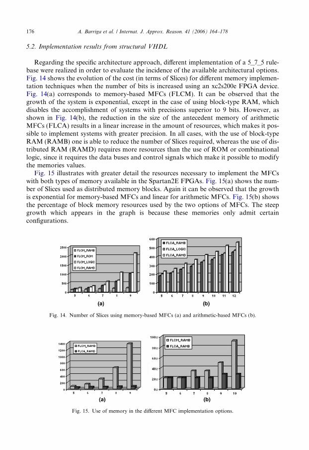
Regarding the specific architecture approach, different implementation of a 5_7_5 rule-base were realized in order to evaluate the incidence of the available architectural options.Fig. 14 shows the evolution of the cost (in terms of Slices) for different memory implemen-tation techniques when the number of bits is increased using an xc2s200e FPGA device.Fig. 14(a) corresponds to memory-based MFCs (FLCM). It can be observed that thegrowth of the system is exponential, except in the case of using block-type RAM, whichdisables the accomplishment of systems with precisions superior to 9 bits. However, asshown in Fig. 14(b), the reduction in the size of the antecedent memory of arithmeticMFCs (FLCA) results in a linear increase in the amount of resources, which makes it pos-sible to implement systems with greater precision. In all cases, with the use of block-typeRAM (RAMB) one is able to reduce the number of Slices required, whereas the use of dis-tributed RAM (RAMD) requires more resources than the use of ROM or combinationallogic, since it requires the data buses and control signals which make it possible to modifythe memories values.
Fig. 15 illustrates with greater detail the resources necessary to implement the MFCswith both types of memory available in the Spartan2E FPGAs. Fig. 15(a) shows the num-ber of Slices used as distributed memory blocks. Again it can be observed that the growthis exponential for memory-based MFCs and linear for arithmetic MFCs. Fig. 15(b) showsthe percentage of block memory resources used by the two options of MFCs. The steepgrowth which appears in the graph is because these memories only admit certainconfigurations.
Fig. 14. Number of Slices using memory-based MFCs (a) and arithmetic-based MFCs (b).
Fig. 15. Use of memory in the different MFC implementation options.
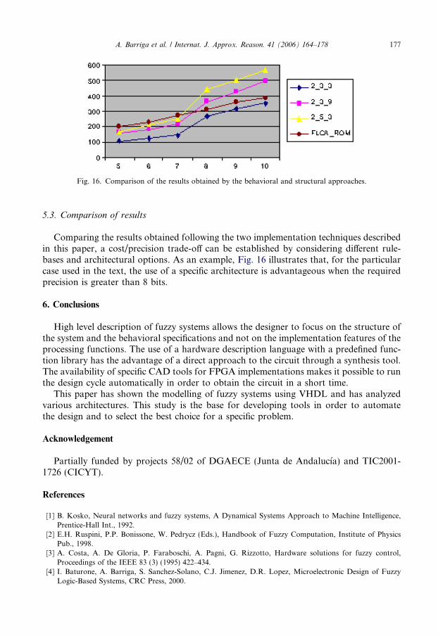
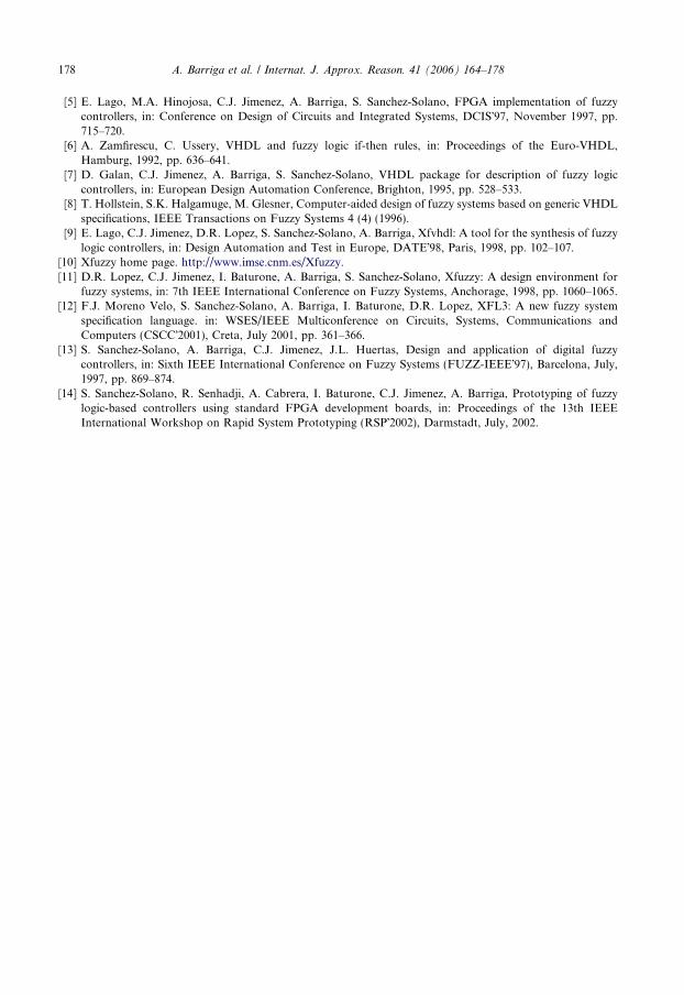
Fig. 16. Comparison of the results obtained by the behavioral and structural approaches.
A. Barriga et al. / Internat. J. Approx. Reason. 41 (2006) 164–178 177
5.3. Comparison of results
Comparing the results obtained following the two implementation techniques describedin this paper, a cost/precision trade-off can be established by considering different rule-bases and architectural options. As an example, Fig. 16 illustrates that, for the particularcase used in the text, the use of a specific architecture is advantageous when the requiredprecision is greater than 8 bits.
6. Conclusions
High level description of fuzzy systems allows the designer to focus on the structure ofthe system and the behavioral specifications and not on the implementation features of theprocessing functions. The use of a hardware description language with a predefined func-tion library has the advantage of a direct approach to the circuit through a synthesis tool.The availability of specific CAD tools for FPGA implementations makes it possible to runthe design cycle automatically in order to obtain the circuit in a short time.
This paper has shown the modelling of fuzzy systems using VHDL and has analyzedvarious architectures. This study is the base for developing tools in order to automatethe design and to select the best choice for a specific problem.
Acknowledgement
Partially funded by projects 58/02 of DGAECE (Junta de Andalucıa) and TIC2001-1726 (CICYT).
References
[1] B. Kosko, Neural networks and fuzzy systems, A Dynamical Systems Approach to Machine Intelligence,Prentice-Hall Int., 1992.
[2] E.H. Ruspini, P.P. Bonissone, W. Pedrycz (Eds.), Handbook of Fuzzy Computation, Institute of PhysicsPub., 1998.
[3] A. Costa, A. De Gloria, P. Faraboschi, A. Pagni, G. Rizzotto, Hardware solutions for fuzzy control,Proceedings of the IEEE 83 (3) (1995) 422–434.
[4] I. Baturone, A. Barriga, S. Sanchez-Solano, C.J. Jimenez, D.R. Lopez, Microelectronic Design of FuzzyLogic-Based Systems, CRC Press, 2000.
178 A. Barriga et al. / Internat. J. Approx. Reason. 41 (2006) 164–178
[5] E. Lago, M.A. Hinojosa, C.J. Jimenez, A. Barriga, S. Sanchez-Solano, FPGA implementation of fuzzycontrollers, in: Conference on Design of Circuits and Integrated Systems, DCIS�97, November 1997, pp.715–720.
[6] A. Zamfirescu, C. Ussery, VHDL and fuzzy logic if-then rules, in: Proceedings of the Euro-VHDL,Hamburg, 1992, pp. 636–641.
[7] D. Galan, C.J. Jimenez, A. Barriga, S. Sanchez-Solano, VHDL package for description of fuzzy logiccontrollers, in: European Design Automation Conference, Brighton, 1995, pp. 528–533.
[8] T. Hollstein, S.K. Halgamuge, M. Glesner, Computer-aided design of fuzzy systems based on generic VHDLspecifications, IEEE Transactions on Fuzzy Systems 4 (4) (1996).
[9] E. Lago, C.J. Jimenez, D.R. Lopez, S. Sanchez-Solano, A. Barriga, Xfvhdl: A tool for the synthesis of fuzzylogic controllers, in: Design Automation and Test in Europe, DATE�98, Paris, 1998, pp. 102–107.
[10] Xfuzzy home page. http://www.imse.cnm.es/Xfuzzy.[11] D.R. Lopez, C.J. Jimenez, I. Baturone, A. Barriga, S. Sanchez-Solano, Xfuzzy: A design environment for
fuzzy systems, in: 7th IEEE International Conference on Fuzzy Systems, Anchorage, 1998, pp. 1060–1065.[12] F.J. Moreno Velo, S. Sanchez-Solano, A. Barriga, I. Baturone, D.R. Lopez, XFL3: A new fuzzy system
specification language. in: WSES/IEEE Multiconference on Circuits, Systems, Communications andComputers (CSCC�2001), Creta, July 2001, pp. 361–366.
[13] S. Sanchez-Solano, A. Barriga, C.J. Jimenez, J.L. Huertas, Design and application of digital fuzzycontrollers, in: Sixth IEEE International Conference on Fuzzy Systems (FUZZ-IEEE�97), Barcelona, July,1997, pp. 869–874.
[14] S. Sanchez-Solano, R. Senhadji, A. Cabrera, I. Baturone, C.J. Jimenez, A. Barriga, Prototyping of fuzzylogic-based controllers using standard FPGA development boards, in: Proceedings of the 13th IEEEInternational Workshop on Rapid System Prototyping (RSP�2002), Darmstadt, July, 2002.