
Modeling of the generalized unified power flow controller for optimal power flow
6
2011 International Conference on Electrical Engineering and Informatics 17-19 July 2011, Bandung, Indonesia Modeling of the Generalized Unified Power Flow Controller for Optimal Power Flow Rakhmad Syafutra Lubis #1 , Sasongko Pramono Hadi *2 and Tumiran *3 # Electrical Engineering, Syiah Kuala University Banda Aceh, Indonesia 1 [email protected] * Electrical Engineering and Information Technology, Gadjah Mada University Yogyakarta, Indonesia 2 [email protected] 3 [email protected] Abstract— The latest generation of FACTS devices, the convertible static compensator (CSC) [1], is the progress of several innovative operating concepts in the historic development and application FACTS. One of the concepts is the GUPFC or multi-line UPFC have been done, which can control bus voltage and power flows of more than one line or according to even a sub-network. The GUPFC should have stronger control capability than the UPFC. In this paper it derived to pile up a novel concept of a mathematical model for the GUPFC consisting of one shunt converter and two or more series converters based on voltage source converter (VSCs) and DC link capacitor is developed and implemented in the nonlinear predictor-corrector primal-dual interior-point OPF algorithm. Numerical results with various GUPFC devices based on the IEEE 30 bus power system demonstrate the feasibility as well as the effectiveness of the GUPFC model established in the OPF method. Keywords: FACTS, UPFC, GUPFC, Optimal Power Flow, Interior-Point Method. I. INTRODUCTION A multifunctional power flow management devices, an innovative approach of FACTS (flexible AC transmission system) controllers was proposed in [1]. There are several possibilities or operating configurations by combining two or more converter block with flexibility. Among them there are two operating configurations, namely the interline power flow controller (IPFC) and the generalized unified power flow controller (GUPFC) [1, 2], which are significantly extended to control power flows of multi-lines or a sub-network, which the originality is the control power flows of single line, by a unified power flow controller (UPFC) [3] or static synchronous series compensator (SSSC) [4]. In contrast to the practical applications of the GUPFC in power systems, very few publications have been focused on the mathematical modeling in power system analysis. A fundamental frequency model of the GUPFC consisting of one shunt converter and two series converters for the EMTP study was proposed quite in [5]. While modeling the GUPFC in power flow and optimal power flow (OPF) analysis was proposed, among them [10] is modeling the GUPFC in non- linear interior-point OPF, where the mathematic models of power injection based on [5], while in [16] is only modelling the GUPFC to incorporate in load flow studies. Furthermore a mathematical modeling of GUPFC in this paper uses the base that is formulated in [12]. In the past four decades, techniques such as Newton method, sequential linear and quadratic programming method, PQ de-coupling method, etc [6] have been used to solve optimal power flow problems. The optimal power flow problem in this paper is solved by the developed non-linear interior-point methods in [7]-[9] that is the non- linear predictor-corrector primal-dual interior point. Experience with application of interior-point methods to power system optimization problems has been positive. II. MODELING OF THE GUPFC A. The Equivalent Circuit of the GUPFC With combining three or more converters , in the GUPFC, the concepts of voltage and power flow controller to be extended beyond what is achievable with the known two- converters UPFC controller of FACTS device [1,2]. The simplest GUPFC consists of three converters, one connected in shunt the other two in series with two transmission lines in a substation [5], therefore it can control total five power system quantities such as a bus voltage and independent active and reactive power flows of two lines. Such a GUPFC, which is shown in Fig. 1 [10], is used to show the basic operation principle for the sake of simplicity. The mathematical derivation is applicable to a GUPFC with an arbitrary number of series converters. This modeling focuses on steady-state mathematical model of GUPFC for the implementation or incorporating of the device in existing power flow programs using the GUPFC injection power flow model. The conventional Newton Raphson power flow program will be applied in order to incorporate the injection power flow GUPFC model in power flow program. In the steady-state operating condition, the main objective of the GUPFC is to control voltage and power flow. While the E6 - 4 978-1-4577-0752-0/11/$26.00 ©2011 IEEE
-
Upload
independent -
Category
Documents
-
view
1 -
download
0
Transcript of Modeling of the generalized unified power flow controller for optimal power flow
2011 International Conference on Electrical Engineering and Informatics 17-19 July 2011, Bandung, Indonesia
Modeling of the Generalized Unified Power Flow Controller for Optimal Power Flow
Rakhmad Syafutra Lubis#1, Sasongko Pramono Hadi*2 and Tumiran*3
#Electrical Engineering, Syiah Kuala University Banda Aceh, Indonesia
*Electrical Engineering and Information Technology, Gadjah Mada University Yogyakarta, Indonesia
[email protected] [email protected]
Abstract— The latest generation of FACTS devices, the convertible static compensator (CSC) [1], is the progress of several innovative operating concepts in the historic development and application FACTS. One of the concepts is the GUPFC or multi-line UPFC have been done, which can control bus voltage and power flows of more than one line or according to even a sub-network. The GUPFC should have stronger control capability than the UPFC. In this paper it derived to pile up a novel concept of a mathematical model for the GUPFC consisting of one shunt converter and two or more series converters based on voltage source converter (VSCs) and DC link capacitor is developed and implemented in the nonlinear predictor-corrector primal-dual interior-point OPF algorithm. Numerical results with various GUPFC devices based on the IEEE 30 bus power system demonstrate the feasibility as well as the effectiveness of the GUPFC model established in the OPF method. Keywords: FACTS, UPFC, GUPFC, Optimal Power Flow, Interior-Point Method.
I. INTRODUCTION A multifunctional power flow management devices, an
innovative approach of FACTS (flexible AC transmission system) controllers was proposed in [1]. There are several possibilities or operating configurations by combining two or more converter block with flexibility. Among them there are two operating configurations, namely the interline power flow controller (IPFC) and the generalized unified power flow controller (GUPFC) [1, 2], which are significantly extended to control power flows of multi-lines or a sub-network, which the originality is the control power flows of single line, by a unified power flow controller (UPFC) [3] or static synchronous series compensator (SSSC) [4]. In contrast to the practical applications of the GUPFC in power systems, very few publications have been focused on the mathematical modeling in power system analysis. A fundamental frequency model of the GUPFC consisting of one shunt converter and two series converters for the EMTP study was proposed quite in [5]. While modeling the GUPFC in power flow and optimal power flow (OPF) analysis was
proposed, among them [10] is modeling the GUPFC in non-linear interior-point OPF, where the mathematic models of power injection based on [5], while in [16] is only modelling the GUPFC to incorporate in load flow studies. Furthermore a mathematical modeling of GUPFC in this paper uses the base that is formulated in [12]. In the past four decades, techniques such as Newton method, sequential linear and quadratic programming method, PQ de-coupling method, etc [6] have been used to solve optimal power flow problems. The optimal power flow problem in this paper is solved by the developed non-linear interior-point methods in [7]-[9] that is the non-linear predictor-corrector primal-dual interior point. Experience with application of interior-point methods to power system optimization problems has been positive.
II. MODELING OF THE GUPFC
A. The Equivalent Circuit of the GUPFC With combining three or more converters , in the GUPFC,
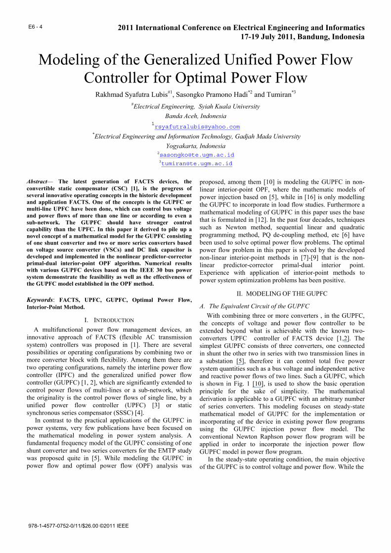
the concepts of voltage and power flow controller to be extended beyond what is achievable with the known two-converters UPFC controller of FACTS device [1,2]. The simplest GUPFC consists of three converters, one connected in shunt the other two in series with two transmission lines in a substation [5], therefore it can control total five power system quantities such as a bus voltage and independent active and reactive power flows of two lines. Such a GUPFC, which is shown in Fig. 1 [10], is used to show the basic operation principle for the sake of simplicity. The mathematical derivation is applicable to a GUPFC with an arbitrary number of series converters. This modeling focuses on steady-state mathematical model of GUPFC for the implementation or incorporating of the device in existing power flow programs using the GUPFC injection power flow model. The conventional Newton Raphson power flow program will be applied in order to incorporate the injection power flow GUPFC model in power flow program. In the steady-state operating condition, the main objective of the GUPFC is to control voltage and power flow. While the
E6 - 4
978-1-4577-0752-0/11/$26.00 ©2011 IEEE
iV ijseV
ishV
jV
kV
jkseV
Fig. 1 Schematic diagram of GUPFC with three converters
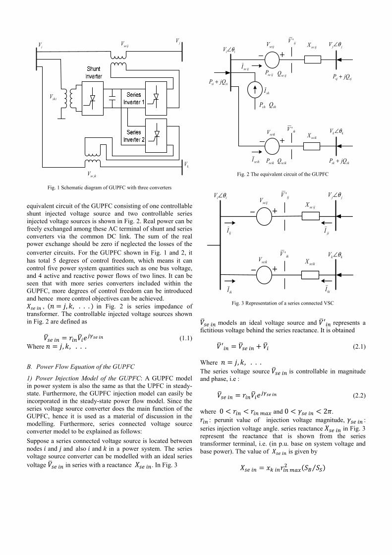
equivalent circuit of the GUPFC consisting of one controllable shunt injected voltage source and two controllable series injected voltage sources is shown in Fig. 2. Real power can be freely exchanged among these AC terminal of shunt and series converters via the common DC link. The sum of the real power exchange should be zero if neglected the losses of the converter circuits. For the GUPFC shown in Fig. 1 and 2, it has total 5 degrees of control freedom, which means it can control five power system quantities such as one bus voltage, and 4 active and reactive power flows of two lines. It can be seen that with more series converters included within the GUPFC, more degrees of control freedom can be introduced and hence more control objectives can be achieved. , , , . . . in Fig. 2 is series impedance of transformer. The controllable injected voltage sources shown in Fig. 2 are defined as (1.1) Where , , . . .
B. Power Flow Equation of the GUPFC
1) Power Injection Model of the GUPFC: A GUPFC model in power system is also the same as that the UPFC in steady-state. Furthermore, the GUPFC injection model can easily be incorporated in the steady-state power flow model. Since the series voltage source converter does the main function of the GUPFC, hence it is used as a material of discussion in the modelling. Furthermore, series connected voltage source converter model to be explained as follows: Suppose a series connected voltage source is located between nodes and and also and in a power system. The series voltage source converter can be modelled with an ideal series voltage in series with a reactance . In Fig. 3
iiV θ∠ jjV θ∠ijseXijV 'ijseV
ijseIijseP ijseQ
sjsj jQP +sisi jQP +
shP shQ
shI
ikseIikseP ikseQ
ikseV ikV 'ikseX kkV θ∠
sksk jQP +
Fig. 2 The equivalent circuit of the GUPFC
iiV θ∠ jjV θ∠
kkV θ∠
ijV '
ikV '
ijI jiI
ikI kiI
ijseX
ikseXikseV
ijseV
Fig. 3 Representation of a series connected VSC
models an ideal voltage source and represents a fictitious voltage behind the series reactance. It is obtained (2.1) Where , , . . . The series voltage source is controllable in magnitude and phase, i.e : (2.2)
where 0 and 0 2 .
: perunit value of injection voltage magnitude, : series injection voltage angle. series reactance in Fig. 3 represent the reactance that is shown from the series transformer terminal, i.e. (in p.u. base on system voltage and base power). The value of is given by ⁄
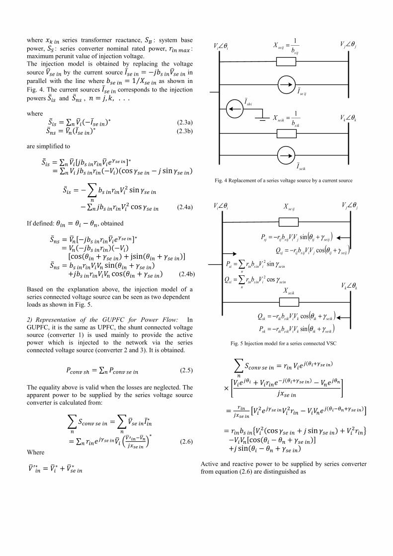
where series transformer reactance, : system base power, : series converter nominal rated power, : maximum perunit value of injection voltage. The injection model is obtained by replacing the voltage source by the current source in parallel with the line where 1 ⁄ as shown in Fig. 4. The current sources corresponds to the injection powers and , , , . . . where ∑ (2.3a) (2.3b)
are simplified to ∑ ∑ cos sin
sin ∑ cos (2.4a)
If defined: , obtained cos jsin sin cos (2.4b) Based on the explanation above, the injection model of a series connected voltage source can be seen as two dependent loads as shown in Fig. 5. 2) Representation of the GUPFC for Power Flow: In GUPFC, it is the same as UPFC, the shunt connected voltage source (converter 1) is used mainly to provide the active power which is injected to the network via the series connected voltage source (converter 2 and 3). It is obtained.
∑ (2.5)
The equality above is valid when the losses are neglected. The apparent power to be supplied by the series voltage source converter is calculated from:
∑ (2.6) Where
iiV θ∠ jjV θ∠
kkV θ∠
ijsijse b
X 1=
iksikse b
X 1=
ishIijseI
ikseI
Fig. 4 Replacement of a series voltage source by a current source
iiV θ∠ jjV θ∠ijseX
ikseX kkV θ∠
( )ijseijjiijsijsj VVbrP γθ +−= sin
( )ijseijjiijsijsj VVbrQ γθ +−= cos
( )ikseikkiiksiksk VVbrQ γθ +−= cos
( )ikseikkiiksiksk VVbrP γθ +−= sin
∑=n
inseiinsinsi VbrP γsin2
∑=n
inseiinsinsi VbrQ γcos2
Fig. 5 Injection model for a series connected VSC
cos sin cos sin Active and reactive power to be supplied by series converter from equation (2.6) are distinguished as
iiV θ∠ jjV θ∠ijseX
ikseX kkV θ∠
( )ijseijjiijsijsj VVbrP γθ +−= sin
( )ijseijjiijsijsj VVbrQ γθ +−= cos
( )ikseikkiiksiksk VVbrQ γθ +−= cos
( )ikseikkiiksiksk VVbrP γθ +−= sin
( )∑ +=n
inseinniinsinsi VVbrP γθsin
( ) shinjn
inseiinsinsi QVbrQ +=∑ γcos2
iqshinj ViQ −=
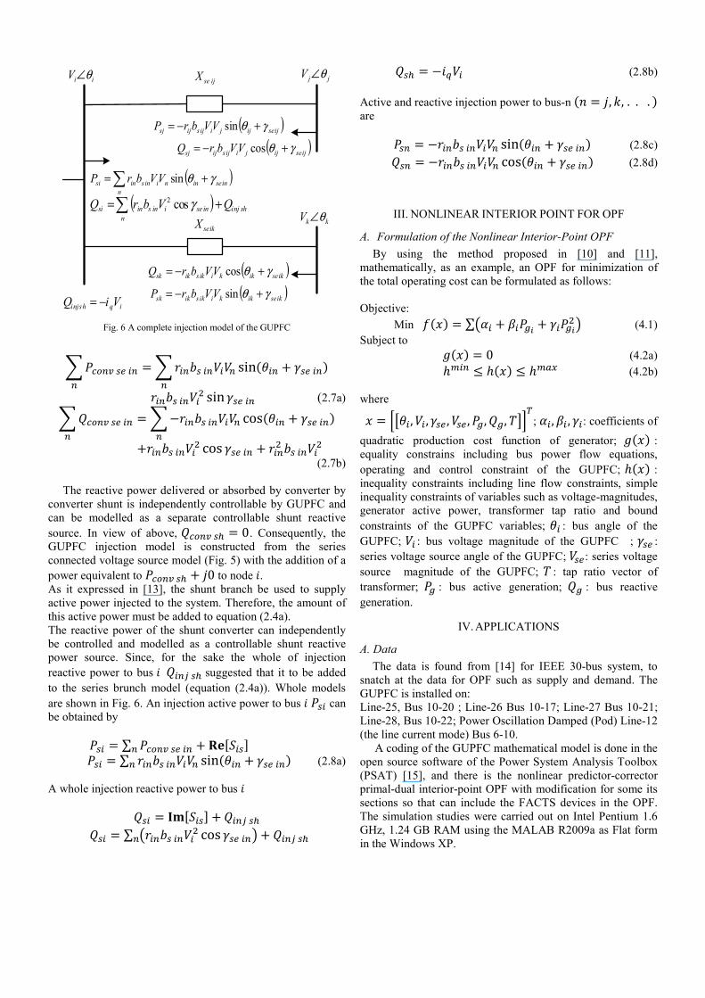
Fig. 6 A complete injection model of the GUPFC
sin
sin (2.7a) cos
cos (2.7b)
The reactive power delivered or absorbed by converter by converter shunt is independently controllable by GUPFC and can be modelled as a separate controllable shunt reactive source. In view of above, 0. Consequently, the GUPFC injection model is constructed from the series connected voltage source model (Fig. 5) with the addition of a power equivalent to 0 to node . As it expressed in [13], the shunt branch be used to supply active power injected to the system. Therefore, the amount of this active power must be added to equation (2.4a). The reactive power of the shunt converter can independently be controlled and modelled as a controllable shunt reactive power source. Since, for the sake the whole of injection reactive power to bus suggested that it to be added to the series brunch model (equation (2.4a)). Whole models are shown in Fig. 6. An injection active power to bus can be obtained by ∑ ∑ sin (2.8a)
A whole injection reactive power to bus ∑ cos
(2.8b)
Active and reactive injection power to bus-n , , . . . are sin (2.8c) cos (2.8d)
III. NONLINEAR INTERIOR POINT FOR OPF
A. Formulation of the Nonlinear Interior-Point OPF By using the method proposed in [10] and [11],
mathematically, as an example, an OPF for minimization of the total operating cost can be formulated as follows:
Objective:
Min ∑ (4.1) Subject to 0 (4.2a)
(4.2b)
where
, , , , , , ; , , : coefficients of quadratic production cost function of generator; : equality constrains including bus power flow equations, operating and control constraint of the GUPFC; : inequality constraints including line flow constraints, simple inequality constraints of variables such as voltage-magnitudes, generator active power, transformer tap ratio and bound constraints of the GUPFC variables; : bus angle of the GUPFC; : bus voltage magnitude of the GUPFC ; : series voltage source angle of the GUPFC; : series voltage source magnitude of the GUPFC; : tap ratio vector of transformer; : bus active generation; : bus reactive generation.
IV. APPLICATIONS
A. Data The data is found from [14] for IEEE 30-bus system, to
snatch at the data for OPF such as supply and demand. The GUPFC is installed on: Line-25, Bus 10-20 ; Line-26 Bus 10-17; Line-27 Bus 10-21; Line-28, Bus 10-22; Power Oscillation Damped (Pod) Line-12 (the line current mode) Bus 6-10. A coding of the GUPFC mathematical model is done in the open source software of the Power System Analysis Toolbox (PSAT) [15], and there is the nonlinear predictor-corrector primal-dual interior-point OPF with modification for some its sections so that can include the FACTS devices in the OPF. The simulation studies were carried out on Intel Pentium 1.6 GHz, 1.24 GB RAM using the MALAB R2009a as Flat form in the Windows XP.
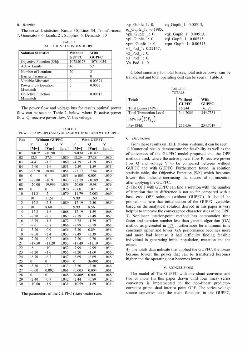
B. Results The network statistics; Buses: 30, Lines 34, Transformers:
7, Generators: 6, Loads: 21, Supplies: 6, Demands: 30 TABLE I
SOLUTION STATISTICS OF OPF
Solution Statistics
Without GUPFC
With GUPFC
Objective Function [$/h]: 1078.0173 1078.0034 Active Limits: 46 52 Number of Iterations 20 21 Barrier Parameter 0 0 Variable Mismatch 0 0.00371 Power Flow Equation Mismatch
0 0.0005
Objective Function Mismatch
0 0.00015
The power flow and voltage bus for results optimal power
flow can be seen in Table 2, below, where P: active power flow, Q: reactive power flow, V: bus voltage.
TABLE II
POWER FLOW (OPF) AND VOLTAGE WITHOUT AND WITH GUPFC
Bus Without GUPFC With GUPFC P [Mw]
Q [Var]
V [p.u.]
P [Mw]
Q [Var]
V [p.u.]
01 260.95 -10.90 1.1 260.81 -10.82 1.1 02 12.3 27.3 1.080 12.29 27.28 1.080 03 -4.4 -1.2 1.060 -4.39 -1.19 1.060 04 -7.60 -1.6 1.051 -7.59 -1.59 1.051 05 -93.20 18.00 1.051 -93.17 17.84 1.050 06 0 0 1.051 1e-005 0.003 1.050 07 -22.80 -10.9 1.043 -22.79 -10.89 1.043 08 -20.00 19.999 1.056 -20.00 19.98 1.056 09 0 0 1.070 -0.001 1.07 1.077 10 -11.8 -2 1.070 -11.79 -2.003 1.069 11 10 11.51 1.1 9.99 11.60 1.1 12 -12.2 -7.5 1.089 -12.19 -7.50 1.089 13 10 8.60 1.1 9.99 8.56 1.1 14 -12.2 -1.6 1.068 -12.19 -1.59 1.068 15 -8.20 -2.5 1.067 -8.19 -2.49 1.067 16 -6.79 -1.8 1.072 -6.75 -1.79 1.071 17 -9.0 -5.8 1.066 -8.99 -5.79 1.065 18 -3.20 -0.9 1.056 -3.20 0.89 1.056 19 -9.50 -3.4 1.053 -9.49 -3.39 1.053 20 -2.20 -0.7 1.056 -2.20 -0.70 1.056 21 -17.50 -11.20 1.053 -17.49 -11.19 1.054 22 -8 -10 1.052 -7.99 -9.99 1.054 23 -3.20 -1.6 1.055 -3.20 -1.60 1.056 24 -8.70 -6.7 1.047 -8.69 -6.69 1.048 25 0 0 1.059 0 3e-005 1.051 26 -3.50 -2.3 1.033 -3.50 -2.30 1.046 27 -0.001 0.002 1.061 -0.003 0.004 1.061 28 0 0 1.048 2e-005 0.001 1.048 29 -2.401 -0.9 1.042 -2.44 -0.89 1.042 30 -10.60 -1.9 1.031 -10.59 -1.89 1.031
The parameters of the GUPFC (state vector) are:
vp_Gupfc_1: 0, vq_Gupfc_1: 0.00513, iq_Gupfc_1: -0.1985, vpk_Gupfc_1: 0, vqk_Gupfc_1: 0.00513, vpl_Gupfc_1: 0, vql_Gupfc_1: 0.00513, vpm_Gupfc_1: 0, vqm_Gupfc_1: 0.00513, v1_Pod_1: 0.22167, v2_Pod_1: 0, v3_Pod_1: 0, Vs_Pod_1: 0
Global summary for total losses, total active power can be transferred and total operating cost can be seen in Table 3.
TABLE III TOTALS
Totals Without GUPFC
With GUPFC
Total Losses [MW]: 16.244 16.123 Total Transaction Level
[MW] ∑ :
344.7085 344.7351
Pay [$/h]: 255.656 254.7019
C. Discussion From these results on IEEE 30-bus systems, it can be seen:
1) Numerical results demonstrate the feasibility as well as the effectiveness of the GUPFC model proposed and the OPF methods used, where the active power flow P, reactive power flow Q and voltage V to be compared between without GUPFC and with GUPFC. Furthermore found, in solution statistic table, the Objective Function [$/h] which becomes lower, this indicate increasing the successful optimization after applying the GUPFC. 2) The OPF with GUPFC can find a solution with the number of iteration that its difference is not so far compared with a base case OPF solution (without GUPFC). It should be pointed out here that initialization of the GUPFC variables based on the analytical solution derived in this paper is very helpful to improve the convergence characteristics of the OPF. 3) Nonlinear interior-point method has computation time faster and iteration number less than genetic algorithm (GA) method as presented in [17], furthermore for minimum time constraint upper and lower, GA performance becomes more and more bad because it had difficulty finding feasible individual in generating initial population, mutation and the others. 4) The totals data indicate that applied the GUPFC: the losses become lower; the power that can be transferred becomes higher and the operating cost becomes lower.
V. CONCLUSIONS The model of The GUPFC with one shunt converter and
two or more (in this paper drawn until four lines) series converters is implemented in the non-linear predictor-corrector primal-dual interior point OPF. The series voltage source converter take the main functions in the GUPFC,
therefore, it is used as the material of discussion in the modelling. Thus a mathematical model of the GUPFC, which is suitable for power flow and optimal power flow study, is established.
By using the same method as [10], [15], analytical solutions for the initial value of the GUPFC is derived. With these starting points, the OPF can converge rapidly. The number of iterations for an OPF solution with the GUPFC devices is relatively comparable or less than that of a base case OPF solution without the GUPFC devices in the nonlinear interior-point OPF.
Numerical results based on IEEE 30-bus systems with placement the GUPFC device, allocated randomly, demonstrate the feasibility as well as the effectiveness of the GUPFC model established.
The GUPFC can construct a multi-terminal (at least three terminals) sub-network, which can control active and reactive power flows for a group of lines and selected bus voltage within a substation.
Furthermore, it will be focused the GUPFC optimal placement problems for OPF and system security.
ACKNOWLEDGMENT The authors would like to thank for the support and helpful
comments of academical members of Gadjah Mada University for this work.
REFERENCES [1] B. Fardanesh, M. Henderson, B. Shperling, S. Zelingher, L. Gyugyi, C.
Schauder, B. Lam, J. Moundford, R. Adapa, and A. Edris, “Covertible Static Compensator: Application to the New York Transmission System”, in CIGRE 14- 103, Paris, France. Sept. 1998.
[2] L. Gyugyi, K. K. Sen, and C. D. Schauder, "The Interline Power Flow Controller : A New Approach to Power Flow Management in Transmission Systems," IEEE Trans. Power Delivery, vol. 14, no. 3, pp. 1115-1123, July. 1999.
[3] L. Gyugyi, C. D. Schauder, S. L. Williams, T. R. Rietman, D. R. Torgerson, and A. Edris, “The Unified Power Flow Controller : A New Approach to Power Transmission Control”, IEEE Trans. Power Delivery, vol. 10, no. 2, pp. 1085-1093, Apr. 1995.
[4] L. Gyugyi, C. D. Schauder, and K. K. Sen, “Static Synchronous Series Compensator : A Solid-State Approach to The Series Compensation of
Transmission Lines”, IEEE Trans. Power Delivery, vol. 12, no. 1, pp. 406-413, Jan. 1997.
[5] B. Fardanesh, B. Shperling, E. Uzunovic, and S. Zelingher, "Multi-Converter FACTS Devices : The Generalized Unified Power Flow Controller (GUPFC)," in IEEE 2000 PES Summer Meeting, Seattle, USA, July 2000.
[6] M. Huneault, and F. D. Galiana, “A Survey of The Optimal Power Flow Literature“, IEEE Trans. Power System, vol. 6, no. 2, pp. 762-770, May 1991
[7] S. Granville, “Optimal Reactive Power Dispatch Through Interior Point Method”, IEEE Trans. Power System, vol. 9, no. 1, pp. 136-146, 1994
[8] Y. C. Wu, A. S. Debs, and R. E. Marsten, ”A Direct Predictor-Corrector Primal-Dual Interior-Point Algorithm for Optimal Power Flow”, IEEE Transactions on Power Systems, vol. 9, no. 2, pp. 876-883, 1994
[9] A. S. El-Bakry, R. A. Tapia, T. Tsuchiya, and Y. Zhang, "On The Formulation and Theory or The Newton Interior-Point Method for Nonlinear Programming," Journal of Optimization Theory and Applications, Vol. 89, No. 3, pp. 507-541, 1996.
[10] X. P. Zhang, E. Handschin, and M. M. Yao, “Modeling of The Generalized Unified Power Flow Controller (GUPFC) in a Nonlinear Interior Point OPF”, IEEE Transactions on Power Systems, vol. 16, no. 3, pp. 367-373, August 2001
[11] X. P. Zhang, and E. J. Handschin, “Advanced Implementation of UPFC in a Nonlinear Interior Point OPF”, IEE Proceeding Generation Transmission Distribution., vol. 148, no. 5, pp. 489-496, Sept. 2001.
[12] M. Norozian, L. Angquist, M. Ghandhari, and G. Andersson, “Use of UPFC for Optimal Power Flow Control”, IEEE Trans. Power Delivery, vol. 12, no. 4, pp. 1629-1634, 1997
[13] A. Farhangfar, S. J. Sajjadi, and S. Afsharnia, "Power Flow Control and Loss Minimization with Unified Power Flow Controller", CCECE 2004-CCGEI 2004, Niagara Falls. 0-7803-8253-6/04/$17.00c2004 IEEE. 2004.
[14] S. B. Warkad, M. K. Khedkar, G. M. Dhole, "A Genetic Algorithm Approach for Solving AC-DC Optimal Power Flow Problem," Journal of Theoretical and Applied Information Technology, JATIT. All rights reserved, Vol. 16, No. 1, pp. 027-039, 2009.
[15] F. Milano, "An Open Source Power System Analysis Toolbox, "IEEE Trans. on Power Systems, Vol. 20, No. 3, pp. 1199-1206, August 2005.
[16] M. Z. El-Sadek, A. Ahmed, and M. A. Mohammed, " Incorporating of GUPFC in Load Flow Studies", Egypt, 2009, available in: www.ipac.kacst..edu.sa/eDoc/2009/172734_1.pdf
[17] J. R. Santos, A. T. Lora, A. G. Exposito, and J. L. M. Ramos, “Finding Improved Local Minima of Power System Optimization Problems by Interior-Point Method”, IEEE Transactions on Power Systems, vol. 18, no. 1, pp. 238-243, 2003.