
Characteristics of the vibrational power flow propagation in a ...
20
Characteristics of the vibrational power flow propagation in a submerged periodic ring-stiffened cylindrical shell J. Yan, T.Y. Li * , T.G. Liu, J.X. Liu Department of Naval Architecture and Ocean Engineering, Huazhong University of Science and Technology, Wuhan 430074, P.R. China Received 7 February 2005; received in revised form 2 June 2005; accepted 18 August 2005 Available online 25 October 2005 Abstract By using space-harmonic analysis method, the characteristics of the vibrational power flow prop- agation in an infinite periodic ring-stiffened cylindrical shell immersed in water are studied. The har- monic motion of the shell and the sound pressure field in the fluid are described by Flu ¨ gge shell equations and Helmholtz equation, respectively, and four kinds of the ringsÕ forces and moments are considered. Along the shell axial direction, the propagation of the power flow carried by different internal forces (moments) of the shell wall can be obtained, thus the total power flow in the shell wall and the ratios of the component power flow carried by different shell internal forces (moments) to the total power flow are also studied. It is found that characteristics of the vibrational power flow prop- agation vary with different circumferential modes order and different frequencies. Moreover, the presence of the stiffeners and structural damping will greatly influence the results. Ó 2005 Elsevier Ltd. All rights reserved. Keywords: Periodic ring-stiffened cylindrical shell; Space-harmonic analysis method; Vibrational power flow propagation 1. Introduction Thin cylindrical shells stiffened by periodic ring stiffeners are commonly used as primary structural components in aircraft and marine structures. The determination of the dynamic 0003-682X/$ - see front matter Ó 2005 Elsevier Ltd. All rights reserved. doi:10.1016/j.apacoust.2005.08.006 * Corresponding author. E-mail address: [email protected] (T.Y. Li). Applied Acoustics 67 (2006) 550–569 www.elsevier.com/locate/apacoust 转载 http://www.paper.edu.cn 中国科技论文在线
-
Upload
khangminh22 -
Category
Documents
-
view
3 -
download
0
Transcript of Characteristics of the vibrational power flow propagation in a ...

http://www.paper.edu.cn中国科技论文在线
Applied Acoustics 67 (2006) 550–569
www.elsevier.com/locate/apacoust
Characteristics of the vibrational powerflow propagation in a submerged periodic
ring-stiffened cylindrical shell
J. Yan, T.Y. Li *, T.G. Liu, J.X. Liu
Department of Naval Architecture and Ocean Engineering, Huazhong University of Science
and Technology, Wuhan 430074, P.R. China
Received 7 February 2005; received in revised form 2 June 2005; accepted 18 August 2005Available online 25 October 2005
Abstract
By using space-harmonic analysis method, the characteristics of the vibrational power flow prop-agation in an infinite periodic ring-stiffened cylindrical shell immersed in water are studied. The har-monic motion of the shell and the sound pressure field in the fluid are described by Flugge shellequations and Helmholtz equation, respectively, and four kinds of the rings� forces and momentsare considered. Along the shell axial direction, the propagation of the power flow carried by differentinternal forces (moments) of the shell wall can be obtained, thus the total power flow in the shell walland the ratios of the component power flow carried by different shell internal forces (moments) to thetotal power flow are also studied. It is found that characteristics of the vibrational power flow prop-agation vary with different circumferential modes order and different frequencies. Moreover, thepresence of the stiffeners and structural damping will greatly influence the results.� 2005 Elsevier Ltd. All rights reserved.
Keywords: Periodic ring-stiffened cylindrical shell; Space-harmonic analysis method; Vibrational power flowpropagation
1. Introduction
Thin cylindrical shells stiffened by periodic ring stiffeners are commonly used as primarystructural components in aircraft and marine structures. The determination of the dynamic
0003-682X/$ - see front matter � 2005 Elsevier Ltd. All rights reserved.
doi:10.1016/j.apacoust.2005.08.006
* Corresponding author.E-mail address: [email protected] (T.Y. Li).
转载
J. Yan et al. / Applied Acoustics 67 (2006) 550–569 551
中国科技论文在线 http://www.paper.edu.cn
properties of these cylindrical shells is thus an important subject in the area of noise andvibration control. Since Goyder and White [1–3] first definitely presented the concept ofpower flow, the method of vibrational power flow has become a useful tool in this area.
Among the extensive researches on the power flow of the coupled system of cylindricalshell and fluid, most concentrated on the thin cylindrical elastic shells filled with fluid. Ful-ler and Fahy [4] first characterized the fluid–structure interaction in terms of power flowand energy distribution. Their work was concerned with the solution and physical inter-pretation of the dispersion equation for the coupled system. Both dispersion behaviorand energy distribution of free waves were investigated. The distribution of vibrationalenergy between the shell wall and the fluid in the shell for free modes of propagationwas obtained and its variation with frequency and material parameters was studied. Brev-art and Fuller [5] investigated on the distribution of vibrational energy between the fluidfield and the shell by considering the effect of an internal uniform flow. They gave the effectof Mach number on the dispersion curves and the distribution of vibrational energy, butthe analysis of the characteristics of the wave propagation was not very clear. Pavic [6]gave the expressions of the axial and the circumferential components of the unit energyflow along the shell wall in terms of the characteristic shell�s components of the motion.He analyzed the influence of the three different terms contributing to the total energy flowand pointed out that the three terms exhibit considerable variations in contributing the to-tal energy flow. Pavic [7] also investigated the wave motion and vibro-acoustical energyflow through a fluid-filled pipe. The expressions of the energy flow in the wall and the fluidwere given from the surface vibration and can be simplified at lower frequencies. Using themethod of residues, Xu and Zhang [8] investigated the vibrational power flow input froman external force and the transmission along the shell axial direction by different internalforces of the shell wall. The results showed that the input power flow and the power flowtransmission depend mainly upon the characteristics of the free propagating waves in thiscoupled system. Sorokin and Ershova [9] used Green�s matrix and the boundary integralequation to study free plane wave propagation in infinitely long periodic elastic structureswith and without heavy fluid loading. They also presented an efficient algorithm to com-pute Bloch parameters (propagation constants) and locate the band gaps. Sorokin et al.[10] formulated an energy flow through arbitrary cross-section of an infinitely long shellat each circumferential mode number. An inspection into the energy redistribution be-tween several transmission paths in a near field and the influence of excitation conditionson steady fluctuations of the overall energy flow in a far field was also performed. Both ofthese studies and the earlier work of Fuller and Fahy [4] provided information on theenergy flow in the time-average sense or on the energy distribution within the system atvarious frequencies. Brevart and Fuller [11] used an analytical approach to study theinstantaneous exchange of energy appearing along an infinite fluid-filled cylindrical elasticshell excited by an impulsive radial point force.
In the case of the shell immersed in fluid, its dispersion equation is similar to that of theshell filled with fluid, but the term of fluid loading differs. Scott [12] has presented a de-tailed study of the dispersion curves for the fluid-loaded cylindrical shells. Guo [13] pre-sented an approximate analytical solution for the dispersion equation of fluid-loadedcylindrical shells in the intermediate and high-frequency region. Zuo et al. [14] were inter-ested in studying the vibrational energy flow in fluid-loaded shells. They presented anumerical method for searching the propagation waves on the real wave number axis.Borgiotti and Rosen [15] investigated the power flow analysis of surface waves on a
n
s--a-s.f]fs-wl-nnws-ydsdgf-
adddur-e-
ld-efense0hl
552 J. Yan et al. / Applied Acoustics 67 (2006) 550–569
中国科技论文在线 http://www.paper.edu.cn
fluid-loaded cylinder by using a shell theory that includes the effects of shear deformatioand rotary inertia.
While cylindrical shell structures with periodic ring stiffeners vibrate in fluid, they tranmit vibrational energy by combinations of wave motion, such as flexural waves, longitudinal waves and torsional waves. When these different types of waves encounterdiscontinuity in the periodicity, they interact and are converted from one type into another. This is an important part of the wave propagation process in periodic structureBut when stiffened cylindrical shell is studied, it becomes very complicated because othe effect of the fluid–structure interaction and the presence of stiffeners. Harari [16,17investigated the wave propagation in shells with a wall joint, and the related problem otravelling waves encountering a ring stiffener attached to the shell wall. The structural dicontinuity considered in the papers consists of a spring-type insert and the results shohigh power reflection coefficients at the cut-on frequencies of various torsional waves. Fuler [18] has investigated the effects of discontinuities in the wall of a cylindrical shell otravelling flexural waves, and both the geometry and material discontinuities have beeconsidered. Xu and Zhang [19] studied the transmission loss of vibrational power flothrough the wall joint in fluid-filled shells and presented an analysis of power flow tranmission and reflection at the joint. They found material stiffness of the joint and frequencare two important factors that strongly influence the results. Zhang and Zhang [20] studiethe input vibrational power flow from an external force into a shell with periodic stiffenerin vacuo. The power transmitted by different internal forces of the shell wall was deriveand its variation with frequency and the shell axial distance was also studied. By idealizinthe coupled system, Lee and Kim [21] first obtained the exact solution for this type oproblem. Characteristics of the system responses and effects of important design parameters were also studied using the transmission losses calculated from the analysis.
Space-harmonic analysis method is an effective method to analyze this coupled systemof periodic structure and fluid. By using space-harmonic analysis, the surface motion toconverted harmonic pressure can be regarded as an infinite sum of space harmonics anthe effects of fluid loading on the forced harmonic response can easily be included. Meaand his collaborators made a great deal contributions on space-harmonic analysis methoby analyzing periodic beam, plate and shell, and their work is well summarized in [22]. Xand Zhang [23] used it to study the input power flow from a cosine harmonic circumfeential line force into an infinite cylindrical fluid-filled shell with periodic stiffeners, but thvibrational power flow propagation in this periodically stiffened structure was not mentioned in their article.
In this paper, space-harmonic analysis method is extended to analyze the vibrationapower flow propagation in an infinite periodic ring-stiffened cylindrical shell immersein fluid. The harmonic motion of the shell and the sound pressure field in the fluid are described by Flugge shell equations and Helmholtz equation, respectively. First, the responsof the coupled system to a convected harmonic pressure is derived. Secondly, four kinds oshell internal forces (moments) can be obtained according to the relationships between thstress and the strain of the shell. At last, the forced vibrational power flow propagatioalong the shell axial direction is given. The total power flow in the shell wall and the ratioof the component power flow carried by different shell internal forces (moments) to thtotal power are also studied. The discussions focus on the circumferential modes n =and n = 1 at three kinds of representative frequencies (that is low, middle and higfrequencies, respectively). Utilizing the analysis results, characteristics of the vibrationa

J. Yan et al. / Applied Acoustics 67 (2006) 550–569 553
中国科技论文在线 http://www.paper.edu.cn
power flow propagation through a periodic ring-stiffened shell are interpreted with specialattention to the role of the periodic ring stiffeners.
2. Forced vibration of the coupled system
An infinite thin-walled periodic ring-stiffened cylindrical shell immersed in fluid shownin Fig. 1 is considered. Supposing the density of the fluid outside is qf and the sound veloc-ity in it is Cf. The shell is characterized by its mean radius a, wall thickness h, mass densityqs, Young�s modulus E and the Poisson�s ratio l. The ring stiffeners have uniform rectan-gular section with width b and height d, attached at x = mL (L is the stiffener spacing,m = 0, ± 1, ± 2, . . .). The connections are rigid, so that, at each line of attachment, theshell and the stiffener have the same linear velocity and angular velocity. The insider stiff-eners may exert axial force, shear and moments on the shell.
2.1. Forces and moments of a ring stiffener acting on the shell
When the external force is applied on the shell-fluid coupled system, the attached ringstiffener will vibrate together with the shell. Omitting shear deformation and rotary inertia,the motion equations of a ring stiffener are [23]
E1I
R41
o4w
oh4� o3v
oh3
� �þ E1A
R21
wþ ovoh
� �þ q1A
o2wot2
¼ F wðh; tÞ; ð1aÞ
E1I
R41
o3w
oh3� o2v
oh2
� �� E1A
R21
owoh
þ o2v
oh2
� �þ q1A
o2vot2
¼ F vðh; tÞ; ð1bÞ
E1I
R41
o4u
oh4� o
2ðR1uÞoh2
� �� G1J
R41
o2u
oh2þ o
2ðR1uÞoh2
� �þ q1A
o2uot2
¼ F uðh; tÞ; ð1cÞ
E1I
R21
R1u� o2u
oh2
� �� G1J
R21
o2u
oh2þ o
2ðR1uÞoh2
� �þ q1Ip
o2ðR1uÞot2
¼ R1F uðh; tÞ; ð1dÞ
where R1 is the mean radius of a stiffener, A is the area of stiffener cross-section, I and �I arethe principal moments of inertia paralleling the axial and the radial, respectively,Ip ¼ I þ �I is the polar moments of inertia, J is the constant of twist of cross-section, q1is mass density of stiffener material, E1 and G1 are Young�s modulus and shear modulusof stiffener material, respectively, Fw, Fv, Fu and M are the sideward forces and momentsof the stiffener acting on the shell, respectively, u = ow/ox.
Fig. 1. Periodical ring-stiffened shell immersed in fluid.
t
Þ
r.
e
ÞÞ
-
s
ÞÞÞÞ
1,
,
,
Þ
d
Þ
Þ
j
i-
554 J. Yan et al. / Applied Acoustics 67 (2006) 550–569
中国科技论文在线 http://www.paper.edu.cn
In order to consider the influence of eccentricity, one may express the displacements athe center of the ring in terms of displacements at middle surface
u� ¼ u� eu; v� ¼ v 1þ eR
� �� eRowoh
; w� ¼ w; u� ¼ u; ð2
where e is the distance from the middle surface of shell to the geometric center of stiffeneWhen e � a, the second equation is deduced to v� = v.
When the vibration of the shell is in the nth mode, the ring stiffener vibrates in the sammode, then
½ u� v w u�T ¼ eixt½ u�a cos nh va sin nh wa cos nh ua cos nh �T; ð3a½ F u F v F w M �T ¼ eixt½ F ua cos nh F va sin nh F wa cos nh Ma cos nh �T; ð3b
where x is circular frequency, i ¼ffiffiffiffiffiffiffi�1
p, subscript a means displacements and forces (mo
ments) at middle surface of shell.Introducing Eqs. (2), (3) into (1) with eixt, cosnh and sinnh omitted, the reaction force
and moments in the line circumferential stiffener at x = 0 can be expressed as follows:
F w;0 ¼ f1wð0Þ=D1 þ f2vð0Þ=D1; ð4aF v;0 ¼ f3wð0Þ=D1 þ f4vð0Þ=D1; ð4b� iM0 ¼ f5uð0Þ=D1 þ f6wð0Þ=D1; ð4cF u;0 ¼ f7uð0Þ=D1 þ f8wð0Þ=D1; ð4d
where f1 = �K1D1, f2 = �K2D1, f3 = K2D1, f4 = K3D1, f5 = �iK5D1, f6 ¼ �kxðK6 � ea K5ÞD
f7 = K4D1, f8 ¼ �ikxðK5 � ea K4ÞD1, D1 = a2(1 � l2)/(Eh), K1 ¼ R1
aE1IR41
n4 þ E1AR21
� q1Ax2
� �K2 ¼ R1
aE1IR41
n3 þ E1AR21
n� �
, K3 ¼ R1
aE1IR41
n2 þ E1AR21
n2 � q1Ax2
� �, K4 ¼ R1
aE1IR41
n4 þ G1JR41
n2 � q1Ax2
� �K5 ¼ 1
aE1IR21
n2 þ G1JR21
n2� �
and K6 ¼ 1a
E1IR21
þ G1JR21
n2��
q1x2IpÞ.
2.2. The responses of the coupled system
The shell is excited by a harmonic line pressure F, acting on x = 0, expressed as
F ðh; tÞ ¼ F 0 cosðnhÞdð0Þ expðixtÞ; ð5where d is the Dirac delta function.
Then the forces exerted on the shell included the external load F, the fluid loading anradial force, circumference force, axial force and moments of the stiffener, respectively.
The wave motions in the shell wall and the sound field in the fluid of the coupled systemare described by Flugge shell equations and Helmholtz equation, respectively [24,25]
X3
i¼1
Lijðu; v;wÞ þ F j ¼ 0; j ¼ 1; 2; 3; ð6
Dpf þ k20pf ¼ 0; ð7where Lij denote differential operators, k0 = x/cf is the free wave number in the fluid. Fdenote terms about the external loads exerted on the shell in the directions of the coordnate x-, r- and h-axes and are expressed as:
J. Yan et al. / Applied Acoustics 67 (2006) 550–569 555
中国科技论文在线 http://www.paper.edu.cn
F 1 ¼ D1
X1m¼�1
F u;mdðx� mLÞ; ð8aÞ
F 2 ¼ D1
X1m¼�1
F v;mdðx� mLÞ; ð8bÞ
F 3 ¼ D1 ðF � pfÞ þX1
m¼�1F w;mdðx� mLÞ þ
X1m¼�1
Mmd0ðx� mLÞ
" #; ð8cÞ
where Fw,m, Fv,m, Fu,m and Mm are the values of Fw, Fv, Fu and M of the mth stiffener,respectively.
The normal mode shapes assumed for the displacement of the shell wall, associated withan axial wave number kns, are given by:
u ¼P1n¼0
P1s¼1
Uns cosðnhÞ expðixt � iknsxÞ;
v ¼P1n¼0
P1s¼1
V ns sinðnhÞ expðixt � iknsxÞ;
w ¼P1n¼0
P1s¼1
W ns cosðnhÞ expðixt � iknsxÞ.
8>>>>>>><>>>>>>>:
ð9Þ
The wave radiated from the shell to the outside will have the same periodic character-istics as the structural wave in the shell, at r = a, pf can be represented as
pf ¼X1n¼0
X1s¼1
Pns cosðnhÞH ð2Þn ðkrrÞ expðixt � iknsxÞ; ð10Þ
where H ð2Þn ð Þ is the second kind Hankel function of order n, kr is the radial wave number.
Application of the fluid momentum equation at the shell wall, r = a, produces
Pns ¼ x2qf=½ðkraÞH ð2Þ0n ðkraÞ�W ns. ð11Þ
Introducing Eq. (11) into (10), acoustic pressure can be obtained as
pf ¼X1n¼0
X1s¼1
x2qfHð2Þn ðkraÞ
ðkraÞH ð2Þ0n ðkraÞ
W ns cosðnhÞ expðixt � iknsxÞ. ð12Þ
Introducing Eqs. (9), (12) into (6) and taking the Fourier transform, the following equa-tions are obtained:
L3�3½ � ~U ~V ~W� �T ¼ ~F u
~F v~F þ ~F w þ ~M
� �T; ð13Þ
where ~U , ~V and ~W are the spectral displacements:
~F ¼ D1
Z 1
�1F 0 e
ikx e�ikxx dx ¼ D1F 0dðk � kxÞ; ð14aÞ
~F u ¼ D1
Z 1
�1
X1m¼�1
F u;mdðx� mLÞeikx dx ¼ D1
X1m¼�1
F u;m eikmL; ð14bÞ
~F v ¼ D1
Z 1
�1
X1m¼�1
F v;mdðx� mLÞeikx dx ¼ D1
X1m¼�1
F v;m eikmL; ð14cÞ

Þ
Þ
oe
Þf
-
Þ.
y
Þo
Þ
Þ
Þ
Þ
556 J. Yan et al. / Applied Acoustics 67 (2006) 550–569
中国科技论文在线 http://www.paper.edu.cn
~F w ¼ D1
Z 1
�1
X1m¼�1
F w;mdðx� mLÞeikx dx ¼ D1
X1m¼�1
F w;m eikmL; ð14d
~M ¼ D1
Z 1
�1
X1m¼�1
Mmd0ðx� mLÞeikx dx ¼ �iD1kx
X1m¼�1
Mm eikmL; ð14e
where kx is the axial wave number.The equations governing the motion of this coupled system differ from the in vacu
shell equations [20] because of the presence of the fluid loading term, FL, which can bobtained from the boundary condition of the shell wall and is given by [14]
FL ¼ X2ðqf=qsÞða=hÞðH ð2Þn ðkraÞÞ=ðkraÞH ð2Þ0
n ðkraÞ; ð15where X ¼
ffiffiffiffiffiffiffiffiffiffiffiffiffiffiffiffiffiffiffiffiffiffiffiffiffiffiffiffiffiffiffiffiffiffiffiffiqsa2x2ð1� l2Þ=E
pis the non-dimensional frequency, which is the ratio o
excitation frequency to ring frequency.Expansion of the determinant of the amplitude coefficient in Eq. (13) provides the char
acteristic equation of this coupled system, expressed as
P 1ðkÞ þ P 2ðkÞFL ¼ 0; ð16where both P1(k) and P2(k) are polynomials of the non-dimensional axial wave number kFor the sake of brevity, the coefficients are not given here.
Since the structure is periodic in x-axes direction, the responses of the shell wall satisfthe periodicity condition,
uðxþ LÞ vðxþ LÞ wðxþ LÞ½ �T ¼ e�ikxL uðxÞ vðxÞ wðxÞ½ �T. ð17Similarly, the forces and the moments in the stiffeners acting on the outer shell wall alssatisfy the periodicity condition,
F u;m F v;m F w;m Mm½ �T ¼ e�ikxmL F u;0 F v;0 F w;0 M0½ �T. ð18Introducing Eq. (18) into (14b)–(14e), the following equations are obtained:
~F u~F v~F w~M
264
375 ¼ D1
F u;0P1
m¼�1e�ikxmL eikmL
F u;0P1
m¼�1e�ikxmL eikmL
F u;0P1
m¼�1e�ikxmL eikmL
�ikM0
P1m¼�1
e�ikxmL eikmL
8>>>>>>>>><>>>>>>>>>:
9>>>>>>>>>=>>>>>>>>>;. ð19
By using the Poisson sum formula [26] in Eq. (19),X1m¼�1
e�ikxmL eikmL ¼ 2pX1
m¼�1d 2mpþ ðkx � kÞL½ �. ð20
The following equations can be obtained
~F u~F v~F w~M
264
375 ¼ 2pD1
F u;0P1
m¼�1d 2mpþ ðkx � kÞL½ �
F v;0P1
m¼�1d 2mpþ ðkx � kÞL½ �
F w;0P1
m¼�1d 2mpþ ðkx � kÞL½ �
�ikM 0
P1m¼�1
d 2mpþ ðkx � kÞL½ �
8>>>>>>>>><>>>>>>>>>:
9>>>>>>>>>=>>>>>>>>>;. ð21

J. Yan et al. / Applied Acoustics 67 (2006) 550–569 557
中国科技论文在线 http://www.paper.edu.cn
Let matrix I be the inverse of matrix L, then the spectral displacements can be obtainedfrom Eq. (13) as follows:
~U~V~W
8><>:
9>=>; ¼
I11 I12 I13I21 I22 I23I31 I32 I33
264
375
~F u
~F v
~F þ ~F w þ ~M
8><>:
9>=>;. ð22Þ
Taking the inverse Fourier transform of Eq. (22), the shell displacements are obtainedas
uðxÞ vðxÞ wðxÞ½ �T ¼ D1 up1 þ uF 1 vp1 þ vF 1 wp1 þ wF 1½ �T; ð23Þwhere
up1 ¼F 0
2pI13ðkxÞe�ikxx; ð24aÞ
vp1 ¼F 0
2pI23ðkxÞe�ikxx; ð24bÞ
wp1 ¼F 0
2pI33ðkxÞe�ikxx; ð24cÞ
uF 1 ¼X1
m¼�1e�ikxx½F u;0I11ðkmÞ þ F v;0I12ðkmÞ þ F w;0I13ðkmÞ � iM0kmI13ðkmÞ�; ð24dÞ
vF 1 ¼X1
m¼�1e�ikxx½F u;0I21ðkmÞ þ F v;0I22ðkmÞ þ F w;0I23ðkmÞ � iM0kmI23ðkmÞ�; ð24eÞ
wF 1 ¼X1
m¼�1e�ikxx½F u;0I31ðkmÞ þ F v;0I32ðkmÞ þ F w;0I33ðkmÞ � iM0kmI33ðkmÞ�; ð24fÞ
where km = kx + 2mp/L.Then the space displacements at x = 0 can be obtained as
uð0Þ ¼ D1
F 0
2pI13ðkxÞ þ D1
X1m¼�1
½F u;0I11ðkmÞ þ F v;0I12ðkmÞ þ F w;0I13ðkmÞ
� iM0kmI13ðkmÞ�; ð25aÞ
vð0Þ ¼ D1
F 0
2pI23ðkxÞ þ D1
X1m¼�1
½F u;0I21ðkmÞ þ F v;0I22ðkmÞ þ F w;0I23ðkmÞ
� iM0kmI23ðkmÞ�; ð25bÞ
wð0Þ ¼ D1
F 0
2pI33ðkxÞ þ D1
X1m¼�1
½F u;0I31ðkmÞ þ F v;0I32ðkmÞ þ F w;0I33ðkmÞ
� iM0kmI33ðkmÞ�. ð25cÞ
Notice that once the forces and the moments of the 0th stiffener in Eqs. (25) are given,the response of the shell to the applied pressure load F can be solved. Introdu- cing Eqs. (4)into (25), the shell displacements at x = 0 can be obtained in matrix form as
l11 l12 l13l21 l22 l23l31 l32 l33
264
375
uð0Þvð0Þwð0Þ
8><>:
9>=>; ¼ D1
pI1pI2pI3
8><>:
9>=>;; ð26Þ
558 J. Yan et al. / Applied Acoustics 67 (2006) 550–569
中国科技论文在线 http://www.paper.edu.cn
where l11 = 1 � f7J11 � f5K13, l12 = �f4J12 � f2J13, l13 = �f8J11 � f3J12 � f1J13 � f6K13,l21 = �f7J12 � f5K23, l23 = �f8J12 � f3J22 � f1J23 � f6K23, l31 = �f7J13 � f5K33, l32 =�f4J23 � f2J33, l33 = 1 � f8J13 � f3J23 � f1J33 � f6K33, pI1 ¼ F 0
2p I13, pI2 ¼F 0
2p I23, pI3 ¼F 0
2p I33,J 11 ¼
P1m¼�1I11ðkmÞ, J 12 ¼
P1m¼�1I12ðkmÞ, J 13 ¼
P1m¼�1I13ðkmÞ, J 22 ¼
P1m¼�1I22ðkmÞ,
J 23 ¼P1
m¼�1I23ðkmÞ, J 33 ¼P1
m¼�1I33ðkmÞ, K13 ¼P1
m¼�1kmI13ðkmÞ,K23 ¼P1
m¼�1kmI23ðkmÞ, K33 ¼
P1m¼�1kmI33ðkmÞ.
Thus, the displacements of the stiffened shell at x = 0 are obtained, then the reactionforces and moments of the 0th stiffener can be obtained from Eq. (4), and so the responsesof arbitrary cross-section of the stiffened shell (that is u(x), v(x) and w(x)) can be obtainedfrom Eq. (23).
3. Power flow propagation of the coupled system
The noise control and vibration reduction methods depend upon the nature of thevibration, and thus it is of prime importance to predict the characteristics of vibrationalpower flow. In this section, the forced vibrational power flow propagation along the shellaxial direction will be discussed.
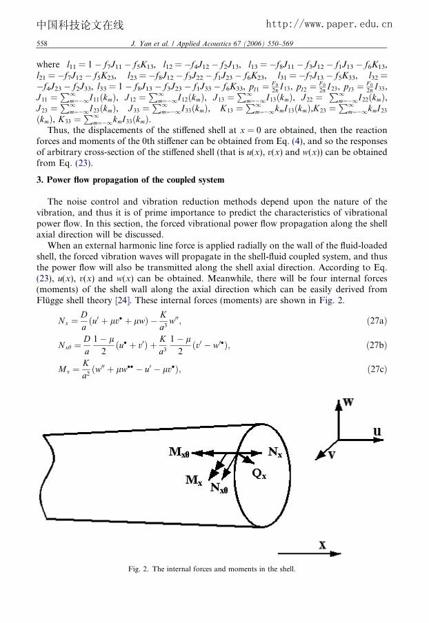
When an external harmonic line force is applied radially on the wall of the fluid-loadedshell, the forced vibration waves will propagate in the shell-fluid coupled system, and thusthe power flow will also be transmitted along the shell axial direction. According to Eq.(23), u(x), v(x) and w(x) can be obtained. Meanwhile, there will be four internal forces(moments) of the shell wall along the axial direction which can be easily derived fromFlugge shell theory [24]. These internal forces (moments) are shown in Fig. 2.
Nx ¼Da
u0 þ lv� þ lwð Þ � Ka3
w00; ð27aÞ
Nxh ¼Da1� l2
u� þ v0ð Þ þ Ka3
1� l2
v0 � w0�ð Þ; ð27bÞ
Mx ¼Ka2
w00 þ lw�� � u0 � lv�ð Þ; ð27cÞ
Fig. 2. The internal forces and moments in the shell.

J. Yan et al. / Applied Acoustics 67 (2006) 550–569 559
中国科技论文在线 http://www.paper.edu.cn
Mxh ¼Ka2
1� lð Þ w0� � v0ð Þ; ð27dÞ
Qx ¼ oMx=ox; ð27eÞ
where D ¼ Eh1�l2 is the tensile stiffness of the shell, K ¼ Eh3
12ð1�l2Þ is the bending stiffness of theshell, and ðÞ0 ¼ a oðÞ
ox , ðÞ� ¼ oðÞ
oh .Then we can obtained the axial force NpF, the effective torsional shear force TpF, the
effective transverse shear force SpF and bending moment MpF
NpF ¼ Nx; ð28aÞ
T pF ¼ Nxh �Mxh
a; ð28bÞ
SpF ¼ Qx þ1
aoMxh
oh; ð28cÞ
MpF ¼ Mx. ð28dÞ
Introducing Eqs. (23) and (27) into (28), the internal forces (moments) can be obtained
NpF ¼ DD1
a½að�ikxup1 þ uF 2Þ þ lnðvp1 þ vF 1Þ þ lðwp1 þ wF 1Þ
� b2a2ð�k2xwp1 þ wF 3Þ�; ð29aÞ
T pF ¼ DD1
a1� l2
½�nðup1 þ uF 1Þ þ ð1þ 3b2Það�ikxvp1 þ vF 2Þ
þ 3b2anð�ikxwp1 þ wF 2Þ�; ð29bÞ
SpF ¼ DD1
ab2½a3ðik3xwp1 þ wF 4Þ � an2ð�ikxwp1 þ wF 2Þ � anð�ikxvp1 þ vF 2Þ
� a2ð�k2xup1 þ uF 3Þ�; ð29cÞMpF ¼ DD1b
2½a2ð�k2xwp1 þ wF 3Þ � ln2ðwp1 þ wF 1Þ � að�ikxup1 þ uF 2Þ� lnðvp1 þ vF 1Þ�; ð29dÞ
where b2 = h2/(12a2) is thickness factor of the shell,
uF 2 ¼X1
m¼�1ð�ikmÞe�ikmx F u;0I11ðkmÞ þ F v;0I12ðkmÞ þ F w;0I13ðkmÞ � iM0kmI13ðkmÞ½ �; ð30aÞ
uF 3 ¼X1
m¼�1ð�k2mÞe�ikmx F u;0I11ðkmÞ þ F v;0I12ðkmÞ þ F w;0I13ðkmÞ � iM0kmI13ðkmÞ½ �; ð30bÞ
vF 2 ¼X1
m¼�1ð�ikmÞe�ikmx F u;0I21ðkmÞ þ F v;0I22ðkmÞ þ F w;0I23ðkmÞ � iM0kmI23ðkmÞ½ �; ð30cÞ
wF 2 ¼X1
m¼�1ð�ikmÞe�ikmx F u;0I31ðkmÞ þ F v;0I32ðkmÞ þ F w;0I33ðkmÞ � iM0kmI33ðkmÞ½ �; ð30dÞ
wF 3 ¼X1
m¼�1ð�k2mÞe�ikmx F u;0I31ðkmÞ þ F v;0I32ðkmÞ þ F w;0I33ðkmÞ � iM0kmI33ðkmÞ½ �; ð30eÞ
wF 4 ¼X1
m¼�1ð�ik3mÞe�ikmx F u;0I31ðkmÞ þ F v;0I32ðkmÞ þ F w;0I33ðkmÞ � iM0kmI33ðkmÞ½ �. ð30fÞ
560 J. Yan et al. / Applied Acoustics 67 (2006) 550–569
中国科技论文在线 http://www.paper.edu.cn
Then, the total internal forces (moments) can be obtained from Eqs. (29) by integralrepresentation
NðxÞ ¼ 1
2p
Z 1
�1NpF cosðnhÞeixt dkx; ð31aÞ
T ðxÞ ¼ 1
2p
Z 1
�1T pF sinðnhÞeixt dkx; ð31bÞ
SðxÞ ¼ 1
2p
Z 1
�1SpF cosðnhÞeixt dkx; ð31cÞ
MðxÞ ¼ 1
2p
Z 1
�1MpF cosðnhÞeixt dkx. ð31dÞ
Eq. (23) can also be expressed as the integral form
uðxÞ vðxÞ wðxÞ½ �T ¼ 1
2pD1
R1�1ðup1 þ uF 1Þ dkxR1�1ðvp1 þ vF 1Þ dkxR1�1ðwp1 þ wF 1Þ dkx
8><>:
9>=>;. ð32Þ
According to the definition of the power flow [8], at the interface x of the shell wall, thevibrational power flow transmitted by these forces (moments) are, respectively, expressedas
PNðxÞ ¼1
2
Z 2p
0
Re NðxÞ � ðixÞuðxÞ�½ �a dh
¼ D1
8pnn�Re
Z 1
�1NpF dkx
� ðixÞ
Z 1
�1ðup1 þ uF 1Þ dkx
� � �; ð33aÞ
PT ðxÞ ¼1
2
Z 2p
0
Re T ðxÞ � ðixÞvðxÞ�½ �a dh
¼ D1
8pnn�Re
Z 1
�1T pF dkx
� ðixÞ
Z 1
�1ðvp1 þ vF 1Þ dkx
� � �; ð33bÞ
PSðxÞ ¼1
2
Z 2p
0
Re SðxÞ � ð�ixÞwðxÞ�½ �a dh
¼ D1
8pnn�Re
Z 1
�1SpF dkx
� ð�ixÞ
Z 1
�1ðwp1 þ wF 1Þ dkx
� � �; ð33cÞ
PMðxÞ ¼1
2
Z 2p
0
Re MðxÞ � ðixÞðowðxÞ=oxÞ�½ �a dh
¼ D1
8pnn�Re
Z 1
�1NpF dkx
� ðixÞ
Z 1
�1ð�ikxwp1 þ wF 2Þ dkx
� � �; ð33dÞ
where Æ denotes vector product, the asterisk denotes the complex conjugate, and
nn ¼0:5; n ¼ 0;
1; n 6¼ 0.
ð34Þ
The total vibrational power flow in the shell wall is the sum of the component power flowcarried by internal forces (moments) and expressed as

J. Yan et al. / Applied Acoustics 67 (2006) 550–569 561
中国科技论文在线 http://www.paper.edu.cn
P shellðxÞ ¼ PNðxÞ þ PT ðxÞ þ PSðxÞ þ PMðxÞ. ð35Þ
4. Numerical computation and results discussion
Some numerical examples will now be given to illustrate the features of the theoreticalresults. In this article, an integrated numerical method discussed in [23] is employed to cal-culate the integration. This method is to integrate numerically along the pure imaginaryaxis of the complex wave number domain. Structural damping is introduced into the shellmaterial in order to avoid singularities in the integrand function along the integrationpath. Damping is introduced into the shell material by modifying the Young�s modulesE to be complex such as E 0 = E(1 � ig). Thus, the solution of free wave numbers of thissystem is unnecessary.
The parameters considered in this paper are shown as following, a thickness to radiusratio of h/a = 0.02, stiffener spacing L = 0.4a, stiffener width and height b = d = 2h, thematerial parameters of the stiffeners are the same as those of the shell (see Table 1 formaterial properties). The discussions will focus on the circumferential modes n = 0 andn = 1, as these two modes represent typical behavior of the system. The following calcu-lations all adopt these parameters if it is not mentioned especially.
Once the external harmonic line force inputs power flow into the coupled system, thepower flow in the shell transmitted along the axial direction can be known. Accordingto symmetry, half of the input power will be transmitted in the positive direction of theshell axial while the other half will be transmitted in the negative direction. Thus,P 0shellðxÞ ¼ P shellðxÞ=ð0:5P shellð0ÞÞ ðx > 0Þ is defined to describe the characteristics of the power
flow in the shell transmitted along the axial direction. In the same time, the ratios of thepower flow carried by different shell internal forces (moments) (those are P 0
NðxÞ ¼ PNðxÞ=P shellðxÞ, P 0
T ðxÞ ¼ PT ðxÞ=P shellðxÞ, P 0SðxÞ ¼ PSðxÞ=P shellðxÞ and P 0
MðxÞ ¼ PMðxÞ=P shellðxÞ, respectively)to the total power in the shell wall also can be obtained.
Here, the variation of P 0shellðxÞ and the variations of P 0
NðxÞ, P0T ðxÞ, P
0SðxÞ and P 0
MðxÞ againstnon-dimensional distance x/a will be investigated for different circumferential mode ordersn and different non-dimensional frequencies X. Thus, the characteristics of shell motionswill be interpreted in the view of energy.
4.1. Power flow transmitted by the shell
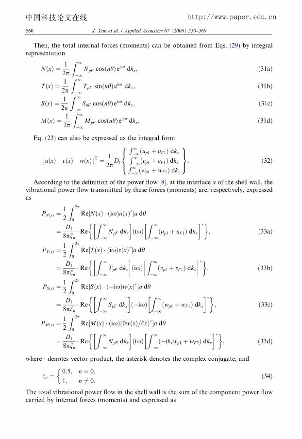
Fig. 3 shows the power flow P 0shellðxÞ transmitted by the shell in the coupled system. The
numerical results focus on the circumferential modes order n = 0 and n = 1 at three rep-resentative frequencies, respectively. In order to investigate the influence of the stiffeners,the results of a shell without stiffeners are also plotted. The following conclusions can bedrawn.
Table 1Material properties
Young�s modulus (N/m2) Poisson�s ratio Density (kg/m3) Free wave speed (m/s) Damping factor
Steel 2.07 · 1011 0.3 7850 5200 0.1Water – – 1000 1500 –
0.0 0.4 0.8 1.2 1.6 2.0 2.4 2.8 3.2 3.6 4.0 4.4 4.80.0
0.2
0.4
0.6
0.8
1.0
llehseht
ybdetti
msnartre
woP
(a)
0.0 0.4 0.8 1.2 1.6 2.0 2.4 2.8 3.2 3.6 4.0 4.4 4.80.0
0.2
0.4
0.6
0.8
1.0
(b)
(3) Non-dimensional distance x/a
0.0 0.4 0.8 1.2 1.6 2.0 2.4 2.8 3.2 3.6 4.0 4.4 4.80.0
0.2
0.4
0.6
0.8
1.0llehs
ehtyb
dettimsnartre
woP
(a)
0.0 0.4 0.8 1.2 1.6 2.0 2.4 2.8 3.2 3.6 4.0 4.4 4.80.0
0.2
0.4
0.6
0.8
1.0
(b)
(1) Non-dimensional distance x/a
0.0 0.4 0.8 1.2 1.6 2.0 2.4 2.8 3.2 3.6 4.0 4.4 4.80.0
0.2
0.4
0.6
0.8
1.0
llehseht
ybdetti
msnartre
woP
(a)
0.0 0.4 0.8 1.2 1.6 2.0 2.4 2.8 3.2 3.6 4.0 4.4 4.80.0
0.2
0.4
0.6
0.8
1.0
(b)
(2) Non-dimensional distance x/a
Fig. 3. Power transmitted by the shell. (The stiffeners� positions are displayed by vertical dash lines). (a) n = 0, (b)n = 1: (1) X = 0.3, (2) X = 1.2, (3) X = 3.0. –––, unstiffened shell and ——, stiffened shell.
562 J. Yan et al. / Applied Acoustics 67 (2006) 550–569
中国科技论文在线 http://www.paper.edu.cn

J. Yan et al. / Applied Acoustics 67 (2006) 550–569 563
中国科技论文在线 http://www.paper.edu.cn
At the driving point, x/a = 0, there is P 0shellðxÞ ¼ 1 for any circumferential mode order n
and non-dimensional frequency X. When x/a increases, P 0shellðxÞ will couple with the fluid
and gradually attenuates because of the structural damping and sound radiation.At low frequencies (X = 0.3, which is below ring frequency and just exceeds the first
cut-on frequency, as shown in Fig. 3(1)), the variations of P 0shellðxÞ has a periodic wave mo-
tion, which means a strong shell-fluid coupling. For circumferential mode order n = 0(breathing mode), the effect of shell–fluid coupling is violence and wave motion phenom-enon can be seen. The reason is that the only important propagating wave in the coupledsystem is fluid type. For circumferential mode order n = 1 (bending mode), the effect ofshell–fluid coupling becomes weaker than that of circumferential mode order n = 0. Com-paring with the unstiffened shell in the fluid, the results of periodic ring-stiffened shell al-most resemble except several peaks and troughs because of the influence of the stiffeners,and the appearances of peaks and troughs correspond to the positions of the stiffeners(those are x/a = 0.4, 0.8, 1.2, . . ., respectively, stiffener spacing L = 0.4a). In some casespredominantly wave motion can propagate in the positive axial direction while the energypropagates in the reverse direction, thus ‘‘negative power flow’’ may be generated.
At middle frequencies (X = 1.2, which is slightly higher than ring frequency, as shownin Fig. 3(2)), the effect of shell–fluid coupling is weaker but wave motion phenomenon canstill be seen, which means the exchange of energy between the shell and the fluid is stillexisting. For circumferential mode order n = 0, because the torsional motion is uncoupledwith other motions, P 0
shellðxÞ in the stiffened shell is almost the same as that in the unstiffenedshell. For circumferential mode order n = 1, P 0
shellðxÞ in the stiffened shell is quite differentfrom that in the unstiffened shell. This is because the stiffener spacing and shell wavelengthalong axial direction are comparable at middle frequencies, so the presence of the period-ically spaced stiffeners has a strong influence on the vibrational power flow propagation.
At high frequencies (X = 3.0, which corresponds to a relatively much higher frequency,as shown in Fig. 3(3)), the effect of shell–fluid coupling is further weaker and wave motionphenomenon is hard to observe. For circumferential mode order n = 0 and n = 1, P 0
shellðxÞonly fluctuates at close range of the driving point, then quickly attenuates as an exponentfunction due to the structural damping with the increasing of x/a for both the stiffenedshell and the unstiffened shell.
4.2. Power flow transmitted by different internal forces (moments) of the shell
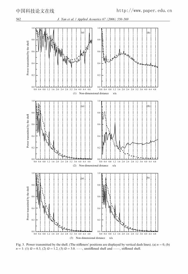
Fig. 4 shows the power flow transmitted by different internal forces (moments) of theshell wall, P 0
NðxÞ, P0T ðxÞ, P
0SðxÞ and P 0
MðxÞ plotted against non-dimensional axial distance x/afor the coupled system. (The positions of the stiffeners are x/a = 0.4, 0.8, 1.2, . . . , respec-tively.) The numerical results vary with different circumferential modes order and differentfrequencies, and the results of a shell without stiffeners are also plotted. The following con-clusions can be drawn.
For circumferential mode order n = 0, because the torsional motion is uncoupled withother motions, so P 0
shellðxÞ ¼ P 0NðxÞ þ P 0
SðxÞ þ P 0MðxÞ. While for circumferential mode order
n = 1, P 0shellðxÞ ¼ P 0
NðxÞ þ P 0T ðxÞ þ P 0
SðxÞ þ P 0MðxÞ.
At the driving point x/a = 0, for any circumferential mode order n and non-dimen-sional frequencies X, there is P 0
shellðxÞ ¼ 1. At close range of the driving point,P 0shellðxÞ P 0
SðxÞ, and the total energy is almost concentrated on flexural motion. As x/aincreases, P 0
shellðxÞ changes into other types of power flow.

0.0 0.4 0.8 1.2 1.6 2.0 2.4 2.8 3.2 3.6 4.0 4.4 4.8-0.2
0.0
0.2
0.4
0.6
0.8
1.0
1.2
(a)
0.0 0.4 0.8 1.2 1.6 2.0 2.4 2.8 3.2 3.6 4.0 4.4 4.8-0.2
0.0
0.2
0.4
0.6
0.8
1.0
1.2
(b)
(1) Non-dimensional distance x/a
)stnemo
m(secrofllehstnereffid
ybdetti
msnartre
woP
0.0 0.4 0.8 1.2 1.6 2.0 2.4 2.8 3.2 3.6 4.0 4.4 4.80.0
0.2
0.4
0.6
0.8
1.0
(a)
0.0 0.4 0.8 1.2 1.6 2.0 2.4 2.8 3.2 3.6 4.0 4.4 4.80.0
0.2
0.4
0.6
0.8
1.0
(b)
(3) Non-dimensional distance x/a
)stnemo
m(secrofllehstnereffid
ybdetti
msnartre
woP
0.0 0.4 0.8 1.2 1.6 2.0 2.4 2.8 3.2 3.6 4.0 4.4 4.8-0.2
0.0
0.2
0.4
0.6
0.8
1.0
1.2
(a)
0.0 0.4 0.8 1.2 1.6 2.0 2.4 2.8 3.2 3.6 4.0 4.4 4.8-0.2
0.0
0.2
0.4
0.6
0.8
1.0
1.2
(b)
(2) Non-dimensional distance x/a
)stnemo
m(secrofllehstnereffid
ybdetti
msnartrewoP
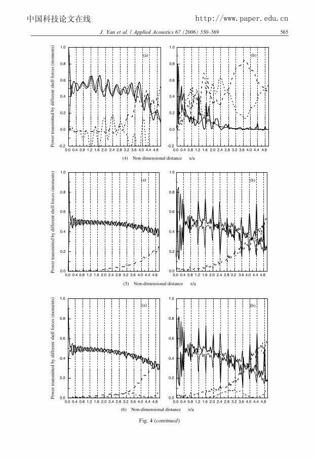
Fig. 4. Power transmitted by different shell forces (moments). (The stiffeners� positions are displayed by verticaldash lines). (a) unstiffened shell, (b) stiffened shell. (1) n = 0, X = 0.3, (2) n = 1, X = 0.3, (3) n = 0, X = 1.2, (4)n = 1, X = 1.2, (5) n = 0, X = 3.0 and (6) n = 1, X = 3.0. –Æ–Æ–, P 0
NðxÞ; –––, P0T ðxÞ; , P 0
SðxÞ and ——, P 0MðxÞ.
564 J. Yan et al. / Applied Acoustics 67 (2006) 550–569
中国科技论文在线 http://www.paper.edu.cn
0.0 0.4 0.8 1.2 1.6 2.0 2.4 2.8 3.2 3.6 4.0 4.4 4.8-0.2
0.0
0.2
0.4
0.6
0.8
1.0
(a)
0.0 0.4 0.8 1.2 1.6 2.0 2.4 2.8 3.2 3.6 4.0 4.4 4.8-0.2
0.0
0.2
0.4
0.6
0.8
1.0
(b)
(4) Non-dimensional distance x/a
)stnemo
m(secrofllehstnereffid
ybdetti
msnartre
woP
0.0 0.4 0.8 1.2 1.6 2.0 2.4 2.8 3.2 3.6 4.0 4.4 4.80.0
0.2
0.4
0.6
0.8
1.0
(a)
0.0 0.4 0.8 1.2 1.6 2.0 2.4 2.8 3.2 3.6 4.0 4.4 4.80.0
0.2
0.4
0.6
0.8
1.0
(b)
(5) Non-dimensional distance x/a
)stnemo
m(secrofllehstnereffid
ybdetti
msnartrewo
P
0.0 0.4 0.8 1.2 1.6 2.0 2.4 2.8 3.2 3.6 4.0 4.4 4.80.0
0.2
0.4
0.6
0.8
1.0
(a)
0.0 0.4 0.8 1.2 1.6 2.0 2.4 2.8 3.2 3.6 4.0 4.4 4.80.0
0.2
0.4
0.6
0.8
1.0
(b)
(6) Non-dimensional distance x/a
)stnemo
m(secrofllehstnereffid
ybdetti
msnartre
woP
Fig. 4 (continued)
J. Yan et al. / Applied Acoustics 67 (2006) 550–569 565
中国科技论文在线 http://www.paper.edu.cn

566 J. Yan et al. / Applied Acoustics 67 (2006) 550–569
中国科技论文在线 http://www.paper.edu.cn
At low frequencies (X = 0.3, as shown in Fig. 4(1) and (2)), for circumferential modeorder n = 0, P 0
SðxÞ þ P 0MðxÞ � P 0
NðxÞ, the shell motion is predominately extensional, flexuralmotion only account for a small energy flow that is even in reverse direction. For circum-ferential mode order n = 1, P 0
SðxÞ þ P 0MðxÞ � P 0
NðxÞ þ P 0T ðxÞ, the motion is mainly in the tor-
sional and extensional directions. The trend in the stiffened shell is similar to that in theunstiffened shell.
At middle frequencies (X = 1.2, as shown in Fig. 4(3) and (4)), for any circumferentialmode order n, at close range of the driving point P 0
SðxÞ þ P 0MðxÞ P 0
NðxÞ þ P 0T ðxÞ, the motion
of the shell wall is mainly in the radial direction. Apart from the driving point, P 0SðxÞ and
P 0MðxÞ gradually attenuate while P 0
NðxÞ gradually increases. Which means the dominatingmotion begins to change from flexural motion to extensional motion along the axial direc-tion. The results of the periodic ring-stiffened shell differ from those of the unstiffened shelllargely. This is because the stiffener spacing and shell wavelength along axial direction arecomparable at middle frequencies, so the presence of the periodically spaced stiffeners hasa strong influence on the different internal forces (moments) of the shell wall.
At high frequencies (X = 3.0, as shown in Fig. 4(5) and (6)), the regularities are similarto those at middle frequencies. At close range of the driving point, the flexural wave stilldominates and P 0
NðxÞ 0, which is because there exists mainly flexural motion in the shellat high frequencies and the axial force hardly transmits power flow under a radial excitingforce. Apart from the driving point, P 0
NðxÞ increases but the amplitude of the increase isslower than that at middle frequencies. Comparing with the unstiffened shell, P 0
SðxÞ andP 0MðxÞ descend quicker while P 0
NðxÞ ascends quicker, which means the dominating motionchanges from flexural motion to extensional motion quickly in stiffened shell. The powerflow carried by different forces (moments) in the stiffened shell also changes along the axialdistance, but the variation amplitudes are much smaller than that in the unstiffened shell.
For all frequencies X and circumferential mode orders n, P 0SðxÞ P 0
MðxÞ, which means thepower transmitted by the transverse shear force equals that transmitted by the bendingmoments.
For an unstiffened shell immersed in fluid, owing to the effect of coupling between theshell and the fluid, at middle or high frequencies, the power flow carried by different shellforces (moments) is the ‘‘periodic’’ function of distance x/a. But this variation amplitude ismuch weaker in the case of stiffened shell.
4.3. Influence of structural damping
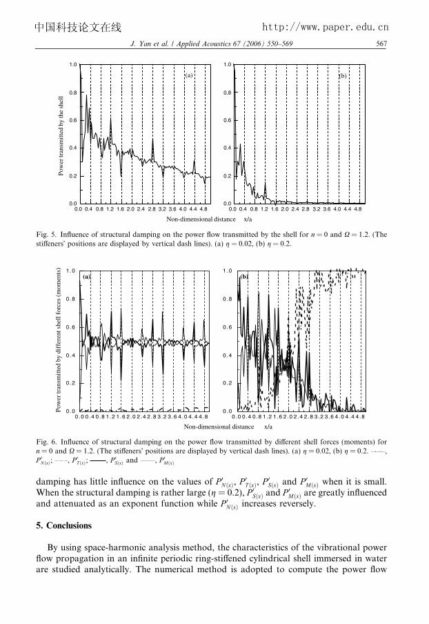
Fig. 5 shows the influence of structural damping on the power flow transmitted by theshell for circumferential mode order n = 0 at middle frequencies (X = 1.2). It can be seenthe power flow transmitted by the shell attenuates obviously along the axial direction withthe increasing of the structural damping. When structural damping is small (g = 0.02), theinfluence of the periodically spaced stiffeners is quite apparent. (The positions of the stiff-eners are x/a = 0.4, 0.8, 1.2, . . ., respectively.) When the structural damping is rather large(g = 0.2), the curve becomes smoother and attenuates rapidly.
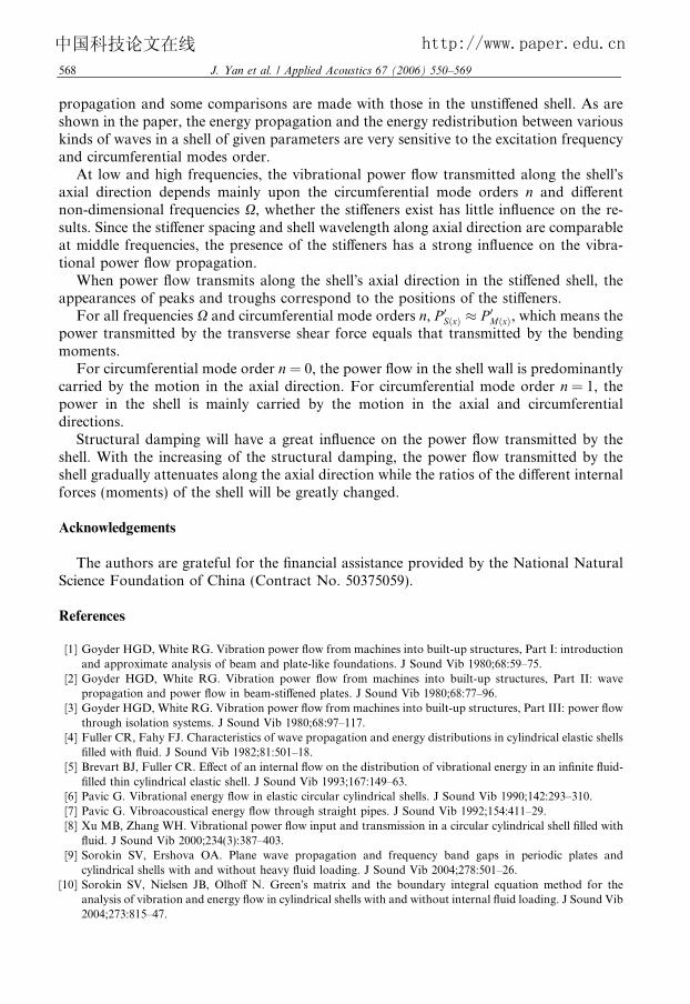
For the same circumferential mode order and frequencies, Fig. 6 shows the influence ofstructural damping on the power flow transmitted by different internal forces (moments)of the shell wall, (The positions of the stiffeners are x/a = 0.4, 0.8, 1.2, . . . respectively.)When the structural damping is small (g = 0.02), the ratios of each internal forces(moments) of the shell wall remain steady after a certain distance. This means structural
dWa
5
fla
0.0 0.4 0.8 1.2 1.6 2.0 2.4 2.8 3.2 3.6 4.0 4.4 4.80.0
0.2
0.4
0.6
0.8
1.0Po
wer
tran
smitt
ed b
y th
e sh
ell
(a)
0.0 0.4 0.8 1.2 1.6 2.0 2.4 2.8 3.2 3.6 4.0 4.4 4.80.0
0.2
0.4
0.6
0.8
1.0
(b)
Non-dimensional distance x/a
Fig. 5. Influence of structural damping on the power flow transmitted by the shell for n = 0 and X = 1.2. (Thestiffeners� positions are displayed by vertical dash lines). (a) g = 0.02, (b) g = 0.2.
0 .0 0 .4 0 .8 1 .2 1 .6 2 .0 2 .4 2 .8 3 .2 3 .6 4 .0 4 .4 4 .80 .0
0 .2
0 .4
0 .6
0 .8
1 .0
0 .0 0 .4 0 .8 1 .2 1 .6 2 .0 2 .4 2 .8 3 .2 3 .6 4 .0 4 .4 4 .80 .0
0 .2
0 .4
0 .6
0 .8
1 .0
Non-dimensional distance x/a
(a) (b)
)stnemo
m(secrofllehstnereffid
ybdetti
msnartrewoP
Fig. 6. Influence of structural damping on the power flow transmitted by different shell forces (moments) forn = 0 and X = 1.2. (The stiffeners� positions are displayed by vertical dash lines). (a) g = 0.02, (b) g = 0.2. –Æ–Æ–,P 0NðxÞ; –––, P
0T ðxÞ; , P 0
SðxÞ and ——, P 0MðxÞ
J. Yan et al. / Applied Acoustics 67 (2006) 550–569 567
中国科技论文在线 http://www.paper.edu.cn
amping has little influence on the values of P 0NðxÞ, P
0T ðxÞ, P
0SðxÞ and P 0
MðxÞ when it is small.hen the structural damping is rather large (g = 0.2), P 0
SðxÞ and P 0MðxÞ are greatly influenced
nd attenuated as an exponent function while P 0NðxÞ increases reversely.
. Conclusions
By using space-harmonic analysis method, the characteristics of the vibrational powerow propagation in an infinite periodic ring-stiffened cylindrical shell immersed in waterre studied analytically. The numerical method is adopted to compute the power flow
568 J. Yan et al. / Applied Acoustics 67 (2006) 550–569
中国科技论文在线 http://www.paper.edu.cn
propagation and some comparisons are made with those in the unstiffened shell. As areshown in the paper, the energy propagation and the energy redistribution between variouskinds of waves in a shell of given parameters are very sensitive to the excitation frequencyand circumferential modes order.
At low and high frequencies, the vibrational power flow transmitted along the shell�saxial direction depends mainly upon the circumferential mode orders n and differentnon-dimensional frequencies X, whether the stiffeners exist has little influence on the re-sults. Since the stiffener spacing and shell wavelength along axial direction are comparableat middle frequencies, the presence of the stiffeners has a strong influence on the vibra-tional power flow propagation.
When power flow transmits along the shell�s axial direction in the stiffened shell, theappearances of peaks and troughs correspond to the positions of the stiffeners.
For all frequencies X and circumferential mode orders n, P 0SðxÞ P 0
MðxÞ, which means thepower transmitted by the transverse shear force equals that transmitted by the bendingmoments.
For circumferential mode order n = 0, the power flow in the shell wall is predominantlycarried by the motion in the axial direction. For circumferential mode order n = 1, thepower in the shell is mainly carried by the motion in the axial and circumferentialdirections.
Structural damping will have a great influence on the power flow transmitted by theshell. With the increasing of the structural damping, the power flow transmitted by theshell gradually attenuates along the axial direction while the ratios of the different internalforces (moments) of the shell will be greatly changed.
Acknowledgements
The authors are grateful for the financial assistance provided by the National NaturalScience Foundation of China (Contract No. 50375059).
References
[1] Goyder HGD, White RG. Vibration power flow from machines into built-up structures, Part I: introductionand approximate analysis of beam and plate-like foundations. J Sound Vib 1980;68:59–75.
[2] Goyder HGD, White RG. Vibration power flow from machines into built-up structures, Part II: wavepropagation and power flow in beam-stiffened plates. J Sound Vib 1980;68:77–96.
[3] Goyder HGD, White RG. Vibration power flow from machines into built-up structures, Part III: power flowthrough isolation systems. J Sound Vib 1980;68:97–117.
[4] Fuller CR, Fahy FJ. Characteristics of wave propagation and energy distributions in cylindrical elastic shellsfilled with fluid. J Sound Vib 1982;81:501–18.
[5] Brevart BJ, Fuller CR. Effect of an internal flow on the distribution of vibrational energy in an infinite fluid-filled thin cylindrical elastic shell. J Sound Vib 1993;167:149–63.
[6] Pavic G. Vibrational energy flow in elastic circular cylindrical shells. J Sound Vib 1990;142:293–310.[7] Pavic G. Vibroacoustical energy flow through straight pipes. J Sound Vib 1992;154:411–29.[8] Xu MB, Zhang WH. Vibrational power flow input and transmission in a circular cylindrical shell filled with
fluid. J Sound Vib 2000;234(3):387–403.[9] Sorokin SV, Ershova OA. Plane wave propagation and frequency band gaps in periodic plates and
cylindrical shells with and without heavy fluid loading. J Sound Vib 2004;278:501–26.[10] Sorokin SV, Nielsen JB, Olhoff N. Green�s matrix and the boundary integral equation method for the
analysis of vibration and energy flow in cylindrical shells with and without internal fluid loading. J Sound Vib2004;273:815–47.

[1
[1
[1
[1
[1
[1[1
[1
[1
[2
[2
[2
[2
[2[2[2
J. Yan et al. / Applied Acoustics 67 (2006) 550–569 569
中国科技论文在线 http://www.paper.edu.cn
1] Brevart BJ, Fuller CR. Energy exchange between the coupled media of impulsively excited, fluid-filled, elasticcylinders. J Sound Vib 1996;190(5):652–63.
2] Scott JFM. The free modes of propagation of an infinite fluid-loaded thin cylindrical shell. J Sound Vib1988;125:241–80.
3] Guo YP. Approximate solutions of the dispersion equation for fluid-loaded cylindrical shells. J Acoust SocAm 1994;95:1435–40.
4] Zuo YT, Zhang XM, Xu MB. Dispersion characteristics of an infinite thin cylindrical shell immersed inacoustic medium (in Chinese). J Huazhong Univ Sci Technol 1997;25:37–9.
5] Borgiotti GV, Rosen EM. Power flow analysis of surface waves on a cylindrical elastic shell in an acousticfluid. J Acoust Soc Am 1994;95:244–55.
6] Harari A. Wave propagation in a cylindrical shell with joint discontinuity. Shock Vib Bull 1978;48:53–61.7] Harari A. Wave propagation in a cylindrical shell with finite region of structural discontinuity. J Acoust Soc
Am 1977;62:1196–205.8] Fuller CR. The effect of wall discontinuities on the propagation of flexural waves in cylindrical shells. J
Sound Vib 1981;75:207–28.9] Xu MB, Zhang XM, Zhang WH. The effect of wall joint on the vibrational power flow propagation in fluid-
filled shell. J Sound Vib 1999;224:395–410.0] Zhang WH, Zhang XM. Vibrational power flow in a cylindrical shell with periodic stiffeners. In: 1991
Proceedings of ASME PVP, Atlanta, USA.1] Lee JH, Kim J. Sound transmission through periodically stiffened cylindrical shells. J Sound Vib
2002;251(3):431–56.2] Mead DJ. Wave propagation in continuous periodic structures: research contributions from Southampton. J
Sound Vib 1996;190:495–524.3] Xu MB, Zhang XM, Zhang WH. Space-harmonic analysis of input power flow in a periodically stiffened
shell filled with fluid. J Sound Vib 1999;222:531–46.4] Flugge W. Stress in shells. Berlin and New York: Springer; 1973.5] Morse PM, Ingard KU. Theoretical acoustics. New York: McGraw-Hill; 1968.6] Mace BR. Periodically stiffened fluid-loaded plates, I: response to convected harmonic pressure and free
wave propagation. J Sound Vib 1980;73:473–86.