
Modeling dynamic component interfaces
13
[HRR98] F. Huber, A. Rausch, B. Rumpe. Modeling Dynamic Component Interfaces. In: TOOLS 26, Technology of Object-Oriented Languages and Systems. Madhu Singh, Bertrand Meyer, Joseph Gil, Richard Mitchell (eds.). IEEE Computer Society. www.se-rwth.de/publications
-
Upload
tuclausthal -
Category
Documents
-
view
2 -
download
0
Transcript of Modeling dynamic component interfaces

Modeling Dynamic Component Interfaces�
Franz Huber� Andreas Rausch� Bernhard Rumpe
email� fhuberf� rausch� rumpeg�in�tum�de
Technische Universit�at M�unchen
Arcisstr� ��� D���� M�unchen� Germany
Abstract
In this paper we adopt a component model based on object�oriented systems� introducing
the concepts of components and their structure� A component consists of a dynamically
changing set of connected objects� Only some of these objects are interface objects� and are
thus accessible from the environment� During the component lifetime not only the number
of objects� but also that of interface objects� and their connections change� To describe
this situation� we introduce Component Interface Diagrams �CIDs� � an adaption of UML
diagrams � as a notation to characterize interfaces of components� their structure� and their
navigability� We show how CIDs can be used to describe the in�house developed Open Editor
Framework �OEF�� Finally� we give guidelines that allow to map components described with
CIDs directly to several component technologies� like ActiveX� CORBA� or Java Beans�
�� Introduction
Today� on top of object�oriented techniques� an additional layer of software development�based on components is being established� The goals of Componentware �BRS��� Sam��are very similar to those of object�orientation reuse of software is to be facilitated andthereby increased� software shall become more reliable and less expensive� One of thegoals of the Frisco project �Tec�� that we currently carry out was to develop a frameworkfor graphical and textual editors that was particularly open for the incorporation of neweditors� without changing the source code of the framework� In order to achieve this� wedecided to use component concepts to structure and encapsulate di�erent entities of theframework� such that they can even be dynamically loaded and unloaded�Componentware takes a large leap toward reusability� since components aim at a gran�
ularity much larger than single objects do� However� today the question what componentconcepts are� is still under investigation� Several approaches �Sam�� in general agree thatcomponents should be based on object�orientation� However� when details are consideredsome explicit or subtile di�erences can be found� So� when applying the ideas of componentswithin our object�oriented framework� we �rst had to clarify our notion of components�Second� after a clari�cation what components are� the question was raised how to de�
scribe components in an abstract and compact way� While todays methods� like UML�Gro��� as well as their predecessors e�g� OMT �RBP�� � Fusion �CAB���� or the Booch
� This paper is joint work of the the project SysLab �supported by the DFG under the Leibniz Program�and by Siemens�Nixdorf�� and the project �A�� Methods for Component�Based Software Engineering� apart of �Bayerischer Forschungsverbund Software�Engineering �FORSOFT�� supported by Siemens ZT
[HRR98] F. Huber, A. Rausch, B. Rumpe. Modeling Dynamic Component Interfaces. In: TOOLS 26, Technology of Object-Oriented Languages and Systems. Madhu Singh, Bertrand Meyer, Joseph Gil, Richard Mitchell (eds.). IEEE Computer Society. www.se-rwth.de/publications

Method �Boo��� o�er Class Diagrams that are suited to describe the internal structure ofcomponents� Class Diagrams are not quite suited to describe the interface of a component�Therefore� we introduce a convenient description technique that allows to describe the
interfaces of a component� which is called �Component Interface Diagrams�� ComponentInterface Diagrams allow to structure interfaces� de�ne multiplicities� and describe naviga�tion paths between these interfaces that can be used to retrieve new sub�interfaces� Sincethe capabilities of components that we want to describe are similar to Class Diagrams� weadapted the latter for our needs�Our Component Interface Diagrams emerged during the development of the framework
Frisco and greatly helped to de�ne a good architecture� This technique was subsequentlygeneralized and proved useful within other developments� The quality of the Frisco frame�work was considerably improved by the notion of components that we introduced�In the remainder of this section� we brie�y introduce the Frisco OEF framework� which
will serve as example application� and discuss the properties of components on which webase our notation� Component Interface Diagrams are introduced and applied to the Fris�co framework in Section �� In Section � we discuss a mapping of our component conceptto common object technologies� such as ActiveX �Cha��� CORBA �OHE��� and especiallyJava Beans �Mic���
���� A brief introduction into Frisco OEF
Frisco is a document�oriented software engineering tool prototype� It is based on asubset of UML notations �Gro�� but incorporates precisely de�ned re�nement and trans�formation rules� Frisco provides a variety of editors combining graphical and textualparts as well as tables within a single document� An example of a Frisco editor is givenin Figure �To achieve �exibility� we developed the OEF �Open Editor Framework� as an open ap�
proach of nesting document parts into one compound document� The developed frameworkprovides a standardized set of protocols for embedding documents� To structure theseprotocols� our notion of component interfaces is used�For each document element� a speci�c kind of editor� called PartHandler� exists� Each
PartHandler component consists of a possibly large set of internal objects implementingits functionality� A subset of these objects provides the protocol interface necessary forembedding it into the enclosing document frame� The interface objects hide the internalobject structure of a PartHandler� They are the only way of communication with theenvironment� This framework� which has deliberate similarities to OpenDoc �App��� isimplemented in Java� and the PartHandlers are realized as Java Beans�
���� Properties of our component�based model
The concept of components is built on top of object�oriented concepts� This allows touse all advantages of object�orientation and build the component layer in such a way thatprogramming in the large is even more feasible� When looking at the implementation of acomponent� we �nd the usual object structure� However� if a set of objects that commonlyperforms a task is grouped together� a new kind of entity with new characteristics emerges�which needs a new and appropriate kind of description�

Figure 1. A Sample Screenshot of a Compound Document Editor in Frisco
We do not enforce every entity of the system to be considered a component� but allowindependent objects to live between components� Thus developers are free to choose whatthey want to be a component� Components may interact directly� but may also be gluedtogether using independent objects�The component concept �ts into the type system of the underlying language� such as
in Java �GJS��� As components are intended to be reused across language boundaries�
there could be a mapping of the component infrastructure into several type systems as�e�g�� found in CORBA�Components exhibit a characteristics similar to objects� Their instances can be dynam�
ically created� they have a clearly de�ned interface� and they have a well�structured state�Beyond objects� they exhibit some additional features� A component has hierarchicallystructured interfaces� hierarchically structured states� and state and interface structuremay change dynamically�To achieve this� we assume a component to consist of a dynamically changing set of
objects� that are either internal to the component or are part of its interface�A so�called principal object controls the components� The lifecycle of the component
instance is exactly the lifecycle its principal object� Other components and objects caninitially access a component via the principal object� From the principal object they canreceive references to other interfaces of the component� This way� a complex interfacestructure to access the component can be obtained�Once a reference of an internal object has been given to the environment� this object is
no longer internal� but belongs to the interface of the component� Thus� the interface ofthe component is dynamically changing�Our experiences show that� in many cases� it is not necessary to use concepts of object
migration between components� Since component�based systems usually have a ratherstatic structure� it is su�cient to allow objects that have been internal to a component to�appear� on the interface� thus allowing to access them from outside� Please note that weregard physical distribution and migration completely independent of the logical structure�Thus a part of a component may migrate between systems� but still be a part of the �nowphysically distributed� component� In general� it is not necessary for components to betightly connected� e�g�� allowing to realize object factories �GHJV���Objects that are created within a component belong to this component during their
lifetime� We assume that objects are not explicitly destroyed but garbage collected whichallows us to disregard dangling references and related problems�
�� Describing components
Using the concept of components during software development� it is important to haveappropriate modeling techniques at hand� that directly allow to deal with components� Thenewly developed standard UML �Gro�� provides a rich set of techniques for describingdi�erent views of objects� Especially useful for describing components are the followingnotations
Interaction Diagrams describe interactions either between objects in a component� orbetween components�
State Diagrams are a descendant of StateCharts �Har�� and characterize the behavior ofsingle objects within a component� but also of an abstraction of the entire component�sbehavior�
Interface and Class Declarations describe the methods and attributes� together withtheir types and access rights�
Class Diagrams are used to describe the possible structures of a system or a component�
Object Diagrams de�ne the static part of the internal structure of a component�
Our experiences show that a larger subset of the objects within a component has thesame lifecycle as the principal object and does not change its linkage� Thus� the internalstructure of a component is rather static and can be described by an Object Diagram�However� when regarding components UML does not directly provide su�cient tech�
niques to describe the interface structure of a component� As the interface structure of acomponent consists of a dynamically changing set of objects� it is increasingly importantto have an appropriate notation to give an abstract and compact overview of this interfacestructure� Beyond the given UML notations� we propose in Section ��� an adapted ver�sion of Class Diagrams � Component Interface Diagrams � that allows us to cope with theextended capabilities of component interfaces�
���� Frisco OEF interfaces
In Frisco OEF several kinds of components are used� We now introduce and brie�ydescribe a subset of the interfaces that PartHandler components provide�
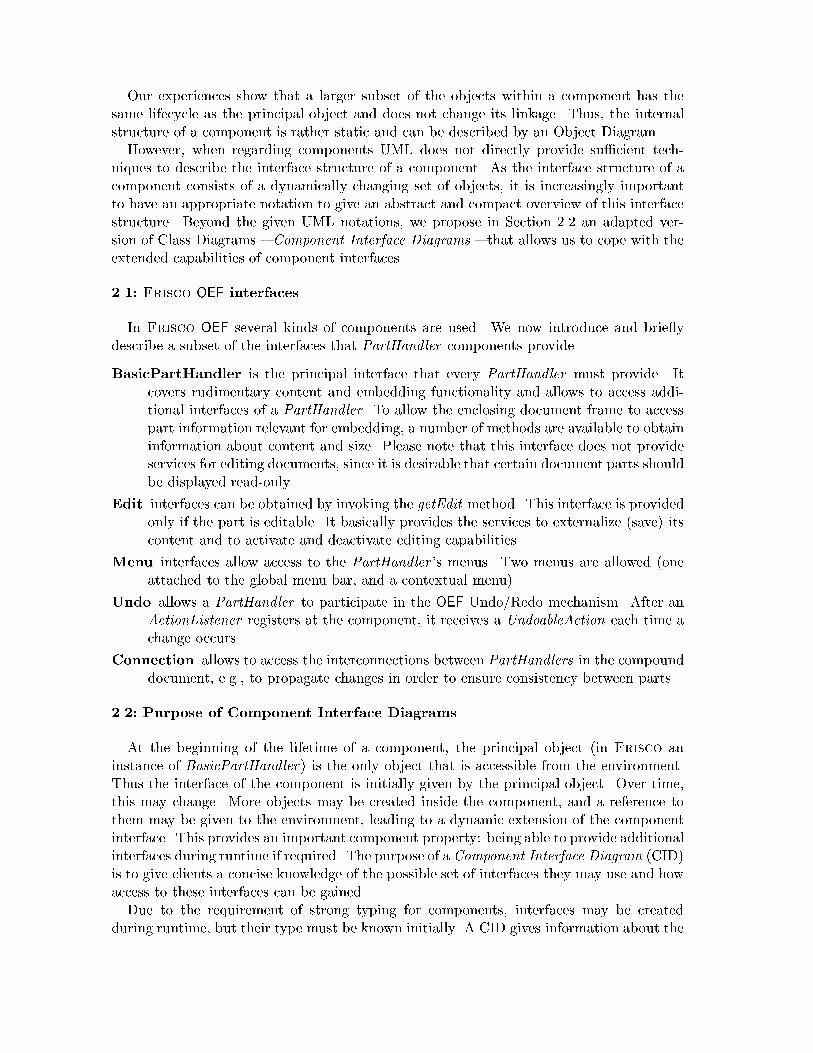
BasicPartHandler is the principal interface that every PartHandler must provide� Itcovers rudimentary content and embedding functionality and allows to access addi�tional interfaces of a PartHandler� To allow the enclosing document frame to accesspart information relevant for embedding� a number of methods are available to obtaininformation about content and size� Please note that this interface does not provideservices for editing documents� since it is desirable that certain document parts shouldbe displayed read�only�
Edit interfaces can be obtained by invoking the getEdit method� This interface is providedonly if the part is editable� It basically provides the services to externalize �save� itscontent and to activate and deactivate editing capabilities�
Menu interfaces allow access to the PartHandler �s menus� Two menus are allowed �oneattached to the global menu bar� and a contextual menu��
Undo allows a PartHandler to participate in the OEF Undo�Redo mechanism� After anActionListener registers at the component� it receives a UndoableAction each time achange occurs�
Connection allows to access the interconnections between PartHandlers in the compounddocument� e�g�� to propagate changes in order to ensure consistency between parts�
���� Purpose of Component Interface Diagrams
At the beginning of the lifetime of a component� the principal object �in Frisco aninstance of BasicPartHandler� is the only object that is accessible from the environment�Thus the interface of the component is initially given by the principal object� Over time�this may change� More objects may be created inside the component� and a reference tothem may be given to the environment� leading to a dynamic extension of the componentinterface� This provides an important component property being able to provide additionalinterfaces during runtime if required� The purpose of a Component Interface Diagram �CID�is to give clients a concise knowledge of the possible set of interfaces they may use and howaccess to these interfaces can be gained�Due to the requirement of strong typing for components� interfaces may be created
during runtime� but their type must be known initially� A CID gives information about the

visible interfaces� their inheritance relations� and navigation paths between these interfaces�Furthermore� methods and multiplicities of these interfaces are shown� CIDs are adaptedfrom UML Class Diagrams� Figure � shows an CID for the PartHandler component�
PartHandler
Menu
«principal»BasicPartHandler
+setDocumentServices()+...()+getMenus()+getConnection()+getEdit(GUIFrame g)
Connection
Edit
+getUndo()
Undo
+undo(UndoableAction a)+redo(UndoableAction a)+addActionListener(a)
UndoableAction
+getUndo()
1 1..2
1
1..n1
0..1
$1->caller
1..2->caller
$0..1->g
$1->caller
*1->a$1->caller
Figure 2. A Frisco Component Interface Diagram
Let us for now disregard the arrows and their labels� Besides denoting the kind of compo�nents a CID belongs to �here PartHandler�� a CID contains externally visible classes� theirinheritance relations� visible methods� and� in addition� multiplicities of possible instances�The PartHandler in Figure � o�ers six externally visible interfaces� among them the
principal interface marked with the appropriate stereotype�Each class can be given a multiplicity that determines the maximum allowed set of
interfaces during runtime� Each interface will usually be implemented by an object� and acomponent may provide multiple objects of the same class at its component interface� Likemany other components PartHandler has several single instance�only interfaces �e�g� theEdit interface�� but also unconstrained ones� like UndoableAction�Public methods together with their type may be provided in the CID just like they can
be de�ned within UML�s Class Diagrams� The � in front of each method just indicates thatit is public as it is in UML� The method list serves two purposes� A method often either isused to provide navigation facilities from one interface to another� or realizes functionalityprovided by the component� Although the latter is the more important� we now focus onthe former�Navigation paths are introduced as a concept to indicate the possible paths where to
navigate from one interface to another� A navigation path is denoted by an arrow from amethod of one interface to another interface� The PartHandler in Figure � shows� whichnavigation paths between interfaces are existing� It tells us� e�g�� that from the Edit inter�face� the Undo interface can be obtained�Navigation between interfaces is done by calling the method� usually resulting in a ref�
erence to a new interface �see Section ��� for a detailed discussion�� Please note that thesenavigation paths are not the same as associations� Although an association is a good candi�

date to be the component�s internal way to implement e�cient support for such navigation�it is left open to the components internal details how to support navigation� Another wayto implement navigation is to create a new object with the appropriate interface each timesuch a navigation access is required�So far the CIDs give a �rst �avor of the interfaces of a component� but their expressiveness
is limited� We therefore add a transition labeling to describe how new interfaces can beobtained� whether we iteratively receive the same interface� or a new one for each request�For example� calling getMenus on the principal interface returns one or two Menu interfacesto the caller �������caller��The multiplicities on navigation arrows indicate how often the use of this method leads
to a new interface� In general they do not tell us what happens� if the method is called toooften�However� if iterative calls result in the same interface for all callers� this is indicated by
���� To indicate the creation of a new interface ��� is used instead �see method addAc�tionListener��The communication between a component is often not limited to a call from the environ�
ment and a return from the component� Instead� when called� a component can itself make�call backs� to objects of the environment� By these call backs� additional objects can be�come externally known� without the initial caller of the components method being involved�Such an example is given by the call of getEdit that does not return an interface to thecaller but passes the method�s parameter along to another call returning this interface tothe object referenced by the parameter ��������g�� Please note� that such a �call back� ingeneral need not take place immediately� but can be delayed �e�g�� done by another thread��Furthermore� repeated call backs are allowed� For instance� the Undo interface allows toregister UndoActionListeners �method addActionListener� that will receive a reference toan UndoableAction each time an undoable change occurs�CIDs specify which references to its objects a component can give to the environment�
A careful �ow analysis� as done for other purposes already in Java compilers� could provecorrectness of the component implementation�There are basic objects� such as Java Strings� that are publicly available �see Section ����
It is useful to exclude such basic classes from the component concept� but to let them �oatthrough component borders freely� regardless� where they have been created� However�such exclusion has to be done carefully� being aware of implicit communication via sharedobjects which could lead to a behavior that is not derivable by observation of componentinterfaces�Given the technique of Component Interface Diagrams and the already mentioned nota�
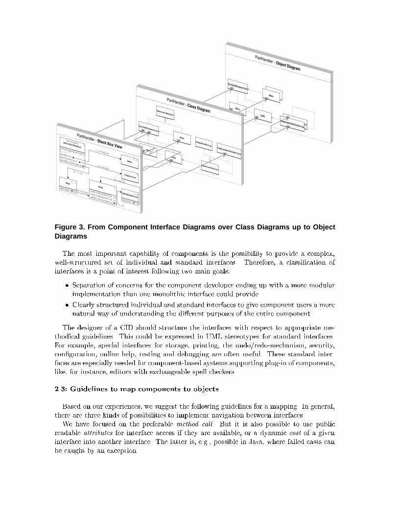
tions of UML� we can de�ne di�erent views of components� With CIDs� we can de�ne theBlack�Box View of components� Class Diagrams are useful to specify the internal struc�ture of a component� the so�called Glass�Box View� With object diagrams we can specifyrun�time behavior of components as an object structure snapshot� Figure � illustrates therelationship between these di�erent diagrams With class diagrams one can show the imple�mentation of CIDs �see Section ��� Object diagrams can be used to show run�time behaviorof class diagrams�Hence� the integration of a CID within standard object�notations like UML can be given
by a mapping of the CID into an embedding class diagram� where all component inter�faces map to classes� the inheritance relation and the multiplicities are preserved� and thenavigation relation is mapped to method calls accordingly�
PartHandler - Object Diagram
PartAndConnection
Undo
Edit
MenuMenu
ComplexUndoableAction
ComplexUndoableAction
PartHandler - Class Diagram
PartAndConnection
Menu
AbstractHandler
UndoableAction
Undo
AbstractAction
EditComplexUndoableAction
PartHandler - Black Box View
Menu
«principal»BasicPartHandler+setDocumentServices()
+...()+getMenus()+getConnection()+getEdit(GUIFrame g)
Connection
Edit
+getUndo()
Undo+undo(UndoableAction a)
+redo(UndoableAction a)
+addActionListener(a)
UndoableAction+getUndo()
1
1..2
1
1..n
1
0..1
$1->caller
1..2->caller
$0..1->g
$1->caller
*1->a
$1->caller
Figure 3. From Component Interface Diagrams over Class Diagrams up to ObjectDiagrams
The most important capability of components is the possibility to provide a complex�well�structured set of individual and standard interfaces� Therefore� a classi�cation ofinterfaces is a point of interest following two main goals
� Separation of concerns for the component developer ending up with a more modularimplementation than one monolithic interface could provide�
� Clearly structured individual and standard interfaces to give component users a morenatural way of understanding the di�erent purposes of the entire component�
The designer of a CID should structure the interfaces with respect to appropriate me�thodical guidelines� This could be expressed in UML stereotypes for standard interfaces�For example� special interfaces for storage� printing� the undo�redo�mechanism� security�con�guration� online help� testing and debugging are often useful� These standard inter�faces are especially needed for component�based systems supporting plug�in of components�like� for instance� editors with exchangeable spell checkers�
���� Guidelines to map components to objects
Based on our experiences� we suggest the following guidelines for a mapping� In general�there are three kinds of possibilities to implement navigation between interfaces�We have focused on the preferable method call� But it is also possible to use public
readable attributes for interface access if they are available� or a dynamic cast of a giveninterface into another interface� The latter is� e�g�� possible in Java� where failed casts canbe caught by an exception�

Component interface types are mapped either into Java classes or Java interfaces� Theformer has the disadvantage that classes are not abstract and thus can be instantiatedfrom the environment� the latter cannot be used if attributes are publicly available inthe interface� As we prefer methods for navigation� we suggest to use Java interfaces toimplement CID interfaces�When the desired multiplicity of an interface is or a link has modi�er �� then the
interface needs to be stored after creation within the component to be repeatedly exported�Its creation can either be done when the component is created� or in a lazy manner� whenthe �rst request is served� Anyhow� these interfaces should be implemented following thesingleton pattern �GHJV���If multiplicity of a navigation� or of an interface is restricted and repetition is not wanted�
at least the number of already created interfaces needs to be stored� A proper reactionfor too many requests is necessary either returning nil or throwing an exception� Thestandard for too many requests is the latter one� the former one should be used to copewith optional interfaces�The creation of a component goes along with the creation of its principal object� For that
purpose� the creator must know the actual class of the principal object� It therefore helpsto use the same names for the component and the principal class� In our example we didnot follow this principle in order to simplify discussion The component PartHandler andthe basic interface resp� class PartHandler �here called BasicPartHandler� are somethingquite di�erent� If clients want to instantiate components in a �exible way� a global nameservice or an object factory �GHJV�� should be implemented�A navigation path will often be realized using an association� However� such an associa�
tion relates objects within the component and therefore is part of the implementation andnot of the interface of the component� Although associations are good candidates for nav�igation path implementation� this is not enforced� Another way to implement navigationsis to use variables that are global within the component when� e�g�� multiplicity is set to � Yet another way to implement navigations is possible if a new interface is created andgiven to the environment with each method invocation� These new interfaces need not bestored within the component� but can themselves contain references to other componentparts�Similar to aggregation of objects� we conceptually allow the hierarchical composition
of components� However� our experiences show� that in practice� components will not bedeeply nested� The composition of components is done by creating and using a componentwithin another one�
�� Mapping the component model to component infrastructures
Today� three main component infrastructures are in practical use Microsoft�s ActiveX�based on OLE and DCOM �Cha��� several CORBA implementations �OHE��� and SUN�sJava Beans �Mic��� It is di�cult to estimate at this time which technology will dominatein the future� Consequently� there should be a mapping of CIDs in all three technologiesavailable�As all three technologies support a composition concept and provide an interface def�
inition language � MS�IDL� IDL� and Java Interfaces � � a CASE tool supporting CIDsor similar description techniques could generate interface de�nitions for each technology�

Hence� a mapping from our component based model to these technologies is basically pos�sible�
PartHandler
«principal»BasicPartHandler
Connection
+registerDocManager()
1..1
$1->caller
getConnection()
DocManager
«principal»DocManager
+registerAtPartHandler()+notifyChanges()
Figure 4. Interacting OEF Components
Representatively� we discuss a Java Bean�based implementation of the component�basedsystem shown in Figure �� This system presents an abstraction of two Frisco componentsThe PartHandler �see Section �� � Figure �� and a new component� the DocManager�The purpose of the DocManager is to observe its PartHandlers and propagate changesto related PartHandlers� If the method registerAtPartHandler is called the DocManager
receives a pointer to the Connection interface �getConnection� and registers itself �regis�terDocManager�� Afterwards� if a user edits any diagram� the corresponding editor com�ponent �PartHandler� noti�es the DocManager� which then ensures that all other a�ectedPartHandlers are informed of the change� eventually disallowing it� if it leads to inconsistentdocuments�
���� Implementing Component Interface Diagrams with Java Beans
According to its creators from JavaSoft �A Java Bean is a reusable software componentthat can be manipulated visually in a builder tool� �Mic��� JT��� This covers a widerange of di�erent possibilities� The scope of functionality reaches from simple GUI parts�like buttons� up to full�featured database access adaptors�In technical terms� a Bean is a Java object� The speci�c characteristics of Beans are
A Public Interface o�ers Properties� Methods� and Events for clients to access the Bean�
Introspection allows a builder tool to explore the Bean�s interfaces and present it toprogrammers� For that purpose� the Java Re�ection Technique is used�
Customization allows developers to change the properties of Beans during design�time�
Persistence is used to store the Bean�s state permanently and restore it later�
Beans can support additional features� such as� e�g�� security� drag � drop� or remoteinvocation� To support several of these features� Beans have to obey some conventions�As Beans are just Java objects� Beans can implement several Java interfaces� This �ts
directly into our component concept� as we also allow several interfaces for each component

and inheritance between interfaces� Beans also support single inheritance� which is not yetused for components in our model�Beans are packaged in so�called JAR �les that include� among code and other resources�
optionally serialized Bean instances� Components in our component model can be con�nected via links� As the standard Java name service is a crude circumvention to establishlinks between Bean instances in di�erent JAR �les� it is necessary to de�ne an own nameservice� or to use the new Java Naming and Directory Interface �Jav��� or even to use aBean�conformant infrastructure supporting a global name service� like� e�g�� IBM�s Compo�nentBroker �IBM���
Figure 5. Implementing CIDs with Java Beans
Each CID interface is mapped into a Java interface� for each CID component a Java Beanis realized� where the Java Bean has to implement the corresponding Java interface� Figure �illustrates an implementation of the example given in Figure � by using a conventional UMLClass and Package Diagram� There are three Java interfaces� one for each CID interface�BasicPartHandler� Connection� and DocManager�� In the presented solution there areonly two Java classes implementing these three interfaces� One could also implement theinterfaces with more classes or provide additional attributes� methods� or classes� like� forinstance� the class PartHandlerImpl� which has an association to the interface DocManager�The Java classes and interfaces are packaged into JAR �les� one for each CID component�The resulting JAR �les resemble the implementation of former components� thus the
PartHandler component is implemented as a package named PartHandlerBean�
���� Implementing Component Interface Diagrams with ActiveX or CORBA
Implementing CIDs with other component infrastructures� like ActiveX or CORBA� issimilar to what has been presented in the previous section with Java Beans� In ActiveX�each component can provide several interfaces� which maps directly into our model� ButActiveX does not support the concept of subtyping� so subtyping should not be used inCIDs if the target is ActiveX� Since ActiveX provides only a simple naming service� calledMonikers� we suggest to implement an own naming service or use standardized implemen�tations� as� e�g�� provided in CORBA� to realize links between ActiveX components�Using CORBA as target means having interfaces that allow multiple inheritance� as
proposed in our model� But a CORBA object cannot implement more than one interface�Instead� CORBA o�ers a module concept where interfaces can be grouped together into aspeci�c namespace� given by the surrounding module� Hence� in CORBA� CID components

are thus reduced to simple namespaces� But CORBA provides a global name service� Linksbetween CORBA objects as needed in our component model can be implemented in astraightforward fashion�
�� Related work
Our work is inspired from work found in the area of Architecture Description Languages�ADL� �HHK���� the OPEN Modeling Language �OML� �FHSGPJ��� Catalysis �DW���and UML �Gro��� In the �eld of ADL descriptions of components and their interactionsare found� OML as well as UML also provide description techniques for components andinterfaces and their collaboration� Finally� Catalysis o�ers description techniques for com�ponents supporting several interfaces and their relations�In contrast to CIDs� where one speci�es a single component� its interfaces� and the corre�
sponding navigation paths� all of these description techniques describe a set of componentsand their interactions� With CIDs one can specify a component and its interfaces withoutdescribing the concrete context� namely other components using the described component�This is especially useful in Componentware since components are intended to be reused indi�erent environments�To sum up� most component�related description techniques describe components and
their interactions in a speci�c context� With CIDs it is possible to describe componentswithout a speci�c context� concentrating on their interfaces and navigation paths�
�� Conclusion
The proposed concept of components was de�ned as a result of designing and implement�ing the Frisco framework for document editing� Although UML provides several descrip�tion techniques to describe di�erent views of object�oriented systems� including componentimplementations� a need for the description of component interfaces arises� To remedy thisproblem� Component Interface Diagrams have been introduced� They are essentially anadaption of UML Class Diagrams for purposes of describing structured and dynamicallychanging interfaces and their navigation paths�The high quality of Frisco shows the suitability of the component concept and the de�
�ned notation� Although several extensions are imaginable� e�g�� allowing object migrationor de�ning a notion of inheritance on components �not only their interfaces�� we expect thegiven notion of components and the de�ned concept of Component Interface Diagrams tobe su�cient for a large class of applications�We consider it to be more important that language and tool support allow to conveniently
de�ne component types and automatically translate them into object�oriented implemen�tations� This would considerably boost component technology�
References
�App� � Apple Computer Inc OpenDoc Programmer�s Guide for the MacOS Addison�Wesley� ���
�Boo��� G Booch Object�Oriented Analysis and Design with Applications Benjamin�Cummings� �ndedition� ����
�BRS��� K Bergner� A Rausch� and M Sihling Componentware � The Big Picture In CBSE����Kyoto� Japan International Workshop on Component�Based Software Engineering� ����
�CAB���� D Coleman� P Arnold� S Bodo�� C Dollin� H Gilchrist� F Hayes� and P Jeremes Object�Oriented Development � The Fusion Method Prentice Hall� ����
�Cha� � D Chappell Understanding ActiveX and OLE Microsoft Press� ���
�DW��� D D�Souza and A Wills Catalysis � practical rigor and re�nement Technical report� ����
�FHSGPJ��� D Firesmith� B Henderson�Sellers� I Graham� and M Page�Jones OPEN Modeling Language�OML Reference Manual ����
�GHJV��� E Gamma� R Helm� R Johnson� and J Vlissides Design Patterns Addison�Wesley� ����
�GJS� � J Gosling� B Joy� and G Steele The Java Language Specication Addison�Wesley� ���
�Gro��� UML Group Uni�ed Modeling Language Version ��� Rational Software Corporation� SantaClara� CA������� USA� July ����
�Har��� D Harel On Visual Formalisms Communications of the ACM� �������������� May ����
�HHK�� � Christoph Hofmann� Eckart Horn� Wolfgang Keller� Klaus Renzel� and Monika Schmidt The�eld of software architecture Technical Report TUM�I� ��� Technische Univerit�at M�unchen����
�IBM��� IBM Component Broker Technical Overview IBM report� ����
�Jav��� JavaSoft JNDI� Java Naming and Directory Interface Version ��� SunMicrosystems� January����
�JT��� H Jubin and Jalapeno Team Cooking Beans in the Enterprise IBM report� ����
�Mic��� Sun Microsystems Java Beans Version ���� Sun Microsystems� July ����
�OHE� � R Orfali� D Harkey� and J Edwards The Essential Distributed Objects Survival Guide JohnWiley and Sons� ���
�RBP���� Rumbaugh� Blaha� Premerlani� Eddi� and Lorensen Object�Oriented Modeling and DesignPrentice Hall� ����
�Sam��� J Sametinger Software Engineering with Reusable Components Springer�Verlag� ����
�Tec��� Technische Universit�at M�unchen Frisco�s Home Page� http���www��informatik�tu�muenchen�de�proj�syslab�frisco�oef� ����


![Dinamica Urbano-regional: Rede urbana e suas interfaces [Urban-Regional Dynamics:Urban Network and its Interfaces]](https://static.fdokumen.com/doc/165x107/631e4d8c05964b686800bf4c/dinamica-urbano-regional-rede-urbana-e-suas-interfaces-urban-regional-dynamicsurban.jpg)