
The Impact of Human-Robot Interfaces on the Learning of Visual Objects
Upload
independentCategory
view
1download
0
Visual-Language System for User Interfaces SHI-KUO CHANG and GENNARO COSTAGLIOLA,
University of Pittsburgh G~UL~ANO PACINI , University of Venice MAURIZIO TUCCI and GENOVEFFA TORTORA, University of Salerno Bm” Yu, Union Switch and Signals JING-SHENG Yu, Transarc
I) This expe?-imentd system lets inteqace deuelopers create a custom uisual language pow sample zisual sentences composed of custom or basic icons. The system has already been tested in t w o m a l l gpplications, one involz1ing a system for speech- impai7-ed users.
ronments for nonprogrammers is growing. Powerful personal computers and workstations with graphical user interfaces can increase a user’s abilities without a long, and often expensive, training period. But even GUIs are limited to simple iconic commands like selecting icons using a mouse or func- tion key. They do little to exploit the user’s ability to visually reason and communicate.
Interface developers have discov- ered that, with traditional text-based systems, users tend to learn only the most basic set of instructions and options. Most of the system’s functions remain untapped. With a GUI, on the other hand, users tend to access the entire range of system functions. A
GUI seems to stimulate individual exploration because it is easy to try a system function represented by an intuitively meaningful icon. This is especially true when all the icons are displayed simultaneously on the screen and the user can apply any system function by simply selecting one.
Encouraged by the siiccess of icons in GCIs, developers have begun to investigate the use of zfisiial languages. These languages let users express their requests as spatially organized icons on the screen. The box on p. 37 describes visual languages and their application in more detail.
The Universities of Pittsburgh and Salerno have jointly developed the Pittsburgh-Salerno Iconic System, which lets users design, specify, and
.- _ _ -
E E E S O F T W A R E 07407459/95/$04 00 0 1995 IEEE 33

Figure 1 . Overziiev of the Pittsbrrrgh-Snler-no Iconic System, which has roo niitiii nib.ystem, the ziisiral-1nnguirg.e conipiler and the ~~lszinl-kriigirii~~e geneiz- tor. T h e visiial-lni7giIi~gr. ronipiler- lrts the zrsw inpzit, tririisliite, ii/ld rwecnte vim- ill .sentc'nces. L'sers consfriict n ne'i~' k i n 1 sentence with thr air1 o j n .yntiix-direct- ed i!i~.irnl-seiire?ice editor. The compiler then tr-nnslntes tlw z.lisirri/ sentence into n sentence in the target lnngiiage, 01- iiito n sequence of euyimitnblt. c07im?nnd.~, fifbr eximple, into it dBnsr giieiy. Diwing this process. it nses either t h gene~nl, f ' i ~ z y , or positional griinirniiir p a n e l ; depending o n t he type of gixnimnr- zised to describe ricceptitble visual sentences. Alirti j~ irsenr rill employ on!y the ~isiini-lirngriage con?- piltv; brit PSIS nlso pmtjide.7 the i:i.sniiGlnngunge geiieintol- to help the user con- struct the zisuirl lnngiiirge f i o n i a sanfple set o j uisiinl sciiteim.v, which coukl be, for eximple, t?picnl visiral guwies coiiceiued 1~ t he ise er. The ;isiinl-lnngringe qeniwtor "learns '' f i -om the simple ziisirnl sentences r r n r l i'o?iSti-/il't.r il customized icon dictionmy (ID), gi~n77zmar- (C), irnd knoulledg-e bnse (KB) j - o n z the initial icoii dictionary (ID 7, gt-nmmni- (G *), and knoudedge bcirc~ (KB :I. The Operator Dictionmy (OD) coritnins the .spec$cation qf reliitional opr-iitou .suck iis horizon- tal iind zerticnl con cn tenii t ion. Whet? s i r ch op e m t o f -5 a ?-c' defiri ed as simple posi - tionnl opemtors, positioriiil pznimar-s c m be irseil to dc~.rcl-ibe oisirirl Inngiiilges, lending t o the {ficient positionnl-gi.ctmmitr- piiiser.
interpret custom visual languages for , + ~i'isiilnl-liinyur~~r compi ler . T h e different applications. T h e system is ~ compiler, developed at the University still in the experimental stage, of Pittsburgh,' consi5ts of a syntax- although we have used it in mc) practi- directed visual-sentence editor and cal applications. i three parsers to parse the sentences
As Figure 1 shows, PSIS has two ~ according to a user-specified grammar major subsystenis: ' and translate them into parse trees.
T h e compiler directly transforms the parsers' output into a sentence in the target language or into a sequence of executable commands, depending on the application.
+ Visual-lnizgiinge genei-iitor. From user-supplied sample visual sentences, this subsystem, developed a t t h e Cniversity of Salerno,' generates the grammar and the related semantic functions used by the compiler. T h e Fenerator uses inference techniques to produce a custoni grammar that gen- eralizes from the initial set of sample sentences. It also uses scmantic infor- mation about the application area to determine the meaning o f visual sen- tences in the inferred language.
In this article, we present the details of PSIS using a specific example to illustrate the system's ojier&ig princi- ples and applications. 'The example involves the construction of a visual language to describe simple operations on files and text blocks.
VISUAL-LANGUAGE COMPILER
Gencrating and interpreting a cus- tomized visual language generally calls for the specification of an application environment, with customized graph- ics tools to create and manipulate visu- al sentences.
A5 Figure 1 shows, the application environment in PSIS is specified in terms of an icon dictionary, a grarn- mar, an operator dictionary, and a knowledge base.
'The conipiler is PSIS'S main graph- ics tool.' I t includes routines that let you choose predefined icons and asso- ciate them with entities in the applica- tion environment. You then assign the icon's name and type, either object or process (the box on 11. 37describes the difference), and add the new icon to create a custom icon dictionary. By selecting icons from this dictionary and using a syntax-directed visual-sentence editor to govern sentence construction, you can create visual sentences. These sentences help you both interpret and
34 M A R C H 1 9 9 5

learn a visual language. The compiler includes three parsers
to give developers the flexibility of choosing the most appropriate parser for the application. The general parser can generate all parse trees according to a relational grammar. T h e fuzzy parser, which also works with a rela- tional grammar, generates only the parse tree with the highest degree of certainty. T h e third parser is a posi- tional-grammar parser, similar to a tra- ditional left-right parser. It is very fast and deterministic.
Custom icon dictionary. Figure 2 shows part of a sample custom icon dictio- nary, For each icon dictionary, there is a description of its static characteris- tics: its physical part - how the image is drawn and its size - and its logical part - the name and type of icon. For process icons, the number of operands and their spatial locations are also specified. These are determined by the type of operators that define the spatial relations, which are given in a prede- fined operator dictionary.
T h e user must create the cus- tomized icons to insert into the initial icon dictionary. After the application becomes well-defined, such as the visu- al language for the speech-impaired (described later), the user can access a predefined icon dictionary.
Grammar selection. Once the user has created a custom icon dictionary, the next step is to define rules for using those icons to construct sentences. T h i s is done through the use of a grammar, either positional or relation- al. In positional grammar,3 an icon is a token or symbol whose only meaning- ful attributes are its name and its posi- tion in 2D space. The visual sentence is a spatial arrangement of tokens (icons). The arrangement is represent- ed by an array, ?U, in which each token is stored; by a list, Q, of pairs (pos, i), where pos is the spatial position of the token w[i]; and by a starting index that points to the first token to parse.
I n positional grammar, an icon
stands for every elementary object icon. While in a string grammar the only possible spatial relation is hori- zontal concatenation, in a positional grammar other spatial relations can be defined. For clarity, we define only two spatial relations: horizontal concatena- tion (Hor) and vertical concatenation (Ver). Two objects a and b are in hori- zontal concatenation if b is to the right of a, and in vertical concatenation if a is above b but b is not to the right of a. Therefore,
aHorc + a ,
aVerb + b a
aVerbHorc + b a L
T h e implication symbol -+ is the positional evaluation. The strings a Hor c, a Ver 6, and a Ver b Hor c are visual sentences.
A simple example of a positional grammar is
S := File Hor ArrowHor OB OB := Printer I Video-ter
An example of a visual sentence for &IS grammar is “File Hor Arrow Hor Printer.” A possible evaluation for this sentence is shown in the last sample visual sentence in Figure A in the box on p. 37. Other evaluations are possi- ble. For example, the printer icon can
kon sketch Iron name
Line - [_I Morked-line
File
Printer
be slightly above or below its current position. T h e rules that describe how an icon is to be generated and where it should appear on the screen relative to the other icons are called production d e s . PSIS allows five types of produc- tion rules in a positional grammar.
1. X := OB Rel, proc-icon Relz OR 2 . X := proc-icon Re1 OB 3 . X : = OB Re1 OB 4. X := term 5. x:= Y
In the first rule, the visual sentence consists of two object icons and a process icon. In the second, it consists of one process icon and an object icon. In the third, it consists of two object icons. (The fourth rule, which replaces a nonterminal with a term, and the fifth rule, which replaces a nonterminal with another nonterminal, are included for housekeeping purposes.)
Positional grammars have well- defined, simple positional evaluation rules. Sometimes, however, it is more desirable to use relational grammar. In this case, the positional evaluation rules are replaced with relational pred- icates. For a relational grammar, the production rules are similar to those for positional grammar, except that relational predicates can be associated with the production rules. T h e rela-
Obiect
Object
Object
Object
Object
Process (2, teh, Right)
Video-tei
Arrow
Figure 2. Sample entriesfjom a custom icon dictionary.
IEEE S O F T W A R E 35

tional predicates must he between adjacent objects in the rule. For exam- ple, in the rule X := OB Rel, proc-icon Re12 OB, the relational predicate Rel, is between the first object and the process icon, and the relational predi- cate Rel, is between the process icon and the second object.
Visual-sentence editor. Each sentence must respect certain structural and syntactic rules. PSIS’S editor ensures that users construct generally correct visual sentences by showing them the current feasible set of icons and their feasible positions on the screen.
T h e editor has two primary func- tions:
4 I t ensures that the sentences formed are generally structurally cor- rect.
+ It analyzes the sentence structure by constructing an internal represen- tation of the sentence while the user is placing icons on the screen. T h i s internal representation is useful for later analysis by the parser.
The editor is also based on the use of positional grammar, which provides consistency across the analysis of the visual
grammar using a technique similar to the one described by Costagliola and Chang,’ in which classic compiler-con- struction techniques are applied to positional grammars.
At each step of the algorithm, a set of active states is a t the top of a graph stack and a set of feasible positions and tokens (icons) are displayed. Once a feasible icon is placed on a feasible position on the screen, the algorithm selects the only active state from which to proceed.
T h e algorithm continues until i t
However , you must deal with the ambiguity inherent in visual sentences using this grammar. People usually randomly scan visual sentences, as they do with almost any 2D pattern,’ which gives rise to a large number of parse trees. Most of these trees probably do not fit (are not reasonable) in the con- text of the application.
T h e general parser deals with this ambiguity by exhaustively generating all possible parse trees for a visual sen- tence. It is therefore rather slow and is likelv to be suitable only when you
Y
reaches a final state - when it can have simple grammars or short visual select neither an icon nor a position, or it selects a $, which is the end-of-input marker.
To illustrate, consider the sample positional grammar given earlier:
S := File fJor Arrow I l o r O B O R := Printer I Video-ter
If the user selects the file icon, the editor can predict that an Arrow icon will be placed to its right. To indicate this to the user, the editor displays the feasible icons at the bottom of the screen and shades the feasible position
area. In this manner, the user constructs a general- 1 !, s t r u c tu r a 1 ly co r re c t visual sentence. W h e n
t i o n a ~ grammar, you HELPS YOU BUILD t he visual sentence is
A STRUCTURALLY h d t , it i\ ready to be ana- lvzed and interpreted by
positional evaluation I CORRECT SENTENCE ;he visual-language com-
sentence. If the initial grammar (G) IS a rela-
re place the r ela t i ona I predicates by simple
THE EDITOR
BY SHOWING YOU (G?. T h i s positional THE FEASIBLE SET Parsers. l‘he parsers’ job is
OF ICONS AND to analyze a visual sen- tence for syntactic cor-
than those generated I POSITIONS. rectnes to conm-uct the
rules, t o construct a posit ional grammar
grammar will generate more visual sentences
by the relauonal gram- mar G - which is why the vlsual sentence IS said to be gener- ally structurally correct. Later the parser will use grammar G to check the correctness of each sentence built with the editor.
The editor uses an algorithm that takes as input the parsing t‘ible of a positional grammar. You can derive the parsing table from the positional - -
~~ ~~
parse tree. The parse tree is a structural representa-
tion of the derivation of the visual sen- tence using production rules. As Figure 1 shous, the compiler contains a general parser, a fuzzy parser, and a positional-grammar parser.
Generol porser. ‘The general parser is useful when yo11 have a relational gram ni a r I+ i t h re la t i on a 1 pr ed i ca te 5 .
sentences-, o r j o u merely want to verify the correctness of the grammar.
Fuzzy parser. The fuzzy parser is much faster than the general parser. You would use it when you expect only one best interpretation for the visual sen- tence. To deal with ambiguity, the fuzzy parser generates the parse tree with the highest degree of certainty, according to rules in fuzzy logic.
The fiizzy parser uses an algorithm developed a t the University of Pittsburgh that augments the user- specified grammar with a fiizzy mem- bership function.’ Th i s function is then associated with each production rule. The parser applies the algorithm for each parse tree of a visual sentence, and then orders the parse trees accord- ing to their degree of certainty.
For rules that describe basic icons, the fuzzy membership function is a constant function in [0,1] that reflects how ambiguous the icon is in a partic- ular application. For an icon with only one interpretation, the function value is always 1. For an icon with n inter- pretations, the fuzzy membership func- tion is a function of 71, for example, 1 ln.
For rules that describe a combina- tion of icons, the fuzzy menibership function tells how reliable the combi- nation is likely to be. Each production rule is associated with a certain npplirn- hili9 d u e , which indicates how effec- tive it would be to apply the rule to the combination to derive its right side.
36 M A R C H 1 9 9 5

WHAT ARE VISUAL LANGUAGES?
h visual language is a pictorial representation o f conceptual entities and operations,’,’ and is essen- tially a tool through which users compose iconic, or visual, sentences. Compilers for visual languages must interpret visual sentences and translate them into a form that leads to the execution of the intended task. This process is not straightfor- ward. The compiler cannot determine the meaning of the visual sentence simply by looking a t the icons. It must also consider the con- text of the sentence, how the objects relate to one anoth- er. Keeping the user’s intent and the machine’s interpre- tation the same is one of the most important tasks of a visual language.
Parsing a visual sentence. h visual sentence is a spatial arrangement of object and/or process icons that usually describes a complex conceptual entity or a sequence of operations. Object icons represent con- ceptual entities or groups of object icons that are arranged in a particular
U ay. Procc~ss icons denote operations and are usually context-dependent.
Figure A shows three visual sentences. The first represents the display of a block of lines, the second visual sentence the insertion of a block of lines, and the third the printing of a file. The three sentences are composed from some primi- tive icons, where the arrow is a process icon, and the others are object icons. The three sentences also have a similar pattern in the spatial arrangement of icons: they all have an object icon to the left of the process icon, with another object icon to the right of the process icon. The visual-language genera- tor can infer from these sample visual sentences, yielding new visual sen- tences such as those in Figure E, which the visual- language compiler can then parse and interpret as “dis- play a file” and “print a block of lines.”
q e , because the common user needs new ways to deal with multimedia information directly. A GUI can display only a limited number of icons simultaneously without cluttering the screen. Moreover, the GUI icons are usually predefined. Visual-language systems let you introduce new icons, and compose icons into many visual sentences with different meanings, thus overcoming the G W s lim- itations.
An important application for visual languages is visual query systems, which let the common user retrieve infor- mation using easy-to-under- stand msual queries. For example, you may want to retrieve engineering draw- ings containing a part that looks like the part depicted in another drawing, and having a signature in the lower-right comer of the document that looks like John Doe’s signature. With visual queries, there is no need to translate the above
ease. \’isual que? s!~stcins for ~nultiinetlia ciatahases are currently under active imw- tigatioii at many univer.;ities as well :as the industrial labs.
Viwal languages can also be applied to software speci- fication and documentation. You can even program using visual languages, and visual programming languages are now enioying some com- mercial success. i’isual languages are also being successhlly applied to augmentative cotnmunica- tion sj’stems for the speech impaired.
As more work is done in multimedia applications, we expect to see multidinien- sional lanLguage systems, in which visual languages will play an important role, both as a theoretical foundation and as a means to explore new applications.
REFERENCES I . Prinriples of Viszrul Pyaramming
Synemx, S.-K. Chang, ed., Prentice-Hall, Englewood Cliffs, NJ., 1990.
2. S.-K. Clhang, “Visual Languages: ATutorial and Survey,” IEEE SofNlare, Jan. 1987, pp. 29-39.

The fuzzy parser then considers the grammar parser is the most efficient Darser of the three, but it is only suit- applicability value and the spatial
arrangement of the icons of interest in determining the combination's relia- bility. The parser combines the applic- ability values o f all the production niles to obtain a single value associated with the entire parse tree. I t then selects the tree with the highest fuzzy membership value, which is the most reasonable tree for the visual sentence in this application. For example, sup- pose the production rule is
S := t?le ITor .Arrow I lor O B
This production rule has as its right side a horizontal composition of three icons. Such a rule i s more likely to apply to three horizontally aligned icons than to three diagonall! posi- tioned ones.
The user can override the parser's selection when the interpretation is wrong. The parser will then present the parse tree with the next highest fuzz!; \due, until either the user selects it or all parse trees w i t h fuzzy values above a user- defined threshold have been exhausted, and the parser declares failure.
fositionul-grummur purser. The positional-
Hble if you can describe relations with simple positional evaluation rules.
The parser exploits the association between a position and a token. Each time the parser asks for a new token to analyze, it also gives the expected posi- tion of the nest token, according to p o s i ti o n a 1 -gram mar r e q u i re in en ts . This information about expected posi- tion reduces the number of parse trees and therefore solves the ambiguity problem. The parser contains a scan- ner that goes to a token in array U: each time its spatial position has been given; each time the scanner reaches a token in a. the spatial position of the next token is provided. Therefore, the pars- er does not hai,e to access the input sequentially but can use positional- grammar requirements to select the next token deterministically.
After checking that ;ill tokens have been parsed, the scanner returns a $ (end-of-input s>nibol). In nonsequen- tial scanning, $ must be made explicit (unlike sequential scanning, in which the scanner simply recognizes the spn- bo1 to end scanning).
For each positional relation, the
Figure 3. The positional-p-amniar p a f - ~ r . The parrer IJ ;'el? similar t o the tm- dztio?iii/ left-Tight pitiser, but t h e differ-eme IJ the lire of positional opel-atol-r t o pick u p the nex't tokenfi-om the input
parser has a positional operator with the same name. Such an operator is a function that takes as input the index of the last token parsed, calculates a new position, and then returns the index of the next token to parse.
T h e positional-grammar parser is very similar to a traditional left-right parser. The main difference is that for the positional-grammar parser, you must define the positional evaluation rules in such a way that the evaluation of the next token becomes determinis- tic. As illustrated in Figure 3 , the posi- tional operators will then be able to find the unique next token from the input.
Continuing our example, the Hor and Ver posit ional operators are defined as follows:
+ Hor(i) = j if the spatial position of w[il is the highest in the first non- empty column on the right of the spa- tial position of m[i] .
+ \'er(i] = j if the spatial position of m[il is on the left of the spatial position of w[i] such that it is the leftmost posi- tion in the first nonempty row 11elow the spatial position of zu[i].
The parser translates the positional grammar into a context-free l+r.ight gi"za7- zuith actions, in which action rules are associated with production ru1es.j You can then employ a tool such as YACC to produce the final parser.
VISUAL-LANGUAGE GENERATOR
T h e visual-language generator has two main tasks:
+ I t infen a nutom gi-ammai-. Given an application-specific icon dictionary, a general positional grammar, and an initial knowledge base, the generator infers from sample visual sentences to provide a custom icon dict ionary, grammar, and knowledge base. Part of this task involves analyzing the seman- tics of the visual sentences.
t I t c o n s t m c t s the z,isnizl-lL~?rrrKiicige tables needed to serrzantically imi1yz.e the hgzynage defined by the i'ustovi g~irmmar.. -4s Figure 1 shows, the knowledge base

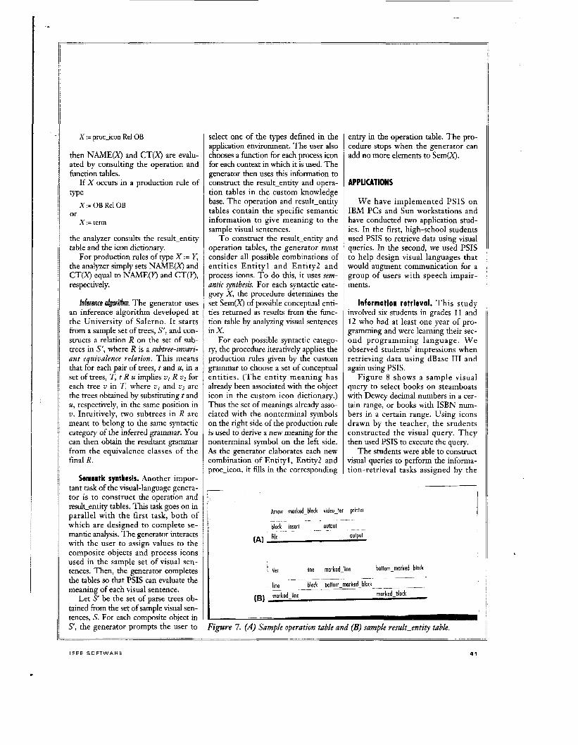
contains four tables: firiti.tioii tnble, which contains all the operations per- missible to the application, enti? tablr, which contains the entities relevant to the application, opri.atio?i tirble, M hich shows the operations corresponding to the application of a process icon t o one or two entities (object icons). and the i.esult-entity tnblt,, which shows what entity you can construct by coni-
tining other entities. T h c generator's second task involves constructing the last two tables, which it needs to coiii- plete the seniantic analysi5.
Both these tasks are tmed on the use of .similm.ity niritsiu%v 1)enveen pairs of seniantic items (entities or opera- tions) and visual-language i t e m (o1)- lect and process icons). 'I'he similarity measure is a value in [O, 1 1 associated bvith pairs of items of the same type (entities or operations). It is rating of how similar entities :i~id operations are to one another in the contest of the ,ipplication environnient. For exaniple, consider the set of entitics (ch. a- L mer . marked-character, string, right-niark- ed-string. selected-string, line, marked- line, b k d , b o t t o ~ - r i ~ t i ~ k e d ~ t ~ l o c k , select- e:d-block. file, printer, video-ter). In a rext-editing and file-inanageinetit envi- ronment. printer ancl video-ter are likely to have a high siniil;irity measure because 110th let you inspect drawinss 'I t i d text docu me t i t s. 0 t i the ( ) the r hand, line and file are likcly to lime a I O W siniilarity measure I ~ c a u s e they u e conceptually very different.
I f similarity measures are not pro- vided in the description of the applica- tion en~-irontiient. the user can supply them in the form of sinii1;irity tables of two t!.pes: function and entity. ?'he function similarity tahle is tmed o n the fiinction table in the knc wledge base. Figire 4 gives a siniilarin table, lmed
(lass (loss name function nome I " i
I
I
Figure 4. Sample similarity table fa?- .firnctions based o n the filnctioz table in Figure Y.
Figure 5. Sample fiinctio?i table. ~
Figure 6. Sample similarity table fa?- entities, whew an e7npf_~ space m e a m a rornbination that vei'er- OCCIUT.
I ~
~ fore similar to the display-file fiinc- because insert and output are both - . o n the function table in 1:igure 5, for tion. Thus they are placed in the same file-editing and -management func- some of the entities given earlier.
The hinction similarity table contains + A pnrtition of' t h e jiiiii~iori.. i n t o
;.lmxv uf' j i 11 ct io 11s th N t (1 i 't' (YI i ~ s i d ~ i ~ e d cimiliii. 1iccaii.w oj the tiisk the?, pe?:fbrnr. For rxaniple, print-file is a hinction to print a file to the printer, m d is there-
class (class 2 ) , and the similarity mea- sure between these two functions is l .
+ A viensri~-e of' coiiceptunl similnr-ity irmoiig those ~~lnsses. In the figure, classes 1 and 2 have a siinilarity measure of 0.3 because insert and output are con- ceptually quite different. I t is not 0 ~ ~ _ _ _ _ ~ - - ~~~~~~ ~~ ~~~~ ~~
tion, and therefore somewhat similar. An ent iF similarity table shows you
how entities compare directly, not as a class. Figure 6 shows an entity siinilari- ty table for some of the sample entities. Selected-block and block receive a similarity rating of 0.4 hecause select-
-~ ~~~~~~ ~ -~~
39

ed-block is the target of an editing operation, but block is not. Printer and video-ter, on the other hand, have a high measure (0.82) because both involve viewing text.
Inference. One of the main features of PSIS is its ability to let you cus- tomize the visual language. PSIS can actually learn from the user’s interac- tion how to specialize the application domain. This is the role of the genera- tor, which employs inference capabili- ties t o automatically generate the information that defines the intended visual language.
Inference is based on a technique developed by Claudia Crimi and other researchers at the Lniversity of Sal- erno? The technique yields a custom positional gratnmar that contains and extends the set of sample visual sen- tences. When analyzing the parse trees provided by the compiler, the genera- tor asks the user for semantic informa- tion that enables PSIS to give meaning to the visual sentences in the set of samDle user-sumlied sentences. This
This approach to semantic analysis is interesting because it lets PSIS actually “learn” the meaning of the visual lan- guage by combining knowledge about entities and operations in an applica- tion environment and their correspon- dence to icons.’
As described earlier, the function and entity tables in the knowledge base contain general information about the application environment. T h e opera- tion and result-entity tables relate com- posite object icons and process icons to application environment entities o r operations. T h e correspondence be- tween object icons and entities is in the icon dictionary.
T h e enti ty table contains enti ty names and their attributes. Each entity may have a variable number of a t - tributes, so the entity table is really a list structure.
In the function talde in Figure 5 , Entityl and Entity2 list the kind of conceptual entities each operation can accept as arguments. The Result col- umn lists the kmd of entities the opera- tion should Droduce.
I L
infokation forms an initial knowledge base that contains struc-
T h e Leit-Kel and Right-Re1 col- umns give conceptual
tural and semantic knowl- edge. T h e generator then uses this knowledge to infer a custom posi- tional grammar and the a ss o ci a te d k n owl edge tables.
Semantic analysis. Each production rule has asso- ciated with i t certain semantic functions that h e h in constructinp. the
PSIS CAN ACTUALLY LEARN FROM THE USER‘S INTERACTIONS HOW TO SPECIALIZE THE APPLICATION DOMAIN.
meaning of the parsed sentence. Two approach- es are supported. In the first approach, Figure 7a the semantic functions are ioutines written in C. This approach is support- ed by YACC and is easy to use by peo- ple familiar with it. For that reason, we do not elaborate on it here.
Another approach involves using the tables in the knowledge base and the information in the icon dictionary.
I ’ 1:-
4 0
relations between the functions and their respect- ive argunients. The con- ceptual relation points out the role played by an entity in the context of a given function. The gen- erator uses this informa- t ion to construct the semantic value of a visual sentence. For example, print-file takes file as the input (I,eft_Rel) and print- er as the output device (kght-Rel). gives a sample operation . .
table- T h e table assigns a function to each process icon depending on its arguments. For each entry, the table gives the oper‘ition to be assigned to proc-icon (a process icon) when i t is applied to entities Entityl (first col- umn) and Entity? (top row). For ex- ample, if the Arrow icon is applied to ____-___ __ ~-
conceptual entities “file” and “printer,” it will be interpreted as an “output” operation.
Figure 7b gives a sample result- entity table. In the table, each result entity is created by the spatial arrange- ment of icons, using a spatial operator that relates Entityl and Entity2.
Semantic analysis involves using the function and entity tables in the knowl- edge base to derive the meaning of the visual sentence from the parse tree pro- vided by the compiler. T h e analyzer constructs the meaning of the parse tree as a conceptual tree, which is a tree with nodes that contain operations or entities (labeled event or object, respec- tively) and arcs that specify the role of entities as arguments of the operations.
T o produce the conceptual tree for a parse tree, the analyzer evaluates the parse tree and applies semantic rules that correspond to the syntactic pro- duction rules of the parse tree. T h e conceptual tree can be transformed into a sentence in a target language or directly executed as a sequence of func- tion calls.
T h e conceptual tree is formalized using an Only-S-attribute grammay. This grammar consists of a context-tiee positional grammar, in which yzthesized attributes (attributes derived from other attributes) are associated with each nontemzinal (non-leaf node) X . The S attribute in this case is the conceptual tree.The synthesized attributes are
+ NAME(X): the entity to be asso- ciated with the occurrence of X in the parse tree;
CT(X): the meaning (the conceptu- al tree) assigned to the subtree rooted in X in the parse tree.
The re is also the synthesized at- tribute CT((s, which is designated to hold the meaning of the entire parse tree.
Semantic functions associated with production rules evaluate attributes in a bottom-up evaluation of the parse trees. Moreover, if the occurrence of nonterminal X in a given parse tree is expanded by a production rule of type
or X : = OR Rel, proc-icon Rell OH
M A R C H 1 9 9 5
X : = proc-icon Re1 OB
then NAME(X) and CT(X) are evalu- ated by consulting the operation and function tables.
If X occurs in a production rule of type
X := OB Re1 OB or
X := term
the analyzer consults the result-entity table and the icon dictionary.
For production rules of type X := Y, the analyzer simply sets NAME(X) and CT(X) equal to NAME(Y) and CT(Y), respectively.
Inference olgorihm. The generator uses an inference algorithm developed a t the University of Salerno. It starts from a sample set of trees, S’, and con- structs a relation R on the set of sub- trees in s’, where R is a subtree-invari- ant equivalence relation. This means that for each pair of trees, t and U, in a set of trees, T, t R U implies v1 R v2 for each tree v in T, where v1 and v2 are the trees obtained by substituting t and U , respectively, in the same position in v . Intuitively, two subtrees in R are meant to belong to the same syntactic category of the inferred grammar. You can then obtain the resultant grammar from the equivalence classes of the final R.
Semantic synthesis. Another impor- tant task of the visual-language genera- tor is to construct the operation and result-entity tables. This task goes on in parallel with the first task, both of which are designed to complete se- mantic analysis. The generator interacts with the user to assign values to the composite objects and process icons used in the sample set of visual sen- tences. Then, the generator completes the tables so that PSIS can evaluate the meaning of each visual sentence.
Let S be the set of parse trees ob- tained from the set of sample visual sen- tences, S. For each composite object in S, the generator prompts the user to
select one of the types defined in the application environment. The user also chooses a function for each process icon for each context in which it is used. The generator then uses this information to construct the result-entity and opera- tion tables in the custom knowledge base. The operation and result-entity tables contain the specific semantic information to give meaning to the sample visual sentences.
T o construct the result-entity and operation tables, the generator must consider all possible combinations of ent i t ies E n t i t y l and Entity2 and process icons. T o do this, it uses sem- antic synthesis. For each syntactic cate- gory X , the procedure determines the set Sem(X) of possible conceptual enti- ties returned as results from the hnc - tion table by analyzing visual sentences in X.
For each possible syntactic catego- ry, the procedure iteratively applies the production rules given by the custom grammar to choose a set of conceptual ent i t ies . ( T h e ent i ty meaning has already been associated with the object icon in the custom icon dictionary.) Thus the set of meanings already asso- ciated with the nonterminal symbols on the right side of the production rule is used to derive a new meaning for the nonterminal symbol on the left side. As the generator elaborates each new combination of Entityl, Entity2 and proc-icon, it fills in the corresponding
entry in the operation table. The pro- cedure stops when the generator can add no more elements to Sem(X).
APPLICATIONS
W e have implemented PSIS on IBM PCs and Sun workstations and have conducted two application stud- ies. In the first, high-school students used PSIS to retrieve data using visual queries. In the second, we used PSIS to help design visual languages that would augment communication for a group of users with speech impair- ments.
Information retrieval. T h i s s tudy involved six students in grades 1 1 and 12 who had a t least one year of pro- gramming and were learning their sec- ond programming language. W e observed students’ impressions when retrieving data using dBase I11 and again using PSIS.
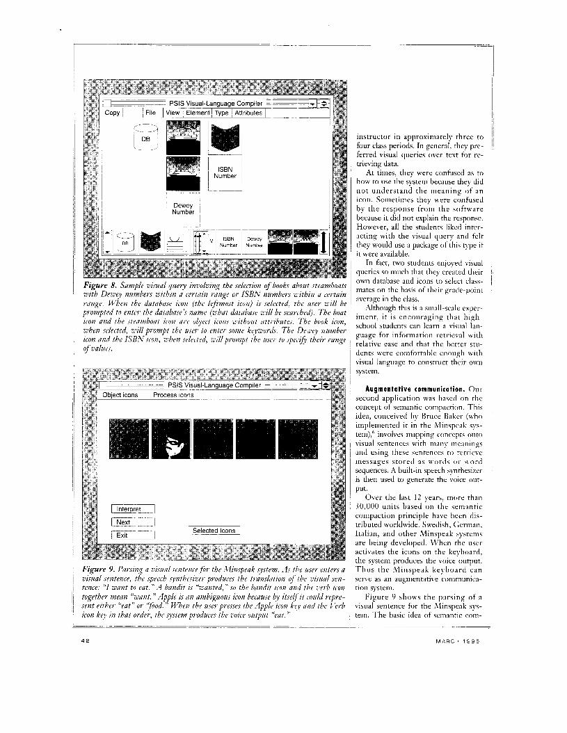
Figure 8 shows a sample visual query to select books on steamboats with Dewey decimal numbers in a cer- tain range, or books with ISBN num- bers in a certain range. Using icons drawn by the teacher, the students constructed the visual query. T h e y then used PSIS to execute the query.
The students were able to construct visual queries to perform the informa- tion-retrieval tasks assigned by the
Arrow marked-block video-ter printer _ _ ~ - - ~- ~ ~-
block i n y t ~ - OutPC - ~ ~
output (A)
Ver line marked-line bottom-morked-block
line ~ ~
markedjine
____ _--_ - ~~
- block bottom-marked-block marked-block
(8)
Figure 7. (A) Sample operation table and (B) sample result-entity table.
I E E E S O F T W A R E 4 1
Dewey Number
Figure 8. Sample vimal q u e q involving the selection of books about steamboats with Dewey numbers within a certain range or ISBAT izumbers r i th in a certain range. When the database icon (the leftmost icow) is selected, the user will be prompted t o enter the datnbase’.r name (what database wilf be seanheil). The boat icon mid the stenmboirt icvn nri’ object icons without atti-ibutes. The book icon, uhen selected, will piampt the user to enter some keywords. The Deziey number icon and the ISBAT icon, rhen selecteil, ail1 pi*ovzpt the iise?’ t o spec.ifi theif- range of i1alzies.
Figure 9. Parsing a z’i514d sentence for the A fimpenk system. As tbe imr enters a visual sentence, the speech synthesizer produces the tipanslrttion of the visual sen- tence: “I wazt t o eat.” A baridit is “ranted, ’’ so the bandit icon and the verb icon together mean “want. ’’ Apple is an ambiguous icon because by itself it could repre- sent either “eat” or ‘pod . ’’ W e n the user presses the Applt) icon key and the Verb icon key iiz that oF-der, the system produces the uoice output “eat. ”
instructor in approximately three to four class periods. In general, they pre- ferred visual queries over text for re- trieving data.
At times, they were confused as to how to use the system because they did not understand the meaning of an icon. Sometimes they were confused by the response from the software because it did not explain the response. However, all the students liked inter- acting with the visual query and felt they would use a package of this type if it were available.
In fact, two students enjoyed visual queries so much that they created their own database and icons to select class- mates on the basis of their grade-point average in the class.
Although this is a small-scale exper- iment, it is encouraging that high- school students can learn a visual lan- guage for information retrieval with relative ease and that the better stu- dents were coinfortable enough with visual language to construct their own
1 system.
Augmentative communication. Our second application was based on the concept of semantic compaction. This idea, conceived by Bruce Baker (who implemented i t in the Minspeak sys- tem),” involves mapping concepts onto
i visual sentences with many meanings i and using these sentences to retrieve
messages stored as words o r word sequences. A built-in speech synthesizer is then used to generate the voice out- put.
Over the last 12 years, more than 30,000 units based on the semantic compaction principle have been dis- tributed worldwide. Swedish, German, Italian, and other Minspeak systems are being developed. U’hen the user
~
activates the icons on the keylmard, ~ the system produces the voice output.
’Thus the Minspeak keybo‘ird can serve as an augmentative communica- tion system.
Figure 9 shows the parsing of a visual sentence for the Minspeak sys- tem. The basic idea of semantic com-
~

Figure 10. Sample screen showing the Iconic Language Developmmt Environment f ir ;Winspeak, an augmentatiz1e speech system for the speech i~npnired. The designer uses ILDE to explore the possible meanings f o r iconic sentences. For example, the designer has selected n skull-and-crossbones icon and a volt iron fj’ovt the list of standard and czistom icons. ILDE mill generate the possible intep*etation.s of the iconic sentence: “death mid stoml, ” “death in the sky, ” m d the like. The desijyzet- selects “death in the sky,” and adds the word “crash ’’ t o the knozledge stmctwe associated with this iconic sentencc. Fmv7 now on. Then the usei- enters this iconic sentence, the speech ynthesizer xill produce the output “crash. ”
paction is to use ambiguous icons to represent concepts. Apple is an am- biguous icon because by itself it could represent either “eat” or “food.” When combined with another icon (into a visual sentence), however, the meaning becomes clear. When the user presses the Apple icon key and the Verll icon key in that order, the system produces the voice output “eat.” Apple then Noun produces the voice output “food.” Users can communicate as many as 2,000 concepts using as few as 50 icons and compose any sentence without
+ T h e icon should tic conceptually rich and created in such a way that when joined to other icons, some other concepts are covered. (’This require- ment differs from the usual require- ments for GCIs, where unambiguous icons are generally preferred.)
+ The icon should he related to the alphanumeric character on the keyboard.
restriction. T h e design of icons is a crucial part
of maintaining a language based on semantic compaction, and the resulting icon must satisfy several requirements:’
+ T h e icon should clearly describe the basic concept.
~- -~~ ~ ~~ ~~~
__ ~
I E E E S O F T W A R E
l though o u r system is still in A the experimental stage, we plan to investigate applications to visual query svstems and personal digital I . I
assistants. T h e work described her; has shown us that u-e can construct effi- cient parsers for subclasses of visual lanpages that are of practical value. It has also given us a way to dynamically construct visual languages through the
.. .~ ~~~~ ...
use of a knowledge base. O u r current work involves using
PSIS t o design iconic languages for the speech impaired and t o assign meanings to visual sentences (specify icon semantics). Figure 10 illustrates a sample screen to translate the visual sentence “skull volt.’’ At the Cniver- sity of Pittsburgh, we have developed a theory on the semantics of visual languages8 that is based on the notion of icon algebra’ and the incorporation of a conceptual dependency theory. W e are extending this formal frame- work to the design of multidimen- sional languages, where the primitives include icons, earcons, niicons (niotion- icons) and vicons (video-icons), for querying multimedia databases in the context of next-generation personal digital assistants. +
__ ~~~ ~~~~ ~
43

REFERENCES 1. S.-K. Chang, “A Visual Language Compiler for Information Retrieval hy
Visual Reasoning,” IEEE Trans. Sofmare Eng., Oct. 1990, pp. 1136.1 149. 2. C. Crimi et al., “Automating Visual Language Generation,” IEEE Trunr.
So@areEng., Oct. 1990,pp. 1122-1135. 3 . G. Costagliola and S:K. Chang, “Parsing 2-D Languages with Positional
Grammars,” Proc. Int? Workshop Parring Tecbnologier, Carnegie Mellon University, Pittsburgh, 1991, pp. 235-243.
4. G. Costagliola and S.-K. Chang, “Parsing Linear Pictorial Languages by Syntax-Directed Scanning,” Language.r of Design, No. 3, 1994, pp. 229-248.
S . C. Crimi e t al., “Grammatical Inference Algorithms for the Generation of Visual Languages,” Int’ly. VizuzlLanguager and Computing, Dec. 1990, pp. 355-368.
6. B. Baker and E. Nyberg, “Semantic Compaction: A Basic Technology for Artificial Intelligence in AAC,” Proc. 4th Minspeak CO$, Prentke Romich Co., Wooster, Ohio, 1989, pp. 1-6.
7. S.-K. Chang et al., “A Methodology for Iconic Language Design with Application to Augmentative Communication,” Proc. Workshop on Visual Languages, IEEE CS Press, Los Alamitos, Calif., 1992, pp. 110-1 16.
8. S:K. Chang et al., “AMethodoliigy and Interactive Environment for Iconic Language Design,” Int’l 7. Human-Computer Studies, No. 41, 1994
9. S:K. Chang, “Icon Semantics - A Formal Approach to Icon System Design,” l n t ’ l ~ . Pattern Recognition and At?i$ci~l Intelligence, No. 1, 1987, pp. 103-120.
Shi-Kuo C h a n g is professor of computer science at the University of Pittsburgh and director of the univer- sity’s Center for Parallel, Distributed and Intelligent Systems. His research interests include distributed sys- tems, image information systems, \<sua1 languages, and multimedia communications. H e has been a consultant to IBM, AT&T Bell Laboratories, Standard Oil, Honeywell, US h-aval Research Laboratory, and Siemens and is founder of the Knowledge Systems Institute, a graduate school dedicated to advanced edu- cation of computer and information sciences. Chang
has published more than 180 papers and eight books, including Principler of PiI-tonal Information Syrtemr Design (Prentice-Hall, 1989), and Principles of Cisual Programming Syrtemr (Prentice-Hall, 1990), and is editor-in-chief of~ozrmal of Viswl L a n p g e s and Computrng and of lntemational~oumal of Sof iare Eiigrneering S. Knowledge Engineering.
University, and an I S and a PhD in electrical engineering and c~imputer \ c i ~ ence from the University of California, I3erkeley. H e is a fellow of the IEEB.
Chang received .I BS in electrical engineering from Nauonal Ta iwan
Gennaro Costagliola i \ A research awiciate in c i m -
puter science at the Lnivcrsity (if Salerno. Hi\ rescarch interests includc parsing techndogies. *isuaI langiiciges. visual programming, image-Jatabasc indexing, and pic- nire matching on parallel architectures.
from the Univer\ity of SaIernri and an ,\lS in coniputer science from the Universiq rif Pittshurgh. H c is :I member of the ACll and the IEEE C:oinputt.r Society
Ciisraglio received a I.aiirea i n computer sciencc
Giuliano Pacini is a prufeswr of computer sciencc at the University cif Venice. His research interests arc language design and implenientauiin, \oftnarc enpi- neering. and logic pr<)grainming. Previously, he U .I> J
professor of ciiniputer science at the L nibcnit) (it Salerno.
Pacini received a L a r e a in physics trtrni the L’niversity of Plsa.
1 ~
Addrc\s questions about this article to Chang at Center for Parallel, Di\trihu- tian and Intelligent Systemr. C S Dept., University of Pittsburgh, PA 15260.
Maurizio Tucci is a research associate and teaching assistant in computer science at the University of Salerno. His research interests nclude syntactic and semantic aspects of visual languages, visual and geo- graphical databases, and tool integration for software engineering.
Tucci received a Laurea in computer science from the University of Salerno.
Genoveffa T o n o r a is a professor of computer science at the University of Salerno and head of curriculum development for its Laurea in computer science pro- gram. Her research interests include software-develop- ment environments, visual languages, and pictorial information sy5tcnis. She is also on the editorial board of Inte?national ~ o u r n a l ofSo@ware Enpicwing und Knowledge i?ngmreriug.
the University of Salerno. Tortora received J Laurea in computer science fmm
Bing Yu is a technical manager w t h the Advanced Technology Group i i f Union Switch & Signal. resprin- sible for advanced user-interface design and ohject-riri- ented design for real-time transportation systems. Hi\ research interest includes object-oriented software engineering, object-oriented DBMS\, user interface\. artificial intelligence, and safety-critical q steins.
Yu reccived a BS in computer science frrim Jiao- T u n g University in China and an M S in coinputer \ci- ence from the University of Pittshurgh. H e is a mem- her of the IEEE Computer Suciety and ACM
Jing-Sheng Yu is with Transarc, where he develops testing tools to address all aspectr of distributed com- puting environment and distributed file sy\trms design, froin network to local. H e is also in charge of reporting and fixing defects and upgrading the operating system for different platforms. Previously, he was <I research assistant in computer science at the L niversiy of Pittsburgh, where he participated in the research and development of the visual-language compiler. Other Droiects include develoDinLc a distributed datahase . . system for l ‘he Northeast University of Irchnology
Yii receircd an ,CIS in crimputer \ciencc froin thc UniversiQ rif t’ittshurgh. iii Chin, i .
I le is a meinher of the Chinese Instrumentation Society.
Copyright © 2022 FDOKUMEN