
Flex Interfaces for Accessory Bus.book - ABB
60
4 ABB SACE Flex Interfaces for Accessory Bus 1SDH000622R0001 L3494 EN FLEX INTERFACES FOR ACCESSORY BUS
-
Upload
khangminh22 -
Category
Documents
-
view
0 -
download
0
Transcript of Flex Interfaces for Accessory Bus.book - ABB

4
ABB SACE Flex Interfaces for Accessory Bus 1SDH000622R0001 L3494 EN
FLEX INTERFACES FOR ACCESSORY BUS

CONTENTS
1. SAFETY NOTES . . . . . . . . . . . . . . . . . . . . . . . . . . . . . . . . . . . . . . . . . . . . . . . . . . . . . . . . . . . 41.1. Notes for dielectric strength tests . . . . . . . . . . . . . . . . . . . . . . . . . . . . . . . . . . . . . . . . . . . . 4
2. OVERVIEW . . . . . . . . . . . . . . . . . . . . . . . . . . . . . . . . . . . . . . . . . . . . . . . . . . . . . . . . . . . . . . . 52.1. System description . . . . . . . . . . . . . . . . . . . . . . . . . . . . . . . . . . . . . . . . . . . . . . . . . . . . . . . . 52.2. References . . . . . . . . . . . . . . . . . . . . . . . . . . . . . . . . . . . . . . . . . . . . . . . . . . . . . . . . . . . . . . 6
3. USER INTERFACE . . . . . . . . . . . . . . . . . . . . . . . . . . . . . . . . . . . . . . . . . . . . . . . . . . . . . . . . . 83.1. MM030 . . . . . . . . . . . . . . . . . . . . . . . . . . . . . . . . . . . . . . . . . . . . . . . . . . . . . . . . . . . . . . . . 8
3.1.1. Front view . . . . . . . . . . . . . . . . . . . . . . . . . . . . . . . . . . . . . . . . . . . . . . . . . . . . . . . . . 83.1.2. Push-buttons . . . . . . . . . . . . . . . . . . . . . . . . . . . . . . . . . . . . . . . . . . . . . . . . . . . . . . . 83.1.3. LEDs meaning . . . . . . . . . . . . . . . . . . . . . . . . . . . . . . . . . . . . . . . . . . . . . . . . . . . . . 9
3.1.3.1. Fault LED . . . . . . . . . . . . . . . . . . . . . . . . . . . . . . . . . . . . . . . . . . . . . . . . . . . 93.1.4. Terminal boxes . . . . . . . . . . . . . . . . . . . . . . . . . . . . . . . . . . . . . . . . . . . . . . . . . . . . 103.1.5. Maintenance serial port . . . . . . . . . . . . . . . . . . . . . . . . . . . . . . . . . . . . . . . . . . . . . . 11
3.2. Common features of Accessory Devices . . . . . . . . . . . . . . . . . . . . . . . . . . . . . . . . . . . . . . 123.2.1. Front view . . . . . . . . . . . . . . . . . . . . . . . . . . . . . . . . . . . . . . . . . . . . . . . . . . . . . . . . 123.2.2. Push-button . . . . . . . . . . . . . . . . . . . . . . . . . . . . . . . . . . . . . . . . . . . . . . . . . . . . . . . 123.2.3. LEDs meaning . . . . . . . . . . . . . . . . . . . . . . . . . . . . . . . . . . . . . . . . . . . . . . . . . . . . 12
3.2.3.1. Fault LED . . . . . . . . . . . . . . . . . . . . . . . . . . . . . . . . . . . . . . . . . . . . . . . . . . 133.2.3.2. Channel LEDs . . . . . . . . . . . . . . . . . . . . . . . . . . . . . . . . . . . . . . . . . . . . . . 13
3.2.4. Rotary selector . . . . . . . . . . . . . . . . . . . . . . . . . . . . . . . . . . . . . . . . . . . . . . . . . . . . 133.3. AD030 DO . . . . . . . . . . . . . . . . . . . . . . . . . . . . . . . . . . . . . . . . . . . . . . . . . . . . . . . . . . . . . 14
3.3.1. Front view . . . . . . . . . . . . . . . . . . . . . . . . . . . . . . . . . . . . . . . . . . . . . . . . . . . . . . . . 143.3.2. Push-button . . . . . . . . . . . . . . . . . . . . . . . . . . . . . . . . . . . . . . . . . . . . . . . . . . . . . . . 143.3.3. LEDs meaning . . . . . . . . . . . . . . . . . . . . . . . . . . . . . . . . . . . . . . . . . . . . . . . . . . . . 14
3.3.3.1. Fault LED . . . . . . . . . . . . . . . . . . . . . . . . . . . . . . . . . . . . . . . . . . . . . . . . . . 143.3.3.2. Channel LEDs . . . . . . . . . . . . . . . . . . . . . . . . . . . . . . . . . . . . . . . . . . . . . . 14
3.3.4. Rotary selector . . . . . . . . . . . . . . . . . . . . . . . . . . . . . . . . . . . . . . . . . . . . . . . . . . . . 153.3.5. Terminal boxes . . . . . . . . . . . . . . . . . . . . . . . . . . . . . . . . . . . . . . . . . . . . . . . . . . . . 15
3.4. AD030 AO unit . . . . . . . . . . . . . . . . . . . . . . . . . . . . . . . . . . . . . . . . . . . . . . . . . . . . . . . . . 163.4.1. Front view . . . . . . . . . . . . . . . . . . . . . . . . . . . . . . . . . . . . . . . . . . . . . . . . . . . . . . . . 163.4.2. Push-button . . . . . . . . . . . . . . . . . . . . . . . . . . . . . . . . . . . . . . . . . . . . . . . . . . . . . . . 163.4.3. LEDs meaning . . . . . . . . . . . . . . . . . . . . . . . . . . . . . . . . . . . . . . . . . . . . . . . . . . . . 16
3.4.3.1. Fault LED . . . . . . . . . . . . . . . . . . . . . . . . . . . . . . . . . . . . . . . . . . . . . . . . . . 163.4.3.2. Channel LEDs . . . . . . . . . . . . . . . . . . . . . . . . . . . . . . . . . . . . . . . . . . . . . . 16
3.4.4. Rotary selector . . . . . . . . . . . . . . . . . . . . . . . . . . . . . . . . . . . . . . . . . . . . . . . . . . . . 173.4.5. Terminal boxes . . . . . . . . . . . . . . . . . . . . . . . . . . . . . . . . . . . . . . . . . . . . . . . . . . . . 17
3.5. AD030 MI unit . . . . . . . . . . . . . . . . . . . . . . . . . . . . . . . . . . . . . . . . . . . . . . . . . . . . . . . . . 183.5.1. Front view . . . . . . . . . . . . . . . . . . . . . . . . . . . . . . . . . . . . . . . . . . . . . . . . . . . . . . . . 183.5.2. Push-button . . . . . . . . . . . . . . . . . . . . . . . . . . . . . . . . . . . . . . . . . . . . . . . . . . . . . . . 183.5.3. LEDs meaning . . . . . . . . . . . . . . . . . . . . . . . . . . . . . . . . . . . . . . . . . . . . . . . . . . . . 18
3.5.3.1. Fault LED . . . . . . . . . . . . . . . . . . . . . . . . . . . . . . . . . . . . . . . . . . . . . . . . . . 183.5.3.2. Channel LEDs . . . . . . . . . . . . . . . . . . . . . . . . . . . . . . . . . . . . . . . . . . . . . . 18
3.5.4. Terminal boxes . . . . . . . . . . . . . . . . . . . . . . . . . . . . . . . . . . . . . . . . . . . . . . . . . . . . 19
3
ABB SACE Flex Interfaces for Accessory Bus 1SDH000622R0001 L3494 1/59

4. INSTALLATION . . . . . . . . . . . . . . . . . . . . . . . . . . . . . . . . . . . . . . . . . . . . . . . . . . . . . . . . . . 214.1. Installation instructions . . . . . . . . . . . . . . . . . . . . . . . . . . . . . . . . . . . . . . . . . . . . . . . . . . . 214.2. Connections . . . . . . . . . . . . . . . . . . . . . . . . . . . . . . . . . . . . . . . . . . . . . . . . . . . . . . . . . . . . 21
5. APPLICATION SCENARIOS . . . . . . . . . . . . . . . . . . . . . . . . . . . . . . . . . . . . . . . . . . . . . . . 225.1. Scenario with PR121/P and PR331/P. . . . . . . . . . . . . . . . . . . . . . . . . . . . . . . . . . . . . . . . 23
5.1.1. AD030 DO output profile . . . . . . . . . . . . . . . . . . . . . . . . . . . . . . . . . . . . . . . . . . . . 245.1.1.1. User-defined signalling . . . . . . . . . . . . . . . . . . . . . . . . . . . . . . . . . . . . . . . 25
5.1.2. AD030 AO and HMI030 output profile . . . . . . . . . . . . . . . . . . . . . . . . . . . . . . . . . 265.1.3. AD030 MI input profile . . . . . . . . . . . . . . . . . . . . . . . . . . . . . . . . . . . . . . . . . . . . . 26
5.2. Scenario with PR122/P, PR123/P, PR332/P and PR333/P . . . . . . . . . . . . . . . . . . . . . . . . 275.2.1. AD030 DO output profile . . . . . . . . . . . . . . . . . . . . . . . . . . . . . . . . . . . . . . . . . . . . 28
5.2.1.1. User-defined signalling . . . . . . . . . . . . . . . . . . . . . . . . . . . . . . . . . . . . . . . 295.2.2. AD030 AO and HMI030 output profile . . . . . . . . . . . . . . . . . . . . . . . . . . . . . . . . . 315.2.3. AD030 MI input profile . . . . . . . . . . . . . . . . . . . . . . . . . . . . . . . . . . . . . . . . . . . . . 31
5.3. Scenario with PR222DS/PD . . . . . . . . . . . . . . . . . . . . . . . . . . . . . . . . . . . . . . . . . . . . . . . 325.3.1. AD030 DO output profile . . . . . . . . . . . . . . . . . . . . . . . . . . . . . . . . . . . . . . . . . . . . 335.3.2. AD030 AO and HMI030 output profile. . . . . . . . . . . . . . . . . . . . . . . . . . . . . . . . . 335.3.3. AD030 MI input profile . . . . . . . . . . . . . . . . . . . . . . . . . . . . . . . . . . . . . . . . . . . . . 34
5.4. Scenario with PR223EF . . . . . . . . . . . . . . . . . . . . . . . . . . . . . . . . . . . . . . . . . . . . . . . . . . 345.4.1. AD030 DO output profile . . . . . . . . . . . . . . . . . . . . . . . . . . . . . . . . . . . . . . . . . . . . 35
5.4.1.1. User-defined signalling . . . . . . . . . . . . . . . . . . . . . . . . . . . . . . . . . . . . . . . 355.4.2. AD030 AO and HMI030 output profile . . . . . . . . . . . . . . . . . . . . . . . . . . . . . . . . . 365.4.3. AD030 MI input profile . . . . . . . . . . . . . . . . . . . . . . . . . . . . . . . . . . . . . . . . . . . . . 36
5.5. Scenario with PR223DS . . . . . . . . . . . . . . . . . . . . . . . . . . . . . . . . . . . . . . . . . . . . . . . . . . 375.5.1. AD030 DO output profile . . . . . . . . . . . . . . . . . . . . . . . . . . . . . . . . . . . . . . . . . . . . 38
5.5.1.1. User-defined signalling . . . . . . . . . . . . . . . . . . . . . . . . . . . . . . . . . . . . . . . 385.5.2. AD030 AO and HMI030 output profile . . . . . . . . . . . . . . . . . . . . . . . . . . . . . . . . . 395.5.3. AD030 MI input profile . . . . . . . . . . . . . . . . . . . . . . . . . . . . . . . . . . . . . . . . . . . . . 40
6. CONFIGURATION . . . . . . . . . . . . . . . . . . . . . . . . . . . . . . . . . . . . . . . . . . . . . . . . . . . . . . . . 416.1. Start a new configuration . . . . . . . . . . . . . . . . . . . . . . . . . . . . . . . . . . . . . . . . . . . . . . . . . . 416.2. Outcomes of the configuration . . . . . . . . . . . . . . . . . . . . . . . . . . . . . . . . . . . . . . . . . . . . . 426.3. Save and restore a configuration . . . . . . . . . . . . . . . . . . . . . . . . . . . . . . . . . . . . . . . . . . . . 436.4. Delete a configuration . . . . . . . . . . . . . . . . . . . . . . . . . . . . . . . . . . . . . . . . . . . . . . . . . . . . 436.5. Re-configuration . . . . . . . . . . . . . . . . . . . . . . . . . . . . . . . . . . . . . . . . . . . . . . . . . . . . . . . . 43
7. DATA EXCHANGE ACTIVITY . . . . . . . . . . . . . . . . . . . . . . . . . . . . . . . . . . . . . . . . . . . . . 447.1. MM030 . . . . . . . . . . . . . . . . . . . . . . . . . . . . . . . . . . . . . . . . . . . . . . . . . . . . . . . . . . . . . . . 44
7.1.1. Management of disconnected devices . . . . . . . . . . . . . . . . . . . . . . . . . . . . . . . . . . 447.2. AD030 DO . . . . . . . . . . . . . . . . . . . . . . . . . . . . . . . . . . . . . . . . . . . . . . . . . . . . . . . . . . . . . 45
7.2.1. Bus fault . . . . . . . . . . . . . . . . . . . . . . . . . . . . . . . . . . . . . . . . . . . . . . . . . . . . . . . . . 457.3. AD030 AO . . . . . . . . . . . . . . . . . . . . . . . . . . . . . . . . . . . . . . . . . . . . . . . . . . . . . . . . . . . . . 45
7.3.1. Bus fault . . . . . . . . . . . . . . . . . . . . . . . . . . . . . . . . . . . . . . . . . . . . . . . . . . . . . . . . . 457.4. AD030 MI . . . . . . . . . . . . . . . . . . . . . . . . . . . . . . . . . . . . . . . . . . . . . . . . . . . . . . . . . . . . . 45
7.4.1. Bus fault . . . . . . . . . . . . . . . . . . . . . . . . . . . . . . . . . . . . . . . . . . . . . . . . . . . . . . . . . 45
8. OTHER OPERATIONS. . . . . . . . . . . . . . . . . . . . . . . . . . . . . . . . . . . . . . . . . . . . . . . . . . . . 468.1. General . . . . . . . . . . . . . . . . . . . . . . . . . . . . . . . . . . . . . . . . . . . . . . . . . . . . . . . . . . . . . . . 46
8.1.1. Self-test . . . . . . . . . . . . . . . . . . . . . . . . . . . . . . . . . . . . . . . . . . . . . . . . . . . . . . . . . . 468.2. MM030 . . . . . . . . . . . . . . . . . . . . . . . . . . . . . . . . . . . . . . . . . . . . . . . . . . . . . . . . . . . . . . . 46
3
ABB SACE Flex Interfaces for Accessory Bus 1SDH000622R0001 L3494 2/59

8.2.1. Reset . . . . . . . . . . . . . . . . . . . . . . . . . . . . . . . . . . . . . . . . . . . . . . . . . . . . . . . . . . . . 468.2.2. Malfunction conditions . . . . . . . . . . . . . . . . . . . . . . . . . . . . . . . . . . . . . . . . . . . . . . 46
8.3. Accessory Devices . . . . . . . . . . . . . . . . . . . . . . . . . . . . . . . . . . . . . . . . . . . . . . . . . . . . . . 468.3.1. Test . . . . . . . . . . . . . . . . . . . . . . . . . . . . . . . . . . . . . . . . . . . . . . . . . . . . . . . . . . . . . 46
9. TECHNICAL CHARACTERISTICS . . . . . . . . . . . . . . . . . . . . . . . . . . . . . . . . . . . . . . . . . 479.1. Electrical characteristics . . . . . . . . . . . . . . . . . . . . . . . . . . . . . . . . . . . . . . . . . . . . . . . . . . 47
9.1.1. Auxiliary power supply . . . . . . . . . . . . . . . . . . . . . . . . . . . . . . . . . . . . . . . . . . . . . . 479.1.2. AD030 DO internal relays characteristics . . . . . . . . . . . . . . . . . . . . . . . . . . . . . . . 479.1.3. AD030 AO channel characteristics . . . . . . . . . . . . . . . . . . . . . . . . . . . . . . . . . . . . . 479.1.4. AD030 MI channel characteristics . . . . . . . . . . . . . . . . . . . . . . . . . . . . . . . . . . . . . 47
9.2. Mechanical characteristic . . . . . . . . . . . . . . . . . . . . . . . . . . . . . . . . . . . . . . . . . . . . . . . . . 489.3. Environmental conditions . . . . . . . . . . . . . . . . . . . . . . . . . . . . . . . . . . . . . . . . . . . . . . . . . 489.4. Communication buses . . . . . . . . . . . . . . . . . . . . . . . . . . . . . . . . . . . . . . . . . . . . . . . . . . . . 48
10. TROUBLESHOOTING . . . . . . . . . . . . . . . . . . . . . . . . . . . . . . . . . . . . . . . . . . . . . . . . . . . . 50
11. CIRCUIT DIAGRAMS . . . . . . . . . . . . . . . . . . . . . . . . . . . . . . . . . . . . . . . . . . . . . . . . . . . . 5211.1. AD030 DO . . . . . . . . . . . . . . . . . . . . . . . . . . . . . . . . . . . . . . . . . . . . . . . . . . . . . . . . . . . . 5211.2. AD030 AO . . . . . . . . . . . . . . . . . . . . . . . . . . . . . . . . . . . . . . . . . . . . . . . . . . . . . . . . . . . . 5311.3. AD030 MI . . . . . . . . . . . . . . . . . . . . . . . . . . . . . . . . . . . . . . . . . . . . . . . . . . . . . . . . . . . . 5411.4. HMI030 . . . . . . . . . . . . . . . . . . . . . . . . . . . . . . . . . . . . . . . . . . . . . . . . . . . . . . . . . . . . . . 5511.5. MM030 with PR12x/P and PR33x/P trip units . . . . . . . . . . . . . . . . . . . . . . . . . . . . . . . . 5611.6. MM030 with PR222DS/PD, PR223EF, PR223DS trip units . . . . . . . . . . . . . . . . . . . . . 5711.7. Graphical symbols for electrical diagrams (617 IEC standards) . . . . . . . . . . . . . . . . . . . 58
3
ABB SACE Flex Interfaces for Accessory Bus 1SDH000622R0001 L3494 3/59

1 SAFETY NOTES
WARNING: This symbol identifies information on practices, actions and circumstances which may result on injuries or harms to personnel, damage to the unit or economic loss.
Read this manual carefully and completely before installing, setting up and operating MM030 and Flex Interfaces units.
These devices should only be used by qualified competent personnel.
If there are any doubts about safe use, the unit should be placed out of service to protect it against unintentional use.
Safe use must be assumed to be impossible if:
1. there is visible damage to the unit2. the unit is not operating (for example in the test)3. the unit has suffered damage during the transport
1.1. Notes for dielectric strength tests
WARNING: Dielectric strength tests on inputs and outputs of devices considered in this document are not permitted.
59
ABB SACE Flex Interfaces for Accessory Bus 1SDH000622R0001 L3494 4/59

2 OVERVIEW
2.1. System descriptionMM030 and Flex Interfaces provide a modular and easy-to-use system for carrying circuit breaker’s trip unit information.
In addition, they can be used for driving additional input signals coming from the field to the trip unit.
The Flex Interfaces family is composed by accessory and system devices. This document describes only the devices that work in conjunction with the MM030, that is accessory devices.
The MM030 is a microprocessor-based device used to manage the information exchange between a trip unit and accessory Flex Interfaces.
It is provided with two different communication buses:• Local bus, used for the connection with the trip unit (Tmax, Emax and T7/X1 series).• Accessory bus, used for the connection with Flex Interfaces units.
MM030 unit gets data from the trip unit and dispatch them to the connected Flex Interfaces. Vice versa, in those scenarios that support this feature (see section 5), MM030 can get data from Flex Interfaces input channels and send it to the trip unit.
MM030 is able to automatically recognize the devices connected on the two buses and to establish the optimum data exchange sequence in order to get the highest transfer rate. This procedure is called ‘Configuration’ and it is initiated by pressing the Configuration push button (see section 6).
Accessory Flex Interfaces are microprocessor-based devices specifically designed to be connected to MM030 and provide input/output digital and analog signals.
Different devices belongs to accessory Flex Interfaces family:
Table 1. Flex Interfaces family of devices
An accessory device provides a rotary selector for choosing which trip unit data is associated with its inputs/outputs.
While only one trip unit can be connected to MM030 Local bus, more than one Flex Interfaces can be connected to MM030 Accessory bus.
Device type Features Description Notes
AD030 DO 8 digital outputsReceives data from MM030 and actuates its digital outputs accordingly
AD030 AO 4 analog outputsReceives data from MM030 and drives its analog outputs accordingly
AD030 MIMixed inputs:2 analog inputs2 digital inputs
Replay the status of its inputs upon MM030 request
HMI030 Human-machine interface Visualizes data received from the MM030
Note 1: HMI030 can operate either connected directly to the trip unit or connected to the MM030. The operation mode must be properly configured (see the relevant documentation for details).
Note 2: only HMI030 with software version equal or greater than 2.0 is supported.
59
ABB SACE Flex Interfaces for Accessory Bus 1SDH000622R0001 L3494 5/59

In particular, the Flex Interfaces units should be of different device type or, if of the same device type, they should have different rotary selector position.
The total number, device type and relevant rotary selector position of the Flex Interfaces that can be connected to MM030 Accessory bus depends on the trip unit connected to MM030 Local bus and are defined in section 5.
The following figure shows a typical architecture involving:• the trip unit (Tmax, Emax or T7/X1 series)• the MM030 unit• units from Flex Interfaces family
Connections between different units are indicatory only; wirings must be carried out according to official ABB SACE documentation and to circuit diagrams in section 11 .
Figure 1. A typical architecture
2.2. ReferencesThe following document describes how to install, set-up and operate MM030 and AD030 XX units.
For information about the trip units that can be interfaced with MM030 unit, the following documents must be consulted:• Instruction manual of trip unit PR121/P (doc. no. 1SDH000460R0002 for IEC version or doc. no.
1SDH000532R0002 for UL version)• Instruction manual of trip unit PR122/P (doc. no. 1SDH000460R0002 for IEC version or doc. no.
1SDH000532R0002 for UL version)• Instruction manual of trip unit PR123/P (doc. no. 1SDH000460R0002 for IEC version or doc. no.
1SDH000532R0002 for UL version)• Instruction manual of trip unit PR222DS/PD (doc. no. 1SDH000436R0502 for IEC version or doc. no.
1SDH000549R0001 for UL version)• Instruction manual of trip unit PR223DS (doc. no. 1SDH000479R0503)• Instruction manual of trip unit PR223EF (doc. no. 1SDH000538R0002)• Instruction manual of trip unit PR331/P (doc. no. 1SDH000587R0002)• Instruction manual of trip unit PR332/P (doc. no. 1SDH000587R0002)• Instruction manual of trip unit PR333/P (doc. no. 1SDH000587R0002)
59
ABB SACE Flex Interfaces for Accessory Bus 1SDH000622R0001 L3494 6/59

• ABB SACE Tmax technical catalogue (doc. no. ISDC210015D0201)• ABB SACE Emax technical catalogue (doc. no. 1SDC200006D0201)• ABB SACE T7/X1 technical catalogue (doc. no. 1SDC20009D0201)
For information about Flex Interfaces for System Bus and HMI030 the following documents must be consulted:• Instruction manual of HMI030 (doc. no. 1SDH1000573R0001)• Instruction manual of Flex Interfaces for System Bus (doc. no. 1SDH000649R001)
59
ABB SACE Flex Interfaces for Accessory Bus 1SDH000622R0001 L3494 7/59

3 USER INTERFACE
3.1. MM030
3.1.1. Front view
The front panel of the MM030 unit consists of:• 2 push-buttons• 3 service LEDs• 2 local bus LEDs• 2 accessory bus LEDs• 2 terminal boxes• 1 maintenance serial port
Figure 2. MM030 front view
3.1.2. Push-buttons
Table 2. MM030 push-buttons
Push-buttons Description
Reset Performs the hardware reset
Configuration Performs scan of Local and Accessorybuses to recognize the devices connected
59
ABB SACE Flex Interfaces for Accessory Bus 1SDH000622R0001 L3494 8/59

3.1.3. LEDs meaning
After performing a test at start-up (see section 8.1.1.), the LEDs assume the following meaning:
Table 3. MM030 LEDs meaning
3.1.3.1Fault LED
Fault LEDs are used to signal many special conditions and malfunctions, as explained in the next table. In case of concurrent conditions / malfunctions, the one with highest priority (lowest number) will be signalled first.
Function LED Status Meaning
Service
PWRON (Green) Power supply voltage on
OFF Power supply voltage off
WDON (Red) Watchdog alarm: internal malfunction, the device is
restarting
OFF Watchdog OK: device is working correctly
WriteON (Red) Internal memory writing
OFF No internal memory operations
Local bus
TXON (Yellow) Data transmission on Local bus
OFF No data transmission on Local bus
FaultON/Blink (Red) Special condition / malfunction on Local bus
OFF No special condition / malfunction on Local bus
Accessory bus
TXON (Yellow) Data transmission on Accessory bus
OFF No data transmission on Accessory bus
FaultON/Blink (Red) Special condition / malfunction on Accessory bus
OFF No special condition / malfunction on Accessory bus
Status Signalling Priority Description
Fixed ON Bus fault 5• Bus not connected or faulty• No device found on bus after configuration• All devices on bus disconnected
Pattern 1 Unconfigured 4 MM030 not yet configuredPattern 2 Device disconnected 6 One or more (but not all) devices disconnected from busPattern 3 Pattern not used -
Pattern 4 Unknown device 7
One or more unknown devices found during the configuration.Some examples:• Device with an ID not recognized by MM030• Device connected to the wrong bus
Pattern 5 Unmanaged device 8
One or more devices have been recognized during the configuration but are not managed by MM030.Some examples:• Scenario different from the ones indicated in section 5• Device with incorrect software version
Pattern 6 Possible device collision 9 Two or more Flex Interfaces configured with rotary selector in the same
position
59
ABB SACE Flex Interfaces for Accessory Bus 1SDH000622R0001 L3494 9/59

Table 4. MM030 Fault LEDs meaning
Pattern x indicates that the LED periodically:• Switches on and off x times.• Stays off for a while.
The following example shows Pattern 3:
Figure 3. Pattern 3
3.1.4. Terminal boxes
The MM030 unit has two terminal boxes (KM101 and KM102 in Figure 2. )
Table 5. MM030 terminal box KM101
Table 6. MM030 terminal box KM102
Pattern 7 Malfunction 2MM030 is detecting a malfunction:• Power supply votage too low or too high• Internal malfunction
Pattern 8 Maintenance mode 1 MM030 is in maintenance mode
Pattern 10 Internal memory error 3 MM030 internal memory is corrupted
KM101 pin no. Signal Description1 0V (Vaux) Auxiliary power supply2 24V (Vaux) Auxiliary power supply3 - -4 Earth Protection earth5 - -6 - -7 - -8 - -9 - -
10 BUSI-A1 RS485 Local bus11 BUSI-B1 RS485 Local bus12 Earth Protection earth
KM102 pin no. Signal Description13 BUSI-A2 RS485 Accessory bus14 BUSI-B2 RS485 Accessory bus15 Earth Protection earth16 - -17 - -18 - -19 - -20 - -21 - -22 - -23 - -24 - -
Status Signalling Priority Description
59
ABB SACE Flex Interfaces for Accessory Bus 1SDH000622R0001 L3494 10/59

Connections must be performed according to section 4.1. and section 11.
3.1.5. Maintenance serial port
The MM030 unit has got a maintenance serial port on the front panel used to connect a personal computer.
The management of this port is reserved to ABB SACE skilled personnel.
WARNING: An incorrect use of this port can lead to a system block.
59
ABB SACE Flex Interfaces for Accessory Bus 1SDH000622R0001 L3494 11/59

3.2. Common features of Accessory Devices
3.2.1. Front view
The following picture points out the features common to all accessory Flex Interfaces (except the rotary selector that is not present on AD030 MI, as shown in Figure 7. )
Figure 4. Front label of AD030 DO
3.2.2. Push-button
Table 7. Accessory Devices push-button
Note: Accessory Devices will keep the signalling of the last trip event if the trip unit is not reset.
3.2.3. LEDs meaning
After performing a test at start-up (see section 8.1.1.), the LEDs assume the following meaning:
Push-button Description
Test
• Pressed for at least 1 second (but less than 5 seconds): resets the output signals and the correspondent LEDS (see Note)
• Pressed for at least 5 seconds: starts the self-test procedure• Pressed during start-up: puts the device into programmig mode
Function LED Status Meaning
Service
PWRON (Green) Power supply voltage on
OFF Power supply voltage off
WDON (Red) Watchdog alarm: internal malfunction, the device is
restarting
OFF Watchdog OK: device is working correctly
59
ABB SACE Flex Interfaces for Accessory Bus 1SDH000622R0001 L3494 12/59

Table 8. Accessory Devices LEDs meaning
3.2.3.1Fault LED
Fault LED is used to signal many special conditions and malfunctions, as explained in the next table. In case of concurrent conditions / malfunctions, the one with highest priority (lowest number) will be signalled first.
Table 9. Accessory Devices Fault LED meaning
Pattern x indicates that the LED periodically:• Switches on and off x times.• Stays off for a while.
See Figure 3. for an example.
3.2.3.2Channel LEDs
Each input/output channel has its own LED to signal its status.
See device description for details.
3.2.4. Rotary selector
The rotary selector placed, if present, is used to determine the input/output profile, i.e. the set of information it exchanges with MM030 (see section 5).
Accessory bus
RXON (Yellow) The device receives a correct Modbus telegram
OFF No data reception
FaultON/Blink (Red) Special condition / malfunction
OFF No special condition / malfunction
Channeldepends on the unit, see relevant section
ON (Green) depends on the unit, see relevant section
OFF depends on the unit, see relevant section
Fault LED Signalling Priority Description
Fixed ON Bus fault 3 The device has been configured but is not receiving telegrams by MM030
Pattern 1 Unconfigured 2 Device not yet configured by MM030
Pattern 2
Rotary switch moved
4
The device has been configured by MM030 but the rotary switch position has been moved.MM030 needs to be re-configured for considering the new rotary switch position, or the original rotary switch position needs to be restored.
Pattern 3 Rotary switch malfunction 5 The rotary switch position can’t be defined clearly
Pattern 7Malfunction
1Device is detecting a malfunction:• Power supply votage too low or too high• Internal malfunction
Function LED Status Meaning
59
ABB SACE Flex Interfaces for Accessory Bus 1SDH000622R0001 L3494 13/59

3.3. AD030 DO
3.3.1. Front view
The front panel of the AD030 DO unit consists of:• 1 push-button• 2 service LEDs• 2 accessory bus LEDs• 8 channel LEDs• 1 rotary selector• 2 terminal boxes
Figure 5. AD030 DO front view
3.3.2. Push-button
See section 3.2.2.
3.3.3. LEDs meaning
See section 3.2.3.
3.3.3.1Fault LED
See section 3.2.3.1.
3.3.3.2Channel LEDs
Each DO channel has its own LED to signal the status of the internal electro-mechanical relay. When the LED is on the relevant relay is closed, while the LED is off when the relevant relay is open.
59
ABB SACE Flex Interfaces for Accessory Bus 1SDH000622R0001 L3494 14/59

Table 10. AD030 DO channel LEDs meaning
3.3.4. Rotary selector
See section 3.2.4.
3.3.5. Terminal boxes
The AD030 DO unit has two terminal boxes (KM101 and KM102 in Figure 5. )
Table 11. AD030 DO terminal box KM101
Table 12. AD030 DO terminal box KM102
Relay open Relay closedLED OFF LED ON (Green)
KM101 pin no. Signal Description1 0V (Vaux) Auxiliary power supply2 24V (Vaux) Auxiliary power supply3 Earth Protection earth4 - -
5 - 6 DO 4 Digital output channel 47 - 8 DO 3 Digital output channel 3
9 - 10 DO 2 Digital output channel 211 - 12 DO 1 Digital output channel 1
KM102 pin no. Signal Description13 - 14 DO 5 Digital output channel 515 - 16 DO 6 Digital output channel 617 - 18 DO 7 Digital output channel 719 - 20 DO 8 Digital output channel 8
21 - -22 Earth Protection earth23 BUSI-A RS485 Accessory bus24 BUSI-B RS485 Accessory bus
59
ABB SACE Flex Interfaces for Accessory Bus 1SDH000622R0001 L3494 15/59

3.4. AD030 AO unit
3.4.1. Front view
The front panel of the AD030 AO unit consists of:• 1 push-button• 2 service LEDs• 2 accessory bus LEDs• 4 channel LEDs• 1 rotary selector• 2 terminal boxes
Figure 6. AD030 AO front view
3.4.2. Push-button
See section 3.2.2.
3.4.3. LEDs meaning
See section 3.2.3.
3.4.3.1Fault LED
See section 3.2.3.1.
3.4.3.2Channel LEDs
Each AO channel has its own LED, whose status depends on the value the channel is currently driving.
A lower bound (LB) value and an upper bound (UB) value are defined for each channel. LB and UB values depend on the application scenario the AD030 AO unit is performing (see section 5).
However, the range of the output current is 4 ... 20mA by default.
59
ABB SACE Flex Interfaces for Accessory Bus 1SDH000622R0001 L3494 16/59

The following table summarizes the channel LEDs behavior according to the relevant AO value.
Table 13. AD030 AO channel LEDs meaning
Pattern x is one of those specified for Fault LED of Accessory Devices in Table 9.
3.4.4. Rotary selector
See section 3.2.4.
3.4.5. Terminal boxes
The AD030 AO unit has two terminal boxes (KM101 and KM102 in Figure 6. )
Table 14. AD030 AO terminal box KM101
Table 15. AD030 AO terminal box KM102
AO value = LB LB < AO value <= UBAO value out of range
AO value < LB AO value > UB Unavailable valueLED OFF LED ON (Green) Pattern 1 Pattern 2 Pattern 3
KM101 pin no. Signal Description1 0V (Vaux) Auxiliary power supply2 24V (Vaux) Auxiliary power supply3 Earth Protection earth4 - -5 - -6 - -
7 - 8 AO 2 Analog output channel 29 - -
10 - -11 - 12 AO 1 Analog output channel 1
KM102 pin no. Signal Description13 - 14 AO 3 Analog output channel 3
15 - -16 - -
17 - 18 AO 4 Analog output channel 419 - -20 - -21 - -22 Earth Protection earth23 BUSI-A RS485 Accessory bus24 BUSI-B RS485 Accessory bus
59
ABB SACE Flex Interfaces for Accessory Bus 1SDH000622R0001 L3494 17/59

3.5. AD030 MI unit
3.5.1. Front view
The front panel of the AD030 AO unit consists of:• 1 push-button• 2 service LEDs• 2 accessory bus LEDs• 4 channel LEDs• 2 terminal boxes
Figure 7. AD030 MI front view
3.5.2. Push-button
See section 3.2.2.
3.5.3. LEDs meaning
See section 3.2.3.
3.5.3.1Fault LED
See section 3.2.3.1.
3.5.3.2Channel LEDs
Each DI and AI channel has its own LED. whose status depends on the value the channel is currently driving.
For the DI channels, the LED points out if a low or high voltage input value is detected, as explained in the following table.
59
ABB SACE Flex Interfaces for Accessory Bus 1SDH000622R0001 L3494 18/59

Table 16. AD030 MI digital input channel LEDs meaning
AI default range is 4 ... 20mA.
The following table summarizes the channel LEDs behavior according to the relevant AI value.
Table 17. AD030 MI analog input channel LEDs meaning
Pattern 2 is the same specified for Fault LED of Accessory Devices in Table 9.
An histeresys has been performed in coincidence with 4mA and 20mA value, in order to avoid unwanted changing of the LED status produced by additional noise. The actual behavior is shown in Figure 8.
Figure 8. Histeresys on 4mA and 20mA AI value
3.5.4. Terminal boxes
The AD030 MI unit has two terminal boxes (KM101 and KM102 in Figure 7. )
Table 18. AD030 MI terminal box KM101
NOT ACTIVE0V < DI value < 4V
ACTIVE15V < DI value < 24V
LED OFF LED ON (Green)
AI value < 4mA 4mA < AI value <= 20mA AI value > 20mALED OFF LED ON (Green) Pattern 2
KM101 pin no. Signal Description1 0V (Vaux) Auxiliary power supply2 24V (Vaux) Auxiliary power supply3 Earth Protection earth4 - -5 - -6 - -
7 - 8 AI 2 Analog input channel 29 - -
10 - -11 - 12 AI 1 Analog input channel 1
59
ABB SACE Flex Interfaces for Accessory Bus 1SDH000622R0001 L3494 19/59

Table 19. AD030 MI terminal box KM102
KM102 pin no. Signal Description13 - 14 DI 1 Digital input channel 1
15 - -16 - -
17 - 18 DI 2 Digital input channel 219 - -20 - -21 - -22 Earth Protection earth23 BUSI-A RS485 Accessory bus24 BUSI-B RS485 Accessory bus
59
ABB SACE Flex Interfaces for Accessory Bus 1SDH000622R0001 L3494 20/59

4 INSTALLATION
4.1. Installation instructionsMM030 and Flex Interfaces are mounted on standard 35 mm guide (DIN EN50022 type TS 35 x 15 mm), see 9.2. Figure 15.
Mount the MM030 unit in the electrical panel near the circuit breaker, then the Flex Interfaces near the MM030 unit.
Check that the units are correctly mounted on DIN rail.
Make connections as indicated in section 4.2. and section 11.
For the removable front connectors use cables with conductors having a cross-section between 0.5 and 1.5 mm2
(AWG 22 ... 14).
An earth terminal is provided to connect the electronic circuit to the installation earth.
4.2. ConnectionsCarefully consider the relevant electrical diagram (par. 11 ) for the wiring of each terminal.
For the dedicated inputs and outputs, wirings different than that described in the official ABB SACE electrical diagram are not allowed.
In MM030, the shield of the connecting cable for Local bus must be connected to earth in proximity of the trip unit, in case of PR121/P, PR331/P, PR122/P, PR332/P, PR123/P and PR333/P.
This is not necessary for PR222DS/PD, PR223EF and PR223DS.
59
ABB SACE Flex Interfaces for Accessory Bus 1SDH000622R0001 L3494 21/59

5 APPLICATION SCENARIOS
An application scenario shows, for a given trip unit connected, which Flex Interfaces (type and rotary selector position) can be connected on the accessory bus. Furthermore, the set of information that will be exchanged among the devices is stated.
The following table sums up all the possible application scenarios. Further details are given in the next sections.
Table 20. Application scenarios: summary table
A dash (-) indicates a not allowed association.
Note: It is not allowed to have two or more Flex Interfaces of the same type with the same rotary selector position connected on the accessory bus.
Flex Interfaces
rotary selector position
PR121/PPR331/P
PR122/PPR123/PPR332/PPR333/P
PR222DS/PD PR223EF PR223DS
AD030 DO
1 yes yes yes yes yes2 yes yes yes yes yes3 yes yes yes yes yes4 yes yes - yes yes
AD030 AO
1 yes yes yes yes yes2 - yes - yes yes3 - yes - - yes4 - yes - - -
AD030 MI fixed yes yes - - -
HMI030
A yes yes yes yes yesV - yes - yes yesW - yes - - yes
A,V,W,... yes yes yes yes yes
59
ABB SACE Flex Interfaces for Accessory Bus 1SDH000622R0001 L3494 22/59

5.1. Scenario with PR121/P and PR331/P
Figure 9. PR121/P and PR331/P application scenario
See section 11.1., section 11.2., section 11.4., section 11.5. circuit diagrams for connection instructions.
59
ABB SACE Flex Interfaces for Accessory Bus 1SDH000622R0001 L3494 23/59

5.1.1. AD030 DO output profile
Up to 4 AD030 DO (rotary selector = 1, 2, 3, and 4) can be connected for signalling trip unit events.
Depending on the rotary selector position, AD030 DO will output the following information coming from the trip unit:
Table 21. Trip units events signalled by AD030 DO with PR121/P
Table 22. Trip units events signalled by AD030 DO with PR331/P
By default, DO 5 output channel is used to signal a bus malfuction condition; moreover, the relevant LED lights if bus stays inactive for more than 5 seconds.
Table 23. Hardware Alarm signals for AD030 DO with PR121/P and PR331/P
AD030 DO output profile with PR121/P
DO Rotary selector 1 Rotary selector 2 Rotary selector 3 Rotary selector 41 L Timing / Trip L Timing Any Alarm Set by user2 S Timing / Trip S Timing S/C Trip Set by user3 I Trip Hardware Alarm Hardware Alarm Set by user
4G Timing / Trip / G Alarm (blocked trip)
G Timing / G Alarm (blocked trip)
RTCC Set by user
5 Bus KO Bus KO Bus KO Bus KO6 L pre-alarm L pre-alarm L pre-alarm Set by user7 Any Trip Any Trip Any Trip Set by user
8Trip command fail (backup protection)
Trip command fail (backup protection)
Trip command fail (backup protection)
Set by user
AD030 DO output profile with PR331/P
DO Rotary selector 1 Rotary selector 2 Rotary selector 3 Rotary selector 41 L Timing / Trip L Timing Any Alarm Set by user2 S Timing / Trip S Timing S/C Trip Set by user3 I Trip Hardware Alarm Hardware Alarm Set by user
4G Timing / Trip / G Alarm (blocked trip)
G Timing / G Alarm (blocked trip)
G Timing Set by user
5 Bus KO Bus KO Bus KO Bus KO6 L pre-alarm L pre-alarm L pre-alarm Set by user7 Any Trip Any Trip Any Trip Set by user
8Trip command fail (backup protection)
Trip command fail (backup protection)
Trip command fail (backup protection)
Set by user
Hardware Alarm with PR121/P and PR331/P
1 Sensor Error on Phase 1
OR
2 Sensor Error on Phase 23 Sensor Error on Phase 34 Sensor Error on Neutral5 TC Error6 Rating Plug Error7 Key Plug Error8 Internal Error
59
ABB SACE Flex Interfaces for Accessory Bus 1SDH000622R0001 L3494 24/59
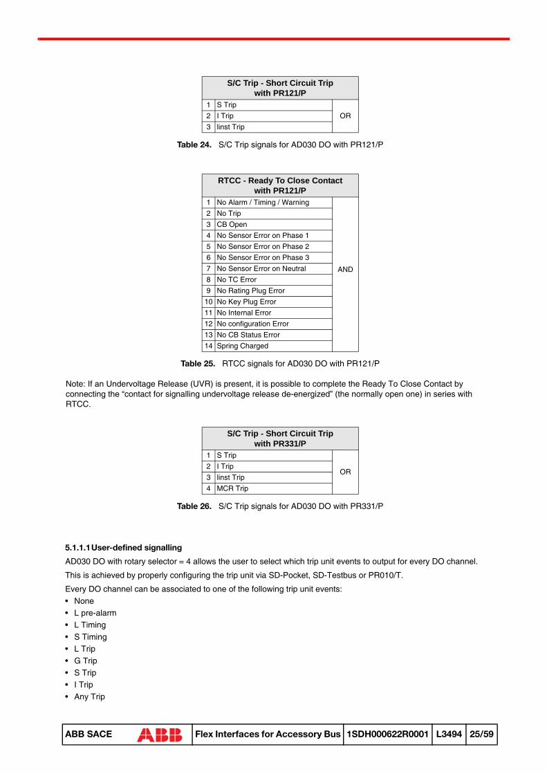
Table 24. S/C Trip signals for AD030 DO with PR121/P
Table 25. RTCC signals for AD030 DO with PR121/P
Note: If an Undervoltage Release (UVR) is present, it is possible to complete the Ready To Close Contact by connecting the “contact for signalling undervoltage release de-energized” (the normally open one) in series with RTCC.
Table 26. S/C Trip signals for AD030 DO with PR331/P
5.1.1.1User-defined signalling
AD030 DO with rotary selector = 4 allows the user to select which trip unit events to output for every DO channel.
This is achieved by properly configuring the trip unit via SD-Pocket, SD-Testbus or PR010/T.
Every DO channel can be associated to one of the following trip unit events:• None• L pre-alarm• L Timing• S Timing• L Trip• G Trip• S Trip• I Trip• Any Trip
S/C Trip - Short Circuit Trip with PR121/P
1 S TripOR2 I Trip
3 linst Trip
RTCC - Ready To Close Contact with PR121/P
1 No Alarm / Timing / Warning
AND
2 No Trip3 CB Open4 No Sensor Error on Phase 15 No Sensor Error on Phase 26 No Sensor Error on Phase 37 No Sensor Error on Neutral8 No TC Error9 No Rating Plug Error
10 No Key Plug Error11 No Internal Error12 No configuration Error13 No CB Status Error14 Spring Charged
S/C Trip - Short Circuit Trip with PR331/P
1 S Trip
OR2 I Trip3 linst Trip4 MCR Trip
59
ABB SACE Flex Interfaces for Accessory Bus 1SDH000622R0001 L3494 25/59

• Any Alarm• Custom
The last option allows to select more events and eventually combine them with and/or logic operations.
See the relevant trip unit user’s manual for details.
5.1.2. AD030 AO and HMI030 output profile
PR121/P and PR331/P trip units perform current measuring function (ammeter), indeed one AD030 AO (rotary selector = 1) and two HMI030 (rotary selector = A and A,V,W,...) can be connected for showing currents.
The other rotary selector positions are not managed.
Table 27. Trip unit measures signalled by AD030 AO with PR121/P and PR331/P
Table 28. Trip unit measures showed by HMI030 with PR121/P and PR331/P
For detailed information about the measures shown by the HMI030 unit, please refer to the relevant user’s manual.
5.1.3. AD030 MI input profile
An AD030 MI can be connected for acquiring external analog/digital signals that will be propagated to the trip unit.
The following table shows how each input channel can be used by the trip unit
Table 29. PR121/P and PR331/P behavior with AD030 MI
AD030 AO output profile with PR121/P and PR331/P
AO Rotary selector 1 Rotary selector 2 Rotary selector 3 Rotary selector 41 Current phase 1 Not managed Not managed Not managed2 Current phase 2 Not managed Not managed Not managed3 Current phase 3 Not managed Not managed Not managed4 Current neutral Not managed Not managed Not managed
AD030 AO lower and upper bound values
Rotary selector 1 Rotary selector 2 Rotary selector 3 Rotary selector 4LB 0 A - - -
UBIn
(trip unit nominal current)- - -
HMI030 output profile with PR121/P and PR331/P
Rotary selector A Rotary selector V Rotary selector W Rotary selector A,V,W,...
Currents Not managed Not managedCurrentsLast trip information
AD030 MI input profile with PR121/P and PR331/P
MI Trip unit behaviorDI 1 Signals the status of the digital inputDI 2 Not supported
AI 1Allows to define a threshold and signals if the analog input is under or over the threshold. In the latter case, generates an alarm condition.
AI 2 Not supported
59
ABB SACE Flex Interfaces for Accessory Bus 1SDH000622R0001 L3494 26/59

5.2. Scenario with PR122/P, PR123/P, PR332/P and PR333/P
Figure 10. PR122/P, PR123/P, PR332/P and PR333/P application scenario
See section 11.1., section 11.2., section 11.3., section 11.4., section 11.5. circuit diagrams for connection instructions.
59
ABB SACE Flex Interfaces for Accessory Bus 1SDH000622R0001 L3494 27/59

5.2.1. AD030 DO output profile
Up to 4 AD030 DO (rotary selector = 1, 2, 3, and 4) can be connected for signalling trip unit events.
Depending on the rotary selector position, AD030 DO will output the following information coming from the trip unit:
Table 30. Trip units events signalled by AD030 DO with PR122/P and PR123/P
Table 31. Trip units events signalled by AD030 DO with PR332/P and PR333/P
By default, DO 5 output channel is used to signal a bus malfuction condition; moreover, the relevant LED lights if busstays inactive for more than 5 seconds.
Table 32. Hardware Alarm signals for AD030 DO with PR122/P, PR123/P and PR332/P, PR333/P
AD030 DO output profile with PR122/P and PR123/P
DO Rotary selector 1 Rotary selector 2 Rotary selector 3 Rotary selector 41 L Timing / Trip L Timing Any Alarm Set by user2 S Timing / Trip S Timing RTCC Set by user3 I Trip Hardware Alarm T Pre-Alarm Set by user
4G Timing / Trip / G Alarm (blocked trip)
Load LC1UV Timing / UV Alarm (blocked trip)
Set by user
5 Bus KO Bus KO Bus KO Bus KO6 L pre-alarm Load LC2 L pre-alarm Set by user7 Any Trip Any Trip Any Trip Set by user
8Trip command fail (backup protection)
Iw Warning F out of range Set by user
AD030 DO output profile with PR332/P and PR333/P
DO Rotary selector 1 Rotary selector 2 Rotary selector 3 Rotary selector 41 L Timing / Trip L Timing Any Alarm Set by user2 S Timing / Trip S Timing S/C Trip Set by user3 I Trip Hardware Alarm T Pre-Alarm Set by user
4G Timing / Trip / G Alarm (blocked trip)
Load LC1UV Timing / UV Alarm (blocked trip)
Set by user
5 Bus KO Bus KO Bus KO Bus KO6 L pre-alarm Load LC2 L pre-alarm Set by user7 Any Trip Any Trip Any Trip Set by user
8Trip command fail (backup protection)
Iw Warning F out of range Set by user
Hardware Alarm with PR122/P, PR123/P and PR332/P, PR333/P1 Sensor Error on Phase 1
OR
2 Sensor Error on Phase 23 Sensor Error on Phase 34 Sensor Error on Neutral5 Sensor Error on External Toroid6 TC Error7 Rating Plug Error8 Key Plug Error9 Internal Error
59
ABB SACE Flex Interfaces for Accessory Bus 1SDH000622R0001 L3494 28/59

Table 33. RTCC signals for AD030 DO with PR122/P, PR123/P
Note: If an Undervoltage Release (UVR) is present, it is possible to complete the Ready To Close Contact by connecting the “contact for signalling undervoltage release deenergized” (the normally open one) in series with RTCC.
Table 34. S/C Trip signals for AD030 DO with PR332/P, PR333/P
Table 35. F out of range signals for AD030 DO with PR122/P, Pr123/P and PR332/P, PR333/P
5.2.1.1User-defined signalling
AD030 DO with rotary selector = 4 allows the user to select which trip unit events to output for every DO channel.
This is achieved by properly configuring the trip unit via its local display, SD-Pocket, SD-Testbus or PR010/T.
Figure 11. describes the procedure for setting up the user-defined signalling using the trip unit local display. First of allthe ‘Settings --> Modules --> Local Bus Unit --> Presence’ should be set to ‘Present’. This will also allow the trip unit tosignal a warning condition in case the communication between trip unit and MM030 is interrupted.
Then every DO channel can be associated to one of the following trip unit events:• None• L pre-alarm• L Timing
RTCC - Ready To Close Contact with PR122/P, PR123/P
1 No Alarm / Timing / Warning
AND
2 No Trip3 CB Open4 No Sensor Error on Phase 15 No Sensor Error on Phase 26 No Sensor Error on Phase 37 No Sensor Error on Neutral
8 No Sensor Error on External Toroid
9 No TC Error10 No Rating Plug Error11 No Key Plug Error12 No Internal Error13 No configuration Error14 No CB Status Error15 CB Connected16 Spring Charged
S/C Trip - Short Circuit Trip with PR332/P, PR333/P
1 S Trip
OR
2 I Trip3 Iinst Trip4 MCR Trip5 D Trip (for PR333 only)6 S2 Trip (for PR333 only)
F out of range with PR122/P, PR123/P and PR332/P, PR333/P1 UF Alarm (blocked trip)
OR2 OF Alarm (blocked trip)3 UF Timing4 OF Timing
59
ABB SACE Flex Interfaces for Accessory Bus 1SDH000622R0001 L3494 29/59

• S Timing• L Trip• G Trip• S Trip• I Trip• Any Trip• Any Alarm• Load LC1• Load LC2• Custom
The last option is available only if using SD-Pocket, SD-Testbus or PR010/T, it allows to select more events andeventually combine them with and/or logic operations.
See the relevant trip unit user’s manual for details.
59
ABB SACE Flex Interfaces for Accessory Bus 1SDH000622R0001 L3494 30/59

Figure 11. Trip unit local display menu for setting user-defined signalling
5.2.2. AD030 AO and HMI030 output profile
The PR122/P, PR123/P, PR332/P and PR333/P trip units perform current measuring function (ammeter). Besides,when the PR120/V or the PR330/V module are connected (optional for PR122/P and PR332/P respectively) additionalmeasurements are available (voltages, powers, energies and more; see the relevant trip unit user’s manual fordetails).
Indeed, up to 4 AD030 AO (rotary selector = 1, 2, 3, and 4) and up to 4 HMI030 (rotary selector = A, V, W, andA,V,W...) can be connected for showing/signalling measures.
AD030 AO output profile with PR122/P, PR123/P, PR332/P and PR333/P
AO Rotary selector 1 Rotary selector 2 Rotary selector 3 Rotary selector 41 Current phase 1 U12 Total active power Total active energy
59
ABB SACE Flex Interfaces for Accessory Bus 1SDH000622R0001 L3494 31/59

Table 36. Trip unit measures signalled by AD030 AO with PR122/P, PR123/P, PR332/P and PR333/P
Table 37. Trip unit measures showed by HMI030 with PR122/P, PR123/P, PR332/P and PR333/P
For detailed information about the measures shown by the HMI030 unit, please refer to the relevant user’s manual.
5.2.3. AD030 MI input profile
An AD030 MI can be connected for acquiring external analog/digital signals that will be propagated to the trip unit.
The following table shows how each input channel can be used by the trip unit
Table 38. PR122/P, PR123/P, PR332/P and PR333/P behavior with AD030 MI
2 Current phase 2 U23 Total reactive power Total reactive energy3 Current phase 3 U31 Total apparent power Total apparent energy4 Current neutral U1n Power factor Network frequency
AD030 AO lower and upper bound values
AO Rotary selector 1 Rotary selector 2 Rotary selector 3 Rotary selector 4
LB
1
0 A 0 V
- In x Un x 10-3 (kW)
- In x Un x 24h x 10-3
(kWh)
2 - In x Un x 10-3 (kVAR)
- In x Un x 24h x 10-3
(kVARh)
3 - In x Un x 10-3 (kVA)
- In x Un x 24h x 10-3
(kVAh)4 - 1 0 Hz
UB
1
In(trip unit nominal current)
Un(trip unit nominal voltage)
In x Un x 10-3
(kW)In x Un x 24h x 10-3
(kWh)
2 In x Un x 10-3
(kVAR)In x Un x 24h x 10-3
(kVARh)
3 In x Un x 10-3
(kVA)In x Un x 24h x 10-3
(kVAh)4 1 66 Hz
HMI030 output profile with PR122/P, PR123/P, PR332/P and PR333/P
Rotary selector A Rotary selector V Rotary selector W Rotary selector A,V,W,...
Currents Voltages Powers
CurrentsVoltages PowersEnergies Power factorFrequency Peak factors Last trip information
AD030 MI input profile with PR122/P, PR123/P, PR332/P and PR333/P
MI Trip unit behaviorDI 1 Signals the status of the digital inputDI 2 Not supported
AI 1Allows to define a threshold and signals if the analog input is under or over the threshold. In the latter case, generates an alarm condition.
AI 2 Not supported
AD030 AO output profile with PR122/P, PR123/P, PR332/P and PR333/P
AO Rotary selector 1 Rotary selector 2 Rotary selector 3 Rotary selector 4
59
ABB SACE Flex Interfaces for Accessory Bus 1SDH000622R0001 L3494 32/59

5.3. Scenario with PR222DS/PD
Figure 12. PR222DS/PD application scenario
See section 11.1., section 11.2., section 11.4., section 11.6. circuit diagrams to realize proper connections.
59
ABB SACE Flex Interfaces for Accessory Bus 1SDH000622R0001 L3494 33/59

5.3.1. AD030 DO output profile
Up to 3 AD030 DO (rotary selector = 1, 2, and 3) can be connected for signalling trip unit events.
Depending on the rotary selector position, AD030 DO will output the following information coming from the trip unit:
Table 39. Trip units events signalled by AD030 DO with PR222DS/PD
AD030 DO with rotary selector position = 4 is not managed.
By default, DO 5 output channel is used to signal a bus malfuction condition; moreover, the relevant LED lights if bus stays inactive for more than 5 seconds.
5.3.2. AD030 AO and HMI030 output profile
The PR222DS/PD trip unit performs current measuring function (ammeter), indeed one AD030 AO (rotary selector = 1) and two HMI030 (rotary selector = A and A,V,W,...) can be connected for showing currents.
The other rotary selector positions are not managed.
Table 40. Trip unit measures signalled by AD030 AO with PR222DS/PD
Table 41. Trip unit measerues showed by HMI030 with PR222DS/PD
For detailed information about the measures shown by the HMI030 unit, please refer to the relevant user’s manual.
AD030 DO output profile with PR222DS/PD
DO Rotary selector 1 Rotary selector 2 Rotary selector 3 Rotary selector 41 L Timing / Trip L Timing L Trip Not managed2 S Timing / Trip S Timing S Trip Not managed3 I Trip Any Alarm I Trip Not managed4 G Timing / Trip G Timing G Trip Not managed5 Bus KO Bus KO Bus KO Not managed6 L pre-alarm L pre-alarm Any Alarm Not managed7 Any Trip Any Trip Any Trip Not managed
8Trip command fail (backup protection)
Trip command fail (backup protection)
Trip command fail (backup protection)
Not managed
AD030 AO output profile with PR222DS/PD
AO Rotary selector 1 Rotary selector 2 Rotary selector 3 Rotary selector 41 Current phase 1 Not managed Not managed Not managed2 Current phase 2 Not managed Not managed Not managed3 Current phase 3 Not managed Not managed Not managed4 Current neutral Not managed Not managed Not managed
AD030 AO lower and upper bound values
Rotary selector 1 Rotary selector 2 Rotary selector 3 Rotary selector 4LB 0 A - - -
UBIn
(trip unit nominal current)- - -
HMI030 unit with PR222DS/PD
Rotary selector A Rotary selector V Rotary selector W Rotary selector A,V,W,...
Currents Not managed Not managedCurrentsLast trip information
59
ABB SACE Flex Interfaces for Accessory Bus 1SDH000622R0001 L3494 34/59

5.3.3. AD030 MI input profile
AD030 MI is not managed.
5.4. Scenario with PR223EF
Figure 13. PR223EF application scenario
See section 11.1., section 11.2., section 11.4., section 11.6. circuit diagrams to realize proper connections.
59
ABB SACE Flex Interfaces for Accessory Bus 1SDH000622R0001 L3494 35/59

5.4.1. AD030 DO output profile
Up to 4 AD030 DO (rotary selector = 1, 2, 3, and 4) can be connected for signalling trip unit events.
Depending on the rotary selector position, AD030 DO will output the following information coming from the trip unit:
Table 42. Trip units events signalled by AD030 DO with PR223EF
By default, DO 5 output channel is used to signal a bus malfuction condition; moreover, the relevant LED lights if busstays inactive for more than 5 seconds.
5.4.1.1User-defined signalling
AD030 DO with rotary selector = 4 allows the user to select which trip unit events to output for every DO channel.
This is achieved by properly configuring the trip unit via SD-Pocker, Sd-Testbus or PR010/T.
Every DO channel can be associated to one of the following trip unit events:• None• Parameters changed• Test unit connected• Test unit not connected• CB Tripped• CB Closed• CB Open• CB status undefined• CB status defined• Trip command fail• Local operating mode• Remote operating mode• Any alarm• L pre-alarm• L Timing• S Timing• G Timing• EF Alarm• EF Interlocked• S Interlocked• G Interlocked• Interlocking fault uplink• Interlocking fault downlink• SOS requested• Trip Coil Alarm• MOE-E Over Temperature Alarm• Frequency Alarm• Any Trip
AD030 DO output profile with PR223EF
DO Rotary selector 1 Rotary selector 2 Rotary selector 3 Rotary selector 41 L Timing / Trip L Timing L Trip Set by user2 S Timing/ Trip S Timing S Trip Set by user3 I Trip / EF Trip Interlock Alarm I Trip Set by user4 G Timing / Trip G Timing G Trip Set by user5 Bus KO Bus KO Bus KO Bus KO6 L pre-alarm L pre-alarm Any Alarm Set by user7 Any Trip Any Trip Any Trip Set by user
8Trip command fail (backup protection)
Trip command fail (backup protection)
Trip command fail (backup protection)
Set by user
59
ABB SACE Flex Interfaces for Accessory Bus 1SDH000622R0001 L3494 36/59

• L Tripped• S Tripped• I Tripped• Iinst Tripped• G Tripped• EF Tripped• SOS Trip• Trip reset event• Vaux present• Vaux absent• MOE-E present• MOE-E absent• Clock failure
See the relevant trip unit user’s manual for details.
5.4.2. AD030 AO and HMI030 output profile
The PR223EF trip unit performs current measuring function (ammeter). Besides, when the VM210 module isconnected additional measurements are available (voltages and more; see the relevant trip unit user’s manual fordetails).
Indeed, up to 2 AD030 AO (rotary selector = 1 and 2) and up to 3 HMI030 (rotary selector = A, V, and A,V,W...) can beconnected for showing/signalling measures.
Table 43. Trip unit measures signalled by AD030 AO with PR223EF
Table 44. Trip unit measures showed by HMI030 with PR223EF
For detailed information about the measures shown by the HMI030 unit, please refer to the relevant user’s manual.
5.4.3. AD030 MI input profile
AD030 MI is not managed.
AD030 AO output profile with PR223EF
AO Rotary selector 1 Rotary selector 2 Rotary selector 3 Rotary selector 41 Current phase 1 U12 Not managed Not managed2 Current phase 2 U23 Not managed Not managed3 Current phase 3 U31 Not managed Not managed4 Current neutral U1n Not managed Not managed
AD030 AO lower and upper bound values
Rotary selector 1 Rotary selector 2 Rotary selector 3 Rotary selector 4LB 0 A 0 V - -
UBIn
(trip unit nominal current)Un
(trip unit nominal voltage)- -
HMI030 output profile with PR223EF
Rotary selector A Rotary selector V Rotary selector W Rotary selector A,V,W,...
Currents Voltages Not managed
CurrentsVoltagesPower factorFrequencyPeak factorsLast trip information
59
ABB SACE Flex Interfaces for Accessory Bus 1SDH000622R0001 L3494 37/59

5.5. Scenario with PR223DS
Figure 14. PR223DS application scenario
See section 11.1., section 11.2., section 11.4., section 11.6. circuit diagrams to realize proper connections.
59
ABB SACE Flex Interfaces for Accessory Bus 1SDH000622R0001 L3494 38/59

5.5.1. AD030 DO output profile
Up to 4 AD030 DO (rotary selector = 1, 2, 3, and 4) can be connected for signalling trip unit events.
Depending on the rotary selector position, AD030 DO will output the following information coming from the trip unit:
Table 45. Trip units events signalled by AD030 DO with PR223DS
By default, DO 5 output channel is used to signal a bus malfuction condition; moreover, the relevant LED lights if busstays inactive for more than 5 seconds.
5.5.1.1User-defined signalling
AD030 DO with rotary selector = 4 allows the user to select which trip unit events to output for every DO channel.
This is achieved by properly configuring the trip unit via SD-Pocker, Sd-Testbus or PR010/T.
Every DO channel can be associated to one of the following trip unit events:• None• Parameters changed• Test unit connected• Test unit not connected• CB Tripped• CB Closed• CB Open• CB status undefined• CB status defined• Trip command fail• Local operating mode• Remote operating mode• Any alarm• L pre-alarm• L Timing• S Timing• G Timing• Trip Coil Alarm• MOE-E Over Temperature Alarm• Frequency Alarm• Any Trip• L Tripped• S Tripped• I Tripped• Iinst Tripped• G Tripped• Trip reset event• Vaux present
AD030 DO output profile with PR223DS
DO Rotary selector 1 Rotary selector 2 Rotary selector 3 Rotary selector 41 L Timing / TripTrip L Timing L Trip Set by user2 S Timing/ Trip S Timing S Trip Set by user3 I Trip L pre-alarm I Trip Set by user4 G Timing / Trip G Timing G Trip Set by user5 Bus KO Bus KO Bus KO Bus KO6 L pre-alarm Any Alarm Any Alarm Set by user7 Any Trip Any Trip Any Trip Set by user
8Trip command fail (backup protection)
Trip command fail (backup protection)
Trip command fail (backup protection)
Set by user
59
ABB SACE Flex Interfaces for Accessory Bus 1SDH000622R0001 L3494 39/59

• Vaux absent• MOE-E present• MOE-E absent• Clock failure
See the relevant trip unit user’s manual for details.
5.5.2. AD030 AO and HMI030 output profile
The PR223DS trip unit performs a current measuring function (ammeter).
When the optional VM210 module is connected additional measurements are available (voltages, powers, energiesand more; see the relevant trip unit user’s manual for details).
Up to 4 HMI030 (rotary selector = ‘A’, ‘V’, ‘W’, and ‘A,V,W...’) and up to 3 AD030 AO (rotary selector = 1, 2 and 3) canbe connected for showing/signalling measures.
Table 46. Trip unit measures signalled by AD030 AO with PR223DS
Table 47. Trip unit measures showed by HMI030 with PR223DS
For detailed information about the measures shown by the HMI030 unit, please refer to the relevant user’s manual.
AD030 AO output profile with PR223DS
AO Rotary selector 1 Rotary selector 2 Rotary selector 3 Rotary selector 41 Current phase 1 U12 Total active power Not managed2 Current phase 2 U23 Total reactive power Not managed3 Current phase 3 U31 Total apparent power Not managed4 Current neutral U1n Power factor Not managed
AD030 AO lower and upper bound values
AO Rotary selector 1 Rotary selector 2 Rotary selector 3 Rotary selector 4
LB
1
0 A 0 V
- In x Un (kW)
-
2- In x Un (kVAR)
-
3- In x Un
(kVA)-
4 - 1 -
UB
1
In(trip unit nominal current)
Un(trip unit nominal voltage)
In x Un x 10-3
(kW)-
2 In x Un x 10-3
(kVAR)-
3 In x Un x 10-3
(kVA)-
4 1 -
HMI030 outout profile with PR223DSRotary selector A Rotary selector V Rotary selector W Rotary selector W
Currents Voltages Powers
CurrentsVoltagesPowersEnergiesPower factorFrequencyPeak factorsLast trip information
59
ABB SACE Flex Interfaces for Accessory Bus 1SDH000622R0001 L3494 40/59

5.5.3. AD030 MI input profile
AD030 MI is not managed.
59
ABB SACE Flex Interfaces for Accessory Bus 1SDH000622R0001 L3494 41/59

6 CONFIGURATION
Configuration is the mandatory operation to perform for setting-up MM030 and Flex Interfaces system.
During the configuration procedure the MM030 executes the following actions:• Scan the local and accessory buses• Find and recognize the trip unit and Flex Interfaces connected• Freeze the Flex Interfaces with their current rotary selector position• Schedule data exchange activities• Store the list of found devices in permanent memory• Begin data exchange
Configuration is a procedure that involves both MM030 and Flex Interfaces.
6.1. Start a new configurationAfter all devices are properly installed as explained in section 11, the auxiliary power supply can be provided.
If MM030 unit has never been configured before (or its configuration has been delete, see section 6.4.), it will signal the Unconfigured condition by lighting the Fault LEDs on the front panel as in Table 4.
If a previous configuration procedure is in execution, press the Reset push-button.
MM030 is able to detect the communication parameters (address, baud rate and similar) used by the devices connected on both buses. Therefore no special setting is requested by the user.
Press the MM030 ‘Configuration’ push-button for at least 1 second.
Configuration procedure is now started.
During the configuration procedure the MM030 Fault LEDs keep on signalling the Unconfigured condition, but the local and accessory bus TX LEDs signal bus activity.
Note: During configuration a further pressure of the ‘Configuration’ push-button is ignored. If you need to re-start the configuration procedure press the ‘Reset’ push-button.
As soon as the configuration is started, the Flex Interfaces connected are unfreezed to reset the configuration parameters in use up to now. This is evident in AD030 XX unit, whose LEDS switch all on for 1 second, and in HMI030 units, whose displays turns off and then slowly turns on again.
It is possible that, at a certain point, one of the two MM030 TX LEDs stops blinking while the other keeps on signalling bus activity. This is due to the fact that the scan is over only for one bus, while is still proceeding on the other bus.
Note: The configuration procedure may last for minutes. The worst case occurs when there are no devices connected on Local bus: the MM030 will take about 5 minutes before finishing the procedure and signalling bus fault on both buses.
When the Configuration procedure is ended, the MM030 stops signalling the Unconfigured condition.
59
ABB SACE Flex Interfaces for Accessory Bus 1SDH000622R0001 L3494 42/59

6.2. Outcomes of the configurationDepending on the results of the bus scan, the configuration procedure may end with different outcomes.
It is possible to have an idea of what happened by firstly looking at the Fault LEDs in MM030.
The LEDs in the slave devices (trip unit or Flex Interfaces) can be analysed afterwards for finding out the exact devices that eventually generated a problem.
The following table sums up all the possible outcomes (see section 3.1.3. for details about the LEDs meaning).
Condition MM030 Fault LED Description
All devices OK OFF
All devices connected on the given bus have been recognized. Data exchange activity is started.
Here is a summary of the status of all LEDs for this condition:• PWR LED ON (Green)• WD LED OFF• Write LED OFF• TX LEDs blink (Yellow)• FAULT LEDs OFF
Bus fault ON
MM030 was not able to find any device on the given bus.This can happen on:• only one bus• on both busesIn both cases, normally no data exchange activity can be initiated and the TX LEDs are OFF.
Unknown device Pattern 4
MM030 has found a device on the given bus, but this device is unknown. This can be due to:• Device ID not recognized• Device connected on the wrong bus (for example trip unit connected to Accessory
bus and/or Flex Interfaces connected to Local bus)It is possible to detect which devices (trip unit and/or Flex Interfaces) generated the problems by:• Identifying the bus (looking at which MM030 Fault LED is blinking)• Identifying the devices, connected on that bus, that still signal the Unconfigured
condition or that do not show bus activityIf the device unknown is the trip unit , normally no data exchange activity can be initiated and the TX LEDs are OFF.If the device unknown is a Flex Interfaces, it is possible that the trip unit and other Flex Interfaces have been correctly recognized. In this case there can be data exchange and the TX LEDs signals bus activity.
Unmanaged device Pattern 5
MM030 has found a device on the given bus, it has recognized it, but this device is unmanaged. This can be due to:• Device does not fit into one of the application scenarios described in section 5.• Device has a software version not managed• Device can’t be associated with any other device for data exchange (for example: a
trip unit has been found, but no Flex Interfaces have been found)• Device connected on the wrong bus (for example trip unit connected to Accessory
bus and/or Flex Interfaces connected to Local bus) and/or bus wires invertedIt is possible to detect which devices (trip unit and/or Flex Interfaces) generated the problems by:• Identifying the bus (looking at which MM030 Fault LED is blinking)• Identifying the devices, connected on that bus, that still signal the Unconfigured
condition or that do not show bus activity If the device unmanaged is the trip unit , normally no data exchange activity can be initiated and the TX LEDs are OFF.If the device unmanaged is one or more Flex Interfaces, it is possible that the trip unit and other Flex Interfaces have been correctly recognized. In this case there can be data exchange and the TX LEDs signals bus activity.
59
ABB SACE Flex Interfaces for Accessory Bus 1SDH000622R0001 L3494 43/59

Table 48. Outcomes after configuration procedure
6.3. Save and restore a configurationWhen MM030 is configured, it automatically stores the list of the devices found and the outcomes of the scan into its permanent memory.
It is possible for MM030 to automatically restore the configuration when there is a power-up after a reset or a power shut-down. Hence, if all the conditions are satisfied, MM030 will re-start autonomously the data exchange.
6.4. Delete a configurationThe procedure to put MM030 and Flex Interfaces to the Unconfigured state is:• Press the ‘Configuration’ push-button• Press the ‘Reset’ push button before the Configuration procedure ends
6.5. Re-configurationIf MM030 is already configured, it is possible to re-configure it by pressing the ‘Configuration’ push-botton (unless the configuration procedure is going on, see section 6.1., or MM030 is in Maintenance mode).
This can be required when:• A new device has been connected (in order to include it into the data exchange activity)• A device has been eliminated (in order to stop MM030 querying it for reconnection, see section 7.1.1.)• A Flex Interfaces rotary selector position have been modified (in order to evaluate the new scenario)• A trip unit communication parameters have been modified (in order to resume the communication with it)
Possible device collision Pattern 6
MM030 has found a possible device collision on the given bus. This can be due to:• Two or more Flex Interfaces with the same rotary selector position• Two or more trip units with the same slave address
Note that also communication errors due to noise disturbs along the buses may generate this outcome. This is the case if one more HMI030 is set for not communication with MM030 (‘MM030 = no’)
Condition MM030 Fault LED Description
59
ABB SACE Flex Interfaces for Accessory Bus 1SDH000622R0001 L3494 44/59

7 DATA EXCHANGE ACTIVITY
7.1. MM030After the configuration procedure succeded, MM030 is normally busy performing a periodic data exchange activity with the connected devices.
The data exchange is optimised in order to guarantee the highest transfer rate and propagate the information from/to trip unit and Flex Interfaces as fast as possible.
The activity is organised on an priority basis: channels with higher prioriy are refreshed more frequently.
The following table shows the default priority policy used:
Table 49. Data exchange priorities
The refresh rate of a single device depends and the total number and type of devices connected to MM030.
The whole data exchange activity is signalled by the Local and Accessory bus TX LEDs, which light on when a message is being transmitted on the relevant bus.
7.1.1. Management of disconnected devices
If during normal data exchange one or more devices are disconnected (voluntarily or as a consequence of a fault) MM030 alerts the user with the Fault LEDs, according to the following outcomes:
Table 50. Outcomes due to device disconnection
MM030 will stop data exchange activity with the disconnected devices. This may cause also the stop of data exchange activity with other devices, directly associated with the disconnected ones. For example, if a trip unit is disconnected also the data exchange with all the Flex Interfaces will stop.
MM030 will periodically query the disconnected devices to check if they are reconnected (heart-beat check). If this is the case, the data exchange activity with them will be restored.
In order to stop MM030 from querying the disconnected device, a new configuration procedure is required.
MM030 will consider a device disconnected (and will apply the same policy for reconnection described above) even if the communication with the device generates error (for example due to noises on the communication bus).
PriorityExchange channel
from toHigh AD030 MI trip unit
Medium trip unit AD030 DOLow trip unit AD030 AO and HMI
OutcomeMM030
Fault LED Description
Bus fault ON All devices on the given bus are disconnected, or MM030 gets no responses from the bus.
One or more (bur not all) devices disconnected
Pattern 2 One or more devices on the given bus are disconnected, but there is still data exchange activity with other devices.
59
ABB SACE Flex Interfaces for Accessory Bus 1SDH000622R0001 L3494 45/59

7.2. AD030 DOAfter the configuration procedure succeded, AD030 DO is normally busy receiving periodic messages from MM030 that update the status or the DO channels (output contact and relevant LED).
The signal associated with each single output contact is kept stable until the associated information in the trip unit changes.
The whole data exchange activity is signalled by the Accessory bus RX LEDs, which lights on when the device receives a message from MM030.
7.2.1. Bus fault
By default, the DO 5 output channel is used to signal a bus inactivity condition. If communication between the device and the MM030 is not present for more than 5 seconds:• DO5 relay will go in the closed state and the relevant LED will be ON• All the other relays will go in the open state and the relevant LEDs will be OFF• The Fault LED will signal the Bus fault condition
7.3. AD030 AOAfter the configuration procedure AD030 AO is normally busy receiving periodic messages from MM030 that update the values output by the AO channels.
The signal associated with each output channel varies accordingly to the associated measure in the trip unit.
The whole data exchange activity is signalled by the Accessory bus RX LEDs, which lights on when the device receives a message from MM030.
7.3.1. Bus fault
If communication between the device and the MM030 is not present for more than 5 seconds:• All the AO channels will output the lower bound (LB) value and the relevant LEDs will be OFF• The Fault LED will signal the Bus fault condition
7.4. AD030 MIAfter the configuration procedure AD030 MI is normally busy answering to the periodic message requests from MM030, relative to the status of the input channels.
The whole data exchange activity is signalled by the Accessory bus RX LEDs, which lights on when the device receives a message from MM030.
7.4.1. Bus fault
If communication between the device and the MM030 is not present for more than 5 seconds:• The Fault LED will signal the Bus fault condition
59
ABB SACE Flex Interfaces for Accessory Bus 1SDH000622R0001 L3494 46/59

8 OTHER OPERATIONS
8.1. General
8.1.1. Self-test
The self-test procedure is executed by the MM030 and Flex Interfaces units immediately after the power on: all theLEDs are turned and kept on for about 1 second; then they are turned off simultaneously.
The procedure ends when the PWR LED is permanently ON.
This test helps to:• Check the device operates correctly during initialization• Check the LEDs switch on and off correctly
8.2. MM030
8.2.1. Reset
It is possible to reset the MM030 unit by pushing the ‘Reset’ push-button on the front panel (see par 3.1).
The optical signals can’t be manually reset since they always reflect the internal status of the MM030 unit.
8.2.2. Malfunction conditions
MM030 can face the following malfunction conditions:
Table 51. MM030 malfunction conditions
8.3. Accessory Devices
8.3.1. Test
It is impossible to execute the AD030 test procedure pressing the Test Push button on the front panel.
ConditionMM030
Fault LEDs (both)
Description
Malfunction Pattern 7MM030 detects a malfunction. This can be due to:• Supply voltage too high or too low• Internal malfunction
Internal memory error Pattern 10 MM030 internal memory is corrupted.
Contact ABB Service.
59
ABB SACE Flex Interfaces for Accessory Bus 1SDH000622R0001 L3494 47/59

9 TECHNICAL CHARACTERISTICS
9.1. Electrical characteristics
Table 52. Electrical characteristcs of MM030 and accessory Flex Interfaces
9.1.1. Auxiliary power supply
The MM030 and Flex Interfaces units must be powered by an auxiliary supply.
Table 53. Auxiliary supply for MM030 and accessory Flex Interfaces
Since the auxiliary voltage must be isolated from the ground, it is necessary to use ‘galvanically separeted converters’, conforming to IEC standard 60950 (UL 1950) or equivalent IEC 60364-41, in order to guarantee a common mode current or a leakage current (as defined in IEC 478/1), not greater than 3.5mA.
9.1.2. AD030 DO internal relays characteristics
The digital output channels have a normally open contact connected to the terminal box and are independent by each other. The following table sums up the main characteristics of the relay used for each channel.
Table 54. Characteristics of AD030 DO relays
9.1.3. AD030 AO channel characteristics
AOs are non isolated analog output channels, able to drive a current signal in the range of 4 ... 20mA with a resolution of 12bit (11bit for the data and 1bit for the sign) and an accuracy of 1% at least.
The behavior of each channel is signalled by means of the relevant LED, as explained in Table 13.
9.1.4. AD030 MI channel characteristics
The digital input channels support a voltage signal in the range 0V ... 24V where:• the range 0V ... 4V will be seen as a not active digital singal (binary 0)• the range 15V ... 24 V will be seen as an active digital signal (binary 1)• the range 5V ... 15V will be seen as an undetermined digital signal
Effective operation Max 10 s after the power on
Electromagnetic compatibilityIEC 61947-2IEC 60533
Characteristics MM030 AD030 AO, AD030 MI AD030 DOSupply voltage 24 Vdc ± 20%
± 5%Maximum ripple
Nominal power @ 24 Vdc 2.5 W 2 W 4 W
(all relays active)
Type Monostable SPDTMax breaking capacity 150 W / 250 VA (resistive load)Max breaking voltage 300 Vdc / 250 Vac
Max breaking current 5 A @ 30 Vdc (resistive load)8 A @ 250 Vac(resistive load)
59
ABB SACE Flex Interfaces for Accessory Bus 1SDH000622R0001 L3494 48/59

The analog input channels support a current signal in the range 4mA ... 20mA with a resolution of 12bit (11bit for the data and 1bit for the sign) and an accuracy of 1% at least. The value that will be transmitted to the trip unit will be the engineering value multiplied by 1000 (4mA --> 4000, 20mA --> 20000).
9.2. Mechanical characteristicThe same box is used for the MM030, AD030 DO, AD030 A0 and AD030 MI.
Table 55. Mechanical characteristics of MM030 and accessory Flex Interfaces
Figure 15. MM030 and Accessory Devices dimensions
9.3. Environmental conditions
Table 56. Environmental conditions
9.4. Communication busesThe MM030 unit has got two serial buses used to communicate with other devices:
Characteristic MM030 and AD030 unitsCase Self-extinguish Noryl resinProtection degree IP20Dimensions see Figure 15. Weight 100 g
Characteristic MM030 - AD030 DO HMI030Operating environmental temperature -25 °C ... +70 °C -20 °C ... +70 °CStorage temperature -40 °C ... +90 °C -30 °C ... +80 °CRelative humidity 5% ... 98% with condensation (with coating)Atmospheric pressure 1 bar, 0 m ... 2000 m
59
ABB SACE Flex Interfaces for Accessory Bus 1SDH000622R0001 L3494 49/59

• the local bus connects the MM030 unit to the trip unit1
• the accessory bus connects the MM030 unit to the modules from the Flex Interfaces family.
Both buses use RS485 as physical layer.
Each RS485 channel is optically isolated and it is possible to connect at most 32 devices.
The connecting cable must be Belden 3105 with 120 Ohm characteristic impedence, or similar. Therefore, a 120 Ohmterminal resistor must be used.
The maximum length of the Accessory bus is 300 m. In case of lot of stub connections, the Accessory bus lengthdecreases accordingly.
The maximum length of the connection between MM030 and trip unit depends on the latter, see the table below.
Table 57. Connection lenght of MM030 to different trip units
1. PR222DS/PD, PR223EF and PR223DS trip unit dont’ have the local bus so they must be connected to MM030 bythe system bus.
Trip unitMM030 to trip unit
connection cable lenght
PR12x/P 15 m
PR33x/P 15 m
PR222DS/PD 200 m
PR223EF/DS 200 m
59
ABB SACE Flex Interfaces for Accessory Bus 1SDH000622R0001 L3494 50/59

10 TROUBLESHOOTING
The following table sums up a number of typical operational situations useful to understand and solve possible faults and malfunctions.
Note: Before consulting the following table, check the LEDs on the front panel of the connected devices (wait for the start up phase to end if the system has just been powered up); see section 3.1.3., section 3.2.3., section 6.2. and section 8.2.2.
Situation Possible causes Suggestions
MM030 does not exchange data:(TX and RX LEDs are off most of the time)
Auxiliary voltage not present Restore supply voltage
MM030 not configured Start MM030 configuration (see section 6.1.)
One or more HMI030 set for not communicating with MM030 (‘MM030 = no’)
Set all connected HMI030 for communicating with MM030 (‘MM030 = yes’)
Impossible to communicate with trip unit:• Local bus disconnected or not
properly connected• Connected trip unit not
recognized by MM030
• Check connections• Connect a managed trip unit (see section 5)
Impossible to communicate with Flex Interfaces units:• Accessory bus disconnected or
not properly connected• No Flex Interfaces unit
recognized by MM030
• Check connections• Connect a managed Flex Interfaces (see
section 5)
One or more (but not all) Flex Interfaces do not exchange data (RX LEDS is off most of the time)
Auxiliary voltage not present Restore supply voltage
Flex Interfaces is not configured (Re)Configure MM030
Flex Interfaces disconnected or not properly connected Check connections
Unknown device
• Check the Flex Interfaces are connected to the Accessory bus
• Check the Flex Interfaces are supported (see section 5)
Unmanaged device
Check the connected Flex Interfaces and their rotary selector position. They should fall into one of the connection scenarios in section 5
Possible device collision
• Check that Flex Interfaces of the same device type (for example AD030 DO) have different rotary selector position.
• Check all connected HMI030 are set for communicating with MM030 (‘MM030 = yes’)
Flex Interfaces signals bus fault
Flex Interfaces connection with MM030 interrupted or disturbed
Check connections between MM030 and Flex Interfaces
MM030 Local bus fault Check connections between MM030 and trip unit
After resetting AD030 DO, the DO channels keep the same values
Trip unit has not been reset after a trip event has occurred
Reset the trip unit (see the relevant user’s manual)
The condition associated with the DO channels is still present Expected behavior
59
ABB SACE Flex Interfaces for Accessory Bus 1SDH000622R0001 L3494 51/59

If the previous list does not solve the problem and/or if you suspect that any device is faulty, malfunctioning or has generated unexpected behavior, we recommend you to follow the instructions below:• Prepare a brief description of the problem ecountered • Note down the serial number of the unit• Send all the information gathered, together with your application circuit diagram, to the nearest ABB technical
support
59
ABB SACE Flex Interfaces for Accessory Bus 1SDH000622R0001 L3494 52/59

11 CIRCUIT DIAGRAMS
11.1.AD030 DO
Figure 16. AD030 DO circuit diagram
59
ABB SACE Flex Interfaces for Accessory Bus 1SDH000622R0001 L3494 53/59

11.2.AD030 AO
Figure 17. AD030 AO circuit diagram
59
ABB SACE Flex Interfaces for Accessory Bus 1SDH000622R0001 L3494 54/59

11.3.AD030 MI
Figure 18. AD030 MI circuit diagram
59
ABB SACE Flex Interfaces for Accessory Bus 1SDH000622R0001 L3494 55/59

11.4.HMI030
Figure 19. HMI030 circuit diagram
59
ABB SACE Flex Interfaces for Accessory Bus 1SDH000622R0001 L3494 56/59

11.5.MM030 with PR12x/P and PR33x/P trip units
Figure 20. MM030 with PR12x/P,PR33x/P trip units circuit diagram
59
ABB SACE Flex Interfaces for Accessory Bus 1SDH000622R0001 L3494 57/59

11.6.MM030 with PR222DS/PD, PR223EF, PR223DS trip units
Figure 21. MM030 with PR222DS/PD and PR223 trip units circuit diagram
59
ABB SACE Flex Interfaces for Accessory Bus 1SDH000622R0001 L3494 58/59

11.7.Graphical symbols for electrical diagrams (617 IEC standards)
Table 58. Description of electrical diagrams captions
Figure 22. Graphical symbols used in circuit diagrams
Caption Description
A26 Unit type AD030 DO with 8 digital outputs to connect to Accessory Bus
A27 Unit type AD030 AO with 4 analog outputs to connect to Accessory Bus
A28 Unit type AD030 MI with 2 digital inputs and 2 analog inputs to connect to Accessory Bus
A29 Unit type HMI030 for remote display on Accessory Bus
A30 Unit type MM030 (master-master) for connection of a trip unit on Accessory Bus
AI Analog Inputs
AO Analog Outputs
DO Digital Outputs
K51 Trip unit
W3 Accessory Bus
59
ABB SACE Flex Interfaces for Accessory Bus 1SDH000622R0001 L3494 59/59