MODELING AND CRASH ANALYSIS OF CAR INTEGRAL ...
9
ISSN: 2455-2631 © January 2019 IJSDR | Volume 4, Issue 1 IJSDR1901014 International Journal of Scientific Development and Research (IJSDR) www.ijsdr.org 78 MODELING AND CRASH ANALYSIS OF CAR INTEGRAL FRAME USING FEM METHOD 1 K. VAMSI KRISHNA, 2 K.V.P.P. CHANDU 1 Student, 2 Assistant Professor Department of Mechanical engineering, Sir C.R.R.College of Engineering, Eluru-534007, A.P. Abstract: The safety to driver and passengers is a major concern to every car manufacturer. For accomplishing this, new standards are being set for the safety of the occupant in different car scenarios like frontal head collision. The automotive chassis is the main load carrier and energy absorbing component in all crash events. In the modern world, fuel consumption also constituted as a serious issue that has to be considered. Keeping all these constrains in consideration, a light and strong material should be used in chassis. In current work, integral frame chassis has been designed with honeycomb structure using CATIA V5 software and was analyzed using a finite element analysis (FEA) program ANSYS. The current research provides a standard finite element analysis procedure for designing off road vehicle integral frame. A multi body dynamic crash analysis is an option to understand the exact behavior of the chassis for frontal collisions, to study the effect of speed (20,40,60 mph) of a vehicle. This report includes the creation of the safe design and material mater for dynamic impact analysis under different loading conditions finally will conclude the suitable design and material based on stresses, deformations, shear stresses. Keywords: Car, Integral Chassis Frame, Honey Comb, Al6061, Carbon Fiber, Steel, Crash Analysis, CATIA V5, ANSYS. 1. INTRODUCTION In automobile design, crash and structural analysis are the two most important engineering processes in developing a high quality vehicle. Computer simulation technologies have greatly enhanced the safety, reliability, and comfort, environmental and manufacturing efficiency of today's automobiles. This significant achievement was realized with the advanced software and powerful computers that have been available in the last twenty years. The primary concern for drivers and passengers is safety. Governments have responded to this key concern and expectation with an increasing number of regulations. Although the details may vary slightly from country to country, the fundamental requirements are almost similar. A vehicle is expected to provide adequate protection to drivers and passengers in a not so serious accident. To protect the occupants of a car, there are many new tangible safety features such as airbags; ABS control brakes, traction control. A less tangible feature that cannot easily be seen by drivers and passengers is the crash response behavior. In a well-designed automobile, the car body and various components are the protective layer for the occupants of the vehicle. They serve as the crumpling zone to absorb the energy of impact. The traditional approach involves multiple iterations of design, prototype and crash tests. The process is time consuming and expensive. The availability of high performance computers and crash simulation software has revolutionized the process. Instead of relying on experimental validations, the safety design process is supplemented with computer simulation to evaluate the design. Since the inception of crash simulation, the product cycle of a new automobile has been reduced by half and the resultant vehicle is safer, better and more comfortable. Figure 1 Crashing of Two Cars 1.1 ROLE OF CHASSIS IN AUTOMOTIVES: Every vehicle body consists of two parts; chassis and bodywork or superstructure. The chassis is the framework of any vehicle. Its principal function is to safely carry the maximum load for all designed operating conditions. It must also absorb engine and driveline torque, endure shock loading and accommodate twisting on uneven road surfaces. The chassis receives the reaction forces of the wheels during acceleration and braking and also absorbs aerodynamic wind forces and road shocks through the suspension. So the chassis should be engineered and built to maximize payload capability and to provide versatility, durability as well as adequate performance. To achieve a satisfactory performance, the construction of a heavy vehicle chassis is the result of careful design and rigorous testing. It should be noted that this ‘ladder’ type of frame construction is designed to offer good downward support fo r the body and payload and at the same time provide torsional flexibility, mainly in the region between the gearbox cross member and the cross member
-
Upload
khangminh22 -
Category
Documents
-
view
4 -
download
0
Transcript of MODELING AND CRASH ANALYSIS OF CAR INTEGRAL ...

ISSN: 2455-2631 © January 2019 IJSDR | Volume 4, Issue 1
IJSDR1901014 International Journal of Scientific Development and Research (IJSDR) www.ijsdr.org 78
MODELING AND CRASH ANALYSIS OF CAR
INTEGRAL FRAME USING FEM METHOD
1K. VAMSI KRISHNA, 2K.V.P.P. CHANDU
1 Student, 2Assistant Professor
Department of Mechanical engineering, Sir C.R.R.College of Engineering, Eluru-534007, A.P.
Abstract: The safety to driver and passengers is a major concern to every car manufacturer. For accomplishing this, new
standards are being set for the safety of the occupant in different car scenarios like frontal head collision. The automotive
chassis is the main load carrier and energy absorbing component in all crash events. In the modern world, fuel consumption
also constituted as a serious issue that has to be considered. Keeping all these constrains in consideration, a light and strong
material should be used in chassis. In current work, integral frame chassis has been designed with honeycomb structure
using CATIA V5 software and was analyzed using a finite element analysis (FEA) program ANSYS. The current research
provides a standard finite element analysis procedure for designing off road vehicle integral frame. A multi body dynamic
crash analysis is an option to understand the exact behavior of the chassis for frontal collisions, to study the effect of speed
(20,40,60 mph) of a vehicle. This report includes the creation of the safe design and material mater for dynamic impact
analysis under different loading conditions finally will conclude the suitable design and material based on stresses,
deformations, shear stresses.
Keywords: Car, Integral Chassis Frame, Honey Comb, Al6061, Carbon Fiber, Steel, Crash Analysis, CATIA V5, ANSYS.
1. INTRODUCTION
In automobile design, crash and structural analysis are the two most important engineering processes in developing a high quality
vehicle. Computer simulation technologies have greatly enhanced the safety, reliability, and comfort, environmental and
manufacturing efficiency of today's automobiles. This significant achievement was realized with the advanced software and
powerful computers that have been available in the last twenty years. The primary concern for drivers and passengers is safety.
Governments have responded to this key concern and expectation with an increasing number of regulations. Although the details
may vary slightly from country to country, the fundamental requirements are almost similar. A vehicle is expected to provide
adequate protection to drivers and passengers in a not so serious accident. To protect the occupants of a car, there are many new
tangible safety features such as airbags; ABS control brakes, traction control. A less tangible feature that cannot easily be seen by
drivers and passengers is the crash response behavior. In a well-designed automobile, the car body and various components are the
protective layer for the occupants of the vehicle. They serve as the crumpling zone to absorb the energy of impact. The traditional
approach involves multiple iterations of design, prototype and crash tests. The process is time consuming and expensive. The
availability of high performance computers and crash simulation software has revolutionized the process. Instead of relying on
experimental validations, the safety design process is supplemented with computer simulation to evaluate the design. Since the
inception of crash simulation, the product cycle of a new automobile has been reduced by half and the resultant vehicle is safer,
better and more comfortable.
Figure 1 Crashing of Two Cars
1.1 ROLE OF CHASSIS IN AUTOMOTIVES:
Every vehicle body consists of two parts; chassis and bodywork or superstructure. The chassis is the framework of any vehicle. Its
principal function is to safely carry the maximum load for all designed operating conditions. It must also absorb engine and driveline
torque, endure shock loading and accommodate twisting on uneven road surfaces. The chassis receives the reaction forces of the
wheels during acceleration and braking and also absorbs aerodynamic wind forces and road shocks through the suspension. So the
chassis should be engineered and built to maximize payload capability and to provide versatility, durability as well as adequate
performance. To achieve a satisfactory performance, the construction of a heavy vehicle chassis is the result of careful design and
rigorous testing.
It should be noted that this ‘ladder’ type of frame construction is designed to offer good downward support for the body and payload
and at the same time provide torsional flexibility, mainly in the region between the gearbox cross member and the cross member

ISSN: 2455-2631 © January 2019 IJSDR | Volume 4, Issue 1
IJSDR1901014 International Journal of Scientific Development and Research (IJSDR) www.ijsdr.org 79
ahead of the rear suspension. This chassis flexing is necessary because a rigid frame is more likely to fail than a flexible one that
can ‘weave’ when the vehicle is exposed to arduous conditions. A torsional flexible frame also has the advantage of decreasing the
suspension
1.2 FRAME CONSTRUCTION: The frame construction usually consists of channel-shaped steel beams welded and fastened together. The frame (chassis) of
vehicle will supports all the running gear mounted on it, it also including the engine, transmission, rear axle assembly (if rear wheel
drive), and all the suspension components. The type of frame construction that is referred to as full frame, is so complete that most
karts can usually be driven without the body. Terms and label of different kind of frame are as follows loading when the vehicle is
on uneven surfaces.
1.2.1 INTEGERAL FRAME:
In this type of construction, there is no separate frame. It is also called unibody construction. Which means that all the
assembly units are attached to the body and all the functions of the frame are carried out by the body itself. The body shell and
underbody are welded into a single unit. The underbody is made of floor plates and box sections welded together. The first and
biggest advantage is weight savings: Since every part of the car is key to structural integrity, there’s no need for the added mass of
a dedicated frame. Next, unibody designs make it much easier to protect passengers by directing energy from a crash away from
the cabin.
1.2.2 PERIMETER FRAME: This type of frame consists of welded or riveted frame members around the entire perimeter of the body as shown in Figure
2.2. The frame members will provide support underneath the sides as well as for the suspension and suspension components.
1.2.3 STUB-TYPE FRAME: Stub-type frame shown in is a partial frame often used on unit-body vehicle, a type of vehicle construction, first used by
the Budd Company of Troy, Michigan, that does not use a separate frame. The body is built strong enough to support the engine
and the power train, as well as the suspension and steering system. The outside body panels are part of the structure to support the
power train and suspension components. It is also called cradle.
2. PROBLEM DEFINITION The most of the frontal crash accidents ends up with the death of the driver, as a results of this, the protection of driver and
also the crew need to be ensured among the case of frontal crash accidents. The safety of driver is crucial, since driver is that the
key person for keeping the control of the cars within the event of accidents so as there to safety of the passengers are getting to be
ensured. Based on the technical analysis of real car head on impacts, in this paper a few modifications are introduced to ensure the
passengers safety. If we take the frame of 2002 Ford Explorer heavy vehicle frame, it is manufactured with Structural Steel. When
Steel structures exposed to air and water, such as bridges are susceptible to corrosion. In conditions of repeated stress and more
temperatures it can suffer fatigue and cracks. These are the main problems of steel and these are compensated by inducing Al 6061
material. In addition to the normal vehicle frame, a frame made of honeycomb structure is provided at front portion of the vehicle
to reduce the amount of force transferred to the passengers.
3. DESIGN CONSIDERATIONS AND PROCUDRE
3.1 MATERIAL PROPERTIES:
Body materials should also possess sufficient strength and controlled deformations under load to absorb crash energy, yet maintain
sufficient survivable space for adequate occupant protection should a crash occur. Further, the structure should be lightweight to
reduce fuel consumption. The majority of mass-produced vehicle bodies over the last six decades were manufactured from stamped
steel components. Manufacturers build only a few limited production and specialty vehicle bodies from composite materials or
aluminum. And for honeycomb structure
MATERIAL
PROPERTIES
AL6061 MATERIAL
SPRING STEEL
TITANIUM ALLOY GRADE 3
Density (Kg/mm3) 2700 7850 4500
Modulus of elasticity (Gpa) 68.9 205 102
Poisson’s ratio 0.3 0.3 0.29
yield strength (Mpa) 276 350 380
Ultimate Tensile strength
(Mpa) 310 1100 1250
3.2 SPECIFICATIONS OF EXISTING HEAVY VEHICLE 2002 FORD EXPLORER:
The modeled car frame which is generated in CATIA, where the car was created as a life size model to accurately examine the
effects of a car crash. The car model studied here is from Andrew Hickey & Shaoping Xiao International Journal of Modern Studies
in Mechanical Engineering (IJMSME) Page | 2 2002 Ford Explorer. The dimensions of the car were researched online on the Ford
website and translated into the design in CREO. The overall dimensions of a 2002 explorer are approximately 71”x190”x71” (W x
L x H) depicts the model of the car that was generated. As mentioned before, only the frame of the explorer was generated in order
to analyze how the frame structure deforms during the impact of a crash.

ISSN: 2455-2631 © January 2019 IJSDR | Volume 4, Issue 1
IJSDR1901014 International Journal of Scientific Development and Research (IJSDR) www.ijsdr.org 80
Figure 2 Dimensions of the Frame
Figure 3 Dimensions of the Frame
Figure 4 Honeycomb Structure Specifications
3.3 DESIGN PROCEDURE FOR CAR FRAME:
In CATIA V5, a 2D sketch (71”x190”) of a car frame developed initially. This 2D sketch is developed into a solid body by using
pad (71”) option. A fillet of radius 200mm used to make the front portion and for the side part of body fillet of radius 150mm used.
And the shell option is used for top and bottom side of the developed car body to remove unnecessary material. An offset command
is used to complete the car body. By using the boss extrude option we are creating a wall in front of car body as shown in figure.
Finally a strip consists of honeycomb structure is attached to the front frame of the body.
ISSN: 2455-2631 © January 2019 IJSDR | Volume 4, Issue 1
IJSDR1901014 International Journal of Scientific Development and Research (IJSDR) www.ijsdr.org 81
Figure 5 Modeled Car Frame
4. ANALYSIS
4.1 INTRODUCTION TO ANSYS:
ANSYS is a general purpose software, used to simulate interactions of all disciplines of physics, structural, vibration, fluid
dynamics, heat transfer and electromagnetic for engineers. So ANSYS, which enables to simulate tests or working conditions,
enables to test in virtual environment before manufacturing prototypes of products. Furthermore, determining and improving weak
points, computing life and foreseeing probable problems are possible by 3D simulations in virtual environment. Also, it can work
integrated with other used engineering software on desktop by adding CAD and FEA connection modules.
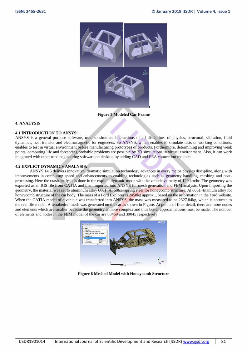
4.2 EXPLICT DYNAMICS ANALYSIS:
ANSYS 14.5 delivers innovative, dramatic simulation technology advances in every major physics discipline, along with
improvements in computing speed and enhancements to enabling technologies such as geometry handling, meshing and post-
processing. Here the crash analysis is done in the explicit dynamic mode with the vehicle velocity of 120 km/hr. The geometry was
exported as an IGS file from CATIA and then imported into ANSYS for mesh generation and FEM analysis. Upon importing the
geometry, the material was set to aluminum alloy 6061, Al 6061+spring steel for honeycomb structure, Al 6061+titanium alloy for
honeycomb structure of the car body. The mass of a Ford Explorer is 2458kg approx.., based on the information in the Ford website.
When the CATIA model of a vehicle was transferred into ANSYS, the mass was measured to be 2327.84kg, which is accurate to
the real life model. A tetrahedral mesh was generated on the car as shown in Figure. At points of finer detail, there are more nodes
and elements which are smaller because the geometry is more complex and thus better approximations must be made. The number
of elements and nodes in the FEM model of the car are 88469 and 39045 respectively.
Figure 6 Meshed Model with Honeycomb Structure

ISSN: 2455-2631 © January 2019 IJSDR | Volume 4, Issue 1
IJSDR1901014 International Journal of Scientific Development and Research (IJSDR) www.ijsdr.org 82
Figure 7 Meshed Model without Honeycomb Structure
4.4 BOUNDARY CONDITIONS:
The wall is rigid and fixed. The car frame of 120km/hr. speed is crashed to the rigid wall.
Figure 8 Boundary Conditions:
VELOCITY: 33.33M/S, TIME: 0.3S
5. RESULTS AND DISCUSSION
At speed of 120km/hr. the vehicle frame of without honeycomb and with honeycomb structure is crashed to a fixed rigid wall and
analyzed accordingly. The results of the analysis are shown in following figures.
5.1 AL 6061 FRAME WITHOUT HONEYCOMB STRUCTURE:
Figure 9 Von-Mises Stress of Al 6061 Frame without honeycomb Structure
Figure 10 Total Deformation of Al 6061 Frame without honeycomb Structure

ISSN: 2455-2631 © January 2019 IJSDR | Volume 4, Issue 1
IJSDR1901014 International Journal of Scientific Development and Research (IJSDR) www.ijsdr.org 83
Figure 11 Strain of Al 6061 Frame without Honeycomb Structure
Figure 12 Shear Stress of Al 6061 Frame Without Honeycomb Structure
5.2 Al 6061 FRAME WITH SPRING STEEL HONEYCOMB STRUCTURE:
Figure 13 Von-Mises Stress of Al 6061 Frame with Spring Steel Honeycomb Structure
Figure 14 Total Deformation of Al 6061 Frame with Spring Steel Honeycomb Structure
Figure 15 Strain of Al 6061 Frame with Spring Steel Honeycomb Structure

ISSN: 2455-2631 © January 2019 IJSDR | Volume 4, Issue 1
IJSDR1901014 International Journal of Scientific Development and Research (IJSDR) www.ijsdr.org 84
Figure 16 Shear Stress of Al 6061 Frame with Spring Steel Honeycomb Structure
5.3 AL 6061 FRAME WITH TITANIUM GRADE 3 HONEYCOMB STRUCTURE:
Figure 17 Von-Mises Stress of Al 6061 Frame with Titanium G3 Honeycomb Structure
Figure 18 Strain of Al 6061 Frame with Titanium G3 Honeycomb Structure
Figure 19 Total Deformation of Al 6061 Frame with Titanium G3 Honeycomb Structure
Figure 20 Shear Stress of Al 6061 Frame with Titanium G3 Honeycomb Structure

ISSN: 2455-2631 © January 2019 IJSDR | Volume 4, Issue 1
IJSDR1901014 International Journal of Scientific Development and Research (IJSDR) www.ijsdr.org 85
6. GRAPHS
The variations of stresses, strains, shear stresses and deformations between Al 6061 frame without honeycomb structure, Al 6061
frame with spring steel honeycomb structure and Al 6061 frame with titanium grade 3 honeycomb structure is shown below.
6.1 VON-MISES STRESS GRAPH
Graph 1 Von-Mises Stress Graph
6.2 TOTAL DEFORMATION GRAPH:
Graph 2 Total Deformation Graph
6.3 STRAIN GRAPH
Graph 3 Strain Graph
6.4 SHEAR STRESS GRAPH:
Graph 4 Shear Stress Graph

ISSN: 2455-2631 © January 2019 IJSDR | Volume 4, Issue 1
IJSDR1901014 International Journal of Scientific Development and Research (IJSDR) www.ijsdr.org 86
7. CONCLUSIONS
This Study was performed to determine the reliability of honeycomb structure with suitable material of vehicle body frame
when it was crashed. The frames with and without honeycomb structures were crash impact analyzed at 120 km/hr. speed of the
car.
The following conclusions are stated, based on the results obtained by analysis:
1. The installation of honeycomb structure to the vehicle frame shows better results, cause of better impact absorption than
the normal frame without honeycomb structure.
2. The vehicle frame with Spring Steel honeycomb structure shows lower equivalent stress than the Al 6061 frame but it has
higher stress values when compared with Titanium Grade 3 honeycomb structure.
3. The comparison of crashworthiness among Al 6061 vehicle frame, Al 6061 frame with Spring Steel honeycomb structure
and Al 6061 frame with Titanium Grade 3 honeycomb structure indicates Titanium Grade 3 honeycomb structure can absorb more
impact energy during the crashing process.
Under the specified crashing conditions, honeycomb cell width and cell wall thickness are proven to have significant effects on
impact absorption.
REFERENCES:
1. Yuxuan Li, Zhongqin, Lin, Aiqin Jiang, Guanlong Chen (2003): Use of high strengthsteel sheet for lightweight and crashworthy
car body< Materials and Design>24, 177- 182.
2. Chenga Z.Q, Thackera J.G, Pilkeya W.D, Hollowellb W.T, Reagana S.W, Sievekaa E.M (2001): Experiences in reverse-
engineering of a finite element automobile crash Model< Finite Elements in Analysis and Design> 37, 843–860.
3. J.G. Thacker, S.W. Reagan, J.A. Pellettiere, et.al, “Experiences during development of a dynamic crash response automobile
model”, Journal of Finite Element Analysis and Design 30 (1998) 279-295.
4. Z.Q. Chenga, J.G. Thackera, W.D. Pilkeya, W.T. Hollowellb, et.al, “Experiences in reverseengineering of a finite element
automobile crash model”, Journal of Finite Elements in Analysis and Design 37 (2001) 843–860.
5. Abdullatif K. Zaouk , Nabih E. Bedewi, Cing-Dao Kan, et.al, “Validation of a non-linear finite element vehicle model using
multiple impact data”, The George Washington University FHWA/NHTSA National Crash Analysis Center.
6. T. Belytschko, W.K. Liu and B. Moran, Nonlinear Finite Elements for Continua and Structures, 1st ed. U.S.: Wiley, New York,
2001.
7. Lin C. S., Chou K. D. and Yu C. C., Numerical simulation of vehicle crashes, Appl. Mech. Mat. 590, 135 (2014).
8. Kankariya N. and Sayyad F. B., Numerical simulation of bumper impact analysis and to improve design for crash worthiness,
Int. J. Engrg. Sci. 4(5), 58 (2015).
9. Sun T., Liu T., Shen I F. and Ma Y. S., Numerical simulation of car rash analysis based on distributed computational environment,
Conference Proceeding, 5th Int. Conference on Algorithms and Architectures for Parallel Processing, Pp 334-337, (2002).
10. Charles M. Farmer, Elisa R. Braver and Eric L. Mitter, Two vehicle side impact crashes: The relationship of vehicle and crash
characteristics to injury severity, A & d. Anal. and Prev, Vol. 29, No. 3, pp. 399-406, 1997