
a hybrid reconfigurable computer integrated manufacturing ...
Upload
independentCategory
view
1download
0
VLSI DESIGN2000, Vol. 10, No. 3, pp. 281-306Reprints available directly from the publisherPhotocopying permitted by license only
(C) 2000 OPA (Overseas Publishers Association) N.V.Published by license under
the Gordon and Breach SciencePublishers imprint.
Printed in Malaysia.
Model-integrated Tools for the Design of DynamicallyReconfigurable Systems
TED BAPTYa’ *, SANDEEP NEEMA JASON SCOTTJANOS SZTIPANOVITS and SAMEH ASAADb
alnstitute for Software Integrated Systems, Vanderbilt University," blBM T.J. Watson Research Center
(Received 1 February 1999; In finalform 1 October 1999)
Several classes of modern applications demand very high performance from systemswith minimal resources. These applications must also be flexible to operate in a rapidlychanging environment. Achieving high performance from limited resources demandsapplication-specific architectures, while flexibility requires architectural adaptationcapabilities. Reconfigurable computing devices promise to meet both needs. While thesedevices are currently available, the issue of how to design these systems is unresolved.This paper describes an environment for design capture, analysis and synthesis ofdynamically adaptive computing applications. The representation methodology is cap-tured in a Domain-Specific, Model-Integrated Computing framework. Formal analy-sis tools are integrated into the design flow to analyze the design space to produce aconstrained set of solutions. HW/SW Co-simulations verify the function of the sys-tem prior to implementation. Finally, a set of hardware and software subsystems aresynthesized to implement the multi-modal, dynamically adaptive application. The ap-plication executes under a runtime environment, which supports common executionsemantics across software and hardware. An application example is presented.
Keywords: Reconfigurable computing, FPGA, HW/SW co-design, HW/SW synthesis, FPGA,HW/SW co-simulation, dynamic reconfiguration, design environment, Model-IntegratedComputing
INTRODUCTION
Modern high-performance embedded systems,such as Automatic Target Recognition for Mis-siles or Dynamic Protocols Mobile Communica-tions devices, face many challenges. Power and
volume constraints limit hardware size. Accurate,high-performance algorithms involve massivecomputations. Systems must respond to demand-ing real-time specifications. In the past, customapplication-specific architectures have been usedto satisfy these demands.
*Address for correspondence: 400 24th Ave. S., Nashville, TN 37235. Tel.: 615-343-6709, Fax: 615-343-6702, e-mail: [email protected]
281

282 T. BAPTY et al.
This implementation approach, while effective,is expensive and relatively inflexible. As the worlddemands flexible, agile systems, the hardwiredapplication-specific architectures fail to meet re-quirements and become expensive to evolve andmaintain. As new algorithms are developed andnew hardware components become available, afixed, application specific architecture will requiresignificant redesign to assimilate the technologies.
Flexible systems must function in rapidly chang-ing environments, resulting in multiple modes ofoperation. On the other hand, efficient hardwarearchitectures must match algorithms to maximizeperformance and minimize resources. Structurallyadaptive, reconfigurable architectures can meetboth these needs, achieving high performance withchanging algorithms. Reconfigurable computingdevices, such as Field Programmable Gate Arraysallow the implementation of architectures thatchange in response to the changing environment.The field of Reconfigurable Computing is
rapidly advancing for scientific and Digital SignalProcessing applications [1- 3]. While today’s FieldProgrammable Gate Array technology showsgreat promise for implementing reconfigurablecomputational systems, their capabilities in certainareas (such as floating point arithmetic) cannotequal other technologies. For this reason, efficientsystem architectures must encompass a hetero-geneous mix of the most suitable technologies,along with the capability to dynamically restruc-ture the system architecture. The target systemsare built on a heterogeneous computing platform:including configurable hardware for computationand structural adaptation, and ASIC’s, general-purpose processors and DSPs for computation.The primary difficulty in this approach lies in sys-tem design. A designer must now maintain a set ofdiverse system architectures, which exist at differ-ent times in the system’s lifetime, and map thesearchitectures onto the same group of resources.The designers must manage the behavior of thesystem, determining the operational modes ofthe system, the rules for transitioning betweenoperational modes, and the functional properties
within each operational mode. In addition, the sys-tem must make efficient use of the resources,enabling the designer to minimize the envelope ofhardware required to support the union of alloperational modes. Current system design toolsare insufficient to manage this complexity.
State of the Art
The standard methods for the design of hardwaresystems use VHDL specifications with use of off-the-shelf components, such as libraries of para-meterized modules (LPM). This approach allowshierarchical design of large systems of a fixedstructure. The ability to specify multiple behav-ioral designs for a single entity allows a complexdesign space to be created. The choice of con-figuration of a system is largely a manual process.Using this approach to design a dynamicallyreconfigurable system would involve multipledesigns, with only a manual linkage between theindividual design modes. Custom runtime supportwould be added to manage the reconfiguration.This approach relies too much on manual, infor-mal interaction between modes. The pure VHDLapproach also provides little support for software/hardware interaction.The Ptolemy design environment [4] has
recently been extended to support reconfigurablehardware. Ptolemy is a comprehensive packagethat supports hardware/software codesign andheterogeneous architectures, spanning from micro-processors/DSP’s to FPGA’s to MEMS devices.It is unclear about the support for dynamic re-configuration design and runtime support.DEFACTO from USC/ISI [5] is a high-level
design tool for design and synthesis of recon-figurabl systems. In DEFACTO algorithms arespecified in a high-level programming languagesuch as C or MATLAB. The target architecture isspecified in an architecture description language.The target architecture is assumed to be consist-ing of a general-purpose processor (GPP) and anumber of configurable computing units (CCU).A parallelizing compiler partitions computation
MODEL-INTEGRATED TOOLS 283
and control among the GPP and the CCUs, andalso manages data storage and communications.The primary drawback of this approach is inthe use of sequential programming languages insystem specification. The effectiveness and scal-ability of programming languages in specifyinglarge, complex systems with parallel interactingcomponents is not determined. Runtime supportfor dynamic reconfiguration has not been ad-dressed. MATCH from NWU [6] employs a simi-lar approach, however, the system specificationsare solely in MATLAB.The DISC project at BYU [7] employs dynam-
ic reconfiguration to support demand-driveninstruction set modification. It can partially recon-figure an FPGA device to page custom application-specific instructions in and out of the device, ondemand. While the approach takes advantage ofthe partial reconfiguration of the instruction setto improve the functional density, it does notaddress the concerns in performing global systemlevel reconfiguration.The CHAMPION project at UTK [8] uses
KHOROS, a popular design tool for Image andSignal processing applications, to capture systemspecifications. These specifications are then auto-matically transformed, partitioned, and mappedto a distributed, heterogeneous resource network,consisting of DSPs and FPGAs. The objective ofthe partitioning process is to partition not onlyin space but also in time. However, it is not clearas to how the reconfiguration process will beorchestrated at runtime.
Several design approaches exist for low-leveldynamic reconfiguration. Some of these involveunique FPGA designs with multiple contexts al-lowing rapid switching between a limited numberof unique designs. Tools for high-level system de-sign using these components in a heterogeneoussystem have not yet appeared.
Target of this Paper
High-level design tools are being developed tocapture designs and to generate functional systems
as part of the DARPA Adaptive ComputingSystems Program. This paper describes a modelintegrated approach, to be used in the develop-ment of reconfigurable systems. There are manysignificant issues in the development process. Theapproach described here divides these issues intoseveral categories: (1) Representation and Captureof design information in terms of Models; (2)Analysis of the models for design/requirements/resource trade-off studies; (3) Synthesis of archi-tectures and executable systems directly from themodels; and (4) Runtime support environmentsto support efficient execution of the synthesizedreconfigurable systems.The Model-Integrated Computing (MIC) ap-
proach has been successfully applied to a diverseset of applications [9-14]. The general MICapproach involves creating a development en-vironment that is customized for a specific ap-plication domain. The resultant developmentenvironment is a multiple-aspect graphical editorthat directly supports the engineering conceptsrequired in the development process. Where sev-eral engineering disciplines are involved in systemdevelopment (e.g., Software, Hardware, DSPalgorithms, Systems Requirement Specification,etc.), the multiple-aspect nature of the approachallows different aspects to be customized forindividual disciplines. The graphical editor allowsconstruction of system Models, which capturethe specifications and components required alongwith their relationships. The Models form adatabase of design information that can then beused in system analysis, trade-off studies, andperformance estimation/simulation. These sameModels are used to synthesize the executing sys-tems. The synthesis process assumes a runtimeenvironment that hides the low-level hardware/software details from the synthesis process.
This paper will follow a logical progression indescribing the Model-Integrated Computing ap-proach for adaptive systems design. The firstsection will describe the rationale and implemen-tation of the design capture approach. The nextsection will give an overview of the current and
284 T. BAPTY et al.
planned analysis capabilities for design-space for transition), and the specifications for sys-exploration. The following sections will describe tem operation while in each operating mode.the system synthesis process and the runtime 2. Algorithm/Structural Modeling In this cate-environment architecture and implementation.Finally, we will show the implementation of a mis-sile Automatic Target Recognition applicationincorporating adaptive system behavior.
DESIGN REPRESENTATION
The customization of the Model-IntegratedComputing design environment involves a carefulanalysis of the needs of the design engineers, themethods and components used in the designs,and the target systems. For an environment tosuccessfully support the creation of systems, theconcepts used by designers must be faithfullyreproduced by the design environment. The criti-cal concepts required for dynamically adaptivecomputing architecture targets include the abilityto specify the dynamic behavior of the system
gory, potential algorithms are described. Thealgorithms define signal flow specifications tocompute required system outputs.
3. Resource Modeling The resource models de-scribe the hardware available for constructionof the system. This consists of physical proces-sors, devices, and the interconnection topology.
4. Constraint Specification These modeling cat-egories are augmented and linked togetherwith a Constraint framework. The Constraintsallow user-defined interactions to be specified,establishing linkages between properties inone category and objects in the same or an-other category. This modeling category alsoallows linkages between processing modulesin adjacent modes, to guide the transition ofstate information between computationalstructures.
(in terms of Modes), the function of the system Behavioral Modelsin each of these modes (inputs, outputs, andalgorithms), and the resources available. Each ofthese concepts can be modified by constraintsknown to the designer. Interactions between theconcepts are captured via references within themodels. The integration of multiple modeling con-cepts with the constraints and references arecritical in the control and optimization of the dy-namically adaptive behavior of the target system.
This section will describe the concepts devel-oped in the creation of the Adaptive ComputingSystems MIC environment.The Adaptive Computing Systems (ACS)
environment divides the design process into fourmajor categories:
Behavioral models capture the dynamic behaviorof the system and the potential interactions be-tween modes of operation Since the system will beoperating in discrete modes, with specific transi-tions between these modes, a Discrete Finite StateMachine formalism is used [15] (Fig. 1). Statesdefine operational modes of the system. Transi-tions define the potential conditions required forthe system to change modes and the end-state ofthe mode-shift. In order to manage system com-plexity, where the system may have many poten-tial operational modes, states have hierarchicaldecomposition.The event expression that triggers a mode
change is defined by the transition rules. A tran-1. Behavioral Modeling Dynamically adaptive sition rule is a Boolean equation composed of
systems must manage multiple system be- event variables. When the transition rule expres-haviors. In this first category, the adaptive sion is satisfied, system reconfiguration occurs.behavior is defined. The designer can specify Inputs to the transition rules, event variables, arethe operating modes of the system, the legal computed in the Algorithmic/Structural model-transitions between modes (and the conditions ing view described below. Event variables can

MODEL-INTEGRATED TOOLS 285
Object Hierarchy/ Example Model
Contains
FIGURE Behavioral model.
be directly sampled external signals or complexcomputational results.The behavioral modeling aspect is linked to
the Algorithmic/Structural aspect by References.A Reference allows the user to establish a point-er from the mode to a defined computationalalgorithm. Each mode references a model in theStructural Aspect that defines the processingalgorithm that is to be operational in that mode.The references allow a single algorithm to be ap-plied to any number of system states.The behavioral modeling aspect also allows the
specification of constraints, such as real-timerequirements and maximal runtime power usage.Maximal permitted system delays can be specifiedfor any pair of input and output ports on the al-gorithm model. Maximum power limits are speci-fied using attributes of the models. Constraintscapture the system performance requirements.
Algorithm/Structural Models
The structural modeling aspect is used to definethe processing algorithm structure. Algorithms aredescribed in terms of computational componentsand data interactions. To manage system com-plexity, a multi-level hierarchy is used to structurealgorithm definition.
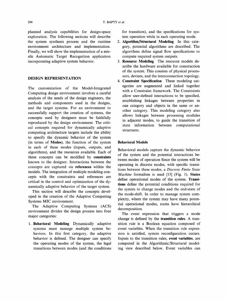
The algorithm is modeled as a dataflow struc-ture with the three classes of objects: compounds,primitives, and templates. The relationship betweenthese objects is captured in Figure 2.A primitive is the basic element, representing a
numerical processing operation. A primitive mapsdirectly to an implementation in either hardwareor software. Primitive objects are annotated withattributes, which capture measured performance,resource (memory) requirements, and other user-defined properties.A compound is an aggregation object that
contains primitives, other compounds, and/ortemplates. These components can be connectedwithin the compound to define the algorithmicdataflow. Compounds provide the hierarchy in thestructural description that is necessary for manag-ing the complexity of large designs.A Template object captures a design alternative.
The Template allows the specification of multiplealgorithm architecture alternatives for a given task.These design alternatives can be composed ofCompounds, Primitives, or other Templates, allow-ing hierarchies of design alternatives. The selectionamong the alternatives occurs at model interpreta-tion, allowing design flexibility to be specified.
Design alternatives allow the model of thesystem to capture a range of design possibilities.
286 T. BAPTY et al.
Object Hierarchy Example Model
FIGURE 2 Compound/primitive/template structure.
The large design space gives the tools the freedomto search for and select an implementation thatmeets the specified requirements and fits withinavailable resources. Each of these alternativemethods has different performance attributes anddifferent hardware requirements. The selectionof the best alternative depends not only on thehardware that is available, but also on whetherthe hardware is to be time-shared, and what hard-ware is already allocated to support the process-ing algorithms that are required for operationsin different modes.For the high-level designer, algorithm alterna-
tives allow a virtual separation of algorithm fromimplementation. Typical algorithm design requiresthe engineer/physicist to consider the hardwaredetails of the underlying architecture to achieve anefficient implementation. The ultimate effect isthat the resulting algorithm reflects the hardwarestructure. This practice leads to highly non-portable, technology-specific designs. System up-grades to use more modern technology requirea bottom-to-top redesign. Algorithm alternativesseparate the algorithm from the architecture, to
postpone the implementation decisions to a muchlater step in the design process, simplifying tech-nology migration efforts.
Resource Models
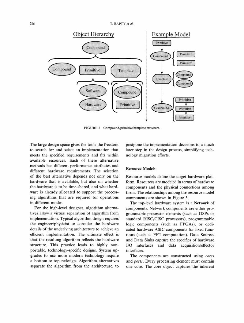
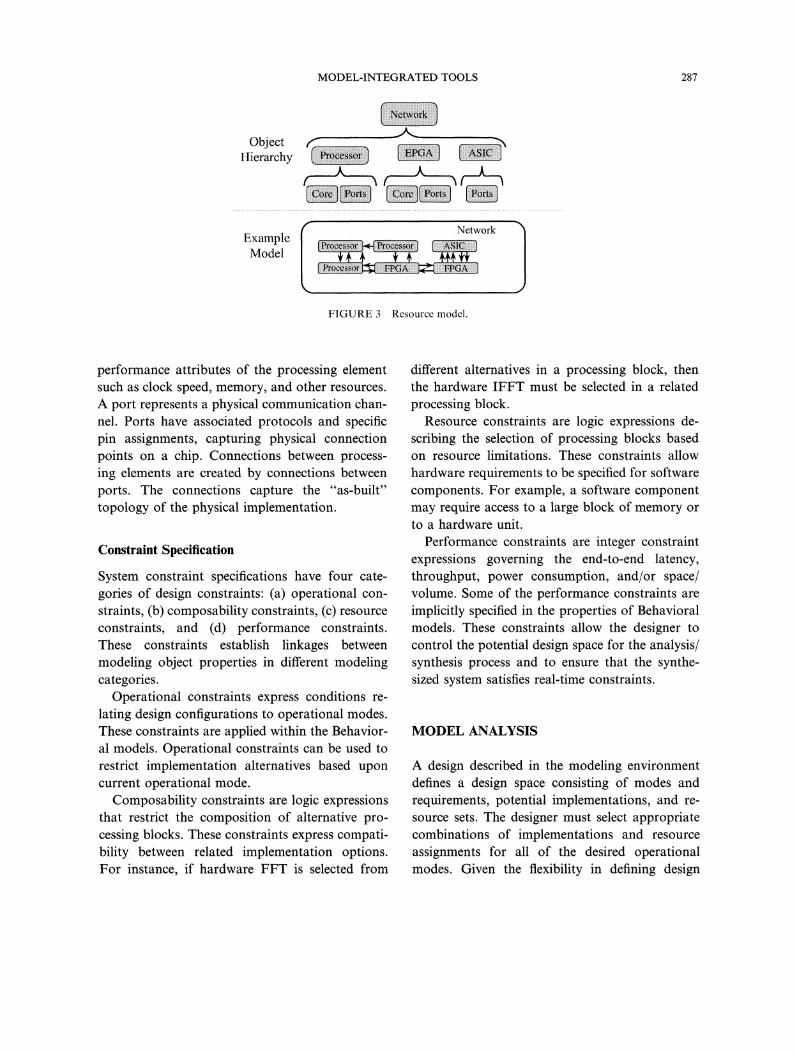
Resource models define the target hardware plat-form. Resources are modeled in terms of hardwarecomponents and the physical connections amongthem. The relationships among the resource modelcomponents are shown in Figure 3.The top-level hardware system is a Network of
components. Network components are either pro-grammable processor elements (such as DSPs orstandard RISC/CISC processors), programmablelogic components (such as FPGAs), or dedi-cated hardware ASIC components for fixed func-tions (such as FFT computation). Data Sourcesand Data Sinks capture the specifics of hardwareI/O interfaces and data acquisition/effectorinterfaces.The components are constructed using cores
and ports. Every processing element must containone core. The core object captures the inherent
MODEL-INTEGRATED TOOLS 287
ObjectHierarchy
NetworkExample
l’,iN(R)!iii’i!iiilNiili]Model i ’4’
FIGURE 3 Resource model.
performance attributes of the processing elementsuch as clock speed, memory, and other resources.A port represents a physical communication chan-nel. Ports have associated protocols and specificpin assignments, capturing physical connectionpoints on a chip. Connections between process-ing elements are created by connections betweenports. The connections capture the "as-built"topology of the physical implementation.
Constraint Specification
System constraint specifications have four cate-gories of design constraints: (a) operational con-straints, (b) composability constraints, (c) resourceconstraints, and (d) performance constraints.These constraints establish linkages betweenmodeling object properties in different modelingcategories.
Operational constraints express conditions re-lating design configurations to operational modes.These constraints are applied within the Behavior-al models. Operational constraints can be used torestrict implementation alternatives based uponcurrent operational mode.
Composability constraints are logic expressionsthat restrict the composition of alternative pro-cessing blocks. These constraints express compati-bility between related implementation options.For instance, if hardware FFT is selected from
different alternatives in a processing block, thenthe hardware IFFT must be selected in a relatedprocessing block.
Resource constraints are logic expressions de-scribing the selection of processing blocks basedon resource limitations. These constraints allowhardware requirements to be specified for softwarecomponents. For example, a software componentmay require access to a large block of memory orto a hardware unit.
Performance constraints are integer constraintexpressions governing the end-to-end latency,throughput, power consumption, and/or space/volume. Some of the performance constraints areimplicitly specified in the properties of Behavioralmodels. These constraints allow the designer tocontrol the potential design space for the analysis/synthesis process and to ensure that the synthe-sized system satisfies real-time constraints.
MODEL ANALYSIS
A design described in the modeling environmentdefines a design space consisting of modes andrequirements, potential implementations, and re-source sets. The designer must select appropriatecombinations of implementations and resourceassignments for all of the desired operationalmodes. Given the flexibility in defining design

288 T. BAPTY et al.
alternatives, this space can be extremely large(moderately sized design examples have defined aspace of 1024th). A designer cannot handle such alarge design space without sufficient tools. Thedesign space must be evaluated to find a set ofdesigns (mode configuration pairs) that best satisfythe design criteria.
There are a large number of conflicting designcriteria in reconfigurable systems. These criteriamust be applied across all of the system opera-tional modes. The processing needs of each ofthe system modes must be satisfied with a singleshared hardware platform. The analysis tools mustallow efficient exploration, navigation, and prun-ing of this space to select feasible hardware/software architectures for user-definable costfunctions such as weight, power, algorithmicaccuracy and flexibility. Given the size of thedesign space, and the complexity of the analysis, apowerful, scalable analytical method is required.
Constraint Satisfaction UsingSymbolic Methods
The design space exploration tool uses a symbolicmethod based on Ordered Binary Decision Dia-grams to represent, navigate, and prune the designspace. In this symbolic representation, sets/spacesare represented as a Boolean expression over themembers of the set. The members of the set areencoded as binary variables under a binary en-coding scheme. The principal benefit of the ap-proach is that it does not require enumeration ofthe set/space to perform operations.
Ordered Binary Decision Diagrams [16, 17] area canonical representation of logic functions, re-presenting Boolean functions as directed acyclicgraph in a memory-efficient format. The opera-tions over the Boolean functions are implementedas graph algorithms, thereby rendering "manip-ulation" of the space fast and efficient.With this symbolic formalism, the application
of logical constraints is relatively straightfor-ward. The user-defined logical constraints can be
represented as a Boolean expression over thecomponents of the design space. Constraint appli-cation is a conjunction of the constraint Booleanexpression with the Boolean expression that re-presents the design space. The resultant Booleanexpression represents the "constrained" designspace. Application of the integer arithmetic con-straints such as timing and power constraintsrequires further analysis (see [20] for details), how-ever the basic approach remains the same.While the approach scales well, in very large
design spaces with many constraints applied anexponential explosion of the OBDD’s can occur.To address this problem we support hierarchicalconstraint processing. The constraint processing isdone hierarchically with constraints scoped to aparticular level; i.e., constraints are applied tosub-spaces first, pruning them to the extent pos-sible and then progressing upwards in the hierar-chy. This technique is very effective when thereare a large number of constraints with a limitedscope. The technique is not effective when thereare many globally scoped constraints in a largedesign space.The constraints "prune" the design space by
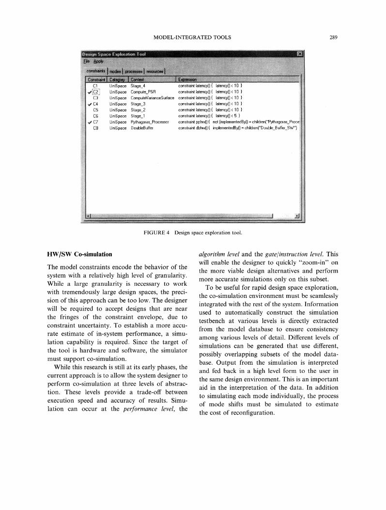
enforcing the requirements specified in the con-straint. These constraints can be iteratively appliedto the design space, with the goal of reducing the"1024th’’ to a more manageable, 10-1000 designalternatives. We have implemented the approachdescribed above in a design space exploration tool.Design engineers can iteratively apply constraintsand visualize the sensitivity of the design space tothe constraint. If a constraint is extremely tight, itsapplication can eliminate the design space alto-gether. In this case, the constraint can be releasedand other constraints can be applied instead. Theoutcome of the constraint satisfaction step is aset of design configurations much smaller than theoriginal design space. Figure 4 shows a screencapture of the design space exploration tool.When the design engineer is satisfied with thisconstrained design set, the design process contin-ues with simulation.
MODEL-INTEGRATED TOOLS 289
UniSpace Stage_4 constraint latency(){ latency(] 10UniSpace Compute_PSR constraint latency[I latency(] 10UniSpace ComputeVarianceSurface constraint latency(] latency[I 10UniSpace Stage_3 constraint latency(] latency[] 10
UniSpace Stage_2 constraint latency(] latency[] 10UniSpace Stage_.1 constraint latency[] latency(] 5U niSpace Pythagoras..Processor constraint pphw[] not [implementedBy[) children[’U hispace DoubleB uffer constraint dbhw[] implementedBy0 children["D ouble._B uffer_SW")
FIGURE 4 Design space exploration tool.
HW/SW Co-simulation
The model constraints encode the behavior of thesystem with a relatively high level of granularity.While a large granularity is necessary to workwith tremendously large design spaces, the preci-sion of this approach can be too low. The designerwill be required to accept designs that are nearthe fringes of the constraint envelope, due toconstraint uncertainty. To establish a more accu-rate estimate of in-system performance, a simu-lation capability is required. Since the target ofthe tool is hardware and software, the simulatormust support co-simulation.
While this research is still at its early phases, thecurrent approach is to allow the system designer toperform co-simulation at three levels of abstrac-tion. These levels provide a trade-off betweenexecution speed and accuracy of results. Simu-lation can occur at the performance level, the
algorithm level and the gate/instruction level. Thiswill enable the designer to quickly "zoom-in" onthe more viable design alternatives and performmore accurate simulations only on this subset.To be useful for rapid design space exploration,
the co-simulation environment must be seamlesslyintegrated with the rest of the system. Informationused to automatically construct the simulationtestbench at various levels is directly extractedfrom the model database to ensure consistencyamong various levels of detail. Different levels ofsimulations can be generated that use different,possibly overlapping subsets of the model data-base. Output from the simulation is interpretedand fed back in a high level form to the user inthe same design environment. This is an importantaid in the interpretation of the data. In additionto simulating each mode individually, the processof mode shifts must be simulated to estimatethe cost of reconfiguration.

290 T. BAPTY et al.
At the performance level, only the performanceof the structural model is simulated. Performanceattributes, such as latency and throughput, asso-ciated with processing primitives are used to con-struct a network of delay models for the system.Data flow is represented by tokens for fastersimulation via packages such as PML [18,21].No distinction of hardware versus software im-plementation is made at this level, however differ-ent components will have different performanceattributes. The output of this step will be anoverall performance assessment of the proposedalgorithm, flagging the critical components orhot spots of the system.At the algorithm level, the functional computa-
tion is simulated. The simulation does not includelow-level timing details, allowing the user toquickly verify the correct numerical functionalityof the system. Hardware functions are describedin VHDL and software functions are described inC and encapsulated in a VHDL-wrapper entity.A commercial VHDL simulator equipped with aforeign language interface will be the target formapping.The lowest level of abstraction is the gate/
instruction level co-simulation. At this level, a
HW/SW co-simulation environment is constructedthat models the system platform as described inthe resource models of Section 1. VHDL simula-tion models will be used to describe hardwarecomponents such as ASICs and FPGAs. Proc-essor models can range from full functionalmodels that mimic the internal architecture ofthe processor to simple bus functional models thatonly describe the interaction of the processorswith external components but do not mimic theinternal architecture [22]. The former is usuallytoo expensive in terms of execution speed andalso difficult to construct from scratch for com-plex processors. The latter approach is moresuitable for debugging the hardware portion butnot well suited for viewing software execution.An intermediate approach is to use an instructionset simulator (ISS) coupled with a bus functionalmodel (BFM) to model the processor, such as
described in [23]. The ISS will be used to simu-late software execution while the BFM willmimic the interaction with the external circuitry.Synchronization techniques between the ISSand the BFM are needed to keep the simulationrealistic.Numerical simulations can be performed at
the algorithmic level by generating Matlab code.A Matlab program is generated by selecting the"*.M" file representing each of the processing leafnodes. A combined Matlab program is generatedthat is a numerically accurate version of thee dataflow diagrams. With the proper Matlab functions,precision effects on numerical accuracy can bestudied. This capability is used to verify algorithmcorrectness of the data flow graph as drawn.
SYSTEM SYNTHESIS
By the time the user is ready for synthesis, the toolshave been used to capture system requirements,design information and alternatives, and theresources available for system implementation inthe form of Models. The constraints developedduring the design representation phase, have beenapplied to the design space to define a manage-able set of implementation alternatives. Expectedperformance has been estimated using the Co-Simulation tools, providing further assurance thatthe system will function to design specifications.The selected design alternatives must now betransformed to software and hardware for systemimplementation. We refer to this process as themodel interpretation/system synthesis phase.A model interpretation process generates hard-
ware architecture specifications, software modules,process/schedule tables, communications maps,synthesizable hardware specifications, and a run-time Configuration Manger for dynamic adap-tation to changing environments. The synthesisprocess attempts to optimize hardware/softwarearchitectures for user-definable cost functionssuch as weight, power, algorithmic accuracy andflexibility.
MODEL-INTEGRATED TOOLS 291
Configuration Manager Synthesis
At this point, the synthesis procedure can gener-ate the actual runtime artifacts. The state-basedbehavior of the system was defined in the BehaviorModels. From the behavioral models, a compactstate table is produced for the ConfigurationManager. The table contains next state equationsfor each operational mode. Interfaces to internaland external events are generated that provide thestate transition variables to the state machine.These tables and variable interfaces are createdin a form to allow direct execution by the config-uration manager. The Configuration Managercore library is compiled along with the compactstate table to generate an executable configura-tion manager. This configuration manager willbe executed on the system control processor.
Hardware Synthesis
For each configurable component (FPGA), adesign specification is generated. This designspecification includes a hardware design file foreach mode. The design for a component for eachmode is specified in structural VHDL. The VHDLdesign incorporates computational componentsfrom the design library. The library can containuser-defined VHDL behavioral/structural descrip-tions and vendor-supplied Intellectual Property(IP) modules. These modules are combined usingcomponents from a standard interface runtimelibrary. The interface library is a key componentof the Runtime Environment, described later.These interfaces connect computational compon-ents on the same chip with simple FIFO’s andasynchronous handshaking interfaces. When thecommunication must occur across chip bound-aries, or between software and hardware compon-ents, a set of more complex interface componentsare used. These interface components managethe physical hardware resources (pins and wires),buffer data, and multiplex multiple logical com-munications across a single set of wires. Whererequired, data format conversions are supplied.
These VHDL files are then compiled usingvendor-supplied/COTS VHDL compilers andpart-specific Place-and-Route tools. The result isa set of "bitfiles". One bitfile is generated for eachreconfigurable hardware device for each mode.Given the current state of the FPGA market,demand has not yet forced the vendors to pro-vide partially reconfigurable devices and supporttools (Xilinx Virtex parts are said to be partial-ly configurable, however the compiler/PPR toolshave not shown documentation and support forthis mode of operation. Earlier generations, theXC62xx family, were dynamically partially recon-figurable however support has been dropped forthese chips). For these reasons, we treat eachFPGA as an atomic part, configurable onlywith a full device reset. A partially reconfigurabledevice is simulated by aggregating multiple stand-ard fully reconfigurable FPGA’s. The approachproposed here will work for partially reconfigur-able devices when the tools become available. Inorder for this approach to work with standardcompilers/PPR tools, the vendor tools must pro-vide methods for floor planning to restrict logicaldesign components (i.e., all components within asingle mode) to non-overlapping, regions that coin-cide with legal chip reconfiguration boundaries.
Software Synthesis
For the general-purpose RISC/DSP components,a set of software implementations is generated.These implementations provide the informationneeded by the Runtime Environment to enact thedesired computational behavior. The RuntimeEnvironment requires several categories of designfiles:
Software Load Modules contain executablemodules that are downloaded to the processorsin the system. The system can generate acommon load module that contains the super-set of all executable functions (if memory is
sufficient) or it will generate a customized mod-ule for each of the processors in the system.

292 T. BAPTY et al.
The customized module is clearly more memory- (implemented on RISC and DSP processors),efficient, configurable hardware on FPGAs, and a mixReal-time schedules contain the list of processes of ASIC components.and their priorities. A unique schedule is gen- Low Overhead/High Performance The runtimeerated for each processor and for each mode of environment must minimize overhead, sinceoperation, overhead results in extra hardware require-Communication maps describe the information ments.flow between processes. These "streams" can Hard Real-Time The target systems have sig-perform communication between two modules nificant real-time constraints.on the same processor, or they can transport Reconfiguration The execution environmentdata across the network, through intermediateprocessors, and to a remote process anywherein the system.
Interfaces between software modules and hard-ware modules, and data sources/sinks are auto-matically inserted during the synthesis process.
must allow hardware and software resourcesto be reallocated dynamically. During reconfig-uration, the application data must remainconsistent and real-time constraints must besatisfied.
These issues must be addressed at multipleThese interfaces perform the management of levels. At the lowest level, the hardware must behardware interfaces, converting complex commu- capable of reconfiguration. Software-programma-nication protocols into simpler hardware com- ble components, such as DSP’s and RISC proces-patible protocols. The interfaces also multiplex sors, have excellent inherent hardware supportmultiple logical streams over a single physical for reconfiguration, since software has the abilityport and perform data conversion functions. It to change system function by changing memoryis the responsibility of the synthesis process to contents. Internal CPU hardware structures areensure that adequate bandwidth exists on each designed to restrict dangerous conditions thatport for the data flow through that port. could damage hardware. FPGA’s, on the other
These design files are processed into a set of hand, are an unrestricted collection of gates,object modules and tables for inclusion in the switches, and connectors. The safeguards builtconfiguration manager and for direct download into CPU’s do not exist and must be enforcedinto the array of parallel processors, manually. This protection must be provided byThe result of the synthesis and post processing a cooperation of the design process and the run-
is a complete executable system, ready for de- time infrastructure.ployment. The deployment is performed in con-cert with the Runtime Environment.
RUNTIME ENVIRONMENTFOR DYNAMIC RECONFIGURATION
The runtime environment must support imple-mentation platforms with the following attributes:
At a slightly higher level, the internal state ofsoftware must be managed under changing task-ing. Modern operating systems have evolved tosupport the flexible implementation of multipletasks, with dynamic addition and removal of taskson a single processor in the form of time-sharingand/or multitasking, and Real-time kernels allowtime critical tasks to be dynamically scheduledon a single processor. These kernels typically
Heterogeneity Optimizing the architecture for do not address the consistency of dynamic recon-
performance, size, and power requires that the figuration for distributed networks of tasks.most appropriate implementation techniques be Finally the issues of application-specific require-used. Implementations will require software ments must be addressed, to allow the peculiar

MODEL-INTEGRATED TOOLS 293
requirements of specific numerical performanceand timing to be achieved in an implementa-tion. Potential solutions to these issues with con-sistency are addressed in the next section.
Hardware/System ConsistencyDuring Reconfiguration
The runtime system must avoid operationaldefects during a reconfiguration event. Lack ofhardware consistency can have many negativeeffects, from temporary loss of performance in anoperational mode to hardware damage and total,permanent system malfunction. Typically, thesedeal with specific issues involving interfaces be-tween hardware processes and/or devices. Some ofthese defects are illustrated in Figure 5.
Port contention occurs when bi-directionalports are improperly initialized, a reconfigurationevent is not properly sequenced/synchronized, orif an improper/inconsistent design is implemented.In this case, two connected drivers are enabled.If resistance is sufficiently low, permanent physi-cal damage can occur to the circuits.Token loss or duplication results from incor-
rect initialization or a loss of communication in-tegrity. Tokens represent the status of empty orfull slots in a communication interface. An extratoken on the sender side can cause too much datato be sent, resulting in a FIFO overrun. A lost
token can effectively block a communication port,resulting in a system deadlock.
Device state maintenance refers to the control ofa complex external hardware device, such as anattached processor or storage device. In control-ling an external device, the controlling computa-tional component must maintain an accuraterepresentation of the device’s state. If a reconfi-guration occurs during a state transition withinthe device, or if the reconfiguration modifies thecomputational component’s representation of thedevice, there can be a state mismatch. This canresult in improper commands being sent to thedevice, or in a deadlock where both componentsare waiting on each other for triggering events.
These three examples show some of the poten-tial hazards that can occur when the hardwaredevice is improperly reconfigured. Runtime recon-figuration support must not permit any of theseconditions to occur.
Software/OS Consistency
Software issues can present a larger challenge todynamic system reconfiguration. While the hard-ware built into standard microprocessor devicesprotects against low-level hardware conflicts, thereare many more details that must be managed.Figure 6 below summarizes some of the potentialproblems from an improper reconfiguration.
Hardware Consistency After Reconfig
Port Contention
Device
Token Loss/Duplication
Controller
Device State Maintenance
FIGURE 5 Hardware reconfiguration problems: maintaining consistency.

294 T. BAPTY et al.
Software/OS Consistency on Reconfig
Reconfig
,/ han
eak
FIGURE 6 Software/OS reconfiguration problems: maintaining consistency.
The example shows an initial configurationof 3 processes (A, B and C) in the normal opera-tional state. A reconfiguration occurs, changingto a new configuration. The new configurationreplaces these process A with A’, C with C’ andremoves Process B altogether. The bottom half
online, the new filter is operating out of syncwith the original filter. A rapid switchoverwill create a discontinuity in both the signaland its first derivative. In a closed-loop systemthis might lead to strong transients in the con-trolled variable.
of the figure shows the new configuration, along 2. The system can fail to maintain real-timewith the potential errors.Memory leaks will adversely affect long-term
reliability. Task structure mismanagement resultsin extra tasks executed by the kernel, with aloss in performance. Messages in transit can bedelivered when the receiving process no longerexists, resulting in mis-matched messages andcommunication errors.
constraints during reconfiguration. If the re-
configuration cannot be completed in sufficienttime, deadlines will be sacrificed. In addition,the timebase can be shifted, resulting in a skewin system output period.
Runtime Reconfiguration Strategies
Application-level Consistency
At a higher level, the application’s requirementsand implementation details impose restrictionsin the reconfiguration process. Typically, theseattributes are highly application-specific. Twoexamples of consistency requirements are dis-played in Figure 7 below.
It is clear that reconfiguration support must bebuilt into the design approach, from the lowestlevels of the execution environment, to the high-level design/requirements capture tools. The extentof support is defined by the requirements of thetarget systems. The driving factors include howfast the system must reconfigure, whether inter-mediate states must be preserved (ApplicationSignal Continuity), and if timing must be .pre-
1. An external system may require signal output served. We now examine the potential reconfig-continuity and/or continuous first derivative uration strategies and their impact on systemproperties. In the example, which swaps filters capabilities.
MODEL-INTEGRATED TOOLS 295
lnit Reeonfig
[origReeonfig Event
T1 T2 T3 T4 T2’ T3’
Missed Deadlines Period Skew
FIGURE 7 Maintaining application consistency through reconfiguration.
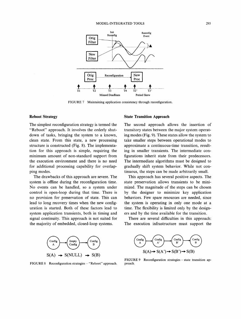
Reboot Strategy
The simplest reconfiguration strategy is termed the"Reboot" approach. It involves the orderly shut-down of tasks, bringing the system to a known,clean state. From this state, a new processingstructure is constructed (Fig. 8). The implementa-tion for this approach is simple, requiring theminimum amount of non-standard support fromthe execution environment and there is no needfor additional processing capability for overlap-ping modes.The drawbacks of this approach are severe. The
system is offline during the reconfiguration time.No events can be handled, so a system undercontrol is open-loop during that time. There isno provision for preservation of state. This canlead to long recovery times when the new config-uration is started. Both of these factors lead tosystem application transients, both in timing andsignal continuity. This approach is not suited forthe majority of embedded, closed-loop systems.
State Transition Approach
The second approach allows the insertion oftransitory states between the major system operat-ing modes (Fig. 9). These states allow the system totake smaller steps between operational modes toapproximate a continuous-time transition, result-ing in smaller transients. The intermediate con-figurations inherit state from their predecessors.The intermediate algorithms must be designed togradually shift system behavior. While not con-tinuous, the steps can be made arbitrarily small.
This approach has several positive aspects. Thestate preservation allows transients to be mini-mized. The magnitude of the steps can be chosenby the designer to minimize key applicationbehaviors. Few spare resources are needed, sincethe system is operating in only one mode at atime. The flexibility is limited only by the design-ers and by the time available for the transition.
There are several difficulties in this approach:The execution infrastructure must support the
FIGURE 8
S(A) -. S(NULL) . S(B)
Reconfiguration strategies "Reboot" approach.
S(A)- S(A’)- S(B’)" S(B)
FIGURE 9 Reconfiguration strategies- state transition ap-proach.

296 T. BAPTY et al.
rapid transition of processes and transition of thestates of the changing processes. The states mustbe mapped to the structures required by the nextstep, and installed with the new processingstructure. The computation of the mapping maybe complex.The design of intermediate states can be com-
plex, depending on the application. These transi-tory states depend both on the initial state andthe final state, the algorithm characteristics, andthe timing requirements. For smooth applicationtransitions, many intermediate states may berequired, leading to long transition times. (Itshould be noted that the application system isstill under control during transition, but proba-bly not the optimal algorithm.)
Parallel State Transition Approach
An extension of the State Transition approachallows the system to execute several modes inparallel. This has the same benefits as the statetransition approach with the added benefit ofbeing able to execute algorithms prior to use, inan offline mode. The state of the offline processcan be allowed to stabilize prior to impactingupon system performance. When transients havedisappeared, the system can be transitioned tothe new state (Fig. 10).
This approach has several benefits. The applica-tion-level transients can be minimized by properdesign. The downtime is minimal, as is the ope-ration of the system in a less-than-optimal con-figuration. Multiple states can be preserved, notforcing all information to be encoded in one
13nfig )S(A)-- S(A’)I[ S(B’)- S(B)
FIGURE lO Reconfiguration strategies "Paralleltion" approach.
execu-
format. This minimizes the impact of the designof one mode on another, thus simplifying design.
There are also several drawbacks. The under-lying runtime environment must support mech-anisms for rapid stepping between processes,the ability to execute multiple threads simul-taneously, and the combination of attributes fromthe parallel executing processes. System designis complicated by the need to design parallelstructures. (In some cases, the parallel approachallows design separability, simplifying matters.)The neces-sary computational resources are in-creased, due to the need to execute multiple par-allel processes.
Execution Environment Design
The previous sections assembled a set of require-ments for the execution environment. They alsopoint out some of the design complexities. Work-ing alone, the execution environment cannot solvethese problems. The overall system design ap-proach must coordinate from the top-level algo-rithm designers/system requirement and resourcespecifications down to the hardware/softwareimplementations. The top-level design issues havebeen discussed in terms of a domain-specificmodeling environment, where the environment istuned to reconfigurable system design. The Execu-tion Environment forms the infrastructure ontowhich these designs are projected.The Execution Environment must be designed
with an interface suitable for synthesis from aMIC-Generator approach. The concepts, proper-ties and interfaces of the runtime environmentmust be compatible with the design representationand synthesis approach. Capabilities and inter-faces should be tuned to simplify the generator.This requirement demands a simple, uniforminterface with a well-defined, consistent set ofsemantics that apply throughout the system.Since the system includes software, hardware,and interactions between parallel modules, acommon structure must map to a wide range ofcomponents.

MODEL-INTEGRATED TOOLS 297
The execution environment concepts have communication schedule, and memory manage-been driven by results from using tools developed ment [19]. Communications interfaces are sup-over the past several years. These tools are ported within the kernel, making cross-processorcurrently used to construct large-scale, parallel, connections invisible. Memory management isreal-time signal processing systems. The runtime integrated with the scheduler and communicationenvironment enabled development of CAD- subsystems, enabling (but not solving) the problemsDMAS systems, which are used by the USAF associated with dynamic reconfiguration. The ker-for turbine engine testing and NASA for SSME nel allows dynamic editing of the process table,monitoring and analysis [9, 19]. and of the communications maps. The properThe semantics of the execution environment sequencing of these operations, including task
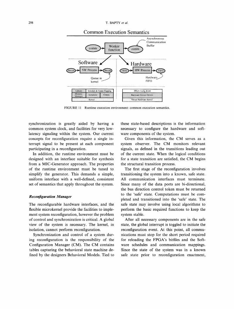
implement a large-grain-dataflow architecture, execution phases, is necessary for the avoidance ofThe Worker Function captures the tasks that reconfiguration problems. The current approachare performed by the system. Communication supports the "Reboot" approach directly, and willnodes capture the transfer of data between work- support the more advanced reconfiguration ap-ers. Computations can be described as a bipartite proaches with cooperation of the applicationgraph, where workers connect to Comm nodes, tasks.and Comm nodes connect to workers. At this The hardware execution environment supportslevel, there are no implied semantics of the the same operational semantics. The implemen-workers. The execution properties of workers tation, however, is much different. The Virtual(Data tokens produced/consumed per execution, Hardware Kernel exists as a concept used in thetiming of execution, etc.) are maintained at a system synthesis. The MIC Generator synthesizeshigher level. The semantics of the Comm units a set of VHDL structural codes, one for eachare asynchronous queues, configurable device multiplied by the number ofWhen the generic large-grain dataflow graphs operational modes. Hardware Processors are
are implemented, they must be mapped down to directly synthesized using predefined components.a physical implementation. The implementation Communications elements are selected from atakes the form of either software or hardware, library of interface types, based on the require-Software workers execute on a DSP or CPU, ments of the workers on either end, the requiredwhich we term Processes. Hardware workers are performance, and the available resources. Theeither implemented in reconfigurable hardware communication infrastructure works in coopera-(FPGA’s), or ASIC implementations, or combina- tion with the software communications, perform-tions of both. Software Processes and Hardware ing the signal buffering, and the necessary off-chipProcessors are logically equivalent, representing interfaces and data converters. The interfacefunctions on data. Processes/Processors are con- components are drawn from a library of modules.nected via logical Comm that must buffer, com- The modules implement a limited set of stand-municate, and match data formats. In software ardized communications protocols to transferimplementations, the Comm object is logical data between modules, and present data in theStream. implemented by the Kernel as a software format required by the destination processor. Asqueue in memory. In hardware, the Comm object the system is used for more applications, the setis implemented with registers and/or FIFO, or of interface types will grow in capability.simply wires (Fig. 11). Inherent in these interface components must beThe execution environment spans software and the capability to reconfigure. This involves strict
reconfigurable hardware. The software environ- synchronization mechanisms, methods for savingment consists of a simple, portable real-time kernel and restoring states, and facilities to allow func-with a run-time-configurable process schedule, tion and structure modification. Global system
298 T. BAPTY et al.
Common Execution SemanticsAsynchronousCommunicationBuffer
-; -e- -,- -eQueue in Hardwares/"
FIFO
[:ii!:i!i:iiiii!::ii!:i{ii!:iii:i:ilil Schedule & Comm Mapping FPGA Collfig RAM
FIGURE 11 Runtime execution environment: common execution semantics.
synchronization is greatly aided by having acommon system clock, and facilities for very low-latency signaling within the system. Our currentconcepts for reconfiguration require a single in-terrupt signal to be present at each componentparticipating in a reconfiguration.
In addition, the runtime environment must bedesigned with an interface suitable for synthesisfrom a MIC-Generator approach. The propertiesof the runtime environment must be tuned tosimplify the generator. This demands a simple,uniform interface with a well-defined, consistentset of semantics that apply throughout the system.
Reconfiguration Manager
The reconfigurable hardware interfaces, and theflexible microkernel provide the facilities to imple-ment system reconfiguration, however the problemof control and synchronization is critical. A globalview of the system is necessary. The kernel, inisolation, cannot perform reconfiguration.
Synchronization and control of a system dur-ing reconfiguration is the responsibility of theConfiguration Manager (CM). The CM containstables capturing the behavioral state machine de-fined by the designers Behavioral Models. Tied to
these state-based descriptions is the informationnecessary to configure the hardware and soft-ware components of the system.
Given this information, the CM serves as asystem observer. The CM monitors relevantsignals, as defined in the transitions leading outof the current state. When the logical conditionsfor a state transition are satisfied, the CM beginsthe structural transition process.The first stage of the reconfiguration involves
transitioning the system into a known, safe state.All communication interfaces must terminate.Since many of the data ports are bi-directional,the bus direction control token must be returnedto the ’safe’ state. Computations must be com-pleted and transitioned into the ’safe’ state. Thesafe state may involve using local algorithms toperform the basic required functions to keep thesystem stable.
After all necessary components are in the safestate, the global interrupt is toggled to initiate thereconfiguration event. At this point, all commu-nications must stop for the short period requiredfor reloading the FPGA’s bitfiles and the Soft-ware schedules and communication mappings.Since the state of the system was in a knownsafe state prior to reconfiguration enactment,
MODEL-INTEGRATED TOOLS 299
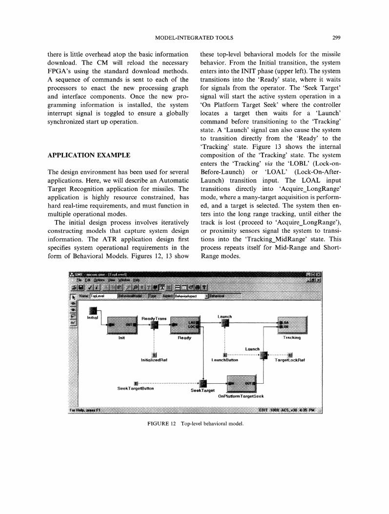
there is little overhead atop the basic information these top-level behavioral models for the missiledownload. The CM will reload the necessary behavior. From the Initial transition, the systemFPGA’s using the standard download methods, enters into the INIT phase (upper left). The systemA sequence of commands is sent to each of the transitions into the ’Ready’ state, where it waitsprocessors to enact the new processing graph for signals from the operator. The ’Seek Target’and interface components. Once the new pro- signal will start the active system operation in a
gramming information is installed, the system ’On Platform Target Seek’ where the controllerinterrupt signal is toggled to ensure a globally locates a target then waits for a ’Launch’synchronized start up operation, command before transitioning to the ’Tracking’
state. A ’Launch’ signal can also cause the systemto transition directly from the ’Ready’ to the’Tracking’ state. Figure 13 shows the internal
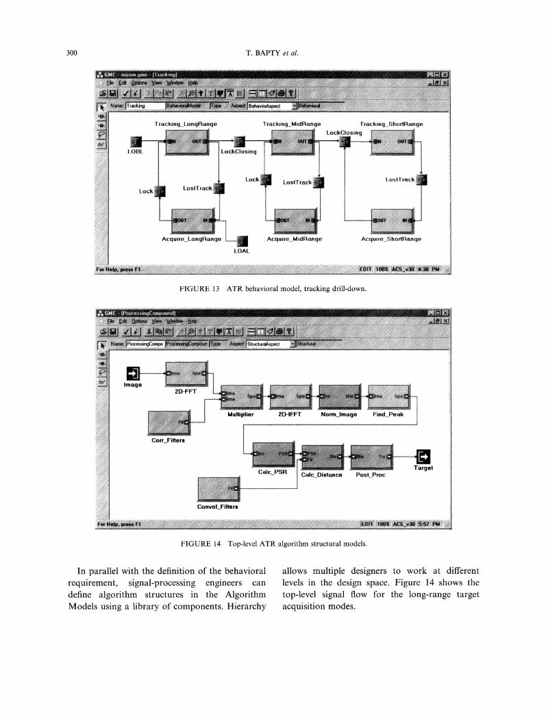
APPLICATION EXAMPLE composition of the ’Tracking’ state. The systementers the ’Tracking’ via the ’LOBL’ (Lock-on-
The design environment has been used for several Before-Launch) or ’LOAL’ (Lock-On-After-applications. Here, we will describe an Automatic Launch) transition input. The LOAL inputTarget Recognition application for missiles. The transitions directly into ’Acquire_LongRange’application is highly resource constrained, has mode, where a many-target acquisition is perform-hard real-time requirements, and must function in ed, and a target is selected. The system then en-
multiple operational modes, ters into the long range tracking, until either theThe initial design process involves iteratively track is lost (proceed to ’Acquire_LongRange’),
constructing models that capture system design or proximity sensors signal the system to transi-information. The ATR application design first tions into the ’Tracking_MidRange’ state. Thisspecifies system operational requirements in the process repeats itself for Mid-Range and Short-form of Behavioral Models. Figures 12, 13 show Range modes.
FIGURE 12 Top-level behavioral model.
300 T. BAPTY et al.
FIGURE 13 ATR behavioral model, tracking drill-down.
::::::::::::::::::::::: Celc_PSR Celc Distance Post Proc
FIGURE 14 Top-level ATR algorithm structural models.
In parallel with the definition of the behavioral allows multiple designers to work at different
requirement, signal-processing engineers can levels in the design space. Figure 14 shows thedefine algorithm structures in the Algorithm top-level signal flow for the long-range targetModels using a library of components. Hierarchy acquisition modes.

MODEL-INTEGRATED TOOLS 301
Correlation Filter BankFilter Bank
Input NormalizeFind
Calculate Peak-
Image Image M-’a Ratioto.Sidelobe
ComputeStandard
valueDeviation
(scalar) "1.Matdx Scalar
Compute _j Matdx ScalarSurface
__Substract
Mean Value(scalar)
FIGURE 15 ATR algorithm signal flow.
FIGURE 16 ATR hardware resource models.
These algorithms are described in a model attributes, such as benchmark results, into thehierarchy, using Compounds, Templates/Alterna- design environment’s component libraries. Intives, and Primitives. Where possible, libraries of the tracking algorithm, several componentspreexisting components are used. When new were developed for hardware in VHDL and soft-components are required, signal processing en- ware (C for the TMS320C40). Figure 15 showsgineers and hardware VHDL designers develop or the top level Algorithm Models of the ATRacquire modules and capture implementation application.
302 T. BAPTY et al.
DatalnputPortPythago as_Processor_SW
consbaint pphw[}not [implementedBy[} children["Pythagoas Processor HW’"
FIGURE !7 ATR constraint specifications.
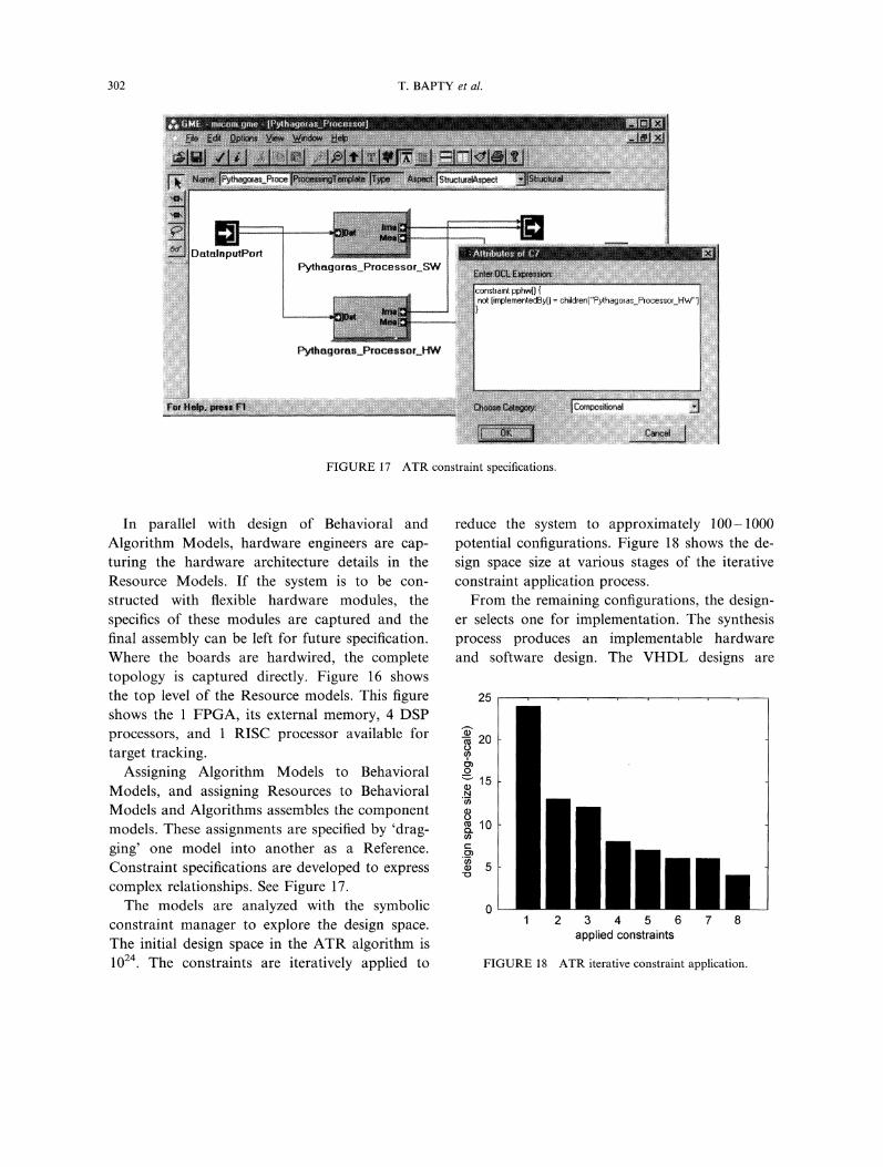
In parallel with design of Behavioral and reduce the system to approximately 100-1000Algorithm Models, hardware engineers are cap- potential configurations. Figure 18 shows the de-turing the hardware architecture details in the sign space size at various stages of the iterativeResource Models. If the system is to be con- constraint application process.structed with flexible hardware modules, the From the remaining configurations, the design-specifics of these modules are captured and the er selects one for implementation. The synthesisfinal assembly can be left for future specification, process produces an implementable hardwareWhere the boards are hardwired, the complete and software design. The VHDL designs aretopology is captured directly. Figure 16 showsthe top level of the Resource models. This figure 25
shows the FPGA, its external memory, 4 DSPprocessors, and RISC processor available for "- 0target tracking. ,
Assigning Algorithm Models to Behavioral_"-’15
Models, and assigning Resources to Behavioral ._Models and Algorithms assembles the component 8models. These assignments are specified by ’drag- 10
ging’ one model into another as a Reference. =Constraint specifications are developed to express 5
complex relationships. See Figure 17.The models are analyzed with the symbolic 0
constraint manager to explore the design space.The initial design space in the ATR algorithm is1024. The constraints are iteratively applied to
2 3 4 5 6 7 8applied constraints
FIGURE 18 ATR iterative constraint application.

MODEL-INTEGRATED TOOLS 303
FIGURE 19 ATR testbench display.
compiled using Synopsys for Xilinx and/or Max- tion, analysis and synthesis of systems will reducePlus2 for Altera. The software structures are design effort and increase system flexibility. Theprocessed via the native C compiler, underlying Runtime Environment, through the
Finally, the system is loaded and executed us- abstraction of hardware and software details,ing the configuration manager. Figure 19 shows presents a uniform architecture for system syn-a testbench configuration with ATR result im- thesis and application implementation.age and target selection crosshairs displayed on a This research adds to the state of the art byWindows-based user interface. Intermediate de- defining and implementing a cohesive design en-
signs can be instrumented with graphical displays vironment, where construction of dynamically ad-to view algorithm internal data structures, aptive systems with structural reconfiguration is
This discussion shows one path through the a primary concern. The combination of behavior,design process. Typically, the process involves algorithm, and resources provide the breadth toseveral iterations, to optimize the algorithm per- represent the design of a flexible reconfigurableformance, resource utilization, and system func- system. The ability to define a broad design spacetional behavior, permits the synthesis tools to optimize target sys-
tems. The extensive set of constraints and modelreferences give the designer control over the syn-
CONCLUSIONS thesis process and allow user-guided pruning oflarge design spaces. The design space explora-
The system described within this paper represents tion tools use scalable OBDD’s to permit mana-an ambitious set of goals for a design tool. The gement of large design spaces, allowing rapiddesign environment is a comprehensive approach iteration over a wide design space. The integra-to building heterogeneous, real-time, resource- tion of performance simulation allows users tolimited, dynamically adaptive systems. The Mod- receive feedback directly, in the native model-el-Integrated approach has been designed to based design concepts. Finally, a unified hard-support the many aspects and disciplines of ware/software runtime environment allows theembedded systems design. The flexible representa- hardware and software to be treated as conceptual
304 T. BAPTY et al.
equivalents. Since the abstraction layers are design alternatives within these hierarchical Mod-handled at design-time, the runtime efficiency els will allow the efficiency of these high-levelimpact is minimized, functions to be maintained near the level of a
There are some limitations in the presented hand-coded implementation.approach. A dataflow model was chosen for There are still many major research challengesrepresentation and execution in the runtime to be addressed before achieving a fully functional,environment. While many data-intensive applica- robust design tool. These issues are:tions fit this paradigm, many control-orientedapplications cannot be modeled or executedefficiently on a dataflow architecture. The OBDDapproach to design space exploration typicallyscales gracefully for large problems, however theyare sensitive to variable ordering. Some orderingsresult in an exponential explosion in number ofOBDD nodes. While the end-result of the con-straint based pruning is independent of the orderof constraint application, the sizes and executiontimes of the intermediate steps is sensitive to theorder in which the constraints are applied. Also,the current runtime environment supports partialreconfiguration only in software and simulatespartial hardware reconfiguration with multipleFPGA’s. Partial hardware reconfiguration in thisdesign environment awaits devices and vendortools that fully support these features.The prototype tool set has been applied to
several small-to-medium-sized design projectswith significant success. While metrics have notyet been collected, experience indicates high de-signer efficiency. The tools are still research-quality and several key components are in theprocess of design and implementation.The design approach leads to flexible solutions.
The implementation architecture is decoupledfrom the algorithm. Hardware is modeled as aset of generalized resources. These two factorscombine to support device technology evolution,with changes required only to the resource models.The high-level approach will produce greater
design efficiencies and code/component reuse.Given an extensive set of component libraries,complex systems can be assembled rapidly. Thecomponent libraries can be extended and special-
1. Optimization The current approach involvesdefining a very large design space and usingconstraint methods to extract a set of potentialdesign solutions. The process relies on theengineer to manipulate a complex, interrelatedconstraint network. This process should beassisted by the design environment. Simpletools are planned that show a sensitivityanalysis of design space vs. user-defined con-straints. This will help to guide the designerto the appropriate constraints that maximizesystem performance. Taking this a step further,optimization procedures can be implementedto automate the manipulation of system para-meters and constraints. In such a non-linear,discretized space, no guarantee of optimizationconvergence is possible.
2. Methods for assessing the transient upsets thatcan occur during a structural reconfigurationare needed. These transient assessment tools areneeded for predicting both numerical resultsand for the real-time behavior during recon-figuration.
3. Procedures for rapidly incorporating vendor IPinto libraries must be available to ensure thatup-to-date components are available for thedesign. This also contributes to the ease of up-dating the technologies in the target platform.
4. Significant effort is required to transition thetools from a research prototype to a commer-cial quality, accepted design methodologyand design environment.
Acknowledgement
ized to very high-level functions by the construc- This work has been supported by DARPA/ITOtion of hierarchical models. The availability of under project DABTII3-97-C-0020.

MODEL-INTEGRATED TOOLS 305
References
[1] Villasenor, J. and Mangione- Smith, W., "ConfigurableComputing", Scientific American, June, 1997.
[2] Arnold, J., Buell, D. and Davis, E., "Splash 2", Pro-ceedings of the 4th Annual ACM Symposium on ParallelAlgorithms and Architectures, June, 1992.
[3] David R. Martinez, "Real-time Embedded Signal Pro-cessing", IEEE Signal Processing Magazine, September,1998.
[4] Davis, J., Goel, M., Hylands, C., Kienhuis, B., Lee, E.,Liu, J., Liu, X., Muliadi, L., Neuendorffer, S., Reekie, J.,Smyth, N., Tsay, J. and Xiong, Y., "Overview of thePtolemy Project", ERL Technical Report UCB/ERL No.M99/37, Dept. EECS, University of California, Berkeley,CA 947 20, July, 1999.
[5] Bondalapati, K., Diniz, P., Duncan, P., Granacki, J.,Hall, M., Jain, R. and Zeigler, H. (1999). "DEFACTO:A Design Environment for Adaptive Computing Tech-nology", In: Proceedings of the 6th Reconfigurable Ar-chitectures Workshop (RA W’99), Springer-Verlag.
[6] Banerjee, P., Shenoy, N., Choudhary, A., Hauck, S.,Bachmann, C., Chang, M., Haldar, M., Joisha, P., Jones,A., Kanhare, A., Nayak, A., Periyacheri, S. and Walkden,M., "MATCH: A MATLAB Compiler for ConfigtirableComputing", Technical Report, Center for Parallel andDistributed Computing, Northwestern University, Aug.1999, CPDC-TR-9908-013. (Also Submitted to the IEEEComputer Magazine, 1999).
[7] Writhlin, M. and Hutchings, B. (1995). "DISC: Thedynamic instruction set computer", FieM ProgrammableGate Arrays (FPGAs) for Fast Board Development andReconfigurable Computing, John Schewel, Ed., Proc.SPIE, 2607, 92-103.
[8] Bouldin, D., "CHAMPION: A Software Design Environ-ment for Adaptive Computing Systems", http://microsy-s6.engr.utk.edu/bouldin/darpa/
[9] Bapty, T., Ledeczi, A., Davis, J., Abbott, B., Hayes, T.and Tibbals, T. (1996). "Turbine Engine DiagnosticsUsing a Parallel Signal Processor", Joint Technology Show-case on Integrated Monitoring, Diagnostics, and FailurePrevention, Mobile, AL.
[10] Karsai, G., Sztipanovits, J., Padalkar, S. and DeCaria, F.,"Model-embedded On-line Problem Solving Environmentfor Chemical Engineering", Proceedings of the Interna-tional Conference on Engineering of Complex ComputerSystems, Ft. Lauderdale, Florida, Nov. 6-10, 1995.
[11] Long, E., Misra, A. and Sztipanovits, J., "SaturnSite Production Flow (SSPF): Accomplishments andChallenges", Proceedings of the Engineering of ComputerBased Systems, Maale Hachamisha, Israel, AL, March,1998.
[12] Davis, J., Scott, J., Sztipanovits, J., Karsai, G. andMartinez, M., "Integrated Analysis Environment for HighImpact Systems," Proceedings of the Engineering ofComputer Based Systems, Jerusalem, Israel, April, 1998.
[13] Bapty, T. and Sztipanovits, J., "Model-Based Engineeringof Large-Scale Real-Time Systems", Proceedings of theEngineering of Computer Based Systems (ECBS) Confer-ence, Montery, CA, March, 1997.
[14] Carnes, J. R. and Misra, A., "Model-Integrated Toolsetfor Fault Detection, Isolation and Recovery (FDIR)",Proceedings of International Conference and Workshop onEngineering of Computer Based Systems, Friedrichshafen,Germany, AL, March 11-15, 1996.
[15] Harel, D. (1987). "StateCharts: A Visual Formalism forComplex Systems", Science of Computer Programming, 8,231-278.
[16] Bryant, R. E., "Symbolic Boolean Manipulation withOrdered Binary Decision Diagrams", Technical ReportCMU-CS-92-160, School of Computer Science, CarnegieMellon University, June, 1992.
[17] Bryant, R. E. (1986). "Graph-based Algorithms forBoolean Function Manipulation", IEEE Transactions onComputers, C35(8).
[18] Kumar, S. and Rose, F., "Integrated Simulation of Per-formance Models and Behavioral Models", Proceedings ofthe Fall 1996 VIUF, pp. 185-194, Durham, NC, October,1996.
[19] Bapty, T. and Abbott, B., "Portable Kernel for High-levelSynthesis of Complex DSP-Systems", Proceedings of thethe International Conference on Signal Processing Applica-tions and Technology, Boston, MA, May, 1995.
[20] Sandeep Neema (1999). "Constraint based System Syn-thesis", Technical Report, Department of Electrical andComputer Engineering, Vanderbilt University.
[21] Hein, C. and Nasoff, D., "VHDL-based PerformanceModeling and Virtual Prototyping", Proceedings ofthe 2ndAnnual RASSP Conference, Arlington, VA, July, 1995.
[22] James Rowson, "Hardware/Software cosimulation",Proceedings of the 31st Design Automation Conference,pp. 439-440, San Diego, CA, June, 1994.
[23] Russel Klein, "Miami: A Hardware-Software cosimula-tion Environment", Proceedings of the 7th IEEE Interna-tional Workshop on Rapid Systems Prototyping, June,1996.
Authors’ Biographies
Ted Bapty is currently working in on tools forAdaptive Computing for dynamically reconfigur-able embedded computing applications, on Model-Based Tools for engineering system design, and ontools and systems for parallel, embedded systems.He is a member of IEEE, the IEEE ComputerSociety, and serves the Engineering of ComputerBased Systems Technical Committee. He is theDirector of the Institute for Software IntegratedSystems, Vanderbilt University, He can be reachedat: [email protected]
Sandeep Neema’s research interests includeReonfigurable Computing, Symbolic ConstraintProcessing and Real-time Embedded SystemsProgramming. He is a research assistant at theInstitute for Software Integrated Systems, Van-derbilt University. Nashville, USA, working onhis doctoral research. He can be reached at:
[email protected] Scott’s research interests include recon-
figurabl systems, and verification of real-time

306 T. BAPTY et al.
systems using symbolic model checking. Jason the 1999 IEEE Engineering of Computer BasedScott is a research assistant currently working Systems Conference. He is author, of over 130on his doctoral research at the Institute for Soft- technical publications. Dr. Sctipanovits is cur-ware Integrated Systems, Vanderbilt University, rently a Program Manager at DARPA. He can
Nashville, TN. He can be reached at" jscott@ be reached at: [email protected] Sameh Asaad works in the area of simulation
Janos Sztipanovits works in the area of Model- of hardware-software systems. He is currentlyIntegrated Computing for design and evolution of a researcher at IBM T. J. Watson Researchcomplex computer-based systems. He has chaired Facility and a graduate student at Vanderbiltseveral conferences and workshops, including University.
Copyright © 2022 FDOKUMEN