Model EX645B70 4-20 MA SENSOR Installation and ...
69
Model EX645B70 4-20 MA SENSOR Installation and Operating Manual For assistance with the operation of this product, contact PCB Piezotronics, Inc. Toll-free: 800-959-4464 24-hour SensorLine: 716-684-0001 Fax: 716-684-3823 E-mail: [email protected] Web: www.imi-sensors.com
-
Upload
khangminh22 -
Category
Documents
-
view
2 -
download
0
Transcript of Model EX645B70 4-20 MA SENSOR Installation and ...
Model EX645B70
4-20 MA SENSOR
Installation and Operating Manual
For assistance with the operation of this product,contact PCB Piezotronics, Inc.
Toll-free: 800-959-446424-hour SensorLine: 716-684-0001
Fax: 716-684-3823E-mail: [email protected]
Web: www.imi-sensors.com
Manual 21354 Rev E ECN 50523
Repair and Maintenance
PCB guarantees Total Customer Satisfaction through its “Lifetime Warranty Plus” on all Platinum Stock Products sold by PCB and through its limited warranties on all other PCB Stock, Standard and Special products. Due to the sophisticated nature of our sensors and associated instrumentation, field servicing and repair is not recommended and, if attempted, will void the factory warranty. Beyond routine calibration and battery replacements where applicable, our products require no user maintenance. Clean electrical connectors, housings, and mounting surfaces with solutions and techniques that will not harm the material of construction. Observe caution when using liquids near devices that are not hermetically sealed. Such devices should only be wiped with a dampened cloth—never saturated or submerged.
In the event that equipment becomes damaged or ceases to operate, our Application Engineers are here to support your troubleshooting efforts 24 hours a day, 7 days a week. Call or email with model and serial number as well as a brief description of the problem.
Calibration
Routine calibration of sensors and associated instrumentation is necessary to maintain measurement accuracy. We recommend calibrating on an annual basis, after exposure to any extreme environmental influence, or prior to any critical test.
PCB Piezotronics is an ISO-9001 certified company whose calibration services are accredited by A2LA to ISO/IEC 17025, with full traceability to SI through N.I.S.T. In addition to our standard calibration services, we also offer specialized tests, including: sensitivity at elevated or cryogenic temperatures, phase response, extended high or low frequency response, extended range, leak testing, hydrostatic pressure testing, and others. For more information, contact your local PCB Piezotronics distributor, sales representative, or factory customer service representative.
Returning Equipment If factory repair is required, our representatives will provide you with a Return Material Authorization (RMA) number, which we use to reference any information you have already provided and expedite the repair process. This number should be clearly marked on the outside of all returned package(s) and on any packing list(s) accompanying the shipment.
Contact Information
PCB Piezotronics, Inc.
3425 Walden Ave.
Depew, NY14043 USA
Toll-free: (800) 828-8840 24-hour SensorLine: (716) 684-0001 General inquiries: [email protected] Repair inquiries: [email protected]
For a complete list of distributors, global offices and sales representatives, visit our website, www.pcb.com.
Safety Considerations
This product is intended for use by qualified personnel who recognize shock hazards and are familiar with the precautions required to avoid injury. While our equipment is designed with user safety in mind, the protection provided by the equipment may be impaired if equipment is used in a manner not specified by this manual.
Discontinue use and contact our 24-Hour Sensorline if:
Assistance is needed to safely operate equipment
Damage is visible or suspected
Equipment fails or malfunctions
For complete equipment ratings, refer to the enclosed specification sheet for your product.
Definition of Terms and Symbols
The following symbols may be used in this manual:
DANGER Indicates an immediate hazardous situation, which, if not avoided, may result in death or serious injury.
Manual 21354 Rev E ECN 50523
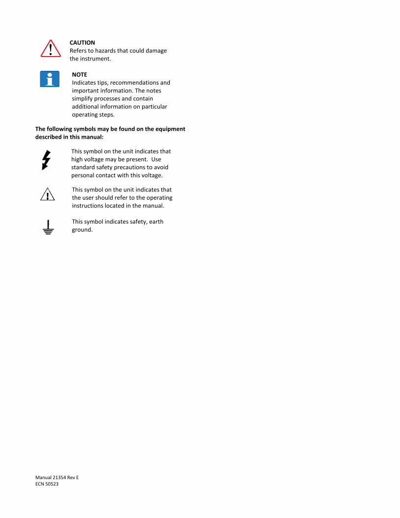
CAUTION Refers to hazards that could damage the instrument.
NOTE Indicates tips, recommendations and important information. The notes simplify processes and contain additional information on particular operating steps.
The following symbols may be found on the equipment described in this manual:
This symbol on the unit indicates that high voltage may be present. Use standard safety precautions to avoid personal contact with this voltage.
This symbol on the unit indicates that the user should refer to the operating instructions located in the manual.
This symbol indicates safety, earth ground.

Manual 21354 Rev E ECN 50523
PCB工业监视和测量设备 - 中国RoHS2公布表
PCB Industrial Monitoring and Measuring Equipment - China RoHS 2 Disclosure Table
部件名称
有害物质
铅 (Pb) 汞
(Hg)
镉
(Cd) 六价铬 (Cr(VI)) 多溴联苯 (PBB) 多溴二苯醚 (PBDE)
住房 O O O O O O
PCB板 X O O O O O
电气连接器 O O O O O O
压电晶体 X O O O O O
环氧 O O O O O O
铁氟龙 O O O O O O
电子 O O O O O O
厚膜基板 O O X O O O
电线 O O O O O O
电缆 X O O O O O
塑料 O O O O O O
焊接 X O O O O O
铜合金/黄铜 X O O O O O
本表格依据 SJ/T 11364 的规定编制。
O: 表示该有害物质在该部件所有均质材料中的含量均在 GB/T 26572 规定的限量要求以下。
X: 表示该有害物质至少在该部件的某一均质材料中的含量超出 GB/T 26572 规定的限量要求。
铅是欧洲RoHS指令2011/65/ EU附件三和附件四目前由于允许的豁免。
CHINA RoHS COMPLIANCE

Manual 21354 Rev E ECN 50523
Component Name Hazardous Substances
Lead (Pb) Mercury (Hg) Cadmium (Cd) Chromium VI Compounds (Cr(VI))
Polybrominated Biphenyls (PBB)
Polybrominated Diphenyl Ethers (PBDE)
Housing O O O O O O
PCB Board X O O O O O
Electrical Connectors O O O O O O
Piezoelectric Crystals X O O O O O
Epoxy O O O O O O
Teflon O O O O O O
Electronics O O O O O O
Thick Film Substrate O O X O O O
Wires O O O O O O
Cables X O O O O O
Plastic O O O O O O
Solder X O O O O O
Copper Alloy/Brass X O O O O O
This table is prepared in accordance with the provisions of SJ/T 11364.
O: Indicates that said hazardous substance contained in all of the homogeneous materials for this part is below the limit requirement of GB/T 26572.
X: Indicates that said hazardous substance contained in at least one of the homogeneous materials for this part is above the limit requirement of GB/T 26572. Lead is present due to allowed exemption in Annex III or Annex IV of the European RoHS Directive 2011/65/EU.

SE
NS
OR
S A
ND
INS
TR
UM
EN
TA
TIO
N F
OR
MA
CH
INE
CO
ND
ITIO
N M
ON
ITO
RIN
G
Model 640/641/645/646 B7 Series Industrial 4-20mA Sensor
Operating Guide with Enclosed Warranty Information
3425 Walden Avenue, Depew, New York 14043-2495
Phone (716) 684-0003
Fax (716) 684-3823
Toll Free Line 1-800-959-4IMI
MANUAL NUMBER: 28077 MANUAL REVISION: B
ECN NUMBER: 42851
PAGE 2
SE
NS
OR
S A
ND
INS
TR
UM
EN
TA
TIO
N F
OR
MA
CH
INE
CO
ND
ITIO
N M
ON
ITO
RIN
G
Table of Contents
Introduction ...................................................................................................................... Page 3
General Features
Dimension Drawing ......................................................................................................... Page 4
Operation and Wiring ...................................................................................................... Page 5
Standard Wiring Taking Measurements RV Option TO Option EP Option
ESD Sensitivity ............................................................................................................... Page 10
Warranty/Servicing
Warranty, Service & Return Procedure .......................................................................... Page 11
Customer Service ........................................................................................................... Page 12

PAGE 3
SE
NS
OR
S A
ND
INS
TR
UM
EN
TA
TIO
N F
OR
MA
CH
INE
CO
ND
ITIO
N M
ON
ITO
RIN
G
Introduction
The Model 640/641/645/646 B7 Series Industrial 4-20mA Sensors combine the capabilities of a piezoelectric
vibration sensor and a 4-20mA vibration transmitter. The sensor outputs a 4-20mA signal that is proportional to
the overall velocity or acceleration of the machinery. Ideal for monitoring the vibration of process equipment such
as fans, motors and pumps, the output of the sensor is used for process control or predictive maintenance. There
are many options in this series. Please refer to specific specification sheets for further details.
General Features
Imbedded Piezoelectric Accelerometer for improved accuracy and frequency response.
Vibration range can be in Acceleration or Velocity.
Allows for continuous vibration monitoring of critical applications.
Reduces sophisticated vibration analysis requirements.
RV (Raw Vibration) option for conducting frequency analysis and machinery diagnostics.
TO (Temperature Output) option via an independent 4-20mA loop.
EP option includes an Explosion Proof capped elbow.
Readily interfaces to existing process control and predictive maintenance equipment.
Rugged stainless steel construction for applications in harsh environments.
Flexible design allows for various custom requirements.
PAGE 4
SE
NS
OR
S A
ND
INS
TR
UM
EN
TA
TIO
N F
OR
MA
CH
INE
CO
ND
ITIO
N M
ON
ITO
RIN
G
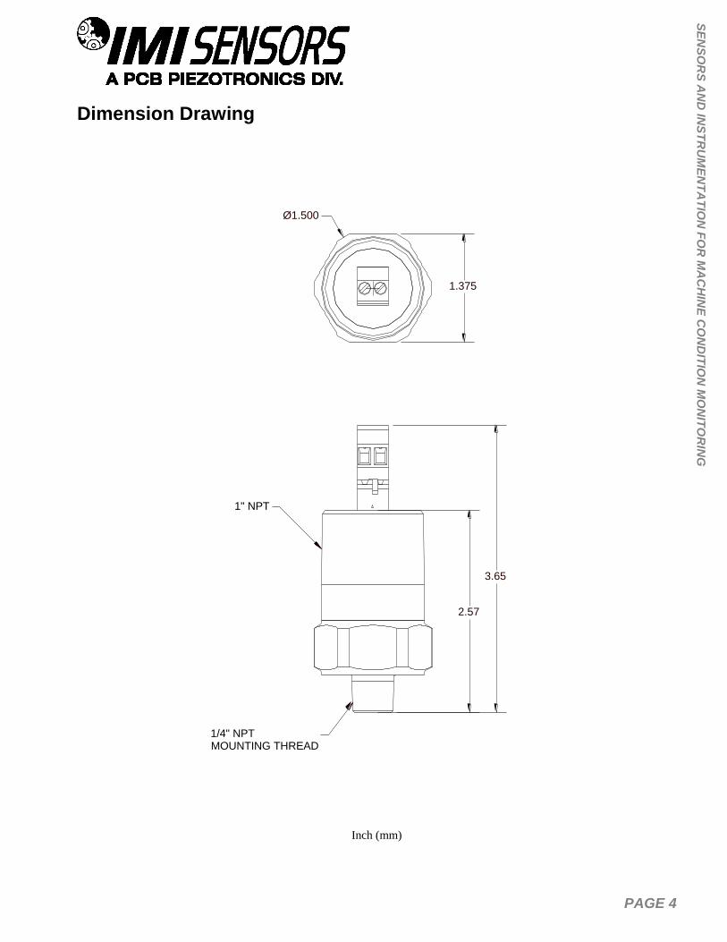
Dimension Drawing
Inch (mm)
1" NPT
2.57
1/4" NPTMOUNTING THREAD
3.65
Ø1.500
1.375

PAGE 5
SE
NS
OR
S A
ND
INS
TR
UM
EN
TA
TIO
N F
OR
MA
CH
INE
CO
ND
ITIO
N M
ON
ITO
RIN
G
Operation and Wiring
Standard Wiring
The Model 640/641/645/646 B7 Series uses plug-in type screw terminal connectors for all input and output
connections and operate from a standard 2-wire, 4-20mA loop. Attach the positive (+) input from the power supply
to Pin 2 and the negative (-) input from the power supply to Pin 3.
Figure 1 – wiring: standard connection
Figure 2 – wiring: loop powered Figure 3 – wiring: loop powered/DC source
If using a standard DC power supply, install either an ammeter and/or load resistor in line with the return
connection Pin 3.
The resistor will generate a DC voltage that is proportional to current by:
V = IR
If R = 500 and I = 6mA, then V = 3Vdc
Note:

PAGE 6
SE
NS
OR
S A
ND
INS
TR
UM
EN
TA
TIO
N F
OR
MA
CH
INE
CO
ND
ITIO
N M
ON
ITO
RIN
G
- Resistor value must be less than: (Vsupply – 12) x 50.
Taking Measurements
When measuring the current output from the unit, use the following formula to calculate the vibration level:
Vibration Output = (Measured Output – 4mA) x (Full Scale Vibration Output /16mA)
Measured mA 640BX0 640BX1 640BX2
4.00 0.0 ips, pk 0.0 ips, pk 0.0 ips, pk
8.00 0.125 ips, pk 0.25 ips, pk 0.5 ips, pk
12.0 0.25 ips, pk 0.5 ips, pk 1.0 ips, pk
15.75 0.37 ips, pk 0.73 ips, pk 1.47 ips, pk
20 0.5 ips, pk 1.0 ips, pk 2.0 ips, pk
Measured mA 641BX0 641BX1 641BX2
4.00 0.0 ips, rms 0.0 ips, rms 0.0 ips, rms
8.00 0.125 ips, rms 0.25 ips, rms 0.5 ips, rms
12.0 0.25 ips, rms 0.5 ips, rms 1.0 ips, rms
15.75 0.37 ips, rms 0.73 ips, rms 1.47 ips, rms
20 0.5 ips, rms 1.0 ips, rms 2.0 ips, rms
Measured mA 645 646
4.00 0.0 g rms 0.0 g rms
8.00 1.25 g rms 2.50 g rms
12.0 2.50 g rms 5.00 g rms
15.75 3.67 g rms 7.34 g rms
20 5.00 g rms 10.0 g rms
PAGE 7
SE
NS
OR
S A
ND
INS
TR
UM
EN
TA
TIO
N F
OR
MA
CH
INE
CO
ND
ITIO
N M
ON
ITO
RIN
G
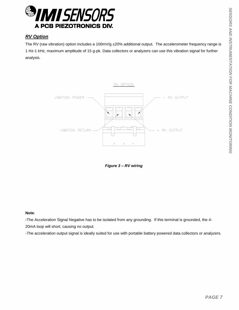
RV Option
The RV (raw vibration) option includes a 100mV/g ±20% additional output. The accelerometer frequency range is
1 Hz-1 kHz, maximum amplitude of 15 g-pk. Data collectors or analyzers can use this vibration signal for further
analysis.
Figure 3 – RV wiring
Note:
-The Acceleration Signal Negative has to be isolated from any grounding. If this terminal is grounded, the 4-
20mA loop will short, causing no output.
-The acceleration output signal is ideally suited for use with portable battery powered data collectors or analyzers.

PAGE 8
SE
NS
OR
S A
ND
INS
TR
UM
EN
TA
TIO
N F
OR
MA
CH
INE
CO
ND
ITIO
N M
ON
ITO
RIN
G
TO Option
The TO (Temperature Output) option includes an additional independent 4-20mA output for temperature
measurement. The temperature range is from -40°C to 125°C with an overall accuracy of ±5%FSO. The
imbedded temperature sensor monitors the environment internal to the sensor housing and is situated at
approximately mid level.
Figure 4 – TO wiring
Note:
- The same power supply can be used for both4-20mA loops. Connect both positive terminals directly to the
power supply, then use the negative terminals for independent process loops.

PAGE 9
SE
NS
OR
S A
ND
INS
TR
UM
EN
TA
TIO
N F
OR
MA
CH
INE
CO
ND
ITIO
N M
ON
ITO
RIN
G
EP Option
The EP option includes an Explosion Proof capped elbow for applications in rigid or IMC conduit systems where
space is limited and access is needed for pulling conductors or maintenance. Standard conduit hub size is 1”NPT.
Figure 5 – EP option
5.777
1.927
3.990
CAPPED ELBOW
3.850
PAGE 10
SE
NS
OR
S A
ND
INS
TR
UM
EN
TA
TIO
N F
OR
MA
CH
INE
CO
ND
ITIO
N M
ON
ITO
RIN
G
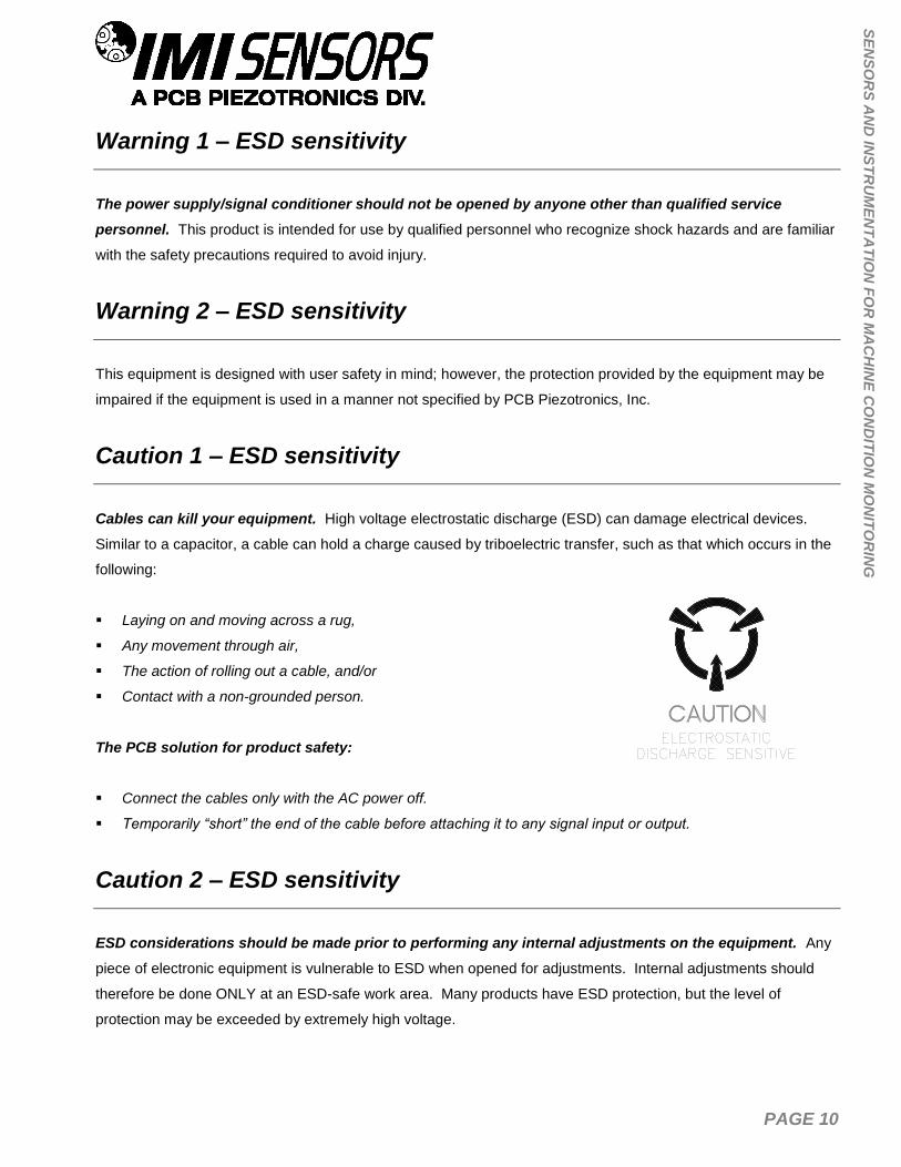
Warning 1 – ESD sensitivity
The power supply/signal conditioner should not be opened by anyone other than qualified service
personnel. This product is intended for use by qualified personnel who recognize shock hazards and are familiar
with the safety precautions required to avoid injury.
Warning 2 – ESD sensitivity
This equipment is designed with user safety in mind; however, the protection provided by the equipment may be
impaired if the equipment is used in a manner not specified by PCB Piezotronics, Inc.
Caution 1 – ESD sensitivity
Cables can kill your equipment. High voltage electrostatic discharge (ESD) can damage electrical devices.
Similar to a capacitor, a cable can hold a charge caused by triboelectric transfer, such as that which occurs in the
following:
Laying on and moving across a rug,
Any movement through air,
The action of rolling out a cable, and/or
Contact with a non-grounded person.
The PCB solution for product safety:
Connect the cables only with the AC power off.
Temporarily “short” the end of the cable before attaching it to any signal input or output.
Caution 2 – ESD sensitivity
ESD considerations should be made prior to performing any internal adjustments on the equipment. Any
piece of electronic equipment is vulnerable to ESD when opened for adjustments. Internal adjustments should
therefore be done ONLY at an ESD-safe work area. Many products have ESD protection, but the level of
protection may be exceeded by extremely high voltage.
PAGE 11
SE
NS
OR
S A
ND
INS
TR
UM
EN
TA
TIO
N F
OR
MA
CH
INE
CO
ND
ITIO
N M
ON
ITO
RIN
G
Warranty
IMI instrumentation is warranted against defective material and workmanship for 1 year unless otherwise
expressly specified. Damage to instruments caused by incorrect power or misapplication, is not covered by
warranty. If there are any questions regarding power, intended application, or general usage, please consult with
your local sales contact or distributor. Batteries and other expendable hardware items are not covered by
warranty.
Service
Because of the sophisticated nature of IMI instrumentation, field repair is typically NOT recommended and may
void any warranty. If factory service is required, return the instrumentation according to the “Return Procedure”
stated below. A repair and/or replacement quotation will be provided prior to servicing at no charge. Before
returning the unit, please consult a factory IMI applications engineer concerning the situation as certain problems
can often be corrected with simple on-site procedures.
Return procedure
To expedite returned instrumentation, contact a factory IMI applications engineer for a RETURN MATERIAL
AUTHORIZATION (RMA) NUMBER. Please have information available such as model and serial number. Also,
to insure efficient service, provide a written description of the symptoms and problems with the equipment to a
local sales representative or distributor, or contact IMI if none are located in your area.
Customers outside the U.S. should consult their local IMI distributor for information on returning equipment. For
exceptions, please contact the International Sales department at IMI to request shipping instructions and an RMA.
For assistance, please call (716) 684-0003, or fax us at (716) 684-3823. You may also receive assistance via e-
mail at [email protected] or visit our web site at www.pcb.com.

PAGE 12
SE
NS
OR
S A
ND
INS
TR
UM
EN
TA
TIO
N F
OR
MA
CH
INE
CO
ND
ITIO
N M
ON
ITO
RIN
G
Customer Service
IMI, a division of PCB Piezotronics, guarantees Total Customer Satisfaction. If, at any time, for any reason, you
are not completely satisfied with any IMI product, IMI will repair, replace, or exchange it at no charge. You may
also choose to have your purchase price refunded.
IMI offers to all customers, at no charge, 24-hour phone support. This service makes product or application
support available to our customers, day or night, seven days a week. When unforeseen problems or emergency
situations arise, call the IMI Hot Line at (716) 684-0003, and an application specialist will assist you.
3425 Walden Avenue, Depew, NY 14043-2495
Phone: (716) 684-0003 USA Fax: (716) 684-3823 INTL Fax: (716) 684-4703
ICP® is a registered trademark of PCB Group, Incorporated,
which uniquely identifies PCB sensors that incorporate built-in microelectronics.

1
1
2
2
3
3
4
4
A A
B B
CODE
IDENT. NO.
52681
DWG. NO.
SCALE: SHEET
DRAWN CHECKED ENGINEER
TITLE
UNLESS OTHERWISE SPECIFIED TOLERANCES ARE:
DIMENSIONS IN MILLIMETERS[ IN BRACKETS ]
ANGLES ` 2 DEGREES
3425 WALDEN AVE. DEPEW, NY 14043(716) 684-0001 E-MAIL: [email protected]
DIMENSIONS IN INCHES
ANGLES ` 2 DEGREES
FILLETS AND RADII
.003 - .005
FILLETS AND RADII
0.07 - 0.13
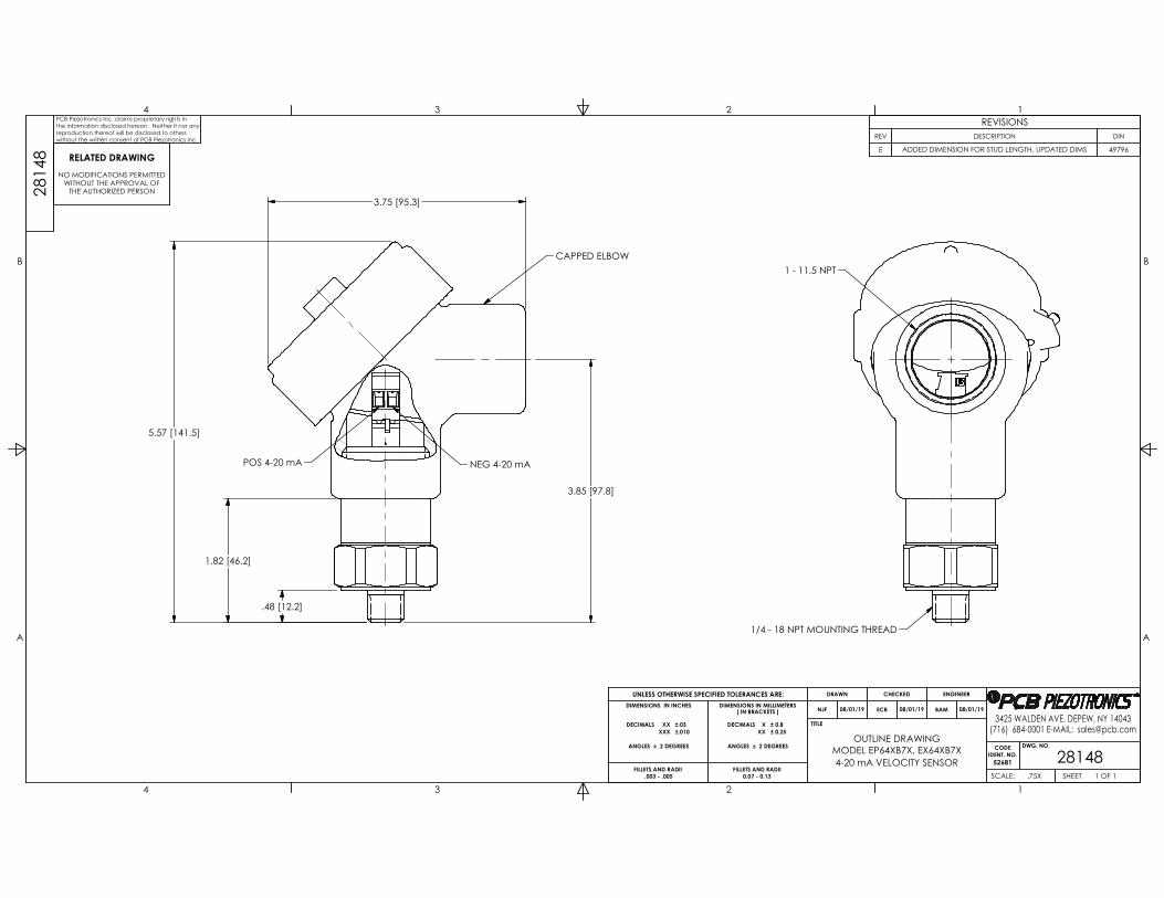
OUTLINE DRAWING
281481 OF 1.75X
MODEL EP64XB7X, EX64XB7X
4-20 mA VELOCITY SENSOR
DECIMALS XX ±.03
XXX ±.010
DECIMALS X ± 0.8
XX ± 0.25
NJF 08/01/19 ECB 08/01/19 BAM 08/01/19
281
48
PCB Piezotronics Inc. claims proprietary rights in
the information disclosed hereon. Neither it nor any
reproduction thereof will be disclosed to others
without the written consent of PCB Piezotronics Inc.
REVISIONS
REV DESCRIPTION DIN
E ADDED DIMENSION FOR STUD LENGTH, UPDATED DIMS 49796
RELATED DRAWING
NO MODIFICATIONS PERMITTEDWITHOUT THE APPROVAL OF
THE AUTHORIZED PERSON
5.57 [141.5]
1.82 [46.2]
.48 [12.2]
3.75 [95.3]
3.85 [97.8]
POS 4-20 mA NEG 4-20 mA
CAPPED ELBOW
1 - 11.5 NPT
1/4 - 18 NPT MOUNTING THREAD
PCB PIEZOTRONICS INC. 3425 WALDEN AVE.
DEPEW, NEW YORK 14043
3425 Walden Ave
Depew, New York 14043
No 32836 No 1 of 3
Rev. D DIN 45670 12/02/2016
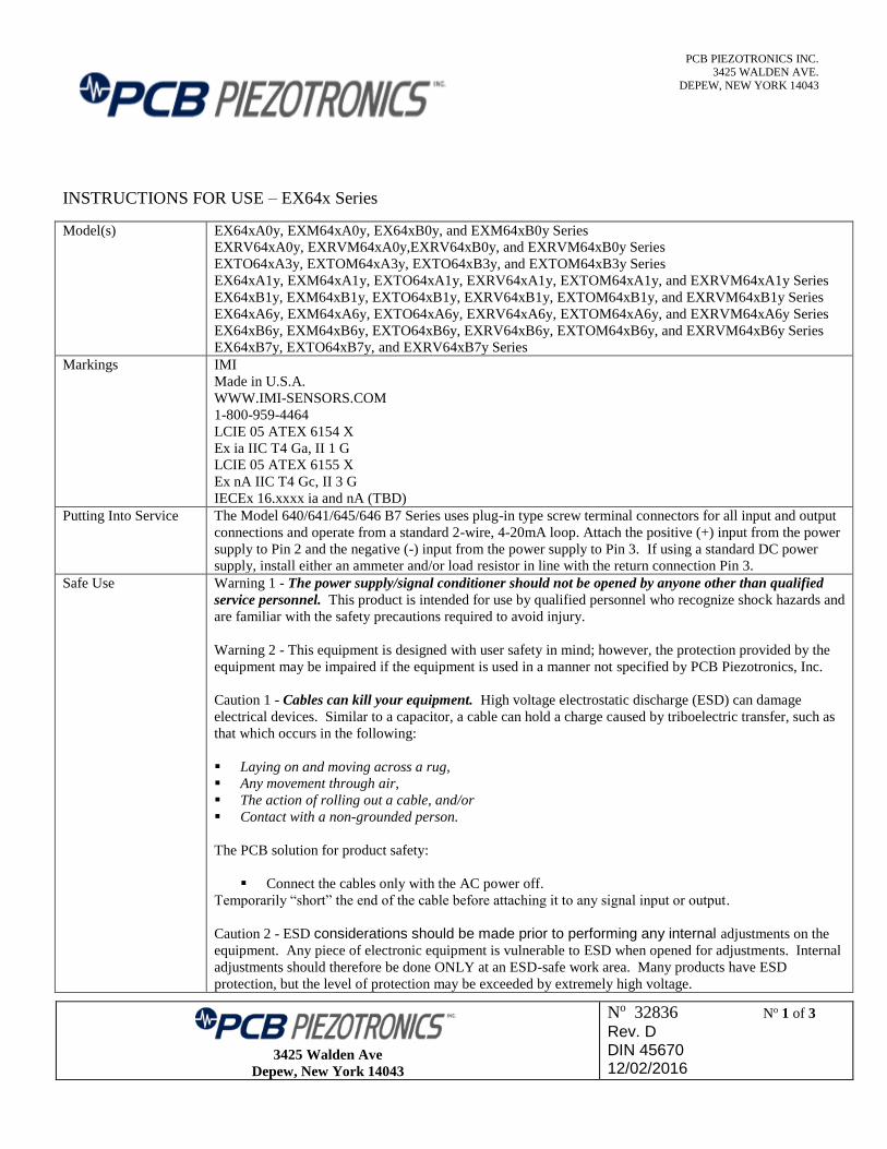
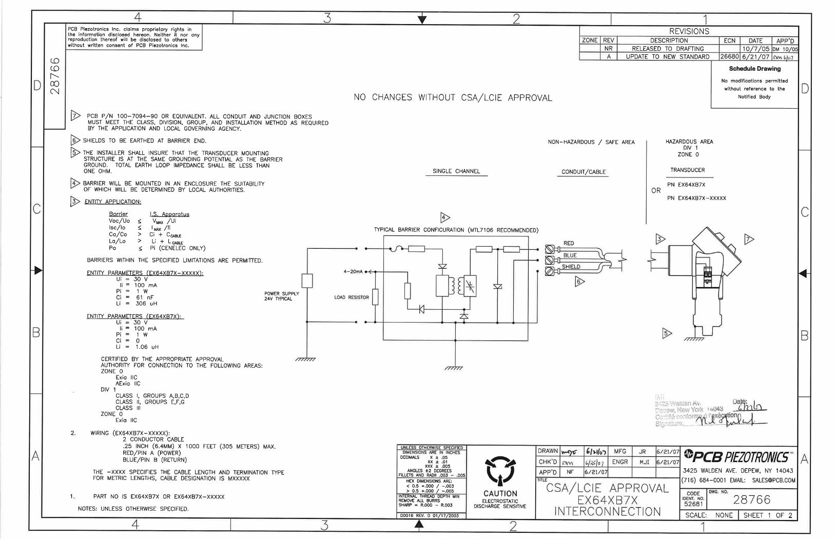
INSTRUCTIONS FOR USE – EX64x Series
Model(s) EX64xA0y, EXM64xA0y, EX64xB0y, and EXM64xB0y Series
EXRV64xA0y, EXRVM64xA0y,EXRV64xB0y, and EXRVM64xB0y Series
EXTO64xA3y, EXTOM64xA3y, EXTO64xB3y, and EXTOM64xB3y Series
EX64xA1y, EXM64xA1y, EXTO64xA1y, EXRV64xA1y, EXTOM64xA1y, and EXRVM64xA1y Series
EX64xB1y, EXM64xB1y, EXTO64xB1y, EXRV64xB1y, EXTOM64xB1y, and EXRVM64xB1y Series
EX64xA6y, EXM64xA6y, EXTO64xA6y, EXRV64xA6y, EXTOM64xA6y, and EXRVM64xA6y Series
EX64xB6y, EXM64xB6y, EXTO64xB6y, EXRV64xB6y, EXTOM64xB6y, and EXRVM64xB6y Series
EX64xB7y, EXTO64xB7y, and EXRV64xB7y Series
Markings IMI
Made in U.S.A.
WWW.IMI-SENSORS.COM
1-800-959-4464
LCIE 05 ATEX 6154 X
Ex ia IIC T4 Ga, II 1 G
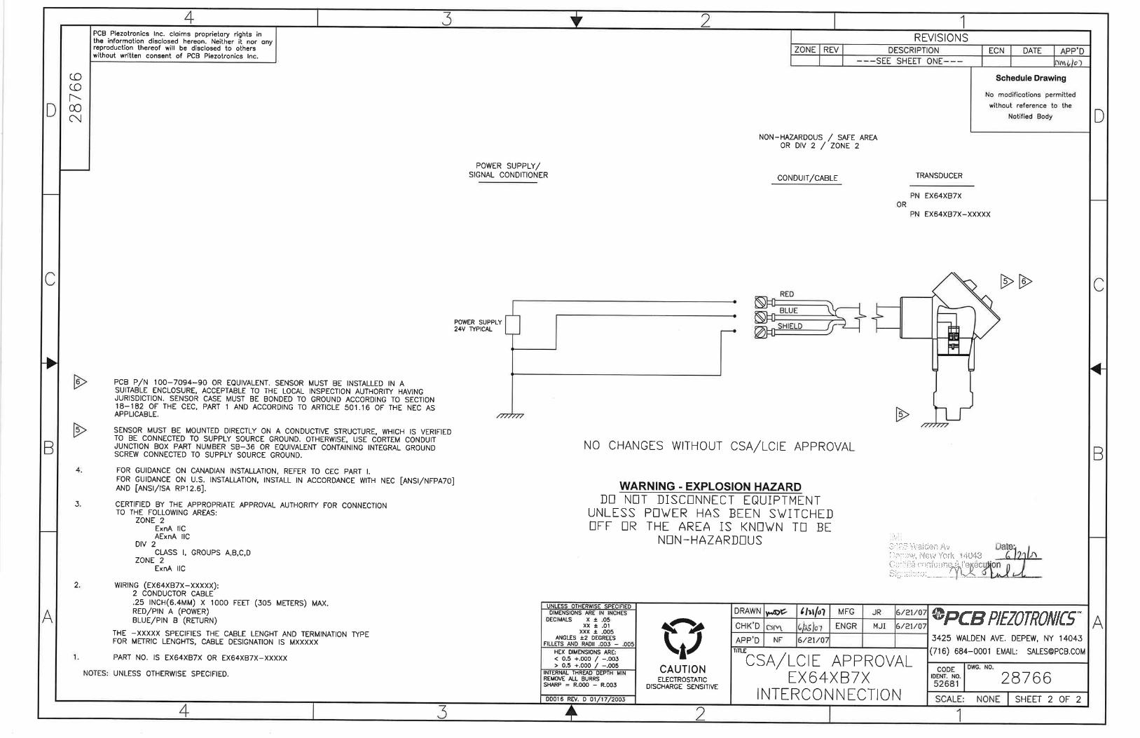
LCIE 05 ATEX 6155 X
Ex nA IIC T4 Gc, II 3 G
IECEx 16.xxxx ia and nA (TBD)
Putting Into Service The Model 640/641/645/646 B7 Series uses plug-in type screw terminal connectors for all input and output
connections and operate from a standard 2-wire, 4-20mA loop. Attach the positive (+) input from the power
supply to Pin 2 and the negative (-) input from the power supply to Pin 3. If using a standard DC power
supply, install either an ammeter and/or load resistor in line with the return connection Pin 3.
Safe Use Warning 1 - The power supply/signal conditioner should not be opened by anyone other than qualified
service personnel. This product is intended for use by qualified personnel who recognize shock hazards and
are familiar with the safety precautions required to avoid injury.
Warning 2 - This equipment is designed with user safety in mind; however, the protection provided by the
equipment may be impaired if the equipment is used in a manner not specified by PCB Piezotronics, Inc.
Caution 1 - Cables can kill your equipment. High voltage electrostatic discharge (ESD) can damage
electrical devices. Similar to a capacitor, a cable can hold a charge caused by triboelectric transfer, such as
that which occurs in the following:
Laying on and moving across a rug,
Any movement through air,
The action of rolling out a cable, and/or
Contact with a non-grounded person.
The PCB solution for product safety:
Connect the cables only with the AC power off.
Temporarily “short” the end of the cable before attaching it to any signal input or output.
Caution 2 - ESD considerations should be made prior to performing any internal adjustments on the
equipment. Any piece of electronic equipment is vulnerable to ESD when opened for adjustments. Internal
adjustments should therefore be done ONLY at an ESD-safe work area. Many products have ESD
protection, but the level of protection may be exceeded by extremely high voltage.

PCB PIEZOTRONICS INC. 3425 WALDEN AVE.
DEPEW, NEW YORK 14043
3425 Walden Ave
Depew, New York 14043
No 32836 No 2 of 3
Rev. D DIN 45670 12/02/2016
Assembling The EX64x Series have a sealed stainless steel housing, with a screw terminal, and do not require any
assembly. Only mounting to the machine being monitored using standard mounting accessories.
Dismantling Other than removal from the mounting, there is no disassembly of the sensor required to take it out of
service.
Maintenance Routine maintenance, such as the cleaning of electrical connectors, housings, and mounting surfaces with
solutions and techniques that will not harm the physical material of construction, is acceptable.
Servicing Due to the sophisticated nature of the sensors and associated instrumentation provided by PCB Piezotronics,
user servicing or repair is not recommended and, if attempted, may void the factory warranty. However,
routine calibration of sensors and associated instrumentation is recommended as this helps build confidence
in measurement accuracy and acquired data.
Repair In the event that equipment becomes damaged or ceases to operate, arrangements should be made to return
the equipment to PCB Piezotronics for repair. User servicing or repair is not recommended and, if
attempted, may void the factory warranty.
Installation Overview: Sensor must be mounted in order to be put into service. When choosing a mounting method,
consider closely both the advantages and disadvantages of each technique. Characteristics like location,
ruggedness, amplitude range, accessibility, temperature, and portability are extremely critical. However, the
most important and often overlooked consideration is the effect the mounting technique has on the high-
frequency performance of the accelerometer. Mounting methods include: Stud mount, adhesive mount,
magnetic mount, handheld, or probe tip mount.
Cabling: Care and attention to cable installation and cable condition is essential as the reliability and
accuracy of any measurement system is no better than that of its weakest link. Due to the nature of
vibration measurements, all sensor cables will ultimately fatigue and fail. Good installation practice will
extend the life of a cable, however, it is highly recommended to keep spare cables on hand to enable
continuation of the test in the event of a cable failure.
Adjustment The sensor is a sealed device and no user adjustments are possible. However, routine calibration of sensors
by the manufacturer is recommended as this helps build confidence in measurement accuracy and acquired
data.
Danger Areas (for
pressure-relief devices)
N/A – not a pressure relief device.
Training Instructions Industrial sensors must be installed in Hazardous Locations by trained professionals according to EN/IEC
60079-14 requirements.
Details on Safety of
Protection Category
Ex ia is “intrinsic safety”, which limits the energy of sparks and surface temperatures to safe levels
Ex nA is “Non-Sparking” no arcs, sparks or hot surfaces (enclosure ≥ IP54)
Entity Parameters and
Limits (Values) Temperature Range: -40⁰C to +80⁰C
IS (ia) Parameters –
Models EX(M)64xA0y, EX(M)64xB0y:
Ui : 30V; Ii : 100 mA; Pi : 1W; Ci: 0nF; Li : 121.1µH
Models EX(M)64xA1y, EX(M)64xA6y, EX(M)64xB1y, EX(M)64xB6y:
Ui : 30V; Ii : 100 mA; Pi : 1W; Ci: 61nF; Li : 426.1µH
Models EX(M)64xA3y, EX(M)64xB3y:
Ui : 28V; Ii : 120 mA; Pi : 1W; Ci: 0nF; Li : 122.2µH
Models EXTO(M)64xA1y, EXTO(M)64xA6y, EXTO(M)64xB1y, EXTO(M)64xB6y:
Ui : 28V; Ii : 120 mA; Pi : 1W; Ci: 61nF; Li : 427.2µH
PCB PIEZOTRONICS INC. 3425 WALDEN AVE.
DEPEW, NEW YORK 14043
3425 Walden Ave
Depew, New York 14043
No 32836 No 3 of 3
Rev. D DIN 45670 12/02/2016
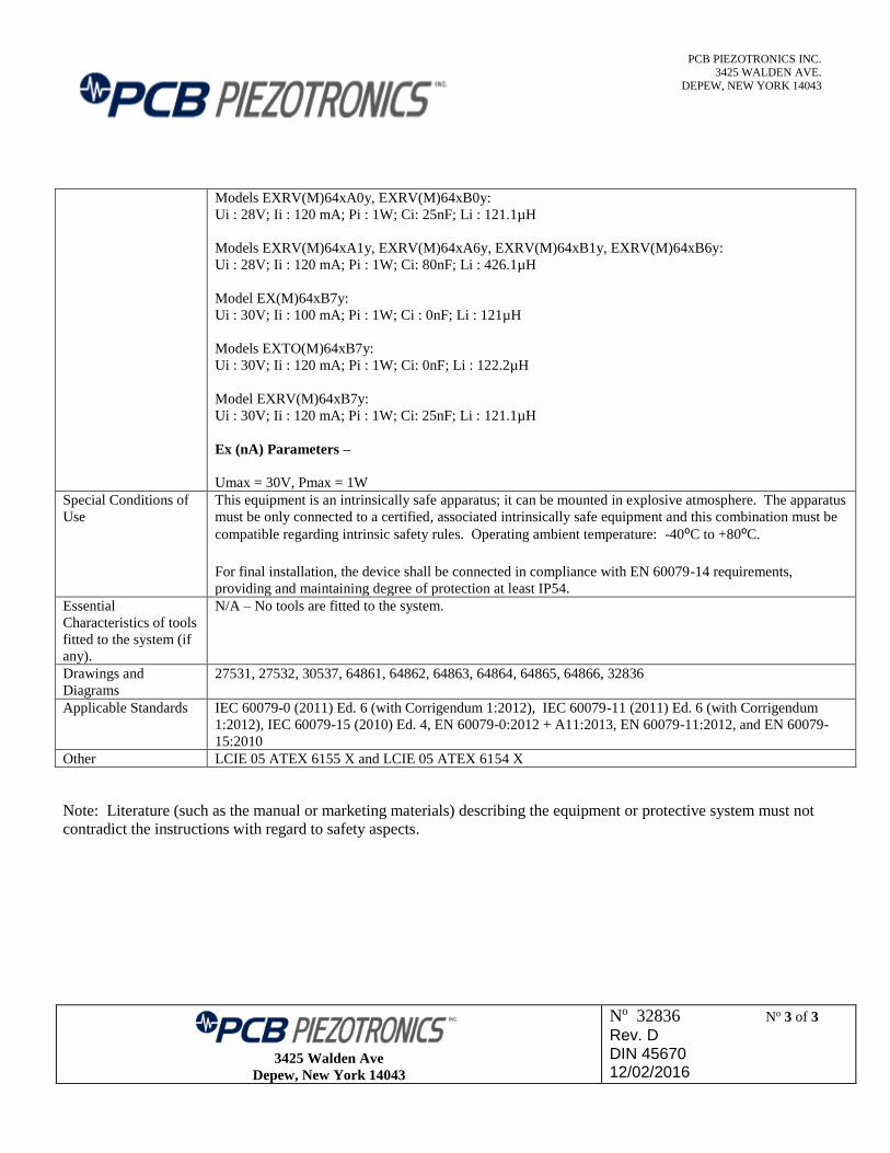
Models EXRV(M)64xA0y, EXRV(M)64xB0y:
Ui : 28V; Ii : 120 mA; Pi : 1W; Ci: 25nF; Li : 121.1µH
Models EXRV(M)64xA1y, EXRV(M)64xA6y, EXRV(M)64xB1y, EXRV(M)64xB6y:
Ui : 28V; Ii : 120 mA; Pi : 1W; Ci: 80nF; Li : 426.1µH
Model EX(M)64xB7y:
Ui : 30V; Ii : 100 mA; Pi : 1W; Ci : 0nF; Li : 121µH
Models EXTO(M)64xB7y:
Ui : 30V; Ii : 120 mA; Pi : 1W; Ci: 0nF; Li : 122.2µH
Model EXRV(M)64xB7y:
Ui : 30V; Ii : 120 mA; Pi : 1W; Ci: 25nF; Li : 121.1µH
Ex (nA) Parameters –
Umax = 30V, Pmax = 1W
Special Conditions of
Use
This equipment is an intrinsically safe apparatus; it can be mounted in explosive atmosphere. The apparatus
must be only connected to a certified, associated intrinsically safe equipment and this combination must be
compatible regarding intrinsic safety rules. Operating ambient temperature: -40⁰C to +80⁰C.
For final installation, the device shall be connected in compliance with EN 60079-14 requirements,
providing and maintaining degree of protection at least IP54. Essential
Characteristics of tools
fitted to the system (if
any).
N/A – No tools are fitted to the system.
Drawings and
Diagrams
27531, 27532, 30537, 64861, 64862, 64863, 64864, 64865, 64866, 32836
Applicable Standards IEC 60079-0 (2011) Ed. 6 (with Corrigendum 1:2012), IEC 60079-11 (2011) Ed. 6 (with Corrigendum
1:2012), IEC 60079-15 (2010) Ed. 4, EN 60079-0:2012 + A11:2013, EN 60079-11:2012, and EN 60079-
15:2010
Other LCIE 05 ATEX 6155 X and LCIE 05 ATEX 6154 X
Note: Literature (such as the manual or marketing materials) describing the equipment or protective system must not
contradict the instructions with regard to safety aspects.

IMI5EN5OR5 A PCB PIEZOTRONICS DIV.
I EXAMINATION CERTIFICATE
2 Component Intended for use in Potentially Explosive Atmospheres meeting ATEX Directive 2014/34/EU
3 Examination Certificate Number: CTDOII X to be used in conjunction with the Type Examination Certificate LClE 05 ATEX 6154 X, Issue: 01
4 Apparatus: Models EX64xAOy, EXM64xAOy, EX64xBOy, and EXM64xBOy Series EXRV64xA0y, EXRVM64xAOy, EXRV64xBOy, and EXRVM64xBOy Series EXT064xA3y, EXTOM64xA3y, EXT064xB3y, and EXTOM64xB3y Series EX64xA1 y, EXM64xA1 y, EXT064xAl y, EXRV64xA1 y, EXTOM64xAl y, and EXRVM64xAl y Series EX64xB1y, EXM64xB1y, EXT064xB1y, EXRV64xB1y, EXTOM64xB1y, and EXRVM64xB1y Series EX64xA6y, EXM64xA6y, EXT064xA6y, EXRV64xA6y, EXTOM64xA6y, and EXRVM64xA6y Series EX64136y, EXM64xB6y, EXT064136y, EXRV64xB6y, EXTOM64136y, and EXRVM64xB6y Series EX64137y, EXT064137y, and EXRV64xB7y Series
The "x" and "y" represent a single digit from 0-9 representing model number and connector type
5 Manufacturer: IMI Sensors, a Division of PCB Piezotronics
6 Address: 3425 Walden Avenue, Depew, New York, 14043
7 This apparatus and any acceptable variation are specified in the schedule in this certificate and all pertinent documents referenced.
8 lMl Sensors certifies that this component has been found to comply with the Essential Health and Safety Requirements relating to the design and construction of components intended to form part of Category 3 equipment intended for use in potentially explosive atmospheres given in Annex II to European Union Directive 2014/34/EU of February 2014. This certificate is based on LCIE confidential report(s) n° 60058689/559760 and 60040901/540946/1, for the above models certified to Equipment Group II Category I Gas Group.
9 Compliance with the Essential Health and Safety Requirements has been assured by compliance with:
EN 60079-0:2012+AI1:2013 EN 60079-11:2012
10 The apparatus may be connected to other ATEX certified equipment, as long as it meets the parameters of the system.
11 This Examination Certificate relates only to the design and construction of this specified equipment in accordance to Directive 2014/34/EU
Page 1 of 3

IMI5EN5OR5 A PCB PIEZOTRONICS DIV.
12 Equipment will be marked per previous approvals:
CE 0344 II 1
This Certificate implies that the equipment can also be used in:
Ex 11 3D
This certificate may only be reproduced in its entirety, without any change, schedule included.
Page 2 of 3
IMI5EN5OR5 A PCB PIEZOTRONICS DIV.
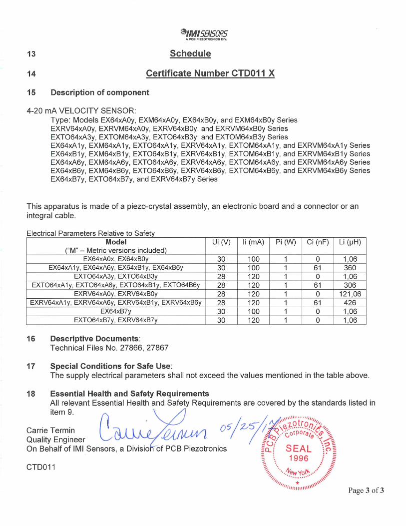
13 Schedule
14 Certificate Number CTDO1 I X
15 Description of component
4-20 mA VELOCITY SENSOR: Type: Models EX64xAOy, EXM64xAOy, EX64xB0y, and EXM64xB0y Series EXRV64xA0y, EXRVM64xA0y, EXRV64xB0y, and EXRVM64xB0y Series EXT064xA3y, EXTOM64xA3y, EXT064xB3y, and EXTOM64xB3y Series EX64xAl y, EXM64xAl y, EXT064xAl y, EXRV64xAl y, EXTOM64xAl y, and EXRVM64xA1 y Series EX64xBly, EXM64xBly, EXT064xBly, EXRV64xBly, EXTOM64xBly, and EXRVM64xBly Series EX64xA6y, EXM64xA6y, EXT064xA6y, EXRV64xA6y, EXTOM64xA6y, and EXRVM64xA6y Series EX64xB6y, EXM64xB6y, EXT064xB6y, EXRV64xB6y, EXTOM64xB6y, and EXRVM64xB6y Series EX64xB7y, EXT064xB7y, and EXRV64xB7y Series
This apparatus is made of a piezo-crystal assembly, an electronic board and a connector or an integral cable.
Electrical Parameters Relative to Safety Model
("M" - Metric versions included)
UI (V) Ii (mA) Pi (W) Ci (nF) Li (pH)
EX64xAOx, EX64xBOy 30 100 1 0 1 7 06 EX64xA1y, EX64xA6y, EX64xB1y, EX64xB6y 30 100 1 61 360
EXT064xA3y, EXT064xB3y 28 120 1 0 11 06 EXT064xA1 y, EXT064xA6y, EXT064xB1 y, EXT064B6y 28 120 1 61 306
EXRV64xAOy, EXRV64xBOy 28 120 1 0 121 7 06 EXRV64xA1y, EXRV64xA6y, EXRV64xB1y, EXRV64xB6y 28 120 1 61 426
EX64xB7y 30 100 1 0 1,06 EXT064xB7y, EXRV64xB7y 30 120 1 0 1 7 06
16 Descriptive Documents: Technical Files No. 27866, 27867
17 Special Conditions for Safe Use: The supply electrical parameters shall not exceed the values mentioned in the table above.
18 Essential Health and Safety Requirements All relevant Essential Health and Safety Requirements are covered by the standards listed in item 9.
Z t ro/7 Carrie Termin 0 Quality Engineer On Behalf of lMl Sensors, a Divisto of PCB Piezotronics SEAL cV" -
CTDO1I 1996
* \\\\
Page 3 of 3
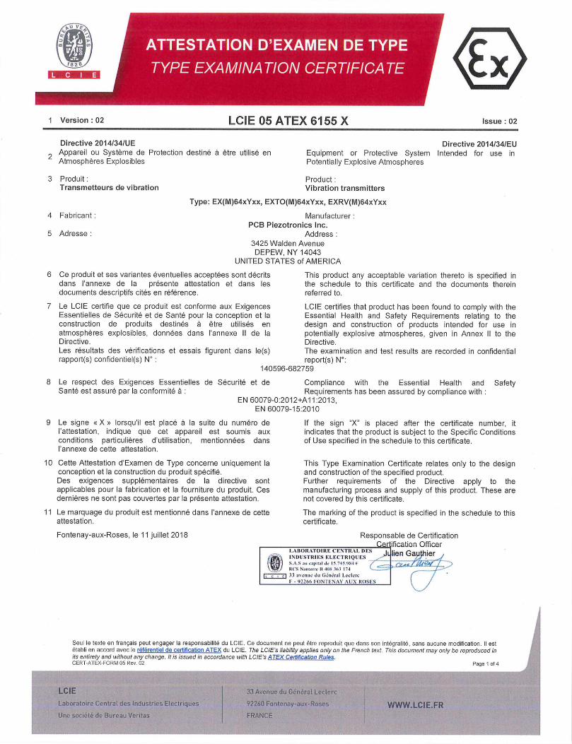
ATTESTATION D'EXAMEN DE TYPE
1 Version :02 LCIE 05 ATEX 6155 X Issue: 02
Directive 2014/34/UE Directive 2014/34/EU 2 Appareil ou Système de Protection destine a être utilisé en Equipment or Protective System Intended for use in
Atmospheres Explosibles Potentially Explosive Atmospheres
3 Produit: Product: Transmetteurs de vibration Vibration transmitters
Type: EX(M)64xYxx, EXTO(M)64xYxx, EXRV(M)64xYxx
4 Fabricant: Manufacturer: PCB Piezotronics Inc.
5 Adresse : Address 3425 Walden Avenue DEPEW, NY 14043
UNITED STATES of AMERICA
6 Ce produit et ses variantes èventuelles acceptées sont décrits This product any acceptable variation thereto is specified in dans I'annexe de la présente attestation et dans les the schedule to this certificate and the documents therein documents descriptifs cites en référence, referred to.
7 Le LCIE certifie que ce produit est conforme aux Exigences LCIE certifies that product has been found to comply with the Essentielles de Sécurité et de Sante pour la conception et Pa Essential Health and Safety Requirements relating to the construction de produits destinés a être utilisés en design and construction of products intended for use in atmospheres explosibles, données dans I'annexe II de Ia potentially explosive atmospheres, given in Annex II to the Directive. Directive. Les résultats des verifications et essais figurent dans le(s) The examination and test results are recorded in confidential rapport(s) confidentiel(s) N : report(s) Nu:
140596-682759
8 Le respect des Exigences Essentielles de Sècurité et de Compliance with the Essential Health and Safety Sante est assure par la conformitè a : Requirements has been assured by compliance with
EN 60079-0:201 2+A1 1:2013, EN 60079-15:2010
9 Le signe eXe lorsquil est place a la suite du numéro de If the sign "X" is placed after the certificate number, it 'attestation, indique que cet appareil est soumis aux indicates that the product is subject to the Specific Conditions conditions particulières d'utilisation, mentionnèes dans of Use specified in the schedule to this certificate. I'annexe de cette attestation.
10 Cette Attestation d'Examen de Type concerne uniquement la This Type Examination Certificate relates only to the design conception et la construction du produit specifie. and construction of the specified product. Des exigences supplementaires de Ia directive sont Further requirements of the Directive apply to the applicables pour la fabrication et la fourniture du produit. Ces manufacturing process and supply of this product. These are dernières ne sont pas couvertes par la présente attestation. not covered by this certificate.
11 Le marquage du produit est mentionné dans I'annexe de cette The marking of the product is specified in the schedule to this attestation. certificate.
Fontenay-aux-Roses, le 11 juillet 2018 Responsable de Certification Certification Officer
I.AB()R.ToRF: CFNTR..tl. I)FS I lr i-' k INDUSTRIES ELEcrRIQLF:s -.
ten ap er /
() S.A.S iv capital Iv I3.'43.954 / ........j IllS Nmnviie II 40N 151 74 .
ci 33 UI lnii/ Cu (wndr.ti Lvrkrr ( 1
I - 92255 FONTTIIN.SY SIX ROSES
5eu1 le texte en français peut engager la responsabiiitO du LCIE. Ce document ne peut ëtre reproduit que dens son integraiite, sans aucune modification. II est Atabli en accord avec le référentiel de certification ATEX du LCIE. The LCIE'.s liability applies only on the French text. This document may only be reproduced in its entirety and without any change. ltis issued in accordance with LCIE's ATEX Certification Rules. CERT-ATEX-FORM 05 Rev. 02 Page 1 of 4
LCIE 1 33 Avenue du Général Lecterc
Laboratotre Centrat des industries Electriques 92260 Fontenay-aux-Roses WWW.LCIE.FR Une socidté cia Bureau Veritas FRANCE
1 Version : 02 LCIE 05 ATEX 6155 Issue : 02
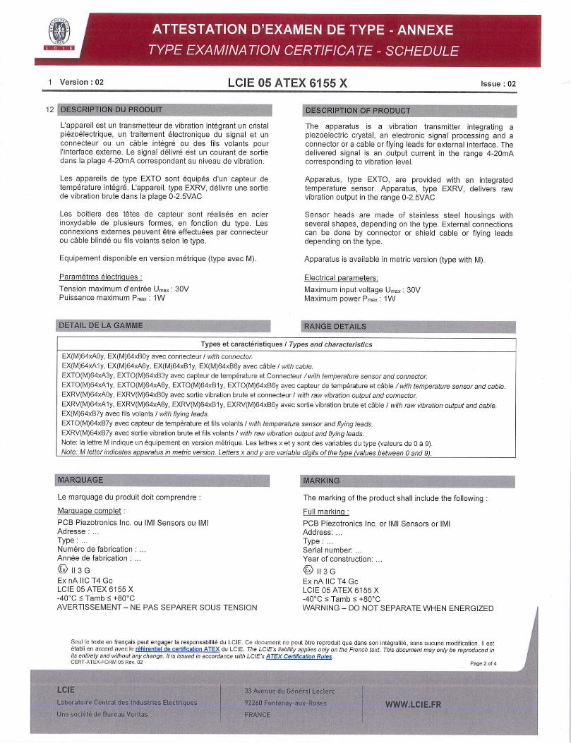
12 DESCRIPTION DU PRODUIT
L'appareil est un transmetteur de vibration intégrant un cristal piézoelectrique, un traitement electronique du signal et un connecteur ou un cable intégré ou des fils volants pour 'interface externe. Le signal délivré est un courant de sortie dans la plage 4-2OmA correspondant au niveau de vibration.
Los appareils de type EXTO sont équipes dun capteur de temperature integre. Lappareil, type EXRV, délivre une sortie de vibration brute dans Ia plage 0-2.5VAC
Les boitiers des têtes de capteur sont réalisés en acier inoxydable de plusieurs formes, en fonction du type. Les connexions externes peuvent être effectuées par connecteur ou cable blindé ou fils volants selon le type.
Equipement disponible en version metrique (type avec M)
Paramètres électrigues:
Tension maximum d'entrée Umax 30V Puissance maximum Pmax: 1W
DETAIL DE LA GAMME
DESCRIPTION OF PRODUCT
The apparatus is a vibration transmitter integrating a piezoelectric crystal, an electronic signal processing and a connector or a cable or flying leads for external interface. The delivered signal is an output current in the range 4-20mA corresponding to vibration level.
Apparatus, type EXTO, are provided with an integrated temperature sensor. Apparatus, type EXRV, delivers raw vibration output in the range 0-2.5VAC
Sensor heads are made of stainless steel housings with several shapes, depending on the type. External connections can be done by connector or shield cable or flying leads depending on the type.
Apparatus is available in metric version (type with M).
Electrical parameters:
Maximum input voltage Umax: 30V Maximum power Pmax: 1W
RANGE DETAILS
Types et caracteristiques / Types and characteristics
EX(M)64xA0y, EX(M)64xB0y avec connecteur I with connector. EX(M)64xA1y, EX(M)64xA6y, EX(M)64xB1y, EX(M)64xB6y avec cflble I with cable.
EXTO(M)64xA3y, EXTO(M)64xB3y avec capteur de temperature et Connecteur /with temperature sensor and connector. EXTO(M)64xA1y, EXTO(M)64xA6y, EXTO(M)64xB1y, EXTO(M)64xB6y avec capteur de temperature et cAble /with temperature sensor and cable.
EXRV(M)64xAOy, EXRV(M)64xB0y avec sortie vibration brute et connecteur I with raw vibration output and connector. EXRV(M)64xA1y, EXRV(M)64xA6y, EXRV(M)64xB1y, EXRV(M)64xB6y avec sortie vibration brute et cAble / with raw vibration output and cable. EX(M)64xB7y avec fils volants I with flying leads. EXTO(M)64xB7y avec capteur de temperature et fils volants I with temperature sensor and flying leads. EXRV(M)64xB7y avec sortie vibration brute et fils volants I with raw vibration output and flying leads. Note: la lettre M indique un équipement en version métrique. Les lettres x et y sent des variables du type (valeurs de 0 a 9). Note: M letter indicates apparatus in metric version. Letters x and are variable digits of the type (values between 0 and 9).
MARQUAGE MARKING
Le marquage du produit doit comprendre The marking of the product shall include the following
Marcuage complet: Full marking
FOB Piezotronics Inc. ou IMP Sensors ou IMI PCB Piezotronics Inc. or lMI Sensors or IMI Adresse Address: Type: Type: Numéro de fabrication Serial number: Année de fabrication Year of construction:
113 G 113 G Ex nA IIC T4 Gc Ex nA 110 T4 Ge LCIE O5 ATEX B155X LCIE 05 ATEX 6155 X -40CC Tamb :5 +80CC -40'C :5 Tamb +80eC AVERTISSEMENT - NE PAS SEPARER SOUS TENSION WARNING - DO NOT SEPARATE WHEN ENERGIZED
Seul le texte en francais peut engager la responsabilité du LCIE. Ce document ne paul étre reproduit qua dans son intégralité, sans aucune modification. II est Otabli en accord avec le référentiel de certification ATEX du LCIE. The LC/Es liability applies only on the French text. This document may only be reproduced in its entirety and without any change. It is issued in accordance with LClEs A TEX Certification Rules. CERT-ATEX-FORM 05 Rev. 02 Page 2 of 4
LCIE 33 Avenue du Gén6ral Leclerc
Laboratoire CentraL des Industries Etectriques j 92260 Fontenay-aux-Roses WWWLCIEFR Une socithté de Bureau Veritas FRANCE

1 Version :02 LCIE 05 ATEX 6155 X Issue :02
MARQUAGE (suite)
Le marquage du produit doit comprendre
Marguage réduit:
PCB Piezotronics Inc. ou IMI Sensors ou IMI Type: N de fabrication An née de fabrication
113 G
Ex nA 110 T4 Gc, Ta = 80CC LCIE 05 ATEX 6155 X
L'appareil doit également comporter le marquage normalement prévu par les normes de construction qui le concernent sous la responsabilité du fabricant.
13 CONDITIONS PARTICULIERES DUTILISATION
a. Plage de temperature ambiante : -40CC a +800C.
b. L'appareil dolt ètre connecté uniquement a une source externe de tension maximum 30Vet de puissance maximum 1W.
c. Le montage du produit dans une installation dolt étre effectué de telle sorte que le corps métallique du capteur et le blindage du cable solent relies de manière fiable a Ia terre du système.
d. Pour installation finale, lutilisateur devra prendre toutes les precautions nécessaires pour maintenir un degre de protection minimum 1P54 de la connexion du capteur lors de son raccordement solon les préconisations de la norme EN 60079-14.
e. L'appareil dolt être raccordé conformément au manuel d'instruction.
f. AVERTISSEMENT— NE PAS SEPARER SOUS TENSION
EXIGENCES ESSENTIELLES DE SANTE ET DE 14
SECURITE
Couvertes par les normes listées au point 8.
15 DOCUMENTS DESCRIPTIFS
MARKING (continued)
The marking of the product shall include the following
Reduced marking
PCB Piezotronics Inc. or IMI Sensors or IMI Type: Serial number: Year of construction:
113 G Ex nA 110 T4 Gc, Ta = 80CC LCIE 05 ATEX 6155 X
The equipment shall also bear the usual marking required by the product standards applying to such equipment under the manufacturer responsibility.
SPECIFIC CONDITIONS OF USE
Ambient temperature range: -40CC to +80CC.
The equipment must only be connected to an external source with 30V maximum voltage and maximum power 1W.
The mounting of the apparatus into an installation must be carried out in such a way that sensor metallic body and cable shield are reliably connected to the system earth.
For final installation, the user shall take all necessary precautions to maintain the minimum degree of protection P54 of the sensor connection when connected according to the requirements of EN 60079-14 standard.
The apparatus must be connected according to instruction manual.
WARNING - DO NOT SEPARATE WHEN ENERGIZED
ESSENTIAL HEALTH AND SAFETY REQUIREMENTS
Covered by standards listed at 8.
DESCRIPTIVE DOCUMENTS
Description Reference Rev. Date Page(s) 1. Notice d'instructions / Instructions notice 32836 - - 3 2. Dossier technique! Technical file 64777 NR 2018/06/28 42
16 INFORMATIONS COMPLEMENTAIRES
Essais individuels
Chaque appareil doit ètre soumis au test de rigidite dielectrique suivant le paragraphe 23.2.1 de Ia norme EN 60079-15:2010. La tension de test dolt ètre appliquee entre les signaux electriques actifs et l'enveloppe.
Seul le texte en français peut engager la responsabilité du LCIE. Ce document ne peut ëtre reproduit que dans son intégralité, sans aucune modification. II eat établi en accord avec le référentiel de certification ATEX du LCIE, The LCIEs liability applies only on the French text. This document may only be reproduced in its entirety and without any change. It is issued in accordance with LCIEs A TEX Certification Rules. CERT.ATEX-FORM 05 Rev. 02 Page 3 of 4
LCIE 33 Avenue du GénCral Leclerc
Laboratoire Central des Industries Electriques 92260 Fontenay-aux-Roses WWW.LCIEFR Uric sociCté de Bureau Veritas FRANCE
ADDITIONAL INFORMATIONS
Routine tests
Each equipment shall be submitted to the dielectric strength test according to the clause 23.2.1 of EN 60079-15:2010. Test voltage shall be applied between active electrical signals and the enclosure.
ii

1 Version :02 LCIE 05 ATEX 6155 X Issue :02
16 INFORMATIONS COMPLEMENTAIRES (suite) ADDITIONAL INFORMATIONS (continued)
En accord avec 'Article 41 de la Directive 20141341UE, les attestations d'examen de type mentionnant la Directive 94/9/CE émises avant la date d'application de la Directive 20141341UE (20 avril 2016) peuvent ètre considérées comme émises en accord avec la Directive 2014/34/UE. Les nouvelles versions de ces attestations peuvent conserver le numéro de attestation dorigine émise avant le 20 avril 2016.
In accordance with Article 41 of Directive 2014/34/EU, Type Examination Certificates referring to Directive 94/9/EC that were in existence prior to the date of application of Directive 2014/34/EU (20 April 2016) may be referenced as if they were issued in accordance with Directive 2014/34/EU. New issues of such certificates may continue to bear the original certificate number issued prior to 20 April 2016.
17 DETAILS DES MODIFICATIONS DETAILS OF CHANGES
Version 00 : Version initiale Issue 00: Initial issue. 2005/12/07 2005/12/07
Version 01 Mise A jour normative suivant les normes Issue 01: Normative update according to EN 60079-0: 2007/08/02 EN 60079-0 : 2006 et EN 60079-15 : 2005. 2007/08/02 2006 and EN 60079-15: 2005 standards.
Version 02 : - Mise a jour normative suivant les normes Issue 02: - Normative update according to EN 60079- EN 60079-0:2012+A11:2013 et EN 60079- 0:2012+A11:2013 and EN 60079-15:2010 15 :2010, standards,
- Distinction entre le nom du fabricant (PCB - Distinction between the name of PiezotronicsInc) et le nom de la marque manufacturer (PCB Piezotronics Inc.) and commerciale (IMI Sensors ou Ml), the trademark (IMI Sensors or IMI),
- Mise a jour de la nomenclature des - Update of the nomenclature of the models. modéles.
Seul le texte en français peut engager Ia responsabilité du LCIE. ce document ne peut étre reproduit que dans son intégralité, sans aucune modification. II est établi en accord avec le référentiel de certification ATEX du LCIE. The LCIE's liability applies only on the French text. This document may only be reproduced in its entirety and without any change. It is issued in accordance with LCIEs A TEX Certification Rules. CERT-ATEX-FORM 05 Rev. 02 Page 4of4
LCIE 33 Avenue du G6n6rat Lecterc
Laboratoire Contra', des Industries Etectriques 92260 Fontenay-aux-Roses WWWLCIEFR One sociótA do Bureau Veritas FRANCE

1 AVENANT D'ATTESTATION D'EXAMEN CE DE TYPE
2 Appareil ou système de protection destine a ëtre utilisé en atmospheres explosibles (Directive 94/9/CE)
3 Numéro de l'avenant: LCIE 05 ATEX 6155X/01
1 SUPPLEMENTARY EC TYPE EXAMINATION CERTIFICATE
2 Equipment or protective system intended for use in potentially explosive atmospheres (Directive 94/9/EC)
3 Supplementary certificate number: LCIE 05 ATEX 61SSX/01
4 Appareil ou système de protection: 4 Equipment or protective system: Capteurs de vibration Vibration sensors
Type: EX64..., EXT064..., EXVR64... Type: EX64..., EXT064..., EXVR64...
5 Demandeur: I.M.I. 5 Applicant: l.M.l.
15 DESCRIPTION DE L'AVENANT 15 DESCRIPTION OF THE SUPPLEMENTARY CERTIFICATE Mise a jour normative selon les normes EN 60079-0 (2006) Normative update according to EN 60079-0 (2006) and et EN 60079-15 (2005). EN 60079-15 (2005) standards.
Les résultats des verifications et essais figurent dans le The examination and test results are recorded in rapport confidentiel N° 60058689/559762 confidential report No 60058689/559762
Paramètres sDécifiaues du ou des modes de Drotection concerné(s): Inchanges
Le marcuage doit être modifié corn me suit: Ex nL 11C T4 Ex nA lIC T4 (pour EX64xB7y, EXT064xB7y, EXRV64xB7y)
16 DOCUMENTS DESCRIPTIFS
Dossier de certification No 27867 Rev. A du 27/06/2007 Ce dossier comprend 18 rubriques (37 pages). Dossier de certification No 28771 Rev. A du 27/06/2007 Ce dossier comprend 12 rubriques (28 pages).
17 CONDITIONS SPECIALES POUR UNE UTILISATION SURE lnchangées
18 EXIGENCES ESSENTIELLES DE SECURITE ET DE SANTE Conformité aux normes europeennes EN 60079-0 (2006) et EN 60079-15 (2005).
19 VERIFICATIONS ET ESSAIS INDIVIDUELS Want
Specific parameters of the mode(s) of protection concerned:
Unchanged
The markinci shall be modified as follows: Ex nL 11C T4 Ex nA I IC T4 (for EX64xB7y, EXT064xB7y, EXRV64xB7y)
16 DESCRIPTIVE DOCUMENTS
Certification file No 27867 Rev. A dated 27/06/2007. This file includes 18 items (37 pages). Certification file N° 28771 Rev. A dated 27/06/2007. This file includes 12 items (28 pages).
17 SPECIAL CONDITIONS FOR SAFE USE
Unchanged
18 ESSENTIAL HEALTH AND SAFETY REQUIREMENTS
Conformity to the European standards EN 60079-0 (2006) and EN 60079-15 (2005).
19 ROUTINE VERIFICATIONS AND TESTS None
Fontenay-aux-Roses, le 2 aoOt 2007
J,.%ED GtN'
182B
Le responsable de certification ATEX ATEX certification manager
CERVELL
E
Seul le texte en français peut engager la responsabilité du LCIE. Ce document ne peut être reproduit que dans son integralite, sans aucune modification. The LCIE's liability applies only on the French text. This document may only be reproduced in its entirety and without any change.
Page 1 sur 1 01A-Annexe lll_CEjyp_app_av - revl.DOC
cl I 446464 ick
2) Laboratoire Central lIP 8 Fax +33 1 40 95 86 56 au capital dc 15 745 9$ €
(13 des Industries Electriques 92206 h)nlcn -aliN-Itoacs cedex [email protected] RCS Nanterre B i08 363 174
Une société de Bureau Veritas France \v\vw.lcie.ft

1828 (0
I ATTESTATION D'EXAMEN DE TYPE 2 Appareils et systèmes de protection destinés a être utilisés
en atmospheres explosibles Directive 94/9/CE
3 Numéro de l'attestation d'examen de type LCIE 05 ATEX 6155 X
4 Appareil ou système de protection: Capteurs de vibrations
Type: EX64 .... EXTO64... ,EXRV64 (voir page suivante)
5 Demandeur: I.M.I. (Industrial Monitoring Instrumentation)
6 Adresse: A PCB PIEZOTRONICS DIVISION 3425 Walden Avenue Depew, New York 14043 U.S.A.
7 Get appareil ou système de protection et ses variantes éventuelles acceptées est décrit dans I'annexe de la présente attestation et dans les documents descriptifs cites en annexe.
8 Le LCIE certifle que cet appareil ou système de protection est conforme aux exigences essentielles en ce qui concerne la sécurité et Ia sante pour la conception et la construction d'appareils et de systèmes de protection destinés a être utilisés en atmospheres explosibles, données dans l'annexe II de la directive. Les vénfications et epreuves figurent dans nos rapports confidentlels no 60040901/540946/2.
9 Le respect des exigences essentielles en ce qui concerne Ia sécurité et la sante est assure par la conformité aux documents suivants:
-EN 50021 (1999)
10 Le signe X Iorsqu'il est place a la suite du numéro de I'attestation, indique que ce materiel ou système de protection est soumis aux conditions spéciales pour une utilisation sure, mentionnées dans l'annexe de la présente attestation.
11 Cette attestation d'examen de type concerne uniquement la conception et la construction de I'appareil ou du système de protection spéciflé, conformément a la directive 94/9/CE. Des exigences supplémentaires de cette directive sont applicables pour la fabrication et la fourniture de I'appareil ou du système de protection.
12 Le marquage de I'appareil ou du système de protection devra comporter, entre autres indications utiles, Ies mentions suivantes:
113 G EExnLounAIlCT4
Fontenay-aux-Roses, le 7 décembre 2005
I TYPE EXAMINATION CERTIFICATE 2 Equipment or protective system intended for use in
potentially explosive atmospheres Directive 9419/EC
3 Type Examination Certificate number LCIE 05 ATEX 6155 X
4 Equipment or protective system: Vibration sensors
Type: EX64... ,EXTO64... ,EXRV64... (see following page)
5 Applicant: I.M.I. (Industrial Monitoring Instrumentation)
6 Address: A PCB PIEZOTRONICS DIVISION 3425 Walden Avenue Depew, New York 14043 U.S.A.
7 This equipment or protective system and any acceptable variation thereto is specified in the schedule to this certificate and the documents therein referred to.
8 LCIE certifies that this equipment or protective system has been found to comply with the essential Health and Safety Requirements relating to the design and construction of equipment and protective system intended for use in potentially explosive atmospheres, given in Annex II of the Directive. The examination and test results are recorded in confidential reports no 60040901/540946/2.
9 Compliance with the Essential Health and Safety Requirements has been assured by compliance with:
-EN 50021 (1999)
10 If the sign X is placed after the certificate number, it indicates that the equipment or protective system is subject to special conditions for safe use specified in the schedule to this certificate.
11 This type examination certificate relates only to the design and construction of this specified equipment or protective system in accordance with the Directive 94/9/EC. Further requirements of the Directive applies to the manufacture and supply of this equipment or protective system.
12 The marking of the equipment or protective system shall include the following:
113 EExnLornAllCT4
Le Directeur de I'organisme certificateur Manager of the certification body
'NUenri CERVELLO Timbre sec I Dry seal
Page 1/3
Seul le texte en francais peut engager la responsabilité du LCIE. ce document ne peut être reproduit que dans son integralité, sans aucune modification The LclE's liability applies only on the French text. This document may be reproduced In full and without any change
LCIE 33, cv du G6n6ii1 Lcc!erc '161 +33 1 co 98 60 60 Societe Anonvme
Laboratoire Central BP 8 Fix +33 1 cO 95 86 cli iu c iplt 0 do ic 745 984 €
/ des Industries Electriques 92266 Fontena -aux-Roses cedex Coll tact@lcie fl- RCS Nanterre B cOB 363
Une société de Bureau Veritas France vwcv. Icie.fr
Q(n03
1825
(Al) ANNEXE (Al) SCHEDULE
(A2) ATTESTATION D'EXAMEN DE TYPE
LCIE 05 ATEX 6155 X
(A3) Description de l'equipement ou du système de protection:
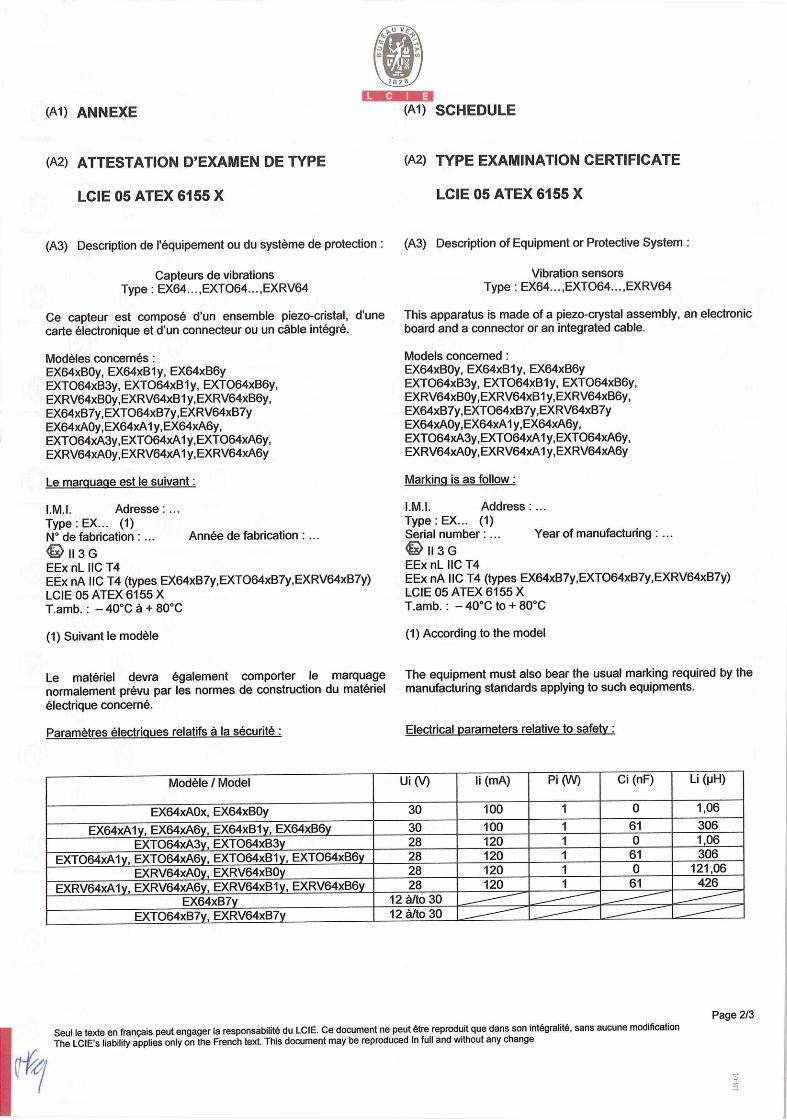
Capteurs de vibrations Type: EX64 .... EXTO64... ,EXRV64
Ce capteur est compose d'un ensemble piezo-cristal, d'une carte électronique et d'un connecteur ou un cable intégré.
Modèles concernés: EX64xB0y, EX64xBl y, EX64xB6y EXT064133y, EXT064131 y, EXT064136y, EXRV64xB0y,EXRV64xBl y,EXRV64xB6y, EX64xB7y,EXT064xB7y,EXRV64XB7y EX64xA0y,EX64xA1 y,EX64xA6y, EXT064xA3y,EXT064xAl y,EXTO64xA6y, EXRV64xA0y,EXRV64xAl y,EXRV64xA6y
Le marguacie est le suivant:
I.M.I. Adresse: Type: EX.. (1) N° de fabrication: ... Année de fabrication:
113 G EEx nLllCT4 EEx nA IIC T4 (types EX64xB7y,EXT064xB7y,EXRV64XB7Y) LCIE 05 ATEX 6155 X T.amb.: - 40°C a + 80°C
(1) Suivant le modèle
Le materiel devra également comporter le marquage normalement prévu par les normes de construction du materiel electrique concerné.
Paramètres électrigues relatifs a la sécurité:
(A2) TYPE EXAMINATION CERTIFICATE
LCIE 05 ATEX 6155 X
(A3) Description of Equipment or Protective System:
Vibration sensors Type: EX64... ,EXTOG4... ,EXRV64
This apparatus is made of a piezo-crystal assembly, an electronic board and a connector or an integrated cable.
Models concerned: EX64xB0y, EX64xBly, EX64xB6y EXT064133y, EXT064131y, EXT064xB6y, EXRV64xB0y,EXRV64xB1 y,EXRV64xB6y, EX64xB7y,EXT064xB7y,EXRV64xB7y EX64xA0y,EX64xAl y,EX64xA6y, EXT064xA3y,EXT064xAl y,EXTO64xA6y, EXRV64xA0y,EXRV64xAl y,EXRV64xA6y
Marking is as follow:
l.M.I. Address: Type: EX... (1) Serial number: .. Year of manufacturing:
113 G EEx nLllCT4 EEx nA IIC T4 (types EX64xB7y,EXT064xB7y,EXRV64xB7y) LCIE 05 ATEX 6155 X T.amb.: - 40°C to + 80°C
(1) According to the model
The equipment must also bear the usual marking required by the manufacturing standards applying to such equipments.
Electrical parameters relative to safety:
Modèle / Model Ui (V) Ii (mA) Pi (W) Ci (nF) Li (pH)
EX64xA0x, EX64xB0y 30 100 1 0 1,06
EX64xAly, EX64xA6y, EX64xBly, EX64xB6y EXT064xA3y, EXT064xB3y
30 28
100 120
1 1
61 0
306 1,06
EXT064xAly, EXT064xA6y, EXT064xB1y, EXT064xB6y 28 120 1 61 306
EXRV64xA0y, EXRV64xB0y 28 120 1 0 121,06
EXRV64xA1y, EXRV64xA6y, EXRV64xBly, EXRV64xB6y 28 120 1 61 426
EX64xB7y 12 a/to 30 EE IEE 1 EXT064xB7y, EXRV64xB7y 12 6/to 30
Page 2/3
Seul le texte en francais peut engager la responsabilité du LCIE. Ce document ne peut ètre reproduit que dans son integralité, sans aucune modification The LCIE's liability applies only on the French text. This document may be reproduced In full and without any change
(Al) ANNEXE
U V
82
qW A-111111W LA
(Al) SCHEDULE
(A2) ATTESTATION D'EXAMEN DE TYPE
LCIE 05 ATEX 6155 X (suite)
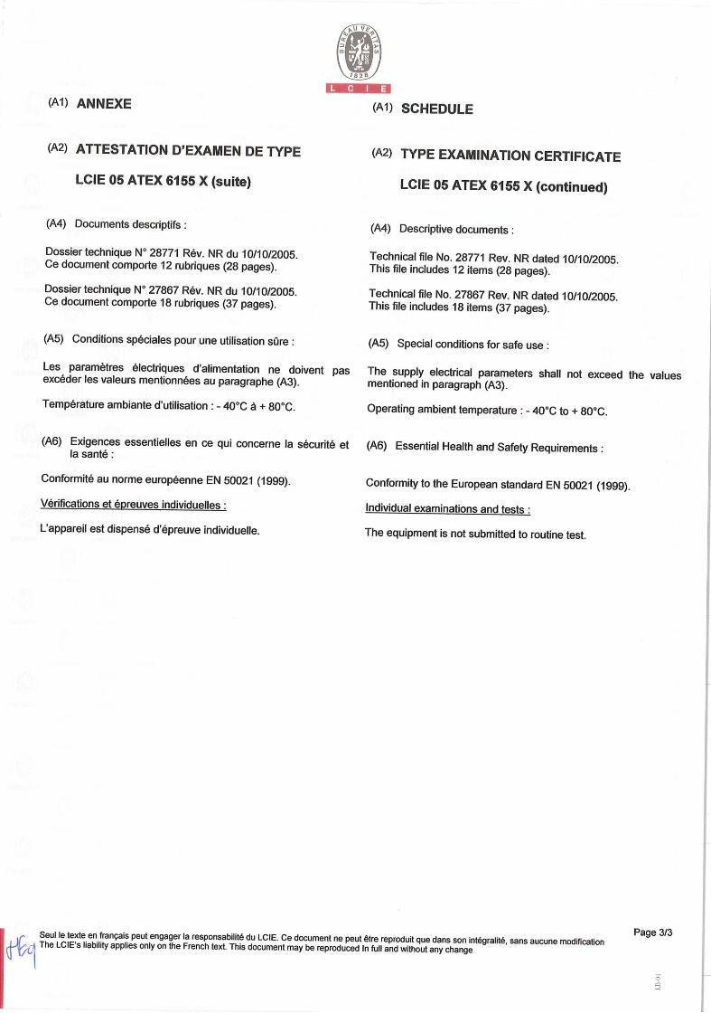
(A4) Documents descriptifs:
Dossier technique No 28771 Rev. NR du 10/10/2005 Ce document comporte 12 rubriques (28 pages).
Dossier technique N° 27867 Rev. NR du 10/10/2005 Ce document comporte 18 rubriques (37 pages).
(A5) Conditions spéciales pour une utilisation sOre:
Les paramétres électriques d'alimentation ne doivent pas excéder les valeurs mentionnées au paragraphe (A3).
Temperature ambiante d'utilisation : - 40°C a + 80°C
(A6) Exigences essentielles en ce qui concerne la sécurité et la sante:
Conformité au norme européenne EN 50021 (1999).
Verifications et épreuves individuelles:
L'appareil est dispense d'épreuve individuelle.
(A2) TYPE EXAMINATION CERTIFICATE
LCIE 05 ATEX 6155 X (continued)
(A4) Descriptive documents:
Technical file No. 28771 Rev. NR dated 10/10/2005. This file includes 12 items (28 pages).
Technical file No. 27867 Rev. NR dated 10/10/2005. This file includes 18 items (37 pages).
(AS) Special conditions for safe use:
The supply electrical parameters shall not exceed the values mentioned in paragraph (A3).
Operating ambient temperature : - 40°C to + 80°C.
(A6) Essential Health and Safety Requirements:
Conformity to the European standard EN 50021 (1999).
Individual examinations and tests:
The equipment is not submitted to routine test.
Seul le texte en français peut engager la responsabilité du LCIE. Ce document ne peut être reproduit que dans son intégralité, sans aucune modification Page 3/3
i The LcIE's liability applies only on the French text. This document may be reproduced In full and without any change
:Yt
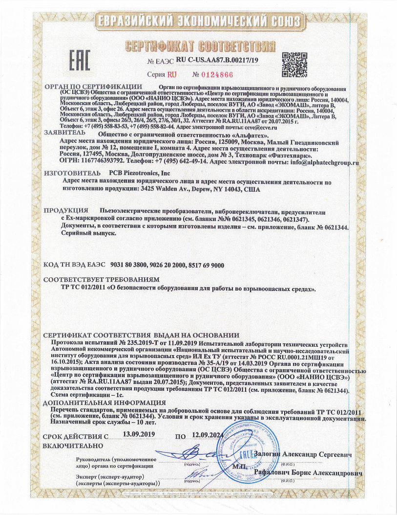
$ J.A)( RU C-US.AA87.B.00217/I9
Eepu51 IUJ .N ) tB(;
R1 114. WWI
OPFAH HO CEPT144?HKA1HH Opran no cepTu4umawlll B3pb1Bo3au11Luerntoro It pyiwnrnoro o(5opyoaarnisi (OC LCB3) O6iuecTBa C Orpanu'iennoü OTBeTCTBeHHOcThIO d1eHTp no cepTH4nuawI1I B3pb1Bo3aw1llenfloro It
M u'1uOro o6opyjwBannn (000 HAFIHO UC83>>). Ajpec eca naxoeimu Iopivinecioro .rinia: Poccaw, 140004, icoacian 06jiacm, J1i06epeciiii patton, ropoR Jlio6epubI, noce.moK BYFH, AO <<3anoi (0KOMAIII>), .rmTepa B, 06ecr 6, :)Tam 3, o4rnc 26. Mpec MecTa ocywecTarzenlnl W1eJThHocTIa B o6.iiacm aicicpeiurrawin: Poccan, 140004, MocKoncKasl o6jiacm, .JIio6epewnfi paou, ropwi illo6epubt, noceio EYf14, AO <3aaoj K0MAIll>, JlnTepa B, Mimi- 6,3Ta 3, o4nci,i 26/3,26/4,26/5,27/6,30/1,32. ATrecTaT X RA.RU.11AA87 OT 20.07.2015 r. Teae4on +7(495) 558-&3-53, +7 (495) 5588244 Aiipec 3JleKrpOnnoll noqmi ccve(ccve ru
3A51B14TEAb OöIICCTBO C orpallwlenlloui OTBTCTBCi1HOCTb1O <<AJ1b4rnTex>> Aipec MecTa Haxoeiiuii !opumn'lecKoro .rinua: Poccun, 125009, Mocicna, MaJibiul 1Ne3EIHHKoBcKHä uepeyJioK, LoM N2 12, noeweijne I, KoMuaTa 4. A.rpec meCTa ocyuecTB3enun JeuTe.J1bIIocTn: Poccnn, 127495, MocKna, oJIronpy)HencIcoe mocce, joi N2 3, TexuonapK <<(1n3TexHapK>>. OFPH: 1167746393792. Teie4ou: +7 (495) 642-49-14. At*pec 3iieNTPOH110ft no'imi: [email protected]
H3FOTOBHTEAb PCB Piezotronics, Inc Ajpec Mecra naxoacreunsi Joputw'IecKoro AHija H aipec MecTa ocywecTBJlellnsl )eaTeJIbHocTn no fl3FOToI3CHhIO npoiyicwin: 3425 Walden Av., Depew, NY 14043, CIlIA
HPO4YKI45I flbe3oIeIcTp1I 'lecKne ii pe06pa308aTe.rin, Bn6poHepeKJuoqaTeJuj, n peJycHJInTe.rIH c Ex-MapidnpoBKoIr cormacuo HHJ1OKCHftI0 (CM. 6JIarndn .NW& 0621345, 0621346, 0621347).
OKyMCHTbI, B COOTBeTcTBHU C KOTOpbJMH 1130TOBJCHbI H3J*e3HNI - CM. UpflJIOKdHHe, 6JIaJ1K Ni 0621344. Cepafinblui flblllyCK.
KOA TH B3A EA3C 903180 3800,902620 20009 8517 69 9000
COOTBETCTBYET TPEBOBAHHSIM TP TC 012/2011 <0 6e30nad110cT11 O6Opy/oBa11Hu1 Aim pa6oTbI BO B3pb4noonacn16lx cpeiax>.
CEPT11414KAT COOTBETCTBFI5I BbI4AH HA OCHOBAHI{H ilporoKoJia Ildilbiranuhi J'& 235.2019-Tor 11.09.2019 lfcnblTaTeju.uoui JIa6opaTopnh1 TexunqecKux yCTpouicTn ABTOHOMBOhi HeKOMMeptiecKon oprannaiiin <<HanoHaJi16H161fl llCflblTaTejlbnblhi U HaIHO-HCcJieoBaTeJ1 bcKllli HHCTUTT 060pyLOBaHH51 TJ111 113L1BOOfl2CHb1X cpej>> Iii! Ex TY (arrecTaT Ni P0CC RU.0001.21M11119 OT 16.10.2015); AKTa anaJm3a COCTOSIHUH 11pOU3BocTna .N1i 35-A119 or 14.03.2019 Opraiia no cepuniaiau -T B3PbIB03 1UftWC1II10fO if pyjnt,uoro o6opyjwnaiina (OC 1ICB3) 06utecTBa C orpanutielijioli ornercrnennocrblo <Iewrp 110 cepTll4nlKauu11 B3pb1Bo3aH1nueuHoro 11 pyiun'uioro o6opyloBaHuH>> (000 <<HAHIIO 1C133>>) (arrecrar )& RA.RU.11AA87 ubliiaii 20.07.2015); ,LoKyMenTos, npe/cTaBJIe}rnb,x 3auBnTeJIeM B Kaqecme )oKa3aTeJ1hc7FBa COOTBTCTBHS1 I1pOJyK1HH Tpe6oBaH1mM TP TC 012/2011 (CM- npuaoaenne, 6JIaIIK Ng 0621344). CxcMa cepmrnauniz - ic.
- AOHOAHHTEJThHASI HH(OPMA1145I
I1epeqCHb cTaHJapToB, UHMHHMLIX Ha )06pOBoJIbnohi OCHOBe /1q co6Jt1oL(ellaln Tpe6oBaulihi TP TC 012/2011 t npJuioxenue, 6JIaI1K 0621344). YcJIOBHn H COR xpanennn Eh! a 'lKdnJIyaTaunonHohi /o1cyMeuT a14uu. llaqelnlblhi COOK CJty*c6b1 - 10 JICT. .. -
CPOK 4EhCTBH 20 M C 13.09.19 rio 12.09.2024,
'T7. :•\
BKUOqHTEAbHO 1
3tjioi un A ,ecanp Cepreennq PyKonoAnTeith (yno4inoM0eHHoe
oprana no ceprn4nixairm (nognm b I a4aaiom14 hope A.rIeIcaHELpoBnq
31c1wpT(9xdnpJ-av4nrop) • - ()LcIIeprhI (3KcIu:plf.1- ayAJIropbl)) . - ....

PyKoioAnTeu (ynoAnoMoennoe 2tJno) oprana no ceprn4)m<aIm1
3acnepT (aKcnepl-ayAnlop) (axcnepmi (3xcneprbI-ayiTopbI))
4JleIcan,Ip CeplecBll'I • fii
H 1opiic AJ1eKeaJ1J11)0131011
MXL
-
060ia'ieiue cTaIIIaproB HanMeHosanHeCTaIJL*apToB -
I_FOCI 3 1610M-2014 (IEC 60079-0:2011) B3pbIBoonaduMecpewacmo. 06opyoBanue. 061aneTpe6oaim 1-OCT IEC 60079-1 -2011 l33pblBoorlaculie cpelbl, '-lacm 1. 06opyjioname c BH)0M B3pbJ303auwr&I
<li3pbrnoHenponMuaeMwe o6ojiotnui <d>> [OCT 31610.11-2014 (IEC 60079-11:2011) B3pbrBoonacllble CpeJibl. 4aem 11. 06opyjWt3alllle C l3IU0M 133ph1B03a[UHTM
((HcKpo6e3onacHasl DllelcrpnLlecKasl ieim <<1>>
[OCT 31610. 15-2012/M3K 60079-15:2005 3jiei t'poo5op•yoaaniie ansi npwsoonacmtx 1a30rn1x cpei. 4acm 15. KoIic-rpyKuwl, flcrihllaulnl H mapyaipoBica 3jieKTpoo6opyAOBanmjq C BW0M 3aUM-r1.1 <(fl>
11 ,1OKYMEIITh1, 11PEJCTAB.ThFHHME 3A5IBIITEJIEM 13 KAECTBE AOKA3ATEJIbCTBA COOTBETCTBHM I1PO)YKIHh1 TPEOBAHH5LM TP TC 012/2011
PKo1JocTHa 110 31dfl1yaTaLHH N 750119 oi 230119 N 83011901 230119 N' 940219 oT0702 19 K 630119 oi 220119 N 610119or2201 19 N29102190T0702 19 N 950219oi0802 19 N 970219oi0802 19 Temili'lecraic ~aUbr X2 54202oT02022017 N 54204or02022017 Ki, 22438Coi 19072012 X2 62501 or06 102016 XL, 33699 oi 16062016 N 56178oT01072016 XL, 70893oT24072019 1L54707oi 10082016 XL, 48813oT06012011 L1epj.c)J(}, X2 47912oT31032017 X2 49038oT31032017 flepe'lLHb cral-LoapTol3 CM Ii I
111 )IOKYMEHTb1, B COOTBETCTBHH C KOTOPb1MH 1131'OTOBJIEHA llPOJYK1115I IexHuqecKH.()aHJ1b1 Xg 54202 OT 02.02.2017, N 54204 0T02 022017 N 22438CoT 19072012 XL, 62501 oi06 102016 K 33699 0116062016N056l780101072016N0708930124072019 XL) 5470701 1008.2016, N948813 oi06 012011 1-h.p-reKM XL, 47912oT3103 2017 X2 49038oT31 032017
JJWAJJJ$JJJJ
IPFLAO){<EHILE RU K CEPTWDHKATY COOTBETCTBH5I N EA3C PT ,0
Jl h1CT2
Cepiisi LW NQ 0621345
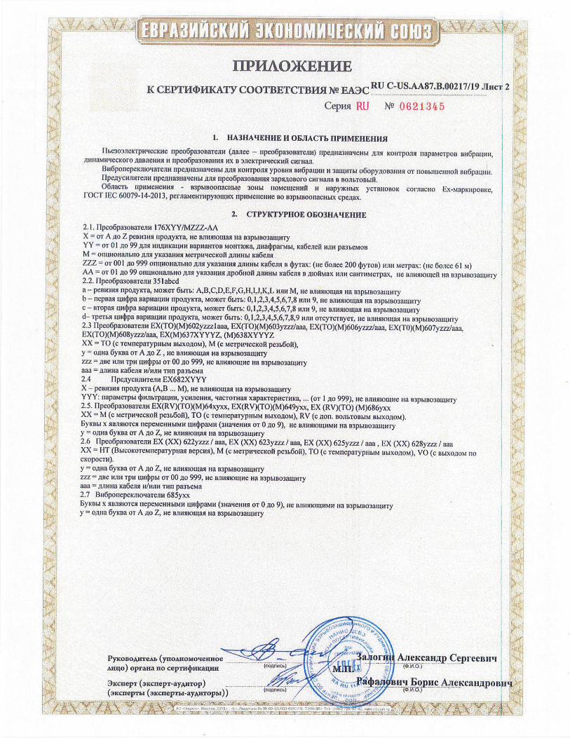
k 1. HA3HAqEHHE II OBJIACTb EIPHMEHEHII$I
flbe3o3J1e1crpHecKI1e npeo6pa3ooaTeJ1M (.aaiiee - npeo6pa3oi3aTellll) npeJuia3na'eJmt ,TI)1Sl KOHT0351 11apaMe'poB BH5paiWH, /j1IHaMHqeCKOfO .oaB1eHMsl ii npeo6pa30Ballusl HX B 3J1eIcrpHqecKMi CHFHWL
BH6p0rIepeKrn04aTeJ1H I1pe.iva31IattenbI ,LULSL K0HT0J1$l yporw BH6paW4H H 3amHTbl o6opyJoRarnin OT rlol3buhle}ilroil wi6paullH. I1pe.uycrfnwreJlH llpe1ula3Ha'lenbl ,BJISI flpC0pa30BaHH1 3apsUtolloro CHI'Hana B B0JJbT0B1,111, 06iacm flMMCHHH$l - 03p&lBoonacnble 30}thl fl0MeWeHHi H HO)KH14X yclal-roBoic corsiaciio Ex-vrapKripoDxe,
['OCT IEC 60079-14-2013, pernar1eH'rHpyrouu1x HPHMCHCHHC BO B3pbr000nacI-ralx cpezrax.
2. CTPYKTYPHOE OF03HAEHJ1E k.
2.1. llpeo6pa3onalenH 176XYY/MZZZ-AA X = or A 110 Z PC111131131 rtpo,ayicra, He Bslmllotlrag na n3pbrrr03alullly YY = or 01)10 99 ,rrrn HH,iuu<anrn BapnlaHloa Mowra)Ka, an1aparMM, Ka6encri 111111 pa3'beMoB M = OI1UHOHJIhHO )UTB yfca3aHn MC'rpHtlecKO[i .E1J1HHM ka6ellsl ZZZ =oT001 iio 999 0HIH0HaJ1bll0 jllrsr yKaarmsr 2IJIUHb1 Ka6eJor B 4yTaX: (He 6w=200 yToD) wur Me'rpax: (rio 6oiee 61 M) AA = or 01 jo 99 OHUHOHaJmHO .11101 yK113HiB1 )lpO6110fi AJBlHhl xa6en,i i 1uo1Max 05tH callloMelpax, He BJtH5110ll)eI na 113p61liO3auw'ly
H 2.2. flpeo6pa3oBaTeirn 351abcd a - pernl3itn npo.ayrcra, roce'r 6brrb: A,B,C,D,E,F,G,H,I,J,K,L ruin M, He wlnls0011rall ua B3pMr30'3amllly b— nepuai 1uujpa BaPMaIIHH npo,lryrcra, MO)KOT 6Mm: 0, 1,2,3,4.5,6,7,8 wilt 9, ire BJIH11I0Ua Ha B3pMu03a[unly C - BT011M uwpa 011P011UiIM flpO)1y'a, M0Of 6bITb 0, 1,2,3,4,5,6,7,8 115tH 9, He Bjumomaq na B'3pbIBOau1HTy d— TPCTMt un4pa DapHaIUH rlpo.iryx'ra, M0CT 6tnn.: 0, 1,2,3,4,5,6,7,8,9 rum o'rcyTcBye, He nuuurnourail Ha B3PblB03WHTY 2.3 I1peo6pa300aTeaH EX(TO)(M)602yzzzlaaa, EX(TO)(M)603yzzz1aaa, EX(TO)(M)606yzz7Jaaa, EX(TO)(M)607yzzz/aaa, EX(TO)(M608yzzz/aaa, EX(M)637XYYYZ, (M)638XYYYZ 1 ;H XX = TO (c emepaiypimri m.rxo.LroM), M (c MeTpI-NCCK01 pe3b6ol),
= y o.tma 6yiura 01 A ,iO Z He usuuirooiasr Ha B1pbIB03auU1Ty ZZZ =ABC 11.1111 TPH U)M 01' 00.110 999, HO 131I115l10U1H oa B3p6ln03auioly aaa = ,rijuuna Ka6eslsr 11/Hfl}1 TILt pameia 2.4 IIpesrycmiirreiinr EX682XYYY X - peirnrwi npoxrycra (A,B ... M), He Biioiiioiiasr Ha R3pI.1B03aIIrHTy YYY: rrapairepr 4mlrblpaumi, ycirnerinrir, qacTomall xaparcrepilc'InfKa, ... (01 1 ,rio 999), oe niiiusrioanre ira 133pbrno3awll'ry 2.5. 11peo6pa30ualeilo EX(RV)(TO)(M)64xyxx, EX(RV)(TO)(M)649yxx, EX (RV)(TO) (M)686yxx XX = M (c MeTpwlecxoi pe3&6oi), TO (c leMllepalypllhiM Bb1X01l0M), RV (c 51011. BOJIbTOBbIM BbIX0J1OM). b'.rcobr x 51BJIMIOTCSI flLMOHh4b1M14 [IH4)paMH (311a reuwi 01 0)10 9) He BJIHIHO[WIMH ma 113p1I1303auulry y = osu-ja 6yKrra UT A 510 Z oe BJ1HlHoII1as1 Ha 133b1B0311U1H1
2.6 [1peo6pa3oaaTeJm EX (XX) 622yzzz / aaa, EX (XX) 623yzzz / aaa, EX (XX) 625yzzz / aaa, EX (XX) 628yzzz / aaa XX = FIT (BblcoKoTeronepalypoair Bepcwi), M (c Merpru'IecKoi pe3b601j), TO (c ieMnepa'rypno.ibi m.lxo51oM), VO (c BI.IXO51oM Ho c1(OpOCT11).
y = oiuia Gyrura or A 510 Z, ne ojiilsriouiasi ua BIPMBO3BIUHTY iiz = 1113e Will ipo 1114!p1o1 OT 00 40 999 He oimiaouloe nia 113pbro03alunny aaa srjrriva ha6esur ilIwIn1 11111 pamea 2.7 Bll6porTepcInroaTennr 685yxx
X 51Balflo'rCsl nepeM000brMlr IuurIrpaMH (30aierunlB OT 0A 9), nie BJ1HM1OLUHMH nia 113pb1B03aiuHTy y = o nra 6yKw1 or A oo Z nie Brnrtllolllarl nia
H Ponone ( Cepreeniiti 1 H Mu4o) oprana no cep4nrKam
" 3iciiepi (3EcnepT ay,nTop) Pâ4a$Iu Bopuc A.r!u.caLI,iLpoBItq (3xcnepml (arcrrepmr-ayuTopbI))
1 T .IjSHL:. t:.'/

I I. Ex-iapiuipoaia: npeo6pa3ooaieiel 176XYY1MZZ-AA 0Ex ia IIC 1660°C. .16 Ga X ripeo6pmmeacA 35 labcd 0Ex ia HC T4 Ga X an6ponepeimoa'reiie3 685yxx lEx d 1113+1-12 14 Gb npeo6pa3onaTenei EX(TO)(M)602yzz21aaa, EX(TO)(M)603yzzz/aaa. 2Ex nA TIC 14 Ge X EX(TO)(M)606y7zz/aaa, EX(TO)(M)607yzzzlaaa, EX(TO)(M)608yzzz1aaa HIM
0Ex ia IIC 14 (laX npe06pa30aa1e2re11 EX(M)637XYYYZ, (M)638XYYYZ 0Ex ia IIC T4 Ga X
14JTh 2Ex nA IIC T4GcX
npe,aycimmenck EX682XYYY 0Ex in lie 14 Ga X Will
2Ex nA IIC 14 Ge X EX(RV)(TO)(M)64xyxx, EX(RV)(TO)(M)649yxx, EX (RV)(TO) (M)686yxx I Ex d TIC 14 Gb X
1 Lx d IIC 13 Gb X ripeo6paaonaiemiei EX (XX) 622yzzz/ aaa, EX (XX) 623yzzz/ aaa, LX (XX) 2Ex nA IIC T4 Ge X 625yzzz/ aaa, EX (XX) 628yzzz/ aaa
3,2. Amalmoll TeMnepaTyp 0KpyKalolueii Cpeai, °C, npeo6pa3onnaTeneti I76XYYfMZZ-AA OT -70 jio 650 npeo6pa3oaa'remnet 351 abed OT -196 ,mto 121 1m6ponepeKJno4aTcJle1 685yxx or -25 ito 60 upeo6pa3oaa'renetl EX(TO)(M)602y7-zz1aaa, EX(TO)(M)603yzzz/aaa, EX(TO)(M)606yzzzlaaa, EX(TO)(M)607yzzz1aaa, EX(TO)(M)608yzzzJaaa OT -54 Ao 121 rlpeo6pa3onaTeneii EX(M)637XYYYZ, (M)638XYYYZ npe,tiycHllHTeilell EX682XYYY or -196 .io 121 ripeo6paaonaieine EX(RV)(TO)(M)64xyxx, EX(RV)(TO)(M)649yxx, LX OT -40 io 85 (RV)(TO) (M)686yxx npeo6pa308aTemle1l EX (XX) 622yz7z/ aaa, EX (XX) 623yzzz / aim, EX (XX) OT —20 jo 80 625yzzz / aaa • EX (XX) 628yzzz/ aaa
OT-54210 121 -, ""1-' lit l(i.'¼LlJbi
nncnfinAInnATnqeri ilfltflurn4rlUTprlptl'
MOAeJlb Ut, B Ii, MA Pt, 131
--•1--
Cj, WI) -
Li. Nin, upco6pa30aaTemleui I76XYY/MZZ-AA
30 300 I 5 0,5 rlpco6pa3ooaTenetl 35labed
28 200 1,2 61 305 M1d'H npeo6pa3osalemidil EX(TO)(M)602yzzz I aaa, EX(TO)(M)603yzzzlaaa, EX(TO)(M)606yzzz/aaa, 28 200 mm
npeeicoio Ma,na16,2 l-IJI}1
EX('l'0)(M)607yzzz/aaa, 77,2 (c Ka6eJ1eM) 305 NIKi11 (c y;ne-roi EX(TO)(M)608y7,zz Ka6ei15l 305M)1aaa llpeo6pa3ollale.qefl EX(M)637XYYYZ,
28 93 0,65 6,5 - (M)638XYYYZ npee6peaciito mam
npeitycnun.rrexie0 EX682XYYY28 EIOO
0,7lnpcne6pe?KoMQ aim flpCllC6pCixHMo
--------------------
3 Ponoie
a oi .iiird Aiiei canp CepreeBllq
AuIo) opraita no ceprn4ma4mt
3xcnep1 (xcnepT-aytTop) Iitj,aJtbiuiq Eopnc AJeIcaHjpoB1Iq
(.ncnIepT1n (iKdneprbn-.l)'xnnopzin)) .';Ii•'.' l
H
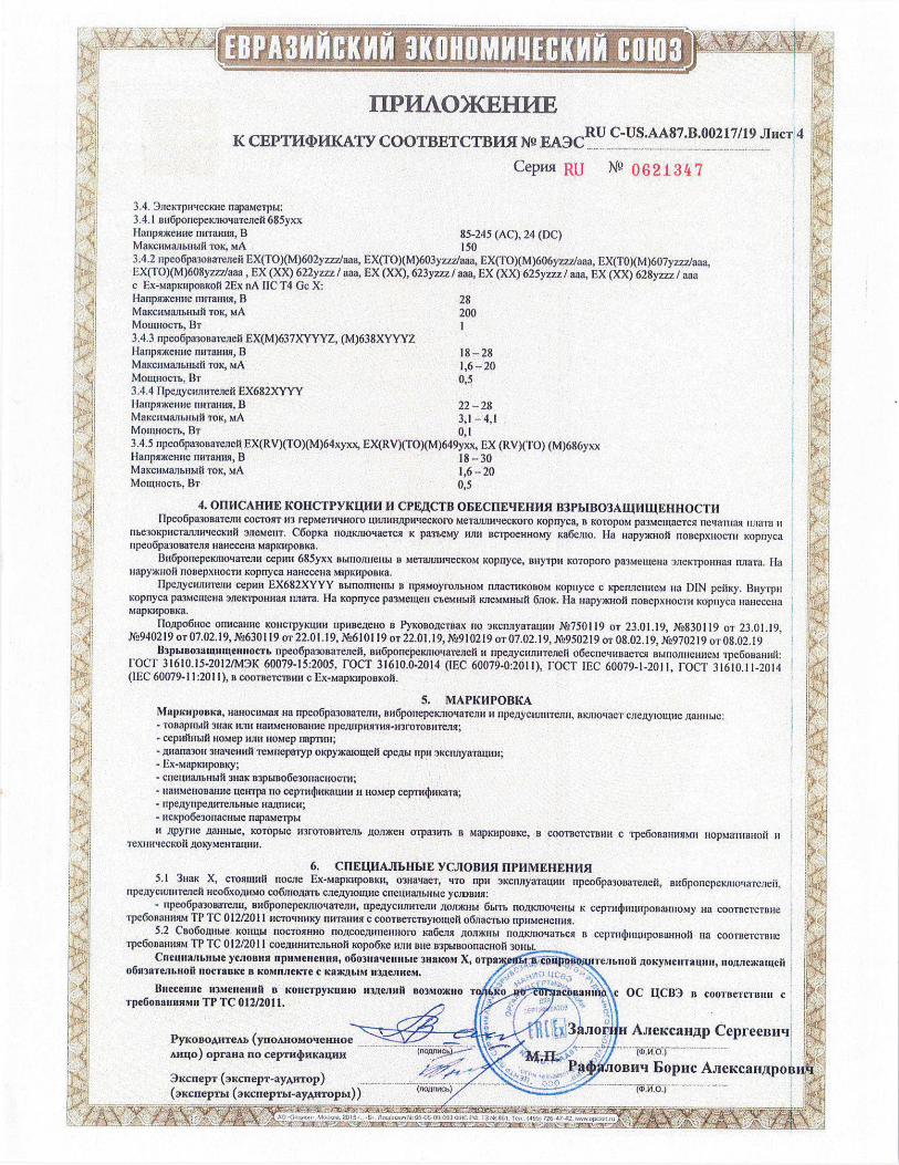
3.4. 3ieicrpirtecore napaMerpb1 3.4.1 Bu6ponepekJllo4alcneil 685yxx Hanpoceiie rmTaun3I, B 85-245 (AC), 24 (DC) VtaKcMaJibnb0 10K, MA 150 3.4.2 npeo6pa3o1saTeJIei EX(T0)(M)602yzzzlaaa, EX(TO)(M)603yzzz/aaa, EX(T0)(M)606yzzz1aaa, EX(TO)(M)607yzzz/aaa. EX(TO)(M)608yz77Jaaa , EX (XX) 622yzzz/ aaa, EX (XX), 623yzzz/ aaa, EX (XX) 625yzzz / aaa, EX (XX) 628yzzz/ aaa c Ex-MapknponKofi 2Ex nA DC T4 Gc X: Haiipaaeiiue niiraiiiui, B 28 MaKcaMaibtn!i1 10K, MA 200 Mownocm, BI 3.4.3 ripeo6paonareieii EX(M)637XYYYZ, (M)638XYYYZ llarlpsnKem(e riwraiui, 13 18-28 MaKcw1arIbIab1fi TOK, MA 1,6-20 Motiuiocm, Br 0,5 3.4.4 F1pcjycwin'reiieil EX682XYYY I1anpenne riniatnin, II 22-28 MaKdHMaJi1Im1i 10K, MA 3,1 —4,1 Moiwiocm, 13i 0,1 3.4.5 npeo6pa01aiejeii EX(RV)(TO)(M)64xyxx, EX(RV)(TO)(M)649yxx, EX (RV)(TO) (M)686yxx 11aripnKenne rnn'annii, 13 18-30 MaKdllMaflbiibi0 10K, NiA 1,6-20 Moiiwocm, BI 0,5
4. OIIHCAHIIE KOHCTPYKUIIII H CPE,ECTB 0EECHE4EIIH5L B3Pb1B03AEIHLEEH}LOCT11 11peo6pa3osaTe1u COCTOI1T 113 repMe'rivuioro LUrn11W1pi{eCKoro MelaluiwiecKoi-o Koprryca, 14 KOTOPOM pa3MeiLLaeTcsJ nCiaI1iasi rIJIaTa H
nhe3oKpuc'ranJlliqecKnui 3J1eMeuT. C6opKa noj.usuoae'rvsi K pamey njni nclpoenHoMy Ka6eJuo. Ha Hapy)KHOO IIOBCXH0CTiI Kopuyca npeo6pa3oBaTcJin iiaiiecena MapluiponKa.
Bu6ponepeKjnotiaTeJni ceprni 685yxx Bbinoimem.I a MeTaJLr11tMecKoM Kopoyce, BUTH Koroporo pa3Mewe1-Ia 3JIeK'rpollm131 rriaa. Ha uapyiio1i noaepxuocm Kopnyca naiiecena M4pKapoeKa.
flpe)lycarmlemu cepin EX682XYYY BbiIIOJIHCHLI B 11PS1M0F0JThH0M IUTaCTHKoBoM K0I1CC C RiUiCHCM na DIN peOKy. 13iiyipu opnyca paemena 3JICKTPOHMA miaTa. Ha Kcipayce paeiueu e'eiiiadl KJ1eMMHbIti 6110K. Ha HapyMcuoi OOBCpXHOCTII icopnyca iiaeceiia
Mapiu!poaKa.
UTojpo6iioe ornicai-me KoHc'rpylauln ripiine;teuo B PyKoBo.cTBax no 3KCflJTYBTLUffi X2750119 Or 23.01.19, M830119 01 23.01.19, M940219 OT 07.02.19, XL,630119 oT 22.01.19, XL,610119 OT 22.01,19, M-010219 OT 07.02.19, XL050219 OT 08-02.19, X970219 wr 08.02,19
BJphIBo3atUnhfela!ioem npeo6pa3onaTeiieii, aH6ponepeKnlo'.{aldneil ti npejycrnrriie,rie1i o6ecnctRrnaelcli BbinORMIRCM i'pe6onauiiit roc- 31610.15-2012/M3K 60079-15:2005, FOCI 31610.0-2014 (IEC 60079-0:2011), FOCI IEC 60079-1-2011, FOCI 31610.11-2014 (IEC 60079-11:2011), B COOTBCTCIBHII c Ex-MapiuJponicoii.
5. MAPICIIPOBKA MapluiponKa, HBHOCHMBH ua npeo6pa3oBaTernx, nll6poliepeKnioqalejllf H npemyciuni'reini, BKJIIO'iaCT CJIeiyIouue ;aillihIe: - Tonapriblil 3IiK 111111 nanenonane flpejljipil5llH5l-113roloni!lejisi; - cepuihiMli iioitep 111111 HOMC riapTilhi; - /jna11a3011 311a'4e111111 TemnepaTyp oKpyx(aIoaeIi cpeILh1 npii )KCri11yaraui111; - Ex-1apKupoaKy;
- crIe1LHa1IbLIbiI 3HaK 133phuIo6e30r1aeuocTri; - iiaiienonaune ueirrpa no cepllillnn(awm ii Romep cepm4mKaTa; - upejlynpe4uleJmuble 1114.LIHHCM - ncKpo6e300aduMe napaMe'rpM ii ipynie /xallnbie, K0T0b1C ll3rolonwrenb 10JDKCH o'rpa3llm B MaplalpoaKe, B COOTBCTCTBHH c 'rpe6onami51ii uopMa'rualioii U
'rex}lHtiecKoii .aoxyMenrarunl.
6. CflELEIAJ1bF1b1E YCJIOBH5I LIPHMEHEHH5I 5.1 3i1aK X, CTORUIIIO nocile Ex-laapJcMpoBKn, 0311aBeT, 'iTO BPI' 3KCi1flflTtjH14 flpeo6pa3ol3alelieii, B116ponepeKJnoMaTcJieii,
npej.tycwuiieieii lieo6xouiMo co6mo;jam cmejyioinne cueLHaJmubie VCJIBIIII: - 0pe06pa300a'resui, nri6ponepexinoqaierni, flP1C111iHTCJIH Aonwubi 6b1m no11Knjoqenbi K cepTncjnn.uponamtoiy Ha COOTBCTCTEIHC
1pe6oaallnslM TP 'rc 0 12/2011 IICTOMimKy linmilhia c coolncicluylolaeui o6nacmio np}IMeHemn. 5.2 Cno6oflhlbic K01!Lhl II0CTOMHHO noJeoe.rumewioro xa6e1131 .L4011)K.Hbi no/jicriioqamcn B CCPTII(1)illhiipoaaijh{ojl HB c0olnelcr13iIe
i-pe6onaiitii TP IC 012/2011 COCJUIRHTCJIbHOIi Kopo6Ke 113Th nue 133phiBO0rIaCH0ii 3011141.
Cueuuallbnkle ycionnn npnMe,ie,nhii, 06031109e1111a1c 3BBKOM X, o'rpaeiI1.i pojLjileln.hloh oIyMcIIrawm, I1oJmeKaIIeii o6a3aTeJu.uoil IJOCTBBICC B KONIHJIeKI'e C KBK3bi4i II31ICJIUCM. 7 .
.,.
Bueceane u3Meflenlltl a KoncvpyKuliw 113JeJi1iü B03MO)RIIO I Oe acnnanlno\c OC UCB3 B coolnercunuit C 'rpe6onauunMll TP TC 012/2011. ;.
. . 3aJioru As1eicca1I)p CeprceBuq
PYK0BOAnTeA1 (yno2s.noMoeRHoe .. .. Amlo) oprana no cep1n4nwawu1 OATli : )
Pa4jJIoBnq BoplIc Aiei'cazijtpoi 3KcnepT (adnepT-ayAnTop) .
(10flCb) (2 4 ID)................... (3xcixepml (cnepTb1-ayAnT0pbi))
AN /
,f -------------
PCB PISOTRONG MIS SYSTEMS CORPORATION
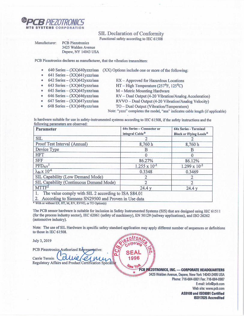
SIL Declaration of Conformity Functional safety according to IEC 61 508
Manufacturer: PCB P iezotronics 3425 Walden Avenue Depew, NY 14043 USA
PCB P iezotron I cs declares as manufacturer, that the vibration transmitters:
• 640 Series - (XX)640yzz71aaa (XX) Options include one or more of the following: • 641 Series - (XX)64 I yzzzlaaa • 642 Series - (XX)642yzzz/aaa EX - Approved for Hazardous Locations • 643 Series - (XX)643yzzz/aaa HT High Temperature (2570 F, 1250C) • 645 Series - (XX)645yzzz/aaa M - Metric Mounting Hardware
646 Series - (XX)646yzzz/aaa RV * Dual Output (4-20 Vibration/Analog Acceleration) • 647 Series - (XX)647yzzz/aaa RVVO - Dual Output (4-20 Vibration/Analog Velocity)
648 Series - (XX)648yzzz/aaa TO - Dual Output (Vibration/Temperature) Note: "yzzz" completes the model, "aaa' indicates cable length (if applicable)
Is hardware suitable for use in safety-instrumented systems according to IEC 61508, if the safety instructions and the following parameters are observed:
Parameter ' 64x Series - Connector or
integral Cable* I 64x Series - Terminal
Block or Flying Leads*.
SIL 2 2 Proof Test Interval (Annual) 85760 h
-- 8,760 h
Device Type B B HFT 0 0 SFF 86.27% 86.12% PFDAV' 1.255x10 3 1.299x10 3 XduX 10 6 0.3348 0.3469 SIL Capability (Low Demand Mode) 2 2 SIL Capability (Continuous Demand Mode) 2 2 MTTF2 24.4 y 24.4 y 1. The value comply with SIL 2 according to ISA S84.01 2. According to Siemens SN29500 and Proven in Use data With or without EX, HI, M, RV, RVVO, or TO Option(s)
The PCB sensor hardware is suitable for inclusion in Safety Instrumented Systems (SIS) that are designed using IEC 615 11 (for the process industry sector), IEC 62061 (safety of machinery), EN 50129 (railway applications), and ISO 26262 (automotive industry).
Note: The use of SIL Hardware in specific safety standard application may apply different number of sequences or definitions to those in IEC 61508.
lilt iii
July 3, 2019
PCB Piezotronics uthorized R re tive: ?ç/ SEAL
Carrie Termin 1996 / Regulatory Affairs and Product Certification Speci ii •1
........ ..1CBZOTRONICS, INC. - CORPORATE HEADQUARTERS
3425 Walden Avenue, Depew, New York 14043-2495 USA
Phone: 716-684-0001 Fax: 716-684-0987
E-mail: [email protected]
Web site: www.pcb.com
AS9100 and IS09001 Certified IS017025 Accredited

tntertek Total Quality. Assured.
INTERTEK ASSURANCE SAFETY INTEGRITY LEVEL SUMMARY REPORT r lL t# I iIu
CLIENT NAME PCB Piezotronics, Inc. 3425 Walden Ave
Depew, NY 14043-2417
REPORT NO
103685042CSL1-001
COMPILED BY
Ashton D. Hainge, CFSP, PMP
PROJECT NAME
G103685042
DATE
16 November 2018
I .
I. 41
C.
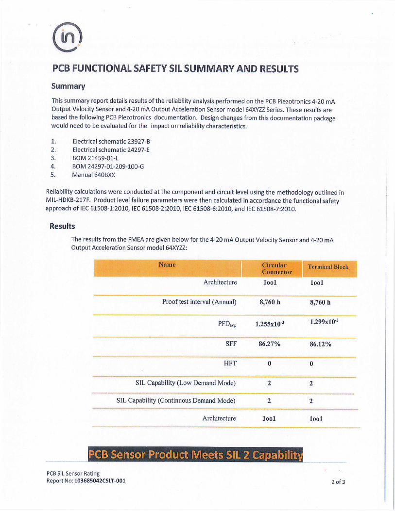
On PCB FUNCTIONAL SAFETY SIL SUMMARY AND RESULTS
Summary
This summary report details results of the reliability analysis performed on the PCB Piezotronics 4-20 mA
Output Velocity Sensor and 4-20 mA Output Acceleration Sensor model 64XYZZ Series. These results are
based the following PCB Piezotronics documentation. Design changes from this documentation package
would need to be evaluated for the impact on reliability characteristics.
1. Electrical schematic 23927-B
2. Electrical schematic 24297-E
3. BOM 21459-01-L
4. BOM 24297-01-209-100-G
5. Manual 640BXX
Reliability calculations were conducted at the component and circuit level using the methodology outlined in
MIL-HDKB-217F. Product level failure parameters were then calculated in accordance the functional safety
approach of lEC 61508-1:2010, IEC 61508-2:2010, JEC 61508-6:2010, and lEC 61508-7:2010.
Results
The results from the FMEA are given below for the 4-20 mA Output Velocity Sensor and 4-20 mA
Output Acceleration Sensor model 64XYZZ:
Name Circular Terminal Block Connector
Architecture lool lool
Proof test interval (Annual) 89760 h
PFDavg 1.255x10 3
SFF 86.27%
HFT 0
SIL Capability (Low Demand Mode) 2
SIL Capability (Continuous Demand Mode) 2
Architecture lool
PCB SIL Sensor Rating Report No: 103685042C51T-001
8,760 h
1.299x10 3
86.12%
0
2
2
lool
2 of 3

Ot"n Name Results*
Safe Detected failure rate 2USD x 10 0.4937 (0.5 117)
Safe Undetected failure rate 2su x 10 0.3291 (0.3411)
Dangerous Detected failure rate 2DD x 10-6 1.2813 (1.2993)
Dangerous Undetected failure rate 7DU X 10-6 0.3348 (0.3468)
Average frequency of a dangerous -6
failure on demand PFHx 10 1255.0477
(1299.0000)
Type B components: 64XVZZ Series (includes EX64XVZZ Series)
The safety relevant parameter PFDavg iS in compliance with the corresponding requirements for SIL 2 according to IEC 615081.
The safety relevant parameters HFT and 5FF are in compliance with the corresponding requirements
for SIL 1 according to IEC 61508.
The user should consider, that the hardware fault tolerance of all inspected devices is zero and that
a single fault can lead to a dangerous failure.
Senior Consultant,
40'747;r Ashton Hainge, lntertek
CFSP, PMP
*Note: Values are for Circular/Cylindrical connectors. Values for Terminal Block connectors are given in parenthesis.
1 The assessment results described in this report only refer to the safety-related parameters PFD avg, HFT, and SFF according to JEC 61508.
This report does not make any statements, that the manufacturer meets all other requirements of the above cited standards for hardware, software, documentation, management of functional safety, verification, and validation.
This report does not imply that the examined pressure sensors have been certified for functional safety by the assessor according to IEC 61508 or any other standards.
The sensors are only one part of a complete safety function. It is at the responsibility of the end-user to prepare and to apply an extensive reliability model, that brings out the complete safety function and that meets all requirements of the claimed SIL level according to IEC 61508.
PCB SIL Sensor Rating Report No: 103685042CSL1-001 3 of 3

PS053 REV. N 07/01/2021
EU Declaration of Conformity PS053 In Accordance with ISO/IEC 17050
Manufacturer: PCB Piezotronics, Inc. 3425 Walden Avenue Depew, New York 14043 USA
Authorized PCB Piezotronics Europe GmbH European Porschestrasse 20-30 Representative: 41836 Hückelhoven,Germany
Certifies that type of equipment: Vibration Sensor(s)
Whose Product Models Include: EX64…, EXTO64…, EXRV64… Series
This declaration is applicable to all Vibration Sensor(s) of the above series which have the CE & (EX) ATEX mark on their data sheets and where those data sheets refer to this declaration of conformity. The data sheets for all model numbers referenced above, which include the CE & (EX) ATEX mark on such data sheets and refer to this Declaration of Conformity are hereby incorporated by reference into this Declaration.
Conform to the following EU Directive(s) when installed per product documentation:
2014/30/EU 2014/34/EU 2011/65/EU w/2015/863/EU
EMC Directive ATEX Directive RoHS Directive
Standards to which Conformity is Declared:
Harmonized Standards EN 61326-1:2013
EN 61326-2-3: 2013
EN 61010-1:2010
EN 60079-0 :2012+ A11:2013 EN 60079-11: 2012 EN 63000:2018
Electrical Equipment for Measurement, Control and Laboratory Use- EMC
Electrical Equipment for Measurement, Control and Laboratory Use- EMC
Safety Requirements for Electrical Equipment for Measurement, Control, and Laboratory Use - Part 1: General Requirements
General Explosive Atmosphere Intrinsic safe, i Technical documentation for the assessment of electrical and electronic
products with respect to the restriction of hazardous substances
Emissions Test Standards
EN 55011:2009+ A1:2010
Industrial, scientific and medical (ISM) radio frequency equipment-Electromagnetic disturbance characteristics- Limits and methods of Measurement Class B
Other Standards Applied (non-OJEU)
Immunity Test Standards
EN 61000-4-2:2001 EN 61000-4-3:2006 EN 61000-4-4:2004 EN 61000-4-5:2005 EN 61000-4-6:2006 EN 61000-4-8:2001
Electrostatic discharge (ESD) Radiated, radio-frequency, electromagnetic field immunity Electrical fast transient (EFT) / Burst immunity Surge immunity Immunity to RF conducted line disturbances Power frequency magnetic field immunity
Test Reports EMC Reports Safety Reports
GM29045c GM29046s
EC Type Examination ATEX Certification LCIE 05 ATEX 6154 X Ex ia IIC T4, II 1G
PS053 REV. N 07/01/2021
Voluntary Certification Supplemental ATEX Certification
LCIE 05 ATEX 6155 X Ex nL IIC T4 Ex nA IIC T4 (for EX64xB7y, EXTO64xB7y, and EXRV64xB7y)
Notified Body Name Laboratoire Central des Industries Electriques (0081)
Notified Body’s
Address
FONTENAY-AUX-ROSES (Head Office)
33, avenue du Général Leclerc FR- 92260 Fontenay-aux-Roses Tel. : + 33 1 40 95 60 60 Fax : + 33 1 40 95 86 56
I, the undersigned, hereby declare that the equipment specified above conforms to the above Directive(s) Standard(s)
Place: Depew, NY Date: 07/01/2021
Signature:
Name: Carrie Termin
Title: Regulatory Affairs and Product Certification Specialist

ATTESTATION D'EXAMEN UE DE TYPE
I C I E EU TYPE EXAMINATION CERTIFICATE
I Version :02 LCIE 05 ATEX 6154 X Issue :02
Directive 201 4/341UE Directive 2014/34/EU 2 Appareil ou Système de Protection destine a être utilisé en Equipment or Protective System Intended for use in
Atmospheres Explosibles Potentially Explosive Atmospheres
3 Produit: Product: Transmetteurs de vibration Vibration transmitters
Type: EX(M)64xYxx, EXTO(M)64xYxx, EXRV(M)64xYxx
4 Fabricant: Manufacturer: PCB Piezotronics Inc.
5 Adresse : Address: 3425 Walden Avenue DEPEW, NY 14043
UNITED STATES of AMERICA
6 Ce produit et ses variantes éventuelles acceptées sont décrits This product any acceptable variation thereto is specified in dans lannexe de la présente attestation et dans les the schedule to this certificate and the documents therein documents descriptifs cites en référence. referred to.
7 Le LCIE, Organisme Notifié sous la rèfèrence 0081 LCIE, Notified Body number 0081 in accordance with article conformément a 'article 17 de Ia directive 2014134/UE du 17 of the Directive 2014/34/EU of the European Parliament Parlement europèen et du Conseil du 26 février 2014, certifie and the Council of 26 February 2014 certifies that product has que ce produit est conforme aux Exigences Essentielles de been found to comply with the Essential Health and Safety Sècurité et de Sante pour la conception et la construction de Requirements relating to the design and construction of produits destinés a être utilisès en atmospheres explosibles, products intended for use in potentially explosive données dans l'annexe II de la Directive, atmospheres, given in Annex II to the Directive. Les résultats des verifications et essais figurent dans le(s) The examination and test results are recorded in confidential rapport(s) confidentiel(s) N" : report(s) N":
140596-682756
8 Le respect des Exigences Essentielles de Sécurité et de Compliance with the Essential Health and Safety Sante est assure par Ia conform ité a : Requirements has been assured by compliance with
EN 60079-0:2012+A11:2013, EN 60079-11:2012
9 Le signe <<Xa lorsqu'il est place a la suite du numéro de If the sign "X" is placed after the certificate number, it I'attestation, indique que cet appareil est soumis aux indicates that the product is subject to the Specific Conditions conditions particulieres d'utilisation, mentionnèes dans of Use specified in the schedule to this certificate. I'annexe de cette attestation.
10 Cette Attestation d'Examen UE de Type concerne uniquement This EU Type Examination Certificate relates only to the a conception et la construction du poduit spécifi(§. design and construction of the specified product.
Des exigences supplementaires de la directive sont Further requirements of the Directive apply to the applicables pour la fabrication et la fourniture du produit. Ces manufacturing process and supply of this product. These are dernières ne sont pas couvertes par la présente attestation. not covered by this certificate.
11 Le marquage du produit est mentionné dans l'annexe de cette The marking of the product is specified in the schedule to this attestation. certificate.
Fontenay-aux-Roses, le 11 juillet 2018 Responsable de Certification Certification Officer
l..BoR.\1orIu: CI:NFR..u. DES C4
SFRIES EI.E(IItIQtEs Jul errGau.tler S.A.S au capital if, I 57.4954 ( ) R(SN.,eu,urc B 40S;6374 ... -.
IT 33 euuuue du Cuiuierut I,eeteuu
I . 92255 rocrINAY At:x tWSt,S
Seul le texte en français peut engager la responsabilité du LCIE. Ce document ne peut Otre reproduit que dans son intégralitO, sans aucune modification. II est établi en accord avec le référentiel de certification AlEX du LCIE. The LCIE's liability applies only on the French text. This document may only be reproduced in its entirety and without any change. It is issued in accordance with LClE's ATEX Certification Rules. CERT-ATEX-FORM 04 Rev. 02 Page 1 of 4
LCIE 33 Avenue du Général Leclerc
Laborato;re Central des Industries Etectriques 92260 Fontonay-aux-Roses WWW.LCIE.FR One sociétà dc 8ureau Ventas FRANCE
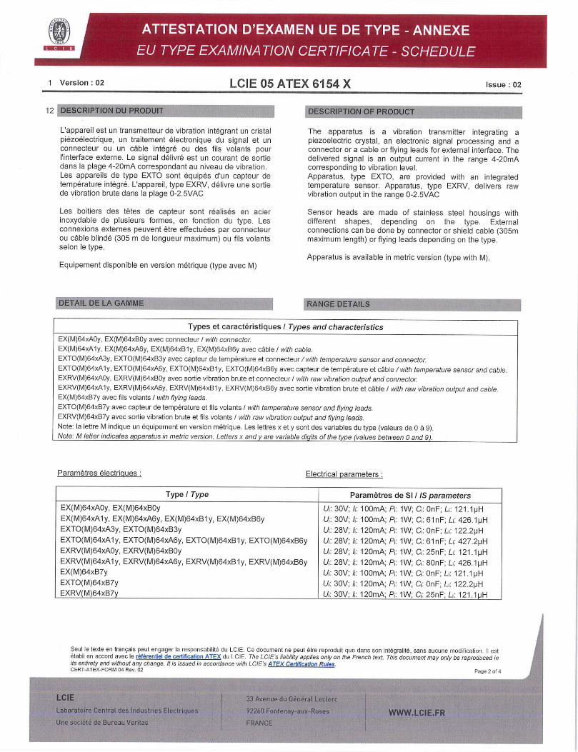
1 Version :02 LCIE 05 ATEX 6154 X Issue :02
12 DESCRIPTION DU PRODUIT
L'appareil est un transmetteur de vibration integrant un cristal piezoelectrique, un traitement électronique du signal et un connecteur ou un cable integre ou des fils volants pour 'interface externe. Le signal délivré est un courant de sortie dans Ia plage 4-20mA correspondant au niveau de vibration. Les appareils de type EXTO sont equipes d'un capteur de temperature integre. L'appareil, type EXRV, délivre une sortie de vibration brute dans la plage 0-2.5VAC
Les boitiers des tétes de capteur sont réalisés en acier inoxydable de plusieurs formes, en fonction du type. Les connexions externes peuvent être effectuées par connecteur ou cable blindé (305 m de longueur maximum) ou fils volants selon le type.
Equipement disponible en version metrique (type avec M)
DETAIL DE LA GAMME
DESCRIPTION OF PRODUCT
The apparatus is a vibration transmitter integrating a piezoelectric crystal, an electronic signal processing and a connector or a cable or flying leads for external interface. The delivered signal is an output current in the range 4-20mA corresponding to vibration level.
Apparatus, type EXTO, are provided with an integrated temperature sensor. Apparatus, type EXRV, delivers raw vibration output in the range 0-2.5VAC
Sensor heads are made of stainless steel housings with different shapes, depending on the type. External
connections can be done by connector or shield cable (305m maximum length) or flying leads depending on the type.
Apparatus is available in metric version (type with M).
RANGE DETAILS ..
I Types et caractéristiques I Types and characteristics I EX(M)64xA0y, EX(M)64xBOy avec connecteur / with connector
EX(M)64xA1y, EX(M)64xA6y, EX(M)64xB1y, EX(M)64xB6y avec cable /with cable.
EXTO(M)64xA3y, EXTO(M)64xB3y avec capteur de temperature et connecteur / with temperature sensor and connector.
EXTO(M)64xA1y, EXTO(M)64xA6y, EXTO(M)64xB1y, EXTO(M)64xB6y avec capteur de temperature et cable/with temperature sensor and cable. EXRV(M)64xA0y, EXRV(M)64xB0y avec sortie vibration brute et connecteur I with raw vibration output and connector. EXRV(M)64xA1y, EXRV(M)64xA6y, EXRV(M)64xB1y, EXRV(M)64xB6y avec sortie vibration brute et cable I with raw vibration output and cable. EX(M)64xB7y avec fils volants I with flying leads.
EXTO(M)64xB7y avec capteur de temperature et fils volants I with temperature sensor and flying leads.
EXRV(M)64xB7y avec sortie vibration brute et fils volants I with raw vibration output and flying leads.
Note: la lettre M indique un équipement en version métrique. Les lettres x et y sont des variables du type (valeurs de 0 a 9). Note: M letter indicates apparatus in metric version. Letters x and are variable digits of the type (values between 0 and 9).
Paramètres electriques Electrical parameters:
Type I Type Paramètres de SI/IS parameters
EX(M)64xA0y, EX(M)64xB0y Ut: 30V; /t: lOOmA; P: 1W: Ct: 0nF; L: 121.1pH EX(M)64xA1y, EX(M)64xA6y, EX(M)64xB1y, EX(M)64xB6y Ut: 30V; It: lOOmA; Pt: 1W; Ct: 61nF; Lt: 426.1pH EXTO(M)64xA3y, EXTO(M)64xB3y Ut: 28V; It: 120mA; Pt: 1W; Ct: 0nF; Lt: 122.2pH EXTO(M)64xA1y, EXTO(M)64xA6y, EXTO(M)64xB1y, EXTO(M)64xB6y Ut: 28V; It: 120mA; Pt: 1W; Ct: 61nF; Li: 427.2pH EXRV(M)64xA0y, EXRV(M)64xB0y Ut: 28V; It: 120mA; Pt: 1W; Ct: 25nF; Lt: 121.1pH EXRV(M)64xA1y, EXRV(M)64xA6y, EXRV(M)64xB1y, EXRV(M)64xB6y Ut: 28V; It: 120mA; Pt: 1W; Ct: 80nF; Lt: 426.1pH EX(M)64xB7y Ut: 30V; /t: lOOmA; Pt: 1W; Ct: 0nF; Lt: 121.1pH EXTO(M)64xB7y Ut: 30V; /t: 120mA; Pt: 1W; Ct: 0nF; Lt: 122.2pH EXRV(M)64xB7y Ut: 30V; It: 120mA; Pt: 1W; Ct: 25nF; Li: 121.1pH
Seul le texte en français peut engager la responsabilité du LCIE. Ce docLiment ne peut ëtre reproduit que dens son intégralite, sans aucune modification. II est établi en accord avec le référentiel de certification ATEX do LCIE. The LCIEs liability applies only on the French text. This document may only be reproduced in its entirety and without any change. Ills issued in accordance with LCIE's ATEX Certification Rules. CERT-ATEX-FORM 04 Rev. 02 Page 2 of 4
LCIE 33 Avenue du Gbnbrol Leclerc
Laboratoire Central des Industries Electriques 92260 Fontenay-auxRoaes WWWLCIEFR line sociCtC de Bureau Voritas FRANCE

Description Reference Rev. Date Page(s) 1. Notice d'instructions / Instructions notice 32836 - - 3 2. Dossier technique I Technical file 64777 NR 2018/06/28 42
Seul le texte en francais peut engager la responsabilité du LCIE. Ce document ne peut btre reproduit que dens son integralité, sans aucune modification. II est établi en accord avec le référentiet de certification ATEX du LCIE. The LcIEs liability applies only on the French text. This document may only be reproduced in its entirety and without any change. It is issued in accordance with LCIE's ATEX Certification Rules. CERT-ATEX-FORM 04 Rev. 02 Page 3 of 4
1 Version 02 LCIE 05 ATEX 6154 X Issue 02
MARQUAGE
Le marquage du produit dolt comprendre
Marguage complet: FOB Piezotronics Inc. ou IMI Sensors ou IMI Adresse: Type: No de fabrication Année de fabrication
Ill G Ex ia IIC T4 Ga [OlE 05 ATEX 6154 X 40CC :5 Tamb :5 +80'C
(complété suivant le modèle)
Marguage réduit: FOB Piezotronics Inc. ou IMI Sensors ou IMI Type: No de fabrication Année de fabrication
Ill G Ex ia IIC T4 Ga, Ta = 800C [OlE 05 ATEX 6154 X
L'appareil dolt également comporter le marquage normalement prévu par les normes de construction qui le concernent sous Ia responsabilité du fabricant.
13 CONDITIONS PARTICULIERES DUTILISATION
a. Flage de temperature ambiante : -40CC a +80CC.
b. Les matériels de sécurité intrinsèque ne doivent être raccordés qua des matériels associés de sécurité intrinseque certifies pour 'usage considéré. Cette association doit répondre aux exigences de la norme EN 60079-25.
c. Le montage du produit clans une installation doit ètre effectué de telle sorte que le corps metallique du capteur et le blindage du cable soient relies de manière fiable a la terre du système.
d. L'appareil doit être raccordé conformément au manuel d'instruction.
EXIGENCES ESSENTIELLES DE SANTE ET DE 14 SECURITE
Couvertes par les normes listées au point 8.
15 DOCUMENTS DESCRIPTIFS
MARKING
The marking of the product shall include the following
Full marking FOB Piezotronics Inc. or IMI Sensors or IMI Address: Type: Serial number: Year of construction:
Ill G Ex ia 110 T4 Ga [OlE 05 ATEX 6154 X -40'C :5 Tamb +80O
(completed following the model)
Reduced marking FOB Piezotronics Inc. or IMI Sensors or IMI Type: Serial number: Year of construction:
lI1G Ex ia 110 T4 Ga, Ta = 80CC [OlE O5 ATEX 6154X
The equipment shall also bear the usual marking required by the product standards applying to such equipment under the manufacturer responsibility.
SPECIFIC CONDITIONS OF USE
Ambient temperature range: -40O to +80O
The intrinsically safe apparatus shall only be connected to associated intrinsically safe apparatus certified for the intended use. This association shall comply with the requirements of the standard EN 60079-25.
The mounting of the apparatus into an installation must be carried out in such a way that sensor metallic body and cable shield are reliably connected to the system earth.
The apparatus must be connected according to instruction manual.
ESSENTIAL HEALTH AND SAFETY REQUIREMENTS
Covered by standards listed at 8.
DESCRIPTIVE DOCUMENTS
LCIE 33 Avenue du Génirat Lecterc
Laboratoirc Central des Industries Etoctriques 92260 Fontenayeux-Roses WWW.LCIEFR Une sociétb do Bureau Veritas i FRANCE
-- .- ....

1 Version :02 LCIE 05 ATEX 6154 X Issue :02
16 INFORMATIONS COMPLEMENTAIRES
Essais individuels
Néant.
Conditions de certification
Les détenteurs d'attestations dexamen UE de type doivent également satisfaire les exigences de contrOle de production telles que définies a ]'article 13 de la Directive 2014/34/UE.
17 DETAILS DES MODIFICATIONS
Version 00 : Version initiale. 2005/12/07
Version 01 : Mise a jour normative suivant les normes EN 2007/08/02 60079-0 (2006) et EN 60079-11(2007).
Version 02 : - Mise a jour normative suivant les normes EN 60079-0:2012+A11:2013 et EN 60079-11:2012.
- Modification des paramètres de sécurité intrinseque.
- Distinction entre le nom du fabricant (PCB Piezotronics Inc) et le nom de la marque commerciale (IMI Sensors ou Ml).
- Mise a jour de Ia nomenclature des modéles.
ADDITIONAL INFORMATIONS
Routine tests
None.
Conditions of certification
Holders of UE type examination certificates are also required to comply with the production control requirements defined in article 13 of Directive 2014/34/UE.
DETAILS OF CHANGES
Issue 00: Initial issue. 2005/12/07
Issue 01: Normative update according to EN 60079-0 2007/08/02 (2006) and EN 60079-11 (2007) standards.
Issue 02: - Normative update according to EN 60079- 0:2012+A11:2013 and EN 60079-11:2012 standards.
- Modification of intrinsic safety parameters. - Distinction between the name of
manufacturer (PCB Piezotronics Inc.) and the name of trademark (IMI Sensors or IMI).
- Update of the nomenclature of the models.
Seul le texte en français peut engager la responsabilité du LCIE. Ce document ne peut être reproduit que dens son intégralite, sans aucune modification. II est établi en accord avec le référentiel de certification ATEX du LCIE. The LCIEs liability applies only on the French text. This document may only be reproduced in its entirety and without any change. It is issued in accordance with LCIEs ATEX Certification Rules. cEnT-Alex-FORM 04 Rev. 02
Page 4 of 4
LCIE 33 Avenue du G6nérot Leclerc
Lahoratoire Central des Industries ELectriques 92260 Fontenay-aux Roses WWWLCIEFR Une sociétó do Bureau Veritas FRANCE

0
47
AM X 182 9
1 AVENANT D'ATTESTATION D'EXAMEN CE 1 SUPPLEMENTARY EC TYPE EXAMINATION DE TYPE CERTIFICATE
2 Appareil ou système de protection destine a être utilisé 2 Equipment or protective system intended for use in en atmospheres explosibles (Directive 94/9/CE) potentially explosive atmospheres (Directive 94/9/EC)
3 Numéro de l'avenant: 3 Supplementary certificate number: LCIE 05 ATEX 6154 X / 01 LCIE 05 ATEX 6154 X / 01
4 Appareil ou système de protection: 4 Equipment or protective system Capteurs de vibration Vibration sensors
Type: EX64..., EXT064..., EXVR64... Type: EX64..., EXT064..., EXVR64...
5 Demandeur: l.M.l. 5 Applicant: l.M.l.
15 DESCRIPTION DE L'AVENANT 15 DESCRIPTION OF THE SUPPLEMENTARY CERTIFICATE Mise a jour normative selon les normes EN 60079-0 (2006) Normative update according to EN 60079-0 (2006) and et EN 60079-11 (2007). EN 60079-11(2007) standards.
Les résultats des verifications et essais figurent dans le The examination and test results are recorded in rapport confidentiel N° 60058689/559760 confidential report No 60058689/559760
Paramètres sDécificiues du ou des modes de protection Specific parameters of the mode(s) of protection concerned: concerné(s) Inchangés Unchanged
Le marcuage doit être modifié comme suit: The marking shall be modified as follows: ExiallCT4 ExiallCT4
16 DOCUMENTS DESCRIPTIFS 16 DESCRIPTIVE DOCUMENTS
Dossier de certification No 27866 Rev. A du 27/06/2007. Certification file No 27866 Rev. A dated 27/06/2007. Ce dossier comprend 18 rubriques (37 pages). This file includes 18 items (37 pages). Dossier de certification No 28770 Rev. A du 27/06/2007. Certification file No 28770 Rev. A dated 27/06/2007. Ce dossier comprend 12 rubriques (28 pages). This file includes 12 items (28 pages).
17 CONDITIONS SPECIALES POUR UNE UTILISATION 17 SPECIAL CONDITIONS FOR SAFE USE SURE Inchangées Unchanged
18 EXIGENCES ESSENTIELLES DE SECURITE ET DE 18 ESSENTIAL HEALTH AND SAFETY REQUIREMENTS SANTE ConformitO aux normes européennes EN 60079-0 (2006) Conformity to the European standards EN 60079-0 (2006) et EN 60079-11 (2007). and EN 60079-11 (2007).
19 VERIFICATIONS ET ESSAIS INDIVIDUELS 19 ROUTINE VERIFICATIONS AND TESTS Want None
Fontenay-aux-Roses, le 2 aoOt 2007 Le responsable de certification ATEX ATEX certification manager
IED ?\ (i1I0
1-
008 (/) LAI I
7828
LSME ! Seul le texte en français peut engager la responsabilité du LCIE. Ce document ne peut être reproduit que dans son intégralite, sans aucune modification. The LCIE's liability applies only on the French text. This document may only be reproduced in its entirety and without any change.
Page 1 sur 1 01A-Annexe III_CE_typ_app_av - rev l.DOC
I
Laboratoire Central SF S Fax +33 1 40 95 86 56 au capital Oc 15 76 98-4 €
des Industries Electriques 92266 Foicnav-uux-Roses ceclex [email protected] RCS Nanteite B 108 363 174
Une sociëté de Bureau Veritas Fiance \vw\v.lciefr

v
cn
1825
1 ATTESTATION D'EXAMEN CE DE TYPE l EC TYPE EXAMINATION CERTIFICATE 2 Appareils et systèmes de protection destinés a être utilisés
en atmospheres explosibles Directive 94/9/CE
3 Numéro de l'attestation d'examen CE de type LCIE 05 ATEX 6154 X
4 Appareil ou système de protection: Capteurs de vibrations
Type: EX64 .... EXTO64.. ,EXRV64 (voir page suivante)
5 Demandeur: I.M.I. (Industrial Monitoring Instrumentation)
6 Adresse: A PCB PIEZOTRONICS DIVISION 3425 Walden Avenue Depew, New York 14043 U.S.A.
7 Cet appareil ou système de protection et ses variantes éventuelles acceptées est décrit dans I'annexe de la présente attestation et dans les documents descriptifs cites en annexe.
8 Le LCIE, organisme notiflé sous la référence 0081 conformément a I'article 9 de la directive 9419/CE du Parlement européen et du Conseil du 23 mars 1994, certifie que cet appareil ou système de protection est conforme aux exigences essentielles en ce qul concerne la sécurité et la sante pour la conception et la construction d'appareils et de systèmes de protection destinés a être utilisés en atmospheres explosibles, données dans I'annexe II de la directive. Les verifications et épreuves figurent dans nos rapports confidentiels no 60040901/540946/1.
9 Le respect des exigences essentielles en ce qui concerne la sécurité et la sante est assure par la conformité aux documents suivants: -EN 50014 (1997) + amendements I et 2, -EN 50020 (2002).
10 Le signe X Iorsqu'il est place a la suite du numéro de I'attestation, indique que ce materiel ou système de protection est soumis aux conditions spéciales pour une utilisation sOre, mentionnées dans I'annexe de la présente attestation.
11 Cette attestation d'examen CE de type concerne uniquement la conception et la construction de I'appareil ou du système de protection spéciflé, conformément a la directive 94/9/CE. Des exigences supplémentaires de cette directive sont applicables pour la fabrication et la fourniture de I'appareil ou du système de protection.
12 Le marquage de I'appareil ou du système de protection devra comporter, entre autres indications utiles, les mentions suivantes:
II I G EExiallCT4
Fontenay-aux-Roses, le 7 décembre 2005
2 Equipment or protective system intended for use in potentially explosive atmospheres Directive 9419/EC
3 EC type Examination Certificate number LCIE 05 ATEX 6154 X
4 Equipment or protective system: Vibration sensors
Type: EX64 .... EXTO64... ,EXRV64... (see following page)
5 Applicant: I.M.I. (Industrial Monitoring Instrumentation)
6 Address: A PCB PIEZOTRONICS DIVISION 3425 Walden Avenue Depew, New York 14043 U.S.A.
7 This equipment or protective system and any acceptable variation thereto is specified in the schedule to this certificate and the documents therein referred to.
8 LCIE, notified body number 0081 in accordance with article 9 of the Directive 94/9/EC of the European Parliament and Council of 23 March 1994. certifies that this equipment or protective system has been found to comply with the essential Health and Safety Requirements relating to the design and construction of equipment and protective system intended for use in potentially explosive atmospheres, given in Annex II of the Directive. The examination and test results are recorded in confidential reports no 60040901/540946/1.
9 Compliance with the Essential Health and Safety Requirements has been assured by compliance with:
-EN 50014 (1997) + amendments I and 2, -EN 50020 (2002).
10 If the sign X is placed after the certificate number, it indicates that the equipment or protective system is subject to special conditions for safe use specified in the schedule to this certificate.
11 This EC Type examination certificate relates only to the design and construction of this specified equipment or protective system in accordance with the Directive 94/9/EC. Further requirements of the Directive applies to the manufacture and supply of this equipment or protective system.
12 The marking of the equipment or protective system shall include the following
111 G EExiallCT4
Le Directeur de l'organisme certificateur Manager of the certification body
l'lenn CERVELLO Timbre sec / Dry seal
Page 1/3
Seul le texte en francais peut engager la responsabilité du LCIE. Ce document ne peut être reproduit que dans son integralité, sans aucune modification The LCIE's liability applies only on the French text. This document may be reproduced In full and without any change
LCIE 33, av du Géndral Leclerc
Laboratoire Central BP 8
tfe, des Industries Electriques 92266 Fontenav-aux-lloses cedex
Une société de Bureau Veritas Fiance
Tél : +33 1 u0 95 60 60 Sociétd Anonyme
Fax +33 1 40 95 86 36 au capital de 15 7-15 98-4 €
colit,ict(ol lcie.fr RCS Nanterre B 408 363 14
\\'\vv.lcle.h
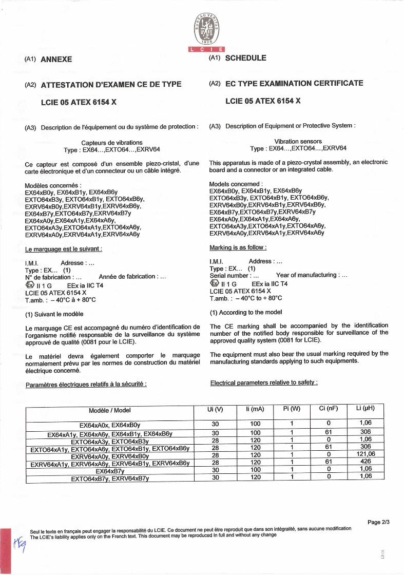
(Al) ANNEXE (Al) SCHEDULE
(A2) ATTESTATION D'EXAMEN CE DE TYPE
LCIE 05 ATEX 6154 X
(A3) Description de l'équipement ou du système de protection
Capteurs de vibrations Type: EX64 .... EXTO64... ,EXRV64
Ce capteur est compose d'un ensemble piezo-cristal, d'une carte electronique et d'un connecteur ou un cable intégré.
Modèles concernés: EX64xB0y, EX64xBl y, EX64xB6y EXT064xB3y, EXT064xBly, EXT064xB6y, EXRV64xB0y,EXRV64xBl y,EXRV64xB6y, EX64xB7y,EXT064xB7y,EXRV64XB7Y EX64xA0y,EX64xA1 y,EX64xA6y, EXT064xA3y,EXT064xA1y,EXT064XA6Y, EXRV64xA0y,EXRV64XA1 y,EXRV64xA6y
Le marquage est le suivant:
LM.I. Adresse: Type: EX... (1) N° de fabrication: ... Année de fabrication:.
111 EExiallCT4 LCIE 05 ATEX 6154 X T.amb.: - 40°C A + 80°C
(1) Suivant le modèle
Le marquage CE est accompagné du numéro d'identification de l'organisme notiflé responsable de la surveillance du système approuvé de qualite (0081 pour le LCIE).
Le materiel devra également comporter le marquage normalement prévu par les normes de construction du materiel electrique concerné.
Paramètres électrigues relatifs a la sécurité:
(A2) EC TYPE EXAMINATION CERTIFICATE
LCIE 05 ATEX 6154 X
(A3) Description of Equipment or Protective System:
Vibration sensors Type: EX64... ,EXTO64... ,EXRV64
This apparatus is made of a piezo-crystal assembly, an electronic board and a connector or an integrated cable.
Models concerned: EX64xB0y, EX64xB1 y, EX64xB6y EXT064xB3y, EXT064xBly, EXT064xB6y, EXRV64xB0y,EXRV64xB1 y,EXRV64xB6y, EX64xB7y,EXT064xB7y,EXRV64XB7Y EX64xA0y,EX64xA1 y,EX64xA6y, EXT064xA3y,EXT064xA1 y,EXTO64xA6y, EXRV64xA0y,EXRV64xA1 y,EXRV64xA6y
Marking is as follow:
I.M.I. Address: Type: EX... (1) Serial number: ... Year of manufacturing:
111 EExiallCT4 LCIE 05 ATEX 6154 X T.amb.: - 40°C to + 80°C
(1) According to the model
The CE marking shall be accompanied by the identification number of the notified body responsible for surveillance of the approved quality system (0081 for LCIE).
The equipment must also bear the usual marking required by the manufacturing standards applying to such equipments.
Electrical parameters relative to safety:
Modèle / Model Ui ('I) Ii (mA) Pi (W) Ci (nF) Li (pH)
EX64xA0x, EX64xB0y 30 100 1 0 1,06
EX64xAly, EX64xA6y, EX64xB1y, EX64xB6y EXT064xA3y, EXT064xB3y
30 28
100 120
1 1
61 0
306 1,06
EXT064xAly, EXT064xA6y, EXT064xB1y, EXT064xB6y EXRV64xA0y, EXRV64xB0y
28 28
120 120
1 1
61 0
306 121,06
EXRV64xA1y, EXRV64xA6y, EXRV64xBly, EXRV64xB6y EX64xB7y
28 30
120 100
1 1
61 0
426 1,06
EXT064xB7y, EXRV64xB7y 30 120 1 0 1,06
Page 2/3 Seul le texte en français peut engager la responsabilité du LCIE. ce document ne peut étre reproduit que dans son intégralité, sans aucune modification
The LcIE's liability applies only on the French text. This document may be reproduced In full and without any change

1828
(Al) ANNEXE (Al) SCHEDULE
(A2) ATTESTATION D'EXAMEN CE DE TYPE
LCIE 05 ATEX 6154 X (suite)
(A4) Documents descriptifs:
Dossier technique N° 28770 Rev. NR du 10/10/2005 Ce document comporte 12 rubriques (28 pages).
Dossier technique No 27866 Rev. NR du 10/10/2005 Ce document comporte 18 rubriques (37 pages).
(A5) Conditions spéciales pour une utilisation sOre:
Ce materiel est un appareil de sécurité intrinseque, ii peut être place en atmosphere explosible. Le materiel ne doit être raccordé qu'à un materiel associé de sécurité intrinséque certiflé et cette association doit être compatible du point de vue sécurité intrinséque (voir paramétres electriques au paragraphe (A3)). Temperature ambiante d'utilisation : - 40°C a + 80°C.
(A2) EC TYPE EXAMINATION CERTIFICATE
LCIE 05 AlEX 6154 X (continued)
(A4) Descriptive documents:
Technical file No. 28770 Rev. NR dated 10/10/2005. This file includes 12 items (28 pages).
Technical file No. 27866 Rev. NR dated 10/10/2005. This file includes 18 items (37 pages).
(A5) Special conditions for safe use:
This equipment is an intrinsically safe apparatus, it can be mounted in explosive atmosphere. The apparatus must be only connected to a certified associated intrinsically safe equipment and this combination must be compatible regarding intrinsic safety rules (see electrical parameters clause (A3)). Operating ambient temperature : - 40°C to + 80°C.
(A6) Exigences essentielles en ce qui concerne la sécurité et (A6) Essential Health and Safety Requirements: la sante:
Conformité aux normes europeennes EN 50014 (1997 + amendements 1 et 2) et EN 50020 (2002).
Verifications et épreuves individuelles:
L'appareil est dispense d'épreuve individuelle.
Conformity to the European standards EN 50014 (1997 + amendments I and 2) and EN 50020 (2002).
Individual examinations and tests:
The equipment is not submitted to routine test.
Seul le texte en francais peut engager la responsabilité du LCIE. Ce document ne peut étre reproduit que dans son intégralité, sans aucune modification The LCIE's liability applies only on the French text. This document may be reproduced In full and without any change
Page 3/3
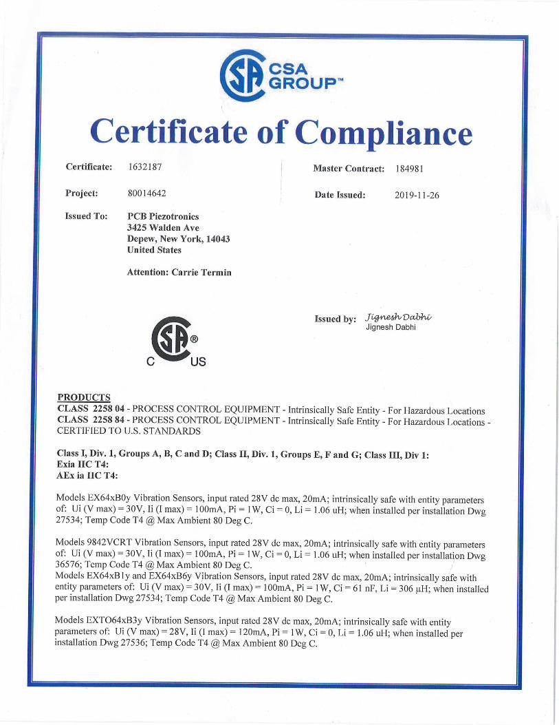
CIPC SAGROUP TM
Certificate of Compliance Certificate: 1632187 Master Contract: 184981
Project: 80014642 Date Issued: 2019-11-26
Issued To: PCB Piezotronics 3425 Walden Ave Depew, New York, 14043 United States
Attention: Carrie Termin
J4cLe4J1JDcthhL/ Issued by: Jignesh Dabhi
C US
PRODUCTS CLASS 2258 04 - PROCESS CONTROL EQUIPMENT - Intrinsically Safe Entity - For Hazardous Locations CLASS 2258 84 - PROCESS CONTROL EQUIPMENT - Intrinsically Safe Entity - For Hazardous Locations - CERTIFIED TO U.S. STANDARDS
Class I, Div. 1, Groups A, B, C and D; Class II, Div. 1, Groups E, F and G; Class III, Div 1: Exia IIC T4: AEx ia IIC T4:
Models EX64xB0y Vibration Sensors, input rated 28V dc max, 20mA; intrinsically safe with entity parameters of: Ui (V max) 30V, Ii (I max) = lOOmA, Pi = 1W, Ci 0, Li = 1.06 uH; when installed per installation Dwg 27534; Temp Code T4 @ Max Ambient 80 Deg C.
Models 9842 VCRT Vibration Sensors, input rated 28V dc max, 20mA; intrinsically safe with entity parameters of: Ui (V max) = 30V, Ii (I max) = lOOmA, Pi = 1W, Ci = 0, Li = 1.06 uH; when installed per installation Dwg 36576; Temp Code T4 @ Max Ambient 80 Deg C. Models EX64xB1y and EX64xB6y Vibration Sensors, input rated 28V dc max, 20mA; intrinsically safe with entity parameters of: Ui (V max) = 30V, Ii (I max) = lOOmA, Pi = 1W, Ci = 61 nF, Li = 306 iH; when installed per installation Dwg 27534; Temp Code T4 @ Max Ambient 80 Deg C.
Models EXT064xB3y Vibration Sensors, input rated 28V dc max, 20mA; intrinsically safe with entity parameters of: Ui (V max) 28V, Ii (I max) = 120mA, Pi = 1W, Ci = 0, Li = 1.06 uH; when installed per installation Dwg 27536; Temp Code T4 @ Max Ambient 80 Deg C.

CSA sir GROUPTM
Models EXT064xB1y and EXT064xB6y Vibration Sensors, input rated 28V dc max, 20mA; intrinsically safe with entity parameters of: Ui (V max) = 28V, Ii (I max) = 120mA, Pi = 1W, Ci = 61 nF, Li = 306 fl-I; when installed per installation Dwg 27536; Temp Code T4 @ Max Ambient 80 Deg C.
Models EXRV64xB0y Vibration Sensors, input rated 28V dc max, 20mA; intrinsically safe with entity parameters of: Ui (V max) = 28V, Ii (I max) = 120mA, Pi = 1W, Ci = 0, Li 121.06 uH; when installed per installation Dwg 30538; Temp Code T4 @ Max Ambient 80 Deg C.
Models EXRV64xBly and EXRV64xB6y Vibration Sensors, input rated 28V dc max, 20mA; intrinsically safe with entity parameters of: Ui (V max) = 28V, Ii (I max) = 120mA, Pi = 1W, Ci = 61 nF, Li = 426 iiH; when installed per installation Dwg 30538; Temp Code T4 @ Max Ambient 80 Deg C.
Models EX64xB7y Vibration Sensors, input rated 28V dc max, 20mA; intrinsically safe with entity parameters of: Ui (V max) = 30V, Ii (I max) = lOOmA, Pi = 1W, Ci = 0, Li = 1.06 uH; when installed per installation Dwg 28766; Temp Code T4 @ Max Ambient 80 Deg C.
Models EXT064xB7y Vibration Sensors, input rated 28V dc max, 20mA; intrinsically safe with entity parameters of: Ui (V max) = 28V, Ii (I max) = 120mA, Pi = 1W, Ci = 0, Li = 1.06 uH; when installed per installation Dwg 28767; Temp Code T4 @ Max Ambient 80 Deg C.
Models EXRV64xB7y Vibration Sensors, input rated 28V dc max, 20mA; intrinsically safe with entity parameters of: Ui (V max) = 28V, Ii (I max) = 120mA, Pi = 1W, Ci = 0, Li = 1.06 uH; when installed per installation Dwg 29987; Temp Code T4 @ Max Ambient 80 Deg C.
Note: The "x" in the model code may be a 0 to 9, which denotes variations in frequency response range of the sensors. The "y" in the model code may be a 0 to 9, which denotes variations in sensor sensitivity.
Models EX64xA0y Vibration Sensors, input rated 28V dc max, 20mA; intrinsically safe with entity parameters of: Ui (V max) = 30V, Ii (I max) = lOOmA, Pi = 1W, Ci = 0, Li = 1.06 uH; when installed per installation Dwg 27535; Temp Code T4 @ Max Ambient 80 Deg C.
Models 9942VCRT Vibration Sensors, input rated 28V dc max, 20mA; intrinsically safe with entity parameters of: Ui (V max) = 30V, Ii (I max) = lOOmA, Pi = 1W, Ci = 0, Li = 1.06 uH; when installed per installation Dwg 36578; Temp Code T4 @ Max Ambient 80 Deg C.
Models EX64xA1y and EX64xA6y Vibration Sensors, input rated 28V dc max, 20mA; intrinsically safe with entity parameters of: Ui (V max) = 30V, Ii (I max) = lOOmA, Pi = 1W, Ci = 61 nF, Li = 306 jH; when installed per installation Dwg 27535; Temp Code T4 @ Max Ambient 80 Deg C.
Models EXT064xA3y Vibration Sensors, input rated 28V dc max, 20mA; intrinsically safe with entity parameters of: Ui (V max) = 28V, Ii (I max) = 120mA, Pi = 1W, Ci = 0, Li = 1.06 uH; when installed per installation Dwg 27537; Temp Code T4 @ Max Ambient 80 Deg C.
Models EXT064xAly and EXT064xA6y Vibration Sensors, input rated 28V dc max, 20mA; intrinsically safe with entity parameters of: Ui (V max) 28V, Ii (I max) = 120mA, Pi = 1W, Ci = 61 nF, Li = 306 jiH; when installed per installation Dwg 27537; Temp Code T4 @ Max Ambient 80 Deg C.

CpCSA GROUP TM
Models EXRV64xA0y Vibration Sensors, input rated 28V dc max, 20mA; intrinsically safe with entity parameters of: Ui (V max) = 28V, Ii (I max) = 120mA, Pi = 1W, Ci = 0, Li = 121.06 uH; when installed per installation Dwg 30540; Temp Code T4 @ Max Ambient 80 Deg C.
Models EXRV64xA1y and EXRV64xA6y Vibration Sensors, input rated 28V dc max, 20mA; intrinsically safe with entity parameters of: Ui (V max) = 28V, Ii (I max) 120rnA, Pi = 1W, Ci = 61 nF, Li = 426 jiH; when installed per installation Dwg 30540; Temp Code T4 @ Max Ambient 80 Deg C.
Models CS64xB9yVibration Sensors, input rated 28V dc max, 20mA; intrinsically safe with entity parameters of: Ui (V max) = 30V, Ii (I max) = lOOmA, Pi = 1W, Ci = 0, Li = 1.06 uH; when installed per Dwg 56140; Temp Code T4 @ Max Ambient 80 Deg C.
Note: The "x" in the model code may be a 0 to 9, which denotes variations in frequency response range of the sensors. The "y" in the model code may be a 0 to 9, which denotes variations in sensor sensitivity.
APPLICABLE REQUIREMENTS
CAN/CSA-C22.2 No. 0-M91 - General Requirements - Canadian Electrical Code, Part II C22.2 No. 142-M 1987 (R2009) - Process Control Equipment CAN/CSA-C22.2 No. 157-92 (R2012) - Intrinsically Safe and Non-Incendive Equipment for Use in
Hazardous Locations
UL 913 (7111 Ed.) - Intrinsically Safe Apparatus and Associated Apparatus for Use in Class I, II and III, Division 1, Hazardous Locations
UL 916 (4th Ed.) - Energy Management Equipment
CAN/CSA-E60079-0:07 - Electrical apparatus for explosive gas atmospheres - Part 0: General Requirements
CAN/CSA-E60079-1 1:02 - Electrical apparatus for explosive gas atmospheres - Part 11: Intrinsic Safety 'i'
ANSI/UL 60079-0:05 - Electrical Apparatus for Explosive Gas Atmospheres - Part 0: General Requirements
ANSI/UL 60079-11:07 - Electrical apparatus for Explosive Gas Atmospheres - Part 11: Intrinsic Safety "i"
CLASS 2258 03 - PROCESS CONTROL EQUIPMENT - Intrinsically Safe and Non-Incendive Systems - For Hazardous Locations CLASS 2258 83 - PROCESS CONTROL EQUIPMENT - Intrinsically Safe and Non-Incendive Systems - For Hazardous Locations - CERTIFIED TO U.S. STANDARDS
Ex nL IICT4: AEx nA IICT4: Class I, Div. 2, Groups A, B, C, D:
Models EX64xB0y Vibration Sensors, input rated 28V dc max, 20mA; non-incendive with entity parameters of: Ui (V max) = 30V, Ii (I max) = lOOmA, Pi = 1W, Ci = 0, Li = 1.06 uH; when installed per installation Dwg 27534; Temp Code T4 @ Max Ambient 80 Deg C.
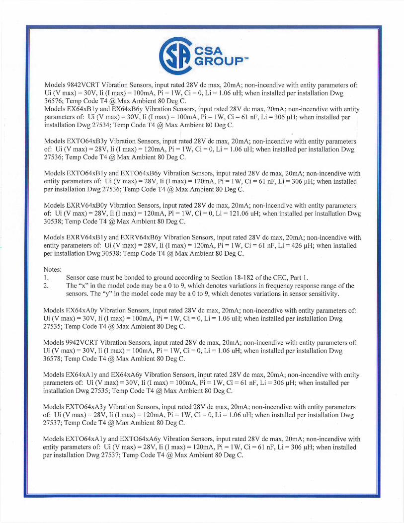
CSA (Ep GROUP1M
Models 9842VCRT Vibration Sensors, input rated 28V dc max, 20mA; non-incendive with entity parameters of: Ui (V max) = 30V, Ii (I max) lOOmA, Pi = 1W, Ci = 0, Li = 1.06 uH; when installed per installation Dwg 36576; Temp Code T4 @ Max Ambient 80 Deg C. Models EX64xB1y and EX64xB6y Vibration Sensors, input rated 28V dc max, 20mA; non-incendive with entity parameters of: Ui (V max) = 30V, Ii (I max) = lOOmA, Pi = 1W, Ci = 61 nF, Li = 306 H; when installed per installation Dwg 27534; Temp Code T4 @ Max Ambient 80 Deg C.
Models EXT064xB3y Vibration Sensors, input rated 28V dc max, 20mA; non-incendive with entity parameters of: Ui (V max) = 28V, Ii (I max) = 120mA, Pi = 1W, Ci = 0, Li = 1.06 uH; when installed per installation Dwg 27536; Temp Code T4 @ Max Ambient 80 Deg C.
Models EXT064xB ly and EXT064xB6y Vibration Sensors, input rated 28V dc max, 20mA; non-incendive with entity parameters of: Ui (V max) = 28V, Ii (I max) = 120mA, Pi = 1W, Ci = 61 nF, Li = 306 H; when installed per installation Dwg 27536; Temp Code T4 @ Max Ambient 80 Deg C.
Models EXRV64xB0y Vibration Sensors, input rated 28V dc max, 20mA; non-incendive with entity parameters of: Ui (V max) = 28V, Ii (I max) = 120rnA, Pi = 1W, Ci = 0, Li 121.06 uH; when installed per installation Dwg 30538; Temp Code T4 @ Max Ambient 80 Deg C.
Models EXRV64xBly and EXRV64xB6y Vibration Sensors, input rated 28V dc max, 20mA; non-incendive with entity parameters of: Ui (V max) = 28V, Ii (I max) = 120mA, Pi = 1W, Ci = 61 nF, Li = 426 jiH; when installed per installation Dwg 30538; Temp Code T4 @ Max Ambient 80 Deg C.
Notes: 1. Sensor case must be bonded to ground according to Section 18-182 of the CEC, Part 1. 2. The "x" in the model code may be a 0 to 9, which denotes variations in frequency response range of the
sensors. The "y" in the model code may be a 0 to 9, which denotes variations in sensor sensitivity.
Models EX64xA0y Vibration Sensors, input rated 28V dc max, 20mA; non-incendive with entity parameters of: Ui (V max) = 30V, Ii (I max) lOOmA, Pi = 1W, Ci = 0, Li = 1.06 uH; when installed per installation Dwg 27535; Temp Code T4 @ Max Ambient 80 Deg C.
Models 9942VCRT Vibration Sensors, input rated 28V dc max, 20mA; non-incendive with entity parameters of: Ui (V max) = 30V, Ii (I max) = lOOmA, Pi = 1W, Ci = 0, Li = 1.06 uH; when installed per installation Dwg 36578; Temp Code T4 @ Max Ambient 80 Deg C.
Models EX64xA1y and EX64xA6y Vibration Sensors, input rated 28V dc max, 20mA; non-incendive with entity parameters of: Ui (V max) = 30V, Ii (I max) = lOOmA, Pi = 1W, Ci = 61 nF, Li = 306 H; when installed per installation Dwg 27535; Temp Code T4 @ Max Ambient 80 Deg C.
Models EXT064xA3y Vibration Sensors, input rated 28V dc max, 20mA; non-incendive with entity parameters of: Ui (V max) = 28V, Ii (I max) = 120mA, Pi = 1W, Ci = 0, Li = 1.06 uH; when installed per installation Dwg 27537; Temp Code T4 @ Max Ambient 80 Deg C.
Models EXT064xA1y and EXT064xA6y Vibration Sensors, input rated 28V dc max, 20mA; non-incendive with entity parameters of: Ui (V max) = 28V, Ii (I max) = 120mA, Pi = 1W, Ci = 61 nF, Li = 306 itH; when installed per installation Dwg 27537; Temp Code T4 @ Max Ambient 80 Deg C.

CSA 11' GROUPTM
Models EXRV64xA0y Vibration Sensors, input rated 28V dc max, 20mA; non-incendive with entity parameters of: Ui (V max) = 28V, Ii (I max) = 120mA, Pi = 1W, Ci = 0, Li = 121.06 uH; when installed per installation Dwg 30540; Temp Code T4 @ Max Ambient 80 Deg C.
Models EXRV64xA1y and EXRV64xA6y Vibration Sensors, input rated 28V dc max, 20mA; non-incendive with entity parameters of: Ui (V max) = 28V, Ii (I max) = 120mA, Pi = 1W, Ci = 61 nF, Li = 426 H; when installed per installation Dwg 30540; Temp Code T4 @ Max Ambient 80 Deg C.
Models CS64xB9y Vibration Sensors, input rated 28V dc max, 20mA; non-incendive with entity parameters of: Ui (V max) = 30V, Ii (I max) = lOOmA, Pi = 1W, Ci = 0, Li = 1.06 uH; when installed per Dwg 56140; Temp Code T4 @ Max Ambient 80 Deg C.
Notes:
1. For Canadian Installations, senor case must be bonded to ground according to Section 18-182 of the CEC, Part 1.
2. For US Installations, sensor case must be bonded to ground according to Article 501.16 of the NEC. 3. The "x" in the model code may be a 0 to 9, which denotes variations in frequency response range of the
sensors. The "y" in the model code may be a 0 to 9, which denotes variations in sensor sensitivity.
APPLICABLE REQUIREMENTS
CAN/CSA-C22.2 No. 0-M91 - General Requirements - Canadian Electrical Code, Part IT C22.2 No. 142-M 1987 (R2009) - Process Control Equipment C22.2 No. 213-M1987 (R2008) - Non-Incendive Electrical Equipment for Use in Class I, Division 2
Hazardous Locations
UL 916 (4th Ed.) - Energy Management Equipment
UL 1604 (3 31( Ed.) - Electrical Equipment for Use in Class I and II, Division 2; Class III
Hazardous (Classified) Locations
ANSI/ISA 12.12.01-2000 - Nonincendive Electrical Equipment for Use in Class I and II, Division 2 and Class III, Divisions 1 and 2 Hazardous (Classified) Locations
CAN/CSA-E60079-15:02 - Electrical apparatus for explosive gas atmospheres - Part 15: Type of Protection "n'
ANSI/UL 60079-15:02 - Electrical apparatus for Explosive Gas Atmospheres - Part 15: Type of Protection "n"
CLASS 2258 02 - PROCESS CONTROL EQUIPMENT - For Hazardous Locations CLASS 2258 82 - PROCESS CONTROL EQUIPMENT - For Hazardous Locations - CERTIFIED TO U.S. STANDARDS
Ex nA IICT4: AEx nA TIC T4: Class I, Div. 2, Groups A, B, C, D:
Models EX64xB7y Vibration Sensors, input rated 28V dc max, 20mA; suitable for use in Class I, Div. 2 or Class I, Zone 2 locations, when installed per installation Dwg 28766; Temp Code T4 @ Max Ambient 80 Deg C.

CPCSA GROUP TM
Models EXT064xB7y Vibration Sensors, input rated 28V dc max, 20mA; suitable for use in Class I, Div. 2 or Class I, Zone 2 locations, when installed per installation Dwg 28766; Temp Code T4 @ Max Ambient 80 Deg C.
Models EXRV64xB7y Vibration Sensors, input rated 28V dc max, 20mA; suitable for use in Class I, Div. 2 or Class I, Zone 2 locations, when installed per installation Dwg 28766; Temp Code T4 @ Max Ambient 80 Deg C.
Models CS64xB9y Vibration Sensors, input rated 28V dc max, 20mA; suitable for use in Class I, Div. 2 or Class I, Zone 2 locations, when installed per installation Dwg 56140; Temp Code T4 @ Max Ambient 80 Deg C.
Notes:
1. Sensor must be installed in a suitable enclosure, acceptable to the local inspection authority having jurisdiction.
2. The "x" in the model code may be a 0 to 9, which denotes variations in frequency response range of the sensors. The "y" in the model code may be a 0 to 9, which denotes variations in sensor sensitivity.
APPLICABLE REQUIREMENTS
CAN/CSA-C22.2 No. 0-M91 - General Requirements Canadian Electrical Code, Part II
C22.2 No. 142-M1987(R2009) - Process Control Equipment C22.2 No. 213-M1987(R2008) - Non-Incendive Electrical Equipment for Use in Class I,
Division 2 Hazardous Locations
UL 916 (4th Ed.) - Energy Management Equipment
UL 1604 (31d Ed.) - Electrical Equipment for Use in Class I and II, Division 2; Class III Hazardous (Classified) Locations
ANSI/ISA 12.12.01-2000 - Nonincendive Electrical Equipment for Use in Class I and II, Division 2 and Class III, Divisions 1 and 2 Hazardous (Classified) Locations
CAN/CSA-E60079-15:02 - Electrical apparatus for explosive gas atmospheres - Part 15: Type of Protection 'n'
ANSI/UL 60079-15:02 - Electrical apparatus for Explosive Gas Atmospheres - Part 15: Type of Protection "n"
CLASS 2258 04 - PROCESS CONTROL EQUIPMENT - Intrinsically Safe Entity - For Hazardous Locations CLASS 2258 84 - PROCESS CONTROL EQUIPMENT - Intrinsically Safe Entity - For Hazardous Locations - CERTIFIED TO U.S. STANDARDS
Ex ia IIC; AEx ia IIC; Class I, Div. 1, Groups A, B, C and D; Class II, Div. 1, Groups E, F and G; Class III; Tamb: -40C to 121C; Tcode: T3C
Models EXHT(M)64x (with connector or integral cable), Vibration Sensors, input rated 28V dc max, 20mA; intrinsically safe when installed per installation drawing 71991 (sheet 1);
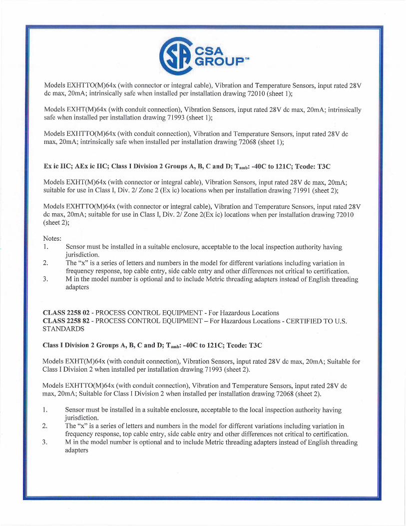
CSA (Ep GROUPIrm Models EXHTTO(M)64x (with connector or integral cable), Vibration and Temperature Sensors, input rated 28V dc max, 20mA; intrinsically safe when installed per installation drawing 72010 (sheet 1);
Models EXHT(M)64x (with conduit connection), Vibration Sensors, input rated 28V dc max, 20mA; intrinsically safe when installed per installation drawing 71993 (sheet 1);
Models EXHTTO(M)64x (with conduit connection), Vibration and Temperature Sensors, input rated 28V dc max, 20mA; intrinsically safe when installed per installation drawing 72068 (sheet 1);
Ex ic TIC; AEx ic IIC; Class I Division 2 Groups A, B, C and D; Tamb: -40C to 121C; Tcode: T3C
Models EXHT(M)64x (with connector or integral cable), Vibration Sensors, input rated 28V dc max, 20mA; suitable for use in Class I, Div. 2/ Zone 2 (Ex ic) locations when per installation drawing 71991 (sheet 2);
Models EXHTTO(M)64x (with connector or integral cable), Vibration and Temperature Sensors, input rated 28V dc max, 20niA; suitable for use in Class I, Div. 2/ Zone 2(Ex ic) locations when per installation drawing 72010 (sheet 2);
Notes: 1. Sensor must be installed in a suitable enclosure, acceptable to the local inspection authority having
jurisdiction. 2. The "x" is a series of letters and numbers in the model for different variations including variation in
frequency response, top cable entry, side cable entry and other differences not critical to certification. 3. M in the model number is optional and to include Metric threading adapters instead of English threading
adapters
CLASS 225802 - PROCESS CONTROL EQUIPMENT - For Hazardous Locations CLASS 2258 82 - PROCESS CONTROL EQUIPMENT - For Hazardous Locations - CERTIFIED TO U.S. STANDARDS
Class I Division 2 Groups A, B, C and D; Tamb: -40C to 121C; Tcode: T3C
Models EXHT(M)64x (with conduit connection), Vibration Sensors, input rated 28V dc max, 20mA; Suitable for Class I Division 2 when installed per installation drawing 71993 (sheet 2).
Models EXHTTO(M)64x (with conduit connection), Vibration and Temperature Sensors, input rated 28V dc max, 20mA; Suitable for Class I Division 2 when installed per installation drawing 72068 (sheet 2).
1. Sensor must be installed in a suitable enclosure, acceptable to the local inspection authority having jurisdiction.
2. The "x" is a series of letters and numbers in the model for different variations including variation in frequency response, top cable entry, side cable entry and other differences not critical to certification.
3. M in the model number is optional and to include Metric threading adapters instead of English threading adapters
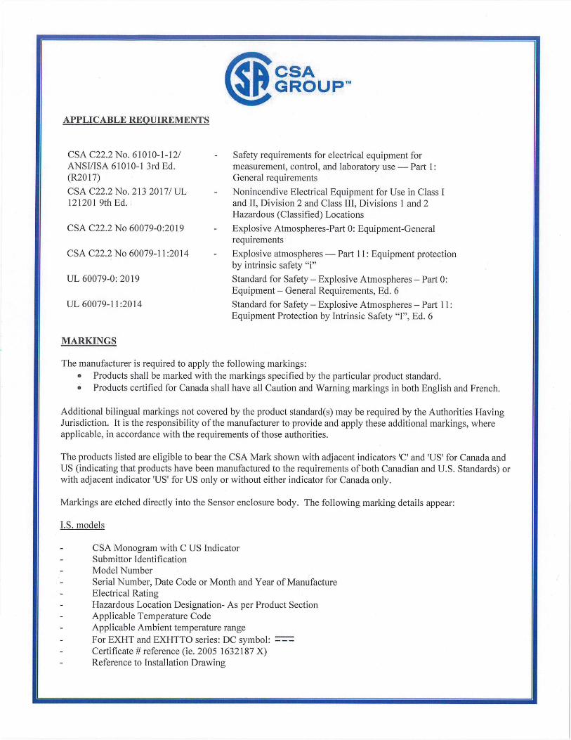
CSA IP GROUPTM
APPLICABLE REQUIREMENTS
CSA C22.2 No. 61010-1-12/ ANSI/ISA 610 10-1 3rd Ed. (R2017)
CSA C22.2 No. 213 2017/ UL 121201 9th Ed.
CSA C22.2 No 60079-0:2019
CSA C22.2 No 60079-11:2014
UL 60079-0: 2019
UL 60079-11:2014
MAPKINGS
- Safety requirements for electrical equipment for measurement, control, and laboratory use Part 1: General requirements
- Nonincendive Electrical Equipment for Use in Class I and TI, Division 2 and Class III, Divisions 1 and 2 Hazardous (Classified) Locations
- Explosive Atmospheres-Part 0: Equipment-General requirements
- Explosive atmospheres Part 11: Equipment protection by intrinsic safety "i"
Standard for Safety - Explosive Atmospheres - Part 0: Equipment - General Requirements, Ed. 6
Standard for Safety - Explosive Atmospheres - Part 11: Equipment Protection by Intrinsic Safety "I", Ed. 6
The manufacturer is required to apply the following markings: • Products shall be marked with the markings specified by the particular product standard. • Products certified for Canada shall have all Caution and Warning markings in both English and French.
Additional bilingual markings not covered by the product standard(s) may be required by the Authorities Having Jurisdiction. It is the responsibility of the manufacturer to provide and apply these additional markings, where applicable, in accordance with the requirements of those authorities.
The products listed are eligible to bear the CSA Mark shown with adjacent indicators 'C' and 'US for Canada and US (indicating that products have been manufactured to the requirements of both Canadian and U.S. Standards) or with adjacent indicator 'US' for US only or without either indicator for Canada only.
Markings are etched directly into the Sensor enclosure body. The following marking details appear:
I.S. models
- CSA Monogram with C US Indicator - Submittor Identification - Model Number - Serial Number, Date Code or Month and Year of Manufacture - Electrical Rating - Hazardous Location Designation- As per Product Section - Applicable Temperature Code - Applicable Ambient temperature range - For EXHT and EXHTTO series: DC symbol: - Certificate # reference (ie. 2005 1632187 X) - Reference to Installation Drawing
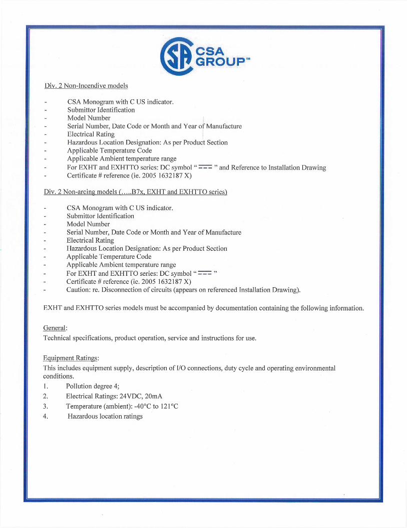
CPCSA GROUP T"
Div. 2 Non-Incendive models
- CSA Monogram with C US indicator. - Submittor Identification - Model Number - Serial Number, Date Code or Month and Year of Manufacture - Electrical Rating
Hazardous Location Designation: As per Product Section - Applicable Temperature Code - Applicable Ambient temperature range - For EXHT and EXHTTO series: DC symbol " and Reference to Installation Drawing - Certificate # reference (ie. 2005 1632187 X)
Div. 2 Non-arcing models (.137x, EXHT and EXHTTO series)
- CSA Monogram with C US indicator. - Submittor Identification - Model Number - Serial Number, Date Code or Month and Year of Manufacture - Electrical Rating - Hazardous Location Designation: As per Product Section - Applicable Temperature Code - Applicable Ambient temperature range - For EXHT and EXHTTO series: DC symbol
- Certificate # reference (ie. 2005 1632187 X) - Caution: re. Disconnection of circuits (appears on referenced Installation Drawing).
EXHT and EXHTTO series models must be accompanied by documentation containing the following information.
General:
Technical specifications, product operation, service and instructions for use.
Equipment Ratings:
This includes equipment supply, description of I/O connections, duty cycle and operating environmental conditions.
1. Pollution degree 4;
2. Electrical Ratings: 24VDC, 20mA
3. Temperature (ambient): -40°C to 12 1°C
4. Hazardous location ratings

0002655913
0002108819
0001920106
0001878614
0001632187
2013-09-26
2008-11-26
2007-06-06
2007-01-31
2005-11-03
CSA GROUPM
Supplement to Certificate of Compliance
Certificate: 1632187 Master Contract: 184981
The products listed, including the latest revision described below, are eligible to be marked in accordance with the referenced Certificate.
Product Certification Histo
000070051763 2016-03-22
Quote assumes that maximum two versions of similar schematics are needed to be assessed. Quote includes one temperature test. Only the new model will be assessed with the latest applicable standards.
Any other testing that may be required to accomplish the reassessment will be quoted separately if necessary.
Update to Existing Report Certificate 1632187; Report 2655913. Expansion of the "x" and "y" variable digits.
Update to include new Model CS64xB9y Vibration Sensors.
Update to cover revisions to numerous drawings.
Update to cover minor revisions to circuitry and to related drawings.
Update to cover addition of models 9842 VCRT and 9942 VCRT.
640 Series Vibration Sensors for Hazardous Locations
Project
80014642
Date Description
2019-11-26 Evaluation for update of report 1632187 (last update 70051763) to include High Temperature option.

IECEx Certificate
in P1.1 of Conformity
INTERNATIONAL ELECTROTECHNICAL COMMISSION lEG Certification Scheme for Explosive Atmospheres
for rules and details of the lECEx Scheme visit www.iecex.com
Certificate No.: lECEx LCIE 17.0016X Issue No: 0 Certificate history:
Issue No. 0(2018-07-11) Status: Current
Page 1 of 3 Date of Issue: 2018-07-11
Applicant: IMI, a division of PCB Piezotronics
3425 Walden Avenue
DEPEW, NY 14043
United States of America
Equipment: Vibration Transmitter, Type: EX(M)64xYxx, EXTO(M)64xYxx, EXRV(M)64xYxx
Optional accessory:
Type of Protection: Ex ia or Ex nA
Marking: Ex ia IIC T4 Ga
or
Ex nA IIC T4 Ge
(See attchment full marking)
Approved for issue on behalf of the IECEx
Certification Body:
Position:
Signature.-
(for printed version)
Date:
Julien GAUTHIER
Certification Officer
LABORATOIRE CENTRAL D INDUSTRIESLELECTRIOLIF.S SA.S nu capital de 15.745.984 RCS Nanterre 13 41111 363 174
IL C I 33 avenue du Gfndrat Leclerc 2 C Q)?A1 P(INTPNIAV AllY PflCPC
1. This certificate and schedule may only be reproduced in full.
2. This certificate is not transferable and remains the property of the issuing body.
3. The Status and authenticity of this certificate may be verified by visiting the Official lECEx Website.
Certificate issued by:
Laboratoire Central des Industries Eleclsiques (LCIE)
33 Avenue du General Leclerc
FR-92260 Fontenay-aux-Roses U France

®w
lECEx Certificate of Conformity
iFI
Certificate No: lECEx LCIE 17.0016X Issue No: 0
Date of Issue: 2018-07-11 Page 2 of 3
Manufacturer: IMI, a division of PCB Piezotronics
3425 Walden Avenue
DEPEW, NY 14043
United States of America
Additional Manufacturing location(s):
This certificate is issued as verification that a sample(s), representative of production, was assessed and tested and found to comply with the
lEC Standard list below and that the manufacturer's quality system, relating to the Ex products covered by this certificate, was assessed and
found to comply with the lECEx Quality system requirements. This certificate is granted subject to the conditions as set out in lECEx Scheme
Rules, lECEx 02 and Operational Documents as amended.
STANDARDS:
The apparatus and any acceptable variations to it specified in the schedule of this certificate and the identified documents, was found to comply
with the following standards:
lEO 60079-0: 2011 Explosive atmospheres - Part 0: General requirements
Edition:6,0
lEG 60079-11: 2011 Explosive atmospheres - Part 11: Equipment protection by intrinsic safety 'i"
Edition:6.0
lEG 60079-15: 2010 Explosive atmospheres - Part 15: Equipment protection by type of protection 'n"
Edition:4
This Certificate does not indicate compliance with electrical safety and performance requirements other than those expressly included in the
Standards listed above.
TEST & ASSESSMENT REPORTS:
A sample(s) of the equipment listed has successfully met the examination and test requirements as recorded in
Test Report:
FR/LClElExTR17.0041/00 FR/LCIE/ExTR17.0009/00
Quality Assessment Report:
NL/DEK/QARI 4.0004/03
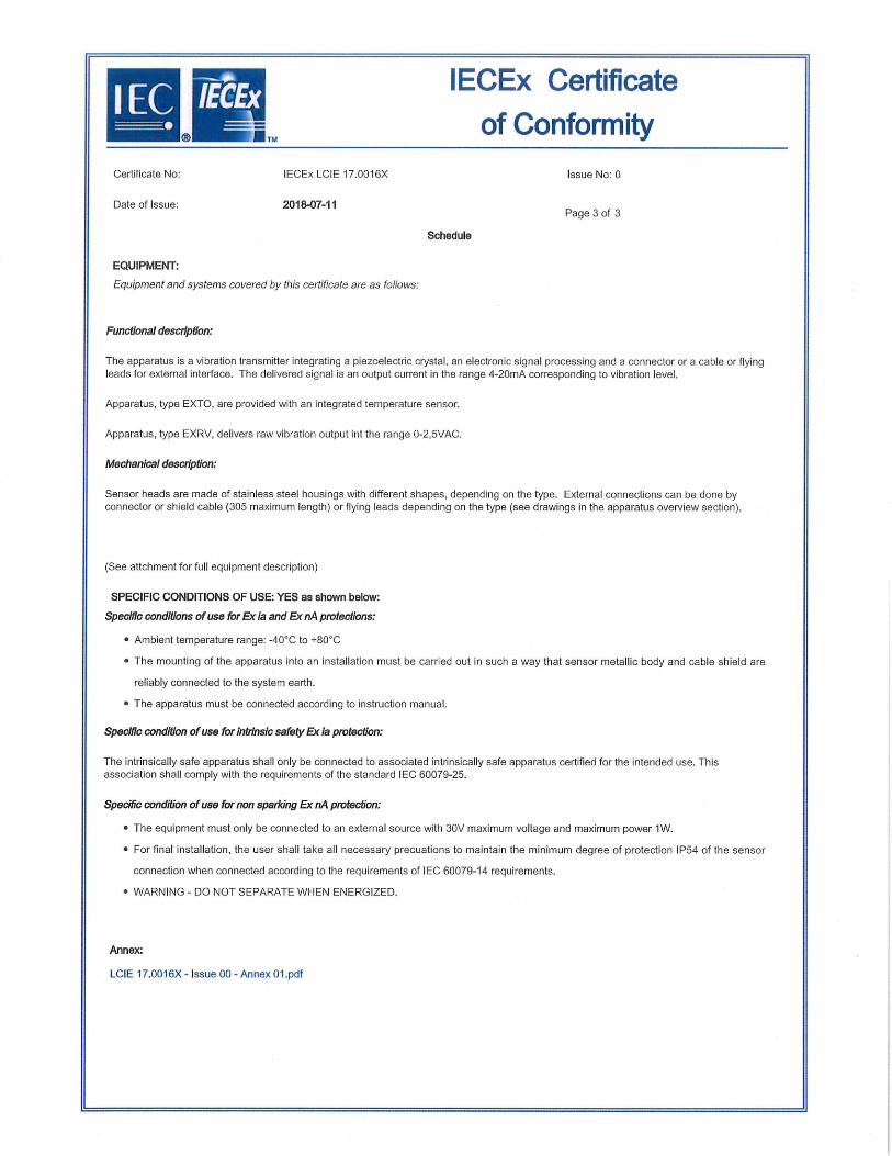
IECEx Certificate
F of Conformity
Certificate No: lECEx LCIE 17.0016X Issue No: 0
Date of Issue: 2018-07-11 Page 3 of 3
Schedule
EQUIPMENT:
Equipment and systems covered by this certificate are as follows.
Functional description:
The apparatus is a vibration transmitter integrating a piezoelectric crystal, an electronic signal processing and a connector or a cable or flying leads for external interface. The delivered signal is an output current in the range 4-20mA corresponding to vibration level.
Apparatus, type EXTO, are provided with an integrated temperature sensor.
Apparatus, type EXRV, delivers raw vibration output int the range 0-2,5VAC.
Mechanical description:
Sensor heads are made of stainless steel housings with different shapes, depending on the type. External connections can be done by connector or shield cable (305 maximum length) or flying leads depending on the type (see drawings in the apparatus overview section).
(See attchment for full equipment description)
SPECIFIC CONDITIONS OF USE: YES as shown below:
Specific conditions of use for Exia and ExnA protections:
• Ambient temperature range: -40CC to +80CC
• The mounting of the apparatus into an installation must be carried out in such a way that sensor metallic body and cable shield are
reliably connected to the system earth.
• The apparatus must be connected according to instruction manual.
Specific condition of use for intrinsic safety & Ia protection:
The intrinsically safe apparatus shall only be connected to associated intrinsically safe apparatus certified for the intended use. This association shall comply with the requirements of the standard lEO 60079-25.
Specific condition of use for non sparking ExnA protection:
• The equipment must only be connected to an external source with 30V maximum voltage and maximum power 1W.
• For final installation, the user shall take all necessary precuations to maintain the minimum degree of protection 1P54 of the sensor
connection when connected according to the requirements of lEO 60079-14 requirements.
• WARNING - DO NOT SEPARATE WHEN ENERGIZED.
Annex:
LCIE 17.0016X - Issue 00- Annex 01.pdf
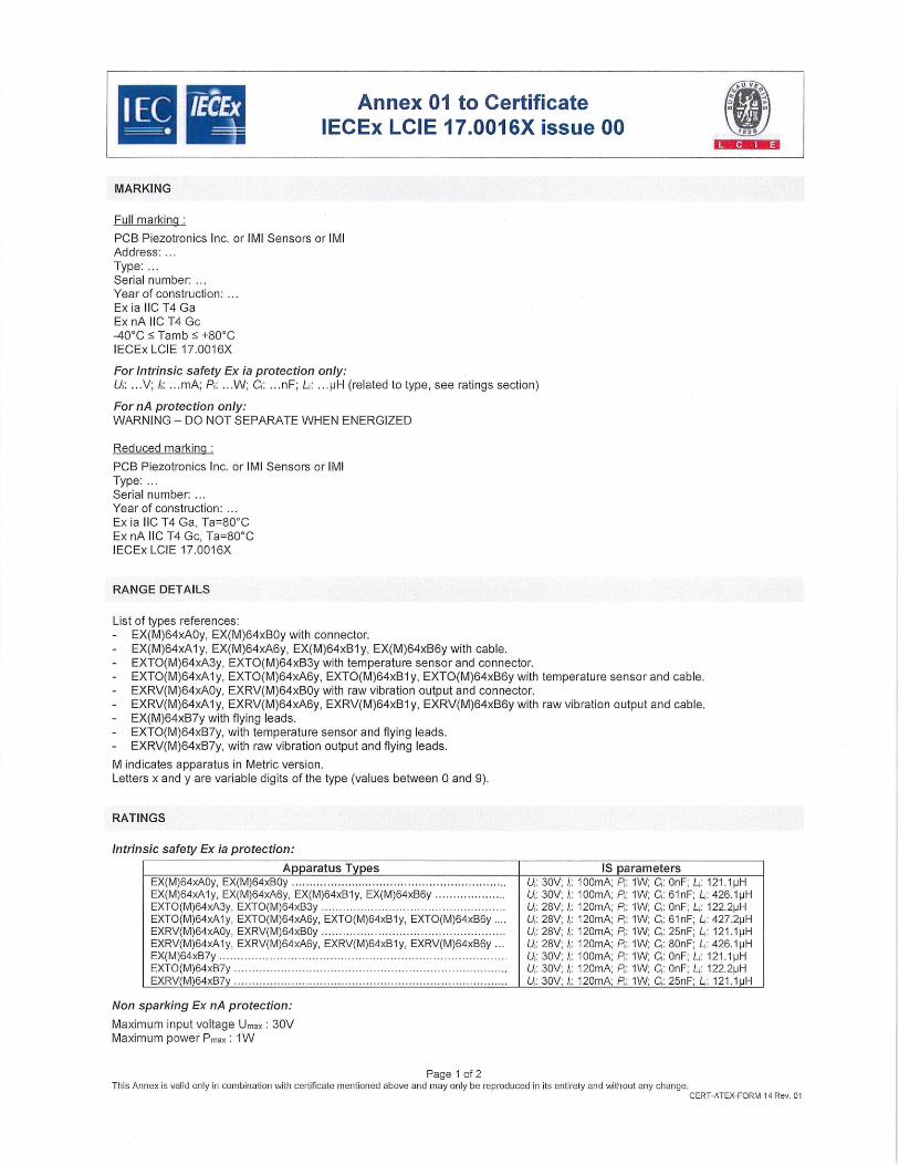
- V
zi
Annex 01 to Certificate lECEx LCIE 17.0016X issue 00 a
MARKING
Full marking
FOB Piezotronics Inc. or IMI Sensors or IMI Address: Type: Serial number: Year of construction: Ex ia 110 T4 Ga Ex nA IIC T4 Gc -40C :5 Tamb +80C lECEx LCIE 17.0016X
For Intrinsic safety Ex ía protection only: U: . .V; I: ... mA; P: ...W; C: .. .nF; L: . . . pH (related to type, see ratings section)
For nA protection only: WARNING - DO NOT SEPARATE WHEN ENERGIZED
Reduced marking
FOB Piezotronics Inc. or IMI Sensors or IMI Type: Serial number: Year of construction: Ex ia 110 T4 Ga, Ta=80C Ex nA 110 14 Gc, Ta=80O lECEx LCIE 17.0016X
RANGE DETAILS
List of types references: - EX(M)64xAOy, EX(M)64xBOy with connector. - EX(M)64xA1y, EX(M)64xA6y, EX(M)64xB1y, EX(M)64xB6y with cable. - EXTO(M)64xA3y, EXTO(M)64xB3y with temperature sensor and connector. - EXTO(M)64xA1y, EXTO(M)64xA6y, EXTO(M)64xB1y, EXTO(M)64xB6y with temperature sensor and cable. - EXRV(M)64xAOy, EXRV(M)64xBOy with raw vibration output and connector. - EXRV(M)64xA1y, EXRV(M)64xA6y, EXRV(M)64xB1y, EXRV(M)64xB6y with raw vibration output and cable. - EX(M)64xB7y with flying leads. - EXTO(M)64xB7y, with temperature sensor and flying leads. - EXRV(M)64xB7y, with raw vibration output and flying leads.
M indicates apparatus in Metric version. Letters x and y are variable digits of the type (values between 0 and 9).
RATINGS
Intrinsic safety Ex Ia protection:
Apparatus Types IS parameters EX(M)64xAOy, EX(M)64xBOy.U: 30V; I: lOOmA; P,: 1W; C1 : OnF; L: 121.1pH EX(M)64xA1y, EX(M)64xA6y, EX(M)64xB1y, EX(M)64xB6y .....................U1 : 30V; i: lOOmA; P: 1W; C1: 61nF; L: 426.1 pH EXTO(M)64xA3y, EXTO(M)64xB3y .....................................................U1 : 28V; f: 120mA; F: 1W; Cl: OnF; L1 : 122.2pH EXTO(M)64xA1y, EXTO(M)64xA6y, EXTO(M)64xB1y, EXTO(M)64xB6y U1 : 28V; /: 120mA; P1 : 1W; C1: 61nF; L,: 427.2pH EXRV(M)64xAOy, EXRV(M)64xBOy. .......................................................U1 : 28V; f: 120mA; F: 1W; C1: 25nF; L: 121.1pH EXRV(M)64xA1y, EXRV(M)64xA6y, EXRV(M)64xB1y, EXRV(M)64xB6y U1 : 28V; f: 120mA; F: 1W; C1: 80nF; L: 426.1pH EX(M)64xB7y ......................................................................................U: 30V; f: lOOmA; F: 1W; C1: OnF; L: 121.1pH EXTO(M)64xB7y ..............................................................................U: 30V; I,: 120mA; F1: 1W; C,: OnF; L1 : 122.2pH EXRV(M)64xB7y U1 : 30V; I: 120mA; F: 1V'J; C:25nF;L1: 121.1pH
Non sparking Ex nA protection:
Maximum input voltage Umax: 30V Maximum power Pmax 1W
Page 1 of 2 This Annex is valid only in combination with certificate mentioned above and may only be reproduced in its entirety and without any change.
CERT-ATEX-FORM 14 Rev. 01

II - (1 Annex 01 to Certificate lECEx LCIE 17.0016X issue 00
ROUTINE TESTS TESTS
Intrinsic safety Ex Ia protection:
None.
Non sparking Ex nil protection:
Each equipment shall be submitted to the dielectric strength test according to the clause 23.2.1 of IEC 60079-15:2010. Test voltage shall be applied between active electrical signals and the enclosure.
APPARATUS OVERVIEW
Mechanical constructions of the apparatus, head shapes and external connection possibilities:
CONNECTOR
WELD ELECTRONICS HOUSING
POTTING ELECTRONICS
WELD
- - INSULATOR SENSOR
SENSOR HOUSING
EXTO64OBSX 0(T0641 33X xrosax
EXTO64NB3X
CABLE ..- ASSEMBLY
WELD - .- ELECTRONICS
HOUSING
POTTING
Iic-:7 ELECTRONICS
WELD
INSULATOR SENSOR
SENSOR HOUSING
EXTOt4OEIX 0(1064131 X 0(10 6453 IX EXO646B1X
ARMORED JACKET
CABLE ASSEMBLY
WELD ELECTRONICS
-
HOUSING
POTTING :. ELECTRONICS
WELD
- INSULATOR SENSOR
SENSOR HOUSING
0(1064086X 0(1064136X 0(1064536X D<1064636X
IN!']
FL I1I0!1 IM L ThliTEc
. ....... iliETiI —•—•-•EIiclrn3.lS1r$
MIN
0(10647A3X EXTO642A1X E(10642MX EXI0643A3X E(T0643A1X EX10643A6X 0(T0647A3X EXT0647AIX EXTO647A6X EXTO64BA3X 0(10648A1X DCI0648A6X
CABLE ASSEMBLY
SENSOR WELD JACKET - EASE
Page 2 of 2 This Annex is valid only in combination with certificate mentioned above and may only be reproduced in its entirety and without any change.
CERT-ATEX-FORM 14 Rev. 01