MICROSCOPIC DETERMINATION OF THE ORE MINERALS
343
UNITED STATES DEPARTMENT OF THE INTERIOR Harold L. Ickes, Secretary GEOLOGICAL SURVEY W. C. Mendenhall, Director Bulletin 914 MICROSCOPIC DETERMINATION OF THE ORE MINERALS M. N. SHORT SECOND EDITION UNITED STATES GOVERNMENT PRINTING OFFICE WASHINGTON : 1940 For sale by the Superintendent of Documents, Washington, D. C. - - - - - Price $1.00 (Paper)
-
Upload
khangminh22 -
Category
Documents
-
view
0 -
download
0
Transcript of MICROSCOPIC DETERMINATION OF THE ORE MINERALS

UNITED STATES DEPARTMENT OF THE INTERIOR Harold L. Ickes, Secretary
GEOLOGICAL SURVEY W. C. Mendenhall, Director
Bulletin 914
MICROSCOPIC DETERMINATION
OF THE ORE MINERALS
M. N. SHORT
SECOND EDITION
UNITED STATES
GOVERNMENT PRINTING OFFICE
WASHINGTON : 1940
For sale by the Superintendent of Documents, Washington, D. C. - - - - - Price $1.00 (Paper)


CONTENTS
PagePreface_ ________________________________________________________ VIIPART 1. Microscopic technique..--___________._____..._______-___--- 1
Introduction........______...___________._._____._____._._._.__ 1The metallographic microscope.__-____-____________-_..__-_-_--. 4Mounting the specimen________________________________________ 8
Mounting in modeling wax. ____________.._..._._...-___---- 8Mounting in brass boxes--..---------.---------------------- 8Warming oven___________-___-___-__^___-_-__-_.__________ 10Mounting in bakelite_.___-----_-----_---_-______-__----_-_- 11
Grinding and polishing.____.____________---_______-_.___-___--- 13Sawing the specimen,___------__-_-___-______..______-_---,.- 13
Diamond saw_________________-__-____--_____-___---_- 13Corundum and silicon carbide saws._____________________ 15Patt'on lathe feed.._---_---____---________-_____-_-__-- 16
Grinding and polishing machinery___________________--_-_--. 18Eardley-Hatton polishing table_______-_______--.-----_.. 18Suggestions for construction of grinding table.------------ 21
Abrasives and polishing powders_____________--_._-_-_-_--- 22Sizing of fine abrasives._________________________________ 22
Rodda method_____-_____-_---____. --------------- 23Vanderwilt classifier._____-_-_-___________.------_- 23
Sizes of some well-known abrasives______________________ 26Polishing process at the Geological Survey,___.______._-____-_ 27
Procedure,____________---_-_-_---_____-_.___._--_---- 27Geneial remarks.-.-------------------------..___. ------ 30Impregnating the specimen_____________________________ 30
Harvard polishing process.______-_____________-_.___._-_--- 32Summary. __..__-_-._________._-____-__.____-.__--__-. 32Principles of polishing__--_,__-_---____-__--_-___--.---. 33Graton-Vanderwilt polishing machine.__.___________._--. 34Details of process as used at Harvard-___________________ 36Details of process used at Canada Department of Mines and
Resources._____.._______._________._._._____-_----. 38General remarks______________________-_,____--_-_-_- 38
Polishing process at Columbia University____-_____..------- 4.0Polishing process at the University of Minnesota.______--_---_ 42Metallographic polishing at the Watertown Arsenal.__..-....-. 42
Photomicrography of polished sections.___---_________-__.------.' 44Photomicrographic camera____ _______._____-___._____..-_-.. 44rilms_______-_.-...---._-_._----.-...------....--..----.. 51Light filters.-,___-______-____.___-____.__-___-_._._------. 51Exposure formula.______._________._____________._._-__-.-. 55Developing and printing..__________-__-_______._.____-----. 57References...______-___________._________.___._._____-_-.- 58
in

IV CONTENTS
PagoPART 2. Physical properties and measurements._______________________ 59
Color.____ 59Hardness-___----------___---______-_______.___---_-_---_-_-__ 63Examination of opaque minerals in polarized light__.-___-__--__-_. 66
Summary.. _ _______________________________________________ 66References.._ _____________________________________________ 67Apparatus.-______.____________-__.__-_____-------__--_-_. 67Details of the method..__--___-______--_____--____-----__-_ 69Methods of observation._______________________________ ... 73Adjustment of the instrument-__ _ ____________--._-___-___-_"- 74Sources of error.___._________________.______ _____________. 75
Electroconductivity__ _-______--__--_______--____---_-_-_--_-___ 76Measurement of reflectivity...--___-_________._..___________ _ ___ 76
The slit microphotometer of Berek_____j___________________ 78Measurement of reflectivity with photoelectric cells......______ 83
Alkali cells___________________________:>-_____________ 84Rectifying cells___-_-_____-_________._-______-_-_--__- 86
Spectroscopic methods.______________^____________________.. ____ 92\J PARTS. Etch reactions and determinative table_-__-_-_-_- ____________ 95
Etch reactions.________-_-_-___________________-_-_-_-_-_.--_- 95Determinative table.____----___-_______________---_____-_.-_-- 103
Introduction _______________________________________________ 103Outline of table.__-_-__--____-_-_______________---_-_-_-_- 105Soft minerals___-___--____-_______________------_--_-____ 112Hard minerals__-__--_____-_-____--_______-_-_-_-__-__-_- 159Binnenthal minerals.______________________ __-.__-_-____-_ 168Discredited or doubtful minerals_________-_-_-_-_-_-___-_- 169
Staining tests__________________________________________________ 170PART 4. Microchemical methods___________________________________ 173
Introduction. _ ________________________________________________ 173Procedure and apparatus.__---____-_-_-_-_______----____-_-_-_- 174
Collecting the material,____________________________________ 176Glass slides.______________________________________________ 178Microburner. _---__-_-_________-_____._____-_-____---...__- 178Reagents-__-_---___----_-_-__--_-.__._______-___._-_._-.. 179Capillary tubes______ _____________________._______.______ 179
Methods of applying tests._____________________________________ 180Sensitivity of microchemical tests.---.-._________________________ 183Reagents-_-_________-----_-_____--____-_._____-_-_._-_--._--- 184Tests made directly on a glass slide.__-___-_______-___-_-_-___-_- 187
Zinc___-_____----_..___..___..._:.-.._._._-_-_._._._._-.- 187Cadmium_____ _._-_____________-_________._____-___--___-- 190Copper_-__-----__-__-_______-___-_____-_-_-_-_-_-___--- 190Nickel . .I 192Cobalt________-_--.--_______.___-_-_-_____--_____--_._--- 193Iron.__--____-----.__ __ _.._ 198Silver_________-___._____._____.___.___.___-_______---__-- 199Selenium _________________________________________________ 204Tellurium. __________.___._____._.____._._-__..___.._.-. 206Arsenic_________________________________________________ 208Antimony and bismuth________-_-_---__-______-_-__-------- 212Tin..__.__---_-------__-__-__---___._-_____--_____________ 218Lead... __________________________________________________ 220Gold .- .. _ __-__-__ _______---_-_-__-__.-- 223

CONTENTS V
PART 4. Microchemical methods Continued.; Tests made directly on a glass slide Continued. Page
Mercury__. ________________-_-_-______--..------__-----.. 225Manganese __>_________.___________________________.___.- 226Sulphur_____..._.___.__-__.__---___--_-------------- - 227
Tests after fusion in loop of platinum wire.________________________ 231Molybdenum. ____-____-----------------_-----_----------. 233Tungsten_._...__.__._..._._._._..._...___.._.._._......_ 235Vanadium._ ___-_______-_---_-_-_-___-___-----_-_--_---___ 237Titanium. __.__... .._.....___. .______._._..._........... 239Chromium.._ _____..-___-____---______-___-_-----_-_----__- 240
Tests requiring special apparatus.".__--_______-_--__._-_______-_- 240Germanium. ______________________________________________ 240The platinum metals..._______.._-_________-..____-_____-____ 243
Palla d i u m _.__._._._..._.._._........__..-.._......_.. 244Platinum......._..... _.__...___.._.._..._........... 245Iridium _______________________________________________ 247Osmium._____________--_-------___-_-_.---_-__-_-_--- 248Rhodium. ______ .....__..._............._._......_.._... 250Ruthenium _________________--____..____-_-_______-_--- 250
A systematic scheme of microchemical analysis.__-_-__--_.__.-___- 252Hard minerals______-___-_-__-----________._.-_-____..-_-_- 252Soft minerals_________________-__-__-___-_-._-_-__-__-_--_ 254Outline of systematic analysis-______________________________ 257
Outline of microchemical tests.__-__-_-----.-_---______________ 259Potassium mercuric thiocyanate___-_--_-___--__-________---. 259Cesium chloride____________---_-__--_.._-___---.-_._-_-_--- 200Potassium iodide___________.___-_---_____-_______..___-_.._- 201Cesium chloride and potassium iodide...______________________ 262Potassium bichromate____-_-_--_---___-____--_-_-_.______ 263Thiourea__.___......_.______..._._....._...___....._. 264
Specific tests for minerals______-_____-_---_.___-_-_-_____ ._-____ 265Index of minerals, grouped by elements.____-_-_-_-_---------___----- 297Index of minerals and elements, alphabetical._________________________ 307General index.____________.______-------___-----_-------------._-.. 313
ILLUSTRATIONS
PagePLATE 1. Detail of Patton lathe feed__________________________________ 16
2. Photomicrographs of ores polished by Harvard process...______ 2963. Photomicrographs of ores polished by Watertown process____ 2964. Photomicrographs of polished section of specimen from Magma
mine, Superior, Ariz____--__---_--_-_____---_______.____ 2965. Microchemical tests for zinc and sulphur.___.__._._____.____ 2966. Microchemical tests for copper.__-__-_____._._._________.__ 2967. Microchemical tests for cobalt and nickel..--.-----__-__-___. 2968. Microchemical tests for silver._____________________________ 2969. Microchemical tests for arsenic and tellurium ________________ 296
10. Microchemical tests for antimony._________________________ 296tl..Microchemical tests for bismuth and tin_____________________ 29612. Microchemical tests for lead and germanium.________________ 29613. Microchemical tests for gold._..__--__--____------_-_._---_- 29614. Microchemical tests for mercury____________-___---___--.. 297

VI CONTENTS
Pag-e FIGURE 1. Metallographic microscope with equipment for. investigating
polished sections.______-_._______-____-______..____--__ 42. a, Prism illuminator; b, Glass-disk illuminator. _____._-___-_- 53. Bakelite press__^_________________________._.._____._._. 124. Diamond saw and lathe feed..____.___._______ ._____.______ 165. Eardley-Hatton polishing table and detail of mounting._____ . 196. Siphon for abrasiveg___---_-______-_-----_------_--___--_ 237. Vauderwilt abrasive classifier.____________________________ 248. Graton-Vanderwilt polishing machine_____________._.___;__ 359. Mortar and pestle__-__--_---------_---_------.---_------- 39
10. Improvised microscope camera_____ ____-__-._________---_- 4511. Leitz "Makam" camera attachment-..-......--..-_----_-_-.. 4812. Vertical camera with observation eyepiece.__..___________._. 4913. Bausch & Lomb large metallographic camera.___--__-_--___ 5014. Comparison microscope.____-_---_-_-_-_--_-'-_-._--_--___ 6015. Talmage hardness machine__----__-______----------_----_ 6516. Microscope arranged for use with polarized reflected light.... 6817. Photomicrographs of ores taken in polarized reflected light.... 7518. Microscope with Berek slit micro photometer attachment.--.. 7819. Sectional view of microscope and Berek slit microphotometer.- 7920. Alkali photoelectric cell._________________________________ 8421. Simple amplifying circuit for alkali celL__-____-_--------_-- 8522. Thermionic amplifying circuit for alkali cell..._________._-_. 8523. Construction of rectifying cell________________ .___._____._- 8724. Cross section through rectifying cell-__ ____________________ 8725. Platinum wire for transferring drop of reagent to polished sur
face_______-___.__-___-___--__-_------------_-----_- 9726. Enlarged view of needle for scraping polished surface- _ ______ 17727. Improvised alcohol lamp.________________________________ 17928. Capillary tube______._.-:___--.-_-_______________-_----- 18029. Diagram showing Chamot's method I_______.___-.._______. 18230. Glass-stoppered dropping bottle.-_____-____-____-_-.._-- . _. 18731. Zinc and copper mercuric thiocyanate crystals.___-.___--__- 18932. Apparatus for germanium test.___--_------_------..------- 24133. Apparatus for decomposition of platinum minerals...... .____ 244

PREFACE
The development of improved methods for the determination of the ore minerals and the collection of data on these minerals occupied the attention of the writer for more than 4 years prior to the publication in 1931 of Bulletin 825, the first report on this study. That work was done mostly in the laboratories of the United States Geological Survey, except from September 1927 to June 1928, while the writer occupied the position of lecturer in economic geology in Harvard University and carried forward the work with the aid afforded by the resources of the Harvard Laboratory of Mining Geology.
In the 8 years since the publication of the first edition, the study of ore minerals has been widely extended. It is safe to say that the number of articles published annually dealing partly or wholly with microscopic studies of ores has doubled in this interval. Many new methods of identification have been devised or adapted, among which the most important are spectroscopy and reflectivity of metallic sur faces. In Germany the study of the theory of light reflected from minerals has been carried on intensively. The results have been encouraging, but much yet remains to be done.
Improvements in the technique of polishing have proceeded apace in the last few years, as shown by comparison of photomicrographs in current periodicals with, those in older publications. The importance of getting a good polish on specimens is taken into consideration in this report, and much more space is devoted to this feature than in the first edition.
For the 8 years 1931-39 the writer has taught the subject of pol ished-section study to advanced students of geology at the University of Arizona. A new collection of reference minerals has been studied by them, resulting in most of the corrections made in part 3 of this report. Experience in teaching microchemistry has led to most of the changes in part 4. Because tests must be simple enough for students of average ability to apply, some microchemical tests have been eliminated and others added. Tests involving preliminary fusion with sodium carbonate have been added for molybdenum and some other elements.
In a work of this nature much of the material is a compilation of the published researches of others. The writer takes this opportunity of thanking those who have generously given permission to take material from their articles. Among these are Drs. Hans Schneiderhohn and. Paul Ramdohr, of Germany; J. Orcel, of France; J. A. Dunn, of the

VIII PBEFACE
Geological Survey of India; Maurice Haycock, of the Canada Depart ment of Mines and Resources; J. H. Moses, of the Cerro de Pasco Copper Corporation, Peru; H. J. Fraser, of the California Institute of Technology; and A. M. Gaudin, of the Montana School of Mines. Prof. L. C. Graton, of Harvard University, gave the writer full use of his laboratory and supplied most of the information regarding the Harvard polishing process. Miss M. R. Norton, of the Watertown Arsenal, prepared for the writer a description of the metallographic polishing process used there.
The writer had the full cooperation of the United States Geological Survey. . In working out the microchemical tests for molybdenum, tungsten, and vanadium, he is especially indebted to J. J. Fahey and E. T. Erickson, of the Section of Chemistry and Physics, for assistance and helpful suggestions. K. E. Lohman, of the Section of Paleon tology and Stratigraphy, revised the section on photomicrography.

MICROSCOPIC DETERMINATION OF THE OREMINERALS
By M. N. SHOET
PART 1. MICROSCOPIC TECHNIQUE
INTRODUCTION
The metallographic microscope is the most valuable instrument for identifying opaque minerals and for studying their mutual rela tionships. It plays the same part for the opaque minerals that the petrographic microscope does for transparent minerals. The metal lographic microscope differs from the petrographic microscope in that it contains a reflector placed in the barrel of the microscope directly above the objective, and light is reflected vertically downward through the objective onto the specimen to be studied. The specimen or mineral is prepared for study by grinding and polishing a flat surface. It is then mounted so that the polished surface is parallel to the micro scope stage, and the microscope is focused on the surface to be studied.
The identification of the opaque ore minerals in polished sections has made much progress since 1916, when Murdoch's pioneer re searches were first published. 1 The textbooks of Davy and Farnham, 2 Schneiderhohn,3 and Van der Veen 4 have all contributed new ideas and methods of attack. Farnham's text, 5 published in 1931, is in part a revision of the earlier text of Davy and Farnham, but it contains many new data.
The most comprehensive text on the ore minerals is that by Schneiderhohn and Ramdohr. 6 It comprises two volumes and an appendix. The second volume, which was the first to be published, contains a detailed description of every ore mineral known to the authors. This description comprises the usual mineralogic properties, many new physical properties, such as reflective power and polariza-
1 Murdoch, Joseph, Microscopical determination of the opaque minerals, New York, 1916.3 Davy, W. M., and Farnham, C. M., Microscopic examination of the ore minerals, New York, 1920.3 Schneiderhohn, Hans, Mikroskopischen Bestimmung und Untersuchung von Erzen, Berlin, 1922.4 Van der Veen, R. W., Mineragraphy and ore deposition. The Hague, 1925. 8 Farnham, O. M., Determination of the ore minerals, New York, 1931.«Schnelderhohn, Hans, and Ramdohr, Paul, Lehrbuch der Erzmikroskopie, Berlin, Qebriider Born-
traeger, Band 2,1931: Bestimmungstafeln (appendix), 1931; Band 1, H&lfte 1,1934.

2 MICROSCOPIC DETERMINATION OF ORE MINERALS
tion colors, paragenetic relations with other minerals, a list of localities where the mineral occurs, and a complete bibliography. The first volume is more general and contains a description of various micro scopes, methods of polishing, determination of anisotropism and re flective power, photomicrography, and determination of mineral orientation. The appendix (Bestimmungstafeln), which is actually a third volume, is a table for the determination of minerals by means of their microscopic properties.
Not all the methods outlined in the texts cited have proved entirely satisfactory, and some discrimination is required in selecting from the methods described those winch are of greatest value. The writer has made an effort to select those methods which, in his opinion, are most useful and which at the same time do not require elaborate and expensive apparatus. The scheme of identification adopted is based on the following observations:
1. By means of polarized light, minerals crystallizing in the iso metric system can be separated from those crystallizing in the other five systems.
2. By means of a needle, minerals can be graded as to hardness into two classes hard, or those which can be scratched with difficulty or not at all, and soft, or those which are easily scratched with a needle. The three grades of hardness described by Murdoch and by Davy and Farnham are accordingly modified by eliminating the "intermediate" class.
3. The systematic etching scheme described by Davy and Farn ham, although far from perfect, is of great value in saving time. The etch tests are sufficient for the identification of some minerals, but for most minerals identifications based on this method must be checked by other methods.
4. Qualitative microchemical tests constitute the most reliable method available for identifying an ore mineral. These tests require considerable time. Unless the investigator has a clue as to what elements are present, he must test for the different elements in turn in a systematic way, analogous to the methods of ordinary qualitative analysis. The most effective and the quickest method of identifying a mineral is first to obtain all the data yielded by methods 1 to 3. This procedure will generally limit the designation to a choice of half a dozen or less minerals. The final choice will be governed by definite microchemical tests for one or more suspected elements.
The necessity for more accurate data than are available in the literature was brought out during the present investigations. Micro- chemical tests made on Murdoch's original suite of ore minerals and on the suite of specimens selected by the writer from the United States National Museum showed that over 20 percent of these minerals were

MICROSCOPIC TECHNIQUE 3
mislabeled. The necessity for careful selection of specimens is thus manifest.
The present investigation by no means eliminates all the errors resulting from incorrectly designated specimens. Microchemical tests are qualitative and not quantitative and are thus incapable of dis tinguishing between different minerals having the same elements. The writer cannot, at present, distinguish beegerite, Pb6Bi2S9 ; cosalite, Pb2Bi2S5 ; and lillianite, Pb3Bi2S6 . The only safe way of distinguishing between these minerals would be to obtain quantitative chemical analyses of selected specimens and try to obtain distinctive criteria on polished sections of these specimens by methods 1 to 3 outlined above. Usually but not always it suffices to obtain material from the type localities of the minerals. With such material it is not necessary to make analyses, as the original identification of the minerals from these localities is usually based on quantitative analyses. This plan is especially useful on minerals that are confined to one or two localities. For example, mineral from Rezbanya, Hungary, containing lead and bismuth and labeled "rezbanyite," is probably what it purports to be.
It should not be forgotten, however, that many published analyses, especially the earlier ones, were based on impure material. Before the reflecting microscope was applied to the study of ores many ore minerals were assumed to be pure because no impurities were visible in the hand specimen. Microscopic investigation lias shown the error of such an assumption. Even apparently pure crystals are by no means always pure. The correct formula for bornite escaped determination for over a hundred years because the crystals of ap parently pure bornite analyzed were not pure but were later shown to be intermixtures of bornite and chalcopyrite. It thus becomes evident that no ore mineral should be analyzed until it has first been examined microscopically and shown to be pure. In the descrip tions of minerals given in this bulletin, data obtained from analyzed material will be accompanied by reference to the analyses.
A suitable designation for the study of the ore minerals under the metallographic microscope has not yet been suggested. The term "mineralography" proposed by Murdoch is obviously not suitable, as the study embraces only a certain group of minerals. The term "mineragraphy" proposed by Whitehead 7 and used by Davy and Farnham and by Van der Veen is decidedly harsh and unpleasant. Notwithstanding this objection, this term has come into more wide spread use than any other. The term "chalcography" used by Schneiderhohn is unsuitable, as it has already been applied to the art of engraving on copper.8 The most recent suggestion is "Erz-
' Whitehead, W. L., Notes on the technique of mineragraphy: Econ. Geology, vol. 12, p. 697,1917. 8 Webster's New International Dictionary. This confusion in terminology was first noted by Mr.
E. E, Fairbanks in an unpublished paper.

4 MICROSCOPIC DETERMINATION OF ORE MINERALS
mikroskopie" as proposed by Schneiderhohn and Kamdobr. This might be translated literally as "ore microscopy." The term is not adaptable to the English language, as the corresponding adjective cannot be formed. The writer prefers not to use any of the above terms and will retain the exact if cumbersome phrase "microscopic study of the ore minerals."
THE METALLOGRAPHIC MICROSCOPE
Any compound microscope can be converted into a metallographic microscope by means of a vertical illuminator, consisting of a short
FIGURE 1. Metallographic microscope with equipment for investigating polished sections, a, Spencer lamp, No. 374; (i, rubbing block; c, reagents for etch tests; d, vertical illuminator; e, polished section on modeling wax; ]t screw for racking stage up and down; g, polished section in brass mount; ft, lead filling; i, sleeve; i, nipple; k, flange: (, mounting cup.
tube in which is mounted a reflector. An opening in the side of the tube admits light to the reflector. The light after impinging on the reflector is thrown vertically downward through the objective and strikes the polished surface of the mineral to be examined. The light is then reflected vertically upward from the polished surface, passes through the objective and beliind or through the reflector, and after passing through the ocular reaches the eye.
There are two types of vertical illuminator, the difference depend ing on the kind of reflector used. The prism illuminator consists of a glass prism which occupies about one-half of the area of the tube. This arrangement enables part of the rays reflected from the surface to pass behind the reflector. (See fig. 2.) The glass-disk illuminator consists of a thin transparent glass disk which occupies practically

MICROSCOPIC TECHNIQUE
the entire area of the tube. In both types the reflector is rotatable in the tube and is turned until the clearest image appears.
The vertical illuminator screws on to the lower end of the micro scope barrel, and the objective, in turn, screws on or is fastened by a spring clip to the lower end of the illuminator.
The glass-disk illuminator, also referred to as the plane-glass illuminator, gives a more even illumination than the prism illumi nator, but only about half of the light striking the glass disk is re flected downward to the polished section; the rest of the light is absorbed by the disk or passes horizontally through it and is ab sorbed in the walls of the illuminator tube. The light impinging
M
FIGURE 2. a, Prism illuminator. (Courtesy of E. Leitz, Inc.) T, microscope barrel; K, prism; L, con verging lens; 0, short-mounted objective; P, bundle of rays passing upward behind prism; M, polished surface; C, spring clip holding objective to illuminator barrel, b, Glass-disk illuminator. (Courtesy of Bausch & Lomb Optical Co.)
downward on the polished surface is reflected upward. On striking the plate-glass disk again, part of the upward-moving light is reflected back toward the lamp and leaves the microscope. A small pro portion of the upward-moving light is absorbed by the disk itself, and the remainder gets through the disk and so reaches the eye. As a result of these losses only a small part, possibly less than one- fourth, of the original intensity of the light is available for microscopic observation.
The prism illuminator reflects downward practically all the light that impinges on the prism. However, only part of the light re flected by the polished section reaches the eye, as the prism itself occupies half of the section of the tube, and all that part cf the light which, on its upward path, strikes the prism is reflected outside of the microscope and lost. Only that part of the upward-moving light that passes behind the illuminating prism reaches the eye. To get the maximum illumination the prism is turned so that the rays do not move exactly vertically downward but strike the surface

6 MICROSCOPIC DETEEMmATIOST OF ORE MINERALS
with a slight inclination from the vertical and in turn are reflectedwith just enough inclination from the vertical to pass by the prism.
Van der Veen 9 compares the two types of illuminator as follows:
The specific intensity of the illumination by the prism illuminator is higher than that of the glass [disk] illuminator, because the bundle of rays, although divided into two parts, keeps its original intensity. In the plane-glass type every ray is reduced in intensity while the whole bundle remains intact. For this reason, the resolving power of the plane-glass illuminator is much higher than that of the prism illuminator. Therefore, the former is especially desirable for high magnification.
The writer prefers the prism type of illuminator for work with daylight and with ordinary artificial illumination (using an ordi nary incandescent electric bulb and a daylight glass screen). This is satisfactory for observation with objectives of 32-, 24-, 16-, 8-, and 4-millimeter focal length. With objectives of higher magnification tha'n the 4-millimeter lens and for microphotography the glass-disk illuminator is preferable. Strong artificial illumination is required for the higher magnifications. The writer finds the 6-volt 108-watt tungsten-ribbon Mazda lamp the most satisfactory. The arc lamp gives an intense light but one which varies in intensity.
Figure 1 shows the most common type of metallographic micro scope. The stage can be moved vertically by means of a rack and pinion but is not rotatable. The microscope barrel with attached illuminator and objective remains fixed, and the polished surface is brought into focus by racking the stage up or down. The advantage of this arrangement is that the light source does not need to be shifted in position when the objective is changed. The distance of the polished surface above the glass slide that supports the specimen can likewise be changed without moving the microscope barrel or light source. The metallographic microscope of this type is entirely satisfactory for most work but has the disadvantage that it can not be used in investigations requiring polarized light.
The writer prefers a petrographic microscope for use with reflected light. The illuminator can be attached and detached in a few seconds by means of a ring that fits in a clamp. In this manner the microscope can be changed from a petrographic to a metallographic microscope with a minimum of effort. Nearly all the work with reflected light is done with a short-mounted objective of 16-millimeter focal length. Consequently, the objective is screwed into the vertical illuminator and not detached from it when the illuminator is removed from the microscope.
The 16-millimeter objective is the best all-round lens for metallo graphic work for the following reasons:
1. It gives the most satisfactory field of view for the greatest number of mineral intergrowths that is, the size of mineral grains
8 Van der Veen, E. W., op. cit., p. 3.

MICROSCOPIC TECHNIQUE 7
in the greatest number of specimens is such that they are best observed with that lens.
2. It combines clearness of vision with depth of focus and freedom from boundary shadows. (See pi. 4.)
3. It is the best lens for use with polarized light. (See p. 69.)Objectives of lower magnification than the 16-millimeter lens are
more frequently used than those of higher magnification. The 24- millimeter and 32-millimeter lenses are the ones most frequently used. These two lenses do not have to be designed for use without the cover gla.ss and do not require special short mounts; the 24- and 32-milli meter petrographic objectives are entirely satisfactory for metallo- graphic work.
If the mineral grains are so large that they require the use of an objective of still lower magnification, it is best to dispense with the use of the metallographic microscope altogether and view the polished section under the binocular microscope, using oblique light. By tilting the surface at the correct angle, a mirrorlike reflection is obtained which is similar to that produced by vertical illumination.
The 8-millimeter and 4-millimeter short-mounted objectives and more rarely the short-mounted 1.9-millimeter oil-immersion lens are occasionally used for higher magnifications, but the difficulty of ob taining a flat surface on a polished mineral specimen hinders the use of the oil-immersion lens. Fortunately the size of grain in min eral intergrowths is rarely so small that the oil-immersion lens is required.
The rotatable stage and tube analyzer of the petrographic micro scope are necessary when polished sections are examined in polarized light.
For ordinary microscopic work, where the comparison microscope is not required, daylight furnishes satisfactory illumination. With some experience, the eye readily adjusts itself to changing strength of daylight. A north exposure or one shielded from direct sunlight is required. If trees, buildings, or other objects of any considerable size are in front of the microscope, the images of these objects are apt to be reflected on the surface of the mineral under the microscope. If an uninterrupted view cannot be obtained, artificial illumination is required.
The Spencer microscope lamp No. 370, now used by the writer at the University of Arizona, is highly satisfactory for both petrographic and metallographic microscopic work. This lamp has a diaphragm in front of the bulb by means of which a horizontal cylinder of light about 1 centimeter in diameter can be obtained, making a satisfactory illuminant for work in reflected light. For thin-section, work the lamp is tilted so that the light shines obliquely downward, and the diaphragm is opened to its full width of 6.5 centimeters.

8 MICROSCOPIC DETERMINATION OP ORE MINERALS
The lamp is provided with a 100-watt Mazda projection bulb. For ordinary observation with polarized light, a ground-glass "daylight" color screen is placed in front of the bulb. This gives color values approximating those of daylight. As the 110-volt current gives too bright a light for ordinary observation, a rheostat is placed in the circuit, which reduces its potential to 90 volts. This reduced voltage also prolongs the life of the bulb.
For polarized reflected light the full voltage is used and the ground- glass "daylight" screen is removed. Where polarized reflected light is not required the lamp is equipped with a 60-volt frosted "daylight" Mazda bulb together with a "daylight" ground-glass screen. This bulb costs about 30 cents, as contrasted with $1.50 for the 100-watt projection bulb.
MOUNTING THE SPECIMEN
Mounting in modeling wax. The polished specimen is mounted by being pressed into a lump of modeling wax on a glass slide. A con venient size for the slide is 3% by IK inches by % inch. The polished surface is, of course, uppermost and must be parallel to the glass slide. A number of leveling devices are on the market, but none of them are as convenient as the home-made mounting cup made of 2-inch pipe fittings shown in figure 1, which is similar to one illustrated by Davy and Farnham. 10
This consists of a 2-inch nipple 3 inches long filled with lead, a sleeve 2% inches long, and a flange. The upper surface of the nipple with its lead filling and the upper edge of the sleeve are machined so as to be at right angles with the length. The sleeve is rotated so that its upper edge is a convenient distance above the lead surface. The distance selected determines the distance between the polished surface and the upper surface of the slide. The section is pressed down by hand into the wax, the polished surface being approximately parallel to the glass slide; then the slide with wax and section is turned upside down, and the polished surface is lowered till it comes into contact with the lead surface of the cup. The slide is then pushed downward until it rests on the sleeve. The advantage of this leveling device is that the height of the polished surface above the slide can be adjusted at will.
Mounting in brass boxes. A much more effective method of mount ing than the temporary emplacement in modeling wax is to cement the polished chip in a section of rectangular brass tubing by means of sealing wax. The polished sections thus mounted are easier to handle, and tiny fragments or fragile chips that could not be held steadily by hand or that would break to pieces during the polishing process are firmly gripped in the cement, so that the grinding can be continued to any required degree. A flatter surface is obtained when
10 Davy, W. M., and Farnham, 0. M., op. cit., p. 5.
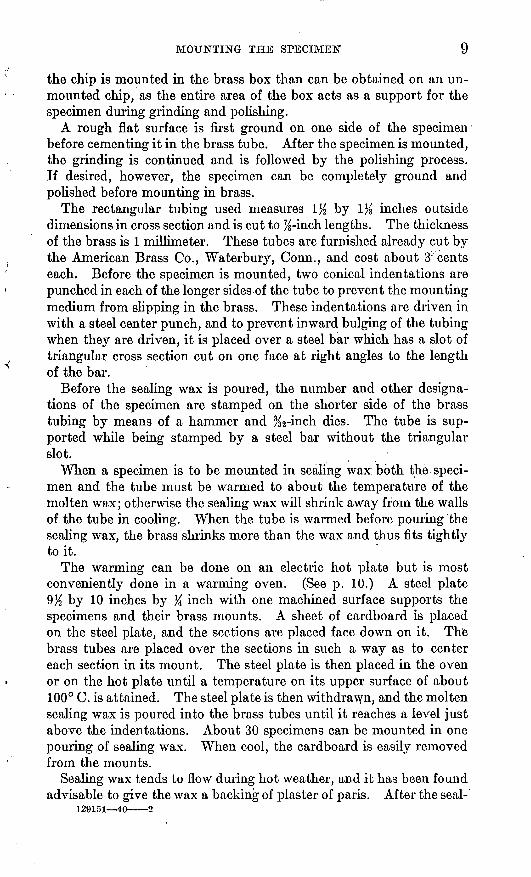
MOUNTING THE SPECIMEN 9
the chip is mounted in the brass box than can be obtained on an un mounted chip, as the entire area of the box acts as a support for the specimen during grinding and polishing.
A rough flat surface is first ground on one side of the specimen before cementing it hi the brass tube. After the specimen is mounted, the grinding is continued and is followed by the polishing process. If desired, however, the specimen can be completely ground and polished before mounting in brass.
The rectangular tubing used measures 1% by 1% inches outside dimensions in cross section and is cut to %-inch lengths. The thickness of the brass is 1 millimeter. These tubes are furnished already cut by the American Brass Co., Waterbury, Conn., and cost about 3 cents each. Before the specimen is mounted, two conical indentations are punched in each of the longer sides of the tube to prevent the mounting medium from slipping in the brass. These indentations are driven in with a steel center punch, and to prevent inward bulging of the tubing when they are driven, it is placed over a steel bar which has a slot of triangular cross section cut on one face at right angles to the length of the bar.
Before the sealing wax is poured, the number and other designa tions of the specimen are stamped on the shorter side of the brass tubing by means of a hammer and % 2-inch dies. The tube is sup ported while being stamped by a steel bar without the triangular slot.
When a specimen is to be mounted in sealing wax both the speci men and the tube must be warmed to about the temperature of the molten wax; otherwise the sealing wax will shrink away from the walls of the tube in cooling. When the tube is warmed before pouring "the sealing wax, the brass shrinks more than the wax and thus fits tightly to it.
The warming can be done on an electric hot plate but is most conveniently done in a warming oven. (See p. 10.) A steel plate 9K by 10 inches by K inch with one machined surface supports the specimens and their brass mounts. A sheet of cardboard is placed on the steel plate, and the sections are placed face down on it. The brass tubes are placed over the sections in such a way as to center each section in its mount. The steel plate is then placed in the oven or on the hot plate until a temperature on its upper surface of about 100° C. is attained. The steel plate is then withdrawn, and the molten sealing wax is poured into the brass tubes until it reaches a level just above the indentations. About 30 specimens can be mounted in one pouring of sealing wax. When cool, the cardboard is easily removed from the mounts.
Sealing wax tends to flow during hot weather, and it has been found advisable to give the wax a backing of plaster of paris. After the seal-
129151 40 2

10 MICROSCOPIC DETERMINATION OF ORE MINERALS
ing wax is cold the section is placed face down, and plaster of paris is poured until it almost fills the tube, about % inch of clearance being left in order that the mount will rest on its brass edges when righted.
A sealing wax made of 60 grams of flaked shellac, 45 grams of resin, and 23 cubic centimeters of turpentine has been found entirely satisfactory and is superior to sealing waxes on the market in that it is free from gritty filler. The ingredients are placed in a "granite-ware" saucepan about 5^ inches in diameter and 2% inches deep, and the pan is heated until vigorous bubbling sets in, the mixture being stirred from time to time with a tablespoon. When the ingredients are thoroughly mixed, the pan is removed from the heat source and the mixture stirred until it ceases to bubble. Bubbles on the surface of the mount that is, adjacent to the polished surface are objection able, as they tend to collect grit during the subsequent grinding and polishing. The above proportions give enough sealing wax to mount about 10 polished sections. It is best to avoid preparing more wax than is to be used at one time. If wax is heated 2 or 3 times, so much of the volatile constituents is expelled that the wax becomes rubbery and must be discarded. Sections mounted as described above and kept away from the sun or other sources of heat will last several years without any appreciable deterioration of the sealing wax. The writer has sections that have been mounted 5 years, most of which are free from checking on the surface of the wax and others show it only slightly. Experience at Harvard has shown that eventually the sealing wax will disintegrate and the specimen will have to be re mounted.
Portland cement has been suggested as a mounting medium, 11 but experience has shown that it is almost impossible to prevent particles of grit from breaking from the surface and scratching the softer minerals.
Warming oven. In the Geological Survey laboratory the warm ing is done in an oven equipped with electric heating coils. The oven measures 11 by 11 by 14% inches and was manufactured by the Central Scientific Co., Chicago, 111. By means of a thermostat a constant temperature is maintained. The temperature range is from 70° to 115° C.
A simple home-made oven will give good service. The design of this oven was suggested by Dr. Edwin P. Cox, formerly of the University of Oregon. It is a box constructed of metal and lined with asbestos to prevent the escape of heat. The box measures 16K by 12% by 12K inches, outside dimensions. Heating is accomplished by six 75-watt electric bulbs arranged in parallel. Each bulb can be turned on or off by screwing it in or out in its socket. Such an oven constructed at Harvard University gave a temperature after
" Short, M. N., Preparation of polished sections of ores: Ecori. Geology, vol. 21, p. 658,1926.

MOUNTING THE SPECIMEN 11
2 hours of 40° C. with one bulb burning and 120° C. with all six burning. The temperature maintained was almost constant. Inter mediate temperatures were obtained by varying the number of bulbs in the circuit. This oven serves very well in impregnating a porous specimen with bakelite, as described on page 30.
Mounting in bakelite. The use of solid bakelite for mounting metal- lographic and ore specimens has increased greatly since the first edition of this bulletin. Solid bakelite has some decided advantages over sealing wax or Wood's metal. Once molded it withstands high temperatures and is chemically inert. It takes a good polish and is attractive in appearance. The disadvantages are the relatively high temperature and very high pressure necessary to mold it. This re quires a rather expensive hydraulic press. Also, once the specimen is mounted it is removed from the bakelite with difficulty.
In several institutions where bakelite is used as a mounting medium, the press is home-made. Such a press has already been described by Krieger and Bird. 12 Although the cost of the materials is not over $30, construction involves a considerable expenditure of time, and it is doubtful if such a press would work as well at first as one made by an experienced manufacturer from a standard design.
The hydraulic press used by the United States Geological Survey (fig. 3) is made by Adolph I. Buehler, 228 North La Salle Street, Chicago, 111. (price, $120, 1936). It has given good service. The cylindrical mount is 1% inches in diameter and about % inch in height.
The molding tools proper are three in number. The specimen rests face down on a steel cylindrical disk \}{ inches in diameter by % inch in height. This is termed "base plate" by the manufacturer. A steel hollow cylinder l}( inches in interior diameter by 3}£ inches in height is placed over the base plate. The specimen is then covered with enough bakelite powder to make the combined volume of bakelite and specimen 28 cubic centimeters. The grade of bakelite used is BM 120. This is then covered with a solid cylinder 1% by 2% inches that serves as a piston to compress the bakelite. The upper surface of the piston is plane but its lower surface is convex downward. The mold assembly, consisting of base plate, hollow cylinder, and piston, is a part independent of the hydraulic press and can be removed. The assembly rests on an insulating plate of asbestos. This in turn is supported by a movable platen that is pushed upward by the hy draulic jack. The movable platen glides on two vertical rods. The upper crosspiece is stationary and acts as a buttress, against which the lower movable support pushes the mold assembly.
Surrounding the cylindrical mold is a heating unit consisting of a coil of wire in asbestos, operating on a 110-volt alternating or direct
" Krieger, Philip, and Bird, P. H., Mounting polished surfaces in bakelite: Econ. Geology, vol. 27, pp. 676-678,1932.

12 MICROSCOPIC DETERMINATION OF ORE MINERALS
current and capable of heating the cylinder and its contents to a temperature of about 170° C. The temperature actually used, how ever, is much lower. A thermometer fits into a cylindrical cavity in the piston. The press is then pumped up until a pressure on the bakelite of 1,000 pounds is attained. The heat is then turned on.
At about 60° C. the bake lite mel ts . This is indicated by a sudden lowering of the pressure-gage reading. The pressure is then increased to 2,500 pounds and is held there until no further melting is in dicated. It is then raised to 3,500 pounds, and heating is continued until the tempera ture reaches 135° C.
The mold assembly is then removed from the press and quenched in water. The base plate, piston, and mounted specimen are then removed from the cylinder by putting the mold assembly in the hy draulic press for ejection un der the short rod at the left, which projects downward from the upper cross piece. Below the short rod is a hole in the lower support, 1 1A inches in diameter. As the movable support is pushed upward, the base plate and bakelite mount are pushed out of the cylinder and through the hole in the support.
The press mounts, according to size, one or more specimens at a time, and the time required from start to finish for making a mount of the size above indicated is about 20 minutes.
A bakelite press specially designed for the Harvard process and described on page 34 mounts four specimens at one time.
Extreme care must be taken to clean out any fragments of bakelite adhering to the inside of the mold after the mount is removed. This can be done with a knife as the steel in the mold assembly is case- hardened. Emery paper should not be used, as it might scratch the
FIGURE 3. Bakelite press. (From catalog of A. I. Buehler, Chicago.)

GRINDING AND POLISHING 13
steel. A thin film of beeswax applied from time to time aids in preventing the mount from sticking too tightly in the mold. The mold must be absolutely clean, and the polished section must not be impregnated with Canada balsam before mounting in bakelite, or the mount may stick so tightly that it cannot be removed by the hydraulic press.
GRINDING AND POLISHING
SAWING THE SPECIMEN
Diamond saw. The diamond saw has been used by lapidaries for many years to saw rock specimens and gem stones, but it has not yet come into general use in making thin and polished sections. Its use has been recommended by Davy and Farnham. 13 The saw consists of a metal disk ranging in diameter from 6 to 12 inches and in thick ness from 0.02 to 0.03 inch, the edge of which is charged with diamond dust. The material used is copper, bronze, or soft steel. Saws pur chased from dealers are believed to be cheaper in the long run. The diamond saw used by the Geological Survey is manufactured by the Felker Manufacturing Co., Torrance, Calif. The life of the saw is about 500 rock slides averaging 1 square inch in area, and its cost is about $4.60.
Vanderwilt 14 has described the construction of an inexpensive saw. A disk, of somewhat larger diameter than desired, is cut with shears from cold rolled copper 0.02 to 0.03 inch in thickness. The arbor hole is cut with an auger. First a small hole is made for the bit-feed screw; then the bit is turned until a depression is cut halfway through the disk from one side, after which the hole is completed by cutting through from the opposite side. The edge of the disk must be a little thicker than the body. This thickening is accomplished by tapping the edge lightly but firmly with a small hammer. The disk is trued by holding a file or piece of carborundum against its edge while it is turning on a shaft. For charging the edge with diamond dust a small case-hardened steel roller, which revolves on a shaft at the edge of a handle, is used. Detailed instructions for the construc tion of a similar diamond saw are given by Shaub. 15
Diamond dust used by Vanderwilt was purchased from the Arthur Crafts Co., 125 Summer Street, Boston, Mass., for $5 to $6 a carat. The size of grain found most satisfactory was No. 1, measuring from 0.008 to 0.01 millimeter in diameter. The dust is mixed to a thin paste with olive oil. Crushed bort used by Shaub was obtained from the Diamond Drill Carbon Co. and J. K. Smit & Sons, Inc., both of New York, for $1.50 to $2.50 a carat.
" Davy, W. M., and Farnham, C. M., op. cit., p. 2.» Vanderwilt. J. W., A simple diamond saw: Econ. Geology, vol., 25, p. 222, 1930.» Shaub, B. M., An inexpensive rock-slicing machine: Econ. Geology, vol. 30, pp. 916-922, 1935.

14 MICROSCOPIC DETERMINATION OF ORE MINERALS
To charge the saw, the steel roller is coated with the diamond paste and pressed against the edge of the disk, which is turned several revolutions by hand. Then with the motor running, the charging is completed. The saw used by Vanderwilt is 6 inches in diameter and runs at 1,725 revolutions a minute. A stream of water is turned against the contact of the disk and the specimen.
The diamond saw described by Rosenbusch (Wulfing) 16 differs from that above described in that the dust is not charged uniformly around the periphery of the saw but is introduced in small nicks or notches cut at regular intervals around the periphery.
The notches are about 0.5 millimeter deep and are not parallel to the radii but make with them angles of 10° to 20°, uniformity of angle not being important. Diamond dust is mixed with thick oil and intro duced into the notches with the linger. The notches are then closed by rotating the disk by hand in a 2-millimeter groove in an agate roller.
The diamond saw of Dake and Young 17 is similar to that described by Rosenbusch (Wulfing) but differs in some details. Instead of a stream of water playing on the edge of the saw to remove the cuttings, the saw runs in a mixture of equal parts of crankcase oil and kerosene. A pan of oil is so placed that the lower edge of the saw dips into it. The saw is made from a disk of Armco or automobile-fender steel, the periphery of which has % 2-inch notches at intervals of about Ke inch. A suitable blade for cutting these notches can be ground from a hacksaw. The hacksaw is sharpened to a slightly dull chisel edge. A light hammer is used to drive the blade into the edge of the disk in making the notches. One carat of diamond bort powdered to 220 mesh is mixed with a bulk of vaseline about the size of a pea. When this diamond paste has been carefully worked into the notches on the saw blade, the notches are closed by lightly tapping with a peen ham mer. After this operation the saw is rotated in a groove in a case- hardened steel roller to close the notches and grip the diamond paste better.
A little experience is needed to charge and operate a diamond saw properly, but the authors state that with proper precautions a 12- inch diamond saw will section at least 1,000 square niches of material of the hardness of agate.
The 6- to 12-inch saws have a thickness of 0.031 inch (No. 22, U. S. S. gage). Larger saws are somewhat thicker. The speed of the 6-inch saw is 600 revolutions a minute and that of the 12-inch saw about 300.
Dake 18 has commented on the diamond saw as follows:Disks of sheet metal ready for charging with diamond dust can be purchased
from any sheet-metal company at low cost. The saws are cut by a machine so"8 Eosenbusch (Wulfing), Mikroskopische Physiographie, Band 1, Halite 1, p. 9, Stuttgart, 1924. » Dake, H. C., and Young,T. S., Complete and modern cabochon cutting technic: Mineralogist, vol. 3,
p. 59, 1935. is Dake, H. C., written communication.

GRINDING AND POLISHING 15
that the periphery of the disk will be very true, and the arbor hole can be cut to any specified diameter. To cut a disk satisfactorily without the proper tools it a difficult matter.
The minor difficulties that attend the charging and using of a diamond saw are overcome by the operator by the time he has spoiled a few saws. When all the diamond grit has been torn from the periphery the disk can be repeatedly re charged until the saw becomes too small to be useful.
It is important to have the edge of the saw true prior to charging. A sharp edge of broken chalcedony makes an excellent tool for trimming off and truing the edge. This is done while the saw is rotating.
Sometimes a saw gets bent in such a manner that it tends to wobble with con siderable side movement. To eliminate this difficulty a hardwood stick 2 by 1 by 14 inches is pressed against the saw while it is in motion, starting near tha arbor and working toward the peripheiy. The pressure is lessened as the periph ery is approached. This "massage" will reduce the wobble to a minimum.
A case-hardened steel roller is used not only to force the diamond grit into the edge of the disk but also to give the saw a "set." The roller slightly flattens the edge of the metal and thus enables the saw to cut its own clearance without binding and friction. The roller can be applied with rather heavy pressure. If the "set" is lacking on one side of the saw, the disk will tend to bend in the opposite direction, thus causing binding and cutting at an angle.
Some workers charge the diamond saw by merely smearing a little diamond paste on the edge. This is not nearly so effective as charging notches cut in the edge. It is also wasteful of diamond dust. Diamond saws can be purchased ready charged for $3 to $6, the price depending on the amount of diamond dust used and the size of the disk. A well-charged 12-inch disk should carry at least 1 carat of diamond dust on the edge.
Corundum and silicon carbide saws. Saws similar to the diamond saw but constructed from artificial corundum (alundum) or silicon carbide (carborundum) bonded with bakelite have recently come into general use. Most of these saws are 6 inches in diameter and X« or %i inch in thickness. No metal is used in the construction of the disk, as the bonding is sufficiently tenacious to hold it rigid. Such saws are used in the same manner as diamond saws. They are cheaper than diamond saws and last much longer, as the entire disk is capable of cutting, whereas the effective cutting edge of the diamond saw is only %z inch or less in width. The disadvantages of the abrasive-bakelite saws are as follows:
1. They are somewhat brittle and sometimes fly to pieces when force is applied at an angle to the plane of the disk or when too much force is used on the periphery. At the University of Arizona the operator protects himself against such mishaps by wearing a fencing: mask and gloves.
2. They cut a wider groove than the diamond saw.3. They are somewhat slower in cutting than the diamond saw.The abrasive-bakelite saw used by the United States Geological
Survey is 6 inches in diameter by %2 inch in thickness, is made of No. 60 carborundum grit, and is sold by the National Grinding Wheel Co., North Tonawanda, N. Y., for about 65 cents. At 2,000 revolutions a minute it saws through a 1-inch granite drill core in 2 minutes or less.

16 MICROSCOPIC DETERMINATION OF ORE MINERALS
The abrasive-bakelite saw used by the writer at the University of Arizona is a Norton alundum, catalog No. X6-3760-07-T-2, sold by the Norton Co., Worcester, Mass., for about 45 cents. It is 6 inches in diameter by }ie inch in thickness. It has a finer grain than the saw described above and is a little slower but not so likely to shatter M fragile specimen. At 2,200 revolutions a minute it saws through a 1-inch granite drill core in 2 to 1% minutes.
Both the diamond and abrasive-bakelite saws are superior to the lap in that they make possible successive cuts in the same direction.
Patton lathe Jeed. An excellent holder for feeding a rock to a dia mond or abrasive-bakelite saw is described by Patton. 19 Some changes
"4'
FIGURE 4. Diamond saw and lathe feed.
in his design have been incorporated in the holder constructed at the University of Arizona (fig. 4). The rock is gripped between two jaws made of 4-inch channel iron. The upper jaw is a simple channel section 1% inches long. The lower jaw is constructed by sawing a channel section at about 45° to its length and welding to it a similar section, the whole forming an elbow (pi. 1, a). The upper jaw is bolted to the upper end of the lower jaw in such a manner that the upper jaw swings freely while the lower jaw remains stationary (pi. 1, a). Attached to each jaw by screws is a wooden block. The rock is clamped tightly between these wooden blocks. The upper block (pi. 1, g) is simple in design, being cut to fit the channel iron. In the lower block (pi. 1, d, e, and/) are grooves to accommodate the sliding mechanism.
The jaws with the specimen can be moved in two directions at right angles to each other parallel to the plane of the diamond saw and parallel to its axis. As these motions are similar to those of a turning lathe, the entire apparatus may be designated a lathe feed.
» Patton, L. T., A holder for a diamond saw: Econ. Geology, vol. 29, p. 703,1935. . '.-.

GEOLOGICAL SURVEY BULLETIN 914 PLATE 1
; H ^ ; .g. ; i-f >P^'XS^ «J
H-/V-I i-- - ~-->, « /A/ / -^ Steel block with
SteeWoctmtti ( fhreacfscf bore 1^ smooth bore_
i^JSMfflffiMl \jjto\AAAAA'
'xs" board
-H\Cutout portion / for rivet
-\Ho/eWe/d
7 ?Elevation
Smooth_ ho/e
B/ock bolted to carriage -
Tongue fits slot of '/ower Jaw -
I- 7*" |
"<W£-
jr '/8">screw "T i Carriage-d--------^cr--- - - -«--Q.
y Plan^
DETAIL OF PATTON LATHE FEED.
o, 6, Assembly with exception of wooden jaw blocks; c, lower jaw, steel block, carriage, track, and feed screw; d, e, /, detail of lower wooden block; g, detail of upper wooden block; h, detail of carriage, steel block, and feed screw; i, detail of lower jaw

GRINDING AND POLISHING 17
The motion parallel to the saw is controlled by a track that screws onto a secure foundation. A board 1% by 5 by 12 inches makes a satisfactory foundation. The track and consequently the movement of the specimen must be exactly parallel to the saw to prevent binding. The track is 11% inches long and % inch high. Its bottom width is 3% inches and the top has been cut so as to form a tongue whose cross section is shown in plate 1, a. The top of the tongue is 1% niches wide, the bottom 1% inches wide, and it is %2 inch high. A carriage 6 inches long, 3 inches wide,- and 1 inch high slides on the track. A channel in the bottom of the carriage fits the tongue of the track (pi. 1, A). Because of the difficulty of getting a carriage that would slide freely and smoothly throughout the length of the track, the Texas Technological College laboratory made the channel about % 2 inch wider than the tongue of the track and placed between the two a ^-inch shim 6 inches long. The shim is held against the tongue by means of three %-inch screws, which are tight enough to keep the jaw assembly from wobbling but loose enough to allow free movement of the carriage. The motion of the carriage is controlled by a crank that is threaded as shown in plate 1, c. The jaw and carriage assembly is attached to the end of the crank by means of a % by %- by %-inch block, with a smooth %-inch bore. The crank turns freely in the bore, but horizontal motion of the crank is transmitted to the entire assembly. This motion is attained by another steel block % inch square in horizontal cross section and 1% inches in height counter sunk into the track. This is bored with a %-inch female thread fitting that of the crank.
Motion parallel to the axis of the diamond saw is attained by means of a %-inch screw driven by a 6%-inch wheel. This wheel is manufac tured by the South Bend Lathe Works, South Bend, Ind. The screw turns in a steel block 2% by 1% by 1% inches (pi. 1, A). This is bored with a %-inch female thread. At the left end of the screw is a cylin drical lug % inch in diameter and % inch in length which is attached firmly to the screw. The screw is smooth to the left of the lug. It turns freely in a smooth hole % inch in diameter cut in the end of the channel iron of the lower jaw. Hence the lug overlaps the hole in the channel iron, and as the screw turns counterclockwise, the lug presses against the channel iron and carries the entire jaw assembly with it, away from the saw. On the other hand, when the screw is turned clockwise the shoulder of the wheel presses against the outside of the channel iron and pushes the entire jaw assembly to the right, toward the saw (pi. 1, a). The block in which the %-inch screw turns is fixed firmly onto the carriage by two ^-inch screws (pi. 1, h). Hence the block has no motion parallel to the axis of the saw. On the bottom of the block is a tongue, rectangular in cross section, % inch wide and % inch high the thickness of the channel iro^i which fits snugly in

18 MICROSCOPIC DETERMINATION OF ORE MINERALS
a %- by 5-inch slot in the bottom of the channel (pi. 1, i). The block overlaps the slot % inch on each side of the slot, and the screw that clamps the block to the carriage is tightened sufficiently to prevent the jaw assembly from rocking, yet it permits the jaw assembly to move freely parallel to the axis of the saw. The manner in which this motion is controlled has already been described. The block that controls the %-inch screw must be attached to the carriage exactly at right angles to it; otherwise the screw will not be parallel to the axis of the saw.
The specimen is clamped tightly between the wooden blocks by means of a capstan-headed screw that turns in a female thread bored through the top of the strap (pi. 1, a). The strap is bent around the outside of the upper jaw, forming an inverted U, and swings freely on rivets inserted through the sides of the lower jaw. Upward return motion of the upper jaw is attained by means of a coiled or auto valve spring whose lower end is countersunk a short distance in the lower block (pi. 1, d) and whose upper end presses against the upperblock.
GRINDING AND POLISHING MACHINERY
Eardley-Hatton polishing table. To date most of the polishing wheels used in metallographic and mineragraphic laboratories have been of the Sauveur-Boylston type, described by Murdoch. 20 This wheel consists of two disks about 6 inches in diameter which are attached to the projecting ends of the armature shaft of an electric motor. The disks thus revolve in vertical planes. Cloths of different types are fastened to the disks by means of brass hoops. Sheeting or linen is generally used for coarser polishing powders such as finer grades of carborundum or alundum, chromic oxide, and rouge, and billiard cloth for magnesia or "black magnetic rouge." The disad vantages of a polishing wheel of this type are that the abrasive tends to fly off the wheel, and the effort required to hold the specimen against the vertical disk is much greater than against a horizontal wheel.
With the horizontal wheel gravity tends to retain the abrasive and aids the operator in maintaining a steady pressure of the specimen against the cloth.
Horizontal laps, most of which have been constructed locaUy, are used in several institutions.
One of the most inexpensive and yet most effective of these machines was designed by Prof. A. J. Eardley and constructed in the Depart ment of Geology of the University of Michigan. This design was somewhat modified by J. H. Hatton, and a polishing table was con structed by him in the Department of Geology of the University of
!° Murdoch, Joseph, Microscopical determination of the opaque minerals, p. 19, New York, 1916.

GRINDING AND POLISHING 19
Arizona in September 1935. Hatton's paper 21 gives working drawings and directions for construction. The table completely equipped with two horizontally revolving laps costs about $110, the expense depend-
FIOUKE 5. Eardley-Hatton polishing table (top) and detail of mounting (bottom).
ing on the cost of labor. By increasing the length of the table 12 inches a third lap can be installed at an additional expense of about $30.
The table proper, constructed of wood, is made unusually strong in order to minimize vibration. The bearings supporting the shaft, which in turn supports the revolving lap, are the end plate and thrust bearing from a Delco-Remy generator used in the Plymouth automo-
» Hatton, J. H., An inexpensive table for polishing ores: Am. Mineralogist, vol. 21, pp. 800-809,1936.

20 MICROSCOPIC DETERMINATION OF ORE MINERALS
bile. The bearing hole into which the shaft fits is cut from a special hard steel, which is reamed with difficulty; hence the shaft must be turned so as to fit snugly in the bearing. The bearing has an inner diameter of 4 % 4 inch. The upper thrust bearing acts merely as a guide. The bushing is slightly smaller than is neccessary for the K-inch shaft and must be reamed to fit the shaft.
Individual motors are used to permit independent operation of each lap. These are K-horsepower Kenmore 110-volt alternating- current motors of 1,750 revolutions a minute and are supplied by Sears, Roebuck & Co. The driver pulley is 5 inches in diameter. The driven pulley, which is 6% inches in diameter, turns the shaft 1,350 revolutions a minute. Experience has shown this speed to be the most satisfactory for a 5-inch lap. A greater speed tends to pull the specimen from the hands and to hurl too much abrasive off the wheel, whereas excessively low speeds only prolong the time of polishing. Pulleys and the accompanying 42-inch V-shaped fan belts are likewise obtainable from Sears, Roebuck & Co. The motor is mounted on the back of the table in such a position that the slack of the belt is taken up.
The laps, which are brass castings machined on the upper surface, can be obtained from the Metallurgical Laboratory of the University of Michigan, Ann Arbor, for about $5 each (1936). The laps do not screw onto the shaft but have a tapered socket that fits onto the tapered upper end of the shaft. As all the laps of this type made at the University of Michigan have the same size of tapered socket, it is advisable to obtain one of the laps before having the shafts made so that the machinist can turn the shaft to fit. A close fit between the shaft of the motor and the socket of the lap prevents slipping during the polishing process. The lap can be removed almost instan taneously with a moderate upward jerk. The ease of changing laps makes it advisable to keep a lap for each type of abrasive, thus obviat ing the need for frequent changing of cloths.
The University of Michigan also makes laps of greater diameter, which have the same-sized socket as that used on the 5-inch lap and can therefore be used on this machine. However, a larger lap neces sitates a slowing down of the motor to bring the peripheral speed down to that of the 5-inch lap. Larger laps are also unnecessarily wasteful of cloth, as the cloth must be replaced on the appearance of the smallest hole or tear.
The most satisfactory method of attaching the cloth to the lap is by the use of a % 6-inch fairly strong coiled spring made of No. 20 wire. The spring is cut, and the ends are joined by wiring or welding or with a hook and eye. The cloth is easily put on and wrinkles can be readily removed by this method.

GKINDING AND POLISHING 21
The polishing machine is kept in the laboratory with the microscopes and opaque sections, thus allowing frequent polishings during identi fication of the mineral.
Suggestions for construction of grinding table. A grinding table may be constructed according to the same design as that of the polishing table. The grinding laps are usually 10 inches in diameter, hence wider holes must be provided on the table top. If a three-lap table is desired, the table should be lengthened by 15 inches. This would allow for a distance of 78 % inches (outside dimensions) between supporting posts and an over-all table-top length of 86 inches. The lap holes should be cut 15 inches in diameter with their centers 11% inches from the edge of the table and 25 inches apart.
The grinding laps are metal disks 1 inch thick. Brass laps like those used in the polishing machine are used as bases for the disks. The disks are attached to the brass laps by means of lag bolts % inch in diameter and Ks inch long. Four holes are drilled through the brass laps to accommodate four holes similarly placed in the disks. The holes in the brass laps are not threaded, but the holes in the disks have threads which fit similar threads at the ends of the bolts. The holes in the disks should not be over % inch deep, so that the life of the disks may be prolonged as much as possible.
Care must be taken to center the disk on the center of the shaft to avoid vibration and undue wear on the bearings.
The advantages of a grinding machine of this type are as follows:1. Metal disks are less expensive than large laps that are provided
with screw threads or other methods of attachment.2. Worn or uneven disks can be machined easily.If only two laps are provided, cast iron is preferable for coarse
grinding and wrought iron for fine grinding. The cast-iron lap is made by casting a disk of the requisite diameter and thickness and then machining one surface and the periphery. The wrought-iron laps are cut from a 1-inch sheet of boiler plate, usually by means of an acetylene torch, and the periphery machined. If the surfaces are not sufficiently smooth, one of them must be machined.
The third lap, if provided, is made of copper and is used for the finest-grinding abrasives. Copper laps are used for this purpose at Columbia University and at the California Institute of Technology. Concentric grooves are cut on the surface of the copper to prevent grabbing of the specimens. Directions for cutting such grooves are given by Vanderwilt.22
The laps on the grinding table should not be run faster than 750 revolutions a minute; otherwise the abrasive will be hurled off. The best set of pulleys to use with the'Kenmore motor described above is a 3-inch driver pulley and a 7-inch pulley.
" Vanderwilt, J. W., Improvements In the polishing of ores: Econ. Geology, vol. 23, p. 307,1938.

22 MICROSCOPIC DETERMINATION OF ORE MINERALS
ABRASIVES AND POLISHING POWDERS
For many years natural emery was the only abrasive used for grind ing metallographic and ore specimens. It is still widely used, espe cially in optical grinding, and emery papers are extensively used to polish metallographic specimens. Since the invention of the electric furnace silicon carbide has largely replaced emery as an abrasive. This is sold under such trade names as "carborundum'' and "crys- talon," each manufacturer having his own name. In addition to silicon carbide, artificial corundum is made in the electric furnace and is well known under the trade name "alundum.''
Examination under the microscope shows that most of the coarser abrasives are well sized, as they are classified by ordinary wire screens. But the mechanical methods of sizing the finer abrasives are not completely effective, and a small proportion of coarse particles is usually mixed with the predominant fine material. This is highly injurious, as coarse particles cut grooves across a surface that other wise would have been well polished.
SIZING OF FINE ABRASIVES
The sizing of the finer abrasives is best accomplished by settling in water. The simplest method consists of mixing the abrasive with water in a cylindrical jar. The coarser particles settle to the bottom of the jar in a comparatively short time, while the finer particles remain suspended. The liquid with the suspended fine material is drawn off and used. This method is effective and quick but not suf ficiently refined for use with the Harvard polishing process. Details of the method as used by the United States Geological Survey to classify chromic oxide and rouge are as follows: The material is mixed in about 20 times its weight of water and dumped into a tall cylindrical jar 7.2 centimeters in diameter and 56 centimeters in height. Enough water is added to nearly fill the jar. The contents are then well shaken and allowed to stand 10 minutes. The top 15 centimeters of the contents of the jar is withdrawn by means of a siphon, the end of which should start at the top and be lowered slowly so as not to disturb the lower sludge. The material drawn off is placed in a 2.5- liter bottle. The measuring jar is again nearly filled with water, and the contents are thoroughly stirred and allowed to stand 10 minutes. The top 15 centimeters is again siphoned off into the bottle containing the sludge already removed. This process can be repeated until the 2.5-liter bottle is filled. The bottle is allowed to stand overnight, and the sludge settles to the bottom. The excess of clear water is siphoned off, and the sludge is ready for use. This sludge is termed "10-minute chrome," or rouge. It is obvious that the largest grains in the material remaining suspended 15 minutes would be smaller than those of the 10-minute suspension. Hence the size of the largest

GRINDING AND POLISHING 23
particles can be controlled. On the whole this method works very well, but occasionally an aggregation of fine grains surrounds a coarse grain and keeps it suspended longer than it would have been had its path been unimpeded.
Rodda method. A refinement of the above method has been de scribed by Rodda.23 He calls attention to the necessity of thoroughly dispersing the particles before classifying them. This is accomplished by grinding in a ball or pebble mill for 2 hours. A little sodium silicate is added to the mixture as a dispersing agent. The mixture is dumped into a 2-liter settling cylinder, which is 5 inches in diameter. The mixture recommended is 1 cubic centimeter of 40-percent sodium silicate and about 0.5 liter of water for every 100 grams of abrasive. Rodda's finest abrasive is a 4-hour suspension. The top inch is carefully siphoned off, care being taken not to allow the tip of the siphon to extend more than 1 inch be low the surface. The remaining contents of the jar is allowed to stand another 4 hours, and then another inch is taken from the top. This is re peated until the level of the liquid approaches the caked sludge at the bottom of the cylinder. The caked material is then stirred while fresh water is added until the jar is nearly full. It ie then allowed to stand another 4 hours, and 1 inch is drawn from the top. The process can be FIGURE e.-siphon tor repeated until the suspension is too thin for use. The abrasive thus obtained is that which falls in the liquid at the rate of 1 inch in 4 hours or slower.
The same process was repeated for 30 minutes, 3 minutes, and 20 seconds, and it was found that the average grain size of each prepara tion was three times the si?e of the preceding one.
The form of siphon used by Rodda is shown in figure 6. The limb a is placed in the liquid to be siphoned. The mouth is placed at c, and suction is applied while the end of b is covered with the finger. When once the liquid starts flowing the finger and mouth are removed and the siphon functions normally.
Vanderwilt cZas^e/v- Commercial abrasives are not sufficiently well sized to use in the later stages of the Harvard polishing process. (See p. 37.) In order to prepare suitable abrasives of finer grain, Vanderwilt 24 devised a classifier to sort abrasives in accordance with their grain size. This consists of a series of siphons and bottles arranged in sequence as shown in figure 7. Jar 1 is placed high .to
23 Rodda, J. L., Preparation of graded abrasives for metallographic polishing: Am. Inst. Min. Met. Eng. Tech. Pub. 438, 1931.
'* Vanderwilt, J. W., A laboratory method for grading abrasives: Econ. Geology, vol. 24, pp. 853-859,1029.
sives. (After Rodda.) text for explanation.
Sec

24 MICROSCOPIC DETERMINATION OF ORE MINERALS
furnish head for the flow of water. Dimensions of the jars are given in the table below. The size of jars 1 and 8 need not be exactly as specified, as they are not included in the closed-siphon system. In the apparatus set up by the present writer at the University of Arizona jar 1 is a tin cylinder 15 centimeters in diameter and 70 centimeters
FIGURE 7. Vanderwilt abrasive classifier, TJnivi;rt,;iy >! Arizona.
in height. A glass cylinder would be preferable, but one of this size is expensive. A vertical slot 7.5 centimeters wide is cut in the tin cylinder, and over this slot is cemented by means of "Arrowhead" cement a strip of celluloid, which permits sufficient visibility within the jar. In the writer's apparatus jar 8 is an ordinary water bucket. The tubes between the jars are 7 millimeters in interior diameter.
Data on Vanderwilt classifier
Jar
2... -_.------.---_.------.-... ._3_____. ------.-.-..------.-.._..
5................ ..............
Diam eter of jars
(cm.)
12 6 7.9 9.5
12.7 14.6 16.5 12
Inlet above
bottom of jars (cm.)
24 3 3 0.6 0.6 0.6
Upward velocity (cm. per
hour)
15.1 8.7 6.1 3.4 2.6 2.1
Size of grains 600 alundum.Vander- wilt, 1929
Largest grain (mm.)
0.008 .0047 .0035 .0025 .002 .0015
Most of material
(mm.)
Size of grains 600 alundum, Arizona, 1938
Largest grain (mm.)
0.064 .019 .010 .007 .007 .003 .004
Most of material
(mm.)
0.012 .006 .004 .0025 .001 (') (')
i 0.001 or less.
Jars 2 to 7 are closed at the top by rubber stoppers, in each of which are bored three holes. Two of the holes admit the tubes leading to the jars on each side. Through the third hole is a short straight tube at the upper end of which is attached a short rubber tube closed by a

GRINDING AND POLISHING 25
stopcock. Opening this stopcock permits the air trapped at the top of the liquid to escape and the liquid below it to rise in the jar.
The abrasives most commonly used for classifying are 600 alundum and tin oxide. According to Vanderwilt it is best to let clear water flow through the classifier for several hours before the abrasives are added. In this way small leaks in. the siphon or air bubbles in the tubes can be eliminated.
The abrasive to be sized is then placed in jar 1 in the proportion of 58 grams to the liter of water. The flow of the liquid is regulated at 60 to 65 drops a minute by the pinchcock between jars 7 and 8.
The rate of settling of grains against an upward current of water is a function, of the size and density of the grains, but authorities differ as to the laws regulating this rate. In a general way, however, it can be stated that the faster the current the larger the grains carried upward. The table shows that the diameter of jars 2 to 7 increases progressively, hence the velocity of the flow decreases in proportion.
A motor rotates a long shaft to which is attached at the lower end a small propeller. This is placed near the bottom of jar 1, and the shaft is rotated at a speed just great enough to keep the mixture stirred up, or about 100 to 200 revolutions a minute. In the apparatus con structed by Vanderwilt the shaft is attached directly to the motor. To reduce the motor to this low speed, an adjustable rheostat is placed in the electric circuit. Vanderwilt describes a home-made water rheostat, but an ordinary coil rheostat would probably prove more satisfactory.
In the present writer's apparatus an 8-inch wooden pulley attached to the upper end of the shaft is used to reduce the speed (fig. 7). The advantage of this arrangement is that the motor can be run at its rated speed and is less liable to overheat. The motor shown is taken from a smaU electric fan. Resting in the bottom of jar 1 is a short iron bar, the ends of which are rounded so as to fit the jar. This bar can be withdrawn when the abrasive is removed and the jar cleaned. A cone on the lower end of the shaft fits into a conical depression bored in the center of this bar, thus making the shaft revolve in the center of the jar and preventing the propeller from striking the sides of the jar.
The bulk of the abrasive settles in jar 2. The finest material reaches jar 8. If it is desired to collect this fine material, the mixture is acidified with nitric acid when the jar is half full. Then enough con centrated acid is added to make the mixture one part of acid to 900 parts of water. The fines will settle in a few hours, after which the upper part of the jar is siphoned off.
The classifier can be run continuously until one of the jars is filled with sized abrasive up to the bottom of the outlet tube. The flow is
129151 40 3

26 MICKOSCOPIC DETERMINATION OF ORE MINERALS
then shut off by the stopcock between jars 7 and 8, and all the rubber tubes between the jars are clamped to prevent abrasive from being carried from one jar to another. The filled jar is then removed from the system and emptied. It is then refilled with clear water, recon nected in the system, the clamps are loosened, and the flow is resumed. All joints must be kept airtight in order to avoid all air-water inter faces, which would invariably tend to collect larger grains by flotation and then at erratic times to dump these grains into jars farther along in the sequence.
The greatest difficulty encountered in the operation of the classifier is the collection of air bubbles at the tops of the tubes between the jars, especially between jars 1 and 2. The bubbles hinder the passage of the abrasive particles. The bubbles can be removed by opening the discharge stopcock (between jars 7 and 8) for a few seconds. The accelerated current carries over the bubbles to the next jar, where they collect above the liquid in the jar. The bending of glass into sharp turns usually results in serious constrictions which tend to trap air bubbles. Copper tubing of X-inch interior diameter is easily bent while cold into sharp curves with no noticeable decrease in diameter. In the writer's apparatus the curved parts of the tubes are constructed of copper tubing and the straight parts of glass, the two being joined by short sections of rubber tubing.
Although the classifier needs little attention during its operation, it should be inspected every few hours. Regulation of the flow calls for some skill. In the course of a few hours the flow tends to diminish, and the stopcock must be opened sufficiently to bring it back to normal. For instance, 8 hours after regulating the flow at 65 drops a minute it may have diminished to 40 drops a minute.
SIZES OF SOME WELL-KNOWN ABRASIVES
The following table summarizes the characteristics of several of the more important commercial abrasives. The size was measured microscopically by means of a micrometer ocular.
Characteristics of abrasives used in polishing mineral specimens
303 emery (American Optical Co.)-
Size (mm.)
Largest grain
observed
0. 29! .20 .Ofi^ .054 .075
.072
.045
Most of the material
±0. 156 . 052- . 104 .013- .036 . 009- . 027 .004- .01
. . 009- . 027
. 009- . 018
Characteristics
Angular and well sized. Do. Do. Do.
Contains a considerable proportion of 0.025 mm., also much fine material, poorly sized.
Angular and well sized. Largest frag ments are not corundum but rock minerals.
Do.

GRINDING AND POLISHING 27
These observations are more or less of a qualitative nature but serve to show the relative characters of the different abrasives. This is of some importance, for the trade names give no indication of real sizing of the material. These observations were first made by Samp son. 25 They have been checked and supplemented by the present writer and further checked by C. S. Ross.
POLISHING PROCESS AT THE GEOLOGICAL SURVEY
Procedure. The procedure outlined below is the one used in the Petrographic Laboratory of the Geological Survey for grinding and polishing unmounted specimens:
A. Removal of chip from hand specimen by chisel or with diamond saw.B. Grinding of flat surface with 120 carborundum. Used only on hard ores;
omitted on soft ores.C. Grinding with F carborundum. This is the first grinding with soft ores
and the second grinding with hard ores.D. Grinding with 600 carborundum.E. Polishing on muslin-covered lap with GOO alundum.FI. Polishing on billiard cloth with magnesia oxide or black magnetic rouge.
Omitted for some hard ores.F2 . Polishing on muslin-covered lap with chromic oxide or rouge. Used in
place of FI on some hard ores. Omitted for most ores.
A. The desired fragment of the specimen is first chipped off by means of a cold chisel. If a diamond or abrasive-bakelite saw is not available, a satisfactory surface can be prepared in a surprisingly short time by grinding on a horizontal lap with carborundum powder. Ordinarily the surface prepared should not exceed 1 square inch in area.
B. If the specimen consists of a large proportion of hard mineral such as pyrite, it is best to do the first rough grinding with 120 car borundum. This is continued until a surface of sufficient area is obtained. The specimen is then removed and carefully washed to remove adhering carborundum grit. The hands should likewise be cleaned carefully to prevent coarse grit from getting into the suc ceeding finer grinding material. If the specimen consists mostly of softer minerals and contains only a minor proportion of pyrite or other hard minerals, it is best to begin the grinding process with F carborundum, as the coarser grades tend to tear deep holes and gashes in the softer minerals. A horizontal steel lap 12 inches in diameter is used. Its speed is 1,150 revolutions a minute.
After grinding the first surface, corners and projections of the specimen should be ground off in order to avoid excessive grooving of the surface by fragments breaking loose during the succeeding stages. It is advisable to bevel back the edge of the surface at least 60° from the face, especially on specimens that are to be mounted in Sampson, Edward, written communication.

28 MICROSCOPIC DETERMINATION OF ORE MINERALS
brass, as the mounting medium is more or less viscous and would have difficulty in flowing under a flatter beveled edge. The beveling is best done by holding the chip against the side of a rapidly rotating carborundum or emery wheel, which is kept wet to avoid heating. If such a wheel is not available the beveling can be done on the hori zontal lap.
C. The section is then ground on a horizontal steel lap with F car borundum. The pits and scratches made by the coarser abrasive are removed, and a new series of pits and scratches, shallower than the first set, are made. Usually a minute suffices for this step. The speed of this lap is likewise 1,150 revolutions a minute.
D. The hands and specimens are carefully washed to remove any adhering F carborundum. The final grinding is done on a horizon tal steel lap with 600 carborundum. The pits and scratches made by the F carborundum are ground out, and a still narrower and shal lower series is made. Thirty seconds usually suffices for this stage of the grinding process. The section is then ready for polishing. The speed of this lap is likewise 1,150 revolutions a minute.
E. In the first stage of the polishing process 600 alundum is used on a lap covered with muslin or fine-textured linen. The linen is more expensive but requires changing less often because of its greater resistance to abrasion. The lap is 6 inches in diameter, and its speed is 1,150 revolutions a minute. The cloth is first wet, then stretched tightly over the surface of the lap by means of a hoop around the periphery or by means of strong elastic bands held in place by a groove around the periphery. The amount of time required for polishing with 600 F alundum varies with the specimen. It is best to polish for 1 minute at a time, observing the effect under the micro scope at the end of each step. When no further improvement is noted, the section is ready for the next stage. Ordinarily the 600 F alundum accomplishes all it can do in 3 minutes. If pits remain at the end of that time, it is best to take them out on the chrome or rouge wheel. With some crumbly or very soft minerals the alundum keeps making new pits as fast as it removes the old ones. Experience is the best guide in determining when to discontinue polishing with 600 F alundum.
FI. The final polishing is accomplished by means of either mag nesia or "black magnetic rouge" on a horizontal lap covered with billiard cloth. The trade name of this cloth is Samson cloth, and it is supplied by J. Magann & Co., 78 Washington Street, Boston. Magnesia (MgO) is effective in polishing pyrite and minerals of inter mediate hardness. It also gives a good polish to softer minerals but tends to form more scratches than black magnetic rouge. Mag nesia is mixed with about 2 parts by volume of water and blown out of a wash bottle. Credit for discovering the value of magnesia

GRINDING AND POLISHING 29
as a polishing agent is due to Dr. Hans Schneiderhohn, of the Univer sity of Freiburg, Germany. He advises keeping the bottle tightly stoppered, as the magnesia tends to absorb carbon dioxide from the air, forming magnesium carbonate, which scratches the softer minerals. Magnesium oxide actually has a greater hardness than the carbonate but breaks down in polishing to an exceedingly fine state of subdi vision. Magnesia will remove fine pits as well as scratches from pyrite. Five minutes or less usually suffices to give a perfect polish to pyrite. Additional time may be advisable for polishing some minerals such as marcasite, which are prismatic in habit and more or less porous. The writer has spent as much as 15 minutes to good advantage. Magnesia is ineffective in polishing specularite and some other minerals of equal or greater hardness; for these minerals chromic oxide or rouge is more satisfactory.
"Black magnetic rouge" is a polishing powder manufactured by Binney & Smith, 41 East Forty-second Street, New York. Its use was recommended to the Geological Survey by Prof. Alan M. Bateman. According to the manufacturers it is obtained by a patented process of precipitation and contains 99 percent of Fe203 . In general it has the same effect as magnesia, but it does not cut as fast. It is the best medium for polishing soft minerals, such as galena and chalcocite. It is more stable than magnesia and does not deteriorate when exposed to the air. It is mixed with a small proportion of water and applied to the cloth by means of a small paint brush. When used wet it will remove practically all the scratches, but in spite of care to prevent contamination by extraneous grit, a few scratches will persist, however long the polishing is continued. If the section is to be photographed, these last scratches can usually be removed by the following procedure, which was developed in the Geological Survey laboratory by F. S. Reed and J. L. Mergner.
Apply moist magnetic rouge to the rotating lap, and press the specimen very lightly against it, giving the specimen a slow rotation. Continue until the lap is entirely dry. Some skill and experience are required in manipulation. If polishing is continued too long after the lap is dry, the specimen tends to overheat. If polishing is stopped too soon the magnetic rouge tends to gum up and adhere to the specimen.
F2 . Polishing on a billiard cloth with magnesia or black magnetic rouge as above described is effective for by far the greater number of specimens. It fails, however, to give a good final polish to very hard minerals, such as specularite, chromite, franklinite, and the hard manganese oxides. For this purpose fine floated chromic oxide or rouge on a muslin- or linen-covered lap is recommended in place of magnesia as the final polishing agent. Neither fine floated chromic oxide nor fine floated rouge is available in the market, but both products

30 MICROSCOPIC DETERMINATION OF ORE MINERALS
are prepared in the Geological Survey laboratory by grinding in a small ball mill for 100 hours. The batch is removed from the ball mill and classified by the method described on page 22.
The effect produced by rouge is practically identical with that produced by chromic oxide, but the chromic oxide is somewhat faster in its polishing action. Both powders are very effective in polishing quartz, glass, and the silicate minerals.
General remarks. The average time for grinding and polishing an unmounted specimen by the process above described is 12 to 15 minutes. If the specimen is mounted in brass, an additional 10 minutes is required. The mounting should be done after the first flat surface is ground in other words, between steps B and C. If the first surface is ground with F carborundum, it should be mounted and then again ground with F carborundum until all edges of the brass tube rest evenly on the steel lap and the entire surface of the sealing wax has come into contact with the abrasive. The upper edges and corners of the brass mount should be beveled off after this stage of grinding is complete, in order to prevent the sharp edges of the brass from tearing the polishing cloth. This is done by holding the mount against the edge of a carborundum wheel. The wheel should be at least IK inches thick, as its cutting edge should overlap the specimen. The wheel should be kept wet in order to prevent overheating the sealing wax. The bevel should make an angle of about 45° with, the sides of the tube. Mounting in brass slows clown the polishing somewhat but gives a more nearly plane surface to the specimen and does not affect adversely the quality of the polish.
Impregnating the specimen. By far the greater proportion of specimens to be polished are strong enough to maintain themselves during the operations of grinding and polishing without noticeable disintegration. In ores that are porous and crumbly, however, the grains tend to work loose before they are completely polished, and when they are carried across the face of the specimen they groove and scratch it. This may be avoided by filling the pore spaces with some binding medium that is carried into the pore spaces by capillarity or under a vacuum. The binding medium must be dissolved in some fluid of low viscosity, in order that the resulting solution can readily enter the pores. The section is heated sufficiently to evaporate the solvent, leaving the binding medium in the pores. As impregnation is most effective at the outer surface of the specimen, it is advisable to give a flat surface to the specimen before it is impregnated. Some specimens are too crumbly to permit grinding even a rough flat sur face. Such specimens should have a first impregnation before grind ing and a second impregnation afterward.

GRINDING AND POLISHING 31
The technique of impregnation with bakelite varnish has been described by Koss, 26 who developed the method as used in making thin sections of friable rocks. In his paper in Economic Geology a method of impregnating specimens with bakelite under a vacuum is described.
The procedure described by Ross is highly successful with polished ores. The specimen is immersed in a dish containing the solution of bakelite in ether and alcohol or ether and acetone. The bakelite should be thinned to about the consistency of a thin watery sirup. The dish is covered to prevent too rapid evaporation of the solvent. The bakelite solution is drawn into the pores of the specimen by capillarity. After 4 to 8 hours the cover is taken off the dish, and the contents are exposed to the air over night. The solution is then about the consistency of unthinned bakelite or possibly still thicker. The specimen is then removed from the dish and placed with its flat side uppermost in a warming oven. Care should be taken to have a generous coating of the solution on the surface and to keep the surface horizontal so that the solution will not run off. A temperature of approximately 40° C. is maintained for about 24 hours. The tempera ture is then gradually raised to about 110° C. and maintained there an additional 24 hours. At the end of that time the bakelite is hard and resembles amber. It is futile to attempt to hasten the process of curing bakelite. The application of too much heat or a too rapid increase in the heat will cause its decomposition and the formation of bubbles, which tend to blow out material already in the pores.
The excess bakelite is ground oft' the surface on a horizontal lap, with F carborundum. The specimen is then examined under the microscope. If impregnation has not been sufficient, the entire process can be repeated, as cured bakelite is not affected by the solvent used. The second impregnation is usually not necessary, however, as bakelite holds the mineral grains firmly, and a specimen with 50 per cent of its pore spaces filled with bakelite will take a satisfactory polish.
The method above described is, in the writer's opinion, the best method yet devised for impregnating a specimen. It has the dis advantage, however, that it requires at least 2% days for its completion.
Another method that is quick and sufficiently satisfactory for most purposes involves the use of "kollolith," an artificial product some what similar to Canada balsam; it is manufactured by Voigt & Hochgesang, Gottingen, Germany. It is prepared in two grades, hard and soft. The hard grade is recommended for impregnating the specimen. A piece of kollolith is cut or broken off from the
2' Ross, C. S., A method of preparing thin sections of friable rocks: Am. Jour. Sci., 5th ser., vol. 7, p. 483, 1924; Methods of preparation of sedimentary materials for study: Econ. Geology, vol. 21, pp. 454-468, 1926.

32 MICROSCOPIC DETERMINATION OF ORE MINERALS
tube in which it comes, placed in a porcelain dish, and heated until it melts. The specimen is ground with a rough flat surface and then immersed in the melt, which is boiled for 3 minutes. The specimen is then removed, care being taken to keep the flat surface uppermost so as to prevent the sirupy melted kollolith from running off. On cooling the kollolith again hardens.
If kollolith is not available, Canada balsam diluted with xylol forms a satisfactory substitute. The balsam is placed in an evaporating dish and slowly heated over a hot plate or Bunsen burner, and suffi cient xylol is added to bring the mixture to a light sirupy consistency. If a Bunsen flame is used, it should be kept rather low, and a wire screen should be placed between the flame and the evaporating dish. If the mixture catches fire, the fire is easily extinguished by placing an asbestos board over the dish.
The specimen to be impregnated is immersed in the mixture, which is then heated to the boiling point. The volatile constituents are slowly boiled off. The mixture should be tested frequently by dipping the end of a match in it and slowly lifting the match. With insufficient cooking a drop adheres to the match, but as the proper consistency is approached, a long, slender thread is formed extending from the surface of the balsam to the match as the match is lifted. When the proper degree of cooking is attained, the thread is still flexible but can be broken by bending.
The melt is then cooled and becomes more viscous as it cools. When it has about the viscosity of a rather thick sirup, the specimens are withdrawn from the dish face up and cooled to room temperature. The balsam should be slightly sticky to the touch. If the balsam is overcooked, it is too brittle and tends to be pulled from the mineral during the polishing process.
HARVARD POLISHING PROCESS
Summary. The most effective method of polishing yet devised is that developed in the Laboratory of Mining Geology, Harvard Univer sity. After years of trial in the perfection of a method of polishing mechanically, certain fundamental principles were established and put to use. Vanderwilt 27 has described the method as it stood in 1927. The method and the machine for executing it have been under going further improvement since that time. The method is based on two fundamental factors:
1. Polishing is a grinding process in which the grinding scratches are of submicroscopic width. To obtain a polish by fine grinding, the abrasives must be very carefully sized, and in the final grinding the diameter of the largest grains must not exceed 0.001 millimeter. Vanderwilt devised a method of sizing grains based on slow circulation
27 Vanderwilt, J. W., Improvements in the polishing of ores: Econ. Geology, vol. 23, p. 292,1928.

GRINDING AND POLISHING 33
of the sludge through a series ofji cylinders. (See p. 23.) This method is slow but gives a much more uniform product than the quick method described on page 22 of this paper.
2. Cloth laps are dispensed with, and the polishing is done on laps made of soft metal. Water is excluded in the final stages of the process, and the abrasive is carried in oil. The laps run at a low speed, the process from beginning to end requiring 3 to 12 hours. The grinding and polishing are all done by machinery; each machine holds six specimens, which are polished simultaneously.
This method gives a surface of almost no relief, even between minerals of great contrast in hardness, such as pyrite and galena. It is superior to the usual polishing methods for preparing surfaces for microscopic observations and photomicrography at high magnifica tions. It is particularly valuable in the investigation of gold ores in which the gold occurs as minute inclusions in hard minerals such as pyrite and arsenopyrite. By this means gold can be studied in ores of as low grade as 0.3 ounce to the ton. It is also markedly superior to older methods of polishing in the study of thin alteration zones between hard and soft minerals, such as zones of incipient chalcocite enrichment along boundaries between pyrite and chalcopyrite. The principal disadvantages of the method are that it requires expensive apparatus and more time and a higher degree of technical skill than the usual methods.
Principles of polishing. In the usual grinding and polishing pro cedure the grinding is done on a cast-iron plate, and the abrasion of the surface of the specimen is accomplished by grains of the abrasive rolling freely on the surface of the plate. The actual work of abrasion is to a large degree a bombardment of the surface of the specimen by these rolling particles. This causes pits and scars on the specimen and a shattering beneath the surface which may extend to a considera ble depth. This fracturing and fissuring loosens particles on the sur face, which are plucked out and removed. According to Vanderwilt it is impossible to polish by merely reducing the size of the pits pro duced by rolling grains even with the finest abrasives obtainable. Magnesia grains, for instance, with an average diameter of about 0.0008 millimeter, produce pits in soft minerals when used on a hard- metal lap.
In the Harvard process all stages of grinding except the first are accomplished on soft-metal plates; these are made of soft ductile metals like copper, tin, and lead, which are readily charged with the abrasives. When the abrasive becomes embedded in the surface of the lap, it cannot be removed by washing, but is removed by planing off a layer from the lap with a lathe. The lap, with its embedded abrasive, grinds the specimen by cutting a series of grooves. By grinding on a series of soft-metal laps charged with successively finer-

34 MICROSCOPIC DETERMINATION OF ORE MINERALS
grained abrasives, these grooves finally become so narrow that a mirror surface results.
According to this view, which is by no means universally accepted, there is no essential difference between grinding and polishing, as polishing also produces a grooved surface, in which the scratches are of submicroscopic width. With a hard-metal lap a rolling abrasive grain is capable of cutting a groove equal to its full thickness; with a soft-metal lap, however, at least one-half the thickness of the abrasive grain is buried in the lap, and therefore it can cut the specimen less deeply than a grain of equal size rolling freely 011 a hard lap.
Polishing on a cloth-covered lap produces strong relief between hard and soft minerals. Because the fabric yields, it reaches the sur face of the softer mineral, which continues to wear faster than an adjacent harder mineral. Hence, the longer the polishing is continued, the greater will be the relief produced. Moreover, polishing is a slow process at best, but this is counteracted in part by running the polish ing wheel at a high speed. This accentuates the abrading action and produces new pits and other imperfections of the surface while others are being removed. As mentioned on page 42, polishing wheels are run at speeds as high as 1,800 revolutions a minute.
In the Harvard process the metal laps are unyielding, and the softer minerals cannot wear away faster than the harder ones. In other words, the polishing of the harder minerals regulates the time of polishing. The speed of the polishing laps does not exceed 150 revolutions a minute, and the total length of time for grinding and polishing may amount to 12 hours. This length of time would make the process prohibitive in cost were it not for the fact that a machine has been devised that grinds or polishes six specimens simultaneously.
Graton-Vanderwilt polishing machine. The successful design and construction of the machine for grinding and polishing has been a triumph of persistent and painstaking endeavor coupled with scien tific research and mechanical skill. The scientific features and the principles on which the design was based were worked out by L. C. Graton and J. W. Vanderwilt in the Laboratory of Mining Geology, Harvard University. Some details of the design were perfected by David Mann, formerly proprietor of the Mann Instrument Co. (now the Mico Corporation), of Cambridge, Mass., which constructed the machines.
Before the machine could be successfully designed, a suitable mounting medium for the specimens had to be found. Bakelite has proved to meet this need admirably. (See p. 11.) The specimen is placed face downward in the bottom of a mold, and the mold is then filled with powdered bakelite and placed in a hydraulic press that contains heating units. In the press used at Harvard four rectangular openings 1% by 1% inches in cross section are cut through

GRINDING AND POLISHING 35
a steel block 1% inches thick. Tightly clamped to this block is a solid steel block % inch thick. Four molds are thus formed from the two steel blocks, and four specimens can be mounted simultaneously. A steel die, whose cross section is the same as that of the mold, presses downward on each specimen and the bakelite powder covering it. The pressure is high, at least a ton to the square inch, and the tempera ture is held at about 130° C. for 14 minutes. At this temperature the bakelite first softens, then solidifies. The molds are then removed from the press, and the mounted specimens are taken from the molds. The dimensions of the mount are identical with those of the brass mount described on page 8 \% by 1% inches outside dimensions by % inch deep. At Harvard the specimens to be mounted receive a first flat sur face by sawing through them with the diamond saw described on page 13 of this bulletin. At the Canada Department of Mines and Resources the first flat surface is obtained by grind ing on a cast-iron plate (p. 38).
Figures shows the most recent model of the Graton-Vanderwilt polishing machine as made by the Mico Corporation. This macliine differs from preceding models in many respects, but mainly in the use of ring-shaped laps and an improved method of holding specimens while polishing, kindly furnished by Mr. Mann:
A sturdy cast-iron box-shaped frame contains in its base a motor arranged with a shaft extension on each end. At one end a built-in gear-reduction unit with a vertical shaft carries a lap table rotating at a speed of about 85 revolu tions a minute. Interchangeable ring laps 9% inches in outside diameter and 3% inches in inside diameter may be placed on this table. Lead laps are sup plied with a cast-iron backing, and laps of other materials, such as iron, tin, aluminum, and copper, are offered, each having certain special uses. The laps are provided with concentric grooves about 1 millimeter wide and about 0.75 millimeter deep. Vanderwilt remarks that the grooving of laps is common practice in commercial grinding and polishing plants, but their importance has been overlooked in ore polishing. The grooves also serve to keep the lubricants and abrasives evenly distributed over the lap surface.
FIGURE 8. Graton-Vanderwilt polishing machine. (From catalog of Mico Corporation, Cambridge, Mass.)
The following description was

36 MICROSCOPIC DETERMINATION OF ORE MINERALS
Power to drive the specimen is taken from the opposite end of the motor by means of a V-belt drive to the top of the machine. A bevel-gear reduction unit transmits the power to a vertical shaft at the lower end of which is attached the geared specimen head. This head rotates at a speed of about 150 revolutions a minute and is bowl-shaped in order to catch dust particles and thus prevent their reaching the specimens below. Meshing with a fixed or sun gear are the six specimen spindle gears which rotate the specimen at about 75 revolutions a minute. The specimen spindles are. free to move vertically, and each carries a permanent loading weight of 2 pounds. Provision is made for locking each spindle in a top position at which it can be placed when rotating idly or when specimens are changed. Extra loading weights may be added at the top of each spindle. Projecting from the lower part of each permanent loading weight are two fork-shaped members which engage a gimbal device into which the speci mens are clamped. This holds the specimens well below their centers of gravity and in intimate contact with the lap, with the result that the polished surfaces are very nearly optically flat.
The vertical shaft carrying the specimen head is drilled to permit oil from a cup on the top of the machine to be supplied to the specimen while being pol ished without the necessity of opening the celluloid dust guards with which the machine is supplied and which are not shown in the photograph.
The price of the machine complete with motor, six round or rec tangular specimen holders, one cast-iron lap, one lead lap, and an assortment of abrasives and oil is $560 f. o. b. Cambridge, Mass. (1936). The price of extra lead laps is $8 each and cast-iron laps $6 each.
The use of a ring lap obviates the dishing of the center of the lap which occurred in the earlier design described by Vanderwilt, where the specimen passed across the center of the lap.
The Canada Department of Mines and Resources makes its own lead laps, which are 2% inches thick and allow 15 or more machinings before they are discarded. Electrolytic lead is preferable for their construction because of its superior softness.
Details of process as used at Harvard. Vanderwilt found that water cannot be used as a medium for carrying the abrasive when soft- metal laps are used. After experimenting with various liquids, he found that the most satisfactory medium for this purpose is a mixture of three parts of kerosene to one part of mineral oil (nujol). The abrasive is mixed into a thick paste with the lubricant, and a ball of this paste 3 or 4 millimeters in diameter is spread evenly over the lap with a spatula. This amount suffices for about 3 or 4 hours of con tinuous grinding.
The lap is cleaned with a strong solution of sodium hydroxide (NaOH) and a stiff brush after a few hours of use.
The amount of oil to use on the lap requires some delicacy of ad justment. If not enough oil is used, both the lap and the surface of the specimen are damaged. Too much oil saves the lap but results in a badly scratched surface on the specimen. When the proper amount of oil is applied the lap appears practically dry but slightly

GRINDING AND POLISHING 37
greasy, and a piece of white paper touched to it shows a slight amount of oil. This balance between oil and abrasive is acquired only through experience. But a filter paper or .porous paper towel slightly moistened in oil applied from time to time, not oftener than once an hour, gives an approximation to the mixture desired."
The stages in the process as used on an average specimen at Har vard, according to Charles Fletcher, preparator for the Laboratory of Mining Geology, who has contributed much to the improvement of the present technique used there, are:
1. A first surface is prepared by sawing through the hand specimen with a diamond saw.
2. The specimen is mounted in bakelite by means of a hydraulic press.
3. If the surface is porous or crumbly it is impregnated with bake lite by a process similar to that described on page 31. The entire mount is not immersed in bakelite, but a solution of thin sirupy bakelite is applied to the upper surface of the specimen and the specimen is put in the oven. The curing starts with a temperature of about 40° C., which is gradually raised to about 90° and kept there for some hours.
4. The specimen is ground on a copper lap. If it contains a con siderable percentage of hard minerals, No. 2 abrasive siphoned from 600 alundum is used. If soft minerals predominate, No. 3 abrasive from 600 alundum is used. The average time of grinding is 20 minutes.
5. First lead lap, Nos. 3 and 4 abrasive siphoned from 600 alundum. This eliminates most of the pits and scratches caused from step 4. The average time is 30 minutes.
6. Second lead lap, No. 5 abrasive siphoned from 600 alundum. The average time is 90 minutes.
7. Third lead lap, tin oxide is used as polishing abrasive. The commercial product siphoned from jars 2 and 3 is used. Average time is 15 minutes. Step 7 may be omitted if the pits and scratches are sufficiently removed in the preceding stages. The aggregate time for polishing the average specimen on the total cycle of laps is thus about 3 hours, for the most exacting results, such as required for high-power photography.
Four machines are connected to the same drive shaft. As each machine holds 6 specimens, 24 specimens can be ground or polished at one time. Thus, with all machines running at capacity, the average time charged against each specimen, including time for changing from lap to lap and the necessary interim control inspections under the microscope, is about 15 minutes. The machines require little at tention after they start running, other than to keep the bearings oiled and to apply a little oil to the laps from time to time.

38 MICROSCOPIC DETERMINATION OF ORE MINERALS
Details of process used at Canada Department of Mines and Re sources. Through the courtesy of Maurice Haycock, of the Minera- graphic Laboratory of the Canada Department of Mines and Resources at Ottawa, the writer was able to obtain some details of the process used there.
The two Graton-Vanderwilt machines in use, constructed by the Mico Corporation, differ in a few minor details from the machines used at Harvard. The head runs clockwise at 162 revolutions a minute, the specimens rotate on their own axes clockwise at 85 revolutions a minute, and the lap runs clockwise at 150 revolutions a minute.
The steps of the process are as follows:1. Specimen is rough ground by hand on iron lap with 120 carbo
rundum.2. Rough grinding is completed on copper lap with 3 F carborun
dum.3. Specimen is mounted in bakelite in hydraulic press. Details
are practically the same as at Harvard.4. Specimen is ground on iron lap in Graton-Vanderwilt machine.
Abrasive used is product from jars 2, 3, and 4 of Vanderwilt classifier, using 600 alundum. Time of grinding, about 1 hour.
5. First lead lap with product of jar 3, using 600 alundum. Time, 3 to 4 hours.
6. Second lead lap with product of jar 4, using 600 alundum. Time, 3 to 4 hours.
7. Third lead lap with magnesia powder, commercial grade. Time, 3 to 4 hours.
At the Canada Department of Mines and Resources most of the work is done on mill products, and here the advantage of the Vander wilt process over ordinary hand polishing on a cloth lap is very marked. The mill products range in size from 40 mesh to submicroscopic and average about 200 mesh. The product is mixed with about seven times its volume of bakelite, which has been ground to pass 200 mesh. A cylindrical pellet is made of the mixture by pressing in a small steel mortar (fig. 9) under a pressure of about 1,000 pounds. The powder sticks together without a binder, and the pellet is placed in the bake lite mold, which has the same dimensions as that at Harvard. The mount is then made exactly like that of a polished chip in the hy draulic press. The polishing process is the same as that for a polished chip except that step 4 on the iron lap is omitted.
At the Canada Department of Mines and Resources the average output of one man, using two machines and polishing both ore chips and mill products, was seven.specimens a day over a period of several weeks.
General remarks. The hydraulic press with- heating units is manu factured by the Watson-Stillman Co. and costs about $500 (1929).

GRINDING AND POLISHING 39
A serious objection to the Harvard process is the high temperature and pressure required in mounting with bakelite. As already men tioned, a temperature of 130° C. is maintained for about 14 minutes. At this temperature certain intergrowths tend to form solid solutions.
Bateman and Lasky 28 have shown that if intergrowths of chalcocite and covellite are heated in an oven for 3 hours at 75° C. and atmospheric pressure, solid solutions between these minerals will form. The same solid solutions will form when the minerals are heated 1 hour at 100°- 120° C. Solid solution, however, does not form below a superficial film a fraction of a millimeter thick.
According to Graton,29 experiments with chalcocite-covellite inter mixtures have been made in which pieces from the same specimen were
FIGUEE 9. Mortar (a) and pestle (6).
mounted in bakelite and mounted in the cold. No difference between the two specimens could be 'detected. Probably there are other mineral pairs that will form solid solutions below the temperature of bakelite mounting.
Also, the high pressure used cracks certain fragile specimens and certain unusually brittle minerals. At Ottawa the Harvard process is not at present used for ores containing pyrrhotite.
All these problems have been solved at Harvard by substituting Wood's metal cores in bakelite shells when mounting minerals sus ceptible to shattering or alteration by the usual bakelite mounting process. The shells are prepared by mounting a rectangular plaster dummy in the bakelite mold as if it were a specimen. The dummy is then removed, leaving a bakelite shell of the usual l}{ by \% by % inches, outside dimensions, but containing a rectangular depression. In this depression the specimen is then mounted with Wood's metal in a manner analogous to that already described for mounting with seal ing wax in brass boxes. Wood's metal is composed of bismuth 50 percent; lead, 25 percent; tin, 12^ percent; and cadmium, 12% percent.
M Bateman, A. M., and Lasky, S. O., Covellite-chalcocite solid solution and exsolution: Econ. Geology, vol. 27, pp. 64, 73, 1932.
2 > Qraton, L. C., written communication.
40 MICROSCOPIC DETERMINATION OF ORE MINERALS
It melts at a temperature of 65.5° C. and flows around the specimen by gravity; no pressure is required as with powdered bakelite.
The first cost of the machinery is a handicap to the general adoption of the Harvard process. One man can tend four machines almost as well as one, and the labor cost would make the use of one machine alone relatively expensive. Two machines would give a better balance between first cost and operating expense. The cost of two machines, together with the bakelite press, would be about $2,000. A high degree of technical skill is required of the operator. A man of average intelligence can learn to use the process after an apprenticeship of a few weeks under a skilled technician, but it will be several months before he can work to the best advantage.
Notwithstanding the disadvantages above set forth, the Harvard process is the best that has been devised for polishing most ores.
POLISHING PROCESS AT COLUMBIA UNIVERSITY
Bird 30 gives the following description of the polishing process used at Columbia University.
A suitable chip is sawed or broken from the specimen and ground to shape on a cast-steel lap with 100 carborundum. The surface to be polished is further ground on a lap made of ordinary boiler plate with 3 F carborundum until all marks left by the first grinding are entirely removed. It is then ground on a grooved copper lap with American Optical Co.'s No. 303 emery abrasive. This grinding is continued until an appreciable thickness of the chip is removed to make sure of getting below any fractures or pits that may have been caused by the first two grindings. If the thickness of the chip permits, at least a millimeter is removed in this final grinding. All the above abrasives are suspended in water.
Every chip that is intended for a polished surface is impregnated before mount ing, regardless of its physical appearance or condition, thus avoiding the trouble caused by plucking.
Bakelite resinoid (not varnish) No. BM-0014 is far superior to anything else tried as an impregnating medium. This sirupy material is diluted with about an equal amount of denatured alcohol. The chips, after having been ground on the copper lap, are placed in a small metal container and well covered with this thinned bakelite resinoid. They are then placed in an electric oven and heated at a temperature of 75° C. until the bakelite is about the consistency of thick sirup. The chips are then removed from the bakelite to a piece of cardboard and placed back in the oven at the same temperature until the bakelite can merely be dented with the fingernail. The temperature is then raised to 90° to 100° C. and main tained there until the bakelite is thoroughly cured. The time required for these three steps is about 12, 5, and 12 hours, respectively, or a total of nearly 30 hours. However, the amount of curing required can be judged better by observing the physical condition of the bakelite than by attempting to hold the treatment to a definite amount of time.
After the impregnation is complete the chip is again ground on the grooved copper lap with No. 303 emery in water, but only until the film of cured bakelite is removed. Further grinding will destroy the desirable results of impregnation, at least partly.
so Bird, P. H., written communication.

GRINDING AND POLISHING 41
The specimen is then mounted in bakelite. The mold used is constructed in the laboratory of Columbia University and has already been described,31 but some improvements in design have been made since the description was published. The mold is heated to only 120° C. instead of 140° C. as formerly. The bakelite now used is BM 45. The molding takes place under a pressure of 9 tons applied to the plunger, which has a diameter of 1% inches. The press is a Weaver hy draulic truck jack.
The bakelite mounts are 1% inches in diameter and about 1 inch thick and have absolutely parallel sides. In this respect they are superior to the brass mounts formerly used by the Geological Survey.
After the mounted specimen is removed from the mold, the surface to be polished is ground on the copper lap with No. 303% emery in ethylene glycol, but only sufficiently to remove the "burr" around the edge of the mount and possibly just a film from the specimen itself. The purpose of this grinding is to prevent the bakelite of the mount from protruding above the top of the specimen.
The first step in the polishing process itself is done on a 6;-inch lap covered with coarse canvas revolving about 1,200 revolutions a minute, \tith carborundum that will float 6 minutes. This carborundum is faster and just as satisfactory as chromic oxide. No attempt is made to hold the surface on this lap any specified length of time. The specimen is examined frequently, and polishing is continued until no further improvement is noted.
The second step of the polishing is done on the same kind of lap revolving at the same speed, but covered with a good grade of linen, which is much cheaper in the long run than muslin. The medium in this step is Norton "levigated alumina" that has been floated 15 to 20 minutes. The lap is thoroughly wet with water, a quantity of the alumina is squirted on from a bottle with a tube in the cork, and the polishing is begun immediately. No water is allowed to drip onto the lap during this step. The specimen is held on the lap until it seems to grip the linen, which is an indication that the lap is beginning to dry out. The specimen is then removed and examined. If necessary, the same procedure may be repeated several times, until the optimum results are obtained. The most important thing in this step is to stop at exactly the proper time. If polishing is carried too far the specimen will be unduly scratched; if not carried far enough, the highest degree of polish possible in this step will not be obtained.
The third and final step in the polishing process is done on another lap of the same size and speed as the other two but covered with a special grade of felt known as red bushing cloth, which is heavier and much tougher than billiard cloth and gives equally good results. This is supplied by the Continental Felt Co., 890 Broadway, New York, N. Y.; weight 22% ounces, width 52 inches, cost about $4 a yard.
The final polishing powder is black magnetic rouge. (See p. 29.) This is floated 5 minutes before using, and the mixture of water and rouge in equal volumes is kept in a bottle. The best results are obtained by using liberal quantities of this material, which is rather inexpensive.
The final polish is applied as follows: The felt is dampened and tightly stretched over the lap. It is then brushed briskly with a stiff-bristled brush while the lap is running with a stream of water playing on the center. While the felt is still wet, and with a little water dropping from above onto the lap, a cake of ordinary toilet soap (Lifebuoy) is pressed firmly against the lap and held there until the surface is thoroughly filled with soap. The dripping water is turned off, a gen erous quantity of rouge is squirted onto the center of the lap, and the polishing is
31 Krieger, Philip, and Bird, P. H., Mounting Dolishflrt surfaces in bakelite: Econ. Geology, vol. 27, pp. 675-678,1932.
129151 40 4

42 MICROSCOPIC DETERMINATION OF ORE MINERALS
begun. A good bit of pressure is used at first, and the specimen is held near the rim of the lap, but as the specimen is slowly moved toward the center of the lap the pressure is relieved until it is just touching. The specimen is then turned a little and the same motion followed through again. This is continued until the lap begins to dry. Here again the difficulty is to know just when to stop. When properly executed this procedure will produce a high degree of polish with few scratches.
POLISHING PROCESS AT THE UNIVERSITY OF MINNESOTA
In the process used at the University of Minnesota the first surface is ground on a horizontal wheel using a paste of 46 or 120 alundum. The flat surface thus obtained is beveled on a carborundum wheel. This is followed by hand grinding on a glass plate with alundum 5 F, followed on another plate with alundum 60 F. About 1 minute usually suffices for this step, but for some specimens more time can be spent to advantage. Polishing is accomplished on three vertical wheels driven at 1,800 revolutions a minute. The wheels are mounted with heavy linen or sheeting. The best grade of sheeting costs much less than linen and gives very satisfactory results. All abrasives are applied to these wheels with paint brushes dipped in the abrasive suspended in water. Alundum 60 F is used on the first wheel, chromic oxide (10 minutes) on the second, and either rouge (60 minutes) or magnesia for the final polish. Schwartz,32 who describes this process, states that the average amount of time spent for speci mens presenting no unusual difficulties is from 6 to 10 minutes.
METAIIOGRAPHIC POLISHING AT THE WATERTOWN ARSENAL
The technique of polishing iron, steel, arid other metals and alloys, as developed in metallography, differs from that of polishing brittle minerals, owing to the fact that the metals are sectile and tend to flow when pressed against the polishing lap. In metallographic pol ishing, the grinding and preliminary polishing stages are carried out dry on emery papers of successively finer grain size. The final polish ing is done on cloth with wet abrasive and is similar to that already described for brittle minerals.
Metallographic polishing differs in detail as practiced in different laboratories. Inspection of the results of different procedures indi cates that the polishing process used at the United States Arsenal, Watertown, Mass., is superior to other processes. The usual process, described on pages 27-37, has not been entirely satisfactory for pol ishing specimens containing native metals, so the writer submitted a suite of mineral specimens to the Watertown Arsenal to learn whether the process used there could be used on minerals. In addition to specimens containing native metals, others containing chalcocite, galena, and other soft minerals and some containing intergrowths of
32 Schwartz, Q. M., Preparation of polished sections of ores: Econ. Geology, vol. 22, p. 123,1927.

GRINDING AND POLISHING 43
hard and soft minerals were submitted. The results indicate that the Watertown process is superior to any other kind of hand polish ing for native metals and soft minerals. For pyrite and other hard minerals the Watertown process gives excellent results but requires an hour or more for each specimen, whereas the usual wet polishing methods for minerals give a good polish on pyrite in much less time.
Miss Norton,33 of the Watertown Arsenal, who perfected the Watertown process, describes it as follows:
Grinding and dry polishing. The specimen in the first step is leveled on a surface grinder, whose action is purely mechanical, thus avoiding the inequalities resulting when the specimen is held by hand.
In the next seven steps the specimen is ground by holding it against seven successive abrasive papers starting with relatively coarse and finishing with very fine. The papers used are aloxite 240, 320, and 400, obtainable from the Carbo- rumdum Co., Niagara Falls, N. Y., at about 3 cents a standard sheet, 9 by 11 inches, and emery 0, 00, 000, and worn 000 glazed with graphite. The emery papers, called "metallographic emery papers," are made by Behr-Manning Co., Troy, N. Y., and cost about 5 cents a standard sheet, 9 by 13% inches. The papers as used are 9 inches square and are attached to the center of a rotating horizontal plate by means of a J^-inch cap screw and a J^-inch washer. The periphery of the paper is not attached. The plate rotates at about 2,000 revolu tions a minute.
A few seconds of grinding on each grade of paper is sufficient. Pressure on the sample is light, being just sufficient to hold the specimen against the wheel. The specimen is moved slowly from the center of the wheel toward the periphery.
The specimen is not rotated around its own axis; with the coarsest paper a series of paralleled grooves is cut tangential to the wheel. On the next finer paper the specimen is held in such a way as to cut a series of parallel grooves at right angles to the first series. On the third paper the grooves are cut parallel to those cut by the first paper. On the fourth paper the grooves are cut parallel to those of the second, and this sequence is continued to the finest paper. Each paper is discarded after using, as fragments of mineral embed themselves between the abrasive grains and hinder further proper cutting.
The last paper is prepared by rubbing a worn 000 emery paper with a stick of the purest graphite obtainable. Graphite supplied for electrodes is satisfac tory. Graphite glazes over the 000 grits and minimizes their depth of cutting. They then produce a series of scratches that are finer than those made by the original 000 abrasive particles. The glazed 000 paper, therefore, constitutes an additional dry-grinding course and thus fulfills the most essential function of the polishing procedure here described the lessening of the amount of work on the wet laps by extending the dry-paper cutting to the finest possible stage.
Wet polishing. The last two steps are accomplished on cloth-covered hori zontal stainless-steel laps, using two grades of carefully sized "levigated alumina," which is manufactured by the Norton Co., Worcester, Mass. Owing to their tendency to agglomerate, the particles are measured with difficulty. The com mercial product is sized by stirring up 100 grams of abrasive in about half a liter of water to which has been added 1 cubic centimeter of 40 percent sodium silicate. The sodium silicate acts as a dispersing agent to deflocculate the abrasive.
The abrasive is then sized by the Rodda method (see p. 23), and two grades are obtained, comprising grains which remain suspended after 5 minutes and
83 Norton, M. R., written communication, published by permission of the War Department.

44 MICROSCOPIC DETERMINATION OF ORE MINERALS
after 4 hours of settling, respectively. The two grades are designated "coarser alumina" and "finer alumina."
In the ninth step the specimen is polished on the crepe side of a satin crepe fabric by means of coarser alumina. This satin crepe is manufactured by the Widder Silk Mills, Paterson, N. J., under the number 28W. The abrasive is used sparingly, the pressure is only that necessary to hold the specimen against the disk, and the moisture is restricted to such a degree that when the sample is taken off the lap, its surface may be seen to dry immediately. The wheel is rotated at about 200 revolutions a minute. With soft minerals the paper scratches are removed in 1 to 4 minutes.
In the last step the specimen is polished on satin or on the satin side of the above-described satin crepe fabric. The speed of the wheel is about 100 to 200 revolutions a minute, the moisture is the same as in step 9, and the pressure is exceedingly light. In both step 9 and step 10 the specimen is rotated in a direction contrary to the direction of rotation of the wheel.
With soft minerals the marks of the coarser powder disappear in about 5 to 10 minutes. Results, particularly with the soft minerals, are greatly improved if the wheel is kept stationary during the last minutes of polishing. The specimen is rotated by hand on the stationary wheel, never rubbed back and forth.
The specimen is examined frequently under the microscope to determine when each step is complete.
The foregoing outline is not a prescription for polishing a specimen. Its successful application depends on the experience, skill, and patience of the person who handles it. Speed, pressure, moisture, time, and other factors are variables which his good judgment alone must determine.
With minerals of medium and high hardness, steps 9 and 10 require about the time, in minutes, shown below.
rite... ........... .......-.... .
Pyrrhotite, pentlandite, magnetite,
Step 9
GO
402
2
Stop 10 '
451.0
M10
10
Native bismuth ________ .. _ .
Native tellurium. ............ _ .....
Step 9
222222
Step 10
10
rr
r>
These periods are only approximations. It is impossible to state definitely that step 9 or step 10 will be completed in a certain number of minutes. They must be continued until the polish can no longer be improved. The time is therefore determined by the operator and by the polishing conditions.
Photomicrographs of specimens polished in the Watertown Arsenal are shown on plate 3.
PHOTOMICROGRAPHY OF POLISHED SECTIONS
Photomicrographic camera. Davy and Farnham 34 state that
For the mining geologist, photographs of the ore minerals and the relations between them, as seen by vertical illumination, are almost indispensable in pre paring reports. A well-chosen illustration will establish a point more con clusively in the minds of the readers than pages of written description. For the student of ore deposits, such photomicrographs are invaluable records to be preserved as reference material.
Davy, W. M., and Farnham, C. M., op. cit., p. 12.

PHOTOMICROGRAPHY OF POLISHED SECTIONS 45
Photomicrography is a very simple operation, far more so than is generally believed. All that is necessary is a camera box attached to the microscope, the objective and ocular of the microscope act ing as a compound lens for the camera. The microscope itself is a projection instrument and will project the image of the object on which it is focused. If a sheet of white paper is held horizontally above the ocular of the ________________________ microscope, a circular im age of this object is thrown on the paper. The diam eter of the image depends upon the power of the oc ular and the distance oi the paper above it. An ocular of low magnification, such as the No. 1 Leitz, projects a cone of rays of relatively small vertical angle. An ocular of higher magnifica tion projects a cone of rays with a wider angle, and consequently at a given dis tance the image projected is larger. The diameter of the image varies directly with the distance from the ocular, because the image is the base of a right circu lar cone of rays. All that is necessary in photograph ing an image, then, is to place a photographic plate at a certain distance above the ocular of the microscope, the distance depending upon the size of the image de sired, and to screen out all light other than that projected by the ocular of the microscope itself. The most essential requirement of the camera is that it be made rigid, to prevent vibration of the plate during exposure.
Figure 10 shows such an arrangement which gives excellent results. The camera is a 4- by 5-inch Folmer & Schwing plate camera from which the lens has been removed. This is supported on a tripod, the legs of which are screwed onto the camera box. The plate holder is 57 centimeters vertically above the base of the tripod and 20 centimeters above the ocular of the microscope, with a 16-milli-
FIOUBE 10. Improvised microscope camera. The camera is held in a square frame supported by three legs. A Leitz lens for focusing the image rests on the plate holder.

46 MICROSCOPIC DETERMINATION OF ORE MINERALS
meter objective focused on a polished section mounted in brass. The tube length of the microscope with the vertical illuminator attached is 205 millimeters. The adjustable bellows provides for variations in focal distance. A black cloth provides a light-tight joint where the ocular enters the bellows. Differences in magnification are pro vided for by changing the objective or ocular. The No. 3 Leitz ocular just covers a 4- by 5-inch plate in the arrangement shown. With this ocular the different objectives give the following magnifi cation: 32-millimeter Bausch & Lomb, 29; No. 2 Leitz (24-milli meter), 49; 16-millimeter Bausch & Lomb, 78; No. 4 Leitz (9-milli meter), 144; 4-millimeter Bausch & Lomb, 360.
This attachment does not provide a shutter for timing the exposure, which is accomplished by switching the electric light on and off. The exposure usually ranges from 1 second to 10 minutes, hence a shutter that will give exposures of fractions of a second is not required. *
The image is first focused as well as possible at the top of the camera; i~ the ground glass is in the position that the photographic film will later occupy and gives an accurate view of the image as it will appear in the photograph. It also enables the operator to equalize the illumination by turning the vertical illuminator or shifting the lamp. The light should be as strong as possible, and no filter should be used while - arranging the object and equalizing the illumination. If the minerals V- do not all show already, the effect produced by different color filters' is then tried out by testing them in succession, as described on pages 51-55. The filter should be in place during both final focusing and exposure, as the achromatic objectives commonly used have slightly different focal lengths for the different color:,.
For an accurate focus the ground glass is inadequate. A trans- ^ parent plate of glass with several diagonal scratches made with a dia- +f, mond is much more satisfactory. The ground glass is removed from the camera, and the transparent glass put in its place. A transparent glass is conveniently obtained by soaking a photographic plate in hot water and scraping off the emulsion. A focusing magnifier magnifying three to seven times is first focused on the scratches on the transparent x glass. By means of the fine adjustment of the microscope, the image is then focused into the same plane as the scratches.
When viewed with the unaided eye no image is seen at first, and all that is visible is a strong spot of light in the ocular of the microscope. For this reason it is not generally known that it is possible to focus on a transparent glass. However, if a small hand lens is focused on the v glass and the eye placed in a certain position, to be ascertained by trial, a sharp image appears. The optical axis of the hand lens must ' be parallel to the ray of light at that point, hence it is best to focus at the center of the plate, where the plate and medial plane of the lens are

PHOTOMICROGKAPHY OF POLISHED SECTIONS 47
parallel. Some skill is necessary in detecting the image at first, but once successful the operator encounters no further trouble. With a little practice he almost instinctively locates the definite place where the image is seen. The image seen is only that part of the plate cov ered by the lens, but this image is sharp, and the amount of light required to give an observable image is only a small proportion of the light necessary to give a good image on the ground glass.
When the focus is obtained the transparent glass focusing plate is removed, and the plate holder with its enclosed photographic plate is inserted in its place. The slide of the plate holder is pulled out and the light turned on for the required exposure. The light is then turned off, the slide of the plate holder pushed back into place, and the plate holder removed and taken into a dark' room, where the negative is developed and fixed.
The Leitz "Makam" camera attachment, which, lias been used in the Geological Survey laboratory, is similar to the improvised camera above described but has some features of advantage. It consists of a camera box with an ocular. (The cost of this attachment is about $85.) The ocular of the camera fits into the barrel of the microscope and takes the place of the usual ocular of the microscope. This sup ports the camera and thus obviates the need of a tripod support. The camera has a horizontal eyepiece in a tube at right angles to the ocular. A prism placed in the optical axis of the camera just above the ocular throws the microscopic image through the eyepiece. The eyepiece can be moved in and out of its tube for the purpose of focusing. A lug attached to the eyepiece moves in a spiral slot, and by means of a circular vertical scale its position with the image in focus can be accurately located. The advantage of this arrangement is that it is not necessary to focus the image on the ground glass or transparent glass every time a picture is taken. The eyepiece is adjusted so that the image is in focus at the same time that it is in focus on the ground glass. Then when additional pictures are taken it is only necessary to focus the image in the eyepiece.
The eyepiece in the side tube can be adjusted for each user by focus ing the cross hairs sharply with the revolving graduated collar. If the 'maximum intensity of illumination is required, the prism that throws the image through the side tube can be removed from the path of light by means of a wire release. If, however, moving objects, such as growing crystals, are being photographed, the prism may be left in the path and the exposure increased. The prism is a beam- splitting device that reflects only about 20 percent of the light into the side tube and allows the rest to go to the film. All the photographs of microchemical tests shown in part 4 of this bulletin were taken with this attachment. The size of the photographs is 3 % by 4% inches.

48 MICROSCOPIC DETERMINATION OF ORE MINERALS
As the camera attachment is an inverted pyramid, larger sizes would tend to make it more unstable and more readily affected by vibration.
Satisfactory pictures with exposures as long as 12 minutes have been taken in the writer's laboratory with this attachment, though the laboratory is by no means free from vibration caused by heavy
FIGURE 11. Leitz "Makam" camera attachment.
machinery. With longer exposures some precaution should be taken to protect the camera and microscope from vibrations, by waiting until the machinery has shut down and nearby street traffic is not heavy.
As the distance between the ocular and the plate holder is fixed, each objective gives a fixed definite magnification as follows: 32- millimeter, 40; 24-millimeter, 68; 16-millimeter, 95; 9-millimeter,

PHOTOMICROGRAPHY OF POLISHED SECTIONS 49
170; 4-millimeter, 385. The tube length of the microscope with vertical illuminator attached is 215 millimeters.
Similar instruments are manufactured by both the Spencer Lens Co. and the Bausch & Lomb Optical Co. These have the added advantage that the camera body is supported on a heavy vertical rod
FIGURE 12. Vertical camera with observation eyepiece.
entirely independent of the microscope, with a decided increase in stability.
A large part of the photomicrography of both thin sections and polished sections at magnifications above 25 diameters at the United States Geological Survey is now done with the apparatus shown in figure 12. The arrangement for photographing polished sections consists of a standard petrographic microscope, a vertical illuminator with both prism and transparent plate reflectors, a direct-current clock- feed arc lamp, and a 4- by 5-inch plate camera with an observation eyepiece (made by Bausch & Lomb Optical Co.) for searching and focusing the specimen. The observation eyepiece operates in a man ner quite similar to the side tube on the Leitz Makam camera described above.

50 MICROSCOPIC DETERMINATION OF ORE MINERALS

PHOTOMICROGRAPHY OF POLISHED SECTIONS 51
Many metallurgical laboratories and universities where much photo micrography of opaque specimens is carried on use the Le Chatelier model inverted microscope with camera attachment. This is manu factured by several firms, such as Leitz, Bausch & Lomb, and Zeiss. A Bausch & Lomb instrument used by the Geological Survey is shown in figure 13.
The polished surface is placed face down on the stage of the micro scope; hence no mounting is necessary, and the object can be of any size that the stage can support without undue strain. The bellows is horizontal and has an extensible length of more than 3 feet. The camera box, bellows, microscope, and lamp are all supported on a firm horizontal standard, which in turn is suspended from springs. The standard vibrates freely from the springs, and the camera and other fixtures vibrate as a unit with it, but during these vibrations the camera ajid microscope maintain the same relative positions; consequently, there is no blurring of the picture. Vibrations in the building are transmitted in part to the springs of the instrument, but they have little or no effect on the picture. This instrument is better than the camera attachments already described for magnifica tions greater than 800 diameters. It is more convenient to operate, and, as the bellows has a wide range in length, magnifications of any desired magnitude can be taken. The instrument without objectives and ocular costs $880 (1935), however, and it is not very often that magnifications as high as bOO diameters will be required. Moreover, if the polished section has much relief, a magnification as high as this is not possible, as part of the picture will be out of focus. (See pi. 4, D.)
Films. Films have gradually but steadily improved in quality and variety, until at present they offer many advantages over plates, particularly for photomicrography. Films are more easily handled and stored than plates, are unbreakable, have much better nonhalation properties, and, in the form of film packs, are efficient timesavers both in the exposing of the film and in its subsequent processing. A pan chromatic emulsion is not needed except in the exceedingly rare event of having to differentiate pink or red minerals from dark gray or black. A highly orthochromatic emulsion is preferable because it can be developed in red light sufficiently bright for convenient manipulation and is insensitive to the red rays for which the achromatic objectives are poorly corrected. Excellent emulsions in film packs are Eastman verichrome and Agfa plenachrome; on cut films, Eastman commercial ortho, Agfa plenachrome, and Defender pentagon. For the rare occasions when a panchromatic emulsion is necessary, Eastman panatomic film, obtainable either as cut film or film packs, is recom mended.
Light filters. Photomicrographs of thin, sections usually show sufficient contrast between the component minerals if photographed

52 MICROSCOPIC DETERMINATION OF ORE MINERALS
in white light, and no color filter is required. In fact, in many thin sections the minerals have too much contrast in light or color to photograph well without screening out some of the component colors of white light. The resulting negatives may appear satis factory, but the printing paper does not permit as much contrast a$ the negative. A light-colored mineral is dense in the photo graphic negative, whereas a dark-colored mineral is more transparent. If the contrast between the minerals in the negative is too great, the light-colored mineral will have to be printed so long in order to bring out the detail that the dark-colored mineral is overprinted and its detail obliterated. In this event some means should be taken to reduce the contrast between the minerals. This is accomplished by the use of red or yellow light instead of white. Inspection of many photomicrographs of thin sections in geologic papers indicates that this factor of overcontrast has not been sufficiently taken into consideration.
On the other hand, the greater part of the minerals in a polished section are of various shades of gray, and the contrast between the colors may be so slight that boundaries between the component minerals are almost invisible. Under such conditions means must be taken to increase the contrast between the component minerals. This is accomplished by screening out some of the colors of white light.
Color filters, or light filters, are commonly made in three forms (1) colored glass in which the color is incorporated in the glass melt;(2) dyed gelatin sheets; and (3) dyed gelatin sheets cemented between two glass plates. Those of the first form are the most permanent but are relatively expensive and are obtainable in a smaller variety of colors than the other forms. The dyed gelatin sheets are inexpensive and are obtainable in more than a hundred color varieties but are easily damaged. Filters of the third type are obtainable in the same variety of color as the plain gelatin sheets and are much more durable. A great amount of useful quantitative data regarding the Wratten filters of this type is available.35
Liquid filters, which were once widely used, are now replaced by the more convenient types listed above.
Different color filters have selective absorption for different parts of the spectrum. When light passes through a green filter, for instance, the colors of the red end of the spectrum are absorbed, but the green, with some of the other colors near it in the spectrum, passes through. To get contrast between two minerals that are close together in the color spectrum, a filter that transmits light at the other end of the spectrum is chosen.
Let us take a specific example. Chalcopyrite is light yellow, and galena silvery white. It is desired to increase the contrast in color
36 Wratten light filters, 13th ed., revised, 91 pp., Rochester, N. Y., Eastman Kodak Co., 1934.

PHOTOMICROGRAPHY OF POLISHED SECTIONS 53
between them. If a yellow filter (the K2 Wratten, for instance) is used, the chalcopyrite reflects yellow light, and its color is not materially changed by light passed through the filter. Galena, being white, reflects a large part of the visible spectrum, including yellow; but only the yellow rays and those near it in wave length reach the eye, as many of the rays at the other end of the spectrum were absorbed by the filter. Hence both chalcopyrite and galena reflect yellow light, and the contrast between them is lessened. It is obvious that a yellow filter is not suitable for bringing out a contrast between two yellow minerals or between a yellow and a white mineral. On the other hand, when a blue filter is used for chalcopyrite and galena, the galena, which reflects most of the colors of the spectrum, will reflect the blue components. The chalcopyrite absorbs colors near the blue end of the spectrum, and, as only blue rays reach it, the mineral will appear dark. Hence in the photograph the chalcopyrite will be darker than the galena.
The Wratten filters, made by the Eastman Kodak Co., have been found highly satisfactory for this purpose. They are not completely monochromatic; indeed, this would be a disadvantage rather than an advantage. For instance, the blue filter transmits all the colors of the spectrum but not in the same proportion; it absorbs most of the red, transmitting only a small proportion of it. On the other hand, it transmits most of the blue but absorbs a small proportion.
The filters used by the writer are A, red; B, green; X2 , greenish yellow; K2 , yellow; G, deep yellow; and H, blue. Other colors have been recommended by different investigators, but the writer believes that the importance of having a particular shade of any color has been overestimated. A partial list of filters of this group that are suitable for different mineral combinations is as follows:Chalcopyrite and galena, H is best; B very good.Chalcopyrite and pyrite, H.Chalcopyrite and chalcocite, B.Chalcocite and bornite, any filter will do; no filter required.Chalcocite, bornite, and chalcopyrite, B.Mottled chalcocite, B needed.Chalcocite and covellite, H (covellite prints dark, and means should be taken
to reduce the contrast). Specularite and magnetite, H.Bornite and covellite, H is best; B gives very little contrast. Bornite and tennantite, B. Argentite and galena, B.Sphalerite, K2 or Xgj with other filters this mineral appears too dark. Gangue minerals, K2 or Xa is best; with other filters transparent minerals print
too dark. The A and G filters are good for reducing contrast.
Apochromatic objectives are much to be preferred for photo micrography in ordinary light but are usually unsatisfactory for work

54 MICROSCOPIC DETERMINATION OF ORE MINERALS
in polarized light on account of the anomalous double refraction of the fluorite lenses used in them. Achromatic objectives, which are gen erally used, have slightly different focal lengths for the different colors and have their best spherical corrections in the yellow-green portion of the spectrum. Therefore the filter to be used should be in place for the final focusing. When no filter is needed for increasing contrast, the best image with achromatic objectives will be produced if the Wratten B and G filters are used. Usually the B filter alone gives satisfactory results.
The exposure factor of each filter with a particular kind of light is given by the manufacturer. This is the multiple of time required by the filter to give the same density of negative as the same picture taken with white light. For instance, the photomicrograph of pyrite and chalcopyrite shown in plate 4, B, was taken with the Bausch & Lomb inverted photomicrographic camera using a 16-millimeter ob jective and a tungsten incandescent lamp. The magnification is 112 diameters. This required an exposure of 2 minutes with a B filter and only 20 seconds with no filter. The negatives obtained were of the same density. The exposure factor of filter B is therefore 6.
Exposure factors of Wratten filters 1
Filter......... .........
Wratten "M" plate... ...
/Tung.'____\Arc2...... /Tung__... \Arc_ ......fTung.....\Arc. ......fTung.....\Arc. ......
A
2
5 10
B
78 885q8
15
C6
1.05
20 10433 53
OH
30it) 55 3012
<)97
E
23.5 4 fi
F
48
10?0
G
22.5 2 36
10fi
12
H
1412 1417
58fi9
X,
45 3 44fi57
X,
56 4557fi8
K"i
1.51.5 1.5 1 52f, 5f, 53
K",
1.52 1.5 ?,3445
B+G
1420 8
1220501225
1 Photomicrography, 13th ed., p. 82, Eastn;an Kodak Co., 1935.2 Tung., high intensity tungsten; arc, cored carbon arc.
The exposure factors vary with the speed of the emulsion and its spectral sensitivity, as well as with the color itself and the character of the light. It is best for the investigator to determine these items for himself experimentally. This is best done by dividing the negative into five strips and photographing each strip separately. The slide of the plate holder is pulled out until it covers only one-fifth of the width of the negative. With a colored pencil a mark across the opposite side of the slide is made where the slide first meets the slot through which it passes. The slide is then pushed until it covers two-fifths of the width of the negative, and another pencil mark is made on the opposite side of the slide. The same procedure is repeated for the other strips.
The exposures are made in geometrical rather than arithmetical ratio. For instance, the first strip is exposed for 10 seconds, the

PHOTOMICROGRAPHY OF POLISHED SECTIONS 55
second 20 seconds, the third 40 seconds, the fourth 80 seconds, and the fifth 160 seconds. If the last strip still looks underexposed when developed, the same procedure is followed with exposures of whole minutes for instance, 1, 2, 4, 8, and 16 minutes. The manner in which the strips are exposed is as follows:
The slide is pulled out until the entire plate is uncovered, and the plate is exposed 10 seconds. Then the slide is pushed one-fifth of the way across the plate, which is exposed another 10 seconds. One-fifth of the plate has been exposed 10 seconds, and four-fifths of it a total of 20 seconds. Then the slide is pushed another fifth of the distance across the plate and the rest of the plate exposed 20 seconds. Three- fifths of the plate will have been exposed a total of 40 seconds. Then the slide is pushed another fifth of the distance across the plate and the rest of the plate exposed another 40 seconds. The remaining two- fifths of the plate will have been exposed a total of 80 seconds. The slide is then pushed until only one-fifth of the negative is uncovered and it is exposed an additional 80 seconds, making a total for this strip of 160 seconds. The plate is developed and examined, and the strip showing the desired density is chosen; or if the desired density would be between those of two adjacent strips, the mean between the two exposure factors is selected.
If an arc lamp is used instead of a tungsten incandescent lamp, the filter factors will be somewhat different from those given above and should be determined experimentally by the investigator. The arc lamp may be necessary in taking pictures with very high magnifica tion.
Exposure formula. The time of exposure is affected by other factors, the most important of which are the numerical aperture of the lens used and the magnification. The aperture of a lens is defined as the angle of the widest cone of rays which the lens can utilize. The numerical aperture (usually marked on a lens by the letters N. A.) is defined as the product of the sine of one-half the angle of aperture and the refractive index of the medium (air, oil, etc.) in which the objective works. The longer the focus and the lower the magnification of a lens, the smaller will be its numerical aperture.
The working aperture of the objective is the aperture actually used in any particular set-up and usually varies from one-half to three- quarters of the numerical aperture. It can be estimated by pulling out the ocular or sliding in the Bertrand lens and viewing the back lens of the objective. Only excellent objectives will permit use at full aperture. Although maximum resolution is obtained at full aperture, contrast is reduced, so that the aperture finally adopted is a compromise between sufficient resolution and necessary contrast. In the photo micrography of thin sections, working apertures of one-half to two-

56 MICROSCOPIC DETERMINATION OF ORE MINERALS
thirds the numerical aperture usually give best results. Large work ing apertures can be obtained only when the transparent plate re flector is used in the vertical illuminator. When the small excentric prism is used in the vertical illuminator the working aperture is always less than half the numerical aperture of the objective. The current models of both Leitz and Bausch & Lomb vertical illuminators have a short side tube containing an iris diaphragm and a condensing lens. The iris should be closed down until it can be seen in the field and should be focused as sharply as possible by moving the condensing lens on the vertical illuminator. Then the iris should be opened until its image is just outside the field of view. This materially reduces the glare resulting from reflections within the components of the objective and between the front lens and the specimen, with great improvement in the final image. An iris diaphragm immediately in front of the condenser on the lamp acts as an aperture stop and is used to control the working aperture.
The exposure of the negative varies inversely as the square of the working aperture. The following table gives the numerical apertures of the different lenses used by the writer and the relative exposure factors calculated in comparison with that for the 16-millimeter lens.
32-millimeter ________ -.-...
4-millimeter.. ___ ..- _ .....--.
N. A.
0.10.20.25
.45
.85
( ' VVN-A.;
1002516
5
1.4
Approximate
factor
6.21.71.0 u L"3.2
08G=TTfi11. O
The exposure of the negative varies directly with the square of the magnification. Hence the working aperture factor and the mag nification factor tend to balance each other. To take a specific example: The negative of plate 4, B, was exposed 2 minutes with a B filter, a 16-millimeter lens, and a tungsten incandescent lamp with a magnification of 112. The calculated exposure required for a 32-millimeter lens to take the same picture with a magnification of
47247 is 2 minutes X 6.2X7773;=2.2 minutes. The exposure actually
i LZ
used, which was determined by exposing successive strips of the nega tive, was 3 minutes. (See pi. 4, A.}

PHOTOMICROGKAPHY OF POLISHED SECTIONS 57
The same procedure was applied to the other lenses, and the total results mav be tabulated as follows:
Lens Magnifica tion
47 70
112 200 455
Exposure (minutes)
Calculated
2.2 1.33 2.0 2.0 2.85
Determined experimentally
3.0 2.67 2.0 1.5 2.0
A careful record of exposures should be kept by the investigator, and this will prove much more useful in determining future exposures than the factors above given.
Developing and printing. Panchromatic plates must be developed in total darkness or with the aid of the special Wratten green safe light. The writer prefers to work in total darkness, giving the development a specified time depending on the temperature. The plate is developed in a tray, then removed, rinsed in water, and placed in the fixing bath.
A very satisfactory developer is Eastman Universal, which is put up in tubes, each tube making sufficient solution for 12 films. Another satisfactory developer is Rodinal, which is prepared by the Agfa- Ansco Corporation and sold in liquid form in 16-ounce bottles. Dilut ing 5 cubic centimeters of the solution by adding 95 cubic centimeters of water makes sufficient solution for a 4- by 5-inch tray. Rodinal de veloper oxidizes less rapidly than pyro developer and consequently may be used for several plates. If the developing is done within 3 hours, six or more plates may be developed in the same solution. As more plates are developed the solution begins to lose its strength, and it is better to discard the solution than to add to the time of develop ment purely by guesswork. The writer prefers to take and develop one picture at a time. This may seem to be less economical of time than taking several pictures at once and developing them together, but it is questionable if, in the long run, any time is gained by the latter procedure. By taking and developing the pictures one at a time errors in procedure or defects of apparatus or materials are revealed at once, and immediate steps can be taken to correct them.
The time of development depends on the temperature, as follows: 80° F., 1.5 minutes; 75°, 2 minutes; 70°, 3 minutes; 65°, 4 minutes. It is best to use an acid fixing bath. Plates fixed in this bath do not require absolute darkness. Once they are placed in the fixing solution, a moderate amount of daylight can be admitted. A good formula is as follows: Sodium thiosulphate ("hypo"), 300 grams;
129151 40 5

58 MICROSCOPIC DETERMINATION OF ORE MINERALS
potassium metabisulphite, 25 grams; water, 1,000 cubic centimeters. This formula is satisfactory during the winter, when the wash water is cool. For summer use, or whenever the temperature of the wash water is above 65° F., the following formula is particularly recom mended: Water (about 125° F.), 1.25 liters; hypo, 480 grams; sodium sulphite, desiccated, 30 grams; acetic acid (28 percent), 95 cubic centimeters; boric acid (crystals), 15 grams; potassium alum, 30 grams; cold water to make 2 liters. Fixing is continued until the milkiness has disappeared from the emulsion when viewed from the opposite side of the plate. The negative is then washed in running water for half an hour and dried.
The choice of printing paper depends on the contrast between the minerals as seen in the negative. If this contrast is weak, a contrasty paper is required; a contrasty negative requires a paper giving less contrast. Glossy paper is recommended, as it shows more detail than the different matte papers. The prints are mounted on a ferrotype plate.
References. The subject of photomicrography is too extensive and involved to be described here in all its ramifications. A very excellent and concise introduction to the subject is given in the booklet "Photo- .micrography," published by the Eastman Kodak Co., 13th ed., 1935. Another is the "Handbook of photomicrography/' by H. Lloyd Hind and W. Brough Randies, published by George Rutledge & Sons, Ltd., London, 1927.

PART 2. PHYSICAL PROPERTIES AND MEASUREMENTSCOLOR
The color of a transparent mineral in reflected light depends largely on its index of refraction. Minerals of low index have low reflective power and absorb most of the incident light. The zeolites are nearly black, calcite and quartz are dark gray, sphalerite is light gray. In oblique incident light these minerals show internal reflection. This is favored by minute seams and cleavage cracks in the interior of the grain, which reflect the light. The internal reflection of a mineral usually gives the same color as the mineral itself in the hand specimen. Quartz is white, sphalerite brown, cuprite red, etc. The internal reflection is best seen by shutting off the light from the vertical illuminator and tilting the lamp so as to shine obliquely on the surface of the specimen.
Opaque minerals, if well polished, reflect nearly all the light im pinging upon them and therefore, in vertically reflected light, appear lighter than the transparent minerals. Only a small proportion of the opaque minerals have distinct colors in vertically reflected light. By far the greater number are white or have various shades and tints of gray. The minerals with distinctive colors are recognizable at sight or after scratching with a needle. With practice, color memory may be developed so highly that the investigator can recognize at a glance some of the more common white and gray minerals, as well as those with more distinctive colors. Murdoch ' says with reason, "The beginner in this work may at the outset experience some diffi culty in this matter of color determination, but it has been found that the ability to distinguish minute differences in color grows very rap idly with experience, and it is astonishing how much more can be seen after a week's work than at the start."
Color is perhaps the most valuable property of a mineral in aiding in its identification. By means of color, crystal habit, and relief, all the more common ore minerals, such as pyrite, pyrrhotite, chalcopy- rite, sphalerite, arsenopyrite, galena, and hematite, can be recognized at sight. This is fortunate, for if it were necessary to go through the etching and microchemical tests for each mineral, the amount of time required to examine a suite of specimens would be prohibitive.
It is difficult to describe the color of a polished surface of a mineral in such a way that one not familiar with it can recognize it by its color. Talmage,2 in a very able discussion of the value of color, says:
Descriptions of color are subject to nearly as many interpretations as there are interpreters, no one of whom may get near to the idea that the describer intended
Murdoch, Joseph, Microscopical determination of the opaque minerals, p. 28, New York, 1916. 'Talmage, S. B., Diagnostic value of color in polished sections: Econ. Geology, vol. 20, p. 171, 1925.
59

60 MICROSCOPIC DETERMINATION OK ORE MINERALS
to convey. Likewise, descriptions of the same color by different investigators show variation. Take, for example, a very common mineral pyrrhotite. Its color is variously described as light bronze, cream, pale reddish yellow, pale creamy brown, bronze-yellow, and pale brownish cream, but no one can know just what it looks like from any or all of these descriptions. When once a man has worked with it, the term "pyrrhotite color" conveys to his mind a very definite idea.
With these statements the writer is in complete agreement. Pyr rhotite has a definite color, but it is elusive and defies accurate descrip tion. Once this color has been fixed in mind by examination of a
FIGURE 14. Comparison microscope.
sufficient number of polished surfaces of pyrrhotite, it can be recog nized immediately. Cubanite (CuFe2S4 ) and perhaps one or two other minerals have the "pyrrhotite color."
The same thing is true of sphalerite, which has a peculiar gray color with a tinge of blue. With some practice this color can be recognized with unerring accuracy, but no description, however wordy, can convey to the mind an accurate mental picture of the "sphalerite color." Davy and Farnham are particularly fond of the description "cream color" and have applied it to pyrite, marcasite, pyrrhotite, cubanite, pentlandite, and several other minerals. In the writer's opinion, none of these minerals resemble cream in color. Pyrite, marcasite, pentlandite, and millerite closely resemble one
, 'another in color and could be described as pale yellow.

PHYSICAL PROPERTIES AND MEASUREMENTS 61
It should not be forgotten that the ability to distinguish colors varies with different people; and this renders it difficult to apply any systematic classification on the basis of color, such as that set up in Murdoch's book.
The comparison microscope (fig. 14) is the best instrument for com paring colors of two minerals not in contact with each other. This consists of two fixed microscope tubes, each with its own objective and reflecting illuminator. Instead of two oculars there is only one, between the tubes, and the images from the objectives are projected into it by means of prisms. The ocular shows both surfaces under examination, each occupying half of the field. Carefully paired ob jectives and reflectors are necessary. Talmage recommends the glass- disk type of reflector rather than the prism, as it gives a more equal illumination. Uniformity of illumination is a necessity and is in sured by obtaining polished sections of the same specimen of galena, placing one on each stage, and adjusting the light source and the re flectors until the appearance of the two halves of the single field, as viewed through the comparison eyepiece, is identical. 3
Work with the comparison microscope convinced Talmage that no two minerals, even among those classed as white and gray, have the same color, and hence that anyone, regardless of his color sensitive ness, could observe a color difference with such a microscope.
The comparison microscope also brings out the fact that the color of a mineral depends in part on its environment. According to Talmage: 4
Chalcopyrite, in a field of gray or white minerals, looks brass yellow; against pure native gold chalcopyrite looks a dirty olive green, and if adjacent to native copper, chalcopyrite looks nearly grass green. Tennantite and tetrahedrite are another pair almost indistinguishable. But by comparing the two with galena, the tennantite looks faintly olive green, while the tetrahedrite looks brown with the green suggestion.
Many attempts have been made to define actual color values for the ore minerals. These efforts have met with only partial success. Murdoch 5 says:
Except in the case of the distinctly colored minerals, the differences in color arc so slight than even spectroscopic measurements of the reflected wave length would probably be ineffective. The books on colors and color standards deal with far brighter colors than most of the tinted white minerals show. Ridgway's book on "Color standards and nomenclature," giving 1,100 named colors, is the best of this sort. He gives colored plates reproducing the shades and tints of the spectrum colors, with a white blank for comparison with the lightest tint of each color. Unfortunately, except for the distinctly colored minerals, which are relatively few in number, all the sulphide minerals have colors falling somewhere between pure white and his lightest tint, usually much nearer the white end, so his standards are of little use in this connection.
" Talmage, S. B., op. cit., p. 173.1 Idem, p. 174. Murdoch, Joseph, op. cit., p. 28.

62 MICROSCOPIC DETERMINATION OF ORE MINERALS
Schneiderhohn 6 uses a drawing ocular or camera lucida, by means of which he reflects the image of the mineral on the white-paper margin of a color chart. This scheme seems to the writer to have less merit than direct comparison by means of a comparison micro scope.
The writer suggests that the white and gray minerals be divided into four classes by comparison with native silver, the whitest, and sphalerite, the darkest, of the ore minerals, as follows:
Silver
Galena
Argentite/ C
Tetrahedrite<^>V
Sphalerite -^
Chalcocite, for instance, is darker than galena and lighter than argentite and thus belongs in class B. This scheme would require a comparison microscope, and for the present it is not used in the determinative tables.
For work with the comparison microscope daylight does not furnish a satisfactory illumination, as it varies too much during the day and is affected by cloudiness and other atmospheric changes. The artificial light Talmage recommends consists of a 75-watt 115- volt blue ground-glass lamp, screened by Wratten filters 78b and 78c. "This arrangement," he says, "gives a light value well within the normal daylight range and also gives good visual color values, minerals under this illumination looking just about as they do in daylight."
Minerals that exhibit colors other than shades of white or gray when viewed in vertically reflected light are listed in table 1, page 293.
Polished sections of many transparent minerals show distinctive colors when observed microscopically under oblique instead of ver tically incident light. Seams, cracks, and cleavage planes below the surface of the section reflect back part of the light penetrating into the mineral. The color of a mineral under these conditions is usually nearly the same as that of the powder of the mineral. Internal re flections are also observed in vertically reflected polarized light (between crossed nicols) when the illumination is strong.
Minerals showing colored internal reflections are listed in table 2, page 293.
Nonmetallic minerals and some metallic minerals, such as sphaler ite, huebnerite, and cassiterite, give powders ranging from white to light brown in color. Transparent or translucent minerals distinctly colored in the hand specimen that is, in ordinary oblique light usually yield powders of nearly the same color. These minerals are usually gray or bluish gray in reflected light. The powders are best obtained under the reflecting microscope by holding the needle at an
' Schneiderhohn, Hans, Mikroskopischen Bestimmung und Untersuchung von Erzen, p. 91, Berlin, 1922.

PHYSICAL PROPERTIES AND MEASUREMENTS 63
inclination to the polished surface and pushing it against the surface, at the same time giving the needle a rotary motion. The powder tends to collect as windrows on both sides of the groove.
Minerals that give characteristic colored powders are listed in table 3, page 294.
HARDNESS
There is lack of agreement among various authorities as to the definition of hardness. 7 Methods of measuring the relative hardness of materials mat be briefly outlined as follows:
1. Scratching with a needle or other sharp instrument.2. Pressure exerted on the surface by means of a steel ball.3. Impact on the surface by dropping a steel ball on it.4. Grinding the surface on a steel lap, with emery or similar abrasive, the
length of time required to grind away a certain weight of a mineral of standard size and shape affording a measure of the hardness.
5. Boring with a diamond point of standard size and shape, the number of revolutions of the drill required to bore a definite depth in the mineral affording a measure of the hardness.
Of the methods cited, those employing scratching are the most applicable to minerals in general and are the only ones suitable for use on polished surfaces under the microscope. The scratching method most used up to the present time is that described by Mur doch.8 A No. 10 Sharps needle is mounted in a handle 5 or 6 inches long, weighing a quarter of an ounce. The needle is brought into the field of view of the microscope and is held at an angle to the polished surface and dragged (not pushed) across the surface with its point inclined downward and to the rear. Murdoch recognized three grades of hardness, as follows:
1. Soft, or low hardness, including minerals that can be scratched with the weight of the handle alone or very easily scratched with light pressure.
2. Medium hardness, including minerals that can be scratched only faintly with slight pressure but easily with moderate or heavy pressure.
3. Hard, or high hardness, including minerals that can be scratched but slightly or not at all with heavy pressure.
The writer has used this method as well as he could for some years; but many serious errors have resulted from incorrect determinations based on it. A needle point will remain sharp for only a small number of hardness tests; it tends to curl like the toe of a ski, and thus its effectiveness for scratching is lessened.
The ore minerals exhibit all grades of hardness from the hardest to the softest, and any scheme of subdividing them is arbitrary; overlaps are inevitable. Moreover, some minerals vary considerably in hard ness in different crystallographic directions.
7 For an excellent discussion of hardness in minerals see Talmage, S. B., Quantitative standards for hard ness of the ore minerals: Econ. Geology, vol. 20, pp. 531-553,1925.
s Murdoch, Joseph, op. cit, p. 29.

64 MICROSCOPIC DETERMINATION OF ORE MINERALS
There are more minerals which approximate the boundary between the medium and soft of Murdoch's three grades of hardness than between the medium and hard. A sharp needle will scratch chal- copyrite, tetrahedrite, and sphalerite, minerals listed by Murdoch and by Davy and Farnham as of medium hardness. The average worker is unable to decide whether these minerals scratch easily, thus falling in the "soft" group, or whether they scratch faintly, thus falling in the "medium" group.
For the reasons above set forth the writer had decided to dispense with the "medium" class of Murdoch and to place the minerals hitherto classed as of medium hardness in the "soft" class. In the scheme here adopted two grades of hardness are recognized:
1. Soft, including minerals which are scratched readily by a needle.2. Hard, including minerals which are scratched with difficulty or not at all
by a needle.
There are, no doubt, minerals as to which the investigator is puzzled to decide whether they scratch easily or with difficulty. This is in evitable, and experience is the only guide in aiding in a decision.
Observations of hardness as shown by resistance to wear are use ful to a moderate extent. If two adjacent minerals are of different hardness the harder mineral will stand up in relief above the softer mineral. As polishing methods are improved this relief decreases. A scratch passing from a softer mineral to a hard is less distinct in the harder mineral than in the softer. In addition, an effect some what similar to the Becke ray used in petrography to detect differ ences of index of refraction between two adjacent transparent miner als is of value in determining differences of hardness between two adjacent opaque minerals. The harder mineral has a border that slopes downward toward the softer mineral. Light striking this border is reflected outside of the field of view. A dark band thus results. Adjoining this dark border on the side of the harder mineral and parallel to it is a line of light. When the tube of the microscope is raised, this bright line of light is seen to move from the hard to the soft mineral; when the tube is lowered the reverse takes place.9
An instrument for measuring the relative hardness of minerals in polished sections (fig. 15) has been described by Talmage. 10 It consists essentially of a diamond attached to the end of a graduated beam. The beam carries a sliding weight like that of a weighing scale. The edge of the diamond is wedge-shaped, like that of an ax. The beam rides horizontally on jeweled pivots and balances when the adjustable weight is at zero. The apparatus is so arranged that the scratching point is directly under the objective of the microscope,
' Van der Veen, E. W., Mineragraphy and ore deposition, p. 28, The Hague, 1925. 10 Talmage, S. B., Quantitative standards for hardness of the ore minerals: Econ. Geology, vol. 20, pp.
533-543, 1925.

PHYSICAL PROPERTIES AXD MEASUREMENTS 65
and the entire operation of scratching can be watched under the microscope. By means of the movable weight, Talmage determined the pressure necessary to produce a scratch of given character, called by him the standard scratch. The diamond remains stationary and the specimen is moved under it by means of a micrometer stage.
FIGURE 15. Talmage hardness machine. Detailed view of scratching mechanism. (After Talmage.Courtesy of Economic Geology.)
Talmage divides the minerals into seven classes of hardness, as follows:
Classes of hardness
Designation
A. ..........BC. ..........D. ._._.___._
Type mineralPosition of weight on beam
0.2
.71.0
Actual weight on
scale (grams)
.520
Designation
E... ........FG... ........
Type mineralPosition of weight on beam
1.52.03.0
Actual weight on
scale (grams)
0.7551.035
According to Vanderwilt: nThis device gives highly reliable results that can be readily checked, provided
the surfaces have an essentially scratchless polish. It is believed to yield far more accurate values of scratch hardness than any device hitherto employed. On badly scratched or pitted surfaces the scratch made by the diamond edge cannot be clearly seen and the test is not reliable.
Experiments made by the writer on Talmage's instrument indicate that the time required to make a reliable hardness test averages about 15 minutes.
11 Vanderwilt, J. W., The nature of polished surfaces (doctor's thesis, Harvard University), p. 70. 1927.

66 MICROSCOPIC DETERMINATION OF ORE MINERALS
This instrument is not manufactured by any instrument maker at present, and its construction would involve some difficulty. It is not yet certain whether another instrument could be constructed that would duplicate Talmage's numerical results, but undoubtedly one similar to it could be made, and the figures corresponding to the type minerals in Talmage's table could be determined without difficulty.
Talmage's classes A, B, C, and D correspond to the "soft" group as used by the writer, and classes F and G to the "hard" group. Class E is about on the boundary between hard and soft, and minerals with that hardness are included in both classes.
The hardness determinations by Talmage are given in part 3 of this bulletin. A few of the determinations there given differ from those of Talmage, owing to the fact that for these minerals he obtained his results on mislabeled specimens in the Murdoch suite. The writer, using Talmage's machine, determined the hardness of a number of minerals not found in that suite, and these results are included in the tables. It is believed that the Talmage hardness determinations af ford a mental picture of the relative hardness of different minerals, especially those in the "soft" class. Thus there would be no difficulty in getting a mental picture of the hardness of hessite (class A), which is about that of Talmage's type mineral, argentite, whereas millerite (class D) is about on the boundary between the "hard" and "soft" classes. The investigator, after some experience in scratching known minerals with an ordinary needle and looking up their Talmage hardness in the tables, will be able to subdivide minerals in the "soft" class roughly on the basis of hardness.
EXAMINATION OF OPAQUE MINERALS IN POLARIZED LIGHT
Summary. The most useful test that can be applied to determine an unknown opaque mineral is the test for anisotropism. The test is made in less than a minute, and the result is highly definite and instructive. In this test a nicol prism is placed between the light source and the vertical illuminator of the metallographic micro scope; after reflection from the polished surface, the light passes through another nicol prism whose planes of vibration are nearly or exactly at right angles with the planes of vibration of the polariz ing prism. Isotropic minerals cause no change in the polarization direction of the light impinging upon them. Anisotropic minerals, on the other hand, rotate the plane of polarization of the incident light, and when the light passes the analyzer of the microscope inter ference effects are set up. Quantitative optical data corresponding to those obtained on transparent minerals by means of the petro- graphic microscope cannot be obtained on opaque minerals. The amount of rotation produced can be measured but is only about 5° for the mineral causing the greatest rotation; all other minerals

PHYSICAL PROPERTIES AND MEASUREMENTS 67
show less than this amount. The results that are most valuable are qualitative. Minerals crystallizing in the isometric system and amorphous minerals are isotropic; minerals crystallizing in the other five crystal systems are anisotropic. Thus, a mineral can be quickly placed in one of two main classes by means of this test, and in the determinative tables here given this distinction is the first one made.
References. The pioneer work on the effects of polarized light on opaque minerals is that of Koenigsberger. 12 His apparatus makes use of only one nicol, the analyzer. Between the vertical illuminator and the analyzer is a Savart plate. He describes the anisotropism of a number of minerals.
A mathematical discussion of the optical principles involved in Koenigsberger's apparatus is given by Wright, 13 who describes cer tain improvements in the apparatus and advocates the use of the Wright biquartz wedge in place of the Savart plate.
A greatly increased interest in the possibilities of the method was caused by the work of Schneiderhohn. The apparatus that he devised is substantially that used by all subsequent investigators, including the present writer. A theoretical discussion of the phe nomenon by Berek is given in Schneiderhohn's text. 14 A discus sion of Schneiderhohn ;s method, together with many original data, is given by Sampson. 15 Some of Schneiderhohn's theoretical con clusions are criticized by Van der Veen. 16 Excellent descriptions of the apparatus and directions for its use are given by Osborne 17 and by Fairbanks. 18 The most recent and in many respects the most comprehensive description of the method is that of Sampson. 19
Apparatus. A petrographic microscope with an analyzing nicol in the barrel is the best instrument for investigating anisotropism. It is converted into a metallographic microscope by merely inserting a vertical illuminator between barrel and objective. The lower nicol of the petrographic microscope is not used in its original location but may be taken from its mounting and clamped in such a posi tion that light passes horizontally through it and is polarized before reaching the vertical illuminator. It is preferable, however,"to leave
12 Koenigsberger, J., Ueber einen Apparat zur Erkennung und Messung optischer Anisotropie undurch- sichtiger Substanzen und dessen Verwendung:Centralbl. Mineralogie, 1908, pp. 565-573, 597-605. (Trans lated in Winchell, N. H. and A. N., Elements of optical mineralogy, pp. 465-475, 1909.)
" Wright, F. E., Polarized light in the study of ores and metals: Am. Philos. Soc. Proc., vol. 58, pp. 401- 447, 1919.
14 SchneiderhShn, Hans, Anleitung zur mikroskopischen Bestimmung und Untersuchung von Erzen und Aufbereituagsprodukten besonders im auffallenden Licht, pp. 65-71, Berlin, 1922.
" Sampson, Edward, Note on the determination of anisotropism in metallic minerals: Econ. Geology, vol. 18, pp. 775-777,1923.
ID Van der Veen, J. W., Mineragraphy and ore deposition, pp. 32-36, The Hague, 1925.17 Osborne, F. F., Technique in the investigation of iron ores: Econ. Geology, vol. 23, pp. 442-450,1928.is Fairbanks, E. E., The laboratory investigation of ores, pp. 24-27, New York, 1928." Sampson, Edward, The determination of anisotropism in metallic minerals: Econ. Geology, vol. 21,
pp. 412-423, 1929.

68 MICROSCOPIC DETERMINATION OF ORE MINERALS
the lower iiicol in its original place, in order to be able to change the instrument back to a petrographic microscope quickly. For a polarizer the writer uses a small iiicol (made by E. Leitz), which is attached directly to the vertical illuminator and can be rotated. (See fig. 15.) A cap analyzer can be used instead of an inside analyzer. This form is required when the Wright biquartz wedge (p. 73) is used. The cap analyzer cuts down the field of vision and is very tiring to the eye, and its use is not recommended ex cept where unavoidable. In the writer's instrument the inside an-
Tt,
FIGURE 16. Microscope arranged for use with polarized reflected light. Photographed by E. B. Dane, Jr. o, Bausch & Lomb petrographic microscope; 6, vertical illuminator; c, polished section in brass mount; d, polarizer attached to vertical illuminator; e, analyzer; /, blue ground glass; g, rotatable disk; A, small arc lamp.
alyzer is rotatable through an angle of 90°. This is more convenient than an analyzer fixed in position but is not absolutely necessary, as the same optical effect can be obtained by rotating the polarizing nicol. Sampson states that the plane of vibration of the polarizer should be parallel or afc right angles to the plane of the reflector of the vertical illuminator; if these planes are in an intermediate posi tion serious disturbing effects are introduced. Ordinary light, such as is furnished by reflected daylight or the ordinary incandescent electric light, is inadequate for investigating opaque minerals in polarized light. A more intense illumination is needed, and a small arc lamp is very satisfactory for this purpose. The arc lamp used in the Harvard Laboratory of Economic Geology is made by E. Leitz and is known as the Lilliput arc lamp. (See fig. 16.) It is provided with a clockwork attachment for automatically feeding

PHYSICAL PKOPERT1ES AND MEASUREMENTS 69
the carbon to the electric arc; this attachment is convenient but not necessary. A rheostat giving about 13 ohms is necessary when using a lighting circuit of 110 volts. Direct current is superior to alternating current for this purpose.
When the analyzer is thrown out, this light is too strong for the eyes, and a ground glass is placed between light and microscope. In the apparatus shown in figure 16 this is placed on a rotatable disk by means of which it can quickly be placed in and out of the line of light.
The illumination unit furnished by Bausch & Lomb consists of a 6-volt 108-watt Mazda tungsten-ribbon filament incandescent lamp with housing and a transformer for stepping the current down from 110 volts. It is used with an alternating; current. The principal advantage of the incandescent lamp over the arc lamp is the steadi ness of the illumination. On the other hand, the 6-volt 108-watt incandescent lamp has only a short life roughly 20 hours and is expensive, whereas carbons for the arc lamp are relatively cheap. The writer uses the tungsten-ribbon lamp above described for microphotography.
The illumination unit used in the laboratory of the Geological Sur vey for investigating anisotropism is the Busch microscope lamp, made in Rathenow, Germany, and sold by the Palo Co., New York. The price of this lamp is about $21. It is somewhat less expensive than the lamps already described and is highly satisfactory. It is furnished with a Mazda 110-volt 250-watt projection bulb using either alternating or direct current. This bulb is less expensive than the 6-volt ribbon-filament bulb and has a longer life. It requires more manipulative skill, however, as the coiled filament gives a distinct image, and the lamp must be shifted in such a way as to eliminate this image. This unit is almost identical with that devised by Prof. A. M. Bateman, of Yale University, and described by Osborne in the paper already cited. The illumination unit used at the University of Ari zona is the Spencer microscope lamp No. 370, which is described on page 7.
The 16-millimeter short-mounted objective and the 24-millimeter objective are by far the best for observations on opaque minerals in polarized light. An 8-millimeter objective also gives fair results but is inferior to those above mentioned. The 4-millimeter objective, which is the one most used for high magnification, is very unsatisfac tory for this purpose, and with it only minerals of strong anisotropism exhibit the phenomenon. The writer can offer no explanation for this fact and lias not seen it mentioned elsewhere in the literature.
Details of the method. Opaque minerals belonging to the isometric system are isotropic when examined in the manner outlined above. If the polished section is turned 360° by rotating the stage of the

70 MICROSCOPIC DETERMINATION OF ORE MINERALS
microscope, isometric minerals show no change of color or change of intensity of light during the revolution. Minerals of the other five crystal systems, on the other hand, are anisotropic when examined in the same manner. Some of them show four extinctions during the revolution, thus behaving like anisotropic transparent minerals examined in polarized transmitted light on the petrographic micro scope. By far the greater number of anisotropic opaque minerals will give only two extinctions to a revolution. The minerals noted thus far that give four extinctions are covellite, umangite, manga- nite, pyrolusite, hausmannite, stibnite, and molybdenite. This list is incomplete, and probably a few more minerals will be added to it in the course of time. This property of giving four extinctions is of great diagnostic value because so small a proportion of the total number of opaque anisotropic minerals exhibit it.
A few exceptions should be noted to the general rule that all iso metric minerals are isotropic. Certain varieties of cobaltite exhibit weak anisotropism, as already noted by Schneiderhohn and Sampson. The same is true of certain varieties of hessite, argentite, cuprite, pyrite, bornite, and perhaps a few others. Most specimens of these minerals are isotropic, however. A possible cause of the anisotropism may be the presence in small proportion of accessory elements which are not found in most specimens of the mineral. A more probable theory, however, is that these minerals may have been isometric at the temperature of formation but have undergone in version to a lower symmetry during cooling. It is known that chal- cocite and other minerals exhibit this phenomenon, as do also some transparent isometric minerals, notably leucite. Amorphous min erals are also isotropic. Very fine grained anisotropic minerals are sometimes apparently isotropic. For instance, specularite is mod erately anisotropic, but earthy red hematite, which is probably not -amorphous but minutely crystalline, appears isotropic.
Transparent minerals of high birefringence are anisotropic when examined in polished section, but those of low birefringence are ap parently isotropic. The carbonate minerals can be identified at a glance and distinguished from quartz and other gangue minerals by this method. Light penetrates deeper into the transparent min erals, and only that which is reflected is visible. Small cracks and seams below the surface tend to disperse the light reflected and nullify the effects of polarization. In the determinative tables which follow it is noted that the ore minerals realgar and wurtzite are apparently isotropic.
The effect produced on polarized light by an anisotropic mineral is easily described. The nicols are first placed in the crossed posi tion. This can be accomplished by observation on an isotropic mineral, such as galena. The analyzer is turned until the mineral

PHYSICAL PROPERTIES AND MEASUREMENTS 71
appears darkest. If an anisotropic mineral is now observed, it is found that the mineral is not in the position of extinction, but it will appear in that position if the analyzer is rotated a few degrees to the right or left. The anisotropic mineral has rotated the plane of polarization of the rays impinging upon it; rays striking the min eral with a "north-south" vibration are reflected with the direction of vibration of a small angle from that direction. The direction of vibration of the rays is no longer at right angles with the direc tion of vibration of the analyzer, and some of the light gets through. The angular rotation given to the analyzer to bring about extinc tion measures the angular rotation produced by the mineral.
It is found that in a rotation of the stage the mineral rotates the polarization plane first to the right, and after a 90° rotation of the stage the polarization plane is rotated to the left; in a complete rotation of the stage there are two rotations to the right and two to the left.
As already stated, usually only two extinctions are observed, and even with a mineral showing four extinctions, such as molybdenite, two of them 180° apart are sharp and clean-cut and the other two are less definite. This phenomenon, as Sampson points out, is due to absorption of light by the mineral; this absorption is stronger in certain directions than in others. It is analogous to pleochroism in a transparent mineral. Owing to this absorption, the positions of extinction during the revolution of the stage may be prolonged, and where the brightening of the mineral might otherwise have taken place, it is masked by absorption. However, if the Wright biquartz wedge plate is used, all minerals will give four extinctions, for with this plate actual rotation is the effective agent, and this is not modified by the intensity of the reflected light. From the reasoning set forth above it is concluded that there is no fundamental difference between anisotropic minerals which give two extinctions and those which give four extinctions to the revolution. The latter group is confined to minerals in which the color differences due to rotation of the plane of polarization prevail over the effect of color absorption. According to Goranson,20 every mineral regardless of its absorption gives four extinctions exactly 90° apart, provided the nicols are exactly crossed.
Absorption is selective on rays of different wave length. Some are absorbed more than others, the degree of absorption depending on the mineral. Hence the color of the mineral as seen in polarized light is usually very different from its color as seen in ordinary light.
In minerals of strong anisotropism differently oriented grains have entirely different colors. For instance, arsenopyrite shows colors
M Qoranson, E. A., The behavior of ore minerals in polarized light (doctor's thesis, Harvard University), p. 13, 1933.

72 MICROSCOPIC DETERMINATION OF ORE MINERALS
similar to those shown by thin sections of hypersthene, ranging from pink to blue. However, such evidence should be accepted with caution. The polarization colors vary with the adjustment of the nicols, the source of light (arc or incandescent), the intensity of illumination, and the perfection of polish, in addition to the effects produced by the mineral itself. Owing to these factors the writer has not been able to check the descriptions given in the tables of either Van der Veen or Farnham.
The amount of rotation produced by any particular anisotropic mineral ranges from zero to a maximum depending on the direction of the polished section with reference to the optical orientation of the mineral. Basal sections of hematite and molybdenite, for instance, are isotropic, whereas prismatic sections exhibit the greatest aniso- tropism for these minerals. Thus the maximum rotation of a mineral is a definite property of that mineral.
The measurement of such a constant, however, is attended with great difficulty, because the position is not clean-cut like that of a transparent mineral but is wavy and is thus harder to locate. To obtain this position a Wright biquartz wedge is necessary, and even with this a series of observations is required in order to obtain the exact angle by the method of averages. This must be extended to several grains, as the rotation of the polarization plane produced by the mineral depends on the orientation of the grain and tlius varies in the different grains cut by a polished section. On the other hand, it is a simple matter to pick out the grains giving the greatest rota tion, by simply noting those that show the greatest contrast between light and dark positions as the stage is rotated.
In addition to the difficulty in obtaining the maximum angle of rotation of the plane of the polarization for any given mineral, there is the added objection that this angle, even if constant for any mineral, varies only a few degrees between the minerals with greatest polari zation effect and those with least. Chalcopyrite, whose anisotropism is barely discernible, gives a rotation of a small fraction of a degree, whereas covellite, which has a greater polarization than any other mineral yet observed, rotates the angle only about 5°. The others are covered by this small range. Owing to these difficulties, the writer does not believe that it is practicable to use the maximum rotation as a constant to determine a mineral, as the maximum ex tinction perpendicular to "m" is used to determine a feldspar; but minerals can be subdivided readily into two groups, isotropic and anisotropic, and the latter can be subdivided by such general terms as weakly, moderately, and strongly anisotropic not exact terms, to be sure, but useful hints.

PHYSICAL PROPERTIES AZSTD MEASUREMENTS 73
Methods oj observation. 21 ADisotropism may be detected in three ways (1) with the analyzer in the crossed position; (2) with the analyzer slightly rotated from the crossed position; and (3) by the use of the Wright biquartz wedge and nicol.
The method with the analyzer crossed is the least sensitive of the three. As the stage is rotated, a strongly acting mineral will change from complete darkness to a very faint illumination.
If the analyzer is placed so that it is not exactly in the crossed position, the anisotropic effect can be seen better, particularly where several contiguous grains of the mineral he in the same field. With the analyzer thus turned, the mineral when in the four positions of no rotative effect will be in extinction, as if it were isotropic; but when in the position of greatest rotative effect it will be brighter or darker than it would have appeared had the analyzer not been turned, because the mineral by its rotative effect is adding to or subtracting from the effect of the turned analyzer. The advantage of this method of observation is similar to that obtained by using a gypsum plate with a petrographic microscope to secure a sensitive tint. The eye can better detect changes in the intensity of a moderate brightness than in that of almost complete darkness. In a polished section that shows several grains of a mineral the effect of anisotropism is readily seen, for one grain may be in the position of least illumination while its neighbor may be in the position of greatest brightness.
An effect similar to that, caused in a granular aggregate is pro duced in a single grain, by using a Wright biquartz wedge plate with the analyzer in the exactly crossed position. This compares two moderately bright fields. The plate contains two sections of quartz cut parallel to the base. One section is from a right-hand crystal, the other from a left. They are so mounted that the line separating them is a medial line in the microscope field. Half of the plate rotates light to the right, and half to the left. The combined quartz sections are ground to a wedge, so that the degree of rotation varies according to the thickness of the part of the plate used. The Wright wedge is used with a cap nicol. If light reflected up the microscope tube is plane-polarized, and the plane of polarization corresponds to the zero setting of the cap nicol, the two halves of the field will be equally illuminated. If, however, the reflected light has its plane of polarization turned from this zero position, as may be brought about by an anisotropic mineral, the intensity of illumination on opposite sides of the plate will vary according to whether the ro tation caused by that side of the plate is the same as or opposite to that caused by the mineral. If the cap nicol is now rotated an amount equal to the rotation caused by the mineral, the illumination
11 This description of the three ways of detecting anisotropism is taken almost verbatim from Sampson's article (Econ. Geology, vol. 24, pp. 415-418,1929).
129151 40 6

74 MICROSCOPIC DETERMINATION OF ORE MINERALS
will again be equal. By this method the amount of rotation of the plane of polarization caused by the mineral may be measured quanti tatively. However, the Wright biquartz wedge is useful principally for refined qualitative determinations, particularly when such de terminations must be made on an isolated grain; with such a grain the effect of a slight change in the intensity of illumination is aug mented by using the Wright plate, because the effect of the reflected light adds to the brightness on one side of the plate and detracts from that on the other side, according to whether the rotation caused by the mineral is the same as or opposite to that of the piece of rotating quartz in each half of the plate.
Adjustment of the instrument. The writer uses the second method described above exclusively. The Wright wedge is an effective method of determining anisotropism, but the use of the cap nicol is a serious handicap. The second method gives results equally good, permits the use of a tube analyzer, and dispenses with a change of ocular.
The question naturally arises as to how far from the crossed posi tion the analyzer (or polarizer) should be turned. The writer finds a polished section of chalcopyrite from Sudbury, Ontario, of value in getting the best adjustment of nicols. This chalcopyrite shows multiple twinning similar to that of plagioclase feldspar, but the ani sotropism is very feeble. The nicol (either polarizer or analyzer) is turned until there is a maximum color difference between adjacent lamellae. The darker lamellae will have a color about the same as that of bornite in ordinary light, and the lighter lamellae will be greenish yellow. This adjustment is found to be satisfactory for all anisotropic minerals. Figure 17 shows chalcopyrite that gives an effect identical with that of the Sudbury mineral.
Experience in teaching the subject demonstrates that making this adjustment is by far the most difficult task that the student will en counter. Sufficient practice alone will overcome this difficulty. The nicols are first set in approximately the crossed position. The polar izer and vertical illuminator are then pointed as directly at the light source as possible. The chalcopyrite surface is then observed through the microscope while one of the nicols is turned through a few degrees one way and then the other. If the appearance of the chalcopy rite lamellae is not satisfactory, the polarizer and vertical illuminator are swung a little to either side on the vertical axis of the illuminator, and the same process is repeated. This is continued until the chal copyrite lamellae show the maximum contrast. Then the lamp is shifted to one side or the other until the illumkiation as seen in the microscopic image is evenly distributed. After some experience a student of average ability can make this adjustment in 5 minutes or less.

PHYSICAL PROPERTIES AND MEASUREMENTS 75
In the determinative table in part 3 of this bulletin polarization colors for the anisotropic minerals are noted. These colors were observed under illumination with a Spencer microscope lamp No. 370 using a 100-watt Mazda projection bulb. The nicols were adjusted as described in the preceding paragraph. Too much reliance should not be placed on these color values, as with some minerals, such as pyrrhotite, the colors vary markedly when either nicol is rotated a fraction of a degree.
Sources of error. The surface of the mineral must be at right angles to the axis of the microscope that is, parallel to the stage otherwise there is a variation in the intensity of the light as the sec-
FIGURE 17. Photomicrographs of ores taken in polarized reflected light. (After Sampson. Courtesy of Economic Geology.) A, Marcasite, showing polysynthetic twinning, in pyrite. Nicols nearly crossed. From material collected by A. W. Stickney and studied by him in the laboratories of the United States Geological Survey. This plate also illustrates that an imperfect polish does not interfere with clear-cut qualitative results. X60. B, Twinning in chaloopyrite from Bass prospects, Grand Canyon, Ariz. Nicols nearly crossed. Specimen unetched. X150.
tion is rotated. In a complete rotation of the stage the section will be tilted toward the light once and away from it once if the section and stage are not parallel. If the section is tilted toward the lamp, that part of the field of view toward the lamp is more strongly illuminated, and the other part is shaded. If the section is tilted away from the lamp (toward the observer), the reverse is true. This variation in intensity resembles the extinctions of anisotropic min erals, but it may be distinguished from anisotropism by the fact that there is only one "extinction" to the revolution and also by the fact that it can be observed with the analyzer out. If the polished sec tions are mounted on modeling wax they can be easily adjusted by

76 MICROSCOPIC DETERMINATION OF ORE MINERALS
means of the leveling cup (see p. 8) so that the surface is parallel to the stage. When the specimens are solidly mounted in brass boxes, the top and bottom of each box should be ground parallel.
If more than one grain of an anisotropic mineral is in the field of view, the above-mentioned possibility of error is obviated, because differently oriented grains of the mineral have sharp boundaries and show different colors or different shades of the same color under crossed nicols. Fortunately, most opaque minerals are fine-grained1 that is, the size of individual grains is smaller than the field of view of the 16-millimeter objective, which is approximately 2 milli meters in diameter.
Poor polishing and irregularities of relief also lead to error in in terpretation of polarization effects. This is particularly true of the hard minerals, such as chloanthite and other arsenides. Rotation of the stage gives rise to vague irregularities in illumination which the beginner is wont to interpret as anisotropism. Experience alone will enable him to discount these effects. Above all, grain boundaries should be looked for.
The causes of failure in the investigation of anisotropism are lack of adequate illumination, poor adjustment of the nicols, and pseudo- extinctions due to lack of parallelism between polished surface and microscope stage or to irregularities of relief on the polished surface.
In classroom practice it has not been found necessary to equip each student with a polarizing apparatus for reflected light. It is sufficient to have one polarizing microscope centrally located in the classroom, and this will suffice for a class of eight or less.
ELECTROCONDUCTIVITY
Methods for determining the electrical conductivity of minerals have been described by Farnham,22 by Kerr and Cabeen,23 and by Harvey.24 The writer has not had any experience with these meth ods, but they promise to be of considerable assistance in the identifi cation of the ore minerals. It appears from Harvey's work that the conductivity in some minerals varies enormously in different speci mens, and this factor weakens the effectiveness of the method. Ac cording to Harvey, the principal cause of this variation lies in slight differences in chemical composition of the mineral.
MEASUREMENT OF REFLECTIVITY
The lack of numerical optical constants that can be determined microscopically for opaque minerals has long been felt by investiga-
22 Davy, W. M., and Farnham, C. M., op. cit., p. 8.23 Kerr, P. P., and Cabeen, C. K., Electrical conductivity of the ore minerals: Econ. Geology, vol. 20,
pp. 729-737,1925. M Harvey, R. D., Electrical conductivity and polished sections: Econ. Geology, vol. 23, p. 778,1928.

PHYSICAL PROPERTIES AND MEASUREMENTS 77
tors. The determination of such constants is much more difficult than with nonopaque minerals.
The measurement of reflectivity seemed to offer a possible means of supplying numerical constants that would afford a valuable aid in the determination of an unknown mineral. It was believed that reflectivity would prove to be a definite constant for an isotropic mineral and would be confined within narrow limits for an anisotropic mineral. With certain exceptions, which are described beyond, this belief has been verified.
Reflectivity is defined as the ratio of the intensity of light reflected from a given surface to the intensity of light vertically incident on that surface. Reflectivity has been exhaustively investigated by many scientists, notably Drude. 25
If the indices of refraction and absorption can be determined, the reflectivity can be calculated by a somewhat complex formula. These determinations have been made for several materials, both native metals and transparent minerals. Such determinations on opaque ore minerals have been comparatively few, however.
In recent years reflectivity has been measured experimentally by means of attachments to the metallographic microscope. Leaders in these investigations are Schneiderhohn and Ramdohr and their co- workers in Germany and Orcel and his coworkers in France. The most successful investigation in the United States has just been concluded by John H. Moses.
Microscopic methods for determination of reflectivity can be grouped into two classes:
1. Photometric methods. By means of a prism photometer the image of a mineral surface is brought into juxtaposition in the ocular with a field of light whose intensity can be varied. The intensity of the variable field is adjusted so that it is equal to that of the image of the mineral. The image of the mineral and that of the variable field appear to be two half circles separated by a vertical line through the axis of the ocular.
2. Photoelectric methods. By means of a photoelectric cell placed above the ocular of the microscope, the actual intensity of the light reflected from the mineral can be measured. This is compared with a measurement made on a standard mineral whose reflectivity is already known.
The two methods have about the same degree of accuracy, and determinations of reflectivity can be made with an error of not more than 1 or 2 percent. The determinations made by the two methods do not agree with each other, because the spectral sensitivity of the human eye differs from that of the photoelectric cell. The main objection to the methods is that two minerals of widely different chemical composition may have reflectivity values within 1 percent of each other. Hence, these methods cannot be relied upon to determine a mineral in the absence of other methods, but they may offer valuable confirmatory evidence.
2J Drude, P., The theory of optics, translated from the German hy Mann and Millikan, London, 1902.

78 MICROSCOPIC DETERMINATION OF ORE MINERALS
THE SLIT MICROPHOTOMETER OF BEREK 26
In 1922 Schneiderhohii requested M. Jierek, who had designed many valuable attachments and improvements for the petrographic microscope, to construct a photometer ocular for the metallographic microscope. In 1923 a working model was constructed by means of which Schneiderhohn made some preliminary measurements. Im provements to the instrument rapidly followed, and in 1930 the in-
FIOURE 18. Microscope with Berek slit microphotometer attachment, s, Slit-shaped diaphragm; /, filter holder. (Courtesy of E. Leitz, Inc.)
strument was placed on the market by the firm of E. Leitz, Wetzlar, Germany. The microscope with the photometer attachment is shown in figure 18, and a sectional view of it in figure 19.
The incident light is split into two parts in a glass prism Wi with an oblique, semitransparent separation surface (fig. 19). The rays separated in this manner take different paths. Finally they are brought into juxtaposition by means of a photometer prism W2 , which is similar in construction to the Lummer-Broadhun cube. The part of light that passes the prism Wi traverses a rotatable polarizer P. Horizontal markings on its mounting indicate the positions in which its direction of vibration is vertical, 45°, and horizontal, respectively. After passing the polarizer the light goes through the collimator lens C, in front of which is an iris diaphragm J. The light then strikes the vertical illuminator and is thrown downward onto the specimen.
" The following description is based on that given in the text of Schneiderhobn and Ramdohr (Lehrbuch der Erzmikroskopie, Band 1, pp. 157-164,1934), the catalog of E. Leitz, Inc., and several written communi cations from Mr. H. W. Zieler, president of E. Leitz, Inc.

PHYSICAL PROPERTIES AND MEASUREMENTS 79
19. Sectional view of microscope and Berek slit microphotometer. (Courtesy of K Leitz, Inc.) See text for explanation.

80 MICROSCOPIC DETERMINATION OF ORE MINERALS
After reflection it travels upward into one half field of the photometer prism W2 . The image of the iris diaphragm J is thrown on the polished surface by means of the collimator lens C and the objective of the microscope. It serves to adjust the prism as well as to show the boundary of the illuminated field.
The other part of the light that enters the glass prism Wi goes upward through a tube parallel to the tube of the microscope; this tube contains a succession of diaphragms. The light then strikes the total reflecting prism R and goes through two polarizers, NI and N2 . From these it passes into one-half of the field of the photometer cube, where it is totally reflected and goes upward into the ocular.
The prism W\ does not divide the incident light into two portions of equal intensity. On the contrary, it is so designed that the part passing through the auxiliary tube exceeds in intensity that passing into the microscope itself. As a result, the light of the auxiliary sys tem, even after being reflected three times and passing through two nicols, is still brighter than the light that is reflected from a mineral of high reflectivity such as native silver.
The two nicols NI and N2 afford the means by which the intensity of the light in the auxiliary system is controlled and measured. When their vibration directions are at'right angles, no light reaches the photometer prism. When their vibration directions are parallel the maximum amount of light reaches the photometer prism. In the parallel position the amount of this light is a little less than one-half of the light striking NI. (The ordinary rays of NI are deflected and absorbed in its mounting, and a small percentage of the extraordinary rays are absorbed and turned into heat by NI and N2 .) Likewise one-half of the rays reaching the polarizer P are absorbed by it. N2 is rotatable, and its rotation is determined by means of a circular arc T attached to it. In contact with the movable arc is a fixed vernier which reads to 0.1°. The arc and polarizer are turned by means of a knob (not shown in fig. 19). The vernier is read with the aid of a lens L. A mirror illuminates the arc.
When the vernier reads 0°, the nicols are in the crossed position, and the half field of the auxiliary system as viewed in the ocular is black. When the vernier reads 90°, the nicols are in the parallel position, and the maximum brightness is seen in the ocular. Any intensity between these two extremes can be obtained by rotating N2 the requisite distance from 0°. The intensity of light does not in crease in direct proportion to the angle of rotation; on the contrary, it has been shown by mathematical analysis that the intensity increases in proportion to the square of the sine of the angle of rotation, As a result the intensity near the crossed position increases rapidly for a small increase in rotation, whereas near the 90° or parallel position the rate of increase is much less.

PHYSICAL PROPERTIES AND MEASUREMENTS 81
Another very essential part of the apparatus is a slit-shaped dia phragm which, is not attached to the microscope or auxiliary system but is supported on a vertical rod between the lamp and the auxiliary tube. (See fig. 18.) This diaphragm takes the place of the iris diaphragm usually found in front of the vertical illuminator. It serves two main purposes: (1) It permits a more accurate adjustment of the auxiliary system with respect to the microscope proper than is afforded by an iris diaphragm. (2) It eliminates rays of relatively high angle of incidence that strike the objective of the microscope, thus insuring that the rays which strike the mineral have a relatively low angle of incidence. This is important, as reflectivity is denned for zero angle of incidence. The width and height of the slit are controlled by accurate adjusting devices. The slit is oriented with its long dimension vertical. Color filters can be inserted at F (fig. 19) above the eyepiece. The filters recommended are red (Lifa No. 79), orange (Lifa No. 78), and green (Lifa No. 74). On account of the importance of the slit, the manufacturers have termed the entire apparatus the "slit microphotometer."
A neutral gray filter can be inserted into the auxiliary system. This serves to cut down the light that passes through this system. The reason for its use is as follows:
The amount of light reflected by some dark minerals, such as quartz, is so small that only a small rotation of N2 is necessary to match it. In this range a small rotation of the nicol N2 produces a large difference in the amount of light transmitted, and an accurate determination of the necessary rotation is difficult. When the intensity of light conveyed to NI is diminished by means of a gray filter, a larger rotation of N2 is required to produce a match with the light reflected by the mineral, and, as already explained, the rate of increase of light transmitted is slower than near the crossed position of the nicols. Therefore, a more accurate determination of the neces sary rotation is possible.
In calibrating the instrument the measurement is first made on a standard mineral whose reflectivity is known. Then under the same conditions that is, the width and height of the slit, the adjustment of the auxiliary system, and the setting of the lamp and nicols the mineral whose reflectivity is to be determined is placed on the micro scope, and N2 is rotated until a color match is obtained. The reflec tivity of the mineral can be calculated by the formula already given, but the process is much simplified by coordinate paper supplied by the manufacturer. This is constructed in a manner analogous to that of logarithmic coordinate paper, so that a straight-line relation ship exists between the angle of rotation and the reflectivity.
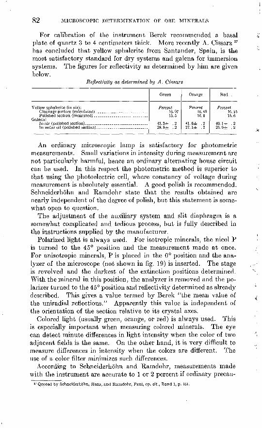
82 MICROSCOPIC DETERMINATION OF ORE MINERALS
For calibration of the instrument Berek recommended a basal plate of quartz 3 to 4 centimeters thick. More recently A. Cissarz 27 has concluded that yellow sphalerite from Santander, Spain, is the most satisfactory standard for dry systems and galena for immersion systems. The figures for reflectivity as determined by him are given below.
Reflectivity as determined by A. Cissarz
Yellow sphalerite (in air): Cleavage surface (calculated).-...----...----.---..----.
Galena:
Green
Percent 16.9715.5
43. 3± . 228. 8± . 2
Orange
Percent 16. 4916.0
41. 6± .227. 1± . 2
Red
Percent 16.1515.6
40. 1 ± .225. 9± .2
An ordinary microscopic lamp is satisfactory for photometric measurements. Small variations in intensity during measurement are not particularly harmful, hence an ordinary alternating house circuit can be used. In this respect the photometric method is superior to that using the photoelectric cell, where constancy of voltage during measurement is absolutely essential. A good polish is recommended. Schneiderhohn and Ramdohr state that the results obtained are nearly independent of the degree of polish, but this statement is some what open to question.
The adjustment of the auxiliary system and slit diaphragm is a somewhat complicated and tedious process, but is fully described in the instructions supplied by the manufacturer.
Polarized light is always used. For isotropic minerals, the nicol P is turned to the 45° position and the measurement made at once. For anisotropic minerals, P is placed in the 0° position and the ana lyzer of the microscope (not shown in fig. 19) is inserted. The stage is revolved and the darkest of the extinction positions determined. With the mineral in this position, the analyzer is removed and the po larizer turned to the 45° position and reflectivity determined as already described. This gives a value termed by Berek "the mean value of the uniradial reflections." Apparently this value is independent of the orientation of the section relative to its crystal axes.
Colored light (usually green, orange, or red) is always used. This is especially important when measuring colored minerals. The eye can detect minute differences in light intensity when the color of two adjacent fields is the same. On the other hand, it is very difficult to measure differences in intensity when the colors are different. The use of a color filter minimizes such differences.
According to Schneiderhohn and Ramdohr, measurements made with the instrument are accurate to 1 or 2 percent if ordinary precau-
!7 Quoted by Schneiderhohn, Hans, and Ramdohr, Paul, op. cit., Band 1, p. 161.

PHYSICAL PROPERTIES AND MEASUREMENTS 83
tions are taken. By using a more elaborate procedure this figure can be cut to about 0.2 percent.
The method above described is complicated and requires a high degree of technical skill, as the personal element enters into determi nations of relative color intensity. The instrument itself is expensive, costing approximately $334, according to most recent quotations of the Leitz Co. (1936). The method is being rapidly improved through the efforts of Schneiderhohn and Cissarz and offers much promise for the future.
Determinations of reflectivity as given by Schneiderhohn and Ramdohr are shown in table 4 (p. 294). These determinations were made some years ago, and the authors state that more recent deter minations differ from those given by as much as 2 percent.
MEASUREMENT OF REFLECTIVITY WITH PHOTOELECTRIC CELLS
A second method of measuring reflectivity which is free from the personal equation or defects in the human eye is based on the photo electric effect. Expressed in common language this is the transfor mation of light energy into electricity. Certain substances, such as metallic sodium, lose electrons when struck by light. Probably all substances show the effect to a greater or less degree, but those which show it markedly with visible light are relatively few.
There is an extremely simple relation between the intensity of illumination and the strength of the current produced. One is di rectly proportional to the other, and the graph expressing the relation is a straight line.
In practice, a polished section of a mineral whose reflectivity is known is used as a standard for calibration. It is placed on the stage of a reflecting microscope. The photoelectric cell is housed in an attachment that fits into the barrel of the microscope and takes the place of the ocular. The current produced by the standard mineral is measured. Immediately afterward the mineral whose reflectivity is unknown is placed on the microscope and measured in the same way. The lamp, the opening of the diaphragm in front of the illu minator, and other conditions, must be the same for both measure ments, and the lamp must not be shifted between measurements, otherwise the comparisons cannot be made. If the current produced by the standard mineral is x amperes, and that produced by the other mineral is nx amperes, the reflectivity of the other mineral is just n times that of the standard.
The accepted explanation of the photoelectric effect is based on the quantum theory. A detailed explanation will not be given here but will be found in modern textbooks of physics. It is sufficient to state that the energy of the current produced is equal to the total energy of the light emission minus the work of separating the electrons from

84 MICROSCOPIC DETERMINATION OF ORE MINERALS
Ss .
the bombarded substance. This is known as Einstein's equation. Where the work of separation of electrons is large, the output will be correspondingly small.
Credit for the first application of the photoelectric cell to measure ment of reflectivity is due to Dr. J. Orcel,28 of the Museum national d'histoire naturelle, Paris.
Two kinds of photoelectric cells have been used alkali cells and rectifying cells.
Alkali cells. The cell first described and used by Orcel is an alkali cell. This consists of a bulb of glass filled with argon under low
pressure. The interior of the bulb is coated with a film of potassium hydride (KH) de posited on a film of silver. This consti tutes the cathode of the cell. When struck by light coming up the barrel of the micro scope, it emits electrons that strike the anode T (fig. 20), a wire of tungsten bent in a loop.
Owing to the high internal resistance of the cell, the output is small and must be amplified. Two amplification circuits are used by Orcel and his coworkers. A simple type is shown in figure 21 and is sufficient for ordinary determinative measurements. The photoelectric cell is in series with a 150- to 170-volt battery and a mirror galvanometer.
For more exact work, such as calibration of standard minerals, a thermionic tube is used in the amplifying circuit, as shown in figure 22.
The photoelectric cell C is connected in series with a 150- to 180- volt battery B2 and a resistance R. The anode of the cell is connected with grid G of the amplifying tube L, the filament F of which is heated by battery Bl} of 4 volts. The galvanometer D is connected with the screen grid G' and the plate P of the amplification lamp. To com pensate the constant current flowing in the amplifying tube with the nonilluminated cell C, a compensating resistance p is connected as shown.
The sensitivity of the galvanometer is 10~9 to 10~10 amperes per millimeter of the scale at 1-meter distance. The amplification of the thermionic circuit is 100- to 150-fold.
Attached to the cell and below it is a total reflecting prism (P, fig. 20) similar to that in the Leitz Makam photomicrographic camera.
2S Orcel, J., La mesure du pouvoir rfiflecteur de mineraux opaques a I'aide de la cellule photo-filectrique et, ses applications: Soc. franchise mine'ralogie Bull., torne 53, pp. 301-349, 1930; Acad. Sci. Paris Comptes rcndus, tome 185, p. 10.r>5; torne 187, p. 1141, 1928.
FIGURE 20. Alkali photoelectric cell. (After Orcel.)

PHYSICAL PROPERTIES A2STD MEASUREMENTS 85
(See p. 47.) This allows observation of the field of the microscope and accurate focusing of the specimen. The prism can be withdrawn from the axis of the microscope just before measurement with the cell. It possesses an adjustment by means of which it can be shifted
GalvQnome ter
FIGUKE 21. Simple amplifying circuit for alkali cell.
in three different directions at right angles to each other. An iris diaphragm under the prism blocks off all light except that part reflected from the mineral whose reflectivity is to be measured.
r~AA#WWW °
FIGURE 22. Thermionic amplifying circuit for alkali cell. (After Orcel.) See text for explanation.
A very high polish is necessary for best results with this instrument. All focusing should be done with a movable stage in order to avoid shifting the barrel of the microscope between measurements.
The following crystalline substances are used as standards for cali bration of the apparatus:
Reflectivity of standard mineralsPercent
Sphalerite (yellow)_____________________________________ 17. 9Tetrahedrite__.--_.._...___.__^.___._-__.__.._______._ 30. 0Silicon___-.__-.__.-_..._.....__..__.._._._._____._.__ 42. 9Galena.__-_-.-----.__.._._.___.__....._.._._.___.__._ 40. 0

86 MICROSCOPIC DETERMINATION OF ORE MINERALS
These figures represent averages of a series of very careful measure ments.
The spectral sensitivity of the alkali cell shows a well-defined maxi mum at 465 millimicrons (blue); the sensitivity diminishes rapidly with variations from this wave length in either direction. Hence measurements with white light approximate rather closely those with monochromatic blue. Measurements with yellow and red light are inexact or impossible owing to lack of sensitivity to these colors.
All measurements are made with one nicol prism placed in front of the illuminator. Its plane of polarization is placed parallel to the plane of incidence of the prism.
A factor to be taken into consideration is extraneous light reflected from the upper surface of the microscope objective. This light is constant, but the galvanometer deviation that corresponds to it should be subtracted from the total deviation when a mineral is measured. The deviation produced by this extraneous light is measured by lowering the stage of the microscope or placing a black paper under the microscope. 29
Work with alkali cells is time-consuming on account of fatigue phenomena in the cell, which must be obviated by pauses for recovery. In addition, the lamp must be heated for an hour before constant results are obtained. Comparisons with the photometer ocular of Berek are possible only to a moderate degree, owing to the fact that the sensitivity of the human eye is greatest in the range of yellowish green (555 millimicrons); hence the sensitivity of the alkali cell does not correspond to that of the eye. In spite of these handicaps, consistent and reliable results have been obtained by Orcel and his coworkers, who have been carrying on active research work.
Rectifying cells. A second type of photoelectric cell differs from the alkali cell in that it does not require the introduction of extraneous electricity produced by batteries but has the property of converting light into electricity directly. It is known as a rectifying cell. The first investigations making use of a rectifying cell to determine reflectivity were made in 1932 by H. Ehrenberg under the direction of P. Ramdohr. A complete description of his results is given by Schneiderhohn and Ramdohr.30
In the rectifying cell the work of separating electrons is greatly reduced in comparison with that required in the alkali cell, and there fore the output of electricity produced by a given intensity of light is much greater.
The principle on which the rectifying cell is constructed is shown schematically in figure 23. It consists essentially of a very thin layer (U) of silver selenide or cuprous oxide between two electrodes. This is
28 Orcel, J., written communication.»o Schneiderhohn, Hans, and Ramdohr, Paul, Lehrbuch der Erzmikroskopie, Band 1, pp. 168-178,1934.

PHYSICAL PROPERTIES AND MEASUREMENTS 87
known as the rectifying layer, as it is unipolar conducting. EI is theelectrode first struck by the light rays. It must allow them to passthrough in order to strike the rectifying layer. As none of the transparent substances are conductors, the rectifying layer is sprayed on ametallic grid. Only the rays that strike theopenings in the grid affect the rectifying layer.E2 is a second metal electrode . The light striking EI drives off electrons, which reach therectifying substance U and pass to the opposite electrode E2 . An electric current passesfrom E2 to EI through a galvanometer.
The construction of an ocular cell is shown in figure 24. The figure is not drawn to scale, FIGURE ^.-construction of rectify- as the rectifying layer is only a few molecules ing cel1 - (Aftcr
J , . J m, and Kamdohr.)thick. The ocular is a No. 4 penplane. I he explanation.
Sec text for
FIGURE 24. Cross section through rectifying cell. (After Schneiderhohn and Kamdohr.)
distance of the cell from the ocular lens is 9 centimeters.The cell can be removed and a ground-glass disk installed in its
place for the purpose of focusing the specimen. The change from the cell to the ground glass and vice versa is quickly accomplished by a horizontal sliding device attached to the top of the microscope barrel. After the focus is attained, the disk is removed, and the cell is placed in the axis of the microscope. The image will now fall on the lower electrode. Focusing is accomplished by moving the stage, in order not to disturb the adjustment of the microscope with the light.

88 MICROSCOPIC DETERMINATION OF ORE MINERALS
There is a direct proportional relationship between intensity of illumination and electric current up to 1,000 lux.31 Above that inten sity the current approaches a limiting value. Hence there is a limit to the strength of light that can be used; fortunately this limit is well above that of ordinary microscopic illumination. The lamp used by Ehrenberg and Ramdohr is a 250-watt nitra attached to an ordinary 110-volt alternating circuit.
The spectral sensitivity of the silver selenide rectifying cell reaches a maximum with yellow light of 575 millimicrons wave length, thus approaching that of the human eye more nearly than that of the alkali cell. The authors cited make the measurements with red, yellow, and green light. The light filters are placed directly in front of the vertical illuminator.
The galvanometer used is of the mirror type and is read by means of a telescope. Its sensitivity is 10~7 amperes.
It is not feasible to work without an ocular, owing to internal reflec tions set up in the barrel of the microscope.
There is a minimum size of grain below which determinations of reflectivity cannot be made. Only the image of the mineral to be measured must be projected on the ground glass; with an anisotropic mineral only the individual mineral that has a uniform optical orienta tion can be measured. With coarse-grained minerals the 16-milli meter objective can be used, but where the grain size is small the 4-millimeter or oil-immersion objectives must be used, and with many specimens the field even with these high magnifications must be reduced by means of the iris diaphragm. Measurements with these high powers are not so accurate as with low powers. For exact measurements, the use of the new silvered prism, designed by Berek, is recommended by the authors.
The excellence of polish has an important influence on reflectivity. Scratches and pits deflect the light rays and diminish the percentage of the light that reaches the cell. In this respect the photoelectric cell is inferior to the photometer ocular, in which the measurement uses only that part of the specimen lying at the boundary between the two fields, and the errors above mentioned can be allowed for subjec tively. It is necessary, therefore, to obtain as good a polish as possible before making measurements.
The calibration is accomplished by comparison with standard minerals in a manner similar to the calibration of the alkali cell.
Schneiderhohn and Ramdohr do not give tables of reflectivity determined by this instrument but promise to do so in the future. Experiments designed to eliminate some sources of error in the method are still under way. They state, however, that with ordinary pre-
31 A lux is the strength of illumination produced by one standard candle on 1 square meter of surface at a distance of 1 meter.

PHYSICAL PROPERTIES AND MEASUREMENTS 89
cautions and careful manipulation reflectivity can be measured with an accuracy of about 0.2 percent.
An interesting result of the published researches of Orcel was that almost at the same time that Ramdohr and Ehrenberg were working with the rectifying cell in Germany, J. H. Moses was conducting similar experiments at Harvard University. Moses was unaware of the work of Ramdohr and Ehrenberg, and consequently his results are entirely independent of theirs. The following description is abstracted from his thesis.32
Moses' apparatus is similar in many respects to that of Ramdohr and Ehrenberg but contains some important points of difference. The vertical illuminator is of the prism type with a small condenser. Attached to the barrel of the microscope and parallel to it is a metal disk through which a hole 1 millimeter in diameter has been bored. This hole is at the focus of the condenser and serves to control the area of the specimen illuminated. It is termed the "field diaphragm" by Moses.
The 4-millimeter objective is used for all measurements. The reasons for using it are that very small grains can be measured, and the perfection of polish is a vital factor. With the 4-millimeter objective it is possible to search for areas free from scratches and other imperfections. The principal objection to its use is that the angle of incidence for the most oblique ray is 58°. Moses discusses this factor in detail and concludes that it has little effect in measuring relative reflectivities.
The ocular is a No. 7.5. In the plane of the photocell this system gives a magnification of 120 diameters. The cell can be removed and a ground glass inserted in its place for the purpose of focusing the specimen. The arrangement is similar to that described for the Ram- dohr-Ehrenberg apparatus (p. 86). A diaphragm is placed between the photocell and the ocular to control the size of the area of light striking the cell. The diameter of the opening is 16 millimeters. On the plane of the cell this diameter is a little smaller than the diameter of the image of the field diaphragm. The vertical illuminator is adjusted by turning it until the image of the field diaphragm covers the upper diaphragm. The cell used by Moses is a Westinghouse "Photox." It is of the cuprous oxide type.
The galvanometer is of the reflecting type and throws an image on a horizontal scale placed at a distance of 1 meter from it. It is made by the Leeds & Northrup Co., type 2500-g, and has a sensitivity of 5 X 10~ 10 amperes per millimeter deflection. It has a critical damping resistance of 7,000 ohms, an external resistance of 470 ohms, and a period of 6.4 seconds. In order to read the galvanometer deflections,
11 Moses, J. H., The identification of opaque minerals by their reflecting power as measured photo- electrically (doctor's thesis, Harvard University), 1936.
129151 40 7

90 MICROSCOPIC DETERMINATION OF ORE MINERALSJV
/
a 50-centimeter ground-glass scale with 1-millimeter divisions marked on it was used. Both the scale and the galvanometer are supported ~ on a specially built vibration-free frame. In making photoelectric measurements it is extremely important that the illumination be con stant during measurement. Also, as the determination of reflectivity for the mineral in question is compared with that of a standard, the strength of illumination must be the same for both measurements. A strong source of light is necessary, and it was found that an auto mobile headlight furnished the most satisfactory source. That selected was the "Tung-sol, 32-32 candle power, 6-8 volt, T 100" lamp manufactured by the Tung-Sol Lamp Works, Inc., Newark, N. J. It was found that the 110-volt alternating circuit available varied too much to be used with a transformer supplying 6 volts. Likewise, the direct-current system available at Harvard varied too much to be ( reduced by a rheostat to 6 volts. A 6-volt storage cell was used but was found to lose strength too fast. The difficulty was finally solved by connecting a 6-volt direct current (reduced from the 110-volt cir cuit) in series with a 6-volt storage battery. v
It was found immediately that the amount of light available from many different minerals was more than enough to deflect the gal- v vanometer beyond the limits of a meter scale. This difficulty was solved by placing a resistance of 4,470 ohms as a shunt across the gal vanometer. A well-polished specimen of pyrite was chosen as a standard, and the resistance chosen was such that it gave a swing of a little more than 25 centimeters. The lamp is held in a light-tight box and is adjustable so that its distance relative to the field diaphragm 4 can be varied. When the light beam from the galvanometer has come ^ to rest, the lamp is moved until the image reads exactly 25 centi meters. The pyrite is then removed, and the mineral to be deter mined is placed on the stage of the microscope and a reading obtained. "^ With a galvanometer of this type the deflection of the image obtained is exactly proportional to the strength of the current, and this, as -*- stated on page 83, is exactly proportional to the intensity of the light striking the cell. !
The cell surface is not uniformly responsive to light in different f places. Hence the sliding device is adjusted so that the cell is exactly centered over the center of the diaphragm. Moses differs from the European practice in that he uses unpolarized light. He gives his reasons for doing so as follows:
In spite of the undeniable evidence in the literature pointing out the importance of orientation on reflecting power and consequently the desirability of using plane- i polarized light when making measurements of reflecting power, the writer per sisted in using nonpolarized light for all of his final measurements. His reasons were dependent on several factors. Firstly, one of the outstanding goals of.the entire problem was to develop a quick and easy method of opaque-mineral identi fication, and the complications introduced by the use of polarized light result in

PHYSICAL PROPERTIES AND MEASUREMENTS 91
a procedure which is anything but simple. Secondly, although realizing the similarity in the use of nonpolarized light in this case and in the case of determining the index of refraction in nonopaque minerals, it was believed (and this belief was eventually more or less verified) that the variations in the measurements with the orientation of the crystal would be very slight if strictly nonpolarized light were used. Unfortunately, it is difficult, if not impossible, to pass nonpolarized light through a microscope equipped with a vertical illuminator without producing a noticeable percentage of plane-polarized light. In spite of the presence of this unavoidable portion of plane-polarized light, only a few strongly anisotropic minerals showed a variation of as much as 1 percent on rotation of the microscope stage. Likewise, when the quality of the polished surface of a heterogeneously oriented group of grains of one mineral was constant over all, very little difference was found in the reflecting power measured on several different grains. A few minerals, including stibnite, when specially prepared specimens polished normal to the three crystal axes were used, did show a very noticeable difference in reflecting power by the three surfaces. The writer believes that such minerals are exceptional.
A third reason for using nonpolarized light for all the final measurements lay in the fact that, except when dealing with individual crystals, it is an extremely difficult and uncertain task to determine the position of the crystallographic axes when viewing a polished surface. And, in order to gain much useful information with plane-polarized light, knowledge of the position of the crystallographic axes is very essential.
The surface of the specimen must be exactly perpendicular to the axis of the microscope. In this respect unmounted polished sections leveled in modeling wax are superior to specimens mounted in bakelite or sealing wax. It has been found difficult to keep the top and bottom of such specimens absolutely parallel, especially if the specimen is ground by hand after mounting. According to Moses:
A difference of 1 to 2 percent was found in the galvanometer deflection when a block about 1 inch long was tilted by the thickness of a single sheet of typewriting paper, about 0.004 inch, under one end. Increasing the number of sheets increased the difference of the reading as compared with the normal position. Furthermore, as previously shown, when the polished surface is not strictly perpendicular to the tube of the microscope, there is a marked fluctuation in the galvanometer reading as the microscope stage is rotated. This phenomenon holds true even in the case of an isotropic mineral, such as galena, on a perfectly centered stage. On the other hand, no such fluctuation is observed when the surface is perpendicular to the microscope tube.
Moses' results as given in his thesis are expressed as galvanometer readings. They can be reduced to absolute reflectivity by multiplying each of his results by the fixed constant 2.29. This constant was obtained as follows: The reflectivity of galena as given by Orcel is 44.3 percent and that given by Cissarz is 43.3. These figures, arrived at independently, agree very well. By taking the mean, 43.8, and dividing by Moses' galvanometer reading 19.1, the factor 2.29 is obtained.
The perfection of polish has an important bearing on the measured reflectivity. This is especially true of the native metals (see figures

92 MICROSCOPIC DETERMINATION OF ORE MINERALS
for silver and copper in table 4), but it also limits the accuracy of the results for the "metallic ores to ±1 percent. The precaution must be taken of obtaining the best polish that is permitted by the means at hand, and seeking under the microscope the best-polished area on the surface of the specimen. Owing to this limitation,' the figures for reflectivity given in table 4 (p. 294) cannot be regarded as absolute constants for the respective minerals.
SPECTROSCOPIC METHODS
The most delicate of all tests for the presence of an element is afforded by the spectroscope. By means of this instrument quali tative determinations can be made on quantities of material almost infinitely small. Several attempts have been made to combine the methods of spectroscopy with the study of polished sections. A very successful investigation by Haycock 33 is of unusual interest, in that he was able to estimate with considerable accuracy the relative atomic percentages of different elements in a mineral.
The quartz spectrograph is a modification of the spectroscope in which a prism of quartz takes the place of the usual glass prism, and which has a camera by means of which the image of the spectral lines may be photographed. The photographic plate obtained by photo graphing the spectrum of an unknown mineral is placed immediately above or below a plate made under the same conditions from a known element. If the spectral lines coincide, the known element is present in the mineral.
The quantitative estimation of elements in a substance is based on the following principles: (1) Other conditions remaining constant, the number and intensity of lines of an element recorded by the photo graphic plate decrease with decreasing concentration of that element in the source. (2) Other conditions remaining constant, the time required for the disappearance of all but the ultimate lines of an ele ment depends upon the amount of that element in the source. The method employed was to compare the spectrum of the unknown mineral with the spectra produced by known amounts of the element to be determined. An estimate of the amount of the element was then made on the basis of intensity and number of lines. A unit vol ume of solution containing the unknown mineral was introduced into the arc and its spectrum photographed. The amount of solution used for every exposure was 0.002 cubic centimeter. This was estimated by filling a capillary tube to a given height.
A reference collection of photographs was made from solutions of given strength of all the metallic elements for whose presence tests were to be made. The standard strengths were normal, %N,
33 Haycock, M. H., The application of the quartz spectrograph to the study of opaque minerals: Econ. Geology, vol. 28, pp. 364-382, 1933.

. PHYSICAL PROPERTIES AND MEASUREMENTS 93
, KoN, XoN, XoN, ^0N, XooN, and ^ 0 oN. As five exposures could be made on one plate, two plates were needed for each element. Unfortunately sulphur does not furnish a satisfactory spectrum. In practice, therefore, it was not possible to determine the relative atomic ratio of sulphur to the metallic elements.
The material to be tested is bored from the polished surface of the specimen under microscopic observation. The boring is facilitated by a special drill devised by Haycock.34 This enabled amounts of material less than 0.25 millimeter in diameter to be removed and tested. With microchemical methods this amount would give a feeble test or none at all for most elements.
The material is taken into solution with nitric acid or aqua regia and then converted to the chloride by repeated evaporations with HC1. It is then taken into solution with 1: 8 HC1 and transferred to the tip of one of the graphite electrodes. This must be cold and dry when the solution is introduced. When the current is turned on, the spectrum is produced and photographed. Where tiny inclusions in a host are to be tested, enough areas are bored and the resulting material collected together to furnish an adequate amount for the test. For instance, tiny areas of argentite in galena can be tested, provided the galena is free from silver. Where the inclusions are small, it is impossible to avoid including small amounts of the host. Hence under these conditions it would not be possible to determine lead in a mineral included in galena, but it would be possible to test for all other elements except sulphur.
Let us assume that we are.testing a mineral containing both lead and silver. Let us assume, further, that the lead lines in the photo graph corresponded to a solution KoN with respect to lead and that the silver lines corresponded to a solution %oN with respect to silver. The atomic ratio of lead to silver in the mineral would be 2:1. From the foregoing statements it is clear that all the metallic ma terial must go into solution. If sulphur is present it will probably separate out. It is also clear that the conditions must be rigorously controlled. Haycock describes the factors to be considered as follows:
1. The length, diameter, and shape of the electrodes. Any difference in these factors will alter the temperature of the arc, both because of the effect on the potential drop and because of the rate of conduction of heat away from the points. Moreover, if sharp angles are present at the points, a high potential may occur and introduce spark lines into the spectrum.
2. Distance between the electrodes. A variation in distance between electrodes causes variation in the drop in potential.
3. Amperage of the current. Variation of the amperage causes variation in the drop in potential. It is to be noted that under the most favorable conditions, the arc will vary about 10 percent. Generally speaking, the higher the voltage
3( Haycock, M. H., A method for sampling minerals in polished sections: Econ. Geology, vol. 26, pp. '115-420, 1931.
94 MICROSCOPIC DETERMINATION OF ORE MINERALS
of the supply, the steadier the arc. Commensurate with safety of operation, the best results are thought to be obtained with voltages above 220, and many spectroscopists prefer voltages or 350 or even 700. The present work was done with a voltage of 110, higher voltages not being available.
4. Preparatory burning of the electrodes. Consistency on this part will produce electrodes of similar shape and porosity.
5. Volume of solution. This has been referred to previously.6. Procedure of adding the solution to the electrode. It is necessary to take care
that the solution is absorbed by the tip of the electrode and not allowed .to run down over the side. Therefore it must be added slowly.
7. Period of drying of impregnated electrode. Appreciable moisture remaining in the electrode will volatilize at the outset and affect the spectrum.
8. Position of the source with reference to the slit of the spectrograph. This is a common source of error, and care must be taken to keep the light accurately focused on and covering the slit.
9. Adjustments to the optical system of the spectrograph. Any changes in adjust ment of slit and focus should be rigorously avoided.
10. Timing of exposures.11. Type and make of plate. Variations in the sensitivity of photographic
plates are different for different wave lengths, and a standard make of plate should be adopted and used consistently.
12. Development of the plate. Consistency in development is probably best obtained by following a time-temperature method, taking care to use developer of fixed concentration.
The quartz spectrograph used by Haycock is made by Adam Hilger, London. Of the three models made by Hilger large, inter mediate, and small Haycock uses and recommends the intermediate model, because the' entire range of the spectrum can be shown on one exposure. It costs approximately $1,400. However, as mentioned in the description of microchemical tests p. (173), the extreme sensitivity of the spectrograph is often a handicap to the determination of the mineral, for elements are sometimes identified, such as copper in bismuthinite, which are not shown in the formula as ordinarily written. Aside from the expensive apparatus required, a further objection is that a long apprenticeship and great personal ability are necessary to produce good results.

PART 3. ETCH REACTIONS AND DETERMINATIVE TABLE
ETCH REACTIONS
The term "microchemical test" is used both by Murdoch and by Davy and Farnham to describe the etching effects produced by nitric acid and other reagents on the polished surface of the mineral to be investigated. It is believed that the term "etch test," used by Schnei- derhohn and by Van der Veen, is preferable. The terms "micro- chemistry" and "microchemical test" have been used since 1877 to designate qualitative microscopic tests or reactions for elements. The tests are usually made on a glass slide. To avoid confusion, the term "microchemical test" will be confined in this bulletin to qualitative chemical tests made on a glass slide; tests made directly on the polished section will be referred to as "etch tests."
The etching effects or lack of effects of a set of chemical reagents of standard strength have been the principal means relied upon by all the above-named men to identify the unknown opaque minerals.
Murdoch "pigeonholes" the minerals according to their reactivity toward the following solutions: HN03 , 1:1; HN03 , concentrated; aqua regia; HC1, 1:1; HC1, concentrated; KCN, 20 percent; FeCl3 , 20 percent; KOH, saturated solution. In his descriptions of the individual minerals, their reactions with the following solutions are also given: NH4OH, NaOH, iodine, (NH4) 2SX , K4Fe(CN) 6 , K3Fe(CN)fl , H2S04 , AgN03 , KC103 . Not all these reagents were used on any one mineral.
Davy and Farnham greatly simplified the scheme by using only four reagents to "pigeonhole" the minerals. These are HNO3 , 1:1; HC1, 1:1; KCN, 20 percent; and FeCl3, 20 percent. In then- detailed descriptions of the minerals the reactions produced by saturated solutions of KOH and HgCl2 are also given.
Both Schneiderhohn and Van der Veen have added a number of reagents to those already mentioned. Neither made any at tempt at a systematic classification of minerals according to their reactivity toward chemical reagents, but both laid emphasis on reagents that bring out twinning and other internal structures in the mineral.
There are some strong objections against relying too much on etch behavior in identifying a mineral. The greatest trouble with the scheme is that some reactions are very feeble. Many of them, indeed, are so feeble that they will work sometimes and fail to work at other times, even on the same specimen. It is known that the
95

96 MICROSCOPIC DETERMINATION OF ORE MINERALS
susceptibility to etching is different in different orientations of the same mineral specimen, and orientation alone may be the chief factor in determining whether or not a reagent will etch a specimen. Slight differences in chemical composition of a mineral may cause some specimens to etch, whereas other specimens may be entirely negative to the same reagent. These variations were recognized specifically in the text of Davy and Farnham and in that of Van der Veen, but in the former the variations are not sufficiently considered, and the authors did not make the tests on a sufficient number of specimens of each mineral to reveal all the variations.
It is obvious that a mistake in interpreting any one reaction will cause the determinative scheme to fall down completely. When a reaction is weak some difficulty is experienced in deciding whether or not it is positive. The only solution of these difficulties is to place a mineral that is sometimes etched by a reagent and is some times negative toward it in both the "positive reaction" and "nega tive reaction" classes. For instance, tetrahedrite is sometimes etched by 1:1 HN03 and is sometimes inert toward it. It should be placed in both the "etched by HN03" and "negative to HNO3" groups. Sphalerite is usually negative to 1:1 HC1, but one or two specimens that gave faint reactions with HC1 have been observed. These facts should be noted in describing sphalerite, and it should be placed in both the "etched by HG1" and "negative to HC1" groups.
When two different minerals are covered by a drop of a reagent, an electric current is generated owing to the difference of potential between the minerals. As a result, the effect of the reagent is inten sified on one of the minerals and diminished on the other. For instance, when bornite and galena in contact are covered with ferric chloride solution, the bornite reaction is stronger than it is with pure bornite alone; on the other hand, the galena adjacent to the bornite is entirely negative to ferric chloride solution, whereas pure galena alone gives a strong reaction with this solution. It is therefore advisable to find an area of the mineral larger than the drop to be applied and to prevent the drop from spreading over the contact with an adjacent mineral. It is not always possible to do this, and under such conditions a knowledge of the electrolytic effects pro duced by the different mineral associations is advisable, in order to discount them in identify ing the mineral. Fortunately in the great majority of mineral associations these electrolytic effects are too feeble to affect the etch reactions.
The manner of applying the reagents to the polished surface differs considerably. Schneiderhohn immerses the entire polished surface face down in a receptacle containing the reagent. In this manner the entire section is acted upon by the etching reagent, and
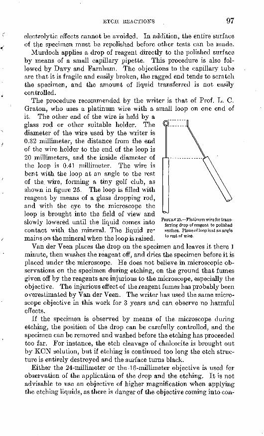
ETCH .REACTIONS 97
electrolytic effects cannot be avoided. In addition, the entire surface of the specimen must be repolished before other tests can be made.
Murdoch applies a drop of reagent directly to the polished surface by means of a small capillary pipette. This procedure is also fol lowed by Davy and Farnham. The objections to the capillary tube are that it is fragile and easily broken, the ragged end tends to scratch the specimen, and the amount of liquid transferred is not easily controlled.
The procedure recommended by the writer is that of Prof. L. C. Graton, who uses a platinum wire with a small loop on one end of it. The other end of the wire is held by a glass rod or other suitable holder. The diameter of the wire used by the writer is 0.32 millimeter, the distance from the end of the wire holder to the end of the loop is 20 millimeters, and the inside diameter of the loop is 0.41 millimeter. The wire is bent with the loop at an angle to the rest of the. wire, forming a tiny golf club, as shown in figure 25. The loop is filled with reagent by means of a glass dropping rod, and with the eye to the microscope the loop is brought into the field of view and slowly lowered until the liquid comes into contact with the mineral. The liquid re mains on the mineral when the loop is raised.
Van der Veen places the drop on the specimen and leaves it there 1 minute, then washes the reagent off, and dries the specimen before it is placed under the microscope. He does not believe in microscopic ob servations on the specimen during etching, on the ground that fumes given off by the reagents are injurious to the microscope, especially the objective. The injurious effect of the reagent fumes has probably been overestimated by Van der Veen. The writer has used the same micro scope objective in this work for 3 years and can observe no harmful effects.
If the specimen is observed by means of the microscope during etching, the position of the drop can be carefully controlled, and the specimen can be removed and washed before the etching has proceeded too far. For instance, the etch cleavage of chalcocite is brought out by KCN solution, but if etching is continued too long the etch struc ture is entirely destroyed and the surface turns black.
Either the 24-millimeter or the-16-millimeter objective is used for observation of the application of the drop and the etching. It is not advisable to use an objective of higher magnification when applying the etching liquids, as there is danger of the objective coming into con-
FIGUKE 25. Platinum wire for trans ferring drop of reagent to polished surface. Plane of loop is at an angle to rest of wire.

98 MICROSCOPIC DETERMINATION OF ORE MINERALS
tact with corrosive fluids. The fluid should be removed and the speci men washed before changing to objectives of higher magnification.
The time during which etching is continued varies with the min eral. Some minerals tarnish instantly with certain reagents, and the etching fluid can be removed immediately. The time limit set by the writer for the slower reactions is usually 1 minute.. If no effect can be observed at the end of 1 minute the test is considered negative. If the mineral is not completely etched at the end of 1 minute, but some change is noticed on the surface, sufficient time is given to allow the effect to be completed. An exception is made of HN03 . With some minerals like jamesonite the etching with this reagent is sometimes slow in starting, but once started it proceeds rapidly. For this reason, if the HNO3 drop still has a negative effect at the end of 1 minute, it is preferably allowed to remain on the surface until it begins to dry up, or approximately 2 minutes.
The reagents recommended by Davy and Farnham are on the whole satisfactory and are therefore used by the writer. Adding to the number of reagents merely adds to the difficulties already men tioned without any compensating advantages. Any reagent used will strongly etch some minerals but will have no effect on others, and there is a group of minerals on which the effect will be between these extremes and with many of them weak and indefinite. The reagent recommended by Schneiderhohn, KMn04 in H2S04, is effective in bringing out structures in certain minerals, but it has the disad vantage just noted and in addition is messy and has to be made up fresh every few days. It is therefore not recommended for routine determinative etch tests.
Of the reagents used by Davy and Farnham, HN03 and HC1 leave no residues on evaporation. KCN, FeCl3 , KOH, and HgCl2 , being dissolved salts, will each leave a residue on evaporation, and this sometimes forms an iridescent sediment which is closely similar to an etch tarnish. Owing to this difficulty it is not advisable to al low the reagent to evaporate to a point where it begins to drop its dissolved load. Consequently it is recommended that the saturated KOH solution be changed to a 40-percent solution. Mercuric chlo ride is more troublesome. Davy and Farnham recommend a satu rated solution ^approximately 7 percent at ordinary temperatures). In a saturated solution mercurous chloride separates out, as well as mercuric chloride. Mercurous chloride tends to stick to the sur face of a mineral and is hard to remove. Beginners especially are liable to confuse this precipitate with an etch reaction. For this reason the writer recommends a 5-percent solution of mercuric chloride (1 gram of HgCl2 dissolved in 19 cubic centimeters of water). Even with this concentration some mercurous chloride will slowly separate out, and it is advisable to filter the solution from time to time.

ETCH 11EACT10NS 99
The reagents used by the writer are as follows:HN03 , 1:1 (1 part HNO3) specific gravity 1.42, to 1 part H20).HC1, 1:1 (1 part HC1, specific gravity 1.19, to 1 part H 2 O).KCN, 20 percent solution (by weight).FeCla, 20 percent solution (by weight).KOH, 40 percent solution (by weight).HgCl2 , 5 percent solution (by weight).Aqua regia (3 parts concentrated HC1 to 1 part concentrated HNOa).H202 , commercial reagent.
Aqua regia is used only for minerals that are negative to the other solutions. The strength of the acids should be checked from time to time by means of a specific-gravity hydrometer.
The researches of Thiel have shown that most of the manganese oxide minerals break down hydrogen peroxide, H202 . A drop of the commercial reagent placed on the mineral effervesces, but the mineral itself is not etched. 1 According to Smitheringale,2 these reactions are less positive than is indicated in Thiel's paper. The present writer checked Thiel's results rather closely and found that if anything, the reactions are even more positive than indicated by Thiel. Evidently the quality of the reagent is a vital factor in the intensity of the test. The writer uses a 3 percent commercial solution. It is used only to confirm manganese oxides.
It is advisable to keep the HN03 and HC1 solutions in glass-stop pered dropping bottles similar to those used for refractive-index oils, as rubber stoppers are corroded by the acids. The other solu tions, on the contrary, should not be kept in glass-stoppered bottles, as the liquid tends to evaporate, and the solid residue cements the stopper to the bottle. KOH will often form so tight a cement that the bottle will be broken in trying to remove the stopper. For the salt solutions other than the acids rubber stoppers are recommended. The stopper has a hole punched in it for the purpose of holding a glass dropping rod 4 millimeters in diameter. All the reagent bottles have a capacity of 15 cubic centimeters.
Minerals that effervesce when acted upon by 1: 1 HN03 are sepa rated from those that are etched but do not effervesce. This is a useful distinction that is made both by Murdoch and by Davy and Farnham and is retained by the writer. For instance, niccolite and breithauptite, which otherwise cannot be distinguished except by chemical tests, are separated by the fact that niccolite effervesces with HN03 and breithauptite tarnishes without effervescence. The great difficulty with effervescence as a criterion is that the efferves cence is sometimes very weak and liable to be overlooked. For in stance, pyrite will give a slow effervescence, a few bubbles at a time,
1 Thiel, G. A., The manganese minerals; their identification and paragenesis: Econ. Geology, vol. 19, p. 107,1924.
3 Smitheriugale, W. V., Etching tests and X-ray examinations of some manganese minerals: Econ. Geology, vol. 24, p. 481, 1929.

100 MICROSCOPIC DETERMINATION OF ORE MINERALS
if the surface is smooth and well polished, but usually the surface is rough and the grains small, and under these circumstances, effer vescence generally does not take place. Here again such a mineral may be placed in both the "tarnishes with effervescence" and "tarnishes without effervescence" classes.
The effect of calcite and other carbonates must be watched for. When a carbonate is present as a gangue mineral a vigorous effer vescence produced by acids is often mistaken for a reaction on an adjacent ore mineral. This can be discounted by noting that the ore mineral is not tarnished. When an area on a polished section shows effervescence with both HN03 and HC1, the presence of calcite should be suspected.
A fountain-pen filler or medicine dropper is useful for removing a reagent drop from the specimen. The end of the filler is heated and drawn out to a point and broken off, giving a tube of small diameter. This is filled with water. When the etch reaction is complete, the polished section is removed from the microscope, and by means of the fountain-pen filler, a stream of water is squirted on that part of the surface of the section just etched, and the reagent drop is washed off. With care, only part of the surface need be wetted. The polished section is again brought under the microscope, and the area formerly covered by the etch drop is examined while still wet. The etch test is now complete, and the information is recorded.
The surface is then dried by means of a filter paper and rubbed on a chamois cloth which is mounted on a block of wood. Very fine floated rouge should be sprinkled on the surface of the rubbing block. (See p. 102.) The unknown mineral is then ready for the next etch test. The writer does not recommend examining the sec tion after rubbing on the block, as recommended by Murdoch and by Davy and Farnham. In both books are to be found descriptions like the following: "Stains brown; rubs to a gray roughened sur face." It has been found that the character of the surface after rub bing varies too much to be of use in identification tests. The rouge has an abrading action and if continued long enough would remove the etching from any surface.
In addition, some remnants of the reagents are likely to remain on the surface, even after washing. The reagent may have soaked into the cracks, pits, and pore spaces; or the residue after evapora tion may adhere to the surface itself and remain there in spite of continued efforts to wash it off. Blotting and rubbing on a block only spread this residue over the surface, giving an iridescent film which, as experience has shown, is often mistaken for a positive etch reaction.
The .safest and most satisfactory method of making an etch test is to observe it microscopically from the time the drop of reagent

ETCH REACTIONS 101
is applied to the surface until the section is removed for the purpose of washing the reagent off. The effect can be observed right through the drop with all reagents except ferric chloride solution. This solution has a dense yellow color which may obscure the color of the etched surface. The effect of the ferric chloride can only be observed after washing it off, shaking the section to remove the excess water from the surface, and observing the section through the water remain ing on its surface. It is never advisable, to blot the specimen or to dry it before making the final microscopic observation. The water itself usually contains enough dissolved matter to smear a film over the surface when dried. This smear can be removed only by rubbing it on the rouged chamois.
The character of the etching is well described in all the textbooks cited. Generally the effect is merely a discoloration of the surface. Where the etching action is strong the surface may be corroded, be coming rough or full of pits. With many minerals, scratches formed during polishing and invisible before etching are brought out by the etching process, owing to the fact that the scratches are widened by solution of the mineral.
With some minerals, notably chalcocite, etching brings out a series of closely spaced parallel cracks. This is known as "etch cleavage." Etch cleavage indicates the direction of greatest solution, and this does not necessarily indicate the direction of least molecular cohesion. For instance, the etch cleavage of orthorhombic chalcocite is parallel to the base, whereas the cohesion cleavage is parallel to the prism. In most specimens the etch cleavage probably indicates twinning planes. These are planes of structural weakness and are readily widened by the access of the reagents.3 In some specimens of cobaltite, for example these cracks indicate the boundaries between shells in zoned crystals.
The intensity of etching differs in different directions of a crystal. A random polished section cuts different grains of the same mineral in different crystallographic directions; consequently, when a pol ished surface is etched, adjacent grains will show different colors after etching. This effect is extremely useful in bringing out mineral- grain patterns. In addition to this differential etching, the spaces between adjacent grains are widened by solution, and spaces that were submicroscopic before etching may become visible after it.
With some minerals, certain reagents have no effect on the surface covered by the drop, but fumes from the liquid tarnish the area im mediately contiguous to the periphery of the drop, thus forming an aureole around it. Usually this halo is soluble in water and disap pears on washing the specimen. Under some conditions, however,' Dr. Paul F. Kerr in a personal communication to the writer suggests that for many specimens the term
"etch cleavage" is inaccurate and that where twinning planes are followed the term "etch parting" would be preferable.

102 MICHOSCOPIC DETERMINATION OF ORE MINERALS
it is permanent and thus becomes of additional diagnostic value. For instance, some silver minerals, such as argentite and stephanite, will form an insoluble aureole when etched- by 1:1 HC1, and this aureole is diagnostic of silver. These aureoles have been ignored by some authors and used by others. The present writer considers that a test resulting in an aureole is positive. Some nicety of judgment is required when an aureole is faint or when it does not entirely sur round a drop. This is usually due to different orientation of adjacent grains. Such difficulties are unavoidable; the etching scheme is not perfect, and unless the effects are distinctive the mineral must be checked by other properties.
Some minerals show nothing but a halo of small drops of liquid adjacent to the main drop. These might be termed "sweat halos." They are ignored in the tables of etch reactions.
Probably the greatest source of error in making the etch tests arises from not having a clean surface to begin with. Some minerals like bornite tarnish very quickly, and with such minerals consistent results cannot be expected. It is remarkable how quickly a specimen can acquire a slight film of dirt or grease from contact with other objects. This film hinders a good contact between polished surface and liquid and may cause an otherwise positive reaction to fail. The obvious remedy is to make sure that any such film is removed before applying the reagent. The rouge block is usually effective in removing a film of dirt or grease, but it may fail to remove an oxidized tarnish unless rubbing is continued for some time. This rubbing, if contin ued, is certain to scratch the softer minerals. All laboratories where determinative work on the opaque ore minerals is carried on should be equipped with a burnishing wheel, using wet magnesia or black magnetic rouge on a billiard cloth. (See p. 29.) Such a wheel can readily be improvised from an electric fan by removing the propeller blades and mounting a wooden or steel disk on the shaft. By holding the specimen a few seconds on such a wheel the specimen is freed of any oxidized tarnish, grease film, or light etching. This wheel, how ever, is insufficient to remove a deep corrosion on the surface of the specimen, such as that made on galena by HN03 , which usually re quires regrinding the surface on a steel lap.
Although the systematic etching scheme just described has many disadvantages and cannot be relied upon by a beginner, it is highly useful owing to the rapidity with which the tests can be made and the number of groups or "pigeonholes" that can be formed from a few reagents. A series of six etch tests can be completed, allow ing for duplications of tests in doubtful reactions, in about 20 min utes. The ambiguities of etch behavior can for the most part be tabulated by a sufficient number of observations on specimens of the same mineral from different localities. The error resulting from

DETEBMINATIVE TABLE 103
mistaking a residue from the evaporation of a reagent for an etch tarnish can be avoided after a little experience.
It must be remembered that no set of tables of etch reactions will ever be perfect, however carefully they are made. Ninety-nine speci mens of galena may be etched by HN03 , and the hundredth will not etch even after it is carefully burnished. Therefore, the etch tables cannot be relied upon absolutely for the final determination of a mineral, and a determination made by systematic etching must be checked by other properties, such as color, hardness, polarization or microchemical tests, or all of these.
In the table the terms "stain" and "tarnish" are used synonymously. The term "etch" indicates that the chemical action has removed material from the surface. When the reagent is removed the surface then appears corroded or pitted, or cracks are developed.
DETERMINATIVE TABLE
INTRODUCTION
In the following determinative table the minerals are divided into two principal classes soft and hard and each class is subdivided into isotropic and anisotropic. The soft minerals are given on pages 105-110 and the hard minerals on pages 110-111.
In each of the main groups the minerals are further divided into "pigeonholes" by means of their etch reactions. The arrangement of these "pigeonholes" is the same as that of Davy and Farnham. The three principal subdivisions are based on the reactivity of the minerals toward nitric acid, as follows: (1) Effervesces with HN03 ; (2) reacts with HN03 without effervescence; (3) does not react with HN03 . Each of these subdivisions is further subdivided by reac tivity toward HC1, KCN, and FeCl3 , in order.
An outline of the scheme is given on pages 105-111. In this outline the subdivisions based on reactivity toward nitric acid are indicated in the columns farthest to the left on each page. They are divided by means of horizontal lines extending entirely across the page. The subdivisions based on the remaining reagents are similarly arranged. The chemical symbol of the reagent alone, without fur ther designation, indicates that the etch test is positive. If the reaction is negative, the abbreviation "neg." is given with/the chemi cal symbol. An inspection of the outline will show the systematic way in which the "pigeonholes" are arranged. In the detailed descriptions the reactions to KOH and HgCl2 are also given.
The following examples will illustrate the use of the tables:1. The mineral is soft, anisotropic; color, galena white; etch reac
tions, HN03 effervesces, HC1 negative, KCN negative, FeCl3 stains light brown, KOH negative, HgCl2 negative. Reference to the tables shows that the mineral falls into the group on page 106. The de-

104 MICROSCOPIC DETERMINATION OF ORE MINERALS
scription fits any mineral in the group except calaverite, and if the observer's color perception is not good he might assume that it fits calaverite as well. To determine the mineral microchemical tests are necessary. It will also be seen that every mineral in that group contains arsenic, bismuth, or tellurium, hence they are the first ele ments to be tested for. Tests are made for other elements if necessary.
2. The mineral is soft, strongly anisotropic; gray in vertically re flected light; etch reactions, HNO3 negative, HC1 fumes tarnish faintly, KCN stains brown, FeCl3 negative, KOH stains iridescent, HgCl2 negative. The corresponding pigeonhole in the tables is the group on page 107, and the mineral is either stephanite or miargyrite. Scratching the mineral with a chisel-pointed needle (see p. 63) yields a ruby-red powder, which determines the mineral as miargyrite; therefore no microchemical tests are necessary. The HC1 reaction is evidently doubtful, and on the assumption that it is negative the mineral will be found in the group on page 107. Miargyrite is one of the minerals in that group, thus affording further confirmatory evidence.
The formulas given for minerals in the determinative table, with a few exceptions, are those of Wherry and Foshag.4 The descriptions of hollandite, jacobsite, and sitaparite are summarized from the excellent paper of Dunn.5
4 Wherry, E. T., The nomenclature and classification of sulfide minerals: AVashington Acad. Sci. Jour vol. 10, pp. 489-496,1920. Wherry, E. T., and Foshag, W. F., A new classification of the sulfo-salt minerals Idem, vol. 11, pp. 2-8, 1921.
8 Dunn, J. A., A study of some microscopical aspects of Indian manganese ores: Nat. Inst. Sci. India Trans., 1936, pp. 103-124.

OUTLINE OF DETERMINATIVE TABLE
Soft
min
eral
s 0 3 _L -1
Rea
gent
s
x 3
HN
03
*> ef
l.H
C1
HC
1 ne
g.
KC
N
KC
N
neg.
KC
N
FeC
l3
FeC
ls
neg.
FeC
ls
FeC
h ne
g.
FeC
b
FeC
ls
neg.
Isot
ropi
c
Min
eral
Cop
per
arse
nide
s:
Cha
lcoc
ite _
_ ..
..- _
__
....
Sil
ver.
....
....
....
....
....
....
.
Ala
band
ite _
...-
----
-.-.
----
..
Cha
lcoc
ite-
__
_ . _
_ ..
-.-.
..
Sil
ver.
---.
--..-.
--..-.
-..-
.--.
.
For
mul
a
CusA
s .
---_--.-
__ .-
--..
..
Cu_
. .-_
__.-
.... ...
....
....
....
..
Cu
2S. ............... _
__
__
....
A a
Acr
PbT
e. ...
.. .
..... .........
Pb
S.... ...
.--..
...-
-..
.-..
....
MnS
..... .
........................
Cue
As _
. __ ..
. __
__
. ..
....
..
Cu....... .
........................
Cu2
S_ --.
..-.
.--.
-.--
........ ..
....
Ag
sSb
- .-
. ..
.. ..
Ag
... .
.....
-- -_
.---
Page 11
2 11
2 11
2 11
3 11
3 11
3 11
3
114
114
114
115
115
117
117
117
118
118
118
119
119
119
Anis
otr
opic
Min
eral
Ben
jam
init
e ____ _
....
Jam
eson
ite _
.--.
..-.
----
. P
lagi
onit
e __ .-
--.-
...-
..-
Sem
seyi
te _
.-..
_ ..
.--.
- Z
inke
nite
.- - -----.
Tro
ilit
e...
. _
__
__
.....
Bis
mut
opla
gion
ite --
----
--
Men
eghi
nite
-.--
__ ..
....
Tfi
llnri
iim
Sti
bnit
e.. _
_ ..
..-.
.---
-..
For
mul
a
CU
3T
62
-----------------------
Cu2
S._-
_._ ...... ---
----
----
----
-
SbsS
j............ ..
. ...
. ..
.
Bi.
... .
..........................
(Cu,
Ag)
2S.2
PbS.
2Bi2S
3 - --
N
iTes
..........................
Te.. - _
.. ..
4PbS
.FeS
.3Sb
2S3 ------ -
5PbS
.4Sb
2S3 . -
----
----
----
--
9PbS
.4Sb
!S3 - -
PbS
.Sb
2S3. ..
. ..
....
F
eS... .
.........................
Bi2
S3 ..
. ..
..
. ...........
5PbS
.4B
i2S3 . .
5PbS
.2Sb
jS3 ..
.... .-. ..
SP
bS.S
bjS
s... . - .
4PbS
.Sb
2S3 ---
----
- --
---
Te.
. ...
... -
.... .--
Ag
sSb
. ..
....
..
SbjS
s .
Page 11
3 11
3 11
4 11
4
114
115
115
115
115
115"
116
116
116
116
116
116
116
116
117
117
117
119
119
119
120
120

Soft
min
era
ls C
onti
nued
Rea
gent
s
HN
O3
eff.
HN
O3
HC
1 ne
g.
HC
1
KC
N
neg.
KC
N
FeC
U
FeC
U
neg.
FeC
U
Isot
ropi
c
Min
eral
Poly
dym
ite
---
----
----
-- _
_
Vio
lari
te.. -.
Ant
imon
y __
....
.. _
. _ ..
Arg
enti
te. .
. . _
__ ..
..... _
..D
ysc
rasi
te..
.---
----
----
- _ ..
.H
essi
te _
___________
..
For
mul
a
AgsS
b .
Pb
Te.
. -..
---.
--.-
. ---
----
----
-
Nij
Si.
..
ZnS
- ---
----
----
----
----
...
(Ni,
Fe)
sS4
Sb... ..
... .
................
AgjS
....... ---
----
----
-A
gjS
b . .....................
AgjT
e. ...................
Page 12
0 12
0 12
1 12
1
123
123
123
125
125
125
126
Ani
sotr
opic
Min
eral
Nic
colit
e ____ . .
........
Ram
mel
sber
gite
...........
Tel
luri
um ..
.... ..........
Tet
radym
ite.
.. --
----
- ....
Aik
init
e __
. __ . ..
....
...
Cal
aver
ite.
.. .............
Kre
nner
ite.
. __ --
----
....
Mel
onit
e __
__
__
__
_S
ylva
nite
.. __ . .
........
Aik
init
e __
.---
----
-.-.
..B
ism
uthi
nite
__
__
. ....
Cal
aver
ite _
__
__
_ .....
Em
plec
tite
_ ..
. __ ..
....
G
uana
juat
ite _
_ ..
.-.-
-.-
Jord
anit
e ...
....
....
....
...
Mil
leri
te .. . --
Syl
vani
te. .
...............
Tel
luri
um _
_ ...
....
....
.
Dys
cras
ite-
. __
_ ..
....
Hes
site
__
_ ..
.. _
....
..P
olyb
asit
e _
. ___ ..
...
Str
omey
erit
e. . _
...
....
.U
man
gite
__ . __ _
_ ;.
.
For
mul
a
As
AgsS
b. -
NiA
s...
....
..
----..
....
-..
NiA
sj . .
Te.
...... ..
....
Bij
(Te,
S)s
... ..
... ..
. ...
...
Cu2
S.2P
bS.B
i2S
3_ ..
.. ..
(Cu,
Ag)
jS.2
PbS
.2B
ijS
j.. ..
. ...
..
PbS.
Biz
Sj _
__
_ .
.(A
u,A
g)T
ej...
. . _.
NiT
es
..-
. --
----
--A
uAgT
e* _
......................
4PbS
.FeS
.3Sb
sSa
5PbS
.4Sb
zS3-
---
---
----
--C
u2S.
2PbS
.Bi2
S3_
__ -_
.__ -
Bii
Ss
. .
. .
5PbS
.2Sb
2S3 . .
.-- .
(A
u,A
g)T
ej.
....
. .
..........
Cuz
S.B
isS
s.--
- -. ..
.
3PbS
.Asj
S3...
--.
....--
......-
. 4
Pb
S.A
sjS
j...
...
...
....
....
.4P
bS
.Sb
jS3
-.
. ..... .
... .
... .
.
Cu2
S.3P
bS.5
Bi2
S3. -
----
.....-
.-.
Sb SA
gjS
.Sbj
Sj.
......
.. .. ..
....
.A
gjS
........ ..
....
....
........
AgsS
b.. .
---
A cr
oTft
(Ag,
cu)j
S..
... ..
... ;.
._
.C
ojS
er
r ..
. i
Page 12
1 12
1 12
1 12
1 12
1 12
1 12
1 12
2 12
2 12
2 12
2 12
2 12
2 12
2
123
123
123
123
124
124
124
124
124
124
124
124
124
125
125
126
126
126
126
126
126
126
127
it:

DETERMINATIVE TABLE 107^Sc5c5
5Ag2S.Sb2S3-.--- 2Sb!S3.SbjO3.--'. SbaSs -... SAgjS.SbjSs-..
Stephanite.. Kermesite ... Stibnite..... . Polybasite . . .
- 1*
;^in^-^
|
^H
3
Colusite _ _ .--..--..-....-
bil §
S 8 8 8°, °>°,
idIB
6PbS.Sb2S3.6SnS 2CuO.2PbO.V2O AgtS.FenSt.~~.
\ i1 i
Cylindrite... Mottramite. ^Sternbergite.
CO
s rco'o
5?sei
i.t fil
Ag2S.PbS.Bi»S3.
2.
1 a
8S888R
<
a
! 1
Lead (native)..- .--..-----_ __
<0H
h »-f£^P-
a"5
a* S i D. f£c
<DHwbox
WI-M
OC
O o
OOl-<l-H'- -H i-l -H IN N IN IN
Ag2S.2PbS.3Sb>S
S
1a«!
6PDS.SD2B3.6BnS 5PbS.Sb2S3.2SnScc
<
ccKb<
iosJ3.C o>p_
C?'<£ i*K
1
V.OQ;fe
.2-2
illllsDfePntfwE-'
00coco
c*
o c
Hauerite ___ -.----........".
a:0
2 33 a.0
C?
5a
&
«
1 <a.ft fc oc
1
fe
o: cc
Bismutoplagi Owybeeite... Teallite __
Caa
C
6a %
"3
I
Tenorite or ir Hausmannite
|iO bo o
«cocoroM«coromcoco
4Ag2S.(Sn,Ge)S2.
Canfleldite..
3AgsS.SbjS3.. "SAo.S RK..Q.
1
Pyrargyrite. .RterVhanita
a^ol^ ^ * K "So03 c£ P- w a "1 |*«:|||^
«iCQ-< Ocx a vi
: ..a ^il^ a «<"3 S co a b l*» S
) 3oq >-a g-g 5 <^0^;(Li(.VW
CNCNCOCOCO
ca<
co 1"J=r^
bob<J<COT)
Pyrargyrite.---------- _ .-..-.
HanflfilditA
£.Cf
M<H
Antimony __ ....... ....... Dyscrasite.-.---- _ ------ _ _
o>H
^
^
CD
(S
o
cocom«co«««cScomcSTO««
G(7"a
C
E/
cV« b
i
1
'1C
c! o ^»03 <
a t/b;c'
01 e»
Si*.jo |-g.-S
1^-^
«9J=^a K
1 b 1 J
w cs
itto a|l
S?c?§§^Sg!S
Cf
eOa
^_
h-r1
a4^
C"3 <nccflO
0cf
ronn
cr
0)h
^S^^ COCO
TXCC
i^-^O
c4 ^
c
e X
1j a "i
Obl<! ijK
§5
IIII^T
crco
i> IN
a cocu a;fcfe3 3COIN IN
a co3 3CO
Tennantite _ .. _ ...
Tetrahedrite..- __ ... __ ,
Kaccc
e
fl6s-^0
a^ cc
e>SC
K0
ECTt
c C
-2 2 "5 8 '5c c t>-a aJ3 COW
CC
1"= CccEC
iCOI
Fainatinite.. Klaprothite..
«i6W
o ^

108 MICROSCOPIC DETERMINATION OF ORE MINERALS
3B3
.B-1
3;>oo3>-. »S *i
s *.
?Q
Anisotropic
Isotropic
bo 08fa
a "3
E o fa
2S ds
03PH
3gfefa
20d
I_H
A
42'c
S
§5! 5)5.355) 22 2S2222S
e'CO
ei
5X
t/c
\
c
CD
X
1 ccCC
1cc
%p.CC
TC
a-
b
[
Ag.(Se,S) _______ Sb ______ ___
i
|
- [
<D > -§:§ES'-sbl) C
OS C TOTf
;
oCO(**i
co'a?
3"
OIN
fflg
<J H - <
Ob> x<5 to**-
1
'>242
XIag
4|c iX
iPQ
c
asPH
a
5X! «>COcot* - by MQ <!<.co
e t/
P
t/
X3p.
I
42 42 g£g Qj,d £
ll|l
^ TT -5 T
C/3
13
iS
a> .
CA
a
g o O *
ro
(Pb,Ag2)S.Bi2S3- 2Ag2S.3PbS.2Sbji PbS.BijSs . AuAgTei.. ....
Oi
2 3
||j|CO Q> r3 ^-
c
2 to c.COX!p.
b<j
5o a a<j
S?
ccc-z: P=XCC"^
CC
bi<
, f
Icca fa
e<COc wcc
1awXPH
ccc
ccc<
a ^ cc ccXp-ir
e-
CX
,
2ccIM
1fa
If |f||
555^5?
,t« "3
<^^ Be
1.2 CD QJ
og'loS'l.-S'Sl
fl ^£"S^'o ca-^ir1
Oofa
-.
g
o 0
g
42
a
^ c
COJ2a
CO"3
3"
O^r/5(Cu,Ag)2i
fiSTi.FetS..
4_> p «
Sii P 42 S'g
1 l-gf ll(_, ~ _:_,' DO W Q
6i3pHtoO£
cc
cccc<v.
2E-
£ 1
fc.
>
'
I
cr
(2 ccftCv
V
c
l.Es^ S3
^ X CC
?
e £S
cc
S-t'I
IT
a
a «
£ p a
J
'3.0Kr,
JMCC
fa"
3_!oc
(L
CC (/ - 4 -SSfaW a coa cc3 3~OOP=
<D a
^~
K
|a«a^^ a K a
0. < ^V>**.m
gpfet
sa>~42'C3 s+s'3 - ^ o,.g ^,s a ;S a ca « £O FH S o O a C3 *c? ^ C ^ rtsSS.-.SS'IaSSS^C«3c3^jX!g'«~1s2bl
MSpqOOOWOOOJ.?
5^^^^5!5
aN
acaw01
a
a
J5 a
u
c<cc^~a
fa
:a?5CO
1ir-
c?^raC1
a'aPL
iO ^ c-a3 C 11-
CQ-^
pq x>sg
a)42-C
aa.g
aa
o 0
aaN
a"d '"5 42 ".a"® 43 'c ^
c-aggllij<o D<^ o 4» rt.^ir'
. §
^
£
'c?
c a a -
Jt
<S =
i5 |
30 t> 42 "> coco
O ^
oS?
S
- S^^§I-.-1 M
X

HN
Os
HC
1
HC
1
KC
N
KC
N
KC
N
KC
Nne
g.
FeC
h
FeC
l3ne
g.
FeC
ls
FeC
h
FeC
b
Fed
.,
Arg
yro
dit
e..-
. ...
....
....
......
K
lapro
thit
e _
__
_ -.. ._
...._
Go
ld..
....
....
-..-
.---
..-.
....
Agz
S_.
_.._
_ _
_. . ..
. ..
3Ag2
S.Sb
2S3--
.-.-
-- -
----
----
----
--
MnS
2_-.
... .
......................
Fes
Oi.
. ......-
.-..-......--.-
...
Ag
2S_.
............................
AgC
l. ............................
AsS
....
....
....
......... ..........
4Ag2
S.G
eS2.
--.
.-_-.
--.-
.--_
----
. .
3Cus
S.2B
izSs
- ---
----
----
----
----
- .
3Cu
2S.V
2S5 ---
----
----
----
----
-H
gS
e -
....-
-- -. ..
AU
... .-
.-.-
.-.-
.----_
---....--...-
Hg
Te............. .......
147
147
148
149
149
150
151
152
152
152
152
Pyra
rgyri
te..- .
Mia
rgyri
te. -
----
----
----
--
Tea
llit
e. _
_ - _ ..
_ - ....
Liv
ings
toni
te ---
----
----
--
Cha
lcos
tibi
te. -
----
----
----
SA
gzS
.Sbz
Sj..
___
..._.
___.
. _.-
...
AgzS
.Sb
jSs
. --
----
----
----
----
Ag2
S. .
....
....
....
. .-
...-
----
-..
3Ag2
S.S
b2S
3-_. .
.__
_... .---
5Ag2
S.Sb
2S3.
_ -...._
.-....-.
-.A
g2S
.Sb
2S3-
---
---
----
----
---
Ag»
S.2
PbS
.3S
b2S
3._ ..
....
....
...
Cm
O.'F
etO
t... .
.................
MD
3O
4 _
__ ....
---------
Mn
2Os _
_ -.-
--_.-
__ -.....-
--C
uO
. ..... ...
....
.......
MnO
s __
_ ..
.... _
.......--
.S
nS
.PbS
.... ...
....
......... --.
.
Ag
aS..
....
..................... .
8Ag2
S.Sb
2S8.
..
-....-
-.-.
.--.
-
3Ag2
S.S
b2S
3-..._
.-_ ...
....
....
.
HgS
.2S
b2S
3 _ -.-
_ ------
Ag2
S.Sb
2S3.
. ---
----
----
----
---
.
2Ag2
S.M
nS. S
b2S
3..... ...
....
...
Cu2
S.Sb
2S3 ,.
..-.
-...
....
... .
C
uS...
....
.. ..
.................
.
SC
uiS
.VjS
s.......... .
....
....
...
PbS
.Sb2
S3_
. .___
_ .-
... -...
2Ags
S.3
PbS
.2S
b2S
3. ...
....
....
..
147
148
148
148
148
148
149
149
149
150
150
150
150
150
150
151
151
151
151
152
153
153
153
153
153
154
i £4 154
154
154
155
155
o o

110 MICROSCOPIC DETERMINATION OF ORE MINERALS
OO
Anisotropic
o
o
oHH
b/laPH
3a8
a
CDte03 "
033
O
"3
a<,
Eeagents
SggSJSfetolofeSoSSSS
o,0a:
£j
«'£
Andorite. _ __ ...---. _ Bertbierite __ . _ . ......
1010 o *o
XO
a «
c = OO
CD
iygg
c a
a £
&<'£
Livingstonite. _ . ........ Miargyrite __ -...----....
Pyrrhotite. ________
id|w
w a ^^CuzS.2PbS. (Mn,Zn)O.2
Bournonite . __ . ........ Chalcophanite . _ --.-....
Ohalconvrit.fi
\C. U3 CO CO CO CC
«a= -5'c<«I N
02
enXI
CNcn's>
*s/ w a3 popM O
i
a
1Cflc<3 0
''£ «X 3 D
'
abw
SX
5
D
a x
i ^1co 3~^ a <)«
'!ISi
al 53 2 » - xi9.-s3®.2 bo*^
'S"S ^-g
£.-§IS'Sfl g
DOOf§o2coEH E-1
*S
2SS5SSS
aa
EO
Chalcopyrite _ . __ ......
6
o a
OS
5a TS p0.-°JJ a
0|I
acS
a'£ a c
XI"c
S
ca§
5'5E
! it
c02
Tungstenite _____ _ _
cocoIO »O
a <
f 'CD*
i<
Ss«
73 M
II
< £ a
£§
giffl a
o ^
0'S S.
. o'3 <
CJ'5 oUi"S * <
£bj ccaPi
be 03 Pi
.3"3
a8
PH
"cotrt CDa§
CD
03
03
Formu]
"3cua^
0
§000 eo co co
| !
a c
q ' CD
<* < o-
I
CD
a 'g1'|>3
« ^2 i
g oooo CO CO CO CO
I I
i I
: | '^UC ^ PM^^ .« ~_ .. cs1 c
6Z6BB
* d
1 1a a1 ^5
l|lllOOPnoitn
Q
gis§?M S
6 .w*

HN
Oj
HN
03
neg.
HC
1
HC
1 ne
g.
HC
1
KC
N
neg.
KC
N
neg.
KC
Nne
g.
FeC
h
neg.
FeC
h
FeC
l,
neg.
FeC
h
FeC
h
neg.
FeC
lj
neg.
Ger
sder
P
yri
teff
ite._
___ ..
....
....
....
.
Psi
lom
e
Psi
lom
e
Sk
utt
er
Kal
lili
t U
llm
an
Ura
nini
W
Uly
ai
Bra
voil
C
obal
ti
Cor
ynil
G
ersd
oi
Pyri
te
J-. .
_-.
.__..
_..
_-.
.__
_it
e. ..................
te. .
................. ...
nit
e.-
-. _
_ . _
_ --
- ...
te. -
.--.
....
--..
..-.
.-..
ffi
te...... .
...... ....
Wil
lyam
ite.
. _______ . ....
Fra
nkli
M
agne
Rea
gent
s
HN
Os
neg.
HC
1ne
g.K
CN
neg.
FeC
h
neg.
Aq.
re
g. Aq.
re
g.
neg.
nit
e. _
__
. _
_ ..
. ...
..
ite_
. ...
....
....
....
....
NiA
sS.,
1. .
.......................
FeS
j............... ............
Ni(
Sb,B
i)S
.
NiS
bS
. ...
...
... ...... .-..-...
(Co,
Ni)
SbS
. ......................
(Fe,
Ni)
Sj.
_ .. ...
Ni(
As,
Sb)S
...... -- .. .
NiA
sS..
....
.. ....... ...
....
....
..
(Co
.Ni)
Sb
S.
- - - - ........
ZnO
.Fej
Os-
- --- -
Fe3O
4...
161
161
162
162
162
163
163
163
163
163
164
164
164
164
164
165
165
Isot
ropi
c
Min
eral
Pyr
ite.
-. --
----
----
----
Sper
ryli
te.-
. __
...
...
Jaco
bsi
te... _
_ - __
For
mul
a
FeS
jP
tAS
j. ..
... ...................
Fej
Os.
. . . . ..
.m
(Ba,
Mn
)jM
nO
5+nF
e4(M
nOj)
j__
MnO
.Fej
Os-
- ___ _
_ . __ ..
9M
njO
3.4
Fej
O3.M
nO
j.3C
aO. ..
Page 16
5 16
5
166
166
166
166
166
166
166
167
167
Loe
llin
gite
(ni
ckel
ifer
ous)
.
Py
rite
.--.
..... ...
....
.
Gla
uco
dot.
-.-
--.-
-.--
_ .
Py
rite
.-..
....
. .......
Hau
sman
nit
e..-
.- _
_ ..
.
FeA
sS ................. _
......
FeA
sj _
__ _
_ . __ . ........
(Fe,
Ni)
Asj
__ ...
....
....
. . .
...
FeS
i ..
.. -- . _
F
eS
j..
...
....
....
....
. ..
.-.,
-
MnO
j.M
njO
s. ..
....
...
...
MnO
.Mnj
Os.
__ . _
__
__
__
MnO
j.M
njO
a- _
_______ , ...
NiS
b .
... .
-.-.
.....-
.-......-
Co
AsS
... .
..... .
....
....
.. ......
(Co
,Fe)
AsS
... .
..... _
.. _
_ ..
.
FeS
j. ...........................
FeS
j. ........ .............
.
MnO
.Mn
2Os-
---
----
----
---
161
161
161
161
161
161
162
162
162
162
163
164
164
164
164
164
165
165
Ani
so tr
opic
Min
eral
Fer
ber
ite _
___ _
_ .
Go
eth
ite.
. ................
Holl
andit
e. ...
....
....
....
Ilm
enit
e- _
________ .
Ruti
le..
..................
Sit
apar
ite.
-. _
_ --.
---.
.-
Wolf
ram
ite-.
..--
-.. ..
For
mul
a
4MnO
.3M
nOj.
SiO
j. _
---
----
--S
nO
» .
__
__
_ ..
_ --.
-..-
.-
FeO
.WO
s
Fej
Os.
HjO
.. _
. __ . ____ .
Fej
Os-
.- . . ..
m(B
a,M
n)jM
nO5+
nFe4
(MnO
s)s-
M
nO
.WO
t. . ..
FeO
.TiO
j _____ --.
-. _
_ . ...
MnO
.FejO
j _
_ -..
.-- __ ..
..
TiO
i..-
... - ..
....
. .
....
9Mnj
Oa.
4Fej
Os.
MnO
j.3C
aO...
- (F
e,M
n)O
.W0
3- ...... ......
Page 16
7 16
7 16
7 16
7 16
7 17
7 16
7 16
8 16
8 16
8 16
8 16
8 16
8 16
8

112 MICROSCOPIC DETERMINATION OF ORE MINERALS
SOFT MINERALS
HNO 3 eff., HC1, KCN, FeCl 3
ISOTROP1C
Copper arsenides. Textbooks in mineralogy usually describe three arsenides of copper domeykite (Cu3As), algodonite (CusAs), and whitneyite (Cu9As). Recent microscopic investigation has shown that algodonite is really an inter- growth of two distinct minerals which are closely similar in color and etch tests. In fact, the two constituents are rarely recognized under the microscope before etching, but they are brought out by reagents owing to the fact that one constituent etches more rapidly than the other. Similarly "whitneyite" comprises four distinct minerals, at least two of which are usually present in any specimen. It is not considered feasible for the average investigator to separate the individual constituents of algodonite or whitneyite; this requires considerable experience with these ores. It is possible, however, to distinguish between the different groups by following the descriptions given below. More complete details are given by Broderick. 6
KOH, HgClj
Domeykile (CusAs). Isometric; color white; hardness C . HNOs effervesces. turns dark gray, and brings out a triangular etch cleavage. HC1 brings out a triangular etch pattern; mineral stains slowly. KCN slowly brings out triangular etch pattern; surface does not stain. FeClj instantly stains black. KOH stains differentially iridescent and brings out triangular etch pattern. HgCl2 tarnishes black. Domeykite is an authentic mineral, readily distinguished from algodonite and whitneyite by its color. In oblique reflected light color has a suggestion of yellow. Fairly sectile but more brittle than other arsenides of copper.
Algodonite (CugAs). Isometric; color greenish gray; hardness C . effervesces and blackens; some varieties give parallel (possible cubic) etch cleavage. HCl, some specimens stain brown; with some specimens etch cleavage is developed but surface does not stain ; action sometimes requires more than 1 minute. KCN stains brown; with some varieties reagent effervesces and etch cleavage is de veloped; action sometimes requires more than 1 minute. FeCls instantly stains black. KOH slowly stains iridescent; some specimens negative. HgCl2 quickly stains brown. Algodonite is an intergrowth of two constituents, each a definite mineral, termed a and /3 algodonite. a algodonite is greenish gray, /3 algodonite has a suggestion of blue. With HCl a algodonite etches more rapidly than /3 algo donite. More sectile than domeykite. Algodonite intergrown with niccolite is termed "mohawkite."
Whitneyite (CugAs). Isometric; color pale coppery pink; hardness C . HNOs effervesces vigorously and stains iridescent; on some varieties brings out grain structure; with others etching brings out a distinct lamellar structure. HCl slowly stains gray; with some varieties action requires more than 1 minute. KCN slowly browns; with some varieties reagent effervesces slowly. FeCls instantly blackens. KOH slowly stains iridescent. HgCl2 instantly stains brown to black. Four distinct constituents have been recognized in whitneyite. These are termed a, /?, y, and 5 whitneyite. The first three are a distinctly lighter shade of pink than native copper, but the last is almost indistinguishable from copper in color. They vary in color from a, the lightest, to 5, the most distinctly coppery. Some of these constituents may be alloys of copper and arsenic rather than definite chemical compounds. Whitneyite is more brittle than native copper.
* Broderick, T. M., in Butler, B. S., and others, The copper deposits of Michigan: U.S.Geol. Survey Prof. Paper 144, p. 56, 1929.

DETERMINATIVE TABLE 113
In polishing, pits form on whitneyite, whereas they are almost completely absent on copper. On the other hand, polishing scratches are more numerous and deeper on copper than on whitneyite. The best test for whitneyite, however, is a microchemical test for arsenic.
Copper (Cu). Isometric; color coppery red; hardness B + . HN03 effervesces; some specimens tarnish brown; others seem to effervesce without tarnishing; surface roughens. HC1, some specimens slowly tarnish brown, others negative. KCN slowly browns. FeCl3 quickly darkens. KOH slowly tarnishes brown to iridescent. HgC^ quickly stains iridescent. Very sectile. Polishing gives multitude of parallel scratches which extend across specimen.
KOH neg.. HgCh
Arsenargentite (Ag3As). Isometric; color creamy white; hardness B. HN03 effervesces and stains black. HC1 tarnishes iridescent. KCN tarnishes brown. FeCl3 instantly tarnishes iridescent. KOH negative. HgCl2 tarnishes brown. Almost sectile. Very rare. Identical with huntilite. From Silver Islet, Lake Superior.
Chalcocite (Ci^S). Orthorhombic; color bluish gray; hardness B. Very fine grained supergene chalcocite is apparently isotropic. Most chalcocite is weakly anisotropic. HN03 effervesces vigorously; mineral stains blue; with most specimens of orthorhombic chalcocite brings out parallel etch cleavage; very fine grained supergene chalcocite shows no etch cleavage. HCl negative; some varieties tarnish faintly. KCN quickly stains black; first brings out etch cleavage, but if solution is allowed to remain on surface, the etch cleavage is destroyed, and a rough, corroded surface remains. FeCl3 stains blue; with most specimens of orthorhombic chalcocite brings out parallel etch cleavage; very fine grained super- gene chalcocite, however, does not show etch cleavage. KOH negative. HgClj, some specimens tarnish slightly; others negative.
Silver (Ag). Isometric; color silvery white; hardness B. HNOa effervesces few seconds; leaves white coating. HC1 fumes tarnish some specimens; on others deposit dark coating near periphery; some specimens negative. KCN tarnishes dark gray to brown, especially near periphery of drop; some specimens almost negative. FeCls instantly stains iridescent. KOH negative. HgCla stains brown to iridescent. Very sectile.
ANISOTROPIC
KOH, HgClj
Rickardite (Cu3Te2). Crystal system unknown; color purplish red, similar to bornite; hardness B. Strong anisotropism; gives four extinctions per revolution. Interference color fiery orange, very similar to that of umangite. HN03 blackens with effervescence. HC1 etches gray to brown. KCN slowly bleaches gray. FeCls bleaches gray to brown. KOH tarnishes iridescent to black. HgCl2 slowly tarnishes purple. Very rare; reported only from Vulcan, Colo. Always inter- grown with weissite and other tellurides; hence formula (Cu4Te3) given in text books is probably incorrect. Similarity to umangite indicates that Cu 3Te2 is more probably correct.
Weissite (Cu2Te). Crystal system unknown; color light gray, about the same as chalcocite; hardness B. Weak anisotropism; interference colors pink, bluish gray, similar to chalcocite. HN03 effervesces and stains brown. HCl stains light brown. KCN stains light brown. FeCl 3 stains brown. KOH slowly stains brown. HgClz stains light brown. Specimen from Vulcan, Colo. Always asso ciated with rickardite (Cu3Te2). Distinguished from rickardite by color. Formula

114 MICKOSCOPIC DETERMINATION OF ORE MINERALS
given in literature is Cu5Te3 . Similarity to chalcocite indicates that Cu2Te is more probably correct.
KOH neg., HgCI 2
Chalcocite (Cu2S). Orthorhombic; color bluish gray; hardness B. Most chal cocite is weakly anisotropic; polarization colors steel gray, bornite pink. HNOs effervesces vigorously; mineral stains blue; with most varieties brings out parallel etch structure; very fine grained supergene chalcocite, however, will not show etch cleavage; with fine-grained sooty chalcocite brings out grain boundaries only. HC1 negative; some varieties tarnish faintly. KCN quickly stains black; first brings out etch cleavage, but if drop is allowed to remain etch cleavage is de stroyed, and a rough, corroded surface remains. FeCl3 stains blue; with most specimens brings out parallel etch cleavage. KOH negative. HgC^, some specimens tarnish slightly; others negative.
KOH neg., HgCl 2 neg.
Cuprite (Cu20). Isometric; color bluish gray; hardness D . Anisotropic; polarization colors purple, greenish blue, brown. HN03 effervesces and deposits coating of metallic copper. HC1 deposits white coating. KCN darkens and brings out parallel etch structure. FeCl3 tarnishes iridescent. KOH and HgCl 2 negative. Ruby-red powder and internal reflection.
HN0 3 eff., HCI, KCN, FeCI3 neg.
ANISOTROPIC
KOH, HgCh neg.
Stibnite (SbzSs). Orthorhombic; color gray; hardness B. Very strong aniso- tropism; polarization colors white, pinkish gray, pink, blue, brown, dark gray; many varieties show multiple twinning. HN03 stains differentially iridescent; some varieties effervesce slowly. HCI fumes tarnish; surface stains differentially brown after long etching; some varieties negative. KCN brings out scratchea and sometimes stains differentially light brown. FeCl3 negative. KOH instantly tarnishes brown and gives yellow coating; this is the most characteristic reaction for stibnite. HgCl2 negative. Prismatic. One perfect cleavage. Hardness and color vary somewhat with orientation, giving mottled appearance suggesting the presence of more than one mineral.
HNO3 eff., HCI, KCN neg., FeCl3
ISOTROPIC
KOH neg., HgCb
Silver (Ag). Isometric; color silvery white; hardness B. HNO3 effervesces a few seconds and leaves white coating. HCI fumes tarnish some specimens; on others deposit dark coating near periphery; some specimens negative. KCN stains dark gray to brown, especially near periphery of drop; some specimens negative. FeCl 3 quickly stains iridescent. KOH negative. HgCl2 stains brown to iridescent. Very sectile.
KOH neg.. HgCh neg.
Altaite (PbTe). Isometric; color galena white; hardness B. HN03 effervesces and stains through iridescent to dark gray. HCI, some specimens tarnish irides cent, others negative. KCN negative. FeCl3 quickly tarnishes iridescent. KOH and HgCb negative. Cubic cleavage but less marked than galena; shows fewer triangular pits. Distinguished from galena by absence of H2S fumes.

DETERMINATIVE TABLE 115
Galena (PbS). Isometric; color galena white; hardness B. HN03, a small per centage of galena specimens effervesce and turn black; most specimens blacken without effervescence. HC1 tarnishes iridescent. KCN negative. FeCl3 stains iridescent; with galena areas in contact with bornite, reaction is negative. KOH and HgClz negative. Perfect cubic cleavage; many specimens show abundant triangular pits. Galena specimens that effervesce with HN03 give off noticeable amounts of H2S.
ANISOTROPIC
EOH neg., HgClj
Bismuth (Bi). Hexagonal; color light coppery pink; hardness A . Strong anisotropism; polarization colors brass yellow, bornite pink. HNO3 effervesces and darkens. HC1 slowly stains differentially black; sometimes brings out lamellar structure. KCN negative. FeCl3 instantly stains iridescent to black. KOH negative. HgCl2 stains brown in spots; doubtful. Perfect basal cleavage. Sectile but yields powder when scratched; polishing gives parallel scratches which extend across specimen.
Tetradymile (Bi2 (Te, 8)3). Hexagonal; color silvery white; hardness B. Aniso- tropic; polarization colors light to dark gray. HN03 effervesces and stains brown to black; action sometimes slow in starting. HC1 stains light brown to iridescent; on some areas action is very slow. KCN negative. FeCl3 stains iridescent. KOH negative. HgCl2, some varieties tarnish iridescent; others negative. Some sulphur usually replaces tellurium in the molecule. A sulphur-free variety is known as telluro-bismutite. Perfect basal cleavage.
KOH neg., HgClj neg.
Benjaminite ((Cu,Ag) 2 S.2PbS.2Bi2S3). Orthorhombic; color galena white; hard ness B. Anisotropic; polarization colors light to dark gray; shows multiple twin ning. HN03 quickly effervesces and turns black. HCl fumes tarnish faintly; some areas negative. KCN negative. FeCl3 stains light brown; effect may be overlooked. KOH and HgCl2 negative. Good cleavage in one direction. Dis tinguished from aikinite only by microchemical test for silver. Reported only from Outlaw mine, Manhattan, Nev. Analyzed by E. V. Shannon (U. S. Nat. Mus. Proc., vol. 65, p. 1, 1924).
Melonite (NiTe2). Color pale yellow; hardness B. Strongly anisotropic; polarization colors white, light brown, dark brown. HNO3 instantly effervesces and stains black. HCl stains faint brown; not always observed. KCN negative. FeCl3 stains dark brown. KOH and HgCl2 negative. Very rare. A polished surface when tilted so as to get the reflection of daylight and viewed with the unaided eye has a distinct light coppery tinge, about that of bismuth.
Tellurium (Te). Hexagonal; color silvery white; hardness B. Strong aniso tropism; polarization colors light to dark gray. HN03 stains black with effer vescence. HCl fumes tarnish some varieties, others negative. KCN negative. FeCl3 slowly stains light brown; action weak and on some specimens practically negative. Perfect prismatic cleavage. Elongated cracks well developed. Scratches produced by polishing usually extend entirely across specimen.
HNO3 eff., HCl, KCN neg., FeCI3 neg.
ISOTROPIC
KOH neg., HgCh neg.
Alabandite (MnS). Isometric; color gray, similar to sphalerite; hardness C. HN03 effervesces and gives off H2S; tarnishes brown; sometimes brings out grain structure. HCl effervesces and gives off H2S; tarnishes black. KCN, FeCl3 , KOH, and HgCl2 negative. Powder and internal reflection greenish yellow.

116 MICROSCOPIC DETERMINATION OF ORE MINERALS
ANISOTROPIC
KOH. HgCIs neg.
Jamesonite (4PbS.FeS.3Sb2S3). Monoclinic; color galena white; hardness B + - Strong anisotropism; polarization colors light gray, dark brown, dark gray. HNO3 tarnishes iridescent with slow effervescence. HC1 fumes tarnish. KCN and FeCl3 negative. KOH tarnishes iridescent. HgCl2 negative. Prismatic. Perfect basal cleavage.
Plagionite (5PbS.4Sb2 S3). Monoclinic; color white; hardness C. Anisotropic; polarization colors light to dark gray. HNO3 effervesces and stains black. HC1 fumes tarnish on some areas; other areas negative. KCN and FeCl3 negative. KOH stains gray to brown. HgCl3 negative. Prismatic. Very rare. Dis tinguished from zinkenite only by crystal form.
Semseyite (9PbS.4Sb2S3). Monoclinic; color gray; hardness C. Strong aniso- tropism; polarization colors light gray, bluish gray, brown, dark gray. HN03 effervesces and stains black. HCl fumes tarnish a little; surface stains slightly in places. KCN and FeCl3 negative. KOH slowly stains iridescent; reaction sometimes requires more than 1 minute for effect to be perceptible. HgClj negative. Prismatic.
Zinkenite (PbS.Sb2S3). Orthorhombic; color gray; hardness C. Anisotropic; polarization colors white to dark gray. HNO3 effervesces and darkens. HCl fumes tarnish slightly. KCN and FeCl3 negative. KOH stains iridescent. HgCl2 negative. Prismatic. Has no distinct cleavage. Specimen from Wolfs- berg, Harz, the type locality.
Troilite (FeS). Hexagonal; color somewhat similar to pyrrhotite but more yellowish; hardness D. Strong anisotropism; polarization colors white to reddish brown. HN03 , some specimens effervesce and give off H2 S; most specimens stain without effervescence. HCl effervesces and gives off H 2 S. This action usually begins in less than 1 minute. On some areas, however, it may be as long as 3^ minutes before any action is observed. Once initiated, it proceeds vigorously. KCN and FeCl3 negative. KOH stains differentially iridescent; slow. HgCl2 negative. Very rare in mineral deposits but sometimes found in meteorites.
KOH neg., HgCh
Bismuthinite (Bi2 S3). Orthorhombic; color galena white; hardness B + . Strong anisotropism; polarization colors white, brown, black. HN03 slowly effervesces and stains black. HCl fumes tarnish some specimens, others negative. KCN, FeCl3 , and KOH negative. HgCl2 stains light brown; some specimens negative. Prismatic. One perfect cleavage.
KOH neg., HgCh neg.
Bismidoplagionite (5PbS.4Bi2S3). Orthorhombic; color gray; hardness B + . Anisotropic; polarization colors white to dark gray. HNO3 quickly stains iri- descent; effervesces slightly. HCl fumes tarnish; some areas stain iridescent; others negative. KCN, FeCl3 , KOH, and HgCl2 negative. Prismatic. Good cleavage in two directions. Reported only from Wickes, Mont. Analyzed by E. V. Shannon. 7 Cannizzarite (Pb3Bi5Su) is probably identical with bismuto- plagionite.8
Boulangerite (5PbS.2Sb2 S3). Orthorhombic; color galena white; hardness B + . Strong anisotropism; polarization colors white, steel blue, brownish gray, dark gray; some specimens show shreddy or fibrous structure. HNO3 effervesces;
' U. S. Nat. Mus. Proc., vol. 58, p. 589,1920.8 Wolfe, C. W., Cannizzarite and bismuthinite: Am. Mineralogist, vol. 23, p. 704,1038.

DETERMINATIVE TABLE 117
surface stains black; action sometimes slow in starting. HCl fumes tarnish slightly some specimens, others negative. KCN, FeCl3 , KOH, and HgCl2 negative. Prismatic. Distinguished from jamesonite by KOH test.
Geocronite (5PbS.Sb2S3). Orthorhombic; color gray, in contact with galena mineral has a greenish tinge; hardness B. Anisotropic; polarization colors pinkish brown, steel blue. HNO3 effervesces and stains black. HCl fumes tarnish but mineral does not stain. KCN, FeCl3 , KOH, and HgCl2 negative. Has at least one good cleavage. Gives a negative microchemical test for copper, which distinguishes it from meneghinite.
Meneghinite (4PbS.Sb2S3). Orthorhombic; color white; hardness C . Strong anisotropism; polarization colors light gray, pinkish brown, steel blue. HN03 effervesces; surface stains black; usually reaction is slow in starting, but once started the etching rapidly advances as a wave from one side of the drop to the other. HCl fumes tarnish; some areas negative. KCN, FeCl3 , KOH, and HgCl2 negative. Occurs as long, slender prisms vertically striated. Specimen examined came from Bottino, Tuscany, Italy, the type locality. Contains about 3 percent of copper, readily detected microchemically.
Tellurium (Te). Color silvery white; hardness B + . Strong anisotropism; polarization colors light to dark gray. HN03 stains black with effervescence. HCl fumes tarnish some areas, others negative. KCN negative. FeCl3 slowly stains light yellow; action slow and on some specimens practically negative. KOH negative. HgCl2 , some areas stain light brown; others negative. Perfect prismatic cleavage; elongated cracks well developed. Scratches produced by polishing usually extend entirely across specimen.
HNO3 eff., HCl neg., KCN, FeCl3
ISOTROPIC
KOH, HgCh
Domeykite (Cu 3 As). Isometric; color creamy gray; hardness C. HNOs effer vesces and brings out lamellar structure. HCl brings out etch cleavage; some areas action very slow, reaction doubtful. KCN brings out etch cleavage. FeClj quickly stains iridescent. KOH stains iridescent and brings out lamellar structure. HgCl2 stains brown. Almost sectile but yields powder when scratched.
Algodonite (Cu e As). Isometric; color greenish gray; hardness C . HNOj effervesces and blackens; some varieties give parallel (possibly cubic) etch cleav age. HCl, some specimens stain brown; other specimens develop etch cleavage but surface does not stain; action sometimes requires more than 1 minute. KCN stains brown; with some varieties reagent effervesces and etch cleavage is de veloped; action sometimes requires more than 1 minute. FeCl 3 instantly stains black. KOH slowly stains iridescent; some specimens negative. HgCl2 quickly stains brown. Algodonite is an intergrowth of two constituents, each a definite mineral, termed a and 0 algodonite. a algodonite is greenish gray. 0 algodonite has a suggestion of blue. With HCl, a algodonite etches more readily than 0 algodonite. More sectile than domeykite. Algodonite intergrown with niccolite is termed "mohawkite."
Whilneyite (Cu fl As). Isometric; color pale coppery pink; hardness C . HN03 effervesces vigorously and stains iridescent; on some varieties brings out grain structure; with others etching brings out a distinct lamellar structure. HCl slowly stains gray; with some varieties action requires more than 1 minute. KCN slowly browns; with some varieties reagent effervesces slowly. FeCl3

118 MICROSCOPIC DETERMINATION OF ORE MINERALS
\instantly blackens. KOH slowly stains iridescent. HgCl2 instantly stains brown to black. Four distinct constituents have been recognized in whitneyite. These % have been termed a, 0, y, and « whitneyite. The first three are a distinctly lighter shade of pink than native copper, but the last is almost indistinguishable from ,* copper in color. They vary in color from «, the lightest, to s, the most distinctly coppery. Some of these constituents may be alloys of copper and arsenic rather -*' than definite chemical compounds. Whitneyite is more brittle than native copper. In polishing, pits form on whitneyite, whereas on copper they are almost com pletely absent. On the other hand, polishing scratches are more numerous and deeper on copper than on whitneyite. The best method of distinguishing whitney ite from copper is a microchemical test for arsenic. (For further details of the copper arsenides see p. 112.) (
-M*' Copper (Cu). Isometric; color coppery red; hardness B. HNOs effervesces;
some specimens tarnish brown, others seem to effervesce without tarnishing;surface roughens. HC1, some specimens slowly stain brown, others negative.KCN slowly browns. FeCls quickly darkens. KOH slowly stains brown to . \iridescent. HgCl2 quickly stains iridescent to black. Very sectile; polishinggives multitude of parallel scratches which extend across specimen. ^
KOH neg., HgCh ^
Chalcocite (Cu2S). Orthorhombic; color bluish gray; hardness B. Very fine . grained supergene chalcocite is apparently isotropic. Most chalcocite is weakly anisotropic. HNO3 effervesces vigorously; mineral stains blue; most specimens of orthorhombic chalcocite give parallel etch cleavage; very fine grained supergene < chalcocite, however, will not show etch cleavage. HC1 negative; some varieties \ tarnish faintly. KCN quickly stains black; first brings out etch cleavage, but if drop is allowed to remain, etch cleavage is destroyed and a rough, corroded surface ^,. remains. FeCls stains blue. KOH negative. HgCl2, some specimens tarnish slightly; others negative.
"Chalcocite" (Cu 2S). Isometric; color bluish gray; hardness B. Orthorhombic chalcocite heated above 91° C. inverts to an isometric mineral with the same chem ical composition. With specimens containing less than 8 percent of dissolved covellite the inversion is reversible. If the mineral contains 8 percent or more of dissolved covellite, the inversion of isometric to orthorhombic Cu2S does not take -' -v place when cooled below 91° C., and the isometric form persists at ordinary tem peratures. A well-known locality for isometric Cu2S is Kennecott, Alaska. HNOg > effervesces, stains blue, and brings out octahedral etch cleavage. HC1 negative. KCN quickly stains black, giving a rough corroded surface. FeCls stains blue and brings out octahedral etch cleavage. KOH negative. HgCl 2 , some speci mens tarnish slightly, others negative. This isometric mineral merits but has not received a species name.
Dyscrasite (Ag3Sb). Orthorhombic; color silvery white; hardness B to C. -<. Some varieties are isotropic, others are weakly anisotropic; some exhibit grating structure. HNOs effervesces vigorously; effervescence usually ceases in a few seconds; leaves white deposit; on some specimens brings out grating structure. HCl negative. KCN, some specimens slowly stain black; on some specimens brings out etch cleavage; usually requires at least 2 minutes before effect is per- ceptible; some specimens negative. FeCls quickly stains iridescent; on some specimens brings out etch cleavage. KOH negative. HgCl2 quickly stains brown. Chemical analyses, as well as physical and chemical properties, of dyscrasite vary widely. There is probably more than one mineral containing antimony and silver, analogous to the arsenides of copper. Ford 9 suggests that
Ford, W. E., Textbook of mineralogy/p. 441,1932.

DETERMINATIVE TABLE 119
some specimens may be alloys of Ag3Sb with native silver or native antimony or both. Some specimens, especially those from Cobalt, Ontario, can be distin guished from native silver only by a microchemical test for Sb. See also descrip tion on page 120.
Silver (Ag). Isometric; color silvery white; hardness B. HNO3 effervesces a few seconds and leaves white coating. HC1 fumes tarnish some specimens; on others drop deposits dark coating near periphery; some specimens negative. KCN, mineral tarnishes light gray to brown, especially near periphery of drop; some specimens almost negative. FeCl 3 instantly tarnishes iridescent. KOH negative. HgCl2 stains brown to iridescent. Very sectile.
KOH ncg., HgCh neg.
Bornite (CujFeSi). Isometric; color pinkish brown; tarnished bornite is purple; hardness B. Usually isotropic, but some specimens show weak anomalous anisotropism. HN03 effervesces; surface stains yellowish brown; sometimes develops etch cleavage, which tends to form a bricklike pattern. HCl negative. KCN stains brown. FeCl3 stains orange. KOH and HgCl2 negative. Usually associated with chalcopyrite and other copper minerals.
ANISOTROPIC
KOH neg., HgCh
Chalcocite (Cu2S). Orthorhombic; color bluish gray; hardness B. Most chalcocite is weakly anisotropic; polarization colors steel gray, bornite pink. HNOj effervesces vigorously; mineral stains blue; with most varieties brings out parallel etch cleavage; very fine grained supergene chalcocite, however, will not show etch cleavage; with fine-grained sooty chalcocite brings out grain boundaries only. HCl negative; some varieties tarnish faintly. KCN quickly stains black; first brings out etch cleavage, but if drop is allowed to remain, etch cleavage is destroyed, and a rough, corroded surface remains. FeCl 3 stains blue; most specimens exhibit parallel etch cleavage. KOH negative. HgCh tarnishes slightly.
Dyscrasite (Ag3Sb). See description above.KOH neg.. HgClj neg.
Bornite (CugFeS^. Isometric; color pinkish brown; hardness B. Most speci mens are isotropic, but some exhibit weak anomalous anisotropism. HNOj effervesces; surface stains yellowish brown; sometimes develops etch cleavage, which tends to form a bricklike pattern. HCl negative. KCN stains brown. FeCla stains orange. KOH and HgCl2 negative. Usually associated with chalcopyrite and other copper minerals.
HNO3 eff., HCl neg., KCN, FeCl3 neg.
ISOTROPIC
KOH neg., HgCh
Electrum (alloy of Au and Ag). Isometric; color light yellow; hardness B. HN03 fumes tarnish; effervesces slightly. HCl negative. KCN quickly stains dark. FeCl3 and KOH negative. HgClj stains iridescent to black. Very sectile.

120 MICROSCOPIC DETERMINATION OF ORE MINERALS
ANISOTROPIC
KOH, HgCh neg.
Stibnite (Sb2S3). Orthorhombic; color gray; hardness B. Very strong ani- sotropism; polarization colors, white, pinkish gray; pink, blue, brown, dark gray; many varieties show multiple twinning. HN03 effervesces slowly and stains differentially iridescent; effervescence not always observed. HC1, some varieties stain differentially light brown after long etching; most varieties negative. KCN stains differentially light brown. FeCl3 negative. KOH instantly tarnishes brown and gives yellow coating; this is the most characteristic reaction for stib- nite. HgCl2 negative. Prismatic; one perfect cleavage. Hardness and color vary somewhat with orientation, giving mottled appearance suggesting the pres ence of more than one mineral.
KOH neg., HgCh neg.
Klaprothite, also known as klaprotholite (3Cu 2S.2Bi2S3). Probably isometric; color gray like tetrahedrite; in oblique light it has a pinkish-brown tinge; hardness C. Weak anisotropism, possibly anomalous. HN03 slowly stains brown; fumes tarnish; seems to be a slow effervescence; some areas negative. HC1 negative. KCN stains differentially iridescent. FeCls, KOH, and HgCl2 negative. Specimen examined came from Butte, Mont. It was determined by F. B. Laney as klaprothite. It is intergrown with covellite in "mutual boundary" and subgraphic structures. °
HNO3 eff., HC1 neg., KCN neg., FeCI3
ISOTROPIC
KOH, HgCls
Al(jodonite (CueAs). Isometric; color greenish gray; hardness C. HNOs effervesces and blackens;some varieties give parallel, possibly cubic etch cleavage. HC1, some specimens stain brown; other specimens develop etch cleavage, but surface does not stain; action sometimes requires more than 1 minute. KCN stains brown; with some varieties reagent effervesces and etch cleavage is developed; action sometimes requires more than 1 minute. FeCls instantly stains black. KOH slowly stains iridescent; some specimens negative. HgCl2 quickly stains brown. Algodonite is an intergrowth of two constituents, each a definite mineral, termed a and /3 algodonite. a algodonite is greenish gray, j3 algodonite has a sug gestion of blue. With HC1 a algodonite etches more readily than /3 algodonite. More sectile than domeykite. Algodonite intergrown with niccolite is termed"mohawkite."
KOH neg., HgCh
Dyscrasite (Ag3Sb). Orthorhombic; color silvery white; hardness B to C. Some varieties are isotropic, others are weakly anisotropic; some exhibit grating structure. HN03 effervesces vigorously; effervescence usually ceases in a few seconds; leaves white deposit; on some specimens brings out grating structure. HC1 negative. KCN, some specimens slowly stain black; on some specimens brings out etch cleavage; usually requires at least 2 minutes before effect is perceptible; some specimens negative. FeCl3 quickly stains iridescent; on some specimens brings out etch cleavage. KOH negative. HgCl2 quickly stains brown. Chemical analyses, as well as physical and chemical properties, of dyscrasite vary widely. There is probably more than one mineral containing antimony and silver, analogous to the arsenides of copper. Ford 10 suggests that some specimens may be alloys of Ag3Sb with native silver or native antimony or both. Some speci mens, especially those from Cobalt, Ontario, can be distinguished from native silver only by a microchemical test for Sb. See also description on page 118.
10 Ford ,W. E., Textbook of mineralogy, p. 441, 1932.

DETERMINATIVE TABLE 121
KOH neg., HgCl2 neg.
Arsenic (native) (As). Hexagonal; color gray; hardness C. Weakly auiso- tropic; polarization colors shades of gray; some of the fine-grained varieties may appear isotropic. HN03 slowly effervesces; surface stains iridescent. HC1 and KCN negative. FeCls quickly stains iridescent to black. KOH negative. HgCl2 slowly stains light brown; some areas almost negative. Good basal cleavage. Fairly sectile but gives powder when scratched.
Allaite (PbTe). Isometric; color galena white; hardness B. HN03 effervesces and stains through iridescent to dark gray. HCl, some specimens tarnish iridescent, others negative. KCN negative. FeCl3 quickly tarnishes iridescent. KOH and HgCl2 negative. Cubic cleavage but less marked than galena; shows fewer triangular pits. Distinguished from galena by the absence of H2 S fumes.
ANISOTROPIC
KOH neg., HgCIa
Arsenic (native) (As). See description above.Dyscrasite (Ag3Sb). See description above.Maucherile (Ni3As2). Tetragonal; color pinkish gray, about the same as cobalt-
ifce; hardness D., Weak anisotropisni, contrasting markedly with niccolite, with which it is usually intergrown; polarization colors bornite pink of slightly different hues. HNOs instantly effervesces and stains black. HC1 and KCN negative. FeCl3 stains brown to iridescent and brings out a columnar or radial structure. KOH negative. HgCl2 slowly stains brown to iridescent. Resembles niccolite in color but is a lighter tinge of pink.
Niccolite (NiAs). Hexagonal; color coppery pink; hardness E. Strongly, anisotropic; polarization colors vivid yellow, steel blue, bornite pink. HNOs effervesces and tarnishes differentially. HC1 and KCN negative. FeCl3 slowly stains brown to iridescent. KOH negative. HgCl2 stains brown to iridescent. Niccolite in contact with breithauptite is distinctly buff. Breithauptite is more coppery in color and does not effervesce with HNOs.
Rammelsbergite (NiAs2). Orthorhombic; color white; hardness E. Strongly anisotropic; polarization colors pink, bornite pink, brown, light gray, greenish gray. Some specimens show multiple twinning. HN03 effervesces, stains dark, and brings out lamellar structure; leaves rough surface. HC1 and KCN negative. FeCl3 stains brown. KOH negative. HgCl2 slowly stains brown. Usually intergrown with niccolite or other nickel minerals.
Tellurium (Te). Color silvery white; hardness B + . Strong anisotropisni; polarization colors light to dark gray. HNOs tarnishes black with effervescence. HCl fumes tarnish some areas, other areas negative. KCN negative. FeCls stains faintly yellow; action weak and on some specimens practically negative. KOH negative. HgCl2 , some areas stain light brown, others negative. Perfect prismatic cleavage; elongated cracks well developed. Scratches produced by polishing usually extend entirely acioss specimen.
Tetradymite (Bi2 (Te,S)s). Hexagonal; color galena white; hardness B+. Anisotropic; polarization colors light to dark gray. HNOs effervesces; surface stains brown to black; action sometimes slow in starting. HCl slowly stains light brown to iridescent; some areas negative. KCN negative. FeCl3 stains iridescent. KOH negative. HgCl2 , some specimens stain iridescent, others negative. Perfect basal cleavage. The sulphur-free variety is known as telluro- bismutite.
12915.1 40 0

122 MICROSCOPIC DETERMINATION OF ORE MINERALS
KOH neg., HgCh neg.
Aikinite (Cu2S.2PbS.Bi2 S3). Orthorhombic; color white; hardness C. Strongly anisotropic; polarization colors light gray, violet, brown, dark gray. HNOs effervesces; surface tarnishes iridescent to black. HCl and KCN negative. FeCIs stains light brown; action very slow and effect slight. KOH and HgCl2 negative.
Benjaminite ((Cu,Ag) 2 S.2PbS.2Bi2S3). Orthorhombic; color galena white; hardness B. Anisotropic; polarization colors light to dark gray; shows multiple twinning. HN03 quickly effervesces and turns black. HCl fumes tarnish faintly; some areas negative. KCN negative. FeCl3 stains light brown; effect may be overlooked. KOH and HgCl2 negative. Good cleavage in one direction. Dis tinguished from aikinite only by microchemical test for silver. Reported only from Outlaw mine, Manhattan, Nev. Analyzed by E. V. Shannon (U. S. Nat. Mus. Proc., vol. 65, p. 1, 1924).
Calaverite ((Au,Ag)Te2). Monoclinic; color light yellow; hardness C. Strongly anisotropic; polarization colors light gray, brown, dark gray; some specimens show multiple twinning. HN03 effervesces; surface stains black. HCl and KCN negative. FeCls, most specimens negative; some stain light brown. KOH and HgCU negative. Prismatic. Distinctions between calaverite and krennerite described by Short. 11
Galenobismutite (PbS.Bi2 S3). Color galena white; hardness B. Anisotropic; polarization colors white to dark gray. HN03 effervesces and stains differentially iridescent; effervescence not always observed. HCl and KCN negative FeCls leaves slight yellow stain; some areas negative. KOH and HgCl2 negative. Prismatic cleavage. Specimen from Fahlun, Sweden. Gives microchemical tests for Pb, Bi, S, and Se.
Krennerite ((Au,Ag)Te2). Orthorhombic; color creamy white; hardness C. Strongly anisotropic; polarization colors light gray, yellow, brown; some grains show multiple twinning. HN03 effervesces and stains dark brown; some grains show etch cleavage. HCl and KCN negative. FeCl 3 stains light yellow. KOH and HgCl2 negative. Prismatic. Distinguished from sylvanite only by external crystal form. Distinctions between krennerite and calaverite described by Short."
Melonite (NiTe2). Color pale yellow; hardness B. Strongly anisotropic; polarization colors white, light brown, dark brow-n. HN03 instantly effervesces; surface stains black. HCl stains faint brown; not always observed. KCN nega tive. FeCl 3 stains dark brown. KOH and HgCl negative. Very rare. A polished surface when tilted so as to get the reflection of daylight and viewed with the unaided eye has a distinct light coppery tinge, about that of bismuth.
Sylvanite (AuAgTe4). Monoclinic; color creamy gray; hardness C. Aniso tropic; polarization colors light gray, brownish gray, dark gray. HN03 slowly effervesces; surface stains iridescent; effervescence not always observed. HCl and KCN negative. FeClj sometimes leaves light-yellow stain; most areas nega tive. KOH and HgCl 2 negative. Lighter in color than calaverite. One perfect cleavage. Distinguished from krennerite only by crystal form. Distinctions between sylvanite, krennerite, and calaverite described by Short. 11
ii Short, M. N., Etch tests on calaverite, krennerite, and sylvanite: Am. Mineralogist, vol. 22, pp. 667-674, 1937.
DETERMINATIVE TABLE 123
HNO3 eff., HC1 neg. KCN neg., FeCl3 neg.
ISOTROPIC
KOH neg., HgCh neg.
Polydymite (NisSO. Isometric; color brass yellow; hardness F. HN03 , slight effervescence; fumes tarnish; mineral slowly stains iridescent. HC1, drop turns yellow; mineral unaffected. KCN, FeCl3 , KOH, and HgCl2 negative. Color about same as that of pentlandite. The only genuine polydymite seen by the writer comes from Grunau, Saxony; the other specimens of so-called polydymite from Sudbury and elsewhere have proved to be violarite.
Sphalerite (ZnS). Isometric; color gray; hardness C . HN03 fumes tarnish; more rarely slow effervescence can be observed; on areas smaller than drop reac tion is usually negative. HCl fumes tarnish some specimens, others negative; drop sometimes turns yellow, but surface is unaffected. KCN, FeCl3 , KOH, and HgCl2 negative. Aqua regia effervesces and stains dark brown; fumes tarnish. Some specimens show resin-colored internal reflection. Powder white to brown; if iron content is high, powder is metallic. Some specimens exhibit triangular pits from dodecahedral cleavage.
Violarite ((Ni,Fe) 3S4). Isometric; color violet; hardness C. HN03 slowly effervesces; surface stains slowly brown. HCl, KCN, FeCl3 , KOH, and HgCl 2 negative. Some specimens exhibit triangular pits and cubic cleavage. Mineral is unstable and usually crumbly. Associated with and usually a supergene replace ment product of pentlandite or pyrrhotite. 12
ANISOTROPJC
KOH, HgCb neg.
Jamesonite (4PbS.FpS.3Sb2S3). Monoclinic; color galena white; hardness B. Strong anisotropism; polarization colors light gray, dark brown, dark gray. HN03 tarnishes iridescent with slow effervescence. HCl fumes usually tarnish; sometimes negative. KCN and FeCl3 negative. KOH stains differentially iridescent. HgCl2 negative. Prismatic. Perfect basal cleavage.
Plagionite (5PbS.4Sb2 S3). Monoclinic; color gray; hardness C. Anisotropic; polarization colors white to dark gray. HN03 effervesces; surface stains iridescent. HCl negative; on some areas fumes tarnish slightly. KCN and FeCl 3 negative. KOH stains gray to brown. HgCl 2 negative. Distinguished from zinkenite only by its crystal form. Prismatic. Rare.
KOH neg., HgCh neg.
Aikinite (CuS.2PbS.Bi2 S3). Orthorhombic; color galena white; hardness C. Strong anisotropism; polarization colors light gray, violet, brown, dark gray. HN03 slowly effervesces; surface stains black. HCl negative. KCN negative. FeCl3 stains light brown; action slow and'effect slight. KOH and HgClo nega tive.
Bismuthinite (Bi2 S3). Orthorhombic; color galena white; hardness B. Strong anisotropism; polarization colors white, brown, black. HN03 \effervesces; surface stains iridescent. HCl fumes tarnish some specimens; others negative. KCN, Feds, and KOH negative. HgCl2 , some specimens stain light brown; others negative. Prismatic. One perfect cleavage.
" See Short. M. N., and Shannon, E. V., Violarite and other rare nickel sulphides: Am. Mineralogist, vol. 15, pp. 2-7, 1930.

124 MICROSCOPIC DETERMINATION" OF ORE MINERALS
Boulangerite (5PbS.2Sb2S3). Orthorhombic; color galena white; hardness B. Strong anisotropism; polarization colors white, steel blue, brownish gray, dark gray. Some specimens show shreddy or fibrous structure. HN03 effervesces; surface stains black; action often slow in starting. HC1 fumes tarnish slightly some specimens; others negative. KCN, Feds, KOH, and HgCl2 negative. Prismatic. Distinguished from jamesonite by KOH test.
Calaveriie ((Au,Ag)Te2). Monoclinic; color light yellow; hardness C. Strong anisotropism. Polarization colors light gray, brown, dark gray; some specimens show multiple twinning. HN03 effervesces; surface stains black. HC1 and KCN negative. FeCl 3 , most specimens negative; some stain slowly light brown. KOH and HgCl2 negative. Prismatic.
Emplectite (CujS.P^Sa). Orthorhombic; color creamy; hardness C. Aniso- tropic; polarization colors light gray, purple, light brown. HN03 slowly effer- vesces; surface stains light brown; effervescence not always observed. HC1 nega tive; drop sometimes turns yellow but surface does not stain. KCN, FeC] 3, KOH, and HgCl2 negative. Aqua regia instantly effervesces and stains iridescent. Rare.
Guanajualite (Bi2 (Se,S)a). Orthorhombic; color gray; hardness B . Strong anisotropism; polarization colors white to dark gray. HNOa slowly effervesces and stains iridescent; fumes tarnish; effervescence not always observed. HC1, KCN, FeCl3 , KOH, and HgCl2 negative. Prismatic. Rare.
Guitermanile (3PbS.As2S3). Orthorhombic; color galena white; hardness C. Anisotropic; polarization colors reddish brown, steel blue; some areas show mul- tiple twinning. HNOs effervesces slowly and stains iridescent; effervescence not always observed. HC1, KCN, FeCla, KOH, and HgCl2 negative. Specimen from Zuni mine, Silverton, Colo., the type locality. Rare.
Jordanite (4PbS.As2S3). Monoclinic; color galena white; hardness C. Aniso tropic; polarization colors light gray, pinkish gray, violet, dark gray. HNOs, no action for 30 to 60 seconds, then quickly stains gray to brown with slow effer vescence. HC1, KCN, FeCl3 , KOH, and HgCl2 negative. Very rare. Some specimens from Beuthen, Silesia, show circular cross sections.
Meneghinite (4PbS.Sb2 S3). Orthorhombic; color galena white; hardness C. Strong anisotropism; polarization colors light gray, pinkish brown, steel blue. HN03 effervesces; surface stains black; usually reaction is slow in starting, but once started it rapidly advances from one side of the drop to the other. HC1 fumes tarnish; some areas negative. KCN, FeCla, KOH, and HgCl2 negative. Occurs as long, slender needles vertically striated. Contains about 3 percent of copper, readily detected microchemically.
Millerite (NiS). Hexagonal; color brass yellow, between color of pyrite and that of chalcopyrite; hardness E. Anisotropic; polarization colors light yellow to dark purple. HNOs effervesces slowly and stains brown; fumes tarnish; effer vescence not always observed. HC1, KCN, FeCl 3 , and KOH negative. HgCl 2 , some specimens slowly stain brown, others negative. Usually but not invariably fibrous in habit.
Rezbanyile (Cu2S.3PbS.5Bi2Ss). Crystal system unknown; color galena white; hardness C. Strong anisotropism. HN03 effervesces strongly; surface turns black. HC1, KCN, FeCl3 , KOH, and HgCl2 negative. Specimen examined came from Rezbanya, Hungary, the type locality. Distinguished from other lead-bismuth compounds by the lack of prismatic habit. Rare.

DETERMINATIVE TABLE 125
Sylvanite (AuAgTe^. Monoclinic; color creamy gray; hardness C. Aniso- tropic; polarization colors light gray, brownish gray, dark gray. HNOs efl'er- vesces and tarnishes iridescent; effervescence not always observed. HC1 and KCN negative. FeCls, some areas stain light yellow; most areas negative. KOH and HgClz negative. Lighter in color than calaverite. One perfect cleavage. Distinctions between sylvanite, calaverite, and krennerite described by Short. 13
'Tellurium (Te). Color silvery white; hardness B + . Strong anisotropism; polarization colors light to dark gray. HNOs stains black with effervescence. HC1 fumes tarnish some varieties; others negative. KCN negative. FeCls slowly stains light yellow; action slow and on some specimens practically negative. KOH negative. HgCl2, some specimens stain light brown; others negative. Perfect prismatic cleavage; elongated cracks well developed. Scratches produced by polishing usually extend entirely across specimen.
HNO3 , HCJ, KCN, FeCl3
ISOTROPIC
KOH neg., HgCh
Antimony (Sb). Hexagonal; color silvery white; hardness B. Specimens from Borneo show some areas apparently isotropic; others weakly anisotropic. Speci mens from Tulare County, Calif., and from Allemont, France, are weakly aniso tropic. Some specimens exhibit multiple twinning. HNOs, on specimen from Borneo quickly stains black and brings out lamellar structure; specimen from Tulare County slowly stains brown; specimen from Allemont stains iridescent to black; action slower than with arsenic. HC1, on some specimens fumes tarnish and surface stains after long etching; most specimens negative. KCN, on speci men from Borneo some areas stain brown,1 most areas negative; specimens from Tulare County and Allemont negative. FeCls, specimen from Borneo stains brown; specimen from Tulare County stains black; specimen from Allemont slowly stains differentially iridescent after about 1 minute. KOH negative. HgCl2, specimen from Borneo stains brown; specimens from Tulare County and Allemont negative. Specimen from Tulare County is an arsenic-antimony alloy. Specimen from Allemont is a fine-grained graphic intergrowth between native antimony and native arsenic, the intergrowth being known as "allemontite." 13
Specimen from Borneo shows triangular pits.
Argentite (Ag2S). Isometric; color gray, hardness A. Most specimens are isotropic, but some show weak anomalous anisotropism. HNOs, some specimens slowly etch differentially; on others fumes tarnish but surface does not stain; some specimens negative. HC1 fumes tarnish; aureole will not wash off; this is the most distinctive reaction for argentite. KCN stains brown to black; some specimens develop structure. FeCls stains gray to black. KOH negative. HgClz quickly stains iridescent. Sectile. Yields filings instead of power when scratched. Polishing gives a multitude of fine scratches which extend entirely across spec imen.
a dyscrasite (Ag3Sb). Orthorhombic; color silvery white; hardness B to C. Some specimens are isotropic; others appear weakly anisotropic; some exhibit grating structure. Specimen here described came from Broken Hill, Australia, and consists of an intergrowth of two minerals, both consisting of antimony and
is Short, M. N., Etch tests on calaverite, krennerite, and sylvanite: Am. Mineralogist, vol. 22, pp. G67- 674,1937.
'< Schneiderhohn, Hans, and Ramdohr, Paul, Lehrbuch der Erzmikroskopie, Band 2, p. 30, 1931.

126 MICROSCOPIC DETERMINATION OF ORE MINERALS.
silver. They are designated here a and /3 dyscrasite; a dyscrasite is somewhat more chemically reactive than /3 dyscrasite. HNOs, both varieties etch without effervescence and leave white coating. HC1 stains a dyscrasite light brown; /3 dyscrasite negative. KCN, both varieties stain iridescent to black, but a dyscra- site stains more quickly. FeCls, both varieties quickly stain iridescent. KOH, both varieties negative. HgCl2, both varieties stain brown. The two minerals of the intergrowth are closely similar in appearance, but a dyscrasite is somewhat more silvery in color than /3 dyscrasite. See also description on page 120.
Hessite (Ag2Te). Isometric; color gray; hardness A. Some specimens are isotropic; most, however, show anomalous anisotropism; polarization colors white, steel blue, borni'te pink; some areas show multiple twinning. HNOs stains iridescent to black. HCl slowly stains black; negative on some areas. KCN, some specimens slowly stain black; action usually requires more than 1 minute and on some specimens negative. FeCl3 quickly stains iridescent. KOH negative. HgCl2 tarnishes light brown. Closely resembles argentite in appear ance, but hessite will yield powder when scratched; argentite yields only metallic shavings.
ANISOTROPIC
KOH, HgCh
Polybasite (8Ag2S.Sb2S3). See description below.Stephanite (5Ag2S.Sb2S3). Orthorhombic; color gray; hardness B. Strongly
anisotropic; polarization colors light gray, steel gray, bornite pink. HNOs prac tically negative; after long etching fumes tarnish faintly and mineral seems to stain very light brown; reaction doubtful. HCl fumes tarnish; halo will not wash off; action slow and on some specimens practically negative. KCN stains dark gray to black and brings out scratches. FeCl3 practically negative; seems to stain light gray in places; solution leaves sediment, which rubs off easily. KOH quickly stains black. HgCl2 quickly stains brown to iridescent. Metallic powder. Best distinguished from polybasite by powder and lack of internal reflection.
._.- KOH neg., HgCh
Antimony (Sb). See description above.Argentite (Ag2S). See description above.a dyscrasite (Ag3Sb). See description above.Hessite (Ag2Te). See description above.Polybasite (8Ag2S.Sb2S3). Monoclinic; color gray; hardness C. Strongly
anisotropic; interference colors brown, grayish, violet, yellowish green. HNOs fumes tarnish; some specimens negative. HCl fumes tarnish: halo does not wash off; action slow and on some specimens negative. KCN stains brown to black and brings out scratches. FeCls tarnishes iridescent; some specimens negative. KOH, some specimens slowly tarnish iridescent; most specimens nega tive. HgCl2 stains brown to black. Variability in etch behavior probably due to variable chemical composition. More or less copper always present. Powder dark ruby red; if particles are coarse, powder is black. Internal reflection red; hot always seen. Stephanite and pearceite always give black powder and show no internal reflection. All specimens examined by writer gave good micro- chemical tests for copper.
Stromeyerite ((Ag,Cu) 2S). Orthorhombic; color gray, similar to argentite; hardness B. Strong anisotropism; polarization colors light violet, purple, brown, black. HNOs stains through iridescent to black. HCl fumes tarnish; halo does not wash off; action sometimes almost negative; specimens from Silver King, Ariz., quickly stain black. KCN quickly stains black. FeCls quickly stains

DETERMINATIVE TABLE 127
iridescent. KOH negative. HgCl2 stains iridescent. Closely resembles argen- tite in color and etch tests; stromeyerite has stronger anisotropism and yields a powder when scratched.
Umangite ( 113862). Color purple, similar to slightly tarnished bornite; hard ness B. Strongly anisotropic; gives four extinctions; interference color is a fiery orange very similar to that of klockmannite. HNOs fumes tarnish; surface tar nishes slightly bluish. HCl, surface tarnishes bluish. KCN, surface tarnishes differentially blue to dark gray, bringing out grain structure. FeCls, surface turns bluish. KOH negative. HgCl2 tarnishes to a covellite-like blue. Asso ciated with clausthalite and klockmannite.
HNO3( HCI, KCN, FeC!3 neg.
KOH, HgCh
Pyrargyrite (3Ag2S.Sb2S3). Hexagonal; color bluish gray; hardness C. Moder ately anisotropic, but some areas appear isotropic owing to transparency; polari zation colors light gray, steel gray, brown; colors somewhat masked by internal reflection. HNOs, some specimens slowly stain gray to brown; on others fumes tarnish but surface does not stain; most specimens negative. HCl fumes tarnish; halo does not wash off; action slow in starting and on some specimens negative. KCN quickly stains brown to black and brings out scratches. FeCl3 negative; solution deposits sediment which does not wash off easily, but surface does not stain. KOH stains gray to iridescent. HgCl2 slowly stains brown. Ruby-red powder and internal reflection; lighter in color and more easily seen than in polybasite. In hand specimen color varies from dark red to black and mineral is distinguished from miargyrite with difficulty. Miargyrite has a darker-red powder and internal reflection than pyrargyrite. Proustite is a lighter red in hand specimen than pyrargyrite.
Colusite ((Cu,Fe,Mo,Sn) 4 (S,As,Te)3-4). Isometric; color bronzy gray; hard ness C. HNOs tarnishes brown; etches to pitted surface. HCl tarnishes brown; fumes tarnish. KCN slight tarnish, which washes off; solution colors pink. FeCls, KOH, and HgCl2 negative. Associated with other copper ores at Butte, Mont., the only reported occurrence. 15
ANISOTKOPIC
KOH, HgCh
Pyrargyrite (3Ag2S.Sb2 S3). See description above.Stephanite (5Ag2S.Sb2S3). Orthorhombic; color gray; hardness B. Strongly
anisotropic; polarization colors light gray, steel gray, bornite pink. HNOs prac tically negative; after long etching fumes tarnish faintly and mineral stains very light brown; reaction doubtful. HCl fumes tarnish; halo will not wash off; action slow and on some specimens practically negative. KCN quickly stains black. FeCls practically negative; seems to stain light gray in places; solution leaves sediment which rubs off easily. KOH, some specimens stain iridescent to black; others negative. HgCl2 stains brown to iridescent. Metallic powder. Best distinguished from polybasite by powder and lack of internal reflection.
16 Landon, R. E., and Mogilnor, A. H., Colusite, a new mineral of the sphalerite grouty. Am. Mineralogist, vol. 18, pp. 528-533, 1933.

128 MICROSCOPIC DETERMINATION OF ORE MINERALS
KOH, HgCh neg.
Kermesite (2Sb2S3.Sb203). Monoclinic; color gray; hardness B. Strong ani- sotropism; polarization colors greenish yellow, purple. HNO3 tarnishes brown. HCl tarnishes light brown; some areas negative. KCN stains slightly light brown; doubtful. FeCl3 negative. KOH tarnishes and gives yellow coating; this is the most characteristic reaction for the mineral; reaction is identical with that for stibnite. HgCl2 negative. Prismatic. Red powder and red internal reflection (best seen with strong polarized light).
Stibnite (Sb2Ss). Orthorhombic; color gray; hardness B. Very strong anisotro- pism; polarization colors white, pinkish gray, pink, blue, brown, dark gray; many varieties show multiple twinning. HNOs effervesces slowly and stains differen tially iridescent; effervescence not always observed. HCl, some varieties stain differentially light brown after long etching; most varieties negative. KCN stains differentially light brown. FeCl3 negative. KOH instantly tarnishes brown and gives yellow coating; this is the most characteristic reaction for stibnite. HgCl2 negative. Prismatic. One perfect cleavage. Hardness and color vary somewhat with orientation, giving mottled appearance that suggests the presence of more than one mineral.
KOH neg., HgCh
Polybasite (8Ag2S.Sb2S3). Monoclinic; color gray, hardness C . Strongly anisotropic; interference colors brown, grayish, violet, yellowish green. HNOs fumes tarnish; some specimens negative. HCl fumes tarnish; halo does not wash off; action slow and on some specimens negative. KCN stains brown to black and brings out scratches. FeCls tarnishes iridescent; some specimens negative. KOH, some specimens slowly tarnish iridescent; most specimens negative. HgCl2 stains brown to black. Variability in etch behavior probably due to variable chemical composition. More or less copper always present. Powder dark ruby red; if particles are coarse, powder is black. Internal reflection red; not always seen. Stephanite and pearceite always give black powder and show no internal reflection. All specimens examined by writer gave good microchemical tests for copper.
HNO3 , HCl, KCN neg., FeCl3
ISOTROPIC
EOH neg., HgCh
Aguilarite (Ag2 (S,Se)). Isometric; color gray; hardness A. Some specimens are isotropic, but most are anisotropic. HN03 slowly stains light brown. HCl usually negative; fumes sometimes tarnish. KCN, some specimens stain dif ferentially light brown, others negative. FeCl3 stains iridescent. KOH negative. HgCl2 stains iridescent. Sectile. Rare.
Lead (native) (Pb). Isometric; color gray, but tarnishes in a few hours, giving a yellowish, brownish, or iridescent coating; hardness A. HN03 quickly tarnishes black. HCl fumes tarnish and bring out scratches. KCN negative but seems to remove scratches. FeCl3 quickly stains iridescent to black. KOH negative but seems to remove tarnish. HgCl2 quickly stains black. Rare.
Petzite ((Ag,Au) 2Te). Isometric; color galena white; hardness A. HN03 quickly stains iridescent. HCl stains iridescent; some specimens negative. KCN negative. FeCl3 quickly stains iridescent. KOH negative. HgCl2 slowly stains brown. Petzite is whiter than hessite and has a smoother surface. Hessite has a rough surface and resembles argentite closely. Petzite has a cubic cleavage and exhibits triangular pits, like galena, but the cleavage is less perfect than that of galena. Petzite is a much rarer mineral than hessite; most so-called

DETERMINATIVE TABLE 129
petzites examined] by the writer proved to be intergrowths of hessite with calaverite or other minerals.
KOH neg., HgCh neg.
Clausthalite (PbSe). Isometric; color galena white; hardness A . HN03 tarnishes and leaves a coating that is brick red in oblique light; this distinguishes the mineral from galena. HCl slowly tarnishes light brown; if acid comes into contact with calcite, reaction may be negative. KCN negative. FeCls tarnishes iridescent; if reagent comes into contact with calcite, etching may require more than 1 minute. KOH and HgCl2 negative. Has cubic cleavage less perfect than galena. Usually shows individual triangular pits here and there. A cobaltiferous variety is known as "tilkerodite" and can be distinguished from ordinary claus- thalite only by microchemical means.
Coloradoite (HgTe). Isometric; color pinkish gray; hardness C. HNOs slowly stains brown; some areas almost negative. HCl slowly stains dark gray to black. KCN negative. FeCla stains iridescent. KOH and HgCl2 negative. Rare.
Galena (PbS). Isometric; color galena white; hardness B. HNOs, small per centage of galena specimens effervesce and turn black; most specimens blacken without effervescence. HCl tarnishes brown to iridescent. KCN negative. FeCls tarnishes iridescent; this reaction is negative when galena is in contact with bornite. KOH and HgCl2 negative. Perfect cubic cleavage. Most specimens show parallel triangular pits.
ANISOTROPIC
KOH, HgCIs neg.
Cylindrite (6PbS.Sb2S3 .6SnS2). Tetragonal; color gray; hardness C . Strong anisotropism; polarization colors light to dark gray. HNOs fumes tarnish; surface stains iridescent. HCl fumes tarnish; stains slightly after etching 2 minutes; some areas negative. KCN negative. FeCls stains slightly light brown; doubt ful. KOH stains light gray; in places iridescent. HgCl2 negative. Basal sections are more or less cylindrical and are made up of concentric shells. Pris matic sections are needlelike.
Mottramite (2Cu0.2PbO.V205 .H20). Orthorhombic; color gray, similar to sphalerite: hardness D. Weak anisotropism; polarization colors light to dark gray. HNOs quickly darkens differentially iridescent, brown -and black; brings out grain structure and leaves yellowish-green coating which rubs off; fumes tarnish differentially brown and do not wash off. HCl instantly blackens and leaves yellow coating which does not wash off. KCN negative. FeCls stains faint brown. KOH stains faint brown. HgCl2 negative. Yellow powder. Red and orange internal reflection. Radial fibrous structure.
Sterribergite (Ag2S.Fe4S5). Orthorhombic; color light brown; hardness B. Very strong anisotropism; shows without analyzing nicol; polarization colors light gray, pink, violet, brown, steel blue, black. HNOs fumes tarnish brown, do not wash off; surface slowly stains iridescent. HCl fumes tarnish slowly; tarnish does not wash off. KCN negative. FeCls stains iridescent. KOH stains differential ly iridescent. HgCl2 negative; gives a deceptive "etching" owing to deposition of HgCl2 crystals. Habit prismatic. Some crystals curved like those of cylindrite. Usually associated with ruby silver minerals.
KOH neg., HgCb
Hessite (Ag2Te). Isometric; color gray, resembles argentite;'hardness A + . Most specimens show anomalous anisotropism; polarization colors white, steel

130 MICROSCOPIC DETERMINATION OF ORE MINERALS
blue, bornite pink; some areas show multiple twinning. HNOs stains black. HCl slowly stains black; some specimens negative. KCN, some specimens slowly stain black; action usually requires more than 1 minute and on some specimens negative. FeCls stains iridescent. KOH negative. HgCl2 stains brown to iridescent. Almost sectile but yields powder when scratched.
KOH neg., HgCh neg.
Alaskaite ((Pb,Ag2)S.Bi2S3). Orthorhombic; color gray; hardness C. Strong anisotropism; polarization colors white to dark gray. HNOs slowly stains dark. HCl fumes tarnish a little; doubtful. KCN negative. FeCls stains iridescent. KOH and HgCl2 negative. Argentiferous galenobismutite. Prismatic. Rare. Two analyses quoted by Dana give Ag 3 and 8 percent.
Cosalite (2PbS.Bi2Ss). Monoclinic, color galena white; hardness B. Strong anisotropism. HNOs stains black with slow (doubtful) effervescence. HCl slowly stains differentially gray to black. KCN negative. FeCls stains light brown. KOH and HgCl2 negative. Prismatic. Specimen from Boston Creek mine, Cobalt, Ontario, described and analyzed by T. L. Walker.
Schapbachite (Ag2S.PbS.Bi2Ss). Orthorhombic; color gray; hardness B Anisotropic; polarization colors light to dark gray. HNOs slowly stains brown. HCl stains differentially; some areas unaffected. KCN negative. FeCls stains iridescent. KOH and HgCl2 negative. From Schapbach, Baden, the only locality reported. Differs from alaskaite in its higher silver content (Ag 11.6 percent).
HNO3 , HCl, KCN neg., FeCl3 neg.
ISOTEOPIC
KOH neg., HgCh neg.
Hauerite (MnS2). Isometric; color gray; hardness E. HN03 fumes tarnish slowly; some areas practically negative. HCl solution turns brown; mineral stains light brown; fumes tarnish; some areas do not stain. KCN, FeCls, KOH, and HgClz negative. H202, slow effervescence; surface does not stain. Cubic cleavage; surface shows triangular pits. Red powder.
Sphalerite (ZnS). Isometric; color gray; hardness C. HNOs fumes tarnish; more rarely slow effervescence can be observed; on areas smaller than the drop reaction is Usually negative. HCl fumes sometimes tarnish; usually negative; drop sometimes turns yellow, but surface is unaffected. KCN, FeCl3 , KOH, and HgCl2 negative. Aqua regia effervesces and stains dark brown; fumes tarnish. Some specimens show resin-colored internal reflection. Dodecahedral cleavage; some specimens show triangular pits. Powder white to brown; if proportion of iron is high, powder is metallic.
ANISOTROPIC
KOH, HgCh neg.
Andorite (Ag2S.2PbS.3Sb2Ss). Orthorhombic; color gray; hardness C. Aniso tropic; polarization colors light to dark gray. HNOs fumes tarnish; some areas stain slowly brown, others negative. HCl fumes tarnish faintly; some specimens negative. KCN arid FeCls negative. KOH slowly stains brown. HgCl2 nega tive. Aqua regia effervesces vigorously and stains black; this is the most dis tinctive etch test. Almost invariably associated with stannite. Rare. Pris matic.
Cylindrite (6PbS.Sb2Ss.6SnS2). Tetragonal; color gray; hardness C . Strong anisotropism; polarization colors light to dark gray. HNOs fumes tarnish; sur-

DETERMINATIVE TABLE 131
face stains iridescent. HCl fumes tarnish; stains slightly after etching 2 minutes; some areas negative. KCN negative. FeCl3 stains slightly brown; doubtful. KOH stains light gray, in places iridescent. HgCl2 negative. Basal sections are more or less cylindrical and are made up of concentric shells. Prismatic sections are needlelike.
Franckeite (5PbS.Sb2 S3 .2SnS2). Color gray; hardness B. Strong anisotropism; polarization colors light to dark gray. HN03 stains differentially iridescent; fumes tarnish. HCl fumes tarnish slightly after long etching; doubtful. KCN and FeCl3 negative. KOH, some areas stain slightly; others negative. HgCl2 negative. Strong cleavage in one direction.
Pyrrhotite (FeS]+). Hexagonal; color brownish or pinkish cream; hardness D . Strong anisotropism; polarization colors light gray, bluish gray, brown. HNOs fumes tarnish most specimens; surface usually stains slightly light brown; some specimens, especially those poorly polished, negative. HCl, on most speci mens drop slowly turns yellow but surface does not stain; on a small proportion fumes tarnish and halo does not wash off; on specimens from Mary mine, Duck- town, Tenn., effervesces and brings out parallel etch cleavage; surface stains brown. Analysis of one of these specimens, insoluble 0.16, Fe 61.92, S 38.19, total 100.27 (George Steiger, Geol. Survey, analyst). KCN negative. FeCls negative. KOH, surface slowly turns brown, especially near periphery of drop. HgClj negative. Distinctly magnetic.
Ramdohrite (3PbS.Ag2S.3Sb2S3). Crystal system unknown; color galena white; hardness C. Anisotropic; polarization colors light to dark gray. HNOs slowly stains dark; some areas almost negative. HCl slowly stains brown; some areas almost negative. KCN and FeCls negative. KOH slowly stains faint brown; some areas negative. HgCl2 negative. Aqua regia effervesces vigorously and stains black. Prismatic. Rare.
Slernbergite (Ag^.Fe^Ss). Orthorhombic; color light brown; hardness B. Very strong anisotropism; shows without analyzing nicol; polarization colors light gray, pink, violet, brown, steel blue, black. HNOs fumes tarnish; surface slowly stains iridescent; some specimens practically negative. HCl fumes tarnish brown. KCN and FeCls negative. KOH stains differentially iridescent. HgCl2 negative; gives a deceptive "etching," owing to deposition of HgCl2 crystals. Habit prismatic. Some crystals curved like those of cylindrite. Usually associated with ruby silver minerals.
Troilite (FeS). Hexagonal; color somewhat similar to pyrrhotite but more yellowish; hardness D. Strong anisotropism; polarization colors white to reddish brown. HNOs, some specimens effervesce and give off H2S; other specimens stain without effervescence. HCl effervesces and gives off H2S; this reaction usually begins in less than 1 minute; on some areas, however, it may be as long as 3K minutes before any action is observed; once initiated, it proceeds vigorously. KCN and FeCls negative. KOH stains differentially iridescent; slow. HgCl2 negative. Very rare in mineral deposits but sometimes found in meteorites.
KOH neg., HgCh neg.
Bismutoplagionite (5PbS.4Bi2 S3). Orthorhombic; color gray; hardness B + . Anisotropic; polarization colors white to dark gray. HNOs quickly stains iri descent; effervesces slightly. HCl fumes tarnish; some areas stain iridescent; others negative. KCN, FeCl3 , KOH, and HgCl2 negative. Prismatic. Good cleavage in two directions. Reported only from Wickes, Mont. Analyzed by E. V. Shannon (U. S. Nat. Mus. Proc., vol. 58, p. 600, 1920.)

132 MICROSCOPIC DETERMINATION OF ORE MINERALS
Owyheeite (8PbS.2Ag2S.5Sb2S3). Orthorhombic; color gray; hardness B. Strong anisotropism. HNOs stains differentially iridescent. HC1 fumes-tarnish. KCN, FeCls, KOH, and HgCl2 negative. Prismatic structure. Shows triangular cleavage pits. Very rare. Specimen from Poorman mine, Silver City district, Idaho; analyzed by E. V. Shannon (Am. Mineralogist, vol. 6, pp. 82-83, 1921).
Teallite (SnS.PbS). Orthorhombic (?); color galena white; hardness C. Aniso- tropic; polarization colors light gray, brownish gray, dark gray, steel blue, violet. HNOs, some specimens slowly stain differentially brown; most specimens negative. HCl quickly tarnishes gray to brown; some areas give off H2S. KCN, FeCls, KOH, and HgCl2 negative. Aqua regia stains black and evolves H2 S. Sections are elongated parallel to the base and show perfect basal cleavage. Plates are flexible and curved like those of molybdenite.
Tenorite or melaconite (CuO). Monoclinic; color gray; hardness E . Moder ately strong anisotropism; polarization colors white, dark purple, dark gray. HN03 fumes tarnish; surface slowly stains differentially brown; some specimens negative. HCl slowly stains differentially brown; some areas unaffected; drop colors green to brown. KCN, FeCls, KOH, and HgCl2 negative. Found in the oxidized zone of copper deposits. The massive variety, the more common, is melaconite; ind the prismatic variety tenorite. Melaconite commonly has more or less chemically combined manganese oxide and silica. If it contains more than about 5 percent of either of these two components the mineral is known as "copper pitch ore."
Hausmannite (MnO.Mn2Os). Tetragonal; color white with a faint tinge of blue; hardness D . Strongly anisotropic; most specimens show multiple twin ning resembling that of plagioclase; polarization colors white, dark gray. HNOs fumes tarnish; some specimens negative. HCl tarnishes differentially brown in places; some areas negative; drop stains brown. KCN, FeCls, KOH, and HgClj negative. H202 effervesces slowly without staining surface. Good basal cleav age. Powder and internal reflection deep red. Takes a high polish.
HNOs, HCl neg., KCN, FeCi3
ISOTROPIC
KOH, HgCIj
Pyrargyrite (3Ag2S.Sb2Ss). Hexagonal; color bluish gray; hardness C. Moder ately strong anisotropism, but some areas appear isotropic owing to transparency; polarization colors light gray, steel gray, brown; colors somewhat masked by internal reflection. HNOa, some specimens slowly stain gray to brown; on others fumes tarnish but surface does not stain; most specimens negative. HCl fumes tarnish; halo does not wash off; action slow in starting and on some specimens negative. KCN quickly stains brown to black and brings out scratches. FeCls negative; solution deposits sediment which does not wash off easily, but surface does not stain. KOH stains gray to iridescent. HgCl2 slowly stains brown. Ruby-red powder and internal reflection, lighter in color and more easily seen than in polybasite. In hand specimen color varies from dark red to black and is distinguished from miargyrite with difficulty. Miargyrite has a darker-red powder and internal reflection than pyrargyrite. Proustite is a lighter red in hand specimen than pyrargyrite.
Canfieldite (4Ag2S.(Sn,Ge)S2). Isometric; color gray with pinkish tinge. Most areas isotropic, but some show anomalous anisotropism. HNOs slowly stains brown; reaction usually requires more than 1 minute before effect is perceptible. HCl negative. KCN stains brown or dark gray and develops etch cleavage.

DETERMINATIVE TABLE 133
FeCls deposits sediment which tends to cling to surface, but reaction should be termed"negative. KOH tarnishes iridescent; reaction usually requires more than 1 minute before effect is perceptible. HgCl2 tarnishes iridescent; some areas negative.
KOH neg.. HgCh
Antimony (Sb). Hexagonal; color silvery white; hardness B. Specimens from Borneo show some areas apparently isotropic, others weakly anisotropic. Speci mens from Tulare County, Calif., and from Allemont, France, are weakly aniso tropic. Some specimens exhibit multiple twinning. HNOa on specimen from Borneo quickly stains black and brings out lamellar structure; specimen from Tulare County slowly stains brown; specimen from Allemont stains iridescent to black; action slower than with arsenic. HC1, on some specimens fumes tarnish and surface stains after long etching; most specimens negative. KCN, on speci men from Borneo some areas stains brown; most areas negative; specimens from Tulare County and Allemont negative. FeGa, specimen from Borneo stains brown; specimen from Tulare County stains black; specimen from Allemont slowly stains differentially iridescent after about 1 minute. KOH negative. HgClz, specimen from Borneo stains brown; specimens from Tulare County and Allemont negative. Specimen from Tulare County is an arsenic-antimony alloy. Specimen from Allemont is a fine-grained intergrowth between native antimony and native arsenic, the intergrowth being known as "allemontite." 10 Specimen from Borneo shows triangular pits.
/3 dyscrasile (Ag3 Sb). Orthorhombic; color silvery white; hardness B to C. Some specimens are isotropic, others appear weakly anisotropic; some exhibit grating structure. Specimen here described came from Broken Hill, Australia, and consists of an intergrowth of two minerals, both consisting of antimony and silver. They are designated here a and j3 dyscrasite; a dyscrasite is somewhat more chemically reactive than /3 dyscrasite. HNOs, both varieties etch without effervescence and leave white coating. HC1 stains a dyscrasite light brown; /3 dyscrasite negative. FeCls, both varieties quickly stain iridescent. KOH, both varieties negative. HgCl2, both varieties stain brown. The two minerals of the intergrowth are closely similar in appearance, but a dyscrasite is some what more silvery in color than /3 dyscrasite. See also description on page 125. Etch tests on dyscrasite from Andreasberg, Germany, are identical with those for /3 dyscrasite.
Petzite ((Ag,Au)2Te). Isotropic; color galena white; hardness A. HNO» quickly stains iridescent. HC1, some specimens stain iridescent, others negative. KCN, some specimens slowly stain light brown; most specimens negative. FeCls stains iridescent. KOH negative. HgCl2 slowly stains brown. Usually intergrown with hessite, altaite, or other tellurides. Petzite is whiter than hessite and has a smoother surface. Hessite has a rough surface and resembles argentite closely. Petzite has a cubic cleavage and exhibits triangular pits like galena, but the cleavage is less perfect than that of galena. Petzite is a much rarer mineral than hessite; most so-called petzites examined by the writer proved to be inter- growths of hessite with calaverite or other minerals.
ANISOTROPIC
KOH, HgCla
Canfieldite (4Ag2S.SnS2 with some germanium). See description above. Proustite (3Ag2 S.As2S3). Hexagonal; color in reflected light bluish gray; hard
ness B . Anisotropic; polarization colors light to dark gray, largely masked
' Schneiderhohn, Hans, and Ramdohr, Paul, op. cit., Band 2, p. 30.

134 MICROSCOPIC DETERMINATION OF ORE MINERALS
by strong red internal reflection. HNOs fumes tarnish some specimens; most specimens negative. HC1 negative. KCN stains black and brings out scratches. FeCl3 , some specimens slowly stain gray to black; most specimens negative. KOH stains gray to black. HgCl2 stains brown. Color of powder ruby red. Color in hand specimen ruby red, in contrast to pyrargyrite, which is maroon to black.
Pyrargyrite (3Ag2S.Sb2S3). See description above.Stephanite (SAgaS.SbjSs). Orthorhombic; color galena white; hardness B.
Strongly anisotropic; polarization colors light gray, steel gray, bornite pink. HNOs practically negative; after long etching fumes tarnish faintly and mineral seems to stain very light brown; reaction doubtful. HC1 fumes tarnish; halo does not wash off; action slow and on some specimens practically negative. KCN quickly stains brown to black and brings out scratches. FeCla practically nega tive; seems to stain light gray in places; solution leaves sediment which rubs off easily. KOH, some specimens stain iridescent to black, others negative. HgCl2 stains brown to iridescent. Metallic powder. Best distinguished from poly- basite by powder and lack of internal reflection.
KOH neg.. HgCI 2
Aguilarile (Ag2 (S,Se)). Listed as isometric; color gray; hardness A. Strong anisotropism; polarization colors gray, violet, green, brown; brings out multiple twinning with curved or crinkly lamellae. HNOs stains differentially brown. HC1 negative. KCN, some specimens stain differentially light brown, others negative. FeCls quickly stains iridescent. KOH negative. HgCl2 stains dif ferentially brown to iridescent. Shows different degrees of hardness in different crystallographic directions, giving surface a shreddy appearance. The strong anisotropism raises the question whether this mineral is isometric. Resembles argentite but yields powder when scratched. Reported only from Guanajuato, Mexico.
Antimony (Sb). Hexagonal; color silvery white; hardness B. Specimens from Borneo show some areas apparently isotropic, others weakly anisotropic. Speci mens from Tulare County, Calif., and from Allemont, France, are weakly aniso tropic. Some specimens exhibit multiple twinning. HN03 on specimen from Borneo quickly stains black and brings out lamellar structure; specimen from Tulare County slowly stains brown; specimen from Allemont stains iridescent to black; action slower than with arsenic. HC1, on some specimens fumes tarnish and surface stains after long etching; most specimens negative. KCN, on speci men from Borneo some areas stain brown; most areas negative; specimens from Tulare County and from Allemont negative. FeCl3 , specimen from Borneo stains brown; specimen from Tulare County stains black; specimen from Allemont slowly stains differentially iridescent after about 1 minute. KOH negative. HgCl2 , specimen from Borneo stains brown; specimens from Tulare County and from Allemont negative. Specimen from Tulare County is an arsenic-antimony alloy. Specimen from Allemont is a fine-grained intergrowth between native antimony and native arsenic, the intergrowth being known as "allemontite." 17 Specimen from Borneo shows triangular pits.
0 dyscrasite (Ag3 Sb). Orthorhombic; color silvery white; hardness B to C. Some specimens appear isotropic, others weakly anisotropic; some exhibit grating structure. Specimen here described came from Broken Hill, Australia, and con sists of an intergrowth of two minerals, both consisting of antimony and silver.
i 7 Schneiderhohn, Fans, and Ramdohr, Paul, op. cit., Band 2, p. 30.

DETERMINATIVE TABLE 135
They are designated here a and /? dyscrasite. HN03 , both varieties etch with out effervescence and leave white coating. HC1 stains a dyscrasite light brown; j3 dyscrasite negative. KCN, both varieties stain iridescent to black, but a dyscrasite v stains more quickly. FeCl3 , both varieties quickly stain iridescent. KOH, both varieties negative. HgClz, both varieties stain brown. The two minerals of the intergrowth are closely similar in appearance, but <x dyscrasite is somewhat more silvery in color than 0 dyscrasite. See also description on page 125.
Naumannite ((Ag2,Pb) Se). Isometric; color gray; hardness B. Weak anom alous anisotropism. HN03 stains iridescent and brings out structure. HC1 negative. KCN very slowly stains brown and brings out cleavage. FeCl3 in stantly stains iridescent. KOH negative. HgCl2 stains brown to iridescent and brings out structure. Usually shows traces of cubic cleavage. Isomorphous with and usually indistinguishable from aguilarite.
Pearceite (8Ag2S.As2 S3) . Monoclinic; color white; hardness C. Strongly anisotropic; polarization colors bluish green, purple, dark brown. HNOa fumes tarnish. HC1 negative. KCN quickly stains dark gray. FeCl3 stains iridescent. KOH negative. HgCl2 stains iridescent. Powder black. Most specimens give good microchemical test for copper.
Polybasite (8Ag2S.Sb2Ss). Monoclinic; color gray; hardness C . Strongly anisotropic; interference colors brown, yellowish green, grayish violet. HN03 fumes tarnish some specimens, others negative. HC1 fumes tarnish; halo does not wash off; action slow and on some specimens negative. KCN stains brown to black. FeCl3 , some specimens tarnish iridescent, others negative. KOH, some specimens slowly tarnish iridescent; most specimens negative. HgCl2 stains brown to black. Variability in etch behavior probably due to variable chemical composition. More or less copper is always present. Powder dark ruby red; if particles are coarse, powder appears black. Internal reflection red; not always seen. Stephanite and pearceite always give black powder and show no internal reflection. All specimens examined by writer gave good microchemical test for copper.
Eucairite (Cu2Se.Ag2 Se). Isometric; color galena white to buff; hardness B . Weakly anisotropic; polarization colors greenish yellow, bluish gray. HN03 fumes tarnish strongly; surface slowly stains dark gray. HC1 negative. KCN instantly stains black. FeCl3 instantly tarnishes differentially iridescent. KOH negative. HgC^ stains pinkish violet. Associated with clausthalite and klock- mannite.
HNO3 , HC1 neg., KCN, FeCl3 neg.
ISOTKOPIC
KOH, HgCIs
Canfieldite (4Ag2S.(Sn,Ge)S2). Isometric; color gray with pinkish tinge. Most areas isotropic, but some show anomalous anisotropism. HN03 slowly stains brown; usually requires more than 1 minute to work. HC1 negative. KCN stains dark gray and brings out structure. FeCl3 deposits sediment which tends to cling to surface, but reaction should be termed negative. KOH tarnishes through iridescent to dark gray; reaction usually requires more than 1 minute.
tarnishes iridescent; some areas negative.
Pyrargyrite (3Ag2S.Sb2S3). Hexagonal; color bluish gray; hardness C. Moder ately strong anisotropism, but some specimens appear isotropic owing to trans parency; polarization colors light gray, steel gray, brown; colors somewhat masked by internal reflection. HNOs; some specimens slowly stain gray to brown; on

136 MICROSCOPIC DETERMINATION" OF ORE MINERALS
others fumes tarnish, but surface does not stain; most specimens negative. HC1 fumes tarnish; halo does not wash off; action slow in starting and on some speci mens negative. KCN quickly stains brown to black and brings out scratches. FeCl3 negative; solution deposits sediment which does not wash off easily, but surface does not stain. KOH stains gray to iridescent. HgCl2 slowly stains brown. Ruby-red powder and internal reflection, lighter in color and more easily seen than in polybasite. In hand specimen color varies from dark red to black, and mineral is distinguished from miargyrite with difficulty. Miargyrite has a darker-red powder and internal reflection than pyrargyrite. Proustite is a lighter red in hand specimen than pyrargyrite.
KOH neg., HgCb
Argyrodite (4Ag2S.GeS2). Tetragonal, pseudo-isometric; color gray, similar to enargite; hardness C. Some specimens isotropic; others weakly anisotropic. HN03 fumes tarnish some areas faintly; usually negative. HC1 negative. KCN stains light brown to black and brings out scratches. FeCl3 and KOH negative. HgCl2 quickly stains iridescent.
Goldfieldile (6CuS.Sb2(S,Te)3). Isometric; color grayish white with a tinge of brown, almost identical with that of tetrahedrite; hardness B. HN03 fumes tarnish; drop turns brown. HC1 almost negative; some areas stain faint brown. KCN stains brown and etches rapidly, developing scratches and crystal structures. FeCl3 , KOH, and HgCl2 negative. No cleavage observed; mineral is brittle. Reported only from Goldfield, Nev. Above description by Tolman and Am brose. 18
KOH neg., HgCIz neg.
Tennantile (5Cu2 S.2(Cu,Fe)S.2As2 S3). Isometric; color gray; hardness D. HNO3 fumes tarnish. HC1 negative. KCN, some specimens stain slowly light brown, bringing out scratches; most specimens negative. FeCls, KOH, and HgCl2 negative. Color distinctly greenish where in contact with galena. Powder metallic in some specimens, reddish brown in others.
Tetrahedrite (5Cu2 S.2(Cu,Fe)S.2Sb2 S3). Isometric; color gray; hardness D. HNOs fumes tarnish; some specimens stain iridescent. HC1 negative. KCN, some specimens stain slowly light brown, bringing out scratches; most specimens negative. FeCl3 , KOH, and HgCl2 negative. Powder metallic in some specimens, reddish brown in others.
ANISOTHOFIC
KOH, HgCla
Canfieldite (4Ag2S(Sn,Ge)S2). Isometric; color gray with pinkish tinge; hard ness B. Most areas isotropic, but some show anomalous anisotropism. HNO? slowly stains brown; usually requires more than 1 minute to work; weak. HC1 negative. KCN stains dark and brings out structure. FeCl3 deposits coating of ferric chloride which tends to cling to surface, but reaction should be termed nega tive. KOH tarnishes through iridescent to dark gray; reaction usually requires more than 1 minute. HgCl2 instantly tarnishes iridescent; some areas negative.
Klockmannite (CuSe). Hexagonal; color greenish gray; hardness C. Strong anisotropism; gives four extinctions per revolution; interference color fiery like covellite but orange rather than red. HN03 fumes tarnish. HC1 negative. KCN quickly stains black. FeCl3 negative. KOH slowly stains differentially brown; some areas negative. HgCl2 stains differentially blue. Mottled in
18 Tolman, C. F., and Ambrose, J. W., The rich ores of Goldfleld, Nev.: Econ. Geology, vol. 29, p. 274, 1934.

DETERMINATIVE TABLE 137
appearance. Close resemblance to covellite indicates that the formula given above is correct. 19 Associated with clausthalite and other selenides.
Polybasite (8Ag2S.Sb2 S3). Monoclinic; color gray; hardness C . Strongly anisotropic; interference colors yellowish green, brown, grayish violet. HN03 fumes tarnish; some specimens negative. HC1 fumes tarnish; halo does not wash off; action slow and on some specimens negative. KCN stains brown to black and brings out scratches. FeCl3 usually tarnishes iridescent; some specimens negative. KOH, some specimens slowly tarnish iridescent; most specimens nega tive. HgCl2 stains brown to black. Variability in etch behavior probably due to variable chemical composition. More or less copper always present. Powder dark ruby red; if particles are coarse, powder appears black. Internal reflection red; not always seen. Stephanite and pearceite always give black powder and show no internal reflection. All specimens examined by writer gave good micro- chemical test for copper.
Proustite (3Ag2S.As2S3). Hexagonal; color bluish gray; hardness B. Anisotropic; polarization colors light to dark gray, largely masked by strong red internal reflection. HN03 fumes tarnish some specimens; others negative. HC1 nega tive. KCN stains black and brings out scratches. FeCl3 , some specimens slowly stain gray to black; most specimens negative. KOH stains gray to black. HgCl2 stains brown. Color of powder ruby red. Color in hand specimen ruby red, in contrast to pyrargyrite, which is maroon to black.
Pyrargyrite (3Ag2S.Sb2S3). Hexagonal; color bluish gray; hardness C. Mod erately strong anisotropism, but some specimens appear isotropic owing to transparency; polarization colors light gray, steel gray, brown; colors somewhat masked by internal reflection. HNOs, some specimens slowly stain gray to brown ; on others fumes tarnish but surface does not stain; most specimens negative. HC1 fumes tarnish; halo does not wash off; action slow in starting and on some specimens negative. KCN quickly stains brown to black and brings out scratches. FeCls, negative; solution deposits sediment which does not wash off easily, but sur face does not stain. KOH stains gray to iridescent. HgCl2 slowly stains brown. Ruby-red powder and internal reflection, lighter in color and more easily seen than in polybasite. In hand specimen color varies from dark red to black, and the mineral is distinguished from miargyrite with difficulty. Miargyrite lias a darker-red powder and internal reflection than pyrargyrite. Proustite is a lighter red in hand specimen than pyrargyrite.
KOH. HgCto ncg.
Kermesile (2Sb2 S3 .Sb2O;i). Monoclinic; color gray; hardness U. Strong aniso tropism; polarization colors greenish yellow, purple. HNOs tarnishes brown. HC1 tarnishes light brown; some areas negative. KCN stains slightly light brown; doubtful. FeCls negative. KOH tarnishes and gives yellow coating; this is the most characteristic^ reaction for the mineral; reaction is identical with that for stibnite. HgCl2 negative. Prismatic. Red powder and red internal reflection (best seen with strong polarized light).
Livingslonite (HgS.2Sb2S3). Orthorhombic; color lead gray; hardness C. Strong anisotropism; polarization colors white, steel blue, black. HN03 slowly stains brown to iridescent; some specimens negative. HCl negative. KCN stains brown and brings out scratches; some specimens negative. FeCl 3 negative. KOH instantly darkens, leaving yellow deposit; action highly characteristic,
" See also Ramdohr, Paul, Klochmannite, em neues naturaliches Kupferselenid: Centralbl. Mineralogie, 1928, Abt. A, no. 7, pp. 225-232.
12915.1 40 10

138 MICROSCOPIC DETERMINATION OF ORE MINERALS
resembling that of stibnite. HgCl2 negative. Aqua regia effervesces and stains iridescent. Powder is red when finely divided. Bright-red internal reflection.
Miargyrite (Ag2S.Sb2S3). Monoclinic; color light gray, almost white; hardness B. Strong anisotropism; polarization colors white, bluish gray, light brown, dark brown. HN03 usually negative; sometimes stains slightly. HC1 fumes usually tarnish; halo does not wash off; action slow and sometimes negative. KCN slowly stains differentially dark gray; on some specimens action requires more than 1 minute. FeCl3 doubtful; solution deposits sediment which does not wash off easily, but surface does not stain. KOH quickly tarnishes differentially iridescent. HgCl2, some specimens stain slightly light brown; most specimens negative. Ruby-red powder and internal reflection. In contact with miargyrite, pyrargyrite is distinctly bluish. Miargyrite is more strongly anisotropic than pyrargyrite, with which it is almost invariably associated.
Slibnile (Sb2S3). Orthorhombic; color gray; hardness B. Very strong aniso tropism; polarization colors white, pinkish gray, pink, blue, brown, dark gray; many varieties show multiple twinning. HNOs effervesces slowly and stains differentially iridescent; effervescence not always observed. HC1, some varieties stain differentially light brown after long etching; most varieties negative. KCN stains differentially light brown. FeCl3 negative. KOH instantly tarnishes brown and gives yellow coating; this is the most characteristic reaction for stib nite. HgCl2 negative. Prismatic. One perfect cleavage. Hardness and color vary somewhat Avith orientation, giving mottled appearance that suggests the presence of more than one mineral.
KOH neg., HgCh
Argyrodile (4Ag2S.GeS2). Tetragonal, pseudo-isometric; color gray, like enargite; hardness C. Some specimens isotropic; others weakly anisotropic. HN03 fumes sometimes tarnish faintly; usually negative. HC1 negative. KCN stains light brown to black and brings out scratches. FeCl3 and KOH negative. HgCl2 quickly tarnishes iridescent, the most characteristic reaction.
KOH neg., HgCh neg.
Covellite (CuS). Hexagonal; color indigo blue, purple when wet; hardness B-)-. Strong anisotropism; polarization colors white, blue, fiery orange to red. HNOs fumes tarnish some specimens, others negative. HC1 negative. KCN stains black. FeCl3 , KOH, and HgCl2 negative. Perfect basal cleavage. Usually of supergene origin, replacing chalcocite, bornite, and other copper sulphides, also frequently sphalerite or galena. In such associations covellite occurs as minute scales without crystal outlines. At Butte much covellite is hypogene and occurs as large hexagonal plates, in places several centimeters in diameter.
Chalcostibite (Cu 2 S.Sb2S3). Orthorhombic; color galena white; hardness C. Anisotropic; polarization colors pinkish to greenish gray. HNOs fumes tarnish; mineral stains iridescent after long etching; some areas negative. HC1 negative. KCN slowly stains brown and brings out scratches; some specimens almost nega tive. FeCls, KOH, and HgCl2 negative. Lighter in color than tetrahedrite. Has well-marked cleavage.
Enargite (Cu2S.4CuS.As2S3). Orthorhombic; color, two varieties known, one-, gray, the other pinkish; the pinkish variety is known as "luzonite"; both varieties may be seen in the same specimen; hardness D . Strong anisotropism; polari zation colors purple, gray, greenish yellow. HNO3 fumes tarnish faintly; some times negative. HC1 negative. KCN stains black and sometimes brings out a parallel structure. FeCl3 and KOH negative. HgCl2 sometimes stains slightly;

DETERMINATIVE TABLE 139
doubtful. In many places intergrown with tennantite. Prismatic. Perfect cleavage in two directions.
Famatinite (Cu2S.4CuS.Sb2 S3). Orthorhombic; color pinkish gray, similar to pink enargite; hardness D. Strongly anisotropic; polarization colors greenish yellow, purplish red. HN03 stains differentially iridescent; fumes tarnish. HC1 negative. KCN stains differentially dark; action slower than on enargite. FeCl3 , KOH, and HgCl2 negative. Prismatic cleavage. Isomorphous with enargite.
Klaprothite, also known as klaprotholite (3Cu 2 S.2Bi2S3). Probably isometri,c; color gray, like tetrahedrite; in oblique light it has a pinkish-brown tinge; hard ness C. Very weak anisotropism, possibly anomalous. HN03 slowly stains brown; fumes tarnish; some areas negative. HC1 negative. KGN stains dif ferentially iridescent. FeCl3 , KOH, and HgCl2 negative. Spe.cimen from Butte, Mont., determined by F. B. Laney as klaprothite. It is intergrown with coarse grained covellite in mutual-boundary and subgraphic structures.
HNO3 , KC1 neg., KCN neg., FeCl3
ISOTROPIC
KOH neg.. HgCI 2
Antimony (Sb). Hexagonal; color silvery white; hardness B. Specimens from Borneo show some areas apparently isotropic, others weakly anisotropic. Speci mens from Tulare County, Calif., and from Allemont, France, are weakly aniso tropic. Some specimens exhibit multiple twinning. HN03 on specimen from Borneo quickly stains black and brings out lamellar structure; specimen from Tulare County slowly stains brown; specimen from Allemont stains iridescent to black; action slower than with arsenic. HC1, on some specimens fumes tarnish and surface stains after long etching; most specimens negative. KCN, on speci men from Borneo some areas stain brown; most areas negative. Specimens from Tulare County and from Allemont negative. FeCl 3 , specimen from Borneo stains brown; specimen from Tulare County stains black; specimen from Alle mont slowly stains differentially iridescent after about 1 minute. KOH nega tive. HgCl 2 , specimen from Borneo stains brown; specimens from Tulare County and from Allemont negative. Specimen from Tulare County is an arsenic- antimony alloy. Specimen from Allemont is a fine-grained intergrowth between native antimony and native arsenic; intergrowth is known as "allemontite." 20 Specimen from Borneo shows triangular pits.
Dyscrasite (Ag:tSb). Orthorhombic; color silvery white; hardness B to C. Some specimens are isotropic, others weakly anisotropic. HN03 stains differ entially iridescent; with some specimens brings out grating structure. HC1 negative. KCN slowly stains brown; some areas negative. FeCl3 tarnishes iridescent. KOH negative. HgCl2 stains brown. Almost sectile but yields powder when scratched. The above description relates to specimen from An- dreasberg, Germany. Etch tests are identical with those on /3 dyscrasite from Broken Hill, Australia. (See p. 125.) Compare also with description of specimen from Cobalt, Ontario (p. 118).
Freibergite (5(Cu, Ag) 2 S.2(Cu, Fe)S.2Sb2 S3). Isometric; color very light gray; hardness D. HN03 slowly stains brown. HC1 and KCN negative. FeCl 3 stains iridescent. KOH negative. HgCl 2 leaves spotty residue; almost negative. Specimens examined came from Randsburg, Calif., and Mayo district, Yukon. Both are relatively high in silver.
2 ° Schneiderhohn, Hans, and Ramdohr, Paul, Lehrbuch der Erzmikroskopie, Band 2, p. 30, 1931.

140 MICROSCOPIC -DETERMINATION OF ORE MINERALS
Petzite ((Ag,Au) 2Te). Isometric; color galena white; hardness A. HNO3 quickly stains iridescent. HC1, some specimens stain iridescent, others negative. KCN negative. FeCl3 stains iridescent. KOH negative. HgCl2 slowly stains brown. Usually intergrown with hessite. Petzite is whiter than hessite and has a smoother surface. Hessite has a rough surface and resembles argentite closely. Petzite has a cubic cleavage and exhibits triangular pits like galena, but the cleavage is less perfect than that of galena. Petzite is a much rarer mineral than hessite; most so-called petzites examined by the writer proved to be inter- growths of hessite with calaverite or other minerals.
KOH neg., HgCh neg.
Clausthalile (PbSe). Isometric; color galena' white; hardness A . HN03 tarnishes and leaves a coating which is brick red in oblique light; this distinguishes the mineral from galena. HCl slowly tarnishes brown; if acid conies into con tact with calcite, reaction may be negative. KCN negative. FeCU tarnishes iridescent; if reagent comes into contact with calcite, etching may require more than 1 minute. KOH and HgCl2 negative. Has cubic cleavage less perfect than that of galena. Usually shows triangular pits here and there. A cobaltif- erous variety is known as "tilkerodite" and can be distinguished from ordinary clausthalite only by microchemical means.
Coloradoite (HgTe). Isometric; color pinkish gray; hardness C. HN03 slowly stains brown; some areas almost negative. HCl and KCN negative. FeCl3 stains differentially iridescent. KOH and HgCl2 negative.
Kallilite (Ni(Sb,Bi)S). Isometric; color gray; hardness D. HN03 tarnishes iridescent. HCl and KCN negative. FeCl3 stains faintly, almost negative. KOH and HgCl2 negative. From Schoenstein, Germany. Very rare. Two minerals occur in the specimen. One occupies greater proportion of total area, is soft and readily scratched. It gives etch tests as above and microchemical tests for Ni, Sb, and Bi. Sb greatly predominates over Bi. This is undoubtedly kallilite. The second mineral is unknown. It is harder than kallilite and cannot be scratched with a needle. It gives the same etch tests as kallilite, but the reactions are slower than those of kallilite. It gives microchemical tests for Ni, Co, and Sb. According to Thomson 21 kallilite is a mixture. The data given above indicate that kallilite is an authentic mineral.
Ullmanite (NiSbS). Isometric; color gray; hardness E. HN03 stains brown to iridescent. HCl and KCN negative. FeCls stains light brown. KOH and HgCJ 2 negative. Has well-defined cubic cleavage and shows triangular pits.
Willyamile (Co,Ni)SbS). Isometric; color gray; hardness E. HN03 tarnishes iridescent; seems to effervesce slightly. HCl and KCN negative. FeCl3 stains slightly; almost negative. KOH arid HgCl2 negative. From Broken Hill, Australia. Rare.
ANISOTROPIC
KOH, HgCh neg.
Aramayoite (Ag2S.(Sb,Bi) 2S3). Orthorhombic (?); color gray; hardness C. Strong anisotropism; polarization colors light pink, steel blue. HNO3 stains iridescent; action slow in starting. HCl and KCN negative. FeCl3 stains faint yellow; reaction may be overlooked. KOH slowly stains iridescent. HgClj negative. Prismatic. Specimen from Chocaya, Bolivia, described by Spencer.22
« Thomson, Ell Is, A mineralographic study of the pyrite group: Toronto Univ. Studies, Oeol. ser., no. 12, p. 36, 1921.
" Spencer, L. J., Mineralog. Mag., vol. 21, pp. 152-162,1927.

DETERMINATIVE TABLE 141
Cylindrite (6PbS.Sb2S3.6SnS2). Tetragonal; color gray; hardness C . Strong anisotropism; polarization colors light to dark gray. HN03 fumes tarnish; surface slowly stains iridescent. HCl fumes tarnish; stains slightly after etching 2 minutes; some areas negative. KCN negative. FeCl 3 seems to stain slightly; doubtful. KOH slowly stains brown to iridescent. HgCl2 negative. Prismatic. Basal sections are more or less cylindrical and are made up of concentric shells. Prismatic sections are needlelike.
KOH neg., HgCh
Aguilarite (Ag2 (S,Se)). Listed as isometric; color gray; hardness A. Strong anisotropism; polarization colors gray, violet, green, brown; brings out multiple twinning with curved or crinkly lamellae. HN03 quickly stains through iridescent to black. HCl negative. KCN, some specimens tarnish differentially light brown, others negative. FeCl 3 quickly stains iridescent. KOH negative. HgCl 2 quickly stains iridescent. Shows different degrees of hardness in different crystallographic directions, giving surface a shreddy appearance. The strong anisotropism raises the question whether this mineral is isometric. Resembles argentite but yields powder when scratched. Reported only from Guanajuato, Mexico.
Antimony (Sb). Hexagonal; color silvery white; hardness B. Specimens from Borneo show some areas apparently isotropic, others weakly anisotropic. Speci mens from Tulare County, Calif., and from Allemont, France, are weakly ani sotropic. Some specimens exhibit multiple twinning. HN03 on specimen from Borneo quickly stains black and brings out lamellar structure; specimen from Tulare County slowly stains brown; specimen from Allemont stains iridescent to black; action slower than with arsenic. HCl, on some specimens fumes tarnish and surface stains after long etching; most specimens negative. KCN, on speci men from Borneo some areas stain brown, most areas negative; specimens from Tulare County and Allemont negative. FeCl3 , specimen from Borneo stains brown; specimen from Tulare County stains black; specimen from Allemont slowly stains differentially iridescent after about 1 minute. KOH negative. HgCl2, specimen from Borneo stains brown; specimens from Tulare County and Allemont negative. Specimen from Tulare County is an arsenic-antimony alloy. Specimen from Allemont is a fine-grained intergrowth between native antimony and native arsenic; the intergrowth is known as "allemontite." 23
Specimen from Borneo shows triangular pits.
Breithauptite (NiSb). Hexagonal; color coppery pink; hardness E. Strong anisotropism; polarization colors light gray, bluish green, dark reddish brown. HNOs stains differentially iridescent. HCl and KCN negative. FeCl3 stains differentially iridescent. KOH negative. HgCl2 stains slightly, practically negative. Usually intergrown with niccolite and other arsenides of nickel and cobalt. In contact with niccolite, breithauptite is distinctly redder.
Dyscrnsite (Ag3Sb). Orthorhombic; color silvery white; hardness B to C. Some specimens are isotropic, others weakly anisotropic. HN03 stains differ entially iridescent; with some specimens brings out grating structure. HCl negative. KCN slowly stains brown; some areas negative. FeCl3 tarnishes iridescent. KOH negative. HgCl2 stains brown. Almost sectile but yields powder when scratched. The above description relates to specimen from Andreas- berg, Germany. Etch tests are identical with those on /? dyscrasite from Broken Hill, Australia. (See p. 125.) Compare also with description of specimen from Cobalt, Ontario (p. 118).
"Schneiderhohn, Hnns, and Ramdohr, Paul, Lehrbnch der Erzmikroskopip, Band 2, p. HO, lO.'tl.

142 MICROSCOPIC DETERMINATION OF ORE MINERALS
Plessite (Ag2Te). Isometric; color gray; hardness A-f. Most specimens of hessite exhibit anomalous anisotropism; polarization colors white, steel blue, bornite pink; some areas show multiple twinning. HNO3 stains black. HCl slowly stains black; negative on some areas. KCN, some specimens slowly stain black; action usually requires more than 1 minute and on some specimens nega tive. FeCl3 stains iridescent. KOH negative. HgCl2 stains brown to iridescent. Resembles argentite but yields powder when scratched.
KOH neg., HgCh
WMichenite (3Cu2 S.Bi2 S3). Color gray; hardness C. HNO3 quickly tarnishes iridescent. HCl and KCN negative. FeCl3 stains light brown. KOH negative. HgCl2 stains slightly light brown. Specimen from Colquijirca, Peru; collected by Dr. Waldcmar Lindgren and analyzed at the Massachusetts Institute of Technology.
KOH neg., HgCh neg.
Aikinile (Cii 2 S.2PbS.Bi 2 S3). Orthorhombic; color white; hardness C. Strong anisotropism; polarization colors light gray, violet, brown, dark gray. HNO:i , most areas effervesce and stain iridescent; some areas stain without effervescence. HCl and KCN negative. FeCl3 stains slightly very light brown; action weak and might be considered negative. KOH and HgCl2 negative.
Alaskaite ((Pb,Ag2)S.Bi2 S3). Orthorhombic; color gray; hardness C. Strong anisotropism. HN03 slowly stains dark. HCl fumes tarnish a little; doubtful. KCN negative. FeCl3 stains iridescent. KOH and HgCl2 negative. Argen tiferous galenobismutite. Prismatic. Rare. Analysis of a specimen from Silver- ton, Colo., by J. G. Fairchild shows Pb 15.4 ; Ag 11.7, Cu 1.6, Bi 55.3, S 16.0.
Freieslebenite (2Ag2S.3PbS.2Sb2 S3). Monoclinic; color galena white; hardness C. Strongly anistropic; polarization colors light gray, brownish gray, dark gray; some areas show multiple twinning. HNO3 practically negative; some areas seem to stain slightly after long etching. HCl and KCN negative. FeCl3 practically negative; seems to stain slightly. KOH and HgCl2 negative. Hand specimen shows striated crystals. Very rare. Specimen from Hiendelencia, Spain.
Galenobismutite (PbS.Bi2S3). Color galena white; hardness B. Anisotropic; polarization colors white to dark gray. HN03 effervesces and stains differentially ' iridescent; effervescence not always observed. HCl and KCN negative. FeCl 3 leaves slight yellow stain; some areas not affected. KOH and HgCU negative. Prismatic cleavage. Specimen from Fahlun, Sweden. Gives microchemical tests for Pb, Bi, S, and Se.
Sylvanite (AuAgTe^. Monoclinic; color creamy white; hardness C. Aniso- V tropic; polarization colors light gray, brownish gray, dark gray. HNO3 effervesces and stains iridescent; effervescence not always observed. HCl and KCN negative. FeCl3 sometimes leaves light-yellow stain; usually negative. KOH and HgCl 2 ,. negative. One perfect cleavage. Distinctions between sylvanite, krennerite, and calaverite described by Short.24
HNO,, HCl neg., KCN neg., FeCl3 neg.ISOTROFIC
KOH neg., HgCh
Carrollite ((Co,Cu) 3 S4). Isometric; color creamy white, similar to linnaeite L but somewhat lighter; specimens from Rhodesia have a color similar to pyrrhotite but lighter; hardness E. HN03 fumes tarnish iridescent. HCl, KCN, FeCl3 ,
24 Short, M. N., Etch tests on calaverite, krennerite, and sylvanite: Am. Mineralogist, vol. 22, pp. 667- 674,1937.

DETERMINATIVE TABLE 143
and KOH negative. HgCl2 stains brown to iridescent; action somewhat slow; specimen from Rhodesia negative. Microchemical tests on carefully selected areas indicate that carrollite is a distinct mineral and not a mixture of linnaeite and copper minerals, as has been averred. 25 From Carroll County, Md., and the N'Kana mine, Rhodesia.
Linnaeite (Co3 S4). Isometric; color creamy white; hardness E + . HN03 fumes tarnish. HCl, KCN, FeCl3 , and KOH negative. HgCl2 stains brown differen tially; some areas almost negative.
Polydymite (Ni3 S4). Color light brass yellow; hardness F. Isotropic. HN03 effervesces slightly and slowly tarnishes brown to iridescent; fumes tarnish. HCl, drop slowly turns yellow; surface unaffected. KCN, FeCl3 , KOH, and HgCl2 negative. Color about the same as that of pentlandite. The only genuine polydymite seen by the writer comes from Grunau, Saxony; the other specimens of so-called polydymite from Sudbury and elsewhere have proved to be violarite.
Siegenite ((Ni,Co) 3 S4). Isometric; color creamy white; hardness E + . HN03 fumes tarnish strongly; surface slowly stains differentially brown. HCl, KCN, FeCl3 , and KOH negative. HgCl2 , some specimens stain slightly, others negative. Readily scratched by needle. Specimen from Carroll County, Md., shows good cubic cleavage. Specimens from Mine la Motte, Mo., and Heinrichsiegen, Ger many, show no cleavage. Siegenite is more abundant than linnaeite. Indistin guishable from linnaeite except by microchemical tests for Ni and Co. The color is best seen by viewing the polished section with the unaided eye in oblique light, tilting it so as to get the reflection from a light source, preferably daylight from a north window.
KOH neg., HgCh neg.
Chalcopyrite (CuFeS2). Tetragonal; color brass yellow; hardness C. Most specimens are weakly but discernibly anisotropic, but a small proportion are apparently isotropic. HN03 fumes tarnish; some varieties negative. HCl, KCN, FeCl3 , KOH, and HgCl2 negative. Aqua icgia fumes tarnish differentially and bring out grain structure; area covered by drop usually stains slowly brown, but some areas almost unaffected. Easily scratched by needle, which distinguishes it from pyrite. Gives powder when scratched, in contrast to gold, which is sectile.
Freibergite (5(Cu,Ag) 2S.2(Cu,Fe)S.2Sb2S3). Isometric; color gray; hardness D. HN03 stains iridescent; on some varieties fumes tarnish, but mineral covered by drop not affected. HCl, KCN, FeCI 3 , KOH, and HgCl2 negative. Silver-bearing tetrahedrite.
Pentlandite ((Fe,Ni)S). Isometric; color brass yellow; hardness D . HN03 fumes tarnish; mineral slowly stains brown. HCl, KCN, FeCl3 , KOH, and HgCl2 negative. Imperfect octahedral cleavage. Nonmagnetic. Almost invariably associated with pyrrhotite and chalcopyrite.
Sphalerite (ZnS). Isometric; color gray; hardness C+. HN03 fumes tarnish; more rarely slow effervescence can be observed; on areas smaller than drop reac tion is usually negative. HCl fumes tarnish some specimens, others negative; drop sometimes turns yellow but surface is unaffected. KCN, FeCl3 , KOH, and HgCl2 negative. Aqua regia effervesces and stains dark brown; fumes tarnish. Some specimens show resin-colored internal reflection. Some show triangular pits from dodecahedral cleavage. Powder white to brown. If proportion of iron is high powder may be metallic.
» See Shannon, E. V., The identity of carrollite with linnaeite: Am. Jour. Sci., 5th ser., vol. 11, pp. 489- 493, 3926.

144 MICROSCOPIC DETERMINATION OF ORE MINERALS
Stannite (Cu2 S.FeS.81182). Tetragonal, pseudo-isometric; color light brownish gray; hardness D +. Most specimens show weak anisotropism; a small proportion are apparently isotropic. HN03 stains iridescent to black; fumes tarnish. HCl, KCN, FeCl3 , KOH, and HgCl2 negative. Usually associated with chalcopyrite.
Tennantite (5Cu2S.2(Cu,Fe)S.2As2 S3). Isometric; color gray; tennantite in contact with galena shows distinct greenish tinge; hardness D. HNO3 fumes tarnish. HCl negative. KCN usually negative; stains light brown and brings out scratches on some specimens. FeCl3 , KOH, and HgCl2 negative. Some specimens yield reddish-brown powder, others black metallic powder.
Telrnhedrite (5Cu2S.2(Cu,Fe)S.281^283). Isometric; color gray; hardness D. HN03 fumes usually tarnish; some specimens tarnish iridescent, but usually requires more than 1 minute for test to work. HCl, KCN, FeCl3 , KOH, and HgCl 2 negative. Some specimens yield reddish-brown powder; others yield black metallic powder.
Ullmanite and kallilite. Reactions like willyamite. (For descriptions see p. 163.)
Willyamite ((Co,Ni)SbS). Isometric; color gray; hardness E. HNOs tar nishes iridescent; seems to effervesce slightly. HCl and KCN negative. FeCl3 seems to stain slightly; this reaction is easily overlooked. KOH and HgCl2 negative.
Wurtzite (ZnS). Hexagonal; color dark gray; hardness D . Apparently isotropic. HN03 fumes tarnish. HCl, KCN, FeCl3 , KOH, and HgCl2 negative. Aqua regia fumes tarnish; surface stains brown. Occurs most commonly as coatings on sphalerite and other sulphides. In the hand specimen, as in polished section, sphalerite and wurtzite are distinguished with difficulty. The only certain way is to examine crushed fragments microscopically between crossed nicols, using transmitted light. Sphalerite is isotropic, whereas wurtzite exhibits strong birefringence.
ANISOTROPIC
KOH, HgCI2 neg.
Andorite (Ag2S.2PbS.3Sb2S3). Orthorhombic; color gray; hardness C. Strongly anisotropic; polarization colors light to dark gray. HN03 fumes tarnish; some areas slowly stain brown, others negative. HCl fumes tarnish faintly; some specimens negative. KCN and FeCl3 negative. KOH slowly stains brown. HgCl2 negative. Aqua regia effervesces vigorously and stains black; this is the most distinctive etch test. Almost invariably associated with stannite. Rare. Prismatic.
Aramayoite (Ag2S.(Sb,Bi) 2S3). Orthorhombic (?); color gray; hardness C. Strong anisotropism; polarization colors light pink to steel blue. HNO3 stains iridescent; action slow in starting. HCl and KCN negative. FeCl3 stains faint yellow; reaction may be overlooked. KOH slowly stains iridescent. HgCl2 negative. Prismatic. Specimen from Chocaya, Bolivia, described by Spencer.26
Berthierite (FeS.Sb2S3). Orthorhombic; color gray; hardness D . Strong anisotropism; some grains give four extinctions per revolution; polarization colors light gray, steel blue, dark brown. HN03 tarnishes differentially brown to iridescent; on some specimens reaction requires more than 1 minute before it is apparent. HCl negative; solution sometimes turns yellow. KCN and FeCl3 negative. KOH tarnishes iridescent. HgCl2 negative. Aqua regia effervesces and stains light brown. Prismatic.
'« Spencer, L. J , Mineralog. Mag., vol. 21, pp. 156-162, 1927.

DETERMINATIVE TABLE 145
Cylindrite (6PbS.Sb2S3 .6SnS2). Tetragonal; color gray; hardness C . Strong anisotropism; polarization colors light to dark gray. HNOs fumes tarnish; surface slowly stains iridescent. HC1 fumes tarnish; stains slightly after etching 2 minutes; some areas negative; KCN negative. FeCl3 seems to stain slightly; doubtful. KOH slowly stains brown to iridescent. HgCl2 negative. Prismatic. Basal sections are more or less cylindrical and are made up of concentric shells. Prismatic sections are needlelike.
Franckeite (5PbS.813283.281182). Color gray; hardness B. Strong anisotropism; polarization colors light to dark gray. HNO;t stains differentially iridescent; fumes tarnish. HCl fumes tarnish after long etching; doubtful. KCN and FeCls negative. KOH, some areas stain slightly, others negative. HgClj negative. Strong cleavage in one direction.
Kermesite (2Sb2S3 .Sb2O3). Monoclinic; color gray; hardness B. Strong aniso tropism; polarization colors greenish yellow, purple. HNOs tarnishes light brown; some areas negative. HCl tarnishes light brown; some areas negative. KCN stains slightly light brown; doubtful. FeCls negative. KOH tarnishes and gives yellow coating; this is the most characteristic reaction for the mineral; reaction is identical with that for stibnite. HgCl 2 negative. Prismatic. Red powder and red internal reflection (best seen with strong polarized light).
Pyrrhotite (FeSj+). Hexagonal; color brownish or pinkish cream; hardness D . Strong anisotropism; polarization colors light gray, bluish gray, brown. HNOs slowly stains light brown; fumes tarnish; some specimens, especially those poorly polished, negative. HCl, on most specimens solution slowly turns yellow, but mineral is unaffected; on a small proportion fumes tarnish and halo does not wash off; on specimens from Mary mine, Ducktown, Term., effervesces, gives off H2S, and develops etch cleavage. KCN and FeCls negative. KOH, surface slowly turns brown, especially near periphery of drop. HgCl2 negative. Distinctly magnetic.
Vrbaite (Tl2S.3(As,Sb) 2S3). Orthorhombic; color gray; hardness C. Weak anisotropism. HN03 fumes tarnish. HCl, KCN, and FeCl3 negative. KOH instantly stains iridescent and brings out parallel etch cleavage. HgCl2 negative. Red powder and internal reflection. Only locality reported is Allchar, Macedonia.
KOH neg., HgCh
Millerite (NiS). Hexagonal; color brass yellow, between color of pyrite and that of chalcopyrite; hardness E. Strong anisotropism; polarization colors light yellow to dark purple. HNOs effervesces slowly and stains brown; fumes tar nish; effervescence not always observed. HCl, KCN, FeCl3 , and KOH negative. HgClj, some specimens slowly stain brown, others negative. Usually but not. invariably fibrous in habit.
KOH neg., HgCh neg.
Aikinite (CuS.2PbS.Bi2S3). Orthorhombic; color galena white; hardness C. Strong anisotropism; polarization colors light gray, violet, brown, dark gray. HN03 , most areas effervesce and stain iridescent to black; a few areas seem to stain without effervescence. HCl and KCN negative. FeCls stains slightly light brown; action weak and may be overlooked. KOH and HgCl2 negative.
Berthonite (2(Pb,Cii2)S.Sb2S3). Color gray, about like tetrahedrite; hardness C. HN03 fumes tarnish; mineral slowly stains brown to iridescent. Other reagents negative. Massive: no cleavage. From Tunisia. Described by Buttgenbach. 27
» Bnttgenbach, B., Soc. g<5ol. Belgique Annales, vol. 46, p. 212,1923.

146 MICROSCOPIC DETERMINATION OF ORE MINERALS
Bismutoplagionite (5PbS.4Bi2 S3). Orthorhombic; color gray; hardness B + . Anisotropic; polarization colors white to dark gray. HNO3 quickly stains irides cent; effervesces slightly. HCl fumes tarnish; some areas stain iridescent; others negative. KCN, FeCl3 , KOH, and HgCl 2 negative. Prismatic. Good cleavage in two directions. Reported only from Wickes, Mont. Analyzed by E. V'. Shannon (U. S. Nat, Mus. Proc., vol. 58, p. 589, 1920).
Bournonite (Cu2S.2PbS.Sb2S3). Orthorhombic; color gray, about like tetrahe- drite; hardness C . Anisotropic; polarization colors greenish gray, dark brown, purple; some specimens show multiple twinning. HN03 fumes tarnish slowly; some specimens tarnish slightly light brown; other specimens negative. HCl, KCN, FeCl3 , KOH, and HgCl2 negative. Aqua regia effervesces and stains iri descent. Distinguished from tetrahedrite by means of polarized light.
Clialcopyrite (CuFeS2). Tetragonal; color brass yellow; hardness C. Speci mens from most localities are weakly anisotropic; those from a few localities, notably Insizwa, South Africa, show fairly strong anisotropism; polarization col ors greenish yellow, bornite pink. Chalcopyrite associated with pyrrhotite usu ally shows multiple twinning in polarized light. HNO3 fumes tarnish; some varieties negative. HCl, KCN, FeCl3 , KOH, and HgCl2 negative. Aqua regia fumes tarnish differentially and bring out grain structure; area covered by drop usually stains slowly brown, but some areas almost unaffected. Easily scratched by needle, which distinguishes it from pyrite; gives powder when scratched, in contrast to gold, which is sectile.
Chalcostibite (Cu 2S.Sb2 S3). Orthorhombic; color white; hardness C. Aniso tropic; polarization colors pinkish to greenish gray. HN03 fumes tarnish; surface stains iridescent after long etching; some areas negative. HCl negative. KCN slowly stains brown and biings out scratches; some areas almost negative. FeCl3 , KOH, and HgCl2 negative. Two good cleavages. Distinguished from tetrahe drite by means of polarized light.
Cubanite (Cu 2S.Fe4S5). Orthorhombic; color brownish or pinkish cream; hard ness C. Strong anisotropism; polarization colors yellow, grayish blue. HN03 , some specimens stain light brown; on some specimens fumes tarnish but surface does not stain; others negative. HCl, KCN, FeCl3 , KOH, and HgCl2 negative. Invariably intergrown with chalcopyrite and usually associated with pyrrhotite. Color almost identical with that of pyrrhotite but a little yellower. Cubanite is weakly magnetic, less so than pyrrhotite. Cubanite shows no relief with chalcopyrite; pyrrhotite is harder than chalcopyrite and stands in relief above it. Also known as "chalmersite."
Emplectite (Cu2S.Bi2S3). Orthorhombic; color creamy gray; hardness C. Ani sotropic; polarization colors light gray, purple, light brown. HN03 , most speci mens effervesce and stain light brown; some specimens, however, stain without effervescence, and on some specimens the only effect is a brown halo made by the fumes. HCl negative; with some specimens the drop turns yellow, but the mineral does not stain. KCN, FeCl3 , KOH, and HgCl2 negative. Aqua regia instantly effervesces and stains iridescent. The color is the most characteristic property of this mineral.
Guanajuatite (Bi2 (Se,S) 3). Orthorhombic; color gray; hardness B + . Strong anisotropism; polarization colors white to dark gray. HN03 tarnishes differen tially iridescent. HCl, KCN, FeCl3 , KOH, and HgCl2 negative. Prismatic. Rare.

DETERMINATIVE TABLE 147
Guitermanite (3PbS.As2S3). Orthorhombic; color galena white; hardness C. Anisotropic; polarization colors reddish brown, steel blue; some areas show mul tiple twinning. HN03 slowly effervesces and stains iridescent; effervescence not always observed. HC1, KCN, FeCl3 , KOH, and HgCl2 negative. Specimen from Zuni mine, Silverton, Colo., the type locality. Rare.
Gratonite (Pb9As4 Si5). Hexagonal rhombohedral; color white; hardness B. Ani sotropic; polarization colors blue, yellow; weaker anisotropisin than jordanite or guitermanite. HN03 effervesces abundantly after a short wait and stains irides cent to black. HC1, KCN, FeCl3 , and KOH negative. HgCl 2 somewhat doubt fully negative. Type material used in original study. From Cerro de Pasco, Peru.
Lorandite (TJ2S.As2S3). Monoclinic; color gray; hardness B. HN03 fumes give permanent tarnish; mineral stains slowly in places. HCl, KCN, FeCl 3 , KOH, and HgCl2 negative. Very rare; only locality reported Allchar, Mace donia. Red powder and internal reflection.
Nagyagite (Pb,Au,Te,S(?), sulphotelluride of Pb and Au). Orthorhombic; color bluish white; hardness B . Anisotropic; polarization colors light gray, brown, dark gray. HN03 slowly stains iridescent; some areas practically nega tive. HCl, KCN, FeCl3 , KOH, and HgCl2 negative. Habit platy. Plates are flexible and frequently curved like those of molybdenite. From Nagyag, Hun gary. Formula doubtful.
Stannite (Cu2S.FeS.SnS2). Tetragonal; pseudo-isometric; color light brownish gray; hardness D + . Weak anisotropisin; polarization colors yellowish brown, light violet. HN03 stains iridescent to black; fumes tarnish. HCl, KCN, FeCl3 , KOH, and HgCl2 negative. Usually associated with chalcopyrite.
Sylvanite (AuAgTe.i). Monoclinic; color creamy gray; hardness C. Aniso tropic; polarization colors light gray, brownish gray, dark gray. HN03 effervesces and stains iridescent; effervescence not always observed. HCl and KCN nega tive. FeCls, some areas stain light yellow, others negative. KOH and HgCl 2 negative. Lighter in color than calaverite. One perfect cleavage. Distinctions between sylvanite, krennerite, and calaverite described by Short. 28
HN03 neg., HCl, KCN, FeCl3
ISOTROPIC
KOH neg., HgClj
Polybasite (8Ag2S.Sb2 S3). See description below (p. 151). Ar gentile (Ag2S). See description below.
ANISOTROPIC
KOH, HgCh
Stephanite (5Ag2S.Sb2S3). Orthorhombic; color gray; hardness B. Strongly anisotropic; polarization colors light gray, steel gray, bornite pink. HN03 , after long etching fumes tarnish slightly and mineral seems to stain very light brown; reaction doubtful. HCl fumes tarnish; halo will not wash off; action slow and on some specimens practically negative. KCN stains dark gray to black and brings out scratches. FeCl3 practically negative; seems to stain light gray in places; solution leaves sediment which rubs off easily. KOH, some specimens stain iridescent to black; others negative. HgCl2 stains brown to iridescent. Metallic
38 Short, M. N., Etch tests on calaverite, krennerite, and sylvnnite: Am. Mineralogist, vol. 22, pp. 067- 674, 1937.

148 MICROSCOPIC DETERMINATION OF ORE MINERALS
powder. Best distinguished from polybasite by powder and lack of internal reflection.
KOH, HgCh neg.
Miargyrite (Ag2S.Sb2S3). Monoclinic; color light gray, almost white; hardness B. Strong anisotropism; polarization colors white, bluish gray, light brown, dark brown. HN03 usually negative; sometimes stains slightly. HC1 fumes usually tarnish; halo does not wash off; action slow and sometimes negative. KCN slowly stains dark gray; on some specimens action requires more than 1 minute. FeCl3 doubtful; solution deposits sediment which does not wash off easily, but surface does not stain. KOH quickly tarnishes differentially iridescent. HgCl 2 , some specimens stain slightly light brown; most specimens negative. Powder and internal reflection ruby red. In contact with miargyrite, pyrargyrite is dis tinctly bluish. Miargyrite is more strongly anisotropic than pyrargyrite. It is almost invariably associated with pyrargyrite. Tested microchemically miargyrite shows only a trace of copper, in contrast with polybasite, which gives a strong test.
KOH neg., HgCh
Argentite (Ag2S). Isometric; color gray; some specimens aie isotropic, others weakly anisotropic. HNO3 , some specimens slowly etch differentially; on others fumes tarnish but surface does not stain; some specimens negative. HCl fumes tarnish brown to iridescent; halo does not wash off; this is the most characteristic etch test for argentite. KCN stains brown to black; some specimens develop structure. FeCl3 stains gray to black. KOH negative. HgCl 2 stains brown to iridescent. Very sectile. Yields filings instead of powder when scratched. Polishing gives a multitude of fine scratches which extend across specimen.
HN03 neg., HCl, KCN, FeCl3 neg.
ISOTROPIC
KOH, HgCh
Pyrargyrite (3Ag2S.Sb2S3). Hexagonal; color bluish gray; hardness C. Weakly anisotropic, but some areas appear isotropic owing to transparency; polarization colors light to dark gray. HN03 , some specimens slowly stain gray to brown; on others fumes tarnish but surface does not stain; most specimens negative. HCl fumes tarnish; halo does not wash off; action slow in starting and on some speci mens negative. KCN quickly stains brown to black and brings out scratches. FeCl3 negative; solution deposits sediment which does not wash off easily, but surface does not stain. KOH stains gray to iridescent. HgCl2 slowly stains brown. Ruby-red powder and internal reflection; lighter in color and more easily seen than in polybasite. In hand specimen color varies from dark red to black, and the mineral is distinguished from miargyrite with difficulty. Miargy rite has a darker-red powder and internal reflection than pyrargyrite. Proustite is a lighter red in hand specimen than pyrargyrite.
ANISOTROPIC
KOH, HgClj
Polybasite (8Ag2S.Sb2S3). See description below (p. 151).Pyrargyrite (3Ag2 S.Sb2 S3). See description above.Stephanite (5Ag2S.Sb2S3). Orthorhombic; color gray; hardness B. Strongly
anisotropic; polarization colors light gray, steel gray, bornite pink. HN03 , after long etching fumes tarnish slightly and mineral seems to stain very light brown; reaction doubtful. HCl fumes tarnish; halo will not wash off; action slow and on some specimens practically negative. KCN stains dark gray to black and brings out scratches. FeCl3 practically negative; seems to stain light gray in places;

J)ETEBMI5TATIVE TABLE 149
solution leaves sediment which rubs off easily. KOH, some specimens stain iridescent to black, others negative. HgCl2 stains brown to iridescent. Metallic powder. Best distinguished from polybasite by powder and lack of internal reflection.
Miargyrite (Ag2S.Sb2S3). Monoclinic; color light gray, almost white; hardness B. Strong anisotropism; polarization colors white, bluish gray, light brown, dark brown. HN03 usually negative; sometimes stains slightly. HCl fumes usually tarnish; halo does not wash off; action slow and sometimes negative. KCN slowly stains dark gray; on some specimens action requires more than 1 minute. FeCl3 doubtful; solution deposits sediment which does not wash off easily, but surface does not stain. KOH quickly tarnishes differentially iridescent. HgCl2 ,
.some specimens stain slightly light brown; most specimens negative. Powder and internal reflection ruby red. In contact with miargyrite, pyrargyrite is dis tinctly bluish. Miargyrite is more strongly anisotropic than pyrargyrite. It is almost invariably associated with pyrargyrite. In microchemical tests shows only a trace of copper, in contrast with polybasite, which gives a strong test.
HN03 neg., HCl, KCN neg., FeCI3 neg.
ISOTBOPIC
KOH neg., HgCh neg.
Hauerite (MnS2). Isometric; color gray; hardness E. HN03 fumes tarnish slowly; some areas negative. HCl solution turns brown; mineral stains light brown. KCN, FeC]3 , KOH, and HgCl2 negative. Triangular pits indicate cubic cleavage. Red powder.
Magnetite (FeO.Fe2 O3). Isometric; color gray; hardness F. HN03 negative. HCl, on smooth surfaces larger than drop fumes tarnish; solution turns yellow. KCN, FeCl 3 , KOH, and HgCl2 negative. Aqua regia solution turns yellow. Black powder when scratched. Powder is magnetic. (See description of chro- mite, p. 166.) Magnetite has the property of yielding somewhat to pressure. A needle drawn across a smooth surface will often leave a distinct mark. This is not a true scratch as the sides of the mark are unbroken. It will be found diffi cult to push the point of the needle diagonally against the surface and thus obtain a powder. Magnetite is properly a "hard" mineral but is placed in the "soft" group to obviate the difficulty caused by its anomalous behavior.
ANISOTIIOIMC
KOH, HfjCh neg.
AndorUv (Ag2 S.2PbS.3Sb2S3). Orthorhombic; color gray; hardness C. Aniso tropic; polarization colors light to dark gray. HN03 fumes tarnish; some areas slowly stain brown; others negative. HCl fumes tarnish faintly; some specimens negative. KCN and FeCl3 negative. KOH slowly stains brown. HgCl2 nega tive. Aqua regia effervesces vigorously and stains black; this is the most distinc tive test. Almost invariably associated with stannite. Rare.
Slernbergite (Ag2S. 1^6485). Orthorhombic; color light brown; hardness B. Very strong anisotropism, shows without analyzing nicol; polarization colors light gray, pink, violet, brown, steel blue, black. HN03 fumes tarnish brown; tarnish does not wash off; surface slowly stains iridescent; some specimens prac tically negative. HCl fumes tarnish slowly; tarnish does not wash off. KCN negative. FeCl3 stains iridescent; some specimens negative. KOH stains differ entially iridescent. HgCl2 negative; gives a deceptive "etching" owing to deposi tion of HgCJ2 crystals. Habit prismatic. Some crystals curved like those of cylindrite. Usually associated with ruby silver minerals.

150 MICROSCOPIC DETERMINATION OF ORE MINERALS
KOH neg., HgCh neg.
Delafossite (Cu20.Fe2O3). Color gray; hardness E. Strong anisotropism; shows radial structure. HNO3 negative. HC1 etches differentially black; drop turns yellow. KCN, FeCl3 , KOH, and HgCl2 negative. Black powder, showing tiny crystalline plates. Very rare.
Hausmannite (MnO.Mn203). Tetragonal; color white with a faint tinge of blue; hardness D . Strongly anisotropic; most specimens show multiple twinning resembling that of plagioclase; polarization colors white, dark gray. HNO3 fumes tarnish; some specimens negative. HC1 tarnishes differentially light brown; some areas negative; drop stains brown. KCN, FeCl3 , KOH, and HgCl2 negative. H 202 effervesces slowly without staining surface. Good basal cleavage. Powder and internal reflection deep red. Takes a high polish.
Manganite (Mn2 O3). Orthorhombic; color gray; hardness E + . Strongly aniso tropic; gives four extinctions per revolution; polarization colors white, light gray, violet, brown, dark gray. HN03 negative. HC1 fumes tarnish; surface stains light brown. KCN, FeCl3 , KOH, and HgCl2 negative. H 2O2 effervesces slowly without staining surface. Prismatic. Two perfect cleavages. Gives brown powder.
Melaconite or tenorite (Cu'O). Monoclinic; color gray; hardness E . Moder ately strong anisotropism; polarization colors white, dark purple, dark gray. HN03 fumes tarnish; surface slowly stains differentially brown; some specimens negative. HCl slowly stains differentially brown; some areas unaffected; drop colors green to brown. KCN, FeCl3 , KOH, and HgCl2 negative. Found in the oxidized zone of copper deposits. The massive variety, the more common, is melaconite; and the prismatic variety tenorite. Melaconite commonly has more or less chemically combined manganese oxide and silica. If it has more than about 5 percent of either of these two components, the mineral is known as "copper pitch ore."
Pyrolusite (Mn02). Orthorhombic; color gray, almost white, similar to hema tite; hardness D to E. Strongly anisotropic; gives four extinctions per revolution; polarization colors white to black. HN03 negative. HCl, drop colors brown; surface stains on some specimens, especially near periphery of drop; other speci mens Jiegative. KCN, FeCl3 , KOH, and HgCl2 negative. Aqua regia same as HCl. H202 , drop effervesces vigorously, but surface does not stain. H202 + H 2S04 , surface stains black. Gives black powder. Hand specimen sooty black. Prismatic; perfect prismatic cleavage. The apparently amorphous variety is seen to be a mat of tiny interlocking crystals. Some specimens soil fingers.
Teallite (SnS.PbS). Orthorhombic (?); color galena white; hardness C. Aniso tropic; polarization colors light gray, brownish gray, dark gray, steel blue, violet. HN03 some specimens slowly stain differentially brown; most specimens negative. HCl quickly tarnishes gray to brown; some areas give off H 2S. KCN, FeCl3 , KOH, and HgCl2 negative. Aqua regia stains black and evolves H2S. Sections are elongated parallel to the base and show perfect basal cleavage. Plates are flexible and curved like those of molybdenite.
HN03 neg., HCl neg., KCN, FeCl3
ISOTROPIC
KOH neg., HgCb
Argentite (Ag2S). Isometric; color gray; hardness A. Some specimens are isotropic; others show anomalous anisotropism. HNOs and HCl fumes tarnish

DETERMINATIVE TABLE 151
most specimens, but some are negative. KCN stains differentially black and brings out structure. FeCls quickly stains black. KOH negative. HgCl 2 quickly stains brown. Very sectile; does not yield powder.
AN1SOTUOPIC
KOH, HgCh
Proustite (3Ag2S.As2S3). Hexagonal; color in reflected light bluish gray; hardness B . Anisotropic; polarization colors light to dark gray, largely masked by strong red internal reflection. HNOs fumes tarnish some specimens; most specimens negative. HCl negative. KCN stains black and brings out scratches, FeCls, some specimens slowly stain gray to black; most specimens negative. KOH stains gray to black. HgCl2 stains brown. Color of powder, ruby red. Color in hand specimen ruby red, in contrast to pyrargyrite, which is maroon to black.
KOH neg., HgCh
Argenlite (Ag2S). See description above.Eucairite (Cu 2Se.Ag2Se). Isometric; color galena white to buff gray; hardness
B . Weakly anisotropic; polarization colors greenish yellow, bluish gray. HN03 fumes tarnish strongly; surface slowly turns dark gray; in presence of calcite reaction may be negative. HCl negative. KCN quickly stains black. FeCl3 stains iridescent; in presence of calcite reaction may be slow. KOH nega tive. HgCl2 stains pinkish violet. Associated with clausthalite, umangite, klock- mannite, and other selenides.
Polybasite (8Ag2S.Sb2S3). Monoclinic; color gray; hardness C . Strongly anisotropic; interference colors brown, grayish violet, yellowish green. HNOs fumes tarnish; some specimens negative. HCl fumes tarnish; halo does not wash off; action slow and on some specimens negative. KCN stains brown to black. FeCl3 , some specimens stain iridescent, others negative. KOH, some specimens slowly tarnish iridescent; most specimens negative. HgCl2 stains brown to black. Variability in etch behavior probably due to variable chemical composition; more or less copper is always present. Powder dark ruby red; if particles are coarse, powder appears black. Internal reflection red; not always seen. Stephanite and pearceite always give black powder and show no internal reflection. All speci mens examined by writer gave good microchetnical test for copper.
HNO3 neg., HCl neg., KCN, FeClg neg.
ISOTROI'IC
KOH, HgCh
Pyrargyrite (3Ag2S.Sb2S3). Hexagonal; color bluish gray; hardness C. Most areas show moderately strong anisotropisni, but some areas appear isotropic, owing to transparency; polarization colors light gray, steel gray, brown; colors somewhat masked by internal reflection. HNOs, some specimens slowly stain gray to brown; on others fumes tarnish but surface does not stain; most specimens negative. HCl fumes tarnish; halo does not wash off; action slow in starting and on some specimens negative. KCN quickly stains brown to gray and brings out scratches. FeCl3 negative; solution deposits sediment which does not wash off easily, but surface does not stain. KOH stains gray to iridescent. HgCl2 slowly.'., stains brown. Ruby-red powder and internal reflection; lighter in color and more easily seen than in polybasite. Distinguished from miargyrite by a more' pronounced red color in hand specimen, miargyrite being practically black. Miar-; gyrite lias a darker-red powder and internal reflection than pyrargyrite. Prous-^ tite is ruby red in hand specimen and has a more pronounced internal reflection-; than pyrargyrite.

152 MICROSCOPIC DETERMINATION OF ORE MINERALS
KOH, HgCh neg.
Cerargyrite (AgCl). Isometric; color dark gray; hardness A. HN03 and HCl negative. KCN instantly stains dark gray to brown. FeCl3 negative. KOH stains brown. HgCl2 negative. Waxy yellow in oblique light, light-yellow internal reflection. Very sectile; the most characteristic quality of cerargyrite. Usually associated with native silver.
Realgar (AsS). Monoclinic; hardness B. Apparently isotropic; mineral is fairly transparent, and most of the incident light is absorbed. HNO3 and HCl negative. KCN fumes tarnish on some areas; others negative. FeCls negative. KOH instantly stains black. HgCl2 and aqua regia negative. Red internal reflection and powder.
KOH neg., HgCh
Argyrodite (4Ag2S.GeS2). Tetragonal, pseudo-isometric; color gray; hard ness C. Some specimens isotropic; others weakly anisotropic. HN03 fumes tarnish some areas, others negative. HCl negative. KCN stains slowly brown to black and brings out scratches. FeCl3 doubtful or negative. KOH negative. HgCl2 tarnishes iridescent.
KOH neg., HgCh neg.
Gold (Au). Isometric; hardness B. HN03 and HCl negative. KCN, some specimens etch black, giving roughened surface; others negative. FeCl3 , KOH, and HgCl2 negative. Aqua regia, slight effervescence, which soon ceases; stains brown; fumes tarnish brown; colors may be masked somewhat by color of mineral itself.
Klaprothite, also known as klaprotholite (3Cu2S.2Bi2S3). Probably isometric; color gray, similar to tetrahedrite; in oblique light it has a pinkish-brown tinge; hardness C. Weak anisotropism, possibly anomalous. HN03 slowly stains brown; seems to be a slow effervescence; fumes-tarnish; some areas negative. HCl negative. KCN stains differentially iridescent. FeCls, KOH, and HgCl2 negative. Specimen examined came from Butte, Mont., and was determined by F. B. Laney as klaprothite. It is intergrown with covellite in "mutual boundary" and subgraphic structures.
Sulvanite (3Cu2S.V2S5). Isometric; color galena white; hardness C. Some areas appear isotropic, others feebly anisotropic; polarization colors reddish brown and greenish gray. HN03 and HCl negative. KCN stains slightly and brings out scratches; some areas practically negative. FeCls, KOH, and HgCl 2 negative. Aqua regia stains brown. Cubic cleavage, not prominent. Very rare.
Tiemannite (HgSe). Isometric; color galena white; hardness B. HN03 and HCl negative. KCN, some areas tarnish iridescent, others negative. FeCl 3 KOH, and HgCl 2 negative. Aqua regia effervesces and stains iridescent. Rare.
ANISOTROPIC
KOH. HgCb
Proustite (3Ag2S.As2 S3). Hexagonal; color in reflected light, bluish gray; hardness B . Anisotropic; polarization colors light to dark gray, largely masked by strong red internal reflection. HNO3 fumes tarnish some specimens; most specimens negative. HCl negative. KCN stains black and brings out scratches. FeCl3 , some specimens slowly stain gray to black; most specimens negative. KOH stains gray to black. HgCl2 stains brown. Color of powder ruby red. Color in hand specimen ruby red, in contrast to pyrargyrite, which is maroon to black.

DETERMINATIVE TABLE 153
Pyrargyrile (3Ag2 S.Sb2 S3). Hexagonal; color bluish gray; hardness C. Most areas show moderately strong anisotropism, but some areas appear isotropic owing to transparency; polarization colors light gray, steel gray, brown; colors somewhat masked by internal reflection. HN03 , some .specimens slowly stain gray to brown; on others fumes tarnish, but surface does not stain; most speci mens negative. HCl fumes tarnish; halo does not wash off; action slow mTstart- ing and on some specimens negative. KCN quickly stains brown to gray and brings out scratches. FeCl3 negative; solution deposits sediment which does not wash off easily, but surface does not stain. KOH stains gray to iridescent. HgCl2 slowly stains brown. Ruby-red powder and internal reflection; lighter in color and more easily seen than in polybasite. Distinguished from miargyrite by a more pronounced red color in hand specimen, miargyrite being practically black. Miargyrite has a darker-red powder and internal reflection than pyrar- gyrite. Proustite is ruby red in hand specimen and has a more pronounced inter nal reflection than pyrargyrite.
Stephanite (5Ag2S.Sb2S3). Orthorhombic; color gray; hardness B. Strongly anisotropic; polarization colors light gray, steel gray, bornite pink. HNO3 , after long etching fumes tarnish slightly and mineral seems to stain very light brown; reaction doubtful. HCl fumes tarnish; halo will not.wash off; action may re quire more than 1 minute and on some specimens practically negative. KCN stains dark gray to black and brings out scratches. FeCl 3 practically negative; seems to stain light gray in places; solution leaves sediment which rubs off easily. KOH, some specimens stain iridescent to black, others negative. Hgd2 stains brown to iridescent. Metallic powder. Best distinguished from polybasite by powder and lack of internal reflection. :
KOH, HgCh neg.
Livingslonite (HgS.2Sb2S3). Orthorhombic; color gray; hardness C. Strongly anisotropic; polarization colors white, steel blue, black. HNO3 , some specimens slowly stain iridescent, others negative. HCl negative. KCN, some specimens stain brown, others negative. FeCl3 negative. KOH instantly darkens and leaves yellow deposit; reaction highly characteristic and resembles that of stibnite. HgCl2 negative. Aquaregia effervesces and stains iridescent. Powder red when finely divided. Red internal reflection. Prismatic. Rare.
Miargyrite (Ag2S.Sb2 S3). Monoclinic; color light gray, almost white; hardness B. Strong, anisotropism; polarization colors white, bluish gray, light brown, dark brown. HN03 usually negative; sometimes stains slightly. HCl fumes usually tarnish; halo does not wash off; action slow and sometimes negative. KCN slowly stains dark gray; on some specimens action requires more than 1 minute. FeCl3 doubtful; solution deposits sediment which does not wash off easily, but surface does not stain. KOH quickly tarnishes differentially irides cent. HgCl 2 , some specimens stain slightly light brown; most specimens nega tive. Powder and .internal reflection ruby red. In contact with miargyrite, pyrargyrite is distinctly bluish. Miargyrite is more strongly anisotropic than pyrargyrite. It is almost invariably associated with pyrargyrite. Tested micro- chemically, miargyrite shows only a trace of copper, in contrast with polybasite, which usually gives a strong test.
Orpiment (As2 S3). Monoclinic; color gray in vertically incident light, yellow in oblique light; hardness B. Weakly anisotropic; polarization colors masked by internal reflection. HN03 and HCl negative. KCN etches and brings out structure. FeCl3 negative. KOH instantly stains dark brown. HgCl2 deposits sediment but does not etch surface. Yellow powder and internal reflection.
129151 39 11

154 MICROSCOPIC DETERMINATION OF ORE MINERALS
Samsonite (2Ag2S.MnS.Sb2S3). Monoclinic; color gray; hardness C. Weakly anisotropic; polarization colors greenish gray, purple. HNO3 negative. HC1 negative. KCN slowly stains brown. FeCl3 negative. KOH quickly stains differentially iridescent. HgCl2 negative. Shows triangular pits. Red powder and internal reflection.
KOH neg., HgCh
Argyrodite (4Ag;S.GeS2). Isometric; color gray, similar to enargite; hardness C. Some specimens isotropic, others weakly anisotropic. HN03 fumes some times tarnish faintly; usually negative. HC1 negative. KCN stains light brown to black and brings out scratches. FeCl3 and KOH negative. HgCl 2 quickly stains iridescent, the most characteristic etch test.
Polybasite (8Ag2S.Sb2 S3). Monoclinic; color gray; hardness C. Strongly aniso tropic; interference colors brown, grayish violet, yellowish green. HN03 fumes tarnish; some specimens negative. HC1 fumes tarnish; halo does not-wash off; action slow and on some specimens negative. KCN stains brown to black. FeCl3 , some specimens stain iridescent, others negative. KOH, some specimens slowly tarnish iridescent; most specimens negative. HgCl 2 stains brown to black. Variability in etch behavior probably due to variable chemical composition; more or less copper is always present. Powder dark ruby red; if particles are coarse, powder appears black. Internal reflection red; not always seen. Stephanite and pearceite always give black powder and show no internal reflection. All specimens examined by writer gave good microchemical test for copper.
KOH neg.. HgCh ncg.
Chalcoslibite (Cu2S.Sb2 S3). Orthorhombic; color galena white; hardness C. Anisotropic; polarization colors pinkish to greenish gray. HN03 tarnishes some specimens; on others fumes tarnish but surface does not stain; some specimens negative. .HCl negative. KCN slowly stains brown and brings out scratches; some specimens almost negative. FeCl3 , KOH, and HgCl2 negative. Lighter in color than tetrahedrite. Has well-marked cleavage.
KOH neg., HgCh neg.
Covellite (CuS). Hexagonal; color indigo blue; hardness B . Strong aniso- tropism; polarization colors white, fiery orange; four extinctions per revolution. HNO3 fumes tarnish some specimens, others negative. HCl negative. KCN stains black. FeCl3, KOH, and HgCl2 negative. Perfect basal cleavage. Usu ally of supergene origin, replacing chalcocite, bornite, and other copper sulphides, frequently also sphalerite or galena. In such associations covellite occurs as minute scales without crystal outlines. At Butte much covellite is hypogene and occurs as large hexagonal plates, in places several centimeters in diameter.
Enargite (Cu2S.4CuS.As2S3). Orthorhombic; two varieties known, one colored gray, the other pinkish; the pinkish variety is known as "luzonite"; both varie ties are sometimes to be seen in the same specimen; hardness D . Strongly anisotropic; polarization colors purple, gray, greenish yellow. HN03 fumes tar nish faintly; sometimes negative. HCl negative. KCN stains black and some times brings out a parallel structure. FeCl 3 and KOH negative. HgCl 2 some times stains slightly; doubtful. Commonly intergrown with tennantite. Pris matic. Perfect cleavage in two directions.
Sulvanite (3Cu 2S.V2 S5). Isometric; color galena white; hardness C. Some specimens appear isotropic, others feebly anisotropic; polarization colors reddish brown, greenish gray. HN03 and HCl negative. KCN stains slightly and brings out parallel scratches; some areas practically negative. FeCls, KOH, and HgCl2 negative. .Aqua regia stains brown. Cubic cleavage, not prominent. Very rare.

DETERMINATIVE TABLE 155
HNO3 neg., HC1 neg., KCN neg., FeCl3
ISOTROPIC
KOH neg., HgCh'neg.
Coloradoite (HgTe). Isometric; color gray with a distinct tinge of pink; hard ness C . HN03 , some areas stain slowly light brown to iridescent; other areas negative. HC1 and KCN negative. FeCl 3 stains differentially iridescent. KOH and HgCl2 negative.
ANISOTROPIC
KOH, HgCh neg.
Keeleyite (PbS.Sb2S3). Orthorhombic; color gray; hardness C. Strong aniso- tropism. HN03 , HC1, and KCN negative. FeCl3 slowly tarnishes differentially. KOH stains black; brings out scratches. HgCl2 negative. Prismatic. Specimen from Oruro, Bolivia. Has same composition as zinkenite but different color and etch reactions.29
Freieslebenite (2Ag2 S.3PbS.2Sb2 S3). Monoclinic; color galena white; hardness C. Strongly anisotropic, polarization colors light gray, brownish gray, dark gray; some areas show multiple twinning. HNOs practically negative; some areas seem to stain slightly after long etching. HC1 and KCN negative. FeCJ 3 prac tically negative; seems to stain slightly. KOH and HgCl 2 negative. Hand specimen shows striated crystals. Very rare. Specimen is from Hiendelencia, Spain.
HNO3 neg., HCI neg., KCN neg., FeCl3 neg., aqua regia
ISOTROPIC
KOH neg., HgCh neg.
Chalcopyrite (CuFeS2). Tetragonal, color brass yellow; hardness C. Most specimens are weakly but discernibly anisotropic; a small proportion are appar ently isotropic. HN03 fumes tarnish; some specimens negative. HCI, KCN, FeCl3, KOH, and HgCl2 negative. Aqua regia fumes tarnish differentially and bring out grain structure; area covered by drop usually stains slowly brown, but some areas unaffected. Easily scratched by needle, which distinguishes it from pyrite. Gives powder when scratched, in contrast to gold, which is sectile.
Germanite (Cu 3 (Fe,Ge)S4). Isometric; color pinkish gray, about the same as pink enargite; hardness C. HN03 , HCI, KCN, FeCl3 , KOH, and HgCl2 negative. Aqua regia effervesces and slowly stains light brown.
Gold (Au). Isometric; hardness B. HN03 and HCI negative. KCN, some specimens etch black, giving roughened surface; others negative. FeCl 3 , KOH, and HgCl2 negative. Aqua regia slight effervescence, which soon ceases; stains brown; fumes tarnish brown; colors may be masked by color of mineral itself. Very sectile.
Metacinnabar (HgS). Isometric; color gray, black in oblique light; hardness B. Most specimens are isotropic, but some are weakly anisotropic and show multiple twinning. HN03 , HC1, KCN, FeCl3 , KOH, and HgCI 2 negative. Aqua regia. effervesces and turns black. Almost invariably intergrown with cinnabar. In polished sections metacinnabar has a smooth surface and gives a black powder, whereas cinnabar has a rougher surface and gives red powder and internal reflec tion.
28 See Shannon, E. V., and Short, M. N., A reexamination of the lead sulphosalt keeleyite from'Bolivia: Am. Mineralogist, vol. 12, pp. 405-408,1927: discussion, by E. T. Wherry, idem, vol. 13, pp. 29-30,1928,

156 MICROSCOPIC DETERMINATION OF ORE MINERALS
Sphalerite (ZnS). Isometric; color gray; hardness C + . HNO3 fumes usually tarnish; mineral stains light brown after long etching; more rarely slow effer vescence can be observed; on areas smaller than drop reaction is usually negative. HC1 fumes tarnish some specimens, others negative; drop sometimes turns yellow but surface is unaffected. KCN, FeCl 3, KOH, and HgCl2 negative. Aqua regia effervesces and stains dark brown; fumes tarnish. Some specimens show resin- colored internal reflection. Dodecahedral cleavage; some specimens show tri angular pits. Powder white to brown. If proportion of iron is high, powder may be metallic.
Sulvanite (3Cu2S.V2S5). Isometric; color galena white; hardness C. Some specimens appear isotropic, others feebly anisotropic; polarization colors reddish brown, greenish gray. HN03 and HC1 negative. KCN stains slightly and brings out parallel scratches; some areas practically negative. FeQ3 , KOH, and HgCl2 negative. Aqua regia stains brown. Cubic cleavage, not prominent. Very rare.
Telrahedrite (5Cu2S.2(Cu,Fe)S.2Sb2S3). Isometric; color gray; hardness D. HNOs fumes usually tarnish; some specimens stain iridescent but usually requires more than 1 minute for test to work; some specimens negative. HC1, KCN, FeCl 3, KOH, and HgCl2 negative. Aqua regia fumes tarnish. Some specimens yield reddish-brown powder; others black metallic powder.
Tiemannite (HgSe). Isometric; color galena white; hardness B. HNOs, HC1, and KCN negative. FeCls slowly stains brown, some areas negative. KOH and HgCl2 negative. Aqua regia instantly effervesces and stains iridescent.
ANISOTROPIC
KOH, HgCh neg.
Andorite (Ag2S.2PbS.3Sb2S3). Orthorhombic; color gray, similar to tetrahe- drite; hardness C. Anisotropic; polarization colors light to dark gray. HNOs fumes tarnish; some areas slowly stain brown; some specimens negative. HC1 negative; fumes sometimes tarnish faintly. KCN and FeCl3 negative. KOH slowly stains brown. HgCl2 , some specimens slowly stain iridescent; others negative. Aqua regia effervesces vigorously and stains black; this is the most distinctive etch test. Almost invariably associated with stannite. Prismatic. Rare.
Berthierite (FeS.Sb2Ss). Orthorhombic; color gray; hardness D . Strongly anisotropic; some grains give four extinctions per revolution; polarization colors light gray, steel blue, dark brown. HN03 slowly stains iridescent; usually takes more than a minute before effect begins to show. HC1 negative; solution some times turns yellow. KCN and FeCl3 negative. KOH stains iridescent. HgCl2 negative. Aqua regia effervesces and stains light brown. Prismatic.
Livingstonite (HgS.2Sb2S3). Orthorhombic; color gray; hardness C. Strongly anisotropic; polarization colors white, steel blue, black. HN03 , some specimens tarnish iridescent; others negative. HC1 negative. KCN, some specimens tarnish brown; others negative. FeCl3 negative. KOH instantly darkens, leav ing yellow deposit; reaction highly characteristic and resembles that of stibnite. HgCl2 negative. Aqua regia effervesces and stains iridescent. Prismatic. Rare. Red powder.
Miargyrite (Ag2 S.Sb2 S3). Monoclini.c; color light gray, almost white; hardness B. Strong anisotropism; polarization colors white, bluish gray, light brown, dark brown. HNOs usually negative; sometimes stains slightly. HC1 fumes usually

DETERMINATIVE TABLE 157
tarnish; halo does not wash off; action slow and sometimes negative. KCN slowly stains dark gray; on some specimens action requires more than 1 minute. FeCl3 doubtful; solution-deposits sediment which does not wash off easily, but surface does not stain. KOH quickly tarnishes differentially iridescent. HgCl2 , some specimens stain slightly light brown; most specimens negative. Powder and internal reflection ruby red. In contact witho miargyrite, pyrargyrite is distinctly bluish. Miargyrite is more strongly anisotropic than pyrargyrite. It is almost invariably associated with pyrargyrite. Tested microchemically, miargyrite shows only a trace of copper, in contrast with polybasite, which usually gives a good test.
Pyrrhotite (FeSi+). Hexagonal; color brownish or pinkish cream; hardness D . Strong anisetropism; polarization colors light gray, bluish gray, brown. HNOa fumes tarnish most specimens; surface usually stains slightly light brown; some specimens, especially those pcorly polished, negative. HCl, on most specimens drop slowly turns yellow, but surface does not stain; on a small proportion fumes tarnish and halo does not wash off; on specimens from Mary mine, Ducktown, Tenn., effervesces, gives off H 2S, and brings out etch cleavage. KCN negative. FeCl3 negative. KOH, surface slowly turns brown, especially near periphery of drop. HgCl2 negative. Distinctly magnetic.
KOH neg., HgCh neg.
Bournonite (Cu2S.2PbS.Sb2 S3). : Orthorhombic; color gray, about the same as tetrahedrite; hardness C . Anisotropic; polarization colors greenish gray, dark brown, purple; some specimens show multiple twinning. HN03 , usually fumes tarnish, some specimens negative. HCl, KCN, FeCl3 , KOH, and HgCl2 negative. Aqua regia quickly effervesces and stains differentially iridescent.
Chalcophanite ((Mn,Zn)0.2Mn02.2H 20). Orthorhombic; color gray. Strongly anisotropic; gives four extinctions per revolution. HN03 negative. HCl, drop colors brown; surface does not stain. KCN, FeCl 3 , KOH, and HgCl2 negative. H 202 effervesces vigorously, but surface does not stain. Aqua regia, drop colors brown; surface stains differentially light brown. Prismatic.
Chalcopyrite (CuFeS2). Tetragonal; color brass yellow; hardness C. Speci mens from most localities are weakly anisotropic; those from a few localities, notably Insizwa, South Africa, show fairly strong anisotropism; polarization colors greenish yellow, bornite pink. Chalcopyrite associated with pyrrhotite usually shows multiple twinning in polarized light. HN03 fumes tarnish; some varieties negative. HCl, KCN, FeCl3 , KOH, and HgCl 2 negative. Aqua regia fumes tarnish differentially and bring out grain structure; area covered by drop usually stains slowly brown, but some areas almost unaffected. Easily scratched by needle, which distinguishes it from pyrite; gives powder when scratched, in contrast to gold, which is sectile.
Cubanite (Cu 2S.Fe4S5). Orthorhombic; color brownish or pinkish cream; hardness C. Strong anisotropism; polarization colors yellow, grayish blue. HN03 , some specimens stain light brown; on some specimens fumes tarnish, but surface does not stain; others negative. HCl, KCN, FeCl3 , KOH, and HgCl 2 negative. Invariably intergrown with Chalcopyrite and usually associated with pyrrhotite. Color almost identical with that of pyrrhotite but a little yellower. Cubanite is weakly magnetic; less so than pyrrhotite. Cubanite shows no relief with Chalcopyrite; pyrrhotite is' harder than chalcopyrite and stands in relief above it. Also known as chalmersite.

158 MICROSCOPIC DETERMINATION OF ORE MINERALS
Cinnabar (HgS). Hexagonal; color bluish gray; hardness B. Anisotropic; polarization colors light to dark gray. HN03 , HC1, KCN, FeCl3 , KOH, and HgCl2 negative. Aqua regia slowly effervesces and stains differentially iridescent. Red powder and internal reflection.
Freieslebenite (2Ag2 S.3PbS.2Sb2 S3). Monoclinic; color galena white; hard ness C. Strongly anisotropic; polarization colors light gray, brownish gray, dark gray; some areas show multiple twinning. HNO3 practically negative; some areas seem to stain slightly after long etching. HC1 and KCN negative. FeCl3 practically negative; seems to stain slightly. KOH and HgCl2 negative. Aqua regia immediately effervesces and stains dark. Hand specimen shows striated crystals. Very rare. Specimen from Hiendelencia, Spain.
Metacinnabar (HgS). Isometric; color gray, black in oblique light; hardness B. , Most specimens are isotropic, but some are/weakly anisotropic and show multiple twinning. HNO3) HC1, KCN, FeCl3 , KOH, and HgCl 2 negative. Aqua regia effervesces and turns black. Almost invariably intergrown with cinnabar. In polished sections metacinna'bar has a smooth surface and gives a black powder, whereas cinnabar has a rougher surface and gives red powder and internal reflection.
Nagyagite (Pb,Au,Te,S(?)). Orthorhombic; color gray; hardness B. Aniso tropic; polarization colors light gray, brown, dark gray. HNO3 slowly stains iridescent; some areas practically negative. HC1, KCN, FeCl3 , KOH, and HgCl2 negative. Aqua regia stains differentially iridescent. Habit platy; plates are flexible like those of molybdenite. From Na-gyag, Hungary. Formula doubtful.
Sulvanile (3Cu 2 S.V2 S5). Isometric; color galena white; hardness C. Some specimens appear isotropic, others feebly anisotropic; polarization colors reddish brown, greenish gray. HN03 and HCl negative. KCN stains slightly and brings out scratches; some areas practically negative. FeCl 3 , KOH, and HgCl2 negative. Aqua regia stains brown. Cubic cleavage, not prominent. Very rare.
HNO3 neg., HCl neg., KCN neg., FeCl 3 neg., aqua regia neg.
ISOTROPIC
KOH, HgCh neg.
Realgar (AsS). Monoclinic; hardness B. Apparently isotropic; the mineral is fairly transparent, and most of the incident light is absorbed. HN03 and HCl negative. KCN fumes tarnish some areas; others negative. FeCl3 nega tive. KOH instantly stains black. HgCl2 and aqua regia negative. Red internal reflection and powder.
KOH neg., HgCh neg.
Magnetite (FeO.Fe203). Isometric; color gray; hardness F. HNO3 negative. HCl, on smooth surfaces larger than drop fumes tarnish; solution turns yellow. KCN, FeCl3 , KOH, and HgCl2 negative. Aqua regia solution turns yellow. Black powder when scratched. Powder is magnetic. (See description of chro- mite, p. 166). Magnetite has the property of yielding somewhat to pressure. A needle drawn across a smooth surface will often leave a distinct mark. This is not a true scratch, as the sides of the mark are unbroken. It will be found difficult to push the point of the needle diagonally against the surface and thus obtain a powder. Magnetite is properly a hard mineral but is placed in the soft group as well, in order to obviate the difficulty caused by its anomalous behavior.

DETERMINATIVE TABLE 159
ANISOTROPIC
KOH neg., HgCh neg.
Chalcopyrite (CuFeS2). See description above (p. 43).Graphite (C). Hexagonal; color gray with a brownish tinge; hardness A.
Anisotropic; polarization colors light to dark gray; two extinctions per revolution, contrasting with molybdenite, which has four; basal sections are isotropic. Negative to all standard etch reagents. Perfect basal cleavage. Plates are flexible like those of molybdenite, and cross sections are likely to show thin curved bands.
Huebnerite (MnO.W03). Monoclinic; color gray, like sphalerite; hardness E. Strong anisotropism. Can readily be scratched by needle. Negative to all reagents. Gives yellow powder and dark-red internal reflection.
Molybdenite (MoS2). Hexagonal; color galena white; hardness B + . Strong anisotropism; polarization colors white, light violet, black; basal sections are isotropic; prismatic sections give nearly parallel extinction and four extinctions per revolution. Negative to all reagents. Perfect basal cleavage. Plates tend to be more or less curved.
Pyrolusite (MnC>2). Orthorhombic; color gray, almost white, similar to hematite; hardness D to E. Strongly anisotropic; gives four extinctions per revolution; polarization colors white to black. HN03 negative. HCl, drop colors brown; surface stains on some specimens, especially near periphery of drop; other specimens negative. KCN, FeCl 3 , KOH, and HgCl2 negative. Aqua regia same as HCl. H2O2 , drop effervesces vigorously, but surface does not stain. H 2O2 + H2SO.i, surface stains black. Gives black powder. Hand speci men sooty black. Prismatic; perfect prismatic cleavage. The apparently amorphous variety is seen to be a mat of tiny interlocking needles. Some speci mens soil fingers.
KOH neg., HgCh neg.
Tungstenile (WS2). Hexagonal; color gray; hardness A. Strong anisotropism; gives four extinctions per revolution. Negative to all reagents. Easily scratched by thumb nail. Appears as a steel-blue smear along tiny fracture planes. Very fine grained, porous, and crumbly; polishes with difficulty. Resembles molyb denite but distinguished from it by its fineness of grain. Rare; reported only from Cottonwood, Utah. Analyzed and described by Wells.30
HARD MINERALS
HNO3 eff., HCl neg., KCN neg., FeCl3
ISOTROPIC
KOH neg., HgCh
Chloanthite-smaltite ((Ni,Co)As2). Isometric; color gray; hardness F. HN03 effervesces vigorously and stains dark gray. HCl and KCN negative. FeClg stains differentially and brings out etch cleavage. KOH negative. HgCl2 stains differentially iridescent. Specimen from Schneeberg, Germany. Analysis by J. G. Fairchild, of the Geological Survey, shows Ni 15.2, Co 4.5, Fe 3.5, Cu 0.7, As 75.4, S 0.0, insoluble 0.0, total 99.3. This corresponds approximately to the formula (Ni,Co) 2As5, which can be expressed for purposes of comparison as (Ni,Co)As2 . 5 . See description of smaltite-chloanthite, below. The different varieties of the isomorphous series chloanthite-smaltite all give the same etch tests and can be distinguished only by microchemical methods. The end members are verv rare.
30 Wells, R. C., Washington Acad. Sci. Jour., vol. 7, pp. 596-599, 1917.

160 MICROSCOPIC DETERMINATION OF ORE MINERALS
Corynite (Ni(As,Sb)S). Isometric; color grayish white; hardness F. HNO3 effervesces and brings out etch cleavage. HC1 and KCN negative. FeCl3 stains brown and brings out etch cleavage; on some specimens reaction is faint. KOH negative. HgCl2 , some specimens slowly stain brown to iridescent, others nega tive. Specimen from Olsa, Carinthia, Austria.
Plessite ((Ni,Fe)AsS). Isometric; color white; hardness F. Some specimens are isotropic; others show weak anomalous anisotropism. HNO3 effervesces and stains black. HCl and KCN negative. FeCl3 effervesces and stains differentially brown to iridescent. KOH negative. HgQ2 slowly stains light brown; some areas unaffected. Iron-bearing gersdorffite. Isotropic specimens are distin guished from gersdorffite only by a microchemical test for iron.
Smaltite-chloanthite ((Co,Ni)As2). Isometric; color gray; hardness F. HN03 effervesces vigorously; surface stains differentially, bringing out concentric shell structure. HCl and KCN negative. FeCl3 stains differentially brown. KOH negative. HgQ2 stains brown to iridescent. Specimen from Schneeberg, Germany. Analysis by J. J. Fahey, of the Geological Survey, shows insoluble 0.32, Ni 15.07, Co 15.83, Fe 3.69, Bi 0.86, As 63.42, total 99.19. This corre sponds approximately to the formula (Co,Ni)Asi. 5 . Analyses of smaltite- chloanthite show considerable variation, ranging from (Co,Ni)Asi.5 to (Co,Ni)Ass. The latter end member is termed skutterudite. Nickel-free varieties are rare. The average corresponds to about (Co,Ni)As2.
Skutterudite ((Co,Ni)As3). Isometric; color creamy; hardness F. HNOs effervesces and turns iridescent to black. HCl and KCN negative. FeCls stains brown. KOH and HgCl2 negative. Occurs as pyritohedrons with con centric shells. Specimen from type locality gave good microchemical tests for nickel and cobalt.
ANTSOTROPIC
KOH neg.. HgCI 2
Niccolile (NiAs). Hexagonal; color coppery pink; hardness E. Strongly anisotropic; polarization colors vivid yellow, steel blue, bornite pink. HN03 tarnishes differentially with effervescence. HCl and KCN negative. FeCla slowly stains differentially brown to iridescent. KOH negative. HgCl2 stains brown to iridescent. In contact with breithauptite, niccolite appears buff. Breithauptite is more coppery in color and does not effervesce with HN03 .
Plessite ((Ni,Fe)AsS). Isometric'; color white; hardness F. Some specimens are isotropic; others show weak anomalous anisotropism. HN03 effervesces and stains black. HCl and KCN negative. FeCl3 effervesces and stains differentially brown to iridescent. KOH negative. HgCl2 slowly stains light brown; some areas unaffected. Iron-bearing gersdorffite. Distinguished from gersdorffite by anisotropism and HgCl2 test.
Rammelsbergite (NiAs2). Orthorhombic; color white; hardness E. Strongly anisotropic; polarization colors pink, bornite pink, brown, light gray, greenish gray; some specimens show multiple twinning. HN03 effervesces, stains dark, and brings out lamellar structure; leaves rough surface. HCl and KCN negative. FeCl3 stains brown. KOH negative. HgCl2 slowly stains brown. Usually intergrown with niccolite or other nickel minerals.
Safflorile-loellingite ((Co,Fe)As2). Orthorhombic; color grayish white, identical with smaltite; hardness F. Strongly anisotropic; polarization colors yellow, purple, brown, steel blue. HN03 slowly effervesces, stains black, and brings out grain structure. HCl and KCN negative. FeCl3 stains differentially light brown

DETERMINATIVE TABLE 161
and brings out structure. KOH negative. HgCl 2 stains differentially light brown. Specimen from Cobalt, Ontario. Mineral has a spherulitic structure, shown on polished surface as aggregates of radiating crystals.
HNO3 eff., HC1 neg., KCN neg., FeCl3 neg.
ISOTROPIC
KOH neg., HgClj neg.
Gersdorffde (NiAsS). Isometric; color gray, almost white; hardness F . HNO3 effervesces slowly and stains iridescent; HCl, KCN, FeCl 3 , KOH, and HgCl2 negative. Distinct cubic cleavage.
Pyrite (FeS2). Isometric; color pale brass yellow; hardness F. HN03 fumes tarnish; some specimens slowly effervesce; with small grains or poorly polished surfaces reaction may be entirely negative. HCl, KCN, FeCl3 , KOH, and HgClj negative. Aqua regia fumes tarnish; some specimens slowly effervesce. Not scratched by needle, which is best means of distinguishing from chalcopyrite.
ANISOTROPIC
KOH neg., HgCh neg.
Arsenopyrite (FeAsS). Orthorhombic; color galena white; hardness F+. Anisotropic; polarization colors greenish yellow, brown, violet. HN03 slowly effervesces and stains differentially iridescent; on some specimens brings out parallel etch cleavage or zonal structure; effervescence not always observed. HCl, KCN, FeCl3 , KOH, and HgCl2 negative. Diamond-shaped cross sections fre quently observed. Distinguished from loellingite by whiter color.
Glaucodot ((Co,Fe)AsS). Orthorhombic; color white; hardness F. Weak aniso- tropisrn; polarization colors pinkish gray to light gray. HNO» stains iridescent witli slow effervescence. HCl, KCN, FeCl ;i , KOH, and HgClj negative.
Leucopyrite (Fe3 As4). Orthorhombic; color white; hardness F. Strong anisotropism; polarization colors greenish yellow, purple, dark brown. HN03 effervesces slowly and stains brown; solution deposits white octahedral crystals; effervescence not always observed. HCl, KCN, FeCl 3 , KOH, and HgCU negative. Distinguished with difficulty from arsenopyrite. Distinguished from loellingite only by chemical analysis.
Loellingite (FeAs2). Orthorhombic; color grayish white; hardness F . Strong anisotropism; polarization colors light yellow to deep blue. HN03 effervesces slowly and stains gray; on some specimens brings out fibrous or prismatic struc ture; solution deposits abundant white to black octahedra. HCl, KCN, FeCl 3 , KOH, HgClz negative. Does not show diamond-shaped cross-sections as does arsenopyrite.
Loellingite (nickeliferous) ((Fe,Ni)As2). Orthorhombic; color galena white; hardness E + , Strongly anisotropic. HN0 3 slowly effervesces; deposits colorless octahedral mineral; tarnishes iridescent. HCl, KCN, FeCl3 , KOH, and HgCl2 negative. Etch tests practically the same as on ordinary loellingite. Micro- chemical tests show abundant nickel as well as iron.
Marcasite (FeS2). Orthorhombic; color pale brass yellow; hardness E + . Anisotropic; polarization colors vivid yellow, green, steel blue, brown. HN03 stains brown to iridescent with slow effervescence; sometimes effervescence not observed. HCl, KCN, FeCl3 , KOH, and HgCl2 negative. Prismatic. Marcasite is slightly paler in color than pyrite. Pyrite and marcasite can usually be dis tinguished by means of polarized light. This means is not infallible, however. (See under pyrite.)

162 MICROSCOPIC DETERMINATION OF ORB MINERALS
Pyrite (FeS2). Isometric; color pale brass yellow; hardness F. More than 99 percent of pyrite specimens are isotropic; very rarely, however, polished sections show pyritohedrons with the color of pyrite rather than of marcasite, each pyrito- hedron being a mosaic of grains of weak anisotropism and diverse orientation. HNOs fumes tarnish; some specimens stain slightly; drop effervesces slowly. Other reagents negative. Specimens examined came from Cerro de Pasco, Peru. The color and the square rather than prismatic cross sections are sufficient criteria to identify mineral as pyrite.
HN03 , HC1, KCN neg., FeCl3
ISOTROPIC
KOH neg., HgCh neg.
Psilomelane (Mn02.Mn2 O3). Amorphous; color gray; hardness D . Some areas appear isotropic; other areas are anisotropic, especially where they consist of radiating fibers; polarization colors white to black; four extinctions per revolu tion. HN03 stains light brown; fumes tarnish. HC1 stains brown to black; action more intense than that of HNO3 . KCN negative. FeCl3 , some specimens stain light brown; others negative. KOH and HgCl2 negative. H2 02 effervesces vigorously without etching. Massive, botryoidal, or reniform structure. Polished surfaces commonly show concentric banding.
ANISOTROPIC
Psilomelane. See description above.
HNOs, HC1, KCN neg., FeCl3 neg.
ISOTROPIC
Psilomelane. See description above.
ANISOTROPIC
KOH neg.. HgCh neg.
Hausmannite (MnO.Mn 203). Tetragonal; color white with a suggestion of blue; hardness D . Strongly anisotropic; most specimens show multiple twin ning'resembling that of plagioclase; polarization colors white, dark gray. HN03 fumes tarnish; some specimens negative. HC1 stains differentially brown; some areas negative; drop turns brown. KCN, FeCls, KOH, and HgCl2 negative. H2 O2 effervesces slowly without staining surface. Good basal cleavage. Powder and internal reflection brick red to deep red. Takes a high polish. Can be scratched with a sharp needle.
Psilomelane. See description above.
HNO3 , HC1 neg., KCN neg., FeCl3
ISOTROPIC
KOH neg., HgCI 2
Skutterndite (ferriferous) ((Co,Ni,Fe)As3). Isometric; color gray; hardness D + . HNO3 slowly tarnishes iridescent; sometimes effervesces slightly. HCl and KCN negative. FeCl3 stains slightly and brings out scratches. KOH negative. HgCl2 leaves a brown deposit which rubs off easily. Specimen from Horace Porter mine, Gunnison County, Colo. Analysis by J. G. Fairchild, of the Geological Survey, shows Co 10.98, Ni 5.14, Fe 5.82, As 75.30, insoluble 1.44, total 98.68.

DETERMINATIVE TABLE 163
KOH neg., HgCk neg.
Kallilite (Ni(Sb,Bi)S). Isometric; color gray; hardness D. HN03 tarnishes iridescent. HC1 and KCN negative. FeCl3 stains faintly, almost negative. KOH and HgCl2 negative. From Schoenstein, Germany. Very rare. Accord ing to Thomson,31 kallilite is a mixture. Two minerals occur in specimen. One, which occupies greater proportion of total area, is soft and readily scratched. It gives etch tests as above and microchemical tests for Ni, Sb, and Bi. Sb greatly predominates over Bi. This is undoubtedly kallilite. The second mineral is un known. It is harder than kallilite and cannot be scratched with a needle. It gives the same etch tests as kallilite but the speed of the reactions is slower. It gives microchemical tests for Ni, Co, and Sb. The data above given indicate that kallilite is an authentic mineral.
Ullmanite (NiSbS). Isometric; color galena white; hardness E. HN03 stains brown to iridescent. HCl and KCN negative. FeCl3 stains light brown. KOH and HgCl2 negative. Distinctly softer than gersdorffite. Has well-defined cleavage and shows triangular pits.
Uraninite (uranate of U, Pb, etc.). Isometric; color dark gray; hardness G. HN03 stains differentially brown. HCl and KCN negative. FeCl3 slowly tarnishes to still darker brownish gray. KOH, HgCl2, and aqua regia negative. Massive. Powder greenish brown to black.
Willyamite ((Co,Ni)SbS). Isometric; color gray; hardness E. HN03 tar nishes iridescent; seems to effervesce slightly. HCl and KCN negative. FeCl 3 stains faintly, almost negative. KOH and HgCI 2 negative. From Broken Hill, Australia.
KOH neg., HgClj neg.
Breilhauptite (NiSb). Hexagonal; color coppery pink; hardness E. Strong anisotropism; polarization colors light gray, bluish green, dark reddish brown. HN03 stains differentially iridescent. HCl and KCN negative. FeCl 3 stains differentially iridescent. KOH negative. HgCl2 stains slightly, practically negative. Usually intergrown with niccolite or other arsenides of nickel and cobalt. In contact with niccolite, breithauptite is distinctly redder.
HNO3 , HCl neg., KCN neg., FeCI3 neg.
ISOTROPIC
KOH neg.. HgCh neg.
Bravoite ((Fe,Ni)S2). Isometric; color pale violet; hardness E. HN03 fumes tarnish; mineral stains iridescent and brings out zonal structure. HCl, KCN, FeCl3 , KOH, and HgCl2 negative. Specimen from Mechernich, Germany. Occurs in zoned pyritohedrons, with alternate yellow and violet shells. The yellow shells are pyrite with only a trace of nickel, and the violet shells consist of bravoite. The analyses probably show too much iron in the bravoite, owing to the mechan ical admixture of pyrite.32
31 Thomson, Ellis, A mineralographie study of the pyrite group: Toronto Univ. Studies, Oeol. ser., no. 12, p. HO, 1921.
32 See Short, M. N., and Shannon, E. V., Violarite and .other rare nickel sulphides: Am. Mineralogist, vol. 15, pp. 12-14, 1930.

164 MICROSCOPIC DETERMINATION OF ORE MINERALS
Cobaltite (CoAsS). Isometric; color pinkish gray; hardness G. Some speci mens isotropic; others weakly anisotropic. HNO3 , some specimens stain differ entially iridescent after long etching and fumes tarnish; other specimens negative. HC1, KCN, FeCls, KOH, and HgCl2 negative. Usually crystallizes in cubes and pyritohedrons.
Corynite (Ni(As,Sb)S). Isometric; color gray; hardness E + . HN03 stains iridescent; fumes tarnish. HC1, KCN, FeCl3 , KOH, and HgCl2 negative. Speci men from Chatham, Conn. Analysis by J. G. Fairchild: Ni 31.6, Co 0.7, Fe 3.9, As 34.9, Sb 9.1, Bi 0.4, S 17.1, total 97.2. Etch tests differ from those of speci mens from Olsa, Carinthia. (See p. 160.)
Gersdorffite (NiAsS). Isometric; color gray, almost white; hardness F . HN03 effervesces slowly and stains iridescent. HC1, KCN, FeCl3 , KOH, and HgCl2 negative. Distinct cubic cleavage.
Pyrite (FeS2). Isometric; color pale brass yellow; hardness F. HNO3 fumes tarnish; with some specimens drop slowly effervesces; with small grains or poorly polished surfaces reaction may be entirely negative. HC1, KCN, FeCl3 , KOH, and HgCl2 negative. Aqua regia fumes tarnish; with some specimens drop slowly effervesces. Not scratched by needle, which is best means of distinguishing from chalcopyrite.
Willyamite ((Co,Ni)SbS). Isometric; color gray; hardness E. HNOs tar nishes iridescent; seems to effervesce slightly. HC1 and KCN negative. FeCla seems to stain faintly; this reaction is easily overlooked. KOH and HgCl 2 negative. .Rare; only locality reported is Broken Hill, New South Wales.
ANISOTROl'IC
KOH neg.. HgCIs neg.
Arsenopyrite (FeAsS). Orthorhombic; color galena white; hardness F+- Anisotropic; polarization colors greenish yellow, brown, violet. HNOs stains differentially iridescent; on some specimens brings out parallel etch cleavage or zonal structure. HCl, KCN, FeCl3 , KOH, and HgCl2 negative. Diamond- shaped cross sections frequently observed. Distinguished from loellingite by whiter color.
Cobaltite (CoAsS). Isometric; color pinkish gray; hardness G. Some speci mens isotropic; others faintly anisotropic; polarization colors gray, bornite pink. HN03 , some specimens stain differentially iridescent after long etching and fumes tarnish; other specimens negative. HCl, KCN, FeCl3 , KOH, and HgCl2 negative. Usually crystallizes in cubes and pyritohedrons.
Glaucodot ((Co,Fe)AsS). Orthorhombic; color white; hardness F. Weak anisotropism; polarization colors pinkish gray to light gray. HNO3 stains iri descent with slow effervescence. HCl, KCN, FeCl3 , KOH, and HgCl2 negative.
Leucopyrite (Fe3 As4). Orthorhombic; color white; hardness F. Strong aniso tropism. HN03 effervesces slowly and stains brown; solution deposits white octahedral crystals; effervescence not always observed. HCl, KCN, FeCl3 , KOH, and HgCl2 negative. Distinguished with difficulty from arsenopyrite. Distinguished from loellingite only by chemical analysis.
Marcasite (FeS2). Orthorhombic; color pale brass yellow; hardness E+. Anisotropic; polarization colors vivid yellow, green, steel blue, brown. HNOs

DETERMINATIVE TABLE 165
stains brown to iridescent; with larger grains sometimes gives slow effervescence; with smaller grains effervescence usually not observed. HC1, KCN, FeCl 3 , KOH, and HgCls negative. Prismatic. Color paler than that of pyrite. Marcasite and pyrite can usually be distinguished by means of polarized light. This method is not infallible, however. (See under pyrite.)
Pyrite (FeS2). Isometric; color pale brass yellow; hardness F. More than 99 percent of pyrite specimens are isotropic; very rarely, however, polished sections show pyritohedrons with the color of pyrite rather than of marcasite, each pyri- tohedron being a mosaic of weakly anisotropic grains. HN03 fumes tarnish. Other reagents negative. Specimen examined came from Cerro de Pasco, Peru. The color and the square rather than prismatic cross sections of crystals are sufficient criteria to identify the mineral as pyrite.
HNO3 neg., HC1, KCN neg., FeCl3 neg.
ISOTUOPIC
KOH neg., HgCI 2 neg.
Franklinite (ZnO.Fe2 Oa). Isometric; color gray, about the same as magnetite; hardness G. HNO3 negative. HC1 usually negative, but fumes sometimes tarnish; solution turns yellow. KCN, FeCl3 , KOH, and HgCl 2 negative. Aqua regia solution turns yellow. Dark-brown powder when scratched. Powder is some what magnetic. (See description of chromite, p. 166).
Magnetite (FeO.Fe203). Isometric; color gray; hardness F. HN03 negative. HC1, on smooth surfaces larger than drop fumes tarnish; solution turns yellow. KCN, FeCl3 , KOH, and HgCl 2 negative. Aqua regia, solution turns yellow. Black powder when scratched. Powder is magnetic. (See description of chromite, p. 166.)
ANISOTJIOPIC
KOH neg., HgCh neg.
Hausmannite (MnO.Mn203). Tetragonal; color white with a suggestion of blue; hardness D . Strongly anisotropic; most specimens show multiple twin ning resembling that of plagioclase; polarization colors white, dark gray. HN03 fumes tarnish; some specimens negative. HC1 stains differentially light brown; some areas negative; drop stains brown. KCN, FeCl3 , KOH, and HgCl2 negative. H202 effervesces slowly without staining surface. Good basal cleavage. Powder and internal reflection brick red to deep red. Takes a high polish. Can be scratched with a sharp needle.
HNO3 neg., HCI neg., KCN neg., FeCl3 neg., aqua regia
ISOTKOPIC
KOH neg.. HgCh neg.
Pyrite (FeS2). Isometric; color pale brass yellow; hardness F. HN03 fumes tarnish; some specimens slowly effervesce; with small grains or poorly polished surfaces reaction may be entirely negative. HCI, KCN, FeCl3 , KOH, and HgCl2 negative. Aqua regia fumes tarnish; some specimens slowly effervesce. Not scratched by needle, which is best means of distinguishing from chalcopyrite.
Sperrylite (PtAs2). Isometric; color white; hardness F. HN03 , HCI, KCN. FeCl 3 , KOH, arid HgCl2 negative. Aqua regia effervesces slightly and stains light brown in places. Occurs as small isometric crystals.

166 MICROSCOPIC DETERMINATION" OF ORE MINERALS
HNO3 neg., HC1 neg., KCN neg., FeCI3 neg., aqua regia neg.
ISOTROPIC
KOH neg., HgCh neg.
Braunite (4Mn0.3MnO2 .SiO2). Tetragonal; color gray; hardness G. Weakly anisotropic; effect may be overlooked. HNO3 , HC1, KCN, FeCl3 , KOH, HgCl2 , and aqua regia negative. H 202 slowly effervesces without staining surface. Gives dark-brown powder when scratched. Frequently associated with haus- mannite. Commonly in pseudo-octahedrons giving nearly equidimensional cross sections.
Chromite (FeO.Cr203). Isometric; color gray; hardness G. Negative to all reagents, including H202 . Chromite has a fairly light-brown powder; franklinite has a dark-brown and magnetite a black powder. Magnetite is much more strongly magnetic than chromite. Magnetite particles will stand on end when a magnetic needle approaches them. Chromite and franklinite will cling to a magnetized needle when the needle comes into contact with them.
Coballite (CoAsS). Isometric; color pinkish gray; hardness G. Some speci mens isotropic; others show weak anisotropism. HN03 , on some specimens fumes tarnish and mineral stains differentially iridescent after long leaching; other specimens negative. HC1, KCN, FeCl 3 , KOH, HgCl 2 , and aqua regia negative. Usually crystallizes in cubes and pyritohedrons.
Franklinite (ZnO.Fe203). Isometric; color gray, about the same as magnetite; hardness G. HNO3 negative. HC1 usually negative, but fumes sometimes tarnish; solution turns yellow. KCN, FeCl 3 , KOH, and HgCl2 negative. Aqua regia, solution turns yellow. Dark-brown powder when scratched. Powder is somewhat magnetic. (See description of chromite.)
Hematite (Fe203). Hexagonal; color gray; hardness G. Most specimens are anisotropic; some specimens are so fine-grained as to appear isotropic. Negative to all reagents. Fine-grained and earthy varieties of hematite will give a red powder when scratched with a needle. Some specularite specimens, however, yield a metallic powder.
Hollandile (m(Ba,Mn) 2 Mn05 -|-nFe4(Mn05)). Tetragonal. Color white with an almost imperceptible yellow tint differing from the faint bluish tint of hematite. Hardness G but varies somewhat in different crystallographic directions. Some specimens are slightly softer and others harder than braunite. Anisotropic; polarization colors, gray, yellow, blue; basal sections are isotropic. Some speci mens show lamellar twinning similar to that of hausmannite and hematite. HNO3 , HC1, KCN, FeCl3 , KOH, HgCl 2 , aqua regia, and H202 negative. SnCl 2 positive. Always associated with other ores of manganese and in some specimens iutergroAvn with hematite. Hollandite has a strong cleavage parallel to (101). It resembles hematite closely, but hematite gives a negative and hollandite a positive etch test with SnCl 2 . Hematite has a red internal reflection, whereas hollandite has no internal reflection. Occurs in several localities in India.
Jacobsite (MnO.Fe203). Isometric. Color pale gray with an olive tint. Hardness F, a little less than that of braunite. Some varieties are isotropic and others feebly anisotropic. HN03 , HC1, KCN, FeCl 3 , KOH, HgCl2 , aqua regia, and H202 negative. From Jakobsberg, Sweden, Szolczva, Hungary, and several localities in India. Always associated with other manganese minerals. An intergrowth of jacobsite and hausmannite is known as "vredenburgite." In this intergrowth hausmannite occurs as lamellae arranged parallel to the octahedral

DETERMINATIVE TABLE 167
planes in jacobsite. In other specimens jacobsite is intergrown with hematite. Some specimens of jacobsite show deep-red internal reflection.
Magnetite (FeO.Fe203). Isometric; color gray; hardness F. HN03 negative. HC1 usually negative; on smooth surfaces larger than drop fumes tarnish. KCN, FeCl3 , KOH, and Hgdz negative. Aqua regia, solution turns yellow. Black powder when scratched. Powder is magnetic. (See description of chromite.)
Sitaparite (9Mn 2 03.4Fe203.Mn02-3CaO). Probably tetragonal; color a dis tinctive yellow tint with a suggestion of olive; much lighter than jacobsite; hardness G; slightly harder than braunite. Weakly anisotropic; some grains apparently isotropic. HN03 , HC1, KCN, FeCl 3 , KOH, HgCl2, aqua regia, and H 2 02 negative. SnClz slowly develops lamellar twinning. Occurs at Gowari Warhona, India, intimately intergrown with braunite; the braunite follows the twinning lamellae in sitaparite. Cleavage absent. Presence of sitaparite is indicated by bronzy luster apparent to naked eye. In some specimens sitaparite occurs as well-developed crystals with square and rectangular outline.
ANISOTUO'PIC
KOH neg., HgClz nea.
Braunite (4Mn0.3Mii02 .Si02). Tetragonal; color gray; hardness G. Weakly anisotropic; effect may be overlooked. HN03 , HC1, KCN, FeCl 3 , KOH, HgCJ 2 , and aqua regia negative. H 2 02 slowly effervesces without staining surface. Gives dark-brown powder when scratched. Frequently associated with liaus- mannite. Commonly in pseudo-octahedrons giving nearly equidimensional cross sections.
Cassiterite (Sn02). Tetragonal; color gray; hardness G. Anisotropic; polari/a- tion colors light to dark gray; boundaries between adjacent grains often straight edges. Negative to all reagents. Cannot be scratched by needle. Resin- colored internal reflection; not always seen. Color of hand specimen white, yellow to black.
Cobaltite (CoAsS). Isometric; color pinkish gray; hardness G . Usually shows weak anomalous anisotropism; polarization colors gray, bornite pink. Some specimens negative to all reagents.
Ferberite (FeO.WOs). Monoclinic; color gray, like sphalerite; hardness E. Anisotropic; polarization colors yellow, brown, dark gray. Negative to all reagents. Powder dark, almost metaliic.
Goelhite (Fe203 .H20). Orthorhombic; color gray; hardness E. Moderately strong anisotropism. HNOs negative. HC1 doubtful; fumes tarnish slightly after long standing. KCN, FeCl3 , KOH, and HgCl2 negative. Aqua regia same as HC1. Gives yellow to orange-colored powder.
Hematite (specular) (Fe203). Hexagonal; color galena white; hardness G. Anisotropic; polarization colors light gray, dark brown, black; some grains show multiple twinning. Negative to all reagents. Habit platy.
Hollandite (m(Ba,Mn)2 Mn05+nFe4 (Mn05) 3). Tetragonal; color white with an almost imperceptible yellow tint differing from the faint bluish tint of hematite; hardness G but varies somewhat in different crystallographic directions. Some specimens are slightly softer and others harder than braunite. Anisotropic; polarization colors gray, yellow, blue; basal sections are isotropic. Some speci mens show lamellar twinning similar to that of hausmannite and hematite. HN03, HC1, KCN, FeCl3 , KOH, HgCl2 , aqua regia, and H 202 negative. SnClj

168 MICROSCOPIC DETERMINATION OF ORE MINERALS
positive. Always associated with other ores of manganese and in some specimens intergrown with hematite. Hollandite has a strong cleavage parallel to (101). It resembles hematite closely, but hematite gives a negative and hollandite a positive etch test 'with SnCl2 . Hematite has a red internal reflection, whereas hollandite has no internal reflection. Occurs in several localities in India.
Huebnerile (MnO.W03). Monoclinic; color gray, like sphalerite; hardness E. Strong anisotropism. Can readily be scratched by needle. Negative to all reagents. Gives yellow powder and dark-red internal reflection.
Ilmenite (FeO.Ti02). Hexagonal; color brownish gray; some specimens have suggestion of violet color; hardness G. Anisotropic; polarization colors light gray, dark brown. Negative to all reagents. Commonly intergrown with specularite and magnetite.
Jacobsite (MnO.Fe203). Isometric. Color pale gray with an olive tint. Hardness F, a little less than that of braunite. Some varieties are isotropic and others feebly anisotropic. HNO3 , HC1, KCN, FeCls, KOH, HgCl2, aqua regia, and H202 negative. From Jakobsberg, ^ Sweden, Szolczva, Hungary, and several localities in India. Always associated with other manganese minerals. An intergrowth of jacobsite and hausmannite is known as "vredenburgite." In this intergrowth hausmannite occurs as lamellae arranged parallel to the octahedral planes in jacobsite. In other specimens jacobsite is intergrown with hematite. Some specimens of jacobsite show deep-red internal reflection.
Polianite (MnO2). Tetragonal; color gray; hardness G. Strongly anisotropic; gives four extinctions. HNO3 , HC1, KCN, FeCl2 , KOH, HgCl, and aqua regia negative. H2 02 effervesces vigorously without staining surface. Prismatic. Very rare; found only at Flatten, Bohemia. Resembles pyrolusite closely but distinguished by hardness.
Rutile (Ti02). Tetragonal; color gray, similar to sphalerite; hardness G . Moderately strong anisotropism; four extinctions per revolution. Negative to all reagents. Orange to red internal reflection and powder. Almost invariably prismatic.
Sitaparile (9Mn203 .4Fe203.Mn02 .3CaO). Probably tetragonal: color a dis tinctive yellow tint with a suggestion of olive; much lighter than jacobsite; hardness G; slightly harder than braunite. Weakly anisotropic; some grains apparently isotropic. HN03 , HC1, KCN, FeCl3 , KOH, HgCl2 , aqua regia, and H2 02 negative. SnCl 2 slowly develops lamellar twinning. Occurs at Gowari Warhona, India, intimately intergrown with braunite; the braunite follows the twinning lamellae in sitaparite. Cleavage absent. Presence of sitaparite is indicated by bronzy luster apparent to naked eye. In some specimens sitaparite occurs as well-developed crystals with square and rectangular outline.
Wolframite ((Fe,Mn)O.W03). Monoclinic; color gray, like sphalerite; hardness E. Negative to all reagents. Shows cleavage in two directions. Gives dark- brown powder. Distinguished from huebnerite and ferberite only by chemical tests.
BINNENTHAL MINERALS
The following data cover minerals that have been reported only from Binnenthal, Switzerland. Data on lengenbachite and seligman- nite are taken from Davy and Farnham's text. The present author was unable to obtain specimens of these minerals. The effect of

DETERMINATIVE TABLE 169
polarized light is inferred from the crystal system as given in Dana's System of mineralogy.
Dufrenoysile (2PbS.As2S3). Orthorhombic; color gray; hardness C. Weakly anisotropic; polarization colors shades of gray; shows multiple twinning. HN03 , HC1, KCN, and FeCl2 negative. KOH tarnishes iridescent and darkens. HgCl 2 negative. Gives reddish-brown powder.
Baumhauerite (4PbS.3As2 S3). Monoclinic; color grayish white; hardness C. Anisotropic; polarization colors light gray, brown, dark gray; reveals multiple twinning. HNOs slowly tarnishes brown to black; brings out parallel etch cleavage; some areas unaffected. HC1, KCN, and FeCl3 negative. KOH tar nishes iridescent. HgCl 2 negative. Brittle. Gives red-brown powder. Perfect cleavage in one direction.
Lengenbachite (6PbS.(Ag,Cu) 2S.2As2S3). Triclinic; color gray; hardness B. Anisotropic. HNOs practically negative, but sometimes tarnishes slightly. HC1, KCN, FeCls, KOH, and HgCl 2 negative.
Rathite (3PbS.2As2 S3). Orthorhombic; color galena white; hardness C. Weak anisotropism. HN03 effervesces slowly and stains black; effervescence not always observed. HCl, KCN, and FeCl3 negative. KOH stains brown. HgCl2 negative.
Seligmannite (Cu2S.2PbS.As2 S3). Orthorhombic; color gray; hardness C. Anisotropic. HN03) HCl, KCN, FeCls, and HgCl2 negative. KOH slowly tarnishes iridescent.
DISCREDITED OR DOUBTFUL MINERALS 33
Arsenoferrile (FeAs2). Fine-grained loellingite.34 Specimen from Jachymov (Joachimsthal), Czechoslovakia. Contains 1.34 percent of copper according to an analysis by Dr. W. F. Foshag.
Chilenite (AgeBi). Specimen from Copiapo, Chile, the type locality, is an inter- growth of native silver and cuprite (Cu 2 0).
Cliivialile (2PbS.3Bi2 S3). Specimens from Chiviato, Peru, the type locality, proved to be a mixture of bismuthinite and various copper minerals.
Comuccite. Formula not given by describer, but analysis is as follows: Pb 37.8(i, Fe 3.99, Sb 36.01, S 21.54, total 99.40. Specimen from San Giorgio, Sardinia, the type locality, is identical in physical properties and etch tests with jamesonite (4PbS.FeS.3Sb2S3).
Cuprobismutite (3Cu2S.4Bi2 S3). Specimen from Halls Valley, Colo., the type locality, is identical with emplectite (Cu2S.Bi2S3).
Dognacskaite (Cu, Bi, and S). Specimens from Dognacska, Hungary, the type locality, proved to be a mixture of bismuthinite and chalcocite and other copper sulphides.
Epiboulangerite (3PbS.Sb2S5). Identical in physical properties and etch tests with boulangerite. The formula Sb2Ss seems illogical, and the method of analysis employed was questionable.
Guejarite (Cu2S.2Sb2S3). Identical with chalcostibite (Cu2 S.Sb2 S3). (See Dana's System of mineralogy, Appendix I, p. 16.)
" The formula given after each mineral is the one which is usually given in the literature.*' Buerger, M. J., The probable nonexistence of arsenoferrite: Am. Mineralogist, vol. 21, p. 70, 1936.
129151 40 12

170 MICROSCOPIC DETERMINATION OF OEE MINERALS
Hauchecornite ((Ni,Co)7(S,Sb,Bi) 8). Specimen from Hamm an der Sieg, Prussia, the type locality, is a mixture of two unknown minerals with the following properties:
1. Contains nickel, bismuth, and sulphur. Gave negative tests for cobalt and antimony. Color pink; hardness about E (Tahnage). Moderate anisotropism. HN03 slowly stains brown to iridescent. HC1, KCN, FeCl3 , KOH, and HgCl2 negative.
2. Contains nickel, arsenic, antimony, and sulphur. Gave negative tests for cobalt and bismuth. Color gray with tinge of yellow; hardness about E. Strong anisotropism. HN03 slowly stains brown with slight effervescence. HC1, KCN, FeCl3 , KOH, and HgCl2 negative.
Hengleinile ((Fe,Ni,Co)S2). Specimen from Musen, Westphalia, the type locality, is a mixture of siegenite ((Ni.Co^S-i) and pyrite.
Kalgoorlite (HgAu2 Ag6Tec). Specimen from Kalgoorlie, Western Australia, the type locality, proved to be coloradoite (HgTe).
Lehrbachite (PbSe,HgSe) and zorgite. Do not exist.35
Limonite (mixture of iron oxides). -Coarse-grained varieties are anisotropic; stalactitic limonite is usually amorphous and isotropic. Limonite is a mixture of oxides of iron, usually hematite and goethite; some varieties also contain jarosite. It is always of supergene origin and is most characteristically found in weathered outcrops. Gives yellow to orange-colored powder.
Matildiie (Ag2 S.Bi2Sa). Same as schapbachite.36
Onofrite (Hg(S,Se)). Specimen from Marysvale, Utah, is a mixture of tieman- nite (HgSe) and sphalerite (ZnS).
Polyargyrite (12Ag2S.Sb2S3). Specimen from Wolfach, Baden, the type locality, is a mixture of argentite (Ag2 S) and tetrahedrite (5Cu 2 S.2(Cu,Fe)S.2Sb2S3).
Regnolite (5(CuS,FeS,ZnS).As2S3). Specimen from Cajamarca, Peru, the type locality, is tennantite (5Cu 2S.2(Cu,Fe,Zn)S.2As2S3).
Tapalpite (3Ag2 (S,Te).Bi2 (S,Te)3)- Specimen from Tapalpa, Mexico, the type locality, is an intergrowth of tetradymite (Bi 2 (Te,S)3) and argentite (Ag2 S).
Turgile (2Fe203 .H2O). Is a fibrous variety of hematite (Fe20;t). 37
STAINING TESTS
In the determinative table no effort has been made to describe the exact chemical effect of subjecting the mineral surface to etching by liquids. Any test which left the surface of the specimen a different color or which left a corroded surface was termed a positive etch reaction. Likewise, the terms "stain" and "tarnish" are considered synonymous and come under the general heading of etching.
A more exact terminology has been developed by Gaudin.38 He has divided etching as follows: (1) Dissolution of the surface; (2) precipita-
35 Frebold, Georg, Ueber einige Selenerze und ihre Paragenesen in Harz: Centralbl. Mineralogie, 1927, Abt. A, pp. 16-32.
58 Ramdohr, Paul, Bleiglanz, Schapbachit, Matildit: Fortschr. Mineralogie, Band 20, pp. 56-57, 1936.17 See Posnjak, E., and Merwin, H. E., The system ferric oxide-sulphur trioiide-water: Am. Chem.
8oc. Jour., vol. 44, p. 1971, 1922.39 Oaudin, A. M., Staining minerals for easier identification in quantitative mineragraphic problems:
Econ. Geology, vol. 30, pp. 552-562,1935.

STAINING TESTS 171
tion on the surface of a coating differing in color from the mineral treated; (3) formation of transparent coatings that acquire inter ference colors. Combinations of any of these effects may occur and thus complicate the nature of the etching. Examples of dissolution of the surface are the corrosion of enargite by KCN and of chalcocite by HNO3 . A striking example of the deposition of a coating is the yellow coating deposited on stibnite by the KOH etch test. The forma tion of transparent coatings which display interference colors is exem plified by the iridescent tarnishing that is so commonly mentioned in the descriptions of minerals in the determinative table.
The object of Gaudin's investigation was to develop special staining reagents whereby it would be possible to determine very minute grains that were too small to isolate for microchemical tests. This is particularly important in investigating metallurgical products, espe cially mill tailings, where the ore minerals may not be seen in contact so that comparisons could be made. Where two minerals occur in contact, the eye is sensitive to slight color differences. Thus pyrrhotite and pentlandite are sufficiently different in ordinary ore specimens to involve no difficulty in distinguishing them. But where these minerals occur as tiny isolated grains in a bakelite mount of mill tailings the distinction is more difficult and very tiring to the eye. If, however, a reagent could be found that would stain one mineral a distinctive color and would stain the other mineral a different color or not stain it at all, numerical counts of these minerals in a polished section of mill products would be greatly facilitated. Gaudin decided that the third type of etching namely, the formation of iridescent transparent coatings offered the greatest possibilities of success. As these coat ings are chiefly oxidation products, he sought for and experimented with strong oxidizing agents.
In practice it was found necessary to control all factors rigidly. The specimen is either unmounted or mounted in bakelite. It is immersed face down in & small beaker or dish, kept at the proper temperature on a water bath, and maintained there for a definite period of time. It is then; withdrawn with a noncorrosive forceps, washed under running water, then in a small stream of alcohol, and finally in a stream of diethyl ether, and then dried by a fan or by waving in air.
A very successful solution was made as follows: One part of chromic acid (Cr03 ) was first mixed with five parts of water; two parts of this solution was mixed with three parts of concentrated HC1; the mixture was diluted with water in the proportion of 1 to 2 and aged for half an hour or more before use.
Polished pentlandite exposed to this solution for 5 to 6 minutes at 62° F. becomes brilliant blue in color; chalcopyrite is not changed in color, and pyrrhotite is darkened to a duller, darker bronze. If the period of etching is prolonged beyond 6 minutes, the pyrrhotite tends

172 MICROSCOPIC DETERMINATION OF ORE MINERALS
to take on brilliant colors. During 5 to 6 minutes of etching pyrite and arsenopyrite are unaffected and galena takes on a dull-yellow color.
The solution above described is also effective in distinguishing be tween enargite, tetrahedrite, and tennantite. A reaction time of 4 to 5 minutes at 62° to 65° F. produces the following results: Enargite, unchanged; tetrahedrite, buff; tennantite, blue green. Solid solutions of tennantite in tetrahedrite exhibit colors ranging from blue green to dull buff through apple green, yellow green, and straw.
The staining method of Gaudin is more akin to the structure etching of Schneiderhohn than to the systematic etching scheme of Davy and Farnham, which is closely followed by the writer. As definite colors are sought for, the time of etching varies for different mineral associa tions and is not held to a definite time as specified in the determinative table. Experiments by Gaudin and his coworkers are being continued for the purpose of finding other staining reagents for other mineral associations. The method promises to become very valuable, especially in the study of metallurgical products and in the investigation of minerals in the polished section too small to isolate for microcbemical tests.

PART 4. MICROCHEMICAL METHODSINTRODUCTION
Microchemical qualitative analysis consists in testing for one or more unknown elements in a solution by adding suitable reagents that will precipitate these elements, if present, out of the unknown solution. The reactions are carried out on a glass slide and observed under the microscope. The reagents usually chosen are those that will precipitate the elements as crystals of characteristic shape and color; the crystals are thus diagnostic of the elements sought. With only a few elements is the precipitate amorphous, and this is only because suitable crystalline precipitates are lacking. In a color re action no precipitate is thrown down, but the unknown solution turns a characteristic color when the reagent is added. " Two great advantages possessed by microchemical analysis over ordinary qualitative analysis are the saving of time and the saving of material. Practically every microchemical analysis can be made in 10 minutes or even less, whereas an ordinary qualitative analysis may consume hours in evaporations over a steam bath or in nitrations. Microchemical analyses also require much less material than ordinary chemical analyses. A microchemical analysis can usually be made on a quantity of material almost invisible to the unaided eye.
Microchemical methods are by no means new or modern, but they have been singularly neglected by the analytical chemist, owing to the prevailing belief that microscopic methods are intricate and re quire a long apprenticeship. They have received far greater recog nition from European than from American chemists and petrologists.
The pioneer investigations in microchemistry were carried out by Boricky, 1 who worked out methods for determining the elements in rock-forming minerals. The methods used by Bofick£ were im proved and expanded by Prof. H. Behrens,2 of the Polytechnic School of Delft, Holland, who developed microchemical methods for the identification of practically all the known solid elements. His book was later revised and translated into English by himself. 3 Behrens deserves the credit of having done more to further the science of microchemistry than anyone else. Several editions of his textbook
' Boficky^ Emmanuel, Elementc einer neuen chemisch-mikroskopischen Mineral- und Oesteins-analyse: Nattmviss. Landesdurchf. Bohmen Archiv, Band 3, Prague, 1877. Translated into English by Winchell, N. H., Minnesota Geol. Survey Ann. Kept, (or 18!)0, vol. 19, pp. l-8u, 1892.
8 Behrens, II., Mikrochemische Methoden, Amsterdam, 1882.3 Behrens, H., A manual of microchemieal analysis, London, 1894. (Now out of print.)
173

174 MICROSCOPIC DETERMINATION OF ORE MINERALS
have appeared, and the latest, in 1921, revised by Kley,4 is the fore most work on this subject in Europe.
The best text written in English is that of Chamot and Mason,5 of Cornell University, where Chamot has carried on instruction in microchemistry for more than 30 years. For many years Cornell was the only institution in the United States where microchemistry was taught. Kecently other institutions have taken it up, but it is regrettable that many of the leading universities still offer no courses in this subject.
Credit for the first application of microchemical methods to the identification of opaque minerals in polished sections is due to Dr. Waldemar Lindgren, who initiated instruction in this application .of the method at the Massachusetts Institute of Technology in 1920. The present writer first became acquainted with microchemical methods while studying under Professor Lindgren in 1922. The possibilities of the method were set forth in a timely editorial.6
In 1927 McKinstry 7 contributed a valuable article, references from which will be found in the description of the tests for arsenic (p. 208) and elsewhere in this bulletin.
Putnam, Roberts, and Selchow 8 are coauthors of a valuable series of articles on microchemical methods. These authors record the results of much new and original research work and give tests for some of the rarer elements. The present writer is indebted to them for the pyridine double bromide test for gold that appears on page 223.
PROCEDURE AND APPARATUS
The elements of a mineral are identified by means of microchemical tests made on a very small amount of material gouged out of the surface of the mineral. In order to be certain that the material tested is pure that is, does not contain extraneous minerals which may be intergrown with the mineral to be tested a polished surface is pre pared and observed under a reflecting microscope, and the powder to be tested is gouged from this surface by means of a chisel-pointed needle. The powder thus obtained is collected by means of a sharp ened match or splinter of soft wood, the point of which has been moistened and wiped nearly dry. The powder adheres to the damp wood. The match with its adhering powder is dipped into a drop of nitric acid or other suitable acid on a glass slide. The surface tension which holds the powder to the wood is broken, and the powder drops
4 Behrens, H., Mikrochemische Analyse, revised by P. D. C. Kley, Leipzig, Leopold Voss. 1921. (No translation into English has yet appeared.)
8 Chamot, E. M., and Mason, C. W.. Handbook of chemical microscopy, 2 vols., New York, 1931.6 Lindgren, Waldemar, Microchemical reactions; Econ. Geology, vol. 19, p. 762,1924.' McKinstry, H. E., Microchemical methods in the identification of opaque minerals: Econ. Geology,
vol. 22, p. 830.1927.s Putnam, P. C., Roberts, E. J., and Selchow, D. H., Contributions to determinate mineralogy: Am.
Jour. Sci., 5th ser., vol. 15, pp. 89-102, 253-261, 423-430, 455-460,1928.

MICKOCHEMICAL METHODS 175
from the wood and falls to the bottom of the drop.9 The acid is evaporated off by holding the slide over a microflame. The residue is observed under the microscope to see if any of the original material has remained unattacked. If necessary, successive drops of the reagent can be applied and evaporated off until the material has been dissolved or broken up chemically. The residue is tested by means of microchemical tests.
In general, this method can be applied to any mineral, but it is most suitable to the opaque or nearly opaque ore minerals, because nearly all of these can be taken into solution by means of ordinary acids. The quantity of material tested depends on the delicacy of the test, but usually an amount which can be collected within an area on the polished surface from 0.17 to 0.35 millimeter in. diameter is sufficient. The textbooks used in this work are those of Chamot and Mason and of Behrens and Kley, already referred to. Neither was written primarily with the idea of adapting the methods to mineralogy, but the methods described in both are for the most part applicable to these tests. Chamot describes in great detail the effect that some interfering elements have on the tests. However, his descriptions do not exhaust the combinations of elements found in ore minerals. Behrens and Kley's book is written in German. It gives tests for practically every element found in ore minerals but is open to the objection that the effect of interfering elements is hardly mentioned. For instance, the thallium nitrate test for gold is given the preference over other tests. 10 It is a very beautiful and delicate test when applied to pure native gold but is valueless in the presence of tellu rium ions.
The efforts of the present writer have been directed to the determi nation of the extent to which a test for an element in a mineral is interfered with by chemical compounds of other elements occurring in the same mineral. He has found, for instance, that the presence of copper ions does not interfere with the precipitation of silver as a bichromate, whereas lead is precipitated as bichromate simultaneously with silver bichromate and somewhat masks the recognition of the silver compound. Consequently, if lead is greatly in excess of silver it must be removed from the solution before proceeding with the silver test. In other tests a double compound of the interfering elements may be formed. For example, lead is usually precipitated as an iodide. This is honey yellow in color and crystallizes in well- defined plates. But if mere traces of bismuth ions are present in solution, the lead precipitate is entirely changed in character, and a rusty-brown amorphous precipitate results.
9 This method of transferring material from a polished section to a glass slide was originated by Dr. K.K. Landes while a student in the Laboratory of Mining Geology at Harvard University.
' 'Behrens, H., and Kley, P. D. C., op. cit. (1921), p. 155.

176 MICROSCOPIC DETERMINATION" OF ORE MINERALS
A more detailed investigation of the mutual interference of elements has recently been completed by Fraser and Dreyer. 11 This is based largely on the systematic scheme published in the first edition of this bulletin. As mentioned elsewhere, Dr. Fraser is one of the originators of the scheme. Excerpts from their article are given in the outline of microchemical tests (p. 243) and elsewhere in this bulletin.
These interfering effects have made it necessary to experiment on each mineral until a suitable procedure could be developed to obviate the difficulties encountered. Usually a chemical separation is neces sary. One or more of the elements in the drop is precipitated, leaving the other element or elements in solution. Methods of filtration on a microscopic scale were tried, especially the Behrens method described by Chamot and Mason. 12 These methods were found unsuitable owing to the small size of the drops used in the present investigation, the amount of liquid absorbed by the filter paper being too great. A suitable method of filtration was devised, involving the use of small capillary tubes. The precipitate in the drop is allowed to settle; water is carefully added to the drop in case the evaporation is rapid. Usually the precipitate clings to the glass slide after it has settled. The capillary tube is dipped into the drop, and the filtrate is drawn up into the tube by capillarity. The presence of a few particles of the precipitate in the liquid can be neglected. No difficulties from this source have been encountered by the writer. The tube is then moved to another place on the slide, and the liquid is removed by blowing on the other end of the tube. The lower end of the tube should be in contact with the slide before blowing the drop out of the tube; otherwise the drop tends to cling to the outside of the tube.
The precipitate is then washed with one or more drops of water or dilute acid to remove the remaining traces of the filtrate. Each drop is picked up by means of the capillary tube and either added to the filtrate or blown out onto a blotter and rejected.
Collecting the material. The polished section is placed in the field of the microscope and observed, using a short-mounted Bausch & Lomb 16-millimeter or Leitz No. 3 objective. Objectives of higher magnification focus too close to the surface of the specimen to permit the free manipulation of the needle.
An area of the mineral to be tested is then selected. It should be free from small inclusions of extraneous minerals. The diameter of the mineral should be a little larger than the minimum diameter re quired to give a satisfactory test, as it requires considerable skill to avoid pushing the needle over the mineral boundary.
The size of needle depends chiefly on the hardness of the mineral scratched. The needles used by the author range from Sharps No. 6
11 Fraser, H. J., and Dreyer, R. M., Mutual interference in the microchemical determination of ore min erals: Am. Mineralogist, vol. 22, pp. 949-976,1937.
' s Chamot, E. M., and Mason, C. W., op. cit., vol. 2, p. 11.

MICROCHEMICAL METHODS 177
to No. 12 in size. With the smaller sizes a smaller area can be scratched. The No. 12 needles are very easily broken, however, and can be used only on very soft minerals. For harder minerals, such as cobaltite, the force necessary to obtain a groove requires .a larger and stronger needle, and No. 6 has been found satisfactory.
The point is ground off by holding the needle diagonally against a rapidly rotating carborundum wheel. The surface obtained is a frustum of a cone. The contact between needle and wheel should be only momentary, a fraction of a second, as it is not necessary to grind off entirely the tapering point of the needle. The beveled surface should make an angle of about 60° with the axis of the needle. (Seefig. 26.)
The needle is then brought into the field of the microscope and the point is worked back and forth within the area until a groove or craterlike cavity is gouged. Beveled The depth of this cavity isusually kept considerably less E"d vie» than the diameter of its inter- FIOUE. n-***^* * 1* for scraping
section with the surface of thesection a precaution necessary to avoid penetration into an adjoin ing underlying mineral.
Some difficulty is usually experienced in scratching the harder min erals. It is best to follow a small pit, seam, or abrasion on the sur face. The needle wears rapidly and should be sharpened after every operation. In the softer minerals a roUing motion while pushing the needle is sometimes of help.
A sharpened match is highly effective in collecting the powder. A jagged point is to be avoided. The point should be smooth and regu lar in shape. A safety-razor blade has been found superior to a knife in sharpening the match. After wetting the end of the match, it should be wiped with a clean rag to remove the superfluous moisture before touching it to the specimen. If it is too wet, some liquid is likely to be transferred from the match to the specimen. A little practice will indicate the extent to which the moisture should be removed.
A platinum wire, in which a loop has been bent at its lower end, is the best instrument for applying the drops of the necessary reagents to the slide. The size of the drop should be kept to a minimum, and the deeper the drop with respect to its diameter on the slide the slower wiU be the rate of evaporation and the larger the growth of the crystals to be investigated. A wire of very small diameter bends too readily and is hard to keep in shape. A wire of comparatively large diameter does not readily permit the bending of a small loop. The diameter of the wire used by the writer is 0.35 millimeter, and the

178 MICEOSCOPIC DETERMINATION OF ORE MINERALS
inside diameter of the loop is 0.62 millimeter. The loop is formed by bending around a needle.
Glass slides. The chemical operations are carried out on a glass slide. The slide should be perfectly clean and free from scratches or abrasions. The slides used in mounting thin sections for petrographic work are satisfactory. Those used in this work are 25 by 45 milli meters in area and not over 1 millimeter thick. If heat is to be applied, the drop should be placed at one corner of the slide; otherwise the slide will almost certainly break.
Keeping a slide clean is much more difficult than would appear at first thought. The slightest trace of grease or other material on the slide causes the drop to spread and prevents certain manipulations necessary for the best performance of the tests. The usual sulphuric chromic cleansing mixture is occasionally used for cleaning slides. The writer uses a soap containing pumice. The soap is rubbed with a small wet sponge until the sponge is partly filled with lather. The slide is first rubbed with the soapy sponge, then held under a faucet supplying water as hot as can be comfortably endured. When the lather is completely removed by the hot water, the slide is dipped into a vessel containing distilled water in order to remove the remaining tap water. The slide is then removed, shaken vigorously to remove as much water as possible, and dried by rubbing with filter paper.
Drying the slide with a cloth tends to add lint or a film of grease to the slide. The clean slides are kept in a beaker and protected from dust by a watch-glass cover.
The tests given by Chamot and Mason 13 illustrate the difficulty in getting a perfectly clean slide. The extreme cleanliness required by the use of the ultramicroscope is not necessary, but the slide should be sufficiently clean to permit the performance of Chamot's method I. (See p. 181.) The following test is sufficient to determine this matter of cleanliness: Dip a clean platinum wire into a drop of water placed on the slide and draw the wire slowly out of the drop, keeping the end in contact with the surface of the slide. If a channel of liquid accompanies the wire, the slide is clean, for otherwise the liquid will not follow the wire.
Microburner. The ordinary Bunsen flame is not suitable for micro- chemical work, as it spreads the heat over too great an area. The somewhat elaborate auxiliary flame described by Chamot and Mason 14 is likewise not essential. An improvised alcohol lamp made by the writer (fig. 27) is just as good and obviates the necessity of a gas connection. The temperature attained by the flame need not be much above the boiling point of the acids used. Chemical reactions
' 3 Chamot, E. M., and Mason, C. W., op. cit., vol. 1, p. 173. i« Chamot, E. M., and Mason, C. W., op. cit., vol. 1. p. 138.

MICROCHEMICAL METHODS 179
FT
fe'^:»?i^£§$ *?ii
c
involving roasting or sublimation have not been utilized in the present investigation; all tests used are wet tests. The principal requirement of the lamp is that it furnish a flame of small cross section.
Reagents. A great deal more difficulty is experienced in getting a mineral in solution by evaporating a drop of acid containing the mineral on a glass slide than by placing the mineral in a test tube containing the reagent and boiling the reagent a minute or two. When heating the drop on a slide, a good part of the reagent is evapo rated before it comes to boiling, and even after it reaches the boiling point it is entirely evaporated within a few seconds at the most. For this reason it is essential to have a drop of minimum diameter and maximum thickness rather than to have it spread, out over the slide.
Very few of the ore minerals thus far tested have .hitherto resisted attack by the reagents used. Some oxides, such as chromite, hema- tite, and cassiterite, cannot be brought into solution by nitric acid on a slide. Some sul phides, sulpharsenites, and sulphantimonites go into solution with great difficulty. For such minerals Chamot and Mason recommend the use of a small capsule or crucible covered with a glass slide, together with a suitable holder. In this way the reagent can be brought to boil ing point and held there a minu te or so . ] 6 Pyr ar- gyrite, which is almost insoluble when heated on a slide, was tested in a crucible and was easily broken up chemically. Above twice the quan tity of material ordinarily used on a glass slide is necessary when using the capsule. The liquid is boiled to dryness. The capsule is allowed to cool, then leached with three or four drops of dilute acid. This is picked up by means of the capillary tube and transferred to a glass slide and there subjected to the usual treatment.
The reagent most frequently used is 1:1 nitric acid (1 volume of concentrated HN03 , specific gravity 1.42, plus 1 volume of H20). Aqua regia (3 volumes of concentrated HC1 plus 1 volume of concen trated HN03 ) is used where a strong oxidizing action is required. Where it is necessary to make use of a strong oxidizing action without introducing chlorine ions, fuming nitric acid is used. The stronger reagents have a tendency to spread over the slide, and it is greatly preferable to use 1:1 HN03 where possible. The reagent to be used is always determined by trial.
Capillary tubes. The process of separating a filtrate from a precipi tate is described above (p. 176). The capillary tubes used by the writer are made from a tube of soft glass originally 3.6 millimeters in
" Chamot, E. M., and Mason, C. W., Handbook of Chemical Microscopy, vol. 2, p. 7, New York, 1931.
FIGURE 27. Improvised alco hol lamp, a, Tinfoil cover to keep cork from catching flro; b, brass tube r, cork; d, ink bottle; e, one or two strings.

180 MICROSCOPIC DETERMINATION OF ORE MINERALS
puter diameter, 2.2 millimeters in inner diameter, and about 16 centi meters long. The tube is held, one end in each hand, and heated in the middle over a hot flame of small cross section; when red hot, but before it begins to sag, it is quickly removed from the flame and elon gated by pulling the hands away from each other. (See fig. 28.) Puring the heating the tube should be given a rotary motion in order to heat the cross section equally. The tube should not be elongated while still in the flame. An ordinary Bunsen flame is not suitable for this purpose, as it does not concentrate the heat in a sufficiently small cross section, and the improvised alcohol lamp already described does not give a hot enough flame. A blowpipe flame has been found most satisfactory. The writer uses a blowpipe operated by a power blast and fixed in a stand. An ordinary hand blowpipe serves just as
V
FIGURE 23. Capillary tube. About natural size.
well, but the services of an assistant who operates the blowpipe will be necessary, as the worker will need both of his hands to draw out the tubing.
Ordinarily the capillary tube thus obtained is longer than is con venient to work with and is therefore broken off at a point 8 to 10 centimeters from the constriction. The inner diameter of the capil lary part generally ranges from 0.06 to 0.12 millimeter. If the diam eter is smaller than 0.06 millimeter it is difficult to blow the liquid out of the tube. If larger than 0.12 millimeter, the liquid is blown out too easily and tends to form a drop of large diameter in comparison to its volume. With a little practice satisfactory tubes can easily be made. The diameter of the capillary part is remarkably uniform over a comparatively great length, and it is still more remarkable that the walls of the tube rarely coalesce anywhere. Tubes 2 feet or more in length can be prepared in this manner with the exercise of a little skill. The longer the tube is drawn out the smaller the diameter tends to be. Usually the best practice is to draw it out about a foot and then break it off to a convenient length.
METHODS OF APPLYING TESTS
The criterion used in the recognition of nearly every element is the character of crystals formed by precipitation within the drop. It is therefore desirable to regulate the conditions of the tests so as to obtain crystals of maximum size and constant character. The reagent used in bringing about the precipitation should have a higher concentration than the unknown elements in the drop to be tested. If the concentration of ions that unite to form the precipitate is too great, the crystals will be small and poorly formed. If the concen-

MICHOCHEMICAL METHODS 181
tration is too low, the precipitate will not form at all. The medium at which the crystals will be of maximum size is determined by experiment. For instance, the crystals of silver bichromate ar<l of maximum size and most satisfactory in character when a smalj fragment of ammonium bichromate is placed in a 0.5 percent solution of silver nitrate. Similarly the crystals of copper mercuric thiocya-? nate, which are the most useful for the recognition of copper, are most satisfactory in size and shape when a solution of potassium mercurid thiocyanate is added to a 0.5 percent solution of copper nitrate. The writer believes that approximately this concentration is most satis* factory for most elements. Efforts have been made, therefore,- to start with a quantity of material that will yield approximately this concentration of the metallic element in the drop to be tested. If the concentration is too great the fact will be manifest at once by the abundance of the precipitate and its tendency to be amorphous. The test can therefore be repeated on new material, or the drop can b.e diluted and a portion picked up by the capillary tube, transferred to a new place on the slide, and tested. On the other hand, efforts have been made to ascertain the minimum amount of mineral necessary to give a definite positive test for the element in question. Chamot10 says:
It is essential that reagents be always applied in the best possible manner and in concentrations and under conditions such as will lead to the separation of a solid crystalline phase in a very short period of time. It is therefore neces sary that we first ascertain the best method of procedure for each particular reagent. Most failures to obtain satisfactory results when attempting micro- chemical reactions are due to a lack of appreciation of the importance of this fact. Manuals of microchemical analysis usually neglect to state definitely the best manner of adding a reagent to the drop to be tested, assuming that the investi gator will ascertain for himself the conditions which will yield him products mogt easily identified. Under similar conditions as to concentration, acidity, and manner of reagent application, the crystalline phase will not only almost invari ably separate with the same habit, but the crystals will usually develop to tljje same size and will lie upon the object slide in each experiment in the same positions with respect to faces.
Chamot and Mason describe the typical procedures used by them and designate them by roman numerals. Their nomenclature is followed by the present writer. Some of their procedures had no application in the writer's tests and are not here described. ;
Method I is the one most used in this investigation and is preferable to any other. 17 "A drop of the reagent is placed near a drop of the solution to be tested. By means of a platinum wire or drawn-out glass rod a tiny channel is made to flow from the reagent into the test drop, the slide being tipped to facilitate the flow, but under no condi tion should the two drops merge completely." If the slide is not
'» Chamot, E. M., Elementary chemical microscopy, p. 298, New York, 1921. 17 Chamot, E. M., and Mason, C. W., op. cit., vol. 2, p. 30.

Slide
182 MICKOSCOPIC DETERMINATION OF ORE MINERALS
perfectly clean, it will be almost impossible to form a channel between the drops, as the liquid will not wet the glass. Except in a test for iron a sharp-pointed needle is better than a platinum wire or glass rod for joining the drops. A platinum wire of small diameter will bend too easily, and a tiny glass rod is too fragile. The presence of a little iron gained from the needle can be ignored in by far the greater pro portion of tests. Where iron is objectionable a sharpened match serves very well to form the channel. The size of the drops used by the writer is smaller than that pictured by Chamot (see fig. 29), the
maximum being 2 millimeters and the average about 1.5 millimeters. The distance between the edges of the drops is usually not more than 1 millimeter.
In method II a tiny fragment of the solid reagent is added to a drop of the solution of the substance to be tested. This method is of frequent use. It furnishes a high concentration of ions of the reagent but is open to the objection that the quantity of reagent applied is not so easily controlled as when applied as a liquid of a
FIGURE ^y. Diagram showing '. *chamot's method i. The definite concentration. Beginners almost reagent drop (r> has been made invariably use too large a fragment of theto flow into the drop to be test- -, -, -, f ied (s) through a tiny channel reagent, and this causes a large proportion of the(c>. The precipitate separates reagent to crystallize out in advance of the
precipitate desired and to mask it. The writercrushes the solid reagent and spreads it over a dark surface and by means of a moist sharpened match picks up about the smallest frag ment that can be seen by the unaided eye and transfers it to the center of the drop. If, after the microscopic observation, more reagent seems to be needed it can be supplied.
In method I-A a drop of the reagent is added to the test drop at its center. 18 An example of this method is given on page 178 of this paper. Where it is desirable to keep the drop from spreading, the test drop is slowly evaporated, and when it is nearly dry but still moist a drop of the reagent is added directly to it. An example of this procedure is the ammonium molybdate test for arsenic.
The operations of joining the drops or dropping the fragment in the test drop are best done under the microscope, using a Leitz No. 2 or a Bausch & Lomb 32-millimeter objective. After the crystals of the desired precipitate begin to form, higher powers can be used. The Leitz No. 4 is the objective most used for final observation. It combines high magnification with clearness of vision and good per
is Chamot, E. M., and Mason, C. W., op. cit., vol. 2, p. 31.

MICROCHEMICAL METHODS 183
spective. Objectives of higher magnification than this are only rarely needed.
In both of the textbooks cited more than one test is usually given for one element. The choice between tests is determined only by experiment. Some of the tests are of such great delicacy that they indicate the presence of an element when its proportion in a mineral is so small that it does not appear in the formula given in the usual texts. For instance, when chalcocite is taken into solution in nitric acid, the test drop will usually stain a solution of potassium mercuric thiocyanate pink, indicating the presence of iron in chalcocite. In such tests experience is the best guide in judging whether the element is present in sufficiently large amounts to be recorded in the formula. These tests can also be supplemented by tests of lower delicacy.
The microchemical method cannot be used to distinguish between two minerals having the same elements, such" as boulangerite and zinkenite, or petzite and sylvanite. Moreover, the susceptibility of this method is strictly limited, and reliable tests cannot be expected on quantities of material represented by areas on the section less than 0.17 millimeter in diameter. It is useless to make tests on grains of a mineral so minute that they can be seen only with objectives of stronger magnification than the 16-millimeter lens. With such material the identity of a mineral must be based on other characteris tics, such as behavior in polarized light, cleavage, color, hardness, and etching behavior.
SENSITIVITY OF MICROCHEMICAL TESTS
In. the outline preceding the description of each test is given the concentration of the most dilute solution that will yield a satisfac tory reaction. It is recognized that to assign, a definite value for allowable dilution, is always more or less arbitrary. The figures given are based largely on the result of the writer's experience in teaching microchemistry to advanced students in economic geology. They are believed to represent the most dilute solutions that ordi narily will yield consistent results to the average student.
The molality of a solution with respect to an element is defined as the weight of the element in grams per liter of solution divided by the atomic weight of the element. For instance, a solution of lead acetate containing 0.379 gram of salt per 100 cubic centimeters is 0.01 molal with respect to lead; likewise a solution of cobalt nitrate containing 0.291 gram of salt per 100 cubic centimeters is 0.01 molal with respect to cobalt. These two solutions have an equal number of atoms of the metallic element per unit volume.

184 MICROSCOPIC DETERMINATION OF ORE MINERALS
A comparison of the molalities of the limiting solutions, shown in the following table, gives a truer conception of the sensitivity of the tests than the concentrations of the solutions themselves:
Approximate sensitivities of microchemical tests
Element
Zinc............
Do
Do Cobalt. ........
Do Do
Do ..... .Do. .....
Silver..........Do...--...Do. -.--.
Do .. Do-
Do .
Do-Do
Do ..
Do .... .Tin.. ..... ..
Do ...Gold .
Do ... ...
Manganese ... ..
Test
Potassium mercuric thiocyanate.
..... do ..... ... ....... ........
Potassium mercuric thiocyanate.
Potassium mercuric thiocyanate.
Potassium mercuric thiocyanate.
Thiourea _______ . ..........
Ammonium molybdate.. ....... Potassium iodide __ .. __ -...
Cobalt mercuric thiocyanate. ...
Concentration of most dilute solution (grams of salt per 100 cubic centimeters of solution)
0.01 Zn(CjH302)2.3H20 0.01 Cd (NO3 ) 2 .4H2O .....0.01 Cu(NOs)2.3HjO.. _0.02 CuCl2.2H20....._ ... ...0.02 Ni(N03) 2.6H20 .............. do ......... ....0.01 Co(N03)2.6H2O..... ....0.02 Co(N0 3)2.6H2O. .....0.05 C6(N03) 2.6H2O. . ....0.02 Fe(N03)3.9H2O.._. .. ..do...... ..............0.03 Fe(NOj) 8 .9HsO. .0.03 AgNOs.. ... .... .0.02AgNOs-- .do.... ........ .
0.03 Se02. ___ --- . __ .0.05 SeO2. ... ... _. _ .
.... . do.. ....... .....0.01 (NH4)sAsO4.3H2O.. . 0.02 (NH4)3AsO4.3H2O.. . .do. ..... ...........0.02 SbClt. ...............0.01 SbCls 0.02 Bids 0.01 BiCls 0.01 SnCh- __ .. _ . __ ...0.005 Pb(C 2H302 ) 2 .3H20-... 0.10 Pb(C2H302).3H20.. 0.02 HAuCl4.H2O. ..........0.10 HAuCl4.H2O... ... ..0.005 HgCls-. .0.02 MnCl 2 .4H20... ... ...0.15 HtSOi.... ..............
Concentration of element
Grams per 100 cubic
centimeters
0. 0027 .0033 .0026 .0095 .0041 .0041 .0020 .0041 .0101 .0028 .0028 .0041 .0190 .0127 .0127 .0356
. . 0214 .0356 .01 .01 .0300 .0061 .0061 .0107 . 0053 .0132 .0066 .0063 .0027 .0546 .0016 .0580 .0037 .0054 .0545
Molalityof solution
0.00042 . 00032 . 00041 . 00149 . 00069 . 00069 . 00034 .00069 .00172 .00050 .00050 .00074 .00177 .00118 .00118 . 00449 .00270 . 00449 . 00078 . 00078 .00040 . 00080 . 00080 . 00086 . 00043 . 00062 .00031 . 00053 .00013 . 00264 . 00060 . 00300 .OC018 .00101 . 00154
REAGENTS
Below is a list of the reagents used.
Acids, ammonia, and hydrogen peroxide
1 : 1 HN03 1 volume of concentrated HN03 (specific gravity 1.42) added to 1volume of H20.
1 : 7 HNO3 1 volume of 1 : 1 HN03 added to 3 volumes of H2 0. 1 percent HN03 1 volume of concentrated HNO3 added to 99 volumes of H 20. Aqua regia 1 volume of concentrated HN03 added to 3 volumes of concentrated
HC1 (specific gravity 1.09). Concentrated HC1.1 : 5 HC1 1 volume of 1 : 1 HC1 added to 2 volumes of H20. 5 percent HC1 5 volumes of 1 : 1 HCl added to 45 volumes of H2 0. Concentrated H2S04 . 1 : 3 H2S04 . 20 percent H2 S04 . NH4OH concentrated solution. 20 percent NH^OH 1 volume of concentrated NH4 OH added to 4 volumes of
H20.

MICROCHEMICAL METHODS 185
Pyridine-hydrobrornic acid 1 volume of pyridine added to 9 volumes of 40 percent HBr.
Salt solutions
Dimethyl glyoxime 2 percent solution in alcohol.Potassium mercuric thiocyanate 3 percent solution in water. (See directions
for preparing salt below.)Stannous chloride 2 percent solution in 1 : 5 HC1. Ammonium molybdate 1.5 percent solution in 1 : 7 HN03 . Sodium sulphide saturated solution.Cinchonine reagent 1 gram cinchoriine in 8 grams of 1 : 1 HC1. Diphenyl carbazide 1 percent solution in alcohol. Benzidine reagent 0.05 gram solid in 10 cubic centimeters of glacial acetic acid
and 90 cubic centimeters of water. Ammonium bichromate reagent 0.1 gram K2 Cr207 in 33 cubic centimeters of
water.Potassium thiocyanate 10 percent solution in water.Rhodanine reagent 0.03 percent dimethyl-amino-benzol-rhoclanine in acetone. Thiourea 10 percent solution in water.
Solids
Calcium acetate Ca(C2H 302) 2 .Metallic zinc Zn.Soda-niter flux 19 parts Na2 C03 and 1
part KNO3 . Hydroquinone. Thiourea SC(NH2). Fluorite CaF2 . Sodium chloride NaCl. Ammonium chloride NH4 C1.
Cesium chloride CsCl. Potassium iodide KI. Potassium nitrite KN02 . Potassium ferrocyanide lv4Fe(CN)o. Cobalt nitrate Co(N03) 2 .6H20. Potassium thiocyanate KCNS. Ammonium bichromate (NH4 ) 2 Cr207 . Rubidium chloride RbCl. Copper acetate Cu(C2H 302) 2 . Sodium bismuthate NaBi03 .
Potassium mercuric thiocyanate is not purchasable in the market but can be made up in the laboratory as follows:
Dissolve 2 grams of metallic mercury in 20 cubic centimeters of 1 : 1 HN03 . Mercury goes readily into solution without the application of heat. Dilute to about 100 cubic centimeters. Prepare a saturated solution of ferric alum by adding an excess of the solid reagent to about 5 cubic centimeters of water. Filter off the undissolved solid and add 1 : 1 HN03 a drop at a time to the ferric alum solution until the reddish color is removed. Pour about 1 cubic centimeter of the ferric alum solution, which serves as the indicator in the subsequent titra- tion, into the mercuric nitrate solution.
Prepare a 10 percent solution of potassium thiocyanate by dissolving exactly 10 grams of KCNS in water and adding enough water to make exactly 100 cubic centimeters of solution.
The mercury is now completely precipitated as thiocyanate by titrating KCNS into the beaker containing the mercuric nitrate. The reaction proceeds as follows:
Hg+2KCNS = Hg(CNS) 2 +2K 200.6 + 194.2 =316.6 + 78.2
(The nitrate ions are ignored, as the same quantity occurs on both sides of the equation.) 19
'» This procedure is used for determining mercury in gravimetric analysis. See Hillebrand, W. F., and Lundell, O. E. F., Applied inorganic analysis, p. 172, New York, 1929.
129151 40 13

186 MICROSCOPIC DETERMINATION OF ORE MINERALS
The weight of KCNS required according to the above reaction is calculated as follows:
200.6 : 194.2 = 2 :x£=1.94 grams or 19.4 cubic centimeters of KCNS solution
If the KCNS reagent is fresh, a milky-white precipitate of mercuric thiocyanate is formed when the first drop of KCNS is added to the mercuric nitrate. If the KCNS reagent is not fresh, as much as 5 cubic centimeters of KCNS may be required before the first precipitate of mercuric thiocyanate appears. The solu tion should be stirred vigorously as the titration proceeds. When the titration is complete, an additional drop of KCNS will turn the solution pink owing to the formation of the soluble red ferric thiocyanate from the ferric ion in the indicator.
In a typical preparation made by the present writer, 19.5 cubic centimeters of KCNS was required to complete the precipitation of the mercury as thiocyanate. The precipitate is then filtered, washed, and dried in a weighed 50 cubic centimeter beaker over a steam bath. When nearly dry the beaker is then removed from the bath, placed in a desiccator, and left for several hours. The beaker and contents are then weighed and the weight of the precipitate obtained. In the preparation above described 2.82 grams of Hg(CNS) 2 precipitate was obtained, as compared with a theoretical amount of 3.16 grams.
If more KCNS solution is added to the mercuric thiocyanate precipitate, this goes back into solution, with the formation of the double thiocyanate of potassium and mercury, according to the following reaction:
Hg(CNS) 2 + 2KCNS = K2Hg(CNS) 4 316.6+194.2 = 510.8
The theoretical weight of KCNS necessary to complete this reaction with the 2.82 grams of Hg(CNS)2 is as follows:
316.6 : 194.2 = 2.82 : xx= 1.73 grams KCNS
The solution (17.3 cubic centimeters) is now added to the Hg(CNS)2 precipitate and the beaker warmed over a steam bath. The solution should not be heated to the boiling point, but only until the solution appears to be complete. With stale KCNS reagent, some elemental sulphur may be dropped and the completion of the above reaction obscured. An excess of KCNS is to be avoided. A small deficiency does no harm. It is better to use the calculated amount of KCNS necessary to complete the formation of the double thiocyanate and then if a small quantity of Hg(CNS) 2 remains undissolved, it can be filtered off.
In the above-mentioned preparation, 2.82 + 1.73 = 4.55 grams of K2Hg(CNS)4 was obtained. While the solution was still warm it was poured into a 200-cubic- centimeter beaker and enough water was added to make a total of 150 cubic centimeters of solution, or a 3 percent solution of K2Hg(CNS)4. The solution was then carefully filtered.
The solution should be tested by merging a drop of it into a drop of 1 percent cobalt nitrate solution, weakly acidified with HNOs. A blue precipitate should form immediately and should consist of isolated or interlocking needles. (See pi. 7, A.) If precipitation is delayed and branching forms appear at the edges of the drop (see pi. 14, .4), an excess of KCNS in the reagent is indicated. In this event it is probably quicker and more satisfactory to start from the beginning again than to attempt to purify the reagent by recrystallizing it from water. The entire procedure, with the exception of the final evaporation, does not require more than 30 minutes. The reagent should also be tested by merging it with a drop of 0.01 percent cobalt nitrate solution. When the drop approaches dry ness

M1CROCHBMICAL METHODS 187
tiny blue cobalt mercuric thiocyanate prisms will appear, provided the reagent is of satisfactory purity. Copper, iron, and zinc do not require the same degree of purity of reagent as cobalt.
The preceding list of reagents comprises 13 acids and other liquids leaving no residue on evaporation, 12 salt solutions, and 18 solids. The liquid reagents are best kept in 15-cubic- centimeter glass-stoppered dropping bottles. (See fig. 30.) Care must be taken, however, to remove the glass dropping rods from the bottles from time to time, as the rods tend to become "frozen" to the necks of the bottles owing to evap oration of the salts.20 The solids are kept in cylindrical phials with cork stoppers.
.Ground-glass surface
TESTS MADE DIRECTLY SLIDE
ON A GLASS
FIGURE 30. Glass-stoppered dropping bottle. About natural size.
The order in which the elements are arranged in the following pages is the same as the order in which they appear in the systematic scheme on page 152.
ZINC
Potassium mercuric thiocyanate test. Reagent: 3% potassium mercuric thiocyanate solution in H 20.Product: Zinc mercuric thiocyanate (Zn(CNS)2.Hg(CNS)2), white feathery crosses.Limit: 0.01 % zinc nitrate solution. 21
This is the only test used by the writer for the determination of zinc. Another test, the sodium carbonate reaction described by Chamot, is characteristic when obtained, but the writer has never had much success with it, as the conditions under which the zinc carbonate tetrahedrons form are not always obtainable. The potassium mercuric thiocyanate test, on the other hand, is reliable, delicate, and easily controlled. The mineral is taken into solution with 1 : 1 HNO3 or aqua regia. The residue is leached with a drop of 1 : 7 or 1 percent HN03 . The drop is transferred and merged with a drop of potassium mercuric thiocyanate solution, using method I of Chamot and Mason. (See p. 181.) The acidity of the nitric acid depends on the presence or absence of other metallic elements. When zinc alone is present or greatly predominates over other metals, as in testing for sphalerite, the test seems to work a little better with the stronger acid. In the systematic scheme described on pages 266-292, the weaker acid is called for.
20 Glass-stoppered dropping bottles similar to that shown in the sketch may be obtained from Arthur H Thomas Co., Philadelphia,.Pa., for approximately 60 cents each.
31 This outline was devised by Putnam, Roberts, and Selchow. See articles already cited.

188 MICROSCOPIC DETERMINATION OF ORE MINERALS
Potassium mercuric thiocyanate (K2Hg(CNS) 4 ; see p. 187) is the most useful reagent yet discovered for microchemical determination of the ore minerals. It yields delicate and satisfactory tests with solutions containing zinc, copper, cobalt, nickel, iron, silver, and gold, providing that only one metal is present in the solutions. With lead the reaction is less satisfactory. The reactions with the different metals are tabulated on page 259.
The acetates of. these metals work equally well when acidified with HN03 .
All reactions involving the use of potassium mercuric thiocyanate succeed best in the presence of HN03 , although they work fairly well with neutral solutions. Potassium mercuric thiocyanate does not precipitate zinc, copper, etc., from alkaline solutions.
Tests were made to determine the delicacy of the zinc reaction by successively diluting a solution of zinc acetate in 1 percent HN03 . The solution was free from cadmium.
1%: The solution gave a strong reaction but was too concentrated. Amor phous grains and distorted forms predominate.22
0.5%: Highly satisfactory. Feathery crosses predominate. 0.1%: Highly satisfactory. The simpler forms predominate.
0.05%: Satisfactory. Simple crosses, some with arrowhead points common. 0.01 %: Test distinct but requires time. A few small simple crosses are observed.
This is probably the limit of allowable dilution.
The most common forms are illustrated in plate 5.The presence of other metals in addition to zinc in the unknown
solution modifies the results above given.Iron does not materially alter the shape of the zinc mercuric thio
cyanate crystals but stains them a light lavender to purplish red, the color depending on the concentration of iron. This color is best ob served in reflected light. Most specimens of sphalerite when tested in this way show the presence of more or less iron.
Copper has a far-reaching effect on the zinc reaction, the two ele ments tending to form isomorphous crystals. If one element is in excess of the other, part of the predominating element will unite with all of the subordinate element to form mixed crystals, and the re mainder of the predominating element will form pure crystals. Ace tates of zinc and copper acidified with HN03 were mixed and tested with K2Hg(CNS) 4 , with the following results:0.5% zinc acetate 23 and 0.005% copper acetate. Pure zinc crystals alone form.
No sign of copper.
81 In this paper solutions are usually expressed, for convenience, as percentages of the dissolved salt. This is slightly inaccurate, because 1 cubic centimeter of the solution weighs more than 1 gram. The concen trations as given are actually grams of salt per 100 cubic centimeters of solution.
» This solution is actually 1 cubic centimeter of 1 percent zinc acetate added to 1 cubic centimeter of 0.01 percent copper acetate. The percentages as given above are percentages of each salt expressed in terms of total solution.

MICROCHEMICAL METHODS 189
0.5% zinc acetate and 0.01% copper acetate. Almost no evidence of copper.Some of the zinc crosses show a faint violet tinge in reflected light.
0.5% zinc acetate and 0.02% copper acetate. Same as normal zinc test, butcrystals are tinged violet in reflected light; almost opaque in transmitted light.In addition to crosses, simpler crystals also seen. (See fig. 31, a.)
0.5% zinc acetate and 0.05% copper acetate. Same as preceding, but color is alight violet. Simpler crosses predominate over feathered crosses. (See fig.31, 6.)
0.5 % zinc acetate and 0.1 % copper acetate. Isolated purple prisms like those shownin figure 31, c. Crystals fairly transparent. Crosses like preceding subordinate.
0.5% zinc acetate and 0.25%copper acetate. Isolatedprisms like preceding mostcharacteristic. Color vio let to purple; some opaque.No crosses observed.
0.5% zinc acetate and 0.5%copper acetate. Clumpsof prisms which have thesame form as the coppercompound but are darkpurple. In addition somenormal yellowish - greencopper prisms are present.(See fig. 31, d.)
0.25% zinc acetate and 0.5%copper acetate. Typicalcopper crystals greatly pre dominate, but in additionthere are clumps of spore- like prisms, opaque intransmitted light and darkpurple in reflected light.
0.1% zinc acetate and 0.5%copper acetate. Same asabove, but clumps of mixedcrystals are smaller andless numerous. (See fig. r e , , FIGURE 31 . Zinc and copper mercuric thiocyanate crystals.31, e.)
0.05% zinc acetate and 0.5% copper acetate. Similar to preceding, but mixedcrystals still less numerous.
0.02% zinc acetate and 0.5% copper acetate. No indication of zinc.
The conclusion is that a very small percentage of copper in a fairly concentrated zinc solution is readily detected by this method; the presence of a small percentage of zinc in a fairly concentrated copper solution is also easily detected, although the sensitivity of the test is less than when the zinc predominates.
Cobalt and zinc also form mixed crystals. Mixtures of cobalt and zinc nitrates yielded the following results:0.5% zinc nitrate and 0.5% cobalt nitrate. Almost no indication of the presence
of zinc. Some deep-blue crosses and V-shaped crystals have the forms of the normal zinc compound. Normal deep-blue cobalt prisms predominate.
o a

190 MICROSCOPIC DETERMINATION OF ORE MINERALS
0.5% zinc nitrate and 0.1% cobalt nitrate. Zinc crosses predominate. Most ofthem are normal, but some are tinged with blue.
0.5% zinc nitrate and 0.05% cobalt nitrate. Zinc crosses, most of them normalbut a few tinged light blue.
0.5% zinc nitrate and 0.02% cobalt nitrate. Normal zinc crosses, a few of whichare tinged pale blue in reflected light. About the limit of possible dilution forcobalt.
The conclusion is that a small percentage of cobalt can be detected in a concentrated zinc solution but zinc cannot be detected in a strong cobalt solution. The cobalt should be removed by means of potassium nitrite (p. 197) before testing for zinc with potassium mercuric thio- cyanate.
CADMIUM
Potassium mercuric thiocyanate test. Reagent: 3% K2Hg(CNS) 4 in H20.Product: Cadmium mercuric thiocyanate in colorless prisms.Limit: 0.01% cadmium nitrate solution.
The test for cadmium is carried out precisely like the corresponding test for zinc. The mineral is taken into solution with 1:1 HN03 , the residue is leached with a drop of 1:7 or 1 percent HN03 , transferred to another place on the slide, and merged with a drop of potassium mercuric thiocyanate solution according to method I.
According to Chamot and Mason: 24The cadmium salt Cd(CNS)2.Hg(CNS) 2 separates more slowly (than zinc) in
brilliant colorless orthorhombic prisms usually several times as long as broad, one end usually pyramidal, the other beveled or truncated (probably sphenoidal or bisphenoidal); an almost constant peculiarity is the presence of cavities near each end of the prisms. As in the case of zinc, the habit of the cadmium double thiocyanate is peculiar to the element and thus affords a most valuable test. The prisms are single and are rarely grouped or in aggregates unless formed in concentrated solutions.
COPPER
Potassium mercuric thiocyanate test. Reagent: 3% K2Hg(CNS) 4 in H20.Product: Copper mercuric thiocyanate in greenish-yellow mosslike aggregates
and prisms. Limit: 0.01% copper nitrate solution.
The test for copper is carried out precisely like the corresponding test for zinc. Method I (p. 178) is followed. A drop of potassium mercuric thiocyanate solution is merged into the drop containing copper ions in 1:7 or 1 percent HNO3 . Clumps of mosslike or fernlike dendrites are precipitated in solutions of relatively high concentration. The color of the aggregate is yellow with a tinge of green. Where the dilution is greater, aggregates of acicular prisms form. These give parallel extinction in polarized light. They are generally light
» Chamot, E. M., and Mason, C. W., op. cit., vol. 2, p. 125.

MICROCHEMICAL METHODS 191
greenish yellow, but some of the thicker crystals may be distinctly olive green. (See pi. 6.)
In addition to the above-mentioned crystals, certain opaque forms, usually rounded or hexagonal in outline, occasionally appear. Crystals of the usual thiocyanate compound sprout from a large proportion of these black forms.
Extraneous elements, for the most part at least, do not seem to interfere with the copper test. Copper, however, may interfere with tests for other elements. It is frequently desirable to separate the copper from some other elements that are soluble in nitric acid. ' This can be done by taking the copper into solution by means of a drop of ammonia, transferring the drop to a different position on the slide, evaporating off the ammonia, and taking the copper into solution again by means of 1:7 nitric acid. The copper is then proved by means of potassium mercuric thiocyanate, as already described. If the concentration of copper is sufficiently great in the ammoniacal solution the familiar blue color is readily recognized, and the final test is not absolutely necessary. It should be remembered that nickel, cobalt, zinc, silver, arsenic, and some other elements are also soluble in ammonia. None of these seem to interfere with the copper test.
The potassium mercuric thiocyanate test for copper is so satisfactory and so nearly "foolproof" that none other is needed. The only fault that can be found with it is that some minerals which are not supposed to contain copper yield good tests for it. For instance, a good copper test can usually be obtained from bismuthinite. The student should be on guard for results of this kind and ignore faint tests.
Potassium iodide test. Reagent: Solid potassium iodide.Product: Copper iodide, an amorphous precipitate.Limit: 0.02% copper chloride.
If a fragment of potassium iodide is placed in a 1:5 HC1 solution containing copper, a finely divided light-yellow amorphous precipitate of cuprous iodide (Cul) is formed. The larger grains are disk-shaped or plates with outlines suggesting hexagons. This reaction is sensitive and useful, in that it often appears in tests for other elements, especi ally for antimony, bismuth, and tin. Copper should be eliminated before testing for these elements. When the copper iodide precipitate appears, it is best to wash the original residue with successive drops of 1 percent HN03 and test each one for copper withK2Hg(CNS) 4 solution until a negative reaction is obtained. Then proceed with the test for Sb, Bi, or Sn.
Cesium chloride. When a fragment of cesium chloride is placed in a 1:5 HC1 solution containing copper ions, orange or golden-colored needles form at the edge of the drop. The precipitate does not form in solutions more dilute than 0.10 percent copper chloride. This result,

192 MICROSCOPIC DETERMINATION OF ORE MINERALS
like that with potassium iodide, sometimes appears in tests for other elements and does not interfere to any extent with the tests for Sb, Bi, orSn.
When successive fragments of KI and CsCl are placed in a 1:5 HC1 solution containing copper, irregular, more or less rounded grains form. These are opaque in transmitted light and white in obliquely reflected light. In addition long colorless prisms with ragged sides sometimes form. It is best to remove all copper before making the KI and CsCl test for antimony or bismuth.
NICKEL
Dimethyl glyoxime test. Reagent: 2% dimethyl glyoxime solution in alcohol. Product: Nickel dimethyl glyoxime (Ni(C4.H 7^02)2). Limit: 0.02% nickel nitrate.
The familiar dimethyl glyoxime test used in qualitative analysis is also the best for microchemical tests. This reagent is not soluble in water but is readily soluble in alcohol and other organic solvents. A 2 percent solution of the reagent in alcohol is the most satisfactory strength. The solution continually precipitates white crystalline dimethyl glyoxime, which sinks and tends to form a cake. For this reason it is best to avoid shaking or stirring the solution. The di methyl glyoxime crystals are easily recognized under the microscope and do not obscure the nickel test.
The precipitation takes place in neutral, weakly alkaline, and weak acetic acid solutions. It is most satisfactory in an ammoniacal solu tion. No precipitation occurs in HN03 or HC1 solutions. Cobalt retards the formation of the precipitate, and therefore if much cobalt is present it should be removed by starting with an acetic acid solu tion, precipitating the cobalt with potassium nitrite, and testing the nitrate with dimethyl glyoxime.
The familiar pink precipitate is usually amorphous at first, but a felty mass of tiny pink needles soon forms. When observed with a high power these needles are seen to be strongly pleochroic between colorless and pink. With the analyzer inserted, the interference color is usually light blue.
In testing an unknown mineral for nickel the material is dissolved in 1 : 1 HN03 or aqua regia. The residue is leached with 1 : 7 HN03 , and the filtrate is transferred to a new place on the slide and evapo rated over the microflame. A drop of 20 percent NH4OH is added to the residue from the evaporation in order to precipitate any iron present. If iron were left in solution it would likewise be thrown down by dimethyl glyoxime as a reddish precipitate. Hence it is advis able to eliminate the iron by precipitation with ammonia before making the nickel test. The ferric hydroxide formed includes a considerable percentage of nickel, but most of the nickel remains in solution. The

MTCROCHEMICAL METHODS 193
gelatinous ferric hydroxide does not interfere with the formation or observation of the nickel precipitate.
Alcohol has a low surface tension and tends to spread out over a wide area on the slide. If a drop of the reagent (dimethyl glyoxime in alcohol) is carefully added to a drop of 20 percent ammonia con taining the nickel by just touching the platinum loop containing the reagent to the top of the ammonia drop on the slide, this spreading tendency can be avoided. Some practice is necessary to accomplish this. The glass slide must be absolutely clean. The test is so nearly foolproof, however, that the pink nickel precipitate will appear even if the alcohol spreads out over a considerable area. Dimethyl glyoxime gave a good test on a 0.02 percent solution but a poor test on a 0.01 percent solution of nickel nitrate.
Potassium mercuric thiocyanate test. Reagent: 3%K2Hg(CNS) 4 inH20.Product: Nickel mercuric thiocyanate (NiHg(CNS)4).Limit: 0.02%Ni(N03) 2 solution.
Potassium mercuric thiocyanate added to a 1:7 HN03 solution containing nickel ions precipitates round spherulites that are light brown in transmitted light and white in reflected light. Sometimes an amorphous white powder is first precipitated at the edge of the drop, but it tends to redissolve with the formation of the spherulites. The nickel mercuric thiocyanate is more soluble than the correspond ing cobalt precipitate and does not form till the drop is partly evapo rated. The spherulites are tinged pink if iron is present in solution. (See pi. 7, D.} This test is exceedingly useful in that the nickel spherulites often appear when testing for cobalt and iron.
COBALT
Potassium mercuric thiocyanate test. Reagent: 3% K2Hg(CNS) 4 in H20.Product: Cobalt mercuric thiocyanate (CoHg(CNS)4), in indigo-blue prisms.Limit: 0.01% cobalt nitrate solution.
Tests for cobalt are carried out exactly like those for copper and zinc. The precipitate separates as dark-blue prisms, usually in clusters. (See pi. 7, A) With dilute solutions (0.05 per cent or less of Co(N03 ) 2 ), blue spherulites also form. The formation of spheru lites has not been sufficiently emphasized by Chamot and is not men tioned by Behrens and Kley. If much nickel is present the cobalt mercuric thiocyanate will not form as prisms but will appear at the edge of the drop as blue spherulites. (See pi. 7, CO. If the ratio of cobalt to nickel is relatively high the spherulites will show radiat ing fibers, each giving parallel extinction. With still higher ratios incipient prisms form at the surface of the spherulite, and finally a mass of radiating quills something like a prickly pear results. The

194 MICROSCOPIC DETERMINATION OF ORE MINERALS
presence of other elements also causes the formation of the spheru- lites. Potassium cobalt nitrite when taken into solution with nitric acid and tested with potassium mercuric thiocyanate will cause the formation of the spherulites.
Tests with mixed solutions of nickel and cobalt nitrates indicate that some cobalt is taken into the nickel spherulites without materially changing their color, and the rest of the cobalt forms the usual blue spherulites. Hence in minerals in which the nickel is largely in excess of cobalt blue spherulites may not appear. This became evident when testing some specimens of siegenite (Ni,Co) 3S4 , and chloanthite- smaltite (Ni,Co)As2 , which gave good cobalt tests with CsCl but none with K2Hg(CNS)4 . The cesium chloride test (p. 191) should be made as a confirmatory test when the mineral contains much nickel or iron.
Although the potassium mercuric thiocyanate test for cobalt is as delicate as the corresponding test for copper, the cobalt compound tends to supersaturate and frequently does not begin to be precipi tated until evaporation of the drop is well advanced. This is par ticularly true when spherulites predominate over prisms. Once formed, however, the precipitate is not readily taken into solution by diluting the drop with water or nitric acid.
The spherulites may appear anywhere within the drop but are most commonly found at the circumference. At first thought it would seem that the absence of the more typical prisms and the formation of blue spherulites in their place is a serious drawback to this test. However, one soon becomes familiar with their appear ance and accepts them as proof of the presence of cobalt. Experi ments performed on mixtures of cobalt and nickel chlorides indicate that if the ratio of nickel to cobalt is greater than 1:5, only spheru lites will form. If the ratio is less than that, some well-formed crystals will be produced in addition to the spherulites.
A comparatively strong nitric acid solution (1:7 HN03 ) gives the best results, although the test will work in a neutral, weak nitric or acetic acid solution. It does not work well in hydrochloric or sulphuric acid. With weak nitric acid the precipitate tends to as sume branching and mosslike forms rather than prisms.
Experiments were made to determine the sensitiveness of the cobalt test by successively diluting a solution of cobalt nitrate.
1.0%: Excellent test. 0.5%: Even better.0.1%: Good test but requires a minute or more. The crystals appear at the
edge of the drop. Most of the precipitate appears as small formless rounded grains. The blue color is sufficiently diagnostic.
0.05%: Similar to preceding.0.01%: Blue spherulites first appear at the edge of the drop. After a while
tiny needles also appear, both singly and in clusters. This is prob ably close to the limit of possible dilution.

MICROCHEMICAL METHODS 195
The formation of the triple thiocyanate of cobalt, zinc, and mer cury is described on page 189. Copper and cobalt do not combine to form mixed crystals under the same conditions, but each forms its own precipitate. Copper comes down first in characteristic yellow ish-green crystals, and cobalt later in blue prisms and spherulites.
Iron does not interfere with the formation of typical cobalt prisms unless in relatively concentrated solution. Ferric ions stain the thio cyanate solution reddish but do not form an insoluble compound. Mixtures of ferric and cobalt nitrates in 1 : 7 HN03 in various pro portions were tested as follows:0.5% Co(N03) 2 and 0.05% Fe (N03) 3 Normal cobalt prisms.0.5% Co(N03) 2 and 0.10% Fe(N03)3. Normal cobalt prisms predominate; also
some formless grains much darker but distinctly blue in strong transverseillumination.
0.5% Co(N03) 2 and 0.25% Fe(N03) 3 . Cobalt prisms; some normal, but most of them very dark blue. The blue color appears with strong illumination. 0.5% Co(N03) 2 and 0.5% Fe(NOs)3. Same as preceding, but solution turns
very pink, and prisms are envelope-shaped. 0.25% Co(N03) 2 and 0.5% Fe(N03)3. Same as preceding. Most of the prisms
are opaque, but a few normal cobalt prisms are also seen. 0.1% Co(NO3) 2 and 0.5% Fe(N03) 3 . Cobalt prisms black but show blue at thin
edges.0.05% Co(N03) 2 and 0.5% Fe(N03) 3 Solution strong red. Prisms light pur
plish to black. No sign of blue. 0.02% Co(N03) 2 and 0.5% Fe(N03) 3 Solution red to purple. Small seedlike
grains purplish to black.0.05% Co(N03) 2 and 2.5% Fe(N03) 3 Very good test. Prisms purple to black. 0.05% Co(N03) 2 and 5.0% Fe(N03) 3 . Black prisms and spherulites. Some of
the thinnest prisms are purplish.
Summarizing the above experiments shows that a moderate con centration of iron does not interfere with the thiocyanate test for cobalt, but a high concentration modifies the shape and color of the precipitate. As iron occurs in most cobalt minerals, especially the arsenides, the student should familiarize himself with the appearance of the mixed crystals. A potassium mercuric thiocyanate test yield ing a red solution and purple to black prisms calls for a confirmatory test for cobalt by the cesium chloride method.
Cesium chloride test. Reagent: Solid cesium chloride (CsCl).Product: Cesium cobalt double chloride (3CsCl.CoCl2) in large blue soluble
prisms. Limit: 0.02% cobalt nitrate solution.
The double chloride of cesium and cobalt forms in a concentrated solution of cobalt ions in 1 : 5 HC1 when solid CsCl is introduced into the test drop. The mineral is broken down with three or four applica tions of 1 : 1 HN03 . The residue is leached with a drop of 1:5 HC1 and the drop is transferred to another place on the slide. A small fragment of CsCl is introduced into the drop. The crystals formed

196 MICROSCOPIC DETERMINATION OF ORE MINERALS
are long needles; prisms, some with irregular and others with arrow- shaped terminations; knife-shaped crystals; irregular grains. These are of considerable size, usually much larger than the crystals formed in the thiocyanate test. Their color is usually blue with a distinct suggestion of green. They belong to the tetragonal system. 25
This precipitate is very soluble and forms only in concentrated solutions, but fortunately the test can be made in very dilute solutions if the drop is allowed to evaporate nearly to dryness.
Iron, nickel, and arsenic, the elements most commonly associated with cobalt, do not interfere with the test. Iron and nickel each forms its own double chloride in the presence of cobalt. The iron compound appears before the cobalt. The iron crystals appear first at the periphery of the drop and come down successively closer to the center until the drop is dry. Common forms of the cesium-iron double chloride are bipyramids resembling octahedrons, hexagons, and thin diamond-shaped plates. The bipyramids are golden brown and resemble the corresponding tellurium compound except for the color. (Cesium chlorotellurite is honey yellow.) The hexagons and dia mond-shaped plates are orange and resemble those formed in the double iodide test for antimony, but the cesium-iron double chloride comes down in the absence of KI, and hence antimony and iron are not mistaken for each other in this test.
The cobalt compound usually does not appear until the iron com pound is completely precipitated. Apparently the two are not iso- morphous, and the presence of a large excess of iron has no effect on the color of the cobalt compound.
When the test is made in a drop containing nickel ions to the exclu sion of other metallic ions, the cesium-nickel double chloride does not begin to come down until the drop is nearly dry. A fine granular white to light-yellow amorphous precipitate then slowly appears at the edge of the drop. If cobalt is associated with nickel, the cesium- nickel double chloride is entirely changed in character and is distinctly crystalline. Yellow elongated slivers, pointed at both ends, and boat- shaped crystals predominate. They are considerably smaller than those of the cobalt compound. Apparently a minor proportion of cobalt enters into the nickel compound, but after the nickel compound has all precipitated, just before the drop dries up, the usual blue cobalt compound appears. The color is unaffected by the presence of nickel.
When iron and nickel ions are present in the drop to the exclusion of cobalt, the nickel test does not appear. The crystals formed resemble in every respect those of iron alone, and it is evident that nickel enters into the compound isomorphously. Minerals tested
" Chamot, E. M., and Mason, C. W., Handbook of chemical microscopy, vol. 2, p. 141,1931.

MICBOCHEMICAL METHODS 197
with the above-stated result were pentlandite, (Ni,Fe)S, and violarite, (Ni,Fe)3S4 .
The cesium chloride test for cobalt fails completely in the presence of even a small proportion of copper. The crystals formed are grass green instead of blue. A specimen of siegenite, (Ni,Co)3S4 , from Mine La Motte, Mo., which gave no copper test by the thiocyanate method, yielded green crystals with cesium chloride. The absence of a thiocyanate test for copper indicates that the copper content of this siegenite is probably less than 1 percent.
Specimens of siegenite from other localities yielded good cobalt and nickel tests with cesium chloride. Some of them failed to give cobalt tests with the thiocyanate reagent.
In conclusion, the cesium chloride test for cobalt is particularly valuable when testing minerals high in iron or nickel or both. Al though the test has long been known, Fraser and Dreyer 20 are entitled to credit for recognition of this important advantage.
Potassium nitrite test. Reagent: Solid potassium nitrite (KN02).Product: Potassium cobalt nitrite (3KN02 .Co(N02 ) 2 .l]£H20) in small yellow
isometric cubes. Limit: 0.5% Co(N03) 2 .
The potassium nitrite test for cobalt is described in detail both by Chamot and Mason and by Behrens and Kley. The solution contain ing the cobalt, generally a nitric acid solution, is evaporated to dryness. It is then redissolved in a drop of 1 percent acetic acid, a fragment of potassium nitrite is added, and the drop is gently heated but not sufficiently to evaporate it. Potassium cobalt nitrite separates out in tiny yellow cubes, so minute as to simulate an amorphous or finely granular deposit. With high magnification the grains seem almost spherical and greatly resemble those of ammonium arseni- molybdate, described on page 209.
Behrens and Kley *7 state that this reaction is especially valuable for separating cobalt from other metals, because in the absence of elements of the barium group only cobalt is precipitated.
The test would be very useful indeed if it were as reliable as these comments would indicate. The present writer cannot agree with their conclusions. The results of many days of experimentation with cobalt solutions of various strengths indicate that the test is unreliable when the concentration of cobalt is less than 0.5 percent of cobalt nitrate. There is evidently a strong tendency for the double nitrite to supersaturate, and it may not come down at all. The test requires a great deal of manipulative skill. The fragment of KN02 must not be too large, and the solution must not be heated too much, or it will
2 « Fraser, H. 3., and Dreyer, R. M., Mutual interference in the microchemical determination of ore min erals: Am. Mineralogist, vol. 22, pp. 949-976, 1937.
» Behrens, H., and Kley, P. D. C., op. cit., p. 77.

198 MICROSCOPIC DETERMINATION- OF ORE MINERALS
evaporate before the precipitate has a chance to come down. For these reasons this test is not recommended as a test for cobalt, but it is occasionally useful in removing an excess of cobalt before testing for other elements.
IRON
Potassium mercuric thiocyanate test. Reagent: 3% K2Hg(CNS) 4 in H20.Product: No precipitate forms, but solution turns pink.Limit: 0.02% Fe(N03) 3 .
Any thiocyanate solution will give a delicate test for iron. The iron must be in the ferric state in this as in the other tests described in this paper. As a matter of fact, the iron is certain to be left in the ferric state if the mineral to be determined is taken into solution or broken down by means of nitric acid or aqua regia.
The residue is then leached with 1: 7 HN03 , and the drop is trans ferred to another place on the slide and joined to a drop of the re agent by method I (p. 182). Ferric nitrate solutions of 0.2 percent or greater concentration immediately turn pink near the junction of the two solutions. If the concentration is less than 0.2 percent the color may not appeal until the test drop is nearly dry. The pink to purple color then appears at the periphery of the drop.
This test is very valuable in that it often appears when testing for other elements. Many minerals containing 1 percent or more of iron will often give a distinct thiocyanate test for iron when, as a matter of fact, iron is not expressed in the formulas usually given for these minerals. This is not an objection to the test but merely records the fact that more or less iron is found in many ore minerals that are not usually classed as iron-bearing.
Potassium ferrocyanide test. Reagent: Solid potassium ferrocyanide (K4Fe(CN) 4). Product: Amorphous blue precipitate (prussian blue). Limit: 0.02% ferric nitrate or chloride solution.
A fragment of potassium ferrocyanide when added to a solution containing ferric ions will give the familiar prussian-blue precipitate. It is amorphous but sufficiently characteristic in color to be diagnostic. When transverse illumination is used the color is likely to be greenish. The blue color is best observed by tilting the mirror and observing the precipitate in oblique illumination.
The greatest objection to this test is that many elements are pre cipitated by potassium ferrocyanide, and if any of them are present with the iron the blue color of the iron precipitate may be obscured. In the presence of a predominance of nickel or cobalt, for instance, some other test for iron should be used.
The ferrocyanide test works in neutral or acid solutions but is much more sensitive in the presence of acid. The writer could not

MICRO CHEMICAL METHODS 199
get a blue precipitate with neutral ferric nitrate solutions in a con centration of less than 0.1 percent, but by adding HN03 the solution could be diluted to 0.02 percent and still give a satisfactory test.
The test works equally well in 1:7 HN03 and 1:5 HC1 solutions. The acid should not be more concentrated than this, as the reagent itself contains iron in the molecule, and a strong acid would tend to liberate it and thus contaminate the test.
Ammonium hydroxide test. Reagent: NH4 OH solution.Product: Gelatinous ferric hydroxide.Limit: About 0.03% ferric nitrate or chloride.
When ammonia is added to a neutral ferric salt or added in excess to an acid ferric solution, the familiar yellow to orange-colored gelat inous ferric hydroxide precipitate immediately forms. In order to avoid making the drop too large it is best to evaporate off nearly all the excess of acid and then add the ammonia directly to the still moist residue.
The precipitate tends to cling to the glass. It can be washed by three or four successive drops of water, taken again into solution with 1:7 HN03 , and the drop tested for iron with a fragment of potassium ferrocyanide. In this manner iron can be separated from copper, nickel, and many other elements soluble in ammonia. Ordi narily, however, the ferric hydroxide precipitate is so distinctive in appearance that no confirmatory test is needed.
Summary. None of the tests for iron described above precipitate the iron in definite crystals. However, all the tests are sufficiently distinctive to identify the element. The choice of a test depends chiefly on the other elements present. In acid solutions containing unknown elements the first test is usually made with potassium mer curic thiocyanate, and hence this constitutes the most valuable test for iron. The potassium ferrocyanide test is the most distinctive of the four and can be made in the absence of other elements precipi tated by the reagent. The ammonium hydroxide test is of value in. separating iron from copper or nickel. The ferric hydroxide formed, if insufficient in quantity to be distinctive in appearance, can be redis- solved in HN03 or HC1 and tested for iron with K4Fe(CN)6 .
SILVER
A large number of silver minerals occur in nature, but many of them are rare. The most abundant sources of silver, however, are certain copper and lead minerals, such as tetrahedrite, tennantite, and galena. Careful microscopic examination of these ore minerals indicates that in most localities the silver is contained in the mole cule itself and not as definite silver minerals included in the base- metal minerals.

200 MICROSCOPIC DETERMINATION OF OEE MINERALS
All the silver minerals tested by the writer are broken down by 1 : 1 HN03 , but some of them entail considerable difficulty. Pyrar- gyrite, for instance, usually requires about 10 successive drops of nitric acid, each evaporated to dryness over a microflame, before enough material is available in soluble form for testing. It is ex ceedingly important that no chlorine ions be introduced, as silver chloride is immediately precipitated and once formed cannot be broken down by subsequent treatment with nitric acid. Hence in transferring material from the polished sulphide to the glass slide the match should be moistened with distilled water not by touch ing it to the tongue, as the saliva contains enough sodium chloride to precipitate part of the silver when the match is introduced into the test drop. The nitric acid should be tested for its freedom from chlorine ions by pouring a little of it into silver nitrate solu tion. If any cloudiness appears, the acid should be rejected. These precautions are not necessary if the silver chloride test is used.
Ammonium bichromate test.28 Reagent: Solid ammonium bichromateProduct: Silver bichromate in ruby-red triclinic crystals; sometimes also silver
chromate in ruby-red orthorhombic crystals. Limit: 0.03% AgN03 .
The mineral is dissolved in 1 : 1 nitric acid. The excess acid is carefully evaporated off, avoiding overheating the residue. The residue is leached with 1 percent nitric acid. The drop is trans ferred to a different place on the slide and tested with a fragment of ammonium bichromate by method II. The silver -separates as bichromate and chromate. Both compounds are dark ruby red. The bichromate is triclinic, and the plates give inclined extinction in polarized light. The chromate is orthorhombic and shows parallel extinction. The bichromate shows little or no pleochroism, whereas the chromate shows strong pleochroism; thin chromate plates are blood red when the elongation is parallel to the plane of polarization and yellow when perpendicular to it. Usually the bichromate pre dominates over the chromate if the silver nitrate solution is pure.
In the presence of sulphuric, selenious, or tellurious acids and other extraneous ions the silver tends to precipitate as chromate. The bichromate shows an astonishing variety of forms, a few of which are shown in plate 8. The color of the crystals and their solubility in ammonia are distinctive criteria. With a weaker concentration of silver it is necessary to use a very small fragment of ammonium bi chromate just enough to give part of the drop a faint tinge of yellow.
When the drop has nearly evaporated the yellowish ammonium bichromate residue usually obscures the reddish silver compounds, and it is necessary to add a drop of 1 percent HN03 in order to take
38 Potassium bichromate gives an identical test and is equally satisfactory.

M1CROCHEMICAL METHODS 201
the excess ammonium bichromate into solution again. Both silver compounds are insoluble in weak nitric acid after they have once formed.
Copper does not interfere with the bichromate test for silver unless, it is present greatly in excess of the silver. The writer was unable to get a bichromate test for silver in tennantite which assayed 1 per cent of Ag. Some freibergite specimens, however, gave good bichro mate tests for silver. No analyses of these specimens were available. A solution containing 2.5 percent of Cu(N03 ) 2 and 0.05 percent of AgN03 gave a good silver test, but a solution containing 2.5 percent of Cu(N03) 2 and 0.025 percent of AgN03 gave a negative silver test.
Lead is precipitated as chromate, usually as an amorphous yellow powder. It does not prevent the formation of the red silver bichro mate and chromate crystals, but an abundance of the yellow powder may interfere with the observations of the silver crystals. A solution containing 0.5 percent of Pb(N03) 2 and 0.05 percent of AgN03 gave a good bichromate test for silver. None of the specimens of argen tiferous galena tested by the writer yielded a bichromate test for silver.
The ammonium bichromate test for silver is highly distinctive, and when the concentration of silver is comparatively high the test is almost spectacular. On the other hand, certain solutions seem to re duce the sensitivity of the test greatly. Also it requires considerable skill and experience to get the conditions just right. One source of error, getting chloride ions into the test drop, has already been men tioned. Another error commonly made by beginners is mistaking ammonium bichromate itself for the silver compound. The ammo nium bichromate is orange-colored and very soluble, whereas the sil ver compound is red and once formed is highly stable in 1 percent HNO3 . To make certain that the observer sees the silver compound, he should allow the drop to evaporate almost to dryness, then add a drop of 1 percent HN03 to the residue. The ammonium bichromate goes back into solution, and any silver bichromate and chromate crystals present are not affected.
Again it should be emphasized that when the concentration of silver is low (less than 0.1 percent of AgN03 ) the crystals of silver bichromate will be very small, needlelike, but usually irregular, and will form at the edge of the crop. (See pi. 8, D.) The color of these crystals is the main criterion. If the crystals are very small, the color may best be observed in obliquely reflected light.
The student should make a 0.03 percent AgN03 solution in 1 per cent HN03 and prove his skill by making successive tests until con sistent positive results are obtained.
129151 40 14

202 MICROSCOPIC DETERMINATION OF ORE MINERALS
Chloride test. Reagents: 1:5 HC1 and concentrated NH 4OH.Product: Silver chloride in minute colorless isometric crystals.Limit: 0.02% AgN03 .
The mineral is broken down chemically by successive drops of 1:1 HN03 . A drop of 1:5 HC1 is applied to the dried residue. Any silver present is immediately precipitated as chloride. Silver chlo ride is so insoluble in water and in acids that it is completely amor phous. It can be made to crystallize by dissolving in concentrated ammonia and allowing the solution to evaporate. As evaporation proceeds tiny highly refracting colorless isometric silver chloride crystals begin forming at the periphery of the drop, and precipita tion proceeds toward the center until the drop dries up. If the concentration in silver is comparatively high, the crystals will assume complex forms, such as combinations of cube and hexoctahedron, cube and octahedron, and, more rarely, the tetrahedron. Viewed with a 4-millimeter objective many of these crystals are very beautiful. Often triangular and pseudohexagonal plates can be observed. When the concentration of silver is comparatively low simpler forms pre dominate. The cube is the most characteristic form, but the octa hedron is frequently formed.
Some elements have a detrimenta! effect on the test, notably copper and tellurium. Copper causes the precipitate to come down as very small black skeletal crystals. When these appear copper should be tested for. If found, the silver test should be repeated, and the silver chloride should be leached with successive drops of 1:7 HN03 until the drop fails to give a copper test with potassium mercuric thiocyanate. Then the silver chloride should be leached with a drop of water to remove the nitric acid. It is then dissolved in ammonia.
If tellurium is present, the silver chloride should be leached by successive drops of 1: 5 HC1, and each drop removed and tested by means of a fragment of CsCl. When the drop does not give an immediate precipitate with cesium chloride, the silver chloride is suf ficiently free from tellurium to proceed with the silver test. It is then washed with a drop of water and taken into solution with NH4OH.
Mercurous mercury and lead are the other common elements of group I (qualitative analysis), which are precipitated by chlorine ions. Neither dissolves in ammonia. Mercurous chloride turns black; lead chloride is converted to the insoluble hydrate, usually retaining the needle forms of the lead chloride pseudomorphously. Formerly the writer preferred to leach the silver chloride with am monia and transfer the ammonia drop to another place on the slide for observation. It has been found better to leave the ammonia drop on the original residue; the crystals seem to be larger and better

MICROCHEMICAL METHODS 203
formed in this manner. To avoid confusion between the white par ticles of the original residue and the silver chloride crystals the ammonia drop is made large enough to spread out a little beyond the edge of the residue. Then the microscope is trained on the edge of the ammonia drop until the first crystals of silver chloride form.
A specimen of tennantite from Bonanza, Colo., was analyzed and found to contain 1.00 percent of Ag. It was tested in the manner above described and yielded well-formed cubes of AgCl. However, the writer was not able to obtain a satisfactory chloride test for silver by making up a solution containing 0.5 percent each of Cu(N03) 2 and AgN03 in H20. The silver yielded an abundant amorphous white precipitate when HC1 was added to the solution. This pre cipitate was washed with five successive drops of 1:7 HN03 and one of water. When dissolved in NH4OH, the forms reprecipitated were small, black, and skeletal. The writer cannot explain this discrepancy.
Mixtures of Pb(N03 ) 2 and AgN03 were tested by this method. The lead chloride occludes some of the silver chloride formed and so reduces the sensitivity of the test somewhat, although not seri ously. A solution containing 0.5 percent of Pb(N03 ) 2 and 0.05 per cent of AgNO3 gave well-formed cubes. One containing 0.5 percent of Pb(N03)2 and 0.025 percent of AgN03 gave a negative test. Sev eral specimens of galena associated with silver minerals were tested in the same way, but all of them gave negative silver tests.
It frequently happens that in making this test minute black form less grains come down when the ammonia drop evaporates. Com monly these are probably silver chloride grains, but in the absence of definite isometric forms it is safest to consider the test indecisive.
The silver chloride test does not give the satisfaction that the bichromate test affords. The crystals are small and colorless. How ever, a little experience with this method imparts a surprising amount of confidence in it, owing to the unique chemical behavior of silver chloride. The test is more sensitive than the bichromate test, but its chief value lies in the fact that silver can be separated from ele ments, notably lead, that interfere with the bichromate test. Fa miliarity with the chloride test is therefore recommended, although for most purposes the bichromate test is best.
A curdy white precipitate suddenly appearing when a drop of HC1 is introduced in the course of a microchemical test gives a de cided indication of the presence of silver. This precipitate should be cleaned by suitable acids and further tested by means of ammonia.
Potassium mercuric thiocyanate test. Reagents: 3% K,Hg(CNS) 4 in H 20.Product: Curdy white amorphous precipitate (KCNS.AgCNS).Limit: 0.02% AgN03.

204 MICROSCOPIC DETERMINATION OF ORE MINERALS
The mineral is broken down with 1:1 HNO3 . The residue is leached with a drop of 1:7 HNO3, the drop transferred to another place on the slide and joined to a drop of potassium mercuric thio- cyanate (method I). An amorphous cloudy white precipitate forms. This reaction is useful in that the precipitate often appears inciden tally ID tests for other elements. So far as the writer is aware no other element gives a similar precipitate with potassium mercuric thiocyanate. However, when it appears, the presence of silver should be confirmed by the bichromate test.
The potassium mercuric thiocyanate test for silver works particu larly well in the presence of copper. The silver precipita'te comes down before the copper precipitate and may be seen as a horseshoe- shaped wave of white grains spreading out in front of the copper precipitate. The silver precipitate is best seen in obliquely reflectedlight.
SELENIUM
Stannous chloride test. Reagent: 2% SnCl2 solution in 1: 5 HC1. Product: Native selenium, a brick-red powder. Limit: 0.05% Se02 in H20.
The red color of native selenium is very characteristic and when obtained no additional test is necessary to confirm the presence of the element. Most selenides are readily broken down by nitric acid. Usually metallic selenium is thrown down at once and can be ob served best in oblique light. When once precipitated it cannot be taken into solution with nitric acid or aqua regia. With some com pounds, such as claustbalite, some metallic selenium is precipitated, but most of it goes into solution as selenious acid (H2Se03). r<*,The usual procedure is as follows: Break down the mineral with 1:1 HNO3 and leach the residue with a drop of 1:5 HC1. A red tinge in the residue indicates selenium. To confirm it, transfer the filtrate and merge with it a drop of 2 percent SnCl2 solution (method I). Sele nium will be precipitated as a brick-red powder. This test is highly satisfactory, but the precipitate is amorphous, and it is best to use a larger amount of mineral than when testing for tellurium. An area on the mineral 0.35 millimeter in diameter is usually sufficient. Gold, mercury, and tellurium, if present in solution, will likewise be thrown down but rarely obscure the red color of the precipitate.
Potassium iodide test. Reagent: Solid potassium iodide (KI).Product: Selenium iodide (SeI4), a reddish-brown powder.Limit: 0.03% Se02 in H 20.
The mineral is broken down by repeated applications of 1:1 HNO3 . Usually some of the selenium will be precipitated as the element, and the remainder will form the acid H2SeO3 , which remains as a

MICRO CHEMICAL METHODS 205
white powder when the solution is evaporated. The residue from evaporation is leached with a drop of 1:5 HCI, and the drop is trans ferred. A fragment of KI is placed in the center of the drop. A reddish-brown amorphous precipitate of SeI4 is thrown down imme diately and spreads toward the periphery of the drop as a widening ring. (See description of the corresponding test for tellurium, p. 207.) The color is very similar to that of the corresponding Te precipitate but is a lighter shade of brown.
Although the iodide reaction for selenium is more sensitive than the stannous chloride test, the color of the iodide precipitate is less characteristic than that of the native element. The iodide test is of value in that it is sometimes encountered in testing for other elements, notably antimony, bismuth, and tin.
Cesium chloride gives no precipitate with selenious acid, and this fact constitutes the best means of distinguishing between selenium and tellurium. When the iodide precipitate is obtained, it is best to take more material into solution with 1:5 HCI. Usually enough selenious or tellurious acid remains in the residue from the preceding test to yield another satisfactory test for the respective element. If not, fresh mineral powder is dissolved in 1:1 HN03 , and the residue is leached with a drop of 1:5 HCI. A fragment of cesium chloride is added. A precipitate of honey-yellow isometric crystals proves tellurium. If no precipitate forms, the solution contains selenium. This is confirmed by merging the drop with a drop of stannous chloride solution; a brick-red precipitate proves selenium.
Thiourea test. Reagent: 10% thiourea, SC(NHj), in H20.Product: Deep-red, finely divided amorphous precipitate of unknown composition.Limit: 0.05% SeO2 .
This test was discovered and described by Evans.29 The precipitating reagent is the oiganic compound thiourea. The
reagent drop is merged into a drop of 1: 5 HCI, containing the unknown elements (method I). If selenium is present, a fine amorphous bril liant-red precipitate forms in the test drop near its junction with the reagent drop. The precipitate spreads toward the opposite edge in a narrow horseshoe-shaped band. By transmitted light the precipitate ranges in color from dark blue to purplish red, but hi oblique reflected light the precipitate is ruby red.
The sensitivity of the test is of the same order of magnitude as that of the SnCl2 test described above. The volumes of precipitate formed by the two reagents are approximately equal, but the thiourea pre cipitate consists of smaller particles than the stannous chloride pre cipitate, and therefore, with dilute solutions containing selenious acid, the stannous chloride precipitate is observed more easily. For both
M Evans. M. H., A new microchemical test for selenium: Am. Mineralogist, vol. 22, pp. 1128-1130, 1937.

206 MICROSCOPIC DETERMINATION OF ORE MINERALS
tests the 16-millimeter objective is the best for observation in oblique reflected light.
Of the common elements tested, only copper, gold, mercury, and bismuth interfere with the thiourea test for selenium.
Copper produces a finely divided, feathery precipitate, white by reflected and brownish by transmitted light. Mercury produces a colorless crystalline precipitate. Bismuth forms a clear yellow solu tion with thiourea. This is recommended by Watson 30 as a spot test for bismuth. Gold forms an immediate blue-black precipitate which dissolves and does not interfere further.
These reactions are seldom strong enough to mask the brilliantly colored selenium precipitate, but interference by these elements can be largely obviated by the following procedure:
The mineral is decomposed with a drop of 1:1 HN03 . Part of the selenium is precipitated as the element. This forms either a red agglutinated mass or a red powder. The rest of the selenium is converted to the acid H2Se03 . The elements associated with sele nium are converted to mtrates; an exception is gold, which is deposited as the element if present. The original residue is leached with a drop of 1 percent HNO3 followed by a drop of water. Most of the nitrates of copper and mercury are removed in this manner, and the concentra tion of the remaining part is too low to interfere with the subsequent selenium test. The original residue is then tested for selenium by leaching with a drop of 1:5 HC1, transferring the drop, and testing with thiourea as described above. Bismuth is largely carried over in the 1:5 HC1 drop with the selenium. The yellow color of the bismuth masks the selenium precipitate to a small extent. Selenium will mask bismuth, but if the test drop is filtered, or the precipitate allowed to settle, both elements can readily be recognized.
The reactions of thiourea with 25 metallic elements are presented on page 264.
The thiourea test is particularly valuable for detecting selenium in the presence of tellurium; the tellurium gives no reaction with thiourea, whereas stannous chloride precipitates tellurium as a black powder, which obscures to a large degree the red selenium precipitate. On the other hand, stannous chloride gives no precipitate with either copper or bismuth and is more satisfactory than thiourea for tests of most minerals containing selenium.
TELLURIUM
Cesium chloride test. Reagent: Solid cesium chloride (CsCl). Product: Cesium chlorotellurite (CszTeCU). Limit: 0.01% Te in 1:5 HC1.
'»Watson, J. A., Colour reactions in the microcheinical determination of minerals: Mineralog. Mng., vol. 24, No. 148, pp. 21-24, March 1935.

MICKOCHEMICAL METHODS 207
The mineral is broken down by 1:1 HN03 . The residue is leached with a drop of 1:5 HC1. The drop is then transferred and tested with a fragment of cesium chloride, by method II. Well-formed lemon-yellow isometric crystals are precipitated. If the concentra tion of tellurium is low the crystals begin to appear at the edge of the drop and the precipitation proceeds toward its center.
In concentrated solutions octahedrons predominate in the precipi tate. With lower concentrations pseudohexagonal plates and tri angles are more common. These show no double refraction and are probably isometric. (See pi. 9, A, B.) The composition of the crystals may be confirmed, as stated by Behrens and Kley, by adding a small fragment of KI to the center of the drop. If the amount added is small the crystals are stained brown, but if greater quan tities are added the crystals are completely destroyed, and a precipi tate of small amorphous brown grains is formed.
The principal difficulty with the tellurium test is that of getting the material into solution. A minimum of heat is required, other wise anhydrous tellurous acid (H2Te03 ) forms instead of the normal compound H2Te03 .nH20. The anhydrous variety is only sparingly soluble in even the strongest acids.
This test is exceedingly satisfactory in every respect. It is simple and reliable, and the product .is highly characteristic.
The test does not work well in neutral or weakly acidic solutions. The strength of acid given above was determined by experiment, as follows: 0.5 gram of metallic tellurium was placed in a beaker containing 20 cubic centimeters of 1:1 HN03 , and the solution evaporated to dryness on a steam bath. The white powder, H2Te03 .nH2O, was taken into solution in 17 cubic centimeters of 1:1 HC1. When dissolved, 33 cubic centimeters of H2O was added to the solution, the result being 1 percent of Te in 1:5 HC1.
Potassium iodide test. Potassium iodide added to a solution con taining H2Te03 precipitates a finely divided amorphous chocolate- brown powder consisting in part of the tetra-iodide of tellurium (TeI4) and in part of the native element. When the KI is added the precipitate comes down immediately in the place where the fragment is added; then the precipitate spreads out toward the periphery of the drop in a widening ring. The precipitate in the center of the ring is redissolved, forming a liquid with a peculiar greenish tinge in transmitted light. This liquid is surrounded by the ring of brownish precipitate. The reaction is not easy to describe but is highly characteristic and when once observed will never be forgotten.
Selenious acid gives exactly the same reaction with KI. The pre cipitate is of a lighter shade of brown than the corresponding tel lurium precipitate, and when the quantity precipitated is small

208 MICROSCOPIC DETERMINATION OF ORE MINERALS
the prevailing tint may be pinkish or orange-colored. The inex perienced observer, however, should make confirmatory tests on a fresh drop of test solution. (The solvent is, of course, 1:5 HC1.) First a fragment of CsCl is added to the drop. If a honey-yellow precipitate of isometric crystals forms, tellurium is present. If no precipitate forms, the drop is merged with a drop of stannous chloride solution (see p. 204); a brick-red precipitate proves selenium.
All the amorphous precipitates described here are best observed in obliquely reflected light, with a 16-millimeter objective.
The iodide test for tellurium is of particular value in that it is sometimes encountered in testing for other elements. It is the main reliance for identifying both selenium and tellurium in the system atic scheme of analysis described on pages 255-257.
ARSENIC
The reactions for arsenic recommended in the textbooks on micro- chemistry can be summarized as follows:
1. The production of arsine. This test is highly recommended by Chamot and Mason and is an adaptation of the familiar Marsh test for arsenic used in qualitative chemical analysis. It is undoubtedly exceedingly sensitive but requires a somewhat complicated appara tus 31 and is therefore not used in this work, as the ammonium molyb- date test described below is highly satisfactory and can be made on a glass slide.
2. The formation of silver arsenate. The red crystals formed by adding silver nitrate to an arsenate solution are characteristic, but the test solution must be nearly neutral, and, moreover, many other elements interfere with this test.
3. The formation of ammonium-magnesium arsenate. This com pound is the one commonly used in quantitative analysis. It ie recommended by Behrens and Kley as a microchemical test. A grain of magnesium acetate is added to an ammoniacal arsenate solution. The crystals formed are colorless but are characteristic in shape.32 It is the writer's experience that this test requires conditions re stricted in range. Although it is sensitive and was obtained on a 0.01 percent ammonium arsenate solution, the crystals so formed were blunt square prisms rather than the more distinctive envelope- shaped crystals depicted by Behrens and Kley, which were obtained only in relatively concentrated solutions. The test requires alkaline conditions and is therefore less convenient than one that will work in acid solutions.
4. The formation of ammonium arseni-molybdate. This test is the same as the corresponding phosphorus test used in qualitative
31 Chamot, E. M., and Mason, C. W., op. cit., vol. 2, p. 199.32 Behrens, H., and Kley, P. D. C., op. cit., p. 130, fig. 93.

MICBOCHEMICAL METHODS ' 209
analysis. According to Behrens and Kley it is far inferior to the ammonium-magnesium arsenate test just described, but the writer's experience is decidedly to the contrary. The molybdate test is entirely satisfactory and is recommended for the following reasons: It is at least as sensitive as the ammonium-magnesium arsenate test and gives a good reaction with 0.01 percent ammonium or sodium arsenate; it is effective in strongly acid solutions; the crystals obtained are yellow and characteristic in shape; only two elements (phos phorus and silicon) interfere with the test; the test works over a great range of conditions and is almost "foolproof."
Ammonium molybdate test. Reagent: 1.5% ammonium molybdate in 1:7 HNOs.Product: Ammonium arseni-molybdate in tiny yellow isometric crystals.Limit: 0.01% (NH 4)3As04 .3H20.
The mineral is decomposed on a glass slide by successive drops of 1:1 HN03 or aqua regia. Arsenic compounds in general are more easily broken down by aqua regia than by nitric acid, but if anti mony is also to be tested for it is better to use nitric acid. Both acids have a strongly oxidizing action and convert arsenic to the pentavalent state.
The residue is leached with a drop of 1:7 HN03 . Antimony re mains behind; arsenic goes into solution as arsenic acid, H3As04 . The drop is transferred to a new place on the slide and slowly evaporated over the microflame. When nearly dry a drop of the 1.5 per cent ammonium molybdate solution is added to the residue. This is evaporated very slowly by holding the slide at least 4 inches above the microflame and drawing it in and out of the heat until evaporation is complete. When dry, the excess ammonium molyb date is dissolved by adding a drop of 1:7 HN03 to the residue. Tiny yellow octahedrons of ammonium arseni-molybdate remain if arsenic is present in the unknown solution. (See pi. 9, C, D.}
These crystals are isometric. Octahedrons predominate but usually other isometric forms such as the trisoctahedron are combined with the octahedron. The crystals are usually very small and are often so nearly spherical that the individual forms cannot be distinguished. Twins, especially on the spinel law, are common, and tiny crosses seem to suggest other systems than the isometric. The crystals are, however, isotropic in polarized light. The color is distinctive a light lemon yellow and is best observed in oblique light, using an 8-millimeter objective and turning aside the reflecting mirror so as to cut off the transverse illumination. The crystals are readily soluble in NH4OH but are not easily recrystallized.
Ammonium arseni-molybdate is precipitated slowly and only partly in cold solutions, in contrast to the corresponding phosphorus com pound, which is precipitated rapidly and completely under the same

210 MICROSCOPIC DETERMINATION OF ORE MINERALS
conditions. Few if 'any ore minerals having a metallic luster contain phosphorus.
Bismuth, according to Behrens and Kley, will form a precipitate identical in appearance with the corresponding arsenic compound. The writer cannot confirm this statement. Tests carried out on dif ferent concentrations of bismuth nitrate, using the same procedure as the test for arsenic, failed to give any precipitate.
Silicic acid is completely removed by evaporating the mineral to dryness with HN03 ; insoluble Si02 separates out of the solution.
The ammonium molybdate test for arsenic does not interfere with the usual tests for other elements. For instance, after the arsenic test already outlined is made, the unknown solution can be tested for cobalt or copper by placing a drop of potassium mercuric thiocyanate directly on top of the 1 : 7 HN03 solution containing the excess of ammonium molybdate. In fact, the copper or cobalt mercuric thiocyanate forms better crystals when arsenic has been removed from solution than it does when arsenic is present.
Antimony and arsenic aie common associates but are easily sepa rated by means of nitric acid. In testing for arsenic, it is customary to test for antimony as well. If bismuth is present it will be indicated in the test for antimony.
To throw down ammonium arseni-molybdate there must be a con siderable excess of ammonium molybdate. However, if too much ammonium molybdate is present some will separate out in advance of the arseni-molybdate and obscure it. For this reason it is preferable to use an ammonium molybdate solution of definite strength rather than to introduce the solid reagent. The test works in acid or neutral solutions, but the ammonium arseni-molybdate crystals are most char acteristic when formed in a nitric acid solution. The writer has found by experiments with solutions of various strengths that a 1.5 percent solution of ammonium molybdate in 1:7 HN03 forms the most satisfactory reagent.
Potassium iodide test. Reagent: Solid KI.Product: Arsenic tri-iodide (Asia), an amorphous yellow powder.Limit: 0.02% (NH4) 3 As04 .3H 20 in 1:5 HC1.
The mineral is broken down by means of 1:1 HN03 or aqua regia. The residue is leached with a drop of 1:5 HC1, and the drop trans ferred to another place on the slide. A fragment of KI is placed in the drop. A yellow to orange-colored precipitate forms if arsenic is present. Usually this is amorphous, but if the concentration of arsenic is fairly high, yellow hexagons will form. These are almost indistinguishable from lead iodide.
The color of the amorphous arsenic precipitate resembles that of the copper iodide precipitate but is a darker shade of yellow. The

MICKO CHEMICAL METHODS 211
color is best observed in obliquely reflected light, with a 16-millimeter objective.
With solutions of greater concentration than 0.10 percent am monium arsenate the precipitation is immediate; with lesser concentra tion, the precipitate comes down at the edge of the drop a few seconds later.
Under the same conditions antimony colors the drop yellow but gives no precipitate.
The .'odide test is not as distinctive as the molybdate test for arsenic but is very sensitive and is frequently encountered in making the cesium double iodide test for antimony or bismuth.
Cesium double iodide test. Reagents: Solid KI and CsCl.Product: Arsenic cesium double iodide (AsIa.SCsI) in orange-colored hexagons
or formless grains. Limit: 0.02% (NH4) 3 AsO4.3H20 in 1: 5 HCl.
The mineral is broken down by 1:1 HN03 or aqua regia. The residue is leached with a drop of 1:5 HCl, and the drop transferred. A fragment of KI is added, then one of CsCl. The KI gives an amorphous precipitate, as described in the preceding test. When the CsCl fragment is added the arsenic iodide precipitate is replaced by a deep orange-colored precipitate which is probably the cesium arsenic double iodide. This is usually amorphous, but if the concentration in arsenic is relatively high, orange-colored hexagons will sometimes form in addition to the amorphous precipitate. These hexagons are identical in shape and color with those of the corresponding antimony compound. (See p. 214.) This would apparently be an exceedingly good test for arsenic were it not for the danger of confusing it with the antimony test.
In contrast with antimony, cesium chloride alone does not give an immediate precipitate with arsenic, hence in testing for both arsenic and antimony it would be better to add the cesium chloride before the potassium iodide. The fact that potassium iodide alone pre cipitates arsenic out of an HCl solution is also of great value in dis tinguishing between arsenic and antimony. When the yellow arsenic iodide precipitate appears the original residue should be leached with successive drops of 1:7 HN03 until all the arsenic is removed before testing for antimony. When the arsenic is removed from the original residue this can be tested for antimony by leaching with a drop of 1:5 HCl. This is transferred and a fragment of KI added. If a yellow amorphous precipitate forms, arsenic is still present and the purifica tion is not complete. If no precipitate forms and the solution stains yellow, the presence of antimony is indicated. It may be confirmed by adding a fragment of CsCl. Orange-colored hexagons will then prove antimony and not arsenic. If no yellow precipitate appears

212 MICROSCOPIC DETERMINATION OF ORE MINERALS
when KI is added and the solution does not turn yellow, antimony cannot be tested for by the cesium double iodide method, because orange-colored hexagons would mean either arsenic or antimony. The process should be repeated, using the cesium double chloride test for antimony (p. 214).
These facts are summarized as follows:
KI alone gives an amorphous yellow precipitate with arsenic.KI alone gives no precipitate with antimony. It colors a moderately con
centrated antimony solution light yellow but is without effect on a dilute solution.
CsCl alone does not give an immediate precipitate with arsenic (p. 211).CsCl alone gives an immediate precipitate with antimony.
The cesium double iodide reaction with arsenic is not mentioned in the literature. For reasons already given it is regarded as a nuisance by the present writer. However, a complete understanding of it is of vital importance when dealing with arsenic and antimony minerals.
ANTIMONY AND BISMUTH
The microchernical tests for antimony and bismuth are so similar that some experience is necessary to distinguish between them. If either element is in the solution to the exclusion of the other, no diffi culty is experienced in its identification. If both elements are pres ent, however, they tend to form isomorphous crystals. Hence it is believed best to describe the two elements together.
Bismuth compounds are readily soluble in HN03 , with the forma tion of the nitrate Bi(N03 ) 3 . This will remain in solution in even weak concentrations of HN03 , but in the absence of acids it is hydro- lyzed by H20, precipitating the oxy-nitrate BiON03 . These bismuth compounds are readily soluble in 1:5 HC1, with the formation of BiCl3 . The chloride is likewise hydrolyzed by pure water and precipitates BiOCl. In testing for bismuth the ore mineral con taining it is first broken down by 1:1 HN03 . The bismuth nitrate resulting is taken into solution by 1:5 HC1, as the microchernical tests to be described work better in a hydrochloric than in a nitrate solution.
Antimony differs from bismuth in that its compounds are not read ily soluble in nitric acid. Antimony compounds, however, are almost without exception easily broken down by 1:1 HN03 , the 'antimony being oxidized to Sb205 . This is a white powder comparatively insoluble in 1:7 HN03 but unfortunately sufficiently soluble to give a microchernical test for antimony. Therefore nitric acid cannot be relied on to separate antimony and bismuth in the residue obtained by evaporating a compound containing the two elements down to dryness with 1:1 HNO3 . Sb2O5 is readily soluble in 1:5 HC1. Usu ally not all the antimony goes into solution in the first drop; succes sive drops can be applied to the same residue and an antimony test

M1CROCHEMICAL METHODS 213
obtained from each. Hence if too much antimony is present in the first drop to give a satisfactory test, as shown by a dense amorphous precipitate, the second or third drop of 1:5 HC1 applied to the original residue will usually exhibit well-formed crystals when tested in the same way.
The microchemical tests recommended for antimony and bismuth are (a) the formation of the double chloride with cesium (SbCl3 .3CsCl or BiCl3 .3CsCl) and (6) the formation of the double iodide with cesium (SbI3 .CsCl or BiI3 .CsCl). Both tests have their advantages and disadvantages. If both antimony and bismuth are present in the same compound it is recommended that both tests be made so that the good points of each test can be combined.
Double chloride test. Reagent: Solid cesium chloride (CsCl).Product: Antimony (or bismuth) cesium chloride (SbCl3 .3CsCl) in colorless
highly refracting plates. Limit: 0.02% SbCl3 solution; 0.02% BiCl3 solution.
The mineral is broken down by placing it in a drop of 1 : 1 HN03 and evaporating to dryness. The residue is leached in a drop of 1 : 5 HC1, the drop is transferred to another place on the slide, and a fragment of CsCl introduced into the solution (method II).
Antimony forms star-shaped crystals, also hexagonal plates, some with radiating spokes. The forms exhibited are identical in shape with those of the double iodide. (See p. 215.) Those of the double iodide are strongly colored, however, whereas the double chloride crystals are transparent and colorless. Most of the double chloride precipitate is amorphous. The best-formed crystals are found at the edge of the mass, the center of the mass usually comprising form less, more or less equidimensional grains.
Bismuth forms transparent rhombs that resemble cleavage flakes of calcite. (See pi. 11, <7.) In addition to the rhombs, petal-shaped and knifeblade-shaped crystals sometimes form, more rarely hexagons resembling the corresponding antimony compound. In solutions containing bismuth, however, hexagons have never been observed alone, except with very dilute bismuth chloride solutions (0.02 per cent or less BiCl3). Almost invariably rhombs are also present.
Bismuth-cesium chloride invariably forms very thin transparent plates. They are so thin that they show little or no birefringence in polarized light. In fact, at times they are almost invisible in ordi nary light but are readily detected owing to their refringence. By raising and lowering the objective the Becke line becomes prominent. The plates are highly reflecting, however, and sometimes exhibit iridescent colors owing to interference between the waves reflected from top and bottom surfaces. This is marked in polarized light, and the effect has been mistaken for birefringence. It disappears

214 MICROSCOPIC DETERMINATION OF ORE MINERALS
when oblique light is shielded from the slide by means of the hand or other object. The bismuth compound has a much stronger crystal lizing tendency than the corresponding antimony compound, and amorphous grains are rare.
To summarize the above observations, colorless hexagons, stars, and formless grains indicate antimony; very thin, colorless rhombs, petals, and blades indicate bismuth.
When both antimony and bismuth are presemt the subordinate ele ment combines with part of the predominant element to form iso- morphous crystals. The remainder of the predominant element forms the crystals characteristic of that element. The isomorphous crystals have characteristics foreign to both of the constituent ele ments. Solutions of antimony chloride in 1 : 5 HC1 and bismuth chloride in 1 : 5 HC1 were mixed in different proportions and tested with CsCl, with the following results:0.5% SbCl3 and 0.01% BiCl3 . Antimony hexagons and formless grains. No
signs of bismuth.0.5% SbCU and 0.02% BiCl3 . Same as preceding.0.5% SbCl3 and 0.03% BiCl3 . Antimony stars, hexagons, and formless grains.
No signs of bismuth.0.5% SbCl3 and 0.06% Bids. Star-shaped crystals, some of considerable size.
These undoubtedly contain both antimony and bismuth, as they are not characteristic of either.
0.5% SbCl3 and 0.12% BiCl3 . Beautiful star-shaped crystals with branching arms.
0.5% SbCl3 and 0.25% BiCl3 . Same as preceding; also some large white hex agons with ribs.
0.5% SbCl3 and 0.5% Bids. Complex star-shaped and treelike crystals.0.25% SbCl3 and 0.5% BiCl3 . Same as preceding; also characteristic bismuth
rhombs.0.12% SbCl3 and 0.5% BiCl3 . Rhombs very abundant; stars less so. Many of
the crystals are seedlike, irregular grains.0.06% SbCl3 and 0.5% BiCl3 . Rhombs abundant; "seeds" less so. The "seeds"
are highly refracting and have a heavy black line around them. Some of them are better formed and seem to be flat-lying hexagonal prisms. Irregu lar forms are abundant.
0.03% SbCl3 and 0.5% BiCl3 . Rhombs greatly predominate, but "seeds" also abundant.
0.015% SbCls and 0.5% BiCl3 . Abundant bismuth rhombs; no sign of antimony.
The student should make up one or more of the above-described mixed solutions and test with CsCl in order to familiarize himself with the appearance of the mixed crystals.
Double iodide test. Reagents: Solid potassium iodide (KI) and solid cesium chloride (CsCl). Product: Antimony (or bismuth) cesium double iodide (SbI3 .3CsI) in orange-
colored to red hexagons and stars. Limit: 0.01% SbCl3 solution; 0.01% BiCl3 solution.
The mineral is broken by placing it in a drop of 1:1 HN03 and evaporating to dryness. The residue is leached in a drop of

MICROCHEMICAL METHODS 215
1:5 HC1, and the drop is transferred to another place on the slide. A tiny fragment of potassium iodide is poked into one side of the drop. If antimony or bismuth chloride is present in 0.10 percent or greater concentration, that part of the solution adjacent to the frag ment is colored light yellow. Bismuth gives the solution a deeper yellow than antimony. If either element is absent or present in concentrations weaker than 0.10 percent of the chloride, no coloration of the solution takes place.
When the fragment of KI is dissolved, a fragment of CsCl is poked into the opposite side of the drop. Where the solutions come into contact the yellow color disappears and the double iodide of antimony or bismuth is precipitated in hexagons or stars. The antimony compound is orange-colored and the bismuth compound rose-red. (See pi. 10 and pi. 11, A, B.} Hexagons are most abund ant, but stars are very common with antimony. Hexagons, some of them elongated, are the usual forms precipitated by bismuth. This presents a marked contrast to the corresponding double chloride of cesium and bismuth. Stars are seldom seen where bismuth is present to the exclusion of antimony.
If the solution is concentrated with respect to antimony, or if some compounds that interfere with the test are present, notably arsenic, tellurium, or H2S04 , the first antimony precipitate is likely to be in the form of irregular rounded grains. Usually some of these grains will act as nuclei around which well-formed hexagonal plates will later crystallize. The nuclei are of a darker color than the material added later. If the quantity of the antimony precipitate is great the color of the aggregate is distinctly reddish and is almost identical with that of the bismuth compound. If the antimony crystals themselves are thick they may be red and be mistaken for bismuth. This is the greatest objection to the double iodide test. In oblique reflected light the antimony crystals are likewise red. Beginners are likely to make mistakes in judging the color of the crystals. With experience this difficulty tends to be minimized, final determination on thick, more or less equidimensional crystals being avoided and thinner and more platy hexagons and stars sought. It is recommended that the student have on hand stock solutions of SbCl3 and BiCl3 in 1: 5 HC1 and that he occasionally check his ability to distinguish colors.
The bismuth crystals are more constant in character, and if suffi cient iodide is present the bismuth hexagons are always red. A few of the ore minerals contain both antimony and arsenic. The mineral is usually broken down with 1:1 HN03 and then leached with three successive drops of 1:7 HN03 . Nearly all the arsenic is removed by this treatment, also nearly all the copper and other more basic min-

216 MICROSCOPIC DETERMINATION OF ORE MINERALS
erals. Nevertheless it is very difficult to remove the final traces of arsenic.
Compounds containing both arsenic and bismuth are rare in nature.The double iodide test was performed on solutions of SbCl3 in 1:5
HC1 and BiCl3 in 1:5 HC1 mixed in various proportions. The fol lowing results were obtained:0.5% SbCl3 and 0.01% BiCl3. The usual orange-colored hexagons and stars
characteristic of Sb; no sign of Bi. 0.5% SbCl3 and 0.02% Bids. Orange-colored hexagons predominate, but a few
red hexagons are also present. 0.5% SbCl3 and 0.03% BiCl3 . Orange-colored stars and hexagons predominate,
but some red stars and hexagons are also present. It is believed that redstars are indicative of the presence of both Sb and Bi.
0.5% SbCl3 and 0.06% BiCl3. Same as preceding. Orange-colored hexagonspredominate over red.
0.5% SbCl3 and 0.12% BiCl3 . Same as preceding, but red hexagons morenumerous.
0.5% SbCl3 and 0.25% BiCl3. Red bismuth hexagons alone seen. No signof Sb.
As the proportion of bismuth in the solution increases, the effect of the antimony on the characteristics of the mixed crystals de creases and finally becomes zero.
The folio whig conclusions seem justified:1. If either antimony or bismuth is present to the exclusion of
the other, either the double iodide or double chloride test is satis factory. However, the color effect of the double iodide would seem to make that test preferable.
2. If both antimony and bismuth are present, with bismuth pre dominant, only the double chloride test will indicate the presence of antimony.
3. If both antimony and bismuth are present, with antimony pre dominant, the double iodide test is preferable.
4. A small proportion of bismuth is detectable in the presence of a large proportion of antimony, but a small proportion of antimony is not detectable in the presence of a large proportion of bismuth.
5. If both elements are suspected, both the double chloride and double iodide tests should be performed.
Arsenic causes a precipitate identical in character with antimony- cesium double iodide. Means for distinguishing between the arsenic and antimony compounds are discussed on page 211.
Chemical separation oj antimony and bismuth by means of Na2S. The difficulty of distinguishing beween the cesium-antimony double chloride and the cesium-bismuth double chloride is largely removed by the fact that cesium-antimony double chloride is readily soluble in sodium sulphide solution, whereas the cesium-bismuth double chloride is converted into black insoluble bismuth sulphide, Bi2S3 .
33 This test was originated by S. B. Riley (Ore-body zoning: Econ. Geology, vol. 31,p. 177,1936).

M1CKOCHEMICAL METHODS 217
The test is carried out as follows: The 1:5 HC1 solution from which the antimony or bismuth has been largely precipitated by means of cesium chloride is allowed to evaporate until nearly dry. A drop of saturated sodium sulphide solution is added directly to the residue. If antimony is present, an amorphous yellow precipitate of Sb2S3 is first thrown down, but this redissolves in an excess of sodium sulphide. Crystals of antimony-cesium double chloride are quickly destroyed. If no other metallic elements than antimony are present, the anti mony-cesium double chloride crystals are completely dissolved. This is the result when this test is carried out with metallic antimony or stibnite. If other elements such as lead or copper are present, traces of these elements are occluded during the formation of antimony- cesium double iodide. As the crystals are dissolved, the extraneous element is converted into a black sulphide which remains undissolved near the centers of the former crystals. These residues are formless rounded grains much smaller than the original crystals. In order to dissolve completely all the antimony present, one or more additional drops of sodium sulphide may be needed.
With bismuth, the test is carried out in the same manner. The 1:5 HC1 solution containing bismuth-cesium double chloride crystals is allowed to evaporate almost to dryness. A drop of saturated so dium sulphide solution is applied to the residue. If any bismuth remains in solution in addition to that present as bismuth-cesium double chloride, it is precipitated immediately as a cloud of minute black amorphous grains. The bismuth-cesium double chloride crystals are very thin and fragile plates, and these are usually broken up with the formation of finely divided black amorphous bismuth sulphide grains. More rarely black pseudomorphs of the rhomb- or blade-shaped plates are formed.
The objection to this test is that a small amount of bismuth com pletely obscures a larger amount of antimony present. Crystals containing both elements behave in every respect like those containing bismuth alone.
The sodium sulphide test works still better in distinguishing be tween the cesium double iodides of antimony and bismuth. The test is carried out in the manner already described. The 1:5 HC1 solution containing antimony or bismuth partly or wholly precipitated by cesium iodide is allowed to evaporate until nearly dry. A drop of saturated sodium sulphide solution is added to the residue. If antimony is present to the exclusion of bismuth, the orange hexagons of antimony-cesium double iodide are quickly dissolved. An amor phous precipitate of antimony sulphide is thrown down which dis solves in an excess of sodium sulphide. One or more drops of the reagent may be required to bring about complete solution. If extra neous metallic elements such as copper or lead are absent, the anti-
129151 40 15

218 MICROSCOPIC DETERMINATION OF ORE MINERALS
mony-cesium double iodide crystals are completely dissolved. This is the result when metallic antimony or stibnite is tested by this method. When extraneous metallic elements are present, the orange hexagons are destroyed and black insoluble residues remain. Usually these residues are found near the centers of the original crystals, but more rarely they concentrate on the peripheries of the hexagons, each of which appears to be outlined by a thin black line. Within the periphery the crystal is colorless or nearly so.
When bismuth is tested for by this method, the test works much better than with the bismuth-cesium double chloride crystals as described above. The double iodide crystals are red hexagons instead of colorless rhornb- or blade-shaped plates, and the hexagons are thicker and stronger. Hence, perfect pseudomorphs of black bismuth sulphide are formed from the red double iodide crystals. If some bismuth is carried in solution in addition to that precipitated as double iodide, an amorphous cloud of black grains is also thrown down which may obscure observation of the test. In this event, it is preferable to repeat the test on a solution less concentrated with respect to bis muth. The original residue from solution of the mineral powder is leached with a second drop of 1:5 HC1, and the bismuth-cesium double iodide is precipitated from this solution. The solution is allowed to evaporate until nearly dry, and the sodium sulphide is added. The red hexagons are immediately stained black.
The objection to this test is the same as that to the corresponding test on the double chlorides. The presence of even a large amount of antimony is obscured by that of a small amount of bismuth. For instance, in testing ullmanite (NiSbS) from Siegen, Germany, enough bismuth was present to prevent destruction of the orange hexagons. The outlines were preserved and the color was changed from an orange to a steely gray. In some places the crystals were opaque and in other places partly transparent.
The sodium sulphide test cannot be used to distinguish between the double iodides of arsenic and antimony, as they behave exactly alike in a sodium sulphide solution.
TIN
Cesium (or rubidium} chloride test. Reagent: Solid cesium chloride.Product: Cesium chlorostannate (Cs2SnClfl), or rubidium chlorostannate (Rb2 -
SnCl6), in colorless highly refracting octahedrons. Limit: 0. 01 % SnCl2 .
The test for tin is similar to the cesium chloride test for antimony. The mineral is broken down by 1:1 HN03 . The residue is leached by three successive drops of 1: 7 HN03 to remove the soluble nitrates and finally with a drop of water to remove the remaining traces of

MICROCHEMICAL METHODS 219
HN03 . The tin remains in the residue. This is leached with a drop of 1: 5 HC1, and the drop is transferred to another place on the slide and tested with a fragment of CsCl (method II). A precip itate of colorless highly refracting octahedrons proves tin. (See pi.11,0.)
Usually one drop of 1:5 HC1 will not dissolve all of the tin inthe residue. Three or four successive drops can be applied to the residue, each giving a good tin test.
Tin compounds behave similarly to those of antimony in that the tin does not dissolve in nitric acid but is oxidized to metastannic acid (H2Sn03). This is a white amorphous powder which dissolves in HC1, forming stannic chloride (SnCl4 ). When a fragment of cesium (or rubidium) chloride is placed in a stannic chloride solution the insoluble compound cesium (or rubidium) chlorostannate is precipi tated in colorless isometric crystals, which are almost invariably octahedrons. The tin must be in the tetravalent condition in order to give this test. In testing the SnCl2 solution cited in the outline, a few drops of H202 were added to oxidize the tin to SnCl4 .
If tin alone is to be tested for, the writer prefers rubidium to cesium chloride as a reagent. The rubidium chlorostannate octa hedrons are always larger and better-formed than those of the corre sponding cesium compound. The sensitivity of the rubidium chloride test seems to be as great as that of the cesium chloride test.34 The cesium salt is more insoluble than the rubidium salt and forms smaller crystals, frequently requiring a 4-millimeter objective for their discernment.
On the other hand, rubidium chloride is not a satisfactory reagent for identifying antimony and bismuth. Consequently in making a systematic series of tests on an unknown mineral it is better to use cesium chloride. If tin is present, a precipitate will form, and if this is unsatisfactory as far as the forms of the individual crystals are concerned, the test can be repeated with rubidium chloride.
The precipitate is sometimes so fine-grained that the individual crystal forms cannot be recognized. This indicates that the tin was not completely oxidized to the stannic condition. This is remedied by replacing a drop of aqua regia on the original residue and evapo rating to dryness. The residue is leached by a drop of 1:5 HC1, and the drop is transferred to another place on the slide and tested with a fragment of rubidium chloride as before.
Antimony does not form an isomorphous compound with tin. When a mineral containing both antimony and tin is tested antimony forms the characteristic orange-colored hexagons of the double iodide, and tin forms colorless octahedrons side by side with the anti-
" The writer differs with Chamot in this regard.

220 MICROSCOPIC DETERMINATION OF ORE MINERALS
mony hexagons. (See detailed description of tests for franckeite and cylindrite, p. 276.)
The textbooks of Chamot and Mason and of Behrens and Kley state that if a fragment of potassium iodide is dissolved in the tin-bearing solution the cesium precipitate will be colored yellow. The present writer is unable to agree with this statement. Under the conditions described here the octahedrons remain colorless.
Lead forms a double salt with cesium similar to the tin salt. Most of the lead is removed by leaching the original residue with 1:7 HN03 and transferring the drop. By the addition of HC1 the remaining lead is converted to PbCl2 , which is almost insoluble in the HC1. However, if lead is present in the mineral, it is best to add a fragment of KI to the HC1 solution before adding the CsCl. The double iodide of cesium and lead will form orange-colored needles, which will not interfere with the formation of the tin salt.
The tin test above described is highly satisfactory in every respect. The octahedrons are sometimes almost spectacular in appearance. All the tin sulphosalts occurring in nature are readily broken down by HNO3 . Cassiterite (SnO2 ) is insoluble and must first be fused in a sodium carbonate bead in order to be converted to a soluble form. The bead is then crushed and dissolved in a few drops of 1:5 HC1 in a small capsule or annealing cup like that described by Chamot and Mason.35 A drop of the solution is drawn up into a capillary tube and blown out on a glass slide. A fragment of CsCl is added to the drop. The presence of NaCl caused by dissolving in HC1 the excess of Na2C03 does not interfere with the formation of the tin salt. Of course, the amount of cassiterite required to give a satisfactory tin test is several times that of the sulphosalts.
LEADLead iodide test.
Reagent: Solid KI.Product: PbI2 ; hexagonal lemon-yellow pleochroic plates and disks.Limit: 0.005% lead acetate.
This is the most useful test for lead. The mineral is taken into solution with nitric acid. Chlorine ions should not be introduced into the solution. The acid is carefully evaporated off with a mini mum quantity of heat, otherwise a relatively insoluble basic nitrate or even the oxide will form. It is preferable not to use strong acid, as even with 1 : 1 HN03 part of the sulphur is oxidized and the lead precipitated as the insoluble sulphate. Repeated evaporations with weak acid have the same effect. The residue frequently shows a box- work structure, which is one of the indications of the presence of lead. (See pi. 12, D.) Mercury compounds leave a similar residue
35 Chamot, E. M., and Mason, C. W., op. cit., vol. 2, p, IGfl.

MICBOCHEMICAL METHODS 221
when broken down by means of aqua regia. Practically all the lead minerals are easily attacked by nitric acid, whereas mercury minerals are almost completely inert to it.
The residue is leached with water, and the drop is transferred and tested with a tiny fragment of KI, using method II. A lemon-yellow precipitate of normal lead iodide is thrown down.36 If the concen tration of lead ions is relatively large (0.1 percent Pb(N03 ) 2 or greater) well-formed hexagonal plates will usually appear. (See pi. 12, A, B.) They may, however, be star-shaped or irregular. If the solution is very dilute the crystals will be disk-shaped. Chamot recommends that a weak nitric acid solution be used. It is the writer's experience that better-formed crystals are precipitated from a neutral solution. The plates are greenish yellow in transverse illumination. They apparently show no double refraction with the analyzer inserted but are strongly pleochroic when turned up on edge, and the effect greatly resembles that of biotite plates. The best test, however, is to view them in oblique light with a 16-millimeter objective. The plates are highly reflecting and glitter like the tinsel on a Christmas tree.
As lead iodide is very soluble in potassium iodide solution, the size of the KI fragment must be kept at a minimum. (See p. 182.) As the drop dries, colorless needles of the double iodide 2KI.PbI2 usually appear at the edge of the drop. These needles usually form a boxwork pattern, which is very characteristic and diagnostic of lead. The investigator will soon become familiar with this pattern and will not assume that it represents another element in addition to lead.
The double iodide of potassium and lead usually forms as a product of the destruction of the normal lead iodide. As the drop evaporates, the destruction of the yellow lead iodide plates begins at the periphery, and the colorless double iodide needles take the place of the plates. As evaporation continues, the wave of destruction advances toward the center until all the normal lead iodide plates have been destroyed and a mat of the double iodide needles has taken its place. Thus the normal iodide is a transitory product, and the observer should have his eye to the microscope when he introduces the KI fragment into the drop; otherwise the normal lead iodide may disappear before being observed. Once destroyed the normal lead iodide cannot be repre- cipitated from a solution of the residue. However, if the concentra tion of lead with respect to KI is high, the normal yellow iodide plates may persist even after the drop has completely evaporated.
Copper and bismuth interfere with this test, and double iodides are formed. Copper can be removed by ammonia, as described on page 191, and the residue afterward tested for lead. In the presence of bismuth it is best to prove the lead by the chloride test described
» This compound is referred to in this bulletin as "normal" lead iodide to distinguish it from the basic iodide and double iodides of lead with potassium, bismuth, and other elements.

222 MICROSCOPIC DETERMINATION OF ORE MINERALS
below. Chamot and Mason 37 say that the normal lead iodide can be recrystallized from the double iodide of lead and bismuth by boiling the mixed product with hot water. The writer has never had much success with this procedure. The drop is so small that trying to heat it over a flame will usually result in the entire disappearance of the liquid. Adding water already heated is equally futile, as when taken from the flame the drop cools too rapidly to do much good. The same remarks apply to recrystallizing the normal iodide from hot water. In testing ore minerals containing other metallic ele ments, it is usually preferable to precipitate the lead as chloride and then make the iodide test. (See below.)
Chloride test. Reagent: 1 : 5 HC1.Product: PbCl2 , white orthorhombic needles.Limit: 0.1% lead acetate.
If hydrochloric acid is added to a solution containing lead or a soluble salt of lead, characteristic long white acicular crystallites of lead chloride separate out. According to Chamot and Mason,38 there are also seen feathery dendritic X's and long irregular ragged prisms, but under the conditions here described the prism is the only form that has been observed by the writer. The investigator should familiarize himself with these forms, as they are likely to appear when he is testing for other elements involving the use of HC1, notably antimony and bismuth. It is usually advisable to make an additional test on the lead chloride. This can be done by converting the chloride into the more characteristic normal iodide.
Although generally regarded as insoluble in water, lead chloride is far more soluble than the iodide. Hence if the dried chloride residue is leached with water and the drop transferred, lead iodide in the usual hexagonal plates can be precipitated by adding a fragment of KI to the drop. This procedure is of far greater value in tests with ore minerals than the direct iodide test described on page 221. This procedure is particularly valuable if bismuth is present, because the bismuth will hydrolyze, forming insoluble BiOCl, when water is added to a BiCl3 residue. This is the only method by which the writer has been able to obtain a lead solution free from bismuth if any bismuth is present in the unknown mineral.
Cesium chloride. Lead chloride has only a slight solubility in 1 : 5 HC1. However, a fragment of cesium chloride placed in such a solu tion will precipitate small but well-formed crystals of the double chlpride PbCl2 .2CsCl. These are usually short colorless prisms of rectangular outline. They give a low interference color in polarized light and parallel extinction. The quantity of such a precipitate is
a7 Chamot, E. M., and Mason, C. W., op. cit, vol. 2, p. 182. 38 Idem, p. 144.

MICROCHEMICAL METHODS 223
small, and it does not interfere with tests for antimony, bismuth, tin, and tellurium.
This reaction is not recommended as a test for lead, but the student should be familiar with it, as it is likely to appear when he is testing for other elements.
If successive fragments of KI and CsCl are placed in a 1:5 HC1 solution containing lead ions, the double chloride just described usually forms. In addition long, thin yellow to orange-colored needles are usually observed at the edge of the drop. These may be crystals of the double iodide, but this is not certain.
Ammonium bichromate. A fragment of ammonium bicrhomate placed in a 1 percent HN03 solution containing lead ions precipi tates a finely divided amorphous yellow powder, which is lead bi chromate. This reaction often appears in testing for silver. It is best to check the presence of lead in the original residue by the potassium iodide test. Usually 1 percent HN03 will remove only a small propor tion of the lead. A drop of 1:5 HC1 is applied to the original residue and then removed. The residue is then leached with two or more drops of H20, each of which is transferred and tested with a fragment ofKL
GOLD
Gold minerals in nature are few. The most common is the native metal itself. It is readily recognized in polished surfaces by its color and sectility.
Tellurium is the element most commonly found in chemical com bination with gold in fact it is almost the only one in which such a combination occurs in nature. A selenide of gold is known but is ex ceedingly rare. There are a number of tellurides of gold, most of them containing more or less silver. These minerals are not characteristic in appearance, and it is usually desirable to confirm their identity by microchemical tests.
The tellurides are easily broken down by 1:1 HN03 . The dense white amorphous tellurous acid and metallic gold remain. The gold is usually covered and obscured by the tellurous acid. This acid is readily soluble in 1:5 HC1, however, and the gold can then be recog nized by its color by observing it in obliquely reflected light. A 16- millimeter objective is most satisfactory for this purpose. This suffices to identify gold in the majority of tests.
Where a confirmatory test is desirable, the gold can be taken into solution by means of aqua regia. Before doing this it is best to make sure that all the tellurium is removed. The original residue should be leached by successive drops of 1:5 HC1 and each drop tested by means of a fragment of cesium chloride until a precipitate is not immediately thrown down. (See p. 207.) A drop of aqua regia is then applied and the gold dissolved. The residue is gold chloride (HAuCl4 )

224 MICROSCOPIC DETERMINATION OF ORE MINERALS
and is orange-colored and very soluble in water. A drop of H20 is applied to this residue. When the residue is dissolved the drop is transferred to another place on the slide and tested by one of the two following methods.
Pyridine double bromide test. Reagent: 1 volume pyridine in 9 volumes of 40% HBr. Product: (ClsH5NH)AuBr4; pleochroic crystals. Limit: 0.02% HAuCl4.4H20 solution.
The most satisfactory test for gold is the formation of the double bromide of gold and pyridine. Credit for this test is due to Putnam, Roberts, and Selchow, who discovered and described it. (See p. 174.) The gold is taken into solution by one or more applications of aqua regia, and the excess acid is evaporated off. The residue is leached with a drop of water, and the drop is transferred to another place on the slide and joined to a drop of the reagent by method I. A well-crystal lized precipitate forms if gold is present in sufficient concentration.
The crystal form varies somewhat with the concentration. With moderately concentrated solutions prisms predominate. With dilute solutions the crystals are leaflike and feathery, often radiating inward from the periphery of the drop. (See pi. 13.)
The crystals are extraordinarily pleochroic, varying from orange- colored to maroon when the elongation is perpendicular to the vibra tion direction of the lower nicol and from colorless to pale yellow for the parallel orientation. This extreme pleochroism is diagnostic of the compound. The crystals are monoclinic or triclinic, and the maximum extinction is about 10° on the prism.
The authors cited state that the following elements give no reac tions themselves within 10 minutes from 0.02 molal solution, nor does their presence singly or together appreciably affect the forma tion of the gold compound: Al, As, Ba, Be, Bi, Ca, Cd, Cl, Co, Cr, Cs, Cu, Fe, Ga, Ge, Hg (mercuric), I, In, Ir, La, Mg, Mn, Mo, Ni, Os, P04) Pd, Pt, Ru, Se, Sn (stannic), Te, Th, Ti, U02 , V, W, Zn, and, by analogy based on the periodic system, B, Li, Na, K, Rb, Sr, Sb.
Under ordinary conditions the analogous lead compound may also be precipitated. This compound is characterized by long, grasslike, colorless, nonpleochroic crystals and hence differs widely from the corresponding gold compound. Most of the lead remains behind as chloride when the residue from the original aqua regia treatment is leached with water. The authors state that the lead can be kept in solution by adding NaBr to the test drop belore joining the reagent drop to it.
This gold test is particularly valuable in that the presence of tellurious acid does not interfere with it. The limit of dilution as determined by the present writer is about 0.02 percent of gold chloride.
Experiments carried out on lead nitrate solutions of various con-

MICKOCHEMICAL METHODS 225
centrations indicate that the pyridine and HBr solution will cause precipitate from a 0.05 percent Pb(N03 ) 2 or more concentrated solution. The precipitate is not sufficiently characteristic in appear ance and properties to constitute a good lead test, but the student should familiarize himself with this compound, as it may appear when he is testing for gold.
Stannous chloride test. Reagent: 2% SnCl2 in 1:5 HC1.Product: Metallic gold (purple of Cassius).Limit: 0.1% gold chloride.
The mineral is dissolved in 1:1 HN03 . Usually metallic gold separates out and may be recognized by its color. If necessary, however, a confirmatory test can be made as follows: Dissolve the residue in aqua regia. The reddish-brown trichloride is formed. Dissolve this in a drop of water and transfer the drop. Test the drop with stannous chloride solution, using method I. A precipi tate of finely divided metallic gold forms where the solutions come into contact. This spreads out toward the periphery of the test drop in a widening band. The precipitate is amorphous and ranges in color from reddish to bluish tinges. Purple is the most distinctive color (purple of Cassius).
Under similar conditions selenious acid yields a red precipitate and tellurious acid a dull-black powder. It must be admitted that this test leaves much to be desired as regards delicacy and uniformity in appearance of the precipitate. It works in the presence of other elements, however, and is given here because the reaction may appear in testing for selenium. All traces of tellurious acid must be removed before testing for gold.
The thallous nitrate reaction described by Behrens and Kley is unreliable and should be avoided.
MERCURY
Double thiocyanate test. Reagents: Solid cobalt nitrate (Co(N03)2.6H20) and solid potassium thiocyanate
(KCNS).Product: Cobalt mercuric thiocyanate in blue prisms and branching forms. Limit: 0.005 HgCl2 in 1% HN02 .
The test for mercury is the formation of cobalt mercuric thiocya nate in other words, this test is the reverse of the cobalt test above described. Mercury compounds are distinctive in that they are almost insoluble in HN03 and HC1 but are readily soluble in aqua regia. The residue (HgCl2 ) when examined under the microscope is seen to be decidedly crystalline. It shows dendrites with right- angle branches, which often form a well-defined grating resembling that of lead nitrate. (See pi. 14, C, D.}

226 MICROSCOPIC DETERMINATION OF ORE MINERALS
The mineral is broken down with aqua regia, the residue leached with 1 percent HNO3 , and the solution transferred. A small frag ment of cobalt nitrate is added; when this is dissolved, a fragment of potassium thiocyanate is added. Blue prisms and dendrites prove the presence of mercury. (See pi. 14, A, B.) If the solution is very weak with respect to mercury the formation of the blue crystals is delayed. In very dilute solutions less than 0.02 percent HgCl2 , for instance blue spherulites will predominate over well-defined crystals. Sometimes the usually insoluble cobalt mercuric thio cyanate precipitate will not form at all, but when the solution is nearly dry, it will turn a deep-blue color and will precipitate soluble light-blue feathery crystals of unknown composition. If a drop of water is added to this residue, the dark-blue insoluble cobalt mercuric thiocyanate will usually form.
This test is very sensitive, and a 0.005 percent mercuric chloride solution will give a satisfactory reaction. The solution must be slightly acidified with nitric acid before adding the solid reagents. Ordinarily the precipitate will not come down at once, as the solution tends to be supersaturated.
In taking the mineral into solution, the evaporation of the aqua regia should be carried out slowly by passing the slide in and out of the flame. The reason for this precaution is that mercury is very volatile, and this tendency to volatilize is increased by boiling the drop.
The fragments of cobalt nitrate and potassium thiocyanate should be somewhat larger than is usual with method II. However, they must not be too large, or the excess of reagents will crystallize out ahead of the desired precipitate and obscure it. This test is more difficult to obtain than any of the others hitherto described in this bulletin. It is recommended that the student practice the test by making it on cinnabar until he acquires confidence in his skill.
MANGANESE
Sodium bismuthate test. Reagent: Solid sodium bismuthate (NaBiOs).Product: Sodium permanganate (NaMn04), which colors solution pink to
purple. Limit: 0.02% MnCl2 .4H20 in 1: 7 HN03 .
The oxides of manganese are only sparingly soluble in nitric acid but are readily soluble in 1:1 HC1 and in aqua regia. The powder is taken into solution by means of three or four successive drops of either of these reagents. The residue, MnCl2 .4H2O, collects as a ring around the periphery of the drop. It usually has a pinkish tinge and is distinctively crystalline, but the nature of the crystals cannot be determined, owing to their small size.

MIOBOCHEMIOAL METHODS 227
The residue is taken into solution in a drop of 1:7 HN03 . A fragment of sodium bismuthate is added. This is a strong oxidizing agent and oxidizes the bivalent manganese to the permanganate state. The Mn04 ions color the solution pink to purple, the color depending on the concentration of Mn04 . If the concentration is very low the color may not appear immediately but will be apparent near the edge of the drop when it begins to dry up.
The permanganate solution thus formed is not permanent under the conditions just described. In a short time, usually about a quar ter of a minute, the permanganate ions break down and deposit manganese dioxide as a brown powder. The deposition of this powder begins at the edge of the drop and proceeds toward the center. The solution loses its color as the powder is deposited.
It is advisable to use a fairly large quantity of sodium bismuthate, much more than is usual in method II. Only a part of the reagent is dissolved, the amount depending on the proportion of manganese present.
The sodium bismuthate test is described by Chamot but is not given the prominence which it merits. It is sensitive and highly distinctive, and other elements do not interfere with it. In addition it works in a strongly acid solution.
Some minerals, such as huebnerite (MnW04 ) and wolframite ((Fe,Mn)W04 ), are difficultly soluble in nitric or hydrochloric acids or in aqua regia. With these minerals, the sodium bismuthate test can be made, after fusion in a sodium carbonate bead. The bead is then dissolved in a few drops of 1:7 HN03 in a porcelain crucible, and the sodium bismuthate reagent is added to the solution.
SULPHUR
Reagent: Solid calcium acetate (Ca(C2H302)2)- Product: Calcium sulphate (gypsum) crystals. Limit: 0.15% H2S04 .
Elemental sulphur and H2S. The element sulphur is known in several allotropic modifications, but the form existing in commercial deposits is the ordinary orthorhombic form, usually with crystal faces. It is soluble in carbon disulphide (CS2), benzene (C6H8), and several other organic solvents and can be recrystallized from these reagents, thus affording a quick and accurate test. Car bon disulphide is the most effective solvent, but it slowly decom poses, liberating elemental sulphur. If this reagent is employed it should be tested by evaporating a drop on a glass slide. If a residue is observed the reagent should be rejected. Benzene forms a satisfactory solvent, but it evaporates with extreme rapidity. The powder to be tested is placed on a glass slide, and a cover glass about 3 millimeters in diameter is placed over it. A drop of ben-

228 MICROSCOPIC DETERMINATION OF ORE MINERALS
zene is brought to the edge of the cover glass by means of a plati num wire. When liberated from the wire, it immediately flows under the cover glass. Although partly protected by the cover glass the drop evaporates in about a minute, but meanwhile some sulphur has been dissolved, and as the drop evaporates the sulphur is pre cipitated in crystals. The crystals are large and tend to agglom erate. Recognizable forms are not common, but straight edges are seen at the boundaries of the mass. The best indication of crystal line sulphur is the very high birefringence of the mass. The inter ference color is white of a high order, similar to that of carbonate crystals. In oblique reflected light crystalline sulphur is yellow.
Some simple sulphides, such as stibnite, sphalerite, and bismuth- inite, and all or nearly all of the sulphosalts of bismuth yield a yellow globule of sulphur when decomposed by nitric acid. This is identical in appearance with ordinary fused sulphur but does not dissolve in carbon disulphide or benzene. However, the appearance of the globule itself is sufficiently indicative, and no other test for sulphur is necessary.
A few simple sulphides when treated with nitric acid evolve H2S gas. The odor of this gas is very distinctive, and minute quantities are easily detectable. The test is carried out directly on the polished section, thus obviating the necessity of transferring powder to a glass slide. The minerals liberating H2S are alabandite (MnS), troilite (FeS), and a small proportion of galena specimens.
By far the greater proportion of the sulphides and sulphosalts when decomposed by nitric acid deposit sulphur as a white amorphous powder. This powder is not sufficiently distinctive in appearance to constitute a test for sulphur. It is one of the allotropic forms of sulphur and like the yellow globule above described does not dissolve in carbon disulphide or benzene.
Sulphate test. Attempts to take the amorphous white sulphur residue into solution on a glass slide have resulted in failure. The reagents tried were 1 : 1 HN03, fuming HN03, and aqua regia. It is possible to take this sulphur into solution by treatment hi a beaker with fuming HN03 . The sulphur is oxidized to H2S04 and in quan titative analysis is precipitated by barium chloride and weighed as barium sulphate. Oxidation of the sulphur in this manner requires continued boiling of the reagent and hence is not possible on a glass slide. A possible means of escaping this difficulty is to fuse the sulphide in a sodium carbonate or potassium nitrate bead. This re quires much more material than has been used in tests already described, and high concentrations of sodium or potassium are intro duced into the test drop. Hence this means is employed only as a last resort.

M1CBOCHEMICAL METHODS 229
Fortunately in treating most sulphur-bearing minerals with 1 : 1 HN03 , some sulphur is oxidized to H2S04 in addition to that de posited as the solid element. With some sulphides high in sulphur, such as pyrite, marcasite, and hauerite (MnS2), a relatively large proportion of the sulphur is oxidized." The same is true of minerals readily soluble in HN03 , such as chalcocite and sphalerite. Sulphides difficultly soluble in HNO3 and many sulphosalts yield a relatively lower proportion of H2S04 . In evaporating a mineral to dryness care should be taken not to raise the temperature so high that the H2S04 begins to evaporate. Fortunately HaS04 is not very volatile, and to evaporate it requires a higher temperature and more time than is usually employed in making microchemical tests. With rea sonable care very little is lost by evaporation.
The common elements yielding insoluble sulphates are barium, strontium, calcium, and lead. The most insoluble sulphate and theo retically the one which should yield the most sensitive test is barium. However, under the conditions here described the precipitate is always amorphous and can be recrystallized only in strong sulphuric acid. Strontium acetate forms with sulphate ions an amorphous precipitate in neutral solutions and weak acids. With high mag nifications a few tiny orthorhombic crystals can usually be observed at the edge of the amorphous mass. In strong HC1 strontium sul phate is more soluble, and more of the precipitate is crystalline. This precipitate should also be observed with high magnification. The crystals are colorless and highly refracting but too small to show birefringence with crossed nicols. The most common forms are orthorhombic bipyramids resembling octahedrons, blunt prisms with rounded terminations, and oval spherulites. Like barium sulphate the strontium compound can be recrystallized in hot, concentrated H2S04 , but this is, of course, prohibited in testing for sulphates. It is useful in testing for strontium with H2S04 . The crystals so ob tained are larger, more uniform in character, and hence more dis tinctive than those obtained from strong HC1. The strontium reac tion can be used as a test for the presence of sulphate ions, but the corresponding calcium test is better, for it yields more distinctive crystals. The limit of dilution with the strontium reaction is about 0.05 percent of H2S04 , or three times that of the calcium test.
Lead acetate furnishes a much more satisfactory test for sulphate ions than the strontium salt. Lead sulphate has a stronger crystal lizing tendency than strontium sulphate, and a larger percentage of the precipitate is crystalline, although most of it is amorphous. The most characteristic forms of lead sulphate are tiny colorless diamond-shaped or boat-shaped plates and slender prisms with sharp-pointed terminations. Many of these prisms have enlarge ments or protuberances, oval or diamond-shaped in cross section, at

230 MICROSCOPIC DETERMINATION OF ORE MINERALS
the center of the prisms. The limit of possible dilution with this test is about 0.02 percent of H2S04 . The reagent is used in solid form and is applied to the center of the drop. The lead sulphate test would be very satisfactory were it not for the fact that other ions, notably those of arsenic acid, also precipitate lead. Lead arsenate resembles lead sulphate, and if arsenic is present in a substance, sulphur cannot be tested for in this manner.
Calcium acetate precipitates sulphates from a neutral or weak hydrochloric acid solution. The reaction is less satisfactory in a nitric acid solution. Calcium sulphate is more soluble than the sulphates of strontium and lead, and the tendency to crystallize is strong, hence the precipitate is entirely crystalline. From neutral or weak acid solutions the product is gypsum (CaS04 .2H2O); from strong acid solutions anhydrite (CaS04 ) predominates. Under the conditions here described gypsum alone will form. Gypsum ordi narily is not precipitated immediately from solutions low in S04 ions. The first crystals are usually precipitated near the edge of the drop, and precipitation proceeds toward the center. The crys tals are colorless and very characteristic (pi. 5, Z>). Long, slender needles predominate. The terminations show various forms. Usually they are very irregular, and many resemble the frayed ends of wood splinters. In somewhat more concentrated solutions the ends may show regular crystal faces inclined at an angle to the prism, indi cating that the crystal form is monoclinic. A highly characteristic form is a reentrant angle in either or both ends, giving a fishtail or swallowtail appearance to the crystals. Arrowhead twins, although occasionally encountered, are not common. The birefringence is low, and the crystals are so thin that polarization colors are usually not observed. The prisms are often so slender that they resemble fibers. These tend to interlock and form a mat.
Arsenic acid precipitates calcium as a white amorphous calcium arsenate powder from neutral solutions. Calcium arsenate is kept in solution by a 5 percent or stronger HC1 solution. The best gyp sum crystals are obtained with as weak an acid solution as can be used. Consequently, the 5 percent HC1 solution is recommended for the sulphate test.
Aqua regia is the most effective reagent for oxidizing sulphur. The mineral is broketo down by two or more applications of aqua regia. The residue is cooled and then leached with a drop of 5 per cent HC1. This drop is transferred to another place on the slide, and a fragment of calcium acetate is added at its center. The char acteristic gypsum crystals should appear in half a minute or less. The amount of material required to give a good sulphate test is about double that used with most tests. An area on the polished section about 0.35 millimeter in diameter is sufficient.

MICEOCHEMICAL METHODS 231
Arsenic acid and ferric chloride both delay the crystallization of gypsum but do not prevent it entirely. Arsenic acid is a gelatinous substance and if present in relatively concentrated proportion pre vents the diffusion of the elements through the solution. Ferric chloride has practically the same effect. Consequently if too much material containing arsenic and iron is used in too small a drop, the resulting sulphur test will be unsatisfactory. If the calcium acetate dissolves very slowly or fails to dissolve, it indicates that either or both of these detrimental compounds are present. The student should practice with arsenopyrite until he can get a good sulphate test at every attempt. The following modification of the procedure above described is suggested:
Break down the mineral with two successive drops of aqua regia, evaporating each to dryness. Leach the residue with a drop of 5 percent HC1, transfer the drop, and add a fragment of calcium ace tate. If the fragment dissolves slowly or fails to dissolve, the concen tration of arsenic acid or ferric chloride or both is probably too high. It is then necessary to wait until the drop is nearly dry before gyp sum crystals begin to form, and they may not form at all. If the expected gypsum crystals fail to appear add a drop of aqua regia to the original residue, evaporate to dryness, leach with 5 percent HC1, and test for sulphates with calcium acetates as before. The rea son for this modification is that arsenic is much more readily oxidized by aqua regia than sulphur. The first attack on the mineral will oxi dize most of the arsenic and take into solution most of the iron. When these are removed in the first drop of 5 percent HC1, the pro portion of arsenic acid and iron with respect to sulphur in the resi due is much lower. After the second attack the effect of the detri mental compounds is much less, and the sulphate test can be carried out successfully.
In conclusion, the writer does not advocate that the sulphur test be made except where absolutely necessary. The great majority of ore minerals contain sulphur, and identification of the metallic elements usually suffices to determine the mineral. The sulphate test is necessary, however, to distinguish between such minerals as arseno pyrite (FeAsS) and loellingite (FeAs2 ) or between chloanthite (NiAs2 ) and gersdorffite (NiAsS). Earthy minerals containing suphur, such as hauerite (MnS2 ), should be tested for sulphur in this manner.
TESTS AFTER FUSION IN LOOP OF PLATINUM WIRE
Many metallic minerals are only slightly attacked when treated on a glass slide in the manner previously described that is, when placed in a drop of HN03 , HC1, or aqua regia followed by evaporation of the drop to dryness over a microflame. Among such resistant minerals are a few sulphides, such as molybdenite, most oxides of iron, chromite,

232 MICROSCOPIC DETERMINATION OF ORE MINERALS
franklinite, most of the tungstates, vanadates, and titanium minerals, and many of the rare-earth minerals, such as uranmite and monazite. Few if any of these minerals can withstand fusion in some flux such as sodium carbonate.
Therefore, this method has been relied upon for many years in ordi nary chemical mineralogy to prepare these minerals for chemical tests or analysis. The objections to such a fusion in microchemical work are that (1) it dilutes the material to be tested, as a volume of flux several tunes the volume of mineral to be tested is introduced into the test drop; (2) it introduces a high concentration of extraneous elements such as sodium; (3) it requires more time and work than is required for minerals directly soluble in acids.
On the other hand, the method offers some valuable advantages, of which the most valuable is the fact that the flux combines with certain unwanted elements to form insoluble compounds that can be filtered off.
Sodium carbonate is the flux most commonly used. It fuses readily in the ordinary Bunsen flame. Some oxidation accompanies the flux ing action. This is not provided by the sodium carbonate itself but is effected by atmospheric oxygen. The oxidizing action is greatly increased by adding a small proportion of potassium nitrate; the flux most commonly used by the writer is made by mixing 19 parts of Na2C03 with 1 of KN03 .
Most of the qualitative tests which are made after fusion are color reactions; the reagent does not give a precipitate with the test drop but changes its color. The tests for iron and manganese already described are of this type. The quantity of liquid concerned is much greater than that of reactions on a glass slide, but on the other hand many of the color reactions have a sensitivity comparable with those which involve precipitation. Usually the total volume of liquid at the end of the test is about 0.5 cubic centimeter. This is held in a small white porcelain capsule or crucible. The porcelain makes an excellent background for observing the color.
Where nitrations are called for, they are made with a funnel and filter paper rather than .by means of a capillary tube. The funnel used by the writer is 2.0 centimeters in diameter, ,and the filter paper is No. 590 Schleicher & Schull.
The fusion takes place in a loop of a platinum wire which has an interior diameter of 2 to 2.5 millimeters. The loop is moistened and dipped into the bottle containing the flux. It is then withdrawn and heated in the flame until the flux fuses, forming a bead. This is cooled and moistened. The mineral powder is collected by a moistened match in the manner described on page 174. The end of the match with its adhering powder is brought to the moistened bead, and on touching it, the powder transfers itself to the bead. These manipu-

MICROCHEMICAL METHODS 233
lations are best performed under a binocular microscope, as the low- power objective of the petrographic microscope lacks sufficient depth of focus. After fusion the bead is ready for chemical treatment. When the amount of material to be fused is comparatively great for instance, the amount collected from an area on the specimen of 1 millimeter or more in diameter it may be difficult to get all the powder to stick to the bead long enough to be incorporated by fusion. This can be obviated by making the fusion in two stages. Approxi mately half of the powder is transferred to the bead and fused in it. Then the bead is cooled and moistened, and the remainder of the powder is transferred to the bead in the same manner.
It is more than a coincidence that most of the elements that are best tested by color reactions are those which form salts with sodium that are soluble in water. Some of the elements that form soluble sodium salts are phosphorus, arsenic, vanadium, molybdenum, tung sten, chromium, and manganese.
MOLYBDENUM
Potassium thiocyanate test. Reagents: 10% solution KCNS in H 20 and granulated zinc metal. Product: A complex ion of orange to red color. Limit: 0.003 milligram of molybdenum.
When thiocyanate ions are added to a molybdate solution, in a reducing environment, the solution is colored orange to red, the color depending on the concentration of molybdenum. The fact that a reducing environment is essential serves to distinguish molybdenum from iron. When H202 is added to the solution, the red color disap pears. With iron the reverse is true, the red color being apparent only when the iron is in the ferric condition. Hence when H202 is added to a solution containing ferric and thiocyanate ions, the red color persists. Molybdenite is the only metallic mineral containing molybdenum described in this bulletin, and the following description applies to it, although the test works equally well on any molybdenum compound.
A flake of molybdenite measuring 0.2 to 0.5 millimeter in diameter is fused in a platinum wire loop with Na2C03 , KN03 flux. After fusion, the wire is lowered until the bead is immersed in a porcelain capsule containing 0.5 cubic centimeter of 1:5 HC1. When the bead has dissolved, 0.2 cubic centimeter of 10 percent KCNS is added to the solution. This is colored light yellow, but the color may not be apparent if the concentration in molybdenum is low. If iron is present the solution is colored pink to red. From 5 to 10 fragments of 20- mesh metallic zinc are added to the solution. Nascent hydrogen is liberated as the zinc is attacked by HC1. This has a powerful reduc-
129151 40 16

234 MICROSCOPIC DETERMINATION OF ORE MINERALS
ing action, which colors the solution from orange to red. According to Feigl,39 the compound formed has the composition K3[Mo(CNS)6]. Several drops of H202 are now added. Unless iron is also present in solution, the color disappears immediately. Most textbooks on microchemistry advocate adding phosphoric acid to the solution. This prevents the reddish iron coloration from forming. However, this precaution is unnecessary because the iron is reduced by nascent hydrogen to the ferrous condition, in the presence of which the thiocyanate is uncolored.
If other metallic elements besides molybdenum are present in the mineral, it is better to immerse the bead in hot water instead of 1: 5 HC1. The reason for this variation in procedure is that most metallic elements form carbonates that are insoluble in water when fused in a sodium carbonate bead, but molybdenum forms sodium molybdate, which is soluble. Hence, when the bead is immersed in hot water the sodium molybdate dissolves, but lead or other insoluble carbonates do not. The insoluble residue is filtered off and the filtrate evapo rated to dryness in the porcelain capsule. After cooling, 0.5 cubic centimeter of 1:5 HC1 is added to the capsule, and from then on the test is carried out in the same way as with molybdenite.
Tungsten interferes with the test, producing an insoluble blue oxide when the zinc is added to the acid, This should be filtered off, or most of the liquid can be withdrawn from the precipitate by means of a pipette. Titanium, vanadium, and uranium do not influence the reaction.
Sulphuric acid test. Reagent: 1:3 H2S04 .Product: Deep-blue molybdenum oxide of unknown composition.Limit: 0.03 milligram of molybdenum.
This is a modification of the familiar test described in most text books of mineralogy. Although it does not involve a fusion, it is included here for convenience.
The test is most applicable to molybdenite, MoS2 , and is the best one for distinguishing this mineral from graphite. The minimum amount of material required to give a satisfactory test is a flake of molybdenite about 0.5 millimeter in diameter. The weight of molyb denum in this flake, on the assumption that its thickness is one-tenth its diameter, is 0.03 milligram. Molybdenum must be in the molybdic state (valence 6), hence the sulphur of molybdenite must be roasted off before making the test. The flake is placed in a small porcelain crucible and the crucible tilted at an angle from the vertical. A low Bunsen flame is turned on the crucible. It must not be high enough to heat the crucible to redness; otherwise the molybdic oxide formed may volatilize. If the heat is too low the mineral will not oxidize.
« Feigl, F., Qualitative Analyse mit Hilfe von Tiipfelreaktionen, p. 175, Leipzig, 1931.

MICEOCHEMICAL METHODS 235
Some experience is needed to determine how much heat should be used. Usually it requires from 10 to 20 minutes to complete the oxidation. The flake should be observed from time to time, if neces sary with a hand lens. As oxidation proceeds, the flake loses its luster and becomes coated with white (pale yellow when hot) crystals of Mo03 . When the oxidation is complete the black core disappears, and nothing but the white crystals is visible. This oxidation is the most important part of the test. If the fragment is comparatively large, say 2 millimeters or more in maximum diameter, the oxidation need not be carried to completion. In any event, it is the white oxide and not the sulphide which gives the test.
The crucible is cooled and a drop of 1:3 H2S04 is added to the Mo03 residue. The crucible is again heated over a low flame. As fumes of S03 appear, they are blown away with short puffs. This is continued until the evaporation is nearly complete. When this stage seems to have been reached the crucible is removed with tongs and righted. When the proper stage of evaporation is reached no fluid will flow to the bottom of the crucible, but the sides will be moist. The crucible is then cooled. If the test has been carried out correctly a beautiful blue coating will appear in places on the inside wall of the crucible. Its exact composition is unknown, but it consists of an oxide or mixture of oxides of molybdenum of lower valence than 6. The reduction is accomplished by means of the human breath. According to some mineralogists it is not the breath itself which accomplishes the reduction, but the breath carries reducing dust to the mineral. According to others, the saliva carried by the breath is the reducing agent. Still others state that moisture is the active agent.
When the molybdenum is already in the molybdate state (as in wulfenite, PbMo04 ) no roasting is required.
TUNGSTEN Nascent hydrogen test.
Reagents: 1:5 HC1 and metallic zinc.Product: Turbid slate-gray to gray-blue solution.Limit: 0.2 milligram of W03 .
Tungstates can be broken down by strong acids when boiled in a test tube, but on a glass slide the action is too feeble to yield a satisfactory microchemical test. Hence, fusion in a platinum wire is necessary. The sodium carbonate-niter mixture is effective. The tungsten of the mineral forms sodium tungstate, Na2W04 , which is soluble in water, and if either calcium or iron is present it will remain insoluble. If the test is made on scheelite, calcium carbonate is formed and can be separated from sodium tungstate by leaching the fused mass with hot water and filtering. Similarly, when wolframite (Fe,Mn)W04 , is fused in the soda-niter flux, iron oxide is formed and can be removed by filtration. Part of the manganese combines with

236 MICROSCOPIC DETERMINATION OF ORE MINERALS
the sodium to form, soluble sodium manganate, but most of it forms a brown flocculent precipitate, insoluble in water. The minerals on which the test for tungsten is most often made are scheelite, CaWO4 , and the isomorphous series ferberite-huebnerite. The end members, ferberite, FeWO4 , and huebnerite, MnWO4 , and the intermediate compound wolframite, (Fe,Mn) W04 , are fairly widely distributed in nature, but the wolframite is the most abundant.
The most satisfactory test for tungsten is the reduction by nascent hydrogen, which is described in most textbooks of mineralogy. The sodium tungstate produced by fusion in a soda-niter bead is dissolved in 0.5 cubic centimeter of water in a porcelain capsule. It is then withdrawn from the insoluble iron and manganese residues by means of a medicine dropper and transferred to another porcelain capsule. 1:5 HC1 is added until effervescence ceases. Some small fragments of metallic zinc are then placed in the solution. If HC1 is in excess, hydrogen will be evolved as minute bubbles. If necessary 1:5 HC1 is added drop by drop to maintain the effervescence. After 2 to 3 minutes the solution slowly turns through slate gray to grayish blue, owing to a precipitate of W03 +WO2 held in suspension. If the re duction process is continued the blue color disappears, and a brown precipitate collects at the bottom of the capsule.
The test is similar to that described for molybdenum except that KCNS is not added. Its presence does not affect the test other than to dilute the solution. Hence tungsten is sometimes detected in testing for molybdenum.
In practice more material is needed for the tungsten than for the molybdenum test. The amount of mineral recommended is that supplied by a craterlike cavity on the polished section 0.5 to 1.0 millimeter in diameter. The lower limit will give a slate gray sus pension, whereas a crater 1 millimeter in diameter will give a dark grayish-blue suspension.
The precipitate remaining in the first capsule contains iron and manganese oxides. If the amount of manganese in the mineral is comparatively large, the soda-niter bead will be colored bluish green when cold. If the percentage of manganese is small, as in some wolframite specimens, no coloration of the bead is observed. The chemical test for manganese is mucli more sensitive than the bead test and will detect the presence of manganese in many soda-niter beads that show no greenish coloration.
The precipitate containing iron and manganese oxides is now dis solved in 0.5 to 1.0 cubic centimeter of 1:7 HNO3 . Some undis- solved brown particles are ignored. The solution is divided into two approximately equal parts by withdrawing about one-half by means of a medicine dropper and transferring it to another porcelain capsule. To one part is added a few drops of KCNS. If the solution is colored

MIOBOCHBMICAL METHODS 237
red, iron is present. The K4Fe(CN) 8 test is not satisfactory, for some reason not exactly understood. The solution turns green instead of the expected Prussian blue.
The other portion is tested for manganese by adding fragments of sodium bismuthate. The insoluble material is allowed to settle. If the solution is colored violet or purple, manganese is present.
Cinchonine test. Reagent: Cinchonine solution in HC1.Product: Flocculent white amorphous precipitate.Limit: 0.05 milligram of W03 .
Cinchonine is an organic compound which has the property of pre cipitating tungsten from an acid solution. No other element is pi-e- cipitated.41 The reagent is made by dissolving 1 gram of cin.chonine in 8 cubic centimeters of 1:1 HC1.
The mineral is fused in a platinum wire with soda-niter flux. If manganese is present the bead will be bluish green when cold, pro vided that the oxidizing flame was used. Dissolve the fused mass in a small crucible containing about 0.5 cubic centimeter of warm water. If manganese is present as indicated by the bead add 0.2 cubic centi meter of H2O2 and heat on a steam bath until the manganese is pre cipitated. Filter the residue and collect the filtrate in another por celain crucible.
The filtrate must now be acidified with 1:1 HC1. The acid is added drop by drop until an acid reaction is shown by litmus paper. Three drops of cinchonine reagent are now added and the crucible placed on a steam bath for an hour. A cover is placed over the crucible to prevent evaporation to dryness. If tungsten is present a heavy yellowish-white flocculent precipitate collects in the bottom of the crucible.
If the presence of molybdenum is suspected the tungsten precipitate is filtered off and the filtrate collected in another porcelain crucible. A few drops of 5 percent thiocyanate solution and a few grains of metallic zinc are added. If molybdenum is present the solution turns orange to red.
In practice the cinchonine test will rarely be needed. It finds its chief use on minerals which are to be tested for both molybdenumand tungsten.
VANADIUM
Hydrogen 'peroxide test. Reagents: H202 solution and HNOa. Product: Orange to red solution. Limit: 0.6 milligram of V206 .
Compounds of vanadium are broken down by means of concen trated HN03 ; the vanadium separates from the solution as V2O5,
41 Hillebrand, W. F., and Lundel), O. E. F., Applied inorganic analysis, p. 553, New York, 1929.

238 MICROSCOPIC DETERMINATION OF ORE MINERALS
which is a reddish-brown amorphous precipitate. The V205 pre cipitate is soluble in 1:1 HNO3 or more dilute solutions. If the mineral is dissolved in HN03 and the solution is evaporated to dry- ness a dense red precipitate appears in the residue. This furnishes a good indication of the presence of vanadium but not an absolute proof.
A good test for vanadium, which can be made on a glass slide and which yields characteristic crystals, unfortunately has not been described. Moreover, some compounds of vanadium are only with great difficulty broken down on a glass slide. Hence it is best to take the mineral into solution in a small porcelain crucible.
All compounds of vanadium are soluble in cold 1:1 HN03 except sulvanite, Cu3VS4 , which requires heating in concentrated HNO3 . It has been found best to test for the cations Cu, Pb, and Zn by break ing down the mineral on a glass slide with 1:1 HNO3 . The test for vanadium is made on additional mineral powder in a porcelain crucible.
The hydrogen peroxide test for vanadium has been used in ordinary qualitative analysis for many years, and when a sufficient quantity of material is available and the conditions of the test are carefully controlled, it leaves little to be desired. It is carried out micro- chemically as follows:
The mineral is taken into solution in a porcelain crucible with about 0.3 cubic centimeter of . 1 : 1 HNO3 , heating if necessary. Lead, copper, zinc, and iron go into solution but do not interfere with the test in such a dilute solution. Sulvanite leaves a globule of sulphur which is likewise ignored. When solution is complete, the crucible and contents are cooled if heat has been applied. An equal quantity of water is added, followed by a few drops of H2O2 . If vanadium is present the solution is colored orange. If the solution is very dilute with respect to vanadium, the color may not appear for 1 or 2 minutes. According to Feigl,42 the solution turns rose red to red. This is true of fairly concentiated solutions, but under the conditions here de scribed the color is always some shade of orange. The test is not as sensitive as those for molybdenum and for tungsten described in this bulletin. According to Prescott and Johnson,43 the concentration of vanadium in the solution should be 1 to 5,000 or greater. Also un favorable is the fact that the concentration of vanadium is low in the minerals containing it, which are described in this bulletin (mot- tramite, ±20 percent V205 ; sulvanite ±12 percent V2O5). Therefore the diameter of the cavity scraped on the polished section should be at least 1 millimeter.
Molybdenum and tungsten when tested in the manner above de scribed give pale-yellow solutions. Hence some experience is
n Feigl, F., Qualitative Analyse niit Hilfe von Tiipfelreaktionen, p. 179, Leipzig, 1931. 43 Prescott, A. B., and Johnson, O. C., Qualitative chemical analysis, revised by McAlpine, R. K., and
Soule, B. A., p. 393, New York. 1933.

MICROCHEMICAL METHODS 239
necessary is distinguishing between the vanadium solution, which is distinctly orange, and the yellow solutions of molybdenum and tung sten. Fortunately the metallic minerals containing molybdenum, tungsten, and vanadium are widely different in their physical proper ties. Chromium when tested in the same manner as vanadium yields a greenish-yellow solution when the residue from the evaporation is dissolved in 20 percent H2S04 . The color does not change when H202 is added.
The hydrogen peroxide test for vanadium, it must be admitted, is not entirely satisfactory, but it has some excellent features and is probably the best available at present.
TITANIUM
Hydrogen peroxide test. Reagents: H202 solution and 1:1 H2 S04 . Product: Yellow solution. Limit: 0.3 milligram of Ti.
This test is the familiar wet test for titanium used in qualitative analysis. Its adaptation to microchemistry involves no new princi ples. The mineral is fused in a platinum loop with soda-niter flux. The loop is then immersed in a small porcelain crucible containing 0.5 cubic centimeter of warm water. When the flux is dissolved the loop is withdrawn. The titanium collects at the bottom of the crucible as reddish-brown, somewhat flocculent sodium titanate, Na 2Ti03 . This is insoluble in water, in contrast with the corresponding vanadate, tungstate, molybdate, and chromate.
The liquid is withdrawn by means of a medicine dropper and re jected. The crucible is then tilted and most of the remaining liquid is withdrawn by inserting a strip of filter paper into the side of the drop. A little remaining liquid does no harm. The precipitate is then dissolved in about 0.3 cubic centimeter of 1 : 1 HaSO^ If neces sary, heat until solution of the precipitate is complete. Cool and add 0.3 cubic centimeter of water, then a few drops of hydrogen peroxide. The solution turns yellow if titanium is present. Iron and calcium, the elements most frequently associated with titanium, do not interfere with the test.
No other element that forms an insoluble carbonate gives a similar test. If desired the test can be confirmed by adding a small quantity of powdered sodium fluoride. The titanium forms complex ions with fluorine, and the yellow color disappears from the solution.
It is well to have a liberal amount of material fused in the bead. The sensitivity given above is based on a cavity 1 millimeter in diam eter scraped on a polished section of ilmenite. With rutile a smaller amount can be used.

240 MICROSCOPIC DETERMINATION OF ORE MINERALS
CHROMIUM
Diphenyl carbazide test. Reagent: 1% diphenyl carbazide in alcohol.Product: Soluble violet compound of unknown composition.Limit: 0.015 milligram of chromium.44
To obtain this test the chromium must be in the chromate state. This is most conveniently attained by fusing the mineral in the loop of a platinum wire with soda-niter flux. The fused mass is dissolved in about 0.5 cubic centimeter of warm water in a porcelain crucible. If there is an insoluble residue, as when chromite is tested in this manner, the filtrate can be withdrawn from the insoluble portion by means of a medicine dropper. The filtrate, which contains the chro mium as sodium chromate, is transferred to another porcelain cruci ble and acidified by adding 20 percent H2SO4 drop by drop until effer vescence ceases and a litmus paper gives an acid reaction.
A drop of the dimethyl carbazide reagent is added. The solution turns a violet color if chromium is present.
The chromate test is very sensitive. An amount of material ob tained by gouging a cavity 0.3 millimeter in diameter in chromite gives a good test, but if iron or other elements are to be tested for in the same material, the cavity should be 0.5 millimeter in diameter.
The diphenyl carbazide solution is red. If the reagent is added to the sodium carbonate filtrate before it is acidified, the red color is intensified. The red color disappears and the solution becomes color less when it is acidified. If chromate ions are present in the acidified solution, they will give the solution the characteristic violet color, which is not influenced by the color of the reagent itself.
TESTS REQUIRING SPECIAL APPARATUS
GERMANIUM
Reagents: Solid fluorite, CaF2 ; solid sodium chloride,, NaCl; concentratedH 2S04 ; l:7HN03 .
Results: Sodium fluogermanate, NajGeFe, in small transparent six-sided plates orrosettes.
Limit: 0.4 milligram of germanium.
This test is a modification of the corresponding test for silicon, which was discovered and described by Boficky 45 and which is one of the earliest known in microchemistry. Silicon and germanium are closely related elements in the periodic table, and their fluosalts of sodium are isomorphous and form under similar conditions. Consequently, when testing for germanium, care must be taken to prevent contamina tion of the sample by silica or silicates.
«* This figure was obtained by calculating the weight of chromium contained in a hemisphere of chromite 0.3 millimeter in diameter.
«» Bofick#, E., Elemente einer neuen chemisch-mikroskopisuhen Mineral- und Qosteinsanalyse: Natur- wiss. Landesdurchf. BShmen Archiv, Band 3, Prague, 1877. Translation by Winchell, N. H., Minnesota Geol. and Nat. Hist. Survey 19th Ann. Kept., for 1890, p. 18,1892.

MICROCHEMICAL METHODS 241
The procedure described below is identical with that devised by Staples 46 for silicon and germanium, and his description is essentially as given below with a few small changes.
The mineral, sulphuric acid, and fluorite are mixed in a platinum spoon with a bowl approximately 1 centimeter in diameter. The spoon weighs 1.33 grams and costs about $3.47 An ordinary charcoal block of the type used in blowpipe work is hollowed out so that the platinum spoon sits in it. A hole of a slightly smaller diameter than the bowl of the spoon is cut through the charcoal directly under the bowl (fig. 32).
The sulphuric acid attacks the fluorite, with the production of hy drofluoric acid, HF, and this in turn attacks the germanium-bearing
a
FIGURE 32. Apparatus for germanium test, a, Charcoal block; b, platinum spoon; c, drop of dilute nitric acid; rf, celluloid slide. About natural size. (After Staples.)
mineral, with the production of hydrofluo-germanic acid, H2GeF6 .' When the mixture is heated at a temperature of about 75° C. this distills off in gaseous form. Enough of the gas can be caught in a drop of 1:7 nitric acid to give a satisfactory test. A drop about 3 milli meters in diameter is placed on a slide, and the slide is inverted so that the drop hangs directly over the spoon. The slide should not be made of glass or any material containing silica, as the fumes would attack the slide, forming a compound identical in appearance with the germanium compound. Transparent celluloid, sometimes called "xylonite," is used. A slide 25 by 45 millimeters by 0.5 millimeter thick costs only about one-third of a cent.
The charcoal is supported by a ring stand at a distance of about 5 centimeters over an alcohol lamp like that described on page 179. The distillation is carried on for 10 minutes. The distance of the char coal above the flame depends on the height of the flame. If the dis tance is too great, the distillation takes place too slowly to give a good microchemical test. If the distance is too small, the slide may get so warm that the drop wiU dry up in less than 10 minutes. Hence some experience is necessary in adapting the height of the charcoal so as to give the best temperature. There is no danger of the slide taking fire, as the flame does not come into direct contact with it.
44 Staples, L. W., A simple microchemical test for silicon: Ain. Mineralogist, vol. 21, No. 6, pp. 379-383, 1936.
« For sale by Elmer & Amend, New York.

242 MICROSCOPIC DETERMINATION OF ORE MINERALS
The slide is then placed right side up on the microscope stage. The drop is usually reduced in volume but is still somewhat larger than with most other microchemical tests. A fragment of sodium chloride is then introduced into the drop. Some experience is necessary to judge the right size of the fragment, but it should be several times the size of the KI fragments used, in the lead and antimony tests. If H2GeF6 is present in appreciable amounts in the HN03 drop, a crys talline precipitate of sodium fluogermanate, Na2GeF6 , is formed imme diately. The crystals may assume several habits, but the two most characteristic and common are 6-sided tabular plates and 6-pointed stars or rosettes (pi. 12, O). The crystals are pseudohexagonal and are unusual in that all the indices of refraction are less than that of dilute nitric acid. This forms the most valuable diagnositc feature of the compound, for even if the crystals do not show good euhedral forms, the Becke line on each will move into the liquid when the tube of the microscope is raised.
The mode of formation of the crystals is decidedly different from that of most other microchemical tests. The fluogermanate crystals seem to shoot out in a stream from the sodium chloride fragment like bees emerging from a hive.
The amount of material necessary to give a satisfactory test is somewhat more than in most other microchemical tests; in part this is due to the relatively low percentage of germanium in the two minerals containing it. The crater on the surface of argyrodite (6.9 percent Ge) should be about 1.5 millimeters in diameter. On germanite with a somewhat higher percentage of germanium the crater can be smaller. The sensitivity of the test as given above is based on the amount of the element in a hemisphere of argyrodite 1.5 millimeters in diameter. The amount of fluorite does not need .to be rigidly controlled: Staples recommends 2 milligrams, whereas the present writer uses about three tunes the volume of the mineral tested. Likewise, the amount of sulphuric acid is not fixed. The writer uses three drops about 2 millimeters in diameter, or enough to form a mixture which, when stirred with a platinum wire, is about the consistency of thick soup.
The chief precaution necessary is to use pure reagents. Fluorite, especially, is liable to be contaminated with silica, and a blank test should be run on fluorite alone according to the preceding directions.
The test for germanium seems more complicated than it really is. After making a few tests on a known germanium mineral, one quickly acquires skill with and confidence in the method. According to Staples, no other element except silicon gives a similar test under the same conditions.

MICEOCHEMICAL METHODS 243
THE PLATINUM METALS
The following description of the microchemistry of the platinum metals is condensed from a recent paper by Eraser. 48 The platinum metals (hereafter designated the platinum group) can be divided into two subgroups on the basis of their atomic weight and chemical behavior. One subgroup consists of palladium, rhodium, and ru thenium; the atomic weights of these elements are 106.7, 102.9, and 101.7, respectively. The other subgroup consists of platinum, iridium, and osmium; the atomic weights of these elements are 195.2, 193.1, and 191.5, respectively.
It is difficult to distinguish between individual members of a sub group such as rhodium and ruthenium, but less difficult to distinguish between two elements belonging to different subgroups, such as platinum and palladium.
Characteristic tests for all six elements are available, and when any one of them occurs alone in a solution, no difficulty is encountered in identifying it. Unfortunately, these elements are closely asso ciated in nature. Sperrylite (PtAs2) and cooperite (PtS) are almost pure, but nearly all other natural occurrences of the platinum group are alloys of two or more native metals. Platinum alloys with gold, with iron, and with copper have also been found in nature.
The solubility of platinum alloys varies greatly, depending on their composition. Those containing substantial amounts of iron or copper are fairly soluble in aqua regia. Those containing much osmium or iridium are not soluble in aqua regia. Sperrylite is only slightly soluble in aqua regia. On the other hand, palladium differs from the other five elements in that alloys containing a substantial percentage of palladium are readily decomposed by nitric acid, and the palladium is taken into solution. This procedure is similar to the parting of gold and silver in fire assaying. Finely divided palladium is also soluble in concentrated hydrochloric acid. Hence, in testing a speci men for unkown platinum metals, a first separation can be made by treating the specimen in a small porcelain crucible with concentrated HN03 . The acid is evaporated to dryness, and the residue is taken up with concentrated HC1 and tested for palladium with dimethyl glyoxime.
A specimen (ordinarily not larger than a pin head) insoluble in con centrated HN03 or aqua-regia or an insoluble residue from such an acid attack requires a special apparatus and procedure. Fusion with Nad in a chlorine atmosphere is the treatment recommended by Fraser.
« Fraser, H. J., Microchemistry of the precious-metal elements: Am. Mineralogist, vol. 22, pp. 1016-1034, 1937.

244 MICROSCOPIC DETERMINATION OF ORE MINERALS
The specimen is ground in an agate mortar with about four times its weight of fused sodium chloride and the mixture placed in a small hard open glass tube. (See fig. 33.) The tube is connected with a chlorine generator and is heated carefully until the mass gently glows. The heating is maintained for 3 minutes; the tube is then disconnected
and its contents allowed to cool. The contents of the tube are dissolved in distilled water and filtered. Any undissolved residue is again treated in a similar manner. Ordinarily, two fusions are sufficient. Avoidance of overheating is necessary, particularly with platinum, the chloride of which is readily decomposed by excess heat. All six of the platinum metals are con verted to water-soluble chlorides. The color of the solution may be of some assistance in determining the dominant elements present. Thus, a 1 percent solution of gold is yellow; platinum and osmium, yellow with a faint tinge of orange; iridium, brown; palladium, brownish red; rhodium, cherry red; ruthenium, dark cherry red.
The tests for the six platinum metals are made in a neutral solution of the
chloride of sodium and the metals, except as otherwise mentioned for example, for palladium.
Figure 33. Apparatus for decomposition of platinum minerals, a, Acid chamber, concentrated HC1; b, chlorine chamber, containing KClOd c, cork with hole in end to take tube d; d, hard glass tube con taining mixture of crushed mineral and fused NaCl; e, Bunsen burner.
PALLADIUM
Dimethyl glyoxime test*9 Reagent: 2% dimethyl glyoxime in alcohol.Product: Heavy precipitate of felted needles, yellow in direct light, pale green
with a tinge of yellow in reflected light. Limit: Not determined, but less than 0.1% Pd.
This test is the most satisfactory of those described for the six ele ments of the platinum group, as it is specific for palladium, and if the test is made in a strong HC1 solution, it is not interfered with by any other element.
The powder is treated in a crucible with strong nitric acid. The residue is evaporated to dryness, the crucible and contents cooled, and the residue leached with a drop of concentrated HC1. The drop is taken up with a capillary tube and blown out on a glass slide. A
48 Putnam, P. C., Roberts, E. J., and Selchow, D. H., Contributions to determinate mineralogy: Am. Jour. Sci., 5th ser., vol. 15, p. 424,1928. Chamot, E. M., and Mason, C. W., Handbook of chemical micros copy, vol. 2. p. 265, New York, 1931.

MICROCHEMICAL METHODS 245
drop of dimethyl glyoxime solution is added to the test drop. An immediate heavy precipitate of felted needles, yellow in direct light and pale green with a tinge of yellow in reflected light, is thrown down. After standing, the precipitate recrystallizes into larger needles that are darker and greener in direct light and almost colorless in reflected light. The dried drop is pinkish.
If the test is not acidified with strong HC1, the palladium precipitate will be identical in appearance with that tormed by palladium in concentrated HC1, but rhodium or gold if present will also be precipi tated. The palladium and rhodium precipitates are almost identical in appearance; hence the test is not distinctive; rhodium is precipi tated in a 1:5 HC1 solution. For this reason the dimethyl glyoxime test for palladium must always be made in a strong HC1 solution.
PLATINUM
Benzidine test. Reagent: Benzidine in acetic acid.Product: Long, thin, hairlike needles, green to yellowish green in direct light.Limit: Not determined, but less than 0.1% Pt.
Benzidine reagent is made up by dissolving 0.05 gram of the powder in 10 cubic centimeters of glacial acetic acid, and diluting this solution to 100 cubic centimeters with distilled water. A drop of reagent is merged with the neutral test drop (method I). If platinum is present, long, thin, hairlike needles immediately form. These are green to yellowish green in direct light and yellowish white in reflected light. The needles have parallel extinction, and the thicker ones show high birefringence. The needles are usually single units, but in places several will radiate from a common center.
Benzidine reactions with other elements of the platinum group are as follows:
Palladium: As the drop evaporates, radiating needles and branch ing blades, brownish yellow in direct light and yellow in reflected light, form. The crystals grow from the edge of the drop. The test is slow but strong before the drop dries.
Rhodium: No immediate precipitate. Spherules and rounded grams slowly form. These are pink to yellowish black in direct light and rose pink in reflected light. The test is slow but strong.
Ruthenium: No immediate precipitate. As the drop dries, rounded grains and spherules or a few needles (sometimes both) form. These are faintly yellowish in direct light. The forms are not very dis tinctive.
Osmium: Long brilliant yellow blades form after about 15 seconds. These are also yellow in reflected light. The blades give parallel extinction and are faintly pleochroic between shades of yellow.
Iridium: A precipitate immediately forms, consisting of small iso metric grains, faint yellow to black in direct light and light yellow in

246 MICROSCOPIC DETERMINATION OF ORE MINERALS
reflected light. The test is strong, but the forms are not very distinctive.
The benzidine test for platinum is not distinctive in the presence of iridium but is not seriously influenced by palladium, rhodium, ruthen ium, or osmium. If much iridium is present with platinum, a pre cipitate is immediately obtained, but often it is an aggregate of small shapeless grains with no diagnostic features. If this appears, the thiocyanate test for platinum should be made on a fresh sample.
Potassium mercuric thiocyanate test. Reagent: 3% K2Hg(CNS) 4 in H 20.Product: Lemon-yellow octahedrons and cubes, also some feathery crosses.Limit: Not determined, but less than 0.1% Pt.
The reagent drop is merged into the neutral test drop (method I). A precipitate of lemon-yellow octahedrons and crystals showing cubic and octahedral faces rapidly forms. In places feathery crosses are also present. The crystals are isometric. The color ranges from greenish yellow in thin crystals to black in thick crystals. All are canary yellow in reflected light. °
Thiocyanate tests for other elements of the platinum group are as follows:
Palladium: An immediate color change from yellow to yellowish brown takes place, at the junction of the drop, followed by precipi tation of chocolate-brown, rather acicular crystals. These are greenish yellow to orange in reflected light. As the drop dries, pale greenish-yellow radiating branches grow.
Rhodium: Immediate precipitation of tiny black grains, white in reflected light. As the solution dries, branching spines develop with a pale pink color and strong birefringence.
Ruthenium: Tiny black grains, white in reflected light, slowly precipitate. Small dark crosses, reddish brown in reflected light, form at the edge as the drop dries.
Iridium: A few small black grains form, but no characteristic precipitate. As the drop dries, small pale-yellow rectangular needles and crosses form at the edge.
Osmium: A few small black cubes, yellowish in reflected light, form first. Then cubes, feathery crosses, dendrites, and blades, ranging from yellow in thin blades to reddish or dark brown in thick crystals, slowly grow at the edge of the drop. These later forms are all reddish brown in reflected light and have no birefringence.
Although the thiocyanate test for platinum is not as distinctive as the benzidine test, it is of special value when platinum and iridium are both present, as iridium will not prevent the formation of the typical platinum test.

Benzidine test.
MICROCHEMICAL METHODS 247
IRIDIUM
Reagent: Benzidine in acetic acid.Product: Small yellow isometric cyrstals and spherulites.Limit: Not determined but less than 0.1% Ir.
Iridium is the most difficult element of the -platinum group to identify, as, with most reagents, it gives a poorly formed precipitate, or no precipitate. The benzidine test for iridium is described under the corresponding test for platinum. In spite of the fact that benzidine gives an immediate precipitate with both platinum and iridium, it is the best test for iridium in the presence of platinum. The platinum is first removed with potassium mercuric thiocyanate; the drop is filtered and the filtrate transferred to another place on the slide and tested with benzidine. Iridium will yield small yellow isometric crystals in the absence of platinum, and small yellow spherules if platinum is present. Enough platinum will be carried over from the thiocyanate precipitation to influence the shape of the iridium com pound precipitated by benzidine.
Ammonium bichromate test. Reagent: Ammonium bichromate solution in H20.Product: Black cubes, cubo-octahedral forms, rhombs, and crosses.Limit: Not determined, but less than 0.1% Ir.
The regent is prepared by dissolving approximately 0.1 gram of solid ammonium bichromate in 30 cubic centimeters of water. A drop of the reagent is introduced into the test drop (method I).
Iridium yields an immediate precipitate of black isometric forms. Among these are cubes, combinations of cube and octahedron, rhombs, and crosses. They are black in reflected light. Ammonium bichro mate reactions with other elements of the platinum group are as follows:
Platinum: Immediate precipitation of feathery crosses, cubes, and octahedrons. These are dark in direct light and yellow in reflected light.
Osmium: Immediate precipitation of orange to black rhombs and hexagons.
Palladium: Strong precipitation of feathery crosses and jagged three- pointed stars, brown to black in direct light and reddish brown in reflected light. The test is slow but strong.
Rhodium: There is no precipitate until the drop evaporates.Ruthenium: Fairly rapid precipitation of very small red grains,
red in reflected light.Of the above-named elements, platinum and osmium must be
removed before testing for iridium. This is accomplished as follows:A fragment of solid KI is introduced into the neutral test drop.
Reactions of elements of the platinum group are:
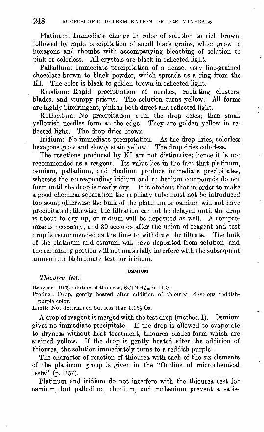
248 MICROSCOPIC DETERMINATION OF ORE MINERALS
Platinum: Immediate change in color of solution to rich brown, followed by rapid precipitation of small black grains, which grow to hexagons and rhombs with accompanying bleaching of solution to pink or colorless. All crystals are black in reflected light.
Palladium: Immediate precipitation of a dense, very fine-grained chocolate-brown to black powder, which spreads as a ring from the KI. The. color is black to golden brown in reflected light.
Rhodium: Rapid precipitation of needles, radiating clusters, blades, and stumpy prisms. The solution turns yellow. All forms are highly birefringent, pink in both direct and reflected light.
Ruthenium: No precipitation until the drop dries; then small yellowish needles form at the edge. They are golden yellow in re flected light. The drop dries brown.
Iridium: No immediate precipitation. As the drop dries, colorless hexagons grow and slowly stain yellow. The drop dries colorless.
The reactions produced by KI are not distinctive; hence it is not recommended as a reagent. Its value lies in the fact that platinum, osmium, palladium, and rhodium produce immediate precipitates, whereas the corresponding iridium and ruthenium compounds do not form until the drop is nearly dry. It is obvious that in order to make a good chemical separation the capillary tube must not be introduced too soon ; otherwise the bulk of the platinum or osmium will not have precipitated; likewise, the filtration cannot be delayed until the drop is about to dry up, or iridium will be deposited as well. A compro mise is necessary, and 30 seconds after the union of reagent and test drop is recommended as the time to withdraw the filtrate. The bulk of the platinum and osmium will have deposited from solution, and the remaining portion will not materially interfere with the subsequent ammonium bichromate test for iridium.
OSMIUM
Thiourea test. Reagent: 10% solution of thiourea, SCCNE^K in H 20.Product: Drop, gently heated after addition of thiourea, develops reddish-
purple color. Limit: Not determined but less than 0.1% Os.
A drop of reagent is merged with the test drop (method I) . Osmium gives no immediate precipitate. If the drop is allowed to evaporate to dryness without heat treatment, thiourea blades form which are stained yellow. If the drop is gently heated after the addition of thiourea, the solution immediately turns to a reddish purple.
The character of reaction of thiourea with each of the six elements of the platinum group is given in the "Outline of microchemical tests" (p. 257).
Platinum and iridium do not interfere with the thiourea test for osmium, but palladium, rhodium, and ruthenium prevent a satis-

MICKOCHEMICAL METHODS 249
factory test on 0.1 percent osmium solution, if they are present in proportions of 1 percent or greater. If the concentration of osmium is equal to that of these elements, the test is satisfactory. Palladium can be removed by precipitation with dimethyl glyoxime in a strong HC1 solution. The filtrate is transferred to a glass slide and the drop evaporated to dryness to remove the excess of HC1. The residue is then taken up with a drop of water and tested for osmium with thiourea as already described.
The ammonium chloride test, a description of which follows, will detect osmium in the presence of rhodium or ruthenium.
Ammonium chloride test. Reagent: Solid NH 4C1.Product: Reddish-brown to black cubes, three- and four-pointed stars, and
octahedrons. Limit: Not determined but less than 0.1% Os.
A fragment of the reagent is introduced into the neutral test drop (method II).
Osmium gives an immediate and copious precipitation of medium- sized reddish-brown to black cubes, three- and four-pointed stars, and octahedrons. The crystals are reddish brown in reflected light.
Reactions with other elements of the platinum group are as follows:Platinum: Immediate precipitation of feathery crosses, cubes,
feathery three-, four-, and five-pointed stars, dark in direct light and faint yellow in reflected light.
Iridium: Immediate and abundant precipitation of tiny cubes around the reagent. The cubes are black in both direct and reflected light.
Palladium: Slow formation of long yellow needles which in some tests grow across the drop. The needles are pleochroic, from golden yellow to grass green; they have parallel extinction and high birefringence.
Rhodium: No precipitate until drop is partly evaporated; then tiny dark cubes with high index of refraction form first, followed by large pink hexagons and petals. These are usually thin and have a moder ate index. The test is very characteristic but slow.
Ruthenium: No precipitate until drop is partly evaporated; then, slowly, tiny yellow cubes form and become dark as they grow. Excess reagent becomes stained dark yellow. Later a few crosses may form, and in some tests, just as the drop dries, pinkish-brown hexagons may appear. The test is not distinctive or reliable.
The ammonium chloride test for osmium is riot as distinctive as the thiourea test. It is unreliable in the presence of platinum and iridium but is not seriously interfered with by palladium, rhodium, or ruthenium.
129101 40 17

250 . MICKOSCOPIC DETERMINATION OF ORE MINERALS
RHODIUM
Dimethyl glyoxime test. Reagent: 2% dimethyl glyoxime solution in alcohol.Product: Precipitate of small needles, dark in direct light, greenish yellow in
reflected light. Limit: Not determined but less than 0.1% Rh.
The reagent drop is added directly to the test drop. Rhodium produces in a few seconds a very fine-grained mass of small needles, sometimes felted, dark in direct light and greenish yellow in reflected light. As the drop dries, blades and feathery crosses, faintly pink in direct light, form. The needles become greenish. The test is similar to that for palladium, except that needles lack yellow color in direct light. The dried residue is pink.
Rhodium can be identified in the presence of platinum, iridium, osmium, and ruthenium, by dimethyl glyoxime added to a neutral or weakly acidic solution. Palladium and gold will also be pre cipitated. A drop of concentrated HC1 added to the precipitate will dissolve the rhodium glyoxime readily, the gold slowly, and the palladium glyoxime not at all.
Benzidine will give a distinctive test for rhodium in the presence of gold and iridium. The palladium is first precipitated with dimethyl glyoxime in concentrated HC1. The filtrate is transferred to another place on the slide and tested for rhodium with benzidine.
Benzidine test. Reagent: Benzidine solution in acetic acid.Product: Slow precipitation of pink to black rounded grains.Limit: Not determined but less than 0.1% Rh.
The preparation of the reagent and the reactions with other ele ments of the platinum group are described under the heading "Platinum."
Rhodium does not yield an immediate precipitate. Spherules and rounded grains, pink to yellowish black in direct light and rose pink in reflected light, slowly form. The test is slow but strong. It is not as good as the dimethyl glyoxime test for rhodium but is of special value where rhodium and palladium are associated in the same sample.
RUTHENIUMThiourea test.
Reagent: 10% solution of thiourea, SC(NH2) 2 , in H20. Product: Warmed drop turns inky blue. Limit: Not determined but less than 0.1% Ru.
The reagent drop is merged with the test drop (method I). Ruthe nium gives no immediate precipitate. The cold drop very slowly develops a deep inky-blue color. As the drop dries, blue-black spherules form at the edge of the drop. If the drop is gently heated after the thiourea is added, it immediately turns inky blue.

MICKOCHEMICAL METHODS 251
Reactions of thiourea with other elements of the platinum group are described in the outline of microchemical tests (p. 265).
Thiourea gives a satisfactory test for ruthenium in the presence of any other elements of the platinum group except palladium and possibly osmium. An experienced observer can recognize the ruth enium test in the presence of osmium, but the blue ruthenium color is quickly replaced by the red osmium color. The rhodanine test, a description of which follows, gives a satisfactory ruthenium test in the presence of osmium. If palladium is present, it can be removed with dimethyl glyoxime, the solution filtered, and ruthenium tested for with either thiourea or rhodanine.
Rhodanine test. Reagent: 0.03% dimethyl-amino-benzal-rhodanine in acetone. Product: Colorless to yellowish-brown needles and radiating clusters. Limit: Not determined but less than 0.1% Rh.
The reagent drop is merged with the test drop (method I).Ruthenium produces an immediate precipitation of colorless to
yellowish-brown needles and radiating clusters. The crystals have low birefringence. They are yellowish in reflected light.
Reactions of the rhodanine reagent with other elements of the platinum group and gold are as follows:
Platinum: No precipitate.Palladium: Strong pink color in the solution. Pink needles and
clusters are precipitated immediately. The presence of 1:5 HC1 prevents coloration of the solution but not the formation of the precipitate.
Rhodium: The color of the test drop changes from normal faint pink to yellow, with precipitation of tiny needles.
Iridium: No definite precipitate.Osmium: No definite precipitate.Gold: Immediate precipitation of a purplish fine-grained aggre
gate which slowly changes in color to yellow green. A mass of small yellow-green needles forms; the needles are white in reflected light. Still later, red hairy clusters, red in reflected light, may also appear. The test is strong.
The rhodanine test for ruthenium is not satisfactory in the presence of palladium, rhodium, and gold. Palladium can be removed before testing, as described under the thiourea test for ruthenium. If rhodium or gold is associated with ruthenium, the thiourea test is preferable to the rhodanine test. On the other hand, if ruthenium is associated with osmium, the rhodanine test is preferable.

252 MICROSCOPIC DETERMINATION OF ORE MINERALS
A SYSTEMATIC SCHEME OF MICROCHEMICAL ANALYSIS 5°
Microchemical tests are applicable to any mineral provided it can be taken into solution. However, it is usually most convenient to determine transparent minerals by optical methods. The best of these methods consists in determination of the indices of refraction of the mineral by immersing the powdered mineral in liquids of known indices of refraction.
The scheme of analysis described here is almost entirely confined to the opaque ore minerals. Under the reflecting microscope the opaque minerals are easily distinguished from the nonopaque minerals by their color in vertically reflected light. This is discussed more fully on pages 69 and 70.
As already stated (p. 63), it is best to identify the opaque ore mineral by means of hardness, polarization, and etching tests and then confirm the identification by microchemical tests for one or more elements. However, this scheme may fall down because of errors in the etch tables, mistakes in interpreting polarization or etching effects, or errors in the formulas of the minerals as given in the standard texts, or because the minerals may be "new" that is, not yet described in the literature. Any one of these factors would cause a failure in the scheme. The next resource will then be to identify the elements of the mineral by a systematic scheme similar to that of qualitative chemical analysis.
Any systematic scheme of this kind is greatly simplified by mak ing the hardness test at the outset. This is described on page 63 but is outlined here for convenience. The mineral is tested for hard ness by means of a sharp needle. Minerals that scratch readily are classified as soft, and those that scratch with difficulty or not at all are classified as hard. The advantage of making this classification at the outset is that certain elements are rarely if ever found in the hard group and others are rarely if ever found in the soft group.
HARD MINERALS
The hard opaque minerals may be divided into three groups, as follows:
A. Insoluble or very difficultly soluble in concentrated HN03 , 1 : 1 HN03 , or aqua regia. This group consists mostly of the iron- bearing oxide minerals, also cassiterite, tungstates, and rare-earth minerals.
B. Readily soluble in 1 : 1 HNO3 or aqua regia. This group con sists mostly of the nickel-cobalt-iron arsenides, antimonides, sul- pharsenites, and sulphantimonites; also pyrite and marcasite.
w This scheme is based on one originated by the writer's former students, Drs. H. J. Fraser and H. A. Powers.

MICROCHEMICAL METHODS 253
C. Insoluble or slightly soluble in HN03 but readily soluble in aqua regia and 1 : 1 HC1. This group consists of the hard manganese oxides.
Group A. The No. 9 needle ordinarily used will not scratch, a hard mineral. A powder may usually be obtained by using a No. 6 or stronger needle, the point of which is ground back by means of the emery wheel so as to give a relatively large cutting edge. By working it back and forth in a pit on the surface of the minera], powder will gather in front of the needle. A nonmetallic red pow der indicates hematite; brick red to light brown indicates the hy drous iron oxides of the "limonite" group, also chromite; dark brown indicates franklinite or braunite; a black metallic powder is probably magnetite. All these minerals except braunite are almost insoluble in strong nitric acid and aqua regia. However, by many repeated applications of aqua regia, each evaporated over the microflame, enough material can be taken into solution to give an iron test. The residue is colored orange to brown. It is taken into solution with a drop of 1 : 7 HN03 and tested for iron with a fragment of K4Fe(CN)8 .
If the mineral is too hard to yield any powder by the method just described it is probably a rare-earth mineral. As already stated, these minerals are not considered in this investigation.
Group B. The minerals of group B are readily broken down by means of 1:1 HNO3 or aqua regia. Minerals of the nickel-cobalt- arsenic-antimony group tend to be associated together. Niccolite is recognized at sight from its color. Its neighbors can be assumed to belong to that group until proved otherwise. This group is large, and nearly all the minerals in it look almost exactly alike. In re flected light they are ashy gray and "hard" (in the sense already mentioned). With experience one can always tell from color and hardness that a mineral with the above description is chloanthite, loellingite, gersdorffite, skutterudite, rammelsbergite, smaltite, kal- lilite, willyamite, safflorite, or ullmanite. Arsenopyrite and loel lingite cannot be told apart by etching, polarization, or micro- chemical tests. They are slightly different in color, however, arseno- pyrite being galena white and loellingite ashy gray. Arsenopyrite tends to be associated with pyrrhotite, sphalerite, galena, and chal- copyrite; and loellingite with the other arsenides in the group just described.
A hard white mineral soluble in nitric acid will contain only nickel, cobalt, iron, arsenic antimony, bismuth, or sulphur. Dissolve the mineral in either HN03 or aqua regia. Notice the residue:
A white amorphous powder indicates sulphur or antimony.A gelatinous ring around the drop indicates arsenic.If the residue is green look for nickel; if yellow or orange, iron;
if pink, cobalt.

254 MICROSCOPIC DETERMINATION OF ORE MINERALS
Tests for all the elements of this group can be made from the above-mentioned residue. Leach the residue with 1 percent HN03 .
1. Iron, nickel, cobalt, and arsenic go into the solution. Transfer 1 percent HN03 drop and evaporate almost to dryness. Add drop of ammonium molybdate solution and heat very slowly till dry. Add drop of 1 : 7 HN03 , which dissolves the excess of ammonium molyb date, leaving minute yellow octahedrons or twinned isometric crys tals if arsenic is present. Filter the solution from these crystals, transfer to another place on the slide, and add potassium mercuric thiocyanate (method I). If iron is present, the solution turns red. If cobalt is present, it forms acicular blue crystals, which usually are grouped as crosses or rosettes. If nickel is present, minute brown spherulites form slowly near the edge of the drop.
2. Antimony, bismuth, and sulphur remain undissolved in the origi nal residue. The formation of a flocculent precipitate at this stage indicates bismuth. Leach original residue with at least three suc cessive drops of 1 percent HN03 to remove remaining traces of arsenic, then a drop of H20 to remove the nitric acid. Then leach original residue with a drop of 1:5 HC1. Transfer drop and add fragment of KI. If an amorphous yellow or orange-colored precipi tate or yellow hexagonal plates form, some arsenic is still present. If solution turns light yellow, it contains antimony or bismuth, or both. Add fragment of CsCl. Orange-colored hexagons prove antimony; red hexagons prove bismuth.
There are only three hard minerals that contain antimony kallilite (Ni(Bi,Sb)S), ullmanite (Ni(As,Sb)S), and willyamite ((Co,Ni)SbS).
Group C. If a hard mineral is almost insoluble in 1:1 HN03 but readily soluble in aqua regia, the presence of manganese should be tested for by leaching the residue with a drop of 1:7 HNO3 , trans ferring the drop, and adding solid sodium bismuthate. If the drop turns pink or purple, manganese is present.
SOFT MINERALS
The soft minerals are divided into three groups (A) soluble in 1:1 HN03 , (B) insoluble in 1:1 HN03 but soluble in aqua regia, (C) insoluble in both 1:1 HN03 and aqua regia. Group C is not con sidered in the analytical scheme here proposed.
Group A. A soft mineral soluble in nitric acid will not contain mercury. Examine the residue for the following hints:
A white amorphous powder indicates sulphur or antimony.A gelatinous ring indicates either arsenic or silver.A curdy white structureless mass suggests bismuth or tellurium.A white lattice or boxlike structure indicates lead: more rarely an
excess of silver may give a similar structure.

MICROCHEMICAL METHODS 255
Sulphur sometimes leaves a light-yellow agglutinated mass instead of a white powder.
An agglutinated brick-red mass proves selenium.If the residue is green, suspect copper or nickel; if yellow or orange-
colored, iron.Selenium occurs only in combination with silver, gold, bismuth,
copper, mercury, lead, tellurium, and sulphur.Step 1, for iron, copper, zinc, cobalt, nickel, and silver: Leach the
residue from the original mineral solution with a drop of 1 percent HN03 . Transfer the drop, and merge with it a drop of potassium mercuric thiocyanate. If iron is present, the test solution will turn red; copper forms a crystalline precipitate consisting of greenish- yellow mosslike clumps, prisms, and crosses; zinc forms white or gray feathery crosses; silver forms an amorphous white powder; cobalt forms indigo-blue prisms; nickel forms small brown spher- ulites near the edge of the drop.
Step 2, for copper, arsenic, selenium, and tellurium: Leach the original residue with a drop of H20 to remove traces of HN03 . Kemove the drop. Then leach the original residue with a drop of 1 '5 HC1. Any silver remaining from the preceding test will come down here as curdy white chloride. Lead compounds are changed to the chloride, which often appears as white needles. Transfer the filtrate to another place on the slide. Add a fragment of KI. Any copper remaining from the preceding test will come down as an amorphous white, gray, or light-yellow powder; arsenic will come down as an amorphous yellow to orange-colored powder; if the solution is con centrated with respect to arsenic, yellow hexagonal plates may appear either with or without the amorphous precipitate; tellurium or selenium will come down as a fine-grained amorphous chocolate- brown powder; if antimony or bismuth is present in appreciable amount (0.1 percent or more of SbCl3 ), the solution will be colored yellow in the neighborhood of the KI fragment. The selenium and tellurium precipitates come down instantly. . The arsenic and copper precipitates are sometimes slow in forming. Therefore, it is best to observe the drop until it has nearly evaporated, then add sufficient 1:5 HC1 to give the drop its original volume. Once formed, the copper and arsenic precipitates are not soluble in the additional acid. All the precipitates thrown down by KI are amorphous and are best observed in oblique reflected light. The tellurium and selenium precipitates will not be confused with the arsenic and copper precipitates, owing to the peculiar manner in which the tellurium and selenium reactions proceed. (See detailed description, p. 207.) When a tellurium or selenium precipitate is obtained, confirmatory tests by the cesium chloride and stannous chloride reactions should be made to determine whether the precipitate is tellurium or selenium. The confirmatory

256 MICROSCOPIC DETERMINATION OF ORE MINERALS
tests can usually be made by leaching the original residue with another drop of 1:5 HC1 and testing the resulting solution. If not enough material remains in the original residue to yield these tests, it may be necessary to make them on additional mineral powder. The arsenic and copper precipitates are very much alike a fact which may cause some confusion in identification. The arsenic pre cipitate is yellower than the copper precipitate and sometimes is dis tinctly orange-colored. If there is any doubt as to the identity of the precipitate, it is advisable to make the ammonium molybdate test for arsenic on fresh mineral powder. It should be remembered that a large part, possibly most of the arsenic has been removed from the original residue by leaching the residue with 1 percent HNO3 and the subsequent drop of water and removal of both drops. This arsenic is lost in making the thiocyanate test for other elements (step 1); hence failure to get the iodide test for arsenic at this stage does not indicate that no arsenic was present in the mineral. This is the weakest point in the entire analytical scheme. However, in nine cases out of ten there is enough arsenic acid remaining to give a good indication for arsenic when tested with KL As already indicated, if there is any reason to believe that arsenic is present in the mineral and the iodide test fails to show it, the molybdate test for arsenic should be made on additional powdered mineral.
Step 3, for arsenic, antimony, bismuth, and tin: A fragment of cesium chloride is added to the same drop in which the KI test has just been made. The drop should first be restored to its original size by adding more 1:5 HC1. If arsenic is present, part of the iodide precipitate formed by the preceding test is converted to the cesium arsenic double iodide, which forms as an orange-colored amor phous precipitate near the border of the drop. Usually the concen tration in arsenic is not great enough to cause the formation of the orange-colored hexagons described on page 211. The precipitate is best observed in oblique reflected light. Antimony will form orange- colored hexagons; bismuth will form red hexagons; tin will form colorless octahedrons.
Step 4, for lead, gold, sulphur, and selenium: Examine the original residue in obliquely reflected light, using a 16-millimeter objective.-, Gold, if present, will be seen as yellow metallic grains; any selenium not converted to the soluble acid and removed in the preceding opera tion remains behind in the original residue as the native element, which is observed as a reddish powder or agglutinated mass. When HC1 was added in step 2, the lead was converted into the chloride (PbCl2). Usually the lead chloride needles can be recognized at sight under the microscope. It is always advisable, however, to make the iodide test for lead, whether the chloride crystals are recog nizable or not. Leach residue with two or three successive drops of

MICROCHEMICAL METHODS 257
water. Transfer each drop to another place on the slide and add a fragment of KL Lead, if present, will form lemon-yellow hexagons and disk-shaped plates of the normal iodide. To confirm the presence of gold, add a drop of aqua regia to the residue and evaporate to dry- ness over the micron1 ame. Gold is converted to an orange-colored to brown residue that is very soluble in water. Leach this residue with a drop of water, transfer the drop, and merge with it a drop of pyridine-HBr solution. Pleochroic red crystals prove gold.
The following observations on the soft minerals attacked by HN03 are of value: The presence of arsenic excludes bismuth, tellurium, mercury, selenium, and zinc; the presence of nickel excludes copper, gold, lead, mercury, selenium, silver, and zinc.
Group B. A soft mineral insoluble in HN03 but easily soluble in aqua regia probably contains mercury or manganese. If Hg is present, the HgCl2 residue will usually show a lattice pattern. (See pi. 13, D.) A manganese residue forms as a circular ring with a faint tinge of pink.
Test for mercury: Dissolve in aqua regia. Leach the residue with 1 percent nitric acid. Transfer the drop, and add a small frag ment of Co(N03) 2 . When dissolved, add a fragment of KCNS. Blue branching or acicular crystals, the same as seen in the test for cobalt, prove the presence of mercury. M'ercury is associated only with antimony, selenium, tellurium, and sulphur.
Test for manganese: Dissolve in aqua regia. Leach the residue with a drop of 1:7 HN03 , transfer the drop, and add solid sodium bismuthate. If the solution turns pink or purple, manganese is present.
The following outline of the systematic analytic procedure was kindly prepared for the writer by F. M. Chace, of Harvard University.
OUTLINE OF SYSTEMATIC ANALYSIS
HARD MINERALS
Group A. Minerals insoluble or very difficultly soluble in concentrated HNOs, 1:1 HNOs, or aqua regia. Group consists of iron-bearing oxides, cassiterite, tungstates, and rare earths.
Procedure: Remove powder of mineral from polished section with chisel- pointed No. 6 needle. Nonmetallic red powder=hematite. Brick-red to light- brown powder=limonite or chromite. Dark-brown powder=franklinite or braunite. All these minerals are almost insoluble in aqua regia, but by several applications and evaporations enough material taken into solution to test for Fe. Residue orange to red. Take residue into solution with 1:7 HNOs. Add frag ment of K4Fe(CN)6- Prussian blue precipitate=Fe.
Group B. Minerals soluble in 1:1 HNOs or aqua regia. Group consists of cobalt-nickel-iron arsenides, antimonides, sulpharsenides, sulphantimonites, pyrite, and marcasite.
Procedure: Hard white minerals soluble in HNOs contain only Ni, Co, Fe, As, Sb, Bi, S. Dissolve mineral in HNO3 . Note residue. White amorphous powder

258 " MICROSCOPIC DETERMINATION OF ORE MINERALS
= Sb or S. Gelatinous ring around drop = As. Green residue = Ni. Yellow or orange residue = Fe. Pink residue = Co. Leach residue with 1 percent HNOs.
Solution: Fe, Ni, Co, and As go into solution. Transfer drop. Add 1 percent HNOs. Evaporate almost to dryness. Add (NH4)Mo04 and slowly evaporate to dryness, then add drop of 1 percent HN03 .. Precipitate, yellow octahedrons or twins=As. Filter and transfer drop. Add K2Hg(CNS) 4 . Precipitate, blue acicular crystals=Co; solution turns red=Fe; brown spherulites=Ni.
Residue: Sb, Bi, S remain in original residue. Leach original residue with three drops 1 percent HNOs to remove traces of As. Then leach with H20 to remove HN03 . Addl:5HCl. Transfer drop. Add fragment KI. Precipitate, amorphous yellow to orange=As; solution turns light yellow=Sb or Bi. Add fragment CsCl. Precipitate, orange hexagons = Sb; red hexagons = Bi.
Group C. Minerals insoluble or slightly soluble in HNOs but readily soluble in aqua regia and 1:1 HCl. Group includes hard manganese oxides. Test for Mn, use sodium bismuthate test.
SOFT MINERALS
Group A. Minerals soluble in 1:1 HNOs. These minerals will not contain Hg. Presence of As excludes Bi, Te, Hg, Se, Zn; presence of Ni excludes Cu, Au, Pb, Hg, Se, Ag, Zn. Powder mineral. Place in 1:1 HN03 . Warm gently. Examine residue.
Residue: White amorphous powder=S or Sb. Gelatinous ring=As or Sb. Curdy white structureless mass = Bi or Te. White lattice or boxwork structure = Pb, rarely Ag. Light-yellow agglutinated mass, may be S. Agglutinated brick- red mass = Se. Residue green = Cu or Ni. Residue yellow or orange=Fe.
Solution: Step 1 (test for Ag, Co, Cu, Fe, Ni, Zn). Leach residue from original mineral solution with 1 percent HNOs. Transfer drop. Add drop of K2Hg- (CNS)4. Amorphous white powder=Ag. Indigo-blue prisms=Co. Precipi tate of green-yellow moss, prisms and crosses=Cu. Solution turns red = Fe. Small brown spherulites at margin of drop = Ni. White to gray feathery crosses = Zn.
Step 2 (test for Cu, As, Se, Te). Leach original residue with H20 to remove HNOs. Add drop 1:5 HCl. Ag present will precipitate as a curdy white mass. Pb may precipitate as needles. Transfer drop. Add fragment KI. Amorphous yellow to orange powder=As. Amorphous white, gray, or yellow powder=Cu. Solution turns yellow near fragment= Sb or Bi. Fine amorphous chocolate- brown precipitate=Te or Se. All precipitates by KI are amorphous. Observe in reflected light. Te and Se precipitate will not be confused with As and Cu, because of peculiar way in which Te and Se precipitate. When Te and Se are present distinguish the two by CsCl and SnCl2 tests made by leaching original drop with 1:5 HCl, transferring drop and adding reagent. Cu and As precipitates very similar; arsenic yellower and sometimes orange. To confirm, use ammonium molybdate test on new mineral powder.
Step 3 (test for As, Bi, Sb, Sn). Fragment of CsCl is added to same drop in which KI test was made in step 2. May restore drop to original size with 1:5 HCl. Iodide precipitate of step 2 will form orange amorphous precipitate at border of drop=As. Red hexagons=Bi. Orange hexagons=Sb. Colorless octahedrons = Sn. Milky white crosses = Pb.
Step 4 (test for Au, Pb, Se, S). Examine residue from original solution in reflected light. Yellow metallic grains = Au. White PbCl2 needles = Pb (if any remains). Metallic red powder=Se (if any remains). Pb confirmatory test. Leach original residue with two or three successive drops of H20, transfer and add to each a fragment of KI. Pb will form lemon-yellow hexagons and disklike plates. Au confirmatory test: Add drop of aqua regia to residue, and evaporate

MICROCHEMICAL METHODS 259
to dryness. Au is converted to orange-brown residue very soluble in H20. Transfer drop, merge with pyridine-HBr solution. Pleochroic red crystals = Au.
Group B. Soft minerals insoluble in HNOs but soluble in aqua regia. Probably contain Hg or Mn. HgCl2 residue forms lattice pattern. Mn forms a pink circular ring.
Test for Hg: Dissolve in aqua regia. Leach residue with 1 percent HNOs. Transfer drop. Add fragment Co(NOs)2- When dissolved add fragment of- KCNS. Blue branching or acicular crystals prove presence of Hg. Hg occurs only with Sb, Se, Te, and S.
Test for Mn: Dissolve in aqua regia. Leach residue with 1:7 HNOs. Transfer ' drop and add a fragment of sodium bismuthate. Solution turns pink or purple if Mn is present.
Group C. Soft minerals insoluble in both 1:1 HNOs and aqua regia. No pro cedure given.
OUTLINE OP MICROCHEMICAL TESTS
In this outline is given in condensed form a description of the precipitates formed by the standard microchemical reagents. The elements to be identified are present in either 1 percent HN03 or 1 : 5 HC1. Except as otherwise described, precipitates appear within 30 seconds after the reagent is applied. Exceptions to this rule are the potassium mercuric thiocyanate tests for nickel and cobalt and the cesium chloride test for cobalt. These compounds are slow in forming, not because they are soluble but because they tend to supersaturate. Once formed they will not dissolve by restoring the drop to its original size.
The data on mutual interference of elements are taken from the paper of Fraser and Dreyer.51
Numbers in parentheses refer to concentration in percentage of the element in solution. Thus, Cu (0.1) signifies 0.1 percent of copper.
POTASSIUM MERCURIC THIOCYANATE
A drop of a 3 percent solution of the reagent is merged with a drop of the element in a 1 percent HN03 solution.Antimony: No precipitate.Arsenic: No precipitate.Bismuth: No precipitate.Cadmium: Blunt white hemimorphic prisms which usually have cavities at each
end.Cobalt: Blue prisms and spherulites.
Co (0.1) Cu(l): No Co test.Co (1.0) Cu (0.1): Crystals of Cu form, but all colored blue. A mineral with
concentrations approximately equal, as in carrollite (Co,Cu)sS4, gives typical tests for both elements.
Co (0.1) Fe (1): All Co crystals dark, irregular peripheral aggregates. Testpoor.
Co (1.0) Fe (1): All Co crystals dark but well formed.Co (1.0) Ni (1): No evidence of Co until evaporation is far advanced, and
then only blue globules form.
81 Fraser, H. J., and Dreyer, R. M., Mutual interference in the microchemical determination of ore minerals: Am. Mineralogist, vol. 22, pp. 949-976,1937.

260 MICROSCOPIC DETERMINATION OF ORE MINERALS
Co (1) Ni (0.1): No nickel test. Most specimens 'of siegenite, (Ni,Co)aS4, smaltite-chloanthite, (Co,Ni)As2 , and other minerals containing both nickel and cobalt give satisfactory tests for both elements. The cobalt compound does not precipitate until the drop begins to dry.
Copper: Greenish-yellow mosslike aggregates and prisms.Gold: Dilute solutions of AuCU in 1 percent HNOs give white or creamy amorphous
precipitate. Solutions containing more than 0.1 percent AuCls give yellowish-brown mosslike aggregates.
Iron: Solution turns red. Faint in solutions containing 0.1 percent Fe.Lead: White granular amorphous precipitate. Comes down only in concentrated
solution.Manganese: No precipitate.Mercury: No precipitate.Nickel: White to brown spherulites.Selenium: Numerous peripheral greenish-yellow globules, very late forming. As
drop dries up, elemental selenium is deposited.Silver: Curdy white, exceedingly fine-grained precipitate.Tellurium: No precipitate.Tin: Not soluble in HN03 solution.Zinc: White feathery crosses.
Zn (0.1) Cu (1): No Zn test. Zn (1.0) Cu (1): Some Zn crosses, all purple.
The reagent is applied in solid form to the element in a 1 : 5 HC1 solution.
Antimony: White hexagons and stars. Most of the precipitate tends to beamorphous.
Sb (0.1) Te (0.1): Sb crystals small and indistinct. Sb (1) Te (0.1): Te precipitate largely masked by Sb. Sb (0.1) Sn (1): Sb masked by Sn precipitate.
Arsenic: Numerous small, formless, late-forming peripheral grains and hexagonal plates.
Bismuth: Very thin colorless rhombs and knifelike prisms. Bi (0.1) As (1): Bi largely masked by As.
Cadmium: Tiny colorless hexagonal bipyramids. Best observed with an 8-milli meter objective. A 0.5 percent solution of CdCl2 gives a good test, but a 0.1 percent solution gives a poor test.
Cobalt: Soluble light-blue blades and prisms form around the periphery of the drop very late in period of evaporation.
Copper: Golden-yellow needles appear at edge of drop after evaporation is some what advanced. Does not appear in dilute solutions.
Co (1) Cu (1): Residue colored light green by Cu, so that Co cannot be recognized.
Gold: Small brown octahedrons and skeletal isometric crystals.Iron: From relatively concentrated solutions tiny golden-yellow crystals appear
at edge of drop, at a late stage in evaporation. Bipyramids resembling octahedrons, pseudohexagons, and diamond-shaped plates predominate. They are probably orthorhombic.
Lead: Small colorless rhombs, crosses, and plates of irregular shape. Crystals have a high refractive index and low double refraction. Precipitate appears only in relatively concentrated solutions.
Manganese: No precipitate.

MICEOCHEMICAL METHODS 261
Mercury: In a 0.5 percent solution of HgCl2 in water highly refracting colorless cubes and octahedrons are precipitated in a few seconds. These resemble the AgCl precipitate (see p. 202), but the crystals of the mercuric compound are much larger. In a 0.1 percent solution of HgCl2 in water no precipitate appears until the evaporation is advanced. The presence of HCl greatly reduces the sensitivity of this reaction.
Nickel: No precipitate until drop is almost dry, when tiny formless grains appear. These are white to light yellow.
Selenium: Colorless plates and formless grains. Weak in 0.1 percent solution.Silver: Not soluble in an HCl solution; hence no precipitate.Tellurium: Honey-yellow isometric crystals, chiefly octahedrons, also hexagonal
and triangular plates.Tin: Small white octahedrons and Y-shaped crystals.
Sn (0.1) Cu (1): No Sn test.
POTASSIUM IODIDE
A small fragment of the reagent is applied to a drop of 1:5 solution containing the element.Antimony: Solution turns yellow. Color very faint in 0.1 percent Sb solution.Arsenic: Yellow amorphous precipitate. Concentrated solutions sometimes give
small disks. Reaction delayed in 0.1 percent As solution. As (0.1) Sb (1): Arsenic precipitate alone gives very few disks at this con
centration, but in the presence of Sb the solution is colored yellow, and yellow disks appear which are very similar to those formed in the Sb double iodide test.
Bismuth: Solution turns yellow.Cadmium: No precipitate.Cobalt: No precipitate.Copper: Light-yellow amorphous precipitate.
Cu, Se, Te, Au: It is very difficult to distinguish the KI precipitates of these elements. In the systematic scheme Au will not go into solution when the mineral is broken down with 1:1 HNOs. Most of the Cu is removed by leaching original residue with 1 percent HNOs.
Cold: Yellow amorphous ring surrounds KI fragment. Ring widens as KI dis solves. Liquid inside of ring colors yellow. Reaction resembles that of selenium, but precipitate is a lighter yellow, and some metallic gold (gold- colored in reflected light), as well as light-green rectangular to irregular plates, is precipitated.
Iron: No precipitate. Solution turns yellow.Lead: Greenish-yellow hexagons. HCl reduces solubility of Pb; hence test is
better in neutral H20 solution.Manganese: No precipitate, but solution turns yellow near KI fragment.Mercury: From a solution of HgCl2 in water, KI precipitates a fine-grained
amorphous precipitate which spreads in a widening solution away from the KI precipitate as it dissolves. This precipitate is light yellow in oblique reflected light. Within the yellow ring, and adjacent to it, is another ring composed of red particles. These are amorphous but larger in grain size than those of the yellow ring. The red ring follows the yellow ring as it expands. Within the red ring the solution is colorless. This test was satis factory in a 0.1 percent solution but unsatisfactory in a 0.05 percent solu tion of HgCl2 . In a 1:5 HCl solution, small red and orange cubes appear. Satisfactory in a 0.5 percent solution but unsatisfactory in a 0.1 percent solution of HgCl2 .

262 MICROSCOPIC DETERMINATION OF ORE MINERALS
Nickel: No precipitate.Selenium: Chocolate-brown amorphous precipitate.Silver: Not soluble in HCl solution.Tellurium: Chocolate-brown precipitate.Tin: No precipitate.Zinc: No precipitate.
CESIUM CHLORIDE AND POTASSIUM IODIDE
Small fragments "of the reagents are applied to a 1:5 HCl solution containing the element.Antimony: Orange to red hexagons and stars.
Sb-As: Arsenic gives a precipitate which, in all concentrations, is very much like the Sb precipitate. Arsenic, however, unlike Sb, gives a precipitate after the KI has been added and before the CsCl has been added.
Sb (0.1) Cu (1): No Sb test.. Sb (1) Cu (1): Sb somewhat masked by Cu precipitate.
Sb (0.1) Sn (1): Sb crystals small, poorly formed, and somewhat delayed. No difficulty is met in getting both Sb and Sn from the same drop when testing cylindrite (6PbS.Sb2S3 .6SnS2) and franckeite (5PbS.Sb2S3 .2SnS2).
Arsenic: Brown amorphous precipitate near edge of drop. Concentrated solu tions may give orange hexagons indistinguishable from the antimony precipitate.
As (0.1) Cu (1): Arsenic test masked by Cu. As (1) Cu (1): Many As crystals, but many of the crystals are poorly formed
and more brown than usual.As-Fe: If the Fe concentration is relatively high, there may be some diffi
culty in noting As.Bismuth: Red hexagonal plates. Very thin plates may be orange and indis
tinguishable from those of the antimony test. Bi-Sb: Except where one of the elements is greatly in excess of the other,
Sb and Bi can usually be separated. The Bi test is more sensitive. Bi (0.1) Cu (1): Bi largely masked by Cu. Bi (0.1) Se (1): No Bi test. Satisfactory tests for both elements are obtained
without difficulty from guanajuatite, Bi2 (Se,S) 3 .Bi (0.1) Te (1): Bi masked by Te. The double iodide test for Bi in tetrady-
mite, Bi2Te3 , is unsatisfactory. The cesium chloride test should be used instead.
Cadmium: Colorless cubes. Precipitate appears only in concentrated solutions. Cobalt: Soluble bluish-green prisms and rhombs appear at edge of drop. Precipi
tate appears only in relatively concentrated solutions. Late forming. Copper: Long, ragged, slender colorless needles appear in addition to normal copper
iodide.Gold: Same as cesium chloride test.Iron: Aggregates of splintery colorless needles slowly appear at edge of drop.
These resemble calcium sulphate needles but tend to assume hexagonal star shapes.
Lead: In addition to normal lead iodide, there is precipitated a mat of slender white needles, probably the double iodide of cesium and lead. This test is val uable in that it often appears in tests for other elements, especially anti mony, bismuth, and tin.
Manganese: No precipitate. Mercury: Same as KI test. Nickel: No precipitate.

MICROCHEMICAL METHODS 263
Selenium: Same as normal potassium iodide and cesium chloride tests, plus irregu lar reddish-brown to opaque crystals.
Silver: Not soluble in HC1.Tellurium: Same as KI test.Tin: Same as CsCl test.Zinc: Colorless rhombs and branching forms at edge of drop. Forms show low-
order interference colors.
POTASSIUM BICHROMATE
A small fragment of the reagent is applied to a 1 percent HN03 solution containing the element.Antimony: No precipitate.Arsenic: Slow formation of good octahedrons and tetrahedrons. Some colorless,
some dark. Form only at a late stage in evaporation of drop. Bismuth: Immediate fine-grained dark precipitate, yellow in reflected light.
Soluble in 1:7HN03 . Cadmium: No precipitate. Cobalt: No precipitate. Copper: No precipitate. Gold: No precipitate. Iron: No precipitate. Lead: Yellow amorphous precipitate predominates, but minute rhombs and
needles sometimes appear. Manganese: No precipitate. Mercury: Mercuric ions give no precipitate. Nickel: No precipitate. Selenium: No precipitate.Silver: Ruby-red crystals. Concentrated solutions give rectangular or coffin-
shaped plates. Dilute solutions give needles at edge of drop. As (1) Ag (1): Slow formation of good octahedrons and tetrahedrons, color
less to dark in transmitted light, white in reflected light. No silver bichro mate or chromate blades.
As (1) Ag (0.1): Octahedrons and tetrahedrons. No silver test. As (0.1) Ag (1.0): Strong silver test.As (0.1) Ag (0.1): Slow formation of bladed and feathery dark-red to black
forms at edge of drop. Forms sometimes very feathery. Good bichromatetests for silver are obtained from pearceite, 8Ag2S.As2 S3, and proustite,3Ag2S.As2S3 .
Cu (1) Ag (0.1): Silver blades are small and often colored blue, but test issatisfactory.
Pb (1) Ag (0.1): Heavy yellow lead precipitate masks later silver test. Pb (0.1) Ag (0.1): Immediate precipitation of lead chromate; later good
silver precipitate.Se (1) Ag (0.1): Immediate fine-grained precipitate; no silver test. Se (1) Ag (1): Black grains, clumps of needles, crosses, white in reflected light.
Later a few red spherules are formed. No silver blades. Se (0.1) Ag (0.1): Black grains and needles, then red grains and spherules
around edge of drop. No silver bichromate blades.Se (0.1) Ag (1): Black grains, colorless to black feathery blades, feathery
clumps and crosses; later formation of blades that are red when they begin to form but turn black as they grow. Owing to the slight solubility of selenious acid in 1 percent HNOs, satisfactory bichromate tests for silver are obtained from aguilarite, Ag2 (S,Se), and eucairite, Cu2Se.Ag2Se.

264 MICROSCOPIC DETERMINATION OF ORE MINERALS
Te (0.1) Ag (0.1): Fine-grained precipitate. Weak silver test of red to blackblades.
Te (0.1) Ag (1): Fine-grained precipitate, then good silver test. Satisfactory bichromate tests for silver are obtained from hessite, Ag2Te, and petzite (Ag,Au)2Te. The chloride test for silver is preferable for sylvanite, AuAgTe4 , krennerite, (Au,Ag)Te2, and calaverite, (Au,Ag)Te2 .
Tellurium: No precipitate. Tin: Not soluble in HNOs solution. Zinc: No precipitate.
THIOUREA M
A drop of a 10 percent solution of thiourea, SC(NH2 ), was added to a drop of a 1 percent solution of the element in 1:5 HC1, unless otherwise stated.Ag: Reaction in 1 percent nitric acid. Ag precipitates as a dark ring at junction of
drops, soluble in excess of thiourea. Au: No reaction.Bi: Solution turns canary yellow; no precipitate. Reaction succeeds best in HNOs
solution. Less sensitive in HC1. The interference tests for bismuth were run in a nitric acid solution.
Ag (1) Bi (0.1): Silver precipitate partly masks Bi color. Cr (1) Bi (0.1): Yellow drop, slightly greenish. Fe (1) Bi (0.1): Yellow drop, slightly orange. Hg (1) Bi (0.1): Mercury precipitate partly masks Bi color. Se (1) Bi (0.1): Bi color not visible unless drop is filtered.
Cd: No reaction. Co: No reaction.Cr: Solution turns faint blue; no precipitate.Cu: Immediate heavy dark fine-grained precipitate, white in reflected light. Fe: Solution turns faint pink; no precipitate. Hg: Immediate precipitate of colorless needles and dark grains. Mn: No reaction. Ni: No reaction. Pb: No reaction.Sb: Solution turns faint yellow; no precipitate Se: Immediate precipitation of reddish to blue-black small grains that spread as
streamers through the drop. Brilliant red in reflected light. Bi (1) Se (0.1): The strong yellow color of Bi appears first. Se precipitates,
but color is obscured by the Bi. In strong reflected light the red selenium precipitate is sometimes visible. Test not always satisfactory.
Bi (1) Se (1): Satisfactory test. Cu (1) Se (0.1): Copper precipitate, dark in transmitted light, brownish in
reflected light; selenium obscured. Cu (1) Se (1): Satisfactory selenium test.Hg (1) Se (0.1): Heavy Hg precipitate partly obscures red Se precipitate. Sb (1) Se (0.1): Part of the Sb may precipitate by hydrolysis and partly
obscure the Se precipitate. Sn: No reaction. Te: No reaction. Ti: No reaction. Zn: No reaction.
*' Eraser, H. J., and Dreyer, R. M., op. cit.

MICROCHEMICAL METHODS 265
Platinum group and gold. 53 Concentration of element in solution, 1 percent
Platinum: Thin yellow petals and rhombs, moderate index of refraction, low birefringence, slowly form. Then jagged prisms grow, dark in direct light, brick red in reflected light. Still later, long spines grow across drop, dark in direct light, faint yellow in reflected light. These usually form just before drop dries.
Palladium: Immediate strong precipitation of fine-grained chocolate-brown to black aggregate, followed by very feathery blades and needles that range from light yellow green to deep yellow, high index of refraction, high birefringence. Yellow to pinkish brown in reflected light. Strong test. Color of solution changes from brown to yellow on addition of thiourea. Heating the drop dissolves all the precipitate, but it re-forms with slow cooling. Rapid cooling gives radiating clusters of (thiourea?) needles stained yellow.
Rhodium: Fairly rapid precipitation of feathery crosses and rosettes of faint to strong yellow color. Very low index of refraction, isotropic. On drying, pink blades form at edge of drop. Fairly strong test. Gentle heating changes the solution from pinkish to yellowish orange.
Ruthenium: No precipitate. Cold drop very slowly develops a deep inky-blue color. As drop dries, blue-black spherules form at edge of drop. If drop is gently heated after thiourea is added, it immediately turns inky blue. Strong, positive test.
Iridium: No precipitate. No color change in cold or hot solution.Osmium: No precipitate. Cold drop dries to give thiourea blades stained
yellow. Gently heated drop after addition of thiourea immediately changes to a reddish purple. Very distinctive test.
Gold: Immediate precipitate of blue-black grains, soluble in excess thiourea. As drop evaporates, colorless rhombs and petals form at edge, low birefringence. Still later prisms appear with a high birefringence. .
SPECIFIC TESTS FOR MINERALS
The systematic scheme of microchemical analysis described above is designed to identify in as few operations as possible alJ the principal elements occurring in ore minerals. The tests given in the scheme are those which are applicable to the greatest number of elements. The test for any particular element as described in the outline is not necessarily the best test for that element. For instance, the tests with potassium mercuric thiocyanate for both silver and nickel are given preference in the scheme because that reagent will indicate the presence of a considerable number of additional elements; but the ammonium bichromate test for silver and the dimethyl glyoxime test for nickel are more characteristic for the respective elements than the thiocyanate tests.
As a rule, the investigator, by means of polarization, color, hardness, and etch tests, has a definite clue to the identity of the mineral under investigation. He then desires to confirm his observation by tests for the elements he believes are contained in the mineral. In the following pages the procedure believed to be the best for identifying
53 Fraser, H. J., Microchemistry of the precious-metal elements: Am. Mineralogist, vol. 22, pp. 1016-1034, 1937.
129151 40 ]8

266 ' MICROSCOPIC DETERMINATION OF ORE MINERALS
the elements in each mineral is described in detail. In using this procedure many short cuts are possible, in comparison with the systematic scheme. For instance, there is no particular need of making a thiocyanate test on galena. It is hoped that the use of these short cuts will result in much saving of time.
Aguilarite (Ag2 (S,Se)). Decompose mineral with 1:1 HNOs. Usually several applications of acid are necessary. The residue is gelatinous and may be tinged yellow and reddish. Leach residue with drop of 1 percent HNOs, transfer drop and add fragment of ammonium bichromate. The presence of selenious acid will delay but not prevent the formation of silver bichromate. Red crystals prove silver. Leach original residue with drop of 1:5 HC1. Any silver remaining is converted into white flocculent chloride. Transfer filtrate and merge with it a drop of stannous chloride. A brick-red amorphous precipitate proves selenium. If desired the silver chloride in the residue can be tested by the ammonia method. Remove all traces of selenium by several successive drops of 1:5 HC1; remove traces of HC1 with a drop of water. Then place a drop of concentrated NH4 OH on residue. After a few seconds colorless highly refracting isometric crystals will separate out of the solution. (See description of naumannite, p. 283.)
Aikinite (Cu 2S.2PbS.Bi2 S3). Decompose mineral with one or two applications of 1:1 HNOs. Aikinite is very easily attacked by HNOs. The residue is white and curdy. Carefully examine residue for lattice structure (lead nitrate). Leach residue with drop of 1 percent HNO3 , transfer drop, and merge with a drop of K2Hg(CNS)4 solution. Greenish-yellow mosslike aggregates and needles prove copper. Leach original residue with successive drops of water to remove remain ing traces of copper and HN03 . Test each drop with a drop of K2Hg(CNS)4 until the copper precipitate does not immediately appear. Usually three or four drops of water are needed. The original residue is now sufficiently free from copper to permit the subsequent tests for bismuth and lead . Leach original residue with a drop of 1:5 HC1. Lead is precipitated in shreddy white prisms. Usually this is a sufficiently diagnostic test for lead. Bismuth goes into solution. Trans fer drop and add fragment of KI. If any copper has persisted after the preceding efforts to remove it, an amorphous yellow precipitate of copper iodide will appear. The solution turns yellow from the presence of bismuth. Add fragment of CsCl. Red hexagons prove bismuth. The double iodide test for bismuth is not as satis factory with aikinite as with most other bismuth minerals. For some unknown reason orange hexagons appear in addition to the red. The double chloride test for bismuth is more satisfactory. Leach the original residue with another drop of 1:5 HC1, transfer drop and make the double chloride test by adding fragment of CsCl. The colorless rhombs of the double chloride precipitate are of normal shape. The chloride test for lead can now be confirmed by the iodide test. The original residue should be freed from remaining traces of bismuth by washing with additional drops of 1:5 HCl, transferring each drop and adding to each a small fragment of KI. As long as bismuth is present in the original residue, the drop will be stained yellow near the fragment. Usually one or two drops of HCl will suffice. Leach original residue with successive drops of water, transfer each and test for lead with a fragment of KI. The first drop may not give a satisfac tory test, owing to the presence of traces of HCl or of bismuth, but the second or third drop will give yellow hexagons of the characteristic normal lead iodide.
Alabandite (MnS). Take mineral into solution with 1:1 HNOs. H2 S gas is usually evolved. Evaporate, cool, and leach residue with a drop of 1:7 HNO3 . Add fragment of sodium bismuthate. Solution turns pink or purple, proving manganese.

MICKOCHEMICAL METHODS 267
Alaskaite ((Pb,Ag2)S.Bi2S3). Decompose mineral with 1:1 HN03 . Leach residue with drop of 1 percent HN03 . Transfer drop and add fragment of am monium bichromate. A yellow amorphous precipitate indicates lead, and red crystals indicate silver. The original residue contains bismuth and most of the lead. Add drop of 1:5 HCl, transfer drop, and add fragment of KI. Solution turns yellow near fragment. Then add fragment of CsCl. Red hexagons prove bismuth. Leach original residue with three more drops of 1:5 HCl to remove last traces of bismuth. Then add three successive drops of water to original residue. Transfer each drop to another place on slide and add fragment of KI. The first drop may not give a satisfactory test for lead, owing to the presence of remaining traces of HCl and Bi. The second or third drop will yield yellow hexagons, which prove lead.
Frequently the presence of lead masks the bichromate test for silver. In case there'is reason to suspect its presence from etch tests on the polished section or otherwise, it is best to start with fresh mineral powder. Take mineral into solu tion with 1:1 HN03 . Leach original residue with at least five successive drops of 1:5 HCl to remove bismuth, followed by five drops of water to remove some of the lead. Reject these drops. Part of the lead and all the silver remain in the original residue as chlorides. Place a diop of concentrated NH4 OH on the original residue. After a few seconds, tiny colorless highly refracting isometric crystals of AgCl will separate out of the solution, beginning hear the edge of the drop. Lead is changed to the insoluble hydroxide and does not mask the silver test.
Algodonite (CiieAs). Take mineral into solution with aqua regia. Residue is gelatinous with tinge of brown. Leach residue with drop of 1:7 HN03 , transfer drop, and heat slowly by passing in and out of flame. When nearly dry add direc.tly a drop of ammonium molybdate solution. Again heat slowly over flame till dry. Add drop of 1:7 HNOs solution to redissolve excess of ammonium molybdate and examine. Tiny yellow isometric crystals prove arsenic. Transfer filtrate (containing copper nitrate and dissolved ammonium molybdate) and merge with it a drop of potassium mercuric thiocyanate solution. A yellowish- green precipitate proves copper.
Altaite (PbTe). Decompose mineral with 1:1 HN03 . Examine residue for lattice structure. Leach residue with drop of 1:5 HCl. Transfer drop and add fragment of CsCl. Honey-yellow isometric crystals prove tellurium. Add to original residue two or three successive drops of H20, transfer each, and add frag ment of KI. The first or second drop may not give a satisfactory test for lead, owing to remaining traces of HCl, but the second or third drop will yield the usual yellow hexagons of the normal lead iodide.
Andorite (Ag2S.2PbS.3Sb2 S3). Decompose mineral with 1:1 HN03 . The min eral is somewhat resistant to attack, but with a liberal supply of finely divided material and at least 10 successive drops of liquid, enough can be taken into solution to yield to tests. Leach residue with a drop of 1: 5 HCl, transfer drop, and test for Sb by means of KI and CsCl. Orange-colored hexagons prove anti mony. Leach original residue with two additional drops of HCl to remove remain ing traces of Sb and reject drops. Then leach original residue with three success ive drops of H20, transfer each drop, and test with a small fragment of KI. Yellow glistening hexagons prove lead. Finally leach original residue with drop of concentrated NH.iOH. Observe edge of drop with an 8-millimeter objective. Tiny highly refracting isometric crystals of AgCl separate from solution after a few moments. The bichromate test for silver has been successfully used on ando- rite, but it requires about three times the amount of material ordinarily used for microchemical tests and, in addition, more than an average degree of technical skill.

268 MICROSCOPIC DETERMINATION OF ORE MINERALS
Antimony (Sb). Decompose mineral with 1:1 HN03 . Residue is white and powdery. Leach residue with drop of 1: 5 HC1, transfer drop, and add fragment of KI. Solution turns yellow near fragment. Add fragment of CsCl. Orange- colored hexagons and stars prove antimony.
Aramayoite (Ag2S.(Sb,Bi) 2S3). Decompose mineral with 1:1 HN03 . Leach residue with drop of 1 percent HNOs, transfer drop, and add fragment of ammo nium bichromate. Red crystals prove silver. Leach original residue with drop of 1:5 HC1. Transfer drop and add fragment of KI. Solution turns yellow near fragment. Add fragment of CsCl. Both orange-colored and red hexagons form, proving antimony and bismuth.
Argentite (Ag2S). Decompose mineral with 1 :1 HN03 . Leach residue with 1 percent HN03 , transfer drop, and add fragment of ammonium bichromate. Red crystals prove silver.
Argyrodite (4Ag2S.GeS2). Argyrodite is very resistant to attack by 1:1 HN03 , but by repeated applications (usually about ten suffice) enough material can be taken into solution to give the silver test. Leach residue with drop of 1 percent HNOs, transfer drop, and add fragment of ammonium bichromate. Red crystals prove silver. Test for germanium by procedure described on page 240.
Arsenargentile (Ag3As). Take a mineral into solution with 1:1 HN03 . Leach residue with two or three successive drops of 1 percent HN03 , and add to each a fragment of ammonium bichromate. Red crystals prove silver. The second or third drop will probably give a better test than the first, as the concentration of gelatinous arsenic acid in the first drop is usually high. Take more mineral into solution with aqua regia. Leach original residue with a drop of 1:7 HNO3 , transfer drop, and slowly evaporate over microflame. When nearly dry add drop of ammonium molybdate solution and again evaporate slowly over microflame. When dry, cool and add drop of 1:7 HNO3 to residue. Tiny yellow isometric crystals prove arsenic.
Arsenic (As). Take mineral into solution with two or three drops of aqua regia. Residue forms a white gelatinous ring around periphery. Leach residue with drop of 1:7 HN03 , transfer drop, and evaporate almost to dryness. Leach residue with drop of ammonium molybdate reagent and evaporate slowly to dry- ness over flame. Cool and leach with a drop of 1:7 HN03 . Tiny yellow isomet ric crystals prove arsenic.
Arsenopyrite (FeAsS). Decompose mineral with aqua regia. The residue usu ally has a tinge of yellow or orange. Leach residue with drop of 1:7 HN03 , transfer drop, and evaporate slowly by passing slide in and out of microflame. When nearly dry add directly a drop of ammonium molybdate solution and again heat slowly over microflame. When dry, cool and add drop of 1:7 HN03 to redis- solve excess ammonium molybdate. Examine under microscope. Tiny yellow isometric crystals prove arsenic. Take up filtrate and transfer to another place on slide. Merge with it a drop of potassium mercuric thiocyanate solution. A red coloration of test solution proves iron.
Baumhauerite (4PbS.3As2S3). Decompose mineral with aqua regia. Leach resi due with drop of 1:7 HN03 , transfer drop, and evaporate almost to dryness. Add a drop of ammonium molybdate solution directly to the residue from the evaporation of the 1:7 HNOa drop. Evaporate slowly to dryness. Cool and add drop of 1:7 HN03 . Tiny yellow isometric crystals prove arsenic. Leach original residue with three successive drops of H20, transfer drops, and add to each a fragment of KI. Yellow glistening hexagonal plates prove lead.

MICROCHEMICAL METHODS 269
Benjaminite ((Cu,Ag) 2S.2PbS.2Bi2Ss). Decompose mineral with 1:1 HNOs. Leach residue with drop of 1 percent HNO3 , transfer drop, and merge with it a drop of potassium mercuric thiocyanate solution. Greenish-yellow mosslike clumps and prisms prove copper, and an amorphous white powder proves silver. Leach original residue with drop of 1:5 HCl, transfer drop, and add fragments of KI and CsCl. Red hexagonal plates prove bismuth. Leach original residue with successive drops of 1:5 HCl,and test each with KI and CsCl until no test for bismuth appears. Leach original residue with three successive drops of H20, transfer each drop, and test with a fragment of KI. The first drop may not give a satisfactory test, owing to presence of remaining traces of HCl. This keeps a trace of bismuth in solution, which tends to modify the lead iodide pre cipitate. The second or third drop will give good yellow hexagons, which prove lead.
Berthierite (FeS.Sb2S3). Decompose mineral with 1:1 HN03 . Leach residue with drop of 1:7 HN03 , transfer drop, and add fragment of KiFeCCNV A blue amorphous precipitate proves iron. Leach original residue with drop of 1:5 HCl, transfer drop, and add fragment of KI. Solution is colored yellow near fragment. Then add fragment of cesium chloride. Yellow hexagons and stars prove antimony.
Berthonite (2(Pb,Cu2)S.Sb2S3). Decompose mineral with 1:1 HN03 . Leach residue with drop of 1 percent HN03 . Transfer drop and merge with drop of K2Hg(CNS)4 solution. Greenish-yellow mosslike aggregates and needles prove copper. Leach original residue with successive drops of 1 percent HN03 to remove most of the remaining traces of copper and HNOs. Test each drop with a drop of K2Hg(CNS)4 until the yellow copper precipitate does not immediately appear. The original residue is then reasonably free from copper. Leach original residue with drop of 1:5 HCl. Transfer drop arid add fragment of KI. If any copper has persisted after the preceding efforts to remove it, an amorphous yellow pre cipitate of copper iodide will appear. The solution turns yellow near the frag ment of KI. Add fragment of CsCl. Orange-colored hexagons prove anti mony. Leach original residue with two or three successive drops of water, trans fer each drop, and test each with a fragment of KI. The first drop may not give a satisfactory test for lead, owing to traces of HCl, but the second or third drop will yield yellow hexagons of the characteristic normal lead iodide.
Bismuth (Bi). Dissolve mineral in 1:1 HN03 . All goes into solution. Evap oration leaves white curdy residue. Take this into solution with 1:5 HCl. Add fragment of KI. Solution turns vivid yellow. Then add fragment of CsCl. Red hexagons prove bismuth.
Bismuthinite (Bi2 S3). Decompose mineral with 1:1 HN03 . Add drop of 1:5 HCl to residue. The bismuth goes into solution as chloride; the sulphur remains as an agglutinated yellow mass. Transfer filtrate, then add successive fragments of KI and CsCl. Red hexagons prove bismuth. Most specimens of bismuthinite give a distinct copper reaction.
Bismutoplagionite (5PbS.4Bi2 S3). Decompose mineral with 1:1 HNOs. Leach residue with drop of 1:5 HCl, transfer drop, and add to it fragments of KI and CsCl. Red hexagonal plates prove Bi. Leach original residue with two succes sive drops of 1:5 HCl to remove most of the remaining bismuth; reject both drops. Then leach original residue with three successive drops of H20. Add to each a fragment of KI. The first drop may not give a satisfactory lead test, owing to remaining traces of HCl. This keeps a trace of bismuth in solution, which tends to modify the lead iodide precipitate. The second or third drop will give good yellow hexagons, proving lead.

270 MICROSCOPIC DETERMINATION OF ORE MINERALS
Bornite (CusFeS^. Decompose mineral with 1:1 HNOs. Leach residue with 1:7 HNOs. Transfer drop and merge with it a drop of potassium mercuric thiocyanate solution (method I). Part of the drop turns pink, indicating iron. A greenish-yellow crystalline precipitate indicates copper. The iron test may be faint unless a relatively large amount of mineral is used. A microchemical test for bornite is rarely needed.
Boulangerite (5PbS.2Sb2S3). Decompose mineral with 1:1 HN03 . Examine residue for lattice structure, indicating lead. Leach residue with drop of 1:5 HC1. Transfer drop and add fragment of KI. Solution turns yellow near frag ment as it dissolves. Then add fragment of cesium chloride. Orange-colored hexagons and stars prove antimony. Leach original residue with two or three drops of water and test each with a fragment of KI. The first drop may not give a satisfactory test for lead, owing to traces of HCl, but the second or third drop will yield yellow hexagons of the characteristic normal lead iodide.
Bournonite (Cu2S.2PbS.Sb2S3). Decompose mineral with 1:1 HNOs. Ex amine residue for lead nitrate lattice. Leach residue with drop of 1 percent HNOs. Transfer drop and merge with drop of K2Hg(CNS)4 solution. Greenish-yellow mosslike aggregates and needles prove copper. Wash original residue with three or more successive drops of 1 percent HNOs, followed by one of H20 to remove most of the remaining traces of copper and HNOs. Test each with a drop of K2Hg(CNS)i until the yellow copper precipitate does not immediately appear. The original residue is then reasonably free from copper. Leach original residue with drop of 1:5 HCl. Transfer drop and add fragment of KI. If any copper has persisted after the preceding efforts to remove it, an amorphous yellow pre cipitate of copper iodide will appear. The solution turns yellow near the frag ment of KI. Add fragment of CsCl. Orange-colored hexagons prove antimony. Leach original residue with two or three successive drops of water, trans fer each drop, and test each with a fragment of KI. The first drop may not give a satisfactory test for lead, owing to traces of HCl, but the second or third drop will yield yellow hexagons of the characteristic normal lead iodide.
Braunite (4Mn0.3Mn02 .Si02). Decompose mineral with several successive applications of aqua regia. Leach residue with drop of 1:7 HNOs, transfer drop, and add solid sodium bismuthate. Solution turns purple near fragments, proving manganese.
Bravoite ((Fe,Ni)S2). Decompose mineral with 1:1 HNOs. Leach residue with 1 percent HNOs, transfer drop, and evaporate to dryness. To residue from this evaporation add directly a drop of 20 percent NH40H. A gelatinous yellow or orange-colored precipitate proves iron. Add directly drop of dimethyl glyox- ime solution to the ammonia drop (method I-A). A pink precipitate proves nickel.
Breithauptite (NiSb). Decompose mineral with 1:1 HNOs. Leach residue with 1:7 HNOs, transfer drop, and evaporate to dryness. To residue from this evaporation add directly a drop of 20 percent NH 4 OH. Add drop of dimethyl glyoxime solution directly to the ammonia drop. A pink precipitate proves nickel. Leach original residue with a drop of 1:5 HCl, transfer drop, and add fragment of KI. Solution turns yellow near fragment as it dissolves. Then add fragment of CsCl. Orange-colored hexagons and stars prove antimony.
Calaverite ((Au,Ag)Te2). Decompose mineral with 1:1 HNOs. One or two applications of acid suffice. The residue is a white curdy powder. Leach resi due with 1:5 HCl. The white curdy residue goes into solution at once. Transfer drop and add a fragment of CsCl. Honey-yellow isometric crystals prove

MICKOCHEMICAL METHODS 271
tellurium. Gold remains in the original residue in small metallic grains and lumps. Usually examination in oblique reflected light, with a 16-millimeter objective, suffices to identify it. If the appearance of the residue is not sufficiently charac teristic, add drop of aqua regia to residue and evaporate to dryness. An orange- colored residue of gold chloride remains. Dissolve this in water, transfer drop, and merge with it a drop of pyridine-HBr reagent. Strongly pleochroic (color less to deep-red) prisms prove gold. Silver remains in the original residue as the curdy white chloride. Leach it with two or three successive drops of 1:5 HCl to remove remaining traces of gold and tellurium, then one of water to remove HCl. Then add to original residue a drop of concentrated NH 4 OH. Observe with an 8-millimeter objective. In a few seconds tiny colorless isometric crystals of AgCl will be seen floating in the solution.
Canfieldite (4Ag2 S.(Sn,Ge)S2). Decompose mineral with several applications of aqua regia. Leach residue with drop of 1:5 HCl, transfer drop, and add frag ment of rubidium chloride. Highly refracting colorless octahedrons prove tin. Germanium is not tested for. Add drop of water to original residue and remove drop to remove last traces of HCl. Then add to original residue a drop of con centrated NH 4OH. Observe drop with 8-millimeter objective. After a few seconds tiny colorless, highly refracting isometric crystals of AgCl will be seen floating in the solution.
Carrollite ((Co,Cu)3S4). Decompose mineral with 1:1 HN03 . Leach residue with drop of 1:7 HN03 , transfer drop, and merge with it a drop of potassium mercuric thiocyanate solution. Copper precipitates as yellowish-green prisms and mosslike clumps, and cobalt precipitates separately as indigo-blue prisms.
Cassiterite (Sn02). Fuse mineral in sodium carbonate bead in loop of platinum wire. Dissolve residue in a small capsule containing a few drops of 1:5 HCl. Pick up a drop by means of capillary tube and transfer to slide. Add to the drop a fragment of rubidium chloride. Highly refracting colorless octahedrons prove tin.
Cerargyrite (AgCl). Place fragment of mineral in a drop of concentrated NH 4OH. In a few seconds crystals of AgCl will separate out of the solution. Frequently these are skeletal and opaque. They are white in obliquely reflected light. The prevalent forms are right-angle crosses and stars in which three arms 120° apart radiate from a center. A careful search and repeated drops of ammonia will almost always yield well-formed transparent cubes and other isometric forms.
Chalcocite (Cu2 S). Decompose mineral by means of 1:1 HN03 . One appli cation suffices. Leach residue with drop of 1:7 HNOs, transfer drop, and merge with it a drop of potassium mercuric thiocyanate solution. Greenish-yellow mosslike clumps and needlelike prisms prove copper.
Chalcophanite ((Mn,Zn)0.2Mn02 .2H20). Take mineral into solution with aqua regia. Leach residue with 1:7 HN03 . Transfer drop and merge with a drop of potassium mercuric thiocyanate. A precipitate of violet or purple prisms proves zinc. Some crosses are usually to be seen, but most of the crystals are arrow-shaped or short prisms with ragged ends. Take fresh material into solution with aqua regia, leach residue with drop of 1:7 HNOa, transfer drop, and add solid sodium bismuthate fragments. Solution turns purple near fragments, proving manganese.
Chalcopyrite (CuFeSj). Decompose mineral by several applications of 1:1 HNO3 . Residue is orange-colored or yellow. Leach residue with drop of 1:7 HN03) transfer drop, and merge with it a drop of potassium mercuric thiocyanate.

272 MICROSCOPIC DETERMINATION OF ORE MINERALS
Greenish-yellow mosslike clumps and needlelike prisms prove copper. The test drop turns reddish, proving iron. A microchemical test for chalcopyrite is rarely needed.
Chalcostibite (Cu2S.80283). Decompose mineral by means of 1:1 HNO3 . Leach residue with drop of 1:7 HNOs, transfer drop, and merge with it a drop of potassium mercuric thiocyanate solution. Greenish-yellow mosslike clumps and prisms prove copper. Leach residue with successive drops of 1 percent HNOs to remove copper; test each drop with potassium mercuric thiocyanate until no test for copper is obtained. Then leach residue with a drop of 1:5 HC1, transfer drop, and add fragment of KI. The solution near the fragment turns yellow as the KI dissolves. If copper ions are present, an amorphous yellow precipitate will appear. Add fragment of CsCl. Orange-colored hexagons and stars prove antimony.
Chloanthite-smaltite ((Ni,Co)As2). Take mineral into solution with aqua regia. Leach residue with drop of 1:7 HNOs, transfer drop, and slowly evaporate till nearly dry. Then add drop of ammonium molybdate solution and again slowly evaporate by passing the slide over the microflame several times. When dry, cool and add drop of 1:7 HNOs to redissolve the excess of ammonium molybdate. Examine with 8-millimeter objective. Tiny yellow isometric crystals prove arsenic. Transfer filtrate to another place on slide and merge with it a drop of potassium mercuric thiocyanate solution. Small brown spherulites prove nickel. If desired this test may be confirmed by drying drop and adding first a drop of 20 percent NH4OH and then one of dimethyl glyoxime solution (method I-A). A pink precipitate will form if nickel is present. The reason the thiocyanate test is given precedence here is that iron and cobalt are usually contained isomor- phously in chloanthite, and these are immediately precipitated by the thiocyanate solution. If the ratio of nickel to cobalt is relatively high, the blue spherulites may not appear. In this ev.ent it is best to make the cesium chloride test for cobalt as a confirmatory test. Take new material into solution with aqua regia. Leach residue with a drop of 1:5 HC1, transfer drop, and add fragment of CsCl. Iron and nickel come down first in small brown isometric crystals. Cobalt comes down late in the evaporation as long soluble blue prisms.
Chromite (FeO.Cr203). Fuse mineral in loop of platinum wire with soda-niter flux. Dissolve melt in 0.5 cubic centimeter of warm water in a porcelain crucible. Withdraw nearly all of solution by means of a medicine dropper and transfer to a second porcelain crucible. Acidify solution by adding 20 percent H2S04 drop by drop until effervescence ceases and the solution gives an acid test with litmus paper. Add one or two drops of a 1 percent solution of diphenyl carbazide in alcohol. Solution turns violet, proving chromium. The undissolved residue in the first crucible consists of iron carbonate. Take this into solution with about 0.5 cubic centimeter of 1:5 HC1, warming if necessary. Add a small amount of powdered K4Fe(CN) 6 . A deep-blue precipitate proves iron.
Cinnabar (HgS). Decompose mineral by means of aqua regia. Two succes sive drops are sufficient. The evaporation should be carried out slowly. Examine residue for mercuric chloride lattice structure. Leach residue with drop of 1 percent HN03 , transfer drop, and add fragment of Co(NOs)2. When dissolved add fragment of potassium thiocyanate. Indigo-blue prisms and branching forms of cobalt mercuric thiocyanate prove mercury.
Clausthalite (PbSe). Decompose mineral by means of 1:1 HNOs. Examine residue for lead nitrate lattice structure and a red tinge, which indicates selenium. Leach residue with drop of 1:5 HC1, transfer drop, and merge with it a drop of

MICROCHEMICAL METHODS 273
stannous chloride solution. A brick-red amorphous precipitate proves selenium. Leach original residue with two or three successive drops of water, transfer each drop, and test each with a fragment of KI. The first drop may not give a satis factory test for lead, owing to traces of HC1, but the second or third drop will yield yellow hexagons of the characteristic normal lead iodide.
Cobaltite (CoAsS). Decompose mineral by means of 1:1 HNOs. Leach residue with drop of 1:7 HN03 , transfer drop, and slowly evaporate by placing slide in and out of microflame several times. When nearly but not entirely dry add drop of ammonium molybdate solution and again slowly evaporate over flame. When dry cool and add drop of 1:7 HNOs to redissolve excess of ammonium molybdate. Examine microscopically with 8-millimeter objective. Tiny yellow isometric crystals prove arsenic. Transfer filtrate to another place on slide and merge with it a drop of potassium mercuric thiocyanate solution (method I). Indigo-blue prisms prove cobalt. If the solution turns pinkish, iron is also present.
Coloradoile (HgTe). Decompose mineral by means of aqua regia. Leach resi due with drop of 1 percent HN03 , transfer drop, and add to it a fragment of cobalt nitrate. When dissolved, add a fragment of potassium thiocyanate (KCNS) to the solution. Indigo-blue branching forms and prisms prove mercury. Leach original residue with drop of 1:5 HC1. Transfer drop and add fragment of CsCl. Honey-yellow isometric crystals prove tellurium.
Copper (Cu). Dissolve mineral in 1:1 HNQs. One application is sufficient. Leach residue with drop of 1:7 HNOs, transfer drop, and merge with it a drop of potassium mercuric thiocyanate solution. Greenish-yellow mosslike clumps and prisms prove copper.
Corynite (Ni(As,Sb)S). Decompose mineral with 1:1 HNOs. Leach residue with 1:7 HNOs, transfer drop, and evaporate slowly. When nearly dry add drop of ammonium molybdate solution and again evaporate slowly till completely dry. Add drop of 1:7 HNOs to residue in order to redissolve excess of ammonium molybdate. Tiny yellow isometric crystals prove arsenic. Transfer filtrate and merge with it a drop of potassium mercuric thiocyanate. Small brown spherulites prove nickel. Leach original residue with two successive drops of 1:7 HNOs and one of H20 in order to remove remaining traces of arsenic. Then leach residue with drop of 1:5 HC1, transfer drop, and add fragment of CsCl. Colorless hexa gons prove antimony.
Cosalite (2PbS.Bi2Ss). Decompose mineral with 1:1 HNOs. Examine residue for lead nitrate lattice. Leach residue with 1:5 HCl. Transfer drop and add fragment of KI. Solution turns yellow near fragment as it dissolves. Then add fragment of CsCl. The yellow color disappears near fragment, and red hexagons form, proving bismuth. Leach original residue with successive drops of 1:5 HCl and test each with KI and CsCl fragments until no test for bismuth appears. Then add three successive drops of water to original residue. Transfer each drop to another place on slide and test with fragment of KI. The first drop may not give a satisfactory test for lead, owing to the presence of remaining traces of HCl and bismuth, but the second or third drop will yield yellow hexagonal plates, which prove lead.
Covellite (CuS). Decompose mineral with 1:1 HNOs. Leach residue with drop of 1:7 HNOs, transfer drop, and merge with it a drop of potassium mercuric thiocyanate solution. Greenish-yellow mosslike clumps and prisms prove copper. A microchemical test for covellite is rarely needed.

274 MICKOSCOPIC DETERMINATION OF ORE MINERALS
Cubanite (Cu2S.Fe4S6). Decompose mineral by several applications of 1:1 HN03 . Residue is orange-colored or yellow. Leach residue with drop of 1:7 HN03 , transfer drop, and merge with it a drop of potassium mercuric thiocyanate. Greenish-yellow mosslike clumps and prisms prove copper. A reddish color in the test drop proves iron.
Cuprite (Cu20). Dissolve mineral with 1:1 HN03 . Leach residue with drop of 1:7 HNO3 , transfer drop, and merge with it a drop of potassium mercuric thio cyanate solution. Greenish-yellow mosslike clumps and prisms prove copper.
Cylindrite (6PbS.Sb2S3.6SnS2). Decompose mineral with 1:1 HN03 . Leach residue with 1:5 HC1, transfer drop, and add fragment of KI. Solution turns yel low near fragment as it dissolves. Add fragment of CsCl to solution. The yellow color of the solution disappears, and orange-colored hexagons and colorless octa hedrons form, proving antimony and tin. Leach original residue with two or three successive drops of water, transfer each drop, and test with a fragment of KI. The first drop may not give a satisfactory test for lead, owing to traces of HC1, but the second or third drop will yield yellow hexagons of the characteristic normal lead iodide.
Delafossite (Cu20.Fe203). Dissolve mineral in 1:1 HN03 . Leach residue with drop of 1:7 HN03 , transfer drop, and merge with it a drop of potassium mercuric thiocyanate solution. Greenish-yellow mosslike clumps and prisms prove copper. Test solution is tinged red, proving iron.
Domeykite (Cu3As). Take mineral into solution with aqua regia. Add drop of ammonium molybdate solution to residue 'and slowly evaporate to dryness. Cool and add drop of 1:7 HNOs to residue to redissolve excess of ammonium molybdate. Tiny yellow isometric crystals prove arsenic. Transfer filtrate and merge with it a drop of potassium mercuric thiocyanate solution. Greenish- yellow mosslike clumps and prisms prove copper.
Dufrenoysite (2PbS.As2S3). Decompose mineral with 1:1 HN03 . Examine residue for lead nitrate lattice. Leach residue with drop of 1:5 H.Cl, transfer drop, and evaporate almost to dryness. Leach residue from this evaporation with drop of ammonium molybdate solution. Evaporate slowly to dryness. Cool and add drop of 1:7 HNOs. Tiny yellow isometric crystals prove arsenic. Leach original residue with three successive drops of H2O, transfer drops, and add to each a fragment of KI. Yellow glistening hexagonal plates prove lead.
Dyscrasite (Ag3Sb). Decompose mineral with 1:1 HN03 . Leach residue with drop of 1 percent HN03 , transfer drop, and add fragment of ammonium bichro mate. Red crystals prove silver. Leach original residue with 1:5 HC1, transfer drop, and add fragment of KI. Solution is colored yellow near fragment as it dis solves. Add fragment of CsCl. Orange-colored hexagons and stars prove antimony.
Electrum (alloy of Au and Ag). Decompose mineral with 1:1 HN03 . Leach residue with drop of 1 percent HN03 , transfer drop, and add fragment of ammo nium bichromate. Red crystals prove silver. Examine original residue in obliquely reflected light. Usually the gold color of the particles of the residue is sufficient to identify the element. If not, dissolve residue in aqua regia and evaporate to dryneso. Leach residue with drop of water, transfer drop, and merge with it a drop of pyridine-HBr solution. Strongly pleochroic red prismis prove gold.

MICKOCHEMICAL METHODS 275
Emplectite (Cu2S.Bi2S3). Decompose mineral with 1:1 HN03 . Leach residue with drop of 1 percent HN03 , transfer drop, and merge with it a drop of potassium mercuric thiocyanate solution. Greenish-yellow mosslike clumps and prisms prove copper. Leach original residue with two additional drops of 1 percent HN03 and one of water in order to remove as much of the remaining traces of copper as possible. Reject the three drops. Leach original residue with drop of 1:5 HC1, transfer drop, and add fragment of KI. If any copper was carried over in the drop, it will precipitate as a light-yellow or gray amorphous powder. The solution turns yellow near the fragment as it dissolves. Then add fragment of CsCl. Red hexagons prove bismuth.
Enargite (Cu2S.4CuS.As2S3). Decompose mineral with aqua regia. Leach resi due with 1:7 HN03 , transfer drop, and evaporate slowly over microflame. When nearly dry add drop of ammonium molybdate solution and again slowly evaporate. When dry, cool and add drop of 1:7 HN03 to redissolve excess of ammonium molybdate. Tiny yellow isometric crystals prove arsenic. Transfer filtrate and merge with it a drop of potassium mercuric thiocyanate solution. Greenish- yellow mosslike clumps and prisms prove copper.
Eucairite (Cu2Se.Ag2 Se). Decompose mineral with 1:1 HN03 . Leach residue with drop of 1 percent HN03 , transfer drop, and merge with it a drop of potassium mercuric thiocyanate solution. Greenish-yellow mosslike clumps and prisms prove copper, and an amorphous milky-white powder proves silver. Leach original residue with drop of 1:5 HCl, transfer drop, and merge with it a drop of stannous chloride solution. A brick-red amorphous precipitate proves selenium. Some elemental selenium will probably remain behind in the original residue as a red powder and can be best observed in oblique reflected light, using a 16-milli meter objective.
Famatiniie (Cu2S.4CuS.Sb2S3). Decompose mineral with 1:1 HN03 . Leach residue with drop of 1:7 HN03 , transfer drop, and evaporate slowly over micro- flame. When nearly dry, add directly a drop of ammonium molybdate solution.
.Again evaporate over microflame. When dry, cool and add drop of 1:7 HN03 to redissolve excess of ammonium molybdate. If arsenic is present in the mineral tiny yellow isometric crystals will be seen near the periphery of the drop. Most specimens of famatinite contain more or less arsenic, and some idea of the pro portion can be gained from the abundance of the ammonium-arsenic molybdate precipitate. Transfer filtrate and test it for copper with potassium mercuric thiocyanite. Leach original residue with two drops of 1 percent HN03 and one of water to remove final traces of copper. Then leach original residue with drop of 1:5 HCl, transfer drop, and add fragment of KI. If any copper is present in the drop it will be precipitated as a light-yellow amorphous powder. The solution stains yellow near the KI fragment as it dissolves. Add fragment of CsCl. The yellow color of the solution disappears, and orange-colored hexagons and stars form, proving antimony. Examine edge of drop in obliquely reflected light for amorphous orange-colored cesium-arsenic iodide precipitate.
Ferberite (FeW04). Fuse mineral in a platinum wire with soda-niter flux. Dissolve fused mass in about 0.5 cubic centimeter of water in a porcelain crucible, warming on a hot plate to hasten solution. Withdraw filtrate from undissolved material by means of a medicine dropper and transfer to another porcelain crucible. Add about 0.2 cubic centimeter of 1:5 HCl. This is usually sufficient to acidify the solution. Add some fragments of metallic zinc. Hydrogen should be evolved vigorously if acid is in excess. If not, add more 1:5 HCl drop by drop until abundant bubbles are evolved from the zinc fragments. After 2 or 3 minutes the solution turns slate gray to grayish blue, the color depending on the concentra-

276 MICROSCOPIC DETERMINATION OF ORE MINERALS
tion in tungsten. Add about 0.6 centimeter of 1:7 HN03 to the precipitate in the other crucible. Ignore undissolved material. Divide the solution into two parts by withdrawing part by means of a medicine dropper and transferring to a third crucible. To one part add a few drops of KCNS. A red coloration proves iron. To the other solution add some fragments of sodium bismuthate, allowing excess reagent to settle. A violet solution proves manganese. Ferberite is distinguished from wolframite only by the absence of a manganese test.
Franckeite (5PbS.Sb2S3.2SnS2). Decompose mineral with 1:1 HNO3 . Leach residue with 1:5 HCl, transfer drop, and add fragment of KI. Solution turns yellow near fragment as it dissolves. Add fragment of CsCl to solution. The yellow color of the solution disappears, and orange-colored hexagons and colorless octahedrons form, proving antimony and tin. Leach original residue with two or three successive drops of water, transfer each drop, and test each with a frag ment of KI. The first drop may not give a satisfactory test for lead, owing to traces of HCl, but the second or third drop will yield yeJlow hexagons of the characteristic normal lead iodide.
Franklinite (ZnO.Fe2O3). Take mineral into solution with repeated applica tions of aqua regia. Leach residue with a drop of 1:7 HN03 , transfer drop, and merge with it a drop of potassium mercuric thiocyanate solution. Solution turns red, and black prisms of indefinite form are precipitated. The composition of these prisms is unknown, but both manganese and zinc may possibly be present. The test solution turns deep red, proving iron. Take additional fresh material into solution by means of aqua regia, leach residue with a drop of 1:7 HNO3 , transfer drop, and test for manganese with sodium bismuthate fragments. A liberal amount of franklinite powder should be used in making the manganese test. Franklinite is extremely resistant to acid attack, but with persistence enough material can be taken into solution to give satisfactory tests.
Freibergite (5(Cu,Ag) 2S.2(Cu,Fe)S.2Sb2S3). Decompose mineral with 1:1 HNO3 . Leach residue with 1 percent HNO3 , transfer drop, and merge with it a drop of potassium mercuric thiocyanate solution. A white curdy precipitate proves silver, and greenish-yellow mosslike clumps and prisms prove copper. Leach original residue with successive drops of 1 percent HNO3 , transfer each, and test with a drop of K2Hg(CNS)4 until no copper precipitate appears. Then leach original residue with drop of 1:5 HCl, transfer drop, and add fragment of KI. Solution turns yellow near drop as it dissolves. If copper is present in drop it is precipitated here as an amorphous light-yellow or gray powder. Add frag ment of CsCl. Orange-colored hexagons and stars prove antimony.
Freieslebenite (2Ag2S.3PbS.2Sb2 S3). Decompose mineral with 1:1 HN03 . Leach residue with drop of 1 percent HNO3 . Transfer drop and add fragment of ammonium bichromate. Red crystals, usually needle-shaped, prove silver, and am amorphous yellow precipitate proves lead. Leach original residue with a drop of 1:5 HCl. Transfer drop and add fragment of KI. Solution turns yellow near fragment. Then add fragment of CsCl to opposite side of drop. Orange- colored hexagonal plates prove antimony. If necessary, lead can be confirmed by adding a drop of H 2 O to the original residue, transferring drop, and adding a fragment of KI. Yellow glistening hexagonal plates prove lead. Silver can now be confirmed by placing a drop of concentrated NH4OH on original residue. Tiny colorless isometric crystals appear near edge of drop.
Galena (PbS). Decompose mineral with 1:1 HNO3 . Examine residue for lead nitrate lattice structure. Add drop of 1:5 HCl to residue. Remove and reject HCl drop. Leach original residue with two or three drops of water, transfer each

MICROCHEMICAL METHODS 277
drop, and test with a fragment of KI. The first drop may not give a satisfactory test for lead, owing to traces of HC1, but the second or third drop will yield yellow hexagons of the characteristic normal lead iodide.
Galenobismutite (PbS.Bi2S3). Decompose mineral with 1:1 HN03 . Examine residue for lead nitrate lattice. Leach residue with 1:5 HC1. Transfer drop and add fragment of KI. Solution turns yellow near fragment as it dissolves. Then add fragment of CsCl. The yellow color disappears near fragment, and red hexagons form, proving bismuth. Leach original residue with two successive drops of 1:5 HC1, rejecting both. This will remove most of the remaining trace of bismuth. Then add three successive drops of water to original residue. Transfer each drop to another place on slide and add fragment of KI. The first drop may not give a satisfactory test, owing to presence of remaining traces of bismuth. The second or third drop will give good yellow hexagons, which prove lead.
Geocronite (5PbS.Sb2S3). Decompose mineral with 1:1 HNOs. Examine residue for lattice structure, indicating lead. Leach residue with drop of 1:5 HC1. Transfer drop and add fragment of KI. Solution turns yellow near fragment as it dissolves. Then add fragment of cesium chloride. Orange-colored hexagons and stars prove antimony. Leach original residue with two or three drops of water and test each with a fragment of KI. The first drop may not give a satis factory test for lead, owing to traces of HC1, but the second or third drop will yield yellow hexagons of the characteristic normal lead iodide.
Germanite (Cu3(Fe,Ge)S4). Mineral very resistant to acid attack, but by repeated efforts with aqua regia enough can be broken down to give a copper test. Leach residue with 1:7 HN03 , transfer drop, and test for copper by merging with drop of potassium mercuric thiocyanate solution. Test for germanium by pro cedure described on page 240.
Gersdorffite (NiAsS). Decompose mineral with aqua regia. Leach residue with 1:7 HN03 , transfer drop, and slowly evaporate over microflame. When nearly dry, add a drop of ammonium molybdate and again slowly evaporate over niicroflame to dryness. Cool and add drop of 1:7 HN03 to redissolve excess of ammonium molybdate. Tiny yellow isometric crystals prove arsenic. Trans fer filtrate and merge with drop of potassium mercuric thiocyanate (method I). Small brown spherulites prove nickel. Cobalt and iron, if present, will be indi cated at the same time. If desired, the dimethyl glyoxime test for nickel can be made by adding directly to the dried residue from the thiocyanate test a drop of 20 percent NH4 OH followed by a drop of dimethyl glyoxime solution.
Glaucodot ((Co,Fe)AsS). Decompose mineral with aqua regia. Leach residue with 1:7 HN03 , transfer drop, and evaporate slowly over microflame. When nearly dry, add drop of ammonium molybdate solution and again evaporate slowly to dryness over microflame. Cool and add drop of 1:7 HN03 to redissolve excess of ammonium molybdate. Tiny yellow isometric crystals prove arsenic. Transfer filtrate and merge with drop of potassium mercuric thiocyanate solution. Test drop turns pink, proving iron, and dark indigo-colored prisms are precipi tated, proving cobalt. Sometimes the prisms are so dark that the blue color is not apparent. In this event cobalt should be confirmed by the cesium chloride test. Take new material into solution with aqua regia. Leach residue with drop of 1:5 HC1, transfer drop, and add fragment of CsCl. Iron and nickel come down first in small brown isometric grains. Cobalt comes down late in the evaporation as long soluble blue prisms.
Goethite (Fe203.H20). Take mineral into solution in aqua regia. Repeated applications are necessary, as the mineral is resistant to chemical attack. Leach

278 MICROSCOPIC DETERMINATION OF ORE MINERALS
residue with a drop of 1:5 HC1 and add K4Fe(CN) 6 fragments. A blue amorphous powder proves iron.
Gold (Au). The color and sectility of gold are usually sufficient to identify it in polished section. If desired, however, a microchemical test can be made by dissolving mineral in aqua regia. The residue is dissolved in water, and the drop transferred and merged with a drop of pyridine-HBr solution. Strongly pleochroic (colorless to deep red) prisms prove gold.
Guanajuatite (Bi2 (Se, S) 3). Decompose mineral with 1:1 HN03 . Leach residue with drop of 1:5 HC1, transfer drop, and add fragment of CsCl. Thin iridescent colorless rhombs and knifeblade-shaped plates prove bismuth. Examine residue in obliquely reflected light. An agglutinated deep-red mass proves selenium. If necessary a microchemical test for selenium can be made by decomposing more mineral with 1:1 HN03 . The residue is leached with a drop of 1:5 HC1, and the drop is transferred and merged with a drop of stannous chloride solution (method I). A brick-red powder proves selenium.
Guitermanite (3PbS.As2S3). Decompose mineral with 1:1 HN03 . Examine residue for lead nitrate lattice. Leach residue with 1:5 HC1, transfer drop, and evaporate slowly over microflame. When nearly dry add drop of ammonium molybdate solution and again evaporate slowly over microfiame. When dry, cool and add drop of 1:7 HN03 to redissolve excess of ammonium molybdate. Tiny yellow isometric crystals prove arsenic. Leach original residue with two or three successive drops of water and test each with a fragment of KI. The first drop may not give a satisfactory test for lead, owing to traces of HC1 and arsenic acid, but the second or third drop will yield yellow hexagons of the characteristic normal lead iodide.
Hauerite (MnS2). Take mineral into solution in aqua regia. Take up residue in drop of 1:7 HN03 and add fragments of sodium bismuthate. Solution turns pink or purple near fragments, proving manganese.
Hausmannite (MnO.Mn 203). Take mineral into solution in aqua regia. Leach residue with a drop of 1:7 HN03 , transfer drop, and add fragments of sodium bismuthate. Solution turns pink or purple near fragments, proving manganese.
Hematite (Fe203). This mineral is very resistant to chemical attack, but by repeated applications of aqua regia enough material can be taken into solution to give an iron test. Leach residue with a drop of 1:5 HCl, transfer drop, and add fragment of K4 Fe(CN) 6 . A blue amorphous precipitate proves iron.
Hessite (Ag2Te). Decompose mineral with 1:1 HN03 . Leach residue with drop of 1 percent HNO3 , transfer drop, and add fragment of ammonium bi chromate. Red crystals prove silver. Leach original residue with drop of 1:5 HCl. Any silver not already removed will be precipitated as a curdy white mass. Transfer filtrate and add fragment of CsCl. Honey-yellow isometric crystals prove tellurium.
Huebnerite (MnW04). Fuse mineral in a platinum wire with soda-niter flux. Bead turns green when cold, proving manganese. Dissolve fused mass in about 0.5 cubic centimeter of water in a porcelain crucible, warming on a hot plate to hasten solution. Withdraw filtrate from undissolved material by means of a medicine dropper and transfer to another porcelain crucible. Add about 0.2 cubic centimeter of 1:5 HCl. This is usually sufficient to acidify the solution. Add some fragments of metallic zinc. Hydrogen should be evolved vigorously if acid is in excess. If not, add more 1:5 HCl drop by drop until abundant bubbles

MICROCHEMICAL METHODS 279
are evolved from the zinc fragments. After 2 or 3 minutes the solution turns slate gray to grayish blue, the color depending on the concentration in tungsten.
llmenite (FeO.Ti02). Fuse mineral in soda-niter bead in loop of platinum wire. Leach residue in 0.5 cubic centimeter of warm water. Withdraw water by means of medicine dropper and reject it. Brown insoluble residue contains both Ti and Fe. Dissolve residue in 0.3 cubic centimeter of 1:1 HNO3 , warming if necessary. Cool, add an equal quantity of water. By means of a medicine dropper with draw part of the solution and transfer to another porcelain crucible. Add frag ments of K4Fe (CN) 8 . Solution turns deep blue, proving Fe. To other crucible add two to four drops of H202 . Solution turns yellow, proving Ti. Confirm by adding fragments of NaF. Yellow color disappears.
Jamesonite (4PbS.FeS.3Sb2S3). Decompose mineral with 1:1 HN03 . Leach residue with drop of 1 percent HNOs, transfer drop, and merge with drop of potas sium mercuric thiocyanate solution. Test solution is tinged pink, proving presence of iron. Leach original residue with drop of 1:5 HC1. Transfer filtrate and add fragment of KI. Solution is colored light yellow near fragment as it dissolves. Add fragment of CsCl. Orange-colored hexagons and stars prove antimony. Leach original residue with two or three drops of water, transfer each, and test with a fragment of KI. The first drop may not give a satisfactory test for lead, owing to traces of HC1, but the second or third drop will yield yellow hexagons of the characteristic normal lead iodide.
Jordanite (4PbS.As2S3). Decompose mineral with 1:1 HN03 . Examine residue for lead nitrate lattice. Leach residue with 1:5 HC1, transfer drop, and evaporate slowly over microflame. When nearly dry, add drop of ammonium molybdate solution and again evaporate slowly over microflame. When dry, cool and add drop of 1:7 HNOs to redissolve excess of ammonium molybdate. Tiny yellow isometric crystals prove arsenic. Leach original residue with two or three drops of water, transfer each drop, and test with a fragment of KI. The first drop may not give a satisfactory test for lead, owing to traces of HC1 and arsenic acid, but the second or third drop will yield yellow hexagons of the char acteristic normal lead iodide.
Kallilile (Ni(Sb,Bi)S). Decompose mineral with 1:1 HN03 . Leach residue with 1 percent HNOs, transfer drop, evaporate to dryness. Add to residue from this evaporation first a drop of 20 percent NH4 OH followed by a drop of dimethyl glyoxime solution (method I-A, p. 182). A pink precipitate proves nickel. Leach original residue with drop of 1:5 HC1, transfer drop, and add fragment of KI. Solution turns yellow. Add fragment of CsCl. Red hexagons prove bismuth. Leach original residue with another drop of 1:5 HC1 and repeat cesium double iodide test. Both red and orange-colored hexagons will form, proving that antimony is also present.
Keeleyite (PbS.Sb2 S3). Decompose mineral with 1:1 HN03 . Examine residue for lattice structure, indicating lead. Leach residue with drop of 1:5 HC1. Transfer drop and add fragment of KI. Solution turns yellow near fragment as it dissolves. Then add fragment of cesium chloride. Orange-colored hexagons and stars prove antimony. Leach original residue with two or three drops of water, transfer each drop, and test with a fragment of KI. The first drop may not give a satisfactory test for lead, owing to traces of HC1, but the second or third drop will yield yellow hexagons of the characteristic normal lead iodide.
Kermesite (2Sb2S3 .Sb203). The KOH etch test is very characteristic. The presence of antimony can be confirmed microchemically as follows: Decompose mineral with aqua regia. Leach residue with drop of 1:5 HC1, transfer drop, and

280 MICROSCOPIC DETERMINATION OF ORE MINERALS
add fragment of KI. Solution turns yellow near fragment as it dissolves. Add fragment of CsCl to solution. Orange-colored stars and hexagons, the stars predominating, prove antimony.
Klaprothite (3Cu2S.2Bi2 S3). Decompose mineral with 1:1 HN03 . Leach residue with drop of 1 percent HNOs, transfer drop, and merge with it a drop of potassium mercuric thiocyanate solution. Greenish-yellow mosslike clumps and prisms prove copper. Leach original residue with two additional drops of 1 percent HNOs and one of water in order to remove as much of the remaining traces of copper as possible. Reject the three drops. Leach original residue with drop of 1:5 HCl, transfer drop, and add fragment of KI. If any copper was carried over in the drop, it will be precipitated as a light-yellow or gray amorphous powder. The solution turns yellow near the fragment as it dissolves. Then add fragment of CsCl. Red hexagons prove bismuth.
Klockmannite (CuSe). Take mineral into solution in 1 : 1 HNOs. Leach residue with a drop of 1 percent HN03 , transfer drop, and test for copper by merg ing with a drop of potassium mercuric thiocyanate reagent. Greenish-yellow mosslike clumps and prisms prove copper. Leach original residue with drop of 1 : 5 HCl, transfer drop, and merge with drop of stannous chloride reagent. An amorphous brick-red precipitate proves selenium.
Krennerite ((Au,Ag)Te2). Decompose mineral with 1 : 1 HNO3 . One or two applications of acid suffice. The residue is a white curdy powder. Leach residue with 1:5 HCl. The white curdy residue goes into solution at once. Transfer drop and add a fragment of CsCl. Honey-yellow isometric crystals prove tel lurium. Gold remains in the original residue in small metallic grains and lumps. Usually examination in oblique reflected light with a 16-millimeter objective suffices to identify the gold. If the appearance of the residue is not sufficiently character istic, add drop of aqua regia to residue and evaporate to dryness. An orange- colored residue of gold chloride remains. Dissolve this in water, transfer drop, and merge with it a drop of pyridine-HBr reagent. Strongly pleochroic (colorless to deep red) prisms prove gold. Silver remains in the original residue as a curdy white chloride. Leach it with two or three successive drops of 1:5 HCl to remove remaining traces of gold and tellurium, then one of water to remove HCl. Then add to original residue a drop of concentrated NH4 OH. Observe with an 8-milli meter objective. In a few seconds tiny colorless isometric crystals of AgCl will be seen floating in the ammonia.
Lengenbachite (6PbS.(Ag,Cu) 2S.2AsS3). Decompose mineral with 1:1 HNOs. Leach residue with drop of 1 percent HN03 , transfer drop, and merge with drop of potassium mercuric thiocyanate reagent. An amorphous finely divided milk- white precipitate proves silver, and greenish-yellow mosslike clumps and prisms prove copper. Leach original residue with drop of 1:5 HCl, take up drop, and reject. Leach original residue with three successive drops of H20, transfer each drop, and test with a tiny fragment of KI. Yellow glistening hexagonal plates prove lead. Some arsenic and copper may get into the first drop and hinder the formation of characteristic PbI2 plates, but the second or third drop should give a good test for lead. To test for arsenic take additional fresh mineral into solu tion in 1:1 HN03 . Leach residue with drop of 1:7 HN03 , transfer drop, and slowly evaporate. When nearly dry, add drop of ammonium molybdate reagent and slowly evaporate to dryness. Cool and add a drop of 1:7 HNOs to residue. Tiny yellow isometric crystals prove arsenic.
Leucopyrite (Fe3As4). Decompose mineral with aqua regia. The residue usually has a tinge of yellow or orange. Leach residue with drop of 1:7 HNOj,

MICKOCHEMICAL METHODS 281
transfer drop, and evaporate slowly by passing in and out of microflame. When nearly dry add directly a drop of ammonium molybdate solution and again heat slowly over microflame. When dry, cool and add drop of 1:7 HN03 to redissolve excess ammonium molybdate. Examine under microscope. Tiny yellow iso metric crystals prove arsenic. Take up filtrate and transfer to another place on slide. Merge with it a drop of potassium mercuric thiocyanate solution. A red coloration of test solution proves iron.
Limonite (Fe203.nH20). Take mineral into solution in aqua regia. Repeated applications of acid are necessary, as limonite is resistant to chemical attack. Add drop of 1:5 HCl to residue and add fragment of K4 Fe(CN)6 to drop. An amor phous blue precipitate proves iron.
Linnaeile (Co3 S4). Decompose mineral with 1:1 HNOs. Leach residue with 1:7 HN03, transfer drop, and merge with it a drop of potassium mercuric thio cyanate solution. Indigo-blue prisms prove cobalt. Brownish nickel spherulites will usually come down in addition to the cobalt precipitate.
Livingstonile (HgS.2Sb2S3). Decompose mineral with a drop of aqua regia. Examine residue for mercuric chloride lattice structure. Leach residue with drop of 1 percent HN03 , transfer drop, and add fragment of cobalt nitrate. When dissolved add fragment of KCNS. Indigo-blue arborescent forms and prisms prove mercury. Leach original residue with drop of 1:5 HCl. Transfer drop and add fragment of KI. Solution turns yellow near fragment as it dissolves. Add fragment of CsCl. Orange-colored hexagons and stars prove antimony.
Loellingile (FeAs2). Dissolve mineral in aqua regia. The residue usually lias a tinge of yellow or orange. Leach residue with drop of 1:7 HN03 , transfer drop, and evaporate slowly by passing in and out of microflame. When nearly dry, add directly a drop of ammonium molybdate solution and again heat slowly over micro- flame. When dry, cool and add drop of 1:7 HN03 to redissolve excess ammonium molybdate. Examine under microscope. Tiny yellow isometric crystals prove arsenic. Take up filtrate and transfer to another place on slide. Merge with it a drop of potassium mercuric thiocyanate solution. A red coloration of test solution proves iron.
Lorandite (T^S.AsaSs). A fragment of mineral tested in a Bunsen flame gives a vivid green (thallium) coloration to the flame. Fragment was held in a very small loop on a platinum wire that also held a small drop of HCl. Under the same conditions copper gives a blue flame. To test for arsenic decompose mineral with aqua regia. Leach residue with drop of 1:7 HN03 , transfer drop, and slowly evaporate over microflame. When nearly dry, add drop of ammonium molyb date solution and again slowly evaporate, this time to dryness. Cool and add drop of 1:7 HN03 to redissolve excess of ammonium molybdate. Tiny yellow isometric crystals prove arsenic.
Magnetite (FeO.Fe203). This mineral is very resistant to chemical attack, but by repeated applications of aqua regia enough material can be taken into solu tion to give an iron test. Leach residue with a drop of 1:5 HCl, transfer drop, and add fragment of K4 Fe(CN) fl . A blue amorphous precipitate proves iron.
Manganite (MnO.Mn203). Take mineral into solution in aqua regia. Take up residue in drop of 1:7 HN03 , transfer drop, and add fragments of sodium bismuthate. Solution turns pink or purple near fragments, proving manganese.
Marcasile (FeS2). Decompose mineral with 1:1 HN03 . Residue is colored yellow or orange. Leach residue with drop of 1:5 HCl, transfer drop, and add fragment of K4Fe(CN) 6 . A blue amorphous precipitate proves iron.
129101 40 19

282 MICROSCOPIC DETERMINATION OF ORE MINERALS
Matildite ((Ag2 ,Pb)S.Bi2S3). Decompose mineral with 1:1 HN03 . Leach resi due with drop of 1 percent HN03 , transfer drop, and add fragment of ammonium bichromate. A yellow amorphous precipitate proves lead, and red crystals prove silver. Leach original residue with drop of 1:5 HC1. Transfer drop and add fragment of KI. Solution stains yellow near fragment as it dissolves. Then . add fragment of CsCl. Red hexagons prove bismuth. Leach original residue with two successive drops of 1 : 5 HC1 and reject both. This will remove nearly all the remainder of the bismuth. Then leach original residue with three successive drops of water. Transfer each drop to another place on slide and test with fragment of KI. The first drop may not give a satisfactory test for lead, owing to the presence of remaining traces of lead and bismuth, but the second or third drop will yield hexagonal plates, which prove lead. The silver can now be con firmed by the chloride test. Apply a drop of concentrated NEUOH to the original residue and observe edge of drop. Tiny colorless isometric crystals prove silver.
Maucherite (Ni3As2). Take mineral into solution with aqua regia. Leach residue with drop of 1:7 HN03 . Transfer drop and evaporate slowly over microflame. When nearly dry, add drop of ammonium molybdate and again evaporate slowly over microflame, this time to dryness. Cool and add drop of 1:7 HN03 to redissolve excess of ammonium molybdate. Tiny yellow isometric crystals prove arsenic. Transfer filtrate and evaporate to dryness. Cool and add directly to the residue from this evaporation a drop of 20 percent NH4 OH, followed by a drop of dimethyl glyoxime solution (p. 192). A pink precipitate proves nickel.
Melaconite (CuO). Dissolve mineral in 1:1 HNOs. Take up residue with drop of 1 : 7 HN03 , transfer drop, and merge with drop of potassium mercuric thiocyanate reagent. Greenish-yellow mosslike clumps and prisms prove copper.
Melonite (NiTe2). Dissolve mineral in 1:1 HN03 . Take up residue in drop of 1:5 HC1. By means of capillary tube divide this drop into two equal parts. Test one part by adding fragment of CsCl. Honey-yellow isometric crystals prove tellurium. Evaporate other part to dryness and add a drop of 20 percent NEUOH, followed by a drop of dimethyl glyoxime reagent. A pink precipitate proves nickel.
Meneghinite ^PbS.SbaSs). Decompose mineral with 1:1 HNOs. Examine residue for lattice structure, indicating lead. Leach residue with drop of 1 percent HN03 , transfer and merge with drop of potassium mercuric thiocyanate reagent. Meneghinite differs from other lead sulphantimonites in that it contains enough copper to give a positive test. Leach original residue with drop of 1:5 HC1. Transfer drop and add fragment of KI. Solution turns yellow near fragment as it dissolves. Then add fragment of cesium chloride. Orange-colored hexagons and stars prove antimony. Leach original residue with two or three drops of water, transfer each drop, and test with a fragment of KI. The first drop may not give a satisfactory test for lead, owing to traces of HC1, but the second or third drop will yield yellow hexagons of the characteristic normal lead iodide.
Metacinnabar (HgS). Decompose mineral by means of aqua regia. Examine residue for mercuric chloride lattice structure. Leach residue with drop of 1 percent HN03 and transfer drop. Add fragment of Co(N03) 2 . When dis solved add fragment of potassium thiocyanate. Indigo-blue prisms and branch ing forms of cobalt mercuric thiocyanate prove mercury.
Miargyrite (Ag2S.Sb2S3). Decompose mineral with 1:1 HN03 . Leach residue with 1 percent HN03 , transfer drop, and add fragment of ammonium bichromate. Red crystals prove silver. Leach original residue with a drop of 1 : 5 HC1, transfer

MICRO CHEMICAL METHODS 283
drop, and add fragment of KI. Solution turns yellow near the fragment as it dissolves. Then add a fragment of CsCl. Orange-colored hexagons and stars prove antimony.
Millerite (NiS). Decompose mineral with 1:1 HN03 . Leach residue with drop of 1:7 HN03 , transfer drop, and evaporate to dryness. To the residue from this evaporation add a drop of 20 percent NH4 OH followed by a drop of dimethy glyoxime solution (p. 192). A pink precipitate proves nickel.
Molybdenite (MoS2). Fuse mineral in a platinum wire with soda-niter flux. Cool and dissolve fused mass in about 0.5 cubic centimeter of 1:5 HCI in a small porcelain crucible. Add 0.2 cubic centimeter of 10 percent KCNS. Solution may remain colorless or may change to a light yellow. Add five to ten fragments of 20-mesh zinc dust. Solution is colored orange to red. Add a few drops of H202 . The solution becomes colorless.
Mottramite (cuprodescloizite) (Pb2 (Cu, Zn) 2V209 .H20). Test for Cu and Pb on a glass slide. Dissolve mineral in 1:1 HN03 . Residue is gelatinous and red dish brown, resembling iron residue. Leach residue with drop of 1 percent HN03 , transfer drop, and merge with it a drop of potassium mercuric thiocyanate solu tion. Greenish-yellow mosslike clumps and prisms prove copper. If zinc is present, the typical zinc precipitate should appear. (See description of zinc- copper isomorphous precipitate, p. 188.) Two specimens of mottramite from dif ferent locations gave negative zinc tests. Leach original residue with drop of 1:5 HCI. remove drop from residue and reject it. Leach original residue with two or three successive drops of water, transfer each drop, and test with fragment of KI. The first drop may not give a satisfactory test for lead owing to traces of HCI, but the second or third drop will yield glistening yellow hexagons and plates of the normal lead iodide. Test for V in a porcelain crucible. Dissolve additional mineral powder (diameter of crater should be about 1 millimeter) in 0.3 cubic centimeter of 1:1 HN03 . Add an equal amount of water, then two to four drops of H202 . If solution turns orange, vanadium is present.
Nagyagite (Pb,Au,Te,S?). Decompose mineral with 1:1 HN03 . Leach residue with drop of 1:5 HCI. Transfer drop and add fragment of CsCl. Honey-yellow isometric crystals prove tellurium. The crystals are smaller with nagyagite than with other tellurides, for some unknown reason. Leach original residue with two or three drops of water, transfer each drop, and test with a fragment of KI. The first drop may not give a satisfactory test for lead, owing to traces of HCI, but the second or third drop will yield yellow hexagons of the characteristic normal lead iodide. The writer was unable to get a test for gold by the pyridine-HBr method.
Naumannite ((Ag2 ,Pb)Se). Decompose mineral with 1:1 HN03 . Leach residue with 1 percent HN03 , transfer drop, and add a fragment of ammonium bichromate. A yellow amorphous precipitate proves lead, and red crystals prove silver. Add drop of 1:5 HCI to original residue. Any silver remaining is converted into the white flocculent chloride. Transfer filtrate and merge it with a drop of stannous chloride solution. A brick-red amorphous precipitate proves selenium. Leach original residue with two or three drops of water, transfer each drop, and test with a fragment of KI. The first drop may not give a satisfactory test for lead, owing to traces of HCI, but the second or third drop will yield yellow hexagons of the characteristic normal lead iodide. Naumanite and aguilarite can be distinguished only by a microchemical test for lead.
Niccolile (NiAs). Take mineral into solution with aqua regia. Leach residue with drop of 1:7 HN03 . Transfer drop and evaporate slowly over microflame.

284 MICROSCOPIC DETERMINATION OF ORE MINERALS
When nearly dry, add drop of ammonium molybdate and again evaporate slowly over microflame, this time to dryness. Cool and add drop of 1:7 HN03 to re- dissolve excess of ammonium molybdate. Tiny yellow isometric crystals prove arsenic. Transfer filtrate and evaporate to dryness. Cool and add a drop of 20 percent NH 4OH, followed by a drop of dimethyl glyoxime solution (method I-A). A pink precipitate proves nickel.
Orpiment (As2S3). Decompose mineral with five drops of aqua regia. Leach residue with 1:7 HN03 , transfer drop, and evaporate slowly over microflame. When nearly dry, add drop of ammonium molybdate solution and again evaporate slowly over microflame, this time to dryness. Cool and add drop of 1:7 HNOs to dissolve excess of ammonium molybdate. Tiny yellow isometric crystals prove arsenic.
Owyheeite (8PbS.2Ag2 S.5Sb2 S3). Decompose mineral with 1:1 HN03 . Leach residue with drop of 1 percent HN03 , transfer drop, and add tiny fragment of ammonium bichromate. An amorphous yellow precipitate proves lead, and red needlelike crystals prove silver. Leach original residue with drop of 1:5 HCl. Transfer drop and add tiny fragment of KI to one side of drop. Solution turns yellow near fragment. Then add fragment of CsCl to other side of drop. Orange- colored hexagons and stars prove antimony. If necessary the presence of lead can be confirmed by leaching original residue with two or three drops of water, transferring each drop, and testing for lead with fragment of KI.
Pearceite (8Ag2 S.As2S3). Decompose mineral with 1:1 HNO3 . Leach residue with 1 percent HNO3 , transfer drop, and merge with a drop of potassium mercuric thiocyanate solution (method I). An amorphous white precipitate proves silver. Usually there is also a significant proportion of copper in pearceite, which is the reason for choosing the thiocyanate test in preference to the bichromate test. Much of the arsenic acid was also carried from the original residue by the 1 percent HN03 drop. Usually there is enough arsenic remaining to give a satisfactory test, Leach original residue with aqua regia, and evaporate to dryness. Cool, then leach original residue with drop of 1:7 HN03 , transfer drop, and evaporate slowly over microflame. When nearly dry, add drop of ammonium molybdate solution and again evaporate slowly over microflame, this time to dryness. Cool and add drop of 1:7 HN03 to redissolve excess of ammonium molybdate. Tiny yellow isometric crystals prove arsenic.
Pentlandile ((Fe,Ni)S). Decompose mineral with 1:1 HNO. Leach residue with 1:7 HN03 , transfer drop, and evaporate to dryness. Add drop of 20 percent NH 4 OH to residue. A yellow gelatinous precipitate of Fe(OH) 3 proves iron. Add directly to the ammonia drop a drop of dimethyl glyoxime solution. A pink (nickel) precipitate will form on top of the gelatinous ferric hydroxide coating.
Petzite ((Ag,Au) 2Te). Decompose mineral with 1:1 HN03 . Leach residue with 1 percent HNO3 , transfer drop, and add a fragment of ammonium bichromate. Red crystals prove silver. Leach original residue with a drop of 1:5 HCl, transfer drop, and add a fragment of CsCl. Honey-yellow isometric crystals prove tellurium. Examine original residue in oblique illumination with a 16-millimeter objective. Usually metallic gold particles in the residue are sufficiently dis tinctive in appearance to make a confirmatory test unnecessary. If necessary it can be made as follows: The original residue is dissolved in aqua regia and the solution evaporated to dryness. The residue, which is orange-colored to light brown, is dissolved in water, the drop transferred and merged with a drop of pyridine-HBr solution. Strongly pleochroic (colorless to deep red) prisms prove gold.

M1CROCHEMICAL METHODS 285
Plagionite (5PbS.4Sb2S3). Decompose mineral with 1:1 HNO3 . Examine residue for lattice structure, indicating lead. Leach residue with drop of 1:5 HCl. Transfer drop and add fragment of KI. Solution turns yellow near fragment as it dissolves. Then add fragment of cesium chloride. Orange- colored hexagons and stars prove antimony. Leach original residue with two or three drops of water, transfer each drop, and test with a fragment of KI. The first drop may not give a satisfactory test for lead, owing to traces of HCl, but the second or third drop will yield yellow hexagons of the characteristic normal lead iodide.
Plessite ((Ni,Fe)AsS). Decompose mineral with aqua regia. Leach residue with a drop of 1 : 7 HNOs, transfer drop, and evaporate it slowly over microflame. When nearly dry add drop of ammonium molybdate solution and again evaporate slowly, this time to dryness. Cool and add drop of 1 : 7 HN03 . Tiny yellow isometric crystals prove arsenic. Transfer filtrate and merge with drop of potas- s'ium mercuric thiocyanate. Test solution turns red, proving iron, and small brown spherulites are precipitated, proving nickel. If desired confirm nickel test by allowing the drop containing the nickel spherulites to evaporate to dryness and then adding directly a drop of 20 percent NH4OH, followed by a drop of dimethyl glyoxime solution. A pink precipitate confirms the presence of nickel.
Polybasite (8Ag2 S.Sb2 S3). Decompose mineral with 1:1 HN03 . Leach residue with drop of 1:7 HN03, transfer drop, and merge with drop of potassium mercuric thiocyanate. A white curdy amorphous precipitate proves silver, and just behind it a copper precipitate usually forms when testing polybasite. Leach original residue with drop of 1:5 HCl, transfer drop, and add fragment of KI. The solution turns yellow near the fragment as it dissolves. Then add fragment of CsCl. Orange-colored hexagons and stars prove antimony.
Polydymite (Ni 3S,i). Decompose mineral with 1:1 HN03 . Leach residue with drop of 1:7 HN03 , transfer drop, and evaporate to dryness. To the residue from this evaporation add a drop of 20 percent NH4 OH. If any iron is present it will be precipitated as a brown gelatinous coating at the bottom of the drop. To the ammonia drop add directly a drop of dimethyl glyoxime solution. A pink precipitate proves nickel.
Proustite (3Ag2 S.As2S3). Decompose mineral with 1:1 HN03 . Leach residue with drop of 1 percent HNO3 , transfer drop, and add fragment of ammonium bichromate. Red crystals prove silver. Some of the arsenic was removed from the original residue in the drop of 1 percent HN03 . Enough is usually left in the original residue to give a satisfactory arsenic test. Leach original residue with drop of 1:7 HN03 , transfer drop, and evaporate slowly over microflame. When nearly dry, add drop of ammonium molybdate solution and again evaporate slowly over microflame, this time to dryness. Cool and add drop of 1:7 HN03 to dissolve excess ammonium molybdate. Tiny yellow isometric crystals prove arsenic.
Psilomelane (Mn02 .Mn203). Take mineral into solution in aqua regia. Take up residue in drop of 1:7 HN03 and add fragment of sodium bismuthate. Solu tion turns pink or purple near fragments, proving manganese.
Pyrargyrite (3Ag2 S.Sb2 S3). Decompose mineral with 1:1 HN03 . Leach residue with 1 percent HN03 , transfer drop, and add fragment of ammonium bichromate. Red crystals prove silver. Leach original residue with a drop of 1:5 HCl, transfer drop, and add fragment of KI. Solution turns yellow near the fragment as it dissolves. Then add a fragment of CsCl. Orange-colored hexagons and stars prove antimony.

286 MICROSCOPIC DETERMINATION OF ORE MINERALS
Pyrolusite (MnO2). Take mineral into solution in aqua regia. Take up residue in drop of 1:7 HNO3 and add fragments of sodium bismuthate. Solution turns pink or purple near fragments, proving manganese.
Pyrrhotite (FeSi+). Decompose mineral with 1:1 HN03 . Residue is colored yellow or orange. Leach residue with drop of 1:5 HC1, transfer drop, and add fragment of K4Fe(CN) 6 . A blue amorphous precipitate proves iron.
Pyrite (FeS2). Decompose mineral with 1:1 HNOs. Residue is colored yellow or orange. Leach residue with drop of 1:5 HCl, transfer drop, and add fragment of K4Fe(CN) 8 . A blue amorphous precipitate proves iron.
Rammelsbergite (NiAs2). Take mineral into solution with aqua regia. Leach residue with drop of 1:7 HNOs. Transfer drop and evaporate slowly over micro- flame. When nearly dry, add drop of ammonium molybdate and again evaporate slowly over microflame, this time to dryness. Cool and add drop of 1:7 HN03 to redissolve excess of ammonium molybdate. Tiny yellow isometric crystals prove arsenic. Transfer filtrate and evaporate to dryness. Cool and add a drop of 20 percent NH 4OH to residue. Add directly to the drop of ammonia a drop of dimethyl glyoxime solution. A pink precipitate proves nickel.
Rathite (3PbS.2As2S3). Decompose mineral with 1:1 HN03 . Examine residue for lead nitrate lattice. Leach residue with 1:5 HCl, transfer drop, and evaporate slowly over microflame. When nearly dry, add drop of ammonium molybdate solution and again evaporate slowly over microflame, When dry cool and add drop of 1:7 HN03 to redissolve excess of ammonium molybdate. Tiny yellow isometric crystals prove arsenic. Add three successive drops of water to original residue. Transfer each drop to another place on slide and add fragment of KI. The first drop may not give a satisfactory test for lead, owing to the presence of remaining traces of arsenic, but the second or third drop should give yellow hexagons, possibly somewhat distorted, proving lead.
Realgar (AsS). Decompose mineral with five drops of 1:1 HNOs, followed by one of aqua regia. Leach residue with 1:7 HNOs, transfer drop, and evaporate slowly over microflame. When nearly dry, add drop of ammonium molybdate solution arid again evaporate slowly over microflame, this time to dryness. Cool and add drop of 1:7 HNO3 to dissolve excess of ammonium molybdate. Tiny yellow isometric crystals prove arsenic.
Rezbanyile (Cu2 S.3PbS.5Bi2S3). Decompose mineral with 1:1 HNOs. Exam ine residue for lead nitrate lattice. Leach residue with 1:5 HCl. Transfer drop and add fragment of KI. Solution turns yellow near fragment as it dissolves. Then add fragment of CsCl. The yellow color disappears near fragment, and red hexagons form, proving bismuth. Leach original residue with two successive drops of 1:5 HCl, rejecting both. This will remove most of the remaining trace of bismuth. Then add three successive drops of water to original residue, transfer each drop to another place on slide, and add fragment of KI. The first drop may not give a satisfactory test for lead, owing to the presence of remaining traces of Bi and HCl, but the second or third drop should yield yellow hexagons, proving lead.
Rickardite (Cu3Te2). Take mineral into solution with 1:1 HN03 . Leach residue with 1 percent HNO3 , transfer drop, and merge with drop of potassium mercuric thiocyanate solution. Greenish-yellow mosslike aggregates and prisms prove copper. Leach original residue with 1:5 HCl, transfer drop, and add fragment of CsCl. Honey-yellow isometric crystals prove tellurium.

MICROCHEMICAL METHODS 287
Rutile (Ti02). Most specimens of rutile contain appreciable amounts of iron. Fuse mineral in soda-niter bead in loop of platinum wire. Leach residue in 0.5 cubic centimeter of warm water. Withdraw water by means of medicine dropper and reject. Brown insoluble residue contains both Ti and Fe. Dissolve residue in 0.3 cubic centimeter of 1:1 HN03, warming if necessary. Cool, add an equal quantity of water. By means of a medicine dropper withdraw part of the solution and transfer to another porcelain crucible. Add fragments of K4Fe(CN) 6 . Solution turns deep blue, proving Fe. To other crucible add two to four drops of H202 . Solution turns yellow, proving Ti. Confirm by adding fragments of NaF. Yellow color disappears.
Safflorite-loellingite ((Co,Fe)AsS). Decompose mineral with aqua regia. Leach residue with 1:7 HN03, transfer drop, and evaporate slowly over microflame. When nearly dry, add drop of ammonium molybdate solution and evaporate slowly to dryness. Cool and add drop of 1:7 HN08 to redissolve excess of ammo nium molybdate. Tiny yellow isometric crystals prove arsenic. Transfer filtrate and merge with drop of potassium mercuric thiocyanate solution. Test drop turns pink, proving iron, and dark indigo-colored prisms are precipitated, proving cobalt. Sometimes the prisms are so dark that the blue color is not apparent. In this event cobalt should be confirmed by the cesium chloride test. Take new material into solution with aqua regia. Leach residue with drop ofj[.l:5 HC1, transfer drop, and add fragment of CsCl. Iron and nickel come down first in small isometric grains. Cobalt comes down late in the evaporation as long soluble blue prisms.
Schapbachite (Ag2S.PbS.Bi2S3). Decompose mineral with 1:1 HN03 . Leach residue with drop of 1 percent HN03 , transfer drop, and add fragment of ammo nium bichromate. A yellow amorphous precipitate proves lead, and red crystals prove silver. Leach original residue with drop of 1:5 HCl, transfer drop, and add fragment of KI to one side of drop. Solution turns yellow near drop. Then add fragment of CsCl to opposite side of drop. Red hexagons prove Bi. If necessary the presence of lead can be confirmed as follows: Leach original residue with three successive drops of 1:5 HCl, rejecting each. This removes most of remaining traces of bismuth. Then leach original residue with successive drops of H20, transfer each drop, and test with a fragment of KI. The first drop may give an indefinite result, owing to a trace of bismuth, but this tends to hydrolyze in the water, and the second or third drop will give good PbI2 hexagonal plates.
Semseyite (9PbS.4Sb2S3). Decompose mineral with 1:1 HNOs. Examine residue for lattice structure, indicating lead. Leach residue with drop of 1:5 HCl. Transfer drop and add fragment of KI. Solution turns yellow near fragment as it dissolves. Then add fragment of cesium chloride. Orange- colored hexagons and stars prove antimony. Leach original residue with two or three drops of water, transfer each drop, and test with a fragment of KI. The first drop may not give a satisfactory test for lead, owing to traces of HCl, but the second or third drop will yield hexagons of the characteristic normal lead iodide.
Siegenite ((Ni,Co) 3S4). Decompose mineral with 1:1 HN03 . Leach residue in drop of 1:7 HN03 , transfer drop, and merge with drop of potassium mercuric thiocyanate reagent. If solution turns red, iron is present. Brown spherulites prove nickel, and blue spherulites prove cobalt. If the ratio of cobalt to nickel is low, the blue cobalt spherulites may not appear. Siegenite is much more abundant than the nickel end member, polydymite, Ni3S4 . Hence, if a mineral has been determined by etch tests or otherwise as a member of the linnaeite group (linnaeite, Co3S4 , carrollite, (Co,Cu) 3S4) of'polydymite, the cesium chloride

288 MICROSCOPIC DETERMINATION OF ORE MINERALS
test for cobalt should u be made jn addition to the thiocyanate test. Take new material into solution with aqua.regia. Leach residue with drop of 1:5 HC1, transfer drop, and add fragment of CsCl. Iron and-'nickel .come down first in small brown isometric grains. Cobalt comes down late in the evaporation as long soluble blue prisms.
Silver (Ag). Take into solution with 1:1 HNOs. Add drop of 1 percent HNOs to residue. Transfer drop and add fragment of ammonium bichromate. Red crystals prove silver.
Skutterudite ((Co.Ni) Ass). Take mineral into solution with aqua regia. Leach residue with drop of 1:7 HNOs, transfer drop, and evaporate slowly over micro- flame. When nearly dry, add drop of ammonium molybdate solution and again slowly evaporate. When dry, cool and add drop of 1:7 HNOs solution to redis- solve excess of ammonium molybdate. Tiny yellow isometric crystals prove arsenic. Transfer filtrate and merge with drop of potassium mercuric thio cyanate solution. Brown spherulites prove nickel and blue prisms cobalt.
Smaltite-chloanthtie ((Co,Ni) As2). ;Take mineral into solution in aqua regia. Take up residue in a drop of 1:7 HNOs, transfer, and slowly evaporate drop. When nearly dry, add drop of ammonium molybdate reagent and slowly evaporate to dryness. Cool, add drop of 1:7 HNOs to residue, and examine with an 8- millimeter objective. Tiny yellow isometric crystals prove arsenic. Transfer filtrate and merge with drop of potassium mercuric thiocyanate reagent. If solution turns red, iron is present. Brown spherulites prove nickel; blue spheru lites, cobalt.
Sphalerite (ZnS). Decompose mineral with aqua regia. Leach residue with drop of 1:7 HNOs, transfer drop, and merge with drop of potassium mercuric fchiocyanate. White feathery crosses prove zinc. If iron is present the crosses will be stained pink.
Stannite (Cu 2S.FeS.SnS2). Decompose mineral with 1:1 HNOs. Leach residue with drop of 1:7 HN03 , transfer drop, and merge with drop of potassium mercuric thiocyanate solution. Greenish-yellow mosslike aggregates and isolated prisms prove copper. Test solution turns pink, proving iron. Remove last traces of copper in original residue by leaching it with two successive drops of 1:7 HNOs and one of H2O; reject all three drops. Leach residue with drop of 1:5 HCl, transfer drop, and add fragment of rubidium chloride. Colorless highly refracting octahedrons prove tin.
Sternbergite (Ag2S.Fe4S5). Decompose mineral with 1:1 HNOs. Leach residue with 1 percent HN03 , transfer drop, and add fragment of ammonium bichromate. Red crystals prove silver. Leach original residue with a drop of 1:7 HN03 , transfer drop, and add fragment of K4 Fe(CN) 8 . An amorphous blue precipitate proves iron. Most of the iron was carried over with the silver in the first drop, but there is usually enough left in the original residue to yield a satisfactory test.
Stephanile (5Ag2S.Sb2 Ss). Decompose mineral with 1:1 HNOs. Leach residue with 1 percent HNOs, transfer drop, and add fragment of ammonium bichromate. Red crystals prove silver. Leach original residue with a drop of 1:5 HCl, transfer drop, and add fragment of KI. Solution turns yellow near the fragment as it dissolves. Then add a fragment of CsCl. Orange-colored hexagons and stars prove antimony.
Stibnite (Sb2S3). The KOH etch test is very characteristic. The presence of antimony can be confirmed microchemically as follows: Decompose mineral with aqua regia. Leach residue with drop of 1:5 HCl, transfer drop, and add fragment

MICKOCHEMICAL METHODS 289
of KI. Solution turns yellow near fragment as it dissolves. Add fragment of CsCl to solution. Orange-colored stars and hexagons, the stars predominating, prove antimony. With some specimens of stibnite the double iodide crystals are redder than with most antimony compounds.
Stromeyerile ((Ag,Cu) 2S). Decompose mineral with 1:1 HN03 , leach residue with drop of 1 percent HN03 , transfer drop, and add fragment of ammonium bichromate. Red crystals prove silver. Leach original residue with drop of 1:7 HNOs, transfer drop, and merge with drop of potassium mercuric thiocyanate solution. Greenish-yellow mosslike aggregates and prisms prove copper.
Sulvanite (CusVS^. Copper is tested for on a glass slide. Decompose min eral with 1:1 HNOs. Leach residue with drop of 1:7 HNOs, transfer drop, and merge with drop of potassium mercuric thiocyanate reagent. Greenish-yellow inosslike clumps and prisms prove copper. Vanadium is tested for with addi tional mineral powder in porcelain crucible without fusion in soda-niter flux. Scrape surface until a crater about 1 millimeter in diameter is formed. Transfer powder to crucible containing about 0.3 cubic centimeter of 1 : 1 HN03 . Heat on hot plate or over small Bunsen flame with slow boiling until solution is evaporated. Ignore undissolved material, which is chiefly sulphur. Residue is orange-colored to brown. Cool and take up residue in about 0.5 cubic centimeter of 1 : 1 HN03 . Add two to four drops of H 202 . Solution is colored orange with a suggestion of red.
Sylvanite (AuAgTe^. Decompose mineral with 1:1 HN03 . One or two applications of acid suffice. The residue is a white curdy powder. Leach residue with 1:5 HC1. The white curdy residue goes into solution at once. Transfer drop and add a fragment of CsCl. Honey-yellow isometric crystals prove tellurium. Gold remains in the original residue in small metallic grains and lumps. Usually examination in oblique reflected light with a 16-millimeter objective suffices to identify the gold. If the appearance of the residue is not sufficiently characteristic, add drop of aqua regia to residue and evaporate to dryness. An orange-colored residue of gold chloride remains. Dissolve this in water, transferdrop, and merge with it a drop of pyridine-HBr reagent. Strongly pleochroic (colorless to deep red) prisms prove gold. Silver remains in the original residue as a curdy white chloride. Leach it with two or three successive drops of 1:5 HCl to remove remaining traces of gold and tellurium, then one of water to remove HCl. Then add to original residue a drop of concentrated NH4 OH. Observe with an 8-millimeter objective. In a few seconds tiny color less isometric crystals of AgCl will be seen floating in the ammonia solution.
Teallite (PbS.SnS). Decompose mineral with aqua regia. Leach residue with drop of 1:5 HCl, transfer drop, and add fragment of rubidium chloride. Colorless, highly refracting octahedrons prove tin. Leach original residue with two or three drops of water, transfer each drop, and test with a fragment of KI. The first drop may not give a satisfactory test for lead, owing to traces of HCl, but the second or third drop will yield yellow hexagons of the characteristic normal lead iodide.
Tellurium (Te). Dissolve in 1:1 HN03 . Leach residue with drop of 1:5 HCl, transfer drop, and add fragment of CsCl. Honey-yellow isometric crystals prove tellurium. Metallic tellurium is most frequently mistaken for tetradymite. The precautions for obtaining the bismuth test described under tetradymite should be carried out; the mineral cannot be identified as tellurium until bismuth is definitely proved to be absent.

290 MICROSCOPIC DETERMINATION OF ORE MINERALS
Tennantite (5Cu2S.2(Cu,Fe)S.2As2S3). Decompose mineral with aqua regia. Leach residue with 1:7 HNOa, transfer drop, and evaporate slowly over micro- flame. When nearly dry, add drop of ammonium molybdate solution and again slowly evaporate. When dry, cool and add drop of 1:7 HNOs to redissolve excess of ammonium molybdate. Tiny yellow isometric crystals prove arsenic. Trans fer filtrate and merge with it a drop of potassium mercuric thiocyanate solution. Greenish-yellow mosslike clumps and prisms prove copper. The molybdate test for arsenic is more difficult than with enargite. The crystals tend to be very small and the distinctive yellow color not so apparent.
Tetradymite (Bi2 (Te,S) 3). Dissolve mineral in 1:1 HNOs. Dissolve residue in drop of 1:5 HC1. Add fragment of CsCl. Colorless iridescent rhomb-shaped and blade-shaped plates prove bismuth. In addition honey-yellow isometric crystals also form, proving tellurium. All the tellurium must be precipitated as cesium chlorotellurite before bismuth cesium double iodide can form. Hence if the reagent is not in excess, the bismuth compound may not appear in the drop. The beginner usually gets the first drop too concentrated. For this reason the second or third drop of 1:5 HC1 taken from the original residue usually gives a better bismuth test than the first drop. The cesium double iodide test for bismuth will not work in the presence of tellurium.
Tetrahedrite (5Cu2S.2(Cu,Fe)S.2Sb2S3). Decompose mineral by means of 1:1 HN03 . Leach residue with drop of 1:7 HNOs, transfer drop, and merge with it a drop of potassium mercuric thiocyanate solution. Greenish-yellow mosslike clumps and prisms prove copper. Leach residue with successive drops of 1 per cent HNOs, transfer each drop, and test with drop of K2Hg(CNS)4 until no test for copper appears. Then leach original residue with a drop of 1:5 HC1, transfer drop, and add fragment of KI. If copper is present in the drop, an amorphous precipitate of yellow copper iodide will appear. The solution near the fragment turns yellow as the KI dissolves. Then add fragment of CsCl. Orange-colored hexagons and stars prove antimony.
Tiemanmte (HgSe). Decompose mineral with aqua regia. Examine residue in oblique reflected light for mercuric chloride lattice and red tinge of elemental selenium. Leach residue with 1 percent HNOs, transfer drop, and add a small fragment of cobalt nitrate. When dissolved add a fragment of KCNS. Indigo- blue arborescent forms and prisms prove mercury. Leach original residue with drop of 1:5 HC1, transfer drop, and merge with a drop of stannous chloride solu tion. A brick-red amorphous precipitate proves selenium.
Troilite (FeS). Dissolve mineral in 1:1 HN03. Leach residue with drop oi: 1:5 HC1, transfer drop, and add fragment of K^FeCCNV Amorphous blue pre cipitate proves iron.
Tungstenite (WS2). Fuse mineral in a platinum wire with soda-niter flux. Dissolve fused mass in about 0.5 cubic centimeter of water in a small porcelain crucible. Make solution acid with 1:1 HCl and evaporate to dryness. Add drop of concentrated H2S04 and heat over low Bunsen flame until fumes appear. Cool and examine residue. If it is liquid add a few crystals of hydroquinone. Residue turns violet. After a few minutes violet color disappears and residue turns gray to black.
Ullmanite (NiSbS). Decompose mineral with 1:1 HNOs. Leach residue with drop of 1:7 HNOs, transfer drop, and evaporate to dryness. To the residue from this evaporation add a drop of 20 percent NH^H, followed by a drop of dimethyl glyoxime solution (p. 192). A pink precipitate proves nickel. Leach original residue with a drop of 1:5 HCl, transfer drop, and add fragments of KI and CsCl. Orange-colored hexagons and stars prove antimony.

MICKOCHEMICAL METHODS 291
Umangite (Cu3 Se2). Decompose mineral with 1:1 HN03 . Examine residue in oblique reflected light for a reddish tinge, indicating selenium. Leach residue with a drop of 1 percent HN03 , transfer drop, and merge with drop of potassium mercuric thiocyanate solution. Greenish-yellow mosslike aggregates and isolated prisms prove copper. Leach original residue with drop of 1:5 HC1, transfer drop, and merge with drop of stannous chloride solution. An amorphous brick- red precipitate proves selenium.
Violarite ((Ni,Fe) 3S4). Decompose mineral with 1:1 HN03 . Leach residue with 1:7 HN03 , transfer drop, and evaporate to dryness. Add drop of 20 percent NH4 OH to residue. A yellow gelatinous precipitate of Fe(OH) 3 proves iron. Add directly to the ammonia a drop of dimethyl glyoxime solution. A pink pre cipitate will form on top of the gelatinous ferric hydroxide coating, proving nickel.
Vrbaite (Tl2S.3(As,Sb) 2S3). Thallium tested for by flame coloration. A small loop at the end of the platinum wire is filled with a drop of 1:1 HC1, and a small fragment of mineral is placed in this loop. This is placed in the hottest part of a Bunsen flame. A vivid green color identifies thallium. Test for arsenic and antimony microchemically as follows: Decompose mineral with 1:1 HN03 . Leach residue with drop of 1:7 HN03 and slowly evaporate over microflame. When nearly dry add drop of ammonium molybdate solution and again evaporate slowly over microflame. When dry add a drop of 1:7 HN03 to redissolve excess of ammonium molybdate. Tiny yellow isometric crystals prove arsenic. Leach original residue with drop of 1:5 HC1, transfer drop, and add fragment of CsCl. Colorless hexagons prove antimony.
Weissite (Cu2Te). Take mineral into solution with 1:1 HN03 . Leach residue with 1 percent HISOs, transfer drop, and merge with drop of potassium mercuric thiocyanate solution. Greenish-yellow mosslike aggregates and prisms prove copper. Leach original residue with 1:5 HC1, transfer drop, and add frag ment of CsCl. Honey-yellow isometric crystals prove tellurium.
Whitneyite (Cu9As). Take mineral into solution with aqua regia. Residue is gelatinous with a tinge of brown. Leach residue with drop of 1:7 HN03 , trans fer drop, and heat slowly by passing in and out of flame. When nearly dry, add directly a drop of ammonium molybdate solution. Again heat slowly over flame until dry. Add drop of 1:7 HN03 solution to redissolve excess of ammonium molybdate and examine. Tiny yellow isometric crystals prove arsenic. Trans fer filtrate (containing copper nitrate and dissolved ammonium molybdate) and merge with it a drop of potassium mercuric thiocyanate solution. A yellowish- green precipitate, usually mosslike, proves copper.
Willyamite ((Co,Ni)SbS). Decompose mineral with drop of 1:1 HN03 . Leach residue with drop of 1:7 HNOs, transfer drop, and merge with it a drop of potassium mercuric thiocyanate. Blue prisms prove cobalt, and brown spheru- lites, nickel. (See description on p. 193.) Leach origi'nal residue with a drop of 1:5 HC1. Transfer drop and add fragment of KI. The solution turns yellow near the drop as it dissolves. Then add fragment of CsCl. Orange-colored hexagons and stars prove antimony.
Wittichenite (3Cu2S.Bi2S3). Decompose mineral with 1:1 HN03 . Leach residue with drop of 1 percent HN03 , transfer drop, and merge with drop of po tassium mercuric thiocyanate solution. Greenish-yellow mosslike clumps and prisms prove copper. Leach original residue with drop of 1:5 HCl, transfer drop, and add fragment of CsCl. Thin colorless rhombohedral plates prove bismuth. The double iodide test for bismuth does not work well, as more or less copper is carried over with the bismuth, and this is precipitated by KI, masking the bismuth test.

292 MICROSCOPIC DETERMINATION OF ORE MINERALS
Wolframite (Fe, Mn) W04. Fuse mineral in a platinum wire with soda-niter flux. Dissolve fused mass in about 0.5 cubic centimeter of water in a porcelain crucible, warming on a hot plate to hasten solution. Withdraw filtrate from undissolved material by means of a medicine dropper and transfer to another porcelain crucible. Add about 0.2 cubic centimeter of 1:5 HCI. This is usually sufficient to acidify the solution. Add some fragments of metallic zinc. Hy drogen should be evolved vigorously if acid is in excess. If not, add more 1:5 HCI drop by drop until abundant bubbles are evolved from the zinc fragments. After 2 or 3 minutes the solution turns slate gray to grayish blue, the color de pending on the concentration in tungsten. Add about 0.6 cubic centimeter of 1:7 HNOs to the precipitate in the other crucible. Ignore undissolved material. Divide the solution into two parts by withdrawing part by means of a medicine dropper and transferring to a third crucible. To one part add a few drops of KCNS. 'A red coloration proves iron. To the other solution add some frag ments of sodium bismuthate, allowing excess reagent to settle. A violet solution proves manganese. Wolframite is distinguished from ferberite only by giving a definite manganese test.
Wurlziie (ZnS). Decompose mineral with aqua regia. Leach residue with drop of 1:7 HNO3 , transfer drop, and merge with drop of potassium mercuric thiocyanate reagent. White feathery crosses prove zinc.
Zinkemte (PbS.Sb2S3 .) Decompose mineral with 1:1 HN03 . Examine residue for lattice structure, indicating lead. Leach residue with drop of 1:5 HCI. Transfer drop and add fragment of KI. Solution turns yellow near frag ment as it dissolves. Then add fragment of cesium chloride. Orange-colored hexagons and stars prove antimony. Leach original residue with two or three drops of water, transfer each drop, and add a fragment of KI. The first drop may not give a satisfactory test for lead, owing to traces of HCI, but the second or third drop will yield yellow hexagons of the characteristic normal lead iodide.

TABLES
TABLE 1. Colored minerals
Color
Do--
Do Do Do..
Do Do. ... ... ... ... Do.... -Do
Do
Do..-.-,':..-...-....------..-.-...-.Do..
Do -Do
Bufflsh pink.........- . -.
Do.. -__ ......
Do .Do. ... ...
Mineral
Rickardite.. ---_ .
Millerite... ........... ....................
Gold
Cobaltite ...... ....-----. . -------------
Famatinite... __ . _________Coloradoite... ... _____ . __ . ___
Cubacite ___________ . __ .. _Emplectite ___ . ___________ ...
Composition
(Ni,Fe) 3S 4(Ni,Fe)SsCu»FeS<
Cu 3 (Fe,ae)S4CuS
FeSsNiSFeSj(Fe,Ni)S
CuFe32AnNi3AsjNiTejCuNiAsNiSb
BiCnjS.4ruS.A<!jSj
Ho-Tn
AgjS.Fe^Ss
CujS.Fe^Sseu2S.Bi2S3
(Au,Ag)Te3
TABLE 2. Minerals that show distinctive internal reflections
Color of internal reflection
Do Do.. . -.. ......
Yellow....
Do. .... . ...........Rod
Do ... .... ... Do ~ .Do........ ..... . Do.. Do .Do.... .... . ...... ...... Do.. .... ... .....
. Do. ...... ... . ... ....Do . Do
Mineral
Rutile... ....... ........... .... ..
Orpiment _____ . ___ : ...............
Composition
AsS2Sb2S3 .Sb2 OrTiOjMnS
ZnS
8Ag2S.8b2SsSAgzS.AszSs3AgsS.SbsS 3
4PbS.3As2S!HgS.2Sb2S3Mn 304
293

294 MICROSCOPIC DETERMINATION OF ORE .MINERALS
TABLE 3. Minerals that give characteristic colored powders
Color of powder
Red-- -Do Do. Do... -Do... -Do.. ... Do.... .Do... Do
OrtvniTA
Do.... ...
White to resin brown.
Do... - ... Do-. ... ... ... ... ...
Mineral
Polybasite 1 -------
Proustite.. . ....
Pearceite 1 -. ...
Hematite- . ...__
Tetrahedrite 2 -Tennautite J. ___
Sphalerite. .
Franklinite .
Composition
HgS.... SAgzS.SbzSs- ---.-----...
3Ag20.As2S3 _ -.- ... . AgjS.SbaSj SAgjS.AsaSs. ------------- ...HgS.2SbiSj..._ -----.Tho.AsjSs ___________ -VetOt.. .......................MnO.MnjOj AsS -
5Cu2S.2(Cu,Fe)S.2Sb23 3 5Cu2S.2(Cu,Fe)S.2As2S3.. -
ZnS . MnS.-
ZnO.FejOs- ----- _ -
4MnO.3MnOj.Si02-
Color of mineral in ver tically reflected light
Do.
Do.
Do.
Do.Do.
Do.Do.Do.
Bluish gray. Do.
Do.
Do.
1 Most specimens give black powder. J Some specimens give black powder.
TABLE 4. Reflectivity of minerals
Name
Aiklnite Alabandite.. ___ .-. ...
Altaite -------- _ -.-.-..-.-------.--.Andorite _ _ _ -------------------
Aramayoite. _ ------------- ..- ...
Berthierite... . . . - .Berthonite __ ----------------------- ...
Calaverite. ___ _ . Canfleldite- _ -._- -.- Carrollite _____ ..---..-. -.-. ...
Chalcostibite. --------------------------Chloanthite-smaltite _ ..-..---------.--
Cobaltite _ -.... _ ....--..------------
Covellite _ .. .. . .
Cnnrite _________________ .
Symbol
Aga (S,Se)-- ... ... -----CujS.2PbS.Bi»S3 . ----------------- MnS... .... -- .. ..-.-.-....... ....(Pb,Ag2)S.Bi2S3
PbTe. - - -AgjS.2PbS.3SbsS3 ---------------- Sb . . ... ... .AgjS.(Sb,Bi)jSs- -- - AgjS. ... . .. -..4AgjS.aeSj.. .. As.-.--.--- __ ---..-. -.-FeAsS..... ... .... (Fe.Nij). - (Cu,Ag,)S.2PbS.2BijS3 FeS.SbjSs. .. . ------- -2(Pb,Cu3)S.Sb8S3. .. -------------- Bi .-.... . . -- Bi2 S3 ...... ------------------Cu 5FeS4 -------------------5PbS.2Sb2S3 ------------------CujS.2PbS.SbjS 8 4MnO,3MnOs .SiO 2 - ------------- -----NiSb... - . . .(Au,Ag)Te8...- . ------------------- 4Ag2 S.(Sn,Ge)S2... --. ------------- . (Co,Cu) 3S 4 .... .... - Sn0 2... ... _ ... _ -.-.----.--..--.-.-CujS . . ... ....(Mn,Zn)0.2Mn0 2 .2H 20. ----...-.. -CuFeSj. ......... ....... ...-..-..-....Cu 2S.Sb2 S3. __ . .- .-- --.--(Ni,Co)Asj-. ... . . FeO.Cr2 Os, __ . .. .- -..--.-HgS.... ...... ..--..-PbSe -.. ------------CoAsS. . ..... ....... ------------HgTe __ . __ . .. . --. .-.-Cu- - ----------Ni(As,Sb)S_... --------- -----
CuS .. -..
Cu20... . .-.. ....
Photo metric
measure ment '
-
43
61316834 36256257
27-38 68
18373318
35-4556
.....
29
42
"""""14""
295052
85
18-264129
Photoelec tric cell
measure ment 8
31.643.5 24.8
66.566.537.8 72.638.5
328.6
55.555.560.945.835.735.7 68.543.025.041.536.221.350.264.1 25.2 47.2 13.833.4
19.9-21.144.941.659.1
4 12.827.7
55.536.2
68.3-71.350.242.1
10. 5-16. 344.028.6
See footnotes at end of table.

TABLES 295
TABLE 4. Reflectivity of minerals Continued
Name
Cylindrite.............................
Famatinite ____ . _ ... _ ....... ...
Franklinite ..........................Freibergite... _ . _ ..-.---.. _ ........
Goethite. ....... .. .._... ........ ..Gold................ ....................
Jamesonite. ______________
ICallilite. ............................
Lengenbachite. ___ .. ___ ..-. __ ..
LoelHnglto.......... ...... ... .....
Moneghinite. ___ .. __ .... __ .....
Millerite............... ....... ..........
Mcttramite ______ . ________
Peti'.ite... ..............................Plaiiionite.... _ .......-...--.-.....-.
Polianite ............ ............ .....
Rathite...... ___ .....-----.-...
Rezbmyite. ____ .. . ......
Symbol
6PbS.Sb2Ss .6SnSj. ............ ..... CujO.FejOs ______ ........ .......
2PbS.AsjS3 .......... ... ...........AgsSb..... ............. ...._._.__.....Cu2S.Bi2S3-... ...................... ..CusS.4CuS.As2S3.~_ ..-.....-...--....Cu2Se.Ag8Se. .........................Cu2S.4CuS.SbjS3.......... .... ........ FeO.WOs... ..........................SPbS.SbjSj^SnSj.. ............. ......ZnO.FeaOs ....................5(Cu,Ag)jS.2(Cu,Fe)S.2Sb2S3-.- ... 2Ag2S.3PbS.2Sb2S3 .................PbS...................................PbS.BizSs ... .......................5PbS.Sb2Ss. ...... ................Cu3 (Fe,Ge)S«.. .. ........_. ...NiAsS. ...............................
Fej03.H20. ..... .............. ....Au............. .......................C..... .....
MnSi.'......... ................. ......MnO.Mn20 3. ___ .. __ . _ ........Fes03... ..............................AgjTe ..... .........................m(Ba,Mn)2Mn0 5+nFe<(Mn0 5)3 .. .MnO.W03. _____ . __ ...........FeO.TiOj.. _ . __ ... _ . __ ......MnO.Fe20j __ . __ .............. ..4PbS.FeS.3Sb2S3..... ....... .......... 4PbS.AsjS3..... ....... ................Ni(Sb,Bi)S_. .........................PbS.SbjSj................ ......... ..2SbiS8.Sbj0 3.. ........... ............3Cu8S.2BisS3.. .. ...... ............CuSe....... __ . ___ ...............(Au.AfOTes.......... ... ...... ........6PbS.(Ag,Cu) 2S.2As2S3 -. -
HgS.2Sb2S3.... _____ .-.....--......FeAsj.......... ........ ...............ThS.AsjSj.... ........................Cu2S.4CnS.As2S3......... ............FeO.FejOj. .. _ .....................
FeSt.. ................... . .........NiiAsj... _________ . _____ .
4PbS.Sb2S3..... .......... . ......... HgS............ .......................
NiSMoSj.. ........ ....2CuO.2PbO.V203.H20. ...............
(Agj,Pb)Se .. .......................NiAs............. ..... .. .........AsjS3 __________ . .........
3CuSe.2PbSe2.5(Ni,Co)Se2... ..... .
(Ag.AuijTe...... ......................5PbS.4Sb 8S3....... .......... .......... Pt._ ..................................Mn02.. _____ .........--.-.--......
3Ap2S.As2S3__._ .... ... . ...MnOs.Mn203.. ... . ..... . ..
FeSa.. ................................MnOs... _____ ......................
NiAs23PbS.2AszS3 -.-.-. -... . AsS........... ........................Cii2S.3PbS.5Bi 8S3. ............... .....
Photo metric
measure ment
40
66372332.525
3716
43.3
362250
2183
5-22
2521254328
172138 38
34-38
19-31
............
3656292521
16-185259
40
32.553
15-35............
3543-5026-31
51
32.5 70332927
32.554
37
............
Photoelec tric cell
measure ment
33. 0-35. 523.165.446.5
42.629.648.627.9 19.036.610 7
32.5 36. 8-38. 0
43.828.243.024.366.6
16.9 60.0
48.825.2
19.7-21.528.441.2
17.420.1
39.6 40.349.738.227.9
61.840.4 50.2
56.530.228.221.7
«34. 153. 3-54. 5
39.6 28.835.555.4
24. 0-26. 416.5
40. 0-41. 2
54.323.133.2
42. 8-52. 051.0
38.9
40. 7-42. 832.232.1
29. 7-34. 432.557.234.843.063.036.2 19.745.6
See footnotes at end of table.

296 MICROSCOPIC DETERMINATION OF ORE MINERALS
TABLE 4. Reflectivity of minerals Continued
Name
Semseyite __ _ . .... ..... -------- Silver... ....... ........................
Stibnito.... .. -
Teallite. ._.. . ... -
Tenorite... ___ .... ___ ... ____ .
Tetrahedrite.... ....... -.-.-.--.-.-..-..
Troilite...... ........ ...... ...-....--.
Vlolarite............... ..............
Symbol
TiOi .-.- ....(Co,lS7i,Fe)As2. ........................2Ag2S.MnS.Sb 2S 3 ..... .............. ..PbS.AssSj... ....... ................. ..
9PbS.4Sb 2?3 ...................... .. AR.. .......... ........................9Mn203.4Fe203.Mn02.3CuO... .......(Co,Ni)As3- .. -- .-. --.--(Co,Ni)As2~. .PtAsj. ................... ..........ZnS..... ........................... ..CujS.FeS.SnS2. ................ ....
AgsS.Fe<S 6 .. ..........................SbsSj..... ...... ................. ..(Ag,Cu) sS._ ...........................3Cu8S.V2S5--. ------------------------ .AuAgTe4.- ---------------- --------RnS.PbS..... .........................Te.......... ..........................5Cu?S.2(Cu,Fe)S.2As2S3 ------ CuO. ................. ...... ........ ..Bi2(Te,SVi -_ 5Cu2S.2(Cu,Fe)S.2Sb2S.i . ......... ..HgSe. ............. ...... ........... -FeS-. . .. ... ........ ....NiSToS... .............................
Uranate of TJ,Pb, etc. _ . .............(Ni,Fe)sS4 -. Cu2Te. _ . ________ .....(Co,Ni)SbS... ..................... ...(Fe,Mn)O.W03.~ ~ZnS....... ............................PbS.Sb2S 3 ........... ............
Photo metric
measure ment
215732.5
39 952161
56182228
30-432727564063
482929
4816-18
161837
Photoelec tric cell
measure ment
24.0
Ofi A
44.038. 7-40. 5 S6. 0-97. 0
58.258 2cc o
18.528. 0-29. S
31.4
39. 6-42. 232. 1-34. 0
31.258.636.259. 3
30. 0-32. 122.244.032.827.139.849.716. 1
44.233. 549.71Q r,
18.3
i Schneiderhohn, Hans, and Ramdohr, Paul, op. cit., Band 1, pp. 162-163.> Moses, J. H., op. cit.> Etches too rapidly for positive reading.4 On one specimen; 16.5 on another.8 Polish was poor.6 On one specimen; 19.9 on another.
TABLE 5. Summary of tests for precious-metal elements
Element
Gold.............
Test
plus concentrated HC1.
thiocyanate.
mate.
Distinctive in 10 times as much of
Pt, Rh, Ru, Ir, Os, Au..
Pt, Ir, Rh, Ru, Os, Au..
Pd, Rh, Ru, Os, An....Ir, Rh, Ru.... ..........Ir, Rh.Ru.. ............
Pd, Rh, Ru, Au........Au, Rh...... ...........
Pt, Ir, Au .. .... ......Ru, Au._. _ ...........
Pt, Ir, Os, Ru.-.-._. .Ir, Au..... .........
Pt, Rh, Ir, Os, Au......Pt, Ir, Os...... .........
Pt, Pd, Rh, Ru. Ir, Os..
Distinctive in equal propor
tions of
Pt, Os-.. ...... .Pt, Ru.... ......
Pd.Rh, Ru.....
Pt, Pd, Os......
Pd..............Au.. ............
Not distinctive in presence of
Ir.Pd, Os, Au.Pd, Os, Au.
Os, Pd.
Pt, Pd, Ir, Rh.
Pd, Au.Ru.
Pd. Rh.

PLATE 2
PHOTOMICROGRAPHS OF ORES POLISHED BY HARVARD PROCESS
A. General field of pyrite in quartz gangue and containing inclusions of gold.Hollinger mine, Porcupine district, Ontario. X 1,000.
13. General field of pyrite with composite inclusion containing gold and threeother soft minerals (probably tellurides) and gangue. Ferreira deep mine,Rand district, South Africa. X 860.
C. Dendrites of bornite in field of bornite-chalcocite, and fractured, corrodedpyrite. 2,000-foot level, .Magma mine, Superior district, Ariz. X 108.Dark-gray cigar-shaped areas, bornite; light-gray mineral in groundmass,chalcocite.
/). Highly porous area of oolitic marcasite (supergene), derived from pyrrhotite;sphalerite and chalcopyrite have resisted attack. Mary mine, Ducktowndistrict, Tenn. X 43.
bn, bornite; cc, chalcocite; py, pyrite; ms, marcasitc; cp, chalcopyrite; si, sphal erite.

GEOLOGICAL SURVEY
c
BULLETIN 914 PLATE 2

PLATE 3
PHOTOMICROGRAPHS OF ORES POLISHED BY WATERTOWN PROCESS
A. Supergene native silver replacing supergene chalcocite. Aspen, Colo. X 150. B. Native copper, cuprite, and malachite. All are supergene. The order of
deposition is cuprite, copper, malachite. Morenci, Ariz. X 150. C. Covellite and chalcocite replacing pyrite. Butte, Mont. X 150. D. Intergrowth of magnetite, chalcopyrite, pyrrhotite, and pentlandite. Sud-
bury, Ontario. X 150.
Ag, native silver; cc, chalcocite; Cu, native copper; Cu 20, cuprite; mal, malachite; cv, covellite; py, pyrite; mag, magnetite; cp, chalcopyrite; po, pyrrhotite; pnt, pentlandite; g, galena.

GEOLOGICAL SURVEY

BULLETIN 914 PLATE 3

PLATE 4
PHOTOMICROGRAPHS OF POLISHED SECTION OF SPECIMEN FROM MAGMA MINE, SUPERIOR, ARIZ.
Pyrite (py), chalcopyrite (cp), bornite (bn), and quartz (qtz). Same field taken with different objectives to illustrate effect of relief. White rectangles on A, B, and C show areas covered by B, C, and D, respectively. B (green) filter, Bausch & Lomb inverted photomicrographic camera.
A. 32-millimeter objective, 3-minute exposure. X 47. The black borders at the peripheries of pyrite grains are very pronounced. They are due to reflec tion from the beveled sides of the pyrite. (See p. 56.)
B. 16-millimeter objective, 2-minute exposure. X 112. The black borders are much less pronounced than in A, owing to the fact that the cone of rays striking the surface is flatter than it is with the 32-millimeter objective, and more oblique rays strike the beveled edge of the pyrite. The 16- millimeter objective is the most satisfactory for most purposes.
C. 9-millimeter (No. 4 Leitz) objective, 1.5-minute exposure. X 200. This picture is likewise satisfactory, but the objective was focused on the softer min erals, and the imperfections (small pits) on the surface of the pyrite are slightly out of focus. The black borders are very inconspicuous.
D. 4-millimeter objective, 2-minute exposure. X 455. Pyrite is decidedly out of focus.

GEOLOGICAL SURVEY

BULLETIN 014 PLATE 4

PLATE 5
MlCROCHEMICAL TESTS FOR ZINC AND SULPHUR
A, B, C, Zinc mercuric thiocyanate crystals obtained from a 0.5-percent solution of zinc nitrate. X 175. D, Calcium sulphate (gypsum) crystals obtained from a 1.0-percent solution of H 2S04 . X 210.

GEOLOGICAL SURVEY
*
£P* MUBfc(tehihiaii>ife»

BULLETIN 9H PLATE 5
D

GEOLOGICAL SURVEY BULLETIN 914 PLATE 6
*» \,
\
MICROCHEMICAL TESTS FOR COPPER.
A, Copper mercuric thiocyanate crystals. Obtained from a 0.5 percent solution of copper nitrate. X130. B, Copper mercuric thiocyanate crystals. Obtained from a 0.1 percent solution of copper nitrate. X130. C, D, From same solution as B.

GEOLOGICAL SURVEY
sirBULLETIN 914 PLATE 7
C D
MICROCHEMICAL TESTS FOR COBALT AND NICKEL.
A, Cobalt mercuric thiocyanate prisms. From a 1 percent solution of cobalt nitrate. X130. B, Cobalt mercuric thiocyanate prisms and spherulites. From a solution containing 0.5 percent of cobalt nitrate and 0.1 percent of nickel nitrate. X260. C, Cobalt and nickel mercuric thiocyanate spherulites. From a solution containing 0.5 percent of cobalt nitrate and 0.5 percent of nickel nitrate. X210. D, Nickel mercuric thiocyanate spherulites. From a solution containing 0.5 percent of nickel nitrate. X210.

GEOLOGICAL SURVEY BULLETIN 914 PLATE 8
: .*r:'^»J»
' 54
\ ^ *- » ^^
x-" *- /i '_ ^ /%
V.*K
i>«'
MICROCHEMICAL TESTS FOR SILVER.A, Silver bichromate crystals. Obtained from a 0.5 percent solution of silver nitrate. X70. B, C, From
same solution as A. D, Silver bichromate crystals. Obtained from a 0.1 percent solution of silver nitrate. X70.

GEOLOGICAL SURVEY BULLETIN 914 PLATE 9
& Q 9« £ ' oct-'
V <;?
>«M
<#
W <**<,*»
<5 o
O
°4^>a jp*J? ??30 . <?~aft
^
*CS
f~\
0/rM:
SQfc o1P4 **o» ^
BK1
V
; a *f! Q*?;
-,«+»<0
0^oo fl>
^' o Q* *
*J
Q
«i
,5 ?WQ»po a,
c-Q
a
&
QtlC^ * ^ Lt'<** *
^
-^ <& dP3^ - jP
'<?
o OQ<? vflb V
~V 9j&
* £e .S<
a **o,..»!,_»-.,
?t.
!*
^<Svo %
MICROCHEMICAL TESTS FOR ARSENIC AND TELLURIUM.^4, Cesium chloro-tellurite crystals. Obtained from a 1:5 HCI solution containing 1 percent of Te. X70.
B, From same solution as A. C, Ammonium arseno-molybdate crystals. Obtained from a 1:7 HNOa solution containing 0.5 percent of ammonium arsenate. X215. D, From same solution as C.

GEOLOGICAL SURVEY BULLETIN 914 PLATE 10
* * ' '***: >
MICROCHEMICAL TESTS FOB ANTIMONY., B, C, D, Antimony-cesium iodide crystals. Obtained from a 1:5 HCI solution containing 0.5 percent of
antimony iodide. X130.

GEOLOGICAL SURVEY BULLETIN 914 PLATE 11
*«
f?. >i : -**t «1 V * av-» «-. ?l
It
t®#
et
»*
/I
«?r,-v./f^ay^Vvr-v»-»- - ---
«""> r . N* '^ - ' ^,v;^:^.^>:- :-^»:>, C^-|1 .A.
,^s. ^/i*T
o o O
'A^^ fJtL/
aB ,
O aD
MICROCHEMICAL TESTS FOR BISMUTH AND TIN.
A, B, Bismuth-cesium iodide crystals. X250. C, Bismuth-cesium chloride crystals. X75. D, Tin- rubidium chloride crystals. X145.

GEOLOGICAL SURVEY BULLETIN 914 PLATE 12
MICROCHEMICAL TESTS FOR LEAD AND GERMANIUM.
A, Lead iodide crystals. Obtained from a 0.5 percent solution of lead acetate. X 70. B, From same solu tion as A. C, Sodium fluogermanate crystals obtained from argyrodite, 4Ag2S.GeS2. X 60. D, Lead nitrate residue. Obtained by evaporating to dryness a drop of 1:1 HNOs containing galena powder. X 70.

GEOLOGICAL SURVEY
/ v j vBULLETIN 914 PLATE 13
%
7
\
^ -,
MICEOCHEMICAL TESTS FOR GOLD.Crystals of gold pyridine double bromide. X250. Agfa color plate. Halftone by The Colorplate Engrav
ing Co., New York, N. Y. Courtesy of G. P. Putnam, E. J. Roberts, and D. Selehow.

GEOLOGICAL SURVEY BULLETIN 914 PLATE 14
C DMICROCHEMICAL TESTS FOR MERCURY.
A, B, Cobalt mercuric thiocyanate. From a 0.5 percent solution of mercuric chloride. X210. C, Mer curic chloride residue. Obtained by evaporating cinnabar (HgS) powder to dryness with aqua regia. X23. D, Mercuric chloride residue. Obtained by evaporating cinnabar powder to dryness on a glass slide with aqua regia. X130.

INDEX OF MINERALS GROUPED BY ELEMENTS
Antimony (Sb)Page
Andorite, Ag2 S.2PbS.3Sb2 S3 --------------------------- 130, 144, 149, 156, 267Antimony (native), Sb.___.._.. 125, 126, 133, 134, 139, 141, 212-218, 268, pi. 10 Aramayoite,Ag2S.(Sb,Bi) 2S3---.------------------------------ 140,144,268
: Berthierite, FeS.Sb2 S3 -------------------------------_-----.--- 144,156,269Berthonite, 2(Pb,Cua)S.Sb2 S3-~-- ------------------------------- 145, 269
* Boulangerite, 5PbS.2Sb2 S3 -_---_ ______ _-___________..____-_.__ 116, 124,270Bournonite, Cu2 S.2PbS.Sb2 S3 ------------------------------- 146, 157, 270Breithauptite, NiSb__------.____._-_-.-...-......_.. ------- 141, 163, 270Chalcostibite, Cu2 S.Sb2S 3 ---------------_-. --._._-___-_--_ 138, 146, 154,272Corynite, Ni(As,Sb)S_.-.--------..--- __---__.____._-_-_-_- 160, 164, 273Cylindrite, 6PbS.Sb2 S3.6SnS2 ------------------------- 129, 130, 141, 145, 274Dyscrasite, Ag3Sb. ______.__- 118, 119, 120, 121, 125, 126, 133, 134, 139, 141,274
v Fainatinite, Cu2S.4CuS.Sb2 S3___-_-_-_-.......__._._.___.-__._--.-_ 139, 275Franckeite, 5PbS.Sb2S3 .2SnS2 _________________________________ 131, 145, 276Freibergite, 5(Cu,Ag) 2S.2(Cu,Fe)S.2Sb2 S3 ____.-__________-___._- 139, 143, 276Freieslebenite, 2Ag2S.3PbS.2Sb2S3__-_--------------------- 142, 155, 158, 276Geocronite, 5PbS.Sb,S3--------.---------------------------------- 117,277Goldfieldite,6CuS.Sb2 (S,Te) 3 ---_---_--..--_...-._.-.._-.---.---.- 136 Jamesonite, 4PbS.FeS.3Sb2S3~ ----------------------------- 116, 123,279
Kaffllite, Ni(Sb,Bi)S__---i.__----.---_-..-.-____.__ --------- 140,163,279Keeleyite, PbS.Sb2 S3 - ------ r ---- ---. ------------------------ 155,279Kermesite, 2Sb2S3.Sb203 . _... T ---_-_-._..._-...__..__..._^ 128, 137, 145, 279 Livingstonite, HgS.2Sb2 S3 _ _----------.---.-_._-.-__.--_ 137, 153, 156, 281Meneghinite^PbS-SbaSs--.---------------------------------- 117,124,282Miargyrite, Ag2 S.Sb2S3 .___.___--__ --_..__-_._.,.._ 138, 14.8, 149, 153, 156,282 Owyheeite, 8PbS.2Ag2S.5Sb2S3 __ ----..----..____-_____---_------- 132,284
, . Plagioriite, 5PbS.4Sb2S3 ------------------------.-------------- 116,123,285Polybasite, 8Ag2 S.Sb2S3 ------------ 126, 128, 135, 137, 147, 148, 151, 154, 285Pyrargyrite, 3Ag2 S.Sb2S3 - ---------- 127, 132, 134, 135, 137, 148, 151, 153, 285Ramdohrite, 3PbS.Aga S.3Sb2S S ----_----- -.___--.---.-_----.._--__ 131
: Samsonite, 2Ag2S.MnS.Sb2 S3 ___--_------...--___._ ._.. ------------ 154Semseyite, 9PbS.4Sb2S3 -------------------..--__------------------ 116,287
r Stephanite, 5Ag2 S.Sb2S3 . ___-.----_-.-_...... 126, 127, 134,147, 148, 153, 288Stibnite, Sb2S3 ______-___-____-___.._._____.______..__ 114, 120, 128, 138,288Tetrahedrite, 5Cu2 S.2(Cu,Fe)S.2Sb2S3 -._.. ....__._..__._ .. 136,144,156,290Ullmanite, NiSbS.._._.----------_.-_...--........._._._._.._ 140, 163, 290Vrbaite> Tl2S.3(As,Sb) 2S3 -------------- .. .---..--...-_.----- .. 145,291Willyamite, (Co,Ni)SbS---- _--- --------._.-__..__ 140,144,163,164,291Zinkenite, PbS.Sb2S 3 .-_--...--___-__--......._.__..__..__..__._.._ 116, 292
i'
Arsenic (As) ' Algodonite, Cu 6As.---_--_---___-__--....._..___..------- 112, 117, 120, 267
Arsenargentite, Ag3As__________-___--__. .__.._.._.._.___________. 113, 268Arsenic (native), As .--_-------_---.--.--....._.._ 121, 208-212, 268, pi. 9Arsenopyrite, FeAsS-_-___ .________.__._ _.____.__.___.-._.- 161, 164, 268Baumhauerite, 4PbS.3As2S8---------------.---------.------------- 169, 268
129151 40 20 297

298 MICKOSCOPIC DETERMINATION OF ORE MINERALS
PageChloanthite-smaltite, (Ni,Co)Asj--____._____---____... 159, 160,272 Cobaltite, CoAaS-_ --------- ------ - ----- 164, 166, 167, 273Colusite, (Cu,Fe,Mo,Sn) 4 (S,As,Te)3-4 ----------------------------- 127Corynite, Ni(As,Sb)S_.._ I--- 160, 164, 273Domeykite, Cu8As_---__-----_--_--_-____--__.__._._._.._ 112, 117, 274Dufrenoysite, 2PbS.As2S8 -- ----------- -- .- 169,274Enargite, Cu2 S.4CuS.AsaSj.___-_ -- __-._ __ ___-_ __ 138,154, 275 Gersdorffite, NiAsS- - _.--.- -.--.--- --_ _.-__- 161, 164, 277 Glaucodot, (Co,Fe)AsS__ --_--- ----------_---_---_ __ 161,164,277Gratonite, Pb9As4 Si5 ----------------------------------------------- 147Guitermanite, 3PbS.As2S3_._._---_..__-.._.____._____-_.__ 124, 147, 278Huntilite, Ag3 As (identical with arsenargentite) ________________________ 113Jordanite, 4PbS.As2S8 - --_-.- ---- -.__ 124, 279Lengenbachite, 6PbS.(Ag,Cu) 2S.2As2S3-_____..._____..__.____._.__. 169,280Leucopyrite, Fe3As4_-_____-- -----------------______ 161,164,280Loellingite, FeAs2________________________________________ 161, 281Lorandite, TlaS.Ae^Ss- -_. -_-__ _ . 147, 281Luzonite, Cu2S.4CuS.As2S3 (variety of enargite)____-_-___-______._._ 138,154Maucherite, Ni3As2 --_-_______--_ ._-____-____._______._ 121, 282Niccolite, NiAs__________________________________________ 121,160, 283Orpiment, As2 S3 --_-._-_----- ---------------_________ 153, 284Pearceite, 8Ag_S.As_Sa ----_--------_----_----_---_---___-__ 135, 284Plessite, (Ni,Fe)AsS-___.________________________________________ 160,285Proustite, 3Ag2S.Aa2S8 -_-------------------------__ 133, 137, 151,152, 285Rammelsbergite, NiAs2 ____._---__--_-_-_-__________________ 121, 160, 286Rathite, 3PbS.2As2S3____.___-----_---_---______-_____________ 169, 286Realgar, AsS____ -_ ----_--------------------_- 152, 158, 286Safflorite-loellingite, (Co,Pe)As2_--.-.---.---------------------__ 160,287Seligmannite, Cu2 S.2PbS.As2 S3 _-------------------------------___ 169Skutterudite, (Co,Ni)A8s---------- ---- -- ------ _- 160, 162, 288Smaltite-chloanthite, (Co,Ni)As2________________________ 159,160,288Sperrylite, PtAs2------..------------------------------------_--_-__ 165Tennantite, 5Cu2S.2(Cu,Fe)S.2As2 S3 _._____________________ 136,144,290Vrbaite, T_aS.3(A8,Sb) 8Ss___-_-__--____-__-__ ___________________ 145,291Whitneyite, Cu9As-_-___ - _------- -_ _ _ 112,117, 291
Bismuth (Bi) Aikinite, Cu2 S.2PbS.BiaS8-__---------_ _-__--- 122, 123, 142,145, 266Alaskaite (Pb.AgOS.BijSs...-- ______ _~-__-~_--__-_ ____ 130,142,267Aramayoite, Ag2S.(Sb,Bi) 2S3 ------------------_-----_--_____ 140, 144, 268Benjaminite (Cu,Ag) 2S.2PbS.2Bi2 S8 ____ _.____________________ 115,122,269Bismuth (native), Bi________ _ -_-__________ 115, 212-218, 269, pi. 11Bismuthinite, Bi2S3 ._______________________________________ 116,123, 269Bismutoplagionite, 5PbS.4Bi2S3 _________________________ 116,131,146, 269Cosalite, 2PbS.Bi2Sn_________ ______ ___________________________ 130, 273Emplectite, Cu2S.BiaS8 ___________--_----_____-___-___________ _ 124,146, 275Galenobismutite, PbS.Bi2S8 ---_-_----_____ _--_--_____-______ 122, 142,277Guanajuatite, Bi2(Se,S)3--------------------------------_---_- 124,146, 278Kallilite, Ni(Sb,Bi)S_____.___ _-----_- _. _-_- __-____ 140, 163,279Klaprothite, 3Cu2 S.2Bi2Sa____ _- _----_ __----_____- 120, 139, 152, 280Matildite (Ag2,Pb)S.Bi2S8 __-_ _ __ _ __ _ ______________________ 170,282Rezbanyite, Cu2S.3PbS.5Bi2S8 ___ _ _ ____________________________ 124,286Schapbachite, Ag2S.PbS.Bi2S8____---_ ___-_______________"_ 130, 287Tetradymite, Bi2 (Te,S) 3 ._____________________________________ 115,121, 290Wittichenite, 3Cu2S.Bi2S3____-----_-_______________ 142, 291

INDEX OF MINERALS GROUPED BY ELEMENTS 299
Cadmium (Cd) Page . Cadmium, Cd_. ___________________________________________________ 190
Carbon (C) Graphite, C ------------- .....__......_._....._.----........_-.. 159
Chromium (Cr) Chromite, FeO.Cr20 3_--_---------- _______________________________ 166,272Chromium, Cr.. ___________________________________________________ 240
Cobalt (Co) Carrollite (Co,Cu) 3 S4 --------------------------------------------- 142, 271Cobalt, Co-_-.-.-.. --------------------------------------- 193-198, pi. 7Cobaltite, CoAsS-___--___-_-_--------_-_-__--_-_--_-_--- 164, 166, 167,273Glaucodot (Co,Fe)AsS--------------------------------------- 161, 164, 277Linnaeite, Co3 S4 - ________________________________________________ 143, 281
v Safflorite-loellingite (Co,Fe)As2 ----------------------.-------_-_--- 160,287Siegenite (Ni.CoJsS^ -- ---.------_---_--.------_---_._____- 143,287Skutterudite (Co.NiJAss--. ----------------------------------. 160, 162, 288Smaltite-chloanthite (Co,Ni) As2_ __ _ _________________________ 159, 160, 288Willyamite (Co.NiJSbS. -------------------.--..--- 140, 144, 163, 164, 291
Copper (Cu) Aikinite, Cu2S.2PbS.Bi2 S3 -------------------------- 122, 123, 142, 145, 266Algodonite, CueAs___-___-___---_----_-__________________ 112, 117, 120, 267Benjaminite (Cu > Ag)jS.2PbS.2Bi2Ss--------_-___-____--_______. 115, 122,269Berthonite, 2(Pb l Cuj)S.Sb2S8 --- ---------- .__-_______-_-___-_.____ 145,269Bornite, Cu5FeS4 -_ _ ___________________________________________ 119,270Bournonite, Cu2S.2PbS.SbaS3 -_-_--_ ------------------------ 146,157,270Carrollite (Co,Cu) 3S4 -----------------------------------_-----_-_- 142,271Chalcocite, CuS --------------------------------- 113, 114, 118, 119, 270Chalcopyrite, CuFeS2______-_-_-___-________-____ 143, 146, 155, 157, 159, 271Chalcostibite, Cu2S.Sb2S3 -_---------.-.-. _________________ 138,146,154,272Chalmersite. See Cubanite.Colusite, (Cu,Fe,Mo,Sn) 4 (S,As,Te) 3_4 -. _______________________________ 127Copper (native), Cu__ _ __ _ __________________ 113, 118, 190- 192, 273, pi. 6Covellite, CuS___-__-_------_-______-______________..________ 138, 154, 273Cubanite, Cu2S.Fe4S8 _-__-_-_-_-____-______-__________________ 146, 157, 274Cuprite, Cu 20 ________________________________________________ 114,274Delafossite, Cu 2O.Fea03--------------------. -.-_-_---_-_--._-___. 150, 274Domeykite, Cu3A8_____---_----_____-_-__.____________..______ 112, 117,274Emplectite, CujS.BijSa.----.---------_----__-_-_-_-___-_-____ 124, 146, 275Elnargite, Cu_S.4CuS.As2Ss~-- ------------ ____________________ -138, 154, 275Elucairite, Cu2Se.Ag2Se-------------------_-----_-... -.-.--... 135,151,275Famatinite, Cu2S.4CuS.Sb2S3 . _ __________________________________ 139,275Freibergite, 5(Cu,Ag) 2S.2(Cu,Fe)S.2Sb2S3 ---------------------.- 139,143,276Germanite, Cu3 (Fe,Ge)S4 ---------_-._--. ________________ _________ 155, 277Goldfieldite, 6CuS.Sbj(S,Te) 8----. _________________ _________________ 136Eilaprothite, 3Cu2S.2Bi2S3 ______________________________ 120, 139, 152, 280Klockmannite, CuSe_ _____________________________________________ 136, 280Lengenbachite, 6PbS. (Ag,Cu) 2S. As2 S3 _ _____________________________ 169, 280Luzonite, Cu2S.4CuS.As2 S3 (variety of enargite)_---_-_____ ___________ 138,154Melaconite, CuO (variety of tenorite) _____._______'________.____ 132, 150, 282Mottramite, 2Cu0.2PbO.V205 .H20 ________________________________ 129, 283Bezbanyite, 3PbS.Cu_S.5BiaS3 _______________________ _ _________ 124, 286

300 MICROSCOPIC DETERMINATION OF ORE MINERALS
Page Rickardite, Cu8Te2 - --------------1 _------..---_..-------__------ 113, 286Seligmannite, (5u2S.2PbS. As2S3 - ------------------------------------- 169Stannite, Cu2 S.FeS.SnS2 -------------------------------------- 144,147,288Stromeyerite (Ag,Cu) 2S------------------------------------------- 126, 289Sulvanite, BC^S-VtSt---- ------------------------ 152, 154, 156, 158,289Tennantite, 5Cu2 S.2(Cu,Fe)S.2As2S3 - __-_-------.--.._--.------ 136, 144, 290Tenorite, CuO.------------------------------------------------- 132, 150Tetrahedrite, 5Cu 2S.2(Cu,Fe)S.2Sb2 S3 - ._..-_-- -_-_ -_--- 136, 144, 156, 290 Umangite, Cu3Se2-..__--.--------._...-.---..-._..___._-__._..___ 127, 291Weissite, Cu2Te._...___..._...._......._. _'e ..................... 113, 291Whitneyite, Cu9As ..A ...:__.__---_-__- 112, 117,291Wittichenite, 3Cu2S.Bi2S3----------------------.---_--------.----- 142, 291
Germanium (Ge) Argyrodite, 4Ag2S.GeS2. .__.-_-.--...._......__..__... 136, 138, 152, 154, 268Canfieldite, 4Ag2S.(Sn,Ge)S2 _.....-.....__....._..__._. 132, 133, 135, 136, 271Germanite, Cu3 (Fe,Ge)S4---.-----..-.-.------------_..-------..-- 155, 277Germanium, Ge___--_-_._-_--___.___...._._._..._.... ----- 240-242, pi. 12
Gold (Au) Calaverite, (Au,Ag)Te2--~---------------------- ---------- 122,124,270Electrum, Ag, Au-_-_________ _____ _ -V - ----------------- 119, 274Gold (native), Au__ ____.._.._....__-_..-_. 152, 155, 223-225, 278, 296, pi. 13Krennerite, (Au,Ag)Te2 --_---_---_-_____-__-__-___,.__-__----__'___ 122, 280Nagyagite, Pb,Au,Te,S -_-_-_ __.___.*___ ,._ _ 147, 158,283 Petzite, (Ag,Au) 2Te-- - --__ -_1_ _ __. _ 128, 133, 140,284 Sylvanite, AuAgTe4 --------------------------------- 122, 125, 142, 147,289
Iridium (Ir) Iridium, Ir_..__-_-.____-__-_--_______._____-_.____....-..-______ 247, 296
Iron (Fe) Arsenopyrite, FeAs8....__.....---....-.._._....-__-_._.____. 161, 164, 268Berthierite, FeS.Sb2 S3 --------- ----------------------- ------- 144, 156, 269Bornite, Cu 5FeS4 -------- ----------------._-_-__.--_ ----------- 119,270Bravoite, (Fe,Ni)S2 ...._-.---_-_-........_._____._._. ----------- 163,270Chalcopyrite, CuFeS2 ---...-----------...-..----_- 143, 146, 155, 157, 159, 271Chalmersite. See Cubanite.Chromite, FeO.Crg03 ---------------------------- ----------- 166, 272Colusite, (Cu,Fe,Mo,Sn)<(S,AF,TO:'-<------------------- - --- ------- 127Cubanite, Cu2S.Fe4S5 ---.--------- --- -- ------- 146, 157, 274Delafossite, CuO.Fe203 - -- - - - -. ---.--_-.___ 150, 274Ferberite, FeO.WOs--.-.------------------------------ ----------- 167, 275Franklinite, ZnO.Fe203 .-----------_------------------- ------- 165, 166, 276Freibergite, 5(Cu,Ag) 2S.2(Cu,Fe)S.2Sb2 S 3--------------- ------- 139, 143, 276Germanite, Cu 3 (Fe,Ge) 84-------------- -.-- ----_.-.-..----.--- -- 155,277Glaucodot, (Co,Fe)AsS ----------.-------_ - ------------ 161, 164,277Goethite, FejO3 .H20_...--..._----_----------- -..... ----------- 167,277Hematite, Fe2O3 . _____. --_-_ ..__.._ ._._ '166, 167,278Hollandite, m(Ba,Mn) 2Mn08 + nFe4 (MnOj) 3 - --__-.-.__-.--_____.-__ 166, 167Ilmenite, FeO.TiO2 ._...__.........-.......___. __. .._..___ ___ 168,279Iron, Fe -_-------..------------_-_-_ _-__-.-.__. .,.-_-_-.._._._. 198Jacobsite, MnO.Fe203 .-------------------------------- ---------- 166, 168Jamesonite, 4PbS.FeS.3Sb2 S3 . --.- _ . - 116, 123,279 Leucopyrite, Fe3As4 .-. ----_ .___- __ ..__ . - 161, 164, 280

INDEX OF MINERALS GROUPED BY ELEMENTS 301
Page Doellingite, FeAs2 _..._....._... ....___.__....___.._._...._._.____ 161, 281Magnetite, FeO.Fe208 _-_--___---_-_-------_--____---_ 149, 158, 165, 167,281Marcasite, FeS2 __-.._._.....__.._...-._.....____._.....__._. 161, 164, 281Pentlandite, (Fe,Ni)S..........-........._.--.__...__--.....___._ 143,284Plessite, (Ni.Fe)AsS_...._...._.._....._......____...___..._.____ 160, 285Pyrite, FeS,._______.._______________._____.__________ 161, 162, 164, 165,286Pyrrhotite, FeSi+________________________________________ 131, 148, 157,286Safflorite-loellingite (Co f Fe)As2 -_____---______-.___________________ 160,287Sitaparite, 9Mn 208 .4Fe_08.Mn02 .3CaO---__- ..___--______-._____._. 167, 168Stannite, Cu2S.FeS.SnS2 ________--______----'____-_-_-_-___-_._ 144, 147, 288Sternbergite, Ag.S.Fe4S5 __._______________________________ 129, 131, 149, 288Tennantite, 5Cu2S.2(Cu,Fe)S.2As2S3_----_---_-__-----_---_--__ 136, 144,290Tetrahedrite, 5Cu2S.2(Cu,Fe)S.2Sb2 S3 --_-__________________ 136, 144, 156, 290Troilite, FeS_.______________________________________________ 116, 131, 290Violarite, (Ni,Fe) 3S4 _-_ ---------------------------------------- 123, 291Wolframite, (Fe,Mn)O.WOs ___.___________________________________ 168, 292
Lead (Pb) Aikinite, Cu_S.2PbS.Bi_S8 ______._____________-________ 122, 123, 142, 145, 266Alaskaite, (Pb,Ag_)S.Bi2S3------------------------------------ 130, 142, 267Altaite, PbTe.._______________------------------------------ 114, 121,267Andorite, Ag2S.2PbS.3Sb2S3 ._-._______________________ 130, 144.149, 156, 267Baumhauerite, 4PbS.3As2S3 __- __---------------_--_-------__ -- 169,268Benjaminite, (Cu,Ag) 2S.2PbS.2Bi2 S3 - __________________________ 115, 122, 269Berthonite, 2(Pb,Cu_)S.Sb,S8 ----------------------------------- 145,269Bismutoplagionite, 5PbS.4Bi_S3-_-_----------------------- 116, 131, 146,269Boulangerite, 5PbS.2Sb2S3 - ________________________________ 1 _. 116, 124, 270Bournonite, Cu8S.2PbS.Sb2S3 ------------------------------- 146, 157, 270Clausthalite, PbSe_.____-_____-_____-_-___-_--_-__-___-_-_-._ 129, 140, 272Cosalite, 2PbS.Bi.S8 ___------------------------------------------- 130, 273Cylindrite, 6PbS.Sb2S3 .6SnS2 _ _________________________ 129, 130, 141, 145, 274Dufrenoysite, 2PbS. As2S 3 .________________________________________ 169, 274Franckeite, 5PbS.Sb2S3.2SnS2 .____________________ . ____________ 131, 145,276Freieslebenite, 2Ag2S.3PbS.2Sb2 S3 ..________________________ 142, 155, 158,276Galena, PbS______.._______________-__-______________________ 115, 129,276Galenobismutite, PbS.Bi2 S3 -__________________________________ 122, 142, 277Geocronite, 5PbS.Sb.Sj_-_-___-__-___---__--___-______-_-_________ 117, 277Gratonite, PbjAs^Sis __________._____-_____-______..__._ .__-___.___. 147Guitermanite, 3PbS.As.S8 ---------------------------------- 124, 147,278Jamesonite, 4PbS.FeS.3Sb2S3-__-_-_---__---__-___--_----______ 116, 123, 279Jordanite, 4PbS.As2S8------_-_---_---------------..----_-----__-_- 124, 279Keeleyite, PbS.Sb2S8 __--_________________-____________._______-__ 155, 279Lead, Pb_______________________ -------------------------- 128,220-223Lengenbachite, 6PbS.(Ag,Cu) 2S.2As2S3 ---------------------------- 169, 280Matildite, (Ag2 ,Pb)S.Bi2S3 -_________________________________________ 282Meneghinite, 4PbS.Sb2 S3 -_----------------------------------- 117, 124,282Mottramite, 2Cu0.2PbO.V.08 .H 2 O ________________________________ 129,283Nagyagite, Pb.Au.Te.S....................................... 147, 158, 283Naumannite, (Ag2,Pb)Se--__-___..____-_____..-._-_-_.__-_-_-l_____ 135,283Owyheeite, 8PbS.2Ag 2S.5Sb2 S3 _.__. __________________________.__ ___ 132,284Plagionite, 5PbS.4Sb2S8__ _----__------- ---.. --_---_--___ 116, 123,285IRamdohrite, 3PbS.Ag2S.3Sb2S3 ___________________________.__.__- 131Rathite, 3PbS.2As2S3-_-.----_.__._--_.__-.-._-_._-._____ 169, 286Rezbanyite, Cu 2S.3PbS.5Bi2 S 3_______.____________.----.___- 124, 286

302 MICROSCOPIC DETERMINATION OF ORE MINERALS
Page Schapbachite, Ag2S.PbS.Bi2S3 ______ ._ __.__ ____________ _ 130, 287Seligmannite, Cu2S.2PbS.As2S3 __.________.._.._._._......._________. 169Semseyite, 9PbS.4Sb2 S3 ---------------------------------------- 116, 287Teallite, SnS.PbS. ------ - --------_-----.--- 132,150,289Uraninite, uranate of U, Pb, etc______________-_--__----------------- 163Zinkenite, PbS.Sb2S3 .-------------------------------------------- 116,292
Manganese (Mn) Alabandite, MnS.__._..____._-__-_______ __ ____________ _ 115, 266Braunite, 4MnO.3Mn02.Si02 ______________________________ 166, 167,270Chalcophanite, (Mn,Zn)0.2Mn02 .2H20 __________.__._-__--_._._-__ 157,271Hauerite, MnSa __._ _--------------_-__---------------- 130, 149, 278Hausmannite, MnO.Mn203 ____-_.._..._____.._-.. 132, 150, 162, 165, 278Hollandite, m(Bat Mn)jMn05+nFe4(Mn08)8----------------------- 166, 167Huebnerite, MnO.WOi- _--------------------- 159, 168, 278Jacobsite, MnO.Fe203 -._-_._._-_____._.._.__..____-------._. _ 166,168Manganese, Mn_________..___-.__-_-___--__-_-_-____---__.-------_ 226Manganite, Mn203 ._.__________.________..__._..____-____._.. 150, 281Polianite, Mn02-___-__.________..._........_.-_._---.__-____ 168Psilomelane, Mn02.Mn_0___ _ -__ _ 162, 285Pyrolusite, MnO____________---------------------------__ 150, 159, 286Samsonite, 2Ag2S.MnS.As2S3 _____________._-._..__.._-____________._ 154Sitaparite, 9Mn2O3 .4Fe2O3 .MnO2 .3CaO_-----____-___--______.___.__ 167, 168Wolframite, (Fe,Mn)O.W03 _ _ _______-_ -__ _-___-_-____ 168,292
Mercury (Hg) Cinnabar, HgS--_-_-...-_-_-___._._-._..___-_..__-___--__.-_.____ 158,272Coloradoite, HgTe.._ .- - -----.- -_- ____ 129, 140, 155, 273Livingstonite, HgS.2Sba S8~ ---------------------------- 137, 153, 156, 281Mercury, Hg__-_----_-_---_-__------.-_----.._-_--__---___-__ 225, pi. 14Metacinnabar, HgS_------_-___--_-_-__--..--------________-_- 155, 158, 282Tiemannite, HgSe__-______-___._--___.---_-__--__.___-______ 152, 156, 290
Molybdenum (Mo)Colusite, (Cu,Fe,Mo,Sn) 4 (S,As,Te)3_4 ------------------------------ 127Molybdenite, MoS2 -- - --------------------------- _ - 159, 283Molybdenum, Mo__________._---__-________-__--___-_______. ____ 233-235
Nickel (Ni) Bravoite, (Fe,Ni)S2 _-__ 163, 270Breithauptite, NiSb______________________________________ 141, 163, 270Chloanthite-smaltite, (Ni,Co)As2 -______-_-_-------_---____-_-- 159, 160, 272Corynite, Ni(As,Sb)S_____.____--_-_-_-___._---_-_-- __-__ 160, 164, 273Gersdorffite, NiAsS____-______. _ . _______-_ -_-_ _______ 161, 164, 277Kallilite, Ni(Sb,Bi)S_-_--__-_---_-_-_._-_-___--_-______-____ 140, 163, 279Loellingite (nickeliferous), (Fe,Ni)As2 -------.-----_-_-_---_--------- 161,281Maucherite, Ni3 As2 ___________..--_-___-__.__-____.-..____________ 121, 282Melonite, NiTe2 _____________________________ _ _ ________ 115, 122, 282Millerite, NiS__________________________ ._._--.-----.________ 124, 145,283Niccolite, NiAs____-_________________-_-_---_-___-________ 121, 160, 283Nickel, Ni______ ___ _ _______ __ _ _______ 192, pi. 7Pentlandite, (Fe,Ni)S__-_-__--__-_-_-----------.--_--_-___-___:__ 143, 284Plessite, (Ni,Fe)AsS_____ _____ _ ______-_ __________________ 160,285Polydymite, Ni3S4-- _ _ _----- 123, 143, 285Rammelsbergite, NiAs2_.___________.-_.---__-...___________ 121, 160, 286

INDEX OF MINERALS GROUPED BY ELEMENTS 303
Page Siegenite, (Ni,Co) 3S4 ------------------------------------------ 143, 287Skutterudite, (Co,Ni)As8 -__ __ 160, 162, 288Ullmanite, NiSbS ---------------------------------------- 140, 163, 290Violarite, (Ni,Fe) 8S4_---_ - --.------- ---- --- - -- - 123, 291Willyamite, (Co,Ni)SbS __-._... . 140, 144, 163, 164, 291
Osmium (Os) Osmium, Os_..-.___-._-_______-__--_--__-___-______-__.____ 248,284
Palladium (Pd) Palladium, Pd... ----_.--_-._-__-----_--_-------_-----__---__- 244,296
Platinum (Pt) Platinum, Pt ___________________-__- _-__ __-__--_____ __ 245, 296Sperrylite, PtAs2 ------------_---------___..____________ 165
Rhodium (Rh) Rhodium, Rh...._.__..__.._._____________________ 250,296
Ruthenium (Ru) Ruthenium, Ru__-___.___________.____________ 250, 296
Selenium (Se) Aguilarite,Ag2 (S,Se)--.---------------------------------- 128,134,141,266Clausthalite, PbSe...__._.__.___.._._..._.._..._ ..._....... 129,140,272Eucairite, Cu2Se.Ag2Se___-._--__-_--------_--------------_. 135,151, 275Guanajuatite, Bi_(Se,S) 8 ____ _ 124, 146, 278Klockmannite, CuSe_-___-----__-_---_--_--_------.--_-.____--- 136, 280Naumannite, (Ag2,Pb)Se_-_-._----------------------_______._.. 135, 283Selenium, Se_._._._.--__._ _ __ - - - 204-206Tiemannite, HgSe________________-----------________ 152,156, 290Umangite, Cu3Se2__-____-__-__-----_--______--- 127, 291
Silver (^g) Aguilarite, Ag_(S,Se) __ _ 128, 134, 141,266Alaskaite, (Pb,Ag_)S.Bi_S_-- 130, 142, 267Andorite, Ag2S.2PbS.3Sb2Sj-__________________________ 130, 144, 149, 156, 267Aramayoite, Ag2S.(Sb l Bi) 8S8 _ - __-_-------- 140, 144, 268Argentite, AgaS -------------------------- 125, 126, 147, 148,150, 151, 268Argyroditel 4Ag_S.GeSj -------------------------- 136,138,152,154,268
"Arcenargentite, Ag3As_______,.__----_-__-_-_--___--_-__ ____-_ 113, 268Benjaminite, (Cu,Ag) 2S.2PbS.2Bi2S3- ----------------------- 115, 122,269Calaverite, (Au,Ag)Tea_____..________________________________ 122, 124, 270Canfieldite, 4Ag2S.(Sn,Ge)S2 __________________________ 132,133,135,136, 271Cerargyrite, AgCl._____________________________________________ 152, 271Dyscrasite, Ag3Sb.__________ 118, 119,120, 121, 125, 126, 133, 134, 139, 141, 274Electrum, AgAu_______________________________________________ 119, 274Eucairite, Cu_Se.Ag_Se______-_______-________________________ 135, 151, 275Freibergite, 5(Cu > Ag)_S.2(Cu,Fe)S.2SbaS8----_ ------__-_-_ 139, 143, 276Freieslebenite, 2Ag2S.3PbS.2Sb2S3 ----------------------- 142, 155, 158, 276Hessite, Ag2Te___________--------_________________ 126, 129, 142, 278Huntilite, Ag3As (identical with arsenargentite)_____-__-__--_-_____.__ 113Krennerite (Au,Ag)Te2 ---_---- r ------___-_____--____-_.________ 122, 280Lengenbachite, 6PbS.(Ag,Cu) 2S.As2 S3_-----------_-_-______ 169, 280Matildite (Ag2,Pb)S.Bi2S3 ------------------------------------- 170, 282.Miargyrite, Ag2S.Sb«S8 ___ _____-----_----- 138, 148, 149, 153, 156, 282

304 MICEOSCOPIC DETERMINATION OF ORE MINERALS
Page Naumannite (Ag2,Pb)Se___.___._.____..___..._.__...._ __....._. 135,283Owyheeite, 8PbS.2Ag2S.5Sb2 S3 --------------------------------- 132, 284Pearceite, 8AgaS.As2S8 -_~-~---- ------------------------- 135, 284Petzite (Agf Au)_Te_____-__ __ _ 128, 133, 140, 284Polybasite, 8Ag2S.Sb2S3 ------------ 126, 128, 135, 137, 147, 148, 151, 154, 285Proustite, 3AgaS.AsaS3 -- ------- -- 133, 137, 151, 152, 285Pyrargyrite, 3Ag2S.SbjS3 ----------- 127, 132, 134, 135, 137, 148, 151, 153, 285Ramdohrite, 3PbS.Ag2 S.3Sb2S3------------------------------------- 131Samsonite, 2Ag2 S.MnS.Sb2S3 -_ ___ - _ _,-__-- _--- __ 154Schapbachite, Aga S.PbS.BiaS3 __--.--------_------.--.-_--------- 130,287Silver (native), Ag.__ - --_. ----. -_- 113, 114, 119, 199-204, 288, pi.. 8Stephanite, 5Ag2S.Sb2S3 _ ____-_ _- --- -._ - 126, 127, 134, 147, 148, 153, 288Sternbergite, Ag_S.Fe4S5--------------_ -- 129, 131, 149, 288Stromeyerite (Cu f Ag)2S____-_ -_- - 126, 289Sylvanite, AuAgTe4___ -- _ _-_ _ _ _ 122, 125, 142, 147,289
Sulphur (S) Sulphur, S __ -_ ____ - --_- --------- 227-231, pi. 5
Tellurium (Te) Altaite, PbTe_- _ _ -- - _ - - 114, 121,267Calaverite (Au,Ag)Te2------ -- - - - - 122, 124, 270Coloradoite, HgTe_._---_--__ --------_-__-------_--_-_- 129, 140, 155, 273Colusite, (Cu,Fe,Mo,Sn) 4 (S,As,Te) 3_4-------------------------------- 127Goldfieldite, 6CuS.Sb2 (S,Te) 3 ___.--_- _ _-_.-_. --.- _ 136 Hessite, Ag_Te._ _- - --__ -_ - __ ------- 126, 129, 142, 278Krennerite(Au,Ag)Te2 ------------------------------------------ 122,280Melonite, NiTea ___----------------------------- 115, 122, 282Nagyagite, Pb,Au,Te,S -- _.__ _. _. .- -_ _- __ 147, 158, 283 Petzite (Ag,Au) 2Te__-_-._._____.__ ___._._.. __.._ __ 128, 133, 140, 284Rickardite, Cu8Tea- _--.-----_ --_- ---- ----- --- 113,286Sylvanite, AuAgTe*-----.---------------------..----- 122, 125, 142, 147, 289Tellurium (native), Te__-_ -. - __. 115, 117, 121, 125, 206-208, 289, pi. 9 Tetradymite, Bi2 (Te,S) 3 ._-.--.__-._ _ .__..__._._.-__ -__- 115, 121, 290 Weissite, CuaTe_-_-_ - --_ -- ----- 113,291
Thallium (Tl) Lorandite, T12 S.As2S3._ .-___________ __ __ ___ _ ______ 147, 281Vrbaite, Tl2 S.3(As,Sb) 2S3 . ___---__..-__ - -.___ .--._-_-. 145, 291
Tin (Sn) Canfieldite, 4Ag2 S.(Sn,Ge)S2 .------------------------- 122, 133, 135, 136, 271Cassiterite, SnOa __.._________________.____ ___________________.. 167,271Colusite, (Cu,re,Mo,Sn) 4 (S,As,Te) 3-4 ------------------------------ 127Cylindrite, 6PbS.Sb2 S3.6SnS2 - .__________..___ __._____ 129, 130, 141,145,274Franckeite, 5PbS.Sb2 S3.2SnS2 _____ __________.________________ 131, 145,276Stannite, Cu2 S.FeS.SnS2 ___-___._ _--____.____________________ 144, 147, 288Teallite, SnS.PbS_ . _ __ _.__. _____ _ ___________ 132,150, 289Tin, Sn__ - - .-_ 218-220.pl. 11
Titanium (Ti) Ilmenite, FeO.Ti02 --------------------_______--_____..____... 168, 279Rutile, TiOa .._.._ __________ -___--__ ________________________ 168,287Titanium, Ti___ _--_ --_ _.__ _ _ _ __ _ 239

INDEX OF MINERALS GROUPED BY ELEMENTS 305
Tungsten (W) Page Ferberite, FeO.W03 ------------------------------------------- 167, 275Huebnerite, MnO.W03 __-------_-------___..____.__._.___ 159, 168, 278Tungsten, W-------------------------------------------------- 235-237Tungstenite, WS2---------_-----------------_.--_____-_-_-__ 159, 290Wolframite (Fe.MnJO.WOs- -- - .- -- -- 168, 292
Uranium (U) Uraninite, uranate of U, Pb, etc___..______----_-_-_-_-__-__-_-_____. 163
Vanadium (V) Mottramite, 2Pb0.2CuO.V205.H20->_.______.__.___._._.___._.____ 129, 283Sulvanite, 3Cu2S.V2S5 ---------------------------- 152, 154, 156, 158, 289Vanadium, V__-------------- _.__...__..._.___._._......____.____ 237-239
Zinc (Zn) Chalcophanite (Mii,Zn)0.2Mn02 .2H80._..-..__------..___..._-__.- 157, 271Franklinite, ZnO.FeaOs ---- - --------------- - ------------ 165, 166, 276Sphalerite, ZnS..._------.-----------_-_------------- 123, 130, 143, 156, 288Wurtzite, ZnS___... ..-. - --_ ._-. ... .-.._._.____.. 144, 292Zinc, Zn__.__._._.___-__.__......-.-..._.--... .....___... 187-190, pi. 5


ALPHABETICAL INDEX OF MINERALS AND ELEMENTS
[Minerals marked * are discredited or doubtful] t Page
Aguilarite, Ag2 (S,Se;__._____________________ --- _._ 128, 134, 141, 266 ., Aikinite, Cu2S.2PbS.Bi2S3 - - ... .......-.--.-_..-- 122, 123, 142, 145, 266
Alabandite, MnS--.-.---.------------------------------------- 115,266; Alaskaite, (Pb,Ag2)S.Bi2S3 -------------------------------- 130,142,267
Algodonite, Cu9As___ .-_---_ __ -- -------------- 112, 117, 120, 267-1- Altaite, PbTe.... . ~_---~--~--------_ - 114, 121, 267
Andorite, Ag2 S.2PbS.3Sb2S3 . ------------------------- 130, 144, 149, 156, 267Antimony, Sb..__------------ 125, 126, 133, 134, 139, 141, 212-218, 268, pi. 10Aramayoite, Ag2S.(Sb,Bi) 2 S3 ------------------------------- 140,144,268Argentite, Ag2S...------------------------- 125,126, 147,148,150,151, 268Argyrodite, 4Ag_S.GeS. _-_ ----_----_------- 136, 138, 152, 154, 268Arsenargentite, AgaAs -__----_-________________________________ 113, 268Arsenic, As..._..._._._.__..-._..__.____.._..-._.. 121, 208-212, 268, pi. 9
*Arsenoferrite, FeAs2_____________________________________________ 169Arsenopyrite, FeAsS_______..._._....____..._.._..._.._.._ 161, 164, 268
^ Baumhauerite, 4PbS.3As2 S3 -----__-_-_---_-_-----------_..--_-.--- 169, 2681 Benjaminite (Cu,Ag) 2S.2PbS.2Bi2S3-____.__.._...____.__._... 115,122,269
Berthierite, FeS.Sb_S8-.-------~_--------------------------- 144, 156, 269Berthonite, 2(Pb,Cu2)S.Sb2Ss- ----~------------~------~~ 145, 269Bismuth, Bi...__..__.---_--.....-..--_.-.-.-.-_- 115, 212-218, 269, pi. 11Bismuthinite, EitS,......................................... 116, 123, 269Bismutoplagionite, 5PbS.4Bi2S3__.__._.._._._..._._._.___. 116, 131, 146, 269 Bornite, Cu5FeS4 ----------------------------------------------- 119,270Boulangerite, 5PbS.2Sb2S3 __-..--_-...._._....__._.___....._. 116, 124, 270Bournonite, Cu2S.2PbS.Sb2 S3______._____-___-_._...___..._. 146, 157, 270
2 Braunite, 4Mn0.3Mn02 .Si02___..____..__..__.._._._.._.... 166, 167, 270Bravoite (Fe,Ni)Sa-------..-..-__...__._...._.-.-_-____.-_...._ 163,270Breithauptite, NiSb_.__....._..__.__._...__._._._..._...._.. 141, 163,270
Cadmium, Cd_-_--___--_-___-_._--__-_______-____________._____ 190Calaverite (Au,Ag)Te2 ._.__..._.._.____........__..._.._. 122, 124, 270
' Canfieldite, 4Ag2S.(Sn,Ge)S2 _.____...______._.._._... 132, 133, 135,136,271Carrollite (Co,Cu)sS4-___________________________________________ 142, 271
* Cassiterite, Sn02 ______-___---______ ....1....................... 167,271Cerargyrite, AgCl_____._-_-_..___.._-_-_-_________-_.__.._.._.. 152,271Chalcocite, Cu2S._.____.____________________________ 113, 114, 118, 119,270Chalcophanite, (Mn,Zn)0.2Mn02.2H20-_---------------_-._______ 157,271Chalcopyrite, CuFeS2 _.....___......___._________ 143, 146, 155, 157, 159, 271Chalcostibite, Cu2S.Sb2 S3 -.--. ___________________________ 138,146,154,272Chalmersite. See Cubanite.
*Chilenite, Ag6Bi...._.._.___......________________________________ 169*Chiviatite, 2PbS.3Bi2S3 _________________________________________ 169
H Chloanthite-smaltite (Ni,Co)As2 __. ___________________________ 159,160,272Chromite, FeO.Cr_08 . _---.--_._____________'__________________ 166, 272
*"* Chromium, Cr___________________________________________________ 240Cinnabar, HgS__________--____.________________________________ 158, 272Clausthalite, PbSe._________....._.___._..._________._._..__ 129, 140,272
307

308 MICROSCOPIC DETERMINATION OF ORE MINERALS
i Page Cobalt, Co...._--_---------------------.------.---------- 193-198, pi. 7Cobaltite, CoAsS - -- - 164, 166, 167,273Coloradoite, HgTe 129, 140, 155, 273Colusite, (Cu l Fe,Mo,Sn)4(S l As,Tb) 3-4 127
*Comuccite___. ______________.._____________.___--_--____-__-_----- 169Copper, Cu .._-------.-.-_--------_--------- 113, 118, 190-192, 273,,pl. 6Copper pitch ore. See Tenorite.Corynite, Ni(As,Sb)S__ - - -------------.,- 160,164,273Cosalite,2PbS.Bi2 S3_ --------------.-_-..--------------------- 130,273CoveUite, CuS_____---------------------------------------- 138, 154, 273Cubanite, CuaS.Fe486 -------------- 146, 157, 274Cuprite, Cu20____---------------------------------------------- 114,274
*Cuprobismutite, 3Cu2S.4Bi2S3 ---______-_.____.-_-_-_.___---_.__--__ 169Cylindrite, 6PbS.Sb2S3 .6SnS2 _ _---.-._...._ ....-.__:_ 129, 130, 141, 145, 274Delafossite, Cu 2 O.Fe203 -.__'_--_-_-_-__.._-_--._-_-_---_-_-__.--- 150, 274
*Dognacskaite, Cu,Bi,S__-__----____-_______-______-__-_____-___-_- 169Domeykite, Cu8As _.--_------------------------.--_---___- 112, 117, 274Dufrenoysite, 2PbS.As2 S3 -. 169, 274Dyscrasite, Ag3Sb___._-_.__ 118, 119, 120, 121, 125, 126, 133, 134, 139, 141, 274 Electrum, Ag,Au_ - .. - 119, 274Emplectite, CuaS.Bi2 S8 -- 124, 146, 275Enargite, CuaS.4CuS.AsaS3~------------_-- ---------------- 138, 154, 275
*Epiboulangerite, 3PbS.Sb2 S5 _.____-._.___.______.__.__._.___.______ 169Eucairite, Cu2Se.Ag2Se_ --- _ __ - __ 135, 151, 275Famatinite, Cu2S.4CuS.SbaS8 _ __ __ _ _--------- 139, 275Ferberite, FeO.W03 ------------------------------------------ 167, 275Franckeite, 5PbS.SbaS8.2SnS2- ----------------------- 131, 145,276Franklinite, ZnO.Fe203-----_ 165, 166, 276Freibergite, 5(Cu,Ag) aS.2(Cu > Fe)S.2Sb2S3 ------------------- 139, 143, 276Freieslebenite, 2Ag2S.3PbS.2Sb2S3 _ - _- ____ 142, 155, 158, 276Galena, PbS -- -- -_--_-------- 115, 129, 276Galenobismutite, PbS.Bi8S8 __ 122, 142, 277Geocronite, 5PbS.Sb2S3 117, 277Germanite, Cu3 (Fe,Ge)S4 _ .-.-. -----.. 155, 277Germanium,, Ge_ _-----------_---_---_-_---_-_-_---_-___- 240-242, pi. 12Gersdorffite NiAsS____.-.__-_.__.._.__..__._ ._____...__ 161, 164, 277Glaucodot (Co,Fe)AsS-_ - 161, 164, 277Goethite, Fe203 .H20_-.____--__-_______-.--_----__.___.__ _ 167, 277Gold, Au __ __ 152, 155, 223-225, 278, 296, pi. 13Goldfieldite, 6CuS.Sb2 (S,Te) 3 - - 136Graphite, C_ .._......_ _ . _ _ ._. 159Gratonite, Pb9As4Si5 __ _ _ _ _______ _ _ 147Guanajuatite, Bi2 (Se,S) 3 -----------------__----_-_-_____... 124, 146, 278
*Guejarite, Cu8S.2SbaS8 __-_ 169 Guitermanite, 3PbS.As2S3_____.-__.._._____.____.._..___ 124, 147, 278
*Hauchecornite (Ni,Co)7(S,Sb,Bi) 8______..__._._ __.._.___________ 170Hauerite, MnS2 .-__ __--_-___---_-_-.____.._._ 130, 149, 278Hausmannite, MnO.Mn203 ---_ _ --------- 132, 150, 162, 165, 278Hematite, Fe2O3___-_______ .._________._..______.____ 166, 167, 278
*Hengleinite (Fe,Ni,Co)S2__ __________.---__ 170Hessite, Ag8Te 126, 129, 142, 278Hollandite, m(Ba,Mn)2Mn05 +nFe(Mn05)3 _..-.._._._____... 166, 167Huebnerite, MnO.W03----------------.--------------------- 159, 168,278Huntilite, Ag3As (identical with arsenargentite)______________________ 113

ALPHABETICAL INDEX OF MINERALS AND ELEMENTS 309
Pago > Ilmenite, FeO.Ti02 -___..._.........--......--_...._--...-_-..._. 168, 279
Iridium, Jr----------------------------------------- --------- 247,296rroii,Fe--_------------------------------------------------------ 198Jacobsite, MnO.FeoOs--.------ - ----------------------------- 166, 168
t. Jamesonite, 4PbS.FeS.3Sb2 S3 -------------------------------- 116,123,279' Jordanite, 4PbS.As2S3 __-_---_-____-__-_-__--__---____-_____--_ 124, 279 *Kalgoorlite, HgAu 2 Ag6Te8 ----------------------------------------- 170
Kallilite, Ni(Sb,Bi)S--__------.-------------- --------__-- 140,163,279Keeleyite, PbS.Sb2 S8 - ------__----------------- --__ - 155, 279
^ Kermesite, 2Sb2S3.Sb203--.------------------------------ 128, 137, 145, 279Klaprothite (also known as klaprotholite), 3Cu2 S.2Bi2S3--___- 120, 139, 152, 280 Klockmannite, CuSe--_-----------------------------_-----.-_-._ 136,280Krennerite, (Ag,Au)Tea -_- -----_-- ------ -.-- 122,280Lead, Pb - - -----------_----_--- -- -- 128, 220-223, pi. 12
*Lehrbachite, (PbSe+HgSe)------ ----------------_- _-_.--_ 170Lengenbachite, 6PbS.(Ag,Cu) 2S.2As2 S 3 ------------------- _ 169,280Leucopyrite, Fe8As4----------------------------------------- 161, 164, 280
*Limonite, Fe2O3.nH2 O._ ._._._. ---_--_---__----__--_-____________ 170, 281Linnaeite, Co3S4--------_-----------. ---------------_---- __. 143, 281Livingstonite, HgS.2Sb2 S3 ------------------.-..- - 137, 153, 156, 281Loellingite, FeAB2_ -_-------_--_----'_-_-----.-.._...._._____ 161,281Lorandite, Tl2 S.As2 S 3 --- __---------- ----.---_.._ ._ 147, 281Luzonite, Cu2S.4CuS.As2 S3 (variety of enargite).___- _______________ 138, 154Magnetite, Fe304 --,-------------------------------- 149,158,165,167,281
\ Manganese, Mn._____..__-__-____-___----_______.___._______._.__ 226Manganite, Mn203 --------_--------_----_----_-------__---___-._ 150, 281Marcasite, FeS2 --_------------------------------.---_------- 161, 164, 281Matildite, (Ag2 ,Pb)S.Bi 2S3 ----------------------------------------- 282Maucherite, Ni3 As2 _-_--------------------------------_---___-__ 121,282Melaconite, CuO (variety of tenorite)____--.--__--...____.____ 132, 150,282Melonite, NiTe2 _______--__------_----------___--__--_______ 115, 122,282Meneghinite, 4PbS.Sb2 S3 _- ---------------------------------- 117, 124,232Mercury, Hg_ _----__--__---_-----__-_--'--__---_-____---___- 225, pi. ll
> Metacinnabar, HgS---__-.------__---_____--___. __._._--____ 155, 158, 282Miargyrite, Ag2 S.Sb2 S3 __----------__ ._ 138, 148, 149, 153, 156,282Millerite, NiS ------- -.----.--------___-.-_.---_. ____ _ _ 124, 145,283Molybdenite, MoS2 . ._.._.----_---.._________._..____.__________ 159, 283Molybdenum, Mo_--__-_---_------___----_-__----_.__-__-__ 233-235Mottramite, 2Cu0.2PbO.V208 .H20_--_-_-_____-__-___-_-__-____._ 129, 283
1 Nagyagite, Pb,Au,Te,S.-..--_--.---._ ___._ .___. __ 147, 158,283^ Naumannite, (Ag2|Pb)Se -. ---------------_---_-.-_--.__._ 135,283
Niccolite, NiAs ------------------____-__^._._._..._.__ 121, 160, 283* Nickel, Ni._-_._ ___ .__._.___.._ ____ _ .-_ 192, pi. 7
*0nofrite, Hg(S,Se) .---.---...--_._...---..._..__.._...._. .___ 170Orpiment, As2S3 -_---_---_---.--_.--___--_------..-_._-._._._... 153, 284Osmium, Os...-________________-__._______.____..._._.__.__..._ 248, 284
»? Osvyheeite f 8PbS.2Ag2S.5Sb2 Sa .-..---.------------.-------_._... 132,284i Palladium, Pd... _.___..___..___.____.____.___. __._.__.____ 244, 296
^ Poarceite, 8Ag2S.A82S3 ---------------__----_-__----_--_-__-____._ 135, 284,, Pentlandite, (Fe,Ni)S. . .-.----...______...________ 143,284
Potzite, (Ag,Au) 2Te _--.----------_ _ ._.___ . 128,133,140,284Plagionite, 5PbS.4Sb2S3_-------.-.-_-__-_____._______ 116, 123, 285Platinum, Pt...____.___-_-._.____..__._.._-__.__..__._.____ 245, 296Plessite, (Ni.FeJAsS....-----------.._._.__..___.__________. 160, 285

310 MICKOSCOPIC DETERMINATION OF ORE MINERALS
Polianite, Mn02_- ______ ________________________. 168*Polyargyrite, 12Ag2S.Sb2S3_- ------ _________________________ 170Polybasite, 8Ag2S.Sb2S3 ----------- 126, 128, 135, 137, 147, 148, 151, 154, 285Polydymite, Ni3S4____----_---------_____-_-__--______-____- 123, 143, 285Proustite, 3Ag2S.As2S3______._____.____----________ 133, 137, 151, 152,285Psilomelane, Mn02 .Mn203-----------------------------_______ 162,285Pyrargyrite, 3Ag2 S.Sb2S3 ---------- 127, 132, 134, 135, 137, 148, 151, 153, 285Pyrite, FeS____ __---------- _ _ 161, 162, 164, 165, 286Pyrolusite, Mn02_.__.__________________________________ 150, 159, 286Pyrrhotite, FeS.*. ------------- - - 131, 145, 157, 286Ramdohrite, 3PbS.Ag2 S.3Sb.S3_----- --------------------_____ 131Rammelsbergite, NiAsj____.------..---_-------------_____--__ 121, 160, 287Rathite, 3PbS.2AsjS8 __---._-----.----_--------- -- 169, 286Realgar, AsS.__ ._- .___--------- ._---- ___-___-_______ 152, 158, 286
*Regnolite, 5(CuS,FeS> ZnS).As8S8 .--------------------_-----_ 170Rezbanyite, Cu2S.3PbS.5Bi2S3 ____------__-_-_-______-_-______ 124, 286Rhodium, Rh___________.___--__.__.______-.____.____ 250, 296Rickardite, Cu3Te2____________________ _______________________ 113, 286Ruthenium, Ru._______.________________________________ 250, 296Rutile, TiOa ____ _ .-------____ _______ ____ 168, 287Safflorite-loellingite, (Co,Fe)As2 ____ _ _________________________ 160,287Samsonite, 2Ag2 S.MnS.Sb2S3___-------------_______________ 154Schapbachite, Ag2S.PbS.Bi_S3 -_---_--------_______-_-__________ 130, 287Selenium, Se.____._____-_-------_---_-_-_-.______________ 204-206Seligmannite, Cu2S.2PbS.As2S3-__------_----__.----__________ 169Semseyite, 9PbS.4Sb2S3__-_-------------_-______-___________-__ 116, 287Siegenite, (Ni,Co) 3S4 (?)------- --_-------_- _______-_____.____. 143,287Silver, Ag____________--___-----_-----____ 113, 114, 119, 199-204, 288, pi. 8Sitaparite, 9Mn203.4Fe2O3.Mn02.3CaO___.._________________ 167, 168Skutterudite, (Cof Ni)As8 _---~-- --------_--- -------- 160,162,288Smaltite-chloanthite, (Co,Ni) As2 _ _ _ _ __--_____--_____-____ 159, 160, 288Sperrylite, PtAs2 _._____--.--------____-________.__________ 165Sphalerite, ZnS_ - ----------_ --_ 123, 130, 143, 156, 288Stannite, CujS.FeS.SnSj -------------__________________ 144, 147, 288Stephanite, 5Ag2 S.Sb2S3 _________----__-__-__ 126, 127, 134, 147, 148, 153, 288Sternbergite, Ag2S.Fe4S5 ____.___--_----____________ 129, 131, 149, 288Btibnite, SbaSj.... __--------- ____- 114, 120, 128, 138, 288Stromeyerite, (Ag,Cu)_S__.__---------- ____.___________ 126, 289Sulphur, S ._.. _-__------_- -_ __-.------ 227-231, pi. 5Sulvanite, 3Cu2S.V2 S5 _-_____________________-_-_ 152, 154, 156, 158, 289Sylvanite, AuAgTe4 ___ -___-----_________ 122, 125, 142, 147, 289
*Tapalpite, 3Ag,(S,Te).Bi_(S,Te) 8 _--_-- _ __ 170Teallite, SnS.PbS_.__ _---_ __.___ 132, 150, 289 Tellurium, Te._.__._ __ __-_----_ 115, 117, 121, 125, 206-208, 289, pi. 9Tennantite, 5Cu2S.2(Cu,Fe)S.2As2S3 __________________________ 136, 144, 290Tenorite, CuO.__-______._ --_._____ ______________ 132, 150Tetradymite, Bi_(Te,S) 8 - ------- ---- -- 115, 121, 290Tetrahedrite, 5Cu2S.2(Cu,Fe)S.2Sb2S3 -________..___-___-__ 136, 144, 156, 290Tiemannite, HgSe__ _----_____-__-- _______ 152, 156,290Tin, Sn.______--________-_-___-____-__________--____-_-__ 218-220, pi. 11Titanium, Ti______-___-____--_---_-_-_-_-_-___._______-_-______ 239Troilite, FeS__ _----- _-_------ _ ----------------- 116, 131, 290Tungsten, W_________----____-__--____-_____-.__.____..__ 235-237Tungstenite, WS2___---_-____-____. _-_...._-_.____-______--__ 159, 290

ALPHABETICAL INDEX OF MINERALS AND ELEMENTS 311
i Page ' :NTurgite, 2Fe203.H20--.._------------------------____..._____ 170y Ullmanite, NiSbS......._...._........_..___...___..__. _.. 140, 163, 290
Umangite, Cu3Se2 -_---____..._._.._.______________------ 127, 291Uraninite, uranate of U, Pb, etc___-__-_-__-_______________________ 163
± Vanadium, V__._______________________________________________ 237-239" Violarite, (Ni,Fe) 3S4-.-----------------------------------_----- 123, 291» Vrbaite, TljS.SCAs.StOjSs--------.. ----------~-_--~~~--~ 145, 291
Weissite, Cu2Te___..___.___...... ..__....._.__.._._..____ 113, 291\ Whitneyite, Cu0As____________________________________ 112, 117, 291| Willyamite, (Co,Ni)SbS -------------------------- 140,144,163,164,291v Wittichenite, 3Cu2S.BijSi .._..----..-._..-___ __ __...__ 142, 291
Wolframite, (Fe,Mn)O.W03--_-_.------_ ._. - -- 168,292Wurtzite, ZnS__. ...-....._.--.-..__.....____.____._._.., 144, 292
, Zinkenite, PbS.SbaS8 ----------- ---------------------------- 116,292Zinc, Zn.____.____._.___._._...__...___._.._._.__.._. 187-190, pi. 5Zorgite____._____.__......__....____.__.____..._.._______ 170


GENERAL INDEX
PageAbrasives, Rodda method of sizing. . 23
size of........................_...._.. 26-27sizing of.-__----.-..-.-.....--- ___ 22-26Vander wilt classifier of.... _.-...-. _.. 23-26
Ambrose, J. W............................... 136
B Bakelite, mounting in............_..__ 11-13Batenian, A. M.....................__._ 29,39Behrens, H..................... 173,174,175,197,208Berek slit microphotometer...___...___ 78-83 Binuenthal minerals...........__._..... 168-169Bird, P. H................................ 11,40-42Bofickjr, Emmanuel............______ 173,240Broderick, T. M_............................ 112Buerger, M. J................................ 169Buttgenbach, H.............................. 145
Cabeen, C. K................................ 76Camera, improvised......._................ 45-46
Le Chatelier model....................... 51Leitz "Makam"............__._._.. 47-49vertical.___.........________.... 49
Canada Department of Mines and Resources,polishing process at._.......... 38
Chalcography.__............._.__.__ 3Chamot, E. M......................... 174,178,178,
179,181,182,190,196,208, 220,222,244 Chance, F. M................................ 257Color _. . __.......................... 59-63Colored minerals..........________.. 293-294Columbia University, polishing process at.... 40-42Corundum saw.................._.__ _ 15-16
D Dake, H. C.................................. 14-15Davy, W. M.......................... 1,8,13,44,76Determinative table........................ 103-170Development of photographic plate...._.... 57-58Diamond saw...................__.__ 13-15,16Discredited or doubtful minerals...__.... 169-170Dreyer, R. M...................... 176,197,259,264Drude, P...................................... 77Dunn, J. A......;.......................... vii, 104
E
Eardley-Hatton polishing table............... 18-21Electroconductivity.......................... 76Erickson, E. T............................... viiiErzmikroskopie..................._._._ 3-4Etch reactions.....................__.__ 95-103Evans, M. H................................. 205Exposure formula.....i-..................... 55-57
Page Fahey, J. J.................................. viiiFairbanks, E. E....................... . 67Farnham, C. M....................... 1,8,13,44,76Feigl, F.....-................-.-.--.--..... 234,238Films............-.-.........-....--..-..-..- 51Filters, light...... . - -. .--.. 51-55Ford, W. E-. . . . 118,120 Foshag, W. F................................ 104Fraser, H. J............ 176,197,243,253,259,264,265Frebold, Qeorg................. ... 170
G Gaudin, A.M....__- .. -- - viii, 170Geological Survey, U. S., polishing process at. 27-32 Goranson, E. E......------------------------ 71Graton, L. C............................... viii, 39Graton-Vanderwilt polishing machine........ 34-36Grinding table.....____-_-_--..---.-. 21
H Hard minerals . 110-111,159-168
solubility of.. - 252-254systematic analysis of ------- 257-258
Hardness. . .. --.-..- -.------. 63-66type minerals classified according to...... 65
Harvard University, polishing process at...-. 32-40 Harvey, R. 'D................................ 76Hatton, j:n................................. 19Haycock, Maurice -.I.-.-----.---.-- viii, 92, 93Hillebrand, W. F.--.... 185,237
Impregnation of specimen.... . ......... 30-32
JJohnson, O. C. 238
KKerr. P. F................................... 76,101Kley, P. D. C..... ............ 174,175,197,208Koenigsberger, J.____...... __ __ 67Krieger, Philip. . 11,41
Landes, K. K.................... ......... 175Landon, R. E.___ 127Lasky, S. G..__.................. ..... 39Lathe feed..-........................... 16-18, pi. 1Lindgren, Waldemar._____...___.... 174Lohman, K. E...___________ ._ viii Lundell, G. E. F . . . 185,237 Lux, defined................................. 83
313

314 INDEX
M Page McAlpine, R. K... .... ............. 238McKinstry, H. E. _ 174 Mann, David-.....-...-......-----....---... 34-86Mason, C. W.......................... 174,176,178,
179,181^ 182,190,196, 208, 220,222,244 Mergner, J. L...-.......?______-----_.. 29Merwin, H. E....-....-..-..-----.----------- 170Metallographic microscope...... ......... 1,4-8Microburner. .............................. 178-179Microchemical methods..... ____.... _ 173-296Microchemical tests.....-....--.-.------. 95-103
outline of..------.....-.-....-....-.-.-- 259-265Microphotometer_......._____...-- 78-83Mineragraphy_------------ ---...i.-.---..- 3Mineralography_____ ... ...- 3 Minnesota, University of, polishing process at. 42 Mogilnor, A. ~B................................ 127Moses, J.H -....-.--.........-.-... viii, 89,90-91Mounts, brass.........________-----_. 8-10Murdoch, Joseph.................. 1,18,59,61,63-64
N Norton, M. R......................... viii,43^4
O Orcel, J---..-.-----------------.---------- vii,84,86Ore microscopy-.--.---- ... -- 4 Osborne, F. F__._..-------------------------- 67Oven, warming..- ...- . -...].. ... 10-11
Patton, L. T............- - ............. 16Patton lathe feed..............--.------- 16-18, pi. 1Photoelectric cell, measurement of reflectivity
with..........-....- . 83-92Photomicrography of polished sections.44-58, pis. 2-4 Platinum metals, microchemical tests for... 243-251 Polarized light.-.-------....----- ------.- 66-76Polishing, Eardley-Hatton table for......-... 18-21
materials used for..-..-.. . . 18,22 Polishing process at Canada Department of
Mines and Resources__... ..- 38 at Columbia University-____....-. . 40-42at Harvard University.---...------------ 32-40at U. S. Geological Survey-- - --.--- 27-32 at University of Minnesota_........... 42at Watertown Arsenal (Mass.)...- 42-44
Posnjak, E -- 170Potassium mercuric thiocyanate, preparation
Of 185-186Powers, H. A.. .-.-.--- -. - 252 Prescott, A. B.... ......... ...... 238Putnam, P. C.. ..... . 174,187,244
RRamdohr, Paul .. . - vii, 1,
4, 78,82,86,125,133,134,137,139,141,170Reagents.--.-,---..-.-.. - 179,184-187
etch.._ ------- _------ 99Reed, F. S._ 29Keflectivity, measurement of __ 76-92
of minerals.._.......___.___ 293-296Biley, S. B ........ .. 216Eoberts, E. J........... 174,187,244Rodda, J. L .-.---- - - -- 23
1'ageRosenbusch (Wiilfing). _ . _ . ________ 14 Ross, C. S...... ....--. ......... .............. 27,31
Sampson, Edward.--.--. _ ..... ..'....... 27,67,73Saw, corundum.... _ .. .. _ ... ___ ...-.- 15-16
diamond----. . . -- . ____ 13-15,16silicon carbide--.-.--. .. . _ .. __ .-. _ 15-16
Schneiderhohn.Hans --. _.... vii, 1,4, 62, 67, 78, 82, 86, 125, 133, 134, 139, 141
Schwartz, G. M 42Selchow, D. K...............^. ........ '174,187,244Sensitivity of microchemical tests. __ .... 183-184Shannon, E. V.. ............... 116,123,143,155,163Shaub, B. M. ...... ............ ... ... _'_ 13Short, M. N.... ..... 10, 122, 123, 125, 142, 147, 155, 163Silicon carbide saw.,... ,__ __ .............. 15-16Slides, glass-.. - _ ...... 178Slit microphotometer... . -- . --- . 78-83Smitheringale, W. V.. ....... ...... ........ 99Soft minerals-...-..-.-..--..... 105-110,112-159
solubility of...-........- .- _ .... 254-257systematic analysis of .... . 258-259
Soule, B. A.. .. . 238 Spectroscopy, methods of.. ----------------- 92-94Spencer, L. J- .............. ............... 140,144Staining tests....---.------------ 170-172Staples, L. W ................................ 241Systematic scheme of microchemical analysis . 252-259
Talmage, S. B..... .59-60,61,63,64Tests, miciochemical --- -.__.... 95-103
michrochemical, for platinum metals... 243-251 outline of..........:..........__ 259-265sensitivity of---..-.-..--.-----. 183-184
Thiel, G. A .............. ............. 99Thomson, EHis...... ........_. _.... 140,163Tolman, C. F............. ........... 136
Vander Veen, R. W.......... ..... 1,6,64,67Vanderwilt, J. W................. 13-14,21,23,33,65
Watertown Arsenal (Mass.), polishing processat . . 42-44
specimens polished at. pi. 3Watson, J. A .__ 206Wax, modeling...............__............ S
sealing ..._.__...... 8-10Wells, R. C... .............. . _.- 159Wherry, E. T................................ . 104Whitehead, W. Ij............................ 3Winchell, A. N............. . ... ... 67Winchell. N. H . 67,173,240 Wolfe, C. W ..... ... 116Wright, F. E . 67
Young, F. S.
Zieler, H. W.
O