Beyond Brightfield: “Forgotten” Microscopic Modalities
22
See discussions, stats, and author profiles for this publication at: https://www.researchgate.net/publication/336441240 Beyond Brightfield: “Forgotten” Microscopic Modalities Chapter · September 2020 DOI: 10.1007/978-1-0716-0428-1_8 CITATIONS 0 READS 1,461 1 author: Radek Pelc The Czech Academy of Sciences 32 PUBLICATIONS 61 CITATIONS SEE PROFILE All content following this page was uploaded by Radek Pelc on 09 February 2021. The user has requested enhancement of the downloaded file.
-
Upload
khangminh22 -
Category
Documents
-
view
3 -
download
0
Transcript of Beyond Brightfield: “Forgotten” Microscopic Modalities

See discussions, stats, and author profiles for this publication at: https://www.researchgate.net/publication/336441240
Beyond Brightfield: “Forgotten” Microscopic Modalities
Chapter · September 2020
DOI: 10.1007/978-1-0716-0428-1_8
CITATIONS
0READS
1,461
1 author:
Radek Pelc
The Czech Academy of Sciences
32 PUBLICATIONS 61 CITATIONS
SEE PROFILE
All content following this page was uploaded by Radek Pelc on 09 February 2021.
The user has requested enhancement of the downloaded file.

Chapter 8
Beyond Brightfield: “Forgotten” Microscopic Modalities
Radek Pelc
Abstract
“Forgotten” microscopic modalities, devices, and accessories derived from or complementary to brightfieldmicroscopy are briefly surveyed. These include off-axis illumination, schlieren contrast, Abbe diffractionapparatus, Rheinberg illumination, darkfield and phase-contrast microscopy combined, incident-illumination microscopy, camera lucida, and comparison microscopy. Examples of their use are shown.While most of them are no longer or only rarely available or used, they are still important for properunderstanding of image formation, contrast generation, and data interpretation in microscopy. In somecases, they are superior to their more modern counterparts.
Key words Comparison microscope, Condenser, Conjugate planes, Darkfield, Incident illumination,Kohler illumination, Objective, Rheinberg illumination, Schlieren contrast
1 Introduction
The late professor David John Hugh Cockayne (1942–2010),former president of the International Federation of Societies forMicroscopy, claimed1 that it is vital to read the very original papersin the field. Ernst Abbe (1840–1905) is, of course, a classicalexample, as his main paper, although translated to English [1]shortly after the German original [2] was published in 1873, isvery rarely quoted (forty times less often than the original accord-ing to Google Scholar [earliest citation dated 1996]). A possibleexplanation may be that over 98% of the English-speaking popula-tion can also read German with confidence . . .Whatever is the case,Colin J. R. Sheppard has recently done justice to Abbe in this sense[3]. It is worth noting that a number of previously popular micro-scopic modalities are either extinct or repeatedly “rediscovered,” asexemplified in Subheading 2.
August Kohler suggested a new way of illuminating micro-scopic specimens [4, 5] some time after the introduction by Ernst
Radek Pelc et al. (eds.), Neurohistology and Imaging Techniques, Neuromethods, vol. 153,https://doi.org/10.1007/978-1-0716-0428-1_8, © Springer Science+Business Media LLC 2020
1 16th International Microscopy Congress (IMC16), Sapporo, Japan (3-8 Sept 2006)
225
PelcR
Text Box
https://experiments.springernature.com/articles/10.1007/978-1-0716-0428-1_8

Abbe of a better condenser [6, 7]. Both of them worked jointlywith Carl Zeiss in the newly founded company, Carl Zeiss AG inJena, Germany. Kohler’s main aim was to facilitate photomicrogra-phy so that homogeneous distribution of light intensity in theviewing field is achieved. Previously, the so-called “critical” (Nel-son) illumination was more popular, and a ribbon filament lampwas the preferred light source [8].
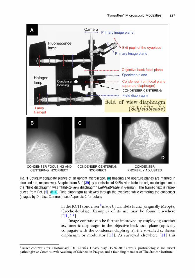
The chief advantage of the Kohler illumination method is thatthe light source does not have to be homogeneous for the viewingfield to be evenly bright, so that an ordinary light bulb can be used;the tungsten wire coil is not seriously degrading the image (adiffuser is sufficient to mitigate that). This can be achieved bypositioning the light source in the condenser front focal plane.However, as this would result in exposing the specimen to excessiveheat, it is more practical to place the light source further away, in anoptically conjugate plane (Fig. 1); the collector lens (Fig. 2A, B)serves this purpose. The light source in the microscope is typicallyfixed, and optimal condenser position must be adjusted for eachobjective lens. This adjustment when changing objectives was easierin the so-called pancratic (“all-mighty”) condenser that used to bepart of Zeiss microscopes (e.g., NfpK or Amplival); the condenserposition did not need to be vertically changed, and an internalzooming system was used to achieve Kohler illumination.
2 Off-Axis Illumination and Schlieren (Modulation) Contrast
An important implication of the Kohler illumination principle isthat the condenser can be partly obstructed at its front focal plane(aperture diaphragm level), without introducing luminance inho-mogeneity into the image. In a microscope properly adjusted forKohler illumination, and its condenser diaphragm fully open (ide-ally matching the numerical aperture [NA] of the objective), anaxially symmetrical light beam illuminates the specimen. Nonab-sorbing objects such as unstained living cells are rendered in mini-mal contrast, and very thin ones such as filopodia or lamellipodiaare hardly visible.
Decentering the condenser diaphragm, or asymmetricallyobstructing it results in contrast enhancement. An example isshown in Fig. 2C, D obtained in a slightly different way, in thatan accessory lens (rather than the diaphragm) of the condenser isoffset. The contrast enhancement is greater in optical thickerobjects. Condensers in microscopes made till ~1960s by CarlZeiss (e.g., NfpK from 1960s) and Meopta (e.g., C36Bi) wereequipped with a laterally shifting diaphragm (Fig. 2E) to achievethis effect [9, 10]. In author’s experience, however, a shiftingstraight-edge diaphragm (Fig. 2F) is more efficient, and available
226 Radek Pelc
in the RCH condenser2 made by Lambda Praha (originally Meopta,Czechoslovakia). Examples of its use may be found elsewhere[11, 12].
Image contrast can be further improved by employing anotherasymmetric diaphragm in the objective back focal plane (opticallyconjugate with the condenser diaphragm), the so-called schlierendiaphragm or modulator [13]. As surveyed elsewhere [11] this
Fluorescencelamp
Halogenlamp
Lamp filament
Condenser focusing
CameraPrimary image plane
Exit pupil of the eyepiece
Specimen plane
Field diaphragm
Objective back focal plane
Condenser front focal plane(aperture diaphragm)
Primary image plane
CONDENSER CENTERING
B C
D
CONDENSER FOCUSING AND CENTERING INCORRECT
CONDENSER CENTERING INCORRECT
CONDENSERPROPERLY ADJUSTED
A
Fig. 1 Optically conjugate planes of an upright microscope. (A) Imaging and aperture planes are marked inblue and red, respectively. Adapted from Ref. [39] by permission of© Elsevier. Note the original designation ofthe “field diaphragm” was “field-of-view diaphragm” (Sehfeldblende in German). The framed text is repro-duced from Ref. [5]. (B–D) Field diaphragm as viewed through the eyepiece while centering the condenser(images by Dr. Lisa Cameron); see Appendix 2 for details
2Relief contrast after Hostounsky. Dr. Zdenek Hostounsky (1925-2013) was a protozoologist and insectpathologist at Czechoslovak Academy of Sciences in Prague, and a founding member of The Stentor Institute.
“Forgotten” Microscopic Modalities 227
PelcR
Highlight
PelcR
Highlight
PelcR
Rectangle
PelcR
Text Box
4

CCon
STAGE
Obj
AD
FD
ID
CL
SPECIMEN
A
SHIFTING IRISDIAPHRAGM
CONDENSERE F
SHIFTING EDGE DIAPHRAGM
CONDENSER
D
10 µm
EYEPIECE
OBJECTIVE
CONDENSER
COLLECTOR LENS
B
Fig. 2 Adjustment of a microscope for Kohler and off-axis illumination. (A) Original diagram adapted from Refs.[4], [5]; copyright expired 70 years after author’s death (August Kohler, 1866–1948). Kohler’s portrait is aspublished by Zeiss Microscopy (Jena, Germany). AD Aperture diaphragm (in condenser), CL Collector lens, ConCondenser, FD Field diaphragm, ID Iris diaphragm (inside objective), Obj Objective lens. (B) Field (imaging) andaperture planes. Adapted from Ref. [40]; the origin of this drawing (recently shown in Ref. [41]) may be tracedto Carl Zeiss materials at least 75 years old [10]. (C, D) Off-axis (oblique) illumination obtained by offsetting acondenser accessory lens. Reproduced from Ref. [42]. C Condenser aperture diaphragm viewed through acentering telescope. D Unstained protozoon (Peranema trichophorum) and its separately contrast-optimizedflagellum, otherwise hardly visible in axially symmetrical illumination. (E, F) Off-axis (oblique) illuminationsetups utilizing a shifting diaphragm. E When needed, the shifting-iris diaphragm is swung into a workingposition under the condenser. Reproduced from Ref. [9]. F Dedicated off-axis illumination condenser with ashifting-edge diaphragm. Reproduced from Ref. [12]
228 Radek Pelc
PelcR
Highlight
PelcR
Highlight
PelcR
Highlight
PelcR
Highlight
PelcR
Highlight
PelcR
Highlight
PelcR
Highlight
PelcR
Highlight
PelcR
Highlight
PelcR
Highlight
PelcR
Highlight
PelcR
Highlight
PelcR
Highlight
PelcR
Highlight
PelcR
Highlight
PelcR
Highlight

simple modality was “rediscovered” approx. every 25 years since itwas first published [14], most likely because the papers describing itusually lacked micrographs. Eventually, it matured into Hoffmanmodulation contrast [15], a direct competitor of a noticeably morecostly differential interference contrast (DIC Nomarski) inventedmore than 20 years earlier [16]. Single-sideband edge-enhance-ment microscopy represents yet another variant [17, 18].
At this point, it should be emphasized that in images of greateroptical thickness such as cell clusters, bigger cells or tissue replicasthe setup employing no modulator (i.e., off-axis illumination) ismore suitable (data not shown). In that case the objective aperturefulfills the role of a modulator to some extent [19] when thecondenser diaphragm is open a bit more than required by thenumerical aperture of the objective. This represents a slight depar-ture from the optimal Kohler illumination (i.e., condenser dia-phragm setting exactly matching the numerical aperture of theobjective) as stray light may start contributing to image formation.However, this is usually more than compensated for by improvedimage contrast. It should be noted that the improvement is notvery significant as the objective aperture is circular rather thanstraight (cf. the text above on the condenser shifting diaphragms(Fig. 2E, F)).
3 Abbe Diffraction Apparatus
The abovementioned modulation (schlieren) contrast relies onselectively filtering certain diffraction maxima (orders) at the objec-tive back focal plane, with the aim to improve image contrast. Inbrightfield microscopy, there is no filtering. Darkfield microscopy,on the other hand, represents the other extreme, in that all direct(undiffracted) light, also referred to as the 0th order diffractioncomponent, is blocked. Examples are shown in Subheadings 4and 5.
A classical (the simplest) example of the importance of diffrac-tive phenomena in microscopic image formation is shown in Figs. 3and 4. Preventing the 1st and higher diffractive orders (maxima)from contributing to image formation results in complete disap-pearance from images of the structures (periodically spaced dots)represented by them (Fig. 3B). Likewise, merely increasing theillumination wavelength λ (e.g., by switching from blue to redlight) renders previously visible structures invisible (Fig. 3C, D) asresolution is inversely proportional to wavelength (resolutionlimit ¼ λ/2NA [1, 2]).
The first of these phenomena can be demonstrated with the aidof an objective with a built-in iris diaphragm. For example, theNikon �100/0.50�1.30 objective offers the option to gradually
“Forgotten” Microscopic Modalities 229

reduce its numerical aperture from 1.30 down to 0.50 (resolutionworsens 1.30/0.50 ¼ 2.6-fold).
In order to convince the scientific community that the diffrac-tion theory of image formation [1, 2] is indeed valid [20] theso-called Abbe Diffraction Apparatus was designed, and later alsomade commercially available by Carl Zeiss [8, 21]. Nowadays, itmay be occasionally found on eBay. Its components are shown inFigs. 4 and 5, including the effects on images of passing or blockingspecific diffraction maxima (Fig. 4). False structures (lines nonexis-tent in the specimen) appear in the image if only the 1st diffractionmaxima are blocked because the spatial frequency (line density)seemingly increases. One may say that the 0th and 2nd diffractionorder rays “do not know” the 1st diffraction order rays are missing,and interfere with each other as usual, but this time forming anonrealistic image.
Similar demonstrations have been described [22] and illu-strated [23] in greater detail elsewhere, most extensively by KurtMichel [24]. They would be surely of great benefit in microscopytraining courses. Earlier, the equipment was referred to as the“Abbe Demonstration Microscope” [8] or the “Pulfrich-Abbe
OPENING OF THE OBJECTIVE APERTURE
BLOCKED 1st DIFFRACTION MAXIMA
A B C D
NA = 1.40 (full)Green light
NA = 0.40Green light
NA = 0.80Blue light
NA = 0.80Red light
2 µm
0th
1st
1st1st
1st1st
1st0th
1st
1st
1st
1st1st
1st
0th
Fig. 3 Diffractive nature of microscopic image formation. Diatom (Pleurosigma angulatum) viewed with a high-resolution, oil-immersion objective (�60/0.40 � 1.40) fitted with an iris diaphragm making it possible toadjust its numerical aperture anywhere between maximum (1.40 in A) and minimum (0.40 in B); anintermediate value (0.80) is shown in C and D. (A, C) Inclusion of the 1st order diffraction maxima makesthe periodic structure visible. (B, D) Exclusion of the 1st order diffraction maxima renders the periodicstructure invisible. (C, D) Dependence of resolution on wavelength: blue light resolves the structure, redlight does not. Adapted from Ref. [43]
230 Radek Pelc
PelcR
Highlight
PelcR
Highlight
PelcR
Highlight
PelcR
Highlight
PelcR
Highlight
PelcR
Highlight

DemonstrationMicroscope” [25]. Please note that the phase platesshown in Fig. 5 were not included in the early models as phase-contrast microscopy was only invented in early 1930s.
4 Rheinberg Illumination
Until the invention of phase-contrast microscopy [26] darkfieldand schlieren microscopy were dominating the realm of imagingunstained (nonabsorbing) objects. A modality combining darkfieldand brightfield microscopy became known as Rheinberg illumina-tion [27]. It can render objects under investigation in a color ofchoice, against a background of another color. This is achieved byusing concentric color filters (Fig. 6) inserted into the condenserfilter holder. If the central disc is black and sufficiently large thebrightfield component is not present, and a darkfield image in acolor of choice is obtained (Fig. 6C) [28].
A dedicated condenser called “Mikropolychromar” (Fig. 6A)used to be manufactured by Carl Zeiss since 1933 [8], and found its
NO IMAGE
REALISTIC IMAGE
FALSE IMAGE
IMAGE PLANE
CONDENSERfront focal planediaphragm
OBJECTIVEback focal plane diaphragm
0th only -2nd, 0th, +2ndDIFFRACTION MAXIMA passed-1st, 0th, +1stDIFFRACTION FUNNEL
S1
Fig. 4 Abbe diffraction apparatus in action. This simple device used to be commercially available from CarlZeiss at least since 1937. The objective back focal plane diaphragms are inserted into a slider (S1) in the“diffraction funnel” fitted above the objective of an upright microscope. Depending on which diffractionmaxima are allowed to pass the image looks different (0th order maximum yields no image at all, passing onlythe second order maxima (i.e., blocking the first order one) results in twice higher density of the lines in theimage (i.e., every other line in the image is an artifact). A hypothetical object consisting of vertical parallel linesis considered here, similar to those engraved in the “Diffraction Plate” that is part of the original equipment(Fig. 5). The diffraction funnel is reprinted from Carl Zeiss catalogue, “Der Diffraktions-Apparat nach Abbe”(Druckschrift “Mikro 11-432-1” dated 1940)
“Forgotten” Microscopic Modalities 231

use, for example, in studying intracellular motility [29]. Eastman-Kodak Co. was supplying Wratten-Rheinberg filter sets for thismicroscope [8, 30]. Thread cells of hagfish slime gland [31, 32]could be conveniently visualized under Rheinberg illuminationusing custom-made color filters (Fig. 6D). It should be notedthough that the Mikropolychromar is in fact a simple condenser,not a dedicated darkfield one, and as such only performs well atsmaller magnifications. An excellent recent review about Rheinbergillumination is available [33].
A dedicated darkfield condenser capable of mixing brightfieldand darkfield images was also made and referred to as the “Quick-Change-Over” condenser (Fig. 7A) [30], implying the ease ofswitching between brightfield and darkfield. The author has notencountered any images arising from its use. An interesting
LAMPHOUSE SLIT
SLIDERS Eyepiece pinhole
(‘diopter’)Substage diffuser
Clip-M
Eyepiecex16 DIFFRACTION PLATE
(testing specimen)
Achromatic objective x6.3/0.20
D-FunGround glass insert
S1 S2
Clip-M = Clip-on magnifierD-Fun = Diffraction funnel
CONDENSER
COLOR FILTERS
Fig. 5 Abbe diffraction apparatus at rest. The “diffraction plate” hosts microscopic gratings as testing objects.The red box highlights (left) five aperture stops (masks), and (right) two phase (“retardation”) plates andcorresponding substage condenser diaphragms. Each of the masks and phase plates fits in the S1 sliderinserted into the diffraction funnel (D-Fun) mounted above an objective. The S2 slider is fitted with a variablediaphragm, and enables experiments shown in Fig. 3 even if the objective is not fitted with the iris diaphragm.To directly examine the (intermediate) image of the specimen the eyepiece may be replaced with a ground-glass insert. The diffraction pattern generated by the specimen is inspected either with a clip-on magnifier(Clip-M) above the eyepiece (with an effect of either a centering [“phase”] telescope or Bertrand lens) or withan eyepiece pinhole (“diopter”). Details may be found in Ref. [21]. Image (unmarked) reprinted by permissionof © The Trustees of the National Museums of Scotland (Edinburgh, UK) where this piece of equipment (madeca. 1970) is held
232 Radek Pelc
PelcR
Rectangle

B
MIK
RO
PO
LYC
HR
OM
AR A
BRIGHT FIELD
DARK FIELD
500 µm
C
x5
A B C D
50 µm D20 µm
x2
BF
SEM
20 µm
Fig. 6 Rheinberg illumination. Color discs shown at the bottom (A-D) were used to obtain the images. (A) TheMikropolychromar condenser (aplanatic) capable of mixing brightfield and darkfield images. As it is not adedicated darkfield condenser it is suitable for low-power objectives only (cf. Fig. 7a). Reproduced from CarlZeiss catalogue, “Mikropolychromar” (Druckschrift “Mikro 493/II” from 1938). (B) Lens-cleaning paper.Original magnification �50, image width ca. 2 mm. Courtesy of © Stephen W. Downing (University ofMinnesota Medical School-Duluth Campus [Duluth, MN, USA]), originally presented in a 1980 photomicrogra-phy competition (https://www.nikonsmallworld.com/people/steve-downing). (C) Proboscis of a house cricket(Acheta domesticus) in pure darkfield (the brightfield component is blocked). Courtesy of © Stefano Barone(Diatom Lab, Italy; www.diatomshop.com, www.testslides.com). Image originally presented in a 2014photomicrography competition (https://www.nikonsmallworld.com/people/stefano-barone), and a similar oneelsewhere [28]. (D) Two thread cells of a hagfish slime gland, with the threads unwinding. Correspondingbrightfield (BF) and SEM images are shown. Courtesy of © Stephen W. Downing (University of MinnesotaMedical School-Duluth Campus [Duluth, MN, USA])
“Forgotten” Microscopic Modalities 233
PelcR
Highlight
PelcR
Highlight
PelcR
Highlight
PelcR
Highlight
PelcR
Highlight

accessory of darkfield condensers is the so-called Traviss expandingstop, essentially an iris diaphragm working in reverse (Fig. 7B).Jointly with the standard iris diaphragm, light annulus of anydiameter and thickness can be produced. This is helpful in correctlyadjusting darkfield illumination [34]. The Traviss stop used to bemanufactured by W. Watson & Sons (London) [8].
5 Heine Condenser and Incident Illumination
The examples shown in the previous section (Rheinberg illumina-tion) illustrate the capabilities of darkfield microscopy. A moreadvanced option was available in the form of the Heine condenser(Fig. 8A, B). This was a variant of the cardioid condenser (the shapeof its mirror is derived from the cardioid curve), that is, a dedicateddarkfield condenser performing well not only at small magnifica-tions. Additionally, it enabled easy switching not only to brightfieldbut also to phase-contrast imaging [35, 36]. The cardioid con-denser alone (inset in Fig. 8B), that is, without the phase-contrastmodality add-on, makes it possible to visualize, for example, singleunstained microtubules (Fig. 8C), and to follow their dynamicinstability (Fig. 8D). Darkfield imaging provides better contrast inimages of single microtubules than other suitable label-free mod-alities such as interferometric scattering [37] or interference reflec-tion [38] microscopy.
c cp p
D
ID ID
ED
BF
DFDF
BF
Control arm
TRAVISS STOP(expanding diaphragm, ED)
W. Watson & Sons
(London)
Lamelae
A B
Fig. 7 Darkfield microscopy aided by Traviss stop. (A) Dedicated darkfield condenser for mixing darkfield andbrightfield illumination. It used to be manufactured by Leitz, and marketed as the “Quick-Change-Over”condenser. BF Brightfield. C Central rays for darkfield illumination. D Diffusely reflecting surface generatingbrightfield illumination. DF Darkfield. ED Expanding diaphragm (Traviss stop). ID Iris (aperture) diaphragm.p Peripheral rays for brightfield illumination. (B) The Traviss stop made the use of a darkfield condenser morestraightforward, even though originally not part of the type shown here. Image A is adapted from Ref.[10]. Image B is based on Ref. [34] (copyright expired 70 years after author’s death; Edmund J. Spitta,1853–1921 [20]), as adapted in Ref. [44] (reprinted by permission of © Macmillan Magazines/Springer)
234 Radek Pelc
PelcR
Highlight
PelcR
Highlight
PelcR
Highlight
PelcR
Highlight
PelcR
Highlight
PelcR
Highlight
PelcR
Highlight
PelcR
Highlight
PelcR
Highlight

More recently, a revival of the combined illumination schemehas been presented in an incident illumination setup (Fig. 9) bettersuited to inspect, for example, tissue surfaces. As it also providesdarkfield and phase-contrast images, complementary image infor-mation can be conveniently obtained (Fig. 9B, C). It is inspired bythe “Ultropak” device (Leitz) which did not offer the phase-contrast modality.
BRIGHT FIELD
PHASE CONTRAST
BRIGHT FIELD
DARK FIELD
DARK FIELD
Z = phase ring L’ = illuminating light
HEINE CONDENSER
cardioid condenser
Distance (µm) of microtubule tip from a reference point
2
4
6
0 2010 Time (min)AC
BD
5µ
msingle microtubule
Fig. 8 Heine condenser. (A, B) The Heine condenser is based on the cardioid (i.e., dedicated darkfield)condenser, and makes it possible to gradually change from one modality to another (brightfield, darkfield andphase contrast). The main image is reproduced from Leitz catalogue № 51.3-5a/Engl.–X/60/FY/L (early1950s). The photograph of the condenser (complete with a screwable lens for use of immersion oil) was takenby Peter Hobel (Erlangen, Germany; http://www.mikroskopie-ph.de/index-Heine.html). The ray diagram (bot-tom right) is reproduced from Ref. [10]. (C, D) Time-lapse imaging of a single unstained microtubule bydarkfield microscopy, using the cardioid condenser (inset in B). Microtubule growth and shortening (dynamicinstability) can be followed; microtubule tip is the plus end. Adapted from Ref. [45] by permission of © NaturePublishing Group (Springer)
“Forgotten” Microscopic Modalities 235
PelcR
Highlight
PelcR
Highlight
PelcR
Highlight
PelcR
Highlight

6 Camera Lucida and Comparison Microscopy
The drawing attachment (tube) often referred to as camera lucida,literally “light chamber,” used to be commonplace in microscopylaboratories even when photomicrography was already widely used.When using it, the microscopist is simultaneously viewing the cellunder the microscope, and his/her drawing of that cell (Fig. 10A).Semi-transparent mirror (beam splitter) project the drawing intothe eyepieces. Naturally, both images should be of comparablebrightness, and built-in rotatable polarizing filters, for example, incamera lucida made by Carl Zeiss (“Zeichenapparat”) facilitatethat.
Nowadays, software is available to skeletonize cell images, thatis, to convert their grayscale representations (typically 8-bit, 0 to255) to line-drawing type images (one-bit models). Nevertheless, itis still often more convenient to draw the images manually withcamera lucida (Fig. 10B). The drawings of neurons by Ramon yCajal (1852–1934) of course represent a classical example.3
A need often arises to view two similar scenes (specimens)simultaneously. For this purpose, a so-called comparison micro-scope may be conveniently employed. It in fact consists of twoseparate microscopes connected with a special (dual) eyepiece
BBRIGHT FIELD
Phase contrast
~100 µm C
DARK FIELD
Specimen
A
DiaphragmBright field Phase contrast
ULTROPAK
Phase plate
Dark fieldPhase contrast
Phase plate
Fig. 9 Incident illumination. (A) Vertical illuminators inspired by the “Ultropak” (Leitz) which was not fitted witha phase plate. Various modalities (color-coded in the image) and their combinations may be obtained,depending on the annular diaphragm(s) used (small, large or both). The drawings are adapted from Refs.[46, 47] by permission of © Cambridge University Press. The photograph is reproduced from Leitz catalogue№ 513-36a/Engl (1965). (B, C) Filamentous algae in incident illumination; note complementary rendering inbrightfield, darkfield, and phase-contrast. Reprinted from Ref. [46] by permission of © Cambridge UniversityPress
3 The Beautiful Brain (Abrams Books 2017, ISBN: 9781419722271)
236 Radek Pelc
PelcR
Highlight
PelcR
Highlight
PelcR
Highlight
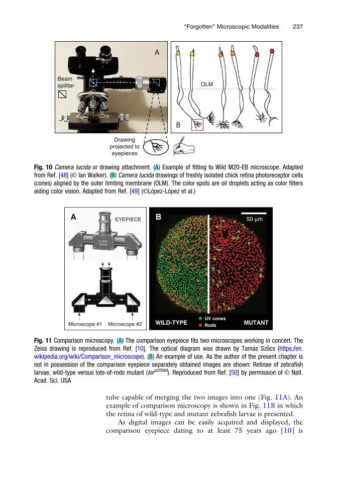
tube capable of merging the two images into one (Fig. 11A). Anexample of comparison microscopy is shown in Fig. 11B in whichthe retina of wild-type and mutant zebrafish larvae is presented.
As digital images can be easily acquired and displayed, thecomparison eyepiece dating to at least 75 years ago [10] is
OLM
B
A
Drawing projected to eyepieces
Beam splitter
Fig. 10 Camera lucida or drawing attachment. (A) Example of fitting to Wild M20-EB microscope. Adaptedfrom Ref. [48] (© Ian Walker). (B) Camera lucida drawings of freshly isolated chick retina photoreceptor cells(cones) aligned by the outer limiting membrane (OLM). The color spots are oil droplets acting as color filtersaiding color vision. Adapted from Ref. [49] (©Lopez-Lopez et al.)
A 50 µmB
WILD-TYPE MUTANTUV conesRods
EYEPIECE
Microscope #1 Microscope #2
A
Fig. 11 Comparison microscopy. (A) The comparison eyepiece fits two microscopes working in concert. TheZeiss drawing is reproduced from Ref. [10]. The optical diagram was drawn by Tamas Szocs (https://en.wikipedia.org/wiki/Comparison_microscope). (B) An example of use. As the author of the present chapter isnot in possession of the comparison eyepiece separately obtained images are shown: Retinae of zebrafishlarvae, wild-type versus lots-of-rods mutant (lorp25bbt). Reproduced from Ref. [50] by permission of © Natl.Acad. Sci. USA
“Forgotten” Microscopic Modalities 237
PelcR
Highlight
PelcR
Highlight
PelcR
Highlight
PelcR
Highlight

nowadays hardly encountered in biological laboratories. However,it is still useful in situations when only one digital camera is avail-able, or when routine comparative observations are made. Indeed,dedicated comparison microscopes, inseparable from each other,have been commercially available at least since 1935. Examples ofsituations where comparative microscopy is useful include patho-logical, biological, forensic, and industrial laboratories specializing,for example, in the following [8]:
1. Examining tissue in health and disease
2. Identifying powdered adulterated drugs
3. Biological systematics (inspecting unknown vs. type specimen)
4. Identifying crystals, hair, or textile fibers from a crime scene
5. Comparing optical performance of two microscopes
Acknowledgments
The author is grateful to Dr. Petro Khoroshyy (Czech Academy ofSciences, Prague) and Dr. Floris G. Wouterlood (Amsterdam Uni-versity Medical Centers) for helpful comments, and acknowledgessupport via Ministry of Education projects: Chiral Microscopy(LTC17012) and ChemBioDrug.4
Appendix 1 (Hands-on Demonstration)
Diffraction and ResolutionInspect a diatom specimen5 using an objective fitted with a
built-in iris diaphragm (e.g., Nikon �100/0.50 � 1.30) at differ-ent settings (i.e., different effective numerical aperture, NA). In thisway, it is possible to artificially reduce the objective’s resolvingpower to the extent (NA ¼ 0.40 in our example) that the finestdetails in the diatom image completely disappear (Fig. 3B).
Alternatively, use an ordinary objective (having no iris dia-phragm) jointly with a diffraction funnel fitted under the ocularhead of an upright microscope. Insert S2 slider (with a built-in irisdiaphragm) into the funnel (Figs. 4 and 5).
Inspect the objective back focal plane using a centering(“phase”) telescope or Bertrand lens6 to monitor the diffractionmaxima of different orders while closing and opening the dia-phragm in (or above) the objective lens. Typically, 0th and 1st
4CZ.02.1.01/0.0/0.0/16_019/00007295Available, for example, from Diatom Lab (www.diatomshop.com, www.testslides.com)6The Bertrand lens is an extra focusable lens that, when inserted into the optical path, works in conjunction withthe eyepiece to form a small telescope to give a magnified view of the objective back focal plane.
238 Radek Pelc

order maxima will be visible (the former representing direct orundiffracted light).
Note that the diffraction patterns may be clearly observed onlywith the condenser aperture diaphragm closed as much as possible(down to a “pinhole”).
Illuminate the diatom specimen with light of different wave-lengths. Blue light (shorter wavelength, ca. 450 nm) is more likelyto resolve fine details than red light, ca. 700 nm) as the resolvingpower is inversely proportional to NA. For this effect to be suffi-ciently prominent, the objective (or S2 slider) iris controlling theeffective NA needs to be set to an appropriate value (0.80 in theexample shown in Fig. 3C, D), as checked by viewing the diffrac-tion patterns in the objective back focal plane.
Be aware that different diatom species feature structures ofdifferent periodicities.
Appendix 2 (Exercise)
Setting Kohler Illumination(minor adaptation of a text originally written by Dr. Lisa
Cameron, Light Microscopy Core Facility, Duke University, Dur-ham, NC, USA)
Following is a step-by-step protocol for Kohler illuminationwith transmitted light. An interactive version is also available at theonline Microscopy U(niversity)7 and elsewhere8. For informationon focusing the light source, please see the “Focusing the lightsource” section further below.
First, open all diaphragms. Raise the condenser to its highestpoint (on an upright microscope). Put a well-stained specimen onthe stage, and inspect it with a low power (10�) objective.
Focus the objective lens to obtain a sharp image of the speci-men by using the coarse and fine focus controls. This first step setsthe correct relationship between the specimen and objective lens.
On a binocular microscope, each user may need to adjust theeyepieces for their own eyes for optimal focus. At least one eyepiecewill have an adjustment collar. Use one eye to look down themicroscope and focus on some detail in the specimen while keepingthe eye which uses the eyepiece with adjustable collar closed. Thenswitch and use the other eye. Turn the adjustable eyepiece collar tofocus the same detail in the image as sharp as before. This procedureis referred to as diopter adjustment and is recommended every timea microscope is used, for the sake of microscopist’s visual comfort.
7 https://www.microscopyu.com/tutorials/kohler8 https://micro.magnet.fsu.edu/optics/timeline/people/kohler.html
“Forgotten” Microscopic Modalities 239

Setting Kohler illumination is possible without it if using oneeye only.
Focus the condenser by first closing the illuminated field dia-phragm and then adjust the height of the condenser with thecondenser focus knob until a sharp image of the field diaphragmis seen superimposed on the image of the specimen (Fig. 1C). Makesure that the condenser diaphragm is wide open. This adjustmentsets the correct relationship between the condenser lens and thespecimen. If the microscope has an Abbe condenser, this image willlikely have a fringe of color around the field aperture.
Center the condenser lens. To do this, make the image of thefield diaphragm concentric with the field of view (Fig. 1D) usingthe condenser centering screws. This adjustment makes the opticalaxis of the condenser lens coincide with that of the microscope asdefined by the field diaphragm and the objective lens.
Adjust the area of the field that is illuminated. Open the fielddiaphragm until its image is just outside the field of view; readjustthe condenser centering if necessary (as you open it). This ensuresthat illumination falls only on the area of specimen within the fieldof view, and that the diameter of the primary image is only a littlelarger than the field-limiting diaphragm as seen by the eyepiece.This prevents light from falling on the internal walls of the micro-scope to be scattered to produce hot spots and haze, reducingcontrast in the final image.
Adjust the aperture diaphragm (illuminating aperture) in thecondenser. To do this, remove the eyepiece, or turn the Bertrandlens into position if available—look down the microscope tubefrom ca. 100 mm above the tube, and observe the back focalplane of the objective, the disc of light at the base of the tube.More conveniently, use a centering (“phase”) telescope in place ofthe eyepiece, in the same way as during adjustment of the annulardiaphragm for phase-contrast imaging. Close the aperture dia-phragm until the image of the iris is approximately 70–80% of theviewing field (the aperture of the objective). Replace the eyepiece(or remove the Bertrand lens). The working (effective) aperture ofthe condenser is now slightly smaller than the aperture of theobjective lens. Do not close the diaphragm too far; this will causea serious deterioration in the quality of the image.
Adjust the brightness of illumination using the control on thelamp power supply, or by inserting neutral density filter(s). Theseare usually found along the base of the microscope between thelamp and the field diaphragm. The microscope optical adjustmentsor diaphragms should not be used to control brightness. This willadversely affect the quality of the image. For instance, if the con-denser diaphragm is closed too much, the image will appear toocontrasty, as refractile structures will be highlighted too much dueto diffraction effects; and with it wide open, there will be glare dueto stray light (internal reflections). The resolution is poor in both.
240 Radek Pelc

In a microscope with absolutely no internal reflections the setting isoptimal when the effective numerical aperture of the condenser(adjustable by its diaphragm) matches the NA of objective in use.As such microscopes do not exist in reality the abovementionedsetting of ca. 70–80% is recommended. Image contrast is slightlyimproved yet the diffraction artifacts thus introduced are minimal.
For a higher power objective:Rotate the nosepiece to the 40� dry objective. Owing to parfocal-ity of objective design, the 40� objective should be almost in focusafter aligning the microscope for 10�; it was not the case in very oldmicroscopes.
As before, focus and center the image of the field diaphragmusing the condenser focus knob and the condenser centeringknobs. The aperture of the field diaphragm will need to bereadjusted.
Remove an eyepiece (ideally replace it with the centering[“phase”] telescope), or use the Bertrand lens to observe the backfocal plane of the objective. Notice that the area illuminated for thelow power objective is much smaller than the diameter of the backaperture of the 40� objective.
Adjust the condenser diaphragm so that the effective NA of thecondenser is about the same as the objective NA.
For a high-power oil immersion objective:Rotate the nosepiece so that a high-power oil immersion objectiveis near-vertical. Just before it is clicked into place, stop and add oilto the coverslip, as close as possible to the optical axis (light beamcoming from condenser prealigned at smaller magnifications, seeabove). Be sure the oil droplet does not have any bubbles. Useimmersion oil provided by the microscope manufacturer, as thereare some slight differences. Ideally, the refractive index of the oil,coverslip, and objective lenses should be the same.
Click the oil immersion objective into place. The space betweenthe front lens of the objective and the coverslip should now be filledwith oil.
Remove an eyepiece (ideally replace it with the centering[“phase”] telescope) or use the Bertrand lens to view the backaperture of the objective. Open the condenser diaphragm to almostfill the objective aperture.
Replace the eyepiece (or remove the Bertrand lens) and observethe specimen. Adjust the field diaphragm until the edge justmatches the field of view. Strictly speaking, the condenser shouldagain be readjusted as above (focus and centering). However,switching from �40 to �100 objective will rarely misalign thecondenser beyond tolerable limit.
“Forgotten” Microscopic Modalities 241

Focusing the light source:Remove the diffuser from the lamp housing or along the base of themicroscope stand, if possible, in order to see bulb and filament.Lamp illumination should fill most of the front aperture of thecondenser. Put a sheet of lens paper on the specimen stage to helpvisualize the area of illumination. Focus light on the lens paper bymoving the lamp-focusing knob. Then remove the eyepiece (ideallyreplace it with the centering [“phase”] telescope) or insert theBertrand lens to view the back focal plane of the objective. Besure the lamp filament is centered and focused in the plane of thecondenser diaphragm. Adjust the collector lens on the lamphousing.
N.B.: Many student microscopes and more recently releasedmodern research ones do not have illumination bulb adjustments,but are designed to deliver even illumination.
References
1. Abbe E (1874/1875) A contribution to thetheory of the microscope, and the nature ofmicroscopic vision. Proceedings of the BristolNaturalists’ Society (new series) 1(Pt 2):200–261 (translated and commentedon by H. E. Fripp). https://biodiversitylibrary.org/page/7506100
2. Abbe E (1873) Beitr€age zur Theorie des Mik-roskops und der mikroskopischen Wahrneh-mung. (Schultze’s) Archiv fur MikroskopischeAnatomie (Bonn) 9:413–468. https://doi.org/10.1007/BF02956173. BHL:13290331.https://biodiversitylibrary.org/page/13290331
3. Sheppard CJR (2017) Resolution and super-resolution. Microsc Res Tech 80(6):590–598.https://doi.org/10.1002/jemt.22834
4. Kohler A (1893) Ein neues Beleuchtungsver-fahren fur mikrophotographische Zwecke.Zeitschrift fur Wissenschaftliche Mikroskopieund fur Mikroskopische Technik 10(4):433–440. https://biodiversitylibrary.org/page/3013561
5. Kohler A (1894) New method of illuminationfor photomicrographical purposes. J RoyMicrosc Soc (volume not numbered, Aprilissue):261–262. https://biodiversitylibrary.org/page/49603250
6. Abbe E (1873) Ueber einen neuen Beleuch-tungsapparat am Mikroskop. (Schultze’s)Archiv fur Mikroskopische Anatomie (Bonn)9:469-480. https://doi.org/10.1007/BF02956177. BHL:13290387. https://biodiversitylibrary.org/page/13290387
7. Abbe E (1875) A new illuminating apparatusfor the microscope. Monthly Microscopical J
13:77–82. https://biodiversitylibrary.org/page/14276730
8. Needham GH (1958) The practical use of themicroscope. Charles C Thomas, Springfield,IL. https://lccn.loc.gov/57010440
9. Metzner P (1928) Das Mikroskop, 2nd edn.Franz Deuticke, Leipzig/Vienna
10. Wolf J (1944) Mikroskopicka technika. Vesmır,Prague
11. Hostounsky Z, Pelc R (2006) An efficient wayof high-contrast, quasi-3D cellular imaging:off-axis illumination. J Biochem BiophysMeth 68(1):23–30. https://doi.org/10.1016/j.jbbm.2006.03.016
12. Hostounsky Z, Pelc R (2007) Phase-contrastversus off-axis illumination: is a more complexmicroscope always more powerful? Adv PhysiolEduc 31(2):232–235. https://doi.org/10.1152/advan.00028.2006
13. Axelrod D (1981) Zero-cost modification ofbright field microscopes for imaging phase gra-dients on cells: Schlieren optics. Cell Biophys 3(2):167–173. https://doi.org/10.1007/BF02788132
14. Topler A (1866) Ueber die Methode derSchlierenbeobachtung als mikroskopischesHulfsmittel, nebst Bemerkungen zur Theorieder schiefen Beleuchtung. (Poggendorf’s) AnnPhys Chem 127(4):556–580. [Ann Phys 203(4):556–580]. https://doi.org/10.1002/andp.18662030405
15. Hoffman R, Gross L (1975) The modulationcontrast microscope. Nature 254:586–588.https://doi.org/10.1038/254586a0
242 Radek Pelc

16. Padawer J (1968) The Nomarski interference-contrast microscope. An experimental basis forimage interpretation. J Microsc (Oxf) 88(Pt3):305–349. https://doi.org/10.1111/j.1365-2818.1968.tb00616.x
17. Bretschneider F, Teunis PFM (1994) Reduced-carrier single-sideband microscopy: a powerfulmethod for the observation of transparentmicroscopical objects. J Microsc (Oxf) 175(Pt2):121–134. https://doi.org/10.1111/j.1365-2818.1994.tb03475.x
18. Inoue S, Spring K (1997) Video microscopy:the fundamentals. Plenum Press (Springer),New York. ISBN: 978-0306455315
19. Murphy DB, Davidson MW (2012) Funda-mentals of light microscopy and electronicimaging, 2nd edn. Wiley-Blackwell,New York. https://doi.org/10.1002/9781118382905
20. Bradbury S (1996) The reception of Abbe’stheory in England. Proc Roy Microsc Soc 31(4):293–299. http://www.microscopist.co.uk/wp-content/uploads/2017/04/The-reception-of-Abbes-Theory-in-England.pdf
21. Nuttall B (2008) Image formation in themicroscope: the Abbe diffraction apparatus.Bull Sci Instr Soc 96:27–29
22. Fripp HE (1876/1877) On professor Abbe’sexperimental demonstration of diffractionspectra in the microscope. Proc Bristol Natur-alists’ Soc (new series) 2(Pt 1):24–38.BHL:7545726. https://biodiversitylibrary.org/page/7545726
23. Stephenson JW (1877) Observations on pro-fessor Abbe’s experiments illustrating his the-ory of microscopic vision. MonthlyMicroscopical J 17:82–88. BHL:14157879.https://biodiversitylibrary.org/page/14157879
24. Michel K (1964) Die Grundzuge der Theoriedes Mikroskops in elementarer Darstellung(Physik und Technik), vol 1. WissenschaftlicheVerlagsgesellschaft, Stuttgart
25. Wetzel RA, Needham GH (1928) Somephotographs of optical images after Abbe.Washington Meeting of the American PhysicalSociety (Washington, D.C., 20–21 Apr 1928).Phys Rev 31(6):1108. https://doi.org/10.1103/PhysRev.31.1108
26. Zernike F (1955) How I discovered phase con-trast. Science 121(3141):345–349. https://doi.org/10.1126/science.121.3141.345
27. Rheinberg J (1896) On an addition to themethods of microscopical research, by a newway of optically producing colour-contrastbetween an object and its background, orbetween definite parts of the object itself. J
Roy Microsc Soc (volume not numbered,August issue):373–388. https://biodiversitylibrary.org/page/49597776
28. Gautier C (2012) Proboscis (“tongue”) of acricket (Gryllus campestris) under Rheinbergillumination. The Scientist (Image of the Day,30 Oct 2012) https://www.the-scientist.com/image-of-the-day/image-of-the-day-40285and Nikon Small World https://www.nikonsmallworld.com/people/christian-gautier
29. Bunning E (1935) Einige Beobachtungen uberdie Kornchenstromung in den Staubfadenhaa-ren von Tradescantia, nebst Bemerkungen uberdie Verwendbarkeit des Mikropolychromarsbei zellphysiologischen Studien. Zeitschrift furwissenschaftliche Mikroskopie und fur mikros-kopische Technik 52(2):166–172
30. Shillaber CP (1959) Photomicrography in the-ory and practice, 5th edn. John Wiley & Sons,New York (Chapman & Hall, London)
31. Downing SW, Spitzer RH, Salo WL, DowningJS, Saidel LJ, Koch EA (1981) Threads in thehagfish slime gland thread cells: Organization,biochemical features, and length. Science 212(4492):326–328. https://doi.org/10.1126/science.212.4492.326
32. Downing SW, Spitzer RH, Koch EA, Salo WL(1984) The hagfish slime gland thread cell. I. Aunique cellular system for the study of interme-diate filaments and intermediate filament-microtubule interactions. J Cell Biol 98(2):653–669. https://doi.org/10.1083/jcb.98.2.653
33. Havics AA (2014) Contrast methods inmicroscopy: Rheinberg illumination. TheMicroscope 62(4):157–169
34. Spitta EJ (1907) Microscopy. The construc-tion, theory and use of the microscope. E. P.Dutton & Co, New York
35. Gottschewski GHM (1953) €Uber die Anwen-dungsmoglichkeiten der neuen Leitz-Phasenkontrasteinrichtung nach Heine. Zeits-chrift fur Wissenschaftliche Mikroskopie undfur Mikroskopische Technik 61(4):185–200
36. James P (2003) The Heine condenser (Part1 and 2). Micscape, issue 95 http://www.microscopy-uk.org.uk/mag/sep03ind.htmland 97 http://www.microscopy-uk.org.uk/mag/nov03ind.html
37. Andrecka J, Arroyo JO, Lewis K, Cross RA,Kukura P (2016) Label-free imaging of micro-tubules with sub-nm precision using interfero-metric scattering microscopy. Biophys J 110(1):214–217. https://doi.org/10.1016/j.bpj.2015.10.055
“Forgotten” Microscopic Modalities 243

38. Mahamdeh M, Simmert S, Luchniak A,Sch€affer E, Howard J (2018) Label-free high-speed wide-field imaging of single microtu-bules using interference reflection microscopy.J Microsc 272(1):60–66. https://doi.org/10.1111/jmi.12744
39. Rottenfusser R (2013) Proper alignment of themicroscope. Meth Cell Biol 114:43–67.https://doi.org/10.1016/B978-0-12-407761-4.00003-8
40. Bradbury S, Evennett PJ, Haselmann H, PillerH (1989) RMS dictionary of light microscopy(RMS Handbook №15). Oxford UniversityPress and Royal Microscopical Society, Oxford.ISBN: 978-0198564218
41. Sanderson J (2019) Understanding lightmicroscopy. Wiley (RMS series), Hoboken,NJ. ISBN: 978-0470973752
42. Wessenberg H, Reed MK (1971) The use ofoblique illumination in microscopic observa-tions of living protozoa. Trans Am MicroscSoc 90(4):449–457. https://jstor.org/stable/3225459
43. Michel K (1943) Grundzuge der Mikrophoto-graphie. In: Zeiss Nachrichten, Sonderheft(special issue), vol 4, 2nd edn. Kommissions-verlag Gustav Fischer, Jena, pp 1–192
44. Amos WB (2000) Lessons from the history ofmicroscopy. Nat Cell Biol 2(8):E151–E152.https://doi.org/10.1038/35019639
45. Horio T, Hotani H (1986) Visualization of thedynamic instability of individual microtubules
by dark-field microscopy. Nature 321(6070):605–607. https://doi.org/10.1038/321605a0
46. Piper T, Piper J (2012) Variable phase dark-field contrast – a variant illumination techniquefor improved visualizations of transparent spe-cimens. Microsc Microanal 18(2):343–352.https://doi.org/10.1017/S1431927612000153
47. Piper T, Piper J (2013) Variable phase bright-field contrast – an alternative illumination tech-nique for improved imaging in transparent spe-cimens. Microsc Microanal 19(1):11–21.https://doi.org/10.1017/S1431927612013323
48. Walker I (2005) Wild M20-EB microscope.Micscape, issue 122 http://www.microscopy-uk.org.uk/mag/dec05ind.html
49. Lopez-Lopez R, Lopez-Gallardo M, Perez-Alvarez MJ, Prada C (2008) Isolation of chickretina cones and study of their diversity basedon oil droplet colour and nucleus position. CellTiss Res 332(1):13–24. https://doi.org/10.1007/s00441-007-0572-6
50. Alvarez-Delphin K, Morris AC, Snelson CD,Gamse JT, Gupta T, Marlow FL, Mullins MC,Burgess HA, Granato M, Facool JM (2009)Tbx2b is required for ultraviolet photoreceptorcell specification during zebrafish retinal devel-opment. Proc Natnl Acad Sci U S A 106(6):2023–2028. https://doi.org/10.1073/pnas.0809439106
244 Radek Pelc

N E U R O M E T H O D S
Series Editor
Wolfgang Walz
University of Saskatchewan
Saskatoon, SK, Canada
For further volumes:
http://www.springer.com/series/7657
Cite the chapter as:
Pelc R. (2020) Beyond brightfield: “Forgotten” microscopic modalities.
In: Neurohistology and Imaging Techniques (Neuromethods 153), pp. 225-244
(Pelc R., Walz W. & Doucette J.R., eds.). Springer (Humana Press), New York.
DOI: 10.1007/978-1-0716-0428-1_8
https://doi.org/10.1007/978-1-0716-0428-1
https://www.springer.com/gp/book/9781071604267
View
publication statsV
iew publication stats


![Microscopic and macroscopic creativity [Comment]](https://static.fdokumen.com/doc/165x107/63222cba63847156ac067f99/microscopic-and-macroscopic-creativity-comment.jpg)