Micropropulsion devices with pulsed optical lattices / gas nonresonant dipole interaction
12
44th AIAA Aerospace Sciences Meeting and Exhibit, 9 - 12 Jan 2006, Reno, Nevada Micropropulsion devices with pulsed optical lattices / gas nonresonant dipole interaction Mikhail N. Shneider * Princeton University, Princeton, NJ 08544 Cedrick Ngalande † and Sergey F. Gimelshein ‡ University of Southern California, Los Angeles, 90089 The direct simulation Monte Carlo method is used to study the feasibility of new propul- sion concepts based on the interaction of an optical lattice with gas molecules. Two regimes are considered, high density and low density. In the first one, a de Laval nozzle is examined with the carrier gas driven by energy and momentum deposition from the lattice to the region near the nozzle throat. Analytical expressions are developed and compared with the numerical predictions, that describe the energy and momentum energy transfer between the lattice and the gas. In the second regime, a multiple orifice flow is considered with molecules accelerated to high velocities by a chirped lattice potential. Specific impulse of about 500 is obtained with the total thrust of over 10 μN per single 100 μm orifice. I. Introduction An optical lattice, which represents a periodic optical dipole potential, is created by the interaction between a polarizable particle and the field of an optical interference pattern formed by counter propagating laser fields. Optical dipole potentials have been used extensively to trap and manipulate ultra cold atoms in the nK to μK range using the optical dipole force. Although these conservative optical forces are weak they are capable of trapping ultra cold atoms, 1, 2 and have been used to guide atoms through optical fibers. 3 Larger potentials in the 100 K range can be produced by high intensity pulsed lasers for shorter time periods where the maximum potential is limited by the probability of multi-photon dissociation and ionization at high laser intensities. These stronger potentials have been used to deflect cold molecules, ∼ 5 K, and, more recently, to dissociate diatomic molecules by strong centrifugal optical forcing. 4 Synchronous acceleration of charged particles to energies in excess of 100 GeV can be achieved using electrostatic and Lorentz forces, and accelerated neutral atomic beams can be created from ion beams by charge capture. 5 Gas dynamic methods that accelerate molecules to velocities greater than 10 km/s (14.5 eV for N 2 ) 6 have been demonstrated, but it is extremely challenging to accelerate neutral molecules above this energy range without a large fraction of the gas being thermally ionized and dissociated. Linear acceleration within the time varying electric field of an accelerated optical traveling wave has been proposed as a means to accelerate atoms to high velocities, 7, 8 and more recently molecular acceleration has been proposed. 9 Linear acceleration using optical fields is attractive because extremely large dipole forces can be produced by high electric field gradients that can be created within an optical traveling wave. The electrodeless electric field gradient produced by a focused laser beam can be orders of magnitude greater than electrostatic gradients, allowing acceleration of not only polar, but also polarizable molecules and atoms. This concept has already been demonstrated with acceleration of ultracold atoms up to the velocities in the m/s range using very weak optical periodic potentials, which are called optical lattices. 10, 11 A one- dimensional optical lattice was created by two counterpropagating laser beams, and acceleration of the lattice was achieved by changing the frequency of the counter-propagating fields (chirping) with respect to time. In contrast to acceleration of ultracold atoms in weak lattices, 10, 11 the authors of Refs. 12, 13 have studied the acceleration of polarizable gas particles, both molecules and atoms, at much higher temperatures (5- 300 K) and to velocities in the 10 to 100 km/s range by application of large lattice potentials created by * Research Scientist, Department of Aerospace and Mechanical Engineering, Senior Member AIAA. † Graduate Student, Department of Aerospace and Mechanical Engineering. ‡ Research Assistant Professor, Department of Aerospace and Mechanical Engineering, Member AIAA. Copyright c 2006 by the authors. Published by the American Institute of Aeronautics and Astronautics, Inc. with permission. 1 of 12 American Institute of Aeronautics and Astronautics Paper 2006-0768
-
Upload
independent -
Category
Documents
-
view
2 -
download
0
Transcript of Micropropulsion devices with pulsed optical lattices / gas nonresonant dipole interaction
44th AIAA Aerospace Sciences Meeting and Exhibit, 9 - 12 Jan 2006, Reno, Nevada
Micropropulsion devices with pulsed optical lattices
/ gas nonresonant dipole interaction
Mikhail N. Shneider∗
Princeton University, Princeton, NJ 08544
Cedrick Ngalande† and Sergey F. Gimelshein‡
University of Southern California, Los Angeles, 90089
The direct simulation Monte Carlo method is used to study the feasibility of new propul-sion concepts based on the interaction of an optical lattice with gas molecules. Two regimesare considered, high density and low density. In the first one, a de Laval nozzle is examinedwith the carrier gas driven by energy and momentum deposition from the lattice to theregion near the nozzle throat. Analytical expressions are developed and compared with thenumerical predictions, that describe the energy and momentum energy transfer betweenthe lattice and the gas. In the second regime, a multiple orifice flow is considered withmolecules accelerated to high velocities by a chirped lattice potential. Specific impulse ofabout 500 is obtained with the total thrust of over 10 µN per single 100 µm orifice.
I. Introduction
An optical lattice, which represents a periodic optical dipole potential, is created by the interactionbetween a polarizable particle and the field of an optical interference pattern formed by counter propagatinglaser fields. Optical dipole potentials have been used extensively to trap and manipulate ultra cold atomsin the nK to µK range using the optical dipole force. Although these conservative optical forces are weakthey are capable of trapping ultra cold atoms,1,2 and have been used to guide atoms through optical fibers.3
Larger potentials in the 100 K range can be produced by high intensity pulsed lasers for shorter time periodswhere the maximum potential is limited by the probability of multi-photon dissociation and ionization athigh laser intensities. These stronger potentials have been used to deflect cold molecules, ∼ 5 K, and, morerecently, to dissociate diatomic molecules by strong centrifugal optical forcing.4
Synchronous acceleration of charged particles to energies in excess of 100 GeV can be achieved usingelectrostatic and Lorentz forces, and accelerated neutral atomic beams can be created from ion beams bycharge capture.5 Gas dynamic methods that accelerate molecules to velocities greater than 10 km/s (14.5 eVfor N2)6 have been demonstrated, but it is extremely challenging to accelerate neutral molecules above thisenergy range without a large fraction of the gas being thermally ionized and dissociated.
Linear acceleration within the time varying electric field of an accelerated optical traveling wave has beenproposed as a means to accelerate atoms to high velocities,7,8 and more recently molecular acceleration hasbeen proposed.9 Linear acceleration using optical fields is attractive because extremely large dipole forcescan be produced by high electric field gradients that can be created within an optical traveling wave. Theelectrodeless electric field gradient produced by a focused laser beam can be orders of magnitude greaterthan electrostatic gradients, allowing acceleration of not only polar, but also polarizable molecules andatoms. This concept has already been demonstrated with acceleration of ultracold atoms up to the velocitiesin the m/s range using very weak optical periodic potentials, which are called optical lattices.10,11 A one-dimensional optical lattice was created by two counterpropagating laser beams, and acceleration of the latticewas achieved by changing the frequency of the counter-propagating fields (chirping) with respect to time.
In contrast to acceleration of ultracold atoms in weak lattices,10,11 the authors of Refs.12,13 have studiedthe acceleration of polarizable gas particles, both molecules and atoms, at much higher temperatures (5-300 K) and to velocities in the 10 to 100 km/s range by application of large lattice potentials created by
∗Research Scientist, Department of Aerospace and Mechanical Engineering, Senior Member AIAA.†Graduate Student, Department of Aerospace and Mechanical Engineering.‡Research Assistant Professor, Department of Aerospace and Mechanical Engineering, Member AIAA.Copyright c© 2006 by the authors. Published by the American Institute of Aeronautics and Astronautics, Inc. with
permission.
1 of 12
American Institute of Aeronautics and Astronautics Paper 2006-0768
pulsed lasers. The latter work follows on from the original work of Kazantsev,7,8 and investigates the motionof trapped and untrapped particles in the velocity phase space of the accelerated optical dipole potential.The dynamics of the accelerating ensemble of polarizable particles under the influence of large dipole orstark forces is examined, and the velocity distribution function of both trapped and untrapped particles ispredicted.12
Recently, the molecular beam formation was also demonstrated in the collisional regime (pressures 3and 10 Torr) by the DSMC method.14 Such molecular beams are of great potential importance for materialprocessing (etching, deposition, etc.), as well as for studying the relaxation processes in gases and gas-surfacecollisions. Another possible application of lattice-accelerated beams of neutral particles is rocket propulsion,where high velocities of trapped particles may result in extremely large specific impulses of lattice-drivenpropulsion devices. At pressures on the order of 1 atm, it is not possible to trap particles and create amolecular beam using a chirped optical lattice. It is possible, however, to transfer the momentum andenergy from a traveling optical lattice to the gas; the optimal phase velocity in this case is close to theaverage gas thermal velocity.13 Microscale thrusters with typical throat diameters of hunderds of micronsto millimeters is one of the possible applications of this type of interaction.
The main goal of this paper is to numerically study new propulsion concepts based on the interactionof an optical lattice with gas molecules in two flow regimes, nearly free-molecule and continuum. Two newmicrothruster schemes are considered for these regimes that use (1) acceleration of molecules to very highvelocities with a linearly chirped lattice, and (2) energy and momentum deposition from an optical latticetraveling at a constant speed into the throat of a microscale nozzle. The estimates of thruster performancecharacteristics are presented and possible ways to improve them are outlined. The direct simulation MonteCarlo method15 (DSMC) is used in this study.
II. Laser beam propulsion
Propulsion concepts based on laser energy deposition, primarily to the solid matter, were proposed asearly as forty five years ago. One of the first studies in the field is presented in Ref.16 where the thrustproduced by molecules vaporized from a target surface due to laser radiation was examined. The process ofsurface ablation and thrust generation by pulsed laser beams has been extensively studied experimentallyand theoretically starting in early 70s17,18 for different chemical composition of the surface. The use of laserbeam propulsion with a terrestrial source of laser energy was proposed in Ref.18 More recent research19
includes the use of high-energy lasers to transmit solar power through free space in the form of coherentlight.
The laser ablation of the surface is not the only known laser-based mechanism of spacecraft thrustgeneration. The laser beam energy may also be used for liquid propulsion thrusters, where the laser energyplays role of the oxidizer, and for air-driven thrusters.20 In the latter concept, the thruster is powered byatmospheric air effectively heated by a laser beam. At present, although lasers did not take on a thrust-producing role of ion engines, the idea of beaming energy from both space- and terrestrial-based lasers topower spacecraft continues to draw interest. A radiatively driven hypersonic wind tunnel has being proposedin Princeton ten years ago21 to provide high enthalpy, high Mach number true air flows for durations ofseconds with high power laser or electron beams as suitable energy sources. The concept has recently beendemonstrated at 1 MW of electron beam energy power.22
The principal difference of the present work from previous studies is that the non-resonant impulse andenergy deposition is used here. This means that only translational and not internal energies of molecules aredirectly changed by laser radiation, and it is therefore possible to avoid or minimize a number of undesirableeffects such as molecular dissociation and ionization, and associated charging and degradation of workingsurfaces.
III. Optical lattices in free molecular and weakly collisional regimes
A periodic optical dipole potential is created by the interaction between a polarizable particle and thefield of an optical interference pattern created by counter-propagating laser fields with wave vectors k1 andk2. The phase velocity of the pattern, and therefore the potential, is given by ξ = Ω/q, where q = |k1 + k2|and Ω = ω1 − ω2.
For molecules far from resonance the force on the molecules within the lattice is given by the quasi-
2 of 12
American Institute of Aeronautics and Astronautics Paper 2006-0768
electrostatic approximation24
F (x, t) = 0.5α∇E(x, t)2
where α is the static molecular polarizability and E(x, t) is the optical electric field. It has been shown12
that the equation of collisionless motion of a particle moving in a pulsed accelerated or decelerated opticallattice is given by
d2x
dt2= −αqE1(t)E2(t)
2msin(qx− βt2),
where E1 and E2 are the amplitudes of the electric fields of the two laser beams, m is the particle mass, andβ is the frequency chirp. Here, the first term of the product represents the maximum force per unit masssupplied by the optical lattice. In a reference frame that accelerates with the optical lattice, this equationmay be conveniently re-written in non-dimensional units,
d2θ
dT 2= −αq
βsin(θ)− 2,
where θ = X − T 2 is the phase of the particle with respect to the accelerated frame, and T =√βt and
X = qx are the nondimensional temporal and spatial variables, respectively. The phase space analysis12
shows that particles with velocities and coordinates that satisfy the requirement∣∣∣ 2βαq∣∣∣ < 1 will be trapped by
accelerated lattice, and their velocities increase with the lattice velocityWith increasing laser beam intensities, the optical lattice potential depth increases and at relatively low
gas densities a large number of gas particles can be trapped and collisionless accelerated. Particle velocitiescan be increased from the room level to 10 - 100 km/s range in a short laser pulse over distances of 100’smicrons.12 The evolution of particles that are distributed over a range of velocities, and over all phases, isdescribed by the Boltzmann equation. For short acceleration periods, acceleration without collisions betweenparticles becomes possible at pressures in the 100 torr range, and the collision integral in this equation canbe set to zero. The results of calculations of particle acceleration using the solution of the collisionlessBoltzmann equation are given in Ref.12
To model the evolution of particles at higher pressures, when the collision time in gas becomes on the orderof the pulse duration, and molecular collisions are important, the full integro-differential Boltzmann equationhas to be solved. One of the most convenient and widely used approaches to the solution of the Boltzmannequation is the DSMC method. This method has been used in all presented computations. The principalcomputational tool used in this work is SMILE, an advanced code based on the DSMC method. Details onthe tool may be found elsewhere.23 The variable hard sphere model is used for intermolecular interactions.The discrete Larsen-Borgnakke model with temperature-dependent rotational relaxation number is utilizedfor rotation-translation energy transfer.
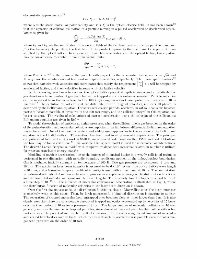
Modeling of particle acceleration due to the impact of an optical lattice in a weakly collisional regime isperformed in one dimension, with periodic boundary conditions applied at the inflow/outflow boundaries.Gas is methane, initially stagnant at temperature of 300 K. Two gas pressure are considered, 3 torr and10 torr. The maximum laser beam intensity is assumed to be 6×10¹⁵ W/m2, the optical lattice wave lengthis 400 nm, and a Gaussian temporal profile of intensity is used with a maximum at 10 ns. The computationis performed with about 3 million molecules to provide an acceptable accuracy of the distribution functions,and the computational domain spans over ten wave lengths. The unsteady flow development is modeled witha time step of 10−12 s. The influence of molecular collisions on acceleration is illustrated in Fig. 1, wherethe distribution function of molecular velocities in the laser beam direction is shown.
Over the first few nanoseconds, the distribution function is close to Maxwellian since the beam intensityis relatively weak at this stage. Then, by forth nanosecond, a bimodal distribution is starting to appear.The separation of trapped molecules from untrapped ones becomes clear at times larger than 6 ns. It is alsoclearly seen that there is a considerable amount of trapped molecules accelerated up to velocities of 15 km/sover the time period of 16 ns for a pressure of 3 torr. The larger number of molecular collisions at 10 torrgenerally reduces the number of trapped particles, since almost all trapped particles that collide with otherparticles leave the potential well as the result of collisions. Still, there is a significant amount of moleculesaccelerated to velocities over 10 km/s, which means that such an acceleration is possible even for collisionalgas with pressures on the order of 10 torr.
3 of 12
American Institute of Aeronautics and Astronautics Paper 2006-0768
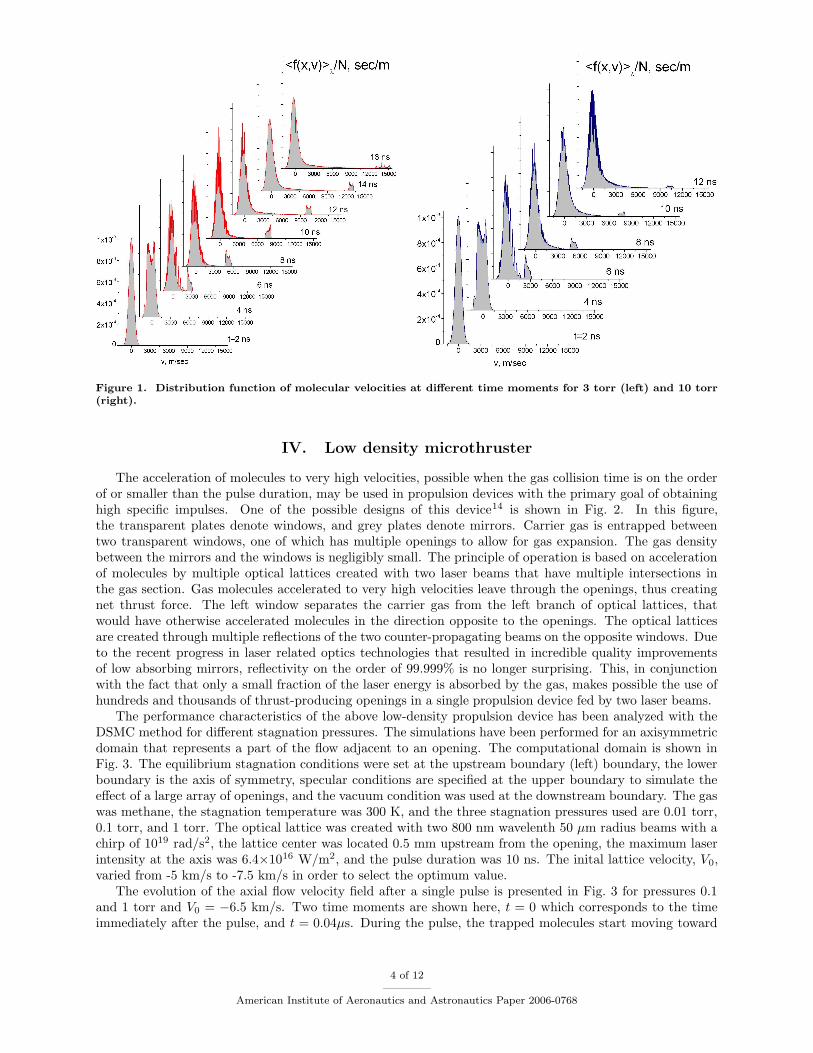
Figure 1. Distribution function of molecular velocities at different time moments for 3 torr (left) and 10 torr(right).
IV. Low density microthruster
The acceleration of molecules to very high velocities, possible when the gas collision time is on the orderof or smaller than the pulse duration, may be used in propulsion devices with the primary goal of obtaininghigh specific impulses. One of the possible designs of this device14 is shown in Fig. 2. In this figure,the transparent plates denote windows, and grey plates denote mirrors. Carrier gas is entrapped betweentwo transparent windows, one of which has multiple openings to allow for gas expansion. The gas densitybetween the mirrors and the windows is negligibly small. The principle of operation is based on accelerationof molecules by multiple optical lattices created with two laser beams that have multiple intersections inthe gas section. Gas molecules accelerated to very high velocities leave through the openings, thus creatingnet thrust force. The left window separates the carrier gas from the left branch of optical lattices, thatwould have otherwise accelerated molecules in the direction opposite to the openings. The optical latticesare created through multiple reflections of the two counter-propagating beams on the opposite windows. Dueto the recent progress in laser related optics technologies that resulted in incredible quality improvementsof low absorbing mirrors, reflectivity on the order of 99.999% is no longer surprising. This, in conjunctionwith the fact that only a small fraction of the laser energy is absorbed by the gas, makes possible the use ofhundreds and thousands of thrust-producing openings in a single propulsion device fed by two laser beams.
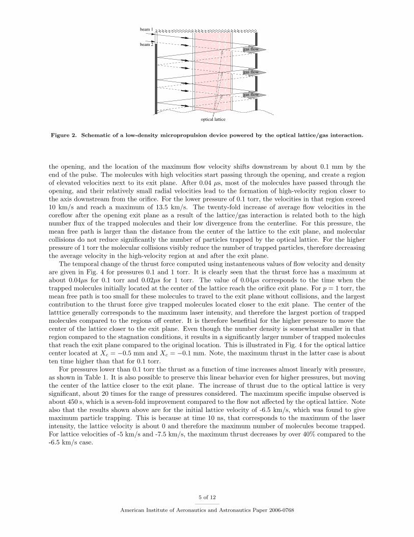
The performance characteristics of the above low-density propulsion device has been analyzed with theDSMC method for different stagnation pressures. The simulations have been performed for an axisymmetricdomain that represents a part of the flow adjacent to an opening. The computational domain is shown inFig. 3. The equilibrium stagnation conditions were set at the upstream boundary (left) boundary, the lowerboundary is the axis of symmetry, specular conditions are specified at the upper boundary to simulate theeffect of a large array of openings, and the vacuum condition was used at the downstream boundary. The gaswas methane, the stagnation temperature was 300 K, and the three stagnation pressures used are 0.01 torr,0.1 torr, and 1 torr. The optical lattice was created with two 800 nm wavelenth 50 µm radius beams with achirp of 1019 rad/s2, the lattice center was located 0.5 mm upstream from the opening, the maximum laserintensity at the axis was 6.4×10¹⁶ W/m2, and the pulse duration was 10 ns. The inital lattice velocity, V0,varied from -5 km/s to -7.5 km/s in order to select the optimum value.
The evolution of the axial flow velocity field after a single pulse is presented in Fig. 3 for pressures 0.1and 1 torr and V0 = −6.5 km/s. Two time moments are shown here, t = 0 which corresponds to the timeimmediately after the pulse, and t = 0.04µs. During the pulse, the trapped molecules start moving toward
4 of 12
American Institute of Aeronautics and Astronautics Paper 2006-0768
gas flow
gas flow
gas flow
optical lattice
beam 2
beam 1
Figure 2. Schematic of a low-density micropropulsion device powered by the optical lattice/gas interaction.
the opening, and the location of the maximum flow velocity shifts downstream by about 0.1 mm by theend of the pulse. The molecules with high velocities start passing through the opening, and create a regionof elevated velocities next to its exit plane. After 0.04 µs, most of the molecules have passed through theopening, and their relatively small radial velocities lead to the formation of high-velocity region closer tothe axis downstream from the orifice. For the lower pressure of 0.1 torr, the velocities in that region exceed10 km/s and reach a maximum of 13.5 km/s. The twenty-fold increase of average flow velocities in thecoreflow after the opening exit plane as a result of the lattice/gas interaction is related both to the highnumber flux of the trapped molecules and their low divergence from the centerline. For this pressure, themean free path is larger than the distance from the center of the lattice to the exit plane, and molecularcollisions do not reduce significantly the number of particles trapped by the optical lattice. For the higherpressure of 1 torr the molecular collisions visibly reduce the number of trapped particles, therefore decreasingthe average velocity in the high-velocity region at and after the exit plane.
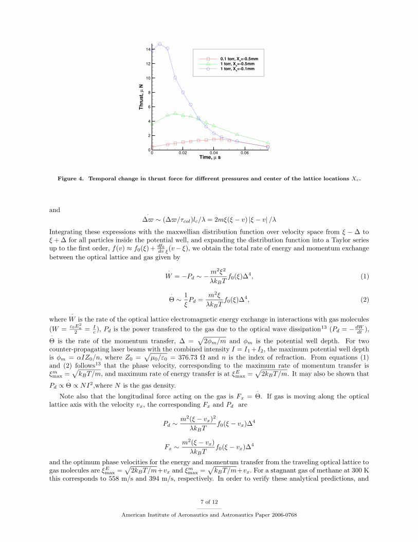
The temporal change of the thrust force computed using instanteneous values of flow velocity and densityare given in Fig. 4 for pressures 0.1 and 1 torr. It is clearly seen that the thrust force has a maximum atabout 0.04µs for 0.1 torr and 0.02µs for 1 torr. The value of 0.04µs corresponds to the time when thetrapped molecules initially located at the center of the lattice reach the orifice exit plane. For p = 1 torr, themean free path is too small for these molecules to travel to the exit plane without collisions, and the largestcontribution to the thrust force give trapped molecules located closer to the exit plane. The center of thelatttice generally corresponds to the maximum laser intensity, and therefore the largest portion of trappedmolecules compared to the regions off center. It is therefore benefitial for the higher pressure to move thecenter of the lattice closer to the exit plane. Even though the number density is somewhat smaller in thatregion compared to the stagnation conditions, it results in a significantly larger number of trapped moleculesthat reach the exit plane compared to the original location. This is illustrated in Fig. 4 for the optical latticecenter located at Xc = −0.5 mm and Xc = −0.1 mm. Note, the maximum thrust in the latter case is aboutten time higher than that for 0.1 torr.
For pressures lower than 0.1 torr the thrust as a function of time increases almost linearly with pressure,as shown in Table 1. It is also possible to preserve this linear behavior even for higher pressures, but movingthe center of the lattice closer to the exit plane. The increase of thrust due to the optical lattice is verysignificant, about 20 times for the range of pressures considered. The maximum specific impulse observed isabout 450 s, which is a seven-fold improvement compared to the flow not affected by the optical lattice. Notealso that the results shown above are for the initial lattice velocity of -6.5 km/s, which was found to givemaximum particle trapping. This is because at time 10 ns, that corresponds to the maximum of the laserintensity, the lattice velocity is about 0 and therefore the maximum number of molecules become trapped.For lattice velocities of -5 km/s and -7.5 km/s, the maximum thrust decreases by over 40% compared to the-6.5 km/s case.
5 of 12
American Institute of Aeronautics and Astronautics Paper 2006-0768
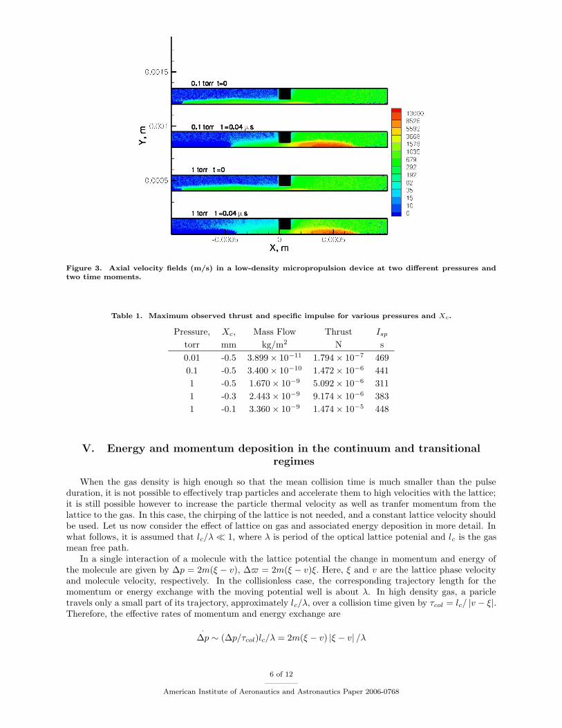
Figure 3. Axial velocity fields (m/s) in a low-density micropropulsion device at two different pressures andtwo time moments.
Table 1. Maximum observed thrust and specific impulse for various pressures and Xc.
Pressure, Xc, Mass Flow Thrust Isptorr mm kg/m2 N s
0.01 -0.5 3.899× 10⁻¹¹ 1.794× 10⁻⁷ 469
0.1 -0.5 3.400× 10⁻¹⁰ 1.472× 10⁻⁶ 441
1 -0.5 1.670× 10⁻⁹ 5.092× 10⁻⁶ 311
1 -0.3 2.443× 10⁻⁹ 9.174× 10⁻⁶ 383
1 -0.1 3.360× 10⁻⁹ 1.474× 10⁻⁵ 448
V. Energy and momentum deposition in the continuum and transitionalregimes
When the gas density is high enough so that the mean collision time is much smaller than the pulseduration, it is not possible to effectively trap particles and accelerate them to high velocities with the lattice;it is still possible however to increase the particle thermal velocity as well as tranfer momentum from thelattice to the gas. In this case, the chirping of the lattice is not needed, and a constant lattice velocity shouldbe used. Let us now consider the effect of lattice on gas and associated energy deposition in more detail. Inwhat follows, it is assumed that lc/λ 1, where λ is period of the optical lattice potenial and lc is the gasmean free path.
In a single interaction of a molecule with the lattice potential the change in momentum and energy ofthe molecule are given by ∆p = 2m(ξ − v), ∆$ = 2m(ξ − v)ξ. Here, ξ and v are the lattice phase velocityand molecule velocity, respectively. In the collisionless case, the corresponding trajectory length for themomentum or energy exchange with the moving potential well is about λ. In high density gas, a paricletravels only a small part of its trajectory, approximately lc/λ, over a collision time given by τcol = lc/ |v − ξ|.Therefore, the effective rates of momentum and energy exchange are
·∆p ∼ (∆p/τcol)lc/λ = 2m(ξ − v) |ξ − v| /λ
6 of 12
American Institute of Aeronautics and Astronautics Paper 2006-0768
Time, µ s
Thru
st,µ
N
0 0.02 0.04 0.060
2
4
6
8
10
12
14
0.1 torr, Xc=-0.5mm1 torr, Xc=-0.5mm1 torr, Xc=-0.1mm
Figure 4. Temporal change in thrust force for different pressures and center of the lattice locations Xc.
and ·∆$ ∼ (∆$/τcol)lc/λ = 2mξ(ξ − v) |ξ − v| /λ
Integrating these expressions with the maxwellian distribution function over velocity space from ξ − ∆ toξ + ∆ for all particles inside the potential well, and expanding the distribution function into a Taylor seriesup to the first order, f(v) ≈ f0(ξ) + df0
dv ξ(v− ξ), we obtain the total rate of energy and momentum exchange
between the optical lattice and gas given by
·W = −Pd ∼ −
m2ξ2
λkBTf0(ξ)∆4, (1)
·Θ ∼ 1
ξPd =
m2ξ
λkBTf0(ξ)∆4, (2)
where·W is the rate of the optical lattice electromagnetic energy exchange in interactions with gas molecules
(W =ε0E
2a
2 = Ic ), Pd is the power transfered to the gas due to the optical wave dissipation13 (Pd = −dWdt ),
·Θ is the rate of the momentum transfer, ∆ =
√2φm/m and φm is the potential well depth. For two
counter-propagating laser beams with the combined intensity I = I1 +I2, the maximum potential well depthis φm = αIZ0/n, where Z0 =
√µ0/ε0 = 376.73 Ω and n is the index of refraction. From equations (1)
and (2) follows13 that the phase velocity, corresponding to the maximum rate of momentum transfer isξmmax =
√kBT/m, and maximum rate of energy transfer is at ξEmax =
√2kBT/m. It may also be shown that
Pd ∝·Θ ∝ NI2,where N is the gas density.
Note also that the longitudinal force acting on the gas is Fx =·Θ. If gas is moving along the optical
lattice axis with the velocity vx, the corresponding Fx and Pd are
Pd ∼m2(ξ − vx)2
λkBTf0(ξ − vx)∆4
Fx ∼m2(ξ − vx)
λkBTf0(ξ − vx)∆4
and the optimum phase velocities for the energy and momentum transfer from the traveling optical lattice togas molecules are ξEmax =
√2kBT/m+vx and ξmmax =
√kBT/m+vx. For a stagnant gas of methane at 300 K
this corresponds to 558 m/s and 394 m/s, respectively. In order to verify these analytical predictions, and
7 of 12
American Institute of Aeronautics and Astronautics Paper 2006-0768
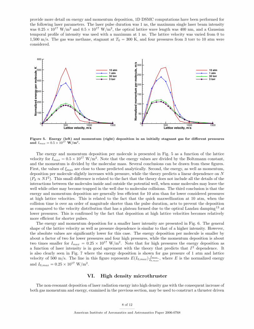
provide more detail on energy and momentum deposition, 1D DSMC computations have been performed forthe following laser parameters. The laser pulse duration was 1 ns, the maximum single laser beam intensitywas 0.25 × 10¹⁷ W/m2 and 0.5 × 10¹⁷ W/m2, the optical lattice wave length was 400 nm, and a Gaussiantemporal profile of intensity was used with a maximum at 1 ns. The lattice velocity was varied from 0 to1,500 m/s. The gas was methane, stagnant at T0 = 300 K, and four pressures from 3 torr to 10 atm wereconsidered.
Lattice velocity, m/s
Nor
mal
ized
ener
gype
rmol
ecul
e,K
0 500 1000 15000
100
200
300
400
500
600
10 atm1 atm30 torr3 torr
Lattice velocity, m/s
Nor
mal
ized
mom
entu
mpe
rmol
ecul
e,m
/s
0 500 1000 15000
50
100
150
200
250
300
10 atm1 atm30 torr3 torr
Figure 5. Energy (left) and momentum (right) deposition in an initially stagnant gas for different pressuresand Imax = 0.5× 10¹⁷ W/m2.
The energy and momentum deposition per molecule is presented in Fig. 5 as a function of the latticevelocity for Imax = 0.5× 10¹⁷ W/m2. Note that the energy values are divided by the Boltzmann constant,and the momentum is divided by the molecular mass. Several conclusions can be drawn from these figures.First, the values of ξmax are close to those predicted analytically. Second, the energy, as well as momentum,deposition per molecule slightly increases with pressure, while the theory predicts a linear dependence on N(Pd ∝ NI2). This small difference is related to the fact that the theory does not include all the details of theinteractions between the molecules inside and outside the potential well, when some molecules may leave thewell while other may become trapped in the well due to molecular collisions. The third conclusion is that theenergy and momentum deposition are generally less efficient for 10 atm than for lower considered pressuresat high lattice velocities. This is related to the fact that the quick maxwellization at 10 atm, when thecollision time is over an order of magnitude shorter than the pulse duration, acts to prevent the depositionas compared to the velocity distribution that has a plateau formed due to the optical Landau damping13 atlower pressures. This is confirmed by the fact that deposition at high lattice velocities becomes relativelymore efficient for shorter pulses.
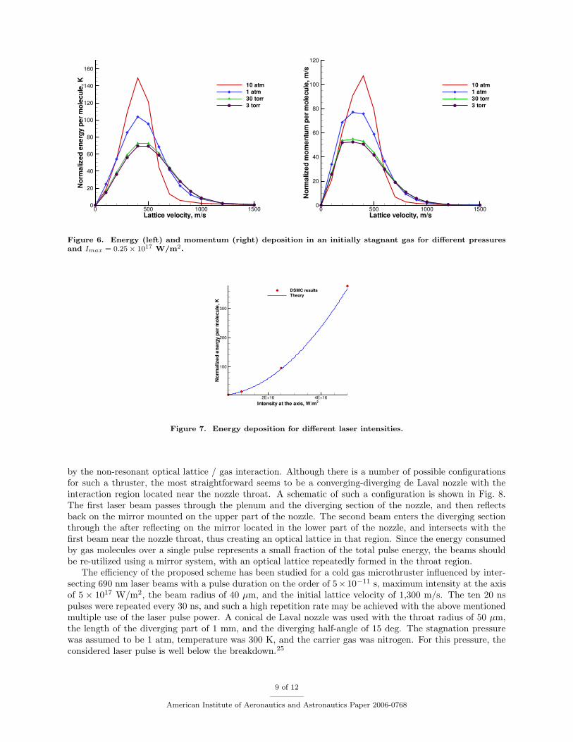
The energy and momentum deposition for a smaller laser intensity are presented in Fig. 6. The generalshape of the lattice velocity as well as pressure dependence is similar to that of a higher intensity. However,the absolute values are significantly lower for this case. The energy deposition per molecule is smaller byabout a factor of two for lower pressures and four high pressures, while the momentum deposition is abouttwo times smaller for Imax = 0.25 × 10¹⁷ W/m2. Note that for high pressures the energy deposition asa function of laser intensity is in good agreement with the theory that predicts that I 2 dependence. Itis also clearly seen in Fig. 7 where the energy deposition is shown for gas pressure of 1 atm and latticevelocity of 500 m/s. The line in this figure represents E(I0,max) Imax
I0,max, where E is the normalized energy
and I0,max = 0.25× 10¹⁷ W/m2.
VI. High density microthruster
The non-resonant deposition of laser radiation energy into high density gas with the consequent increase ofboth gas momentum and energy, examined in the previous section, may be used to construct a thruster driven
8 of 12
American Institute of Aeronautics and Astronautics Paper 2006-0768
Lattice velocity, m/s
Nor
mal
ized
ener
gype
rmol
ecul
e,K
0 500 1000 15000
20
40
60
80
100
120
140
160
10 atm1 atm30 torr3 torr
Lattice velocity, m/s
Nor
mal
ized
mom
entu
mpe
rmol
ecul
e,m
/s
0 500 1000 15000
20
40
60
80
100
120
10 atm1 atm30 torr3 torr
Figure 6. Energy (left) and momentum (right) deposition in an initially stagnant gas for different pressuresand Imax = 0.25× 10¹⁷ W/m2.
Intensity at the axis, W/m2
Nor
mal
ized
ener
gype
rmol
ecul
e,K
2E+16 4E+16
100
200
300
DSMC resultsTheory
Figure 7. Energy deposition for different laser intensities.
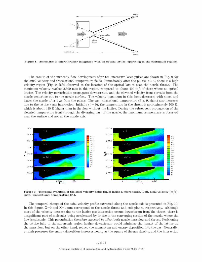
by the non-resonant optical lattice / gas interaction. Although there is a number of possible configurationsfor such a thruster, the most straightforward seems to be a converging-diverging de Laval nozzle with theinteraction region located near the nozzle throat. A schematic of such a configuration is shown in Fig. 8.The first laser beam passes through the plenum and the diverging section of the nozzle, and then reflectsback on the mirror mounted on the upper part of the nozzle. The second beam enters the diverging sectionthrough the after reflecting on the mirror located in the lower part of the nozzle, and intersects with thefirst beam near the nozzle throat, thus creating an optical lattice in that region. Since the energy consumedby gas molecules over a single pulse represents a small fraction of the total pulse energy, the beams shouldbe re-utilized using a mirror system, with an optical lattice repeatedly formed in the throat region.
The efficiency of the proposed scheme has been studied for a cold gas microthruster influenced by inter-secting 690 nm laser beams with a pulse duration on the order of 5×10⁻¹¹ s, maximum intensity at the axisof 5 × 10¹⁷ W/m2, the beam radius of 40 µm, and the initial lattice velocity of 1,300 m/s. The ten 20 nspulses were repeated every 30 ns, and such a high repetition rate may be achieved with the above mentionedmultiple use of the laser pulse power. A conical de Laval nozzle was used with the throat radius of 50 µm,the length of the diverging part of 1 mm, and the diverging half-angle of 15 deg. The stagnation pressurewas assumed to be 1 atm, temperature was 300 K, and the carrier gas was nitrogen. For this pressure, theconsidered laser pulse is well below the breakdown.25
9 of 12
American Institute of Aeronautics and Astronautics Paper 2006-0768
beam 2: k ,2 2ω
1 1beam 1: k ,ω
mirror
opticallattice
gas flow gas flowphase velocity
mirror
win
dow
win
dow
Figure 8. Schematic of microthruster integrated with an optical lattice, operating in the continuum regime.
The results of the unsteady flow development after ten successive laser pulses are shown in Fig. 9 forthe axial velocity and translational temperature fields. Immediately after the pulses, t = 0, there is a highvelocity region (Fig. 9, left) observed at the location of the optical lattice near the nozzle throat. Themaximum velocity reaches 2,500 m/s in this region, compared to about 400 m/s if there where no opticallattice. The velocity perturbation propagates downstream, and the elevated velocity front spreads from thenozzle centerline out to the nozzle surface. The velocity maximum in this front decreases with time, andleaves the nozzle after 1 µs from the pulses. The gas translational temperature (Fig. 9, right) also increasesdue to the lattice / gas interaction. Initially (t = 0), the temperature in the throat is approximately 700 K,which is about 450 K higher than in the flow without the lattice. During the subsequent propagation of theelevated temperature front through the diverging part of the nozzle, the maximum temperature is observednear the surface and not at the nozzle axis.
Figure 9. Temporal evolution of the axial velocity fields (m/s) inside a micronozzle. Left, axial velocity (m/s);right, translational temperature (K).
The temporal change of the axial velocity profile extracted along the nozzle axis is presented in Fig. 10.In this figure, X=0 and X=1 mm correspond to the nozzle throat and exit planes, respectively. Althoughmost of the velocity increase due to the lattice-gas interaction occurs downstream from the throat, there isa significant part of molecules being accelerated by lattice in the converging section of the nozzle, where theflow is subsonic. This perturbation therefore expected to affect both nozzle mass flow and thrust. Positioningthe lattice fully in the supersonic region further downstream would minimize the impact of the lattice onthe mass flow, but on the other hand, reduce the momentum and energy deposition into the gas. Generally,at high pressures the energy deposition increases nearly as the square of the gas density, and the interaction
10 of 12
American Institute of Aeronautics and Astronautics Paper 2006-0768
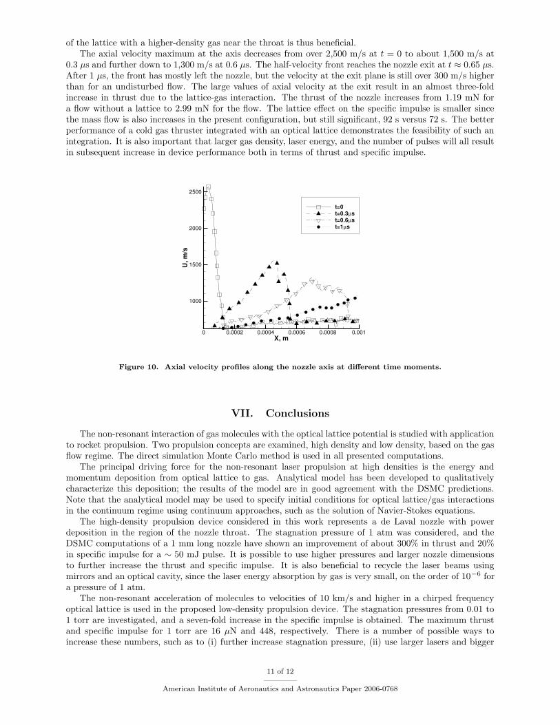
of the lattice with a higher-density gas near the throat is thus beneficial.The axial velocity maximum at the axis decreases from over 2,500 m/s at t = 0 to about 1,500 m/s at
0.3 µs and further down to 1,300 m/s at 0.6 µs. The half-velocity front reaches the nozzle exit at t ≈ 0.65 µs.After 1 µs, the front has mostly left the nozzle, but the velocity at the exit plane is still over 300 m/s higherthan for an undisturbed flow. The large values of axial velocity at the exit result in an almost three-foldincrease in thrust due to the lattice-gas interaction. The thrust of the nozzle increases from 1.19 mN fora flow without a lattice to 2.99 mN for the flow. The lattice effect on the specific impulse is smaller sincethe mass flow is also increases in the present configuration, but still significant, 92 s versus 72 s. The betterperformance of a cold gas thruster integrated with an optical lattice demonstrates the feasibility of such anintegration. It is also important that larger gas density, laser energy, and the number of pulses will all resultin subsequent increase in device performance both in terms of thrust and specific impulse.
X, m
U,m
/s
0 0.0002 0.0004 0.0006 0.0008 0.001
1000
1500
2000
2500
t=0t=0.3µst=0.6µst=1µs
Figure 10. Axial velocity profiles along the nozzle axis at different time moments.
VII. Conclusions
The non-resonant interaction of gas molecules with the optical lattice potential is studied with applicationto rocket propulsion. Two propulsion concepts are examined, high density and low density, based on the gasflow regime. The direct simulation Monte Carlo method is used in all presented computations.
The principal driving force for the non-resonant laser propulsion at high densities is the energy andmomentum deposition from optical lattice to gas. Analytical model has been developed to qualitativelycharacterize this deposition; the results of the model are in good agreement with the DSMC predictions.Note that the analytical model may be used to specify initial conditions for optical lattice/gas interactionsin the continuum regime using continuum approaches, such as the solution of Navier-Stokes equations.
The high-density propulsion device considered in this work represents a de Laval nozzle with powerdeposition in the region of the nozzle throat. The stagnation pressure of 1 atm was considered, and theDSMC computations of a 1 mm long nozzle have shown an improvement of about 300% in thrust and 20%in specific impulse for a ∼ 50 mJ pulse. It is possible to use higher pressures and larger nozzle dimensionsto further increase the thrust and specific impulse. It is also beneficial to recycle the laser beams usingmirrors and an optical cavity, since the laser energy absorption by gas is very small, on the order of 10−6 fora pressure of 1 atm.
The non-resonant acceleration of molecules to velocities of 10 km/s and higher in a chirped frequencyoptical lattice is used in the proposed low-density propulsion device. The stagnation pressures from 0.01 to1 torr are investigated, and a seven-fold increase in the specific impulse is obtained. The maximum thrustand specific impulse for 1 torr are 16 µN and 448, respectively. There is a number of possible ways toincrease these numbers, such as to (i) further increase stagnation pressure, (ii) use larger lasers and bigger
11 of 12
American Institute of Aeronautics and Astronautics Paper 2006-0768
openings, (iii) use the multiple openings setup to recycle laser power, (iv) optimize the device in terms oflattice location, chirp, and velocity, (v) utilize polar molecules, such as H2O. Only the latter option alonemay give several times larger specific impulse due to the larger forces on molecules.
The shown ability of the optical lattice to accelerate molecular beams to extremely high velocities inweakly collisional regime without ionization and dissociation of molecules may be used not only in propulsion,but also in various material processing devices. The non-resonant energy deposition at high pressures mayalso be used to create high-temperature gas pockets in arbitrary points of space. Note that a variable latticevelocity needs to be used for this purpose in order to account for gas temperature increase and provideoptimum energy deposition.
Acknowledgments
The authors would like to thank Drs. Ingrid Wysong, Andrew Ketsdever, and Peter Barker for many help-ful discussions. SFG acknowledges the encouragement and support from the Air Force Research Laboratory,Propulsion Directorate.
References
1Schiffer, M., Rauner, M., Kuppens, S., Zinner, M., Sengstock, K., Ertmer W. “Guiding, focusing, and cooling of atomsin a strong dipole potential,” App. Phys. B 67, 705 (1998)
2Stamper-Kurn, D.M., Andrews, M.R., Chikkatur, A.P., Inouye, S., Miesner, H.J., Stenger, J., Ketterle, W. “Opticalconfinement of a Bose-Einstein condensate,” Phys. Rev. Lett. 80, 2027 (1998)
3Renn, M.J., Montgomery, D., Vdovin, O., Anderson, D.Z., Wieman, C.E., Cornell, E.A. “Laser-guided atoms in hollow-core optical fibers,” Phys. Rev. Lett. 75, 3253 (1995)
4Karczmarek, J., Wright, J., Corkum, P., Ivanov, M. “Optical centrifuge for molecules,” Phys. Rev. Lett. 82, 3420 (1999)5Livingston, M.S., Blewett, J.P. Particle Accelerators, McGraw-Hill, New York, 1962.6Neely, A.J., Morgan, R.J., “The superorbital expansion tube concept, experiment and analysis,” Aeronaut. J. 98, 97
(1994)7Kazantsev, A.P. “Acceleration of atoms by light,” Sov. Phys. JETP 39, 784 (1974)8Kazantsev, A.P. “Resonance light pressure,” Uspekhi Fizicheskikh Nauk, 124(1), 113 (1978)9Corkum, P.B., Ellert, C., Mehendale, M., Dietrich, P., Hankin, S., Aseyev, S., Rayner, D., Villeneuve, D. “Molecular
science with strong laser fields,” Faraday Discuss., 113, 47 (1999)10Madison, K.W., Bharucha, C.F., Morrow, P.R., Wilkinson, S.R., Sundaram, Q.N.B., Raizen, M.G. “Quantum transport
of ultracold atoms in an accelerating optical potential,” Appl. Phys. B, 65, 693 (1997)11Peik, E., Ben Dahan, M., Bouchoule, I., Castin, Y., Salomon, C. “Bloch oscillations and an accelerator for cold atoms,”
Appl. Phys. B, 65, 685, (1997)12Barker, P.F., Shneider, M.N. “Optical microlinear accelerator for molecules and atoms,” Phys. Rev. A, 2001, Vol. 64,
No. 3, 033408.13Shneider, M.N., Barker, P.F. “Optical Landau damping,” Phys.Rev. A, 2005, Vol. 71, No. 5, 053403.14Shneider, M.N., Gimelshein, S.F., Barker, P.F. “Development of efficient micropropulsion devices based on molecular
acceleration in pulsed optical lattices,” Submitted to the Journal of Applied Physics, Sep 2005.15Bird, G.A. Molecular Gas Dynamics and the Direct Simulation of Gas Flows, Clarendon Press, Oxford, 1994.16Askar’yan, G.A., Moroz, E.M. ”Effects of the gradient of a strong electromagnetic beam on electrons and atoms”, Zh.
Eksp. Teor. Fiz., 1962, Vol. 43, No. 6, p. 2319.17Prokhorov, A., Batanov, V., Bunkin, F., Fedorov, V. “Metal evaporation under powerful optical radiation,” IEEE J.
Quantum Electron., 1973, Vol. 9, No. 5, pp. 503-510.18Pirri, A.N., Monsler, M.J., Nebolsine, P.E. “Propulsion by absorption of laser radiation,” AIAA Journal, 1974, Vol. 12,
pp. 1254-1261.19Smith, M.H., Fork, R.L., Cole, S.T. “Safe delivery of optical power from space,” Optics Express 8, 2001, pp. 537-546.20Bunin, F.V., Prokhorov, A.M. “The use of laser power source to create thrust,” Uspekhi Fizicheskikh Nauk, Vol. 119,
Issue 3, pp. 425-446.21Miles, R.B., Brown, G.L., Lempert, W.R., Yetter, R., Williams, G.J. Bogdanoff, S.M., Natelson, D., Guest, J.R. “Radia-
tively driven windtunnel,” AIAA Journal, 1995, Vol. 33, No. 8, pp. 1463-1470.22Girgis, I.G., Brown, G.L., Miles, R.B., Lipinski, R.J. “Fluid Mechanics of a Mach 8-12, Electron Beam Driven, Missile-
Scale Hypersonic Wind Tunnel: Modeling and Predictions,” Phys. Fluids, Vol. 14, No. 11, pp. 4026-4039, 2002.23Ivanov, M.S., Markelov, G.N., Gimelshein, S.F. ”Statistical simulation of reactive rarefied flows: numerical approach and
applications,” AIAA Paper 98-2669, June 1998.24Boyd, R.W. Nonlinear Optics, Academic Press, Boston, 1992.25Dewhurst, R.J. “Comparative data on molecular gas breakdown thresholds in high laser-radiation fields,” J. Phys. D:
Applied Phys., Vol. 11, 1978, L191-L195.
12 of 12
American Institute of Aeronautics and Astronautics Paper 2006-0768