Micromechanics of brittle faulting and cataclastic flow in Berea sandstone
Upload
independentCategory
view
0download
0
AIAA JOURNAL
Vol. 41, No. 9, September 2003
Micromechanics-Based Modeling of WovenPolymer Matrix Composites
Brett A. Bednarcyk¤
Ohio Aerospace Institute, Brookpark, Ohio 44142and
Steven M. Arnold†
NASA John H. Glenn Research Center at Lewis Field, Cleveland, Ohio 44135
A novel approach is combined with the generalized method of cells (GMC) to predict the elastic propertiesof plain-weave polymer matrix composites (PMCs). The traditional one-step three-dimensional homogenizationprocedure thathasbeen used in conjunction with GMC for modelingwoven composites in the past is inaccurate dueto the lack of shear coupling inherent in the model. However, by performing a two-step homogenizationprocedurein which the woven composite repeating unit cell is homogenized independently in the through-the-thicknessdirection prior to homogenization in the plane of the weave, GMC can now accurately model woven PMCs. Thistwo-step procedure is outlined and implemented, and predictions are compared with results from the traditionalone-step approachas well as other model and experimental results from the literature. Full couplingof this two-steptechnique within the recently developed Micromechanics Analysis Code with GMC software package will resultin a widely applicable, ef� cient, and accurate tool for the design and analysis of woven composite materials andstructures.
I. Introduction
C OMPOSITES with woven reinforcements are attractive dueto their ease of manufacture compared to unidirectionalcom-
posites and laminates. Reinforcement preforms can be woven (orbraided) into complex shapes that will remain intact prior to in� l-tration with the matrix material. This can reduce costs associatedwith machining because near-net-shapedcomponents can be fabri-cated. Woven reinforcements are particularly effective in polymermatrix composites(PMCs) applicationswhere cost is often a drivingdesign factor.
The bene� cial qualities of woven composites come at a cost interms of analysis; their thermomechanicalbehavior is signi� cantlymore dif� cult to model due to the complex and inherently three-dimensional geometry associated with the woven reinforcement.Typically, woven composites have been modeled either by con-sidering a simpli� ed geometric representation and using homog-enization techniques (usually isostress and isostrain assumptions)or via analysis of the actual three-dimensional geometry using � -nite element analysis (FEA). For recent reviews of such efforts,the reader is referred to Refs. 1 and 2. In general, the drawbacksof these approaches involve the accuracy of the predictions, ge-ometric generality, computational ef� ciency, the ability to admitlocal (constituent-scale) submodels (i.e., viscoplasticity, damage,microfailure), or suitability to function in the framework of broadercomponent-level analysis techniques. A notable exception to thepreceding characterization is the binary model developed by Coxet al.3 The binarymodelemploysa nonlinear� niteelementapproach
Received 5 February 2001; presented as Paper 2001-1567 at the AIAA/ASME/ASCE/AHS/ASC 42nd Structures, Structural Dynamics, and Mate-rials Conference, Seattle, WA, 16–19 April 2001; revision received 15 June2002; accepted for publication 10 December 2002. Copyright c° 2003 bythe American Institute of Aeronautics and Astronautics, Inc. The U.S. Gov-ernment has a royalty-free license to exercise all rights under the copyrightclaimed herein for Governmental purposes. All other rights are reserved bythe copyright owner. Copies of this paper may be made for personal or inter-nal use, on conditionthat the copier pay the $10.00per-copy fee to the Copy-right Clearance Center, Inc., 222 Rosewood Drive, Danvers, MA 01923;include the code 0001-1452/03 $10.00 in correspondence with the CCC.
¤Senior Research Associate; also Senior Visiting Research Scientist,Department of Civil Engineering, University of Virginia, Charlottesville,VA 22904-4742.Member AIAA.
†Senior Research Engineer, Structures Division, Life Prediction Branch.
in which complex three-dimensionalwoven (or braided)geometriesare resolved into a number of stiff towline elements and compli-ant solid elements. Hence, the arbitrary composite geometry can beaccuratelycapturedwhile circumventingthe cumbersomeand com-putationally intensive three-dimensionalmesh normally associatedwith FEA (for modeling complex weaves).
Anotherapproachthat overcomesmany drawbacksrelated to pre-vious woven-composite modeling efforts is the method of cells,developedby Aboudi.4 The generalizationof this model, the gener-alizedmethod of cells (GMC),5 and the three-dimensionaltriply pe-riodic versionof GMC6 increased the breadthof applicabilityof theoriginal method of cells considerably.The macroscale (composite-level) accuracy of GMC for modeling the thermomechanical be-havior of continuous and discontinuous composites has been wellestablished. GMC also admits arbitrary doubly and triply periodicgeometries, making the method completely general with respect togeometry (provided a geometric repeating unit cell can be iden-ti� ed). In its original form, GMC was quite computationally ef� -cient compared to FEA (see, e.g., Ref. 7); however, the ef� ciencyof the method has been signi� cantly increased via a reformulationby Pindera and Bednarcyk.2;8 Similarly, because GMC provides ef-� cient access to the local (constituent) stress and strain � elds insimulated composite materials, it is ideal for inclusion of local sub-models and, because it represents a material rather than a structure(such as a plate) it is well suited for implementation in higher scaleanalysis techniques such as FEA.9;10
Due to its useful aforementioned characteristics, GMC was se-lected as the foundation for NASA Glenn Research Center’s Mi-cromechanics Analysis Code with Generalized Method of Cells(MAC/GMC) software package.9 This product is available to (andin use by) U.S. industry and universities for composite design andanalysis.‡ MAC/GMC takes advantage of GMC’s bene� cial prop-erties and providesmany additionalfeatures such as 1) the ability tosimulate arbitrary thermomechanical loading histories, 2) a libraryof geometric repeating unit cells, 3) user-de� nable subroutines,4) damage and local failure modeling, 5) a library of elastic andviscoplastic material constitutive models, and 6) a seamless inter-face with the ABAQUS FEA package.Thus, MAC/GMC is an idealcandidate for modeling woven composite materials.
‡Data available online at http://www.grc.nasa.gov/WWW/LPB/mac[cited 18 July 2003].
1788

BEDNARCYK AND ARNOLD 1789
Bednarcyk and Pindera1;2 used GMC to model a woven car-bon/copper(C/Cu) metalmatrix composite(MMC). In thesestudies,the originalmethod of cells was used to represent the unidirectionalin� ltrated � ber yarns embedded within the triply periodic versionof GMC, thus enabling representation of the composite’s three-dimensionalrepeatingunit cell. Local submodelswere incorporatedto account for matrix plasticity and � ber–matrix debonding, allow-ing reasonably good agreement with mechanical experimental testdata.However, due to GMC’s inherent lack of couplingbetween thenormal and shear stress and strain � elds, the method has (until now)been unable to model PMCs accurately. In C/Cu MMCs, however,the dominant nature of the effects of matrix plasticity and � ber–matrix debonding muted the inaccuracies associated with GMC’slack of shear coupling, permitting reasonably accurate predictionsfor C/Cu systems. PMCs, on the other hand, are typically mod-eled elastically, and � ber–matrix debonding is often restricted tothe near-failure regime of the PMC’s response. Hence, GMC’s pre-dictions for the elastic properties of PMCs have been poor. Withthe inability to predict accurately the effective properties of PMCs(the most common form of woven composites), the usefulness ofGMC in modeling woven composites could only be characterizedas limited.
A concept that immediately exhibited potential for overcomingGMC’s dif� culties in accurately modeling woven PMCs was re-cently reported independently by Tabiei and Jiang11 and Huang.12
These authorspresentedapproachesto model a plain-weavePMC inwhich, prior to homogenizing in the plane of the woven reinforce-ment, homogenization (via use of isostress and isostrain assump-tions) was performed through the thicknessof the weave. As will beshown, this two-step homogenization concept can be used in con-junction with GMC to enable accurate and consistent prediction ofwoven PMC elastic properties.Furthermore, in the contextof a fullyembedded approach to modeling general woven and braided com-posites like that presentedby Bednarcykand Pindera,2;13 employinga through-the-thickness homogenizationstep (before homogeniza-tion in the plane of the weave, but after homogenization of the� ber and matrix to obtain the in� ltrated yarn behavior) is clearlywarranted.
II. GMC Mixed Concentration EquationsThe reader is referred to Refs. 5 and 6 for full presentations of
the doubly and triply periodic versions of GMC and to Refs. 8and 2 for the corresponding reformulations. Here we will estab-lish a theoretical background for the GMC equations based on theconcept of mixed-concentrationequations. Whereas the traditionalstress and strain concentration equations relate local stresses toglobal stress and local strains to global strain, the desired mixed-concentration equations relate local stresses to global strain. Suchmixed-concentrationequationsare essentialin the reformulatedver-sion of GMC.
We begin with Hill’s14 stress and strain concentration equationsincluding thermal and inelastic effects:
¾.®¯° / D B.®¯° / N¾ CX
¸» ´
B.®¯°;¸»´/
T C.¸» ´/".¸» ´/
T
CX
¸» ´
B.®¯°;¸»´/
I C.¸» ´/".¸» ´/
I (1)
".®¯° / D A.®¯° / N" CX
¸»´
A.®¯°;¸»´/
T ".¸» ´/
T CX
¸»´
A.®¯°;¸»´/
I ".¸»´/
I (2)
where ¾.®¯° / and ".®¯° / are the vectors of the six (average) stressand strain components, respectively, in a subvolume de� ned by theindices.®¯° /; N¾ and N" are theaverage(global)stressandstraincom-ponent vectors, respectively;".¸»´/
T and ".¸»´/
I are the (average) ther-mal and inelastic strain vectors, respectively, in subvolume .¸»´/;andC.¸» ´/ is the elasticstiffnessmatrix for subvolume.¸»´/. The fa-miliar stress and strain concentrationmatrices for subvolume.®¯° /are B.®¯° / and A.®¯° / , respectively.The inelastic and thermal straindistributions in each subvolume affect the stresses and strains in
every other subvolume. Hence, the thermal and inelastic stress con-centration matrices, B.®¯° ;¸» ´/
T and B.®¯° ;¸» ´/
I , respectively, as wellas the thermal and inelastic strain concentrationmatrices, A.®¯°;¸» ´/
Tand A.®¯°;¸»´/
I , respectively,have the double-indexsuperscripts.Thesummations appearing in Eqs. (1) and (2), 6¸»´ , represent summa-tion over all subvolumes denoted by .¸»´/.
The local constitutive equation for subvolume .®¯° / may bewritten
¾.®¯° / D C.®¯° /£".®¯° / ¡ "
.®¯° /
T ¡ ".®¯° /
I
¤(3)
and the global (effective) constitutive equation is
N¾ D C¤[N" ¡ N"T ¡ N" I ] (4)
where, C¤ is the effective elastic stiffness matrix and N"T and N" I
are the global (average) thermal and inelastic strain vectors, respec-tively. The average stress vector is de� ned as
N¾ D 1V
X
®¯°
V .®¯° /¾.®¯° / (5)
where V is theoverallvolumeand V .®¯° / is thevolumeof subvolume.®¯° /.
Substituting Eq. (3) into Eq. (5) yields
N¾ D 1V
X
®¯°
V .®¯° /C.®¯° /£".®¯° / ¡ "
.®¯° /
T ¡ ".®¯° /
I
¤(6)
and substituting Eq. (2) into Eq. (6) gives
N¾ D 1V
X
®¯°
V .®¯° /C.®¯° /
µA.®¯° / N" C
X
¸»´
A.®¯°;¸» ´/
T ".¸» ´/
T ¡ ".®¯° /
T
CX
¸» ´
A.®¯°;¸»´/
I ".¸»´/
I ¡ ".®¯° /
I
¶(7)
ComparingEq. (7)with Eq. (4) allows the identi� cationof theglobalor effective terms appearing in Eq. (4), namely
C¤ D 1V
X
®¯°
V .®¯° /C.®¯° /A.®¯° / (8)
N"T D[C¤]¡1
V
X
®¯°
V .®¯° /C.®¯° /
µ"
.®¯° /
T ¡X
¸» ´
A.®¯°;¸»´/
T ".¸»´/
T
¶(9)
N"I D[C¤]¡1
V
X
®¯°
V .®¯° /C.®¯° /
µ"
.®¯° /
I ¡X
¸»´
A.®¯°;¸» ´/
I ".¸» ´/
I
¶(10)
Now, to obtain the local stresses in terms of global strain, we substi-tute Eq. (4) into Eq. (1), followed by the substitutionof Eqs. (8–10)into the resulting expression, thereby giving
¾ .®¯° / D B.®¯° / 1V
X
¸»´
V .¸»´/C.¸» ´/A.¸» ´/ N"
C B.®¯° / 1V
X
O® O O°
V . O® O O° /C. O® O O° /X
¸» ´
A. O® O O° ;¸» ´/
T ".¸»´/
T
¡ B.®¯° / 1V
X
¸»´
V .¸»´/C.¸»´/".¸»´/
T CX
¸»´
B.®¯°;¸» ´/
T C.¸»´/".¸»´/
T
C B.®¯° / 1V
X
O® O O°
V . O® O O° /C. O® O O° /X
¸» ´
A. O® O O° ;¸» ´/
I ".¸»´/
I
¡ B.®¯° / 1V
X
¸»´
V .¸»´/C.¸»´/".¸»´/
I
CX
¸» ´
B.®¯°;¸»´/
I C.¸» ´/".¸»´/
I (11)

1790 BEDNARCYK AND ARNOLD
We now write Eq. (11) as
¾ .®¯° / D G.®¯° / N" CX
¸» ´
G.®¯°;¸»´/
T ".¸»´/
T CX
¸»´
G.®¯°;¸» ´/
I ".¸»´/
I
(12)
where the mixed concentrationoperators are de� ned as follows:
G.®¯° / D B.®¯° / 1V
X
¸» ´
V .¸»´/C.¸» ´/A.¸» ´/ (13)
G.®¯°;¸»´/
T D B.®¯° /X
O® O O°
V . O® O O° /
VC. O® O O° /A. O® O O° ;¸»´/
T
¡ B.®¯° /V .¸»´/
VC.¸» ´/ C B.®¯°;¸»´/
T C.¸» ´/ (14)
G.®¯°;¸»´/
I D B.®¯° /X
O® O O°
V . O® O O° /
VC. O® O O° /A. O® O O° ;¸»´/
I
¡ B.®¯° /V .¸»´/
VC.¸» ´/ C B.®¯°;¸»´/
I C.¸» ´/ (15)
Equation (12) is the mixed concentration equation. It relates thelocalstresscomponentsto theglobalstraincomponentsand the localthermal and inelastic strain components.Equations (13–15) providethe mixed concentration matrix, the thermal mixed concentrationmatrix, and the inelastic mixed concentration matrix, respectively.
We now link this general derivation to the speci� c geometry con-sidered by GMC, (Fig. 1) which is a parallelepiped repeating unitcell whose average response is that of the triply periodic volumein question. The unit cell consists of an arbitrary number of par-allelepiped subcells, each of which is considered to have knownaverage properties. The indices .®¯° / used previously to representarbitrary subvolumes now represent speci� c subcells within the re-peating unit cell.
The mixed concentration equation is of interest because, due tothe lack of coupling between the normal and shear � elds inherentin the GMC approach,not all subcell stress componentsare unique.Thus, computational advantage can be taken by utilizing only theunique subcell stress components as unknown quantities. This wasthe basis for the reformulationof GMC presentedby Bednarcykand
Fig. 1 GMC three-dimensional repeating unit cell.
Pindera,2 who arrived at the following equation:2
666666664
T .¯° /
11
T .®° /
22
T .®¯/
33
T .®/
23
T .¯/
13
T .° /
12
3
777777775
D
2
666666664
A.¯° /
11 B.¯° /
11 X .¯° /
11 3.¯° /
11 Ä.¯° /
11 9.¯° /
11
A.®° /
22 B.®° /
22 X .®° /
22 3.®° /
22 Ä.®° /
22 9.®° /
22
A.®¯/
33 B.®¯/
33 X .®¯/
33 3.®¯/
33 Ä.®¯/
33 9.®¯/
33
A.®/
23 B.®/
23 X .®/
23 3.®/
23 Ä.®/
23 9.®/
23
A.¯/
13 B.¯/
13 X .¯/
13 3.¯/
13 Ä.¯/
13 9.¯/
13
A.° /
12 B.° /
12 X .° /
12 3.° /
12 Ä.° /
12 9.° /
12
3
777777775
2
6666664
N"11
N"22
N"33
N"23
N"13
N"12
3
7777775
C
2
666666664
0.¯° /
11
0.®° /
22
0.®¯/
33
0.®/
23
0.¯/
13
0.° /
12
3
777777775
1T C
2
666666664
8.¯° /
11
8.®° /
22
8.®¯/
33
8.®/
23
8.¯/
13
8.° /
12
3
777777775
(16)
where T .¢/i j are the unique subcell stress components and, clearly,
comparing Eqs. (16) and (12),
G.®¯° / D
2
6666666664
A.¯° /
11 B.¯° /
11 X .¯° /
11 3.¯° /
11 Ä.¯° /
11 9.¯° /
11
A.®° /
22 B .®° /
22 X .®° /
22 3.®° /
22 Ä.®° /
22 9.®° /
22
A.®¯/
33 B.®¯/
33 X .®¯/
33 3.®¯/
33 Ä.®¯/
33 9.®¯/
33
A.®/
23 B.®/
23 X .®/
23 3.®/
23 Ä.®/
23 9.®/
23
A.¯/
13 B .¯/
13 X .¯/
13 3.¯/
13 Ä.¯/
13 9.¯/
13
A.° /
12 B.° /
12 X .° /
12 3.° /
12 Ä.° /
12 9.° /
12
3
7777777775
(17)
X
¸»´
G.®¯°;¸»´/
T ".¸» ´/
T
Dh0
.¯° /
11 0.®° /
22 0.®¯/
33 0.®/
23 0.¯/
13 0.° /
12
iT
1T (18)
X
¸»´
G.®¯°;¸»´/
I ".¸» ´/
I
Dh8
.¯° /
11 8.®° /
22 8.®¯/
33 8.®/
23 8.¯/
13 8.° /
12
iT
(19)
when the propereliminationof nonuniquecomponentsis performed(a superscript T indicates a matrix transpose). As Bednarcyk andPindera2;8 showed, a signi� cant speed increase (execution-timereduction) arises by employing the mixed concentration equationapproach over the previous GMC strain concentrationequation ap-proach, without any loss in accuracy.
III. Application of GMC to Woven PMCsTo examine the viabilityof GMC in predicting the elastic proper-
tiesof a wovenPMC, rigorouscomparisonwill bemade to numerousresults from the literature. In particular, we compare to 1) the re-sults of Naik and Ganesh15 for plain-weave 42% e-glass/epoxy andplain-weave 41% graphite/epoxy; 2) the results of Dasgupta et al.16
for plain-weave35% e-glass/epoxy; and 3) the results of Tanov andTabiei17 for plain-weave 35% e-glass/epoxy, plain-weave 35% sil-icon carbide/titanium (SiC/Ti; treated as elastic), plain-weave 46%e-glass/epoxy, and plain-weave 35% graphite/epoxy. Toward this

BEDNARCYK AND ARNOLD 1791
Fig. 2 Top view of the plain-weave geometry and repeating unit cell.
Fig. 3 MAC/GMC repeating unit cell used to represent a plain-weavecomposite.
end, consider the geometry of a plain-weave reinforcement shownin Fig. 2 as viewed from above. The warp and � ll yarns undulatein and out of the plane to form the pattern depicted. Also shown inFig. 2 is the repeating unit cell for the weave, which remains thesame even when the weave is in� ltrated with a matrix material toform a plain-weave composite.
Figure 3 shows a MAC/GMC repeating unit cell that representsthe geometry of a plain-weave composite. Clearly, a more re� nedgeometric representation of the composite is possible, but, for thepresent study, the unit cell shown in Fig. 3 is suf� cient.
The traditional procedure for modeling the plain-weavecomposite with GMC would be to � rst determine the effective (ho-mogenized) behavior of the in� ltrated � ber yarns that occupy thethree-dimensionalsubcells in Fig. 3 and then to homogenize thesethree-dimensionalsubcells in one step via the triplyperiodicversionof GMC. If local effects such as matrix plasticity, damage, or localfailure are included, this procedure is not simple because an em-bedded local model is needed to represent the in� ltrated � ber yarns.Bednarcyk and Pindera2 used the method of cells as such a localmodel so that the stresses and strains in the � ber and matrix phaseswere known during the simulated thermomechanical loading his-tory on the woven MMC. However, in the present case of an elasticwoven PMC, a localmodel is neededonly to determine the effectiveelastic properties of the in� ltrated � ber yarns. Arnold et al.9 usedGMC to � rst determine the yarn elastic properties before analyzinga plain-weave repeating unit cell (similar to that shown in Fig. 2),also with GMC. For consistency, in the present study, when possi-ble, we employ the homogenized in� ltrated yarn properties givenby the authors of the results to which we are comparing.
Given the in� ltrated yarn properties (and the appropriateunit celldimensions), the effective elastic properties of the repeating unitcell shown in Fig. 3 can readily be determined using a transverselyisotropicelasticmaterialconstitutivemodel to representthe subcellsoccupied by the in� ltrated � ber yarns. Provided the constitutive
model can admit an arbitrary plane of transverse isotropy, appro-priate representation of all subcell materials present in Fig. 3 ispossible. Effective elastic properties for the speci� c plain-weavecomposites (listed earlier) that have been predictedvia this one-stephomogenizationprocess are presented and discussed in Sec. IV.
An alternative two-step approach, as mentioned previously, hasbeen suggested by the work of Tabiei and Jiang11 and Huang12
and can be easily employed within the context of the GMC frame-work. Assuming the effective behavior of the in� ltrated � ber yarnsis known, a two-step homogenization process, wherein homoge-nization is performed through the thicknessof the woven reinforce-ment prior to homogenization in the plane of the weave, can beconducted. Examining the exploded view of the plain-weave com-posite repeating unit cell employed previously (Fig. 4), it is clearthat six unique types of through-the-thickness subcell groups exist.These six groups are shown in Fig. 5. Group 1 consists of subcellscontaining � bers oriented at 0 and 90 deg to each other in the planeof the weave. Groups 2, 3, 4, and 6 consist of two subcells of in-clined � bers sandwichedbetween two pure matrix subcells.Finally,group 5 contains only pure matrix subcells.
These six subcellgroupsare now homogenizedindependentlyviaGMC. That is, the effectiveelasticpropertiesof each groupshowninFig. 5 are determinedby analyzing the groupas if it were a triply pe-riodic repeatingunit cell. Clearly, group 5 will have effectiveelasticproperties identical to those of the matrix. The homogenizedmate-rial represented by group 1 is orthotropic, while those representedby groups 2, 3, 4, and 6 are monoclinic. Note that both stackingsequences of the 0- and 90-deg subcells in Fig. 4 result in identicaleffective properties.
The second step in determining the effective elastic propertiesof the plain-weave composite involves homogenizing the proper-ties determined for the subcell groups in the plane of the wovenreinforcement.This step was also performed using MAC/GMC andthe corresponding repeating unit cell is shown in Fig. 6, where the
Fig. 4 MAC/GMC repeating unit cell for a plain-weave composite:exploded view.
Fig. 5 Unique through-the-thicknesssubcell groups in the MAC/GMCrepeating unit cell for a plain-weave composite.
Fig. 6 MAC/GMC repeating unit cell for a plain-weave compositeafter through-the-thickness homogenization.
1792 BEDNARCYK AND ARNOLD
numbers refer to the group numbers identi� ed in Fig. 5. Clearly, byemploying the effective material properties determined in step one,as shown in Fig. 6, the unit cell shown in Fig. 3 has been representedin a post-through-the-thickness homogenizationcondition.
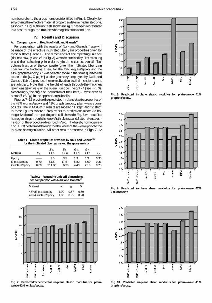
IV. Results and DiscussionA. Comparison with Results of Naik and Ganesh15
For comparison with the results of Naik and Ganesh,15 use willbe made of the effective in� ltrated � ber yarn properties given bythese authors (Table 1). The dimensions of the repeating unit cell(de� ned as a, g, and H in Fig. 3) were determined by � rst selectinga and then selecting g in order to yield the correct overall � bervolume fraction of the composite (given the in� ltrated � ber yarn� ber volume fraction). Then, for the 42% e-glass/epoxy and the41% graphite/epoxy, H was selected to yield the same quarter-cellaspect ratio [.a C g/=H ] as the geometry employed by Naik andGanesh. Table 2 provides the normalizedunit cell dimensions;unitsare arbitrary. Note that the height of each through-the-thicknesslayer was taken as 1
4 of the overall unit cell height H (see Fig. 3).Accordingly, the angle of inclination of the � bers, µ , was taken asarctan(§H=2g) in the appropriate subcells.
Figures 7–12 provide the predicted in-plane elastic properties ofthe 42% e-glass/epoxy and 41% graphite/epoxy plain-weave com-posites. The MAC/GMC results are labeled “1 step” and “2 step”in these � gures, where 1 step refers to predictions made via ho-mogenizationof the repeating unit cell shown in Fig. 3 without � rsthomogenizingthroughtheweave’s thickness,and2 step refers to uti-lizationof the proceduredescribed in Sec. III wherebyhomogeniza-tion is � rst performed through the thicknessof the weave prior to thein-plane homogenization.All other results presented in Figs. 7–12
Table 1 Elastic properties provided by Naik and Ganesh15
for the in� ltrated � ber yarns and the epoxy matrix
EA , ET , G A, GT ,Material V f GPa GPa GPa GPa ºA
Epoxy —— 3.5 3.5 1.3 1.3 0.35E-glass/epoxy 0.70 51.5 17.5 5.80 6.60 0.31Graphite/epoxy 0.80 311.00 6.30 4.40 2.10 0.25
Table 2 Repeating unit cell dimensionsfor comparison with Naik and Ganesh15
Material a g H
42% E-glass/epoxy 1.00 0.67 0.5041% Graphite/epoxy 1.00 0.95 0.78
Fig. 7 Predicted/experimental in-plane elastic modulus for plain-weave 42% e-glass/epoxy.
Fig. 8 Predicted in-plane elastic modulus for plain-weave 41%graphite/epoxy.
Fig. 9 Predicted in-plane shear modulus for plain-weave 42%e-glass/epoxy.
Fig. 10 Predicted in-plane shear modulus for plain-weave 41%graphite/epoxy.

BEDNARCYK AND ARNOLD 1793
Fig. 11 Predicted in-plane Poisson ratio for plain-weave 42%e-glass/epoxy.
Fig. 12 Predicted in-plane Poisson ratio for plain-weave 41%graphite/epoxy.
were taken from Ref. 15. These authors presented the slice arraymodel (SAM) and two versions of the element array model (EAM),one in which the in-plane homogenization occurs � rst in paralleland then in series (PS) and the other in which this homogenizationoccurs in the reversed order (SP). The EAM in-plane homogeniza-tion is performedvia use of isostress (series) and isostrain (parallel)assumptions in the two in-plane coordinate directions.The order inwhich these directional homogenization schemes are applied givesrise to the two distinctEAM models (PS or SP), which, as indicatedin Figs. 7–12, yield different predictions. For details on the EAMand SAM models, the reader is referred to Ref. 15.
Naik and Ganesh15 also provided additional simple model re-sults to which their more re� ned EAM and SAM results were com-pared. These simple models are the modi� ed mosaic parallelmodel(MMPM), which is an extension of the mosaic model developedbyChou and Ishikawa,18 the modi� ed Kabelka model (MKM), whichis an extension of the model developedby Kabelka,19 and the orig-inal Kabelka model. In addition, an experimental in-plane elasticmodulus was provided by Naik and Ganesh for the e-glass/epoxycomposite.
Examining Figs. 7 and 8, it is clear that utilizationof the two-stephomogenization procedure with MAC/GMC rather than the tradi-tional one-step procedure signi� cantly affects the in-plane elasticmodulus predictions.For the plain-weave e-glass/epoxy composite,the predictedmodulushas increasedfrom13.4 to 18.1GPa, a changeof 35%. The increase is even more dramatic for the graphite/epoxycomposite, from 8.53 to 17.4 GPa, or 104%. This greater increase
is clearly due to the greater degree of transverse isotropy exhibitedby the graphite/epoxy yarns compared to the e-glass/epoxy yarns(see Table 1). As mentioned previously, the low predicted in-planeelastic modulus associatedwith the one-stepMAC/GMC procedureis due to the lack of couplingbetween normal and shear stressesandstrains in GMC. A manifestationof this lack of shear couplingis thateach normal stress component is constant in rows of subcells alongthe stress component’s direction.That is, in Fig. 3, ¾22 is constant inrows of subcells along the x2 direction while ¾33 is constant in rowsof subcellsalong the x3 direction.Thus, if a single compliantsubcellis present in series with many stiff subcells, that compliant subcellmust carry the same (appropriatecomponent of) stress as the stiffersubcells. This then causes the entire row to have an unrealisticallylow stiffness, like a chain with a highly compliant link, because nostress can be transferredvia shear to adjacent rows of subcells.Thislack of shear coupling has a signi� cant impact on the ability of theone-step MAC/GMC procedure to predict accurately the in-planemodulus of woven composites because all rows of subcells containcompliant matrix-only subcells or transversely oriented compositesubcells (see Fig. 4). Because the repeatingunit cell lacks any com-plete subcell rows with continuous � bers, the one-step approachunderpredicts the in-plane modulus of the woven composite.
By homogenizing through the weave’s thickness, the propertiesof the subcellgroups(Fig. 5) are linkedor “smeared” together.Then,in step two (see Fig. 6), two rows of subcells exist in both in-planedirections that do not contain any highly compliant subcells. Thisallows the two-step MAC/GMC procedure to predict signi� cantlymore realistic in-planeelastic moduli for woven composites.This isillustratedvia comparisonwith the other results given in Figs. 7 and8. The two-step MAC/GMC predictionfor the in-planeelastic mod-ulus compareswell with the re� ned EAM and SAM models for bothcompositesand compares well with experiment for the plain-weavee-glass/epoxy composite. Particularly encouraging is the fact thatthe two-step MAC/GMC elastic modulus prediction falls betweenthe EAM-PS and EAM-SP predictions for both woven composites.It should be noted that the EAM models employed 2500 individualgeometric elements, whereas the present MAC/GMC predictionswere performed with a total of 64 subcells.
ExaminingFigs. 9–12, it is clear that the two-stepMAC/GMC ho-mogenization procedure gives rise to higher in-plane shear moduliand lower in-plane Poisson ratios compared to the one-step pro-cedure. It appears that the MAC/GMC shear modulus predictionsare improved via use of the two-step procedure because they are inbetter agreement with the EAM and SAM model predictions. ThePoisson ratio predictionsof the one-step MAC/GMC procedure areactually in better agreement with the EAM and SAM models thanthe corresponding two-step MAC/GMC predictions.
B. Comparison with Results of Dasgupta et al.16
Dasgupta et al.16 performed a unit-cell-based three-dimensionalFEA of a 35% plain-weave e-glass/epoxy composite. However, thehomogenized properties of the in� ltrated � ber yarns were not pro-vided.The authorsemployedthe Mori–Tanakamethod to determinethe properties from the � ber and matrix constitutive properties. Tocompare the GMC results with the results of Dasgupta et al., the� ber and matrix propertiesemployedby these authorswere homog-enized using MAC/GMC to obtain the effective properties of thee-glass/epoxy in� ltrated � ber yarns. A 26 £ 26 subcell GMC re-peating unit cell was used for this purpose. The � ber and matrixproperties given by Dasgupta et al., as well as the homogenized in-� ltrated � ber yarn properties determined by MAC/GMC, are givenin Table 3.
Dasguptaet al.16 also did not providethe dimensionsof their 35%plain-weave e-glass/epoxy composite; thus, for comparison withtheir results, H was selected to yield the same quarter-cell aspectratio as that employedby Naik and Ganesh15 for their e-glass/epoxycomposite.Accordingly,a, g, and H were taken as 1.00, 0.857, and0.554, respectively.Finally, as before, the angle of inclinationof the� bers, µ , was taken as arctan(§H=2g) in the appropriate subcells.
Table 4 presents a comparison between MAC/GMC and the re-sults of Dasgupta et al.16 for the 35% plain-weave e-glass/epoxy

1794 BEDNARCYK AND ARNOLD
Table 3 Elastic properties provided by Dasgupta et al.16 for thee-glass � ber and the epoxy matrix and the properties of the in� ltrated
e-glass/epoxy � ber yarns determined via MAC/GMC
EA , ET , G A , GT ,Material V f GPa GPa GPa GPa ºA
Epoxy —— 3.45 3.45 1.26 1.26 0.37E-glass —— 72.4 72.4 29.67 29.67 0.22E-glass/epoxy 0.65 48.3 14.5 5.06 5.09 0.264
Table 4 Comparison of elastic property predictionsand experiment16 for 35% plain-weave e-glass/epoxy
Result E , GPa º
Experiment 18.8 0.14MAC/GMC–1 step 11.4 0.183MAC/GMC–2 step 17.0 0.144Dasgupta et al.16 19.7 0.14
composite. Dasgupta et al. also provided the experimental resultsgiven in Table 4. Recall that since Dasgupta et al. did not providethedimensions of the composite, the geometry of the GMC repeatingunit cell is approximate. It is clear from Table 4 that the predictionsof GMC have again been signi� cantly improved through the utiliza-tionof the two-stepapproachcomparedto theone-stepapproach.Asdescribedearlier, the in-planemodulus rises signi� cantly (by 49%),resulting in much better agreement with experiment. Furthermore,as described earlier, the in-plane Poisson ratio has decreased sig-ni� cantly, but we now see that this decrease provides signi� cantlybetter agreement with experiment. Thus, it appears that the EAMmodels’ Poisson ratio predictions (Figs. 11 and 12), which agreedwell with the GMC one-step prediction, may not be as accurate asthose made using the GMC two-step approach.
In Table 4 it is also clear that the three-dimensionalFEA predic-tionsperformedby Dasguptaet al.16 are in better agreementwith ex-periment than the GMC two-step predictions.This is to be expectedbecausethis FEA employeda signi� cantlymore accurategeometricrepresentationthan that employed in this study (see Fig. 3). Utiliza-tion of a more re� ned unit cell geometry might further improve theMAC/GMC predictions.
C. Comparison with Results of Tanov and Tabiei17
Tanov and Tabiei17 presented two models for determining theelastic properties of plain-weave composites that they called thefour-celland the single-cellmodels.The approach taken in the four-cell model is similar to that employed herein with MAC/GMC. Thewoven composite geometry is subdivided into regions containingeither unidirectional in� ltrated � ber yarns or pure matrix material,and groups of these subregionsare homogenized through the thick-ness of the woven composite. Finally, the effective properties ofthese through-the-thickness groupsare homogenizedin the planeofthe weave to determine the effective properties of the plain-weavecomposite. The homogenization at both stages is performed usingisostress and isostrainassumptionson certain stress and strain com-ponents. Clearly, in the four-cell model, Tanov and Tabiei circum-vent the lack of shearcouplingin theirhomogenizationprocedurebyperforming through-the-thickness homogenization prior to the in-plane homogenization. In the single-cell model, on the other hand,theassumedcompositegeometryis such thatcontinuous� bers travelthe entire length of the analysisvolume. Thus, thanks to this simpli-� ed geometric representation,the homogenizationprocedure’s lackof shear couplingdoes not lead to underpredictionof the compositein-plane elastic modulus.
The homogenized in� ltrated � ber yarn properties, as well as thepure matrix materialpropertiesemployedby Tanovand Tabiei,17 aregiven in Table 5. Because the four-cell model geometry is similarto the unit cell geometry employed herein with GMC, the unit celldimensions, given in Table 6, were readily available. Note that theangle of inclination of the � ber yarns, µ (see Fig. 3), was providedexplicitlyby Tanovand Tabiei and was used within the GMC model.
Table 5 Elastic properties employed by Tanov and Tabiei17
for the in� ltrated � ber yarns and the pure matrices
EA , ET , G A,Material V f GPa GPa GPa ºA ºT
Epoxy —— 3.5 3.5 1.3 0.35 0.35E-glass/epoxy 65 47.77 18.02 3.877 0.314 0.249TIMETAL 21S —— 112.0 112.0 41.8 0.34 0.34SCS-6/TIMETAL 65 293.88 253.84 93.46 0.278 0.2846
21SEpoxy (a) —— 3.45 3.45 1.26 0.37 0.37Glass/epoxy (a) 80a 58.61 14.49 5.38 0.250 0.247Epoxy (b) —— 4.511 4.511 1.634 0.38 0.38Graphite/epoxy (b) 65 137.3 10.79 5.394 0.26 0.46
aDeduced from properties, not explicitly stated in Ref. 17.
Table 6 Repeating unit cell dimensions for comparison with Ref. 17
Material a g H µ , deg
35% E-glass/epoxy 0.5385 0.4615 0.3077 9.4635% SCS-6/TIMETAL 21S 0.5385 0.4615 0.3077 9.4646% Glass/epoxy 0.26 0.74 0.3701 4.238% Graphite/epoxy 0.58 0.42 0.1545 1.4
Table 7 Model results for 35% plain-weave e-glass/epoxy
E2, E3, E1 , G12 , G13 , G23,Model GPa GPa GPa GPa º21, º31 º23
GMC (1 step) 13.1 9.42 2.53 2.46 0.307 0.246GMC (2 step) 18.1 9.85 2.54 2.76 0.318 0.177Tanov and Tabiei17 17.853 9.788 2.497 3.529 0.3321 0.1724
(four cell)Tanov and Tabiei17 18.209 7.798 2.294 3.407 0.3923 0.1739
(single cell)Chung and Tamma20 18.634 8.346 2.422 3.190 0.3720 0.1745
upper bound
Table 8 Model results for 35% plain-weave SCS-6/TIMETAL21S
E2 , E3 , E1, G12 , G13, G23 ,Model GPa GPa GPa GPa º21 , º31 º23
GMC (1 step) 185.8 177.8 62.49 61.90 0.3075 0.2902GMC (2 step) 195.1 180.8 62.50 64.35 0.3073 0.2813Tanov and Tabiei17 194.47 180.30 61.00 69.44 0.3086 0.2810
(four cell)Tanov and Tabiei17 196.32 170.60 59.15 68.83 0.3237 0.2779
(single cell)Chung and Tamma20 196.05 174.15 60.00 67.23 0.3180 0.2790
upper bound
Table 9 Model results for 46% plain-weave e-glass/epoxy
E2 , E3 , E1 , G12 , G13, G23 ,Model GPa GPa GPa GPa º21, º31 º23
GMC (1 step) 9.16 5.76 1.67 1.63 0.402 0.203GMC (2 step) 11.84 6.21 1.68 1.78 0.402 0.167Tanov and Tabiei17 11.86 6.21 1.70 2.33 0.404 0.166
(four cell)Tanov and Tabiei17 11.93 5.67 1.59 2.31 0.436 0.159
(single cell)Marrey and Sankar21 11.81 6.14 1.84 2.15 0.408 0.181
Tables 7–10 compare the GMC one-step and two-step proce-dure predictions with those of the four-cell and single-cell Tanovand Tabiei17 models. Also included in the tables are additional re-sults from the literature that were included by Tanov and Tabiei.These additional results include � nite element results of Chung andTamma,20 which represent an upper bound (displacement bound-ary conditions employed), for the 35% plain-weave e-glass/epoxyand 35% SCS-6/TIMETAL21S composites; Marrey and Sankar’s21

BEDNARCYK AND ARNOLD 1795
Table 10 Model results for 35% plain-weave graphite/epoxy
E2, E3, E1 , G12, G13 , G23,Model GPa GPa GPa GPa º21 , º31 º23
GMC (1 step) 14.2 8.11 2.75 2.99 0.460 0.131GMC (2 step) 45.08 10.12 2.756 3.235 0.4637 0.0564Tanov and Tabiei17 45.08 10.12 2.763 3.815 0.4643 0.0562
(four cell)Tanov and Tabiei17 45.17 9.782 2.585 3.813 0.4784 0.0542
(single cell)Jiang et al.22 46.35 —— —— 3.83 —— 0.0538Ishikawa et al.23 48.3a/49.8b —— —— 5.41a/3.83b —— 0.062a/0.068b
aOne ply. bFour plies.
Fig. 13 Illustration of amultiscale approach to mod-eling woven compositemate-rials and structures.
� nite-element-based analysis of 46% plain-weave e-glass/epoxycomposite plates; and micromechanical model results of Jianget al.,22 as well as experimental results of Ishikawa et al.,23 for 35%plain-weave graphite/epoxy.
As the tables show, the GMC results have improved by utilizingthe two-step approach compared to the one-step approach, espe-cially with respect to the in-plane elastic modulus. We see again,as shown in Sec. IV.B, that the reduction of the in-plane Poisson
ratio associatedwith the utilizationof the two-step procedureratherthan the one-step approach improves the model’s agreement withother results from the literature. Note that, for the MMC (SCS-6/TIMETAL21S), whose constituentpropertiesexhibit signi� cantlyless stiffness mismatch than that of the PMCs, the differences be-tween the one-step and two-step GMC approaches are muted, asexpected.
Also noteworthy is the excellent agreement between the GMCtwo-step and the Tanov and Tabiei17 four-cell results. In Tables 9and 10, the results of these two models are nearly identical for allproperties with the exception of the in-plane shear modulus, whichis somewhat lower in the case of the GMC prediction. The simi-larity of the results is expected because the models themselves arequite similar. This similarity, as well as the in-plane shear modu-lus discrepancy, can be understood by examining the isostress- andisostrain-basedequationsemployedby Tanovand Tabiei in the four-cell model to preform the in-plane homogenization. This in-planehomogenization is performed on four subcell groups, which havealready been homogenized in the through-the-thickness direction.Thus, at thispoint the geometry is similar to that shown in Fig. 6 with4 rather than 16 distinct regions or subcells. The homogenization isperformedvia use of Tanov and Tabiei’s17 Eqs. (23) and (24),whichare, with one small variation, the equations of GMC specialized tofour subcells (i.e., the method of cells4/. This variation occurs be-cause, rather than assuming the average in-plane shear strain is thesum of four distinct subcell in-plane shear strains (as they do forthe other shear strains), Tanov and Tabiei assume that the in-planeshear strain is constant. In GMC, on the other hand, it is the in-planeshear stress that is constant. As one might expect, this differencein the equations that pertain to the in-plane shear behavior of thecomposite manifests as a difference in the two models’ predictionsfor the in-plane shear modulus. GMC, which forces the subcells toexperience the same in-plane shear stress, results in a lower shearstiffness than does the four-cell model, which forces the subcells toexperience the same in-plane shear strain.
V. ConclusionsA two-step homogenizationprocedurehas been outlined that en-
ables the accurate predictionof woven PMC elastic propertieswithGMC. Previously, woven PMCs could not be accurately modeledusing the GMC approach due to the lack of shear coupling inher-ent in the model. For woven MMCs, this lack of shear couplingwas not prohibitive because the effects of matrix inelasticity and� ber–matrix debonding tended to dominate the woven MMC’s re-sponse.Via utilizationof an independent through-the-thickness ho-mogenizationstep, as suggestedby Tabiei and Jiang11 and Huang,12
MAC/GMC can now accurately model the response of the morecommon woven PMCs.
The results presented herein indicate that the two-stepMAC/GMC homogenizationprocedure predictionscompare favor-ably with results from several previous models for woven com-posites and experiment. These results serve as a proof of conceptfor this new GMC procedure for modeling woven composites. Thenext step will involve fully coupling this two-step procedure withthe embedded approachused previously to model woven MMCs2;13
and incorporating these capabilities into NASA’s MAC/GMC soft-ware package. This will, in effect, result in a multiscale model for

1796 BEDNARCYK AND ARNOLD
arbitrarywoven and braidedcompositematerialsand structures,ow-ing to MAC/GMC’s interface with FEA. This multiscale approachcan be visualized as shown in Fig. 13. Via continuous localizationand homogenization,the stress and strain � elds in the � ber and ma-trix constituents can be tracked throughout the woven compositeand structure during time-dependent thermomechanical loading onthe global (structure) scale. This will then allow employment of ar-bitrary viscoelastoplasticconstitutive models, damage models, andlocal failure criteria on the scale of the individual constituents.
It should be noted that the plain-weave composite model devel-oped by Tabiei and Jiang11 that introduced the concept of an inde-pendent through-the-thickness homogenizationstep also was linkedwith FEA. However, their model localized only to the level of thein� ltrated � ber yarns. Thus, the constituent-level � elds were notavailable and microscale constitutive, damage, and failure modelscould not be incorporated.The same is true for the work of Tanovand Tabiei.17 Furthermore, the work of Tabiei and Jiang consideredonly one particular woven composite architecture.Because the pe-riodic composite microstructure admitted by GMC is arbitrary, theprocedureoutline herein can be employed for any type of woven orbraided composite.
AcknowledgmentThe � rst author gratefully acknowledges the funding for this
work provided by the NASA Glenn Research Center under Con-tract NCC3-650.
References1Bednarcyk, B. A., and Pindera, M.-J., “Micromechanical Modeling of
Woven Metal Matrix Composites,” NASA CR-204153, 1997.2Bednarcyk, B. A., and Pindera, M.-J., “Inelastic Response of a Woven
Carbon/Copper Composite—Part II: Micromechanics Model,” Journal ofComposite Materials, Vol. 34, No. 4, 2000, pp. 299–331.
3Cox, B. N., Carter, W. C., and Fleck, N. A., “A Binary Model of Tex-tile Composites—I. Formulation,” Acta Metallurgica et Materialia, Vol. 42,No. 10, 1994, pp. 3463–3479.
4Aboudi, J., Mechanics of Composite Materials:A Uni� ed Micromechan-ical Approach, Elsevier Science, New York, 1991.
5Paley, M., and Aboudi, J., “Micromechanical Analysis of Compositesby the Generalized Cells Model,” Mechanics of Materials, Vol. 14, 1992,pp. 127–139.
6Aboudi, J., “Micromechanical Analysis of Thermo-Inelastic MultiphaseShort-Fiber Composites,” Composites Engineering, Vol. 5, No. 7, 1995,pp. 839–850.
7Wilt, T. E., “On the Finite Element Implementation of the GeneralizedMethod of Cells Micromechanics Constitutive Model,” NASA CR-195451,1995.
8Pindera, M.-J., and Bednarcyk, B. A., “An Ef� cient Implementation ofthe Generalized Method of Cells for Unidirectional, Multi-Phased Com-posites with Complex Microstructures,” Composites B, Vol. 30, 1999,pp. 87–105.
9Arnold, S. M., Bednarcyk, B. A., Wilt, T. E., and Trowbridge,D., “Micromechanics Analysis Code With Generalized Method of Cells(MAC/GMC) User Guide: Version 3.0,” NASA TM-1999-109070,1999.
10Arnold, S. M., Saleeb, A. F., Wilt, T. E., and Trowbridge, D.,“UMAT Implementation of Coupled, Multilevel, Structural Deformationand Damage Analysis of General Hereditary Materials,” Proceedings of the2000 ABAQUS Users’ Conference, Hibbitt, Karlsson, and Sorensen, Inc.,Pawtucket, RI, 2000, pp. 67–84.
11Tabiei, A., and Jiang, Y., “Woven Fabric Composite Material Modelwith Material Nonlinearity for Nonlinear Finite Element Simulation,” In-ternational Journal of Solids and Structures, Vol. 36, 1999, pp. 2757–2771.
12Huang, Z. M., “The Mechanical Properties of Composites Reinforcedwith Woven and Braided Fabrics,” Composites Science and Technology,Vol. 60, 2000, pp. 479–498.
13Bednarcyk, B. A., and Pindera, M.-J., “Inelastic Response of a Wo-ven Carbon/Copper Composite—Part III: Model-Experiment Correlation,”Journal of Composite Materials, Vol. 34, No. 5, 2000, pp. 352–378.
14Hill, R., “Elastic Properties of Reinforced Solids: Some TheoreticalPrincipals,” Journal of the Mechanics and Physics of Solids, Vol. 11, 1963,pp. 357–372.
15Naik, N. K., and Ganesh, V. K., “Prediction of On-Axes Elastic Proper-ties of Plain Weave Fabric Composites,” Composites Science and Technol-ogy, Vol. 45, 1992, pp. 135–152.
16Dasgupta, A., Agarwal, R. K., and Bhandarkar, S. M., “Three-Dimensional Modeling of Woven-Fabric Composites for Effective Thermo-Mechanical and Thermal Properties,” Composites Science and Technology,Vol. 56, 1996, pp. 209–223.
17Tanov, R., and Tabiei, A., “ComputationallyEf� cient MicromechanicalModels for Woven Fabric Composite Elastic Moduli,” Journal of AppliedMechanics, Vol. 68, No. 5, 2001, pp. 553–360.
18Chou, T.-W., and Ishikawa, T., “Analysis and Modeling of Two-Dimensional Fabric Composites,” Textile Structural Composites, edited byT.-W. Chou and F. K. Ko, Elsevier, New York, 1989, pp. 209–264.
19Kabelka, J., “Prediction of the Thermal Properties of Fibre-Resin Com-posites,” Developments in Reinforced Plastics—3, edited by G. Pritchard,Elsevier, London, 1984, pp. 167–202.
20Chung, P. W., and Tamma, K. K., “Woven Fabric Composites—Developments in Numerical Bounds, Homogenization and Applications,”International Journal of Numerical Methods in Engineering, Vol. 45, 1999,pp. 1757–1790.
21Marrey, R. V., and Sankar, B. V., “A Micromechanical Model for TextileComposite Plates,” Journal of Composite Materials, Vol. 31, No. 12, 1997,pp. 1187–1213.
22Jiang, Y., Tabiei, A., and Simitses, G. J., “A Novel Micromechanics-Based Approach to theDerivationofConstitutiveEquationsforLocal/GlobalAnalysis of aPlain-WeaveFabric Composite,”CompositesScience andTech-nology, Vol. 60, 2001, pp. 1825–1833.
23Ishikawa, T., Matsushima, M., Hayashi, Y., and Chou, T.-W., “Experi-mental Con� rmation for theTheoryofElastic ModuliofFabric Composites,”Journal of Composite Materials, Vol. 19, 1985, pp. 443–458.
A. M. WaasAssociate Editor
Copyright © 2022 FDOKUMEN