Hybrid micromachining using a nanosecond pulsed laser and micro EDM
Upload
independentCategory
view
0download
0
International Scholarly Research NetworkISRN Condensed Matter PhysicsVolume 2012, Article ID 387380, 12 pagesdoi:10.5402/2012/387380
Research Article
Micromagnetic Simulation of Spin Transfer TorqueMagnetization Precession Phase Diagram in a Spin-ValveNanopillar under External Magnetic Fields
H. B. Huang,1, 2 X. Q. Ma,1 Z. H. Liu,1 X. M. Shi,1 T. Yue,1 Z. H. Xiao,1 and L. Q. Chen2
1 Department of Physics, University of Science and Technology Beijing, Beijing 100083, China2 Department of Materials Science and Engineering, The Pennsylvania State University, University Park, PA 16802, USA
Correspondence should be addressed to X. Q. Ma, [email protected]
Received 29 May 2012; Accepted 21 June 2012
Academic Editors: N. Birge and A. A. Kordyuk
Copyright © 2012 H. B. Huang et al. This is an open access article distributed under the Creative Commons Attribution License,which permits unrestricted use, distribution, and reproduction in any medium, provided the original work is properly cited.
We investigated spin transfer torque magnetization precession in a nanoscale pillar spin-valve under external magnetic fieldsusing micromagnetic simulation. The phase diagram of the magnetization precession is calculated and categorized into four statesaccording to their characteristics. Of the four states, the precessional state has two different modes: steady precession mode andsubsteady precession mode. The different modes originate from the dynamic balance between the spin transfer torque and theGilbert damping torque. Furthermore, we reported the behavior of the temporal evolutions of magnetization components insteady precession mode at the condition of the applied magnetic field using the orbit projection method and explaining perfectlythe magnetization components evolution behavior. In addition, a result of a nonuniform magnetization distribution is observedin the free layer due to the excitation of non-uniform mode.
1. Introduction
There has been intensive interest in spintronics for the pasttwo decades [1]. An important example is giant magnetore-sistance (GMR), proposed by Fert et al. [2] and Grunberget al. [3], which has led to commercial products [4]. GMReffect has many potential applications such as magneticsensor, magnetic read head, data memory and spin transistor,and so forth. Spin-valve [5], as a simple GMR device, alsoexhibits the switching effect. The merit of spin-valve is thatthe magnetization reversal can be realized under a smalldriving magnetic field. Besides being driven by the magneticfield, the magnetization may also be driven by a torque,spin transfer torque (STT), originated from the electronspins in the conducting current. The angular momentumsmay be transferred from the electrons of the spin-polarizedcurrent to the ferromagnet, giving rise to a switching ofmagnetization or stable precession of magnetizations [6] thatleads to the generation of spin waves [7]. This mechanismof STT was initially proposed by Berger et al. [8] andSlonczewski [9] in 1996 and attracted significant interests
because of the great potential for direct current-inducedspintronic devices [10–12]. The role of STT in magnetizationswitching has been verified by numerous experiments inspin-valve nanopillars [13–15], magnetic nanowires [16, 17],point contact geometry [18–20], and magnetic tunnel junc-tions [21–24]. The most attractive application of current-induced magnetization switching is magnetic random-accessmemory (MRAM), which has the advantages of nonvolatile,high addressing speed, low-energy consumption, and avoid-ance of cross writing. Another important application is thecurrent-induced spin transfer nanooscillators (STNO), inwhich the magnetization precesses, causing a spin wave in themicrowave range. In previous researches, it was shown thatthe application of magnetic field affects the magnitudes ofswitching field and switching time [25–28], opening new per-spectives for information technology. Previous studies haveshown that there are different magnetization types in theswitching process depending on the magnetic field and thecurrent [14]. Therefore, the understanding of magnetizationprecession and its mechanism under the external magneticfields is very important for designing functional devices.

2 ISRN Condensed Matter Physics
Many attempts have been made to increase the outputpower of STNOs; for example, an effective way to increaseoutput power is magnetic-tunnel-junction- (MTJ-) basedSTNO with a larger linewidth [29–32]. Compared withMTJ-STNO, there are several advantages that STNO withfull metal GMR structure have, such as narrow oscilla-tion linewidth, low device resistance, and good impedancematching. Therefore, it is very important to understand themagnetization precession state under the external magneticfield in the conventional 3d-FM-based GMR structure. Thephase diagram of magnetization precession under in-planeexternal field has been studied by several authors [14, 26,33–35]. Kiselev et al. [36] showed that several differentprecessional modes exist, that is, small angle precession,large angle precession, and out-of-plane precession. Gmitraet al. [37] presented the phase diagram of magnetic fieldversus current density, illustrating that precessional state(PS) occurs at small current density and external magneticfields. Although there have been a number of works on thephase diagram, the detailed analysis of the phase diagram islacking. Xiao et al. [38] demonstrated that there were severalprecessional states in the magnetization reversal, that is,large-amplitude, in-plane, and out-of-plane precession fromtheory. In addition, they also presented the formation ofphase diagram from the balance of STT and Gilbert dampingtorque. However, few published papers showed the detaileddiscussion of in-plane precession in the phase diagram.
In this paper, we present a systematic study on mag-netization precession under spin-polarized currents andmagnetic fields using micromagnetic simulation. The mag-netization precession is grouped into several types accordingto their characteristics, which are unchanging state (UN),precessional state (PS), multidomain state (MS), and bistablestate (BS). Among them, PS under magnetic field has twoprecession modes. Furthermore, the orbit projection methodis applied to explain the magnetization component oscilla-tion, and the snapshots of magnetization distribution shownonuniform magnetization precession. The magnetizationprecession phase diagram is helpful for understanding themagnetization precession mode and affecting the oscillationlinewidth during the design of spin transfer nanooscillators.
2. Theoretical Model
The magnetization precession of a nanoscale pillar structureis investigated under the influence of spin-polarized currentsand magnetic fields by micromagnetic simulations based onthe Landau-Lifshitz-Gilbert (LLG) equation incorporatingSTT effect. The nanopillar structure is schematically shownin Figure 1. The thicknesses of each layer are Co (2 nm)/Cu(4 nm)/Co (10 nm) from top to bottom, and the size ofthe nanopillar is 16 × 64 × 16 nm3. The two Co layers areseparated by a thin Cu layer; the top Co layer is the freelayer whose magnetization precession is triggered by a spin-polarized current. The bottom Co layer is the pinned layerwith its magnetization vector P fixed in the direction alongthe positive x-axis. The initial magnetization vector M of thelayer is along the negative or positive x-axis. The middle Culayer is a space layer whose function is to avoid the exchange
z
x
y
Hzext
Hxext
Hyext
J > 0
2 nm Co
4 nm Cu
10 nm Co
M
P
Figure 1: Model geometry definition of Co/Cu/Co nanopillar inCartesian coordinates.
coupling between the two Co layers. The thickness of thespacer layer (4 nm) is much smaller than the spin diffusionlength to conserve the spin momentum. The positive currentis defined as the current flow from the free layer to the pinnedlayer.
The dynamics could be described by the temporal evo-lution of the magnetization M, and M obeys the generalizedLandau-Lifshitz-Gilbert-Slonczewski (LLGS) equation:
dMdt
= − γ′M×Heff − αγ′
MsM× (M×Heff)
− 2μBJ
(1 + α2)edM3s
g(M, P)M× (M, P)
+2μBαJ
(1 + α2)edM2s
g(M, P)(M, P).
(1)
The first term on the right-hand side of (1) is aconventional magnetic torque with gyromagnetic ratio γ,where γ′ = γ/(1 + α2). This torque is driven by an effectivefield,
Heff = − 1μ0
δE
δM. (2)
The effective field of the LLGS includes the anisotropy,demagnetization, external, and the exchange fields, namely,Heff = Hexch + Hani + Hms + Hext. Taking account ofexchange energy, anisotropy energy, magnetostatic energy,and Zeeman energy, the total energy E is given by
E = Eani + Eexch + Ems + Eext. (3)
The anisotropy energy of Co in a Co/Cu/Co nanopillar is
Eani =∫ (
K1[1−m2
s (r)]
+ K2[1−m2
s (r)]2)d3r, (4)
where K1 and K2 are the anisotropy constants, ms(r) is theunit magnetization vector at each grid, ms(r) = Ms(r)/Ms,and the easy axis is along the x-axis. Considering the fact that

ISRN Condensed Matter Physics 3
0.1
0.08
0.06
0.04
0.02
00 1 2 3 4 5 6 7
App
lied
fiel
d (M
s)
Current density (×107 A/cm2)
No
swit
chin
g
Swit
chin
g
UN PS MS BS
(a)
0.1
0.08
0.06
0.04
0.02
0
App
lied
fiel
d (M
s)
Current density (×107 A/cm2)
No
swit
chin
g
Swit
chin
g
UNMSBS
−14 −12 −10 −8 −6 −4
(b)
Figure 2: Phase diagram of magnetization precession under perpendicular magnetic fields (a) for a positive current and (b) for a negativecurrent.
K1 is far greater than K2, we ignore the second term in thesimulations.
The exchange energy is
Eexch =∫(
A
M2s|∇M(r)|2
)d3r, (5)
where A is the exchange stiffness constant.The magnetostatic energy can be presented as a sum of
energies of interacting magnetic dipoles as follows:
Ems = 12
∫∫⎧⎨⎩Mi(r)
⎡⎣ δi j
|r − r′|3 −3(ri − r′i
)(r j − r′j
)
|r − r′|5⎤⎦
× M j(r)
⎫⎬⎭d3rd3r′.
(6)
We utilize the fast Fourier transform (FFT) technique forobtaining the magnetostatic energy as it involves doubleintegrals in real space.
The Zeeman energy is
Eext = −μ0
∫[Hext ·M(r)]d3r, (7)
where Hext is the externally applied magnetic field.The second term in (1) is the “Gilbert damping” which
takes into account energy dissipation, such as coupling tolattice vibrations [39] and spin-flip scattering [40]. This isused by most practitioners, although there is an active debatewhether this form of the damping is correct [41–43].
The last two terms on the right side of (1) describe STTwhich tends to drag the magnetization away from its initialstate to its final state and drive the magnetization precessionaround the effective field. The scalar function is given by [9]
g(M, P) =[−4 +
(1 + η
)3(3 + M · P/M2s
)4η3/2
]−1
. (8)
where HSTT is the corresponding effective field given by
HSTT = 2μBJg(M, P)M× P(γedM3
s
) , (9)
where μB, J, d, e, and Ms, are the Bohr magneton, currentdensity, thickness of the free layer, electron charge, andsaturation magnetization, respectively.
Analysis and micromagnetic calculations based on thismodel show that magnetization reversal in the layer requiresan initial deviation from strictly parallel or antiparallelalignment. If M is parallel or antiparallel to P(θ = 0◦or θ =180◦), STT is zero as M × P = 0. To initiate the simulation,a small angle deviation from the parallel or antiparallelconfiguration between M and P was assigned. The classicalOersted field scales as 1/r generated by conduction electrons,where r is the lateral size of the free layer, while STTscales as 1/r2. Therefore, for small sizes like a nanopillarwith the cross-section 64 × 64 nm2, STT dominates overthe classical Oersted field. We ignore the Oersted field andthermal activation in this work for studying a “minimal”model of the spin torque-driven magnetization precession.In our simulations, we assumed θ = 0.1◦ for parallel andθ = 179.9◦ for antiparallel configurations at the beginning.The parameters of Co are adopted from the values at heliumtemperature (4.2 K) [26]: η = 0.35,Ms = 1.446 × 10⁶ A/m,γ = 2.3245 × 10⁵ m/(A · s), K1 = 6.86 × 10⁵ J/m3,α = 0.01, A = 2.0 × 10⁻¹¹ J/m, and d = 2 nm. Thedynamics of magnetization is investigated by numericallysolving the time-dependent LLGS equation using the Gauss-Seidel projection method [44, 45] with a constant time stepΔt = 14.875 fs. Simulation performed with shorter timestep gave the same results. The free layer is discrete incomputational cells of 2× 2× 2 nm3 [46].
3. Results
Figure 2 shows the phase diagram of magnetization pre-cession under perpendicular magnetic fields along z-axisdirection. Each precessional state corresponds to a certaincurrent density range under external field. The case of posi-tive current results in magnetic switching from antiparallelstate to parallel state, like the situation without magneticfield [26]. The magnetization process can be grouped intofour types: unchanging state (UN), precessional state (PS),

4 ISRN Condensed Matter Physics
0 1 2 3
Time (ns)
−0.99
−1
⟨Mx/M
s⟩
4
⟨Mx/Ms⟩
(a)
0 1 2 3 4
Time (ns)
0.2
0.1
0
−0.1
−0.2
⟨My,z/M
s⟩
⟨My/Ms⟩⟨Mz/Ms⟩
(b)
Figure 3: The temporal evolution of the magnetization components under J = 1.00× 10⁷ A/cm2.
−0.88
−0.92
−0.96
−10 4 8 12 16
Time (ns)
−0.94
−0.96
−0.98
−114.8 14.84 14.88 14.92 14.96 15
a
b
c
d
e
⟨Mx/M
z⟩
⟨Mx/Ms⟩
(a)
0.2
0
0.8
0.4
0
−0.4
−0.8
0 4 8 12 16
Time (ns)
0.2
0
−0.2
14.8 14.84 14.88 14.92 14.96 15
a
b
cde
14.8 14.84 14.88 14.92 14.96 15
a
b
c
d
e
⟨My,M
z/M
s⟩
⟨My/Ms⟩⟨Mz/Ms⟩
(b)
Figure 4: The temporal evolutions of the magnetization components under J = 1.60×10⁷ A/cm2. The insets are the zooms of time span from14.80 ns to 15.00 ns. The five points (a, b, c, d, and e) correspond to the times of 14.877 ns, 14.883 ns, 14.890 ns, 14.893 ns, and 14.899 ns,respectively.
multidomain state (MS), and bistable state (BS). In UN,the magnetization keeps in the initial antiparallel state. Themagnetizations in PS precess around the effective field withsteady motion in the film plane. In MS, the magnetizationlies in the multidomain state. Only in BS, the magnetizationcan be switched from the initial antiparallel state to the finalparallel state. However, different from the situation of theuniform state in PS under zero field [26], when the externalmagnetic field is applied, two precession modes were foundin this state: steady and substeady precession modes.
A negative current favors antiparallel state, resultingin the magnetic reversal from the initial parallel to finalantiparallel state, as shown in Figure 2(b). Different from thepositive current case, only three types of states were observedin the reverse process with PS missing.
To illustrate the feature and mechanism of magnetizationprecession under perpendicular magnetic fields, we takeHz
ext = 0.10Ms(1.82 KOe) as an example. In this condition,if the current density varies in the range of 0 ≤ J <1.50 × 10⁷ A/cm2, the magnetization dynamics lies in theUS. In this state, STT energy is less than the Gilbert energy
dissipation. Any finite fluctuation is damped down, and themagnetization keeps in the initial state. Figures 3(a) and3(b) show that the temporal evolutions of magnetizationcomponents are heavily damped under J = 1.00×10⁷ A/cm2.
In the range of 1.50 × 10⁷ A/cm2 ≤ J < 1.95 ×10⁷ A/cm2, the magnetization dynamics lies in the PS, wherethe Gilbert energy dissipation equals the STT energy input.PS corresponds to the in-plane precession (IPP) in the filmplane; the out-of-plane precession (OPP) is not found inour micromagnetic simulations, which means the transitionfrom the precessional state to multidomain state occursdirectly in the presence of magnetic fields. The absence ofOPP was identified as a consequence of the underestimationof the exchange constant and the role of the initial self-magnetostatic field, which was demonstrated by Jaromirskaet al. [47]. The two modes in the PS, that is, steady precessionmode, and substeady precession mode, are in the rangesof 1.50 × 10⁷ A/cm2 ≤ J < 1.65 × 10⁷ A/cm2 and 1.65 ×10⁷ A/cm2 ≤ J ≤ 1.95× 10⁷ A/cm2, respectively.
Figure 4 shows the temporal evolution of the magne-tization components in the steady precession mode. The

ISRN Condensed Matter Physics 5
−0.8
−0.84
−0.88
−0.92
−0.96
−1
−0.94
−0.96
−0.98
−1
0
Time (ns)
7.2 7.3 7.4 7.5 7.6 7.7⟨Mx/M
z⟩
AB
C
2 4 6 8
⟨Mx/Ms⟩
(a)
0.8
0.4
0
−0.4
−0.8
⟨My,M
z/M
s⟩
0
Time (ns)
2 4 6 8
0.2
0
−0.2
7.2 7.3 7.4 7.5 7.6 7.7
7.2 7.3 7.4 7.5 7.6 7.7
0.2
0.1
0
A
B
C
A
B
C
⟨My/Ms⟩⟨Mz/Ms⟩
(b)
Figure 5: The temporal evolution of the magnetization components under J = 1.70 × 10⁷ A/cm2. The insets show the “beat” behavior ofmagnetization in the zoom of 0.5 ns. The three points (A, B, and C) correspond to the time of 7.299 ns, 7.410 ns, and 7.540 ns, respectively.
temporal evolution of 〈Mx/Ms〉 shows two stages: initialand stable stages. In the initial stage, the Gilbert dampingtorque is smaller than the STT, therefore, the amplitude of〈Mx/Ms〉 increases with the time evolution. Then the Gilbertenergy dissipation equals the STT energy input in the stablestage; the magnetic moments precess around the effectivefield, with oscillations at constant frequency and ampli-tude. Different from the precession without magnetic field,the temporal evolution of the magnetization component〈Mx/Ms〉 has a “sag” in the oscillation crest at a perpendicularmagnetic field. Although this phenomenon had also beenreported by Siracusano et al. [48] and Horley et al. [49, 50],the explanation is not found. We shall give a systematicexplanation of this phenomenon later.
In the range of 1.65 × 10⁷ A/cm2 ≤ J ≤ 1.70 ×10⁷ A/cm2, the magnetization lies in the substeady precessionmode. Figure 5 depicts the temporal evolutions of themagnetization components under J = 1.70 × 10⁷ A/cm2.The amplitude is modulated by a low-frequency sinusoidalcontour, showing the feature of “beat” phenomenon. Thebeat frequency equals to 4.03 GHz and this phenomenondoes not appear in the case of zero applied fields. ThoughFinocchio et al. [51] and Berkov and Gorn [52] reported thismode, the mechanism is not presented. We will show thediscussion of the mechanism.
Figure 6 shows the temporal evolution of the magneti-zation components. In the range of 1.95 × 10⁷ A/cm2 ≤J < 5.5 × 10⁷ A/cm2, the magnetization dynamics lies inthe MS, which corresponds to the region “W” describedin [14]. The mechanism is similar to that of PS. Thedifferences are that the free layer is not a monodomain andthe amplitudes of magnetization oscillation are not constant.This multidomains evolution process could be explained bythe large current input energy. The energy per unit timepumped into the nanopillar by the current is so large, that theformation of magnetic excitations with the wavelength muchshorter than the element size becomes possible, leading to theformation of multidomains.
0.5
0
−0.5
−10 0.5 1 1.5 2 2.5
Time (ns)
⟨Mx,M
y,M
z/M
s⟩
⟨Mx/Ms⟩⟨My/Ms⟩⟨Mz/Ms⟩
Figure 6: The temporal evolution of the magnetization compo-nents under J = 5.0× 10⁷ A/cm2.
When −∞ < J ≤ −10.0 × 10⁷ A/cm2 and 5.5 ×10⁷ A/cm2 ≤ J < ∞, the magnetization can be switched bythe STT. As shown in Figure 7, the magnetization dynamicslies in the BS. In this state, the magnetization can be switchedback and forth between two stable states: parallel or antipar-allel configurations. The threshold current densities are Jc =5.5 × 10⁷ A/cm2 from antiparallel state to parallel state andJ−c = −10.0 × 10⁷ A/cm2 from parallel state to antiparallelstate. The magnetization switching is accompanied by drasticmagnetization oscillation. In fact, as soon as the current isapplied, the magnetization oscillation occurs until the finalstatic state is reached. Comparing with the critical currentdensity of the zero fields, the threshold switching currentunder perpendicular magnetic fields is lower. This resultcan explain that the applied field changes the direction of
6 ISRN Condensed Matter Physics
Time (ns)
⟨Mx/M
s⟩
1
0.5
0
−0.5
−10 0.5 1 1.5
Positive currentNegative current
Figure 7: The temporal evolution of the magnetization compo-nents under 9.0 × 10⁷ A/cm2 (black curve) and −16.0 × 10⁷ A/cm2
(red curve).
effective field and stimulates the magnetization precessionaround it.
4. Discussion
To understand magnetization precession phase diagram ofspin-valve nanopillar under perpendicular external magneticfields, one needs to study the characteristics of STT andGilbert damping torque. The balance between them deter-mines the final states of the system.
STT can be described by the Slonczewski’s model, whichtakes into account the interface spin-flip scattering effect.STT versus θ is described by (9), and Gilbert dampingtorque is proportional to the function sin θ [53, 54]. Theyare plotted in Figure 8, where the current density is 9.0 ×10⁷ A/cm2, and the perpendicular external magnetic field of0.10Ms is applied. STT reaches its maximum at θ = 127.17◦,which leads to easier reversal from the antiparallel to theparallel state than that of the reverse process. Thus |Jc|(5.5×10⁷ A/cm2) is smaller than |J−c|(| − 10.0× 10⁷ A/cm2|).
As shown in Figure 9, in UN, the total torque is negativein all ranges of θ since STT is less than the Gilbert dampingtorque in this state. Therefore, any finite oscillation isdamped and the magnetization keeps in the initial state.
There are two curves of total torque for PS in Figure 9,corresponding to two precession modes. Stable precessionmode occurs at angles where the total torque changesfrom positive to negative, which means the Gilbert energydissipation equals STT energy input in this case. In the steadyprecession mode, the total torque is always equal to zerowith θ in the range from 178◦ to 179◦. The magnetizationtrajectory is precessing around the effective field, showinga limiting cycle of saddle-shaped orbit which is plottedin Figure 10(a). The color curves stand for the projectionson the planes Oxy (red), Oxz (green), and Oyz (blue),respectively. The simulated magnetization dynamics has a
Angle θ
0.03
0.02
0.01
0
−0.01
0 20 40 60 80 100 120 140 160 180
Gilbert damping torque
STT
STT,
Gilb
ert
dam
pin
g to
rqu
e (1
/Ms)
Figure 8: The relationships of STT and Gilbert damping torqueversus θ of Slonczewski’s model.
steady-state character, as can be observed from the temporalevolutions of magnetization components in Figure 4. Withthe increase of current density, the temporal evolutions ofmagnetization components lie in substeady precession mode,and the modulation oscillation can be observed in Figure 5.The total torque equals to zero at the range of 166◦ ≤θ ≤ 179◦, and the magnetization trajectory precesses withthe effective field in this range from the limiting cycle to aband of cycles as shown in Figure 10(b). The quasiperiodicmagnetization trajectory filling a bent torus was also shownin [46, 47], but we give the explanation of this modeformation. The explanation of the “beat” phenomenon isthat since the range of θ corresponding to the balancebetween STT and the Gilbert damping torque increases from178◦ ≤ θ ≤ 179◦ to 166◦ ≤ θ ≤ 179◦ with the increaseof current density, that is, the range of the precession angleis enlarged, therefore, the transition of the trajectory fromthe limiting cycle to the band of cycles occurs. In addition,there is no PS in the case of negative current, since the totaltorque is negative at small θ. This explains the absence of PSin the case of negative current density, as shown in magneticdynamics phase diagram of Figure 2.
In MS, the total torque becomes positive at the rangeof 70◦ ≤ θ ≤ 179◦. It is impossible for the magnetizationdynamics to have a steady precessional state at θ = 70◦
because micromagnetic simulation divides the pillar intomany cell grids and the magnetization in each domain willprecess around the local effective field. It is different from themacrospin model which describes the magnetic particle as amacroscopic magnetic moment [47, 52, 53].
In BS, STT increases with θ and eventually destabilizesthe initial antiparallel state. When the total torque becomespositive in all ranges of θ, the system abruptly switches tothe parallel state. In this state, STT is always bigger than theGilbert damping torque in the whole switching process sothat the total torque may drive the magnetization switching.In addition, the balance between STT and Gilbert dampingtorque for the negative current has similar behavior except inPS.

ISRN Condensed Matter Physics 7
0.02
0.015
0.01
0.005
0
−0.005
−0.010 20 40 60 80 100 120 140 160 180
BS
MS
PS
UNST
T+
Gilb
ert
dam
pin
g to
rqu
e (1
/Ms)
Angle θ
Figure 9: The total of STT and Gilbert damping torque versus θ at different current densities, each color curve stands for the total torque inthe different current densities.
0.2
0.1
0
−0.1−1−0.98
−0.96−0.4 −0.2 0 0.2 0.4
⟨Mz/M
s⟩
⟨Mx /M
s ⟩ ⟨My/Ms⟩
(a)
0.2
0.1
0
−0.1−1−0.98
−0.96 −0.2 00.2
0.4
⟨Mz/M
s⟩
⟨Mx /M
s ⟩ ⟨My/Ms⟩
(b)
0.2
0.1
0
−0.98
−0.96
−0.2 0 0.2 0.4
⟨Mz/M
s⟩
⟨Mx /M
s ⟩ ⟨My/Ms⟩
−0.97
−0.95−0.94
(c)
Figure 10: The trajectories and projections on the planes Oxy (red), Oxz (green), and Oyz (blue): (a) steady precession mode, (b) substeadyprecession mode, and (c) multidomain precession state.
We show the sketch of magnetization precession trajecto-ries in Figure 11(a) for explaining the “sag” in the oscillationcrest of Figure 4. The magnetization precesses around theeffective field Heff along the saddle-shaped orbit [14]. Thetemporal evolution of three components 〈mx〉, 〈my〉, and
〈mz〉 of magnetization 〈m〉(m = M/Ms) may be obtainedby projecting the magnetization trajectory onto three axes.For example, the magnetization trajectory under the x-axismagnetic field can be projected to the plane Oxy and then tothe x-axis to get the x-component of magnetization 〈mx〉, as

8 ISRN Condensed Matter Physics
Hz
z
y
Hy
Hxyz
M
Heff
Hx−x
Φ
(a)
−x
−x
−x
−x
y
y
y
y
Hx
Hy
Hz
Hxyz
−0.96
−0.97
−0.98
−0.9945 45.02 45.04
Time (ns)
⟨Mx/M
s⟩
−0.94
−0.96
−0.98
10 10.02 10.04
Time (ns)
⟨Mx/M
s⟩
−0.96
−0.97
−0.98
−0.99
10 10.02 10.04Time (ns)
⟨Mx/M
s⟩
−0.94
−0.96
−0.98
−129.8 29.82 29.84
Time (ns)
⟨Mx/M
s⟩
Projections on Oxy plane
Projections on Oxy plane
Projections on Oxy plane
Projections on Oxy plane
(b)
Figure 11: (a) Sketch of magnetizationtrajectories, (b) projections on the plane Oxy under different external magnetic fields (left) andtemporal evolutions of the average magnetizations 〈mx〉(right).
shown in Figure 11(b). There is a curve with two overlappingminor arcs symmetric to the x-axis. When the magnetizationis precessing around the x-axis, the 〈mx〉 component movesback and forth twice during one complete precession cycle,and hence the oscillation frequency of 〈mx〉 is approximatelytwice as large as that for 〈m〉 oscillation. The projectionunder the y-axis field is a curve asymmetrical to the x-axisand inclining towards +y-axis. Thus, the temporal evolutionof 〈mx〉 has a “salient” in the trough, which results fromthe asymmetrical projection to the x-axis on the plane Oxy.The projection under the z-axis field is a loop with twononoverlapping minor arcs symmetrical to the x-axis, whichleads to the result of magnetization oscillation having a“sag” in the crest. For the field along xyz-axis, the oscillationhas two maximums and two minimums in one cycle ofprecession, since the projection is a loop asymmetrical to thex-axis and inclining towards +y-axis.
Furthermore, the “sag” in the crest will disappear asthe magnetic field increases from zero to 0.30Msz (Hz =0.30Ms), as shown in Figure 12. In the zero field, theprojection on the plane Oxy is a curve with two overlapping
minor arcs. When the 〈m〉 precesses around the effectivefield for one cycle, the 〈mx〉 has two oscillations. There is no“sag” in the crest in this case. But the applied field increasesto 0.05Msz, there are “sags” in the crests of the temporalevolution of magnetization component 〈mx〉, because of theprojection of a loop with two nonoverlapping minor arcs. Asthe applied field increases to 0.20Msz, the “sag” in the crestbecomes smaller than that for the field of 0.05Msz. When theapplied field increases to 0.30Ms, the projection on the planeOxy becomes a loop with a straight line and an arc from twononoverlapping minor arcs and the “sag” disappears. Similarbehavior can be found in the fields along y-axis and xyz-axis.
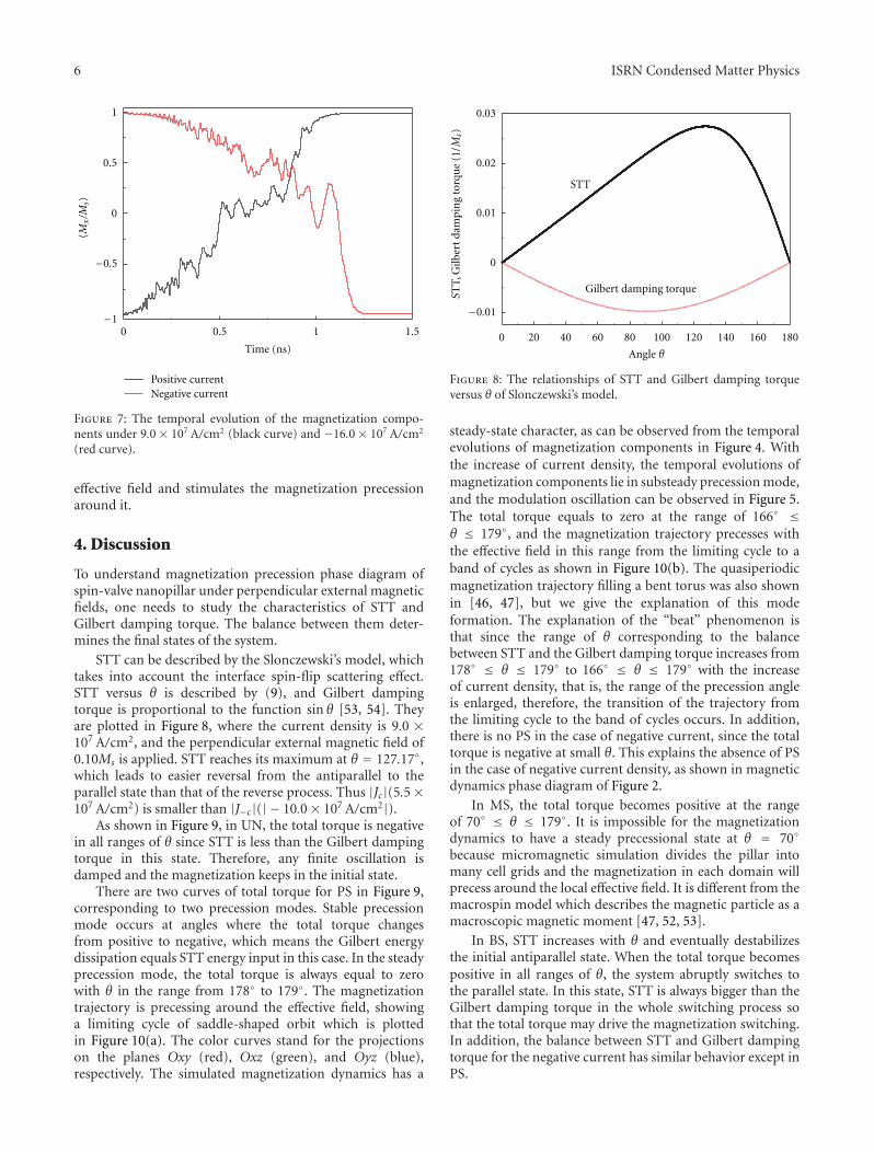
Figure 13 shows the temporal evolution of 〈mx〉, trajec-tory, and snapshots of the magnetization distribution underHy = 0.04Ms and J = 1.60 × 10⁷ A/cm2. The 〈mx〉 has amaximum −0.930 at the point a, a second maximum −0.973at the point b, and two minimums −0.983 at the pointsb and d. The five snapshots of magnetization distributionscorrespond to the five points in the temporal evolutionof magnetization. The colors represent the magnitude ofthe magnetization component 〈mz〉 (−0.3∼0.3), while the

ISRN Condensed Matter Physics 9
Time (ns)
−0.95
−0.96
−0.97
−0.98
60 60.04 60.08 60.12 60.16 60.2
⟨mx⟩
Zero field
(a)
−0.95
−0.96
−0.97
−0.98
−0.99
13 13.04 13.08 13.12 13.16 13.2
⟨mx⟩
Time (ns)
0.05 Msz
(b)
Time (ns)
−0.94
−0.95
−0.96
−0.97
−0.98
−0.99
−113 13.04 13.08 13.12 13.16 13.2
⟨mx⟩
0.2 Msz
(c)
Time (ns)
−0.94
−0.96
−0.98
−113 13.04 13.08 13.12 13.16 13.2
⟨mx⟩
0.3 Msz
(d)
Figure 12: The temporal evolutions of magnetization components under four different magnetic fields along the z-axis.
arrows indicate the magnetization projection on the planeOxy, through which the magnetization components 〈mx〉and 〈my〉 were shown. The magnetization almost entirelylies in the plane Oxy at the point a, where 〈mz〉 is nearlyzero. At the point b, the average magnetization component〈mz〉 is about −0.2. The magnetization is first excited atthe boundaries of the structure via the nucleation processbecause of spatially nonuniform local demagnetization fields[33] and becomes broader and broader with time, showingnonuniform magnetization precession. In the point c, themagnetization is also on the plane Oxy. However, thearrows rotate toward a different direction. The averagemagnetization component 〈mz〉 is 0.2 at the point d. At theend of the period, the oscillation returns to its original state.
5. Conclusions
Based on our micromagnetic simulation of spin transfertorque magnetization precession under magnetic fields inCo/Cu/Co nanopillars, the magnetization process can begrouped into four types: unchanging state (UN), preces-sional state (PS), multidomain state (MS), and bistablestate (BS). Of the four states, PS could be further divided
into two modes: steady precession mode and substeadyprecession mode. Balance of the spin transfer torque andGilbert damping torque can lead to the three modes; themagnetization dynamics depends on the total torque ofSTT and Gilbert damping torque. Only in the case ofpositive current, the PS state can present. In addition,the temporal evolutions of magnetization components insteady precession mode are explained by the method of theorbit projection, and the “sag” in the crest will disappearas the magnetic field increases from zero to 0.30Msz.Furthermore, the magnetization distributions together withits trajectory and temporal evolution are shown to elucidatethe nonuniform magnetization precession.
Acknowledgments
This work was sponsored by the National Science Foun-dation of China (11174030), by the US National ScienceFoundation under Grant no. DMR-1006541 (Chen), andin part by the China Scholarship Council. The computersimulations were carried out on the LION and Cyberstarclusters at The Pennsylvania State University.
10 ISRN Condensed Matter Physics
Time (ns)
−0.92
−0.94
−0.96
−0.98
−159.56 59.58 59.6 59.62
⟨mx⟩
a e
c
db
0.2
0
−0.2−1 −0.98 −0.96 −0.94 −0.92
−0.2
0
0.2
0.4
0.6
⟨mx⟩
⟨mz⟩
⟨my⟩
a(e)
c
d
b
0.5
0.3
0
−0.3
−0.5
(a) (b) (c) (d) (e)
(A) (B)
(C)
Figure 13: (a) The temporal evolution of 〈mx〉 in the zoom of 59.55∼59.62 ns under J = 1.60 × 10⁷ A/cm2 and Hy = 0.04Ms. (b) Themagnetization precessional trajectory. (c) Micromagnetic simulation result of the snapshots of magnetization distribution. The colorsrepresent the magnitude of the magnetization component 〈mz〉 (pink positive, cyan negative).
References
[1] I. Zutic, J. Fabian, and S. D. Sarma, “Spintronics: fundamen-tals and applications,” Reviews of Modern Physics, vol. 76, no.2, pp. 323–410, 2004.
[2] M. N. Baibich, J. M. Broto, A. Fert et al., “Giant magnetore-sistance of (001)Fe/(001)Cr magnetic superlattices,” PhysicalReview Letters, vol. 61, no. 21, pp. 2472–2475, 1988.
[3] P. Grunberg, R. Schreiber, Y. Pang, M. B. Brodsky, and H.Sowers, “Layered magnetic structures: evidence for antiferro-magnetic coupling of Fe layers across Cr interlayers,” PhysicalReview Letters, vol. 57, no. 19, pp. 2442–2445, 1986.
[4] S. S. P. Parkin, N. More, and K. P. Roche, “Oscillationsin exchange coupling and magnetoresistance in metallicsuperlattice structures: Co/Ru, Co/Cr, and Fe/Cr,” PhysicalReview Letters, vol. 64, no. 19, pp. 2304–2307, 1990.
[5] B. Dieny, V. S. Speriosu, S. S. P. Parkin, B. A. Gurney, D.R. Wilhoit, and D. Mauri, “Giant magnetoresistive in softferromagnetic multilayers,” Physical Review B, vol. 43, no. 1,pp. 1297–1300, 1991.
[6] M. Tsoi, A. G. M. Jansen, J. Bass et al., “Excitation of amagnetic multilayer by an electric current,” Physical ReviewLetters, vol. 80, no. 19, pp. 4281–4284, 1998.
[7] E. B. Myers, D. C. Ralph, J. A. Katine, R. N. Louie, andR. A. Buhrman, “Current-induced switching of domains inmagnetic multilayer devices,” Science, vol. 285, no. 5429, pp.867–870, 1999.
[8] B. Fisher, L. Patlagan, and G. M. Reisner, “Transport proper-ties of L1−xSrxMnO3 (L = Pr, Nd; 1/4 ≤ x ≤ 1/2),” PhysicalReview B, vol. 54, pp. 9359–9364, 1996.
[9] J. C. Slonczewski, “Current-driven excitation of magneticmultilayers,” Journal of Magnetism and Magnetic Materials,vol. 159, no. 1-2, pp. L1–L7, 1996.
[10] D. C. Ralph and M. D. Stiles, “Spin transfer torques,” Journalof Magnetism and Magnetic Materials, vol. 320, pp. 1190–1216,2008.
[11] G. Tatara, H. Kohno, and J. Shibata, “Microscopic approachto current-driven domain wall dynamics,” Physics Reports, vol.468, no. 6, pp. 213–301, 2008.
[12] J. Z. Sun and D. C. Ralph, “Magnetoresistance and spin-transfer torque in magnetic tunnel junctions,” Journal ofMagnetism and Magnetic Materials, vol. 320, no. 7, pp. 1227–1237, 2008.
[13] J. Z. Sun, D. J. Monsma, D. W. Abraham, M. J. Rooks, and R.H. Koch, “Batch-fabricated spin-injection magnetic switches,”Applied Physics Letters, vol. 81, no. 12, pp. 2202–2204, 2002.
[14] S. I. Klselev, J. C. Sankey, I. N. Krivorotov et al., “Microwaveoscillations of a nanomagnet driven by a spin-polarizedcurrent,” Nature, vol. 425, no. 6956, pp. 380–383, 2003.
[15] S. Urazhdin, N. O. Birge, W. P. Pratt, and J. Bass, “Current-driven magnetic excitations in permalloy-based multilayernanopillars,” Physical Review Letters, vol. 91, no. 14, Article ID146803, 4 pages, 2003.
[16] J. E. Wegrowe, X. Hoffer, P. Guittienne et al., “Spin-polarizedcurrent induced magnetization switch: is the modulus ofthe magnetic layer conserved? (invited),” Journal of AppliedPhysics, vol. 91, no. 10, p. 6806, 2002.
[17] D. Kelly, J.-E. Wegrowe, T.-K. Truong, X. Hoffer, and J.-P. Ansermet, “Spin-polarized current-induced magnetizationreversal in single nanowires,” Physical Review B , vol. 68, no.13, Article ID 134425, 13 pages, 2003.

ISRN Condensed Matter Physics 11
[18] M. Tsol, A. G. M. Jansen, J. Bass, W.-C. Chlang, V. Tsol, and P.Wyder, “Generation and detection of phase-coherent current-driven magnons in magnetic multilayers,” Nature, vol. 406, no.6791, pp. 46–48, 2000.
[19] W. H. Rippard, M. R. Pufall, S. Kaka, S. E. Russek, and T.J. Silva, “Direct-Current Induced Dynamics in Co90Fe10/Ni80Fe20 Point Contacts,” Physical Review Letters, vol. 92, no. 2,pp. 272011–272014, 2004.
[20] T. Y. Chen, Y. Ji, C. L. Chien, and M. D. Stiles, “Current-driven switching in a single exchange-biased ferromagneticlayer,” Physical Review Letters, vol. 93, no. 2, Article ID 026601,4 pages, 2004.
[21] J. Z. Sun, “Current-driven magnetic switching in manganitetrilayer junctions,” Journal of Magnetism and Magnetic Mate-rials, vol. 202, no. 1, pp. 157–162, 1999.
[22] Y. Liu, Z. Zhang, P. P. Freitas, and J. L. Martins, “Current-induced magnetization switching in magnetic tunnel junc-tions,” Applied Physics Letters, vol. 82, no. 17, pp. 2871–2873,2003.
[23] Y. Huai, M. Pakala, Z. Diao, and Y. Ding, “Spin transferswitching current reduction in magnetic tunnel junctionbased dual spin filter structures,” Applied Physics Letters, vol.87, no. 22, Article ID 222510, 3 pages, 2005.
[24] D. H. Lee and S. H. Lim, “Increase of temperature due to Jouleheating during current-induced magnetization switching ofan MgO-based magnetic tunnel junction,” Applied PhysicsLetters, vol. 92, no. 23, Article ID 233502, 3 pages, 2008.
[25] H. Huang, X. Ma, T. Yue, Z. Xiao, S. Shi, and L. Chen,“Magnetization switching modes in nanopillar spin valveunder the external field,” Science China: Physics, Mechanics andAstronomy, vol. 54, no. 7, pp. 1227–1234, 2011.
[26] X. Q. Ma, Z. H. Xiao, P. P. Wu, J. X. Zhang, S. Q. Shi, and L. Q.Chen, “Current-induced magnetization dynamics in CoCuConanopillars,” Journal of Applied Physics, vol. 103, no. 7, ArticleID 07B111, 2008.
[27] F. B. Mancoff, R. W. Dave, N. D. Rizzo, T. C. Eschrich,B. N. Engel, and S. Tehrani, “Angular dependence of spin-transfer switching in a magnetic nanostructure,” AppliedPhysics Letters, vol. 83, no. 8, pp. 1596–1598, 2003.
[28] P. Weinberger, A. Vernes, B. L. Gyorffy, and L. Szunyogh,“Noncollinear magnetic structures: a possible cause forcurrent-induced switching,” Physical Review B, vol. 70, no. 9,Article ID 094401, 13 pages, 2004.
[29] A. M. Deac, A. Fukushima, H. Kubota et al., “Bias-drivenhigh-power microwave emission from MgO-based tunnelmagnetoresistance devices,” Nature Physics, vol. 4, no. 10, pp.803–809, 2008.
[30] D. Houssameddine, S. H. Florez, J. A. Katine et al., “Spintransfer induced coherent microwave emission with largepower from nanoscale MgO tunnel junctions,” Applied PhysicsLetters, vol. 93, no. 2, Article ID 022505, 2008.
[31] Z. M. Zeng, P. Upadhyaya, P. Khalili Amiri et al., “Enhance-ment of microwave emission in magnetic tunnel junctionoscillators through in-plane field orientation,” Applied PhysicsLetters, vol. 99, no. 3, Article ID 032503, 2011.
[32] K. Mizushima, T. Nagasawa, K. Kudo, Y. Saito, and R. Sato,“Decrease of nonlinearity and linewidth narrowing in spin-transfer oscillators under the external field applied near thehard axis,” Applied Physics Letters, vol. 94, no. 15, Article ID152501, 2009.
[33] K. J. Lee, A. Deac, O. Redon, J. P. Nozieres, and B. Dieny,“Excitations of incoherent spin-waves due to spin-transfertorque,” Nature Materials, vol. 3, no. 12, pp. 877–881, 2004.
[34] A. Deac, K. J. Lee, Y. Liu et al., “Spin transfer effectsin exchange-biased spin-valves for current-perpendicular-to-plane magnetoresistive heads,” Journal of Magnetism andMagnetic Materials, vol. 290-291, pp. 42–47, 2005.
[35] L. G. Pereira, O. Boulle, M. M. Sanchez, V. Cros, F. Petroff, andA. Fert, “Current-driven differential resistance phase diagramin nanopillars of NiFe/Cu/NiFe,” Physica B, vol. 384, no. 1-2,pp. 33–35, 2006.
[36] S. I. Kiselev, J. C. Sankey, I. N. Krivorotov et al., “Current-induced nanomagnet dynamics for magnetic fields perpendic-ular to the sample plane,” Physical Review Letters, vol. 93, no.3, Article ID 036601, 4 pages, 2004.
[37] M. Gmitra and J. Barnas, “Current-driven destabilizationof both collinear configurations in asymmetric spin valves,”Physical Review Letters, vol. 96, no. 20, Article ID 207205, 2006.
[38] J. Xiao, A. Zangwill, and M. D. Stiles, “Macrospin modelsof spin transfer dynamics,” Physical Review B, vol. 72, no. 1,Article ID 014446, 13 pages, 2005.
[39] H. Suhl, “Theory of the magnetic damping constant,” IEEETransactions on Magnetics, vol. 34, no. 4, part 1, pp. 1834–1838, 1998.
[40] V. Kambersky, “On the Landau-Lifshitz relaxation in ferro-magnetic metals,” Canadian Journal of Physics, vol. 48, no. 24,pp. 2906–2911, 1970.
[41] V. L. Safonov, “Tensor form of magnetization damping,”Journal of Applied Physics, vol. 91, no. 10, p. 8653, 2002.
[42] A. Rebei, M. Simionato, and G. J. Parker, “Correlationfunctions of the magnetization in thin films,” Physical ReviewB, vol. 69, no. 13, Article ID 134412, pp. 134412–10, 2004.
[43] S. Zhang and S. S.-L. Zhang, “Generalization of the Landau-Lifshitz-Gilbert equation for conducting ferromagnets,” Phys-ical Review Letters, vol. 102, no. 8, Article ID 086601, 2009.
[44] X. P. Wang, C. J. Garcıa-Cervera, and E. Weinan, “A Gauss-seidel projection method for micromagnetics simulations,”Journal of Computational Physics, vol. 171, no. 1, pp. 357–372,2001.
[45] J. X. Zhang and L. Q. Chen, “Phase-field microelasticity theoryand micromagnetic simulations of domain structures in giantmagnetostrictive materials,” Acta Materialia, vol. 53, no. 9, pp.2845–2855, 2005.
[46] H. B. Huang, X. Q. Ma, Z. H. Liu et al., “Micromag-netic simulation of spin-transfer switching in a full-HeuslerCo2FeAl0.5Si0.5 alloy spin-valve nanopillar,” Journal of AppliedPhysics, vol. 110, no. 3, Article ID 033913, 2011.
[47] E. Jaromirska, P. Balaz, L. Lopez Dıaz, and J. Barnas, “Compu-tational study of microwave oscillations in nonstandard spinvalves in the diffusive transport limit,” Physical Review B, vol.81, no. 1, Article ID 014408, 2010.
[48] G. Siracusano, G. Finocchio, I. N. Krivorotov, L. Torres, G.Consolo, and B. Azzerboni, “Micromagnetic simulations ofpersistent oscillatory modes excited by spin-polarized currentin nanoscale exchange-biased spin valves,” Journal of AppliedPhysics, vol. 105, no. 7, Article ID 07D107, 2009.
[49] P. P. Horley, V. R. Vieira, P. M. Gorley, V. K. Dugaev, andJ. Barnas, “Current-induced dynamics of a monodomainferromagnet in an external magnetic field applied in easymagnetic plane: macrospin model,” Physical Review B, vol. 77,no. 9, Article ID 094427, 2008.
[50] P. P. Horley, V. R. Vieira, P. M. Gorley, V. K. Dugaev, J.Berakdar, and J. Barna, “Influence of a periodic magnetic fieldand spin-polarized current on the magnetic dynamics of amonodomain ferromagnet,” Physical Review B, vol. 78, no. 5,Article ID 054417, 2008.

12 ISRN Condensed Matter Physics
[51] G. Finocchio, V. S. Pribiag, L. Torres, R. A. Buhrman,and B. Azzerboni, “Spin-torque driven magnetic vortex self-oscillations in perpendicular magnetic fields,” Applied PhysicsLetters, vol. 96, no. 10, Article ID 102508, 2010.
[52] D. Berkov and N. Gorn, “Transition from the macrospinto chaotic behavior by a spin-torque driven magnetizationprecession of a square nanoelement,” Physical Review B, vol.71, no. 5, Article ID 052403, 4 pages, 2005.
[53] D. V. Berkov and N. L. Gorn, “Magnetization precession dueto a spin-polarized current in a thin nanoelement: numericalsimulation study,” Physical Review B, vol. 72, no. 9, Article ID094401, 2005.
[54] G. Finocchio, G. Siracusano, V. Tiberkevich, I. N. Krivo-rotov, L. Torres, and B. Azzerboni, “Time-domain studyof frequency-power correlation in spin-torque oscillators,”Physical Review B, vol. 81, no. 18, Article ID 184411, 2010.
Copyright © 2022 FDOKUMEN