
Optical sinc-shaped Nyquist pulses of exceptional quality
11
ARTICLE Received 27 May 2013 | Accepted 7 Nov 2013 | Published 4 Dec 2013 Optical sinc-shaped Nyquist pulses of exceptional quality Marcelo A. Soto 1 , Mehdi Alem 1 , Mohammad Amin Shoaie 2 , Armand Vedadi 2 , Camille-Sophie Bre `s 2 , Luc The ´venaz 1 & Thomas Schneider 1,w Sinc-shaped Nyquist pulses possess a rectangular spectrum, enabling data to be encoded in a minimum spectral bandwidth and satisfying by essence the Nyquist criterion of zero inter- symbol interference (ISI). This property makes them very attractive for communication systems since data transmission rates can be maximized while the bandwidth usage is minimized. However, most of the pulse-shaping methods reported so far have remained rather complex and none has led to ideal sinc pulses. Here a method to produce sinc-shaped Nyquist pulses of very high quality is proposed based on the direct synthesis of a rectangular- shaped and phase-locked frequency comb. The method is highly flexible and can be easily integrated in communication systems, potentially offering a substantial increase in data transmission rates. Further, the high quality and wide tunability of the reported sinc-shaped pulses can also bring benefits to many other fields, such as microwave photonics, light storage and all-optical sampling. DOI: 10.1038/ncomms3898 OPEN 1 EPFL Swiss Federal Institute of Technology, Group for Fibre Optics, SCI-STI-LT, Station 11, CH-1015 Lausanne, Switzerland. 2 EPFL Swiss Federal Institute of Technology, Photonic Systems Laboratory, STI-IEL-PHOSL, Station 11, CH-1015 Lausanne, Switzerland. w Present address: Institut fu ¨r Hochfrequenztechnik, Hochschule fu ¨r Telekommunikation Leipzig, Gustav-Freytag-Strae 43-45, 04277 Leipzig, Germany. Correspondence and requests for materials should be addressed to M.A.So. (email: marcelo.soto@epfl.ch). NATURE COMMUNICATIONS | 4:2898 | DOI: 10.1038/ncomms3898 | www.nature.com/naturecommunications 1 & 2013 Macmillan Publishers Limited. All rights reserved.
-
Upload
khangminh22 -
Category
Documents
-
view
1 -
download
0
Transcript of Optical sinc-shaped Nyquist pulses of exceptional quality

ARTICLE
Received 27 May 2013 | Accepted 7 Nov 2013 | Published 4 Dec 2013
Optical sinc-shaped Nyquist pulses ofexceptional qualityMarcelo A. Soto1, Mehdi Alem1, Mohammad Amin Shoaie2, Armand Vedadi2, Camille-Sophie Bres2,
Luc Thevenaz1 & Thomas Schneider1,w
Sinc-shaped Nyquist pulses possess a rectangular spectrum, enabling data to be encoded in a
minimum spectral bandwidth and satisfying by essence the Nyquist criterion of zero inter-
symbol interference (ISI). This property makes them very attractive for communication
systems since data transmission rates can be maximized while the bandwidth usage is
minimized. However, most of the pulse-shaping methods reported so far have remained
rather complex and none has led to ideal sinc pulses. Here a method to produce sinc-shaped
Nyquist pulses of very high quality is proposed based on the direct synthesis of a rectangular-
shaped and phase-locked frequency comb. The method is highly flexible and can be easily
integrated in communication systems, potentially offering a substantial increase in data
transmission rates. Further, the high quality and wide tunability of the reported sinc-shaped
pulses can also bring benefits to many other fields, such as microwave photonics, light
storage and all-optical sampling.
DOI: 10.1038/ncomms3898 OPEN
1 EPFL Swiss Federal Institute of Technology, Group for Fibre Optics, SCI-STI-LT, Station 11, CH-1015 Lausanne, Switzerland. 2 EPFL Swiss Federal Institute ofTechnology, Photonic Systems Laboratory, STI-IEL-PHOSL, Station 11, CH-1015 Lausanne, Switzerland. w Present address: Institut fur Hochfrequenztechnik,Hochschule fur Telekommunikation Leipzig, Gustav-Freytag-Stra�e 43-45, 04277 Leipzig, Germany. Correspondence and requests for materials should beaddressed to M.A.So. (email: [email protected]).
NATURE COMMUNICATIONS | 4:2898 | DOI: 10.1038/ncomms3898 | www.nature.com/naturecommunications 1
& 2013 Macmillan Publishers Limited. All rights reserved.

In currently deployed optical networks, wavelength divisionmultiplexing (WDM) is used to enhance the carrier capacity ofoptical fibres. However, since the data rate in optical networks
increases by close to 29% per year1, new approaches are beingdeveloped2. The bulk of these approaches consists in increasingthe spectral efficiency of optical links. Using multilevelmodulation formats and polarization multiplexing, the spectralefficiency can be increased from 0.8 to several bit s� 1Hz� 1
(refs 3–5). However, such schemes drastically increase therequirements on electrical signal processing and are typicallyaccompanied by higher energy consumption. To keep pace withthe growing demand, a data rate of 1 Tbit s� 1 per channeltogether with high spectral efficiency has been envisaged for thenext decade6. Even with parallelization, these data rates arebeyond the limits of current digital signal processing, and theresulting baud rate exceeds the possibilities of current electroniccircuits7. A possible solution is the combination of several lower-rate channels with high spectral efficiency into a Tbit s� 1
‘superchannel’, which can be routed through the existing opticalnetworks as a single entity8. Such an aggregation can be achievedin the frequency or time domain9. In orthogonal frequency-division multiplexing (OFDM), a superchannel consisting of a setof subcarriers is generated. Each subcarrier exhibits a sinc-shapedspectrum and can therefore be spaced at the baud rate withoutinter-channel interference. With OFDM, a data rate of26 Tbit s� 1 and a net spectral efficiency of 5 bit s� 1Hz� 1 havebeen demonstrated10. Similarly, for Nyquist transmission, thesymbols are carried by Nyquist pulses11 that overlap in the timedomain without ISI. Recently, a 32.5-Tbit s� 1 Nyquist WDMtransmission with a net spectral efficiency of 6.4 bit s� 1Hz� 1 hasbeen shown12. Compared with OFDM, Nyquist pulse shaping hasseveral unique advantages as it reduces the receivercomplexity13,14, is less sensitive to fibre nonlinearities14,requires much lower receiver bandwidths15 and leads to lowerpeak-to-average power ratios16.
A general expression in the time domain for the amplitudewaveform of Nyquist pulses is17,18:
r tð Þ¼sin 2pt
tp
� �2pttp
cos 2bpttp
� �1� 4bt
tp
� �2 ; ð1Þ
where tp is the pulse duration between zero crossings and b isknown as a roll-off factor17, which is in the range 0rbr1.Among the class of Nyquist pulses11, the sinc-shaped pulse isof particular interest owing to its rectangular spectrum17 and zeroroll-off. This allows minimizing the guard band between opticalchannels. Theoretically, for a sinc-pulse Nyquist transmission,each symbol consists of a time-unlimited sinc-pulse. However,since causality makes it impossible, periodic pulses are typicallyused in every experimental demonstration of Nyquist pulsetransmission12–20. Such transmission systems rely onmultiplexing and modulation techniques. A possible scheme isshown in Fig. 1. Nyquist channels can be multiplexed in timedomain; this is designated as orthogonal time-divisionmultiplexing (TDM)18,21,22. The generated sequence is split intoN channels, which are then delayed and modulated to transportthe channel corresponding data. This requires Nmodulators, withN being the number of branches or the number of time-domainchannels. However, compared with a direct modulation, the baudrate of each modulator is N times reduced. This drastically relaxesthe requirements on modulators and electronics. In addition,time-domain channels can be multiplexed at differentwavelengths; this is designated as Nyquist WDM8 where pulsescan be generated and modulated for each carrier. Since higher-order modulation formats, multiplexing, transmission and
demultiplexing of Nyquist pulses have already been shownelsewhere12–18, here the focus is placed on the generation of asinc-pulse shape as ideal as possible.
The temporal and spectral features of sinc-shaped pulses bringbenefits not only to optical communications but also to manyother fields. Actually, sinc-shaped pulses correspond to the idealinterpolation function for the perfect restoration of band-limitedsignals from discrete and noisy data23. Hence, sinc pulses canprovide substantial performance improvement to opticalsampling devices24. Further, the spectral features of sinc pulsescould enable the implementation of ideal rectangular microwavephotonics filters25–27 with tunable passband profiles, thus alsoproviding interesting possibilities for all-optical signal process-ing28, spectroscopy29 and light storage30,31.
Several approaches for the generation of Nyquist pulses havebeen suggested. In refs 9 and 16, an arbitrary waveform generatorwas programmed offline to create Nyquist filtering of thebaseband signal. This can provide a quite good roll-off factor ofb¼ 0.0024 (ref. 16). However, this method is restricted by thespeed of electronics because of the limited sampling rate andlimited processor capacities, whereas the quality of the Nyquistpulses highly depends on the resolution (number of bits) ofdigital-to-analogue converters32. Another possibility is the opticalgeneration of Nyquist pulses13,18,20. These optical sequences canreach much shorter time duration and can thus be multiplexed toan ultrahigh symbol rate. To generate Nyquist pulses, a liquidcrystal spatial modulator has been used to shape Gaussian pulsesfrom a mode-locked laser into raised-cosine Nyquist pulses. It isalso possible to generate Nyquist pulses using fibre opticalparametric amplification, pumped by parabolic pulses, and aphase modulator to compensate the pump-induced chirp20.However, compared with electrical pulse shaping, optical Nyquistpulse generation produces much higher roll-off factors33, such asb¼ 0.5 (refs 13,18); therefore, multiplexing using this kind ofpulses results in a non-optimal use of bandwidth. Further, mostof the reported methods use complex and costly equipment.
In this paper, a method to generate a sequence of very high-quality Nyquist pulses with an almost ideal rectangular spectrum(bB0) is proposed and demonstrated. The method is based onthe direct synthesization of a flat phase-locked frequency combwith high suppression of out-of-band components. It istheoretically demonstrated and experimentally confirmed thatthis comb corresponds to a periodic sequence of time-unlimited
Time Time
0 M0
M1
MN–1
M2
�
(N-1)�
2�
Figure 1 | Possible multiplexing of sinc-shaped Nyquist pulses. Periodic
sinc-pulse sequences can be split into N branches, each of which
corresponds to an independent channel. In the nth branch, the periodic
sequence is delayed by n times the interval t¼ 1/(NDf), with n¼0,...,N� 1.
Each channel can be modulated independently with a modulator
M0,...,MN� 1. These devices can apply any modulation formats to the signal.
Then, the N modulated channels are multiplexed. The shown multiplexing is
carried out in the time domain at one carrier wavelength. Since the
multiplexed channel shows a sharp-edged spectrum, the next wavelength
channel can be directly adjacent to the previous with almost no guard band
and can be multiplexed in the time domain in the same way, reaching high
temporal and spectral densities together.
ARTICLE NATURE COMMUNICATIONS | DOI: 10.1038/ncomms3898
2 NATURE COMMUNICATIONS | 4:2898 | DOI: 10.1038/ncomms3898 | www.nature.com/naturecommunications
& 2013 Macmillan Publishers Limited. All rights reserved.
sinc pulses. The wide tunability of the method, using a proof-of-concept experiment based on two cascaded Mach–Zehndermodulators (MZM), is demonstrated over 4 frequency decades.Experimental results also verify the remarkable high quality of thegenerated pulses, exhibiting in all cases zero roll-off, minimumspectral broadening when modulated and o1% deviation withrespect to the ideal sinc shape. These pulses simultaneously showa minimum ISI and a maximum spectral efficiency, making theman attractive solution for high-capacity TDM–WDM systems.
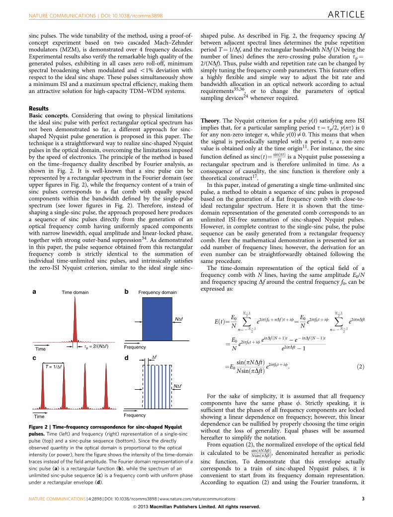
ResultsBasic concepts. Considering that owing to physical limitationsthe ideal sinc pulse with perfect rectangular optical spectrum hasnot been demonstrated so far, a different approach for sinc-shaped Nyquist pulse generation is proposed in this paper. Thetechnique is a straightforward way to realize sinc-shaped Nyquistpulses in the optical domain, overcoming the limitations imposedby the speed of electronics. The principle of the method is basedon the time–frequency duality described by Fourier analysis, asshown in Fig. 2. It is well-known that a sinc pulse can berepresented by a rectangular spectrum in the Fourier domain (seeupper figures in Fig. 2), while the frequency content of a train ofsinc pulses corresponds to a flat comb with equally spacedcomponents within the bandwidth defined by the single-pulsespectrum (see lower figures in Fig. 2). Therefore, instead ofshaping a single-sinc pulse, the approach proposed here producesa sequence of sinc pulses directly from the generation of anoptical frequency comb having uniformly spaced componentswith narrow linewidth, equal amplitude and linear-locked phase,together with strong outer-band suppression34. As demonstratedin this paper, the pulse sequence obtained from this rectangularfrequency comb is strictly identical to the summation ofindividual time-unlimited sinc pulses, and intrinsically satisfiesthe zero-ISI Nyquist criterion, similar to the ideal single sinc-
shaped pulse. As described in Fig. 2, the frequency spacing Dfbetween adjacent spectral lines determines the pulse repetitionperiod T¼ 1/Df, and the rectangular bandwidth NDf (N being thenumber of lines) defines the zero-crossing pulse duration tp¼2/(NDf). Thus, pulse width and repetition rate can be changed bysimply tuning the frequency comb parameters. This feature offersa highly flexible and simple way to adjust the bit rate andbandwidth allocation in an optical network according to actualrequirements35,36, or to change the parameters of opticalsampling devices24 whenever required.
Theory. The Nyquist criterion for a pulse y(t) satisfying zero ISIimplies that, for a particular sampling period t¼ tp/2, y(nt) is 0for any non-zero integer n, while y(0)a0. This means that whenthe signal is periodically sampled with a period t, a non-zerovalue is obtained only at the time origin11. For instance, the sincfunction defined as sincðtÞ¼ sinðptÞ
pt is a Nyquist pulse possessing arectangular spectrum and is therefore unlimited in time. As aconsequence of causality, the sinc function is therefore only atheoretical construct17.
In this paper, instead of generating a single time-unlimited sincpulse, a method to obtain a sequence of sinc pulses is proposedbased on the generation of a flat frequency comb with close-to-ideal rectangular spectrum. Here it is shown that the time-domain representation of the generated comb corresponds to anunlimited ISI-free summation of sinc-shaped Nyquist pulses.However, in complete contrast to the single-sinc pulse, the pulsesequence can be easily generated from a rectangular frequencycomb. Here the mathematical demonstration is presented for anodd number of frequency lines; however, the derivation for aneven number can be straightforwardly obtained following thesame procedure.
The time-domain representation of the optical field of afrequency comb with N lines, having the same amplitude E0/Nand frequency spacing Df around the central frequency f0, can beexpressed as:
E tð Þ¼E0N
XN � 12
n¼� N � 12
e2ip f0 þ nDfð Þtþ if¼E0N
e2ipf0tþ ifXN � 1
2
n¼� N � 12
e2ipnDft
¼ E0N
e2ipf0tþ if eipDf ðN þ 1Þt � e� ipDf ðN � 1Þt
e2ipDft � 1
¼E0sin pNDftð ÞNsin pDftð Þ e
2ipf0tþ if: ð2Þ
For the sake of simplicity, it is assumed that all frequencycomponents have the same phase f. Strictly speaking, it issufficient that the phases of all frequency components are lockedshowing a linear dependence on frequency; however, this lineardependence can be nullified by properly choosing the time originwithout the loss of generality. Equal phases will be assumedhereafter to simplify the notation.
From equation (2), the normalized envelope of the optical fieldis calculated to be sinðpNDftÞ
NsinðpDftÞ, denominated hereafter as periodicsinc function. To demonstrate that this envelope actuallycorresponds to a train of sinc-shaped Nyquist pulses, it isconvenient to start from its frequency domain representation.According to equation (2) and using the Fourier transform, it
Time domain
T = 1/Δf
Frequency domaina b
c d
�p = 2/(NΔf )Time Frequency
Time Frequency
Δf
NΔf
NΔf
Figure 2 | Time–frequency correspondence for sinc-shaped Nyquist
pulses. Time (left) and frequency (right) representation of a single-sinc
pulse (top) and a sinc-pulse sequence (bottom). Since the directly
observed quantity in the optical domain is proportional to the optical
intensity (or power), here the figure shows the intensity of the time-domain
traces instead of the field amplitude. The Fourier domain representation of a
sinc pulse (a) is a rectangular function (b), while the spectrum of an
unlimited sinc-pulse sequence (c) is a frequency comb with uniform phase
under a rectangular envelope (d).
NATURE COMMUNICATIONS | DOI: 10.1038/ncomms3898 ARTICLE
NATURE COMMUNICATIONS | 4:2898 | DOI: 10.1038/ncomms3898 | www.nature.com/naturecommunications 3
& 2013 Macmillan Publishers Limited. All rights reserved.

follows:
Fsin pNDftð Þsin pDftð Þ
� �¼F
XN � 12
n¼� N � 12
e2ipnDft
8<:
9=;¼
XN � 12
n¼� N � 12
d f � nDfð Þ:
ð3ÞIntroducing the rectangular function & n
N
� �that is 1 for all
integers n where nj j � N � 12 and 0 elsewhere, the above equation
can be written as:
XN � 12
n¼� N � 12
d f � nDfð Þ¼Xþ1
n¼�1�
nN
� �d f � nDfð Þ
¼�f
NDf
� Xþ1
n¼�1d f � nDfð Þ;
ð4Þ
where the rectangular spectrum � fNDf
� �, covering a bandwidth
NDf, is represented in the time domain by the sinc-pulseNDf sinc(NDft). The temporal dependence of the above expres-sion can then be obtained by taking its inverse Fourier transformand using the Poisson summation formula37:
F � 1 �f
NDf
� Xþ1
n¼�1d f � nDfð Þ
( )¼Nsinc NDftð Þ
�Xþ1
n¼�1d t� n
Df
� ;
ð5Þ
where # denotes the convolution operation. Thus, it follows forthe right-hand side of equation (5):
Nsinc NDftð Þ �Xþ1
n¼�1d t� n
nDf
� ¼
Xþ1
n¼�1Nsinc NDf t� n
Df
� � :
ð6Þ
Therefore, it can be written that
sin pNDftð ÞNsin pDftð Þ¼
Xþ1
n¼�1sinc NDf t� n
Df
� � : ð7Þ
Similarly, for an even number of spectral lines, the envelope ofthe optical field can be expressed as a train of sinc pulses throughthe following equation:
sin pNDftð ÞNsin pDftð Þ¼
Xþ1
n¼�1� 1ð Þnsinc NDf t� n
Df
� � ; ð8Þ
where the factor (� 1)n comes from the absence of a spectral lineat the central frequency of the comb; this eliminates the directcurrent (DC) component in the optical field envelope.
Comparing equations (7) and (8), the following generalexpression for the normalized envelope of the optical fieldresulting from a flat frequency comb is obtained, independent ofthe parity of N:
sin pNDftð ÞNsin pDftð Þ¼
Xþ1
n¼�1� 1ð Þ N � 1ð Þnsinc NDf t� n
Df
� � : ð9Þ
The difference in the periodic sinc function x tð Þ¼ sin pNDftð ÞNsin pDftð Þ for
even and odd N can be figured out easily. As depicted in Fig. 3a,all sinc pulses of the pulse train for odd N show the same phase,so that x(ts)¼ 1 at every sampling instant ts¼ n
Df for all integer n.For even N, x(ts)¼ (� 1)n, so that each pulse envelope is ofopposite sign with its preceding and following pulses, as shown inFig. 3b. Aside from this difference, the optical intensity measured
by a photodetector is the same in both cases, and is given by:
I tð Þ¼ E tð Þj j2¼E20sin2ðpNDftÞN2sin2ðpDftÞ : ð10Þ
Consequently, it is proven that the field envelope of the time-domain representation of a frequency comb of N identical andequally spaced lines corresponds to an infinite summation ofsinc-shaped Nyquist pulses with period 1
Df and zero-crossing pulse
width 2NDf . Thus, considering that the pulse repetition period
T¼ 1Df is a multiple of the time interval t¼ 1
NDf , the resulting time-domain envelope x(t) satisfies the following condition for anyinteger m:
x mtð Þ¼ � 1ð Þ N � 1ð Þm=N m¼:::; � 2N; �N; 0;N; 2N; :::0 otherwise:
�ð11Þ
Thus, the sequence of sinc pulses resulting from a locked phase,rectangular frequency comb satisfies the Nyquist criterion for freeISI within every pulse repetition period T. This condition isautomatically and intrinsically satisfied for any flat frequencycomb since the number of lines N is an integer by definition.Therefore, the generated sinc-pulse sequence can be multiplexedin time without ISI.
Proof-of-concept experiment. There are several differentapproaches for the generation of a frequency comb. For instance,they can be obtained from conventional femtosecond lasers, suchas Er-fibre38,39, Yb-fibre40 and Ti:sapphire41 mode-locked lasers,or from a continuous wave optical source exploiting Kerr-nonlinearities in an optical resonator42–45, or employing acombination of strong intensity and phase modulation46–48
together with chirped Bragg gratings49, dispersive medium50 orhighly nonlinear fibres51–53. However, every comb does notnecessarily result in a sequence of Nyquist pulses, since a sinc-
0 1 2 3 4 5−1.5
−1
−0.5
0
0.5
1
1.5
Time (t/T)
Nor
mal
ized
am
plitu
de
a
0 1 2 3 4 5−1.5
−1
−0.5
0
0.5
1
1.5
Time (t/T)
b
Nor
mal
ized
am
plitu
de
Figure 3 | Normalized field envelope of a frequency comb. (a) Odd
(N¼ 9) and (b) even (N¼8) number of spectral lines. The time axis is
normalized with respect to the pulse period T. An odd number of lines leads
to a sequence of in-phase sinc-shaped Nyquist pulses, while an even
number N results in a sequence with alternated p-phase-modulated pulses.
ARTICLE NATURE COMMUNICATIONS | DOI: 10.1038/ncomms3898
4 NATURE COMMUNICATIONS | 4:2898 | DOI: 10.1038/ncomms3898 | www.nature.com/naturecommunications
& 2013 Macmillan Publishers Limited. All rights reserved.

pulse sequence can only be obtained under specific conditions,requiring that the produced comb has to show line amplitudes asequal as possible, linear phase dependence through all lines and astrong suppression of out-of-band lines. Thus, although flatfrequency combs can be obtained using different methods, as forinstance through phase modulation48–50, the phase differencebetween lines and the existing out-of-band components makephase modulators improper for clean generation of sinc-shapedpulses.
In general, a close-to-ideal rectangular-shaped optical fre-quency comb can be produced using various implementations; forinstance, a non-optimal frequency comb38–53 can be used incombination with a spectral line-by-line manipulation of theoptical Fourier components54,55 to control the amplitude andphase of each spectral line. It turns out that the complexity of thiskind of pulse shapers significantly increases with the number ofspectral lines, and in general pulse shapers are unable tomanipulate a frequency comb having spectrally spaced linesbelow 1GHz54,55. Here a simple proof-of-concept experimentalset-up, shown in Fig. 4a, is proposed. This uses two cascadedlithium niobate MZM with a specific adjustment of the bias andmodulation voltages (see Methods for details). An opticalspectrum analyzer (OSA) with a spectral resolution of 0.01 nmis used to measure the generated frequency combs, while anoptical sampling oscilloscope with 500GHz bandwidth isemployed to measure the time-domain pulse train waveforms.While the first modulator, driven by a radio-frequency (RF)signal at a frequency f1 is adjusted to generate three seedingspectral components, the second MZM re-modulates those linesusing an RF signal at f2. Thus, for instance, to generate N¼ 9spectral lines, the condition f1¼ 3f2 or f2¼ 3f1 has to be satisfiedwithout any carrier suppression, resulting in a frequency spacingbetween the lines of Df¼min(f1,f2). However, to generate a combwith N¼ 6 lines, the carrier of one of the modulators must besuppressed leading to two possible configurations, as illustrated inFig. 4b,c. If the optical carrier is suppressed in the first modulator(see Fig. 4b), the RF frequencies must satisfy the condition2f1¼ 3f2, giving a line spacing Df¼ f2. On the other hand, if thecarrier is suppressed in the second modulator (see Fig. 4c), therelation between modulating frequencies has to be f1¼ 4f2,resulting in a frequency spacing Df¼ 2f2.
A high-quality rectangular-shaped frequency comb can beobtained by tuning the DC bias VB and the RF voltage amplitudens of each modulator following the description presented in theMethods section. To ensure that the three components generatedby each modulator are in phase, VB and ns might take eitherpositive or negative values. Moreover, to obtain spectral lines withsimilar phase using two cascaded MZMs, the phase differencebetween the modulating RF signals has to be finely adjusted tocompensate propagation delays in optical and electrical links,thus leading to almost perfectly shaped symmetric pulses.
On the other hand, to confine the sinc-pulse sequence into theNyquist bandwidth, a low modulating voltage ns must be used tostrongly suppress the out-of-band components. In particular, theRF-driving voltage ns of both modulators is here adjusted toremain below B0.36Vp (where Vp is the half-wave voltage of theMZM), securing a suppression of more than 27 dB for the out-of-band components. Note that this level of confinement is onlypossible, thanks to the two degrees of freedom provided byintensity modulators, since both operating bias point andmodulating voltages can be adjusted.
Quality and tunability of the sinc-shaped Nyquist pulses. Thequality of the pulses and the flexibility of the method have beenexperimentally verified by changing the modulating signal
frequencies f1 and f2 in a wide spectral range, and comparingmeasurements with the theoretical expectations. This way dif-ferent frequency combs with N¼ 9 spectral components havebeen generated with a frequency spacing Df spanning over manydecades (between 10MHz and 10GHz). In Fig. 5, the measuredsinc pulses (black straight lines) are compared with the theoreticalones (red-dashed lines) described by equation (10). Measured andtheoretical curves are normalized in all figures. Temporal wave-forms have been acquired with a sampling interval of 0.2 ps forthe case of Df¼ 10GHz; this interval has been proportionallyincreased for longer pulse widths. In particular, Fig. 5a shows thecase of modulating frequencies f1¼ 30MHz and f2¼Df¼ 10MHz, resulting in sinc-shaped Nyquist pulses with zero-crossingpulse duration of tp¼ 22.22 ns, full-width at half-maximum(FWHM) duration of 9.8 ns and a repetition period of T¼ 100 ns.In Fig. 5b–d, the modulating frequencies have been sequentiallyincreased by one order of magnitude. It is observed that thegenerated pulse sequences coincide very well with the ideal onesover 4 frequency decades, showing a root mean square (r.m.s.)error below 1% for all cases. In addition, it was verified that thespectrum for all these conditions resulted to be close to the idealrectangular case, as it will be detailed below.
The shaded box in Fig. 6a shows an ideal rectangular spectrum,which corresponds to a single-sinc pulse with a FWHM durationof 9.8 ps, as the one reported in Fig. 5d. The red curve representsthe measured flat phase-locked comb in such a case, showingmore than 27 dB suppression of the higher-order sidebands and apower difference between components lower than 0.2 dB. Thepulse repetition period, corresponding to T¼ 100 ps, is clearlyobserved in Fig. 6b.
ECL MZM1 MZM2
Phase
RF-generatorRF-generator
BIAS BIAS
Synchro
Optical spectrumanalyzer
Optical samplingoscilloscope
f1 f1 f1 f1
f2 f2 f2 f2 f2 f2 f2 f2 f2 f2
a
b c
f1 f2
Figure 4 | Basic experimental implementation. (a) Proof-of-concept set-
up. Solid and dashed lines describe optical and electrical connections,
respectively. An external cavity laser (ECL) generates a narrow linewidth
continuous wave light at 1,550 nm. MZM1 generates spectral lines
separated by a frequency f1. Then, MZM2 re-modulates these seeding
components with a frequency f2. RF power and DC bias in both MZMs are
adjusted so that all lines result with the same amplitude and phase, and
additional sidebands are highly suppressed. An undistorted waveform is
only obtained with a proper adjustment of the relative modulating phase,
and therefore both RF generators have been synchronized using a common
time base. (b) Generation of a frequency comb with N¼6 lines. MZM1 is
driven with a frequency f1 and operates in carrier suppression mode, so that
MZM2 re-modulates the two seeding lines, with no carrier suppression, at
a frequency f2¼Df. (c) Second option to generate a comb with N¼6
spectral lines; in this case, MZM1 is driven with a frequency f1 (no carrier
suppression), while MZM2 re-modulates the three seeding components, in
carrier suppression mode, at a frequency f2¼ f1/4¼Df/2.
NATURE COMMUNICATIONS | DOI: 10.1038/ncomms3898 ARTICLE
NATURE COMMUNICATIONS | 4:2898 | DOI: 10.1038/ncomms3898 | www.nature.com/naturecommunications 5
& 2013 Macmillan Publishers Limited. All rights reserved.

Then, the pulse duration and the repetition rate have beeneasily changed by modifying the spectral characteristics of thegenerated frequency comb. For instance, if the second modulatoris driven by two RF signals combined in the electrical domain,each of the three frequency components resulting from the firstMZM are modulated to create up to five spectral lines each (foursidebands and carrier). This way, N¼ 10 spectral lines separatedby Df¼ 10GHz have been generated by modulating the firstMZM at f1¼ 25GHz in carrier suppression mode and by drivingthe second MZM with two RF signals at f21¼ 10GHz andf22¼ 20GHz. The measured optical spectrum, showing abandwidth of 100GHz and spurious components suppressed bymore than 26 dB, is illustrated in Fig. 6c. Note that in this case,the first modulator is working in carrier suppression mode and,therefore, the main spurious lines observed in the spectrum resultpredominantly from the limited extinction ratio of the mod-ulators (in this case, 40GHz MZMs with typical extinction ratioof about 23–25 dB), which makes a perfect carrier suppressionimpossible. Higher suppression of such spurious components canbe obtained using modulators with better extinction ratio (notethat MZMs with 40 dB extinction ratio are commercially availableat 10GHz bandwidth). Since the frequency spacing amongcomponents is the same as in the previous case, that is, Df¼ 10GHz, the pulse repetition period T¼ 100 ps has not changed;however, the zero-crossing pulse duration has been reduced downto tp¼ 20 ps (FWHM duration of 8.9 ps), as shown in Fig. 6d.
By rearranging the modulating frequencies to f1¼ 30, f21¼ 6and f22¼ 12GHz, and by adjusting the bias point of the firstmodulator (see equation (14) in the Methods), so that the carrieris not suppressed in this case, a frequency comb expanding over abandwidth of 90GHz has been obtained, with N¼ 15 spectralcomponents, a frequency spacing Df¼ 6GHz and more than27 dB suppression of higher-order sidebands, as reported inFig. 6e. The measured sinc pulse has a zero-crossing duration of
tp¼ 22 ps (FWHM duration of 9.8 ps) and a repetition period ofT¼ 166.67 ps, as depicted in Fig. 6f.
Finally, the bandwidth of the comb has been broadenedexploiting the second-order sidebands of the modulators. Asdescribed in the Method section, this can be achieved by using aproper DC bias voltage that suppresses simultaneously all odd-order sidebands; but it also requires a modulating amplitude ofnsE1.52Vp for a complete carrier suppression. For the MZMsused here, this optimal modulating amplitude corresponds to anRF power of about 1W. Using standard drivers, it was notpossible to reach such an RF power level and suppress completelythe carrier, although a strong suppression of unwanted sidebandscould be reached by a simple DC bias adjustment. As aworkaround, two narrowband fibre Bragg gratings (3GHzbandwidth each), centred at the carrier wavelength, have beenplaced at the output of the first MZM, providing more than 40 dBcarrier rejection (an optical isolator has also been insertedbetween the fibre Bragg gratings to avoid multiple reflexions).Thus, driving the first MZM at f1¼ 19.5GHz, two frequencycomponents (second-order sidebands) are obtained with aspectral separation of 78GHz. Then, the second MZM is drivenat f2¼ 26GHz to obtain a comb expanding over a bandwidth of156GHz, with N¼ 6 spectral components equally spaced byDf¼ 26GHz. The obtained comb is shown in Fig. 6g, presenting a21-dB suppression of unwanted components. In the time domain,the measured sinc pulse has a zero-crossing duration of tp¼ 12.8ps (FWHM duration of 5.75 ps) and a repetition period ofT¼ 38.46 ps, as shown in Fig. 6h.
Note that the apparent line broadening shown for all frequencycomponents in Fig. 6 results from the limited resolution of theOSA, which is 0.01 nm. The real linewidth is essentially given bythe laser linewidth, which is in the kHz range for the usedexternal cavity laser, that is, more than seven orders of magnitudelower than the pulse rectangular bandwidth.
−20 0 20 40 60 80
0
0.2
0.4
0.6
0.8
1
Time (ns)
Nor
mal
ized
inte
nsity
(a.
u.)
a
Pulse bandwidth: 90 MHzRepetition period: 100 ns
Pulse FWHM: 9.8 ns
−2 0 2 4 6 8
0
0.2
0.4
0.6
0.8
1
Time (ns)
Nor
mal
ized
inte
nsity
(a.
u.)
b
Pulse bandwidth: 900 MHzRepetition period: 10 ns
Pulse FWHM: 0.98 ns
−200 0 200 400 600 800
0
0.2
0.4
0.6
0.8
1
Time (ps)
Nor
mal
ized
inte
nsity
(a.
u.)
c
Pulse bandwidth: 9 GHzRepetition period: 1 ns
Pulse FWHM: 98 ps
−20 0 20 40 60 80
0
0.2
0.4
0.6
0.8
1
Time (ps)
Nor
mal
ized
inte
nsity
(a.
u.)
d
Pulse bandwidth: 90 GHzRepetition period: 100 ps
Pulse FWHM: 9.8 ps
Figure 5 | Tunability of sinc-shaped Nyquist pulses using nine spectral lines. Sinc-shaped Nyquist pulses measured using a 500-GHz optical sampling
oscilloscope. The calculated waveforms (red-dashed lines) according to equation (10) are compared with the measured pulses (black straight lines) for
different bandwidth conditions over 4 decades. Nyquist pulses are obtained from the generation of a rectangular frequency comb with nine phase-locked
components spanning over a spectral width between 90MHz and 90GHz, using modulating frequencies (a) f1¼ 30MHz and f2¼Df¼ 10MHz,
(b) f1¼ 300MHz and f2¼Df¼ 100MHz, (c) f1¼ 3GHz and f2¼Df¼ 1 GHz, and (d) f1¼ 30GHz and f2¼Df¼ 10GHz. The maximum difference between
measured pulses and theoretical ones remained in all cases below 1%.
ARTICLE NATURE COMMUNICATIONS | DOI: 10.1038/ncomms3898
6 NATURE COMMUNICATIONS | 4:2898 | DOI: 10.1038/ncomms3898 | www.nature.com/naturecommunications
& 2013 Macmillan Publishers Limited. All rights reserved.

Figure 7a shows a colour-grade plot of the measured Nyquistpulses for the case reported in Fig. 6a,b, demonstrating that eventhe simple set-up proposed in Fig. 4 can generate very stable andhigh-quality sinc-shaped pulse sequences with very low jitter(82 fs, equivalent to 0.82% of the FWHM) and very high signal-to-noise ratio (SNR440 dB, above the oscilloscope SNR mea-surement capacity). Jitter and SNR for all other measuredconditions exhibit similar values with respect to the ones reportedhere. The quality of the measured pulses is also analyzed bycomparing them with the intensity derived from the analytical
expression for Nyquist pulses as a function of the roll-off factor b,as described in equation (1). Figure 7b shows the r.m.s. errorbetween the measured pulses and the theoretical intensitywaveforms for roll-off factors between 0 and 1. It can be observedthat the minimum r.m.s. error is reached with a factor b¼ 0,indicating that the obtained pulses coincide very well with theideal sinc-pulse shape with an r.m.s. error of 0.98%. All othermeasurements reported in Figs 5 and 6 also present the samequality as the one described here. When this factor b¼ 0is compared with the roll-off obtained by other optical
Time (ps)
−150 −100 0 50 150
0
0.2
0.4
0.6
0.8
1
Nor
mal
ized
inte
nsity
(a.
u.)
b
9.8 ps
100 ps
−50 100
0
0.2
0.4
0.6
0.8
1
Time (ps)
Nor
mal
ized
inte
nsity
(a.
u.)
d
8.9 ps
100 ps
−150 −100 0 50 150−50 100
−200 −100 0 100 200
0
0.2
0.4
0.6
0.8
1
Time (ps)
Nor
mal
ized
inte
nsity
(a.
u.)
f
9.8 ps
166.67 ps
1,549.4 1,549.8 1,550.2 1,550.6−30
−20
−10
Opt
ical
pow
er (
dBm
)O
ptic
al p
ower
(dB
m)
Opt
ical
pow
er (
dBm
)O
ptic
al p
ower
(dB
m)
0
10
Wavelength (nm)
a90 GHz
27 dB
1,549.4 1,549.8 1,550.2 1,550.6−30
−20
−10
0
10
Wavelength (nm)
c100 GHz
26 dB
1,549.4 1,549.8 1,550.2 1,550.6−30
−20
−10
0
10
Wavelength (nm)
e90 GHz
27 dB
–50 0 50
0
0.2
0.4
0.6
0.8
1
Time (ps)
Nor
mal
ized
inte
nsity
(a.
u.)
h
5.75 ps
38.46 ps
g
1,549.4 1,549.8 1,550.2 1,550.6−40
−30
−20
−10
0
Wavelength (nm)
156 GHz
21 dB
Figure 6 | Frequency and time-domain representation of the generated sinc-shaped Nyquist pulses. Pulse duration and repetition rate can be easily
modified by adjusting the bias voltage of the modulators as well as the frequency and amplitude of modulating signals. Frequency combs with different
bandwidth and number of spectral components have been experimentally generated. (a) Measured spectrum and (b) measured time-domain waveform of
a comb generated with N¼9 spectral components separated by Df¼ 10GHz, and expanding over a bandwidth of 90GHz. (c) Spectrum and (d) time-
domain waveform of a comb generated with N¼ 10, Df¼ 10GHz, and bandwidth of 100GHz. (e) Spectrum and (f) time-domain waveform of a comb
generated with N¼ 15, Df¼ 6GHz, and bandwidth of 90GHz. (g) Spectrum and (h) time-domain waveform of a comb with N¼6, Df¼ 26GHz, and an
extended bandwidth of 156GHz. The comb has been spectrally broadened using the second-order sidebands of the first MZM. A power difference among
spectral components lower than 0.2 dB is obtained in all cases. The shaded boxes in a,c,e and g represent the theoretical Nyquist bandwidth of the
generated sinc pulses. Spectral measurements are obtained with a resolution of 0.01 nm, temporal waveforms acquired with a 500-GHz optical
oscilloscope using a sampling interval of 0.2 ps and two time-averaged traces. Only the waveform in h is measured with eight times averaging.
NATURE COMMUNICATIONS | DOI: 10.1038/ncomms3898 ARTICLE
NATURE COMMUNICATIONS | 4:2898 | DOI: 10.1038/ncomms3898 | www.nature.com/naturecommunications 7
& 2013 Macmillan Publishers Limited. All rights reserved.

pulse-shaping methods13,18,20,21 (reporting b¼ 0.4 in the bestcase21), a significant improvement in the quality of the pulsesgenerated here can be easily concluded. This is also evident bysimply comparing the spectral and time-domain measurementsshown in Figs 5 and 6 with results reported in refs 13,18,20 and 21.
DiscussionIn conclusion, a simple technique to produce sinc-shaped Nyquistpulses of unprecedented high quality has been proposed anddemonstrated based on the optical generation of a phase-lockedfrequency comb with a rectangular spectral shape. The methodoffers a high flexibility to modify the pulse parameters, thanks tothe possibility of easily changing the bandwidth of the comb, thenumber of spectral lines and their frequency separation. Becauseof its conceptual simplicity, many experimental variants can beimplemented using similar approaches.
In the context of telecommunication systems, the generatedsequence of sinc-shaped pulses can be multiplexed either in thetime or frequency domain following the standard approaches fororthogonal TDM18 or Nyquist WDM8 transmission schemes. Toimplement an almost ideal Nyquist transmission system, thezero-ISI criterion has to be satisfied by the modulated channels aswell. However, it is important to mention that the nearly idealrectangular spectra reported in Fig. 6 will no longer be obtained ifpulses are modulated with data. Since a modulation in timedomain corresponds to a convolution in the frequency domain,the spectrum of the modulated sinc-shaped pulses is given by the
convolution of the frequency comb and the frequencyrepresentation of the modulating signal. Assuming an idealrectangular modulation window equal to the pulse repetitionperiod T¼ 1/Df, the frequency comb will be convolved with asinc function in the frequency domain9 having zero crossings atn � 1/T¼ n �Df, with n being a non-zero integer number. Thus, thefrequency components of the comb coincide with the zerocrossings of the modulating signal, which also holds forneighbouring WDM channels (assuming zero guard band).
Figure 8a and c shows the simulated spectra resulting frommodulating ideal sinc pulses with on-off keying and binary phase-shift keying modulation formats, respectively. It is possible toobserve the expected spectral broadening resulting from themodulation. As can be seen from the dashed lines, the spectralzero crossings outside the Nyquist bandwidth fall exactly in thecomb lines of the adjacent WDM channels, indicating that noguard band between the channels is necessary. Thus, this resultsin an optimal exploitation of the bandwidth. Both simulatedconditions have been experimentally verified by modulating thegenerated sequence of sinc-shaped pulses using a pseudo-randombinary sequence with a length of 231–1. Figure 8b and d comparesthe spectral measurements (for on-off keying and binary phase-shift keying modulation, respectively) with the spectrum resultingfrom the simulations convolved with the spectral response of theOSA (a resolution filter with 0.01 nm bandwidth). It is clearlyobserved that when the generated sinc pulses are modulated, thespectral broadening matches very well the expected behaviourdescribed by the simulations. The small differences betweensimulation and experiment come from the non-ideal rectangularmodulation window and additional convolutions between thevery small out-of-band comb lines and the modulation spectrum.
Measurements and simulations indicate that a spectral broad-ening, so-called excess bandwidth17, of about 11% results frommodulating the generated sinc pulses (considering only the powerwithin the main spectral lobe, confining about 99% of the power).However, different from other optical pulse-shapingtechniques13,18,21, it is important to notice that this excessbandwidth, expressed as a percentage of the Nyquist frequency,does not depend on the roll-off factor of the unmodulated pulses,since this factor is practically zero in the present case. Instead, thebroadening here is only given by the ratio between the pulserepetition rate (defining the modulating window) and the pulsewidth (defining the Nyquist bandwidth)9,17, thus beingproportional to Df/(NDf)¼ 1/N (where N is the number of linesin the comb). It is therefore remarkable that even with only N¼ 9spectral lines, the excess bandwidth resulting from modulation,equal to 1/N¼ 0.11 and here obtained with a simple proof-of-concept set-up, is significantly lower than the one obtained byother optical pulse-shaping methods13,18,21. Such methodsactually report a roll-off factor between b¼ 0.4 (ref. 21) andb¼ 0.5 (refs 13,18) for unmodulated pulses, which is alreadyhigher than the factor 0.11 obtained here after modulation. Inaddition, because of the fixed relation between the symbolduration of the modulating data and the pulse width, thisbroadening does not require a guard band between WDMchannels, as already discussed.
It is worth mentioning that the spectral broadening obtainedhere can be significantly reduced if the number of lines in thefrequency comb is increased9,32. This results in an extension ofthe modulating window (that is, a narrower modulatingspectrum) and/or in a broadening of the Nyquist bandwidth.Thus, for instance, if the pulses in Fig. 6f are modulated, theexcess bandwidth would be reduced down to 6.7%. This way, andbecause of the zero roll-off of the unmodulated pulses, thespectrum of the modulated periodic sinc pulses can expectedly getcloser to an ideal rectangular shape9,32.
0 0.2 0.4 0.6 0.8 10
2
4
6
8
10
12
14
Roll-off factor β
r.m
.s. e
rror
(%
)
Minimumr.m.s. error:
0.98%
b
Time (ps)
Sig
nal p
ower
(m
W)
–150 –100 –50 0 50 100 150
4035302520151050
SNR >40 dBJitter: 82 fs
a
Figure 7 | High stability and quality of periodic sinc pulses. (a) Colour-
grade figure for one of the measured sinc-pulse sequences. In this case, a
frequency comb with N¼9 spectral components separated by Df¼ 10GHz
is generated (corresponding to the case depicted in Fig. 6a,b, but with no
averaging). Measurement indicates a jitter of 82 fs and a SNR440dB.
Other generated pulse sequences exhibit it similar levels of jitter and SNR.
(b) r.m.s. error between measured pulses and the theoretical Nyquist pulse
intensity derived from equation (1) as a function of the roll-off factor b.The r.m.s. error is minimized for b¼0, indicating that the generated pulses
match very well the ideal sinc shape with an error of 0.98%. Waveforms
measured with other modulating frequencies exhibit similar behaviour.
ARTICLE NATURE COMMUNICATIONS | DOI: 10.1038/ncomms3898
8 NATURE COMMUNICATIONS | 4:2898 | DOI: 10.1038/ncomms3898 | www.nature.com/naturecommunications
& 2013 Macmillan Publishers Limited. All rights reserved.

Finally, in a more general context, it is expected that the use ofnearly ideal optical sinc-shaped pulses would not only increasethe transmission data rates in existing optical networks but canalso provide great benefits for optical spectroscopy, all-opticalsampling devices and photonic analogue-to-digital converters,among other potential applications.
MethodsRectangular-shaped frequency comb generation. Consider M intensity mod-ulators, so that each of them can generate two or three equal-intensity, phase-locked main spectral lines by controlling its DC bias voltage and RF signalamplitude. The impact of the higher-order sidebands will be addressed in a secondstage. If a subset of m modulators each creates three spectral lines (carrierand two first-order sidebands) and the remaining M�m modulators each pro-duces two lines (two first-order sidebands with suppressed carrier), a comb withN¼ 2M�m3m equally spaced spectral lines, with the same amplitude and phase,can be generated by cascading the modulators and by properly adjusting theapplied bias voltage and modulating amplitude, and by appropriately selecting theirmodulation frequency.
To properly adjust the DC bias and modulating RF voltage in each MZM, theexpression for the output field from each modulator has to be analyzed. If the DCbias and the RF signal voltages applied to a single modulator are VB and ns cos(ost),respectively, its normalized output optical field is given by the expression48,56:
E tð Þ¼Xþ1
k¼�1� 1ð Þk cos
pE2
� �J2k
pa2
� �cos o0tþ 2kostð Þ
n
þ sinpE2
� �J2k� 1
pa2
� �cos o0tþ 2k� 1ð Þostð Þg; ð12Þ
where Jk is the Bessel function of the first kind and order k, E¼VB/Vp, and a¼vs/Vp, in which Vp is the half-wave voltage of the modulator. Note that according toequation (12), the amplitude of the carrier, first-order sidebands and higher-ordersidebands can be adjusted by a proper tuning of the RF-driving voltage a and theDC bias E. The primary objective is to equalize the amplitudes of the carrier andfirst-order sidebands, and the condition to realize it can be found out from the
expression of the output field reduced to these three spectral components:
E tð Þ¼ cospE2
� �J0
pa2
� �cos o0tð Þ� sin
pE2
� �J1
pa2
� �
cos o0 �osð Þtð Þþ cos o0 þosð Þtð Þf g: ð13ÞIt is important to notice that by using intensity modulators, two degrees of
freedom, that is, bias voltage VB and modulating amplitude vs, can be used toequalize the amplitude of the spectral lines having a linear locked-phase differenceand to achieve a simultaneous suppression of the higher-order sidebands. This issuemakes a significant difference with respect to the use of phase modulators46–51
where only the modulating voltage can be adjusted, making it impossible to obtainspectral components with the same amplitude and uniform-locked phase.
Figure 9a shows a contour plot representing the amplitude difference betweenthe first-order sidebands and the carrier (that is, � J1(pa/2)sin(pE/2)� J0(pa/2)cos(pE/2)) as a function of the normalized voltages a and E. The figure indicatesthat there are many combinations of a and E (represented by the thick solid lines atzero level in the contour plot) that equalize the amplitudes of the carrier and thefirst-order sidebands. Actually, as depicted in Fig. 9a, the relation between theoptimum bias voltage VB and the driving RF signal amplitude vs that fulfils thiscondition is a periodic function, which can be simply obtained from equation (13):
VB¼2Vp
ptan� 1 �
J0 pvs2Vp
� �J1 pvs
2Vp
� �8<:
9=;: ð14Þ
Although all valid combinations of VB and vs given by equation (14) andgraphed in Fig. 9a provide equalized amplitudes for the three frequencycomponents (two first-order sidebands and carrier), their absolute amplitude canvary considerably. Moreover, phase and amplitude of the higher-order sidebandscan also be adjusted by changing the operating bias point and the modulating RFvoltage amplitude. Figure 9b shows the amplitude of the three lower-ordersidebands as a function of the normalized RF-driving voltage a, when the optimumbias is set according to equation (14). It can be observed that a high amplitude ofthe first-order sidebands (equal to the carrier amplitude) together with a lowamplitude of higher-order sidebands is only possible if the normalized RF voltage ais set to be lower than 0.8. Other voltage conditions result in lower suppression ofthe higher-order sidebands, leading to a frequency comb with badly equalizedfrequency components.
It must be pointed out that the higher-order sidebands have to be stronglysuppressed to confine the sinc-pulse sequence into the Nyquist bandwidth.
−60 −40 −20 0 20 40 60−35−30−25−20−15−10
−505
10
Frequency detuning (GHz)
Nor
mal
ized
pow
er (
dB)
−60 −40 −20 0 20 40 60−30
−25
−20
−15
−10
−5
0
5
10
Frequency detuning (GHz)
Nor
mal
ized
pow
er (
dB)
b
d
MeasurementSimulation
MeasurementSimulation
−60 −40 −20 0 20 40 60−70
−60
−50
−40
−30
−20
−10
0
10
Frequency detuning (GHz)
Nor
mal
ized
pow
er (
dB)
a
−60 −40 −20 0 20 40 60−30
−25
−20
−15
−10
−5
0
5
10
Frequency detuning (GHz)
Nor
mal
ized
pow
er (
dB)
c
Figure 8 | Spectrum of modulated sinc pulses. (a) Simulated spectrum resulting from modulating ideal sinc-shaped pulses with on-off keying (OOK)
format, using an ideal rectangular modulating window. (b) Measured spectrum obtained from the OOK modulation of the generated sequence of
sinc-shaped pulses using a pseudo-random binary sequence of length 231� 1. The measured spectrum (black straight line) is compared with the simulated
one reported in a convolved with the finite spectral bandwidth (0.01 nm) of the OSA (red-dashed line). (c) Simulated spectrum resulting from modulating
ideal sinc-shaped pulses with binary phase-shift keying (BPSK) format using an ideal rectangular modulating window. (d) Measured spectrum
obtained from modulating the generated sequence of sinc-shaped pulses with BPSK. The measured spectrum (black straight line) is compared with the
simulated one reported in c convolved with the filtering bandwidth of the OSA (red-dashed line). The dotted boxes in a and c show the rectangular
spectrum of one single pulse and the dashed lines indicate the position of the two adjacent WDM channels, showing that although the spectrum is
broadened by the modulation, no guard band between the channels is necessary.
NATURE COMMUNICATIONS | DOI: 10.1038/ncomms3898 ARTICLE
NATURE COMMUNICATIONS | 4:2898 | DOI: 10.1038/ncomms3898 | www.nature.com/naturecommunications 9
& 2013 Macmillan Publishers Limited. All rights reserved.

Figure 9c shows the power level of the three higher-order sidebands in dB scaleversus the normalized RF voltage, when the bias point is set at its optimum valueaccording to equation (14) (power levels in the figure have been normalized to themaximum power of the equalized first-order sidebands). The figure points out that,as previously mentioned, strong suppression of the higher-order sidebands canonly be achieved by using a low RF signal amplitude. Although only the threelower-order sidebands are analyzed here, higher-order sidebands are expected tohave much reduced power levels because of the lower amplitude of the higher-order Bessel functions Jk in this driving voltage range. This can be readily justifiedas a result from the asymptotic form of the Bessel function Jk(x)Bxk for smallargument x.
According to Fig. 9c, the maximum power of the carrier and the first-ordersidebands can be reached using a driving voltage vs¼ 0.8Vp. This condition offers a15-dB suppression of the second-order sidebands (see red-dashed line in thefigure). However, stronger higher-order sideband suppression can be achieved by aslight reduction of the driving voltage, which also leads to a small power reductionof carrier and first-order sidebands. Thus, for instance, using a modulating voltagevs¼ 0.32Vp, a higher-order sideband suppression of more than 30 dB can beachieved with a power reduction of 4.5 dB on the carrier and the first-ordersidebands with respect to the maximum reachable power level. Thus, arbitrary out-of-band suppression can be obtained using lower RF voltages, while the power
reduction of carrier and first-order sidebands can be easily compensated by opticalamplification.
To implement the proposed idea, a proof-of-concept set-up is implemented inthis paper based on two cascaded MZM, driven by independent RF generators;however, there are many ways to extend and improve the proposed set-up. Insteadof a second generator, a frequency tripler and a phase shifter can be used to driveboth modulators. In addition, the number of frequency lines generated by eachmodulator can be increased combining two or even more RF signals in theelectrical domain. In this way, the set-up can even be compacted to operate using asingle MZM.
Further, shorter pulses can be generated with higher bandwidth modulators, orby the exploitation of the second-order sidebands48,56 and the simultaneoussuppression of the out-of-phase components. According to equation (12), all odd-order sidebands can be simultaneously suppressed using a bias voltage VB¼ EVp, Ebeing an even number. Under this condition, only the carrier and even-ordersidebands could exit the modulator. While higher-order sidebands are expected tobe very low, a strong carrier can still exist. Unfortunately, the carrier component isout-of-phase with respect to the second-order sidebands, and therefore it needs tobe conveniently suppressed. This suppression can be achieved with a properRF-modulating amplitude, so that the Bessel function of zero order inequation (12) vanishes. This optimal condition is given by a driving voltagevsE1.52Vp. Figure 9c points out that in such an optimal operating point, thesecond-order sidebands can be exploited together with a high suppression of thecarrier and odd-order sidebands. This would lead to a broader frequency comb andhence to shorter sinc-shaped Nyquist pulses. The main practical limitation for thisscheme is given by the possibility that the required driving voltage can exceed themaximum RF power allowed by the MZM, and therefore modulators with reducedVp could be more suitable for this purpose.
The proposed technique can produce sinc-shaped Nyquist pulse sequences ofvery high quality; however, slight deviations from the ideal sinc shape can beexpected in the implementation because of some practical limitations, such as thelaser linewidth or the chirp induced by the modulators, leading to small phasedifferences among the comb spectral components. Possible improvements can beobtained using narrower linewidth optical sources, such as Brillouin lasers withlinewidth in the Hz range57, or employing optimized x-cut chirp-free intensitymodulators58.
References1. Cisco Visual Networking Index: Forecast and Methodology, 2011–2016 (http://
www.cisco.com/en/US/solutions/collateral/ns341/ns525/ns537/ns705/ns827/white_paper_c11-481360.pdf) (2013).
2. Richardson, D. J. Filling the light pipe. Science 330, 327–328 (2010).3. Essiambre, R.-J., Foschini, G., Winzer, P. J. & Kramer, G. in Proc. OFC 2009
OThL1 (San Diego, 2009).4. Essiambre, R. J., Foschini, G. J., Kramer, G. & Winzer, P. J. Capacity limits of
information transport in fiber-optic networks. Phys. Rev. Lett. 101, 163901(2008).
5. Essiambre, R. J., Kramer, G., Winzer, P. J., Foschini, G. J. & Goebel, B. Capacitylimits of optical fiber networks. J. Lightw. Technol. 28, 662–701 (2010).
6. Desurvire, E. Capacity demand and technology challenges for lightwavesystems in the next two decades. J. Lightw. Technol. 24, 4697–4710 (2006).
7. Freund, R. et al. in Proc. ICTON, TuD1.4. Munich, Germany (2010).8. Bosco, G., Curri, V., Carena, A., Poggiolini, P. & Forghieri, F. On the
performance of Nyquist-WDM terabit superchannels based on PM-BPSK, PM-QPSK, PM-8QAM or PM-16QAM subcarriers. J. Lightw. Technol. 29, 53–61(2011).
9. Schmogrow, R. et al. Real-time Nyquist pulse generation beyond 100 Gbit/s andits relation to OFDM. Opt. Express 20, 317–337 (2012).
10. Hillerkuss, D. et al. 26 Tbit/s line-rate super-channel transmission utilizing all-optical fast Fourier transform processing. Nat. Photonics 5, 364–371 (2011).
11. Nyquist, H. Certain topics in telegraph transmission theory. Trans. Am. Inst.Electr. Eng. 47, 617–644 (1928).
12. Hillerkuss, D. et al. Single-Laser 32.5 Tbit/s Nyquist WDM transmission. J. Opt.Comm. Netw. 4, 715–723 (2012).
13. Hirooka, T., Ruan, P., Guan, P. & Nakazawa, M. Highly dispersion-tolerant 160Gbaud optical Nyquist pulse TDM transmission over 525 km. Opt. Express 20,15001–15007 (2012).
14. Hirooka, T. & Nakazawa, M. Linear and nonlinear propagation of opticalNyquist pulses in fibers. Opt. Express 20, 19836–19849 (2012).
15. Bosco, G., Carena, A., Curri, V., Poggiolini, P. & Forghieri, F. Performancelimits of Nyquist-WDM and CO-OFDM in high-speed PM-QPSK systems.IEEE Phot. Technol. Lett. 22, 1129–1131 (2010).
16. Schmogrow, R. et al. 512QAM Nyquist sinc-pulse transmission at 54 Gbit/s inan optical bandwidth of 3 GHz. Opt. Express 20, 6439–6447 (2012).
17. Proakis, J. G. & Salehi, M. Digital Communications 5th edn (McGraw-Hill,2008).
18. Nakazawa, M., Toshihiko, H., Peng, R. & Pengyu, G. Ultrahigh-speed‘‘orthogonal’’ TDM transmission with an optical Nyquist pulse train.Opt. Express 20, 1129–1139 (2012).
−4 −2 0 2 4−4
−3
−2
−1
0
1
2
3
4
Normalized driving voltage (α)
−0.8
−0.8
−0.8
−0.8−0.4
−0.4−0
.4
−0.4
−0
−0.4
−0.4
−0.4
−0.4
−0.4
0
0
0
0
0
0
0
0
0
0
0
0
0
0.4
0.4
0.4
0.4
0.4
0.4
0.4
0.4
0.4
0.4
0.8 0.8
0.8 0.8
–1
–0.5
0
0.5
1
Nor
mal
ized
bia
s vo
ltage
( )
a
Normalized driving voltage (�)
Nor
mal
ized
am
plitu
de (
a.u.
)
0 1 2 3 4−0.6
−0.3
0
0.3
0.6b
1st orderand carrier
2nd order
3rd order
0 1 2 3 4−40
−30
−20
−10
0
10
Normalized driving voltage (�)
Nor
mal
ized
inte
nsity
(dB
) 1st orderand carrier 2nd order 3rd order
c
Figure 9 | Rectangular frequency comb generation with MZMs. (a)
Amplitude difference between first-order sidebands and carrier component
[� J1(pa/2)sin (pE/2)� J0(pa/2)cos (pE/2)]. Equalization of the amplitude
between the two first-order sidebands and carrier is only possible if pairs of
bias voltage E and driving voltage a lying over the thick black line at zero
level are used. This amplitude equalization not only leads to frequency
components with the same power level but also ensures the same phase
between them. (b) Field amplitude and (c) power of the three lower-order
sidebands as a function of the normalized RF voltage, when the DC bias is
set to equalize carrier and first-order sideband amplitudes. Power levels
have been normalized to the maximum power reached by the first-order
sidebands.
ARTICLE NATURE COMMUNICATIONS | DOI: 10.1038/ncomms3898
10 NATURE COMMUNICATIONS | 4:2898 | DOI: 10.1038/ncomms3898 | www.nature.com/naturecommunications
& 2013 Macmillan Publishers Limited. All rights reserved.

19. Schmogrow, R. et al. in Proc. Optical Fiber Communication Conference,OM2A.6. Los Angeles, California, USA (2012).
20. Vedadi, A., Shoaie, M. A. & Bres, C. S. Near-Nyquist optical pulse generationwith fiber optical parametric amplification. Opt. Express 20, 27344–27354(2012).
21. Nguyen Tan, H., Inoue, T. & Namiki, S. in Proc. Optical Fiber CommunicationConference/National Fiber Optic Engineers Conference, JW2A.50. Anaheim,(2013).
22. Hu, H. et al. in Proc. Optical Fiber Communication Conference/National FiberOptic Engineers Conference, JW2A.61. Anaheim, California, USA (2013).
23. Pawlak, M. & Rafajlowicz, E. On restoring band-limited signals. IEEE Trans.Inf. Theory 40, 1490–1503 (1994).
24. Valley, G. C. Photonic analog-to-digital converters. Opt. Express 15, 1955–1982(2007).
25. Supradeepa, V. R. et al. Comb-based radiofrequency photonic filters with rapidtenability and high selectivity. Nat. Photonics 6, 186–194 (2012).
26. Song, M. et al. Reconfigurable and tunable flat-top microwave photonic filtersutilizing optical frequency combs. IEEE Phot. Technol. Lett. 23, 1618–1620(2011).
27. Hamidi, E., Leaird, D. E. & Weiner, A. M. Tunable programmable microwavephotonic filters based on optical frequency comb. IEEE Trans. Microw. TheoryTechn. 58, 3269–3278 (2010).
28. Santagiustina, M. et al. All-optical signal processing using dynamic Brillouingratings. Sci. Rep. 3, 1594 (2013).
29. Pestov, D. et al. Optimizing the laser-pulse configuration for coherent ramanspectroscopy. Science 316, 265–268 (2007).
30. Preu�ler, S. et al. Quasi-light-storage based on time-frequency coherence. Opt.Express 17, 15790–15798 (2009).
31. Schneider, T, Jamshidi, K. & Preu�ler, S. Quasi-light storage: a method for thetunable storage of optical packets with a potential delay-bandwidth product ofseveral thousand bits. J. Lightw. Technol. 28, 2586–2592 (2010).
32. Schmogrow, R. et al. Real-time OFDM or Nyquist pulse generation—whichperforms better with limited resources? Opt. Express 20, B543–B551 (2012).
33. Schmogrow, R. et al. Pulse-shaping with digital, electrical, and optical filters—acomparison. J. Lightw. Technol. 31, 2570–2577 (2013).
34. Soto, M. A. et al. in CLEO: 2013, CM4G.3. San Jose, CA, USA (2013).35. Jinno, M. et al. Spectrum-efficient and scalable elastic optical path network:
architecture, benefits and enabling technologies. IEEE Commun. Mag. 47,66–73 (2009).
36. Christodoulopoulos, K., Tomkos, I. & Varvarigos, E. A. Elastic bandwidthallocating in flexible OFDM-based optical networks. J. Lightw. Technol. 29,1354–1366 (2011).
37. Bracewell, R. N. The Fourier Transform and Its Applications 3rd edn (McGraw-Hill, 2000).
38. Washburn, B. R. et al. Fiber-laser-based frequency comb with a tunablerepetition rate. Opt. Express 12, 4999–5004 (2004).
39. Kubina, P. et al. Long term comparison of two fiber based frequency combsystems. Opt. Express 13, 904–909 (2005).
40. Ruehl, A., Marcinkevicius, A., Fermann, M. E. & Hartl, I. 80 W, 120 fs Yb-fiberfrequency comb. Opt. Lett. 35, 3015–3017 (2010).
41. Bartels, A., Gebs, R., Kirchner, M. S. & Diddams, S. A. Spectrally resolvedoptical frequency comb from a self-referenced 5 GHz femtosecond laser. Opt.Lett. 32, 2553–2555 (2007).
42. Kippenberg, T. J., Holzwarth, R. & Diddams, S. A. Microresonator-basedoptical frequency combs. Science 332, 555–559 (2011).
43. Del’Haye, P. et al. Optical frequency comb generation from a monolithicmicroresonator. Nature 450, 1214–1217 (2007).
44. Koos, C. et al. Terabit/s data transmission using optical frequency combs. Proc.SPIE 8600, 860009 (2013).
45. Pfeifle, J. et al. in Proc. Optical Fiber Communication Conference/National FiberOptic Engineers Conference, OW3C.2 (2013).
46. Wu, R., Supradeepa, V. R., Long, C. M., Leaird, D. E. & Weiner, A. M.Generation of very flat optical frequency combs from continuous-wave lasersusing cascaded intensity and phase modulators driven by tailored radiofrequency waveforms. Opt. Lett. 35, 3234–3236 (2010).
47. Ozharar, S., Quinlan, F., Ozdur, I., Gee, S. & Delfyett, P. J. Ultraflat opticalcomb generation by phase-only modulation of continuous-wave light. IEEEPhot. Technol. Lett. 20, 36–38 (2008).
48. Chang, Q., Gao, J. & Su, Y. in Proc. Optical Fiber Communication &Optoelectronic Exposition & Conference 1, 1–3 Shanghai, China (2008).
49. Yamamoto, T., Komukai, T., Suzuki, K. & Takada, A. Spectrally flattenedphase-locked multi-carrier light generator with phase modulators and chirpedfibre Bragg grating. Electron Lett. 43, 1040–1042 (2007).
50. Yamamoto, T., Komukai, T., Suzuki, K. & Takada, A. Multicarrier light sourcewith flattened spectrum using phase modulators and dispersion medium.J. Lightw. Technol. 27, 4297–4305 (2009).
51. Yang, T. et al. Comparison analysis of optical frequency comb generationwith nonlinear effects in highly nonlinear fibers. Opt. Express 21, 8508–8520(2013).
52. Ataie, V., Kuo, B.P.P., Myslivets, E. & Radic, S. in Proc. Optical FiberCommunication & Optoelectronic Exposition & Conference. PDP5C.1 Anaheim,(2013).
53. Tong, Z. et al. Spectral linewidth preservation in parametric frequency combsseeded by dual pumps. Opt. Express 20, 17610–17619 (2012).
54. Jiang, Z., Seo, D. S., Leaird, D. E. & Weiner, A. M. Spectral line-by-line pulseshaping. Opt. Lett. 30, 1557–1559 (2005).
55. Jiang, Z., Huang, C.-B., Leaird, D. E. & Weiner, A. M. Optical arbitrarywaveform processing of more than 100 spectral comb lines. Nat. Photonics 1,463–467 (2007).
56. Sadeev, T. S. & Morozov, O. G. Investigation and analysis of electro-opticaldevices in implementation of microwave photonic filters. Proc. SPIE 8410,841007 (2012).
57. Geng, J. et al. Highly stable low-noise Brillouin fiber laser with ultranarrowspectral linewidth. IEEE Phot. Technol. Lett. 18, 1813–1815 (2006).
58. Wooten, E. L. et al. A review of lithium niobate modulators for fiber-opticcommunications systems. IEEE J. Sel. Topics Quantum Electron. 6, 69–82(2000).
AcknowledgementsT.S. acknowledges the financial support from the EPFL for his visit as a guest professor.
Author contributionsT.S. and A.V. developed the presented basic idea for the generation of Nyquist pulses.M.A.So. proposed the proof-of-concept set-up, and M.A. carried out the theoreticalanalysis and mathematical proofs. M.A.So., M.A., M.A.Sh., A.V. and T.S. contributed tothe experiments. C.-S.B and L.T supervised the experiments in the Photonic SystemsLaboratory and in the Group for Fibre Optics, respectively. All authors contributed to thewriting of the manuscript.
Additional informationCompeting financial interests: The authors declare no competing financial interests.
Reprints and permission information is available online at http://npg.nature.com/reprintsandpermissions/
How to cite this article: Soto, M. A. et al. Optical sinc-shaped Nyquist pulses ofexceptional quality. Nat. Commun. 4:2898 doi: 10.1038/ncomms3898 (2013).
This work is licensed under a Creative Commons Attribution-NonCommercial-ShareAlike 3.0 Unported License. To view a copy of
this license, visit http://creativecommons.org/licenses/by-nc-sa/3.0/
NATURE COMMUNICATIONS | DOI: 10.1038/ncomms3898 ARTICLE
NATURE COMMUNICATIONS | 4:2898 | DOI: 10.1038/ncomms3898 | www.nature.com/naturecommunications 11
& 2013 Macmillan Publishers Limited. All rights reserved.