Nanosecond Motions in Proteins Impose Bounds on the Timescale Distributions of Local Dynamics
Upload
independentCategory
view
1download
0
This content has been downloaded from IOPscience. Please scroll down to see the full text.
Download details:
IP Address: 18.78.7.156
This content was downloaded on 22/05/2015 at 21:52
Please note that terms and conditions apply.
Hybrid micromachining using a nanosecond pulsed laser and micro EDM
View the table of contents for this issue, or go to the journal homepage for more
2010 J. Micromech. Microeng. 20 015037
(http://iopscience.iop.org/0960-1317/20/1/015037)
Home Search Collections Journals About Contact us My IOPscience
IOP PUBLISHING JOURNAL OF MICROMECHANICS AND MICROENGINEERING
J. Micromech. Microeng. 20 (2010) 015037 (8pp) doi:10.1088/0960-1317/20/1/015037
Hybrid micromachining using ananosecond pulsed laser and micro EDMSanha Kim1, Bo Hyun Kim2, Do Kwan Chung1, Hong Shik Shin1
and Chong Nam Chu1
1 School of Mechanical and Aerospace Engineering, Seoul National University, 599 Gwanak-ro,Gwanak-gu, Seoul 151-742, Korea2 Department of Mechanical Engineering, Soongsil University, 511 Sangdo-dong, Dongjak-gu,Seoul 156-743, Korea
E-mail: [email protected]
Received 8 October 2009, in final form 9 November 2009Published 14 December 2009Online at stacks.iop.org/JMM/20/015037
AbstractMicro electrical discharge machining (micro EDM) is a well-known precise machiningprocess that achieves micro structures of excellent quality for any conductive material.However, the slow machining speed and high tool wear are main drawbacks of this process.Though the use of deionized water instead of kerosene as a dielectric fluid can reduce the toolwear and increase the machine speed, the material removal rate (MRR) is still low. In contrast,laser ablation using a nanosecond pulsed laser is a fast and non-wear machining process butachieves micro figures of rather low quality. Therefore, the integration of these two processescan overcome the respective disadvantages. This paper reports a hybrid process of ananosecond pulsed laser and micro EDM for micromachining. A novel hybridmicromachining system that combines the two discrete machining processes is introduced.Then, the feasibility and characteristics of the hybrid machining process are investigatedcompared to conventional EDM and laser ablation. It is verified experimentally that themachining time can be effectively reduced in both EDM drilling and milling by rapid laserpre-machining prior to micro EDM. Finally, some examples of complicated 3D microstructures fabricated by the hybrid process are shown.
(Some figures in this article are in colour only in the electronic version)
1. Introduction
Of late, the increasing demand for micro technologyhas called for higher efficiency and accuracy in microstructuring processes for industrial applications. Micro EDM(micro electrical discharge machining), a thermal-basednonconventional machining process, has become one of themost effective and reliable methods in micromachining dueto the high quality of features regardless of the hardness ofany conductive material. Since the development of WEDG(wire electrical discharge grinding), which has facilitatedthe fabrication of simple rod-shaped micro electrodes, EDMcan be well applied not only for drilling micro holes butalso for milling complicated, 3D micro structures [1–4].However, in comparison with other conventional ornonconventional machining processes, micro EDM is
restricted by relatively low MRR (material removal rate)and the tool wear problem that requires additional and time-consuming compensation processes. In attempts to enhancethe efficiency of micromachining, some researchers havefocused on laser ablation using pulsed laser as a substitutefor micro EDM. Laser ablation is an optical–thermal-basedmachining process that is applicable to any materials thatabsorb light. In particular, short pulsed lasers, whose pulsesrange from nanoseconds to microseconds, enable high ablationrate at the micro scale without any tool wear; they arecurrently already at the threshold of production in many fields[5, 6]. Nonetheless, the low quality of micro figures thatare machined by short pulsed lasers cannot meet industrialstandards for micromachining due to the formation of melts,droplets and cracks. Laser ablation using an ultrashort pulsedlaser, whose pulses range from picoseconds to femtoseconds,
0960-1317/10/015037+08$30.00 1 © 2010 IOP Publishing Ltd Printed in the UK
J. Micromech. Microeng. 20 (2010) 015037 S Kim et al
can achieve high precision micromachining with high qualitybecause of the extremely short pulse duration. Nevertheless,major impediments, such as the long machining time,expense in purchase as well as maintenance, and difficultyin beam alignment through complex optic components, renderultrashort pulsed lasers unsuitable for industrial applications[7–9].
In order to overcome the major drawbacks and enhancethe machining efficiency of micro EDM while preservingthe prominent quality of the resulting micro structures, ananosecond pulsed laser can be acceptably utilized as usefulsupport. Micro structures can be machined effectively by ahybrid procedure, which features pre-machining using rapidlaser ablation with no tool wear and post-machining usingprecise and reliable micro EDM. To reduce the machiningtime and tool wear in micro drilling, Allen et al drilledmicro hole with a diameter of about 38 μm using a coppervapor laser (CVL) as a roughing process for micro EDM[10]. Li et al combined an Nd:YAG laser and micro EDMto improve the efficiency of drilling micro holes with adiameter of 140 μm in diesel fuel injection nozzles [11].However, these hybrid studies are limited to micro drillingand impractically conducted through two separate machines.In this paper, a novel hybrid micromachining system thatintegrates a nanosecond pulsed fiber laser and a micro EDMsystem is introduced to minimize the time lapse between thetwo discrete machining processes. Moreover, not only microholes but also micro grooves, and complex 3D structures,have been fabricated using this hybrid machining process.Furthermore, the machining efficiency of the hybrid machiningprocess is evaluated along with the quality of micro figures incomparison to those of conventional laser ablation and microEDM.
2. Experimental procedures
2.1. Sequential procedures of hybrid micromachining
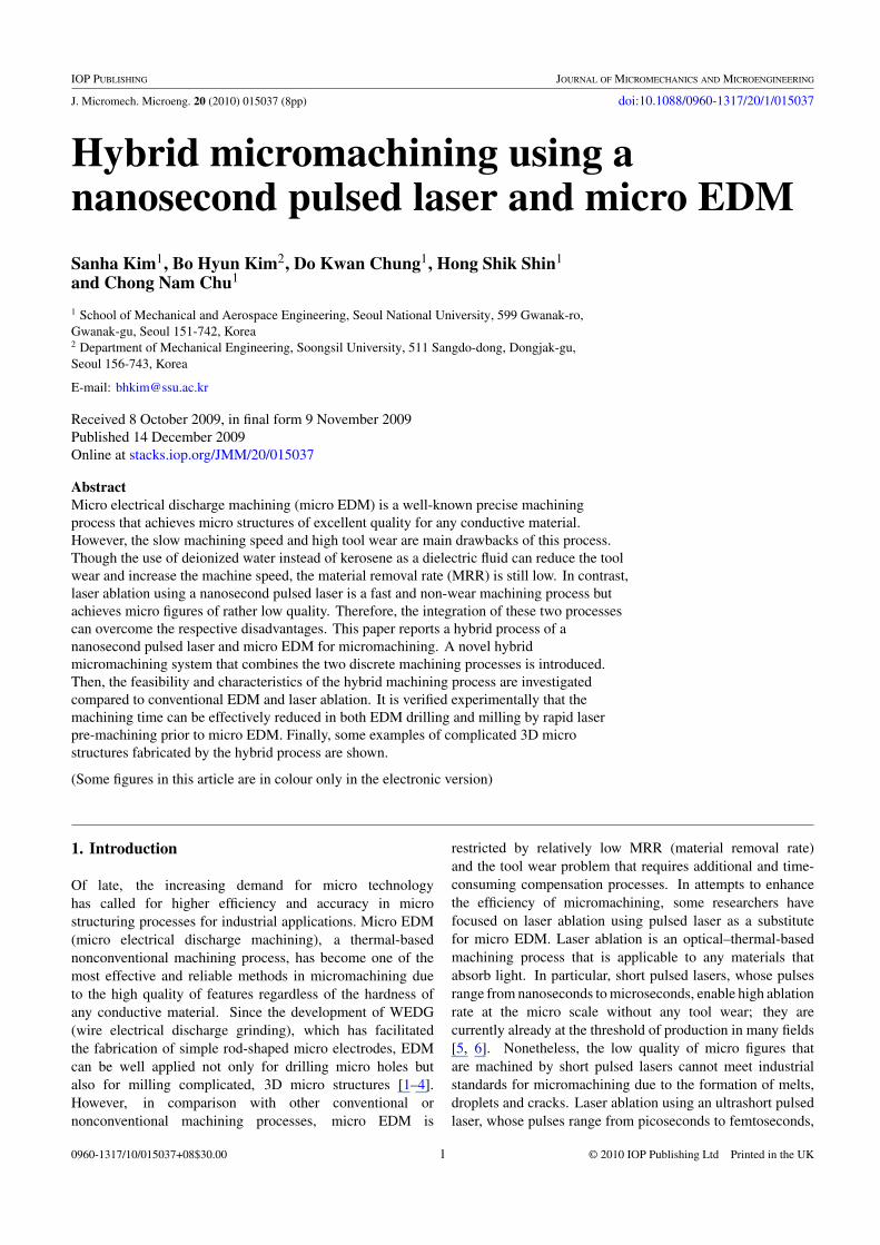
The main concept of hybrid micromachining is to combinethe two different thermal-based machining processes, laserablation and micro EDM, in sequence as shown in figure 1.Initially, a nanosecond pulsed laser that has high ablationrate is used to rough-machine a certain amount of materialwithout any tool wear. Subsequently, micro EDM, which isslow but reliable, can finish the machining with high qualityby removing the recast layer that forms around the structurethrough the laser. Hence, a hybrid process can decrease thetotal machining time while maintaining the high quality that isshifted from conventional EDM. Since the machining time forthe pre-machining process using a nanosecond pulsed laseris relatively negligible compared to that for EDM, the twodominant factors for improving the machining efficiency arethe minimization of the time interval and the reduction ofthe machining time in EDM that is supported by laser pre-machining (figure 2).
2.2. Hybrid micromachining system
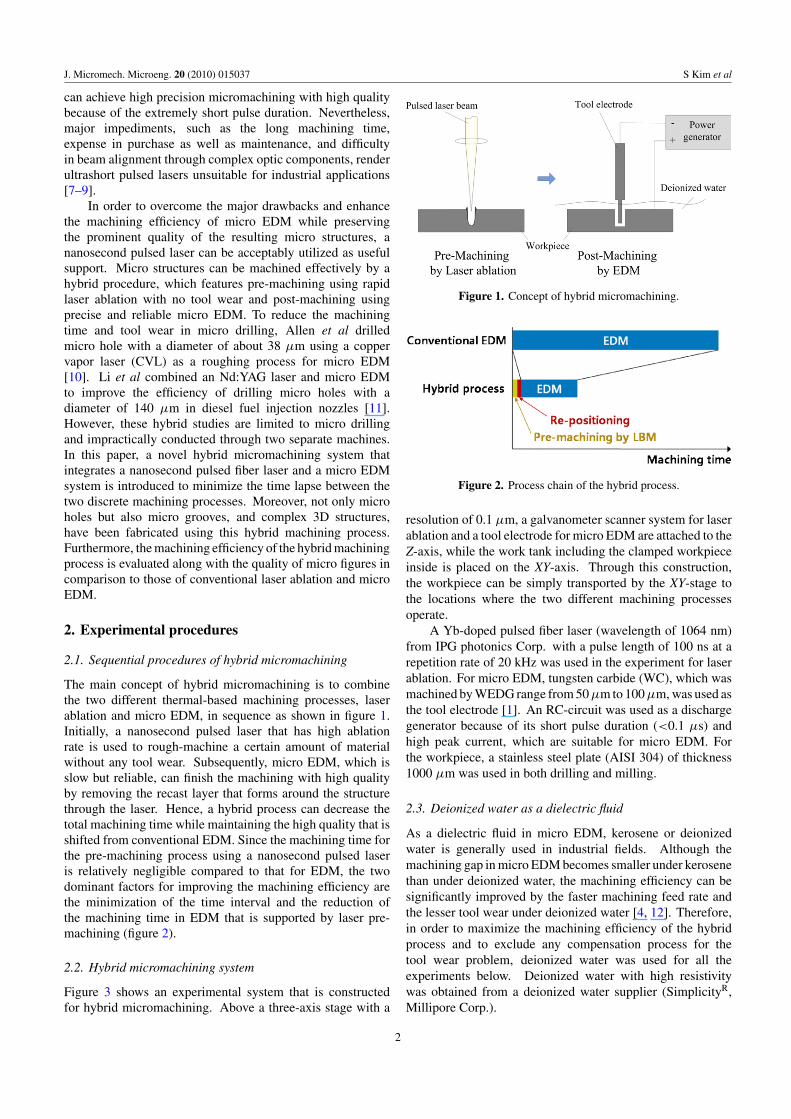
Figure 3 shows an experimental system that is constructedfor hybrid micromachining. Above a three-axis stage with a
Figure 1. Concept of hybrid micromachining.
Figure 2. Process chain of the hybrid process.
resolution of 0.1 μm, a galvanometer scanner system for laserablation and a tool electrode for micro EDM are attached to theZ-axis, while the work tank including the clamped workpieceinside is placed on the XY-axis. Through this construction,the workpiece can be simply transported by the XY-stage tothe locations where the two different machining processesoperate.
A Yb-doped pulsed fiber laser (wavelength of 1064 nm)from IPG photonics Corp. with a pulse length of 100 ns at arepetition rate of 20 kHz was used in the experiment for laserablation. For micro EDM, tungsten carbide (WC), which wasmachined by WEDG range from 50 μm to 100 μm, was used asthe tool electrode [1]. An RC-circuit was used as a dischargegenerator because of its short pulse duration (<0.1 μs) andhigh peak current, which are suitable for micro EDM. Forthe workpiece, a stainless steel plate (AISI 304) of thickness1000 μm was used in both drilling and milling.
2.3. Deionized water as a dielectric fluid
As a dielectric fluid in micro EDM, kerosene or deionizedwater is generally used in industrial fields. Although themachining gap in micro EDM becomes smaller under kerosenethan under deionized water, the machining efficiency can besignificantly improved by the faster machining feed rate andthe lesser tool wear under deionized water [4, 12]. Therefore,in order to maximize the machining efficiency of the hybridprocess and to exclude any compensation process for thetool wear problem, deionized water was used for all theexperiments below. Deionized water with high resistivitywas obtained from a deionized water supplier (SimplicityR,Millipore Corp.).
2
J. Micromech. Microeng. 20 (2010) 015037 S Kim et al
Figure 3. Hybrid micromachining system.
Micro EDM is not a constantly stable process because ofthe erratic influence of debris and bubbles that are generatedby the discharge spark between the tool electrode and theworkpiece. In order to reduce the possible waste of machiningtime that occurs through these unstable discharges and improvethe machining efficiency, the feed rate of the tool electrode wasvaried during micro EDM [13]. Beginning from a minimumvalue (0.5 μm s−1 in drilling and 10 μm s−1 in milling), thefeed rate of the tool electrode was increased (by 0.5 μm s−1
in drilling and 2 μm s−1 in milling, respectively) when themachining was stable, while it was halved when the dischargebecame unstable.
3. Hybrid micro drilling
3.1. Machining efficiency
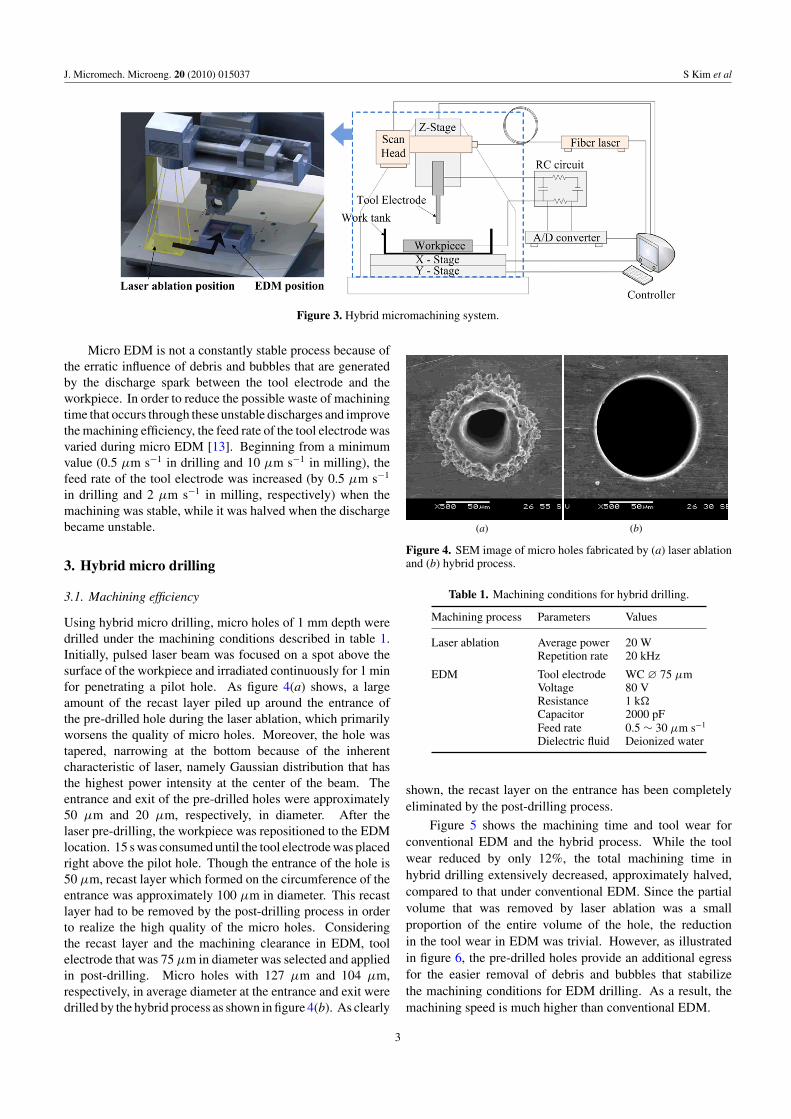
Using hybrid micro drilling, micro holes of 1 mm depth weredrilled under the machining conditions described in table 1.Initially, pulsed laser beam was focused on a spot above thesurface of the workpiece and irradiated continuously for 1 minfor penetrating a pilot hole. As figure 4(a) shows, a largeamount of the recast layer piled up around the entrance ofthe pre-drilled hole during the laser ablation, which primarilyworsens the quality of micro holes. Moreover, the hole wastapered, narrowing at the bottom because of the inherentcharacteristic of laser, namely Gaussian distribution that hasthe highest power intensity at the center of the beam. Theentrance and exit of the pre-drilled holes were approximately50 μm and 20 μm, respectively, in diameter. After thelaser pre-drilling, the workpiece was repositioned to the EDMlocation. 15 s was consumed until the tool electrode was placedright above the pilot hole. Though the entrance of the hole is50 μm, recast layer which formed on the circumference of theentrance was approximately 100 μm in diameter. This recastlayer had to be removed by the post-drilling process in orderto realize the high quality of the micro holes. Consideringthe recast layer and the machining clearance in EDM, toolelectrode that was 75 μm in diameter was selected and appliedin post-drilling. Micro holes with 127 μm and 104 μm,respectively, in average diameter at the entrance and exit weredrilled by the hybrid process as shown in figure 4(b). As clearly
(a) (b)
Figure 4. SEM image of micro holes fabricated by (a) laser ablationand (b) hybrid process.
Table 1. Machining conditions for hybrid drilling.
Machining process Parameters Values
Laser ablation Average power 20 WRepetition rate 20 kHz
EDM Tool electrode WC ∅ 75 μmVoltage 80 VResistance 1 k�Capacitor 2000 pFFeed rate 0.5 ∼ 30 μm s−1
Dielectric fluid Deionized water
shown, the recast layer on the entrance has been completelyeliminated by the post-drilling process.
Figure 5 shows the machining time and tool wear forconventional EDM and the hybrid process. While the toolwear reduced by only 12%, the total machining time inhybrid drilling extensively decreased, approximately halved,compared to that under conventional EDM. Since the partialvolume that was removed by laser ablation was a smallproportion of the entire volume of the hole, the reductionin the tool wear in EDM was trivial. However, as illustratedin figure 6, the pre-drilled holes provide an additional egressfor the easier removal of debris and bubbles that stabilizethe machining conditions for EDM drilling. As a result, themachining speed is much higher than conventional EDM.
3
J. Micromech. Microeng. 20 (2010) 015037 S Kim et al
Figure 5. Machining time and tool wear for drilling micro hole.
Figure 6. Advantage of the hybrid drilling process.
3.2. Upset hybrid micro drilling
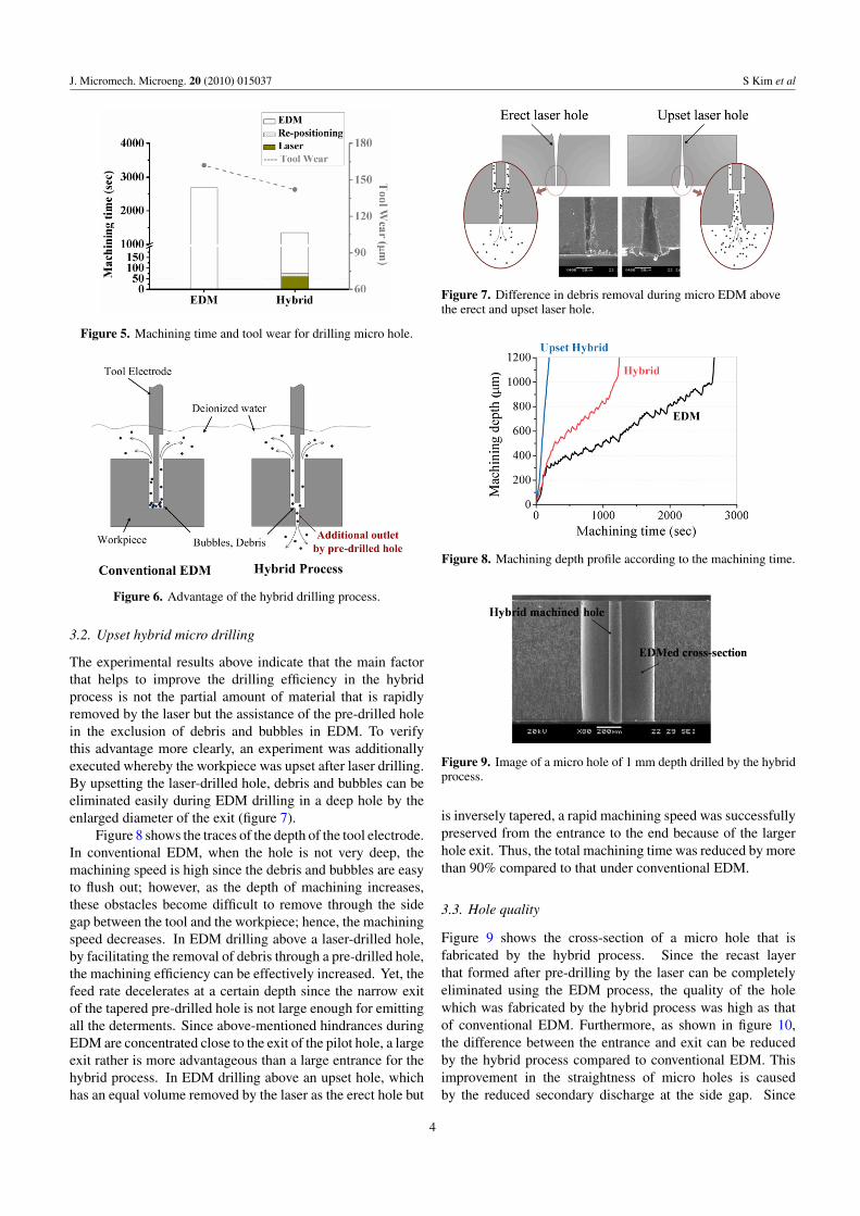
The experimental results above indicate that the main factorthat helps to improve the drilling efficiency in the hybridprocess is not the partial amount of material that is rapidlyremoved by the laser but the assistance of the pre-drilled holein the exclusion of debris and bubbles in EDM. To verifythis advantage more clearly, an experiment was additionallyexecuted whereby the workpiece was upset after laser drilling.By upsetting the laser-drilled hole, debris and bubbles can beeliminated easily during EDM drilling in a deep hole by theenlarged diameter of the exit (figure 7).
Figure 8 shows the traces of the depth of the tool electrode.In conventional EDM, when the hole is not very deep, themachining speed is high since the debris and bubbles are easyto flush out; however, as the depth of machining increases,these obstacles become difficult to remove through the sidegap between the tool and the workpiece; hence, the machiningspeed decreases. In EDM drilling above a laser-drilled hole,by facilitating the removal of debris through a pre-drilled hole,the machining efficiency can be effectively increased. Yet, thefeed rate decelerates at a certain depth since the narrow exitof the tapered pre-drilled hole is not large enough for emittingall the determents. Since above-mentioned hindrances duringEDM are concentrated close to the exit of the pilot hole, a largeexit rather is more advantageous than a large entrance for thehybrid process. In EDM drilling above an upset hole, whichhas an equal volume removed by the laser as the erect hole but
Figure 7. Difference in debris removal during micro EDM abovethe erect and upset laser hole.
Figure 8. Machining depth profile according to the machining time.
Figure 9. Image of a micro hole of 1 mm depth drilled by the hybridprocess.
is inversely tapered, a rapid machining speed was successfullypreserved from the entrance to the end because of the largerhole exit. Thus, the total machining time was reduced by morethan 90% compared to that under conventional EDM.
3.3. Hole quality
Figure 9 shows the cross-section of a micro hole that isfabricated by the hybrid process. Since the recast layerthat formed after pre-drilling by the laser can be completelyeliminated using the EDM process, the quality of the holewhich was fabricated by the hybrid process was high as thatof conventional EDM. Furthermore, as shown in figure 10,the difference between the entrance and exit can be reducedby the hybrid process compared to conventional EDM. Thisimprovement in the straightness of micro holes is causedby the reduced secondary discharge at the side gap. Since
4
J. Micromech. Microeng. 20 (2010) 015037 S Kim et al
Figure 10. Straightness of micro holes.
the debris additionally flows out through the bottom of thepre-drilled hole, the incidence of secondary discharge, whichenlarges the gap at the entrance during EDM drilling, canbe decreased. Moreover, a lower time for EDM may causeless anodic dissolution through the electrochemical reaction,which also may widen the entrance gap [14]. In conclusion,hybrid drilling can improve the machining efficiency with evenenhanced straightness of the micro hole.
4. Hybrid micro milling
4.1. Machining efficiency
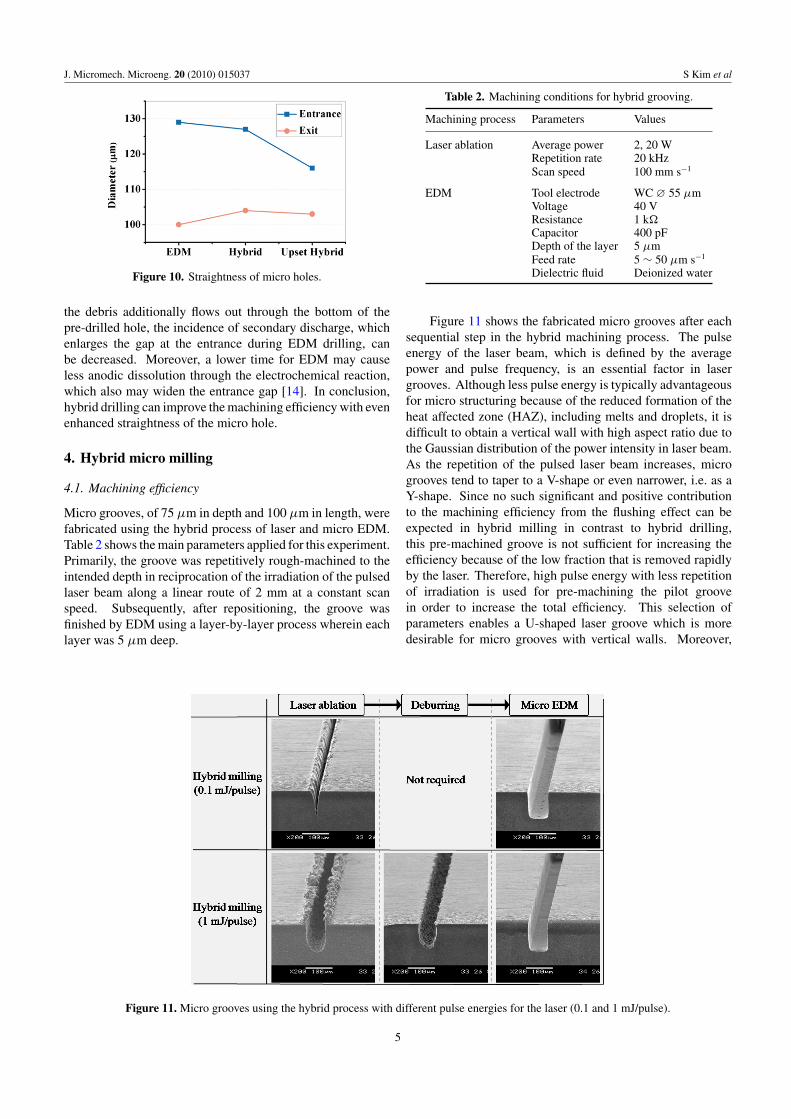
Micro grooves, of 75 μm in depth and 100 μm in length, werefabricated using the hybrid process of laser and micro EDM.Table 2 shows the main parameters applied for this experiment.Primarily, the groove was repetitively rough-machined to theintended depth in reciprocation of the irradiation of the pulsedlaser beam along a linear route of 2 mm at a constant scanspeed. Subsequently, after repositioning, the groove wasfinished by EDM using a layer-by-layer process wherein eachlayer was 5 μm deep.
Figure 11. Micro grooves using the hybrid process with different pulse energies for the laser (0.1 and 1 mJ/pulse).
Table 2. Machining conditions for hybrid grooving.
Machining process Parameters Values
Laser ablation Average power 2, 20 WRepetition rate 20 kHzScan speed 100 mm s−1
EDM Tool electrode WC ∅ 55 μmVoltage 40 VResistance 1 k�Capacitor 400 pFDepth of the layer 5 μmFeed rate 5 ∼ 50 μm s−1
Dielectric fluid Deionized water
Figure 11 shows the fabricated micro grooves after eachsequential step in the hybrid machining process. The pulseenergy of the laser beam, which is defined by the averagepower and pulse frequency, is an essential factor in lasergrooves. Although less pulse energy is typically advantageousfor micro structuring because of the reduced formation of theheat affected zone (HAZ), including melts and droplets, it isdifficult to obtain a vertical wall with high aspect ratio due tothe Gaussian distribution of the power intensity in laser beam.As the repetition of the pulsed laser beam increases, microgrooves tend to taper to a V-shape or even narrower, i.e. as aY-shape. Since no such significant and positive contributionto the machining efficiency from the flushing effect can beexpected in hybrid milling in contrast to hybrid drilling,this pre-machined groove is not sufficient for increasing theefficiency because of the low fraction that is removed rapidlyby the laser. Therefore, high pulse energy with less repetitionof irradiation is used for pre-machining the pilot groovein order to increase the total efficiency. This selection ofparameters enables a U-shaped laser groove which is moredesirable for micro grooves with vertical walls. Moreover,
5
J. Micromech. Microeng. 20 (2010) 015037 S Kim et al
Figure 12. Machining time for micro grooves fabricated byconventional EDM and hybrid process under different pulseenergies for the laser (0.1 and 1 mJ/pulse).
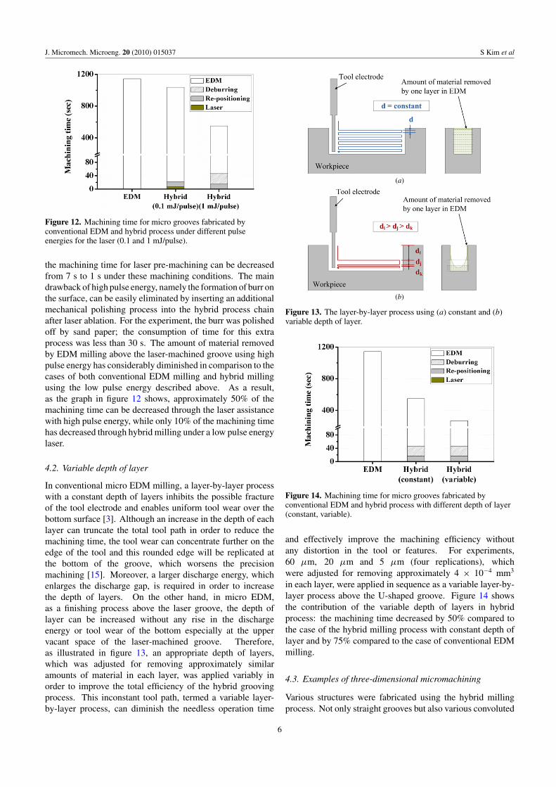
the machining time for laser pre-machining can be decreasedfrom 7 s to 1 s under these machining conditions. The maindrawback of high pulse energy, namely the formation of burr onthe surface, can be easily eliminated by inserting an additionalmechanical polishing process into the hybrid process chainafter laser ablation. For the experiment, the burr was polishedoff by sand paper; the consumption of time for this extraprocess was less than 30 s. The amount of material removedby EDM milling above the laser-machined groove using highpulse energy has considerably diminished in comparison to thecases of both conventional EDM milling and hybrid millingusing the low pulse energy described above. As a result,as the graph in figure 12 shows, approximately 50% of themachining time can be decreased through the laser assistancewith high pulse energy, while only 10% of the machining timehas decreased through hybrid milling under a low pulse energylaser.
4.2. Variable depth of layer
In conventional micro EDM milling, a layer-by-layer processwith a constant depth of layers inhibits the possible fractureof the tool electrode and enables uniform tool wear over thebottom surface [3]. Although an increase in the depth of eachlayer can truncate the total tool path in order to reduce themachining time, the tool wear can concentrate further on theedge of the tool and this rounded edge will be replicated atthe bottom of the groove, which worsens the precisionmachining [15]. Moreover, a larger discharge energy, whichenlarges the discharge gap, is required in order to increasethe depth of layers. On the other hand, in micro EDM,as a finishing process above the laser groove, the depth oflayer can be increased without any rise in the dischargeenergy or tool wear of the bottom especially at the uppervacant space of the laser-machined groove. Therefore,as illustrated in figure 13, an appropriate depth of layers,which was adjusted for removing approximately similaramounts of material in each layer, was applied variably inorder to improve the total efficiency of the hybrid groovingprocess. This inconstant tool path, termed a variable layer-by-layer process, can diminish the needless operation time
(a)
(b)
Figure 13. The layer-by-layer process using (a) constant and (b)variable depth of layer.
Figure 14. Machining time for micro grooves fabricated byconventional EDM and hybrid process with different depth of layer(constant, variable).
and effectively improve the machining efficiency withoutany distortion in the tool or features. For experiments,60 μm, 20 μm and 5 μm (four replications), whichwere adjusted for removing approximately 4 × 10⁻⁴ mm3
in each layer, were applied in sequence as a variable layer-by-layer process above the U-shaped groove. Figure 14 showsthe contribution of the variable depth of layers in hybridprocess: the machining time decreased by 50% compared tothe case of the hybrid milling process with constant depth oflayer and by 75% compared to the case of conventional EDMmilling.
4.3. Examples of three-dimensional micromachining
Various structures were fabricated using the hybrid millingprocess. Not only straight grooves but also various convoluted
6
J. Micromech. Microeng. 20 (2010) 015037 S Kim et al
(a) (b)
(c) (d )
(e) ( f )
(g) (h)
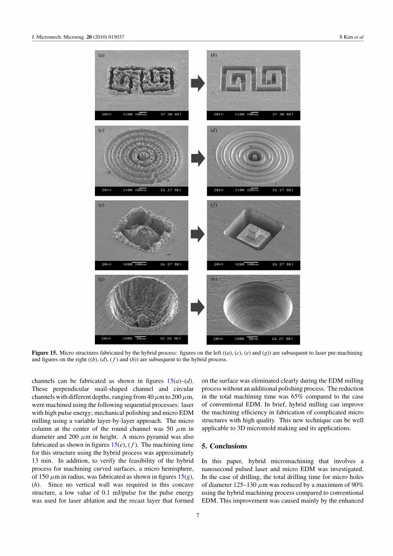
Figure 15. Micro structures fabricated by the hybrid process: figures on the left ((a), (c), (e) and (g)) are subsequent to laser pre-machiningand figures on the right ((b), (d), (f ) and (h)) are subsequent to the hybrid process.
channels can be fabricated as shown in figures 15(a)–(d).These perpendicular snail-shaped channel and circularchannels with different depths, ranging from 40 μm to 200 μm,were machined using the following sequential processes: laserwith high pulse energy; mechanical polishing and micro EDMmilling using a variable layer-by-layer approach. The microcolumn at the center of the round channel was 50 μm indiameter and 200 μm in height. A micro pyramid was alsofabricated as shown in figures 15(e), (f ). The machining timefor this structure using the hybrid process was approximately13 min. In addition, to verify the feasibility of the hybridprocess for machining curved surfaces, a micro hemisphere,of 150 μm in radius, was fabricated as shown in figures 15(g),(h). Since no vertical wall was required in this concavestructure, a low value of 0.1 mJ/pulse for the pulse energywas used for laser ablation and the recast layer that formed
on the surface was eliminated clearly during the EDM millingprocess without an additional polishing process. The reductionin the total machining time was 65% compared to the caseof conventional EDM. In brief, hybrid milling can improvethe machining efficiency in fabrication of complicated microstructures with high quality. This new technique can be wellapplicable to 3D micromold making and its applications.
5. Conclusions
In this paper, hybrid micromachining that involves ananosecond pulsed laser and micro EDM was investigated.In the case of drilling, the total drilling time for micro holesof diameter 125–130 μm was reduced by a maximum of 90%using the hybrid machining process compared to conventionalEDM. This improvement was caused mainly by the enhanced
7

J. Micromech. Microeng. 20 (2010) 015037 S Kim et al
machining speed in EDM that was assisted by a laser-drilledpilot hole, which facilitated the removal of debris and bubbles.In addition, the straightness of the micro hole can be improveddue to the fewer secondary discharges and less electrochemicaldissolution. In the case of milling, micro grooves, of 75 μmin width and 100 μm in depth, were also fabricated using thehybrid process and the total machining time was reduced by amaximum of 75%. The machining efficiency in EDM has beenimproved by rough machining using rapid laser ablation andthe adjustment of the tool path using a variable layer-by-layerprocess. Finally, the feasibility of various micro structureswith high quality has been demonstrated using hybrid micromilling.
Acknowledgments
This research was supported by the Korea Science andEngineering Foundation (KOSEF) grant funded by the Koreagovernment (MEST) (no 20090080379).
References
[1] Masuzawa T, Fujimoto M and Kobayashi K 1985 Wireelectro-discharge grinding for micro machining Ann. CIRP34 431–4
[2] Masuzawa T, Tsukanoto J and Fujimoto M 1989 Drilling ofdeep microholes by EDM Ann. CIRP 38 195–8
[3] Yu Z, Masuzawa T and Fujino M 1997 Micro-EDM forthree-dimensional cavities—development of uniform wearmethod Ann. CIRP 47 169–72
[4] Chung D K, Kim B H and Chu C N 2007 Micro electricaldischarge milling using deionized water as a dielectric fluidJ. Micromech. Microeng. 17 867–74
[5] Kaldos A, Pieper H J, Wolf E and Krause M 2004 Lasermachining in die making—a modern rapid tooling processJ. Mater. Process. Technol. 155 1815–20
[6] Dhara S K, Kuar A S and Mitra S 2008 An artificial neuralnetwork approach on parametric optimization of lasermicro-machining of die-steel Int. J. Adv. Manuf. Technol.39 39–46
[7] Tinshoff H K, Alvensleben F, Ostendprf A, Kamlage Gand Nolte S 1999 Micromachining of metals usingultrashort laser pulses Int. J. Electr. Mach. 4 1–6
[8] Meijer J, Du K, Gilner A, Hoffmann D, Kovalenko V S,Masuzawa T, Ostendon A, Poprawe R and Schulz W 2002Laser machining by short and ultrashort pulses, state of theart and new opportunities in the age of the photons Ann.CIRP 51 531–50
[9] Pham D T, Dimov S S, Petkov P V and Petkov S P 2002 Lasermilling Proc. Inst. Mech. Eng. B216 657–67
[10] Allen D M and Huang S X 1997 The reduction of tool wearand machining time for the micro-electro dischargemachining of micro-holes by using copper vapour lasermachining as a roughing process Int. J. Electr. Mach. 2 9–11
[11] Li L, Diver C, Atkinson J, Giedl-Wagner R and Helml H J2007 Sequential laser and EDM micro-drilling for nextgeneration fuel injection nozzle manufacture Ann. CIRP55 179–82
[12] Chen S L, Yan B H and Huang F Y 1999 Influence of keroseneand distilled water as dielectrics on the electric dischargemachining characteristics of Ti-6Al-4V J. Mater. Process.Technol. 87 107–11
[13] Lee B U, Yi S M, Kim B H and Chu C N 2004 Fabrication of3D micro structure using micro electrical discharge millingJ. KSPE 21 41–7
[14] Seo D W, Park M S, Yi S M and Chu C N 2007 Machiningcharacteristics of micro-EDMed holes according todielectric fluid, capacitance and ultrasonic vibrationsJ. KSPE 24 42–9
[15] Tsai Y Y, Masuzawa T and Fujino M 2001 Investigations onelectrode wear in micro-EDM 13th Int. Symp. onElectromachining (ISEM XIII) pp 719–26
8
Copyright © 2022 FDOKUMEN