
Wire-cut EDM Systems MP Series
20
HEAD OFFICE: TOKYO BLDG., 2-7-3 MARUNOUCHI, CHIYODA-KU, TOKYO 100-8310, JAPAN K-KL2-8-C0268-A Printed December 2018 All trademarks acknowledged. Wire-cut EDM Systems MP Series series M P FACTORY AUTOMATION MP Series ▶MPSeries [YouTube] [YouTube logo] is a trademark or registered trademark of Google Inc. Global Partner. Local Friend. Mitsubishi Electric Corporation Nagoya Works is a factory certified for ISO14001 (standards for environmental management systems) and ISO9001(standards for quality assurance management systems)
-
Upload
khangminh22 -
Category
Documents
-
view
0 -
download
0
Transcript of Wire-cut EDM Systems MP Series

HEAD OFFICE: TOKYO BLDG., 2-7-3 MARUNOUCHI,CHIYODA-KU, TOKYO 100-8310, JAPAN
K-KL2-8-C0268-A Printed December 2018 All trademarks acknowledged.
Wire-cut EDM SystemsMP Series
seriesMP
FACTORY AUTOMATIONMP
Series
▶MPSeries
[YouTube] [YouTube logo] is a trademark or registered trademark of Google Inc.
Global Partner. Local Friend.
Mitsubishi Electric Corporation Nagoya Works is a factory certified for ISO14001 (standards for environmental management systems) and ISO9001(standards for quality assurance management systems)

ContentsContents
INDEX
13. Power Supply, Control Specifications / Machine Installation . . 33
14. Solutions . . . . . . . . . . . . . . . . . . . . . . . . . . . . . . . . . . . . . . . . . . . . . . . . . . . . . . . . 38
8. Automatic Wire Threading . . . . . . . . . . . . . . . . . . . . . . . . . . . . . . . . . . . 21
9. Productivity . . . . . . . . . . . . . . . . . . . . . . . . . . . . . . . . . . . . . . . . . . . . . . . . . . . . . . 23
10. Operability . . . . . . . . . . . . . . . . . . . . . . . . . . . . . . . . . . . . . . . . . . . . . . . . . . . . . . 25
11. Energy Savings, Low Operating Cost . . . . . . . . . . . . . . . . . . . 29
12. Options . . . . . . . . . . . . . . . . . . . . . . . . . . . . . . . . . . . . . . . . . . . . . . . . . . . . . . . . . . 31
1. History of Wire-cut EDMs . . . . . . . . . . . . . . . . . . . . . . . . . . . . . . . . . . . . 3
2. MP Series . . . . . . . . . . . . . . . . . . . . . . . . . . . . . . . . . . . . . . . . . . . . . . . . . . . . . . . . 5
3. Wire-cut EDM Systems . . . . . . . . . . . . . . . . . . . . . . . . . . . . . . . . . . . . . . . 7
4. Product Lineup. . . . . . . . . . . . . . . . . . . . . . . . . . . . . . . . . . . . . . . . . . . . . . . . . .
6. Sample . . . . . . . . . . . . . . . . . . . . . . . . . . . . . . . . . . . . . . . . . . . . . . . . . . . . . . . . . . . . 15
5. Functions and Features. . . . . . . . . . . . . . . . . . . . . . . . . . . . . . . . . . . . . . . 13
9
7. Machining Accuracy/control. . . . . . . . . . . . . . . . . . . . . . . . . . . . . . . . . 17
14
1
2
3
4
6
5
7
8
9
10
11
12
13
Mitsubishi Electric continues thechallenge to be the only one FAmachine and systems supplierdelivering total customer satisfaction.
Mitsubishi Electric is a world-leading general electrical and electronic products manufacturer with wide-ranging business reach, from
appliances for the home to systems used in outer space. Global-scale business development is in �ve business domains: heavy electrical
machinery and systems, industrial automation, information and communication systems, electronic devices, and home appliances.
Producing general electrical machinery for over 90 years, as Mitsubishi Electric's Factory Automation Systems Business Group, we have
supported manufacturing in Japan, China, and Asia, and around the globe. In doing so, we have accumulated and re�ned technologies
for FA control, drive control, automation, and manufacturing that are utilized to expand and improve a vast product lineup, such as
controllers, drives, and automation and power distribution control products. In addition to product components like those listed above,
we are quick to propose systems such as e-F@ctory and iQ Platform as solutions for production site innovation. As a comprehensive
supplier of FA products and systems, Mitsubishi Electric will continue to respond to the voice of customers and deliver products of the
utmost quality throughout the world.
Global Player
GLOBAL IMPACT OFMITSUBISHI ELECTRIC
We bring together the best minds to create the best technologies. At Mitsubishi Electric, we understand that technology is the driving force of change in our lives. By bringing great-er comfort to daily life, maximizing the efficiency of businesses and keeping things running across society, we integrate technology and innovation to bring changes for the better.
Mitsubishi Electric is involved in many areas including the following
Energy and Electric SystemsA wide range of power and electrical products from generators to large-scale displays.
Electronic DevicesA wide portfolio of cutting-edge semiconductor devices for systems and products.
Home ApplianceDependable consumer products like air conditioners and home entertain-ment systems.
Information and Communication SystemsCommercial and consumer-centric equipment, products and systems.
Industrial Automation SystemsMaximizing productivity and efficiency with cutting-edge automation technology.
Through Mitsubishi Electric’s vision, “Changes for the Better“ are possible for a brighter future.
1 2

New generation makes its mark in a continuously updated lineage.
MP SeriesMP Series
1980
1990
2000
2017~ 2014~
1972DWC50H-DNC2 DWC100H-CNC2 DWC90-CNC1DWC50S-LT1 DWC90FSK-CNC1 DWC90G DWC90H DWC90PH DWC110PH DWC90CDWC110N-CNC1
PX05 DWC90HADWC90SBDWC110SZDWC110SADWC400HASX20CX20DWC90PAFX10
FX20K QA20 RA90AT FA20P PA20 FA30V PA05S
MP1200 PA10 ADVANCE
FA20S
FA50V
FA10PS
BA8 FA20S AdvanceNA2400P
FA20
Line tracer typewire-cut EDM Taper machining unit
Max. machining speed60mm²/min
Max. machining speed 110mm²/minOptimum surface roughness of Rz2μm
Automatic wire threading unit(water jet type)
1
32 bit CNCAutomatic wire
threading unit "AF2"Anti-electrolysis power supply
(AE power supply)Ultrahigh precision wire-cut EDM
(Full-cabin)
64 bit CNCWorld's fastest "V500"
power supplySuper �ne �nishing
power supply "Digital-FS"
Large-sized wire-cut EDMDigital-AE power supplyLinear Shaft motor
MX600
Oil wire-cut EDM
Max. machining speed 325mm²/minAutomatic wire threading unit "AT"
Max. machining speed250mm²/min
MV1200RMV1200R
MP1200 MITSUBISHI ELECTRIC Wire-cut EDM Systems
Histo
ry of W
ire-cut ED
Ms
MPSeries3 4

2
MP
Series
Outstanding accuracy for the most critical application in the field of world.Outstanding accuracy for the most critical application in the field of world.
MPseries5 6

Wire-cut EDM to meet toanticipations for ultrahigh accuracy
MPSeries
3
Wire-cut E
DM
System
sMP SeriesMP Series
Wire-cut EDM Systems LineupModel lineup covers your machining needs from parts production machining to super-accurate mold making
MV-R SeriesHigh performance model innovatingnext-generation high-performance machine
Oil
Micro slit width 23μm
Flagship model incorporatingextreme precision machining
PA05S ADVANCE
Ultrahigh precision machines
MX 600Flagship model incorporatingextreme precision machining
MP SeriesFlagship model incorporatingextreme precision machining
Highperformance machine
MV-S SeriesStandard model pursuinga cost performance standard machine
Highproductivity machine
7 8

2015
(79.
3)
2015
(79.
3)
400st
1910(75.2)460(18.1)460(18.1)
MP1200
(Automatic elevation tank)
*1 ø0.2(.008") DD guides and ø1.5(.06") jet nozzle are standard equipment.
ModelMax. workpiece dimensionsMax. workpiece weightTable dimensionsMachine travels (XxYxZ)
Machine travels (UxV)
Max. taper angleWire diameterWeight
[mm](in)[kg](lb)
[mm](in)[mm](in)
[mm](in)
[ °][mm](in)
[kg](lb)
Mac
hine
uni
tD
iele
ctric
�ui
dre
serv
oir
Tank capacityFiltration methodFiltered particle sizeWater puri�er (ion exchange resin)Dielectric �uid chiller unitWeight (dry)
[ℓ](US gal)
[μm][ℓ](cu.ft.)
[kg](lb)
Air pressureAir rate
13.50.5(72.5)~0.7(101.5)
75(2.65) or more
[kVA][MPa](psi)
[ℓ(cu.ft.)/min]Required air rate
General input
MP1200810(31.9)×700(27.6)×215(8.5)
500(1102)640(25.2)×540(21.3) (4-sided)
400(15.7)×300(11.8)×220(8.7) (XY axis OPT-drive specifications)±60(2.4)×±60(2.4)
(OPT-drive specifications)15°(max. 200mm(7.9"))
3100(6834)(including dielectric �uid reservoir)550(145)
—(included in the machine unit weight)
MP24001050(41.3)×820(32.3)×305(12.0)
1500(3307)840(33.1)×640(25.2) (4-sided)
600(23.6)×400(15.7)×310(12.2) (XY axis OPT-drive specifications)±75(2.9)×±75(2.9)
(OPT-drive specifications)15°(max. 260mm(10.2"))
4100(9039)800(211)
350(772)
0.1(.004)~0.3(.012)*1
Paper �lter (2)3
10(0.35)Unit cooler
Standard machine speci�cations
MP24004-axis LSM (XYUV linear shaft motor)
Four-sided hardened table
80
10
10
10
10
80
10
10
100
Thickness: 20mmUnit: mm
10
10
100
30
●Workpiece:Steel (PD613 t20mm(0.79")(SKD11 improved steel))HRC56-57 after quenching the workpiece, sub-zero treatment, high thermal tempering, stabilizing treatment and demagnetization are conducted.
●Wire electrode: Ø0.2(.008")/BS
●Room temperature: 20°C±1°C
Accuracy guarantee con�rmation shape
Machining accuracy ±2μm achieved (Note 1)
(Note 1) The machining accuracy follows the Mitsubishi Electric
machining conditions.
Machining accuracy ±2μm achieved (Note 1)
(Note 1) The machining accuracy follows the Mitsubishi Electric
machining conditions.
Product Lineup (Unit:mm (in))MP1200 <Outline drawing> <Layout drawing>
<Table drawing>
<Table drawing>
A: Clean tank drain port Fitted with PT1 screw valve (165mm from �oor)B: Dirty tank drain port Fitted with PT1 screw valve (165mm from �oor)C: Power supply port 200/220VAC±10% 50/60Hz, 13.5kVAD: Primary air side 0.5 to 0.7MPa, 75ℓ/min or more, 1/4 hose connection (hose sleeve outer diameter: Ø9mm)
A: Clean tank drain port Fitted with PT1 screw valve (165mm from �oor)B: Dirty tank drain port Fitted with PT1 screw valve (165mm from �oor)C: Power supply port 200/220VAC±10% 50/60Hz, 13.5kVAD: Primary air side 0.5 to 0.7MPa, 75ℓ/min or more, 1/4 hose connection (hose sleeve outer diameter: ø9mm)
*1 is min.500(19.7) and *2 is min.700(27.6) when the 20/25kg(44.1/55.2lb) wire spool unit is mounted.
Machine unit dimensionsWidth:1910mm(75.2) Height: 2015mm(79.3) Wire electrode mounting height: 1492mm(58.74´)
Machine unit dimensionsWidth: 2022mm (79.6) Height: 2150mm (84.6)Wire electrode mounting height: 1627mm (64.1)
(Unit:mm (in))MP2400 <Outline drawing> <Layout drawing>
*3 is min.670(26.4) when the 20/25kg(44.1/55.2lb) wire spool unit is mounted. Footprint : 3387(133.3)×3830(150.8)(including maintenance space)
4-axis LSM (XYUV linear shaft motor)
Four-sided hardened table
(Automatic elevation tank)
MP Series
4
Pro
duct Lineup
MP Series
Standard functions• Automatic wire threading• Digital-AEⅡ power supply• LAN/W(Ethernet)• FTP/DNC(S/W)• Angle Master (S/W)
• Anti-virus protection• Sleep mode• Super-DFS power supply• Built-in scheduler
• Option Box• 20/25kg(44.1/55.2lb) wire spool unit• External signal output• Built-in warning light• Run timer
• 4-piece filter system• Filter automatic switching (4-piece filter system)• Temperature monitoring function
• Ø0.05, Ø0.07 Automatic wire threading• Angle Master ADVANCE Ⅱ(S/W)• Angle Master ADVANCE Ⅱ dice kit Ø0.2• Angle Master ADVANCE Ⅱ dice kit Ø0.25
Option
2760(108.7)555(21.9)1325(52.2)
1766
(69.
5)
300st
One-piece 4-sided table hardened stainless steel
2702
(106
.4)
min
.300
(11.
8)
2025(79.7)min.300*2
(11.8)115(4.53)
2760
(108
.7)
min.2
00*1
(7.9
)20/25kg(44.11/55.2 lb)wire spool unit(option)
920
B
A
2103
(82.
8)
D CB
One-piece 4-sidedtable hardenedstainless steel
555555
950(
37.4
)
2684(105.7)134(5.3)
810(31.9)976(38.4)
2150
(84.
6)
337 337 300st300st 300st300st
224(8.8)
1765
(69.
5)
3030(119.3)680(26.8) 760(29.9) 457(18.0)
600st600st400st(15.7)
min
.500
(19.
7)30
30(1
19.3
)m
in.5
90(2
3.2)
2292
(90.
2)
2987
(117
.5)
min.400(15.7)
D
B
A
C
2684(105.7)
915
min.300*3
(11.8)
20/25kg(44.1/55.2 lb) wire spool unit(option)
↑Front↑
50-M8tapped holes
110(4.3)
110(4
.3)
110 (4
.3)
540 (
21.3
)32
0 (12
.6)
640(25.2)
300(
11.8
) Tra
vel
400(15.7) Travel
110(4.3)
↑Front↑110(4.3)110(4.3)
420 (
16.5
)11
0 (4.3
)11
0 (4.3
)64
0 (25
.2)
840(33.0)
72-M8tapped holes
400(
15.7
) Tra
vel
600(23.6) Travel
Detail on the other page.
9 10

(Automatic elevation tank)
MP4800
*1 ø0.2(.008") DD guides and ø1.5(.06") jet nozzle are standard equipment.
ModelMax. workpiece dimensionsMax. workpiece weightTable dimensionsMachine travels (XxYxZ)
Machine travels (UxV)
Max. taper angleWire diameterWeight
[mm](in)[kg](lb)
[mm](in)[mm](in)
[mm](in)
[ °][mm](in)
[kg](lb)
Mac
hine
uni
t
Tank capacityFiltration methodFiltered particle sizeWater puri�er (ion exchange resin)Dielectric �uid chiller unitWeight (dry)
[ℓ](US gal)
[μm][ℓ](cu.ft.)
[kg](lb)Die
lect
ric �
uid
rese
rvoi
r
Air pressureAir rate
13.50.5(72.5)~0.7(101.5)
75(2.65) or more
[kVA][MPa](psi)
[ℓ(cu.ft.)/min]Required air rate
General input
MP48001250(49.2)×1020(40.2)×305(12.0)
1500(3307)1080(42.5)×870(34.3) (Separated 4-sided table)
800(31.5)×600(23.6)×310(12.2) (XY axis OPT-drive specifications)±75(2.9)×±75(2.9)
(OPT-drive specifications)15°(max. 260mm(10.2"))
0.1(.004)~0.3(.012)*1
5800(12786)1100(291)
Paper filter (4)3
10(0.70)Unit cooler450(992)
Standard machine speci�cations
Machining accuracy ±2μm achieved (Note 1)
(Note 1) The machining accuracy follows the Mitsubishi Electric
machining conditions.
Product Lineup MP4800
4-axis LSM (XYUV linear shaft motor)
Separated 4-sided hardened table
MP Series
4
Pro
duct Lineup
MP Series
<Outline drawing>
Standard functions• Automatic wire threading• Digital-AEⅡ power supply• LAN/W• FTP/DNC(S/W)• Angle Master (S/W)
• Anti-virus protection• Sleep mode• Super-DFS power supply• 4-piece filter system• Built-in scheduler• Dynamic thermal protection (DTPro)
• Option Box• 20/25kg(44.1/55.2lb) wire spool unit• External signal output• Built-in warning light• Run timer
• Filter automatic switching• Temperature monitoring function
• Angle Master ADVANCE Ⅱ(S/W)• Angle Master ADVANCE Ⅱ dice kit Ø0.2• Angle Master ADVANCE Ⅱ dice kit Ø0.25
Option
2415
(95.
1)
1100
(43.
3)
1560(61.4)1280(50.4)980(38.6)
2902(114.3)
800st
400st(15.8)
400st(15.8)
555(21.9)
600(23.6)
300st(11.8)
300st(11.8)
600(23.6)
335(13.3)
800st
196.7(7.74)
3445(135.6)
1765
(69.
5)
980(38.6) 750(29.6) 250(9.8)
450(17.7)
965(
38.0
)
600st
20° 5°
24-M8 tapped holes
68-M8 tapped holes
<Layout drawing>
20/25kg(44.1/55.2 lb) wire spool unit(option)
D
A
B
C
E
2823
(111
.1)
2902(114.3)
285(11.2) 1065(41.9)
min.50
0 (19 .7
)34
45(1
35.6
)m
in.30
0 (11 .
8 )
2745
(108
.1)
min.400(15.7)
min.300*1
(11.8)
<Table drawing>
Separated 4-sidedtable hardenedstainless steel
↑Front↑
620 (
24.4
)12
0 (4.7 )
10 (0.4
)
870 (
34.3
)13
0 (5.1 )
130(5.1)
1080(42.5)
800(31.5) Travel600(
23.6
) Tra
vel
130(5.1)
A: Clean tank drain port Fitted with PT1/2 screw valve (52mm from �oor)B: Dirty tank drain port Fitted with PT1/2 screw valve (60mm from �oor)C: Dirty tank drain port Fitted with PT1 screw valve (52mm from �oor)D: Power supply port 200/220VAC±10% 50/60Hz, 13.5kVAE: Primary air side 0.5 to 0.7MPa, 75ℓ/min or more, 1/4 hose connection (hose sleeve outer diameter: ø9mm)
*1 is min.570(26.4) when the 20/25kg(44.1/55.2lb) wire spool unit is mounted.Footprint : 3602(141.8)×4245(167.1)(including maintenance space)
Machine unit dimensionsWidth:2550mm(100.4) Height:2415mm(95.1)
Supporting table
Detail on the other page.11 12

Functions and FeaturesFully equipped with useful functions for the manufacturing workplace,featuring re�ned style, high performance, energy savings,simple operation and vast expertise.
Automatic wire threadingMachining accuracy
• Equipped with a linear shaft motor(LSM)• Circular accuracy within 1μm is realized
using optical drive system(ODS).
Refer topage 21-22
Refer topage 23-24
5
Functio
ns and F
eatures
Refer topage 17-20
Productivity
• MP Water Technology increased Tungsten Carbide Productivity up to 30% from the conventional oil dielectric �uid wire-cut EDM.
• Newly added Built-in scheduler function Easy and �exible multiple program operation.
MP1200/MP2400/MP4800MP1200/MP2400/MP4800
MP SeriesMP Series
▲Video of automaticwire threading
Ø0.20 (.008") BS Wire, Tungsten carbide/thickness 60mm(2.36")
Conventional (Oil)
MPWater Technology
Machining Speed
Up to 30% Faster
Thickness [mm]
Sur
face
roug
hnes
s [μ
mR
z]
1
2
3
4
5
020 60 100 150 200
Improved performance area on S-DFS
Improved performance area on PF circuit
Operability
Refer topage 25-28
• Information is displayed on a large 19-inch screen.• Functions to be viewed or used are called
by one touch from the HOME screen.• The number of operations performed on the
Navigation menu from setup to machining is reduced by almost 40%. (as compared to the past)
• Setup performance is improved by a thin hand pendant box with LED.
• The operating cost of the machine can be viewed on the cost management screen.This is useful for budget planning.
Energy savings, low operating cost
Refer topage 29-30
Power monitor
Machining results monitor
サーボアンプservo AMP
LSM with linear glassscale feedback
D-CUBES制御装置D-CUBES
New controller
シャフトリニアモータLSM with linear glass scale feedbackBuilt-in scheduler
Built-in CAD
• New annealing system greatly improves wire threading with a curl ratio of less than 10%.
• Wire break point insertion is greatly improved for thick workpieces.
• Wire threading suitable for workpiece shape. (jet on/off and submerged break point insertion)
13 14

6
Sam
ple
MP SeriesMP Series
Ra0.08μm finish tungstencarbide machining ●High speed �ne surface �nishing is possible by super
�nish power supply (Super-DFS power supply).●Machining accuracy of 2μm or less for various size
of corners is realized by updated CM control.
Model MP1200Electrode material Ø0.2(.008")/BSWorkpiece Tungsten carbideWorkpiece thickness 35mm(1.38")Surface roughness Rz0.7μm/Ra0.08μmMachining accuracy Corner accuracy 2μm(.00008")
±1.5μm straightness tallpunch machining
●Straightness of ±1.5μm(.00006") is possible even with a 100mm (3.94") thick workpiece.
●High-accurate straightness is realized by shape control power supply. (Digital-AEⅡ power supply)
●Rz0.8 μm is realized by the advanced Super Digital-FS(SDFS) power supply.
Model MP2400Electrode material Ø0.2(.008")/MEGACut TypeAWorkpiece Steel(SKD11)Workpiece thickness 100mm(3.93")Surface roughness Rz0.8μm/Ra0.10μmMachining accuracy Straightness ±1.5μm(.00006")
1.3μm roundness circularmachining ●Rz0.6 μm is realized by the advanced Super
Digital-FS(SDFS) power supply.●High circular accuracy is realized by ODS and
entranced EM control.
Model MP2400Electrode material Ø0.2(.008")/BSWorkpiece Tungsten carbide Workpiece thickness 80mm(3.15")Surface roughness Rz0.6μm/Ra0.08μmMachining accuracy Roundness 1.3μm straightness 1.3μm
±1.5μm accuracy pitchmachining ●Stable high accuracy machining is realized by
ODS, improvement of axis movement accuracy and dielectric �uid control.
●Stable automatic wire threading is realized by Intelligent AT even in multi-shape machining.
Model MP4800Electrode material Ø0.2(.008")/BSWorkpiece Steel(SKD11)Workpiece thickness 30mm(1.18")Surface roughness Rz1.8μm/Ra0.22μmMachining accuracy Pitch accuracy ±1.5μm(.00006")
Uniform land cut machining ●High accuracy machining with uniform land height is possible by Angle Master ADVANCE Ⅱ.
●Enhanced accuracy machine movement by XYUV LSM and the round guides.
□Angle Master ADVANCE Ⅱ <Option>
Model MP1200Electrode material Ø0.2(.008")/BSWorkpiece Steel(SKD11)Workpiece thickness 30mm(1.18")Surface roughness Rz2.5μm/Ra0.32μmMachining accuracy —
Fine shape machining ●High speed �ne surface �nishing is possible by super �nish power supply (Super-DFS power supply).
●Shape accuracy of ±1μm in the L/D = 20 (pin width: 0.12mm, pin length: 2.4mm) is realized by NL control.
Model MP1200Electrode material Ø0.05(.002” )/Sumi sparkγMWorkpiece SteelWorkpiece thickness 0.5~ 1.0mmSurface roughness Rz0.80μm/Ra0.10μmMachining accuracy Shape accuracy ±1μm(.00004” )
SampleNext-level machining that adds extra value to your products
▶Machining samples
15 16

Servo amplifier(in-house product)
Servo amplifier(in-house product)
LSM with linear glassscale feedback
LSM with linear glassscale feedback
D-CUBEScontrol unitD-CUBES
control unit
LSM with linear glassscale feedback
LSM with linear glassscale feedback
Machining Accuracy
Highly rigid structure
Next-generation drive system and optimum machine structure
●MP1200 utilizes a split X/Y-axis construction method allowing both to be directly mounted to the T-shaped base casting for optimum stability. This combination moves the table in the X-axis and the column in the Y-axis.●MP2400 utilizes a �xed table traveling column design for improved
accuracy in large heavy workpieces.
Axis movement accuracy●This effort ensures precise linear movement by reducing waving of the
linear guide.●Ultra-high accuracy linear guides are carefully installed on precisely
machined mounting surfaces to provide straightness accuracy of 1- 2μm.
Controlling temperature of machine structure synchronized with dielectric �uid temperature, stabilizing accuracy machining for a long period time by controlling relative displacement of upper and lower guides.
●This process is synchronized through thermal sensors on the machine casting while circulating the �uid through key areas of the machine structure (Thermal buster).●A chiller system is used to cool the dielectric �uid to remove the heat
generated by the EDM machining process.
●High-accuracy machining of large-size pitch plates is realized with the next generation optical drive system equipped with the latest control device "D-CUBES" and the thermal displacement compensation system “Thermal Buster”.
●Ra0.08μm surface �nish is realized using Super-DFS power supply.●Enhanced EM function is used to reduce the over cut of approach point.
Thermal Stability System
Dynamic thermal protection (DTPro)(Dielectric fluid temperature control and Thermal displacement compensation function) (MP4800)
Optical Drive System●High-speed �ber-optic communications and a linear shaft motor
synergistically improve machining accuracy.●A servo ampli�er and control unit developed by Mitsubishi Electric
contribute to system optimization.
Linear Shaft Motor(LSM)●Power consumption is reduced by utilizing a full 360° magnetic �ux as
the effective driving force.●Highly accurate axis movement is possible without any backlash.●Non contact power transmission ensures stable and accurate axis
movement for many years.
③Temperature control of X axis linear shaft motor and machine structure (table) (synchronized with dielectric �uid temperature)
Dielectric fluid reservoir
①Temperature control of lower arm and working tank (synchronized with dielectric �uid temperature)
②Temperature control of machine Structure (z-axis base) (synchronized with dielectric �uid temperature)
④Temperature control of Y axis linear shaft motor and machine structure (column) (synchronized with dielectric �uid temperature)
N S NN NS
Shaft Magnet Coil
Utilizes full magnetic fluxas an effective driving force.
Pitch (MP4800)
Roundness (MP2400)
7
Machining
Accuracy
MP SeriesMP Series
◀Video of linear shaft motor
1℃ 1℃2.4μm2.4μm
1μm1μm
Outside temp.(Over the machine)[℃]
10
Ther
mal
dis
plac
emen
tam
ount
Ther
mal
dis
plac
emen
tam
ount
Tem
pera
ture
TimeTime
Tem
pera
ture5
0
-5
-10
10
5
0
-5
-10
22
20
18
16
14
22
20
18
16
14Upper / Lower relative displacement [μm]
Outside temp.(Over the machine)[℃]Upper / Lower relative displacement [μm]
Without thermal displacement compensation With thermal displacement compensation
Pitch accuracy650(25.6")325(12.8")
150(5.9")300(11.8")
180(7.09")
180(7.09")
9-□10(.39")
X-a
xis
[mm
]Y-
axis
[mm
]
Dimension error ±1μm(.00004”)
0.0060.0030.000
-0.003-0.006
Dimension error ±1.2μm(.000047”)
0.0060.0030.000
-0.003-0.006
Workpiece
Workpiece thickness
Electrode material
No. of cuts
machining time
Surface roughness
Machining accuracy
STEEL
30mm(1.18”)
Ø0.2(.008”)BS
5 times
7hr30min
Rz1.8μm Ra0.22μm
±1.5μm
面あらさ Rz0.6μm
Workpiece
Workpiece thickness
Electrode material
No. of cuts
machining time
Surface roughness
Straightness
Tungsten carbide
80mm(3.15”)
Ø0.2(.008”)BS
13 times
29.5hr
Rz1.8μm Ra0.22μm
1.3μm
●10% improvement in high-speed machin-ing compared to conventional models.●±1μm accuracy even in the L/D=20
machining under the nozzle away condi-tion.●Wire marks on the �nished surface is
greatly reduced by the new servo “NL control”.
Connector (MP1200)
Sample
Workpiece
Workpiece thickness
Electrode material
No. of cuts
Surface roughness
Machining accuracy
Steel
0.5~1.0mm(.02~.04”)
Ø0.05(.002”)Sumi sparkγM
10 times
Rz0.8μm Ra0.1μm
±1μm(.00004”)
±2μm
roundness 1.3μm
(Including approach)
Surface roughness Rz0.6μm
Magnet
Magneticflux
Coil
17 18

Machining Accuracy Machining Control
Enhanced corner machining control (CM control)
●Signi�cant improvement in-corner accuracy by the combination of the updated corner control and new machining servo “D-CUBES NL control”.
●Corner control adjustments have been simpli�ed, leading to high-accuracy machining compared to conventional controls.
Over-cut (dimple) reduction control(EM control: Entrance Master)
●The dent of approach point is reduced at thick workpiece.●Allows shape adjustment from convex to concave.
Machining surface step/straightness control(SL control: Stepless control)
●Greatly improves the step �nish and wall straightness for workpieces with varying thicknesses.
●Highly accurate �nishing of complicated parts.
Fully-automatic rough machining control (PM control: Power Master)
●No need to set machining conditions or have knowledge of EDM machining.
●Automatically recognizes machining conditions and makes adjustment for the optimum machining condition.
Stepped shape machining
Spot-facing, Reverse �ank machining
Cross-cavity shape machining
Examples of PM machining applications
Conventional control:Step, straightness -3μm to +7μm (-.0001 to +.0003")
7μm(.0003") 3μm(.0001")
1μm(.00004")2μm(.00008")
SL control:Step, straightness +2μm (+.00008") or less
7
Machining
Accuracy / M
achining C
ontro
l
7.0μm(.0003")
-7.0μm(-.0003")
Adaptive control setting screen
Over-cut
Die machining example
Wire electrode :ø0.2 (.008")/BSWorkpiece :Steel, t60mm(2.36")Surface roughness :Ra0.20μm
Taper accuracy●Taper accuracy of ±0.01° and dimensional
accuracy of ±5μm are realized.●ODS provides high accuracy even
when cutting tapered shapes.●Taper accuracy is improved regardless
of wire angle direction using Angle Master ADVANCE Ⅱ.
Angle Master ADVANCE Ⅱ (option)●Taper angle accuracy is more
consistent in all taper directions.
Highly accurate pick-up function●Workpiece pick-up positioning error is reduced.
Machining accuracy of thick workpiece●Straightness of ±1.5μm (.00006") is possible even with a 100mm (3.94") thick workpiece.●High-accurate straightness is realized by shape control power supply
(Digital-AEⅡ power supply).●Surface roughness of Rz0.8μm/Ra0.1μm is realized using Super-DFS power supply.
Shape control power supply (Digital-AEⅡ)●Wire straightness is digitally controlled with electrical-discharge position control.●Straightness accuracy is improved during rough, intermediate and
�nishing processes.
Wire electrode: Ø0.2(.008")/MEGA TypeA
Workpiece: Steel (SKD11) t100mm(3.94")
Surface roughness: Rz0.8μm /Ra0.10μm
Digital-AEⅡDischarge rate relative to workpiecethickness is monitored by electrical-discharge position control.
0 5 10 15
100mmt
200mmt
Straightness accuracy (both sides) μm
Comparison of straightness accuracy during finish machining
* Compared to conventional Mitsubishi Electric Wire-cut EDM (FA Series)
Wire electrode: ø0.25mm(.010") Workpiece: SteelNo. of cuts: 5
Conventional model
Digital-AEⅡ
Straight Taper 10 degree
Wire electrode: Ø0.2(.008")/BS
Workpiece: Steel (SKD11) t20mm(0.79")
0.020
0.010
0.015
0
-0.005
0.005
-0.010
-0.015
-0.020
Dimension error
Dim
ensi
on e
rror
[mm
]
+Y -Y +X -X
Dimension error of upper opening top surfaceDimension error of lower opening top surface
0.020
0.015
0.010
0.005
0
-0.005
-0.010
-0.015
-0.020
Ang
le e
rror
[°]
Angle error
+Y-Y
+X
-X
Upper openingangle error
Super-DFS power supply (standard)●Realize surface
roughness of Rz0.6μm/ Ra0.08μm. (steel)
●Machining with the workpiece set directly on the table. (insulation jig not required)
●Machining range not limited. (entire XY stroke area)
Measuring jig Angle Master ADVANCE Ⅱ screen
Conventional technology●Machining conditions are optimized.●Number of cuts are increased.●Upper/lower dimension difference is
compensated mechanically (taper angle).
MP SeriesMP Series
4µm
1µm
Workpiece center is reduced signi�cantly
+2.0µm
+0.0µm
−2.0µm
−4.0µm
−6.0µm
+4.0µm
+2.0µm
+0.0µm
−2.0µm
−4.0µm
In cornerOut corner
Finishing
Sha
pe c
ontr
olpo
wer
sup
ply
Workpiece thickness [mm]
Sur
face
roug
hnes
s μm
Rz]
1
2
3
4
5
020 60 100 150 200
Improved performance area on S-DFS
Improved performance area on PF circuit
Lower openingUpper opening
High-speed anti-electrolysis power supply(AE power supply)●Electrolytic corrosion is suppressed, preventing the formation of soft
layers.●Compatible with all power circuits, from rough machining to �nish
machining.●High-speed, safe unmanned machining possible using water.
Comparison of AE and DC power-supply
machining
*Photo shows a comparison under adverse conditions where electrolysis occurs easily
DC power-supply machining AE power-supply machining
Titanium alloy
DC power-supply machining AE power-supply machining
Brass
DC power-supply machining AE power-supply machining
Aluminum
Adjustment screen
Conventional control
New CM control
Conventional control
New CM control
30 deg 135 deg 30 deg 135 deg
AE power-supply machining
Workpiece top Workpiece top
DC power-supply machining
Machined surface Machined surface
19 20

Wire break point insertion is possibleSubmerged automatic wire threading/re-threading drastically reduces total machining time of multiple level workpieces.
▼Video of wire threadingin water
▼Video of wire break point insertion
Automatic Wire ThreadingAdvanced technology for greatly improved productivity
Improved automatic wire threading
●New annealing system greatly improves wire threading with a curl ratio up to 10%●Wire break point insertion is greatly improved for thick workpieces●Suitable wire threading can be set for workpiece shape (jet on, jet off and submerged break point insertion)●Automatic threading time is reduced by up to 35% when using AT high-speed mode (one insertion cycle includes one cut and insertion process)
Automatic threading with 0.05 wire electrode into a 0.2 start hole
Jet mechanism●Flow analysis simulation has been used to optimize the water �ow
mechanism for straightening the jet, which improves wire threading for thick workpieces.
●Stable wire automatic thrading even at Z300 mm.
Wire electrode annealing structure●Improved wire annealing power supply and tension control enhance
wire threading (producing a curl ratio up to 10% *), which straightens the natural curl caused by spooling.
●The greatly lengthened distance of annealed wire improves automatic wire threading for thick workpieces.* A curl ratio up to 3% applied for the conventional model (FA Series).
One-touch lever clamp mechanism●New one-touch lever clamping system provides quick, easy and
accurate power feed indexing.●The clamp lever accurately locates the power feeder with
repeatable torque, unlike systems that use the set-screw method.
Diamond guide●A round diamond guide is used to provide the best accuracy for
both straight and taper cutting applications.●Both upper and lower guides can be replaced by simply
unscrewing the �ush cups.
Wire collection unit●Broken wire collection, which clears the upper guide after a wire
break, has been improved so it handles even highly curled wire.
Tension control
Anneal structure
Water flow distortedWater flow distorted
No water flow distortionNo water flow distortion
Non-optimized wire guide structureNon-optimized wire guide structure
A-A cross-sectionA-A cross-section
Optimized wire guide structureOptimized wire guide structure
↑A
↑A
MP SeriesA
utom
atic Wire T
hreading
8
MP Series
Maintenance management●The AT maintenance screen displays each section of the AT unit
and records any miss-feed locations. This quick reference makes it easy to maintenance the effected area.
21 22
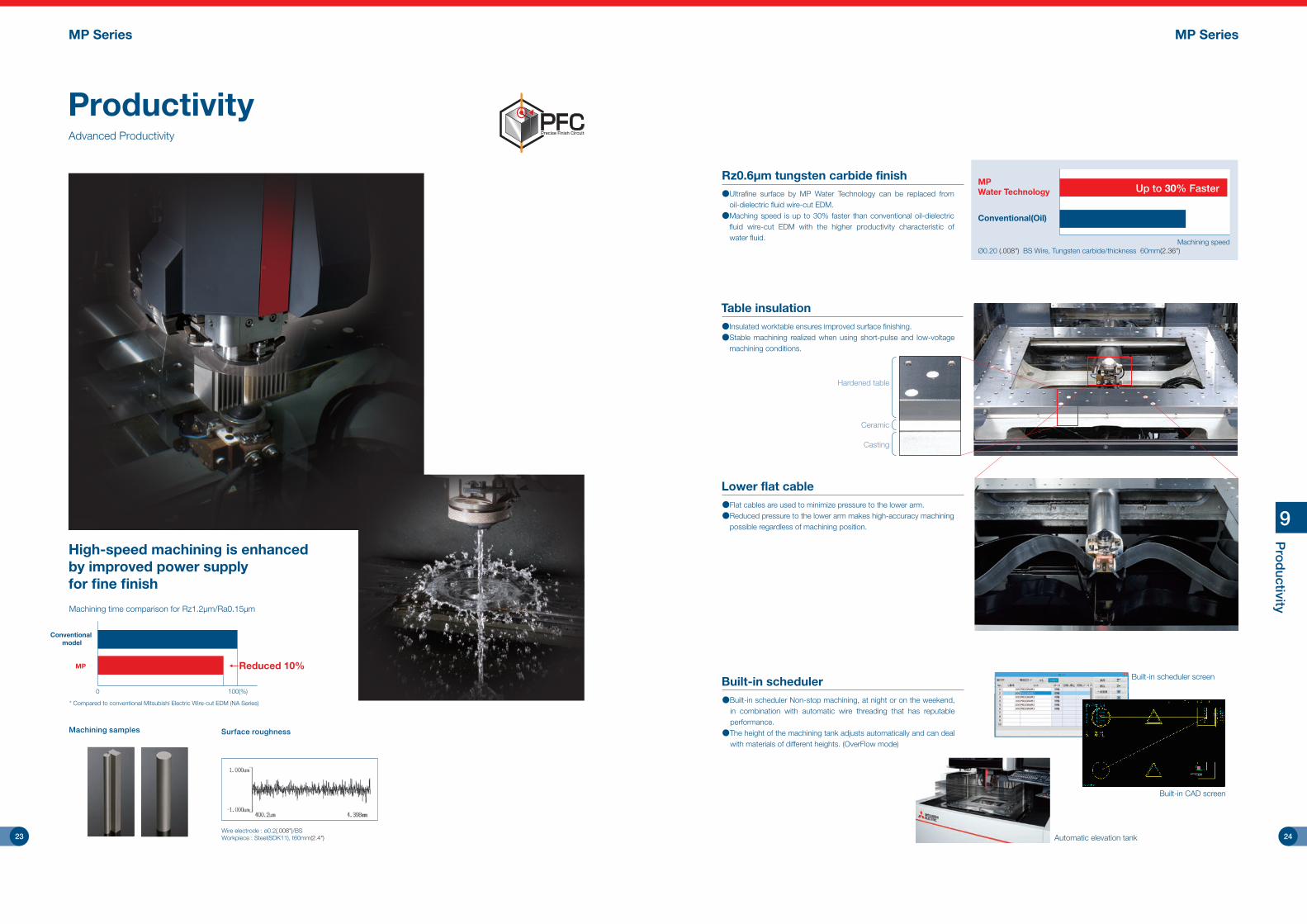
Productivity
High-speed machining is enhanced by improved power supplyfor fine finish
Machining time comparison for Rz1.2μm/Ra0.15μm
Machining samples Surface roughness
Advanced Productivity
* Compared to conventional Mitsubishi Electric Wire-cut EDM (NA Series)
Wire electrode : ø0.2(.008")/BSWorkpiece : Steel(SDK11), t60mm(2.4")
Lower flat cable●Flat cables are used to minimize pressure to the lower arm.●Reduced pressure to the lower arm makes high-accuracy machining
possible regardless of machining position.
Hardened table
Ceramic
Casting
9
Pro
ductivity
Rz0.6μm tungsten carbide finish●Ultra�ne surface by MP Water Technology can be replaced from
oil-dielectric �uid wire-cut EDM.●Maching speed is up to 30% faster than conventional oil-dielectric
�uid wire-cut EDM with the higher productivity characteristic of water �uid.
Conventional model
MP
0 100(%)
←Reduced 10%
MP SeriesMP Series
Table insulation●Insulated worktable ensures improved surface �nishing.●Stable machining realized when using short-pulse and low-voltage
machining conditions.
Ø0.20 (.008") BS Wire, Tungsten carbide/thickness 60mm(2.36")Machining speed
Up to 30% Faster
Conventional(Oil)
MPWater Technology
Built-in scheduler●Built-in scheduler Non-stop machining, at night or on the weekend,
in combination with automatic wire threading that has reputable performance.
●The height of the machining tank adjusts automatically and can deal with materials of different heights. (OverFlow mode)
Built-in CAD screen
Built-in scheduler screen
Automatic elevation tank23 24
MP SeriesMP Series
10
Op
erability
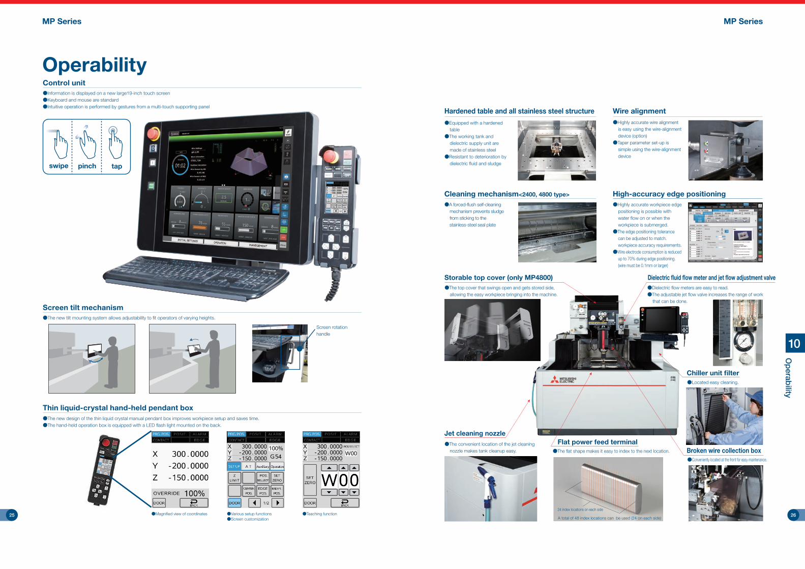
Storable top cover (only MP4800)
●Located easy cleaning.
Chiller unit filter
●The convenient location of the jet cleaning nozzle makes tank cleanup easy.
Jet cleaning nozzle
Hardened table and all stainless steel structure●Equipped with a hardened
table●The working tank and
dielectric supply unit are made of stainless steel
●Resistant to deterioration by dielectric fluid and sludge
●The top cover that swings open and gets stored side, allowing the easy workpiece bringing into the machine.
Dielectric fluid flow meter and jet flow adjustment valve●Dielectric flow meters are easy to read.●The adjustable jet flow valve increases the range of work
that can be done.
●Conveniently located at the front for easy maintenance.
Flat power feed terminal●The flat shape makes it easy to index to the next location. Broken wire collection box
A total of 48 index locations can be used (24 on each side)
24 index locations on each side
●Highly accurate workpiece edge positioning is possible with water flow on or when the workpiece is submerged.
●The edge positioning tolerance can be adjusted to match. workpiece accuracy requirements.
●Wire electrode consumption is reduced up to 70% during edge positioning. (wire must be 0.1mm or larger)
High-accuracy edge positioningCleaning mechanism<2400, 4800 type>
●A forced-flush self-cleaning mechanism prevents sludge from sticking to the stainless-steel seal plate
●Highly accurate wire alignment is easy using the wire-alignment device (option)
●Taper parameter set-up is simple using the wire-alignment device
Wire alignment
OperabilityControl unit●Information is displayed on a new large19-inch touch screen●Keyboard and mouse are standard●Intuitive operation is performed by gestures from a multi-touch supporting panel
Screen tilt mechanism●The new tilt mounting system allows adjustability to fit operators of varying heights.
swipe pinch tap
Thin liquid-crystal hand-held pendant box●The new design of the thin liquid crystal manual pendant box improves workpiece setup and saves time.●The hand-held operation box is equipped with a LED �ash light mounted on the back.
●Magnified view of coordinates ●Various setup functions●Screen customization
●Teaching function
Screen rotation handle
25 26

MP Series
10
Op
erability
MP Series
"Fast" and "Ergonomic" operation
Excellent performance with "Easy operation", "human error reduction" and "connect ability" supporting productivity improvement for customers.
Operability
Initial setting
HOMEEasy to understand machining progress and screen selection• The machining progress status can
be check with a single view. (machining path, remaining time, consumables)
• Operation screens are intuitively selected by one-touch on screen tiles.
Main menuTo enable the necessary information to be set and referred at the required time, aggregated on three screens.This enables easy usage of information by anyone without being getting confused by operating procedures and operation methods.
ClassicInherited ADVANCE control operability• Operations can be performed on
the previous ADVANCE control style screens for operators that are accustomed to them.
• Easy-to-view with larger size of characters.
Machine log managementThe operation event log, inspection and maintenance log, consumables, and cost can be managed
■Operating cost• The operating cost can be viewed on the cost management screen.
This is useful for budget planning.
Operation
■Pre-machining preparationDaily inspection and wire/workpiece mountingMaintenance inspection tools• The maintenance manual as well as
maintenance history are supported.• Reduction in machine down time from
insufficient maintenance.
■Workpiece setupReference positioning, Z paramater (Z1, Z2, Z5) settingZ-axis limit setting• The Z-axis limit can be set easily after
mounting the workpiece.• Collisions caused by erroneous operations are
prevented.
Consumables check• The remaining amount of consumables is checked
in accordance with the machining estimate.• It prevents a machine stop caused by insufficient
consumables, such as an empty wire spool.
■Dry runPrograms can be checked for possible interference.Override• The dry run speed can be set at the
pendant box to shorten the required run time.
■Monitoring machiningThe start of machining and the machining status can be checkedResuming machining• A machining task that has been
aborted by resetting the machine can be selected from the list and resumed.
No limit set Limit set
STOP
Automatic setting of adaptive control• Our EDM knowhow is used to
optimize machining through automatic control settings.
■ProgramSimple creation of machining programStandard shape library• Simple standard shapes can be easily
programmed by entering a few key dimensions into variables.
■Built-in 2D CAD / CAM• Complex shape can be
programmed with built-in CAD / CAM.
• Program can be created by reading data such as DXF data.
■Machining condition search function
• In addition to thickness, material, surface roughness wire diameter, line type, manufacturer can be selected.
The items that do not change during the daily operation are set.Calculation tool (vertical correction and taper function adjustment)• Even calculations specific to the machine can be performed only by
entering the measurement results, and do not require any manual calculations.
• Reduces operator’s labor and also errors by operation setting.
■Check listAll necessary operations to be performed before machining can be checkedCheck list• The pre machining checklist is
displayed.• The machine cannot be started if
any checklist item has been skipped.
• Errors by operators who are not accustomed to using the machine are prevented.
■Consumables management• The consumables screen manages usage time and replacement log
of all consumables.
27 28

11
Energy Savings, Low O
perating Cost /
Other Functions
MP SeriesMP Series
New energy-saving mode (Sleep Mode)
●The new energy-saving mode can be scheduled according to the current job ending time and start time the next day●In Sleep Mode, the amount of energy consumed is greatly reduced as
the result of using an automated pump-shut-off system●Once the scheduled start time is reached, the system restarts the �uid
system thermally, stabilizing the machine for work the next day
EDM work
22:00End of work
[Fluid system shut-down time]
6:00Wake-up
[Fluid system start-up time]
8:00Start of work
EDM workSleep Mode Recovery Temperatureadjustment
Saves electricity by supplying only the minimum required amount of power
Supplies power and supplies dielectric fluid to the bottom of the table
Supplies dielectric fluid to the bottom of the table
Temperature adjusted so machine can be used immediately
*Compared to conventional Mitsubishi Electric Wire-cut EDM (FA Series), compared to the same machining amounts
Running cost●Total running cost reduced up to 38%, which is accounted for 90% by
�lter, ion exchange resin and power consumption
Power consumption reduced up to 69%
Wire electrode : ø0.2(.008")/BSWorkpiece : Steel(SKD11), t60mm(2.4")Surface roughness : Rz3.5μm/Ra0.45μm/18μ"Ra
Conventionalmodel
200 40 60 80 100(%)
MP ←Reduced 69%←Reduced 69%
Compared to conventional Mitsubishi Electric Wire-cut EDM (FA Series)
0 20 40 60 80 100[%]
Conventionalmodel
MP
Power consumption OthersIon exchange resinFilterWire electrode
Reduced 38%×
Power consumption reduced by ODS
Filter cost reduced up to 45%
Conventionalmodel
200 40 60 80 100(%)
MP ←Reduced 45%←Reduced 45%
Wire consumption reduced up to 46%
200 40 60 80 100(%)
MP ←Reduced 46%←Reduced 46%
Increased power-supply ef�ciency reduces the wear on the wire allowing the wire spooling rate to be reduced by PFC
●Filter cost is reduced by changing the �ltration �ow rate between the rough cut and �nishing processes
Energy Savings, Low Operating Cost
Conventionalmodel
Angle Master ADVANCE Ⅱ (option)High-accuracy taper machining using round dies
●Highly accurate machining of extremely small tapered sections is possible.●Uniform die edge land cuts are possible.●Angle Master Function realizes highly accurate machining of large tapered sections.
Wire electrode : ø0.05(.002")/SPWorkpiece : Steel(PD613), Length 20mm(.79") width 2mm(.08")
ø0.05(.002"), ø0.07(.003") automatic wire threading (option: MP1200/MP2400)
●Improved design reduces maintenance●Various machining shape,it is equipped with the machining conditions
that can correspond to the machining state, can accommodate a wide range of applications.
Other Functions
Angle deviation point
Diamond dice Accurate angle
Wire electrode
Specification value compensation
29 30

MP4800MP2400MP1200Option name
◎××○○●◎◎◎◎◎●○◎◎◎○○○◎◎○○○○○○◎○○◎/○◎◎
◎●〇○○●×◎◎○◎●○◎◎◎○○○◎◎○○○○○○◎○○◎/○◎◎
◎●〇○○●×◎◎○◎●○◎◎◎○○○◎◎○○○○○○◎○○◎/○◎◎
UV OPT-drive system speci�cations
ø0.05 (.002"), ø0.07 (.003") automatic wire threading *1
High precision Narrow slit speci�cation *2
Wire processing unit *3
20/25kg (44.1/55.2lb) wire spool unit
Temperature monitoring function
Dynamic thermal protection (DTPro)
Ultra�ne �nish power supply (Super-DFS power supply)
H-FS power supply
4-piece �lter system
Filter pressure sensor
Filter automatic switching *4
External signal output *9
LAN/W *5
DNC (FTP) (S/W)
Built-in scheduler
Angle Master ADVANCE Ⅱ set *6
Angle Master ADVANCE Ⅱ guide kit ø0.2 (.008") (±30°,±45°) *7
Angle Master ADVANCE Ⅱ guide kit ø0.25 (.010") (±30°,±45°) *7
Anti-virus protection
Sleep mode
COREHOLD
3D Data import
Optionbox *8
Warning light *9
Built-in warning light *9
Run timer *9
Manual (e-manual)
Manual (Booklet)
LED light
Wire-alignment device / High-accuracy wire-alignment device
Tool box
Workpiece clamp set
Machine unit
Power supply
Dielectric �uid
system
Communications
Taper Machining
Software
Display
Others
20/25kg wire spool unitLong-time continuous machining is possible
Warning light
Wire processing unitThe wire is chopped after the collection roller
Angle Master ADVANCE Ⅱ guide kitMax. 45° tapered machining possible
using dedicated diamond guide
Workpiece clamp setClamp jigs dedicated for use in holding workpieces
Built-in warning lightRun timerIndicates accumulated machining time
High-accuracy wire-alignment device /wire-alignment device
This device aligns the wire electrode with the table
High-accuracy wire-alignment device
Wire-alignment device(standard)
4-piece filter system4-piece filter specifications reduce filter replacement frequency
Tools (tool box)
Angle Master ADVANCE Ⅱ (jig)This device aligns the wire electrode with the table
12
Op
tions
◎: Standard equipment ○ : Can be retrofitted ● : Factory installation only × : Not availableSpecifications differ according to country and region;please contact a Mitsubishi Electric representative for details.Options
MP SeriesMP Series
*1 : The ø0.05 (.002") to ø0.15 (.006") wire electrodes cannot be used with the wire processing unit. A dedicated diamond guide is not included.*2 : Parts for ø0.05 (.002"),ø0.07 (.003") are included with the ø0.05, 0.07 automatic wire threading specification.*3 : Cannot be used with the ø0.05 (.002"), ø0.07 (.003") automatic wire threading.*4 : 4-piece filter system is needed.*5 : LAN cable should be all straight wiring type with shielding connector, category 5 (100BASE-TX compliant), STP (four shielded twist pair).
A switchable hub that can ground the shielded LAN cable should be used.*6 : Dedicated devices for Anglemaster ADVANCE Ⅱ (S/W). Anglemaster ADVANCE Ⅱdiamond guide and recti�er nozzles are sold separately.*7 : Standard diamond guide and nozzle (ø7(.28")) is used for taper machining of 15 degrees or less. Angle Master ADVANCE Ⅱ guide kit (H/W) is needed for taper machining of 15
degrees or more (A wire electrode for taper machining should be used).*8 : Necessary for mounting External signal output, Warning light, Built-in warning light and Run timer.*9 : Option box is needed.
Standard• Accumulates workpiece measurement data
· Compatible for external set-up using a coordinate measuring machine
· Enables automatic measurement when measuring on an EDM• Creates processes offline• Automatically exchanges workpieces using a robot
* Please contact a Mitsubishi Electric representative for details.
<Personal computer><Schedule software>
<Process creation software> <Coordinate measuring machine> <Robot + WEDM>
DNC
Wire-cut EDM automation system Network connection specifications (DNC, FTP)Data, such as NC programs, machining conditions and variables can be exchanged between a personalcomputer and EDM.The required options differ according to the models and purpose, and can be confirmed using the following table.One IP address must be prepared for each EDM within the user’s in-house network.
Required specifications Image drawing SupplementRequired option
Use EDM’s Explorer and receive data in the common HDD on the EDM side.After that, data I/O operations arerequired.
Operate on the EDM sideand receive data frompersonal computer.
Operate on the personalcomputer side and senddata to the EDM.
Operate on the personalcomputer side and senddata directly to the EDM'sNC data area.
The personal computer’s Explorerand the EDM’s common HDD are used. After that, data I/O operations are required for the EDM.
Commercially available DNC software must be installed on the personal computer side.Refer to DNC specifications operation for details.
Data transmission
Data transmission
Data transmissionLAN/W
(standard)
LAN/W(standard)
DNC(standard)
Data transmissionOperate on the EDM sideand send data directly tothe EDM's NC data area.
Data can be received only using data I/O operation.
FTP(standard)
Automatically send datafrom machiningmachine to FTP server
Customer should prepare FTP server
No parson in bothOperating status
data output
31 32

MP SeriesMP Series
13
Pow
er Supply, C
ontrol Speci�cations /
Machine Installation
1. Installation site①Constant-temperature dust-proof room
· Recommended room temperature 20±1°C (68°F±2)· Usable temperature range 5 to 35°C (41°F to 95°F)
Temperature fluctuation will directly affect machine accuracy. To maintain performance accuracy, select a place with minimal temperature fluctuation.Install the EDM in a constant-temperature room when performing high precision machining, even when using skim cuts.Note that an environment where the temperature fluctuates by 3°C (5°F) or more within 24 hours, or 1°C (2°F) or more within one hour can adversely affect machining accuracy. Make sure that the machine body is not subject to direct wind from air-conditioners or to direct sunlight.
· Dust-free location is recommended.Install a wire-cut EDM in an environment with no corrosive gases, such as acid or salt, or mist, and with low levels of dust.Grinding dust can adversely affect the machine's linear scales and ball screws. Pay special attention to installation location to avoid this hazard (separate from grinding machine, or install in separate room, etc.).
· Humidity Within 30 to 75%RH (with no dew condensation).· Temperature range during transportation and storage
-25 to 55°C (-13°F to 131°F) (when power is not connected).②Tolerable vibration of floor
· Select a floor where vibration or impact will not be conveyed.· As a reference, the vibration level should have a max. amplitude of 2µm or less at a 10 to
20Hz frequency.* Consult with the contractor or vibration measuring instrument manufacturer for details on the measuring method.③Foundation
· The floor should be concrete with a thickness of 400mm (15.7") or more so it can sufficiently withstand the system’s weight.
· The floor inclination (step) must be within 6/1000 (floor inclination 6mm per 1m) (MP2400 Series).
Power Supply, Control Specifications/Machine Installation●Power supply/Control unit specifications
Con
trol
uni
t
Control unit specifications
Compatible model
Power supply unit specifications
MP1200 / MP2400 / MP4800
Pow
er s
uppl
y un
it
WMP(WMP48:only MP4800)Regenerative transistor pulse typeCompletely sealed/Indirect cooling
All modes50A
12 types : Anti-electrolysis power supply19 types45 types20 types10 types20 types 7 types 5 types 2 types
Built-in600 × 650 × 1767 (23.6 × 25.6 × 69.6)
250 (551)
ModelPower supply circuitCooling methodAnti-electrolytic power supplyMaximum output currentPower supply modeMachine voltage selectionMachining settingOFF timeStabilization circuit AStabilization circuit BStabilization circuit CStabilization circuit EFM circuit (LA, LC)
PM control
AVRUnit dimensions (mm) (in) Unit weight (kg) (lb)
W41MP-2Keyboard, USB flash memory, Ethernet
Touch panel, mouse19” color TFT
Alphanumeric charactersCNC closed loop
Max. 6 axes simultaneouslyX, Y, U, V, Z … 1/0.1µm
50nm (0.000050mm(0.000002")) ±99999.999mm
Combined use of increment/absolute valuesLinear, circular, and spiral
0.00001 ~ 99.999999 (G code) 0.001 ~ 9999.999 (S code)Automatic selection of machining speed according to gap voltage sensing
Reverse path retrace during short-circuit±99999.999mm Offset numbers: 1 to 900 (intersection point calculation)
3 types (Initial setting, operation, history management)Interactive screen method
1 to 69991 to 99999999Nesting level 30
1 to 99999Input on screen
Thin liquid-crystal type with LED flash lightXY plane, XY-XZ plane, solid, table scaling, 3D model display, background drawing, automatic machining path drawing
1GBManagement of consumable parts (time display)
SL, CM, EM, PM, BM518 × 97 × 363 (20.3 × 3.8 × 14.3) (Excluding keyboard and mouse pad)
15 (33)
ModelNC program input methodPointing deviceDisplayDisplay charactersControl methodNumber of control axesSetting unitMinimum driving unit (mm) (in) Max. command valuePosition command formatInterpolation functionScale magnificationOptimum feed controlPath-retrace controlWire offsetBasic screen menuAutomatic 2nd cutMachining condition (E-pack) storageProgram number commandSub-programSequence numbersManual input positioningManual operation boxGraphicsUser memory capacityMaintenance functionAdaptive controlExternal dimensions (mm) (in) Weight (kg) (lb)
3 notches (changeable with M code or screen)• Workpiece material: Steel, tungsten carbide, copper, aluminum
• Applicable only for rough-cut conditions
Machine installation checklist
Installation conditions
2. Machining heating valueUse the equipment capacity to calculate the wire-cut EDM's heating value required for designing a constant-temperature room.
The above value is a guideline. Consult with the constant-temperature room manufacturer for details.
3. Power-supply equipment• Primary wiring 3-phase 200/220VAC±10% 60Hz, 3-phase 200VAC±10% 50Hz• Power capacity 10.0kVA (during normal use) (when using ø0.2(.008")mm wire electrode) 13.5kVA (when using the maximum)
* Use a 14mm² or thicker cable for the primary connection.
4. Grounding workWire-cut EDMs must always be grounded to prevent external noise, radio disturbance and earth leakage.Install a wire-cut EDM in an environment with no corrosive gases, such as acid or salt, or mist, and with low levels of dust.
· Common grounding can be used if noise from other devices will not enter through the common grounding; the grounding cable must be connected independently to the grounding location (Fig. 2).
· Use a 14mm² grounding wire.
Confirmation of foundation and power-supply workIf there is any possibility of radio disturbance, investigate it prior to starting work.1) Confirmation of floor area2) Confirmation of environment (constant-temperature dust-proof room, measure for radio disturbance, prevention of external noise)3) Confirmation of foundation floor4) Foundation work5) Primary wiring for power lead-in6) Grounding work7) Construction of dielectric fluid (city water) supply/drainage facilities8) Air piping work
Preparation of installation fixtures1) Plan the installation fixtures2) Prepare or manufacture the fixtures
Preparation of consumable parts1) Purchase consumable parts such as wire electrodes
1) Select the programmers and operators2) Apply for training seminars
Training of programmers and operators
The standard delivery entrance dimensions for standard shipment delivery are given on the product lineup page. If the entrance is smaller than the standard delivery entrance, a machine with different dimensions can be shipped. * Please contact a Mitsubishi Electric representative for details (a separate estimate will be issued).Note that delivery may not be possible in some cases depending on the dimensions.
Precautions for selecting earth-leakage breakerTo prevent malfunctions caused by the external noise from control units, etc., a filter is installed for the power-supply input. By grounding one end of this filter, an earth-leakage current of approx. 30 to 40mA passes through the filter. A highly sensitive earth-leakage breaker (sensitivity current 30mA) could malfunction. Thus, a medium-sensitivity earth-leakage breaker (sensitivity current 100 to 200mA) is recommended for the wire-cut EDM. Class C grounding (grounding resistance of 10Ω or less) is recommended for the wire-cut EDM. Even if the sensitivity current is 200mA, the contact voltage will be 2V or less, and no problems will occur in preventing electric shock (application of tolerable contact current Class 2, 25V or less).
Terms of warranty
DisposalThe dielectric fluid, dielectric fluid filter, ion exchange resin, wire, etc., are industrial waste. These must be disposed of following national and local laws and ordinances.
Harmonic distortionIf there is harmonic distortion in the power supply, the machine operation could be affected even if the voltage does not fluctuate. In addition, the harmonic current could flow from the wire-cut EDM to the power system and adversely affect peripheral devices. If the effect of the harmonic distortion causes problems, install a harmonic suppression filter or take other measures.
Refrigerant for dielectric fluid chillerThe dielectric fluid chiller unit includes a fluorinated greenhouse gas R410A. Please use only the specified refrigerant (R410A), when servicing the dielectric fluid chiller unit. The use of any refrigerant other than that specified will cause mechanical failure, system malfunction or unit breakdown. In the worst case, this could lead to a serious impediment to securing product safety.
5. Primary air equipment• Hose diameter : 1/4 hose (hose sleeve outer diameter: ø9.0 (0.35"))• Pressure : 0.5 to 0.7MPa (72.5 to 101.5psi)• Flow rate : 75ℓ/min or more (2.65cu.ft./min.)
6. Shield roomInstall a shield room if a wire-cut EDM affects televisions or other communication facilities in the area. Observe the following points when installing the wire-cut EDM in the shield room.
1. Ground the wire-cut EDM in the shield room (Fig. 3).2. If the wire-cut EDM cannot be grounded in the shield room, connect the wire-cut EDM's
grounding cable to the shield room's grounding terminal (through bolt) as shown in Fig. 4.3. Consult with a Mitsubishi Electric representative for details on installing a shield room.
Shield roomMachine
bodyPower-supply
unit
Shield room
Through bolt
Within 1m
Machinebody
Power-supplyunit
Fig. 3 Fig. 4
Power-supply unitMachine body R
STE
Power-supply unit
Machine body
Grounding cable for other device
RSTE
Fig. 1 Fig. 2
Determining the machining details
1) Determine the workpiece2) Determine the machining site3) Determine the pre-processing site4) Determine the post-processing site
Check each item, and make sure that no item or order is overlooked.
Confirmation of delivery path
1) Traffic restrictions to factory Road width Entry road2) Factory entrance and width of gate in factory Factory building entrance dimensions (height × width) 3) Constant-temperature dust-proof room entrance dimensions (height × width)
Check the path inside and outside the factory to avoid any trouble during delivery.
Cautions
Wire electrodes
*The wire electrodes shown above do not guarantee performance
Recommended sliding surface lubricants
ManufacturerExxon MobilIdemitsu KosanShowa ShellJX Nippon Oil & Energy Corporation
Product nameMobil DTE26Super Hydro 68ATerrace Oil 68Super Mulpas DX68
Use the following wire electrodes
Use one of the following lubricants for sliding surface As of November 2018
Heating value (kW) = Equipment capacity (kVA) x 0.6 = 13.5kVA x 0.6 = 8.1kW
This will differ according to country and region of sale; please contact a Mitsubishi Electric representative for details.
1.Terms of warranty
After the warranty period expires, all standard service rates and travel expenses will apply. Normal service life expectancy is 11 years after installation, but there may be some cases where discontinued electrical parts such as semiconductors and motors will reduce this period.
(2)Exclusion of loss in opportunity and secondary loss from warranty liabilityRegardless of the gratis warranty term, Mitsubishi shall not be liable for compensation to: ①Damages caused by any cause found not to be the responsibility of Mitsubishi.②Loss in opportunity, lost profits incurred to the user by Failures of Mitsubishi products.③Special damages and secondary damages whether foreseeable or not, compensation for accidents, and compensation for damages to products other than Mitsubishi products.④Replacement by the user, maintenance of on-site equipment, start-up test run and other tasks.
3.Post Warranty / Expected Service Life
(1)Terms of repairment free of chargeParts labor and travel are included free of charge when the failure occurs during normal use for the stated Terms of the warranty (based on proper usage and maintenance as described in the operations manual and sales agreement).Coverage exceptions:①When a failure occurs that was caused by a machine modification that directly affects the
machine’s functioning or accuracy. ②When a failure occurs caused by the use of non-standard parts, consumables or lubricants. ③When a failure occurs caused by a natural disaster such as lighting, earthquake or storms and flooding. ④When the use of non-recommended consumables or aftermarket parts are used such as filters or
flushing nozzles.
2.Coverage
OB-PN (ø0.1/BS ~ ø0.3/BS)HBZ-U(N) (ø0.1/BS ~ ø0.3/BS)SBS-HN (ø0.1/BS ~ ø0.3/BS)SWP-SP (ø0.05/SP ~ ø0.07/SP)
Oki Electric CableHitachi MetalsSumiden Fine ConductorsNippon Steel & Sumikin Wire
* Air (compressed air) is used to operate the automatic wire feeder and work tank door, etc. Air supplied from a normal compressor contains various impurities that could cause operation faults if they get into the pneumatic devices such as the solenoid valve. Install an air filter with a drainage discharge mechanism, etc., in the air source (primary source) piping to prevent impurities from entering the pneumatic devices.
(m)(m)(m)
(3)Information regarding what should be revised or improved acquired during product support may be used to improve product quality or services.
33 34

MP SeriesMP Series
MEMO
35 36

14
So
lutions
MP Series
MEMO
37 38