Hybrid micromachining using a nanosecond pulsed laser and micro EDM

Processing and laser micromachining of HAP based biocomposites 1
Processing and laser micromachining of HAP based biocomposites
Gabriel Benga, Oana Gingu, Ion Ciupitu, Lucian Gruionu, Ileana Pascu and Jose Calderon Moreno
X
Processing and laser micromachining of HAP based biocomposites
Gabriel Benga*, Oana Gingu*, Ion Ciupitu*, Lucian Gruionu*,
Ileana Pascu* and Jose Calderon Moreno**
*University of Craiova **Institute of Chemical-Physics “I.G. Murgulescu”, Romanian Academy,
Romania
1. Introduction
Bone grafting is a usual technique commonly applied in order to repair the hard tissue. In special cases, small defects detected inside the bones can be removed only using the grafting technique. From the point of view of the materials dedicated to this purpose, the biomaterials (metallic, ceramics or their composites) are used for grafts processing. Among the main demands for these materials, ones of the most important are: biocompatibility, comparable biomechanical properties with the adjacent bone, good wear behaviour in dry or wet conditions (depending on the graft placement). Also, another issue to produce bone grafts is the post-processing operation. This aspect concerns possible small cuttings, drillings and chamfers that could be processed after the grafts elaboration. Considering the mechanical characteristics of the grafts (most brittle than ductile, as the bones are) as well as their small dimensions, laser machining is a recommended technology for this purpose. This chapter presents a new approaching of processing of hydroxyapatite (HAP)-based biocomposites by powder metallurgy (PM) technology, which could be applied for bone grafting. Also, the wear behaviour of these biocomposites tested in dry friction conditions and their capability to be micro-machined by laser beam fulfils the overview concerning the potential of HAP based biocomposites for hard tissue grafting.
1.1 Biomaterials for hard tissue grafting. Processing technologies One of the most used techniques to repair the damaged hard tissue (vertebrae, hips etc.) is grafting. Bone grafting is a surgical procedure that replaces missing bone with material from the patient’s own body, named autologous or autogeneous bone grafting (Francaviglia et al., 2004; Huber et al., 2008), an artificial/synthetic material, named alloplastic grafting, or a natural substitute, named allografting (Antuna et al., 2002). Regarding the alloplastic grafting, this is one of the most used technique because it allows using different biomaterials with specific properties according to the adjacent hard tissue in terms of low clinical risks (Huber et al., 2008; Seiler III et al., 2000). In this respect, the
1
Engineering the Future2
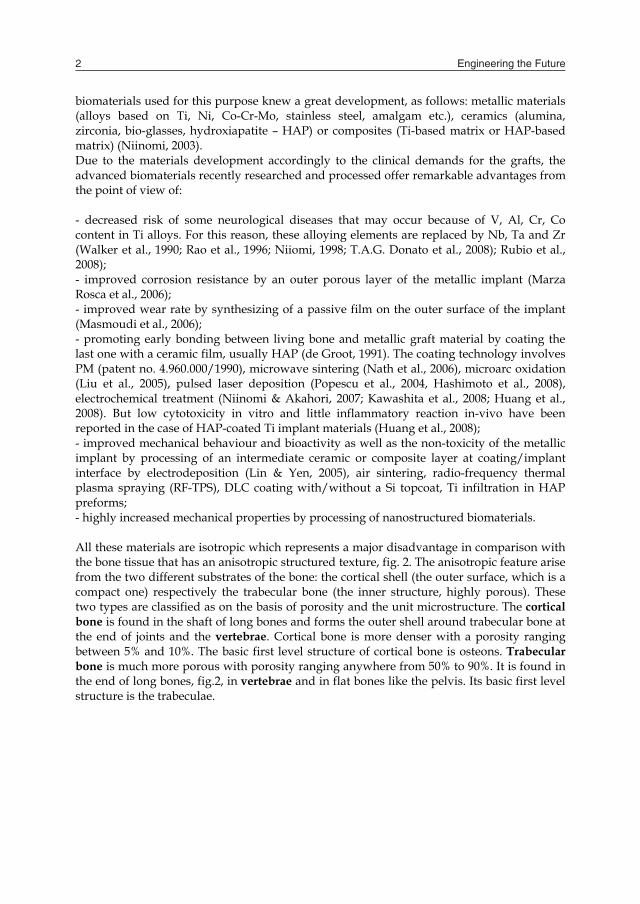
biomaterials used for this purpose knew a great development, as follows: metallic materials (alloys based on Ti, Ni, Co-Cr-Mo, stainless steel, amalgam etc.), ceramics (alumina, zirconia, bio-glasses, hydroxiapatite – HAP) or composites (Ti-based matrix or HAP-based matrix) (Niinomi, 2003). Due to the materials development accordingly to the clinical demands for the grafts, the advanced biomaterials recently researched and processed offer remarkable advantages from the point of view of: - decreased risk of some neurological diseases that may occur because of V, Al, Cr, Co content in Ti alloys. For this reason, these alloying elements are replaced by Nb, Ta and Zr (Walker et al., 1990; Rao et al., 1996; Niiomi, 1998; T.A.G. Donato et al., 2008); Rubio et al., 2008); - improved corrosion resistance by an outer porous layer of the metallic implant (Marza Rosca et al., 2006); - improved wear rate by synthesizing of a passive film on the outer surface of the implant (Masmoudi et al., 2006); - promoting early bonding between living bone and metallic graft material by coating the last one with a ceramic film, usually HAP (de Groot, 1991). The coating technology involves PM (patent no. 4.960.000/1990), microwave sintering (Nath et al., 2006), microarc oxidation (Liu et al., 2005), pulsed laser deposition (Popescu et al., 2004, Hashimoto et al., 2008), electrochemical treatment (Niinomi & Akahori, 2007; Kawashita et al., 2008; Huang et al., 2008). But low cytotoxicity in vitro and little inflammatory reaction in-vivo have been reported in the case of HAP-coated Ti implant materials (Huang et al., 2008); - improved mechanical behaviour and bioactivity as well as the non-toxicity of the metallic implant by processing of an intermediate ceramic or composite layer at coating/implant interface by electrodeposition (Lin & Yen, 2005), air sintering, radio-frequency thermal plasma spraying (RF-TPS), DLC coating with/without a Si topcoat, Ti infiltration in HAP preforms; - highly increased mechanical properties by processing of nanostructured biomaterials. All these materials are isotropic which represents a major disadvantage in comparison with the bone tissue that has an anisotropic structured texture, fig. 2. The anisotropic feature arise from the two different substrates of the bone: the cortical shell (the outer surface, which is a compact one) respectively the trabecular bone (the inner structure, highly porous). These two types are classified as on the basis of porosity and the unit microstructure. The cortical bone is found in the shaft of long bones and forms the outer shell around trabecular bone at the end of joints and the vertebrae. Cortical bone is more denser with a porosity ranging between 5% and 10%. The basic first level structure of cortical bone is osteons. Trabecular bone is much more porous with porosity ranging anywhere from 50% to 90%. It is found in the end of long bones, fig.2, in vertebrae and in flat bones like the pelvis. Its basic first level structure is the trabeculae.
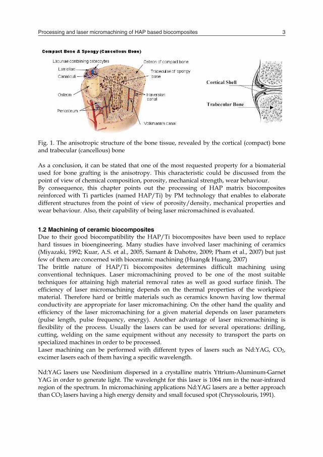
Fig. 1. The anisotropic structure of the bone tissue, revealed by the cortical (compact) bone and trabecular (cancellous) bone As a conclusion, it can be stated that one of the most requested property for a biomaterial used for bone grafting is the anisotropy. This characteristic could be discussed from the point of view of chemical composition, porosity, mechanical strength, wear behaviour. By consequence, this chapter points out the processing of HAP matrix biocomposites reinforced with Ti particles (named HAP/Ti) by PM technology that enables to elaborate different structures from the point of view of porosity/density, mechanical properties and wear behaviour. Also, their capability of being laser micromachined is evaluated.
1.2 Machining of ceramic biocomposites Due to their good biocompatibility the HAP/Ti biocomposites have been used to replace hard tissues in bioengineering. Many studies have involved laser machining of ceramics (Miyazaki, 1992; Kuar, A.S. et al., 2005, Samant & Dahotre, 2009; Pham et al., 2007) but just few of them are concerned with bioceramic machining (Huang& Huang, 2007) The brittle nature of HAP/Ti biocomposites determines difficult machining using conventional techniques. Laser micromachining proved to be one of the most suitable techniques for attaining high material removal rates as well as good surface finish. The efficiency of laser micromachining depends on the thermal properties of the workpiece material. Therefore hard or brittle materials such as ceramics known having low thermal conductivity are appropriate for laser micromachining. On the other hand the quality and efficiency of the laser micromachining for a given material depends on laser parameters (pulse length, pulse frequency, energy). Another advantage of laser micromachining is flexibility of the process. Usually the lasers can be used for several operations: drilling, cutting, welding on the same equipment without any necessity to transport the parts on specialized machines in order to be processed. Laser machining can be performed with different types of lasers such as Nd:YAG, CO2, excimer lasers each of them having a specific wavelength. Nd:YAG lasers use Neodinium dispersed in a crystalline matrix Yttrium-Aluminum-Garnet YAG in order to generate light. The wavelenght for this laser is 1064 nm in the near-infrared region of the spectrum. In micromachining applications Nd:YAG lasers are a better approach than CO2 lasers having a high energy density and small focused spot (Chryssolouris, 1991).
Processing and laser micromachining of HAP based biocomposites 3
biomaterials used for this purpose knew a great development, as follows: metallic materials (alloys based on Ti, Ni, Co-Cr-Mo, stainless steel, amalgam etc.), ceramics (alumina, zirconia, bio-glasses, hydroxiapatite – HAP) or composites (Ti-based matrix or HAP-based matrix) (Niinomi, 2003). Due to the materials development accordingly to the clinical demands for the grafts, the advanced biomaterials recently researched and processed offer remarkable advantages from the point of view of: - decreased risk of some neurological diseases that may occur because of V, Al, Cr, Co content in Ti alloys. For this reason, these alloying elements are replaced by Nb, Ta and Zr (Walker et al., 1990; Rao et al., 1996; Niiomi, 1998; T.A.G. Donato et al., 2008); Rubio et al., 2008); - improved corrosion resistance by an outer porous layer of the metallic implant (Marza Rosca et al., 2006); - improved wear rate by synthesizing of a passive film on the outer surface of the implant (Masmoudi et al., 2006); - promoting early bonding between living bone and metallic graft material by coating the last one with a ceramic film, usually HAP (de Groot, 1991). The coating technology involves PM (patent no. 4.960.000/1990), microwave sintering (Nath et al., 2006), microarc oxidation (Liu et al., 2005), pulsed laser deposition (Popescu et al., 2004, Hashimoto et al., 2008), electrochemical treatment (Niinomi & Akahori, 2007; Kawashita et al., 2008; Huang et al., 2008). But low cytotoxicity in vitro and little inflammatory reaction in-vivo have been reported in the case of HAP-coated Ti implant materials (Huang et al., 2008); - improved mechanical behaviour and bioactivity as well as the non-toxicity of the metallic implant by processing of an intermediate ceramic or composite layer at coating/implant interface by electrodeposition (Lin & Yen, 2005), air sintering, radio-frequency thermal plasma spraying (RF-TPS), DLC coating with/without a Si topcoat, Ti infiltration in HAP preforms; - highly increased mechanical properties by processing of nanostructured biomaterials. All these materials are isotropic which represents a major disadvantage in comparison with the bone tissue that has an anisotropic structured texture, fig. 2. The anisotropic feature arise from the two different substrates of the bone: the cortical shell (the outer surface, which is a compact one) respectively the trabecular bone (the inner structure, highly porous). These two types are classified as on the basis of porosity and the unit microstructure. The cortical bone is found in the shaft of long bones and forms the outer shell around trabecular bone at the end of joints and the vertebrae. Cortical bone is more denser with a porosity ranging between 5% and 10%. The basic first level structure of cortical bone is osteons. Trabecular bone is much more porous with porosity ranging anywhere from 50% to 90%. It is found in the end of long bones, fig.2, in vertebrae and in flat bones like the pelvis. Its basic first level structure is the trabeculae.
Fig. 1. The anisotropic structure of the bone tissue, revealed by the cortical (compact) bone and trabecular (cancellous) bone As a conclusion, it can be stated that one of the most requested property for a biomaterial used for bone grafting is the anisotropy. This characteristic could be discussed from the point of view of chemical composition, porosity, mechanical strength, wear behaviour. By consequence, this chapter points out the processing of HAP matrix biocomposites reinforced with Ti particles (named HAP/Ti) by PM technology that enables to elaborate different structures from the point of view of porosity/density, mechanical properties and wear behaviour. Also, their capability of being laser micromachined is evaluated.
1.2 Machining of ceramic biocomposites Due to their good biocompatibility the HAP/Ti biocomposites have been used to replace hard tissues in bioengineering. Many studies have involved laser machining of ceramics (Miyazaki, 1992; Kuar, A.S. et al., 2005, Samant & Dahotre, 2009; Pham et al., 2007) but just few of them are concerned with bioceramic machining (Huang& Huang, 2007) The brittle nature of HAP/Ti biocomposites determines difficult machining using conventional techniques. Laser micromachining proved to be one of the most suitable techniques for attaining high material removal rates as well as good surface finish. The efficiency of laser micromachining depends on the thermal properties of the workpiece material. Therefore hard or brittle materials such as ceramics known having low thermal conductivity are appropriate for laser micromachining. On the other hand the quality and efficiency of the laser micromachining for a given material depends on laser parameters (pulse length, pulse frequency, energy). Another advantage of laser micromachining is flexibility of the process. Usually the lasers can be used for several operations: drilling, cutting, welding on the same equipment without any necessity to transport the parts on specialized machines in order to be processed. Laser machining can be performed with different types of lasers such as Nd:YAG, CO2, excimer lasers each of them having a specific wavelength. Nd:YAG lasers use Neodinium dispersed in a crystalline matrix Yttrium-Aluminum-Garnet YAG in order to generate light. The wavelenght for this laser is 1064 nm in the near-infrared region of the spectrum. In micromachining applications Nd:YAG lasers are a better approach than CO2 lasers having a high energy density and small focused spot (Chryssolouris, 1991).
Engineering the Future4
CO2 lasers are molecular lasers that use gas molecules as the lasing medium and the excitation of the dioxide is achieved by increasing the vibrational energy of the molecule. The wavelength of CO2 lasers is 10.6 m in the region of the electromagnetic spectrum. Excimer lasers are gas lasers that use argon fluoride (ArF), krypton fluoride (KrF), xenon fluoride (XeF) and xenon chloride (XeCl). The wavelength of an excimer laser depends on the molecules used, but is usually in the ultraviolet spectrum 123-351 nm. The excimer lasers are useful in micromachining of ceramics, surgery, litography of semiconductors. Laser ablation offers new possibilities by selective processing of all kinds of technical ceramics. It can be concluded that for attaining high accuracies and small geometries in the micrometer range, shorter wavelength, e.g., from Nd:YAG lasers and Excimer lasers, have to be used. However some researchers (Gillner et al., 2005) mention that for Nd:YAG lasers the absorption of ceramics is poor and therefore using frequency tripled Nd:Vanadate lasers ablation accuracies of <10 m with surface qualities <1 m can be achieved with sufficient ablation rates for the tooling industry. 2. PM processing of HAP/Ti biocomposites for hard tissue grafting
Because the main demand of a hard tissue graft is the biocompatibility correlated to the mechanical properties, the selected biocomposites presented in this chapter is a HAP matrix reinforced by Ti, both components being biocompatible. The flexibility in choosing the reinforcing ratio as well as the characteristics of the components (matrix and reinforcement) is provided by PM technology. This processing route, also allows selecting the powder particles size, shape, chemical composition (elemental or pre-alloyed particles) that has a great influence on the biocomposite properties. In the same time, anisotropic biocomposites can be processed by PM technology, due to the modern routes tailoring the porosity/density, hardness, and mechanical properties. On the other hand, recent advances in biocomposites provide information on nanostructured materials, no matter ceramic or metallic matrix because of the above mentioned advantages offered by the nanosized crystalline grains of the structure. Thus, processing anisotropic PM nanostructured biocomposites represents a challenge to produce bone grafts. The basic concepts to process such biocomposites are presented as follow. First, the composite matrix is ceramic respectively HAP nanopowders particles because up to now research proves very good interface behaviour between the bone and any other metallic implants (K de Groot, 1991; S. Huang et al., 2008; Y.H. Meng et al., 2008). Secondly, HAP nanopowders present a lack of dimensional stability in as-sintered state [F.-X. Huber et al., 2008) and the reinforcement with different materials is highly recommended (Y.H. Meng et al., 2008). Thus in this chapter nanometric HAP particles are reinforced by Ti microparticles (Gingu et al., 2010). On the other hand the PM route includes, briefly, the following steps: forming of green compacts and sintering. Because the conventional sintering allows the grains growth, it is obviously that in the case of nanoparticles as initial powders, advanced sintering routes must be applied. In this chapter, spark plasma sintering (SPS) and two steps sintering (TSS) are presented, in short, as adequate technologies to process HAP/Ti nanostructured biocomposites that could be used as bone grafts biomaterials.
2.1 Preparation of HAP+Ti powder mixture The preparation of the biocomposite powder mixture is presented in detail in (Gingu et al., 2010) and consists in: calcination in air of HAP nanoparticles powders (average 200 nm particle size) followed by mixing and homogenisation of HAP particles with Ti microparticles (~100µm), the mixing ratio is 1:1 ... 4:1.
Fig. 2. Biocomposite powder mixture prepared of HAP nanopowders and Ti microparticles in 3:1 ratio participation to the mixture (Pascu I. et al., 2010)
2.2 Preparation of sintered HAP/Ti biocomposites Nanopowders particles used as raw materials for nanostructured biocomposites processing request special sintering techniques. The main reason is the risk of grain growth that can occur during long time sintering and/or high sintering temperature. The technical solution to decrease this risk is to develop the sintering treatment at low temperatures and short sintering times. SPS and TSS are ones of the PM advanced sintering techniques allowing nanostructured materials processing. Fig. 3 presents comparatively the thermal cycle of classic sintering (CS), SPS and TSS. The main sintering parameters, dwell time and temperature, are different for each sintering route and their influence on processed biocomposites properties will be discussed below. SPS route is an advanced sintering technique developed in a special equipment and consists in a rapid heating (average 1000/min.) of the powder mixture in a carbon die, in a vacuum chamber, up to the sintering temperature, TSPS, simultaneously with the compaction motion performed by the upper and lower punches. As figure 3 shows, TSPS is lower than the classic sintering temperature, TCS, because the diffusion phenomena in SPS route develop in plasma conditions generated between the powder particles. Thus, the sintering necks get shape in much shorter time (less than 60 minutes) than in the case of CS (usually hours). Shorter sintering times and lower sintering temperatures represent the great advantages of SPS route. Therefore, SPS is recommended to process:
- ceramics (which normally are sintered at high temperatures and very long sintering times);
- nanostructured materials because the nanosized crystalline grains are kept inside the nanometric range.
Ti
HA

Processing and laser micromachining of HAP based biocomposites 5
CO2 lasers are molecular lasers that use gas molecules as the lasing medium and the excitation of the dioxide is achieved by increasing the vibrational energy of the molecule. The wavelength of CO2 lasers is 10.6 m in the region of the electromagnetic spectrum. Excimer lasers are gas lasers that use argon fluoride (ArF), krypton fluoride (KrF), xenon fluoride (XeF) and xenon chloride (XeCl). The wavelength of an excimer laser depends on the molecules used, but is usually in the ultraviolet spectrum 123-351 nm. The excimer lasers are useful in micromachining of ceramics, surgery, litography of semiconductors. Laser ablation offers new possibilities by selective processing of all kinds of technical ceramics. It can be concluded that for attaining high accuracies and small geometries in the micrometer range, shorter wavelength, e.g., from Nd:YAG lasers and Excimer lasers, have to be used. However some researchers (Gillner et al., 2005) mention that for Nd:YAG lasers the absorption of ceramics is poor and therefore using frequency tripled Nd:Vanadate lasers ablation accuracies of <10 m with surface qualities <1 m can be achieved with sufficient ablation rates for the tooling industry. 2. PM processing of HAP/Ti biocomposites for hard tissue grafting
Because the main demand of a hard tissue graft is the biocompatibility correlated to the mechanical properties, the selected biocomposites presented in this chapter is a HAP matrix reinforced by Ti, both components being biocompatible. The flexibility in choosing the reinforcing ratio as well as the characteristics of the components (matrix and reinforcement) is provided by PM technology. This processing route, also allows selecting the powder particles size, shape, chemical composition (elemental or pre-alloyed particles) that has a great influence on the biocomposite properties. In the same time, anisotropic biocomposites can be processed by PM technology, due to the modern routes tailoring the porosity/density, hardness, and mechanical properties. On the other hand, recent advances in biocomposites provide information on nanostructured materials, no matter ceramic or metallic matrix because of the above mentioned advantages offered by the nanosized crystalline grains of the structure. Thus, processing anisotropic PM nanostructured biocomposites represents a challenge to produce bone grafts. The basic concepts to process such biocomposites are presented as follow. First, the composite matrix is ceramic respectively HAP nanopowders particles because up to now research proves very good interface behaviour between the bone and any other metallic implants (K de Groot, 1991; S. Huang et al., 2008; Y.H. Meng et al., 2008). Secondly, HAP nanopowders present a lack of dimensional stability in as-sintered state [F.-X. Huber et al., 2008) and the reinforcement with different materials is highly recommended (Y.H. Meng et al., 2008). Thus in this chapter nanometric HAP particles are reinforced by Ti microparticles (Gingu et al., 2010). On the other hand the PM route includes, briefly, the following steps: forming of green compacts and sintering. Because the conventional sintering allows the grains growth, it is obviously that in the case of nanoparticles as initial powders, advanced sintering routes must be applied. In this chapter, spark plasma sintering (SPS) and two steps sintering (TSS) are presented, in short, as adequate technologies to process HAP/Ti nanostructured biocomposites that could be used as bone grafts biomaterials.
2.1 Preparation of HAP+Ti powder mixture The preparation of the biocomposite powder mixture is presented in detail in (Gingu et al., 2010) and consists in: calcination in air of HAP nanoparticles powders (average 200 nm particle size) followed by mixing and homogenisation of HAP particles with Ti microparticles (~100µm), the mixing ratio is 1:1 ... 4:1.
Fig. 2. Biocomposite powder mixture prepared of HAP nanopowders and Ti microparticles in 3:1 ratio participation to the mixture (Pascu I. et al., 2010)
2.2 Preparation of sintered HAP/Ti biocomposites Nanopowders particles used as raw materials for nanostructured biocomposites processing request special sintering techniques. The main reason is the risk of grain growth that can occur during long time sintering and/or high sintering temperature. The technical solution to decrease this risk is to develop the sintering treatment at low temperatures and short sintering times. SPS and TSS are ones of the PM advanced sintering techniques allowing nanostructured materials processing. Fig. 3 presents comparatively the thermal cycle of classic sintering (CS), SPS and TSS. The main sintering parameters, dwell time and temperature, are different for each sintering route and their influence on processed biocomposites properties will be discussed below. SPS route is an advanced sintering technique developed in a special equipment and consists in a rapid heating (average 1000/min.) of the powder mixture in a carbon die, in a vacuum chamber, up to the sintering temperature, TSPS, simultaneously with the compaction motion performed by the upper and lower punches. As figure 3 shows, TSPS is lower than the classic sintering temperature, TCS, because the diffusion phenomena in SPS route develop in plasma conditions generated between the powder particles. Thus, the sintering necks get shape in much shorter time (less than 60 minutes) than in the case of CS (usually hours). Shorter sintering times and lower sintering temperatures represent the great advantages of SPS route. Therefore, SPS is recommended to process:
- ceramics (which normally are sintered at high temperatures and very long sintering times);
- nanostructured materials because the nanosized crystalline grains are kept inside the nanometric range.
Ti
HA

Engineering the Future6
Fig. 3. Schematically representation of thermal cycles in the case of classic sintering (CS), spark plasma sintering (SPS) and two steps sintering (TSS) Thus the research work has been developed to process HAP/Ti nanostructured biocomposites by SPS. On the other side, TSS takes place in a classic heat treatment furnace, in a special sintering atmosphere (inert, reducing or oxidizing) depending on the processed material, Fig. 3. The advantage of TSS vs. CS consists in tailoring of sintering temperature, TTSS, and dwell time in two steps as follows:
- the first step: in order to initiate the diffusion processes between the compacted powder particles (no matter the compaction route), the samples are heated (around 100/min) up to T1-TSS which is higher than TCS. The first dwell time is very short (few minutes) just to allow the ignition of the diffusion phenomena;
- the second step: it consists in the densification of the compacts that develops at the temperature T2-TSS, lower than TCS, for a specific dwell time, depending on the material to be processed.
Nanostructured materials have been sintered by TSS route and HAP/Ti nanostructured biocomposites are elaborated and patented by this method. In this chapter, the processing of HAP/Ti nanostructured biocomposites by TSS is presented. The technological parameters used for this purpose are monitored in Tab. 1.
Cold compaction of Φ12 mm discs
[MPa]
TSS route 1st step 2nd step
T1 [0C] τ1 [min.] T2 [0C] τ2 [min.] 50...200 800...1000 1-10 700...800 200...1500
Table 1. TSS technological parameters
CS
SPS TSS
time [h]
temp [0C]
TCS
TSPS
T1-TSS
T2-TSS
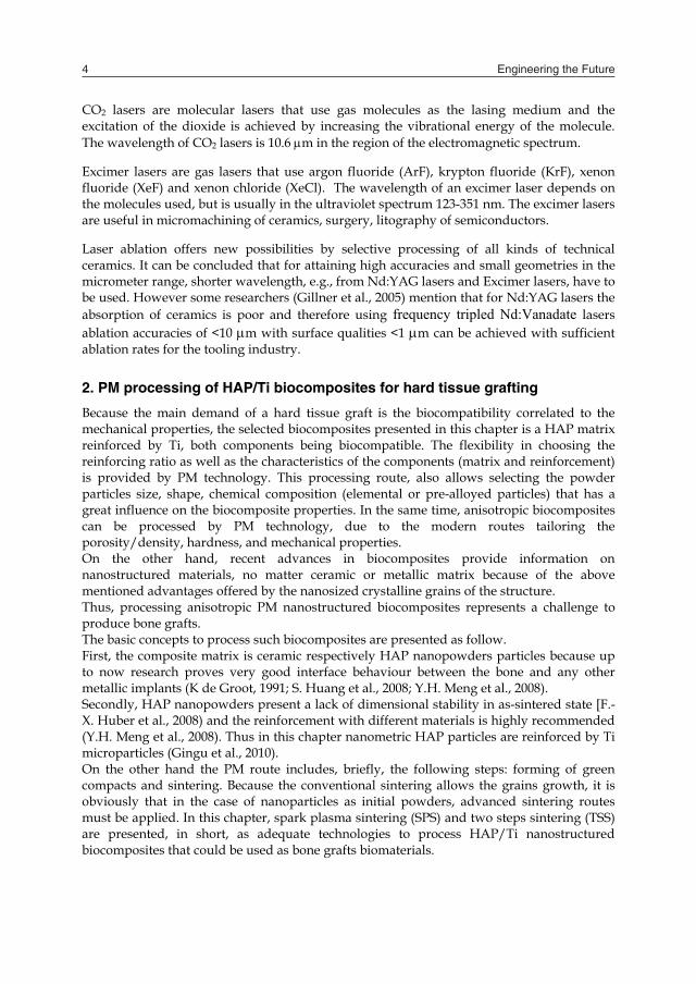
The processing parameters, as they are presented in Tab.1, allow obtaining nanostructured HAP/Ti biocomposites. Fig. 4 represents SEM microstructure of such biocomposite processed by TSS in the following parameters: cold compaction at 120 MPa followed by first step sintering at 9000C for 1 min. respectively the second step at 8000C for 1200 min. (Pascu I. et al., 2010). The microstructural details revealed by Fig. 4 are: homogeneous structure of the biocomposite, rounded pores less than 20 µm and nanostructured ceramic matrix with crystalline grain size about 400 nm. These aspects correspond to the cortical structure of the hard tissue that is characterised, mainly, by a dense structure which the porosity is (5...10)%. All the sintered HAP/Ti biocomposites by TSS route have the same structural characteristics as the above mentioned ones: dense structures, low porosity and nanostructured ceramic matrix and could be recommended for hard tissue grafting. Furthermore, one of the most important demands of these materials is good wear behaviour in dry or wet friction conditions. In this chapter some preliminary experimental data are presented regarding the wear behaviour of HAP/Ti tested in dry ball-on-disc friction conditions.
Fig. 4. SEM microstructural aspects on HAP/Ti biocomposite cold compacted at 120 MPa and processed by TSS at 1step sintering at 9000C/1 min. and the second sintering step at 8000C/1200 min. (Pascu I. et al., 2010)
spherical pore
Processing and laser micromachining of HAP based biocomposites 7
Fig. 3. Schematically representation of thermal cycles in the case of classic sintering (CS), spark plasma sintering (SPS) and two steps sintering (TSS) Thus the research work has been developed to process HAP/Ti nanostructured biocomposites by SPS. On the other side, TSS takes place in a classic heat treatment furnace, in a special sintering atmosphere (inert, reducing or oxidizing) depending on the processed material, Fig. 3. The advantage of TSS vs. CS consists in tailoring of sintering temperature, TTSS, and dwell time in two steps as follows:
- the first step: in order to initiate the diffusion processes between the compacted powder particles (no matter the compaction route), the samples are heated (around 100/min) up to T1-TSS which is higher than TCS. The first dwell time is very short (few minutes) just to allow the ignition of the diffusion phenomena;
- the second step: it consists in the densification of the compacts that develops at the temperature T2-TSS, lower than TCS, for a specific dwell time, depending on the material to be processed.
Nanostructured materials have been sintered by TSS route and HAP/Ti nanostructured biocomposites are elaborated and patented by this method. In this chapter, the processing of HAP/Ti nanostructured biocomposites by TSS is presented. The technological parameters used for this purpose are monitored in Tab. 1.
Cold compaction of Φ12 mm discs
[MPa]
TSS route 1st step 2nd step
T1 [0C] τ1 [min.] T2 [0C] τ2 [min.] 50...200 800...1000 1-10 700...800 200...1500
Table 1. TSS technological parameters
CS
SPS TSS
time [h]
temp [0C]
TCS
TSPS
T1-TSS
T2-TSS
The processing parameters, as they are presented in Tab.1, allow obtaining nanostructured HAP/Ti biocomposites. Fig. 4 represents SEM microstructure of such biocomposite processed by TSS in the following parameters: cold compaction at 120 MPa followed by first step sintering at 9000C for 1 min. respectively the second step at 8000C for 1200 min. (Pascu I. et al., 2010). The microstructural details revealed by Fig. 4 are: homogeneous structure of the biocomposite, rounded pores less than 20 µm and nanostructured ceramic matrix with crystalline grain size about 400 nm. These aspects correspond to the cortical structure of the hard tissue that is characterised, mainly, by a dense structure which the porosity is (5...10)%. All the sintered HAP/Ti biocomposites by TSS route have the same structural characteristics as the above mentioned ones: dense structures, low porosity and nanostructured ceramic matrix and could be recommended for hard tissue grafting. Furthermore, one of the most important demands of these materials is good wear behaviour in dry or wet friction conditions. In this chapter some preliminary experimental data are presented regarding the wear behaviour of HAP/Ti tested in dry ball-on-disc friction conditions.
Fig. 4. SEM microstructural aspects on HAP/Ti biocomposite cold compacted at 120 MPa and processed by TSS at 1step sintering at 9000C/1 min. and the second sintering step at 8000C/1200 min. (Pascu I. et al., 2010)
spherical pore

Engineering the Future8
3.Laser micromachining of HAP based biocomposites
3.1 Micromachining conditions and equipment The laser micromachining tests were performed on the HAP/Ti samples obtained under the same sintering conditions. The biocomposite cylindrical billets of 12 mm diameter have been processed by unilateral cold compaction in a metallic die, at 150 MPa, first sintering step at 9000C for 1 min. and second sintering step at temperature T2=7000C and the dwell time 600 min. The micromachining of the HAP/Ti biocomposites was performed on a LASAG KLS 246 pulsed Nd:YAG laser for industrial materials processing. The principal applications are cutting, drilling and welding. Characteristic for the whole type range is the excellent beam quality and the flexibility in the possibilities of adaptation to the different applications. Of the multitude of available lasers, for the materials fine processing (spot - and seam welding, cutting, drilling, marking, etc.), the pulsed solid state laser has proved to be particularly suitable. The laser source has been primarily conceived for processing with the direct beam but it can also be used on its own with supplementary fiber optic cables. The optical system is horizontally mounted on the processing facility free of any stress with a three point bearing system. Utilities supply and control system are accommodated in a completely enclosed cubicle, protected from dust and water. An internal cooling circuit cools the optical system and the power supply. The heat is conducted to the external cooling water in a controlled manner via a heat exchanger, without heating up the ambient or ventilating the surrounding air. Installation in a cubicle is possible without any additional cooling measures. In the Nd:YAG solid state laser, the rod shaped laser crystal is illuminated by visible light (“pumped”). The source of the pumping light is a plasma electronic flashlamp (electrical discharge in a plasma filled quartz tube). The laser rod stores the pumping light energy for a short time in the form of excited electron levels and subsequently emits it again at the infrared wavelength of 1064 nm (fluorescence effect). With the optical resonator, which consists essentially of one or several laser crystals and two parallel mirrors, one achieves several passes through the crystal, which lead to induced light emission and therefore 10 coherent (constant phase) light. The laser beam can exit through the partially translucent outlet mirror.
Fig. 5. Laser principle
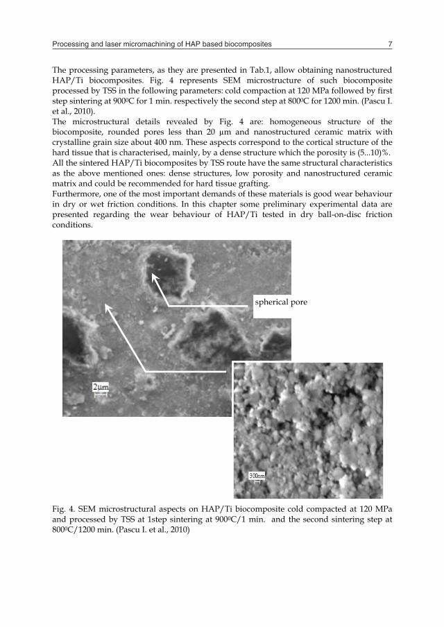
The technical parameters of the LASAG KLS 246 are presented below:
Laser type pulsed Nd:YAG solid state laser Wave length 1064 nm Beam diameter 4 mm Pulse length 0.02-20 ms Pulse frequency 0.1-1000 Hz Pulse energy. max. 15 J Pulse power at 3ms, max 4 kW Average power. max. 1000 W
Table 2. Laser source KlS 246 specifications The laser parameters: voltage [V], pulse frequency [Hz] and pulse duration [ms] influence the quality of a laser micro machined surface for a given material. In order to analyze the influence of each parameter on the surface quality eight different cutting regimes were employed as presented in table 3.
Laser parameters Laser regime
Voltage [V]
Pulse frequency
[Hz]
Pulse duration
[ms]
Average power
[W]
Surface roughness
Ra [m] R1 250 50 0.35 41 18.2 R2 310 70 0.55 144 11 R3 280 60 0.45 74 7.8 R4 280 40 0.35 34 4.6 R5 280 50 0.35 43 5.2 R6 280 60 0.35 52 15.4 R7 310 50 0.35 58.5 4.8 R8 280 60 0.25 32.4 34.4
Table 3. Laser parameters for micromachining of HAP/Ti Other regimes have been tested in order to check the possibility of cutting and the results confirmed that using a voltage below 250 V and a repeating frequency less than 50 Hz make the cutting impossible. Therefore the laser micromachining regimes were chosen accordingly. Further tests should involve a central composite design considering three factors of influence at different levels and surface finish as a target function. 3.2 Laser micromachining results and discussions The influence of each laser parameter on the surface roughness is analyzed and Then the influence of pair of factors is also taken into consideration. The reason for this analyze is to find the most appropriate parameters that offer a better surface roughness. Figure 6 presents the variation of surface roughness with the voltage. It seems that an increased voltage lead to a lower surface roughness. This is confirmed by the microscope photos presented below. The photos of the machined surface confirm the fact that increasing the voltage from 250 to 310 a significant improvement in surface roughness is obtained. Pulse frequency and pulse duration were maintained constant at 50 Hz and respectively 0.35 ms. When the first cutting regime was employed a sever dross occurred at the beginning of
Processing and laser micromachining of HAP based biocomposites 9
3.Laser micromachining of HAP based biocomposites
3.1 Micromachining conditions and equipment The laser micromachining tests were performed on the HAP/Ti samples obtained under the same sintering conditions. The biocomposite cylindrical billets of 12 mm diameter have been processed by unilateral cold compaction in a metallic die, at 150 MPa, first sintering step at 9000C for 1 min. and second sintering step at temperature T2=7000C and the dwell time 600 min. The micromachining of the HAP/Ti biocomposites was performed on a LASAG KLS 246 pulsed Nd:YAG laser for industrial materials processing. The principal applications are cutting, drilling and welding. Characteristic for the whole type range is the excellent beam quality and the flexibility in the possibilities of adaptation to the different applications. Of the multitude of available lasers, for the materials fine processing (spot - and seam welding, cutting, drilling, marking, etc.), the pulsed solid state laser has proved to be particularly suitable. The laser source has been primarily conceived for processing with the direct beam but it can also be used on its own with supplementary fiber optic cables. The optical system is horizontally mounted on the processing facility free of any stress with a three point bearing system. Utilities supply and control system are accommodated in a completely enclosed cubicle, protected from dust and water. An internal cooling circuit cools the optical system and the power supply. The heat is conducted to the external cooling water in a controlled manner via a heat exchanger, without heating up the ambient or ventilating the surrounding air. Installation in a cubicle is possible without any additional cooling measures. In the Nd:YAG solid state laser, the rod shaped laser crystal is illuminated by visible light (“pumped”). The source of the pumping light is a plasma electronic flashlamp (electrical discharge in a plasma filled quartz tube). The laser rod stores the pumping light energy for a short time in the form of excited electron levels and subsequently emits it again at the infrared wavelength of 1064 nm (fluorescence effect). With the optical resonator, which consists essentially of one or several laser crystals and two parallel mirrors, one achieves several passes through the crystal, which lead to induced light emission and therefore 10 coherent (constant phase) light. The laser beam can exit through the partially translucent outlet mirror.
Fig. 5. Laser principle
The technical parameters of the LASAG KLS 246 are presented below:
Laser type pulsed Nd:YAG solid state laser Wave length 1064 nm Beam diameter 4 mm Pulse length 0.02-20 ms Pulse frequency 0.1-1000 Hz Pulse energy. max. 15 J Pulse power at 3ms, max 4 kW Average power. max. 1000 W
Table 2. Laser source KlS 246 specifications The laser parameters: voltage [V], pulse frequency [Hz] and pulse duration [ms] influence the quality of a laser micro machined surface for a given material. In order to analyze the influence of each parameter on the surface quality eight different cutting regimes were employed as presented in table 3.
Laser parameters Laser regime
Voltage [V]
Pulse frequency
[Hz]
Pulse duration
[ms]
Average power
[W]
Surface roughness
Ra [m] R1 250 50 0.35 41 18.2 R2 310 70 0.55 144 11 R3 280 60 0.45 74 7.8 R4 280 40 0.35 34 4.6 R5 280 50 0.35 43 5.2 R6 280 60 0.35 52 15.4 R7 310 50 0.35 58.5 4.8 R8 280 60 0.25 32.4 34.4
Table 3. Laser parameters for micromachining of HAP/Ti Other regimes have been tested in order to check the possibility of cutting and the results confirmed that using a voltage below 250 V and a repeating frequency less than 50 Hz make the cutting impossible. Therefore the laser micromachining regimes were chosen accordingly. Further tests should involve a central composite design considering three factors of influence at different levels and surface finish as a target function. 3.2 Laser micromachining results and discussions The influence of each laser parameter on the surface roughness is analyzed and Then the influence of pair of factors is also taken into consideration. The reason for this analyze is to find the most appropriate parameters that offer a better surface roughness. Figure 6 presents the variation of surface roughness with the voltage. It seems that an increased voltage lead to a lower surface roughness. This is confirmed by the microscope photos presented below. The photos of the machined surface confirm the fact that increasing the voltage from 250 to 310 a significant improvement in surface roughness is obtained. Pulse frequency and pulse duration were maintained constant at 50 Hz and respectively 0.35 ms. When the first cutting regime was employed a sever dross occurred at the beginning of
Engineering the Future10
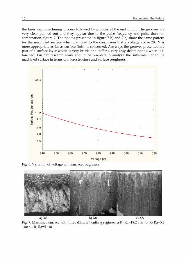
the laser micromachining process followed by grooves at the end of cut. The grooves are very clear pointed out and they appear due to the pulse frequency and pulse duration combination, figure 7. The photos presented in figure 7 b) and 7 c) show the same pattern for the machined surface which can lead to the conclusion that a voltage above 280 V is more appropriate as far as surface finish is concerned. Anyways the grooves presented are part of a surface layer which is very brittle and suffer a very easy delaminating when it is touched. Further research work should be oriented to analyze the substrate under the machined surface in terms of microstructure and surface roughness.
240 250 260 270 280 290 300 310 320
Voltage [V]
4,6
7,8
11,0
15,4
18,2
34,4
Sur
face
Rou
ghne
ss [
m]
Fig. 6. Variation of voltage with surface roughness
a) X8 b) X8 c) X8 Fig. 7. Machined surface with three different cutting regimes: a-R1 Ra=18.2 m ; b- R5 Ra=5.2 m; c – R7 Ra=5 m
The influence of pulse frequency on surface roughness is presented in figure 8. This graph clearly shows that increasing the pulse frequency from 40 Hz to 60 Hz lead to a significant increasing in surface roughness. This trend is more clearly presented later in a surface plot with voltage and pulse duration as factors of influence vs. surface roughness.
35 40 45 50 55 60 65 70 75
Pulse frequency [Hz]
4,6
7,8
11,0
15,4
18,2
34,4
Sur
face
Rou
ghne
ss [
m]
Fig. 8. Variation of pulse frequency with surface roughness
Figure 9 presents the surface roughness photos for three different cutting regimes as follows: R4: Voltage=280V, Pulse frequency=40Hz, Pulse duration=0.35 ms R5: Voltage=280V, Pulse frequency=50Hz, Pulse duration=0.35 ms R3: Voltage=280V, Pulse frequency=60Hz, Pulse duration=0.35 ms Maintaining voltage and pulse duration constant and varying pulse frequency a change in the machined surface pattern has occurred as it is shown in figure 9.
a) X24 b) X8 c) X16 Fig. 9. Machined surface with three different cutting regimes: a-R4 Ra=4.6 m; b- R5 Ra=5.2m ; c – R3 Ra=7.8 m

Processing and laser micromachining of HAP based biocomposites 11
the laser micromachining process followed by grooves at the end of cut. The grooves are very clear pointed out and they appear due to the pulse frequency and pulse duration combination, figure 7. The photos presented in figure 7 b) and 7 c) show the same pattern for the machined surface which can lead to the conclusion that a voltage above 280 V is more appropriate as far as surface finish is concerned. Anyways the grooves presented are part of a surface layer which is very brittle and suffer a very easy delaminating when it is touched. Further research work should be oriented to analyze the substrate under the machined surface in terms of microstructure and surface roughness.
240 250 260 270 280 290 300 310 320
Voltage [V]
4,6
7,8
11,0
15,4
18,2
34,4
Sur
face
Rou
ghne
ss [
m]
Fig. 6. Variation of voltage with surface roughness
a) X8 b) X8 c) X8 Fig. 7. Machined surface with three different cutting regimes: a-R1 Ra=18.2 m ; b- R5 Ra=5.2 m; c – R7 Ra=5 m
The influence of pulse frequency on surface roughness is presented in figure 8. This graph clearly shows that increasing the pulse frequency from 40 Hz to 60 Hz lead to a significant increasing in surface roughness. This trend is more clearly presented later in a surface plot with voltage and pulse duration as factors of influence vs. surface roughness.
35 40 45 50 55 60 65 70 75
Pulse frequency [Hz]
4,6
7,8
11,0
15,4
18,2
34,4
Sur
face
Rou
ghne
ss [
m]
Fig. 8. Variation of pulse frequency with surface roughness
Figure 9 presents the surface roughness photos for three different cutting regimes as follows: R4: Voltage=280V, Pulse frequency=40Hz, Pulse duration=0.35 ms R5: Voltage=280V, Pulse frequency=50Hz, Pulse duration=0.35 ms R3: Voltage=280V, Pulse frequency=60Hz, Pulse duration=0.35 ms Maintaining voltage and pulse duration constant and varying pulse frequency a change in the machined surface pattern has occurred as it is shown in figure 9.
a) X24 b) X8 c) X16 Fig. 9. Machined surface with three different cutting regimes: a-R4 Ra=4.6 m; b- R5 Ra=5.2m ; c – R3 Ra=7.8 m
Engineering the Future12
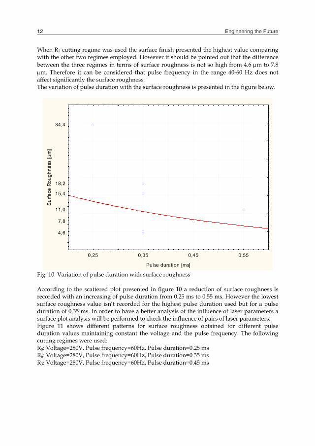
When R3 cutting regime was used the surface finish presented the highest value comparing with the other two regimes employed. However it should be pointed out that the difference between the three regimes in terms of surface roughness is not so high from 4.6 m to 7.8 m. Therefore it can be considered that pulse frequency in the range 40-60 Hz does not affect significantly the surface roughness. The variation of pulse duration with the surface roughness is presented in the figure below.
0,25 0,35 0,45 0,55
Pulse duration [ms]
4,6
7,8
11,0
15,4
18,2
34,4
Sur
face
Rou
ghne
ss [
m]
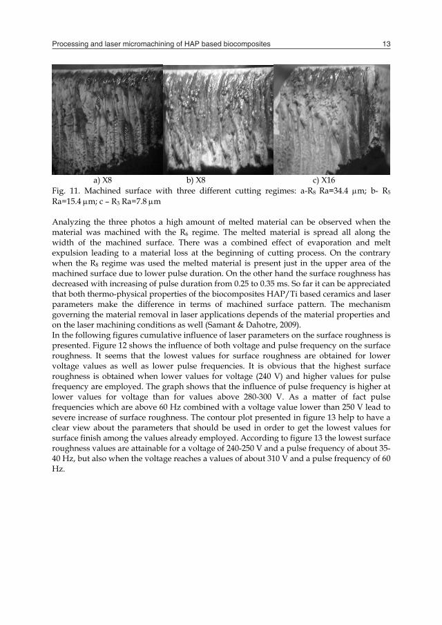
Fig. 10. Variation of pulse duration with surface roughness According to the scattered plot presented in figure 10 a reduction of surface roughness is recorded with an increasing of pulse duration from 0.25 ms to 0.55 ms. However the lowest surface roughness value isn’t recorded for the highest pulse duration used but for a pulse duration of 0.35 ms. In order to have a better analysis of the influence of laser parameters a surface plot analysis will be performed to check the influence of pairs of laser parameters. Figure 11 shows different patterns for surface roughness obtained for different pulse duration values maintaining constant the voltage and the pulse frequency. The following cutting regimes were used: R8: Voltage=280V, Pulse frequency=60Hz, Pulse duration=0.25 ms R6: Voltage=280V, Pulse frequency=60Hz, Pulse duration=0.35 ms R3: Voltage=280V, Pulse frequency=60Hz, Pulse duration=0.45 ms
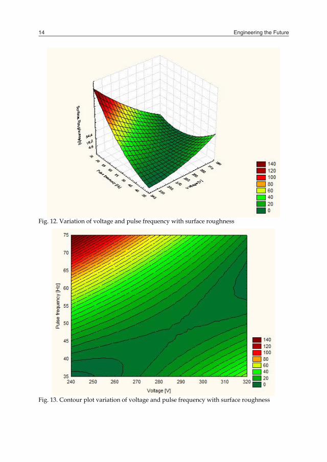
a) X8 b) X8 c) X16 Fig. 11. Machined surface with three different cutting regimes: a-R8 Ra=34.4 m; b- R5 Ra=15.4m; c – R3 Ra=7.8 m Analyzing the three photos a high amount of melted material can be observed when the material was machined with the R6 regime. The melted material is spread all along the width of the machined surface. There was a combined effect of evaporation and melt expulsion leading to a material loss at the beginning of cutting process. On the contrary when the R8 regime was used the melted material is present just in the upper area of the machined surface due to lower pulse duration. On the other hand the surface roughness has decreased with increasing of pulse duration from 0.25 to 0.35 ms. So far it can be appreciated that both thermo-physical properties of the biocomposites HAP/Ti based ceramics and laser parameters make the difference in terms of machined surface pattern. The mechanism governing the material removal in laser applications depends of the material properties and on the laser machining conditions as well (Samant & Dahotre, 2009). In the following figures cumulative influence of laser parameters on the surface roughness is presented. Figure 12 shows the influence of both voltage and pulse frequency on the surface roughness. It seems that the lowest values for surface roughness are obtained for lower voltage values as well as lower pulse frequencies. It is obvious that the highest surface roughness is obtained when lower values for voltage (240 V) and higher values for pulse frequency are employed. The graph shows that the influence of pulse frequency is higher at lower values for voltage than for values above 280-300 V. As a matter of fact pulse frequencies which are above 60 Hz combined with a voltage value lower than 250 V lead to severe increase of surface roughness. The contour plot presented in figure 13 help to have a clear view about the parameters that should be used in order to get the lowest values for surface finish among the values already employed. According to figure 13 the lowest surface roughness values are attainable for a voltage of 240-250 V and a pulse frequency of about 35-40 Hz, but also when the voltage reaches a values of about 310 V and a pulse frequency of 60 Hz.
Processing and laser micromachining of HAP based biocomposites 13
When R3 cutting regime was used the surface finish presented the highest value comparing with the other two regimes employed. However it should be pointed out that the difference between the three regimes in terms of surface roughness is not so high from 4.6 m to 7.8 m. Therefore it can be considered that pulse frequency in the range 40-60 Hz does not affect significantly the surface roughness. The variation of pulse duration with the surface roughness is presented in the figure below.
0,25 0,35 0,45 0,55
Pulse duration [ms]
4,6
7,8
11,0
15,4
18,2
34,4
Sur
face
Rou
ghne
ss [
m]
Fig. 10. Variation of pulse duration with surface roughness According to the scattered plot presented in figure 10 a reduction of surface roughness is recorded with an increasing of pulse duration from 0.25 ms to 0.55 ms. However the lowest surface roughness value isn’t recorded for the highest pulse duration used but for a pulse duration of 0.35 ms. In order to have a better analysis of the influence of laser parameters a surface plot analysis will be performed to check the influence of pairs of laser parameters. Figure 11 shows different patterns for surface roughness obtained for different pulse duration values maintaining constant the voltage and the pulse frequency. The following cutting regimes were used: R8: Voltage=280V, Pulse frequency=60Hz, Pulse duration=0.25 ms R6: Voltage=280V, Pulse frequency=60Hz, Pulse duration=0.35 ms R3: Voltage=280V, Pulse frequency=60Hz, Pulse duration=0.45 ms
a) X8 b) X8 c) X16 Fig. 11. Machined surface with three different cutting regimes: a-R8 Ra=34.4 m; b- R5 Ra=15.4m; c – R3 Ra=7.8 m Analyzing the three photos a high amount of melted material can be observed when the material was machined with the R6 regime. The melted material is spread all along the width of the machined surface. There was a combined effect of evaporation and melt expulsion leading to a material loss at the beginning of cutting process. On the contrary when the R8 regime was used the melted material is present just in the upper area of the machined surface due to lower pulse duration. On the other hand the surface roughness has decreased with increasing of pulse duration from 0.25 to 0.35 ms. So far it can be appreciated that both thermo-physical properties of the biocomposites HAP/Ti based ceramics and laser parameters make the difference in terms of machined surface pattern. The mechanism governing the material removal in laser applications depends of the material properties and on the laser machining conditions as well (Samant & Dahotre, 2009). In the following figures cumulative influence of laser parameters on the surface roughness is presented. Figure 12 shows the influence of both voltage and pulse frequency on the surface roughness. It seems that the lowest values for surface roughness are obtained for lower voltage values as well as lower pulse frequencies. It is obvious that the highest surface roughness is obtained when lower values for voltage (240 V) and higher values for pulse frequency are employed. The graph shows that the influence of pulse frequency is higher at lower values for voltage than for values above 280-300 V. As a matter of fact pulse frequencies which are above 60 Hz combined with a voltage value lower than 250 V lead to severe increase of surface roughness. The contour plot presented in figure 13 help to have a clear view about the parameters that should be used in order to get the lowest values for surface finish among the values already employed. According to figure 13 the lowest surface roughness values are attainable for a voltage of 240-250 V and a pulse frequency of about 35-40 Hz, but also when the voltage reaches a values of about 310 V and a pulse frequency of 60 Hz.
Engineering the Future14
Fig. 12. Variation of voltage and pulse frequency with surface roughness
Fig. 13. Contour plot variation of voltage and pulse frequency with surface roughness
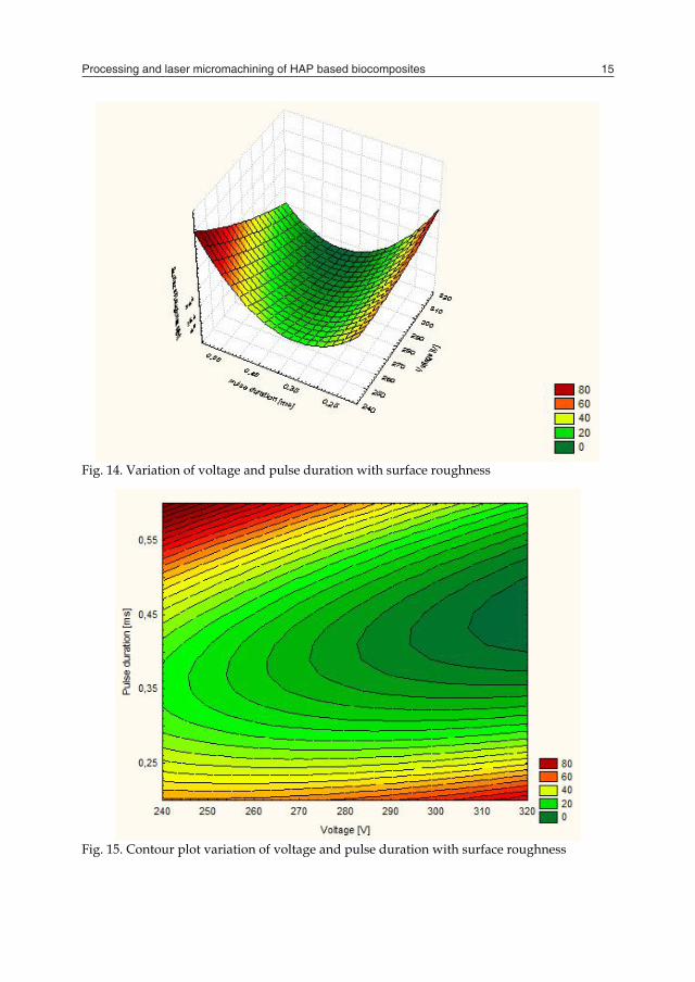
Fig. 14. Variation of voltage and pulse duration with surface roughness
Fig. 15. Contour plot variation of voltage and pulse duration with surface roughness
Processing and laser micromachining of HAP based biocomposites 15
Fig. 12. Variation of voltage and pulse frequency with surface roughness
Fig. 13. Contour plot variation of voltage and pulse frequency with surface roughness
Fig. 14. Variation of voltage and pulse duration with surface roughness
Fig. 15. Contour plot variation of voltage and pulse duration with surface roughness
Engineering the Future16
Analyzing the graphs presented in figure 14 and 15 it seems that a value around 310 V for voltage and 0.35-0.45 ms for pulse duration are the prerequisites for obtaining a good surface finish.
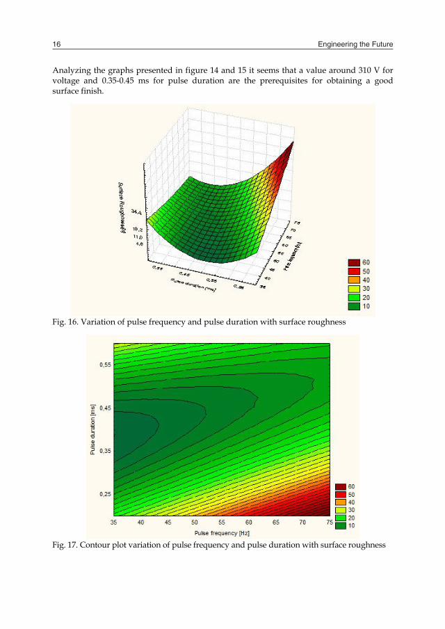
Fig. 16. Variation of pulse frequency and pulse duration with surface roughness
Fig. 17. Contour plot variation of pulse frequency and pulse duration with surface roughness
When it comes to analyze the influence of pulse frequency and pulse duration on the surface roughness it is obvious that a pulse frequency that is less than 45 Hz and pulse duration in the range of 0.35 to 0.45 ms are the best option for a low surface roughness. An analysis based on the macroscopic pattern of the micromachined surface is presented furthermore. Thus from macroscopically point of view, it can be stated that the micromachined surface of the sample presents longitudinal tracks whose diameter is almost the same to the beam laser. The differences between the macroscopic aspects may occur due to the different laser micromachining parameters, as it is shown in figure 18.
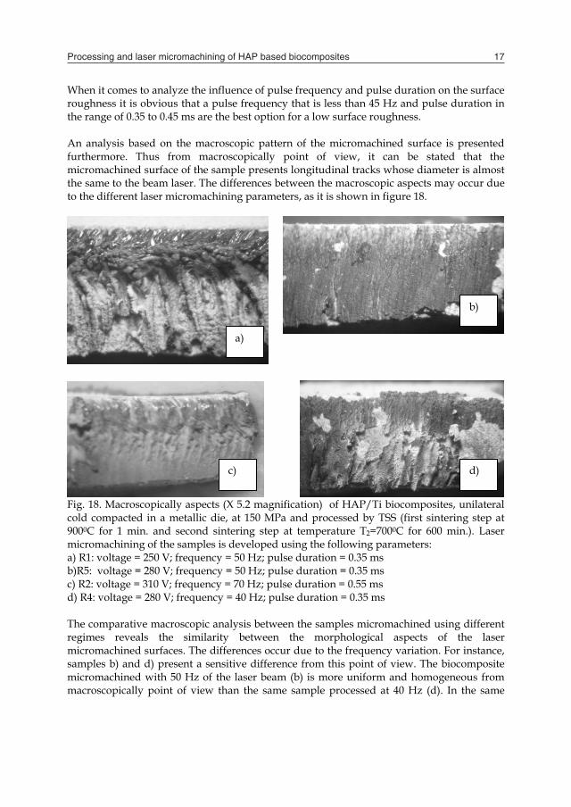
Fig. 18. Macroscopically aspects (X 5.2 magnification) of HAP/Ti biocomposites, unilateral cold compacted in a metallic die, at 150 MPa and processed by TSS (first sintering step at 9000C for 1 min. and second sintering step at temperature T2=7000C for 600 min.). Laser micromachining of the samples is developed using the following parameters: a) R1: voltage = 250 V; frequency = 50 Hz; pulse duration = 0.35 ms b)R5: voltage = 280 V; frequency = 50 Hz; pulse duration = 0.35 ms c) R2: voltage = 310 V; frequency = 70 Hz; pulse duration = 0.55 ms d) R4: voltage = 280 V; frequency = 40 Hz; pulse duration = 0.35 ms The comparative macroscopic analysis between the samples micromachined using different regimes reveals the similarity between the morphological aspects of the laser micromachined surfaces. The differences occur due to the frequency variation. For instance, samples b) and d) present a sensitive difference from this point of view. The biocomposite micromachined with 50 Hz of the laser beam (b) is more uniform and homogeneous from macroscopically point of view than the same sample processed at 40 Hz (d). In the same
a)
b)
c) d)
Processing and laser micromachining of HAP based biocomposites 17
Analyzing the graphs presented in figure 14 and 15 it seems that a value around 310 V for voltage and 0.35-0.45 ms for pulse duration are the prerequisites for obtaining a good surface finish.
Fig. 16. Variation of pulse frequency and pulse duration with surface roughness
Fig. 17. Contour plot variation of pulse frequency and pulse duration with surface roughness
When it comes to analyze the influence of pulse frequency and pulse duration on the surface roughness it is obvious that a pulse frequency that is less than 45 Hz and pulse duration in the range of 0.35 to 0.45 ms are the best option for a low surface roughness. An analysis based on the macroscopic pattern of the micromachined surface is presented furthermore. Thus from macroscopically point of view, it can be stated that the micromachined surface of the sample presents longitudinal tracks whose diameter is almost the same to the beam laser. The differences between the macroscopic aspects may occur due to the different laser micromachining parameters, as it is shown in figure 18.
Fig. 18. Macroscopically aspects (X 5.2 magnification) of HAP/Ti biocomposites, unilateral cold compacted in a metallic die, at 150 MPa and processed by TSS (first sintering step at 9000C for 1 min. and second sintering step at temperature T2=7000C for 600 min.). Laser micromachining of the samples is developed using the following parameters: a) R1: voltage = 250 V; frequency = 50 Hz; pulse duration = 0.35 ms b)R5: voltage = 280 V; frequency = 50 Hz; pulse duration = 0.35 ms c) R2: voltage = 310 V; frequency = 70 Hz; pulse duration = 0.55 ms d) R4: voltage = 280 V; frequency = 40 Hz; pulse duration = 0.35 ms The comparative macroscopic analysis between the samples micromachined using different regimes reveals the similarity between the morphological aspects of the laser micromachined surfaces. The differences occur due to the frequency variation. For instance, samples b) and d) present a sensitive difference from this point of view. The biocomposite micromachined with 50 Hz of the laser beam (b) is more uniform and homogeneous from macroscopically point of view than the same sample processed at 40 Hz (d). In the same
a)
b)
c) d)
Engineering the Future18
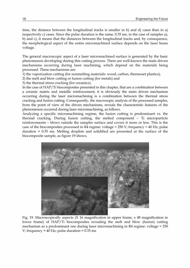
time, the distance between the longitudinal tracks is smaller in b) and d) cases than in a) respectively c) cases. Since the pulse duration is the same, 0.35 ms, in the case of samples a), b) and c), it means that the distances between the longitudinal tracks and, by consequence, the morphological aspect of the entire micromachined surface depends on the laser beam voltage. The general macroscopic aspect of a laser micromachined surface is generated by the basic phenomenon developing during this cutting process. There are well-known the main driven mechanisms occurring during laser machining, which depend on the materials being processed. These mechanisms are: 1) the vaporization cutting (for nonmelting materials: wood, carbon, thermoset plastics), 2) the melt and blow cutting or fusion cutting (for metals) and 3) the thermal stress cracking (for ceramics). In the case of HAP/Ti biocomposites presented in this chapter, that are a combination between a ceramic matrix and metallic reinforcement, it is obviously the main driven mechanism occurring during the laser micromachining is a combination between the thermal stress cracking and fusion cutting. Consequently, the macrosopic analysis of the processed samples, from the point of view of the driven mechanisms, reveals the characteristic features of the phenomenon occurred during laser micromachining, as follows. Analyzing a specific micromachining regime, the fusion cutting is predominant vs. the thermal cracking. During fusion cutting, the melted component – Ti microparticle reinforcements – blows outside the samples surface and covers it more or less. This is the case of the biocomposites processed in R4 regime: voltage = 250 V; frequency = 40 Hz; pulse duration = 0.35 ms. Melting droplets and solidified are presented at the surface of the biocomposite sample, as figure 19 shows.
Fig. 19. Macroscopically aspects (X 16 magnification in upper frame, x 48 magnification in lower frame) of HAP/Ti biocomposites revealing the melt and blow (fusion) cutting mechanism as a predominant one during laser micromachining in R4 regime: voltage = 250 V; frequency = 40 Hz; pulse duration = 0.35 ms
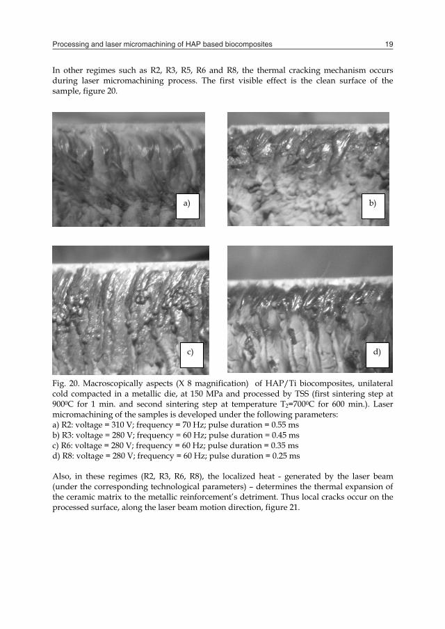
In other regimes such as R2, R3, R5, R6 and R8, the thermal cracking mechanism occurs during laser micromachining process. The first visible effect is the clean surface of the sample, figure 20.
Fig. 20. Macroscopically aspects (X 8 magnification) of HAP/Ti biocomposites, unilateral cold compacted in a metallic die, at 150 MPa and processed by TSS (first sintering step at 9000C for 1 min. and second sintering step at temperature T2=7000C for 600 min.). Laser micromachining of the samples is developed under the following parameters: a) R2: voltage = 310 V; frequency = 70 Hz; pulse duration = 0.55 ms b) R3: voltage = 280 V; frequency = 60 Hz; pulse duration = 0.45 ms c) R6: voltage = 280 V; frequency = 60 Hz; pulse duration = 0.35 ms d) R8: voltage = 280 V; frequency = 60 Hz; pulse duration = 0.25 ms Also, in these regimes (R2, R3, R6, R8), the localized heat - generated by the laser beam (under the corresponding technological parameters) – determines the thermal expansion of the ceramic matrix to the metallic reinforcement’s detriment. Thus local cracks occur on the processed surface, along the laser beam motion direction, figure 21.
a) b)
c) d)
Processing and laser micromachining of HAP based biocomposites 19
time, the distance between the longitudinal tracks is smaller in b) and d) cases than in a) respectively c) cases. Since the pulse duration is the same, 0.35 ms, in the case of samples a), b) and c), it means that the distances between the longitudinal tracks and, by consequence, the morphological aspect of the entire micromachined surface depends on the laser beam voltage. The general macroscopic aspect of a laser micromachined surface is generated by the basic phenomenon developing during this cutting process. There are well-known the main driven mechanisms occurring during laser machining, which depend on the materials being processed. These mechanisms are: 1) the vaporization cutting (for nonmelting materials: wood, carbon, thermoset plastics), 2) the melt and blow cutting or fusion cutting (for metals) and 3) the thermal stress cracking (for ceramics). In the case of HAP/Ti biocomposites presented in this chapter, that are a combination between a ceramic matrix and metallic reinforcement, it is obviously the main driven mechanism occurring during the laser micromachining is a combination between the thermal stress cracking and fusion cutting. Consequently, the macrosopic analysis of the processed samples, from the point of view of the driven mechanisms, reveals the characteristic features of the phenomenon occurred during laser micromachining, as follows. Analyzing a specific micromachining regime, the fusion cutting is predominant vs. the thermal cracking. During fusion cutting, the melted component – Ti microparticle reinforcements – blows outside the samples surface and covers it more or less. This is the case of the biocomposites processed in R4 regime: voltage = 250 V; frequency = 40 Hz; pulse duration = 0.35 ms. Melting droplets and solidified are presented at the surface of the biocomposite sample, as figure 19 shows.
Fig. 19. Macroscopically aspects (X 16 magnification in upper frame, x 48 magnification in lower frame) of HAP/Ti biocomposites revealing the melt and blow (fusion) cutting mechanism as a predominant one during laser micromachining in R4 regime: voltage = 250 V; frequency = 40 Hz; pulse duration = 0.35 ms
In other regimes such as R2, R3, R5, R6 and R8, the thermal cracking mechanism occurs during laser micromachining process. The first visible effect is the clean surface of the sample, figure 20.
Fig. 20. Macroscopically aspects (X 8 magnification) of HAP/Ti biocomposites, unilateral cold compacted in a metallic die, at 150 MPa and processed by TSS (first sintering step at 9000C for 1 min. and second sintering step at temperature T2=7000C for 600 min.). Laser micromachining of the samples is developed under the following parameters: a) R2: voltage = 310 V; frequency = 70 Hz; pulse duration = 0.55 ms b) R3: voltage = 280 V; frequency = 60 Hz; pulse duration = 0.45 ms c) R6: voltage = 280 V; frequency = 60 Hz; pulse duration = 0.35 ms d) R8: voltage = 280 V; frequency = 60 Hz; pulse duration = 0.25 ms Also, in these regimes (R2, R3, R6, R8), the localized heat - generated by the laser beam (under the corresponding technological parameters) – determines the thermal expansion of the ceramic matrix to the metallic reinforcement’s detriment. Thus local cracks occur on the processed surface, along the laser beam motion direction, figure 21.
a) b)
c) d)
Engineering the Future20
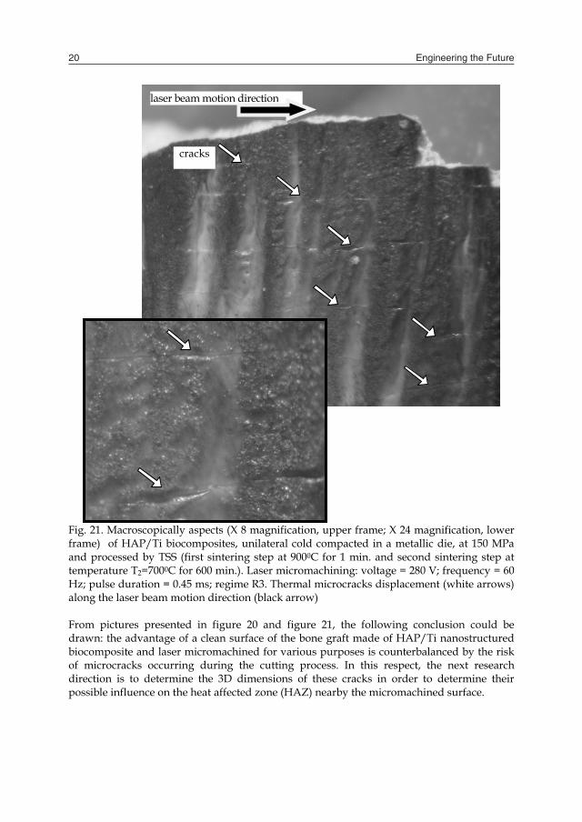
Fig. 21. Macroscopically aspects (X 8 magnification, upper frame; X 24 magnification, lower frame) of HAP/Ti biocomposites, unilateral cold compacted in a metallic die, at 150 MPa and processed by TSS (first sintering step at 9000C for 1 min. and second sintering step at temperature T2=7000C for 600 min.). Laser micromachining: voltage = 280 V; frequency = 60 Hz; pulse duration = 0.45 ms; regime R3. Thermal microcracks displacement (white arrows) along the laser beam motion direction (black arrow) From pictures presented in figure 20 and figure 21, the following conclusion could be drawn: the advantage of a clean surface of the bone graft made of HAP/Ti nanostructured biocomposite and laser micromachined for various purposes is counterbalanced by the risk of microcracks occurring during the cutting process. In this respect, the next research direction is to determine the 3D dimensions of these cracks in order to determine their possible influence on the heat affected zone (HAZ) nearby the micromachined surface.
laser beam motion direction
cracks
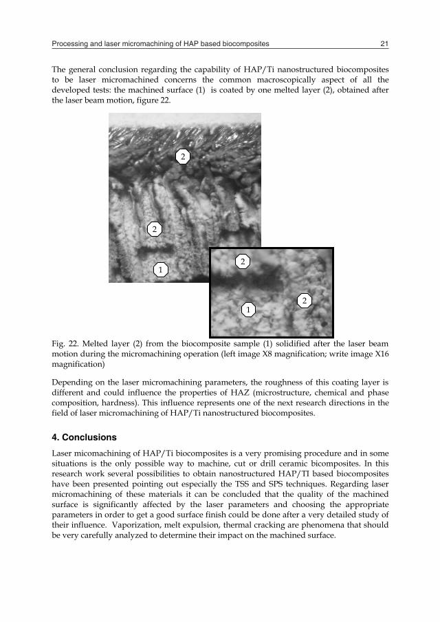
The general conclusion regarding the capability of HAP/Ti nanostructured biocomposites to be laser micromachined concerns the common macroscopically aspect of all the developed tests: the machined surface (1) is coated by one melted layer (2), obtained after the laser beam motion, figure 22.
Fig. 22. Melted layer (2) from the biocomposite sample (1) solidified after the laser beam motion during the micromachining operation (left image X8 magnification; write image X16 magnification) Depending on the laser micromachining parameters, the roughness of this coating layer is different and could influence the properties of HAZ (microstructure, chemical and phase composition, hardness). This influence represents one of the next research directions in the field of laser micromachining of HAP/Ti nanostructured biocomposites. 4. Conclusions
Laser micomachining of HAP/Ti biocomposites is a very promising procedure and in some situations is the only possible way to machine, cut or drill ceramic bicomposites. In this research work several possibilities to obtain nanostructured HAP/TI based biocomposites have been presented pointing out especially the TSS and SPS techniques. Regarding laser micromachining of these materials it can be concluded that the quality of the machined surface is significantly affected by the laser parameters and choosing the appropriate parameters in order to get a good surface finish could be done after a very detailed study of their influence. Vaporization, melt expulsion, thermal cracking are phenomena that should be very carefully analyzed to determine their impact on the machined surface.
1 2
1
2
2
2
Processing and laser micromachining of HAP based biocomposites 21
Fig. 21. Macroscopically aspects (X 8 magnification, upper frame; X 24 magnification, lower frame) of HAP/Ti biocomposites, unilateral cold compacted in a metallic die, at 150 MPa and processed by TSS (first sintering step at 9000C for 1 min. and second sintering step at temperature T2=7000C for 600 min.). Laser micromachining: voltage = 280 V; frequency = 60 Hz; pulse duration = 0.45 ms; regime R3. Thermal microcracks displacement (white arrows) along the laser beam motion direction (black arrow) From pictures presented in figure 20 and figure 21, the following conclusion could be drawn: the advantage of a clean surface of the bone graft made of HAP/Ti nanostructured biocomposite and laser micromachined for various purposes is counterbalanced by the risk of microcracks occurring during the cutting process. In this respect, the next research direction is to determine the 3D dimensions of these cracks in order to determine their possible influence on the heat affected zone (HAZ) nearby the micromachined surface.
laser beam motion direction
cracks
The general conclusion regarding the capability of HAP/Ti nanostructured biocomposites to be laser micromachined concerns the common macroscopically aspect of all the developed tests: the machined surface (1) is coated by one melted layer (2), obtained after the laser beam motion, figure 22.
Fig. 22. Melted layer (2) from the biocomposite sample (1) solidified after the laser beam motion during the micromachining operation (left image X8 magnification; write image X16 magnification) Depending on the laser micromachining parameters, the roughness of this coating layer is different and could influence the properties of HAZ (microstructure, chemical and phase composition, hardness). This influence represents one of the next research directions in the field of laser micromachining of HAP/Ti nanostructured biocomposites. 4. Conclusions
Laser micomachining of HAP/Ti biocomposites is a very promising procedure and in some situations is the only possible way to machine, cut or drill ceramic bicomposites. In this research work several possibilities to obtain nanostructured HAP/TI based biocomposites have been presented pointing out especially the TSS and SPS techniques. Regarding laser micromachining of these materials it can be concluded that the quality of the machined surface is significantly affected by the laser parameters and choosing the appropriate parameters in order to get a good surface finish could be done after a very detailed study of their influence. Vaporization, melt expulsion, thermal cracking are phenomena that should be very carefully analyzed to determine their impact on the machined surface.
1 2
1
2
2
2

Engineering the Future22
5. Acknowledgements
The authors gratefully thank to the Materials Science and Engineering Department from the University Carlos III of Madrid, Spain, for the electronic imaging of the processed biocomposites.
6. References
Antuna, S. et al. (2002) Reimplantation of a glenoid component after component removal and allograft bone grafting: A report of 3 cases, Journal of Shoulder and Elbow Surgery, 11, no.6, pp. 637-641
Chryssolouris, G. (1991) Laser Machining Theory and Practice, Springer-Verlag, New York de Groot, K. (1991) Medical applications of calcium phosphate bioceramics, Journal of
Ceramic Society of Japan, 99, pp. 943–953 Donato, T. A. G. et al. (2008) Cytotoxicity study of some ti alloys used as biomaterial,
Materials Science and Engineering, C., DOI: 10.1016/j.msec.2008.10.021 Francaviglia, N. et al. (2004) Biospacer an innovative intervertebral Alumina spacer with a
bioactive coating for the cervical spine surgery, Argos Spine News, 9, pp.37-38 Gillner, A. et al. (2005) Laser application in microtechnology, Journal of Materials Processing
Technology, 167, pp. 494–498 Gingu O. et al. (2010), Wear behaviour of ceramic biocomposites based on hydroxiapatite
nanopowders, Journal of Process Mechanical Engineering, DOI: 10.1243/09544089JPME307 (in press)
Hashimoto, Y. et al. (2008) Cytocompatibility of calcium phosphate coatings deposited by an ArF pulsed laser, Journal of Materials Science. Materials in Medicine, 19, no.1, pp. 327-333
Huang, Jin-Xia & Huang, Yao-Xiong (2007) Nd:YAG laser maching of bioceramics, Current Applied Physiscs, 781, pp.45-48
Huang, S. et al. (2008) Preparation of an electrodeposited hydroxyapatite coating on titanium substrate suitable for in-vivo applications, Journal of Materials Science. Materials in Medicine, 19, pp. 437–442
Huber F.-X. et al. (2008) Evaluation of a novel nanocrystalline hydroxyapatite paste and a solid hydroxyapatite ceramic for the treatment of critical size bone defects (CSD) in rabbits, Journal of Materials Science. Materials in Medicine, 19, no.1, pp.33-38
Kawashita, M. et al. (2008) Apatite formation on titanium substrates by electrochemical deposition in metastable calcium phosphate solution, Journal of Materials Science. Materials in Medicine, 19, pp. 137–142.
Kuar, A.S. et al.(2005) Experimental investigations on Nd:YAG laser cutting of silicon nitride, International Journal of Manufacturing Technology and Management, vol. 7, no.2-4, pp. 181-191
Lin, C.-M. & Yen, S.-K. (2005) Characterization and bond strength of electrolytic HA/TiO2 double layers for orthopaedic applications, Journal of Materials Science. Materials in Medicine, 16, pp. 889–897
Liu, F. et al. (2005) Journal of Bioscience and Bioengineering, 100, no. 1, pp. 100-104 Masmoudi, M. et al. (2006) Friction and wear behaviour of cp Ti and Ti6Al4V following
nitric acid passivation, Applied Surface Science, 253,pp. 2237– 2243
Mirza Rosca, J.C. et al. (2006) Stability of some copper-based dental materials in artificial saliva, Microscopy and Microanalysis, 12, suppl 2, pp. 1632-1633
Miyazaki, T. (1992) Laser machining of ceramics, Ceramics Japan, vol.27, no. 10, pp. 975-980 Nath, S. et al. A (2006) Comparative Study of Conventional Sintering with Microwave
Sintering of Hydroxyapatite Synthesized by Chemical Route Trends Biomater., Artificial Organs, 19, no.2, pp. 93–98
Niinomi, M. & Akahori,T. (2007) Hybridization of biomedical beta type titanium alloy and bioactive ceramic by electrochemical treatment , Azojomo, 3, December 2007
Niinomi, M. (2003) Recent research and development in titanium alloys for biomedical applications and healthcare goods, Science and Technology of Advanced Materials , 4, pp.445–454
Niiomi, M. (1998) Mechanical properties of biomedical titanium alloys, Materials Science and Engineering, 243, no.1-2, pp.231–236
Pascu, I. et al. (2010) Study about the quality of ceramic biocomposites HAP/Ti obtained by two steps sintering (TSS) route, World Powder Metallurgy Congress and Exhibition WPM 2010, Florence, Italy (in press)
Patent no. 4.960.000/1990 Pham, D.T. et al. (2007) Laser milling of ceramic components, International Journal of Machine
Tools &Manufacture, 47, pp.618-626 Popescu, M. L. et al. (2004) Biocompatibility of hidroxyl-apatite thin films obtained by
pulsed laser deposition, Review of Advanced Materials Science, 8, pp. 164–169 Rao, S. et al. (1996) Effect of Ti, Al, and V ions on the relative growth rate of fibroblasts (L929)
and osteoblasts (MC3T3-E1) cells, Biomedical Materials Engineering, 6, pp.79–86 Rubio, J. C. et al. (2008) Determination of metallic traces in kidneys, livers, lungs and
spleens of rats with metallic implants after a long implantation time, Journal of Materials Science. Materials in Medicine, 19, pp. 369–375.
Samant, A.& Dahotre, N. (2009) Laser machining of structural ceramics- A review, Journal of European Ceramic Society, 29, pp. 969-993
Seiler III J.G. et al. (2000), Journal of South Orthopaedic Association, 9, no. 2, pp.91-97, Georgia Hand and Microsurgery Clinic, Atlanta, Ga., http://medgenmed.medscape.com/viewarticle/410431_print
Walker, P. R. et al. (1990) Effects of aluminum and other cations on the structure of brain and liver chromatin, Biochemistry, 28, pp.3911

Processing and laser micromachining of HAP based biocomposites 23
5. Acknowledgements
The authors gratefully thank to the Materials Science and Engineering Department from the University Carlos III of Madrid, Spain, for the electronic imaging of the processed biocomposites.
6. References
Antuna, S. et al. (2002) Reimplantation of a glenoid component after component removal and allograft bone grafting: A report of 3 cases, Journal of Shoulder and Elbow Surgery, 11, no.6, pp. 637-641
Chryssolouris, G. (1991) Laser Machining Theory and Practice, Springer-Verlag, New York de Groot, K. (1991) Medical applications of calcium phosphate bioceramics, Journal of
Ceramic Society of Japan, 99, pp. 943–953 Donato, T. A. G. et al. (2008) Cytotoxicity study of some ti alloys used as biomaterial,
Materials Science and Engineering, C., DOI: 10.1016/j.msec.2008.10.021 Francaviglia, N. et al. (2004) Biospacer an innovative intervertebral Alumina spacer with a
bioactive coating for the cervical spine surgery, Argos Spine News, 9, pp.37-38 Gillner, A. et al. (2005) Laser application in microtechnology, Journal of Materials Processing
Technology, 167, pp. 494–498 Gingu O. et al. (2010), Wear behaviour of ceramic biocomposites based on hydroxiapatite
nanopowders, Journal of Process Mechanical Engineering, DOI: 10.1243/09544089JPME307 (in press)
Hashimoto, Y. et al. (2008) Cytocompatibility of calcium phosphate coatings deposited by an ArF pulsed laser, Journal of Materials Science. Materials in Medicine, 19, no.1, pp. 327-333
Huang, Jin-Xia & Huang, Yao-Xiong (2007) Nd:YAG laser maching of bioceramics, Current Applied Physiscs, 781, pp.45-48
Huang, S. et al. (2008) Preparation of an electrodeposited hydroxyapatite coating on titanium substrate suitable for in-vivo applications, Journal of Materials Science. Materials in Medicine, 19, pp. 437–442
Huber F.-X. et al. (2008) Evaluation of a novel nanocrystalline hydroxyapatite paste and a solid hydroxyapatite ceramic for the treatment of critical size bone defects (CSD) in rabbits, Journal of Materials Science. Materials in Medicine, 19, no.1, pp.33-38
Kawashita, M. et al. (2008) Apatite formation on titanium substrates by electrochemical deposition in metastable calcium phosphate solution, Journal of Materials Science. Materials in Medicine, 19, pp. 137–142.
Kuar, A.S. et al.(2005) Experimental investigations on Nd:YAG laser cutting of silicon nitride, International Journal of Manufacturing Technology and Management, vol. 7, no.2-4, pp. 181-191
Lin, C.-M. & Yen, S.-K. (2005) Characterization and bond strength of electrolytic HA/TiO2 double layers for orthopaedic applications, Journal of Materials Science. Materials in Medicine, 16, pp. 889–897
Liu, F. et al. (2005) Journal of Bioscience and Bioengineering, 100, no. 1, pp. 100-104 Masmoudi, M. et al. (2006) Friction and wear behaviour of cp Ti and Ti6Al4V following
nitric acid passivation, Applied Surface Science, 253,pp. 2237– 2243
Mirza Rosca, J.C. et al. (2006) Stability of some copper-based dental materials in artificial saliva, Microscopy and Microanalysis, 12, suppl 2, pp. 1632-1633
Miyazaki, T. (1992) Laser machining of ceramics, Ceramics Japan, vol.27, no. 10, pp. 975-980 Nath, S. et al. A (2006) Comparative Study of Conventional Sintering with Microwave
Sintering of Hydroxyapatite Synthesized by Chemical Route Trends Biomater., Artificial Organs, 19, no.2, pp. 93–98
Niinomi, M. & Akahori,T. (2007) Hybridization of biomedical beta type titanium alloy and bioactive ceramic by electrochemical treatment , Azojomo, 3, December 2007
Niinomi, M. (2003) Recent research and development in titanium alloys for biomedical applications and healthcare goods, Science and Technology of Advanced Materials , 4, pp.445–454
Niiomi, M. (1998) Mechanical properties of biomedical titanium alloys, Materials Science and Engineering, 243, no.1-2, pp.231–236
Pascu, I. et al. (2010) Study about the quality of ceramic biocomposites HAP/Ti obtained by two steps sintering (TSS) route, World Powder Metallurgy Congress and Exhibition WPM 2010, Florence, Italy (in press)
Patent no. 4.960.000/1990 Pham, D.T. et al. (2007) Laser milling of ceramic components, International Journal of Machine
Tools &Manufacture, 47, pp.618-626 Popescu, M. L. et al. (2004) Biocompatibility of hidroxyl-apatite thin films obtained by
pulsed laser deposition, Review of Advanced Materials Science, 8, pp. 164–169 Rao, S. et al. (1996) Effect of Ti, Al, and V ions on the relative growth rate of fibroblasts (L929)
and osteoblasts (MC3T3-E1) cells, Biomedical Materials Engineering, 6, pp.79–86 Rubio, J. C. et al. (2008) Determination of metallic traces in kidneys, livers, lungs and
spleens of rats with metallic implants after a long implantation time, Journal of Materials Science. Materials in Medicine, 19, pp. 369–375.
Samant, A.& Dahotre, N. (2009) Laser machining of structural ceramics- A review, Journal of European Ceramic Society, 29, pp. 969-993
Seiler III J.G. et al. (2000), Journal of South Orthopaedic Association, 9, no. 2, pp.91-97, Georgia Hand and Microsurgery Clinic, Atlanta, Ga., http://medgenmed.medscape.com/viewarticle/410431_print
Walker, P. R. et al. (1990) Effects of aluminum and other cations on the structure of brain and liver chromatin, Biochemistry, 28, pp.3911

Engineering the Future24
Copyright © 2022 FDOKUMEN