Microfabrication and characterization of a silicon-based millimeter scale, PEM fuel cell operating...
10
Sensors and Actuators B 107 (2005) 882–891 Microfabrication and characterization of a silicon-based millimeter scale, PEM fuel cell operating with hydrogen, methanol, or formic acid J. Yeom a , G.Z. Mozsgai a , B.R. Flachsbart a , E.R. Choban b , A. Asthana b , M.A. Shannon a,1 , P.J.A. Kenis b,∗ a Department of Mechanical & Industrial Engineering, University of Illinois, Urbana, IL 61801, USA b Department of Chemical & Biomolecular Engineering, University of Illinois, Urbana, IL 61801, USA Received 16 July 2004; received in revised form 25 November 2004; accepted 9 December 2004 Available online 29 January 2005 Abstract A silicon-based microfabricated fuel cell has been developed to provide a high energy and power density power source on the millimeter size scale. An integrated silicon microscale membrane electrode assembly (Si-MEA) consisting of a Nafion 112 TM membrane bonded between two electrodes on microstructured silicon substrates forms the core element of this polymer electrolyte membrane fuel cell. The use of silicon meshes that serve the purpose of catalyst support, current collector, and structural element provides a promising alternative to the traditional gas diffusion layer-based MEAs for the development of robust, high-performance microfuel cells. The cell performance was characterized using hydrogen, methanol, and concentrated formic acid–water fuels at the anode, and oxygen at the cathode. The catalyst used for each fuel was Pt black. Preliminary results show that the microfabricated fuel cell running on formic acid may be a promising alternative for fuel cell applications running at ambient temperature and pressure, provided additional work on catalyst improvement, assembly, and packaging is performed so that the power density achieves that of traditional forced fed PEM fuel cell design. © 2004 Elsevier B.V. All rights reserved. Keywords: Microfuel cell; Membrane electrode assembly; Formic acid; Portable power sources; Microfabrication 1. Introduction Recently, microfabricated polymer electrolyte membrane (PEM) fuel cells are being developed by many research groups to generate power for MEMS and IC devices [1–17]. The proliferation of portable electronic devices such as cel- lular telephones, PDAs, laptops, etc. has led to an increased demand for cheap, efficient, and lightweight power sources. Moreover, very small systems that employ MEMS sensors, actuators, and RF communications are being developed for large-scale distributed networks. A major problem for these MEMS devices is that they need to operate for sustained ∗ Corresponding author. Tel.: +1 217 265 0523; fax: +1 217 333 5052. E-mail addresses: [email protected] (M.A. Shannon), [email protected] (P.J.A. Kenis). 1 Tel.: +1 217 244 1545. periods of time (longer than 30 days) with relatively high power demands on the order of milliwatts. These criteria are driving the development of both high energy (1 KJ/cm 3 ) and power density (10 W/cm 3 ) on-chip electrical sources [6]. This paper reports on the design, fabrication, and characterization of a silicon-based microfabricated fuel cell as a high energy and power density power source on the millimeter size scale. Unfortunately, batteries, while ideal for supplying solid-state electrical power, are often limited in the ability to simultaneously deliver high energy and power densities, and a great deal of research and development has been expended to continuously improve their performance [18]. Microfabri- cated fuel cells may offer another solution, if some of the sub- stantial challenges faced in supplying both high energy and power densities are solved. To supply both high energy and power density, fuel cell systems are often operated at elevated temperatures and pressures [19]. Also, these fuel cell systems 0925-4005/$ – see front matter © 2004 Elsevier B.V. All rights reserved. doi:10.1016/j.snb.2004.12.050
-
Upload
independent -
Category
Documents
-
view
1 -
download
0
Transcript of Microfabrication and characterization of a silicon-based millimeter scale, PEM fuel cell operating...
Sensors and Actuators B 107 (2005) 882–891
Microfabrication and characterization of a silicon-based millimeter scale,PEM fuel cell operating with hydrogen, methanol, or formic acid
J. Yeoma, G.Z. Mozsgaia, B.R. Flachsbarta, E.R. Chobanb, A. Asthanab,M.A. Shannona,1, P.J.A. Kenisb,∗
a Department of Mechanical& Industrial Engineering, University of Illinois, Urbana, IL 61801, USAb Department of Chemical& Biomolecular Engineering, University of Illinois, Urbana, IL 61801, USA
Received 16 July 2004; received in revised form 25 November 2004; accepted 9 December 2004Available online 29 January 2005
Abstract
A silicon-based microfabricated fuel cell has been developed to provide a high energy and power density power source on the millimeter sizescale. An integrated silicon microscale membrane electrode assembly (Si-�MEA) consisting of a Nafion 112TM membrane bonded betweent e of siliconm e traditionalg racterizedu for each fuelw r fuel cella ackaging isp©
K
1
(gTldMalM
k
ighare
ationergycale.ngy to, andended
sub-andand
vateds
0d
wo electrodes on microstructured silicon substrates forms the core element of this polymer electrolyte membrane fuel cell. The useshes that serve the purpose of catalyst support, current collector, and structural element provides a promising alternative to thas diffusion layer-based MEAs for the development of robust, high-performance microfuel cells. The cell performance was chasing hydrogen, methanol, and concentrated formic acid–water fuels at the anode, and oxygen at the cathode. The catalyst usedas Pt black. Preliminary results show that the microfabricated fuel cell running on formic acid may be a promising alternative fopplications running at ambient temperature and pressure, provided additional work on catalyst improvement, assembly, and performed so that the power density achieves that of traditional forced fed PEM fuel cell design.2004 Elsevier B.V. All rights reserved.
eywords:Microfuel cell; Membrane electrode assembly; Formic acid; Portable power sources; Microfabrication
. Introduction
Recently, microfabricated polymer electrolyte membranePEM) fuel cells are being developed by many researchroups to generate power for MEMS and IC devices[1–17].he proliferation of portable electronic devices such as cel-
ular telephones, PDAs, laptops, etc. has led to an increasedemand for cheap, efficient, and lightweight power sources.oreover, very small systems that employ MEMS sensors,ctuators, and RF communications are being developed for
arge-scale distributed networks. A major problem for theseEMS devices is that they need to operate for sustained
∗ Corresponding author. Tel.: +1 217 265 0523; fax: +1 217 333 5052.E-mail addresses:[email protected] (M.A. Shannon),
[email protected] (P.J.A. Kenis).1 Tel.: +1 217 244 1545.
periods of time (longer than 30 days) with relatively hpower demands on the order of milliwatts. These criteriadriving the development of both high energy (1 KJ/cm3) andpower density (10 W/cm3) on-chip electrical sources[6]. Thispaper reports on the design, fabrication, and characterizof a silicon-based microfabricated fuel cell as a high enand power density power source on the millimeter size s
Unfortunately, batteries, while ideal for supplyisolid-state electrical power, are often limited in the abilitsimultaneously deliver high energy and power densitiesa great deal of research and development has been expto continuously improve their performance[18]. Microfabri-cated fuel cells may offer another solution, if some of thestantial challenges faced in supplying both high energypower densities are solved. To supply both high energypower density, fuel cell systems are often operated at eletemperatures and pressures[19]. Also, these fuel cell system
925-4005/$ – see front matter © 2004 Elsevier B.V. All rights reserved.oi:10.1016/j.snb.2004.12.050

J. Yeom et al. / Sensors and Actuators B 107 (2005) 882–891 883
often utilize ancillary equipment such as heaters, pumps,fuel reformers, and water and air management systems toaddress specific issues and problems encountered with fuelcells. Such ancillary devices can be difficult to scale downin size with a proportionate decrease in energy consumptiondue to parasitic loses. The total percentage of parasitic lossesoften increases as size decreases, reducing energy and powerdensities attainable. Minimizing ancillary systems, therefore,is one of our goals in developing an on-chip fuel cell.
The fuel used in fuel cell systems sets the upper limitsof power and energy densities that can be achieved. For in-stance, hydrogen gas is known to be a high power but lowenergy density fuel unless packaged under very high pres-sures. The use of liquid fuels such as methanol (MeOH) canpotentially achieve several orders of magnitude higher energydensity than H2. However, slow oxidation reaction kineticsat ambient conditions and severe fuel crossover through theNafion membrane that typically separates the anode and cath-ode, reduce the actual performance from the theoretical. Kel-ley et al. demonstrated miniaturized direct methanol fuel cells(DMFC) in 2000[1,2] with a performance comparable to tra-ditional large-scale systems. Other miniature fuel cells anddesign approaches have also been studied[3–8], where mostof these approaches have used methanol as a fuel and were notnecessarily post-CMOS compatible. Shah et al. fabricated aSi- and Nafion membrane-based FC using micromachiningt Sa asedm
o-t redP nolw owere solu-t vert ion-a o ber eOH( ree gherp thes an-u ed8 ma ast cma inia-t plyh ity asw r ano rmica inarfl yet ind
ec from
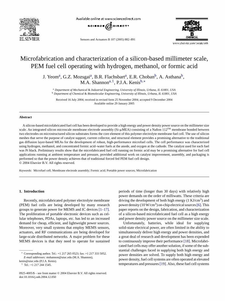
Fig. 1. A photograph of six Si-�MEAs in operation with 10 M HCOOH asthe liquid fuel passively delivered to anode and oxygen from the air as theoxidant illuminating LEDs at room temperature.
the anode to the cathode, causing a mixed potential and thesubsequent drop in cell performance. In contrast, HCOOHcrossover through Nafion membranes as a result of naturaldiffusion seems to be considerably lower at room temper-ature, yet these measurements do not account for electro-osmotic drag[25]. Crossover of formic acid through a mem-brane electrode assembly (MEA) in a working fuel cell sys-tem has not yet been quantified, and cannot be ruled out basedon our data. Low open-circuit cell potential is one indicatorof such a mixed potential, which will be discussed later.
This paper reports the design, fabrication, and perfor-mance of a monolithic silicon-based microscale membraneelectrode assembly (Si-�MEA) consisting of an integratedmetallic current collector and a standard Nafion membranewith microfabricated Si structural elements. This integratedSi-�MEA represents a promising alternative to traditionalmultilayer gas diffusion MEAs in the development of robust,high-performance microfuel cells. Miniature fuel cellswere successfully fabricated using silicon microfabricationtechniques adapted from the MEMS and microelectronicindustries (Fig. 1). Room temperature fuel cell performancecharacteristics for three fuel–oxidant combinations willbe presented and the performance limitations of theseSi-�MEAs as well as further opportunities to increase theirperformance will be discussed.
2
s,w g aN desa Aul with
echnology[9]. More recently, Shah et al. also utilized PDMnd soft lithographic techniques to develop a polymer-bicroPEM fuel cell[10].Rice et al.[20] and Ha et al.[21] have demonstrated the p
ential of HCOOH as a fuel in a traditionally manufactuEM fuel cell, in particular its advantages over methahen operated at room temperatures. Although it has lnergy density than MeOH (50% less comparing neat
ions), formic acid’s higher reaction kinetics can yield ohree orders of magnitude gains in power density. Additlly, reduced fuel crossover allows formic acid fuel cells tun at much higher concentrations (20–80%) versus M∼6%), which can potentially lead to higher fuel mixtunergy densities, and thus fuel cell systems with a hiower density (or a smaller fuel cell system to provideame power). Zhu et al. reported that in a traditionally mfactured flow-through fuel cell, 3 M formic acid provid4 mA/cm2 at 0.3 V and 18◦C with a forced oxygen streat the cathode[22], while the same cell run with 1 M MeOH
he fuel under the same conditions only provided 45 mW/2
t 0.2 V. This gain is a key to the usefulness of such a murized cell. Most importantly, retaining the ability to supigh power densities at ambient temperature and humidell as to eliminate many ancillary systems is crucial fon-chip microfuel cell. Choban et al. have also used focid as a fuel in membraneless fuel cells that exploit lamow to keep the cathodic and anodic streams separateiffusional contact[8].
A particularly troubling problem with DMFCs is throssover of methanol through the Nafion membrane
. Experimental
The Si-�MEA is comprised of two silicon electrodeith catalyst deposited directly on them, supportinafion 112TM membrane between them. The two electrore identical gold-covered Si structures, where the
ayers serve as the current collector and are covered
884 J. Yeom et al. / Sensors and Actuators B 107 (2005) 882–891
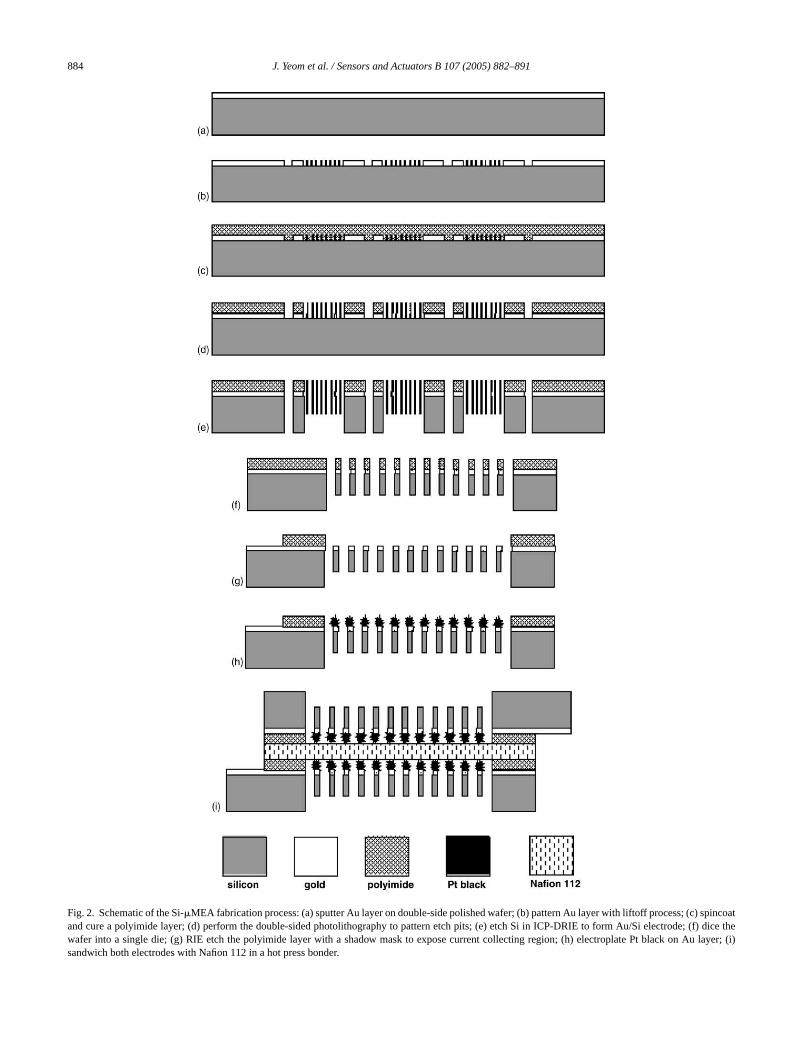
Fig. 2. Schematic of the Si-�MEA fabrication process: (a) sputter Au layer on double-side polished wafer; (b) pattern Au layer with liftoff process; (c) spincoatand cure a polyimide layer; (d) perform the double-sided photolithography to pattern etch pits; (e) etch Si in ICP-DRIE to form Au/Si electrode; (f) dice thewafer into a single die; (g) RIE etch the polyimide layer with a shadow mask to expose current collecting region; (h) electroplate Pt black on Au layer; (i)sandwich both electrodes with Nafion 112 in a hot press bonder.

J. Yeom et al. / Sensors and Actuators B 107 (2005) 882–891 885
electrodeposited Pt black catalyst for both the anode andcathode. A schematic of the processing sequence for thefabrication and assembly of the Si-�MEA is shown inFig. 2.
2.1. Fabrication of silicon electrode grids
The Si-based electrode structures were fabricated usingtraditional MEMS fabrication processes from a 100 mmdouble-side polished wafer (Silicon Quest, 500�m thick,〈1 0 0〉 oriented, 100� cm of the nominal resistivity). Toenhance the current collection of the silicon electrodes,a 1000A Au layer with a 100A Cr adhesion layer wasdeposited using DC magnetron sputtering (∼10−2 Torr of Arbackground pressure) and patterned with a liftoff process.
The front of the wafer was coated with a PMDA-ODApolyimide layer (PI-2808, HD Microsystem) used as anadhesion and spacer layer between the silicon die and thenafion membrane. The spacer layer is required to accom-modate the volume of the catalyst that is grown up from thesurface of the current collector. In addition, the polyimidefilm in combination with a native oxide serves to electricallyisolate the cell halves. The film is deposited by spincoatingpolyamic acid and then thermally imidized under vacuum.The polyimide layer was patterned using photolithographyand subsequent RIE to form the mask for etching the silicon.I wasa -likeS singI ith5l s thec hingi tem( ask.
ntot tingp Thed bulk
resistance losses within the cell versus traditional catalystinks applied to the membrane. The plating bath consisted of120 ml of DI water, 5 g of dihydrogen hexachloroplatinate(H2PtCl6·6H2O, Alfa AESAR), and 30 mg of lead acetate(Pb(CH2COOH)2·3H2O, Alfa AESAR). The amount of Pbincorporated into the final dendritic Pt structures was belowthe detection limit of XPS, and thus negligible. High surfacearea structures were achieved by carrying out the depositionat relatively high current densities of about 1 A/cm2.
2.2. Silicon-�MEA preparation
The two Si electrodes and Nafion membrane are sand-wiched and hot-pressed to form the membrane electrodeassembly, where a PI adhesion promoter (VM652, HDMicrosystem) was employed at the interface promoting theadhesion between the Nafion membrane and the PMDA-ODA surface. The membrane electrode assembly wasbonded at 120◦C under a pressure of∼200 N/cm2 in the EV-420 bonder. Prior to bonding, the Nafion 112TM membrane(Fisher Scientific) was protonated by soaking it at 80◦C in se-quence in dilute H2O2, DI water, dilute H2SO4, and DI waterfor 1 h each. Following assembly, the complete Si-�MEAswere stored in DI water to keep the membranes hydrated.
2
tingst ndh d ina acP facesa ctort entsw toa h isa ltage
F midifie Si-c to the c
n the second photolithographic process, the front patternligned to the etch pits on the back of the wafer. The gridi structure of the electrodes was etched through u
CP-DRIE (Plasma-Therm SLR 770) to form a mesh w0�m wide ribs separated by a 150�m pitch. The polyimide
ayer is then removed from the electrode region as well aontact pads to expose the Au layer. The polyimide etcs accomplished with an oxygen plasma in the RIE sysMarch Instruments, Jupiter III) using a silicon shadow m
A catalytic layer of Pt black was electroplated directly ohe current collector to create a direct electron-conducath between the catalyst and the current collector.irect path is intended to reduce the contact and
ig. 3. A schematic of the Si-�FC test apparatus. It can supply dry or huells. Current control is achieved by supplying opposing voltage bias
.3. Fuel cell testing setup
The cell was tested with a custom-built fuel cell tesystem as shown inFig. 3. Gases (H2 and O2) are deliveredo the cell through mass flow controllers (MKS, MC20) aumidifiers (bubbling through water). The cell is mounteglass-filled TeflonTM composite test fixture (PTFE, K-mlastics) that facilitates gas flow over the electrode surs well as electrical interconnection of the current colle
hrough jumper contacts. Voltage and current measuremere performed utilizing LabView 5.0 software coupledNational Instruments Field Point DAQ system, whic
lso used to regulate the load on the cell. Current–vo
d oxygen, air, hydrogen, liquid methanol, formic acid and water to the�FCell, which is recorded by computer.

886 J. Yeom et al. / Sensors and Actuators B 107 (2005) 882–891
curves were generated by recording data points for a numberof different loads from the open cell to 0 V, while allowingthe system to reach steady state before recording data points.All tests were performed near room temperature (∼20◦C)following a preconditioning routine that consisted of operat-ing the cell with H2 and O2 at no load conditions for 15 min,followed by 15 min at short circuit. This sequence was re-peated twice. The preconditioning was required to hydratethe membrane, as significant drying occurs during the bond-ing process.
Following preconditioning, the cell was tested using threedifferent combinations of fuel and oxygen. The formic acid(ACS grade, 96% from ACROS) solutions and the methanol(Fischer) solutions were obtained by dilution with DI wa-ter. The liquid fuels were delivered to the anode with a sy-ringe pump (PHD 2000 i/w, Harvard Apparatus) through theglass-filled TeflonTM composite test fixture. Both H2 and O2gas were regulated with flow controllers (MKS, MC20) andpassed through a 18.3 M� cm Millipore water to humidify thestreams before delivery to the Si-�MEA. When testing theSi-�MEA with the liquid fuels (MeOH and HCOOH), higheroxygen flow rates were used to ensure that the cell would notbe limited by oxygen transport on the cathode side. All errorsin each point reported in theIV plots are estimated as±5%.
3
3
usedt cellc uallyd ting,s e ofem d gasd ellsa oyed
in wafer scale MEMS fabrication. In this work, we fabricatedan entire wafer of MEA dies with integrated catalyst in batchmode by electroplating the catalyst directly onto the currentcollector, without handwork or single process catalyst appli-cation.Table 1compares some of the main design, operation,and performance differences between traditional PEMFCdesigns and the Si-�MEA-based fuel cell design studied inthis work.Fig. 4(a) shows a photograph of a fully integratedSi-�MEA. A scanning electron microscope (SEM) imageof a silicon electrode substrate grid is shown inFig. 4(b). Anarray of 100�m square holes in the electrode structures mayfacilitate (i) reduction in the transport resistance of fuel to thecatalyst and (ii) rapid transport of CO2 generated at the anodefrom the interface. Another advantage of our Si-�MEA struc-tures is the ease in fabricating and assembling due to the factthat the current collector, catalyst support, and fuel/oxidantdelivery structure are all integrated in one chip. Similarelectrode designs for the microscale fuel cells were reportedpreviously using anisotropic wet etching of Si[1,11]. Thethickness of the electrode substrate mesh can be characterizedby controlling the DRIE etching time. The thinner the Si sup-porting structure can be made, the faster the fuel and productscan be transported to and from the electrode, but the poorerstructural integrity will be. A 50�m wide and 50�m thickelectrode substrate mesh was chosen for our Si-�MEA as acompromise for handling strength and utility versus thinness.
i Thed em-b ayer,d ntactata doS lec-tT Ptd alyst
TS scale f ) or formia
F or DF
D (1), cumemb
ents by by hot
Oed
(5–12
rof exc
P ]
. Results and discussion
.1. Design of fuel cell electrodes
Though microfabrication techniques have beeno create the miniaturized structures for the fuelomponents, the deposition of the catalyst layer is usone on the electrolyte membrane by means of paincreen-printing, and spraying inks containing a mixturlectrolyte and carbon-supported catalysts[12–14,26]. Theseethods are adapted from the traditionally manufactureiffusion layer-based MEAs for large-scale PEM fuel cnd are not typical of microfabrication processes empl
able 1ummary of properties and characteristics of individual cells of microcid (FA) as the fuel
uel cell type PEM-based FC (DMFC
esign MEA components Serpentine channelscarbon cloth (3), Nafion
Assembled MEA Stack of MEA compon
peration Primary fuels MeOH or HCOOHFuel delivery Forced liquid feed[22]Catalyst Pt, Pt/Ru, Pt/PdFuel concentration MeOH (∼3 M), HCOOHOperating temperature 25–60◦COxidant Forced O2, quiescent aiProduct water management Possible evaporation
erformance Power density (mW/cm2) ∼100 at 0.3 V, MeOH[24
Another issue in optimizing the Si-�MEA performances related to the thickness of the polyimide spacer layer.istance between the catalyst layer and the Nafion mrane can be adjusted by the thickness of polyimide letermining how well the catalysts structures are in cond/or penetrating the Nafion membrane. Si-�MEA with
wo different thicknesses (2 and 5�m) of polyimide layersre tested and compared using the H2 and O2 as the fuel anxidant, respectively (vide infra).Fig. 4(c) illustrates theEM images of Pt black catalyst directly deposited by e
roplating on the metal-covered Si grid shown inFig. 4(b).he exploded view inFig. 4(d) suggests a high-densityeposition (dendritic Pt). The electrodeposited Pt cat
uel cells based on PEM FC and Si FC technology using methanol (Mc
AFC) Si-�MEA-based FC (Si DMFC or Si DFAFC)
rrent collector (2),rane
Single Si die, Nafion membrane
clamping Sandwich of 2 Si dies and Nafion membranepressing
MeOH or HCOOHQuiescent or forced (this work) liquid feed, vapor fe
Pt (this work), Pt/PdM) MeOH (1–3 M), HCOOH (5–12 M)
25◦C (room temperature)Forced O2, quiescent air
ess H2O at cathode Possible evaporation of excess H2O at cathode
∼20 at 0.2 V, FA (non-optimized)

J. Yeom et al. / Sensors and Actuators B 107 (2005) 882–891 887
Fig. 4. Images of the Si-�MEA: (a) a photograph of a completely bonded MEA; (b) SEM micrograph of the silicon electrode structure etched in DRIE; a50�m thick electrode mesh with an array of 150�m wide square holes; (c) SEM micrograph of the Pt catalyst deposited directly onto the Au-covered siliconmesh; (d) SEM micrograph of the electrodeposited Pt black structure with a roughness factor of about 500.
layer exhibits two distinct structures: open pore structureson the microscale and dendritic surface structure on thenanoscale. The dendritic growth of Pt black catalyst is notuniform and its thickness varies from 3 to 5�m. The surfacearea of these structures was determined from the area underthe H2 adsorption/desorption curve obtained with cyclicvoltammetry and then dividing this area by the catalyst load-ing. A surface area of 9.7–12.3 m2/g was typically obtained,which corresponds to a roughness factor of about 500.
Different ways to apply the catalyst material to formMEAs in microscale fuel cells include evaporation, sputter-ing, and electroplating, common techniques in the microelec-tronic industry. The catalyst layer, commonly Pt, is sputteredor evaporated on the polymer electrolyte membrane servingas a current collector simultaneously[15,16]. Shah et al.deposited electrodes and catalysts on both sides of the Nafionmembrane by sputtering using elastomeric shadow mask ofPDMS to achieve better utilization of the catalyst with verylow catalyst loading[10]. They employed a micro-patternedelectrode structure on the membrane surface of a thin layer ofcatalyst (Pt or Pd) together with a thick patterned structure ofother conductive material as a current collector to minimizeseries and contact resistance and to allow sufficient opensurface for reactant gas to access and diffuse through the ac-tive catalyst sites. Sputtered catalyst, however has a very lowsurface area and thus yields fewer catalytically active sites.
rentc ero thec g tot cted.T the
catalyst surface, the proton would have no more than a fewmicrons to travel before reaching the membrane. Similarly,upon ionization, the freed electron is conducted directlythrough the catalyst and into the current collector, withouthaving to conduct through Nafion ink or other contactbarriers. This direct conduction path reduces the resistiveloss associated with traditional fuel cell designs.
Fabricating the current collector out of gold rather thancarbon cloth further reduces transport resistance. Carboncloth was first used in H2 fuel cells to carry current whileallowing the gaseous fuel, oxygen, and byproducts to diffusethrough the current collectors en route to the catalyticsurfaces at the anode and cathode. Due to the low viscosityof H2 and O2, the resistance of transport through the carboncloth is very low. However, in viscous liquids, carbon clothcan add extra resistance to transport of active species at theanode. In our Si-�MEA, the carbon cloth is replaced withAu and dendritic Pt, resulting in easy wetting of the metalsurfaces by liquids such as water, formic acid, and methanol.Consequently, these fuels will easily wick through thecatalyst-covered Si grid/current collector to the PEM. Theeffective surface area of the single Si-�MEA was measuredto be 0.44 cm2. A drawback of this approach is that thePt loading of SiFC is higher than desired, approximately2.5 mg/cm2. A new process for Pt deposition is currently un-der development to lower Pt loading to less than 0.5 mg/cm2.C ofi ntc andf next.D nalP
An electroplated catalyst layer on the metal curollector in our Si-�MEA exhibits some advantages ovther methods reviewed. The catalyst was grown onurrent collector and then was subsequently bondinhe membrane leaving all three parts intimately conneherefore, upon dissociation of the hydrogen ion on
urrent–voltage characteristics of cells compriseddentical Si-�MEAs with the three different fuel–oxidaombinations of hydrogen–oxygen, methanol–oxygen,ormic acid–oxygen can be performed as discussedifferences and similarities in operation between traditioEMFCs and the Si-�MEAs studied here are listed inTable 1.

888 J. Yeom et al. / Sensors and Actuators B 107 (2005) 882–891
Fig. 5. IV (dark circle) and power density (clear circle) profiles of a Si-�FCoperating with 7 ml/min of humidified hydrogen and 7 ml/min of humidifiedoxygen at room temperature and atmospheric pressure. The distance betweenthe Au electrode and the Nafion membrane is 2�m. The error in each pointis estimated as±5%.
3.2. Performance: hydrogen–oxygen testing
The hydrogen–oxygen reactive couple has the sim-plest and best understood reaction mechanism. Therefore,hydrogen–oxygen tests were carried out to provide a base-line of cells performance. Fuel cell performance was testedwith hydrogen and oxygen flow rates of 7 ml/min. Both fueland oxidant streams are humidified by leading the streamsthrough Millipore water as explained in Section2.
An open cell potential (OCP) of 1 V was measured whileoperated at room temperature (Fig. 5). With the theoreticalelectromotive force (EMF) of the reaction pair being 1.23 V,the cathode overpotential can be responsible for at mosta 0.23 V drop in cell potential. Considering that the cellis operated at room temperature, the cell performance iscomparable to other miniaturized PEM fuel cells reportedearlier[2,12]. FromFig. 5, the abrupt potential drop in thehigh current regime suggests an oxygen transport limitationon the cathode side, since on the anode side Pt black is anexcellent catalyst for H2 in anode. The electrodeposited cata-lyst exhibits excellent wettability, which, however, generatesan excess of water on the cathode thereby blocking oxygentransport to the catalyst. At room temperature, a maximumpower density of 35 mW/cm2 was achieved (Fig. 5) at 0.6 V.
As shown inFig. 6, different performances have beenobserved for the different thicknesses of the polyimide spacerl ygenfl rgeii eent morei rodei ouldt andt riorp nt
Fig. 6. IV curves of Si-�FCs for a different thickness of the polyimide spacerlayer between the Au electrode and the Nafion membrane under the sameoperating condition: 7 ml/min of humidified hydrogen and 7 ml/min of hu-midified oxygen at room temperature.
testing on the two liquid fuels, MeOH and HCOOH, wasperformed with a Si-�MEA with a 2�m polyimide layer.
3.3. Performance: MeOH–oxygen testing
The methanol oxidation reaction at the anode has beenstudied extensively, since the DMFC gained significantattention as a special form of a low temperature PEM fuelcell [19]. The overall reaction at the anode is
CH3OH + H2O → CO2 + 6H+ + 6e− (1)
with a number of different reaction pathways occurring tovaried degrees depending on the potential[27]. Note thatthis reaction requires water to oxidize carbon to CO2, andthat CO is formed as an intermediate in the electro-oxidationof the methanol atom. CO is a known catalyst poison, whichreduces the catalytic activity[20,27].
A Si-�MEA, identical to those used for H2–O2 tests, witha 2�m polyimide layer, was operated with 1.25 M methanolsolution at a flow rate of 1 ml/min as the fuel and humidifiedoxygen at a flow rate of 90 ml/min as the oxidant. Similarperformance characterizations were carried out with a 10 Mformic acid solution as the fuel. In these tests, the oxygenflow rate was increased from 7 to 90 ml/min to assure thatthere were no mass transport limitations at the cathode,a . Am MFo lowO rentd ited.A da rest thant uslyr ar-i s ofM
ayer under the same testing condition (hydrogen and oxow rates each 7 ml/min at room temperature). A lancrease in performance of a thinner spacer layer (2�m)s attributed to the fact that the shorter distance betwhe Au electrode and the Nafion membrane ensures antimate contact of the catalysts grown on the Au electnto the electrolyte membrane. Therefore, balancing shake place between the height of the catalysts grownhe thickness of the polyimide layer. Due to the supeerformance seen in the H2–O2 testing, the subseque
nd so, the cell performance would be anode limitedaximum OCP of 0.42 V was observed, while the Ef the methanol–oxygen reaction pair is 1.18 V. ThisCP and an abrupt initial drop of voltage in the low curensity regime suggest that the fuel cell is anode limmaximum power density of 0.38 mW/cm2 was obtaine
t 0.15 V (seeFig. 7). Although the current densities aignificantly lower than in the H2–O2 case, the cell’s roomemperature performance with MeOH is much higherhe performance of other microscale DMFCs previoeported[4,5,16]. The low performance is attributed primly to the slow room temperature decomposition kinetic
eOH as well as CO poisoning of the Pt catalysts[4,20].

J. Yeom et al. / Sensors and Actuators B 107 (2005) 882–891 889
Fig. 7. IV (dark circle) and power density (clear circle) profiles of a Si-�FC operating with 1 ml/min of 1.25 M MeOH and 90 ml/min of humidifiedoxygen at room temperature and atmospheric pressure. The distance betweenthe Au electrode and the Nafion membrane is 2�m.
To overcome these issues, the cell is often operated athigher temperature, and Pt/Ru is used as the catalyst toavoid the CO poisoning issue[17,26]. An OCP of roughlyone-third of EMF is indicative of mixed potentials at theelectrodes, most likely due to fuel crossover to the cathodeside[4,20,21]. Employing a thicker Nafion membrane couldreduce crossover in both liquid fuel systems, although thatwould also increase the internal resistance in the cell.
3.4. Performance: HCOOH–oxygen testing
Waszczuk et al.[23] and Lu et al.[24] have investigatedthe electro-oxidation of HCOOH on Pt and Pt–Pd. Two pos-sible pathways for the oxidation of formic acid on platinumhave been proposed: dehydrogenation and dehydration. Thedehydrogenation pathway in which HCOOH is directly ox-idized to CO2 is believed to dominate over the kineticallyslower dehydration pathway, which goes through the forma-tion of the unwanted catalyst poisoning CO intermediate. Theoverall oxidation reaction at the anode is
HCOOH → CO2 + 2H+ + 2e− (2)
In the present work, the concentration of formic acid is chosenas 10 M with a flow rate of 1 ml/min, while the humidifiedoxygen is fed to cathode under the same condition as them 10 Mrt andp da n-s isa si-t amec ea t theh e tor to them
Fig. 8. IV (dark circle) and power density (clear circle) profiles of a Si-�FCoperating with 0.5 ml/min of 10 M HCOOH and 90 ml/min of humidifiedoxygen at room temperature and atmospheric pressure. The distance betweenthe Au electrode and the Nafion membrane is 2�m.
The OCP (∼0.55 V) in these formic acid FC tests issignificantly lower than the theoretical EMF of 1.45 V.Similar to the methanol fuel cell case, this reduced OCP istypically attributed to fuel crossover through the membraneto the cathode by means of diffusion and electro-osmoticdrag and to catalyst poisoning. In the Si-�MEAs fabricatedin this study, thin Nafion 112TM membranes (thickness of∼50�m) have been employed, easing the crossover of fuelto cathode. According to literature, it is unclear, however,whether fuel crossover is caused by the direct diffusionof HCOOH or through the occurrence of side reactionsreplacing HCOOH with MeOH, which is known to crossovermore readily than formic acid[20]. In addition, experimentalobservations indicate that poisoning of the catalyst alsocontributes to the low OCP in the Si-�MEA. Though thedirect oxidation of HCOOH into CO2 is favored in the anodereaction, decomposition of formic acid into CO, a knownpoisoning agent, can still occur through the second reactionpathway for HCOOH on pure Pt catalyst[16,20]. Furtherimprovements to our catalyst formulation, e.g. using Pt/Pdcatalyst[23,24], can increase the HCOOH oxidation activityand is expected to greatly improve the cell performance byincreasing both its OCP and cell current density.
Several other performance-related issues that have previ-ously been addressed in traditional PEMFC system but havenot yet been addressed in the design and operation of the Si-� ofO ucem COf tput;( tancea ntacto d oru n ofe n act,t nsityo
ethanol case. Formic acid concentrations higher thaneduced the OCP due to increase in cell resistance[20]. Withhe HCOOH at 10 M, the OCP is approximately 0.55 Veak powers as high as 17 mW/cm2 at 0.25 V were reachet room temperature (seeFig. 8). The maximum current deity of the Si-�MEA when running on 10 M formic acidpproximately 135 mA/cm2. These current and power den
ies at room temperature are very similar to the exact sell operating with 1.25 M MeOH at 60◦C demonstrating thttractiveness of formic acid as a fuel source. Note thaighly concentrated formic acid (10 M) can be used dueduced crossover at room temperature in comparisonethanol case[20].
MEA fuel cells studied here include: (i) the exclusion2 from the anode to supply oxygen-free fuel and to redixed potential at the anode; (ii) the exhaust rate of2
rom the anode, both of which can reduce the power ouiii) the decrease in power output due to increased resiss a result of edge collection of current and uneven cof the catalyst-current collector on the PEM; (iv) reduceneven fuel transport to the anode; and (v) the rejectioxcess water from the cathode. Each of these issues cao some, yet unknown extent, in reducing the power dever that of traditional PEMFC designs.
890 J. Yeom et al. / Sensors and Actuators B 107 (2005) 882–891
4. Conclusion
We have demonstrated a silicon-based microfabricatedMEA design that is expected to have certain advantages overthe traditional approach to fabrication and assembly. Mesh-type electrode design allows faster transport of fuels andbyproducts in comparison to the traditional MEAs relying onthe pore-diffusion in the gas diffusion layer. Electrodeposit-ing Pt catalyst directly on the gold current collector reduceselectron resistance in the cell. The performance characteri-zation of the Si-�MEA was carried out by testing with threedifferent fuels: H2, MeOH, and HCOOH. As expected, thehydrogen gas fuel cell achieved the highest power densitiesof the three fuel combinations due to higher transport rates,fast reaction kinetics, low crossover, and the absence of cat-alyst poisoning. Microscale silicon-based PEMFCs runningon HCOOH at room temperature appear to offer a number ofadvantages due to an order of magnitude faster kinetics thanMeOH, and many orders of magnitude higher energy den-sity than H2. The use of unoptimized catalysts, a thin Nafion112TM membrane, and various other factors limit the perfor-mance in the two liquid fuel cases. In ongoing work, whichwe will report shortly, we have been able to address some ofthese limitations.
A
cedP 615-0 forM rialr llys rantD clu-s n aret ws oft nseA
R
/air000)
ri-
el002)
rce
MS,
ater-, pp.
[6] H.L. Maynard, J.P. Meyers, Miniature fuel cells for portable power:design considerations and challenges, J. Vac. Sci. Technol. B 20(2002) 1287–1297.
[7] A. Jansen, S. van Leeuwen, A. Stevels, Design of a fuel cell poweredradio, a feasibility study into alternative power sources for portableproducts, in: IEEE International Symposium on Electronics and theEnvironment, 2000, pp. 155–160.
[8] E.R. Choban, L.J. Markoski, P.J.A. Kenis, Microfluidic fuel cellsbased on laminar flow, J. Power Sources 128 (1) (2004) 54–60.
[9] K. Shah, W.C. Shin, R.S. Besser, Novel microfabrication approachesfor directly patterning PEM fuel cell membranes, J. Power Sources123 (2003) 172–181.
[10] K. Shah, W.C. Shin, R.S. Besser, A PDMS micro proton exchangemembrane fuel cell by conventional and non-conventional microfab-rication techniques, Sens. Actuatators B 97 (2004) 157–167.
[11] J.D. Morse, A.F. Jankowski, R.T. Graff, J.P. Hayes, Novel protonexchange membrane thin-film fuel cell for microscale energy con-version, J. Vac. Sci. Technol. A 18 (4) (2000) 2003–2005.
[12] J. Yu, P. Cheng, Z. Ma, B. Yi, Fabrication of a miniature twin-fuel-cell on silicon wafer, Electrochim. Acta 48 (2003) 1537–1541.
[13] J. Yu, P. Cheng, Z. Ma, B. Yi, Fabrication of miniature siliconfuel cells with improved performance, J. Power Sources 124 (2003)40–46.
[14] S.J. Lee, A. Chang-Chien, S.W. Cha, R. O’Hayre, Y.I. Park, Y. Saito,F.B. Prinz, Design and fabrication of a micro fuel cell array withflip-flop interconnection, J. Power Sources 112 (2002) 410–418.
[15] K.B. Min, S. Tanaka, M. Esashi, Silicon-based micro-polymer elec-trolyte fuel cells, IEEE International Conference On MEMS, Tech-nical Digest, 16 (2003) 379–382.
[16] Y.H. Seo, Y.H. Cho, A miniature direct methanol fuel cell usingplatinum sputtered microcolumn electrodes with limited amount of
est,
[ nolt. 83
[ bar,evi,
and97/98
[ ci-2000)
[ , T.002)
[ ingrces
[ cid
[ i, Aof
[ onhys.
[ fion
[ ess130
[ noleri-pp.
cknowledgements
This work was supported by the Defense Advanrojects Research Agency under US Air Force Grant F331-C2172. All SEM work was conducted in the Centericroanalysis of Materials, in the Frederick Seitz Mate
esearch Laboratory, University of Illinois, which is partiaupported by the U.S. Department of Energy under gEFC02-91-ER45439. Any opinions, findings, and conions or recommendations expressed in this publicatiohose of the authors and do not necessarily reflect the viehe Department of Energy, the US Air Force, or the Defedvanced Projects Research Agency.
eferences
[1] S.C. Kelley, G.A. Deluga, W.H. Smyrl, A miniature methanolpolymer electrolyte fuel cell, Electrochem. Solid-State Lett. 3 (2407–409.
[2] S.C. Kelley, G.A. Deluga, W.H. Smyrl, Miniature fuel cells fabcated on silicon substrates, AIChE J. 48 (2002) 1071–1082.
[3] A. Heinzel, C. Herbling, M. Muller, M. Zedda, C. Muller, Fucells for low power applications, J. Power Sources 105 (2250–255.
[4] W.Y. Sim, G.Y. Kim, S.S. Yang, Fabrication of micro power sou(MPS) using a micro direct methanol fuel cell (�DMFC) for themedical application, in: IEEE International Conference On METechnical Digest, 14, 2001, pp. 341–344.
[5] M.N. Mench, Z.H. Wang, K. Bhatia, C.Y. Yang, Design ofmicro direct methanol fuel cell, in: Proceeding of ASME Innational Mechanical Engineering Congress Exposotion, 2001317–324.
fuel, IEEE International Conference On MEMS, Technical Dig16 (2003) 375–378.
17] T.J. Yen, N. Fang, X. Zhang, G.Q. Lu, C.Y. Yang, A micro methafuel cell operating at near room temperature, Appl. Phys. Let(19) (2003) 4056–4058.
18] D. Aurbach, Y. Gofer, Z. Lu, A. Schechter, O. Chusid, H. GizY. Cohen, V. Ashkenazi, M. Moshkovich, R. Turgeman, E. LA short review on the comparison between Li battery systemsrechargeable magnesium battery technology, J. Power Sources(2001) 28–32.
19] L. Carrette, K.A. Friedrich, U. Stimming, Fuel cells: prinples, types, fuels, and applications, Chem. Phys. Chem. 1 (162–193.
20] C.A. Rice, S. Ha, R.I. Masel, P. Waszczuk, A. WieckowskiBarnard, Direct formic acid fuel cells, J. Power Sources 111 (283–89.
21] S. Ha, C.A. Rice, R.I. Masel, A. Wieckowski, Methanol conditionfor improved performance of formic acid fuel cells, J. Power Sou112 (2002) 655–659.
22] Y. Zhu, S.Y. Ha, R.I. Masel, High power density direct formic afuel cells, J. Power Sources 130 (2004) 8–14.
23] P. Waszczuk, T.M. Barnard, C. Rice, R.I. Masel, A. Wieckowsknanoparticle catalyst with superior activity for electro-oxidationformic acid, Electrochem. Commun. 4 (2002) 599–603.
24] G. Lu, A. Crown, A. Wieckowski, Formic acid decompositionpolycrystalline platinum and pallidized platinum electrodes, J. PChem. 103 (1999) 9700–9711.
25] Y. Rhee, S. Ha, R.I. Masel, Crossover of formic acid through namembranes, J. Power Sources 117 (2003) 35–38.
26] D. Kim, E.A. Cho, S.A. Hong, I.H. Oh, H.Y. Ha, Recent progrin passive direct methanol fuel cells at KIST, J. Power Sources(2004) 172–177.
27] A. Hamnett, in: Andrzej Wieckowski (Ed.), Mechanism of MethaElectro-oxidation, Interfacial Electrochemistry: Theory, Expment, and Applications, Marcel Dekker, New York, 1999,843–883.

J. Yeom et al. / Sensors and Actuators B 107 (2005) 882–891 891
Biographies
J. Yeom is a PhD student in the Department of Mechanical & IndustrialEngineering at the University of Illinois. His research interests are in thefabrication and characterization of novel microfluidic systems.
G.Z. Mozsgai joined Renew Power Inc. after graduation with a MS in theMechanical Engineering from the University of Illinois. He is currentlydeveloping a miniaturized formic acid fuel cell system.
B.R. Flachsbart, PhD in Electrical Engineering from UIUC, is presentlya research scientist in the Department of Mechanical & Industrial En-gineering at the University of Illinois. His research interests include thefabrication and characterization of optoelectronic and microfluidic sys-tems with applications in the area of BioMEMS.
E.R. Choban received his PhD in Chemical & Biomolecular Engineeringfrom the University of Illinois. His research included the development oflaminar flow-based membraneless microfuel cell as well as the charac-terization of silicon-based miniature fuel cell systems. He joined 3M inJanuary of 2005.
A. Asthana obtained his PhD in Chemistry from Bhopal University, India,and was a postdoc at UIUC working on silicon-based microfuel cells.Presently he is a research scientist at Chungnam National University,Korea. His research interests include the application of microfluidics forbiofuel cells, microanalysis systems, and microreactors.
M.A. Shannon received a PhD in mechanical engineering from UCBerkeley. He is currently a professor of Mechanical & Industrial En-gineering at the University of Illinois since 1994 and an affiliate of theBeckman Institute for Advanced Science and Technology with appoint-ments in electrical and computer Engineering as well as bioengineering.His current field of research is MEMS and microfabrication technologies,including the fabrication of biosensors.
P.J.A. Kenis received a PhD in Chemical Engineering from TwenteUniversity, The Netherlands and is currently an assistant professor ofChemical & Biomolecular Engineering at the University of Illinoissince 2000 with affiliate appointments in the Beckman Institute, theInstitute for Genomic Biology, and the department of Mechanical& Industrial Engineering. His research utilizes microfabrication andmicro/nanofluidics in the development of microchemical systems:microreactors for fuel reforming or biocatalysis, microfuel cells, and awide range of microfluidic tools for biological studies.