Optimal PID plus fuzzy controller design for a PEM fuel cell air feed system using the self-adaptive...
13
Optimal PID plus fuzzy controller design for a PEM fuel cell air feed system using the self-adaptive differential evolution algorithm Hamed Beirami a,* , Ali Zargar Shabestari b , Mohammad Mahdi Zerafat c a Department of Instrumentation and Automation Engineering, Shiraz University, Shiraz, Iran b Control Engineering Department, Faculty of Electrical and Computer Engineering, University of Tabriz, Tabriz, Iran c Faculty of Advanced Technologies, Nano Chemical Engineering Department, Shiraz University, Shiraz, Iran article info Article history: Received 19 October 2014 Received in revised form 14 May 2015 Accepted 16 May 2015 Available online xxx Keywords: PEM fuel cell (PEMFC) Air supply system Maximum power tracking Fuzzy logic control Self-adaptive differential evolution (SaDE) algorithm abstract Various control strategies for the air feed to a PEM fuel cell are investigated. Feedback and feedforward control strategies are used simultaneously in order to achieve maximum net power and prevent oxygen starvation. The control objective is to adjust the oxygen excess ratio using compressed air based on external disturbance variations. Maximum power tracking is obtained using the optimal oxygen excess ratio which is also compared to the constant oxygen excess ratio. In the feedforward strategy, a fuzzy logic controller and in the feedback a filtered PID controller is applied. The controller parameters are optimized simultaneously using a self-adaptive differential evolution algorithm. Simulation results show that the proposed technique improves the fuel cell system performance and prevents oxygen starvation by fixing the oxygen ratio at a proper setpoint. Copyright © 2015, Hydrogen Energy Publications, LLC. Published by Elsevier Ltd. All rights reserved. Introduction The ever-increasing energy demand in industrial societies and the predictable expiration of fossil fuel reserves has led to a constant search toward new energy resources. Besides, due to environmental pollution caused by fossil fuel combustion, new energy sources such as solar, wind, geothermal or hydrogen are considered as inevitable alternatives by energy supervisors. In spite of boundless possibilities for the appli- cation of these new energy sources and environmental friendly features the main disadvantage lies in their limited availability in specific situations. Fuel cells are proposed as one of these alternatives for energy conversion systems during recent decades. Fuel cells are electrochemical systems capable of chemical energy conversion to the electrical form without combustion. High efficiency, low process temperatures, low pollution, high safety factors, flexibility of power generation and short startup times are among the most important advantages of these systems [1]. Hydrogen and oxygen are consumed to produce electricity in a fuel cell and byproducts are discharged as water and heat. However, short lifetime and high expenses has impeded their vast applicability in common systems up to now. As a result, in order to improve the performance, enhance the lifetime and reduce the production costs, the * Corresponding author. Tel.: þ98 9141241479. E-mail address: [email protected] (H. Beirami). Available online at www.sciencedirect.com ScienceDirect journal homepage: www.elsevier.com/locate/he international journal of hydrogen energy xxx (2015) 1 e13 http://dx.doi.org/10.1016/j.ijhydene.2015.05.114 0360-3199/Copyright © 2015, Hydrogen Energy Publications, LLC. Published by Elsevier Ltd. All rights reserved. Please cite this article in press as: Beirami H, et al., Optimal PID plus fuzzy controller design for a PEM fuel cell air feed system using the self-adaptive differential evolution algorithm, International Journal of Hydrogen Energy (2015), http://dx.doi.org/ 10.1016/j.ijhydene.2015.05.114
Transcript of Optimal PID plus fuzzy controller design for a PEM fuel cell air feed system using the self-adaptive...

ww.sciencedirect.com
i n t e r n a t i o n a l j o u r n a l o f h yd r o g e n e n e r g y x x x ( 2 0 1 5 ) 1e1 3
Available online at w
ScienceDirect
journal homepage: www.elsevier .com/locate/he
Optimal PID plus fuzzy controller design for a PEMfuel cell air feed system using the self-adaptivedifferential evolution algorithm
Hamed Beirami a,*, Ali Zargar Shabestari b, Mohammad Mahdi Zerafat c
a Department of Instrumentation and Automation Engineering, Shiraz University, Shiraz, Iranb Control Engineering Department, Faculty of Electrical and Computer Engineering, University of Tabriz, Tabriz, Iranc Faculty of Advanced Technologies, Nano Chemical Engineering Department, Shiraz University, Shiraz, Iran
a r t i c l e i n f o
Article history:
Received 19 October 2014
Received in revised form
14 May 2015
Accepted 16 May 2015
Available online xxx
Keywords:
PEM fuel cell (PEMFC)
Air supply system
Maximum power tracking
Fuzzy logic control
Self-adaptive differential evolution
(SaDE) algorithm
* Corresponding author. Tel.: þ98 914124147E-mail address: [email protected]
http://dx.doi.org/10.1016/j.ijhydene.2015.05.10360-3199/Copyright © 2015, Hydrogen Ener
Please cite this article in press as: Beiramusing the self-adaptive differential evol10.1016/j.ijhydene.2015.05.114
a b s t r a c t
Various control strategies for the air feed to a PEM fuel cell are investigated. Feedback and
feedforward control strategies are used simultaneously in order to achieve maximum net
power and prevent oxygen starvation. The control objective is to adjust the oxygen excess
ratio using compressed air based on external disturbance variations. Maximum power
tracking is obtained using the optimal oxygen excess ratio which is also compared to the
constant oxygen excess ratio. In the feedforward strategy, a fuzzy logic controller and in
the feedback a filtered PID controller is applied. The controller parameters are optimized
simultaneously using a self-adaptive differential evolution algorithm. Simulation results
show that the proposed technique improves the fuel cell system performance and prevents
oxygen starvation by fixing the oxygen ratio at a proper setpoint.
Copyright © 2015, Hydrogen Energy Publications, LLC. Published by Elsevier Ltd. All rights
reserved.
Introduction
The ever-increasing energy demand in industrial societies and
the predictable expiration of fossil fuel reserves has led to a
constant search toward new energy resources. Besides, due to
environmental pollution caused by fossil fuel combustion,
new energy sources such as solar, wind, geothermal or
hydrogen are considered as inevitable alternatives by energy
supervisors. In spite of boundless possibilities for the appli-
cation of these new energy sources and environmental
friendly features the main disadvantage lies in their limited
availability in specific situations.
9.om (H. Beirami).14gy Publications, LLC. Publ
i H, et al., Optimal PID pution algorithm, Interna
Fuel cells are proposed as one of these alternatives for
energy conversion systems during recent decades. Fuel cells
are electrochemical systems capable of chemical energy
conversion to the electrical form without combustion. High
efficiency, low process temperatures, low pollution, high
safety factors, flexibility of power generation and short
startup times are among the most important advantages of
these systems [1]. Hydrogen and oxygen are consumed to
produce electricity in a fuel cell and byproducts are discharged
as water and heat. However, short lifetime and high expenses
has impeded their vast applicability in common systems up to
now. As a result, in order to improve the performance,
enhance the lifetime and reduce the production costs, the
ished by Elsevier Ltd. All rights reserved.
lus fuzzy controller design for a PEM fuel cell air feed systemtional Journal of Hydrogen Energy (2015), http://dx.doi.org/

i n t e r n a t i o n a l j o u r n a l o f h y d r o g e n en e r g y x x x ( 2 0 1 5 ) 1e1 32
optimization of system design, components and materials as
well as effective control strategies are essential.
Several control strategies are proposed for PEM fuel cells
suchasPI [2], LQG [1,3,4], fuzzy slidingmode [5], fuzzy [6,7], time
delay [8,9], and neural networks [10,11] which are not validated
in real plants. Other studies validated in plant-wide control
strategies can also bementioned as robust [12], gain-scheduled
control [13], sliding mode [14,15] and model predictive control
[16e18] which are applied for the manipulation of oxygen
excess ratio in PEM fuel cells with various degrees of success.
This study is focused on the design and validation of a PIDF
(PID with low band filter) and fuzzy controller optimized by
the self-adaptive differential evolution (SaDE) algorithm for
controlling the oxygen excess ratio in a PEM fuel cell. The
main control objectives are preventing oxygen starvation and
obtaining the maximum net power output. Oxygen starvation
is considered as a critical condition for fuel cell resulting in
rapid degradation of the membrane and catalyst layer [19],
which is controlled by keeping the oxygen excess ratio higher
than a minimum value.
After the introductionofdifferential evolution (DE)algorithm
in 1995 [20], many researchers have paid attention to the issue
and as a result many improved algorithms have been under
development since then. The SaDE algorithmused in this study
is developed by Qin et al. [21] in 2009 and applied in antenna
design [22,23], filter design [24] and transforming geocentric
Cartesian coordinates [25], thereafter. This algorithm is used in
control applications and fuzzy controller optimization for the
first time in this study.A feed forward controlleruses fuzzy logic
which is a representation of human thinking process. Fuzzy
logic was introduced by Zadeh [26,27], Mamdani and Assilian
[28] identified frameworks for fuzzy control strategy and devel-
oped the first industrially applied fuzzy controller and Beirami
and Zerafat [29] applied fuzzy control strategy for adaptation of
PID controller parameters in a heat exchanger system.
This study is organized as follows: Firstly, the mathemat-
ical model of the PEM fuel cell (PEMFC) air feed system and
control objective is presented (Section 2). In Section 3, the
Fig. 1 e Schematic of the PEM fuel cell and ancillary
components.
Please cite this article in press as: Beirami H, et al., Optimal PID pusing the self-adaptive differential evolution algorithm, Interna10.1016/j.ijhydene.2015.05.114
control scheme of fuzzy logic and PIDF are designed. The
self-adaptive differential evolution (SaDE) algorithm and
optimization of controller parameters are discussed in Section
4. Simulation results of the fuel cell model are given in Section
5. Finally, main conclusions are presented in Section 6.
The PEMFC model
The 75 kW PEM fuel cell model used in this study is developed
by Pukrushpan et al. [30,31]. The fuel cell stack consists of 381
cells, each with a 280 cm2 membrane. This model has been
widely accepted by researchers as a representative model to
indicate real fuel cells for control objectives. The stack is
combined with ancillary equipment for power generation.
Fig. 1 shows the components of the fuel cell system as well as
the chemical reactions involved. Increased pressures improve
the reaction rate and enhance the efficiency and the fuel cell
power density as well [32]. A cooling system is used to
decrease the temperature of compressed air. Upon cooling, air
humidity is increased to the desired value in order to prevent
electrolyte dehydration. In the anode section, hydrogen is
suppliedwhile flow rate and pressure aremanipulated using a
control valve. Hydrogen molecules are converted to 2Hþ and
two electrons on the anode catalytic layer:
H2/2Hþ þ 2e� (1)
Produced protons move toward the cathode catalytic layer
through the membrane. Since the membrane is not conduc-
tive to electrons, released electrons flow in the external cir-
cuit. In the cathode, oxygen passes through the gas layer and
reacts with protons and electrons in the catalyst layer
resulting in water production:
12O2 þ 2Hþ þ 2e�/H2O (2)
The general reaction taking place in the fuel cell is a
combination of Eqs. (1) and (2) accompanied by heat
generation:
H2 þ 12O2/H2Oþ heatþ electrical energy (3)
The PEMFC air feed system model
This section deals with the investigation of dynamic behavior
of variables concerning air flow control in order to prevent
oxygen starvation. Oxygen, nitrogen and vapor partial pres-
sures in the cathode are calculated using mass conservation
combined with ideal gas law:
dPO2
dt¼ RTfc
VcaMO2
�WO2 ;in �WO2 ;out �WO2 ;reacted
�(4)
dPN2
dt¼ RTfc
VcaMN2
�WN2 ;in �WN2 ;out
�(5)
dPv
dt¼ RTfc
VcaMv
�Wv;in �Wv;out þWv;gen þWv;membr �Wl;out
�(6)
lus fuzzy controller design for a PEM fuel cell air feed systemtional Journal of Hydrogen Energy (2015), http://dx.doi.org/

i n t e r n a t i o n a l j o u r n a l o f h yd r o g e n e n e r g y x x x ( 2 0 1 5 ) 1e1 3 3
where, R is the universal gas constant, Vca is the cathode
volume; Tfc is the fuel cell temperature and MN2and MO2
are
oxygen and nitrogen molecular weights, respectively. The
oxygen and nitrogen outlet mass flow rates are denoted by
WO2 ;out and WN2 ;out. The inlet mass flow rates are also shown
by WO2 ;in and WN2 ;in. The rate of oxygen reaction is also given
by WO2 ;reacted. Wv;in is the mass flow rate of vapor entering and
Wv;out is the mass flow rate of vapor leaving the cathode.
Wv;gen, Wv;membr and Wl;out, represent the rate of vapor gener-
ated in the fuel cell, mass flow rate of water transferred
across the membrane and liquid water leaving the cathode,
respectively.
Increasing the oxygen excess ratio by increasing the inlet
oxygen mass inflow rate to the cathode is the most efficient
way to prevent oxygen starvation. Oxygen starvation is a
complicated phenomenon and an important reason of fuel
cell degradation [33e35]. It must be mentioned that oxygen
starvation risk is very high at high disturbance fluctuation
rates [36]. As a result, the air inflow to the cathode must be
increased in order to prevent sudden oxygen starvation during
fast disturbance fluctuations. Oxygen excess ratio is defined
as the ratio of oxygen supplied and oxygen made to react in
the fuel cell stack [14,6,30,37]:
lO2¼ WO2 ;in
WO2 ;reacted(7)
The inlet mass flow rates are also defined as:
WO2 ;in ¼ xO2Wca;in (8)
WN2 ;in ¼ �1� xO2
�Wca;in (9)
Wca;in ¼ 11þ uatm
kca;inðPsm � PcaÞ (10)
where, kca;in is the inlet orifice constant and Pca the cathode
pressure, given by:
Pca ¼ PO2þ PN2
þ Psat (11)
Oxygen mass fraction can also be calculated as:
xO2¼ ylO2
MO2
yO2MO2
þ �1� yO2
�MN2
(12)
where, oxygenmole fraction is denoted by yO2. Humidification
rate is also given by:
uatm ¼ Mv
Ma
Pv;ca;in
Pa;ca;in(13)
where,
Pv;ca;in ¼ fatmPsat
�Tca;in
�(14)
Pa;ca;in ¼ Patm � Pv;ca;in (15)
Ma ¼ yO2MO2
þ �1� yO2
�MN2
(16)
where, Ma and Mv are air and vapor molecular weights and
Pv;ca;in and Pa;ca;in are also vapor and dry air pressures, respec-
tively. Atmospheric pressures and air relative humidity at the
cathode inlet are also denoted by Patm and fatm. Tca;in is the inlet
flow temperature to the cathode, and PsatðTca;inÞ is also the
Please cite this article in press as: Beirami H, et al., Optimal PID pusing the self-adaptive differential evolution algorithm, Interna10.1016/j.ijhydene.2015.05.114
vapor saturation pressure, with the following temperature
dependency [31].
log10ðPsatÞ ¼��1:6� 10�10
�T4 þ �
3:85� 10�7�T3
� �3:39� 10�4
�T2 þ 0:143T� 20:29 (17)
The outlet mass flow rates are also given by:
WO2 ;out ¼MO2
PO2
MO2PO2
þMN2PN2
þMvPsatWca;out (18)
WN2 ;out ¼MN2
PN2
MO2PO2
þMN2PN2
þMvPsatWca;out (19)
Since, the pressure difference between the cathode and the
ambient is large in pressurized stacks. The total flow rate at
the cathode exit Wca;out is calculated using the nozzle flow
equation [38].
Wca;out ¼ CDATPcaffiffiffiffiffiffiffiffiffiRTfc
p �Patm
Pca
�1g
8<: 2gg� 1
"1�
�Patm
Pca
�g�1g
#9=;
12
for
�Patm
Pca
�>�
2gþ 1
� gg�1
(20)
and,
Wca;out ¼ CDATPcaffiffiffiffiffiffiffiffiffiRTfc
p g12
�2
gþ 1
� gþ12ðg�1Þ
for
�Patm
Pca
��
�2
gþ 1
� gg�1
(21)
where, g is the ratio of heat capacities for air, AT is the nozzle
opening area and CD is the discharge coefficient of the nozzle.
Finally, the total flow rate is determined using the simplified
orifice equation [31]:
Wca;out ¼ kca;out
ffiffiffiffiffiffiffiffiffiffiffiffiffiffiffiffiffiffiffiffiffiPca � Patm
p(22)
Oxygen consumption rate is proportional to the stack
current and is calculated based on fundamental electro-
chemical principles as follows:
WO2 ;reacted ¼ MO2
nIst4Fr
(23)
where, n is the number of stack cells, Fr Faraday constant and
Ist the stack current. Compressor rotational speed (ucp) is the
only dynamic state of the compressor model, which is
modeled using [31]:
ducp
dt¼ 1
Jcp
�tcm � tcp
�(24)
Where, the compressor motor inertia is denoted by Jcp and tcm
is the compressor motor torque and tcp is the external load
torque. tcm and tcp given as follows:
tcm ¼ hcm
kt
Rcm
�Vcm � kvucp
�(25)
tcp ¼ CpTatm
hcpucp
"�Psm
Patm
�g�1g
� 1
#Wcp (26)
where, Rcm, kv and kt are motor constants and hcm and hcp the
compressor and motor mechanical efficiencies, respectively.
Cp and Vcm are the air heat capacity at constant pressure
and the inlet voltage to the compressor motor. Compressor
lus fuzzy controller design for a PEM fuel cell air feed systemtional Journal of Hydrogen Energy (2015), http://dx.doi.org/

Fig. 2 e eThe lO2 performance curve for different
disturbance conditions.
i n t e r n a t i o n a l j o u r n a l o f h y d r o g e n en e r g y x x x ( 2 0 1 5 ) 1e1 34
flow (Wcp) is modeled by applying Jensen and Kristensen
nonlinear fitting method [3] as a function of pressure ratio
(Psm=Patm), upstream temperature (Tatm) and the compressor
rotational speed (ucp). Dynamical behavior of the supply
manifold air pressure is expressed as follows:
dPsm
dt¼ RTcp
MaVsm
�Wcp � kca;inðPsm � PcaÞ
�(27)
where,
Tcp ¼ Tatm þ Tatm
hcp
"�Psm
Patm
�g�1g
� 1
#(28)
where, Vsm and Tcp are the supply manifold volume and the
outlet gas temperature from the compressor, respectively.
Details of the compressor model used in this study can be
found elsewhere [31].
Control objective
Oxygen excess ratio (lO2 ) can be considered as an index of
system efficiency [30]. Oxygen starvation results in quick
degradation of the stack as a result of hot spot generation,
membrane surface burning and the reduction of power gen-
eration. The measure generally considered to prevent oxygen
starvation is simultaneous termination of reactant inflow and
outflow from the stack [31]. For lO2 <1, oxygen starvation
occurs. However, lO2[1means high oxygen availability at the
cathode which improves power generation in the stack. At the
same time, if oxygen availability is very high, net power (Pnet)
will be reduced due to the elevation of compressor power
consumption known as oxygen saturation. Since the air
compressor consumes the highest power among fuel cell
auxiliary components, others may be neglected in the calcu-
lation of net power:
Pnet ¼ Pst � Pcm (29)
where,
Pst ¼ VstIst (30)
and
Pcm ¼ tcmucp (31)
where, Pst and Pcm are the stack power generation and
compressor power consumption, respectively and Vst is also
the stack voltage.
The PEMFC system explained in Section 2 has two inputs;
One is the compressor motor voltage (Vcm) as the inlet to
the control system and the other is the stack current (Ist) as
the disturbance. Based on Eqs. (7)e(28), lO2 is dependent
on the compressor motor voltage and the stack current
and since Ist is the disturbance, lO2 must be manipulated
by Vcm.
The control objective is the maximum output power gen-
eration for various disturbance conditions. The relationship
between the net power output and lO2 for different distur-
bance conditions is called the performance curve. From Fig. 2,
the maximum power output for each current ends in lO2
(optimal lO2 shown by “*” in Fig. 2). Those lO2 values generating
the maximum power are in the 1.98e2.53 range for 100e300 A
Please cite this article in press as: Beirami H, et al., Optimal PID pusing the self-adaptive differential evolution algorithm, Interna10.1016/j.ijhydene.2015.05.114
stack currents. lO2 ¼ 2 is proposed in some studies [31] for
simplicity. In other studies [2,37,39], the reference lO2 is
assumed as a variable with the aim of maximum power gen-
eration for each load. In the first scenario, the control objective
is to keep lO2 at lO2 ¼ 2 which has been the subject of most
studies up to now. In the second scenario, a lookup table is
generated using lO2 which results in the maximization of Pnetfor the inlet Ist (Fig. 3). Obtained values are lO2 setpoints for
tracking. The controller task is also tracking the reference lO2
generated by the lookup table.
The control scheme
The fuel cell system has a complicated and nonlinear
behavior due to multiple inputs. So, in order to manipulate
the oxygen excess ratio as the control objective, a proper
control scheme is required to manipulate the compressor
motor voltage (Vcm). As a result, PIDF plus fuzzy controller is
implemented in this study with control parameters opti-
mized by SaDE algorithm. The proposed control scheme is
given in Fig. 4.
Feedforward fuzzy logic control
Fuzzy controllers are nonlinear having a special structure
with successful applications in engineering problems. These
controllers perform similar to expert humans while control-
ling a system.
In feedforward control, the measurement of stack current
as the inlet disturbance to the fuel cell and its implementation
as additional information results in the enhancement of PID
(feedback loop) control performance [40]. This measurement
can be considered as an early warning of lO2 deviation from
the setpoint. Based on this warning, the feedforward
controller will have sufficient time to vary the manipulated
variable (Vcm) before deviation.
lus fuzzy controller design for a PEM fuel cell air feed systemtional Journal of Hydrogen Energy (2015), http://dx.doi.org/
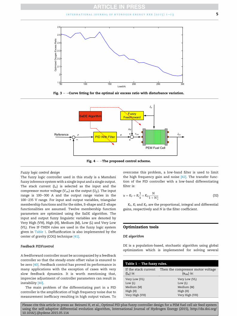
Fig. 3 e eCurve fitting for the optimal air excess ratio with disturbance variation.
Fig. 4 e eThe proposed control scheme.
Table 1 e The fuzzy rules.
If the stack current(Ist) is:
Then the compressor motor voltage(vcm) is:
Very Low (VL) Very Low (VL)
Low (L) Low (L)
Medium (M) Medium (M)
High (H) High (H)
Very High (VH) Very High (VH)
i n t e r n a t i o n a l j o u r n a l o f h yd r o g e n e n e r g y x x x ( 2 0 1 5 ) 1e1 3 5
Fuzzy logic control designThe fuzzy logic controller used in this study is a Mamdani
fuzzy inference systemwith a single input and a single output.
The stack current (Ist) is selected as the input and the
compressor motor voltage (Vcm) as the output (Uff ). The input
range is 100e300 A and the output range varies in the
100e235 V range. For input and output variables, triangular
membership functions and for the sides, S-shape and Z-shape
functionalities are assumed. Twelve membership function
parameters are optimized using the SaDE algorithm. The
input and output fuzzy linguistic variables are denoted by
Very High (VH), High (H), Medium (M), Low (L) and Very Low
(VL). Five IF-THEN rules are used in the fuzzy logic system
given in Table 1. Deffuzification is also implemented by the
center of gravity (COG) technique [41].
Feedback PIDFcontrol
A feedforward controllermust be accompanied by a feedback
controller so that the steady-state offset value is ensured to
be zero [40]. Feedback control has proved its performance in
many applications with the exception of cases with very
slow feedback dynamics. It is worth mentioning that,
imprecise adjustment of controller parameters can result in
instability [40].
The main problem of the differentiating part in a PID
controller is the amplification of high frequency noise due to
measurement inefficacy resulting in high output values. To
Please cite this article in press as: Beirami H, et al., Optimal PID pusing the self-adaptive differential evolution algorithm, Interna10.1016/j.ijhydene.2015.05.114
overcome this problem, a low-band filter is used to limit
the high frequency gain and noise [42]. The transfer func-
tion of the PID controller with a low-band differentiating
filter is:
u ¼ KP þ KI1sþ KD
N
1þN 1s
(32)
KP, KI and KD are the proportional, integral and differential
gains, respectively and N is the filter coefficient.
Optimization tools
DE algorithm
DE is a population-based, stochastic algorithm using global
optimization which is implemented for solving several
lus fuzzy controller design for a PEM fuel cell air feed systemtional Journal of Hydrogen Energy (2015), http://dx.doi.org/

Fig. 5 e Memory of success and failure: (a) memory of success, (b) memory of failure.
i n t e r n a t i o n a l j o u r n a l o f h y d r o g e n en e r g y x x x ( 2 0 1 5 ) 1e1 36
engineering problems due to simplicity and high efficiency.
More information on DE applications can be found elsewhere
[43,44]. In DE algorithm, the population consists of NP vectors
as Xi;G ði ¼ 1;…;NPÞ. Each Xi;G is a D-dimensional vector rep-
resenting a candidate solution. The Xi;G vectors are initially
randomized within the search space with a uniform distri-
bution. The population of the forthcoming generations is
produced by mutation, crossover and selection operators.
Based on these operators, various DE algorithms are gener-
ated. Different strategies are in mutation with the most
common as:
Vi ¼ XGr1þ F
�XG
r2� XG
r3
�; r1sr2sr3 (33)
Three vectors (r1, r2 and r3) are thus selected randomly
from the population and the r2 � r3 vector is multiplied by an
F factor and added to r1 to generate the trial vector. F is the
mutation control parameter which is a positive number
close to unity. The selection of the appropriate mutation
strategy is dependent on the problem. The mutation oper-
ator in DE, has a more pronounced role compared with other
operators contrary to other algorithms and is identified by
trial and error. In order to remove this shortcoming, a
strategy candidate pool consisting of a number of various
strategies is applied instead of the time consuming trial and
error strategy. Upon mutation, the crossover operator is
implemented to generate offsprings from the previous trial
population. In this algorithm, two crossover operators are
Please cite this article in press as: Beirami H, et al., Optimal PID pusing the self-adaptive differential evolution algorithm, Interna10.1016/j.ijhydene.2015.05.114
defined; One is exponential and the other binomial crossover
which is used here:
uji;G ¼
(vji;G; if
�randj½0;1Þ �CR
�or
�j¼ jrand
�xji;G; otherwise
; j¼ 1;2;…;D (34)
The crossover rate (CR) is randomly chosen from the [0, 1)
range showing the parameters’ share copied from the mutant
vector. jrand is a random integer from the [1, D] range. The se-
lection process in DE is different from other algorithms. In
other evolutionary algorithms, the remainingmembers for the
next generation are selected based on probability, while se-
lection in DE is performed deterministically between the
offspring and parent vectors based on fitness. This approach is
usually called a selection tournament given as follows:
Xi;Gþ1 ¼Ui;G; if f
�Ui;G
� � f�Xi;G
�Xi;G; otherwise
(35)
where, fðXi;GÞ and fðUi;GÞ are fitness functions of the offspring
and parent vectors. The stopping criterion for DE is usually
the number of generations or the number of objective func-
tion evaluations.
SaDE algorithm
Estimation of DE parameters entails a trial and error approach
which imposes an extra computational load on the solution
procedure. The SaDE algorithm can adjust F and CR during the
lus fuzzy controller design for a PEM fuel cell air feed systemtional Journal of Hydrogen Energy (2015), http://dx.doi.org/

Fig. 6 e eSaDE algorithm.
i n t e r n a t i o n a l j o u r n a l o f h yd r o g e n e n e r g y x x x ( 2 0 1 5 ) 1e1 3 7
Please cite this article in press as: Beirami H, et al., Optimal PID plus fuzzy controller design for a PEM fuel cell air feed systemusing the self-adaptive differential evolution algorithm, International Journal of Hydrogen Energy (2015), http://dx.doi.org/10.1016/j.ijhydene.2015.05.114

Fig. 7 e eEncoding of candidate solutions.
i n t e r n a t i o n a l j o u r n a l o f h y d r o g e n en e r g y x x x ( 2 0 1 5 ) 1e1 38
algorithm performance and can select the mutation strategy.
In SaDE, both the generation of trial vectors and control
parameters become gradually self-adapted by learning from
previous generations. In this paper, a strategy candidate
pool is used that consists of four generation strategy trial
vectors as follows:
Table 2 e Parameters used in the simulation.
Symbol Parameter
n Number of cells in fuel cell stack
R Universal gas constant
Ra Air gas constant
Patm Atmospheric pressure
Tatm Ambient temperature
Tfc Fuel cell temperature
Fr Faraday constant
Ma Air molar mass
MO2 Oxygen molar mass
MN2 Nitrogen molar mass
Mv Vapor molar mass
g Ratio of specific heats of air
Jcp Compressor inertia
Kv Motor constant
Kt Motor constant
Rcm Motor constant
Cp Specific heat of air at constant pressure
hcp Compressor efficiency
hcm Motor mechanical efficiency
Vca Cathode volume
Vsm Supply manifold volume
Kca; in Cathode inlet orifice constant
Kca; out Cathode outlet orifice constant
AT Cathode outlet throttle area
CD Cathode outlet throttle discharge coefficie
ra Air density
YO2 Oxygen mole fraction
fatm Average ambient air relative humidity
N Derivative filter time constant
ui;j ¼xr1 ;j þ F
�xbest;j � xi;j
�þ F�xr1 ;j � xr2 ;j
�þ F�xr3 ;j � xr4 ;j
�; if rand½0; 1
xi;j; otherwise
Please cite this article in press as: Beirami H, et al., Optimal PID pusing the self-adaptive differential evolution algorithm, Interna10.1016/j.ijhydene.2015.05.114
“DE/rand/bin”:
ui;j ¼xr1 ;j þ F
�xr2 ;j � xr3 ;j
�; if rand½0;1Þ<CR or j ¼ jrand
xi;j; otherwise(36)
“DE/rand-to-best/2/bin”:
SI units Value
381
Jmol�1K�1 8.31451
Jmol�1K�1 286.9
Pa 101.325
K 298.15
K 353.15
Cmol�1 96.487
Kgmol�1 28.97 � 10�3
Kgmol�1 32 � 10�3
Kgmol�1 28 � 10�3
Kgmol�1 18.02 � 10�3
1.4
Kgm2 5 � 10�5
Vrad�1s 0.0153
N-mA�1 0.0225
U 1.2
Jkg�1K�1 1004
80%
98%
m3 0.01
m3 0.02
Kgs�1Pa�1 0.3629 � 10�5
Kgs�1Pa�1 0.2177 � 10�5
m2 0.00175
nt 0.0124
Kgm�3 1.23
0.21
0.5
s 100
Þ<CR or j ¼ jrand (37)
lus fuzzy controller design for a PEM fuel cell air feed systemtional Journal of Hydrogen Energy (2015), http://dx.doi.org/

Fig. 8 e eThe optimizedmembership functions of the fuzzy
feedforward controller (a) input membership functions, (b)
output membership functions.
i n t e r n a t i o n a l j o u r n a l o f h yd r o g e n e n e r g y x x x ( 2 0 1 5 ) 1e1 3 9
“DE/rand/2/bin”:
ui;j ¼xr1 ;j þ F
�xr2 ;j � xr3 ;j
�þ F�xr4 ;j � xr5 ;j
�; if rand½0;1Þ<CR or j ¼ jrand
xi;j; otherwise(38)
“DE/current-to-rand/1”:
Ui;G ¼ Xi;G þ K�Xr1 ;G � Xi;G
�þ F�Xr2 ;G � Xr3 ;G
�(39)
A probability value is assigned to the selection of each
strategy so that the summation of these probabilities equals
unity. Initially, these probabilities are equally assumed as 1=k
and will be modified by the evolution of the algorithm. The
probability of the K th strategy being selected is Pk
(k ¼ 1; 2;…;K) where K is the number of strategies. In the
generation G, after the calculation of the whole trial vectors,
the total number of generated vectors by the K th strategy
which could successfully enter the next generation are
denoted as nsk;G and the others as nfk;G. Registration of these
numbers for decision making in the upcoming generations
can identify the memory of success and failure (Fig. 5)
being responsible for the registration of nsk;G and nfk;G for a
number of previous generations equal to the learning period
(LP). After the initial LP generations, the probability of different
strategies being selected will be updated at each subsequent
generation based on the memory of success and failure:
Pk;G ¼ Sk;GPKk¼1Sk;G
(40)
where,
Sk;G ¼PG�1
g¼G�LPnsk;gPG�1g¼G�LPnsk;g þ
PG�1g¼G�LPnfk;g
þ ε ðk ¼ 1;2;…;K;G> LPÞ (41)
Please cite this article in press as: Beirami H, et al., Optimal PID pusing the self-adaptive differential evolution algorithm, Interna10.1016/j.ijhydene.2015.05.114
and Sk;G is the success rate of generated trial vectors with the K
th strategy in previous LP generations from generation G
successfully entered the next generation.
A small constant value, ε ¼ 0:01 is added to SaDE in order to
prevent null probability. It is obvious that a larger Sk;Gindicates a higher probability value for the selection of the Kth
strategy in the current generation. At the next step, control
parameters will become self-adapted. The selection of NP is
totally dependent on the nature of the problem being
performed through simple estimations. Among other param-
eters, CR is very sensitive to the problem type and can have a
significant role in obtaining the correct solution. The F value
has a great impact on the rate of convergence, which is
selected randomly with a probability proportional to a
normal distribution with an average of 0.5 and a variance
equal to 0.3, denoted by N (0.5, 0.3). The control parameter K in
“DE/current-to-rand/1” strategy is also selected randomly
from the [0, 1] range.
The crossover rate control parameter is selected with a
normal distribution probability and a standard variance equal
to 0.1. CRm is also given an initial value of 0.5 equal for all
strategies. The CR value with a successful trial vector in the
previous generation is registered in the crossover rate mem-
ory ðCRmemoryk Þ for every strategy and the previous generation
LP. The CRm value for every generation and the K th strategy is
calculated by averaging the registered values in the CRmediank
memory and CR is also obtained using a normal distribution
probability with a CRm average and a variance equal to 0.1. The
flowchart of the SaDE algorithm is given in Fig. 6. More in-
formation on SaDE can be found elsewhere [21].
Encoding
A number of parameters are required for encoding the
candidate answers for fuzzy and PIDF controllers. Simulta-
neous optimization of fuzzy and PIDF controllers is performed
to obtain improved results. In this study, optimization of
proportional (KP), Integral (KI) and differential (KD) coefficients
of the PIDF controller and membership functions of the fuzzy
controller are performed using SaDE algorithm.
Encoding the position of membership functions has been
performed by different techniques in the literature [45,46].
Fig. 4 shows the encoding approach used in this study. The
position of membership functions are represented by aji,
where j shows the number of εf and i a special point from εf .
The initial and end points of triangular membership functions
are shown by i¼ 1 and i¼ 3, respectively and the point εf ¼ 1 is
represented by i ¼ 2. For Z-Shape membership functions, the
point separated from unity (Fig. 7) is i ¼ 1 and the point
touching zero is indicated by i ¼ 2. For S-shape membership
functions, the point separated from zero is i ¼ 1 and the point
touching unity is i ¼ 2. In many studies, membership function
parameters for each εf are defined independently in the
lus fuzzy controller design for a PEM fuel cell air feed systemtional Journal of Hydrogen Energy (2015), http://dx.doi.org/

Fig. 9 e eThe comparison of three control strategies with a constant oxygen excess ratio: (a) disturbance variation, (b) stack
voltage variation, (c) oxygen excess ratio variation using PIDF plus Fuzzy FF, (d) oxygen excess ratio variation using PI þ FF,
(e) oxygen excess ratio variation using FF.
i n t e r n a t i o n a l j o u r n a l o f h y d r o g e n en e r g y x x x ( 2 0 1 5 ) 1e1 310
candidate solution for the optimization problem leading to an
extra step for changing or removing impossible solutions
bringing about large computational loads. Special rules are
devised in order not to confront impossible solutions. We
assume that the sequence of membership function linguistic
variables does not change and each value from the output
range has at least one nonzero member in one of its
Please cite this article in press as: Beirami H, et al., Optimal PID pusing the self-adaptive differential evolution algorithm, Interna10.1016/j.ijhydene.2015.05.114
membership functions in order to simplify the solutions
encoding and algorithm acceleration by eliminating impos-
sible solutions. To this end, the sequence of points indicates
the position of membership functions (Fig. 7).
The optimization problem parameters for the fuzzy
controller are x1 through x12 where xi shows the relative dis-
tance between the membership function points in the [0, 1]
lus fuzzy controller design for a PEM fuel cell air feed systemtional Journal of Hydrogen Energy (2015), http://dx.doi.org/

Fig. 10 e The magnified plot of oxygen excess ratio variations at: (a) 10 s, (b) 20 s.
Table 3 e Performance index comparison with theconstant oxygen excess ratio.
Performance index IAE ITAE ISE
PIDF þ Fuzzy FF 0.1069 1.234 0.02029
PI þ FF 0.1557 2.060 0.02873
FF 0.7413 8.371 0.06231
i n t e r n a t i o n a l j o u r n a l o f h yd r o g e n e n e r g y x x x ( 2 0 1 5 ) 1e1 3 11
range. The membership function point values are calculated
as follows: a1 is the initial point in the range and the other
points are previous values plus Li ¼ xi=P
xi � L, where L is the
length of the controller output range. Finally, x13, x14 and x15are defined for proportional, Integral and differential param-
eters of the PIDF controller, respectively.
Simulation results
The PIDF plus Fuzzy control scheme is applied to the 75 kW
PEMFC system. The numerical parameters used in the
Fig. 11 e ePIDF plus Fuzzy FF control scheme for the case of m
variation, (b) stack voltage variation.
Please cite this article in press as: Beirami H, et al., Optimal PID pusing the self-adaptive differential evolution algorithm, Interna10.1016/j.ijhydene.2015.05.114
simulation are given in Table 2. PIDF controller parameters
and the parameters regarding the membership functions of
the fuzzy controller are optimized using SaDE algorithm. The
optimized membership functions for the fuzzy controller are
given in Fig. 8. The main control objectives are: (a) Preventing
oxygen starvation by keeping lO2 constant at lO2 ¼ 2, and (b)
acquiring the maximum power tracking by the optimal lO2 to
achieve the best system performance.
Controller performance with constant lO2
The first simulation is performed by keeping lO2 constant
and stepwise changing of the disturbance covering the
whole fuel cell performance range (Fig. 9). Despite load
fluctuations, the control system adjusts lO2 at the setpoint.
Fig. 9 (c)e(d) shows the simulation results for controlling lO2
using feedforward [30,31], PI plus feedforward [30,31] and
PIDF plus fuzzy feedforward control strategies. Also, Fig. 10
indicates a magnified version of the oxygen excess ratio
graph using various control techniques. Based on the re-
sults, the proposed techniques have improved values of
aximum power tracking: (a) optimal oxygen excess ratio
lus fuzzy controller design for a PEM fuel cell air feed systemtional Journal of Hydrogen Energy (2015), http://dx.doi.org/

Fig. 12 e eThe comparison of fuel cell net power for changing the oxygen excess ratio.
i n t e r n a t i o n a l j o u r n a l o f h y d r o g e n en e r g y x x x ( 2 0 1 5 ) 1e1 312
rising time, undershoot and overshoot compared with pre-
vious studies [30,31]. The comparison of the total perfor-
mance criteria is given in Table 3. As it is obvious, the PIDF
plus fuzzy feedforward has a better response compared to
other techniques.
Besides, the proposed technique has a better performance
toward the instantaneous disturbance rise. The settling time
for PI plus feedforward and pure feedforward are 230 and
430 ms, respectively reduced to 100 ms in the PIDF plus fuzzy
feedforward control scheme (Fig. 10(a)). A sudden decrease of
the disturbance results in 110 and 60 ms settling times for PI
plus feedforward and feedforward control schemes, respec-
tively reduced to 20 ms in the PIDF plus fuzzy feedforward
type (Fig. 10(b)). The results show that the PIDF plus fuzzy
feedforward controller is a promising alternative for oxygen
supply to the fuel cell especially in case of continual distur-
bance variations.
Variable lO2 tracking for maximum power efficiency
Based on Section 2.2, the variable reference lO2 based on
disturbance variations is derived in order to achieve the
maximum efficiency and reduction of fuel cell expenses. lO2
must be manipulated according to disturbance variations in
order to obtain the maximum net power. However, the risk of
oxygen starvation in case of sudden high power demands is
increased as a result of oxygen shortage in the stack. As a
result, the controller capacity for tracking the variable lO2
setpoint is very important. Using the same disturbance
variation characteristics in the first simulation, the proposed
controller is tested for the case of variable lO2 (Fig. 11). The
results show that the proposed control scheme has per-
formed successfully for setpoint tracking and noise rejection.
Finally, the net power efficiency is calculated for all tech-
niques (Fig. 12). The results show that the second scenario
(maximum power tracking) results in a higher net power by
1% compared with the first scenario (constant oxygen excess
ratio). Based on the results, the proposed control strategy has
a higher efficiency compared with other techniques in both
scenarios.
Please cite this article in press as: Beirami H, et al., Optimal PID pusing the self-adaptive differential evolution algorithm, Interna10.1016/j.ijhydene.2015.05.114
Conclusions
In this study, the hybrid PIDF plus fuzzy feedforward control
technique is developed for oxygen excess ratio to manipulate
the air inflow to the PEMFC. Controller parameters are opti-
mized simultaneously using SaDE algorithm. The control
objective is preventing oxygen starvation and obtaining the
maximum fuel cell efficiency. The results show that, the
proposed control scheme performs better compared with
other methods for fuel cell control under various disturbance
fluctuations. Also, this technique reduces the settling time,
overshoot and undershoot significantly in comparison with
other techniques. The calculation of the optimal oxygen
excess ratio as the system setpoint results in the enhance-
ment of net power by 1% compared with other control stra-
tegies or constant oxygen excess ratio resulting in an
improved fuel cell efficiency.
Acknowledgments
We gratefully acknowledge the financial support provided by
Fuel cell Steering Committee of the Iranian Organization of
Renewable Energies (SUNA).
r e f e r e n c e s
[1] Rodatz S, Paganelli G, Guzzella L. Optimizing air supplycontrol of a PEM fuel cell system. In: American ControlConference, 2003 Proceedings of the 2003. IEEE; 2003.p. 2043e8.
[2] Ahn J-W, Choe S-Y. Coolant controls of a PEM fuel cellsystem. J Power Sources 2008;179:252e64.
[3] Pukrushpan JT, Peng H, Stefanopoulou AG. Control-orientedmodeling and analysis for automotive fuel cell systems. JDyn Syst Meas Control 2004;126:14e25.
[4] Bao C, Ouyang M, Yi B. Modeling and control of air streamand hydrogen flow with recirculation in a PEM fuel cell
lus fuzzy controller design for a PEM fuel cell air feed systemtional Journal of Hydrogen Energy (2015), http://dx.doi.org/

i n t e r n a t i o n a l j o u r n a l o f h yd r o g e n e n e r g y x x x ( 2 0 1 5 ) 1e1 3 13
system - I. Control-oriented modeling. Int J Hydrogen Energy2006;31:1879e96.
[5] Li C-H, Sun Z-H, Wang Y-L, Wu X-D. Fuzzy sliding modecontrol of air supply flow of a PEM fuel cell system. Unifyingelectrical engineering and electronics engineering. Springer;2014. p. 933e42.
[6] Hao X, Zhang H, An A, Liu X, Chen L. Fuzzy double modelcontrol for air supply on a PEM fuel cell system. Intelligentcomputing for sustainable energy and environment.Springer; 2013. p. 392e400.
[7] Mammar K, Chaker A. Fuzzy logic control of fuel cell systemfor residential power generation. J Electr Eng 2009;60:328e34.
[8] Kim Y-B. Improving dynamic performance of proton-exchange membrane fuel cell system using time delaycontrol. J Power Sources 2010;195:6329e41.
[9] Wang Y-X, Xuan D-J, Kim Y-B. Design and experimentalimplementation of time delay control for air supply in apolymer electrolyte membrane fuel cell system. Int JHydrogen Energy 2013;38:13381e92.
[10] Almeida PE, Simoes MG. Neural optimal control of PEM fuelcells with parametric CMAC networks. Ind Appl2005;41:237e45. IEEE Transactions on.
[11] Hasikos J, Sarimveis H, Zervas P, Markatos N. Operationaloptimization and real-time control of fuel-cell systems. JPower Sources 2009;193:258e68.
[12] Matraji I, Laghrouche S, Jemei S, Wack M. Robust control ofthe PEM fuel cell air-feed system via sub-optimal secondorder sliding mode. Appl Energy 2013;104:945e57.
[13] Bianchi FD, Kunusch C, Ocampo-Martinez C, S�anchez-Pe~na RS. A gain-scheduled LPV control for oxygenstoichiometry regulation in PEM fuel cell systems. ControlSyst Technol 2014;22:1837e44. IEEE Transactions on.
[14] Garcia-Gabin W, Dorado F, Bordons C. Real-timeimplementation of a sliding mode controller for air supply ona PEM fuel cell. J Process Control 2010;20:325e36.
[15] Kunusch C, Puleston PF, Mayosky MA, Fridman L.Experimental results applying second order sliding modecontrol to a PEM fuel cell based system. Control Eng Pract2013;21:719e26.
[16] Chen Q, Gao L, Dougal RA, Quan S. Multiple model predictivecontrol for a hybrid proton exchange membrane fuel cellsystem. J Power Sources 2009;191:473e82.
[17] Arce A, del Real AJ, Bordons C, Ramırez DR. Real-timeimplementation of a constrained MPC for efficient airflowcontrol in a PEM fuel cell. Ind Electron 2010;57:1892e905. IEEETransactions on.
[18] Ziogou C, Papadopoulou S, Georgiadis MC, Voutetakis S. On-line nonlinear model predictive control of a PEM fuel cellsystem. J Process Control 2013;23:483e92.
[19] Varigonda S, Kamat M. Control of stationary andtransportation fuel cell systems: progress and opportunities.Comput Chem Eng 2006;30:1735e48.
[20] Storn R, Price K. Differential evolution-a simple and efficientadaptive scheme for global optimization over continuousspaces. Berkeley: ICSI; 1995.
[21] Qin AK, Huang VL, Suganthan PN. Differential evolutionalgorithm with strategy adaptation for global numericaloptimization. Evol Comput 2009;13:398e417. IEEETransactions on.
[22] Goudos SK, Siakavara K, Samaras T, Vafiadis EE, Sahalos JN.Self-adaptive differential evolution applied to real-valuedantenna and microwave design problems. Antennas Propag2011;59:1286e98. IEEE Transactions on.
[23] Xie L, Jiao Y-C, Wei Y-Q, Zhao G. A compact band-notchedUWB antenna optimized by a novel self-adaptive differentialevolution algorithm. J Electromagn Waves Appl2010;24:2353e61.
Please cite this article in press as: Beirami H, et al., Optimal PID pusing the self-adaptive differential evolution algorithm, Interna10.1016/j.ijhydene.2015.05.114
[24] Zhu W, Fang J-A, Tang Y, Zhang W, Du W. Digital IIR filtersdesign using differential evolution algorithm with acontrollable probabilistic population size. PloS One2012;7:e40549.
[25] Civicioglu P. Transforming geocentric cartesian coordinatesto geodetic coordinates by using differential searchalgorithm. Comput Geosciences 2012;46:229e47.
[26] Zadeh LA. Fuzzy sets. Inf Control 1965;8:338e53.[27] Zadeh LA. Outline of a new approach to the analysis of
complex systems and decision processes. Syst Man Cybern1973:28e44. IEEE Transactions on.
[28] Mamdani EH, Assilian S. An experiment in linguisticsynthesis with a fuzzy logic controller. Int J Man Mach Stud1975;7:1e13.
[29] Beirami H, Zerafat MM. Self-tuning of an interval type-2fuzzy PID controller for a heat exchanger system. Iran J SciTechnol Trans Mech Eng 2015;39:113e29.
[30] Pukrushpan JT, Stefanopoulou AG, Peng H. Control offuel cell breathing. control systems, vol. 24. IEEE; 2004.p. 30e46.
[31] Pukrushpan JT, Stefanopoulou AG, Peng H. Control of fuelcell power systems: principles, modeling, analysis andfeedback design. Springer; 2004.
[32] Appleby A, Foulkes F. Fuel cell handbook. 1989. p. 3e7.Chpters.1.
[33] Qu S, Li X, Hou M, Shao Z, Yi B. The effect of air stoichiometrychange on the dynamic behavior of a proton exchangemembrane fuel cell. J Power Sources 2008;185:302e10.
[34] Yousfi-Steiner N, Mocot�eguy P, Candusso D, Hissel D. Areview on polymer electrolyte membrane fuel cell catalystdegradation and starvation issues: causes, consequencesand diagnostic for mitigation. J Power Sources2009;194:130e45.
[35] Schmittinger W, Vahidi A. A review of the main parametersinfluencing long-term performance and durability of PEMfuel cells. J Power Sources 2008;180:1e14.
[36] Danzer MA, Wittmann SJ, Hofer EP. Prevention of fuel cellstarvation by model predictive control of pressure, excessratio, and current. J Power Sources 2009;190:86e91.
[37] Gruber J, Doll M, Bordons C. Design and experimentalvalidation of a constrained MPC for the air feed of a fuel cell.Control Eng Pract 2009;17:874e85.
[38] Heywood JB. Internal combustion engine fundamentals. NewYork: McGraw-Hill; 1998.
[39] Arce A, Ramirez D, del Real A, Bordons C. Constrainedexplicit predictive control strategies for PEM fuel cellsystems. In: Decision and Control, 2007 46th IEEEConference. IEEE; 2007. p. 6088e93.
[40] Marlin TE. Process control: designing processes and controlsystems for dynamic performance. McGraw-Hill; 2000.
[41] Lee C-C. Fuzzy logic in control systems: fuzzy logiccontroller. II Syst Man Cybern 1990;20:419e35. IEEETransactions on.
[42] Ang KH, Chong G, Li Y. PID control system analysis, design,and technology. Control Syst Technol 2005;13:559e76. IEEETransactions on.
[43] Price K, Storn RM, Lampinen JA. Differential evolution: apractical approach to global optimization. Springer; 2006.
[44] Das S, Suganthan PN. Differential evolution: a survey of thestate-of-the-art. Evol Comput 2011;15:4e31. IEEETransactions on.
[45] Caux S, Hankache W, Fadel M, Hissel D. On-line fuzzy energymanagement for hybrid fuel cell systems. Int J HydrogenEnergy 2010;35:2134e43.
[46] Schumacher J, Gemmar P, Denne M, Zedda M, Stueber M.Control of miniature proton exchange membrane fuel cellsbased on fuzzy logic. J Power Sources 2004;129:143e51.
lus fuzzy controller design for a PEM fuel cell air feed systemtional Journal of Hydrogen Energy (2015), http://dx.doi.org/