Thermodynamic evaluation of geothermal energy powered hydrogen production by PEM water electrolysis
11
Thermodynamic evaluation of geothermal energy powered hydrogen production by PEM water electrolysis Ceyhun Yilmaz, Mehmet Kanoglu * Department of Mechanical Engineering, University of Gaziantep, 27310 Gaziantep, Turkey article info Article history: Received 12 June 2013 Received in revised form 18 February 2014 Accepted 15 March 2014 Available online 14 April 2014 Keywords: Geothermal energy Hydrogen production Electrolysis Energy Exergy abstract Thermodynamic energy and exergy analysis of a PEM water electrolyzer driven by geothermal power for hydrogen production is performed. For this purpose, work is produced from a geothermal resource by means of the organic Rankine cycle; the resulting work is used as a work input for an electrolysis process; and electrolysis water is preheated by the waste geothermal water. The first and second-law based performance parameters are identified for the considered system and the system performance is eval- uated. The effects of geothermal water and electrolysis temperatures on the amount of hydrogen pro- duction are studied and these parameters are found to be proportional to each other. We consider a geothermal resource at 160 C available at a rate of 100 kg/s. Under realistic operating conditions, 3810 kW power can be produced in a binary geothermal power plant. The produced power is used for the electrolysis process. The electrolysis water can be preheated to 80 C by the geothermal water leaving the power plant and hydrogen can be produced at a rate of 0.0340 kg/s. The energy and exergy efficiencies of the binary geothermal power plant are 11.4% and 45.1%, respectively. The corresponding efficiencies for the electrolysis system are 64.0% and 61.6%, respectively, and those for the overall system are 6.7% and 23.8%, respectively. Ó 2014 Elsevier Ltd. All rights reserved. 1. Introduction Renewable energies are increasing in their use throughout the world. This is motivated by the fact that fossil fuels are depleting and their combustion cause pollution and greenhouse emissions. The increase in utilization of renewable energy requires technical and infrastructural changes. These major changes are energy sav- ings on the demand side, efficiency improvements in the energy production, and the replacement of fossil fuels by various sources of renewable energy [1]. Hydrogen energy can become one of the effective solutions in the future. Hydrogen can play a significant role in reducing environmental emissions if it is produced from renewable energy resources [2,3]. Hydrogen is a subject of many research work and some consider it as the energy of the future. Hydrogen is an energy carrier; it stores and delivers energy in a usable form, but it must be produced from compounds that contain it [4,5]. Hydrogen can be produced using diverse, domestic re- sources including fossil fuels, such as coal (with carbon seques- tration) and natural gas; nuclear; and biomass and other renewable energy technologies, such as wind, solar, geothermal, and hydro- electric power [6]. Producing hydrogen from renewable and nuclear energy sour- ces using the process of electrolysis involves different costs. It is estimated to be 7e11 $/kg for wind, 10e30 $/kg for solar, 2e4 $/kg for nuclear, and 2.2e7.0 $/kg for geothermal [7]. If hydrogen is to become the energy of the future, it must be produced using renewable energy sources and the technical and economic problems on its production, storage, transportation, and use should be solved. There are various methods used in hydrogen production. These methods may require both electricity and heat inputs, and renewable energy such as solar, wind, hydro and geothermal energy use are being investigated [8]. Hydrogen pro- duction via electrolysis is being pursued for renewable (wind, solar and geothermal) options. These pathways result in virtually zero greenhouse gas and pollutant emissions [9]. Hydrogen can be produced by using electrolysis techniques. Electrolysis splits water electrochemically into hydrogen and oxy- gen molecules with the aid of electrical energy. There are three kinds of electrolysis techniques; alkaline, solid oxide and PEM (Proton Exchange Membrane) electrolysis [10,11]. The trend today for the future electrolysis devices, even at high pressure, goes through PEM technology. Many studies and papers demonstrate * Corresponding author. Tel.: þ90 342 3172508; fax: þ90 342 3601104. E-mail address: [email protected] (M. Kanoglu). Contents lists available at ScienceDirect Energy journal homepage: www.elsevier.com/locate/energy http://dx.doi.org/10.1016/j.energy.2014.03.054 0360-5442/Ó 2014 Elsevier Ltd. All rights reserved. Energy 69 (2014) 592e602
Transcript of Thermodynamic evaluation of geothermal energy powered hydrogen production by PEM water electrolysis
lable at ScienceDirect
Energy 69 (2014) 592e602
Contents lists avai
Energy
journal homepage: www.elsevier .com/locate/energy
Thermodynamic evaluation of geothermal energy powered hydrogenproduction by PEM water electrolysis
Ceyhun Yilmaz, Mehmet Kanoglu*
Department of Mechanical Engineering, University of Gaziantep, 27310 Gaziantep, Turkey
a r t i c l e i n f o
Article history:Received 12 June 2013Received in revised form18 February 2014Accepted 15 March 2014Available online 14 April 2014
Keywords:Geothermal energyHydrogen productionElectrolysisEnergyExergy
* Corresponding author. Tel.: þ90 342 3172508; faxE-mail address: [email protected] (M. Kanog
http://dx.doi.org/10.1016/j.energy.2014.03.0540360-5442/� 2014 Elsevier Ltd. All rights reserved.
a b s t r a c t
Thermodynamic energy and exergy analysis of a PEM water electrolyzer driven by geothermal power forhydrogen production is performed. For this purpose, work is produced from a geothermal resource bymeans of the organic Rankine cycle; the resulting work is used as a work input for an electrolysis process;and electrolysis water is preheated by the waste geothermal water. The first and second-law basedperformance parameters are identified for the considered system and the system performance is eval-uated. The effects of geothermal water and electrolysis temperatures on the amount of hydrogen pro-duction are studied and these parameters are found to be proportional to each other. We consider ageothermal resource at 160 �C available at a rate of 100 kg/s. Under realistic operating conditions,3810 kW power can be produced in a binary geothermal power plant. The produced power is used for theelectrolysis process. The electrolysis water can be preheated to 80 �C by the geothermal water leaving thepower plant and hydrogen can be produced at a rate of 0.0340 kg/s. The energy and exergy efficiencies ofthe binary geothermal power plant are 11.4% and 45.1%, respectively. The corresponding efficiencies forthe electrolysis system are 64.0% and 61.6%, respectively, and those for the overall system are 6.7% and23.8%, respectively.
� 2014 Elsevier Ltd. All rights reserved.
1. Introduction
Renewable energies are increasing in their use throughout theworld. This is motivated by the fact that fossil fuels are depletingand their combustion cause pollution and greenhouse emissions.The increase in utilization of renewable energy requires technicaland infrastructural changes. These major changes are energy sav-ings on the demand side, efficiency improvements in the energyproduction, and the replacement of fossil fuels by various sources ofrenewable energy [1]. Hydrogen energy can become one of theeffective solutions in the future. Hydrogen can play a significantrole in reducing environmental emissions if it is produced fromrenewable energy resources [2,3]. Hydrogen is a subject of manyresearch work and some consider it as the energy of the future.Hydrogen is an energy carrier; it stores and delivers energy in ausable form, but it must be produced from compounds that containit [4,5]. Hydrogen can be produced using diverse, domestic re-sources including fossil fuels, such as coal (with carbon seques-tration) and natural gas; nuclear; and biomass and other renewable
: þ90 342 3601104.lu).
energy technologies, such as wind, solar, geothermal, and hydro-electric power [6].
Producing hydrogen from renewable and nuclear energy sour-ces using the process of electrolysis involves different costs. It isestimated to be 7e11 $/kg for wind, 10e30 $/kg for solar, 2e4 $/kgfor nuclear, and 2.2e7.0 $/kg for geothermal [7].
If hydrogen is to become the energy of the future, it must beproduced using renewable energy sources and the technical andeconomic problems on its production, storage, transportation, anduse should be solved. There are various methods used in hydrogenproduction. These methods may require both electricity and heatinputs, and renewable energy such as solar, wind, hydro andgeothermal energy use are being investigated [8]. Hydrogen pro-duction via electrolysis is being pursued for renewable (wind, solarand geothermal) options. These pathways result in virtually zerogreenhouse gas and pollutant emissions [9].
Hydrogen can be produced by using electrolysis techniques.Electrolysis splits water electrochemically into hydrogen and oxy-gen molecules with the aid of electrical energy. There are threekinds of electrolysis techniques; alkaline, solid oxide and PEM(Proton Exchange Membrane) electrolysis [10,11]. The trend todayfor the future electrolysis devices, even at high pressure, goesthrough PEM technology. Many studies and papers demonstrate

C. Yilmaz, M. Kanoglu / Energy 69 (2014) 592e602 593
the interest in this technology. The PEM electrolyzer uses a solidelectrolyte membrane that can be expected to increase the lifetimeof the electrolyzer. No caustic alkaline or acidic fluid electrolyte isrequired. Additional advantages of PEM electrolysis over alkalineelectrolysis include lower parasitic energy losses and higher purityhydrogen output. PEM electrolysis is potentially a simple, sustain-able, and cost-effective technology for generating, compressing,and storing hydrogen [12]. Many establishments have beeninvolved in the development of high efficiency, high security elec-trolysers such as alkaline and PEM (proton exchange membrane)electrolysers. For instance, the International Clean Energy Networkusing Hydrogen Conversion (WE-NET), which is a program fundedby AIST (Agency of Industrial Science and Technology) in the MITI(Ministry of International Trade and Industry) of Japan, have beenactively involved in the development of large-scale hydrogen pro-duction technologies [13]. In our system, we select a PEM electro-lyzer mainly because it can operate over a temperature range and itis commonly considered in studies on renewable based hydrogenproduction.
Among renewable sources, geothermal energy has significantpotential in hydrogen production. Electricity output from ageothermal power plant and direct geothermal heat or thatresulting from power plants can be used in hydrogen productionby means of water electrolysis process. The use of geothermalenergy for hydrogen production with the electrolysis operationmay prove to be an effective option in the future hydrogenstructure. Power production from geothermal energy is wellestablished and various thermodynamic systems such as singleflash, double flash, binary, and combined flash/binary designs arecommonly used. In this study, we select a binary designgeothermal power plant since it is more efficient and morecommonly used design for liquid dominated and relatively low-temperature geothermal resources. Both binary geothermal po-wer plant and PEM electrolyzer are common technologies andincorporating them with a heat exchange system can provide aviable option for geothermal powered hydrogen productiontechnology. The systems considered in this study are assumed tohave appropriate dimensions to perform the necessary thermo-dynamic functions as described in the analysis.
Although, there are a large number of studies in using solar,wind and nuclear energies for hydrogen production, limited num-ber of studies exists on using geothermal energy. Next, we providean overview of some of the more relevant studies in literature.Kanoglu et al. [14] investigated energy, exergy, and exergoeconomicanalysis of a geothermal assisted high temperature electrolysisprocess. Energy and exergy performance parameters such as heattransfer, power, exergy destruction, and exergy efficiencies weredetermined. Heat exchanger network and high temperature elec-trolysis unit are primarily responsible for exergy destructions in thesystem. Ahmadi et al. [15] developed amodel for energy and exergyanalyses of hydrogen production via an OTEC (ocean thermal en-ergy conversion) system coupled with a solar-enhanced PEM(proton exchange membrane) electrolyzer. The energy and exergyefficiencies of the integrated OTEC system are determined to be3.6% and 22.7%, respectively, and the exergy efficiency of the PEMelectrolyzer is 56.5%. Esmaili et al. [16] analyzed low temperatureelectrolysis of a hydrogen production system using molybdenumoxo catalysts in the cathode and a platinum bared anode. A ther-modynamic model was developed for the electrolysis process inorder to predict and analyze the energy and exergy efficiencies. Thenew electrolysis systemwith molybdenum oxo catalysts consists oftwo half cells of PEM (proton exchange membrane) and alkalineelectrolysis. The results were presented and compared with pre-vious studies to demonstrate the promising performance of thesystem.
Kanoglu et al. [17] investigated three cases for the use ofgeothermal energy for hydrogen liquefaction. A binary geothermalpower plant was considered for power production while the pre-cooled Linde Hampson cycle was selected for hydrogen liquefac-tion. Kanoglu et al. [8] developed four models for the use ofgeothermal energy for hydrogen production. These models werestudied thermodynamically, and both reversible and actual (irre-versible) operations of the models were considered. Yilmaz [18]and Yilmaz et al. [19] considered seven models for hydrogen pro-duction and liquefaction by geothermal energy, and their thermo-dynamic and economic analyses were performed. The amount ofhydrogen production and liquefaction per unit mass of geothermalwater and the cost of producing and liquefying a unit mass ofhydrogen are calculated for each model. The effect of geothermalwater temperature on the cost of hydrogen production and lique-faction were also investigated.
Balta et al. [20] and Balta et al. [21] investigated variousgeothermal based hydrogen production methods using energy andexergy methods. Balta et al. [22] conducted an exergy, cost, energy,and mass analysis of a copperechlorine thermochemical watersplitting cycle driven by geothermal energy for hydrogen produc-tion. Ratlamwala et al. [23] focused on a comparative assessment ofmulti-flash geothermal power generating systems integrated withelectrolyzers through three definitions of energy and exergy effi-ciencies. Valdimar et al. [24] presented a feasibility study exploringthe use of geothermal energy for hydrogen production. Theyinvestigated a newly developed HOT ELLY high temperature steamelectrolysis process operating between 800 and 1000 �C. Theelectrical power of this process is reduced from 4.6 kWh pernormalized cubic meter of hydrogen (kWh/Nm3 H2) for conven-tional process to 3.2 kWh/Nm3 H2 for the HOT ELLY process with anelectrical energy reduction of 29.5%. The price of geothermal en-ergy is approximately 8e10% of electrical energy and therefore asubstantial reduction in production cost of hydrogen can be ach-ieved this way. Using HOT ELLY process with geothermal steam at200 �C can reduce the hydrogen production cost by approximately19%. Zhang et al. [25] investigated a water electrolysis hydrogenproduction system, which mainly includes the electrolysis cell,separator, and heat exchangers. Three expressions of the systemefficiency in literature are compared and evaluated. Several newconfigurations of a water electrolysis system are put forward. Somerecent studies have focused on various thermodynamic aspects ofgeothermal district heating systems and enhanced geothermalsystems [26e28].
The previous work cited on using geothermal energy onhydrogen production concentrate on (a) geothermal assisted high-temperature electrolysis process, (b) geothermal assisted hydrogenliquefaction, (c) thermodynamic and conventional economic anal-ysis of hydrogen production and liquefaction driven by geothermalenergy, and (d) geothermal based hydrogen production methodsusing conventional energy and exergy methods. In this paper, weconsider a thermodynamic system for the production of hydrogendriven by geothermal energy. The system consists of a binarygeothermal power plant, a heat exchange system, and a PEMelectrolysis unit. The present work represents the first investigationthat considers these particular systems with realistic operatingconditions and their thermodynamic analysis using the first andsecond laws. Also, this study extends on Yilmaz et al. [19] for whichthe possible systems for power production and hydrogen produc-tion were not considered and instead these units were only rep-resented by simple boxes.
In our analysis, both thermal and electrical energy outputs of thegeothermal system are used in hydrogen production. For thermo-dynamic evaluation of the system, mass, energy and exergy bal-ances are applied and efficiency and other performance parameters

Table 1Critical properties of organic working fluids [25].
Working fluid Critical temperature (�C) Critical pressure (kPa)
Isobutane 135.92 3685n-butane 150.98 3718Isopentane 187.8 3409n-pentane 193.9 3204
C. Yilmaz, M. Kanoglu / Energy 69 (2014) 592e602594
are defined. The analysis is applied under realistic operating con-ditions and the system performance for hydrogen production isestimated under varying geothermal water temperatures.
The system considered in this study involves well-establishedtechnologies such as a binary geothermal power plant, a heatexchanger, and a PEM electrolyzer. All of these units are technicallyfeasible since there are numerous applications in actual engineer-ing systems. One can select alternative systems to all of these units.For example, a flash design power plant can replace the binary cycleand an alkaline unit can replace the PEM electrolyzer. The newintegrated system would also be technically feasible. One maycompare different design choices for geothermal poweredhydrogen production but this is not within the scope of this study.
2. System operation
In this study, a binary geothermal power plant is considered, asshown in Fig. 1. In this design, geothermal water is used as the heatsource and the working fluid undergoes an actual closed thermo-dynamic cycle, called organic Rankine cycle. The working binaryfluid has a low boiling temperature. Isobutane, pentane, and iso-pentane are commonly used as theworking fluid. Theworking fluidis completely vaporized and usually superheated by the heat ofgeothermal water in the heat exchanger. The vapor expands in theturbine, and then condensed in an air-cooled or water-cooledcondenser before being pumped back to the heat exchanger tocomplete the cycle. The used geothermal water leaving the heatexchanger is used to preheat electrolysis water. This decreasespower requirement in the PEM electrolyzer. The geothermal waterleaving the water preheater is reinjected back to the ground. PEMelectrolyzer uses power output from the binary geothermal plant toproduce hydrogen fromwater. The geothermal water is assumed to
Fig. 1. Hydrogen production by PEM electrolysis
be introduced to the heat exchanger by a production pump at thewell head. Since the work consumed by this pump is smallcompared to work consumed by the fans of air-cooled condenser, itis neglected in thermodynamic analysis.
The selection of the working fluid plays a key role in organicRankine cycle performance. The critical properties of various binaryfluids are listed in Table 1. For each working fluid, the maximumpower output is plotted against the resource temperature, asillustrated in Fig. 2. In Fig. 3, the optimum heat exchanger pressureis plotted against geothermal resource temperature. The data inFigs. 2 and 3 correspond to each other in that optimum heatexchanger pressure is obtained by maximizing work output fromthe cycle. The maximum value of the specific net power output inFig. 2 and the corresponding optimum heat exchanger pressure inFig. 3 are proportional to geothermal resource temperature in therange of 100e180 �C for organic Rankine cycle operating with n-butane, isopentane, and n-pentane, and in the range of 100e160 �Cfor organic Rankine cycle operating with isobutane [29].
A Rankine cycle operating with isobutane for resource temper-atures below 160 �C gives a slightly higher power output comparedwith the rest of the working fluids. For temperatures above 160 �C,the maximum working pressure for isobutane with 3200 kPa isreached at 86% of the critical pressure. The resulting shift of the
powered by binary geothermal power plant.

Fig. 2. Maximum net work output from organic Rankine cycle as a function of resourcetemperature for different working fluids. The maximum work output corresponds tooptimum heat exchanger pressure in Fig. 3.
Fig. 4. Temperature entropy (Tes) diagram of organic Rankine cycle.
C. Yilmaz, M. Kanoglu / Energy 69 (2014) 592e602 595
pinch point, from the inlet of the boiler to the inlet of the preheater,leads to higher efficiency compared to the other working fluids.This effect takes place because the maximum processing pressureof the binary fluid is reached, which leads to a high quantity ofthermal energy coupled to the cycle. As a result, operating withisobutane cools the geothermal resource more effectively and thiswill limit the preheating temperature of the electrolysis water [29].In this study, the selection of the working fluid is based on theoptimum specific power output; the reinjection temperature is nota restriction.
The organic Rankine cycle operation is shown on a temperature-entropy diagram in Fig. 4. It is noted that the saturated vapor line ofisobutane has a positive slope ensuring superheated vapor state atthe turbine outlet. Thus, no moisture is involved in the turbineoperation. This is one reason isobutane is a suitable working fluid inbinary geothermal power plants.
The geothermal power plant considered is a binary power plantthat generates an average net power output of 3810 kW. The plantutilizes dry-air condenser to condense the working fluid, so nofresh water is consumed. Isobutane circulates in a closed cycle,which is based on the organic Rankine cycle. We assume that the
Fig. 3. Optimum heat exchanger pressure in organic Rankine cycle for maximumworkoutput as a function of resource temperature for using different working fluids.
heat source for the plant is the flow of geothermal water enteringthe plant at 160 �C with a total mass flow rate of 100 kg/s. In orderto make sure that geothermal water remains as a liquid throughoutthe plant, and we take the pressure of geothermal water to be700 kPa, which is sufficiently higher than the saturation pressure ofwater at 160 �C. Due to the occurrence of a pinch-point during heatexchange between the geothermal water and the binary workingfluid, geothermal water leaves the heat exchanger at a relativelyhigh temperature. Geothermal water leaves the power plant heatexchanger at 90 �C for an inlet geothermal temperature of 160 �C.
The entire operation of geothermal power plant and the asso-ciated assumptions used in this study closely agree with actualoperation of existing geothermal power plants operating with re-sources at comparable temperatures [30e32]. Refs. [30e32]consider actual binary geothermal power plants using resourcetemperatures of 160 �C, 140 �C, and 170 �C in liquid state, respec-tively. The performance results of the power plant closely agreewith those in Refs. [30e32]. This may be taken as the validation ofthe geothermal power plant model.
In hydrogen production system, the PEM electrolysers (protonexchange membrane) are built around a proton conductive poly-mer electrolyte. The electrodes are:
H2O (l) / 1/2O2 (g) þ 2Hþ (aq.) þ 2e� anode
2Hþ (aq.) þ 2e� / H2 (g) cathode
H2O (l) / 1/2O2 (g) þ H2 (g) overall
The schematic of PEM electrolysis unit for hydrogen productionis shown in Fig. 1. Electricity and preheat water are supplied to thePEM electrolysis to drive the electrochemical reactions. H2O (Liquidwater) is fed to the preheater at a reference environment (298.15 Kand 1 atm) and is heated by the used geothermal water at 90 �C.Having a 10 �C temperature difference for effective heat transfer inthe preheater, we take the temperature of electrolysis water at thepreheater exit to be 80 �C. It is calculated that geothermal waterleaves the heater at 75 �C based on an energy balance on the pre-heater with the given mass flow rate of electrolysis water. Exitingfrom the cathode, produced H2 (hydrogen) dissipates heat to theenvironment and cool down to the reference environment tem-perature. O2 (Oxygen) gas produced at the anode is separated fromH2O/O2 mixture and cooled down to the reference environmenttemperature. The remaining hot H2O is circulated to the H2O supplystream for the next H2 production cycle.

Table 2System data, thermodynamic properties, and exergies in the system with respect to state points in Fig. 1.
State Fluid TemperatureT (�C)
PressureP (kPa)
Enthalpyh (kJ/kg)
Entropys (kJ/kg�C)
Specificexergy ex (kJ/kg)
Mass flowrate _m (kg/s)
Exergyrate (kW)
0 Brine 25 101.3 104.8 0.3672 0 100 e
00 Isobutane 25 101.3 589.9 2.513 0 57 e
000 Air 25 101.3 298.6 5.695 0 1694 e
1 Isobutane 58.9 300 246.5 1.163 50.21 57 28532 Isobutane 59.9 3000 253.3 1.17 54.87 57 31283 Isobutane 150 3000 779.9 2.597 156.1 57 88984 Isobutane 80.58 300 694.8 2.658 52.79 57 30095 Brine 160 700 675.5 1.942 101 100 10,1006 Brine 90 700 374.9 1.185 26.21 100 26217 Brine 75 700 314.6 1.015 16.5 100 16508 Air 25 101.3 298.6 5.695 0 1694 09 Air 40 101.3 313.6 5.745 0.3452 1694 584.910 Water 25 101.3 104.8 0.367 0 0.3041 011 Water 80 101.3 334.6 10.78 10.99 0.3041 3.34212 Oxygen 80 101.3 2150 13.12 247 0.2701 68.9513 Hydrogen 80 101.3 2110 67.21 116,691 0.03403 3973
Fig. 5. Diagram showing the heat exchange process between the geothermal fluid andthe isobutane fluid in the heat exchanger. State numbers refer to Fig. 1.
C. Yilmaz, M. Kanoglu / Energy 69 (2014) 592e602596
3. Thermodynamic analysis
3.1. Energy and exergy analysis
In an actual irreversible process, mass and energy are conserved,entropy is generated, and exergy is destroyed due to irreversibil-ities. Mass, energy and exergy balances for any control volume atsteady state with negligible kinetic and potential energy changescan be expressed, respectively, by
X_mi ¼
X_me (1)
_Q þ _W ¼X
_mehe �X
_mihi (2)
_Exheat þ _W ¼X
_meexe �X
_miexi þ _Exdest (3)
where _Q and _W are the net heat and work inputs, _m is the massflow rate of the fluid stream, h is the enthalpy, ex is the specific flowexergy, _Exheat is the rate of exergy transfer by heat, _Exdest is the rateof exergy destruction, and the subscripts i and e stand for inlet andexit states.
The specific flow exergy and the rate of total exergy are given by
ex ¼ ðh� h0Þ � T0ðs� s0Þ (4)
_Ex ¼ _mðexÞ (5)
where s is entropy, T0 is the dead state temperature, and the sub-scripts 0 stands for the restricted dead state.
The maximum specific work that can be obtained by ageothermal power plant utilizing geothermal water at Ts in anenvironment at T0 is given by
wmax ¼ ðhs � h0Þ � T0ðss � s0Þ (6)
where hs and ss are enthalpy and entropy of geothermal water,respectively.
The energy and exergy efficiencies are generally defined as:
hth ¼�energy in productstotal energy input
�(7)
hex ¼�exergy in productstotal exergy input
�(8)
3.2. Binary geothermal power plant
Application of energy and exergy balances on the components ofbinary power plant gives the data in Table 2. The state numbers inTable 2 refer to Fig. 1. State 0, 00 and 000 are the restricted dead statesfor geothermal water, binary working fluid, and air, respectively.The dead state is taken as 25 �C and 1 atm (101.3 kPa). Forgeothermal fluid, thermodynamic properties of water are used.
The heat exchange process between the geothermal water andthe working fluid isobutane involves heating, vaporization, andsuperheating of the working fluid, as shown in Fig. 5. Energy bal-ances can be written for the heat exchanger of the power plant as
_mgeo�h5 � hpp
� ¼ _mbinary
�h3 � hf ; binary
�(9)
_mgeo�hpp � h6
� ¼ _mbinary
�hf ; binary � h2
�(10)
where and are the mass flow rates of geothermal water and binaryworking fluid, hf is the saturated liquid enthalpy of isobutane at thesaturated (vaporization) temperature, hpp is the enthalpy ofgeothermal water at the pinch-point. In this plant, the vaporizationtemperature is Tvap ¼ 123.2 �C and the geothermal water temper-ature at the pinch-point is Tpp ¼ 129.7 �C. The pinch-point tem-perature difference DTpp is simply the difference between brinepinch-point temperature and the vaporization temperature ofisobutane, and is calculated as 6.5 �C. Also, these calculations give a

C. Yilmaz, M. Kanoglu / Energy 69 (2014) 592e602 597
geothermal water temperature of 90 �C at the heat exchanger exit.A pinch-point temperature difference of 6.5 �C is in agreement withthe values found in actual binary geothermal power plants [30,33].
Thermodynamic analysis of an energy conversion system usu-ally includes the assessment of individual performances of systemcomponents. In general, the thermal or energy efficiency of ageothermal power plant may be expressed as [34]
hth ¼_Wnet; out
_Ein(11)
where is the energy input to the power plant, which may beexpressed as the enthalpy of the geothermal water with respect toenvironmental statemultiplied by themass flow rate of geothermalwater. That is,
hth;1 ¼_Wnet; out
_mgeo�hgeo � h0
� ¼_Wnet; out
_mgeoðh5 � h0Þ(12)
In eq. (12), the energy input to the power plant represents themaximum heat the geothermal water can release and this can onlyhappenwhen the geothermal water is cooled to the temperature ofthe environment. The energy efficiency may be expressed based onthe heat transfer to the organic Rankine cycle:
hth;2 ¼_Wnet;out
_mgeoðh5 � h6Þ(13)
or
hth;2 ¼_Wnet;out
_mbinaryðh3 � h2Þ(14)
Using the exergy of geothermal water as the exergy input to theplant, the second-law or exergy efficiency of a geothermal powerplant can be expressed as [35]
hex ¼_Wnet;out_Exin
(15)
For an organic Rankine cycle, the exergy efficiency may bedefined based on the exergy decrease of geothermal water orexergy increase of the binary working fluid in the heat exchanger.That is,
hex;binary;1 ¼_Wnet;out
_mgeo½h5 � h0 � T0ðs5 � s0Þ�(16)
hex;binary;2 ¼_Wnet;out
_mbinary½h3 � h2 � T0ðs3 � s2Þ�(17)
The difference between the numerator and denominator of botheq. (16) and eq. (17) represents exergy destruction in the heatexchanger. In above equations, state numbers refer to Fig. 1 andTable 2.
3.3. PEM water electrolysis system
We present a brief thermodynamic analysis of PEM electro-lyzers. This analysis is performed to calculate the voltage and flowrate in the electrolyzer, and study the effects of temperature andcurrent density on these parameters. For PEM electrolyzers, thevalid temperature range is approximately 25e80 �C [36], and thecurrent density range is approximately 0e10,000 A/m2 [37]. In thefollowing analysis, we assume that all gases involved are ideal gasesand any side reaction or mixing is neglected.
For an electrochemical process operating at constant pressureand temperature, the maximum possible useful work (i.e., thereversible work) is equal to the change in Gibbs energy. The elec-trical work is positive for electrolysis (i.e., work input) and negative(i.e., work output) for fuel cell operations when analyzing chemicalreactions. The total energy demand for PEM electrolysis can becalculated from Ref. [36]
DH ¼ DGþ TDS (18)
where DG is the electrical energy demand (change in Gibb’s freeenergy) and TDS is the thermal energy demand (kJ/kmol). Thevalues of G, S, and H for H2, O2, and H2O can be obtained from theJANAF table [37]. According to LeRoy [38] and Onda [39], twoessential voltages, taking into account the energy needed forhydrogen production, can be defined as
The enthalpy voltage at T and P:
VT ;P ¼ DHT;P
nF(19)
The water electrolysis voltage at T and P:
ET ;P ¼ DGT ;P
nF(20)
Here, n is the number of electrons transferred, F is the Faradayconstant, which is equal to 96,500 C mol-1. The voltage associatedwith DHT,P is commonly called the thermo neutral cell voltage,which is the voltage at which a perfectly efficient cell wouldoperate if electricity provided the entire energy requirement. Un-der these conditions, the cell does not generate any waste heat, nordoes it require any heat input; hence it is said to be thermo neutral[38]. Since the enthalpy voltage and the water electrolysis voltagedepend on the enthalpy and the Gibbs energy of the formationreaction of water, we can predict the temperature changes bymeans of thermodynamics relationships [39]. The calculationapproach is based on the fact that the enthalpy and Gibbs energyare properties that depend on the initial and final states of thereactants and products of electrolysis.
The enthalpies of reactants and products are expressed as afunction of temperature by
DH0ðT ; finalÞ ¼ DH0ðT ; initialÞ þX
species
ZT ;finalT ;initial
C0P;speciesðTÞdT
(21)
where (T, initial) is the initial temperature in K; (T, final) is the finaltemperature in K; Cp is the heat capacity of the species in kJ/kmolK.The entropy change is expressed by considering the followingrelationship of ideal gases [40]
DS0ðT; finalÞ ¼ DS0ðT ; initialÞ þX
species
ZT ;finalT;initial
C0P;speciesðTÞ
TdT
(22)
Combining these two equations, we can calculate Gibbs energyof the formation.
Neglecting kinetic and potential exergy changes, the exergy of asubstance can be determined from Ref. [41]
ex ¼ exCH þ exPH (23)
where exCH and exPH are chemical and physical exergies (in kJ/kmol), respectively. The chemical exergy values of various

C. Yilmaz, M. Kanoglu / Energy 69 (2014) 592e602598
compounds are given in Table 3. The physical exergy can bedetermined from the flow exergy relation as [41]
exPH ¼ h� h0 � T0ðs� s0Þ (24)
where h, s, and T represent the general thermodynamic propertiesof enthalpy, entropy and temperature respectively, and subscript0 represents the reference environment condition.
The mass flow rate of H2 at the outlet can be determined from
_mH2;out ¼ J2F
MH2(25)
where, J is the current density; F is the Faraday constant, andMH2 isthemolecular weight of H2. Similarly, themass flow rate of O2 at thePEM electrolysis outlet can be calculated as
_mO2;out ¼ J4F
MO2(26)
The energy and exergy of electricity involved in the PEM elec-trolysis operation can be determined by the following electro-chemical model developed in Ref. [42] as
_Welectricity ¼ JET ;P (27)
ET ;P ¼_Welectricity
nF(28)
where ET,P is the necessary cell voltage for the start up of electrolysisoperation, J is the current density, and _Welectricity is the electricalpower consumption in electrolysis. These equations are valid if thecurrent density is not too high.
The heat input to the PEM electrolysis is then calculated as [42]
_Qheat;PEM ¼ _mH2OTDS (29)
The exergy rate of this heat input is expressed as [42]
_Exheat;PEM ¼ _Qheat;PEM
1� T0
Telectrolysis
!(30)
where T0 and Telectrolysis are the temperatures of the referenceenvironment and the PEM electrolysis, respectively.
The total energy demand is the theoretical energy required forH2O electrolysis without any losses. In actual systems, losses areinevitable and the performance of the system can be evaluated interms of energy and exergy efficiencies. These two efficiencies canbe defined as [42]
hth ¼ LHV � _mH2;out_Qelectric þ _Qheat;PEM þ _Qheat;H2O
(31)
hex ¼_ExH2
_Exelectric þ _Exheat;PEM þ _Exheat;H2O(32)
Table 3Enthalpy, entropy and Gibbs free energy of formation and standard chemical exergyfor electrolysis [25].
Elements h0f ðkJ=kmolÞ s0f ðkJ=kmolÞ g0f ðkJ=kmolÞ exchðkJ=kmolÞH2O (l) 285,830 6992 237,180 45H2 (g) 0 130.57 0 236,100O2 (g) 0 205.3 0 3970
where LHV is the lower heating value of H2, _mH2;out is the mass flowrate of H2 at the outlet, _Qelectric and _Qheat;PEM are the rates of electricand thermal energy inputs for the electrolysis, respectively, and_Qheat;H2O is the rate of thermal energy input in the preheater. _Exstands for exergy rate and its values in the denominator of eq. (32)corresponds the exergy rates of variables in the denominator eq.(31). _ExH2
is the exergy of H2 produced in the electrolyzer.
3.4. Overall performance evaluation
The energy and exergy efficiencies of the overall system can bedefined as the total energy value of the hydrogen produced (heat-ing value of hydrogen times its production rate) divided by theenergy (or exergy) input to the system, which is energy (or exergy)value of geothermal water at the plant inlet with respect to theenvironmental state.
hth;overall ¼LHV� _mH2;out_mgeo
�hgeo � h0
� (33)
hex;overall ¼_ExH2
_mgeo�hgeo � h0 � T0
�sgeo � s0
� (34)
A detailed exergy analysis of a power system should includecalculating the exergy destruction in each component and relatingthis to the exergy of the fuel and to the total exergy destruction inthe system. The exergy destruction in steady flow operation of acomponentmay be obtained using an exergy balance. It may also becalculated from
_Exdest ¼ T0 _Sgen (35)
where is the rate of entropy generation in the component. The rateof exergy destruction in a system for the kth component can becompared to the exergy rate of the fuel provided to the overallsystem as
ydest;k ¼_Exdest;k_Exfuel
(36)
Alternatively, the component exergy destruction rate can becompared to the total exergy destruction rate within the system as
y�dest;k ¼_Exdest;k
_Exdest; total(37)
The two exergy destruction ratios are useful for comparisonsamong various components of the overall system. For the energeticand exergetic analyses in this study, the overall system is separatedinto subsystems. Energy- and exergy-based performance resultsare calculated and given in Table 4.
4. Results and discussion
Heat source temperatures for geothermal power plants aremuch lower than those for fossil fuel powered conventional powerstations. As a result, geothermal power plants have low thermalefficiencies. The thermal efficiency of the plant is calculated to be11.4% based on the heat input to the organic Rankine cycle and 4.5%based on the energy of geothermal water with respect to theenvironmental state. The exergy efficiency of the power plant isdetermined to be 45.1% based on the exergy of geothermal water atthe plant inlet. The exergy losses shown in Table 4 indicate that30.1% of the exergy of the brine is reinjected. PEM electrolysis unitis responsible for 25.9% of the exergy destruction in the system and
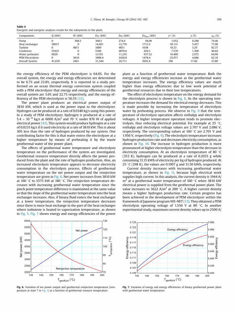
Table 4Energetic and exergetic analyses results for the subsystems in the plant.
Components _Q (kW) _W (kW) _ExF (kW) _ExP (kW) _Exdest (kW) y* (%) y (%) hex (%)
Pump 0 368.5 368.5 274.4 94.09 1.652 0.298 74.46Heat exchanger 30037 0 14,491 12,776 1715.2 30.131 5.437 77.08Turbine 0 4851 5889 4851 1038 18.23 3.29 82.37Condenser 25425 0 5306 4876.6 429.2 7.539 1.360 46.64Water preheater 6020 0 12193 11,255 937.52 16.469 2.972 64.99PEM Electrolysis 0 3810 3908.4 2430.0 1478.4 25.971 4.686 62.18Overall System 41,639 2461 31,544 26,711 5692.4 100 17.66 23.80
C. Yilmaz, M. Kanoglu / Energy 69 (2014) 592e602 599
the energy efficiency of the PEM electrolyzer is 64.0%. For theoverall system, the energy and exergy efficiencies are determinedto be 6.7% and 23.8%, respectively. It is reported in a study per-formed on an ocean thermal energy conversion system coupledwith a PEM electrolyzer that energy and exergy efficiencies of theoverall system are 3.6% and 22.7% respectively, and the exergy ef-ficiency of the PEM electrolyzer is 56.5% [15].
The power plant produces an electrical power output of3810 kW, which is used as the power input to the electrolyzer.Hydrogen can be produced at a rate of 0.0340 kg/s using this power.In a study of PEM electrolyzer, hydrogen is produced at a rate of5.4 � 10�6 kg/s at 6000 A/m2 and 70 �C under 876 W of appliedelectrical power [43]. This systemwould produce hydrogen at a rateof 0.0235 kg/s if it used electricity at a rate of 3810 kW. This is about30% less than the rate of hydrogen produced by our system. Onecontributing factor for this is that water enters the electrolyzer at ahigher temperature by means of preheating it by the wastegeothermal water of the power plant.
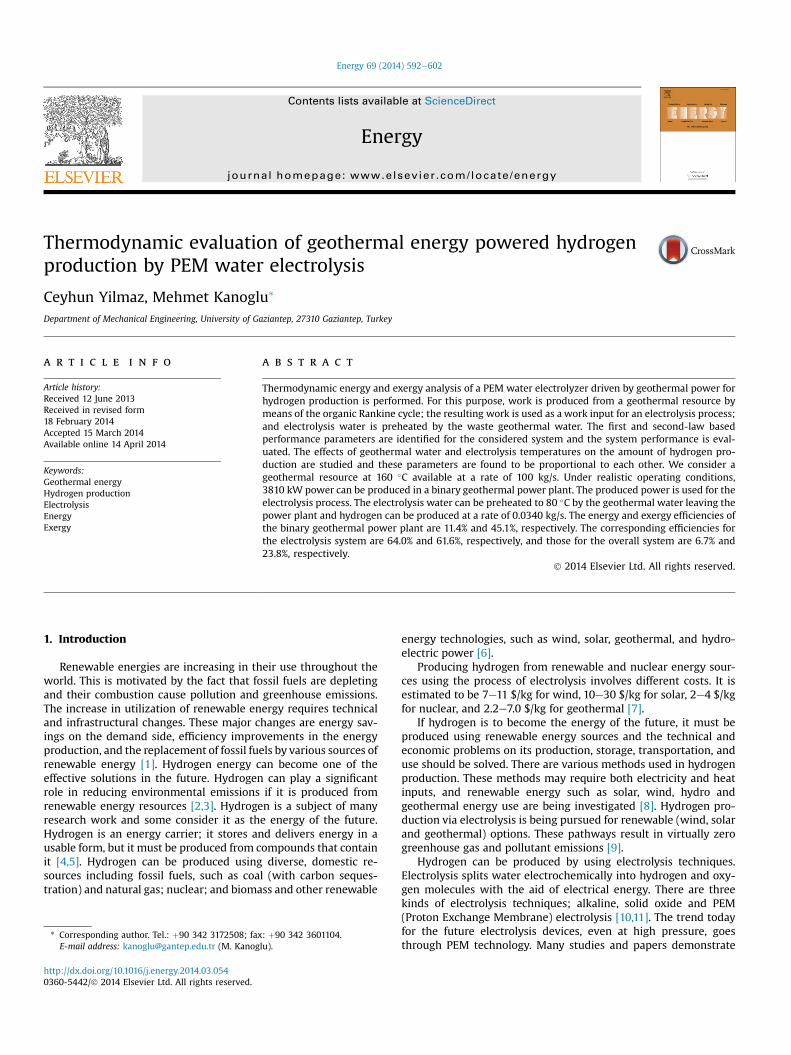
The effects of geothermal water temperature and electrolysistemperature on the performance of the system are investigated.Geothermal resource temperature directly affects the power pro-duced from the plant and the rate of hydrogen production. Also, anincreased electrolysis temperature appears to decrease electricityconsumption in the electrolysis process. Effects of geothermalwater temperature on the net power output and the reinjectiontemperature are given in Fig. 6. Net power increases from 3810 kWat 160 �C to 5575 kW at 180 �C. The reinjection temperature de-creases with increasing geothermal water temperature since thepinch point temperature difference is maintained at the same valueso that the slope of the geothermal water temperature into the heatexchanger increases. Also, if binary fluid enters the heat exchangerat a lower temperature, the reinjection temperature decreasessince there is more heat exchange in the part of the heat exchangerwhere isobutene is heated to vaporization temperature, as shownin Fig. 5. Fig. 7 shows energy and exergy efficiencies of the power
Fig. 6. Variation of net power output and geothermal reinjection temperature (tem-perature at state 7 in Fig. 1) as a function of geothermal resource temperature.
plant as a function of geothermal water temperature. Both theenergy and exergy efficiencies increase as the geothermal watertemperature increases. The exergy efficiency values are muchhigher than energy efficiencies due to low work potential ofgeothermal resources due to their low temperatures.
The effect of electrolysis temperature on the energy demand forthe electrolysis process is shown in Fig. 8. As the operating tem-perature increases the demand for electrical energy decreases. Thisis made possible by increasing the temperature of electrolysiswater by preheating process. We observe in Fig. 9 that the tem-perature of electrolysis operation affects enthalpy and electrolysisvoltages. A higher temperature operation tends to promote elec-trolysis, thus reducing electrical potential. For example at 25 �C,enthalpy and electrolysis voltage values are 2.707 V and 2.086 V,respectively. The corresponding values at 160 �C are 2.701 V and1.956 V, respectively (Fig. 9). The electrolysis temperature increaseshydrogen production rate and decreases electricity consumption, asshown in Fig. 10. The increase in hydrogen production is morepronounced at higher electrolysis temperature than the decrease inelectricity consumption. At an electrolysis temperature of 80 �C(353 K), hydrogen can be produced at a rate of 0.2033 g whileconsuming 31.15 kWh of electricity per kg of hydrogen produced. At25 �C (298 K), the values are 0.1907 g and 31.50 kWh, respectively.
Current density increases with increasing geothermal watertemperature, as shown in Fig. 11, because high electrical worksupplies high current. In this analysis, the current density is 1944 A/m2 at a geothermal water temperature of 160 �C when 3810 kWelectrical power is supplied from the geothermal power plant. Thevalue increases to 3622 A/m2 at 200 �C. A higher current densitymeans a higher hydrogen production rate. Certain progress hasbeen achieved in the development of PEM electrolyzer within theframework of Japanese programWE-NET [13]. They obtained a PEMelectrolysis operating voltage of 1.556 V at 80 �C. In anotherexperimental study, maximum current density values up to 2500 A/
130 140 150 160 170 180 190 2000.105
0.107
0.109
0.111
0.113
0.115
0.117
0.119
0.121
0.123
0.125
0.430
0.435
0.440
0.445
0.450
0.455
0.460
0.465
Tgeofluid (°C)
ycneiciffe ygrenE Exe
rgy
effic
ienc
y
Energy efficiency
Exergy efficiency
Fig. 7. Variation of exergy and energy efficiencies of binary geothermal power plantwith geothermal water temperature.

Fig. 8. Energy requirements of electrolysis operation versus electrolysis temperature.Fig. 11. Variation of current density in electrolysis with geothermal water temperature.
280290 300 310 320 330 340 350 360 370 380 390 4001.8
1.9
2.0
2.1
2.2
2.3
2.4
2.5
2.6
2.7
2.8
TElectrolysis (K)
Vol
tage
(V)
Electrolysis voltage
Enthalpy voltage
Fig. 9. Electrolysis operation voltages versus electrolysis temperature.
C. Yilmaz, M. Kanoglu / Energy 69 (2014) 592e602600
m2 were measured at 80 �C with an operating voltage of 1.1 V. Thiscorresponds to 29.2 kWh of power consumption per kg H2 [44]. Theelectricity consumption in our system is determined to be 31.5 kWhper kg H2 at an electrolysis temperature of 80 �C, as shown inFig. 10.
280 290 300 310 320 330 340 350 360 370 380 390 4000.19
0.19
0.20
0.20
0.21
0.21
0.22
0.22
30.8
30.9
31.0
31.1
31.2
31.3
31.4
31.5
31.6
31.7
31.8
TElectrolysis (K)
Ele
ctric
ity (k
Wh/
kg H
2)
gram
hyd
roge
n / k
g ge
oflu
id
Hydrogen production
Electricity
Fig. 10. Amount of hydrogen production and electricity consumption as a function ofelectrolysis temperature.
As part of the investigation, we studied the effect of electrolysistemperature on the energy and exergy efficiencies of the electrol-ysis process (Fig. 12). Both efficiencies increase with electrolysistemperature. At a temperature of 80 �C (353 K), the energy andexergy efficiencies are calculated to be 64.0% and 61.6%, respec-tively. In an experimental study conducted at the Industrial Engi-neering School of the University of Extremadura, Badajoz, Spain,exergy efficiency of the electrolyzer was obtained to be 68.8% whilephotovoltaic modules supplying electricity to the electrolyzer onlyhad an exergy efficiency of 8.4% [45].
Energy and exergy efficiencies of the overall system are inves-tigated at various geothermal water temperatures (Fig. 13). Energyefficiency increases almost linearly while exergy efficiency in-creases logarithmically with geothermal water temperature. En-ergy efficiency of the system is calculated as 6.7%, and exergyefficiency of the system is calculated as 23.8% at a geothermaltemperature of 160 �C. The efficiencies at 200 �C are 12.3% for en-ergy efficiency and 27.6% for exergy efficiency.
5. Conclusions
A hydrogen production system design and configuration hasbeen developed for geothermal powered hydrogen production byPEM water electrolysis. An analysis is presented on the thermo-dynamic and electrochemical characteristics of a PEM electrolyzer
280 290 300 310 320 330 340 350 360 370 380 390 4005.6
5.7
5.8
5.9
6.0
6.1
6.2
6.3
6.4
6.5
6.6
0.54
0.55
0.56
0.57
0.58
0.59
0.60
0.61
0.62
0.63
0.64
TElectrolysis (K)
Ene
rgy
effic
ienc
y
Exe
rgy
effic
ienc
y
Energy efficiency
Exergy efficiency
Fig. 12. Variation of energy and exergy efficiencies of electrolysis operation withelectrolysis temperature.

130 140 150 160 170 180 190 2000.00
0.02
0.04
0.06
0.08
0.10
0.12
0.14
0.00
0.05
0.10
0.15
0.20
0.25
0.30
Tgeofluid (°C)
Ove
rall
ener
gy e
ffici
ency
Ove
rall
exer
gy la
w e
ficie
ncy
Energy efficiency
Exergy efficiency
Fig. 13. Energy and exergy efficiencies of overall system versus geothermal watertemperature.
C. Yilmaz, M. Kanoglu / Energy 69 (2014) 592e602 601
plant and thermodynamic characteristics of a binary geothermalpower plant. The system provides a viable option for renewableenergy powered hydrogen production. Energy efficiency of theoverall system is calculated as 6.7%, and exergy efficiency of thesystem is calculated as 23.8% at a geothermal resource temperatureof 160 �C. The amount of hydrogen production is proportional togeothermal resource temperature. The binary geothermal powerplant produces an electrical power output of 3810 kW, which isused as the power input to the electrolyzer. Hydrogen can be pro-duced at a rate of 0.0340 kg/s using this power. Parametric analysisresults show that both energy and exergy efficiencies increase withelectrolysis temperature and the energy efficiency values areslightly higher than the exergy efficiencies. Also, both overall en-ergy and overall exergy efficiencies increase with geothermal watertemperature and the increase in exergy efficiency is at a lower rateat higher geothermal temperatures.
Acknowledgments
This study is sponsored by the Scientific and TechnologicalResearch Council of Turkey (TUBITAK) with project number113M207. This support is greatly appreciated.
Nomenclature
ex specific exergy (kJ/kg)_Ex exergy rate (kW)h specific enthalpy (kJ/kg)_m mass flow rate (kg/s)P pressure (kPa)_Q heat flow rate (kW)s specific entropy (kJ/kg K)T temperature (�C)Tvap vaporization temperature (�C)Tpp pinch-point temperature (�C)_W Power (kW)DTpp pinch-point temperature difference (�C)DH total energy demand for electrolysis (kJ/kmol)DG gibbs free energy (kJ/kmol)DS thermal energy demand (kJ/kmol K)VT,P enthalpy voltage (Volt)ET,P electrolysis voltage (Volt)F Faraday constant (Cmol�1)CP heat capacity (kJ/kmol K)J current density (A/m2)
M molecular weight of element (kg/kmol)LHV lover heating value of hydrogen (kJ/kg)ydest,k component exergy destruction over total exergy inputy�dest;k component exergy destruction over total exergy
destructionn number of electronhex exergetic efficiencyhth first-law efficiencyl liquidg gas
Subscripts0 dead statesbinary isobutane fluidex exergyf saturated liquidgeo geothermal fluiddest destructioni inlete exitpp pinch-pointth thermal
References
[1] Lund H, Mathiesen BV. Energy system analysis of 100% renewable energysystemsdThe case of Denmark in years 2030 and 2050. Energy 2009;34(5):524e31.
[2] Midilli A, Dincer I. Key strategies of hydrogen energy systems for sustain-ability. Int J Hydrogen Energy 2007;32:511e24.
[3] Yilanci A, Dincer I, Ozturk HK. A review on solar-hydrogen/fuel cell hybridenergy systems for stationary applications. Prog Energy Combust Sci2009;35(3):231e44.
[4] Berry GD, Pasternak AD, Rambach GD, Smith JR, Schocks RN. Hydrogen as afuture transportation fuel. Energy 1996;Vol. 21(No. 4):289e303.
[5] Cohce MK, Dincer I, Rosen MA. Thermodynamic analysis of hydrogen pro-duction from biomass gasification. Int J Hydrogen Energy 2010;35(10):4970e80.
[6] Momirlan M, Veziroglu TN. The properties of hydrogen as fuel tomorrow insustainable energy system for a cleaner planet. Int J Hydrog Energy 2005;30:795e802.
[7] Lipman TE. What will power the hydrogen economy? Present and futuresources of hydrogen energy, analysis and report prepared for the NaturalResources Defense Council; July 12, 2004. UCD-ITS-RR-04e10.
[8] Kanoglu M, Bolatturk A, Yilmaz C. Thermodynamic analysis of models used inhydrogen production by geothermal energy. Int J Hydrog Energy 2010;35:8783e91.
[9] Bozoglan E, Midilli A, Hepbasli A. Sustainable assessment of solar hydrogenproduction techniques. Energy 2012;46:85e93.
[10] Shapiro D, Duffy J, Kimble M, Pien M. Solar-powered regenerative PEM elec-trolyzer/fuel cell system. Sol Energy 2005;79:544e50.
[11] Grigoriev SA, Porembsky VI, Fateev VN. Pure hydrogen production by PEMelectrolysis for hydrogen energy. Int J Hydrog Energy 2006;31:171e5.
[12] Selamet O, Becerikli F, Mat M, Kaplan Y. Development and testing of a highlyefficient proton exchange membrane (PEM) electrolyzer stack. In: Pro-ceedings of the international Conference on hydrogen production; June 16e18, 2010. Istanbul, Turkey.
[13] Hashimoto A, Hashizaki K, Shimizu K. Development of PEM water electrolysistype hydrogen production system for WE-NET. In: Proceedings of the 14thWorld Hydrogen Energy Conference on CD; June 9e13, 2002. Montreal,Canada.
[14] Kanoglu M, Ayanoglu A, Abusoglu A. Exergoeconomic assessment of ageothermal assisted high temperature steam electrolysis system. Energy2011;36(7):4422e33.
[15] Ahmadi P, Dincer I, Marc AR. Energy and exergy analyses of hydrogen pro-duction via solar-boosted ocean thermal energy conversion and PEM elec-trolysis. Int J Hydrog Energy 2013;38(4):1795e805.
[16] Esmaili P, Dincer I, Naterer GF. Energy and exergy analyses of electrolytichydrogen production with molybdenum-oxo catalysts. Int J Hydrog Energy2012;37(9):7365e72.
[17] Kanoglu M, Dincer I, Cengel YA. Investigation of geothermal energy use in gasliquefaction. Energy 2008;29(10):885e92.
[18] Yilmaz C. Thermodynamic and economic analysis of geothermal energy use inhydrogen production and liquefaction. M.Sc. Thesis In Mechanıcal Engi-neerıng, Gaziantep, Turkey; August 2011.

C. Yilmaz, M. Kanoglu / Energy 69 (2014) 592e602602
[19] Yilmaz C, Kanoglu M, Bolatturk A, Gadalla M. Economics of hydrogen pro-duction and liquefaction by geothermal energy. Int J Hydrog Energy2012;37(2):2058e69.
[20] Balta T, Dincer I, Hepbasli A. Potential methods for geothermal basedhydrogen production. Int J Hydrog Energy 2010;35(10):4949e61.
[21] Balta T, Dincer I, Hepbasli A. Thermodynamic assessment of geothermal en-ergy use in hydrogen production. Int J Hydrog Energy 2009;34(7):2925e39.
[22] Balta T, Dincer I, Hepbasli A. Energy and exergy analyses of a new four-stepcopperechlorine cycle for geothermal-based hydrogen production. Energy2010;35(8):3263e72.
[23] Ratlamwala TAH, Dincer I. Comparative efficiency assessment of novel multi-flash integrated geothermal systems for power and hydrogen production.Appl Therm Eng 2012;48:359e66.
[24] Valdimar KJ, Gunnarsson RL, Árnason B, Sigfússon TI. The feasibility of usinggeothermal energy in hydrogen production. Geothermics 1992;21(5e6):673e81.
[25] Zhang H, Lin G, Chen J. Evaluation and calculation on the efficiency of a waterelectrolysis system for hydrogen production. Int J Hydrog Energy2010;35(20):10851e8.
[26] Alkan MA, Kecebas A, Yamankaradeniz N. Exergoeconomic analysis of a dis-trict heating system for geothermal energy using specific exergy cost method.Energy 2013;60:426e34.
[27] Zheng G, Li F, Tian Z, Zhu N, Li Q, Zhu H. Operation strategy analysis of ageothermal step utilization heating system. Energy 2012;44(1):458e68.
[28] Mohan AR, Turaga U, Shembekar V, Elsworth D, Pisupati SV. Utilization ofcarbon dioxide from coal-based power plants as a heat transfer fluid forelectricity generation in enhanced geothermal systems (EGS). Energy2013;57(1):505e12.
[29] José RES. Geothermal power plant projects in Central America: technical andfinancial feasibility assessment model. Faculty of Industrial Engineering,Mechanical Engineering and Computer Science School of Engineering andNatural Sciences University of Iceland Reykjavík; 2012.
[30] Kanoglu M, Bolatturk A. Performance and parametric investigation of a binarygeothermal power plant by exergy. Renew Energy 2008;33:2366e74.
[31] DiPippo R, Marcille DF. Exergy analysis of geothermal power plants. GeothermResour Counc Trans 1984;8:47e52.
[32] Ganjehsarabi H, Gungor A, Dincer I. Exergetic performance analysis of Dora IIgeothermal power plant in Turkey. Energy 2012;46(1):101e8.
[33] Kanoglu M. Exergy analysis of a dual-level binary geothermal power plant.Geothermics 2002;31:709e24.
[34] KanogluM,Dincer I, RosenMA.Understanding energy and exergy efficiencies forimprovedenergymanagement inpowerplants. EnergyPolicy2007;35:3967e78.
[35] Kanoglu M, Cengel YA. Improving the performance of an existing binarygeothermal power plant: a case study. Trans ASME J Energy Resour Technol1999;121(3):196e202.
[36] Ni M, Leung MKH, Leung DYC, Sumathy K. A review and recent developmentsin photocatalytic water splitting using TiO2 for hydrogen production. RenewSustain Energy Rev 2007;11(3):401e25.
[37] Chase MW. NIST-JANAF thermochemical tables. 4th ed. American ChemicalSociety; American Institute of Physics for the National Institute of Standardsand Technology; 1998.
[38] LeRoy RL, Bowen CT. The thermodynamics of aqueous water electrolysis.J Electrochem Soc; 1980:1954e62.
[39] Onda K, Kyakuno T, Hattori K, Ito K. Prediction of production power for highpressure hydrogen by high-pressure water electrolysis. J Power Sources2004;132:64e70.
[40] Prausnitz M, O’Connell JP. The properties of gases and liquids. 5th ed. TheMcGraw-Hill Companies,; 2004.
[41] Kotas TJ. The exergy method of thermal plant analysis.. London: Butterworth;1985.
[42] Ni M, Leung MKH, Leung DYC. Energy and exergy analysis of hydrogen pro-duction by a proton exchange membrane (PEM) electrolyzer plant. EnergyConvers Manag 2008;49:2748e56.
[43] Blasi AD, Andaloro L, Siracusano S, Briguglio N, Brunaccini G, Stassi A, et al.Evaluation of materials and components degradation of a PEM electrolyzer formarine applications. Int J Hydrog Energy 2013;38:7612e5.
[44] Caravaca A, Sapountzi FM, Lucas-Consuegra A, Molina-Mora C, Dorado F,Valverde JL. Electrochemical reforming of ethanolewater solutions for pure H2production in a PEM electrolysis cell. Int J Hydrog Energy 2012;37:9504e13.
[45] Calderón M, Calderón AJ, Ramiro A, González JZ, González I. Evaluation of ahybrid photovoltaic-wind system with hydrogen storage performance usingexergy analysis. Int J Hydrog Energy 2011;36:5751e62.