Michele Stocchero - DiVA-Portal
218
DOCTORAL DISSERTATION IN ODONTOLOGY MICHELE STOCCHERO ON INFLUENCE OF AN UNDERSIZED IMPLANT SITE ON IMPLANT STABILITY AND OSSEOINTEGRATION
-
Upload
khangminh22 -
Category
Documents
-
view
0 -
download
0
Transcript of Michele Stocchero - DiVA-Portal

DO
CT
OR
AL
DIS
SE
RTA
TIO
N IN
OD
ON
TO
LOG
Y
MIC
HE
LE
ST
OC
CH
ER
O
MA
LM
Ö U
NIV
ER
SIT
Y 2
01
8O
N IN
FL
UE
NC
E O
F A
N U
ND
ER
SIZ
ED
IMP
LA
NT
SIT
E O
N IM
PL
AN
T S
TAB
LIT
Y A
ND
OS
SE
OIN
TE
GR
AT
ION
MICHELE STOCCHEROON INFLUENCE OF AN UNDERSIZED IMPLANT SITE ON IMPLANT STABILITY AND OSSEOINTEGRATION

O N I N F L U E N C E O F A N U N D E R S I Z E D I M P L A N T S I T E O N I M P L A N T S T A B I L I T Y A N D O S S E O I N T E G R A T I O N

Malmö UniversityFaculty of Odontology Doctoral Dissertation 2018
© Michele Stocchero 2018
ISBN 978-91-7104-969-8 (print)
ISBN 978-91-7104-970-4 (pdf)
Holmbergs, Malmö 2018

MICHELE STOCCHERO ON INFLUENCE OF AN UNDERSIZED IMPLANT SITE ON IMPLANT STABLITY AND OSSEOINTEGRATION
Malmö University, 2018Faculty of Odontology
Department of Oral and Maxillofacial Surgery and Oral Medicine
Malmö, Sweden

This publication is available in electronic format at:https://muep.mau.se/handle/2043/26189

To my father and mother,
and to my future wife, Marta


This thesis is number 53 in a series of investigations on implants, hard tissues and the locomotor apparatus originating from the Department of Biomaterials, University of Gothenburg, the Department of Prosthodontics/Material Sciences and Department of Oral & Maxillofacial Surgery and Oral Medicine, Malmö University.
1. Anders R Eriksson DDS, 1984. Heat-induced Bone Tissue Injury. An in vivo investigation of heat tolerance of bone tissue and temperature rise in the drilling of cortical bone.Thesis defended 21.2.1984. External examiner: Docent K-G. Thorngren.
2. Magnus Jacobsson MD, 1985. On Bone Behaviour after Irradiation.Thesis defended 29.4.1985. External examiner: Docent A. Nathanson.
3. Fredric Buch MD, 1985. On Electrical Stimulation of Bone Tissue.Thesis defended 28.5.1985. External examiner: Docent T. Ejsing-Jörgensen.
4. Peter Kälebo MD, 1987. On Experimental Bone Regeneration in Titanium Implants. A quantitative microradiographic and histologic investigation using the Bone Harvest Chamber.Thesis defended 1.10.1987. External examiner: Docent N. Egund.
5. Lars Carlsson MD, 1989. On the Development of a new Concept for Orthopaedic Implant Fixation.Thesis defended 2.12.1989. External examiner: Docent L-Å Broström.
6. Tord Röstlund MD, 1990. On the Development of a New Arthroplasty.Thesis defended 19.1.1990. External examiner: Docent Å. Carlsson.
7. Carina Johansson Res Tech, 1991. On Tissue Reaction to Metal Implants.Thesis defended 12.4.1991. External examiner: Professor K. Nilner.
8. Lars Sennerby DDS, 1991. On the Bone Tissue Response to Titanium Implants.Thesis defended 24.9.1991. External examiner: Dr J.E. Davies.
9. Per Morberg MD, 1991. On Bone Tissue Reactions to Acrylic Cement.Thesis defended 19.12.1991. External examiner: Docent K. Obrant.
10. Ulla Myhr PT, 1994. On factors of Importance for Sitting in Children with Cerebral Palsy.Thesis defended 15.4.1994. External examiner: Docent K. Harms-Ringdahl.

11. Magnus Gottlander MD, 1994. On Hard Tissue Reactions to Hydroxyapatite-Coated Titanium Implants.Thesis defended 25.11.1994. External examiner: Docent P. Aspenberg.
12. Edward Ebramzadeh MScEng, 1995. On Factors Affecting Long-Term Outcome of Total Hip Replacements.Thesis defended 6.2.1995. External examiner: Docent L. Linder.
13. Patricia Campbell BA, 1995. On Aseptic Loosening in Total Hip Replacement: the Role of UHMWPE Wear Particles.Thesis defended 7.2.1995. External examiner: Professor D. Howie.
14. Ann Wennerberg, DDS, 1996. On Surface Roughness and Implant Incorporation.Thesis defended 19.4.1996. External examiner: Professor PO. Glantz.
15. Neil Meredith BDS MSc FDS RCSm, 1997. On the Clinical Measurement of Implant Stability Osseointegration.Thesis defended 3.6.1997. External examiner: Professor J. Brunski.
16. Lars Rasmusson DDS, 1998. On Implant Integration in Membrane-Induced and Grafter Bone.Thesis defended 4.12.1998. External examiner: Professor R. Haanaes.
17. Thay Q Lee MSc, 1999. On the Biomechanics of the Patellfemoral Joint and Patellar Resurfacing in Total Knee Arthroplasty.Thesis defended 19.4.1999. External examiner: Docent G. Nemeth.
18. Anna Karin Lundgren DDS, 1999. On Factors Influencing Guided Regeneration and Augmentation of Intramembraneous Bone.Thesis defended 7.5.1999. External examiner: Professor B. Klinge.
19. Carl-Johan Ivanoff DDS, 1999. On Surgical and Implant Related Factors Influencing Integration and Function of Titanium Implants. Experimental and Clinical Aspects.Thesis defended 12.5.1999. External examiner: Professor B. Rosenquist.
20. Bertil Friberg DDS MDS, 1999. On Bone Quality and Implant Stability Measurements.Thesis defended 12.11.1999. External examiner: Docent P. Åstrand.
21. Åse Allansdotter Johansson MD, 1999. On Implant Integration in Irradiated Bone. An Experimental Study of the Effects of Hyperbaric Oxygeneration and Delayed Implant Placement.Thesis defended 8.12.1999. External examiner: Docent K. Arvidsson-Fyrberg.

22. Börje Svensson FFS, 2000. On Costochondral Grafts Replacing Mandibular Condyles in Juvenile Chronic Arthritis. A Clinical, Histologic and Experimental Study.Thesis defended 22.5.2000. External examiner: Professor Ch. Lindqvist.
23. Warren Macdonald BEng, MPhil, 2000. On Component Integration on Total Hip Arthroplasties: Pre-Clinical Evaluations.Thesis defended 1.9.2000. External examiner: Dr A.J.C. Lee
24. Magne Røkkum MD, 2001. On Late Complications with HA Coated Hip Arthroplasties.Thesis defended 12.10.2001. External examiner: Professor P. Benum.
25. Carin Hallgren Höstner DDS, 2001. On the Bone Response to Different Implant Textures. A 3D analysis of roughness, wavelength and surface pattern of experimental implants.Thesis defended 19.11.2001. External examiner: Professor S. Lundgren.
26. Young-Taeg Sul DDS, 2002. On the Bone Response to Oxidised Titanium Implants: The role of microporous structure and chemical composition of the surface oxide in enhancedosseointegration.Thesis defended 7.6.2002. External examiner: Professor J.E. Ellingsen.
27. Victoria Franke Stenport DDS, 2002. On Growth Factors and Titanium Implant Integration in Bone.Thesis defended 11.6.2002. External examiner: Associate Professor E. Solheim.
28. Mikael Sundfeldt MD, 2002. On the Aetiology of Aseptic Loosening in Joint Arthroplasties and Routes to Improved cemented Fixation.Thesis defended 14.6.2002. External examiner: Professor N. Dahlén.
29. Christer Slotte CCS, 2003. On Surgical Techniques to Increase Bone Density and Volume. Studies in Rat and Rabbit.Thesis defended 13.6.2003. External examiner: Professor C.H.F. Hämmerle.
30. Anna Arvidsson MSc, 2003. On Surface Mediated Interactions Related to Chemomechanical Caries Removal. Effects on surrounding tissues and materials.Thesis defended 28.11.2003. External examiner: Professor P. Tengvall.
31. Pia Bolind DDS, 2004. On 606 retrieved oral and craniofacial implants. An analysis of consequently received human specimens.Thesis defended 17.12.2004. External examiner: Professor A. Piattelli.

32. Patricia Miranda Burgos DDS, 2006. On the influence of micro- and macroscopic surface modifications on bone integration of titanium implants.Thesis defended 1.9.2006. External examiner: Professor A. Piattelli.
33. Jonas P. Becktor DDS, 2006. On factors influencing the outcome of various techniques using endosseous implants for reconstruction of the atrophic edentulous and partially dentate maxilla.Thesis defended 17.11.2006. External examiner: Professor K.F. Moos.
34. Anna Göransson DDS, 2006. On Possibly Bioactive CP Titanium Surfaces.Thesis defended 8.12.2006. External examiner: Professor B. Melsen.
35. Andreas Thor DDS, 2006. On plateletrich plasma in reconstructive dental implant surgery.Thesis defended 8.12.2006. External examiner: Professor E.M. Pinholt.
36. Luiz Meirelles DDS MSc, 2007. On Nano Size Structures for Enhanced Early Bone Formation.Thesis defended 13.6.2007. External examiner: Professor Lyndon F. Cooper.
37. Pär-Olov Östman DDS, 2007. On various protocols for direct loading of implant-supported fixed prostheses.Thesis defended 21.12.2007. External examiner: Professor B. Klinge.
38. Kerstin Fischer DDS, 2008. On immediate/early loading of implant supported prostheses in the maxilla.Thesis defended 8.2.2008. External examiner: Professor K. Arvidsson Fyrberg.
39. Alf Eliasson 2008. On the role of number of fixtures, surgical technique and timing of loading.Thesis defended 23.5.2008. External examiner: Professor K. Arvidsson Fyrberg.
40. Victoria Fröjd DDS, 2010. On Ca2+ incorporation and nanoporosity of titanium surfaces and the effect on implant performance.Thesis defended 26.11.2010. External examiner: Professor J.E. Ellingsen.
41. Lory Melin Svanborg DDS, 2011. On the importance of nanometer structures for implant incorporation in bone tissue.Thesis defended 01.06.2011. External examiner: Associate professor C. Dahlin.

42. Byung-Soo Kang MSc, 2011. On the bone tissue response to surface chemistry modifications of titanium implants.Thesis defended 30.09.2011. External examiner: Professor J. Pan.
43. Kostas Bougas DDS, 2012. On the influence of biochemical coating on implant bone incorporation.Thesis defended 12.12.2012. External examiner: Professor T. Berglundh.
44. Arne Mordenfeld DDS, 2013. On tissue reaction to and adsorption of bone substitutes.Thesis defended 29.5.2013. External examiner: Professor C. Dahlin.
45. Ramesh Chowdhary DDS, 2014. On efficacy of implant thread design for bone stimulation.Thesis defended 21.05.2014. External examiner: Professor Flemming Isidor.
46. Anders Halldin MSc, 2015. On a biomechanical approach to analysis of stability and load bearing capacity of oral implants.Thesis defended 28.05.2015. External examiner: Professor J. Brunski.
47. Francesca Cecchinato MSc, 2015. On magnesium-modified titanium coatings and magnesium alloys for oral and orthopaedic applications: in vitro investigation.Thesis defended 20.11.2015. External examiner: Professor C. Stanford.
48. Jonas Anderud DDS, 2016. On guided bone regeneration using ceramic membranes.Thesis defended 27.05.2016. External examiner: Professor S. Lundgren
49. Silvia Galli DDS, 2016. On magnesium-containing implants for bone applications.Thesis defended 08.12.2016. External examiner: Professor J.E. Ellingsen.
50. Bruno Chrcanovic DDS MSc, 2017. On Failure of Oral Implants.Thesis defended 08.06.2017. External examiner: Associate Professor B. Friberg.
51. Pär Johansson DDS, 2017. On hydroxyapatite modified PEEK implants for bone applications.Thesis defended 15.12.2017. External examiner: Professor L. Rasmusson.
52. Ali Alenezi DDS MSc, 2018. On enhancement of bone formation using local drug delivery systems. Thesis defended 05.06.2018. External examiner: Professor J.E. Ellingsen.

53. Michele Stocchero DDS, 2018. On influence of an undersized implant site on implant stability and osseointegration
Thesis to be defended 14.12.2018. External examiner: Professor S. Lundgren.
https://muep.mau.se/

TABLE OF CONTENTS
THESIS AT A GLANCE ................................................... 15
ABSTRACT .................................................................. 16
LIST OF PAPERS ........................................................... 19Contribution by the respondent ..............................................20
ABBREVIATIONS .......................................................... 21
INTRODUCTION .......................................................... 23
OSSEOINTEGRATION AS A BIOMECHANICAL PROCESS .... 25Primary and Secondary stability .............................................25Insertion torque ....................................................................27Resonance Frequency Analysis ...............................................29Removal Torque ....................................................................30Static and dynamic peri-implant bone strain .............................30
OSSEOINTEGRATION AS A BIOLOGIC PROCESS ............. 33Bone-Implant Interface ...........................................................33Peri-implant bone healing .....................................................34Bone modeling/remodeling ...................................................35Basic Multicellular Unit ..........................................................36
SURGICAL ASPECTS OF OSSEOINTEGRATION ................. 40Surgical principles for osseointegration ...................................40Osteonecrosis and bone overheating ......................................41Bone quality assessment ........................................................45Implant design ....................................................................46Undersized drilling techniques ...............................................48Alternative surgical techniques ...............................................50Bone compression necrosis ...................................................51Clinical issues related to undersized drilling .............................52
AIMS ......................................................................... 55
MATERIALS AND METHODS ........................................... 56Data collection (systematic review) ..........................................56Implant system and drilling protocol ........................................58Patient selection and clinical treatment ...................................59In vivo methods ...................................................................62Stability assessment ..............................................................63Micro-computed tomography .................................................64Histology .............................................................................64In silico methods ..................................................................66Statistics ..............................................................................70
RESULTS ..................................................................... 73Systematic review .................................................................73Clinical analysis ...................................................................76Biologic analysis ..................................................................80Biomechanical analysis .........................................................83In silico analysis ...................................................................84
DISCUSSION ............................................................... 88Undersized drilling in trabecular bone ...................................88Undersized drilling in cortical bone .......................................91Intracortical bone remodeling around undersized implant sites .........................................................................95The influence of intra-cortical remodeling spaces on material properties ...........................................................99Clinical significance and a new definition of undersized drilling ..........................................................102Clinical considerations on the Insertion Torque .......................105Limitations of the studies ......................................................107
CONCLUSIONS AND FUTURE PERSPECTIVES...................109
POPULÄRTVETENSKAPLIG SAMMANFATTNING ................112
AKNOWLEDGEMENTS .................................................115
REFERENCES ..............................................................120
PAPERS I–IV ................................................................147
THES
IS A
T A
GLA
NC
E

15
THES
IS A
T A
GLA
NC
ESt
udy
Aim
Il
lust
rati
on
Key
fin
din
gs
(I) B
iom
echa
nica
l, Bi
olog
ic, a
nd C
linic
al
Out
com
es o
f Und
ersiz
ed Im
plan
t Sur
gica
l Pr
epar
atio
n: A
Sys
tem
atic
Rev
iew
To co
mpi
le th
e cur
rent
evid
ence
on
biom
echa
nica
l, bi
olog
ic, a
nd cl
inic
al o
utco
mes
of
unde
rsiz
ed su
rgic
al p
repa
ratio
n pr
otoc
ols i
n de
ntal
impl
ant s
urge
ry.
An
unde
rsiz
ed d
rillin
g pr
otoc
ol is
effe
ctiv
e in
ITV
in lo
w-d
ensit
y bo
ne. B
iolo
gic r
espo
nse i
n lo
ng-t
erm
hea
ling
afte
r und
ersiz
ed im
plan
t pl
acem
ent i
s com
para
ble t
o th
at in
the
nonu
nder
sized
surg
ical
dril
ling
prot
ocol
. Clin
ical
ev
iden
ce, a
lbei
t spa
rse,
indi
cate
that
un
derp
repa
ratio
n in
low
-den
sity
bone
is a
safe
pr
oced
ure.
(II)
Clin
ical
Con
sider
atio
ns o
f Ada
pted
Dril
ling
Prot
ocol
by
Bone
Qua
lity
Perc
eptio
n.
To ev
alua
te IT
V a
nd M
BL o
f an
impl
ant s
yste
m
afte
r a cl
inic
ally
per
ceiv
ed b
one q
ualit
y–ad
apte
d dr
illin
g.
Exce
ssiv
e ITV
in d
ense
bon
e can
caus
e neg
ativ
e m
argi
nal b
one r
espo
nses
. A p
resu
rgic
al
radi
ogra
phic
ass
essm
ent a
nd th
e per
cept
ion
of
bone
qua
lity
are n
eces
sary
to se
lect
an
optim
al
drill
ing
prot
ocol
and
to m
inim
ize s
urgi
cal
trau
ma.
(III
) Inf
luen
ce o
f diff
eren
t dril
ling
prep
arat
ion
on
cort
ical
bon
e: A
bio
mec
hani
cal,
hist
olog
ical
, and
m
icro
-CT
stud
y on
shee
p.
To in
vest
igat
e the
exte
nt o
f cor
tical
bon
e re
mod
elin
g be
twee
n 2
diffe
rent
dril
ling
prot
ocol
s by
mea
ns o
f hist
omor
phom
etric
, µC
T, a
nd
biom
echa
nica
l ana
lyse
s.
Impl
ants
inse
rted
into
und
ersiz
ed si
tes h
ave a
n in
crea
sed
biom
echa
nica
l per
form
ance
, but
pr
ovok
ed m
ajor
rem
odel
ing
of th
e cor
tical
bon
e du
ring
the e
arly
hea
ling
perio
d co
mpa
red
to
nonu
nder
sized
pre
para
tions
. Afte
r 10
wee
ks, n
o di
ffere
nce w
as o
bser
ved.
(I
V) I
n sil
ico
mul
ti-sc
ale a
naly
sis o
f the
effe
ct o
f re
sorp
tion
cavi
ties o
n pe
ri-im
plan
t bon
e afte
r un
ders
ized
dril
ling
tech
niqu
e.
To ev
alua
te th
e mec
hani
cal p
rope
rtie
s and
load
di
strib
utio
n of
per
i -im
plan
t cor
tical
bon
e mod
el
with
and
with
out r
esor
ptio
n ca
vitie
s.
Cor
tical
bon
e with
reso
rptio
n ca
vitie
s sho
wed
im
paire
d m
echa
nica
l pro
pert
ies.
Stre
ss/s
trai
n di
strib
utio
n su
gges
ts th
at th
is bo
ne m
odel
is
mor
e pro
ne to
mic
roda
mag
e, th
us d
elay
ing
the
heal
ing
proc
ess.

16
ABSTRACT
The use of dental implants for the rehabilitation of edentulous areas is an established treatment, showing high success rates. Primary stability is one of the pre-requisites for osseointegration, and it is ensured by the mechanical interlocking at the bone to implant interface. Current procedures have changed from the original protocols, towards a reduction of treatment time. Nowadays, the achievement of a great magnitude of primary stability is demanded in clinical practice, since there is a trend to load the implant immediately or in the early stages after implant insertion. Aiming on this, several modifications have been introduced, such as more aggressive implant design, modified surfaces and novel surgical techniques. Undersized drilling preparation is one of the most commonly adopted protocols during the implant surgery. This technique creates an osteotomy that is consistently smaller than the implant diameter, so that a tight interfacial contact and compression is created. Clinically this is perceived with an increase of the insertion torque value (ITV).
Albeit commonly performed, several aspects of undersized drilling are still not well investigated. It was hypothesized that a great magnitude of compression at the implant insertion would generate tissue damage and may trigger a negative bone response during the healing time. This could lead to an impairment of bone material properties, a decrease of stability and marginal bone loss. Based on a clinical need, the general aim of this thesis was a more consistent understanding of the effects of an undersized drilling osteotomy.
Study I aimed to provide the current evidence based on the literature on biomechanical, biologic and clinical outcomes. An electronic and a manual search were undertaken including in vitro,

17
animal, and clinical studies in which an undersized drilling protocol was compared with a non-undersized drilling protocol. 29 studies met the inclusion criteria, including 14 biomechanical, 7 biologic, 6 biologic and biomechanical, and 2 clinical. A meta-analysis was not performed. Several studies showed that implants inserted with an undersized drilling approach reached a significantly higher ITV than conventional drilling in low-density substrates, while this effect is less evident in denser substrates. Similar long-term bone-to-implant contact (BIC) was achieved between implants inserted with undersized and non-undersized protocols. Results in the short term were inconclusive. Clinical studies did not show negative outcomes for undersized drilling in low-density bone, although clinical evidence was sparse.
In study II, clinical outcomes were evaluated with a retrospective design, which included 87 patients treated with 188 implants inserted with an adapted drilling protocol according to the surgeon’s perception of bone quality. ITV and Marginal bone loss (MBL) between implant placement and permanent restoration was calculated. ITV differed significantly based on mandible/maxilla, bone quality, implant diameter, and drilling protocol. Median MBL was 0.05 mm (0.00; 0.24). A significant difference was found between the mandible and maxilla and between drilling protocols. In particular, significantly higher MBL was found in the undersized drilling protocol. Multiple regression models were built to test the effect of independent variables on the outcomes. ITV was influenced by bone quality and implant diameter. MBL was influenced by bone quality, implant diameter, ITV, and the interaction between bone quality and ITV. It was estimated that MBL was greater with increased bone density and ITV.
Study III aimed to evaluate in vivo the extent of cortical bone remodeling and the bone integration of implants placed after different drilling protocols. Forty-eight implants were inserted into the sheep mandible following two drilling protocols: undersized preparation and non‐undersized preparation. Healing time was set at 5 and 10 weeks. Removal torque (RTQ) was measured and the peri-implant bone was scanned using a micro-computed tomography (μ‐CT). Bone volume density (BV/TV) was calculated in pre‐determined hollow cylinders. Total BIC and newly‐formed BIC (newBIC) and Bone Area Fraction Occupancy (BAFO) was measured. Results showed that, at

18
5 weeks of healing, significantly greater RTQ value was present for the undersized group, while non-undersized group presented greater values of BV/TV, newBIC and BAFO. No differences were noted at 10 weeks. The purpose of study IV was to assess bone material properties and to predict the strain/stress distribution on cortical bone using a multi-scale in silico model. Two types of micro-scale bone structures were assessed: cortical bone models with resorption cavities and without resorption cavities, following undersized and non-undersized drilling protocols respectively. In a macro-scale model, oblique load of 100N was simulated. Maximum principal stress/strain, and shear stress/strain were calculated. Bone with resorption cavities presented anisotropic material properties. Compared to bone without cavities, greater maximum values of Maximum principal stress/strain was calculated, both in macro- and micro-scale models. These values were located at the implant neck area and in the proximity of cavities respectively. Greater values of shear stress/strain were found in the test along the mandibular longitudinal plane.
In summary, this thesis suggested that undersized drilling technique can cause negative effects in the cortical bone. The literature indicated that undersized drilling technique is effective in increasing the ITV in low-density bone. However, ITV is mostly influenced by bone quality, rather than drilling protocol. Furthermore, high ITV can induce greater bone resorption in dense bone. Cortical bone has the capability to maintain high levels of rotational stability at undersized sites in the early phases of healing, despite the great amount of micro-damage. From a biologic point of view, this procedure causes a reduced apposition of newly formed bone at the interface and it initiates an intense bone resorption activity in the surrounding tissue. This creates a temporary porosity into cortical bone, reducing the volume of peri-implant mineralized tissue. Intra-cortical resorption cavities caused an impairment of material properties and compromised mechanical behavior. This bone model is more prone to micro-damage and to a delayed healing process. Therefore, avoiding early loading protocols is recommended. Future clinical studies should focus on the longer-term outcome of undersized drilling, since the current clinical evidence is insufficient.

19
LIST OF PAPERS
The dissertation is based on four papers, which will be referred in the main text by their Roman numerals. The papers are appended at the end of the thesis.
I. Biomechanical, Biologic, and Clinical Outcomes of Undersized Implant Surgical Preparation: A Systematic Review.
Stocchero M, Toia M, Cecchinato D, Becktor JP, Coelho PG, Jimbo R.
The International Journal of Oral & Maxillofacial Implants. 2016;31(6):1247–63.
II. Clinical Considerations of Adapted Drilling Protocol by Bone Quality Perception.
Toia M, Stocchero M, Cecchinato F, Corrá E, Jimbo R, Cecchinato D.
The International Journal of Oral & Maxillofacial Implants. 2017;32(6):1288–95.
III. Influence of different drilling preparation on cortical bone: A biomechanical, histological, and micro-CT study on sheep. Stocchero M, Toia M, Jinno Y, Cecchinato F, Becktor JP,
Naito Y, Halldin A, Jimbo R. Clinical Oral Implants Research. 2018;29(7):707-715.

20
IV. In silico multi-scale analysis of the effect of resorption cavities on peri-implant bone after undersized drilling technique.
Stocchero M, Jinno Y, Toia M, Jimbo R, Lee C, Yamaguchi S, Imazato S, Becktor JP.
(Submitted)
Reprint permissions have been granted from:Paper I: Quintessence Publishing Company Inc, License Number 4427150671453Paper II Quintessence Publishing Company Inc, License number 4427150611044Paper III: John Wiley and Sons, License number: 4462351433318
Contribution by the respondentThe respondent performed most of the work from planning, experimental work (with the exception of the histological preparation, the histological imaging and the in silico modeling) and he performed the analysis of data. The respondent was also the main contributor to writing the manuscripts.

21
ABBREVIATIONS
2D Two-dimensional3D Three-dimensionalBAFO Bone Area Fraction OccupancyBIC Bone to Implant ContactBMP Bone Morphogenetic ProteinBMU Basic Multicellular UnitBV/TV Bone Volume DensityCBCT Cone Beam Computed TomographyEM Elastic ModulusPR Poisson’s RatioFEA Finite Element AnalysisITQ Insertion TorqueITV Insertion Torque ValuekV KilovoltMBL Marginal Bone Lossmm MillimetreMPStrain Maximum Principal StrainMPStress Maximum Principal StressnewBIC Newly Formed Bone to Implant ContactOPG Osteoprotegerin
RANKReceptor Activator Of Nuclear Factor Kappa-Β
RANKLReceptor Activator Of Nuclear Factor Kappa-Β Ligand

22
RFA Resonance Frequency AnalysisROI Region of Interestrpm Revolutions per MinuteRTQ Removal Torques SecondTcutting Cutting TorqueTfriction Friction TorqueTGF-β Transforming Growth Factor BetatotBIC Total Bone to Implant ContactVOI Volume of InterestµA MicroampereµCT or Micro-CT Micro-Computed Tomography
µm Micrometre
23
INTRODUCTION
Dental implants are medical devices used for the rehabilitation of complete [1], partial [2], or single [3] edentulous areas. Thanks to the discoveries conducted from the 1960s in the laboratory headed by Prof. P.I. Brånemark, modern dental implantology is a scientifically solid branch of dentistry, which stands on the concept of osseointegration. This term describes a direct contact between living bone and load bearing implant observed from light microscopy [4,5]. This definition involves two key concepts, one belonging to biologic aspects and one to mechanical: the histological interface between a living tissue and an inorganic surface and the load-carrying function of implants.
Unquestionably, implant rehabilitation is nowadays a common procedure, based on an established predictability and supported by high success rate on long-term clinical data [6]. Nevertheless, failures are still encountered [7].
It is true that the use of dental implants is currently adopted even in challenging situations, that were previously avoided if not contraindicated [8]. Technological and procedural innovations have been continuously introduced, from new implant designs to new clinical procedures. Despite the indisputably superior performance of current treatments, many clinical routines have changed over the years. A vast part of the theoretical background is based on the early protocols and may appear out of date; the research field itself may not face the rapid evolution of implant therapy. Basically, current trends aim to a simplified and time-reduced treatment often without the support of evidence from the literature. Clinical opinion-leaders and implant manufacturers have been encouraging immediate or

24
early implant loading, before reaching a complete osseointegration. Implant surgical routines have changed considerably over time. Modifications have been made, intended to improve implant stability, together with more aggressive implant designs. However the biologic interactions between bone and implant are rarely investigated with novel procedures. It is likely that several unexpected implant failures may be explained because of the lack of observation of the basic concepts of osseointegration.
Before analyzing the influence of the surgical protocol on peri-implant bone, main biological and biomechanical aspects of osseointegration will be reviewed.

25
OSSEOINTEGRATION AS A BIOMECHANICAL PROCESS
Primary and Secondary stabilityImplant stability has been regarded as one of the most important factors for a successful osseointegration. It should be maintained from the time of insertion and throughout the healing period [9]. On the contrary, implant mobility is a visible sign of failure, mostly caused by fibrous encapsulation [10]. The initial mechanical interlocking between the implant and bone is known as primary stability. This is provided mostly by the engagement with cortical bone [11]. On the other hand, bone formation on the implant surface provides the secondary stability. This requires the biological process of de novo bone formation [12]. Implant stability is commonly subjected to modifications with time (Figure 1)[13], according to the type of contact between the implant and the surrounding bone tissue [14]. After the initial peak of stability, due to mechanical anchorage, the primary fixation decreases until the so-called stability dip. In this period, the shift from the mechanical to the biological stability occurs. The initial drop of stability is caused by osteoclastic activity [15] together with visco-elastic relaxation phenomena of pre-stressed bone [16]. The following increase of stability is guaranteed by the apposition of new bone supported by osteoblasts along with the remodeling process.
The concept of implant stability can be measured as implant micro-motion, that is the displacement of an implant relative to the surrounding bone. This can be influenced by several factors, such as the mechanical engagement between the threads and the bone,

26
the geometry of the implant, the magnitude of biologic attachment and physical properties of the surrounding bone tissue (i.e. elastic modulus) [17]. A minimal degree of micro-motion seems not to be necessarily followed by fibrous encapsulation, and it was recognized that implants with limited amount of micro-motion can actually integrate [18]. However the degree of such mobility is debatable. It was hypothesized that a threshold of tolerated mobility lies between 50 and 150 µm [19,20]. Moreover, it was observed that a low range of micro-motion at the interfacial tissues may even have a positive biologic effect, such as stimulation of interfacial bone formation [21,22]. Thus, one of the main objectives during clinical procedures is to maintain the level of micro-motion below the dangerous threshold, even when immediate or early loading protocols are applied. Thus, one of the primary focuses during implant surgery is the achievement of a good and appropriate level of primary stability.
Figure 1. A representation of the turnover from primary to secondary stability of dental implants as described by Raghavendra et al. [14]. The total stability typically shows a lowest point (stability dip), due to decrease of the mechanical engagement before the onset of the biological fixation. Modified from Suzuki et al. [13].
27
The importance of assessing implant micro-motion reflects a major problem in implant dentistry: implant stability cannot be directly measured. However, there exist some methods for the clinical practice or experimental quantification of the grade of stability (primary and/or secondary). The currently most used ones are: Insertion Torque, Resonance Frequency Analysis and Removal Torque evaluations.
Insertion torqueInsertion torque value (ITV) is the most common parameter used in the clinical practice to measure implants stability, due to the easy calculation at the time of surgery. Insertion torque (ITQ) is a measure of the rotational resistance during implant installment [23] and it is measured in Ncm. Many clinicians rely on this value as a good predictor for osseointegration [24]. Specifically, high ITV is often seen as desirable [25]. However, this statement is controversial, since good results in terms of clinical outcomes have been reported for implants inserted both at extremely high [26] and extremely low [27] ITV. Rotational mobility per se, at the time of insertion, does not necessarily lead to an impaired osseointegration of non-loaded implants [28].
A clinical common opinion claims that the increase of ITV can act as a stimulus for a reduced-time osseointegration. A systematic review stated that a high ITV is a prerequisite for immediate or early loading [29]. Hence, many researchers and clinicians have been discussing the threshold values for these procedures. Ottoni et al. [30] declared that an ITV above 32 Ncm is necessary to achieve osseointegration for immediate load on single implants. According to Aparicio et al. [31], an ITV in the range of 30 to 50 Ncm provides adequate stability. Lower values were recommended by Norton et al. [32], since 25 Ncm would seem more than sufficient to achieve successful immediately loaded single-tooth implants. These torque values have been proposed not just to prevent micro-motion, but also to withstand the forces of prosthetic procedures related to the type of implant connection and functional loading. Based on the implant-abutment interface design, different levels of tightening torque are recommended, from 15 Ncm to 30 Ncm or even more [33]. Thus, ITV should be greater than the torque values recommended for the immediate fixation of the abutment [34]. Otherwise the final force impressed to the screw would disrupt the initial implant interlocking, causing implant spinning. However, the actual force transferring

28
along the prosthetic connection is debatable and not a focus of the present work.
De facto, any statement that suggests the ideal clinical protocol based on the ITV may not apply to every clinical situation, since ITV is not an absolute parameter for primary stability. Although some researchers reported that high ITV is positively correlated with primary stability [35,36], other studies had observed that such an association might not be present in all implant systems [37,38]. On the contrary, an in vitro study demonstrated that low levels of ITV might be associated with decreased micro-motion [39] when trimmed threaded implants are used.
From a theoretical point of view, ITQ is the sum of two distinct processes: torque generated by bone cutting (cutting torque, Tcutting) and torque generated by bone friction (friction torque, Tfriction).
From these formulas it is clear that when interpreting the mere ITV, several factors have to be considered. For example, Tfriction is
proportional to the implant radius raised to the power of 2. As a consequence, by simply switching to an implant with larger diameter, the ITV is significantly enhanced as evidenced by several authors in low-density bone [40,41]. In addition, ITV is largely affected by the area of contact with bone, specifically to the cortical layer [42]. This means that the thickness of the cortical bone plays a major role in the stress distribution at implant insertion. Another aspect to be considered is whether ITV is generated mostly by Tcutting or by Tfriction. If the implant cutting efficiency is high, there is more debris production, but less bone deformation and mechanical damage. In
30
Insertion Torque ≈ 𝑇𝑇!"##$%& + 𝑇𝑇!"#$%#&' More specifically:
𝑇𝑇!"##$%& = 𝐶𝐶×𝑝𝑝!×𝑟𝑟×𝑘𝑘! 𝑇𝑇!"#$%#&' = 𝑃𝑃×𝐴𝐴×µμ×𝑟𝑟
where: C: constant p: thread pitch r: radius kc: specific cutting force P: critical pressure on the bone 𝐴𝐴 = 2𝜋𝜋𝜋𝜋×ℎ𝑒𝑒𝑒𝑒𝑒𝑒ℎ𝑡𝑡: area of contact µ: coefficient of friction.

29
contrast, if ITQ is mostly affected by friction, the implant impresses an increased compression with bone deformation. Consequently, the same ITV may have completely different bone effects based on implant geometry.
Hence, ITV provides site- and implant-specific information that cannot be used for a direct comparison with different implants, neither inter-individually or even in the same patient.
Resonance Frequency AnalysisA non-invasive method for measuring implant stability involves the use of resonance frequency analysis (RFA) of the implant–bone complex. Due to a transducer, which is directly tightened to the implant, RFA measures the stiffness and deflection of the implant into the bone [43]. One of the main advantages of the RFA is the reproducibility of this measure over time. In this manner the clinician could check the variation of the implant stability during the healing phase [44].
The frequency obtained is then translated into a value, which is called Implant Stability Quotient (ISQ), ranging from 0 to 100. This scale indicates that the higher is the value, the greater is the implant stiffness. Clinical guidelines suggest an ISQ>65 for successful osseointegration. An ISQ<50 may indicate an unstable implant [11]. However, the prognostic value of RFA has been questioned and some studies have shown that these measurements are more accurate in predicting implants that were at risk of failure after the establishment of osseointegration [45,46]. The basic assumption of over-time RFA measurements is that, since implant and the surrounding bone act as single unit, modifications of stiffness represent a modification in the bone-to-implant interface [11]. However, ISQ values have to be carefully interpreted, since they do not entirely rely on the quality of osseointegration. Besides from the stiffness of the implant-bone interface, the stiffness of the bone itself and the stiffness of the implant components can influence ISQ [12]. Moreover, other factors related to implant geometry strongly influence the ISQ values, such as implant length, diameter, macro- and micro-design, placement position and type of abutment [47,11]. Therefore, the clinical relevance of the RFA is comparing the stability in the follow-up of each individual implant, but, similarly to ITV, caution should be taken when comparing ISQ from different implants [48].

30
Removal TorqueRemoval Torque (RTQ) test determines the critical torque value for disrupting the bone-to-implant interlocking by unscrewing the implant [49]. This destructive method is mainly used in research that does not involve humans. Analogously to ITQ, RTQ is affected by implant geometry and bone quality. In in vivo studies, RTQ is affected both by primary and secondary stability [24]. In fact, it is the result of initial interlocking between the implant and the bone (primary stability) and the osseointegration process after healing, remodeling, and bone apposition (secondary stability). Therefore, due to the controlled settings of the experiments, usually RTQ values can estimate the quality of osseointegration in terms of bone-to-implant contact [11]. However, it has to be remarked that residual strain in the peri-implant bone could influence the results by increasing the RTQ [50].
Static and dynamic peri-implant bone strainOne of the regulatory systems for bone physiology is mechanical stimulus. Bone has the capability to adapt its mass and structure according to the strains induced by loads, through modeling and remodeling processes [51]. This adaptive mechanism is regulated by the magnitude, frequency, rate and duration of the strain [52-54].
According to Frost’s theory on bone modeling/remodeling regulation, a certain degree of deformation is required for the initiation of the process and the maintenance of bone mass [55]. There is a threshold of physiological strains in which bone is triggered in a steady state of normal remodeling. In case of lower strains, bone resorption is initiated, while higher strains may lead to increased bone mass. On the other hand, peak load levels may cause bone micro-damage and stress fracture (Figure 2)[56]. Strains can be either of a static or a dynamic nature.
During implant installation with a certain ITV, static strains are generated in the surrounding bone. The magnitude of such strains depends on several factors, such as the implant geometry, status of the host bed, and preparation of the osteotomy site, which is of particular interest of the present thesis. When the diameter of the osteotomy is narrower than the diameter of the implant, implant stability is secured via press-fit phenomena. The concept of press-fit, which is

31
different from screw-fixation, is taken from orthopedic surgery. This stability is generated by the radial contact stresses, which develop frictional shear resistance to relative motion at the bone-implant interface [57,58].
The magnitude of strains that bone can tolerate depends primarily on bone quality [59]. If the induced static strain lies within the yield limit, the mechanical engagement between the bone and the implant is linearly related to the strain [60,61]. When the magnitude of the strain is higher, plastic deformation and numerous microcracks are expected, thus altering the pristine bone mechanical properties [62,16]. Even if short cracks, i.e. less than 100 μm, can be caused by drilling procedures [63], longer microcracks are generated during implant insertion [64]. From previous studies, it was hypothesized that bone damage created by static strain can trigger the modeling/remodeling process [65]. According to a revision of the Frost theory on bone remodeling, bone is controlled by an inhibitory signal triggered by mechanical stimuli [66]. The remodeling process is restrained when load lies within the physiologic threshold. On the contrary, remodeling is increased when load is extremely low or excessively high, due to tissue damage [67]. In an in vivo study on rabbits by Halldin et al. [50], induced static strains were maintained 24 days after insertion. Interestingly, if the induced bone strains are beyond the ultimate cortical yield limit, there was no negative bone response in a rabbit tibia model [16]. On the contrary higher RTQ and a tendency of higher BIC was observed after 3 and 13 days.
In addition, bone has the capability to withstand static strains thanks to relaxation phenomena [68,69]. This means that when a deformation is impressed constantly, the measured force decreases over time. This can be explained by the visco-elastic properties of bone complex structural composition [70]. A decrease of intra-bony forces over time is further expected due to the removal of the pre-stressed bone by remodeling.
Dynamic strains that typically are generated in the peri-implant bone are due to masticatory functions and para-functions [71]. These forces involve a repeated pattern of cyclical impacts on the implant that are transferred to the surrounding bone [72]. In bone physiology, dynamic strains are the driving force behind bone modeling and remodeling [73]. A theory elaborated by Qin et al. [54], affirms

32
that bone mass maintenance is defined by the relation between the magnitude of stress and strain and loading cycle numbers per day. According to this theory, low stress/strain require a higher number of cycles to maintain the bone, while fewer cycles would lead to bone mass resorption. On the contrary, it is generally accepted that excessive masticatory loads on peri-implant bone would lead to marginal bone loss and eventually loss of osseointegration [74,75]. It was observed that dynamic overload induces typically to crater-shaped bone defects [76]. This pattern of bone loss may be explained by the excessive microdamage occurring at the interfacial bone, which could trigger a relevant bone remodeling. This process may not keep pace with accumulating damages, thereby predisposing to bone loss [77]. The investigation of implant load transferring is often performed with the help of Finite Element Analysis (FEA) models. Thanks to these computer simulations, stress and strain patterns can be calculated to explore the mechanism of peri-implant bone behavior [77,78].
Figure 2. Graphical illustration of the bone modeling/remodeling regulation according to Frost’s theory. The strain magnitude predicts bone behavior, resulting in an increase or decrease in bone mass (vertical axis). In the left part, strains are low and bone remodeling is activated to decrease bone mass due to disuse. Above this threshold, a low-intensity remodeling activity is sustained for the preservation of bone mass. At higher strains modeling is triggered with an increase in bone mass. Pathological overload zone is defined when strains are greater than the repair capability. Modified from Su et al. [56].

33
OSSEOINTEGRATION AS A BIOLOGIC PROCESS
Bone-Implant InterfaceHistological and electron microscopical observations of osseointegrated implants in humans described the bone anchored implants to be provided with well-organized lamellar structures. The tight interface between the cells and the implant surface is not interposed by organized collagenous and fibroblastic matrix, but by an acellular layer. Histologic and electron microscopical observations described a layer, approximately 500 nm thick, composed by amorphous material, enriched in proteoglycans and glycoproteins, which separates the implant surface from the vital tissue [79,80]. A stable peri-implant tissue includes the presence of different types of cells and structures, which could be observed in normal conditions by light microscopy: osteoblasts, osteoclasts, multinucleate giant cells, monocytes, vessels, collagenous matrix and mineralized matrix [81].
Differently from the ideal scenario, a failure of osseointegration is described when soft connective tissue is interposed, i.e fibrous encapsulation. In this condition, the anchorage is not stable and the implant will be lost. A third situation can be considered when the bone in contact with the implant is partially necrotic. According to the early opinions, this anchorage is less reliable in bearing the occlusal load than a full osseointegration with vital bone. However it was stated that this interface might function as a temporary stabilization of the implant even for several years, before this is replaced or resorbed [4].

34
Light microscopy investigations of bone-to-implant interfaces have assessed the relative presence of mineralized tissue in contact with the implant surface, rather than fibrous tissue. This outcome is generally regarded as Bone-to-Implant Contact (BIC). The majority of the analyses involved the use of various animal models or, in some cases, human retrieved samples [82]. On the basis of the current literature, it can be said that there is no clear cut-off value of what we can consider as “osseointegration” [81]. Extremely different results can be obtained based on the type of model, type of bone, time of healing, type of implant, etc. Yet, a BIC of 100% is indeed to be regarded as unrealistic, while it is more reasonable to consider 60% as a result of good integration [83]. The rate of contact in the interface between mineralized bone and implant surface is subjected to continuous biological transformation and may change with time. More recent interpretations look at osseointegration as a dynamic process in a phase of equilibrium; if negative actors interfere, we could observe a break-down of the status [84].
Peri-implant bone healing Once the osteotomy is prepared and the implant is placed into its final position, a cascade of biologic events are in involved in the bone formation adjacent to the implant. This process begins with the clot formation: blood cells, including erythrocytes, neutrophils and macrophages are interconnected through a network of fibrin [85]. This is followed by an inflammatory phase, in which blood and inflammatory cells, including neutrophils and then monocytes are recruited to the peri-implant tissues. Together with platelet activation, cytokines and growth and differentiation factors are released. At this time, angiogenesis and bone formation are stimulated. Thus, mesenchymal cells are recruited in the proximity to the titanium surface and they start to differentiate into osteogenic cells [85,86]. These cells deposit new bone matrix in the vicinity of the implant site. In such a manner, de novo bone formation may occur directly on the surface of the implant (contact osteogenesis), or either on the surface of the pre-existing bone approximating to the implant (distance osteogenesis) [87].
The unique interplay between implant geometry and site preparation in terms of gaps and interlocking areas induces distinct

35
bone-healing phenomena. According to several animal studies, two major healing patterns have been described [85, 60]. If void spaces are created between the implant surface and the osteotomy walls, an intra-membranous like healing scenario can be expected [88,89]. These bone-chamber structures are filled with blood clot and will rapidly evolve in woven bone formation [85,90,91]. Thus, when a large contact free surface is left, we can observe a high magnitude of de novo bone formation. Depending on the implant micro-topography, the new bone apposition may start in the center of the chamber for smooth surfaces, or directly at the implant interface for modified surfaces [90,92]. When new bone apposition occurs directly on the implant surface it has been defined as contact osteogenesis [87]. Immature bone structures are then replaced by lamellar bone in later stages [85].
A different healing pattern can be observed when the implant is inserted in intimate contact with the bone walls, called interfacial remodeling [89]. The tight interlocking between the fixture and the bone causes press-fit phenomena, with micro-cracks and diffuse damage formation [93]. Necrotic bone can be observed in the location of greater compression. This bone can be encountered as small spotted areas [94], or as wider regions [95]. The damaged bone is then removed with intense osteoclastic activity and eventually replaced with new bone, thanks to the time-consuming remodeling process. This so-called distance osteogenesis will result in a bone formation approximating the implant surface [87].
These two distinct healing processes are typically observed along the surface of the same site, for a standard screw-shape implant installed in a conventional osteotomy. Bone chambers will form between the threads, while interfacial remodeling will take place in the areas of primary engagement with the pristine bone, typìcally at the implant thread tips [85]. This favorable combination will provide both the biological advantages of de novo bone formation with the mechanical advantages of primary interlocking, which in turn provides stability to the implant.
Bone modeling/remodelingThe bone surrounding an implant is involved with complex physiologic mechanisms from the time of insertion and throughout the functioning period. Bone is a dynamic tissue that undergoes to

36
a continuous modification of its composition. As seen previously, bone has the adaptive capability to modify its mass and structure depending on the external stimuli. Thanks to the bone modeling process, bone mass can be altered. Based on the type of load, new bone formation (increase of bone mass) or resorption (decrease of bone mass) can occur.
On the other hand, the skeletal system has the capability to renovate itself with the lifelong process of bone remodeling. Thanks to this process a discrete volume of old bone is removed and then replaced by newly formed tissue, which would mineralize subsequently into new bone [96]. Remodeling has three main functions: balancing the body mineral content, adapting the bone structure to mechanical environment and repairing to bone micro-damage [97]. Thus, two kinds of remodeling can be distinguished [98]. In physiological conditions, a sustained not-site specific remodeling process takes place. Thanks to this mechanism, bone tissue is cyclically renovated with a turnover rate per year of 2-10% for cortical bone and 20-30% for trabecular bone [99,100]. A second type of bone turnover is targeted remodeling, which directs the action of the process to specific sites. This is the case of bone repair in case of bone injury. It has been established that targeted remodeling is triggered by micro-damage [67,101]. More specifically, the initiating factor has been pointed out to be the death of osteocytes [102]. Osteocyte apoptosis is induced by compressive stresses and strains and it is commonly a result of bone micro-damage [103,104]. It was observed that microcracks may impair canalicular fluid flow interconnecting adjacent osteocytes and this can lead to cell apoptosis [105]. As a matter of fact, pro-apoptotic molecules were identified in the proximity of microcracks [106]. Therefore, remodeling activities are regulated by strain as well, but not simultaneously to damage. In the presence of a relevant injury (i.e. surgical trauma), damage-induced remodeling would come first over the attempt of strain normalization [107,108].
Basic Multicellular UnitThe remodeling process requires the coordinated action of catabolic and anabolic actions, i.e. bone resorption by osteoclasts and new bone apposition by osteoblasts, respectively. The entire process is orchestrated in specialized structures known as Basic Multicellular Units (BMUs) (Figure 3). An active BMU consists of number of

37
osteoclasts in the front, referred as the cutting cone, and a number of lining osteoblasts behind it, forming the closing cone. The structure is provided of blood supply and associated connective tissue [110]. BMUs are active both in cortical and cancellous bone: in the former they excavate tunnels, in the latter they are in contact with the endosteal surface of bone trabeculae. BMUs can proceed with a rate of 0.15-0.30 mm/day in rabbits [111] or 25-30 µm/day longitudinally, and 6-7 µm/day radially in humans [112]. It has been calculated that a BMU can travel roughly for 4 mm through the cortex with a life span of 200 days [112].
Dying osteocytes promote cells activation and guide the movement of BMUs through the cortex [113]. The direction of motion is oriented by the principal stress trajectory, but also toward micro‐damage, depending on its proximity [114]. In cortical bone BMUs the tunneling resorption occurs in linear planes forming remodeling spaces, or remodeling cavities, or resorption cavities, which constitutes the Haversian canal formation for secondary osteons [66].
The remodeling takes place with temporal and spatial distinct phases:
• Activation phase: the detection of the initiating signal for remodeling is the first step. It is believed that the starting stimulus is influenced by the mechanical environment, including strain, stress, shear, pressure, liquid flow and biochemical agents [115]. The activation is a continuing process that occurs in the cutting cone of an active BMU. An osteocyte is at the center of this mechanism thanks to its mechanosensory properties, and it is responsible of the initiation of osteoclasts recruitment via the RANK/RANKL signaling [116]. A major role in this phase is also played by bone lining cells, which is a sub-popuation of osteoblasts. They fold together forming a canopy in proximity of osteoclasts and in contact with the bone surface. It is believed that they modulate the resorption activity by stimulating osteoclast differentiation and initiating the resorption phase by digesting non-mineralized bone matrix [117].

38
• Resorption phase: osteoclasts dissolve the mineralized bone in the front of the BMU forming resorption lacunae (Howship’s lacunae). The bone resorption mechanism includes a mineral dissolution and enzymatic degradation of the organic matrix [115].
• Reversal phase: this is the period of transition (10 days) between the osteoclastic and osteoblastic activity. Osteoclast formation and function is inhibited by cytokines, such as OPG [118]. Old osteoclasts that completed bone excavation ultimately undergo apoptosis [107]. The bone lining cells enter the resorption cavity and clean its bottom from bone matrix remnants, a fundamental phase for the subsequent deposition of the cement line for osteoblasts attachment [115].
Figure 3. A representation of a Basic Multicellular Unit (BMU) and sequential events in the remodeling process of cortical bone (moving to the right). On the right, the cutting cone (R) is at the front of this structure and it is composed by osteoclasts. This moves through the bone cortex removing bone longitudinally and centrifugally. The bone formation (F) is promoted by osteoblasts. Four cross-sections of the gradual formation of secondary osteons are shown below. Cells from the osteoclast lines are in red, from the osteoblastic line in blue. The reversal cement line (green) is formed at the peripheral limit of the osteon. The reversal line represents the point at which cell function reverses from osteoclastic resorption to formation of bone by osteoblasts. Figure reprinted from Roberts et al. [109].

39
• Formation phase: the bone formation is promoted by osteoblasts. This stage takes longer than the resorption. In fact this is the longest phase of the remodeling process [115]. Osteoblasts recruitment and differentiation is promoted by molecules stored in the bone matrix and liberated during the bone resorption, such as TGF-β [119]. The bone formation process is regulated by bone morphogenetic proteins (BMPs) [120]. Osteoblasts proliferation corresponds to a secretion of the proteins of the osteoid tissue. After an average time of 15 days during which the tissue incurs to several modifications, the extracellular matrix undergoes a mineralization process [121].
• Termination phase: most of the cells gradually slow down their activity and become quiescent lining cells, while some osteoblasts remain trapped in the matrix and differentiate into osteocytes. The exact mechanism of cessation of the remodeling process is actually still unknown in large parts. A role seems to be played by newly formed osteocytes close to the resorption cavities, which may create inhibitory factors for further bone degradation.
The total time of active remodeling in human is around 17 weeks after placement of an implant [122].

40
SURGICAL ASPECTS OF OSSEOINTEGRATION
Surgical principles for osseointegrationIn the beginning of the osseointegration era, a fundamental study by Albrektsson et al. [4] listed a number of pre-requisites for a successful implant treatment based on 15-year clinical experience. Implant surgery has been regarded as one of the key-factors, together with implant material, implant design, implant surface, status of the bone site and loading conditions. In that review, a “delicate surgical technique” was advocated. The authors suggested the preparation with a minimized surgical trauma by continuous irrigation of cooling agents, adequate drill geometry to implant shape and adequate drill speed. Cortical bone preparation with counter-sink drills and tapping was also considered as mandatory before implant installation (Figure 4). The same author, twenty years later, emphasized again the importance of the surgeon and prosthodontist skills in the clinical success [123]. The author refers to a retrospective analysis on the outcome of almost 1000 implants placed in a single treatment facility during a certain year, and it was noted that one single operator was responsible of 40% of the failures. Another study focused on the outcome of implant rehabilitation using a single implant type from different surgeons and prosthodontist [124]. Again, it was found that there was a correlation between the outcome and the operator responsible for the treatment. In a recent multifactorial analysis on clinical factors associated to early implant failures, 9582 implants and 3448 implant operations were assessed [125]. According to the results, the “surgeon” factor showed the highest risk of early implant

41
failure. A similar observation was made in an analysis of 10.096 consecutively placed oral implants at a Malmö Clinic; one surgeon saw 12.2% failures which was statistically more than his peers did [126].
Another influential research team compiled a clinical guideline with integral surgical principles for successful implant rehabilitation. It was suggested that a proper surgical protocol plays an essential role, including the selection of the patient and the appropriate implant type (shape, length and diameter) [127]. It was advocated that a low-trauma surgical procedure should avoid unnecessary tissue damage during surgery and possible contamination of the implant site [128]. The basic principles to follow during an optimal surgery included: the respect of appropriate hygienic principles, copious cooling with refrigerated saline solution, the use of sharp drills, drilling procedures with intermittent movements without applying excessive pressure. A precise adaptation of the flap margins allowing a primary wound closure was considered as well [127]. Flapless surgery is an alternative approach for implant surgery. According to some reports, this technique can reduce the surgical time and patient discomfort [129]. Moreover, since the periosteal membrane is not elevated and the blood supply is not disrupted, it is claimed that bone trauma could be minimized in this manner [130]. Besides, from a clinical point of view, a meta-analysis stated that flapless and conventional flap approaches showed comparable radiographic marginal bone loss [131].
Osteonecrosis and bone overheatingRegardless of any precautions for a minimally invasive technique, implant surgery is a traumatic event for the alveolar ridge. From histological observations, a zone of necrotic bone at the interface with the implant is always to be expected immediately after implant surgery [4] . As stated before, bone tissue provides a primary rigid fixation of the implant during the initial phase of healing. For a long-term bone-to-implant structural interface, such tissue has to be replaced with vital bone in the remodeling process [122]. It was stated that the thinner this layer, the faster is the repair and thus the establishment of vital tissues at the implant interface [4] .

42
Osteonecrosis is primarily due to the disruption of blood vessels and bone over-heating. During implant site drilling procedures, the frictional heating of the surrounding bone is an unavoidable phenomenon. It has been demonstrated that the increase of the bone temperature over 47° for one minute can prevent the formation of new bone in contact with the implant [132]. It was observed that the extent of the necrotic zone around the drilling site is proportional to the amount of heat generated [133]. Osteonecrosis is a process that takes several weeks for repair. Histologically, necrosis is characterized by osteocyte cellular reduction, which is followed by osteoclastic resorption. The subsequent events follow the model of the remodeling process, with new bone apposition and secondary osteon formation. However, if the damaging stimulus is excessive, an abnormal osteoclastic activity can lead to irreversible damage to the bone structural composition [134]. This massive resorption of peri-implant bone can impair the osseointegration process [135].
Based on the severity of the necrosis encountered in orthopedic surgery, four grades were described [136]:
Figure 4. The original implant surgical protocol illustrated by Albrektsson et al. (4]. A series of drills (a-d) had to be used, including a cortical enlargment with counter-sink (e) and final tapping of the recipient site (f), before implant installation (g). Modified from Albrektsson et al. (4].

43
Grade 0 No damage; no devascularization
Grade 1Insulted tissue is eliminated by the subsequent drilling; devascularization is observed
Grade 2Insulted tissue is not eliminated by subsequent drilling; devascularization and heat damage can be observed
Grade 3The entire cross-section of bone, including periostium is necrotic. The process is irreversible
There are several factors associated with the generation of heating during the drilling procedures on cortical bone (Table 1).
Table 1. Influential parameters affecting bone heating during drilling procedures. Modified from Augustin et al. [137].
Parameters of the drill Parameters of drilling Other parameters
Drill design Drilling speed Bone cortical thickness
Drill diameter Drilling force Guided surgery
Drill wearing Cooling
Drilling depth
Drill design is one of the most influential parameters on the generation of heat. Drill consists of three different parts: shank, body and cutting edge. The drill body is provided with flutes, which are limited by the outer portions of the body, called lands. The drill diameter is measured in the largest portion of the drills across the top of the lands. The clearance is the space provided between the land and the substrate walls. The non-cutting portion of the land, called flank, determines the clearance angle by which the material is cleared. Drills could be provided of relief angle, which is the surface adjacent to the cutting edge [137]. An in vitro study on three implant drill designs observed that those which were not provided with relief angles and with reduced clearance angles showed the highest increase of temperature [138]. Twist drills can be provided by different number of flutes. These can be helical or straight. It was observed that three fluted drills, compared with two-fluted drills showed higher cutting efficiency reduction of heat generation [139]. However these findings are in partial disagreement with another study, which observed that

44
two-fluted drills provided lower heat generation [140]. Regarding the drill diameter, larger drills produce significantly greater amount of heat. On the other hand larger drills have larger flutes, thus providing a better elimination of bone chips and debris [141]. Drill wear is another aspect that was often investigated. The repeated use and sterilization cause a reduction of cutting efficiency and therefore an increase of heat production [138]. The material of the drill, in conjunction with its design, can influence the wear amount and the cutting efficiency [142]. The drilling speed is a matter of debate. According to some research, increasing both the speed and the load allowed more efficient cutting with no significant increase of temperature. [143, 144]. On the other hand, in vivo experiments demonstrated that high drilling speed increases the duration and the degree of excessive temperatures and it was associated with an increase in the zone of necrosis, and subsequently more pronounced bone resorption [145]. However, one crucial aspect concerning the heat generation during drilling procedures is the force impressed to the drill. Higher forces deliver more energy to the tissue, thus increasing the friction and the temperature [137]. There is a general agreement on the importance of cooling during the drilling procedures. Double irrigation, seems to provide a better heat decrease compared with external and internal cooling [146]. The temperature of the cooling agent is relevant too [147]. As one could expect, the higher the drilling depth, the greater amount of heat is generated. However, the quality of bone remains another factor of importance. One could expect that in the deeper part of the osteotomy there is cancellous bone, while in the coronal part there is the cortical layer. The hardness of the latter is related to an increased friction, thus a greater increase of temperature [148]. The duration of the cortical bone drilling depends on the thickness of the layer. According to previous works, the thickness of rabbit cortical bone is 1.5 mm with average drilling duration of 5s, dog cortical bone is 3.5 mm with a duration of 15s. Human femur cortical thickness is 6-6.5 mm and the drilling takes 18 s [149,132]. The use of a surgical guide is another clinical aspect that can influence bone temperature. One negative factor of computer-guided surgery is that this technique is more susceptible of hazardous bone over-heating, increasing bone temperatures [150-152] and reduced cell viability [153].
45
Bone quality assessmentOptimal implant surgery should be preceded by an appropriate treatment plan, in which the surgeon has to consider several aspects. Once the ideal prosthetic-driven implant site is selected, bone quality and quantity have to be carefully evaluated in a pre-surgical assessment [154]. Bone quality has been regarded as one of the most influential factors affecting implant survival rates [10] and it has been proposed as a discriminating aspect for the determination of the length of the healing period [155]. Bone quality can be defined by mineral density, micro-architecture, and trabecular thickness [156,157]. A conventional and widely-reported bone classification for clinical implant dentistry was proposed by Lekholm & Zarb and it is based on the relative composition of cortical and trabecular bone [158]. The assessment of the bone quality is established by pre-clinical radiographic analysis in association with the tactile perception during surgery.
According to such classification, which is still broadly used, four types of bone were distinguished (Figure 5):
• Quality 1: Almost entire jaw is comprised of homogenous compact bone
• Quality 2: A thick layer of compact bone surrounds a core of dense trabecular bone
• Quality 3: A thin layer of cortical bone surrounds a core of dense trabecular bone
• Quality 4: A thin layer of cortical bone surrounds a core of low-density trabecular bone. Traditionally this bone was regarded as poor quality
However, this classification has some drawbacks. Clinical perceptions can hardly distinguish one bone quality from the next one, while it is easier to distinguish between “hard” and “soft” bone tissue [156]. The concept of good and poor quality, as well, is nowadays obsolete. The initial difficulties of reaching improved outcome in the low-density bone, is now improved, thanks to the technological advances in implant dentistry. In addition, recent research showed that when an osteotomy is prepared, trabecular bone heals faster than cortical bone [145]. This can be explained because trabecular bone possesses

46
great surface area in the contact with the bone marrow. This tissue contains mesenchymal progenitor cells and a rich vasculature that can supply both the circulating osteoclasts precursor cells and the endothelial population needed for angiogenesis [160].
Implant design Implant design, including macro- and micro-geometry has a remarkable impact on primary and secondary stability. Regarding the implant overall shape, one of the first implant design modification from the cylindrical standard Brånemark implant was increasing the tapered effect at the apex [161]. Conical and tapered implants achieve better initial fixation compared with cylindrical implants in low-density bone [162,163]. Those implants can induce a higher degree of compression on the cortical layer, even with the engagement of only few threads [164]. It was also suggested that, once osseointegration is established, the lesser surface area offered by tapered implants increases the amount of stress at the crestal portion [165]. However, in case of a cylindrical implant, higher compressive forces are induced on the trabecular bone [166]. From a clinical point of view, a 10-year prospective study stated that macro-design influences the implant success rate [167]. However, due to the vast number of implant systems available on the market, whether one implant macro-design is better than another has not yet been sufficiently investigated [168,169].
Implant cutting capacity is another relevant aspect to be considered when evaluating the effect of surgical procedures. Self-tapping features were added in order to skip the tap, and so increase implant
Figure 5. A graphic interpretation of Lekholm & Zarb classification [158] in mandibular edentulous ridge. Image from Alghamdi et al. [159].

47
stability [170,171]. A non-self-tapping implant creates direct bone compression while being inserted [172,16]. As demonstrated by an in vivo study, this would delay the bone response [173]. Cutting features at the apex and at the thread crest allow the implant to scrape the osteotomy walls, reducing the magnitude of compression [174]. As a matter of fact, the thread cutting edge creates a mating thread removing the bone, while bone debris is collected into chip cavities [175]. However, the efficacy of implant cutting capacity is declined when the volume of removed bone is too large, so that the entire collecting flutes are occupied by debris.
In recent years, there has been an increasing attention in the development of thread designs, since those may impact the dynamic of osseointegration [176]. Implant threads besides from providing initial stability, can influence the secondary stability by enlarging implant surface area and minimizing the peak stresses when occlusal load is introduced [177,178]. In order to induce favorable bone biologic and mechanical response, different thread designs were developed, by modifying some of the parameters, such as thread pitch depth and shape [78,179]. Micro-threads can be obtained by reducing the thread pitch, which is the distance from the center of one thread to the center of the next thread, and the thread depth, which is measured from the implant outer diameter to the inner (minor diameter). Microthreads at the implant neck were introduced for reducing the peak interfacial shear stresses [180]. This feature might have an effect in maintaining the marginal bone loss against loading [181,182]. Specifically, V-shaped microthreads seem to be preferable over other designs, since they can promote bone formation [183]. When V-shaped threads are in a combination pattern with macro-threads, bone formation could be stimulated, especially in softer bone [184,185]. From histological observations after dynamic loading, bone implant density was greater on the bottom of the thread surface, rather than in the thread crest where the peak stresses are concentrated [186,76].
Needless to say, the surface microtopography and chemical composition influences the implant osteoconductive properties [187]. Particularly, moderately rough surfaces facilitate the increase of secondary stability, compared with smoother surfaces [188,189]. However, rougher surfaces can modulate primary stability as well,

48
by increasing implant ITV compared to smoother surfaces [190,162]. Nevertheless, it has been questioned whether this effect is due to the implant-drill discrepancy more than the surface roughness itself [191]. Clinically, moderately roughened implants showed improved outcome, especially in sites with lower bone density with thin cortical layers [192-194]. However, it has been observed that surface textures could enhance the initial biomechanical performance, but for longer healing times the surface interlocking capacity, i.e. macro-design, seems to be more important [195].
Thus, the complex combination of implant macro- and micro-geometry has a significant impact on the mechanical and biological events after implant installation, not only by influencing initial stability but it further determines the amount and the location of contact available for load transfer, the interfacial stiffness and the maintenance of marginal bone [154]. Certainly, the type of osteotomy before implant insertion has a major role in the initiation of those processes [196], thus the operator should carefully take into consideration which surgical technique to choose based on the implant design.
Undersized drilling techniquesUndersized drilling techniques, or undersizing or underpreparation, represents one of the most common procedures for increasing implant primary stability (Figure 6). Under preparation of the implant site was initially proposed in low-density bone, especially in the posterior maxilla [197,198]. The justification of such a technique is to locally maximize the initial implant contact with the bone, optimize bone density and consequently improve the insertion torque [199]. According to the Oxford English Dictionary (Oxford University Press, http://www.oed.com) the term undersized is an adjective to indicate something that is “below the proper or ordinary size”. In implant dentistry, one of the first definitions of undersizing was reported by Friberg et al. [23] as an implant osteotomy substantially narrower than the implant diameter. In fact, this technique has been reported since the 1990s [200,201] and it was achieved by skipping the last drill and the tap. At the time when this definition was given, only few implant systems were commonly utilized and the screw-shape Brånemark system was the most used one. This means that

49
for a 3.75 mm self-tapping Brånemark implant, the osteotomy was prepared at 2.75 or 2.8 mm [202]. As an alternative, “adapted” drilling of 3.0 mm was prepared for 4.0 or 5.0 mm implants [41,161,202]. Given the multitude of implant systems that are available today, it is clear that such definitions are nowadays outdated. It is hard to state what is a narrow osteotomy with regards to implant diameter, since a number of implant features are now involved, such as the thread depth, implant outer profile, the implant core geometry, apical design, etc.
Undersized drilling techniques became quite common due to the increased popularity of immediate and early loading protocols [203,204]. The insertion of implants in low-density bone or extraction sockets, and the use of shorter implants have further encouraged this technique. The application of such protocols subjects the implant to mechanical stresses before the achievement of osseointegration. Thus, an augmented compression was advocated to compensate the expected decrease of stability after installation. Therefore, to
Figure 6. A representation of a standard and an undersized implant site. Greater discrepancy between the osteotomy (drilling preparation line is displayed in light blue) and the implant outer diameter (red dotted line) is expected with the undersized technique.

50
secure implant stiffness during the healing period, undersized drilling should provide a higher primary stability and a greater interfacial contact. Moreover, it has been speculated that the higher amount of undersizing, the higher ITV could be accomplished [163].
On the other hand, one could question whether a loose preparation would be detrimental to osseointegration in some way. In an early in vivo experiment, Carlsson et al. [205], implants were placed in implant beds leaving different gaps between the implant and the osteotomy walls: 0 mm, 0.7 mm and 1.7 mm. The stability of the implant was secured by a plate anchored to lateral implants. It was found that the perfect fit is desirable for a better biologic response, however a small gap may be present to achieve bone-to-implant contact.
Still, undersized drilling technique lacks of a specific protocol and it is often based on clinically perceived sensibility. In some cases, manufacturers provide drilling guidelines based on bone quality. However, the application of this approach is controversial, since novel treatment protocols suggest it even for intra-foramina implant installment [206,207], where the trabecular bone quality is poorly represented.
Alternative surgical techniquesUndersized drilling is not the only technique which has been proposed along the years to increase primary stability. Bone condensation using osteotomes is a routine procedure designed for cancellous bone, originally introduced in the posterior maxilla [208]. With implant-shaped instruments trabecular bone is compressed laterally. In addition, the alveolar bone can be expanded and the sinus floor can be elevated through a trans-crestal approach [209-214]. The in vivo bone reaction to this technique was experimentally induced on minipig tibia [215]. Implant preparation was performed using osteotomes or conventional drilling. There were no significant difference in BIC at 7 days, while conventional drilling showed a greater amount of BIC at 28 days. However, the authors observed higher bone density and cell proliferation around implants installed with the osteotome technique. Another study performed in trabecular bone of goats did not show any advantages using this technique with undersized drilling from a histological point of view [216].

51
Currently novel non-subtractive techniques for the preparation of the implant site, i.e. osseodensifiation, were introduced in order to compact the bone, maximize initial contact at the interface and so confer better primary stability [217,218]. By using special drills in both clockwise and counter-clockwise directions, it is claimed that a layer of compact interfacial bone is established [219]. From in vivo evidence, which is still scarce, this technique seems to provide higher ITV and greater amount of Bone Area Fraction Occupancy (BAFO) compared with conventional drilling, however, no significant improvement on BIC was observed [218,220]. In a multi-scale analysis in a murine model [221], condensing techniques were able to increase the bone density, as measured by a significant change in Bone volume density (BV/TV) and trabecular spacing, but condensation techniques may present relevant drawbacks; the condensed bone is damaged, as confirmed by the observation of micro fractures, increased presence of osteoclasts, and inferior mechanical properties. Thus it was concluded that condensation might not improve primary and secondary stability.
Bone compression necrosis The undersized osteotomies with the aim of reaching high ITVs, have raised some concerns among clinicians and researchers. It has been pointed out that implant installed with increased lateral compression may be at increased risk for a loss of integrity of marginal bone and implant failure. As a matter of fact, excessive stresses and strains beyond bone physiological limits can have disadvantageous effects on the local microcirculation and bone cellular responses. This scenario may lead to bone necrosis with an impeded or compromised implant osseointegration [88,71].
Bone compression necrosis is far from being an established concept, since it was never clearly defined in the implant literature. However, it is possible that the consequences of this type of necrosis may have been underestimated. The effects of compression necrosis would most likely occur in the early healing phase. During this period, unexpected marginal bone resorption -that could not be explained otherwise- may depend on compression necrosis. Compression necrosis was first described by Bashutski [222] in a case report. Four implants placed with high ITV in the mandible failed in the early phases, by

52
spontaneous exfoliation or by severe bone resorption. The author hypothesized that the excessive bone compression was the reason of implants failure. Interestingly, a bone biopsy was taken at the same time as implant removal and from the histologic sections, peri-implant tissues were described as lamellar, necrotic bone sequesters. No signs of viable bone were visible, as indicated by a lack of osteocytes in the lacunae. Similar findings were also reported in an animal study by Cha et al. [223] in which micro-implants were inserted in rat femurs with high and low ITVs. The zone of dying osteocytes was twice as large around high-ITV implants compared to low-ITV implants. Moreover, the high interfacial stresses and strains created with high-ITV caused micro-fractures, increased bone resorption, and decreased bone formation.
However, as said before, the bone remodeling process is more sensitive to micro-damage due to other reasons rather than stresses and strains. The indirect effects of trauma, such as vascular interruption and overheating, may alter the remodeling response to mechanical stimuli within the physiological threshold [224]. Dense cortical bone, for example, may be at increased risk of overcompression. Having limited vascularity, this tissue is more vulnerable to ischemia when vessels are interrupted by drilling procedure and compressed by implant insertion.
Thus, bone necrosis during implant surgery is a complex process and may be difficult to interpret in a clinical setting. Thermal injury, ischemia and micro-damage induced both by the drilling and the implant insertion trauma may be additional causes of osteocyte necrosis and subsequent osteoclast activation. The precise details are, however, not thoroughly investigated.
Clinical issues related to undersized drillingThe research question of the present thesis was inspired by the clinical scenario of early implant failures. The appearance in the early weeks of unexpected bone resorption, or even implant loosening after a tight insertion, raised some concerns on the surgical protocol (Figure 7). According to Chrcanovic et al. [225], failures can be distinguished in early and late phases, depending on whether they arise before abutment connection or after definitive prosthetic restoration, respectively. The authors suggested that failures occurring in distinct

53
Figure 7. The occurrence of early marginal bone resorption possibly due to surgical trauma. An implant was inserted into an undersized site. A crack appeared in the buccal side of the bone (A). Radiographic exams show the bone resorption from the time of implant installment (B) to the prosthetic delivery (C). Courtesy of Dr. M. Toia.
periods might be explained by different factors. In case of early implant loss, which is nowadays an infrequent event, the osseointegration process is impaired somehow and may be influenced by local and systemic factors [226]. Differently, the appearance of a certain grade of marginal bone loss (MBL) in the early or late phases is a common occurrence. Originally, an annual MBL of <0.2mm after the first

54
year of function was regarded as one of the criteria for implant success [227]. Even though contemporary implant dentistry is aimed at minimizing such bone resorption, one can agree that the extent of MBL may be a discerning point for implant success or failure, and the design of the implant neck portion seems to play a major role [228]. However, other factors are involved. A recent consensus on implant complications agreed that “Bone loss may be a result of many different complications caused by implant treatment itself such as using certain implants, clinician error, patient conditions, treatment protocol and quality of treatment” [229].
The selection of a certain drilling protocol based on the implant design and bone quality is part of the clinician’s responsibility. It is hypothesized that undersized drilling, aiming to an increased primary stability, may lead to clinical failure in certain cases. However, there is no clinical agreement on the effects and the effectiveness of such techniques. Therefore, a deeper understanding on bone response in terms of biomechanical, biologic and clinical outcome is needed in order to establish whether undersized drilling protocols are safe procedures or not.

55
AIMS
The general aim of the present thesis was to provide a consistent scientific background on the effects of undersized osteotomy on implant stability and osseointegration.
Specific aims were:
1. to collect the scientific evidence regarding the effects of undersized drilling for implant site preparation, specifically on biomechanical, biologic and clinical outcomes (study I);
2. to assess mechanical and clinical effects of an adapted drilling protocol based on the bone quality perception in the early phases of osseointegration (study II);
3. to evaluate the osseointegration of cortical bone in undersized drilling sites (study III)
4. to assess the structural outcome of bone remodeling after undersized drilling (study III)
5. to predict the effect of the presence of resorption cavities after undersizing on material properties and implant loading in a multi-scale simulation of cortical bone (study IV).

56
MATERIALS AND METHODS
Data collection (systematic review)Search protocol: In the systematic review (Study I), an electronic search was conducted using three different bibliographic databases: Medline-Pubmed, Web of Science and Cochrane Library. In addition, the reference lists from the selected publications and implant-related journals were screened for any other relevant study.
The search was performed in October 2015, aiming to answer three research questions formulated according to the PICO (Population, Intervention, Comparison, Outcome) format.
• Do dental implants inserted with the use of an undersized drilling technique compared to a non-undersized drilling technique show improved performance in terms of stability?
• Do dental implants inserted with the use of an undersized drilling technique compared to a non-undersized drilling technique present more interfacial bone tissue around dental implants?
• In patients undergoing dental implant placement, does the use of an undersized drilling technique compared to a non-undersized drilling technique show a higher survival rate and less marginal bone loss?
In this manner, literature was screened according to the following search terms: dental implants (population), undersized drilling technique (intervention); non-undersized drilling technique (comparison); insertion torque, Bone-to-Implant-Contact, survival rate and marginal bone loss (outcomes).

57
Inclusion/exclusion criteria: In the study all in vitro, ex vivo, in vivo and clinical studies comparing at least two groups, with one related to the use of an undersized drilling technique and the other related to the use of a non-undersized drilling technique were screened for inclusion. Articles were excluded if they presented the following characteristics: studies on orthodontic or orthopedic implants; studies on mini-implants (diameter ≤ 3.00 mm); FEA or review studies; no information available on last drill size and/or the correspondent implant diameter; studies with duplicated data population; studies that directly compared different implant systems; implants placed simultaneously to bone augmentation procedures.
Study selection: For the screening and selection process, two independent reviewers examined the identified studies. After an electronic and manual search from different sources, duplicates were identified and merged into a single collection. A first study selection was carried out after a title, keywords and abstract screening. The full text of the selected articles were obtained and analyzed for inclusion/exclusion criteria. In case of distinct studies reporting the same findings, only the most extensive manuscript was selected. Corresponding authors were contacted requesting the full-text or additional information if not available. After an exhaustive manuscript screening, and the exclusion of further titles, the final study collection was obtained and included in the review. At each screening phase, agreement between the reviewers was calculated using Cohen’s kappa coefficient. Disagreements were resolved after discussion. Full-text files were organized and accessed using reference management software (Papers 3.3.3 for Mac, Mekentosj BV, Dordrecht 3311 GX, The Netherlands).
Data extraction: Based on the outcome, selected studies were allocated into three groups: biomechanical studies, biologic studies, and clinical studies. In case of studies, which presented both biologic and biomechanical findings, the outcomes were split and depicted in the respective group.
A table of evidence was created collecting the following extracted data from the included studies: author, year of publication, study design, type of substrate, implant system, implant shape and surface,
58
number of implants placed, follow-up, outcome variables, implant diameter, last drill diameter, implant-drill discrepancy. The latter data was obtained by calculating the relative discrepancy between implant maximum diameter and last drill size. If the above information was not provided in the study, implant measures were extrapolated from the respective portfolio. Based on the type of study the following outcome were also collected: insertion torque value (ITV) and removal torque value (RTQ) for the biomechanical studies; bone-to-implant contact (BIC) and bone area fraction occupancy (BAFO) for biologic studies; number of patients, bone quality, implant length and failed implants for clinical studies. Standard deviation was reported when available.
Implant system and drilling protocolDental implant: In study II and study III, which involved the in vivo use of dental implants, OsseoSpeed™ EV (Astra Tech Implant System, DentsplySirona Implants, Mölndal, Sweden) was adopted. In study IV a CAD model of the same type of dental implant was designed (Figure 8).
OsseoSpeed™ EV has a micro-threaded portion in the neck area. Micro-threads have a pitch of 0.3 mm, depth of 0.15 mm and thread angle of 60º. The macro threads had a pitch of 0.66 mm, depth of 0.3 mm and angle of 75°. The tapered apex is provided with cutting edges. According to the manufacturer, the titanium implant was characterized with fluoride-modified TiO2 surface to improve the biomechanical anchorage [230].
In study II the following implant diameters were studied: 3.0, 3.6, 4.2 and 5.4 mm; the implant lengths were: 6, 8, 9, 11, 13 and 15 mm. In study III 3.6x6mm implants were used only.
Drilling protocol: The body of the osteotomy was enlarged using stepped drills. The operator could determine the final osteotomy by using a combination of stepped, cylindrical and cortical drills. Based on last drill, different discrepancy between the implant diameter and the osteotomy is provided (Figure 9).
- Stepped drill (S) created a stepped instrumentation. Discrepancy at the implant coronal/body and apex were 0.5 and 0.8 mm, respectively.

59
- Cortical drills: were used in the 2.5 mm most coronal portion. Based on the width/thickness of the cortical layer, either an A or a B drill is chosen. According to the manufacturer, the A drill is to be used in cases of thin cortical bone and provides a discrepancy of 0.3 mm at the coronal portion. The B drill is suggested in cases of thick cortical bone and provides an osteotomy with the same size as the implant diameter, 0 mm discrepancy, in the coronal portion.
-An additional X drill created a wider osteotomy in cases of exceptionally dense bone. Discrepancy at the implant body and apex were 0.15 and 0.5 mm, respectively.
Drilling procedures were performed at a maximum of 1,500 rpm using abundant external irrigation with a saline solution. Implant placement was performed at 25 rpm under irrigation.
Patient selection and clinical treatment Inclusion/exclusion criteria: Study II retrospectively analyzed patients that were treated with implant rehabilitations from June 2014 to April 2016 at three private practice offices. All patients signed an informed consent before the implant treatment. To be included in the study, all cases must have fulfilled the following inclusion/exclusion criteria:
Figure 8. A representation of a 3.6x6 mm OsseoSpeed™ EV implant (Astra Tech Implant System, DentsplySirona Implants, Mölndal, Sweden). This implant system was adopted in study II, study III and study IV.

60
Table 2. Inclusion and exclusion criteria for the retrospective clinical study.
Inclusion criteria Exclusion criteria
Implant treatment usingOsseoSpeed™ EV
Implants placed in post-extractive, in regenerated or augmented sites
Record on implant drilling protocol and implant diameterand lenght
Implants placed with computer guided surgery
ITV record using SA-310 W&H Elcomed implant unit (W&H)
Failed implants at the time of second surgery
Radiographs at the time of implant placement and at the time of permanent restoration
Immediately loaded implants
Bone type record, according to Hämmerle classification [231]
Implants placed with manual torque wrench
Bone quality record according to Lekholm and Zarb classification [158].
Patients smoking more than 10 cigarettes/day.
Figure 9. Schematic picture of drilling protocols for OsseoSpeed™ EV implant system. Discrepancy between osteotomy and implant diameter at different level are shown in mm.
• (S) stepped body preparation which create an undersized osteotomy;
• (SA) body preparation followed by thin cortical bone drill;
• (SB) body preparation followed by thick cortical bone drill;
• (SX) stepped body preparation followed by additional body and apical drill;
• (SXB) stepped body preparation followed by additional body and apical drill and by thick cortical bone drill.

61
Treatment procedure: a proper treatment plan was designed according to clinical and radiographic evaluations. At each center, one experienced implant surgeon performed surgical and prosthetic procedures. After local anesthesia, a full-thickness flap was raised to expose the implant site. Implants were placed according to the manufacturer guidelines, using a two-stage protocol [232]. The final position was achieved at bone-crestal or slightly subcrestal levels. Final ITV was recorded using the implant drill unit. Bone quality was assessed based on pre-surgical cone beam computed tomography (CBCT) and clinical perception during implant placement. The operation was finalized by the insertion of a cover screw followed by careful adaptation of the flaps. At the second stage surgery, healing abutments were inserted and the restorative treatment steps followed the protocol provided by the manufacturer. The final restoration was delivered at maximum 6 weeks after the impression.
Radiographic assessment: Standardized peri-apical radiographs were taken at the time of implant placement and at the time of final restoration delivery. Rinn Universal Collimator (Dentsply RINN) was used to ensure image reproducibility.
To assess the marginal bone loss (MBL), radiographs were analyzed with image processor software (ImageJ, National Institutes of Health). Measurement calibration was obtained using implant length and diameter. The distance between the reference point (implant shoulder) and the first visible bone-to-implant contact was measured both at a mesial and distal site. In cases where the implant reference point was below the margin of the crestal bone (subcrestal position) the value was considered as ± 0. The mean of mesial and distal values was calculated at implant placement and permanent restoration. MBL was calculated as a difference between the two time points. The radiographic analysis was performed in a blind manner by one experienced examiner not involved in the study. Intra-examiner variability was also assessed, by re-examining 10% of all measurements, randomly selected.
Clinical variables: For each case included, the following parameters were collected: patient age and sex, implant diameter and length, bone quality, arch (mandible/maxilla) and drilling protocol (S, SA, SB, SX, SXB). ITV and MBL were considered as outcome variables.

62
In vivo methods Ethical approval and animal model: In study III, the surgical procedures for the animal study were performed at the Center of Biomedical Research of the Ecole Nationale Vétérinaire d’Alfort, Paris, France, after being approved by the French Ministry of Higher Education, Research and Innovation (Ministère de lʼEnseignement supérieur, de la Recherche et de lʼInnovation) with reference number: B940462. All possible measurements to limit pain and discomfort were prioritized, before, during and after the surgeries. Moreover, the manuscript of study III was written according to the ARRIVE (Animal Research: Reporting In Vivo Experiment) guidelines. The experimental procedures involved the inferior border of sheep mandible. This anatomical region was selected because of its high amount of cortical bone thickness. Additionally, this animal model has previously been used in similar settings and sheep bone turnover resembles bone processes in humans [233-235]. Six female Finnish Dorset sheep (mean age of 5years and 4 months; mean weight of 60.9 kg) were housed together in the animal research facility stable for 1 week prior to surgery and until sacrifice.
Surgical procedures: Surgical procedures were performed under general anesthesia. Animals were sedated with ketamine and diazepam. Anesthesia was maintained by inhalation of 2.5% isoflurane. The surgical field was shaved and disinfected with ethanol 40% alcohol and 0.5% chlorhexidine solution. After incision, the inferior and lateral edge of the mandible was exposed. Bilaterally, four osteotomies for 3.6x6 mm OsseoSpeed™ EV were prepared with a distance of 10 mm. Surgery started with the 1.9/2.5 mm twist drill, followed by the second drill, 2.5/3.1 mm S drill and ending up using two different drills for test and control, as defined accordingly:
- Group A, undersized preparation (test): the coronal cortical bone was prepared to 3.3 mm with the A drill which provided a discrepancy of 0.3 mm at the coronal portion.
- Group B, non-undersized preparation (control): the coronal cortical bone was prepared to 3.6 mm with the B drill which provided no discrepancies at the coronal portion.
Last drill was used only for the 2.5 mm coronal portion of the osteotomy. Two A and two B osteotomies were performed in each

63
hemi-mandible in a randomized fashion, for a total of 48 sites. Implants were seated into the final position with the surgical unit (SA‐310 Elcomed, W&H, Burmoos, Austria) and in some cases completed with the manual wrench when the insertion torque exceeded 80 Ncm, which was the ultimate limit for the surgical unit. After implant installation and insertion torque recordings, inner and outer soft tissue layers were sutured with resorbable and non‐absorbable sutures, respectively. Post‐operative analgesics (Meloxicam, 0.4mg/ kg) were given for 3 days, together with Benzylpenicillin 114 mg, dihydrostreptomycin 164 mg, and procaine 13 mg as antibiotic therapy for 5 days.
One side of the mandible was let to heal for 10 weeks, and the contralateral side for 5 weeks. This approach resulted in balanced surgical procedures that allowed comparison of the same number of implants per group, per healing time in vivo and per animal. At animal sacrifice, a combination of 4,000 mg embutramide, 538.4 mg mebezonium, and 87.8 mg tetracaine was administered. Mandibular bone blocks containing the implants were retrieved.
Stability assessmentInsertion Torque analysis: In study II and study III, the insertion torque was measured using SA-310 Elcomed implant unit (W&H). The obtained torque curve was stored and exported to a .csv file. In study II, the peak value was assumed as the insertion torque value (ITV).
Removal Torque analysis: in study III, immediately after sacrifice, the removal torque (RTQ) was measured on 24 implants, equally distributed per group and time‐point. After firmly fixing the fresh bone samples, the reverse torque, time and angle of rotation were registered with a calibrated torque measurement device (DR‐2112 Lorenz Messtechnik GmbH Germany), using a constant speed of 0.03 rpm. Increasing removal torque was applied to the implant until the implant-bone interface failure. RTQ was assumed as the peak value of rotational resistance.

64
Micro-computed tomographyIn study III, peri-implant cortical bone micro-architecture was analyzed using micro-computer tomography (µCT). Prior to the scan, implants were unscrewed and the bone specimens from the RTQ test were subdivided into individual bone blocks (n=24). Thereafter blocks were processed with immersion in formalin solution, dehydration in alcohol and embedding in methacrylate‐based resin. Samples were acquired with using Skyscan 1176 (Brucker, Kontich, Belgium) at the University of Tokushima, Japan.
Table 3. Micro-CT acquisition specifications.
X-ray tube voltage 50kV
Current intensity 500 µA
Filter 0.5 mm aluminum
Pixel size 17.59 µm
Exposure time 225 ms
Images were reconstructed, processed and analyzed using manufacturer imaging software (NRecon, Data Viewer, CTAn; Brucker, Kontich, Belgium) (Figure 10). Morphometric analyses were performed on binary images. Thanks to a threshold-based segmentation, the 2.5 mm coronal bone was selected. Volume of interests (VOI) were calculated to assess bone volume (BV) and total tissue volume (TV). BV was calculated as the amount of mineralized bone tissue. TV is the volume of the whole selected VOI. Three 0.5 mm thick cylindrical VOI of the surrounding bone were calculated in the regions of 0–1.5 mm from implant outer diameter (Figure 10). The following volumes were considered: VOI1 (inner, 0-0.5 mm), VOI2 (middle, 0.5-1 mm), and VOI3 (outer, 1-1.5 mm). VOItot was calculated as the total volume of the three regions (range 0–1.5 mm)(Figure 11). Volume Density (BV/TV) was calculated for each volume. This parameter measures the ratio of the mineralized tissue in the VOI.
HistologyPreparation of histological sections: In study III, 24 bone samples, which were not used for the RTQ and µCT analyses, were processed for histologic preparation following the undecalcified ground

65
Figure 10. Image procession for the morphometric analysis in study III. A: The selection of the cylindrical VOI (red area) based on a cross-sectional slice. The total VOI included 1.5 mm from the implant surface. B: After the removal of the volume occupied by the implant, a threshold-based segmentation was calculated in the VOI. According to this procedure, the green areas were considered as non-mineralized bone.
Figure 11. Cross-sectional view of a bone block after segmentation. VOI1, VOI2, and VOI3 were considered at a distance of 0.5, 1.0, and 1.5 mm from implant external line. VOItot was considered as the total volume.

66
sectioning technique [236]. After individual bone block subdivision, samples were immersed in formaldehyde solution, dehydrated in alcohol and embedded in light curing resin. The blocks then were cut into slices with a precision diamond saw. The section was glued to acrylic plates and then reduced to a final thickness of approximately 30 μm using a series of abrasive papers. To identify newly-formed bone, necrotic bone and pristine bone, samples were stained with toluidine blue and pyronin G [237].
Histomorphometric analysis: Sections were observed using a light microscope with an imaging software (BZ‐9000 KEYENCE, Osaka, Japan) and analyzed with an image-processing program (Image J v. 1.43u; National Institute of Health). Only the most coronal 2.5 mm of the bone was assessed. The osseointegration process was assessed as the percentage of total bone‐to‐implant contact (totBIC) and percentage of newly‐formed bone‐to‐implant contact (newBIC). Moreover, three 0.5 mm width regions of interest (ROI) were selected in the peri‐implant tissues 0–1.5 mm from implant surface. In this manner, ROI1, ROI2, ROI3, and ROItot were considered (Figure 12). Bone Area Fraction Occupancy (BAFO) was determined in all regions of interest. This parameter measures the bone tissue without the area occupied by cavities [238].
Histologic observations were performed with 20x and 60x magnification lenses.
In silico methods Multi-scale analysis: In study IV, a multi-scale analysis was performed. This approach entails a coupled method for analysis of material physical properties and behaviors taking account of different dimensional scales. Two distinct processes are involved in this methodology: homogenization analysis and localization analysis. In the homogenization analysis, material micro-scale structure is used to obtain physical properties at the macro-scale. In the localization analysis, stress and strain distribution at the micro-scale level are calculated based on the results of the homogenization. In study IV, multi-scale analysis was used to assess the influence of complex micro-structures as cortical bone with resorption cavities on the physical properties at the macro-scale.

67
Micro-scale model: In study IV micro-scale voxel models of cortical bone were developed based on the µCT data of study III. Files (format .stl) were imported and volumes reconstructed with the aid of an engineering software (VOXELCON2015, Quint Corporation, Fuchu, Japan). Six cuboid voxel models of peri-implant bone were created: three representing undersized sites (Figure 13) and three representing non-undersized site (Figure 14). The presence of resorption cavities was visually assessed.
Macro-scale model: In study IV, a macro-scale model of a mandibular crest was designed using a CAD software (Solidworks Simulation 2011, Dassault Systèmes Solidworks Corporation, Massachusetts,
Figure 12. One side peri-implant bone area from one histologic section. ROI1, ROI2, and ROI3 were considered at a distance of 0.5, 1.0, and 1.5 mm from implant external line. ROItot was considered as the total volume. Both sides were considered, and average value was calculated. Original magnification 20×.
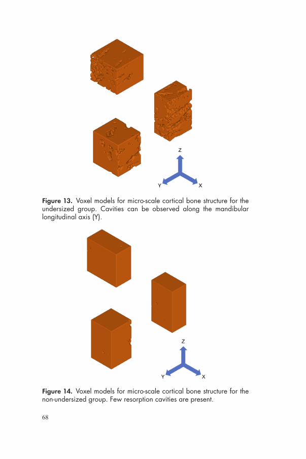
68
Figure 14. Voxel models for micro-scale cortical bone structure for the non-undersized group. Few resorption cavities are present.
Figure 13. Voxel models for micro-scale cortical bone structure for the undersized group. Cavities can be observed along the mandibular longitudinal axis (Y).

69
USA). The model (20×10×20 mm) consisted of 1mm cortical layer and trabecular bone. A 3.6×6 mm OsseoSpeed™ EV with abutment (Temp Abutment EV, Dentsply Sirona Implants, Mölndal, Sweden) was designed and positioned at bone crestal level. Moreover, a 1.5mm wide cortical bone volume from implant surface was selected as peri-implant cortical bone (Figure 15). X, Y and Z axes were set as shown in Table 4.
Table 4. Axis direction.
Axis Direction
X bucco-lingual
Y mandible longitudinal
Z implant longitudinal
Figure 15. Macro-scale CAD model of the mandibular ridge with implant and abutment. 1.5 mm wide peri-implant cortical bone was selected. A static load of 100 N with an inclination of 45° from bucco-lingual direction was impressed on top of the abutment (red arrow).

70
Homogenization and Localization analyses: Cortical bone material properties from previous study [239] were initially applied to the micro-scale models (Table 5). Then, elastic modulus (EM) and Poisson’s ratio (PR) for each model was calculated by the homogenization analysis (VOXELCON2015). EM and PR mean values and standard deviation were calculated and applied to the peri-implant cortical bone area in the macro-scale model. Cortical bone, trabecular bone and implant material parameters used in the localization analysis are shown in Table 5.
A static load of 100 N with an inclination of 45° from bucco-lingual direction was impressed on top of the abutment.
The maximal principal stress (MPStress) and maximum principal strain (MPStrain) distribution in the macro-scale model was assessed and maximum values were calculated.
The MPStress and MPStrain distribution in micro-scale models was obtained by localization analysis (VOXELCON2015). The calculation was achieved at the location in the macro-scale model where the maximum values of MPStress and MPStrain were observed and compared.
Values of shear stress and shear strain were calculated in the micro-scale models along XY, XZ, and YZ planes.
Table 5. Material properties used for the multi-scale analysis.
Material Elastic modulus (MPa) Poisson’s ratio Reference
Cortical bone 14,000 0.300 [239]
Trabecular bone 620 0.300 [239]
Fixture 105,000 0.360 [240]
StatisticsIn study I, Cohen’s Kappa coefficient for inter-rater agreement during the screening process was calculated. This value is obtained from the proportion of observed agreement (po) and the expected chance of agreement (pe), as follows:
𝜿𝜿 =𝒑𝒑𝒐𝒐 − 𝒑𝒑𝒆𝒆𝟏𝟏 − 𝒑𝒑𝒆𝒆

71
This value provides a robust esteem of the accordance between the reviewers, since it is adjusted considering the effect of chance [241]. The coefficient was to be interpreted in such way: >0.6 is substantial agreement, while >0.8 is almost perfect agreement. Systematic review findings were presented with no further statistical analyses, since the included articles presented large methodological differences; therefore, a direct comparison through a meta-analysis was not possible.
In study II and III outcome distributions were checked if they could be assumed as normal using the Kolmogorov–Smirnov test.
In study II, the implant was used as statistical unit. Discrete variables, such as implant diameter and length, bone quality, arch, implant position and drilling protocol were presented as frequency and percentage. Mean value, standard deviation, minimum, median, maximum and quartiles were calculated for continuous variables (age, healing time, ITV, MBL). ITV and MBL were set as outcome of interest. Comparisons were performed using one-way analysis of variance (ANOVA) test for normally distributed variables, whereas the Kruskal-Wallis test was used in case of non-normally distributed data. Multiple comparisons were checked with Bonferroni and Dunn/Bonferroni post hoc tests. Thereafter, the influence of independent variables on the outcomes was examined using multiple regression. This statistical method includes the constitution of complex models to study the relationship between those variables that resulted in affecting the outcome. Accordingly, the possible influence of the joined effect of two or more variables on the outcome was examined. Multiple regression models were built and analyzed using R 3.5.1 (R Foundation for Statistical Computing, Vienna, Austria).
In study III implant site was used as statistical unit. The following outcomes were compared between the groups at each healing period: RTQ, totBIC, newBIC, BV/TV, BAFO. The possible effect of the subject on the outcome was considered by carrying out paired difference tests. Based on the normality of data distribution, paired t test was applied to all variables but newBIC, which did not result normally distributed. Thus, Wilcoxon signed-rank test was used. The change of RTQ between two healing times was also checked with paired t test.

72
In study IV, EM and PR were compared based on group and axis with repeated measurement ANOVA with Bonferroni post-hoc pairwise comparisons. For micro-scale analysis, maximum values of MPStress and MPStrain were compared with repeated measurement ANOVA. Values of shear stress and shear strain were compared based on the group and plane using repeated measurement ANOVA with Bonferroni post-hoc pairwise comparison.
All analyses conducted in this thesis (Study II-IV) were performed setting the level of significance at p=0.05. With the exception of the multiple regression (study II), IBM SPSS Statistics for Mac, v. 22 was used.
Table 6. Outcomes studied in each study. ITV: insertion torque value, RTQ: removal torque, BIC: Bone-to-implant contact, BAFO: bone area fraction occupied, MBL: marginal bone loss, totBIC: total bone-to-implant contact, newBIC: newly formed bone-to-implant contact, BV/TV: bone volume fraction, EM: elastic modulus, PR: Poisson’s ratio, MPStress/strain: maximum principal stress/strain.
Study Outcome variable Type
ITV, RTQ Biomechanical
Study I BIC, BAFO Biologic
Survival rate, MBL Clinical
Study IIITV Biomechanical
MBL Clinical
Study IIIRTQ Biomechanical
totBIC, NewBIC, BAFO, BV/TV Biologic
Study IV EM, PR, MPStress/strain, shear stress/strain Biomechanical

73
RESULTS
Systematic reviewLiterature search: From the electronic and hand search, 1,655 titles were obtained. The two independent reviewers excluded 1,434 and 157 entries after screening titles (κ-score: 0.79) and abstracts (κ-score: 0.87), respectively. An additional hand search of the reference list provided four more related articles, which were included in the analysis. A total of 68 full-text articles were obtained and assessed following the inclusion/exclusion criteria. 29 articles fulfilled the inclusion/exclusion criteria and thus were included in the review, while 39 did not and were thus rejected. Full agreement was reached between the reviewers (Figure 16). Reasons for exclusion were: study on mini-implants (n=1), comparison between different
Figure 16. Flow chart illustrating the search process in study I.

74
implant designs (n=4), studies in which an undersized protocol was not performed (n=4), studies that used radio frequency analysis as a unique outcome (n=2), studies in which only one protocol was performed (n=3), studies in which bone condensing or another non-drilling protocol was used as a comparison (n=6), and studies in which different protocols were not grouped and compared (n=19). Selected articles, based on the objectives, were grouped as follows: 14 biomechanical, 7 biologic, 6 biologic and biomechanical, and 2 clinical. Based on the study design, 12 of these comprised in vitro studies, 15 in vivo, and 2 clinical studies.
Surgical protocol: Included studies compared an undersized drilling protocol (test) and one a non-undersized drilling protocol (control). At least two groups were compared. In most of the studies, the control treatment consisted of the standard sequence drilling protocol, suggested by the manufacturer. The undersized approach was typically achieved by skipping the final drill from the suggested protocol. The implant-drill discrepancy for the non-undersized drilling protocol ranged from –5% to 18%, while the implant-drill discrepancy for the undersized protocol ranged from 15% to 32%. One article stated that 50% implant-drill discrepancy was reached at the apex.
Biomechanical studies: The majority of the studies adopted an in vitro model, using synthetic or fresh animal cadaver bone. One study used a human cadaver ex vivo model [242]. Seven studies performed biomechanical analyses in an in vivo model, including goat, dog, and sheep models [243,244,93,245,246,61] All the selected studies used ITQ as a biomechanical outcome, with the exception of one study, which used only RTQ [245]. Several studies demonstrated that implants inserted with an undersized drilling approach reached significantly higher insertion torque than conventional drilling in low-density substrates [247,190,248,199,249-252,242,253]. Two studies compared different amounts of undersizing. One study found no differences between 21% and 34% undersized approaches into fresh trabecular bovine bone [253]. Another compared various drilling protocols, including 21% and 26% two undersized protocols, inserting implants of three different shapes in different substrates [252]. Regardless of the implant shape and substrate density, implants inserted with 26% undersized protocol reached significantly

75
higher insertion torque. Two studies investigated the effect of the cortical layer [248,251]. Undersized drilling had higher ITV with 0- or 1-mm-thick cortical layer. No difference was found for 2-mm thick cortical layer. Three studies did not find any difference on ITV between undersized and standard drilling protocol [254,163,61]. These in vivo studies were performed in highly corticalized bone (dog radius diaphysis, proximal tibia, and mandible respectively).
There is no clear evidence on the effect of undersized drilling in RTQ, since quite different results were found [247,243,93,252]. In vivo studies showed that RTQ values vary with time. There is a tendency of a steep decrease during the initial week for drilling, while a constant increase for non-undersized drilling protocol [93,245].
Biologic studies: Animal models included both trabecular (goat iliac crest [255,246], sheep iliac crest, [245]) and cortical bone (dog mandible [244,256,28], dog radius [257], dog proximal tibia [61], sheep mandible [93,258,163] and rabbit tibia [71]). No significant difference in BIC between groups was noted in the majority of the studies [216,244,257,245,246,61,28]. Three studies found significantly higher BIC for the undersized group [256,93,71], while only one article observed significantly lower BIC [255]. However, it must be noted that in two studies [93,71] the significant difference was found only in the shorter-term time point. One study obtained lower BAFO in the undersized group compared with the control group [245].
Descriptive histology displayed similar healing pathways. In the early phase of healing, Trisi et al. [93] observed an intimate contact between the native bone and the implant. Compression and distortion in the peri-implant bone occurs just after placement, with long cracks and microfractures in the coronal part of the cortex, and delamination of lamellar bone at the primary thread engagement area. Extensive bone necrotic areas between the first threads were detected by other authors [257,254,163,61]. The presence of bone particles was also distinguished [249,255,93]. Bone resorption activity was observed around cortical as well as trabecular bone. Remodeling cavities, with the presence of osteoclasts and osteoblasts and new bone apposition was a common finding [216,256,259,257,163,61]. Extensive integration into mature lamellar bone was revealed in studies that investigated long-term healing [216,258].

76
Clinical studies: Only two clinical studies fulfilled the inclusion/exclusion criteria, involving a total of 51 patients and 112 implants. A retrospective clinical study [260] evaluated the effect of undersized drilling preparation in the posterior maxilla compared to controls. Twenty-two patients and 60 implants were included. ITV was higher for the undersized compared to the non-undersized drilling. A prospective study [261] compared the 1-year survival rate and stability of 26 implants placed using the undersized technique in soft bone (posterior maxilla) with 26 implants placed using the standard technique in normal bone. Insertion torque was similar for both groups, and 100% of the 1-year survival rate was achieved.
No clinical data regarding marginal bone loss was found in the literature.
Clinical analysisIn study II, 87 patients and 188 implants were included in the retrospective analysis. Of patients 50.6% were males; the mean age was 60.8 ± 13.3 years. The average period between implant placement and mean permanent restoration was 144 ± 59 days. Implant diameter and length frequency distributions are showed in Table 7. Relative frequency of drilling protocol based on bone quality is displayed in Figure 17.
The mean ITV measured 30.8 ± 15.1 Ncm; significantly lower ITV was recorded in the maxilla (25.3 ± 12.9 Ncm) compared with the mandible (33.2 ± 15.5)(P = .001). Based on bone quality, ITV differed significantly among the groups (P < .001) (Table 8, Figure 18). Specifically, higher ITV was recorded in bone quality 1, as showed
Figure 17. Relative frequency of drilling protocol based on bone quality. Details on the drilling protocols are showed in Figure 9.
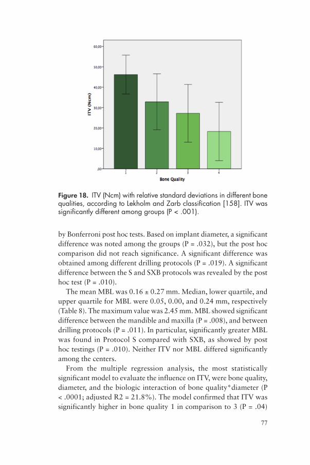
77
by Bonferroni post hoc tests. Based on implant diameter, a significant difference was noted among the groups (P = .032), but the post hoc comparison did not reach significance. A significant difference was obtained among different drilling protocols (P = .019). A significant difference between the S and SXB protocols was revealed by the post hoc test (P = .010).
The mean MBL was 0.16 ± 0.27 mm. Median, lower quartile, and upper quartile for MBL were 0.05, 0.00, and 0.24 mm, respectively (Table 8). The maximum value was 2.45 mm. MBL showed significant difference between the mandible and maxilla (P = .008), and between drilling protocols (P = .011). In particular, significantly greater MBL was found in Protocol S compared with SXB, as showed by post hoc testings (P = .010). Neither ITV nor MBL differed significantly among the centers.
From the multiple regression analysis, the most statistically significant model to evaluate the influence on ITV, were bone quality, diameter, and the biologic interaction of bone quality*diameter (P < .0001; adjusted R2 = 21.8%). The model confirmed that ITV was significantly higher in bone quality 1 in comparison to 3 (P = .04)
Figure 18. ITV (Ncm) with relative standard deviations in different bone qualities, according to Lekholm and Zarb classification [158]. ITV was significantly different among groups (P < .001).
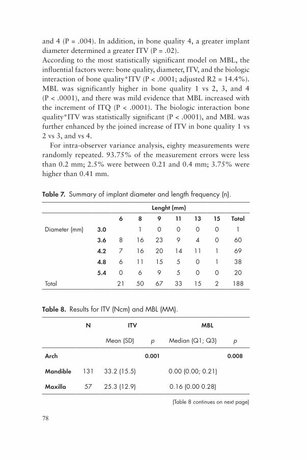
78
and 4 (P = .004). In addition, in bone quality 4, a greater implant diameter determined a greater ITV (P = .02). According to the most statistically significant model on MBL, the influential factors were: bone quality, diameter, ITV, and the biologic interaction of bone quality*ITV (P < .0001; adjusted R2 = 14.4%). MBL was significantly higher in bone quality 1 vs 2, 3, and 4 (P < .0001), and there was mild evidence that MBL increased with the increment of ITQ (P < .0001). The biologic interaction bone quality*ITV was statistically significant (P < .0001), and MBL was further enhanced by the joined increase of ITV in bone quality 1 vs 2 vs 3, and vs 4.
For intra-observer variance analysis, eighty measurements were randomly repeated. 93.75% of the measurement errors were less than 0.2 mm; 2.5% were between 0.21 and 0.4 mm; 3.75% were higher than 0.41 mm.
Table 7. Summary of implant diameter and length frequency (n).
Lenght (mm)
6 8 9 11 13 15 Total
Diameter (mm) 3.0 1 0 0 0 0 1
3.6 8 16 23 9 4 0 60
4.2 7 16 20 14 11 1 69
4.8 6 11 15 5 0 1 38
5.4 0 6 9 5 0 0 20
Total 21 50 67 33 15 2 188
Table 8. Results for ITV (Ncm) and MBL (MM).
N ITV MBL
Mean (SD) p Median (Q1; Q3) p
Arch 0.001 0.008
Mandible 131 33.2 (15.5) 0.00 (0.00; 0.21)
Maxilla 57 25.3 (12.9) 0.16 (0.00 0.28)
(Table 8 continues on next page)

79
N ITV MBL
Mean (SD) p Median (Q1; Q3) p
Bone Quality <.001 0.116
1 19 46.2 (9.5) 0.00 (0.00; 0.19)
2 93 32.8 (13.7) 0.00 (0.00; 0.21)
3 53 27.2 (14.2) 0.09 (0.00; 0.25)
4 23 18.3 (14.3) 0.16 (0.00; 0.44)
Diameter 0.032 0.519
3 1 40.6 0
3.6 61 29.2 (14.8) 0.00 (0.00; 0.18)
4.2 68 28.2 (15.7) 0.10 (0.00; 0.28)
4.8 38 34.3 (14.1) 0.07 (0.00; 0.23)
5.4 20 37.6 (14.3) 0.00 (0.00; 0.27)
Drilling protocol 0.019 0.11
S 55 25.4 (14.0) 0.15 (0.00; 0.31)
SA 22 29.5 (13.0) 0.00 (0.00; 0.18)
SB 38 33.7 (13.2) 0.13 (0.00; 0.24)
SX 8 35.2 (14.4) 0.16 (0.01; 0.25)
SXB 65 33.6 (16.9) 0.00 (0.00; 0.12)
Total 188 30.8 (15.2) 0.05 (0.00; 0.24)
(Table 8 cont.)

80
Biologic analysisDescriptive histology: overall histological healing scenario obtained in study III is depicted in figures 19. Undersized Group: at 5 weeks, numerous micro-cracks were observed departing from the implant surface (thread crest) in the context of the cortical layer, along lamellar direction. Several resorption cavities were spotted along micro-cracks. More cavities were likely to be found in the proximity of the implant; however, they could be observed even at great distance from the implant surface. Higher magnification (Figure 20a) revealed areas of necrotic bone in contact with the implant surface, especially in the most coronal portion of the implants. Observations of remodeling cavities showed multi-cellular structures, i.e. Basic Multicellular Unit (BMU). At 10 weeks bone remodeling cavities can still be observed.
Non-undersized Group: at 5 weeks, peri-implant bone presented fewer micro-cracks and cavities than the undersized group. Overall bone architecture seemed to maintain a preserved lamellar structure. At high magnification (Figure 20b) bone chamber structures were observed between micro-threads. Newly formed bone was observed along the osteotomy line and at implant surface. Cement lines between the secondary osteons under formation and native bone could be spotted.
Figure 19. Histological micrographs of the two groups obtained at 5 and 10 weeks. (A): Undersized Group at 5 weeks; (B): Undersized Group at 10 weeks; (C): Non-undersized Group at 5 weeks; (D): Non-undersized Group at 5 weeks. Scale bar 1,000 µm.
D

81
Histomorphometric analysis: No difference in totBIC was observed between Group A and Group B at both time‐points (Table 9). Non-undersized Group presented greater amount of newBIC at 5 weeks (p= .046), while no difference was present at 10 weeks (p= .893). Results of BAFO are shown in Figure 21. Higher BAFO value was observed in ROItot (p= .028) at 5 weeks
µCT analysis: Three-dimensional reconstructions of mineralized coronal cortical bone revealed the presence of elongated tunnel-like structures around the implant. Those structures are mainly directed along bone longitudinal direction (mesio-distal). The number and density of such cavities seem to be prominent in the undersized group
Figure 20. Histological micrographs at the interface (implant micro-threaded portion) obtained at 5 weeks. (A): Undersized group. Areas of necrotic bone can be spotted in contact with implant surface (white asterisk). Active bone resorption (red arrows) occurs at implant surface and along micro-cracks (yellow arrow). Scale bar, 100 µm. Original magnification 60×. (B): Non-undersized Group. New bone apposition appears along the osteotomy line (green arrow). Bone chamber structures are present between micro-threads (light blue asterisk). Cement line between the pristine and the newly formed bone is showed (black arrow). Active resorption can be spotted in the vicinity of the interface (red arrow). Scale bar, 100 µm.

82
Figure 21. Results of bone density (BV/TV) and Bone Area Fraction (BAFO) obtained at 5 and 10 weeks. Significant greater BV/TV was observed in Group B for VOI2, VOI3 and VOItot respectively. Results from BAFO analysis showed similar trend, however, significant difference was observed only in ROItot at 5 weeks. No differences in BV/TV and BAFO were noted at 10 weeks.
Table 9. Results from totBIC and newBIC obtained at 5 and 10 weeks in study III. SD: Standard Deviation.
Group Mean SD P value
totBIC
5 WeeksA 0.63 0.10 .157
B 0.51 0.16
10 WeeksA 0.61 0.09 .505
B 0.58 0.08
NewBIC
5 WeeksA 0.13 0.08 .046
B 0.32 0.08
10 WeeksA 0.09 0.06 .893
B 0.10 0.06

83
than control. Results obtained from micromorphometric analysis are shown in Figure 21. At 5 weeks, Group B presented higher BV/TV value at VOI2 (p= .012) and VOI3 (p= .004) and VOItot (p= .008). No differences were noted at 10 weeks.
Biomechanical analysisIn study III, ITV was measured until 80 Ncm, i.e. maximum ITV supplied by the implant unit. 87.5% (n=21) and 8.3% (n=2) of the test and control implants respectively exceeded such value before reaching the final position. Visible cracks within the cortical bone occurred during implant insertion. At 5 weeks, Group A had significantly higher RTQ values than Group B (paired t test, p= .047) and at 10 weeks no difference was obtained (paired t test, p= .907) (Figure 22). RTQ values increased significantly between week 5 and week 10 (paired t test, p= .033) in Group B.
RTQ tests revealed that Group A had significantly higher values than Group B (p= .047) at 5 weeks. No differences were found (p= .907) at 10 weeks. Removal torque value increased significantly between week 5 and week 10 (p= .033) in Group B.
Figure 22. Results of Removal Torque (RTQ) comparing Group A and Group B at 5 and 10 weeks. Results are displayed as mean (Ncm); error bar represents the standard deviation. Significantly higher RTQ value was observed in Group A at 5 weeks. No difference was noted at 10 weeks.

84
In silico analysisMaterial Properties: EM and PR values of peri-implant cortical bone were obtained by the homogenization analysis and are shown in Table 7. EM values differed based on the axis (p= .047), however, pairwise comparisons did not show a statistically significant difference in EM values among X, Y and Z axes. Thus, the Test Group showed anisotropic properties. A tendency of statistical difference was observed for PR values based on the axis (p= .056). On the other hand, the Control group showed isotropic characteristics, since similar EM and PR values were calculated. Based on group, statistically significant lower EM values were present for Test Group compared with Control Group for X (p< .001), Y (p< .001) and Z (p< .001) axis. Statistically significant lower PR value for X axis was observed in the Test Group (p= .002).
Table 10. Material properties of peri-implant cortical bone.
Axis Elastic modulus (MPa) Poisson’s ratio
Test Control Test Control
X 8,448 113,701 0.221 0.297
Y 9,089 13,690 0.274 0.298
Z 10,788 13,780 0.287 0.287
Multi-scale analysis: Results of the macro- and micro-scale analyses are showed in Table 11. At the macro-scale model, maximum values of MPStress were located at the buccal side of the bone-to-implant interface. A wider area of high MPStress values was observed in tests compared with controls (Figure 23a). Maximum values of MPStrains were located at the most coronal bone-to-implant interface, along the bone longitudinal axis (Figure 23b).
Table 11. Results of multi-scale analysis. For the micro scale analysis mean values (standard deviation) are showed.
Macro-scale analysis Micro-scale analysis
Test Control Test Control
MPStress (MPa) 0.84 0.46 38.3 (7.74) 5.92 (0.56)
MPStrain 11,260 5,075 4,509 (513) 726 (137)

85
In the micro-scale model, the difference between the two groups resulted in statistical significance for MPStress (p= .002) as well as MPStrain (p= .001). The localization of such values in each model was positioned around cavities (Figure 24). Shear stress and shear strain mean values along each plane are presented in Table 12. Regarding shear stress values, statistically significant greater values were observed for the tests compared with the controls along planes YZ (p= .004), ZX (p= .002) and XY (p= .001). In the same manner, for what concerning shear strain, statistically significant greater values were observed for test compared with control along planes YZ (p= .004), ZX (p= .002) and XY (p= .001). Shear stress and strain values differed based on the axis in Test groups (p= .027,). In Test group, shear stress and strain along YZ plane showed the greatest values.
Figure 23. MPStress (a) and MPStrain (b) distribution at the peri-implant cortical bone in the macro-scale model.Wider area of MPStress can be observed in the test group at the buccal side of bone-implant interface. Peak values of MPStrain were located in the most coronal part of bone-implant interface along the bone longitudinal axis. X: bucco-lingual axis, Y: mandible longitudinal axis; Z: implant longitudinal axis.

86
Table 12. Mean values (standard deviation) of Shear Stress and Shear Strain in the micro-scale model
Plane Shear Stress (MPa) Shear Strain
Test Control Test Control
YZ 11.20 (2.43) 0.93 (0.10) 2,080 (450) 173 (19)
ZX 7.43 (0.73) 1.89 (0.83) 1,379 (136) 350 (154)
XY 1.07 (0.09) 0.09 (0.14) 198 (17) 18 (26)
Figure 24. MPStress (a) and MPStrain (b) distribution in micro-scale model section. The location of the maximum value of MPStress/MPStrain is facing the cavity. More heterogeneous stress/strain distribution can be observed in test compared to control.
X: bucco-lingual axis, Y: mandible longitudinal axis; Z: implant longitudinal axis.

87
Figure 25. Histograms representing mean values of maximum shear stress (a) and shear strain (b) along each plane. Bars represent standard deviation.
X: bucco-lingual axis, Y: mandible longitudinal axis; Z: implant longitudinal axis.
88
DISCUSSION
Undersized drilling in trabecular bone The underpreparation of the implant site is commonly performed to increase implant primary stability. Thus, it is a common opinion among clinicians that undersized drilling has to be performed whenever an enhanced level of ITV is necessary [164]. In general, undersized drilling has been proposed to increase the cutting torque resistance in the upper jaw [202].
Early studies reported that the failure rate was approximately 10% higher in the maxilla than in the mandible [262,263,2]. Accordingly, bone with low-density was considered as “poor quality bone” [158]. The modest primary stability and the limited biologic response of minimally rough surface implants were the reasons of such higher rate of failures [264]. As showed by Lindhe et al. in a histologic study on human edentulous areas [265], bone composition presents large differences between the maxilla and the mandible. The mandible presents a thicker cortical layer, greater amount of lamellar bone rate and osteoid tissue, while the maxilla has significantly higher rates of woven bone, fibrous tissue and bone marrow. Nowadays, evidence on long-term implant survival suggests that implant location is not a determinant factor on the success rate [7]. This means that implant outcome has improved especially in what used to be challenging conditions, such as the posterior maxilla. Due to the different innovations on implant macro- and micro-features the outcome in trabecular bone has dramatically improved. Current implants are provided with more aggressive design, which increase primary stability, and with modified surfaces, which increase secondary stability. In fact, the loose internal macro-architecture of

89
the so-called “poor” bone is rich of vascular structures necessary to recruit osteogenic cells. A beneficial bone response is therefore expected when tissues are in contact with modified surfaces [230].
Another relevant contribution to higher survival rates has been due to the modifications of the surgical procedure. In particular, focus has been on producing enlarged contacts between implant and bone [266]. A common approach is to adapt the size of the osteotomy to the bone quality, based on the surgical perception during the initial phases of drilling [267]. Usually, the surgeon skips the final steps of the drilling sequence. Generally, the softer the bone, the narrower is the osteotomy. Another approach was to reduce the length of the osteotomy, or to fully enlarge only the coronal part, in order to achieve an underpreparation both in width and height [268,269]. Alternatively, similar osteotomy is reached with stepped drills. Recently, new implant systems were developed with surgical drilling protocols specifically designed for different bone qualities, such as the one used in this research project.
From the evidence collected in the systematic review (study I), it was clear that an undersized approach is effective in enhancing insertion torque in low-density bone. In this type of host bed, undersized techniques provoke intense modification of peri-implant bone anatomy: the cavity diameter increases when inserting the implant due to cutting and compressing the bone walls. This will result in an increased initial contact between the trabecular bone and the implant [190,270]. A static strain is therefore created, contributing to stabilize the implant during the initial phases of healing [16]. The morphological changes as an effect of bone condensation are explained by reduced trabecular separation, increased relative bone volume, and increased trabecular number in peri-implant bone within 1 mm from the site of preparation [271]. Results from in vivo studies suggest that the induced modification of peri-implant bone micro-architecture remains so with time [246], and so the implant fixation [190,243]. Implants placed with an undersized technique is the reason for a greater amount of translocated bone particles as well that are translocated between the threads, in the apical part of the osteotomy and pushed into the trabecular void spaces [190,249] (Figure 26). The presence of these bone chips may be beneficial to the initiation of bone deposition and they may play a role in de

90
novo bone formation between the pristine and the new bone on the implant surface [272]. Some studies have investigated how bone particles may have osteogenic potential, since they were characterized by viable osteoblasts and osteocytes embedded into an extracellular matrix [255]. If bone debris remains retained to the implant surface, a stronger bone response was observed, compared with implants in which the bone fragments were removed prior to insertion [273]. However, the role of the translocated bone particles might be limited to the initial healing phases only [249].
Underpreparation of low-density bone may achieve an improved biologic response compared with standard drilling in the long-term healing [256]. Nevertheless, one study pointed out that excessive undersizing might give a negative biologic response [259]. This study was performed in the goat iliac crest, which is composed of loose trabecular bone deprived of a cortical layer. According to their findings on early healing time, lower BIC and more micro-fractures were observed in 25% undersized compared with 15% and 5% undersized techniques, i.e. standard drilling. It was speculated that the excessive amount of undersizing had provoked relevant damage to the original micro-architecture of the bone along the implant interface, thereby impairing the early trabecular healing.
Figure 26. When an implant provided with cutting features is inserted into an undersized site generates bone particles that are translocated in the apical area. Figure from Shalabi et al. [190].

91
The systematic review highlighted how clinical evidence was extremely sparse on the topic of undersizing. Several clinical studies reported the importance of this technique to achieve favorable results in terms of implant success in low-density maxillary bone [274,161,204,275-281]. However, those trials refer to undersize drilling as a procedure in general, while they often fail to report the exact reduction in diameter for the final osteotomy. Moreover, a comparison between standard and undersized osteotomy was considered in two studies only [260,261]. In both of these studies the undersized drilling was applied in low-density bone with good survival rates. However, the number of implants considered was too few to allow for a statistical comparison.
In study II, surgeons adapted the osteotomy dimension according to the bone quality perception. The drilling protocol was specifically designed to avoid excessive bone compression and at the same time provide adequate primary stability [282]. Undersized osteotomy was performed in 78% of the implants placed in bone quality 4 and 38% in bone quality 3. Despite the adoption of such techniques, ITV was significantly lower in bone quality 4 than in bone quality 1 and 2. Thus the effect of the bone quality is prevalent for predicting the ITV. However, since insufficient data was available for low-density bone, definitive conclusions are not given.
Undersized drilling in cortical bone Biomechanical aspects When implants are inserted in an undersized site of cortical bone, a great rotational friction, i.e. ITV has to be expected. This means that an elevated static strain is generated in the peri-implant tissues. Differently from cancellous bone, the compression is not dissipated by the porous trabecular structures. On the contrary, the entire static strain is propagated in the surrounding bone. When a considerable discrepancy between the implant diameter and the osteotomy site is created, strains are expected to be beyond the elastic limit, thus in the range of plastic deformations.
The strain experimentally created in the coronal portion of undersized implants (study III) was 0.09, which is far beyond the ultimate strain of cortical bone (0.02 [283]), while virtually no strain was created in the non-undersized group. The portion of bone, that

92
was undersized, was compressed by the implant microthreaded area. A previous FEA investigated the press-fit phenomena of the insertion of an implant with a design similar to the one used in the present thesis [284]. It was affirmed that the micro-thread portion, due to its confirmation and greater average diameter, induced more relevant strains compared to the situation without microthreads. It was quite clear that implants in the undersized group reached higher ITV than control, even if a quantification of such values were not possible. The excessive strain created by installing the implants, resulted in visible macro-cracks along the longitudinal direction of the bone (Figure 27). Due to the plastic deformation of the cortical layer, micro-damage would partially dissipate the energy produced during the installation [285]. Actually, numerous microcracks, organized in a network, have the capacity of absorbing stresses and reducing the length of major crack propagation [286,105]. Therefore, performing undepreparation in dense bone will increase ITV, but it may not be as effective as in soft bone. Moreover, it was observed that its effectiveness is reduced, as the cortical layer is thicker [248].Nevertheless, the initial strain appeared to be maintained through the initial phases of the healing time. The stresses created in Group A can be only partially dissipated with the generation of bone diffuse damage [287,285]. Residual compression was still present in the bone
Figure 27. Overview of the surgical field after implant installation in study III. Macro-cracks of the cortical bone can be observed along the longitudinal direction of the mandible.

93
at 5 weeks, as higher RTQ values observed in the undersized group. Interestingly, test implants were equalized by the control group at 10 weeks of healing. This finding suggests that all the pre-stressed bone, which conferred initial stability to the undersized group, had disappeared and was possibly replaced; as a matter of fact, when the resorption occurs at the bone‐to‐implant interface, the stability is expected to decrease. Moreover, these findings indicate that the that secondary stability would increase gradually in the non-undersized group, as a significant increase of value was observed comparing 5 and 10 weeks of healing, due to the maturation of the newly‐formed bone.
Biologic aspectsFrom the biologic point of view, different drilling techniques had a significant impact on the interfacial cellular reactions and on the circumferential peri-implant bone tissue. The presence of an area of empty ostecyte lacunae could be due to several factors: overheating during drilling procedures or implant insertion, interruption of the bone vascularity during drilling, hypoxia due to compression during implant placement, cell apoptosis induced by microdamage and even sectioning artifacts [288].
The relevant qualitative difference observed in the histology between the two groups cannot be explained by the surgical trauma per se. Both groups received the same kind and amount of insult in the drilling preparation. Moreover, possible bias on the site location is low, since test and control sites were randomized in each hemi-mandible. A more probable cause of primary tissue damage is the implant insertion.
During the installment into an osteotomy site, energy is supplied to the bone. Part of it is transferred as heat, the magnitude of which depends on the torque and the number of revolutions [289]. According to thermodynamics, thermal energy is partially absorbed and conducted by the implant itself, and by the bone, in the form of an increase of temperature. If the rotational friction, i.e. ITV, increases, it is reasonable to think that the temperature will rise consequently. Thus, it is more likely that thermal damage is caused by undersized drilling than a situation in which the implant is inserted with a reduced friction.

94
Both scenarios, i.e. thermal insult and microdamage, may be involved during implant insertion into an underprepared site. Both of them can resemble the so-called compression necrosis concept. However, from the current evidence and from the present findings, it is not possible to state which is the predominant process involved. More research is needed in order to further investigate the mechanism beneath this notion.
Despite the large areas of necrotic bone, the osseointegration process was not compromised by undersized preparation procedure after 10 weeks of healing. The amount of total BIC did not differ between undersized and non‐undersized groups both at 5 and 10 weeks. However, there was a qualitative difference between the two groups. The control group showed vital newly-formed woven bone in contact with the implant surface in large parts, as attested by the greater value of newBIC at 5 weeks. The newly formed bone took place from the time of implant placement in the void spaces created between the threads and the osteotomy walls, also called bone chambers [85,15] (Figure 28). This tissue developed into lamellar bone, as revealed by histologic observation at 10 weeks. Hence, the healing pattern following non-undersized osteotomy presented the characteristics of the intra-membranous like type of healing [290,89]. On the contrary, it was evident that damaged and necrotic bone tissue was in contact with implant surfaces in undersized sites demonstrated at 5 weeks of healing. This tissue was then removed by a vast process of targeted remodeling, as indicated by the presence of osteoclasts and osteoblasts. As a consequence, only limited areas of dead bone were observed at 10 weeks. This type of healing, which is time consuming, was described previously as interfacial remodeling [254,290].
It can be hypothesized that the great amount of compression to the cortical bone can be involved in the process of marginal bone resorption. Cortical bone has less blood supply than trabecular bone. This may influence the cell metabolism and consequently bone repair may be reduced in cortical bone [117]. The accumulation of micro-damage and osteocyte apoptosis might modulate a remodeling signal towards a catabolic instead of an osteogenic response [291]. Moreover, the addition of the functional load would expose the crestal bone with further stimuli for resorption. It has been stated that this area is mechanically sensitive and being exposed to high strain levels [292,117].

95
Intracortical bone remodeling around undersized implant sitesOne of the major findings of study III was the determination of the remodeling spaces around implants placed with different osteotomies. With the remodeling process, bone is able to remove the accumulated microdamage and necrotic tissue by the targeted action of the osteoclast population, involving osteoclast activation and bone resorption [103]. Steering in the direction of the insult [114], BMUs are responsible of tissue renovation, by a conjunct action of old bone degradation and new bone formation activities. Osteoclastic activity is expected in the peri-implant bone after implant insertion and the remodeling endures for several weeks (Figure 29). The presence of BMUs in the proximity of the implant surface is a common finding in several histological studies [293,256,163]. According to early research, implant insertion induced an increased local remodeling activity at the implant interface and supporting bone [294]. After
Figure 28. Bone chamber structures were firstly described by Berglundh et al. [90] in which an implant system similar to the one used in study II, III and IV was investigated. Bone chambers structures are formed at the bone implant interface when void spaces are created along the wall of the osteotomy. 3.5 mm implants were inserted into a 3.3 mm osteotomy, so that the implant-drill discrepancy was 0.15 mm. Figure from Berglundh et al. [90].

96
a period of time -which was approximated to 1 year in humans- the remodeling activity returns to normal levels [295]. However, sustained remodeling during the implant functioning period is related to the mechanical stress distribution at the interface [296].
In study III, a large presence of BMUs indicated that an intense remodeling process was ongoing around implants of the undersized group at 5 weeks. It is stated that the turnover rate during bone remodeling is associated with the number of BMUs [296]. In the early healing phases the bone remodeling balance activity changes towards a decrease of mineralized tissue, by anabolic bone resorption. With time, this means a decrease of primary stability with time (stability dip)
Figure 29. A representation of the cortical bone targeted remodeling after the insertion of an implant in the early phases of healing. A layer of necrotic bone tissue is present at the implant interface. BMUs are moving towards the direction of micro-cracks generated during implant insertion. Osteoclasts are depicted in green, osteoblasts in light blue.

97
because of the removal of the dead bone initially in contact with the implant. As a matter of fact, BMUs excavate a canal into the cortical layer, which is subsequently filled by osteoblast action of new bone apposition (Figure 30). Cutting cones follow previous Haversian canals in cortical repair, i.e. they grow mainly in a linear direction [111,66]. This osteonal tunneling generates a temporary porosity, known as remodeling space, which has been usually described in bi-dimensional representations [235]. The remodeling porosity was more commonly observed in the area of non-vital bone in the proximity of the implant and in the subperiosteal region, due to the mucoperiostal flap elevation [297]. These structures deviate to their usual course and progress perpendicular to the implant interface [298].
In study III the remodeling space was elaborated in 3D representations from the µCT images, by selecting a threshold for non-mineralized bone (Figure 31). We can presume that these tunnels are filled by BMUs, provided by large vascular compartments [293], following the principal stress direction with deviations due to micro-damage [114]. From these figures it is possible to observe that the network of tunnels are developed mainly along the longitudinal
Figure 30. Group A, 5 weeks. Basic Multicellular Unit (BMU) in the proximity of implant surface. Resorption is promoted by osteoclasts (red arrows), while osteoid tissue (black arrow) is deposited by osteoblasts. Cement line (black arrow) can be spotted between the new bone and the old damaged tissue. Scale bar, 100 µm.

98
direction, supposedly due to the micro-cracks trajectory of lamellae separation [101,299]. This plane, perpendicular to the implant axis, runs accordingly to stress lines of force [300]. This finding is related to the type of specimen considered. It is reasonable to think that the tunneling direction might lie in different planes according to the trajectories of force of the anatomical region [301]. Thus, a different scenario may exist in the maxilla, in which the stress lines are vertically oriented [302].
The two‐dimensional and three‐dimensional quantification of mineralized spaces in the peri-implant bone were evaluated through the BAFO and BV/TV analyses respectively. Overall lower bone values for the undersized compared to the control group were calculated in the space from implant surface up to 1.5 mm (ROItot and VOItot) at 5 weeks. This means that undersized drilling caused a higher amount of bone resorption cavities in the peri-implant bone. When analyzing the sub-volumes according to the distance to the implant, it was observed that even the most distant volume (VOI3) was influenced
Figure 31. Three‐dimensional reconstruction of bone remodeling spaces surrounding an undersized site. Elongated tunnels which are directed in longitudinal direction of the bone and perpendicular to the implant major axis are the result of the combined action of cracks and remodeling process. The image was obtained with CTAn software (Bruker, Kontich, Belgium).

99
by the drilling protocol. The evaluation of the presence of cavities beyond 1.5 mm was not possible due to the dimensional limitation of the samples. In the inner area, the one closest to the implant (0 to 0.5 mm), the bone ratio resulted to be similar between group A and B (VOI1 and ROI1). Supposedly this part of the bone is the one most influenced by surgical trauma itself, irrespective of the drilling protocols. Interestingly, this intense area of remodeling resemble the early observations by Roberts et al. [294], in which the BMUs were described in the proximity of implant surfaces, and occasionally they deviated in the plane perpendicular to the implant axis, exactly as demonstrated in the three dimensional reconstructions of the study III (Figure 32). In the healing period of 10 weeks, no further differences were noted. This result is not surprising, as the remodeling process was almost completed in both groups. The active remodeling cycle time in sheep has been demonstrated to be approximately 12 weeks [235].
The influence of intra-cortical remodeling spaces on material propertiesAccording to early loading protocol, the implant is connected to a prosthesis days or weeks after the insertion, before the conventional 3/6 months of healing [31]. It was stated that a pre-requisite for early loading is achieving high level of ITV [29] and for this aim the underpreparation of the implant site was suggested [304,305]. This means that a provisional prosthesis is inserted prior to the completed interfacial bone formation [303,306].
In study IV an early loading of an implant inserted into an undersized site scenario was simulated with a multi-scale in silico analysis. Due to this approach, it was possible to calculate how stresses and strains are distributed in the surrounding bone when a load is introduced [307]. A mechanical theoretic insight of cortical bone is therefore of utmost importance to understand common marginal bone behavior [308,309]. In a majority of the previous FEAs in implant research, cortical bone was assumed to be a homogeneous layer with isotropic material properties. From findings of study III it is clear that this structure may be, in fact, more complex and it is subjected to adaptations throughout the healing phase and the functioning period [310-312].

100
Thanks to the multi-scale analysis, two µCT-based models of cortical bone micro-architecture in the early healing phase were introduced: data were taken from undersized and from non-undersized sites of study III. The micro-scale analysis revealed that intracortical porous structure conferred anisotropic properties to the peri-implant cortical layer. The main orientation of the tunnels had an impact on the EM and PR, which differed significantly based on the axis, showing the smallest value for the bucco-lingual direction. Comparing the material properties in the two groups, it can be said that the presence of cavities weakened cortical bone strength.
Once the material properties were calculated, the macro-scale analysis identified the locations of higher stress and strain concentrations. According to the majority of the previous studies,
Figure 32. An artistic interpretation of the remodeling process after a 4-month healing period in human cortical bone around a screw-shaped implant. Active BMUs are responsible for the turnover of the necrotic bone at the interface. In this manner secondary osteons are generated, mainly along the direction perpendicular to the implant major axis. It is notable how this artistic rendition is similar to the three-dimensional reconstruction obtained with the µCT analysis. Figure from Roberts et al. [303].
101
maximal values of MPStress were developed at the implant neck area in both undersized and non-undersized groups. Due to the distinctive location, stress and strain concentration in this area was indicated as a mechanism of marginal bone resorption [308,313]. The undersized group presented greater maximal values of MPStresses and MPStrains compared to the non-undersized group. Moreover a larger area was exposed to high values in the former group, involving the entire cortical layer at the buccal side. The location of maximal value MPStress, which is a tensile stress, was alongside the bucco-lingual axis. Differently, the maximum value of MPStrain was located in the mesio-distal axis, showing that a higher magnitude of deformation is expected in the mesial and distal sides of the marginal bone. From these findings it is suggested that the most superficial region of the cortical layer on the buccal side might be more subjected to resorption than other sides. Furthermore, greater shear stress and strain were observed in the plane along the longitudinal direction and parallel to the implant long axis. It is known that bone is more susceptible to shear strength than compressive and tensile strength [314]. The analysis of the micro-scale models revealed a highly irregular stress and strain pattern for the undersized group. The cortical bone portion facing the cavities was the most solicited by stress and strain concentration. Thin bone belts between two nearby cavities were the locations of greater values. On the contrary, relatively low levels of stress and strain were present in thicker bone areas, far from the resorption cavities.
The interpretation of these findings suggests that the introduction of loading on cortical bone during the remodeling phase might be detrimental to the healing phase itself. The fatigue and consequent micro-damage that is expected to occur in the bone adjacent to the cavities would act as a further stimulus for the continuation of bone remodeling. In fact, a revision of the Wolff’s law hypothesized that bone remodeling is controlled by an inhibitory signal triggered by mechanical stimuli, such as load [66]. According to this theory, the remodeling process is restrained when load lies in the physiologic threshold. On the contrary, remodeling is increased when load is extremely low or excessively high, due to tissue damage. A similar scenario was postulated by a FEA on load distribution within a single bone trabecula [315]. The study reported that localized high stress registered in the pit of the cavities might promote a continuation

102
of the resorbing activity beyond the original damaged bone. Since greater values for MPStresses and MPStrains were observed both at the micro- and macro-levels, it can be hypothesized that the undersized group would react with a further increase of osteoclastic activity after the introduction of the load, compared with the non-undersized group. According to stress and strain distributions, remodeling cavities are expected to locally spread along the longitudinal direction. As stated before, the process involving the resorption of damaged tissue, followed by new bone apposition is time-consuming [85,160]. Therefore, an additional resorption phase, in a remodeling bone would delay the healing process and possibly disturb the bone-to implant interface.
Study IV, to conclude, showed that the appearance of remodeling bone structure might not be an optimal healing phase for the introduction of load. On the contrary, postponing loads until the completion of the remodeling process with a reduction of the intra-cortical cavities, might be a safer procedure. Therefore it was demonstrated that, from a theoretical point of view, undersized drilling would prolong the healing time in cortical bone, rather than reduce it.
Clinical significance and a new definition of undersized drillingFrom a clinical standpoint, performing undersized drilling, in high density cortical bone may seem contradictory. Even more so, one can argue that investigating the effects of undersized drilling is of little clinical importance. However, in reality undersized drilling may be quite important for cortical bone healing, even if this technique was originally intended only for low-density bone. According to some current trends on immediate loading, it has been suggested to undersize even in the anterior portion of the lower jaw [206,207] (Figure 33). It is acknowledged that early implant failure is now a rare event compared with the early days of implant dentistry. Nevertheless, poor surgical treatment was pointed as one factor disturbing the stability of osseointegration, triggering marginal bone resorption and eventually the breakdown of bone-to-implant contact [84]. This thesis considers the influence of a less investigated topic as a possible cause of primary clinical failure, namely the excessive compression following an

103
undersized preparation. Based on the findings of the present thesis, the application of underpreparation in highly corticalized bone would present several drawbacks: creation of micro-damage with osteocytes apoptosis, low rate of new bone formation at implant interface, activation of a large remodeling process (study III) that weakens material properties and possibly delay the healing process (study IV). Even though high ITV is expected in dense bone (study II), the introduction of undersizing would not be as effective as in other types of bone (study I); moreover the high ITV would lead to a negative biologic response in terms of early marginal bone loss (study II).
There are clinical situations in which the preservation of the crestal bone is crucial, such as sinus floor elevation and simultaneous implant placement. In these cases, where the highly corticalized residual bone can be less than 4 mm high [316], undersized osteotomy is necessary in most cases [317]. The success of such therapy is therefore strictly associated with the cortical bone reaction, and so, according to the present results, excessive compression should be avoided. An early bone resorption or a cortical fracture before the onset of osseointegration, would lead to implant failure [318]. If the buccal plate is extremely thin, it will easily present cracks. After a vast osteoclastic resorption, the structural support for osteoblasts would be too weak and arguably a buccal bone loss would follow [319]. In study III undersized drilling was performed in a controlled setting,
Figure 33. Undersized drilling technique is not only a prerogative of the upper jaw. There are several treatment protocols for immediate loading which recommend the preparation of an undersized site even in the anterior mandible. In the pictures an example of a protocol for the immediate loading of a mandibular fixed prostheses supported by two implants. Note the implant-drill discrepancy. Figure modified from Cannizzaro et al. [207].

104
with an extra-oral approach. One can postulate that additional potential negative factors could interfere with the remodeling process. As previously stated, under-preparation is performed in many cases of immediate loading protocols. The exposition to the oral environment, inflammation and masticatory loads could adversely affect the delicate remodeling tissues. In a recent study by Stavropoulos [320], it was observed that immediate loaded implants inserted with an undersized procedure showed lower BIC compared with those installed with standard drilling protocol. Furthermore, excessive marginal bone loss and crater formation were observed in some of the immediately loaded undersized implants. Inflammatory infiltration was further found around the implant neck.
Therefore the application of an optimal drilling protocol, providing the necessary primary stability without provoking excessive damage, is crucial in such cases. In clinical reality, instrumentation is usually based on empirical grounds. The discriminant factor on the selection of the last drill size is the bone quality, which is subjectively evaluated by the surgeon. However, osteotomy size and implant diameter are not sufficient to predict the biomechanical and biologic effects. The clinician should be fully aware of which portion of the implant is going to initially impact the pristine bone: this could be in the cutting part or in the non-self-tapping portion. In the latter case, a pure compression will be achieved if tapping is not previously performed. On the other hand, even a self-tapping implant could encounter a limit: if the removed bone volume is excessive, the cutting flutes are entirely occupied by bone debris. This would be the case of excessive amounts of under-preparation and/or in case of high-density bone. Therefore, the surgeon should consider that drilling protocol, implant design and bone quality are strictly related factors. Thus, the selection of the appropriate implant design and drilling sequence is recommended based on a pre-surgical assessment.
Study I has highlighted that clinical evidence on under-preparation is sparse and inconsistent in the description of the relationship of the drill sequence and the implant design. In several cases, the amount of implant-drill discrepancy is not clear, and consequently the amount of undersizing. In order to facilitate future research on this topic, a novel definition is hereby suggested: an undersized osteotomy is achieved when the walls of the osteotomy are compressed by the implant

105
inner diameter. This process may occur along the entire length of the implant or only in some of its parts, such as coronally or apically.
Clinical considerations on the Insertion TorqueIt is indisputable that the most common parameter to clinically assess the implant primary stability is ITV. Study II focused on the outcome of ITV and revealed that bone quality is the predominant factor, regardless of the drilling protocol. A robust model, from the multiple regression analysis, revealed that ITV was significantly dependent on bone type and diameter, among other matters. Although the surgeons adapt the drilling protocol based on the perception of bone quality, in order to achieve similar ITVs in all bone types, higher values were shown in bone quality class 1 vs 3 and 4. These findings, in accordance with previous studies, indicate that bone quality is a critical factor affecting ITV, more than the drilling protocol [321,322,268].
The influence of ITV on the stability of marginal bone is another aspect of clinical relevance. In study II, the multiple regression analysis revealed that ITV was regarded as one of the most influential factors on MBL. Greater resorption is predictable in bone quality 1 compared with bone qualities 2, 3, and 4. Moreover, MBL is more significantly increased by the biologic interaction between bone quality 1 and an increase of ITV. Hence, a clinical recommendation to implant surgeons would be to minimize ITV in the dense bone. The use of taps and/or countersinking for the cortical bone before implant insertion can be suggested for reducing the local pressure [323,173,324,270].
Other recent studies investigated the relationship between ITV and MBL. Khayat et al. [26] assessed the clinical outcome of implants placed with high ITVs. A total of 42 implants were installed with ITV>70 Ncm, with an average value of 110.6 Ncm (range = 70.8–176 Ncm). As comparison, the control group was composed by 9 implants placed with ITVs between 30 and 50 Ncm. After a healing period of 2 to 3 months, MBL was assessed at the time of prosthetic delivery and 1 year after loading. No difference related to MBL was observed in the two groups. The author did not find any correlation between ITV and MBL. However, an increase of MBL could be observed at 1-year follow up: from 0,72 mm to 1,24 mm. In a more recent RCT, implants with high ITV (>50 Ncm) were compared to regular ITV

106
(<50 Ncm) after 1 year [325] and 3 years [326]. It was found that MBL at both follow-up visits was greater for high ITV groups in the mandible. The authors concluded that implants placed with higher ITV in the mandible lead to greater bone loss and mucosal recession, compared with implants installed with regular ITV.
Another study by Maló et al. [327] retrospectively assessed the success rate and MBL in immediately loaded full-arch rehabilitations in the maxilla. Implants were grouped according to their ITV, and 30 Ncm was the discriminant value. The authors observed that implants inserted with <30 Ncm had significantly lower MBL at 1-year (p< .001) compared with implants inserted with >30 Ncm (1.14 and 1.39 mm respectively). The success rates, however, were comparable.
Being aware of the limits in comparing those clinical trials (limited sample size different types of implants, different healing times, different rehabilitation, …), we could postulate that there is a suggestion indicating that excessive ITV might lead to greater MBL. This finding is likely to be more evident after the prosthetic loading. It can be hypothesized that at the baseline, which was commonly 2 to 3 months from implant insertion, the remodeling could have been still ongoing. As demonstrated by study IV, the application of the prosthetic load might generate great stress and strain to the marginal bone that could cause resorption.
ITV implies a critical pressure to the bone, however the potential effects of marginal bone resorption might not always be always related by its absolute value. As previously stated, ITV is strictly dependent on implant geometry, and the same mere value could generate different pressure, based on the implant diameter [42]. It can be suggested to recognize the importance of the local compression. ITV is a useful parameter for the clinician when assessing both the primary fixation and the possible local damage with respect of the osteotomy and the bone quality.
To conclude, the final aim of the surgeon should not be reaching high ITV, but aiming for a good primary stability with an osteotomy that should be designed respecting the rate of cortical and trabecular bone. Based on the implant design, the osteotomy should provide the initial interlocking from the trabecular bone, while there should be a more delicate contact with the cortical layer.

107
Limitations of the studiesThe studies included in this thesis presented some limitations. In study I, data from selected articles could not be directly compared, due to the large methodological differences between the studies. Thus, a meta-analysis was not performed. Moreover, a study selection based on methodological quality assessment was not possible because of the scarcity of trials. Implant-drill discrepancy was calculated and used as a parameter to compare different groups. Even if this percentage value could help the reader to have an idea of the discrepancy created, it is acknowledged that such factor presents some weaknesses. The dimensions of the outer implant diameter and last drill size do not provide enough information to estimate the magnitude of underpreparation. For more accurate information, a multitude of implant and osteotomy feature would be required, such as the implant inner and outer geometry, thread geometry, implant cutting feature, osteotomy geometry and so on. Unfortunately, such information is seldom provided in the literature and is not often provided even by implant manufacturers.
The clinical analysis of study II evaluated the early outcome of implants placed with a drilling protocol based on bone quality. Such assessments were achieved by using the Lekholm and Zarb classification [158]. It is admitted that this classification is based on subjective assessment, which could vary based on personal tactile sensitivity and experience. Several different methods for clinical assessment of jawbone quality were proposed over the years [156]. However, it was observed that the Lekholm and Zarb classification is capable of determining the bone mineral density and microarchitecture [328,157,329], in addition being the method most used in the literature and clinical practice. Another limitation of the clinical study is that a retrospective design was adopted. Thus, a large number of variables were introduced. In order to limit possible confounding factors, strict inclusion/exclusion criteria were applied for case selection. Moreover, the possible influence of the prosthetic construction was excluded by considering radiographic data just before rehabilitation delivery. Even though study II presented data on the association between undersized drilling and marginal bone resorption for the first time, these findings are preliminary and have

108
to be confirmed in future prospective controlled trials. Data on longer term healing is also lacking in the current literature.
In study III implants were inserted in an extra-oral bone ridge for the easy access of highly corticalized bone. This setting excludes potentially negative factors, which are present in the mouth, such as microbial contamination, wound dehiscence, masticatory function and so on. The possible association of clinically relevant scenarios with underpreparation was therefore prevented. A methodological drawback in the µCT analysis was that implants were removed before scanning, in order to avoid possible scattering and noise phenomena [330]. This could have generated additional bone damage, thus creating artifacts. Nevertheless, this procedure seemed not to affect the results, as previously reported [293,331]. As a confirmation, similar trends were noted between µCT analysis, i.e. BV/TV, and histological analyses, i.e BAFO, where implants were not removed.
Study IV introduced for the first time a multi-scale analysis of peri-implant bone architecture. However, in order to run the simulation, a number of limitations appeared. The cortical and trabecular bone were assumed to be fully in contact with the implant. However, this condition is seldom reported and it may represent an oversimplification of the clinical reality [332]. Another limitation in the analysis was that residual strain could endure in the peri-implant bone even several weeks after implant insertion, due to press-fit phaenomena [284,50,16,195]. However this aspect was not considered in the model.
When interpreting the results of this thesis, one should keep in mind that Study II, Study III and Study IV used the same type of implant (OsseoSpeed™ EV, Astra Tech Implant System, DentsplySirona Implants, Mölndal, Sweden). This system was chosen among others due to the high flexibility in the surgical procedures. This feature allowed focusing on the effects of the drilling protocol. However the conclusions of this thesis should be interpreted carefully. The effects obtained in this study may be quite different if another implant system is used. More than describing the influence of a single combination of drill and implant design, this thesis has explored the effects obtained whenever an excessive circumferential compression is dispensed to the cortical layer. Thus future studies should confirm the present findings using different implant systems.

109
CONCLUSIONS AND FUTURE PERSPECTIVES
From the studies of the present thesis, the following effects of undersized drilling on implant were observed:
1. Strong evidence indicates that undersized drilling protocol can significantly increase ITV in low-density bone, while it might have limited efficacy in dense bone. Despite the different initial healing pattern, similar biologic response is expected after undersized and standard drilling protocols. Clinical evidence is insufficient.
2. Implants placed with an adapted drilling protocol based on bone quality perception showed good level of ITV and minimized marginal bone loss. ITV is mostly influenced by bone quality, rather than drilling protocol. High ITV in dense bone can induce higher bone resorption, thus wider osteotomy in the cortical bone is suggested. A pre-clinical assessment of bone quality is necessary for the selection of the optimal drilling protocol.
3. Undersized osteotomy does not influence the bone-to-implant contact at early and late phases of healing in cortical bone. Undersized drilling causes extensive bone damage in the peri-implant bone, thus inducing an interfacial remodeling healing pathway. A lower amount of newly-formed bone is formed at the implant surface. Implants inserted in undersized sites maintain high levels of rotational stability in the early phases of healing.
4. Intense bone resorption activity will follow implants placed in an undersized site up to 1.5 mm from the implant surface. This creates a temporary porosity into cortical bone, reducing
110
the volume of peri-implant mineralized tissue. The tunneling network of remodeling cavities is principally directed to the longitudinal axis of the bone.
5. The presence and the configuration of intra-cortical resorption cavities caused an impairment of material properties and compromised mechanical behavior compared with cortical bone without cavities. Wider areas of stress and strain were found at the most coronal implant interface and around cavities. This bone model is more prone to micro-damage and to a delayed healing process.
This thesis showed the effects of undersized drilling protocols on cortical bone. In controlled extra-oral settings, thick cortical bone is capable to withstand the great compressions exerted. For the first time, clinical data were collected on marginal bone loss based on the drilling protocol. Due to the three-dimensional reconstructions of the remodeling cavities, the BMU resorption activity was quantified. The structural visualization of the remodeling cavities may be beneficial for future studies on bone pato-physiology.
Future studies should consider testing the influence of the introduction of loading to implants inserted after undersized drilling. The potential negative effect of early loading should be confirmed by in vivo data, while the application of immediate loading protocols would be of clinical interest. Moreover, the current knowledge on the concept of compression necrosis should be expanded by identifying the cellular and molecular mechanisms of bone damage. Furthermore, the possible influence of metabolic conditions, such us osteoporosis, on the peri-implant bone remodeling process following underpreparation should be evaluated.
Clinical studies are needed to investigate the longer-term outcome of undersized drilling with controlled prospective trials.
It is opinion of the author that present findings will enhance the knowledge on bone response to implant insertion. These results would help the clinician in order to better interpret the peri-implant biology and avoid the most critical conditions for bone resorption. The surgeon may face new clinical scenarios in the near future, in which novel implant systems and novel treatment protocols will be

111
introduced. In this manner he or she could have a deeper knowledge for an appropriate selection of the surgical technique based on the implant design and bone anatomy. Lastly, the present thesis may contribute to the development of new technologies in order to improve implant stability with respect of the bone biology.

112
POPULÄRTVETENSKAPLIG SAMMANFATTNING
Orala implantat används för att skapa käkbensförankrade ersättningar i partiellt eller helt tandlösa käkar. Denna möjlighet att återställa bettfunktionen bygger på konceptet om osseointegration, där en främmande kropp i form av ett implantat accepteras och integreras i benvävnaden, för att senare utgöra plattformen för den fortsatta bettrekonstruktionen. Implantatbehandling har visat långsiktigt hög överlevnad och lyckandefrekvens med stor patienttillfredsställelse, men brister i osseointegration och implantatförluster uppstår fortfarande. En av riskfaktorerna för misslyckande vid implantatbehandling är olämpligt kirurgiskt tillvägagångssätt. Vid implantatoperation är fixeringen av implantatet i käkbenet en viktig faktor så kallat implantatets primärstabilitet. Denna variabel kan mätas kliniskt och är ett momentvärde vid insättande av implantat (Insertion Torque Value; ITV).
Att modifiera borrprotokollet där det borras ett mindre (underpreparation) säte i benet (osteotomi) än implantatets diameter är en vanlig metod för att öka implantatets primärstabilitet. Denna teknik skapar en tätare kontakt i gränsytan mellan ben och implantat med en ökad kompression. Antagandet är att för hög kompression vid implantatinstallationen även genererar benskada och att det därmed skapas negativa konsekvenser på implantatbehandlingen. Även om underpreparation av implantatsätet är en vanligt förekommande metod så finns det ingen vetenskaplig evidens för denna metodik. Den här avhandlingen har som övergripande syfte att utvärdera effekterna av ett modifierat borrprotokoll för att uppnå bättre primärstabilitet.

113
Delarbete I var en systematisk litteraturöversikt om biomekaniska, biologiska och kliniska effekter där modifierat och konventionellt borrprotokoll jämfördes. Det visade sig att implantat som installerades i en modifierad osteotomi nådde betydligt högre ITV än vid konventionell osteotomi i käkben med låg densitet. Den biologiska reaktionen i ben i kontakt med implantat var likartad mellan modifierad och konventionell osteotomi efter fullständig läkning. Litteraturöversikten visade att den kliniska evidensen var sparsam.
Delarbete II var en retrospektiv studie som utvärderar resultatet av implantat som installerades efter modifierat borrprotokoll enligt operatörens egen uppfattning om käkbenets kvalitet. ITV påverkades mest av benkvalitet och diametern på implantatet. Signifikant högre benresorption upptäcktes runt implantaten som installerades efter modifierat borrprotokoll. Marginal benförlust (runt kragen på implantatet) påverkades av benkvalitet, implantatdiameter, ITV och interaktion mellan benkvalitet och ITV. Den marginala benförlusten visade sig vara större med öka bendensitet i kombination med högre ITV.
Delarbete III syftade till att in vivo (i levande vävnad) utvärdera benets biologiska respons vid implantatinstallation i käkben på får efter modifierat och konventionellt borrprotokoll. Modifierat borrprotokoll säkerställde högre rotationsstabilitet men orsakade samtidigt mindre nybildning av ben vid implantatens gränsyta till ben. En tre- och tvådimensionell analys av benvävnaden visade en lägre mängd mineraliserat ben med många kaviteter runt de underpreparerade osteotomierna. Dessa skillnader mellan de två grupperna observerades efter 5 veckors inläkning av implantaten, medan inga skillnader noterades efter 10 veckors inläkning.
Syftet med delarbete IV var att bedöma käkbenets egenskaper och att förutsäga mekaniskt reaktionssätt vid funktionell belastning i en datasimulerad modell. Två typer av benstrukturer i underkäken simulerades: en modell med benkaviteter och en modell utan benkaviteter i likhet med benvävnad där implantatinstallationer utförts i modifierat respektive konventionellt borrprotokoll. Studien visade att kaviteterna avsevärt försämrade benets mekaniska egenskaper. I modellen för underpreparerade osteotomier, uppmättes högre spänning vid kragen på implantatet och vid benkaviteterna.

114
Sammanfattningsvis indikerar denna avhandling att modifierat borrprotokoll med underpreparerade osteotomier kan orsaka negativa effekter i benet. Den underpreparerade osteotomin genererar en intensiv benresorptionsaktivitet i det omgivande benet kring implantatet under den tidiga fasen av benläkningen. Porositeter i ben på grund av kaviteter och marginal benförlust bidrar till försämrade mekaniska egenskaper och en fördröjd läkningsprocess i käkbenet. Nuvarande klinisk evidens bör förbättras genom framtida kliniska studier för att bekräfta de föreliggande resultaten.
115
AKNOWLEDGEMENTS
Writing this thesis was the final step of an intense experience that changed my life. It is with some sadness that I conclude this 4-year journey full of indelible memories of happiness, joy, enthusiasm, struggle and commitment. This experience would have been so empty without meeting many people from all over the world. Everyone has left his/her mark on me, but I would like to express my deepest gratitude in particular to:
Associate Professor Jonas Peter Becktor, my main supervisor. Thank you for your endless support to my work, for your energetic enthusiasm and determination in the research, thank you for having sustained me in the time of need. And of course thank you for all the fun we had and all the numerous instruments we played.
Dr. Ryo Jimbo, my co-supervisor. I cannot forget how you always supported me. You taught me more than you may know, probably. Recollecting the years in which we worked together, I believe that you were one of the most talented minds in research that I have known. I wish you all the best.
Professor Ann Wennerberg, my co-supervisor. I would like to thank you with profound gratitude for the most inspiring person you have been during these years. Thank you for your kindness, your good advices and your sincere support. I consider myself fortunate being one of your team.

116
Professor Tomas Albrektsson. Thank you for your precious notes and for the proof reading of my thesis. My deepest gratitude is for your endless passion for research. Studying your work and having the chance to meet you was really motivating. I feel so lucky to have you in the faculty.
Associate Professor Satoshi Yamaguchi. I feel thankfulness for having worked with you. Thank you for accepting me in Osaka, and making my experience memorable there. I cannot forget how you supported me with your dedication, your serious commitment to the work and your always-quick reply to my questions. Arigato gozaimashita. I am looking forward to future collaborations with you.
Professor Eriberto Bressan. You were the one who convinced me to enter into the research work, the one who incited me to go abroad, the one who always supported me even when not in Padova. I will always be grateful for your support.
Dr. Denis Cecchinato for your valuable input and for letting me start the PhD on the right foot. Thank you for sharing your knowledge with me.
Dr. Stig Hansson for supporting my projects. I was honored to share with you the early results of my thesis.
Associate Professor Cristiano Tomasi for being an example to me. You once told me that writing a Swedish doctoral thesis is time-consuming. You were more than right. It was indeed.
All my colleagues that I had the luck to meet at the Department of Prosthodontics, Malmö University. In particular, I want to thank Dr. Silvia Galli for everything you taught me. You have been an example of what a good researcher should be, and a good friend always available for help. Thank you for your super effort with front-page image as well. I am so grateful for having worked with you, and our collaboration has just started!
117
My dear friend Dr. Francesca Cecchinato, for all the good time we shared in Malmö. We met when you were almost at the beginning of your PhD and I can testify how you have changed your way of thinking through those years. I agree with you that we have had a remarkable journey that has changed how we are thinking and who we are. I am so glad for being your friend.
Dr. Anders Halldin for your priceless collaboration and for sharing your knowledge with your countless trips to Malmö. I learned a lot from your enthusiastic approach to research.
Ricardo Trindade, for all the discussions we had in our past, and will have at present and in the future, on our aspirations, on our values. I believe we always had a special understanding between us. You are a free thinker and I wish you all the best.
Dr. Ramesh Chowdhary, for all the funny moments we shared in Malmö and to all our unexpected meetings around the world. Dr. Ali Alenezi for all the discussions we had and the nice time in Nösund. Dr. Pär Johansson, for all the fruitful discussions we had. Dr. Bruno Chrcanovic, for your precious support in the last period.
Smiling Dr. Lisa Papia for your continuous optimism and for your sensitive words of support when I was worried and tired. Dr. Zdenka Prgomet and Dr. Anna Trudesson for the nights out. Anna Klinge for the time we shared and your help when I broke my tooth; that was fun to remember. Marianne Ahmad for your generous help during the last months of my thesis work.
All the people at the Department of Oral Surgery, Malmö University for the kind support you gave me in the last three years: Amjad, Eva, Fredrik, Krister, Lars, Magda, Monika, Nathalie, Samra, Selma and Yvonne.
The administrators for their outstanding job: Monica Lotfinia, Christina Stenervik, Helén Åkesson. Thank you for having taken care of innumerable issues, requests, forms, questions, invoices that I sent you.

118
The people I had the chance to meet during my two trips to Japan. Dr. Yoshihito Naito and your wonderful family, for the happy moments and all the ramen we shared; to Henmichan for your joyful guidance in my first-shocking experience in the far East; to Lily for our interesting discussions: I am glad for having met you and hope you can realize your dreams. To all other people I met in Japan: otsukaresama desu!
All the Padova crew: Sivo and Bru, for your sincere friendship; Sara, Ricky and Luca for all the fun time we shared; Ciccio Saverio, Maddi and Marika for the late night discussions.
My flat mates in Malmö: Guillaume, Johan, Nacho, Camilla, Hanna and Tove. I recall happy memories in Sweden. Thank you for letting me playing the drums.
The dearest friends in Valdagno: Gaspa, Paolo, Andrea, Carlo, Fede, Davide, Chiara and Tomi. The thought that you will always be there for me even in the most difficult moments is blissful.
During the past years I achieved many gratifications, however the most precious gift was having met you, Marco and Yohei. You have been the pillars of my doctorate; for all these years, you have always been ready to support me.
Marco Toia, my bigger brother, thank you for everything you did, I really mean it. It is almost impossible to list all the ways you supported my research work and my everyday life. You helped me with your determination, sensitivity, passion and blind trust. Always ready for a good advice. You know that I believe that you are one of the most talented persons I ever met and I am so glad to having had the chance to work with you and being your friend.
Dr. Yohei Jinno, my senpai, for all our work together. It is almost impossible to quantify how hard we worked, how far we traveled, how many troubles we encountered and finally resolved. Thank you for all the fun we had, the beers we drank, the jokes we made, for our long talks, confiding our problems. All those moments are life-

119
long memories. I’m sad that we may not be able to meet as often as previously, but you deserve all the best for your future. I am glad to call you best friend.
My family, for your endless love. Paolo, thank you for always being an example to me since I was a kid, being my calmer, gentler and more profound part. And I am so happy that Monica has joined the family.
Mum and Dad. This journey would not have been possible if it was not for you. You accepted my choices, even though they sometimes were the most difficult ones. I feel so grateful thinking how much you supported me in my endless trips, my confusing schedule, my deadlines and even during my bad moods.
Marta for being my soul mate. You alone know how much I sacrificed during these years. How many weekends working at home, how many nights I stayed up, and how much free time I lost. You only know because you always stayed with me, no matter what. Thank you. I love you.

120
REFERENCES
1. Brånemark, P.I., Svensson, B. & van Steenberghe, D. Ten-year survival rates of fixed prostheses on four or six implants ad modum Branemark in full edentulism. Clin Oral Implants Res 6, 227-231 (1995).
2. van Steenberghe, D., Lekholm, U., Bolender, C., Folmer, T., Henry, P., Herrmann, I., Higuchi, K., Laney, W., et al. Applicability of osseo-integrated oral implants in the rehabilitation of partial edentulism: a prospective multicenter study on 558 fixtures. Int J Oral Maxillofac Implants 5, 272-281 (1990).
3. Schmitt, A. & Zarb, G.A. The longitudinal clinical effectiveness of osseointegrated dental implants for single-tooth replacement. Int J Prost-hodont 6, 197-202 (1993).
4. Albrektsson, T., Branemark, P.I., Hansson, H.A. & Lindstrom, J. Osseo-integrated titanium implants. Requirements for ensuring a long-lasting, direct bone-to-implant anchorage in man. Acta Orthop Scand 52, 155-170 (1981).
5. Brånemark, P.-I., Chien, S., Gröndahl, H.-G. & Robinson, K. The os-seointegration book: from calvarium to calcaneus, (Quintessence Berlin, 2005).
6. Donati, M., Ekestubbe, A., Lindhe, J. & Wennstrom, J.L. Marginal bone loss at implants with different surface characteristics - A 20-year follow-up of a randomized controlled clinical trial. Clin Oral Implants Res 29, 480-487 (2018).
7. Derks, J., Hakansson, J., Wennstrom, J.L., Tomasi, C., Larsson, M. & Berglundh, T. Effectiveness of implant therapy analyzed in a Swedish population: early and late implant loss. J Dent Res 94, 44S-51S (2015).
8. Chaushu, G., Chaushu, S., Tzohar, A. & Dayan, D. Immediate loading of single-tooth implants: immediate versus non-immediate implantation. A clinical report. Int J Oral Maxillofac Implants 16, 267-272 (2001).

121
9. Albrektsson, T. & Albrektsson, B. Osseointegration of bone implants. A review of an alternative mode of fixation. Acta Orthop Scand 58, 567-577 (1987).
10. Esposito, M., Hirsch, J.M., Lekholm, U. & Thomsen, P. Biological fac-tors contributing to failures of osseointegrated oral implants. (I). Success criteria and epidemiology. Eur J Oral Sci 106, 527-551 (1998).
11. Atsumi, M., Park, S.H. & Wang, H.L. Methods used to assess implant stability: current status. Int J Oral Maxillofac Implants 22, 743-754 (2007).
12. Simunek, A., Strnad, J., Kopecka, D., Brazda, T., Pilathadka, S., Chau-han, R., Slezak, R. & Capek, L. Changes in stability after healing of immediately loaded dental implants. Int J Oral Maxillofac Implants 25, 1085-1092 (2010).
13. Suzuki, S., Kobayashi, H. & Ogawa, T. Implant stability change and osseointegration speed of immediately loaded photofunctionalized im-plants. Implant Dent 22, 481-490 (2013).
14. Raghavendra, S., Wood, M.C. & Taylor, T.D. Early wound healing around endosseous implants: a review of the literature. Int J Oral Max-illofac Implants 20, 425-431 (2005).
15. Abrahamsson, I., Berglundh, T., Linder, E., Lang, N.P. & Lindhe, J. Early bone formation adjacent to rough and turned endosseous implant surfaces. An experimental study in the dog. Clin Oral Implants Res 15, 381-392 (2004).
16. Halldin, A., Jimbo, R., Johansson, C.B., Wennerberg, A., Jacobsson, M., Albrektsson, T. & Hansson, S. Implant stability and bone remodeling after 3 and 13 days of implantation with an initial static strain. Clin Implant Dent Relat Res 16, 383-393 (2014).
17. Van Oosterwyck, H., Duyck, J., Vander Sloten, J., Van der Perre, G., De Cooman, M., Lievens, S., Puers, R. & Naert, I. The influence of bone mechanical properties and implant fixation upon bone loading around oral implants. Clin Oral Implants Res 9, 407-418 (1998).
18. Duyck, J., Vandamme, K., Geris, L., Van Oosterwyck, H., De Cooman, M., Vandersloten, J., Puers, R. & Naert, I. The influence of micro-mo-tion on the tissue differentiation around immediately loaded cylindrical turned titanium implants. Arch Oral Biol 51, 1-9 (2006).
19. Brunski, J.B. Biomechanical factors affecting the bone-dental implant interface. Clin Mater 10, 153-201 (1992).
20. Szmukler-Moncler, S., Salama, H., Reingewirtz, Y. & Dubruille, J.H. Timing of loading and effect of micromotion on bone-dental implant interface: review of experimental literature. J Biomed Mater Res 43, 192-203 (1998).

122
21. Rubin, C.T. & McLeod, K.J. Promotion of bony ingrowth by frequency-specific, low-amplitude mechanical strain. Clin Orthop Relat Res, 165-174 (1994).
22. De Smet, E., Jaecques, S., Vandamme, K., Vander Sloten, J. & Naert, I. Positive effect of early loading on implant stability in the bi-cortical guinea-pig model. Clin Oral Implants Res 16, 402-407 (2005).
23. Friberg, B., Sennerby, L., Grondahl, K., Bergstrom, C., Back, T. & Lek-holm, U. On cutting torque measurements during implant placement: a 3-year clinical prospective study. Clin Implant Dent Relat Res 1, 75-83 (1999).
24. Meredith, N. Assessment of implant stability as a prognostic determi-nant. Int J Prosthodont 11, 491-501 (1998).
25. O’Sullivan, D., Sennerby, L. & Meredith, N. Measurements comparing the initial stability of five designs of dental implants: a human cadaver study. Clinical Implant Dentistry and Related Research 2, 85-92 (2000).
26. Khayat, P.G., Arnal, H.M., Tourbah, B.I. & Sennerby, L. Clinical out-come of dental implants placed with high insertion torques (up to 176 Ncm). Clin Implant Dent Relat Res 15, 227-233 (2013).
27. Roccuzzo, M., Bunino, M., Prioglio, F. & Bianchi, S.D. Early loading of sandblasted and acid-etched (SLA) implants: a prospective split-mouth comparative study. Clin Oral Implants Res 12, 572-578 (2001).
28. Rea, M., Lang, N.P., Ricci, S., Mintrone, F., Gonzalez Gonzalez, G. & Botticelli, D. Healing of implants installed in over- or under-prepared sites--an experimental study in dogs. Clin Oral Implants Res 26, 442-446 (2015).
29. Esposito, M., Grusovin, M.G., Willings, M., Coulthard, P. & Wort-hington, H.V. The effectiveness of immediate, early, and conventional loading of dental implants: a Cochrane systematic review of randomized controlled clinical trials. Int J Oral Maxillofac Implants 22, 893-904 (2007).
30. Ottoni, J.M., Oliveira, Z.F., Mansini, R. & Cabral, A.M. Correlation between placement torque and survival of single-tooth implants. Int J Oral Maxillofac Implants 20, 769-776 (2005).
31. Aparicio, C., Rangert, B. & Sennerby, L. Immediate/early loading of dental implants: a report from the Sociedad Espanola de Implantes World Congress consensus meeting in Barcelona, Spain, 2002. Clin Implant Dent Relat Res 5, 57-60 (2003).
32. Norton, M.R. The influence of insertion torque on the survival of imme-diately placed and restored single-tooth implants. Int J Oral Maxillofac Implants 26, 1333-1343 (2011).

123
33. Romanos, G.E. Bone quality and the immediate loading of implants-critical aspects based on literature, research, and clinical experience. Implant Dent 18, 203-209 (2009).
34. Javed, F., Ahmed, H.B., Crespi, R. & Romanos, G.E. Role of primary stability for successful osseointegration of dental implants: Factors of influence and evaluation. Interv Med Appl Sci 5, 162-167 (2013).
35. Kahraman, S., Bal, B.T., Asar, N.V., Turkyilmaz, I. & Tozum, T.F. Clinical study on the insertion torque and wireless resonance frequency analysis in the assessment of torque capacity and stability of self-tapping dental implants. J Oral Rehabil 36, 755-761 (2009).
36. Trisi, P., Perfetti, G., Baldoni, E., Berardi, D., Colagiovanni, M. & Scogna, G. Implant micromotion is related to peak insertion torque and bone density. Clin Oral Implants Res 20, 467-471 (2009).
37. Akkocaoglu, M., Uysal, S., Tekdemir, I., Akca, K. & Cehreli, M.C. Im-plant design and intraosseous stability of immediately placed implants: a human cadaver study. Clin Oral Implants Res 16, 202-209 (2005).
38. Akkocaoglu, M., Cehreli, M.C., Tekdemir, I., Comert, A., Guzel, E., Dagdeviren, A. & Akca, K. Primary stability of simultaneously placed dental implants in extraoral donor graft sites: a human cadaver study. J Oral Maxillofac Surg 65, 400-407 (2007).
39. Freitas, A.C., Jr., Bonfante, E.A., Giro, G., Janal, M.N. & Coelho, P.G. The effect of implant design on insertion torque and immediate micro-motion. Clin Oral Implants Res 23, 113-118 (2012).
40. Langer, B., Langer, L., Herrmann, I. & Jorneus, L. The wide fixture: a solution for special bone situations and a rescue for the compromised implant. Part 1. Int J Oral Maxillofac Implants 8, 400-408 (1993).
41. Ivanoff, C.J., Grondahl, K., Sennerby, L., Bergstrom, C. & Lekholm, U. Influence of variations in implant diameters: a 3- to 5-year retrospective clinical report. Int J Oral Maxillofac Implants 14, 173-180 (1999).
42. Norton, M. Primary stability versus viable constraint--a need to redefine. Int J Oral Maxillofac Implants 28, 19-21 (2013).
43. Griffin, T.J. & Cheung, W.S. The use of short, wide implants in posterior areas with reduced bone height: a retrospective investigation. J Prosthet Dent 92, 139-144 (2004).
44. Glauser, R., Sennerby, L., Meredith, N., Ree, A., Lundgren, A., Gott-low, J. & Hammerle, C.H. Resonance frequency analysis of implants subjected to immediate or early functional occlusal loading. Successful vs. failing implants. Clin Oral Implants Res 15, 428-434 (2004).
45. Rodrigo, D., Aracil, L., Martin, C. & Sanz, M. Diagnosis of implant sta-bility and its impact on implant survival: a prospective case series study. Clin Oral Implants Res 21, 255-261 (2010).

124
46. Atieh, M.A., Alsabeeha, N.H., Payne, A.G., de Silva, R.K., Schwass, D.S. & Duncan, W.J. The prognostic accuracy of resonance frequency analysis in predicting failure risk of immediately restored implants. Clin Oral Implants Res 25, 29-35 (2014).
47. Ostman, P.O., Hellman, M., Wendelhag, I. & Sennerby, L. Resonance frequency analysis measurements of implants at placement surgery. Int J Prosthodont 19, 77-83; discussion 84 (2006).
48. Lachmann, S., Jager, B., Axmann, D., Gomez-Roman, G., Groten, M. & Weber, H. Resonance frequency analysis and damping capacity assess-ment. Part I: an in vitro study on measurement reliability and a method of comparison in the determination of primary dental implant stability. Clin Oral Implants Res 17, 75-79 (2006).
49. Johansson, C. & Albrektsson, T. Integration of screw implants in the rabbit: a 1-year follow-up of removal torque of titanium implants. Int J Oral Maxillofac Implants 2, 69-75 (1987).
50. Halldin, A., Jimbo, R., Johansson, C.B., Wennerberg, A., Jacobsson, M., Albrektsson, T. & Hansson, S. The effect of static bone strain on implant stability and bone remodeling. Bone 49, 783-789 (2011).
51. Frost, H.M. Wolff’s Law and bone’s structural adaptations to mechani-cal usage: an overview for clinicians. Angle Orthod 64, 175-188 (1994).
52. Goodship, A.E., Lanyon, L.E. & McFie, H. Functional adaptation of bone to increased stress. An experimental study. J Bone Joint Surg Am 61, 539-546 (1979).
53. Rubin, C.T. & Lanyon, L.E. Regulation of bone formation by applied dynamic loads. J Bone Joint Surg Am 66, 397-402 (1984).
54. Qin, Y.X., Rubin, C.T. & McLeod, K.J. Nonlinear dependence of lo-ading intensity and cycle number in the maintenance of bone mass and morphology. J Orthop Res 16, 482-489 (1998).
55. Frost, H.M. From Wolff’s law to the Utah paradigm: insights about bone physiology and its clinical applications. Anat Rec 262, 398-419 (2001).
56. Su, S.C., Skedros, J.G., Bachus, K.N. & Bloebaum, R.D. Loading condi-tions and cortical bone construction of an artiodactyl calcaneus. J Exp Biol 202, 3239-3254 (1999).
57. Damm, N.B., Morlock, M.M. & Bishop, N.E. Friction coefficient and effective interference at the implant-bone interface. J Biomech 48, 3517-3521 (2015).
58. Damm, N.B., Morlock, M.M. & Bishop, N.E. Influence of trabecular bone quality and implantation direction on press-fit mechanics. J Ort-hop Res 35, 224-233 (2017).
59. Reilly, D.T. & Burstein, A.H. The mechanical properties of cortical bone. J Bone Joint Surg Am 56, 1001-1022 (1974).

125
60. Jimbo, R., Anchieta, R., Baldassarri, M., Granato, R., Marin, C., Te-ixeira, H.S., Tovar, N., Vandeweghe, S., et al. Histomorphometry and bone mechanical property evolution around different implant systems at early healing stages: an experimental study in dogs. Implant Dent 22, 596-603 (2013).
61. Campos, F.E., Jimbo, R., Bonfante, E.A., Barbosa, D.Z., Oliveira, M.T., Janal, M.N. & Coelho, P.G. Are insertion torque and early osseointegra-tion proportional? A histologic evaluation. Clin Oral Implants Res 26, 1256-1260 (2015).
62. O’Brien, F.J., Taylor, D. & Clive Lee, T. The effect of bone microstruc-ture on the initiation and growth of microcracks. J Orthop Res 23, 475-480 (2005).
63. Warreth, A., Polyzois, I., Lee, C.T. & Claffey, N. Generation of microda-mage around endosseous implants. Clin Oral Implants Res 20, 1300-1306 (2009).
64. Bartold, P.M., Kuliwaba, J.S., Lee, V., Shah, S., Marino, V. & Fazzalari, N.L. Influence of surface roughness and shape on microdamage of the osseous surface adjacent to titanium dental implants. Clin Oral Implants Res 22, 613-618 (2011).
65. Lynch, J.A. & Silva, M.J. In vivo static creep loading of the rat forelimb reduces ulnar structural properties at time-zero and induces damage-dependent woven bone formation. Bone 42, 942-949 (2008).
66. Martin, R.B. Toward a unifying theory of bone remodeling. Bone 26, 1-6 (2000).
67. Burr, D.B., Martin, R.B., Schaffler, M.B. & Radin, E.L. Bone remode-ling in response to in vivo fatigue microdamage. J Biomech 18, 189-200 (1985).
68. Perren, S.M., Huggler, A., Russenberger, M., Allgower, M., Mathys, R., Schenk, R., Willenegger, H. & Muller, M.E. The reaction of cortical bone to compression. Acta Orthop Scand Suppl 125, 19-29 (1969).
69. Iyo, T., Maki, Y., Sasaki, N. & Nakata, M. Anisotropic viscoelastic properties of cortical bone. J Biomech 37, 1433-1437 (2004).
70. Natali, A.N., Carniel, E.L. & Pavan, P.G. Constitutive modelling of inelastic behaviour of cortical bone. Med Eng Phys 30, 905-912 (2008).
71. Duyck, J., Roesems, R., Cardoso, M.V., Ogawa, T., De Villa Camargos, G. & Vandamme, K. Effect of insertion torque on titanium implant osseointegration: an animal experimental study. Clin Oral Implants Res 26, 191-196 (2015).
72. Stanford, C.M. & Brand, R.A. Toward an understanding of implant occlusion and strain adaptive bone modeling and remodeling. J Prosthet Dent 81, 553-561 (1999).

126
73. Halldin, A. On a biomechanical approach to analysis of stability and load bearing capacity of oral implants, (Malmö university. Faculty of Odontology, 2015).
74. Isidor, F. Loss of osseointegration caused by occlusal load of oral im-plants. A clinical and radiographic study in monkeys. Clin Oral Im-plants Res 7, 143-152 (1996).
75. Isidor, F. Histological evaluation of peri-implant bone at implants subjec-ted to occlusal overload or plaque accumulation. Clin Oral Implants Res 8, 1-9 (1997).
76. Duyck, J., Ronold, H.J., Van Oosterwyck, H., Naert, I., Vander Slo-ten, J. & Ellingsen, J.E. The influence of static and dynamic loading on marginal bone reactions around osseointegrated implants: an animal experimental study. Clin Oral Implants Res 12, 207-218 (2001).
77. Brunski, J.B. In vivo bone response to biomechanical loading at the bone/dental-implant interface. Adv Dent Res 13, 99-119 (1999).
78. Geng, J.P., Ma, Q.S., Xu, W., Tan, K.B. & Liu, G.R. Finite element analysis of four thread-form configurations in a stepped screw implant. J Oral Rehabil 31, 233-239 (2004).
79. Linder, L., Obrant, K. & Boivin, G. Osseointegration of metallic im-plants. II. Transmission electron microscopy in the rabbit. Acta Orthop Scand 60, 135-139 (1989).
80. Albrektsson, T.O., Johansson, C.B. & Sennerby, L. Biological aspects of implant dentistry: osseointegration. Periodontol 2000 4, 58-73 (1994).
81. Masuda, T., Yliheikkila, P.K., Felton, D.A. & Cooper, L.F. Generaliza-tions regarding the process and phenomenon of osseointegration. Part I. In vivo studies. Int J Oral Maxillofac Implants 13, 17-29 (1998).
82. Donati, M., Botticelli, D., La Scala, V., Tomasi, C. & Berglundh, T. Effect of immediate functional loading on osseointegration of implants used for single tooth replacement. A human histological study. Clin Oral Implants Res 24, 738-745 (2013).
83. Albrektsson, T., Eriksson, A.R., Friberg, B., Lekholm, U., Lindahl, L., Nevins, M., Oikarinen, V., Roos, J., et al. Histologic investigations on 33 retrieved Nobelpharma implants. Clin Mater 12, 1-9 (1993).
84. Albrektsson, T., Dahlin, C., Jemt, T., Sennerby, L., Turri, A. & Wenner-berg, A. Is marginal bone loss around oral implants the result of a pro-voked foreign body reaction? Clin Implant Dent Relat Res 16, 155-165 (2014).
85. Berglundh, T., Abrahamsson, I., Lang, N.P. & Lindhe, J. De novo alveo-lar bone formation adjacent to endosseous implants. Clin Oral Implants Res 14, 251-262 (2003).

127
86. Meyer, U., Joos, U., Mythili, J., Stamm, T., Hohoff, A., Fillies, T., Stratmann, U. & Wiesmann, H.P. Ultrastructural characterization of the implant/bone interface of immediately loaded dental implants. Biomate-rials 25, 1959-1967 (2004).
87. Osborn, J.F. Dynamic aspects of the implant-bone-interface. in Dental implants. Materials and systems (ed. Heimke, G.) 111-123 (Carl Hanser Verlag, Munchen, 1980).
88. Coelho, P.G., Suzuki, M., Guimaraes, M.V., Marin, C., Granato, R., Gil, J.N. & Miller, R.J. Early bone healing around different implant bulk de-signs and surgical techniques: A study in dogs. Clin Implant Dent Relat Res 12, 202-208 (2010).
89. Coelho, P.G., Jimbo, R., Tovar, N. & Bonfante, E.A. Osseointegration: hierarchical designing encompassing the macrometer, micrometer, and nanometer length scales. Dent Mater 31, 37-52 (2015).
90. Berglundh, T., Abrahamsson, I., Albouy, J.P. & Lindhe, J. Bone healing at implants with a fluoride-modified surface: an experimental study in dogs. Clin Oral Implants Res 18, 147-152 (2007).
91. Abrahamsson, I., Albouy, J.P. & Berglundh, T. Healing at fluoride-modi-fied implants placed in wide marginal defects: an experimental study in dogs. Clin Oral Implants Res 19, 153-159 (2008).
92. Bonfante, E.A., Granato, R., Marin, C., Suzuki, M., Oliveira, S.R., Giro, G. & Coelho, P.G. Early bone healing and biomechanical fixation of dual acid-etched and as-machined implants with healing chambers: an experimental study in dogs. Int J Oral Maxillofac Implants 26, 75-82 (2011).
93. Trisi, P., Todisco, M., Consolo, U. & Travaglini, D. High versus low implant insertion torque: a histologic, histomorphometric, and biome-chanical study in the sheep mandible. Int J Oral Maxillofac Implants 26, 837-849 (2011).
94. Jimbo, R., Tovar, N., Marin, C., Teixeira, H.S., Anchieta, R.B., Silveira, L.M., Janal, M.N., Shibli, J.A. & Coelho, P.G. The impact of a modified cutting flute implant design on osseointegration. Int J Oral Maxillofac Surg 43, 883-888 (2014).
95. Marao, H.F., Jimbo, R., Neiva, R., Gil, L.F., Bowers, M., Bonfante, E.A., Tovar, N., Janal, M.N. & Coelho, P.G. Cortical and Trabecular Bone Healing Patterns and Quantification for Three Different Dental Implant Systems. Int J Oral Maxillofac Implants (2016).
96. Fraher, L.J. Biochemical markers of bone turnover. Clin Biochem 26, 431-432 (1993).
97. Burr, D.B. Targeted and nontargeted remodeling. Bone 30, 2-4 (2002).
98. Martin, R.B. & Burr, D.B. Structure, function, and adaptation of com-pact bone, (Raven Pr, 1989).

128
99. Parfitt, A.M. Misconceptions (2): turnover is always higher in cancellous than in cortical bone. Bone 30, 807-809 (2002).
100. Clarke, B. Normal bone anatomy and physiology. Clin J Am Soc Neph-rol 3 Suppl 3, S131-139 (2008).
101. Prendergast, P.J. & Huiskes, R. Microdamage and osteocyte-lacuna strain in bone: a microstructural finite element analysis. J Biomech Eng 118, 240-246 (1996).
102. Hedgecock, N.L., Hadi, T., Chen, A.A., Curtiss, S.B., Martin, R.B. & Hazelwood, S.J. Quantitative regional associations between remodeling, modeling, and osteocyte apoptosis and density in rabbit tibial midshafts. Bone 40, 627-637 (2007).
103. Noble, B.S., Peet, N., Stevens, H.Y., Brabbs, A., Mosley, J.R., Reilly, G.C., Reeve, J., Skerry, T.M. & Lanyon, L.E. Mechanical loading: bip-hasic osteocyte survival and targeting of osteoclasts for bone destruction in rat cortical bone. Am J Physiol Cell Physiol 284, C934-943 (2003).
104. Takano-Yamamoto, T. Osteocyte function under compressive mechani-cal force. Japanese Dental Science Review 50, 29-39 (2014).
105. Herman, B.C., Cardoso, L., Majeska, R.J., Jepsen, K.J. & Schaffler, M.B. Activation of bone remodeling after fatigue: differential response to linear microcracks and diffuse damage. Bone 47, 766-772 (2010).
106. Verborgt, O., Tatton, N.A., Majeska, R.J. & Schaffler, M.B. Spatial dist-ribution of Bax and Bcl-2 in osteocytes after bone fatigue: complemen-tary roles in bone remodeling regulation? J Bone Miner Res 17, 907-914 (2002).
107. Jilka, R.L. Biology of the basic multicellular unit and the pathophysio-logy of osteoporosis. Med Pediatr Oncol 41, 182-185 (2003).
108. McNamara, L.M. & Prendergast, P.J. Bone remodelling algorithms incorporating both strain and microdamage stimuli. J Biomech 40, 1381-1391 (2007).
109. Roberts, W.E., Roberts, J.A., Epker, B.N., Burr, D.B. & Hartsfield Jr, J.K. Remodeling of mineralized tissues, part I: the frost legacy. in Semi-nars in orthodontics, Vol. 12 216-237 (Elsevier, 2006).
110. Klein-Nulend, J., Nijweide, P.J. & Burger, E.H. Osteocyte and bone structure. Curr Osteoporos Rep 1, 5-10 (2003).
111. Albrektsson, T. Repair of bone grafts. A vital microscopic and histolo-gical investigation in the rabbit. Scand J Plast Reconstr Surg 14, 1-12 (1980).
112. Parfitt, A.M. Targeted and nontargeted bone remodeling: relationship to basic multicellular unit origination and progression. Bone 30, 5-7 (2002).

129
113. Eriksen, E.F. Cellular mechanisms of bone remodeling. Rev Endocr Metab Disord 11, 219-227 (2010).
114. Martin, R.B. Targeted bone remodeling involves BMU steering as well as activation. Bone 40, 1574-1580 (2007).
115. Parra-Torres, A.Y., Valdés-Flores, M., Orozco, L. & Velázquez-Cruz, R. Molecular aspects of bone remodeling. in Topics in osteoporosis (InTech, 2013).
116. Khosla, S. Minireview: the OPG/RANKL/RANK system. Endocrinology 142, 5050-5055 (2001).
117. Insua, A., Monje, A., Wang, H.L. & Miron, R.J. Basis of bone metabo-lism around dental implants during osseointegration and peri-implant bone loss. J Biomed Mater Res A 105, 2075-2089 (2017).
118. Thirunavukkarasu, K., Miles, R.R., Halladay, D.L., Yang, X., Galvin, R.J., Chandrasekhar, S., Martin, T.J. & Onyia, J.E. Stimulation of osteo-protegerin (OPG) gene expression by transforming growth factor-beta (TGF-beta). Mapping of the OPG promoter region that mediates TGF-beta effects. J Biol Chem 276, 36241-36250 (2001).
119. Raggatt, L.J. & Partridge, N.C. Cellular and molecular mechanisms of bone remodeling. J Biol Chem 285, 25103-25108 (2010).
120. Maus, U., Andereya, S., Gravius, S., Ohnsorge, J.A., Niedhart, C. & Siebert, C.H. BMP-2 incorporated in a tricalcium phosphate bone substi-tute enhances bone remodeling in sheep. J Biomater Appl 22, 559-576 (2008).
121. Need, A.G., Horowitz, M., Morris, H.A., Moore, R. & Nordin, C. Seasonal change in osteoid thickness and mineralization lag time in ambulant patients. J Bone Miner Res 22, 757-761 (2007).
122. Roberts, W.E., Turley, P.K., Brezniak, N. & Fielder, P.J. Implants: Bone physiology and metabolism. CDA J 15, 54-61 (1987).
123. Albrektsson, T. Is surgical skill more important for clinical success than changes in implant hardware? Clin Implant Dent Relat Res 3, 174-175 (2001).
124. Bryant, S.R. The effects of age, jaw site, and bone condition on oral implant outcomes. Int J Prosthodont 11, 470-490 (1998).
125. Jemt, T. A retro-prospective effectiveness study on 3448 implant ope-rations at one referral clinic: A multifactorial analysis. Part I: Clinical factors associated to early implant failures. Clin Implant Dent Relat Res 19, 980-988 (2017).
126. Chrcanovic, B.R., Kisch, J., Albrektsson, T. & Wennerberg, A. Impact of Different Surgeons on Dental Implant Failure. Int J Prosthodont 30, 445-454 (2017).

130
127. Buser, D., von Arx, T., ten Bruggenkate, C. & Weingart, D. Basic sur-gical principles with ITI implants. Clin Oral Implants Res 11 Suppl 1, 59-68 (2000).
128. Johansson, K., Jimbo, R., Ostlund, P., Tranaeus, S. & Becktor, J.P. Ef-fects of Bacterial Contamination on Dental Implants During Surgery: A Systematic Review. Implant Dent 26, 778-789 (2017).
129. Arisan, V., Karabuda, C.Z. & Ozdemir, T. Implant surgery using bone- and mucosa-supported stereolithographic guides in totally edentulous jaws: surgical and post-operative outcomes of computer-aided vs. stan-dard techniques. Clin Oral Implants Res 21, 980-988 (2010).
130. Sclar, A.G. Guidelines for flapless surgery. J Oral Maxillofac Surg 65, 20-32 (2007).
131. Lin, G.H., Chan, H.L., Bashutski, J.D., Oh, T.J. & Wang, H.L. The effect of flapless surgery on implant survival and marginal bone level: a systematic review and meta-analysis. J Periodontol 85, e91-103 (2014).
132. Eriksson, R.A. & Albrektsson, T. The effect of heat on bone regenera-tion: an experimental study in the rabbit using the bone growth cham-ber. J Oral Maxillofac Surg 42, 705-711 (1984).
133. Weinlaender, M. Bone growth around dental implants. Dent Clin North Am 35, 585-601 (1991).
134. Bronner, F., Farach-Carson, M.C. & Rubin, J. Bone resorption, (Spring-er, 2006).
135. Trisi, P., Berardini, M., Falco, A., Podaliri Vulpiani, M. & Perfetti, G. Insufficient irrigation induces peri-implant bone resorption: an in vivo histologic analysis in sheep. Clin Oral Implants Res 25, 696-701 (2014).
136. Ochsner, P.E., Baumgart, F. & Kohler, G. Heat-induced segmental necro-sis after reaming of one humeral and two tibial fractures with a narrow medullary canal. Injury 29 Suppl 2, B1-10 (1998).
137. Augustin, G., Zigman, T., Davila, S., Udilljak, T., Staroveski, T., Brezak, D. & Babic, S. Cortical bone drilling and thermal osteonecrosis. Clin Biomech (Bristol, Avon) 27, 313-325 (2012).
138. Chacon, G.E., Bower, D.L., Larsen, P.E., McGlumphy, E.A. & Beck, F.M. Heat production by 3 implant drill systems after repeated drilling and sterilization. J Oral Maxillofac Surg 64, 265-269 (2006).
139. Bertollo, N., Milne, H.R., Ellis, L.P., Stephens, P.C., Gillies, R.M. & Walsh, W.R. A comparison of the thermal properties of 2- and 3-fluted drills and the effects on bone cell viability and screw pull-out strength in an ovine model. Clin Biomech (Bristol, Avon) 25, 613-617 (2010).
140. Oh, H.J., Kim, B.I., Kim, H.Y., Yeo, I.S., Wikesjo, U.M. & Koo, K.T. Implant Drill Characteristics: Thermal and Mechanical Effects of Two-, Three-, and Four-Fluted Drills. Int J Oral Maxillofac Implants 32, 483-488 (2017).

131
141. Augustin, G., Davila, S., Mihoci, K., Udiljak, T., Vedrina, D.S. & Anta-bak, A. Thermal osteonecrosis and bone drilling parameters revisited. Arch Orthop Trauma Surg 128, 71-77 (2008).
142. Ercoli, C., Funkenbusch, P.D., Lee, H.J., Moss, M.E. & Graser, G.N. The influence of drill wear on cutting efficiency and heat production during osteotomy preparation for dental implants: a study of drill dura-bility. Int J Oral Maxillofac Implants 19, 335-349 (2004).
143. Abouzgia, M.B. & Symington, J.M. Effect of drill speed on bone tempe-rature. Int J Oral Maxillofac Surg 25, 394-399 (1996).
144. Sharawy, M., Misch, C.E., Weller, N. & Tehemar, S. Heat generation during implant drilling: the significance of motor speed. J Oral Maxillo-fac Surg 60, 1160-1169 (2002).
145. Wang, L., Aghvami, M., Brunski, J. & Helms, J. Biophysical regulation of osteotomy healing: An animal study. Clin Implant Dent Relat Res 19, 590-599 (2017).
146. Gehrke, S.A., Aramburu Junior, J.S., Perez-Albacete Martinez, C., Rami-rez Fernandez, M.P., Mate Sanchez de Val, J.E. & Calvo-Guirado, J.L. The influence of drill length and irrigation system on heat production during osteotomy preparation for dental implants: an ex vivo study. Clin Oral Implants Res (2016).
147. Boa, K., Barrak, I., Varga, E., Jr., Joob-Fancsaly, A., Varga, E. & Piffko, J. Intraosseous generation of heat during guided surgical drilling: an ex vivo study of the effect of the temperature of the irrigating fluid. Br J Oral Maxillofac Surg 54, 904-908 (2016).
148. Karaca, F., Aksakal, B. & Kom, M. Influence of orthopaedic drilling pa-rameters on temperature and histopathology of bovine tibia: an in vitro study. Med Eng Phys 33, 1221-1227 (2011).
149. Eriksson, A.R., Albrektsson, T. & Albrektsson, B. Heat caused by drilling cortical bone. Temperature measured in vivo in patients and animals. Acta Orthop Scand 55, 629-631 (1984).
150. Misir, A.F., Sumer, M., Yenisey, M. & Ergioglu, E. Effect of surgical drill guide on heat generated from implant drilling. J Oral Maxillofac Surg 67, 2663-2668 (2009).
151. Migliorati, M., Amorfini, L., Signori, A., Barberis, F., Silvestrini Biavati, A. & Benedicenti, S. Internal bone temperature change during guided surgery preparations for dental implants: an in vitro study. Int J Oral Maxillofac Implants 28, 1464-1469 (2013).
152. dos Santos, P.L., Queiroz, T.P., Margonar, R., de Souza Carvalho, A.C., Betoni, W., Jr., Rezende, R.R., dos Santos, P.H. & Garcia, I.R., Jr. Evaluation of bone heating, drill deformation, and drill roughness after implant osteotomy: guided surgery and classic drilling procedure. Int J Oral Maxillofac Implants 29, 51-58 (2014).

132
153. dos Santos, P.L., Queiroz, T.P., Margonar, R., Gomes de Souza Carval-ho, A.C., Okamoto, R., de Souza Faloni, A.P. & Garcia, I.R., Jr. Guided implant surgery: what is the influence of this new technique on bone cell viability? J Oral Maxillofac Surg 71, 505-512 (2013).
154. Misch, C.E. Dental Implant Prosthetics-E-Book, (Elsevier Health Sci-ences, 2004).
155. Friberg, B., Sennerby, L., Roos, J. & Lekholm, U. Identification of bone quality in conjunction with insertion of titanium implants. A pilot study in jaw autopsy specimens. Clin Oral Implants Res 6, 213-219 (1995).
156. Ribeiro-Rotta, R.F., Lindh, C. & Rohlin, M. Efficacy of clinical methods to assess jawbone tissue prior to and during endosseous dental implant placement: a systematic literature review. Int J Oral Maxillofac Implants 22, 289-300 (2007).
157. Ribeiro-Rotta, R.F., de Oliveira, R.C., Dias, D.R., Lindh, C. & Leles, C.R. Bone tissue microarchitectural characteristics at dental implant sites part 2: correlation with bone classification and primary stability. Clin Oral Implants Res 25, e47-53 (2014).
158. Lekholm, U. & Zarb, G. Patient selection and preparation. in Brane-mark, P.-I., Zarb, G.A., Albrektsson, T.: Tissue Integrated Prostheses: Osseointegration in Clinical Dentistry 199-209 (Quintessence Publishing Company, Chicago, 1985).
159. Alghamdi, H.S. Methods to Improve Osseointegration of Dental Im-plants in Low Quality (Type-IV) Bone: An Overview. J Funct Biomater 9(2018).
160. Davies, J.E. Understanding peri-implant endosseous healing. J Dent Educ 67, 932-949 (2003).
161. Friberg, B., Jisander, S., Widmark, G., Lundgren, A., Ivanoff, C.J., Sen-nerby, L. & Thoren, C. One-year prospective three-center study com-paring the outcome of a “soft bone implant” (prototype Mk IV) and the standard Branemark implant. Clin Implant Dent Relat Res 5, 71-77 (2003).
162. Dos Santos, M.V., Elias, C.N. & Cavalcanti Lima, J.H. The effects of superficial roughness and design on the primary stability of dental im-plants. Clin Implant Dent Relat Res 13, 215-223 (2011).
163. Jimbo, R., Tovar, N., Anchieta, R.B., Machado, L.S., Marin, C., Teix-eira, H.S. & Coelho, P.G. The combined effects of undersized drilling and implant macrogeometry on bone healing around dental implants: an experimental study. Int J Oral Maxillofac Surg 43, 1269-1275 (2014).
164. O’Sullivan, D., Sennerby, L., Jagger, D. & Meredith, N. A comparison of two methods of enhancing implant primary stability. Clin Implant Dent Relat Res 6, 48-57 (2004).
133
165. Misch, C.E. Contemporary implant dentistry-E-Book, (Elsevier Health Sciences, 2007).
166. Eser, A., Tonuk, E., Akca, K. & Cehreli, M.C. Predicting time-dependent remodeling of bone around immediately loaded dental implants with different designs. Med Eng Phys 32, 22-31 (2010).
167. Karoussis, I.K., Bragger, U., Salvi, G.E., Burgin, W. & Lang, N.P. Effect of implant design on survival and success rates of titanium oral implants: a 10-year prospective cohort study of the ITI Dental Implant System. Clin Oral Implants Res 15, 8-17 (2004).
168. Astrand, P., Engquist, B., Dahlgren, S., Grondahl, K., Engquist, E. & Feldmann, H. Astra Tech and Branemark system implants: a 5-year pro-spective study of marginal bone reactions. Clin Oral Implants Res 15, 413-420 (2004).
169. Jokstad, A. & Ganeles, J. Systematic review of clinical and patient-reported outcomes following oral rehabilitation on dental implants with a tapered compared to a non-tapered implant design. Clin Oral Implants Res 29 Suppl 16, 41-54 (2018).
170. Friberg, B., Grondahl, K. & Lekholm, U. A new self-tapping Branemark implant: clinical and radiographic evaluation. Int J Oral Maxillofac Implants 7, 80-85 (1992).
171. Olsson, M., Friberg, B., Nilson, H. & Kultje, C. MkII--a modified self-tapping Branemark implant: 3-year results of a controlled prospective pilot study. Int J Oral Maxillofac Implants 10, 15-21 (1995).
172. Kim, D.R., Lim, Y.J., Kim, M.J., Kwon, H.B. & Kim, S.H. Self-cutting blades and their influence on primary stability of tapered dental implants in a simulated low-density bone model: a laboratory study. Oral Surg Oral Med Oral Pathol Oral Radiol Endod 112, 573-580 (2011).
173. Nevins, M., Nevins, M.L., Schupbach, P., Fiorellini, J., Lin, Z. & Kim, D.M. The impact of bone compression on bone-to-implant contact of an osseointegrated implant: a canine study. Int J Periodontics Restorative Dent 32, 637-645 (2012).
174. Chai, J., Chau, M., Anson, C., Chu, S., Frederick, C. & Chow, T.W. Correlation between dental implant insertion torque and mandibular alveolar bone density in osteopenic and osteoporotic subjects. Interna-tional Journal of Oral & Maxillofacial Implants 27(2012).
175. Hansson, S.G.V. & Holmen, A. Fixture for use in a dental implant sys-tem. (Google Patents, 1996).
176. Vivan Cardoso, M., Vandamme, K., Chaudhari, A., De Rycker, J., Van Meerbeek, B., Naert, I. & Duyck, J. Dental Implant Macro‐Design Features Can Impact the Dynamics of Osseointegration. Clinical Implant Dentistry and Related Research 17, 639-645 (2015).

134
177. Lazzara, R.J. Criteria for implant selection: surgical and prosthetic con-siderations. Pract Periodontics Aesthet Dent 6, 55-62; quiz 64 (1994).
178. Eraslan, O. & Inan, O. The effect of thread design on stress distribution in a solid screw implant: a 3D finite element analysis. Clin Oral Investig 14, 411-416 (2010).
179. Steigenga, J., Al-Shammari, K., Misch, C., Nociti, F.H., Jr. & Wang, H.L. Effects of implant thread geometry on percentage of osseointegra-tion and resistance to reverse torque in the tibia of rabbits. J Periodontol 75, 1233-1241 (2004).
180. Hansson, S. The implant neck: smooth or provided with retention ele-ments. A biomechanical approach. Clin Oral Implants Res 10, 394-405 (1999).
181. Lee, D.W., Choi, Y.S., Park, K.H., Kim, C.S. & Moon, I.S. Effect of mi-crothread on the maintenance of marginal bone level: a 3-year prospec-tive study. Clin Oral Implants Res 18, 465-470 (2007).
182. Niu, W., Wang, P., Zhu, S., Liu, Z. & Ji, P. Marginal bone loss around dental implants with and without microthreads in the neck: A systematic review and meta-analysis. J Prosthet Dent 117, 34-40 (2017).
183. Kumararama, S.S., Mishra, S. & Chowdhary, R. Evaluation of bone stimulation by different designs of microthreaded implants in enhancing osseointegration: An in vivo animal study supported by a numerical analysis. Clin Implant Dent Relat Res 20, 215-221 (2018).
184. Chowdhary, R., Jimbo, R., Thomsen, C.S., Carlsson, L. & Wennerberg, A. The osseointegration stimulatory effect of macrogeometry-modified implants: a study in the rabbit. Clin Oral Implants Res 25, 1051-1055 (2014).
185. Chowdhary, R., Halldin, A., Jimbo, R. & Wennerberg, A. Influence of Micro Threads Alteration on Osseointegration and Primary Stability of Implants: An FEA and In Vivo Analysis in Rabbits. Clin Implant Dent Relat Res 17, 562-569 (2015).
186. Sennerby, L., Ericson, L.E., Thomsen, P., Lekholm, U. & Astrand, P. Structure of the bone-titanium interface in retrieved clinical oral im-plants. Clin Oral Implants Res 2, 103-111 (1991).
187. Wennerberg, A. & Albrektsson, T. Effects of titanium surface topograp-hy on bone integration: a systematic review. Clin Oral Implants Res 20 Suppl 4, 172-184 (2009).
188. Buser, D., Schenk, R.K., Steinemann, S., Fiorellini, J.P., Fox, C.H. & Stich, H. Influence of surface characteristics on bone integration of tita-nium implants. A histomorphometric study in miniature pigs. J Biomed Mater Res 25, 889-902 (1991).

135
189. Dohan Ehrenfest, D.M., Coelho, P.G., Kang, B.S., Sul, Y.T. & Albrekts-son, T. Classification of osseointegrated implant surfaces: materials, chemistry and topography. Trends Biotechnol 28, 198-206 (2010).
190. Shalabi, M.M., Wolke, J.G. & Jansen, J.A. The effects of implant surface roughness and surgical technique on implant fixation in an in vitro mo-del. Clin Oral Implants Res 17, 172-178 (2006).
191. Skalak, R. & Zhao, Y. Interaction of force-fitting and surface roughness of implants. Clin Implant Dent Relat Res 2, 219-224 (2000).
192. Albrektsson, T. & Wennerberg, A. Oral implant surfaces: Part 2--review focusing on clinical knowledge of different surfaces. Int J Prosthodont 17, 544-564 (2004).
193. Albrektsson, T. & Wennerberg, A. Oral implant surfaces: Part 1--review focusing on topographic and chemical properties of different surfaces and in vivo responses to them. Int J Prosthodont 17, 536-543 (2004).
194. Le Guehennec, L., Soueidan, A., Layrolle, P. & Amouriq, Y. Surface treatments of titanium dental implants for rapid osseointegration. Dent Mater 23, 844-854 (2007).
195. Halldin, A., Jimbo, R., Johansson, C.B., Gretzer, C. & Jacobsson, M. Improved osseointegration and interlocking capacity with dual acid-trea-ted implants: a rabbit study. Clin Oral Implants Res 27, 22-30 (2016).
196. Giro, G., Marin, C., Granato, R., Bonfante, E.A., Suzuki, M., Janal, M.N. & Coelho, P.G. Effect of drilling technique on the early integration of plateau root form endosteal implants: an experimental study in dogs. J Oral Maxillofac Surg 69, 2158-2163 (2011).
197. Venturelli, A. A modified surgical protocol for placing implants in the maxillary tuberosity: clinical results at 36 months after loading with fixed partial dentures. Int J Oral Maxillofac Implants 11, 743-749 (1996).
198. Martinez, H., Davarpanah, M., Missika, P., Celletti, R. & Lazzara, R. Optimal implant stabilization in low density bone. Clin Oral Implants Res 12, 423-432 (2001).
199. Bilhan, H., Geckili, O., Mumcu, E., Bozdag, E., Sunbuloglu, E. & Kutay, O. Influence of surgical technique, implant shape and diameter on the primary stability in cancellous bone. J Oral Rehabil 37, 900-907 (2010).
200. Edmonds, R.M., Yukna, R.A. & Moses, R.L. Evaluation of the surface integrity of hydroxyapatite-coated threaded dental implants after inser-tion. Implant Dent 5, 273-278 (1996).
201. Misch, C.M., Jolly, R.L., Williams, D.R. & Chorazy, C.J. Maxillary implant surgery on a patient with thalassemia: a case report. Oral Surg Oral Med Oral Pathol Oral Radiol Endod 86, 401-405 (1998).
202. Friberg, B. Doctoral thesis, Göteborgs universitet (1999).

136
203. Cavicchia, F. & Bravi, F. Case reports offer a challenge to treatment strategies for immediate implants. Int J Periodontics Restorative Dent 19, 66-81 (1999).
204. Ostman, P.O., Hellman, M. & Sennerby, L. Direct implant loading in the edentulous maxilla using a bone density-adapted surgical protocol and primary implant stability criteria for inclusion. Clin Implant Dent Relat Res 7 Suppl 1, S60-69 (2005).
205. Carlsson, L., Rostlund, T., Albrektsson, B. & Albrektsson, T. Implant fixation improved by close fit. Cylindrical implant-bone interface studied in rabbits. Acta Orthop Scand 59, 272-275 (1988).
206. Cannizzaro, G., Leone, M. & Esposito, M. Immediate versus early loading of two implants placed with a flapless technique supporting mandibular bar-retained overdentures: a single-blinded, randomised controlled clinical trial. Eur J Oral Implantol 1, 33-43 (2008).
207. Cannizzaro, G., Loi, I., Viola, P., Ferri, V., Leone, M., Trullenque-Eriks-son, A. & Esposito, M. Immediate loading of two (fixed-on-2) versus three (fixed-on-3) implants placed flapless supporting cross-arch fixed prostheses: One-year results from a randomised controlled trial. Eur J Oral Implantol 9 Suppl 1, 143-153 (2016).
208. Buchter, A., Kleinheinz, J., Wiesmann, H.P., Kersken, J., Nienkemper, M., Weyhrother, H., Joos, U. & Meyer, U. Biological and biomechani-cal evaluation of bone remodelling and implant stability after using an osteotome technique. Clin Oral Implants Res 16, 1-8 (2005).
209. Summers, R.B. A new concept in maxillary implant surgery: the osteo-tome technique. Compendium 15, 152, 154-156, 158 passim; quiz 162 (1994).
210. Summers, R.B. The osteotome technique: Part 2--The ridge expansion osteotomy (REO) procedure. Compendium 15, 422, 424, 426, passim; quiz 436 (1994).
211. Summers, R.B. The osteotome technique: Part 3--Less invasive methods of elevating the sinus floor. Compendium 15, 698, 700, 702-694 passim; quiz 710 (1994).
212. Summers, R.B. Sinus floor elevation with osteotomes. J Esthet Dent 10, 164-171 (1998).
213. Rosen, P.S., Summers, R., Mellado, J.R., Salkin, L.M., Shanaman, R.H., Marks, M.H. & Fugazzotto, P.A. The bone-added osteotome sinus floor elevation technique: multicenter retrospective report of consecutively treated patients. Int J Oral Maxillofac Implants 14, 853-858 (1999).
214. Silverstein, L.H., Kurtzman, G.M., Moskowitz, E., Kurtzman, D. & Hahn, J. Aesthetic enhancement of anterior dental implants with the use of tapered osteotomes and soft tissue manipulation. J Oral Implantol 25, 18-22 (1999).

137
215. Buchter, A., Kleinheinz, J., Wiesmann, H.P., Jayaranan, M., Joos, U. & Meyer, U. Interface reaction at dental implants inserted in condensed bone. Clin Oral Implants Res 16, 509-517 (2005).
216. Shalabi, M.M., Wolke, J.G., de Ruijter, A.J. & Jansen, J.A. Histological evaluation of oral implants inserted with different surgical techniques into the trabecular bone of goats. Clin Oral Implants Res 18, 489-495 (2007).
217. Trisi, P., Berardini, M., Falco, A. & Podaliri Vulpiani, M. New Osseo-densification Implant Site Preparation Method to Increase Bone Density in Low-Density Bone: In Vivo Evaluation in Sheep. Implant Dent 25, 24-31 (2016).
218. Huwais, S. & Meyer, E.G. A Novel Osseous Densification Approach in Implant Osteotomy Preparation to Increase Biomechanical Primary Stability, Bone Mineral Density, and Bone-to-Implant Contact. Int J Oral Maxillofac Implants 32, 27-36 (2017).
219. Lahens, B., Neiva, R., Tovar, N., Alifarag, A.M., Jimbo, R., Bonfante, E.A., Bowers, M.M., Cuppini, M., et al. Biomechanical and histologic basis of osseodensification drilling for endosteal implant placement in low density bone. An experimental study in sheep. J Mech Behav Bio-med Mater 63, 56-65 (2016).
220. Tretto, P.H.W., Fabris, V., Cericato, G.O., Sarkis-Onofre, R. & Bacchi, A. Does the instrument used for the implant site preparation influence the bone-implant interface? A systematic review of clinical and animal studies. Int J Oral Maxillofac Surg (2018).
221. Wang, L., Wu, Y., Perez, K.C., Hyman, S., Brunski, J.B., Tulu, U., Bao, C., Salmon, B. & Helms, J.A. Effects of Condensation on Peri-implant Bone Density and Remodeling. J Dent Res 96, 413-420 (2017).
222. Bashutski, J.D., D’Silva, N.J. & Wang, H.L. Implant compression necro-sis: current understanding and case report. J Periodontol 80, 700-704 (2009).
223. Cha, J.Y., Pereira, M.D., Smith, A.A., Houschyar, K.S., Yin, X., Moura-ret, S., Brunski, J.B. & Helms, J.A. Multiscale Analyses of the Bone-implant Interface. Journal of Dental Research 94, 482-490 (2015).
224. Lanyon, L.E. & Rubin, C.T. Static vs dynamic loads as an influence on bone remodelling. J Biomech 17, 897-905 (1984).
225. Chrcanovic, B.R., Kisch, J., Albrektsson, T. & Wennerberg, A. Factors Influencing Early Dental Implant Failures. J Dent Res 95, 995-1002 (2016).
226. Alsaadi, G., Quirynen, M., Komarek, A. & van Steenberghe, D. Impact of local and systemic factors on the incidence of oral implant failures, up to abutment connection. J Clin Periodontol 34, 610-617 (2007).

138
227. Albrektsson, T., Jansson, T. & Lekholm, U. Osseointegrated dental implants. Dent Clin North Am 30, 151-174 (1986).
228. Bratu, E.A., Tandlich, M. & Shapira, L. A rough surface implant neck with microthreads reduces the amount of marginal bone loss: a prospec-tive clinical study. Clin Oral Implants Res 20, 827-832 (2009).
229. Albrektsson, T., Canullo, L., Cochran, D. & De Bruyn, H. “Peri-Implan-titis”: A Complication of a Foreign Body or a Man-Made “Disease”. Facts and Fiction. Clin Implant Dent Relat Res 18, 840-849 (2016).
230. Ellingsen, J.E., Johansson, C.B., Wennerberg, A. & Holmen, A. Im-proved retention and bone-tolmplant contact with fluoride-modified titanium implants. Int J Oral Maxillofac Implants 19, 659-666 (2004).
231. Hammerle, C.H., Chen, S.T. & Wilson, T.G., Jr. Consensus statements and recommended clinical procedures regarding the placement of im-plants in extraction sockets. Int J Oral Maxillofac Implants 19 Suppl, 26-28 (2004).
232. Cecchinato, D., Olsson, C. & Lindhe, J. Submerged or non-submerged healing of endosseous implants to be used in the rehabilitation of parti-ally dentate patients. J Clin Periodontol 31, 299-308 (2004).
233. Atkinson, P.J., Spence, J.A., Aitchison, G. & Sykes, A.R. Mandibular bone in ageing sheep. J Comp Pathol 92, 51-67 (1982).
234. Turner, A.S. The sheep as a model for osteoporosis in humans. Vet J 163, 232-239 (2002).
235. Calcagno, J. California Polytechnic State University San Luis Obispo (2011).
236. Donath, K. & Breuner, G. A method for the study of undecalcified bones and teeth with attached soft tissues. The Sage-Schliff (sawing and grin-ding) technique. J Oral Pathol 11, 318-326 (1982).
237. Dahlin, C., Sennerby, L., Lekholm, U., Linde, A. & Nyman, S. Genera-tion of new bone around titanium implants using a membrane techni-que: an experimental study in rabbits. Int J Oral Maxillofac Implants 4, 19-25 (1989).
238. Slaets, E., Naert, I., Carmeliet, G. & Duyck, J. Early cortical bone heal-ing around loaded titanium implants: a histological study in the rabbit. Clin Oral Implants Res 20, 126-134 (2009).
239. Amid, R., Raoofi, S., Kadkhodazadeh, M., Movahhedi, M.R. & Kha-demi, M. Effect of microthread design of dental implants on stress and strain patterns: a three-dimensional finite element analysis. Biomed Tech (Berl) 58, 457-467 (2013).
240. Jimbo, R., Halldin, A., Janda, M., Wennerberg, A. & Vandeweghe, S. Vertical fracture and marginal bone loss of internal-connection implants: a finite element analysis. Int J Oral Maxillofac Implants 28, e171-176 (2013).
139
241. McHugh, M.L. Interrater reliability: the kappa statistic. Biochem Med (Zagreb) 22, 276-282 (2012).
242. Boustany, C.M., Reed, H., Cunningham, G., Richards, M. & Kanawati, A. Effect of a modified stepped osteotomy on the primary stability of dental implants in low-density bone: a cadaver study. Int J Oral Maxillo-fac Implants 30, 48-55 (2015).
243. Shalabi, M.M., Wolke, J.G., de Ruijter, A.J. & Jansen, J.A. A mechanical evaluation of implants placed with different surgical techniques into the trabecular bone of goats. J Oral Implantol 33, 51-58 (2007).
244. Pantani, F., Botticelli, D., Garcia, I.R., Jr., Salata, L.A., Borges, G.J. & Lang, N.P. Influence of lateral pressure to the implant bed on osseoin-tegration: an experimental study in dogs. Clin Oral Implants Res 21, 1264-1270 (2010).
245. Jimbo, R., Tovar, N., Yoo, D.Y., Janal, M.N., Anchieta, R.B. & Coelho, P.G. The effect of different surgical drilling procedures on full laser-etched microgrooves surface-treated implants: an experimental study in sheep. Clinical Oral Implants Research (2013).
246. Tabassum, A., Meijer, G.J., Walboomers, X.F. & Jansen, J.A. Evaluation of primary and secondary stability of titanium implants using different surgical techniques. Clin Oral Implants Res 25, 487-492 (2014).
247. Sakoh, J., Wahlmann, U., Stender, E., Nat, R., Al-Nawas, B. & Wagner, W. Primary stability of a conical implant and a hybrid, cylindric screw-type implant in vitro. The International journal of oral & maxillo-facial implants 21, 560-566 (2006).
248. Tabassum, A., Meijer, G.J., Wolke, J.G. & Jansen, J.A. Influence of the surgical technique and surface roughness on the primary stability of an implant in artificial bone with a density equivalent to maxillary bone: a laboratory study. Clin Oral Implants Res 20, 327-332 (2009).
249. Tabassum, A., Walboomers, X.F., Wolke, J.G., Meijer, G.J. & Jansen, J.A. Bone particles and the undersized surgical technique. J Dent Res 89, 581-586 (2010).
250. Toyoshima, T., Wagner, W., Klein, M.O., Stender, E., Wieland, M. & Al-Nawas, B. Primary stability of a hybrid self-tapping implant compared to a cylindrical non-self-tapping implant with respect to drilling proto-cols in an ex vivo model. Clin Implant Dent Relat Res 13, 71-78 (2011).
251. Ahn, S.J., Leesungbok, R., Lee, S.W., Heo, Y.K. & Kang, K.L. Differenc-es in implant stability associated with various methods of preparation of the implant bed: an in vitro study. J Prosthet Dent 107, 366-372 (2012).
252. Elias, C.N., Rocha, F.A., Nascimento, A.L. & Coelho, P.G. Influence of implant shape, surface morphology, surgical technique and bone quality on the primary stability of dental implants. Journal of the mechanical behavior of biomedical materials 16, 169-180 (2012).

140
253. Degidi, M., Daprile, G. & Piattelli, A. Influence of underpreparation on primary stability of implants inserted in poor quality bone sites: an in vitro study. J Oral Maxillofac Surg 73, 1084-1088 (2015).
254. Coelho, P.G., Marin, C., Teixeira, H.S., Campos, F.E., Gomes, J.B., Gu-astaldi, F., Anchieta, R.B., Silveira, L. & Bonfante, E.A. Biomechanical evaluation of undersized drilling on implant biomechanical stability at early implantation times. J Oral Maxillofac Surg 71, e69-75 (2013).
255. Tabassum, A., Walboomers, F., Wolke, J.G., Meijer, G.J. & Jansen, J.A. The influence of surface roughness on the displacement of osteogenic bone particles during placement of titanium screw-type implants. Clin Implant Dent Relat Res 13, 269-278 (2011).
256. Al-Marshood, M.M., Junker, R., Al-Rasheed, A., Al Farraj Aldosari, A., Jansen, J.A. & Anil, S. Study of the osseointegration of dental implants placed with an adapted surgical technique. Clin Oral Implants Res 22, 753-759 (2011).
257. Campos, F.E., Gomes, J.B., Marin, C., Teixeira, H.S., Suzuki, M., Witek, L., Zanetta-Barbosa, D. & Coelho, P.G. Effect of drilling dimension on implant placement torque and early osseointegration stages: an experi-mental study in dogs. J Oral Maxillofac Surg 70, e43-50 (2012).
258. Consolo, U., Travaglini, D., Todisco, M., Trisi, P. & Galli, S. Histologic and biomechanical evaluation of the effects of implant insertion torque on peri-implant bone healing. J Craniofac Surg 24, 860-865 (2013).
259. Tabassum, A., Meijer, G.J., Walboomers, X.F. & Jansen, J.A. Biological limits of the undersized surgical technique: a study in goats. Clin Oral Implants Res 22, 129-134 (2011).
260. Turkyilmaz, I., Aksoy, U. & McGlumphy, E.A. Two alternative surgi-cal techniques for enhancing primary implant stability in the posterior maxilla: a clinical study including bone density, insertion torque, and resonance frequency analysis data. Clin Implant Dent Relat Res 10, 231-237 (2008).
261. Alghamdi, H., Anand, P.S. & Anil, S. Undersized implant site prepara-tion to enhance primary implant stability in poor bone density: a pro-spective clinical study. J Oral Maxillofac Surg 69, e506-512 (2011).
262. Adell, R., Lekholm, U., Rockler, B. & Branemark, P.I. A 15-year study of osseointegrated implants in the treatment of the edentulous jaw. Int J Oral Surg 10, 387-416 (1981).
263. Albrektsson, T. A multicenter report on osseointegrated oral implants. J Prosthet Dent 60, 75-84 (1988).
264. Pjetursson, B.E., Asgeirsson, A.G., Zwahlen, M. & Sailer, I. Improve-ments in implant dentistry over the last decade: comparison of survival and complication rates in older and newer publications. Int J Oral Max-illofac Implants 29 Suppl, 308-324 (2014).

141
265. Lindhe, J., Bressan, E., Cecchinato, D., Corra, E., Toia, M. & Liljenberg, B. Bone tissue in different parts of the edentulous maxilla and mandible. Clin Oral Implants Res 24, 372-377 (2013).
266. Friberg, B., Sennerby, L., Meredith, N. & Lekholm, U. A comparison between cutting torque and resonance frequency measurements of max-illary implants. A 20-month clinical study. Int J Oral Maxillofac Surg 28, 297-303 (1999).
267. Beer, A., Gahleitner, A., Holm, A., Birkfellner, W. & Homolka, P. Adap-ted preparation technique for screw-type implants: explorative in vitro pilot study in a porcine bone model. Clin Oral Implants Res 18, 103-107 (2007).
268. Anitua, E., Alkhraisat, M.H., Pinas, L. & Orive, G. Efficacy of bio-logically guided implant site preparation to obtain adequate primary implant stability. Ann Anat 199, 9-15 (2015).
269. Sierra-Rebolledo, A., Allais-Leon, M., Maurette-O’Brien, P. & Gay-Es-coda, C. Primary Apical Stability of Tapered Implants Through Reduc-tion of Final Drilling Dimensions in Different Bone Density Models: A Biomechanical Study. Implant Dent 25, 775-782 (2016).
270. Di Stefano, D.A., Perrotti, V., Greco, G.B., Cappucci, C., Arosio, P., Piattelli, A. & Iezzi, G. The effect of undersizing and tapping on bone to implant contact and implant primary stability: A histomorphometric study on bovine ribs. J Adv Prosthodont 10, 227-235 (2018).
271. Fanuscu, M.I., Chang, T.L. & Akca, K. Effect of surgical techniques on primary implant stability and peri-implant bone. J Oral Maxillofac Surg 65, 2487-2491 (2007).
272. Bosshardt, D.D., Salvi, G.E., Huynh-Ba, G., Ivanovski, S., Donos, N. & Lang, N.P. The role of bone debris in early healing adjacent to hydrophi-lic and hydrophobic implant surfaces in man. Clin Oral Implants Res 22, 357-364 (2011).
273. Tabassum, A., Walboomers, X.F., Meijer, G.J. & Jansen, J.A. Transloca-tion of autogenous bone particles to improve peri-implant osteogenesis. J Tissue Eng Regen Med 6, 519-527 (2012).
274. Calandriello, R., Tomatis, M. & Rangert, B. Immediate functional loading of Branemark System implants with enhanced initial stability: a prospective 1- to 2-year clinical and radiographic study. Clin Implant Dent Relat Res 5 Suppl 1, 10-20 (2003).
275. Ostman, P.O. Immediate/early loading of dental implants. Clinical do-cumentation and presentation of a treatment concept. Periodontol 2000 47, 90-112 (2008).

142
276. Ostman, P.O., Hellman, M. & Sennerby, L. Immediate occlusal loading of implants in the partially edentate mandible: a prospective 1-year ra-diographic and 4-year clinical study. Int J Oral Maxillofac Implants 23, 315-322 (2008).
277. Ostman, P.O., Hellman, M., Sennerby, L. & Wennerberg, A. Temporary implant-supported prosthesis for immediate loading according to a chair-side concept: technical note and results from 37 consecutive cases. Clin Implant Dent Relat Res 10, 71-77 (2008).
278. Bahat, O. Technique for placement of oxidized titanium implants in compromised maxillary bone: prospective study of 290 implants in 126 consecutive patients followed for a minimum of 3 years after loading. Int J Oral Maxillofac Implants 24, 325-334 (2009).
279. Ostman, P.O., Hupalo, M., del Castillo, R., Emery, R.W., Cocchetto, R., Vincenzi, G., Wagenberg, B., Vanassche, B., et al. Immediate provisiona-lization of NanoTite implants in support of single-tooth and unilateral restorations: one-year interim report of a prospective, multicenter study. Clin Implant Dent Relat Res 12 Suppl 1, e47-55 (2010).
280. Ostman, P.O., Wennerberg, A. & Albrektsson, T. Immediate occlusal loading of NanoTite PREVAIL implants: a prospective 1-year clinical and radiographic study. Clin Implant Dent Relat Res 12, 39-47 (2010).
281. Ostman, P.O., Wennerberg, A., Ekestubbe, A. & Albrektsson, T. Im-mediate occlusal loading of NanoTite tapered implants: a prospective 1-year clinical and radiographic study. Clin Implant Dent Relat Res 15, 809-818 (2013).
282. Stanford, C.M., Barwacz, C., Raes, S., De Bruyn, H., Cecchinato, D., Bittner, N. & Brandt, J. Multicenter Clinical Randomized Controlled Trial Evaluation of an Implant System Designed for Enhanced Primary Stability. Int J Oral Maxillofac Implants 31, 906-915 (2016).
283. Currey, J.D. Tensile yield in compact bone is determined by strain, post-yield behaviour by mineral content. J Biomech 37, 549-556 (2004).
284. Natali, A.N., Carniel, E.L. & Pavan, P.G. Dental implants press fit phenomena: biomechanical analysis considering bone inelastic response. Dent Mater 25, 573-581 (2009).
285. Diab, T. & Vashishth, D. Effects of damage morphology on cortical bone fragility. Bone 37, 96-102 (2005).
286. Sahar, N.D., Hong, S.I. & Kohn, D.H. Micro- and nano-structural ana-lyses of damage in bone. Micron 36, 617-629 (2005).
287. Martin, R.B. & Burr, D.B. A hypothetical mechanism for the stimula-tion of osteonal remodelling by fatigue damage. J Biomech 15, 137-139 (1982).

143
288. Kenzora, J.E., Steele, R.E., Yosipovitch, Z.H. & Glimcher, M.J. Experi-mental osteonecrosis of the femoral head in adult rabbits. Clin Orthop Relat Res, 8-46 (1978).
289. Matsuoka, M., Motoyoshi, M., Sakaguchi, M., Shinohara, A., Shi-geede, T., Saito, Y., Matsuda, M. & Shimizu, N. Friction heat during self-drilling of an orthodontic miniscrew. Int J Oral Maxillofac Surg 40, 191-194 (2011).
290. Coelho, P.G. & Jimbo, R. Osseointegration of metallic devices: current trends based on implant hardware design. Arch Biochem Biophys 561, 99-108 (2014).
291. Jahani, M., Genever, P.G., Patton, R.J., Ahwal, F. & Fagan, M.J. The ef-fect of osteocyte apoptosis on signalling in the osteocyte and bone lining cell network: a computer simulation. J Biomech 45, 2876-2883 (2012).
292. Naert, I., Duyck, J. & Vandamme, K. Occlusal overload and bone/im-plant loss. Clin Oral Implants Res 23 Suppl 6, 95-107 (2012).
293. Slaets, E., Carmeliet, G., Naert, I. & Duyck, J. Early cellular responses in cortical bone healing around unloaded titanium implants: an animal study. J Periodontol 77, 1015-1024 (2006).
294. Roberts, W.E. Bone tissue interface. J Dent Educ 52, 804-809 (1988).
295. Frost, H.M. The skeletal intermediary organization. Metab Bone Dis Relat Res 4, 281-290 (1983).
296. Garetto, L.P., Chen, J., Parr, J.A. & Roberts, W.E. Remodeling dynamics of bone supporting rigidly fixed titanium implants: a histomorphometric comparison in four species including humans. Implant Dent 4, 235-243 (1995).
297. Roberts, W.E., Garetto, L.P. & DeCastro, R.A. Remodeling of devita-lized bone threatens periosteal margin integrity of endosseous titanium implants with threaded or smooth surfaces: indications for provisional loading and axially directed occlusion. J Indiana Dent Assoc 68, 19-24 (1989).
298. Roberts, W.E., Helm, F.R., Marshall, K.J. & Gongloff, R.K. Rigid endosseous implants for orthodontic and orthopedic anchorage. Angle Orthod 59, 247-256 (1989).
299. Mohsin, S., O’Brien, F.J. & Lee, T.C. Microcracks in compact bone: a three-dimensional view. J Anat 209, 119-124 (2006).
300. Ralph, J.P. Photoelastic studies in the edentulous human mandible. J Dent 3, 9-14 (1975).
301. Zioupos, P. & Currey, J.D. The extent of microcracking and the morp-hology of microcracks in damaged bone. Journal of Materials Science 29, 978-986 (1994).

144
302. Lehman, M.L. Stress distribution in bone: a study of Benninghoff trajec-tories of the facial skeleton. Proc R Soc Med 66, 390-391 (1973).
303. Roberts, W.E., Simmons, K.E., Garetto, L.P. & DeCastro, R.A. Bone physiology and metabolism in dental implantology: risk factors for osteoporosis and other metabolic bone diseases. Implant Dent 1, 11-21 (1992).
304. Villa, R. & Rangert, B. Early loading of interforaminal implants im-mediately installed after extraction of teeth presenting endodontic and periodontal lesions. Clin Implant Dent Relat Res 7 Suppl 1, S28-35 (2005).
305. Testori, T., Galli, F., Capelli, M., Zuffetti, F. & Esposito, M. Immediate nonocclusal versus early loading of dental implants in partially edentu-lous patients: 1-year results from a multicenter, randomized controlled clinical trial. Int J Oral Maxillofac Implants 22, 815-822 (2007).
306. Attard, N.J. & Zarb, G.A. Immediate and early implant loading proto-cols: a literature review of clinical studies. J Prosthet Dent 94, 242-258 (2005).
307. Geng, J.P., Tan, K.B. & Liu, G.R. Application of finite element analysis in implant dentistry: a review of the literature. J Prosthet Dent 85, 585-598 (2001).
308. Kitamura, E., Stegaroiu, R., Nomura, S. & Miyakawa, O. Biome-chanical aspects of marginal bone resorption around osseointegrated implants: considerations based on a three-dimensional finite element analysis. Clin Oral Implants Res 15, 401-412 (2004).
309. Akca, K. & Cehreli, M.C. Biomechanical consequences of progressive marginal bone loss around oral implants: a finite element stress analysis. Med Biol Eng Comput 44, 527-535 (2006).
310. Knets, I. Peculiarities of the structure and mechanical properties of bio-logical tissues. Meccanica 37, 375-384 (2002).
311. Chang, M.C., Ko, C.C., Liu, C.C., Douglas, W.H., DeLong, R., Seong, W.J., Hodges, J. & An, K.N. Elasticity of alveolar bone near dental implant-bone interfaces after one month’s healing. J Biomech 36, 1209-1214 (2003).
312. Natali, A.N., Carniel, E.L. & Pavan, P.G. Modelling of mandible bone properties in the numerical analysis of oral implant biomechanics. Com-put Methods Programs Biomed 100, 158-165 (2010).
313. Yamanishi, Y., Yamaguchi, S., Imazato, S., Nakano, T. & Yatani, H. Effects of the implant design on peri-implant bone stress and abutment micromovement: three-dimensional finite element analysis of original computer-aided design models. J Periodontol 85, e333-338 (2014).
145
314. Guo, M.Z., Xia, Z.S. & Lin, L.B. The mechanical and biological pro-perties of demineralised cortical bone allografts in animals. J Bone Joint Surg Br 73, 791-794 (1991).
315. McNamara, L.M., Van der Linden, J.C., Weinans, H. & Prendergast, P.J. Stress-concentrating effect of resorption lacunae in trabecular bone. J Biomech 39, 734-741 (2006).
316. Arosio, P., Greco, G.B., Zaniol, T., Iezzi, G., Perrotti, V. & Di Stefano, D.A. Sinus augmentation and concomitant implant placement in low bone-density sites. A retrospective study on an undersized drilling pro-tocol and primary stability. Clin Implant Dent Relat Res 20, 151-159 (2018).
317. Cricchio, G., Imburgia, M., Sennerby, L. & Lundgren, S. Immediate loading of implants placed simultaneously with sinus membrane eleva-tion in the posterior atrophic maxilla: a two-year follow-up study on 10 patients. Clin Implant Dent Relat Res 16, 609-617 (2014).
318. Kher, U., Mazor, Z., Stanitsas, P. & Kotsakis, G.A. Implants placed simultaneously with lateral window sinus augmentation using a putty alloplastic bone substitute for increased primary implant stability: a retrospective study. Implant Dent 23, 496-501 (2014).
319. McKibbin, B. The biology of fracture healing in long bones. J Bone Joint Surg Br 60-B, 150-162 (1978).
320. Stavropoulos, A., Cochran, D., Obrecht, M., Pippenger, B.E. & Dard, M. Effect of Osteotomy Preparation on Osseointegration of Immediately Loaded, Tapered Dental Implants. Adv Dent Res 28, 34-41 (2016).
321. Barewal, R.M., Stanford, C. & Weesner, T.C. A randomized controlled clinical trial comparing the effects of three loading protocols on dental implant stability. Int J Oral Maxillofac Implants 27, 945-956 (2012).
322. Degidi, M., Daprile, G. & Piattelli, A. Primary stability determination by means of insertion torque and RFA in a sample of 4,135 implants. Clin Implant Dent Relat Res 14, 501-507 (2012).
323. Kohri, M., Cooper, E.P., Ferracane, J.L. & Waite, D.F. Comparative study of hydroxyapatite and titanium dental implants in dogs. J Oral Maxillofac Surg 48, 1265-1273 (1990).
324. Sennerby, L., Pagliani, L., Petersson, A., Verrocchi, D., Volpe, S. & Andersson, P. Two different implant designs and impact of related dril-ling protocols on primary stability in different bone densities: an in vitro comparison study. Int J Oral Maxillofac Implants 30, 564-568 (2015).
325. Barone, A., Alfonsi, F., Derchi, G., Tonelli, P., Toti, P., Marchionni, S. & Covani, U. The Effect of Insertion Torque on the Clinical Outcome of Single Implants: A Randomized Clinical Trial. Clin Implant Dent Relat Res 18, 588-600 (2016).

146
326. Marconcini, S., Giammarinaro, E., Toti, P., Alfonsi, F., Covani, U. & Barone, A. Longitudinal analysis on the effect of insertion torque on de-layed single implants: A 3-year randomized clinical study. Clin Implant Dent Relat Res 20, 322-332 (2018).
327. Malo, P., Lopes, A., de Araujo Nobre, M. & Ferro, A. Immediate fun-ction dental implants inserted with less than 30N.cm of torque in full-arch maxillary rehabilitations using the All-on-4 concept: retrospective study. Int J Oral Maxillofac Surg 47, 1079-1085 (2018).
328. Bergkvist, G., Koh, K.-J., Sahlholm, S., Klintström, E. & Lindh, C. Bone density at implant sites and its relationship to assessment of bone quality and treatment outcome. Int J Oral Maxillofac Implants 25(2010).
329. Linck, G.K., Ferreira, G.M., De Oliveira, R.C., Lindh, C., Leles, C.R. & Ribeiro-Rotta, R.F. The Influence of Tactile Perception on Classification of Bone Tissue at Dental Implant Insertion. Clin Implant Dent Relat Res 18, 601-608 (2016).
330. Parsa, A., Ibrahim, N., Hassan, B., van der Stelt, P. & Wismeijer, D. Bone quality evaluation at dental implant site using multislice CT, micro-CT, and cone beam CT. Clin Oral Implants Res 26, e1-7 (2015).
331. Slaets, E., Carmeliet, G., Naert, I. & Duyck, J. Early trabecular bone healing around titanium implants: a histologic study in rabbits. J Perio-dontol 78, 510-517 (2007).
332. Cecchinato, D., Bressan, E.A., Toia, M., Araujo, M.G., Liljenberg, B. & Lindhe, J. Osseointegration in periodontitis susceptible individuals. Clin Oral Implants Res 23, 1-4 (2012).


The International Journal of Oral & Maxillofacial Implants 1247
©2016 by Quintessence Publishing Co Inc.
Biomechanical, Biologic, and Clinical Outcomes of Undersized Implant Surgical Preparation:
A Systematic ReviewMichele Stocchero, DDS1/Marco Toia, DDS2/Denis Cecchinato, MD, DDS3/
Jonas P. Becktor, DDS, PhD4/Paulo G. Coelho, DDS, PhD5/Ryo Jimbo, DDS, PhD4
Purpose: To compile the current evidence on biomechanical, biologic, and clinical outcomes of undersized surgical preparation protocols in dental implant surgery. Materials and Methods: An electronic search using three different databases (PubMed, Web of Science, and Cochrane Library) and a manual hand search were performed including in vitro, animal, and clinical studies published prior to October 2015. Studies in which an undersized drilling protocol was compared with a nonundersized drilling protocol were included. Results: From an initial selection of 1,655 titles, 29 studies met the inclusion criteria, including 14 biomechanical, 7 biologic, 6 biologic and biomechanical, and 2 clinical. Due to methodologic variation, meta-analysis was not performed. Several studies showed that implants inserted with an undersized drilling approach reached a significantly higher insertion torque value than conventional drilling in low-density substrates, while this effect is less evident if a thick cortical layer is present. Similar results in terms of bone-to-implant contact (BIC) were achieved in the longer term between implants inserted with undersized and nonundersized protocols. Results in the short term were inconclusive. Clinical studies did not show negative outcomes for undersized drilling, although clinical evidence was sparse. No data are available on marginal bone loss. Conclusion: From the biomechanical standpoint, an undersized drilling protocol is effective in increasing insertion torque in low-density bone. Biologic response in long-term healing after undersized implant placement is comparable to that in the nonundersized surgical drilling protocol. Clinical studies indicate that performing an undersized drilling protocol on low-density bone is a safe procedure; however, more extensive studies are needed to confirm these data. INT J ORAL MAXILLOFAC IMPLANTS 2016;31:1247–1263. doi: 10.11607/jomi.5340
Keywords: dental implant, primary stability, secondary stability, surgical protocol, systematic review, undersized osteotomy
Modern dental implantology is based on the os-seointegration concept in which the bone
forms directly at the implant surface, allowing the implant to bear occlusal load.1 Today, osseointegrat-ed implants have become a reliable and successful
treatment option for the rehabilitation of partial and full edentulism.2–6
Surgical procedure is considered to be one of the influential factors for the success of osseointegration.1 An optimal surgical technique for implant placement is to prepare the implant bed with a delicate procedure avoiding overheating, and at the same time to provide a preparation adequate for implant stability.7 Initial stabil-ity (better known as primary stability) achieved from the time of placement is an important factor for the eventu-al biologic stability (secondary stability).8 It is suggested that lack of initial stability hampers the osteoconduc-tive capability of the implant and could result in implant failure with fibrous connective tissue encapsulation.9 It has been previously shown that the critical micromove-ment for implant failure is more than 150 µm during the healing phase.9,10 This suggests that once the implant is faced with intolerable forces exceeding this limit, the force is released directly to the surrounding bone, which may result in implant failure.11,12
Nowadays, the achievement of a high level of pri-mary stability is demanded in clinical practice since there is a trend to load the implants immediately or in
1PhD Student, Department of Oral and Maxillofacial Surgery and Oral Medicine, Faculty of Odontology, Malmö University, Malmö, Sweden.
2PhD Student, Department of Prosthodontics, Faculty of Odontology, Malmö University, Malmö, Sweden; Department of Oral and Maxillofacial Surgery and Oral Medicine, Faculty of Odontology, Malmö University, Malmö, Sweden.
3Private Practice, Institute Franci, Padova, Italy.4Associate Professor, Department of Oral and Maxillofacial Surgery and Oral Medicine, Faculty of Odontology, Malmö University, Malmö, Sweden.
5Associate Professor, Department of Biomaterials and Biomimetics, New York University, New York, New York, United States.
Correspondence to: Dr Michele Stocchero, via Roma, 56, 36070 Castelgomberto (VI) Italy. Fax: +39 0445940679. Email: [email protected]
© 2016 BY QUINTESSENCE PUBLISHING CO, INC. PRINTING OF THIS DOCUMENT IS RESTRICTED TO PERSONAL USE ONLY. NO PART MAY BE REPRODUCED OR TRANSMITTED IN ANY FORM WITHOUT WRITTEN PERMISSION FROM THE PUBLISHER.

Stocchero et al
1248 Volume 31, Number 6, 2016
Several studies have shown that when an implant is inserted with extreme levels of pressure— ie, due to an excessive undersized site preparation— micro-fracture and compression necrosis of the bone can oc-cur, and a delayed healing process will follow.30–34 On the other hand, an implant that is inserted with a very poor initial stability— ie, excessively loose site prepa-ration— can lead to low levels of osseointegration and potential early failure.35,36 It is of great importance that detailed information with regard to the optimal levels of underpreparation is identified.
The objective of this systematic review is to compile current evidence on the effects of undersized surgi-cal protocol on bone, in particular on biomechanical, biologic, and clinical outcomes and to provide a more consistent compilation on this subject.
MATERIALS AND METHODS
Focus QuestionsThis systematic review was conducted following the PRISMA (Preferred Reporting Items for Systematic Re-views and Meta-Analyses) statement guidelines.37
Three different focus questions were formulated, according to the PICO (Problem, Intervention, Com-parison, Outcome) format:
• Do dental implants inserted with the use of an undersized drilling technique compared to a non-undersized drilling technique show improved per-formance in terms of stability?
• Do dental implants inserted with the use of an undersized drilling technique compared to a non-undersized drilling technique present improved os-seointegration around dental implants?
• In patients undergoing dental implant placement, does the use of an undersized drilling technique compared to a nonundersized drilling technique show a higher survival rate and less marginal bone loss?
Inclusion/Exclusion CriteriaThe studies to be selected were screened based on the following inclusion criteria:
• In vitro, ex vivo, in vivo, or clinical studies• Studies published until October 2015• Studies investigating an undersized drilling tech-
nique for dental implant placement• Comparative studies with a minimum number of
two groups, with one related to the use of an un-dersized drilling technique and the other related to the use of a nonundersized drilling technique
the early stages after implant insertion.10,13–15 The clin-ical perception of primary stability is often associated with the rotational resistance during implant inser-tion,16 which is measured by insertion torque.17–19 In-sertion torque is affected by a combination of several factors, including status of the host bed (bone quality and quantity),20 implant features (macrodesign and microdesign),21–23 and surgical technique.24
One of the commonly conducted techniques in clinical practice to obtain high primary stability is un-dersized drilling preparation (or underpreparation, or underdimensioned drilling).25 From the current clinical practice definition, this concept is based on an oste-otomy preparation that is smaller in diameter than the size of the implant.26 The undersized drilling protocol generates a press-fit situation where the bone walls are in intimate contact with the implant,26,27 poten-tially enhancing primary stability.20 Depending on the width of the last drill in relation to the implant diam-eter, macrodesign and microdesign features, and the density of the bone, different levels of strain can be created, resulting in different insertion torque values.17 Many of the manufacturers recommend surgical pro-tocols that generate a slight underdimensioned site to achieve adequate implant stability. When the implants are to be placed in low-density bone, where cortical bone is less represented and a low insertion torque value is expected, even greater levels of undersized drilling are suggested.28 However, the exact amount of underpreparation, which would be the discrepancy between the implant diameter and last drill size (Fig 1), is not specified, and clinicians often rely on manual stability perception when they undersize their oste-otomies.29 Moreover, the existing protocol may not always meet the optimal surgical procedure for differ-ent situations, and a customization of the undersized drilling protocol may be necessary.
Fig 1 Schematic view of the discrepancy between implant di-ameter (red dotted line) and last drill size (blue dotted line).
© 2016 BY QUINTESSENCE PUBLISHING CO, INC. PRINTING OF THIS DOCUMENT IS RESTRICTED TO PERSONAL USE ONLY. NO PART MAY BE REPRODUCED OR TRANSMITTED IN ANY FORM WITHOUT WRITTEN PERMISSION FROM THE PUBLISHER.
The International Journal of Oral & Maxillofacial Implants 1249
Stocchero et al
(Papers 3.3.3 for Mac, Mekentosj BV, Dordrecht 3311 GX, The Netherlands).
Data ExtractionIncluded studies were divided into three groups: bio-mechanical studies, biologic studies, and clinical stud-ies. Results from studies that examined both biologic and biomechanical outcomes were split and depicted in the respective group.
The reviewers independently extracted the follow-ing data (when available): author, year of publication, study design, type of substrate, implant system, im-plant shape and surface, number of implants placed, follow-up, outcome variables, implant diameter, last drill diameter. Furthermore, the relative discrepancy between implant diameter and last drill size implant-drill discrepancy was calculated as follows:
(implant diameter-last drill size)/(implant diameter) *100
Additional information was extracted as follows:
• Biomechanical outcome: insertion torque value and removal torque
• Biologic outcome: BIC and bone area fraction occupied
• Clinical outcome: number of patients, bone charac-teristics, implant length, and failed implants.
Authors were contacted for missing data. Extrapola-tion of implant measures from the respective portfolio was performed when further data were unavailable.
Standard deviation is reported when available. Sig-nificant differences between groups and the relative P value are reported.
RESULTS
Study SelectionThe workflow for the study selection is depicted in Fig 2. From the initial electronic search and hand search, 1,655 potentially relevant titles were obtained. The two reviewers independently screened titles, and 221 were selected, while 1,434 were excluded for not being related to the review topic (κ-score: 0.79). After abstract analysis, 157 more irrelevant papers were ex-cluded (κ-score: 0.87). The full texts of the 64 remain-ing articles were obtained. An additional hand search of the reference list provided four more related articles, which were included in the analysis. A total of 68 full-text articles were assessed in detail for potential inclu-sion, following the inclusion/exclusion criteria.
After the full-text analysis, 29 articles fulfilled the inclusion/exclusion criteria and thus were included in the review, while 39 did not and were thus rejected.
Additional criteria for biomechanical outcomes included studies investigating primary stability mea-sured with insertion torque or removal torque value.
Additional criteria for biologic outcomes included studies investigating bone-to-implant contact (BIC).
Additional criteria for clinical outcomes included studies investigating implant survival rate and/or mar-ginal bone loss.The following exclusion criteria were applied:
• Studies on orthodontic or orthopedic implants• Studies on mini-implants (diameter < 3.00 mm)• Finite element analyses• Review studies• No information available on last drill size and/or the
correspondent implant diameter• Studies with duplicated data population• Studies that compared different implant systems
for different groups• Implants placed simultaneously to bone augmenta-
tion procedures
Search StrategyAn electronic search using three different databases (MEDLINE-PubMed, Web of Science, and Cochrane Li-brary) was performed including studies published pri-or to October 2015. The search algorithm is described in Table 1.
An additional manual search of reference lists from the selected manuscripts and implant-related journals (for the past 6 months) was then conducted.
Study SelectionThe screening and selection process was conducted by two independent reviewers (M.S. and M.T.). Agreement between the reviewers for the title and abstract selec-tion was calculated using Cohen’s kappa coefficient (κ).38 Disagreement between the reviewers was re-solved after discussion. After an electronic and manual search, duplicated titles from different databases were merged, and titles obtained were screened for eligibil-ity. Keywords and abstracts of the selected titles were then analyzed, and irrelevant studies were excluded. Full texts of the eligible articles were obtained for the analysis using the stated inclusion/exclusion criteria. The references of all selected publications were addi-tionally screened for further relevant publications. In cases of missing or insufficient data, the correspond-ing authors were contacted via email. When multiple studies reported the same data, only the most exten-sive article was selected. After comprehensive full-text analysis and full agreement between reviewers, fur-ther articles were excluded. All remaining studies were included in this systematic review. The references were managed with bibliographic management software
© 2016 BY QUINTESSENCE PUBLISHING CO, INC. PRINTING OF THIS DOCUMENT IS RESTRICTED TO PERSONAL USE ONLY. NO PART MAY BE REPRODUCED OR TRANSMITTED IN ANY FORM WITHOUT WRITTEN PERMISSION FROM THE PUBLISHER.

Stocchero et al
1250 Volume 31, Number 6, 2016
Table 1 Strategy and Algorithms for Electronic Search in Different Databases
MEDLINE (via PubMed)
#1 Population ((((((((“Dental Prosthesis”[Mesh]) OR dental prosthesis[Title/Abstract]) OR “Dental Implantation, Endosseous”[Mesh] OR “dental implantation”[Title/Abstract]) OR “dental implants”[Title/Abstract] OR dental implants[MeSH Terms]) OR osseointegr*[Title/Abstract]) OR “Osseointegration”[Mesh])))))
#2 Intervention
(((((press-fit[Title/Abstract]) OR underprep*[Title/Abstract]) OR undersize*[Title/Abstract]) OR ((osteotomy[MeSH Terms]) OR osteotomy[Title/Abstract])) OR ((torque[MeSH Terms]) OR torque[Title/Abstract])))
#3 Outcome (((((((torque[MeSH Terms]) OR torque[Title/Abstract])) OR stabil*[Title/Abstract]) OR retention[Title/Abstract]) OR histologic*[Title/Abstract]) OR ((BIC[Title/Abstract]) OR “Bone to implant contact”[Title/Abstract]))
Final search #1 AND #2 AND #3
The Cochrane Library (Wiley)
#1 MeSH descriptor: [Dental Prosthesis, Implant-Supported] explode all trees#2 MeSH descriptor: [Dental Implants] explode all trees#3 MeSH descriptor: [Osseointegration] explode all trees#4 press-fit#5 underprep*#6 undersize*#7 MeSH descriptor: [Osteotomy] explode all trees#8 MeSH descriptor: [Torque] explode all trees#9 MeSH descriptor: [Dental Prosthesis Retention] explode all trees#10 MeSH descriptor: [Prosthesis Retention] explode all trees#11 MeSH descriptor: [Histological Techniques] explode all trees#12 BIC#13 bone to implant contactFinal search (#1 or #2 or #3) and (#4 or #5 or #6 or #7 or #8) and (#8 or #9 or #10 or #11 or #12 or #13)
Web of Science
#1 TOPIC: (dental implants) OR TOPIC: (osseointregration) OR TOPIC: (dental prosthesis)#2 TOPIC: (press-fit) OR TOPIC: (undersiz*) OR TOPIC: (underprep*) OR TOPIC: (osteotomy) OR TOPIC: (torque)#3 TOPIC: (torque) OR TOPIC: (stabil*) OR TOPIC: (retention) OR TOPIC: (histologic*) OR TOPIC: (BIC) OR TOPIC:
(Bone to implant contact)Final search #1 AND #2 AND #3
Potentially relevent titles identified by electronic and hand search:
n = 1,655
Titles excluded after title screening: n = 1,434
Titles excluded after abstract analysis: n = 157
κ-score: 0.79
κ-score: 0.87
κ-score: 1.00
Titles excluded after full-text analysis: n = 39
Articles selected for abstract analysis: n = 221
Articles identified for full-text analysis: n = 64
Further related articles included from references:
n = 4
Articles selected after full-text analysis: n = 29
Fig 2 Flow chart illustrating the search process.
© 2016 BY QUINTESSENCE PUBLISHING CO, INC. PRINTING OF THIS DOCUMENT IS RESTRICTED TO PERSONAL USE ONLY. NO PART MAY BE REPRODUCED OR TRANSMITTED IN ANY FORM WITHOUT WRITTEN PERMISSION FROM THE PUBLISHER.
The International Journal of Oral & Maxillofacial Implants 1251
Stocchero et al
that implants inserted with an undersized drilling ap-proach reached significantly higher insertion torque than conventional drilling.80,82,85–91 Regarding under-sizing amounts, two studies compared the biome-chanical outcome obtained using different undersized approaches. Degidi et al86 tested two levels of under-sizing (implant-drill discrepancy: 21% and 34%, re-spectively) into fresh trabecular bovine bone, where they demonstrated that no difference was present between the two undersized protocols. Elias et al87 compared various drilling protocols, including two un-dersized protocols (implant-drill discrepancy: 21% and 26%), inserting implants of three different shapes in different substrates. Regardless of the implant shape and substrate density, implants inserted with 26% un-dersized protocol reached significantly higher inser-tion torque.
Two studies investigated the effect of the cortical layer.92,93 Tabassum et al93 investigated the effect of the cortical thickness when implants were inserted with an undersized protocol into synthetic bone. It was shown that underpreparation (implant-drill discrepan-cy: 26%) had a significantly higher effect on insertion torque than standard drilling in specimens with a 0- or 1-mm-thick cortical layer. However, the thicker the cor-tical layer, the less the effect of the undersized surgical approach. For implant sites with a cortical thickness of 2 mm or more, undersized drilling had no significant effect on insertion torque. Ahn et al92 investigated un-dersized and conventional drilling placing implants in synthetic blocks simulating monocortical and bicorti-cal fixation in maxillary posterior bone. The undersized group showed significantly higher values on insertion torque in both monocortical and bicortical models.
No difference in insertion torque values between underdimensioned and standard protocols were not-ed in Coelho et al,94 Campos et al,75 and Jimbo et al,95 in which implants were placed in dog radius diaphysis, proximal tibia, and mandible, respectively, represent-ing highly corticalized bone.
With regards to removal torque values, there is no clear evidence on the effect of the undersized group compared to the control, as both a significant differ-ence81,87 and a nonsignificant difference88,96 were found. Removal torque, when applied in an in vivo model, seems to vary with time, as demonstrated by Trisi et al81 and Jimbo et al.36 Trisi et al81 analyzed bi-ologic and biomechanical events in the first 6 weeks of healing when implants were inserted into sheep mandibles. The undersized group showed significantly higher removal torque values for each week com-pared with the control group. However, the interfa-cial strength decreased to almost half of the insertion torque in the early healing period (week 2: 62.66 Ncm), and it remained constant until week 6 (61.33 Ncm). On
Reasons for exclusion were: study on mini-implants,39 comparison between different implant designs,40–43 studies in which an undersized protocol was not per-formed,44–47 studies that used radio frequency analysis as a unique outcome,48,49 studies in which only one protocol was perfomed,19,50,51 studies in which bone condensing or another nondrilling protocol was used as a comparison,52–57 and studies in which different protocols were not grouped and compared.15,18,28,58–73
Selected articles, based on the objectives, were grouped as follows: 14 biomechanical, 7 biologic, 6 biologic and biomechanical, and 2 clinical. Based on the study design, 12 of these comprised in vitro stud-ies, 15 in vivo, and 2 clinical studies. An overview of the selected studies’ characteristics, including type of implant, number of implants placed, type of substrate, and type of outcome is shown in Table 2. Data on study groups, surgical protocol, implant-drill discrepancy, and results on biomechanical, biologic, and clinical studies are shown in Tables 3, 4, and 5, respectively.
Due to methodologic variations between studies, it was decided not to perform a meta-analysis.
Surgical ProtocolStudies included in the present review compared at least two surgical approaches, in which one was an un-dersized drilling protocol, used as the test, and one was a nonundersized drilling protocol, used as the control. In most of the studies, the control treatment consisted of the conventional sequence drilling protocol, sug-gested by the manufacturer (standard drilling proto-col). The undersized approach was typically achieved by skipping the final drill from the suggested protocol. The implant-drill discrepancy for the nonundersized drilling protocol ranged from –5%74 to 18%,36 while the implant-drill discrepancy for the undersized pro-tocol ranged from 15%75 to 32%.76 One article stated that 50% implant-drill discrepancy was reached at the apex level.77
In seven articles, the adopted surgical protocol in-cluded countersinking and/or tapping prior to implant placement.34,77–81
Biomechanical StudiesBiomechanical study results are shown in Table 3.
The majority of the studies adopted an in vitro model, using synthetic or fresh animal cadaver bone. One study used a human cadaver ex vivo model.82 Seven studies performed biomechanical analysis in an in vivo model, including goat, dog, and sheep models.36,75,79,81,83,84,96 All the selected studies used insertion torque as a biomechanical outcome, with the exception of one study, which used only removal torque.36 When implant insertion was performed into low-density substrates, several studies demonstrated
© 2016 BY QUINTESSENCE PUBLISHING CO, INC. PRINTING OF THIS DOCUMENT IS RESTRICTED TO PERSONAL USE ONLY. NO PART MAY BE REPRODUCED OR TRANSMITTED IN ANY FORM WITHOUT WRITTEN PERMISSION FROM THE PUBLISHER.

Stocchero et al
1252 Volume 31, Number 6, 2016
Table 2 General Characteristics of the Included Studies
Study (year) GroupStudy design Substrate Implant system
No. of implants Implant shape Surface
Follow- up
Biomechanical outcome
Biologic outcome
Clinical outcome
Sakoh et al (2006)88 Biomechanical In vitro Porcine iliac bone blocks Camlog n.a. Hybrid cylindric n.a. ITQ, RFA, perio-test, pullout
Shalabi et al (2006)89 Biomechanical In vitro Femoral condyles, goat Biocomp 60 Conical Machined (n = 30), blasted/etched (n = 30)
ITQ, RTQ, BIC from mCT
Shalabi et al (2007)97 Biologic In vivo Goat (n = 6), femur condyle Biocomp 36 Conical Machined (n = 18), blasted/etched (n = 18)
12 wk BIC
Beer et al (2007)78 Biomechanical In vitro Porcine vertebrae Mk III (Nobel Biocare) 45 implants, 141 sites
Cylindrical Machined ITQ
Shalabi et al (2007)96 Biomechanical In vivo Goat (n = 8), femur condyle Biocomp 48 Conical Machined (n = 24), blasted/etched (n = 24)
ITQ, RTQ, SEM analysis
Turkyilmaz et al (2008)77
Clinical Retrospective study
Posterior maxilla (n = 22) MkIII (Nobel Biocare) 60 Cylindrical Anodized 3 ± 1 y ITQ, RFA Survival rate
Tabassum et al (2009)90
Biomechanical In vitro PTFU bone model with two densities Biocomp 80 Conical Machined, blasted/etched
ITQ, RTQ
Bilhan et al (2010) 85 Biomechanical In vitro Fresh cow ribs Osseospeed conical (Astra Tech), Laserlock TLX (BioHorizons)
90 Blasted, laser-treated ITQ, RFA
Pantani et al (2010)79 Biomechanical + Biologic
In vivo Labrador dog (n = 6), mandibular premolar and molar
Outlink 2 (Sweden & Martina) 24 Cylindrical Blasted/etched 4 mo ITQ BIC
Tabassum et al (2010)80
Biomechanical In vitro Goat, iliac crest Biocomp 38 Conical Blasted/etched ITQ, BIC, mCT, Calcium
Tabassum et al (2010)93
Biomechanical In vitro PTFU bone models with 0, 1, 2, and 2.5 cortical layer
Biocomp 160 Conical Blasted/etched ITQ, RTQ
Toyoshima et al (2011)91
Biomechanical In vitro Porcine iliac bone blocks Straumann Bone Level, Straumann Tapered, Straumann Standard
30 Cylindrical n.a. ITQ, periotest, RFA, pullout
Al-Marshood et al (2011)99
Biologic In vivo Beagle dog (n = 12), mandibular premolars
SSII (Osstem) n.a. Cylindrical n.a. 3 mo BIC, BV, mbl, soft-tissue attachment
Tabassum et al (2011)98
Biologic In vivo Goat (n = 4), iliac crest Dyna Dental BV 24 Cylindrical Etched 3 wk BIC, new bone
Trisi et al (2011)81 Biomechanical + Biologic
In vivo Sheep (n = 5), mandible Swiss Plus tapered (Zimmer) 40 Tapered Blasted/etched 1, 2, 4, 6 wk
ITQ, RTQ, RFA BIC, BV
Alghamdi et al (2011)20 Clinical Prospective study
Maxilla and mandible (n = 29) ITI Standard Plus (Straumann) 52 Cylindrical Blasted/etched 1 y ITQ, RFA Survival rate, PI, BOP, PD
Elias et al (2012)87 Biomechanical In vitro PTFE, PU, swine ribs Master Screw, Conect Conic, Conect AR (Conexao Sistemas e Protese)
255 Cylindrical Machined, etched, and anodized
ITQ, RTQ
Ahn et al (2012)92 Biomechanical In vitro Monocortical and bicortical polyurethane block
Neobiothech 60 Tapered Blasted ITQ, RFA
Campos et al (2012)22 Biologic In vivo Beagle dog (n = 6), radius Colosso, Emfils 36 Cylindrical Blasted/etched 1 and 3 wk
BIC, BAFO
Coelho et al (2013)94 Biomechanical In vivo Beagle dog (n = 6), radious diaphisis Colosso, Emfils 36 Cylindrical Blasted/etched ITQJimbo et al (2014)36 Biomechanical
+ BiologicIn vivo Sheep (n = 6), iliac crest Laser-Lok (BioHorizons) 96 Conical Laser-treated
microgrooved3, 6 wk ITQ, RTQ BIC, BAFO
Consolo et al (2013)76 Biologic In vivo Sheep (n = 2), mandible Screw Vent (Zimmer) 12 Tapered Blasted/etched 8 and 12 wk
RTQ, RFA BIC
Duyck et al (2015)34 Biologic In vivo Rabbit (n = 5), tibia JNE (GC Int.) 20 Conical n.a. 2, 4 wk BIC, de novo BIC, host BIC, Peri-implant bone area, Bone defect depth
Tabassum et al (2014)84
Biomechanical + Biologic
In vivo Goat (n = 8), iliac crest Dyna Dental 48 Conical Acid etched 3 wk ITQ BIC, BV, m-CT BV fraction
Campos et al (2015)75 Biomechanical + Biologic
In vivo Beagle dog (n = 10), proximal tibia Unitite (SIN) 30 Tapered Acid etched 2 wk ITQ BIC, BAFO
Jimbo et al (2014)95 Biomechanical + Biologic
In vivo Sheep (n = 6), mandible Implacil de Bortoli 48 Cylindrical (n = 24) and conical (n = 24)
Blasted/etched 3, 6 wk ITQ BIC, BAFO
Rea et al (2015)74 Biologic In vivo Dog (n = 6), mandible GS III (Osstem) 24 Cylindrical n.a. 4 mo Mineralized BICBoustany et al (2015)82 Biomechanical Ex vivo Human cadaver, maxilla Screw-Vent (Zimmer) 22 Tapered n.a. ITQ, RFA, HUDegidi et al (2015)86 Biomechanical In vitro Bovine fresh hip bone (no cortical) Xive (Dentsply) 60 Cylindrical n.a. ITQ, VTW, RFA
ITQ = insertion torque; RFA = radio-frequency analysis; RTQ = removal torque; BIC = bone-to-implant contact; BV = bone volume; mbl = marginal bone loss; PI: Plaque Index; BOP: bleeding on probing; PD = pocket depth; HU = Hounsfield Unit; VTW = variable torque work; n.a. = not available.
© 2016 BY QUINTESSENCE PUBLISHING CO, INC. PRINTING OF THIS DOCUMENT IS RESTRICTED TO PERSONAL USE ONLY. NO PART MAY BE REPRODUCED OR TRANSMITTED IN ANY FORM WITHOUT WRITTEN PERMISSION FROM THE PUBLISHER.
The International Journal of Oral & Maxillofacial Implants 1253
Stocchero et al
Table 2 General Characteristics of the Included Studies
Study (year) GroupStudy design Substrate Implant system
No. of implants Implant shape Surface
Follow- up
Biomechanical outcome
Biologic outcome
Clinical outcome
Sakoh et al (2006)88 Biomechanical In vitro Porcine iliac bone blocks Camlog n.a. Hybrid cylindric n.a. ITQ, RFA, perio-test, pullout
Shalabi et al (2006)89 Biomechanical In vitro Femoral condyles, goat Biocomp 60 Conical Machined (n = 30), blasted/etched (n = 30)
ITQ, RTQ, BIC from mCT
Shalabi et al (2007)97 Biologic In vivo Goat (n = 6), femur condyle Biocomp 36 Conical Machined (n = 18), blasted/etched (n = 18)
12 wk BIC
Beer et al (2007)78 Biomechanical In vitro Porcine vertebrae Mk III (Nobel Biocare) 45 implants, 141 sites
Cylindrical Machined ITQ
Shalabi et al (2007)96 Biomechanical In vivo Goat (n = 8), femur condyle Biocomp 48 Conical Machined (n = 24), blasted/etched (n = 24)
ITQ, RTQ, SEM analysis
Turkyilmaz et al (2008)77
Clinical Retrospective study
Posterior maxilla (n = 22) MkIII (Nobel Biocare) 60 Cylindrical Anodized 3 ± 1 y ITQ, RFA Survival rate
Tabassum et al (2009)90
Biomechanical In vitro PTFU bone model with two densities Biocomp 80 Conical Machined, blasted/etched
ITQ, RTQ
Bilhan et al (2010) 85 Biomechanical In vitro Fresh cow ribs Osseospeed conical (Astra Tech), Laserlock TLX (BioHorizons)
90 Blasted, laser-treated ITQ, RFA
Pantani et al (2010)79 Biomechanical + Biologic
In vivo Labrador dog (n = 6), mandibular premolar and molar
Outlink 2 (Sweden & Martina) 24 Cylindrical Blasted/etched 4 mo ITQ BIC
Tabassum et al (2010)80
Biomechanical In vitro Goat, iliac crest Biocomp 38 Conical Blasted/etched ITQ, BIC, mCT, Calcium
Tabassum et al (2010)93
Biomechanical In vitro PTFU bone models with 0, 1, 2, and 2.5 cortical layer
Biocomp 160 Conical Blasted/etched ITQ, RTQ
Toyoshima et al (2011)91
Biomechanical In vitro Porcine iliac bone blocks Straumann Bone Level, Straumann Tapered, Straumann Standard
30 Cylindrical n.a. ITQ, periotest, RFA, pullout
Al-Marshood et al (2011)99
Biologic In vivo Beagle dog (n = 12), mandibular premolars
SSII (Osstem) n.a. Cylindrical n.a. 3 mo BIC, BV, mbl, soft-tissue attachment
Tabassum et al (2011)98
Biologic In vivo Goat (n = 4), iliac crest Dyna Dental BV 24 Cylindrical Etched 3 wk BIC, new bone
Trisi et al (2011)81 Biomechanical + Biologic
In vivo Sheep (n = 5), mandible Swiss Plus tapered (Zimmer) 40 Tapered Blasted/etched 1, 2, 4, 6 wk
ITQ, RTQ, RFA BIC, BV
Alghamdi et al (2011)20 Clinical Prospective study
Maxilla and mandible (n = 29) ITI Standard Plus (Straumann) 52 Cylindrical Blasted/etched 1 y ITQ, RFA Survival rate, PI, BOP, PD
Elias et al (2012)87 Biomechanical In vitro PTFE, PU, swine ribs Master Screw, Conect Conic, Conect AR (Conexao Sistemas e Protese)
255 Cylindrical Machined, etched, and anodized
ITQ, RTQ
Ahn et al (2012)92 Biomechanical In vitro Monocortical and bicortical polyurethane block
Neobiothech 60 Tapered Blasted ITQ, RFA
Campos et al (2012)22 Biologic In vivo Beagle dog (n = 6), radius Colosso, Emfils 36 Cylindrical Blasted/etched 1 and 3 wk
BIC, BAFO
Coelho et al (2013)94 Biomechanical In vivo Beagle dog (n = 6), radious diaphisis Colosso, Emfils 36 Cylindrical Blasted/etched ITQJimbo et al (2014)36 Biomechanical
+ BiologicIn vivo Sheep (n = 6), iliac crest Laser-Lok (BioHorizons) 96 Conical Laser-treated
microgrooved3, 6 wk ITQ, RTQ BIC, BAFO
Consolo et al (2013)76 Biologic In vivo Sheep (n = 2), mandible Screw Vent (Zimmer) 12 Tapered Blasted/etched 8 and 12 wk
RTQ, RFA BIC
Duyck et al (2015)34 Biologic In vivo Rabbit (n = 5), tibia JNE (GC Int.) 20 Conical n.a. 2, 4 wk BIC, de novo BIC, host BIC, Peri-implant bone area, Bone defect depth
Tabassum et al (2014)84
Biomechanical + Biologic
In vivo Goat (n = 8), iliac crest Dyna Dental 48 Conical Acid etched 3 wk ITQ BIC, BV, m-CT BV fraction
Campos et al (2015)75 Biomechanical + Biologic
In vivo Beagle dog (n = 10), proximal tibia Unitite (SIN) 30 Tapered Acid etched 2 wk ITQ BIC, BAFO
Jimbo et al (2014)95 Biomechanical + Biologic
In vivo Sheep (n = 6), mandible Implacil de Bortoli 48 Cylindrical (n = 24) and conical (n = 24)
Blasted/etched 3, 6 wk ITQ BIC, BAFO
Rea et al (2015)74 Biologic In vivo Dog (n = 6), mandible GS III (Osstem) 24 Cylindrical n.a. 4 mo Mineralized BICBoustany et al (2015)82 Biomechanical Ex vivo Human cadaver, maxilla Screw-Vent (Zimmer) 22 Tapered n.a. ITQ, RFA, HUDegidi et al (2015)86 Biomechanical In vitro Bovine fresh hip bone (no cortical) Xive (Dentsply) 60 Cylindrical n.a. ITQ, VTW, RFA
ITQ = insertion torque; RFA = radio-frequency analysis; RTQ = removal torque; BIC = bone-to-implant contact; BV = bone volume; mbl = marginal bone loss; PI: Plaque Index; BOP: bleeding on probing; PD = pocket depth; HU = Hounsfield Unit; VTW = variable torque work; n.a. = not available.
© 2016 BY QUINTESSENCE PUBLISHING CO, INC. PRINTING OF THIS DOCUMENT IS RESTRICTED TO PERSONAL USE ONLY. NO PART MAY BE REPRODUCED OR TRANSMITTED IN ANY FORM WITHOUT WRITTEN PERMISSION FROM THE PUBLISHER.

Stocchero et al
1252 Volume 31, Number 6, 2016
Table 2 General Characteristics of the Included Studies
Study (year) GroupStudy design Substrate Implant system
No. of implants Implant shape Surface
Follow- up
Biomechanical outcome
Biologic outcome
Clinical outcome
Sakoh et al (2006)88 Biomechanical In vitro Porcine iliac bone blocks Camlog n.a. Hybrid cylindric n.a. ITQ, RFA, perio-test, pullout
Shalabi et al (2006)89 Biomechanical In vitro Femoral condyles, goat Biocomp 60 Conical Machined (n = 30), blasted/etched (n = 30)
ITQ, RTQ, BIC from mCT
Shalabi et al (2007)97 Biologic In vivo Goat (n = 6), femur condyle Biocomp 36 Conical Machined (n = 18), blasted/etched (n = 18)
12 wk BIC
Beer et al (2007)78 Biomechanical In vitro Porcine vertebrae Mk III (Nobel Biocare) 45 implants, 141 sites
Cylindrical Machined ITQ
Shalabi et al (2007)96 Biomechanical In vivo Goat (n = 8), femur condyle Biocomp 48 Conical Machined (n = 24), blasted/etched (n = 24)
ITQ, RTQ, SEM analysis
Turkyilmaz et al (2008)77
Clinical Retrospective study
Posterior maxilla (n = 22) MkIII (Nobel Biocare) 60 Cylindrical Anodized 3 ± 1 y ITQ, RFA Survival rate
Tabassum et al (2009)90
Biomechanical In vitro PTFU bone model with two densities Biocomp 80 Conical Machined, blasted/etched
ITQ, RTQ
Bilhan et al (2010) 85 Biomechanical In vitro Fresh cow ribs Osseospeed conical (Astra Tech), Laserlock TLX (BioHorizons)
90 Blasted, laser-treated ITQ, RFA
Pantani et al (2010)79 Biomechanical + Biologic
In vivo Labrador dog (n = 6), mandibular premolar and molar
Outlink 2 (Sweden & Martina) 24 Cylindrical Blasted/etched 4 mo ITQ BIC
Tabassum et al (2010)80
Biomechanical In vitro Goat, iliac crest Biocomp 38 Conical Blasted/etched ITQ, BIC, mCT, Calcium
Tabassum et al (2010)93
Biomechanical In vitro PTFU bone models with 0, 1, 2, and 2.5 cortical layer
Biocomp 160 Conical Blasted/etched ITQ, RTQ
Toyoshima et al (2011)91
Biomechanical In vitro Porcine iliac bone blocks Straumann Bone Level, Straumann Tapered, Straumann Standard
30 Cylindrical n.a. ITQ, periotest, RFA, pullout
Al-Marshood et al (2011)99
Biologic In vivo Beagle dog (n = 12), mandibular premolars
SSII (Osstem) n.a. Cylindrical n.a. 3 mo BIC, BV, mbl, soft-tissue attachment
Tabassum et al (2011)98
Biologic In vivo Goat (n = 4), iliac crest Dyna Dental BV 24 Cylindrical Etched 3 wk BIC, new bone
Trisi et al (2011)81 Biomechanical + Biologic
In vivo Sheep (n = 5), mandible Swiss Plus tapered (Zimmer) 40 Tapered Blasted/etched 1, 2, 4, 6 wk
ITQ, RTQ, RFA BIC, BV
Alghamdi et al (2011)20 Clinical Prospective study
Maxilla and mandible (n = 29) ITI Standard Plus (Straumann) 52 Cylindrical Blasted/etched 1 y ITQ, RFA Survival rate, PI, BOP, PD
Elias et al (2012)87 Biomechanical In vitro PTFE, PU, swine ribs Master Screw, Conect Conic, Conect AR (Conexao Sistemas e Protese)
255 Cylindrical Machined, etched, and anodized
ITQ, RTQ
Ahn et al (2012)92 Biomechanical In vitro Monocortical and bicortical polyurethane block
Neobiothech 60 Tapered Blasted ITQ, RFA
Campos et al (2012)22 Biologic In vivo Beagle dog (n = 6), radius Colosso, Emfils 36 Cylindrical Blasted/etched 1 and 3 wk
BIC, BAFO
Coelho et al (2013)94 Biomechanical In vivo Beagle dog (n = 6), radious diaphisis Colosso, Emfils 36 Cylindrical Blasted/etched ITQJimbo et al (2014)36 Biomechanical
+ BiologicIn vivo Sheep (n = 6), iliac crest Laser-Lok (BioHorizons) 96 Conical Laser-treated
microgrooved3, 6 wk ITQ, RTQ BIC, BAFO
Consolo et al (2013)76 Biologic In vivo Sheep (n = 2), mandible Screw Vent (Zimmer) 12 Tapered Blasted/etched 8 and 12 wk
RTQ, RFA BIC
Duyck et al (2015)34 Biologic In vivo Rabbit (n = 5), tibia JNE (GC Int.) 20 Conical n.a. 2, 4 wk BIC, de novo BIC, host BIC, Peri-implant bone area, Bone defect depth
Tabassum et al (2014)84
Biomechanical + Biologic
In vivo Goat (n = 8), iliac crest Dyna Dental 48 Conical Acid etched 3 wk ITQ BIC, BV, m-CT BV fraction
Campos et al (2015)75 Biomechanical + Biologic
In vivo Beagle dog (n = 10), proximal tibia Unitite (SIN) 30 Tapered Acid etched 2 wk ITQ BIC, BAFO
Jimbo et al (2014)95 Biomechanical + Biologic
In vivo Sheep (n = 6), mandible Implacil de Bortoli 48 Cylindrical (n = 24) and conical (n = 24)
Blasted/etched 3, 6 wk ITQ BIC, BAFO
Rea et al (2015)74 Biologic In vivo Dog (n = 6), mandible GS III (Osstem) 24 Cylindrical n.a. 4 mo Mineralized BICBoustany et al (2015)82 Biomechanical Ex vivo Human cadaver, maxilla Screw-Vent (Zimmer) 22 Tapered n.a. ITQ, RFA, HUDegidi et al (2015)86 Biomechanical In vitro Bovine fresh hip bone (no cortical) Xive (Dentsply) 60 Cylindrical n.a. ITQ, VTW, RFA
ITQ = insertion torque; RFA = radio-frequency analysis; RTQ = removal torque; BIC = bone-to-implant contact; BV = bone volume; mbl = marginal bone loss; PI: Plaque Index; BOP: bleeding on probing; PD = pocket depth; HU = Hounsfield Unit; VTW = variable torque work; n.a. = not available.
© 2016 BY QUINTESSENCE PUBLISHING CO, INC. PRINTING OF THIS DOCUMENT IS RESTRICTED TO PERSONAL USE ONLY. NO PART MAY BE REPRODUCED OR TRANSMITTED IN ANY FORM WITHOUT WRITTEN PERMISSION FROM THE PUBLISHER.
The International Journal of Oral & Maxillofacial Implants 1253
Stocchero et al
Table 2 General Characteristics of the Included Studies
Study (year) GroupStudy design Substrate Implant system
No. of implants Implant shape Surface
Follow- up
Biomechanical outcome
Biologic outcome
Clinical outcome
Sakoh et al (2006)88 Biomechanical In vitro Porcine iliac bone blocks Camlog n.a. Hybrid cylindric n.a. ITQ, RFA, perio-test, pullout
Shalabi et al (2006)89 Biomechanical In vitro Femoral condyles, goat Biocomp 60 Conical Machined (n = 30), blasted/etched (n = 30)
ITQ, RTQ, BIC from mCT
Shalabi et al (2007)97 Biologic In vivo Goat (n = 6), femur condyle Biocomp 36 Conical Machined (n = 18), blasted/etched (n = 18)
12 wk BIC
Beer et al (2007)78 Biomechanical In vitro Porcine vertebrae Mk III (Nobel Biocare) 45 implants, 141 sites
Cylindrical Machined ITQ
Shalabi et al (2007)96 Biomechanical In vivo Goat (n = 8), femur condyle Biocomp 48 Conical Machined (n = 24), blasted/etched (n = 24)
ITQ, RTQ, SEM analysis
Turkyilmaz et al (2008)77
Clinical Retrospective study
Posterior maxilla (n = 22) MkIII (Nobel Biocare) 60 Cylindrical Anodized 3 ± 1 y ITQ, RFA Survival rate
Tabassum et al (2009)90
Biomechanical In vitro PTFU bone model with two densities Biocomp 80 Conical Machined, blasted/etched
ITQ, RTQ
Bilhan et al (2010) 85 Biomechanical In vitro Fresh cow ribs Osseospeed conical (Astra Tech), Laserlock TLX (BioHorizons)
90 Blasted, laser-treated ITQ, RFA
Pantani et al (2010)79 Biomechanical + Biologic
In vivo Labrador dog (n = 6), mandibular premolar and molar
Outlink 2 (Sweden & Martina) 24 Cylindrical Blasted/etched 4 mo ITQ BIC
Tabassum et al (2010)80
Biomechanical In vitro Goat, iliac crest Biocomp 38 Conical Blasted/etched ITQ, BIC, mCT, Calcium
Tabassum et al (2010)93
Biomechanical In vitro PTFU bone models with 0, 1, 2, and 2.5 cortical layer
Biocomp 160 Conical Blasted/etched ITQ, RTQ
Toyoshima et al (2011)91
Biomechanical In vitro Porcine iliac bone blocks Straumann Bone Level, Straumann Tapered, Straumann Standard
30 Cylindrical n.a. ITQ, periotest, RFA, pullout
Al-Marshood et al (2011)99
Biologic In vivo Beagle dog (n = 12), mandibular premolars
SSII (Osstem) n.a. Cylindrical n.a. 3 mo BIC, BV, mbl, soft-tissue attachment
Tabassum et al (2011)98
Biologic In vivo Goat (n = 4), iliac crest Dyna Dental BV 24 Cylindrical Etched 3 wk BIC, new bone
Trisi et al (2011)81 Biomechanical + Biologic
In vivo Sheep (n = 5), mandible Swiss Plus tapered (Zimmer) 40 Tapered Blasted/etched 1, 2, 4, 6 wk
ITQ, RTQ, RFA BIC, BV
Alghamdi et al (2011)20 Clinical Prospective study
Maxilla and mandible (n = 29) ITI Standard Plus (Straumann) 52 Cylindrical Blasted/etched 1 y ITQ, RFA Survival rate, PI, BOP, PD
Elias et al (2012)87 Biomechanical In vitro PTFE, PU, swine ribs Master Screw, Conect Conic, Conect AR (Conexao Sistemas e Protese)
255 Cylindrical Machined, etched, and anodized
ITQ, RTQ
Ahn et al (2012)92 Biomechanical In vitro Monocortical and bicortical polyurethane block
Neobiothech 60 Tapered Blasted ITQ, RFA
Campos et al (2012)22 Biologic In vivo Beagle dog (n = 6), radius Colosso, Emfils 36 Cylindrical Blasted/etched 1 and 3 wk
BIC, BAFO
Coelho et al (2013)94 Biomechanical In vivo Beagle dog (n = 6), radious diaphisis Colosso, Emfils 36 Cylindrical Blasted/etched ITQJimbo et al (2014)36 Biomechanical
+ BiologicIn vivo Sheep (n = 6), iliac crest Laser-Lok (BioHorizons) 96 Conical Laser-treated
microgrooved3, 6 wk ITQ, RTQ BIC, BAFO
Consolo et al (2013)76 Biologic In vivo Sheep (n = 2), mandible Screw Vent (Zimmer) 12 Tapered Blasted/etched 8 and 12 wk
RTQ, RFA BIC
Duyck et al (2015)34 Biologic In vivo Rabbit (n = 5), tibia JNE (GC Int.) 20 Conical n.a. 2, 4 wk BIC, de novo BIC, host BIC, Peri-implant bone area, Bone defect depth
Tabassum et al (2014)84
Biomechanical + Biologic
In vivo Goat (n = 8), iliac crest Dyna Dental 48 Conical Acid etched 3 wk ITQ BIC, BV, m-CT BV fraction
Campos et al (2015)75 Biomechanical + Biologic
In vivo Beagle dog (n = 10), proximal tibia Unitite (SIN) 30 Tapered Acid etched 2 wk ITQ BIC, BAFO
Jimbo et al (2014)95 Biomechanical + Biologic
In vivo Sheep (n = 6), mandible Implacil de Bortoli 48 Cylindrical (n = 24) and conical (n = 24)
Blasted/etched 3, 6 wk ITQ BIC, BAFO
Rea et al (2015)74 Biologic In vivo Dog (n = 6), mandible GS III (Osstem) 24 Cylindrical n.a. 4 mo Mineralized BICBoustany et al (2015)82 Biomechanical Ex vivo Human cadaver, maxilla Screw-Vent (Zimmer) 22 Tapered n.a. ITQ, RFA, HUDegidi et al (2015)86 Biomechanical In vitro Bovine fresh hip bone (no cortical) Xive (Dentsply) 60 Cylindrical n.a. ITQ, VTW, RFA
ITQ = insertion torque; RFA = radio-frequency analysis; RTQ = removal torque; BIC = bone-to-implant contact; BV = bone volume; mbl = marginal bone loss; PI: Plaque Index; BOP: bleeding on probing; PD = pocket depth; HU = Hounsfield Unit; VTW = variable torque work; n.a. = not available.
© 2016 BY QUINTESSENCE PUBLISHING CO, INC. PRINTING OF THIS DOCUMENT IS RESTRICTED TO PERSONAL USE ONLY. NO PART MAY BE REPRODUCED OR TRANSMITTED IN ANY FORM WITHOUT WRITTEN PERMISSION FROM THE PUBLISHER.
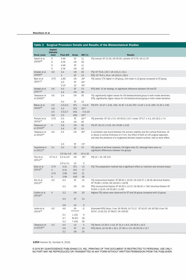
Stocchero et al
1254 Volume 31, Number 6, 2016
Table 3 Surgical Procedure Details and Results of the Biomechanical Studies
Study (year)
Implant diameter
(mm) Final drill Group IDD (%) Results Significance P value
Sakoh et al (2006)88
5 4.46 ST 11 ITQ conical: ST 11.00, UN 25.00, cylindric ST 5.75, UN 11.75 UN > ST < .055 3.76 UN 255 4.46 ST 11 UN > ST < .055 3.76 UN 25
Shalabi et al (2006)89
4.6 3.4 UN 26 ITQ: ST 70.8 ± 25.7, UN 115.2 ± 31.1 UN > ST < .054 ST 13 RTQ: ST 76.6 ± 24.4, UN 102.9 ± 36.4 No
Beer et al (2007)78
3.75 2.85 UN 24* ITQ values 17% higher in UN group, 21% lower in LO group compared to ST group n.a. n.a.3.0 ST 20*3.15 LO 16*
Shalabi et al (2007)96
4.6 4.0 ST 13 RTQ after 12 wk healing: no significant difference between UN and ST No –3.4 UN 26
Tabassum et al (2009)90
4.6 3.4 UN 26 ITQ: significantly higher values for UN blasted/etched group in both model densities; RTQ: significantly higher values for UN blasted/etched group in both model densities
UN > ST (both surfaces, both densities) < .001
4.0 ST 13Bilhan et al (2010)85
4.5 4.5/3.2 ST1 0 to 9 ITQ ST1: 15.37 ± 2.61, UN1: 41.87 ± 6.44; ST2: 11.62 ± 2.13, UN2: 21.50 ± 4.81 UN > ST .0013.8 3.2 ST2 16*°4.5 4.5/2.7 UN1 0 to 233.8 2.5 UN2 34*°
Pantani et al (2010)79
3.75 3.0 ST 20*° ITQ premolar: ST 15 ± 5.5, UN 35.8 ± 10.7; molar: ST 6.7 ± 4.2, UN 19.2 ± 7.4 UN > ST < .052.8 UN 25
Tabassum et al (2010)80
4 2.8 UN 30 ITQ ST: 30.13 ± 5.33, UN: 40.80 ± 9.23 UN > ST n.a.3.4 ST 15
Tabassum et al (2010)93
4.6 3.4 UN 26* A correlation was found between the primary stability and the cortical thickness. At or above a cortical thickness of 2 mm, the effect of both an UN surgical approach, and also the presence of a roughened (etched) implant surface, had no extra effect.
No cortical: ITQ, RTQ: UN (etched) > ST (machined); 1 mm cortical: ITQ, RTQ: UN (etched) > ST (etched and machined); 2 mm cortical; RTQ: UN (etched) > ST (etched); 2.5-mm cortical: RTQ: UN (etched) > ST (etched)
4.0 ST 13*Toyoshima et al (2011)91
4.1 3.5 ST 15 ITQ values of all three implants; UN higher than ST, although there were no significant differences between the groups
No –
3.5 t£o 2.8 UN 15 to 32Trisi et al (2011)81
3.7 to 3 3.2 to 3.9 UN 25* ITQ LO < 10, UN 110 RTQ 2 wk: LO 16.67 ± 16.07, UN 60.17 ± 9.7; 6 wk: LO 40 ± 10, UN 61.33 ± 12.06
–
3.9 to 3.1 LO 0Elias et al (2012)87
3.75 3.31 ST1 12 ITQ: The preparation method had a significant effect on insertion and removal torque < .0014 3.31 ST2 173.75 2.96 UN1 214 2.96 UN2 26
Ahn et al (2012)92
4.0 3.4 ST 15 ITQ monocortical fixation: ST 89.45 ± 10.03, UN 104.57 ± 18.16; Bicortical fixation: ST 76.98 ± 15.84, UN 104.62 ± 18.58
UN > ST < .05
3.2 UN 20 RTQ monocortical fixation ST 40.53 ± 12.17, UN 38.32 ± 7.60; bicortical fixation ST 54.64 ± 12.04, UN 53.28 ± 11.86
No –
Coelho et al (2013)94
4 3.2 UN 20 Highest ITQ values were observed for ST and UN group compared with LO group ITQ: UN > LO; RTQ: UN > LO ITQ < .001; RTQ < .04
3.5 ST 13 ITQ: ST > LO; RTQ: ST > LO ITQ < .001; RTQ < .01
3.8 LO 5Jimbo et al (2014)36
4.5 4.6 OV (Oversized)
–2 Estimated RTQ (Ncm), 3 wk: OV 56.83, LO 71.17, ST 91.67, UN 107.83; 6 wk: OV 92.67, LO 92.33, ST 98.67, UN 106.83
- –
4.1 L (LO) 93.7 M (ST) 183.2 T (UN) 29
Tabassum et al (2014)84
4.2 4.0 LO 5 ITQ (Ncm): LO 26.5 ± 5.8, ST 31.4 ± 8.5, UN 30.9 ± 10.3 ITQ ST > LO .0463.6 ST 14 RTQ (Ncm): LO 44.39 ± 16.1, ST 39.4 ± 14, UN 35.03 ± 13.7 No –3.2 UN 24
© 2016 BY QUINTESSENCE PUBLISHING CO, INC. PRINTING OF THIS DOCUMENT IS RESTRICTED TO PERSONAL USE ONLY. NO PART MAY BE REPRODUCED OR TRANSMITTED IN ANY FORM WITHOUT WRITTEN PERMISSION FROM THE PUBLISHER.
The International Journal of Oral & Maxillofacial Implants 1255
Stocchero et al
the other hand, an increase of removal torque values was observed in the nonundersized group (2 weeks: 16.67 Ncm; 6 weeks: 40.00 Ncm). Jimbo et al36 tested four different drilling protocols, based on the last drill used: 2% oversized than implant (“reamer”), 9% small-er (“loose”), 18% smaller (“medium”), and 29% small-er (“tight” or undersized) than the implant. Removal torque tests were performed at weeks 3 and 6. The undersized group presented a lower removal torque at week 6 compared with week 3. At week 3, the removal torque was significantly greater in the medium and tight groups than in the reamer and loose groups, but after 6 weeks, no significant differences were found between all groups.
Biologic StudiesBiologic studies are shown in Table 4.
Studies that investigated biologic outcomes used different in vivo models. Animal models included: goat femur condyle,97 goat iliac crest,84,98 dog man-dible,74,79,99 dog radius,22 dog proximal tibia,75 sheep mandible,76,81,95 sheep iliac crest,36 and rabbit tibia.34
Results obtained depicted an unclear scenario re-garding the biologic effects of the undersized drilling protocol compared with the nonundersized protocol. No significant difference in BIC between groups was noted in the majority of the studies.22,36,74,75,79,84,97 Significantly higher BIC values were obtained in three studies,34,81,99 while only one article observed signifi-cantly lower BIC values for the undersized group.98 However, it must be noted that in reports by Trisi et al81 and Duyck et al,34 the significant difference was found in the shorter-term time point, while it no longer ap-peared in the longer term. A distinction between con-tact of the implant with the host bone (host-BIC) and newly formed bone (BIC-de novo) was made by Duyck and Vandamme.100 In the study, significantly higher host-BIC was detected in the undersized group com-pared with the control group.
Regarding bone area fraction occupied, Jimbo et al36 obtained lower bone area fraction occupied in the undersized group compared with the control group.
Descriptive histology around implants placed with the undersized technique was assessed in different an-imal models at different healing time points. However, findings from all the studies seem to follow a similar healing pathway. In the early phase of healing, Trisi et al81 observed an intimate contact between the native bone and the implant. Compression and distortion in the peri-implant bone occurs just after placement, with large cracks and microfractures in the coronal part of the cortex, and delamination of lamellar bone at the primary thread engagement area. Extensive bone ne-crotic areas between the first threads were detected by other authors.22,26,75,94 The presence of bone particles
Table 3 Surgical Procedure Details and Results of the Biomechanical Studies
Study (year)
Implant diameter
(mm) Final drill Group IDD (%) Results Significance P value
Sakoh et al (2006)88
5 4.46 ST 11 ITQ conical: ST 11.00, UN 25.00, cylindric ST 5.75, UN 11.75 UN > ST < .055 3.76 UN 255 4.46 ST 11 UN > ST < .055 3.76 UN 25
Shalabi et al (2006)89
4.6 3.4 UN 26 ITQ: ST 70.8 ± 25.7, UN 115.2 ± 31.1 UN > ST < .054 ST 13 RTQ: ST 76.6 ± 24.4, UN 102.9 ± 36.4 No
Beer et al (2007)78
3.75 2.85 UN 24* ITQ values 17% higher in UN group, 21% lower in LO group compared to ST group n.a. n.a.3.0 ST 20*3.15 LO 16*
Shalabi et al (2007)96
4.6 4.0 ST 13 RTQ after 12 wk healing: no significant difference between UN and ST No –3.4 UN 26
Tabassum et al (2009)90
4.6 3.4 UN 26 ITQ: significantly higher values for UN blasted/etched group in both model densities; RTQ: significantly higher values for UN blasted/etched group in both model densities
UN > ST (both surfaces, both densities) < .001
4.0 ST 13Bilhan et al (2010)85
4.5 4.5/3.2 ST1 0 to 9 ITQ ST1: 15.37 ± 2.61, UN1: 41.87 ± 6.44; ST2: 11.62 ± 2.13, UN2: 21.50 ± 4.81 UN > ST .0013.8 3.2 ST2 16*°4.5 4.5/2.7 UN1 0 to 233.8 2.5 UN2 34*°
Pantani et al (2010)79
3.75 3.0 ST 20*° ITQ premolar: ST 15 ± 5.5, UN 35.8 ± 10.7; molar: ST 6.7 ± 4.2, UN 19.2 ± 7.4 UN > ST < .052.8 UN 25
Tabassum et al (2010)80
4 2.8 UN 30 ITQ ST: 30.13 ± 5.33, UN: 40.80 ± 9.23 UN > ST n.a.3.4 ST 15
Tabassum et al (2010)93
4.6 3.4 UN 26* A correlation was found between the primary stability and the cortical thickness. At or above a cortical thickness of 2 mm, the effect of both an UN surgical approach, and also the presence of a roughened (etched) implant surface, had no extra effect.
No cortical: ITQ, RTQ: UN (etched) > ST (machined); 1 mm cortical: ITQ, RTQ: UN (etched) > ST (etched and machined); 2 mm cortical; RTQ: UN (etched) > ST (etched); 2.5-mm cortical: RTQ: UN (etched) > ST (etched)
4.0 ST 13*Toyoshima et al (2011)91
4.1 3.5 ST 15 ITQ values of all three implants; UN higher than ST, although there were no significant differences between the groups
No –
3.5 t£o 2.8 UN 15 to 32Trisi et al (2011)81
3.7 to 3 3.2 to 3.9 UN 25* ITQ LO < 10, UN 110 RTQ 2 wk: LO 16.67 ± 16.07, UN 60.17 ± 9.7; 6 wk: LO 40 ± 10, UN 61.33 ± 12.06
–
3.9 to 3.1 LO 0Elias et al (2012)87
3.75 3.31 ST1 12 ITQ: The preparation method had a significant effect on insertion and removal torque < .0014 3.31 ST2 173.75 2.96 UN1 214 2.96 UN2 26
Ahn et al (2012)92
4.0 3.4 ST 15 ITQ monocortical fixation: ST 89.45 ± 10.03, UN 104.57 ± 18.16; Bicortical fixation: ST 76.98 ± 15.84, UN 104.62 ± 18.58
UN > ST < .05
3.2 UN 20 RTQ monocortical fixation ST 40.53 ± 12.17, UN 38.32 ± 7.60; bicortical fixation ST 54.64 ± 12.04, UN 53.28 ± 11.86
No –
Coelho et al (2013)94
4 3.2 UN 20 Highest ITQ values were observed for ST and UN group compared with LO group ITQ: UN > LO; RTQ: UN > LO ITQ < .001; RTQ < .04
3.5 ST 13 ITQ: ST > LO; RTQ: ST > LO ITQ < .001; RTQ < .01
3.8 LO 5Jimbo et al (2014)36
4.5 4.6 OV (Oversized)
–2 Estimated RTQ (Ncm), 3 wk: OV 56.83, LO 71.17, ST 91.67, UN 107.83; 6 wk: OV 92.67, LO 92.33, ST 98.67, UN 106.83
- –
4.1 L (LO) 93.7 M (ST) 183.2 T (UN) 29
Tabassum et al (2014)84
4.2 4.0 LO 5 ITQ (Ncm): LO 26.5 ± 5.8, ST 31.4 ± 8.5, UN 30.9 ± 10.3 ITQ ST > LO .0463.6 ST 14 RTQ (Ncm): LO 44.39 ± 16.1, ST 39.4 ± 14, UN 35.03 ± 13.7 No –3.2 UN 24
© 2016 BY QUINTESSENCE PUBLISHING CO, INC. PRINTING OF THIS DOCUMENT IS RESTRICTED TO PERSONAL USE ONLY. NO PART MAY BE REPRODUCED OR TRANSMITTED IN ANY FORM WITHOUT WRITTEN PERMISSION FROM THE PUBLISHER.

Stocchero et al
1256 Volume 31, Number 6, 2016
No significant differences in mean probing depth be-tween groups were found.
DISCUSSION
The purpose of the present systematic review was to collect and compile the current evidence on biome-chanical, biologic, and clinical effect of undersized drilling protocol prior to implant placement.
The major limitation of this study is that large meth-odologic differences between the studies were noted; therefore, the results between studies could not be directly compared. For this reason, meta-analysis was not performed. Moreover, a study selection based on methodologic assessment was not possible because of the scarcity of clinical trials. In vitro and animal study methodologic quality assessment was also not performed.
To evaluate the biomechanical effects, most of the papers used insertion torque as the outcome to evalu-ate primary stability. Insertion torque is a measure of the maximum friction rotational resistance of the bone when the implant is inserted, and it is affected by a combination of factors, including bone density, implant features (macrodesign and microdesign), and surgical technique.20,21,24,87,94 Insertion torque is a purely mechanical parameter, perceived by the clini-cian as a good estimator for primary stability, although studies have shown that an inverse relationship be-tween insertion torque and implant primary stability may occur due to cutting groove design alterations.19
Insertion torque, however, seems not to be an ab-solute parameter for primary stability, especially when comparing different implant systems, as it is largely af-fected by implant design parameters.101–103 In the pres-ent review, removal torque was used as an additional
was also distinguished.81,84,98 Bone resorption activ-ity was observed both around cortical81 and trabecu-lar bone.98 Remodeling lacunae, with the presence of osteoclasts and osteoblasts and new bone apposition was a common finding.22,26,75,97,98,99 Extensive integra-tion into mature lamellar bone was revealed in studies that investigated long-term healing.76,79
Clinical StudiesOnly two clinical studies, including 82 implants, ful-filled the inclusion/exclusion criteria (Table 5). Mar-ginal bone loss was not calculated in the two studies.
A retrospective clinical study77 evaluated the effect of undersized drilling preparation in the posterior max-illa. Twenty-two patients were recruited for this pro-spective study, and a total of 60 implants were placed, with two different lengths. Control group implants were inserted after 20% implant-drill discrepancy. Test group 1 implants were inserted after 25% discrepancy preparation, and test group 2 implants after stepped preparation 25% to 50% implant-drill discrepancy at the apex. Countersink drills were used for all implants. Maximum insertion torque was higher for test groups than the control. The difference was statistically sig-nificant between the control and test 1 group, regard-less of implant length. Two control implants were lost within the first month of healing.
A prospective study20 compared the 1-year survival rate and stability of 26 implants placed using the un-dersized technique in soft bone (posterior maxilla) with 26 implants placed using the standard technique in normal bone. A total of 52 implants were inserted in 29 patients. For the test group, a 32% implant-drill discrepancy was achieved, while those in the control group were inserted with a 15% implant-drill discrep-ancy. Insertion torque was similar for both groups, and 100% of the 1-year survival rate was achieved.
Table 3 continued Surgical Procedure Details and Results of the Biomechanical Studies
Study (year)
Implant diameter
(mm) Final drill Group IDD (%) Results Significance P value
Campos et al (2015)75
4.1 3.75 ST 9 ITQ: LO 17.0 ± 7.9, ST 40.0 ± 6.2, UN 73.0 ± 10.9 UN > ST > LO .0053.5 UN 154.0 LO 2
Jimbo et al (2015)95
4 3.2 UN 20 ITQ decreased nonsignificantly (P > .65) as a function of drilling Diameter from 3.2 mm to 3.5 mm for both designs
No –
3.5 ST 13Boustany et al (2015)82
3.7 3.4 ST 8 ITQ ST 15.9, UN 26.8 ITQ: UN > ST .0013.4 2.8 2.3 UN 24
Degidi et al (2015)86
3.4 3.0 ST 12 Peak torque (Ncm) ST: 11.3 ± 4.44, UN1: 20.26 ± 7.03, UN2: 17.15 ± 10.39 ITQ: UN > ST < .0013.8 UN1 214.5 UN2 34
IDD = implant-drill discrepancy; ST = standard drilling protocol; UN = undersized drilling protocol; LO = loose drilling protocol; * = countersinking; ° = tapping. ITQ and RTQ results are expressed in Ncm
© 2016 BY QUINTESSENCE PUBLISHING CO, INC. PRINTING OF THIS DOCUMENT IS RESTRICTED TO PERSONAL USE ONLY. NO PART MAY BE REPRODUCED OR TRANSMITTED IN ANY FORM WITHOUT WRITTEN PERMISSION FROM THE PUBLISHER.
The International Journal of Oral & Maxillofacial Implants 1257
Stocchero et al
been speculated that undersized drilling creates an ex-cessive pressure on dense bone, reaching values that go beyond the yield point, so that plastic deformation and microcracks will mask the effect of underprepara-tion compared with standard drilling, due to a deterio-ration of bone properties.49,110
For the present review, relative discrepancy was calculated for each study, and it was used to compare different groups. The limitation of such a parameter is recognized by the authors, as the dimensions of the outer implant diameter and last drill size do not pro-vide enough information to estimate the degree of compression created in the peri-implant bone, since multiple implant features have to be taken into ac-count for such an estimation. In the current literature, such information is seldom provided and is not often provided by implant manufacturers. Thus, when con-sidering two implants with the same diameter placed into two identical sites (which would have the same percent of discrepancy in the present review), different biomechanical and biologic events may occur, if other implant features, such as cutting capacity and inner di-ameter, are different. Due to the limitation of the avail-able information, these aspects were not considered in the present review.
Implant cutting capacity and macrodesign are ma-jor aspects to be considered. Different mechanical and biologic responses are expected if implants with the same macrogeometry provided with or without self-cutting features are inserted into the same drilled site. Cutting features allow displacement of bone volume occupied by the threads during implant placement. If an implant is deprived of cutting features, it creates di-rect bone compression while being inserted.45 Higher bone compression and delayed biologic responses were observed when non–self-cutting tapered im-plants were inserted into underdimensioned sites, compared with self-cutting implants.54 The efficacy of implant cutting capacity is questionable, as it seems to rely on thread geometry.21,40,111
Implant macrodesign has a remarkable impact on rotational stability. Conical and tapered implants achieve higher insertion torque compared with cylin-drical implants even in poor bone sites, as demonstrat-ed by several studies.21,26,40 A mechanical explanation would be that the tapering effect induces a higher de-gree of compression to the cortical bone.40
Furthermore, inner diameter is another implant fea-ture that determines bone compression, given the last drill diameter. If the last drill diameter is narrower than the implant inner diameter, a great amount of com-pression is created along the bone-implant interface.
From a biologic point of view, when implants are inserted into living bone, the initial mechanical in-terlocking goes through major changes due to bone
biomechanical outcome. Removal torque is a useful parameter when it is performed in in vivo studies since it measures the primary and secondary stability.104 In fact, removal torque in animal models is the result of initial interlocking between the implant and the bone (primary stability) and the osseointegration process af-ter healing, remodeling, and bone apposition (second-ary stability).105
The present review demonstrates a large body of evidence that the undersized drilling protocol is effec-tive in enhancing insertion torque for soft bone. This procedure induces intense modification of peri-im-plant bone anatomy. During implant insertion into an underdimensioned site, the cavity diameter increases, cutting and compressing the bone walls. In particu-lar, reduced trabecular separation, increased relative bone volume, and increased trabecular number were noted in peri-implant bone within 1 mm.57 This proce-dure results in static strain to the peri-implant bone, in which the magnitude depends on the implant ge-ometry, osteotomy preparation, bone anatomy, and surgical technique.45 The static strain creates a press-fit situation that stabilizes the implant during the initial phases of healing.
If the bone strain produced lies below the yield point, elastic behavior is expected, which means that the initial interlocking between the bone and the im-plant is linearly related to the strain.2,36,75,106 When the strain generated is higher than the yield point, plastic deformation and numerous microcracks alter pristine bone mechanical properties due to extensive remod-eling.45,107 Smaller cracks (less than 100 µm) can also be detected during drilling procedures,108 and longer cracks are often detected when the implant is placed into an undersized site.109 The results of the present review showed that the undersized protocol has a lim-ited effect on insertion torque in dense bone. It has
Table 3 continued Surgical Procedure Details and Results of the Biomechanical Studies
Study (year)
Implant diameter
(mm) Final drill Group IDD (%) Results Significance P value
Campos et al (2015)75
4.1 3.75 ST 9 ITQ: LO 17.0 ± 7.9, ST 40.0 ± 6.2, UN 73.0 ± 10.9 UN > ST > LO .0053.5 UN 154.0 LO 2
Jimbo et al (2015)95
4 3.2 UN 20 ITQ decreased nonsignificantly (P > .65) as a function of drilling Diameter from 3.2 mm to 3.5 mm for both designs
No –
3.5 ST 13Boustany et al (2015)82
3.7 3.4 ST 8 ITQ ST 15.9, UN 26.8 ITQ: UN > ST .0013.4 2.8 2.3 UN 24
Degidi et al (2015)86
3.4 3.0 ST 12 Peak torque (Ncm) ST: 11.3 ± 4.44, UN1: 20.26 ± 7.03, UN2: 17.15 ± 10.39 ITQ: UN > ST < .0013.8 UN1 214.5 UN2 34
IDD = implant-drill discrepancy; ST = standard drilling protocol; UN = undersized drilling protocol; LO = loose drilling protocol; * = countersinking; ° = tapping. ITQ and RTQ results are expressed in Ncm
© 2016 BY QUINTESSENCE PUBLISHING CO, INC. PRINTING OF THIS DOCUMENT IS RESTRICTED TO PERSONAL USE ONLY. NO PART MAY BE REPRODUCED OR TRANSMITTED IN ANY FORM WITHOUT WRITTEN PERMISSION FROM THE PUBLISHER.
Stocchero et al
1256 Volume 31, Number 6, 2016
No significant differences in mean probing depth be-tween groups were found.
DISCUSSION
The purpose of the present systematic review was to collect and compile the current evidence on biome-chanical, biologic, and clinical effect of undersized drilling protocol prior to implant placement.
The major limitation of this study is that large meth-odologic differences between the studies were noted; therefore, the results between studies could not be directly compared. For this reason, meta-analysis was not performed. Moreover, a study selection based on methodologic assessment was not possible because of the scarcity of clinical trials. In vitro and animal study methodologic quality assessment was also not performed.
To evaluate the biomechanical effects, most of the papers used insertion torque as the outcome to evalu-ate primary stability. Insertion torque is a measure of the maximum friction rotational resistance of the bone when the implant is inserted, and it is affected by a combination of factors, including bone density, implant features (macrodesign and microdesign), and surgical technique.20,21,24,87,94 Insertion torque is a purely mechanical parameter, perceived by the clini-cian as a good estimator for primary stability, although studies have shown that an inverse relationship be-tween insertion torque and implant primary stability may occur due to cutting groove design alterations.19
Insertion torque, however, seems not to be an ab-solute parameter for primary stability, especially when comparing different implant systems, as it is largely af-fected by implant design parameters.101–103 In the pres-ent review, removal torque was used as an additional
was also distinguished.81,84,98 Bone resorption activ-ity was observed both around cortical81 and trabecu-lar bone.98 Remodeling lacunae, with the presence of osteoclasts and osteoblasts and new bone apposition was a common finding.22,26,75,97,98,99 Extensive integra-tion into mature lamellar bone was revealed in studies that investigated long-term healing.76,79
Clinical StudiesOnly two clinical studies, including 82 implants, ful-filled the inclusion/exclusion criteria (Table 5). Mar-ginal bone loss was not calculated in the two studies.
A retrospective clinical study77 evaluated the effect of undersized drilling preparation in the posterior max-illa. Twenty-two patients were recruited for this pro-spective study, and a total of 60 implants were placed, with two different lengths. Control group implants were inserted after 20% implant-drill discrepancy. Test group 1 implants were inserted after 25% discrepancy preparation, and test group 2 implants after stepped preparation 25% to 50% implant-drill discrepancy at the apex. Countersink drills were used for all implants. Maximum insertion torque was higher for test groups than the control. The difference was statistically sig-nificant between the control and test 1 group, regard-less of implant length. Two control implants were lost within the first month of healing.
A prospective study20 compared the 1-year survival rate and stability of 26 implants placed using the un-dersized technique in soft bone (posterior maxilla) with 26 implants placed using the standard technique in normal bone. A total of 52 implants were inserted in 29 patients. For the test group, a 32% implant-drill discrepancy was achieved, while those in the control group were inserted with a 15% implant-drill discrep-ancy. Insertion torque was similar for both groups, and 100% of the 1-year survival rate was achieved.
Table 3 continued Surgical Procedure Details and Results of the Biomechanical Studies
Study (year)
Implant diameter
(mm) Final drill Group IDD (%) Results Significance P value
Campos et al (2015)75
4.1 3.75 ST 9 ITQ: LO 17.0 ± 7.9, ST 40.0 ± 6.2, UN 73.0 ± 10.9 UN > ST > LO .0053.5 UN 154.0 LO 2
Jimbo et al (2015)95
4 3.2 UN 20 ITQ decreased nonsignificantly (P > .65) as a function of drilling Diameter from 3.2 mm to 3.5 mm for both designs
No –
3.5 ST 13Boustany et al (2015)82
3.7 3.4 ST 8 ITQ ST 15.9, UN 26.8 ITQ: UN > ST .0013.4 2.8 2.3 UN 24
Degidi et al (2015)86
3.4 3.0 ST 12 Peak torque (Ncm) ST: 11.3 ± 4.44, UN1: 20.26 ± 7.03, UN2: 17.15 ± 10.39 ITQ: UN > ST < .0013.8 UN1 214.5 UN2 34
IDD = implant-drill discrepancy; ST = standard drilling protocol; UN = undersized drilling protocol; LO = loose drilling protocol; * = countersinking; ° = tapping. ITQ and RTQ results are expressed in Ncm
© 2016 BY QUINTESSENCE PUBLISHING CO, INC. PRINTING OF THIS DOCUMENT IS RESTRICTED TO PERSONAL USE ONLY. NO PART MAY BE REPRODUCED OR TRANSMITTED IN ANY FORM WITHOUT WRITTEN PERMISSION FROM THE PUBLISHER.
The International Journal of Oral & Maxillofacial Implants 1257
Stocchero et al
been speculated that undersized drilling creates an ex-cessive pressure on dense bone, reaching values that go beyond the yield point, so that plastic deformation and microcracks will mask the effect of underprepara-tion compared with standard drilling, due to a deterio-ration of bone properties.49,110
For the present review, relative discrepancy was calculated for each study, and it was used to compare different groups. The limitation of such a parameter is recognized by the authors, as the dimensions of the outer implant diameter and last drill size do not pro-vide enough information to estimate the degree of compression created in the peri-implant bone, since multiple implant features have to be taken into ac-count for such an estimation. In the current literature, such information is seldom provided and is not often provided by implant manufacturers. Thus, when con-sidering two implants with the same diameter placed into two identical sites (which would have the same percent of discrepancy in the present review), different biomechanical and biologic events may occur, if other implant features, such as cutting capacity and inner di-ameter, are different. Due to the limitation of the avail-able information, these aspects were not considered in the present review.
Implant cutting capacity and macrodesign are ma-jor aspects to be considered. Different mechanical and biologic responses are expected if implants with the same macrogeometry provided with or without self-cutting features are inserted into the same drilled site. Cutting features allow displacement of bone volume occupied by the threads during implant placement. If an implant is deprived of cutting features, it creates di-rect bone compression while being inserted.45 Higher bone compression and delayed biologic responses were observed when non–self-cutting tapered im-plants were inserted into underdimensioned sites, compared with self-cutting implants.54 The efficacy of implant cutting capacity is questionable, as it seems to rely on thread geometry.21,40,111
Implant macrodesign has a remarkable impact on rotational stability. Conical and tapered implants achieve higher insertion torque compared with cylin-drical implants even in poor bone sites, as demonstrat-ed by several studies.21,26,40 A mechanical explanation would be that the tapering effect induces a higher de-gree of compression to the cortical bone.40
Furthermore, inner diameter is another implant fea-ture that determines bone compression, given the last drill diameter. If the last drill diameter is narrower than the implant inner diameter, a great amount of com-pression is created along the bone-implant interface.
From a biologic point of view, when implants are inserted into living bone, the initial mechanical in-terlocking goes through major changes due to bone
biomechanical outcome. Removal torque is a useful parameter when it is performed in in vivo studies since it measures the primary and secondary stability.104 In fact, removal torque in animal models is the result of initial interlocking between the implant and the bone (primary stability) and the osseointegration process af-ter healing, remodeling, and bone apposition (second-ary stability).105
The present review demonstrates a large body of evidence that the undersized drilling protocol is effec-tive in enhancing insertion torque for soft bone. This procedure induces intense modification of peri-im-plant bone anatomy. During implant insertion into an underdimensioned site, the cavity diameter increases, cutting and compressing the bone walls. In particu-lar, reduced trabecular separation, increased relative bone volume, and increased trabecular number were noted in peri-implant bone within 1 mm.57 This proce-dure results in static strain to the peri-implant bone, in which the magnitude depends on the implant ge-ometry, osteotomy preparation, bone anatomy, and surgical technique.45 The static strain creates a press-fit situation that stabilizes the implant during the initial phases of healing.
If the bone strain produced lies below the yield point, elastic behavior is expected, which means that the initial interlocking between the bone and the im-plant is linearly related to the strain.2,36,75,106 When the strain generated is higher than the yield point, plastic deformation and numerous microcracks alter pristine bone mechanical properties due to extensive remod-eling.45,107 Smaller cracks (less than 100 µm) can also be detected during drilling procedures,108 and longer cracks are often detected when the implant is placed into an undersized site.109 The results of the present review showed that the undersized protocol has a lim-ited effect on insertion torque in dense bone. It has
Table 3 continued Surgical Procedure Details and Results of the Biomechanical Studies
Study (year)
Implant diameter
(mm) Final drill Group IDD (%) Results Significance P value
Campos et al (2015)75
4.1 3.75 ST 9 ITQ: LO 17.0 ± 7.9, ST 40.0 ± 6.2, UN 73.0 ± 10.9 UN > ST > LO .0053.5 UN 154.0 LO 2
Jimbo et al (2015)95
4 3.2 UN 20 ITQ decreased nonsignificantly (P > .65) as a function of drilling Diameter from 3.2 mm to 3.5 mm for both designs
No –
3.5 ST 13Boustany et al (2015)82
3.7 3.4 ST 8 ITQ ST 15.9, UN 26.8 ITQ: UN > ST .0013.4 2.8 2.3 UN 24
Degidi et al (2015)86
3.4 3.0 ST 12 Peak torque (Ncm) ST: 11.3 ± 4.44, UN1: 20.26 ± 7.03, UN2: 17.15 ± 10.39 ITQ: UN > ST < .0013.8 UN1 214.5 UN2 34
IDD = implant-drill discrepancy; ST = standard drilling protocol; UN = undersized drilling protocol; LO = loose drilling protocol; * = countersinking; ° = tapping. ITQ and RTQ results are expressed in Ncm
© 2016 BY QUINTESSENCE PUBLISHING CO, INC. PRINTING OF THIS DOCUMENT IS RESTRICTED TO PERSONAL USE ONLY. NO PART MAY BE REPRODUCED OR TRANSMITTED IN ANY FORM WITHOUT WRITTEN PERMISSION FROM THE PUBLISHER.

Stocchero et al
1258 Volume 31, Number 6, 2016
during implant placement, a compression of bone structures occurs, along with biomechanical events, namely, microcracks.39 Plastic bone deformation with spotted ischemic necrosis is expected in areas where a greater degree of compression is achieved. This situ-ation will lead to rapid bone resorption, which results
healing through the modeling-remodeling processes. As results showed, it is evident that the undersized protocol presents higher degrees of different osseo-integration indicators in the short term. Arguably, two bone healing patterns after implant placement have been described. When a press-fit situation is present
Table 4 Surgical Procedure Details and Results of the Biologic Studies
Study (year)
Implant diameter
(mm)Final drill
(mm) GroupIDD (%) BIC (%) Significance
P value
Shalabi et al (2007)97
4.6 4 ST 13 BIC: ST, machined: 20 ± 11; UN, machined: 24 ± 11; ST, blasted/etched: 28 ± 12; UN,blasted/etched: 38 ± 9
No –
3.4 UN 26
Pantani et al (2010)79
3.75 3 ST 20*° Total BIC premolar: ST 48.6 ± 8.8, UN 59 ± 14.7; Molar: ST 54.1 ± 15.1, UN 51.7 ± 16.2
No –
2.8 UN 25
Al-Marshood et al (2011)99
4.1 3.3 UN 20 ST: 47.5 ± 11.7, UN: 60.6 ± 14.2 BIC: UN > ST .01183.8 ST 7
Tabassum et al (2011)98
4.2 4 LO 5 LO 47.78 ± 11.13, ST 47.5 ± 9.57, UN 32.1 ± 9.73 LO = ST > UN < .053.6 ST 143.2 UN 24
Trisi et al (2011)81
3.7 to 3.0 3.2 to 3.9 UN 25* 2 wk total BIC: LO 8.70 ± 5.55, UN 39.11 ± 9.47; 6 wk total BIC: LO 44.90 ± 8.80, UN 50.29 ± 18.42
BIC: UN > ST (1, 2, 3, 4 wk) –
3.9 to 3.1 LO 0
Campos et al (2012)22
4.0 3.2 UN 20 BIC and BAFO: No significant differences between groups
No –
3.5 ST 133.8 LO 5
Consolo et al (2013)76
3.8 2.8 UN 32 8 wk: ST 38.62, UN 46.06; 12 wk: ST 58.75, UN 45.94
No statistical analysis –
3.4 ST 11
Duyck et al (2015)34
3.9 3.8 LO 3 2 wk total BIC (%): ST 38.78 ± 4.65, UN 54.84 ± 6.58; 4 wk de novo BIC (%): ST 44.55 ± 16.96, UN 29.84 ± 13.85
2 wk: total BIC: UN > ST .0001
3.2 UN 18*
Jimbo et al (2014)36
4.5 4.6 Reamer (OV)
–2 Estimated BIC (%) 3 wk: OV 34.50, LO 46.01, ST 50.53, UN 51.03; 6 wk: LO 39.02, LO 42.99, ST 60.99, UN 64.56
BIC (3 wk) R < T,M,L < .05
4.1 Loose (LO)
9 BIC (6 wk) T,M > L,R < .05
3.7 Medium (ST)
18 BAFO (3 wk): no difference –
3.2 Tight (UN) 29 BAFO (6 wk): T,M > L,R < .05
Tabassum et al (2014)99
4.2 4 LO 5 No difference No –3.6 ST 143.2 UN 24
Campos et al (2015)75
4.1 3.75 ST 9 BIC LO 17.5 ± 6.6, ST 36.3 ± 11.3, UN 30.3 ± 10.1 ST = UN > LO < .013.5 UN 154 LO 2
Jimbo et al (2014)95
4.0 3.2 UN 20 No differences in BIC were observed between implants placed in different diameter sites at 3 wk
No –
3.5 ST 13 BAFO (6 wk): ST > UN < .01
Rea et al (2015)74
4.0 3.0 UN 25 Mineralized BIC (%): OV 55.2 ± 12.2, ST 62.1 ± 20.9, UN 59.2 ± 9.7 and 60.8 ± 19.4
MBIC: No differences –
4.2 Oversized –53.3 ST 18
IDD = implant-drill discrepancy; ST = standard drilling protocol; UN = undersized drilling protocol; LO = loose drilling protocol; * = countersinking; ° = tapping.
© 2016 BY QUINTESSENCE PUBLISHING CO, INC. PRINTING OF THIS DOCUMENT IS RESTRICTED TO PERSONAL USE ONLY. NO PART MAY BE REPRODUCED OR TRANSMITTED IN ANY FORM WITHOUT WRITTEN PERMISSION FROM THE PUBLISHER.
The International Journal of Oral & Maxillofacial Implants 1259
Stocchero et al
bone walls and implant surface; namely, implant-drill discrepancy is lower. This healing scenario has been coined as a “healing chamber” by Berglundh et al.115 The empty space is filled by a blood clot, which is the start-point for new bone formation through an intra-membranous-like ossification. From the very first days after insertion, osteogenic cells gather along the im-plant surface and start to create an extracellular matrix (osteoid tissue), which then ossifies (woven bone).116 The chamber structure does not contribute to implant primary stability, as initially, no contact is present be-tween the pristine bone and the implant; however, it provides secondary stability as it is rapidly filled with new bone, without undergoing the more time-de-manding remodeling process, where bone first resorbs to subsequently integrate with the implant.23,110,118
Bone remodeling after implant insertion represents the shifting period from primary to secondary stabil-ity. From theoretical, experimental, and clinical stand-points, it results in implant stability loss, also known as stability dip. Thereafter, implant stability tends to increase due to new bone apposition.9,119–123 It has been suggested that surgical techniques could impact this delicate process, influencing stability changes and bone healing time. It has been suggested that an ideal surgical technique is when implants are inserted with high initial stability (not necessarily high insertion torque), followed by a rapid and stable onset of sec-ondary stability.110
in an accelerated bone remodeling process. This kind of healing reflects the main remodeling pathway in the living bone, named primary bone healing, through the mechanosensitive cell-mediated response to mi-crodamage.81,112–114 From histologic observations, extensive osteoclastic activity takes place during re-modeling along with microcracks and bone debris; the empty areas along the implant surface are then partially filled with new bone. This bone replacement is typically described as gradual interfacial remodeling in the area of contact between the pristine bone wall and implant surface.57,115,116 This is the type of healing pathway to be expected after undersized implant in-sertion, as several studies have noted.22,75,81,84,94,95,97–99 It has been suggested that bone could tolerate certain levels of compressive strain, even beyond the yield point without having negative bone reactions.44,75,117 On the other hand, if this threshold is exceeded, nega-tive biologic responses are expected, with massive bone necrosis and resorption. In a recent paper, Cha et al39 observed that undersized preparation in a rat femur model adversely affected osseointegration with significantly more dead osteocytes in peri-implant tis-sue. In addition, peri-implant tissue proliferation and osteogenetic differentiation were disfavored. Never-theless, there was little evidence reported of clinical failure due to bone over-compression.32
Different from the interfacial remodeling healing scenario, an alternate healing pattern is observed when empty spaces are created between the pristine
Table 5 Surgical Procedure Details and Results of the Clinical Studies
Study (year)
No. patients Bone
Implant diameter
(mm)
Implant length (mm)
Final drill (mm) Group IDD
Failed Implants ITQ (Ncm) Significance
P value
Turkyilmaz et al (2008)77
22 Posterior maxilla
3.75 10 3.0 ST1 18 (apex)* ST1 n = 1, ST2 n = 1
ST1 29.71 ± 8, UN1 35.91 ± 6, UN2 37.21 ± 7, ST2 30.91 ± 7, UN 338.51 ± 7, UN4 41.11 ± 6
ITQ: UN1 = UN2 > ST
< .05
4 10 3.0 UN1 25 (apex)*
4 10 2.0 (apex)/ 3.0 (body)
UN2 50 (apex)*
3.75 11.5 3.0 ST2 18 (apex)*
4 11.5 3.0 UN3 25 (apex)*
4 11.5 2.0 (apex)/ 3.0 (body)
UN4 50 (apex)*
Alghamdi et al (2011)20
29 1–2 Leckholm and Zarb
4.1 10 3.5 ST 15 n = 0 ITQ: ST 34.62 ± 5.82; UN 35.19 ± 4.79; Failed implants: ST 0; UN 0; PD: ST 2.87 ± 0.79; UN 2.75 ± 0.75
No –
3–4 Leckholm and Zarb
10 2.8 UN 32
IDD = implant-drill discrepancy; ST = standard drilling protocol; UN = undersized drilling protocol; * = countersinking.
© 2016 BY QUINTESSENCE PUBLISHING CO, INC. PRINTING OF THIS DOCUMENT IS RESTRICTED TO PERSONAL USE ONLY. NO PART MAY BE REPRODUCED OR TRANSMITTED IN ANY FORM WITHOUT WRITTEN PERMISSION FROM THE PUBLISHER.

Stocchero et al
1260 Volume 31, Number 6, 2016
outcome, there is strong evidence that the undersized drilling protocol has a significant effect on insertion torque in low-density bone; there is no certainty if there is a biomechanical limit in the entity of undersiz-ing; undersized drilling compared with conventional drilling might have a limited effect on insertion torque in dense bone, provided with a thick cortical layer; and initial high rotational stability obtained with under-sized technique seems to decrease over time, in in vivo models. For the biologic outcome, it is not clear if the undersized drilling protocol has a significant biologic effect in terms of BIC in short-term healing; undersized and nonundersized have a similar biologic response, in terms of BIC in long-term healing; and the healing pathway around the implant placed in an undersized site includes extensive bone compression necrosis, followed by resorption and remodeling. For the clini-cal outcome, the undersized drilling protocol seems to have a favorable survival rate when applied in the soft bone; clinical evidence of the undersized protocol is sparse and inconclusive; and no evidence on the ef-fect of the undersized protocol on marginal bone loss is present in the current literature.
ACKNOWLEDGMENTS
The authors would like to thank Carina Olsson and Hanna Wil-helmsson at Malmö University Library for their valuable assis-tance with the literature search; Francesca Cecchinato, Silvia Galli, Anders Halldin, Yohei Jinno, and Cristiano Tomasi for their precious help and support; Chad M. Boustany, Joke Duyck, Pär-Olov Östman, Anil Sukumaran, and Ilser Turkylmaz,for providing additional information about their studies. The authors declare that the present study was conducted in the absence of any con-flict of interest. The authors did not receive any kind of financial support in any form to conduct the present review.
REFERENCES
1. Albrektsson T, Brånemark PI, Hansson HA, Lindström J. Osseointe-grated titanium implants. Requirements for ensuring a long-last-ing, direct bone-to-implant anchorage in man. Acta Orthop Scand 1981;52:155–170.
2. Jimbo R, Giro G, Marin C, et al. Simplified drilling technique does not decrease dental implant osseointegration: A preliminary report. J Periodontol 2013;84:1599–1605.
3. Ferrigno N, Laureti M, Fanali S, Grippaudo G. A long-term follow-up study of non-submerged ITI implants in the treatment of totally edentulous jaws. Part I: Ten-year life table analysis of a prospec-tive multicenter study with 1286 implants. Clin Oral Implants Res 2002;13:260–273.
4. Jimbo R, Albrektsson T. Long-term clinical success of minimally and moderately rough oral implants: A review of 71 studies with 5 years or more of follow-up. Implant Dent 2015;24:62–69.
5. Cecchinato D, Parpaiola A, Lindhe J. Mucosal inflammation and incidence of crestal bone loss among implant patients: A 10-year study. Clin Oral Implants Res 2014;25:791–796.
6. Cecchinato D, Parpaiola A, Lindhe J. A cross-sectional study on the prevalence of marginal bone loss among implant patients. Clin Oral Implants Res 2013;24:87–90.
It is clear that, based on the final drill size used for site preparation and implant morphology, namely, im-plant inner and outer diameters, thread shape, depth, and pitch, different spaces can be created between the bone and the implant, and different responses are expected.124–126 The aforementioned healing patterns could be combined differently, in distinctive areas, re-sulting in different biomechanical and biologic charac-teristics over time. When the last drill diameter is larger than the implant inner diameter but slightly smaller than the implant outer diameter, pristine bone walls are less likely to be overly compressed by the implant surface while allowing healing chamber formation.
The effect of bone type on healing is also debatable since few studies compared the insertion of implants with the same protocol in different bone densities. Consistent differences in terms of bone composition and mineralized content were noted between eden-tulous sites.127 Underpreparation into dense poorly vascularized cortical bone may result in major remod-eling through the bone volume in proximity with the implant resulting in major biomechanical competence loss after implantation. On the other hand, after wider preparation of trabecular bone, which has abundant vascular and cellular components, substantial bone growth is expected into healing chamber structures, rapidly initiating the onset of osseointegration.39
In clinical practice, instrumentation and specific bone characteristic recommendations appear to be based on empirical grounds.89 The current key factor on deciding the drilling protocol is bone quality, which is subjectively evaluated by the surgeon59 or through radiographic examination.128 Clear scientific evidence is still lacking, even if the undersized drilling protocol to increase primary stability was reported 20 years ago.18,70,73
Nevertheless, as the number of implants consid-ered in the studies included in the present review is few, it must be disclosed that data available are limited before drawing definitive conclusions. Even moreso, included clinical studies did not show a high level of evidence, as no randomized clinical trial was found on this topic. No sufficient information on marginal bone changes is available, as one could argue that the trau-ma from overcompression of the cortical layer could lead to marginal bone loss. In fact, clinical studies in-vestigating the effect of different cortical preparations are currently lacking, although this is performed in daily clinical practice.
CONCLUSIONS
Within the limitations of the present study, the follow-ing conclusions were drawn. For the biomechanical
© 2016 BY QUINTESSENCE PUBLISHING CO, INC. PRINTING OF THIS DOCUMENT IS RESTRICTED TO PERSONAL USE ONLY. NO PART MAY BE REPRODUCED OR TRANSMITTED IN ANY FORM WITHOUT WRITTEN PERMISSION FROM THE PUBLISHER.
The International Journal of Oral & Maxillofacial Implants 1261
Stocchero et al
28. Friberg B, Ekestubbe A, Mellström D, Sennerby L. Brånemark im-plants and osteoporosis: A clinical exploratory study. Clin Implant Dent Relat Res 2001;3:50–56.
29. Greenstein G, Cavallaro J, Greenstein B, Tarnow D. Treatment plan-ning implant dentistry with a 2-mm twist drill. Compend Contin Educ Dent 2010;31:126–128.
30. Duyck J, Corpas L, Vermeiren S, et al. Histological, histomorpho-metrical, and radiological evaluation of an experimental implant design with a high insertion torque. Clin Oral Implants Res 2010;21:877–884.
31. Rodoni LR, Glauser R, Feloutzis A, Hämmerle CH. Implants in the posterior maxilla: A comparative clinical and radiologic study. Int J Oral Maxillofac Implants 2005;20:231–237.
32. Bashutski JD, D’Silva NJ, Wang HL. Implant compression ne-crosis: Current understanding and case report. J Periodontol 2009;80:700–704.
33. Sennerby L, Roos J. Surgical determinants of clinical success of osseointegrated oral implants: A review of the literature. Int J Prosthodont 1998;11:408–420.
34. Duyck J, Roesems R, Cardoso MV, Ogawa T, De Villa Camargos G, Vandamme K. Effect of insertion torque on titanium implant os-seointegration: An animal experimental study. Clin Oral Implants Res 2015;26:191–196.
35. Ottoni JM, Oliveira ZF, Mansini R, Cabral AM. Correlation between placement torque and survival of single-tooth implants. Int J Oral Maxillofac Implants 2005;20:769–776.
36. Jimbo R, Tovar N, Yoo DY, Janal MN, Anchieta RB, Coelho PG. The effect of different surgical drilling procedures on full laser-etched microgrooves surface-treated implants: An experimental study in sheep. Clin Oral Implants Res 2014;25:1072–1077.
37. Moher D, Liberati A, Tetzlaff J, Altman DG, PRISMA Group. Pre-ferred reporting items for systematic reviews and meta-analyses: The PRISMA statement. PLoS Med 2009;6:e1000097.
38. Landis JR, Koch GG. The measurement of observer agreement for categorical data. Biometrics 1977;33:159–174.
39. Cha JY, Pereira MD, Smith AA, et al. Multiscale analyses of the bone-implant interface. J Dent Res 2015;94:482–490.
40. O’Sullivan D, Sennerby L, Meredith N. Measurements comparing the initial stability of five designs of dental implants: A human cadaver study. Clin Implant Dent Relat Res 2000;2:85–92.
41. Coelho PG, Suzuki M, Guimaraes MV, et al. Early bone healing around different implant bulk designs and surgical techniques: A study in dogs. Clin Implant Dent Relat Res 2010;12:202–208.
42. Park JH, Lim YJ, Kim MJ, Kwon HB. The effect of various thread designs on the initial stability of taper implants. J Adv Prosthodont 2009;1:19–25.
43. Toyoshima T, Tanaka H, Ayukawa Y, et al. Primary stability of a hybrid implant compared with tapered and cylindrical implants in an ex vivo model. Clin Implant Dent Relat Res 2015;17:950–956.
44. Halldin A, Jimbo R, Johansson CB, et al. The effect of static bone strain on implant stability and bone remodeling. Bone 2011;49:783–789.
45. Halldin A, Jimbo R, Johansson CB, et al. Implant stability and bone remodeling after 3 and 13 days of implantation with an initial static strain. Clin Implant Dent Relat Res 2014;16:383–393.
46. Trisi P, Berardini M, Falco A, Podaliri Vulpiani M, Perfetti G. Insufficient irrigation induces peri-implant bone resorption: An in vivo histologic analysis in sheep. Clin Oral Implants Res 2014;25:696–701.
47. Möhlhenrich SC, Heussen N, Loberg C, Goloborodko E, Hölzle F, Modabber A. Three-dimensional evaluation of implant bed preparation and the influence on primary implant stability after using 2 different surgical techniques. J Oral Maxillofac Surg 2015;73:1723–1732.
48. Moon SH, Um HS, Lee JK, Chang BS, Lee MK. The effect of implant shape and bone preparation on primary stability. J Periodontal Implant Sci 2010;40:239–243.
49. Yoon HG, Heo SJ, Koak JY, Kim SK, Lee SY. Effect of bone quality and implant surgical technique on implant stability quotient (ISQ) value. J Adv Prosthodont 2011;3:10–15.
7. Sharawy M, Misch CE, Weller N, Tehemar S. Heat generation during implant drilling: The significance of motor speed. J Oral Maxillofac Surg 2002;60:1160–1169.
8. Stacchi C, Vercellotti T, Torelli L, Furlan F, Di Lenarda R. Changes in implant stability using different site preparation techniques: Twist drills versus piezosurgery. A single-blinded, randomized, con-trolled clinical trial. Clin Implant Dent Relat Res 2013;15:188–197.
9. Raghavendra S, Wood MC, Taylor TD. Early wound healing around endosseous implants: A review of the literature. Int J Oral Maxil-lofac Implants 2005;20:425–431.
10. Szmukler-Moncler S, Salama H, Reingewirtz Y, Dubruille JH. Timing of loading and effect of micromotion on bone-dental implant interface: Review of experimental literature. J Biomed Mater Res 1998;43:192–203.
11. Martinez H, Davarpanah M, Missika P, Celletti R, Lazzara R. Optimal implant stabilization in low density bone. Clin Oral Implants Res 2001;12:423–432.
12. Wazen RM, Currey JA, Guo H, Brunski JB, Helms JA, Nanci A. Micromotion-induced strain fields influence early stages of repair at bone-implant interfaces. Acta Biomater 2013;9:6663–6674.
13. Szmukler-Moncler S, Piattelli A, Favero GA, Dubruille JH. Consid-erations preliminary to the application of early and immediate loading protocols in dental implantology. Clin Oral Implants Res 2000;11:12–25.
14. Javed F, Romanos GE. The role of primary stability for successful immediate loading of dental implants. A literature review. J Dent 2010;38:612–620.
15. Östman PO, Hellman M, Sennerby L. Direct implant loading in the edentulous maxilla using a bone density-adapted surgical proto-col and primary implant stability criteria for inclusion. Clin Implant Dent Relat Res 2005;7(suppl):s60–s69.
16. Kan JY, Roe P, Rungcharassaeng K. Effects of implant morphology on rotational stability during immediate implant placement in the esthetic zone. Int J Oral Maxillofac Implants 2015;30:667–670.
17. Norton MR. The influence of insertion torque on the survival of immediately placed and restored single-tooth implants. Int J Oral Maxillofac Implants 2011;26:1333–1343.
18. Friberg B, Sennerby L, Gröndahl K, Bergström C, Bäck T, Lekholm U. On cutting torque measurements during implant placement: A 3-year clinical prospective study. Clin Implant Dent Relat Res 1999;1:75–83.
19. Freitas AC Jr, Bonfante EA, Giro G, Janal MN, Coelho PG. The effect of implant design on insertion torque and immediate micromo-tion. Clin Oral Implants Res 2012;23:113–118.
20. Alghamdi H, Anand PS, Anil S. Undersized implant site preparation to enhance primary implant stability in poor bone density: A pro-spective clinical study. J Oral Maxillofac Surg 2011;69:e506–e512.
21. dos Santos MV, Elias CN, Cavalcanti Lima JH. The effects of su-perficial roughness and design on the primary stability of dental implants. Clin Implant Dent Relat Res 2009;13:215–223.
22. Campos FE, Gomes JB, Marin C, et al. Effect of drilling dimension on implant placement torque and early osseointegration stages: An experimental study in dogs. J Oral Maxillofac Surg 2012;70:e43–e50.
23. Bonfante EA, Granato R, Marin C, et al. Early bone healing and bio-mechanical fixation of dual acid-etched and as-machined implants with healing chambers: An experimental study in dogs. Int J Oral Maxillofac Implants 2011;26:75–82.
24. Kim DR, Lim YJ, Kim MJ, Kwon HB, Kim SH. Self-cutting blades and their influence on primary stability of tapered dental implants in a simulated low-density bone model: A laboratory study. Oral Surg Oral Med Oral Pathol Oral Radiol Endod 2011;112:573–580.
25. Ahn SJ, Leesungbok R, Lee SW, Heo YK, Kang KL. Differences in implant stability associated with various methods of prepa-ration of the implant bed: An in vitro study. J Prosthet Dent 2012;107:366–372.
26. Jimbo R, Tovar N, Anchieta RB, et al. The combined effects of undersized drilling and implant macrogeometry on bone healing around dental implants: An experimental study. Int J Oral Maxil-lofac Surg 2014:43:1269–1275.
27. Irinakis T, Wiebe C. Clinical evaluation of the NobelActive implant system: A case series of 107 consecutively placed implants and a review of the implant features. J Oral Implantol 2009;35:283–288.
© 2016 BY QUINTESSENCE PUBLISHING CO, INC. PRINTING OF THIS DOCUMENT IS RESTRICTED TO PERSONAL USE ONLY. NO PART MAY BE REPRODUCED OR TRANSMITTED IN ANY FORM WITHOUT WRITTEN PERMISSION FROM THE PUBLISHER.

Stocchero et al
1262 Volume 31, Number 6, 2016
68. Östman PO, Wennerberg A, Albrektsson T. Immediate occlusal loading of NanoTite PREVAIL implants: A prospective 1-year clinical and radiographic study. Clin Implant Dent Relat Res 2010;12:39–47.
69. Östman PO, Wennerberg A, Ekestubbe A, Albrektsson T. Immedi-ate occlusal loading of NanoTite tapered implants: A prospective 1-year clinical and radiographic study. Clin Implant Dent Relat Res 2013;15:809–818.
70. Venturelli A. A modified surgical protocol for placing implants in the maxillary tuberosity: Clinical results at 36 months after loading with fixed partial dentures. Int J Oral Maxillofac Implants 1996;11:743–749.
71. Cooper LF, Reside GJ, Raes F, et al. Immediate provisionalization of dental implants placed in healed alveolar ridges and extrac-tion sockets: A 5-year prospective evaluation. Int J Oral Maxillofac Implants 2014;29:709–717.
72. Ivanoff CJ, Gröndahl K, Sennerby L, Bergström C, Lekholm U. Influ-ence of variations in implant diameters: A 3- to 5-year retrospec-tive clinical report. Int J Oral Maxillofac Implants 1999;14:173–180.
73. Langer B, Langer L, Herrmann I, Jorneus L. The wide fixture: A solu-tion for special bone situations and a rescue for the compromised implant. Part 1. Int J Oral Maxillofac Implants 1993;8:400–408.
74. Rea M, Lang NP, Ricci S, Mintrone F, González González G, Bot-ticelli D. Healing of implants installed in over- or under-prepared sites--an experimental study in dogs. Clin Oral Implants Res 2015;26:442–446.
75. Campos FE, Jimbo R, Bonfante EA, et al. Are insertion torque and early osseointegration proportional? A histologic evaluation. Clin Oral Implants Res 2015;26:1256–1260.
76. Consolo U, Travaglini D, Todisco M, Trisi P, Galli S. Histologic and biomechanical evaluation of the effects of implant inser-tion torque on peri-implant bone healing. J Craniofac Surg 2013;24:860–865.
77. Turkyilmaz I, Aksoy U, McGlumphy EA. Two alternative surgi-cal techniques for enhancing primary implant stability in the posterior maxilla: A clinical study including bone density, insertion torque, and resonance frequency analysis data. Clin Implant Dent Relat Res 2008;10:231–237.
78. Beer A, Gahleitner A, Holm A, Birkfellner W, Homolka P. Adapted preparation technique for screw-type implants: Explorative in vitro pilot study in a porcine bone model. Clin Oral Implants Res 2007;18:103–107.
79. Pantani F, Botticelli D, Garcia IR Jr, Salata LA, Borges GJ, Lang NP. Influence of lateral pressure to the implant bed on osseointe-gration: An experimental study in dogs. Clin Oral Implants Res 2010;21:1264–1270.
80. Tabassum A, Walboomers XF, Wolke JG, Meijer GJ, Jansen JA. Bone particles and the undersized surgical technique. J Dent Res 2010;89:581–586.
81. Trisi P, Todisco M, Consolo U, Travaglini D. High versus low implant insertion torque: A histologic, histomorphometric, and biomechanical study in the sheep mandible. Int J Oral Maxillofac Implants 2011;26:837–849.
82. Boustany CM, Reed H, Cunningham G, Richards M, Kanawati A. Effect of a modified stepped osteotomy on the primary stability of dental implants in low-density bone: A cadaver study. Int J Oral Maxillofac Implants 2015;30:48–55.
83. Jimbo R, Tovar N, Marin C, et al. The impact of a modified cutting flute implant design on osseointegration. Int J Oral Maxillofac Surg 2014;43:883–888.
84. Tabassum A, Meijer GJ, Walboomers XF, Jansen JA. Evaluation of primary and secondary stability of titanium implants using differ-ent surgical techniques. Clin Oral Implants Res 2014;25:487–492.
85. Bilhan H, Geckili O, Mumcu E, Bozdag E, Sünbüloğlu E, Kutay O. Influence of surgical technique, implant shape and diam-eter on the primary stability in cancellous bone. J Oral Rehabil 2010;37:900–907.
86. Degidi M, Daprile G, Piattelli A. Influence of underpreparation on primary stability of implants inserted in poor quality bone sites: An in vitro study. J Oral Maxillofac Surg 2015;73:1084–1088.
50. Hsu JT, Huang HL, Chang CH, Tsai MT, Hung WC, Fuh LJ. Relation-ship of three-dimensional bone-to-implant contact to primary implant stability and peri-implant bone strain in immediate load-ing: Microcomputed tomographic and in vitro analyses. Int J Oral Maxillofac Implants 2013;28:367–374.
51. Huang HL, Chang YY, Lin DJ, Li YF, Chen KT, Hsu JT. Initial stability and bone strain evaluation of the immediately loaded dental implant: An in vitro model study. Clin Oral Implants Res 2011;22:691–698.
52. Cehreli MC, Kökat AM, Comert A, Akkocaoğlu M, Tekdemir I, Akça K. Implant stability and bone density: Assessment of correlation in fresh cadavers using conventional and osteotome implant sockets. Clin Oral Implants Res 2009;20:1163–1169.
53. Canullo L, Peñarrocha D, Peñarrocha M, Rocio AG, Peñarrocha-Diago M. Piezoelectric vs. conventional drilling in implant site preparation: Pilot controlled randomized clinical trial with cross-over design. Clin Oral Implants Res 2014;25:1336–1343.
54. Nevins M, Nevins ML, Schupbach P, Fiorellini J, Lin Z, Kim DM. The impact of bone compression on bone-to-implant contact of an osseointegrated implant: A canine study. Int J Periodontics Restor-ative Dent 2012;32:637–645.
55. Kim SK, Lee HN, Choi YC, Heo SJ, Lee CW, Choie MK. Effects of anodized oxidation or turned implants on bone healing after using conventional drilling or trabecular compaction technique: Histomorphometric analysis and RFA. Clin Oral Implants Res 2006;17:644–650.
56. Marković A, Calasan D, Colić S, Stojčev-Stajčić L, Janjić B, Mišić T. Implant stability in posterior maxilla: Bone-condensing versus bone-drilling: A clinical study. Oral Surg Oral Med Oral Pathol Oral Radiol Endod 2011;112:557–563.
57. Fanuscu MI, Chang T-L, Akça K. Effect of surgical techniques on primary implant stability and peri-implant bone. J Oral Maxillofac Surg 2007;65:2487–2491.
58. Friberg B, Sennerby L, Meredith N, Lekholm U. A comparison be-tween cutting torque and resonance frequency measurements of maxillary implants. A 20-month clinical study. Int J Oral Maxillofac Surg 1999;28:297–303.
59. Bahat O. Technique for placement of oxidized titanium implants in compromised maxillary bone: Prospective study of 290 implants in 126 consecutive patients followed for a minimum of 3 years after loading. Int J Oral Maxillofac Implants 2009;24:325–334.
60. Calandriello R, Tomatis M, Rangert B. Immediate functional load-ing of Brånemark System implants with enhanced initial stability: A prospective 1- to 2-year clinical and radiographic study. Clin Implant Dent Relat Res 2003;5(suppl):10–20.
61. Degidi M, Perrotti V, Strocchi R, Piattelli A, Iezzi G. Is insertion torque correlated to bone-implant contact percentage in the early healing period? A histological and histomorphometrical evalua-tion of 17 human-retrieved dental implants. Clin Oral Implants Res 2009;20:778–781.
62. Friberg B, Ekestubbe A, Sennerby L. Clinical outcome of Brånemark System implants of various diameters: A retrospective study. Int J Oral Maxillofac Implants 2002;17:671–677.
63. Friberg B, Jisander S, Widmark G, et al. One-year prospective three-center study comparing the outcome of a “soft bone im-plant” (prototype Mk IV) and the standard Brånemark implant. Clin Implant Dent Relat Res 2003;5:71–77.
64. González-Martín O, Lee EA, Veltri M. CBCT fractal dimension changes at the apex of immediate implants placed using under-sized drilling. Clin Oral Implants Res 2011;23:954–957.
65. Grandi T, Guazzi P, Samarani R, Grandi G. Clinical outcome and bone healing of implants placed with high insertion torque: 12-month results from a multicenter controlled cohort study. Int J Oral Maxillofac Surg 2013;42:516–520.
66. Ostman PO. Immediate/early loading of dental implants. Clinical documentation and presentation of a treatment concept. Peri-odontol 2000 2008;47:90–112.
67. Östman PO, Hupalo M, del Castillo R, et al. Immediate provision-alization of NanoTite implants in support of single-tooth and unilateral restorations: One-year interim report of a prospective, multicenter study. Clin Implant Dent Relat Res 2009;12:e47–e55.
© 2016 BY QUINTESSENCE PUBLISHING CO, INC. PRINTING OF THIS DOCUMENT IS RESTRICTED TO PERSONAL USE ONLY. NO PART MAY BE REPRODUCED OR TRANSMITTED IN ANY FORM WITHOUT WRITTEN PERMISSION FROM THE PUBLISHER.
The International Journal of Oral & Maxillofacial Implants 1263
Stocchero et al
108. Warreth A, Polyzois I, Lee CT, Claffey N. Generation of micro-damage around endosseous implants. Clin Oral Implants Res 2009;20:1300–1306.
109. Bartold PM, Kuliwaba JS, Lee V, Shah S, Marino V, Fazzalari NL. Influence of surface roughness and shape on microdamage of the osseous surface adjacent to titanium dental implants. Clin Oral Implants Res 2010;22:613–618.
110. Coelho PG, Jimbo R, Tovar N, Bonfante EA. Osseointegration: Hi-erarchical designing encompassing the macrometer, micrometer, and nanometer length scales. Dent Mater 2015;31:37–52.
111. Chai J, Chau ACM, Chu FC, Chow TW. Correlation between dental implant insertion torque and mandibular alveolar bone density in osteopenic and osteoporotic subjects. Int J Oral Maxillofac Implants 2012;27:888–893.
112. Chamay A, Tschantz P. Mechanical influences in bone remodeling. Experimental research on Wolff’s law. J Biomech 1972;5:173–180.
113. Verborgt O, Gibson GJ, Schaffler MB. Loss of osteocyte integrity in association with microdamage and bone remodeling after fatigue in vivo. J Bone Miner Res 2000;15:60–67.
114. McNamara LM, Prendergast PJ. Bone remodelling algorithms incorporating both strain and microdamage stimuli. J Biomech 2007;40:1381–1391.
115. Berglundh T, Abrahamsson I, Lang NP, Lindhe J. De novo alveolar bone formation adjacent to endosseous implants. Clin Oral Im-plants Res 2003;14:251–262.
116. Rossi F, Lang NP, De Santis E, Morelli F, Favero G, Botticelli D. Bone-healing pattern at the surface of titanium implants: An experimen-tal study in the dog. Clin Oral Implants Res 2014;25:124–131.
117. Perren SM, Huggler A, Russenberger M, et al. The reaction of cortical bone to compression. Acta Orthop Scand Suppl 1969;125:19–29.
118. Leonard G, Coelho P, Polyzois I, Stassen L, Claffey N. A study of the bone healing kinetics of plateau versus screw root design titanium dental implants. Clin Oral Implants Res 2009;20:232–239.
119. Gomes JB, Campos FE, Marin C, et al. Implant biomechanical stabil-ity variation at early implantation times in vivo: An experimental study in dogs. Int J Oral Maxillofac Implants 2013;28:e128–e134.
120. Ersanli S, Karabuda C, Beck F, Leblebicioglu B. Resonance fre-quency analysis of one-stage dental implant stability during the osseointegration period. J Periodontol 2005;76:1066–1071.
121. Barewal RM, Oates TW, Meredith N, Cochran DL. Resonance frequency measurement of implant stability in vivo on implants with a sandblasted and acid-etched surface. Int J Oral Maxillofac Implants 2003;18:641–651.
122. Huwiler MA, Pjetursson BE, Bosshardt DD, Salvi GE, Lang NP. Reso-nance frequency analysis in relation to jawbone characteristics and during early healing of implant installation. Clin Oral Implants Res 2007;18:275–280.
123. Han J, Lulic M, Lang NP. Factors influencing resonance frequency analysis assessed by Osstell mentor during implant tissue integra-tion: II. Implant surface modifications and implant diameter. Clin Oral Implants Res 2010;21:605–611.
124. Vivan Cardoso M, Vandamme K, Chaudhari A, et al. Dental implant macro-design features can impact the dynamics of osseointegra-tion. Clin Implant Dent Relat Res 2015;17:639–645.
125. Chowdhary R, Jimbo R, Thomsen CS, Carlsson L, Wennerberg A. The osseointegration stimulatory effect of macrogeometry-modified implants: A study in the rabbit. Clin Oral Implants Res 2014;25:1051–1055.
126. Amid R, Raoofi S, Kadkhodazadeh M, Movahhedi MR, Khademi M. Effect of microthread design of dental implants on stress and strain patterns: A three-dimensional finite element analysis. Biomed Tech (Berl) 2013;58:457–467.
127. Lindhe J, Bressan E, Cecchinato D, Corrá E, Toia M, Liljenberg B. Bone tissue in different parts of the edentulous maxilla and man-dible. Clin Oral Implants Res 2013;24:372–377.
128. Anitua E, Alkhraisat MH, Piñas L, Orive G. Efficacy of biologically guided implant site preparation to obtain adequate primary implant stability. Ann Anat 2015;199:9–15.
87. Elias CN, Rocha FA, Nascimento AL, Coelho PG. Influence of implant shape, surface morphology, surgical technique and bone quality on the primary stability of dental implants. J Mech Behav Biomed Mater 2012;16:169–180.
88. Sakoh J, Wahlmann U, Stender E, Nat R, Al-Nawas B, Wagner W. Primary stability of a conical implant and a hybrid, cylin-dric screw-type implant in vitro. Int J Oral Maxillofac Implants 2006;21:560–566.
89. Shalabi MM, Wolke JG, Jansen JA. The effects of implant surface roughness and surgical technique on implant fixation in an in vitro model. Clin Oral Implants Res 2006;17:172–178.
90. Tabassum A, Meijer GJ, Wolke JG, Jansen JA. Influence of the surgi-cal technique and surface roughness on the primary stability of an implant in artificial bone with a density equivalent to maxillary bone: A laboratory study. Clin Oral Implants Res 2009;20:327–332.
91. Toyoshima T, Wagner W, Klein MO, Stender E, Wieland M, Al-Nawas B. Primary stability of a hybrid self-tapping implant compared to a cylindrical non-self-tapping implant with respect to drilling proto-cols in an ex vivo model. Clin Implant Dent Relat Res 2011;13:71–78.
92. Ahn SJ, Leesungbok R, Lee SW, Heo YK, Kang KL. Differences in implant stability associated with various methods of prepa-ration of the implant bed: An in vitro study. J Prosthet Dent 2012;107:366–372.
93. Tabassum A, Meijer GJ, Wolke JG, Jansen JA. Influence of surgical technique and surface roughness on the primary stability of an implant in artificial bone with different cortical thickness: A labora-tory study. Clin Oral Implants Res 2010;21:213–220.
94. Coelho PG, Marin C, Teixeira HS, et al. Biomechanical evaluation of undersized drilling on implant biomechanical stability at early implantation times. J Oral Maxillofac Surg 2013;71:e69–e75.
95. Jimbo R, Tovar N, Anchieta RB, et al. The combined effects of undersized drilling and implant macrogeometry on bone healing around dental implants: An experimental study. Int J Oral Maxil-lofac Surg 2014;43:1269–1275.
96. Shalabi MM, Wolke JG, de Ruijter AJ, Jansen JA. A mechanical evaluation of implants placed with different surgical techniques into the trabecular bone of goats. J Oral Implantol 2007;33:51–58.
97. Shalabi MM, Wolke JG, de Ruijter AJ, Jansen JA. Histological evaluation of oral implants inserted with different surgical tech-niques into the trabecular bone of goats. Clin Oral Implants Res 2007;18:489–495.
98. Tabassum A, Meijer GJ, Walboomers XF, Jansen JA. Biological limits of the undersized surgical technique: A study in goats. Clin Oral Implants Res 2011;22:129–134.
99. Al-Marshood MM, Junker R, Al-Rasheed A, Al Farraj Aldosari A, Jansen JA, Anil S. Study of the osseointegration of dental implants placed with an adapted surgical technique. Clin Oral Implants Res 2011;22:753–759.
100. Duyck J, Vandamme K. The effect of loading on peri-implant bone: A critical review of the literature. J Oral Rehabil 2014;41:783–794.
101. Akkocaoglu M, Uysal S, Tekdemir I, Akca K, Cehreli MC. Implant design and intraosseous stability of immediately placed implants: A human cadaver study. Clin Oral Implants Res 2005;16:202–209.
102. Akkocaoglu M, Cehreli MC, Tekdemir I, et al. Primary stability of si-multaneously placed dental implants in extraoral donor graft sites: A human cadaver study. J Oral Maxillofac Surg 2007;65:400–407.
103. Norton M. Primary stability versus viable constraint—a need to redefine. Int J Oral Maxillofac Implants 2013;28:19–21.
104. Meredith N. Assessment of implant stability as a prognostic deter-minant. Int J Prosthodont 1998;11:491–501.
105. Atsumi M, Park SH, Wang HL. Methods used to assess im-plant stability: Current status. Int J Oral Maxillofac Implants 2007;22:743–754.
106. Jimbo R, Anchieta R, Baldassarri M, et al. Histomorphometry and bone mechanical property evolution around different implant systems at early healing stages. Implant Dent 2013;22:596–603.
107. O’Brien FJ, Taylor D, Clive Lee T. The effect of bone microstruc-ture on the initiation and growth of microcracks. J Orthop Res 2005;23:475–480.
© 2016 BY QUINTESSENCE PUBLISHING CO, INC. PRINTING OF THIS DOCUMENT IS RESTRICTED TO PERSONAL USE ONLY. NO PART MAY BE REPRODUCED OR TRANSMITTED IN ANY FORM WITHOUT WRITTEN PERMISSION FROM THE PUBLISHER.


1288 Volume 32, Number 6, 2017
©2017 by Quintessence Publishing Co Inc.
Clinical Considerations of Adapted Drilling Protocol by Bone Quality Perception
Marco Toia, DDS1/Michele Stocchero, DDS1/Francesca Cecchinato, MS, PhD2/Enrico Corrà, DDS3/Ryo Jimbo, DDS, PhD4/Denis Cecchinato, MD, DDS5
Purpose: To evaluate insertion torque value (ITV) and marginal bone loss (MBL) of an implant system after
a clinically perceived bone quality–adapted drilling. Materials and Methods: This multicenter retrospective
study included patients treated with implants, conventionally loaded, in completely healed sites. Operators
customized the osteotomy preparation according to radiographic assessment and their perception of bone
quality. Drilling sequence, bone quality, and ITV were recorded at the time of surgery. Radiographs were
taken at the time of implant placement and permanent restoration. MBL between implant placement and
permanent restoration was calculated. The implant was used as the statistical unit. Demographic and
implant characteristics were shown by means of descriptive statistics. Outcome values were compared
using analysis of variance (ANOVA) and Kruskal-Wallis tests. Multiple regression models were used to test
the effect of independent variables on ITV and MBL. Results: One hundred eighty-eight implants placed
in 87 patients were included in the analysis. The mean observation period was 144 ± 59 days. The mean
ITV was 30.8 ± 15.1 Ncm. ITV differed significantly based on arches (mandible/maxilla) (P = .001), bone
quality (P < .001), implant diameter (P = .032), and drilling protocol (P = .019). Median MBL was 0.05 mm
(0.00; 0.24). A significant difference was found between the mandible and maxilla (P = .008) and between
drilling protocols (P = .011). In particular, significantly higher MBL was found in the undersized drilling
protocol. Multiple regression analysis showed that ITV was influenced by bone quality and implant diameter.
MBL was influenced by bone quality, implant diameter, ITV, and the interaction between bone quality and
ITV. It was estimated that MBL was greater with increased bone density and ITV. Conclusion: Excessive ITV
in dense bone can cause negative marginal bone responses. A presurgical radiographic assessment and
the perception of bone quality are necessary to select an optimal drilling protocol and to minimize surgical
trauma. INT J ORAL MAXILLOFAC IMPLANTS 2017;32:1288–1295. doi: 10.11607/jomi.5881
Keywords: dental implant, insertion torque, marginal bone loss, primary stability, surgical protocol
The use of osseointegrated implants has become a successful treatment option for the prosthetic re-
habilitation of partial and full edentulism, since the implants are capable of restoring both function and esthetics.1–3 Marginal bone maintenance is essential for long-term implant success. Albrektsson et al1 reported that the surgical procedure is one major factor that af-fects osseointegration. In addition, in a 5-year clinical
study, Cochran et al4 reported that 86% of the marginal bone resorption occurred during the early phase before loading. It has been reported that early bone resorption around implants is due to surgical trauma.5,6 An optimal surgical technique of osteotomy preparation should ideally provide adequate initial implant stability and, at the same time, prevent excessive heating or compres-sive trauma.7 Initial stability is achieved through me-chanical interlocking between the implant and the wall of the osteotomy.8 It has been reported that a micromo-tion of 150 µm is a critical threshold.9,10
One of the most common clinical parameters to quantify initial implant stability is the insertion torque value (ITV), which measures the rotational friction and cutting resistance of the bone during implant insertion. ITV is affected by a combination of factors, such as bone anatomy (ie, quality and quanti-ty), implant design (macrogeometry and microgeom-etry), and surgical technique.11–15 However, from an engineering and biologic perspective, the ITV is not directly related to initial stability.16 Furthermore, it is
1PhD Student, Department of Oral and Maxillofacial Surgery and Oral Medicine, Faculty of Odontology, Malmö, Sweden.
2Researcher, Institute Franci, Padova, Italy. 3Private Practice, Institute Franci, Padova, Italy. 4Associate Professor, Department of Oral and Maxillofacial Surgery and Oral Medicine, Faculty of Odontology, Malmö, Sweden.
5Private Practice, Researcher, Institute Franci, Padova, Italy.
Correspondence to: Dr Marco Toia, Corso Italia, 7, 21052 Busto Arsizio VA, Sweden. Fax: +390331320887. Email: [email protected]
© 2017 BY QUINTESSENCE PUBLISHING CO, INC. PRINTING OF THIS DOCUMENT IS RESTRICTED TO PERSONAL USE ONLY. NO PART MAY BE REPRODUCED OR TRANSMITTED IN ANY FORM WITHOUT WRITTEN PERMISSION FROM THE PUBLISHER.

The International Journal of Oral & Maxillofacial Implants 1289
Toia et al
debatable whether ITV can influence osseointegra-tion, since good results in terms of clinical outcomes have been reported for implants inserted both at ex-tremely high ITV17 and extremely low ITV.18 Neverthe-less, clinicians often demand high values of insertion torque, especially when performing an immediate loading protocol.19
The most commonly used technique to enhance ITV is the undersized drilling protocol. Such a drilling protocol creates an osteotomy that is narrower than recommended for the specific implant used.20 Dur-ing implant insertion into an under-dimensioned site, compressive and tensile stresses in the bone are in-duced. Some concerns have been raised over whether this technique may be harmful to the surrounding bone. Numerous studies demonstrate that excessive compression and tension in the cortical layer causes an interruption of the blood supply as well as genera-tion of microcracks.21–23 Hence, the clinician should be aware that high stresses might result in delayed bone healing and early marginal bone resorption.24,25
In selection of the final osteotomy dimension, a different degree of bone compression and primary stability at implant placement can be obtained. The proper final osteotomy dimension may be modu-lated on bone characteristics, obtaining the so-called adapted drilling.26 This choice is often based on the operator’s perception of the bone quality at the time of surgery. However, clinical evidence on how differ-ent osteotomy preparation based on the clinicians’ perception could influence implant initial stability and bone response is sparse.27
Thus, the aim of this retrospective multicenter study was to evaluate ITV and early marginal bone response, before loading, of an implant system after a clinically perceived bone quality–adapted drilling.
MATERIALS AND METHODS
Inclusion/Exclusion CriteriaPatients included in this retrospective study were treated with implant rehabilitations from June 2014 to April 2016 at three private practice–based clinics. All patients signed informed consent prior to the implant treatment. To be included in the study, all cases must have fulfilled the following inclusion criteria:
• Treated with OsseoSpeed EV (Astra Tech Implant System, Dentsply Sirona Implants)
• Radiographs recorded at the time of implant placement and at the time of permanent restoration
• Information recorded regarding implant drilling protocol and implant characteristics in terms of length and diameter
• Bone type recorded, according to Hämmerle classification28 and bone quality according to Lekholm and Zarb classification29
• ITV of the complete implant placement recorded using SA-310 W&H Elcomed implant unit (W&H)
The following exclusion criteria were applied:
• Implants placed in postextractive sockets (Classes I, II, and III according to Hämmerle classification)
• Implants placed in regenerated site or with bone augmentation procedures
• Implants placed with computer-aided surgery• Failed implants at the time of second surgery• Immediately loaded implants• Implants placed with a manual torque wrench• Patient with soft tissue borne complete or partial
denture as provisional restoration• Subjects smoking more than 10 cigarettes/day
Surgical ProceduresPrior to implant placement, clinical and radiographic evaluations were performed to obtain a proper treat-ment plan. In each center, surgical and prosthetic procedures were performed by a single operator with more than 10 years of experience in implant dentistry (M.T., E.C., D.C.).
Patients received antibiotic prophylaxis (Amoxicillin 1 g), 1 hour prior to surgery and after the completion of implant placement until suture removal, with 1 g twice a day. The surgical treatment was performed under lo-cal anesthesia. A full-thickness flap was raised to ex-pose the implant site. Implants were placed according to the manufacturer guidelines, using a two-stage pro-tocol.30 Bone type was assigned based on presurgical cone beam computed tomography (CBCT) scan and clinical perception during implant placement. The op-eration was finalized by the insertion of a cover screw followed by careful adaptation of the flaps by means of an accurate suture to obtain full periosteal coverage.
Postoperative care and instructions were given to the patients.
Drilling Protocol and Implant PlacementThe implant drilling protocol of OsseoSpeed EV is designed to achieve initial implant stability, avoid-ing excessive bone compression.31 A combination of stepped drills (S), cortical bone refinement (A and B), and a wider osteotomy preparation drill (X) was used when the surgeries were performed (Fig 1). The final drilling protocol was selected based on tactile percep-tion during initial osteotomy. All drilling procedures were performed at a maximum of 1,500 rpm using pro-fuse external irrigation with a saline solution. Implant placement was performed at 25 rpm under abundant
© 2017 BY QUINTESSENCE PUBLISHING CO, INC. PRINTING OF THIS DOCUMENT IS RESTRICTED TO PERSONAL USE ONLY. NO PART MAY BE REPRODUCED OR TRANSMITTED IN ANY FORM WITHOUT WRITTEN PERMISSION FROM THE PUBLISHER.
1290 Volume 32, Number 6, 2017
Toia et al
irrigation using the surgical unit. The final position was achieved at bone-crestal or slightly subcrestal level.
Radiographic EvaluationStandardized radiographs were taken with an X-ray ap-paratus supplied with a long cone at each visiting time. Rinn Universal Collimator (Dentsply RINN) was used to ensure image reproducibility.
Radiographs were measured using image processor software (ImageJ, National Institutes of Health) to eval-uate the marginal bone loss (MBL). The length and di-ameter of the implant were used for the calibration of the bone level measurements. The distance between the reference point (implant bevel) and the first visible bone-to-implant contact was measured both at a me-sial and distal site (Fig 2). In cases where the implant reference point was below the margin of the crestal bone, that is, subcrestal, the value was considered as ± 0. The mean of mesial and distal values was calculat-ed at implant placement and permanent restoration.
MBL, before loading, was calculated as a difference be-tween the two time points.
The radiographic analysis was performed in a blind manner by one experienced examiner not involved in the study. Intraexaminer measure variability was deter-mined by re-examining 10% of all measures randomly selected, and the measurement error was calculated.
Data CollectionA dataset was created with the following variables: pa-tient age and sex; implant diameter and length; bone quality (based on Lekholm and Zarb classification29); arch (mandible/maxilla); and drilling protocol (S, SA, SB, SX, SXB) as reported in Fig 1.
Outcome variables were:
• ITV: Calculated as final ITV from Elcomed implant drill unit .csv file created at implant placement and stored in USB stick
• MBL: Calculated as previously described
S SA SB SX SXB
–0.5
–0.5
–0.8
–0.3
–0.5
–0.8
–0.0
–0.5
–0.8
–0.15
–0.15
–0.5
–0.0
–0.15
–0.5
Fig 1 Schematic picture of drilling protocols. Discrepancy between osteotomy and implant diameter at different levels are shown in mm. S = stepped body preparation, which creates an undersized osteotomy; SA = body preparation followed by thin cortical bone drill; SB = body preparation followed by thick cortical bone drill; SX = stepped body preparation followed by additional body and apical drill (X); SXB = stepped body preparation followed by additional body and apical drill and by thick cortical bone drill.
Fig 2 Radiographs involving multiple im-plant reconstruction in the mandible and a single implant reconstruction in the max-illa at (a, c) implant placement and (b, d) permanent restoration, respectively.
a b
c d
© 2017 BY QUINTESSENCE PUBLISHING CO, INC. PRINTING OF THIS DOCUMENT IS RESTRICTED TO PERSONAL USE ONLY. NO PART MAY BE REPRODUCED OR TRANSMITTED IN ANY FORM WITHOUT WRITTEN PERMISSION FROM THE PUBLISHER.
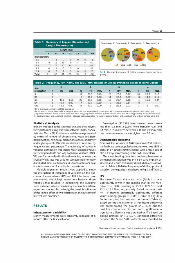
The International Journal of Oral & Maxillofacial Implants 1291
Toia et al
Statistical AnalysisImplant was used as the statistical unit, and the analyses were performed using statistical software (IBM SPSS Sta-tistics for Mac, v.22). Continuous variables are presented by means of number of observations, mean and stan-dard deviation, minimum, median, maximum, and lower and higher quartile. Discrete variables are presented by frequency and percentage. The normality of outcome variables distribution was tested. Mean outcome values were compared with one-way analysis of variance (ANO-VA) test for normally distributed variables, whereas the Kruskal-Wallis test was used to compare non-normally distributed data. Bonferroni and Dunn/Bonferroni post hoc tests were used for multiple comparisons.
Multiple regression models were applied to study the interaction of independent variables on the out-comes of main interest (ITV and MBL). In these com-plex models, the biologic interactions between those variables that resulted in influencing the outcome were included when considering the simple additive regression models. Accordingly, the possible influence of the joined effect of two variables on the outcome of interest was examined.
RESULTS
Intraexaminer VariabilityEighty measurements were randomly repeated at 6 months after the first evaluation.
Seventy-five (93.75%) measurement errors were less than 0.2 mm; 2 (2.5%) were between 0.21 and 0.4 mm; 2 (2.5%) were between 0.41 and 0.6 mm; only one measurement error was higher than 0.6 mm.
Demographic OutcomeFrom an initial inclusion of 248 implants and 131 patients, the final case series population encountered was 188 im-plants in 87 patients (50.6% males), with a mean age of 60.8 ± 13.3 years according to the exclusion criteria.
The mean healing time from implant placement to permanent restoration was 144 ± 59 days. Implant di-ameter and length frequency distribution are summa-rized in Table 1. Relative frequency of drilling protocol based on bone quality is displayed in Fig 3 and Table 2.
ITVThe mean ITV was 30.8 ± 15.1 Ncm (Table 3). It was significantly lower in the maxilla than in the man-dible (P = .001), resulting in 25.3 ± 12.9 Ncm and 33.2 ± 15.5 Ncm, respectively. Based on bone qual-ity, ITV showed statistically significantly different values among groups (P < .001) (Table 3) (Fig 4). A Bonferroni post hoc test was performed (Table 4). Based on implant diameter, a significant difference was noted among the groups (P = .032), but the post hoc comparison did not reach significance. A significant difference was obtained on ITV based on drilling protocol (P = .019). A significant difference between the S and SXB protocols was revealed by
Table 1 Summary of Implant Diameter and Length Frequency (n)
Length (mm)
6 8 9 11 13 15 Total
Diameter (mm) 3.0 1 0 0 0 0 1 3.6 8 16 23 9 4 0 60 4.2 7 16 20 14 11 1 69 4.8 6 11 15 5 0 1 38 5.4 0 6 9 5 0 0 20Total 21 50 67 33 15 2 188
63%
26%
11%47%
18%9%
22%
4%
4%
23%
15%38%
21%78%
13%4%4%
S SA SB SX SXB
Fig 3 Relative frequency of drilling protocol based on bone quality.
Table 2 Frequency, ITV (Ncm), and MBL (mm) Results of Drilling Protocols Based on Bone Quality
Site preparation
1 2 3 4
N ITV MBL N ITV MBL N ITV MBL N ITV MBL
S 0 17 30.0 0.15 20 26.0 0.12 18 29.2 0.17SA 0 8 36.6 0.00 11 28.6 0.09 3 13.5 0.19SB 5 47.1 0.13 20 33.9 0.12 12 29.7 0.12 1 11.5 0.47SX 2 46.4 0.09 4 29.7 0.19 2 35.3 0.14 0SXB 12 45.8 0.00 44 33.0 0.00 8 22.4 0.01 1 5 0.00 ITV is displayed as mean and MBL as median.ITV = insertion torque value; MBL = marginal bone loss; S = stepped body preparation, which creates an undersized osteotomy; SA = body preparation followed by thin cortical bone drill; SB = body preparation followed by thick cortical bone drill; SX = stepped body preparation followed by additional body and apical drill (X); SXB = stepped body preparation followed by additional body and apical drill and by thick cortical bone drill.
Bone quality 1 Bone quality 2 Bone quality 3 Bone quality 4
© 2017 BY QUINTESSENCE PUBLISHING CO, INC. PRINTING OF THIS DOCUMENT IS RESTRICTED TO PERSONAL USE ONLY. NO PART MAY BE REPRODUCED OR TRANSMITTED IN ANY FORM WITHOUT WRITTEN PERMISSION FROM THE PUBLISHER.
1292 Volume 32, Number 6, 2017
Toia et al
the post hoc test (P = .010) (Table 4). ITV did not dif-fer significantly among the centers.
From the multiple regression analysis, the most sta-tistically significant model to evaluate the influence on ITV included bone quality, diameter, and the bio-logic interaction of bone quality*diameter (P < .0001; adjusted R2 = 21.8%). The model confirmed that ITV was significantly higher in group 1 in comparison to group 3 (P = .04) and group 4 (P = .004). In addition, in group 4, a greater diameter determined a greater ITV (P = .02) (Fig 5).
MBLThe mean MBL was 0.16 ± 0.27 mm. Median, lower quartile, and upper quartile for MBL were 0.05, 0.00, and 0.24 mm, respectively (Table 3). The maximum value was 2.45 mm. MBL did not show any significant difference among bone quality groups (Table 3). A sig-nificant difference was found between the mandible and maxilla (P = .008), and between drilling protocols (P = .011). In particular, significant greater MBL was found in Protocol S compared with SXB, as showed by post hoc test (P = .010). MBL did not differ significantly among the centers.
From the multiple regression analysis, bone qual-ity, diameter, ITV, and the biologic interaction of bone quality*ITV influenced MBL according to the most statistically significant model (P < .0001; adjusted R2 = 14.4%). MBL was significantly higher in bone qual-ity group 1 vs groups 2, 3, and 4 (P < .0001), and there was mild evidence that it increases with the incre-ment of ITQ (P < .0001). The biologic interaction bone quality*ITV was statistically significant (P < .0001), and MBL was further enhanced by the joined increase of ITV in bone quality group 1 vs group 2 vs group 3, and vs group 4. A scatter plot showing MBL vs ITV accord-ing to different drilling protocols is displayed in Fig 5.
DISCUSSION
The present retrospective study aimed to evaluate ITV and early marginal bone response of an implant system after an adapted drilling. Based on presurgi-cal radiographic assessment, and on perception of bone density, the operators could select the drilling protocol to achieve initial stability. Particular care was taken to avoid excessive stresses on cortical bone, by
Table 3 Results for ITV (Ncm) and MBL (mm)
N
ITV MBL
Mean (SD) P Median (Q1; Q3) P
Arch .001 .008
Mandible 131 33.2 (15.5) 0.00 (0.00; 0.21)
Maxilla 57 25.3 (12.9) 0.16 (0.00; 0.28)
Bone quality < .001 .116
1 19 46.2 (9.5) 0.00 (0.00; 0.19)
2 93 32.8 (13.7) 0.00 (0.00; 0.21)
3 53 27.2 (14.2) 0.09 (0.00; 0.25)
4 23 18.3 (14.3) 0.16 (0.00; 0.44)
Diameter .032 .519
3.0 1 40.6 0.00
3.6 61 29.2 (14.8) 0.00 (0.00; 0.18)
4.2 68 28.2 (15.7) 0.10 (0.00; 0.28)
4.8 38 34.3 (14.1) 0.07 (0.00; 0.23)
5.4 20 37.6 (14.3) 0.00 (0.00; 0.27)
Drilling protocol .019 .011
S 55 25.4 (14.0) 0.15 (0.00; 0.31)
SA 22 29.5 (13.0) 0.00 (0.00; 0.18)
SB 38 33.7 (13.2) 0.13 (0.00; 0.24)
SX 8 35.2 (14.4) 0.16 (0.01; 0.25)
SXB 65 33.6 (16.9) 0.00 (0.00; 0.12)
Total 188 30.8 (15.2) 0.05 (0.00; 0.24)
N = frequency; Q1 = first quartile; Q3 = third quartile. Bold numbers indicate statistically significant differences.
Fig 4 ITV (Ncm) with relative standard deviations in different bone qualities, according to Lekholm and Zarb classification. ITV was significantly different among groups (P < .001).
Table 4 Multiple Comparison at Post Hoc Test for ITV with Relative Significance
Variable P
Bone quality 1 vs 2 .001
vs 3 < .001vs 4 < .001
2 vs 4 < .001Drilling protocol S SXB .027
Only significant differences are displayed. Bonferroni test was used.
1 2 3 4Bone quality
60.00
50.00
40.00
30.00
20.00
10.00
0.00
ITV
(Ncm
)
© 2017 BY QUINTESSENCE PUBLISHING CO, INC. PRINTING OF THIS DOCUMENT IS RESTRICTED TO PERSONAL USE ONLY. NO PART MAY BE REPRODUCED OR TRANSMITTED IN ANY FORM WITHOUT WRITTEN PERMISSION FROM THE PUBLISHER.

The International Journal of Oral & Maxillofacial Implants 1293
Toia et al
using wider (B) or thinner (A) cortical drills. In the case of dense bone, an additional wider drill (X) was used. Conversely, when the clinician predicted an inade-quate level of initial stability, no cortical or additional drills were used, which resulted in an undersized drill-ing (protocol S).
Several studies reported the successful use of modi-fied drilling protocols with undersized osteotomy in order to enhance initial stability in low-density bone for conven-tional11,26,32–34 or immediate loading protocols.35–37
The results of the present study presented a mean ITV of 30.8 ± 15.1 Ncm. ITV was higher in the mandible, which was in accordance with a recent report in which the same implant system was used.31
Multiple regression analysis revealed a robust model in which ITV was significantly influenced by bone type and diameter, among others. Analyzing the main factors affecting ITV, higher values were shown in bone quality class 1 vs 3 and 4. As previously observed,26,38,39 these findings indicate that bone quality is the critical factor affecting ITV, regardless of the adapted drilling protocol.
The present study data presented a median MBL value of 0.05 mm (Table 3). The time for radiographic assessment for MBL was selected at prosthetic deliv-ery, so that potential influence of prosthetic structure was avoided. Reportedly, MBL during the first healing phase is considered to be caused by surgical trauma,
among few other factors.5 The results obtained are comparable to studies that investigated early bone loss around similarly designed implants. Guljé et al40 ob-served a mean marginal bone change of –0.24 ± 0.21 and –0.45 ± 0.43 mm around 6-mm and 11-mm–length implants, respectively, 6 months after implant place-ment. In a prospective study on narrow-diameter im-plants,41 the 6-month MBL was –0.439 ± 0.893 mm. Donati et al42 reported a mean marginal bone level change between –0.2 and –0.33 mm 3 months after im-plant placement. In a recent publication, Stanford et al reported a mean MBL of 0.33 mm (median: 0.15 mm).31
Although the median value for MBL resulted in clini-cally irrelevant values, the maximum value (2.45 mm) should be taken into consideration. Interestingly, the findings of the present study showed that there was a significantly different value of MBL around implants inserted with different drilling protocols. In particu-lar, MBL was lower after a wider preparation (SXB) compared with an undersized technique (S). When undersized drilling is performed, the stresses in the bone occur along the entire implant length or only in some of its regions, based on the final osteotomy di-mension and implant design.43 Bone cell necrosis and resorption activity are expected in the peri-implant bone.21 A healthy bone can withstand this surgical trauma by a healing pathway known as interfacial
0.00 0.50 1.00 1.50 2.00 2.50
60.00
40.00
20.00
0.00
60.00
40.00
20.00
0.00
60.00
40.00
20.00
0.00
60.00
40.00
20.00
0.00
60.00
40.00
20.00
0.00
ITV
(Ncm
)
MBL_loss
SXB
SX
SB
SA
S
Drilling protocol
Fig 5 Scatter plot of ITV (Ncm) versus MBL (mm) according to drilling protocol.
© 2017 BY QUINTESSENCE PUBLISHING CO, INC. PRINTING OF THIS DOCUMENT IS RESTRICTED TO PERSONAL USE ONLY. NO PART MAY BE REPRODUCED OR TRANSMITTED IN ANY FORM WITHOUT WRITTEN PERMISSION FROM THE PUBLISHER.
1294 Volume 32, Number 6, 2017
Toia et al
remodeling.22,44,45 New bone apposition occurs after resorption of damaged tissue supported by new vas-cularization and migration of undifferentiated cells and regulatory factors.46 Conversely, this biologic process may be impeded in patients with reduced remodeling due to aging or clinical conditions. Immediate or early loading may also play a negative role in the remodel-ing process. In a recent animal study,47 compromised osseointegration was observed around immediately loaded implants inserted with underpreparation. The authors assumed that immediate loading condition together with the surgical procedure could have im-paired the reparatory process of bone remodeling dur-ing the early healing.
Besides, when early MBL exposes the implant sur-face, microbial biofilm accumulation is capable of breaking down the adjacent bone tissues.48
A multiple regression model showed that the main factors influencing MBL were bone quality and ITV. Larger MBL is predictable in bone quality 1 com-pared with bone qualities 2, 3, and 4. Moreover, MBL is more greatly enhanced by the biologic interaction between bone quality 1 and the increase of ITV. This finding is in accordance with a recent study by Barone et al,49 which aimed to compare implants placed with high and regular ITV; high ITV provoked higher bone resorption during the early healing. Furthermore, a greater MBL was recorded in the mandible than in the maxilla for the high ITV group. It may be argued that a poorly vascularized tissue, such as cortical bone, is more susceptible to resorption after compression.
A limitation of the present study was the bone quality assessment, which was obtained by means of Lekholm and Zarb classification. One may argue that such a subjective assessment could vary based on surgeon tactile sensitivity and experience. However, it was shown that this clinical-based assessment is ca-pable of determining the bone mineral density and microarchitecture,50–52 and it is the most commonly utilized classification. The retrospective nature of the study introduced a large number of variables, which could act as confounding factors. Nonetheless, the use of multiple regression analysis gave the possibility to create models where all factors were considered and adjusted for their influence on the outcomes.
From the present findings, the correct custom-ized drilling protocol based on bone perception provides optimal ITV and reduced early MBL. An accurate bone quality assessment is suggested in the presurgical planning in order to select the most optimal drilling protocol. Furthermore, it is a prereq-uisite for success to not result in high ITV in dense bone in order to avoid harmful stresses in the cor-tical area, which is the most susceptible region for bone response. It is suggested that a more gentle
preparation is necessary to avoid biologic complica-tions. Wider drilling, including cortical bone prepara-tion together with additional body preparation (ie, SXB) seems to grant good initial stability in terms of ITV and a minimized early MBL.
CONCLUSIONS
The surgical procedure of adapting the drilling proto-col based on bone quantity and quality as described in the present paper resulted in sufficient initial rotation-al stability (ITV) with minimized early marginal bone resorption in the first healing phase. ITV, however, is mainly influenced by bone quality. Excessive ITV in dense bone has to be avoided; thus, a drilling protocol including a cortical and additional wider osteotomy is suggested. A presurgical bone quality assessment is recommended to choose the proper drilling protocol and to minimize the surgical trauma.
ACKNOWLEDGMENTS
The authors Marco Toia, Michele Stocchero, Francesca Cecchi-nato, Enrico Corrà, and Ryo Jimbo declare that they have no con-flicts of interest. Denis Cecchinato receives grants and travel funds as a consultant from Dentsply Sirona Company.
REFERENCES
1. Albrektsson T, Brånemark PI, Hansson HA, Lindström J. Osseointe-grated titanium implants. Requirements for ensuring a long-last-ing, direct bone-to-implant anchorage in man. Acta Orthop Scand 1981;52:155–170.
2. Jung RE, Zembic A, Pjetursson BE, Zwahlen M, Thoma DS. Sys-tematic review of the survival rate and the incidence of biologi-cal, technical, and aesthetic complications of single crowns on implants reported in longitudinal studies with a mean follow-up of 5 years. Clin Oral Implants Res 2012;23(suppl):s2–s21.
3. Papaspyridakos P, Chen CJ, Singh M, Weber HP, Gallucci GO. Suc-cess criteria in implant dentistry: A systematic review. J Dent Res 2012;91:242–248.
4. Cochran DL, Nummikoski PV, Schoolfield JD, Jones AA, Oates TW. A prospective multicenter 5-year radiographic evaluation of crestal bone levels over time in 596 dental implants placed in 192 patients. J Periodontol 2009;80:725–733.
5. Albrektsson T, Canullo L, Cochran DL, de Bruyn H. “Peri-implan-titis”: A complication of a foreign body or a man-made “disease”. Facts and fiction. Clin Implant Dent Relat Res 2016;18:840–849.
6. Albrektsson T, Zarb G, Worthington P, Eriksson AR. The long-term efficacy of currently used dental implants: A review and proposed criteria of success. Int J Oral Maxillofac Implants 1986;1:11–25.
7. Sharawy M, Misch CE, Weller N, Tehemar S. Heat generation during implant drilling: The significance of motor speed. J Oral Maxillofac Surg 2002;60:1160–1169.
8. Stacchi C, Vercellotti T, Torelli L, Furlan F, Di Lenarda R. Changes in implant stability using different site preparation techniques: Twist drills versus piezosurgery. A single-blinded, randomized, con-trolled clinical trial. Clin Implant Dent Relat Res 2013;15:188–197.
9. Raghavendra S, Wood MC, Taylor TD. Early wound healing around endosseous implants: A review of the literature. Int J Oral Maxil-lofac Implants 2005;20:425–431.
© 2017 BY QUINTESSENCE PUBLISHING CO, INC. PRINTING OF THIS DOCUMENT IS RESTRICTED TO PERSONAL USE ONLY. NO PART MAY BE REPRODUCED OR TRANSMITTED IN ANY FORM WITHOUT WRITTEN PERMISSION FROM THE PUBLISHER.

The International Journal of Oral & Maxillofacial Implants 1295
Toia et al
10. Szmukler-Moncler S, Salama H, Reingewirtz Y, Dubruille JH. Tim-ing of loading and effect of micromotion on bone-dental implant interface: Review of experimental literature. J Biomed Mater Res 1998;43:192–203.
11. Alghamdi H, Anand PS, Anil S. Undersized implant site preparation to enhance primary implant stability in poor bone density: A pro-spective clinical study. J Oral Maxillofac Surg 2011;69:e506–e512.
12. Coelho PG, Marin C, Teixeira HS, et al. Biomechanical evaluation of undersized drilling on implant biomechanical stability at early implantation times. J Oral Maxillofac Surg 2013;71:e69–e75.
13. Dos Santos MV, Elias CN, Cavalcanti Lima JH. The effects of su-perficial roughness and design on the primary stability of dental implants. Clin Implant Dent Relat Res 2009;13:215–223.
14. Elias CN, Rocha FA, Nascimento AL, Coelho PG. Influence of implant shape, surface morphology, surgical technique and bone quality on the primary stability of dental implants. J Mech Behav Biomed Mater 2012;16:169–180.
15. Kim DR, Lim YJ, Kim MJ, Kwon HB, Kim SH. Self-cutting blades and their influence on primary stability of tapered dental implants in a simulated low-density bone model: A laboratory study. Oral Surg Oral Med Oral Pathol Oral Radiol Endod 2011;112:573–580.
16. Freitas AC Jr, Bonfante EA, Giro G, Janal MN, Coelho PG. The effect of implant design on insertion torque and immediate micromo-tion. Clin Oral Implants Res 2012;23:113–118.
17. Khayat PG, Arnal HM, Tourbah BI, Sennerby L. Clinical outcome of dental implants placed with high insertion torques (up to 176 Ncm). Clin Implant Dent Relat Res 2013;15:227–233.
18. Roccuzzo M, Bunino M, Prioglio F, Bianchi SD. Early loading of sandblasted and acid-etched (SLA) implants: A prospective split-mouth comparative study. Clin Oral Implants Res 2001;12:572–578.
19. Esposito M, Grusovin MG, Willings M, Coulthard P, Worthington HV. The effectiveness of immediate, early, and conventional loading of dental implants: A Cochrane systematic review of randomized con-trolled clinical trials. Int J Oral Maxillofac Implants 2007;22:893–904.
20. Friberg B, Sennerby L, Gröndahl K, Bergström C, Bäck T, Lekholm U. On cutting torque measurements during implant placement: A 3-year clinical prospective study. Clin Implant Dent Relat Res 1999;1:75–83.
21. Cha JY, Pereira MD, Smith AA, et al. Multiscale analyses of the bone-implant interface. J Dent Res 2015;94:482–490.
22. Campos FE, Gomes JB, Marin C, et al. Effect of drilling dimension on implant placement torque and early osseointegration stages: An experimental study in dogs. J Oral Maxillofac Surg 2012;70:e43–e50.
23. Duyck J, Corpas L, Vermeiren S, et al. Histological, histomorphomet-rical, and radiological evaluation of an experimental implant design with a high insertion torque. Clin Oral Implants Res 2010;21:877–884.
24. Oh TJ, Yoon J, Misch CE, Wang HL. The causes of early implant bone loss: Myth or science? J Periodontol 2002;73:322–333.
25. Bashutski JD, D’Silva NJ, Wang HL. Implant compression necrosis: Cur-rent understanding and case report. J Periodontol 2009;80:700–704.
26. Anitua E, Alkhraisat MH, Pinas L, Orive G. Efficacy of biologically guided implant site preparation to obtain adequate primary implant stability. Ann Anat 2015;199:9–15.
27. Stocchero M, Toia M, Cecchinato D, Becktor JP, Coelho PG, Jimbo R. Biomechanical, biologic and clinical outcomes of undersized implant surgical preparation: A systematic review. Int J Oral Maxil-lofac Implants 2016;31:1247–1263.
28. Hämmerle CH, Chen ST, Wilson TG Jr. Consensus statements and recommended clinical procedures regarding the placement of implants in extraction sockets. Int J Oral Maxillofac Implants 2004;19(suppl):s26–s28.
29. Lekholm U, Zarb G. Patient selection and preparation. In: Bråne-mark PI, Zarb GA, Albrektsson T (eds). Tissue Integrated Prostheses: Osseointegration in Clinical Dentistry. Chicago: Quintessence, 1985:199–209.
30. Cecchinato D, Olsson C, Lindhe J. Submerged or non-submerged healing of endosseous implants to be used in the rehabilitation of partially dentate patients. J Clin Periodontol 2004;31:299–308.
31. Stanford CM, Barwacz C, Raes S, et al. Multicenter clinical randomized controlled trial evaluation of an implant system designed for enhanced primary stability. Int J Oral Maxillofac Implants 2016;31:906–915.
32. O’Sullivan D, Sennerby L, Jagger D, Meredith N. A comparison of two methods of enhancing implant primary stability. Clin Implant Dent Relat Res 2004;6:48–57.
33. Turkyilmaz I, Aksoy U, McGlumphy EA. Two alternative surgi-cal techniques for enhancing primary implant stability in the posterior maxilla: A clinical study including bone density, insertion torque, and resonance frequency analysis data. Clin Implant Dent Relat Res 2008;10:231–237.
34. Bahat O. Technique for placement of oxidized titanium implants in compromised maxillary bone: Prospective study of 290 implants in 126 consecutive patients followed for a minimum of 3 years after loading. Int J Oral Maxillofac Implants 2009;24:325–334.
35. Ostman PO, Hellman M, Sennerby L. Direct implant loading in the edentulous maxilla using a bone density-adapted surgical proto-col and primary implant stability criteria for inclusion. Clin Implant Dent Relat Res 2005;7(suppl):s60–s69.
36. Östman PO, Wennerberg A, Ekestubbe A, Albrektsson T. Immedi-ate occlusal loading of NanoTite tapered implants: A prospective 1-year clinical and radiographic study. Clin Implant Dent Relat Res 2013;15:809–818.
37. Ostman PO. Immediate/early loading of dental implants. Clinical documentation and presentation of a treatment concept. Peri-odontol 2000 2008;47:90–112.
38. Barewal RM, Stanford C, Weesner TC. A randomized controlled clinical trial comparing the effects of three loading proto-cols on dental implant stability. Int J Oral Maxillofac Implants 2012;27:945–956.
39. Degidi M, Daprile G, Piattelli A. Primary stability determination by means of insertion torque and RFA in a sample of 4,135 implants. Clin Implant Dent Relat Res 2012;14:501–507.
40. Guljé F, Abrahamsson I, Chen S, Stanford C, Zadeh H, Palmer R. Implants of 6 mm vs. 11 mm lengths in the posterior maxilla and mandible: A 1-year multicenter randomized controlled trial. Clin Oral Implants Res 2013;24:1325–1331.
41. Galindo-Moreno P, Nilsson P, King P, et al. Clinical and radiographic evaluation of early loaded narrow diameter implants - 1-year follow-up. Clin Oral Implants Res 2012;23:609–616.
42. Donati M, La Scala V, Di Raimondo R, Speroni S, Testi M, Berglundh T. Marginal bone preservation in single-tooth replacement: A 5-year prospective clinical multicenter study. Clin Implant Dent Relat Res 2015;17:425–434.
43. Boustany CM, Reed H, Cunningham G, Richards M, Kanawati A. Effect of a modified stepped osteotomy on the primary stability of dental implants in low-density bone: A cadaver study. Int J Oral Maxillofac Implants 2015;30:48–55.
44. Coelho PG, Teixeira HS, Marin C, et al. The in vivo effect of P-15 coating on early osseointegration. J Biomed Mater Res Part B Appl Biomater 2014;102:430–440.
45. Jimbo R, Tovar N, Yoo DY, Janal MN, Anchieta RB, Coelho PG. The effect of different surgical drilling procedures on full laser-etched microgrooves surface-treated implants: An experimental study in sheep. Clin Oral Implants Res 2014;25:1072–1077.
46. Burr DB, Martin RB, Schaffler MB, Radin EL. Bone remodel-ing in response to in vivo fatigue microdamage. J Biomech 1985;18:189–200.
47. Stavropoulos A, Cochran D, Obrecht M, Pippenger BE, Dard M. Ef-fect of osteotomy preparation on osseointegration of immediately loaded, tapered dental implants. Adv Dent Res 2016;28:34–41.
48. Carcuac O, Berglundh T. Composition of human peri-implantitis and periodontitis lesions. J Dent Res 2014;93:1083–1088.
49. Barone A, Alfonsi F, Derchi G, et al. The effect of insertion torque on the clinical outcome of single implants: A randomized clinical trial. Clin Implant Dent Relat Res 2016;18:588–600.
50. Bergkvist G, Koh KJ, Sahlholm S, Klintström E, Lindh C. Bone density at implant sites and its relationship to assessment of bone quality and treatment outcome. Int J Oral Maxillofac Implants 2010;25:321–328.
51. Ribeiro-Rotta RF, de Oliveira RC, Dias DR, Lindh C, Leles CR. Bone tissue microarchitectural characteristics at dental implant sites part 2: Correlation with bone classification and primary stability. Clin Oral Implants Res 2014;25:e47–e53.
52. Linck GK, Ferreira GM, De Oliveira RC, Lindh C, Leles CR, Ribeiro-Rotta RF. The influence of tactile perception on classification of bone tissue at dental implant insertion. Clin Implant Dent Relat Res 2016;18:601–608.
© 2017 BY QUINTESSENCE PUBLISHING CO, INC. PRINTING OF THIS DOCUMENT IS RESTRICTED TO PERSONAL USE ONLY. NO PART MAY BE REPRODUCED OR TRANSMITTED IN ANY FORM WITHOUT WRITTEN PERMISSION FROM THE PUBLISHER.


Clin Oral Impl Res. 2018;1–9. wileyonlinelibrary.com/journal/clr | 1© 2018 John Wiley & Sons A/S.
Published by John Wiley & Sons Ltd
Received:23June2017 | Revised:18March2018 | Accepted:11April2018
DOI: 10.1111/clr.13262
O R I G I N A L R E S E A R C H
Influence of different drilling preparation on cortical bone: A
biomechanical, histological, and micro-CT study on sheep
Michele Stocchero1 | Marco Toia1 | Yohei Jinno1 | Francesca Cecchinato2 | Jonas P.
Becktor1 | Yoshihito Naito3 | Anders Halldin4 | Ryo Jimbo5
1DepartmentofOralandMaxillofacialSurgeryandOralMedicine,FacultyofOdontology,MalmöUniversity,Malmö,Sweden
2InstituteFranci,Padova,Italy3DepartmentofBiomaterialsandBioengineering,GraduateSchoolofOralScience,TokushimaUniversity,Tokushima,Japan4R&DDentalImplants,DentsplySirona,Mölndal,Sweden5DepartmentofAppliedProsthodontics,GraduateSchoolofBiomedicalSciences,NagasakiUniversity,Nagasaki,Japan
Correspondence
MicheleStocchero,DepartmentofOralandMaxillofacialSurgeryandOralMedicine,FacultyofOdontology,MalmöUniversity,CarlGustavsväg34,SE20506,Malmö,Sweden.
Email:[email protected]
Abstract
Objective:Theaimofthisstudywastoinvestigatetheextentofcorticalbonere-
modelingbetweentwodifferentdrillingprotocolsbymeansofhistomorphometric,µ‐CT,andbiomechanicalanalyses.Material and methods:Atotalof48implantswere insertedintothemandibleofsixsheepfollowingtwodrillingprotocols:GroupA(Test,n=24),undersizedpreparation;GroupB(Control,n=24),non‐undersizedpreparation.Theanimalswereeuthanatizedtoobtain5and10weeksofimplantationtime.Removaltorque(RTQ)wasmeasuredon12implantsofeachgroupandtheperi‐implantbonewasµ‐CTscanned.Bonevolumedensity (BV/TV)wascalculated inpre‐determinedcylindricalvolumes,upto1.5mmfromimplantsurface.Non‐decalcifiedhistologywaspreparedontheremaining12im-
plantsfromeachgroup,wheretotalbone‐to‐implantcontact(totBIC)andnewly‐formedBIC(newBIC)wasmeasured.BoneAreaFractionOccupancy(BAFO)wasdeterminedinpre‐determined areas up to 1.5mm from implant surface. Paired sample t test orWilcoxonsigned‐ranktestwasusedtoinvestigatedifferencesbetweenthegroups.Results:GroupApresentedsignificantlyincreasedRTQvalueat5weeks,whilenodifferencewasobservedat10weeks.GroupBpresentedincreasedBV/TVvalueat5weeks. Both groups showed comparable values for totBIC at both time‐points.However,GroupApresentedsignificantlylowernewBICat5weeks.HigherBAFOwasobservedinGroupBat5weeks.Conclusions:Implantsinsertedintoundersizedsiteshasanincreasedbiomechanicalperformance,butprovokedmajorremodelingofthecorticalboneduringtheearlyhealingperiodcomparedtonon‐undersizedpreparations.After10weeks,nodiffer-encewasobserved.
K E Y W O R D S
boneremodeling/regeneration,dentalimplant(s),osseointegration,osteotomy,torque,x‐raymicrotomography
1 | INTRODUC TION
Initial mechanical engagement of a dental implant placed in bone,knownasprimarystabilityisnecessaryfromthetimeofinstallation
andthroughoutthehealingphase(Albrektsson,Jansson,&Lekholm,1986).Theosseointegrationprocessoffersbiologicalstability,knownassecondarystability,whichisadirectcontactbetweenvitalboneandimplantsurface(Berglundh,Abrahamsson,Lang,&Lindhe,2003).

2 | STOCCHERO ET al.
Insufficient implant stability could hamper the implant osteo-conductivecapacity,resultinginimpairedhealing,andimplantloss(Brunski,1992;Szmukler‐Moncler,Salama,Reingewirtz,&Dubruille,1998).Many factors could affect primary stability, including bonequantityandquality,implantmacro‐andmicro‐geometry,andsurgi-caltechnique(Boustany,Reed,Cunningham,Richards,&Kanawati,2015;O’Sullivan,Sennerby,&Meredith,2000).
Undersizeddrilling isoneof themostcommonsurgicalproce-durestoimproveimplantprimarystability.Withthistechnique,theimplantosteotomyissubstantiallynarrowerthantheimplantdiam-eter(Fribergetal.,1999).Ithasbeenreportedthatincreasedlateralbonecompressionduringimplantplacementintoanundersizedsiteresultsinhigherinsertiontorque(ITQ),whichmaybeanindicatorforimprovedprimarystability(Tabassum,Walboomers,Wolke,Meijer,&Jansen,2010).
However,arecentsystematicreview(Stoccheroetal.,2016)sug-geststhathigherlateralbonecompressiondoesnotalwaysresultinenhancedmechanicalstabilityandenhancedosseointegration.Onestudypointedoutthatimplantinsertioninunderpreparedsitespro-vokesischemia,osteocytesnecrosis,andgeneratesmicro‐fracturesinthebone(Chaetal.,2015).ItiswellknownthatdamagedcorticalboneisreplacedbytheremodelinghealingpathwayviatheactionofBasicMulticellularUnits(BMUs).Resorptionprocesscreatestempo-raryporesintheperi‐implantboneknownastheremodelingspace(Martin,2000).
Remodelingoccursattheimplantinterfaceandatperi‐implantbonepresumablybeingaffectedbystaticstrain(Slaets,Carmeliet,Naert,&Duyck,2006).However,theextentofthisprocesscom-paring different drilling protocols using implants with the samemacro‐andmicro‐designwasneverassessed.Itmightbeassumedthatapoorlyvascularizedtissue,asindensecorticalbone,couldundergoavaststructuralrearrangementafteragreatamountofcompression.
Thus,theaimofthispre‐clinicalstudywastoinvestigatetheextentofcorticalboneremodelinganditsinfluenceonosseointe-grationinsheepmandiblebetweentwodifferentdrillingprotocolsbymeansofhistomorphometric,micro‐morphometric,andbiome-chanical analyses. This animal model has been previously used,as it resembles bone‐remodeling process in humans (Atkinson,Spence,Aitchison,&Sykes,1982;Calcagno,2011;Turner,2002).
2 | MATERIAL S AND METHODS
2.1 | Surgical procedures
This animal studyhasbeenapprovedby theethical committeeofthe Ecole Nationale Vétérinaire d’Alfort, Paris, France (referencenumber: B940462) and is reported according to ARRIVE (AnimalResearch:ReportingofInVivoExperiments)guidelines.
Six female Finnish Dorset sheep (mean age of 5years and4months; mean weight of 60.9kg) were acquired and housedtogether in the animal research facility stable for 1week priorto surgery. 48 AstraTech Implant System EV (3.6mm×6mm,
DentsplySirona,Mölndal, Sweden) were inserted into the inferiorborder of the mandible body, which consisted of approximately3–4mmofcorticalbone.
Surgicalprocedureswereperformedundergeneralanesthesia.Animalsedationwasinducedbymeansofketamine(ImalgeneNDbyMerial,MerialSAS,Villeurbanne,France)anddiazepam(ValiumNDbyRoche,Roche,Boulogne‐Billancourt,France).Afterendotrachealintubation,anesthesiawasmaintainedbyinhalationof2.5%isoflu-rane (Forane®/Forene®, Drägerverk AG, Lübeck, Germany). Thesurgicalfieldwasshavedanddisinfectedwithethanol40%alcoholand0.5%chlorhexidinesolution.
After skin incision and dissection of the muscular plane, theinferiorandlateralborderofthemandibularbodyandramuswasexposedwithaperiostealelevator.Implantsiteswerepreparedata distance of 10mm according to two drilling cortical protocols,whichdifferedforthecoronalportion.Themaximumbonestrainswereapproximatedbytheratiobetweenundersizeddimensionandthediameterofthedrillhole.Drillingsequencewasperformedasfollows:
• Group A (test): undersized preparation. 1.9mm twist drill wasfollowedby2.5/3.1mmstepdrill.2.5mmlengthofthecoronalcorticalbonewaspreparedto3.3mm(0.3mmundersizedprepa-rationinducedapproximatelyabonestrainof0.09).
• GroupB(control):non‐undersizedpreparation1.9mmtwistdrillwasfollowedby2.5/3.1mmstepdrill.2.5mmlengthofthecor-onal cortical bone was prepared to 3.6mm (0mm undersizedpreparationinduced0bonestrain).
Each side of themandible received two test and two controlosteotomies after computer‐generated randomization (Figure1a).Right side of themandiblewas operated firstwith four implants(twotestandtwocontrol),andafter5weeks,theleftsidewasop-eratedusingthesameimplantdrillingprotocols.Thisapproachre-sultedinbalancedsurgicalproceduresthatallowedthecomparisonofthesamenumberofimplantpergroup,pertimeinvivoandperanimal.
The bone preparation, underneath the coronal 2.5mmmicro‐threaded portion had 0.5 and 0.8mm discrepancy be-tweentheexternaldiameteroftheimplantandtheosteotomyin both groups. All drilling procedures followed manufacturerrecommended drilling speed (1,500rpm) under abundant irri-gation with sterile saline. Implant installation was carried outat25rpmwithprofuseirrigation.Implantswereinstalledatthelevel of the crestal bone. Both drilling procedure and implantinstallationwereperformedwithSA‐310W&HElcomedimplantunit (W&H, Burmoos, Austria). Implants which ITQ exceeded80Ncmduring insertionweremanually installedusingmanualtorquewrench.
After implant installation and ITQ recording, the flap wasclosedintwolayersusingaresorbablesuture(Vicryl™,Ethicon®,Sommerville,NewJersey,USA)forthe internal layerandanon‐absorbable (Ethilon, Ethicon®, Sommerville, New Jersey, USA)
| 3STOCCHERO ET al.
for the external layer. Post‐operatively, Meloxicam, 0.4mg/kg (Metacam®, Boehringer Ingelheim Vetmedica, Ingelheim,Germany),was given for 3days as a pain relief. Benzylpenicillin114mg, dihydrostreptomycin 164mg, and procaine 13mg(PeniDhsCoophavet,M.C. SantéAnimale,Mohammedia28810Morocco) were administered as antibiotic therapy post‐opera-tivelyfor5days.
All animals were euthanized with a combination of 4,000mgembutramide,538.4mgmebezonium,and87.8mgtetracaine(T61,Intervet International, Unterschleißheim, Germany). Mandibularboneblockscontainingtheimplantswereretrieved.
2.2 | Biomechanical analysis
Removaltorque(RTQ)measurementsof24implants,equallydis-tributed per group and time‐point were performed in the freshspecimen. After firmly fixing the bone samples, the reversetorque, time and angle of rotation were registered with a cali-bratedtorquemeasurementdevice(DR‐2112LorenzMesstechnikGmbHGermany), using constant speedof 0.03rpm. The torquedevicewascalibratedintherangeof80–1,800Nmmwith1Nmmaccuracy.
AfterRTQmeasurements,theimplantswereunscrewedfromthe bone. All implant sites were separated into individual boneblocks. Bone blocks were thereafter immersed in 10% bufferedformalin solutionanddehydrated in a seriesof alcohol solutionsranging from70%to100%ethanol.Followingdehydration,sam-pleswereembeddedinamethacrylate‐basedresin.
2.3 | µ‐CT analysis
The bone blocks from the RTQ test were examined using µ‐CT(Skyscan 1176, Brucker, Kontich, Belgium) to evaluate tissuemicro‐architecture.
Scanswereacquiredat50kVand500µA,usingaluminumfil-ter. The pixel sizewas set at 17.59µm and the exposure time at225ms.Imageswererotatedsothattheaxisoftheimplantsitewasperpendicular to cross‐section plane. Three‐dimensional imageswerereconstructed,usingNRecon(Bruker,Kontich,Belgium)pro-cessedwithDataViewer (Bruker,Kontich,Belgium)andanalyzedwithCTAn(Bruker,Kontich,Belgium).Morphometricanalysiswasperformedonbinaryimagesaftersegmentingtheoriginalmicro‐CTvolume.Duetothehighcontrastbetweencorticalboneandsofttissues,asimplethreshold‐basedsegmentationwasperformed.Inall samples, the lower level of the signal intensity of bone in thegray‐scalehistogramwasselectedto85/256.Bonesegmentationwascalculatedconsideringthecoronal2.5mmonly,whichcorre-spondedto145µCTslices (Figure1b).Theentirevolumeconsid-eredwascomprisedinthecorticallayer.Volumeofinterests(VOI)werecalculatedtoassessbonevolume(BV)andtotaltissuevolume(TV).BVwascalculatedastheamountofmineralizedbonetissue.TVisthevolumeofthewholeselectedVOI.ThreecylindricalVOIofthesurroundingbonewerecalculatedintheregionsof0–1.5mmfromimplantouterdiameterasshowedinFigure1c.EachVOIhada thickness of 0.5mm. The following volumes were considered:VOI1(inner),VOI2(middle),andVOI3(outer).VOItotwascalculatedas the total volume of the three regions (range 0–1.5mm). Bone
F I G U R E 1 (a)Overviewofthesurgicalfieldafterimplantinstallation.Macro‐cracksofthecorticalbonecanbeobservedalongmandiblelongitudinaldirection.(b)Three‐dimensionalreconstructionoftheperi‐implantcorticalbone.Thegeometryselectedfortheanalysiswasahollowcylinder2.5mmheightand1.5mmthick(innerradiusof3.6mm,correspondingtotheimplantsize).(c)Cross‐sectionalviewofaboneblockaftersegmentation.VOI1,VOI2,andVOI3wereconsideredatadistanceof0.5,1.0,and1.5mmfromimplantexternalline.VOItotwasconsideredasthetotalvolume.(d)Onesideperi‐implantboneareafromonehistologicsection.ROI1,ROI2,andROI3wereconsideredatadistanceof0.5,1.0,and1.5mmfromimplantexternalline.ROItotwasconsideredasthetotalvolume.Bothsideswereconsidered,andaveragevaluewascalculated.Originalmagnification20×
(a) (b)
(c) (d)

4 | STOCCHERO ET al.
VolumeDensity(BV/TV)wascalculatedforeachvolume.Thispa-rametermeasurestheratioofthemineralizedtissueintheVOI.
2.4 | Histology and histomorphometric analysis
Ontheremaining24samples,histologicpreparationwascarriedout.The sampleswere cut en-bloc andplaced in 4% formaldehyde for24hr;thereafter,theywereplacedinaseriesofdehydrationandin-
filtrationbathsandembeddedinlight‐curingresin(Technovit7200VLC;HeraeusKulzerWehrheim,Germany). The blocks thenwerecut into sliceswith a precision diamond saw (Exakt Apparatebau,Norderstedt,Germany),aimingatthecentralportionoftheimplant.Thesectionwasgluedtoacrylicplateswithanacrylate‐basedce-
mentandthenreducedtoafinalthicknessofapproximately30µmbymeansofaseriesofabrasivepapers.
Thesectionswereobservedusingalightmicroscopewithadigi-talimagingsystem(BZ‐9000KEYENCE,Osaka,Japan)andexaminedusinganimage‐analysissoftware(ImageJv.1.43u;NationalInstituteofHealth).AllsectionswerestainedwithtoluidineblueandpyroninGstaining.Withthisdyetechnique,newly‐formedbonecanbeiden-
tified,asitstainsdarkblue,whileoldbonestainslightblue(Schwarzetal.,2006).Onlythemostcoronal2.5mmofthebonewasconsid-
ered. The percentage of total bone‐to‐implant contact (totBIC) andpercentageofnewly‐formedbone‐to‐implant contact (newBIC)wasmeasured.Additionally,threeRegionsofInterest(ROI)withthewidthof0.5mmwereselected in theperi‐implant tissues0–1.5mmfromimplantsurface,similarlyto3Dregions. Inthismanner,ROI1,ROI2,ROI3, andROItotwere considered (Figure 1d). BoneArea FractionOccupancy (BAFO) was determined in all regions of interest. Thisparameter is influencedbypresenceofbone lacunae (Slaets,Naert,Carmeliet,&Duyck,2009).
2.5 | Statistical analysis
Data management and statistical analysis were performed usingIBMSPSSStatisticsforMac,v.22onthefollowingoutcomes:RTQ,TotBIC,newBIC,BV/TV,BAFO.Implantsitewasusedasunit.SamehealingperioddatafromtestandcontrolwereanalyzedwithpairedttestandWilcoxonsigned‐ranktoreducetheeffectoftheanimal.Thedatawereverifiedifitcouldbeassumedtofitnormaldistribu-
tion.newBICdidnot resultednormallydistributed, thusWilcoxonsigned‐rank testwasapplied.Paired t testwasperformed for theremaining variables. Changes inRTQover timewere tested usingpairedttests.Thelevelofsignificancewassetat=0.05.Bonferronicorrection formultiple comparisons (factor of 4)was adopted ac-cordingtothenumberofsubgroupsforBAFOandBV/TV.
3 | RESULTS
3.1 | Implant placement, ITQ, and general healing
Insertion torque of 21 of 24 test implants exceeded 80Ncm andthe implant unit stopped before reaching the final position. Thus
finalization with manual torque wrench was necessary. Only twocontrolimplantsreachedanITQvalueover80Ncm.Atimplantsur-gery,macro‐cracksofthemandiblewereobservedoriginatingfromthetestimplantsafterfinalpositioning(Figure1a).
All animals survivedduringsurgicalproceduresand theexper-imentalperiod.Noclinical signsof infectionwereobserved.Bonehealingprogresseduneventfullywithoutanylossofplacedimplants.
3.2 | RTQ
RemovaltorquevaluesarepresentedinFigure3.At5weeks,GroupA had significant higher RTQ values than Group B (paired t test,p=0.047)andat10weeksnodifferencewasobtained(pairedttest,p=0.907). Removal torque value increased significantly betweenweek5andweek10(pairedttest,p=0.033)inGroupB.
3.3 | Histomorphometric results
DescriptionsofhistologicobservationsaregiveninFigure2.Resultsof the histomorphometry are shown in Figure 3 and Table 1. Nodifference in totBIC was observed between Group A and GroupBatboth time‐points (paired t test,p = 0.162 and p=0.505 for5and10weeks,respectively).GroupBpresentedincreasednewBICvalue at 5weeks (Wilcoxon signed‐rank test, p=0.046), while nodifference was present at 10weeks (Wilcoxon signed‐rank test,p=0.893).HigherBAFOvalue(pairedttest)wasobservedinROItot(p=0.028)at5weeks(Table2).
3.4 | µ‐CT analysis
Resultsfromµ‐CTanalysisareshowninTable2.At5weeks,GroupBpresentedhigherBV/TV(pairedttest)valueatVOI2(p = 0.012)
andVOI3 (p=0.004)andVOItot (p=0.008).Nodifferenceswerenotedat10weeks(pairedttest).
4 | DISCUSSION
Inthepresentstudy,undersizeddrillingwascomparedwithnon‐un-
dersized drilling in terms of biological cortical bone response andimplantremovaltorque.
Besides established parameters for osseointegration, such asBICandRTQ, thepresent studyexaminedhowperi‐implantbonewasaffectedbytheremodelingactivity.Forthisscope,aquantifica-tionofmineralizedbonepresentinstandardizedthree‐dimensional(VOI)andtwo‐dimensional(ROI)spacesintheproximityoftheim-
plantwasperformed.Accordingtotheresults,itcouldbesuggestedthatthedrillingtechniquehasasignificantimpactbothontheinter-facialcellularreactionsandonthecircumferentialperi‐implantbonetissue.Nevertheless,theosseointegrationprocesswasnotcompro-
misedbyundersizedpreparationprocedure.TotalBICwassimilarinundersizedandnon‐undersizedgroups;
however,adistinctionfromaqualitativepointofviewhastobemade
| 5STOCCHERO ET al.
betweenthetwogroups.Itisknownthattheinstrumentationtech-niquehassignificantinfluenceonbonehealingpattern(Camposetal.,2012;Coelho,Jimbo,Tovar,&Bonfante,2015;Tabassum,Meijer,Walboomers,&Jansen,2014).Accordingly,GroupBshowedhighernewBICat5‐Weeks,aschamberbetweenmicro‐threadsweregrad-uallyfilledwithwovenbone(Figure2d).Theformationofthishighly‐cellular with relative low‐mineral content tissue took place fromthetimeofimplantinstallationandevolvedintoamoreorganizedlamellarmaturestructureat10weeks.Thegreatamountofcom-pressiongeneratedduring implant insertionofGroupAprovokedbone diffuse damage resulting in large necrotic areas in contactwithimplantsurfacestillpresentat5weeksofhealing(Figure2c).Previousstudieshaveindicatedthatthereexistsanarrowzoneof
deadosteocytesinperi‐implantboneafterbonedrillingpreparationand implant insertion (Futamietal.,2000;Shirakuraetal.,2003).Besides, this zone of dead osteocytes is significantly increased ifundersizedtechniqueisapplied(Chaetal.,2015).
As indicated by the presence of osteoclasts and osteoblasts(Figure2c),thistissuewasreplaced.Asaconsequence,onlylimitedareasofdeadbonewereobservedat10weeks.
The secondary stability was evaluated with removal torque,which considered the biomechanical interlocking along the entireimplantsurfaceincontactwithcorticalbone.ThestressescreatedinGroupAcanbeonlypartiallydissipatedwith thegenerationofbonediffusedamage(Diab&Vashishth,2005;Martin&Burr,1982).Moreover,theappearanceofmicro‐crackscouldhaveimpairedbonemechanicalproperties,thusreducingimplantstabilityandviscoelas-ticstressrelaxationofbone(Halldinetal.,2014).Thepresenceofaremarkableongoingremodelingprocessat5weeksindicatesthatBMUswereactivatedtoreplacedamagedpre‐stressedbone(Perrenetal.,1969).Whentheresorptionoccursatbone‐to‐implant inter-face,thestabilityisexpectedtodecrease.However,thehigherRTQvalueobservedinGroupAat5weeksmightbeexplainedbythere-sidualcompressionpresentinthebone.Theremodelingprocesswasstillongoinganddamagedpre‐stressedbonewasnotcompletelyre-moved.At10weeksofhealing,nodifferenceonRTQwaspresentbetweengroupsindicatingthatpre‐stressedbonewasreplacedwithnon‐pre‐stressedbone.At thesametime,asignificant increaseof
F I G U R E 2 Histologicsectionsofcorticalbone.(a)GroupA5weeks:Numerousmicro‐cracksarepresent(blackharrow),proceedingfromtheimplantsurface(threadcrest)alonglamellardirection.Severalremodelinglacunae(redarrow)couldbeobservedalongmicro‐cracks.Morelacunaewerelikelytobefoundintheproximityoftheimplant;however,theycouldbeobservedevenatgreatdistancefromimplantsurface.Scalebar,200µm.Originalmagnification20×.(b)GroupB5weeks:Pristineperi‐implantbonepresentedfewmicro‐cracksandlacunae(redarrow).Overallbonearchitectureseemstomaintainamaturelamellarstructure.Scalebar,200µm.Originalmagnification20×.(c)GroupA5weeks.Areasofnecroticbonecanbespottedincontactwithimplantsurface(yellowasterisk).Activeboneresorptionoccursinremodelinglacunaeatimplantsurface(redarrow)andalongmicro‐cracks(yellowarrow).Scalebar,100µm.Originalmagnification60×.(d)GroupB5weeks.Newboneappositionappearsalongtheosteotomyline(greenlines).Bonechamberstructuresarepresentbetweenmicro‐threads(orangeasterisk).Scalebar,100µm.Originalmagnification60×.(e)GroupA,5weeks.BasicMulticellularUnit(BMU)intheproximityofimplantsurface.Resorptionispromotedbyosteoclasts(redarrow),whileosteoidmatrixisdepositedbyalignedosteoblasts(blackarrow).Scalebar,100µm.Originalmagnification60×.(f)GroupB,5weeks.Newboneisformedalongtheosteotomyline.Cementlinebetweenthesecondaryosteonunderformationandnativebonecanbespotted(redarrow).Scalebar,100µm.Originalmagnification60×.(g)GroupA,10weeks:bone‐remodelinglacunaearestillpresent.Secondaryosteonscanbeobserved.Scalebar,200µm.Originalmagnification20×.(h)GroupB,10weeks:corticalbonehasamaturestructurewithlamellarbone.However,bonelacunaecanstillbespotted.Scalebar,200µm.Originalmagnification20×
(a) (b)
(c) (d)
(e) (f)
(g) (h)

6 | STOCCHERO ET al.
RTQvaluewasobservedinGroupBbetween5and10weeks,duetothecompletematurationofthenewly‐formedbone.
One of the initiating factors for bone remodeling is excessivestrain (Burr,Martin,Schaffler,&Radin,1985). In thisexperimentalsetup, Group A bone strain was approximately 0.09, thus exert-ingbeyond thecorticalultimatebone strain limitbefore substratebreakage,which is around 0.02 (Halldin et al., 2014). Accordingly,
micro‐crackswereevidentinthehistologicpreparations(Figure2a).Withtheprocessofremodeling,damagedosteocytespromotecellsactivation and guide the movement of BMUs through the cortex(Eriksen, 2010).Osteoclasts resorption is directed to the principalstress direction, but also toward micro‐damage, depending on itsproximity(Martin,2007).Resorptionoccursinlinearplanes,creatingelongatedtunnels—knownasremodelingspaces—whichconstitutestheHaversiancanalformationforsecondaryosteons.(Martin,2000).
WiththeµCTevaluation,anaccuratethree‐dimensionalmodelofthespecimencanbeobtained(Gramanzinietal.,2016).Reconstructionsofremodelingspacesappearedtobedirectedalonglongitudinaldirec-tion (Figure4),supposedlydueto inter‐lamellardebonding (Mohsin,O’Brien,&Lee,2006;Prendergast&Huiskes,1996).Thesecavitiesare allegedly composed by BMUs provided by large vascular com-partments(Slaetsetal.,2006).Interestingly,thedirectionoflacunarspacesliesperpendicularlytoimplantaxis,accordingtostresstrajec-toriesofforce(Ralph,1975).Therelationshipbetweenthedirectionofstresslines,boneanatomy,andsurgicaltechniquemightinfluencetheosseointegrationprocess.Supposedly,unfavorablecracksafterunderdrillingmightbeexpectedinjawregions,inwhichstresslinesarever-tical,thusparalleltoimplantaxis.Insuchareas,whichareportionsofthemaxilla(Lehman,1973),boneresorptionmightfollow,leadingtounsuccessfuloutcomefromaestheticalpointofview.However, fur-therstudiesareneededforadeeperknowledgeinthistopic.
Frombothtwo‐dimensionalandthree‐dimensionalanalyses,un-dersizeddrillingcausedthepresenceoflowerbonequantityintheperi‐implanttissueat5weeks.Thelowerbonequantityisaconse-quenceofincreasedpresenceoflargelacunae,andagreateramountofbonethatwasundergoingremodelingcomparedtocontrol.Itisnoticeablethateventhemostdistantvolumefromimplantsurface(VOI3)was influenced by undersizing. Evaluation onmore distantbone,beyond1.5mmwasnotpossibleduetothedimensionallim-itationofthesamples.Since5weeks,boneratioresultedtobesim-ilar between groupA andB in the implantsmost adjacent region(VOI1 andROI1), it is reasonable to suppose that surgical traumahavehadapredominanteffectonbonehealingatsuchvicinityfromtheimplant,regardlessofthedrillingprotocol(Chaetal.,2015).
At 10weeks, no further differences in the remodeling spacescouldbeobserved.Thismaybeapartofthebiologicalprocessastotalremodelingtimeforboneinsheephasbeenshowntocompleteinapproximately12weeks(Calcagno,2011),hencetheminimumre-modelingactivityisunderstandable.
F I G U R E 3 RemovalTorque(RTQ),totalBIC(totBIC),andnewly‐formedBIC(newBIC)comparingGroupAandGroupBat5and10weeks.RTQresultsaredisplayedasmean(Ncm);errorbarrepresentsthestandarddeviation.RTQresultedsignificantlyhigherinGroupAat5weeks(p=0.047);pairedttest.Nodifferencewasnotedat10weeks.totBICresultsaredisplayedasmean;errorbarrepresentsthestandarddeviation.NodifferenceswerenotedfortotBICat5and10weeks.newBICresultsarerepresentedwithbox‐plots.newBICwassignificantlylowerinGroupAat5weeks(p=0.046);Wilcoxonsigned‐ranktest.Nodifferencewasnotedat10weeks
| 7STOCCHERO ET al.
Oneofthelimitationsofthepresentstudywasthatremov-
ingthe implantsbeforetakingtheµCTcouldhavegeneratedadditionalbonedamage,thuscreatingartifacts.Nevertheless,this procedure seemed not to affect the results, as previ-ouslyreported(Slaetsetal.,2006,2007).Ineffect,histologicanalysis—whose implants were not removed—showed similarresults.
Moreover,itshouldbekeptinmindthatasingletypeofimplantwasusedinthisstudy.Thus,theexactcombinationbetweenimplantdesignanddrilledsitemaybedifferentwithother implant systems.However, the effects obtained in the test group may be observed
whenever an excessive circumferential compression is dispensed tothecorticallayer.
Thefindingsofthepresentstudymightbeofclinicalrelevance,asadecreasedratioofmineralizedbonecouldaffectthemechani-calpropertiesandthusloadbearingcapacityoftheimplant.Alossoftissueheterogeneityinpatientswithreducedremodelingduetoagingorclinicalconditioncancausemicro‐damageaccumulationand diminished fracture resistance (Seref‐Ferlengez, Kennedy, &Schaffler,2015).Consideringthattheexperimentwasconductedextra‐orally, influential factors such as implant contaminationbythesalivaandoralbacteria,orimplantloadingcouldbeexcluded.
TA B L E 1 Meanandstandarddeviation(SD)valuesforboneareafractionoccupied(BAFO)ateachregionofinterest(ROI).StatisticalanalysisbetweenGroupAandGroupBwasperformedwithpairedttestandBonferronicorrection(α = 0.05)
5 weeks 10 weeks
ROI1
GroupA
Mean 0.777 0.820
SD 0.048 0.039
GroupB
Mean 0.826 0.852
SD 0.020 0.038
p-value 0.061 0.144
ROI2
GroupA
Mean 0.875 0.883
SD 0.027 0.053
GroupB
Mean 0.945 0.917
SD 0.035 0.037
p-value 0.108 0.224
ROI3
GroupA
Mean 0.940 0.961
SD 0.037 0.014
GroupB
Mean 0.968 0.962
SD 0.026 0.028
p-value 0.112 0.923
ROITOT
GroupA
Mean 0.882 0.875
SD 0.012 0.017
GroupB
Mean 0.916 0.913
SD 0.022 0.009
p-value 0.028 0.520
Boldnumbersindicatestatisticallysignificantdifferences.
TA B L E 2 Meanandstandarddeviation(SD)valuesforBonevolumedensity(BV/TV)ateachVolumeofInterest(VOI).StatisticalanalysisbetweenGroupAandGroupBwasperformedwithpairedttestandBonferronicorrection(α = 0.05)
5 weeks 10 weeks
VOI1
GroupA
Mean 0.750 0.809
SD 0.075 0.059
GroupB
Mean 0.782 0.813
SD 0.055 0.050
p-value 0.249 0.713
VOI2
GroupA
Mean 0.841 0.832
SD 0.059 0.049
GroupB
Mean 0.926 0.851
SD 0.045 0.038
p-value 0.012 0.202
VOI3
GroupA
Mean 0.820 0.820
SD 0.053 0.086
GroupB
Mean 0.905 0.835
SD 0.068 0.061
p-value 0.004 0.544
VOITOT
GroupA
Mean 0.800 0.822
SD 0.036 0.049
GroupB
Mean 0.879 0.835
SD 0.033 0.040
p-value 0.008 0.295
Boldnumbersindicatestatisticallysignificantdifferences.

8 | STOCCHERO ET al.
However,themajorremodelingprocessdidnothampertheosse-
ointegration,asallimplantshealeduneventfully.
5 | CONCLUSIONS
Withinthelimitationsofthepresentanimalstudy,theresultsindi-catedthatdental implants inserted intoundersizedsitesprovokedmajorremodelingofthecorticalbonecomparedtonon‐undersizedpreparations.Agreateramountofremodelingspacesisdetectableevenat1.5mmofdistance from implant surfaceafter5weeksofhealing.However,intheabsenceofnegativefactors,thelargecor-ticalcomposition,as inthisstudy,hasthecapacitytocompensatethemechanicaldamageafterundersizedimplantplacementandthusmaintainingrotationalstabilityandloadbearingcapacity.Moreover,rotational stability is maintained throughout the healing period.After10weeks,theremodelingactivityisalmostcompletedandnodifferenceswereobserved.
ACKNOWLEDG EMENTS
TheauthorsaregratefultoBenoitLecuelleandThomasLilinfromEcoleNationaleVétérinaired’Alfort,Paris,FranceandYokoHenmifromTokushimaUniversity,Tokushima,Japanfortheirvaluablehelp.
CONFLIC T OF INTERE S T
TheauthorsMicheleStocchero,MarcoToia,YoheiJinno,FrancescaCecchinato,JonasPBecktor,NaitoYoshihito,andRyoJimbodeclarethattheyhavenoconflictofinterests.AndersHalldinisemployedatDentplsySironaImplants.
ORCID
Michele Stocchero http://orcid.org/0000‐0002‐9144‐3442
R E FE R E N CE S
Albrektsson,T.,Jansson,T.,&Lekholm,U.(1986).Osseointegratedden-
talimplants.Dental Clinics of North America,30(1),151–174.Atkinson, P. J., Spence, J. A., Aitchison, G., & Sykes, A.
R. (1982). Mandibular bone in ageing sheep. Journal
of Comparative Pathology, 92(1), 51–67. https://doi.org/10.1016/0021‐9975(82)90042‐1
Berglundh,T.,Abrahamsson,I.,Lang,N.P.,&Lindhe,J.(2003).Denovoalveolarboneformationadjacenttoendosseous implants.Clinical
Oral Implants Research,14(3),251–262.Boustany,C.M.,Reed,H.,Cunningham,G.,Richards,M.,&Kanawati,A.
(2015).Effectofamodifiedsteppedosteotomyontheprimarysta-bilityofdentalimplantsinlow‐densitybone:Acadaverstudy.The
International Journal of Oral & Maxillofacial Implants,30(1), 48–55.https://doi.org/10.11607/jomi.3720
Brunski, J. B. (1992). Biomechanical factors affecting the bone‐dentalimplant interface. Clinical Materials, 10(3), 153–201. https://doi.org/10.1016/0267‐6605(92)90049‐Y
Burr, D. B., Martin, R. B., Schaffler, M. B., & Radin, E. L. (1985).Bone remodeling in response to in vivo fatigue microdam-
age. Journal of Biomechanics, 18(3), 189–200. https://doi.org/10.1016/0021‐9290(85)90204‐0
Calcagno, J. (2011). Seasonal and anatomical variation in compact bone
remodeling in the adult sheep. San Luis Obispo, CA: CaliforniaPolytechnicStateUniversity.
Campos,F.E.,Gomes,J.B.,Marin,C.,Teixeira,H.S.,Suzuki,M.,Witek,L.,…Coelho,P.G. (2012).Effectofdrillingdimensionon implantplacement torque and early osseointegration stages: An experi-mentalstudyindogs.Journal of Oral and Maxillofacial Surgery,70(1),e43–e50.https://doi.org/10.1016/j.joms.2011.08.006
Cha,J.Y.,Pereira,M.D.,Smith,A.A.,Houschyar,K.S.,Yin,X.,Mouraret,S.,…Helms,J.A.(2015).MultiscaleAnalysesoftheBone‐implantInterface. Journal of Dental Research,94(3), 482–490. https://doi.org/10.1177/0022034514566029
Coelho, P. G., Jimbo, R., Tovar, N., & Bonfante, E. A. (2015).Osseointegration:Hierarchicaldesigningencompassingthemacro-
meter,micrometer,andnanometerlengthscales.Dental Materials:
Official Publication of the Academy of Dental Materials,31(1),37–52.https://doi.org/10.1016/j.dental.2014.10.007
Diab,T.,&Vashishth,D.(2005).Effectsofdamagemorphologyoncor-ticalbonefragility.Bone,37(1),96–102.https://doi.org/10.1016/j.bone.2005.03.014
Eriksen,E.F. (2010).Cellularmechanismsofboneremodeling.Reviews
in Endocrine & Metabolic Disorders, 11(4), 219–227. https://doi.org/10.1007/s11154‐010‐9153‐1
Friberg, B., Sennerby, L., Gröndahl, K., Bergström, C., Bäck, T., &Lekholm, U. (1999). On cutting torquemeasurements during im-
plant placement: A 3‐year clinical prospective study. Clinical
Implant Dentistry and Related Research, 1(2), 75–83. https://doi.org/10.1111/j.1708‐8208.1999.tb00095.x
Futami,T.,Fujii,N.,Ohnishi,H.,Taguchi,N.,Kusakari,H.,Ohshima,H.,&Maeda, T. (2000). Tissue response to titanium implants in theratmaxilla:Ultrastructural andhistochemicalobservationsof thebone‐titaniuminterface.Journal of Periodontology,71(2),287–298.https://doi.org/10.1902/jop.2000.71.2.287
Gramanzini,M.,Gargiulo,S.,Zarone,F.,Megna,R.,Apicella,A.,Aversa,R.,…Brunetti,A. (2016).Combinedmicrocomputed tomography,biomechanical and histomorphometric analysis of the peri‐im-
plantbone:Apilotstudyinminipigmodel.Dental Materials: Official
Publication of the Academy of Dental Materials, 32(6), 794–806.https://doi.org/10.1016/j.dental.2016.03.025
Halldin,A.,Jimbo,R.,Johansson,C.B.,Wennerberg,A.,Jacobsson,M.,Albrektsson, T., &Hansson, S. (2014). Implant stability and boneremodelingafter3and13daysofimplantationwithaninitialstatic
F I G U R E 4 Three‐dimensionalreconstruction,ofbone‐remodelingspacesaroundimplantcavity.Elongatedtunnelswhicharedirectedinlongitudinaldirectionaretheresultofthecombinedactionofcracksandremodelingprocess.TheimagewasobtainedwithCTAnsoftware(Bruker,Kontich,Belgium)
| 9STOCCHERO ET al.
strain.Clinical Implant Dentistry and Related Research,16(3), 383–393.https://doi.org/10.1111/cid.12000
Lehman,M.L.(1973).Stressdistributioninbone:AstudyofBenninghofftrajectoriesofthefacialskeleton.Proceedings of the Royal Society of
Medicine,66(4),390–391.Martin,R.B.(2000).Towardaunifyingtheoryofboneremodeling.Bone,
26(1),1–6.https://doi.org/10.1016/S8756‐3282(99)00241‐0Martin, R. B. (2007). Targeted bone remodeling involves BMU steer-
ing as well as activation. Bone, 40(6), 1574–1580. https://doi.org/10.1016/j.bone.2007.02.023
Martin, R. B., & Burr, D. B. (1982). A hypotheticalmechanism for thestimulation of osteonal remodelling by fatigue damage. Journal
of Biomechanics, 15(3), 137–139. https://doi.org/10.1016/S0021‐9290(82)80001‐8
Mohsin, S.,O’Brien, F. J.,& Lee, T.C. (2006).Microcracks in compactbone: A three‐dimensional view. Journal of Anatomy, 209(1),119–124.
O’Sullivan, D., Sennerby, L., & Meredith, N. (2000). Measurementscomparingtheinitialstabilityoffivedesignsofdental implants:A human cadaver study. Clinical Implant Dentistry and Related
Research,2(2),85–92.https://doi.org/10.1111/j.1708‐8208.2000.tb00110.x
Perren,S.M.,Huggler,A.,Russenberger,M.,Allgower,M.,Mathys,R.,Schenk,R.,…Muller,M.E.(1969).Thereactionofcorticalbonetocompression.Acta Orthopaedica Scandinavica Supplementum,125,19–29.
Prendergast, P. J., &Huiskes, R. (1996).Microdamage and osteocyte‐lacuna strain in bone: A microstructural finite element analysis.Journal of Biomechanical Engineering,118(2),240–246.
Ralph, J. P. (1975). Photoelastic studies in the edentulous humanmandible. Journal of Dentistry, 3(1), 9–14. https://doi.org/10.1016/0300‐5712(75)90017‐2
Schwarz, F., Jepsen, S., Herten, M., Sager, M., Rothamel, D., &Becker, J. (2006). Influence of different treatment approacheson non‐submerged and submerged healing of ligature in-
duced peri‐implantitis lesions: An experimental study in dogs.Journal of Clinical Periodontology, 33(8), 584–595. https://doi.org/10.1111/j.1600‐051X.2006.00956.x
Seref‐Ferlengez,Z.,Kennedy,O.D.,&Schaffler,M.B.(2015).Bonemi-crodamage, remodeling and bone fragility: Howmuch damage istoomuchdamage?BoneKEy Reports,4,644.
Shirakura,M., Fujii,N.,Ohnishi,H.,Taguchi,Y.,Ohshima,H.,Nomura,S., &Maeda, T. (2003). Tissue response to titanium implantationintheratmaxilla,withspecialreferencetotheeffectsofsurfaceconditionsonboneformation.Clinical Oral Implants Research,14(6),687–696.https://doi.org/10.1046/j.0905‐7161.2003.00960.x
Slaets, E., Carmeliet, G., Naert, I., & Duyck, J. (2006). Early cellularresponses in cortical bone healing around unloaded titanium
implants:Ananimal study. Journal of Periodontology,77(6), 1015–1024.https://doi.org/10.1902/jop.2006.050196
Slaets,E.,Carmeliet,G.,Naert, I.,&Duyck, J. (2007).Early trabecularbonehealingaroundtitaniumimplants:Ahistologicstudyinrabbits.Journal of Periodontology,78(3),510–517.https://doi.org/10.1902/jop.2007.060183
Slaets,E.,Naert,I.,Carmeliet,G.,&Duyck,J.(2009).Earlycorticalbonehealingaroundloadedtitaniumimplants:Ahistologicalstudyintherabbit.Clinical Oral Implants Research,20(2),126–134.https://doi.org/10.1111/j.1600‐0501.2008.01623.x
Stocchero,M.,Toia,M.,Cecchinato,D.,Becktor, J.P.,Coelho,P.G.,&Jimbo,R.(2016).Biomechanical,biologic,andclinicaloutcomesofundersized implantsurgicalpreparation:Asystematicreview.The
International Journal of Oral & Maxillofacial Implants, 31(6), 1247–1263.https://doi.org/10.11607/jomi.5340
Szmukler‐Moncler, S., Salama, H., Reingewirtz, Y., & Dubruille, J. H.(1998). Timing of loading and effect of micromotion on bone‐dental implant interface: Review of experimental literature.Journal of Biomedical Materials Research, 43(2), 192–203. https://doi.org/10.1002/(SICI)1097‐4636(199822)43:2aabbb192:AID‐JBM14aaabb3.0.CO;2‐K
Tabassum,A.,Meijer,G. J.,Walboomers, X. F., & Jansen, J. A. (2014).Evaluationofprimaryandsecondarystabilityoftitaniumimplantsusingdifferentsurgicaltechniques.Clinical Oral Implants Research,25(4),487–492.https://doi.org/10.1111/clr.12180
Tabassum,A.,Walboomers,X.F.,Wolke,J.G.C.,Meijer,G.J.,&Jansen,J. A. (2010). Bone particles and the undersized surgical tech-
nique. Journal of Dental Research, 89(6), 581–586. https://doi.org/10.1177/0022034510363263
Turner,A.S.(2002).Thesheepasamodelforosteoporosisinhumans.Veterinary Journal,163(3),232–239.
SUPPORTING INFORMATION
Additional supporting information may be found online in theSupportingInformationsectionattheendofthearticle.
How to cite this article:StoccheroM,ToiaM,JinnoY,etal.Influenceofdifferentdrillingpreparationoncorticalbone:Abiomechanical,histological,andmicro‐CTstudyonsheep.Clin Oral Impl Res. 2018;00:1–9. https://doi.org/10.1111/clr.13262


In silico multi-scale analysis of the effect of resorption cavities on peri-implant
bone after undersized drilling technique.
Authors:
Michele Stocchero1, Yohei Jinno1, Marco Toia1, Ryo Jimbo2, Chumwoo Lee3, Satoshi
Yamaguchi3, Satoshi Imazato3, Jonas P Becktor1
1Department of Oral and Maxillofacial Surgery and Oral Medicine, Faculty of
Odontology, Malmö University, Carl Gustavs väg 34, SE 205 06, Malmö, Sweden
2Department of Applied Prosthodontics, Graduate School of Biomedical Sciences,
Nagasaki University, Nagasaki, Japan
3Department of Biomaterials Science, Osaka University Graduate School of Dentistry,
Osaka, Japan
Corresponding Author: Michele Stocchero, DDS, Department of Oral and
Maxillofacial Surgery and Oral Medicine, Faculty of Odontology, Malmö University,
Carl Gustavs väg 34, SE 205 06, Malmö, Sweden.
email: [email protected]
mailing address: via Roma, 58, 36070 Castelgomberto (VI) Italy
tel/fax number: +39 3498352786

Abstract
Purpose: The aim of this multi-scale in silico study was to evaluate the mechanical
properties and load distribution of peri-implant cortical bone model with and without
resorption cavities.
Methods: Two different micro-scale bone structures were assessed: cortical bone
models with cavities (test) and without cavities (control) were designed from µCT
data. In a macro-scale model, representing a mandibular ridge, oblique load of 100N
was applied on the implant-abutment. Maximum principal stress/strain, and shear
stress/strain were calculated in the macro- and micro-scale models.
Results: Test presented anisotropic material properties. In tests, greater maximum
values of Maximum principal stress/strain was calculated, both in macro- and micro-
scale models. These values were located at the implant neck area and in the proximity
of cavities respectively. Greater values of shear stress/strain were found in the test
along the mandibular longitudinal plane.
Conclusions: Cortical bone with resorption cavities following undersized drilling
showed an impaired load distribution compared with bone without cavities.
Subsequently, stress/strain distribution suggests that this bone model is more prone to
microdamage, thus delaying the healing process.
Key words: dental implant, undersized osteotomy, multi-scale analysis, resorption
cavities, material properties, biomechanics
1. Introductions
Surgical technique is considered one of the key-factors for successful osseointegration
[1]. At the time of implant placement, the initial mechanical engagement with the
bone, known as primary stability, has to be maintained throughout the healing process
[2].
Undersized drilling is a common surgical technique to increase primary stability by
installing the implant in a substantially smaller osteotomy than its diameter [3]. In this
manner, compression to the bone walls of the osteotomy is created [4]. Interestingly,
data from clinical studies seems to suggest that an increased compression during
implant placement might result in a higher marginal bone resorption [5-7]. When the
local pressure to the cortical layer is excessive, ischemia [8], diffuse damage [9],
microcracks [10] and ultimately an extensive area of apoptic osteocytes [11] is
provoked. Subsequently, an extensive cell-mediated osteoclastic activity, through the
recruitment of basic multicellular units (BMUs), is up-regulated to remove necrotic
and damaged bone. This process, called targeted remodeling, creates temporary
porosity, in cortical layer and is followed by new bone apposition, which gradually
fills the resorption spaces [12]. In the establishment of osseointegration, an interfacial
remodeling is expected when a tight interlocking between the implant and the bone is
created [13]. This type of healing pathway is delayed compared with a de novo bone
formation [14-16].
In a previous study, the authors demonstrated an increased remodeling activity after
undersized drilling in the peri-implant mandibular cortical bone in sheep [17]. At 5
weeks of healing, a microstructure characterized by resorption cavities was observed
up to 1.5 mm from implant surface. A greater relative volume of cavities was

assessed, compared to a non-undersized drilling scenario, which did not present such
micro-structure.
A large body of evidence suggests that bone remodeling is triggered by mechanical
loading and induced strains [18,19]. Finite element models have shown that the
highest stress concentration is around the implant neck when non-axial loading is
applied [20-22]. High stress concentration at bone-implant interface has been
addressed as one of the main causes of marginal bone resorption [23]. Cortical bone
characterized by resorption cavities may present impaired mechanical properties at
the time of the implant loading, thus providing unfavorable occlusal load distribution.
However, due to its complex geometry, the microstructure of cortical bone with
resorption cavities was never applied in previous analyses.
In silico multi-scale analysis is a coupled method for analysis of physical properties
and behaviors among different scales. It has been recently introduced to predict
mechanical properties of composites [24], porous ceramics [25] and titanium [26].
This novel approach enables the assessment of the influence of complex micro-
structures as cortical bone with resorption cavities on the physical properties at the
macro-scale.
It is hypothesized that the mechanical properties of cortical bone with resorption
cavities in the mandible, created by vast remodeling after undersized drilling, is
compromised compared to cortical bone with no large cavities, thus being more prone
to bone resorption when load is imposed.
The aim of this study was to compare the mechanical properties and biomechanical
behavior of peri-implant cortical bone model, with and without resorption cavities.
2. Materials and Methods
In silico models
Micro-scale voxel models of cortical bone were designed by a computer-aided
engineering software (VOXELCON2015, Quint Corporation, Fuchu, Japan) from
µCT data from a previous study, in which implants were inserted with undersized and
non-undersized drilling into sheep mandible [17]. A significant greater relative
volume of resorption cavities was present at undersized sites (Test Group) compared
to non-undersized sites (Control Group) up to a distance of 1.5 mm from implant
surface. Peri-implant bone was selected in a pre-determined position within a radius
of 1.5 mm from the implant. Three cuboid voxel models representing Test Group and
three representing Control Group were constructed (Figure 1a). The presence of bone
cavities was visually assessed.
A macro-scale model was designed using a CAD software (Solidworks Simulation
2011, Dassault Systèmes Solidworks Corporation, Massachusetts, USA). The model
(20×10×20 mm) representing a mandibular ridge consisted of 1-mm cortical layer and
trabecular bone. A 3.6×6 mm OsseoSpeed™ EV (Astra Tech Implant System,
Dentsply Sirona Implants, Mölndal, Sweden) with abutment (Temp Abutment EV,
Dentsply Sirona Implants, Mölndal, Sweden) was designed and positioned at bone-
crestal level. Moreover, a 1.5 mm wide cortical bone volume from implant surface
was selected as peri-implant cortical bone (Figure 1b).
X, Y, and Z axes for macro-scale models were defined along to bucco-lingual
direction, mandible longitudinal direction and implant longitudinal direction,
respectively.

Homogenization and Localization analyses
Cortical bone material properties taken from previous studies [27] were initially
applied to the micro-scale models (Table 1). Then, elastic modulus (EM) and
Poisson’s ratio (PR) for each model was calculated by the homogenization analysis
(VOXELCON2015). EM and PR average values and standard deviation were
calculated for Test Group and Control Group respectively and applied to the peri-
implant cortical bone area in the macro-scale model. Cortical bone, trabecular bone
and implant material parameters are shown in Table 1.
A static load of 100 N with an inclination of 45° from bucco-lingual direction was
impressed on top of the abutment.
The maximal principal stress (MPStress) and maximum principal strain (MPStrain)
distribution in the macro-scale model was assessed and maximum values were
calculated.
The MPStress and MPStrain distribution in micro-scale models was obtained by
localization analysis (VOXELCON2015). The calculation was achieved at the
location in the macro-scale model where the maximum values of MPStress and
MPStrain were observed and compared.
Values of shear stress and shear strain were calculated in the micro-scale models
along XY, XZ, and YZ planes.
Statistical Analysis
EM and PR were compared based on group and axis with repeated measurement
ANOVA with Bonferroni post-hoc pairwise comparison. For micro-scale analysis,
maximum values of MPStress and MPStrain were compared with repeated
measurement ANOVA. Values of shear stress and shear strain were compared based
on the group and plane using repeated measurement ANOVA with Bonferroni post-
hoc pairwise comparison. Statistical analysis was performed with IBM SPSS
Statistics for Mac, v.22. Level of significance was set at α=.05.
3. Results
Material Properties
EM and PR values of peri-implant cortical bone obtained by the homogenization
analysis is presented in Table 1. Different values were observed based on axis and
group. Test Group showed anisotropic material properties. EM values differed based
on the axis (p=.047), however, pairwise comparisons did not show a statistically
significant difference in EM values among X, Y and Z axes. A tendency of statistical
difference was observed for PR values based on the axis (p=.056). Control Group
exhibited isotropic material properties, so that similar values were observed for EM
and PR.
Based on group, statistically significant lower EM values were present for Test Group
compared with Control Group for X (p<.001), Y (p<.001) and Z (p<.001) axis.
Statistically significant lower PR value for X axis was observed in Test Group
(p=.002).
Macro-scale analysis
Maximum values of MPStress in the test and control were 0.84 MPa and 0.46 MPa,
respectively and they were located at the buccal side of the bone-to-implant interface.
A wider area of high MPStress values were observed in test compared with control
(Figure 2a).

Maximum values of MPStrain in test and control were 11,260 and 5,075, respectively
and were located at the most coronal bone-to-implant interface, along the bone
longitudinal axis (Figure 2b).
Micro-scale analysis
Mean maximum value of MPStress in the micro-scale models for Test Group and
Control Group was 38.3 (SD=7.74) MPa and 5.92(SD=0.56) MPa, respectively. Mean
maximum value of MPStrain in the micro-scale models for Test Group and Control
Group was 4509 (SD=513) and 726 (SD=137), respectively. The difference between
the two groups resulted statistically significant both for MPStress (p=.002) and
MPStrain (p=.001). The localization of such values in each model was positioned
around cavities (Figure 3).
Shear stress and shear strain mean values along each plane are presented in Figure 4.
Regarding shear stress values, statistically significant greater values were observed
for test compared with control along planes YZ (p= .004), ZX (p= .002) and XY (p=
.001). In the same manner, for what concerning shear strain, statistically significant
greater values were observed for test compared with control along planes YZ (p=
.004), ZX (p= .002) and XY (p= .001). Shear stress and strain values differed based
on the axis in Test groups (p= .027,). In Test group, shear stress and strain along YZ
plane showed the greatest values (Figure 4).
4. Discussion
Finite element analysis (FEA) in implant dentistry research allows calculating how
loads are transferred to the implant and the surrounding bone [28]. The investigation
of stress and strain distribution, is aimed to predict biological responses, such as
undesirable bone disruption when excessive load is applied [29]. The behavior of
cortical bone is therefore of crucial importance to understand the mechanism of
marginal bone resorption [30]. In several FEA studies, cortical bone appears as a
homogeneous layer with isotropic properties. However, in fact the structure and
behavior of the bone may be more complex [31] and is subjected to structural
modifications, especially during the healing phase [32,33]. Histological and µCT
analyses from a previous in vivo study [17], revealed an intra-cortical cavities,
directed parallel to the longitudinal direction of the bone, in the vicinity of the sites
prepared with undersized drilling.
With the multi-scale analyses used in the present study, two types of cortical-bone
structures were compared (Figure 1). The analysis of the micro-scale bone models
revealed anisotropic properties for Test Group. Average values of EM differed
significantly based on the axis, showing the lowest value for the bucco-lingual
direction. Similarly, the lowest value of PR was observed along the same axis. In
addition, significantly lower EM value was observed in test compared with control in
each direction. Taken these results into account, it can be said that the anisotropic
behaviour of an undersized group can be explained by the presence and the direction
of the cavities. On the contrary the lack of large resorption cavities in the non-
undersized group, presented higher material strength.
The direction of the cavities is established by the initial micro-damage [34], namely
micro-cracks, which can easily occur due to interlamellar splitting [35]. It is generally
accepted that the orientation of cracks propagation is intrinsically related to the
structure of the bone [36]. According to stress trajectories of force, the direction of the
cracks are parallel to the longitudinal axis in the body of the mandible [37]. However,
a completely different scenario may be present in the maxilla [38]. Further studies are
required to investigate different bone macro-architectures.
The analysis at the macro-scale model showed that the MPStress occurred at the
implant neck area for both groups. This finding is in accordance with previous
studies, in which it was hypothesized that a certain degree of marginal resorption
around the implant may be a result of biomechanical adaptation to stress [22,29]. Yet,
higher values were found in the undersized group, compared with the non-undersized.
The maximum value of MPStress, which is a tensile stress, was located along the
bucco-lingual axis, thus corresponding with the load direction. A larger area was
subjected to high values of MPStress in test, including the entire cortical layer at the
buccal side (Figure 2a). This finding suggests that this region of large tensile stresses
might be more prone to marginal bone resorption.
Interestingly, the maximum value of MPStrain was located along the longitudinal
direction, in the most superficial area of bone-to-implant interface. Again, greater
values were observed for the undersized group, demonstrating that higher deformation
occurs in this group in the mesial and distal sides.
From the micro-scale analysis of load transferring, highly heterogeneous stress and
strain patterns were observed. Stress and strain were concentrated into the bone facing
the resorption cavities, while relatively low stress and strain were noticed in the bone
area between the cavities (Figure 3). From a previous study, it is known that bone is
more susceptible to shear strength than compressive and tensile strength [39].
Noticeably, greater shear stress and strain were observed in the plane along the
longitudinal direction and parallel to the implant long axis. Those results suggest that
fatigue and consequent micro-damage is likely to occur in the bone around the
resorption cavities, acting as a stimulus for the continuation of the bone remodeling
process. In fact, a revision of the Wolff’s law hypothesized that bone remodeling is
controlled by an inhibitory signal triggered by mechanical stimuli, such as load [19].
According to this theory, the remodeling process is restrained when load lies into the
physiologic threshold. On the contrary, remodeling is increased when load is
extremely low or excessively high, due to tissue damage. In a previous study, which
analyzed the strain and stress distribution within a single bone trabecular [40], the
authors observed how elevated stress localized in the pit of the cavities could trigger a
continuation of the resorbing activity beyond the original damaged bone. Similarly,
according to the findings in the present study, the application of the occlusal load
would generate further local enlargement of resorption cavities along the longitudinal
direction. It can be said that in the undersized scenario, being the peak stress and
strain significantly higher, excessive load could easily be reached compared with the
non-undersized scenario, thus triggering an increased osteoclastic activity. Arguably,
further resorption would delay the healing process and possibly disturb the bone-to
implant interface. On the contrary, a preserved cortical bone model is more suitable to
sustain occlusal load with a more homogeneous mechanical distribution; this would
act as stimulation for new bone formation.
In order to run the present simulation, a number of assumptions had to be made,
which represent the limitations of this type of study. The cortical and trabecular bone
are assumed to be fully in contact with the implant. However, this condition is seldom
reported and it may represent an oversimplification of the clinical reality [41].
Moreover, previous studies showed that residual strain could remain in the peri-
implant bone after implant insertion into undersized sites, due to press-fit
phaenomena [42,43]; this aspect was not considered in the present model.

The novel voxel-based multi-scale method allowed introducing the influence of the
local micro topography in the simulation. Differently from the conventional mesh-
based finite element analysis, this method can solve geometrical problems for
biological complex and irregular structures. It is acknowledged that the extent of
resorption cavities may be different based on the vicinity of the implant site and on
the location along the bucco-lingual axis. The size of the micro-models selected,
though, was sufficiently large to accurately represent each scenario.
From the results of this multi-scale simulation, it can be said that the bone structure
following undersized drilling in the mandible might not represent an optimal healing
stage for the application of the occlusal loading. The intra-cortical resorption cavities
are capable of altering the load bearing capacity of the peri-implant bone. From this
simulation, it is therefore recommended to postpone the loading until the completion
of the remodeling process with a reduction of the intra-cortical cavities. Present
findings need to be confirmed by future in vivo studies.
5. Conclusions
This in silico multi-scale simulation showed that the cortical bone with resorption
cavities following undersized drilling technique has anisotropic material properties
and compromised biomechanical behavior compared with cortical bone without
resorption cavities.
When the load was imposed, higher peak values of stress and strain were found both
in macro- and micro-scale models in bone with resorption cavities. Wider areas of
stress and strain were concentrated at coronal bone-to-implant interface and around
cavities in the macro- and micro-model respectively. Moreover, higher shear stress
and strain were found in the mandibular longitudinal plane. In conclusion, the present
simulation suggests that cortical bone model with resorption cavities due to
undersized drilling is likely to be more prone to the continuation of microdamage and
consequent remodeling, thus delaying the healing process.
Conflict of Interest
The authors declare that they have no conflicts of interest with the contents of this
article.
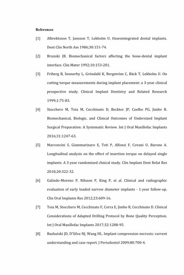
References
[1] Albrektsson T, Jansson T, Lekholm U. Osseointegrated dental implants.
Dent Clin North Am 1986;30:151-‐74.
[2] Brunski JB. Biomechanical factors affecting the bone-‐dental implant
interface. Clin Mater 1992;10:153-‐201.
[3] Friberg B, Sennerby L, Gröndahl K, Bergström C, Bäck T, Lekholm U. On
cutting torque measurements during implant placement: a 3-‐year clinical
prospective study. Clinical Implant Dentistry and Related Research
1999;1:75-‐83.
[4] Stocchero M, Toia M, Cecchinato D, Becktor JP, Coelho PG, Jimbo R.
Biomechanical, Biologic, and Clinical Outcomes of Undersized Implant
Surgical Preparation: A Systematic Review. Int J Oral Maxillofac Implants
2016;31:1247-‐63.
[5] Marconcini S, Giammarinaro E, Toti P, Alfonsi F, Covani U, Barone A.
Longitudinal analysis on the effect of insertion torque on delayed single
implants: A 3-‐year randomized clinical study. Clin Implant Dent Relat Res
2018;20:322-‐32.
[6] Galindo-‐Moreno P, Nilsson P, King P, et al. Clinical and radiographic
evaluation of early loaded narrow diameter implants -‐ 1-‐year follow-‐up.
Clin Oral Implants Res 2012;23:609-‐16.
[7] Toia M, Stocchero M, Cecchinato F, Corra E, Jimbo R, Cecchinato D. Clinical
Considerations of Adapted Drilling Protocol by Bone Quality Perception.
Int J Oral Maxillofac Implants 2017;32:1288-‐95.
[8] Bashutski JD, D'Silva NJ, Wang HL. Implant compression necrosis: current
understanding and case report. J Periodontol 2009;80:700-‐4.
[9] Wang L, Ye T, Deng L, et al. Repair of microdamage in osteonal cortical
bone adjacent to bone screw. PLoS One 2014;9:e89343.
[10] Duyck J, Corpas L, Vermeiren S, et al. Histological, histomorphometrical,
and radiological evaluation of an experimental implant design with a high
insertion torque. Clin Oral Implants Res 2010;21:877-‐84.
[11] Cha JY, Pereira MD, Smith AA, et al. Multiscale Analyses of the Bone-‐
implant Interface. Journal of Dental Research 2015;94:482-‐90.
[12] Burr DB. Targeted and nontargeted remodeling. Bone 2002;30:2-‐4.
[13] Coelho PG, Jimbo R, Tovar N, Bonfante EA. Osseointegration: hierarchical
designing encompassing the macrometer, micrometer, and nanometer
length scales. Dent Mater 2015;31:37-‐52.
[14] Berglundh T, Abrahamsson I, Lang NP, Lindhe J. De novo alveolar bone
formation adjacent to endosseous implants. Clin Oral Implants Res
2003;14:251-‐62.
[15] Davies JE. Understanding peri-‐implant endosseous healing. J Dent Educ
2003;67:932-‐49.
[16] Osborn JF. Dynamic aspects of the implant-‐bone-‐interface. In: Heimke G,
editor. Dental implants. Materials and systems, Munchen: Carl Hanser
Verlag; 1980, p. 111-‐23.
[17] Stocchero M, Toia M, Jinno Y, et al. Influence of different drilling
preparation on cortical bone: A biomechanical, histological, and micro-‐CT
study on sheep. Clin Oral Implants Res 2018;29:707-‐15.
[18] Burr DB, Martin RB, Schaffler MB, Radin EL. Bone remodeling in response
to in vivo fatigue microdamage. J Biomech 1985;18:189-‐200.

[19] Martin RB. Toward a unifying theory of bone remodeling. Bone
2000;26:1-‐6.
[20] Holmgren EP, Seckinger RJ, Kilgren LM, Mante F. Evaluating parameters of
osseointegrated dental implants using finite element analysis-‐-‐a two-‐
dimensional comparative study examining the effects of implant
diameter, implant shape, and load direction. J Oral Implantol 1998;24:80-‐
8.
[21] Hansson S. The implant neck: smooth or provided with retention
elements. A biomechanical approach. Clin Oral Implants Res
1999;10:394-‐405.
[22] Yamanishi Y, Yamaguchi S, Imazato S, Nakano T, Yatani H. Effects of the
implant design on peri-‐implant bone stress and abutment
micromovement: three-‐dimensional finite element analysis of original
computer-‐aided design models. J Periodontol 2014;85:e333-‐8.
[23] Brunski JB. In vivo bone response to biomechanical loading at the
bone/dental-‐implant interface. Adv Dent Res 1999;13:99-‐119.
[24] Yamaguchi S, Inoue S, Sakai T, Abe T, Kitagawa H, Imazato S. Multi-‐scale
analysis of the effect of nano-‐filler particle diameter on the physical
properties of CAD/CAM composite resin blocks. Comput Methods
Biomech Biomed Engin 2017;20:714-‐9.
[25] Takano N, Zako M, Kubo F, Kimura K. Microstructure-‐based stress
analysis and evaluation for porous ceramics by homogenization method
with digital image-‐based modeling. International Journal of Solids and
Structures 2003;40:1225-‐42.
[26] Takano N, Fukasawa K, Nishiyabu K. Structural strength prediction for
porous titanium based on micro-‐stress concentration by micro-‐CT image-‐
based multiscale simulation. International Journal of Mechanical Sciences
2010;52:229-‐35.
[27] Amid R, Raoofi S, Kadkhodazadeh M, Movahhedi MR, Khademi M. Effect of
microthread design of dental implants on stress and strain patterns: a
three-‐dimensional finite element analysis. Biomed Tech (Berl)
2013;58:457-‐67.
[28] Geng JP, Tan KB, Liu GR. Application of finite element analysis in implant
dentistry: a review of the literature. J Prosthet Dent 2001;85:585-‐98.
[29] Kitamura E, Stegaroiu R, Nomura S, Miyakawa O. Biomechanical aspects
of marginal bone resorption around osseointegrated implants:
considerations based on a three-‐dimensional finite element analysis. Clin
Oral Implants Res 2004;15:401-‐12.
[30] Akca K, Cehreli MC. Biomechanical consequences of progressive marginal
bone loss around oral implants: a finite element stress analysis. Med Biol
Eng Comput 2006;44:527-‐35.
[31] Knets I. Peculiarities of the structure and mechanical properties of
biological tissues. Meccanica 2002;37:375-‐84.
[32] Chang MC, Ko CC, Liu CC, et al. Elasticity of alveolar bone near dental
implant-‐bone interfaces after one month's healing. J Biomech
2003;36:1209-‐14.
[33] Natali AN, Carniel EL, Pavan PG. Modelling of mandible bone properties in
the numerical analysis of oral implant biomechanics. Comput Methods
Programs Biomed 2010;100:158-‐65.
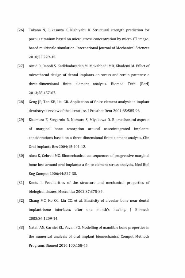

[34] Mori S, Burr DB. Increased intracortical remodeling following fatigue
damage. Bone 1993;14:103-‐9.
[35] Mohsin S, O'Brien FJ, Lee TC. Microcracks in compact bone: a three-‐
dimensional view. J Anat 2006;209:119-‐24.
[36] Zioupos P, Currey JD. The extent of microcracking and the morphology of
microcracks in damaged bone. Journal of Materials Science 1994;29:978-‐
86.
[37] Ralph JP. Photoelastic studies in the edentulous human mandible. J Dent
1975;3:9-‐14.
[38] Lehman ML. Stress distribution in bone: a study of Benninghoff
trajectories of the facial skeleton. Proc R Soc Med 1973;66:390-‐1.
[39] Guo MZ, Xia ZS, Lin LB. The mechanical and biological properties of
demineralised cortical bone allografts in animals. J Bone Joint Surg Br
1991;73:791-‐4.
[40] McNamara LM, Van der Linden JC, Weinans H, Prendergast PJ. Stress-‐
concentrating effect of resorption lacunae in trabecular bone. J Biomech
2006;39:734-‐41.
[41] Cecchinato D, Bressan EA, Toia M, Araujo MG, Liljenberg B, Lindhe J.
Osseointegration in periodontitis susceptible individuals. Clin Oral
Implants Res 2012;23:1-‐4.
[42] Halldin A, Jimbo R, Johansson CB, et al. The effect of static bone strain on
implant stability and bone remodeling. Bone 2011;49:783-‐9.
[43] Natali AN, Carniel EL, Pavan PG. Dental implants press fit phenomena:
biomechanical analysis considering bone inelastic response. Dent Mater
2009;25:573-‐81.
[44] Jimbo R, Halldin A, Janda M, Wennerberg A, Vandeweghe S. Vertical
fracture and marginal bone loss of internal-‐connection implants: a finite
element analysis. Int J Oral Maxillofac Implants 2013;28:e171-‐6.
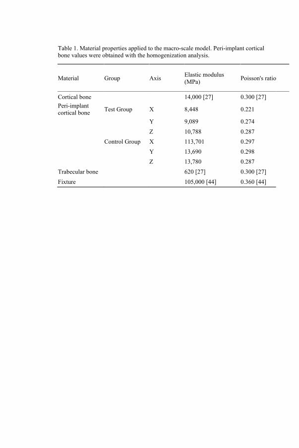
Table 1. Material properties applied to the macro-scale model. Peri-implant cortical bone values were obtained with the homogenization analysis.
Material Group Axis Elastic modulus (MPa) Poisson's ratio
Cortical bone 14,000 [27] 0.300 [27] Peri-implant cortical bone Test Group X 8,448 0.221
Y 9,089 0.274
Z 10,788 0.287
Control Group X 113,701 0.297
Y 13,690 0.298
Z 13,780 0.287 Trabecular bone 620 [27] 0.300 [27] Fixture 105,000 [44] 0.360 [44]
Figure 1.
a) Voxel models for micro-scale cortical bone structure. Cavities can be observed in
the Test Group models, while Control Group models showed a preserved structure. b)
Macro-scale CAD model of the mandibular ridge with implant and abutment. 1.5 mm
wide peri-implant cortical bone was selected. A static load of 100 N with an
inclination of 45° from bucco-lingual direction was impressed on top of the abutment
(red arrow).
X: bucco-lingual axis, Y: mandible longitudinal axis; Z: implant longitudinal axis.
Figure 2.
a) MPStress distribution at the peri-implant cortical bone in the macro-scale model.
Wider area of MPStress can be observed in the test group at the buccal side of bone-
implant interface. b) MPStrain distribution at the peri-implant cortical bone in the
macro-scale model. Peak values were located in the most coronal part of bone-implant
interface along the bone longitudinal axis.
X: bucco-lingual axis, Y: mandible longitudinal axis; Z: implant longitudinal axis.
Figure 3.
MPStress (a) and MPStrain (b) distribution in micro-scale model section. The location
of the maximum value of MPStress/MPStrain is facing the cavity. More
heterogeneous stress/strain distribution can be observed in test compared to control.
X: bucco-lingual axis, Y: mandible longitudinal axis; Z: implant longitudinal axis.

Figure 4.
Histograms representing mean values of maximum shear stress (a) and shear strain (b)
along each plane. Bars represent standard deviation.
X: bucco-lingual axis, Y: mandible longitudinal axis; Z: implant longitudinal axis.
Figure 1
Figure 2

Figure 4.
Histograms representing mean values of maximum shear stress (a) and shear strain (b)
along each plane. Bars represent standard deviation.
X: bucco-lingual axis, Y: mandible longitudinal axis; Z: implant longitudinal axis.
Figure 1
Figure 2
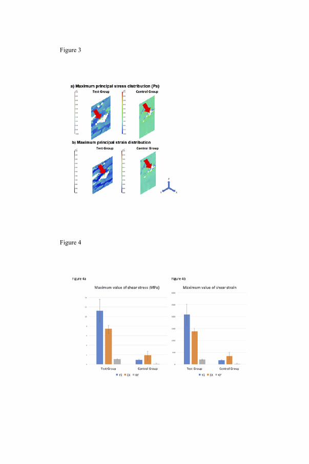
Figure 3
Figure 4


MALMÖ UNIVERSITY
205 06 MALMÖ, SWEDEN
WWW.MAU.SE
isbn 978-91-7104-969-8 (print)
isbn 978-91-7104-970-4 (pdf)
MIC
HE
LE
ST
OC
CH
ER
O
MA
LM
Ö U
NIV
ER
SIT
Y 2
01
8O
N IN
FL
UE
NC
E O
F A
N U
ND
ER
SIZ
ED
IMP
LA
NT
SIT
E O
N IM
PL
AN
T S
TAB
LIT
Y A
ND
OS
SE
OIN
TE
GR
AT
ION