& VTIsärtryck - DiVA-Portal
24
-
Upload
khangminh22 -
Category
Documents
-
view
1 -
download
0
Transcript of & VTIsärtryck - DiVA-Portal
ISSN 0347-6049
& VTIsärtryck [_
1& 1990
Heavy Duty Vehicle Dynamics Related to
Braking, Steering and Tyres - SwedishResearch and Proposals by VTI
Olle NordströmReprint from SAE Technical Paper Series, SP 807 Vehicle Dyna-
mics Related to Braking and Steering, paper 892502, pp 43 57
(Truck and Bus Meeting and Expos/tion, Charlotte, North
Caro/ina, November 6 - 9, 7989)
wVäg'OCI' a /(' Statens väg- och trafikinstitut ( VTI) ' 581 07 Linköping
Inst/tutet Swedish Road and Traffic Research Institute . 8-587 01 Linköping Sweden


&.= The Engineering SocietyFor Advancing MobilityLand Sea Air and Space®
I N T E R N A TI O N A L 400 COMMONWEALTH DRIVE, WARRENDALE, PA15096-0001 U.S.A.
892502
Heavy Duty Vehicle Dynamics Related toBraking, Steering and Tyres Swedish
Research and Proposals by VTIOlle Nordström
Swedish Road and Traffic Research InstituteLinkoping, Sweden
Reprinted from SP-801 Vehicle DynamicsRelated to Braking and Steering
Truck and Bus Meetingand Exposition
Charlotte, North CarolinaNovember 6-9, 1989
SAE GLOBAL MOBILITY DATABASE
The papers included in this volume
are abstracted and indexed in the
SAE Global Mobility Database.
No part of this publication may be reproduced in any form, inan electronic retrieval system or otherwise, without the priorwritten permission of the publisher.
ISSN 0148-7191Copyright 1989 Society of Automotive Engineers, Inc.
Positions and opinions advanced in this paper are those of theauthor(s) and not necessarily those of SAE. The author issolely responsible for the content of the paper. A process isavailable by which diScussions will be printed with the paperit it is published in SAE Transactions. For permission topublish this paper in full or in part, contact the SAE Publica-tions Division.
Persons wishing to submit papers to be considered for pres-entation or publication through SAE should send the manu-script or a 300 word abstract of a proposed manuscript to:Secretary, Engineering Activity Board, SAE.
Printed in U.S.A.

892502
Heavy Duty Vehicle Dynamics Related toBraking, Steering and Tyres Swedish
Research and Proposals by VTI
Olle NordströmSwedish Road and Traffic Research Institute
Linkoping, Sweden
ABSTRACT
Research concerning heavy duty vehicle
dynamics related to braking, steering andtyres has been conducted by the Swedish Roadand Traffic Research Institute (VTI) forabout 20 years. The aim has been to develop
test procedures and propose minimum per-formance requirements primarily for vehiclecombinations. This paper summarizes resultsconcerning dynamic stability in a double lanechange manouevre at constant speed, over-
turning stability, emergency antilock brakingperformance under winter conditions in termsof stability, steerability and braking performance during emergency braking in a turnon ice and during straight line braking onice, split friction and transition from lowto high friction. Hybrid simulation and atyre tester are also described.
THE SWEDISH ROAD AND TRAFFIC RESEARCH
INSTITUTE (VTI) is a governmental research
organization dealing with research and test-ing concerning road building, traffic engine"ering, human factors, road vehicles and
lately also some railway research.The road vehicle research is mainly
safety oriented and deals with both crash-worthiness and crash avoidance problems.
Since about 20 years great emphasis has beenlaid on research concerning the dynamic per-formance of heavy vehicle combinations.
The great majority of Swedish heavyvehicle combinations consists of a truck anda full trailer with a permissible totallength of 24 m. This type of combination aswell as tractor and semitrailer and truck andcentre axle trailer combinations has a speedlimit of 70 km/h (Figure 1).
Combinations with two trailers have aspeed limit of 40 km/h (Figure 2). Individual
approvals for 70 km/h can however be obtainedif certain technical specifications are ful-filled. These restrictions are by Swedish
43
industry transport research organizations(IVA TFK, Volvo) regarded as a majorobstacle for an improvement of the roadtransport system in Sweden.
The VTI research has to a large degreebeen motivated by the actions of theseorganizations and the concern of the roadsafety authorities to ensure that the levelof road safety is maintained or improved.
The research has primarily dealt with thefollowing problem areas.
- the dynamic yaw stability and handlingproperties at constant speed
- the overturning stability
- stability, steerability and brakingefficiency in braking manoeuvres
-;3
[&_ 004475
O Or .
{C} r§() u {BE§""
(it, "" ' '='? 000
Figure 1 Vehicle combinations with 70 km/h
speed limit in Sweden
. - ......i
... ' ... -....-" ...,4_ ! "*I i.
Cf ) Z 5 '~....'
F
lf
k
Figure 2
Tr555? 00 W" 00
Vehicle combinations with 40 km/h
speed limit in Sweden except afterspecial approval
Special interest has been taken inevaluating the performance on ice coveredroads.
The aim of this paper is to review thisresearch and give the present VTI positionconcerning desirable performance and methods
of testing and legislative enforcement,
DYNAMIC STABILITY AT CONSTANT SPEED
1970 72 full scale experiments andcomputer simulations were made with combinations with up to three articulations. Thedynamic stability was tested by means of a
double lane change manoeuvre (Figure 3). Thismaneuvre was chosen as it was regarded as the
most severe in real traffic.In the simulation the motor vehicle was
steered by an automatic controller calledDAVIS in such a way that the lateralacceleration of the c.g. followed a prescri-bed sinusoidal curve with 1.75 m/s2 asmaximum value.
As a result of these studies VTI proposed
that minimum performance requirements in thismanoeuvre should be set for heavy vehiclecombinations (1, 2, 3)*. These were the
following:
- rearward amplification of side slip anglesshould not exceed 2 related to the mean
value of the tractor rear axles
- the side slip angles must not exceed 150mrad (8,6°)
- the oscillatory damping must be such thatall side slip angles are less than 20 mrad(1,15°) when the front axle is 75 metres
away from the entrance of the exit corridor
- the overturning risk must be smaller than1. (No wheel lift must occur)
- the lateral axle deviation must stay withincertain limits ensuring that the vehiclecombination stays on a 7 m wide road
In the period 1972 to 1981 furtherdevelopment of the simulation program was
made (4) and new simulation studies were madeincluding about 400 heavy vehicle combina-tions (7, 8, 9).
The simulation studies that have beenmade indicate that few articulation pointsare desirable. At the same time other para-meters were just as important from stabilitypoint of view. It is desirable to have
speed 70km/h mox lood mox c 9 height
3,5m Mu lxxoncomingjgta _
-3,5m?-_ % ___________l10 40m
J.
obstdcle
Figure 3 VTI double lane change test. Fullscale configuration
*Numbers in parentheses designate references
at the end of the paper
- a short distance between dolly pintle hookand the first semitrailer rear axle (or
load centre of the rear axles in the case
of multiple axles)
- long wheelbase on the trailers
- high tyre cornering stiffness which in-creases proportional to the load
- a low centre of gravity height
high roll stiffness
- optimized roll or side force steer on the
trailer axles as it has a significant
effect
These findings agree with later studiesmade at UMTRI in Michigan USA and inAustralia, Canada and England and the FederalRepublic of Germany.
In 1981 a final report (10) was publish-
ed. The recommendations in the report werebasically the same as 1972 but in addition anapproval system based on simulation resultswas outlined in more detail.
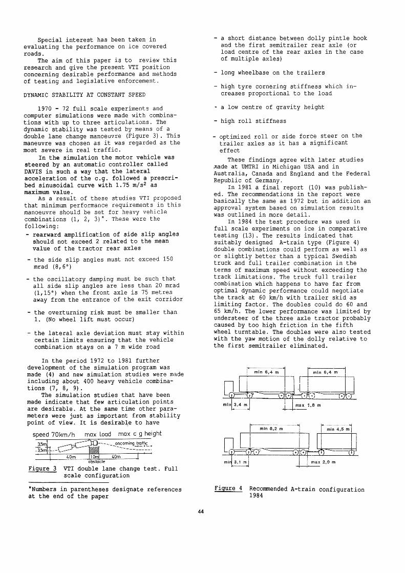
In 1984 the test procedure was used infull scale experiments on ice in comparativetesting (13). The results indicated that
suitably designed A-train type (Figure 4)double combinations could perform as well asor slightly better than a typical Swedishtruck and full trailer combination in theterms of maximum speed without exceeding thetrack limitations. The truck full trailercombination which happens to have far fromoptimal dynamic performance could negotiatethe track at 60 km/h with trailer skid aslimiting factor. The doubles could do 60 and
65 km/h. The lower performance was limited byundersteer of the three axle tractor probably
caused by too high friction in the fifthwheel turntable. The doubles were also tested
with the yaw motion of the dolly relative tothe first semitrailer eliminated.
min 6,4 m min 6,4 m
Umi max 1,8 m
max 2,0 m
Figure 4 Recommended A-train configuration1984
This prevention of dolly jackknife didhowever not improve the lane change per-
formance in terms of maximum speed.Based on these tests and other considera-
tions it was decided to give provisionalpermits for double combinations of the testedconfigurations or with more favourable designto be driven at speeds up to 70 km/h, Specialrequirements were also set for the brakes
that had to be equipped with load sensingvalves and/or an antilock system.
In 1986 and 1988 further lane changetests on ice were made with two specialdouble combinations in order to have themapproved for 70 km/h. The first combinationhad a yaw restrained centre axle trailer assecond trailer (Figure 7, vehicle No. 13).The other combination was a conventionalA-train with a short wheelbase three axletractor where the non driven middle axle was
tested steered and rigid. The test resultswere regarded as successful and were verysimilar to those obtained in 1984 i.e. about65 km/h limit speed. In these tests a singlethree axle truck was used as a reference.This vehicle performed marginally better. Thelimiting factor for the double combinationswas trailer swing of the rearmost trailer. Inthe 1988 the yaw angle velocity rearwardamplification was measured to be 1.6 at therearmost trailer. No clear preferenceconcerning steered or rigid tractor middleaxle was found in this test.
In 1989 it has been proposed that doublecombinations should be approved for 70 kmspeed limit on a self certification basis ifthey fulfilled certain performance demands.The vehicles would have to be equipped withECE/EEC approved antilock brake systems.
The dynamic stability and steerabilitywould be approved by means of a computer
simulation of the double lane changedeveloped by VTI. A more user friendlyversion of the program is planned to bedeveloped for this purpose.
The performance requirements are somewhatchanged compared with those originally pro-posed in 1972 in order to allow a simplerpractical validation of the simulation testresults if needed.
- The maximum allowed rearward amplificationis still 2 but the reference variable hasbeen changed to yaw velocity instead ofside slip angle
- The limitation of lateral axle deviation is
unchanged
- Also as before the overturning risk must belower than 1. This means that no wheel lift
must occur.
Tyre cornering stiffness characteristicshave an important influence on the simulationresults. These characteristics vary with tyretype but also with road surface and inflationpressure.
45
In order to safeguard for these varia-tions the simulations are to be made withreference tyre data which represent the lower
limit of what can be expected on a wetasphalt or concrete road in normal condition.Presently used values of cornering stiffness
are however higher than those used in thestudies earlier presented by VTI and based onmore recent measurements.
The double combination with beststability performance is expected to be ofthe so called B-train concept with only twoarticulation points where the second semi-trailer is coupled directly to a fifth wheelat the rear end of the first semitrailer. Itis however still important to keep the axleload centre of the first semitrailer close tothe fifth wheel for the second semitrailer.
In Sweden several applications have beenmade for approval of combinations consistingof a tractor, a semitrailer and a centre axletrailer. Unlike the typical B-train rearsemitrailer where the load is placed betweenthe axles the centre axle trailer has aconsiderable load platform length behind theaxle centre. On such a trailer it is possibleto get the centre of gravity behind thetrailer axle(s) which would give a tendencyto oscillatory instability above a criticalspeed which could very well be within theoperating speed. The experience with thiskind of combination seems to be very smalland no literature on the subject has beenfound.
OVERTURNING STABILITY
Compared to a passenger car the overtur-
ning stability of a loaded heavy duty vehicleis very low. The most critical cases are whenthe cargo density is such that a vehicleheight of 4 m or even more can be utilized.From safety point of view a high overturninglimit is obviously desirable. Against thisstands the desire to be able to carry thelargest possible load volume and weight. InSweden the maximum combination length is 24 mand the maximum weight is 51 400 kg. This islonger and heavier than in any other Europeancountry but the load per metre vehicle length
is lower and allows for a lower c.g. height.
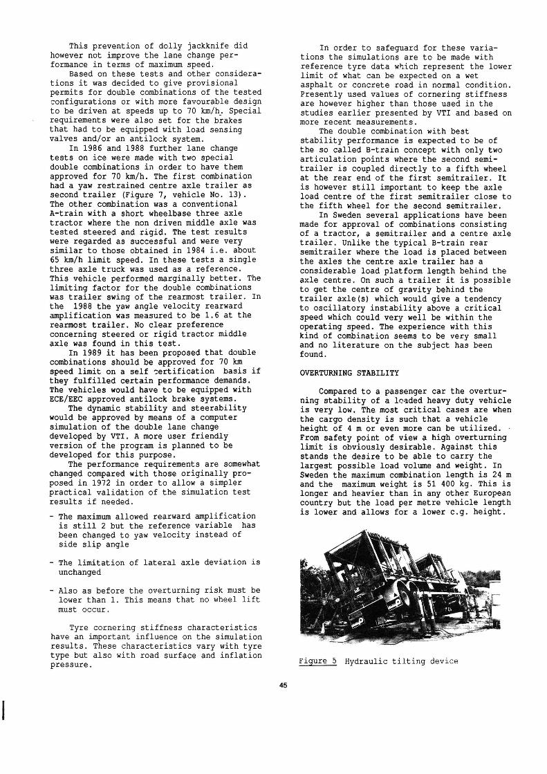
Figure 5 Hydraulic tilting device
After full scale static tests of a numberof representative Swedish trucks and trailers
on a hydraulic tilting device (Figure 5), VTIin 1972 proposed a static overturning limitof 4 m/sz.
Further studies were considered necessaryand were also carried out but did not changethe new recommendation given in 1981 (10).Since then investigators in USA, Australiaand Canada have come to similar conclusions.
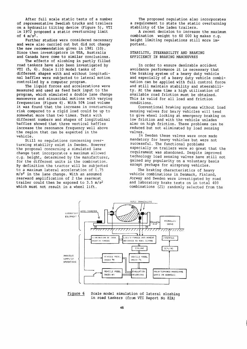
The effects of sloshing in partly filledroad tankers have also been investigated byVTI (5, 6). Scale 1:10 model tanks of
different shapes with and without longitudi-nal baffles were subjected to lateral motioncontrolled by a computer program.
The liquid forces and accelerations were
measured and used as feed back input to theprogram, which simulated a double lane changemanoeuvre and sinusoidal motions with varyingfrequencies (Figure 6). With 50% load volumeit was found that the increase in overturningrisk compared to a rigid load could be up tosomewhat more than two times. Tests withdifferent numbers and shapes of longitudinalbaffles showed that three vertical bafflesincrease the resonance frequency well above
the region that can be expected in thevehicle.
Still no regulations concerning over-turning stability exist in Sweden. Howeverthe proposal concerning a simulated lanechange test incorporates a maximum allowed
c.g. height, determined by the manufacturer,for the different units in the combination.By definition the tractor will be subjectedto a maximum lateral acceleration of 1.75
m/s2 in the lane change. With an assumed
rearward amplification of 2 the rearmosttrailer could then be exposed to 3.5 m/s2which must not result in a wheel lift.
LABORATORYEQUIPMENT 4
CCELEROMETER
The proposed regulation also incorporatesa requirement to state the static overturningstability of the laden trailers.
A recent decision to increase the maximumcombination weight to 60 000 kg makes c.g.height limiting regulations still more im-portant.
STABILITY, STEERABILITY AND BRAKING
EFFICIENCY IN BRAKING MANOEUVRES
In order to ensure desirable accidentavoidance performance it is necessary thatthe braking system of a heavy duty vehicleand especially of a heavy duty vehicle combination can be applied with full control forceand still maintain stability and steerabili-ty. At the same time a high utilization ofavailable road friction must be obtained.This is valid for all load and frictionconditions.
Conventional braking systems without loadsensing valves for heavy vehicles will tendto give wheel locking at emergency braking onlow friction and with the vehicle unladenalso on high friction. These problems can bereduced but not eliminated by load sensingvalves.
In Sweden these valves were once mademandatory for heavy vehicles but were notsuccessful. The functional problemsespecially on trailers were so great that therequirement was abandoned. Despite improvedtechnology load sensing valves have still notgained any popularity on a voluntary basisexcept perhaps for airsprung vehicles.
The braking characteristics of heavyvehicle combinations in Denmark, Finland,
Norway and Sweden were investigated by road
and laboratory brake tests on in total 400combinations (21) randomly selected from the
FORCE TRANSDUCERS
I/
HYDRAULIC__;(3:
H SERVO <13
/'/'/ /U r7/ /' ////////7//////7/ /// /////7/
t
INERTIA FORCES
ELIMINATION OF TANK
LIOUID FORCES AND MOMENT
REFERRED TO TANK CENTRE
INTERFACE
I SCALING I SCALING
TUTT' _'7F
ANALOGUE
COMPUTER 4
OPERATIONS
VEHICLE MODEL
INDEX OR
VEHICLE MODEL
INDLX OS
VEHCILE MODEL
INDEX VR
IIEVALUATION
PREDFTERMINED MANOEUVRE
RECORDING DAVIS OR HARMGHIC
Figure 6
IN
# J
Scale model simulation of lateral sloshingin road tankers (from VTI Report No 82A)
46
traffic on suitable roads.
The theoretical advantage of load sensingvalves could not be confirmed in this study.On the contrary the results indicate thatmaladjustments still is a significant problemthat reduces the braking efficiency at fullload and still gives wheel locking at almostthe same deceleration as for vehicles withoutthese devices. The trailers were in generalunderbraked relative to the truck or tractorespecially at high pressures.
Poor brake adjustment resulting in longpushrod stroke was one of the reasons for
poor braking efficiency despite mandatoryautomatic adjustment. Very short strokes werealso associated with a reduction in brakingefficiency. In Sweden ligtly laden vehiclesshowed significantly smaller brakingforce/pressure ratio than fully ladenvehicles. As these vehicles had no loadsensing valves the results could indicateglazing effects due to the low brake forcesused in the unladen condition which then re-covered when in the laden condition after atransition period. There is however a possi-bility of bias if drivers with laden vehicleswith poor brakes or overload were warned by
their colleagues and changed their route.The VTI conclusion is that closed loop
brake control systems with a warning signalto the driver in case of malfunction is animportant part of the solution to the presentbrake system problems.
An antilock brake system is an example ofsuch a system designed to prevent wheel lock-ing due to overbraking. This solves theproblems of stability and steerability in an
emergency braking situation. Normally alsothe braking performance is improved. Undernon locking condition these systems are how-
ever, inactive. A system for automatic brake
force adaptation between a truck and a fulltrailer has been introduced on the Swedishmarket by the Swedish company VBG under thename Bromsgyro. This system is fullycontained on the truck and consists of acoupling force sensor, a variable pressurereduction valve driven by an electric motorand a controller. A display shows the driverthe degree of pressure reduction and whether
the trailer is over-or underbraked in rela-tion to the truck.
SWEDISH PROPOSAL FOR COMPLEMENTARY WINTER
SERVICE REQUIREMENTS TO BE ADDED TO THE NEW
ECE REQUIREMENTS FOR ANTILOCK BRAKING SYSTEMS(ABS)
In Sweden icy roads can be expected aboutsix months of the year. Safe braking underthese conditions is a considerable problem.
Antilock braking systems with good per-formance on ice are therefore expected to
give a significant reduction in trafficaccidents where braking is involved.
The United Nations Economic Commissionfor Europe (ECE) has developed a large number
of international road vehicle regulations.
47
The ECE Regulation No 13 adresses brakes andcontains since 1979 an annex concerning re-quirements on antilock brakes. A revisedversion became effective in 1987. The samerules have also been adopted by the EuropeanEconomic Community (EEC) in 1986.
Sweden took active part in the establish-ment of the revised version of the ECE-antilock regulation but has still not adoptedit in its national legislation. The author ofthis paper represented Sweden in this workand has also been responsible for severalstudies (11, 12, 13, 15, 17, 18, 19) concer
ning antilock system performance under winterconditions carried out by the Swedish Roadand Traffic Research Institute(VTI).
The VTI investigations have been madewith heavy vehicles and vehicle combinationsfrom about 5 000 to more than 65 000 kg as
well as for a number of passenger cars as
shown in Figure 7. Five different antilocksystems for heavy vehicles and three forpassenger cars have been tested.
Based on these investigations winterservice test methods and requirements areproposed to be added to the ECE/EEC-regula-
tions. These are:
J-turn braking test on ice
- Split friction test with very low frictionon one side
- Straight line braking on ice
- Transition from low friction to high fric-tion surface
A hybrid laboratory test is envisaged asa future possibility of checking these per-formances for electronic antilock systems. In
this test the vehicle is stationary andconnected to a computer.
In the following, these winter testprocedures and requirements are presented.
J TURN TEST ON ICE
GENERAL - Vehicles with antilock systemalso on the steered wheels will if they meetthe requirements of a straight brakingefficiency test certainly possess some degreeof steerability. On very low friction sur-faces a bad antilock system may, however,give either very poor stability or very poorsteerability, due to high slip levels andpoor slip distribution between front and rearaxles. In both cases the expected safety
benefits will not be obtained and in theunstable case it might even be more dangerousto use such an antilock system than a conven-tional brake system or an antilock systemacting only on the rear wheels. It is there-fore essential to test the steering qualities
during emergency braking on low friction in aspecial test.
This is also important for trailers asthe steerability and stability of a vehicle

combination also depends on the performanceof the trailer.
A driver controlled J turn test is pro-posed. Open loop tests were found to be toosevere for heavy vhicles which are normallysomewhat oversteered during antilock braking.A J-turn test is less space demanding than asteady state circular test
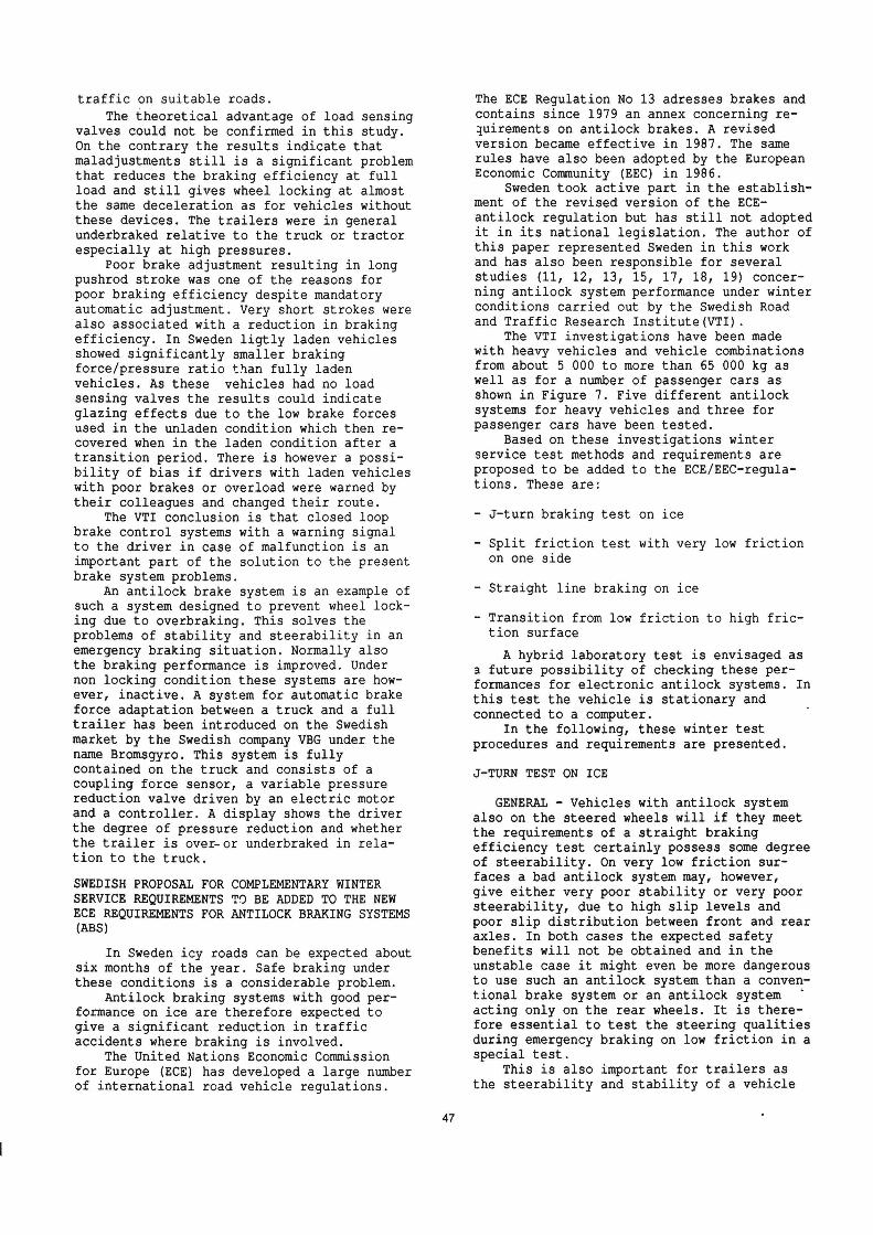
TEST SPECIFICATION - The driver controlledJ turn test on ice (Figure 8) has the follow-
ing specifications.
- The track surface shall consist of ice witha lateral friction corresponding to amaximum cornering speed between 40 and 60km/h
- The test track shall have a 30 m long
entrance corridor, 0.5 m wider than thevehicle, followed by a 100 m radiuscircular track 1.5 m wider than the vehicle
The test procedure comprises:
- determination of maximum cornering speedwithout braking (VM)
- determination of the maximum speed (V0) andthe deceleration (ax) at which the vehicle
can be braked with ABS and full pedal force
Optional reference tests are:
- locked wheel straight line braking from 40km/h on the same surface
- determination of an ECE type maximumconstant deceleration in the turn withoutwheel locking from 75 % of VM based onfront axle braking
PERFORMANCE REQUIREMENT - The following
stability/steerability performance isproposed:
- to stay within the track boundaries withall parts of the tyre treads
- not to exceed a steering correction of +/-180°
- to have a stability/steerability factor ESnot less than 0.64 where ES=(VO/VM)2, i.e.successful braking from 80% of the maximumcornering speed
the braking efficiency EBY = aX/ay, withthe maximum cornering acceleration (a ) asreference, is proposed to be at least 0.5
- the braking efficiency EBE = ax/aECE, basedon the maximum deceleration, with front
brakes only, to be at least 0.75
TEST VEHICLES TEST HEIGHT TEST VEHICLES TEST HEIGHT
10 Misc-Q11w12Må: #13 l-<r-.vli W.vb Lo-02150134]
0 10 20 30Vehicle length m
KG KG
1 &; 5500 13000
2 Egg 9600 22700"Id. .
3 31% 15800 1 14 "GD G 1215-1520HONDA PRELUDE
4 Gig)?! 10800 A -N
12000-33000 15 *@ -@ 1600-1920AUDI 100 MIMI 1984
15 "om-cw . 1580roan SCORPIO
|
17000-51400
13000 28500 GI. ___ 158 1840_ __ O..
15000-36400 17 () C)AUDI 100 AVANT 1985
20500-51400 IUD. .. |
18 ©" ©* _ 1640-181020000-51400 VOLVO 750
I
22000 66400
50900 Figure 7 Test vehicles
48
the braking efficiency EBE = ax/aECE, basedon the maximum deceleration without wheellocking, to be at least 0.75
The test is also proposed for trailerswhich shall be tested in combination with aworst case approved antilock motor vehicle.
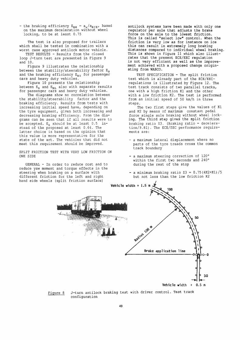
TEST RESULTS - Results from the closedloop J-turn test are presented in Figure 9
and 10.Figure 9 illustrates the relationship
between the stability/steerability factor Esand the braking efficiency EBY for passengercars and heavy duty vehicles.
Figure 10 presents the relationshipbetween ES and EBL also with separate resultsfor passenger cars and heavy duty vehicles.
The diagrams show no correlation between
the stability/steerability factor and thebraking efficiency. Results from tests withincreasing initial speed have, depending onthe tyre equipment, given both increasing anddecreasing braking efficiency. From the dia-grams can be seen that if all results were tobe accepted. ES should be at least 0.5 instead of the proposed at least 0.64. Thelatter choice is based on the opinion thatthis value is more representative for thestate of the art. The vehicles that did notmeet this requirement should be improved.
SPLIT FRICTION TEST WITH VERY LOW FRICTION ON
ONE SIDE
GENERAL - In order to reduce cost and to
reduce yaw moment and torque effects in the
steering when braking on a surface withdifferent friction for the left and righthand side wheels (split friction surface)
Vehicle width + 1.5 m
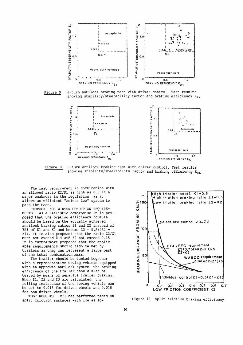
antilock systems have been made with only oneregulator per axle that adjusts the brakeforce on the axle to the lowest friction.This is called "select low" control. When thefriction is very low as for instance on icethis can result in extremely long brakingdistances compared to individual wheel braking.This is shown in Figure 11 which also illust-rates that the present ECE/EEC regulationis not very efficient as well as the improve-ment achieved with a proposed change origin-ating from WABCO.
TEST SPECIFICATION The split frictiontest which is already part of the ECE/EEC-regulations is illustrated by Figure 12. Thetest track consists of two parallel tracks,one with a high friction Kl and the otherwith a low friction K2. The test is performedfrom an initial speed of 50 km/h in threesteps.
The two first steps give the values of Kland K2 by means of maximum constant pedalforce single axle braking without wheel lock-ing. The third step gives the split frictionbraking ratio Z3. (Braking ratio = deceleration/9.81). The ECE/EEC performance require-ments are:
- a maximum lateral displacement where noparts of the tyre treads cross the common
track boundary
- a maximum steering correction of 120°within the first two seconds and 240°during the rest of the stop
a minimum braking ratio Z3 = 0.75(4K2+K1)/5
but not less than the low friction K2
Brake application line
30
Vehicle width + 0.5 m
Figure 8 J-turn antilock braking test with driver control. Test track
configuration
Acceptable
___
___._1
0.64 | *L... ___..____._
0.5 0.
_o a:AL
L
LA
Heavy duty vehicles
L f ' r f
1.0
BY
STABILITY/STEERABILITYFACTOR
ES
0 '03 .BRAKING EFFICIENCY E
Figure 9
' f ' WT ' 'n ' ' TLu 4 I _
g 4 | A , 'i
p. "e A01-0 ' .:..oz '..( | 4. g ou. i o' ,>. 1 | " . .. . .
: | '£ * v Acceptabie '2 * 0.64å_5 _ _ __ __ _ __
5 05.Lu|...U)\
E..J 1
$ Passenger cars q
$° os LOBRAKING EFFICIENCY E
BY
J-turn antilock braking test with driver control. Test results
showing stability/steerability factor and braking efficiency EBY
v v v v v v v v f '
Heavy duty vehicles
STABILITY/STEERABILITYFACTOREs
Tito 2.0 'BRAKING erncneucv ESL
O
d O-
-.
.-
AA
Acceptable___ 10.64 [___
0.90.5 i
Passenger cars *STABILITY/STEERABILITYFACTOR
Es
vvv f v w ' 'i vf
0 1.0 2.0
BRAKING EFFICIENCY EBL
Figure 10 J turn antilock braking test with driver control. Test resultsshowing stability/steerability factor and braking efficiency EBL
The last requirement in combination withan allowed ratio K2/K1 as high as 0.5 is amajor weakness in the regulation as itallows an efficient "select low" system topass the test.
PROPOSAL FOR WINTER CONDITION REQUIRE-
MENTS - As a realistic compromise it is proposed that the braking efficiency formulashould be based on the actually achievedantilock braking ratios Z1 and ZZ instead of75% of K1 and K2 and become Z3 = 0.2(4Z2 +
Zl). It is also proposed that the ratio ZZ/Zlmust not exceed 0.4 and Z2 not exceed 0.15.It is furthermore proposed that the applic-able requirements should also be met by
trailers as they can represent a large part
of the total combination mass.The trailer should be tested together
with a representative towing vehicle equippedwith an approved antilock system. The brakingefficiency of the trailer should also betested by means of separate trailer braking.When 21, Z2 and 23 are calculated, the
rolling resistance of the towing vehicle canbe set to 0.015 for driven wheels and 0.010for non driven wheels.
TEST RESULTS - VTI has performed tests onsplit friction surfaces with ice as low
50
m .
150*
BRAKING
DISTANCE
FROM
50KM/H
Fth hic on coef K1-0.5
High friction braking ratio Zi-O.5
ow friction braking ratio Z2-K2
__Select low control 28-2 2
ECE/EEC requirement
23å0.75(4K2+K1)/5
23>K2
w ABCO requirement
23å(422+Z1)/5
individual contro|23=0.5(21+22) O 03 ota 0:3 014 015 01.6
LOW FRICTION COEFFICIENT K2
0,7
Figure 11 Split friction braking efficiency
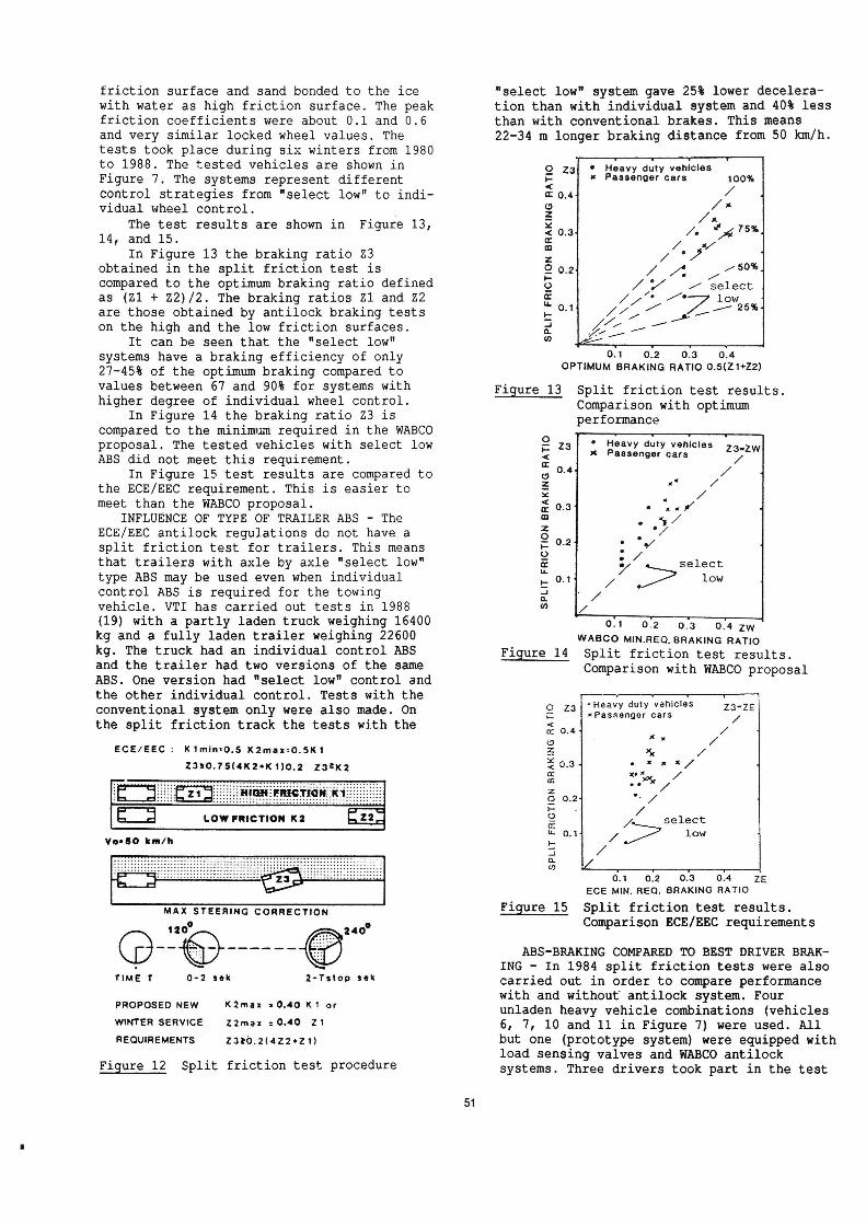
friction surface and sand bonded to the ice
with water as high friction surface. The peakfriction coefficients were about 0.1 and 0.6and very similar locked wheel values. Thetests took place during six winters from 1980to 1988. The tested vehicles are shown inFigure 7. The systems represent differentcontrol strategies from "select low" to indi-vidual wheel control. _
The test results are shown in Figure 13,14, and 15.
In Figure 13 the braking ratio Z3obtained in the split friction test iscompared to the optimum braking ratio definedas (Zl + Z2)/2. The braking ratios Z1 and Z2
are those obtained by antilock braking testson the high and the low friction surfaces.
It can be seen that the "select low"
systems have a braking efficiency of only
27-45% of the optimum braking compared tovalues between 67 and 90% for systems withhigher degree of individual wheel control.
In Figure 14 the braking ratio Z3 iscompared to the minimum required in the WABCOproposal. The tested vehicles with select low
ABS did not meet this requirement.In Figure 15 test results are compared to
the ECE/EEC requirement. This is easier tomeet than the WABCO proposal.
INFLUENCE OF TYPE OF TRAILER ABS The
ECE/EEC antilock regulations do not have asplit friction test for trailers. This meansthat trailers with axle by axle "select low"type ABS may be used even when individual
control ABS is required for the towingvehicle. VTI has carried out tests in 1988(19) with a partly laden truck weighing 16400kg and a fully laden trailer weighing 22600kg. The truck had an individual control ABSand the trailer had two versions of the sameABS. One version had "select low" control andthe other individual control. Tests with theconventional system only were also made. Onthe split friction track the tests with the
ECE/EEC : K1min=0.5 K2max=0.5K1
zaao.75(4K2+K1)o.2 232
5:3 E
LOW FRICTION K 2
VID-80 km/h
.............................................................................................................................................................................................................................................................................................................................
.........................
........................................................................
MAX STEERING CORRECTION
cafeTIME T 0 2 sek z-Tstop sek
K2max 10.40 K1 or
Z2max =0.40 21
zazo.2(422+21)
PROPOSED NEW
W|NTER SERVICE
REQUIREMENTS
Figure 12 Split friction test procedure
51
select low system gave 25% lower decelera-tion than with individual system and 40% lessthan with conventional brakes. This means22-34 m longer braking distance from 50 km/h.
0 23 0 Heavy duty vehiclesC at Passenger cars 10095
* /01 O.4< .0 /x
3 xx< o 3 /. "')4 75%.å ./ Js / ') so../ d; 0.2 / A /9 ///// // selectm ' //% low- 0.1 /£// / 2595+
| / /
&, ///1
OH 05 05 &4OPTIMUM BRAKING RATIO 0.5(Z1+22)
Figure 13 Split friction test results.Comparison with optimumperformance
' Heavy duty vehiclesx Passenger cars
N w zs-zvv/'
o ? \\
9 w .
/
.° roselect
low\X=...
V
SPLITFRlCTIONBRAKING
RATIO
071 o.'2 o.'3 o.'4 zwWABCO MIN.REO,BRAKING RATIOSplit friction test results.Comparison with WABCO proposal
Figure 14
r v 1 ,
O 23 'Heavy duty vehicles ZB'ZE: xPassenger cars /(n: 0 4 x / .
o " /E & /f 0.3 . xx x x / *a: xc
; .. &/,/'9 0-2' .- / 4
* ' /'oE />selictU- 0 1 ow» / ': /a.co
6.1 ofz 0.13 074 25race MIN. nee. samme mmo
Figure 15 Split friction test results.Comparison ECE/EEC requirements
ABS-BRAKING COMPARED TO BEST DRIVER BRAKING - In 1984 split friction tests were alsocarried out in order to compare performancewith and without antilock system. Fourunladen heavy vehicle combinations (vehicles6, 7, 10 and 11 in Figure 7) were used. All
but one (prototype system) were equipped withload sensing valves and WABCO antilocksystems. Three drivers took part in the test
but each combination was tested by only one
driver.The result of these tests was that the
braking efficiency in most cases was 10-20%higher with the normal braking system thanwith the antilock system in operation. Theefficiency of the antilock systems was about80% of (Z1+Z2)/2. Both with and without anti-lock system it was possible to keep thevehicle within a 3.5 m lane. The steering and
braking task was, however, more difficultwithout antilock system. The maximum steeringangles were about 90° with and 135° withoutantilock system.
STRAIGHT LINE BRAKING ON ICE
GENERAL - Straight line braking on a homogeneous surface is the classic and basic wayof testing the braking performance ofvehicles. The ECE/EEC antilock brakingregulations prescribe straight line low fric-tion tests. The friction level is howeverallowed to be as high as 0.4. A test on iceis therefore regarded as a useful winter
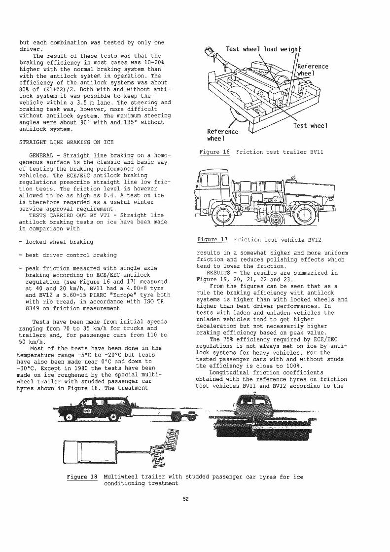
service approval requirement.TESTS CARRIED OUT BY VTI - Straight line
antilock braking tests on ice have been madein comparison with
- locked wheel braking
best driver control braking
- peak friction measured with single axlebraking according to ECE/EEC antilockregulation (see Figure 16 and 17) measured
at 40 and 20 km/h. BV11 had a 4.00-8 tyreand BV12 a 5.60-15 PIARC "Europe" tyre bothwith rib tread, in accordance with ISO TR
8349 on friction measurement
Tests have been made from initial speedsranging from 70 to 35 km/h for trucks andtrailers and, for passenger cars from 110 to
50 km/h.Most of the tests have been done in the
temperature range -5°C to -20°C but testshave also been made near 0°C and down to-30°C. Except in 1980 the tests have beenmade on ice roughened by the special multi-wheel trailer with studded passenger cartyres shown in Figure 18. The treatment
Referencewheel
Figure 16 Friction test trailer BV11
Figure 17 Friction test vehicle BV12
results in a somewhat higher and more uniformfriction and reduces polishing effects whichtend to lower the friction.
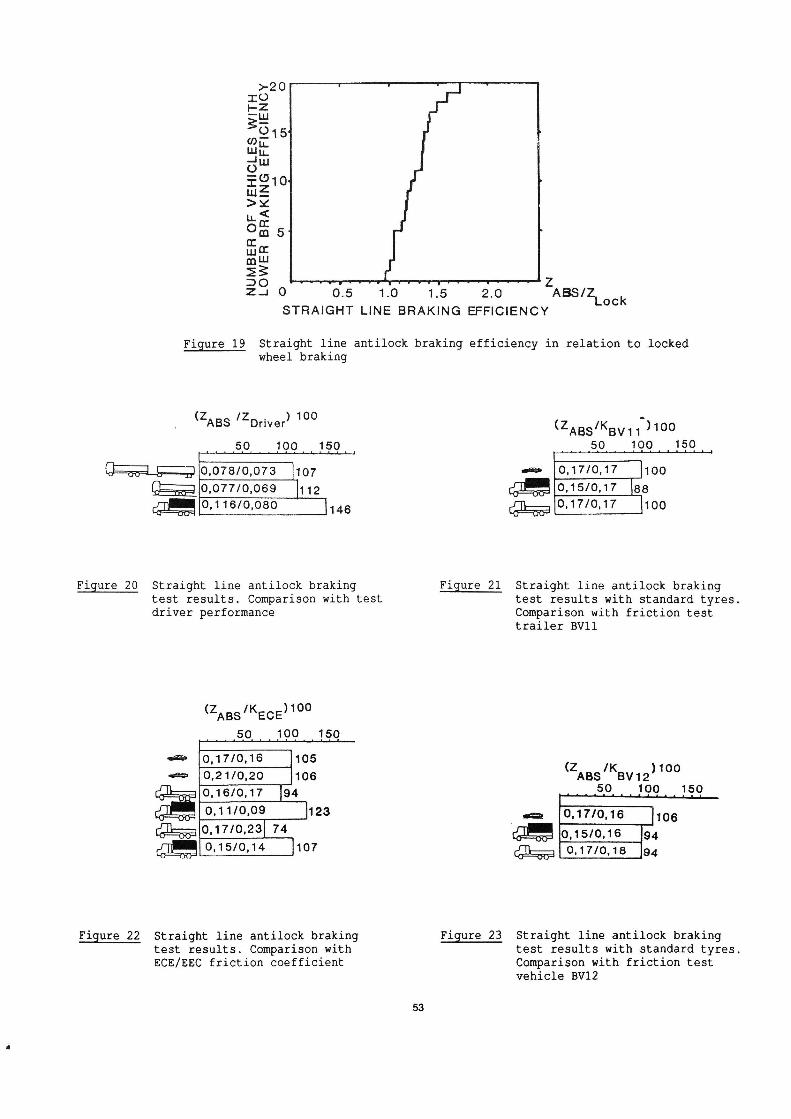
RESULTS - The results are summarized inFigure 19, 20, 21, 22 and 23.
From the figures can be seen that as arule the braking efficiency with antilocksystems is higher than with locked wheels andhigher than best driver performances. In
tests with laden and unladen vehicles theunladen vehicles tend to get higherdeceleration but not necessarily higherbraking efficiency based on peak value.
The 75% efficiency required by ECE/EECregulations is not always met on ice by anti-lock systems for heavy vehicles. For thetested passenger cars with and without studsthe efficiency is close to 100%.
Longitudinal friction coefficientsobtained with the reference tyres on frictiontest vehicles BV11 and BV12 according to the
Figure 18 Multiwheel trailer with studded passenger car tyres for iceconditioning treatment
52
>-2C) ' f .IO
tå3515' pMluniömG 4
P
LI35310
>åu.I
0:0 5 _
En:mIJJ
EE:DO 'f'fova'vu-yr fffffffff Z
::.: 0 0.5 1.0 1.5 2.0 .AE§3/ZLock
STRAIGHT LINE BRAKlNG EFFICIENCY
Figure 19 Straight line antilock braking efficiency in relation to lockedwheel braking
(ZABS/KBVH 0050 100 150 usjouyjqoujqoug
A A 1 L A PLLLLLLLLLL
Mama/0073 ]107 avs- 0.17/0.17 _]100Egon/0,069 1112 (gig 0,15/0,17 J_8_8
%0J16/0980 ' 1146 %OJWO. J100
Figure 20 Straight line antilock braking Figure 21 Straight line antilock brakingtest results. Comparison with test test results with standard tyres.driver performance Comparison with friction test
trailer BV11
0(ZABS/KECE)10
A A A4 A 1 L L LLLLLLLL
& 0,17/0,16 105 (Z IK )100
& 0,21/0,2O 106 ABS BV12O'mm ig , .-.5.0....199..15.90.11/0.09 j123 .a O.17/0,16 7106
(350.17/0231 74 (gm/0.16 94LQ_¥0,15/0,14 ]107 % O,17IO.18 94
Figure 22 Straight line antilock braking Figure 23 Straight line antilock brakingtest results. Comparison with test results with standard tyres.ECE/EEC friction coefficient Comparison with friction test
vehicle BV12
53

constant slip method gave the same values asthe peak friction coefficients obtained bysingle axle braking according to ECE Regula-tion 13 both for a truck and a passenger carwith standard tyres (upeak=0.17).
DISCUSSION - According to Annex 10 in ECERegulation 13 normal brakes are allowed tohave a braking efficiency of 50% at a friction coefficient of 0.2. It could thereforebe debated if the efficiency requirements onantilock systems on ice should be as high as75% of the peak friction coefficient. Thetest results indicate that 90% of the lockedwheel friction could be a more suitablerequirement. A locked wheel test is also thesimplest and least expensive alternative. Inorder to avoid stability problems the lockedwheel braking tests on ice are recommended tobe done from an initial speed of 40 km/h.
PROPOSAL FOR A STRAIGHT AHEAD BRAKING TEST
ON ICE - Based on the field test experience
and theoretical considerations the following
test is proposed.Test surface-The test surface should be
ice with a locked wheel friction of 0.1 +/-
0.05 measured with the test vehicle itself or
the friction test vehicle BV11 or equivalent
equipment. Roughening of the ice by means of
the special multi-wheel trailer according to
Figure 18 is recommended. The air and ice
surface temperature should be below 0°C,preferably between -5 and -15°C.
Test speed-The initial speed should be 40
km/h vehicles for tyres without studs and 50
km/h for tyres with studs (additional test
for passenger cars).Braking tests-Locked wheel and antilock
braking stops should be made with a pedal
force that on high friction would give at
least 5 m/sz. The mean value of the resultsfrom at least three tests of each type should
be used for the efficiency calculation. For
each test the mean deceleration is calculated
by the formula ä=5.56/T m/s2 where T is the
time for V=35 km/h to V=15 km/h.Minimum requirement on braking efficiency-
äABs/äL z 0.9 or (ths/ZLOCK)20.9
äABS = Mean deceleration with the antilock
system operating. ZABS = äABs/9.81
äL = Mean deceleration with all wheels
locked. ZLOCK = äL/9.81
Trailer tests-Trailer tests should be made
by braking only the trailer and correcting
for the rolling resistance of the towing
vehicle. The rolling resistance coefficient
for nondriven wheels may be assumed to be
0.010 and for driven wheels 0.015.Alternative test method Tests may also be
performed according to the procedure pre-
scribed by ECE/EEC regulations but on the
same ice surface. It is considered as more
difficult to carry out and meet the require-
ments of this test.
54
TRANSITION TEST FROM LOW TO HIGH FRICTION
GENERAL - When a vehicle with normalbrakes is braked on very low friction andsuddenly encounters a transition to a highfriction surface the braking torque appliedby the driver is immediately fully utilizedup to the limit of adhesion for each axle asthey pass on to the new surface.
In the same situation but braking avehicle with an antilock system fully adaptedto the low friction there is a risk that thepressure recovery might be very slow andresult in an unacceptably long brakingdistance compared with a normal brakingsystem. The new ECE/EEC antilock brakingregulations therefore demand a test in thisrespect. The requirement on the high/low
friction ratio is however only 2:1 which islow for winter service conditions.
TESTS CARRIED OUT BY VTI - Tests with one
heavy duty truck antilock system on ice withvery low friction resulted in pressure dropsto near zero with recovery rates of not morethan 3 bar/sec that could not be influencedby a sudden transition to high friction. Thiscorresponds to about 1.5 3 to reach 4.5 m/s2deceleration. Transition tests with othersystems indicate that 0.7 s is a reasonabletarget from a technical point of view.
DISCUSSION - If the vehicle decelerationis measured the wheelbase has to be takeninto account. At 50 km/h an additional timedelay of 0.7 s will cover all practicalcases. A total deceleration transition timefrom 1.5 m/s2 to 4.5 m/s2 of 1.5 3 for heavyduty vehicles and 1.0 s for passenger carshas been considered to be a reasonable
requirement for winter service.PROPOSED WINTER SERVICE TEST - The test
shall be made with full brake application ata pressure that corresponds to a decelerationof at least 5 m/s2 starting on a low frictionsurface which must not give the vehicle ahigher deceleration than 1.5 m/s2 with theantilock system in operation. The vehiclespeed at the transition to high friction mustnot be less than 50 km/h. The high frictionsurface must allow an antilock braking
deceleration of at least 4.5 m/sz. Thisdeceleration must be reached within 1.5 s forheavy duty vehicles and within 1.0 3 forpassenger cars. This time is measured fromthe front axle transition time.
HYBRID LABORATORY TESTING ' A FUTURE TYPE
APPROVAL PROCEDURE?
The practical difficulties are consider-able both technically and economically inobtaining test tracks that give the desiredfriction characteristics and are large enoughfor safe high speed and cornering tests. Infact they are so severe that ECE/EEC regula-tions regard peak friction coefficients up to0.4 at 40 to 50 km/h as low and do notspecify speed or slip characteristics of the
tyre/road adhesion. Furthermore the problems
connected with brake lining characteristicsmust not be forgotten.
For antilock systems with electric wheelspeed signals these problems can be eli-minated by real time computer simulation ofthe tyre/road characteristics, brake torquecharacteristics and vehicle motion dynamicsincluding wheel speed sensor signals. The
real vehicle that is to be tested isconnected to the computer through an inter-face so that the simulated wheel speedsignals are received by its antilock systemcontroller and the wheel brake cylinderpressures measured by sensors on each wheelare fed back to the computer. During the testthe vehicle is stationary in the laboratorywith the engine running. The test engineerhas only to apply the brakes after startingthe computer program.
This technique has been used by VTI withpromising results. At present it is possibleto simulate:
- Straight braking on a homogeneous surface
- Straight braking on a split friction sur-face with steering corrections based onyaw motion
- Braking during steady state cornering with
constant steer input
J-turn braking with constant steer inputapplied at the same time as the brakes
- Braking on a surface with changing fric-tion can also be simulated as the computerprogramme contains two tyre models for
each wheel
Validation simulations have been madewith a two axle truck with an unladen weight
of 6 500 kg and a laden weight of 13 000 kg.The vehicle was equipped with three differenttypes of antilock systems. This vehicle wasalso used in the already mentioned tests onreal ice tracks, split friction tracks aswell as on high friction tracks. Thefollowing tests were used for the validation:
- Straight braking on homogeneous ice.Initial speed 10 and 20 m/s
- Straight braking on a split frictionsurface. Initial speed 10 m/s
- J-turn braking on ice with constantsteering input corresponding to 100 mradius applied at the same time as thebrakes. Initial speed 11 m/s
- Straight braking on a high friction sur-face with the peak friction coefficient0.6. Initial speed 20 m/s
In all the tests the ranking order inperformance was the same in simulation andreal test. The general characteristics interms of deceleration, lateral acceleration
and yaw behaviour over time were also quitewell reproduced. This also applies to wheelspeeds and brake pressures. Test were made
both with identical tyre data on front andrear wheels and with somewhat reduced fric-tion on the rear wheels. The best resultswere obtained in the latter case. This is inline with the fact that ice friction isreduced by the polishing effect of slippingtyres. In this case the front tyres polishthe ice for the rear tyres. It is notbelieved that this method of testing canreplace real world tests but it looks promis-ing as a future complement for evaluatingantilock system performance under conditionsthat are too difficult, expensive or dange-rous to require in real type approval tests.
New soft-and hardware with a speciallydesigned parallel processor system has
recently been developed at VTI (20). The
purpose was to reduce the computing time for
wheel velocities and tyre forces from 5 to 1ms and at the same time allow for more wheels
and more detailed tyre data. The system ishowever not yet incorporated in the hybridABS-simulation program.
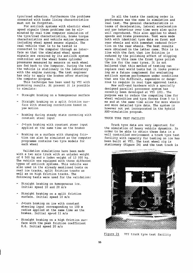
TRUCK TYRE TEST FACILITY
Truck tyre data are very important forthe simulation of heavy vehicle dynamics. Inorder to be able to obtain these data in awell controlled environment a truck tyre test
facility with capacity for testing on ice hasbeen built at VTI. The test wheel rig isstationary (Figure 24) and the test track is
Figure 24 VTI truck tyre test facility
a flat 50 m long moving steel beam. Themaximum speed is at present about 10 m/s.Maximum wheel load is 10 000 kg and lateraland longitudinal forces up to 70 000 N can bemeasured. The side slip angle can be variedup to 90° at up to 30°/s. Ice temperaturesdown to -20°C are possible. The facilitybecame operational in May 1989 but has so faronly been used for evaluating passenger carwinter tyres. The first truck tyre measurements are planned for the autumn 1989.
CONCLUSIONS
The dynamics of heavy duty vehicles andespecially heavy duty vehicle combinationshas since a long time been regarded as an im-portant area of research by VTI and willprobably remain so for a long time.
The main investigation areas have been
- yaw stability and steerability at constantspeed
- overturning stability with rigid and liquidload
- stability, steerability and brakingefficiency during emergency braking
- tyre - road friction characteristics
The behaviour of heavy vehicle combina-tions under severe winter conditions has ahigh priority due to the climatic conditionsin Sweden.
Road and computer simulation test methodsand performance requirements have been in-vestigated proposed for legislation use withthe aim to promote safe vehicles on ourroads.
REFERENCES
The Dynamic Stability of Heavy VehicleCombinations. VTI Report No. 9, Part 1 and 2.
(In Swedish) VTI, Linköping, Sweden 1972
2. Nordström O., Strandberg L.The Dynamic Stability of Heavy VehicleCombinations. VTI Report No. 67A. VTI,
Linköping, Sweden 1974
3. Strandberg L., Nordström O., Nordmark S.
Safety Problems in Commercial VehicleHandling. VTI Report No. 82A. VTI, Linköping,Sweden 1975
4. Nordmark S.
Computer Program for Digital Simulation of aDouble Lane Change Manoeuvre with a HeavyVehicle Combination.list of figures in English) VTI Report No.96. VTI, Linköping, Sweden 1976
Nordström O., Magnusson G. and Strandberg L.
(In Swedish. Summary and
56
10.
11.
12.
13.
14.
Lidström M.Road Tanker Overturning - with and withoutlongitudinal baffles. (In Swedish. Summary
and list of figures in English) VTI ReportNo. 115. VTI, Linköping, Sweden 1977
Strandberg L.
Lateral Stability of Road Tankers. Volume IMain Report. Volume II Appendices. VTI ReportNo. 138A. VTI, Linköping, Sweden 1977
Nordmark S., Nordström O.
Lateral Dynamics of Truck and Full TrailerCombinations. Paper presented at OECDsymposium on Heavy Freight Vehicles and theirEffects. Nov. 1977
Nordmark S., Nordström O.
Lane Change Dynamics versus Geometric Designof Truck and Full Trailer Combinations - aComputer Study. Paper presented at XVIIFISITA Congress in Budapest 1978
Nordström O., Nordmark S.
Test Procedures for the Evaluation of the
Lateral Dynamics of Commercial VehicleCombinations. Automobile Industrie No. 2,1978
Nordström O., Nordmark S.
Handling Caracteristicts of Heavy VehicleCombinations at Constant Speed. Final Report.(In Swedish) VTI Report No. 234. VTI,
Linköping, Sweden 1981
Nordström O.Antilock systems for heavy vehicles - Stateof the art, test methods andregulations.(Extensive Summary in English)VTI Report 257. VTI, Linköping, Sweden1983
Palmkvist G., Nordström O.Hybrid Laboratory Test Method for AntilockSystems. The Dynamics of Vehicles on Roadsand Railway Tracks. Proceedings 8thIAVSD-Symposium Cambridge Mass USA 1983.Swets & Zeitlinger, Lisse, Holland
Nordström O., Ståhl P.Field testing of "double combinations" underwinter conditions. STU Report. (In Swedish)
VTI, Linköping, Sweden June 1984
Oppenheimer P.The development of international antilockbraking regulations. IMechE Conference onAnti-lock braking systems for road vehicles
Paper C190/85. IMechE Conference Publications1985-8. Mech Eng Publ Ltd. London 1985
. Nordström O.
Testing of antilock systems. Winter tests
16.
17.
18.
19.
20.
21.
1985 for evaluation of draft revision of ECEReg. 13 Annex 13. (Extensive Summary inEnglish) VTI Report 304. VTI, Linköping,Sweden 1986
ECE Regulation 13, Annex 13. Addendum 12:Regulation 13 to be annexed to the AgreementRevision 2 - Amendment 3. Supplement 1 to the05 series of amendments which entered intoforce on 1 April 1987. E/ECE/324 Rev 1/Add12/Rev 2/Amendment 3. United Nations, Geneva1987
Nordström O.Antilock system performance under winterconditions-what should be required ? 11th ESVConference Washington DC May 12-15 1987
Nordström O.Antilock Braking System Performance.International Regulations Now and in theFuture - Some Swedish Viewpoints. Paperpresented at TRB - VTI Conference "Road andTraffic Safety on Two Continents" 1987. VTIReport 332A. VTI, Linköping, Sweden 1988
Nordström 0.Test methods and Requirements for ABS onHeavy Duty Trailers suited for Nordic WinterConditions. (In Swedish) VTI Notat TF 50 10.
VTI, Linköping, Sweden 1988
Palmkvist G.Parallel Processor System for Real Time
Simulation. Automotive Simulation.Proceedings of the 2nd European Cars/TrucksSimulation Symposium Schliersee, FRG, May1989. Springer-Verlag, Berlin, Heidelberg,New York, London, Paris, Tokyo 1989
Strandberg L.Braking Characteristics of 400 Heavy TrailerCombinations from Denmark, Finland, Norwayand Sweden. 12th ESV Conference, Gothenburg,
Sweden 1989
57


Positions and opinions advanced in this paper are those of theauthor(s) and not necessarily those of SAE. The author issolely responsible for the content of the paper. A process isavailable by which discussions will be printed with the paperit it is published in SAE Transactions. For permission topublish this paper in full or in part, contact the SAE Publica-tions Division.
Persons wishing to submit papers to be considered for pres-entation or publication through SAE should send the manu-script or a 300 word abstract of a proposed manuscript to:Secretary, Engineering Activity Board, SAE.
Printed in U.S.A.