Effects of Concentrated Ambient Particles and Diesel Engine ...
Upload
khangminh22Category
view
1download
0
ww.sciencedirect.com
i n t e r n a t i o n a l j o u r n a l o f h y d r o g e n en e r g y 4 5 ( 2 0 2 0 ) 2 6 1 1 7e2 6 1 2 5
Available online at w
ScienceDirect
journal homepage: www.elsevier .com/locate/he
Methanol production using hydrogen fromconcentrated solar energy
Nathalie Monnerie a,*, Philipe Gunawan Gan b, Martin Roeb a,Christian Sattler a
a German Aerospace Center (DLR), Linder Hoehe, 51147 Koeln, Germanyb KTH Royal Institute of Technology, Brinnelvagen 68, Stockholm, Sweden
h i g h l i g h t s
� Coupling of methanol production plant with concentrating solar energy is proposed.
� Syngas required for methanol production is produced with thermochemical cycle.
� Flow-sheets and simulations were carried out in MW-range.
� Economic analysis of the process results in methanol production costs of 1.14 V/l.
a r t i c l e i n f o
Article history:
Received 28 October 2019
Received in revised form
19 December 2019
Accepted 29 December 2019
Available online 28 January 2020
Keywords:
Hydrogen
Solar energy
Methanol
Thermochemical redox cycle
Synthesis gas
* Corresponding author.E-mail address: [email protected]
https://doi.org/10.1016/j.ijhydene.2019.12.2000360-3199/© 2020 Hydrogen Energy Publicati
a b s t r a c t
Concentrated solar thermal technology is considered a very promising renewable energy
technology due to its capability of producing heat and electricity and of its straightforward
coupling to thermal storage devices. Conventionally, this approach is mostly used for
power generation. When coupled with the right conversion process, it can be also used to
produce methanol. Indeed methanol is a good alternative fuel for high compression ratio
engines. Its high burning velocity and the large expansion occurring during combustion
leads to higher efficiency compared to operation with conventional fuels. This study is
focused on the system level modeling of methanol production using hydrogen and carbon
monoxide produced with cerium oxide solar thermochemical cycle which is expected to be
CO2 free. A techno-economic assessment of the overall process is done for the first time.
The thermochemical redox cycle is operated in a solar receiver-reactor with concentrated
solar heat to produce hydrogen and carbon monoxide as the main constituents of syn-
thesis gas. Afterwards, the synthesis gas is turned into methanol whereas the methanol
production process is CO2 free. The production pathway was modeled and simulations
were carried out using process simulation software for MW-scale methanol production
plant. The methanol production from synthesis gas utilizes plug-flow reactor. Optimum
parameters of reactors are calculated. The solar methanol production plant is designed for
the location Almeria, Spain. To assess the plant, economic analysis has been carried out.
The results of the simulation show that it is possible to produce 27.81 million liter meth-
anol with a 350 MWth solar tower plant. It is found out that to operate this plant at base
case scenario, 880685 m2 of mirror’s facets are needed with a solar tower height of 220 m. In
this scenario a production cost of 1.14 V/l Methanol is predicted.
© 2020 Hydrogen Energy Publications LLC. Published by Elsevier Ltd. All rights reserved.
e (N. Monnerie).
ons LLC. Published by Els
evier Ltd. All rights reserved.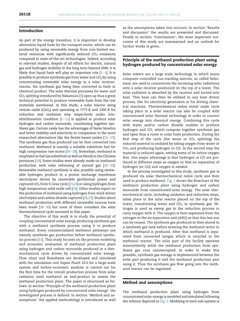
i n t e rn a t i o n a l j o u r n a l o f h y d r o g e n en e r g y 4 5 ( 2 0 2 0 ) 2 6 1 1 7e2 6 1 2 526118
Introduction
As part of the energy transition, it is important to develop
alternative liquid fuels for the transport sector, which can be
produced by using renewable energy from non-limited ma-
terial resources with significantly reduced CO2 emissions
compared to state-of-the-art technologies. Indeed, according
to relevant studies, despite of all efforts for electric, natural
gas and hydrogen mobility in the long term beyond 2040, it is
likely that liquid fuels will play an important role [1e3]. It is
possible to produce synthesis gas fromwater and CO2 by using
concentrating renewable solar energy in a solar receiver-
reactor, the synthesis gas being then converted in fuels or
chemical product. The solar thermal processes for water and
CO2 splitting introduced by Nakamura [4] open up thus a great
technical potential to produce renewable fuels from the raw
materials mentioned. In this study, a solar reactor using
cerium oxide (CeO2) and operating at 1773 K and 1300 K for
reduction and oxidation step respectively under non-
stoichiometric condition [5e11] is applied to produce solar
hydrogen and carbon monoxide, constituting together syn-
thesis gas. Cerium oxide has the advantages of faster kinetics
and better stability and selectivity in comparison to the most
researched alternatives like the ferrite-based oxides [12e15].
The synthesis gas thus produced can be then converted into
methanol. Methanol is namely a suitable substitute fuel for
high compression rate motor [16e18]. Nowadays, methanol is
employed as fuel (as substitute aswell as blend) in the Chinese
provinces [19]. Some studies were already made on methanol
production with solar reforming of natural gas [20e22].
Renewable methanol synthesis is also possible using renew-
able hydrogen produce in a proton exchange membrane
electrolyzer driven by renewable geothermal power and
captured CO2 fromS-Graz cycle [23,24] or using hydrogen from
high temperature solid oxide cell [25]. Other studies report on
the production of methanol using hydrogen fromwind-driven
electrolysis and carbon dioxide captured [26,27]. Studies about
methanol production with different renewable sources have
been made [28e30] but none of them considers the solar
thermochemical cycle assumed in this paper.
The objective of this work is to study the potential of
coupling concentrated solar energy producing synthesis gas
with a methanol synthesis process using it to produce
methanol. Every commercialized methanol pathways use
namely synthesis gas production before methanol synthe-
sis process [31]. This study focuses on the process modeling
and economic evaluation of methanol production plant
using hydrogen and carbon monoxide produced in a ther-
mochemical cycle driven by concentrated solar energy.
Flow chart and flowsheets are developed and simulated
with the simulation tool Aspen Plus® 10.0 for a large-scale
system and techno-economic analysis is carried out for
the first time for the overall production process from solar
radiation until methanol as end-product to assess the
methanol production plant. The paper is structured as fol-
lows: in section “Principle of the methanol production plant
using hydrogen produced by concentrated solar energy” the
investigated process is defined. In section “Method and as-
sumptions” the applied methodology is introduced as well
as the assumptions taken into account. In section “Results
and discussion” the results are presented and discussed.
Finally in section “Conclusions”, the most important out-
comes of this study are summarized and an outlook for
further works is given.
Principle of the methanol production plant usinghydrogen produced by concentrated solar energy
Solar towers are a large scale technology in which many
computer-controlled sun-tracking mirrors, so called helio-
stats, are used to concentrate the incoming solar radiations
onto a solar receiver positioned on the top of a tower. The
solar radiation is absorbed by the receiver and turned into
heat. This heat can then be utilized in any heat driven
process, like for electricity generation or for driving chem-
ical reactions. Thermochemical redox metal oxide cycle
taking place in a solar reactor can also be coupled with
concentrated solar thermal technology in order to convert
solar energy into chemical energy. Combining this cycle
with water and/or carbon dioxide enables to produce
hydrogen and CO, which compose together synthesis gas
and open thus a route to solar fuels production. During the
first step of the cycle (the water or CO2 splitting) the
reduced material is oxidized by taking oxygen from water or
CO2 and producing hydrogen or CO. In the second step the
material is reduced again, setting some of its lattice oxygen
free. One major advantage is that hydrogen or CO are pro-
duced in different steps as oxygen so that no separation of
hydrogen (or CO) and oxygen is needed.
In the process investigated in this study, synthesis gas is
produced via solar thermochemical redox cycle and then
used to produce methanol. Fig. 1 shows the flowchart of the
methanol production plant using hydrogen and carbon
monoxide from concentrated solar energy. The solar ther-
mochemical cycle, including oxidation and reduction steps,
takes place in the solar reactor placed on the top of the
tower, transforming water and CO2 in synthesis gas. Ni-
trogen is used as sweep gas in the reduction process to
carry oxygen with it. The oxygen is then separated from the
nitrogen in the air separation unit (ASU) so that this last one
can be reused. The synthesis gas produced in then stored in
a synthesis gas tank before entering the methanol rector in
which methanol is produced. After that methanol is sepa-
rated from unreacted syngas which is recycled in the
methanol reactor. The solar part of the facility operates
intermittently while the methanol production from syn-
thesis gas runs uninterrupted. In order to make this
possible, synthesis gas storage is implemented between the
solar part producing it and the methanol production part
using it. Thus the synthesis gas flow going into the meth-
anol reactor can be regulated.
Method and assumptions
The methanol production plant using hydrogen from
concentrated solar energy ismodeled and simulated following
the scheme depicted in Fig. 2. Modeling of each sub-system is
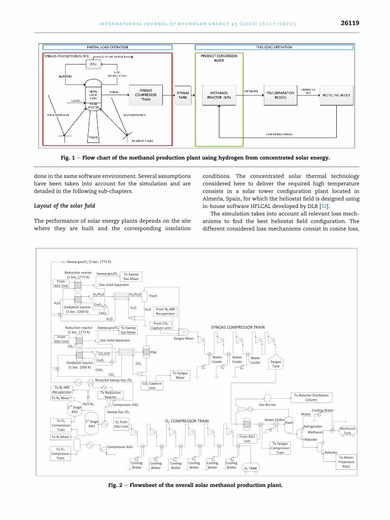
Fig. 1 e Flow chart of the methanol production plant using hydrogen from concentrated solar energy.
i n t e r n a t i o n a l j o u r n a l o f h y d r o g e n en e r g y 4 5 ( 2 0 2 0 ) 2 6 1 1 7e2 6 1 2 5 26119
done in the same software environment. Several assumptions
have been taken into account for the simulation and are
detailed in the following sub-chapters.
Layout of the solar field
The performance of solar energy plants depends on the site
where they are built and the corresponding insolation
Fig. 2 e Flowsheet of the overall so
conditions. The concentrated solar thermal technology
considered here to deliver the required high temperature
consists in a solar tower configuration plant located in
Almerıa, Spain, for which the heliostat field is designed using
in-house software HFLCAL developed by DLR [32].
The simulation takes into account all relevant loss mech-
anisms to find the best heliostat field configuration. The
different considered loss mechanisms consist in cosine loss,
lar methanol production plant.
Table 2 e Assumptions taken into account for themodeling process [40].
i n t e rn a t i o n a l j o u r n a l o f h y d r o g e n en e r g y 4 5 ( 2 0 2 0 ) 2 6 1 1 7e2 6 1 2 526120
shading, reflectivity, blocking, atmospheric attenuation and
spillage. Amore extensive description of these different losses
is provided by the corresponding literature [32e35].
In this study, the considered heliostats are of the type
Sanlucar 120 [36], which have a reflective area of 121.34 m2
and a total beam error of 3.3 mrad. The mirror reflectivity is
87%, including cleanliness and availability. The annual effi-
ciency of the solar part hs is defined as the net thermal power
Pth that the reactor provides throughout the year (including
solar reactor losses) divided by the theoretical maximum of
solar radiation (expressed as the direct normal irradiance DNI)
hitting the entire mirror surfaces (AMirror) and considers thus
the efficiency of the solar reactor and of the solar heliostat
field [37]:
hS ¼
Z TMY
t¼0
PthðtÞdt
AMirror$
Z TMY
t¼0
DNIðtÞdt(1)
As an initial study has shown that the total heliostat field’s
efficiency is higher in this case study by using multi aperture
as by using single aperture, a multi aperture with secondary
concentrator receiver is chosen. In this configuration the solar
reactor apertures face diverse direction and surround the
tower. The heliostats are placed in the area following the di-
rection where the apertures are facing at and the distribution
of heat power for each heliostat zone is depicted in Table 1.
Modeling of the solar reactor
A solar reactor using cerium oxide (CeO2) as redox material is
used to produce hydrogen and carbon monoxide [39]. CeO2 is
thermally reduced efficiently at a temperature of 1773 K. The
reduced CeO2-dox is then oxidized in the presence of H2O or
CO2 so that H2 or CO is respectively generated at a temperature
below 1300 K. The following formula govern the partial redox
of cerium oxide [40]:
CeO2-dox / CeO2-dred þ Dd/2 O2 (2)
CeO2-dred þ Dd H2O / CeO2-dox þ Dd H2 (3)
CeO2-dred þ Dd CO2 / CeO2-dox þ Dd CO (4)
where Dd represents the difference between reduction
and oxidation amount. To model the non-stoichiometric
compound CeO2�dred, a mixture of CeO2 and Ce2O3 with
certain mole ratio is used. The ratio is supposed to follow
dred according to equations (5) and (6) which follows the
conservation of mass law. zCeO2 and zCe2O3 are the mole
fractions of cerium (IV) oxide and cerium (III) oxide
Table 1e Power fraction among subfield inmulti aperturearrangement [38].
Latitude Power fraction
N NE/NW SE/SW S
20�N 21 18 15 13
40�N 22 19 14 12
respectively inside the non-stoichiometric reduced metal
oxide [40].
zCeO2¼ 1� 2dred
1� dred(5)
zCeO2þ zCe2O3
¼ 1 (6)
By using these equations the ratio of Ce to O atoms for the
CeO2/Ce2O3 mixture will be the same as for CeO2-d. To model
the solar reactor with Aspen Plus® a yield reactor module (R-
Yield) based on mass balance, governed by redox extent and
reactor’s conversion is applied. A condensation at 298 K is
carried out to extract water from the hydrogen stream and the
flashing unit is used to separate hydrogen from water. Tem-
perature of 298 K is chosen to minimize the heat needed to
raise the temperature of fresh water before coming into
oxidation step. To separate carbon dioxide from carbon
monoxide stream Pressure Swing Adsorption (PSA) running at
1 bar and 298 K is used (see Fig. 2).
The general assumptions for the modeling process are
summed up in Table 2 [40].
Modeling of the methanol reactor
The hydrogen and carbon monoxide generated is then
stored in the synthesis gas storage before to be sent to the
methanol reactor to produce methanol. To model the
methanol an adiabatic plug-flow reactor utilizing R-Plug
module within Aspen Plus® under Cu based catalyst [31,41]
is applied. The employment of adiabatic working mode is
due to its simplicity and robustness [42] while governing
chemical kinetic reactions are discussed by Bussche et al.
[41]. LHHW kinetic type is applied to bring the reaction into
R-Plug simulation environment within Aspen Plus®. Con-
forming to Bussche et al. [41], the limitations of the reaction
kinetic are 15e51 bar for the pressure, 180e280 �C for the
temperature and H2/CO of 0e4.1. The reaction constant
values are given in Table 3.
The equilibrium constants based on partial pressure Kp is
taken from Graaf et al. [43] and can be seen from equations (7)
and (8):
log Kp MeOH ¼3066 =T� 10:592�bar�2
�(7)
log Kp RWGS ¼�2073 =Tþ 2:029�Pa�1
�(8)
Max Thermal Power to Solar Reactor 350 MWth
Metal oxide Ceria CeO2
Reduction temperature 1773 K
Oxidation temperature 1300 K
Pump efficiency 0.8 isentropic
Compressor efficiency 0.9 mechanical efficiency
Pinch Point Over Heat Exchanger 5 K
Cooling Water Temperature 293 K
Location Almeria (37�050N, 2�210W)
Table 3 e Reaction constant values for methanolsynthesis [41].
Variable Metric Ai Bi
kMeOH mol kg�1cat s
�1 bar�2 1.07 36696
kRWGS mol kg�1cat s�1 bar�1 1.22 $1010 �94765
Ka e 3453.38 e
Kb bar�0:5 0.499 17197
Kc bar�1 6.62$10�11 124119
Table 5 e General economic assumptions.
Interest rate 6% [45]
Life time of plants ðnlifetimeÞ 25 years
USD to V conversion rate 0.8 [46]
CeO2 price 2018 5.6 V/kg [47]
Copper cost for methanol reactor 0.56688 V/kg [47]
Heliostat cost/m2 103 USD2015
Land price 800 000 V/km2 [48]
i n t e r n a t i o n a l j o u r n a l o f h y d r o g e n en e r g y 4 5 ( 2 0 2 0 ) 2 6 1 1 7e2 6 1 2 5 26121
The reactor is supposed to work using catalyst with exact
cylindrical configuration. The catalyst has a density of
1190 kg/m3 and the vacant fraction of the bed is 0.285 [44].
Recycling of unreacted synthesis gas back into the methanol
reactor is considered in order to optimize the methanol pro-
duction. Unreacted synthesis gas is separated using flash at
298 K. The product separation unit is simulated using RadFrac
module. Before entering the first distillation column, the
mixture coming from the methanol reactor is flashed. In the
first stage of distillation column the unreacted gas is sepa-
rated from alcohol mixtures. The bottom stream is next sent
directly to the second stage distillation unit for last extraction
of methanol. The layout of each stage distillation column is
given in Table 4.
Flow chart is defined for the coupling of the methanol
production plant with the concentrated solar energy source.
This flow chart is simulated with Aspen Plus® and presented
in Fig. 2.
Economic evaluation
Economic analysis is carried out to assess the methanol
production plant using hydrogen from concentrated solar
energy. Total capital investment (TCI) was calculated
including contingency and auxiliary facilities. The cost
estimation is based on results of the simulation. The oper-
ation and maintenance costs O&M reflect fixed and variable
costs per year, added for the whole period of consideration.
The general assumptions of the economic evaluation of the
plant are listed in Table 5.
To calculate the methanol production costs (MPC), the
annuity method is used [45]. An interest rate (ir) of 6% [45] and
a lifetime of plant (nlifetime) of 25 years are assumed. The
present value (PV) is defined using the calculated costs. The
multiplication of this present value with the annuity factor
(AF) determines an annual basis, which, divided by the annual
Table 4 e Base case distillation column configuration formethanol reactor system.
Numberof stages
Distillate toFeed Ratio forDistillationColumn
Reflux ratio
1st stage
distillation
5 0.022 1.28713
2nd stage distillation 75 0.7129 21.0018
amount of produced fuel (Vfuel), gives the methanol produc-
tion costs (see equations (9)e(11)) [45]:
PV¼TCIþXnlifetime
n¼1
ðO&MnÞ � Rn
ð1þ irÞn(9)
with Rn plant side income from side product (if any) at year n.
AF¼ð1þ irÞn: irð1þ irÞn � 1
(10)
MPC ½V pro L� ¼PV:AFVfuel
(11)
Data for mechanical and chemical equipment is taken
from Ulrich et al. [49]. Heliostat costs are assumed with 103
USD/m2 [48]. The investment cost for the solar tower is
assumed to be 20 V2015/kWth [50] and the costs for the solar
reactor are taken to be 17.8 V2015 per kWh [50]. For the carbon
dioxide required in the solar thermochemical cycle, cost of 100
V2015/ton of yearly captured carbon dioxide is assumed [50]. To
update the cost to 2018, CEPCI method is used where the
updated cost is the ratio of CEPCI at 2018 to CEPCI at reference
year multiplied by the price at reference year [49]. Ulrich et al.
is based on 2004 price where CEPCI2004 is 400 while CEPCI2018 is
567.5 [51].
Results and discussion
Results for heliostat field
The heliostat field was calculated for the location
Almeria, Spain. The result of the simulation is depicted on
Fig. 3.
The thermal efficiency of the multi aperture arrangement
with secondary concentrator is considered to be 0.85 and the
reflectivity of the secondary concentrator is assumed to be 0.9
[52]. The total heliostat field efficiency is calculated to be
52.1%. This efficiency value corresponds indeed to the average
heliostat field efficiency for such a plant size for this location
[53]. The results of the simulation show that 7258 heliostats
with a total mirror’s facets surface of 880685 m2 are needed to
operate a 350 MWth plant with a solar reactor thermal effi-
ciency of 85%. The tower height has an optimized size of
220 m. The land radius is 1805 m. The results are presented in
Table 6.
Results for solar reactor
By the modeling of the solar reactor, the hydrogen and carbon
monoxide productions have been separately simulated and

Fig. 3 e Multi aperture reactor arrangement [38] - Heliostat field arrangement for solar methanol production plant located in
Almeria, Spain.
Table 6 e Results of the heliostat field’s design.
Annual average receiver-reactor power [MWth] 350
Tower height [m] 220
Number of heliostat 7258
Total mirror’s facets surface [m2] 880685
Annual average solar efficiency [%] 52.1
i n t e rn a t i o n a l j o u r n a l o f h y d r o g e n en e r g y 4 5 ( 2 0 2 0 ) 2 6 1 1 7e2 6 1 2 526122
the reduction and oxidation chamber have been modeled for
each. A non-stoichiometric reduction and oxidation operation
has been implemented in the model using R-Yield module
from Aspen Plus®. The simplified corresponding flow chart is
depicted in Fig. 4.
Fig. 4 e Simplified so
The separation of the solid and gas mixture is modeled
using cyclone separator module, thus for both reduction
and oxidation product stream. The separation of hydrogen
from remained steam which has not been split is simulated
in a condensation step at 298 K following of a flashing unit.
Afterwards the flashed water is combined with a stream of
fresh make-up water and recycled back to the oxidation
chamber. For the separation of carbon monoxide, a Pressure
Swing Adsorption (PSA) system is considered, running at
ambient condition of 298 K and under atmospheric pres-
sure. This PSA unit is modeled as a black-box separation
module by setting the carbon monoxide fraction to be 1 for
the carbon monoxide outlet stream.
lar reactor chart.

Table 8 e Main results of the process simulation.
Location Almerıa, Spain
Number of heliostats 7258
Tower height [m] 220
Heliostat field efficiency 52.1%
Methanol reactor pressure [bar] 50
[H2/CO] for methanol reactor 3.588
Methanol reactor diameter [m] 1.5
Methanol reactor equilibrium temperature [K] 493.2
Methanol output [Million liter/year] 27.81
Fig. 5 e Total capital investment for the solar methanol
production plant.
i n t e r n a t i o n a l j o u r n a l o f h y d r o g e n en e r g y 4 5 ( 2 0 2 0 ) 2 6 1 1 7e2 6 1 2 5 26123
Results for methanol reactor
The methanol reactor model was validated by comparing its
concentration profiles with the results obtained in Bussche
et al. [41]. The reactor was assumed to be a single tube
adiabatic reactor. The operation conditions are presented in
Table 7.
The optimum parameters of this reactor have been
calculated. By the optimization, the pressure stays uniform
at 50 bar in the reactor, which corresponds to the limit of
validity of kinetic equation and to the maximal methanol
output according to Bussche et al. [41]. The mole ratio of
carbon monoxide to carbon dioxide is constant at 4/3, cor-
responding also to the value advanced by Bussche et al. [41].
The optimum value of the ratio hydrogen to carbon mon-
oxide is thus found to be 3.588 and the reactor’s diameter
1.5 m.
The main results for the process simulation of the meth-
anol plant production using hydrogen from concentrated
solar energy including the heliostat field layout are presented
in Table 8.
With sufficient synthesis gas storage it is possible to pro-
duce 27.81 million liter of methanol per year.
Results for economic analysis
The total capital investment of the solar driven methanol
production plant is calculated to be 254 Million Euro. The
share of investment for each part of the plant is shown on
Fig. 5. Around one third (36%) of the total capital investment
come from the concentrated solar thermal components which
represent thus the biggest contributors towards the total
capital investment. 80% of the solar components investment
costs come from the heliostat field. The equipment costs,
consisting in compressors, pumps, mixers, tanks, methanol
reactor, product separation unit, water desalination unit, ox-
ygen separation, synthesis gas buffer tank etc., represent the
second biggest contributor towards the total capital invest-
ment plant.
The operation and maintenance costs of the solar tower
system are assumed to be 2% [48] of the total cost of CSP
Table 7 e Operation conditions to validate methanolreactor according to Refs. [41,44].
Reactor
Diameter (m) 0.016
Length (m) 0.15
Operating conditions
Temperature (K) 493,2
Pressure (bar) 50
Mass Flow of Input Gas (kg/s) 2.8$10-5
Feed Composition
CO (mol%) 4.00
H2O (mol%) 0.00
Methanol (mol%) 0.00
H2 (mol%) 82.0
CO2 (mol%) 3.00
Inert gas N2 (mol%) 11.0
Catalyst
Density (kg/m3) 1190
Bed Void Fraction 0.285
system which comprises the tower, heliostats, land and
solar reactor costs. Moreover it is assumed for the solar
reactor that the redox material CeO2 inside the reactors
must be replaced once a year. Methanol reactor’s operation
and maintenance cost are based on reactor’s volume and
catalyst density while fresh catalyst is fed once every two
years [31]. Based on the results, heliostat cost reduction
would be beneficial for developing such system.
A production cost of 1.14 V/L methanol is obtained for
an annual methanol production of 27.81 million liter.
Comparing to the market price of methanol in Europe [54],
the production cost obtained here from the simulation is
almost 4 times bigger than the market price. Further ef-
forts in this technology are needed in order to make this
solar methanol production pathway competitive for the
market.
Conclusions
Methanol production from solar synthesis gas produced by a
thermochemical cycle using cerium oxide has been simulated
and analyzed. A flowsheet of the overall process has been
developed and simulated with the simulation tool Aspen
Plus®. The solar reactor and the methanol reactor have been
modeled with this software, too. The overall plant from he-
liostat field to methanol production reactor has been simu-
lated for the first time for the location Almerıa, Spain. The
i n t e rn a t i o n a l j o u r n a l o f h y d r o g e n en e r g y 4 5 ( 2 0 2 0 ) 2 6 1 1 7e2 6 1 2 526124
results show that an annual production of 27.81 million liter
methanol with sufficient synthesis gas storage is feasible. For
this a multi aperture solar field has been designed using
HFLCAL and showed that 880685 m2 of heliostat are needed
with an optimized tower height of 220 m. The methanol
reactor was modeled with a plug-flow reactor with respective
kinetic of reactions. Optimum operation temperature, diam-
eter and pressure of this reactor have been calculated. Finally
a techno-economic study of the investigated process has been
carried out and methanol production costs of 1.14 V/l have
been calculated. The concentrated solar thermal components
are the main contributor to the total capital investment.
Therefore it seems obvious that a reduction of the concen-
trated solar thermal components costs, especially the helio-
stats costs will yield better economic viability of the plant.
Moreover, other locations with higher DNI will definitely
improve the results and decrease the methanol production
costs. As a next step, a life cycle analysis should be carried out
to underline the environmental advantages of developing
such plant.
Acknowledgments
The authors of this paper gratefully acknowledge the funding
of the project SolareKraftstoffe (Grant agreement Nr.
03EIV221) by the Federal Ministry for Economic Affairs and
Energy, on the basis of a decision by the German Bundestag.
Abbreviations
AF Annuity Factor
ASU Air Separation Unit
CEPCI Chemical Engineering Plant Cost Index
CSP Concentrated Solar Power
DNI Direct Normal Irradiance
LHHW Langmuir-Hinshelwood-Hougen-Watson
MPC Methanol Production Costs
MR Methanol Reactor
N North
NE North-East
NW North-West
O&M Operation and Maintenance costs
PSA Pressure Swing Adsorption
PSU Product Separation Unit
PV Present Value
S South
SE South-East
SW South-West
SYNGAS Synthesis Gas
TCI Total Capital Investment
USD US dollar
r e f e r e n c e s
[1] Willner T, Lucka K, Gunther A. Fortschrittliche alternativeflussige Brenn- und Kraftstoffe: Fur Klimaschutz im globalenRohstoffwandel. In: ProcessNet-Arbeitsausschuss
"Alternative flussige und gasf€ormige Kraft- und Brennstoffe".DECHEMA e.V; 2017.
[2] Linzenich A, et al. What fuels the adoption of alternativefuels? Examining preferences of German car drivers for fuelinnovations 2019;249:222e36.
[3] H€anggi S, et al. A review of synthetic fuels for passengervehicles. Energy Rep 2019:555e69.
[4] Nakamura T. Hydrogen production from water utilizing solarheat at high temperatures. Sol Energy 1977;19(5):467e75.
[5] de la Calle A, Bayon A. Annual performance of athermochemical solar syngas production plant based onnon-stoichiometric CeO2. Int J Hydrogen Energy2019;44(3):1409e24.
[6] Zoller S, et al. Heat transfer model of a 50 kW solarreceiverereactor for thermochemical redox cycling usingcerium dioxide. J Sol Energy Eng 2019;141(2):021014.
[7] Bulfin B, et al. Solar thermochemical hydrogen productionusing ceria zirconia solid solutions: efficiency analysis. Int JHydrogen Energy 2016;41(42):19320e8.
[8] Krenzke PT, Davidson JH. On the efficiency of solar H-2 andCO production via the thermochemical cerium oxide redoxcycle: the option of inert-swept reduction. Energy Fuel2015;29(2):1045e54.
[9] Bulfin B, et al. Analytical model of CeO2 oxidation andreduction. J Phys Chem C 2013;117(46):24129e37.
[10] Bhosale RR, et al. A decade of ceria based solarthermochemical H2O/CO2 splitting cycle. Int J HydrogenEnergy 2019;44(1):34e60.
[11] Agrafiotis C, Roeb M, Sattler C. 4.18 solar fuels A2 - dincer,ibrahim, in Comprehensive energy Systems. Oxford: Elsevier;2018. p. 733e61.
[12] Romero M, Steinfeld A. Concentrating solar thermal powerand thermochemical fuels. Energy Environ Sci2012;5(11):9234.
[13] Chueh WC, Haile SM. Ceria as a Thermochemical reactionmedium for selectively generating syngas or methane fromH2O and CO2. ChemSusChem 2009;2(8):735e9.
[14] Chueh WC, Haile SM. A thermochemical study of ceria:exploiting an old material for new modes of energyconversion and CO2 mitigation. Philos Trans R Soc A MathPhys Eng Sci 2010;368(1923):3269e94.
[15] Abanades S, et al. Investigation of reactive cerium-basedoxides for H2 production by thermochemical two-step water-splitting. J Mater Sci 2010;45(15):4163e73.
[16] Methanol economy. Danish Methanol Association; 2011.[17] Amine M, Barakat Y. Properties of gasoline-ethanol-
methanol ternary fuel blend compared with ethanol-gasoline and methanol-gasoline fuel blends. Egypt J Pet2019;28:371e6.
[18] Awad OI, et al. Alcohol and ether as alternative fuels in sparkignition engine: a review. Renew Sustain Energy2018;82:2586e605.
[19] Maus W, et al. Synthetische Kraftstoffe e OME1: Einpotenziell nachhaltig hergestellter dieselkraftstoff. In 35.Internat. Wiener motorensymposium. Fortschritt-BerichteVDI Reihe 2014;12.
[20] von Storch H, et al. On the assessment of renewableindustrial processes: case study for solar co-production ofmethanol and power. Appl Energy 2016;183:121e32.
[21] Storch Hv, et al. Theoretical and experimental investigationof effective solar mixed reforming for a less carbon intensiveproduction of methanol. In: AIChE annual meeting; 2018.Pittsburgh, USA.
[22] Storch Hv, et al. On the economics of solar chemical processes- case study for solar co-production of methanol and power.In: Solar world congress 2017. Abu Dhabi: UAE; 2017.
[23] Nami H, Ranjbar F, Yari M. Methanol synthesis fromrenewable H2 and captured CO2 from S-Graz cycle e energy,

i n t e r n a t i o n a l j o u r n a l o f h y d r o g e n en e r g y 4 5 ( 2 0 2 0 ) 2 6 1 1 7e2 6 1 2 5 26125
exergy, exergoeconomic and exergoenvironmental (4E)analysis. Int J Hydrogen Energy 2019;44(48):26128e47.
[24] Nami H, Ranjbar F, Yari M. Thermodynamic assessment ofzero-emission power, hydrogen and methanol productionusing captured CO2 from S-Graz oxy-fuel cycle andrenewable hydrogen. Energy Convers Manag 2018;161:53e65.
[25] Lonis F, Tola V, Cau G. Renewable methanol production anduse through reversible solid oxide cells and recycled CO2
hydrogenation. Fuel 2019;264:500e15.[26] Matzen M, Demirel Y. Methanol and dimethyl ether from
renewable hydrogen and carbon dioxide: alternative fuelsproduction and life-cycle assessment. J Clean Prod2016;139:1068e77.
[27] Soltanieh M, Azar KM, Saber M. Development of a zeroemission integrated system for co-production of electricityand methanol through renewable hydrogen and CO2capture. Int J Greenh Gas Control 2012;7:145e52.
[28] Rivarolo M, et al. Feasibility study of methanol productionfrom different renewable sources and thermo-economicanalysis. Int J Hydrogen Energy 2016;41(4):2105e16.
[29] Bellotti D, et al. RSM approach for stochastic sensitivityanalysis of the economic sustainability of a methanolproduction plant using renewable energy sources. J CleanProd 2019;240:117947.
[30] Crivellari A, Cozzani V, Dincer I. Design and energy analysesof alternative methanol production processes driven byhybrid renewable power at the offshore Thebaud platform.Energy Convers Manag 2019;187:148e66.
[31] Lucking L. Methanol production from syngas : processmodelling and design utilising biomass gasification andintergrating hydrogen supply. Delft University of TechnologyDepartment of Sustainable Energy Technology; 2017.
[32] Schwarzb€ozl P, Pitz-Paal R, Schmitz M. Visual HFLCAL-Asoftware tool for layout and optimisation of heliostat fields.in SolarPACES 2009. 2009. Berlin, Germany.
[33] Vogel W, Kalb H. Large-scale solar thermal power:technologies, Costs and Development. Wiley; 2010.
[34] Stieglitz R, Heinzel V. Thermische solarenergie Elektronischeressource grundlagen, technologie, Anwendungen, inSpringerLink : Bucher. Berlin, Heidelberg: Springer; 2012.Online-Ressource (XV, 703 S. 461 Abb, digital).
[35] Pitz-Paal R, et al. Solar thermal power production, intransition to renewable energy systems. Wiley-VCH VerlagGmbH & Co. KGaA; 2013. p. 307e38.
[36] Mancini TR, editor. SolarPaces, Catalog of Solar Heliostats;2000. Cologne.
[37] Monnerie N, et al. Hydrogen production by couplingpressurized high temperature electrolyser with solar towertechnology. Int J Hydrogen Energy 2017;42:13498e509.
[38] Schmitz M, et al. Assessment of the potential improvementdue to multiple apertures in central receiver systems withsecondary concentrators. Sol Energy 2006;80(1):111e20.
[39] Bulfin B, et al. Thermodynamics of CeO2 thermochemicalfuel production. Energy Fuel 2015;29(2):1001e9.
[40] Gan PG, et al. Modeling, Simulation and EconomicAnalysis of CSP-Driven Solar Fuel Plant for Diesel and Gasoline Production inSolarPaces. Casablanca, Morocco: AIP; 2018.
[41] Bussche KV, Froment G. A steady state kinetic Model fomethanol Synthesis and water gas shift Reaction onCommerical Cu/ZnO/Al2O3 catalyst. Catalyst 1996;161:1e10.
[42] [cited 2018 23.03], https://www.theverge.com/2018/1/8/16861914/hyundai-nexo-hydrogen-fuel-cell-ev-car-ces-2018.
[43] Graaf GH, et al. Chemical Equilibria in methanol synthesischemical engineering science 1986;41:2883.
[44] Chen L, et al. Optimization of methanol yield from a Lurgireactor. Chem Eng Technol 2011;34:817.
[45] Graf D, et al. Economic comparison of solar hydrogengeneration by means of thermochemical cycles andelectrolysis. Int J Hydrogen Energy 2008;33(17):4511e9.
[46] Bloomberg. USD to euro. CUR. 2018 16 April 2018]; Availablefrom: https://www.bloomberg.com/quote/USDEUR:CUR,https://www.bloomberg.com/quote/USDEUR; 2018.
[47] Rare metals. Available from: http://mineralprices.com/; 201826 April 2018.
[48] Dieckmann S, et al. LCOE reduction potential of parabolictrough and solar tower CSP technology unitl 2025. Santiago:American Institute of Physics; 2017.
[49] Ulrich GD, Vasudevan PT. Chemical engineering processDesign and economics: a practical Guide. Durham, NewHampshire, USA: Process Publishing; 2004.
[50] Falter C. Efficiency potential of solar thermochemical reactorConcepts with ecological and economic performanceanalysis of solar fuel production. RWTH Aachen; 2017.
[51] Jenkins S. CEPCI updates: January 2018 (prelim.) andDecember 2017 (final). 2018.
[52] DLR. Internal report - Commercial scale up plant design.Cologne: DLR; 2009.
[53] Schmitz M. Systematischer Vergleich von solarthermischenTurmreflektor- und Turmreceiversystemen. In: Faculty ofmechanical Engineering. RWTH Aachen; 2006.
[54] Methanex posts regional contract methanol prices for NorthAmerica, Europe and Asia. 13.12. Available from: https://www.methanex.com/our-business/pricing; 2019.
Copyright © 2022 FDOKUMEN