SAFETY STANDARD FOR HYDROGEN AND HYDROGEN ...
390
NSS 1740.16 National Aeronautics and Space Administration SAFETY STANDARD FOR HYDROGEN AND HYDROGEN SYSTEMS Guidelines for Hydrogen System Design, Materials Selection, Operations, Storage, and Transportation Office of Safety and Mission Assurance Washington, DC 20546
-
Upload
khangminh22 -
Category
Documents
-
view
3 -
download
0
Transcript of SAFETY STANDARD FOR HYDROGEN AND HYDROGEN ...

NSS 1740.16
National Aeronautics and Space Administration
SAFETY STANDARD FORHYDROGEN AND HYDROGEN
SYSTEMS
Guidelines for Hydrogen System Design, Materials
Selection, Operations, Storage, and Transportation
Office of Safety and Mission Assurance
Washington, DC 20546
PREFACE
This safetystandardestablishesa uniform Agencyprocessfor hydrogensystemdesign,materialsselection,operation,storage,and transportation. This standard
contains minimum guidelines applicable to NASA Headquarters and all NASA Field
Centers. Centers are encouraged to assess their individual programs and develop
additional requirements as needed. "Shalls" and "musts" denote requirements
mandated in other documents and in widespread use in the aerospace industry.
This standard is issued in loose-leaf form and will be revised by change pages.
Comments and questions concerning the contents of this publication should be
referred to the National Aeronautics and Space Administration Headquarters,
Director, Safety and Risk Management Division, Office of the Associate for Safety
and Mission Assurance, Washington, DC 20546.
\Frederick D. GregoryAssociate Administrator for
Safety and Mission Assurance
Effective Date: Feb. 12, 1997

ACKNOWLEDGMENTS
TheNASA HydrogenSafetyHandbookoriginally waspreparedby PaulM. Ordin,ConsultingEngineer,with thesupportof the PlanningResearchCorporation. Thesupportof theNASA Hydrogen-OxygenSafetyStandardsReviewCommitteeinproviding technicalmonitoringof thestandardis acknowledged.Thecommitteeincludedthe following members:
William J. Brown (Chairman) NASA Lewis Research Center
Cleveland, OH
Harold Beeson NASA Johnson Space Center
White Sands Test Facility
Las Cruces, NM
Mike Pedley NASA Johnson Space Center
Houston, TX
Dennis Griffin NASA Marshall Space Flight Center
Alabama
Coleman J. Bryan NASA Kennedy Space CenterFlorida
Wayne A. Thomas NASA Lewis Research Center
Cleveland, OH
Wayne R. Frazier NASA Headquarters
Washington, DC
The special contributions provided by Grace Ordin are noted. Also acknowledged
are the contributions provided by Carol A. Vidoli and, particularly, William J.
Brown of NASA Lewis Research Center for their aid in reviewing, organizing, and
editing this handbook; Fred Edeskuty of Los Alamos National Laboratory for
information on slush hydrogen, and William Price of Vitro Corporation for his
revision. This revision was prepared and edited by personnel at the NASA Johnson
Space Center White Sands Test Facility. This document was extensively reviewed
by experts at the various NASA centers, and their comments and suggections were
instrumental in making the manual as complete and accurate as possible. The
expertise of these professionals in the area of hydrogen system hazards, materials,
selection, design, and operation is gratefully acknowledged.
iii

ABOUT THIS DOCUMENT
This documentandits companiondocument,SafetyStandardfor OxygenandOxygenSystems(NSS1740.151996),are identifiedasTier 2 StandardsandTechnicalRequirementsin the NASA SafetyandDocumentationTree (NHB 1700.11993). Theinformationpresentedis intendedasa referenceto hydrogendesignandpracticeandnotasanauthorizingdocument. Thewords "shall" and "must" areusedin this documentto indicatea mandatoryrequirement,andtheauthority for therequirementis given. Thewords "should" and "will" areusedto indicatearecommendationor thatwhich is advisedbutnot mandatory.
The informationis arrangedin aneasy-to-useformat. Thereaderwill find thefollowing usefulto note:
• A numberedoutline format is usedso informationcanbe readily foundandeasilycited.
• An indexis provided in AppendixH to assistthe reader in locating information
on a particular topic.
• Acronyms are defined when introduced, and a tabulation of acronyms used in the
document is provided in Appendix F.
• The figures and tables referenced in the text are located in the appendices.
All sources are referenced so the user can verify original sources as deemed
necessary. References cited in the main body of the text can be found in
Chapter 10, and references introduced in an appendix is cited in that appendix.
The latest revisions of codes, standards, and NASA directives should be used
when those referenced are superseded.
The International System of Units (SI) is used for primary units, and US
Customary units are given in parentheses following the SI units. Some of the
tables and figures contain only one set of units.
V
Paragraph
TABLE OF CONTENTS
Page
100
101
102
103
104
105
106
107
108
200
201
202
203
204
205
206
300
301
302
400
401
402
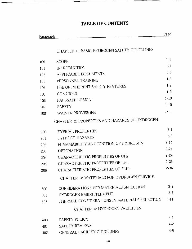
CHAPTER 1: BASIC HYDROGEN SAFETY GUIDELINES
SCOPE 1-1
INTRODUCTION 1-1
APPLICABLE DOCUMENTS 1-5
PERSONNEL TRAINING 1-5
USE OF INHERENT SAFETY FEATURES 1-7
CONTROLS 1-9
FAIL-SAFE DESIGN 1-10
SAFETY 1-10
WAIVER PROVISIONS l-11
CHAPTER 2: PROPERTIES AND HAZARDS OF HYDROGEN
TYPICAL PROPERTIES 2-1
TYPES OF HAZARDS 2-3
FLAMMABILITY AND IGNITION OF HYDROGEN 2-14
DETONATION 2-24
CHARACTERISTIC PROPERTIES OF GH_ 2-29
CHARACTERISTIC PROPERTIES OF LH2 2-35
CHARACTERISTIC PROPERTIES OF SLH2 2-36
CHAPTER 3: MATERIALS FOR HYDROGEN SERVICE
CONSIDERATIONS FOR MATERIALS SELECTION 3-1
HYDROGEN EMBRITTLEMENT 3-7
THERMAL CONSIDERATIONS IN MATERIALS SELECTION 3-11
CHAPTER 4: HYDROGEN FACILITIES
SAFETY POLICY
SAFETY REVIEWS
GENERAL FACILITY GUIDELINES
4-1
4-2
4-6
vii

Paragraph
TABLE OF CONTENTS (continued)
Page
403
404
405
406
407
4O8
4O9
410
411
BUILDINGS AND TEST CHAMBERS 4-12
CONTROL ROOMS 4-18
LOCATION AND QUANTITY-DISTANCE GUIDELINES 4-19
EXCLUSION AREAS 4-29
PROTECTION OF HYDROGEN SYSTEMS AND
SURROUNDINGS 4-32
FIRE PROTECTION 4-36
DOCUMENTATION, TAGGING, AND LABELING OF
STORAGE VESSELS, PIPING, AND COMPONENTS 4-39
INSTRUMENTATION AND MONITORING 4-42
EXAMINATION, INSPECTION, AND RECERTIFICATION 4-46
CHAPTER 5: HYDROGEN STORAGE VESSELS, PIPING, AND
COMPONENTS
500 GENERAL REQUIREMENTS 5-1
501 STORAGE VESSELS 5-3
502 PIPING SYSTEMS 5-15
503 COMPONENTS 5-25
504 OVERPRESSURE PROTECTION OF STORAGE VESSELS AND
PIPING SYSTEMS 5-43
505 HYDROGEN VENT AND FLARE SYSTEMS 5-49
506 CONTAMINATION 5-55
507 VACUUM SYSTEM 5-60
CHAPTER 6: HYDROGEN AND HYDROGEN FIRE DETECTION
600 HYDROGEN DETECTION 6-1
601 HYDROGEN FIRE DETECTION SYSTEMS 6-9
CHAPTER 7: OPERATING PROCEDURES
700 GENERAL POLICY 7-1
viii

Paragraph
TABLE OF CONTENTS (continued)
Page
701 STORAGE AND TRANSFER PROCEDURES
CHAPTER 8: TRANSPORTATION
800
801
802
803
GENERAL
TRANSPORT ON PUBLIC THOROUGHFARES
TRANSPORT ON SITE CONTROLLED THOROUGHFARE
TRANSPORTATION EMERGENCIES
CHAPTER 9: EMERGENCY PROCEDURES
900
902
902
903
904
905
GENERAL
TYPES OF EMERGENCIES
ASSISTANCE IN EMERGENCIES
FIRE SUPPRESSION
FIRST-AID PROCEDURES FOR CRYOGENIC-INDUCED
INJURIES
SAFEGUARDS FOR ENTERING PERMIT-REQUIRED
CONFINED SPACES
CHAPTER 10: REFERENCES
APPENDIX A: TABLES AND FIGURES
APPENDIX B: ASSESSMENT EXAMPLES
APPENDIX C: SCALING LAWS, EXPLOSIONS, BLAST EFFECTS, AND
FRAGMENTATION
APPENDIX D: CODES, STANDARDS, AND NASA DIRECTIVES
APPENDIX E: RELIEF DEVICES
APPENDIX F: ABBREVIATIONS AND ACRONYMS
APPENDIX G: GLOSSARY
APPENDIX H: INDEX
7-10
8-1
8-3
8-6
8-10
9-1
9-4
9-10
9-11
9-15
9-16
A-1
B-1
C-1
D-1
E-1
F-1
G-1
H-1
ix

Figures
LIST OF FIGURES
Page
AI.1
A1.2
A1.3
A1.4
A1.5
A1.6
A1.7
A1.8
A1.9
AI.10
A2.1
A2.2
A2.3
A2.4
A2.5
Equilibrium Percentage of Para-hydrogen vs. Temperature
Enthalpy of Normal Hydrogen Conversion
Vapor Pressure of Liquefied Para-hydrogen (TP to NBP)
Vapor Pressure of LH_ (NBP to CP)
Vapor of Normal and Para-hydrogen Below the Triple Point
Comparison of densities and bulk Fluid Heat Capacities for Slush,
Triple-Point liquid, and NBP Liquid Para-hydrogen
Proposed Phase Diagram (P-T) for Solid Hydrogen at Various
Otho-hydrogen Mole Fractions
Proposed Phase Diagram (V-T Plane) for Solid Normal Hydrogen
Specific Heat (Heat Capacity) of Saturated Solid Hydrogen
Melting Line from Triple Point to Critical Point Pressure
for Para-hydrogen
Flammability Limits at a Pressure of 101.3 kPa (14.7 psia)
and a Temperature of 298 K (77 °F)
Effects of N2, He, CO2, and H20 Diluents on Flammability
Limits of Hydrogen in Air at 101.3 kPa (14.7 psia)
Effects of Halocarbon Inhibitors on Flammability Limits of
Hydrogen-Oxygen Mixtures at a Pressures of 101.3 kPa (14.7 psia)
and a Temperature of 298 K (77 °F)
Distance for Fireball Radiation Flux Induced Third Degree Burns
per Amount of Fuel Burned at a Thermal Radiation Intensity
of 134 kJ/m 2 (11.8 Btu/fl _)
Radiation Intensity as a Function of Exposure Time or Escape Time
A-3
A-4
A-5
A-6
A-7
A-8
A-9
A-10
A-11
A-12
A-37
A-38
A-39
A-40
A-41
X

Figures
LIST OF FIGURES (continued)
Page
A2.6
A2.7
A2.8
A2.9
A4.1
A4.2
A4.3
A4.4
A4.5
A4.6
A5.1
A5.2
A5.3
A5.4
Variation in Distance from a Hydrogen Fire for a Thermal Radiation
Exposure of 2 cal/cm 2 for an Exposure Duration of 10 s
Minimum Dimensions of GH>Air Mixtures for Detonation at
101.3 kPa (14.7 psia) and 298 K (77 °F)
Detonation Cell Widths for Hydrogen-Air Mixtures at
101.3 kPa (14.7 psia)
Minimum Initiation Energies for Direct Detonation of
Hydrogen-Air Mixtures
Flame Dip as a Function of Stack Diameter an Hydrogen Flow
Blowout and Stable Flame Region
Flame Shape in Crosswinds
Minimum Flow Rate for Non-Stratified, Two Phase Hydrogen and
Nitrogen Flow for Pipeline Fluid Qualities Below 95% and 98%
Liquid Hydrogen Flow Rate Limits to Avoid Excessive Cooldown
Stresses in Thick-wall Piping Sections Such as Flanges for 304 SSand 6061 AI
Liquid Nitrogen Flow Rate Limits to Avoid Excessive Cooldown
Stresses in Thick-wall Piping Sections Such as Flanges for 304 SSand 6061 A1
Charpy Impact Strength as a Function of Temperature for
Various Materials
Yield and Tensile Stress of 5086 Aluminum as a Function of
Temperature
Yield and Tensile Stress of AISI 430 Stainless Steel as a Function
of Temperature
Thermal Expansion Coefficient of Copper as a Function
of Temperature
xi
A-42
A-43
A-44
A-45
A-65
A-66
A-67
A-68
A-69
A-70
A-75
A-76
A-77
A-78

Figures
LIST OF FIGURES (continued)
Page
A5.5
A6.1
A6.2
A6.3
A6.4
Total Linear Thermal Contraction as a Function of Temperaturefor Several Materials
hTadiance of Common IR Sources
Atmospheric IR Transmission and H2-Air-Flame Emission
UV/VIS/Near-IR Emissions
Flame Components
A-79
A-93
A-94
A-95
A-95
xii

Tables
LIST OF TABLES
Page
AI.1
A1.2
A1.3
A1.4
A1.5
A1.6
A2.1
A2.2
A2.3
A2.4
A2.5
A3.1
A3.2
A3.3
A3.4
A3.5
A3.6
A3.7
Selected Thermophysical, Chemical, and Combustion Properties
of Gaseous, Liquefied, Slush and Solid Para-hydrogen
Fixed Point Properties of Normal Hydrogen
Thermodynamic Properties of the Hydrogen Solid-Vapor Two
Phase Region
Thermodynamic Properties of the Hydrogen Solid-Liquid Two
Phase Region
Molar Volume of Compressed Solid Para-hydrogen
Thermal Expansion of Solid Para-hydrogen
Potential Ignition Sources
Flammability Limits
Effects of Diluents on Flammable Range for Hydrogen in Air
Inhibitor for Extinction of Hydrogen Diffusion Flames
Critical Radiant Flux Levels
Order of Preference for Location of GH2 Storage Systems
Quantity-Distance Requirements for Nonpropellant GH2 Systemsfor Outdoor Locations
Order of Preference for Locations of LH2 Storage Systems
Quantity-Distance Requirements for Nonpropellant LH2 Systemsfor Outdoor Locations
Liquid Propellant Hazard and Compatibility Groups
Explosive Equivalent Factors for Liquid Propellants
Safe Quantity-Distance Relationships for LH2 Storage for Hazard
,..
Xlll
A-13
A-17
A-19
A-20
A-21
A-22
A-46
A-47
A-48
A-49
A-50
A-53
A-54
A-55
A-56
A-57
A-58

GroupIII Materials A-59
xiv

Tables
LIST OF TABLES (continued)
Page
A3.8
A4.1
A5.1
A5.2
A5.3
A5.4
A5.5
A5.6
A5.7
A5.8
A5.9
A6.1
A6.2
A6.3
A6.4
A7.1
A7.2
Separation and Intraline Quantity-Distance Values for
Mixed Propellants A-61
Summary of Liquefied Hydrogen Spill Data A-71
Summary of Material Compatibility for Hydrogen Service A-80
A Selection of Recommended Materials for Typical Applications A-81
Minimum Temperatures and Basic Allowable Stresses in Tension
for Selected Metals A-82
Elastic Properties of Selected Materials at Room Temperature and
Liquid Hydrogen Temperature A-84
Mechanical Properties of Selected Materials at Room Temperature
and Liquid Hydrogen Temperature A-85
Thermal Properties of Selected Materials at Room Temperature and
Liquid Hydrogen Temperature A-86
Typical Characteristics of Hydrogen Embrittlement Types A-87
Susceptibility of Materials to Embrittlement in Hydrogen at
10,000 psi and 72 °F A-88
Comparison Effects of Air, Helium, and Hydrogen Exposure on
Selected Aluminum, Nickel, and Copper Alloys A-89
Typical Hydrogen Gas Detectors A-96
A Survey and Analysis of Commercially Available Hydrogen Sensors A-97
Sensitivity Limits of Hydrogen Detectors
Typical Hydrogen Fire Detectors
Hydrogen Accidents - Industrial
Hydrogen Accidents - Ammonia Plants
×V
A-98
A-99
A-103
A-104

Tables
LIST OF TABLES (continued)
Page
A7.3
B1
B2
B3
B4
D1
E1
Hydrogen Accidents - Aerospace
Detonation Pressures and Temperatures
Deflagration Pressures
Liquid-Lockup Pressure Change
Minimum Separation Distances for Siting the LH2 Dewar in
Example 6
SeLection of Federal Regulations for Hydrogen Transpor(ation
Considerations for Relief Devices in LH2 Pipelines
A-105
B-2
B-4
B-6
B-20
D-17
E-6
xvi

CHAPTER 1: BASIC HYDROGEN SAFETY GUIDELINES
Note: Hydrogen shall be stored, handled, and used so life and health are
not jeopardized and the risk of property damage is minimized.
100 SCOPE
This handbook is a central agency document containing guidelines for safely
storing, handling, and using hydrogen in gaseous, liquid, or slush form,
whether used as a nonpropellant or propellant. Each designer, user,
operator, maintainer, assurance person, and designated project manager is
responsible for incorporating the appropriate requirements of this guideline
document into their projects or facilities. However, use of this guideline
document does not relieve the designer, user, operator, maintainer, and
assurance person and designated managers of professional responsibility or
allow them to preclude the exercise of sound engineering judgment.
101 INTRODUCTION
a. General.
(1) The purpose of the Hydrogen Safety Handbook is to provide a
practical set of guidelines for safe hydrogen use. For the
purposes of this handbook, hydrogen may refer to the gaseous
(GH2), to the liquefied (LH2), and/or slush (SLH2) form.
Specific or special considerations for each form will be
delineated. This handbook contains chapters on properties and
hazards, facility design, design of components, materials
compatibility, detection, and transportation. It also covers
various operational issues and emergency procedures. The
intent of this handbook is to provide enough information that it
can be used alone, but at the same time, reference data sources
that can provide much more detail if required. Any
information contained herein on hazards and use of hydrogen
is based on current knowledge and is subject to change as
more testing is completed and evaluated.
(2) Federal and state mandatory regulation shall take precedence
over NASA directives in the event of conflicting requirements.
A primary policy of NASA is that when requirements conflict,
the most stringent shall apply (NSS 1740.11 1993).lOla
1-1

lOlb
b.
C.
Nonpropellant Use.
The following standards apply and shall be followed for hydrogen
used as a nonpropellant:
(1) 29 CFR 1910.119 (1996) sets requirements for hazard analysis
for systems involving 4535 kg (10,000 lb) or more of
hydrogen in any form.
(2) 29 CFR 1910. 103 (1996) sets requirements for GH2 systems.
This regulation does not apply to single GH_ systems using
containers having a total hydrogen content of less than 11 CM
(400 CF), measured at 101.3 kPa (14.7 psia) and 294.1 K
(70 °F). The regulation shall apply where individual systems,
each having a total hydrogen content of less than 11 CM
(400 CF), are located less than 1.5 m (5 ft) from each other.
(3) 29 CFR 1910.103 (1996) sets requirements for LH_ systems.
This regulation does not apply to portable containers having a
total LH_ content of less than 150 L (39.63 gal), nor to a LH_
system with a content greater than 283,910 L (75,000 gal).
(4) All pressure vessels for hydrogen service shall be designed,constructed, and tested in accordance with ASME Boiler and
Pressure Vessel Code (BPVC) (1995) and NMI 1710.3
(1994), NSS/HP 1740.1 (1974), and NSS 1740.4 (1976). The
appropriate standards from these codes shall be used for
aerospace pressure vessels. All piping systems for hydrogen
service shall be designed, constructed, and tested in
accordance with ANSI/ASME B31.1 (1995) and
ANSI/ASME B31.3 (1996) as appropriate.
Propellant Use.
The following standards and guidelines apply and shall be followed
for LH2 used as a propellant:
(1) 29 CFR 1910.119 (1996) sets requirements for hazard analysis
for systems involving 4535 kg (10,000 lb) or more of
hydrogen in any form.
1-2

d.
e.
f.
(2) 29 CFR 1910.103 (1996) sets requirements for LH2 systems
except for the requirements for quantity and distance siting
and for personnel monitoring.
(3) NSS 1740.12 (1993)(DoD 6055.9 1992)sets requirements for
siting LH2 storage in relation to facilities and other propellants
and chemical storage and for personnel monitoring.
(4) All pressure vessels for hydrogen service shall be designed,
constructed, and tested in accordance with ASME BPVC
(1995) and NMI 1710.3 (1994), NSS/HP 1740.1 (1974), and
NSS 1740.4 (1976). The appropriate standards from these
codes shall be used for aerospace pressure vessels. All piping
systems for hydrogen service shall be designed, constructed,
and tested in accordance with ANSI/ASME B31.3 (1996).
SLH2 and Solid Hydrogen.
No standards specifically apply to SLH2 and solid hydrogen at
present. It is suggested that when the total mass of these materials in
the system being considered is equivalent to the amounts cited in
101.b(1) and 101 .b(3) that these reference standards be applied.
Except for supplying limited property data in Appendix A1, solid
hydrogen is not discussed further.
Minimum Quantities.
The authority having jurisdiction (AHJ) at the controlling NASA
center is responsible and shall establish requirements for safe storage
and use that shall protect all personnel and facilities, for hydrogen
systems in quantities below the minimum quantity specified in the
above standards and guidelines.
Other Facilities.
Those facilities, equipment, and test articles that do not meet the
definitions of GH2 or LH2 systems as stated in the standards and
guidelines above but are in hydrogen service shall have applied for
their design, construction, testing, and use 29 CFR 1910.103 (1996),
29 CFR 1910.119 (1996), NSS 1740.12 (1993), and other standards
as directed by the AHJ at the controlling NASA center.
lOlf
1-3

lOlg
g. Retroactivity.
(1) An existing system for hydrogen used as a nonpropellant not
in strict compliance with the provisions of these standards and
guidelines shall be permitted to be continued in use wheresuch use does not constitute a distinct hazard to life or
adjoining facilities (NFPA 50A 1994 and NFPA 50B 1994).
(2) Existing facilities for LH2 used as a propellant not in
compliance with current standards may continue to be used for
the balance of their functional lives, as long as current
operations present no significantly greater risk than that
assumed when the facility was originally designed, and it can
be demonstrated clearly that a modification to bring the
facility into compliance is not feasible. However, the facility
must be brought into compliance with current standards (NSS
1740.12 1993) in the case of a major renovation.
102 APPLICABLE DOCUMENTS
Information oil safe use of hydrogen systems is cited in each section. Unless
otherwise specified, the latest revision of documentation shall be used. The
latest revision applies in the event of conflict. Unit conversions are
consistent with ANSI/IEEE Std 268 (1992).
103 PERSONNEL TRAINING
a. Hydrogen Handling Training.
Personnel handling hydrogen or designing equipment for hydrogen
systems must become familiar with the physical, chemical, and
specific hazardous properties of GH2, LH2, and SLH2. Training
should include detailed safety programs that recognize human
capabilities and limitations. The goal of the safety program is to
eliminate accidents and to minimize the severity of accidents that
occur (NHB 1700.1 1993). Appendix B, Example 12 provides a
summary of typical information that may be presented in
training/certification of liquid hydrogen handlers.
1-4
h.
C.
d.
e.
Designer Training.
Personnel involved in equipment design and operations planning must
be trained to carefully adhere to accepted standards and guidelines and
comply with the regulatory codes (NHB 1700.1 1993).
Operator Certification.
Operators must be certified for handling GH2, LH2, and SLH2, as
appropriate, and in the emergency procedures for spills and leaks.
Operators must be kept informed of any changes in safety procedures
and facility operations (NHB 1700.1 1993 and 29 CFR 1910.103
1996).
Hazard Communication Program.
The AHJ at the controlling NASA center shall develop, implement,
and maintain at the workplace a written hazard communications
program for their workplaces (29 CFR 1910.1200 1996).
Annual Review.
Each NASA installation will annually review all operations being
performed at the installation to ensure that the safety training program
is working effectively and to identify and enter into the program all
potentially hazardous jobs in addition to jobs designated mandatory.
Employee safety committees, employee representatives, and other
interested groups should be provided an opportunity to assist in the
identification process (NHB 1700.1 1993).
104 USE OF INHERENT SAFETY FEATURES
a. Hazards Elimination.
Regardless of quantity, all hydrogen systems and operations must be
devoid of hazards by providing adequate ventilation, designing and
operating to prevent leakage, and eliminating potential ignitionsources.
b. Barriers.
Barriers or safeguards should be provided to minimize risks andcontrol failures.
104b
1-5

104c
C.
d.
Safety Systems.
Safety systems should be installed to detect and counteract or control
the possible effects of such hazards as vessel failures, leaks and spills,
embrittlement, collisions during transportation, vaporization system
failures, ignitions, fires and explosions, cloud dispersions, and the
exposure of personnel to cryogenic or flame temperatures.
Safe Interface.
A safe interface must be maintained under normal and emergency
conditions so at least two failures occur before hazardous events could
lead to personal injury, loss of" life, or major equipment or property
damage.
105 CONTROLS
a. Warning Systems.
Warning systems should be installed to detect abnormal conditions,
measure malfunctions, and indicate incipient failures. Warning
system data transmissions with visible and audible signals should have
sufficient redundancy to prevent any single-point failure from
disabling the system.
b. Flow Controls.
Safety valving and flow regulation should be installed to adequately
respond for protection of personnel and equipment during hydrogen
storage, handling, and use.
c. Safety Features.
System and equipment safety features should be installed to
automatically control the equipment required to reduce the hazards
suggested by the triggering of the caution and warning systems.
Manual controls within the systems should be constrained by
automatic limiting devices to prevent over-ranging.
1-6

106 FAIL-SAFE DESIGN
a. Certification.
The equipment, power, and other system services shall be verified for
safe performance in the design and normal operational regimes
through certification.
b. Fail-Safe Design.
Any failure from which potentially hazardous conditions are a risk
shall cause the system to revert to conditions that will be safest for
personnel and with the lowest property damage potential.
c. Redundant Safety.
Redundant safety features shall be designed to prevent a hazardous
condition when a component fails.
107 SAFETY
a. Safety Review.
All plans, designs, and operations associated with hydrogen use must
be subject to an independent, safety review in accordance with NHB
1700.1 (1993). Safety reviews should be conducted on effects of
fluid properties, training, escape and rescue, fire detection, and fire
fighting.
b. Operating Procedures.
Operating procedures for normal and emergency conditions shall be
established and reviewed as appropriate (NHB 1700.1 1993).
c. Hazards Analysis.
Hazards analyses must be performed to identify conditions that may
cause injury, death, or property damage.
107c
1-7
107d
d. Mishap Reporting.
Reporting, investigating, and documenting the occurrences, causes,
and corrective action required for mishaps, incidents, test failures,
and mission failures shall follow established basic policy procedures
and guidelines (NMI 8621.1 1983 and NHB 1700.1 1993).
108 WAIVER PROVISIONS
Although this is a guideline handbook, it contains required safety provisions
noted by shall and must. The actions indicated are required by standards and
regulations and are to be followed to prevent loss of life, injury, or property
damage. Waivers to required safety provisions shall be handled and reviewed
in accordance with local procedures consistent with NHB 1700.1 (1993).
NASA variances, deviations, or waivers do not apply to Federal and
applicable state and local regulations (NHB 1700.1 1993).
Actions specified by should are recommended guidelines and also denote
additional safety considerations.
1-8

CHAPTER 2: PROPERTIES AND HAZARDS OF HYDROGEN
Note: Hydrogen is an equilibrium mixture of ortho-hydrogen and para-
hydrogen. These molecules have slightly different physical properties but
are chemically equivalent; therefore, the hazards associated with the use
of hydrogen are the same irrespective of the molecular form.
TYPICAL PROPERTIES
a. Ortho- and Para-Hydrogen.
The hydrogen molecule exists in two forms, distinguished by the
relative rotation of the nuclear spin of the individual atoms in the
molecule. Molecules with spins in the same direction (parallel) are
called ortho-hydrogen: and those with spins in the opposite direction
(antiparallel), para-hydrogen. Figure A1.1 shows that the ortho-
hydrogen will convert to para-hydrogen as the temperature of
hydrogen is lowered. The equilibrium mixture of ortho- and para-
hydrogen at any temperature is referred to as equilibrium hydrogen.
The equilibrium ortho-para-hydrogen mixture with a content of
75 percent ortho-hydrogen and 25 percent para-hydrogen at room
temperature is called normal hydrogen. The ortho-para-hydrogen
conversion is accompanied by a release of heat, 703 J/g
(302.4 Btu/lb) at 20 K (-423 °F) for ortho- to para-hydrogen
conversion, or 527 J/g (226.7 Btu/lb) for normal to para-hydrogen
conversion (Figure A1.2). Unless catalyzed, this conversion is slow
but occurs at a finite rate (taking several days to complete) and
continues even in the solid state. Catalysts are used to accelerate this
conversion in LH2 production facilities, which produce almost pure
para-hydrogen liquid (_>95 percent). Be aware of some property
differences in these different forms of hydrogen and observe for
which form the data are given.
b. Slush Hydrogen.
SLH2 is a mixture of solid and LH2 at the triple point temperature.
Properties of a 50 percent by mass solid or 50 percent by volume
solid mixture usually are given; although, other mass (or volume)
fraction mixtures of solid and liquid are possible.
200b
2-1

200c
c. Hydrogen Properties.
Selected thermophysical properties of various states of hydrogen,
primarily para-hydrogen, are given in the figures and tables in
Appendix A1. McCarty, Hord, and Roder (1981) provide an
extensive tabulation of the thermophysical properties of hydrogen.
Figure A1.3 shows the vapor pressure of liquefied para-hydrogen as a
function of temperature from the triple point to the normal boiling
point (NBP), and Figure A1.4 shows it from the NBP to the critical
point. Figure A1.5 gives the vapor pressure of para-hydrogen and
normal hydrogen below the triple point. Figure A1.6 gives the
dielectric constant of various states of para-hydrogen. Figure A1.7
gives a comparison of the densities and bulk fluid heat capacities for
slush, triple-point liquid, and normal boiling liquid para-hydrogen.
Figure A1.8 shows a proposed phase diagram (P-T plane) for solid
hydrogen at various ortho mole fractions. Figure A1.9 gives a
proposed phase diagram (V-T plane) for solid normal hydrogen.
Figure A1.10 shows the specific heat (heat capacity) of saturated solid
hydrogen. Figure A1.11 gives the melting line from the triple point
to the critical point pressure for para-hydrogen. Table A1.1 gives
selected thermophysical, chemical, and combustion properties of
para-hydrogen. This table presents property data for gaseous, liquid,
slush, and solid phases. Table A1.2 gives some fixed point properties
of normal hydrogen. Table A1.3 gives a tabulation of
thermodynamic properties of the hydrogen solid-vapor two-phase
region, and Table A1.4 gives a tabulation of the thermodynamic
properties of the hydrogen solid-liquid two-phase region. Table A1.5
gives some data on the molar volume of compressed solid para-
hydrogen. Table A1.6 gives the thermal expansion coefficient of
solid para-hydrogen from 1 to 13.8 K (-458 to -435 °F).
d. Health Hazard Properties.
Hydrogen is nontoxic, classified as a simple asphyxiant, and has no
threshold limit value (TLV). Hydrogen is not listed as a carcinogen
by the National Toxicology Program, International Agency Research
on Cancer, or Occupational Safety and Health Administration.
Health hazard data are given in a hydrogen Material Safety Data
Sheet (MSDS) in Appendix A1, Addendum.
2-2

201 TYPESOF HAZARDS
a. General.
The hazards associated with the use of hydrogen can be characterized
as physiological (frostbite, respiratory ailment, and asphyxiation),
physical (phase changes, component failures, and embrittlement), and
chemical (ignition and burning). A combination of hazards occur in
most instances. The primary hazard associated with any form of
hydrogen is inadvertently producing a flammable or detonable
mixture, leading to a fire or detonation. Safety will be improved
when the designers and operational personnel are aware of the
specific hazards associated with the handling and use of hydrogen.
Hazards of hydrogen use are discussed below.
b. Industrial and Aerospace Accidents.
(I) Industrial and aerospace accidents from the use of hydrogen
have occurred. Tables AT. 1 through A7.3 list types of
accidents. Analyses of these accidents indicate the following
factors are of primary importance in causing system failures:
(a) Mechanical failure of the containment vessel, piping,
or auxiliary components (brittle failure, hydrogen
embrittlement, or freeze-up)
(b) Reaction of the fluid with a contaminant (such as air in
a hydrogen system)
(c) Failure of a safety device to operate properly
(d) Operational error
(2) Analyses of accidents have shown that the response, through
design or operating procedures, to a failure should be such that
a single failure does not lead to a series of failures or a chain
reaction of failures; such as, any failure must be restricted to a
local event; otherwise, the hazard and potential for damage is
greatly enhanced.
201b
2-3
201c
C.
d.
Ignition.
Fires and explosions have occurred in various components of
hydrogen systems as a result of a variety of ignition sources. Ignition
sources have included mechanical sparks from rapidly closing valves,
electrostatic discharges in ungrounded particulate filters, sparks fl'om
electrical equipment, welding and cutting operations, catalyst
particles, and lightning strikes near the vent stack. Table A2.1 lists
additional ignition sources.
Fire and Explosions.
A potential fire hazard always exists when hydrogen is present.
(1) GH_ diffuses rapidly with air turbulence increasing the rate of
GHz dispersion. Evaporation can rapidly occur in an LH2
spill; resulting in a flammable mixture forming over a
considerable distance. Although ignition sources may not be
present at the leak or spill location, fire could occur if themovement of the flammable mixture causes it to reach an
ignition source.
Example: Observation alone is not a reliable technique for
detecting pure hydrogen-air fires or assessing their
severity. A fire resulted from an accident in which
a small leak developed. The equipment was
shutdown and the flame appeared to diminish;
however, molten metal drippings from the
equipment indicated a more severe fire was in
progress.
(2) A deflagration could result if a mixture within flammability
limits is ignited at a single point.
(3) A detonation could occur if the GHz-air mixture is within
detonability limits and an appropriate energy source is
available. A deflagration could transform into a detonation if
there is confinement or a mechanism for flame acceleration.
(4) Flash fires or boiling liquid expanding vapor explosions
(BLEVE) could occur when an external source of thermal
energy is heating LH2 or SLH2 and there is a path to the
surroundings.
2-4

e. Leaks.
f.
Leaks can occur within a system or to the surroundings. Hazards can
arise by air or contaminants leaking into a cold hydrogen system (LHz
or SLH2), such as by cryo-pumping. Leaks are usually caused by
deformed seals or gaskets, valve misalignment, or failures of flanges
or equipment. A leak may cause further failures of construction
materials. For leaks involving LH2, vaporization of cold vapor
hydrogen to the atmosphere may provide a warning because moisture
condenses and forms a fog. Undetected hydrogen leaks can lead to
fires and explosions.
Example: Hydrogen leaks generally originate from valves, flanges,
diaphragms, gaskets, and various types of seals and fittings.
The leaks usually are undetected because of the absence of a
continuous hydrogen monitor in the area. An example of
this condition was a large sphere partitioned by a neoprene
diaphragm with hydrogen stored under the diaphragm and
air above it. An explosion-proof fan was placed on top of
the sphere to provide a slight positive pressure on the
diaphragm. A violent explosion occurred in the sphere
after the plant was shutdown. Hydrogen leaked past the
diaphragm when the fan was turned off. Ignition was
attributed to an electrostatic discharge cause by motion of
the diaphragm or a source associated with the
explosion-proof fan. The explosion could have been
avoided by using an inert gas instead of air across the
diaphragm or monitoring the hydrogen concentration in the
upper hemisphere.
Hydrogen Dispersion.
A property of hydrogen that tends to limit the horizontal spread of
combustible mixtures from a hydrogen spill is its buoyancy.
Although saturated hydrogen is heavier than air at the temperatures
existing after evaporation from a spill, it quickly becomes lighter than
air, making the cloud positively buoyant. The dispersion of the cloud
is affected by wind speed and wind direction and can be influenced by
atmospheric turbulence and nearby structures. Although condensing
moisture is an indication of cold hydrogen, the fog shape does not
give an accurate description of the hydrogen cloud location
(Witcofsky and Chirivella 1982). The use of dikes or barricades
201f
2-5

20If
g,
h,
around hydrogen storage facilities should be carefully examined
because it is preferred to disperse any leaked or spilled LH_ or SLH2
as rapidly as possible. Dikes or berms generally should not be used
unless their purpose is to limit or contain the spread of a liquid spill
because of nearby buildings, ignition sources, etc. However, such
confinement may delay the dispersion of any spilled liquid by limiting
the evaporation rate, and could effect a combustion event that might
Occur.
Storage Vessel Failure.
The release of GH_ or LH2 may result in ignition and combustion,
causing fires and explosions. Damage may extend over considerably
wider areas than the storage locations because of hydrogen cloud
movement. Vessel failure may be started by material failure,
excessive pressure caused by heat leak, or failure of the
pressure-relief system.
Vent and Exhaust System.
Vent and exhaust system accidents are attributed to inadequate
ventilation and the inadvertent entry of air into the vent. Backflow of
air can be prevented with suitable vent stack designs, provision of
makeup air (or adequate supply of inert gas as the situation demands),
check valves, or molecular seals.
Purging.
Pipes and vessels should be purged with an inert gas before and after
using hydrogen in the equipment. Nitrogen may be used if the
temperature of the system is above 80 K (-316 °F), whereas, helium
should be used if the temperature is below 80 K (-316 °F).
Alternatively, a GH2 purge may be used to warm the system to 80 K
(-316 °F) and then switch to a nitrogen purge if the system is below
80 K (-316 °F); however, some condensation of the GH2 may occur if
the system contains LH2. Residual pockets of hydrogen or the purge
gas will remain in the enclosure if the purging rate, duration, or
extent of mixing is too low. Tables AT. 1 through A7.3 list 12 fire or
explosion incidents that resulted from such situations, demonstrating
the difficulties in purging hydrogen from large systems. Uniform
mixing and dilution is unlikely in partially enclosed spaces. Reliable
gas concentration measurements should be obtained at a number of
different locations within the system for suitable purges.
2-6

k.
.
Example: A dangerous purging practice that led to an explosion
occurred when only a portion of a hydrogen system was
isolated to reduce the purge time and volume. Complete
isolation usually cannot be ensured because of the
propensity of hydrogen to leak.
Vaporization System Failure.
Pipe valving in vaporization systems may fail, causing injury from
low-temperature exposures. Ignition of the hydrogen may occur,
resulting in damage from fires and explosions.
Condensation of Air.
An uninsulated line containing LH_ or cold hydrogen gas, such as a
vent line, can be sufficiently cold (less than 90 K (-298 °F) at
101.3 kPa (14.7 psia)) to condense air on the outside of the pipe.
The condensed air, which can be enriched in oxygen to about
50 percent, must not be allowed to contact sensitive material or
equipment. Materials not suitable for low temperatures, such as
carbon steel, can become embrittled and fail. Moving parts and
electronic equipment can be adversely affected. Condensed air must
not be permitted to drip onto combustible materials such as tar and
asphalt Can explosive mixture can be created).
Hydrogen Embrittlement.
Containment systems may fail and the subsequent spills and leaks will
create hazards when the mechanical properties of metallic and
nonmetallic materials degrade from hydrogen embrittlement.
Hydrogen embrittlement is a long term effect and occurs from
continued use of a hydrogen system.
Example: Tables A7.1 through A7.3 list piping and vessel ruptures
caused by materials problems including hydrogen
embrittlement, stress corrosion, and weld failures. Most of
the damage was incurred by ignition of the hydrogen
following the rupture. All repairs and modifications to
piping and equipment that handles hydrogen must be
carefully engineered and tested.
2011
2-7

201m
m. Physiological Hazards.
Personnel present during leaks, fires, or explosions of hydrogen
systems can incur several types of injury.
(1) Asphyxiation is a hazard when someone enters a region where
hydrogen or a purge gas has displaced the air, diluting the
oxygen below 19.5 percent by volume. Stages of asphyxiation
(at ground level) have been noted based on the oxygenconcentration:
15-19 percent by volume Decreased ability to perform
tasks; may induce early
symptoms in persons with
heart, lung, or circulatory
problems
12-15 percent by volume Deeper respiration, faster
pulse, poor coordination
10-12 percent by volume Giddiness, poor judgment,
slightly blue lips
8-10 percent by volume Nausea, vomiting,
unconsciousness, ashen face,
fainting, mental failure
6-8 percent by volume Death in 8 min; 50 percent
death and 50 percent recovery
with treatment in 6 min, 100
percent recovery withtreatment in 4 to 5 min
4 percent by volume Coma in 40 s, convulsions,
respiration ceases, death
(2) Blast waves from explosions will cause injury as a result of
overpressure at a given location or a combination of
overpressure and duration at a given location as follows
(DoD 6055.9 1992):
3 psi overpressure 1 percent eardrum
rupture
2-8

16psioverpressure
10psi overpressurefor 50msor 20-30psi overpressurefor 3 ms
50percenteardrumrupture
Thresholdof lungrupture
(3)
27 psi overpressure for 50 ms
or 60-70 psi overpressure for 3 ms
1 percent mortality
The radiant heat that reaches and is absorbed by a person from
a GH2-air flame is directly proportional to a variety of factors
including exposure time, burning rate, heat of combustion,
size of the burning surface, and atmospheric conditions
(especially water vapor). Thermal radiation flux exposure
levels show the following:
Flux of 0.47 W/cm 2 (I490 Btu/min.fl _) Pain felt in 15-30 s
Skin burns in 30 s
n.
Flux of 0.95 W/cm 2 (2722 Btu/min.ft 2) Immediate skin
reactions
Figure A2.4 shows the distance-fuel weight relationship for
third degree burns for thermal radiation of 134 J/m 2
(11.8 Btu/flz). Figure A2.5 shows heat radiant intensity
versus exposure time for threshold pain values. Figure A2.6
shows the effect of water vapor on radiant energy from a
hydrogen fire.
(4) Cryogenic burns result from contact with cold fluids or cold
vessel surfaces.
(5) Exposure to large LH2 spills could result in hypothermia if
proper precautions are not taken.
Collisions Durin_ Transportation.
Damage to hydrogen transportation systems (road, rail, air, and
water) can cause spills and leaks that may result in fires and
explosions.
201n
2-9

201n
Example: Most of the incidents during transportation occurred outside
of industrial facilities. Seventy-one percent of the hydrogen
releases did not lead to an ignition. The relatively few
ignitions may be due to a lack of ignition sources or the
rapid dispersal of hydrogen into the atmosphere. In any
event, the accident data provide further incentive to
transport, transfer, and store hydrogen outdoors, away from
occupied areas.
202 FLAMMABILITY AND IGNITION OF HYDROGEN
Note: Major emphasis should be on containment, detection, and
ventilation because the minimum energy of GH2 ignition in air at
atmospheric pressure is about 0.02 nO (1.9 x 10 s Btu) and experience
shows that escaped hydrogen is very easily ignited.
It is necessary for hydrogen to be mixed with an oxidant, the mixture be
within flammability limits, and an appropriate ignition source be present for
hydrogen to burn. Leaks and accumulations occur even with the best efforts
to contain hydrogen. The safe procedure is to eliminate all likely sources of
ignition or place them away from areas of possible hydrogen leakage. Fifty-
three percent of the industrial accidents listed in Table A7.1 occurred because
of leaks, off-gassing, and equipment ruptures. Fifteen percent were purging
or vent-exhaust incidents, and the remaining 32 percent were other types of
incidents. The vast majority of the accidents in ammonia plants listed in
Table A?.2 occurred because of gaskets and valve packing leaking. Eighty-
seven out of 107 aerospace hydrogen incidents listed in Table A7.3 involved
release of GH_ or LH2. When accidents were not caused by equipment
failure, they primarily occurred when procedures were not prescribed or
when prescribed procedures were not followed (Ordin 1974). Accident
reports showed that electrical short circuits and sparks were considered to be
responsible for 25 percent of the ignitions, and static charges were
responsible for about 18 percent of the ignitions. Welding or cutting torches,
metal fracture, gas impingement, and the rupture of safety disks were each
considered responsible for 3 to 6 percent of the ignitions.
a. Flammability.
(1) Mixtures of hydrogen with air, oxygen, or other oxidizers are
highly flammable over a wide range of compositions. The
flammability limits, in percent by volume of hydrogen, define
the range over which fuel vapors will ignite when exposed to
an ignition source of sufficient energy. Flammability limits
2-10

C2t
(3)
(4)
are dependent on the ignition energy, temperature, pressure,
presence of diluents, and size and configuration of the
equipment, facility, or apparatus.
A flammable mixture may be diluted with either of its
constituents until the mixture concentration falls outside the
flammability limits: below the lower flammability limit (LFL)
or above the upper flammability limit (UFL). The
flammability range for hydrogen-air and hydrogen-oxygen
mixtures is broadest for upward flame propagation and
narrows for downward flame propagation.
Neither LH_ or SLH_ as fuel, and liquid oxygen (LOX) or
solid oxygen as oxidizer, are hypergolic. Mixtures of these
materials have ignited during the mixing process because the
energy required to ignite them is so small (Bunker, Dees, and
Eck 1995). LH_ and liquid-solid oxygen have been detonated
by an externally generated shock wave. Comparable
experimental examination of SLH_ systems does not exist.
The flammability limits of hydrogen in dry air at 101.3 kPa
(14.7 psia) and ambient temperature are 4.1 percent (LFL) to
74.8 percent (UFL). These limits apply for upward
propagation in tubes. The flammability limits of hydrogen in
oxygen at 101.3 kPa (14.7 psia) and ambient temperature are
4.1 percent (LFL) to 94 percent (UFL). These limits apply for
upward propagation in tubes. Table A2.2 lists the effect of
propagation direction. A reduction in pressure below
101.3 kPa (14.7 psia) tends to narrow the range of
flammability by raising the lower limit and lowering the upper
limit (Table A2.2).
(a) Hydrogen-Air Mixture.
1 The LFL for hydrogen-air mixtures rises to
about 9 percent by volume hydrogen above
10.3 MPa (1500 psia), and the UFL rises to
about 75 percent by volume above 8.3 MPa
(1200 psia). Data indicate that the lowest
pressure for which a low-energy ignition source
produces ignition is approximately 6.9 kPa
(1 psia), at a hydrogen concentration of between
20 and 30 percent by volume (Hertzberg and
Litton 1981).
202a
2-11

202a
(b)
2
3
4
Various hydrogen-air mixtures were subjected
to a 45 mJ (4.27x10 5 Btu) spark ignition source
in a 311 K (100 °F) temperature environment
(Mills, Linley, and Pippen. 1977 and Benz and
Boucher 1981). The tests indicate that the LFL
was 4.5 percent by volume over the pressure
range 34.5 to 101.3 kPa (5 to 14.7 psia). An
increasingly richer hydrogen mixture was
required to obtain combustion below 34.5 kPa
(5 psia). The lowest pressure for which a
low-energy ignition source produced ignition
was 6.2 kPa (0.9 psia) at a GH_-air mixture of
between 20 percent and 30 percent by volume
GH2 (Thompson and Enloe 1966).
Using a strong ignition source, the lowest
pressure for which ignition occurs is 0.117 kPa
(0.02 psia).
Raising the temperature from 290 to 673 K (62
to 752 °F) decreases the LFL of hydrogen-air
(downward propagation) from 9.0 to
6.3 percent by volume hydrogen and increases
the UFL from 75 percent to 81.5 percent by
volume hydrogen. Data are for a pressure of
101.3 kPa (14.7 psia).
Hydrogen-Oxygen Mixtures.
1
2
The flammability range for hydrogen-oxygen
mixtures of 101.3 kPa (14.7 psia) is from 4 to
94 percent by volume hydrogen for upward
propagation in tubes. Reduced pressures
increase the LFL (Benz and Boucher 1981).
The lowest pressure observed for ignition is
57 Pa (0.008 psia) at a hydrogen concentration
of 50 percent by volume when a high-energy
ignition source was used.
Results of tests at elevated pressures indicate the
LFL does not change with pressure to
12.4 MPa (1793 psia). A UFL of 95.7 percent
by volume hydrogen at 1.52 MPa (220.6 psia)
2-12
(c)
(d)
is reported (Benz, Bishop, and Pedley 1988).
Raising the temperature from 288 to 573 K (59
to 572 °F) decreases the LFL from 9.6 to
9.1 percent by volume hydrogen and increases
the UFL from 90 to 94 percent by volume
hydrogen.
Effects of Diluents.
1 Figure A2.1 shows the flammability limits for
hydrogen-oxygen-nitrogen. Table A2.2 shows
flammability limits for GHz and gaseous oxygen
(GOX) with equal concentrations of added inert
gases (helium (He), carbon dioxide (COs), and
nitrogen (N_)). Table A2.3 shows the
qualitative effect of He, COs, N2, and Argon
diluents for various tube sizes. Argon was the
least effective in reducing the flammable range
for hydrogen in air.
2 Figure A2.2 shows the effects of He, COs, N_,
and water vapor on the flammability limits of
hydrogen in air. Measurements were
performed at 298 K (77 °F) and 101.3 kPa
(14.7 psia) except for the water vapor studies,
which were performed at 422 K (300 °F).
Water was the most effective in reducing the
flammability range, and helium was the leasteffective.
Effects of Halocarbon Inhibitors.
1 Figure A2.3 shows the effects of halocarbon
inhibitors on the flammability limits of
hydrogen-oxygen mixtures.
2 Table A2.4 compares the effect of N2, CH3Br,
and CBrF3 required to extinguish hydrogendiffusion flames in air. The inhibitors were
more effective when added to the air stream;
nitrogen was more effective when added to thefuel stream.
2-13
202a

202a
(5) Autoignition Temperature. Hydrogen is only slightly more
difficult to ignite in air than in oxygen. Ignition temperatures
are dependent on GH_ concentration and pressure and the
surface treatment of containers. The reported temperature is
very dependent on the system and values selected should be
applied only to similar systems. At 101.3 kPa (14.7 psia) the
range of reported autoignition temperatures for stoichiometric
hydrogen in air is 773 to 850 K (932 to 1070 °F); in
stoichiometric oxygen it is 773 to 833 K (932 to 1039 °F). At
pressures from 20 to 50 kPa (2.9 to 7.25 psia) GH2-air
ignitions have occurred at 620 K (657 °F).
(6) Minimum Spark Energy for Ignition. Minimum spark energy
for ignition is defined as the minimum spark energy required
to ignite the most easily ignitable concentration of fuel in air
and oxygen. The minimum spark energies of hydrogen in air
are 0.017 mJ (1.6x 10 8 Btu) at 101.3 kPa (14.7 psia), 0.09 mJ
(8.5x10 -_ Btu) at 5.1 kPa (0.735 psia), and 0.56 mJ
(5.31x10 7 Btu) at 2.03 kPa (0.294 psia). The minimum spark
energy required for ignition of hydrogen in air is considerably
less than that for methane (0.29 m J) or gasoline (0.24 m J);
however, the ignition energy for all three fuels is sufficiently
low that ignition is relatively certain in the presence of any
weak ignition source; such as, sparks, matches, hot surfaces,
or open flames. Even a weak spark caused by the discharge of
static electricity from a human body may be sufficient to igniteany of these fuels in air.
(7) Quenching Gap in Normal Temperature and Pressure Air.
(a) The quenching gap for hydrogen in normal temperature
and pressure (NTP) air is 0.6 mm (0.024 in.). This
value depends on the temperature, pressure, and
composition of the combustible gas mixture and the
electrode configuration.
(b) Faster burning gases generally have smaller quenching
gaps, and flame arresters for faster burning gases
require smaller apertures. The lowest reported
quenching distance for hydrogen is 0.076 mm
(0.003 in.) (Wionsky 1972). There are three major
considerations in determining the quenching distance
2-14

b.
for a gaseous fuel such as hydrogen: ignition energy,
mixture ratio, and pressure.
Quenching gap is a function of ignition energy.
Low ignition energy, 0.001 mJ (9.5xi0 _0Btu),
corresponds to a small gap, 0.01 cm
(0.0039 in.). Likewise, high ignition energy,
10 mJ (9.5x10 6 Btu), requires a larger gap, 1 cm
(0.39 in.). (Van Dolah, et al. 1963).
2 Pressure and composition affect the quenching
distance. The quenching distance increases
dramatically at very low pressures. At a
distance of several inches, the pressure is barely
sufficient to support combustion. The effect of
mixture ratios is less well known; however, it
appears to be constant for a given pressure
between the UFL and LFL (Van Dolah, et al.
1963).
3 Specific values for hydrogen-air
mixtures are not available; however, the
effect of pressure as a function of tube
diameter for deflagration and detonation
of acetylene-air mixtures can be used as
a guideline (Zebetakis and Burgess
1961).
Ignition Sources.
There shall be no sources of ignition, such as from open
flames, electrical equipment, or heating equipment in
buildings or special rooms containing hydrogen systems
(29 CFR 1910.103 1996, NFPA 50A 1994 and NFPA 50B
1994).
Note: Ignition sources must be eliminated or safely
isolated and operations should be conducted as if
unforeseen ignition sources could occur.
202b
2-15

202b
(1)
(2)
(3)
(4)
The ignition of GH_-air mixtures usually results in
ordinary deflagration. Table A2.1 gives potential
ignition sources for hydrogen systems. The potential
hazards are significantly less than if detonation results.
It is possible that in a confined or partially confined
enclosure a deflagration can evolve into a detonation.
The geometry and flow conditions (turbulence) have a
strong effect on the transition from deflagration todetonation.
Electrical sparks are caused by sudden electrical
discharges between objects having different electrical
potentials, such as breaking electrical circuits or
discharges of static electricity. The sparks may
dissipate tremendous amounts of energy in comparison
with friction sparks.
Static electricity can generate sparks that will ignite
hydrogen-air or hydrogen-oxygen mixtures. Static
electricity is caused by many common articles, such ashair or fur when combed or stroked or a leather belt
operating on a machine. People generate high-voltage
charges of static electricity on themselves, especially
when walking on synthetic carpet or dry ground,
wearing nylon or other synthetic clothing, sliding on
automobile seats, or combing their hair. Flowing GH_
or LH2 can generate charges of static electricity. This
is true also for all nonconductive liquids or gases.
Flow in SLH2 has the potential for generating static
electricity, although such an effect has not beenconfirmed. Turbulence in containers as well as laminar
flow in systems has the same effect. Static charges
may be induced during electrical storms (Beach 1964
and Beach 1965).
Friction sparks are caused by hard objects coming into
shearing contact with each other, such as metal striking
metal, metal striking stone, or stone striking stone.
Friction sparks are particles of burning material thathave been sheared off as a result of contact. The
particle initially is heated by the mechanical energy of
friction and impact. Sparks struck by hand tools are
considered to have low total energy. Mechanical tools
2-16

(5)
(6)
(7)
such as drills and pneumatic chisels can generate high-
energy sparks.
Impact sparks are also caused by hard objects coming
into forcible contact with each other. Impact sparks
are produced by impact on a quartzitic rock such as the
sand in concrete. As with friction sparks, small
particles of the impacted material are thrown off.
Hot Objects and Flames.
(a) Objects at temperatures from 773 to 854 K (932
to 1078 ° F) can ignite hydrogen-air or
hydrogen-oxygen mixtures at atmospheric
pressure. Substantially cooler objects, about
590 K (602 °F), can cause ignition under
prolonged contact at less than atmospheric
pressure.
(b) Open flames easily ignite hydrogen-airmixtures.
Provisions should be made to acceptably contain any
resulting deflagration or detonation if ignition sources
are a required part of a hydrogen use. As an example,
a combustor or engine should not be operated in
hydrogen-rich atmospheres without well-dispersed
water sprays in its exhaust. Experience indicates that
multiple bank sprays will partially suppress the
detonation pressures and reduce the number and
temperature of ignition sources in an exhaust system.
Water sprays should not be relied on as a means of
avoiding detonations. Carbon dioxide may be used
with the water spray to further reduce hazards.
203 DETONATION
The worst-case event resulting from release of all forms of hydrogen
into the ambient environment is mixing of the hydrogen with an
oxidizer (usually air), reaching detonable concentrations, and
subsequent ignition producing a detonation of the mixture. The
2-17
2O3
203
positive buoyancy and rapid molecular diffusion of GH2 means that any
release will quickly mix with the surrounding gases. Rapid
vaporization occurs and subsequent mixing with the surrounding gasescan lead to a detonable mixture if LH_ or SLH2 leaks. Should a
detonation occur, the resulting reaction zone is a shock wave and the
accompanying blast wave has much greater potential for causing
personnel injury or equipment damage.
a. Detonation Limits.
Lower and upper detonation limits vary considerably with the
nature and dimensions of the confinement and cannot be
specified for any fuel-oxidizer mixture unless the nature and
dimensions of the confinement are also specified (Benz,
Bishop, and Pedley 1988).
(1) Figure A2.7 shows the minimum dimensions of
hydrogen-air mixtures for detonation in three types of
confinement at 101.3 kPa (14.7 psia). The figure
shows a significant effect of confinement type on
detonation limits. The ignition energy for detonation
also becomes large for lean or rich mixtures; however,
it is possible to produce overdriven detonations when
large ignition energy is introduced. Therefore,
detonation limits found in the literature should be used
with caution. Stable detonations are fairly well
characterized by the Chapman-Jouget calculation.
Table B1 gives the type of information obtained from
such calculations for hydrogen-air. This table was
produced using the Gordon-McBride computer code(Gordon and McBride 1994).
(2) While values of lower and upper detonation limits for
GH_-GOX of 15 and 90 percent hydrogen (Lewis and
yon Elbe 1961), respectively, are cited, the values
suffer from the same shortcomings noted for hydrogen-air and should be used with caution.
(3) No specific detonation limits for LH2 and air or GOX
are available. The rapid volatilization of LH2 to GH2
and subsequent mixing with air or GOX would result indetonable mixtures as described above.
2-18

h.
C.
(4) Mixtures of solid oxygen in excess (with respect to
stoichiometry) and LH2 is shock sensitive. A stimulus
(shock) of 100 to 250 MPa (19,500 to 36,000 psia)
will detonate such mixtures. For comparison,
nitroglycerin is detonated by 250 to 500 MPa (36,000
to 73,000 psia) shocks (Perlee, Litchfield, and
Zabetakis 1964).
Detonation Cell Size.
A detonation wave is not a single planar wave front but has a
three-dimensional structure consisting of cells. The size of the
cell, as measured through the pattern left by a detonation on a
smoked plate, is of considerable value in predicting the onset
of detonation and describing the conditions for stable
detonation waves. The cell size has been shown to relate to
several key parameters in assessing a potential hazard,
including critical energies and dimensional characteristics of
structural confinement of the detonation (Lee, et. al. 1982).
The length (a) of a delonation cell is one to two times its width
(b). The aspect ratio (a/b) increases with decreasing initial
pressure. Detonation cell lengths for stoichiometric GH>
air/GOX at 101.3 kPa (14.7 psia) are 15.9 mm (0.626 in.) and
0.6 mm (0.024 in.), respectively (Bull, Ellsworth, and Shift
1982). The measurements are specific to the system
configuration used. Figure A2.8 gives the variation ofdetonation cell widths for GH>air mixtures at 101.3 kPa
(14.7 psia). Ignition energy requirements depend on the
concentration of the detonable mixture. Figure A2.9 gives the
grams of tetryl required to detonate the GH2-air mixtures
shown in Figure A2.8.
Effect of Temperature, Pressure, and Diluents.
The effect of temperature on detonation cell size for GH>air
mixtures gives mixed results. The original source should be
consulted when citing such effects. Bull, Ellsworth, and Shift
(1982) showed decreasing cell size with increasing pressure
for GH>air. Increasing concentrations of diluents (percent by
volume CO2, H20) significantly increases cell widths of GH>
air detonations (Shepard and Roller 1982).
2-19
203c

203d
d,
e,
Energy of Explosion.
The explosive yields for hydrogen-air follow:
NTP GH2-air
approximately 24 g TNT/g GH2 (24 lb TNT/Ib GH2)
2.02 kg TNT/m 3 GH2 (0. 126 lb TNT/fl 3 GH2)
0.17 g TNT/kJ GH2 (4x10 -4 lb TNT/Btu GH2)
NBP LH2-air
1.71 g TNT/cm 3 LH2 (107.3 lb TNT/fl3 LH2)
It should be emphasized that only a fraction of this theoretical
explosive yield will be realized in an actual open air mishap.
It is virtually impossible to spill or release a large quantity of
fuel and have all of it mix in proper proportions with air
before ignition. Appendix B, Example 1, gives an example of
the calculation of the detonation characteristics of hydrogen-
air-oxygen mixtures using the Gordon-McBride computer code
(Gordon and McBride 1994). TNT produces a short duration,
high impulse pressure wave, whereas, a hydrogen-air
explosion would have a longer duration and lower impulse
pressure wave; the external effects of the two can be quitedifferent.
Deflagration-to-Detonation Transition.
A hydrogen-air combustion can start as a detonation, or it can
start as a deflagration and then transit to a detonation after the
flame has traveled for some distance. The composition range
in which a detonation can take place is narrower than that for
deflagration. The commonly quoted range for detonation in a
hydrogen-air mixture is from 18.3 to 59 percent hydrogen.
However, with higher energy ignition sources, the limits can
be extended. The factors that influence whether hydrogen-air
combustion will occur as a detonation, rather than a
deflagration, include the hydrogen percentage, the strength of
the initiator, complete or partial confinement of the reaction,
and the presence of structures that can induce turbulence in the
flame front. An energetic source of initiation is required forcombustion to start as a detonation. A mechanism to
2-20

acceleratethe flamevelocity is necessaryfor a deflagrationtotransit to detonation. Factorsthatfavor this transitionincludethecompositionbeingwithin thedetonationrange,a degreeofconfinement,andanythingthat caninduceturbulencein theflamefront as it travelsthroughthe combustiblemixture. Thelatter tendsto stretchout theflame front and increaseitsvelocity (Lee1977).
204 CHARACTERISTICPROPERTIESOF GH2
While knowledgeof the generalchemicalandphysicalpropertiesofhydrogenmustbeavailableto thedesignerandoperatorsof hydrogensystems,somecharacteristicpropertiesof GH2areof particularconcernfor hazardanalyses.The characteristicsandpropertiesofparticularconcernarediscussedin thissection.
a. Detection.
Hydrogen gas is colorless, odorless, and not detectable in any
concentration by human senses. Hydrogen is not toxic but can
result in asphyxiation by diluting the oxygen required in
breathing air. An atmosphere containing oxygen at a
concentration of less than 19.5 percent by volume is considered
oxygen deficient (NHS/IH 1845.2 1983).
b. Variable Density.
Hydrogen gas is lighter than NTP air and tends to rise at
temperatures above 23 K (-418.6 °F). Saturated vapor is
heavier than air and will remain close to the ground until the
temperature rises. Buoyant velocities are related to the
difference in air and fuel densities; therefore, the cold, dense
fuel gases produced by LH2 spills will rise more slowly than
standard temperature and pressure fuel gases. The buoyant
velocity of hydrogen in NTP air is 1.2 to 9 m/s (3.94 to
29.5 ft/s).
204b
2-21

204c
C.
d.
e.
f.
Lack of Flame Color.
A hydrogen-air-oxygen flame is colorless. Any visibility is
caused by impurities. At reduced pressures a pale blue or
purple flame may be present. Severe burns have been
inflicted on persons exposed to hydrogen flames resulting from
the ignition of hydrogen gas escaping from leaks.
Flame Temperature in Air.
The flame temperature for 19.6 percent by volume hydrogen
in air is 2321 K (3718 °F). Table B2 gives the calculated
characteristics of several mixtures of hydrogen-air-oxygen
using the Gordon-McBride code (Gordon and McBride 1994).
Burning Velocity in NTP Air.
The burning velocity in NTP air, defined as the subsonic
velocity at which a flame propagates through a flammable
fuel-air mixture, is 2.70 to 3.50 m/s (8.86 to 11.48 ft/s). The
burning velocities are affected by pressure, temperature, and
mixture composition. The high burning velocity of hydrogen
indicates its high explosive potential and the difficulty of
confining or arresting hydrogen flames and explosions.
Thermal Energy Radiated from Flame to Surroundings.
(1) Exposure to hydrogen fires can result in significant
damage from thermal radiation. Thermal radiation is
affected by the amount of water vapor in the
atmosphere.
(2) Atmospheric moisture absorbs thermal energy radiatedfrom a fire and can reduce the values. This effect is
significant for hydrogen fires. The intensity of
radiation from a hydrogen flame at a specific distance
depends heavily on the amount of water vapor present
in tile atmosphere and is expressed as:
2-22

.
h.
i.
I = Joe ooo4qbv_ (Eq 1)
where:
I0 = initial intensity (energy/time.area)
w = water vapor (percent by weight)
r = distance (meters)
Figure A2.6 shows additional data on the effect of
water vapor oil radiant energy from hydrogen fires.
(3) Table A2.5 includes effects of thermal radiation
exposure on several materials.
Diffusion Coefficient in NTP Air.
The diffusion coefficient for hydrogen in NTP air is
0.61 cm2/s (6.6x10 _ ftZ/s).
Limiting Oxygen Index.
The limiting oxygen index is the minimum concentration of
oxygen that will support flame propagation in a mixture of
fuel, air, and nitrogen. For example, no mixture of hydrogen,
air, and nitrogen at NTP conditions will propagate flame if the
mixture contains less than 5 percent by volume oxygen.
Joule-Thomson Expansion.
Most gases at ambient temperatures cool when expanded
across a porous plug; however, the temperature of hydrogen
increases when the gas is expanded at a temperature above its
inverse Joule-Thomson temperature 193 K (- 112 ° F).
However, the inverse Joule-Thomson effect will not be the
primary cause of any combustion that occurs when hydrogen is
vented from a high-pressure source. The temperature increase
from this effect is only a few degrees Kelvin at the most; it
would not raise the gas to its ignition temperature unless the
gas was already near the ignition temperature.
204i
2-23

205
205 CHARACTERISTIC PROPERTIES OF LH_
All of the hazards that exist with GH2 also exist with LH2 because of
the ease with which the liquid evaporates. Characteristic properties of
LH_ also of particular concern for hazard analyses are discussed inthis section.
a. Low Boiling Point.
LH_ has an NBP of 20.3 K (-423.5 °F) at sea level pressure.
Any LH2 splashed on the skin or in the eyes can cause serious
burns by frostbite or hypothermia. Inhaling vapor or cold gas
produces respiratory discomfort and asphyxiation can result.
b. Ice Formation.
Vents and valving from storage vessels and dewars may be
blocked by accumulations of ice formed from moisture in the
air. Excessive pressure may then rupture the container and
release hydrogen.
c. Continuous Evaporation.
The continuous evaporation of LH2 in a vessel generates GHa,
which must be vented to a safe location or temporarily
confined safely. Storage vessels and other containers should
be kept under positive pressure to prevent air from entering.
LH_ is subject to contamination with air condensed and
solidified from the atmosphere or with trace air accumulated
during LH2 production. The quantity of oxygen can buildup
during repeated refilling or pressurization of permanent LH2
storage vessels. This mixture is easily ignited and can thendetonate.
d. Pressure Rise.
LH_ will eventually warm to the surroundings giving a
significant pressure rise if it is confined, as in a pipe between
two valves. Considering GH2 as an ideal gas, the pressure
resulting from a trapped volume of LH2 vaporizing and being
heated to 294 K (70 °F) is 85.8 MPa (12452 psia). However,
the pressure is 172 MPa (25,000 psia) when hydrogen
compressibility is considered. A significant pressure increase
2-24

e,
f,
will occur in a system with only one phase present and the
LH_ experiences a temperature increase. Appendix B,
Example 3 is a sample calculation for such a system.
High Density.
The higher density of the saturated vapor may cause the
hydrogen cloud to flow horizontally or downward immediately
upon release if an LH2 leak occurs.
Electric Charge Build Up.
Willis (1966) measured the electrical conductivity of LH_ and
found typical resistivities to be about 10 _9f_.cm at 25 V and
thai the resistivity was a linear function of applied voltage. As
Willis (1966) points out, this indicates that it is not strictly
correct to consider the electrical conductivity of LH2 in terms
of Ohm's Law. Although a current can be passed through
LH_, this current can be explained in terms of charge carriers
formed by background radiation. Thus, the current carrying
capacity is small and more or less independent of the imposed
voltage. Investigation has shown that electric charge build up
in flowing LH2 is not a great concern.
206 CHARACTERISTIC PROPERTIES OF SLH2
All the hazards that exist with GH2 and LH2 also exist with SLH2.
Additional system components are required to handle the two-phase
SLH2; therefore, transfer and storage operations become more
complex. Characteristic properties of SLH2 also of particular concern
for hazard analyses are discussed in this section.
a. Vapor Pressure.
The vapor pressure of SLH2 is 7.04 kPa (1 psia). Therefore,
the SLH_ system is designed structurally to operate at
pressures below atmospheric and greater care must be taken
during operations to prevent air leakage into the system.
206a
2-25

206b
b. Volume Change.
Heat leakage into SLH_ without ullage present requires the
continual addition of high solids fraction SLH2 and the
removal of LH_ because SLH_ expands as it degrades.
Significant increases in volume can occur when the solid phase
of SLH_ melts (see Appendix B, Example 3).
c. Thermal Stratification.
Thermal stratification of SLH2 storage can occur by design, a
layer of LH_ on top of the SLH2 rising in temperature to
20.27 K (-423.5 °F) and an equilibrium pressure of 101.3 kPa
(14.7 psia), or by operation, such as the introduction of
helium into the ullage space for pressure control. Upsetting of
the thermal stratification can lead to hazardous pressure
changes in both cases.
d. Thermal Acoustic Oscillations.
Thermal acoustic oscillations can lead to pressure surges in
SLH_ systems. Egress of SLH2 into warmer instrument or
discharge lines causes vaporization and pressure forcing the
SLH2 back to the bulk SLHz where cooling causes a reverse
surge: such an oscillation results in an increased heat leak.
e. Aging.
Aging of the solid hydrogen particles in SLH2 could result in
particle settling or change in critical flow velocity of the
SLH_. Subsequent settling would result in overpressurizationof the SLH_ flow.
f. Electric Charge Buildup.
While investigation has shown that electric charge buildup in
flowing LH_ is not a great concern, the accumulation of
electric charge in flowing SLH2 has not been definitively
excluded. The elimination of ignition sources might be
compromised during SLH2 flow operations.
2-26

g°
h,
Ortho-Para-Hydrogen Conversion.
The product is at least 95 percent para-hydrogen in normal
production of LH2. The equilibrium content of para-hydrogen
at SLH2 temperature 13.8 K (-435.2 °F) is 100 percent;
therefore, any ortho-hydrogen will be converted to para-
hydrogen. The heat generation by this residual ortho-to-para
conversion acts as an additional heat leak into the system.
This conversion is slow, but finite if no catalyst is present. At
20 K (-424 °F) the heat of conversion for normal hydrogen is
525 J/g (226 Btu/lb). If the rate of decrease (-dx/dt) of ortho-
hydrogen concentration is a bimolecular reaction and can be
described by
(-dx/dt) = k x _
where:
X
k= the fraction of ortho-hydrogen
= the rate constant, 0.0114/h
The spontaneous conversion of ortho-hydrogen to para-
hydrogen even occurs in the solid state, in which the
conversion rate may be even higher. Appendix B, Example 4
contains the analysis of heat leak and ortho-para conversion on
SLH2 systems.
Helium Solubility.
The solubility of helium in SLH2 is a concern if helium is used
to pressurize the SLH2 storage vessel. Although it has not
been determined for SLHa, several reports are available for the
solubility of helium in LH2 over a range of temperature and
pressure (Smith 1952 and Streett, Sonntag, and Van Wylen
1964).
(Eq 2)
2O611
2-27

CHAPTER 3: MATERIALS FORHYDROGEN SERVICE
Note: Awareness of the unique properties of hydrogen and the effect of
cryogenic temperatures on material behavior is essential.
300 CONSIDERATIONS FOR MATERIALS SELECTION
a. General.
A hydrogen system can consist of structural members, vacuum
jackets, valve bodies and valve seats, electrical and thermal
insulation, gaskets, seals, lubricants, and adhesives and will involve a
multitude of different materials. The appropriate data must be
available for the selection of a material for a particular use. The
selection of a suitable material for hydrogen applications requires
consideration of the following as appropriate:
(1)
(2)
(3)
(4)
(5)
(6)
(7)
(8)
(9)
(10)
(11)
(12)
Properties suitable for the design and operating conditions
Compatibility with the operating environment
Availability of selected material and appropriate test data for it
Corrosion resistance
Ease of fabrication, assembly, and inspection
Consequences of a material failure
Toxicity
Hydrogen embrittlement
Potential for exposure to high temperature from a hydrogenfire
Cold embrittlement
Thermal contraction
Property changes that occur at cryogenic temperatures
3-1
300a
300a
b.
C.
Note: Many hydrogen material problems involve welds or the use
of an improper material, such as a 400-series stainless steel for a
pressure gage bourdon tube.
General Materials.
A number of materials have been found acceptable for use in
hydrogen service for conditions ranging from low temperature/low
pressure to high temperature/high pressure. Table A5.1 gives a
summary of the compatibility of some materials for hydrogen service.
Table A5.2 gives a selection of materials for many typical
applications. The selection of a material depends on the specific
conditions of operation. The tables are provided as guidelines.
Metallic Materials.
Metals with a face-centered cubic structure, such as, austenitic
stainless steels, aluminum alloys, copper, and copper alloys, generally
are satisfactory for hydrogen service. Nickel, a face-centered cubic
material, is an exception and generally is not used because it is
subject to severe hydrogen embrittlement. Unstabilized austenitic
stainless steel (some of the 300 series) can revert to a martensitic
structure when stressed above the yield stress at low temperature,
reducing the ductility of the steel. Ordinary carbon steels may be
used in GH_ service, but they lose their ductility at LH2 temperatures
and are considered too brittle for low-temperature service. Iron, low
alloy steels, chromium, molybdenum, niobium, zinc, and most body-
centered cubic crystal structure metals are not acceptable for use at
cryogenic temperatures. The yield and tensile strength of metals with
a body-centered cubic structure depend to a great extent on the
temperature, and the materials exhibit a substantial loss of ductility
within a narrow temperature range.
{1) Trapping sites have been identified in face-centered cubic
metals and alloys: therefore, these materials should be
evaluated carefully in making selections. Trapping is
pronounced at low temperatures. It is important in the
temperature region where hydrogen embrittlement is most
pronounced. Trapping is not important in short-time GH2 or
LH2 exposure.
{2) The designation that a material is suitable for cryogenic
service does not necessarily indicate that the material is
3-2

d.
suitable for LH2 or SLH2service. Nickel steels with 3.5, 5,
and 9 percent nickel are considered satisfactory for cryogenic
service with specific minimum temperature limits as follows:
190 K (-150 °F) for 3.5-nickel steel
129 K (-260 °F) for 5-nickel steel
76 K (-323 °F) for 9-nickel steel
Nonmetallic Materials.
Tables A5.1 and A5.2 list some nonmetallic materials that may be
used in hydrogen service. The use of elastomers and plastics should
be limited in gasketing, packing or other sealing elements in which
failure as a result of fire could cause hydrogen leakage.
(1) The valve seat materials should be the materials of standard
industrial practice for GH2 near room temperature (Moore, et
al. 1959).
(2) Teflon ® or Kel-F ® can be used in cold GH2 or LH2 systems for
the following:
(a) Valve seats (modified Teflon ®, although Fluorogreen ®
is preferred)
(b) Soft coatings on metallic O-rings to provide more
positive seal
(c) Flat, thin gaskets for tongue and groove flanges in
which the gasket is shrouded on four sides
(d) Spacers in the vacuum area between liquid the flow
tube and vacuum pipe
(e) Gland packing or seals (only if maintained near
ambient temperature as in an extended bonnet of a
shutoff valve)
(3) All Teflon ® gaskets must be captured on all sides to prevent
cold flow and subsequent leakage. The contraction or
shrinkage allows leakage when Teflon ® is cooled from
300d
3-3

300d
e.
f.
g.
h.
ambient to cryogenic temperatures (NASA TM 104438 1992).
Filled Teflon ® materials, or Kel-F ®, are preferred to Teflon _'
for use in LH2 service. Kel-F ® has a higher tensile strength
and is less brittle at cryogenic temperatures than Teflon ®.
Valves for liquid service over 2.1 MPa (300 psia) should use
metal-to-metal seats because the pressure requires excessive
seating force for the Kel-F ® and Teflon ® (Moore, el al. 1959).
Clad Materials.
The base metal for the component should be an acceptable material
when a clad or lined component is used. The thickness used in
pressure design should not include tile thickness of the clad or lining.The allowable stress used should be that for the base metal at the
design temperature. Clad components may be difficult to weld.
Gasket Materials.
Table A5.2 lists some gasket materials satisfactory for hydrogen
service.
Welds.
Welds are susceptible to hydrogen embrittlement in all hydrogen
environments. The heat-affected weld zone frequently produces hard
spots, residual stresses, and a microstructure conducive to
embrittlement. Post-weld annealing may be required to restore a
favorable microstructure. Test programs with type 301 stainless steel
and Inconel ® 718 have shown that flaw growth in LH2 or SLH2
storage systems is considerably greater in the welds than in the parent
metal. Type 347 stainless steel is very sensitive to cracking during
welding and should not be used without taking proper welding
precautions. Welding requirements are given in the ASME BPVC
(1995) and ANSI/ASME B31.3 (1996).
Material Properties.
(1) It generally is best to use the room temperature, or higher
temperature if necessary for operational requirements, strength
of a material in the design of cryogenic equipment, although
the strength of materials generally tends to increase as their
temperature is lowered. This recommendation is based on the
recognition that cryogenic equipment must also operate at
3-4

i°
j.
room temperature (or higher), and temperature gradients are
possible within the equipment. Many test conditions and the
form of the material (such as plate, bar, wire, pipe, forgings,
etc.) affect material properties; consequently, unless the
conditions and forms are given and are applicable, material
property values should not be considered as approved design
values. Approved design values may be obtained, for
example, from ASME BPVC (1995) that gives allowable
stresses for materials used in pressure vessels. Table A5.3
presents the allowable stress for some representative materials
from the ANSI/ASME B31.3 (1996). Tables A5.4 (elastic
properties), A5.5 (mechanical properties), and A5.6 (thermal
properties) give some typical property values at room
temperature and LHe temperature for some materials suitablefor LH2 service.
(2) The effect of exposure to hydrogen should be considered in
setting the allowable stress for hydrogen systems. Often, the
allowable stress for vessels or piping used for GHe, LHz, and
SLH_ is set at no greater than 50 percent of the minimum yield
of the material at ambient temperature as an added safety
factor (NASA TM 104438 1992).
Forbidden Materials.
Gray, ductile, or cast iron shall not be used in hydrogen service
(29 CFR 1910.103 1996 and NFPA 50A 1994).
Note: Asbestos and asbestos impregnated with Teflon were once
recommended for hydrogen service, but they shall not be used
because of the carcinogenic hazard of asbestos.
Quality Control.
Materials for hydrogen service should be carefully selected, and good
quality control procedures should be used. A material shall not be
used until appropriate testing and analysis have indicated that the
material is satisfactory for its intended purpose if it is not known to be
compatible with hydrogen. Materials used shall be compatible with
GH2, LH2, and SLHz under the conditions (such as temperature and
pressure) in which they will be used and shall conform to the
specifications approved by the responsible engineering authority. The
3-5
3ooi

3ooj
properties used for design should be based on tests conducted underconditions that simulate service or worst-case conditions. Test
techniques to investigate material compatibility with hydrogen should
include the direct exposure of the materials. As appropriate, testing
should include tensile, fracture toughness, crack growth, fatigue
(including low-cycle fatigue), bend, and stress rupture over a range of
pressures and temperatures. Only materials that have been evaluated
for suitable fatigue life should be used because LH_ or SLH2 systems
are subjected to cyclic loading. Materials for hydrogen systems
should be selected after evaluations under interactions of stress,
pressure, temperature, and exposure conditions.
Note: The designer should be careful in selecting material
property values reported in the literature because test and
material conditions are highly variable.
301 HYDROGEN EMBRITTLEMENT
a. General.
Hydrogen can cause a significant deterioration in the mechanical
properties of metals. This effect is referred to as hydrogen
embrittlement. Hydrogen embrittlement involves a large number of
variables such as the temperature and pressure of the environment; the
purity, concentration, and exposure time of the hydrogen; and the
stress state, physical and mechanical properties, microstructure,surface conditions, and nature of the crack front of the material.
b. Types of Embrittlement.
(1) Hydrogen embrittlement can occur in one or a combination of
the following three forms:
(a) Environmental hydrogen embrittlement that has been
observed in metals and alloys plastically deformed in a
GH2 environment. Deformations under such conditions
lead to increased surface cracks, losses in ductility, anddecreases in fracture stress. Cracks start at the surface.
(b) Internal hydrogen embrittlement caused by absorbed
hydrogen. Small amounts of hydrogen may cause
3-6

C.
premature failures in some metals; the failures may
occur with little or no warning. Cracks start internally.
(c) Hydrogen reaction embrittlement that occurs when the
absorbed hydrogen chemically combines with one ormore of the constituents of the metal to form a brittle
hydride. This reaction occurs more readily at elevated
temperatures. Hydrogen has formed methane with thecarbon in steels.
(2) Table A5.7 gives some of the characteristics of these
embrittlement forms. Tables A5.8 and A5.9 list additional
information on materials embrittlement. Table A5.8
summarizes the susceptibility of some materials to
embrittlement in hydrogen at a 68.9 MPa (10,000 psi) and
295 K (72 °F). Table A5.9 gives the effects of exposure to
air. helium, and hydrogen at various pressures on the yield
strength, ultimate strength, and ductility of some aluminum
alloys, nickel, nickel alloys, and copper alloys.
Effect on Mechanical Properties.
Tile mechanical properties of metals are reduced in the presence of
hydrogen. Tables A5.8 and A5.9 give selected data for hydrogen
effects on several metals and alloys. Studies indicate the following:
(1) The susceptibility of an alloy to adverse hydrogen effects
increases as the strength of the alloy increases.
(2) Hydrogen embrittlement has been observed over a wide range
of temperatures, but for many metals and alloys, the effect of
internal and environmental hydrogen embrittlement is
maximum in the temperature range of 200 to 300 K (-100 to
80 °F). (Swisher et al. 1974). In contrast, hydrogen reaction
embrittlement is associated with higher temperatures; such as
above room temperature.
(3) The susceptibility of steel to hydrogen embrittlement increases
as the hydrogen purity increases.
(4) Susceptibility to embrittlement generally increases as thetensile stress level increases.
301c
3-7

301c
d.
e.
f.
(5) Embrittlement leading to an increased crack growth rate
results in a decreased fatigue life.
Surface and Surface Films.
The hydrogen compatibility of metastable austenitic stainless steels
such as American Iron and Steel Institute (AISI) type 304 is markedly
influenced by surface finish.
(1) Severe ductility losses and extensive surface cracking have
been observed in as-machined samples with a 64 rms finish
(Appendix G) tested to failure in 69 MPa (10,000 psi)
hydrogen. The extent of cracking could be minimized by
removing the layer produced by machining.
(21 Oxides probably are the most common form of surface film on
metals and alloys. Fabrication and operation of engineering
structures can lead to formation or growth of oxides. Oxides
restrict hydrogen absorption and may influence the degree of
embrittlement in any given exposure because oxides usually
have a lower permeability than the base metals. Anomalies in
the absorption and permeation of hydrogen in Inconel ®,
austenitic stainless steels, aluminum alloys, copper, and
low-alloy steels have been attributed to the oxide films.
(3) Synthetic surface films must be ductile at their operating
temperature. Copper and gold are recommended (McPherson
1995).
Effect of Electrical Discharge Machining.
The potential for hydrogen embrittlement is increased by electrical
discharge machining. Electrical discharge machining is a commonly
used technique for producing holes, notches, slots, or other cavities in
electrically conductive material. Electrical discharge machining
processes can introduce hydrogen into a machined component.
Hydrogen is provided by the dielectric fluid (usually oil or kerosene)
when it is ionized by the electrical discharge.
Effect of Trapping Sites.
An additional concern is that of trapping hydrogen at sites within the
structure of the metal, including dislocations, grain and phase
3-8

g.
boundaries, interstitial or vacancy clusters, voids or gas bubbles,
oxygen or oxide inclusions, carbide particles, and other lattice
defects. Hydrogen can be trapped at these sites because such defects
occur in most metals. Trapping is most pronounced at low
temperatures and is important in the near-room temperature region
where hydrogen embrittlement is also pronounced.
Reducing the Effects of Hydrogen Embrittlement:
(1) Hydrogen-induced losses in mechanical properties have been
attributed to three independent primary factors:
(a) The development of a critical, absorbed, localized
hydrogen concentration
(b) The existence of a critical stress intensity (crack length
and applied or residual stress)
(c) The existence of a susceptible path for hydrogen
damage
(2) Successful loss prevention measures include coatings,
elimination of stress concentrations, impurity additions to
gas-phase hydrogen, oxidation treatments, proper grain size or
grain size mix, specifications of inclusion morphology, and
careful alloy selection. Some suggestions for addressing
hydrogen embrittlement concerns include the following:
(a) Aluminum is one of the few metals known to show
only minimal susceptibility to hydrogen, so its use
effectively eliminates hydrogen embrittlement.
(b) Most GH_ equipment is made of medium strength steel
and most LH2 equipment is made of stainless steel.
Hydrogen embrittlement concerns are addressed
through increased thickness, surface finish, welding
techniques, and materials selection.
(c) Containers with thick walls of low-strength metals will
generally contain hydrogen more safely than containers
fabricated from similar alloys treated for high strength,
subject to appropriate welding techniques.
3-9
301g

301g
(d) A metal or alloy is almost certain to have a lower
resistance to fatigue than if hydrogen were not present
if it is exposed to hydrogen and cyclic stresses.
Designers should, in the absence of data, assume a
substantial (up to fivefold) decrease in resistance to
fatigue (NASA TM 104438 1992).
(e) Avoid the use of body-centered cubic metals and alloys
whenever practical. Cast iron shall not be used.
(t3 Hydride-forming metals and alloys should not be used
as structural materials for hydrogen service. Their use
requires careful consideration of operating temperatures
and adverse effects of hydride formation.
(g) Exposure temperatures below room temperature
generally retard hydrogen reaction embrittlement;
however, environmental and internal hydrogen
embrittlement are increased in the temperature range
of 200 to 300 K (-100 to 80 °F).
302 THERMAL CONSIDERATIONS IN MATERIALS SELECTION
a. Low-Temperature Mechanical Properties.
(1) The selection of a structural material for use in LH2 or SLH2
service is based primarily on the mechanical properties (such
as, yield and tensile strength, ductility, impact strength, and
notch insensitivity) of the material. The material must have
certain minimum values of these properties over the entire
temperature range of operation, with appropriate consideration
for nonoperational conditions such as a hydrogen fire. The
material must be metallurgically stable so phase changes in the
crystalline structure do not occur with time or repeated
thermal cycling.
(2) Three main categories of material behavior to be considered
are the following:
(a) The transition from ductile to brittle behavior as a
function of temperature
3-10

b.
(b) The modes of plastic deformation, particularly certain
unconventional modes encountered at very low
temperatures
(c) The effect of metallurgical instability and phase
transformations in the crystalline structure on
mechanical and elastic properties
(3) Two thermal properties to be considered in the selection of a
material for LH_ and SLH_ service are low-temperatureembrittlemen/and thermal contraction.
Low-Temperature Embrittlement.
(1) Some materials change from ductile to brittle behavior as their
temperature is lowered. This temperature varies for different
materials and can be much higher than cryogenic
temperatures.
Example: The failure of an LNG storage vessel in Cleveland
in 1944 is an example of low-temperature
embrittlement and of the tragic consequences of a
low-temperature embrittlement failure. An LNG
storage vessel made of 3.5 percent nickel steel with
a capacity of 4,248 m 3 (150,000 ft 3) ruptured and
released 4,163 m :_(147,000 ft 3) of LNG. The LNG
ignited after having spread into nearby storm
sewers. A nearby storage vessel of a different
design collapsed from the fire and spilled its
contents, which also burned. Flames were reported
to have extended to a height of at least 2,800 ft.
The results were 200 to 400 injuries and 128 deaths
and an estimated $6,800,000 (1944 dollars) in
property damage (Zabetakis, 1967).
(2) The Charpy impact test is commonly used to determine the
ductility of a material (Edeskuty and Stewart 1996). Figure
A5.1 shows tile results of the Charpy impact test at various
temperatures for several materials. The figure clearly showsthe ductile-to-brittle transition of C1020 carbon steel and 201
stainless steel. The large decrease in the Charpy impact
strength for the 9 percent nickel steel indicates it is
3-11
302b

302b
unsatisfactory for LH2 service. In contrast, the Charpy impact
strength for 304 stainless steel does not show a significant
change, it actually increases slightly as the temperature
decreases, indicating 304 stainless steel can be used for LH2
service. The Charpy impact strength of 2024-T4 aluminum is
low, but does not change much as the temperature decreases,
indicating that it can be used for LH2 service but with cautionbecause of its low value.
(3) Another indication of the ductile or brittle behavior of a
material is given by the relationship of the yield and tensile
strengths of the material as a function of temperature. The
yield and tensile strengths of a material generally increase as
the temperature decreases: but the rate of increase of the two
properties gives an indication of the change in ductility of the
material. Figure A5.2 shows the yield and tensile strengths
of 5086 aluminum (a material considered satisfactory for LH_
service) as a function of temperature. The figure shows that
the tensile strength increases faster than the yield strength as
the temperature is decreased. The distance between the two
curves provides an indication of the ductility of the material,and in this case it indicates the material remains ductile. In
contrast, Figure A5.3 shows the behavior of AISI 430 stainless
steel, a material that becomes brittle. The two curves for AISI
430 stainless steel approach each other at LN_ temperature,
77 K (-320 °F); therefore, the material becomes increasingly
brittle as the temperature decreases, and it is not considered
satisfactory for cryogenic service (McClintock and Gibbons
1960).
c. Thermal Contraction.
(1) Materials generally have a positive thermal expansion
coefficient although there are a few exceptions to this over
limited temperature spans. The temperature span from
ambient to cryogenic temperature is about 200 K (360 ° F) or
more. Such a large temperature decrease will result in a
significant thermal contraction in most materials, and this
contraction must be accommodated in the use of the material
at cryogenic temperature. Figure A5.5 shows (using copper
for example) that the thermal expansion coefficient of a
material is itself a function of temperature.
3-12
(2) About 90 percent of the total contraction from room
temperature, 300 K (80 °F), to a temperature lower than LNe
temperature, 77 K (-320 °F), will have occun'ed by a
temperature of 77 K because of the decrease in the thermal
expansion coefficient as a function of temperature foE most
materials. Figure A5.5 shows that a thermal contraction of
about 0.3 percent in iron-based alloys, slightly over
0.4 percent in aluminum, and well over 1 percent in many
plastics occurs in cooling from room temperature to cryogenic
temperature. These values can be used for estimates. Figure
A5.5 shows, for several materials, the total integrated thermal
contraction from room temperature to lower temperatures.
302c
3-13

CHAPTER 4: HYDROGENFACILITIES
Note: The safe and successful use of hydrogen starts with
knowing of and adhering to appropriate standards and guidelines
for the design of the facilities.
400 SAFETY POLICY
a. General.
Safety shall be considered in all phases of a hydrogen facility
life cycle, beginning with its initial design and continuing
through its fabrication, construction, operation, maintenance,
and ending with its decommissioning.
(1) The safe operation of a hydrogen system depends on a
facility with the necessary safety features designed and
built into it and operating personnel appropriately
trained in and cognizant of safety.
(2) The safety of the design shall be reviewed in
accordance with NHB 1700.1 (1993) before hydrogen
facilities, equipment, and systems are constructed,
fabricated, and installed. Safety review and
concurrence procedures should include intended
personnel operations. Construction and construction
practices shall be in accordance with 29 CFR 1926
(1996).
b. Installation Pressure Systems Manager.
An Installation Pressure Systems Manager shall be designated
to direct technical efforts: approve pressure vessels and
pressurized systems (including vacuum) designs, repairs,
configuration changes, etc. and act as the primary point of
contact for all recertification activities. A Pressure Systems
committee should be established. Where appropriate, the
committee should conduct reviews, recommend requirements
and procedures, maintain an overview of pressure system
technology, participate in recertification activities, and provide
guidance on pressure system safety to appropriate officials
including the Pressure Systems Manager and safety officials
(NMI 1710.3 1994).
400b
4-1

400c
C. Fire Protection.
(1) Due to the unique nature of NASA's mission, a
number of specialized facilities and operations are
required. Conventional fire protection doctrine and
existing codes and standards may not be appropriate in
some cases. Nevertheless, adequate safeguards shall be
provided for all facilities and operations.
(2) An analysis shall be conducted to identify all fire
hazards and accomplish the following:
(a) Significant hazards shall be eliminated or
reduced to acceptable risk levels (NHB 1700.1
1993).
(b) Where the hazard cannot be eliminated or
reduced, the system components associated with
the hazard shall be relocated to an area less
threatening to people and property as directed
by the AHJ.
(c) Where the hazard cannot be eliminated,
reduced, or removed, the system componentsassociated with the hazard shall be isolated
within the facility so as not to pose a danger to
the remainder of the structure or its occupants.
(d) Where the hazard cannot be eliminated,
reduced, relocated, or isolated, protection shall
be provided to ensure adequate levels of human
and structural safety. Should a fire occur, the
occupants of the facility shall be provided with
protection to enable them to leave the area
safely and the structure will be protected to
ensure its continued integrity.
401 SAFETY REVIEWS
At each phase in the facility life cycle, specific safety tasks shall be
accomplished to ensure safety during construction, operation,
maintenance, and final disposition of the facility. Safety tasks
identified in the Safety Management Plan for each facility acquisition
should be tailored to include the appropriate tasks considering the size
and complexity of the project and the associated safety risks. This
4-2

sectiondescribespossiblesafetytasksfor new facilitiesandformodificationand/or rehabilitationof existinghydrogenfacilities.
a. New Facilities.
Safety assessment will be integrated into the overall facility
design review of major projects. Each design review phase
will address and evaluate the safety aspects of the project
consonant with its level and maturity.
(1) Concept Design Review (I0 Percent Review). Purpose
and design performance criteria should be established.
Proposed and selected design approaches and basic
technologies should be delineated sufficiently to
indicate the type and magnitude of the principal
potential hazards. Applicable design codes, safety
factors, and safety criteria should be specified. A
preliminary hazards analysis shall be started.
Appropriate safety tasks should be planned and become
the foundation for safety efforts during the system
design, manufacture, test, and operations.
(2) Preliminary Design Review (30/60 Percent Review).Stress calculations for critical structures shall show that
design codes, safety factors, and safety criteria have
been met. The preliminary hazards analysis shall be
completed; system/subsystem hazards analyses should
be under way.
(3) Critical Design Review (90 Percent Review). The
design shall be reviewed for conformance to design
codes, required safety factors, and other safety criteria.
Proposed construction methods and arrangements shall
make clear that construction hazards will be effectively
controlled. Procurement documents, such as a statement
of work (SOW) shall specify appropriate safety
requirements. The system/subsystem hazards analyses
shall be completed and close-out actions shall be
proceeding. An operational hazards analyses shall be
under way.
(4) Design Certification Review (100 Percent Review).
All project documentation (drawings, SOWs,
specifications,) should be complete, reviewed, and
approved. All hazards analyses shall be complete,
including close-out actions. Actions from previous
reviews should be verified as complete.401a
4-3

401a
b.
Ongoing System/Subsystem Hazards Analyses.
Hazards and operational analyses shall be continued
during operations and testing.
(6) Other Reviews. Other reviews that may be conducted
consist of the following:
(a) Test Readiness Review. Operational
procedures, along with instrumentation and
control systems, shall be evaluated for their
capacity to provide the required safety.
Equipment performance should be verified by
analysis or certification testing (NMI 1710.3
1994). It may be necessary to develop special
procedures to counter hazardous conditions.
(b) Emergency Procedures Review. The safety of
personnel at or near hydrogen systems should
be carefully reviewed and emergency
procedures developed in the earliest planning
and design stages. Advance planning for a
variety of emergencies such as fires and
explosions should be undertaken so the first
priority is to reduce any risk to life.
(c) Operational Readiness Review. An Operational
Readiness Review may be required for any major
facility change. Hydrogen hazards should be
reviewed for compliance with, for example, NHB
1700.1 (1993).
Existing Facility Modification or Rehabilitation.
For minor modifications to, or rehabilitation of, existing
hydrogen systems, the safety review process shall provide for
review stages to include the following:
(1) Preliminary Design and Layout.
(a) The initial request shall include a hazards
analysis using the appropriate tools and
equipment, such as, Failure Modes and Effects
Analysis, Fault Tree Analysis, Sneak Circuit
Analysis, Event Tree Analysis, and Hazard
Operability Study for the safety task
undertaken. This hazard analysis shall identify
4-4
C.
d.
e.
all of the hazards associated with the facility or
operations from the beginning of hydrogen use
to the disposal of the hydrogen.
(b) Consideration should be given in the design
review and hazards analysis for the shutdown of
transfer systems, for the automatic closing of
special lines and systems, and for the use of
isolation valves in various legs of multiple
systems.
(2) Final Design. Review of the final drawings, designs,
structures, and flow and containment systems shall
include a safety assessment review. Assessment
reviews shall identify areas of compliance as required
by local, state, and Federal agencies.
Safety Assessment Review.
The Safety Assessment Review shall be updated anytime a
system or process is changed. An annual facility inspection
shall be conducted and documented. A formal Operating and
Support Hazard Analysis shall be performed as directed by the
AHJ at the controlling NASA center. Significant hazards
identified shall be eliminated or reduced to acceptable risk
levels. Record of inspections and Operating and Support
Hazard Analyses shall be retained on file at the involved
installation for a minimum of four years (NHB 1700.1 1993).
Operating Procedures.
Operating procedures along with instrumentation and control
systems shall be evaluated for their capacity to provide the
required safety. Equipment performance shall be verified by
analysis or certification testing.
Training.
Operator training shall be reviewed and demonstrated to be
adequate before operations commence. Operator training shall
be evaluated continuously (NHB 1700.1 1993).
4-5
401e

401f
f. Emergency Procedures.
The safety of personnel at and near the hydrogen facility shall
be carefully reviewed and emergency procedures developed at
the earliest planning and design stages. Advance planning for
a variety of emergencies such as fires and explosions shall be
undertaken so the first priority is the reduction of risk to life.
402 GENERAL FACILITY GUIDELINES
The facility and structure design should include sufficient details for
demonstrating satisfactory safety in the storage and transfer areas.
The facility design should provide for good illumination, lightning
protection, alarm systems, and gas detection and sampling systems.
As delineated in Section 101, separate standards and guidelines
address different portions of overall hydrogen systems; however,
there are safety considerations for the design of facilities common to
all portions or subsystems.
a. Electrical Considerations.
Areas where flammable hydrogen mixtures normally are
expected to occur are classified as Class 1, Group B,
Division 1. Areas where hydrogen is stored, transferred, or
used and where the hydrogen normally is contained are
classified as Class 1, Group B, Division 2, as a minimum.
NFPA 70 (1993) should be consulted when deciding whether
an area will be made safer by the more difficult Division 1
installation.
(1) All electrical sources of ignition should be prohibited
in classified areas, including open electrical arcing
devices and heaters or other equipment that operate at
elevated temperatures. This means using approved
explosion-proof equipment (Class 1, Group B, Division
1) or selecting non-arcing equipment approved for
Division 2 (NFPA 70 1993).
(2) A Division 1 installation differs from a Division 2
installation mainly in its degree of isolation from the
ignition sources that may occur in the electrical system.
A Division 1 installation relies heavily on
explosion-proof enclosures.
4-6

b.
(3) Explosion-proof equipment is equipment qualified by a
testing laboratory as being explosion-proof for a
specific gas. It means that the enclosure is strong
enough to contain the pressure produced by igniting aflammable mixture inside the enclosure if code-
required seals are properly used. The joints and
threads are tight enough and long enough to prevent
issuance of flames or gases that would be hot enough to
ignite a surrounding flammable mixture. An
explosion-proof enclosure is not gas tight.
NFPA 70 (1993), KSC-STD-E-0002 (1976), and
NFPA 496 (1982) give guidelines for installing and
using explosion-proof equipment.
(4) An alternative method for making equipment safe,
other than explosion-proofing, is to locate the
equipment in an enclosure purged and maintained
above ambient pressure with an inert gas.
(5) Intrinsically safe installations in accordance with NFPA
70 (1993) and ANSI UL913 (1988) may be used. The
intrinsically safe installation should be approved for
hydrogen service.
(6) When properly classified equipment is not available,
general-purpose equipment in general-purpose housing
may be used if it is continuously pressure purged with
clean air or nitrogen provided no GH2 sources are
plumbed into them. Positive indication of continued
purge shall be provided. The purge system shall be in
compliance with NFPA 496 (1982) and 29 CFR
1910.103 (1996). The cost of an installation will be
reduced and safety increased if the items that might
become ignition sources are located outside the
hazardous area. Also, systems installed in the
hazardous area, but not required during hazardous
periods, may be built with general purpose equipment
provided they are disconnected before the hazardous
period begins. The conduits for such systems must be
sealed in accordance with NFPA 70 (1993) when they
leave the hazardous area.
Bonding and Grounding.
(1) Mobile hydrogen supply units shall be electrically
bonded to the system before discharging hydrogen
(NFPA 50A 1994 and 29 CFR 1910.103 1996).
4-7
402b
402b
C.
d.
(2) LH2 containers, static and mobile, and associated
piping shall be electrically bonded and grounded
(NFPA 50B 1994 and 29 CFR 1910.103 1996).
(3) NFPA 70 (1993) defines the terms "bonded" and
"grounded" and lists sizes of grounding conductors and
acceptable connections based on the expected amperage
to ground.
(4) All off-loading facilities shall provide easily accessible
grounding connections and be located outside the
immediate transfer area. Facility grounding
connections should be less than 10 g_ resistance.
Transfer subsystem components should be grounded
before subsystems are connected.
(5) Electrical wiring and equipment located within 0.9 m
(3 fl) of a point at which connections are regularlymade and disconnected shall be in accordance with
NFPA 70 (1993) for Class I, Group B, Division 1locations.
Roadways and Area Surfaces.
The roadways and area surfaces located below LH2 piping
from which liquid air may drop shall be constructed of
noncombustible materials such as concrete. Asphalt shall notbe used.
Transfer Piping.
Piping carrying hydrogen to the use point from the dewars,
trailers, and storage vessels shall be installed above ground.
Lines crossing roadways should be installed in concrete
channels covered with an open grating. Hydrogen
transmission lines shall not be located beneath electric powerlines.
Example: A review of an explosion in one of the buildings of
a test stand complex showed that the explosion
resulted when galvanic corrosion and high pressure
caused a GH2 leak in an underground pipe. GH2
was trapped under the test stand apron and entered
several rooms. The explosion originated in the
basement. Shock waves traveled through connecting
ducts to a second room, causing a second explosion.
4-8

e. Elimination of Ignition Sources.
(1) Lightning protection in the form of lightning rods,
aerial cable, and ground rods suitably connected should
be provided at all preparation, storage, and use areas.
All equipment in buildings should be interconnected
and grounded to prevent inducing sparks between
equipment during lightning strikes. The design of
lightning protection systems shall be in accordance
with requirements of NFPA 780 (1995).
(2) A discharge rod welded to the vent must be extended
above the gas discharge point so normal venting GH2 is
always below the flammability point at the discharge
rod tip for systems with static vent stacks where
ignition of the vented GH_ is a concern.
(3) Strong static charges may be generated in flowing
fluids containing solid or liquid particles in spite of all
precautions. The sources may be unknown but could
be caused by the rapid movement of particles in pipes
or vessels during transfer. Sufficiently high potentials
can be developed that will discharge as a spark. The
following measures should be taken to limit spark
generation potential:
(a) Bond and ground all metal parts of a test rig
and the structure enclosing it.
(b) Use conductive machinery belts.
(c) Personnel shall ground themselves before
touching or using a tool on hydrogen dewars orvents.
(d) Personnel should avoid wearing clothes made of
nylon or other synthetics, silk, or wool. Pure
cotton clothing is preferred. Nomex _ material
provides good antistatic qualities and provides
some fire protection.
(e) Avoid electrostatic charge generation and
accumulation. Lines, piping, and components
within each system should be electrically
402e
4-9

402e
(4)
(5)
bonded across each connection and grounded.
Plastic and composite pipes and vessels should
have surface resistivity of between lOs and 10 '_
_/m 2. Conductive coatings should be
considered for use if necessary.
(t3 Electrical circuit designs should consider types
of electrical insulation used and bonding
techniques to prevent arcing.
Spark Generation.
(a) Tile energy required for ignition of flammable
GH>air mixtures is so small that even spark-proof
tools can cause ignitions. All tools should be
used with caution to prevent slipping, glancing
blows, or dropping, all of which can cause
sparks. Spark-proof tools should be used. Extra
care should be taken if they are not available.
(b) Conductive and nonsparking floors. Usingconductive floors is advised for areas where
hydrogen gas could accumulate, such as during
transfer operations or around in-process piping.
Care should be exercised not to destroy the
safety properties of the conductive floor by
cutting grooves in it, painting it with
nonconductive paint, or allowing it to get dirty.
Hot Objects, Flames, and Flame Arrestors.
(a) Flame producing devices shall be prohibited
within the exclusion area around a hydrogen
facility.
(b) Operations causing heat, flames, or sparks,
such as welding or cutting, shall not be
performed with hydrogen present.
(c) Internal combustion systems, motor vehicles, or
equipment employing internal combustion
engines shall be equipped with exhaust system
spark arrestors and carburetor flame arrestors
(hydrogen approved) when operated within the
exclusionary zone with hydrogen present.
4-10

f.
g.
(d) Only flame arrestors specifically designed for
hydrogen applications shall be used. Flame
arrestors designed for hydrocarbon flames will
not stop hydrogen flames. Also, flame
arrestors effective against hydrogen-air flames
may not stop hydrogen-oxygen flames. Flame
arrestors will quench a flame if they can remove
sufficient heat from the gas. The small
quenching distance of 0.06 cm (0.024 in.) for
hydrogen makes it difficult to develop flame
arrestors and explosion-proof equipment for
hydrogen. Sintered-bronze flame arrestors may
be effective in stopping hydrogen flames.Sintered stainless steel is not as effective as
sintered bronze. Arrestors should be well-
maintained to minimize accidental ignition.
Illumination.
Adequate lighting shall be provided for night transfer
operations (29 CFR 1910.103 1996). All lighting components
shall be consistent with the electrical classifications of the
operation area.
Testin_.
Cryogenic components and systems shall be tested prior to
acceptance for operational use. Piping and piping components
shall be tested in accordance with ANSI/ASME B31.3 (1996)
and vessels in accordance with ASME BPVC (1995). Testing
shall include, but not be limited to, cold soak, thermal
performance, pressure, leakage, welding quality, and vacuumretention.
403 BUILDINGS AND TEST CHAMBERS
Buildings and test chambers used in hydrogen service shall be
consistent with the safety requirements of limiting personnel injury
and facility damage in the event of hydrogen fires or explosions.
a. Buildings.
Separate buildings or special rooms shall be constructed in
accordance with 29 CFR 1910.103 (1996), NFPA 50A
(1994), and NFPA 50B (1994).
4-11
403a

403a
b,
(1) Buildings shall be constructed of light, noncombustiblematerials on a substantial flame.
(2) Window panes shall be shatterproof glass or plastic inflames.
(3) Floors, walls, and ceilings should be designed and
installed to limit the generation and accumulation of
static electricity and shall have a fire resistance ratingof at least 2 h.
(4) Explosion venting shall be provided in exterior walls or
the roof only. The venting area shall be not less than
0.11 m2/m "_(0.033 fl2/ft :_)of room volume
(29 CFR 1910.103 1996). Vents may consist of one or
a combination of the following, designed to relieve at a
maximum internal pressure of 1.2 kPa (25 lb/ft_):
(a) Walls of light material
(b) Lightly fastened hatch covers
(c) Lightly fastened, outward-opening swingingdoors in exterior walls
(d) Lightly fastened walls or roof
(5) Doors shall be readily accessible to personnel. Doors
should be hinged to swing outward in an explosion.
Walls or partitions shall be continuous from floor to
ceiling and securely anchored. At least one wall shall
be an exterior wall, and the room shall not be open to
other parts of the building.
(6) Any heating in rooms and test cells containing
hydrogen shall be limited to steam, hot water, or otherindirect means.
Test Chamber, Test Cell, or Test Stand.
(I) Test facilities should be constructed to adhere to
appropriate safety standards and guidelines as directed
by the AHJ at the controlling NASA center.
(2) Test cells that cannot be ventilated sufficiently to cope
with potential explosive hazards may eliminate this
4-12
C.
d.
hazard by providing an inert atmosphere of nitrogen,
carbon dioxide, helium, steam, or other inert gas. The
test cell pressure should be higher than atmospheric to
avoid inward leakage of air in such cases.
Note: The system design shall prevent any
possibility of asphyxiation of personnel in adjacent
areas. The system design shall provide for
prevention of personnel entering the cell unless
confined space entry procedures are strictlyfollowed.
(3) Oxidants may be restricted in a test chamber by using a
partial vacuum. The vacuum should be sufficient to
limit the pressure of an explosion to a value that the
system can withstand. The chamber should withstand
the blast pressure in this case. Heads, baffles, and
other obstructions in a pipe run should be designed to
consider reflected shock waves. Ultimate stress values
may be used because the reaction time during an
explosion is so short.
Weather Shelter or Canopy.
Outdoor locations that include a weather shelter or canopy
shall not be a structure enclosed by more than two walls set at
right angles and shall have vent space provided between the
walls and vented roof or canopy. Such walls shall beconstructed of noncombustible materials.
Electrical Equipment.
(i) Electrical equipment shall conform to the requirements
of NFPA 70 (1993) for Class 1, Group B locations.
(2) Materials for electrical equipment should be selected in
accordance with established guidelines, such as KSC-
STD-E-0002 (1976).
(3) Electrical terminals should not turn or loosen when
subjected to service conditions. Terminal points should
be protected from shorting by eliminating foreign
objects and contaminants.
4-13
403d

403d
e.
(4) All electrical equipment for outdoor locations within
4.6 m (15 ft), separate buildings, and special rooms
shall be in accordance with NFPA 70 (1993) for Class
I, Division 2 locations for GH2 systems (29 CFR
1910.103 1996 and NFPA 50A 1994).
(5) Electrical wiring and equipment located within 0.9 m
(3 ft) of a point where connections are regularly madeand disconnected shall be in accordance with NFPA 70
(1993) for Class 1, Group B, Division 1 locations for
LH_ systems. Electrical wiring and equipment located
within 7.6 m (25 ft) of a point where connections are
regularly made and disconnected or within 7.6 m
(25 ft) of a LH2 storage container, shall be in
accordance with NFPA 70 (1993) for Class I, Group
B, Division 2 for distances greater that 0.9 m (3 ft),.
(6) When equipment approved for Class I, Group B,
atmospheres is not commercially available, the
equipment may be one of the following
(29 CFR 1910.103 1996):
(a) Purged or ventilated in accordance with NFPA
496 (1982)
(b) Intrinsically safe
(c) Approved for Class I, Group C atmospheres
Ventilation.
(1) Any structure containing hydrogen system components
shall be adequately ventilated when hydrogen is in the
system. Ventilation shall be established before
hydrogen enters the system involved and continued
until the system is purged. Ventilation should not be
shut off as a function of an emergency shutdown
procedure. Suspended ceilings and inverted pockets
shall be avoided or adequately ventilated. Appendix B,
Example 11 examines ventilation of occupied space in
the presence of GH2 releases.
(a) The normal air exchange should be about 1 f13
of air per square foot of solid floor in the space.
4-14
(2)
(3)
(4)
(5)
(b) Oxygen concentrations below 19.5 percent by
volume require an air-line respirator in
occupied spaces.
(c) Ventilation rates should be sufficient to dilute
hydrogen leaks to 25 percent of the LEE: it is
about 1 percent by volume for GH_ (29 CFR
1910. 106 1996).
(d) A more stringent GH2 concentration limit of
10 percent of the LFL or about 0.4 percent by
volume is required for permit-required confined
space (29 CFR 1910.146 1996).
Adequate ventilation to the outdoors shall be provided.
Inlet openings shall be located at floor level in exterior
walls. Outlet openings shall be located at the high
point of the room in exterior walls or roof. Inlet and
outlet openings shall have a minimum total area of
0.003 m2/m 3 (0.001 fff/fl3) of room volume
(29 CFR 1910.103 1996).
Within the exclusion area, electric motors used to open
vents, to operate valves, to operate fans, or to powerventilators shall be in accordance with NFPA 70
(1993).
Hydrogen containers in buildings shall have their safety
relief devices vented, without obstruction, to the outdoors at
the minimum elevation to ensure area safety. Vents shall be
located at least 15.2 m (50 ft) from air intakes
(29 CFR 1910.103 1996). The discharge from outlet
openings shall be directed or conducted to a safe location.
GH2 systems of more than 85 m 3 (3000 f13) shall not be
located within 15.2 m (50 ft) of intakes for ventilation,
air conditioning equipment, or air compressors
(29 CFR 1910.134 1996). Stricter limits apply for LH2
or SLH2. The minimum distance to air compressor
intakes, air conditioning inlets, or ventilating
equipment shall be 23 m (75 ft) measured horizontally
for all quantities.
403e
4-15

404
404 CONTROL ROOMS
a. Structure.
(1) A pillbox, or concrete bunker, type of control room
remote from the hydrogen test site is advisable. The
control room of all hydrogen systems should provide a
means of visual observation by direct or closed circuit
television. The control room shall be designed to
protect occupants from the most severe credible
hazard.
Any window opening into a test cell where excessive
pressures or fragments could be present must beconsidered a hazard. A window should be made as
small as practical and should be of bulletproof glass or
the equivalent if one is necessary. A mirror system or
a movable steel panel can be used in some cases.
(3) Any hydrogen-containing cell with openings to other
rooms should be maintained at a negative pressure
relative to the communicating rooms if wall openingsand such cannot be sealed.
b. Piping Systems.
(1) No hydrogen piping should enter the control room.
Any hydraulic or pneumatic control valve should have
a double diaphragm between the hydrogen line and thecontrol room. Manual isolation valves shall be used
for greater protection. Conduits should be sealed at thetest cell end.
(2) Existing GH2 transmission lines buried underground in
the control room area should be periodically proof
tested and leak checked periodically. Buried lines arenot allowed for new facilities.
c. Ventilation.
Ventilation of a control room shall be in accordance with
Section 403e.
(1) Particular attention should be paid to the ventilation or
the air source for control rooms that may, in an
4-16

emergency,beenvelopedin thecombustiblemixtureortheproductsof combustion.
(2) Hydrogen detection equipment should be located within
the control room if hydrogen could possibly be present.
d. Inert Gases.
Ensure that instrumentation, gas sampling systems, and
electrical conduits from purged electrical equipment cannot
provide a leak path for inert gases to enter control rooms.
405 LOCATION AND QUANTITY-DISTANCE GUIDELINES
a. General.
Location and quantity distance (QD) requirements are based
on the concept that the effects of fire, explosion, anddetonation can be reduced to tolerable levels if the source of
the hazard is kept far enough away from people and other
facilities.
(1) The location of hydrogen storage facilities should
consider the effects of possible combustible cloud driftand the effects of thermal radiation should a fire occur.
(2) Hydrogen storage facilities shall be located so all
personnel and facilities, whether involved in the
operation or not, shall be adequately protected by
appropriate design, including distance of separation,
shielding, barricading, or other means. Consideration
for the siting of hydrogen storage is first, to protect
personnel and facilities as above; and second, to
protect the hydrogen storage vessel and contents from
external hazards, hazards associated with the storage
and use of oxidizers, or other propellants and fuels.
(3) Trailers, vehicles, or test articles that contain hydrogen
should be located outdoors or in buildings specially
constructed to avoid entrapment of hydrogen in the
event of leaks or spills. Avoid areas of entrapmentaround the site if outdoors. Distance will have to be
determined by the many variables that can affect thelocation.
4-17
405a
405b
b.
C°
d.
Storage Type.
(1) Storage for nonpropellant use at consumer sites shall be
in accordance with the QD standards of 29 CFR
19t0.103 (1996) (NFPA 50A 1994 and NFPA 50B
1994).
(2) Storage at sites where LH2 is used as a liquid propellant
shall be in accordance with the QD guidelines of NSS
1740.12 (1993)(DoD 6055.9 1992).
Minimum Quantity Storage. QD determination should be
handled on an individual basis by the AHJ at the controlling
NASA center for quantities of hydrogen less than the
minimum specified in the standards or guidelines. Each
situation should be evaluated based on the hazard presented by
the specific quantity of hydrogen being considered.
Location and QD Standards for GH_
(1). The installation and location of GHa storage facilities
shall conform to 29 CFR 1910.103 (1996) and NFPA
50A (1994).
(2) The location of a GH2 system, as determined by the
maximum total contained volume of hydrogen, shall be
in the order of preference indicated in Table A3.1
(29 CFR 1910.103 1996).
(3) The minimum distance from a hydrogen system of
indicated capacity located outdoors, in separate
buildings or in special rooms, to any specified outdoor
exposure shall be in accordance with Table A3.2.
Table A3.2 lists the exceptions to the stated distances
for systems in which protective structures such as
adequate fire walls are located between the GH2 system
and the exposure.
(4) GH2 systems of 84.9 CM (3000 CF) or less located
inside buildings shall be situated in the building so the
following criteria are met:
(a) Adequately ventilated area as described in Section403e
(b) 6.1 m (20 fl) from stored flammable materials
4-18

e°
(c) 7.6 m (25 ft) from open flames, electrical
equipment, or other sources of ignition
(d) 15.2 m (50 ft) from ventilation intakes and air
conditioning equipment
(e) 15.2 m (50 ft) from other flammable gas
storage
(e) 7.6 m (25 fl) from concentrations of people
(f) More than one system of 84.9 CM (3000 CF)
or less may be installed in the same room,
provided the systems are separated by at least
15.2 m (50 ft). Each system shall meet all the
above requirements.
(5) GH2 systems of more than 85 m 3 (3000 f13) shall not be
located within 15.2 m (50 it) of intakes for ventilation,
air conditioning equipment, and air compressors
(29 CFR 1910.134 1996).
Location and QD Standards for Nonpropellant Use of LH2.
(1)
(2)
(3)
(4)
LH2 storage for nonpropellant use shall be in
accordance with 29 CFR 1910.103 (1996) and NFPA
50B (1994).
The location of LH2 storage, as determined by the
maximum total quantity of LH2, shall be in the order of
preference as shown in Table A3.3 (29 CFR 1910.103
1996).
The minimum distance from LH2 systems of indicated
storage capacity located outdoors, in a separate building,
or in a special room to any specified exposure shall be
in accordance with Table A3.4 (29 CFR 1910.103 1996
and NFPA 50B 1994).
Portable LH2 containers between 150 and 189.2 L
(39.63 and 50 gal) capacity housed inside buildings,
not located in special rooms, and exposed to other
occupancies shall comply with the following minimum
requirements:
405e
4-19

405e
f.
(a) Located 6.1 m (20 fl) from flammable liquids
and readily combustible materials
(b) Located 7.6 m (25 fl) from ordinary electrical
equipment and other sources of ignition
including process equipment or analytical
equipment
(c) Located 7.6 m (25 fl) from concentrations of
people
(d) Located 15.2 m (50 fl) from air intakes, air
conditioning equipment, or air compressorintakes
(e) Located 15.2 m (50 fl) from storage of other
flammable gases or storage of oxidizing gases
(13 Welding, cutting operations, and smoking
prohibited while LH2 is in the room
(g) Area adequately ventilated as described in
Section 403e; safety relief devices on the LH2
containers vented directly outdoors to a suitablevent stack or vented to a suitable hood
(5) The minimum distance to air compressor intakes, air
conditioning inlets, or ventilating equipment shall be
23 m (75 fl) measured horizontally for all quantities ofLH_.
Location and QD Guidelines for Propellant Use of LH2.
(1)
(2)
The storage of LH2 for use as a liquid propellant shall
be in accordance with NSS 1740.12 (1993) and
DoD 6055.9 (1992).
The siting of LH2 storage vessels in systems in which
the LH2 is used as a propellant requires considerations
of the quantities of LH2 and other chemicals used: such
as, other fuels and oxidizers. The QD separations are
based on the compatibility or incompatibility of LH2and these materials in addition to the material
classification as to hazard group. LH2 is classified as a
Hazard Group III, Compatibility Class C material asshown in Table A3.5.
4-20
(3)
(4)
(a) Hazard Group III materials are the liquid
propellants for which the hazards result from
the pressure rupture of the storage container.
The hazards that could result are fire,
explosion, and fragmentation.
(b) Class C materials are the liquid chemicals
compatible with LH2 used as propellants. Thisdetermination is based on whether when stored
together there is a significant increase in the
probability of an accident, or for a given
quantity, a significant increase in the magnitudeof the effects of such an accident.
The combined quantity of the two propellants shall be
used to determine the hazard when incompatible liquid
propellants are not separated by the required distances or
provisions are not made to prevent their mixing. The
total quantity of the two propellants is corrected by a
Liquid Propellant Explosive Equivalent Factor (E) given
in Table A3.6 because perfect mixing does not occur in
accidents. The equivalent amount of propellant is
determined as shown in Equation 3.
W = E(Wut + WOTHER) (Eq 3)
where:
W
WLH2
WOTHER
E
= the equivalent weight of propellant (lbs)
= the weight of LH2 (lbs)
= the weight of the incompatible propellant
(lbs)
= the Liquid Propellant Explosive Equivalent
Factor (from Table A3.6)
The QD values are determined as follows:
(a) Table A3.7 gives the QD guidelines for LH2, a
Hazard Group III material, and compatible and
incompatible materials, The quantity of LHz is
found in columns 1 and 2. The separation from
other Hazard Group III, Class C materials is incolumn 5. Class D materials are in columns 3
and 4, depending on whether the LH2 storage is
unprotected or protected, respectively.
405f
4-21

405f
(b) Table A3.8 gives the QD guidelines for LH_
and other propellants and oxidizers from Hazard
Groups I, II, and III. The total quantity of
material for LH2 and Hazard Group I and II
were calculated using Equation 3. This quantity
is used in column 1. The quantity of Hazard
Group IV materials is used in column 1 when
they are present. Columns 3 and 4 give
intraline separation based on barricaded or
unbarricaded storage, respectively.
g. Location and QD Guidelines for SLH2.
Specific experimental data for SLH2 QD determinations are not
available; therefore, no standards or guidelines are published for
SLH2 storage siting. The total mass of SLH2 considered, can be
treated as LH2 equivalent and the appropriate QD standard or
guidelines applied. However, the increased hazards associated
with SLH_, such as air contamination and pressure control,
suggest that the QD guidelines for LH_ propellant be used.
h. Location and QD Guidelines for Piping and Other Hydrogen
Systems.
(1) Hydrogen systems other than those covered by 29 CFR
1910.103 (1996) do not have any QD standards
established. It is recommended that the QD standards
established by 29 CFR 1910.103 (1996) be applied as
appropriate.
(2) A distance of 7.6 m (25 ft) free of inhabited buildings
shall be maintained on either side of the pipelines used
for the transfer of Groups II and III propellants
between unloading points and storage areas or between
storage areas and points of use for LH2 used as a
propellant (NSS 1740.12 1993 and DoD 6055.9 1992).
4-22

406 EXCLUSION AREAS
a. General.
Standards and guidelines for the location of hydrogen
systems effectively define an exclusion area in which access
is limited to necessary personnel (must meet specified
training requirements), equipment (must meet specified
requirements for elimination or control of ignition sources),
and operations (must be consistent with the requirements of
safety to personnel and reducing risks to adjacent facilities)
(29 CFR 1910.103 1996, NFPA 50A 1994, and NFPA 50B
1994). These standards and guidelines should be used as
appropriate for control of access and activities permitted in
the vicinity of any hydrogen systems, such as storage,
transmission piping, and test facilities.
(1) The area within 4.6 m (15 fl) of GH2 equipment, or
7.6 m (25 fl) of LH_ equipment, shall be kept free of
weeds, dry vegetation, and combustible materials
(29 CFR 1910.103 1996, NFPA 50A 1994, and NFPA
50B 1994). Only combustible materials required for
test purposes shall be allowed in the exclusion area.
(2) QD standards and guidelines provide separation of
hydrogen systems and inhabited areas and represent a
minimum exclusion area.
(3) Site specific requirements may establish an additional
area, a control area, in which access is physically
limited by fencing and control gates.
b. Access Control.
Personnel access to any area containing hydrogen shall be
considered as a potentially hazardous event and such entrance
shall be by authorized personnel only. Personnel entering
hydrogen system exclusion areas or control areas shall be
provided necessary and sufficient clothing, equipment,
detection devices, and respiratory devices as required (29 CFR
1910.132 1996, 29 CFR 1910.133 1996, 29 CFR 1910.134
1996).
(1) Access is limited to authorized personnel (29 CFR
1910.103 1996 NFPA 50A 1994) for GH2 systems.
(2) Access is limited to authorized personnel (29 CFR
1910.103 1996 and NFPA 50B 1994) for LH_ systems.
4-23

C.
406b
406b
(3) The number of personnel at an operating location shallbe the minimum consistent with safe and efficient
operation for LH2 propellant systems. Tasks not
necessary to the performance of a hazardous explosives
operation shall not be performed in the same location as
the hazardous operation. Personnel not needed for the
hazardous operation will not be allowed in hazardous
locations. Personnel limits shall allow for necessary
supervision and transients. Sufficient personnel shall be
available to perform a hazardous operation safely and,
in the event of accident, to obtain help and aid the
injured (NSS 1740.12 1993).
{4) Access is limited to authorized personnel for test
chambers, test stands, and test cells. Such access shall
be governed by guidelines established by the AHJ at
the controlling NASA center.
(5) Test cells and buildings in which combustible mixtures
exist in the atmosphere shall not be entered under any
condition. Personnel shall be warned of the presence
of combustible mixtures or low oxygen concentrations
(29 CFR 1910.1200 1996). Warning systems such as
approved vapor detectors, sensors, and continuous
sampling devices shall be employed to ensure that the
test cell environment is safe. The warning and
detection devices shall operate audible and visible
alarms. These systems shall be designed and installed
to allow for the operation of equipment needed to
reduce possible hazards. Examples include operation
of auxiliary exhaust systems for venting upon the
detection of flammable mixtures, operation of purging
systems, and automatic operation of blocking andcontrol valves.
Placarding, Posting, and Labeling.
Exclusion areas and control areas shall have placards,
postings, and labels displayed so personnel shall be aware of
the potential hazard in the area.
{1) The location of GH_ systems shall be permanently
placarded as follows: HYDROGEN - FLAMMABLEGAS - NO SMOKING - NO OPEN FLAMES. Each
portable container shall be legibly marked with the
4-24

(2)
(3)
(4)
(5)
name "Hydrogen". Each manifold hydrogen supply
unit shall be legibly marked with the name
HYDROGEN or a legend such as "This unit contains
hydrogen" (29 CFR 1910.103 1996 and NFPA 50A
1994).
Storage sites for LH2 systems shall be fenced and posted
to prevent entrance by unauthorized personnel
(29 CFR 1910.103 1996 and NFPA 50B 1994).
(a) Sites shall be placarded as follows:
LIQUEFIED HYDROGEN - FLAMMABLE
GAS - NO SMOKING - NO OPEN FLAMES.
(b) A sign shall be placed on the container near the
pressure-relief valve vent stack or on the vent
stack that warns against spraying water on or in
the vent opening.
Placards stating the maximum number of workers and
transients permitted at any one time and the maximum
amount of propellant materials and their
Groups/Classes shall be posted for LH; propellant
systems in a conspicuous place in all buildings,
cubicles, cells, rooms, and storage areas containing
propellant and similar materials. Personnel and
material limits and the placard must be kept current
and maintained for legibility. Placards must be of
sufficient size and color that they are readily visible to
personnel entering the work area. Local or DoD
placards may be used (NSS 1740.12 1993).
Placarding, posting, and labeling for test chambers,
test stands, and test cells shall be determined by the
AHJ at the controlling NASA center.
Safety showers shall be placarded: NOT TO BE
USED FOR TREATMENT OF CRYOGENIC
BURNS.
407 PROTECTION OF HYDROGEN SYSTEMS AND SURROUNDINGS
a. Barricades.
All hydrogen containing vessels, piping, and other equipment
should be protected from potential sources of shrapnel.
Barricades can provide necessary protection in manycircumstances.
4-25

407a
(1)
(2)
(3)
(4)
(5)
(6)
407a
Barricades serve two purposes: to protect uncontrolled
areas from the effects of a hydrogen system failure and
to protect the hydrogen system from the hazards of
adjacent or nearby operations. It is highly desirable to
design pressure vessels, piping, and components so
failure caused by overpressure or material properties
will not produce shrapnel; the system will leak its
contents before it ruptures.
The possibility of system rupture caused by impact
from adjacent hardware should be considered in
locating the hydrogen system. Barricades should be
located adjacent to the expected fragment source and in
a direct line of sight between it and the facility to be
protected because barricades have been shown to be
most effective against fragments and only marginally
effective in reducing overpressures at extended
distances from them. If this is not possible, a
barricade may be placed adjacent to the facility to be
protected and in a direct line of sight between it and
the expected fragment source.
Protection should be provided against failures that
could yield shrapnel when reciprocating or high-speed
equipment, such as a hydrogen pump, are required at
hydrogen storage and use facilities. The equipment
housing provides partial protection in many instances.
Appropriate fragment protection can be achieved in
some applications by blast curtains and/or blast mats
placed adjacent to the vessel or equipment to be
protected.
The most common types of barricades are earthworks
(mounds) and earthworks behind retaining walls
(single-reverted barricades). A mound is an elevation
of naturally sloped dirt with a crest at least 0.91 m
(3 ft) wide. Single-reverted barricades are mounds
modified by a retaining wall on the side facing the
potential hazard source.
Barricades are constructed near potential explosionsources or in front of structures and facilities located
near potential explosion sources. They are intended as
protective devices to arrest fragments or attenuate blast
4-26

b. Liquid
(1)
waves. Results of analyses and tests show (AMCP-706-
180 1972 and Baker, et al. 1978) the following:
(a) Barricades reduce peak pressures and impulses
behind the barricades; however, blast waves can
re-form under some circumstances.
(b) Single-revetted barricades are more efficient in
reducing peak pressures and impulses thanmounds.
(c) Values of peak pressure and impulse are greatly
influenced by the height above ground and
barricade location, dimensions, and
configuration.
(d) Barricades are often needed in hydrogen test areas
to shield personnel, dewars, and adjoining areas
from blast waves and fragments. Barricades
should be placed adjacent to the fragment source
for maximum fragment protection
(AMCP-706-180 1972 and Baker, et al. 1978).
(e) Barricades, when required, should block the
line-of-sight between any part of equipment
from which fragments can originate and any
part of the protected items. Protection of a
public roadway shall assume a 3.66 m (12 ft)
high vehicle on the road.
and Vapor Travel and Confinement.
LH_ or SLHz spills, such as those that might occur
from the rupture of a storage vessel, could result in a
brief period of ground-level flammable cloud travel.
The quick change from a liquid to a vapor and the
thermal instability of the cloud cause the hydrogen
vapors to mix quickly with air, disperse to
nonflammable concentrations, warm up, and become
positively buoyant. The presence of SLH2 briefly
prolongs this time period. Site specific information
should determine whether natural dispersion of the spill
or confinement of the spill is preferred.
407b
4-27

407b
C.
(2) Barricades should not cause excessive confinement that
might lead to detonation rather than simple burning of
escaped hydrogen. LH;, spill tests conducted inside an
open-ended (U-shaped) bunker without a roof produced
detonation of the hydrogen-air mixture (Cloyd and
Murphy 1965).
(3) Although storage facilities for liquefied natural gas are
required by law to include liquid-containment dikes,
the use of dikes and barricades around LH_ or SLH2
storage facilities may prolong ground-level travel of the
flammable cloud. It may be preferable to not use dikes
and barricades to take advantage of the turbulent
mixing of hydrogen with ambient air induced by
vaporization of spills. Where it is necessary to locate
LH2 or SLH2 containers on ground that is level with or
lower than adjacent storage containers for flammable
liquids or LOX, suitable protective means should be
taken (such as diking, diversive curbs, sloped areas,
and grading), with respect to the adjacent storage con-
tainers, to prevent accumulation of liquids within
15.2 m (50 ft) of the LH_ or SLH_ containers (NFPA
50B 1994).
(4) Pipeline ruptures may result in extended ground-level
travel of a flammable cloud. Conditions also could be
aggravated by the orientation of the pipeline for
pipeline ruptures. Ground-level cloud travel may be
prolonged by reduced spill or momentum-induced
cloud turbulence and the long-term cooling of the
ground for prolonged, gentle spills and pipeline
ruptures. Hydrogen detectors should be positioned to
indicate the possible ground-level travel of flammablemixtures.
(5) No sewer drains shall be located in an area in which an
LH2 or SLH2 spill could occur.
Shields and Impoundment Areas.
(I) The facility should include impoundment areas and
shields for diverting spills to control the extent of
liquid and vapor travel caused by spills. The loading
areas and the terrain below transfer piping should be
graded toward a sump or impoundment area. The
surfaces within these areas should be cleared of
4-28

(2)
(3)
flammable materials. Including barriers and insulated
areas within the impoundment areas provides surface
control of evaporation, especially during small leaks.
The use of crushed stone in the impoundment area can
provide added surface area for LH2 dissipation.
Ignition of hydrogen-air mixtures in free space usually
results in combustion or deflagration, but with a
confining or partially confining system geometry a
deflagration can evolve into a detonation. The facility
guidelines and planned installations should eliminate
possible confining spaces developed by the equipment,
tankage, and piping. With flame burning in and
around a collection of pipes or structures, sufficient
turbulence may develop to cause a deflagration to
evolve to a detonation even in the absence of gross
confinement.
408 FIRE PROTECTION
a. General.
Preventive measures against fires should include automatic or
manual process shutdown systems, sprinklers, deluge systems,
water spray systems, dry-chemical extinguishing systems, and
Halon systems. The fire safety policy shall be in accordance
with NHB 1700.1 (1993), NSS 1740.11 (1993), and NHB
7320.1 (1982). Facilities shall provide appropriate automatic
fire detection and suppression system for hydrogen systems
containing significant hazards.
(1) Hydrogen fires normally are not extinguished until the supply
of hydrogen is shut off because of the danger of reignition or
explosion. Reignition may occur if a metal surface adjacent to
the flame is not cooled with water or by other means.
(2) Large quantities of water should be sprayed on adjacent
equipment to cool the equipment and prevent its involvement
in any fire that occurs. Combination fog and solid stream
nozzles have been preferred to permit widest adaptability.
(3) Care shall be exercised to prevent water from entering the vent
openings when using water for hydrogen fire suppression
involving LH2 storage systems (NFPA 50B 1994).
408a
4-29

408a
b.
(4) Small hydrogen fires have been extinguished by dry chemical
extinguishers or with carbon dioxide, nitrogen, and steam.
(5) Water spray systems shall be provided for hydrogen storage
containers, grouped piping, and pumps where potential fire
hazard exists. The system(s) shall be arranged to deliver a
uniform spray pattern over 100 percent of the container
surface, pumps, and adjacent piping. The minimum spray rate
is 8.14 L/min.m _ (0.2 gpm.fl _) of exposed surface. Manual
control stations shall be located outside the hazardous area, but
within effective sight of tile facility protected. Remote control
capability shall be provided as directed by the AHJ. The
design, installation, testing, and maintenance of fixed, water
spray systems shall be in accordance with 29 CFR 1910.163
(1996) and NFPA 15 (1996). With the exception of
preprimed, high speed systems, water spray systems shall be
of the deluge valve and open spray nozzle type. The systems
are provided to protect defined hazardous equipment and areas
and are not intended for complete facility protection.
(6) The fire protection provided should be determined by an
analysis of local conditions of hazard within the plant,
exposure to other properties, water supplies, the probable
effectiveness of plant fire brigades (such personnel must be
trained to fight hydrogen fires), and the time of response and
probable effectiveness of fire departments.
(7) A fire hydrant or 2-in. diameter hose bib shall be provided
adjacent to all LH2 storage areas for wash down (NHB 7320.1
1982).
Exposure Protection.
(1) Fires can damage objects by heat fluxes transmitted by
radiation and convection. Much analytical and experimentalwork has been done on heat radiation from flames to
surroundings. Existing models do not completely describe the
complex phenomena. Factors that complicate the application
of theory to heat radiation safety include changes in flame
motion, turbulence, temperature profiles, flame size and
shape, weather conditions, wind effects on back radiation, and
flame emissivities.
(2) Table A2.5 shows damage caused by various radiation
levels. The damage also depends on the time history of the
4-30

C.
radiation. Atmospheric water vapor is very effective in
absorbing the radiation because the water molecules are
responsible for much of the infrared radiation from the
hydrogen flame. A 1 percent concentration of water vapor
in the atmosphere (corresponding to a relative humidity of
about 43 percent at ambient temperature) will reduce the
radiation flux at least two orders of magnitude at a distance
of 100 m (328 ft) or greater. Figure A2.9 gives the radiant
intensity ratio as a function of distance from a hydrogen
fire for various concentrations of atmospheric water vapor.
(3) Further comparisons of hydrogen fires with hydrocarbon fires
show a lower smoke inhalation danger with hydrogen fires,
but smoke inhalation remains a major cause of injuries and
deaths in a hydrogen fire.
(4) Figure A2.5 gives safe limits for the exposure of personnel
and equipment to thermal-radiation-flux exposure levels that
cover a wide range.
Deluge Systems.
(1) Strong consideration should be given to the installation of
deluge systems along the top of storage areas for
secondary fire protection. The deluge systems should be
capable of being manually or automatically actuated.
Also, any surface capable of becoming an ignition sourceshould be cooled to not constitute a hazard. Fire
extinguishing systems shall be used to protect manifold
piping, relief vents, and transfer pump facilities but not
for vent stack openings.
(2) Rooms containing cryogenic and flammable fluids shall also
be provided with fire and explosion protection. The rooms
shall have a continuously operating exhaust system with a flow
of about 0.3 m3/min-m 2 (1 ft3/min.ft 2) of floor area. With the
detection of a flammable gas at 20 percent of the LFL, the
exhaust capacity should be doubled.
(3) Storage vessels shall be provided with water deluge systems
designed to provide for at least 0.02 m3/min.m 2
(0.5 gal/min.ft _) on vessel surfaces and auxiliary fittings.
Deluge systems shall be actuated by temperature rise detectors
and remote, manual control. Enough hydrant outlets shall be
located to enable use of charged hoses at each operation
involving equipment in hydrogen service.
408c
4-31

409
409 DOCUMENTATION, TAGGING, AND LABELING OF STORAGEVESSELS,PIPING, AND COMPONENTS
a. General.
A uniformsystemfor the identificationof hydrogenvessels,piping, andcomponentsshallbeestablishedto promote greater
safety and lessen the chances of error, confusion, or inaction,
especially in times of emergency.
(1) Each portable GH_ container shall be legibly marked
with the name "HYDROGEN" in accordance with 29
CFR 1910.103 (1996).
(2) Each manifold GH2 supply unit shall be legibly marked
with the name "HYDROGEN" or a legend such as
"This unit contains hydrogen" (29 CFR 1910.103
1996).
(3) Each LH2 container shall be legibly marked
"LIQUEFIED HYDROGEN - FLAMMABLE GAS"
(29 CFR 1910.103 1996).
(4) A sign shall be placed on the container near the
pressure-relief valve vent stack or on the vent stack that
warns against spraying water on or in the vent opening
(NFPA 50B 1994).
b. Documentation.
(I) Each hydrogen pressure vessel or pressurized system
(including vacuum systems) shall be marked to indicate
it is certified or recertified for use and any special
constraints or instructions required for safe operation of
the pressure vessel or pressurized system (including
vacuum systems).
(2) Documentation for each pressure vessel or
pressurized system shall be prepared and revised or
updated periodically. It shall identify the
organization or individual responsible for the
pressure vessel or pressurized system and contain, as
a minimum, a pressure vessel or pressurized system
description, list of available drawings and
documentation, analysis results, certification
requirements, unique inservice inspection
4-32

C.
d.
requirements, and results of the most recent
inspection (NMI 1710.3 1994).
Tagging.
The storage vessels, piping, and components, shall be tagged
and coded to indicate the following as appropriate:
(1) Contents
(2) Capacity
(3) Direction of flow as appropriate
(4) Maximum allowable working pressure (MAWP)
(5) Hydrostatic test pressure
(6) Certified test pressure
(7) Date, month, and year of las! hydrostatic test
(8) NASA or manufacturer part number
(9) Operating temperature
(10) Component number or identification per appropriate
process schematic
Labeling.
The labeling of piping and components shall be uniform and
convey the necessary information (ANSI/ASME A 13.1 1981
and NHB 7320.1 1982).
(1) Lettered legend marked "Hydrogen (by form)" in
black letters on a yellow field.
(2) The label will be white lettering on a blue field for
piping and components for purge gases; or white
lettering on a green field for purge liquids; however,
labels with black letters on a yellow field should be
used for high-pressure or high-temperature purge
fluids.
4-33
409d

409d
{3)
(4)
(5)
(6)
(7)
Labels with white letters on a red field should be used
for piping and components for fire quenchingmaterials.
Arrows shall be used to indicate direction of flow.
Additional information shall be included as necessary.See above.
Legends shall be applied close to valves or flanges and
adjacent to changes in direction, branches, where pipes
pass through walls or floors, and at intervals sufficient
for identification on straight pipe runs.
Attention shall be given to visibility of the legend.
Where pipe lines are located above or below the
normal line of vision, the lettering shall be placed
below or above the horizontal centerline of the pipe.
410 INSTRUMENTATION AND MONITORING
a. Instrumentation.
(1) A hydrogen system should be adequately instrumented for the
following:
(a) Monitor and control its operation.
(b) Provide performance data.
(c) Provide warnings and/or alarms for out-of-limitsconditions.
(d) Indicate a hazardous condition, preferably with
sufficient notice to permit it to be addressed.
(2) Instrumentation used in a hydrogen system shall meet Class I,
Division I/II, Group B requirements of NFPA 70 (1993) when
appropriate.
(3) Instrumentation used in a hydrogen system should have the
following characteristics:
4-34
b.
(a) Be compatible with hydrogen and with all operating
conditions it will experience, such as temperature and
pressure.
(b) Permit local and/or remote operation and monitoring of
the hydrogen system.
(c) Have the appropriate range, accuracy, and response
time.
(4) Instrumentation used in a hydrogen system that provides safety
information should be redundant in number and type of
transducer (pressure indicated locally by a pressure gage and
remotely by a pressure sensor).
(5) Data from the instrumentation should be displayed so the
operator has a clear indication of the status of the hydrogen
system.
(6) Computer control and data acquisition systems should be used
whenever possible and carefully checked out to verify they are
properly interfaced with the instrumentation transducers.
(7) The instrumentation system (computer, data acquisition,
transducer, and wiring) should be calibrated at installation in a
hydrogen system and should be periodically recalibrated as
directed by the AHJ at the controlling NASA center.
(8) Ancillary instrumentation, such as sampling equipment and a
mass spectrometer for purity analysis, should be available onan as-needed basis.
(9) Instrumentation used in LH2 and SLH2 systems should be
selected and installed to minimize heat leak to the cryogenicfluids.
(10) A wide selection of instrumentation options are available for
the parameters commonly monitored in a hydrogen system.
Hydrogen Detection.
(1) Hydrogen gas is colorless and odorless and normally
not detectable by human senses. Means shall be
provided for detecting the presence of hydrogen in all
areas in which leaks, spills, or hazardous
accumulations may occur. Refer to Chapter 6 for
requirements and specifications for hydrogen detection.41Ob
4-35
410b
C.
d.
(2) A combination of portable and fixed installation
hydrogen sensors should be used. Portable hydrogen
detectors should be available for personnel entering an
area in which hydrogen is leaking or may have leaked.
{3} Hydrogen detectors shall meet Class I, Division I/II,
Group B requirements of NFPA 70 (1993) where
appropriate.
Fire Detection.
(1) A hydrogen flame is nearly invisible, and the emissivity of a
hydrogen fire is low: consequently, means should be provided
for detecting the presence of a hydrogen flame in all areas in
which leaks, spills, or hazardous accumulations of hydrogen
may occur.
(2) A hydrogen fire will cause changes in the surroundings that
can be used to detect the fire. The changes commonly are
called the signature of tile fire. Although the nonluminous
hydrogen flame makes visual detection difficult, there is a
strong heat effect and turbulence of the surrounding
atmosphere.
(3) The hydrogen fire detection system should be capable of
monitoring a large area over considerable distances.
(4) The effects of lightning and sunlight should be considered inthe use of IR detectors.
(5) The combination of portable and fixed installation hydrogen
fire detectors should be used. Portable hydrogen fire detectors
should be available for personnel (including fire department)
entering an area in which a hydrogen fire is possible.
(6) Fire detectors shall meet Class I, Division I/II, Group B
requirements of NFPA 70 (1993) where appropriate.
System Monitoring.
Remote television monitoring of a hydrogen system should be
considered if the system is not visible from the Control Center.
4-36

411 EXAMINATION, INSPECTION, AND RECERTIFICATION
a. General.
(1) All storage and piping installations, including their
components, shall be inspected before the initial operations to
ensure compliance with the material, fabrication,
workmanship, assembly, and test requirements. The
completion of all required examinations and testing shall be
verified. Verification shall include, but should not be limited
to, certifications and records pertaining to materials,
components, heat treatment, examination and testing, and
qualification of welding operators and procedures (NHB
1700.1 1993).
(2) Comprehensive control is required of all systems used in GH2,
LH_, and SLH2 installations. A quality control program that
will satisfy the NASA requirements and engineering design for
all vessels, piping, components, materials, and test equipmentshall be established.
(3) Material identification is required for all piping and
components used in fabrications and assemblies subjected to
LH2 temperatures. No substitutions for the materials and
components specified in the engineering design are permitted
except when the substitution has written approval of the AHJ
at the controlling NASA center.
b. Examinations.
(1) Examinations shall be performed in accordance with the
ASME BPVC (1995). Visual examinations should verify
dimensions, joint preparation (alignment, welding, or joining),
and the assembly and erection of supports.
(2) The piping and components should be examined before and
during installation for the integrity of seals and other means of
protection provided to maintain the special cleanliness or
dryness requirements specified for LH2 systems. Protective
coverings should be examined for any damage or omission that
would allow the component or piping to become wetted or
contaminated beyond the limits specified in the engineering
design. Components specified to be maintained under positive
gas pressure should be examined to ensure conformance to the
requirements.
4-37
411b

411c
c. Testing and Recertification.
(1) All NASA pressure vessels and systems shall be designed,
inspected, tested, operated, and maintained in accordance with
the requirements and standards listed in NMI 1710.3 (1994).
(2) After installation, all piping, tubing, and fittings shall be
tested and proved hydrogen gas tight at operating pressure and
temperature using the appropriate test or tests (29 CFR
1910.103 1996, NFPA 50A 1994, and NFPA 50B 1994).
(a) The hydrostatic test pressure should be 1.5 times theMAWP.
(b) Pneumatic tests shall be approved by the AHJ at the
controlling NASA center. The pneumatic test may be
used in lieu of the hydrostatic test for hydrogen
systems designed or supported so they cannot safely be
filled with liquid or if the vessel or system cannot be
readily dried, or is to be used in services in which
traces of the testing liquid cannot be tolerated. The
substitution requires that the parts of the system, when
possible, are previously tested by hydrostatic pressure.
The pneumatic test pressure should be 1.25 times theMAWP.
(c) After a cryogenic system is constructed and has
passed the hydrostatic or pneumatic test, the
system shall be cold tested with LN2. Storage
vessels that cannot support the weight of a
100 percent load of LN2 should be filled with
the equivalent weight of LN2 that corresponds
with a 100 percent load of LH2 or SLH2. LN2
temperature should be maintained in the new
system for a minimum of 1 h.
(3) All welds shall be tested as required by ASME BPVC (1995)
and ANSI/ASME B31.3 (1996). Unless the inner LH2 or
SLH2 container is fully radiographed, all welds in or on the
shell and heads, inside and outside, should be tested by the
magnetic particle method, the fluorescent dye penetrant
method, or by the ultrasonic testing method as appropriate.
All cracks and other defects found should be repaired in
accordance with the proper repair procedures.
4-38

d.
(4) A system to be used in hydrogen service shall be leak tested
prior to operation. Leak testing generally occurs in
conjunction with the pressure testing of the system. The
system should be leak tested to the extent possible with inert
gases before LH_ is introduced into the system. Personnel and
equipment shall be adequately protected during a leak check
involving hydrogen, whether GH2, LH_, or SLH2. Leak
testing methods that may be used are described in NHB
1700.6 (1976).
Records.
Records shall be made and retained for each pressure vessel and
pressurized system (including vacuum) inspection and recertification
examination. The records shall be retained for the life of the pressure
vessel or pressurized system in accordance with NMI 1710.3 (1994)
or as directed by the AHJ at the controlling NASA center. The
records should include the following:
(1) Date of inspection or recertification examination
(2) Identification of system, component, and piping
(3) Test method (for example, hydrostatic, pneumatic, or sensitive
leak test)
(4) Test fluid
(5) Test pressure
(6) Hold time at maximum test pressure, if over 10 min
(7) Test temperature
(8) Locations, types, and causes of failures and leaks in
components and welded joints, types of repair, and other
applicable test records
(9) Approval by NASA-assigned safety or design engineer
4-39
411d

411e
e. Schedule.
The inspection and recertification schedule for each pressure vessel
and pressurized system (including vacuum) shall be established by the
Pressure System Manager at the controlling NASA center where the
system is installed (NMI 1710.3 1994). NHB 1700.6 (1976)
provides guidelines for the creation of inspection and recertificationschedules.
4-40

CHAPTER 5: HYDROGENSTORAGEVESSELS,PIPING, ANDCOMPONENTS
Note: All vessels, piping, fittings, vents, stacks, and other system
components used in hydrogen service shall be designed and operated to
provide maximum protection to personnel and equipment.
500 GENERAL REQUIREMENTS
a. General.
All pressure vessels, pressurized components and pressurized
systems (including vacuum) shall be designed, fabricated,
installed, operated, periodically inspected, maintained,
repaired, and certified/recertified in accordance with the
applicable codes, standards, and guidelines (NMI 1710.3
1994).
b. Special Considerations.
The application of standards such as the ASME BPVC (1995),
ANSI/ASME B31.1 (1995), and ANSI/ASME B31.3 (1996)
for hydrogen storage and piping require special considerations
as a consequence of the unique properties of hydrogen, such as
hydrogen embrittlement.
c. GH2 Temperature Considerations.
The reference to GH2 in this guideline document normally has
implied ambient temperature. However, the designer should
identify the hydrogen systems in which GH2 is at cryogenic
temperature and select materials and design equipment
appropriate to those conditions. This distinction is
characterized by using ANSI/ASME B31.1 (1995) for GH2
above 244 K (-20 °F), and ANSI B31.3 (1996) for cryogenic
GH2 below 244 K (-20 °F) (29 CFR 1910.103 1996).
500c
5-1

501
501 STORAGE VESSELS
a. Fixed and Mobile Storage Systems for GH2.
Containers for GH2 storage shall be designed, constructed, and
tested in accordance with appropriate requirements of ASME
BPVC (1995) or designed, constructed, tested and maintained
in accordance with Department of Transportation (DOT)
specifications and regulations as appropriate. Permanently
installed containers shall be provided with substantial
noncombustible supports or firm noncombustible foundations
(29 CFR 1910.103 1996, NFPA 50A 1994, and NMI 1710.3
1994).
(1) Large volumes of GH2 should be stored outdoors in
mobile or fixed cylinders. Mobile tube trailers of
approximately 2000 CM (70,000 CF) capacity,
pressurized to about 16.5 MPa gage (2400 psig), have
been state of the art for many years and have not
exhibited any undue operating problems. GH2 vessels
for service to 68.9 MPa (10,000 psia) are available.
Vessels for very large volumes and higher gas
pressures have not always been trouble free.
Guidelines include the following:
(a) Materials shall be selected in accordance with
ASME BPVC (1995) and 49 CFR (1995).
(b) No unrelieved penetrations of the side walls
shall be made. Enter through the forged heads
if a pressure gage is needed.
(c) Provisions shall be made for visual inspectionof the interior in accordance with 49 CFR
(1995) for mobile storage units.
(2) Gas tube trailers carrying more than one gas shall be
prohibited unless logistical considerations absolutely
mandate their use. Connecting fittings shall be keyed,
sized, or otherwise configured so that it is physically
impossible to cross-connect incompatible systems
without malicious intent to do so (49 CFR 1995). GH2
tube trailers shall be equipped with safety shutoff
valves that are normally closed and require maintained
power to open and remain open. The valves will
automatically return to fully closed upon the removal
5-2
b.
of the power. This is in addition to manually operatedmain shutoff valves. The valve cabinets shall be well
ventilated.
Example: Findings concerning an explosion in a tube ofa tube trailer that contained a mixture of
hydrogen and oxygen showed that the
accident occurred after a hydrogen tube
trailer and an oxygen tube trailer were
simultaneously connected to the samemanifold. Insufficient barriers and incorrect
purging procedures led to the damage of one
shutoff valve and subsequent flow of higher
pressure oxygen into one tube of the
hydrogen trailer. Ignition was probably
caused by contamination traveling through a
valve at high velocity.
(3) Common gas facilities for fuels and oxidants are not
recommended. Such facilities require the approval of
the AHJ at the controlling NASA center.
(4) Fixed storage vessels shall be located in accordance
with the approved quantity-distance tables in 29 CFR
1910.103 (1996) (see Section 405).
Fixed and Mobile Storage Systems for LH2.
Containers for LH_ storage, whether for nonpropellant or
propellant use, shall be designed, constructed, and tested in
accordance with appropriate requirements of the ASME BPVC
(1995) or applicable provisions of API 620 (1990). Portable
containers for LH_ shall be designed, constructed, and tested
in accordance with DOT specifications and regulations.
Permanently installed containers shall be provided with
substantial noncombustible supports securely anchored or firm
noncombustible foundations. Steel supports in excess of 18
in. high shall be protected with a coating having a 2 h fire
resistance rating (29 CFR 1910.103 1996, NFPA 50B 1994,
and NMI 1710.3 1994).
(i) LH2 vessels should be designed to include thermal
protection systems to minimize the evaporation losses.
The types of insulation systems employed are the
following:
5-3
501b

501b
(3)
(4)
(5)
(6)
(7)
(a) A vacuum equal to that required under
operating conditions
(b) High vacuum plus powders such as perlite,
silica aerogel, diatomaceous earth, fused
alumina, and phenolic spheres
(c) Multiple layers of highly reflecting radiation
shields separated by spacers or insulators plus a
high vacuum
(d) Materials with low thermal conductivity
(Hastelloy ®, titanium) used to support theinsulation
The inner vessel should be designed to have a vapor
tight seal in the outer jacket or covering to prevent air
condensation and oxygen enrichment within the
insulation. Condensed air in the insulation systems
may explosively expand as it reverts to a gas when the
LH2 is emptied from the tanks or pipes.
Construction materials for surfaces exposed to a
cryogen should retain the necessary mechanical
properties and not tend toward low-temperature
embrittlement (Chapter 3).
Fixed storage vessels for nonpropellant or propellant
use shall be located in accordance with the appropriate
QD tables in Section 405.
Pressure relief is required for the inner vessel and
vacuum jacket (see Section 504). Appendix B,
Example 4 examines pressure rise in storage vessels.
Bottom openings on LH2 containers should be avoided
where possible (preventing an uncontrollable leak path
if a valve or connector should fail).
Safety techniques and devices include such special
provisions as elimination of static electricity buildup,
locking devices to prevent loosening of parts, flexible
grounding straps from the compartment doors to the
main vessel frame structure, and the protection of all
fittings, valves, gauging devices, manifolding, etc.,
against damage caused by collision or overturning.
5-4

C.
(8) Recommended procedures, driver training, and basic
operations shall be consistent with 29 CFR (1996) and
49 CFR (1995) (see Chapter 8).
(9) All LH_ vessels, stationary and mobile, should be
equipped with remote control shut off valves, except
manually operated valves may be used under the
following conditions:
(a) The loading operations and valve are attended
by two trained operators using the buddy system
if approved by the AHJ at the controllingNASA center.
(b) The pressure of the vessel does not exceed the
MAWP.
(10) A mobile vessel used as a component of a test facility
should have a remote-operating, fail-safe shut off
valve. A manual override should be provided for use
if the power fails.
Fixed and Mobile Storage Systems for SLH2.
(1) The design principles given above for LH2 are directly
applicable to the handling of SLH2; however, the
properties of SLH2 call for additional considerationsdescribed below.
(2) Cryogenic considerations.
(a) The use of SLH2 requires greater care than
when operating with NBP LH2. The operating
temperature of SLH2 is lower than that for NBP
LH2, 13.80 K (-434.8 °F) versus 20.27 K
(-423.2 °F). The vapor pressure of SLH2 at its
operating temperature is 7.04 kPa (1.02 psia);
therefore, the container should be designed for
operation at subatmospheric pressure. The heat
of fusion (melting of the solid) for SLH2 is
58.29 J/g (25.1 Btu/lb) compared with
445.6 J/g (191.7 Btu/lb) for vaporization ofNBP LH2.
501c
5-5

501c
(3)
(b) It is necessary that systems for SLH_ ground
storage and transfer be built with the lowest
possible heat input (highest quality thermal
insulation). Also provisions should be made for
transferring the liquid-solid mixture to preclude
any accumulation of solid particles that could
block or plug valve seats, instrumentation ports,
or relief valve openings.
(c) The tolerable amount of heat leak into SLH2
storage dewars depends on actual sizes and
logistics. Current technology for the
construction of large-scale cryogenic storage
dewars indicates that maintaining SLH_ at a
50 percent mass fraction of solid would require
a replenishment rate of SLH2, 50 percent solid
by mass of 0.5 percent per day. Without
replenishment, the solid fraction would decrease
by about 0.5 percent per day.
Storage and Upgrading.
(a) A replenishment or upgrading process is needed
to eliminate the possibility of a decrease in solid
fraction and/or to upgrade the SLH2 above the
level at which it was originally transferred into
the storage dewar. This can be accomplished
by placing a filter at the outlet of the storage
vessel leading to a return transfer line, that,
with tile flu line from the SLH2 production unit,will allow for the continuous transfer of SLH2
to the storage dewar with the triple-point liquid
being returned to the slush generator. With
proper attention to maintaining the ullage
pressure, this technique can be used for
replenishing or upgrading the SLH2 in a flightvessel.
(b) A provision for stirring the SLH2 in ground or
flight storage vessels may be required to
prevent the solid particles from settling or
agglomerating. The stirring will also tend to
destroy the thermal gradients that will require
helium pressurization of the vessel to avoid
subatmospheric pressures. The stirring may also
be necessary to maintain a free passageway
5-6

(4)
(5)
through the solids that tend to accumulate at the
filter entrance.
Materials Selection.
(a) From a structural standpoint, the properselection of materials to be used can be assured
by using only materials shown to be suitable for
LH2 service (see Chapter 3). The desirability of
maintaining thermal gradients and the thermal
conductivity of appropriate structural materials
should be considered along with the strength-to-
weight ratios, thermal expansion coefficients,
and low-temperature ductilities.
(b) Although the temperature differences between
LH_ and SLH_ should not cause any problems
when using materials suitable for LH2 service,
the possibility remains that the solid particles
flowing in SLH2 could, over time, cause the
softer materials to erode in certain places, suchas in a valve seat.
Subatmospheric Pressure Considerations. Although
efforts are made to avoid storing and handling the
SLH2 at subatmospheric pressures, the possibility of
pressure collapse is always present. Negative
pressures will occur if the evaporative-cooling
production method is used. Additional safety
precautions should be taken to preclude contamination
and enhance the operational safety of the system.
(a) Systems for handling SLH_ should be designedto make the maximum use of welded
construction as a primary requirement.
Demountable joints should be used only where
absolutely necessary.
(b) State-of-the-art leak detection techniques are to
be used in fabricating all of the equipment inwhich SLH2 is to be handled. A leak detection
test should be performed after thermal cycling
from ambient temperature down to at least 77 K
(-320 °F) (LN2 temperature).
5-7
501c

501c
(6)
(c) SLH2 handling equipment shall be continuouslymonitored for the intrusion of air from the
atmosphere after placing the equipment into
service. Samples of SLHz taken from the stored
fluid are warmed to room temperature and
subjected to gas analysis: mass spectrometry or
gas chromatography. This technique has the
disadvantage of having to determine how
closely a given sample represents the contents
of the entire stored volume (Daney and Mann
1966).
(d) Guard Volumes.
Instrumentation tubes, flanges, wire
pass-throughs, and valve stem packings
compromise, to some extent, the
integrity of the otherwise more robust
and impenetrable, all-welded
construction of an SLH_ system.
2 The SLH2 system design should
maximize the use of external volumes,
under a high vacuum or containing a
noncondensible inert gas (helium),
surrounding the portions of the system at
(or potentially at) subatmospheric
pressure. The vacuum in the guard
volume shall be monitored and providedwith an alarm to warn of the loss of
vacuum when vacuum is used. the
pressure of helium in the guard volumeshall be maintained and monitored if
protection against air intrusion is by
means of an exterior surrounding space,
sealed from the atmosphere and
pressurized with helium gas at a pressure
above that of the atmosphere. Vacuum
pump systems and discharge points of
pressure-relief valves and rupture disks
deserve special attention.
Fluid Quantity Measurements. It is not difficult to
determine the total volume of SLH2 by using liquid
level measurements; however, this procedure does notdetermine the mass. The level of the solid fraction can
5-8

do
be measured when settling is allowed to take place in
the SLH2 system. Without a greater knowledge of the
degree of packing of the solid, the total mass of thestored SLH2 will still be unknown. Nuclear radiation
attenuation or other means whereby the mass
concentration of a representative sample can bemeasured should be considered and the results assumed
to be valid for the entire contents of the vessel.
(7) Thermal Acoustic Oscillations. Thermal acoustic
oscillations and their propagation are a periodic source
of elevated pressure and can pump large quantities of
energy into the main storage volume. Designing SLH_
systems with favorable aspect ratios and surge volumes
is a promising method for reducing this problem.
(8) Instrumentation.
(a) The distribution of solid particles within the
liquid is very difficult to determine, and it
changes during production, storage, aging,
stirring, and transfer. At present, the contentsof a containment vessel needs to be observed to
determine production, storage, aging, and othercritical characteristics of the SLH2.
(b) A number of designs for visual observation
ports have been reported and generally are
composed of two or three quartz, glass, or
sapphire windows separated by high-vacuum asthermal insulation.
(9) At present, the difficulties in handling and maintaining
SLH2 mixtures make it unlikely that SLHz would be
produced at a remote location and transported to the
use site. Thus, transporting SLH2 for significant
distances is not considered, and discussion of mobile
storage systems for SLH_ is not presented.
Aerospace Pressure Vessels.
NSS/HP 1740.1 (1974) and NSS/HP 1740.4 (1976) include
standards providing criteria for using fracture control techniques to
design, fabricate, test and operate aerospace pressure vessels. When
technically possible, each pressure vessel should be designed to
5-9
501d

501d
e.
accommodate proof and verification. Tests should be performed to
confirm the design, manufacturing processes, and service life.
Qualification tests should be conducted on flight-quality hardware.
All aerospace pressure vessels should be subjected to an acceptance
test. Pressure vessels for use in flight or ground support equipment
may be designed to MIL-STD-1522A (1984) or equivalent.
Supports.
(1) The design of vessel support members should account for all
concurrently acting loads transmitted into such supports.
These loads, in addition to weight effects, should include loads
introduced by service pressure and temperature, vibration,
wind, earthquake, shock, and conditions such as thermal
expansion and contraction.
(2) Tile design and construction of supports for inner vessels
systems should be optimized with respect to structural and
thermal operational requirements.
502 PIPING SYSTEMS.
The design of a piping system for hydrogen use shall consider the pressure,
temperature, and various forces applicable to the design of a hydrogen piping
system. Special consideration shall be given for the unique properties of
hydrogen, such as hydrogen embrittlement. Piping systems for hydrogen
use shall be designed based on the most severe condition of coincident
pressure, temperature, and loading. The most severe condition shall be the
one that results in the greatest required pipe thickness and highest flange
rating. Piping as used in this guideline includes pipe, tubing, flanges,
bolting, gaskets, valves, relief devices, fittings, and the pressure containing
portions of other piping components. It also includes hangers and supports
and other equipment items necessary to prevent overstressing pressure
containing components.
a. General.
Piping systems include all hydrogen transmission lines and associated
components including the lines and fittings connecting test articles to
hydrogen supplies. Safety reviews of piping systems designs shall bein accordance with those detailed in Sections 400 and 401.
(1) Piping materials and designs should be in accordance with
ANSI/ASME B31.1 (1995) and ANSI/ASME B31.3 (1996).
ANSI/ASME B31.1 (1995) and B31.3 (1996) generally do not
5-10

(2)
(3)
(4)
(5)
(6)
(7)
(8)
{9)
specify specific materials to be used in piping systems; but
provide guidance and limitations on the selection of some
materials acceptable for use in piping systems. These Codes
provide some useful properties, such as minimum temperature
and maximum allowable stress values as a function of operating
temperature for these materials (Table A5.3). GH2 systems
should also conform to the special requirements of NFPA 50A
(1994) and LH2 systems to NFPA 50B (1994).
Chapter 3 discusses general materials recommended for use in
hydrogen piping and system components.
Piping and pressure containing components shall be proof
tested (ANSI/ASME B31.3 1996). Additional testing may be
included as required; such as pneumatic flow testing at
operating conditions and cold testing.
Facility and transfer piping systems shall include safeguards in
accordance with ANSI/ASME B31.3 (1996) for protection
from accidental damage and for the protection of people and
property against harmful consequences of vessel, piping, and
equipment failures. Barriers should be considered for operator
protection particularly from metal parts associated with pump
failures. Within a process area, hydrogen transport piping
shall be treated similar to hydrogen storage in that all such
piping shall be isolated by an exclusion zone in which access
is restricted and certain types of operations are prohibited
while hydrogen is present in the piping system (see Section
405a.(3)).
New piping for GH2 or LH2 shall not be buried. Piping shall
be placed in open trenches with removable grating if placed
below ground.
Existing, buried GH2 piping shall be operated in accordance
with the conditions of retroactivity detailed in Section 101g.
All piping shall be periodically tested as part of the
recertification of the pressure system (Section 411).
The piping and components shall be tagged and codedas described in Section 409.
Hydrogen lines should not be located beneath electric power
transmission lines. Electric wiring systems permitted above
hydrogen lines should comply with the appropriate code
(NFPA 50B 1994).
502a
5-11

502a
b.
(10) The metal components of a hydrogen system shall be
electrically bonded in accordance with NFPA 70 (t993). This
includes tanks, regulators, valves, pipes, vents, vaporizers,
and receivers (mobile or stationary). Sufficient grounding
connections should be provided to prevent any measurable
static charge from accumulating on any component. Each
flange should have bonding straps in addition to metal
fasteners, which are primarily structural.
(11) Joints in piping and tubing should be made by welding or
brazing. Mechanical joints, such as flanges, should only beused for ease of installation and maintenance and other similar
considerations.
(12) Provisions shall be made for the expansion and contraction of
piping connected to a pressure vessel to limit forces and
moments transmitted to the pressure vessel, by providing
substantial anchorage at suitable points, so there shall be no
undue strain to the pressure vessel.
Supports.
(1) The design of piping support members should account for all
concurrently acting loads transmitted into such supports.
These loads, in addition to weight effects, should include loads
introduced by conditions such as service pressure and
temperature, vibration, wind, earthquake, shock, and thermal
expansion and contraction.
(2) All supports and restraints should be fabricated from materials
suitable for the service conditions. Any attachments welded to
the piping should be of material compatible with the pipingand service conditions. The stress for the base material of all
parts of supporting and restraint assemblies should not exceed
the allowable stress at the operating temperature for the part in
question.
(3) Pipe supports for thin wall vacuum jacketed pipe should be
located at points on the jacket with doubler plates or load-
spreading saddles.
(4) The design and construction of supports for inner piping
systems should be optimized with respect to structural and
thermal operational requirements.
5-12

C°
d.
Pipin_
(1)
(3)
Piping
(1)
(2)
for GH2.
Materials for GH2 piping systems and components must be
suitable for the stress, temperature, pressure, and exposure
conditions.
Conditions considered to characterize hydrogen
embrittlement failures include temperature, pressure, and
hydrogen purity. Failures of piping and components are
most severe at room temperature, at high pressure, and with
very pure hydrogen. (The problems are reduced at
cryogenic temperatures.)
High-pressure gas manifolds are to be constructed of suitable
materials (Chapter 3) and of welded construction wherever
possible. Expansion or contraction should be accommodated,
and adequate supports should be provided.
for LHz and SLH2.
Most LH2 or SLH2 lines are vacuum jacketed or insulated to
reduce heat input and prevent the condensation of atmospheric
air. The piping vacuum jacket systems should be separate
from the vacuum systems of the main hydrogen storage and
handling systems. The jacket design should consider the
thermal flexibility of the inner line and allow the jacket to
follow its natural thermal displacement. The vacuum jacket
shall have its own separate pressure-relief system. Appendix
B, Example 5 examines the effect of insulation for LHz lines
on the heat leak rate.
Bellows expansion joints usually are placed in the outer jacket
when they are used. Expansion joints may be used in the
inner line, but their placement will affect the thermal stress
forces transmitted to the outer jacket and add potential vacuum
leak sources. Bellows should not be extended or compressed
at installation to make up deficiencies in length or for proper
alignment. The inner pipe usually is supported within the
vacuum jacket by spacers in the annulus. The spacer design
and location should take into account the thermal loading
during cool down and forces transmitted to the jacket. The
spacers should also support the dead weight of the inner line
under all imposed conditions. Piping systems must have
sufficient flexibility to prevent thermal expansion or
contraction causing piping failures or leaks. Expansion loops
or Invar ® piping are alternatives to expansion joints.
502d
5-13

502d
(3)
(4)
(5)
(6)
An LH_ or SLH2 system built of stainless steel has a thermal
contraction of about 0.3 percent from ambient temperature to
20 K (-423 °F). Long runs of piping require a support atintervals to allow for axial motion with lateral and vertical
motion restrained.
Expansion joints used in vacuum jacket systems normally have
the lowest pressure rating in the vacuum system and should be
marked to indicate pressure rating and direction of flow.
Swivel joints and connections that allow for three degrees of
freedom should be installed in piping exposed to differential
movements, such as ship-to-dock piping.
Piping systems must have sufficient flexibility to prevent
excessive stresses caused by thermal expansion, contraction,
or movements of piping supports and terminals.
Consideration should be given to the following:
(a) Failure of piping, supports, or anchors from overstress
or fatigue
(b) Leakage at joints
(c) Detrimental stresses or distortion in piping or in
connected equipment resulting from excessive thrusts
and moments in the piping
(d) Resonance with imposed or flow-induced vibrations
(e) Cryogenic bowing in horizontal pipe lines because of
the stratified flow of a single liquid layer on the bottom
of the pipe; Consideration shall be given to the large
forces normally generated by bowing in designing pipe
guides and main and intermediate anchors for bellows
expansion joints. Cryogenic pipe lines should be
operated in regimes in which stratified flow does not
OCCUr.
Each section of cryogenic piping in which liquid lockup is
possible shall be equipped with protective devices to control
overpressures, particularly those caused by insulation failures
and fires. Appendix B, Example 3 examines pressure rise
caused by liquid lockup in a line.
5-14

e.
(7) Insulation for LH2 or SLH2 piping shall have a
self-extinguishing fire rating. Other fluid lines should also be
protected from freezing because of proximity to the LH2 or
SLH2 lines; a thermostatically controlled heater should be
considered to provide protection. Cryogenic piping systems
should not be painted white. Frost is the best indicator of
insulation failure.
(8) Low points (traps) on liquid discharge piping are to be avoided
to prevent the accumulation of contaminants and trapping of
liquid. Low-point drains should be provided if traps areunavoidable.
(9) Any uninsulated piping and equipment operating at LH_ or
SLH_ temperatures shall be installed away from (and not
above) asphalt or other combustible surfaces and protection
provided for incompatible metals subject to coldembrittlement.
(10) SLH2 transfer lines should be designed to eliminate possible
flow segregation and settling or filtering of the solid hydrogen
particles.
(11) Piping and piping components shall be designed for at least the
MAWP of the hydrogen supply or the MAWP is the pump
output pressure when such systems are supplied by pump.
Bending and Forming Piping.
(1) Pipe may be bent to any radius that will result in arc surfaces
free of cracks and substantially free of buckles. Flattening of
a bend, as measured by the difference between the maximum
and minimum diameters at any cross section, should not
exceed 8 percent of the nominal outside diameter for internal
pressure and 3 percent for external pressure.
(2) Piping components may be formed by any suitable hot or cold
working method (swaging, lapping, or upsetting of pipe ends,
extrusion of necks, etc.), provided such processes result informed surfaces that are uniform and free of cracks or other
defects.
(3) The various piping components should be assembled, in a shop
or as a field erection, so the completely erected piping
conforms with the specified requirements of the engineering
design.
502e
5-15

502e
f.
(4) Any compound or lubricant used in threaded joints shall be
suitable for the service conditions and shall not react
unfavorably with hydrogen or the piping materials. Threaded
joints to be seal welded shall be made up without any thread
compound.
Double Block and Bleed.
Consideration should be given to using the double block and bleed
arrangement to isolate supplies from other parts of the system when
designing hydrogen systems.
503 COMPONENTS
a. Joints, Connections, Fittings, and Flanges.
(1) Joints.
(a) Joints In Piping and Tubing.
1I
Joints in piping and tubing may be made for
GH_ by welding or brazing or using flanged,
threaded, socket, or compression fittings. Joints
in piping and tubing for LH2 or SLH2 preferably
shall be made by welding or brazing; flanged,
threaded, socket, or suitable compression
fittings may be used. Brazing materials shall
have a melting point above 811 K
(1000 °F)(NFPA 50A 1994 and NFPA 50B
1994).
2I
The fused joint is recommended in GH2, LH2 or
SLH2 systems because of its simplicity and high
reliability. Hard soldering and welding often can
meet the bonding requirements, but the welded
joint takes preference for safety
(CFR 29 1910.103). This is a potential safety
factor because a melted joint could release
additional large quantities of fuel in the event of
an accidental fire. Such failures could develop
into a chain reaction in large systems. All
general purpose GH_, LH2, or SLH2 systems
should be constructed of high melting pointmaterials for this reason.
5-16

(b) Welded Joints.
2
3
Welding is the first preference for all hydrogen
systems, and all forms of welding can be used
(ANSI/ASME B31.1 1995 and ANSI B31.3
1996, as supplemented by a NASA center
document). The type of weld to be used
generally is determined by factors other than the
system is for hydrogen use. Gas tungsten arc
(heliarc ®) welding generally is preferred for
joining light-gauge stainless steel and often is
preferred for construction of vacuum-jacketed
equipment. Conventional arc techniques also
are used extensively, especially for heavy-gauge
material for which cost is a strong factor. Filler
material and stress-relieving requirements are
determined by the parent material to be joined,
and normal standard practices should befollowed.
To identify individual welds, mark with crayon
or paint not conducive to corrosion of the base
metal, unless another method is specified by the
engineering design. No markings shall be
allowed on the inner pipe of vacuum-jacketed
joints to preclude out-gassing. Welds,
including additions of weld metal for alignment,
shall be made in accordance with a qualified
procedure and by qualified welders or welding
operators.
NASA is responsible for the welding done by
NASA personnel and shall conduct the required
tests to qualify the welding procedures and the
welders or welding operators. Contractors are
responsible for welding done by their
personnel. An employer shall not accept a
performance qualification made by a welder or
welding operator for another employer without
the inspector's specific approval. If approval is
given, acceptance is limited to performance
qualification on piping using the same or
equivalent procedure wherein the essentialvariables are within the limits set forth in
ASME BPVC (1995) Section IX, except as
modified in ANSI/ASME B31.1 1995 and
ANSI/ASME B31.3 (1996).
503a
5-17

503a
(c)
(d)
(e)
Threaded Joints. Threaded joints with a suitable thread
seal are acceptable for use in GH; systems but are to be
avoided in LH2 or SLH; systems. Consideration should
be given to back-welding threaded joints inside
buildings for GHz. Bayonet joints should be used for
LH_ or SLH2 transfer operations.
Mitered Joints. Mitered joints may be used in LH2 or
SLH_ piping systems under the following conditions:
1 A joint stress analysis has been performed and
the appropriate safety committee has approved.
2 The number of full-pressure or thermal cycles
will not exceed 7000 during the expected
lifetime of the pipe system.
3 Full-penetration welds should be used in joining
miter segments.
Quick-Connecting Flange Joints. Quick-connecting
flange joints are recommended for connecting loading
arms from ships to storage to ensure minimum times
for making or braking connections, increasing safety in
an emergency. Docking and unloading facilities should
be designed for possible impact loads, protection from
LH2 or SLH2 spills, and rapid deberthing of ships.
Pier loading facilities shall be located at least 300 m
(1000 ft) from bridges. Effort should be maintained to
keep the ship-to-shore recirculation loops cold so heat
leakage is reduced, geysering is minimized, and
problems related to warm vapor returning to the tanksare eliminated.
Silver Braze Joints. No unique problems have beenencountered with silver braze materials. The choice of
braze composition is determined by ease of application
to the material to be joined; however, cadmium
containing silver brazes shall not he used
(29 CFR 1910.1027 1996). Silver brazes are
recommended for joining copper-base materials and
dissimilar metals such as copper and stainless steel.
The melting point must be greater than 811 K
(1000 °F) (NFPA 50A 1994 and NFPA 50B 1994).
5-18

(2)
(3)
(4)
(g) Soft Solder Joints. Soft solder joints are not
permissible in hydrogen systems. Soft solder has a low
melting point and will quickly fail in fire, potentially
releasing more hydrogen. Also, soft solders containing
tin may become crumbly and lose all strength at
cryogenic temperatures (CFR 29 1910.103). Soft
solder may be used as appropriate in nonhydrogen
portions of the system such as a vacuum jacket.
(h) Bimetallic Transition Joints. Bimetallic transition
joints should only be used as necessary. Emphasis of
the design should be to reduce stress on the joint.
A pipe having a branch connection is weakened by the opening
made in it, and it requires reinforcing unless the pipe wall is
sufficiently thicker than required to sustain the pressure.
Greater flexibility should be provided in the smaller line, of
designs of small branches out of large and heavy runs, to
accommodate thermal expansion and other movements of the
larger line. Branch connections should be made in piping
systems as follows:
(a) Fittings (tees, laterals, and crosses) should be made in
accordance with standard procedures.
(b) Outlet fittings should be welded.
(c) The branch pipe may be welded directly to the run pipewith or without reinforcement.
(d) Extruded outlets in the run pipe, at the attachment of
the branch pipe, should be butt welded.
Tube fittings of flared, flareless, or compression type may be
used for tube sizes not exceeding 5.1 cm (2 in.) outside
diameter within the limitations of applicable standards. The
designer shall determine that the type and the material of the
fitting selected is adequate and safe for the design conditions
in the absence of standards, specifications, or allowable stress
values for the material used to manufacture the fitting
(ANSI/ASME B31.1 1995).
Flanges should be designed and manufactured in accordance
with the ASME BPVC (1995). Blanks to be used for test
purposes only should be designed in accordance with the
5-19
503a

503a
(5)
(6)
ASME BPVC (1995), except the design pressure should be at
least equal to the test pressure and the allowable stress should
be as great as 90 percent of the specified minimum yield
strength of the blank material. Flanges using a soft gasket
should use a raised-face flange with a concentrically serratedface.
Flexible Hoses.
(a) Flexible hoses pressurized to greater than 1.14 MPa
(165 psia) should be restrained at intervals not to
exceed 1.83 m (6 ft) and should have an approvedrestraint device such as the Kellems hose containment
grips attached across each union or hose splice and ateach end of the hose. The restraint devices should be
secured to an object of adequate strength to restrain tilehose if it breaks.
(b) Hose containment methods and devices that differ
from standard devices should be approved by the AHJ
at the controlling NASA center. Hose containmentmethods and devices are described in NASA center
documents such as KHB-1710.2.
(c) Flexible hoses carrying LH2 or SLH2 should be vacuum
jacketed. The inner flexible hose should be the
load-carrying member.
Expansion Joints.
(a) Bellows expansion joints used in hydrogen piping
systems may be convoluted or toroidal and may or may
not be reinforced. Lap-welded tubing should not beused.
(b) A fatigue life able to withstand the full thermal motion
cycles should be a design requirement, but the life ofthe bellows should not be less than 1000 full thermal
movement and pressure cycles in any case
(ANSI/ASME B31.3 1996).
(c) Expansion joints should be marked to show the
direction of flow. Unless otherwise stated in the
design specifications, flow liners should be provided
when flow velocities exceed the following values:
5-20

(d)
(e)
(10
(g)
1 Expansion joint diameter less than or equal to
15.2 cm (6 in.), gas flow velocity of 48 m/s per
meter of tube diameter (4 ft/s per inch of tube
diameter) or liquid flow velocity of 24 m/s per
meter of tube diameter (2 ft/s per inch of tube
diameter).
Expansion joint diameter greater than 15.2 cm
(6 in.), gas flow velocity of 300 m/s per meter
of tube diameter (25 fl/s per inch of tube
diameter) or liquid flow velocity of 120 m/s per
meter of tube diameter (10 ft/s per inch of tube
diameter).
The hydrostatic end force caused by pressure as well as
the bellows spring force and the guide friction force
shall be resisted by rigid external anchors or a tie rod
configuration in all piping systems containing bellows.
The expansion joints should be installed in locations
accessible for scheduled inspection.
Pressure tests of piping systems should be performed
with the bellows expansion joints installed in the line
with no additional restraints so the expansion joint
cross connections or external main anchors carry the
full pressure load. Tests should not be performed until
all anchors and guides are securely in place.
The quality of the expansion joint can be ensured by
any or all of the following means, as specified by the
systems engineer. As a minimum, tests 1 and 2_ should
be performed.
1 One-hundred percent dye penetrant inspectionof the outside surface of the bellows tube weld
before forming
2 One-hundred percent x-ray inspection of the
bellows tube weld before forming
3 One-hundred percent dye penetrant inspectionof the outside surface of the bellows tube weld
after corrugating
4 One-hundred percent dye penetrant inspection
of all pressure-retaining attachment welds503a
5-21

503a
(7)
5 Soap-bubble leak test (air under water or helium
mass spectrometer)
6 Hydrostatic testing at 1.5 times design pressure
(h) The stability of the bellows element in the expansion
joint shall be demonstrated by conducting a standard
manufacturer's hydrostatic test of 1.5 times design
pressure on at least the first item of each design.
(i) When a large pressure gradient exists in a line such as
a flare stack line or a vertical line and the pressure
gradient is largely because of elevation (as with storage
tanks, etc.), the bellows load may be additionally
restrained or the bellows may be blocked off or
removed. Another system test should be conducted at
1.5 times the bellows operating pressure to demonstrate
adequacy of the anchors.
0) Multi-ply expansion joints and bellows should not be
used in cryogenic service.
V-Band Couplings.
(a) Properly applied V-band couplings are approved for
connecting vacuum-jacketed LH2 or SLH2 lines.
Suppliers offer a wide selection of couplings that range
from light to heavy duty and cover a number of flange
angles and thicknesses. Visual inspection often is not
adequate to distinguish between some of the similar
types. It is mandatory to use part numbers to ensure
proper application of the couplings.
(b) Male and female flanges should mate properly before
applicable V-band couplings are applied. The couplings
are not expected to correct any misalignment inherent
in fabrication or make a leak-free joint where flanges
or O-rings have been damaged.
(c) Extreme care should be exercised in applying and
tightening the couplings to ensure a leak-free joint.
(d) Vacuum-jacketed piping must not be subjected toexcessive tension forces. Flexible sections often are
employed; however, to be effective, the sections
should be connected with sufficient slack (or
5-22

(8)
(9)
compression) when warm so they will not be
excessively stretched as the system is cooled to the
operating temperature.
Valves.
(a) Valves subjected to cold hydrogen flows shall be
suitable for cryogenic service.
(b) A shut off valve shall be located in liquid product
withdrawal lines as close to the container as practical.
On containers of over 7.6 m :_(2000 gad capacity, the
shutoff valve shall be a remote control type with no
connections, flanges, or other appurtenances (other
than a welded manual shutoff valve) allowed in the
piping between the shutoff valve and its connection tothe inner container (29 CFR 1910. 103 1996).
(c) Vessels used as components of a test facility should
have remote operating fail-safe shutoff valves. A
manual override must be provided for use if the powerfails.
(d) Excess flow valves for GH2 service are self-actuated
devices that shut off flow when the built-in sensing
mechanism detects that a preset maximum flow rate has
been reached. The excess flow valve may be used to
provide an immediate hydrogen shut off in the event of
failure of the piping system or equipment.
(e) Rupture disks or relief valves must be installed in all
enclosures that contain liquid or can trap liquids or
cold vapors for protection against the hazards
associated with ruptures. Rupture disks or relief valves
may not be necessary if the liquid or the cold vapor
trapped between two valves can be relieved through
one of the valves at a pressure less than the design
operating pressure.
Transfer Connections.
(a) Connections must be keyed, sized, or located so they
cannot be cross connected to minimize the possibility
of connecting incompatible gaseous fluids or pressure
levels. The connections and fittings to be disconnected503a
5-23

503a
(b)
(c)
during operations should be provided with tethered end
plates, caps, plugs, or covers to protect the system
from contamination or damage when not in use.
Pressure relief shall also be provided if cold fluid can
remain trapped in the lines.
GH2 Transfer Connections.
1 GH2 connections from over-the-road tube
trailers or" supply systems should conform to the
specific safety design and material
requirements. The cylinder pressure should not
be allowed to fall below 172 kPa gage (25 psig)
to prevent the infiltration of air into the gas
cylinders.
2 Piping, tubing, and fittings must be suitable for
hydrogen service at the pressures and
temperatures involved. The joints in piping and
tubing preferably should be made by welding.
Provisions must be made for expansion andcontraction.
3 Flexure installations to be used at high pressures
must be designed so restraint is provided on the
hose and adjacent structure. The restraints must
be provided at 1.83 m (6 ft) intervals and at
each end to prevent whiplash in the event of a
rupture.
LH_ and SLH2 Transfer Connections.
1 Vessels should be connected to rigidly mounted
test facility piping with supported and anchoredflexible metal hose insulated for
low-temperature services at the desired
pressure. Recommendations for flexible hosesinclude a maximum allowable slack of about
5 percent of the total length. The hose restraints
should be at least 50 percent stronger than the
calculated impact force on an open line moving
through the flexure distance of the restraint for
greater safety. Sharp bends and twists should
be avoided in the routing of flexible hose. Aminimum of five times the outside diameter of
5-24

b.
the hose is considered acceptable as a bendradius.
2 Each end of the LH2 discharge hose should be
equipped with male bayonet couplings capable
of connecting to a female connector coupling of
the U.S. Air Force bayonet assembly, or as
approved in NASA center documents such as
KHB 1710.2 (I983). The fasteners for the
couplings may be bolted flange, spanner nut, or
V-band fasteners designed for the required
operating pressure.
3 Quick-connecting flange joints are
recommended for connecting loading arms,
especially from ships to storage. Being able to
make or break connections quickly provides
greater safety in an emergency.
4 The mobile supply should be located to provide
safe access, but the flange to flange distance of
the flexible hose should not be greater than 3 m
(10 It) (CGA V-6 1993). The pressure range of
the transfer equipment must be rated equal to or
greater than the tanker design pressure.
5 If condensation or frost appears on the external
surface of the hose during use, the hose shouldbe taken out of service until the vacuum has
been restored.
Gaskets and O-Rings
(1) General.
(a) The selection of a gasket for obtaining a leakproof joint
depends on the mechanical features of the assembly,
system operating conditions, fluid characteristics, and
gasket material characteristics and design. The general
characteristics are interdependent, and a change of one
condition can alter the choice of gasket.
(b) Even with proper assembly and design and sound
installation, subtle changes because of fatigue,
503b
5-25

503b
(2)
(3)
temperature changes, and vibration may reduce gasket
material resilience and cause a leak. Torque loss
becomes a serious consideration and requires a gasket
material that will be minimally affected by thermal
gradien{s.
(c) The contact surface finish of the assembly face and the
type of assembly affect gasket selection. The bolting
should be adequate to produce the degree of gasket
flow required for a pressure-tight seal. A relatively
rough surface finish requires heavier bolting to achieve
the requisite gasket flow than a smooth surface finish.
Concentrically serrated faces are preferred.
(d) Flanges should be leak checked periodically. Flanges
with soft gaskets in LH_ and SLH_ systems should be
retorqued periodically.
Metal O-Rings.
(a) Metal O-rings have proven satisfactory for sealing
flanges on LH2 piping and vessels only when coatedwith a soft material and used on smooth surfaces.
(b) Type 321 stainless steel O-rings with a coating such as
Teflon ® or silver should be used in stainless flangeswith stainless bolts.
(c) Likewise, Teflon®-coated aluminum O-rings should be
used in aluminum flanges with aluminum bolting.
Using similar materials avoids the leakage possibility
from unequal contraction or corrosion of dissimilarmetals.
(d) Surface finishes in the O-ring groove and contact areashould be in accordance with the manufacturer's
specifications. All machine or grind marks should beconcentric.
Gaskets, Seals, and Valve Seats.
(a) KeI-F ® (polytrifluorochloroethylene) or Teflon ®
(polytetrafluoroethylene) can be used in LH2 or SLH2
systems for the following sealing applications:
5-26
(b)
(c)
(d)
(e)
Valve seats may be Kel-F ® or modified Teflon ®
(Fluorogreen ® is preferred).
2 Gland packing or seal only if it is maintained
near ambient temperatures as in an extendedbonnet of a shutoff valve. The contraction or
shrinkage of Teflon ® when cooled from ambient
to cryogenic temperatures allows leakage.
Correct installation of a gasket is of major importance
if subsequent leaks are to be averted. Flange faces
should be clean and as closely aligned as possible. The
gasket should be centered. The bolts should be
tightened by hand then two bolts, 180 ° apart, should
be tightened. The operation should be repeated until
all bolts are uniformly torqued. The amount of torque
applied at each step during tightening should be small
at the start to avoid cocking the flange faces. It may
be necessary in LH_ or SLH_ applications to retighten
bolts to compensate for thermal forces. Means to
prevent bolts from loosening should be provided.
A raised-face flange is recommended for high pressures
or low temperatures. Metallic gaskets have been used
successfully with raised-face flanges for pressures to
20.6 MPa (3000 psig). A tongue-and-groove flange is
desirable for most gasket materials for higher
pressures. A confining flange is mandatory if a plastic
such as Teflon ® is used. Twenty-five percent
glass-filled Teflon ® (Fluorogreen ® or Fluorogold ®)
should be used for flanges that are not seal welded.
Flat, thin gaskets for tongue-and-groove flanges, where
the gasket is shrouded on four sides. Virgin Teflon ®
gaskets should be captured on all sides to prevent cold
flow and subsequent leakage.
Care should be taken to accommodate the cold flow
characteristics of the material for raised-faced,
separated flanges using 25 percent glass-filled Teflon ®
or other, similar soft gaskets. Retorque flanges a
minimum of 30 h after initial torque, after each
cryogenic use until torque relaxation has ceased, andon an annual basis.
503b
5-27

504
504 OVERPRESSURE PROTECTION OF STORAGE VESSELS AND PIPING
SYSTEMS
a. General.
Safety devices shall be installed on tanks, lines, and component
systems to prevent damage by overpressure. The required relieving
capacity of any pressure-relief device should include consideration of
all the vessel and piping systems it protects (29 CFR 1910.103 1996,
CGA S-1.1 1995, CGA S-1.2 1995, and CGA S-1.3 1995).
Appendix E contains additional information.
b. Safety Valves.
Safety valves should be designed so the movable parts cannot stick or
seize even with unequal heating or cooling. Packings that might
hinder the working of the safety valve through friction should not beused.
(1) The design of the safety valve installation requires careful
attention to be paid to all loads acting on the system. All
components in the safety valve installation should be given
consideration, including the complete piping system,
connection to the main header, safety valve, valve and pipe
flanges, downstream discharge or vent piping, and system
support.
(a) The relief or safety valves shall be set to limit the maximum
pressure to not exceed the MAWP.
(3) Safety and relief valves should be direct spring or deadweight
loaded, except pilot valve control or other indirect operation
of safety valves is allowed if the design is such that the main
unloading valve automatically opens at the set pressure or less
and is capable of discharge at its full rate capacity if the pilot
or auxiliary device should fail.
(4) Relief valves shall be sized to accommodate the maximum
flow capacity of the pressure source.
(5) All materials used in the construction of overpressure
protection systems, including the pressure-relief devices,
should be suitable for the operating temperature of the tankage
and piping systems. Pressure-relief devices and the inlet and
discharge piping should be designed and installed to minimize
moisture accumulation and ice buildup from atmosphericcondensation, that could cause them to fail to function
5-28

(6)
(7)
(8)
(9)
properly. The pressure-relief devices preferably should be
located to relieve vapor-gas rather than liquid.
The openings through all pipe fittings between a piping and
tankage system and its pressure-relief device should have at
least the area of the device inlet. The flow characteristics of
the upstream system should be such that the pressure drop will
not reduce the relief capacity below that required or adversely
affect the proper operation of the pressure-relief device. The
pressure drop should not exceed 5 percent of the set pressure.
Pressure-relief devices discharge vents should not beconnected to a common line when feasible. The effect of the
back pressure that may develop when valves operate should be
considered when discharge lines are long or outlets of two or
more valves having different relief set pressures are connected
to a common line. Discharges directly to the atmosphere
should not impinge on other piping or equipment and should
be directed away from platforms and other areas used by
personnel because the discharge gas may ignite and burn.
Reactions on the piping system because of actuation of
pressure-relief devices should be considered, and adequate
strength should be provided to withstand the reactions.
Stop valves should not be installed between the tankage and
piping being protected and their protective devices or between
the protective devices and the point of discharge without
approval of the AHJ at the controlling NASA center. Stop
valves may be installed in other areas under specific
conditions. An authorized person should continuously observe
the operating pressure and should have an arrangement for
relieving the system in the event of overpressure if stop valves
are to be closed while the equipment is in operation. Also,
stop valves may be used in pressure-relief piping if they are
constructed or positively controlled so closing the maximum
possible number of stop valves will not lower the capacity of
the unaffected pressure-relief devices below that required.
A rupture disk or relief valve shall be installed in every
section of a line where liquid or cold gas can be trapped. Thiscondition exists most often between two valves in series. A
rupture disk or relief valve may not be required if at least one
of the valves will, by its design, relieve safely at a pressure
less than the design pressure of the liquid line. This procedure
is most appropriate in situations where rupturing of the diskcould create a serious hazard.
504b
5-29

504b
C.
(lO) The installation design shall include a study of the discharge
piping and pipe supports. Reactive force can be imposed on
the valve or outlet piping and transmitted to the valve inlet and
associated piping. This force could cause extensive damage if
the discharge piping is unsupported. Also to be evaluated are
the effects of sudden chill down stresses and thermal
contractions that may result from the opening of a protective
device. Appendix B, Example 7 is an example of the analysis
of a pressure-relief valve.
Rupture Disks.
(1) Rupture disks are designed to break at a specific pressure and
temperature and tensile strength of the disk; therefore, the
pressure at which a disk will rupture is directly affected by the
temperature. The disks should be located to limit temperature
variations. Rupture disks are susceptible to failure from cyclic
loading. Rupture disks have finite lifetimes and routine
replacement should be planned.
(2) It is recommended that the stamped bursting pressure of
rupture disks be sufficiently above the intended operating pres-
sure to prevent premature failure of the rupture disks when
they are used because of fatigue or creep. Rupture disks may
be used in tandem or series with relief or safety valves and
may be located upstream or downstream of the valves,
provided the system design allows it. Rupture disks should be
kept properly aligned.
(3) Only materials suitable for the working conditions are to be
used for rupture disks. Rupture disks should be rated as
specified in Appendix E.
(4) The response pressures of rupture disks at room temperature
should be determined when testing, in addition to checking
their dimensions. Rupture disks should be provided with a
protective device to catch broken fragments of the bursting
element and should be arranged to be protected against
damage from outside.
(5) The rupture disks may be installed upstream of the relief valve
if the disk rupture pressure is less than the MAWP, methods
of detecting disk failure or leakage are present, sizing iscorrect, and there is no chance for the disk failure to interfere
with the operation of the relief valve.
5-30

d.
e.
(6) Under approved conditions, rupture disks may be installed
downstream of relief valves to prevent mixing of the
atmosphere and the escaping hydrogen in the event of a
temporary low-flow overpressure condition or to prevent ice
from building up in the relief device. The rupture pressure
under such conditions should not exceed 20 percent of the set
pressure of the relief device and the space between the relief
valve and the disk should be vented to a system in which back
pressure will not adversely affect the operation of the reliefvalve.
(7) A rupture disk may be installed in parallel with a second type
of relief device of which the relief valve usually is set to
relieve before the rupture disk.
(8) Weather protection of the vent opening from tile relief devices
should be included.
Supplemental Pressure Relief.
(1) Supplemental pressure-relief devices should be installed to
protect against excessive pressures created by exposure to fire
or other unexpected sources of external heat. Relief devices
installed in any section of the vessel and piping systems limit
the allowable working pressure. The special secondary relief
valves, set at 110 percent of the MAWP, should be provided
wherever it is possible to trap liquid in an appreciable fraction
of the line volume. The supplemental relief device should be
capable of limiting the pressure to 90 percent of the test
pressure.
(2) Transient pressure surges associated with chill-down flow
instabilities, water hammer, and cavitation should be
considered in designing and installing supplemental relief
systems.
Failure Modes.
Failure modes that must be considered in the design and operation of
protective pressure-relief systems include the following:
504e
5-31

504e
(1)
(2)
(3)
Pressure buildup associated with the phase change or
temperature rise caused by the normal heat leak into the
section. The minimum capacity of the primary protective
device should be determined by the heat leak rate. The device
should be located as near as possible to the highest point in the
line section (Appendix B, Example 3).
The overpressure potential associated with connection to a
high-pressure source of any type - pump, pressure-relief valve,
or direct connection through a flow-limiting orifice - requires
the existence of a pressure switch to cut off the source of high
pressure but does not eliminate the need for the primary
protective device. The primary protective device should be
located as close as possible to the high-pressure source. The
primary relief device should be designed and sized to
accommodate liquid flow if it is possible to vent LHz through
it. Additionally, consideration should be given to protection
from overpressure caused by abnormal conditions peculiar to
LH_ tankage and piping, such as insulation failures.
Each section of a vacuum jacket system should be protected
with a relief device. This device, possibly a rupture disk,
should limit the pressure in the annulus to not more than
10 percent above the lesser of the external design pressure of
the inner line or the design pressure of the jacket. Capacity
consideration for the jacket should be based on a catastrophicfailure.
505 HYDROGEN VENT AND FLARE SYSTEMS
a. General.
Hydrogen shall be disposed of by venting unused-unburned hydrogen
and/or by using suitable burning systems. Hydrogen systems and
components must be equipped with venting systems satisfactory for
normal operating requirements and for protection in the event of an
emergency. All dewars, storage, and flow systems shall be equipped
with unobstructed vent systems designed to safely dispose of
hydrogen and prevent the entry and accumulation of atmospheric
precipitation. The vent systems should be equipped for weather
protection, and any lines leading to the vent stack should be long
enough to warm the hydrogen to above liquid-air temperature.
Over-the-road dewar vent systems should be connected to a building
hydrogen vent system when the dewar is parked near a building. The
vent systems should be designed to carry vented hydrogen to
5-32

safe-release locations above the roof. The vent systems should be
designed to support the excess load caused by venting the liquid or
gas. The vent stacks shall be placed to avoid possible contamination
of air intakes leading into nearby buildings and designed to keep airout of the stack.
b. Venting.
The allowable quantities of hydrogen that may be vented are subject
to conditions such as wind direction, wind velocity, proximity of
inhabited buildings, vent stack height, local discharge limitations, or
other environmental restrictions. Quantities of hydrogen of 0.113 to
0.226 kg/s (0.25 to 0.50 lb/s) have been successfully vented from a
single vent 5 m (16 fl) high (NASA TMX-52454 1968). Multiple
roof vents at least 5 m (16 ft) apart across the prevailing wind may be
used. The use of multiple vents is preferred rather than using a
collection header and a single vent stack for multiple sources
requiring venting.
(1) Interconnecting vent discharges to the same vent stack may
overpressurize parts of the vent system. The vent system must
be designed to handle the flows from all discharges, or the
flow may back into parts of the system. Inadequate designs
also may effectively change the release pressure on all relief
valves and rupture disks connected to the vent system.
Overpressure in the vent system, which may be very high
(NFPA 68 1994), can cause overpressure and failure of
connected apparatus.
(2) High-pressure, high-capacity vent discharges and low-pressure
vent discharges should not be connected to the same vent stack
unless the vent capacity is sufficient to avoid overpressurizing
the weakest part of the system.
(3) The discharge from vacuum pumps should be ducted to
suitable vents.
(4) Small quantities of hydrogen may be disposed of outdoors
through vent stacks of suitable heights. A molecular seal,
flapper, check valve, or other suitable device should be
provided in the flow and transfer systems near the atmospheric
discharge to limit the backflow of air. The vent piping should
be purged to ensure that a flammable mixture will not develop
in the piping when hydrogen is introduced. Nitrogen gas may
505b
5-33

505b
C.
be used as a purge and blanketing gas when process
temperatures are above 77 K (-320 °F); for lower
temperatures, helium gas must be used. Hydrogen gas may be
ignited by static electrical charges as it leaves the vent piping.
A helium or nitrogen gas purge, as appropriate, should be
made available to extinguish any flame, and the vent stack
must be located to prevent a fire hazard if adequate
atmospheric dispersion is not available. Gas or liquid backed
into vessels or transfer lines by emergency shutdown
conditions must be released or vented in a safe manner.
Hydrogen Disposal by Burning.
(1) Larger quantities of hydrogen that cannot be safely handled by
roof vent systems are best disposed of in a burn-off system in
which the liquid or the gas is piped to a remote area and
burned with air in a multiple burner arrangement. Such
systems shall have pilot ignition, warning systems in case of
flameout, and means for purging the vent line. The design of
a hydrogen disposal system also must provide sufficient
assurances of tile following:
(a) Hydrogen issuing from the flare stack will be disposed
of safely.
{b) The flare stack system will prevent explosions withinthe stack.
{c) The radiation flux levels from burning hydrogen will
not harm personnel or damage the facility.
(2) Diffusion flames are most frequently used in flare stack
operations. Combustion air comes from the open atmospherearound the downstream end of the stack and is not mixed with
the hydrogen within the stack. Although disposing of
hydrogen by flaring is essentially safe, hazards do exist. The
hazards are flame stability, flame blowoff, and flame blowout.
{3) Malfunctions in flare stacks generally have occurred at low
flows with air forced downward from the atmosphere. Stack
discharge velocities should be from 10 to 20 percent of the
sonic velocity in hydrogen. When the flow is too low to
support stable combustion, a continuous purge or a slight
positive pressure shall be provided, or the stack shall be
designed to limit back flow of air into the stack
(Section 505b. (4)).
5-34

(4)
(5)
(6)
(7)
Negative pressures can be created and maintained in the vent
system for flare stack systems in which high flow rates may
occur. Extra care must be taken to ensure the vent systems is
leak tight to avoid air intrusion and possible detonation.
Hydrogen flow through the flare stack must be within the
operational velocity that provides for stable combustion.
Stream velocities below the low limit may cause the flame to
drop or flash back into the stack. Velocities above the high
limit may cause the flame to blow off or to blow out.
Operations outside the limits may introduce air into the stack
or release unburned hydrogen into the atmosphere.
Experiments performed with hydrogen and helium
demonstrated that high concentrations of air (60 to 85 percent
by volume) could occur at substantial distances within the flare
stack during the upward flow of the gases. Figure A4.1 gives
experimental data showing when the flame was observed toenter the flare stack as a function of stack diameter and
hydrogen flow. Figure A4.2 shows a plot of the boundary
velocity gradient versus the percentage of hydrogen defining
the blowout and stable flame regions. Figure A4.3 shows
predicted flame shapes in crosswinds for hydrogen, methane,
and benzene. Appendix B, Example 8 analyzes a hydrogen
vent-flare system.
The liquid or gas should be piped a safe distance from the
work and storage areas with flared venting systems. Water
pond burning may be used for rapid releases of large quantities
as well as relatively long releases. The hydrogen is dispersed
through a submerged pipe manifold to evolve into the
atmosphere where it is ignited and burned. The water serves
as a seal to prevent back mixing of air into the distribution
manifold and pipeline and provides some protection for the
manifold from thermal radiation damage.
Flare stack exits should provide good corona dissipation and
be equipped for weather protection. The lines from LH2 or
SLH2 systems should be long enough to warm the hydrogen to
above liquid-air temperatures (about 81 K, -314 OF),
preventing liquid-air from flowing back into or around the
system and creating a highly oxidizing environment.
505c
5-35

505d
d.
e.
f.
Hydrogen Disposal Into Exhaust Systems.
Disposal of hydrogen through an exhaust system requires approval of
the AHJ at the controlling NASA center. Such approval shall require
the hydrogen concentrations in air to be limited to less that 25 percent
of the LFL unless the exhaust system has been designed to contain a
hydrogen-air detonation.
Deflagration Venting.
(1) Hydrogen-air deflagrations subject to potential confined spaces
or closed vessels should be vented to prevent explosions. The
maximum deflagration pressure for a given GH2-air mixture is
calculated and an appropriate vent area is provided (NFPA 68
1994). Appendix B, Example 3 shows such a calculation.
(2) Explosion vents should not be connected to hydrogen vent
systems.
Explosion Prevention.
The design, construction, operation, maintenance, and testing of
systems for the prevention of deflagration explosions is accomplished
by means of one or more of the following methods (NFPA 69 1992) :
(1) Control of oxidant concentration
(2) Control of combustible concentration
(3) Explosion suppression
(4) Deflagration pressure containment
(5) Spark extinguishing systems
506 CONTAMINATION
a. General.
The storage and piping systems, including system components, should
be designed and installed to allow cleaning of the hydrogen system
and effective maintenance of a clean system. Contamination shall be
minimized.
5-36

b. Filters.
C.
Adequate filters should be used on hydrogen and associated systems.
The filter should be placed to effectively collect the impurities in the
system and should be accessible for cleaning. Filter elements made of
noncalendered woven wire mesh are recommended. Sintered metal
elements are not suitable because metal tends to spall and get into the
system. As a general rule, the filter element should retain
100 percent of the particles greater than 150 _m (0.0059 in.)
diameter. Some systems may have more stringent requirements.
Provisions for filter isolation and removal of any trapped oxygen or
other solid contaminants should be provided.
Interconnected Systems.
(1) The arrangement of systems shall be designed so that cleaning
or draining practices can be adjusted to ensure dead-end
volumes and possible traps are adequately cleaned.
(2) Adequate means should be provided to prevent damage to the
lower-pressure system and its components for interconnected
systems operating at different pressure levels.
(3) Protection.
(a) Pressure-regulating valves, shutoff valves, and check
valves do not adequately protect low-pressure systems
connected to high-pressure systems. Pressure relief
should be in the low-pressure system. The hydrogen
supply should be disconnected and capped when the
pressure differences in the systems cannot be used in
conjunction with relief valves for preventing leakage.
Relief valves and burst disks also are required for the
protection of third piping systems supplied through
valves from the high- or low-pressure system.
(b) Check valves should not be used when bubble-flee
tightness is required. Bottled gases have beencontaminated when check valves leaked in
interconnected systems. Two check valves in series
have been found to be unreliable. Check valves may
be used when system contamination is not important
and bottle pressures are not permitted to fall within
276 kPa gage (40 psig) of the contaminating pressure.Two shutoff valves with a bleed valve between them
should be used if the contaminating pressure should be
higher than the supply pressure.506c
5-37

506c
(4) Explosion Hazards. Explosion hazards in interconnected
systems, caused by hydrogen leakage from one system into
another, should be prevented by considering the following
principles:
(a) Leakage through valves should always be considered a
possibility.
(b) Overpressurization safety systems should be used for
protection.
(c) The hydrogen supply should be disconnected and
capped when the system is not in active use and system
pressure differences cannot be used in conjunction with
relief valves to prevent unwanted leakage.
(5) Contamination with Oxygen, Air, or Nitrogen.
(a) Contamination may occur from interconnected systems.
Check valves should not be relied on to preventcontamination.
(b) Localized concentrations of solid oxygen particles can
approach and reach flammable range. Impurities from
the pressurization gas can accumulate in the LH2 during
pressurization for transfer operations. Accumulation is
less likely when liquid is frequently withdrawn from
vessels. Therefore, higher boiling point impurities
(everything but helium) will accumulate when liquid is
stored and not used and tanks are occasionally topped
to make up evaporation losses.
(c) The following precautions should be observed:
1 Hydrogen liquid should be stored under positive
pressure to aid in preventing external
contaminants from entering the system.
2M
The pressurizing gas should be as free as
practical of impurities. The levels of
impurities, especially oxygen, shall be known to
ensure the pressurant gas is satisfactory.
3 All transfer and handling equipment for GH2
and LH2 shall be clean, dry, and purged.
5-38

4 Hydrogenshouldnot be recirculatedifcontaminationcannotbeprevented.
(6) Permanent liquid storage facilities should be periodically
monitored or sampled for build up of condensable impurities.
(7) Hydrogen systems should be maintained under a positive
pressure to prevent air, moisture, and particulate
contamination when they are not in use.
507 VACUUM SYSTEM
a. General.
A vacuum system is an important tool in maintaining insulating
vacuum and purging (removing unwanted hydrogen or other gases
from a hydrogen system). The vacuum system includes such
components as a vacuum pump (or pumps), valves, instrumentation
(vacuum gages), protection from over pressure, and a cold trap.
(1) Important considerations for a vacuum system include: flow
regimes (laminar or viscous flow, transition or mixed flow,
and turbulent or free molecular flow), degree of vacuum (such
as rough, high, and ultrahigh), conductance of the vacuum
system, pump-down time, materials of fabrication, fabrication
techniques to eliminate virtual leaks, seals and gaskets,
emissivity of inner surfaces of the vacuum system, and out-
gassing of components in the vacuum system.
(2) GH2 properties involved in a vacuum system that services GH2
include (some of these may be related to instrumentation and
measurements) the following: GH2 thermal conductivity
hydrogen ionization efficiency, the gas molecule average
velocity, molecular diameter, hydrogen permeation, hydrogen
absorption, and hydrogen viscosity.
(3) Vacuum systems should be designed with sufficient volume
and necessary system pressure for all required uses throughout
the system. Vacuum pumps shall be selected for the highest
required degree of vacuum in the system. Pump capacity shall
be based on the total calculated peak demand of the system
and the pump should meet this peak demand when
continuously operating. Multiple pumps shall be installed
5o7a
5-39

5o7a
b.
with the calculated peak demand divided equally among the
units when pumps larger than 3.7 kW (5 hp) are required or
continuity of service is necessary. Standby pumps should not
be installed unless justified by mission criticality. Vacuum
vessels should be provided for reserve storage, momentary
peak demands, pump pulsation absorption, and entrapment of
liquids and other foreign materials that may be introduced into
the system. The vacuum vessels should be sized to prevent the
pump from cycling too frequently (NHB 7320.1 1982).
Hydrogen Vacuum Pumps.
GH_ is a difficult gas to pump for a variety of reasons. Vacuum
pump considerations include the following:
(1) The compression ratio of light gases, such as GH_ and He, is
lower than that of the heavy gases for a diffusion pump
because of their high thermal velocity and small collision cross
section. The compression ratio of a diffusion pump for heavy
gases will be of an order of 10 _ to 101¢1,whereas, it can be on
the order of 10 3 to 10 6 for light gases.
(2) Modern turbo-molecular pumps have high pumping speeds,
large hydrogen compression ratios, and low ultimate
pressures. The compression ratio is exponentially dependent
on rotor speed and the square root of the molecular weight of
the gas. The light gases, such as helium and hydrogen, will
have compression ratios much smaller than the heavy gases.
The speed ratio for argon is about unity for a blade tip velocity
of 400 m/s (1312 ft/s); it is about 3.0 for GI-lz. Compression
ratios of 1.6 for GH2 and 4 for argon are obtained for a blade
angle of 30 ° and velocity of 400 m/s (1312 ft/s). The net
compression ratios are calculated to be approximately 100 for
GH2 and 10 6 for argon if 10 disks (5 rotors and 5 stators) are
cascaded. A special blade design for pumping hydrogen is
used for optimizing performance. No conventional LN2 trap is
required on a turbo-molecular pump to stop bearing or
mechanical pump fluid backstreaming. The compression
ratios for all but GH2, the lightest gas, are high enough that
none will backstream from the foreline side to the high
vacuum side, provided the pump is rotating at rated angular
velocity. An LN2-cooled surface will not trap the smallamount of GH2 that does backstream into the work chamber
because of its low compression ratio (O'Hanlon 1980).
5-40

C.
d.
e.
f.
g.
h.
(3) Cryogenic pumps do not handle all gases equally well. The
capacity for pumping He and GH2 is much less than for other
gases. Because cryo-surfaces condense vapors, they can
accumulate significant deposits able to react with one another
or with the atmosphere when warmed. Cryogenic pumps
easily pump large amounts of GH2, have no high voltages, and
generate no hydrocarbon, metal film flakes, or other
contaminants of their own (O'Hanlon 1980).
GH2 will diffuse rapidly in an evacuated space because of average
velocity of the gas molecule (average velocity is related to the
absolute temperature and the molecular weight). The average
velocity for GH2 is 1750 m/s (5741 fl/s), compared to 464 m/s
(1522 fl/s) for air.
A leak in a system being evacuated could result in air being pulled
into the system, or gas being pulled in from another part of the
system. Consequently, a hydrogen-air mixture could be formed.
Virtual leaks can be reduced by techniques such as using continuous
welds inside and intermittent welds outside avoiding screw threads
and internal blind holes.
Elastomeric materials used in hoses (such as, rubber and Tygon) will
absorb and permeate hydrogen readily. Thus, the length of suchhoses should be minimized.
The exhaust of rotary mechanical pumps should be vented outside of a
building because of oil vapors in the exhaust (an oil mist separator
may be used to reduce the oil vapor in the exhaust, but it does not
adequately remove all the oil vapors). The vent line should not run
vertically from the exhaust connection because water or other vapors
that have condensed on the cooler walls of the vent line will drain into
the pump and contaminate the fluid. This problem may also be
addressed by the addition of a sump at the exhaust connection to
collect the vapors before they can flow into the pump.
Condensation on the interior walls of the vacuum pump can occur
when large quantities of water or other condensable vapors are being
pumped. Gas (usually room air) is admitted through a ballast valve to
avoid condensation and its resulting problems. The ballast valve is
positioned to allow the ballast gas (which can be as much as
I0 percent of the pump displacement) to enter the chamber during the
compression stage. This could result in the creation of a combustible
mixture within the pump when a system containing hydrogen isevacuated.
5O711
5-41

CHAPTER 6: HYDROGENAND HYDROGEN FIRE DETECTION
Note: The system design should ensure that detection occurs
immediately and operating personnel are notified as appropriate if
hydrogen leaks into the atmosphere or a hydrogen fire occurs.
600 HYDROGEN DETECTION
a. General.
GH2 is colorless and odorless and normally not detectable by
human senses. Means shall be provided to detect the presence
of hydrogen in all areas where leaks, spills, or hazardous
accumulations may occur.
(1) The hydrogen detection system must be compatible
with other systems such as those for fire detection and
fire suppression. The detection units should not be
ignition sources. Total times for detection, data
summary, transmission, and display should be as short
as possible. A portable hydrogen detector should beavailable.
(2) Well-placed, reliable hydrogen detectors are imperative
for safe installation. Continuous automatic sampling
equipment with sample points strategically located
should be provided as needed. The sampling
equipment shall be calibrated to provide for short
response times and detection of at least 25 percent of
the LFL. Detection of LH2 or SLH2 leaks by
observation alone is not adequate. Although a cloud of
frozen air and moisture may be visible, such a cloud is
not a reliable sign of a hydrogen leak because clouds of
water vapor also rise from cold, exposed surfaces when
no hydrogen leak is present.
(3) The number and distribution of detection points and
time required to shut off the hydrogen source should be
based on factors such as possible leak rates, ventilation
rates, and the volume of space for an interior location.
The detection signal also should actuate warning alarms
and automatically effect shutoff whenever practicable.
600a
6-1

600a
b.
(4) The design of a reliable hydrogen detection and monitoring
system follows:
(a) Evaluate and list all possible sources to be monitored
(valves, flanges, connections, bellows, etc.) and
provide valid justification for sources not monitored.
(b) Evaluate the expected response time of the leak
detection system to ensure compatibility with the
responding safety system.
(c) Provide visual and audible alarms as necessary when
the worst allowable condition (red line) is exceeded.
The allowable condition must still be in the safe range,
but a warning indicates a problem.
(d) Provide portable detectors for field operations or
isolated areas and permanently installed detectors for
remote-automated operations.
(e) Utilize a program to maintain and periodically
recalibrate detectors to ensure acceptable performance.
(t3 Determine the number and distribution of sampling
points in the hydrogen detection system based on the
possible leak rate, ventilation amount, and area size.
Consideration should be given to methods of routing
hydrogen to the detector.
(5) The appropriate hydrogen detection system should be
used when explosion suppression techniques using inert gas
purges are installed (NFPA 69 1992). The possibility of
oxygen deficiency must be considered when purge gases areused.
(6) Tables A6.1, A6.2, and A6.3 give information on hydrogen
gas detectors. Table A6.1 shows a list of typical GH2
detectors. Table A6.2 shows a survey and analysis of
commercially available hydrogen sensors. Table A6.3 shows
sensitivity limits of hydrogen detectors.
GH2 Detection Specifications
(1) Detection and alarm at 1 percent by volume hydrogen
concentrations in air, equivalent to 25 percent of the LFL,
is required for enclosed areas in which GH2 buildup is
6-2

{2)
{3}
(4)
(5)
{6)
possible (29 CFR 1910.106 1996). Detection and alarm at
0.4 percent by volume hydrogen concentrations in air
(equivalent to 10 percent of the LFL) is required for
permit-required confined spaces (29 CFR 1910.146 1996).
It may be necessary to conduct a gas sample through a sensingline to the sensor under conditions in which the sensor cannot
be located at a leak source. The response time under such
conditions depends on the length of the sensing line.
Response times should be 1 s or less if possible.
A 1 percent by volume hydrogen concentration in an exhaust
purge should generate an alarm. A higher hydrogen
concentration at a purge exhaust indicates a major leak or a
fire hazard after the purge is exhausted in air.
A 1 percent by volume hydrogen concentration should
generate an alarm in a vacuum chamber when it is not
evacuated and at anytime in the evacuation duct.
A 1 percent by volume hydrogen concentration at any point
1 m (3.28 ft) from the hydrogen equipment should generate an
alarm in areas around hydrogen facilities. The performance of
the detectors depends on the location of sensors and the leak
and wind directions, and they may fail to indicate a leak. A
larger number of sensors may be necessary to survey the areaof concern.
Specifications for hydrogen sensors should include
requirements for the following:
(a) Minimum gas concentration detection requirements
(b) Full scale range of the detector system
{c) Level of concentration for which alarm detection is
required
(d) Response time of the detector system
{e) Accuracy of sensors
(fl Reliability and recalibration frequency
(g) Interface to facility safety and shutdown systems
6-3
600b

600c
C. Detection Technologies.
(I) Bubble testing is one of the simplest methods of leak
detection; however, it is not a continuous monitoring system,
needs to be applied directly on the source of the leak, can only
be used with inert gases at low pressure, and is limited to
temperatures above freezing. Bubble solutions can detect very
small leaks but do not measure concentrations.
(2) Catalytic combustion sensors detect hydrogen gas by sensing
the heat generated by the combustion of hydrogen and oxygen
on the surface of a catalytic metal such as palladium or
platinum. The sensors work well for detection of hydrogen in
the 0 to 4 percent by volume (0 to 100 percent LFL) in air but
do not operate in inert environments or 100 percent by volume
hydrogen. Sampling systems can be designed to mix air in
with the sample before exposure to the catalytic sensor for
operation in inert environments; however, this results in a
longer response time. Catalytic sensors such as sinteredbronze utilize a heated filament and need to be enclosed in
flame arrestors to prevent the sensors from becoming ignition
sources. Also, catalytic sensors are not hydrogen specific and
will respond to other combustible gases such as methane.
(3) Thermal conductivity sensors work well in stable
environments with minimal temperature variations and a
constant background gas. Thermal conductivity sensors work
well in background gases that have a thermal conductivity that
varies significantly from hydrogen, such as air or nitrogen.
However, they do not work in helium backgrounds; a
significant drawback for LH2 systems because helium purges
are often required because helium does not solidify at LH2
temperatures. Thermal conductivity sensors can go from 0.02
to 100 percent by volume hydrogen detection.
(4) Electrochemical sensors typically utilize a liquid electrolyte
and require a gas permeable membrane for the hydrogen to
reach the electrolyte. The sensors are low power and can
operate from 0.02 to 100 percent by volume hydrogen.
Exposure of the membrane to cryogenic or time-varying
temperatures greatly affects the gas diffusion and can make thesensor unreliable.
(5) Semiconducting oxide sensors rely on surface effects with a
minimum oxygen concentration present and do not work in
inert environments. Semiconducling oxide sensor can operate
6-4

d.
(6)
(7)
(8)
(9)
(10)
at lower powers than catalytic sensors, but performance at
lower temperatures is degraded. Semiconducting oxide sensors
are relatively new and not as common as the older catalytic
based systems.
Mass spectrometers are extremely sensitive (1 ppm), very
specific to the gas being detected, linear over a wide dynamic
range, and provide continuous monitoring. The complexity
and high cost of mass spectrometers requires skilled operators
and the use of sampling systems to monitor multiple locations
with one instrument. The use of long sample lines can
significantly reduce the response time.
Gas chromatographs are similar to mass spectrometers in their
sensitivity and accuracy; however, measurement times are
extremely slow. Gas chromatographs typically are used in a
laboratory to analyze the gas collected in the field with sample
bottles.
Ultrasonic leak detection can be used when hydrogen
specificity is not required and there is minimal background
interference noise. Ultrasonic systems typically are used to
pinpoint the source of a leak, and cannot measure whether a
combustible mixture is present.
LH_ leaks can be detected through loss of vacuum and by
observing the formation of frost, the formation of solid air, or
a decrease in outer wall temperature on vacuum-jacketed
equipment.
Glow plugs and heat sensors are a less common technique used
for rapid leak detection. The glow plugs ignite any
combustible mixture present and, a heat sensor detects the fire
and provides rapid shutdown of the process. The theory is it
is better to burn the hydrogen gas rather than letting a
combustible mixture accumulate, and the facility can shut
down before the fire can do significant damage if a fire is
started.
Hydrogen Detector Installations at NASA.
(1) Launch and Ground Test Facilities.
(a) Catalytic sensors detecting over a 0 to 4 percent (0 to
1O0 percent of LFL) range are used for sampling in
cryogenic and gas transfer systems.
600d
6-5

600d
(b) Mass spectrometers detecting 0.01 to 10 percent of the
LFL are used for sampling purged enclosures.
(c) Catalytic or semiconductor oxide sensors with air
mixing detecting over a 0 to 4 percent (0 to 100 percent
of LEE) range are used as portable sniffers.
(d) Gas chromatography, which has parts-per-billion-by-
volume capability, is used for the detection of
hydrogen in purged lines and vessels through the use of
samples collected in sample bottles.
(2) Samples are taken in sample bottles at various times during
ascent of flight systems. The samples are analyzed after flight
by a gas chromatograph.
(3) The atmosphere of indoor laboratories is analyzed using
catalytic sensors detecting over a 0 to 4 percent (0 to 100
percent LFL) range. Various chemicals (such as room
temperature vulcanizing adhesives) in an indoor environment
can poison the catalytic sensors.
601 HYDROGEN FIRE DETECTION SYSTEMS
a. Hydrogen Fire Detection.
(1) A fire detection system should be capable of detecting, at a
minimum distance of 4.6 m (15 fl), the flame from the
combustion of 5.0 L/rain (0.18 fl3/min) of GH2 at NTP
flowing through a 1.6 mm (0.0625 in.) orifice to produce a
20 cm (8 in.) high flame. Other sensors are available to
detect flames at distances greater than 4.6 m (15 fl).
(2) The fire detection should not be susceptible to false alarms
from the sun, lightning, welding, lighting sources, and
background flare stacks.
(3) The fire detection system response time should meet the
requirements for the specific application for prevention of loss
of facility, equipment, and personnel protection.
(4) Fixed systems are required for continuous monitoring of
remote operations, and portable systems are required for field
operations.
6-6

b,
(5) Special imaging systems are required for determining the sizeand location of a flame for assessment of the hazard because
hydrogen flames are not visible during daylight conditions.
(6) Table A6.4 gives information on hydrogen fire detection.
Figures A6.1 through A6.4 provide additional information on
optical detection and flame emission properties. Figure A6.1
gives irradiance of common IR sources. Figure A6.2 gives
atmospheric IR transmission and GH2-air flame emission.
Figure A6.3 gives UV/VIS/near-IR emissions. Figure A6.4
gives GH2-air flame components.
(7) The solar-transmission-emission-detector sensitivity trade offfollows:
(a) Solar. The radiation from the sun can overpower the
hydrogen flame emission, resulting in an invisible
flame (luring the day, in the visible spectrum.
(b) Transmission. A large percentage of the radiation
emitted from a hydrogen fire originates from the hot
water molecule. Emission peaks occur at the same
location water (humidity) in the atmosphere absorbsradiation.
(c) Emission. Hydrogen fires tend to emit over a broad
range and are not characterized by extreme peaks such
as the 4.3 x 10 6-m (1.4 X 10 5-ft) peak for hydrocarbonfires.
(d) Detector Sensitivity. Different types of detectors are
sensitive to different parts of the spectrum. A higher
sensitivity detector at a smaller emission peak may
outperform a less sensitive detector at a larger emission
peak.
Detection Technologies.
(1) Thermal fire detectors classified as rate-of-temperature-rise
detectors and overheat detectors have been manufactured for
many years and are reliable. Thermal detectors need to be
located at or very near the site of a fire.
6-7
8Olb

601b
C.
(2) Optical sensors for detecting hydrogen fires fall into two
spectral regions: ultraviolet (UV) and infrared (IR). UV
systems are extremely sensitive; however, they are susceptible
to false alarms and can be blinded in foggy conditions.
Infrared systems typically are designed for hydrocarbon fires
and are not very sensitive to hydrogen fires.
(3) Imaging systems mainly are available in the thermal IR region
and do not provide continuous monitoring with alarm
capability. The user is required to determine if the image
being viewed is a flame. UV imaging systems require special
optics and are very expensive. Low-cost systems, using low-
light silicon charge coupled device (CCD) video technology
with filters centered on the 940- and 1100-nm emission peaks,have been used at some facilities.
(4) A broom has been used for locating small hydrogen fires. Tile
intent is a dry corn straw or sage grass broom easily ignites as
it passes through a flame. A dry fire extinguisher or throwing
dust into the air also causes the flame to emit visible radiation.
This technique should be used with care in windy, outdoor
environments in which the light hydrogen flame can easily beblown around.
Hydrogen Fire Detector Installations at NASA.
(1) Launch and Ground Test Facilities.
(a) Transfer systems use thermal protect-o-wire,
temperature sensors, and UV-only optical firedetectors.
(b) Launch operations, and rocket engine testing use
thermal (8 to 12 _m), Mid-IR (2.7 p.m), and near-IR
(940 nm and 1100 nm) imaging; UV imaging systems
(280 nm); and heat sensing devices.
(2) Flight Systems. Flight systems use fire detection equipment as
determined appropriate by the AHJ at the controlling NASA
center.
(3) Indoor Laboratories. Indoor laboratories use appropriate,
commercially available equipment.
6-8

CHAPTER 7: OPERATING PROCEDURES
Note: The best single investment in safety is trained personnel following
approved operating procedures, standards, and guidelines.
700 GENERAL POLICY
a. Personnel.
Full consideration for the safety of personnel at and near hydrogen
facilities should start in the earliest planning and design stages.
Safety documentation made available to personnel should describe the
safety organization and comment specifically on inspections, training,
safety communications and meetings, operations safety and instruction
manuals, accident investigations, and safety instruction records.
Training should familiarize personnel with the physical, chemical,
and hazardous properties of the cryogens and the nature of the major
process systems of the facility, in accordance with 29 CFR 1910.120
(1996). The buddy system (two qualified personnel shall be present)
must be followed when required. No more than the minimum
personnel necessary should be present in a hazard area.
b. Standard Operating Procedures.
Standard operating procedures, with checklists as required, shall be
developed for hydrogen operations (29 CFR 1910.103 1996, NFPA
50A 1994, and NFPA 50B 1994). All hydrogen standard operating
procedures shall be reviewed and approved by the AHJ at the
controlling NASA center. Procedures shall be periodically reviewed
for observance and improvement (NMI 1710.3 1994). Safety is
achieved while working with hydrogen, by adhering to the following
principles:
(1) Prevent hydrogen leaks.
(2) Keep constant watch to immediately detect accidental leaks,
and take proper action.
(3) Prevent accumulations of leaked hydrogen using plentifulventilation.
(4) Eliminate likely ignition sources, and suspect unknown
ignition sources.
7-1
700b

700b
C.
d.
e.
(5) Ensure safe operation of cryogenic systems through periodic
leak and flange .joint torque checks.
(6) Always assume hydrogen is present, and verify the system has
been purged to less than 1 percent when performing system
maintenance on a hydrogen system. Always assume oxygen is
present, and verify the system has been purged to the
appropriate level when reintroducing hydrogen into a system.
Special Operating Procedures.
Special operating procedures should be developed to counter
hazardous conditions when the design and use of safety equipment do
not reduce the magnitude of an existing or potential hazard. The
procedures should be verified by demonstration tests.
Repairs, Alterations, and Cleaning.
Repairs, alterations, cleaning, or other operations performed, in
confined spaces in which hydrogen vapors or gases are likely to exist,
should have an approved safety procedure. As a minimum, the safety
procedure shall include the evacuation or purging requirements
necessary to ensure safe entry as well as the maximum flammable
limits allowed of 25 percent of the LFL in the confined space. The
limit is 10 percent of the LFL in permit-required confined space.
Personnel engaged in the operations shall be advised of the hazards
that may be encountered, and at least one person shall be immediately
available while the work is being performed to administer emergency
rescue, should it be necessary (NHS/IH 1845.2 1983). An attendant
shall be available for work in permit-required confined spaces (29
CFR 1910.146 1996).
Modifications, Repairs, or Decommissioning.
(1) Before modifications, repairs, or decommissioning, cryogenic
vessels should be drained, warmed to ambient temperature,
purged and sampled, and all pipelines disconnected or flanged
and tagged. Disconnected lines should have blank flanges
with gaskets to prevent the leak or spill of hazardous materials
near the vessel. Any electric power supply to equipment
within the vessel should be deenergized. Vessels placed in
standby condition should be maintained under a positive
pressure of dry GNu.
(2) The vacuum annulus should be warmed and purged with dry
GN2, and the purge supply should be sufficient for warming
7-2

f.
the insulation to remove absorbed moisture or other gases for
major repairs or modifications. Warm-nitrogen purge rates of
4 to 7 CM/min.m 3 (4 to 7 CF/min.fl _) of insulation should be
sufficient. Approved procedures shall ensure that inert gas
purging does not result in a potential asphyxiation hazard to
personnel. Purging is more effective when a sparger
arrangement of small breathers is located at the bottom of the
casing.
Contamination Control.
(1) General.
(a) Cleaning procedures should be established and a
method of effective contamination controls developed
to maintain the hydrogen systems to the cleanliness
levels required. The procedures shall protect personnel
from exposure to toxic chemicals or environments in
which asphyxiation could occur. Effective cleaning
removes greases, oils, and other organic materials as
well as particles of scale, rust, dirt, weld spatter, andweld flux.
(b) LH2 or SLH2 exposed to air can form a slurry of solid
oxygen and nitrogen which tends to be richer in oxygenthan air. Solid contaminants can contribute to the
generation of static electricity in flowing systems andshould be held to a minimum. Filter elements in LH2
servicing systems should be regenerated well before
their capacity is reached. Explosions have occurred in
filters contaminated with solid air. The warm-up and
purge of LHz transfer systems usually accomplishes the
regeneration of filters. SLH2 systems require special
considerations because of the presence of solid
hydrogen particles.
(c) Complete systems may require disassembly for suitable
cleaning. Components that could be damaged during
cleaning shall be removed and cleaned separately. The
cleaning of multiple-branch piping systems should be
integrated into the sequence of construction operations.
(d) It is necessary to determine or estimate the nature,
possible locations, and quantities of contaminants
present to choose the most practical method of
700t"
7-3

700t"
(e)
(f)
cleaning, the level of cleanliness, the inspection
procedures, and the testing for each group of cryogenic
fluids. The fluid operating levels including
temperature and pressure may also affect the
cleanliness level desired. Passage arrangement also
should be studied so cleaning, washing, or draining
practices can be adjusted to be sure dead-end passages
and possible traps are adequately cleaned.
The compatibility of cleaning agents with all
construction materials definitely must be established
before use. The cleaning methods include steam or
hot-water cleaning, mechanical descaling, vapor
degreasing, solvent degreasing (washing), detergent
degreasing (alkaline washing), acid cleaning
(pickling), and purging.
Note: The choice of organic cleaning solvents and
associated procedures currently is being reviewed
and modified. The organic solvent of choice hasbeen chlorofluorocarbon 113
(trichlorotrifluoroethane, MIL-C-81302B (1991),
Amendment 1, type II), because it is an ideal
solvent for performing particle count and
nonvolatile residue analysis. It is also
nonflammable and relatively nontoxic. Production
of chlorofluorocarbons currently is restricted and
is being phased out because the release of the
compounds into the atmosphere damages the
environment. Alternative cleaning solvents are
being developed and investigated and probablywill come into use in the near future. Alternative
cleaning solvents include the new
hydrochlorofluorocarbons (HCFC), deionized (DI)
water, and isopropyl alcohol (IPA). The effects of
these changes on the cleaning of hydrogen systems
have not yet been assessed.
A recommended cleaning procedure for hydrogen
systems follows:
All loose particles such as sand, grit, rust, and
weld splatter should be removed from a warm
system, by flushing the system or component
with an approved solvent to degrease and dry,
7-4

(g)
(h)
and flushed a second time with demineralized
water.
2 The system should be dried by evacuation or by
flowing dry nitrogen gas through it. See 4 if
the system cannot withstand a vacuum. The
system should be cold-shocked with LN_ to
break loose attached particles. The quantity of
LN2 used should not exceed the weight limit ofthe vessel if LN_ cold-shock is used to break
loose attached particles. The particles can be
flushed out with LN2 flowing through filters.
The filters should be cleaned separately.
Systems should be dried by three cycles of
evacuation and purging through a cold trap
before filling with hydrogen gas. Three cycles
usually will dry a system so the cold trap showsno further collection.
4 The system may be dried by flowing hot
nitrogen gas through it if the system cannot
withstand a vacuum. The nitrogen gas
temperature should be sufficient to removewater, but should not be too hot for the
insulation material.
5 Cleaning fluids shall be disposed of according
to appropriate procedures.
Flexible hoses used should be sealed and assurance
indicated that certified cleanliness has been maintained.
The ends of the hoses should be closed with metal
caps, covered with a clean plastic bag or sheet, and
sealed with a tamperproof seal tape as required.
The frequency at which filters should be cleaned
depends on the amount of use and impurities in the
fluid. Operators watch increases in pressure drops and
clean filters as needed. Filters are cleaned by
disconnecting, warming, draining, flushing with an
approved solvent or ultrasonic cleaning, and
thoroughly drying. Filters must not be cleaned by
back-flushing through the system.700t"
7-5
7OO/"
(2) Decontamination.
(a) Vessels should periodically be decontaminated by
draining the contents and letting the product container
warm to permit removal of all contaminants. The
warm-up period is determined from the service history.
Experience shows that contamination occurs in
frequently filled and emptied roadable dewars. Large
fixed dewars that are not often filled and emptied do
not require frequent decontamination unless they have
been subjected to a contaminating condition. The
interval depends on the degree of contamination and
shall be determined by the AHJ at the controllingNASA center.
(b) The container should be vacuum purged, if strong
enough to withstand a vacuum of 1.33 kPa (10 torr), to
ensure decontamination. A warming or pressure purge
is necessary if the dewar is not strong enough.
g. Hazards of Substituting Dewars.
(1) Structural weakness of the vessel. LH2 and liquid He
dewars, as ordinarily constructed, may not be strong
enough to hold LOX, liquid air, or LN2.
(2) Hydrogen and helium equipment can be used
interchangeably although it is not recommended. No
other substitutions are permitted without approval by
the AHJ at the controlling NASA center. The contents
must be accurately marked on the vessel and its
contents sampled for contamination in all cases.
h. Protective Clothing.
(1) All personnel working with LH2 or SLH2 who may be
exposed to cryogenic vapors shall have eye and hand
protection. Face shields are required when operating
any hydrogen system under pressure and connecting or
disconnecting lines or components. Systems should be
designed and operated to reduce potential for
unprotected personnel coming in contact with
uninsulated piping or vessels containing cryogenic
hydrogen.
7-6

(2)
(3)
(4)
(5)
(6)
Properly insulated gloves should be worn when
handling anything that conies in contact with cryogenic
liquids or vapors. Gloves should fit loosely and
remove easily. Adequate foot protection should be
provided, and the trousers should be worn outside
boots or work shoes. Open or porous shoes are not
permitted.
Any clothing splashed or soaked with fuel vapors or
oxidizers shall be removed until completely free of the
gases.
Personnel should avoid wearing clothing made of nylon
or other synthetics, silk, and wool because these
materials produce charges of static electricity that can
ignite flammable gas mixtures. Ordinary cotton,
flame-retardent cotton, or Nomex ® clothing is
preferred. Gauntlet gloves, tight clothing, or clothing
that holds or traps liquid against the body must beavoided.
Hearing protection shall be utilized as appropriate.
Personnel shall be provided appropriate protective
clothing during cleaning or decontamination
operations.
701 STORAGE AND TRANSFER PROCEDURES
a. LH_ Off-Loading.
(1) The procedures for LH2 off-loading at NASA facilities shall
include notification of the safety department or safety
representative of the location, the time, and the amount of LH2
to be off-loaded (NHB 1700.1 1993). The safety
representative shall verify that a preoperation briefing has been
conducted and approved procedures are used, emergency
escape routes are clear, and the operational area is clean and
free of combustible materials and ignition sources.
(2) Contractor unloading procedures, vehicle schematics, and
descriptions of the piping systems that interact with the NASA
facility should be provided by the contractor to better
determine the facility design and necessary precautions and
procedures during and after unloading operations.
701a
7-7

701a
(3} A checklist should be made of the operations to be performed
by the supplier and user of the LH2. No LHz transfer should
begin unless there is a positive remote shutoff capability in the
trailer or other supply vehicle system. This is necessary to
protect the unloading area if a leak or spill occurs.
b. Purging.
The major step to be taken before loading an LH_ vessel is to ensure
the removal of any condensable gas. Condensable gas trapped in the
vessel or transfer line solidifies and introduces a potential fire and
explosion hazard. Appendix B, Example 10 analyzes the purging of a
vessel. Three purge techniques are flowing gas, pressurizing-venting
cycle, and vacuum purge.
(1) A flowing gas purge is least likely to ensure a positively
purged system. It requires the use of an inert gas flowing into
one part of the system and flowing out another part of tile
system. Considerations include the volume to be purged, gas
flow rate, dead ends, and purge duration. Turbulent flow
should be achieved, or the flow rate should be sufficiently
high that all parts of the system are thoroughly purged.
(2) A pressurizing-venting cycle purge requires alternate
pressurizing and venting of the system to progressively dilute
air until a safe atmosphere is obtained. Air in the system is
diluted with an inert gas (helium) to a positive pressure within
the working pressure range of the vessel. The mixture is
displaced by venting to the atmosphere. The system is
repressurized with helium to the positive pressure, and the
mixture is again vented to the atmosphere. A positive
pressure must be maintained in the receiver during these
procedures to prevent the backflow of air. An analysis for
residual air in the system is a desirable means of verifying the
completeness of the purge. LH2 is now slowly introduced into
the container. It is important that all voids or dead legs be
adequately purged.
(3) Vacuum purging requires fewer operations and produces a
uniform concentration throughout the system. It is done by
venting the system to atmosphere, evacuating to a relatively
low pressure (1.33 kPa; 10 torr), repressurizing the system
with an inert gas to a positive pressure, and again venting to
atmospheric pressure. The operator must be sure the
7-8

(4)
(5)
container or system will not collapse when a vacuum is
applied and air does not leak into the system when it is under a
vacuum during vacuum purging.
(a) The use of inert gas before hydrogen.
1 The system is initially evacuated, to 1.33 kPa
(10 torr) for example. The system is tested
under static conditions to ensure it is tight, by
observing the rate of pressure rise within the
system.
2 Nitrogen, or helium if necessary, is introduced
to atmospheric pressure. The system is re-
evacuated to 1.33 kPa (10 torr). The system is
ready for hydrogen gas.
(b) The use of hydrogen gas. The use of hydrogen gas is
similar to the use of inert gas before hydrogen, except
the inert gas step is omitted. The system is purged
with hydrogen gas and evacuated for three complete
cycles, after initial evacuation, to 1.33 kPa (10 tort).
(c) The use of inert gas before air. The use of inert gas
before air is for purging GH2 from a system.
1 The system initially is evacuated, to 1.33 kPa
(10 tort) for example.
2 Nitrogen, or helium if necessary, is introduced
to atmospheric pressure. The system is re-
evacuated to 1.33 kPa (10 torr). The system is
ready for air.
New vessels containing air usually are purged with nitrogen or
helium gas until the oxygen concentration, as measured from
the vent system, is below 1 percent by volume (CGA G-5.4
1992). Hydrogen gas at ambient temperature is used for
purging the nitrogen from the system.
Any liquid remaining in vessels containing LH2 or cold
hydrogen vapor is removed through the liquid transfer hose to
a liquid disposal system or allowed to boil off through the
hydrogen pressure buildup coil.
701b
7-9

7Olc
C. Loading Operations.
(1) Storage and transport vessels must be purged with an inert gasbefore the vessels are loaded. Over-the-road trailers can be
pressurized to about 241 kPa gage (35 psig) and allowed to
stand for 30 rain before they are checked for leaks. The inert
gas should be released through the vent system, maintaining
about 3.4 kPa gage (0.5 psig) in the trailer. The oxygen
content in the vented purge gas should be less than 1 percent
by volume before the GH2 is introduced (CGA G-5.4 1992).
(2) Liquid Level and Sampling.
(a) The procedures for filling LH2 trailers and storage
vessels must be controlled to prevent overloading.
Overloading the vessels reduces the ullage space and
may not only result in LH2 leakage during
transportation (for trailers), but could also cause
unwarranted thermal cycling and result in the relief
valves becoming inoperable.
(b) Composition acceptance tests should be performed on
LH_ in accordance with specification MIL-P-27201B
(1971) and ASTM F310-70 (1980) before it leaves the
filling site. The contents of storage and transport
vessels engaged in continuous service also shall be
sampled as required by the AHJ at the controlling
NASA center. The residual products in trailers, rail-
road cars, or barges irregularly used should be sampled
and analyzed before loading and at arrival at the filling
site (MIL-P-27201B 1971).
(3) LH2 Transfers.
(a) Dewars shall be connected to an appropriate,
periodically verified electrical ground. The dewars
generally shall be inspected for leaks or mechanical
defects and checked for pressure and vacuum. The
connections should be cleaned and purged.Contamination should be avoided.
(b) Surfaces should be watched for condensed water
because it indicates leaks or a deficiency in insulation.
A leak check with a portable detector should be made
after each assembly or alteration. An approved
lubricant for O-rings should be used.
7-10

d.
(c) All transfers should be made in tightly closed systems.
LH_ should not be transferred into an open-mouthed
dewar or allowed to come into contact with air,
because it can become contaminated with solid air.
Ground wires should be securely clamped across each
coupling before transfer. The ground wires should be
connected when the coupling is separated. All fuel
transfers should be made against enough backpressure
to prevent air migration. GH2 and LH_ shall not betransferred in electrical storms or if there is a fire near
the facility. If begun, the transfer shall be terminated
as directed by the AHJ at the controlling NASA center.
(d) Dewars and gas trailers should be disconnected from
the test equipment after the transfer operation and
moved away from the test facility as soon as practical.
Dewars may remain connected between research
operations at the discretion of the test conductor in
controlled areas where large dewars are used and
disconnection may constitute a hazard. Movements of
dewars and tube trailers should be avoided during peak
traffic hours.
(4) Checklists are substantial aids to safe operations and are
required for all except the most simple installations. There
should be checklists of items concerned with safety of the test
room and test area in addition to checklists of items pertaining
to specific equipment. The checklists shall contain such items
as combustible gas detection, ventilation, de-energizing of
electrical ignition sources, posting of warning signs, and
notification to plant protection and central control and other
organizations listed by the AHJ at the controlling NASA
center.
Cool Down of Cryogenic Systems.
(1) During a cool down, cryogenic systems can experience large
circumferential and radial temperature gradients that give rise
to stresses not present during steady-state operation. Liquid
flow cools a pipe faster than comparable gas flow, and the
possibility exists for nonuniform cooling of pipes when
two-phase flow occurs.
7-11
701d

701d
(2)
(3)
{4)
{8)
(6)
The largest circumferential temperature gradients, and
consequently the highest added stresses, occur during stratified
two-phase flow. Stratified two-phase flow occurs when liquid
flows along the bottom or outer radius of a pipe or bend, and
gas flows along the top or inner radius. Such conditions have
caused significant pipe bowing in large cryogenic systems.
Stratified flow has been found to decrease with increasing flow
rate. During cool down, a minimum flow rate should be
maintained to avoid pipe bowing.
Too rapid cooling can also cause large radial temperature
gradients by quickly cooling tile inner wall of sections, such as
thick-walled flanges, while the outer wall remains near
ambient temperature. Appendix B, Example 9 analyzes the
temperature gradient that may occur in these operations.
It is recommended that cool down be accomplished by
introducing a cold gas into the pipe, as from a vaporizer,
instead of a liquid. Cooling with cold gas is always
recommended for large cryogenic systems. Another
alternative is the liquid soak, in which a small amount of
cryogenic liquid is introduced into a limited portion of the
piping system and allowed to evaporate under very low- or
no-flow conditions so cooling occurs mostly by means of cold
gas.
The margin of safety between the recommended cool down
safe-flow limits and the limits at which pipe failure will occur
is not well established, but operation of large systems within
recommended limits has verified their safety.
Quantitative guides have been developed to maintain
circumferential and radial temperature gradients within proven
safe limits throughout cool-down for particular cryogenic
liquids contained in horizontal pipes of particular common
materials. The following guides to safe cool down rates
should be followed:
(a) Thermal stress problems on cooldown are most likely
in long (L/D > 100), thick-wall pipes with thick
flanges.
(b) Figure A4.4 shows the minimum LH2 and LN2 flowrates that must be maintained to avoid wave or
stratified flow up to a given fraction of completion of
the vaporization process (Liebenberg, et al. 1967).
7-12

(c) Figure A4.5 shows the maximum LH_ and LN_ flow
rates to avoid excessive thermal stress from rapid
cooling of the thick-wall piping sections such as flanges
(Novak 1970).
(d) A steady cooldown flow rate of LH2 or LN2 that not
only avoids stratified flow but keeps the maximum
cooldown stress within the allowable stress range may
not be possible for pipelines and flanges of certain sizes
and materials. A pipeline in which this condition exists
may be precooled with gas or slugs of liquid (Novak
1970).
Appendix B, Example 9 examines flow rates during cool-down.
(7) An optional method of preparing a warm vessel or system to
receive LH_ uses LN2 for precooling. The cooling process
evaporates large amounts of the cooling liquid. This may
become a hazard if the cooling liquid is hydrogen. Perform
the following before LH2 is introduced to the vessel or system.
(a) Evacuate the vessel or system to approximately
1.33 kPa (10 torr). A warm, inert gas pressure purge
should be carefully planned as a special case if thisvacuum cannot be tolerated.
(b) Introduce the LN2 into the vessel or system, taking care
to prevent air migration that will cause contamination.
Care should be taken to consider the extra weight of
LN2 because of its density; more than a factor of ten
greater than the density of LH2.
(c) Allow ample time to obtain all of the cooling possible
from the liquid and the cold gas. Drain off the
remaining LN2, and remove the nitrogen atmosphere
by evacuating the vessel.
701d
7-13

CHAPTER 8: TRANSPORTATION
Note: Standards and guidelines for the transportation of hydrogen are
for the protection of people, buildings, roads, and equipment.
800 GENERAL,
a. Public Thoroughfares.
Transportation of GH2 or LH2 on public thoroughfares is covered by
Federal DOT (49 CFR 1995) and state transportation requirements.
NASA operations for the transport of GH2 or LH_ shall adhere to
these requirements. A brief summary of 49 CFR (1995) is provided
in Appendix D.
b. NASA Properties.
Transportation of GH2 or LH_ on thoroughfares controlled by NASA
is the responsibility of the AHJ at the controlling NASA center. Such
transportation shall meet the appropriate federal and state labor
standards and guidelines in addition to standards imposed by the AHJ
at the controlling NASA center.
c. DOT Definitions.
Materials transport containers are described according to the
following definitions developed by the DOT:
(1) GH2 is specified as a compressed gas (package shippingidentification number UN 1049) with a hazard class of 2.1
(flammable gas) by DOT (49 CFR 172.101 1995 and 49 CFR
173.115 1995).
(2) LH2 is specified as a cryogenic liquid (package shipping
identification number UN 1966) with a hazard class of 2.1
(flammable gas) by DOT (49 CFR 172.101 1995 and 49 CFR
173.115 1995).
(3) Cargo tank (49 CFR 171.8 1995) is bulk packaging that meets
the following criteria:
8-1
800c

800c
(4)
(a) A tank primarily intended for the carriage of liquids or
gases that includes appurtenances, reinforcements,
fittings, and closures (for "tank", see 49 CFR 178.345
1995, 49 CFR 178.337 1995, or 49 CFR 178.338
1995, as applicable).
(b) It is permanently attached to or forms a part of a motor
vehicle; or is not permanently attached to a motor
vehicle but, by reason of its size, construction, or
attachment to a motor vehicle is loaded or unloaded
without being removed from the motor vehicle.
(c) It is not fabricated under a specification for cylinders,
portable tanks, tank cars, or multiunit tank car tanks.
A cylinder is a pressure vessel with a circular cross section
designed for pressures greater than 275.7 kPa (40 psia)
(49 CFR 171.8 1995).
801 TRANSPORT ON PUBLIC THOROUGHFARES
a. General.
While most NASA commerce on public thoroughfares involves
commercial carriers, the responsibility for complying with federal and
state transportation laws rests not only with them but also with the
organizations that handle and receive hydrogen.
b. Training.
Personnel involved in handling, receiving, shipping, and transport of
a hazardous material shall receive appropriate training
(49 CFR 172.700 1995). NASA specific training can be obtained
from the Hazardous Materials Coordinator, Transportation Branch,
Lyndon B. Johnson Space Center, Houston, TX 77058,
(713) 483-6509.
c. Emergency Response.
During all phases of transport, emergency response information is
required at facilities where hazardous materials are loaded, stored, or
handled (49 CFR 173.600 1995). Advanced planning for a variety of
potentially hazardous and disastrous fires and explosions shall be
undertaken with full realization that the first priority is reduction of
risk to the lives of emergency personnel and bystanders. MSDSs
8-2

d.
e.
contain useful emergency response information and shall be available
on site. NASA shipments of hydrogen are monitored by
CHEMTREC at 1-800-424-9300. Other emergency information
sources include the Dow Chemical USA Distribution Emergency
Response System at 1-517-634-4400 and the Union Carbide
Corporation Hazardous Emergency Leak Procedure (HELP) that
provides information 24 hours a day at 1-304-744-3487.
Transport Requirements for GH2.
49 CFR 172.101 (1995) and 49 CFR 173 (1995) give general
requirements for the transport of GH2.
(1) Packaging must be labeled or placarded.
(2) 49 CFR (1995) gives packaging requirements for the various
GH2 container types. Appendix D gives a summary of
packaging sections of 49 CFR (1995).
(3) GHz cannot be transported aboard passenger aircraft, railcars,
or ships. Up to 150 kg are permitted aboard cargo aircraft. It
may be stowed above or below deck aboard a cargo ship away
from chlorine gas and living quarters in accordance with
49 CFR172.101 (1995).
Transport Requirements for LHz.
49 CFR 172.101 (1995) and 49 CFR 173 (1995) give general
requirements for the transport of LH2.
{1) Packaging must be labeled or placarded.
(a 49 CFR (1995) gives packaging requirements for the various
LH2 container types. Appendix D gives a summary of
packaging sections of 49 CFR (1995).
{3) LH_ is not permitted aboard passenger aircraft, passenger
railcars, or cargo aircraft. It may be stowed only above deck
on cargo ships away from living quarters in accordance with
49 CFR 172.101 (1995).
8-3
801e

8O2
802 TRANSPORT ON SITE CONTROLLED THOROUGHFARE
a. Standard Commercial Operation on Site.
Federal and state transportation guidelines can be applied in lieu of
special requirements on NASA controlled sites where conditions and
requirements of use are similar to public thoroughfares.
b. Noncommercial Equipment and Special Operations.
Special equipment used for the transport of hydrogen shall meet
federal and state labor requirements (29 CFR 1996) as well as
additional requirements of the AHJ at the controlling NASA center.
c. Guidelines for the Design of Noncommercial Transport Equipment.
(1) General guidelines. When applicable, standard hydrogen
design practice must be used (Chapters 3, 4, and 5).
(a) The vessel design will be in accordance with accepted
design practice (ASME BPVC (1995) and
49 CFR 178.338 1995).
(b) Redundant relief protection must be provided to the
vessel and piping systems.
(c) The process piping should be protected from collision
damage by undercarriage, hampers, or other structure.
Process piping should be designed to be empty during
transportation and shear downstream of the vesselisolation valve in the event of an accident.
(d) The vessel must be insulated such that the holding time
is sufficient to prevent hydrogen venting while thevehicle is in motion.
(e) The trailer shall use a fail-safe emergency brake
system.
Requirements for highway service. The design of
noncommercial vehicles must comply with federal and state
transportation guidelines (Section 801) for operation on public
thoroughfares. Any cargo tank must meet highway standards
for cargo tank design (49 CFR 178.338 1995 for cryogenic
transport and 49 CFR 178.337 1995 for gas carriers).
8-4

d. General Operating Procedures.
The following guidelines apply to all hydrogen operations.
(1) General.
(a) Areas shall be clear of nonessential personnel.
Appropriate personnel protective equipment should be
used. Maintenance of the necessary deluge systemsshall be verified.
(b) All equipment including transport system, transfer
equipment, and facility shall be grounded.
(c) It shall be verified that no flame-producing devices are
located within the operational area. Spark-producing
and electrical equipment within the operational area
and not hazard-proof shall be turned off and locked
out. All tools used shall comply with established
safety requirements.
(d) All vessel inlets and outlets, except safety relief
devices, shall be marked to designate whether they are
covered by vapor or liquid when the vessel is filled.
(e) Transport containers shall be located over
noncombustible surfaces when in operation.
(0 It shall be verified that trailers are equipped with a
dry-chemical fire extinguisher. The rating shall not beless than 10 BC.
(g) Transfer must be stopped, and the leak must be
repaired in the event of a hydrogen leak. Hydrogen
sources should be isolated as quickly as possible in the
event of a hydrogen fire.
(h) The atmosphere shall be sampled for safe hydrogen
limits (less than 25 percent of the LFL) before motor
vehicles are permitted to operate within the controlarea.
(i) Operational procedural checklists shall be used.802d
8-5

802d
e.
(2) Repair operations.
(a) The system shall be verified safe according to
procedures described in Section 700e before any type
of maintenance is attempted.
(b) Repairs, alterations, cleaning, or other operations
performed in confined spaces in which hydrogen
vapors or gases are likely to exist shall be in
accordance with Section 700d. The personnel engaged
in the operations shall be advised of the hazards that
may be encountered, and an attendant shall be
immediately available while the work is being
performed to administer emergency rescue if
necessary.
(3) Venting operations.
(a) Facility venting should be used when possible.
(b) A safe location in the field, remote if possible, should
be selected for venting. Consideration should be given
to the wind direction so vented gas will be safely
carried away.
(c) Boil-off gases from LH2 can ignite in the cargo tank
vent stack. Fire suppression should involve shutting
off the hydrogen flow, when possible, by closing the
vent valve. Helium flow can be applied to the vent
stack discharge if available. The vent valve can be
opened after the fire is out and the vent stack hascooled.
Inspection, Certification, and Recertification of Mobile Vessels.
Testing and certification of mobile vessels for GH2 and for LH2 shall
be in accordance with 49 CFR 178.337 (1995) and 49 CFR 178.338
(1995), respectively. Recertification for mobile vessels shall be in
accordance with 49 CFR 180.407 (1995).
8-6

803 TRANSPORTATIONEMERGENCIES
a. Initial Actions.
The first concern shall be to prevent death or injury. Try to gel the
dewar off the road if possible preferably to an open location if an
accident or emergency occurs. Shut-off the tractor-trailer electrical
system. Post warning lights and signs and keep people at least 152 m
(500 ft) away. Contact authorities and obtain help by calling the
following:
(1) On site. Call the number designated by the AHJ at the
controlling NASA center.
(2) Off site. Call CHEMTREC at 1-800-424-9300.
b. Emergency Actions.
Emergency actions to combat leaks and fires involving hydrogen
tractor-trailers include pulling the vehicle into the least hazardous area
and turning the ignition off. Parking the leaking tractor-trailer in an
open area limits the possibility of partial confinement and decrease the
chance of significant pressure rises should the mixture ignite. A fire
extinguisher should be used for fires originating near the engine;
water or chemical fire extinguishers should be used for tire fires.
Tires may reignite 20 to 30 rain after the initial fire has been
extinguished; therefore, the driver should not leave the scene until the
tire temperature is sufficiently lowered. The driver also should not
leave the scene until the fire has been completely extinguished and the
burning materials cooled. Aid should be requested from the nearest
fire or police department. On the highway, the environment in which
a fire and subsequent damage may occur is difficult to control. An
accident may occur at any time and place along the route. A
controlled release of hydrogen from the trailer through venting should
take into account all possible ignition sources, vapor dispersion,
population exposure, and general safe operations. Flares normally
used for highway vehicular accident identification should not be used
in close proximity to upset or damaged LH2 vessels.
8-7
803b

CHAPTER 9: EMERGENCY PROCEDURES
Note: An emergency action plan shall be developed and implemented.
900 GENERAL
An emergency action plan shall be developed and implemented. The
emergency action plan shall be in writing and shall cover those designated
actions employers and employees must take to ensure employee safety from
fire and other emergencies (29 CFR 1910.38 1996 and NMI 1040.3 1991)
a. General Elements.
The following elements, at a minimum, shall be included in the plan
(29 CFR 1910.38 1996):
(1) Emergency escape procedures and emergency escape route
assignments
(2) Procedures to be followed by employees who remain to
operate critical plant operations before they evacuate
(3) Procedures to account for all employees after emergency
evacuation has been completed
(4) Rescue and medical duties for those employees who are to
perform them
(5) The preferred means of reporting fires and other emergencies
(6) Names and regular job titles of persons for further information
or explanation of duties under the plan
b. NASA Specific Elements.
Plans shall be developed in accordance with QS-EPP-92-001.
Emergency plans shall include procedures for the following situations
(NSS 1740.11 1993):
(1) Actions by initially responding personnel
(2) Appropriate fire suppression response
(3) Establishment and maintenance of communications
900b
9-1

90_
C,
d.
e.
fo
(4) Appropriate medical response
(5) Summoning outside assistance
(6) Establishing security
(7) Possible media coverage
(8) Salvage and restoration operations
(9) Establishing a command post with a predesignated line of
authority
(10) Hazardous material inventory (29 CFR 1910.120 1996)
(11) Asbestos
Alarm System.
The AHJ at the controlling NASA center shall establish an employee
alarm system (29 CFR 1910.165 1996). A distinctive signal for each
purpose shall be used if the employee alarm system is used for
alerting fire brigade members or for other purposes (29 CFR 1910.38
1996).
Incident Management System.
Each AHJ at the controlling NASA center shall adopt and implement
the Incident Management System (IMS) in accordance with NFPA
1561 (1995). The IMS shall be used when managing a disaster or
emergency (NSS 1740.11 1993).
Incident Command System.
The senior emergency response official responding to an emergency
shall become the individual in charge of a site specific Incident
Command System (ICS). All emergency responders and their
communications shall be coordinated and controlled through the
individual in charge of the ICS assisted by the senior official present
for each employer (29 CFR 1910.120 1996).
Training.
The AHJ at the controlling NASA center shall designate and train a
sufficient number of persons to assist in the safe and orderly
emergency evacuation of employees before implementing the
9-2

emergencyactionplan. TheAHJ at thecontrollingNASA centershallreviewtheplanat thefollowing times(29CFR 1910.381996):
(1)
(2)
{3)
During initial plan development
During changes in employee responsibilities or designated
actions under the plan
During plan changes.
902 TYPES OF EMERGENCIES
a. General.
(1) The principal danger from a leak or spill is the potential for
cryogenic burns and fires. Ventilation of storage, transfer,
and use areas and the avoidance of ignition sources helps
reduce the danger of fire.
{2) Trucks, automobiles, or tank cars shall not be allowed through
the area when spills occur, until the AHJ at the controlling
NASA center has certified the area to be safe for operations.
The area shall be completely roped off and signs shall be
posted. A person shall be stationed in a safe location upwind
to warn others of danger if rope or signs are not available.
{3) The source of supply shall be immediately shut off when a
liquid leak or spill occurs in the piping from a vessel or a
pumping system. The system can be disassembled, and the
leak can be repaired after the equipment or piping has been
thoroughly vented and purged.
{4) Catastrophic fires can be prevented by training personnel in
their duties. It is important to remember that if the fire is
extinguished without stopping the gas flow, an explosive
mixture may form, making a more serious hazard than the fire
itself. The approach generally should be to prevent the fire
from spreading and let it burn until the hydrogen is consumed.
(5) High-pressure GH2 leaks are more frequently heard than seen.
Operations shall be immediately stopped, the supply source
shall be isolated from the leaking system, and the line (or the
system) shall be relieved of any pressure as soon as leaks are
noted. Operations shall resume only after the repairs are
completed.
901a
9-3

9Olb
b.
C.
d.
e.
Controllable Leaks.
Controllable leaks are relatively small leaks that would not result in
significant spill quantity before block, shut-off, and relief valves can
be made operational. The AHJ at the controlling NASA center is
responsible for establishing procedures for small GH2 leaks when such
leaks have been shown to present no hazard to personnel, equipment,or facilities.
Uncontrollable Leaks.
Uncontrollable leaks may be large and involve major spills. Actions
to be taken shall be directed to the safety of personnel. Fires and
explosions may develop. Procedures to be followed include the
following:
(1) The supply source shall be shut off if possible.
(2) The area shall be evacuated to 152 m (500 g) from the spill
source.
(3) Safety and fire departments shall be notified.
(4) Adjacent equipment shall be cooled down in case of fire.
Handling Gas Leaks from Cylinders.
(1) Only an acceptable, approved solution shall be used when
testing for leaks.
(2) If a cylinder safety device leaks, personnel shall not attempt to
correct the leak by tightening the safety device cap while the
cylinder is under pressure. The contents of the cylinder shall
be emptied in a safe location. The cap shall be removed to
examine the condition of the threads, correct the damage, and
pressurize and leak test.
(3) Leaking commercial cylinders should be safely vented, tagged
as defective, and returned to the supplier.
Handling Cylinder Fires.
(1) Personnel shall not try to put a fire out unless the cylinder is
in the open or in a well-ventilated area free of combustibles
and ignition sources. Extreme care should be taken in
attempting to extinguish the fire. The process may create a
9-4

f.
mixture of air and escaping hydrogen that, if reignited, might
explode.
(2) In most instances, personnel shall not attempt to remove the
burning cylinder, but the burning cylinder and any
surrounding cylinders and combustibles should be kept cool by
spraying them with water.
(3) The hazard presented by the possibility of the flame increasing
in size and intensity and the possibility of igniting other
cylinders or combustibles shall be kept in mind when making
the decision to move a burning cylinder.
(4) When a group of cylinders is burning, it is extremely
important that the persons fighting the fire do so from as great
a distance as practicable. Personnel should be protected
against the possibility of fragments or shrapnel should an
explosion occur. The efforts of fire fighters in such instances
should be directed toward keeping the cylinders cool and pre-
venting adjacent equipment and buildings from catching fire.
Hydrogen Spills.
Experiments were recently completed on the dispersion of flammable
clouds resulting from large LHz spills. Such data are necessary for
evaluating the safety of hydrogen systems and separation distances
from buildings and roadways and developing satisfactory ignition and
spill controls.
Note: Although they have not been tested, the data should apply
to SLH2 systems, except for the additional energy required to melt
the solid particles.
(1) Table A4.1 summarizes initial data obtained in experiments
performed by A. D. Little, Inc. (1961) and by Zebetakis and
Burgess (1961). Gas evolution rates measured with a gas
meter were compared with calculated vaporization rates. Most
of the A. D. Little, Inc. (1961) vaporization data were
obtained from tests in a 0.6-m (2-ft) diameter,
vacuum-insulated cylinder. Data for spills on sand and bank
gravel exhibited an initial vaporization rate of 2.12 to
2.96 mm/s (5 to 7 in./min), decreasing to an apparently
constant liquid regression rate of about 0.635 mm/s
(1.5 in./min).
9-5
901f

901f
(2) Experiments (Witcofsky and Chirivella 1982) provide basic
information regarding the physical phenomena governing the
dispersion of flammable clouds resulting from large LH_
spills. The experiments consisted of ground spills of LH2 as
large as 5.7 m "_(1500 gaD, with spill durations of
approximately 35 s. Instrumented towers downwind of the
spill site gathered data on the temperature, hydrogen
concentration, and turbulence levels as the hydrogen vapor
cloud drifted downwind. Visual phenomena were recorded by
motion picture and still cameras. Results of the experiments
indicate, for rapid spills, thermal and momentum-induced
turbulences cause the cloud to disperse to safe concentration
levels and to become positively buoyant long before mixing
from normal atmospheric turbulence becomes a major factor.
On the basis of the LH2 spill quantities, rates, and modes
reported and the limited data analyses conducted, the
following conclusions were drawn:
(a) Rapid LH2 spills that might occur from a storage
facility rupture are characterized by a brief period of
ground-level flammable cloud travel during which the
violent turbulence generated by the momentum of the
spill, the quick phase change from a liquid to a vapor,
and the thermal instability of the cloud cause the
hydrogen vapors to mix quickly with air, disperse to
nonflammable concentration, warm up, and become
positively buoyant. The ground-level cloud travels
approximately 50 to 100 m (164 to 328 ft) and then
rises at 0.5 to 1.0 m/s (1.64 to 3.28 ft/s).
(b) Prolonged, gentle spills or spills that might occur from
an LH2 pipeline rupture are characterized by prolonged
ground-level cloud travel. Ground-level cloud travel is
prolonged by low spill or momentum-induced cloud
turbulence and suspected to be aggravated by long-term
ground cooling; the major heat transfer mechanism for
determining the vaporization rate.
(c) The experiments show that the use of dikes around LH2
storage facilities probably prolong ground-level
flammable cloud travel and that it may be preferable
not to use dikes and take advantage of the dispersion
mechanisms provided by spill and vaporization-inducedturbulence.
9-6

902 ASSISTANCEIN EMERGENCIES
Responsiblesafetypersonnelshall monitor theoperationsto ensureall safetyprecautionsare takenduring transfer, loading,testing,anddisposaloperations.Assistancein anyemergencyshall beavailablefrom thoseknowledgeableof safetyandtrainedto dealwith suchanemergency.
a. Fire and Police Departments.
(1) Fire department personnel shall be informed of the operations
to be undertaken and when they will begin. Fire department
assistance in an emergency shall be under the direction of the
senior fire-fighting officer.
(2) Fire fighters and police who respond to a spill, fire, or vehicle
collision should be familiar with the hazard information cards
recommended by the DOT or other safety documents (NHB
2710.1 1982). They should also know the recommended
exclusion areas to protect the public if a spill or fire occurs.
An additional factor for increased safety is awareness of
fragment evacuation distance criteria. Guidance should be
provided to limit danger from fragments and reduce the
probability of injuries or fatalities in explosions.
b. Site Personnel.
Site personnel, trained in handling specific mishaps and accidents,
may be assigned definite tasks to perform in an emergency. These
tasks shall be assigned by the AHJ at the controlling NASA center.
c. Security.
Security personnel shall be informed of actions to be undertaken and
prepared to assist in an emergency.
903 FIRE SUPPRESSION
Note: Hydrogen fires normally are not extinguished until the supply of
hydrogen has been shut off because of the danger of reignition and
explosion.
9-7
903

903a
a, General.
(1) There are many critical areas within NASA Field Installations
where the occurrence of a fire or other related mishap
demands a unique response from workers in the area, the
safety organization, the security or police force, and
responding fire fighters or emergency medical technicians.
Existing routine procedures may not reflect the occurrence of
such events or prove useful in structuring an effective
response. Comprehensive planning for response to emergency
situations shall be undertaken after a thorough analysis of the
potential hazards. See NMI 1040.3 (1991), 29 CFR 1910.38
(1996), 29 CFR 1910.120 (1996), and 29 CFR 1910.156
(1996) (NSS 1740.11 1993).
(2) Fire extinguishing equipment meeting the requirements of 29
CFR 1910.120 (1996) shall be on hand for ready use to
control incipient fires.
(3) Section 408 describes the design and installation of fixed fire
suppression systems.
(4) Employees, other than trained professional firefighters, trained
volunteers, or emergency response personnel, shall not fight
fires except in cases in which the fire is incipient in nature
(NHB 1700.1 1993).
(5) The only positive way of handling a hydrogen fire is to let it
burn under control until the hydrogen flow can he stopped. A
hazardous combustible mixture starts forming at once if the
hydrogen fire is extinguished and the hydrogen flow is not
stopped. It is very possible that the mixture will ignite with an
explosion to cause more damage and restart the fire.
(6) Although the hydrogen fire should not be extinguished until
the hydrogen flow can be stopped, water sprays, etc., shall be
used to extinguish any secondary fire and prevent the spread
of the fire. The hydrogen-containing equipment should be
kept cool by water sprays to decrease the rate of hydrogen
leakage and prevent further heat damage.
(7) Carbon dioxide may be used in the presence of hydrogen fires.
Although some toxic carbon monoxide may be produced in the
flame, it will not be a large amount. Anyone breathing in the
hot flame gases will be affected in any case, regardless of the
presence of carbon monoxide. The carbon monoxide will be
9-8

b.
C.
down to tolerable levels by the time the flame gases are diluted
with fresh air and reach breathable temperatures. Confined
spaces shall be well ventilated and verified as safe as described
in Section 403d before they are entered, unless the appropriate
protective apparatus are being used. Dry chemicals are better
than carbon dioxide because they make the flames visible.
(8) Remotely-controlled water-spray equipment, if it has been
installed, should be used instead of hoses to cool equipment
and reduce the spread of fire. If it is necessary to use hoses,
personnel using them shall stay behind protective structures.
Actions Against GH_ Fires.
(1) Actions against GH_ fires shall be in accordance with
emergency action plans, including supervision as directed bythe ICS.
(2) The GHa supply shall be isolated if possible. Hydrogen
systems shall be designed to stop the gas flow in an
emergency.
{3) Fog and solid-stream nozzles are the most adaptable in
controlling fires. Dry-chemical extinguishers, carbon dioxide,
nitrogen, and steam extinguish small hydrogen fires.
(4) Water shall be sprayed on adjacent equipment to cool it as
necessary.
Actions Against LH2 Fires.
{1) Actions against LH2 fires shall be in accordance with
emergency action plans, including supervision as directed bythe ICS.
(2) The LH2 supply shall be isolated if possible. Hydrogen
systems shall be designed to stop the liquid flow in an
emergency.
(3) Care shall be taken to prevent spraying water on or into vent
openings when using water to suppress LH2 fires (NFPA 50B
1994).
903c
9-9

903c
(4) Water shall not be applied if the inner surface is exposed.
(5) The only action in case of the ignition of a massive LH_ spill
is to keep adjacent equipment and facilities cool by spraying
them with water.
904 FIRST-AID PROCEDURES FOR CRYOGENIC-INDUCED INJURIES
Note: This information represents the most current NASA Headquarters
procedure on cold injuries. It may change, and anyone dealing with
cryogenic hydrogen systems should keep informed on the latest
recommended procedures.
a. General.
Direct physical contact with LH2, cold vapor, or cold equipment can
cause serious tissue damage. Momentary contact with a small amount
of the liquid may not pose as great a danger of a burn because a
protective film may form. Danger of freezing occurs when large
amounts are spilled and exposure is extensive. Cardiac malfunctions
are likely when the internal body temperature drops to 300 K
(80.2 °F), and death may result when the internal body temperature
drops to 298 K (76.4 °F).
b. Medical Assistance.
Medical assistance should be obtained as soon as possible. Treatment
of truly frozen tissue requires medical supervision because incorrect
first aid practices invariably aggravate the injury.
(1) It is safest in the field to do nothing other than to protect the
involved area with a loose cover. Transport the injured person
to a medical facility if directed.
(2) Attempts to administer first aid are often harmful. The
following are important things to remember:
(a) Frozen gloves, shoes, or clothing shall not be removed
except in a slow, careful manner, because the skin may
be pulled off. Unremoved clothing can easily be put
into a warm water bath.
(b) The affected part shall not be massaged.
9-10

C.
(c) The affected part shall not be exposed to temperatures
higher than 318 K (112 OF). Exposure to warm
temperatures superimposes a burn, and gravely
damages already injured tissues.
(d) Water outside the temperature range of 311 K to 318 K
(100 °F to 112 °F) shall not be applied to expose the
affected part.
(e) Safety showers, eyewash fountains, or other sources of
water shall not be used, because the temperature will
almost certainly be therapeutically incorrect and
aggravate the injury. Safety showers shall he tagged,NOT TO BE USED FOR TREATMENT OF
CRYOGENIC BURNS.
(t9 Snow or ice shall not be applied.
(g) Ointments shall not be applied.
Training.
Education of the risk of cold injury as well as preventive and
emergency care must be incorporated into training programs for
operations and emergency response.
9O5 SAFEGUARDS FOR ENTERING PERMIT-REQUIRED CONFINED
SPACES
a. Personnel entering a confined space that may be subject to oxygen
enrichment, oxygen depletion, toxic chemicals, or hydrogen gas shall
follow approved practices and procedures (29 CFR 1910.146 1996).
h. Acceptable entry conditions that must exist in a permit space to allow
entry follow:
(1) Oxygen content shall be between 19.5 percent by volume and
23.5 percent by volume, otherwise appropriate breathing
apparatus shall be used.
(z) Hydrogen content shall be less than 10 percent of LFL (less
than 0.4 percent by volume).
9-11
905b

905b
(3) Atmospheric concentrations of any substance that may expose
personnel to risk of death, incapacitation, impairment of
ability to self-rescue, injury, or acute illness shall be below the
limits established in 29 CFR (1996).
C. Personnel entering permit-required confined spaces shall have an
attendant present and area life-line or other approved safety removal
equipment as required.
d° The internal atmosphere shall be tested, before personnel enter
permit-required confined spaces, with a calibrated direct reading
instrument for the following conditions in the order given:
(1) Oxygen content
(2) Flammable GH_ gases and vapors
(3) Potential toxic air contaminants
9-12

CHAPTER t0: REFERENCES
A. D. Little, Inc. Final Report, Electrostatic Hazards Associated with the Transfer
and Storage of Liquid Hydrogen. A. D. Little report to the Agena and
Centaur Systems Office, Marshall Space Flight Center, NASA, Huntsville,
AL, May (1961).
API 620. Design and Construction of Large, Welded, Low-Pressure, StorageTanks. API Standard 620, fit, Edition. American Petroleum Institute,
Washington, DC, June (1990).
AMC P- 706-180. Engineering Design Handbook, Principles of Explosive Behavior.
Army Materiel Command, Alexandria, VA, April (1972).
ANSI/ASME A13.1. Scheme for Identification of Piping Systems. American
Society of Mechanical Engineers, New York, NY (1981).
ANSI/ASME B31.1. Power Piping. National Standard Code for Pressure Piping
American Society of Mechanical Engineers, New York, NY (1995).
ANSI/ASME B31.3. Process Piping. American Society of Mechanical Engineers,
New York, NY (1996).
ANSI/ASME B31.8. Gas Transmission and Distribution Piping Systems, American
Society of Mechanical Engineers, New York, NY (1986).
ANSI/IEEE Std 268. American National Standard for Metric Practice, Institute of
Electrical and Electronics Engineers, New York, NY (1992).
ANSI/UL 913. UL Standard for Intrinsically Safe Apparatus and Associated
Apparatus for Use in Class I, UL II, and III, Division 1 Hazardous
Locations. National Fire Protection Association, Inc., New York, NY
(1988, 1993 and 1996 updates).
ASME. ASME Boiler and Pressure Vessel Code, Section V, Nondestructive
Examination. American Society of Mechanical Engineers, New York, NY
(1995).
ASME. ASME Boiler and Pressure Vessel Code, Section VIII, Rules for
Construction of Pressure Vessels, Division 1. American Society of
Mechanical Engineers, New York, NY (1995).
ASME. ASME Boiler and Pressure Vessel Code, Section IX, Welding and Brazing
Qualifications Procedures. American Society of Mechanical Engineers,
New York, NY (1995).
10-1

ASTM F310-70. Standard Practice for Sampling Cryogenic Aerospace Fluids.
American Society for Testing Materials, Philadelphia, PA (1980).
Baker, W. E., J. J. Kulesz, R. F. Ricker, P. S. Westine, V. B. Parr, I. M. Vargas,
and P. K. Moseley. Workbook for Estimating Effects of Accidental
Explosions in Propellant Ground Handling and Transport Systems. NASA
CR-3023, NASA (1978).
Beach, R. "Preventing Static Electricity Fires." Chemical Engineering, Volume
71, No. 26 (December 21, 1964): pp. 73-78: Vol. 72, No. 1 (January 4,
1965): pp. 63-66; Vol. 72, No. 3 (February 1, 1965): pp. 85-88.
Benz, F. J., C. V. Bishop, and M. D. Pedley. Ignition and Thermal Hazards of
Selected Aerospace Fluids: Overview, Data, and Procedures. NASA White
Sands Test Facility, Las Cruces, NM, October (1988).
Benz, F. J. and P. L. Boucher. "Flammability Characteristics of Hydrogen/
Oxygen/Nitrogen Mixtures at Reduced Pressures." Workshop on the Impact
of Hydrogen on Water Reactor Safety. Vol. 3, M. Berman, Ed., SAND
81-0661-VOL-3, Albuquerque, NM (1981).
Brown, L. E., H. R. Wesson, and J. R. Welker. "Predict LNG Fire Radiation. "
Hydrocarbon Processing, Vol. 53, No. 5 (May 1974)" pp. 141-143.
Bull D. C., J. E. Ellworth, and P. J. Shift. "Detonation Cell Structures in Fuel/Air
Mixtures." Combustion andFlame, Vol. 45, No. 1 (1982): pp. 7-22.
Bunker, R.L, J. Dees, and M. Eck. Large Scale Hydrogen�Oxygen Explosion
Project. Special Interim Test Data Report, NASA White Sands Test
Facility, WSTF # 95-28791, Las Cruces, NM, January 5, 1995.
Buettner, K. "Effects of Extreme Heat and Cold on Human Skin, II, Surface
Temperatures, Plain and Heat Conductivity in Experiments with Radiant
Heat." Journal of Applied Physiology, Vol. 3 (1951): pp. 703-713.
Burgess, D., et al. "Volume of Flammable Mixture Resulting from the
Atmospheric Dispersion of a Leak or Spill." Proceedings of the Fifteenth
Symposium (International) on Combustion. Combustion Institute,
Pittsburgh, PA (1975): pp. 289-303.
CFR Title 29. Occupational Health and Safety Standards. Code of Federal
Regulations. Part 1910, Sects. 38, 103, 106, 119, 120, 132, 133, 134, 146,
156, 165, 1027, (latest revision).
CFR Title 49. Transportation. Code of Federal Regulations. Parts 171, 172, 173,
177, 178, 180, Sects. 171.8, 172.101,173.31, 173.33, 173.115, 173.302,
173.306, 173.315, 173.316, 173.318, 177.840, 178.36, 178.33-1, 178.33-
7, 178.33-8, 178.345-7,180.407 (latest revision).
10-2

CGA G-5.4. Standard for Hydrogen Piping Systems at Consumer Locations.
Compressed Gas Association. Arlington, VA (1992).
CGA S-1.1. Pressure Relief Device Standards - Part 1-Cylinders for Compressed
Gases. Compressed Gas Association. Pamphlet S-1.1-1995. Arlington,
VA (1995).
CGA S-1.2. Pressure Relief Device Standards - Part 2-Cargo and Portable Tanks
for Compressed Gases. Compressed Gas Association. Pamphlet S-1.2-
1995. Arlington, VA (1995).
CGA S-1.3. Pressure Relief Device Standards - Part 3-Compressed Gas Storage
Containers. Compressed Gas Association, Pamphlet S-1.3-1995.
Arlington, VA (1995).
CGA V-6. Standard Cryogenic Liquid Transfer Connections, CGA Pamphlet V-6.
Compressed Gas Association, Arlington, VA 1993.
Cloyd, D. R. and W.]J. Murphy. Handling Hazardous Materials. NASA SP-5032,
National Aeronautics and Space Administration, Washington DC,
September (1965).
DoD 6055.9. Ammunition and Explosives Safety Standards. Department of
Defense, 1992.
Edeskuty F. ]j. and W. F. Stewart. Safety in the Handling of Cryogenic Fluids.
Plenum Press, New York, NY (1996).
Gordon S, and B. ]j. McBride. Computer Program for Calculation of Complex
Chemical Equilibrium Compositions and Applications. NASA Reference
Publication 1311, October (1994).
Hertzberg, M. and C. D. Litton. Flammability Limits and Pressure Development in
Hydrogen-Air Mixtures. PRC Report No. 4305, Pittsburgh Research
Center, Pittsburgh, PA, ]january (1981).
Kent, G. R. "Find Radiation Effect of Flares." Hydrocarbon Processing, Vol. 47,
No. 6, Section 1 (]june 1968): pp. 119-130.
KHB 1710.2A(V2). KSC Safety Practices Handbook, Volume 2 - Safety Operating
Procedures, No. 41 - Pressure System Safety. Rev. A, NASA Kennedy
Space Center, FL, May 25 (1983).
KSC-STD-E-0002. Standard for Hazard Proofing of Electrically Energized
Equipment. Rev. A, NASA Kennedy Space Center, FL, August (1976).
KSC-STD-Z2-0009. Standard for Design of Cryogenic Ground Support Equipment.
NASA Kennedy Space Center, FL, ]june (1973).
10-3

KSC-SPEC-Z-0020.Specification for Welding of Aerospace Ground Support
Equipment and Related Facilities. NASA Kennedy Space Center, FL
(1995).
Lee, John H. S. "Initiation of Caseous Detonation." Annual Review of Physical
Chemistry, Vol. 28 (1977): pp. 75-104.
Lee, John H. S., R. Knystautas, C. M. Guirao, W. A. Benedict, and J.E. Shepherd.
Hydrogen-Air Detonations. Sandia National Laboratories, Albuquerque,
NM (1982).
Lewis B. and G. von Elbe. Combustion, Flames and Explosion of Gases, 2nd Ed..
New York Academic Press, New York, NY (1961).
McClintock, R. M. and H. P. Gibbons. Mechanical Properties of Structural
Materials at Low Temperature, a Compilation from the Literature, National
Bureau of Standards Monograph 13. United States Department of
Commerce, Washington, DC (1960).
McPherson, W. B. Private Communication (t995).
MIL-C-81302. Military Specification, Cleaning, Compound Solvent,
Trichlorotrifluoroethane, Revision D (1991).
MIL-P-27201. Military Specification, Propellant Hydrogen, Revision B. U. S. Air
Force, 30 June (1971).
MIL-STD-1522A. Military Standard, Standard General Requirements for Safe
Design and Operation of Pressurized Missile and Space Systems, Revision
A. United States Air Force, 1984.
Moore, et al. NASA Lewis Hydrogen Safety Manual. NASA Lewis Research
Center, Cleveland, OH, December, 10 (1959).
Mills, J. C., L. J. Linley, and D. L. Pippen. Lower Flammability Limits of
Hydrogen in Air at Reduced Pressures. TR-205-001, NASA White Sands
Test Facility, Las Cruces, NM, April (1977).
NASA LeRC. Lewis Operational Safety Manual. "Chapter 10: Rocket Propellant."
NASA Lewis Research Center, Cleveland, OH, February (1967).
NASA TM 104438. Lewis Safety Manual, Chapter 6, Hydrogen Propellant.
Cleveland, OH (1992).
NASA TM X-52454. Hydrogen Safety Manual. NASA Lewis Research Center,
Cleveland, OH (1968).
10-4

NFPA 15. Standard for Water Spray Fixed Systems for Fire Protection. National
Fire Protection Association, Quincy, MA (1996).
NFPA 50A. Standard for Gaseous Hydrogen Systems at Consumer Sites. National
Fire Protection Association, Inc., Quincy, MA (1994).
NFPA 50B. Standard for Liquefied Hydrogen Systems at Consumer Sites. National
Fire Protection Association, Inc., Quincy, MA (1994).
NFPA 68. Guide for Explosion Venting of Deflagrations. National Fire Protection
Association, Inc., Quincy, MA (1994).
NFPA 69. Standard for Explosion Prevention Systems. National Fire Protection
Association, Inc., Quincy, MA (1992).
NFPA 70. National ElecU'ic Code (NEC). National Fire Protection Association,
Inc., Quincy, MA (1993).
NFPA 496. Standaig for Purged Enclosures for Electrical Equipment in Hazardous
(Classified) Areas. National Fire Protection Association, Inc., Quincy, MA
(1982).
NFPA 780. Standard for Installation of Lightning Protection Systems. National
Fire Protection Association, Inc., Quincy, MA (1995).
NFPA 1561. Standard on Fire Department Incident Management System. National
Fire Protection Association, Inc., Quincy, MA, August (1995).
NHB 1700.1. NASA Basic Safety Manual. Volume l-A; Vol l-B, National
Aeronautics and Space Administration, Washington, DC (1993).
NHB 1700.6. Guide for Inservice Inspection of Ground-Based Pressure Vessels and
Systems. National Aeronautics and Space Administration, Washington, DC,
January (1976).
NHB 2710.1. Safety and Health Handbook - Occupational Safety and Health
Programs. NASA TM-84718, Washington, DC (1982).
NHB 7320.1. NASA Facilities Engineering Handbook, Revision B. National
Aeronautics and Space Administration, Washington, DC (1982).
NHS/IH 1845.2. NASA Health Standard for Entry Into and Work in Confined
Spaces. (1983).
NMI 1040.3. NASA Management Instruction, Emergency Preparedness Program,
Revision C. National Aeronautics and Space Administration, July (1991).
10-5

NMI 1710.1. NASA Management Instruction, Safety Program for Pressure Vessels
and Pressurized Systems, Revision D. National Aeronautics and Space
Administration, Washington, DC, February (1994).
NMI 8621.1. Mishap Reporting and Investigating, NASA Management Instruction,
Revision D, National Aeronautics and Space Administration, June (1983).
NSS 1740.11. NASA Safety Standard for Fire Protection. National Aeronautics and
Space Administration, Office of Safety and Mission Assurance,
Washington, DC, August (1993).
NSS 1740.12. NASA Safety Standatg for Explosives, Propellants, and Pyrotechnics.
National Aeronautics and Space Administration, Washington, DC, (1993).
NSS 1740.15. NASA Safety Standard for Oxygen and Oxygen Systems. Office of
Safety and Mission Assurance, Washington, DC, January (1996, or latest
revision).
NSS/HP 1740.1. NASA Aerospace Pressure Vessel Safety Standard. National
Aeronautics and Space Administration, Washington, DC, February (1974).
NSS/HP 1740.4. NASA Medium Weight Pressure Vessel Safety Standard. National
Aeronautics and Space Administration, Washington, DC, August (1976).
O'Hanlon, J. F., A User's Guide to Vacuum Technology. John Wiley & Sons,
New York (1980).
Ordin, P. M. and R. C. Carter. Clinch River Breeder Reactor Hydrogen Disposal
and Ignition System. ARSD-00093, General Electric, June (1980).
Ordin, P. M. "A Review of Hydrogen Accidents and Incidents in NASA
Operations." Proceedings in the 9th Intersociety Energy Conversion
Engineering Conference. American Society of Mechanical Engineers (1974):
pp. 442-453.
Perlee H. E., E. L. Litchfield, and M. G. Zabetakis. Review of Fire and Explosion
Hazards of Flight Vehicle Combustibles. Annual Report No. 404, ASD-TR-
61, Supplement 3, N64-28608; AD-602-481, Bureau of Mines, Pittsburgh,
PA, June (1964).
QS-EPP-92-001. NASA Emergency Preparedness Plan, National Aeronautics and
Space Administration, Washington, DC, July (1992).
Raj, P. and S. Atallah. "Thermal Radiation from LNG Spill Fires." Advances in
Cryogenic Engineering, Vol. 20, K.D. Timmerhaus, Ed., Plenum Press,
NY, (1975): pp. 143-150.
10-6

Rosen,B., V. H. Dayan,andR. L. Proffitt. Hydrogen Leaks and Fire Detection, A
Survey. NASA, Washington, DC (1970).
Shepard J. E. and S. F. Roller. Predictions of Detonability of Hydrogen-Air-Steam
Mixtures. SAND 82-2456, Albuquerque, NM (1982).
Siegel, R. and J. R. Howell. Thermal Radiation Heat Transfer, Volume 3 -
Radiation Transfer With Absorbing, Emitting, and Scattering Media.
SP-164-VOL-3, Washington, DC (1971).
NASA
Smith, S. R. Ph.D. Gas-Liquid Phase Equilibrium in the He-He System. Ohio State
University, Columbus, OH (1952).
Streett, W. B., R. E. Sonntag, and G. J. Van Wylen. "Liquid-Vapor Equilibrium
in the System Normal Hydrogen-Helium." Journal of Chemistry and
Physics, Vol. 40, No. 5 (March 1964): p. 1390.
Swisher, J. H., S. C. Keaton, A. J. West, and A. T. Jones. Survey of Hydrogen
Compatibility Problems in Energy Storage and Energy Transmission
Systems. Sandia Laboratories Energy Report, SAND74-8219, Albuquerque,NM (1974).
Thompson, J. D. and J. D. Enloe. "Flammability Limits of Hydrogen-Oxygen-
Nitrogen Mixtures". Combustion and Flame, 1066, 10(4) (December
1996): pp. 393-394
Van Dolah, R.W., et al. Review of Fire and Explosion Hazards of Flight Vehicle
Combustibles. BM-IC-8137, Bureau of Mines, Pittsburgh, PA (1963).
Webb, P. Pain Limited Heat Exposures, Tissue Heating and Thermal Sensations.
Webb Associates, Yellow Springs, OH (1963).
Willis, W. L. "Electrical Conductivity of Some Cryogenic Fluids." Cryogenics,
Vol 6 (October 1966): pp. 279-284.
Wionsky, S. G. "Predicting Flammable Material Classifications." Chemical
Engineering, Vol. 79, No. 26 (November 27, 1972): pp. 81-86.
Witcofsky, W. D. and J. E. Chirivella. "Experimental and Analytical Analyses of
the Mechanisms Governing the Dispersion of Flammable Clouds Formed by
Liquid Hydrogen Spills." Hydrogen Energy Progress-IV, T. N. Veziroglu,
W. D. Van Vorst, and J. H. Kelley, Eds. Vol. 4, Pergamon Press, New
York (1982): pp. 1659-1674.
Zabetakis, M. G. and D. S. Burgess. Research on the Hazards Associated With the
Production and Handling of Liquid Hydrogen. BM-RI-5707, Bureau of
Mines Report of Investigation, Washington, DC (1961).
Zabetakis, M. G. Safety With Cryogenic Fluids. Plenum Press, New York (1967).
10-7

APPENDIX A
TABLES AND FIGURES
A. 1 HYDROGEN CHEMICAL AND PHYSICAL PROPERTIES

|Mm
I=
I00
75
5O
25
..._i i L i i L i i L
.......i.........i.,_...._........i..............L.......i.......i........i..............._........i......i......._.......i i\i i i i i i i i i ii i_i i i i i i i i i i
....... " .........'......"_I........ '..... I....... _"....... °....... ' ....... _ ..... I....... " ........ '...... '....... "4".......i i ...._.'. i t i i i i ! i i i ii i .....i._. i 1 i i i i 1 i i i ii.....i......-:\-r-ill, i -i.....i.....I i i......i........T -
.......i........i........i---_-i.............t.......i.......i........i.......i......1........i......i........t......
....... .i.......... i........ -i ........ i-_ ............ i- ...... i....... i....... i...... ! ....... 4 ....... d ...... i........ ,i.......
' ' I I\ ' ' ' ' I ' ' ' '.......4........i......._"......i--_ ......._......i.......i........i-............4........i....._......4-.............._.........i........-i........i....._ .....i......i.......k......,.......-i........i......i........_.......
i i i i i i i i i i i
.......!........!........!........!..........._-! .......1......._.......i.....!.......k......
0 100 200 300
Temperature (K)
Figure A1.1
Equilibrium Percentage of Para-hydrogen vs. Temperature
Source:
McCarty, R. D., J. Hord, and H. M. Roder. Selected Properties of Hydrogen (Engineering
Design Data). NBS Monograph 168, National Bureau of Standards, Boulder, CO
(1981).
A-3

5OO
400
._o 300
Q)
_o 200
0
100
0
.... _i ii _i ii: _°--.-:--i.+-i--_- " _ ---i-.i.--i--i-.........................
................. _II"_'7]Z?_]ZI ...................................................... 200
...... :"-_"; ........ ;'"_ ......... i"" i'"._"'."" "I'" _"'i'" "._'"i"'['" _."".'"•"._"'."'" 180
_._,..._..._.._...'"_'"'"_'""....................................."*"_" "'_"" ......;Z:__._.:_"""""_;''............"":"':'"'"i""!'"_'_,''''''_'; :"'['" ?"!"'_'"!"""..... " _'"'""""_.""!"'_'" !_""""':"": ...................._,'""!""'?"':"'_"'"'"'"'":_"'"'":":""?"?" ?"?'" 160140 ,--_
, ; ; , , ; , ; , : ; , ; . . 0_
-:!i! ......ii ......:,: ......:,i, ......,,,-,oo o!..........,.............................................-._.-_..._-._..-L.'.-_..._--_.._..-_-.I.-4-._....._...i..._.._-..l..._.._...'.._..,8o o_--!!! ...... !--!-.-i--!-----.!---!-.!----"_."--_."--:"•_,......:""-_.""-._•"_,--"I.... !-",_-"_.'-•
"'_"''"'":''"......:'":""':"_""i'":'"" *'?""""
--_---_---_--_---'---:*--G .-_--_......"--."---'--"-.-, , , , , , , , _ 1 _ "_
---'.'---i---!-.!......._--!-.-'--!---...%.. a...'_.. • ,_... _...*...a..._...,_...
.._....:...?..:..._.._...,..._..,....
-._-..:..._.-_..... _-.._..._.._.-.
_-! .......<"'_'"_"_"_,, , ,
0 100 200 300 400
t_60 _.
0
20
0500
40
Temperature (K)
Figure A1.2
Enthalpy of Normal Hydrogen Conversion
Source:
McCarty, R. D., J. Hord, and H. M. Roder. Selected Properties of Hydrogen (Engineering
Design Data). NBS Monograph 168, National Bureau of Standards, Boulder, CO
(1981).
A-4

mo0
0
100
87
8
8
4
8
Z
10
87
813
l I I I I I I I I I I I I l I
..... !..... ! ..... -.'..... - ..... "..... ! ..... ! ..... -..... ".-.sO_,lz_]e,m_lPo_..._,_.." .....
.....!.....!.....i.....:.....!.....!.....!.....!.....!......_....._.....i....! ....!.....i......
............ , ..... •..... .,,...... ,...... L..... , ..... • ..... , .......... ,...... "...:.:L: ::: :,: : :: :, ..... ":
..... J ..... J ..... j ...... %,..... • ..... i, ..... t ..... ,e ..... .*.... _. ..... _. ..... _. ..... L ..... ,,' ..... ,,*......
...... 1..... l ..... ._...... :....... _...... _..... _...... ._..... -:.... :-..... :-..... _...... _...... .[..... .:......
...... , ..... , ..... .,...... ,....... ,...... , ..... , ..... ,... _,...... ,.".... ,...... ,..[:[:;::[,:;:::':., .... :;i
..... J ..... • ..... A ..... .,L.* *.*. ..... • ..... i ..... • ..... A...... *,, ..... *. ..... • ..... t, ..... • ..... A......
i | , , , , J _ , , , , | , ,
..... , ........................... , .......... ., .............................. ; ..... ; ..... .:.....
: i : , ¢ I i f I I I I i I I
14 15 16 17 18 19 20 21
Temperature (K)
Figure A1.3
Vapor Pressure of Liquefied Para-hydrogen (TP _ to NBP _)
Source:
McCarty, R. D., 3. Hord, and H. M. Roder. Selected Properties of Hydrogen (Engineering
Design Data). NBS Monograph 168, National Bureau of Standards, Boulder, CO
(1981).
' TP = Triple Point
NBP = Normal Boling Point
A-5

cO*1,,I
m
wm4)k_
i.q0
oO
8
100
6?
8
5
4
8
2
10
: : : : : :................ _ ..... . : ,
: : : : ,,
• . , • i
-" * i * * t*
: : : : : :•, .,. **... • ...... •
• : , : :
i.... _...... _...... _...... :...... _.....
: : ..............................-. .... • , ;....... .....*..... :--C_tlmdl,_t"..... ......... °..b .... ._ .........
.i. ..... • ...... k.*..*.*** .... ** ...... a ...... k...
. : .' :i .... :
: : : : :.°..a.o.
..... i......... :::::::::::::::::::::::::::::•_...... :-..... *...... _...... _..... -....... -,...... , ...... r ...."i ................... i...... _ :, ::• -*_ ............ e ...... e ....
....... •. ..... J,.............. ., .... t ..... *.
. -,_...... ,_..... _,...... ,....... .•..... ,....... :...... ....... .
t _ ............ -...... , ......... . _ . .J
: ..; ...... ; ..... -...... :...... ; ..... -...... . ...... :...... -....: --i ...... !-..... _...... i...... ; ...... i...... -i...... i ..... :
: : : : : : : :• r *--*.-i- * .... *,...... • ...... r- *m *, t -;- .....
: : : : : : : : : :-F...... :-..... "[...... 4...... ) ..... -:...... -:...... I ...... I-....
20 22 24 26 28 30 32 34
Temperature (Degree K)
Figure A1.4Vapor Pressure of LH_ (NBP _to CP _)
Source:
McCarty, R. D., J. Hord, and H. M. Roder. Selected Properties of Hydrogen (Engineering
Design Data). NBS Monograph 168, National Bureau of Standards, Boulder, CO(1981).
NBP = Normal Boiling Point2 CP = Critical Point
A-6

10"1
10.2
Eco 10.3
LU
aC:UJo.oCCO..10.4 -- Parakydrogen,,_Z
,0, ///
/'10-6
5
/A¥
/
Triple Point
E//
/*
_Normal Hydrogen
10
TEMPERATURE, K
15
Figure AI.5
Vapor Pressures of Normal and Para-hydrogen Below the Triple Point
Source:
McCarty, R. D., J. Hord, and H. M. Roder. Selected Properties of Hydrogen (Engineering
Design Data). NBS Monograph 168, National Bureau of Standards, Boulder, CO
(1981).
A-7

0.7
{l-Q). mass fraction of solid
0.6 0.5 0.4 0.3 02 0.1
._
..I
0,.
1.2
el_
_ 1.1
_ I I ] I I _
--_-_ AH ratio
TP Liquid
NBP: Normal Boiling Point
TP: Triple Point
I I l I I I NBPLiqoid¢
0.4 0.5 0.6 0.7 0.8 0.9 1.0
Q. mass fraction of liquid
1.2A
O
_o
O.,¢X3
P1.1 _.
.,J
1.0
Figure AI.6Comparison of Densities and Bulk Fluid Heat Capacities for
Slush, Triple-Point Liquid, and NBP 1 Liquid Para-hydrogen
Source;
McCarty, R. D., J. Hord, and H. M. Roder. Selected Properties of Hydrogen (Engineering
Design Data). NBS Monograph 168, National Bureau of Standards, Boulder, CO
(1981).
NBP = Normal Boiling PointA-8

.Jo
O3O_UJt_n
II
I
O0
!!I
!
fcc
I0
TEMPERATURE (K)
FLUID
2O
Figure A1.7
Proposed Phase Diagram (P-T Plane) for Solid Hydrogen
at Various Ortho-hydrogen Mole Fractions, x.
Note: Alternate branches are shown for hcp-fcc transition. Heavy solid line is melting curve.
hcp= hexagonal close packed, fcc = face centered cubic.
Source:
McCarty, R. D., J. Hord, and H. M. Roder. Selected Properties of Hydrogen (Engineering
Design Data). NBS Monograph 168, National Bureau of Standards, Boulder, CO
(1981).
A-9

I I I I I I
_ UlD _x =0.75 \
\-"- 25 -- \ 1 _
0 I0 20
TEMPERATURE (K)
Figure A1.8
Proposed Phase Diagram (V-T Plane) for Solid Normal Hydrogen
Note: Dashed lines indicate alternate branches for hcp-fcc transition curve, x= mole fraction.
hcp =hexagonal close packed, fcc = face centered cubic.
SouFce:
McCarty, R. D., J. Hord, and H. M. Roder. Selected Properties of Hydrogen (Engineering
Design Data). NBS Monograph 168, National Bureau of Standards, Boulder, CO
(1981).
A-IO

.65
.60
.S5
.SO
.45
.4O
.o
.3S
_.3o
.Z5
._0
.IS
.IO
.os
Figure AI.9
Specific Heat (Heat Capacity) of Saturated Solid Hydrogen
Source"
McCarty, R. D., J. Hord, and H. M. Roder. Selected Properties of Hydrogen (Engineering
Design Data). NBS Monograph 168, National Bureau of Standards, Boulder, CO
(1981).
A-11

13.8 13.9 14.0 14.1 14,.2
Temperature (K)
180
160
140
120 _
100
80 |
80
4O
2O
014.3
Figure AI.10Melting Line from Triple Point to Critical Point Pressure for Para-hydrogen
Source:
McCarty, R. D., J. Hord, and H. M. Roder. Selected Properties of Hydrogen (Engineering
Design Data). NBS Monograph 168, National Bureau of Standards, Boulder, CO
(1981).
A-12

Table AI.I
Selected Thermophysical, Chemical, and Combustion Properties of
Gaseous, Liquefied, Slush, and Solid Para-hydrogen _
Molecular Weight 2.01594
NORMAL TEMPERATURE AND PRESSURE (NTP) _'
Density of GH2
Density of air (for comparison)
Specific heat at constant pressure. Cp
Specific heat ratio, y = Cp/C,
Enthalpy
Internal Energy
Entropy
Velocity of sound (adiabatic)
Viscosity
Thermal conductivity, kDielectric constant.
Compressibility factor. ZIndex of refraction
83.764 g/m :_ 0.00523 lb,,/fl :_
1,198 g/m 3 0.0749 lb,,/fl :_
14.89 kJ/kg.K 3.559 Btu/lb,,,. °R
1.383
4097.7 kJ/kg 1762.8 Btu/lb,,,
2888.0 kJ/kg 1242.5 Btu/lb,,,
64.44 kJ/kg.K 15.40 Btu/tbM.°R1294 m/s 4246 fl/s
8.81 tJPa.s 0.00881 centipoise
19.14_JW/m.K 0.111Btu/fl.h.°R1.00026
1.0006
1,00012
CRITICAL POINT
TemperaturePressure
Density
Specific heat at saturation. C_
Specific heat at constant pressure, Cp
Specific heat ratio. Y = Cp/C,
Enthalpy
Internal Energy
Entropy
Velocity of sound
Viscosity
Thermal conductivity, kDielectric constant.
Compressibility factor. Z
32.976 K -400.6 °F
1,292.8 kPa abs 187.5 psia
31.43 kg/m 3 1.96 lb,,,/fl 3
(very large)
(very large)
(large)
38.49 kJ/kg 16.56 Btu/lb,,
2.83 kJ/kg 1.22 Btu/lb.,
17.6 kJ/kg.K 4.20 Btu/lb.,.°R
350 m/s 1148 ft/s
3.5 IJPa.s 0.0035 centipoise
(anomolously large)1.098
0.3025
NORMAL BOILING POINT (NBP)
Normal Boiling Temperature (NBT)Pressure
Density
of vapor
of liquid
Heat of vaporization
Specific heat at saturation. Ccj
of vapor
of liquid
A-13
20.268 K
101.3 kPa
1.338 kg/m :_
70.78 kg/m 3
445.6 kJ/kg
-16.51 kJ/kgK
9.38 kJ/kg.K
-423.2 °F
14.696 psia
0.0835 lbm/fl :I
4.42 lb,,/fl _
191.7 Btu/lb.,
-3.95 Btu/lbm. °R
2.24 Btu/lbm. °R

Table AI.1 (continued)
Selected Thermophysical, Chemical, and Combustion Properties of
Gaseous, Liquefied, Slush, and Solid Para-hydrogen _
Specific heat at constant pressure. Cp
of vapor 12.15kJ/kg.K 2.904 Btu/Ibn,. °R
of liquid 9.688 kJ/kg.K 2.315 Btu/lbm. °R
Specific heat ratio, Y = Cp/C,
of vapor 1.869
of liquid 1.688
Enthalpy
of vapor 189.3 kJ/kg 81.5 Btu/lb,,,
of liquid -256.3 kJ/kg -110.2 Btu/lb,,
Internal energy
of vapor 113,6 kJ/kg 48.87 Btu/Ib,,,
of liquid -257.7 kJ/kg -110.9 Btu/lbm
Entropy
of vapor 29.97 kJ/kg,K 7.162 Btu/lb,,.°R
of liquid 7.976 kJ/kg,K 1.906 Btu/lbm. °R
Velocity of sound (adiabatic)
of vapor 355 m/s 1165 ft/s
of liquid 1093 m/s 3586 ft/s
Viscosity
of vapor 1.1 gPa.s 0.0011 centipoise
of liquid 13.2 laPa.s 0.0132 centipoise
Thermal conductivity, k
of vapor 1.69 I.tW/m.K 0.00977 Btu/ft.h. °R
of liquid 9.9 laW/m.K 0.0572 Btu/ft.h-°R
Dielectric constant,
of vapor 1. 0040
of liquid 1. 230
Compressibility factor. Z
of vapor 0.9061
of liquid 0.01712
Surface tension of liquid 0.00193 N/m 1. lxl0 _ lbTin
Index of refraction of liquid 1.110
TRIPLE POINT
Temperature 13.803 K -434.8 °F
Pressure 7.04 kPa abs 1.02 psia
Density
of vapor 0.1258 kg/m _ 0.00784 lbm/ft "_
of liquid 77.03 kg/m 3 4.81 lboJft :_
of solid 86.50 kg/m 3 5.40 lb_dft 3
Heat of fusion 58.29 kJ/kg 25.08 Btu/lbm
Heat of vaporization 449.17 kJ/kg 193.2Btu/lbm
Heat of sublimation 507.39 kJ/kg 218.3 Btu/lbn,
A-14

Table AI.I (continued)
Selected Thermophysical, Chemical, and Combustion Properties of
Gaseous, Liquefied, Slush, and Solid Para-hydrogen _
Specific heat at saturation, C¢_
of vapor -23.28 kJ/kg.K -5.57 Btu/lb,,-°R
of liquid 6.87 kJ/kg.K 1.64 Btu/lbm.°R
of solid 2.84 kJ/kg.K 0,679 Btu/lbm.°R
Specific heat at constant pressure, Cp
of vapor 10.52 kJ/kg.K 2.513 Btu/lbm.°R
of liquid 6.513 kJ/kg.K 1.557 Btu/lbm.°R
Specific heat ratio, 7 = C_/C,
of vapor 1.693
of liquid 1.382
Enthalpy
of vapor 140.3 kJ/kg 60.4 Btu/lbM
of liquid -308.9 kJ/kg -132.9 Btu/lb,,
of solid -367.2 kJ/kg -158.0 Btu/lbm
Internal energy
of vapor 84.23 kJ/kg 36.24 Btu/lbn_
of liquid -309.0 kJ/kg -132.9 Btu/lb,,
of solid -367.3 kJ/kg -158.0 Btu/lb_,
Entropy
of vapor 37.52 kJ/kg.K 8.967 Btu/Ibm. °R
of liquid 20.16 kJ/kg.K 1.186 Btu/lbm. °R
of solid 0.739 kJ/kg.K 0.177 Btu/lb,,.°R
Velocity of sound
of vapor 305 m/s 1001 ft/s
of liquid 1273 m/s 4177 ft/s
Viscosity
of vapor 0.74 tJPa.s 0.00074 centipoise
of liquid 26.0 pPa.s 0.026 centipoise
Thermal conductivity, k
of vapor 1.24 pW/m.K 0.00717 Btu/ft.h.°R
of liquid 7.3 pW/m.K 0.0422 Btu/ft.h°R
of solid 90 pW/m.K 0.52 Btu/ft.h. °RDielectric constant,
of vapor 1,00038
of liquid 1.252of solid 1.286
Compressibility factor. Z
of vapor 0.9850
of liquid 0.001606
Density of slush (50% by mass solid)
Density of slush (50% by volume solid)
81.50 kg/m 3 5.09 lbm/ft 3
81.77 kg/m 3 5.11 lbm/fl 3
A-15

Table AI.I (continued)
Selected Thermophysical, Chemical, and Combustion Properties of
Gaseous, Liquefied, Slush, and Solid Para-hydrogen
Gaseous, Liquefied, Slush, and Solid Para-hydrogenaTHER PROPERTIES
Equivalent vol solid @ TP/vol liquid @ NBT
Equivalent vol gas @ NTP/vol liquid @ NBT
Pressure required to maintain NBP liquid density
in NTP GH2 (fixed volume, no venting)
Joule-Thomson inversion temperature
Heat of combustion (low)
Heat of combustion (high)
Limits of flammability in NTP air
Limits of flammability in NTP oxygen
Limits of detonability in NTP air
Limits of detonability in NTP oxygen
Stoiehiometric composition in air
Minimum energy for ignition in air
Autoignition temperature
Hot air-jet ignition temperature
Flame temperature in air
Thermal energy radiated from flame
to surroundings
Burning velocity in NTP air
Detonation velocity in NTP airDiffusion coefficient in NTP air
Diffusion velocity in NTP air
Buoyant velocity in NTP air
Maximum experimental safe gapin NTP air
Quenching gap in NTP airDetonation induction distance in NTP air
Limiting oxygen index
Vaporization rates (steady state) of
liquid pools without burning
Burning rates of spilled liquid pools
Energy of explosion (theoretical explosive yield)
=24 (g TNT)/(g H2)
0.17 (g TNT)/(kJ H2)2.02 (kg TNT)/m 3 NTP GH2)
1.71 (g TNT)/(cm 3 NBP LH2)
0.8181
845.1
172 MPa 25,000 psi193 K -112 °F
119.93 kJ/g 51,573 Btu/lb,,
141.86 kJ/g 61,003 Btu/lb_)4.0 to 75.0 vol %
4.1 to 94.0 vol %
18.3 to 59.0 vol %
15 to 90 vol %
29.53 vol %
0.017 mJ 1.6x10 _ Btu
858 K 1085 °F
943 K 1238 °F
2318 K 3713 °F
17 to 25%
265 to 325 cm/s 104 to 128 in/s
1.48 to 2.15 km/s 4856 to 7054 ills
0.61 cm2/s 0.095 in2/s
< 2.0 cm/s 0.79 in/s
1.2 to 9 m/s 3.9 to 30 fl/s
0.008 cm 0.003 in.
0.064 cm 0.025 in.
L/D=100
5.0 vol %
2.5 to 5.0 cm/s
0.5 to 1.1 mm/s
1 to 2 in/s
0.02 to 0.04 in/s
=24 (Ibm TNT)/(Ibm H2)
4.0x10 4 (Ibm TNT)/(Btu H0
0.126 lbm TNT)/(fl 3 NTP GH_)
107.3(Ibm TNT)/(ft 3 NBP LH2)
a McCarty, R. D., J. Hord. and H. M. Roder, Selected Properties of Hydrogen (Eng, ineezing Design Data). NBS Monograph 168,
National Bureau of Standards. Boulder, CO (1981).
b NTP -293 K (68 °F) and 101.3 kPa (14.69 psia)
NOTE: Temperature dependenl ortho-para changes continue to influence properties in the solid state. Several properties (such as
specific heat. thermal conductivity, and thermal diffusivity) are highly sensitive to actual onho-para composition.
A-16

L_O
> >
o
©
E" r_"
D_O"
O_
: _ -_F _
• ,..-..
o
S _
× 0
_0 £$ o_.0 0 _'-' COO
°° S_ - °
0
o
_,oz
o.
_D
<
D
5_
"t/
o
o
o0_

_p
©
Z
o_
o
X
©
0
oo_- _ _
_. eo _ _
-_ _0o _ o
___= -__= _ _ _ =
O_ . _00
0 _" 0 0
oO _
0 0 - b-- 0 0
X
O0
cO
b_
o
×
gc_
c_
X
I : : : i o_c_q
L;
c_
,.o
,..e
z
C./:
z
_ --_.u
_ u
_ ,._ 7
°
o
==,
c
&
"b
z
o
==
#
=0
g_$ _cN .......... _2E
_1_
-c
-_
i.,,- °
-c
t_
o <

i
"tD°_
_._=
0
E
©
=_L_
_L
D'O
mEPC
<1:
D
d
JsqD
_g
0c.j
°
m,,
X
-r
,.-4
7_

Table A1.5
Molar Volume _ of Compressed Solid Para-hydrogeff'
Temperature
(K)Pressure
11.49 13.98 16.89 18.20 19.97(atm)
0 23.08
25 22.63 22.83
50 22.22 22.58
75 21.85 22.24
100 21.53 21.93
150 21.26 22.00
200 21.55 21.52
250 21.10 21.07 21.45
300 20.70 21.30
350 21.15
All values of the molar volume are in cubic centimeters per mole.h
McCarty. R. D., J. Hord, and H. M. Roder. Selected Properties of Hydrogen (Engineering
Design Data). NBS Monograph 168, National Bureau of Standards, Boulder, CO (1981).
A-21

Table AI.6
Thermal Expansion of Solid Para-hydrogen _
I
Temperature Thermal Expansion Temperature
(K) coefficient, ot x 10 4 (K)
Thermal Expansion
coefficient, ct x 10 4
(l/K)
1 0.022 8 21.7
2 0.22 9 26.7
3 1.0 10 30.4
4 3.0 11 34.6
5 6.5 12 39.4
6 11.3 13 44.7
7 16.5 13.80 49.4
a McCarty, R. D., J, Hord, and H. M. Roder. Selected Properties of Hydrogen (Engineering
Design Data). NBS Mono_[raph 168, National Bureau of Standards, Boulder, CO (1981).
A-22

ADDENDUM: SAMPLE MATERIAL SAFETY DATA SHEETS
FOR GASEOUS AND LIQUEFIED HYDROGEN

HYDROGEN- HYDROGEN,TECHNICALMATERIALSAFETYDATA SHEETFSC:6830NIIN: (tobesuppliedby manufacturer)Manufacturer'sCAGE:(tobesuppliedby manufacturer)PartNo. Indicator:APartNumber/TradeName:HYDROGEN
GeneralInformation
ItemName:HYDROGEN,TECHNICALCompany'sName:(tobesuppliedbymanufacturer)Company'sStreet:(tobesuppliedbymanufacturer)Company'sCity: (tobesuppliedbymanufacturer)Company'sState:(tobesuppliedbymanufacturer)Company'sCountry:(tobesuppliedby manufacturer)Company'sZipCode:(tobesuppliedby manufacturer)Company'sEmerPh#: (tobesuppliedby manufacturer)Company'sInfo Ph#: (tobesuppliedbymanufacturer)RecordNo. ForSafetyEntry:001TotSafetyEntriesThisStk#:003Status:SMDateMSDSPrepared:(to besuppliedbymanufacturer)SafetyDataReviewDate:(tobesuppliedby manufacturer)SupplyItemManager:(tobesuppliedbymanufacturer)MSDSSerialNumber:(tobesuppliedbymanufacturer)SpecificationNumber:(tobesuppliedbymanufacturer)
Spec Type, Grade, Class: TYPE IHazard Characteristic Code: G2
Unit Of Issue: CF
Unit Of Issue Container Qty: (to be supplied by manufacturer)
Type Of Container: CYLINDER
Net Unit Weight: UNKNOWNNRC/State License Number: NONE
Net Propellant Weight-Amino: NONE
Ingredients/Identity Information
Proprietary: NO
Ingredient: HYDROGEN
Ingredient Sequence Number: 01Percent: 100
NIOSH (RTECS) Number: MW8900000CAS Number: 1333-74-0
OSHA PEL: NOT ESTABLISHED
ACGIH TLV: NOT ESTABLISHED
Other Recommended Limit: NONE RECOMMENDED
A-25
Physical/ChemicalCharacteristics
AppearanceAndOdor:COLORLESGASAT NORMALTEMPERATUREAND PRESSURE;ODORLESS
Boiling Point: -422F,-252C
Melting Point: -434F,-259C
Vapor Pressure (MM Hg/70 F): GAS
Vapor Density (Air--1): 0.696
Specific Gravity: GASDecomposition Temperature: UNKNOWN
Evaporation Rate And Ref: N/A
Solubility In Water: NEGLIGIBLE
Viscosity: UNKNOWN
Corrosion Rate (IPY): UNKNOWN
Autoignition Temperature: 968F
Fire and Explosion Hazard Data
Flash Point: FLAMMABLE GAS
Lower Explosive Limit: 4
Upper Explosive Limit: 75
Extinguishing Media: CO2, DRY CHEMICALS, WATER SPRAY OR FOG
Special Fire Fighting Proc: EVACUATE AREA. COOL CONTAINER W/WATER SPRAY
(MAX DISTANCE). DO NOT EXTINGUISH FLAMES, ALLOW TO BURN OUT! USE SCBA.STOP GAS FLOW & REMOVE CONTAINERS IF W/O RISK
Unusual Fire And Expl Hazrds: FLAME NEARLY INVISIBLE. FORMS EXPOLSIVEMIXTURES W/AIR & OXIDIZERS. KEEP CONTAINERS BELOW 125F. ESCAPING GAS MAY
IGNITE SPONTANEOUSLY, HAS LOW IGNITION ENERGY.
Reactivity Data
Stability: YES
Cond To Avoid (Stability): FOLLOW COMPRESSED GAS ASSN INSTRUCTIONS INPAMPHLET "SAFE HANDLING OF COMPRESSED GAS IN CONTAINERS".
Materials To Avoid: OXIDIZING AGENTS, LITHIUM, HALOGENS
Hazardous Decomp Products: NONE
Hazardous Poly Occur: NO
Conditions To Avoid (Poly): WILL NOT OCCUR.
Health Hazard Data
LD50-LC50 Mixture: LD50 (ORAL RAT) IS UNKNOWN
Route Of Entry- Inhalation: YES
Route Of Entry - Skin: NO
Route Of Entry - Ingestion: NOHealth Haz Acute And Chronic: INGESTED:UNLIKELY ROUTE OF EXPOSURE. SKIN:NO
EVIDENCE OF ADVERSE EFFECTS. INHALED:SIMPLE ASPHYXIANT. MODERATE
CONCENTRATIONS. MAY CAUSE HEADACHE, DROWSINESS, EXCITATION, EXCESS
A-26

SALIVATION,VOMITING& UNCONSCIOUSNESS.EYE:NOEVIDENCEOFADVERSEEFFECTS.Carcinogenicity- NTP:NOCarcinogenicity- IARC:NOCarcinogenicity- OSHA:NOExplanationCarcinogenicity:MFRLISTEDNO INFORMATIONABOUTTHECARCINOGENICITYOFTHISMATERIAL.HMISDOESNOTEXPECTIT TO BECARCINOGENIC.Signs/SymptomsOf Overexp:INGESTED:UNLIKELYROUTEOFEXPOSURE.SKIN:NOEVIDENCEOFADVERSEEFFECTS.INHALED:SIMPLEASPHYXIANT.HEADACHE,NO EVIDENCEOFADVERSEEFFECTS.MedCondAggravatedBy Exp:A KNOWLEDGEOFTHEAVAILABLE TOXICOLOGYINFORMATIONAND OFTHE PHYSICAL& CHEMICALPROPERTIESOFTHE MATERIALSUGGESTTHAT OVEREXPOSUREISUNLIKELY TOAGGRAVATEEXISTINGMEDICALCONDITIONS.Emergency/FirstAid Proc:INGESTED:PRODUCTISA GAS AT NORMAL TEMPERATURE& PRESSURE. SKIN:WASH WITH SOAP & WATER. INHALED:REMOVE TO FRESH AIR.
GIVE OXYGEN IF BREATHING IS DIFFICULT, ARTIFICIAL RESPIRATION IF NOT
BREATHING. GET IMMEDIATE MEDICAL ATTENTION. EYE:FLUSH W/WATER. NOTE TO
PHYSICIAN:THERE IS NO SPECIFIC ANTIDOTE. PRODUCT IS RELATIVELY INERT.
TREATMENT SHOULD CONTROL SYMPTOMS AND CLINICAL CONDITION.
Precautions for Safe Handling and Use
Steps If Mall Released/Spill: DANGER! FORMS EXPLOSIVE MIXTURES W/AIR!EVACUATE AREA. USE SCBA. REMOVE SOURCES OF IGNITION IF W/O RISK. STOP LEAK
IF W/O RISK. VENTILATE AREA OR MOVE CONTAINER TO WELL-VENTILATED AREA IF
W/O RISK. CHECK ATMOSPHERE FOR EXPLOSIVENESS BEFORE ENTERING.
Neutralizing Agent: NO INFORMATION GIVEN BY MFR ON MSDS.
Waste Disposal Method: PREVENT WASTE FROM CONTAMINATING SURROUNDINGENVIRONMENT. DISCARD ANY PRODUCT, RESIDUE, DISPOSABLE CONTAINER ORLINER IN AN ENVIRONMENTALLY ACCEPTABLE MANNER IN FULL COMPLIANCE
FEDERAL, STATE & LOCAL REGULATIONS.
Precautions-Handling/Storing: FOLLOW COMPRESSED GAS ASSN INSTRUCTIONS INPAMPHLET "SAFE HANDLING OF COMPRESSED GAS IN CONTAINERS". NEVER WORK
ON A PRESSURIZED SYSTEM.
Other Precautions: PROTECT CYLINDERS FROM DIRECT SUNLIGHT & STORE IN A
WELL VENTILATED AREA. PROTECT FROM PHYSICAL DAMAGE. ISOLATE CYLINDERS
FROM OXYGEN & CHLORINE. DO NOT LOAD WITH EXPLOSIVES, POISONS,
RADIOACTIVE MATERIALS & ORGANIC PEROXIDES.
Control Measures
Respiratory Protection: NONE REQUIRED UNDER NORMAL USE, HOWEVER AIRSUPPLIED RESPIRATORS ARE REQUIRED WHILE WORKING IN CONFINED SPACES WITHTHIS PRODUCT. THE RESPIRATORY PROTECTION USE MUST CONFORM WITH OSHA
RULES IN 29 CFR1910.134.
Ventilation: USE EXPLOSION PROOF GENERAL/LOCAL EXHAUST SUFFICIENT TO
CONTROL WORKER EXPOSURE.
Protective Gloves: PREFERRED FOR CYLINDER HANDLING
A-27

EyeProtection:SELECTPEROSHA29CFR1910.133OtherProtectiveEquipment:METATARSALSHOESFORCYLINDERHANDLING.SELECTPEROSHA29CFR1910.132& 1910.133.WorkHygienicPractices:MFR:? HMIS:USEGOODINDUSTRIALHYGIENEPRACTICE.AVOIDUNNECESSARYEXPOSURE.WASHTHOROUGHLYBEFOREEATINGORDRINKINGSuppl.Safety& HealthData:NONE
TransportationData
TransDataReviewDate:DOTPSNCode:HLRDOTDOTDOTDOTIMOIMOIMOIMOIMO
94365
ProperShippingName:HYDROGEN,COMPRESSEDClass:2.1ID Number:UN1049Label:FLAMMABLEGASPSNCode:IGHProperShippingName:HYDROGEN,COMPRESSEDRegulationsPageNumber:2148UN Number:1049UN Class:2(2.1)
IMO SubsidiaryRiskLabel:+IATA PSNCode:NSDIATA UN ID Number:1049IATA ProperShippingName:HYDROGEN,COMPRESSEDIATA UN Class:2.1IATA Label:FLAMMABLEGASAF1PSNCode:NSDAFI Symbols:0AFI Prop.ShippingName:HYDROGEN,COMPRESSEDAFI Class:2.1AFI ID Number:UN1049AFI Label:FLAMMABLEGASAFI BasicPacRef:6-6,6-10
DisposalData
LabelData
LabelRequired:YESTechnicalReviewDate:31DEC94MFRLabelNumber:NONELabelStatus:FCommonName:HYDROGENSignalWord:DANGERtAcuteHealthHazard-Slight:XContactHazard-Slight:XFireHazard-Severe:X
A-28

ReactivityHazard-None:XSpecialHazardPrecautions:**TARGETORGANS:RESPIRATORYSYSTEM**INGESTED:UNLIKELYROUTEOFEXPOSURE.SKIN:NOEVIDENCEOFADVERSEEFFECTS.INHALED:SIMPLEASPHYXIANT.MODERATECONCENTRATIONSMAY CAUSEHEADACHE,DROWSINESS,EXCITATION,EXCESS SALVATION,VOMITING &
UNCONSCIOUSNESS.
EYE:NO EVIDENCE OF ADVERSE EFFECTS.
FOLLOW COMPRESSED GAS ASSN INSTRUCTIONS IN DANGER! FORMS EXPLOSIVE
MIXTURES W/AIR! EVACUATE AREA,USE SCBA. REMOVE SOURCES OF IGNITION &
STOP LEAK IF W/O RISK. VENTILATE AREA OR MOVE CONTAINER TO WELL
VENTILATED AREA IF W/O RISK. CHECK ATMOSPHERE FOR EXPLOSIVENESS
ENTERING AREA.
Protect Eye: YProtect Skin: Y
Label Name: (to be supplied by manufacturer)
Label Street: (to be supplied by manufacturer)
Label City: (to be supplied by manufacturer)
Label State: (to be supplied by manufacturer)
Label Zip Code: (to be supplied by manufacturer)
Label Country: (to be supplied by manufacturer)
Label Emergency Number: (to be supplied by manufacturer)
A-29

LIQUID HYDROGEN- CRYOGENICLIQUIDMATERIAL SAFETYDATA SHEETFSC:9135NIIN: (tobesuppliedbymanufacturer)Manufacturer'sCAGE:(tobesuppliedby manufacturer)Part No. Indicator: A
Part Number/Trade Name: LIQUID HYDROGEN
General Information
Item Name: CRYOGENIC LIQUID
Company's Name: (to be supplied by manufacturer)
Company's Street: (to be supplied by manufacturer)
Company's City: (to be supplied by manufacturer)
Company's State: (to be supplied by manufacturer)
Company's Country: (to be supplied by manufacturer)
Company's Zip Code: (to be supplied by manufacturer)
Company's Emerg Ph #: (to be supplied by manufacturer)
Company's Info Ph #: (to be supplied by manufacturer)
Record No. For Safety Entry: 001Tot Safety Entries This Stk#: 002Status: SE
Date MSDS Prepared: {to be supplied by manufacturer)
Safety Data Review Date: (to be supplied by manufacturer)
Preparer's Company: (to be supplied by manufacturer)
Preparer's St Or P. O. Box: (to be supplied by manufacturer)
Preparer's City: (to be supplied by manufacturer)
Preparer's State: (to be supplied by manufacturer)
Preparer's Zip Code: (to be supplied by manufacturer)
MSDS Serial Number: (to be supplied by manufacturer)
Ingredients/Identity Information
Proprietary: NO
Ingredient: HYDROGEN
Ingredient Sequence Number: 01Percent: 100
NIOSH (RTECS) Number: MW8900000CAS Number: 1333-74-0
ACGIH TLV: SIMPLE ASPHYXIANT
Physical/Chemical Characteristics
Appearance And Odor: COLORLESS, ODORLESS CRYOGENIC LIQUID.
Boiling Point: -422.99F
Melting Point: -434.6F
Vapor Density (Air= 1): 0.0696
Specific Gravity: 0.07
Evaporation Rate And Ref: (BU AC = 1): > 3
Solubility In Water: NEGLIGIBLE
A-30

PercentVolatilesBy Volume:100AutoignitionTemperature:968F
FireandExplosionHazardData
FlashPoint:FLAMMABLEGASLowerExplosiveLimit: 4UpperExplosiveLimit: 75
Extinguishing Media: CO2, DRY CHEMICAL, WATER SPRAY/FOG.
Special Fire Fighting Proc: EVACUATE AREA. IMMEDIATELY COOL CONTAINERSW/WATER SPRAY FROM MAXIMUM DISTANCE W/O EXTINGUISHING FLAMES. REMOVE
ALL IGNITION SOURCES SAFELY. WEAR SCBA WHERE NEEDED.
SAFELY STOP LEAK WHILE COOLING W/WATER SPRAY. SAFELY REMOVE ALL
CONTAINERS FROM AREA. ALLOW FIRE TO BURN OUT.
Unusual Fire And Expl Hazrds: MAY FORM EXPLOSIVE MIXTURES W/AIR &
OXIDIZING AGENTS. LIQUID WILL SOLIDIFY AIR & CREATE EXPLOSION HAZARD.CONTAINER MAY RUPTURE DUE TO HEAT OF FIRE. FLAME ALMOST INVISIBLE.
FIREBALL IS FORMED IF GAS CLOUD IS IGNITED. EXPLOSIVE ATMOSPHERES MAY
LINGER.
Reactivity Data
Stability: YES
Cond To Avoid (Stability): HEAT, FIRE & OTHER IGNITION SOURCES.Materials To Avoid: OXYGEN, OXIDIZING AGENTS, AIR, LITHIUM, HALOGENS.
Hazardous Decomp Products: NONE
Hazardous Poly Occur: NO
Health Hazard Data
Route Of Entry - Inhalation: YES
Route Of Entry - Skin: NO
Route Of Entry - Ingestion: YESHealth Haz Acute And Chronic: INGESTION: CONTACT W/LIQUID MAY CAUSE
FROSTBITE OF LIPS & MOUTH. EYES/SKIN: LIQUID CONTACT MAY CAUSE FROSTBITE.INHALATION: ASPHYXIANT. CAN CAUSE RAPID SUFFOCATION/DEATH DUE TO
OXYGEN DEFICIENCY.
Carcinogenicity - NTP: NO
Carcinogenicity - IARC: NO
Carcinogenicity - OSHA: NO
Explanation Carcinogenicity: NONE
Signs/Symptoms Of Overexp: HEADACHE, DROWSINESS, DIZZINESS, EXCITATION,EXCESS SALIVATION, VOMITING, UNCONSCIOUSNESS.
Emergency/First Aid Proc: SKIN: IMMEDIATELY WARM FROSTBITE AREA W/WARMWATER. DON'T EXCEED 105F. INHALATION: REMOVE TO FRESH AIR. GIVE
CPR/OXYGEN IF NEEDED.
EYES: IMMEDIATELY FLUSH W/WATER FOR 15 MIN.
OBTAIN MEDICAL ATTENTION IN ALL CASES. NOTE TO PHYSICIAN: NO SPECIFIC
ANTIDOTE. PRODUCT IS RELATIVELY INERT. TREATMENT OF OVEREXPOSURE
SHOULD BE DIRECTED AT CONTROL OF SYMPTOMS & CLINICAL CONDITION.
A-31

Precautionsfor SafeHandlingandUse
StepsIf Marl Released/Spill:IMMEDIATELYEVACUATEAREA.WEARSCBAWHERENEEDED.REMOVEIGNITIONSOURCES.REDUCEVAPORSW/FOG/FINEWATERSPRAY.BEFOREENTERINGAREA,CHECKATMOSPHEREW/APPROPRIATEDEVICE.VENTILATEAREA/MOVELEAKINGCONTAINERTOWELLVENTILATEDAREASAFELY.WasteDisposalMethod:PREVENTWASTEFROMCONTAMINATINGSURROUNDINGENVIRONMENT.DISCARDANY PRODUCT�RESIDUE�DISPOSABLECONTAINER/LINERINAN ENVIRONMENTALLYACCEPTABLEMANNERIAW/FEDERAL,STATE& LOCALREGULATIONS.SAFELYSHUTOFFLEAK.Precautions-Handling/Storing:STORE& USEW/ADEQUATEVENTILATIONAT ALLTIMES.USEONLYIN CLOSEDSYSTEM.CLOSEVALVE WHENNOTIN USE/WHENEMPTY.KEEPAWAYFROMOXIDIZINGAGENTS.OtherPrecautions:DON'T GETLIQUID IN EYES,ON SKIN/CLOTHING.USEPIPING& EQUIIPMENTDESIGNEDTO WITHSTANDPRESSURES/TEMPSTO BEENCOUNTERED.ONLY USESPARK/EXPLOSIONPROOFEQUIPMENT.GROUNDALL EQUIPMENT.NEVERWORKONA PRESSURIZEDSYSTEM.
Control Measures
Respiratory Protection: NONE REQUIRED UNDER NORMAL USE. WEAR AIR SUPPLIEDRESPIRATOR WHILE WORKING IN CONFINED AREAS W/THIS PRODUCT.
Ventilation: EXPLOSION PROOF LOCAL EXHAUST SYSTEM W/SUFFICIENT AIR FLOW
VELOCITY RECOMMENDED. GENERAL EXHAUST MAY BE ACCEPTABLE.
Protective Gloves: LOOSE FITTING CRYOGENIC
Eye Protection: SAFETY GLASSES & FULL FACE SHIELD
Other Protective Equipment: METATARSAL SHOES FOR CYLINDER HANDLING,CUFFLESS TROUSERS OUTSIDE SHOES, HIGH TOP SHOES ARE PREFERRED.
Work Hygienic Practices: REMOVE/LAUNDER CONTAMINATED CLOTHING BEFOREREUSE.
Suppl. Safety & Health Data: NONE
Transportation Data
Disposal Data
A-32

LabelData
LabelRequired:YESLabelStatus:GCommonName:LIQUID HYDROGENSpecialHazardPrecautions:INGESTION:CONTACTW/LIQUIDMAY CAUSEFROSTBITEOFLIPS& MOUTH. EYES/SKIN:LIQUIDCONTACTMAY CAUSEFROSTBITE.INHALATION:ASPHYXIANT.CANCAUSERAPIDSUFFOCATION/DEATHDUETOOXYGENDEFICIENCY.HEADACHE,DROWSINESS,DIZZINESS,EXCITATION,EXCESSSALIVATION,VOMITING,UNCONSCIOUSNESS.LabelName:(tobesuppliedbymanufacturer)LabelStreet:(tobesuppliedby manufacturer)LabelCity: (tobesuppliedby manufacturer)LabelState:(tobesuppliedbymanufacturer)LabelZip Code:(tobesuppliedbymanufacturer)LabelCountry:(tobesuppliedbymanufacturer)LabelEmergencyNumber:(tobesuppliedbymanufacturer)
A-33

A.2 FLAMMABILITY, FIRES,DEFLAGRATION,AND DETONATION

0 IO0
2, Lo_oo.,,_,/7..,..y\ ._
/) _....."-,.,......\ o,,,,%. 40 " i ".." t,," : "'-" : 60 _',',
,_ ",, .." "., lrllas_mitble..." "... ...
,o/...._!_:.:.:!::.......:_:.:_........._,..............:_._........../..:._,_ • _-" °% j o° _% oO" i , % i • m" T
_ ". ,'° ., ," ', ,' %.," %°' '%.° _"__ 70 ......... _ .............. :.............. _............. _,........... .',,¢;............ "._............. 30 •
.,_lv0 • o" -_ ,J° ", o° ', D° e" • op" % _"UE.......................................//._... _..'-'",-:..,.._,e,_...-...... -..... "-....'""......"\
__.-;:_..: ......:::":"::_-'".._?_:-:.,":-_::::'.'_::::X"zoo,/ \," '., .-'- -..,,." _.,,d_=..,...-,,_a',,p.,,_,_ ...." -...T - -, _,;__-._
0 10 20 9080 40 5O 60 70 O0
Hydrogen Concentration (7. v/v)
0100
Figure A2.1
Flammability Limits at a Pressure of 101.3 kPa (14.7 psia)
and a Temperature of 298 K (77 °F)
Sources:
Coward, H. F. and G. W. Jones. Limits of Flammability of Gases and Vapors. Bureau of
Mines Bulletin 503, N70-74476; AD-701575 (1952).
Payman, W. and H. Titman. "Limits of Inflammability of Hydrogen and Deuterium in
Oxygen and Air." Nature, 137 (1936) pp. 160-168.
A-36

m lt.to
o ,oo .--- _-_,;IOAgO ----- CO_
b'3o./...• O" /"_ I ." "". ."-'- /'% ¢-,,-
,,."__o/-_ L-" "'....'" ".._..- \ 6oV¢
ooe::::::::::::::::::::::::::::::::::::::::::::::::::::::::::::::::::::/.;_'%L."-..-"_--"'-', ."\ --"
e,_" 7of...._'..::,,-;.._.,,,,:,4,_30.,:,,_ /-//..-"-"........__. _.-._,_, . "... ",..." :,_ , ,. ._-.;,r _._ " ".__ .._ - ,-_ _ .."
90 ............ ::.,;"........... :W"........... ::_"......... ;,f.......... :'- ,'-".......... .':.-.'........... :'4-' .......... :'-._"............ 10
zoo/" """ "','" "'," "__', / '_, h'" """ % o0 10 20 30 40 50 60 70 80 90 lO0
Hydrogen Concentration (Z v/v)
Figure A2.2
Effects of N2, He, CO2, and H20 Diluents on Flammability Limits of
Hydrogen in Air at 101.3 kPa (14.7 psia) (The effects of N2, He,
and CO2 are at 298 K (77 °F) and H20 is at 422 K (300 °F))
Sources:
N2, He, CO_: Coward, H. F. and G. W. Jones. Limits of Flammabifity of Gases and Vapors.Bureau of Mines Bulletin 503, 1952, N70-74476; AD-701575.
CO:_: Jones, G. W. and G. St. J. Perrott. "Oxygen Required for the Propagation of
Hydrogen, Carbon Monoxide, and Methane Flames". Ind. Eng. Chem., 19 (9),(1927): pp. 985-989.
H20: Coley, G. D. and J. E. Field. "Role of Cavities in the Initiation and Growth of
Explosions in Liquids." Proeedings of the. Royal Society of London Series A,
335 (1600), (1973): pp. 67-86.
A-37

CF4
0 iO0 .... CBrFs
/X ......c,r,
NQ....40/// "'_'--"" ":-" __so "o
20 ",-' I ''" .'" "", .'". "". .' V
,o 7_ _._÷_. ___..__., ..._77_( ,_:_" 8o./..../...::__: .......::'..,'-:"...... ;ac..---a¢-.-,-_;'#_..._.__,: ........ ..X_o
-/., / ...'_. ,,- _.- ..... .. ,. . ..-.-..,;_._.-,.._-..,. .....\.," _ _,. ,- _:,, _ _- _ ._, ._-' .... .,,'- _',, _ ._- ":._ _ .. ..•o./....._-_:-""-,.- :..: ;-,: :j .........--_..._. --._"_,"-_'No
/-........--, _....-........._.,,.,_,,_.:,,._;_o._.'........'-.......-.......lOO dr "-.' ., ." ".," • ,',, "_," ", • i ," n • 0
0 10 20 30 40 60 60 70 80 90 100
Hydrogen Concentration (7. v/v)
Figure A2.3
Effects of Halocarbon Inhibitors on Flammability Limits of Hydrogen-Oxygen Mixtures
at a Pressure of 101.3 kPa (14.7 psia) and a Temperature of 298 K (77 °F)
Source:
McHale, E. T., R. W. Geary, G, von Elbe, and C. Huggett, "Flammability Limits of GH>
GO>gFluorocarbon Mixtures," Combustion and Flame, (1971): 16 (2)" pp. 167-175.
A-38
I06
I04
lOS
108 I
lOS I
IO-J 10o 101 102 IOs 104 IOn 10 e 107 XOS
l][ydrolen Fuel, lb
Figure A2.4
Distance for Fireball Radiation Flux Induced Third Degree Burns per Amount of Fuel
Burned at a Thermal Radiation Intensity of 134 kJ/m 2 (11.8 Btu/ft 2)
Source:
Siegel, R. and J. R. Howell. Thermal Radiation Heat Transfer. Vol 3: Radiation Transfer with
Absorbing, Emitting, and Scattering Media. NASA SP-164: Vol. 3 (1971).
A-39

Escape Time, sec
0 10 20 30 40 50 60
._ "-.. 44o8'rul|hrz _da "_ .......... ...
=Ia I n I i I a I o I t O
= 0 0 10 20 30 40 50 80 :_
Exposure Time. sec
Figure A2.5
Radiation Intensity as a Function of Exposure Time or Escape Time
Source:
Kent, G. R. "Find Radiation Effects of Flares," Hydrocarbon Processing. 47 (6), (1968)"
pp. 119-130.
A-40

105
I04
"_ lOS
N-I0mID
lOe
101
Water Vapor. peroent
0 100 200 300 400 500 600
Distance. ft
Figure A2.6
Variation in Distance from a Hydrogen Fire for a Thermal Radiation Exposure of
2 cal/cm 2 for an Exposure Duration of 10 s
Note: 2 cal/cm _ is roughly the radiant flux required to produce flesh burns and
ignite certain combustible materials in short exposure times where
2 cal/cm 2 = 8.4 J/cm _ (0.051 Btu/in_).
Source:
Zebetakis, M. G. and D. S. Burgess. Research on the Hazards Associated With the
Production and Handling of Liquid Hydrogen. BM-RI-5707, Bureau of Mines Report
of Investigation Washington, DC (1961).
A-41

¢)
0
m
O)
0)
0
0
1000
100
A"I-- ]k_-.__,,,'...... ,_l ! •"I_."_°-"•I<--.._:_c _0. -"..-•
•".__"":"- ."_'d ...... :""" :'" "" ":""
!!...-'".-
........ o....
.. 1_ .:...:..._;...
.° ao._° ° o_,.o J_
1 , , , ,.... °o_o°_o°°
.° ,
.. t.o4..._.o.1...
• o , ,
,.. _oo ....+o..
01. ''''10 20
• -11*.-,*--,. * .e .... **. -°e-. i - -._ ..... • *.1***,°o,e .... _,-*-,o - *¢*o ._° •
::;::::::.':::r:: :::::::r::_::_::: ::_::_::--:.:::_::"!_!!-'._.?!s.-!l:,_• -l**_-*-_--r .... %**-_*'s" -_ ..... _ -'_'°-.'''_ ""
...............................................
::t::_':::I::f:: :::::::::::::::::::::::::::: ::_:::::::J:::l::
..;..Z..L..; ..... ;...L..;..j_+: ............................
............... t....... t --................. .... ..:.....:..=,+-....
. .:.. <._; .._ _.,_,_.._.._. <._ oi_t_ii_.._ .... _.::_.._..:..!"_"i_ _':;_!!.F!i_!_'.!i"i!!;'!..""i i"• --_-- _. -_- -." ..... -+-- -;- * -;. - -_ ..... _-- -r--s - ._*- • +--_ • ._---'---_
:::.:.::;::;::::.::: :::::::::::::::::::::::::::::::::::::::::::::""i'":":'":. ...... :"?'?"! ..... ?'?"!"<. ...... !"._':'":"...... :..; ...... l..: .............................. ,_-..,IL_Uv. 1-:::::::::::_::: :::::_:::::::::: :::::::::::::::::::::::::::.,,,.... ..
.'... I. -a...' ..... a.. _...*,.._, ..... **..._... a _. .... *..._..**.. IL_
.........................i...................!
: ; : : • ; : : : ........°..lo.. ii..a...i° ..... l+.. °i...,o ..k ..... .i...i,... I..a ...... i+..,i.. °I... L... ° o_.° i+..+i° ° +.°.,..l.. ° ,._o..,,+ o .+.o, .......,,_ _. • ..... • °°m .......,+ .+ +...° .,-.. l ° ._1°... ...... i..°,..... °.s ..... .e. °°i... j ° ._i ...... +..,l..o**..t °.
; I I I I l I I I I l : I I ; :
::,.--:::-,-,:- ..
.. _....:- - .,+.-+...
.-_...:-.._..<,.,._.°.....t°.J°.
........ °o
........ • °.
.. +........+..° .e. °
I ! l |
30 40 50 60 70
Hydrogen Concentration (_ v/v)
Figure A2.7Minimum Dimensions of GH_-Air Mixtures for Detonation
at 101.3 kPa (14.7 psia) and 298 K (77 °F)
Source:
Lee, J. H., R., Kynstantus, C. M. Guirao, W. A. Benedick, and J. E. Shepherd. "Hydrogen-
Air Detonations." Proceedings of the 2_d International Workshop on the Impact of
Hydrogen on Water Reactor Safeg/. M. Berman, Ed., SAND82-2456, Sandia National
Laboratories, Albuquerque, NM, October (1982).
A-42

100L
E L::..........I
"0
mm
c0
iI
mc-o
ii i,
.... i
, , ,, ,, , ,, , ,,,,i
,,,,,
!
/
iill i
_ .... ,i ill
mkO, bO o i ,.0 -,,G IVQ
^/,
,j
1 ..... 20 30 40 .... 50 0
Hydrogen Concentration (% v/v)
Figure A2.8
Detonation Cell Widths for Hydrogen-Air Mixtures at 101.3 kPa (14.7 psia)
Source:
Lee, J. H., R. Kynstantus, C. M. Guirao, W. A. Benedick, and J. E. Shepherd. "Hydrogen-
Air Detonations." Proceedings of the Z 'J International Workshop on the Impact of
Hydrogen on Water Reactor Safety. M. Berman, Ed., SAND82-2456, Sandia National
Laboratories, Albuquerque, NM, October (1982).
A-43

,i
....... !% , ,
.... 1
2O 35 40 45 50 55 60
Hydrogen Concentration (% v/v)
Figure A2.9
Minimum Initiation Energies for Direct Detonation of Hydrogen-Air Mixtures
Source:
Lee, J. H., R. Kynstantus, C. M. Guirao, W. A. Benedick, and J. E. Shepherd. "Hydrogen-
Air Detonations." Proceedings of the 2 "_ International Workshop on the Impact of
Hydrogen on Water Reactor Safety. M. Berman, Ed., SAND82-2456, Sandia National
Laboratories, Albuquerque, NM, October (1982).
A-44

Table A2.1
Potential Ignition Sources _
Thermal
Ignition
Electrical
Ignition
Personnel smoking
Open flames
Shock waves from tank rupture
Fragments from bursting vessels
Heating of high-velocity jets
Welding
Explosive charges
Friction and galling
Resonance ignition (repeated
shock waves in a flow system)
Mechanical impact
Tensile ruptureMechanical vibration
Electrical short circuits, sparks, and arcsMetal fracture
Static electricity (two-phase flow)
Static electricity (flow with solid particles)
Lightning
Generation of electrical charge by
equipment operations
Exhaust from thermal combustion engine
_' Ordin, P. M. "Safety." Chapter 1, Liquid Cryogens, Vol I, Theory and Equipment. K. D.
Williamson, Jr. and F. J. Edeskut_, Eds., CRC Press, Boca Raton, FL (1983).
A-45

Table A2.2
Flammability Limits
Upward Propagation Downward Propagation
Lower Limit Upper Limit Lower Limit Upper Limit
Horizontal Propagation
Lower Upper Limit
Hydrogen in air and oxygen at 101.3 kPa (14.7 psia):
Hydrogen Content (vol %)
H2 + air:
Tubes 4.1 74.8 8.9 74.5
Spherical Vessels 4.6 75.5 ....
H_ + oxygen 4.1 94.0 4.1 92.0
6.2 71.3
Hydrogen plus inert gas mixtures at 101.3 kPa (14.7 psia):
H_+He+ 21 vol% O_ 7.7 75.7 8.7 75.7
H_+CO_+21 vol% 5,3 69.8 13.1 69.8
O_,
H_+N_+21 vol% O_ 4.2 74.6 9.0 74.6
Hydrogen in air at reduced pressure with a 45 mJ (47.5 Btu) ignition source:
Pressure (kPa) 25 cm Tube 2 L Sphere
Lower Upper Lower Upper
Limit Limit Limit Limit
20 _ 4 = 56 = 5 = 52
10 =i0 =42 _i1 =35
7 = 15 = 33 = 16 _ 27
6 20-30 20-25 (at 6.5 kPa)
Note: Dashes indicate no information available
Source:
Benz, F. J., C. V. Bishop, and M. D. Pedley. Ignition and Thermal Hazards of Selected
Aerospace Fluids. Overview, Data, and Procedures. NASA White Sands Test
Facility, Las Cruces, NM (1988).
A-46

Table A2.3Effectsof Diluents_'on FlammableRangefor Hydrogenin Air
TubeDiameter,cm (in.)
Ratingof Diluentsat ReducingFlammableRange
Wide tubes CO2 <N_ <He <Ar _'2.2 (0.87) CO2 <He <N2 <Ar _)1.6 (0.63) He <CO2 <N2 <Ar t'
Equal concentrations
Ar is the least effective in reducin_ the flammable range.
Source:
Mellish, C. E. and J. W. Linnett. "The Influence of Inert Gases on Some Flame
Phenomena." Proceedings of the 4 'h Symposium (Inten_ational) Combustion,
Baltimore, MD (1953): pp. 407-420.
A-47

Table A2.4
Inhibitor for Extinction of Hydrogen Diffusion Flames
InhibitorConcentration at Flame
Extinction (vol%)
Added to air:
Nitrogen 94.1
CH3Br 11.7
CBrF3 17.7
Added to fuel:
Nitrogen 52.4
CH3Br 58.1
CBrF3 56.6
Source:
Creitz, E. C. "Inhibition of Diffusion Flames by Methyl Bromide and Trifluoromethyl-
Bromide Applied to the Fuel and Oxygen Sides of the Reaction Zone." Journal of
Research for Applied Physics and Chemistry, 65A (1961)" pp. 389-396.
A-48

Table A2.5Critical RadiantFlux Levels
RadiantfluxW/cm2(Btu/h/fl_) Effect
0.473 (1500)1.167 (3700)
1.260 (4000)2.30 (7300)
5.86 (18000)
4.35 (14000)
3.35 (11ooo)
Pain felt in 15-30 s (skin burns in 30 s)
Thin steel with insulated backing can
undergo failure
Minimum flux - wood ignition
Uninsulated steel - undergoes structuralfailure
Fiber insulating board - ignition after 3 s
exposure
Fiber insulating board - ignition after 7 s
exposure
Cotton fabrics - ignition after 7 s exposure
NOTE: Safe limit for extended exposure - 0.139 W/cm 2
(440 Btu/h/ft2). For exposures from 10-30 s:
1" degree burns = 2-4 cal/cm _ or 8.4-16.7 J/cm 2 (0.0051-0.102 Btu/in _)
2'''_degree burns _ 4-8 cal/cm 2 or 8.4-16.7 J/cm 2 (0.0051-0.102 Btu/in2).
Source:
Ordin, P. M. "Safety," Chapter 1, Liquid Cryogens, Vol 1, Theory and Equipment, K. D.
Williamson, Jr. and F. J. Edeskuty, Eds. CRC Press, Boca Raton, FL (1983).
A-49

A.3 HYDROGENSTORAGESITING
A-51

Table A3.1
Order of Preference for Location of GH2 Storage Systems _"
Nature of Location
GH_ Volume
Less Than 3000 to Over
3000 f13 15000 f13 15000 fl:_
(85 m 3) (85 to 425 m 3) (425 m 3)
Outdoors I
In separate building II
In special room III
Inside buildings, but IV
not in a special room
and exposed to other
occupancies.
I I
II II
III Not permitted
Not permitted Not permitted
" 29 CFR 1910.103 (1996) and NFPA 50A (1994)
h The location of GH2 storage, as determined by the maximum total quantity of GH2,
shall be in the order of preference indicated by Roman numerals with I indicating
the most preferred and IV the least preferred location.
A-53

Table A3.2
Quantity-Distance Requirements for Nonpropellant GH2 S_stems for Outdoor Locations _Size of Gaseous t lydrogen System
l,ess 3,000 CF (85 CM) In Excess
Type of Outdoor Exposure _' lhau to of
3000 CF (85 CM) 15000 CF {425 CM) 15000 CF (425 CM)
1. Building or structure
a) Wall(s) adjacent lo system
construcled of noncombustible
or limited combustible
malerials.
I) Sprinklemd building of
structure, or contents non-
Conlbuslible. if'
2) Unsprinklered building orstructure wilh combustible
contents.
Adjacent wall(s) wilh fire-
resislance rating less than2 h _ 0 '_
Adjacenl wall(s) with fire
resistance rating of 2 h or
greater. ' 0
5 ft (1.5 mF 5 ft (1.5 m)"
10 fl (3 ml 25 fl (7,6 m)"
5 fl (1.5 m) 5 fl (1.5 m)
b) Wall(s) adjacent to systemconstructed of other than non-
combustible or limited
materials. 10 25 fl (7.6 m) 50 fl {t5 m)"
2. Wall Openings
3. All classes of flanunable
and combustible liquids
above ground.4. All classes of flammable
and combustible liquids
below ground --
0-1000 gal (0-3785 L)5. All classes of flammable
and combustible liquids
below ground - m excess
of 1000 gal (3785 L)
6. Flammable gas storage
(other than hydrogen),
high pressure or low
pressure
7. Oxygen Storage
Nol above any part of a system
Above any part of a system
0 1000 gal (3785 L)
In excess of 1000 gal (3785 I,)Tank
Vent or fill opening of tankTank
Vent or fill opening of tank
0-15000 CF (255 CM) capacity
10fl (3m) loft (3m) lOft (3m)
25 fl (7.6 m) 25 fi (7.6 m) 25 fi (7.6 m)
10 fl (3 m) _ 10 fl (3 m) f 10 fl (3 m) f
25 fl (7.6 m) I 25 fl (7.6 m) _ 25 fl (7.6 m):
10 fl (3 m) f 10 {1 (3 nl) t 10 fl (3 m) l
25 fl (7.6 m) I 25 fl (7.6 m) _ 25 fl (7.6 m) f
20 fl (6 m) _ 20 fl (6 m) f 20 fl (6 m) _
25 fl (7,6 m) t 25 fl (7.6 m) _ 25 fl (7.6 m) r
10 fl (3 m) 25 fl (7,6 m) 25 fl (7.6 m)
In excess of 15000 CF (255 CM)
capacity 25 fi (7.6 m)
20000 CF (566 CM) or less Refer to NFPA 5l
More than 20000 CF (566 CM) Refer to NFPA 50
50 fi (15 nO 50 fl (15 m)
8. Fast burning solids such as ordinary lumber, excelsior, or paper 50 fl (15 m) 50 fl (15 m) 50 fl 05 m)
9. Slow burnm 8 solids such as hea,Q.' timber or coal 25 fl (7.6 m) 25 fl (7.6 m) 25 fl (7.6 m)
10. Open flames and welding 25 fl (7.6 m) 25 fi (7.6 m) 25 fi (7.6 m)
11. Air compressor intakes or inlets to ventilating or air-
conditioning equipment 50 fl (15 m) 50 ft (15 m) 50 ft (15 m)
12. Places of public assembly 25 fi (7.6 m) 25 fl {7.6 m) 25 fl (7,6 m)
13. Public sidewalks and parked vehicles 15 fl (4.6 m) 15 fl (4.6 m) 15 fl (4,6 m)
14, Line of adjoining property which ma_: be built upon 5 fl (1.5 m) 5 fl (1.5 m) 5 fl (1,5 m)
NFPA 50A (1994).
_' Portions of wall less than lO ft (3 m) (measured horizontally) from any part of a system shall have a fire-resistance rating of at leastone-half hour.
' Exclusive of windows and doors.
'_ Portions of walls less than 10 ft (3 m) (measured horizontally) from any part of a system shall have a fire resistance rating of at least
1 h,
But not less than one half the height of adjacent wall or building or structure.
Distances may be reduced to 15 fl (4.6 m) for Class lllB combustible lktuids. Class lilt3 liquids include those having a closed cup flash
point at or above 200 °F (366.5 K)
The distances m exposure types l, 3 through 10. and 14 shall not apply where protective structures having a minimum fire-resistance
rating of 2 h are located between the system and exposure.
h Unloading connections on delivery equipment shall not be positioned closer to any of the exposures cited than the distances given for the
storage s_stem.
A-54

Table A3.3
Order of Preference for Location of LH2 Storage Systems _ _' c
Nature of Location
LH_ Volume, L (gal)150 (39.63) 190 (51) 1137 (301) In excess
to to to of
189 (50) 1136 (300) 2271 (600) 2271 (600)
Outdoors
In separate building
In special room
Inside buildings, but not
in a special room and
exposed to other
occupancies.
I I I I
II II II Not permitted
III III Not permitted Not permitted
IV Not permitted Not permitted Not permitted
a 29 CFR 1910.103 and NFPA 50B (1994).
bThis table does not apply to the storage in dewars of the type generally used in laboratories for experimental purposes.
c The location of LHe storage, as determined by the maximum total quantity of LHz, shall be in tile order of preference indicated
b_ Roman numerals with 1 indicatin_ the most preferred and IV the least preferred location.
A-55

Table A3.4Quantity-Distance_Requirementsfor NonpropellantLH_Systemsfor OutdoorLocationsb_
Type of Outdoor Exposure _
Total Liquid Hydrogen Storage
Capacity (gal)
39.65 3501 15.001
to to to
3500 15.000 75,000
1. Building�structure
a) Wall(s) adjacent to system constructed of non combustiblematerials or limited combustible materials.
(I) Sprinklered building/structure or unsprinklered
building/structure having noncombustible contents. 5_ 5 '__ 5 ,i t_
(2) Unsprinklered building/structure with combustible
contents. Adjacent wall(s) with fire resistance rating less 25 50 75
than 3 hr/ 5 5 5
Adjacent wall(s) with fire resistance rating of 3 hr or
greater /
b) Wall(s) adjacent to system constructed of combustiblematerials 50 50 50
(1) Sprinklered building/structure 50 75 100
(2) Unsprinklered building/structure
2, Wall openings
a) Openable 75 75 75
b) Unopenable 25 50 50
3. Air compressor intakes, inlets for air conditioning or ventilating
equipment, 75 75 75
4. All classes of flammable and combustible liquids (above ground
and vent or fill openings if below ground). 50 _ 75 _ 100 _
5. Between stationary liquefied hydrogen containers 5 5 5
6. Flammable gas storage (other than hydrogen 50 75 75
7. Liquid oxygen storage and other oxidizers 75 75 758, Combustible solids 50 75 100
9. Open flames and welding 50 50 50
10. Places of public assembly 75 75 75
11. Public ways, railroads, and property lines 25 50 75
12. Inlet to underground sewers 5 5 513. Protective structures 5 f 5_ 5 _
a Distances are given in units of feet.
b NFPA 50B (1994).
c The distances m exposure types 1, 4.6.7, 8. and 11 shall be permitted to be reduced by two thirds, but to not less
than 5 ft (1.5 m), for insulated portions of the system: and, for uninsulated portions of the system, by the use of
protective structures having a minimum fire resistance rating of 2 h, which interrupts the line of sight between theuninsulated portions of the LH_ system and the exposure. The protective structure, or the insulated LH_ tank. shall
interrupt the line of sight between uninsulated portions of the l_t-tzstorage system and the exposure.
d Portions of wall less than t0 fl (3 m) (measured horizontally) from any part of a system shall have a fire resistance
rating of at least one-half hour.
e Exclusive of windows and doors.
f Where protective structures are provided, ventilation and confinement of product shall be considered, The 5 fl (1 5 m)
distance in exposure types 1 and 13 facilitates maintenance and enhances ventilation.
Dislances may be reduced to 15 fi (4.6 m) for Class IIIB combustible liquids (liquids having a flash point at or above
3665 K (2130°F).
_' Unloading connections on delivery equipmenl shall not be positioned closer to any of the exposures cited than thedislances given for the storage system.
II
A-56

Table A3.5Liquid PropellantHazardandCompatibilityGroups f
Hazard
Propellant Group s
Storage
Compatibility
Group b
Alcohols (CH3OH. C2HsOH, and (CH3)_CHOH
Anhydrous ammonia (NH3)Aniline (C6HaNH_)
Hydrocarbon fuels (JP-4, JP-5. and RP-1)
Monopropellant (NOS-58-6)
Nitrogen tetroxide (N200Otto fuel II
Red fuming nitric acid (HNO3)
Triethylboron (B(C2H5)3)
Bromine pentafluoride (BrFs)
Chlorine triflouride (C1F3)
Hydrogen peroxide (H202) greater than 52%Liquid fuorine (LF2)
Liquid oxygen (LO2)
Perchloryl fluoride (C 103F)
Oxygen difluoride (OF2)
Ozone difluoride (O_F_)
Ethylene oxide (C2H40)
Hydrazine (N_H0
Hydrazine and unsymmetrical dimethyl-hydrazine(UDMH) mixtures
Liquid hydrogen (LH_)Mixed amine fuels
Monomethylhydrazine (CH2NHNH3)Pentaborine (B5H9)
UDMH ((CH3)2NNH_)
Nitromethane (CH3NO2)
Tetranitromethane (C(NO2)0
I C
I C
I C
I C
I C
I A
I G
I A
I D
II A
II A
II _ A
II A
II A
II A
II A
II A
III D
III C
III C
III C
III C
III C
III D
III CIV e F"
IV F
" The toxic hazard may be an overriding consideration for some materials listed. Consult applicable
regulations and, if necessary, other authorities or publications for toxic siting criteria.
_' Propellants with same compatibility group letter are considered as compatible propellants and those with
unlike letters incompatible.
Concentrations of hydrogen peroxide greater than 90% can detonate under certain conditions. However,
its sensitivity to detonation is no greater than that of standard energetic double base solid propellant underthe same conditions.
d Technical grade or better nitromethane in unit quantities of 55 gal (208 L) or tess in DOT 17E or C drums
may be stored using hazard group II distances provided drums are stored only one tier high, drums areprotected from direct rays of the sun, and a maximum storage life of 2 years is enforced unless storagelife tests indicate that products meet purchase specifications at that time. Such tests are to be repeated at
1-year intervals thereafter.
Nitromethane is chemically compatible with storage compatibility group C liquid propellants; however,
differences in hazards require nitromethane be stored separately.DoD 6055.9 (1992). NSS 1740,12 (1993).
A-57

Table A3.6
Explosive Equivalent Factors for Liquid Propellants _ h
I
Propellant Combinations Static Test Stands Range Launch Pads
LO2/LH2 60% 60%
L02/LHz + LOJRP-ff 60% for LO2/LH2
+ 10% for LOJRP-1 d
60% for LO2/LH2
+ 20% for LO2/RP-1 d
a NSS 1740.12 (1993), DoD 6055.9 (1992).
b The percentage factors given in the table are to be used to determine the equivalencies of propellant mixtures at static test
stands and range launch pads wben such propellants are located above ground and are unconfined except [or their tankage.
Other configurations shall be considered on an individual basis to determine the equivalencies.
c For quantities of propellant up to but not over the equivalent of 45 kg (100 Ib) of explosives, the distance shall be determined
on an individual basis by the authority having jurisdiction at the controlling NASA center. All personnel and facilities,
revolved m the operation or not. shall be adequately protected by proper operating procedures, equipment design, shielding.
barricading, or other suitable means.d
Alcohols or other hydrocarbons may be substituted for RP-1.
A-58
Table A3.7
Safe Quantity-Distance Relationships for LH2 Storage for Hazard Group III Materials '
Pounds of Propellant Inhabited Buildings, Public Traffic Routes. and Intragroup _'and
Incompatible Group III Storage Distance (fl) Compatible GroupIII
Over- Not Over Unprotected t' Protecteff a Distance (ft)
Column 1 Column 2 Column 3 Column 4 Column 5
0
100
200
300
400
500
600
700
800
900
1.000
2.000
3.000
4.000
5,000
6,000
7,000
8.000
9.000
10.000
15,000
20,000
25,000
30,000
35,000
40.000
45,000
50.000
60,000
70.000
80,000
90,000
I00.000
125,000
150.000
175.000
200,000
250.000
300.000
350,000
400,000
450.000
500.000
600,000
100
200
300
400
5O0
600
700
800
900
1.000
2,000
3.000
4.000
5,000
6,000
7.000
8,000
9.000
10,000
15.000
20.000
25,000
30,000
35,000
40,000
45,000
50,000
60,000
70.000
80,000
90,000
100,000
125,000
150,000
175,000
200,000
250 000
300 000
350 000
400 000
450 000
500 000
600 000
700 000
600 80 30
600 100 35
600 110 40
600 120 45
600 130 50
600 135 50
600 140 55
600 145 55
6O0 150 6O
600 150 60
600 175 65
600 190 70
600 200 75
600 210 80
600 220 80
600 225 85
60O 230 85
600 235 90
600 240 90
1200 260 95
1200 275 100
1200 285 105
1200 295 110
1200 300 110
1200 310 115
1200 315 120
1200 320 120
1200 330 125
1200 340 130
1200 355 130
1200 360 135
1200 365 135
1800 380 140
1800 395 145
1800 405 150
1800 415 155
1800 425 160
1800 440 165
1800 455 170
1800 465 175
1800 475 180
1800 485 180
1800 500 185
1800 515 190
A-59

Table A3.7 (continued)
Safe Quantity-Distance Relationships for LH2 Storage for Hazard Group III Materials _
Pounds of Propellant Inhabited Buildings, Public Traffic Routes, and
Incompatible Group III Storage Distance fit)
Over Not Over Unprotected t' Protected' d
Intragroup (' and
Compatible GroupIII
Distance fit)
Column 1 Column 2 Column 3 Column 4 Column 5
700,000 800,000 1800 530 195
800.000 900,000 1800 540 200
900,000 1,000,000 1800 550 205
1.000,00ff 2.000,000 1800 630 235
2,000,000 3,000,000 1800 675 255
3,000,000 4,000.000 1800 710 265
4,000,000 5,000.000 1800 740 275
5,000,000 6,000,000 1800 760 285
6,000,000 7,000,000 1800 780 295
7.000.000 8,000,000 1800 800 300
8,000,000 9,000,000 1800 815 305
9.000.000 10,000.000 1800 830 310
a From NSS 1740.12, Table 7-5,
bDistances are necessary to provide reasonable protection from fragments of tanks or equipment that are expected to be thrown in a
vapor-phase explosion.
c The term "protected" means tl_aE protection front fragments is provided by terrain, effective barricades, nets. or other physical
nleans.d
Distances are recommended inhabited building distances and extrapolation thereof (2 cal/cm _ on 1% water vapor curve)
(Zabelakis and Burgess 1961).
e This applies to storage of liquict propellants in all types of containers, including missile tankage, in quantities greater than single
minimum size shipping containers such as one 55 gal (208 L) drum or one 500 [b (226.8 kgo (net weight) cylinder. Smaller
quantities shall be stored arid handled as prescribed by controlling NASA center.f
Extrapolation above 1,000,000 lb (453.590 kg) extended well outside data from which original quantity-distance tables were
derived (Zabetakis and Burgess 1961): however, they are supported by independent calculation and knowledge of like phenomena.
A-60

Table A3.8SeparationandIntraline Quantity-DistanceValuesfor Mixed Propellants_
Weight of Explosives
or Group IV
Propellant (lb)Column 1
Distance from Propellant and Explosives Hazard (fl)To Inhabited To Public Intraline
Buildings Traffic Routes Barricaded UnbarricadedColumn 2 Column 3 Column 4 Column 5
_<100>100
200
300
400
500
600
700
800
900
1,000
1,500
2.000
3.000
4,000
5.000
6,000
7,000
8,000
9,000
10.000
15.000
20.000
25,000
30,000
35.000
40,000
45,000
50,000
55,000
60 000
65 000
70 000
75 000
80 000
85 000
90 000
95 000
100 000
125,000
150,000
175,000
200,000
b b b b
190 115 40 80
235 140 50 100
27O 160 60 120
295 175 65 130
320 190 7O 140
340 205 75 150
355 215 80 160
375 225 85 170
390 235 90 180
400 240 95 190
460 275 105 210
505 305 115 230
580 350 130 260
635 380 140 280
685 410 150 300
730 440 160 320
770 460 170 340
800 480 180 360
835 500 190 380
865 520 200 400
990 595 225 450
1090 655 245 490
1170 700 265 530
1245 745 280 560
1310 785 295 590
1370 820 310 620
1425 855 320 640
1475 885 330 660
1520 910 340 680
1565 940 350 700
1610 965 360 720
1650 990 370 740
1685 1010 385 770
1725 1035 390 780
1760 1055 395 790
1795 1075 400 800
1825 1095 410 820
1855 1115 415 830
2115 1270 450 900
2350 1410 475 950
2565 1540 500 1000
2770 1660 525 1050
A-61

Table A3.8 (continued)
Separation and Intraline Quantity-Distance Values for Mixed Propellants _
Weight of Explosives Distance in Feet from Propellant and Explosives Hazard (fi)
or Group IV To Inhabited To Public Intraline
Propellant (lb) Buildings Traffic Routes Barricaded UnbarricadedColumn 1 Column 2 Column 3 Column 4 Column 5
225,000 2965 1780 545 1090
250.000 3150 1890 565 1135
275,000 3250 1950 585 1170
300,000 3345 2005 600 1200
325,000 3440 2065 620 1240
350,000 3525 2115 635 1270
375,000 3605 2165 650 1300
400,000 3685 2210 665 1330
425,000 3760 2250 680 1355
450,000 3830 2300 690 1380
475,000 3900 2340 700 1405
500.000 3970 2380 715 1670
600.000 4220 2530 760 1520
700,000 4440 2660 800 1600
800,000 4640 2780 835 1670
900,000 4830 2900 870 1740
1,000,000 5000 3000 900 1800
2,000.000 6300 3780 1135 2270
2.500,000 6790 4070 1220 2440
3,000,000 7210 4330 1300 2600
3,500,000 7590 4550 1365 2730
4,000.000 7935 4760 1430 2860
5,000,000 8550 5130 1540 3080
From NSS 1740. t2, Table 7-6 except for weights greater than 20,000 lb. Distances for weights above 20,000 lb
from DoD 6055.9, Table 9-1, notes 3 and 7, and Table 9-3.
Distance shalt be determined on individual basis by the authority having jurisdiction at the controlling NASA Center
for quantities of propellant up to but not over equivalent of 100 lb (45 kg) of explosives. All personnel and facilities,
involved in operation or not, shall be protected adequately by proper operating procedures, equipment design,
shielding, barricading, or other suitable means.
A-62

A.4 VENTING AND FLOW OF HYDROGEN
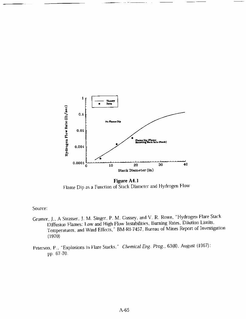
"R_D
_D,,¢.a
O
O
11 I• Da_
0.1
0.01
0.001
0.00010 ......... _.OI ......... 20L ......... _01 ......... 401
Stack Diameter (in)
Figure A4.1
Flame Dip as a Function of Stack Diameter and Hydrogen Flow
Source:
Grumer, J., A Strasser, J. M. Singer, P. M. Gussey, and V. R. Rowe, "Hydrogen Flare Stack
Diffusion Flames: Low and High Flow Instabilities, Burning Rates, Dilution Limits,
Temperatures. and Wind Effects," BM-RI-7457, Bureau of Mines Report of Investigation
(1970)
Peterson, P., "Explosions in Flare Stacks." Chemical Eng. Prog., 63(8), August (1967):
pp. 67-7O.
A-65

'°'r • u.o (sin.l)o oj55 (o.46o)t o.mm (o.le4)• o.o'r7 .(o.1_)
v 0 81,0 (78.7) •
,o,I . o
1061r . . . i . . . I , i , l i , , i , , , i
0 g0 40 60 80 100
Hydrogen ConeentraUon (vo] _)
Figure A4.2
Blowout and Stable Flame Region
Source:
Brzustowski, T. A., S. R. Gollahalli, and H. F. Sullivan, "The Turbulent Hydrogen Diffusion
Flame in a Cross-Wind," Comb. Sci. Tech., 11(1-2), (1975) pp. 20-33.
Ordin, P. M., and R. C. Carter, " Clinch River Breeder Reactor Hydrogen Disposal and
Ignition System," ARSD-00093, General Electric, June (1980).
A-66

11'°/140 [ .......... e_e [
120
100
80 / ."
ss oo"
o S °o°°°
60 , ...
i s¢ o°*°
js o°°o°
4(I I .JpJ o.O°°
$1 oooO*°
213 J -......._s ooOO°*°
so oO.,°o°
0 I ........ _" I . I i I , I
0 10 20 30 40 50 60
_ Flame Height (Vertical Distance above Plane of Fuel Jet Orifice - ft)
Figure A4.3
Flame Shape in Crosswinds
Source:
Brzustowski, T. A., S R. Gollahalli, and H. F. Sullivan, "The Turbulent Hydrogen Diffusion
Flame in a Cross-Wind," Comb. Sci. Tech., 11 (1-2), (1975).
Ordin, P. M., and R. C. Carter, " Clinch River Breeder Reactor Hydrogen Disposal and
Ignition System," ARSD-00093, General Electric, June (1980).
A-67

--..,.C)b-.¢,
t"O
c¢
O
LL
60
10-
01-
: j,
i //
:i-- /i
N_trogen. 98% / _ .//
oo l,ty /i / /
.........................................>:)-< :.;..........!../Nitrogen. 95%.//. // / .,'_., -"
eoat,y / / z / _//-f // / i Hydrogen. 98%
/z/z ././._,./ .......>/...................._>_-;;...................................................................
/" ,/'_// X\
/ /._// Hydrogen. 95%-- Quality
lO
Nominal Pipe Size (in)
30
Figure A4.4
Minimum Flow Rate for Non-Stratified, Two Phase Hydrogen and
Nitrogen Flow for Pipeline Fluid Qualities Below 95% and 98% _
" Liquid and gas phases assumed saturated at normal boiling point.
Source:
Liebenberg, D. H., J. K. Novak, and F. J. Edeskuty. "Cooldown of Cryogenic Transfer
Systems." AIAA 3" Propulsion Joint Specialist Conference, AIAA Paper No. 67-475,
Washington, DC, July 17-21 (1967).
Novak, J. K. "Cooldown Flow Rate Limits Imposed by Thermal Stresses in Liquid Hydrogen
or Nitrogen Pipelines." Advances in Cryogenic Engineering, Vol. 15, K. D.
Timmerhaus, Ed., Plenum Press, New York (1970)" pp. 346-353.
A-68

Er_)
ILl")
03
D
E
6O
10-
1
01
0.01
0.00102
t ID (cmlcm)
Figure A4.5
Liquid Hydrogen Flow Rate Limits to Avoid Excessive Cooldown Stresses
in Thick-wall Piping Sections such as Flanges for 304 SS and 6061 AI
t
D
WIII_X
= maximum radial thickness of flange wall (cm)
= inside diameter of flange (cm)
= cooldown flow rate limit (kg/s)
Upper and lower estimates represent difference in variables such as heat transfer
correlation and limiting stress values.
Source'
Novak, J. K. "Cooldown Flow Rate Limits Imposed by Thermal Stresses in Liquid Hydrogen
or Nitrogen Pipelines." Advances in Cryogenic Engineering, Vol. 15, K. D.
Timmerhaus, Ed., Plenum Press, New York, (1970)' pp. 346-353
A-69

500
E
O3
E_
v
Fh-.-_.X
E
100-
I0-
I
0.1
@06¸IAI
(upper estimate) _'-----__..._._--__.
"_---_._..
_-.--_____ 6o61 A_ _:.............................................. '_-_-"----__ (lower estimate) !
_-_.._,.."----_ i
i "-'---_____
(lower estimate} "'_,--:
0.01 ...... i0.2 1
t/D (cm/cm)
4
Figure A4.6
Liquid Nitrogen Flow Rate Limits to Avoid Excessive Cooldown Stresses
in Thick-wall Piping Sections Such as Flanges for 304 SS and 6061 AI
t
D
Wmax
= maximum radial thickness of flange wall (cm)
= inside diameter of flange (cm)
-- cooldown flow rate limit (kg/s)
Upper and lower estimates represent difference in variables such as heat transfer
correlation and limiting stress values.
Source:
Novak, J. K. "Cooldown Flow Rate Limits Imposed by Thermal Stresses in Liquid Hydrogen
or Nitrogen Pipelines." Advances in Cryogenic Engineering, Vol. 15, K. D.
Timmerhaus, Ed., Plenum Press, New York, (1970): pp. 346-353.
A-70

Size of
spill
(,gal)
Table A4.1
Summary of Liquefied Hydrogen Spill Data
Surface Vaporization Dispersal Ignition Radiation
AD 324/94 '_
0.18 Paraffin wax Yes No No No
1.8 Macadam No Visible cloud No No
rise only
1.8 Gravel No Visible cloud No No
rise only
14.4 Gravel No No Yes Flame size only
15.4 Steel No No Yes Flame size only.8 Macadam No Vertical concentrations No No
in quiescent atmosphere
2.0-23.6 Gravel No No Yes Flame size and
radiant heat flux
BM-RI-5707 h
23.5-44.4 Sand Yes No No No
35.2 Bank Gravel Yes No No No
25.0-50.0 Crushed rock Yes No No No
1.3 Sand Average Observations of visible Yes Fireball size only
vaporization time cloud
Sand Average Observations of visible No Fireball size only
vaporization time cloud
32.0
500.0 Sand Average Observations of visible No Fireball size
vaporization time cloud and radiant heatflux
5000.0 Sand No No Yes c Fireball sizeand radiant heat
flux
A. D, Little, Inc., "An Investigation of Hazards Associated with the Storage and Handling of
Liquid Hydrogen," AD 324/94, A. D. Little, Inc.. Cambridge, MA, March (1960).
b Zebetakis, M. G., and D. S. Burgess, "Research on the Hazards Associated with the Production
and Handling of Liquid Hydrogen," BM-RI-5707, Bureau of Mines Report of Investigation(1961).
Inadvertentl,y
A-71

A. 5 MATERIALS

.gZv
r-
ea
Ca3
"Go__E
E'-
O
3,34 Stainless Steel
9% Nickel Steel
201 Stainiess Steel
C1020 Carbon Sleel
I I *"
' ' 2oo So '0 50 100 150 2 300
Temperature (K)
t350
Figure A5.1
Charpy Impact Strength as a Function of Temperature for Various Materials
Source:
Brown, W. F, Jr., H. Mindlin, and C. Y. Ho, Editors. Aerospace Structural Metals
Handbook. CINDAS/USAF CRDA Handbooks Operation, Purdue University, West
Lafayette, IN (1996 Edition).
Durham, T. F., R. M. McClintock, and R. P. Reed. Cyrogenic Materials Data Handbook.
Office of Technical Services, Washington, DC (1962).
A-76

450
400
350
300
250n
_ 200
150 ......
1O0
5O
00
Ii ..................
'' i .........
!
Yield
I
I
]50 100 150 200 250
Temperature (K)
300
Figure A5.2Yield and Tensile Stress of 5086 Aluminum as a Function of Temperature
Source:
McClintock, R. M., and H. P. Gibbons. Mechanical Properties of Structural Materials at
Low Temperatures, A Complilation from the Literature. National Bureau of Standards,
Monograph 13, United States Department of Commerce, Washington, DC (1960).
A-78

700 _I
600
5OO
---"400 iP__,_
@
300-
2O0
100
0
r
I
!
0 50 100 150 200 250 300
Temperature (K)
Figure A5.3Yield and Tensile Stress of AISI 430 Stainless Steel as a Function of Temperature
Source:
McClintock, R. M., and H. P. Gibbons. Mechanical Properties of Structural Materials at
Low Temperatures, A Compilation from the Literature. National Bureau of Standards,
Monograph 13, United States Department of Commerce, Washington, DC (1960).
A-80

1.8xl O-s.
1,5x10 .5
1.4x10 s
_- 12xi0 4
1,0x10"O
(.3
.o
_8,0x!0 --I,,LI
e"
6.0xI0 _ "_......
2,0xi0 4 -
i
//
P J
E
l
I
00 5O 1 O0 150 2_t_ 250
Temperature (14)
300
Figure A5.4
Thermal Expansion Coefficient of Copper as a Function of Temperature
Source:
Johnson, V. J., Ed.. A Compendium of the Properties of Materials at Low Temperature
(Phase I)," WADD Technical Report 60-56, Part II, Properties of Solids, Office of
Technical Services, United States Department of Commerce, Washington, DC (1960).
A-82
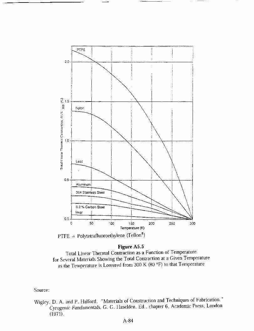
\
2D
_ 1,5
Ny!on
i 304 Stainless Steel
0,2 % Carbon Steei
Invar !
o.o,,F i0 50 _O0 150 200
Tempera,'ure ('K)250 300
PTFE = Polytetrafluoroethylene (Teflon ®)
Figure AS. 5
Total Linear Thermal Contraction as a Function of Temperature
for Several Materials Showing the Total Contraction at a Given Temperature
as the Temperature is Lowered from 300 K (80 °F) to that Temperature
Source:
Wigley, D. A. and P. Halford. "Materials of Construction and Techniques of Fabrication."
Cyrogenic Fundamentals, G. G. Haselden, Ed., chapter 6, Academic Press, London
(1971).
A-84

Table AS.1Summaryof MaterialCompatabilityfor HydrogenService
Material
Service
GH2 LH2 SLH2 Remarks
Aluminum and its alloysAustenitic stainless steels with > 7%
nickel (such as. 304. 304L, 308,316,
321,347)Carbon steels
Copper and its alloys (such as. brass,
bronze, and copper-nickel)
Gray, ductile, or cast ironLow-allow steels
Nickel and its alloys(such as, Inconel ® and Monel ®)
Nickel steels (such as, 2.25.3.5, 5. and
9 % NI)
Titanium and its alloys
Asbestos impregnated with Teflon ®
Chloroprene rubber (Neoprene ®)Dacron ®
Fluorocarbon rubber (Viton ®)
Mylar ®
Nitrile (Buna-N ®)
Polyamides (Nylon ®)
Polychlorotrifluorethylene (KeI-F ®t
Pol_tetrafluoreth.ylene (Teflon ®)
Yes Yes Yes
Yes Yes Yes
Yes No No
Yes Yes Yes
No No
Yes No
No Yes
No
Yes
Yes
Yes
Yes
Yes
Yes
Yes
Yes
Yes
Yes
No
Yes
Yes
No
No
No
No
No
No
Yes
Yes
Some make martensitic conversion if
stressed above yield point at low
temperature.
Too brittle for cryogenic service.
No Not permitted for hydrogen service.
No Too brittle for cryogenic service.
Yes Susceptible to hydrogenembrittlement
No Ductility lost at LH2 and SLH2
temperatures.Yes
Yes
No
No
No
No
No
No
Yes
Yes
Avoid use because of carcinogenichazard.
Too brittle for cryogenic service.
Too brittle for cryogenic semce.
Too brittle for cryogenic service.
Too brittle for cryogenic service.
Too brittle for cryogenic service.
Too brittle for cryogenic servKe.
A-85

Application
Table A5.2
A Selection of Recommended Materials for Typical Applications a
Typical materials
LH_ or SLH2 GH2
Valves
Fittings
O-rings
Gaskets
Flexible hoses
Rupture disk
assembly
Piping
Dewars
Lubricants
Forged, machined, and cast valve bodies (304 or
316 stainless steel, or brass) with extended
bonnet, and with other materials inside
Stainless steel bayonet type for vacuum jackets
Stainless steel _, Kel-F®, or Teflon®
Soft Aluminum, lead, or annealed copper
between serrated flanges: KeI-F®: Teflon®:
glass-filled Teflon®
Convoluted vacuum jacketed 316 or321 stainless steel
304,304L 316, or 316L stainless steel
Appropriate industrial products b
Appropriate industrial products _
Appropriate industrial products b
Appropriate industrial products b
Stainless steel braided with Teflon-
lining304,304L, 316, or 316L stainless steel
304, 304L, 316, or 316L stainless steel
304, 304L, 316. or 316L stainless steel
No lubricants used in some applications, h
Lubricants listed for GH2 are compatible but
will become solid at low temperatures. Dry
lubricants, such as PTFE, PTFE carbon, PTFE
bronze, fiberglass PFTE graphite2 Graphite and
molybdenum disulfide permit only very limited
service life for bearinss, f
300 series stainless steel (316
preferred h)Carbon steel _
Not applicable
Dupont Krytox 240AC, Fluoramics
OXYS, Dow Coming DC 33, Dow
Coming FS-3452, Bray Oil Braycote
60 l, General Electric Versilube,
Houghton Cosmolube 5100, Braycote
640 AC, Dupont GPL 206. Halocarbon
Series 6.3 oil, and KeI-F® oil
a Adapted from Table 6.1, Recommended MateriaLs for Hydrogen Systems. in "Hydrogen Propellant," Chapter 6 in Lewis Safety
Manual. NASA Technical Memorandum 104438, November (1992): pp. 6-70.
b A number of standard industrial products are available covering a wide range of temperatures and pressures m a variew of
compatible materials.
c Metal O-rings have proven satisfactory when coated with a soft material and when used on smooth surfaces. 'Iype 321 stainless
steel, with a coating of teflon or silver, should be used in stainless steel flanges with stainless bolting. Teflon® coated aluminumshould be used in aluminum flang_ with aluminum bolting. Using similar materials avoids the leakage po_ibility f?om unequalcontraction of dissimilar metals, ff,ewis Hydrogen Safety Manual, Decemher 10, (1959) pp. 3-18)
d Threaded joints should be avoided in LH, or SLHe systems. If they must be used. the male and female threads should be tinned
with a 60% lead-40% tin solder, then heated to provide a solderedjoint with pipe thread strength. (Lewis Hydrogen Safety Manual,December 10, (19591 pp. 3-15)
e W. Peschka. Liquid Hydrogen. Fuel of the Future, Springer-Verlag Wien. New York, (1992): pp. 197.
f D, A. Wigley. "The Properties of Nonmetals." In Mechanical Properties of Materials at Low Temperature, Chapter 4, pp. 225.Plenum Press, New York 1971
g Carbon steel meeting ANSI/ASME B31.3 standards may be used for GH_ service above 244 K (-20 "F,) (Lewis Safety Manual,
Chapter 6 "Hydrogen Propellant." NASA Technical Memorandum 104438, November (1992): pp. 6 35.)
h McPherson. B., Private communication (1996).
A-86

Table A5.3
Minimum Temperatures and Basic Allowable Stresses in Tension for Selected Metals _
Specified SpecifiedMinimum Minimum Basic
Metal Minimum Tensile Yield Allowable
and/or Temperature '_ Strength Strength Stress _
Alloy _' Metal Form _ [K (°F)] ]MPa (ksi)] ]MPa (ksi)l [MPa (ksi)]
Aluminum Alloy
WP1100-0, B361 forging & fitting ,4.2 (-452) 75.8 (11) 20.7 (3) 13.8 (2.0)
1100-0, B241 pipe & tube 4.2 (-452) 75.8 (11) 20.7 (3) 13.8 (2.0)
3003-0, B241 pipe & tube 4.2 (-452) 96.5 (14) 34.5 (5) 22.8 (3.3)
5083-0, B209 plate & sheet 4.2 (-452) 275.8 (40) 124.1 (18) 82.7 (12.0)
5083 0, B241 pipe & tube 4.2 (452) 268.9 (39) 110.3 (16) 73.8 (10.7)
WP6061 T6, B361 forging & fitting 4.2 (-452) 262.0 (38) 241.3 (35) 87.6 (12.7)
6061-T6, B241 pipe & tube 4.2 (452) 262.0 (38) 241.3 (35) 87.6 (12.7)
Copper & Copper Alloy
Cu Forging. B283 forging 4.2 (-452) 227.5 (33) 75.8 (11) 50.3 (6.7)
Cu Plate, B152 plate & sheet 4.2 (452) 206.8 (30) 68.9 (10) 46+2 (5.8)
Cu Pipe. B42. annealed pipe & tube 4.2 (452) 206.8 (30) 62.1 (9) 41.4 (6.0)
Red brass pipe pipe & tube 4.2 (452) 275.8 (40) 82+7 (12) 55.2 (8.0)
90Cu-10Ni. BI71 plate & sheet 4.2 (-452) 275.8 (40) 103,4 (15) 68.9 (10.0)
90Cu-10Ni, B466 pipe & tube 4.2 (-452) 262.0 (38) 89.6 (13) 60.0 (8.4)
70Cu 30Ni, B171 plate & sheet 4.2 (452) 482.6 (70) 206.8 (30) 137.9 (20.0)
70Cu 30Ni, B466 pipe & tube 4.2 (452) 344.7 (50) 124.1 (18) 82.7 (12.0)
Nickel & Nickel Alloy
Ni, B366 forging & fitting 74.8 (-325) 379.2 (55) 82.7 (12) 55.2 (8.0)
Ni, B162 plate & sheet 74.8 (425) 379.2 (55) 103.4 (15) 68.9 (10.0)
Ni, B161 pipe & tube 74.8 (-325) 379.2 (55) 103.4 (15) 68.9 (10.0)
Ni Cu, B564 forging & fitting 74.8 (-325) 482.6 (70) 172.4 (25) 115.1 (16.7)
Ni-Cu, B127 plate & sheet 74.8 (-325) 482.6 (70) 193.1 (28) 128.9 (18.7)
Ni-Cu, B165 pipe & tube 74.8 (-325) 482.6 (70) 193.1 (28) 128.9 (18.7)
Ni-Cr-Fe, B564 forging & fitting 74.8 (-325) 551.6 (80) 241.3 (35) 160.6 (23.3)
Ni Cr Fe, B168 plate & sheet 74.8 (-325) 551.6 (80) 241,3 (35) 160.6 (23.3)
Ni Cr-Fe, B167 pipe & tube 74.8 (+325) 551.6 (80) 206.8 (30) 137.9 (20.0)
Steel, Carbon
A285 Grade C, plate & sheet .... f 379.2 (55) 206.8 (30) 126.2 (18.3)
A285 Grade C, A524 pipe & tube 244 (-20) 379.2 (55) 206.8 (30) 126.2 (18.3)
A442 Grade 50, A672 pipe & tube f 413.7 (60) 220.6 (32) 137.9 (20.0)
Steel, Low & Intermediate Alloy
3.5 Ni, A420 forging & fitting 172 (-150) 448.2 (65) 241.3 (35) 149.6 (21.7)
3.5 Ni+ A203 plate 244 (-20) 448.2 (65) 255.1 (37) 149.6 (21.7)
3.5 Ni, A333 pipe & tube 172 (150) 448.2 (65) 241.3 (35) 149.6 (21.7)
5 Ni, A645 plate 103 (-275) 655.0 (95) 448.2 (65) 218.6 (31.7)
9 Ni, A420 forging & fitting 77 (-320) 758.4 (110) 517.1 (75) 218.6 (31.7)
9 Ni, A353 plate 77 (320) 689.5 (100) 517.1 (75) 218.6 (31.7)
9 Ni, A333 pipe & tube 77 (-320) 689.5 (100) 517.1 (75) 218.6 (31.7)
A-87

Table A5.3 (continued)
Minimum Temperatures and Basic Allowable Stresses in Tension for Selected Metals a
Specified Specified
Minimum Minimum Basic
Metal Minimum Tensile Yield Allowable
and/or Temperature ¢_ Strength Strength Stress _
Alloy b Metal Form _ [K (°F)] [MPa (ksi)] [MPa (ksi)] [MPa (ksi)]
Steel, Stainless, Ferritic
405 (12Cr-A1), A240 plate & sheet 244 (-20) 413.7 (60) 172,4 (25) 115.1 (16.7)
430 (17Cr), A240 plate & sheet 244 (-20) 448.2 (65) 206,8 (30) 137,9 (18.4)
Steel, Stainless, Martensitic
410 (13Cr), A240 plate & sheet 244 (20) 448.2 (65) 206.8 (30) 126,9 (18.4)
Steel, Stainless, Austenitic
304 (18Cr-8Ni)
304
F304 (18Cr-8Ni)
304L (18Cr-8Ni)
304L
F304L (18Cr-SNi
310 (25Cr-20Ni)
F310 (25Cr-20Ni
310S (25Cr 20Ni
310S
316 (16Cr-12Ni-2Mo)
316
F316 (16Cr-12Ni-2Mo)
316L (16Cr-12Ni*2Mo)
316L
F316L (16Cr 12Ni-2Mo)
321 (18Cr-10Ni-Ti}
321 (18Cr-lONi-Ti)
F321 (18Cr-10Ni-Ti)
347 (18Cr-10Ni-Cb)
347
F347 (18Cr-10Ni-Cb)
plate & sheet 19.3 (-425) 517.1 (75) 206,8 (30) 137.9 (20,0)
pipe & tube 19.3 (-425) 517.1 (75) 206,8 (30) 137.9 (20.0)
forging & fitting 19.3 (-425) 517.1 (75) 206.8 (30) 137.9 (20.0)
plate & sheet 19.3 (-425) 482.6 (70) 172.4 (25) 115,1 (16.7)
pipe & tube 19.3 (-425) 482.6 (70) 172,4 (25) 115.1 (16.7)
forging & fitting 19.3 (-425) 482.6 (70) 172,4 (25) 115.1 (16.7)
plate & sheet 74.8 (-325) 517.1 (75) 206,8 (30) 137.9 (20.0)
forging & fitting 74.8 (-325) 517.1 (75) 206.8 (30) 137.9 (20.0)
plate & sheet 74.8 (-325) 517.1 (75) 206.8 (30) 137.9 (20.0)
pipe & tube 74.8 (-325) 517.1 (75) 206.8 (30) 137.9 (20.0)
plate & sheet 19.3 (-425) 517.1 (75) 206.8 (30) 137,9 (20.0)
pipe & tube 19.3 (-425) 517.1 (75) 206.8 (30) 137.9 (20.0)
forging & fitting 74.8 (-325) 517.1 (75) 206.8 (30) 137,9 (20.0)
plate & sheet 19.3 (-425) 482.6 (70) 172.4 (25) 115,1 (16.7)
pipe & tube 74.8 (-325) 482.6 (70) 172.4 (25) 115.1 (16.7)
forging & fitting 19.3 (-425) 482.6 (70) 172,4 (25) 115.1 (16.7)
plate & sheet 74.8 (-325) 517.1 (75) 206.8 (30} 137.9 (20.0)
pipe & tube 74.8 (-325) 517.1 (75) 206,8 (30) 137.9 (20.0)
forging & fitting 74.8 (-325) 517.t (75) 206.8 (30) 137.9 (20.0)
plate & sheet 19.3 (425) 517.1 (75) 206.8 (30) 137.9 (20.0)
pipe & tube 19.3 (-425) 517.1 (75) 206.8 (30) 137.9 (20.0)
forging & fitting 19.3 (-425) 517.1 (75) 206,8 (30) 137.9 (20.0)
Titanium & Titanium Alloy
Ti, B337 pipe & tube 214 (-75) 241.3 (35) 172,4 (25) 80.7 (11.7)
Ti-O.2Pd, B337 pipe & tube 214 (-75) 344.7 (50) 275.8 (40) 115.1 (16.7)
ASME B31.3-1996 Edition
ASME B31.3 should be consulted regarding grade and specifications for this material
ASME B31.3 should be consulted for special notes regarding restrictions on this maleria[,
The minimum temperature shown is that design minimum temperature for which the material is normally
suitable without impact testing other than that required by the material specification. However, the use of a
material at a design minimum temperature below 244 K (-20 _F) is established by rules in ASME B31.3.
including any necessary impact test requirements.
Basic allowable stress in tension for the temperature range from the minimum temperature to 311 K (100 °F)
ASME B31.3 should be consulted re_ardin_ the minimum temperature for this material.
A-88

Material
Table A5.4
Elastic Properties of Selected Materials at Room Temperature
and Liquid Hydrogen Temperature
Young's Shear Bulk
Temperature Modulus Modulus Modulus Poisson's(K) (GPa) (GPa) (GPa) Ratio
3003
5083-0
606 l-T6
Invar _
304
304L
310
316
Polytetrafluorethylene (Teflon ®)
(PTFE or TFE)
Polytetrafluorethylene copolymer
hexafluoropropylene (FEP)
Aluminum Alloys300 TBA _ TBA TBA TBA
20 TBA TBA TBA TBA
300 71.6a 26.82 ;' 71.56 '_ 0.3334"
20 80.8a 30.68 _ 74.23 _' 0.3184 ;'
300 70.2a 26.36 _ 72.14 '_ 0.3383"
20 77.7a 29.22 _' 74.8 _ 0.3269 _
300 152.5" 55,8" 110.9 _ 0.2843 a
20 141.5" 50.5 _' 124.1 _ 0.3183"Stainless Steels
300 189.8 '_ 73.2' 150.T 0.290P20 204.5" 80.4 _ 148.8 _ 0.2714 _
300 TBA TBA TBA TBA
20 TBA TBA TBA TBA
300 183.7" 70.2 _ 159.2 a 0.3074 _
20 198.8" 76.7 .7 162.3 _ 0,2958 _
300 203.8" 78.5" 167.T 0.2972 '_
20 220.6 _ 86.0" 168.4 _ 0.2819 _
Fluorocarbon Resins
300 0.55 b.c TBA TBA TBA
20 4.27 b._ TBA TBA TBA300 0.48 b., TBA TBA TBA
20 5.03 b.c TBA TBA TBA
" LNG Materials and Fluids: A User's Manual of Property Data in Graphic Format, D. Mann, Ed., NationalBureau of Standards, Boulder, CO (1977).
b Unfilled resin
Properties of Teflon at C(vogenic Temperatures, E. I. du Pont de Nemours and Co., Wilmington. DE(1976).
_' To be added
A-89

Table A5.5MechanicalPropertiesof SelectedMaterialsat RoomTemperature
andLiquid HydrogenTemperature
Material
Yield Tensile Fatigue
Temperature Strength Strength Strength:'(K) (MPa) (MPa) (MPa)
3003-0
5083-0
6061-T6
Invar ®
3O4
304L
310
316
Polytetrafluorethylene (Teflon ®)(PTFE or TFE)
Polytetrafluorethylene copolymer
Hexafluoroprop,ylene (FEP)
Aluminum Alloys300 40¢ I l0 t TBA f
20 69' 375' TBA
300 14V 31ff 235 _
20 170 _ 52ff 283 __
300 278 _ 310 _ 200
20 350_ 498_ 383
300 280 _ 51ff TBA
20 800 _ 1040 _ TBA
Stainless Steels
300 520 _ 640' 190 _
20 900 _: 1730 _ TBA
300 280_ 600 _ 210 _
20 33ff 1730 _ 210 b_
300 220_ 550 _ 280'20 680 _ 1260 _ 520 b_
300 230 _ 570 _ TBA
20 610 ¢ 1400 _ TBA
Fluorocarbon Resins
300 11.7 d,_ 31.0 Ce TBA
20 122.7 d.e 123.4 d,_ TBA
300 13.8 d,,, 27.6 d,_ TBA
20 163.4 d._ 164.1 d., TBA
'_ Axial fatigue strength at 106 cyclesb At 77 K, not 20 K
': LNG Materials and Fluids: A User's Manual of Property Data in Graphic Format, D. Mann, Ed.,National Bureau of Standards, Boulder, Colorado (1977).Unfilled resin
Properties of Teflon at Cryogenic Temperatures, E. I. du Pont de Nemours and Co., Wilmington,DE (1976),
f To be added
A-90
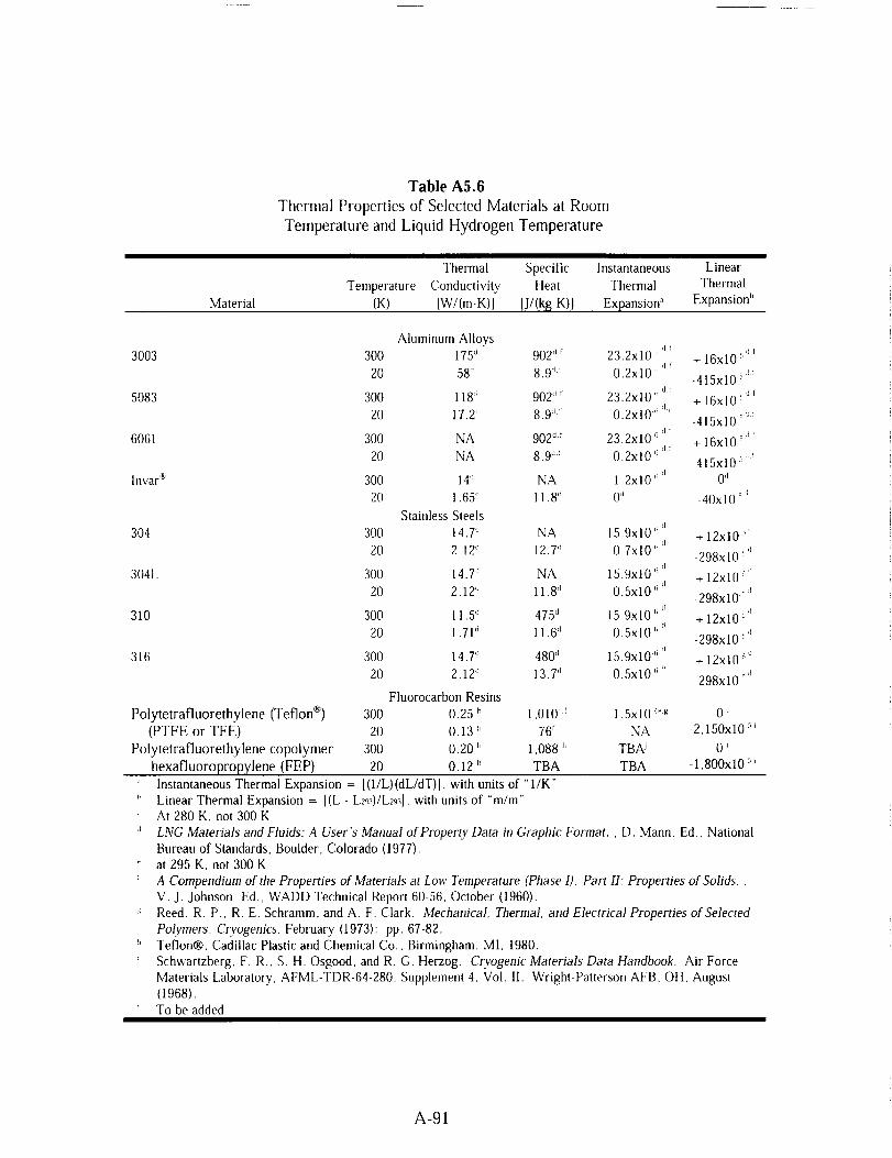
Table A5.6
Thermal Properties of Selected Materials at Room
Temperature and Liquid Hydrogen Temperature
Material
Thermal Specific Instantaneous Linear
Temperature Conductivity Heat Thermal Thermal
(K) [W/(m.K)] IJ/(kg K)] Expansion '_ Expansion"
3003
5083
6061
lnvar _
304
304L
310
316
Polytetrafluorethylene (Teflon _)
(PTFE or TFE)
Polytetrafluorethylene copolymer
hexafluoropropylene (FEP)
Aluminum AlloysLit
300 175 d 902 Ji 23.2x10 _; + 16x10 _,_1d!
20 58 _i 8,9 _t 0.2x10 t_ -415x10 5_
300 118 d 902 `it 23,2x10 _;d_ + 16x10 _t_
20 17.2 '_ 8.9 _ 0,2x10 _ _-415x10 _di
300 NA 902 d'_ 23.2x10 '_dt + 16xl0 __f
20 NA 8.9 _'l 0.2x10 _ 415x10 ::l_
300 14 '_ NA 1.2x 10 _'¢1 0d. d
20 1,65 _1 I 1.8 _ 0'_ -40x10 '
Stainless Steels
300 14,7 d NA 15.9x10 (; d + 12x10 _=1
20 2.12 d 12.7 _ 0,7x10 _ d 298x10 _'_
300 14.T NA 15.9x10 _ _l _,i+ 12x10 :'20 2.12 'l 11.8 '1 0.5x10 <_ rd
-298x10 :'
300 11.5 .1 475 d 15,9x10 (__ + 12x10 _'_
20 1.71 _ 11.6 (l 0.5x10 (__ -298xl 0 5't
300 14.T 480 'j 15.9x10 _ _ + 12x10 _d
20 2.12 'j 13.7 '1 0.5x10 _;_ 298x10 _'1
Fluorocarbon Resins
300 0.25 h 1,01ff '_ 1,5x10 4_._ 0 i
20 0.13 h 76 _ NA -2,150x10 5i
300 0.20 )' 1,088 h TBA_ 0 _
20 0.12 )' TBA TBA - i ,800x i0 _
Instantaneous Thermal Expansion = [(1/L)(dL/dT)], with units of "l/K"
_' Linear Thermal Expansion = [(L - L_)/Lz93], with units of "m/m"
At 280 K, not 300 K
'_ LNG Materials and Fluids: A User's Manual of Property Data in Graphic Format. , D. Mann. Ed., National
Bureau of Standards, Boulder, Colorado (1977),
at 295 K. not 300 K
A Compendium of the Properties of Materials at Low Temperature (Phase 1), Part II: Properties of Solids. ,
V. J. Johnson, Ed,, WADD Technical Report 60 56, October (1960).
Reed, R. P., R. E, Schramm, and A, F, Clark. Mechanical, Thermal. and Electrical Properties of Selected
Polymers, Cryogenics. February (1973): pp, 67-82.
_' Teflon®, Cadillac Plastic and Chemical Co., Birmingham, MI. 1980.
Schwartzberg. F. R., S. H, Osgood. and R, G. Herzog, Cryogenic Materials Data Handbook, Air Force
Materials Laboratory, AFML-TDR-64-280. Supplement 4, Vol. II. Wright-Patterson AFB. OH, August
(1968).
To be added
A-91

Characteristic
Table A5.7
Typical Characteristics of Hydrogen Embrittlement Types
Environmental Internal Hydrogen
Hydrogen Hydrogen ReactionEmbrittlement Embrittlement Embrittlement
Usual source of
hydrogen
Typicalconditions
Test methods for
embrittlement
Location of crack
initiation
Rate-controllingembrittlement
step
Gaseous hydrogen
10 _ to 10 _ Pa H_ gas
pressure. Most severe
near room temperature.Observed from -100 to
700 °C. Gas purity and
strain rate important.
Notched tensile:
unnotched tensile, creep
rupture: fatigue (low,
high cycle): fracture
toughness: disk pressuretest.
On surface or internal, t,
Adsorption is transfer
step; absorption or lattice
diffusion _ is embrittling
step.
Processing,
electrolysis,corrosion
0.1 to l0 ppm average H2content, Most severe near
room temperature. Observedfrom -100 to 100 °C. Strain
rate is important.
Notched tensile delayedfailure; slow strain rate
tensile: bend tests; C-rings;
torqued bolts.
Internal crack initiation:
incubation (reversible);
slow discontinuous growth:and fast fracture.
Lattice diffusion to internal
stress risers.
Gaseous or atomic
hydrogen from anysource.
Heat treatment or service
in H2, especially at
elevated temperatures.
Visual or metallographicobservation.
Usually internal initiationfrom bubbles or flakes.
Chemical reaction to
form hydrides or gasbubbles.
a Gray H. R, "Testingfor Hydrogen EnvironmentEmbritdement: ExperimentalVariables." Hydrogen Embrittlement Testing,American Society for Testing and Materials.Special Technical Publication,ASTM STP-543, Philadelphia.PA (1974). pp. 133-1,51.
t' Unresolved
A-92

TableA5.8Susceptibilityof Materialsto Embrittlementin Hydrogenat 10,000psiand72°F_
Strength ratio. HdHe
Material Notched _' Unnotche
d
Unnotched ductility
Elongation, % Reduction of Area,
He H_ He H_
Extremely embrittled
18Ni-250 Maraging 0.12 0.68 8.2 0.2 55 2.5Steel
410 Stainless Steel .22 .70 15 1.3 60 12
1042 Steel (quenched .22 ................
and tempered)
17 7 pH Stainless Steel .23 .92 17 1.7 45 2,5Fe-9Ni-4 Co-0.20C .24 .86 15 .5 67 15
H 11 .25 .57 8.8 0 30 0
Rene 41 .27 .84 21 4.3 29 11
Electro-Formed Nickel .31 .............
4140 .40 .96 14 2,6 48 9
Iuconel 718 ,46 .93 17 1.5 26 1
440C .50 .40 ........ 3.2 0
Severely embrittled
Ti-6AI-4V (STA) 0.58 ....................
430F .68 .... 22 14 64 37
Nickel 270 .70 .... 56 52 89 67
A515 ,73 .... 42 29 67 35
HY-100 ,73 .... 20 18 76 63
A372 (class IV) .74 .... 20 10 53 18
1042 (normalized) .75 ............ 59 27
A533-B ,78 ............ 66 33
Ti 6A1-4V (annealed) .79 ...........
AISI 1020 ,79 ........ 68 45
HY-50 .80 ........... 70 60
Ti-5A1-2,5Sn (ELI) .81 ............ 45 39
Armco Iron .86 ......... 83 50
Slightly embrittted304 ELC Stainless Steel 0.87 ............ 78 71
305 Stainless Steel 0.89 ............ 78 75
Be-Cu Alloy 25 0.93 ............ 72 71Titanium 0.95 ......... 61 61
Negligibly embrittled310 Stainless Steel 0.93 ............ 64 62
A286 .97 ........ 44 43
7075-T73 Aluminum .98 ............ 37 35
Alloy
316 Stainless Steel 1,00 ............ 72 75
OFHC Copper 1.00 ............ 94 94
NARIoy-Z _ 1,10 ...... 24 22
606l-T6 Aluminum 1.10 ....... 61 66
Alloy
1100 aluminum 1,40 ........... 93 93
a Chandler, W. T. and R. J. Walter. "Testing to Determine the Effect of High Pressure Hydrogen
Environments on the Mechanical Properties of Metals," in H_dro_en Embrittlement Testing, ASTM
A-93

543, American Society for Testing and Materials, Philadelphia, PA (1974) pp. 170-197.Stress concentration factor, K,, = 8.4
Tested in ?000 psi (48.3 MPa) hydrogenNote: Dashes indicate no information available
A-94

AIIo},
2(111
2024
6061
6063
Nickel
Table A5.9
Comparison of Air, Helium, and Hydrogen Exposure
on Selected Aluminum, Nickel, and Copper Alloys _
Stren[_th, psi Ductilily
Tesl Tesl Reduction
Environmenl Pressure (psi) Yield Ultimate ill area (%) Elongation (%)
Aluillil|uln Alloys
Air 1,t5 39.0x111 :_ 49.1x10 :_ 48 17
He 10,000 32.9xl0 :_ 42.9x10 ' 57 18
tt2 10.1100 31.9xl{/ :_ 42.9x10 :_ 58 17
Air 145 51.9x111 :_ 709xl0 :_ 33 15
He 10.000 46.9xI[1 :_ 63.9x11) :_ 36 19
tte 111,000 44.9x111 :_ 61.9xl9 _ 35 18
Air 14.5 25.9x111 :_ 33.9x10 _ 75 I't
lie 1O,000 28 9x111:_ 25 9x10 :¢ 82 15
1f: 10.000 20 0xl0 _ 26.9x1(1 :_ 82 14
Air 1,15 31.0x10 :_ 34 9xl(P 62 13
lie 10,1)00 22.9xl0 :_ 27 9x10 _ 83 15
IL 10.000 22.9x10 _ 29.0xl(P 84 15
Nickel and Nickel Alloys
tie 10000 26.11x10 :_ 61 9xl() _ 79 57
H: 10.000 24.9x10 :_ 62 9x10 :_ 54 47
lnconel* lie 10,000 151x10 :_ 186x10:* 40 25
718 tte 10,00(} 155x10 :* 186x103 11 9
Inconel ® Air 14.7 152x10 :* 204x10 :¢ 45 21
7011 tie 10.000 149x10 :_ 195xllY 44 22
IL 10,000 149x10 :_ 177x10 _ 14 10
[lastelloy 't' X Air 14,7 46.9 xl0 :_ 99.9x10 :_ 69 56lie 10,000 4t.0 xl0 _ 999x10 _ 68 59
IL I0,000 41.9 xl0 :_ 94.9x10 :_ 58 55
Copper Alloys
OFIIC Air 14.7 13.9x10 :_ 33,9x10:' 7t 44
tie 10.000 139x10 _ 33.1x10 :_ 71 45
70-30 brass Air 14.7 17.9x10 :_ 52.9x10 :_ 70 59
t1_ 10,000 14.9x10 :_ 50.0x10 :_ 84 58
Aluminum Air 14.7 32.5x10 :_ 87.0x10 :_ 67 48
bronze t4_ I0,00(1 30.7x10 :_ 83.5x10 :_ 71 49
_' Chandler, W. T. and R. J. Walter. "Hydrogen Environment Embrittlement of Metals and Its Control,"
Hydrogen Energy, Proceedings of the Hydrogen Miami Energy Conference, T. H. Veziroglu, Ed., Plenum
Press, New York (1975): pp, 1057-1058,
_ Groenvald, T. D. and A. D. Elcea. "Hydrogen Stress Cracking in Natural Gas Transmission Pipelines,"
Hydrogen in Metals, I. M. Bernstein and A. W. Thompson, Eds., ASM (1974).
' Robinson, S. L. Hydrogen Compatibility of Structural Materials for Energy Storage and Transmission
Applications. Sandia National Laboratories. SAND77-8240, June 11977).
d Hoover, W. R. et. al. Hydrogen Compatibility of Structural Materials for Energy Storage and
Transmission Applications. Sandia National Laboratories, SAND80-8202, Livermore, CA. February
(1980).
Stuhrke, W. F. and J. L, Carpenter. Fracture Toughness and Testing Data - A Technology Survey.
NASA-CR- 134752. January. (1975).
A-95

A.6 HYDROGENANDHYDROGENFIREDETECTION

10-"-,4- - .... s,,:_._e_ e| ..... _._L._. I 1 10_
L -- --_b_- I zooo" r I o=
]" I//iJ ....
Y'//lO'-e _ 10 a
0.5 1.0 1.5 2.0 _.5 3.0
Microne
Figure A6.1Irradiance of Common IR Sources
Source:
Rosen, B., V. H. Dayan, and R. L. Proffitt. "Hydrogen Leak and Fire Detection - A
Survey." NASA SP-5092, WashingIon, DC (1970).
A-99

O
i
lO0
80
60
40
20
ne[,m,,,-,_-- !
r_A/0 "°
0.5 1.0
ftIJ
\-,, t
1.5 2.0 2.5
Microns
25
; 20
J_ 15
/'i5
h I
3.0
Figure A6.2
Atmospheric IR Transmission and H_-Air-Flame Emission
Source:
Rosen, B., V. H. Dayan, and R. L. Proffitt. "Hydrogen Leak and Fire Detection - A
Survey." NASA SP-5092, Washington, DC (1970).
A-100

101
loo
lO-t
10-=
"; 10-,0
lO-t
|O-S
I}_iltmm
I I I i I I i I I I I I
0 1 2 3 4 5 6 7 8 8 10 11 12
]Yavelez_,t.b. (/,_eters)
Figure A6.3UV/VIS/Near-IR Emissions
Source:
Barnes, H.L. Private communication, NASA Stennis Space Center (1995).
ThermallR
MID-IR
t Near-IR
-- Uffra-Violet
Note:
Figure A6.4
Flame Components
A larger portion of the flame emits in the thermal infrared than in the ultra violet. This
means that a fire looks bigger with a thermal imager that it does with a near-infrared
imager.
A-101

Table A6.1Typical HydrogenGasDetectors
Type of Detector Description
Catalytic A palladiumand/or platinumcatalystis usedtofacilitate the combustion of hydrogen with oxygen.
A sensing element detects the heat of combustion.
Electro chemical Liquid or solid electrolytes surrounding a sensingelectrode and a counter electrode. Reaction with
hydrogen product produces a current. The hydrogen
gas must flow through a gas permeable membrane to
reach the electrolyte.
Semi conductingOxide
Hydrogen gas reacts with chemisorbed oxygen in a
semiconductor material, such as tin oxide, and changesthe resistance of the material.
Thermal Conductivity The rate of heat conduction from a heat source into
the surrounding environment is dependent on the
thermal conductivity of that environment.
Mass Spectrometer The gas is ionized and then accelerated through an
electric field along a curved path. The amount of
curvature induced by the electric field is dependent
on the mass of the particle and is used to separate
the particles by mass. A detector is placed in the
path of the desired gas to be measured.
Sonic Leaking gas can produce acoustical emissions in the
range of 30 to 100 kHz, with 40 kHz being the most
common.
Optical The differences in the refractive index of various
gases can be used for detection in sensors using
optical interferometry.
Glow Plugs Glow plugs are not a true gas detection technique.
When a combustible gas mixture exists, the glow plug
ignites the mixture and then the fire is detectedwith heat sensors.
A-102
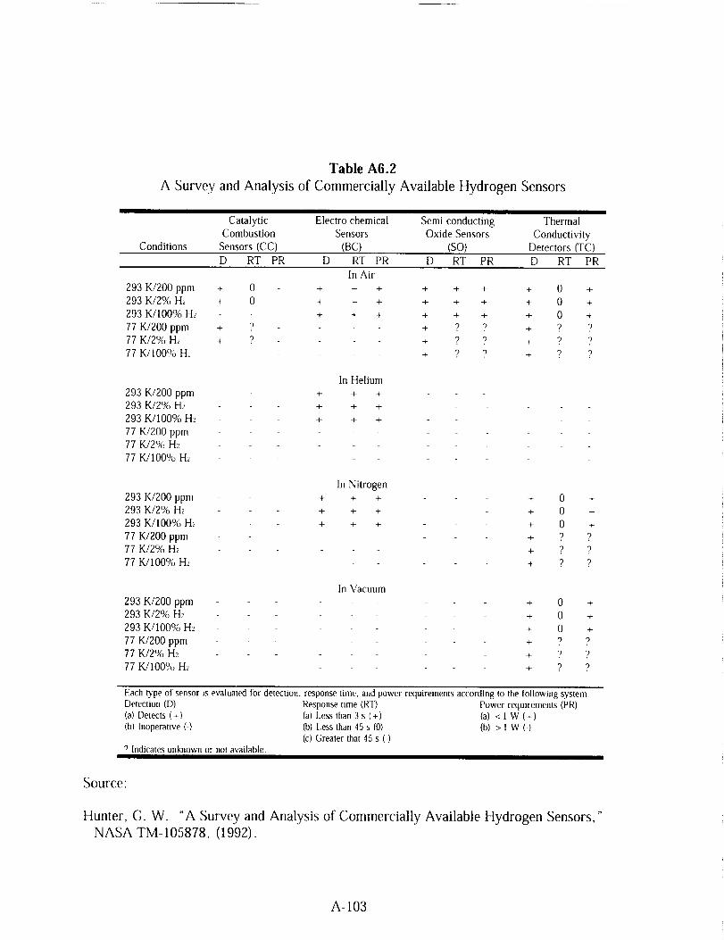
Table A6.2
A Survey and Analysis of Commercially Available Hydrogen Sensors
Catalytic Electro chemical Semi conducting Thermal
Combustion Sensors Oxide Sensors Conductivity
Conditions Sensors (CC) (BC) (SO) Detectors (TC)
D RT PR D RT PR D RT PR D RT PR
In Air
293 KI200 ppm + 0 + + + + + + + 0 +
293 K/2% H_ + 0 + + + + + + + 0 +
293 K/100% H_ + + + + + + + 0 +
77 K/Z00 ppm + ? + ? "_ + "_
77 K/2% H_' + 9 + ? v + "_ "_
77 K/t00% H_ + ? 9 + ? ?
293 K/200 ppm293 K/2% H_
293 K/100% H_
77 K/200 ppm
77 K/2% H2
77 K/100% H_
293 K/200 ppm
293 K/2% H2
293 K/100% H2
77 K/200 ppm77 K/2% H_
77 K/100% H2
293 K/Z00 ppm
293 K/2% H2
293 K/100% Hz
77 K/200 ppm77 K/2% H2
77 K/100% Hz
In Helium
+ 4- +
+ + +
+ + -4-
In Nitrogen
+ +
+,4- +
+ +
In Vacuum
+ 0 +
+ 0 +
+ 0 +
+ "2 ?
+ .9 ")
+ 9 ")
+ 0 +
+ 0 +
+ 0 +
+ 9 ?
+ v ?
+ ? ?
Each type of sensor is evalualed tbr detection, response lime, and power requirements according to the followingDetection (D) Response time (RT) Power requirements(a) Detects (+) (a) Less than 3 s (+) (a) < 1 W (+)(b) Inoperative (-) (b) [Jess than 45 s (0) (b) > 1 W (-)
(c) Greater that 45 s (-)? Indicates unknown or not available
system.(PR)
Source:
Hunter, G. W. "A Survey and Analysis of Commercially Available Hydrogen Sensors,"
NASA TM-105878, (1992).
A-103

Table A6.3
Sensitivity Limits of Hydrogen Detectors
Principle atm-cc/s
Catalytic Combustion 8.0 0.02 0.5
Bubble Testing 1 x 10 .4 NA NA
Sonic-Ultrasonic 1 x 10 _ NA NA
Thermal Conductivity 1 x 10 :_ 5 x 10 4 0.01
Gas Density 1 x 10 2 5 x 10 3 0.1
Hydrogen Tapes 0.25 1.5 35
Scott-Draeger Tubes .... 0.5 13
Electrochemical .... 0.05 1.2
Optical Iuterferometer .... 0.2 5
Minimum Detection Limits, Average Values
In Air In Nitrogen
% Hydrogen % LEL atm-cc/s % Hydrogen Distance (fi)
80 0.2 _' 200ff
1 x 10 4 NA NA
1 x 10 2 NA 1Off
lxl0 3 5x10 4 ---
1 x 10 2 5 x 10 :_ NA
...... (d)
...... NA
.... 0.05 1000/_
.... 0.2 NA
a Only one commercial catalytic instrument has claimed to detect hydrogen in nitrogen.
B The sensing head is remote from readout
c For pressure differential of 25 psi with orifice of 0.20 inch.
0 Tape can be placed on suspected leak site and visually checked periodically',
Dashes indicate information is nol available.
Source:
Rosen, B., V. H. Dayan, and R. L. Proffitt. "Hydrogen Leak and Fire Detection - A
Survey." NASA SP-5092, Washington, DC (1970).
A-104

Type of Detector
Table A6.4
Typical Hydrogen Fire Detectors
Description
Temperature Sensor
Heal Sensitive Cable
Optical
Broadband Imaging
Narrow band
Imaging
Brooms/Dust
Thermocouple or resistance temperature device (RTD)that detects the heat of the fire.
Wire or fiber-optic based cable that changes resistance or
optical properties if any portion of the cable is exposed
to high temperatures or is burned through.
Ultra-violet, mid/near-infrared, and thermal infrared
detectors for the detection of radiation emitted by the
hydrogen flame. Infrared detectors must he optimized
for hydrogen flame emissions that are not the same as
hydrocarbon fires.
Thermal or mid-infrared imaging systems effectively
image hydrogen flames but require an operator to
interpret the image for detection of fire.
Band-pass filters centered around the 950, 1100, and
1400 nm peaks can produce adequate images with
low-cost silicon CCD cameras, image converter tubes,
and vidicon systems. The filters must be carefully
selected to block unwanted solar background while
optimizing the imaging band for atmospheric
transmission of the hydrogen fire radiation.
Putting flammable objects or dust particles into a
hydrogen flame will cause the flame to emit in the
visible spectrum. Corn straw brooms, dirt, and dry fire
extinguishers have been used for this purpose.
Source:
Barnes, H. L. Private communication, NASA Stennis Space Center (1994).
A-105

A.7 ACCIDENTS INVOLVING HYDROGEN

Table A7.1
Hydrogen Accidents - Industrial
Category
Number of
IncidentsPercentage Total
Accidents
Undetected Leaks
Hydrogen-Oxygen Off-gassing Explosions
Piping and Pressure Vessel Ruptures
Inadequate Inert Gas Purging
Vent and Exhaust System Incidents
Hydrogen-Chlorine IncidentsOthers
32 22
25 17
21 14
12 8
10 7
10 7
35 25
Total 145 100
Source'
Zalosh, R. C., and T. P. Short. Comparative Analysis of Hydrogen Fires and Explosion
Incidents. C00-4442-2, Factory Mutual Research Corp., Norwood, MA (1978).
Zalosh, R. G., and T. P. Short. Compilation and Analysis of Hydrogen Accident Reports.
C00-4442-4, Factory Mutual Research Corp., Norwood, MA (1978).
A-109

Table A7.2HydrogenAccidents- AmmoniaPlants
Classification Number
Gaskets:EquipmentflangesPiping flangesValve flanges
Valve packingOil leaksTransferheaderAuxiliary boilerPrimaryreformerCoolingtowerElectricalMiscellaneous
4623167
1024
98732
16
Source:
Williams, G. P. "Causes of Ammonia Plant Shutdowns."
Vol. 74 (9), (1978).
Chemical Engineering Progress,
A-IIO

Table A7.3
Hydrogen Accidents - Aerospace
Description
Accidents Involving
Release of Hydrogen
Accidents Iinvolving Release of
Liquid or Gaseous Hydrogen
Percentage ofTotal Accidents
Location of Hydrogen Release:
To atmosphere
To enclosures (piping,
containers, etc.)
87 81
Ignition of Hydrogen Releases:
To atmosphere
To enclosures
71 _ 66
26 _ 24
44 41
24 22
H_'dro_en was released to both locations in 10 accidents.
Source:
Ordin, P. M. "A Review of Hydrogen Accidents and Incidents in NASA Operations," In 9 'h
Intersociety Energy Conversion Engineering Conference. New York: ASME, (1974).
A-Ill

REFERENCES
ASME B31.3. Process Piping. American Society of Mechanical Engineers, New York, NY
(1996).
Barnes, H.L. Private communication, NASA Stennis Space Center (1995).
Benz, F. J., C. V. Bishop, and M. D. Pedley. "Ignition and Thermal Hazards of Selected
Aerospace Fluids: Overview, Data, and Procedures." NASA White Sands Test
Facility, Las Cruces, NM (1988).
Brown, W. F., Jr., H. Mindlin, and C. Y. Ho, Editors. "Aerospace Structural Metals
Handbook." CINDAS/USAF CRDA Handbooks Operation, Purdue University,
West Lafayette, IN (1996).
Brzustowski, T. A., S R. Gollahalli, and H. F. Sullivan, "The Turbulent Hydrogen Diffusion
Flame in a Cross-Wind," Comb. Sci. Tech., 11(1-2), (1975).
Chandler, W. T. and R. J. Walter, "Testing to Determine the Effect of High Pressure
Hydrogen Environments on the Mechanical Properties of Metals " in Hydrogen
Embrittlement Testing, ASTM 543, American Society for Testing and Materials,
Philadelphia, PA (1974): pp. 170-197.
Chandler, W. T., and R. J. Walter. "Hydrogen Environment Embrittlement of Metals and Its
Control," Hydrogen Energy, Proceedings of the Hydrogen Miami Energy Conference,
T. H. Veziroglu, Ed., Plenum Press (1975): pp. 1057-1058.
Coley, G. D. and J. E. Field. "Role of Cavities in the Initiation and Growth of Explosions in
Liquids." Proceedings of the Royal Society of London Series A, 335 (1600), (1973):
pp. 67-86.
Coward, H. F. and G. W. Jones. "Limits of Flammability of Gases and Vapors." Bureau of
Mines Bulletin 503, N70-74476; AD-701575 (1952).
Creitz, E. C. "Inhibition of Diffusion Flames by Methyl Bromide and Trifluoromethyl-
Bromide Applied to the Fuel and Oxygen Sides of the Reaction Zone." Journal of
Research for Applied Physics and Chemistry, 65A (1961): pp. 389-396.
DoD 6055.9. "Ammunition and Explosives Safety Standards." Department of Defense,
(1992).
Durham, T. F., R. M. McClintock, and R. P. Reed. "Cyrogenic Materials Data Handbook."
Office of Technical Services, Washington, DC (1962).
A-113

GrayH. R., "Testingfor HydrogenEnvironmentEmbrittlement:ExperimentalVariables,"Hydrogen Embrittlement Testing, American Society for Testing and Materials, Special
Technical Publication, ASTM STP-543, Philadelphia, PA (1974): pp. 133-151
Groenvald, T. D. and A. D. Elcea. "Hydrogen Stress Cracking ill Natural Gas Transmission
Pipelines," Hydrogen in Metals, I. M. Bernstein and A. W. Thompson, Eds., ASM
(1974).
Grumer, J., A Strasser, J. M. Singer, P. M. Gussey, and V. R. Rowe. "Hydrogen Flare
Stack Diffusion Flames: Low and High Flow Instabilities, Burning Rates, Dilution
Limits, Temperatures, and Wind Effects," BM-RI-7457, Bureau of Mines Report of
Investigation (1970).
Hunter, G. W. "A Survey and Analysis of Commercially Available Hydrogen Sensors,"
NASA TM-105878, 1992.
Hoover, W. R., et. al. Hydrogen Compatibility of Structural Materials for Energy Storage
and Transmission Applications. Sandia National Laboratories, SAND80-8202,
Livermore, CA February (1980).
Jones, G. W. and G. St. J. Perrott. "Oxygen Required for the Propagation of Hydrogen,
Carbon Monoxide, and Methane Flames". Ind. Eng. Chem., 19 (9), (1927):
pp. 985-989.
Johnson, V. J., Ed. "A Compendium of the Properties of Materials at Low Temperature
(Phase I)," WADD Technical Report 60-56, Part II, Properties of Solids, Office of
Technical Services, United States Department of Commerce, Washington, DC
(1960).
Kent, G. R. "Find Radiation EfDcts of Flares,"HYdrocarbonPmcessing. 47(6), (1968)
pp. 119-130.
Lee, J. H., R. Kynstantus, C. M. Guirao, W. A. Benedick, and J. E. Shepherd. "Hydrogen-
Air Detonations." Proceedings of the 2_d International Workshop on the Impact of
Hydrogen on Water Reactor Safety. M. Berman, Ed., SAND82-2456, Sandia
National Laboratories, Albuquerque, NM, October (1982).
Liebenberg, D. H., J. K. Novak, and F. J. Edeskuty. "Cooldown of Cryogenic Transfer
Systems." AIAA 3 _dPropulsion Joint Specialist Conference, AIAA Paper No. 67-
475. Washington, DC, July 17-21 (1967).
A. D. Little, Inc., "An Investigation of Hazards Associated with the Storage and Handling of
Liquid Hydrogen," AD 324/94, A. D. Little, Inc., Cambridge, MA, March (1960).
LNG Materials and Fluids: A User's Manual of Property Data in Graphic Format, D. Mann,
Ed., National Bureau of Standards, Boulder, CO (1977).
A-114

McCarty, R. D., J. Herd, andH. M. Roder.Design Data). NBS Monograph 168
(1981).
Selected Properties of Hydrogen (Engineering
, National Bureau of Standards, Boulder, CO
McClintock, R. M. and H. P. Gibbons. Mechanical Properties of Structural Materials at Low
Temperatures, A CompiJation from the Literature. National Bureau of Standards,
Monograph 13, United States Department of Commerce, Washington, DC (1960).
McHale, E. T., R. W. Geary, G. von Elbe, and C. Huggett. "Flammability Limits of GH2-
GO2-Fluorocarbon Mixtures." Combustion and Flame, 16 (2), (1971)" pp. 167-175.
Mellish, C. E. and J. W. Linnett. "The Influence of Inert Gases on Some Flame
Phenomena." 4'_ Symposium (International) Combustion, Baltimore, MD (1953)"
pp. 407-420.
NFPA 50. "Bulk Oxygen Systems at Consumer Sites." National Fire Protection Association,
Inc., Quincy, MA (1990).
NFPA 51. "Design and Installation of Oxygen-Fuel Gas Systems for Welding, Cutting, and
Allied Processes." National Fire Protection Association, Inc., Quincy, MA (1992).
Novak, J. K. "Cooldown Flow Rate Limits Imposed by Thermal Stresses in Liquid Hydrogen
or Nitrogen Pipelines." Advances in Cryogenic Engineering, Vol. 15, K. D.
Timmerhaus, Ed., Plenum Press, New York, (1970)" pp. 346-353.
NSS 1740.12. "NASA Safety Standard for Explosives, Propellants, and Pyrotechnics."
National Aeronautics and Space Administration, Washington, DC (1993).
Ordin, P. M. "A Review of Hydrogen Accidents and Incidents in NASA Operations," In 9'h
Intersociety Energy Conversion Engineering Conference, New York, ASME, 1974.
Ordin, P. M., and R. C. Carter, "Clinch River Breeder Reactor Hydrogen Disposal and
Ignition System," ARSD-O0093, General Electric, June (1980).
Payman, W. and H. Titman. "Limits of Inflammability of Hydrogen and Deuterium in
Oxygen and Air." Nature, 137 (1936)" pp. 160-168.
Peterson, P. "Explosions in Flare Stacks," Chem. Eng. Prog., 63(8), August (1967)' pp. 67-70.
"Properties of Teflon ® at Cryogenic Temperatures," E. I. du Pont de Nemours and Co.,
Wilmington, DE (1976).
Reed, R. P., R. E. Schramm, and A. F. Clark. "Mechanical, Thermal, and Electrical
Properties of Selected Polymers," Cryogenics. February (1973): pp. 67-82.
A-115
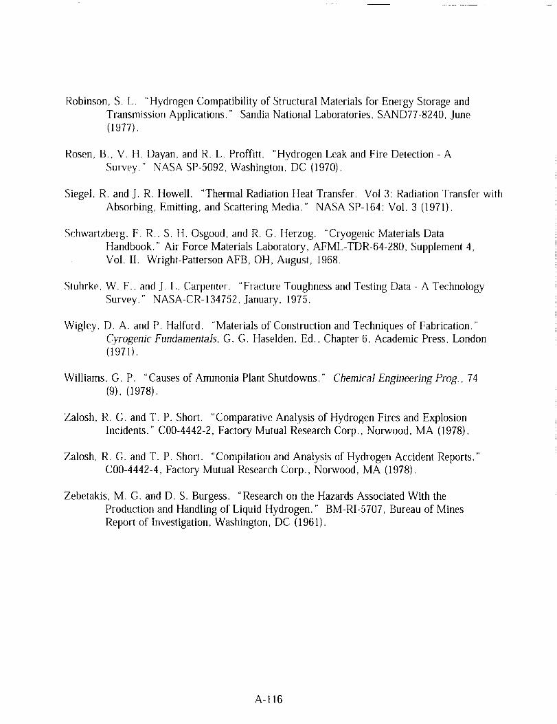
Robinson,S. L. "HydrogenCompatibilityof StructuralMaterialsfor EnergyStorageandTransmissionApplications." SandiaNational Laboratories,SAND77-8240,June(1977).
Rosen,B., V. H. Dayan,and R. L. Proffitt. "HydrogenLeak andFire Detection- ASurvey." NASA SP-5092,Washington,DC (1970).
Siegel,R. andJ. R. Howell. "Thermal RadiationHeatTransfer. Vol 3: RadiationTransferwithAbsorbing,Emitting, andScatteringMedia." NASA SP-164:Vol. 3 (1971).
Schwartzberg,F. R., S. H. Osgood,and R. G. Herzog. "Cryogenic Materials Data
Handbook." Air Force Materials Laboratory, AFML-TDR-64-280, Supplement 4,
Vol. II. Wright-Patterson AFB, OH, August, 1968.
Stuhrke, W. F., and J. L. Carpenter. "Fracture Toughness and Testing Data - A Technology
Survey." NASA-CR-134752, January, 1975.
Wigley, D. A. and P. Halford. "Materials of Construction and Techniques of Fabrication."
Cyrogenic Fundamentals, G. G. Haselden, Ed., Chapter 6, Academic Press, London
(1971).
Williams, G. P. "Causes of Ammonia Plant Shutdowns." Chemical Engineering Prog., 74
(9), (1978).
Zalosh, R. G. and T. P. Short. "Comparative Analysis of Hydrogen Fires and Explosion
Incidents." C00-4442-2, Factory Mutual Research Corp., Norwood, MA (1978).
Zalosh, R. G. and T. P. Short. "Compilation and Analysis of Hydrogen Accident Reports."
C00-4442-4, Factory Mutual Research Corp., Norwood, MA (1978).
Zebetakis, M. G. and D. S. Burgess. "Research on the Hazards Associated With the
Production and Handling of Liquid Hydrogen." BM-RI-5707, Bureau of Mines
Report of Investigation, Washington, DC (1961).
A-116
APPENDIX B
ASSESSMENT EXAMPLES
EXAMPLE 1
Detonation of GH2 with air/oxygen.
System
STATEMENT OF ASSESSMENT:
The inadvertent introduction of GH2 into a volume containing air-oxygen or the reverse
process is the source of many of the industrial and aerospace accidents summarized in
Tables A7,1, A7.2 and A7.3. Hazard analysis requires values for pressures and
temperatures that occur with detonation of the mixture.
B-1

SOLUTION:
The Gordon-McBride(1994)programusesJointArmy-Navy-NASA-Air Force(JANNAF) thermodynamicdataandperformsequilibrium calculations. TableB1showsthe computedvaluesfor a rangeof mixtures.
Table B1
Detonation Pressures and Temperatures
Volume To _' Po _' % Po
% H_ (K) (kPa) T/To PTP, (K) (kPa) T,/To PTPo
Hydrogen/Air
18.3 298 101.3 7.657 12.154 298 10.1 7.580 12.111
25 298 101.3 9.257 14.605 298 10.1 8.870 14.223
50 298 101.3 8.706 13.713 298 10.1 8.482 13.555
59 298 101.3 7.678 12.144 298 10.1 7.601 12.119
Hydrogen/Oxygen
5 298 101.3 3.118 4.880 298 10.1 3.119 4.882
25 298 101.3 9.034 14.289 298 10.1 8.660 13.896
50 298 101.3 11.646 17.857 298 10.1 10.537 16.616
75 298 101.3 12.111 18.671 298 10.1 10.834 17.250
90 298 101.3 8.576 13.584 298 10.1 8.327 13.393
a T = temperature
b P = pressure
The T1/T0 and P1/P0 ratios give the temperature and pressure rise across the detonation shock.
These are equilibrium (Chapman-Jouguet) values. The examples calculated are for a tenfold
change in initial pressure (101.3 kPa and 10.1 kPa). The temperature and pressure rise across
the detonation shock is similar in relative change.
B-2

EXAMPLE 2:
Deflagrationof Hydrogenwith air/oxygen.
System
STATEMENT OF ASSESSMENT:
In those incidents where hydrogen is inadvertently mixed with air or oxygen and only
deflagration occurs, the potential hazards are transformation to detonation, fire damage
to surrounding equipment or injury to personnel and potential explosion of the fire
heating the contents of its vessel. Analysis of the latter case gives the designer an
estimate of the pressure that could occur within the vessel.
Only mixtures that fall within the flammability limits shown in Figure A2.1 need to
be considered. To use Figure A2. I, consider points in the lower portion of the
figure. A point defined by 10% hydrogen/10% oxygen/80% nitrogen is flammable.
A point defined by 2% hydrogen/3% oxygen�90% nitrogen is not flammable.
B-3

SOLUTION:
Thecalculationinvolves a given amount of hydrogen and oxidizer mixed in a specific
volume. The system shown in the schematic is assumed to be 2 m 3. B2 gives the
temperature and pressure in the vessel for a range of compositions. The Gordon-
McBride (1994) computer code provides the computations. The Gordon-McBride
(1994) program uses Joint Army-Navy-NASA-Air Force (JANNAF) thermodynamic
data and performs equilibrium calculations.
Table B2
Deflagration Pressures
Volume % To P. T¢_ Pe_ To Po Tf Pf
H2 (K) (kPa) (K) (kPa) (K) (kPa) (K) (kPa)
Hydrogen/Air
5 298 101.3 707.9 234.7 273 101. 684.3 247.6
3
25 298 101.3 2159.2 643.8 273 101. 2141.9 697.0
3
50 298 101.3 1937.9 590.0 273 101. 1917.7 637.3
3
75 298 101.3 1165.7 375.6 273 101. 1142.6 401.9
3
Hydrogen/Oxygen
5 298 101.3 694.2 230.1 273 101
3
25 298 101.3 2134.5 639.1 273 101
3
50 298 101.3 2913.0 808.5 273 101
3
75 298 101.3 3003.4 837.5 273 101
3
90 298 101.3 1899.2 581.4 273 101
3
95 298 101.3 1132.8 365.9 273 101
3
671.6 243.0
2118.3 692.2
2908.3 880.0
2999.2 911.6
1878.6 612.2
1132.8 399.4
T_ and P_ are the final temperature and pressure that would occur in the fixed volume (2 m 3) when thermodynamic
ec]uflibrium occurred.
B-4

EXAMPLE 3:
Calculationof thepressurerisewith temperaiurefor bothLH2andSLH_.
,...--[
Liquid or Slush
Hydrogen
STATEMENT OF ASSESSMENT:
The possibility of liquid lockup, the blocking of a section of transfer line completely
filled (no ullage) with LH2 or SLH2, can be safely avoided with proper design. Should
such a situation occur, the resulting pressures as the system heats can lead to system
damage or hydrogen leakage. Heating occurs through normal operation because there
is a significant temperature difference between the LH2 or SLH2 and surroundings (at
ambient). Standard storage system designs usually assume a heat leak equivalent to
0.5 percent/day of the liquid contents.
B-5
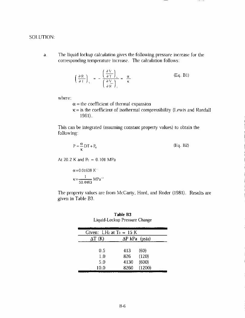
SOLUTION:
a. The liquid lockup calculation gives the following pressure increase for the
corresponding temperature increase. The calculation follows:
OV /aT /,_ _ (Eq. B1)
OR 1_
where:
o_= the coefficient of thermal expansion
_¢= is the coefficient of isothermal compressibility (Lewis and Randall
1961).
This can be integrated (assuming constant property values) to obtain the
following:
P = _ DT + Pc, (Eq. B2)K
At 20.2 K and P0 = 0.101 MPa
ot=0.01638 K 1
1_=-- MPa -_
50.4463
The property values are from McCarty, Hord, and Roder (1981). Results are
given in Table B3.
Table B3
Liquid-Lockup Pressure Change
Given: LH2atT0= 15K
AT (K) AP kPa (psia)
0.5 413 (60)
1.0 826 (120)
5.0 4130 (600)
10.0 8260 (1200)
B-6

b. The pressure rise for SLH2 can occur at constant temperature; the partial molar
volume of solid is less than that of liquid: hence, the melting of solid hydrogen
increases the volume of liquid. The following values for SLH2 and LH2 are
obtained from Table A1.1:
density LH_ = 77.03 kg/m 3
density SLH2 (50% mass) = 81.50 kg/m _
One cubic meter of 50 percent mass SLH2 contains 81.50 kg; therefore, as LH2
50 percent mass would occupy 1.06 m 3. Under a liquid lockup situation, the
melting of the solid hydrogen would lead to the formation of increased volume.
If no ullage were present the system pressure would rise; however, as the
pressure rises, the melting temperature changes (Figure A1.10). The actual
system pressure would be increasing and if the temperature rose 0.4 K, the
melting pressure of the solid would be 1.2 MPa plus the corresponding increase
caused by the change in temperature of the rest of the liquid (part a. of this
example).
NOTE
Liquid lockup of cryogenic systems is possible if the LHe is isolated (not readily
hydraulically connected) so pressure increases within the system are notdistributed to a relief valve or burst disc.
B-7
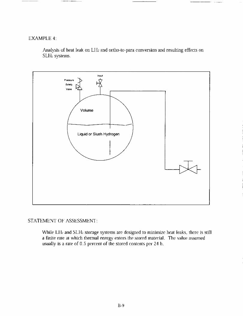
EXAMPLE 4:
Analysisof heatleakon LH2andortho-to-paraconversionandresultingeffectsonSLH_systems.
Input
Volume
STATEMENT OF ASSESSMENT:
While LH2 and SLH2 storage systems are designed to minimize heat leaks, there is still
a finite rate at which thermal energy enters the stored material. The value assumed
usually is a rate of 0.5 percent of the stored contents per 24 h.
B-9

SOLUTION:
a. Assume 100 m a storage (plus 10 percent ullage) of LH_. What is the pressure
rise per day as a result of evaporated liquid? (Neglect effect of pressure
increase on evaporation rate.) Assume LH_ normal hydrogen.
Data: LHz stored at 20.4 K (normal boiling point) P0 = 101.3 kPa
Amount Evaporated = 0.005-100 m 3 = 0.5 m :_
Mass Evaporated = MVAP = 70.91 kg/m:_.0.5 m :_= 35.5 kg
Density from Table A1.2 includes:
Moles Evaporated nvAp = 1.760X10⁴ moles
Initial moles in ullage (assume ideal gas law applies)
PV (Eq. B3)
rltl
101.3kPa. t0m 3
101.3kPa. 0.0224 m 3 ] 20.4 K
2-5-g j
- 6000motes
P, = (n,, + n,, -_--(Eq. B4)
Final pressure:
(1.760-104 + 0.6000 •104)-[ 101"3" 0"0224) "(20'4K)ltool. 273 K
310m
= 400 kPa(58 psia)
b.
If the compressibility of the hydrogen vapor is considered Z = 0.905
(Table A1.2) the final pressure is 362 kPa (52.5 psi&.
Assume 100 m 3 storage (plus 10 percent ullage) of SLH2.
(1) The SLH_ is 50 mass percent solids and assume the solid initially is 80
percent para-hydrogen and 20 percent ortho-hydrogen.
(2) Because the equilibrium vapor pressure of SLH2 is 7.20 kPa (Table A1.2),
assume the SLH2 is under a blanket of helium to bring the initial pressure
to 101.3 kPa.
B-10

(3) The equilibrium temperature of the SLH2 is 13.96 K; therefore, the
temperature difference for heat leak is greater than in the LH_ case and
0.5 percent/day rate will assume an appropriate amount of solid-liquid
phase change.
Total Initial Mass LH2 = 4075 kg
Total Initial Mass Solid = 4075 kg
Initial Mass Para Solid = 3260 kg
Initial Mass Ortho Solid = 815 kg
Assume the total thermal energy entering the system by the heat leak is
the same as in part a.
Q = MvAl,.AHvaP
Q = 35.5 kg • 10 3 g/kg • 446 J/g = 1.583.107 J
(Eq. B5)
Latent Heat of Vaporization from Table A 1. t.
Thermal energy from ortho-to-para conversion
AH co×v = 815 kg • 10 :_g/kg • 525 J/g = 4.279 • l0 s J
Enthalpy of Conversion from Figure A 1.2.
Total Solid Melted = (1.583.107 + 42.79.107) = 7611 kg58.3
(Eq. B6)
Latent Heat of fusion from Table A1.1.
The combined heat leak and ortho-to-para conversion would result in sufficient thermal
energy to melt all the solid because there was originally 4075 kg of solid hydrogen. This
result points to the need for lower heat input or continuous regeneration of SLH2. If this
is accomplished, the ortho-to-para conversion could be accomplished external to the
storage vessel and with external regeneration of solid the vessel pressure could be
maintained at its original value. It is also important to note that the equilibrium triple
point pressure is 7.20 kPa and without the helium blanket the storage vessel would be
at negative pressure with respect to ambient.
B-11

EXAMPLE 5"
Amountof solid insulation(notvacuum)requiredfor a specifiedtest line.
Section of Pipe
I nsutation
Pil;_eWall Y Liquid Hydrogen
Insulation
Given: 2 in. ID (nominal) line 304 stainless steel pipe. Generally, liquid flow
velocity is less than 10 fl/s and assume heat leak is less than 1/2 percent of
line capacity when in use at steady rate.
Basis: 10 m line; LHa at 20.3 K. Line is used to transfer 100.0 m 3 LHa.
Pipe Dimensions:
Length and sizeWall Thickness
Inside Diameter
Outside Diameter
Inside Cross Section
Density from Table A1.1
Total Mass LH2
Total Transferred
(with heat leak)
10 m, 2 in. Schedule 40
3.91 mm
52.50 mm
60.33 mm
21.64.10 .4 m 2
70.78 kg/m 3
100.0 m :_• 70.78 kg/m 3 = 7.078.103 kg
7.078.103 kg (1.0 + 0.005) = 7113.4 kg
Total thermal energy leaking into the system, Assume leak only causes phase change.
= (7113.4 - 7078)kg • 445.6 kJ/kg = 1.577x10⁴ kJ
B-13

LatentHeatof Vaporizationfor parahydrogenfrom TableA1.1 = 445.6 kJ/kg
Lengthof time to accomplishoperation. Assumeflow is at 3 m/s (10 ft/s).
Volumetric Flow = 3 m/s • 21.64.104m2 = 6.492.103m3/s
Time = 100.0m3/6.495.10:_m3/s = 1.5396.104 s = 4.3 h
Inner Surface Area
of Pipe = _d_-L = _.0.05250m. 10.0m-- 1.6493m 2
Thermal Flux -- 1.577-104 kJ/(1.6493 m z • 4.3 h) -- 0.618 kJ/m_.s
Insulation
"__ Pipe
/
1
I roAo
B-14

qSPECIFIED
qCALC
= 1.6493 m 2 • 0.618 kJ/m2.s = 1019 W
= UiAi(TAM_ - TL_Z)
1U_ = (Eq. B7)
I xA i yA i A i+ t- +
h_ kxAtm × kyAl,,, > hoA o
Wh_ = liquid film transfer coefficient = 55--7----
m .K
x = pipe wall thickness = 0.00391 m
k_ = pipe thermal conductivity = 16.3_W
m e .K
A_ = inside pipe surface area = 1.65 m 2 (Geankoplis 1983)
(A l -A,)Al._ = ----A i (Eq. B8)
y = insulation thickness = unknown
ky = insulation (Magnesia, 85%) thermal conductivity = 0.05W
m 2 "K
AIm_ = Ao-Ai=Ao-Ai (Eq. B9)
ho = outside film transfer coefficient = 5_W
m 2 .K
Ao = outside area of insulation
B-15
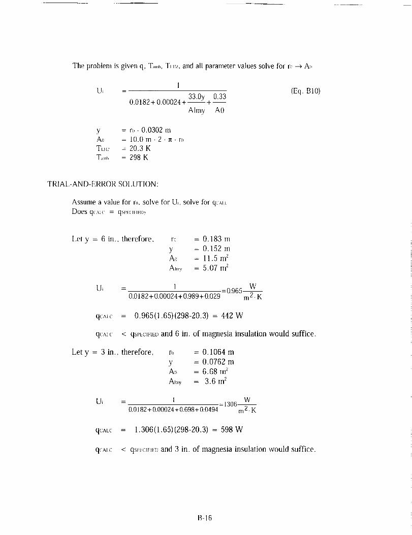
The problem is given q, Ta,,,b, TIH2, and all parameter values solve for rl_--->Ao
U, = (Eq. BI0)33.0y 0.33
0.0182 + 0.00024 +-- +
Almy AO
y = to- 0.0302 mAo = 10.0m. 2.re-to
TLU_ = 20.3 K
T_mt, = 298 K
TRIAL-AND-ERROR SOLUTION:
Assume a value for ro, solve for U_, solve for q_r,l
Does qc,v(, = qSPF('IFIFD?
Let y = 6 in.. therefore, ro = 0. 183 m
y = 0.152 mAo = 11.5 m _
Almy = 5.07 m2
Ui = 1 =0.965 wm2.K0.0182+0.00024+ 0.989+ 0.029
qCALC = 0.965(1.65)(298-20.3) = 442 W
q(:al {: < qsPt:CWmDand 6 in. of magnesia insulation would suffice.
Let y = 3 in., therefore, ro = 0.1064 m
y = 0.0762 mAo = 6.68 m 2
AI,ny = 3.6m 2
Ui = 1 W=1306--
0.0182 + 0.00024 + 0.698 + 0.0494 m 2. K
qCALC
qCAt,C
= 1.306(1.65)(298-20.3) = 598 W
< qSPEC_FmDand 3 in. of magnesia insulation would suffice.
B-16

In comparison an uninsulated line would result in
qCALC
1
0.0182 + 0.00024 + 0.2 (1.65)(278)= 2100 W
twice the qSPECrFIED; therefore, it is not acceptable.
NOTE
Under the assumed heat leak (0.5 percent) 393 m 3 of GH2 formed. It is realistic to
expect this is unacceptable; therefore, the rate of heat leak would need to be reduced,
i.e., a greater level of insulation would be required. Also, this problem assumed
steady state operation and does not address the question of system cool down.
ALTERNATIVE ASSESSMENT:
The assumed heat leak corresponds to 100 W/m (460 Btu/ft) for the 5 cm (nominal ID)
pipe. As described in the note, this may be excessive and a reduced heat leak would be
required. Given the availability of data on heat leak as a function of insulation
thickness for various types of insulation, the designer could readily select sufficient
insulation. The figure below provides the necessary information (Stewart and Prenger
1991).
I00
10
w
.I
.I
-Fill¢
1
Insulation Thickness (cm)
IPo_.
V_
10 100
B-17

EXAMPLE 6:
Calculationfor siting anLH_storagedewar.
Road
,9t
-..-" 100 rn
Possible Dewar Site
?m
Transfer Line
Offices
STATEMENT OF ASSESSMENT:
Assume that given the geographical layout shown in the schematic, the problem is to
locate a 1000 gal LH2 dewar to supply experiments conducted in Cell 1 of theschematic.
a. Cell construction is reinforced concrete wall with vented, flat-poured concrete roof.
b. Operation of experimental systems within the cells is controlled remotely from theoffice structure.
B-19

Total quantityof LH_ = 3.785m'_ = 268 kg (589 lb)
The following separation distances are obtained from the sources indicated.
Table B4
Minimum Separation Distances for Siting the LHz Dewar in Example 6
From LH2 storage dewar to public roadway
From LHz storage dewar to test cells
From LH_ storage dewar offices (place of public
assembly)
From Test Cell 1 LH2 piping to offices
From Test Cell 1 LH_ piping to roada [:rom Table A3.4.
b [:rom [able A3.7.
Minimum Separation Distance lm (fl)]
Nonpropellant Use Propellant Use
7.6 (25) "_ 183 (600) __
1.5 (5)_' 41 (135) _.d
22.9 (75) _ 183 (600) _d
NS e 7.6 (25) lNS NS
A dike or barricade could be []laced adjacent to {he dewar (m its west side to reduce the separation distance to the road.
d "]'he dewar can be pJaeed (m lbe north side of Ihe cells to reduce hydrogen piping} ]englh to Ceil 1, assuming (:ell consnuclion is
adequate to provide prolectiun to the office building.
e Not Specified
f t-:tom Section 405h.(2).I
B-20

EXAMPLE 7"
Analysisof a pressurerelief valve.
/Vent
>
ReliefValve
STATEMENT OF ASSESSMENT:
Each system and item of equipment should be examined for operational safety as set
forth by specified requirements. Relief capacity is based on the most severe
requirement of a system.
B-21

SOLUTION:
The sizingof relief devicesfor safelyventinghydrogenvaporor gasrequiresacalculationof the conditionsof critical flow. Critical flow usuallywill exist for mostgasesandvaporsdischargingthroughthesafetyvalve nozzleandorifice. Criticalpressurenormallywill befound between53and60 percentof thesetpressure:criticalflow will exist if thedownstreamor backpressureon the valveis lessthan 53-60percentof the initial relief pressureplusoverpressure.
Given: 100m3storageLH2 (asin Example4)normalevaporationrate = 35.5 kg/24h = 1.48kg/h
Assumeinsulationfailureand anevaporationrate = 0.32 kg/s.Assumetankrelief valveis setat 75psia; therefore,critical flow.
TheAPI-ASME2formula for capacityduringcritical flow.:4
W = CKAP(M/ZT) '! (Eq. B11)
where:
W = lb/h
C = 377
K = 0.97
P = 75 psia
M = 2.016 lb/lb.mol
Z = 0.9
T = 36.5 °R
Given the mass flow of 0.32 kg/s (2.54x10³ lb/h) and using equation B1 I, the area iscalculated as 0.374 inL
The calculated diameter of the safety relief valve orifice is 0.75 in. (1.91 cm) based on a two
to one safety factor.
NOTE
The diameter of the relief device should be sized to keep the storage vessel from
reaching critical flow, otherwise the tank can continue to build pressure. Given the
variability in the heat leak value a 2:1 safety factor might be reasonable. A more
conservative safety factor could be used if the heat leak is known.
The evaporation rate value is calculated based on a spherical volume of 110 m 3 LH2 storage (includes 10
percent ullage). The surface area for heat transfer would be t 11 m 2and an overall heat transfer coefficient
of U = 4.7 W/m<K(uninsulated system, Example 5) results in heat leak of 1.45x10⁵ W.
2 American Petroleum Institute and American Society of Mechanical Engineers
3 Equation B11 is found on page 225, Volume 1 of E, E. Ludwig "Applied Process Design for Chemical andPetrochemical Plants" and the values of C and K are from this source.
B-22

EXAMPLE 8:
Analysisof a hydrogenvent/flaresystem.
\/ ,
STATEMENT OF ASSESSMENT:
Assume the same quantity of flow exists as in Example 7 (0.3 kg/s). This flow is the
upper limit of the quantity that has been vented without flaring (Section 505 b)"
therefore, a flare should be considered.
B-23

SOLUTION:
Although Example7 calculateda 3/4 in. insidediameterrelief nozzle,a 24 in. flarestackis used. FigureA4.1 showsthatthehydrogenflow rate (0.3 kg/s) and 24 in.stackdiameterresultsin no flamedip. A 24 in. diameterflare stackwould beusedtoget thehigh concentrationsof air (60to 85volumepercent)without increasingpressuredrop andto limit blowout, Theflare flamewouldstill showno flame dip if this werethe case.
Given: 25 percentby volumehydrogenconcentration(at0.3 kg HFs) thetotal gasflow wouldbe thefollowing:
0.75nil2 =0.25:nA,_=-_ n_:
•".MA_R=0.0289-na_e= 12.9kg/ S
vol % = tool %37
at STP velocity at stack exit (24 in. diameter)
(0,45kg tool / s)- (2.2lb mol / kgtool). 359 ft3 / lb tool
3.142ft 2=ll3fl/s
According to Figure A4.2, this velocity would result in a stable flame (no blowout);
the boundary velocity gradient would be 1356 s _ using a 1 in. boundary layerthickness.
B-24

EXAMPLE 9:
Analysisof theheatleak into a LH_ or SLH2transferline andanalysisof thequantityof LH2consumedto cool thetransferline.
STATEMENT OF ASSESSMENT:
Theintroductionof LH2or SLH2into asystempresentstheproblemof cooling thesystemto the appropriatetemperature,20.3 or 13.8K. GH2 will be flashed until the
system approaches these temperatures. Too rapid introduction of the cold fluid can
cause large stresses in the piping and vessels of the system.
Two calculations are of interest: 1) the total amount of LH_ or SLH2 needed to cool the
system and 2) an estimate of the appropriate cooling rate.
Given: 10 m transfer pipe in Example 5.
Mass steel (304L) pipe = P(d 2 2_\ o-di )Lp3o4ss =54.24kg
P (d 2_ d 2 j LPINSH,= 48.06 kgMass insulation (85% n Magnesia) = -_-
B-25

Theflow rateof Example5 is
7.1134.103 kg .f 2.21b/. 1
4.3hr.3600s/h _ kg ] 2in.
lb=0.505--
s. in.
Assume the system is to be cooled from 298 to 20.3 K.
CpJxsui, = 0.98 kJ/kg.K
Cp,_o4ss = 0.461 M/kg.K
r3o4ss = 7817 kg/m :_
FINSU[ = 271 kg/m :_
_Ltt_ = 899 J/tool = 446 kJ/kg
The total enthalpy change of the system is
AH= M304ssCP304SSITT12 dT + MINSULCpINSULJTT12dT
=(54.24 * 0.461+ 48.06 * 0.98)(298 - 20.3)= 2.002x10⁴ kJ
A mass of LH_ is required (assume phase change only). Note: This calculation would
be the maximum required because it does not utilize any of the sensible heat of the GH2
formed (Jacobs 1963).
In changing from 298 to 20.3 K, there is the possibility of a 0.3 percent contraction in
stainless steel. Figure A4.5 gives the maximum flow rate to avoid too rapid cooling of
pipe.
For given pipe:wall thickness 0.392
=_=0.075pipe diameter 5.25
Extrapolation gives a maximum flow rate of 0.1 lb/s.in.
In Example 5, at a steady state, the flow rate was 0.5 lb/s.in.; therefore, the startup
(such as the cool-down period) would need to be at a much lower flow rate (by at least
a factor of 5). In addition, the 44.9 kg of LH2 changed to GH_ would have to be
handled by the system if LH2 is used to cool the system. This solution is for nominal
pipe thickness. Consideration of the thick wall section of the piping system, such as a
flange, would reduce the flow rate because thermal stresses would be greater in thethick wall section.
B-26

EXAMPLE 10:
The purgingof hydrogenfrom systemsprior to maintenanceor remodelingor thepurgingof air from hydrogenstoragevesselsareimportantoperationalprocedures.
Pressure
Relief
Given:
SOLUTION:
100 m _ LH2 (plus 10 percent ullage) storage vessel.
a. Total volume: ll0m 3
Assume initial volume filled with air at NTP; 4 293.3 K and 101.3 kPa
(68 °F and 14.7 psia).
Section 701 stipulates that before filling with LH2, the vessel should be
evacuated to 1.33 kPa (0.193 psia), repressurized with helium, GN2 or GH2 and
vented to atmospheric pressure. Venting must be done safely if GH2 is used.
What is residual oxygen concentration?
Density air = 1.198 kg/m 3
Initial moles air = (110 m3.1.198 kg/m3)/28.82 kg/kg-mol = 4.57 kg-mol
Moles air after evacuation (assume ideal gas)
_ Normal temperature and pressure.B-27

b.
n= P_V= l333kPa'l10m3 = 0.0600 kg.mol
RT ( 101.3kPa.22.4 m3/. 293.3K
L lkg.mol.273K )
Assume vessel repressurized to 25 psig = 273.7 kPa (39.7 psia)
Total moles at pressure
273,TkPa-/t0m 3
(! 01.3kPa _-22.4m 3.].(293 K)
Ikg.moJ.273K
= 12.36
.'. Total GN2 added = 12.36-0.0600 kg.mol = 12.30 kg.mol
.'. Total 02 moles = 0.0600.0.21 = 0.013 kg.mol
.'. Percent oxygen concentration = (0.013/12.36). 100 = 0.1%
It is important to remember that if LH2 is to be stored in the vessel, oxygen and
nitrogen can condense and solidify. Therefore, the use of helium as a purge gas
should be considered, or GH_ should be used to flush residual GN_ and GOX
from the vessel.
If the system is vented to atmospheric and evacuated again to 1.33 kPa
(0.193 psia) aft er repressurization with inert gas to atmospheric, the residual
oxygen is 0.000062 kg.mol or 0.0013 percent.
The second method of Section 701 is to evacuate and purge with GN2 for three
cycles (omits repressurization with inert gas). Assume purge is at atmospheric
pressure.
First cycle: Initial moles =
Evacuate moles =
Moles oxygen =
Pressure to atmospheric adds =
4.57 kg.mol
0.0600 kg.mol
0.013 kg.mol
4.51 kg.mol GN2
Second cycle: Evacuate moles =
Moles oxygen --
Pressure to atmospheric adds =
0.0600 kg.mol
0.00017 kg.mol kg.mol
4.51 kg.mol GN2
Third cycle: Evacuate moles =
Moles oxygen =
Pressure to atmospheric adds =
0.0600 kg.mol
0.0000022 kg.mol
4.51 kg.mol GN2
Final percent oxygenconcentration
= 0.00005 %
B-28

C, The purging of air from new tanks or GH_ vessels for maintenance can be done
using GN2 or helium until the measured exit concentration is 25 percen! of the
LFL (at ambient conditions, less than one percent).
Assume the same storage system initially filled with GH2 at 101.3 kPa and
293.3 K (68 °F and 14.7 psia).
Density GH2 (from Table A1.1) = 0.0838 kg/m 3
Initial moles GH_ = (110 m:_.0.0838 kg/m:_)/2.015 kg/kg.mol= 4.57 kg.mol
Total moles GN2 to give 1% = 452 kg.mol
If added to a single charge (assume constant temperature), final vessel pressure
would equal
Pf = 101.3 kPa (452 + 4.57)/4.57 = 10.1 MPa = 1470 psia
If the vessel cannot contain this pressure, a continuous or semicontinuous batch-
type purge must be used.
B-29

EXAMPLE 11:
The accidentalleakingor releaseof hydrogenresultingin flammablemixtureswith airpresentsa safetyissue• Thehazardanalysisshouldaddresswhethernaturaldispersionis sufficient to dissipate the mixture to below the LFL _ or additional operational
requirements are needed.
10'
SOLUTION"
a. Minimum standard' 400 CF at 70 °F and 14.7 psia. (Section 10lb.(2))
Assume GH2 released into 2000 ft 3 laboratory space.
Given room ventilation at 2000 cfm G (air turnover rate equals once per minute).
Case 1 Assume instantaneous release and mixing; therefore, initial
volume concentration in the room = 20 percent GH2
The concentration of GH2 is equal to the following:
n 14.7psia
RT•0.2 = 0.00052 lb" m-°1 = 0 008 kg ,tool
ft3 • m3
Lower flammability limit.
6 Cubic feet per minute
B-31

Mass balance of GH2 in room (in terms of kg.mol)
d Vhi- .....c=-';,c
where:
Vfln
VC
Co
= volume of room
= room ventilation rate
= concentration of H2
= initial concenlration of H2
(Eq. B12)
cIn - t
Co Vrlil
(Eq. B13)
C = (Eq. B14)
Vrm )
How long does it take to reduce room concentration to less than LFL (4 percent).
Vt= r,. In C _ 2000cf in 4
V C¢, 2000cfm 20
t = 1.6 min
Assume air turnover rate is once every 4 min .-. V = 500 cfm and t = 6.4 minutes. These
values apply only in the case where there is no recirculation of ventilation air.
Case 2: Assuming that leaking GH_ is instantaneously mixed with room air,
what is the maximum leak rate (NoNe) that will always result in
concentrations below LFL (4%)?
Mass Balance on GH2 (in terms of kgmol).
dt
Vrm dC NC,H2t-C-
_/ dt
(Eq. B13)
B-32

For Vr.. / V = 1 minute @ turnover rate + 2000 cfm, a solution is
C= N_H_(I_e -_)V
_'GH2
at t --->ooC = _
V
(Eq. B14)
(Eq. B15)
.'. N GH2 = 1.92x10 -3. 56.63 = 0.109 kg.mol / minor80cfm ofGH 2 (Eq, B 16)
b°
lb. mol ( 0_ 3 kg. mol)For0< ! < _,C < 1.2x10 -4 -_ _,or 1.92xl m3(Eq. B17)
The example above of instantaneous and complete mixing is the first of two
limiting assumptions. The second limiting assumption is that the hydrogen
released remains as a pure volume and at a time (t = 0), natural dissipation
occurs to reduce the concentration of hydrogen.
Assume a spherical cloud of hydrogen 1 in in diameter at ambient conditions
(298 K and 101.3 kPa).
Concentration of Hydrogen in Bubble =
= 0.041 kgmol = 0.003 lb tool (Eq. B18)RT m 3 ft 3
(1) Assuming equal-molal counter diffusion, such as when the hydrogen
leaves the bubble it is replaced by air.
(2) Assume the concentration of hydrogen at the surface of the bubble
remains approximately zero, the solution can be obtained from analytical
solution of diffusion problems (Carslaw and Jaeger 1959).
Concentration at the center of the bubble
Cc 2C0 _( 1)ne-Dn2n2t/a2= - (Eq. B 19)n=l
where:
D = hydrogen diffusivity in air = 0.65 cm2/st = time in seconds
a = bubble radius = 50 cm
B-33

EXAMPLE 12:
Typical material that might be included in certificate training for liquid hydrogen
handlers is summarized in this example.
OVERVIEW
LIQUID HYDROGEN HANDLER'S
QUALIFICATION TRAINING
• BASIC POLICY
• PERSONNEL, TRAINING
• PERSONNEL TRAINING MUST ADDRESS
• HYDROGEN PROPERTIES
• IGNITION SOURCES
• IGNITION PREVENTION
• HYDROGEN IN SYSTEMS
• MATERIALS TO USE IN HYDROGEN SYSTEMS
• PERSONNEL PROTECTIVE EQUIPMENT
• CRYOGENIC EXPOSURE
• GUIDELINES FOR OPERATING PROCEDURES
• TRANSFER PRECAUTIONS
• LOADING PRECAUTIONS
• EMERGENCY PROCEDURES
B-35

BASIC POLICY
Hydrogen can be safely handled like other fuels.
Safety can be achieved by adherence to the following:
Prevent hydrogen leaks
Detect accidental leaks and take proper action
Prevent hydrogen accumulation
Remove likely ignition sources and suspect unknown ignition sources
PERSONNEL TRAINING
• Become familiar with hazards of hydrogen
• Recognize human capabilities and limitations
• Become certified for handling LH2/GH2
• Understand EMERGENCY Procedures for leaks and spills
• Adhere to accepted standards, guidelines, and codes for designing hydrogen systems
PERSONNEL TRAINING MUST ADDRESS
Hazards of hydrogen facilities and operations
Loading and storage systems
Purge systems
Control sampling and analytical systems
Alarm/warning signal systems
Ventilation requirements
Fire and personnel protection
System schematics and emergency procedures
B-36

HYDROGEN PROPERTIES
• Cryogenic liquids: Boiling point 20 K (-423 °F)
• Liquid density: .07 g/cm :_ (water 1 g/cm 3)
• Above 23 K (-418.6 °F). lighter than air
• Flammability limits: Air" U. 74.8(%,
• L. 4.1%
• Detonation limits in Air: 18.3 - 59% hydrogen
• Deflagration 5 to 10 Pi, Detonation _>40 Pi
• Flame temperatures (max.): 2400 K (3865 °F)
• Hydrogen gas can increase in temperature when expanding
Oxygen U.
L.
94.0%
4.1%
IGNITION SOURCES
• Electrical sparks or static electricity (breaking electrical connections, nylon clothing, etc.)
• Friction sparks (metal on metal, stone on stone)
• Impact sparks (sandblasting)
• Autoignition (hot points, etc.) Temperature 584 °C (1084 °F)
IGNITION PREVENTION
• Limit sources (remove flammable items and electrical equipment from the area)
• Inert purge boxes around electrical equipment and connections
• Ground equipment
• Provide lightning protection
• Wear non-sparking clothing
• Spark proof tools
B-37

HYDROGEN IN SYSTEMS
• In LH2 systems, vents and valves can ice up and fail
• Hydrogen systems should be kept at a positive pressure
• Trapped LH_ will evaporate, pressurize and rupture lines
LH2 at 14.7 psia, heated to 70 °F, has a pressure of 28.000 psia
• Enclosed or partially enclosed storage areas should be well ventilated
MATERIALS TO USE IN LIQUID HYDROGEN SYSTEMS
• Austenitic SS, Aluminum alloys, copper and alloys
• Non-metals: Dacron, Teflon, Kel-F, Mylar, and Nylon
• Effects and causes of hydrogen embrittlement
r , ,
PERSONNEL PROTECTIVE EQUIPMENT
The best single investment in safety is trained personnel
Eye. hand, and non-sparking clothing (face shield, gloves, and cotton coveralls)
Closed toe, non-porous shoes
CRYOGENIC EXPOSURE
• Cryogenic burns and injuries
Remove personnel from danger area
Ensure you are wearing protective equipment (also breathing air, if necessary)
Call the EMERGENCY CENTER - 5111
• Asphyxiation
Often occurs in inert H2 purge environments
B-38

GUIDELINES FOR OPERATING PROCEDURES
• Provide control of hazards to an acceptable risk
• Prevention. detection, and course of action for hydrogen leaks
• Adequate ventilation guidelines
• Elimination of ignition hazards
• Outline maintenance procedures, if needed
TRANSFER PRECAUTIONS
• Transfer areas clear of non-essential personnel
• Cancel or discontinue transfers in electrical storms
• Discontinue transfers for leaks or fires
• Isolate, vent. and purge H2 lines before conducting maintenance
• Remove sources of ignition from transfer areas
• Work in a "buddy system"
• Barricades, warning signs, ropes, etc. establish control
LOADING PRECAUTIONS
• Do not overload a vessel, thermal cycling of relief system
• Oxygen content in a vessel < 2%
• Ground dewar when receiving shipment
• Watch for condensed water on surfaces/leaks
• No transfers to open mouth dewars/cryopumping
• Cool down storage vessels slowly
• Examine systems for corrosion or blistering
B-39

EMERGENCY PROCEDURES
• Principle danger from a spill or leak is fire
• For H2 fires, isolate source and let burn keeping adjacent metal components cool withwater
• For a LHz spill, rope off area
• For a leak, isolate source, vent, purge, and repair
• If a vessel is burning near other vessels, the burning vessel may be removed if it can bedone safely
• Do NOT flare leaks deliberately
• If annulus is exposed to air, do NOT cool with water
• If a LH2 vessel overlurns, try venting through a ]iquJd outlet if this wi]] allow the ullage tovent
B-40
REFERENCES
Gordon, S. and B. J. McBride. Computer Program for Calculation of Complex Chemical
Equilibrium Compositions and Applications. NASA Reference Publication 1311.
October (1994).
Lewis, G. N., and M. Randall. Thermodynamics. Revised by K. S. Pitzer and L Brewer,
McGraw-Hill Book Co., Inc., New York (1961).
Ludwig, E. E., "Applied Process Design for Chemical and Petrochemical Plants" and thevalues of C and K are from this source.
Jacobs, R. B. Liquid Requirements for the Cooldown of Cryogenic Equipment. Advances in
Cryogenic Engineering, Vol. 8, (1963): pp. 529-535.
McCarty, R. D., J. Hord, and H. M. Roder. Selected Properties of Hydrogen (Engineering
Design Data). NBS Monograph 168, National Bureau of Standards, Boulder, CO
(1981).
Geankoplis, C.J. Transport Process and Limit Operations. 2 'd Edition, Prentice Hall,
Englewood Cliffs, NJ, 1983, pg. 218-219.
Stewart, W. and F. C. Prenger. Thermal Insulation Options for the Superconducting
Transmission Initiative Project. Los Alamos National Laboratory, LA-UR-91-850, Los
Alamos, NM (1991).
B-41

APPENDIX C
SCALING LAWS, EXPLOSIONS, BLAST EFFECTS, AND FRAGMENTATION
C. 1 SCALING LAWS
A comprehensive review of accidental explosions has been made by
Strehlow and Baker (1975). The review characterizes explosions by type,
discusses the various scaling laws, and summarizes nonideal blast wave
behavior and the mechanisms by which blast waves produce damage (Stull
1977; DoD 6055.9 1992).
a° High explosives or nuclear weapons mainly have been used to
produce the waves in the classical experimental work on blast waves.
The intermediate- and far-field waves generally, quite closely
resemble the waves predicted from point-source theory, and to this
extent high explosives or nuclear explosions can be considered ideal.
b, A point-source blast wave is a blast wave conceptually produced by
the instantaneous deposition of a fixed quantity of energy at an
infinitesimal point in a uniform atmosphere. Essentially there are
three regions of interest as a point-source wave propagates awayfrom its source:
° The near-field wave in which pressures are so large external
pressure (or counter-pressure) can be neglected
. An intermediate region of extreme practical importance
because the overpressure and impulse are sufficiently high to
do significant damage
, A far-field region that yields to an analytic approximation
such that the positive overpressure portion of the curve for
large distances can easily be constructed from the
overpressure-time curve at one far-field position
C° Scaling the properties of point-source blast waves is common practice
and subject to cube-root scaling (Sach's law). A given pressure
theoretically will occur at a distance from an explosion proportional
to the cube root of the energy yield. Full-scale tests have shown this
relationship between distance and energy yield to hold over a wide
range of explosive weights. According to Sach's law, if dl is the
distance from a reference explosion of a mass of W, at which a
specified hydrostatic overpressure or dynamic pressure is found, for
C-1

d.
e.
f.
g°
any explosion of a mass of W, these same pressures will occur at a
distance d given by Equation C l:
f )1 3¢.)_1= Wd, k W----_] (Eq. C1)
Plots of overpressures for various explosive weights consequently
can be superimposed on the curve for 0.45 kg (1 lb) of explosive if,
instead of distance, the distance divided by the cube root of the
weight is plotted against overpressure. This correlating parameter
(d/W)l/:_, called scaled distance, is used to simplify the presentation
of the blast wave characteristics.
Cube-root scaling also can be applied to arrival time of the shock
front, positive-phase duration, and impulse. The distances concerned
also are scaled according to the cube-root law. The relationships can
be expressed in the forms t/t_ = d/dl = (W/WI) 1/3and I/h = d/dl =
(W/W1)_/3, where tl represents arrival time or positive-phase duration
and h is the impulse for the reference explosion WJ; as before, d_
and d are distances from ground zero. If W_ is taken as 0.45 kg
(1 lb), the various quantities are related as t = t_W _/:_at a distance d= d_W _/3and I = I_W _/:_at a distance d = dlW 1/3.
No general laws exist for scaling blast waves from nonideal
explosions because not all the physical parameters affecting such
explosions are known. The general concept of equivalence for a
nonideal explosion is not well understood. The near-field
overpressures usually are much lower than those of a point-source
explosion that produces the equivalent far-field overpressure, but it is
not obvious exactly what the relationship between near- and far-field
behavior should be or how this relationship differs with the type of
accidental explosion. It is also not obvious how to evaluate the blast
damage of any particular type of accidental explosion or how much
the damage depends on the type of explosion.
The comparison between ideal and accidental explosions is inexact
because propellant explosions are not considered point sources. The
concept of TNT equivalence, widely used in safety studies, is also
very inexact and may be quite misleading. Scaling laws for nonideal
explosions are not known exactly, but they can be easily developed
after the physics of such explosions is well known. The scaling laws
likely will be variants on Sach's law (Strehlow and Baker 1975;
CPIA 1984).
Theoretical work suggests that distances at which the pressure levels
are over approximately 101.3 kPa (14.7 psi) for liquid oxygen
(LOX)-liquid hydrogen (LH_) explosions, the TNT equivalent in
terms of peak pressure is about 0.07. The TNT equivalent is about 1
C-2

h.
for pressure levels from 101.3 to 0.7 kPa (14.7 to 0.1 psi): and it is
about 2.0 below 0.7 kPa (0.1 psi).
These numbers mean that to generate the same pressure-distance
relationship as 0.45 kg (1 lb) of TNT at 101.3 kPa (14.7 psi) and
above it takes about 6.5 kg (14.3 lb) of LH2 and LOX: from 101.3 to
0.7 kPa (14.7 to 0.1 psi), about 0.45 kg (1 lb): and at less than
6.9 kPa (0.1 psi) only 0.23 kg (1/2 lb). Correlation with damaging
effects on buildings, vehicles, humans, etc., can be made from
existing methods and data in the literature if blast wave
characteristics can be defined for accidental explosions (CPIA 1984;
Baker et al. 1978:AMCP-706-180 1972). Fragmentation patterns
from accidental explosions and the damaging effects of these
fragments are quite difficult to predict.
C.2 TYPES OF EXPLOSIONS
a°
b.
Explosions In Buildings.
(1) Explosions in buildings are of three main types, increasing in
severity from type a to type c:
(a) a spill of some combustible material and a slow
deflagration wave or flashback fire causes a relatively
slow buildup of pressure in the building
(b) a piece of equipment explodes and produces a blast
wave inside the building that damages the structure or
is relieved by venting
(c) a leak occurs, but the combustible mixture that forms
detonates.
(2) The degree of confinement or the bursting pressure of the
vessel or building, for the first and second types of explosion,
determines the nature of the blast wave generated and damage
patterns. The blast wave behavior and damage patterns in a
detonative combustion (third type) primarily are determined
by the behavior of the detonation and are only modified by
the confinement.
Tank Ruptures.
(1) A rupture followed by combustion is a very special type of
explosion that primarily occurs when a tank of liquefied fuel,
under pressure, is heated by an external fire, following an
C-3

C.
accident, until the tank vents and torches. The heating of the
venting tank needs to be sufficiently intense to cause the
internal pressure to rise above the bursting pressure of the
tank for an explosion to occur, even with venting. This type
of explosion has three distinct damage-producing effects:
(a) A blast wave because of internal pressure relief
(b) A fireball caused by subsequent massive burning ofthe tank's contents in air
(c) Large fragments scattered for long distances because
of the ductile nature of the rupture of the tank and
rocketing of pieces by reaction forces
(2) Recent studies show that no single TNT equivalent can be
used to describe the blast generated by a rupturing pressure
vessel. The tank-rupture blast pressures, combined with the
positive shock wave durations, yield positive values of shock
wave impulse with a impulse-distance relationship similar in
slope to that for TNT. Impulses for tank rupture and the
TNT equivalent are not significantly different quantitatively
for large, high-pressure vessels.
(3) A general comparison of blast and fragment parameters
generated by tank rupture and an equivalent TNT charge
shows that side-on pressures are higher for TNT above 69 to
41 kPa (10 to 6 psi) and lower for TNT at pressures below
these values. Face-on tank pressures show a similar
relationship to face-on TNT pressures. Positive shock wave
durations are longer for tank rupture than for TNT. Impulse,
face-on and side-on, are similar for TNT and tank rupture.
Damage, depending on distance, may be greater for tank
rupture. Tank-rupture fragments are larger than would be
expected from a cased TNT charge. Fragment velocities are
higher for a cased TNT charge than for tank rupture (Baker et
al. 1974 and 1978).
Vapor Cloud Explosions.
. The visual sequence of events in a vapor cloud explosionfollows:
a) A massive release of a combustible fuel
b) A reasonable delay in ignition, 30 s to 30 min
c) Ignition of the cloud resulting in an explosion
C-4

d°
. Vapor cloud ignition can lead to two very different types of
behavior relative to the blast wave produced and leads to the
conclusion that detonative combustion needs to always occur
before a destructive blast wave is produced.
. Studies using the usual atmospheric dispersion equations have
shown that the maximum fraction of the fuel that would be in
the combustible range at any one time from a continuous or
massive spill would be about 10 percent. This agrees quite
satisfactorily with available data, in which the maximum yield
based on TNT equivalent weight is about 10 percent (Baker et
al. 1974; Strehlow, Savage and Vance 1972). Current
research into the behavior of vapor cloud explosions is of two
major types:
a) Assessing the behavior of a deflagrative explosion of
the cloud
b) Assessing the area of cloud dispersion
. The blast waves produced by the explosion of liquid
propellants accidentally mixed generally are quite
unreproducible and difficult to adequately model. Extensive
studies of liquid propellant explosions show that the
explosions differ from TNT explosions in a number of ways,
so the concept of TNT equivalence quoted in pounds of TNTis far from exact.
Ground-Handling System Explosions.
(i) The hazards from accidental explosions in propellant
ground-handling systems are similar in many respects to the
hazards from such explosions in flight vehicles. The
accidents cause damage by air-blast loading, fragment or
appurtenance impact, radiation from fireballs, or fire from the
ignition of combustible materials after an explosion (Strehlow
and Baker 1975; DoD 6055.9 (1992); CPIA PUB. 394
(1984): AMCP-706-180 (1972); Strehlow, Savage, and
Vance 1972).
Flight and ground systems can fail by material fatigue caused
by overstressing. Many possible causes of flight vehicle
explosions; such as loss of thrust during launch, guidance
system failure, or rupture of a bulkhead separating a fuel
from an oxidizer; are inapplicable for ground-handling
systems.
C-5

(3)
(4)
(5)
The nature of the hazards is different because
ground-handling systems have fewer weight constraints than
flight vehicles. The total energy stored in compressed gases
or the total chemical energy stored in fuels and oxidants also
can be much greater than for many flight systems.
Many more accidental explosions involving fuels and
compressed fluids have occurred in ground-handling systems
than in flight vehicles, including the following:
(a) Simple pressure vessel failure caused by fatigue or
flaw growth
(b) Vessel failure induced by impact during a
transportation accident
(c) Vessel failure by overpressure caused by overheating
(d) Vessel and pipeline failure caused by overpressure,corrosion or erosion
(e) Fuel leakage followed by a vapor cloud explosion.
Workbook for Estimating Effects of Accidental Explosions in
Propellant Ground Handling and Transport Systems (Baker et
al. 1978) and Assembly and Analysis of Fragmentation Data
for Liquid Propellant Vessels (Baker et al. 1974) provide
methods for predicting blast and fragment characteristics and
effects for a wide range of possible explosion accidents in
ground and flight systems. The material allows for the
prediction of the following:
(a) Explosive energy yield or energy release
(b) Characteristics of blast pressure waves generated by
spherical and nonspherical explosions
(c) Effects of pressure waves on certain classes of targets
(d) Characteristics of fragments generated by ground
equipment explosions, including massive vessel partsthat rocket
(e) Effects of fragment impact, including effects of
fragment revetments on blast waves
Various safety factors are included in the prediction methods.
C-6

C.3 CHARACTERISTICSOF FRAGMENTS
a° Accidental explosions in ground systems tend to produce very
different types of fragments or missiles than similar explosions in
flight-weight systems. The most striking difference lies in the
number of fragments generated, usually much fewer for ground
systems than flight systems.
b. Workbook for Estimating Effects of Accidental Explosions in
Propellant Ground Handling and Transport Systems (Baker el al.
1978) develops methods of predicting velocities and ranges of
fragments from bursting vessels. The fragment range information is
based on data from various explosion sources.
C. The fragment range and mass distributions for the various explosionsources are also included in the references.
C.4 EFFECTS OF BARRICADES ON BLAST WAVES
a° Barricades are constructed near potential explosion sources or in
front of structures and facilities located near potential explosion
sources. They are intended to be protective devices to arrest
fragments or attenuate blast waves. Results of analyses and tests
show the following:
(1) Barricades reduce peak pressures and impulses behind the
barricades.
(?) Single-revetted barricades are more efficient in reducing peak
pressures and impulses than mounds.
(3) Values of peak pressure and impulse are greatly influenced by
the height above the ground, location of the barricade, and
barricade dimensions and configuration.
b. The effects of near-field, single-revetted barricades on peak
overpressures and side-on impulses are given in Workbook for
Estimating Effects of Accidental Explosions in Propellant Ground
Handling and Transport Systems (Baker et al. 1978) and Principles
of Explosive Behavior (AMCP-706-180 (1972)). The references also
contain curves indicating blast pressures for predicting lung damage
and lethality.
C-7

C.5 ESTIMATESOF EXPLOSIVEYIELDS FROM COMPRESSEDGASBURSTS
a. Compressed Gas Bursts.
The various formulas for total energy release are reviewed. These
include Equation C2:
where
E
PI =
Pa =
gl =
V_ =
1 - 1 I/1 (Eq. C2)
blast yield (energy)
the initial absolute pressure in the vessel
the absolute pressure of the outside atmosphere
the ratio of specific heats for the gas in the vesselthe initial volume
An estimate based oil isentropic expansion from initial burst pressure
to atmospheric pressure and
E= pIV, [t [ p, ]1¥, <1/_,, (Eq. C3)
as a lower limit, the energy released by constant pressure addition to
the explosion source region
E = P,_(V,-V,) (Eq. C4)
where Vf = the final volume occupied by the gas originally in thevessel.
b. The three equations are given in descending order of total blast
energy. The blast yield is considered to lie between equations C3
and C4. Equation C2 gives slightly higher values than does equation
C3, but both are considered to yield overestimates and are veryconservative.
C° The equations given for blast yields are based on the assumption that
all the energy that can drive a blast wave does so depending only on
the energy release rate. Some energy for real vessels needs to be
absorbed by the vessel as it fractures; in the fracturing process itself
and accelerating the vessel fragments to their maximum velocity.
d. Workbook for Estimating Effects of Accidental Explosions in
Propellant Ground Handling and Transport Systems (Baker et al.
1978) provides methods for estimating the velocity and kinetic
C-8

e,
energy of the vessel fragments. Also, the workbook reviews the
characteristics of blast waves from liquid propellant explosions and
spherical gas vessel bursts and their similarities to the differences
from waves from condensed high explosives such as TNT.
All blast parameters are plotted as nondimensional and are shown as
functions (fi) of two nondimensional variables P_/P_ and R,
m
where R =Rp 1 / 3
ElJ,_
Values of the following properties can be calculated from the scaled
curves:
13 =K
T = T aaP_ '':_El/3
(Eq. C5)
f,
where
P_ = ambient pressure (absolute)
as = ambient sound velocity
P_ = peak static (side-on) overpressure
t_ = arrival time of peak averpressure
T = duration of overpressure
Is = specific impulse
R = radius of blast wave (standoff distance)
P_ = internal absolute pressure of sphere
Typical blast pressure histories for a burst of a frangible gas sphere
are given in Baker et al. (1974) and Adamczyk and Strehlow (I977).
Characteristics are a pronounced negative phase compared to the first
positive phase and the strong second shock wave. By contrast,
waves from condensed explosives show much smaller negative
phases and seldom have a discernible second shock.
C-9

g. Peak overpressures and shock wave impulse values from a 55 MPa
gage (8000 psig) and a 4.1 MPa gage (600 psig) tank rupture are
given in Adamczyk and Strehlow (1977) and Strehlow and Ricker
(1976). The term "strength," used in these references, refers to
several characteristics of a blast wave that relate to the potential of
the wave to cause damage and is defined as follows:
(1) Peak overpressure. The static pressure (often called side-on
pressure) is greatest al tile wave front. This is the peak
overpressure, generally reported as pounds/square inch above
atmospheric pressure.
(2) Duration. After the wave front passes, the static pressure
falls to slightly below atmospheric. The duration of the
positive phase - the time required to drop the peak
overpressure to atmospheric pressure - is of greatest
significance in causing damage.
(3) Blast-wind velocity. Behind the front of the blast wave the
air moves at considerable speed in the same direction as the
wave. A peak overpressure of 34.5 kPa (5 psi) will be
accompanied by a 72 m/s (236 fl/s) wind for example.
(4) Dynamic overpressure. The pressure rise produced when the
blast wind is brought to rest is called the dynamic
overpressure.
(5) Peak reflected overpressure. The airflow will be stopped anda shock wave will reflect backward from the surface if a blast
wave strikes a surface (such as a wall) at normal incidence.
Behind the reflected shock the surface briefly will be
subjected to the peak reflected overpressure: sometimes called
the face-on overpressure. It is considerably larger than the
stagnation overpressure; the sum of the peak and dynamic
overpressures.
(6) Positive overpressure impulse. The area under the positive
phase of the overpressure time curve at or near the reflectingsurface.
C.6 DEGREES OF HAZARD
a. Hazards with hydrogen may vary depending on the specific location.
The hazards are most severe at the range launch pads. The proximity
of hydrogen and oxidizers, launchings, nearby facilities, lift-off
problems, and possibilities of fallback make these operations most
hazardous. The liquid propellant explosive equivalent recommended
C-10

is 60percent;however,thepercentagefactorsshouldbe reducedwhenthepropellantsareunconfined(CPIA PUB. 394 1984;DoD6055.9 1992:Bakeret al. 1978;).
bo Hazards at static test stands, where heavier tankage and greater
controls are used, are lower then those at launch pads. Large storage
facilities are not normally involved in feeding the engine during tests.
Also, facility design should limit any mixing of propellants, reducing
the hazard potential.
C, Cold-flow test operations in which the fuel and oxidizer have
completely separate, isolated systems are governed by fire and
fragment hazards.
d, Bulk and temporary storage facilities not directly connected to the
launch and test operations are the least hazardous. Pipelines used for
transferring propellants should be at least 15.2 m (50 ft) from any
inhabited buildings (either side of pipeline).
C.7 ADDITIONAL GUIDELINES
a. Additional guidelines for estimating explosion damage and designs for
limiting explosion damage are presented in Design for Limiting
Explosion Damage (Lawrence and Johnson 1974): Guidelines for
Estimating Damage Explosion (Brasie and Simpson 1968);Structures
to Resist the Effects of Accidental Explosions (Department of the
Army TM5-1300; and Analysis of Hydrogen Explosion Hazards
(Porter 1982).
b, The thermophysical properties of hydrogen are summarized in Selected
Properties of Hydrogen (McCarty, Hord, and Roder 1981).
C-11

C.8 REFERENCES
Adamczyk, A. A., and R. A. Strehlow. Terminal Energy Distribution of Blast Waves
from Bursting Spheres. NASA CR-2903 (1973).
Air Force, Army, and Navy. Structures to Resist the Effects of Accidental Explosions.
Department of the Army Technical Manual TM5-1300, Department of the
Navy Publication NAVFACP-397, Department of the Air Force Manual
ARM 88-22 (.June 1969).
AMCP-706-180. Engineering Design Handbook, Principles of Explosive Behavior.
Army Materiel Command, Alexandria, VA, April (1972).
Baker, W. E., J. J. Julesz, R. F. Ricker, P. S. Westine, V. B. Parr, I. M. Vargas,
and P. K. Moseley. Workbook for Estimating Effects of Accidental
Explosions in Propellant Ground Handling and Transport Systems. NASA
CR-3023, NASA (1978).
Baker, W. E., V. Parr, R. Beesey, and D. Cox. Assembly and Analysis of
Fragmentation Data for Liquid Propellant Vessels. 74N 1562, NASA CR-
134538, NASA (1974).
Brasie, W. C., and D. W. Simpson. "Guidelines for Estimating Damage
Explosion." Loss Prevention, Vol. 2, AIChE, (1968): pp. 91-102.
CPIA. "Hazards of Chemical Rockets and Propellants Vol. I, II, and III."
Publication 394, Chemical Propellant Information Agency, The Johns
Hopkins University, Applied Physics Laboratory, Laurel, MD (September
1984).
DoD 6055.9. Ammunition and Explosives Safety Standards. Department of Defense, July 1992.
Lawrence, W. E., and E. E. Johnson. "Design for Limiting Explosion Damage."
ChemicalEngineering, Vol. 81, No. 1 (January 7, 1974): pp. 96-104.
McCarty, R. D., J. Hord, and H. M. Roder. Selected Properties of Hydrogen.
NBS-MN-168, National Bureau of Standards (February 1981).
Porter, J. B. Analysis of Hydrogen Explosion Hazards. DP-1295, E. I. DuPont
DeNemours, AlLen, SC (July 1982).
Strehlow, R. A., and W. E. Baker. The Characterization and Evaluation of
Accidental Explosions. UILU-ENG-75-0503, NASA Grant NSG-30080,
NASA CR- 134779, Illinois University, Champaign/Urbana, IL (1975).
Strehlow, R. A., and R. E. Ricker. "The Blast Wave from a Bursting Sphere."
Loss Prevention, Vol. 10 (1976): pp. 115-121.
C-12

Strehlow,R. A., L. D. Savage,andG. M. Vance. On Measurement of Energy
Release Rates in Vapor Cloud Explosions. UILU-ENG-72-1503,
University of Illinois, Champaign/Urhana, IL, August (1972).
Stull, D. R. "Fundamentals of Fire and Explosion." AIChE Monograph Series,
Vol. 73, No. 10 (1977).
C-13

APPENDIX D
CODES, STANDARDS AND NASA DIRECTIVES
D.1 GENERAL
a.
b.
c°
d,
e.
f,
Appendix D gives a brief description and scope of the codes, standards,
and NASA directives applicable for hydrogen systems.
Standards, such as the ASME Boiler and Pressure Vessel Code (BPVC)
(1995) and NFPA 50B (1994), are not mandatory by themselves, but
mandatory compliance with various standards can be mandated by
federal, state, or local governments, or by NASA directives.
Federal regulations applying to hydrogen are embodied primarily in
49 CFR (1995) and 29 CFR (1996), DOT and OSHA, respectively.
The DOT portions apply to the transportation of hydrogen, and the
OSHA portion applies to its safe handling in the work place. The DOT
classifies and treats gaseous and liquefied hydrogen as a compressed,
flammable gas. Hydrogen is classified as a hazardous material in
29 CFR (1996).
Hydrogen storage is separated into two categories in this guideline:
nonpropellant and propellant use.
(1) The nonpropellant category involves the storage of GH2 and
LH2 in which the main safety consideration is release and
possible burning of H2 in air. (Section D.4)
(2) The propellant category involves the storage and use of LH2 in
an experimental or test facility or launch complex as a propellant
in conjunction with an oxidizer (such as liquid oxygen (LOX)),
for which the primary safety consideration is pressure rupture
and/or the rapid combustion, or detonation, of a hydrogen-
oxidizer mixture. (Section D.5)
There are no NFPA standards specifically for hydrogen pressure piping
as defined in Section D.3c. (4); however, the Compressed Gas
Association has a standard for piping systems described in Section D.3d
(CGA G-5.4 1992).
The American National Standards Institute (ANSI) is the administrator
and coordinator of the United States private sector voluntary
standardization system. ANSI does not itself develop American
National Standards (ANS); rather, it facilitates development by
D-1

establishingconsensusamongqualifiedgroups.TheAmericanSocietyof MechanicalEngineers(ASME),andanANSI documentoftenhavethesamedesignation.Thedesignationfor theANS onPowerPipingcanbelistedseveralwaysthatincludeANSI B31.1,ASME B31.1,andANSI/ASMEB31.1. ANSI/ASME B31.1 is thenewer,mostproperdesignationfor this standard. A standard developed by an organization
such as ASME does not receive an ANSI designation until it has been
approved as an ANS.
D.2 ASME BOILER AND PRESSURE VESSEL CODE
The ASME BPVC (1986) establishes rules of safety governing the design,
fabrication, and inspection of boilers and pressure vessels and nuclear power
plant components during construction. The objective of the rules is to assure
reasonably certain protection of life and property and provide a margin for
deterioration in service. Advancements in design and material and the evidence
of experience are constantly being added by Addenda. The BPVC (1996) is
organized in the following sections:
I
II
lII
IV
V
VI
VII
VIII
IX
X
XI
Power Boilers
Materials
Part A - Ferrous Material Specifications
Part B - Nonferrous Material Specifications
Part C - Specifications for Welding Rods, Electrodes and Filler Metals
Part D - Properties
Rules for Construction of Nuclear Power Plant Components
Heating BoilersNondestructive Examination
Recommended Rules for the Care and Operation of Heating BoilersRecommended Guidelines for the Care of Power Boilers
Pressure Vessels
Division 1
Division 2, Alternative Rules
Welding and Brazing QualificationsFiber-Reinforced Plastic Pressure Vessels
Rules for Inservice Inspection of Nuclear Power Plant Components
Section VIII, Division 1 of the BPVC (1996) is commonly specified for the
design, fabrication, and testing of storage vessels, GH2 and LH2. Section IX of
the BPVC (1996) is commonly specified for welding.
D-2

D.3 CODESAND STANDARDSFORPRESSUREPIPING
a. General.
(1) ASME B31,Codefor PressurePiping,setsengineeringrequirementsdeemednecessaryfor the safe design and
construction of pressure piping systems. ASME B31 contains
basic reference data and formulas necessary for design of
pressure piping. It contains prohibitions in areas practices or
designs are known to be unsafe. The Code contains warnings or
"flags" when caution is known to be necessary, but it is felt that
a direct prohibition would be unwise. The Code consists of the
following sections:
A 13.1 Scheme for the Identification of Piping Systems
B31G Manual for Determining the Remaining Strength of
Corroded Pipelines: A Supplement to B31, Code for
Pressure Piping
B31.1 Power Piping
B31.2 Fuel Gas Piping
B31.3 Process Piping (formerly Chemical Plant and Petroleum
Refinery Piping)
B31.4 Liquid Transportation Systems for Hydrocarbons, Liquid
Petroleum Gas, Anhydrous Ammonia, and Alcohols
B31.5 Refrigeration Piping
B31.8 Gas Transmission and Distribution Piping Systems
B31.9 Building Services Piping
B31.11 Slurry Transportation Piping Systems
Sections A13.1, B31.1, and B31.3 of ASME B31 are the most
applicable to hydrogen systems.
(2) The development of a code for cryogenic piping (ANSI B31.10)
was started, but never completed. Cryogenic piping
was incorporated into B31.3 rather than having a separate code
specifically for cryogenic piping.
(3) The following specifications are made with regard to the piping
associated with a GHz storage system:
NFPA 50A
29 CFR 1910.103 -
ASME B31.3, Chemical Plant and
Petroleum Refinery PipingANSI B31.1-1967 with addenda B31.1-
1969, Industrial Gas and Air Piping,
Pressure Piping Section 2
D-3

b.
(4)
ASME
(1)
(3)
The following specifications are made with regard to the piping
associated with an LH2 storage vessel:
NFPA 50B ANSI B31.3, Chemical Plant and
Petroleum Refinery Piping, with materia]s
meeting requirements of Chapter III for
piping at an operating temperature below
244 K (-20 °F)
29 CFR 1910.103 - ANSI B31.1-1967 with addenda B31.1-
1969, Industrial Gas and Air Piping,
Pressure Piping Section 2, for GH2 piping
at an operating temperature above 244 K
(-2o°F)ANSI B31.3-1966, Petroleum Refinery
Piping or ANSI B31.5-1966 with addenda
B31.5a- 1968, Refrigeration Piping, for
GH_ piping at an operating temperature
below 244 K (-20 °F), and for LH2 piping
B31.1, Power Piping.
ASME B31,1 (1995) prescribes minimum requirements for the
design, materials, fabrication, erection, test, and inspection of
power and auxiliary service piping systems for electrical
generation stations, industrial and institutional plants, central and
district heating plants, and district heating systems except as
limited by the Code. This code covers boiler external piping as
defined in the Code for power boilers and high-temperature,
high-pressure water boilers.
Power piping systems covered by this Code apply to all piping
and their component parts within or forming a part of the above-
mentioned plants except as excluded in the Code. They include
but are not limited to steam, water, oil, gas, and air services.
This Code does not apply to the following: piping specifically
covered by other Sections of ASME B31 such as fuel gas piping;
pressure vessels covered by the BPVC; building heating and
distribution steam piping (low pressure); roof and floor drains,
plumbing, sewers, and sprinkler and other fire protection
systems; piping for hydraulic or pneumatic tools and their
components; piping for marine or other installations under
Federal control; piping for nuclear installations covered by the
BPVC (1986); and building services piping.
D-4

(4) Piping as used in this Code includes pipe, flanges, bolting,
gaskets, valves, relief devices, fittings, and pressure containing
portions of other piping components. It also includes hangers
and supports and other equipment necessary to prevent
overstressing the pressure containing components.
D-5

C. ASME B31.3, Process Piping (formerly, "Chemical Plant and Petroleum
Refinery Piping").
(1) ASME B31.3 (1996) prescribes minimum requirements for the
design, materials, fabrication, erection, test, and inspection of
pressure piping systems for a variety of applications, including
cryogenic plants, petroleum refineries, chemical plants, and
related processing plants and terminals.
(2) ASME B31.3 (1996) does not cover the piping associated with a
pressure vessel covered by the ASME BPVC (1995). Piping
associated with a pressure vessel is covered by the ASME
BPVC (1995), NEPA 50A (1994), NFPA 50B (1994), and 29
CFR 1910.103 (1996) for hydrogen. Certain piping within a
facility may be subject to other codes and standards, including
but not limited to the following: piping for fuel gas from the
point of delivery to the connection of each fuel utilization
device: fire protection systems using water, carbon dioxide,
Halon, foam, dry and wet chemicals; medical and laboratory gas
systems; potable hot and cold water: and sewer and drain
systems.
(3) Piping as used in this guideline includes pipe, tubing, flanges,
bolting, gaskets, valves, relief devices, fittings, and the pressure
containing portions of other piping components. It also includes
hangers and supports and other equipment necessary to prevent
overstressing pressure containing components.
{4) Piping is considered as the piping that begins when a pressure
vessel proper terminates at the following:
(a) The first circumferential joint for welding endconnections
(b) The face of the first flange in bolted flanged connections
(c) The first threaded joint in that type of connection and
that extends up to and includes the valve or valves on the
pressure vessel as required by the ASME BPVC (1986).
(5) ASME B31.3 (1996) generally does not specify specific
materials to be used in piping systems, but provides guidance
and limitations on the selection of some materials acceptable for
use in piping systems. The Code provides some useful
properties for these materials, such as minimum temperature,
D-6

d,
and maximum allowable stress values as a function of operating
temperature (see summary in Table A5.3).
A standard specifically for hydrogen piping systems is the Compressed
Gas Association's "Standard for Hydrogen Piping Systems at Consumer
Locations," CGA G-5.4 (1992). This CGA standard describes tile
specifications and general principles recommended for piping systems
for gaseous or liquid hydrogen on premises beginning at the point at
which hydrogen enters the distribution piping (the battery limits of the
hydrogen storage system) at service pressure to the use point of the
hydrogen. The information in CGA G-5.4 (1992) is general in nature
and intended for use by designers, fabricators, installers, users, and
maintainers of hydrogen piping systems and should be of interest to
safety personnel, fire departments, building inspectors, and other
emergency personnel. CGA G-5.4 (1992) specifies piping systems
should be designed in accordance with ASME B31.3, "Chemical Plant
and Petroleum Refinery Piping."
D.4 STANDARDS AND REGULATIONS FOR THE COMMERCIAL,
INDUSTRIAL, AND NONPROPELLANT USE OF HYDROGEN
a. General.
(1) NFPA 50A (1994) and NFPA 50B (1994) have a narrow scope
of application. They cover bulk storage vessels from the point
of fill connection to the point at which hydrogen enters the
distribution piping. They do not cover the delivery vehicle or
the distribution piping. The quantity-distance (QD)
requirements are key features of the two standards.
(2) QDs are based on the concept that the effects of fire, explosion,and detonation can be reduced to tolerable levels if the source of
the hazard is kept far enough from people and other facilities.
Having a separation distance between a hydrogen system and
people and other equipment reduces confinement, which
provides a greater probability that hydrogen from leaks or spills
will diffuse and dissipate without contacting an ignition source.
A separation distance also provides flame-propagation control:thermal radiation from a fire does not create a situation in which
fire from one source is propagated to another combustiblematerial.
(3) NFPA 50A (1994) and NFPA 50B (1994) were developed from
tested and proven industrial handling and storage techniques for
D-7

(4)
(5)
the practical needs of a commercial operation. (One of the
activities of the NFPA is the development of codes and
standards to enhance fire safety.) Guidelines of the DoD and
NASA, such as DoD 6055.9 (1992) and NSS 1740.12 (1993),
primarily established for explosives and propeliants for missile
and rocket applications, were considered in the formulation of
the NFPA standards for industrial applications. The QD
guidelines of the DoD and NASA were considered unrealistically
severe and did not apply to conventional industrial users. The
NFPA standards were developed on a concept based on the
maximum credible accidental leakage or spill that could be
expected in a given installation. Spills of 18.9 to 189L (5 to 50
gal) could be expected and would be within the parameters of
the standard in servicing a typical 26,500 L (7000 gal) LH2
customer station using loading and handling techniques
developed by commercial companies for example. It was felt
that this "reasonable scope of expectation," based on experience,
should be recognized as the safety parameter rather than a major
catastrophe, such as a falling airplane. The safety philosophy of
the standard, initially developed as a CGA standard then later as
a NFPA standard, may be simply expressed as follows: protect
the system from the user, notjust the user from the system. The
NFPA standard specifications for construction, installation,
distance locations, and materials were established to limit
hazards so severe damage to surrounding buildings and
personnel would be highly unlikely. (Connolly 1967)
NFPA 50A (1994) and NFPA 50B (1994) do not specify
whether the QD guidelines are determined by the hydrogen
system exposing the adjacent occupancy, the adjacent occupancy
exposing the hydrogen installation, or a mutual exposure. A
difference in the hazards between the "business" end of a storage
vessel and the "nonbusiness" end of a storage vessel is possible.
The business end contains the vessel connections, vaporizers,
and other equipment. NFPA 50B (1994) addresses the
difference by setting different distances for "insulated" versus
"noninsulated" portions of the storage vessel; however, the
distances in NFPA 50A (1994) do not currently reflect anydifference in the hazard between the two ends.
The QD guidelines of NFPA 50B (1994) are predicated on the
installation of an emergency vent system sized to prevent a
storage vessel rupture even when the vessel is surrounded by fire
(NASA TM 104438 1992).
Bender, F. X. Presentation notes on discussion of NFPA 50A and NFPA 50B.
D-8

b.
C,
NFPA 50A, Gaseous Hydrogen Systems at Consumer Sites.
(1) NFPA 50A (1994) covers the requirements for the installation of
GH2 systems on consumer premises that meet the followingcriteria:
(a) The hydrogen supply to the consumer premises
originates outside the consumer premises.
(b) The hydrogen supply is delivered by mobile equipment.
(2) This standard does not apply to single systems using containers
having a total hydrogen content of less than I 1 CM (400 CF).
However, this standard applies to individual systems, each
having a total hydrogen content of less than 11 CM (400 CF)
located less than 1.5 m (5 fl) from each other.
(3) This standard does not apply to hydrogen manufacturing plants
or other establishments operated by a hydrogen supplier or the
supplier's agent for the purpose of storing hydrogen and refilling
portable containers, trailers, mobile supply trucks, or tank cars.
(4) The scope, or extent, of the applicability of NFPA 50A (1994) is
shown in its definition of a GH2 system. A GH2 system is "one
in which the hydrogen is delivered, stored, and discharged in the
gaseous form to consumer's piping. The system includes
stationary or movable containers, pressure regulators, pressure
relief devices, manifolds, interconnecting piping, and controls.
The system terminates at the point at which hydrogen at service
pressure first enters the consumer's distribution piping."
NFPA 50B, Liquefied Hydrogen Systems at Consumer Sites.
(1) NFPA 50B (1994) covers the requirements for the installation of
LH2 systems on consumer premises for which the hydrogen
supply to the consumer premises originates outside the
consumer premises, and is delivered by mobile equipment.
(2) This standard does not apply to the following:
(a) Portable containers having a total LH2 content of less
than 150 L (39.7 gal).
(b) LH2 manufacturing plants or other establishments
operated by a hydrogen supplier or the supplier's agent
D-9

(3)
d,
for the sole purpose of storing LH2 and refilling portable
containers, trailers, mobile supply trucks, or tank cars.
The scope, or extent, of the applicability of NFPA 50B (1994) is shown
in its definition of a LH2 system. A LH2 system is "a system into which
liquefied hydrogen is delivered and stored and from which it is
discharged in the liquid or gaseous form to consumer piping. The
system includes stationary or portable containers, including unconnected
reserves, pressure regulators, pressure relief devices, manifolds,
interconnecting piping, and controls as required. The system originates
at the storage container fill connection and terminates at the point
hydrogen at service pressure first enters the supply line."
29 CFR 1910.103, Hydrogen.
(1) Over time several standards were developed, especially to give
QD recommendations; eventually some of these were
incorporated into the Code of Federal Regulations, and thus
compliance made mandatory. NFPA 50A {1994) and NFPA
50B (1994) for GH2 and LH2 storage, were incorporated almost
completely into 29 CFR 1910.103 (1996) for example.
(2) Part 1910, Occupational Safety and Health Standards, of 29
CFR (1996) provides regulations related to safety in the work
place. Subpart H, Hazardous Materials, of 29 CFR 1910 (1996)
addresses the safe handling of hazardous materials in the
workplace. An outline of 29 CFR 1910 Subpart H, "Hazardous
Materials" (1996), is given below.
1910.101
1910.102
1910.103
1910.104
1910.105
1910.106
1910.107
1910.108
1910.109
1910.110
1910.111
1910.112
1910.113
1910.114
1910.115
Compressed gases (general requirements)
Acetylene
Hydrogen
OxygenNitrous oxide
Flammable and combustible liquids
Spray finishing using flammable and combustiblematerials
Dip tanks containing flammable or combustible
liquids
Explosives and blasting agents
Storage and handling of liquified petroleum gases
Storage and handling of anhydrous ammoniaReserved
Reserved
Effective dates
Sources of standards
D-10

1910.1161910.119
1910.120
StandardsorganizationsProcesssafetymanagementof highlyhazardouschemicalsHazardouswasteoperationsandemergencyresponse
D.5 DIRECTIVESFORTHE PROPELLANTUSEOFLIQUEFIEDHYDROGEN.
a. General.
b.
(1) Two directives that apply to LH_ installations where liquid
propellants are present and cover all types of liquid propellant
storage areas, including missiles, rockets, and multicompartment
tanks in which liquid fuels and liquid oxidizers are stored are
NASA NSS 1740.12 (1993) and DoD 6055.9 (1992).
(2) With experimental facilities, especially if LOX or other powerful
oxidizers are present and used in the same experimental
programs, mechanisms other than those for the nonpropellant
use of hydrogen exist for accidents. Siting concerns include
handling large quantities and high use rates. Hydrogen is
included in the Group III Hazard Grouping in which the hazards
primarily are from the pressure rupture of the storage container,
deflagration, and vapor phase explosions. Pressure rupture of
the container or vapor phase explosion can cause a fragment
hazard from the container and its protective structure, or other
adjacent material.
(3) The DoD and NASA guidelines for Bulk Storage (this is the
most remote storage with respect to launch and test operations,
and never directly connected to any of them) is that fire and
fragment hazards govern. The explosive equivalents shall be
used to determine QDs if positive measures are not taken to
prevent mixing of fuel and oxidizer or to prevent detonation
propagation (NSS 1740.12 1993 and DoD 6055.9 1992).
NASA NSS 1740.12, Safety Standard for Explosives, Propellants, and
Pyrotechnics.
(1) NASA Directive NSS 1740.12 (1993) is based on DoD 6055.9
(1992). The QD guidelines in the documents were developed to
protect from fragments, fire, overpressure, and impulse
following an explosion, a potential hazard in which the
D-11

(2)
(3)
(4)
(6)
(7)
probability is increased by the presence of oxidizers or mixed
propellants being used in the same operation. An example of the
calculations for siting an LH_ storage dewar used to provide LH_
to an experimental test cell is given in Appendix B, Example B6.
NSS 1740.12 (1993) is the central Agency document containing
policy and safety requirements that define the NASA Explosives,
Propellant, and Pyrotechnics Safety Program.
NSS 1740.12 (1993) primarily addresses explosives safety:
however, some health aspects are included.
NSS 1740.12 (1993) contains the minimum explosives,
propellant, and pyrotechnics safety requirements. Additional
explosive safety publications have been developed for which
instructions are too detailed for inclusion in NSS 1740.12 (1993)
or require special distribution.
NSS 1740.12 (1993) is applicable to all NASA facilities engaged
in the development, manufacturing, handling, storage,
transportation (on/offsite), processing, or testing of explosives,
or assemblies containing explosives. It provides procedures for
operations involving explosives, propellants, and pyrotechnics,
and the safe management of such operations.
The propellant section of NSS 1740.12 (1993) applies to storage
of liquid propellants in all types of containers, including rocket
and tank, in quantities greater than a single shipping container
such as one 189-L (55-gal) drum or one 227-kg (500-1b)
cylinder net weight.
Liquid propellant presents various types and degrees of hazards.
Based on these hazards, the following propellant groupings areestablished:
(a) Group I (Fire Hazard)
(b) Group II (Serious Fire Hazard)
(c) Group III (Pressure Rupture, Vapor Phase Explosion,
Fragments)
(d) Group IV (Mass Detonating, Severe Fragments)
LH2 is included in Group III. Hazards in this group primarily are
from pressure rupture of the storage container, resulting from
D-12

(8)
fire, deflagration, or vapor-phase explosion. Hazardous
fragmentation of the container, its protective structure, oi other
nearby material may be produced by pressure rupture of the
storage container or a vapor-phase explosion.
The major hazard of the individual propellant can vary
depending on the location of the propellant storage and
operations involved. The storage and operations conditions, in
order of decreasing hazards, follow:
(a) Range launch pads
(b) Static test stands
(c) Ready storage
(d) Cold-flow test operations
(e) Bulk storage
(0 Run tankage
(g) Pipelines
(h) Fire and fragment hazards in cold-flow test operations
govern if the design is such that the system is closed
(except for approved venting), is completely airtight, fuel
and oxidizer are never employed concurrently and each
has a completely separate isolated system, and
propellants are of the required purity. Otherwise,
explosive equivalents must be used to determine QDs.
(i) Bulk storage is the most remote storage with respect to
launch and test operations, as it is never directly
connected to any of them. It consists of the area, tanks,
and other containers used to hold propellants for
supplying ready storage and, indirectly, run tankage
when no ready storage is available. Individual bulk
storage facilities must be separated from each other and
unrelated exposures. Explosive equivalents must be used
to determine QDs if positive measures are not taken to
prevent mixing.
0) A 7.6-m (25-fl) clear zone to inhabited buildings shall be
maintained on each side of pipelines used for Group II or
III propellants between unloading points and storage
areas or between storage areas and points of use.
D-13

C°
(9) Separation distances shall be measured from the closest hazard
source (containers, buildings, segment, or positive cutoff point in
piping, whichever is controlling).
DoD 6055.9, DoD Ammunition and Explosives Standards
(1) The purpose of this DoD 6055.9 (1992) is to establish uniform
safety standards applicable to ammunition and explosives,
associated personnel and property, and unrelated personnel and
property exposed to the potential damaging effects of an
accident involving ammunition and explosives during their
development, manufacturing, testing, transportation, handling,
storage, maintenance, demilitarization, and disposal. The
standards are considered minimum. They apply to DoD
ammunition and explosives facilities and are designed to provide
protection against serious injury, loss of life, and damage to
property. The standards address the following subject areas:
(2)
(a)
(b)
(c)
(d)
(e)
(f)
(h)
(i)
O)
(k)
Effects of explosives and permissible exposure
Hazard classification and compatibility groups
Personnel protection
Facility construction and siting
Electrical
Lightning protection
Hazard identification for fire fighting
QD
Theater of operations QD
Chemical agents
Real property contaminated with ammunition and
explosives
(1) Mishap reporting and investigation requirements
The damage or injury potential of explosions normally is
determined by the distance prevailing between the Potential
D-14

(3)
(4)
{5)
{6)
(7)
Explosion Site (PES) and the Exposed Site (ES); the ability of
the PES to suppress blast overpressure, primary and secondary
fragments, and debris; and the ability of the ES to resist
explosion effects. The section on liquid propellants sets
minimum standards for separating a PES from an ES taking into
account explosion effects suppression and resistance anticipated.
QD relationships are established for related and unrelated PESs
and explosives and nonexplosive ESs.
The section on liquid propellants applies to their storage in all
types of containers, including rocket and missile tankage, in
quantities greater than single minimum size shipping container
such as one 189 L (55 gal) drum or one 227 kg (500 lb) cylinder
net weight. Smaller quantities are to be stored and handled as
prescribed by the controlling DoD Component.
These standards are based on the estimated credible damage
resulting from an incident, without considering probabilities or
frequency of occurrence.
Quantity of propellant in the associated piping must be included
to the points that positive means are provided for interrupting
the flow through the pipe or interrupting a reaction in the pipe inthe event of an incident.
Separation distances shall be measured from the closest hazard
source (containers, buildings, segment, or positive cutoff point in
piping, whichever is controlling).
A 7.6-m (25-ft) clear zone to inhabited buildings shall be
maintained on each side of pipelines used for Group II or III
propellants.
D.6 REGULATIONS FOR TRANSPORTATION EQUIPMENT AND THE
TRANSPORT OF HYDROGEN
a. Regulations.
Regulations related to transportation equipment and to the transport of
hydrogen are given in 49 CFR, Subtitle B, Chapter I, Subchapters A, B,
and C (1995) in the various parts of these subchapters as shown in the
following outline.
49 CFR - Transportation
Subtitle B - Other Regulations Relating to Transportation
D-15

b.
CHAPTER I - RESEARCH AND SPECIAL PROGRAMS
ADMINISTRATION, DEPARTMENT OF
TRANSPORTATION
SUBCHAPTER A- HAZARDOUS
TRANSPORTATION, OIL
TRANSPORTATION AND
PIPELINE SAFETY
Part 200- [Reserved]
Part 106 - Rule making proceduresPart 107 - Hazardous materials
program proceduresPart 110 - Hazardous materials
public sector training and
planning grantsSUBCHAPTER 13 - OIL TRANSPORTATION
Part 130 - Oil spill prevention and
response plansSUBCHAPTER C - HAZARDOUS MATERIALS
REGULATIONS
Part 171 - General information,
regulations, anddefinitions
Part 172 - Hazardous materials
tables and hazardous
materials communications
regulations
Part 173 - Shippers-general
requirements for
shipments and packagings
Part 174 - Carriage by rail
Part 175 - Carriage by aircraft
Part 176 - Carriage by vessel
Part 177 - Carriage by public
highway
Part 178 - Specifications for
packagings
Part 179 - Specifications for tankcars
Part 180 - Continuing qualificationsand maintenance of
packagings
Scope of Subchapter C.
Subchapter C prescribes the requirements of the DOT governing the
following:
D-16

(1) Thetransportationof hazardousmaterialsby, andtheirofferingto thefollowing:
(a) Carriers by rail car, aircraft, and vessel (water craft such
as ship, ferry, and barge)
(b) Interstate and foreign carriers by motor vehicle
(c) Intrastate carriers by motor vehicle so far as Subchapter
C relates to the following
1 Hazardous waste
2 Hazardous substances
3 Flammable cryogenic liquids in portable tanks
and cargo tanks
Marine pollutants
(2) The manufacture, fabrication, marking, maintenance,
reconditioning, repairing, or testing of a packaging or container
represented, marked, certified, or sold for use in such
transportation as described above
(3) Any person who, under contract with any department, agency,
or instrumentality of the executive, legislative, or judicial branch
of the Federal Government, transports, or causes to be
transported or shipped, a hazardous material or manufacturers,
fabricates, marks, maintains, reconditions, repairs, or tests a
package or container represented, marked, certified, or sold by
such person as qualified for use in the transportation ofhazardous materials
c. Hazard Classification for GHa and LH>
Compressed and liquefied hydrogen are designated as a Hazard class, or
Division, of 2.1 (Flammable Gas) in 49 CFR 172.101 (1995) and
49 CFR 173.2 (1995).
D-17

Table D1 (continued)
Selection of Federal Regulations for Hydrogen Transportation
49 CFR
Part No. Description
173.11
173.31
173.33
173.34
173.115
173.301
173.302
173.314
173.315
173.316
173.318
173.319
173.320
177.822
177.823
177.824
177.826
172.101
173.11
173.31
173.302
173.314
173.319
General Requirements for Shipments and Packaging
Shipper's registration statement; flammable cryogenic liquids
Qualification, maintenance, and use of tank cars
Hazardous materials in cargo tank motor vehicles
Qualification, maintenance and use of cylinders (hydrogen-specific
requirements listed)
Class 2, Divisions 2.1, 2.2, & 2.3-Definitions (hydrogen is designated as
2.1)
General requirements for shipment of compressed gases in cylinders
(hydrogen-specific requirements listed)
Charging of cylinders with nonliquefied compressed gases (hydrogen-
specific requirements listed)
Requirements for compressed gases in tank cars; (hydrogen-specific
requirements listed)
Compressed gases in cargo tanks and portable tanks
Cryogenic liquids in cylinders (hydrogen-specific requirements listed)
Cryogenic liquids in cargo tanks (hydrogen-specific requirements
listed)
Cryogenic liquids in tank cars (hydrogen-specific requirements listed)
Cryogenic liquids; exceptions
Acceptable articles
Marking and placarding motor vehicles
Retesting and inspection of cargo tanks
Carrier's registration statement; flammable cryogenic liquids (includes
Division 2.1 materials)
Rail Transportation
Purpose and use of hazardous materials table (GH2 and LH2 are
forbidden on passenger rail service)
Shipper's registration statement; flammable cryogenic liquids
Qualification, maintenance, and use of tank cars
Charging of cylinders with nonliquefied compressed gases (hydrogen-
specific requirements listed)
Requirements for compressed gases in tank cars; (hydrogen-specific
requirements listed)
Cryogenic liquids in tank cars (hydrogen-specific requirements listed)
D-18

Table D1 (continued)
Selection of Federal Regulations for Hydrogen Transportation
49 CFR
Part No. Description
174
174.200
174.201
174.204
179
179.10
179.13
179.400
179.401
179.500
172.101
173.27
173.302
173.320
175
172.101
172.101 &
176.84
173.11
173.318
176
Rail Transportation (continued)
Carriage by Rail
Special handling requirements (Division 2.1 materials)
Class 2 (gases) material cylinders
Tank car delivery of gases, including cryogenic liquids
Specifications for Tank Cars
Tank mounting
Tank car capacity and gross weight limitation
General specifications applicable to cryogenic liquid tank cars (includes
DOT- 113A60W tank cars for transport of LH2)
Individual specification requirements applicable to inner tanks for
cryogenic liquid tank car tanks (hydrogen-specific requirements)
Specification DOT-107A * * * * seamless steel tank car tanks
Aircraft Transportation
GH_ forbidden on passenger aircraft; 150 kg max. permitted on cargoaircraft
LH_ forbidden on passenger or cargo aircraft
General requirements for transportation by aircraft
Charging of cylinders with nonliquefied compressed gases (hydrogen-
specific requirements listed)
Cryogenic liquids; exceptions
Carriage by Aircraft
Vessel (Watercraft) Transportation
Purpose and use of hazardous materials table (GH_ forbidden on
passenger vessels; must be stowed "on deck" or "under deck on a cargo
vessel LH2 forbidden on passenger vessels; must be stowed "on deck"
on a cargo vessel)
GHe and LH2 must be stowed "clear of living quarters" and GH2 must
be stowed "separate from" chlorine
Shipper's registration statement; flammable cryogenic liquids
Cryogenic liquids in cargo tanks (hydrogen specific requirements listed)
Carriage by Vessel
D-19

Table D1 (continued)
Selection of Federal Regulations for Hydrogen Transportation
49 CFR
Part No. Description
176.76
176.83
176.84
176.200
176.205
176.210
176.220
176.230
173.11
173.33
173.34
173.302
173.314
173.315
173.316
173.318
177
177.816
177.818
177.822
177.823
177.824
177.826
Vessel (Watercraft) Transportation (continued)
Transport vehicles, freight containers, and portable tanks containinghazardous materials
Segregation (Division 2.1 materials included)
Other requirements for storage and segregation for cargo vessels and
passenger vessels (hydrogen specific requirements listed)
General storage requirements (for compressed gases)
Under deck stowage requirements (for compressed gases, including
Division 2.1 materials)
On deck stowage requirements (fox compressed gases)
Smoking or open flame and posting of warning signs
Stowage of Division 2.1 (flammable gases) materials
Public Highway Transport
Shipper's registration statement: flammable cryogenic liquids
Hazardous materials in cargo tank motor vehicles
Qualification, maintenance and use of cylinders (hydrogen-specific
requirements listed)
Charging of cylinders with nonliquefied compressed gases (hydrogen-
specific requirements listed)
Requirements for compressed gases in tank cars (hydrogen specific
requirements listed)
Compressed gases in cargo tanks and portable tanks
Cryogenic liquids in cylinders (hydrogen-specific requirements listed)
Cryogenic liquids in cargo tanks (hydrogen-specific requirements
listed)
Carriage by Public Highway
Driver training
Special instructions; Division 2.1 (flammable gas) materials that are
cryogenic liquids
Acceptable articles
Marking and placarding motor vehicles
Retesting and inspection of cargo tanks
Carrier's registration statement: flammable cryogenic liquids (includes
Division 2.1 materials)
D-20

177.834 Generalrequirements(LoadingandUnloading) (includesClass2(gases)andDivision2.1(flammablegas"materials)
D-21

Table D1 (continued)
Selection of Federal Regulations for Hydrogen Transportation
49 CFR
Part No. Description
177.840
177.848
177.853
177.859
178.57
178.3
178.37
178.57
178.320
178.337
178.338
178
178
180
Public Highway Transport (continued)
Class 2 (gases) materials (includes Division 2.1 materials: hydrogen-
specific requirements listed)
Segregation of hazardous materials
Transportation and delivery of shipments (includes Class 2 (gases) and
Division 2.1 materials)
Accidents; Class 2 (gases) materials (includes Division 2.1 materials)
Specification 4L; welded cylinders insulated (LHe may be shipped in a
DOT-4L cylinder)
Packagings
Marking of packagings
Specification 3AA: seamless steel cylinders made of definitely
prescribed steels or 3AAAX; seamless steel cylinders made of definitely
prescribed steels of capacity of over 1,000 pounds water volume
Specification 4L; welded cylinders insulated (LH2 may be shipped in a
DOT-4L cylinder)
General requirements applicable to all DOT specification cargo tankmotor vehicles
Specification MC 331: cargo tank motor vehicle primarily for
transportation of compressed gases as defined in Subpart G of Part 173
of this subchapter
Specification MC-338; insulated cargo tank
Appendix A - Specifications for Steel
Appendix B - Alternative Leakproofness Test Methods
Continuing Qualification and Maintenance of Packagings
D-22

D.7 REFERENCES
ANSI/ASMEB31.3. Process Piping. American Society of Mechanical Engineers,
New York, NY (1996).
ASME. ASME Boiler and Pressure Vessel Code, Section V, Nondestructive
Examination. American Society of Mechanical Engineers, New York, NY
(1995).
ASME. ASME Boiler and Pressure Vessel Code, Section VIII, Rules for Construction
of Pressure Vessels. Division i. American Society of Mechanical Engineers,
New York, NY (1995).
ASME. ASME Boiler and Pressure Vessel Code, Section IX, Welding and Brazing
Qualifications Procedures. American Society of Mechanical Engineers, New
York, NY (1995).
Bender, F. X., Private Communication.
CFR Title 29. Occupational Health and Safety Standards. Code of Federal
Regulations. Parts 1900 to 1910, U.S. Government Printing Office,
Washington, 1993.
CFR Title 49. Transportation. Code of Federal Regulations. Parts 106-180, Spring
1994 Edition, GSI Computer Services, Branson, MO
CGA G-5.4. Standard for Hydrogen Piping Systems at Consumer Locations.
Compressed Gas Association. Arlington, VA (1992).
Connolly, W. W., "A Practical Safety Standard for Commercial Handling of Liquefied
Hydrogen," in Advances in Cryogenic Engineering, Vol. 12, Plenum Press,New York, 1967.
DoD 6055.9. Ammunition and Explosives Safety Standards. Department of Defense,1992.
NASA TM 104438, Lewis Safety Manual, Chapter 6, Hydrogen Propellant, 1992.
NFPA 50A. Standard for Gaseous Hydrogen Systems at Consumer Sites. National
Fire Protection Association, Inc., Quincy, MA (1994).
NFPA 50B. Standard for Liquefied Hydrogen Systems at Consumer Sites. National
Fire Protection Association, Inc., Quincy, MA (1994).
NSS 1740.12. NASA Safety Standard for Explosives, Propellants, and Pyrotechnics.
National Aeronautics and Space Administration, Washington, DC (1993).
D-23

APPENDIX E
RELIEF DEVICES
E.1 GENERAL
a. The nomenclature used in discussing relief devices is defined as
follows:
(1) Operating pressure. The pressure at which a piping system is
to be used on a steady-state basis. It may range from a
vacuum to the design pressure. Special consideration should be
given to the relief device choice to prevent simmer
(preopening leakage) if a pressure higher than 90 percent of
design is used.
(2) Set pressure. The pressure at which a protective device is set
to discharge.
(3) Maximum Allowable Working Pressure (MAWP). The
maxiumu pressure permissible at the top of a vessel in its
normal operating position at the coincident operating
temperature. It is the least of the values found based on
calculations for every element of the vessel using nominal
thickness exclusive of any allowances for corrosion or
loadings other than pressure, and adjusted for any defference
for static head that may exist between the part considered and
the top of the vessel.
(4) Design Pressure. The pressure used in the design of a vessel
for the purpose of determining the minimum required
thickness of the components of the vessel. When applicable,
static head shall be added to the design pressure.
(5) Protective device. A generic term for any device designed to
limit the pressure in a piping system.
(6) Safety device. An automatic protective device actuated by the
static pressure upstream of the device and characterized by full
opening pop action.
(7) Relief device. An automatic, reseatable protective device
actuated by the static pressure upstream of the device and for
which the opening is proportional to the increase in pressure
over the opening pressure.
E-1

b.
C.
d.
(8) Safety relief device. A protective device combining the
functions of a safety device and relief device, usually being
proportional during the first part of its stroke and having pop
action during the last part.
(9) System relief device. A protective device designed to the
system pressure. This device should be set at or below the
design pressure and should prevent the pressure from rising
more than 10 percent above the design pressure.
(10) Isolation protective device. A protective device required on
each isolatable piping section not directly connected to any
external pressure source and for which the only pressure
source when isolated is the nominal heat leak into the line. It
should be set to open on a pressure no greater than 125
percent of the design pressure or 85 percent of the test
pressure, whichever is lower. It should be sized to prevent the
pressure from rising no more than 10 percent above theselimits.
(11) Supplemental protective device. A protective device installed
to protect against excessive pressure from abnormal sources or
conditions. This device should be capable of preventing the
pressure from rising above the test pressure. Its set pressure
should not exceed 85 percent of the test pressure. It may be a
safety or relief device.
Pressure-relief devices should be applied to all systems having a
pressure source that can exceed the maximum allowable pressure of
the system or for which the malfunction or failure of any component
can cause the maximum allowable pressure to be exceeded. Relief
devices are required downstream of all regulating valves and orifices
unless the downstream system is designed to accept full source
pressure. The protection provided by the ground pressurization
system should be considered satisfactory when spacecraft operational
or weight limitations preclude the use of relief valves and the systems
operate in an environment not hazardous to personnel (unmanned
spacecraft) only if that protection cannot be isolated from the
spacecraft.
All pressure-relief devices should be sized and tested in accordance
with the capacities of the pressure source and provide initial relief at
the maximum allowable working pressure, or lower, in accordance
with ASME, BPVC Section VIII.
Shutoff valves for maintenance purposes on the inlet side of a
pressure-relief valve may be used if a means for monitoring and
E-2

e.
f.
g.
h.
i.
j.
bleeding trapped pressure is provided. It is mandatory that the valve
be locked open when the system is repressurized.
Hydrostatic testing systems for vessels not designed to sustain
negative internal pressure should be equipped with fail-safe devices
for relieving hazardous negative pressure during fluid removal.
Thin-walled vessels that could be collapsed by a combination of
events causing negative pressure should have negative pressure relief
or prevention devices for safety during empty storage and
transportation.
LH_ vessels and each section of LH2 piping capable of being isolated
must be considered to be a pressure vessel with a source of external
energy. This energy, for which the source is the heat leak into the
line, can cause the pressure to increase many orders of magnitude as
the fluid in the line heats to atmospheric temperature. Each such
section must be equipped with a protective device for overpressure
control. Vacuum spaces shall have overpressure protection.
Insulated lines should be considered to be intact for sizing primary
devices and catastrophically failed for sizing supplemental devices in
designing relief systems. Insulation failures in LH2 systems can cause
air condensation and an increased heat flux into the system.
The following guidelines should be followed when evaluating devices
against excessive pressures:
(1) The necessary amount to be blown off should be distributed if
several safety devices are used so the remaining devices can
blow off at least 75 percent of the total amount required if the
largest safety device should fail.
(2) Two independent sources of energy should be available:
energy pipelines and driving mechanisms. If the pressure of
the medium to be safeguarded serves for the drive, this is
sufficient as one source of energy.
(3) The interval between start of excess pressure and full opening
of the safety device should not be more than 5 s.
Safety valves should be unloadable and liflable. The force exerted by
springs or weights should be reducible by hand operation fromoutside.
The pipelines and safety valves should be secured, taking into account
local working conditions, so the static dynamic stresses (reaction
forces) occurring with the quickest opening and closing can be taken
up safely. All cross sections and pipelines should be designed to
E-3

ensurethe necessary discharge and undisturbed functioning of the
safety valve. The material of all parts stressed by hydrogen during
operations and testing should be suitable for the temperature and
pressure conditions arising.
k. Pressure-relief systems should protect against a pressure regulator
sticking or failing in the fully open position.
The maximum internal pressure and temperature allowed shall include
considerations for occasional loads and transients of pressure and
tempurature. Variations in pressure and temperature may occur:
therefore the piping system, except as limited by component standards
or by manufacturers of components, shall be considered safe for
occasional, short operating periods at higher than design pressure or
temperature. Occasional variations above design conditions shall
remain within the limits for pressure design as specified in
ASME B31.3 (1996) paragraph 302.2.4 or ASME B31.t (1995)
paragraph 102.2.4, as appropriate.
E.2 RUPTURE DISKS
a° Rupture disks are safety devices against excess pressure. They are
specially dimensioned bursting elements, destroyed or permanently
deformed on response.
b, In contrast to safety valves, blowoff orifices remain open after the
rupture disk bursts. A similarly tested bursting element needs to be
mounted or an exchange device inserted for further operation of the
vessel. The rupture disk needs to be directly connected with the
pressure space to be protected and may not be shut off. A
changeover valve or similarly controlled fitting (interlocking device)
is permissible in front of the rupture disk if two rupture disks are
present and one serves as a reserve, provided one of the two rupture
disks is always positively connected to the pressure space. The
reliability of the interlocking device should be confirmed.
C, A rupture disk can be connected in series with a safety valve if it is
operationally appropriate and it is not necessary to reckon with a
rapid pressure rise (response inertia of safety valves). It should be
ensured by suitable measure that fragments from bursting elements do
not make the safety valve ineffective and cannot restrict the outflow
cross section. It is also necessary to avoid the possibility of counter
pressure (leaky disk) building up in the space between the rupture
disk and safety valve because this affects the response pressure levelof the disk.
E-4

d° The strength properties of the material used for the bursting elements
should exhibit the least possible dependence on the type of stress
(static or distention), temperature, and duration of the stress (curve of
creep dependent on time).
E.3 CAPACITY RATING OF RELIEF DEVICES
a° Some suggested heat leaks into LH_ and LN2 piping, and estimates of
the the gas evolved are given in Table El.
b° The method of determining the capacity rating of a cryogenic relief
device is recommended in 29 CFR 1910.103. The capacity rating of
a cryogenic relief device may be determined by the followingformulas:
V12h o =/11 4-_ {Eq. El)
2gj
K = Wa (Eq. E3)
wc
where:
ho
hi
Vi
Wc
At
41W_
S
2gj
= enthalpy of fluid at valve inlet, when velocity is assumed
to be zero (Btu/lb)
= enthalpy of fluid at throat (Btu/lb)
= velocity of fluid at throat (Btu/lb)
= calculated flow rate (lb/s)
= area of throat (f12)
= density of fluid at throat (lb/fl 3)
= measured flow rate (lb/s)
= entropy (Btu/lb °R
= proportionality constant
32.21b.fl 778fl.lb lb.ft 22gJ = 2" * = 501032_
lb -s 2 Btu Btu .s 2
E-5
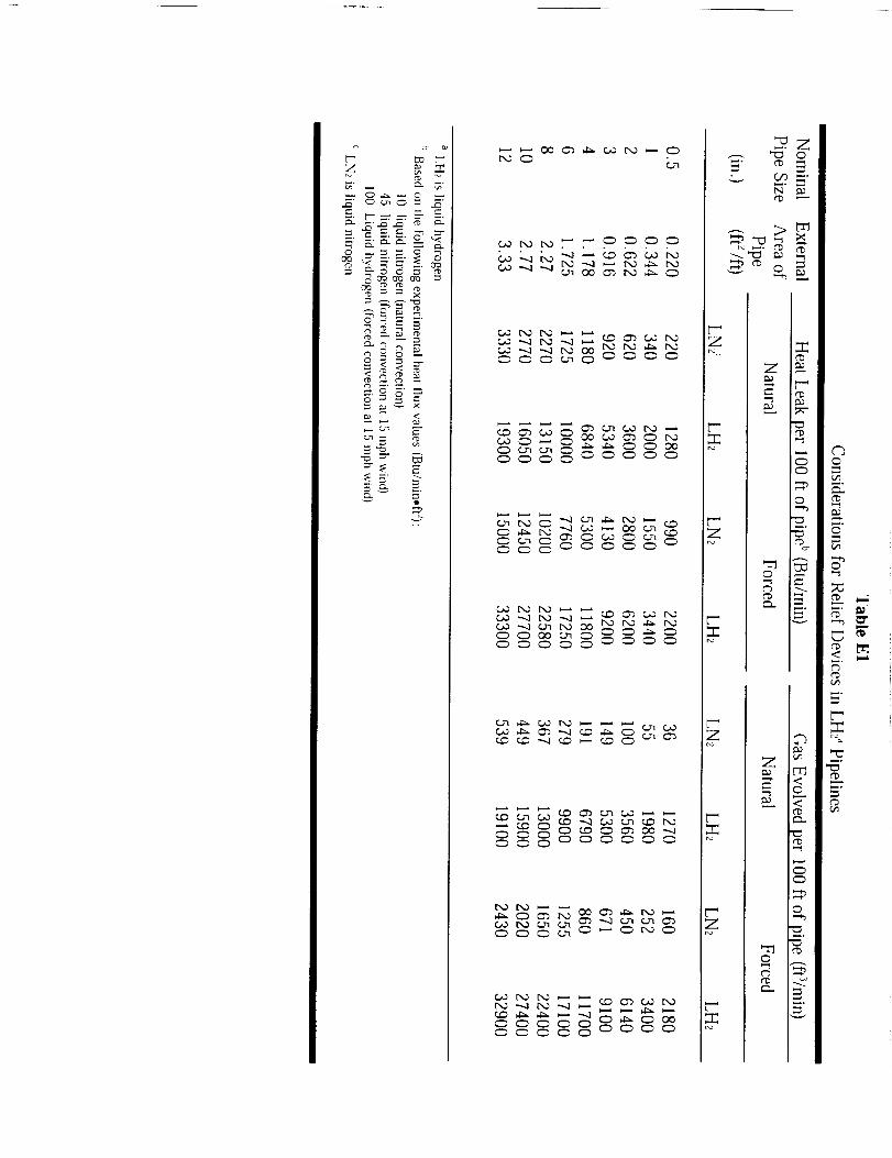
0
_°

C° The properties and characteristics of hydrogen exiting from a relief
device may vary depending on the particular fluid regions of the
liquid, vapor, or gas. The following are recommended solutions for
the various fluid regions:
(1) Region I: subcooled liquid
Isentropic expansion reaches the liquid line before
establishing equality at sonic velocity in Region I.
equation E1 in the following form:
Solve
V12sat = (h0 - hs)2gJ (Eq. E4)
and solve equation E2 using the saturation velocity Vsat and
the liquid saturation density.
(2) Region II: superheated fluid
Isentropic expansion establishes equality before the fluid
reaches either saturated fluid line in Region II. The ideal
throat velocity is sonic velocity at the solution point. Use the
related density to solve equation E2.
(3) Region III: supersaturated gas
The fluid is a supersaturated gas if the isentropic expansion
reaches the saturated vapor line on the temperature-entropy
diagram before equality is established; insufficient time is
available and too few nuclei are present for condensation. Its
properties are determined in the following fashion:
(a) Evaluate at the saturation pressure Psat, 4/3 x Psat,
and 5/3 x Psat for all physical properties, and generate
equations of the following form for each property:
X= Co + C,P+ C2P2 (Eq. E5)
(b) Continue the expansion, assuming entropy is constant,
until equation E1 is solved by using the extrapolated
values of enthalpy and sonic velocity generated by the
polynomials.
(c) Evaluate equation E2 by using the extrapolated values
of density and sonic velocity.
E-7

d.
(4) Region IV: saturated vapor
Use the method of Region III except start at Psat and evaluate
the properties at constant entropy upward for 4/3 x Psat and
5/3 x Psat for the common cause in cryogenic systems of a
relief device relieving a saturated vapor (Region IV). Again,
extrapolate and solve equation El. A series of solutions of
this type can be correlated against saturation pressure in the
manner of Napier's formula for steam. The following
formulas may be used for initial saturation pressures ranging
from 207 kPa (30 psia) to two-thirds of the critical pressure:
Oxygen
Nitrogen
Hydrogen
W = 0.0410(AP)
W = 0.0422(AP)
W = 0.0231(AP)
where:
W = flow rate, lb/s
A = area, in. 2
P = pressure, psia
Extending these equations to higher pressures is not
recommended because the saturation enthalpy is not constant
and the true solution deviates too far from the average valueshown.
Relieving pressures. The recommended principles are listed asfollows:
(1) Single Device.
(a) Set pressure # design pressure (DP)
(b) Maximum relieving pressure # 1.2 DP
(2) Supplementary Device.
(a) Set pressure not specified
(b) Maximum relieving pressure # 1.33 DP and £ test
pressure
E-8

(3/ Thermal Device.
(a) Set pressure # 1.25 DP
(b) Maximum relieving pressure # test pressure
E-9
E.3 REFERENCES
ANSI/ASME B31.1. Power Piping. National Standard Code for Pressure Piping
American Society of Mechanical Engineers, New York, NY (1995).
ANSI/ASME B31.3. Process Piping. American Society of Mechanical Engineers,New York, NY (1996).
ASME. ASME Boiler and Pressure Vessel Code, Section VIII, Rules for
Construction of Pressure Vessels, Division I. American Society of
Mechanical Engineers, New York, NY (1995).
CFR Title 29. Occupational Health and Safety Standards. Code of Federal
Regulations. Part 1910, Sects. 38(e), 103(h), 106(h), 119(h), 120(h),
1320), 1330). 134(8), 146(j), 156(1), 165(1), 1027(z), (latest revision).
E-10

APPENDIX F
ABBREVIATIONS AND ACRONYMS
AHJ
AISI
ANSI
API
ASME
ASTM
BPVC
CBrF:_
CCD
CFR
CF
CGA
CH3Br
CM
CO2
DI
DoD
DOT
fCC
GH_
GN2
GOX
H20
HCFC
He
ICS
IEEE
IMS
IPA
IR
JSC
KHB
KSC
Authority Having JurisdictionAmerican Iron and Steel Institute
American National Standards Institute
American Petroleum Institute
American Society of Mechanical Engineers
American Society for Testing and Materials
Boiler and Pressure Vessel Code (ASME)
Bromotrifluoromethane
Charge Coupled Device
Code of Federal Regulations
Cubic Feet @ 101.3 kPa (14.7 psia), 294.1 K (70 °F)
Compressed Gas Association
Bromomethane
Cubic Meters @ 101.3 kPa (14.7 psia), 294.1 K (70 °F)Carbon Dioxide
Deionized
Department of Defense
Department of Transportation
Face-Centered Cubic
Gaseous Hydrogen
Gaseous Nitrogen
Gaseous Oxygen
Water
HydrochlorofluorocarbonsHelium
Incident Command System
Institute of Electrical and Electronic Engineering
Incident Management Statement
Isopropyl AlcoholInfrared
Johnson Space Center
Kennedy Handbook
Kennedy Space Center
F-1

LeRC
LFL
LH_
LN2
LNG
LOX
MAWP
MSDS
MSFC
NASA
N2
NBP
NBS
NBT
NFPA
NHB
NHS
NIST
NMI
NSS
NTP
QD
SI
SLH2
SOW
SSC
STD
STP
TLV
TM
TNT
UFL
UV
VIS
WSTF
Lewis Research Center
Lower Flammability Limit
Liquefied Hydrogen
Liquefied Nitrogen
Liquefied Natural Gas
Liquid Oxygen
Maximum Allowable Working Pressure
Material Safety Data Sheet
Marshall Space Flight Center
National Aeronautics and Space Administration
Nitrogen
Normal Boiling PointNational Bureau of Standards
Normal Boiling Temperature
National Fire Protection AgencyNASA Handbook
NASA Hazard Standard
National Institute of Standards and Technology
NASA Management Instruction
NASA Safety Standard
Normal Temperature and Pressure, 101.3 kPa (14.7 psia); 293
K (68 °F)
Quantity Distance
International System of Units
Slush hydrogenStatement of Work
Stennis Space CenterStandard
Standard Temperature and Pressure, 101.3 kPa (14.7 psia);
273 K (32 °F)
Threshhold Limit Value
Technical Manual
Trinitrotoluene
Upper Flammability LimitUltraviolet
Visible
White Sands Test Facility
F-2

APPENDIX G
GLOSSARY
ACCEPTANCE TEST. A standard test that leads to certification of a component or
system.
ATTENDANT. An individual stationed outside one or more permit-required
confined spaces who monitors the authorized entrants and who performs all
attendant's duties assigned in the employer's permit-required confined space
program. Authorized entrant means all employee who is authorized by the employer
to enter a permit-required confined space.
AUTOIGNITION. The phenomenon in which a mixture of gases, vapors, mists,
dusts, or sprays ignites spontaneously with no external ignition source. It is
frequently called autogenous ignition or spontaneous ignition.
AUTOIGNITION TEMPERATURE. The lowest temperature at which a material
will spontaneously ignite. No additional ignition energy (ignition source) is
required.
BLAST WAVE. Pressure pulse following a shock wave. It is due to velocity,
imparted by the shock wave, to the medium particles.
BLEVE. _oiling Liquid Expanding Vapor Explosion) Liquefied gases usually (or
almost always) are stored in containers at a pressure above that of the local
atmosphere and, therefore, they are also at a temperature above that of their NBP.
This pressure may be less than 6.9 kPa (1 psi) for some cryogenic gas containers.
The sensible heat which is, in effect, "stored" in the liquid, causes very rapid
vaporization of a portion of the liquid that rapidly increases with an increase in the
temperature difference between that of the liquid at the instant of container failure
and the NBP of the liquid if the pressure is reduced to atmospheric, such as through
container failure. This can result in vaporization of a significant quantity of the
liquid in the container. Liquid vaporization is accompanied by a large liquid-to-
vapor expansion. It is this expansion process that provides the energy for
propagation of cracks in the container structure, propulsion of pieces of the
container, rapid mixing of the vapor and air, resulting in atomization of the
remaining cold liquid, and in the case of combustible liquid, in a characteristic
fireball upon ignition by the fire that caused the BLEVE. Also, in the case of a
combustible liquid, many of the atomized droplets burn as they fly through the air.
However, it is not uncommon for the cold liquid to be propelled from the fire zone
too fast for ignition to occur and fall to earth still in liquid form.
BUDDY SYSTEM. A system of organizing employees into work groups in such a
manner that each employee of the work group is designated to be observed by at
least one other employee in the work group. The purpose of the buddy system is to
provide rapid assistance to employees in the event of an emergency.G-1
CERTIFICATION. The process that results in the documented status that qualifies a
vessel or system to operate in the service for which it is intended or qualifies
operating personnel for specific duties. Also refers to the document itself.
COLD TRAP. A surface refrigerated by LN_ to eliminate water vapor, carbon
dioxide, etc. from the gas before it reaches a vacuum pump, and to eliminate
diffusion of oil particles back into the vacuum space.
CRYOGENIC. Conditions at low temperatures, usually at or below 123 K
(-239 °F).
DEFLAGRATION. A flame moving through a flammable mixture in the form of a
subsonic wave (with respect to the unburned mixture).
DETONATION. Exothermic chemical reaction coupled to a shock wave that
propagates through a detonable mixture. The velocity of the shock wave is
supersonic with respect to the unburned gases. After initiation, the thermal energy
of the reaction sustains the shock wave, and the shock wave compresses theunreacted material to sustain the reaction.
DETONATION LIMITS. The upper and lower detonation limits are the maximum
and minimum concentrations of a gas, vapor, mists, sprays or dust in air or oxygen
for stable detonations to occur. The limits are controlled by the size and geometryof the environment as well as the concentration of the fuel. Detonation Limit is
sometimes used as a synonym for Explosive Limit.
DIAPHRAGM. A membrane that can be used as a seal to prevent fluid leakage or
an actuator to transform an applied pressure to linear force.
EXCLUSION AREA. An area in which personnel access, equipment, and activities
are controlled. Access within an exclusion area is limited to essential personnel
whose presence is necessary. Such personnel must meet specific training
requirements. Equipment located within an exclusion area must meet specific
requirements, such as the elimination or control of ignition sources. Activities and
operations within an exclusion area must be carefully planned with the requirements
of safety to personnel and reduction of risk to adjacent facilities.
EXPLOSION. The rapid equilibration of pressure between the system and the
surroundings, such that a shock wave is produced. Explosions may occur through
mechanical failure of vessels containing high pressure fluids or through rapid
chemical reactions producing large volumes of hot gases.
EXPLOSIVE YIELD. Energy released in an explosion. It is often expressed as a
percent or fraction of the energy that would be released by the same mass of a
standard high explosive such as TNT.
G-2

FAILURE MODE AND EFFECTSANALYSIS (FMEA). A systematic,methodicalanalysisperformedto identify anddocumentall identifiablefailuremodesat a prescribedlevelandto specifytheresultanteffectof themodesoffailure.
FLAME VELOCITY or FLAME SPEED. Refersto thevelocity of propagationofthe reactionzonethroughtheflammablemixture,asmeasuredby a stationaryobserver. Usuallymeasuredat thefront of theflame.
FLAMMABILITY LIMITS. Thelower (LFL) andupper (UFL) vaporconcentrations(usuallyreportedaspercentby volume)of fuel in a flammablemixture that will igniteandpropagatea flame. Theselimits are functionsoftemperature,pressure,diluents,andignition energy.
FLAMMABLE. A flammablematerialis easilyignited in air, oxygen,or othersupportingatmosphere.
FLAMMABLE LIQUID. Liquid with a flashpoint temperaturebelow 300K(80 °F) asdeterminedby ASTM standard methods (D56 flash point by TAG closed
tester or D92 flash point by Cleveland open cup).
FLASH POINT. The lowest temperature at which a flammable liquid gives off
sufficient vapor to form an ignitable mixture with air near its surface or within avessel. Combustion does not continue.
GAS. A gas is defined in this handbook as a substance that cannot be liquefied by
applied pressure at a temperature of 273 K (32 °F).
GASEOUS HYDROGEN (GH2) SYSTEM. An assembly of components to which
hydrogen is delivered, stored, and used in the gaseous form. The system may
include storage vessels, piping, valves, relief devices, pumps, vacuum system,
expansion joints, and gages. The nature of the working fluid (GH2) and operating
parameters, create hazards to people and the surrounding environment. A GH2
system as defined in 29 CFR 1910.103 and NFPA 50A is limited to the bulk storage
vessel (and ancillary components) from the point of the fill connection to the point
where GHe enters the distribution piping.
HAZARD. Existing or potential condition that can result in or contribute to a
mishap.
HYDROSTATIC TEST. A test performed on a pressure vessel or system in which
the vessel or system is filled with a liquid (usually water) and pressurized to a
designated level in a manner prescribed in the applicable code.
G-3

INTRALINE SEPARATION. Theminimumdistanceto bemaintainedbetweenoperatingbuildingsandsiteswithin anoperatingline, of which at leastonecontains,or is designedto contain, propellants or explosives. This distance may be reduced if
equivalent protection to personnel and property is provided by building design andconstruction or a barricade. This distance shall be determined based on the
maximum explosives weight.
INTRINSICALLY SAFE INSTALLATION. An installation in which any spark or
thermal effect, produced normally or in specified fault conditions, is incapable,
under test conditions prescribed in NFPA 493, of causing ignition of a mixture of
flammable material in air in its most easily ignited concentration.
LIQUID HYDROGEN (LH2) SYSTEM. An assembly of components to which
hydrogen is delivered, stored, and used in the liquid and/or gaseous form. The
system may include storage vessels, piping, valves, relief devices, pumps, vacuum
system, expansion joints, and gages. The nature of the working fluid (LH_ and
GH_) and operating parameters, create hazards to people and the surrounding
environment. An LH2 system as defined in NFPA 50B is limited to the bulk storage
vessel (and ancillary components) from the point of the fill connection to the point
where LH_ and/or GH_ enters the distribution piping.
MAXIMUM ALLOWABLE WORKING PRESSURE (MAWP). The maximum
pressure permissible at the top of a vessel in its normal operating position at the
coincident operating temperature. It is the least of the values found based on
calculations for every element of the vessel.
OVERPRESSURE. The pressure in a blast wave above atmospheric pressure.
PERMIT-REQUIRED CONFINED SPACE. A confined space is not normally
occupied by personnel, it has limited or restricted openings for entry and exit, may
lack adequate ventilation, may contain or produce dangerous air contamination, and
may not be safe for entry.
PNEUMATIC OR PNEUMOSTATIC TEST. A test performed on a pressure vessel
or system in which air or gas is introduced and pressurized to a designated level in a
manner prescribed in the applicable code. Pneumatic tests are potentially hazardous
and all personnel shall be excluded from the hazard zone. Pneumatic tests shall be
made following an approved written test procedure.
PORTABLE TANK/CONTAINER. Any tank or container as defined by the U.S.
Department of Transportation designed primarily to be temporarily attached to a
motor vehicle, other vehicle, railroad car other than tank car, or marine vessel, and
equipped with skids, mountings or accessories to facilitate handling of the container
by mechanical means, in which any compressed gas is to be transported.
G-4

PRESSUREVESSEL. Any vesselusedfor thestorageor handlingof gasor liquidunderpositivepressure. Componentsof systemsare included,suchas,heatexchangershellsanddrying towers and other shell structures for which the rules of
the ASME BPVC, Section VIII would apply.
PROOF TEST. A pressure test performed to establish or verify the maximum
allowable working pressure of a vessel, system, or component thereof. May also be
used (1) when the strength cannot be computed with a satisfactory assurance of
accuracy, (2) when the thickness cannot be determined by means of the design rule
of the applicable code or standard, or (3) when the critical flaw size to cause failure
at the certified pressure cannot be identified by other nondestructive test methods.
QUENCHING DISTANCE. The gap dimension required to prevent the propagation
of an open flame through a flammable fuel-air mixture.
QUENCHING GAP. The quenching gap is defined as the spark gap between two
flat parallel-plate electrodes at which ignition of combustible fuel-air mixtures is
suppressed; smaller gaps totally suppress spark ignition. The quenching gap is the
passage gap dimension requirement to prevent propagation of an open flame through
a flammable fuel-air mixture that fills the passage.
RECERTIFICATION. The procedure by which a previously certified vessel or
system, by appropriate tests, inspections, examinations, and documentation, is
qualified to continue or be returned to operations at the design pressure.
RUPTURE DISK. A nonreclosing pressure-relief device designed to remain open
after operation. A manual resetting means may be provided.
SAFETY FACTOR. The ratio, allowed for in design, between the point of failure
of a member, material, structure, equipment or system, and the actual working
stress or safe permissible load placed on it during ordinary use.
SET PRESSURE. The pressure marked on a safety relief valve at which the
pressure relief valve is set to start to discharge.
SHOCK. A violent collision or impact and the subsequent transmission of energy
through the system. The energy moves as a wave at velocities greater than the speedof sound relative to the undisturbed material.
STORAGE CONTAINER. Any container designed to be permanently mounted on a
stationary foundation and is used to store any compressed gas.
SURFACE FINISH (RMS). The degree of surface roughness as measured by the
average deviation from the mean (root-mean-square value) of the maximum peak-to-
valley height. The roughness values are commonly given in units of micro-inches
(millionths of an inch).
G-5

TANK. Any vesselusedfor the storageor handlingof liquids for which the internalpressureis only a functionof the liquid head or a combination of liquid head and
vapor pressure.
G-6

REFERENCES
ASME B31.3. Process Piping. American Society of Mechanical Engineers, New York, NY
(1996).
Barnes, H.L. Private communication, NASA Stennis Space Center (1995).
Benz, F. J., C. V. Bishop, and M. D. Pedley. "Ignition and Thermal Hazards of Selected
Aerospace Fluids: Overview, Data, and Procedures." NASA White Sands Test
Facility, Las Cruces, NM (1988).
Brown, W. F., Jr., H. Mindlin, and C. Y. Ho, Editors. "Aerospace Structural Metals
Handbook." CINDAS/USAF CRDA Handbooks Operation, Purdue University,
West Lafayette, IN (1996).
Brzustowski, T. A., S R. Gollahalli, and H. F. Sullivan, "The Turbulent Hydrogen Diffusion
Flame in a Cross-Wind," Comb. Sci. Tech., 11(1-2), (1975).
Chandler, W. T. and R. J. Walter, "Testing to Determine the Effect of High Pressure
Hydrogen Environments on the Mechanical Properties of Metals," in Hydrogen
Embrittlement Testing, ASTM 543, American Society for Testing and Materials,
Philadelphia, PA (1974): pp. 170-197.
Chandler, W. T., and R. J. Walter. "Hydrogen Environment Embrittlement of Metals and Its
Control," Hydrogen Energy, Proceedings of the Hydrogen Miami Energy Conference,
T. H. Veziroglu, Ed., Plenum Press (1975): pp. 1057-1058.
Coley, G. D. and J. E. Field. "Role of Cavities in the Initiation and Growth of Explosions in
Liquids." Proceedings of the Royal Society of London Series A, 335 (1600), (1973):
pp. 67-86.
Coward, H. F. and G. W. Jones. "Limits of Flammability of Gases and Vapors." Bureau of
Mines Bulletin 503, N70-74476; AD-701575 (1952).
Creitz, E. C. "Inhibition of Diffusion Flames by Methyl Bromide and Trifluoromethyl-
Bromide Applied to the Fuel and Oxygen Sides of the Reaction Zone." .Journal of
Research for Applied Physics and Chernisuy, 65A (1961): pp. 389°396.
DoD 6055.9. "Ammunition and Explosives Safety Standards." Department of Defense,
(1992).
Durham, T. F., R. M. McClintock, and R. P. Reed. "Cyrogenic Materials Data Handbook."
Office of Technical Services. Washington, DC (1962).
A-II3

GrayH. R., "Testingfor HydrogenEnvironmentEmbrittlement:ExperimentalVariables,"Hydrogen Embrittlement Testing, American Society for Testing and Materials, Special
Technical Publication, ASTM STP-543, Philadelphia, PA (1974): pp. 133-151
Groenvald, T. D. and A. D. Elcea. "Hydrogen Stress Cracking in Natural Gas Transmission
Pipelines," Hydrogen in Metals, I. M. Bernstein and A. W. Thompson, Eds., ASM
(1974).
Grumer, J., A Strasser, J. M. Singer, P. M. Gussey, and V. R. Rowe. "Hydrogen Flare
Stack Diffusion Flames: Low and High Flow Instabilities, Burning Rates, Dilution
Limits, Temperatures, and Wind Effects," BM-RI-7457, Bureau of Mines Report of
Investigation (1970).
Hunler, G. W. "A Survey and Analysis of Commercially Available Hydrogen Sensors,"
NASA TM-105878, 1992.
Hoover, W. R., et. al. Hydrogen Compatibility of Structural Materials for Energy Storage
and Transmission Applications. Sandia National Laboratories, SAND80-8202,
Livermore, CA February (1980).
Jones, G. W. and G. St. J. Perrott. "Oxygen Required for the Propagation of Hydrogen,
Carbon Monoxide, and Methane Flames". Ind. Eng. Chem., 19 (9), (1927):
pp. 985-989.
Johnson, V. J., Ed. "A Compendium of the Properties of Materials at Low Temperature
(Phase I)," WADD Technical Report 60-56, Part II, Properties of Solids, Office of
Technical Services, United States Department of Commerce, Washington, DC
(1960).
Kent, G. R. "Find Radiation Effects of Flares," Hydrocarbon Processing. 47 (6), (1968):
pp. 119-130.
Lee, J. H., R. Kynstantus, C. M. Guirao, W. A. Benedick, and J. E. Shepherd. "Hydrogen-
Air Detonations." Proceedings of the 2 _a International Workshop on the Impact of
Hydrogen on Water Reactor Safety. M. Berman, Ed., SAND82-2456, Sandia
National Laboratories, Albuquerque, NM, October (1982).
Liebenberg, D. H., J. K. Novak, and F. J. Edeskuty. "Cooldown of Cryogenic Transfer
Systems." AIAA 3 "dPropulsion Joint Specialist Conference, AIAA Paper No. 67-
475, Washington, DC, July 17-21 (1967).
A. D. Little, Inc., "An Investigation of Hazards Associated with tile Storage and Handling of
Liquid Hydrogen," AD 324/94, A. D. Little, Inc., Cambridge, MA, March (1960).
LNG Materials and Fluids: A User's Manual of Property Data in Graphic Format, D. Mann,
Ed., National Bureau of Standards, Boulder, CO (1977).
A-114

McCarty, R. D., J. Hord, andH. M. Roder. Selected Properties of Hydrogen (Engineering
Design Data). NBS Monograph 168, National Bureau of Standards, Boulder, CO
(1981).
McClintock, R. M. and H. P. Gibbons. Mechanical Properties of Structural Materials at Low
Temperatures, A Compilation from the Literature. National Bureau of Standards,
Monograph 13, United States Department of Commerce, Washington, DC (1960).
McHale, E. T., R. W. Geary, G. von Elbe, and C. Huggett. "Flammability Limits of GH2-
GO2-Fluorocarbon Mixtures." Combustion and Flame, 16 (2), (1971): pp. 167-175.
Mellish, C. E. and J. W. Linnett. "Tile Influence of Inert Gases on Some Flame
Phenomena." 4 'h Symposium (International) Combustion, Baltimore, MD (1953)
pp. 407-420.
NFPA 50. "Bulk Oxygen Systems at Consumer Sites." National Fire Protection Association,
Inc., Quincy, MA (1990).
NFPA 51. "Design and Installation of Oxygen-Fuel Gas Systems for Welding, Cutting, and
Allied Processes." National Fire Protection Association, Inc., Quincy, MA (1992).
Novak, J. K. "Cooldown Flow Rate Limits Imposed by Thermal Stresses in Liquid Hydrogen
or Nitrogen Pipelines." Advances in Cryogenic Engineering, Vol. 15, K. D.
Timmerhaus, Ed., Plenum Press, New York, (1970)" pp. 346-353.
NSS 1740.12. "NASA Safety Standard for Explosives, Propellants, and Pyrotechnics."
National Aeronautics and Space Administration, Washington, DC (1993).
Ordin, P. M. "A Review of Hydrogen Accidents and Incidents in NASA Operations," In 9"
Intersociety Energy Conversion Engineering Conference, New York, ASME, 1974.
Ordin, P. M., and R. C. Carter, "Clinch River Breeder Reactor Hydrogen Disposal and
Ignition System," ARSD-00093, General Electric, June (1980).
Payman, W. and H. Titman. "Limits of Inflammability of Hydrogen and Deuterium in
Oxygen and Air." Nature, 137 (1936): pp. 160-168.
Peterson, P. "Explosions in Flare Stacks," Chem. Eng. Prog., 63(8), August (1967): pp. 67-
70.
"Properties of Teflon ® at Cryogenic Temperatures," E. I. du Pont de Nemours and Co.,
Wilmington, DE (1976).
Reed, R. P., R. E. Schramm, and A. F. Clark. "Mechanical, Thermal, and Electrical
Properties of Selected Polymers," Cryogenics. February (1973)" pp. 67-82.
A-115
Robinson,S. L. "Hydrogen Compatibility of Structural Materials for Energy Storage and
Transmission Applications." Sandia National Laboratories, SAND77-8240, June
(1977).
Rosen, B., V. H. Dayan, and R. L. Proffitt. "Hydrogen Leak and Fire Detection - A
Survey." NASA SP-5092, Washington, DC (1970).
Siegel, R. and J. R. Howell. "Thermal Radiation Heat Transfer. Vol 3: Radiation Transfer with
Absorbing, Emitting, and Scattering Media." NASA SP-164: Vol. 3 (1971).
Schwartzberg, F. R., S. H. Osgood, and R. G. Herzog. "Cryogenic Materials Data
Handbook." Air Force Materials Laboratory, AFML-TDR-64-280, Supplement 4,
Vol. II. Wright-Patterson AFB, OH, August, 1968.
Stuhrke, W. F., and J. L. Carpenter. "Fracture Toughness and Testing Data - A Technology
Survey." NASA-CR-134752, January, 1975.
Wigley, D. A. and P. Halford. "Materials of Construction and Techniques of Fabrication."
Cyrogenic Fundamentals, G. G. Haselden, Ed., Chapter 6, Academic Press, London
(1971).
Williams, G. P. "Causes of Ammonia Plant Shutdowns." Chemical Engineering Frog., 74
(9), (1978).
Zalosh, R. G. and T. P. Short. "Comparative Analysis of Hydrogen Fires and Explosion
Incidents." C00-4442-2, Factory Mutual Research Corp., Norwood, MA (1978).
Zalosh, R. G. and T. P. Short. "Compilation and Analysis of Hydrogen Accident Reports."
C00-4442-4, Factory Mutual Research Corp., Norwood, MA (1978).
Zebetakis, M. G. and D. S. Burgess. "Research on the Hazards Associated With the
Production and Handling of Liquid Hydrogen." BM-RI-5707, Bureau of Mines
Report of Investigation, Washington, DC (1961).
A-116
APPENDIX H
INDEX
AAcceptance test, 5-10
Access control, 4-23
Accident investigation, 7-1Accidents, 1-4, 2-3, 2-6, 2-10, 4-21, 9-7
Aerospace, 1-2, 1-3, 2-10, 3-3, 5-9,5-10, 10-2, 10-4, 10-6
Aerospace pressure vessels, 5-9
Aging, SLH2, 2-26, 5-9Annual review, 1-5, 10-4
Asbestos, 3-5, 9-2
Asphalt, 4-8Attendant, 7-2, 8-6, 9-12
Autoigintion
temperature, 2-14
Autoignition, 2-14
BBarges, 7-10Barricades, 2-5, 4-25, 4-26, 4-27, 4-28
Barriers, 1-5, 4-29, 5-3, 5-11
Blast wave, 2-8, 2-18, 4-27
BLEVE, 2-4
Boiling point, 2-2, 2-24, 5-38
Bonding, 4-7, 4-10, 5-12, 5-16
Breathing Air, 2-21
Buddy system, 5-5, 7-1
Buildings, 4- I I, 4-12
CCell
test, 4-12, 4-16, 4-24, 4-25
Certification, 1-4, 1-5, 1-7, 4-3, 4-4, 4-5,
4-32, 8-6CHEMTREC, 8-3, 8-7
Class C, 4-20, 4-21
Cleaning, 5-36, 5-37, 7-2, 7-3, 7-4, 7-5,7-7, 8-6
Clothing, 7-6Codes, 5-11
Cold trap, 5-39, 7-5Collision, 1-6, 2-9
Combustion, 2-2, 2-6, 2-9, 2-12, 2-15,
2-20, 2-23, 4-10, 4-17, 4-29, 5-34,
5-35, 6-4, 6-6, 10-2, 10-4, I0-7
Compatibility, 1-1, 3-2, 3-6, 3-8, 4-20,6-2, 7-4, 10-7
Components, 1-1, 2-3, 2-4, 2-25, 3-4,4-2, 4-8, 4-9, 4-11, 4-14, 4-26, 4-32,
4-33, 4-34, 4-37, 4-39, 5-1, 5-10,
5-11, 5-12, 5-13, 5-15, 5-16, 5-23,
5-28, 5-32, 5-36, 5-37, 5-39, 6-7, 7-3,
7-6
connections, 5-16, 5-23, 5-24, 10-3
fittings, 5-16, 5-19
flanges, 5-16, 5-19, 5-20, 5-26
joints, 5-12, 5-16, 5-17, 5-18, 5-19,5-20
Concept design review, 4-3Condensation
air, 2-7, 5-4
Confined Spaces, 5-36, 6-3, 7-2, 8-6,9-11, 9-12
Confinement, 4-27
Connections
transfer, 5-23, 5-24, 10-3
Contamination, 2-24, 4-22, 5-3, 5-7,
5-24, 5-33, 5-36, 5-37, 5-38, 5-39,
7-3, 7-6, 7-13
control, 7-3
Continuous Evaporation, 2-24Contraction
thermal, 3-11, 3-12, 3-13, 5-14, 5-30Control
interconnected systems, 5-37, 5-38Control room
inert gases, 4-17
piping systems, 4-16, 10-1, 10-3structure, 4-16
ventilation, 4-14, 4-15, 4-16, 9-3
Control rooms, 4-16
Critical design review, 4-3Cool down, 5-13, 7-11, 7-12
Cryogenics, 1-6, 3-1, 3-2, 3-4, 3-11,3-12, 3-13, 4-31, 4-35, 4-38, 5-1, 5-6,
5-13, 5-14, 5-19, 5-22, 5-23, 5-27,
6-4, 6-5, 7-2, 7-4, 7-6, 7-7, 7-11, 7-
12, 8-1, 8-4, 9-3, 9-10, 9-11, 10-7
H-1

DDecontamination, 7-6, 7-7
Deflagration, 2-4, 2-15, 2-16, 2-17, 2-20.4-29, 5-36
venting, 5-36
Deluge systems. 4-29, 4-31, 8-5
Density, 2-21, 2-25, 7-13
Design
specification, 5-20
Design certification review, 4-3
Detection. 2-21, 4-35, 4-36, 6-1, 6-2,
6-4, 6-6.6-7
fire, 1-7.4-29, 4-36, 6-1, 6-6, 6-7.6-
8, 10-7
hydrogen, 4-17, 4-35, 6-1, 6-2, 6-4
specifications. GH2, 6-2
technologies, 6-4, 6-7Detonation, 2-3. 2-4, 2-15, 2-16, 2-17,
2-18.2-19, 2-20, 4-17.4-28, 4-29.
5-35, 5-36
cell size. 2-19
limits, 2-18
pressure, 2-17
Diaphragm, 2-5.4-16Diffusion coefficient, 2-23
Diffusion coefficient in NTP air, 2-23
Diluents, 2-13, 2-19
Dispersion, 4-27
Disposal
burning, 5-34flare stacks, 5-34, 6-6
Documentation. 1-4, 4-3, 4-32, 7-1
DOT, 5-2.5-3, 8-1, 9-7
definitions, 8-1
EEffect
mechanical properties, 3-7
temperature, pressure, and diluents,2-19
Electric
charge buildup, 2-26
Electric charge, 2-25, 2-26Electrical
equipment, 4-13, 10-5Electrical considerations, 4-6
Embrittlement, 2-7, 3-6, 3-8, 3-9, 3-11
reaction, 3-7, 3-10
Emergency
fire and police departments, 9-7
plans, 9-1
procedures review, 4-4
response, 8-2, 9-8, 9-11
security, 9-7
site personnel, 9-7
Emergency procedures. 1-1, 1-5, 4-4,4-6, 9-1
alarm system. 9-2
fire suppression, ix, 9-7
gas leaks from cylinders, 9-4
general, 9-1GH2 fires, 9-9
incident command system, 9-2
incident management system, 9-2, 10-5leaks
controllable, 9-4
uncontrollable, 9-4
LH_ fires, 9-9
review, 4-4
NASA specific elements, 9-1
training, 1-4, 1-5, 7-1, 8-2, 9-11
Energy
explosion, 2-20radiated, 2-22
Environmental, 3-6
Evaporation, 2-4, 2-5, 2-6, 2-24, 4-29,5-3, 5-38
Examinations, 4-37
Exclusion area, 4-10, 4-15, 4-23, 9-7
access control, 4-23
placarding, posting, and labeling, 4-24Exhaust, 2-6, 2-10.2-17, 4-10, 4-24, 4-
31, 5-36, 5-41, 6-3
Expansion, 2-2, 2-23, 3-12, 3-13, 5-7,5-10, 5-12, 5-13, 5-14, 5-19, 5-20,
5-21, 5-22, 5-24
Explosion
prevention, 5-36. 10-5
Explosive yields, 2-20
Exposure, 1-6, 2-9, 2-22. 2-23, 3-1, 3-2,3-5, 3-6, 3-7, 3-8, 3-10, 4-18, 4-19,
4-30, 4-31. 5-13, 5-31.6-4, 7-3, 8-7,
9-10, 9-11
protection, 4-30
Eyewash fountain, 9-11
H-2

FFacility
design, 1-1, 4-3, 4-6, 7-7modification or rehabilitation, 4-4
Fail modes, 5-31
Fail-safe design, 1-7
Failure modes and effects analysis, 4-4Filter, 5-6, 5-7, 5-37, 7-5
Fire, 2-4, 4-2, 4-31, 4-36, 6-6, 6-8, 8-6,
9-7, 9-8, 10-1, 10-2, 10-5, 10-6, 10-7
detection, 4-36, 6-6, 10-7
explosions, 2-4
extinguishing systems, 4-29, 4-31, 5-36
protection, 4-2, 4-29, 10-1, 10-5, 10-6
suppression, 4-29, 6-1, 9-8First aid
medical assistance, 9-10
training, 1-4, 1-5, 7-1, 8-2, 9-11
Fittings, 5-16, 5-19Flame
temperatures, 1-6
velocity, 2-21Flame color, 2-22
Flammability, 2-4, 2-10, 2-11, 2-12,2-13, 4-9, 10-2, 10-3, 10-4, 10-7
lower flammability limit, 2-11
diluents, 2-13
halocarbon inhibitors, 2-13
pressure, 2-10, 2-14, 5-13
temperature, 2-10
upper flammability limit, 2-11air, 2-11
diluents, 2-13
halocarbon inhibitors, 2-13
pressure, 2-10, 2-14, 5-13
temperature, 2-10
Flammable liquid, 4-20, 4-28
Flanges, 2-5, 3-3, 4-34, 5-8, 5-10, 5-12,5-18, 5-20, 5-22, 5-23, 5-25, 5-26,
5-27, 5-28, 6-2, 7-12, 7-13
Flare systems, 5-35Flow
controls, 1-6
tests, 5-11
velocities, 2-26, 5-20, 5-21
Fluid quantity measurements, 5-8Forbidden materials, 3-5
Frostbite, 2-3, 2-24
GGaseous hydrogen system
detection, 4-35
piping, 4-22QD
nonpropellant, 4-19
propellant, 4-20
storage, 4-18
venting, 4-15, 4-19Gaskets, 5-25, 5-26
Gloves, 7-7, 9-10
Grounding, 4-7, 4-8, 5-4, 5-12
Grounding/Bonding, 4-7Guard volumes, 5-8
Guidelines, 1-1, 1-2, 1-3, 1-4, 1-5, 1-8,
3-2, 4-1, 4-6, 4-7, 4-12, 4-13, 4-18, 4-
20, 4-21, 4-22, 4-23, 4-24, 4-29, 4-40,
5-1, 5-2, 7-1, 8-4, 8-5
HHalocarbon inhibitors, 2-13
Hazard
analysis, 1-2, 4-4
chemical, 1-4, 2-2, 7-1
class, 8-1
communication program, 1-5condensation, 2-7
group, 4-20
Group III, 4-20, 4-21health, 2-2
physical, 1-4, 7-1
physiological, 2-8
Helium, solubility, 2-6, 2-13, 2-26, 2-27,3-7, 4-13, 5-6, 5-8, 5-22, 5-34, 5-35,
5-38, 5-40, 6-4, 7-6, 7-8, 7-9
High density, 2-25Hoses, flexible, 5-20, 5-24, 7-5
Hydrogenair mixture, 2-11
density, 2-21detection, 4-35
detector installations, 6-5
dispersion, 2-5environmental, 3-6
fire detector installations, 6-8
handling, training, 1-4internal, 3-6, 4-10LH2
spills, 2-9, 2-21, 9-5, 9-6transfer, 7-3, 7-8
H-3

normal,2-1,2-2,2-27properties,2-2solid, 1-3
IIce. 2-24
Ignition. 2-4, 2-5, 2-7. 2-14.2-15, 2-19,
4-9, 4-29. 5-3. 10-2, 10-6
hot objects, flames, 2-17sources, 2-15.4-9
Illumination, 4-11
Impounding areas, 4-28
Incident command system, 9-2
Incident management system, 9-2, 10-5
Industrial and aerospace accidents, 2-3
Inspection, 4-37
Installation pressure systems manager, 4-1
Instrunlentation, 4-34, 4-35, 5-8, 5-9Insulation
failure, 5-14, 5-15, 5-32
Interface
safe, 1-6
Intraline separation, 4-22Isolation valve, 4-5, 4-16, 8-4
JJoints
bimetallic, 5-19
expansion, 5-13, 5-14, 5-20, 5-21, 5-22
mitered, 5-18
silver braze, 5-18
soft solder, 5-19
threaded, 5-18
welded, 5-17
LLabeling, 4-24, 4-32, 4-33Leaks, 2-4, 2-5, 2-6, 2-7, 2-10, 2-25,
2-26, 2-27, 4-8, 4-16, 4-17, 4-26,
4-35, 4-39, 5-4, 5-6, 5-7, 5-13, 5-22,
5-26, 5-32, 5-35, 5-41, 6-1, 6-2, 6-3,
6-4, 6-5, 7-2, 7-8, 7-10, 8-5, 9-3, 9-4,
10-7
controllable, 9-4
uncontrollable, 9-4
Liquid hydrogen systemconfinement, 4-27
QD
H-4
nonpropellant, 4-19
propellant, 4-20
Loading operations, 7-10Loads
earthquake, 5-10, 5-12
operating pressure, 4-38, 5-22, 5-23,5-25, 5-29
shock, 2-11, 2-18.2-19.4-13, 5-10,
5-12. 7-5
vibration, 5-10, 5-12, 5-26
weight. 2-9.2-23, 4-21.4-38, 5-7,5-10, 5-12, 5-13, 5-40, 5-41, 7-5.7-13
wind, 2-5, 4-30, 5-10, 5-12, 5-33, 6-3,8-6
Location
piping and other hydrogen systems,4-22
QDGH_, 4-18
LH2, 4-19, 4-20SLH_. 4-22
MMaterials
clad, 3-4
class, 4-20, 4-21
control, 3-5
forbidden, 3-5
gasket, 3-4
general, 3-2metallic, 3-2
nonmetallic, 3-3
properties, 3-4selection, 3-1, 3-10
welds, 3-4, 5-17
Mechanical properties
low temperatures, 2-7, 3-5, 3-6, 3-7,3-9, 3-10, 5-4
Minimum quantities, 1-3
Minimum spark energy, 2-14
Mishap reporting, 1-8, 10-6
Mobile storage, 5-2, 5-3, 5-5
Monitoring, 4-36
NNonpropellant, 1-1, 1-2, 1-4, 4-18, 4-19,
5-3, 5-4
Nonpropellant use, 1-2, 4-19

OOperating procedures, 1-7, 4-5, 7-1, 7-2,
8-5, 10-3
general, 8-5
modifications, repairs, or
decommissioning, 7-2
personnel, 1-4, 1-5, 2-8, 4-9, 4-23,
4-24, 4-25, 4-39, 7-1, 7-2, 7-7, 8-2,
9-4, 9-5, 9-7, 9-11, 9-12
repairs, alterations, and cleaning, 7-2
special, 7-2standard, 7-1
Operational readiness review, 4-4
Operations
loading, 7-10
Operator certification, 1-5
Organic cleaning solvent, 7-4Other facilities, 14
Overpressure, 5-28, 5-33
depletion, 9-11index, 2-23
PPackaging, 8-1, 8-3Personnel, 1-4, 1-5, 2-8, 4-9, 4-23, 4-24,
4-25, 4-39, 7-1, 7-2, 7-7, 8-2, 9-4, 9-
5, 9-7, 9-11, 9-12
training, 1-4
Physiological, 2-8
Piping, 4-32, 5-1, 5-10
bending and forming, 5-15GH2, 5-13
LH2 and SLH2, 5-13
supports, 5-14
systems, 5-10transfer, 4-8
Pneumatic test, 4-38
Police department, 8-7, 9-7Portable
containers, 1-2, 4-24
tanks, 8-2
Posting, 4-24
Preliminary design review, 4-3Pressure
rise, 2-24, 5-4, 5-14, 7-9, 8-7
supplemental relief, 5-31vessel, 1-2, 1-3, 3-5, 4-1, 4-26, 4-32,
4-38, 4-39, 4-40, 5-1, 5-9, 5-10,
5-12, 8-2
Procedures
cleaning, 7-4cool down, 5-13, 7-11, 7-12
operating, 2-3, 7-1, 7-2
purging, 2-6, 5-3, 7-3, 7-8
storage, 7-7transfer, 7-7
Propellant use, 1-2, 4-20
Propellants, 1-1, 1-2, 1-3, 1-4, 4-17,4-18, 4-20, 4-21, 4-22, 4-24, 4-25,
5-3, 5-4
ProperliesGH_, 2-21
density, 2-21diffusion, 2-23
Joule-Thomson expansion, 2-23
oxygen index, 2-23ice, 2-24
LH2, 2-24
density, 2-25
electric charge, 2-25
evaporation, 2-24SLH_, 2-25
aging, 2-26
electric charge, 2-26thermal acoustic oscillations, 2-26,
5-9
thermal stratification, 2-26
vapor pressure, 2-25
volume change, 2-26
Protection, 4-2, 4-26, 4-27, 4-30, 5-37,
10-1, 10-5, 10-6
fire, 4-2, 10-1, 10-5, 10-6
Protective clothing, 7-6
Pumps, 5-40vacuum, 5-8, 5-39, 5-40
Purging, 2-6, 5-3, 7-3, 7-8
QQuality control, 3-5Quantities, minimum, 4-18
Quantity-distance (QD)
guidelines, 4-17
Compatibility groups, 4-21criteria, 4-18
explosive equivalent, 4-21GH2, 4-18
LH2
nonpropellant, 4-19
propellant, 4-20other, 4-22
H-5

piping,4-22SLH2,4-22
Quenchingdistance,2-14,2-15,4-11Quenchinggap,2-14
RRadiation, energy, 2-9, 2-22, 2-23, 2-25,
4-17, 4-30, 4-31, 5-4, 5-9, 5-34, 5-35,
6-7, 6-8
Recertification. 4-37
Records, 4-39
Redundancy, 1-6
Redundant Safety. 1-7Relief valves. 4-25, 4-32, 5-6, 5-8, 5-23,
5-28, 5-29.5-30.5-31, 5-32, 5-33, 5-
37, 5-38, 7-10.9-4
Reporting, mishap, 1-8, 10-6
Retroactivity, 1-4
Roadways, 4-8
Rupture discs, 5-30
SSafe interface, 1-6
Safetyassessment review, 4-5
communication, 7-1
factor, 3-5, 4-3, 5-16
features, 1-6
redundant, 1-7
reviews, 1-7, 4-2
systems, 1-6Schedule, 4-40
Security, 9-2, 9-8
Set pressure, 5-28, 5-29, 5-31
Shields and impoundment areas, 4-28
Shipping, 8-1, 8-2Shock, 2-11, 2-18, 2-19, 4-13, 5-10,
5-12, 7-5
Shoes, 7-7, 9-10
Shutoff valves, 3-3, 5-2, 5-3, 5-23, 5-27,5-37
Site personnel. 9-7Slush, 2-1
Solubility, helium, 2-27
Spark generation, 4-9
Spills, LH2, 2-9, 2-21, 9-5, 9-6Standard, 2-21, 3-3, 4-22, 5-17, 5-19,
5-20, 5-22, 7-1, 8-4
Storage
components, 4-32, 5-1
fixed and mobile
GH2, 5-2
LH2, 5-3
SLH_, 5-5
LH2 liquid propellant, 4-18
nonpropellant use, 4-18tanks, 5-22
transfer procedures, 7-7vessels, 2-6
Stratified flow, 5-14, 7-12, 7-13
Supports, 5-10, 5-12Surface
film, 3-8
System safety analysis/safety review, 4-2
System/subsystem hazards analyses, 4-4
Systemsinterconnected, 5-37
vacuum, 5-39
vent, 5-32
TTagging, 4-32, 4-33
Temperature, 2-14, 2-19, 2-22, 3-10,3-11, 5-1, 10-4
air, 2-22
Test chamber, test cell, or test stand, 4-12
Test readiness review, 4-4
Test/Testing, 1-3, 1-8, 3-1, 3-5, 3-6,3-11, 4-3, 4-8, 4-9, 4-11, 4-12, 4-13,
4-16, 4-17, 4-23, 4-24, 4-25, 4-27,
4-33, 4-37, 4-38, 4-39, 5-5, 5-7, 5-9,
5-10, 5-19, 5-20, 5-22, 5-23, 5-24,
5-31, 7-10, 7-11, 8-6, 9-4, 10-2
system, 5-22
Testing and Recertification, 4-38Thermal
acoustic oscillations, 2-26, 5-9
contraction, 3-12
cycling, 3-10, 5-7, 7-10
expansion, 2-2, 3-12, 3-13, 5-7, 5-10,5-12, 5-13, 5-14, 5-19
radiation, 2-9, 2-22, 2-23, 4-17, 5-35
stratification, 2-26
Toxicity, 3-1Transfer
piping, 4-8
Transport, 2-10, 5-11, 7-10, 8-1, 8-2,8-3, 8-4, 8-5
Transportation, 1-1, 1-6, 2-9, 2-10, 8-1,8-2, 8-4
H-6

DOTdefinitions,8-1emergencies
actions,8-7initial actions,8-7
NASAproperties,8-1design,8-4sitecontrolled,8-4special,8-4standard,8-4
publicthoroughfare,8-1emergencyresponse,8-2,8-3requirementsfor GH28-3requirementsfor LH2,8-3training,1-4,1-5,7-1, 8-2,9-11
Trappingsites,3-8
UUnit conversion, 1-4
Upward flame propagation, 2-11
VVacuum systems, 4-32, 5-13, 5-39Valves, 2-4, 2-5, 2-6, 2-24, 3-4, 4-15,
4-24, 4-34, 5-2, 5-4, 5-5, 5-10, 5-12,
5-23, 5-28, 5-29, 5-30, 5-37, 5-38,
5-39, 6-2
safety, 5-28
Vaporcloud, 9-6
pressure, 2-25travel, 4-28
Vaporization, 1-6, 2-5, 2-7, 2-18, 2-26,4-28, 5-5, 7-12, 9-5, 9-6
Velocityfame, 2-21
flow, 2-26, 5-21
Velocity in NTP air, 2-22Vent stack, 2-4, 2-6, 4-9, 4-20, 4-25,
4-31, 4-32, 5-33, 5-34, 8-6
Vent and exhaust, 2-6
Vent/Venting, 2-6 5-32, 5-33, 5-36, 8-6,10-5
deflagration, 2-20, 5-36Ventilation, 4-14, 4-15.4-16, 9-3
Vessel, 4-32, 5-I, 5-2
aerospace pressure, 5-9
design, 8-4mobile, 5-5, 8-6
support, 5-10, 5-12
Volume change, 2-26
WWaivers, 1-8
Warning systems, 1-6, 5-34
Water spray systems, 4-29, 4-30
Welding, 2-4, 2-10, 3-4, 3-9, 4-10, 4-11,4-20, 4-37, 5-12, 5-16, 5-17, 5-18,
5-24, 6-6, 10-4
H-7