SAFETY INFORMATION
87
i SAFETY INFORMATION All Areas INTERNAL LASER RADIATION Maximum radiation power: 8.8 x 10 -4 (W) Wavelength: 770-810 nm This is a Class IIIb Laser Diode Assy. that has an invisible Laser Beam. The Print Head Unit is NOT A FIELD SERVICE ITEM. Therefore, the Print Head Unit should not be opened under any circumstances. U.S.A. Only LASER SAFETY This LBP printer is certified as a Class 1 laser product under the U.S. Department of Health and Human Services (DHHS) Radiation Performance Standard according to the Food, Drug and Cosmetic Act of 1990. This means that the LBP printer does not produce hazardous laser radiation. Since radiation emitted inside the LBP printer is completely confined within protective housing and external covers, the laser beam cannot escape from the LBP printer during any phase of user operation. CDRH REGULATIONS The Center for Devices and Radiological Health (CDRH) of the U.S. Food and Drug Administration implemented regulations for laser products on August 2, 1976. These regulations apply to laser products manufactured from August 1, 1976. Compliance is mandatory for products marketed in the United States. The label shown in the figure indicates compliance with the CDRH regulations and must be attached to laser products marketed in the United States. CLASSIFICATION OF THE LASER PRODUCT This product is classified as a Class 1 Laser Product under the CDRH Regulations U.S.A. For other Countries Users WARNING: Use of controls, adjustments or performance of procedures other than those specified in this manual may result in hazardous radiation exposure. This is a semiconductor laser. The maximum power of the laser diode is 8.8 x 10 -4 W and the wavelength is 770-810 nm. For Denmark Users ADVARSEL: Usynlig laserstråling ved åbning, når sikkerhedsafbrydere er ude af funktion. Undgå udsttelse for stråling. Klasse 1 laser produkt der opfylder IEC825 sikkerheds kravene. SAFETY INFORMATION
-
Upload
khangminh22 -
Category
Documents
-
view
3 -
download
0
Transcript of SAFETY INFORMATION

i
SAFETY INFORMATION
All Areas
INTERNAL LASER RADIATION
Maximum radiation power: 8.8 x 10⁻⁴ (W)Wavelength: 770-810 nm
This is a Class IIIb Laser Diode Assy. that has an invisible Laser Beam. The PrintHead Unit is NOT A FIELD SERVICE ITEM. Therefore, the Print Head Unitshould not be opened under any circumstances.
U.S.A. Only
LASER SAFETY
This LBP printer is certified as a Class 1 laser product under the U.S. Departmentof Health and Human Services (DHHS) Radiation Performance Standardaccording to the Food, Drug and Cosmetic Act of 1990. This means that the LBPprinter does not produce hazardous laser radiation.
Since radiation emitted inside the LBP printer is completely confined within protectivehousing and external covers, the laser beam cannot escape from the LBP printer duringany phase of user operation.
CDRH REGULATIONS
The Center for Devices and Radiological Health (CDRH) of the U.S. Food and DrugAdministration implemented regulations for laser products on August 2, 1976. Theseregulations apply to laser products manufactured from August 1, 1976. Compliance ismandatory for products marketed in the United States. The label shown in the figureindicates compliance with the CDRH regulations and must be attached to laser productsmarketed in the United States.
CLASSIFICATION OF THE LASER PRODUCT
This product is classified as a Class 1 Laser Product under the CDRH Regulations U.S.A.
For other Countries Users
WARNING: Use of controls, adjustments or performance of procedures other thanthose specified in this manual may result in hazardous radiation exposure.
This is a semiconductor laser. The maximum power of the laser diode is 8.8 x 10⁻⁴W andthe wavelength is 770-810 nm.
For Denmark Users
ADVARSEL: Usynlig laserstråling ved åbning, når sikkerhedsafbrydere er ude affunktion. Undgå udsttelse for stråling.Klasse 1 laser produkt der opfylder IEC825 sikkerheds kravene.
SAFETY INFORMATION

ii
For Finland, Sweden Users
VAROITUS!: Laitteen käyttäminen muulla kuin tässä käyttöohjeessa mainitulla tavallasaattaa altistaa käyttäjän turvallisuusluokan 1 ylittävälle näkymättömälle lasersäteilylle.
VARNNING: Om apparaten används på annat sätt än i denna bruksanvisningspecificerats, kan använderen utsattas för osynling laserstrålnig, som överskridergränsen för laserklass 1.
VARO: Avattaessa ja suojalukitus ohitettaessa olet alttiina nakymattomallelasersateilylle. Aja katso sateeseen.
VARNING: Osynlig laserstråining när denna del är öppnad och spärren är urkopplad.Betrakta ej stråien.
For Norway Users
ADVARSEL: Dersum apparatet brukes på annen måte enn spesifisert i dennebruksanvisning, kan brukeren utsettes for unsynlig laserstråling som overskrider grensenfor laser klasse 1.
Dette er en halvleder laser. Maksimal effeckt til laserdiode er 8.8 x 10⁻⁴W ogbolgelengde er 770-810 nm.
User Instruction (For all users)
The outlet should be located near the printer and should be easily accessible.
SAFETY INFORMATION

iii
̒ߊŒ¾®ÚµÎ²ý¢ÌÐø˲ڼλ¢Õ¨″ðÚȶƒ¾¦¨¤ÍµÏ΂ý¢™Ë”™¡™ªðŒ_ŒØ³¨¤ÍµÏ΂ýÚ®²ý§_¼£
COPYRIGHT
:
Please read the following for your own protection.
Opening the cover indicated by the Caution label below may expose
you to harmful laser radiation which could cause damage or loss of
eyesight. Do not Open the Cover when the power is on.
Caution
SAFETY INFORMATION

iv
PRECAUTIONS
(1) Precautions
Refer to D: DISASSEMBLY/ CLEANING for the Disassembly procedure.
1. When unplugging connectors on the P.W.B.s themselves, always make sure the power is OFF first. Be sure to unplug the printer before disassembling and cleaning.
2. Always unplug connectors by holding the connector housing. Pulling on the wires can lead to problems with poor contact.
3. It is recommended that a body ground not be used when carrying out any trouble-shooting procedure. Be sure to ground DC lines to a ground test point on the P.W.B.
(2) At Replacement/ Adjustment/ Cleaning1. Be sure to handle the Fusing Unit carefully. The unit remains hot for a while after the printer is
turned off.
2. Do not disassemble the Imaging Cartridge or the Print Head Unit.
3. Do not expose the PC Drum of the Imaging Cartridge to direct sunlight for more than one minute or to room lighting for more than 5 minutes.
4. Turn off the power before removing the Print Head Unit to protect the eyes from possible exposure to the laser beam.
5. Use only a Fuse of the indicated rating.
(3) During Operation1. Keep your hands, clothing, etc. well away from operating or rotating parts.
2. Never touch the terminals of electrical parts or high voltage parts.
3. This printer is using an invisible laser beam. To prevent a laser beam leak, the printer performs a trial run to make sure the covers are in position.
HANDLING THE P.W.B.
Observe the following precautions when handling a P.W.B. with ICs.
(1) During Transportation/ Storage1. During transport and storage, P.W.B.s should be kept in conductive bags or on mats and not taken
out unless absolutely necessary.
2. P.W.B.s should be stored in a place where direct sunlight does not strike them.
3. Do not touch IC terminals with your hands.
(2) At Replacement
1. Before removing connectors from a P.W.B., make sure the printer has been unplugged.
2. When P.W.B.s are taken out of their conductive bags or off their mats, hold them by their edges to avoid touching the terminals or the patterned surfaces.
3. Before installing connectors on a P.W.B., make sure the printer has been unplugged.
(3) At Inspection1. Avoid checking a P.W.B. with testers; instead, use operating parts of the printer, indicator lamps,
and other means to evaluate operational conditions.
2. Be careful not to short-circuit IC terminals when using metal tools or screws.
3. If it is necessary to touch elements on the P.W.B. with your hand, make sure your body is properly grounded.
Caution
Caution
Caution
SAFETY INFORMATION

v
CONTENTS
A: PRODUCT INSTALLATION
1. PRECAUTIONS FOR INSTALLATION ........................................................ A-11-1. Installation Site ........................................................................................ A-11-2. Environmental Requirements ................................................................... A-11-3. Power Requirements ................................................................................ A-1
2. INSTALLATION ............................................................................................. A-22-1. Connection ............................................................................................... A-22-2. Moving ..................................................................................................... A-22-3. Space Requirements ................................................................................. A-3
3. TEST PRINT .................................................................................................... A-4
4. OPTION SETUP .............................................................................................. A-74-1. Third Cassette Unit .................................................................................. A-74-2. Duplex Unit .............................................................................................. A-84-3. RAM-SIMM ............................................................................................. A-94-4. Minolta Network Card ........................................................................... A-104-5. PostScript ROM-DIMM ........................................................................ A-114-6. Hard Disk Unit (PS option) .................................................................... A-12
B: GENERAL INFORMATION
1. SPECIFICATIONS ............................................................................................B-1
2. PARTS IDENTIFICATION ..............................................................................B-3
3. CONTROL PANEL ...........................................................................................B-43-1. Control Panel .............................................................................................B-43-2. Condition message ....................................................................................B-53-3. Warning message ......................................................................................B-63-4. Operator call message ...............................................................................B-73-5. Service call message .................................................................................B-83-6. Duplex print ..............................................................................................B-83-7. Key Condition Diagram ............................................................................B-93-8. Menu Tree ...............................................................................................B-103-9. Additional Note .......................................................................................B-11
4. COMPONENT LAYOUT ...............................................................................B-18
5. GEARS/ ROLLERS ASSIGNMENT ..............................................................B-19
6. ELECTRICAL COMPONENT LAYOUT ......................................................B-20
CONTENTS

vi
7. CONNECTORS LAYOUT .............................................................................B-21
8. SWITCHES/ SENSORS IDENTIFICATION ................................................B-22
9. ELECTRICAL SERVICE PARTS ON P.W. BOARDS .................................B-23
10. SYSTEM LAYOUT ......................................................................................B-2510-1. Drive Section ........................................................................................B-2510-2. Electrical Section ..................................................................................B-26
11. SEQUENCE FLOW ......................................................................................B-27
12. BLOCK DIAGRAM .....................................................................................B-28
13. CIRCUIT DIAGRAM ...................................................................................B-29
C: MECHANICAL/ ELECTRICAL
1. PRINTING PROCESS ......................................................................................C-1
2. PAPER FEEDING .............................................................................................C-22-1. Tray 1 (multi-purpose) ..............................................................................C-22-2. Tray 2 (Second Cassette Unit) ..................................................................C-3
3. IMAGING CARTRIDGE .................................................................................C-4
4. CHARGING ......................................................................................................C-5
5. EXPOSURE (P/H) .............................................................................................C-5
6. DEVELOPMENT ..............................................................................................C-6
7. TRANSFER .......................................................................................................C-6
8. FUSING .............................................................................................................C-7
9. PAPER EXIT/ DUPLEX ...................................................................................C-89-1. Paper Exit ..................................................................................................C-89-2. Duplex (Option) ........................................................................................C-8
10. PRINTING SEQUENCE .................................................................................C-910-1. Starting sequence ....................................................................................C-910-2. Multiple sequence ...................................................................................C-910-3. Ending sequence .....................................................................................C-910-4. Duplex sequence ...................................................................................C-1010-5. Power ON sequence (Trouble Check) ..................................................C-10
11. PARALLEL INTERFACE ............................................................................C-1111-1. Connector pin assignments (IEEE1284-B) ...........................................C-1111-2. Compatibility Mode handshake timing values .....................................C-11
CONTENTS

vii
D: DISASSEMBLY/ CLEANING
1. MAINTENANCE/ INSPECTION ....................................................................D-11-1. Replacement of Parts ................................................................................D-11-2. Cleaning Parts ...........................................................................................D-11-3. Required Service Tools ............................................................................D-1
2. DISASSEMBLY PROCEDURE ......................................................................D-22-1. Outer Covers .............................................................................................D-22-2. Fusing Unit ...............................................................................................D-32-3. Image Transfer Unit ..................................................................................D-62-4. High Voltage Unit ....................................................................................D-62-5. Power Unit ................................................................................................D-72-6. Print Head Unit .........................................................................................D-72-7. Paper Empty Sensor Unit. ........................................................................D-82-8. Paper Take-up Roll Unit. ..........................................................................D-82-9. Registration Roller Unit.............................................................................D-82-10. Drive Unit ...............................................................................................D-92-11. Tray 2 (Second Cassette Unit) ................................................................D-9
E: ADJUSTMENT
1. IMAGE REGISTRATION................................................................................. E-1
2. SERVICE MENU ............................................................................................. E-2
3. ROM UPGRADE .............................................................................................. E-3
CONTENTS

viii
F: TROUBLE-SHOOTING
1. TROUBLE DETECTION ................................................................................. F-11-1. JAM detection ........................................................................................... F-11-2. Fusing Unit malfunction ........................................................................... F-21-3. Laser malfunction ..................................................................................... F-21-4. Polygon Motor malfunction ...................................................................... F-21-5. Main Motor malfunction ........................................................................... F-21-6. Fan Motor malfunction ............................................................................. F-3
2. ACTION FOR DETECTED JAM OR MALFUNCTION ................................ F-42-1. JAM1 input ............................................................................................... F-42-2. JAM2 drum ............................................................................................... F-42-3. JAM3 output ............................................................................................. F-52-4. JAM4 duplex ............................................................................................. F-52-5. JAM5 size mismatch ................................................................................. F-62-6. Service call (Fatal error 1 - 8) ................................................................... F-62-7. Fusing Unit malfunction (Fatal error 21) .................................................. F-72-8. Laser malfunction (Fatal error 22) ............................................................ F-72-9. Polygon Motor malfunction (Fatal error 23) ............................................. F-72-10. Main Motor malfunction (Fatal error 24) ............................................... F-72-11. Fan Motor malfunction (Fatal error 25) .................................................. F-7
3. OTHER DETECTED TROUBLE ..................................................................... F-83-1. No Power .................................................................................................. F-83-2. Skew ......................................................................................................... F-8
4. IMAGE QUALITY TROUBLE ........................................................................ F-9 Black/ White Lines .......................................................................................... F-9 Horizontal Lines .............................................................................................. F-9 Low Image Density ......................................................................................... F-9 Foggy Background .......................................................................................... F-9 No Image (Blank/ Black) .............................................................................. F-10 Offset Image .................................................................................................. F-10
CONTENTS

A: PRODUCT INSTALLATION
A-0
A: PRODUCT INSTALLATION
1. PRECAUTIONS FOR INSTALLATION .........................................................A-11-1. Installation Site .........................................................................................A-11-2. Environmental Requirements ...................................................................A-11-3. Power Requirements .................................................................................A-1
2. INSTALLATION ..............................................................................................A-12-1. Connection ................................................................................................A-12-2. Moving ......................................................................................................A-22-3. Space Requirements ..................................................................................A-3
3. TEST PRINT .....................................................................................................A-4
4. OPTION SETUP ...............................................................................................A-74-1. Third Cassette Unit ...................................................................................A-74-2. Duplex Unit ...............................................................................................A-84-3. RAM-SIMM .............................................................................................A-94-4. Minolta Network Card ............................................................................A-104-5. PostScript ROM-DIMM .........................................................................A-114-6. Hard Disk Unit (PS option) ....................................................................A-12
A
A: PRODUCT INSTALLATION
A-1
1. PRECAUTIONS FOR INSTALLATION
1-1. Installation Site
When installing the printer, please avoid the types of locations listed below, both for safety considerations and to avoid breakdowns.
• Which is exposed to direct sunlight.• Which is damp or dusty.• Where it may be splashed with water.• Which is tilted or subject to undue vibration.• Where it will be subject to extremely high or low temperature or humidity.• Where it will be subject to sudden fluctuations in either temperature or
humidity.• Which is near volatile flammables or corrosive gas.• Which is in the direct air stream of an air conditioner, heater, or ventilator.• Which is near a TV set or radio.
1-2. Environmental Requirements
In order to make sure the printer functions in good condition, please make sure the ambient environment satisfies the following requirements:
• Temperature: 10 to 35°C Temperature fluctuation _10°C per hour or less• Humidity: 15 to 85% RH Humidity fluctuation of _20% RH per hour or less• Altitude: 0 - 2500m Atmospheric pressure 760 hPa or more
1-3. Power Requirements
Do not plug the Power Cord into a power outlet via an extension cord supplying electricity to more than one unit.
• Power source: 120V, 50 - 60Hz or 230V - 240V, 50Hz• Voltage fluctuation: _10% (for 120V/ PageWorks 20)• Voltage fluctuation: +6%, -10% (for 230V - 240V/ PagePro 20)• Frequency fluctuation: _3Hz
When any other electric appliance is sourced from the same power outlet, make sure that the current capacity of the outlet is not exceeded.
• Ensure that the power outlet is not hidden behind any object, allowing the user to immediately unplug the power cord when necessary.
• The power-outlet shall be installed near the equipment and be easily accessible.• The power cord should not be cracked or scratched.

A: PRODUCT INSTALLATION
A-2
2. INSTALLATION
2-1. Connection
The following items should be connected before use.
• Connect the Parallel Interface cable.• Connect the Power cord.
2-2. Moving
The printer weighs approximately 37.7 kg (83-3/4 pounds) including the Imaging Cartridge and all Options (500 Sheet Third Cassette Unit, Duplex Unit). Make sure you place it on a desk or table that’s strong enough to hold the weight. Don’t lift the printer by yourself. Have at least one other person assist you.
The printer weighs approximately 25.0 kg (54-2/4 pounds) without the Imaging Cartridge, paper and Options. Don’t lift the printer by yourself. Have at least one other person assist you.
NOTE: This side of the printer is heavier than the other side.
Caution

A: PRODUCT INSTALLATION
A-3
™Þ²ÁÛËÍ’±ž
2-3. Space Requirements
NOTE: The Minimum Space requirements for installation of the printer are enclosed in a . To ensure easy operation, replacement of consumable, and maintenance service jobs, provide the following space for the installation of the printer.
Unit: mm
545
0993_a021
650
0993_a022
618
383
403
106
509
578
541
0993_a024
Third Cassette Unit (Option)
Duplex Unit(Option)
880
593521
151590
15768
175
A: PRODUCT INSTALLATION
A-4
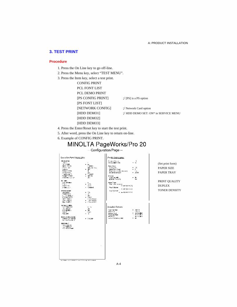
3. TEST PRINT
Procedure
1. Press the On Line key to go off-line.
2. Press the Menu key, select “TEST MENU”.
3. Press the Item key, select a test print.
CONFIG PRINT
PCL FONT LIST
PCL DEMO PRINT
[PS CONFIG PRINT] ;/ [PS] is a PS option
[PS FONT LIST]
[NETWORK CONFIG] ;/ Network Card option
[HDD DEMO1] ;/ HDD DEMO SET: ON* in SERVICE MENU
[HDD DEMO2]
[HDD DEMO3]
4. Press the Enter/Reset key to start the test print.
5. After word, press the On Line key to return on-line.
6. Example of CONFIG PRINT.
(Set print form)
PAPER SIZE
PAPER TRAY
PRINT QUALITY
DUPLEX
TONER DENSITY
A: PRODUCT INSTALLATION
A-5
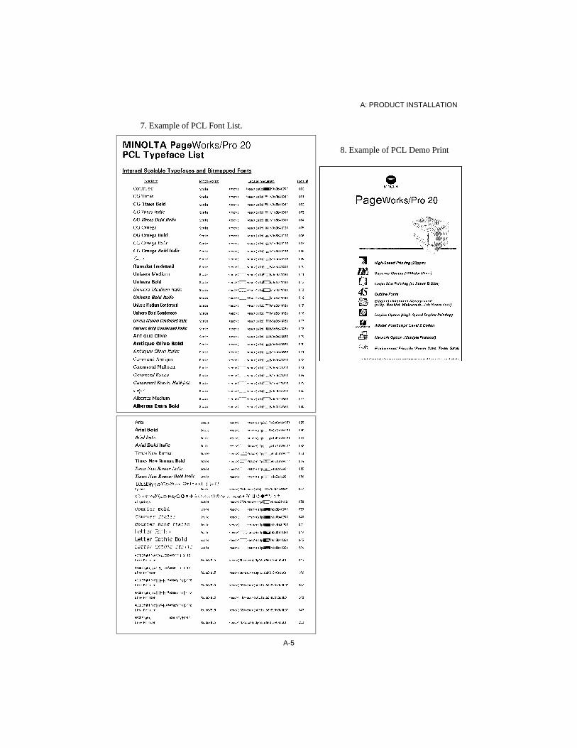
7. Example of PCL Font List.
8. Example of PCL Demo Print

A: PRODUCT INSTALLATION
A-6
9. Example of Network Config print
7066 Minolta Network Configuration Sheet 1 - 2 of 2Minolta
Nj, USA/ GermanyTechnical Support:
See User’s ManualGeneral
Serial Number: 1716489Ethernet Address: 00.40.68.1A.31.09 Cable Type: 10BASE-T
Link Status: N/AF/W Version: 5.04a (9650A) Polarity: N/A ;/ Not Applicable
Rx Packets: 0 Tx Packets: 0Rx Packets Unavailable: 0 Tx Packet Errors: 0Rx Packet Errors: 0 Tx Packet Retries: 1Checksum Errors: 0
Error: ST: Cable not connected. ;/ None
NetWare (ENABLED)
Mode: Unknown ;/ Pserver / Rserver
Print Server Name: MLT1716489
Frame Format: Ethernet 802.2JetAdmin: DisabledTrap Destination: 00.00.00.00 : 00.00.00.00.00.00
TCP/IP (ENABLED
IP Address: Using network protocol (198.102.102.254)IP Address Source: Using network protocol (198.102.102.254)Boot Protocols: Gleaning RARP BOOTP DHCPSubnet Mask: 255.255.255.0Default Gateway Address: 192.168.16.14Timeout Checking: Enabled ;/ DisabledTrap Destination: 255.255.255.255
EtherTalk (ENABLED)
Node Address: 003281hRouter Address: 192.168.16.14 ;/ Not DetectedStatus: Running
Port 1 EnabledPrinter Name: “MLT 1716489”Printer Type 1: “LaserWriter”Zone name: “*”
LAN Server (ENABLED)
Port Configuration
Name:Printer Status: OnlineConnected To: printerError: None

A: PRODUCT INSTALLATION
A-7
4. OPTION SETUP
4-1. Third Cassette Unit
- The Third Cassette makes TRAY3, in
addition to TRAY1 (multi-purpose) and
TRAY2 (second cassette).
1. Turn off the power.
2. Unplug the power cord from the printer.
3. Remove all interface cables from the
printer.
4. Lift the printer.
5. Orient the printer correctly with respect to
the Third Cassette.
- Aligning the printer over the Third Cassette,
gently place the printer onto the Third
Cassette.
- Fit the pins on the cassette into the holes in
the bottom of the printer.
6. Reconnect any interface cables.
Plug in the power cord.
7. Turn on the power.
Run a CONFIG PRINT test print using
paper fed from TRAY3.

A: PRODUCT INSTALLATION
A-8
4-2. Duplex Unit
- The Duplex Unit allows you to print on both
sides of the paper.
1. Turn off the power.
2. Unplug the power cord from the printer.
3. Remove all interface cables from the
printer.
4. Turn the back of the printer.
Remove the gear cover (one screw).
5. Attach the hooks.
6. Place the Duplex Unit on the hooks.
- Press the Duplex Unit against the rear cover
so that its pins fit into the holes in the rear.
7. Tighten the two screws.
8. Reconnect any interface cables.
Plug in the power cord.
9. Turn on the power.
Run a CONFIG PRINT test print feeding
paper through the Duplex Unit.

A: PRODUCT INSTALLATION
A-9
4-3. RAM-SIMM
- The extension memory permits easier
printing of larger print jobs.
1. Turn off the power.
2. Unplug the power cord from the printer.
3. Remove all interface cables from the
printer.
4. Remove the Right Cover. (two screws)
5. Open the shield door. (4 screws)
6. Fit the RAM-SIMMs into SIMM slot 1
(CN3) and then SIMM slot 2 (CN2), in that
order. Mount the SIMM with a larger
capacity in slot 1. Make sure the SIMM is
being mounted in the pin numbers, left 1 to
right 72.
NOTE: RAM is 60ns or less none parity.
8. Close the shield door.
Replace the Right Cover.
9. Reconnect any interface cables.
Plug in the power cord.
10. Turn on the power.
Run a CONFIG PRINT test print and check
the following information on the printout.
- Printer Information, Memory
Total Size (MB) = 4 + xx
- Installed Options
Add SIMM Memory (MB) = xx

A: PRODUCT INSTALLATION
A-10
4-4. Minolta Network Card
- Network Printing allows a number of PCs to
access the printer quite comfortably. It is
automatically selected through a parallel
interface.
1. Turn off the power.
2. Unplug the power cord from the printer.
3. Remove all interface cables from the
printer.
4. Remove the Network Interface cover.
(two screws)
Network Card
5. Insert the Network Card into the grooves in
the interface slot.
- Make sure that the Card is inserted all the
way into the slot.
- Connect either a twin-axial (RJ-45) or
coaxial (BNC) Ethernet cable.
6. Secure the two screws.
7. Reconnect any interface cables.
Connect the Network cable either the
coaxial or twin-axial connector type RJ-45.
Plug in the power cord.
8. Turn on the power.
Run a CONFIG PRINT test print or any
Network print job.

A: PRODUCT INSTALLATION
A-11
4-5. PostScript ROM-DIMM
- A PostSclipt interpreter ROM.
1. Turn off the power.
2. Unplug the power cord from the printer.
3. Remove all interface cables from the printer.
4. Remove the Right Cover. (two screws)
5. Open the shield door. (4 screws)
6. Fit the ROM-DIMM into the DIMM slot
(CN4).
- Make sure the DIMM is mounted in the pin
numbers, left 1 to right 168.
7. Press the DIMM in firmly until it clicks into
place.
8. Close the shield door.
Replace the Right cover.
Reconnect any interface cables.
Plug in the power cord.
9. Turn on the power.
Run a PS CONFIG PRINT test print.

A: PRODUCT INSTALLATION
A-12
4-6. Hard Disk Unit (PS option)
- Supports PostScript operations.
1. Turn off the power.
2. Unplug the power cord from the printer.
3. Remove all interface cables from the
printer.
4. Remove the Right Cover. (two screws)
5. Open the shield door. (4 screws)
6. Install the HDD. (four screws)
7. Plug the flat cable connector into the HDD
and the Controller Board.
8. Close the shield door.
Replace the Right Cover.
Reconnect any interface cables.
Plug in the power cord.
9. Turn on the power.
Run the HDD DEMO1 test print.

B: GENERAL INFORMATION
B-0
B: GENERAL INFORMATION
1. SPECIFICATIONS ........................................................................................................ B-1
2. PARTS IDENTIFICATION .......................................................................................... B-3
3. CONTROL PANEL ....................................................................................................... B-43-1. Control Panel ........................................................................................................ B-43-2. Condition message ................................................................................................ B-53-3. Warning message .................................................................................................. B-63-4. Operator call message ........................................................................................... B-73-5. Service call message ............................................................................................. B-83-6. Duplex print .......................................................................................................... B-83-7. Key Condition Diagram ........................................................................................ B-93-8. Menu Tree ........................................................................................................... B-103-9. Additional Note .................................................................................................. B-11
4. COMPONENT LAYOUT ........................................................................................... B-18
5. GEARS/ ROLLERS ASSIGNMENT .......................................................................... B-19
6. ELECTRICAL COMPONENT LAYOUT .................................................................. B-20
7. CONNECTORS LAYOUT ......................................................................................... B-21
8. SWITCHES/ SENSORS IDENTIFICATION ............................................................. B-22
9. ELECTRICAL SERVICE PARTS ON P.W. BOARDS ............................................. B-23
10. SYSTEM LAYOUT .................................................................................................. B-2510-1. Drive Section .................................................................................................... B-2510-2. Electrical Section .............................................................................................. B-26
11. SEQUENCE FLOW .................................................................................................. B-27
12. BLOCK DIAGRAM .................................................................................................. B-28
13. CIRCUIT DIAGRAM ............................................................................................... B-29
B

B: GENERAL INFORMATION
B-1
1. SPECIFICATIONS
Type : Desktop Laser Beam PrinterPrinting system : Electrostatic dry powdered imaging system + Imaging CartridgeExposure system : Laser Diode + Polygon Mirror scanningPrint resolution : 600 dpi, smoothing, photo tone modePrint Image : Single print within 5 mm of paper edge
Duplex print within 7.5 mm of paper edgePrinting time : Single print 16 sec/ A4 C (C: crosswise)
Duplex print 26 sec/ A4 C (option)Multi printing time : Multi print 20 sheets/ min/ A4 C
Duplex print 12.5 pages/ min/ A4 C (option)Paper : Ordinary plain paper (60-90 g/m2), Recycled paper (60-90 g/m2)
OHP, Transparency, Letterhead, Postcard, LabelPaper size : A3, A3+, B4, ISO B5, Ledger, Legal, Executive, DL, C5, Com10, Monarch
A4, JIS B5, Letter (Crosswise)Paper feeding system : 2 way system
Tray 1 (multi-purpose) 92 - 330 mm (W) x 140 - 483 mm (L) (150 sheets)250 Sheet Cassette (A3/Ledger) 210 - 297 mm (W) x 148 - 432 mm (L)
Paper exit system : Face down (500 sheets maximum/ A4 C/64 g/m2)Warm-up time : Within 70 seconds (when power supplied at 23°C)System speed : 93.8 mm/ secondFusing system : Heat Roller fusing systemCharging system : Rotating Charge Brush systemDevelopment : Fine Micro Toning systemDrum cleaning : Cleaning Blade systemSeparating system : Paper Separator + curvature separating systemDimensions : 545 mm(W) x 383 mm(D) x 403 mm(H) without Paper Cassette
545 mm(W) x 521 mm(D) x 403 mm(H) include 250 Sheet Cassette (A3/Led.)Weight : Approximately 25 kg (without Imaging Cartridge 1.9 kg)Power supply : AC 120V 50-60Hz, 230-240V 50HzPower consumption : 750 W or less (operation)
200 W or less (standby) 45 W or less (low power)
Acoustic noise : 53 dB (A) or less (operation)38 dB (A) or less (standby)
Printer life : 360,000 prints or 5 yearsImaging Cartridge life : 10,000 prints or more (when the black-to-white ratio is 5% on multi prints)
ControllerCPU : NKK NR4645 100MHzMemory : ROM 4 MB (Including fonts: 1 bitmap, 35 Intellifont, 10 True Type)
RAM 4 MB/ RAM-SIMM 2 slot (maximum 64MB option)ROM-DIMM 1 slot (PS option)
Interface : IEEE1284 (Compatible, Nibble, ECP)IEEE802.3, Ethernet (IPX/SPX, TCP/IP, NetBIOS, EtherTalk option)EIDE HDD (only use PS option)
Control Panel : LCD 16 characters x 2 lines, 3 LEDs, 8 keys

B: GENERAL INFORMATION
B-2
: Duplex Unit Specifications
Accessories: Power Cord (only North America)
Imaging Cartridge500 Sheet Cassette (A4/Letter)User’s ManualFD x 4 (Win 95 driver, Win 3.1 driver, Status monitor for Win95,
Agfa Font Manager and 65 fonts)
Options: 500 Sheet Third Cassette Unit (A4/Letter)
250 Sheet Third Cassette Unit (A3/Ledger)500 Sheet Cassette (A4/Letter)250 Sheet Cassette (A3/Ledger)Duplex UnitRAM-SIMM 4, 8, 16, 32 MB/72 pins 60ns or less none parity on marketMinolta Network CardPostScript (ROM-DIMM)Hard Disk Unit (2.5" EIDE)
250 Sheet Cassette (A3/Ledger)Paper : Ordinary Plain Paper (60-90 g/m2), Recycled Paper (60-90 g/m2)Paper size : 210 - 297 mm (width) x 148 - 432 mm (length)
A3, B4, Ledger, Legal, Executive, A4, JIS B5, ISO B5, LetterPaper Feeding system : Paper finger system (250 sheets maximum)
500 Sheet Cassette (A4/Letter)Paper : Ordinary Plain Paper (60-90 g/m2), Recycled Paper (60-90 g/m2)Paper size : A4 or Letter (crosswise)Paper Feeding system : Paper finger system (500 sheets maximum)
Third Cassette UnitPaper : Ordinary Plain Paper (60-90 g/m2), Recycled Paper (60-90 g/m2)Paper Feeding : 250 Sheet Cassette (A3/Ledger) or 500 Sheet Cassette (A4/Letter)Power supply : 5V - 0.1A/ 24V - 0.3A maximum (supplied from printer)Dimensions : 545mm (W) x 377mm (D) x 106mm (H)Weight : Approx. 5.4 kg (Third Cassette Unit 3.3 kg + 250 Sheet Cassette 2.1 kg) Third Cassette Unit life : 150,000 sheets or 5 years
Duplex UnitPaper : Ordinary Plain Paper (60-90 g/m2), Recycled Paper (64-90 g/m2)Paper size : A3, A3+, A4, B4, JIS B5, Ledger, Legal, Letter, ExecutivePower supply : 5V - 0.3A/ 24V - 1.0A maximum (supplied from printer)Dimensions : 424mm (W) x 71mm (D) x 244mm (H)Weight : Approx. 2.1 kgDuplex Unit life : 150,000 sheets or 5 years

B: GENERAL INFORMATION
B-3
10
11
2. PARTS IDENTIFICATION
1. Tray 1 (multi-purpose) 2. Paper Exit Tray 3. Upper Unit Lock Release Lever 4. Duplex Unit (option) 5. Duplex Unit Lower Cover 6. Interface Connector 7. Tray 2 (Second Cassette Unit) 8. Tray 3 (Third Cassette Unit option) 9. Imaging Cartridge10. 500 Sheet Cassette (A4/Letter)11. 250 Sheet Cassette (A3/
Ledger)(option)
1
4
8
3
0993-b022
5
0993-b021
0993-b024
9
0993-b023
2
7 6
0993-b025
1110
Sealing Tape

B: GENERAL INFORMATION
B-4
3. CONTROL PANEL
3-1. Control Panel
1. On Line LED
2. Data LED
3. Message LED
4. LCD
5. Shift key
6. Enter/Reset key
7. Select key
8. Tray1 Paper key
9. Item key
10. Proceed key
11. Menu key
12. On Line key
LED’s
On Line : On : On-line (ready) Flashing : Being off-line Off : Off-line
Data : On : Data in memory Flashing : Receiving data Off : No data
Message : On : Error or malfunction Flashing : Empty or jam error Off : Waiting
KEY’s
On Line : Changes the on-line/off-line condition. Acts as a stop key.Proceed : Commands the printer to continue printing after a Memory Overflow,
Job Too Complex, or Paper Size Jam 5 condition is corrected (goes on-line)
Tray1 Paper : Sets the paper size for the Tray1 (multi-purpose).Shift : Item key + Shift key, Select key + Shift key moves back up the
respective list. Enter/Reset key + Shift key clears data from the memory.
Menu : Selects a Menu from the Menu mode.Item : Selects an Item from the selected Menu.Select : Selects an option from the selected Item. Pressing the key continuously
will cause the printer to move quickly through the options.Enter/Reset : Sets up the Menu selections. Enter/Reset + Shift cancels a printing job
(print data, cache data, I/O buffer) and returns on-line.
• ••
Data Message
t t t
On Line Proceed Tray1 Paper Shift
Menu Item Select Enter
Reset
READY PCL
31 2 4
569 71011 812
s s s ]

B: GENERAL INFORMATION
B-5
3-2. Condition messages
• warning 1
Message: READY : A waiting dataOFFLINE : Off-linePROCESSING : Processing dataPRINTING : Printing dataIMAGE ADAPT : Image data adaption: on, compressing dataBI-CEN OVERFLOW : Host PC not receiving data from printerRESET : Clearing data in memoryTRAY1 PAPER : Setting the Tray1 paper sizePRINT MENU : Menu modePOWER SAVE : Power saving modeWARMING UP : Printer warming upSELF TEST : Power-on self-check cycle
Warning 1: MAINTENANCE REQ : Printer demands maintenanceTRAY 2 IS EMPTY : Tray 2 is paper emptyTRAY 3 IS EMPTY : Tray 3 is paper emptyTONER IS LOW : Toner is near emptyTONER EMPTY : Out of tonerJOB SEPARATION : Tray 1 is in page insertion mode
NOTE: TRAY 2 (3) IS EMPTY: Load paper into Tray 2 (or 3).
NOTE: BI-CEN OVERFLOW: This error does not influence printing of the image.
• PCL/ PS• message
READY PCLTRAY 2 IS EMPTY

B: GENERAL INFORMATION
B-6
3-3. Warning messages
Warning message:NOTE: The “off” or “time delay” settings for AUTO CONTINUE are in the SYSTEM MENU. - Off: After a printing error stops the printing cycle, press the Proceed key. The
printer returns on-line and printing continues. - Time Delay: After a set period of time, the printer automatically returns on-line and
continues printing data from memory.
Warning 2: MEMORY OVERFLOW : Data memory overflow.- The printer needs more memory (optional
RAM-SIMM).- Printer begins to print at the press of the
Proceed key; Or set up AUTO CONTINUE in the SYSTEM MENU.
JOB TOO COMPLEX : Data processing over-run.- Image processing time too longer the printing
time of the engine.- This error will not occur if PAGE
PROTECTION is ON.- The printer needs more memory (optional
RAM-SIMM).
Warning 3: IMAGE ADAPT : Before data memory overflow is being compressed for printing.
- Results in poor image quality.
BI-CEN OVERFLOW : I/O buffer overflow of data sent to host PC.- Image quality will not be affected.
NOTE: The warning message is canceled upon reception of next print data or pressing any key.
• Warning message (warning 2 - 3)
MEMORY OVERFLOW user name
• PCL user name(Indicated only when printing)

B: GENERAL INFORMATION
B-7
3-4. Operator call messages
Message: MANUAL FEED : Manually insert a sheet of paper into Tray1.LOAD TRAY1 : Load paper into Tray 1.LOAD TRAY2 : Load paper into Tray 2.LOAD TRAY3 : Load paper into Tray 3.LOAD : Load paper into the any tray.LOAD TRAY2 NO TRAY : Install the cassette into Tray 2.LOAD TRAY3 NO TRAY : Install the cassette into Tray 3.OUT OF PAPER ALL TRAYS : Load paper into the trays.COVER OPEN : Upper unit is open.DUPLEX OPEN : Duplex Cover is open.PAPER JAM 1 INPUT : Misfeed in take-up section.PAPER JAM 2 DRUM : Misfeed in Imaging Cartridge section.PAPER JAM 3 OUTPUT : Misfeed in exit section.PAPER JAM 4 DUPLEX : Misfeed in Duplex.PAPER JAM 5 SIZE : Paper size mismatch.
NOTE: The part of the message display marked “(paper)” in the above example will contain either a paper size or a message. - Paper sizes: Letter, Legal, Ledger, Exec, C5, DL, Monarc, A4, A3, B4, JIS B5, ISO
B5, COM10. - Messages: Paper Size Error, Paper Empty, Manual Feed.
Paper Feeding: 1. The printer automatically feeds paper when the selected tray is loaded with paper.2. The paper feeding is stopped if the selected tray is not loaded with paper or when it runs
out of paper. The printer resumes the print cycle as soon as paper is added to the tray.4. Select Tray 1 and Universal for the size. This allows you to use paper of a size different
from those specified on the computer screen.5. In automatic feeding, paper of the sizes specified on the screen are selected in the order
of Tray 2, Tray 3, and Tray 1. An empty tray can be loaded with paper during a print cycle. The trays are not automatically selected if SPECIAL PAPER, JOB SEPARATION, or UNIVERSAL is selected.
6. If a misfeed occurs during JOB SEPARATION of Tray 1, printing is not retried.
• Paper size A3, A4, Letter, Legal, etc.
• PCL user nameMessage (paper) user name

B: GENERAL INFORMATION
B-8
3-5. Service call messages
Message: FATAL ERROR 1 ROM : System ROM malfunctionFATAL ERROR 2 PS ROM : PS ROM-DIMM malfunctionFATAL ERROR 3 RAM ; System RAM malfunctionFATAL ERROR 4 SIMM RAM : RAM-SIMM malfunction,
number = slot 0 or 1FATAL ERROR 5 EEPROM : EEPROM malfunctionFATAL ERROR 6 HARD DISK : Hard Disk malfunctionFATAL ERROR 7 NETWORK BOARD: Network Card malfunctionFATAL ERROR 8 INTERFACE : Interface communication error,
number = 1: engine, 2: network cardFATAL ERROR 21 FUSER : Fusing Unit malfunctionFATAL ERROR 22 HSYNC : Laser diode malfunctionFATAL ERROR 23 POLYGON : Polygon Motor malfunctionFATAL ERROR 24 MOTOR : Main Motor malfunctionFATAL ERROR 25 FAN : Fan Motor malfunction
NOTE: Refer to “F: Trouble-shooting”, sections 2-6 through 2-11.
3-6. Duplex printing
1. Portrait long-edge
2. Portrait short-edge
3. Landscape long-edge
4. Landscape short-edge
NOTE: For duplex printing, use paper sizes A4, A3, A3+, B4, JIS B5, Letter, Legal, Ledger, Executive and Universal.NOTE: The printer needs a minimum of 4MB of memory for Letter or A4 size duplex printing.
Message (number)
B: GENERAL INFORMATION
B-9
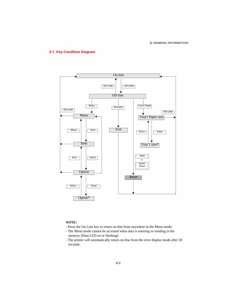
3-7. Key Condition Diagram
NOTE:- Press the On Line key to return on-line from anywhere in the Menu mode.- The Menu mode cannot be accessed when data is entering or residing in the
memory (Data LED on or flashing).- The printer will automatically return on-line from the error display mode after 30
seconds.
Tray 1 size*
On Line
Menu
Enter
Item
Shift
Reset
Exit
Option*
Option
Item
Menu
On-line
Off-line
On Line On Line
On Line
EnterSelect
Item Select
Select
+
Tray1 PaperMenu Proceed
Tray1 Paper size
Enter/Reset

B: GENERAL INFORMATION
B-10
3-8. Menu Tree
Tray1 Paper key Item key Select keyTRAY 1 TRAY 1 LETTER*, LEGAL, LEDGER, EXEC, C5, DL, MONARC, COM10, A4*,
A3, A3+, B4, JIS B5, ISO B5, UNIVERSAL, JOB SEPARATION
Menu key Item key Select keyPRINT MENU COPIES 1 - 999 (1*)
PAPER SIZE LETTER*, LEGAL, LEDGER, EXEC, A4*, A3, B4, JIS B5ORIENTATION PORTRAIT*, LANDSCAPEPAPER TRAY TRAY 1, TRAY 2, [TRAY 3], MANUAL FEED, AUTOMATIC*[DUPLEX] OFF*, LONG-EDGE, SHORT-EDGEFORMLENGTH 5 - 128 (60*, 64) ;linesRESOLUTION 300, 600* ;dpiPRINT QUALITY FINE ART*, TONER SAVE, STANDARDTONER DENSITY EXTRA LIGHT, LIGHT, MEDIUM LIGHT, MEDIUM*, MEDIUM DARK,
DARK, EXTRA DARKPAGE PROTECTION OFF*, ON
PCL MENU FONT NUMBER 0 -50 (o*)PITCH 0.44 ~ 99.99 (10.00*)POINT SIZE 4.00 ~ 999.75 (12.00*) ;pointSYMBOL SET ROMAN-8*, ISO L1, ISO L2, ISO L5, PC-8, PC-8 DN, PC-850, PC-852, PC-
8 TK, WIN L1, WIN L2, WIN L5, DESKTOP, PS TEXT, VN INTL, VN US, MS PUBL, MATH-8, PS MATH, VN MATH, PIFONT, LEGAL, ISO 4, ISO 6, ISO 11, ISO 15, ISO 17, ISO 21, ISO 60, ISO 69, WIN 3.0, MC TEXT, SYMBOL, WING
[PS MENU] JAM RECOVER ON*, OFF
SYSTEM MENU LANGUAGE PCL*, [PS], [AUTO]POWER SAVE 0 - 180 (45*)/ 1- 60 (45*) for Europe ;minuteAUTO CONTINUE OFF*, 20 SEC, 30 SEC, 60 SEC, 90 SEC, 120 SECSPECIAL PAPER NONE*, [TRAY 3], TRAY 1TRAY1 MEDIA PLAIN PAPER*, THIN PAPER, TRANSPARENCY, ENVELOPETRAY2 MEDIA PLAIN PAPER*, THIN PAPER[TRAY3 MEDIA] PLAIN PAPER*, THIN PAPER
PARALLEL MENU IO BUFFER SIZE 16K, 64K, 256K, 1M, AUTO*HIGH SPEED OFF, ON*BI-DIRECTION OFF, ON*TIMING A-B-A*, A-B, B-A[ADOBE PROTOCOL] STANDARD*, BINARY, TBCP (PS only)TIME OUT 5 ~ 300 (15*) ;second
MAINTENANCE MENU DISPLAY LANGUAGE ENGLISH*, DEUTSCH, FRANCAIS, ITALIANO, NEDERLANDS, DANSK, ESPAÑOL, CESKY
FACTORY DEFAULT <none>[SERVICE MESSAGE] ON, OFF (Display of MAINTENANCE REQ)
[NETWORK MENU] IP ADDRESS 198.102.102.254 ; user entry.SUBNET MASK 255.255.255.0 GATEWAY 0.0.0.0 NETWARE FRAME AUTO(*), ETHERNET-2, IEEE-802.3, IEEE-802.2, SNAP+IEEE-802.3
TEST PRINT CONFIG PRINT <none>PCL FONT LIST <none>PCL DEMO PRINT <none>[PS CONFIG PRINT] <none>[PS FONT LIST] <none>[NETWORK CONFIG PRINT]<none>[HDD DEMO1] <none>[HDD DEMO2] <none>[HDD DEMO3] <none>
*: Default setting []: Option
B-10

B: GENERAL INFORMATION
B-11
3-9. Additional Notes
TRAY1 key When use new type paper, secure the paper size and Tray1 Media under System Menu. - At the message “TRAY1 IS EMPTY”, load paper into Tray 1 and printing automatically continues. - When UNIVERSAL is selected, the printer ignores the host PC's paper setting and any paper size can
be used in Tray 1. - When UNIVERSAL is selected and PAPER TRAY is set to AUTOMATIC, Tray 1 is not automati-
cally selected for paper feeding. - When JOB SEPARATION is selected, Tray1 is page insertion mode. Different paper sizes can be
used in Tray 1 and automatic feeding stops when the tray is emptied. - When JOB SEPARATION is selected, Printer not automatic paper feeding when the after message
“TRAY1 PAPER EMPTY”. - When JOB SEPARATION is selected, the printer ignore “Tray1” of the host PC’s paper tray, paper
feeding from Tray in PAPER TRAY and size in PAPER SIZE or the paper feeding from just before use tray and paper size.
PRINT MENU items PAPER SIZE - Operation of DOS file copy to printer (print data does not specify the paper size): The printer paper
feeding from tray in PAPER TRAY and size in PAPER SIZE or the paper feeding from just before use the paper tray and paper size.
- The default paper size is set through dip switch DS-2 (Letter or A4). ORIENTATION - When PORTRAIT or LANDSCAPE is selected, the direction of the image on the paper. PAPER TRAY - When Tray 1 is set to JOB SEPARATION, under PAPER TRAY, Tray 1 will not be listed and Tray 2
will be shown in its place. - If MANUAL FEED is selected, when the data down-loaded from host PC the printer will display the
message “Manual Feed” and go off-line. Manually insert the paper into Tray 1 and press the On Line key to start printing.
- When AUTOMATIC is selected, the printer searches in the order of Tray 2, Tray 3, and Tray 1. When the right paper size is found, it proceeds with feeding.
- When AUTOMATIC is not selected, if the printer cannot find the right paper size or tray, the printer stops. Load the right paper size and the printer continues automatically.
RESOLUTION - Select “300”: Image 300 dpi. ;1 data point to 2 dots. PRINT QUALITY - If RESOLUTION is set to 300 dpi, choosing FINE ART will have very little effect on the image qual-
ity. - When TONER SAVE is selected, alternate data bits are cut out to conserve toner consumption.TONER DENSITY - The settings of LIGHT, MEDIUM*, DARK, etc., are very precise. PAGE PROTECTION - When ON is selected, if the data is complex and hard to process, printing will proceed at a slower rate. NOTE: The settings of the Print Menu of the host PC supersede the settings of the PRINT MENU of
the printer control panel.
PCL MENU items FONT NUMBER - The default font is number 0 (Courier) of the resident PCL fonts number 0 - 50. PITCH - The character spacing for Courier, Letter Gothic and Line Printer. Each press of the Select key
changes the value in +0.01 increments. Hold the Select key down and the value changes in +1.00 increments.

B: GENERAL INFORMATION
B-12
POINT SIZE - The character size of proportional fonts (1 point = 1/72 inch). Each press of the Select key changes the
value in +0.25 increments. Hold the Select key down and the value changes in +1.00 increments. SYMBOL SET - Select the desired character or symbol set.
[PS MENU] items JAM RECOVER - Set to ON, printing is recovered after a misfeed, but printing is at a slower rate. - Set to OFF, printing is not recovered after a misfeed but printing is at a faster rate.
SYSTEM MENU items LANGUAGE - When AUTO is selected, the printer automatically switches between PCL and PS languages. POWER SAVE - Select “0” to disable POWER SAVE. Dip switch DS-3 is ON for European CE mark. - The printer exits POWER SAVE mode when data is received, any key is pressed, a cassette is pulled
out / pushed in, or a cover is opened / closed. AUTO CONTINUE - If selected, the printer will automatically continue printing after a set period of time when a “Memory
Overflow” or “Job Too Complex” warning occurs. - When a time delay is set, the printer will automatically return on-line after that time has elapsed. - When OFF* is selected, the printer stops if one of the above warnings occur.
PAPER - When Tray 1 or Tray 3 is selected for SPECIAL PAPER, that tray is not automatically selected during
printing. - When Tray 1 is set for JOB SEPARATION or UNIVERSAL, it is not automatically selected during
printing. TRAY1 MEDIA, TRAY2 MEDIA, [TRAY3 MEDIA] - Select THIN PAPER for paper weight 60-74 g/m2. NOTE: After a THIN PAPER print job, the printer automatically resets the tray to PLAIN PAPER*.
PARALLEL MENU items IO BUFFER SIZE - Select AUTO* for automatic adjustment of buffer size. HIGH SPEED - OFF: Data transfer speed of approx. 111 kB/s ;Centronics compatible mode. - ON*: When printer data receiving error, this select is OFF. BI-DIRECTION - Select ON* for two-way communication between the printer and host PC. - OFF: Centronics compatible mode. TIMING - Select timing A - B - A*: Ack while Busy ;IEEE1284 Mode - Select timing A - B: Ack in Busy ;IEEE1284 Mode - Select timing B - A: Ack after Busy ;Centronics compatible Mode[ADOBE PROTOCOL] (PS option) - Standard*: Standard Protocol, ASCII character based. - Binary: Binary communication protocol. - TBCP: Tagged binary communication protocol. TIME-OUT - The period of time between processing blocks of data in a DOS operation.

B: GENERAL INFORMATION
B-13
- For PCL data, a block of data will be printed out during the following time-out. For PS data, no print-ing occurs during a time-out.
NOTE: For further information on TIME-OUT, see the text file DOS>copy README.TXT >lpt1.
MAINTENANCE MENU items DISPLAY LANGUAGE - Select the language of the control panel. FACTORY DEFAULT - Returns the printer control panel to the factory-set defaults. - Does not clear the items of the PARALLEL MENU, NETWORK MENU, SERVICE MENU, and the
“Maintenance Required” message setting of the MAINTENANCE MENU. SERVICE MESSAGE - When set to ON, the warning message “MAINTENANCE REQ” will appear on the display when
needed. - Set to OFF and press the Enter/Reset key to clear the warning message setting.
[NETWORK MENU] items - Input the various network settings and press the On Line key to enter them. - Be sure to get the correct address, subnet mask, gateway and ethernet frame type from the system man-
ager. NETWARE FRAME - When set to AUTO, Network Card is automatically selected frame type Ethernet 2, IEEE 802.3, IEEE
802.2 and SNAP+IEEE 802.2.
TEST PRINT items - Refer to examples in A: Product Installation 3. Test Print items.
Warning Messages LED o: On-line, d: Data, m: Message. Key O: On Line, T: Tray1, M: Menu, P: Proceed, R: Reset.
LED condition “-”: off, “?”: undetermined, “*”: flashing. Key operation “x”: invalid, “O”: valid.
Operator Call Messages LED o: On-line, d: Data, m: Message. Key O: On Line, T: Tray1, M: Menu, P: Proceed, R: Reset.
Pr. Message Condition & Action o d m O T M P R
MEMORY OVERFLOW (user name)
Print data memory overflow.(user name): PCL user name.
- * * x x x O O
JOB TOO COMPLEX (user name)
Image processing time too longer the print-ing time of the engine.(user name): PCL user name.
- * * x x x O O
Pr. Message Condition & Action o d m O T M P R
10 MANUAL FEED(paper) (user name)
Manually insert paper in Tray1, press On Line key.(paper): Paper size from host PC.(user name): PCL user name.
- * * O x x x O

B: GENERAL INFORMATION
B-14
10 LOAD (tray)(paper) (user name)printing
Paper empty.(tray): Load paper on the tray, printing begins.(paper): Paper size from host PC.(user name): PCL user name.
- * * x O x O O
10 LOAD (tray)(paper)waiting
Make sure the paper tray and paper size are correct in PRINT MENU.(tray): Load paper on the tray.(paper): Paper size from host PC.
- - * x O O x x
10 LOAD(paper) (user name)
Paper size error when PAPER TRAY = AUTOMATIC.(paper): Paper size from host PC.(user name): PCL user name.
- * * x O x O O
10 LOAD TRAY2NO TRAY
Install Tray 2 - ? * x O O x x
10 LOAD TRAY3NO TRAY
Install Tray 3 - ? * x O O x x
9 OUT OF PAPERALL TRAYS
No paper in all trays.Set-up any paper tray.
- ? * x O O x x
1 COVER OPEN Upper cover opened. - ? * x x x x x
2 DUPLEX OPEN Duplex cover opened. - ? * x x x x x
4 PAPER JAM 1INPUT (user name)
Misfeed at take-up. Correct and close cover.(user name): PCL user name.
- ? * x x x x O
5 PAPER JAM 2DRUM (user name)
Misfeed at drum. Correct and close cover.(user name): PCL user name.
- ? * x x x x O
6 PAPER JAM 3OUTPUT (user name)
Misfeed at exit. Correct and close cover.(user name): PCL user name.
- ? * x x x x O
7 PAPER JAM 4DUPLEX (user name)
Misfeed in duplex. Correct and close cover.(user name): PCL user name.
- ? * x x x x O
8 PAPER JAM 5SIZE (user name)
Paper size mismatch or double feed paper and no paper in the machine.Make sure the correct paper is in the Tray.This error cannot be detected if the Proceed key is pressed or AUTO CONTINUE is turned on.(user name): PCL user name.
- ? * x x x x O
Pr. Message Condition & Action o d m O T M P R

B: GENERAL INFORMATION
B-15
LED condition “-”: off, “?”: indeterminacy, “*”: flashing. Key operation. “x”: invalidity, “O”: valid.NOTE: To cancel a job when a misfeed occurs, press the Shift + Enter/Reset keys.
Service mode - Refer to E: Adjustment 2. Service Menu.
Media type - Plain paper: 75 - 157 g/m2
- Thin paper: 60 - 74 g/m2
- Manual feed: Select the media (plain paper, thin paper, transparency, envelope) for Tray1.NOTE: The printer can automatically change the media setting of a tray before printing each page, but cannot change the fusing temperature also. (The fusing temperature is usually adjusted for each media type.)
[Duplex print] - Do not duplex print on envelope (ISO B5, Com10, C5, DL, Monarc). - When the printer receives a duplexing print job, but does not have a duplex unit, each side of the page
is printed out sequentially on separate sheets of paper. - When “Memory Overflow” is indicated, install an optional RAM-SIMM. - When the messages “Memory Overflow”, “Job Too Complex” or “Paper Empty” occur, press the
Enter/Reset key (the message “Paper Jam4, Duplex” will appear), remove the paper from the duplex, and close the cover. The printer should indicate “Ready”. Press the Proceed key to continue the print job. The print out may contain missing or garbled data.
- The printing sequence for each page of a duplex print job is 2, 4, 1, 6, 3, 8, 5, 10 . . . For 3 sheets: page 2, 2, 1, 2, 1, 4, 1, 4, 3 . . .
- The 1st page printing on the under face.
Page Insertion Mode (Job Separation) - The print of a misfeed page cannot be recovered. - When Tray 1 is empty, the message “Load Tray 1 Paper” appears. Load paper onto Tray 1. - The Counters count up one for each page printed in JOB SEPARATION paper. - When Tray 1 is set to JOB SEPARATION, Tray1 selected in PAPER TRAY automatic change the
Tray2. - With AUTOMATIC in PAPER TRAY selected, Tray 1 it is not automatically selected during print-
ing. - When MANUAL FEED under PAPER TRAY is selected for Tray 1, Tray 1 automatically returns to
the JOB SEPARATION setting after the manual feed job is finished. NOTE: When PAPER TRAY is set to UNIVERSAL, the printer not detected the paper size for Tray 1.
Paper Size error - When the messages “Load (tray) (paper)” or “Load (paper)” appear, load the correct size paper into
the indicated tray. - Press the Proceed key and paper is fed from the same tray as before the error. - The paper size cannot be detected when the Proceed key is pressed.NOTE: When the host PC selects Tray 3, but Tray 3 is not installed, the tray set under PAPER TRAY is used. During a print job, the previously used tray is selected.
3 TONER EMPTY Imaging Cartridge is no toner.Install the new Imaging Cartridge, power on.
- ? * x O x x x
Pr. Message Condition & Action o d m O T M P R
B: GENERAL INFORMATION
B-16
Paper empty errorWhen the message “Load (tray) (paper)” appears, the printer stops and goes off-line. - Press the Proceed key and paper is fed from the same tray as before. - Press the Shift + Enter/Reset keys to reset the printer and go on-line. - When the indicated paper size is loaded onto the indicated tray, the printer continues printing. - When the paper empty condition occurs in a tray not set under PAPER TRAY, the message “Tray 2
(or 3) Is Empty” appears. If the cassette is missing, the printer displays “Load (tray) No Tray”.
Manual FeedThe printer displays the message “Manual Feed (paper)” and goes off-line when the data is received. - Manually insert a sheet of the indicated paper into Tray 1, press the On Line key, and printing begins. - When paper runs out (paper empty), press the On Line key to restart printing. - Paper Jam: Start of print is after the Jam has been cleared, close the Upper Unit or the Duplex Cover. - There is no paper size detection after a “Paper Jam 5, Size” is reset. - Does not page insertion at the after manual feed print. NOTE: Press the Shift + Enter/Reset keys to reset the printer and go on-line.
Engine error - When the “Paper Jam 5, Size” error occurs, check the paper size and open and close the Upper Unit. - Printing is always recovered after a misfeed for PCL data. - Printing is only recovered after a misfeed if JAM RECOVER is set to ON for PS data.
Interface error - When the message “Bi-Cen Overflow” (I/O buffer overflow) appears, printing continues. The printer
goes to “Ready” at the press of any key or the reception of the next job data. - When data comes in from both the parallel and network ports, the printer automatically selects the port
at which data is detected first. - While printing from one port, data is received from the other port and stored in the I/O buffer until the
buffer is filled. - Centronics I/F error: Set-up High Speed = “OFF”, Bi-Direction = “OFF”, Timing = “B-A”.
Memory error - The “Image Adapt” problem and its data compression occur before a “Memory Overflow” problem.
The data compression (1/8) is irreversible and results in poor image quality. - Printing continues when a “Memory Overflow” problem occurs. After the printing job, press any key
to go to “Ready”. To receive new data, press the Proceed key or set up AUTO CONTINUE under SYSTEM MENU. Resolution 600 dpi to 300 dpi in PRINT MENU.
- “Job Too Complex” means a data processing over-time has occurred. Image processing time is too long for the printing time of the engine. Set PAGE PROTECTION = ON in the PRINT MENU and retry the printing job.
- The printer needs more memory (optional RAM-SIMM).
Memory - Page protection OFF*: band memory is 384kB (128kB x 3), other memory is data + work area, cache. - Page protection ON: page buffer 1 page, no band memory.
- Main memory
NOTE: Network I/O buffer: 16kB, Cache memory is cleared at the end of the job.
Memory 4MB 8MB 12MB 16MB 32MB
Data + WorkI/O buffer 16kB 64kB 256kB 256kB 256kB

B: GENERAL INFORMATION
B-17
- Option and memory
Language - PCL5e/ monochrome Printer Control Language/ de facto standard by Hewlett Packerd Inc. - PostScript Level 2/ de facto standard by copyright Adobe Systems Incorporated.
Performance of PageWorks/Pro 20
- Driver speed max. equal average like 2-up/4-up above watermark adjust
- Memory efficiency: J4v same view/ 1 page 1 sheet - Image quality: LJ4v same rank ; J4v, LJ4v/ Hewlett Packerd Inc.
Paper size A4/ Letter A3/ Ledger A3+
Duplex PCL 4 MB 8 MB 8 MBDuplex PS 12 MB 24 MB 28 MBSingle PCL 4 MB 4 MB 4 MBSingle PS 8 MB 12 MB 16 MB
- Print speed DOS mode copy command Genoa 1 page 1 sheet
maximumaverage

B: GENERAL INFORMATION
B-18
20
4. COMPONENT LAYOUT
1. Print Head Unit 2. A3 Exit Tray (Extender) 3. Paper Exit Tray 4. Imaging Cartridge 5. Charge Brush 6. Paper Exit Roller 7. Upper Fusing Roller 8. Paper Exit Sensor (PC3) 9. Lower Fusing Roller10. Duplex Transport Roller (Option)11. Duplex Paper Sensor (PC4)12. Image Transfer Roller13. Paper Take-up Sensor (PC1)
14. Duplex Cover Switch (Option) 15. Registration Sensor (PCR1)16. Registration Roller17. 2nd Transport Roller18. 2nd Paper Take-up Roller19. 2nd Paper Empty Sensor (PE2)20. Paper Lifting Plate21. Tray 3 (Third Cassette Unit option)22. Tray 2 (Second Cassette Unit)23. Tray 1 (multi-purpose)24. Paper Take-up Roll25. Paper Empty Sensor (PE1)26. Toner Empty Sensor (TE1)
2021
2 3 4 65
23
0993b032
13
14
1819
8 9
24
22
25
26
1
17
7
12
16
15
11
10
Fan
Switchback Motor
Transport Motor
Motor
Fan

B: GENERAL INFORMATION
B-19
0993-b041
5. GEARS/ ROLLERS ASSIGNMENT
The Main Motor (M1) transmits the drive to the rollers of the printer and the optional Third Cassette Unit via each gear. The duplex unit Transport Motor (M5) transmits the drive to the rollers of the Duplex Unit. (Refer to C: MECHANICAL/ ELECTRICAL item 2-2. Tray 2, 9-2. Duplex Unit.)
Main Motor (M1)
Charge Brush
Paper Exit Roller
Upper Fusing Roller
Transfer Roller
Sleeve Roller
PC Drum
Engine
Paper Take-up Roll
± 2
3
4
5
67
89
10
11
12
1314
15
16
17
18
1920
21
22
23
24
25
2627
29
2831
30
32
Gear Ratios
1. 20 2. 77 3. 75 4. 39/18 5. 33 6. 31/22 7. 38 9. 60/2910. 3911. 1512. 1513. 3914. 1415. 18/2316. 2417. 1418. 2019. 14/1720. 1621. 4422. 60/2323. 70/1624. 1825. 63/2726. 45/4727. 44/3428. 1829. 15/2130. 4431. 2532. 31/25
Transport Roller Tray 2 Second Cassette drive Gear

B: GENERAL INFORMATION
B-20
PNE1
PNE2
6. ELECTRICAL COMPONENT LAYOUT
PWB-A : Main Control BoardPWB-C : Tray 2 Control BoardPWB-E : Power UnitPWB-F : High Voltage UnitPWB-G : Toner Empty BoardPWB-R : Resistor BoardM1 : Main MotorM3 : Fusing Fan MotorM4 : Power Fan MotorSL1 : Paper Take-up SolenoidSL2 : 2nd Paper Take-up SolenoidCL1 : Registration ClutchS1 : Power SwitchS2 : Interlock SwitchS4 : 2nd Paper Size SwitchPC1 : Paper Take-up Sensor
PC3 : Paper Exit SensorPCR1 : Registration SensorPE1 : Paper Empty SensorPE2 : 2nd Paper Empty SensorH1 : Heater LampTE1 : Toner Empty SensorTH1 : ThermistorTS1 : ThermostatNetwork Card: (option)
PWB-B : Duplex Control BoardM5 : Transport MotorM6 : Switchback MotorS3 : Duplex Cover SwitchPC4 : Duplex Paper Sensor
PWB-A
PWB-E
P/H
PWB-F
S1PC1
M1
SL1
SL2
M4
PWB-C
S3
M5
PCR1M6
CL1
PWB-BPE1
PE2
H1
PC3
TS1TH1
M3
S2
PWB-R
PC4
S4
PWB-G
TE1
0993b053
4321
Duplex Unit (option)
Network Card
Controller Board
B: GENERAL INFORMATION
B-21
CN1
CN2B
7. CONNECTORS LAYOUT
PWB-E
CN11
PWB-F CN5
CN8
PWB-B
CN2(YL)
Guide
CN3
PWB-C
CN1CS
CN2CTCN2C
CN3C
CN2F
CN3ECN5E
CN1E
CN1A
56 8A
10A
CN4B
CN10A : Paper Take-up SensorCN3 : Paper Exit SensorCN10A : Registration SensorCN6A : Paper Empty SensorCN8A : 2nd Paper Empty SensorCN2(YL) : Heater LampCN6A : Toner Empty SensorCN5 : ThermistorCN2(YL) : Thermostat
PWB-B : Duplex Control BoardCN4B : Duplex Cover SwitchCN11A : Duplex Paper Sensor
PWB-A : Main Control BoardPWB-C : Tray 2 Control BoardPWB-E : Power UnitPWB-F : High Voltage UnitCN5A : Main MotorCN2F : Fusing Fan MotorCN5E : Power Fan MotorCN2B(PH): Transport MotorCN1B(PH): Switchback MotorCN12A : Paper Take-up SolenoidCN3C : 2nd Paper Take-up SolenoidCN8 : Registration ClutchCN1E : Power SwitchCN3E : Interlock SwitchCN8A : 2nd Paper Size Switch
0993-b071
Roller
11A
1
PWB-A
CN15
Duplex Unit (Option)
5B 3B1B
2B
CN12A13A
2A3A
4A
CN4E
CN2E
B: GENERAL INFORMATION
B-22
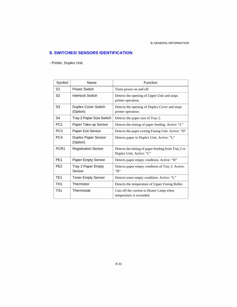
8. SWITCHES/ SENSORS IDENTIFICATION
- Printer, Duplex Unit.
Symbol Name Function
S1 Power Switch Turns power on and off.
S2 Interlock Switch Detects the opening of Upper Unit and stops printer operation.
S3 Duplex Cover Switch (Option)
Detects the opening of Duplex Cover and stops printer operation.
S4 Tray 2 Paper Size Switch Detects the paper size of Tray 2.
PC1 Paper Take-up Sensor Detects the timing of paper feeding. Active: “L”
PC3 Paper Exit Sensor Detects the paper exiting Fusing Unit. Active: “H”
PC4 Duplex Paper Sensor (Option)
Detects paper in Duplex Unit. Active: “L”
PCR1 Registration Sensor Detects the timing of paper feeding from Tray 2 or Duplex Unit. Active: “L”
PE1 Paper Empty Sensor Detects paper empty condition. Active: “H”
PE2 Tray 2 Paper Empty Sensor
Detects paper empty condition of Tray 2. Active: “H”
TE1 Toner Empty Sensor Detects toner empty condition. Active: “L”
TH1 Thermistor Detects the temperature of Upper Fusing Roller.
TS1 Thermostat Cuts off the current to Heater Lamp when temperature is exceeded.

B: GENERAL INFORMATION
B-23
PWB-B(option) CN4
4P CN3
4PCN1
7P
5 2P
CN27P
CN6 3P
PWB-A
PWB-F
VR1
CN2CN3
CN5 CN8 CN11CN10
VR1
CN13
MPU
CN12
CN4
CN1
CN9CN6
+
2P7P20P
12P5P
8P
4P 7P 2P 10P 3P 11P 12P
‹
‹‹
‹ ‹
VR5 VR6VR3VR2
CN2
CN1
11P
2P
PWB-E CN5
CN6
CN410P
3P
2P
CN1 CN2
4P
2P
F2
F1
‹
RV2
‹
RV1
CN33P
CN7
9. ELECTRICAL SERVICE PARTS ON P.W. BOARDS
PWB-E 5
33P
2P
CN1 2
4P
2P
F2
F1 63P
PWB-A
PWB-F
VR1A
CN2
CN5 CN8 CN11CN10
CN13
MPU
CN12
CN4
CN1
CN6
+
2P7P20P
12P
8
4P 7P 12P 11P 12P
PWB-E CN5
CN41
2PCN1
CN2
F2
F1
‹RV2
‹RV1
CN3 3P
P
0P
VR201
VR101
VR102
CN2
CN1
2
11P ‹
‹
‹
P
2P4P
P.W.Boards Symbol Function
PWB-A VR1A Adjusts the Image Registration margin. (Refer to E: Adjustment)
PWB-F VR102- VR201
Factory setting
PWB-E F1
F2
RV1 - RV2
Fuse (100V) 125V - 5A°°(230V) 250V - 3.15A
125V - 12A°° 250V - 6.3A
Factory setting
Do not touch

B: GENERAL INFORMATION
B-24
LED
Controller Board
PWB-P
Dip Switch
DS-1: Printer name (Off: PageWorks 20 / On: PagePro 20); TEST PRINT title name.Parallel port Plug & Play printer name.PostScript Option product name, printer name.
DS-2: Paper size default (Off: LETTER / On: A4); Tray1 Paper default.PRINT MENU - PAPER SIZE default.PRINT MENU - FORM LENGTH (Off: 60 / On: 64).Printer MIB (Off: inch / On: metric).
DS-3: Wait for power save (Off: PageWorks 20 / On: PagePro 20); Time selection.Off: 0 - 180 minutes (default is 45; 0 is no power save).On: 1 - 60 minutes (default is 45; for CE/Europe, power save cannot be turned off).
DS-7: EEPROM default (Off: User setting / On: Factory standard).On: The factory defaults are copied at power-on when EEPROM’s ID is unlike the ROM’s ID. Off: Normal use.
to Control Panel Network Interface Parallel Interface
RAM-SIMM
to PWB-A
PS ROM-DIMM
Hard CPU
TrueR
es
F l a s h o r M a s k R O M
Luster Scan
Disk
1 8offon
DS1-8Dip Switch
RAM RAM
1 8offon
PageWorks 20 PagePro 20
Driver
EEPROM

B: GENERAL INFORMATION
B-25
10. SYSTEM LAYOUT
10-1. Drive Section
Mechanical Control and Sensor Layout
Paper Take-up Sensor (PC1)
Transport Roller
Take-up Roller
Polygon MirrorSOS SensorCurrent of LD
Current of Fusing Fan MotorCurrent of Power Fan Motor
Transfer RollerFusing Roller
Paper Exit Roller
Thermistor (TH1)Thermostat (TS1)
Paper Exit Sensor (PC3)
Interlock Switch (S2)Toner Empty Switch (TE1)
Tray 2 Unit
Main Control Board
(PWB-A)
Registration Roller
Paper Empty Sensor (PE2)
Fusing Roller
Registration Sensor (PCR1)
Transport Roller Duplex Paper Sensor (PC4)
Duplex Unit (Option)
Paper Exit Roller Cover Switch (S3)
Fusing Fan Motor (M3)Power Fan Motor (M4)
Paper Take-up Solenoid (SL2)
Polygon Motor(M2)
Main Motor(M1)
Registration Clutch (CL1)
Heater Lamp(H1)
Transport Motor(M5)
Switchback Motor(M6)
Take-up Roller Paper Empty Sensor (PE1)Paper Take-up Solenoid (SL1)

B: GENERAL INFORMATION
B-26
10-2. Electrical Section
Power Supply and Signal Transmission
- The Power source supplies DC+5V and DC+24V to the main control board and AC to
the Heater Lamp.
- The Printer receives print data from the host PC through an interface.
- The Controller adjusts the size and position of the print data to generate image data.
Printing occurs after the image data has been transmitted to the Print Head unit via the
main control board.
- The main control board controls the various parts of the engine, Print Head unit, Duplex
Unit and Third Cassette Unit (Tray 3).
Signal line
Power line
Print Head Unit
Imaging Cartridge
Motor
Solenoid
Clutch
Duplex Unit
Third Cassette Unit
5V
5V, 24V
5V, 24V
5V, 24V
AC
High Voltage Unit
(PWB-F)
Heater Lamp
Heater Lamp Control
Main Control Board
(PWB-A)
Power Unit(PWB-E)
High Voltage
PC
PC
Control Panel
Control Board
RAMROM
EEPROM
Parallel I/F[Network I/F]
[SIMM][ROM-DIMM][Hard Disk] Control
Video

B: GENERAL INFORMATION
B-27
˸«ºø
ÕлԺØ
11. SEQUENCE FLOW
To carry out printing cycles, signals are transferred between the controller, main control andengine as shown below.
ControllerMain Control
-H. SYNC
-VIDEO
-CPRDY
Duplex print?
Yes
Interface
IEEE1284, [Network]
Command Processor
Language detectionJob controlError check
Image Processing
Paper size, CopiesFont expansion
Fine ArtReal tone
Toner control
Image Memory
Initialize
Warm-upDetecting JAM, Error
ChargingExposure
Development
Feeding
TransferFusing
Exit
Standby
Host PC
No
-PRRDY

B-28
B: G
EN
ER
AL IN
FO
RM
AT
ION
12. BLOCK DIAGRAM
Controller Board
Slot 1 (CN3)
IEEE1284-BParallel I/O
Network Card
Display Controller
Main Control BoardPWB-A RAM RAM
(CN4)
Slot 2 (CN2)
PU PC SL PH
PCL
(PJL)
System RAM
DIP SWDisplay Panel
4MB
4MB ROM
LED System ROM
Resident Fonts 46
IPX/SPX, TCP/IP, NetBIOS,
ROM-DIMM (PS option)
RAM-SIMM (option)
Ethernet
Host PC
CPU64 bits
HDD(PS option)
TrueRes
Luster Scan Driver
Video
INT
1 2 3 4 5READY PCL
M
H1
TrueRes: Fine Art, Real tone, Toner control
EEPROM
Service menu

C: MECHANICAL/ ELECTRICAL
C-0
C: MECHANICAL/ ELECTRICAL
1. PRINTING PROCESS .................................................................................................. C-1
2. PAPER FEEDING ........................................................................................................ C-22-1. Tray 1 (multi-purpose) ......................................................................................... C-22-2. Tray 2 (Second Cassette Unit) ............................................................................. C-3
3. IMAGING CARTRIDGE ............................................................................................. C-4
4. CHARGING .................................................................................................................. C-5
5. EXPOSURE (P/H) ........................................................................................................ C-5
6. DEVELOPMENT ......................................................................................................... C-6
7. TRANSFER ................................................................................................................... C-6
8. FUSING ......................................................................................................................... C-7
9. PAPER EXIT/ DUPLEX ............................................................................................... C-89-1. Paper Exit ............................................................................................................. C-89-2. Duplex (option) .................................................................................................... C-8
10. PRINTING SEQUENCE ............................................................................................ C-910-1. Starting sequence ................................................................................................ C-910-2. Multiple sequence .............................................................................................. C-910-3. Ending sequence ................................................................................................. C-910-4. Duplex sequence .............................................................................................. C-1010-5. Power ON sequence ......................................................................................... C-10
11. PARALLEL INTERFACE ........................................................................................ C-1111-1. Connector pin assignments (IEEE1284-B) ...................................................... C-1111-2. Compatibility mode handshake timing values ................................................. C-11
C

C: MECHANICAL/ ELECTRICAL
C-1
1. PRINTING PROCESS
: Sensor
9. Paper Exit/ Duplex
4. Charging
Tray 2 (second cassette)
6. Development 7. Transfer
8. Fusing
1. Tray 1 (multi-purpose)
3. Imaging Cartridge
2. Feeding
5. Exposure
Take-up
Registration
Duplex
Exit
Duplex (Option)
Empty
Tray 3 (Third Cassette Unit option)

C: MECHANICAL/ ELECTRICAL
C-2
2. PAPER FEEDING
- Paper is fed from either Tray 1 (holding up to 150 sheets of paper) or Tray 2, commonlycalled the universal cassette (holding up to 250 sheets of paper). (The optional ThirdCassette Unit may be installed to serve as a fixed cassette capable of holding 500 sheetsof paper or a universal cassette capable of holding 250 sheets of paper.)
- The Paper take-up roll takes up a sheet of paper and the transport roller feeds it to the PCdrum.
- The signal indicating that the paper take-up sensor (PC1) is activated is used to determinethe starting position of the image.
2-1. Tray 1 (multi-purpose)
- The drive is transmitted from the main drive motor (M1) to the paper take-up clutch (one-way clutch), paper take-up roll, and the push-down cam.
- When the paper take-up solenoid (SL1) is energized, the paper take-up roll and push-downcam turn one complete turn. As the push-down cam turns, the paper lifting plate is raisedso that the paper take-up roll can take up one sheet of paper. The friction with the separatorpad ensures that only one sheet of paper is taken up at a time by the paper take-up roll.
0993c021
Transport Roll
Paper Take-up Solenoid (SL1)
Paper Take-up Sensor (PC1)
Paper
Paper Take-up Clutch
Paper Take-up Roll
Push-down Cam
Paper Lifting Plate
Paper Empty Sensor (PE1)
Separator

C: MECHANICAL/ ELECTRICAL
C-3
2-2. Tray 2 (Second Cassette Unit)
- The drive for the second paper tray is transmitted from the printer to the drive gear, papertake-up clutch, paper take-up roll, and the transport roller.
- Tray 2 is controlled by the main control board (PWB-A) via the Tray 2 control board(PWB-C).
- When the paper take-up solenoid (SL2) is energized, the paper take-up roll is turned onecomplete turn to take up a sheet of paper and the transport roller feeds it to the PC drum.The paper separator fingers prevent the second and subsequent sheets of paper from beingtaken up with the first one.
- The paper size switches (S4-1, 2, 3 and 4) on the control board (PWB-C) detect the size ofthe paper loaded in the tray. The combinations in which these switches are turned on andoff are listed below to represent corresponding paper sizes.
Paper size Switch
Transport Roller
Paper Take-up Roll
Paper Take-up Solenoid (SL2)
0993c024
Paper Empty Sensor (PE2)Control Board
(PWB-C)
Drive Gear
Separator
4321
Paper Take-up Clutch
Paper Size Plate
S4- 4,3,2,1
1 1 1 1
1 1 1 0
1 1 0 1
1 0 1 0
0 1 0 1
1 0 1 1
0 1 1 0
1 1 0 0
PaperNo Cassette
Ledger L
A3 L
B4 L
Legal L
G. Legal L
A4 L
Letter L
S4- 4,3,2,1
1 0 0 1
0 0 1 0
0 1 0 0
1 0 0 0
0 0 0 1
0 0 1 1
0 1 1 1
PaperExecutive L
Letter C
A4 C
G. Letter C
B5 C
A5 C
Invoice C
No Cassette
NOTE: 0: on, 1: off, C: crosswise, L: lengthwise
Paper Size Switch (S4-1, 2, 3, 4)

C: MECHANICAL/ ELECTRICAL
C-4
Parts
TB3Parts Fuse
Toner
3. IMAGING CARTRIDGE
- The illustration below shows the construction of the PC drum charge unit and developingunit.
- The PC drum is charged by the PC drum charge brush.- The laser beam from the print head produces an electrostatic latent image on the surface of
the PC drum.- The agitator blade of the toner hopper agitates toner and the toner feed roller feeds the toner
to the sleeve roller.- The toner regulating plate regulates the amount of toner fed to the sleeve roller.- The sleeve roller feeds toner to the electrostatic latent image formed on the surface of the
PC drum.- Toner remaining on the surface of the PC drum is cleaned off by the cleaning blade.- The mirror/ window cleaner wipes toner off the mirror and window used for detection of a
toner-empty condition.
Sleeve Roller
PC Drum
Charge Brush
Laser beam
Handle
Regulating Plate
Cleaner Mirror/
Window
Toner Hopper
Cleaning Blade
Agitator Blade 0993c033
Charge biasDeveloper bias
Toner biasSeal bias
0993-c032
Window
Mirror
Safety Cover
Toner Feed Roller

C: MECHANICAL/ ELECTRICAL
C-5
4. CHARGING
- A rotary brush is used to charge the PC Drum by static electricity before laser exposure. Itapplies charge directly to the PC Drum at a low voltage and therefore the amount of ozoneproduced is only negligible.
5. EXPOSURE (P/H)
- The print head emits a laser beam to produce an electrostatic latent image on the surfaceof the PC Drum.
- There is a sensor called the SOS sensor installed that correctly times the illumination of thelaser diode with the rotation of the polygon mirror.
PC Drum
Charge bias
PC Drum ground
Charge Brush
Laser Diode
Polygon Mirror
SOS Sensor
0993-c0432
Laser beam
PC Drum

C: MECHANICAL/ ELECTRICAL
C-6
6. DEVELOPMENT
- The developing unit feeds toner to the electrostatic latent image on the surface of the PCdrum to produce a visible toner image.
- When the print cycle is started and the Main drive motor (M1) is energized, the surfacepotential of the PC drum is approximately 0V. The sleeve roller voltage is made positiveto prevent toner from sticking to the 0V areas.
- The LED on PWB-G emits light which is then reflected off the mirror inside the tonerhopper for use in the detection of a toner-empty condition. Readings are taken while theMain drive motor is turning.
7. TRANSFER
- The image transfer roller transfers the toner image on the surface of the PC drum onto thepaper. A comb electrode removes static electricity remaining on the paper.
Developing bias -300V
Toner bias
Toner Hopper
Toner Feed Roller
Sleeve Roller
PC Drum
0993-c0420993-c062
0993-c0610993-c071
Toner Empty Sensor (TE1)(PWB-G)
Transfer roller
Mirror
PC Drum
PC Drum
Sleeve Roller
Needle polePC Drum
Paper
Transfer guide
+
Transfer roller
Transfer bias +4000V
Toner
Seal bias
PWB-F
High Voltage
Unit

C: MECHANICAL/ ELECTRICAL
C-7
8. FUSING
- The fusing unit permanently fixes the toner image onto the paper. This is accomplished bya heated roller. The upper fusing roller, which is heated by a Heater Lamp built into it,melts the toner and then the upper and lower fusing rollers press the melted toner into thepaper.
- The thermistor (TH1) detects the temperature of the upper fusing roller for fusingtemperature control.
- The thermostat (TS1) turns off as it senses an abnormally high temperature, thereby cuttingoff current to the Heater Lamp (H1).
Fusing Temperature Control Circuit
- The thermistor (TH1) detects the surface temperature of the upper fusing roller and inputsthe corresponding analog voltage to the MPU.
- The Heater Lamp (H1) is turned on or off by a signal from the MPU output according tothe temperature detected by the thermistor, thereby controlling the temperature of theupper fusing roller.
- When the thermistor detects an abnormally high temperature, the MPU forces the HeaterLamp OFF.
Fusing Unit Temperature Control
1. During warm-up : The printer starts warm-up to attain a temperature of approx. 190oC whenthe power switch is turned on.
2. During print cycle : On receiving a print command, the printer starts a temperature control cycleto keep the upper fusing roller temperature at approx. 190oC.
3. During standby : The upper fusing roller temperature is maintained at approx. 180oC.4. Energy saving : The controller signal turns off the Heater Lamp.
Thermistor
Heater Lamp
Upper Fusing Roller
PaperThermostat
Lower Fusing Roller
oC
190
180
Time
Warm-up Printing
§Power ON
5 min.2 min. 5 min.
§Heater OFF
out
Temperature Curve
EnergyStandby
MPUThermistorin
Thermostat (190oC)CN2(YL)
H1PWB-Ein
Heater Lamp
+5V
cmp
Lamp
PWB-A
TS1

C: MECHANICAL/ ELECTRICAL
C-8
9. PAPER EXIT/ DUPLEX
9-1. EXIT
- The paper exit roller receives its drive from the Main Drive Motor (M1) via a gear train.The paper is fed onto the exit tray with its printed side down.
9-2. Duplex (Option)
- When the duplex unit is mounted on the printer, the exit roller is connected to the switchbackmotor (M6) by way of the coupling lever and gear.
1. When the printing cycle is completed for 1-sided printing, the paper, moving past the exitsensor, is fed out of the printer by the exit roller.
2. When the printing cycle is completed for the front side in 2-sided printing, the paper is fedtowards the exit by the exit roller until it moves past the exit sensor. When the paper movespast the exit sensor, the switchback motor (M6) is turned backward, feeding the paper backto the duplex paper take-up area. The transport motor (M5) then transports the paper up tothe registration roller. Skew in paper is corrected by the registration sensor and then theregistration roller feeds the paper to the image transfer section for printing on the back side.The paper, having gone through the second print cycle, is fed out of the printer by the exitroller.
Paper Exit
Transport Motor (M5)
Switchback Motor (M6)
Lower Fusing Roller
Upper Fusing Roller
Paper Exit Roller
Transfer Roller
Paper Exit Sensor
Registration Sensor
Gear TrainDuplex Paper
Sensor
Duplex
Registration Roller
Connecting Gear
Exit Roller
1112
1314
1112
Upper Fusing Roller
Connecting Gear
10 Coupling Lever

C: MECHANICAL/ ELECTRICAL
C-9
+ݵ
-ݵ
ªŸ
ýµ§½
10. PRINTING SEQUENCE
10-1. Starting sequence
10-2. Multiple sequence
10-3. Ending sequence
Polygon Motor (M2)
Main Motor (M1)
Exit Sensor(PC3)
Charge bias
Exposure
Developer bias
Transfer bias
2790
[m sec]¶Exit Sensor OFF Print ends ¶
670
290
350
490 1340
Laser
[m sec]¶-Print ¶M3 Continuous
Polygon Motor (M2)
Paper Take-up Sensor (PC1)
Take-up Solenoid(SL1/SL2)
Main Motor (M1)
Charge bias
Exposure
Developer bias
Transfer bias
[m sec]¶Print
500
630 610
Laser
Polygon Motor (M2)
Paper Take-up Sensor (PC1)
Take-up Solenoid (SL1/SL2)
Main Motor (M1)
Charge bias
Exposure
Developer bias
Transfer bias
1000015
260300
300
500
510
1st: 9902nd: 15803rd: 2650
300
2000
Laser

C: MECHANICAL/ ELECTRICAL
C-10
500
10-4. Duplex sequence
10-5. Power ON sequence (Trouble Check)
Switchback Motor (M6)
Transport Motor (M5)
Exit Sensor (PC3)
Duplex Paper Sensor (PC4)Registration
Sensor (PCR1)Registration Clutch (CL1)
¶Switchback ON ¶Duplex
NOTE: Error check sequence.
Paper Take-up Sensor (PC1)
Main Motor (M1)
Regist. Sensor (PCR1, PC4)
Fan Motor (M3, M4)
Polygon Motor (M2)
Paper empty (PE1)
Thermistor (TH1)
¶Power ON ¶Ready
JAM1, 4
JAM2
Fusing Unit malfunction
Paper empty
Exit Sensor (PC3)
Main Motor malfunction
JAM3
Polygon Motor, Laser malfunction
Fan Motor malfunction
Self Test Sequence
Fatal Error 1 - 8

C: MECHANICAL/ ELECTRICAL
C-11
11. PARALLEL INTERFACE
11-1. Connector pin assignments (IEEE1284-B)
NOTE: D-sub full size 36 pin connector. Compatibility mode and (ECP mode).
11-2. Compatibility mode handshake timing values
No. Item No. Item No. Item
1 Strobe (HostClk) 13 Select (Xflag) 25 S.Gnd (D6)
2 DA1 14 AutoFd (HostAck) 26 S.Gnd (D7)
3 DA2 15 Not defined 27 S.Gnd (D8)
4 DA3 16 Logic Gnd 28 S.Gnd/ PE, Select, Ack
5 DA4 17 Chassis Gnd 29 S.Gnd/ Busy, Fault
6 DA5 18 Peripheral Logic High 30 S.Gnd/aFd, selIn, Init
7 DA6 19 S.Gnd (Strobe) 31 Init (Reverse Request)
8 DA7 20 S.Gnd (D1) 32 Fault (PeriphRequest)
9 DA8 21 S.Gnd (D2) 33 N.C
10 Ack (PeriphClk) 22 S.Gnd (D3) 34 N.C
11 Busy (PeriphAck) 23 S.Gnd (D4) 35 N.C
12 PError (AckReverse) 24 S.Gnd (D5) 36 SelectIn (1284Active)
<500ns<500ns
<500ns
<500ns
>500ns
>0
>0 >0
>0
data n
-Strobe
+Busy
-nAck
data n+1 data n+2
<500ns<500ns
<500ns
<500ns>0

D: DISASSEMBLY/ CLEANING
D-0
D: DISASSEMBLY/ CLEANING
1. MAINTENANCE/ INSPECTION D-11-1. Replacement of Parts D-11-2. Cleaning Parts D-11-3. Required Service Tools D-1
2. DISASSEMBLY PROCEDURE D-22-1. Outer Covers D-22-2. Fusing Unit D-32-3. Image Transfer Unit D-62-4. High Voltage Unit D-62-5. Power Unit D-72-6. Print Head Unit D-72-7. Paper Empty Sensor Unit. D-82-8. Paper Take-up Roll Unit. D-82-9. Registration Roller Unit.D-82-10. Drive Unit D-92-11. Tray 2 (Second Cassette Unit) D-9
D

D: DISASSEMBLY/ CLEANING
D-1
ÀÐ⁄ Š×ͼMP-1
1. MAINTENANCE/ INSPECTION
1-1. Replacement of Parts
NOTE: Printer has an electric total counter.
- Replacement Cycle: 120,000 to 60,000 sheets of single printing.
1-2. Cleaning Parts
NOTE: Do not touch the surface of the Image Transfer Roller with the hand.
1-3. Required Service Tools
NOTE: Grease for the drive section: MOLYCORT EM-50L/ Dow Coorning Inc.
°
1-4. »—Õ³
Parts Name Replacement Cycle
Imaging Cartridge Multi printing: 10,000; intermittent: 8,000 sheets
Paper Take-up Roll At detection of fault, or, 120,000 sheets of multi printing
Fusing Unit At detection of fault, or, 120,000 sheets of multi printing
Image Transfer Unit At detection of fault, or, 120,000 sheets of multi printing
Parts Name Cleaning Procedure
Paper Take-up Roll Wipe the dust off with a soft cloth dampened with alcohol.
Image Transfer Roller Wipe the surface with a dry piece of soft cloth.
- Driver
E-ring
+ Driver (No. 2)
General use
Needle Nose Pliers
E-ring
Tools
Use
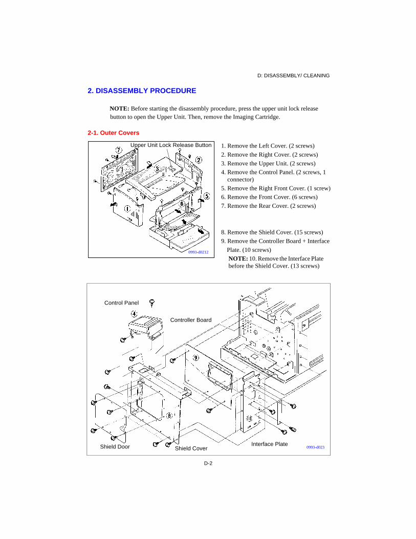
D: DISASSEMBLY/ CLEANING
D-2
6
2. DISASSEMBLY PROCEDURE
NOTE: Before starting the disassembly procedure, press the upper unit lock release button to open the Upper Unit. Then, remove the Imaging Cartridge.
2-1. Outer Covers
1. Remove the Left Cover. (2 screws)
2. Remove the Right Cover. (2 screws)
3. Remove the Upper Unit. (2 screws)
4. Remove the Control Panel. (2 screws, 1 connector)
5. Remove the Right Front Cover. (1 screw)
6. Remove the Front Cover. (6 screws)
7. Remove the Rear Cover. (2 screws)
8. Remove the Shield Cover. (15 screws)
9. Remove the Controller Board + Interface
Plate. (10 screws)
NOTE: 10. Remove the Interface Plate before the Shield Cover. (13 screws)
Upper Unit Lock Release Button
0993-d0212
0993-d023
Control Panel
Controller Board
Interface PlateShield CoverShield Door

D: DISASSEMBLY/ CLEANING
D-3
2-2. Fusing Unit
1. Remove the Outer Covers. (Refer to sect. 2-1.)
2. Remove the Fusing Unit. (4 screws, 3 connectors)
NOTE: When reassembling the Fusing Unit, adjust the position of the Image Transfer Unit.
Heater Lamp Cover
3. Remove the Left Heater Lamp Cover. (1 screw)
NOTE: When removing the Left Heater Lamp Cover, turn the Cover in the clockwise direction.
4. Remove the Right Heater Lamp Cover. (1 screw)
NOTE: When removing the Right Heater Lamp Cover, turn the Cover in the counterclockwise direction.
0993-d0221
Right Heater Lamp Cover
Pin
0993-d0222
Left Heater Lamp Cover
Pin
0993-d0226

D: DISASSEMBLY/ CLEANING
D-4
(¼ÞÍÛ× 1ƒ)
Heater Lamp
5. Holding the right end of the Heater Lamp, take out the stopper and spring.
6. Pressing the Heater Lamp in the direction indicate by the arrow, remove it from the heater socket.
NOTE: Be sure not to touch the lamp surface with bare hands.
Paper Exit Sensor
1. Remove the Paper Exit Sensor. (1 connector)
2. Remove the actuator. (1 spring)
Lower Fusing Roller
1. Remove the Rear Fusing Cover. (2 screws)
2. Push the lock stopper in the direction indicated by the arrow and remove the Lower Fusing Roller.
Separator
1. Release the stoppers of the separator.
2. Pulling and sliding, remove the stoppers.
NOTE: The two paper separator finger stoppers on the right face the opposite direction to the two on the left.
0993-d024
0993-d026
Stopper Spring
0993-d025
0993-d0262

D: DISASSEMBLY/ CLEANING
D-5
Thermistor
1. Remove the front Fusing Cover. (2 screws, 1 harness)
2. Remove the Thermistor. (1 screw)
Thermostat
1. Remove the Thermostat. (2 screws)
Upper Fusing Roller, Gear, G-ring, E-ring
1. Remove the G-ring.
2. Remove the Gear, Ring, Bushing.
3. Remove the Upper Fusing Roller as indicated by the arrow.
4. Remove the Gear. (1 E-ring)
0993-d027
0993-d0272
0993-d028
E-ring
G-ringGear
RingBushing

D: DISASSEMBLY/ CLEANING
D-6
NOTE: When disassembling/ reassembling the Transfer Unit, High Voltage Unit, Registration Roller Unit. and Paper Take-up Roller Unit, please note that each has a peg that fits into a hole in the Right Frame and a screw that secures the unit in the Left Frame.
- Release each unit from the Drive Unit when removing the unit.
2-3. Image Transfer Unit
1. Remove the Outer Cover. (Refer to sect. 2-1.)
2. Remove the Fusing Unit. (Refer to sect. 2-2.)
3. Remove the Rear Frame. (6 screws, 1 connector)
4. Remove the Image Transfer Unit. (1 screw)
NOTE: With the Left Frame open, release the Transfer Unit. Pulling the Transfer Unit in the direction indicated by the arrow, remove it.
NOTE: Don’t touch the surface of the Image Transfer Roller with the hand.
2-4. High Voltage Unit
1. Remove the Outer Cover. (Refer to sect. 2-1.)
2. Remove the Fusing Unit. (Refer to sect. 2-2.)
3. Remove the Transfer Unit. (Refer to sect. 2-3.)
4. Remove the High Voltage Unit. (1 screw, 1 connector)
NOTE: Pulling the High Voltage Unit in the direction indicated by the arrow, remove it.
High Voltage Unit
Drive Unit
Image Transfer Unit
Image Transfer Unit
Left Frame
0993-d042
High Voltage Unit
0993-d032
Registration Roller Unit.
Take-up Roller Unit
Rear Frame
Interface Plate

D: DISASSEMBLY/ CLEANING
D-7
2-5. Power Unit
1. Remove the Outer Cover. (Refer to sect. 2-1.)
2. Remove the Power Unit. (6 screws, 5 connectors)
°Ì¢ÂºŒ‡¦Ú÷„®þ§£
2-6. Print Head Unit
1. Remove the Outer Cover. (Refer to sect. 2-1.)
2. Remove the Harness Cover. (2 screws)
NOTE: Pulling the harness cover to the right, remove it.
3. Remove the Print Head Unit. (3 screws, 1 connector)
0993-d0622
0993-d062
0993-d0512

D: DISASSEMBLY/ CLEANING
D-8
2-7. Paper Empty Sensor Unit
1. Remove the Outer Cover. (Refer to sect. 2-1.)
2. Remove the Harness Cover. (Refer to sect. 2-6.)
3. Remove the Paper Empty Sensor Unit. (3 screws, 2 connectors)
NOTE: After reinstallation, secure the harness in the wire saddle.
2-8. Paper Take-up Roll Unit.
1. Remove the Paper Empty Sensor Unit. (Refer to sect. 2-7.)
2. Pulling up, remove the Transport Guide.
3. Remove the Paper Take-up Roll Unit. (1 screw)
2-9. Registration Roller Unit.1. Remove the Outer Cover. (Refer to sect. 2-1.)
2. Remove the Fusing Unit. (Refer to sect. 2-2.)
3. Remove the Transfer Unit. (Refer to sect. 2-3.)
4. Remove the High Voltage Unit. (Refer to sect. 2-4.)
5. Remove the Paper Empty Sensor Unit. (Refer to sect. 2-7.)
6. Remove the Paper Lifting Plate. (1 screw)
NOTE: Move the printer Left Frame in the direction of the arrow to unlock the plate from the frame.
7. Remove the Paper Take-up Roller Unit. (1 screw)
NOTE: Slide the unit in the direction of the arrow to unlock it from the right drive unit of the printer.
0993-d072
Take-up Roll Unit. Transport Guide
0993-d082
0993-d0822
0993-d0820

D: DISASSEMBLY/ CLEANING
D-9
8. Remove the Registration Roller Unit. (3 screws)
2-10. Drive Unit
1. Remove the Outer Cover. (Refer to sect. 2-1.)
2. Remove the Fusing Unit. (Refer to sect. 2-2.)
3. Remove the Transfer Unit. (Refer to sect. 2-3.)
4. Remove the High Voltage Unit. (Refer to sect. 2-4.)
5. Remove the Paper Empty Sensor Unit. (Refer to sect. 2-7.)
6. Remove the Registration Roller Unit. (Refer to sect. 2-8.)
7. Remove the Drive Unit. (5 screws, 7 connectors)
2-11. Tray 2 (Second Cassette Unit)
1. Loosen 4 screws.
2. Remove the Second Cassette Unit.
NOTE: At reinstallation, position the 4 positioning pins, coupling gear, and coupling connector correctly.
0993-d102
0993-d091
0993-d113

E: ADJUSTMENT
E-0
E: ADJUSTMENT
1. IMAGE REGISTRATION ............................................................................................ E-1
2. SERVICE MENU .......................................................................................................... E-2
3. ROM UPGRADE .......................................................................................................... E-3
E

E: ADJUSTMENT
E-1
Turning VR1A on PWB-A in the + direction makes
the Voltage higher and turning it in the opposite
direction makes the Voltage lower.
2P
CN2CN3 CN13 CN12CN1
CN8 CN11CN10CNCN5
CN4
CN6 CN7
1. IMAGE REGISTRATION
After the Main Control Board (PWB-A) is replaced, adjust the margin by following the
procedure described below.
1. Remove the Right Cover. (2 screws)
2. Remove the Control Panel. (2 screws, 1 connector)
3. Remove the Right Front Cover. (1 screw)
4. Remove the Front Cover. (6 screws)
5. Remove the Rear Cover. (2 screws)
6. Remove the Shield Cover. (15 screws)
(Refer to D: Disassembly / Cleaning item 2-1. Outer Covers)
7. Adjust VR1A so that Registration Margin d on the print becomes the appropriate distance while making prints.
8. Another adjustment.
Adjust VR1A so that the Voltage is 2.50V between VR1A and the ground terminal.
Registration position
Paper Leading Edge
FeedingDirection
PWB-A
2.50V
VR1A
Margin d
2P7P20P
12P
12P 11P 12P
MPUVR1A
+
8
4P 7P
P

E: ADJUSTMENT
E-2
2. SERVICE MENU
When the power is turned on while holding down the On Line and Enter/Reset keys, the
Service Menu is displayed in the off-line mode after the machine has gone through the self-
test and warming-up cycles. To exit from the service mode, press the On Line key. Service
menu added head of common menu. Press On Line key end of this menu go on-line.
• Service menuTOTAL COUNT : xxxxxxx 7-digit numberLARGE SIZE COUNT : xxxxxxx 7-digit numberPAGE COUNT : xxxxxxx 7-digit number, RESET OKMAINT COUNT : xxxxxxx 7-digit number, (0120000*)HDD DEMO SET : OFF*, ON
TOTAL COUNT
xxxxxxx 7-digit number indicating total prints.
LARGE SIZE COUNT
xxxxxxx 7-digit number indicating total prints for A3, A3+ and Ledger.
NOTE: When TRAY1 is set to “UNIVERSAL”, there is no count.
PAGE COUNT
xxxxxxx 7-digit number indicating total pages produced for maint count.
Press the Select key to show the message “RESET OK?” and press the
Enter/Reset key to reset the count to zero.
MAINT COUNT
0120000*: This is the number of prints before the next maintenance is to be
performed. This number can be increased by +1000 when the Select key is
pressed and decreased by -1000 when the Shift and Select keys are pressed
at once. When the Enter/Reset key is pressed, the number is marked with
an asterisk (*), which indicates that the number has been confirmed.
HDD DEMO SET
OFF*: No HDD DEMO set.
If ON is selected, the item “HDD DEMO PRINT” is shown in the TEST
PRINT menu.
SERVICE MENU menu

E: ADJUSTMENT
E-3
3. ROM UPGRADE
1. Binary File
File Names Contents
1. ?m7401.dlb /* OS Driver */
2. ?em5e.dlb /* PCL Core */
3. ?fontrom.dlb /* Font.data */
4. diram.dlb /* ? */
5. m7401lut.dlb /* TrueRes Look up table */
6. cpux4.dlb /* CPU set data */
NOTE: File numbers are used down-loading sequence.
2. Transfer Files
(1) Turn the power off.
- To enter the upgrade mode, press the Menu key + Select key and turn on the power.
- The panel display will read:
Tmax Down-loader
"READY"
(2) Binary files are transferred from the parallel interface.
- Binary files 1 to 6 are transferred one at a time.
- Each time a file has been transferred, check that the message “Complete” appears on the control panel.
- When transferring files from the host computer, use the following command format:
>copy/b m7401.dlb lpt1
- After the transfer, check that “Complete” appears on the control panel.
- Secure the "READY" on LCD.
- Transfer the next file:
>copy/b em5e.dlb lpt1
- Check that “Complete” appears on the control panel.
- Repeat this sequence for the remaining files.
NOTE: These are the file names and file number used down-loading sequence.However, the file name may change over time.If printer is error, turn the power off for 3 second and then back on.
3. Run a CONFIG PRINT test print.
Check the printout for the following under Printer Information:
Firmware Version = Ver. x.xx
Do not try this function, When noUPGRADE. Delete the program.
Caution

F: TROUBLE-SHOOTING
F-0
F: TROUBLE-SHOOTING
1. TROUBLE DETECTION .............................................................................................. F-11-1. JAM detection ....................................................................................................... F-11-2. Fusing Unit malfunction ....................................................................................... F-21-3. Laser malfunction ................................................................................................. F-21-4. Polygon Motor malfunction .................................................................................. F-21-5. Main Motor malfunction ....................................................................................... F-21-6. Fan Motor malfunction ......................................................................................... F-3
2. ACTION FOR DETECTED JAM OR MALFUNCTION ............................................. F-42-1. JAM1 ..................................................................................................................... F-42-2. JAM2 ..................................................................................................................... F-42-3. JAM3 ..................................................................................................................... F-52-4. JAM4 ..................................................................................................................... F-52-5. JAM5 size mismatch ............................................................................................. F-62-6. Service call (Fatal error 1 - 8) ............................................................................... F-62-7. Fusing Unit malfunction (Fatal error 21) .............................................................. F-72-8. Laser malfunction (Fatal error 22) ........................................................................ F-72-9. Polygon Motor malfunction (Fatal error 23) ........................................................ F-72-10. Main Motor malfunction (Fatal error 24) ........................................................... F-72-11. Fan Motor malfunction (Fatal error 25) .............................................................. F-7
3. OTHER DETECTED TROUBLE ................................................................................. F-83-1. No Power ............................................................................................................. F-83-2. Skew ..................................................................................................................... F-8
4. IMAGE QUALITY TROUBLE .................................................................................... F-9 Black/ White Lines ...................................................................................................... F-9 Horizontal Lines .......................................................................................................... F-9 Low Image Density ..................................................................................................... F-9 Foggy Background ...................................................................................................... F-9 No Image (Blank/ Black) .......................................................................................... F-10 Offset Image .............................................................................................................. F-10
F

F: TROUBLE-SHOOTING
F-1
1. TROUBLE DETECTION
NOTE: This printer detects the following misfeeds and malfunctions. When any of these trouble conditions are detected, all printer elements are brought to a stop except the fan motor.
1-1. JAM detection
A misfeed may be classified into one of four categories, JAM1, JAM2, JAM3 and JAM4 as detailed below.
1. When paper is fed from Tray 1 (multi-purpose tray) and the Paper Take-up Sensor (PC1) has NOT been activated, approx. 1.6 sec. after the Paper Take-up Roll has started turning, the machine determines that a Jam 1 condition has occured (JAM1).
2. When paper is fed from Tray 2 (second cassette) and the Registration Sensor (PCR1)
has not been activated, approx. 1.4 sec. (approx. 2.5 sec. for the Third Cassette Unit) after the Paper Take-up Roll has started turning, the machine determines that a Jam 1 condition has occurred. (JAM1).
3. When paper is fed from Tray 2, the Paper Take-up Sensor (PC1) has NOT been activated, approx. 1.0 sec. after the leading edge of the paper has reached the Registration Sensor (PCR1), the machine determines that a Jam 1 condition has occurred.
(JAM1).
4. The Paper Take-up Sensor (PC1) is in the activated state when the power is turned on, or the Upper Unit is closed or Duplex Cover is closed, the machine determines that a Jam 2 condition exsists. (JAM2).
5. The Paper Take-up Sensor (PC1) remains in the activated state, the period of time equivalent to the paper size plus 2.8 sec. after the leading edge of the paper has reached the Paper Take-up Sensor (PC1), the machine determines that a Jam 2 condition has
occurred (JAM2).
6. The Paper Exit Sensor (PC3) has NOT been activated, approx. 2.3 sec. after the leading edge of the paper has reached the Paper Take-up Sensor (PC1), the machine determines that a Jam 2 condition has occurred (JAM2).
7. The Paper Exit Sensor (PC3) is in the activated state, approx. 2.3 sec. after the trailing edge of the paper has moved past the Paper Take-up Sensor (PC1), the machine determines that a Jam 3 condition has occurred (JAM3).
8. The Paper Exit Sensor (PC3) is in the activated state when the power is turned on, or the Upper Unit is closed or Duplex cover is closed, the machine determines that a Jam 3 condition exists (JAM3).
9. The Duplex Paper Sensor (PC4) has NOT been activated, approx. 2.7 sec. after the Switchback motor of the Duplex Unit has been energized, the machine determines that a Jam 4 condition has occurred (JAM4).
10. The Registration Sensor (PCR1) has NOT been activated, approx. 1.1 sec. after the leading edge of the paper has reached the Duplex Paper Sensor (PC4), the machine determines that a Jam 4 condition has occurred. (JAM4).

F: TROUBLE-SHOOTING
F-2
11. The Paper Take-up Sensor (PC1) has NOT been activated, approx. 1.0 sec. after the leading edge of the paper has reached the Registration Sensor (PCR1), the machine determines that a Jam 4 condition has occurred (JAM4).
12. The Duplex Paper Sensor (PC4) is in the activated state when the power is turned on, or the Upper Unit is closed or Duplex cover is closed, the machine determines that a Jam 4 condition exists (JAM4).
13. The Registration Sensor (PCR1) is in the activated state when the power is turned on, or the Upper Unit is closed or Duplex cover is closed, the machine determines that a Jam1 or Jam 4 condition exists (JAM1, JAM4).
JAM Resetting Procedure
After the misfeed has been cleared, close the Upper Unit or the Duplex Cover.
1-2. Fusing Unit malfunction
The printer considers that there is a fusing unit malfunction when any of the following five conditions has been detected.
1. The temperature of the upper fusing roller (as measured with the thermistor) is such that the change in the thermistor voltage is 0.1V or less over a period between 12 sec. to 30 sec. after warm-up has started (with the fusing roller temperature being 160oC or less).
2. The fusing roller temperature does not reach 190oC for a 120 sec. period after warm-up has started.
3. The fusing roller temperature becomes less than 140oC in the standby state.
4. The fusing roller temperature becomes less than 150oC during a printing cycle.
5. The fusing roller temperature remains at/or exceeds 240oC, for an extended period.
1-3. Laser malfunction
The laser output level is adjusted before printing, while the fusing temperature is being controlled. A laser fault is detected if the output level cannot be adjusted to the specified value during this time period.
1-4. Polygon Motor malfunction
The printer considers that there is a polygon motor malfunction when any of the following three conditions is detected.
1. The polygon motor lock signal has NOT been output to the CPU within 10.0 sec. after the motor has been energized.
2. When the Polygon Motor is on, the lock signal switches from ON, and then turns OFF for more than 1 sec.
3. The SOS (Start of Scan) signal is not output during printing.

F: TROUBLE-SHOOTING
F-3
1-5. Main Motor malfunction
The printer considers that there is a main drive motor malfunction when any of the following two conditions is detected.
1. The main drive motor lock signal (connector CN5A-1) remains off for a continuous 1.0 sec. period.
2. The main drive motor lock signal (connector CN5A-1) is off 1.0 sec. after the Main drive motor has been energized.
1-6. Fan Motor malfunction
The printer considers that there is a fan motor malfunction when any of the following two conditions is detected.
1. A fusing fan motor malfunction is detected when the voltage used to detect the fusing fan motor current remains 360/230 mV or less (high speed/ low speed) for a continuous 0.5 sec. period.
2. A power supply fan motor malfunction is detected when the voltage used to detect the power supply fan motor current remains 170/150 mV or less (high speed/ low speed) for a continuous 0.43 sec. period.
Malfunction Resetting Procedure
After the malfunction has been cleared, turn the Power OFF for 3 sec. and then back ON.

F: TROUBLE-SHOOTING
F-4
NG: NoOK: Yes2. ACTION FOR DETECTED JAM OR MALFUNCTION
NOTE: First determine the location of the paper misfeed and perform the appropriate JAM1-5 trouble-shooting procedure before removing the misfeed paper.
2-1. JAM1
2-2. JAM2
No
NoReplace the Main Control Board (PWB-A).
NoYes
No
No
Replace the Main Control Board (PWB-A).
Yes
No
YesIs there paper at the Registration Sensor (PCR1)?
Wipe the Paper Take-up Roll.
No
Replace the Drive Unit.
Check the paper separator of tray 2.
or
Replace the Fusing Unit. (Location of PC3)
Yes
Replace the Drive Unit.
Yes
No
Is there paper at the Paper Exit Sensor (PC3)?
No
No
Replace the Registration Roller/ Sensor unit.
Is there paper at the Paper Take-up Sensor (PC1)?
Replace the Paper Take-up Sensor (PC1).
No
Paper from Tray 1 (multi-purpose tray).
No
Yes
No No
Wipe the paper Take-up Roll, Separator Pad.
Replace the Drive Unit.
Replace the Paper Take-up Roller Unit.
Is there paper at the Paper Take-up Sensor (PC1)?
Replace Tray 2.
No
Double feeding paper.
Wipe the Separator Pad of the Tray 1 (multi-purpose).
Does the 2nd cassette unit Paper Take-up Roll rotate?
Does the Paper Take-up Roll rotate?
Replace HV Unit. (Location of PC1)

F: TROUBLE-SHOOTING
F-5
2-3. JAM3
2-4. JAM4
Replace Fusing Unit. (Where PC3 is located).
Replace the Main Control Board (PWB-A).
No
Yes
No
No
NoNo
Replace the Mech. Control Board (PWB-A).
Yes
No
Yes
No
Does the Switchback Motor (M6) rotate?
Yes
No
Is there paper at the Paper Exit Sensor (PC3)?
No
Replace the Drive Unit. (Location of M5).
Replace the Duplex Unit. (Location of PC4).
No
NoYes
Does the Paper Exit Roller rotate backward?
NoAre the Duplex Unit gear and Upper Unit gear properly connected?
Is there paper at the Paper Take-up Sensor (PC1)?
Yes
No
Replace the Duplex Unit. (Location of M6).
NoNo
Does the Paper Exit Roller rotate?
Yes
Is there paper at the Duplex Paper Sensor (PC4)?
Reattach the Duplex Unit.
Is there paper at the Registration Sensor (PCR1)?
Replace the Registration Roller Unit. (Location of PCR1).
Replace the HV Unit. (Location of PC1.)
Replace the Duplex Unit.

F: TROUBLE-SHOOTING
F-6
2-5. JAM5 size miss match (Paper Size Error)
2-6. Service call (Fatal error 1 - 8)
NOTE: When the printer detects the following malfunctions, all of the printer elements are brought to a stop except the Fan motor.
NOTE: FATAL ERROR 7 occurs, the Network Config Print is printed out and the printer goes off-line (stops).- Check the General section of the printout for the message “Error: Cable not connected”.- Check for communication errors.
Message Condition
FATAL ERROR 1 ROM
System ROM malfunction. Replace Main Controller Board Pwb-P
FATAL ERROR 2 PS ROM PS ROM-DIMM malfunction. Replace Main Controller Board (Pwb-P)
FATAL ERROR 3 RAM
System RAM malfunction. Replace Main Controller Board (Pwb-P)
FATAL ERROR 4 SIMM RAM (number)
Data memory RAM-SIMM malfunctionnumber = SIMM slot number. Replace Memory SIMM.
FATAL ERROR 5 EEPROM EEPROM malfunction. Replace Main Controller Board (Pwb-P)
FATAL ERROR 7 NETWORK BOARD
Network Card malfunction. Replace network Card
FATAL ERROR 8 INTERFACE (number)
Network interface or engine interface malfunction.number = 1: engine, 2: Network Card. Replace 1= Pwb-A and/or Main Controller Board (Pwb-P). 2= Replace Network Card and/or Main Controller Board (Pwb-P).
No
Replace the Mech. Control Board (PWB-A).
No
No
- Secure the actuator of the paper size switches in the Cassette Unit.
Replace the 2nd Cassette Unit or the Control Board (PWB-C).
• Check the paper size on the Host PC.
• Check the paper size in the Print Menu.
• Check the paper size in the feeding tray.

F: TROUBLE-SHOOTING
F-7
2-7. Fusing Unit malfunction (Fatal error 21)
2-8. Laser malfunction (Fatal error 22)Check CN-2----NO---->. Replace Print Head and/or Mechanical Control Board (Pwb-A)
2-9. Polygon Motor malfunction (Fatal error 23)
Fatal error 22 or 23
2-10. Main Motor malfunction (Fatal error 24)
2-11. Fan Motor malfunction (Fatal error 25)
No
NoYes
Replace the Mechanical Control Board (PWB-A).
No
No
Replace the Fusing Unit. (Location of TS1)
Does the Heater Lamp light up when the power is turned on?
Replace the Mech. Control Board (PWB-A).
No
No Replace the Mech. Control Board (Pwb-A).
Replace the Fusing Fan Motor (M3).
Replace the Power Supply Fan Motor (M4).
No
NoReplace the Fusing Unit. (Location of H-1)
Securely plug in connector CN5A.
No Replace the Drive Unit. (Location of M1).
Replace the Mech. Control Board (PWB-A).
No
Replace the Power Unit (PWB-E).
Replace the Fuse (F2) or Pwb-E.
No
Replace the Print Head Unit.
Replace the Fusing Unit. (Location of TS1).

F: TROUBLE-SHOOTING
F-8
3. OTHER DETECTED TROUBLE
3-1. No Power
3-2. Skew
Power Switch is turned on?
Securely plug in the power cord to the AC outlet.
Check the Fuse (F-1) in the Power Unit (PWB-E)?
Replace the Fuse (F1)or Pwb-E.
Yes
No
YesYes Securely plug in the power cord to the printer.
No
Replace the Duplex Unit.
No
Yes
Reload the paper correctly in the tray and lightly press the edge guides against it.
Paper is fed from the Multi-purpose tray?
Make sure the separators are correctly positioned over the paper in the tray.
Paper is fed from the Tray 2 or Tray 3?
Yes
1. Wipe the Fusing Unit, or replace.2. Wipe the Paper Exit Roller.3. Wipe the Registration Roller.
No

F: TROUBLE-SHOOTING
F-9
4. IMAGE QUALITY TROUBLE
ABCDEABCDEABCDEABCDE
Low Image Density
Clean the Gear.Replace the Drive Unit.
Symptom Cause Action
Horizontal Lines
Dust on the gear
Black/ White Lines
Dust, lint in the optical system Clean the Print Head Unit window.Replace the Print Head Unit.
Dust, lint in the Transfer Unit Wipe the surface of the Transfer Roller.Replace the Transfer Unit
Toner empty Change the Imaging Cartridge.
ABCDEABCDEABCDEABCDE
Replace the Print Head.Replace Mech. Control Board (Pwb-A).
Uneven Polygon Motor Speed
Foggy Background
End of PC Drum life Replace the Imaging Cartridge.
Defective high voltage Replace the High Voltage Unit. (PWB-F)Check the paper size, and check the TRAY1-3 MEDIA SETTING in system menu.
ABCDE-ABCDE-ABCDE-ABCDE
Scratch on the PC Drum Replace the Imaging Cartridge.
ABCDE-ABCDE-ABCDE-ABCDE
Poor image transfer Replace High Voltage Unit. (PWB-F)

F: TROUBLE-SHOOTING
F-10
Symptom Cause Action
Improper transfer Clean the Transfer Unit.Wipe the dust off of the Fusing Roller.
Offset Image
ABCDE-ABCDE-ABCDE-ABCDE
No Image(Blank/ Black)
Low developing bias Replace the High Voltage Unit (PWB-F).Change the Imaging Cartridge.
High developing bias Replace the High Voltage Unit (PWB-F).Replace the Imaging Cartridge.
ABCDE-ABCDE-ABCDE-ABCDE
ABCDE-ABCDE-ABCDE-ABCDE
Poor Fusing. Replace the Fusing Unit.Replace the Mech. Control Board (Pwb-A)