Mechanics of network materials with responsive crosslinks
9
C. R. Mecanique 342 (2014) 264–272 Contents lists available at ScienceDirect Comptes Rendus Mecanique www.sciencedirect.com Frontiers of micro and nanomechanics of materials: Soft or amorphous matter, surface effects Mechanics of network materials with responsive crosslinks Chao Wang a,b , Enlai Gao a , Lifeng Wang c , Zhiping Xu a,∗ a Applied Mechanics Laboratory, Department ofEngineering Mechanics and Center for Nano and Micro Mechanics, Tsinghua University, Beijing 100084, China b Institute of Advanced Study, Nanchang University, Nanchang, China c Department of Civil and Environmental Engineering, Clarkson University, Potsdam, NY 13699, USA article info abstract Article history: Received 4 June 2013 Accepted 1 December 2013 Available online 9 May 2014 Keywords: Networked materials Mechanical properties Responsive materials Dynamic materials Crosslinks The mechanics of responsive fiber-network materials have been explored here by perform- ing coarse-grained molecular dynamics simulations. Theoretical analysis based on a simple viscoelastic model is used to characterize the relationship between their microstructures and overall mechanical behaviors. The dynamic responses in stress and strain induced by externally tuned interfiber crosslinks are discussed. Our results here indicate the possibil- ity of optimizing the dynamic performance of macroscopic network materials by tuning the crosslinks at the molecular level, and lay the groundwork for dynamic material design for structural and mechanical applications. © 2014 Académie des sciences. Published by Elsevier Masson SAS. All rights reserved. 1. Introduction Natural and engineering materials featuring hierarchical structures have attracted much interest recently for the rational design of structural and functional materials and the understanding of their structure–property relationship [1,2]. Exam- ples of these materials include fiber-network membranes for filtration and separation uses [3], structural and functional nanocomposites [4], as well as biological materials (e.g., cytoskeleton networks [5], spider webs [6]). The microstructure of these materials features multiple length scales and gives rise to complicated behaviors that remain to be understood. The other side of the coin is that they offer great tunable and controllable material properties. This concept of dynamic (e.g., responsive, self-healable, reversible, active) materials and performance was widely discussed recently, especially for bio-inspired synthetic materials [7–9]. Networked materials constructed from micro and nanofibers with dynamic interfaces between them serve as excellent examples of the aforementioned concept and platforms to explore structure–property relationship. Dynamical crosslinks be- tween synthetic polymers, such as hydrogen bonds and metal–ligand coordination complex, feature responsive and active mechanical properties [10]. The cell, with cytoskeleton fibers as the scaffold, presents an integrated example of highly non- linear materials with dynamic responses to chemical and mechanical cues [5]. From the point of view of engineering, the concept of dynamic properties of materials, especially the stimuli-responsive behavior, holds great promise in broad appli- cations such as robotics, actuators, artificial muscles, and tissues. A representative structure of typical networked materials is illustrated in Fig. 1a. Fibers are connected through strong (e.g., chemical bonds, etc.) and/or weak (e.g., van der Waals interactions, hydrogen bonds, etc.) crosslinks. Synthetic polymers have been widely used in responsive materials where the deformation and mechanics are dominated by the entropic elasticity [10–12]. Attention was paid to the role of dynamic * Corresponding author. E-mail address: [email protected] (Z. Xu). http://dx.doi.org/10.1016/j.crme.2014.03.005 1631-0721/© 2014 Académie des sciences. Published by Elsevier Masson SAS. All rights reserved.
Transcript of Mechanics of network materials with responsive crosslinks

C. R. Mecanique 342 (2014) 264–272
Contents lists available at ScienceDirect
Comptes Rendus Mecanique
www.sciencedirect.com
Frontiers of micro and nanomechanics of materials: Soft or amorphous matter, surface effects
Mechanics of network materials with responsive crosslinks
Chao Wang a,b, Enlai Gao a, Lifeng Wang c, Zhiping Xu a,∗a Applied Mechanics Laboratory, Department of Engineering Mechanics and Center for Nano and Micro Mechanics, Tsinghua University,Beijing 100084, Chinab Institute of Advanced Study, Nanchang University, Nanchang, Chinac Department of Civil and Environmental Engineering, Clarkson University, Potsdam, NY 13699, USA
a r t i c l e i n f o a b s t r a c t
Article history:Received 4 June 2013Accepted 1 December 2013Available online 9 May 2014
Keywords:Networked materialsMechanical propertiesResponsive materialsDynamic materialsCrosslinks
The mechanics of responsive fiber-network materials have been explored here by perform-ing coarse-grained molecular dynamics simulations. Theoretical analysis based on a simpleviscoelastic model is used to characterize the relationship between their microstructuresand overall mechanical behaviors. The dynamic responses in stress and strain induced byexternally tuned interfiber crosslinks are discussed. Our results here indicate the possibil-ity of optimizing the dynamic performance of macroscopic network materials by tuningthe crosslinks at the molecular level, and lay the groundwork for dynamic material designfor structural and mechanical applications.
© 2014 Académie des sciences. Published by Elsevier Masson SAS. All rights reserved.
1. Introduction
Natural and engineering materials featuring hierarchical structures have attracted much interest recently for the rationaldesign of structural and functional materials and the understanding of their structure–property relationship [1,2]. Exam-ples of these materials include fiber-network membranes for filtration and separation uses [3], structural and functionalnanocomposites [4], as well as biological materials (e.g., cytoskeleton networks [5], spider webs [6]). The microstructureof these materials features multiple length scales and gives rise to complicated behaviors that remain to be understood.The other side of the coin is that they offer great tunable and controllable material properties. This concept of dynamic(e.g., responsive, self-healable, reversible, active) materials and performance was widely discussed recently, especially forbio-inspired synthetic materials [7–9].
Networked materials constructed from micro and nanofibers with dynamic interfaces between them serve as excellentexamples of the aforementioned concept and platforms to explore structure–property relationship. Dynamical crosslinks be-tween synthetic polymers, such as hydrogen bonds and metal–ligand coordination complex, feature responsive and activemechanical properties [10]. The cell, with cytoskeleton fibers as the scaffold, presents an integrated example of highly non-linear materials with dynamic responses to chemical and mechanical cues [5]. From the point of view of engineering, theconcept of dynamic properties of materials, especially the stimuli-responsive behavior, holds great promise in broad appli-cations such as robotics, actuators, artificial muscles, and tissues. A representative structure of typical networked materialsis illustrated in Fig. 1a. Fibers are connected through strong (e.g., chemical bonds, etc.) and/or weak (e.g., van der Waalsinteractions, hydrogen bonds, etc.) crosslinks. Synthetic polymers have been widely used in responsive materials where thedeformation and mechanics are dominated by the entropic elasticity [10–12]. Attention was paid to the role of dynamic
* Corresponding author.E-mail address: [email protected] (Z. Xu).
http://dx.doi.org/10.1016/j.crme.2014.03.0051631-0721/© 2014 Académie des sciences. Published by Elsevier Masson SAS. All rights reserved.
C. Wang et al. / C. R. Mecanique 342 (2014) 264–272 265
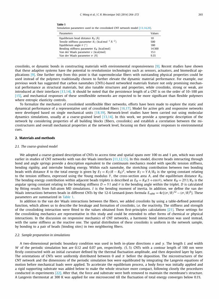
Table 1Simulation parameters used in the crosslinked CNT network model [13,14,20].
Parameters Values
Equilibrium bead distance R0 (Å) 10Tensile stiffness parameter KT (kcal mol−1 Å−2) 500Equilibrium angle θ (◦) 180Bending stiffness parameter KB (kcal/mol) 14 300Van der Waals parameter ε (kcal/mol) 15.1Van der Waals parameter σ (Å) 9.35
crosslinks, or dynamic bonds in constructing materials with environmental responsiveness [9]. Recent studies have shownthat these adaptive systems have the potential to revolutionize technologies such as sensors, actuators, and biomedical ap-plications [9]. One further step from this point is that supermolecular fibers with outstanding physical properties could beused instead of the polymers traditionally chosen to further elevate the dynamic material performance. For example, ourprevious work has suggested that carbon nanotubes (CNTs)-based networked materials feature not only promising mechan-ical performance as structural materials, but also tunable structures and properties, while crosslinks, strong or weak, areintroduced at their interfaces [13,14]. It should be noted that the persistence length of a CNT is on the order of 10–100 μm[15], and mechanical responses of these semiflexible networks are expected to be more significant than flexible polymerswhere entropic elasticity controls.
To formalize the mechanics of crosslinked semiflexible fiber networks, efforts have been made to explore the static anddynamical performance of a representative unit of crosslinked fibers [16,17]. Model for active gels and responsive networkswere developed based on single mechanical units [18,19]. Network-level studies have been carried out using moleculardynamics simulations, usually at a coarse-grained level [13,14]. In this work, we provide a synergetic description of thenetwork by considering properties of all building blocks (fibers, crosslinks) and establish a correlation between the mi-crostructures and overall mechanical properties at the network level, focusing on their dynamic responses to environmentalcues.
2. Materials and methods
2.1. The coarse-grained model
We adopted a coarse-grained description of CNTs to access time and spatial spans over 100 ns and 1 μm, which was usedearlier in studies of CNT networks with van der Waals interfaces [11,12,15]. In this model, discrete beads interacting throughbond and angle springs provide a description equivalent to the continuum mechanics model with specific tension stiffness,bending rigidity, and intertube binding energy. Within each nanotube, the stretching contribution between two bondingbeads with distance R to the total energy is given by ET = KT(R − R0)
2, where KT = Y A/R0 is the spring constant relatingto the tension stiffness, expressed using the Young modulus Y , the cross-section area A, and the equilibrium distance R0.The bending energy contribution within adjacent beads triplets is described as EB = KB(1+cos θ), where KB = 2Y I/R0 is theangular spring constant relating to the bending stiffness D = Y I and θ is the bending angle within the triplet. D is calculatedby fitting results from full-atom MD simulations. I is the bending moment of inertia. In addition, we define the van derWaals interactions between beads in different CNTs by the 12-6 Lennard-Jones formula EvdW = 4ε[(σ /R)12 − (σ /R)6]. Theseparameters are summarized in Table 1.
In addition to the van der Waals interactions between the fibers, we added crosslinks by using a table-defined potentialfunction, which allows us to describe the breakage and formation of crosslinks, i.e. the reactivity. The stiffness and strengthof the crosslinking interaction were fitted to the values obtained from first-principles calculations [21]. These settings forthe crosslinking mechanics are representative in this study and could be extended to other forms of chemical or physicalinteractions. In the discussion on responsive mechanics of CNT networks, a harmonic bond interaction was used instead,with the same stiffness as the reactive one. The spatial distribution of these crosslinks is uniform in the network sample,by bonding to a pair of beads (binding sites) in two neighboring fibers.
2.2. Sample preparation in simulations
A two-dimensional periodic boundary condition was used in both in-plane directions x and y. The length L and widthW of the periodic simulation box are 0.12 and 0.07 μm, respectively. (5,5) CNTs with a contour length of 100 nm werefirstly constructed with an initial curvature defined by the thermal fluctuation amplitude, and then deposited layer by layer.The orientations of CNTs were uniformly distributed between 0 and π before the deposition. The microstructures of theCNT network and the dimensions of the periodic simulation box were equilibrated by integrating the Langevin equations ofmotion before mechanical loads were applied. To accelerate the equilibrium process, a body force was initially applied anda rigid supporting substrate was added below to make the whole structure more compact, following closely the proceduresconducted in experiments [22]. After that, the force and substrate were both removed to maintain the membrane’s structure.A Langevin thermostat at 300 K was applied for one microsecond till the fluctuation of total energy converges below 0.1%.
266 C. Wang et al. / C. R. Mecanique 342 (2014) 264–272
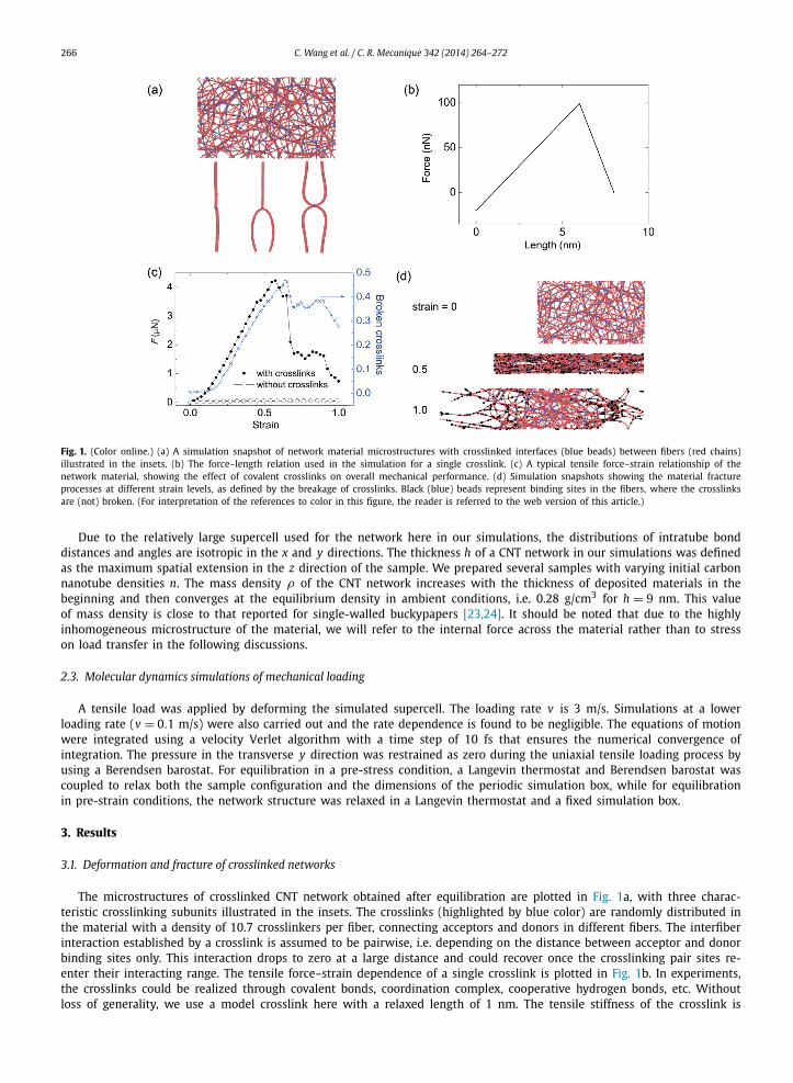
Fig. 1. (Color online.) (a) A simulation snapshot of network material microstructures with crosslinked interfaces (blue beads) between fibers (red chains)illustrated in the insets. (b) The force–length relation used in the simulation for a single crosslink. (c) A typical tensile force–strain relationship of thenetwork material, showing the effect of covalent crosslinks on overall mechanical performance. (d) Simulation snapshots showing the material fractureprocesses at different strain levels, as defined by the breakage of crosslinks. Black (blue) beads represent binding sites in the fibers, where the crosslinksare (not) broken. (For interpretation of the references to color in this figure, the reader is referred to the web version of this article.)
Due to the relatively large supercell used for the network here in our simulations, the distributions of intratube bonddistances and angles are isotropic in the x and y directions. The thickness h of a CNT network in our simulations was definedas the maximum spatial extension in the z direction of the sample. We prepared several samples with varying initial carbonnanotube densities n. The mass density ρ of the CNT network increases with the thickness of deposited materials in thebeginning and then converges at the equilibrium density in ambient conditions, i.e. 0.28 g/cm3 for h = 9 nm. This valueof mass density is close to that reported for single-walled buckypapers [23,24]. It should be noted that due to the highlyinhomogeneous microstructure of the material, we will refer to the internal force across the material rather than to stresson load transfer in the following discussions.
2.3. Molecular dynamics simulations of mechanical loading
A tensile load was applied by deforming the simulated supercell. The loading rate v is 3 m/s. Simulations at a lowerloading rate (v = 0.1 m/s) were also carried out and the rate dependence is found to be negligible. The equations of motionwere integrated using a velocity Verlet algorithm with a time step of 10 fs that ensures the numerical convergence ofintegration. The pressure in the transverse y direction was restrained as zero during the uniaxial tensile loading process byusing a Berendsen barostat. For equilibration in a pre-stress condition, a Langevin thermostat and Berendsen barostat wascoupled to relax both the sample configuration and the dimensions of the periodic simulation box, while for equilibrationin pre-strain conditions, the network structure was relaxed in a Langevin thermostat and a fixed simulation box.
3. Results
3.1. Deformation and fracture of crosslinked networks
The microstructures of crosslinked CNT network obtained after equilibration are plotted in Fig. 1a, with three charac-teristic crosslinking subunits illustrated in the insets. The crosslinks (highlighted by blue color) are randomly distributed inthe material with a density of 10.7 crosslinkers per fiber, connecting acceptors and donors in different fibers. The interfiberinteraction established by a crosslink is assumed to be pairwise, i.e. depending on the distance between acceptor and donorbinding sites only. This interaction drops to zero at a large distance and could recover once the crosslinking pair sites re-enter their interacting range. The tensile force–strain dependence of a single crosslink is plotted in Fig. 1b. In experiments,the crosslinks could be realized through covalent bonds, coordination complex, cooperative hydrogen bonds, etc. Withoutloss of generality, we use a model crosslink here with a relaxed length of 1 nm. The tensile stiffness of the crosslink is

C. Wang et al. / C. R. Mecanique 342 (2014) 264–272 267
Fig. 2. (Color online.) (a) Illustration of the simulation procedure, where prestress or prestrain was applied to the relaxed structure, followed by crosslinktuning and relaxation of network microstructure. The response in force or strain was measured after a plateau of the measured value was reached. (b) Re-sponses in the tensile force at a prestrain of 0.25, when the stiffness of crosslink is modified from k0 to k.
19.8 N/m and a peak force of 99.2 nN is set at d = 6 nm. This crosslink is much softer and more resilient than the fibersand thus under mechanical loads non-affine deformation modulated by stretching the crosslink is expected.
The mechanics of crosslinked networks was explored under uniaxial tensile loads. The force–strain relationship thusobtained is summarized in Fig. 1c. The mechanical behavior is determined by the performance of both the network elasticityand crosslinks, including contributions from stretching, bending, and intertube interaction [13]. Comparing the results forCNT networks with and without covalent crosslinks, it was found that mechanical enhancement with ∼58 times higherstrength is established by crosslinking CNTs because the original van der Waals interaction between CNTs is rather weak,which cannot resist intertube sliding and detachment, which corresponds to the plateau in the force curve and leads toductile material failure. In contrast, for the crosslinked network, the tensile force reaches the maximum at a strain of 0.57.The crosslinks start to break extensively afterwards, and the crosslinked nature of the CNT network is destroyed.
The simulation snapshots in Fig. 1d at uniaxial tensile strains of 0.5 and 1.0 show the microstructures of a CNT networkbefore and after the crosslinks connecting them are broken, successively. The simulation results show that fracture of thenetwork nucleates locally, followed by catastrophic breaking of crosslinks in that region. The percentage of broken crosslinksNC corresponds to distinct behaviors in the force–strain relationship. NC is almost zero at the initial loading stage (ε < 0.1).It gradually increases at larger strain up to 46.9%, with a linear dependence on the strain for ε < 0.65, indicating spreadingof crosslink fracture within the material. After the main fracture zone forms (ε > 0.65), some crosslinks start to be recoveredwithin the relatively intact region of the material, corresponding to a reduction in NC from 46.9% to 37.5%. For 0.7 < ε < 0.9,the external tensile load is withstood by shear resistance between fibers and there are no more breakage or recoveryevents observed for the crosslinks. At ε > 0.9, due to the topological changes in the network facilitated through interfibersliding, progressively reduced shear resistance between the fibers is observed and more crosslinks in the intact region areself-healed.
3.2. Responsive crosslinks
From the previous discussion, we can see that the interfiber crosslink plays a dominant role in modulating the defor-mation and failure behaviors of the network. Moreover, network materials with responsive crosslinks could also behavedynamically in an active environment. Following the discussion above on the crosslinking effects in tuning material proper-ties of CNT networks, we focus in this section on their dynamic responses when the crosslinks are modified. The strength kand the equilibrium position r0 are two key controlling parameters for a crosslink at equilibrium, whose energetic descrip-tion is approximated as a harmonic function E = k(r − r0)
2 here, where r is the distance between the binding sites of thecrosslink. Upon dynamic stimulations, parameters k and r0 could be modified, which consequently leads to changes in thenetwork structure and stress field therein. The response depends on the boundary conditions, i.e. whether the network is ina state of pre-applied strain or stress. The simulation procedure is illustrated in Fig. 2a.
3.2.1. Responses in a pre-strained networkWe firstly discuss here the change in tensile force transferred across the material by tuning the strength k and the equi-
librium position r0 of crosslinks, at a finite pre-strain ε0 = 0.25. The choice of this relatively large strain is made to magnify
268 C. Wang et al. / C. R. Mecanique 342 (2014) 264–272
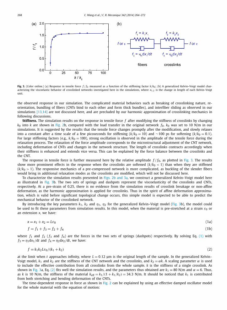
Fig. 3. (Color online.) (a) Response in tensile force f / f0 measured as a function of the stiffening factor k/k0; (b) A generalized Kelvin–Voigt model char-acterizing the viscoelastic behavior of crosslinked networks investigated here in the simulations, where x1,2 is the change in length of each Kelvin–Voigtunit.
the observed response in our simulation. The complicated material behaviors such as breaking of crosslinking nature, re-orientation, bundling of fibers (CNTs bind to each other and form thick bundles), and interfiber sliding as observed in oursimulations [13,14] are not discussed here, and are precluded by our harmonic approximation of crosslinking mechanics infollowing discussions.
Stiffness. The simulation results on the response in tensile force f after modifying the stiffness of crosslinks by changingk0 into k are shown in Fig. 2b, compared with the load transfer in the original network f0. k0 was set to 10 N/m in oursimulations. It is suggested by the results that the tensile force changes promptly after the modification, and slowly relaxesinto a constant after a time scale of a few picoseconds for stiffening (k/k0 = 10) and ∼100 ps for softening (k/k0 = 0.1).For large stiffening factors (e.g., k/k0 = 100), strong oscillation is observed in the amplitude of the tensile force during therelaxation process. The relaxation of the force amplitude corresponds to the microstructural adjustment of the CNT network,including deformation of CNTs and changes in the network structure. The length of crosslinks contracts accordingly whentheir stiffness is enhanced and extends vice versa. This can be explained by the force balance between the crosslinks andthe CNT.
The response in tensile force is further measured here by the relative amplitude f / f0, as plotted in Fig. 3. The resultsshow more prominent effects in the response when the crosslinks are softened (k/k0 < 1) than when they are stiffened(k/k0 > 1). The responsive mechanics of a pre-compressed network is more complicated, as buckling of the slender fiberswould bring in additional relaxation modes as the crosslinks are modified, which will not be discussed here.
To characterize the simulation results presented in Figs. 2b and 3a, we construct a generalized Kelvin–Voigt model hereas illustrated in Fig. 3b. The two sets of springs and dashpots represent the viscoelasticity of the crosslinks and CNTs,respectively. At a pre-strain of 0.25, there is no evidence from the simulation results of crosslink breakage or non-affinedeformation, as the harmonic approximation is applied for crosslinks. Thus in the spirit of affine deformation approxima-tion, which is valid before significant topological change occurs, this simple model is expected to be able to predict themechanical behavior of the crosslinked network.
By introducing the key parameters k1, k2 and η1, η2 for the generalized Kelvin–Voigt model (Fig. 3b), the model couldbe used to fit these parameters from simulation results. In this model, when the material is pre-stretched at a strain ε0 oran extension x, we have:
x = x1 + x2 = Lε0 (1a)
f = f1 + f3 = f2 + f4 (1b)
where f1 and f2 ( f3 and f4) are the forces in the two sets of springs (dashpots) respectively. By solving Eq. (1) withf3 = η1dx1/dt and f4 = η2dx2/dt , we have:
f = k1k2Lε0/(k1 + k2) (2)
at the limit when t approaches infinity, where L = 0.12 μm is the original length of the sample. In the generalized Kelvin–Voigt model, k1 and k2 are the stiffness of the CNT network and the crosslinks, and k2 = αk. A scaling parameter α is usedto include the effective contribution from all crosslinks from the whole sample. k is the stiffness of a single crosslink. Asshown in Fig. 3a, Eq. (2) fits well the simulation results, and the parameters thus obtained are k1 = 80 N/m and α = 6. Thus,as k is 10 N/m, the stiffness of the material keff = k1/(1 + k1/k2) = 34.3 N/m. It should be noticed that k1 is contributedfrom both stretching and bending deformation of the CNTs.
The time-dependent response in force as shown in Fig. 2 can be explained by using an effective damped oscillator modelfor the whole material with the equation of motion:

C. Wang et al. / C. R. Mecanique 342 (2014) 264–272 269
Fig. 4. (Color online.) (a) Responses in the tensile force at a pre-strain of 0.25, when the crosslink length is modified from r0 to r. (b) Responses in thetensile force measured as a function of the change in the crosslink length r/r0 that is fitted to the generalized Kelvin–Voigt model.
mx + cx + keffx = 0 (3)
where m and c are the effective mass and damping coefficients. The solution of Eq. (3) shows a damped oscillation withforce amplitude f = keffx = A exp(−ξωt) sin(ωt + B), where A and B are constants defined by the initial conditions. Theoscillating behavior in response is modulated from the underdamping to the overdamping regime, with the following criticaldamping condition:
ξ = c
2√
mkeff∼
√k1 + k2
k1k2(4)
As a result, ξ increases when k2 decreases, and the oscillation is removed in the underdamping regime, as observed inFig. 2.
Length. Another tunable parameter of the crosslink is its equilibrium length r0. When r0 deviates from its value initiallyset, the potential energy of a crosslink increases. Stress relaxation thus occurs subsequently according to the adjustmentof the network microstructures. For each modified value of r0 from 1.0 nm to a value between 0.7 and 1.3 nm, a durationof ∼20 ps is required for the system to recover to a stable state, as shown in Fig. 4a. Then the amplitude of the forcesaturates into a constant f . The response in force amplitude f / f0 is plotted in Fig. 4b as a function of the relative lengthscaling factor r/r0, which suggests a linear dependence between them, i.e. f / f0 decreases as r/r0 increases. This result isin contrast to the relatively magnified response when softening the crosslink by decreasing k.
This dependence could also be explained by the generalized Kelvin–Voigt model. Solving Eq. (1) gives:
f = keffL[ε0 + β(r0 − r)/r
](5)
where keff is the stiffness of the whole system, β is a fitting parameter introduced to include the contribution of a singlecrosslink to the strain. Fitting the simulation results in Fig. 4 yields β = 0.078, and the stiffness of the material is 50.2 N/mcompared to 34.3 N/m as obtained above from our simulations with a modified stiffness of the crosslinks. In addition, thetime scale of the relaxation is predicted by τ = (η1 + η2)/(k1 + k2), depending synergetically on both the CNT network andcrosslinks. According to this formula, τ decreases when k2 increases as shown in Fig. 2, but does not change with r (Fig. 4a).
3.2.2. Responses in a pre-stressed networkSimilar effects have also been observed while a pre-stress is applied, as illustrated by the results plotted in Figs. 5a
and 5b. The pre-tension in the simulations is f0 = 2.7 μN. Softening shows a more prominent effect in the response. Bytuning the stiffness of crosslinks from k0 = 10 N/m to values in the range of 1–1000 N/m, we fit the response in strainamplitude by:
ε = f0(1/k1 + 1/k2)/L (6)
where k2 = γ k, with k the modified stiffness of a single crosslink as defined above. The fitting parameters γ and thestiffness of CNTs k1 are 57.1 and 45.9 N/m, respectively. These fitting results are consistent with the value k1 = 80 N/mobtained above, with quantitative deviation due to the simplified nature of our analytical model. Numerical fitting usingparameters γ and k1 is also plotted in Fig. 5b. The consistence further validates the predictability of the model. The typicalrelaxation time is τ = η2/k2. Thus, as k2 increases, the time scale of the relaxation τ decreases. However, it does not changewith r. Thus the mechanical response at the network level can be modulated by molecular-level crosslinks in both pre-strainand pre-stress boundary conditions, and is expected to be valid in their combination as well.

270 C. Wang et al. / C. R. Mecanique 342 (2014) 264–272
Fig. 5. (Color online.) (a) Responses in the tensile strain at a pre-tension of 1.5 μN, when the stiffness of a single crosslink is modified from k0 to k.(b) Responses in the tensile strain measured as a function of the change in the crosslink stiffness k/k0. The red line corresponds to the prediction usingthe parameters fitting our prestrain results, as discussed earlier.
Fig. 6. (Color online.) (a) Response under equibiaxial loading with a pre-strain of 0.25, when the crosslink’s stiffness is modified from k0 to k. (b) Responsein tensile force f / f0 measured as a function of the stiffening factor k/k0.
3.2.3. Responses under biaxial loading conditionsWe further extend our exploration to equibiaxial loading conditions. The results show effects similar to the simulation
results for uniaxial loading conditions shown above. For the pre-strain condition with an initial strain of 0.25, the tensionforce in one direction was measured after the crosslinks’ stiffness was tuned (Fig. 6a). The force increases as the crosslinkbecomes stiffer (Fig. 6b). Eq. (2) also fits well the simulation results and the fitting parameters of network stiffness k1 andα are 167.6 N/m and 38.2, respectively. Compared to the uniaxial loading conditions, the response in force is more prompthere because a more affined deformation could be realized under biaxial loads as the reorientation of CNTs is avoided [13].With a pre-tension f0 of 3.5 μN, the strain in both directions was measured (Fig. 7a). The fitting parameters γ and thestiffness of CNTs k1 using Eq. (6) are 41.9 and 134.7 N/m, respectively (Fig. 7b). The latter value is consistent with that of167.6 N/m with biaxial pre-strain.
4. Discussion
The generalized Kelvin–Voigt model constructed here offers a minimal consideration of the mechanical response tocrosslink stiffness and length modulation. However, limited for the sake of simplification to the use of only two units, thefitted parameters from our pre-stress and pre-strain simulations yield quantitatively different, although reasonably consis-tent, results. The variation in network microstructures upon different loading conditions as encountered in the simulations,as well as the randomness in network structures and crosslinks, could lead to additional sources of the deviation of fittingparameters in the model. To improve the model and extend the understanding for material optimization, a continuum-levelviscoelastic model may help.
5. Conclusion
To conclude, we explored the responsive mechanics of crosslinked fiber-network materials using CNTs as an examplehere. By functionalizing CNTs on their sidewalls or ends, various chemical groups could be introduced, and the interac-tions between CNTs through these binding agents can be engineered [25]. Coarse-grained molecular dynamics simulation

C. Wang et al. / C. R. Mecanique 342 (2014) 264–272 271
Fig. 7. (Color online.) (a) Response in equibiaxial loading at a pre-tension of 3.5 μN, when the stiffness of a single crosslink is modified from k0 to k.(b) Response in tensile strain measured as a function of the change in the crosslink stiffness k/k0.
and analysis results reveal not only the dependence of the response on controlling parameters, the stiffness and lengthof crosslinks, but also the detailed microscale dynamics. The prompt response in a subnanosecond timescale and the pre-dicted dependence of the mechanical behavior on the crosslinking nature and its changes imply their high performance asresponsive materials.
In this work, random fiber networks are investigated. However, the performance could be further enhanced by usingmore regular, woven structures. Two further important issues, the dynamic responses of the network material at finitefrequency [18], and effects of the medium (e.g., hydrated environment, polymer matrix), are not discussed here, but inprinciple could be studied using the techniques introduced here.
Acknowledgements
This work was supported by the National Natural Science Foundation of China through Grants 11222217, 11002079,Tsinghua University Initiative Scientific Research Program 2011Z02174. L.F. Wang acknowledges the support of the NationalScience Foundation under Award number CMMI-1234768. The computation was performed on the Explorer 100 clustersystem of Tsinghua National Laboratory for Information Science and Technology.
References
[1] R. Lakes, Materials with structural hierarchy, Nature 361 (1993) 511.[2] M.J. Buehler, Y.C. Yung, Deformation and failure of protein materials in physiologically extreme conditions and disease, Nat. Mater. 8 (2009) 175.[3] N. Halonen, A. Rautio, A.-R. Leino, T. Kyllönen, G. Tóth, J. Lappalainen, K. Kordás, M. Huuhtanen, R.L. Keiski, A. Sápi, M. Szabó, A. Kukovecz, Z. Kónya,
I. Kiricsi, P.M. Ajayan, R. Vajtai, Three-dimensional carbon nanotube scaffolds as particulate filters and catalyst support membranes, ACS Nano 4 (2010)2003.
[4] F. Deng, M. Ito, T. Noguchi, L. Wang, H. Ueki, K.-i. Niihara, Y.A. Kim, M. Endo, Q.-S. Zheng, Elucidation of the reinforcing mechanism in carbon nano-tube/rubber nanocomposites, ACS Nano 5 (2011) 3858.
[5] K.E. Kasza, A.C. Rowat, J. Liu, T.E. Angelini, C.P. Brangwynne, G.H. Koenderink, D.A. Weitz, The cell as a material, Curr. Opin. Cell Biol. 19 (2007) 101.[6] S.W. Cranford, A. Tarakanova, N.M. Pugno, M.J. Buehler, Nonlinear material behaviour of spider silk yields robust webs, Nature 482 (2012) 72.[7] J.S. Mohammed, W.L. Murphy, Bioinspired design of dynamic materials, Adv. Mater. 21 (2009) 2361.[8] M.A.C. Stuart, W.T.S. Huck, J. Genzer, M. Muller, C. Ober, M. Stamm, G.B. Sukhorukov, I. Szleifer, V.V. Tsukruk, M. Urban, F. Winnik, S. Zauscher, I. Luzinov,
S. Minko, Emerging applications of stimuli-responsive polymer materials, Nat. Mater. 9 (2010) 101.[9] R.J. Wojtecki, M.A. Meador, S.J. Rowan, Using the dynamic bond to access macroscopically responsive structurally dynamic polymers, Nat. Mater. 10
(2011) 14.[10] N. Holten-Andersen, M.J. Harrington, H. Birkedal, B.P. Lee, P.B. Messersmith, K.Y.C. Lee, J.H. Waite, pH-induced metal–ligand cross-links inspired by
mussel yield self-healing polymer networks with near-covalent elastic moduli, Proc. Natl. Acad. Sci. USA 108 (2011) 2651.[11] D.E. Fullenkamp, L. He, D.G. Barrett, W.R. Burghardt, P.B. Messersmith, Mussel-inspired histidine-based transient network metal coordination hydrogels,
Macromolecules 46 (2013) 1167.[12] H. Xu, J. Nishida, W. Ma, H. Wu, M. Kobayashi, H. Otsuka, A. Takahara, Competition between oxidation and coordination in cross-linking of polystyrene
copolymer containing catechol groups, ACS Macro Lett. 1 (2012) 457.[13] B. Xie, Y. Liu, Y. Ding, Q. Zheng, Z. Xu, Mechanics of carbon nanotube networks: microstructural evolution and optimal design, Soft Matter 7 (2011)
10039.[14] C. Wang, B. Xie, Y. Liu, Z. Xu, Mechanotunable microstructures of carbon nanotube networks, ACS Macro Lett. 1 (2012) 1176.[15] N. Fakhri, D.A. Tsyboulski, L. Cognet, R.B. Weisman, M. Pasquali, Diameter-dependent bending dynamics of single-walled carbon nanotubes in liquids,
Proc. Natl. Acad. Sci. USA 106 (2009) 14219.[16] F.C. MacKintosh, J. Käs, P.A. Janmey, Elasticity of semiflexible biopolymer networks, Phys. Rev. Lett. 75 (1995) 4425.[17] C.P. Broedersz, M. Depken, N.Y. Yao, M.R. Pollak, D.A. Weitz, F.C. MacKintosh, Cross-link-governed dynamics of biopolymer networks, Phys. Rev. Lett.
105 (2010) 238101.[18] T.B. Liverpool, M.C. Marchetti, J.F. Joanny, J. Prost, Mechanical response of active gels, Europhys. Lett. 85 (2009) 18007.[19] Z. Xu, Mechanics of metal–catecholate complexes: the roles of coordination state and metal types, Sci. Rep. 3 (2013) 2914.[20] S. Cranford, M.J. Buehler, In silico assembly and nanomechanical characterization of carbon nanotube buckypaper, Nanotechnology 21 (2010) 265706.

272 C. Wang et al. / C. R. Mecanique 342 (2014) 264–272
[21] Y. Liu, B. Xie, Z. Xu, Mechanics of coordinative crosslinks in graphene nanocomposites: a first-principles study, J. Mater. Chem. 21 (2011) 6707.[22] M. Xu, D.N. Futaba, T. Yamada, M. Yumura, K. Hata, Carbon nanotubes with temperature-invariant viscoelasticity from −196 ◦C to 1000 ◦C, Science 330
(2010) 1364.[23] R.L.D. Whitby, T. Fukuda, T. Maekawa, S.L. James, S.V. Mikhalovsky, Geometric control and tuneable pore size distribution of buckypaper and buckydiscs,
Carbon 46 (2008) 949.[24] B. Ashrafi, J. Guan, V. Mirjalili, P. Hubert, B. Simard, A. Johnston, Correlation between Young’s modulus and impregnation quality of epoxy-impregnated
SWCNT buckypaper, Composites, Part A, Appl. Sci. Manuf. 41 (2010) 1184.[25] S. Acquah, D. Ventura, H. Kroto, in: J.M. Marulanda (Ed.), Electronic Properties of Carbon Nanotubes, Intech, 2011.