ME 323 Mechanics of Materials
11
ME 323 Mechanics of Materials Homework 12 December 5, 2019 Problem 12.1 (10 points). The state of stress acting at a critical point on the seat frame of an automobile during a crash is shown in Fig 12.1 a) Determine the three principal stresses, the absolute maximum shear stress τ max,abs , and the von-Mises stress σ M . b) If the frame was made of specialized material (considered as ductile material) having yield strength S y = 300 ksi, determine the factor of safety according to 1. The maximum shear stress theory. 2. The maximum distortional energy theory. c) If the frame was made of an experimental light weight composite material which be- haves close to a brittle material whose ultimate strength in tension S UT = 200 ksi, and whose ultimate strength in compression S UC = 500 ksi, determine the factor of safety according to 1. The maximum normal stress theory (for both tensile and compressive loadings). 2. Mohr’s theory of failure. Fig. 12.1 1
-
Upload
khangminh22 -
Category
Documents
-
view
0 -
download
0
Transcript of ME 323 Mechanics of Materials

ME 323 Mechanics of Materials
Homework 12
December 5, 2019
Problem 12.1 (10 points). The state of stress acting at a critical point on the seat frameof an automobile during a crash is shown in Fig 12.1
a) Determine the three principal stresses, the absolute maximum shear stress τmax,abs, andthe von-Mises stress σM .
b) If the frame was made of specialized material (considered as ductile material) havingyield strength Sy = 300 ksi, determine the factor of safety according to
1. The maximum shear stress theory.
2. The maximum distortional energy theory.
c) If the frame was made of an experimental light weight composite material which be-haves close to a brittle material whose ultimate strength in tension SUT = 200 ksi, andwhose ultimate strength in compression SUC = 500 ksi, determine the factor of safetyaccording to
1. The maximum normal stress theory (for both tensile and compressive loadings).
2. Mohr’s theory of failure.
Fig. 12.1
1

Proof. Part a): Given,
σx = 90 ksi;σy = −50 ksi; τxy = −30 ksi
σavg =σx + σy
2=
90− 50
2= 20 ksi
R =
√(σx − σy
2
)2
+ τ 2xy =
√(90 + 50
2
)2
+ 302 = 76.16 ksi
The principal stresses are,
σP1 = σavg +R = 96.16 ksi;σP2 = σavg −R = −56.16 ksi
σP3 = 0
Since σP1 > 0;σP2 < 0. The τmax,abs can be obtained by,
τmax,abs =σP1 − σP2
2= 76.16 ksi
calculating Von-Mises stress,
σM =√σ2P1− σP1σP2 + σ2
P2= 133.42 ksi
Part b): Given, yield strength Sy = 300 ksi. The factor of safety FS according to:1) MSST,
FS =Sy
2 ∗ τmax,abs
=300
2 ∗ 76.16= 1.97
2) MDET,
FS =Sy
σM=
300
133.42= 2.25
Part c): Given, SUT = 200 ksi;SUC = 500 ksi. The factor of safety FS according to:1) MNST,Since σP1 > 0;σP2 < 0, the tensile factor of safety is,
FST =SUT
σP1
=200
96.16= 2.08
compressive factor of safety is,
FSC =SUC
|σP2|=
500
56.16= 8.9
∴ FS = FST (< FSC)
2) Mohr’s theory,σP1
SUT
− σP2
SUC
=96.16
200− −56.16
500' 0.59
FS =1
0.59' 1.69
2

Problem 12.2 (10 points). The A-36 steel pipe (yield strength, Sy = 250 MPa) has outerand inner diameters of 30mm and 20mm, respectively. If the factor of safety guarding againstyielding at point A (as shown in Fig. 12.2 (b)) is 1.5,
a) Determine the maximum allowable force P according to the maximum-shear-stresstheory.
b) Determine the maximum allowable force P according to the maximum-distortional-energy theory.
Hint: Maximum shear stress for a disk cross-section is 2VA
Fig. 12.2 (a)
Fig. 12.2 (b)
3
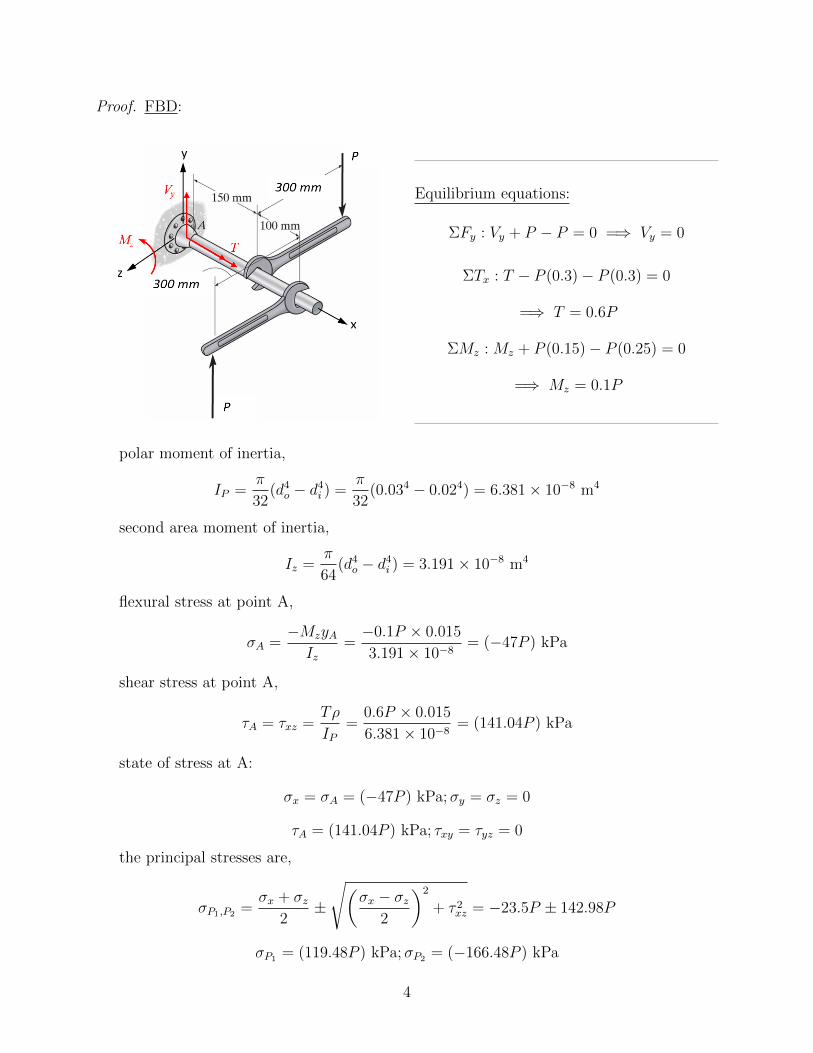
Proof. FBD:
Equilibrium equations:
ΣFy : Vy + P − P = 0 =⇒ Vy = 0
ΣTx : T − P (0.3)− P (0.3) = 0
=⇒ T = 0.6P
ΣMz : Mz + P (0.15)− P (0.25) = 0
=⇒ Mz = 0.1P
polar moment of inertia,
IP =π
32(d4o − d4i ) =
π
32(0.034 − 0.024) = 6.381× 10⁻⁸ m4
second area moment of inertia,
Iz =π
64(d4o − d4i ) = 3.191× 10⁻⁸ m4
flexural stress at point A,
σA =−MzyAIz
=−0.1P × 0.015
3.191× 10−8= (−47P ) kPa
shear stress at point A,
τA = τxz =Tρ
IP=
0.6P × 0.015
6.381× 10−8= (141.04P ) kPa
state of stress at A:
σx = σA = (−47P ) kPa;σy = σz = 0
τA = (141.04P ) kPa; τxy = τyz = 0
the principal stresses are,
σP1,P2 =σx + σz
2±
√(σx − σz
2
)2
+ τ 2xz = −23.5P ± 142.98P
σP1 = (119.48P ) kPa;σP2 = (−166.48P ) kPa
4
a) According to MSS theory,
τmax,abs =σP1 − σP2
2= (142.98P ) kPa
FS =Sy
2 ∗ τmax,abs
=⇒ 1.5 =250× 106
2 ∗ 142.98P × 103=⇒ P = 582.83 N
b) According to the MDE theory,
σM =√σ2P1− σP1σP2 + σ2
P2= (248.76P ) kPa
FS =Sy
σM=⇒ 1.5 =
250× 106
248.76P × 103=⇒ P = 670 N
5
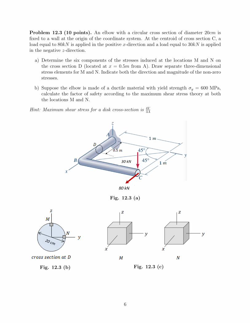
Problem 12.3 (10 points). An elbow with a circular cross section of diameter 20cm isfixed to a wall at the origin of the coordinate system. At the centroid of cross section C, aload equal to 80kN is applied in the positive x-direction and a load equal to 30kN is appliedin the negative z-direction.
a) Determine the six components of the stresses induced at the locations M and N onthe cross section D (located at x = 0.5m from A). Draw separate three-dimensionalstress elements for M and N. Indicate both the direction and magnitude of the non-zerostresses.
b) Suppose the elbow is made of a ductile material with yield strength σy = 600 MPa,calculate the factor of safety according to the maximum shear stress theory at boththe locations M and N.
Hint: Maximum shear stress for a disk cross-section is 4V3A
Fig. 12.3 (a)
Fig. 12.3 (b) Fig. 12.3 (c)
6
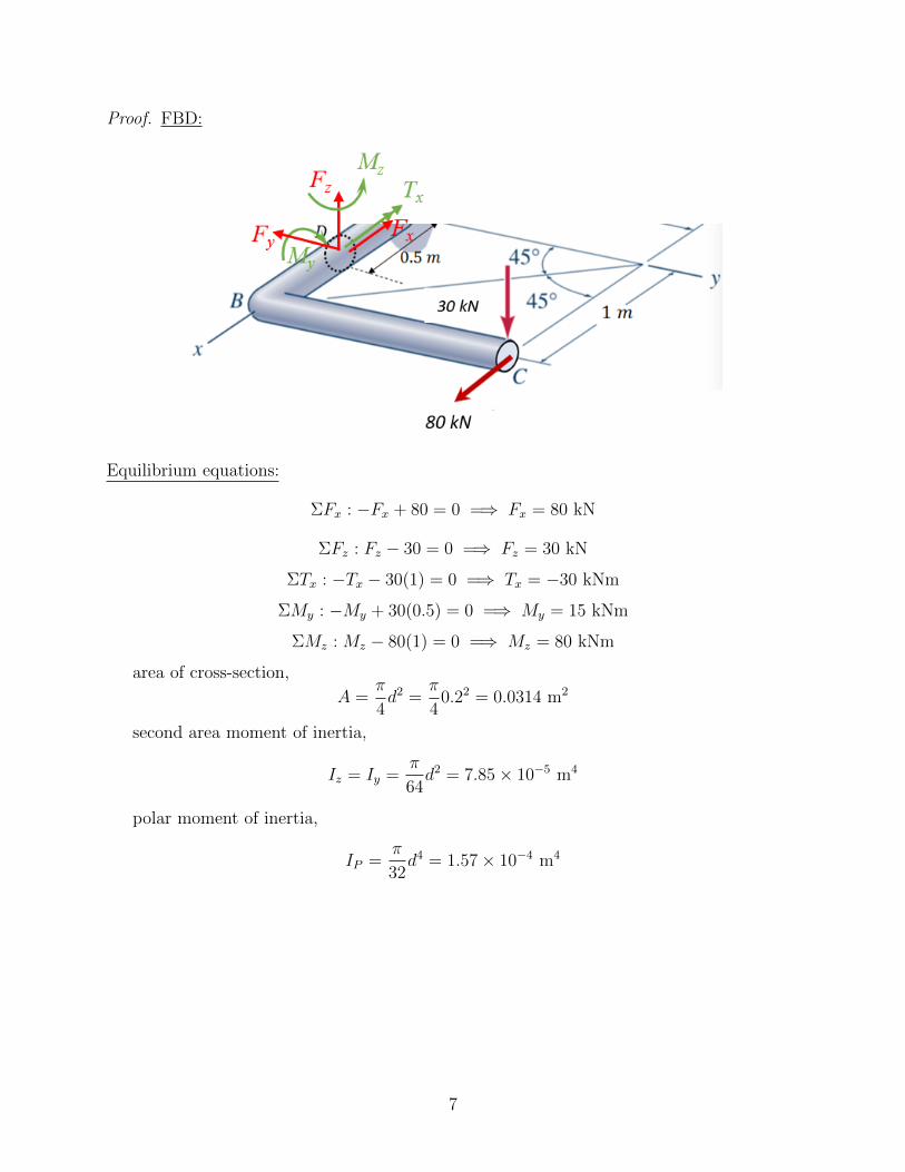
Proof. FBD:
Equilibrium equations:
ΣFx : −Fx + 80 = 0 =⇒ Fx = 80 kN
ΣFz : Fz − 30 = 0 =⇒ Fz = 30 kN
ΣTx : −Tx − 30(1) = 0 =⇒ Tx = −30 kNm
ΣMy : −My + 30(0.5) = 0 =⇒ My = 15 kNm
ΣMz : Mz − 80(1) = 0 =⇒ Mz = 80 kNm
area of cross-section,
A =π
4d2 =
π
40.22 = 0.0314 m2
second area moment of inertia,
Iz = Iy =π
64d2 = 7.85× 10⁻⁵ m4
polar moment of inertia,
IP =π
32d4 = 1.57× 10⁻⁴ m4
7
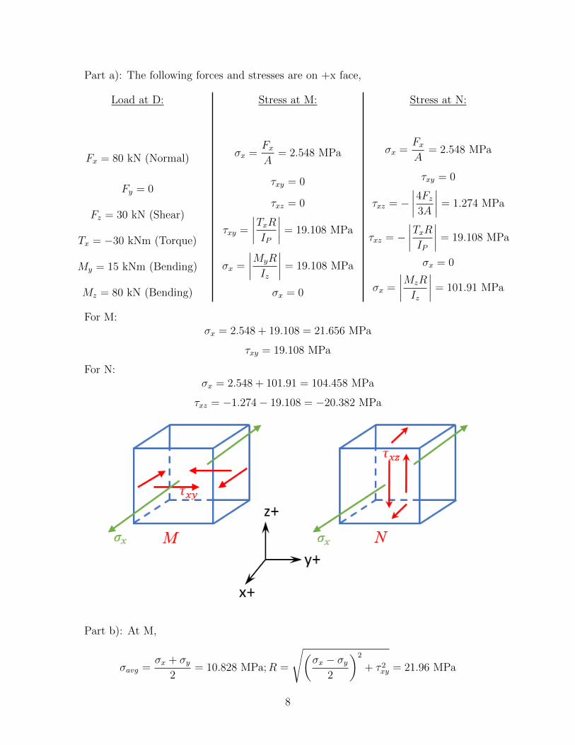
Part a): The following forces and stresses are on +x face,
Load at D:
Fx = 80 kN (Normal)
Fy = 0
Fz = 30 kN (Shear)
Tx = −30 kNm (Torque)
My = 15 kNm (Bending)
Mz = 80 kN (Bending)
Stress at M:
σx =Fx
A= 2.548 MPa
τxy = 0
τxz = 0
τxy =
∣∣∣∣TxRIP∣∣∣∣ = 19.108 MPa
σx =
∣∣∣∣MyR
Iz
∣∣∣∣ = 19.108 MPa
σx = 0
Stress at N:
σx =Fx
A= 2.548 MPa
τxy = 0
τxz = −∣∣∣∣4Fz
3A
∣∣∣∣ = 1.274 MPa
τxz = −∣∣∣∣TxRIP
∣∣∣∣ = 19.108 MPa
σx = 0
σx =
∣∣∣∣MzR
Iz
∣∣∣∣ = 101.91 MPa
For M:σx = 2.548 + 19.108 = 21.656 MPa
τxy = 19.108 MPa
For N:σx = 2.548 + 101.91 = 104.458 MPa
τxz = −1.274− 19.108 = −20.382 MPa
Part b): At M,
σavg =σx + σy
2= 10.828 MPa;R =
√(σx − σy
2
)2
+ τ 2xy = 21.96 MPa
8

σP1 = σavg +R = 32.79 MPa;σP2 = σavg −R = −11.132 MPa
τmax,abs =σP1 − σP2
2= 21.961 MPa
∴ FSM =Sy
2 ∗ τmax,abs
= 13.66
At N,
σavg =σx + σz
2= 52.229 MPa;R =
√(σx − σy
2
)2
+ τ 2xy = 56.065 MPa
σP1 = σavg +R = 108.29 MPa;σP2 = σavg −R = −3.836 MPa
τmax,abs =σP1 − σP2
2= 56.063 MPa
∴ FSN =Sy
2 ∗ τmax,abs
= 5.36
Hence,FS = FSN(< FSM) = 5.36
9
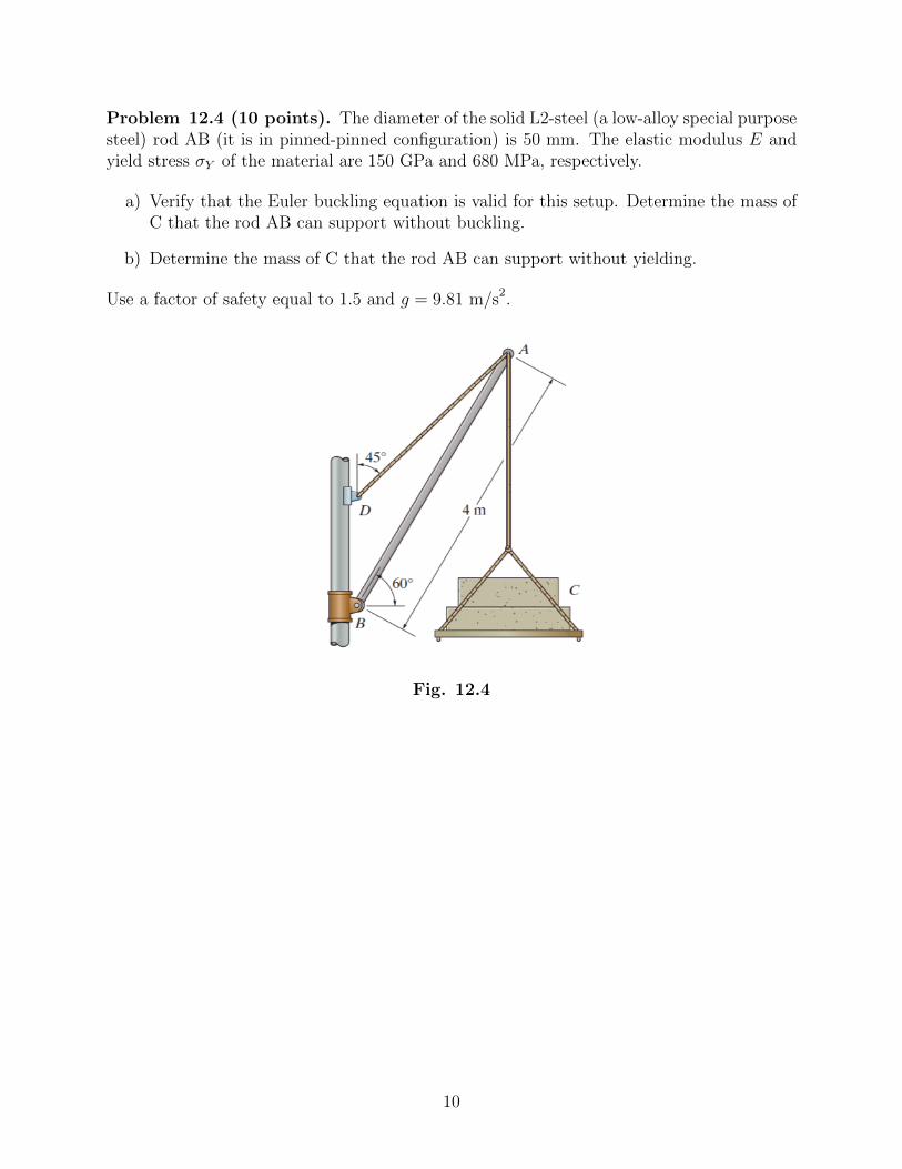
Problem 12.4 (10 points). The diameter of the solid L2-steel (a low-alloy special purposesteel) rod AB (it is in pinned-pinned configuration) is 50 mm. The elastic modulus E andyield stress σY of the material are 150 GPa and 680 MPa, respectively.
a) Verify that the Euler buckling equation is valid for this setup. Determine the mass ofC that the rod AB can support without buckling.
b) Determine the mass of C that the rod AB can support without yielding.
Use a factor of safety equal to 1.5 and g = 9.81 m/s2.
Fig. 12.4
10

Proof. FBD:
Equilibrium equations:
ΣFx = −FABcos(60)− FADcos(45) = 0
=⇒ FAB = −√
2FAD
ΣFx = −FABsin(60)−FADsin(45)−mg = 0
=⇒√
2FAD
√3
2− FAD√
2= mg
∴ FAD = 1.932mg
FAB = −26.8m (compressive force)
Part a): For pin - pin column, Leff = L = 4 m
r =
√I
A;A =
π
4d2 =
π
4(0.05)2 = 1.96× 10⁻³ m2
I =π
64d4 = 3.068× 10⁻⁷m4 =⇒ r = 0.0125 m
verifying the Euler-buckling criteria,(Leff
r
)= 319.71;
√π2E
0.5σy=
(Leff
r
)c
= 66
∴
(Leff
r
)>
(Leff
r
)c
Hence, Euler theory is valid for this situation. So, to find out the critical load,
Pcr =π2EI
L2eff
= 28.387kN = |FAB| × FS = 26.8m× 1.5
=⇒ m = 706.14 kg
Part b) If the column was to yield without buckling then the mass C could be,
σcomp. =FAB
A=
25.8m
1.96× 10−3=
Sy
FS=
680× 106
1.5
=⇒ m = 33, 154 kg
this shows that buckling is a very important phenomena to take into account duringdesign.
11