Mechanics of Materials - Tishk International University
44
Mechanics of Materials Chapter 1 Introduction & stress Fall Semester 2019 Instructor: Twana A. Hussein [email protected] Civil Engineering Dept. Tishk International University
-
Upload
khangminh22 -
Category
Documents
-
view
1 -
download
0
Transcript of Mechanics of Materials - Tishk International University

Mechanics of Materials
Chapter 1
Introduction & stress
Fall Semester 2019
Instructor: Twana A. Hussein
Civil Engineering Dept.
Tishk International University

Course objective
To show how to determine the stress, strain, and deflection
suffered by bi-dimensional (and simple tri-dimensional)
structural elements when subjected to different loads (e.g.
normal, shear, torsion, bending and combined loads).
Once the state of stresses and strains has been established for a
particular structure type, the student will be able to evaluate the
allowable loads and associated allowable stresses before
mechanical failure

Learning Outcomes
Upon successful completion of this course students should be able to:
Understand the fundamental concepts of stress and strain and the relationship between both through the strain-stress equations in order to solve problems for simple tri-dimensional elastic solids.
Calculate and represent the stress diagrams in bars and simple structures
Solve problems relating to pure and non-uniform bending of beams and other simple structures
Solve problems relating to torsional deformation of bars and other simple tri-dimensional structures
Understand the concept of buckling and be able to solve the problems related to isolated bars

Course outline:
Fundamentals of stress and strain
Allowable stresses, allowable loads, and safety factors
Tension, Compression and Shear
Torsion
Bending
Buckling
Deflections of beams

Introduction.
Mechanics of materials is a study of the relationship between the external
loads on a body and the intensity of the internal loads within the body.
It is not possible solely on basis of force calculation to assess the
structural integrity of a component or structure.
Strength of materials is obviously a core subject for mechanical and
mechatronics engineers, since it enables us to determine by calculation, if
the components we design will function as intended or fail.
In order to do so, we define the term stress as a measure for internal force
per area acting inside a structure.

Introduction.
Converting our internal forces to stresses by calculations
provides us with a measure that contrary to forces can be
related to characteristic material values.
We will furthermore consider the problem related to
calculation of deformations in components and structures.
On basis of calculated deformations, it will be considered
how to calculate strains as a measure for how large
deformations are relative to the dimensions of the considered
component.

Recap: the concept of static equilibrium
From statics, we know that the following three relations apply
if a plane mechanical system is in static equilibrium,
∑ 𝐹𝑥 = 0 ∑ 𝐹𝑦 = 0 ∑ 𝑀𝑧 = 0 (1-1)
Equation 1-1 basically reads, that we can sum up all forces in
the directions of a cleverly chosen coordinate system and
furthermore calculate the sum of moments around a point of
our own choice.

Equilibrium of a Deformable Body
Reactions
Surface forces developed at the supports/points of contact between
bodies.

Equilibrium of a Deformable Body
Equilibrium of a body requires a balance of forces and a
balance of moments
For a body with x, y, z coordinate system with origin O,
∑ 𝐹𝑥 = 0 ∑ 𝐹𝑦 = 0 ∑ 𝐹𝑧 = 0
∑ 𝑀x = 0 ∑ 𝑀y = 0 ∑ 𝑀𝑧 = 0
Best way to account for these forces is to draw the body’s
free-body diagram (FBD).

Internal Resultant Loadings
Objective of FBD is to determine the resultant force and
moment acting within a body.
In general, there are 4 different types of resultant loadings:
a) Normal force, N
b) Shear force, V
c) Torsional moment or torque, T
d) Bending moment, M

Example 1.1
Determine the resultant internal loadings acting on the cross
section at C of the beam.

Solution:
Free body Diagram
Distributed loading at C is found by proportion,
Magnitude of the resultant of the distributed load,
,

Solution:
Applying the equations of
equilibrium we have

Example 1.2
Determine the resultant internal loadings acting on the cross section at B
of the pipe. The pipe has a mass of 2 kg/m and is subjected to both a vertical
force of 50 N and a couple moment of 70 N·m at its end A. It is fixed to the
wall at C.

Example 1.2
Free body Diagram

Solution:
Calculating the weight of each segment of pipe,
• Applying the six scalar equations of equilibrium,

Solution:

Stress
Normal Stress- Axial Loading
• The resultant of the internal forces for
an axially loaded member is normal to a
section cut perpendicular to the member
axis.
• The force intensity on that section is
defined as the normal stress.
Both the analysis and design of a given
structure involve the determination of
stresses and deformations.

Normal Stress
The normal stress at a particular point maynot be equal to the average stress but theresultant of the stress distribution must satisfy
The detailed distribution of stress is staticallyindeterminate, i.e., can not be found from staticsalone.
A uniform distribution of stress in a sectionimplies that the line of action of the resultant ofthe internal forces passes through the centroidof the section.

Normal Stress
A uniform distribution of stress is only
possible if the concentrated loads on the end
sections of two-force members are applied at
the section centroids. This is referred to as
centric loading.
If a two-force member is eccentrically loaded,
then the resultant of the stress distribution in a
section must yield an axial force and a
moment.
The stress distributions in eccentrically
loaded members cannot be uniform or
symmetric.

Example 1.3
Two solid circular rods are welded to a plate at B to form a
single rod, as shown in the figure. Consider the 30kN force at
B to be uniformly distributed around the circumference of the
collar at B and the 10 kN load at C to be applied at the
centroid of the end cross section. Determine the axial stress in
each portion of the rod.

Example 1.4
The bar has a constant width of 35 mm and a thickness of 10 mm.
Determine the maximum average normal stress in the bar when it is
subjected to the loading shown.
Solution:
By inspection, different sections have different internal forces.

Solution:
Graphically, the normal force diagram is as shown.
By inspection, the largest loading is in region BC,
Since the cross-sectional area of the bar is
constant,
the largest average normal stress is

Example 1.5
Solution:By drawing a free-body diagram of the top segment,
the internal axial force P at the section is

Shearing Stress
Forces P and P’ are applied transversely to the member
AB.
Corresponding internal forces act in the plane of section
C and are called shearing forces.
The resultant of the internal shear force distribution is
defined as the shear of the section and is equal to the
load P.
The corresponding average shear stress is,
Shear stress distribution varies from zero at the member
surfaces to maximum values that may be much larger
than the average value.
The shear stress distribution cannot be assumed to be
uniform.

Shearing Stress
The average shear stress distributed over each sectioned area that develops a shear force.
τ = average shear stress
P = internal resultant shear force
A = area at that section

Shearing Stress Examples

Bearing Stress in Connections
Bolts, rivets, and pins create
stresses on the points of contact
or bearing surfaces of the
members they connect.
The resultant of the force
distribution on the surface is
equal and opposite to the force
exerted on the pin.
Corresponding average force
intensity is called the bearing
stress,

Allowable Stress
Many unknown factors that influence the actual stress in a
member.
A factor of safety is needed to obtained allowable load.
The factor of safety (F.S.) is a ratio of the failure load divided
by the allowable load

Example 1.6
Solution:
For equilibrium we have

Solution:The pin at C resists the resultant force at C. Therefore,
The pin is subjected to double shear, a shear force of
15.205 kN acts over its cross sectional area between the
arm and each supporting leaf for the pin.The required area is

Example 1.7

Solution

Example 1.8
The structure is designed to support a 30 kN load. The structure consists of a
boom and rod joined by pins (zero moment connections) at the junctions and
supports Perform a static analysis to determine the internal force in each
structural member and the reaction forces at the supports

Structure Free-Body Diagram Structure is detached from supports and the
loads and reaction forces are indicated
Conditions for static equilibrium:
Ay and Cy can not be determined from these equations

Solution
In addition to the complete structure, each component must satisfy the conditions for static equilibrium
Consider a free-body diagram for the boom:
Substitute into the structure equilibrium equation
Results:
Reaction forces are directed along boom and rod
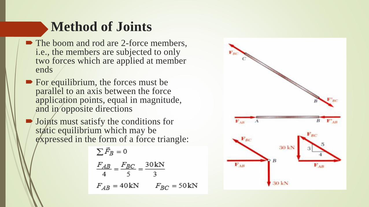
Method of Joints The boom and rod are 2-force members,
i.e., the members are subjected to only two forces which are applied at member ends
For equilibrium, the forces must be parallel to an axis between the force application points, equal in magnitude, and in opposite directions
Joints must satisfy the conditions for static equilibrium which may be expressed in the form of a force triangle:

Stress Analysis
Can the structure safely support the 30 kN load?
From a statics analysis
At any section through member BC, the internal force is 50 kN with a force intensity or stress of
From the material properties for steel, the allowable stress is
Conclusion: the strength of member BC is adequate

Design Design of new structures requires selection of
appropriate materials and component
dimensions to meet performance requirements
For reasons based on cost, weight, availability,
etc., the choice is made to construct the rod
from aluminum. What is an appropriate choice
for the rod diameter?
• An aluminum rod 26 mm or more in diameter is
adequate

Stress Analysis & Design Example
Would like to determine the
stresses in the members and
connections of the structure
shown.
From a statics analysis:
FAB = 40 kN (compression)
FBC = 50 kN (tension)
Must consider maximum
normal stresses in AB and BC,
and the shearing stress and
bearing stress at each pinned
connection

Rod & Boom Normal Stresses

Pin Shearing Stresses

Pin Shearing Stresses