Palæomagnetic results and palæointensity of Late Cretaceous Madagascan basalt
Upload
independentCategory
view
0download
0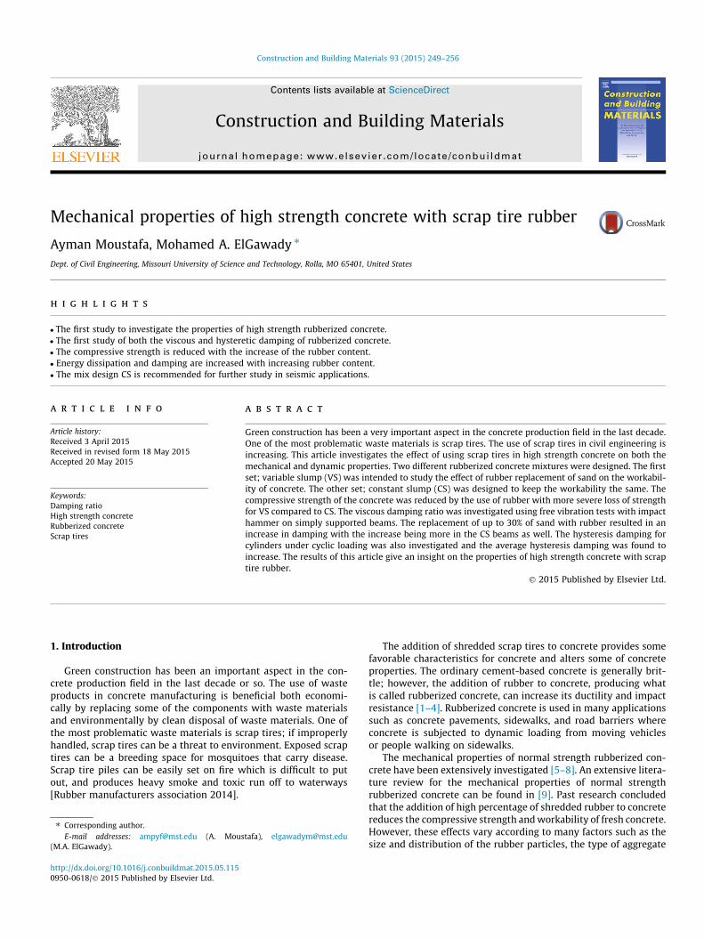
Construction and Building Materials 93 (2015) 249–256
Contents lists available at ScienceDirect
Construction and Building Materials
journal homepage: www.elsevier .com/locate /conbui ldmat
Mechanical properties of high strength concrete with scrap tire rubber
http://dx.doi.org/10.1016/j.conbuildmat.2015.05.1150950-0618/� 2015 Published by Elsevier Ltd.
⇑ Corresponding author.E-mail addresses: [email protected] (A. Moustafa), [email protected]
(M.A. ElGawady).
Ayman Moustafa, Mohamed A. ElGawady ⇑Dept. of Civil Engineering, Missouri University of Science and Technology, Rolla, MO 65401, United States
h i g h l i g h t s
� The first study to investigate the properties of high strength rubberized concrete.� The first study of both the viscous and hysteretic damping of rubberized concrete.� The compressive strength is reduced with the increase of the rubber content.� Energy dissipation and damping are increased with increasing rubber content.� The mix design CS is recommended for further study in seismic applications.
a r t i c l e i n f o
Article history:Received 3 April 2015Received in revised form 18 May 2015Accepted 20 May 2015
Keywords:Damping ratioHigh strength concreteRubberized concreteScrap tires
a b s t r a c t
Green construction has been a very important aspect in the concrete production field in the last decade.One of the most problematic waste materials is scrap tires. The use of scrap tires in civil engineering isincreasing. This article investigates the effect of using scrap tires in high strength concrete on both themechanical and dynamic properties. Two different rubberized concrete mixtures were designed. The firstset; variable slump (VS) was intended to study the effect of rubber replacement of sand on the workabil-ity of concrete. The other set; constant slump (CS) was designed to keep the workability the same. Thecompressive strength of the concrete was reduced by the use of rubber with more severe loss of strengthfor VS compared to CS. The viscous damping ratio was investigated using free vibration tests with impacthammer on simply supported beams. The replacement of up to 30% of sand with rubber resulted in anincrease in damping with the increase being more in the CS beams as well. The hysteresis damping forcylinders under cyclic loading was also investigated and the average hysteresis damping was found toincrease. The results of this article give an insight on the properties of high strength concrete with scraptire rubber.
� 2015 Published by Elsevier Ltd.
1. Introduction
Green construction has been an important aspect in the con-crete production field in the last decade or so. The use of wasteproducts in concrete manufacturing is beneficial both economi-cally by replacing some of the components with waste materialsand environmentally by clean disposal of waste materials. One ofthe most problematic waste materials is scrap tires; if improperlyhandled, scrap tires can be a threat to environment. Exposed scraptires can be a breeding space for mosquitoes that carry disease.Scrap tire piles can be easily set on fire which is difficult to putout, and produces heavy smoke and toxic run off to waterways[Rubber manufacturers association 2014].
The addition of shredded scrap tires to concrete provides somefavorable characteristics for concrete and alters some of concreteproperties. The ordinary cement-based concrete is generally brit-tle; however, the addition of rubber to concrete, producing whatis called rubberized concrete, can increase its ductility and impactresistance [1–4]. Rubberized concrete is used in many applicationssuch as concrete pavements, sidewalks, and road barriers whereconcrete is subjected to dynamic loading from moving vehiclesor people walking on sidewalks.
The mechanical properties of normal strength rubberized con-crete have been extensively investigated [5–8]. An extensive litera-ture review for the mechanical properties of normal strengthrubberized concrete can be found in [9]. Past research concludedthat the addition of high percentage of shredded rubber to concretereduces the compressive strength and workability of fresh concrete.However, these effects vary according to many factors such as thesize and distribution of the rubber particles, the type of aggregate
250 A. Moustafa, M.A. ElGawady / Construction and Building Materials 93 (2015) 249–256
to be replaced (coarse aggregate or fine aggregate), and the percent-age of rubber content in a rubberized concrete mixture. Youssf et al.[4] investigated the FRP confinement effects on rubberizedconcrete.
The dynamic properties of rubberized concrete have not yetreceived the attention it deserves. Hernandez-Olivares et al. [10]reported an increase of 23–30% of the dissipated energy of rubber-ized concrete having low rubber contents of 3.5% and 5% comparedto conventional concrete. Zheng et al. [11] investigated thedynamic properties of rubberized concrete. A more recent study[12] investigated methods for increasing the damping capacity ofconcrete by replacing up to 20% of the fine aggregate with shred-ded rubber. Generally, these researchers reported an increase indamping and decrease in compressive strength was reported.
While there have been some investigations of the dynamicproperties of rubberized concrete [10–12], the mechanical anddynamic properties of high strength concretes with scrap tires, tothe best knowledge of the authors, have not been studied yet. Inthis manuscript, the mechanical and dynamic properties of highstrength concrete (concrete with compressive strength of greaterthan 65 MPa) having scrap tire rubber as a substitution for finegravel were studied. Furthermore, past research on dynamic prop-erties of normal strength rubberized concrete either focused onmeasuring viscous damping [11] or hysteretic damping [10,12].This study represents the first study to carry out comprehensiveevaluation of the viscous and hysteretic damping of rubberizedconcrete. Different percentages of replacement of sand rangingfrom 0% to 30% by volume were investigated. The dynamic proper-ties of high strength rubberized concrete are also investigatedusing an impact hammer. The dissipated energy and hysteresisdamping are also investigated.
2. Experimental investigation
2.1. Material characteristics
Two sets of rubberized concrete mixtures were designed and used during thecourse of this study. The first set, hereafter called variable slump (VS), was usedto test the properties of concrete having 0%, 5%, 10%, 15%, 20%, and 30% volumereplacement of sand with shredded rubber. The second set, hereafter called con-stant slump (CS), is similar to VS set but with variable amounts of superplasticizerto maintain the same workability of the fresh concrete regardless of the rubber per-centages. The materials used for sets VS, and CS are shown in Tables 1 and 2, respec-tively. The mixture nomenclature in Tables 1 and 2 consists of mixture set (VS orCS) followed by the percentage of sand replacement with rubber by volume.
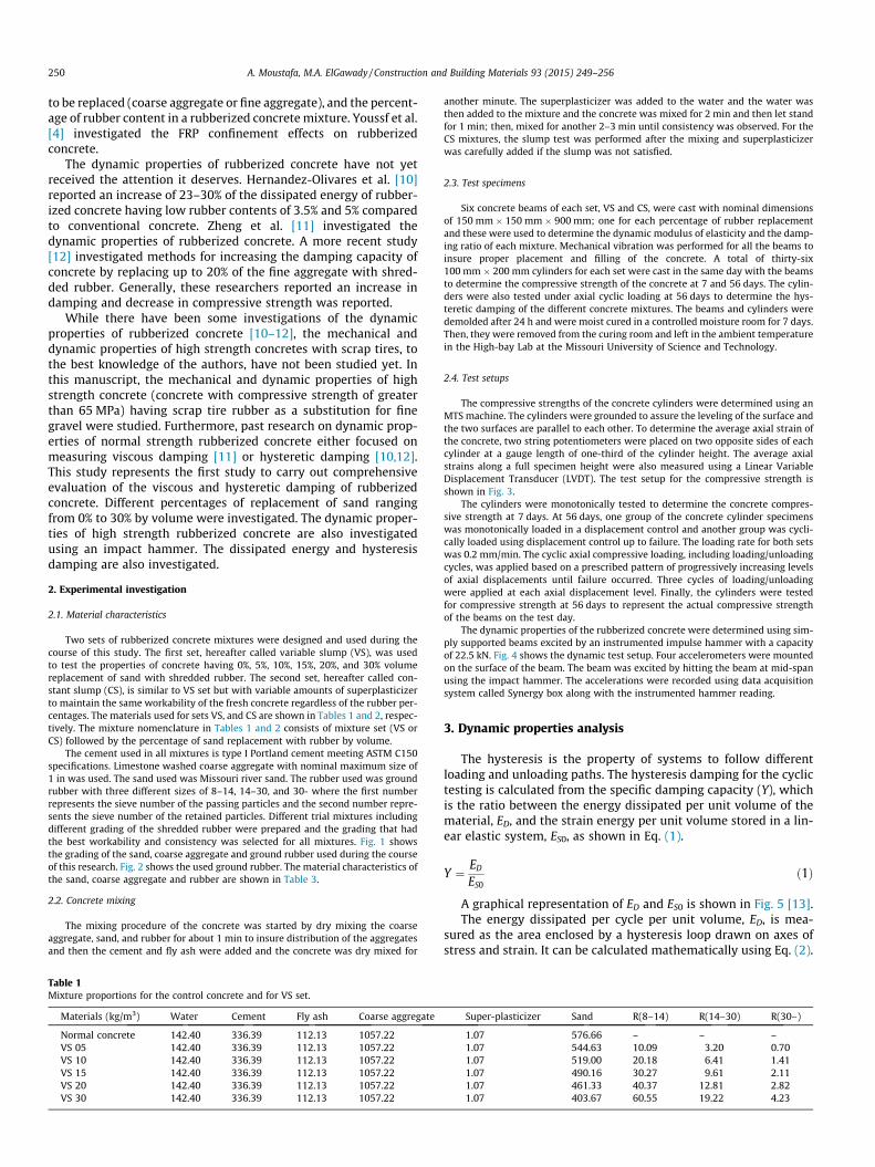
The cement used in all mixtures is type I Portland cement meeting ASTM C150specifications. Limestone washed coarse aggregate with nominal maximum size of1 in was used. The sand used was Missouri river sand. The rubber used was groundrubber with three different sizes of 8–14, 14–30, and 30- where the first numberrepresents the sieve number of the passing particles and the second number repre-sents the sieve number of the retained particles. Different trial mixtures includingdifferent grading of the shredded rubber were prepared and the grading that hadthe best workability and consistency was selected for all mixtures. Fig. 1 showsthe grading of the sand, coarse aggregate and ground rubber used during the courseof this research. Fig. 2 shows the used ground rubber. The material characteristics ofthe sand, coarse aggregate and rubber are shown in Table 3.
2.2. Concrete mixing
The mixing procedure of the concrete was started by dry mixing the coarseaggregate, sand, and rubber for about 1 min to insure distribution of the aggregatesand then the cement and fly ash were added and the concrete was dry mixed for
Table 1Mixture proportions for the control concrete and for VS set.
Materials (kg/m3) Water Cement Fly ash Coarse aggregate
Normal concrete 142.40 336.39 112.13 1057.22VS 05 142.40 336.39 112.13 1057.22VS 10 142.40 336.39 112.13 1057.22VS 15 142.40 336.39 112.13 1057.22VS 20 142.40 336.39 112.13 1057.22VS 30 142.40 336.39 112.13 1057.22
another minute. The superplasticizer was added to the water and the water wasthen added to the mixture and the concrete was mixed for 2 min and then let standfor 1 min; then, mixed for another 2–3 min until consistency was observed. For theCS mixtures, the slump test was performed after the mixing and superplasticizerwas carefully added if the slump was not satisfied.
2.3. Test specimens
Six concrete beams of each set, VS and CS, were cast with nominal dimensionsof 150 mm � 150 mm � 900 mm; one for each percentage of rubber replacementand these were used to determine the dynamic modulus of elasticity and the damp-ing ratio of each mixture. Mechanical vibration was performed for all the beams toinsure proper placement and filling of the concrete. A total of thirty-six100 mm � 200 mm cylinders for each set were cast in the same day with the beamsto determine the compressive strength of the concrete at 7 and 56 days. The cylin-ders were also tested under axial cyclic loading at 56 days to determine the hys-teretic damping of the different concrete mixtures. The beams and cylinders weredemolded after 24 h and were moist cured in a controlled moisture room for 7 days.Then, they were removed from the curing room and left in the ambient temperaturein the High-bay Lab at the Missouri University of Science and Technology.
2.4. Test setups
The compressive strengths of the concrete cylinders were determined using anMTS machine. The cylinders were grounded to assure the leveling of the surface andthe two surfaces are parallel to each other. To determine the average axial strain ofthe concrete, two string potentiometers were placed on two opposite sides of eachcylinder at a gauge length of one-third of the cylinder height. The average axialstrains along a full specimen height were also measured using a Linear VariableDisplacement Transducer (LVDT). The test setup for the compressive strength isshown in Fig. 3.
The cylinders were monotonically tested to determine the concrete compres-sive strength at 7 days. At 56 days, one group of the concrete cylinder specimenswas monotonically loaded in a displacement control and another group was cycli-cally loaded using displacement control up to failure. The loading rate for both setswas 0.2 mm/min. The cyclic axial compressive loading, including loading/unloadingcycles, was applied based on a prescribed pattern of progressively increasing levelsof axial displacements until failure occurred. Three cycles of loading/unloadingwere applied at each axial displacement level. Finally, the cylinders were testedfor compressive strength at 56 days to represent the actual compressive strengthof the beams on the test day.
The dynamic properties of the rubberized concrete were determined using sim-ply supported beams excited by an instrumented impulse hammer with a capacityof 22.5 kN. Fig. 4 shows the dynamic test setup. Four accelerometers were mountedon the surface of the beam. The beam was excited by hitting the beam at mid-spanusing the impact hammer. The accelerations were recorded using data acquisitionsystem called Synergy box along with the instrumented hammer reading.
3. Dynamic properties analysis
The hysteresis is the property of systems to follow differentloading and unloading paths. The hysteresis damping for the cyclictesting is calculated from the specific damping capacity (Y), whichis the ratio between the energy dissipated per unit volume of thematerial, ED, and the strain energy per unit volume stored in a lin-ear elastic system, ES0, as shown in Eq. (1).
Y ¼ ED
ES0ð1Þ
A graphical representation of ED and ES0 is shown in Fig. 5 [13].The energy dissipated per cycle per unit volume, ED, is mea-
sured as the area enclosed by a hysteresis loop drawn on axes ofstress and strain. It can be calculated mathematically using Eq. (2).
Super-plasticizer Sand R(8–14) R(14–30) R(30–)
1.07 576.66 – – –1.07 544.63 10.09 3.20 0.701.07 519.00 20.18 6.41 1.411.07 490.16 30.27 9.61 2.111.07 461.33 40.37 12.81 2.821.07 403.67 60.55 19.22 4.23
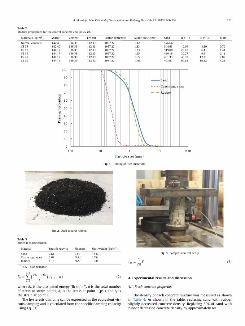
Table 2Mixture proportions for the control concrete and for CS set.
Materials (kg/m3) Water Cement Fly ash Coarse aggregate Super-plasticizer Sand R(8–14) R(14–30) R(30–)
Normal concrete 142.40 336.39 112.13 1057.22 1.12 576.66 – – –CS 05 142.40 336.39 112.13 1057.22 1.33 544.63 10.09 3.20 0.70CS 10 144.17 336.39 112.13 1057.22 1.33 519.00 20.18 6.41 1.41CS 15 144.17 336.39 112.13 1057.22 1.55 490.16 30.27 9.61 2.11CS 20 144.17 336.39 112.13 1057.22 1.65 461.33 40.37 12.81 2.82CS 30 144.17 336.39 112.13 1057.22 1.76 403.67 60.55 19.22 4.23
0
10
20
30
40
50
60
70
80
90
100
0.010.1110100
Pass
ing
perc
enta
ge
Particle size (mm)
Sand
Coarse aggregate
Rubber
Fig. 1. Grading of used materials.
Fig. 2. Used ground rubber.
Table 3Material characteristics.
Material Specific gravity Fineness Unit weight (kg/m3)
Sand 2.61 2.86 1442Coarse aggregate 2.69 N.A.* 1554Rubber 1.16 N.A.* 641
* N.A. = Not available.
Fig. 3. Compression test setup.
A. Moustafa, M.A. ElGawady / Construction and Building Materials 93 (2015) 249–256 251
ED ¼Xn�1
i¼1
riþ1 þ ri
2
� �ðeiþ1 � eiÞ ð2Þ
where ED is the dissipated energy (lb-in/in3), n is the total numberof stress or strain points, ri is the stress at point i (psi), and ei isthe strain at point i.
The hysteresis damping can be expressed as the equivalent vis-cous damping and is calculated from the specific damping capacityusing Eq. (3).
feq ¼1
2pY ð3Þ
4. Experimental results and discussion
4.1. Fresh concrete properties
The density of each concrete mixture was measured as shownin Table 4. As shown in the table, replacing sand with rubberslightly decreased concrete density. Replacing 30% of sand withrubber decreased concrete density by approximately 6%.
Elevation900
150
150
150
Plan
Side view
Accelerometers
900
150
150 150150150 150150
Fig. 4. Dynamic test setup (dimensions are in mm).
Strain
Stre
ss
ED
ES0
Fig. 5. Dissipated energy per unit volume of the material, ED and elastic strainenergy, ES0.
0 5 10 15 20 25 300
50
100
150
200
Rubber content (%)
Slum
p (m
m)
CS
VS
Fig. 6. Slump of the rubberized concrete.
252 A. Moustafa, M.A. ElGawady / Construction and Building Materials 93 (2015) 249–256
As mentioned before, two sets of mixtures were investigated inthis study. The first set, VS, was intended to study the effect ofreplacing sand with rubber on the workability of the concrete.The slump of the rubberized concrete for VS is shown in Fig. 6.The slump of the control mix without rubber was 150 mm and itdecreased with increasing rubber content as shown in the figure.The figure shows that replacements of up to 10% rubber did notseverely affect the workability of the concrete mixtures. Concretehaving 5%, and 10% rubber had a slump loss of 50 mm and62.5 mm, respectively. Beyond 10% replacement, the workabilitydegraded significantly. Using 30% rubber replacement resulted ina loss of slump of about 125 mm and the concrete was no moreworkable. For the 30% rubber replacement, mechanical vibrationwas also needed for the cylinders due to the loss of workability.The second set, CS, was tailored to achieve the same workabilityfor all the mixes by varying the superplasticizer percentage. Theslump for this set is also shown in Fig. 5 and it shows that theslump is almost constant.
60
70
80
treng
th (M
Pa)
56 Days CS 56 Days VS7 Days CS7 Days VC
4.2. Compressive strength
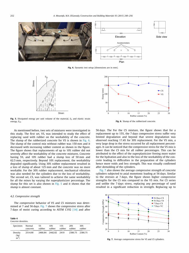
The compressive behavior of VS and CS mixtures was deter-mined at 7 and 56 days. Fig. 7 shows the compressive stress after7 days of moist curing according to ASTM C192 [14] and after
Table 4Concrete densities.
Specimen Normalconcrete
5%rubber
10%rubber
15%rubber
20%rubber
30%rubber
Density(kg/m3)
2514.90 2466.84 2442.82 2419 2386.75 2386.75
56 days. The For the CS mixture, the figure shows that for areplacement up to 15%, the 7 days compressive stress suffer verylimited degradation and beyond that severe degradation wasobserved reaching 17.4% for 30% replacement. For the VS mix, avery large drop in the stress occurred for all replacement percent-ages. It can be noticed that the compressive stress for the VS mix islower than the CS mix for all rubber percentages. This can beattributed to the effect of the superplasticizer freeing more waterfor the hydration and also to the loss of the workability of the con-crete leading to difficulties in the preparation of the cylindershence more voids and less strength. This was visually confirmedafter demolding of the cylinders.
Fig. 7 also shows the average compressive strength of concretecylinders subjected to axial monotonic loading at 56 days. Similarto the stresses at 7 days, the figure shows higher compressivestrengths for the CS mix compared to the VS mix. For CS seriesand unlike the 7 days stress, replacing any percentage of sandresulted in a significant reduction in strength. Replacing up to
0 5 10 15 20 25 3020
30
40
50
Rubber Content (%)
Com
pres
sive
S
Fig. 7. Average compressive stress for VS and CS cylinders.

(a) (b)
0 1 2 3 4 5 6x 10⁻³
0
20
40
60
80
100
Strain
Stre
ss (M
Pa)
Normal Concrete10% Rubber20% Rubber30% Rubber
0 1 2 3 4 5 6x 10⁻³
0
20
40
60
80
100
Strain
Stre
ss (M
Pa)
Normal Concrete10% Rubber20% Rubber30% Rubber
Fig. 8. Stress–strain curves for (a) VS and (b) CS.
(a) (b) (c) (d)
Fig. 9. Failure of the concrete cylinders: (a) normal concrete, (b) 10% rubber, (c) 20% rubber, and (d) 30% rubber replacement.
A. Moustafa, M.A. ElGawady / Construction and Building Materials 93 (2015) 249–256 253
15% of sand with rubber resulted in a strength reduction of approx-imately 10%. At 30% replacement, the strength reduction wasapproximately 32%. Three cylinders were used for determinationof the compressive strength of each rubber content. The standarddeviation for the VS mix was higher than that of the CS mix. Thisdifference was caused by the non-uniform distribution of the rub-ber particles in the VS mix compared to the CS mix.
Fig. 8 shows the stress strain curves for the monotonic loadingat 56 days. The figure shows a very large difference in ductilitybetween the conventional and the rubberized concretes. The con-ventional concrete failed in a brittle way once it reached the peakload. The addition of 5% rubber in the VS mix did not change thebrittle behavior while the addition of higher percentages of rubberincreased the ductility. The addition of up to 15% rubber in the CSmix did not change the sudden failure. It should be noted that forthe cyclic loading, gradual degradation of strength started at 10%.This can be attributed to the fact that the monotonic loading keepsincreasing the displacement demand; preventing the rubber parti-cles for low replacements from providing compressibility. In thecyclic loading, unloading the specimen results in expansion ofthe rubber particle (returning to original position); leading to anaccommodation of compression in the next cycle. The differencein ductility between the two mixes is the VS mix is less uniformso the rubber particles might be concentrated in spots increasingthe compressibility. This makes the VS mix a possible candidate
for applications such as sidewalks and road barriers, where theimpact resistance is required.
The mode of failure for the concrete changed with the additionof rubber. The high strength concrete with no rubber exhibited abrittle failure and shattered into small pieces when it reachedthe maximum load, while the rubberized concrete experienced amore ductile failure and was able to sustain loads after reachingits capacity. The stress–strain curves for these cylinders will be dis-cussed in the next section. Fig. 9 shows the failure shape of cylin-ders having 0%, 10%, 20%, and 30% rubber replacement.
4.3. Hysteresis damping results
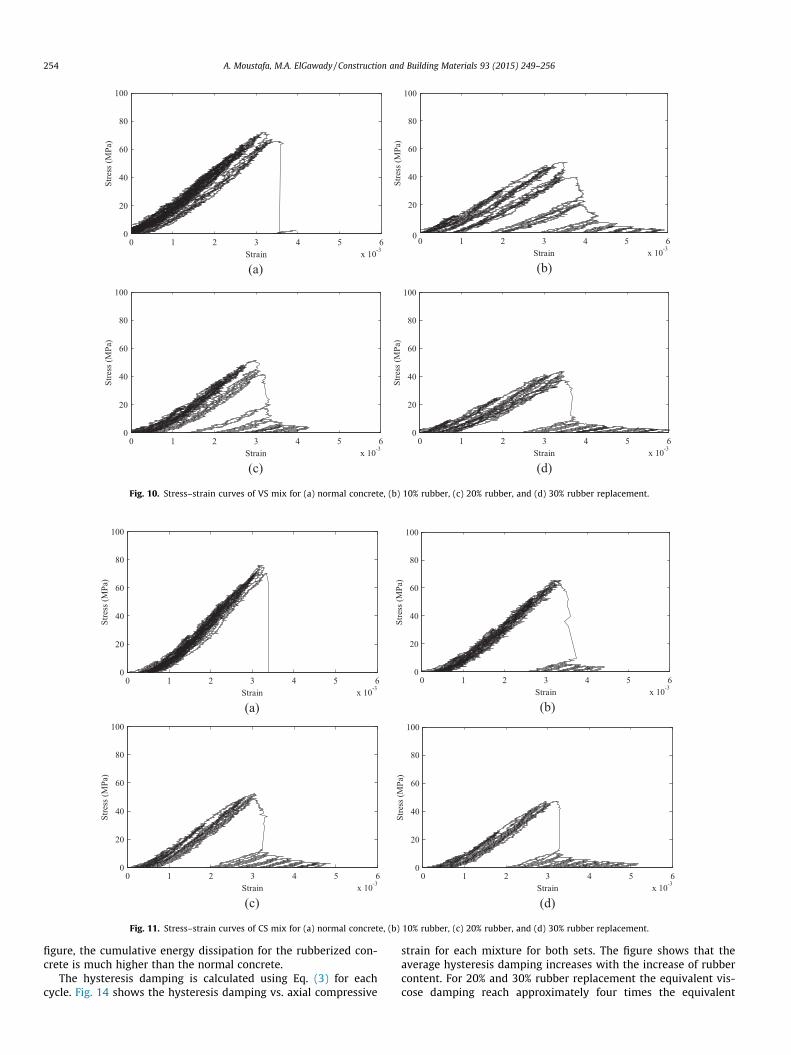
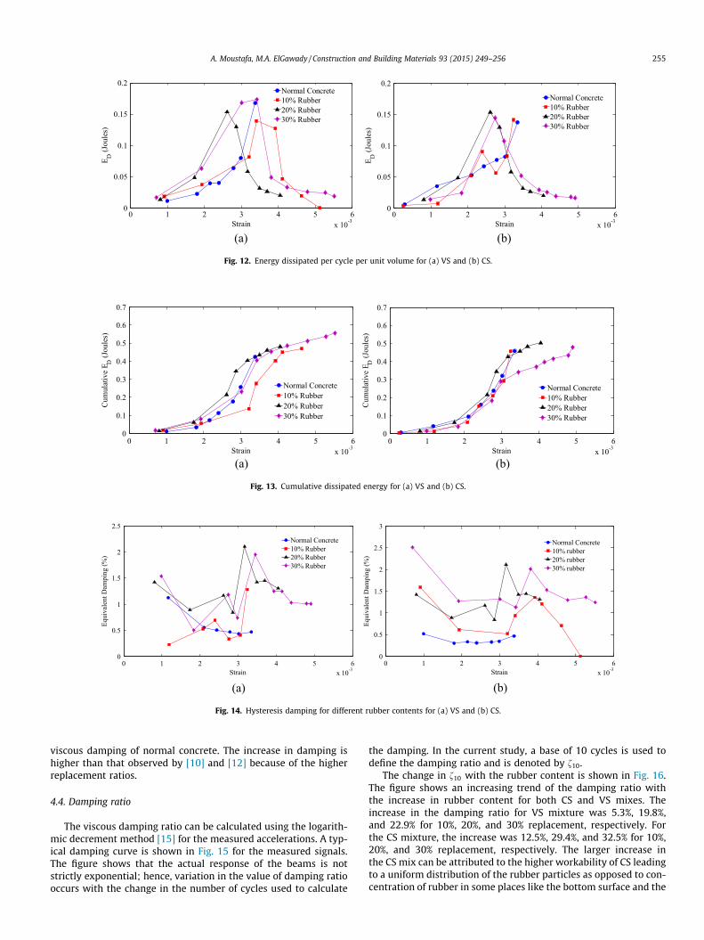
The stress–strain curves for the normal concrete and the rub-berized concretes for SV and SC are shown in Figs. 10 and 11,respectively. The energy dissipated per cycle per unit volume, ED,can be calculated for each of the stress–strain curves using Eq.(2). Since the loading was displacement controlled, it is more rep-resentative to plot ED versus the strain of the test specimen. Fig. 12shows the energy dissipated for the four different specimens. Thefigure shows that the energy dissipated for the normal concreteincreases up to the failure strain, while the rubberized concretedissipates energy after the peak load. Fig. 13 shows the cumulativeenergy dissipation of the different mixtures. As shown in the
(a) (b)
0 1 2 3 4 5 6x 10⁻³
0
20
40
60
80
100
Strain
Stre
ss (M
Pa)
0 1 2 3 4 5 6x 10⁻³
0
20
40
60
80
100
Strain
Stre
ss (M
Pa)
(c)
(d)
0 1 2 3 4 5 6x 10⁻³
0
20
40
60
80
100
Strain
Stre
ss (M
Pa)
0 1 2 3 4 5 6x 10⁻³
0
20
40
60
80
100
Strain
Stre
ss (M
Pa)
Fig. 10. Stress–strain curves of VS mix for (a) normal concrete, (b) 10% rubber, (c) 20% rubber, and (d) 30% rubber replacement.
(a) (b)
(c) (d)
0 1 2 3 4 5 6x 10⁻³
0
20
40
60
80
100
Strain
Stre
ss (M
Pa)
0 1 2 3 4 5 6x 10⁻³
0
20
40
60
80
100
Strain
Stre
ss (M
Pa)
0 1 2 3 4 5 6x 10⁻³
0
20
40
60
80
100
Strain
Stre
ss (M
Pa)
0 1 2 3 4 5 6x 10⁻³
0
20
40
60
80
100
Strain
Stre
ss (M
Pa)
Fig. 11. Stress–strain curves of CS mix for (a) normal concrete, (b) 10% rubber, (c) 20% rubber, and (d) 30% rubber replacement.
254 A. Moustafa, M.A. ElGawady / Construction and Building Materials 93 (2015) 249–256
figure, the cumulative energy dissipation for the rubberized con-crete is much higher than the normal concrete.
The hysteresis damping is calculated using Eq. (3) for eachcycle. Fig. 14 shows the hysteresis damping vs. axial compressive
strain for each mixture for both sets. The figure shows that theaverage hysteresis damping increases with the increase of rubbercontent. For 20% and 30% rubber replacement the equivalent vis-cose damping reach approximately four times the equivalent
(a) (b)
0 1 2 3 4 5 6x 10⁻³
0
0.05
0.1
0.15
0.2
Strain
E D (J
oule
s)Normal Concrete10% Rubber 20% Rubber 30% Rubber
0 1 2 3 4 5 6x 10⁻³
0
0.05
0.1
0.15
0.2
Strain
E D (J
oule
s)
Normal Concrete10% Rubber20% Rubber30% Rubber
Fig. 12. Energy dissipated per cycle per unit volume for (a) VS and (b) CS.
(a) (b)
0 1 2 3 4 5 6x 10⁻³
0
0.1
0.2
0.3
0.4
0.5
0.6
0.7
Strain
Cum
ulat
ive
E D (J
oule
s)
Normal Concrete10% Rubber20% Rubber30% Rubber
0 1 2 3 4 5 6x 10⁻³
0
0.1
0.2
0.3
0.4
0.5
0.6
0.7
Strain
Cum
ulat
ive
E D (J
oule
s)
Normal Concrete10% Rubber20% Rubber30% Rubber
Fig. 13. Cumulative dissipated energy for (a) VS and (b) CS.
(a) (b)
0 1 2 3 4 5 6x 10⁻³
0
0.5
1
1.5
2
2.5
Strain
Equi
vale
nt D
ampi
ng (%
)
Normal Concrete10% Rubber20% Rubber30% Rubber
0 1 2 3 4 5 6x 10⁻³
0
0.5
1
1.5
2
2.5
3
Strain
Equi
vale
nt D
ampi
ng (%
)
Normal Concrete10% rubber20% rubber30% rubber
Fig. 14. Hysteresis damping for different rubber contents for (a) VS and (b) CS.
A. Moustafa, M.A. ElGawady / Construction and Building Materials 93 (2015) 249–256 255
viscous damping of normal concrete. The increase in damping ishigher than that observed by [10] and [12] because of the higherreplacement ratios.
4.4. Damping ratio
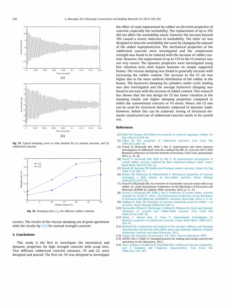
The viscous damping ratio can be calculated using the logarith-mic decrement method [15] for the measured accelerations. A typ-ical damping curve is shown in Fig. 15 for the measured signals.The figure shows that the actual response of the beams is notstrictly exponential; hence, variation in the value of damping ratiooccurs with the change in the number of cycles used to calculate
the damping. In the current study, a base of 10 cycles is used todefine the damping ratio and is denoted by f10.
The change in f10 with the rubber content is shown in Fig. 16.The figure shows an increasing trend of the damping ratio withthe increase in rubber content for both CS and VS mixes. Theincrease in the damping ratio for VS mixture was 5.3%, 19.8%,and 22.9% for 10%, 20%, and 30% replacement, respectively. Forthe CS mixture, the increase was 12.5%, 29.4%, and 32.5% for 10%,20%, and 30% replacement, respectively. The larger increase inthe CS mix can be attributed to the higher workability of CS leadingto a uniform distribution of the rubber particles as opposed to con-centration of rubber in some places like the bottom surface and the
0 0.02 0.04 0.06 0.08 0.1 0.12 0.14 0.16-15
-10
-5
0
5
10
15
Time (seconds)
Acc
eler
atio
n (g
)
(b)
(a)
0 0.02 0.04 0.06 0.08 0.1 0.12 0.14 0.16-8
-6
-4
-2
0
2
4
6
8
Time (seconds)
Acc
eler
atio
n (g
)
Fig. 15. Typical damping curve in time domain for (a) normal concrete, and (b)rubberized concrete.
0 5 10 15 20 25 301
1.1
1.2
1.3
1.4
1.5
Rubber content (%)
Dam
ping
ratio
(%)
VSCS
Fig. 16. Damping ratio (f10) for different rubber contents.
256 A. Moustafa, M.A. ElGawady / Construction and Building Materials 93 (2015) 249–256
corners. The results of the viscous damping are of good agreementwith the results by [11] for normal strength concrete.
5. Conclusions
This study is the first to investigate the mechanical anddynamic properties for high strength concrete with scrap tires.Two different rubberized concrete mixtures, VS and CS, weredesigned and poured. The first set, VS was designed to investigate
the effect of sand replacement by rubber on the fresh properties ofconcrete, especially the workability. The replacement of up to 10%did not affect the workability much; however the increase beyond10% caused a severe reduction in workability. The other set wasdesigned to keep the workability the same by changing the amountof the added superplasticizer. The mechanical properties of therubberized concrete were investigated and the compressivestrength was found to be reduced with the increase of rubber con-tent. However, the replacement of up to 15% in the CS mixture wasnot very severe. The dynamic properties were investigated usingfree vibration tests with impact hammer on simply supportedbeams. The viscous damping was found to generally increase withincreasing the rubber content. The increase in the CS set washigher due to the more uniform distribution of the rubber in thebeams. The hysteresis damping for cylinders under cyclic loadingwas also investigated and the average hysteresis damping wasfound to increase with the increase of rubber content. This researchhas shown that the mix design for CS has lower variation in thedamping results and higher damping properties compared toeither the conventional concrete or VS mixes. Hence, the CS mixcan be used for structural elements subjected to dynamic loads.However, before this can be achieved, testing of structural ele-ments constructed out of rubberized concrete needs to be carriedout.
References
[1] Eldin NN, Senouci AB. Rubber-tire particles as concrete aggregate. J Mater CivEng 1993;5(4):478–96.
[2] Topcu IB. The properties of rubberized concretes. Cem Concr Res1995;25(2):304–10.
[3] Youssf O, ElGawady MA, Mills J, Ma X. Experimental and finite elementinvestigation of rubberized concrete confined by FRP. In: Concrete 2013–26thBiennial Conference of Concrete Institute of Australia, Gold Coast, Queensland;2013, p. 16–18.
[4] Youssf O, ElGawady MA, Mills JE, Ma X. An experimental investigation ofcrumb rubber concrete confined by fibre reinforced polymer tubes. ConstrBuild Mater 2014;53:522–32.
[5] Khatib ZK, Bayomy FM. Rubberized Portland cement concrete. J Mater Civ Eng1999;11(3):206–13.
[6] Khaloo AR, Dehestani M, Rahmatabadi P. Mechanical properties of concretecontaining a high volume of tire–rubber particles. Waste Manage2008;28(12):2472–82.
[7] Youssf O, ElGawady MA. An overview of sustainable concrete made with scraprubber. In: 22nd Australasian Conference on the Mechanics of Structures andMaterials ACMSM 22, Sydney, NSW, Australia; 2012, p. 11–14.
[8] Youssf O, ElGawady MA, Mills J, Ma X. Prediction of crumb rubber concretestrength. In: Smith ST, editor. 23rd Australasian Conference on the Mechanicsof Structures and Materials (ACMSM23). Australia: Byron Bay; 2014. p. 9–12.
[9] Siddique R, Naik TR. Properties of concrete containing scrap-tire rubber – anoverview. Waste Manage 2004;24(6):563–9.
[10] Hernandez-Olivares F, Barluenga G, Bollati M, Witoszek B. Static and dynamicbehaviour of recycled tyre rubber-filled concrete. Cem Concr Res2002;32(10):1587–96.
[11] Zheng L, Sharon Huo X, Yuan Y. Experimental investigation ondynamic properties of rubberized concrete. Constr Build Mater 2008;22(5):939–47.
[12] Bowland AG. Comparison and analysis of the strength, stiffness, and dampingcharacteristics of concrete with rubber, latex, and carbonate additives. VirginiaPolytechnic Institute and State University; 2011.
[13] Chopra AK. Dynamics of structures, 3/E. India: Pearson Education; 2007.[14] ASTM C192, C 192M-13: Standard practice for making and curing concrete test
specimens in the laboratory; 2013.[15] Yan L, Jenkins C, Pendleton R. Polyolefin fiber-reinforced concrete composites:
part I. Damping and frequency characteristics. Cem Concr Res2000;30(3):391–401.
Copyright © 2022 FDOKUMEN