Intermediate Filaments in Muscle and Epithelial Cells of ...
Upload
independentCategory
view
5download
0
1
Testing of Man made staple fibre, Yarn and FilamentN.Balasubramanian
Retired Joint Director(BTRA) and Consultant1i
Among the various factors affecting profitability, sale value, competitivess and brand image of a mill, quality has paramount importance. The mills which produce consistently good quality get a premium in the sales price and are less affected by demand recession or rise in cost of inputs. Mills should therefore have a sound quality assurance program, backed by a well maintained and fully equipped testing laboratory, to survive competition. Though it is said that man-made fibres are made with precision and do not have variability associated with natural fibre, this seldom applies in practise. Not onlysome amount of variability in properties is found but also defects and abnormalities in fibre/filament are encountered which cause processing problems, defects in final product and waste and rejections. So testing of raw material and final product for various properties is equally important in man-made fibres, yarns, and filaments. Staple Fibre
LengthStaple length determines the strength of yarn and optimum twist factor. Extra long staple fibres (50-64mm) require a lower twist factor and enable higher spindle speeds. At the same time, they are more prone to nep generation and result in inferior yarn appearance. Staple fibre yarns from 38mm enjoy a premium over those made from 52mm fibre. In the case of cut staple fibres, fibre length is measured by laying the fibre on a glass plate smeared with paraffin oil to enable straightening of fibre (BISFA,ASTM D5103-07). With highly crimped fibres straightening may be difficult and in this case fibre has to be fixed between two clamps and a slight tension has to be applied to one of the clamps. The amount of tension should be just sufficient to remove crimp and is determined by preliminary tests. Length of fibre is measured on a scale or by a sliding microscope. Roughly about 10-15 fibres are tested and average is determined. In the case of variable staple fibre and synthetic tops used in worsted spinning system, automatic fibre diagram machine by SDL orWIRA is used. Cut square method is used to draw a tuft of fibres from the sliver and tuft is passed between the plates of capacitor. A measure is thus obtained of number of fibres in the tuft from the base to tip, from which cumulative fibre distribution is obtained. The measurement is fully automated and

2
the fibre diagram together with results of mean length, upper halfmean and CV are automatically displayed. While preparing a cut square sample, precaution should be taken to avoid breakage of fibres.
Fibre FinenessFineness in the case of staple fibres determines the count to which the fibre can be spun. It also determines the strength, evenness and imperfections of yarn and also the end breaks in spinning. Fibre fineness is determined gravimetrically or air-flowmethod or by vibration method.
o Gravimetric method
About 25 fibres are cut to a specified length under tension bymeans of a template and weighed in a sensitiveelectronic/torsion balance from which weight per unit length isdetermined. The method is time consuming (ASTM D1577). Errorscan also arise from defects in cutting and sensitivity ofbalance.
o Airflow method
Resistance offered by a Known mass of porous plug of fibrespacked in a cylinder of known dimensions to air flow underconstant pressure is dependent on specific surface area whichin turn is determined fibre fineness. This principle is usedfor determining fibre fineness of cotton by many instruments,important ones being Micronaire and Aerilometer (ASTM D1448).These instruments can also be used for determining fineness ofman-made fibres with suitable calibration. In Micronaire, airflow rate through the plug of fibres under constant compressionis measured. In Aerilometer extent to which the plug has to becompressed to achieve a fixed air flow rate under a givenpressure difference is determined. The instrument should becalibrated with standard fibre samples to avoid errors.
o Vibration Method
The fibre, hung vertically, is taken over a knife edge and tensioned by a pre determined weight and is subjected to transverse vibrations at variable frequency (ASTM D1577). The frequency at which maximum amplitude is obtained, which is resonance frequency, is determined, from which fineness is determined by the following formulae.

3
Fig 1 : Fibre fineness by vibration
Finness,dtex= T4f2l2
× 107
Where T = tension in Newton
F= Frequency in Hertz
L = Length in metres
Vibromat by Textechno Herbertstein and Vibroscop by Lenzing arebased on this principle. The equipment is fully automatic and upon testing a number of fibres randomly selected (around 8-10), mean fibre fineness and CV are displayed. The method is very fast with a total testing time of 5 - 6 sec. However determination of resonance frequency is not precise with some fibres.
Tensile properties
Fibre Strength
4
Fibre strength determines the strength of yarn and spinning value and fibre elongation determines yarn elongation. Both strength and elongation and their variability critically affectperformance in weaving and knitting. Single fibre testing is normally done (ASTM 3822 - 07) at constant rate of elongation with a gauge length of 1 cm. Fibre is clamped preferably pneumatically between two jaws at a predetermined tension. Lower jaw is traversed at a constant rate while upper jaw is attached to a sensitive load cell of 50-100cN capacity. The load extension curve, breaking load, elongation, work of rupture and modulus are determined and displayed. Load at 7% and 10% elongation are also determined for synthetic fibres blended with cotton/viscose. Strength at 7% and 10% elongation,T7 and T10, have to be close to cotton/viscose breaking strength to minimise strength losses in blending. Facility is also offered in some instruments to carry out testsunder liquid and for carrying out cyclic loading test. Fafegraph and Favimat by Textechno Herbert stein and Vibroskop and Vibrodyn by Lenzing are some commonly used instruments. At least 10 fibres should be tested for getting a reliable mean. Considerable automation has taken place in transferring the fibre to the jaws through use of transfer clamp actuated by robot. Manual involvement in testing is restricted to clampingthe fibre between two paper clips and mounting it on a magazine. After that all operations are carried out automatically. Single testing instrument that carries out fineness, strength and crimp all, at one place, have also been developed. Not only testing time is reduced but also the different tests are carried out on the same fibre. Bundle strength in stelometer is not recommended because of fibre slippage under the jaws.
Loop/knot test
To get an estimate of brittleness of fibre, fibre is tested in loop or knot configurations and resulting strength compared with normal strength (ASTM D 3217). Fig 2 shows strength testing of loop and knot. Two filaments are used to form the loop and the ends of loop are clamped on the clamps of the strength tester. Knot is formed on fibre and the fibre/filamentwith knot is placed between the clamps and tested.

5
Fig 2 : Loop and knot strength test
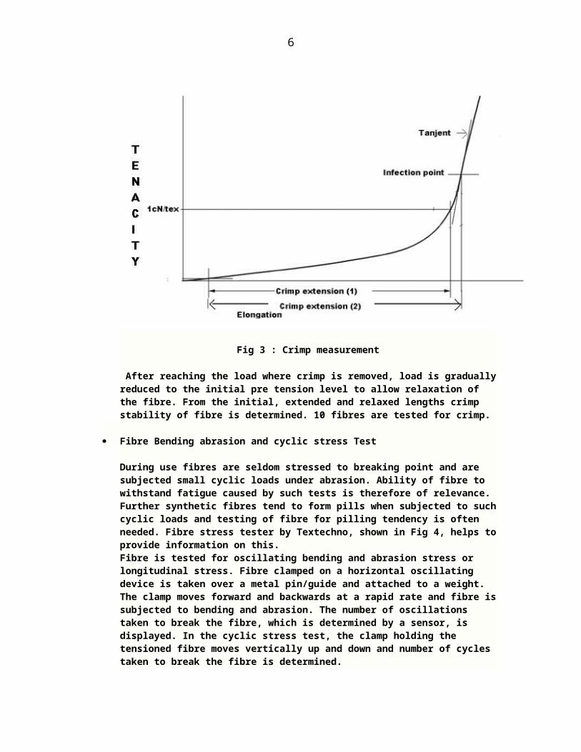
CrimpCrimp is an important property that determines processing behaviour in carding, drafting and fault incidences in yarn. Crimpfrequency, amplitude, crimp stability, crimp elongation, decrimping point are some of the important properties that determine crimp. Crimp stability is an important property as it indicates the extent to which fibre retains the original crimp during opening, carding and drawing. ASTM D3937 describes a simplemethod for determining crimp frequency. Crimp frequency and amplitude may be determined by projecting a magnified image of fibre on screen. Opto electronic sensor is used in some equipmentsto provide digital representation of fibre held between two clampsat very low tension and for determination of crimp geometry. Tensile tests using an extremely sensitive force measuring system with measuring accuracy of 1mN, enables the measurement of the curve of crimp force vs elongation, crimp extension, decrimping point and crimp stability. The fibre is subjected to gradual loading and crimp is measured in two ways 1. Extension at 1cN/tex and 2. Extension at the inflexion point given by tangent1 (Fig 3)
6
Fig 3 : Crimp measurement
After reaching the load where crimp is removed, load is graduallyreduced to the initial pre tension level to allow relaxation of the fibre. From the initial, extended and relaxed lengths crimp stability of fibre is determined. 10 fibres are tested for crimp.
Fibre Bending abrasion and cyclic stress Test
During use fibres are seldom stressed to breaking point and are subjected small cyclic loads under abrasion. Ability of fibre to withstand fatigue caused by such tests is therefore of relevance. Further synthetic fibres tend to form pills when subjected to suchcyclic loads and testing of fibre for pilling tendency is often needed. Fibre stress tester by Textechno, shown in Fig 4, helps toprovide information on this.Fibre is tested for oscillating bending and abrasion stress or longitudinal stress. Fibre clamped on a horizontal oscillating device is taken over a metal pin/guide and attached to a weight. The clamp moves forward and backwards at a rapid rate and fibre issubjected to bending and abrasion. The number of oscillations taken to break the fibre, which is determined by a sensor, is displayed. In the cyclic stress test, the clamp holding the tensioned fibre moves vertically up and down and number of cycles taken to break the fibre is determined.

7
Fig 4 Fibre Stress tester.
Spin FinishNature and quantum of spin finish has critical influence on performance of fibre. Lap licking, cylinder loading and roller lapping are often traced to improper spin finish. Spin finish is traditionally estimated by extraction with a solvent like carbon tetrachloride or benzene on Soxhlet's apparatus. The amount of extracted material is determined gravimetrically or by infrared spectroscopy. This is time consuming though accurate. ALFA 300 by Lenzing and Rapid extraction apparatus by SDL are rapid methods for determining spin finish. Known quantity of fibre is packed in a vessel and spin finish is removed by means of a solvent through constant stirring and the resultant emulsion is subjected to an analyser where organic carbon content is determined. %of oil and finish are separately determined. The equipment is suitable for fibre as well as filament. Low resolution Nuclear Magnetic Resonance is a faster and solvent free method for determining spinfinish and is offered, among others by Lenzing and Oxford instruments. Oil content in filament is an important property. Filament sample is extracted in water and the extraction is conveyed to a furnace.Oil in water is burned and oxidised and the generated gas is analysed for carbon-dioxide content in Infra red analyser.

8
Static GenerationOne of the problems encountered with synthetic fibres is generation of static electricity. Static generation is a cause forlap licking, cylinder loading, web falling incidences and coiler choke up in carding and roller lapping in draw frame to ring frame. High hairiness in yarn, fabric defects like stitches and floats are also attributed static electricity. Sparking may take place due to static in synthetic carpets. Accurate instruments areavailable for estimating the amount static charge and half decay time. Half decay time denotes the time taken for static charge to come down to half its level and a low value is desirable. Sample held in a holder is rubbed for a known duration of time and staticcharge sensing unit measures the charge and decay of charge with time. This method is not normally preferred as it is dependent on rubbing material and conditions. Honestometer which works on the principle of charging the material by irradiating it with air ionsgenerated in a corona discharge field is commonly used. Developed charge, decay curve and half decay time are measured afterwards (Fig 5).
0 10 20 30 40 50 60 700
0.5
1
1.5
2
2.5
3
Time, sec
Voltage
Half Decay Time
Fig 5 : Decay curve of static charge
Drafting Force

9
Drafting behaviour of fibre can be estimated by determining drafting force and its variability. Cohesion testers have been developed for this purpose. The sliver or roving is passed betweentwo pairs of drafting rollers with front pair mounted on a lever fitted to strain gauge. As the material is drafted, front pair of rollers oscillates to and fro as per drafting force and the straingauge measures the force continuously, amplifies and records it ona chart. Mean and coefficient of variation of drafting force are measured. The equipment is also useful in assessing the quality ofspin finish and oil applied on fibre.
Abnormalities in fibrePresence of extraneous agglomerations on the surface of fibre, fused and undrawn fibres, over length fibres are some of the abnormalities in fibre. High precision microscope like Projectina is useful to detect such abnormalities in fibre. Modified Baer sorter of a longer length with double the number of combs is sometimes used for estimating over length fibres. ASTM D3513-02 prescribes a method for determining over length fibres. Over length fibres are the main source of crackers in yarn and should be below .01%. Undrawn and fused fibres cause slubs and long thickplaces in yarn.
UV Stability
Resistance to degradation by UV requires to be tested in geotextiles, automobile materials and others continuously exposed to sunlight. Weather-o-meter is used for finding UV stability. Theinstrument uses UV lamp which simulates the ultra violet rays found in sunlight. After exposing the specimen for a specified duration, strength is tested to assess degradation if any. Polypropylene and nylon have lower UV stability compared to polyester.
Dyeability of fibre
Laboratory model dyeing equipments are offered by various manufacturers for dyeing small samples of fibre up to 5 gm, to check uniformity of dye pick up.
Molecular Orientation
Molecular orientation determines the tenacity, elongation and dyeabilityof fibre. Molecular orientation testers are available by determining birefringence through the use of polarised microscope. Difference in refractive index in the longitudinal direction and cross (diameter) direction gives birefringence. Image of fibre is displayed on monitor by
10
CCD camera fitted on Microscope. Birefringence is automatically measuredand displayed
Whiteness and Colour
Variations in whiteness in grey material and colour in dyed fibre from lot to lot is a source of streakiness and weft bars in fabric. To maintain consistency in whiteness and colour of fabric, raw material should be checked for whiteness, degree of yellowness and colour. Instruments are available for estimating whiteness and degree of yellowness. Bench type spectrophotometer is used for testing and matching of colour.
Filaments and Yarns
Tensile propertiesBreaking load, elongation and work of rupture are some of the important characteristics of filaments and staple fibre yarns. Leaand single thread strength are the commonly used measures of yarn strength and their relative merits have been discussed elsewhere2.
o Single thread strengthTensile testers may be classified as
Constant rate of loading type Constant rate of elongation type Constant rate of traverse type
Constant rate of loadingRate of loading of yarn is constant in these instruments throughout the test period. Inclined plane testers belong to this category. Uster Dynamometer works on this principle. Though this system of loading has many merits, this type of tester is not used now a days.
Constant rate of ElongationThis is most popular system these days. Tensile testers using a range ofsensitive load cells are used for determining breaking load and load elongation curve of yarn (ASTM 2256). The yarn is held between two jaws with upper jaw connected to load cell and lower jaw is traversed downwards at a constant rate of traverse. Insertion of a new specimen into the clamps and clamping of the specimen at a pre determined tensionare done automatically. Automatic package changers (up to 20 packages) are also provided with the tester so that after a prescribed number of tests are carried from a package, the package is automatically changed
11
to a new package and insertion of new yarn to the clamps is automatically done. A series of high resolution load cells enable testing of yarn with strength between 100cN to 1000cN. Software is provided for determining mean, maximum, minimum, modulus, S.D., CV, Confidence limits, load-elongation curve and a host of other useful information. A high resolution opto electronic sensor measures the elongation of yarn. Normally about 50 specimens are tested. Recommended time to break is 20 sec and rate of traverse is accordingly set. Gauge length is infinitely adjustable from 50 to 500 mm and traverse speed of draw off clamp is adjustable from 1 to 5000mm/min. To reduce testing time reverse speed of clamp is kept much higher than normal testing speed. Strength and elongation are also digitally displayed. Some units like Tensomat have a unit which draws off prescribed length of yarn at the start and between two tests and discard it. Facility is also available for placing a knot or splice in the testing zone through a opto electronic sensor and testing their strength. While testing multi filament yarns for strength, the material should be slightly twisted before testing to get better definition of breaking point.
Constant rate of traversePendulum type testers belong to this category. These have become obsolete because of long operating time and higher errors.
Special instruments for testing strength
Uster Tenso jet
As the amount of yarn involved in the normal strength testing is small, the test may not be able to estimate the weak patches of yarn which are the source of break in weaving. Uster tensojet has been developed to overcome this. A high testing speed of 400m/min is used and as much as 30000 tests can be carried out per hour. As a result, larger sample sizecloser to the production area is involved in testing and the results have a better correlation with weaving performance of yarn.
Dynamic elongation Tester (Lawson – Hemphill)
Elongation% of yarn is determined as yarn is run under constant tension at 360m/min. The equipment measures elongation of yarn when it is moving

12
at constant load. Continuous measurement of yarn tension for 21km/hr is possible. The test simulates conditions in weaving and knitting and therefore can be useful in predicting the performance of yarn in these processes. Dynamic strength and weak places can also be provided optionally.
Weak spots tester
Conventional testing equipments do not give a correct indication of weakspots in yarn that result in breakages in subsequent processes as the length of tested material is small. In the weak spots tester, yarn is run at speeds up to 1000m/min under constant tension. The level of tension can be adjusted to be close to that experienced by the yarn in actual manufacturing. The number of breaks during a specified running time is recorded. Upon a break the unit stops for subsequent manual rethreading. Weak spot testers have been developed by among others Textechno, Lawson-Hemphill.
Factors affecting strength
Gauge LengthGauge length has considerable influence on strength. With increase in gauge length, strength will decrease because of increased chances of occurrence of more weak places and the weak place being weaker. So gauge length has to be standardised. Normally 50 cm gauge length is used except in POY yarns where 20cm gauge length is used because of the high elongation of theseyarns.
Rate of loading or elongationRate of loading or elongation influences test results.With increase in rate of loading or elongation, time for break decreases and a higher strength will be obtained. Rate of loading or elongation is usually adjusted so that time for break is around 20sec.
Regular calibration of equipment is essential to avoiderroneous results. Calibration is done by hanging standard calibration weights from upper clamp.
o Lea strengthLea strength test is common in staple fibre yarns. The yarn is wound on a wrap reel of 54 inch circumference for 80 wraps to prepare a lea of 120 yards length. The lea is tested for strength in a pendulum type of tester in olden days. Now a days, a load cell is used in place of pendulum to measure strength and breaking load is digitally displayed. Load cell is attached to the top jaw. Lea strength has the merit of larger sampling length. It also
13
takes into account variability in the yarn and so can give abetter indication of the performance of yarn at later stages2. Lea test is not normally done for filaments.
Cyclic LoadingThe yarn is seldom extended up to breaking point during use. It ismore often subjected to repeated loads of small value. So performance of material under cyclic loading may give better information about durability. The specimen is loaded up to a certain load or elongation, which is adjustable, and brought back to its original level. This action is repeated cyclically a numberof times till the specimen breaks. Number of cycles of loading withstood by specimen, is taken as a measure of its strength. Alternately, the specimen is tested for strength after a known number of cycles of loading. Cyclic loading facility is available in all modern instruments.
Elastomeric yarns
Elastomeric yarns like spandex have a very elongation and special testers have to be used to ensure that the material is transferredto force measuring area at very low pre tension, and pre tension level is set at as low a value of .01 cN/tex (ASTM D2653-07). Force measuring system should have a high resolution of the order of 10μN. Breaking load, tenacity and elongation are determined at first filament break (FFB). Special clamps have to be used to avoid slippage. Eccentric roller grips and rubber grip grips are some of the grips used to prevent slippage. If pneumatic clamps are used pressure is set at 415 kPa(60 psi)
Creep testing
Creep is a very important property in composites used in construction and geotextiles. Creep and relaxation testing of yarncan be done by subjecting loops of yarn to loading for a long time. Load is removed and length is tested. Creep tester has facility for simultaneous testing of 10 – 20 yarns.
CountCount of the yarn is determined along with the lea test by weighing the broken leas. Auto sorter is used to determine mean, minimum, maximum, S.D., CV, Confidence limits and other statisticsfrom count tests of leas from within and from different packages. The instrument consists of an electronic balance to measure the weight of leas. This is equipped with a software for determining the various statistics. Some manufacturers have developed

14
instruments for automatically determining count. This consists of drive rollers which withdraw a known length of yarn from a packageand deposit it on an electronic balance for weighing and estimating count and related statistics.
IrregularityIrregularity is an important quality characteristic of staple fibre yarns. It determines the appearance of yarn and fabric, feelof fabric, performance of yarn in further processes and the strength realisation of fibre in yarn. Irregularity is commonly measured by capacitance type irregularity tester (ASTM D 1425/1425M-09. Uster Evenness tester is the widely used instrumentfor measuring irregularity. The yarn is passed between two capacitance plates at a constant speed. The capacitance of the condenser varies according to weight per unit length of yarn. The variations in capacitance are converted into voltage and amplified. A continuous record of variations is obtained in a recorder chart. Instantaneous values of Mean Deviation%(U%) or Coefficient of variation(CV%) of the variations is computed by an integrator and displayed. A number Condenser slots of different sizes are used for testing slivers, rovings and yarns as per theircount. Apart from short term variation, the instrument has also facility for determining medium term term variations and variance length curve of the yarn. Module for diameter variation is also available in most electronic evenness testers.Imperfection TesterThis is an attachment for determining the extreme places. Thick places, Thin places, Neps, each of 4 categories based on their size, are measured by the instrument.
Faults
While imperfections are frequently occurring defects, faults occurat longer interval of time. Faults have a very critical influence on fabric appearance, rejections and performance of yarn in winding and subsequent stages. Measurement of faults is done by classimat on a laboratory winding unit (ASTM D6197-99).In the winding unit yarn passes through a capacitance sensing unit which counts faults as per their size and length. 23 classes of faults to cover short and long thick places, spinners doubles and long thin places are measured in Uster Classimat. A more detailed article on measurement of faults, their source of occurrence and measures to control them are discussed in an earlier article3,5. 10bobbins are tested for evenness and imperfections and faults. Faults are also tested before and after winding to check the efficiency of clearing unit.SpectrographSpectrogrpah carries out a fourier analysis of mass variations in

15
the material and displays a curve showing the amplitude of different wavelengths present in the material. With constant staple fibres, spectrograph will have two peaks one at2.7l and
another at 12l which is a lower harmonic (Fig 6). The peaks will
be seen even if the yarn is random with no extra irregularities. In mills peak at half the fibre length have been often found in polyester/viscose blend and the technicians and management used tobe unnecessarily perturbed by their presence.
Fig 6 : Spectrogram of staple fibre yarn(with constant fibrelength
Spectrograph is useful to detect the presence of periodic irregularities and their wavelength in the material and for corrective action for minimising periodicities caused by mechanical faults in machinery. Periodic irregularities are a source of weft bars and warp way defects and rejections in woven and knitted fabrics.
Precautions in testing
o ConditioningConditioning of material to test room is important, whentest room humidity varies considerably from manufacturingroom. One hour in the case of yarns and 2-3 hours in thecase of rovings, of conditioning would be adequate. Thebobbins should be laid in such a way that moisture enters

16
from all sides to ensure uniform conditioning. In the caseof sliver, uniform conditioning may take several days. So itis recommended that testing be carried out immediately afterthe material is brought to testing room, after removing afew top layers of sliver
o Material SpeedMaterial speed has to be standardised. With increase in material speed, irregularity will increase.
o Condenser slot sizeCondenser slot size should be properly chosen. It is advisable to use a slot that gives a lower material to air space.
o CalibrationRegular calibration has to be carried out to ensure accuracy
o A more detailed article on concepts and measurement of yarnirregularity is found eleswhere3,4,5.
For filaments, Uster Evenness tester ‘C’ model, where thereis an arrangement for twisting the material before testing,should be used. Without twisting, the material will flattenas a ribbon during passage, which will result in inaccurateresults.
Yarn Roundness
Two dimensional testing of diameter of yarn enablesestimation of roundness. This gives information about thelustre of yarn and appearance of fabric made from it. UsterOM sensor has facility for such measurement.
Simulation of fabric appearance
Equipments for simulation of fabric appearance from yarn diametermeasurements have been developed among others by Uster, Zweigle andLoepfe. This helps to get an estimate of fabric appearance withoutweaving or knitting the yarn. The system uses infra red light formeasurement of diameter of yarn and variations in diameter and simulatesappearance of yarn as seen on boards and woven and knitted fabrics.Attempts have also been made to simulate fabric appearance from videorecordings of a moving yarn by a digital video camera by variousresearch workers6. However correlation between appearance by simulatedmethods and that by trained observers of actual fabric is still notestablished.
Yarn AppearanceTraditionally yarn appearance is determined by winding it on ablackboard and comparing the appearance with ASTM standard boards.

17
Though the test is more commonly used in cotton yarns, it can alsobe used in man-made fibre yarns for comparison of appearance ofyarns from different sources or fibres. Electronic yarn inspectionboard instruments have also been developed. From measurement ofdiameter and imperfections in a yarn through a CCD camera, asimulated yarn appearance board is displayed. This can be used forcomparison of yarn appearance from different mills or differentmachines.
HairinessThough hairiness in staple fibre yarns adds to the textilecharacter of fabric and contributes to comfort and skinfriendliness, excessive hairiness adversely affects appearance ofyarn and performance of material in subsequent stages. Hairinessis generally higher in staple fibre yarns and blends than incotton yarns. Several instruments based on photoelectric principleare available for measuring hairiness (ASTM D5647-01). An LCD beamis projected on yarn and a photocell placed behind the yarn,counts the number of interruptions made by the protruding hairs.Measurement of hairiness as per the length of protruding hair iscarried out. Portable models are also available for measuringhairiness during production. Uster Evenness tester has a hairinessattachment, which gives an estimate of total length of protrudinghairs in a cm length, termed as Hairiness index. More detailedinformation on the causes of hairiness, measurement and the effectof on performance of yarn is given in another article7.
Twist testerTwist in staple fibre yarns is measured by clamping 2.5 cm lengthof yarn between two clamps under tension. One of clamps can berotated to remove the twist and other clamp can be moved to fixthe test length.. A microscope or magnifying glass placed over theyarn enables to determine the point at which twist is fullyremoved and fibres become parallel. Counter fixed on the rotatingclamp determines the twist. This is a time consuming method and issubjective. Untwist twist method represents a quicker method forestimating twist. A length of yarn mounted under a given initialtension is untwisted till the yarn extends to a preset level andthen retwisted in opposite direction till original length andtension are reached. Half of the number of turns (during twistingand untwisting) divided by gauge length gives twist/unit length.Fully automatic electronic testers have been developed based onthis principle (ASTM.1423-08). This method is not quite accurateas some twist is set in yarn and cannot be removed duringuntwisting.
Lint GenerationLint generation during weaving and knitting is experiencedespecially in yarns with high hairiness. Lawson Hemphill hasdeveloped a lint generation tester as an attachment to Constant

18
tension tester. The lint generated during running of yarn at360m/min for 1 km length is estimated.
Draw Force
Draw force is an important property in POY, Textured and Flat filament yarns. Thread tensile force at elevated temperatures and predetermined thread length changes is known as Draw force. Disturbances and faults during manufacture like varying raw material characteristic, spinning temperature, quench conditions and winding speed result in variations of draw force. Draw force determines the performance of yarns and incidence of fabric defects like weft bars. From measurement of draw force, variations in molecular orientation, shrinkage and dyeing characteristics of the material can be assessed.Testing of draw force under dynamic conditions has the merit of high speed testing and continuous recording of variations in draw force. Crimp force or crimp rigidity of textured yarns and shrinkage force of flat and textured yarns are also important quality characteristicsthat determine in fault incidence in fabric. For measuring draw force, the yarn is passed between two godets at high speed. The measuring roll of force measuring system senses the yarn in between the two godets. Below the measuring system, the yarn is heated by a heating system to high temperature. There is usually facility to run the tester either with constant extension or contraction for continuous measurement of yarn tension, or with constant tension for continuous measurement of extension or contraction.
o POY yarnsThe yarn is run at constant extension and draw force is continuously measured and recorded.
o Textured yarnsOverfeed is kept between two godets to determine shrinkage. The test is carried out at low speed and high temperature todetermine shrinkage. Alternatively the yarn is tested at high speed and low yarn temperature to determine crimp contraction or crimp rigidity.
o Flat yarnsShrinkage is tested by running yarn at high yarn temperature
Lawson-Hemphill have developed hot draw knitter with draw force tester to assess the uniformity of dyeing of POY yarns. It employs a knitting machine with precision stitch control and draw force measurement conforming to ASTM D 5344.
Shrinkage Elasiticity

19
Yarn is extended at a slow rate to 3-5% of original length. Tension is then released and length is measured after 2-3 min. Thedifference between original length and final length expressed as %of former gives elasticity of yarn.
Shrinkage and Crimp
Shrinkage of filament can be estimated under static as well as dynamic conditions. The yarn is fitted between 2 clamps in a closed chamber which is heated to predetermined temperature and shrinkage force is estimated by a load cell attached to one of theclamps. Variation of shrinkage force with time is also measured and displayed (Fig 7)
0 0.5 1 1.5 2 2.50
50
100
150
200
250
300
Time, min
Shrinkage Force,gm
Fig 7 : Shrinkage Force against time

20
In dynamic test the material is run at high speed through a heating unit where temperature can be controlled and shrinkage % and shrinkage force are continuously estimated and recorded.
For textured yarns, crimp contraction, crimp modulus, crimp stability and shrinkage can also be determined by preparing hanks (ASTM D4031 DIN 53840). Crimp contraction is estimated by subjecting them to different loads (Fig 8) and measuring the change in length and by using an appropriate formula. Shrinkage isestimated by measuring the initial length and subjecting the hank to thermal treatment and measuring the final length (ASTM D2259). Length measurements are all carried out automatically. Crimp contraction, modulus and stability are given by following formula.
Crimp Contraction% =l1−l2l1
×100
Crimp Modulus % = l1−l3l1
×100
Crimp stability % =l1−l4l1−l2
×100
.

21
Fig 8 : Crimp tester for textured yarns
Residual shrinkage, crimp contraction and their variability can also be estimated by an automated tester(ASTM D 6774).Online instruments for measuring crimp in a running tow are also available which ensures satisfactory processing at later stages.
Broken Filaments
Broken filaments arise from disturbances in process, unsatisfactory manufacturing conditions and ineffective process control. Broken filaments on running threads are determined by sensor consisting of optical and infra red emitter and transmitter. When a broken filament passes through the senser, a signal is generated which is amplified and digitally counted. Alarm units are also fitted in the unit to warn the operator of a sensor not functioning properly because of contamination.
Entanglement Tester
Entanglements are used to hold the filaments together. While tight entanglements affect the performance, weak entanglements result in streakiness in fabric made of intermingled and textured yarns. Entanglements should therefore be of uniform strength in the entire production. Traditionally, this done by piercing the yarn with a needle and pulling it through the yarn till it encounters a compaction (ASTM D4724 – 11). The distance covered by needle is then measured. This is however a time consuming test and has been replaced by automatic testers. Here the piercing unit is automatically inserted into the yarn and the yarn advances at a speed adjustable as required with its tensionbeing measured. As soon the piercing unit encounters a compaction or knot, the tension in yarn increases and at preselected tension levels, the length between two compaction points is determined and displayed. Entanglements per metre its variability, and frequency distribution aredisplayed. In addition, soft entanglement points and weak entanglements are determined. The number and quality of interlacement knots is also

22
measured. The knot is also tested for strength. Entanglement tester, based on the use infra red probe, instead of pin is also available. The sensor detects the variations in yarn size and entanglement points. Two stage testing is done in Lawson-Hemphill entanglement tester. As the filament passes through the first stage, tension developed in the material as entanglements are removed is measured. In the next zone yarndiameter is measured by CCD camera with resolution of 3.5 micron from which number of entanglements is determined. Entanglement strength is calculated as % entanglement remaining in the elongated yarn.
Friction
Friction is an important property particularly in filaments and sewingthreads. The yarn is taken around a guide at constant speed and thetension in the yarn is measured before and after passing over the guideby a sensitive electronic tension meter (Fig 9). Coefficient of frictionis estimated from the two tension values by Eytelwein formula. Guidesmade of ceramic, glass, steel, aluminium are supplied by manufacturers.Yarn to yarn friction can also be measured.
Fig 9 : Fiction measuring unit
Friction μ is given by
μ=logT2−logT1α
T1 = Tension before guide

23
T2 = Tension after guide
α = Angle of wrap over guid
Yarn to Yarn Friction
ASTM D3412 has proposed a method for determining yarn to yarn friction shown in Fig 10 below
Fig 10 : Yarn to yarn friction
The yarn from the package is tensioned by a pulley and over a guide to arotatable pulley and taken forward over another guide to the windingpackage. Rotatable pulley twists the yarn around itself to form loops.Tension in the yarn before and after the rotatable pulley is measured bytension transducers from which friction is determined. The instrumentwith some modification can also be used to measure yarn to yarnabrasion. Instead running the yarn over pulley the yarn is moved forwardand backwards a number of times till it breaks. Number of cyclicmovements is recorded.
Yarn Abrasion
Yarn abrasion is an important property as it affects the life of yarnguides, needles and other material that come into contact with yarnand life of yarn and fabric. Abrasion measurement is useful inoptimising waxing, delustering agents(TiO2) added to fibre and

24
polymer additives. Yarn is passed over a metal trough over specifiedtime and the abraded material is collected by a pick up and weighed(Fig 11) (Lenzing). In the yarn abrasion tester by Lawson-Hemphill,yarn is made to run over a standard wire at constant speed and theamount of yarn run before wire breaks is estimated. In anotherequipment, yarn is pressed over an oscillating cylinder under pre-setpressure. The time taken to break is taken as a measure of abrasion.
Fig 11 : Yarn Abrasion tester
Yarn length and speedMeasurement of yarn length and speed will help to set yarn looplengths, control yarn supply and assist in reproduction ofpatterns in knitting machine. Hand operated equipments areavailable to measure yarn length and running yarn speed.
Monofilament
Roundness, diameter and variability in diameter are measured usingmultiaxis optical measuring system. Online measuring systems are alsoavailable, among others by BSC Electronics.
Dyeability of yarn/filament
Dye pick up, uniformity in dyeing are estimated by knitting the yarn ona sample knitting machine and examining the appearance of the product.Lot to lot variability in yarn in regard to dye pick up, which is asource of weft bars and bands, can also be assessed by this method.

25
Instruments are also available for continuous dyeing of yarn andevaluating the streakiness by an automatic inspection system. Amount oflight transmitted and reflected by the dyed yarn are compared to assesslack of uniformity.
Vicosity
The chips used for manufacturing synthetic fibre should be checked for degree of polymerisation by viscosity tester. Automatic viscometers are available by charging the chips in an extruder and measuring the viscosity of molten material. The molten polymer obtained by heating thechips is allowed to flow capillary tube and discharge pump. Pressure at capillary at entrance and exit point are measured by a displacement pump pressure sensing unit (Fig 12). The difference in pressure is used to measure viscosity.
ή=πr4(P1−P2)8lq
Where ή = Viscosity
r = Cpillary tube radius
l = Capillary tube length
q = Flow rate
Fig 12 : Measurement of Viscosity

26
Melt Flow Index
Melt flow rate and melt volume rate are determined as per DIN 53735 to check the quality of polymer chip.
Laboratory Melt spinning and filter checking unit
Laboratory model melt spinning units have been developed by some manufacturers to assess the quality of polymer chips and for R&D work for developing new fibres. Fibre can be spun from as small quantity of 200gms of polymer chips and properties checked. The efficiency of filtercan be compared by exchanging the filters in the unit.
Package AnalyserWinding conditions during package formation determines the unwinding performance of yarn and tension variations during unwinding. In the package analyser, yarn is unwound under conditions similar to that in actual production. Yarn speed and package position are modified to get unwinding tension tension fluctuations during actual processing. A recorder charts provides short term and medium term tesion fluctuations. The equipment is useful in optimising winding and unwinding conditions.
Moisture Content
Maintenance of moisture to the standard level is important in fibres andyarn packages before they are packed, weighed and sold. If moisture level is lower than standard by even 0.5%, considerable losses will be incurred by mills because of wrong invoicing. Conventional method consists in weighing a preset amount of material after condioning and removing moisture by placing it an oven for required time (ASTM D1348 ASTM 2564, D2495). Oven dry weight is determined. Difference in originaland oven dry weight expressed as percentage of latter is moisture regain%. This is a time consuming method. An improvement over this is automatic measuring , where the electronic balance is kept in the dryingunit. 6 samples can be tested at a time. Instant moisture measuring instruments are based on measuring electrical resistance or capacitance of material. Portable moisture testers with suitable probes are offered by manufacturers to measure moisture in raw material, slivers and rovings and yarn packages. Moisture is also measured in the whole bale or package by a non contacting electrode sensor which passes a harmless electromagnetic field through the package. Variation in moisture inside the bale is also measured.
References

27
1. I.Bauer-Kurx, W.Oxenham and D.A.Shiffler, Mechanism of crimp removal in synthetic staple fibres – Part I Crimp geometry and load-extension curve, Textile Research J, 2004, 74, p343
2. N.Balasubramanian, Merits of Lea CSP and Lea ratio, J Textile Association 2006,April, p94
3. N.Balasubramanian, Yarn Irregularity – Concept and Measurement, Indian Textile J, 2011 April, p20
4. P.Grosberg and R.C.Palmer ,Comparison of variance length curves given by Zellweger instrument and by cutting and weighing, , J. Textile Institute, 1954, 45, T291
5. N. Balasubramanian, Curbing faults, Indian Textile J, 1997, May, p12
6. H.Osdimer and G.Baser, Computer simulations of woven fabric appearances based on digital video camera recordings of moving yarns, Textile Research J, 2008, 78, p148
7. N.Balasubramanian, Hairiness of Yarns, Indian Textile J, 2007, Feb, p31

i Block I, Rajeswari, 36, 17th Road, Chembur, Mumbai 400071, 9869716298
Copyright © 2022 FDOKUMEN