Mechanical Properties and Impact Resistance of Hybrid Fibre ...
166
MECHANICAL PROPERTIES AND IMPACT RESISTANCE OF HYBRID FIBRE-REINFORCED HIGH STRENGTH CONCRETE YEW MING KUN FACULTY OF ENGINEERING UNIVERSITY OF MALAYA KUALA LUMPUR 2012
-
Upload
khangminh22 -
Category
Documents
-
view
0 -
download
0
Transcript of Mechanical Properties and Impact Resistance of Hybrid Fibre ...

MECHANICAL PROPERTIES AND IMPACT RESISTANCE
OF HYBRID FIBRE-REINFORCED HIGH STRENGTH
CONCRETE
YEW MING KUN
FACULTY OF ENGINEERING
UNIVERSITY OF MALAYA
KUALA LUMPUR
2012

i
MECHANICAL PROPERTIES AND IMPACT RESISTANCE
OF HYBRID FIBRE-REINFORCED HIGH STRENGTH
CONCRETE
YEW MING KUN
DISSERTATION SUBMITTED IN FULFILMENT
OF THE REQUIREMENTS
FOR THE DEGREE OF MASTER OF
ENGINEERING SCIENCE
FACULTY OF ENGINEERING
UNIVERSITY OF MALAYA
KUALA LUMPUR
2012

ii
UNIVERSITI MALAYA
ORIGINAL LITERARY WORK DECLARATION
Name of Candidate: Yew Ming Kun (I.C/Passport No:
Registration/Matric No: KGA 080060
Name of Degree: Master’s Degree
Title of Project Paper/Research Report/Dissertation/Thesis (“this Work”):
Mechanical Properties and Impact Resistance of Hybrid Fibre Reinforced High Strength Concrete
Field of Study: Structural Engineering
I do solemnly and sincerely declare that:
(1) I am the sole author/writer of this Work; (2) This Work is original; (3) Any use of any work in which copyright exists was done by way of fair dealing
and for permitted purposes and any excerpt or extract from, or reference to or reproduction of any copyright work has been disclosed expressly and sufficiently and the title of the Work and its authorship have been acknowledged in this Work;
(4) I do not have any actual knowledge nor do I ought reasonably to know that the making of this work constitutes an infringement of any copyright work;
(5) I hereby assign all and every rights in the copyright to this Work to the University of Malaya (“UM”), who henceforth shall be owner of the copyright in this Work and that any reproduction or use in any form or by any means whatsoever is prohibited without the written consent of UM having been first had and obtained;
(6) I am fully aware that if in the course of making this Work I have infringed any copyright whether intentionally or otherwise, I may be subject to legal action or any other action as may be determined by UM.
Candidate’s Signature Date:
Subscribed and solemnly declared before,
Witness’s Signature Date:
Name: Designation:

iii
ABSTRACT
Concrete is the most widely used construction material since it has the lowest ratio
between strength to cost as compared to other available materials. Over the years many
researchers have been able to overcome the inherent weaknesses of concrete thereby
making it significantly more suitable for a wide variety of applications. The introduction
of reinforcement by short discrete fibres (steel, nylon and polypropylene) that are
randomly distributed can be practiced among other that remedy weaknesses of concrete
such as brittleness, low crack growth resistance, low durability, etc. Fibre-reinforced
concrete is a composite obtained by adding a single type or a blend of fibres to the
concrete mix. The use of one type of fibre alone helps to eliminate or reduce the effects
of only a few specific undesirable properties. Based on previous studies, the addition of
two types of fibres in a suitable combination would help to improve more properties of
concrete amongst the fibres. This aspect of combining the fibres, i.e. hybridizing the
fibres in a rational manner to derive maximum benefits, is investigated in a research on
very high strength concrete. High performance fibres- reinforced concrete, with matrix
strength of about 100 MPa was used. An attempt was made resulting in a concrete mix
suitable for practical use, with the required workability, density, etc. This was achieved
by making use of proper admixtures including silica fume and superplasticizers. The
amount and type of fibres to be used in the hybrid composites were planned such that
the strength properties of the hybrid fibres behaviour could be evaluated. The basic
properties of the hybridized material evaluated and analyzed extensively were the
mechanical properties of the material. The various fibre types used in diverse
combinations included macro and micro fibres of steel, nylon and polypropylene.
Control mixes and double fibre hybrids were investigated. Along with basic mechanical
properties, modified cube compressive, non-destructive test (ultrasonic pulse velocity,
iv
dynamic modulus of elasticity and static modulus of elasticity) and impact resistance
tests were also carried out. Results from previous studies indicated that more attractive
engineering properties were observed associated with different fibre types when
hybridized with macro and micro fibres of steel and nylon demonstrated maximum
strength. The volume fraction of macro fibres used for any of the mixes was 0.4% and
0.9% of steel fibres respectively and it appears that this macro fibre volume fraction is
high enough to observe maximized strength properties in the hybrids. These amounts of
fibres appear to be high enough to make the post peak response of the matrix insensitive
to the addition of small dosages (0.1% Vf) of other fibres, such as nylon and
polypropylene micro fibres.

v
ABSTRAK
Konkrit merupakan bahan yang paling banyak digunakan dalam pembinaan kerana
mempunyai nisbah yang terendah terhadap kos dan juga kekuatan jika berbanding
dengan bahan-bahan lain yang sedia ada. Sepanjang tahun ini, kami telah mampu
mengatasi masalah kelemahan konkrit yang bersifat kerapuhan sehingga menjadikan
konkrit signifikan lebih sesuai untuk pelbagai aplikasi yang luas. Salah satu
perkembangan utama adalah peneguhan bahan dengan serabut diskrit singkat (keluli,
nilon dan polipropilena) yang merata dan berorientasikan secara rawak untuk
menangani masalah kelemahan konkrit yang bersifat kerapuhan, daya ketahanan yang
lemah terhadap masalah pertumbuhan pecahan, daya tahan yang rendah dan lain-lain.
Peneguhan serabut dalam konkrit dikenali sebagai komposit yang diperolehi dengan
menambah jenis tunggal atau campuran pelbagai jenis serabut yang berlainan ke dalam
campuran konkrit. Dengan peneguhan satu jenis serabut saja, hanya dapat membantu
untuk menghilangkan atau mengurangkan kesan terhadap beberapa ciri khusus yang
tidak diingini. Hal ini diyakini bahawa dengan peneguhan dua jenis serabut dalam
kombinasi yang sesuai akan membantu untuk memperbaiki sifat asalan konkrit antara
satu sama lain. Aspek menggabungkan serabut, iaitu hibridisasi serabut secara rasional
untuk mendapatkan manfaat maksimum akan diselidik dalam projek ini yang bersifat
kesangat tinggian kekuatan konkrit. Konkrit prestasi tinggi serabut-diperkuatkan dengan
kekuatan matriks daripada 100 MPa digunakan dalam penyelidikan ini. Suatu usaha
telah dilakukan untuk menjadikan konkrit sesuai digunakan secara praktikal dengan
memastikan konkrit yang digunakan dapat menjalankan kerja mengikut keperluan,
kepadatan yang sesuai dan sebagainya. Hal ini dicapai dengan memanfaatkan bahan
tambahan yang sesuai termasuk habuk silika dan ‘superplasticizer’. Jumlah dan jenis
serabut yang akan digunakan dalam komposit hibrida dirancang sedemikian sehingga
sifat kekuatan perilaku serabut hibrida boleh dinilai. Di samping itu, bahan hibrida yang

vi
dinilai dan dianalisis secara menyeluruh adalah berasaskan sifat mekanik. Pelbagai jenis
serabut yang digunakan dalam kombinasi termasuk serabut makro dan mikro seperti
jenis keluli, nilon dan polipropilena. Kawalan dan hibrida campuran serabut ganda juga
diselidik. Seiring dengan sifat mekanik asas, tekan kubus diubahsuai, ujian tanpa
musnah (kelajuan denyutan ultrasonik, modulus keanjalan dinamik, dan modulus
keanjalan statik) dan ujian hentaman juga dipelajari. Penelitian dengan jelas
menunjukkan bahawa sifat teknikal lebih menarik dari segi kejuruteraan berkaitan
dengan jenis serabut yang berbeza bila hibridisasi dengan serabut makro dan mikro
yang berjenis keluli dan nilon telah menunjukkan kekuatan maksimum. Bahagian
ruangan serabut makro yang digunakan dalam campuran adalah bernilai 0.4% dan 0.9%
masing-masing. Di samping itu, kuantiti serabut yang digunakan adalah cukup tinggi
untuk menghasilkan graf respon pasca puncak tidak sensitif terhadap matriks
penambahan dos yang kecil (0.1% isipadu serabut) dari serabut lain, seperti serabut
nilon dan polipropilena mikro.
.

vii
ACKNOWLEDGEMENT
First and foremost, I would like to wish my sincere appreciation to my supervisor, Prof.
Madya Ir Dr. Ismail Bin Othman for his valuable guidance, supports and suggestions on
this project. He had also given me much guidance and also for providing me with ample
amount of knowledge about the field of structural engineering throughout the process
on preparing this project which contributed to the success of this project.
This project would not have been possible without the help and support of all the staffs
and lab assistants at the Civil and Environmental Engineering Department of University
of Malaya. A number of data in this project is based on real data collected from the
Department of Civil and Environmental Engineering laboratory. In this aspect, my
thanks are due to all the staffs and lab assistants for their valuable assistance throughout
the duration of the project.
I would also like to deliver my thankfulness to acknowledge the help given by
Perpustakaan Utama (PUM) and Perpustakaan librarians and friends who are involved
directly or indirectly to the success of this project.
Finally, thanks goes to my family who provided me the encouragement, guidance and
support needed to complete this project.

viii
TABLE OF CONTENTS
Title Page i
Declaration ii
Abstract iii
Abstrak (Bahasa Malaysia Version) v
Acknowledgement vii
Table of Contents viii
List of Figures xi
List of Tables xiv
List of Symbols and Abbreviations xv
1.0 INTRODUCTION 1
1.1 Background and Problem Statement 1
1.2 Research Objectives 5
1.3 Scope of Research 5
1.4 Outline of Thesis 6
2.0 LITERATURE REVIEW 8
2.1 Introduction 8
2.2 Fibre-Reinforced Concrete 8
2.3 Application of FRC 8
2.4 Characteristics of Fibre 10
2.4.1 Group of Fibre 10
2.4.2 Geometrical Properties 10
2.4.3 Mechanical Properties 11
2.4.4 Physical and Chemical Properties 11
2.4.5 Fibre Material 11
2.4.6 Fibre Orientation and Fibre Efficiency Factor 12
2.4.7 Spacing Factor 13
2.5 Synthetic Fibres 14
2.5.1 Nylon Fibre 14
2.5.2 Polypropylene Fibre 17
2.6 Steel Fibres 18
2.7 Types of Fibres Hybridization 20
2.7.1 Macro and Micro Fibres 22
2.8 Parameters of Fibres Reinforcement 24
2.8.1 Aspect Ratio (l/df) 24
2.8.2 Critical Length 24

ix
2.9 Effect on Fresh Concrete Properties 26
2.9.1 Workability 26
2.9.2 Fabrication of Fibre-Reinforced Concrete 27
2.10 Effect on Hardened Concrete Properties 29
2.10.1 Compressive Strength 29
2.10.2 Splitting Tensile Strength 30
2.10.3 Flexural Strength- Modulus of Rupture 31
2.10.4 Concrete Fluidifiers (Superplasticizers) 32
2.10.5 Impact Resistance of Fibre-Reinforced Concrete 33
2.11 Research in Hybrid Fibre-Reinforced Concrete (HyFRC) 35
2.11.1 Double Fibre Hybrid Composites 35
2.11.2 Other Properties of HyFRC 38
2.12 Experiments by Sivakumar and Santhanam (2007b) 41
2.13 Dynamic Experiments 44
3.0 MATERIALS AND METHODOLOGY 46
3.1 Introduction 46
3.2 Materials 46
3.2.1 Cement 47
3.2.2 Coarse Aggregate 48
3.2.3 Fine Aggregate 50
3.2.4 Water 51
3.2.5 Superplasticizer 51
3.2.6 Mineral Admixtures- Silica Fume 53
3.2.7 Fibre (Steel, Nylon and Polypropylene) 57
3.2.8 Fibre Distribution of Nylon and Polypropylene 59
3.3 Mix Design 60
3.4 Sample Preparation 61
3.4.1 Sample Preparation of Plain Concrete (Phase I) 61
3.4.2 Sample Preparation of Hybrid Fibres Trial Mix (Phase II) 62
3.4.3 Sample Preparation of Real Mix (Phase III) 63
3.4.4 Final Stage of Sample Preparation 64
3.5 Fresh Concrete Test 65
3.5.1 Slump Test 65
3.5.2 Vebe Test 67
3.5.3 Density of Fresh Concrete 70
3.6 Hardened Concrete Test (Non-Destructive Test) 70
3.6.1 Ultrasonic Pulse Velocity Test 70
3.6.2 Dynamic Modulus of Elasticity Test 72

x
3.6.3 Static Modulus of Elasticity Test 74
3.7 Hardened Concrete Test (Destructive Test) 75
3.7.1 Compressive Test 75
3.7.2 Modulus of Rupture (MOR) Test 77
3.7.3 Modified Cube Compressive Strength Test 79
3.7.4 Splitting Tension Test 80
3.8 Impact Test 81
4.0 RESULTS AND DISCUSSION 83
4.1 Introduction 83
4.2 Mixture Design 83
4.3 Preliminary Mixture Design of Compressive Tests 85
4.4 Properties of Fresh Concrete Test 86
4.4.1 Fresh Concrete Density 86
4.4.2 Fresh Concrete Temperature 87
4.4.3 Workability of Fresh Concrete 87
4.5 Hardened Concrete Test (Destructive) 89
4.5.1 Compressive Strength 89
4.5.2 Second Stage of Compressive Strength 92
4.5.3 Modulus of Rupture (MOR) 94
4.5.4 Comparison of Flexure Load-Flexure Extension Plots 96
4.5.5 Splitting Tensile Test 102
4.5.6 Modified Cube Compressive Strength 104
4.5.7 Ultra Pulse Velocity 106
4.5.8 Dynamic Modulus of Elasticity 108
4.5.9 Static Modulus of Elasticity 110
4.6 Impact Test 112
5.0 CONCLUSIONS AND RECOMMENDATIONS 117
5.1 Conclusions 117
5.2 Recommendations for Further Research 120
REFERENCES 122
APPENDICES 132
xi
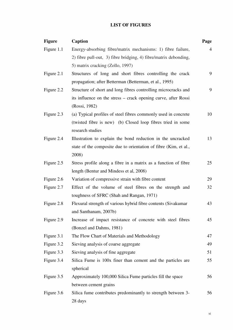
LIST OF FIGURES
Figure Caption Page
Figure 1.1 Energy-absorbing fibre/matrix mechanisms: 1) fibre failure,
2) fibre pull-out, 3) fibre bridging, 4) fibre/matrix debonding,
5) matrix cracking (Zollo, 1997)
4
Figure 2.1 Structures of long and short fibres controlling the crack
propagation; after Betterman (Betterman, et al., 1995)
9
Figure 2.2 Structure of short and long fibres controlling microcracks and
its influence on the stress – crack opening curve, after Rossi
(Rossi, 1982)
9
Figure 2.3 (a) Typical profiles of steel fibres commonly used in concrete
(twisted fibre is new) (b) Closed loop fibres tried in some
research studies
10
Figure 2.4 Illustration to explain the bond reduction in the uncracked
state of the composite due to orientation of fibre (Kim, et al.,
2008)
13
Figure 2.5 Stress profile along a fibre in a matrix as a function of fibre
length (Bentur and Mindess et al, 2008)
25
Figure 2.6 Variation of compressive strain with fibre content 29
Figure 2.7 Effect of the volume of steel fibres on the strength and
toughness of SFRC (Shah and Rangan, 1971)
32
Figure 2.8 Flexural strength of various hybrid fibre contents (Sivakumar
and Santhanam, 2007b)
43
Figure 2.9 Increase of impact resistance of concrete with steel fibres
(Bonzel and Dahms, 1981)
45
Figure 3.1 The Flow Chart of Materials and Methodology 47
Figure 3.2 Sieving analysis of coarse aggregate 49
Figure 3.3 Sieving analysis of fine aggregate 51
Figure 3.4 Silica Fume is 100x finer than cement and the particles are
spherical
55
Figure 3.5 Approximately 100,000 Silica Fume particles fill the space
between cement grains
56
Figure 3.6 Silica fume contributes predominantly to strength between 3-
28 days
56

xii
LIST OF FIGURES
Figure Caption Page
Figure 3.7 Steel fibre (35 mm length) 58
Figure 3.8 Nylon fibre (19 mm length) 58
Figure 3.9 Polypropylene fibre (12 mm length) 59
Figure 3.10 Nylon (left) and polypropylene (right) fibres distribution 60
Figure 3.11 The slump test (BS 1881 Part 102: 1983; BS EN 12350-2:
2000; ASTM C143-90a).
66
Figure 3.12 Apparatus of slump test 67
Figure 3.13 The Vebe test (BS 1881 Part 104: 1983, BS EN 12350-3:
2000)
69
Figure 3.14 Apparatus of Vebe test 69
Figure 3.15 Apparatus of Ultrasonic Pulse Velocity test 72
Figure 3.16 Apparatus of dynamic modulus of elasticity test 73
Figure 3.17 Apparatus of static modulus of elasticity 75
Figure 3.18 Apparatus of cube compressive test 76
Figure 3.19 Apparatus of ELE 3000 KN capacity (left) and INSTRON
5582-100 KN capacity (right) prism flexural tests
79
Figure 3.20 Apparatus of modified cube compressive strength test 80
Figure 3.21 Apparatus of cylinder splitting tensile strength test 81
Figure 3.22 Apparatus of concrete panel drop test 82
Figure 4.1 Compressive capacity of preliminary mixture designs 86
Figure 4.2 Slump and Vebe tests for different % of various fibres content 88
Figure 4.3 Failed 100×100×100mm cube specimens 90
Figure 4.4 Compressive strength vs. various % of fibre content 91
Figure 4.5 Comparison of compressive strength vs. residual strength 93
Figure 4.6 Effect of different fibre content on flexural strength 95
Figure 4.7 (a) Crack in concrete element subjected to bending without
fibres (b) and with fibres
96
Figure 4.8 Flexure load vs. flexure extension- plain concrete 97
Figure 4.9 Flexure load vs. flexure extension- 0.5% HyFRC of steel-
polypropylene
98
Figure 4.10 Flexure load vs. flexure extension- 0.5% HyFRC of steel-
nylon
99

xiii
LIST OF FIGURES
Figure Caption Page
Figure 4.11 Flexure load vs. flexure extension- 1.0% HyFRC of steel-
polypropylene
100
Figure 4.12 Flexure load vs. flexure extension- 1.0% HyFRC of steel-
nylon
101
Figure 4.13 Failed 100×200mm cylinder specimens 102
Figure 4.14 Splitting tensile strength vs. % of various fibre content 103
Figure 4.15 The modified cube compressive strength of various % of
fibres content
105
Figure 4.16 Development of UPV with different % of fibres content 107
Figure 4.17 The dynamic modulus of elasticity with various % of fibres 109
Figure 4.18 The static modulus of elasticity with various % of fibres 111
Figure 4.19 The results of impact resistance with different % of fibre
content
112
Figure 4.20 Failure mode of plain concrete and different % of HyFRCs 116

xiv
LIST OF TABLES
Table Caption Page
Table 2.1 Properties of steel, nylon and polypropylene fibres 20
Table 2.2 Physical and mechanical properties of various fibres used
(Sivakumar and Santhanam, 2007b)
41
Table 2.3 Dosage of different fibre combination used (Sivakumar and
Santhanam, 2007b)
42
Table 2.4 Compressive loading tests of various fibre contents (Sivakumar
and Santhanam, 2007b)
44
Table 3.1 A typical chemical composition of cement is provided below 48
Table 3.2 Properties of coarse aggregate 49
Table 3.3 Properties of fine aggregate 50
Table 3.4 Chemical and physical composition 54
Table 3.5 Design mixture of Grade 97 62
Table 3.6 Hardened test carried out for each mixture of concrete 62
Table 3.7 Type of tests and samples for the real mix concrete (Phase III) 64
Table 3.8 Impact test carried out for each mixture 65
Table 4.1 Mixture design summary 85
Table 4.2 The properties of fresh concrete with different % of fibres 86
Table 4.3 Workability of concrete with different % of various fibres 88
Table 4.4 Modified cube compressive strength of FRC with different % of
fibres
104
Table 4.5 Characterizing the quality of concrete 106
Table 4.6 Ultrasonic Pulse Velocity of concrete with different % of fibres 107
Table 4.7 Dynamic modulus of elasticity of concrete with different % of
fibres
109
Table 4.8 Static modulus of elasticity with different % of fibres 110
Table 4.9 Results of impact test for concrete with different % of fibre
content
112

xv
LIST OF SYMBOLS AND ABBREVIATIONS
Symbol Description Unit
A Cross section area m2
Ac Area of contact m2
Asurface Area of loading surface m2
b Breadth of the specimen m
d Depth of the specimen m
fb Bonding strength Pa
f s Tensile splitting strength Pa
F Force N
g Gravity acceleration ms-²
�� Density of the fibre material kg/��
�� Diameter of a circular fibre m
� Energy Joule
Ea Mean strain under the upper loading stress -
Eb Mean strain under the basic stress -
�� Static modulus of elasticity GPa
Ed Dynamic modulus of elasticity GPa
F Failure load KN
Length of a circular fibre m
� Critical length of the fibre m
m Mass of fresh concrete kg
n Frequency Hz
Density of fresh concrete kg/��
S Spacing of the fibre m
Sa Upper loading stress N/mm ²
Sb Basic stress N/mm ²
T Time s
�� Interfacial bond strength Pa
V Volume of container ��
Velocity Km/s
� fibre percent by volume of the matrix % ��

xvi
LIST OF SYMBOLS AND ABBREVIATIONS
Abbreviation Compound
ACI American Concrete Institute
Al2O3 Aluminium oxide
AR Alkaline resistant
ASTM American Society for Testing and Materials
BS British Standard
°C Degree centigrade
CaO Calcium oxide
Ca (OH)2 Calcium hydroxide
CSH Calcium silicate hydrate
DME Dynamic modulus of elasticity
DOE Design of experiments
ELE Engineering Laboratory Equipment
Fe2O3 Iron(III) oxide
FRC Fibre-reinforced concrete
G Glass fibre
GFRC Glass fibre-reinforced concrete
H2O Water
HPC High performance concrete
HyFRC Hybrid fibre-reinforced concrete
MOR Modulus of Rupture
n Number of drop
OPC Ordinary Portland Cement
PCE Polycarboxylic
PO Polyster fibre
PP Polypropylene fibre
PVA Polyvinyl acetate
Vf Volume fraction
SEM Scanning electron microscope
SF Steel fibre
SFRC Steel fibre-reinforced concrete
SHRP Strategic Highway Research Program
SIFCON Slurry infiltrated fibre concrete

xvii
LIST OF SYMBOLS AND ABBREVIATIONS
Abbreviation Compound
SIMCON Slurry infiltrated mat concrete
SiO2 Silicon dioxide
SP Superplasticizer
SSA Specific surface area
SSD Saturated surface dry
UPV Ultrasonic Pulse Velocity

1
1.0 INTRODUCTION
1.1 Background and Problem Statement
Concrete is the most commonly used construction material in the world due to its
versatility, durability and economy. Progress in concrete materials science and
technology during the last 30 years has far exceeded that made during the previous 150
years (Benjamin, 2006). Ultra-high-strength concrete (UHSC) is a new class of concrete
that has been the result of such development. This new type of concrete is characterized
with very high compressive strength; higher than 100 MPa. It is a new kind of concrete
with certain characteristics, developed for particular environment; the characteristics are
improvement in strength, durability, resistance to various external agents etc.
A very significant development that took place in the history of concrete was the use of
rebars in concrete for structural elements. This system was quite efficient in terms of
resisting the macro-cracks in concrete and in imparting bending strength in flexural
members. The purpose was somehow overcome the low tensile strength of concrete by
strategically placing the rebar. Unfortunately, concrete is a brittle material with low
tensile strength and strain capacities.
To help overcome the inherent weaknesses of concrete, there has been a steady increase
over the past 40 years in the use of fibre-reinforced cements and concretes (FRC).
Reinforcement of concrete with short randomly distributed fibres can address some of
the concerns related to concrete brittleness and poor resistance to crack growth. Fibres
are not added to improve the strength, though modest increases in strength may occur.
Rather, their main role is to control the cracking of concrete, and to alter the behaviour

2
of the material once the matrix has cracked, by bridging across these cracks and so
providing some post-cracking ductility.
When a matrix is strengthened or reinforced due to short fibres, the following
improvements can be observed:
1) Strengthening of the matrix
2) Stress intensity reduction
3) Fibre bonding and frictional pullout
4) Bridging of fibres across cracks and crack face stiffness
Reinforcement of concrete with short randomly distributed fibres can be effective in
arresting cracks at both micro and macro-level. At the micro-level, fibres inhibit the
initiation and growth of cracks, and after the micro-cracks coalesce into macro-cracks,
fibres provide mechanisms that abate their unstable propagation, provide effective
bridging, and impart sources of strength gain, toughness and ductility. (Bentur and
Mindess, 1990)
Concrete has been under the process of development since a long time. A historical
perspective to the development of FRC is given below.
1900 asbestos fibres (Hatschek process)
1950 development of concepts and the science of composite materials
1960 FRC
1970 new initiative for asbestos cement replacement
1980 SFRC, GFRC, PPFRC and Fibre Shotcrete
1990 micromechanics, hybrid systems, wood based fibre systems manufacturing

3
Almost all FRCs used today commercially involve the use of a single fibre type. Clearly,
a given type of fibre can be effective only in a limited range of crack opening and
deflection. In recent years, researchers have realized the benefits of combining fibres, in
terms of extracting synergy and improving the response of the hybridized material. The
benefits of combining organic and inorganic fibres to achieve superior tensile strength
and fracture toughness were recognized nearly 25 years ago by Walton and Majumdar
(1975). After a long period of relative inactivity there appears to be a renewed interest
in hybrid fibre composites and efforts are underway to develop the science and rationale
behind fibre hybridization. It is hoped that there is some interaction between the fibres
so that the resulting properties exceed the sum of properties provided by individual
fibres.
In general, fibre reinforcement is not a substitute for conventional steel reinforcement.
Fibre and steel reinforcements play different roles in concrete. The reinforcing bars
were added to increase the load-bearing capacity of structural concrete members while
fibres are more effective for crack control. There are many applications in which fibres
can be used effectively in conjunction with conventional reinforcement to improve the
behaviour of structural components, for instance when the concrete is to be subjected to
blast or impact loading, or in seismic applications.
Fibres are added to inhibit a propagation of cracks in concrete which occur due to its
low tensile strength. The bridging of the fibres across the cracks and the path followed
techniques, secondary reinforcement, high strength concrete ductility
issues, shrinkage crack control
2000+ structural applications, code integration, new products

4
by the crack, for a specimen in pure tension is clearly seen. Figure 1.1 demonstrates
ways in which fibres act to absorb energy and control the crack growth.
The developments in the recent years have led to FRCs that performs like elasto-plastic
materials. The function of the fibres is to lock the coarse aggregate together and prevent
the propagation and opening of macro cracks. Also, the different fibre types are being
optimized and new ones have been developed to extract maximum benefit from them.
Most of the FRCs used today involves the use of a single fibre type. Such concrete can
be effective only in a limited deflection range. The science of hybrid composites where
two fibres are combined to achieve enhancement in the basic properties of the material
is underdeveloped, yet very significant. One way of achieving more attractive
engineering properties is by judiciously hybridizing or combining different kinds of
macro and micro fibres.
Figure 1.1: Energy-absorbing fibre/matrix mechanisms: 1) fibre failure, 2) fibre pull-out, 3) fibre bridging, 4) fibre/matrix debonding, 5) matrix cracking (Zollo, 1997)

5
It has been shown recently (Yew and Othman, 2011; Ding, et al., 2010; Hsie, et al.,
2008) that by using the concept of hybridization with two different fibres incorporated
in a common cement matrix, the hybrid composite can offer more attractive engineering
properties because the presence of one fibre enables the more efficient utilization of the
potential properties of the other fibre. However, the hybrid composites studied by
previous researchers were focused on cement paste or mortar. The strength properties of
hybrid fibre-reinforced in very high strength concrete have not been studied previously.
Therefore, hybrid nylon-steel- and polypropylene-steel-fibre-reinforced in very high
strength concrete will be investigated.
1.2 Research Objectives
The objectives of this research are listed as below:
(a) To develop very high strength concrete (>100 MPa) mixtures based on
traditional concrete mix formulation,
(b) To determine the behaviour of hybrid nylon-steel- and polypropylene-steel-fibre
content to be used in FRC through the investigation of hybrid composites based
on a very high strength concrete,
(c) To evaluate the effectiveness of hybrid nylon-steel- and polypropylene-steel
fibres in concrete through the investigation of mechanical properties compared
to plain concrete,
(d) To investigate the impact strength of hybrid nylon-steel- and polypropylene-
steel fibres compared to plain concrete.
1.3 Scope of Research
To achieve the research objectives, it is important to study the principal role of fibres in
the concrete. This research is to verify the use of hybrid nylon-steel and polypropylene-

6
steel fibres in concrete. Therefore, there were several investigative tests of fresh and
hardened concrete properties carried out based on the ACI, ASTM and BS codes. The
research targeted quantifying improved engineering properties associated with each mix,
and the combinations of 0.5% and 1.0% volume fraction of nylon-steel and
polypropylene-steel fibres in each mix was judiciously decided so as to be able to offer
more attractive engineering properties to the concrete. Various admixtures were
incorporated into the plain concrete and hybrid mixes to make them workable and at the
same time keeping them feasible for practical use.
1.4 Outline of Thesis
This thesis is presented in five chapters. Chapter one is the introduction to this research,
which describes the background and the problem statement, research objectives and
scope of the research. This experiment was carried out to develop a very high strength
hybrid fibre-reinforced concrete (HyFRC). In chapter two, a review of literature on the
development of FRC and the origin and use of HyFRC is described. The physical and
mechanical properties of FRC were also studied and described. Appropriate literatures
in the area of HyFRC have been reviewed and reported. Finally, the comparison of data
is also presented in tabular form.
Chapter three gives details about the methodology that was adopted to carry out the
preparation, materials used, classification, materials properties, test apparatus and
testing procedures. The development of HyFRC and further tests that were carried out to
study their physical and mechanical properties are explained. The mix design for
HyFRC is also given in this chapter. Different amounts and types of fibres to be added
to obtain the optimum content are determined. The variations in mix proportions to

7
study the effect of different water to binder ratio (w/b) are also described. The brief
testing procedure and the references of relevant codes of practice are summarised.
Chapter four presents the experimental results and discussion on the fresh and hardened
properties of various HyFRC. The mechanical properties of HyFRCs are compared and
the interpretations of the test results are also discussed. The comparison between the test
results of plain concrete and the HyFRC are discussed using tabulated results, graphs
and relevant equations. In addition, the test results of non-destructive tests (NDT)
carried out on specimens is also discussed. The final chapter of this thesis presents the
conclusions arrived after the analysis and discussions of the experimental results. Also,
suggestions of some recommendations for further research work are specified. Some of
the supporting data and analysis are attached in the Appendix.

8
2.0 LITERATURE REVIEW
2.1 Introduction
Concrete failure initiates with the formation of micro-cracks, which eventually grow
and coalesce together to form macro-cracks. The macro-cracks propagate till they reach
an unstable condition and finally result in fracture. Thus, it is clear that cracks initiate at
a micro level and lead to fracture through macro cracking. Hybrid fibres reinforcement
helps to abate both the micro and macro cracks from forming and propagating.
2.2 Fibre-Reinforced Concrete
Fibre-reinforced concrete (FRC) is defined as a concrete incorporating relatively short,
discrete, discontinuous fibres. Generally, the fibres are not added to increase the
concrete strength, though modest increases in strength may occur. Instead, the principal
role of short dispersed fibres in concrete is to inhibit propagation of cracks in concrete
which occur due to its low tensile strength. Fibre will replace large single crack with
dense system of micro cracks which implies the improvement of durability and safety of
structure (Brandt, 2008; Kartini, et al., 2002; Ramana, et al., 2000).
2.3 Application of FRC
Fibre-reinforced concrete has found many applications. The attention is concentrated on
structural concretes for heavy-duty pavements, anti-terrorist shields, high-rise buildings,
long-span bridges, dams, pipes, fire protection coatings; spray concretes highway and
airfield pavements, and many other kinds of outstanding structures (Brandt, 2008).

9
Fine fibres control opening and propagation of micro-cracks as they are densely
dispersed in cement matrix. Longer fibres up to 50 or 80 mm control larger cracks and
contribute to increase the final strength of FRC as shown in Figures 2.1 and 2.2.
Figure 2.2: Structure of short and long fibres controlling microcracks and its influence on the stress – crack opening curve (Rossi, 1982)
Figure 2.1: Structures of long and short fibres controlling the crack propagation (Betterman, et al., 1995)

10
2.4 Characteristics of Fibre
2.4.1 Group of Fibre
Basic groups of fibres applied for structural concretes and classified according to
their material are steel fibre of different shapes and dimensions, glass fibres in
cement matrices used as alkali-resistant (AR) fibres, synthetic fibres made from
polyolefin, polyethylene, polyvinyl alcohol, polypropylene, etc (Brandt, 2008).
2.4.2 Geometrical Properties
Figure 2.3 shows that the properties included the fibre length, diameter or perimeter,
cross-sectional shape, and longitudinal profile can be selected. To develop better
bond between the fibre and the matrix, the fibre can be modified along its length by
roughening its surface or by inducing mechanical deformations. Hence the fibre can
be smooth, indented, deformed, crimped, coiled, twisted, with end hooks, end
paddles, end buttons, or other anchorage system. In some fibres the surface is etched
or plasma treated to improve bond at the microscopic level. Some steel fibres such as
ring, annulus, or clip type fibres have also been used and shown to significantly
enhance the toughness of concrete in compression (Kim, et al., 2008).
Figure 2.3: (a) Typical profiles of steel fibres commonly used in concrete (twisted fibre is new) (b) Closed loop fibres tried in some research studies (Naaman, 2003).
11
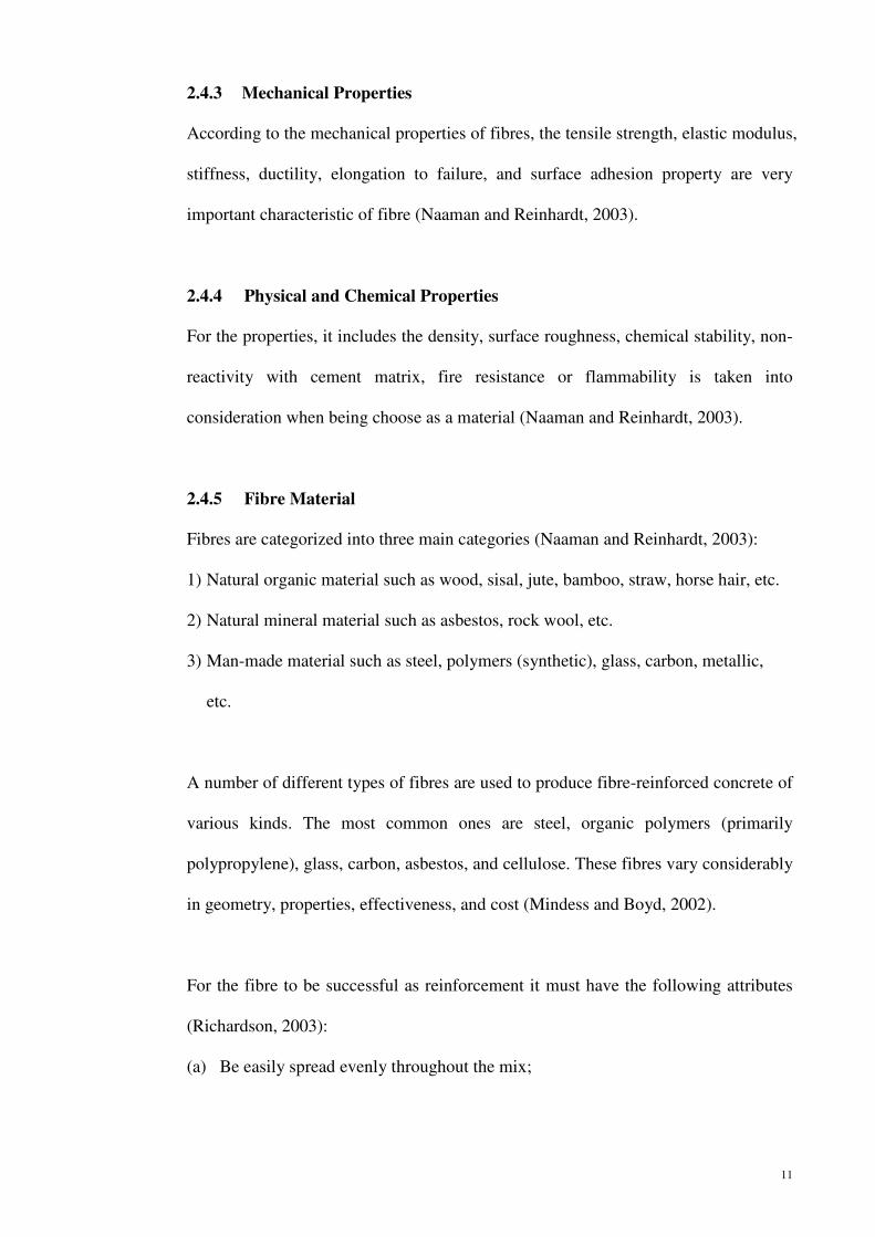
2.4.3 Mechanical Properties
According to the mechanical properties of fibres, the tensile strength, elastic modulus,
stiffness, ductility, elongation to failure, and surface adhesion property are very
important characteristic of fibre (Naaman and Reinhardt, 2003).
2.4.4 Physical and Chemical Properties
For the properties, it includes the density, surface roughness, chemical stability, non-
reactivity with cement matrix, fire resistance or flammability is taken into
consideration when being choose as a material (Naaman and Reinhardt, 2003).
2.4.5 Fibre Material
Fibres are categorized into three main categories (Naaman and Reinhardt, 2003):
1) Natural organic material such as wood, sisal, jute, bamboo, straw, horse hair, etc.
2) Natural mineral material such as asbestos, rock wool, etc.
3) Man-made material such as steel, polymers (synthetic), glass, carbon, metallic,
etc.
A number of different types of fibres are used to produce fibre-reinforced concrete of
various kinds. The most common ones are steel, organic polymers (primarily
polypropylene), glass, carbon, asbestos, and cellulose. These fibres vary considerably
in geometry, properties, effectiveness, and cost (Mindess and Boyd, 2002).
For the fibre to be successful as reinforcement it must have the following attributes
(Richardson, 2003):
(a) Be easily spread evenly throughout the mix;

12
(b) Should have sufficient bond with the concrete to transfer any tensile stresses
across the concrete;
(c) Should be sufficiently stiff and have a suitable modulus of elasticity so as to
limit cracking to acceptable limits;
(d) Provide fracture toughness; and
(e) Should be sufficiently durable to provide service throughout the life of the
concrete.
To improve mortars and concrete behaviour, the fibres must be easily dispersed in
the mixture, have suitable mechanical properties and must be durable in highly
alkaline cement matrix (Silva, et al., 2005).
2.4.6 Fibre Orientation and Fibre Efficiency Factor
Orientation factor or fibre efficiency factor is equal to efficiency with which
randomly oriented fibres can carry a tensile force in any one direction. The idea is
similar to the bent bars and vertical stirrups provided in beams to resist the inclined
diagonal tension stress. If the assumption is perfect, the efficiency factor is 0.41, but
it can varies between 0.33 and 0.65 when close to the surface of the specimen, as
trawling or leveling can modify the orientation of the fibres (Mindess and Young,
1981).

13
2.4.7 Spacing Factor
The spacing of fibre is known to affect the development of cracking in matrix. Fibres
need to be close enough together so that they effectively intercept any cracks as they
propagate through the composite. This is due to reduce of stress intensity factor of
the fracture. Fibre acts as crack arrestor, by decreasing the spacing between
increasing the tensile strength of the composite (Nawy, et al., 2008).
Several expressions have been developed. One of the expressions is from McKee
(1969):
S=3 � ��� (2.1)
Where V is the volume of one fibre element
Another expression is from (Romualdi, 1974) and (Batson, 1976):
S=13.8����.��� (2.2)
Figure 2.4: Illustration to explain the bond reduction in the uncracked state of the composite due to orientation of fibre (Naaman, 2003)

14
Where; s= spacing of the fibre
��= diameter of fibre
�= fibre percent by volume of the matrix
An expression which takes into account of the fibre length (Mindess and Young,
1981)
S=13.8�� √��� (2.3)
2.5 Synthetic Fibres
Synthetic (polymer) fibres are increasingly being used for the reinforcement of
cementitious materials. Some fibres, such as polypropylene and nylon, are used very
extensively, and many fibres are available that have been formulated and produced
specifically for reinforcement of mortars and concretes.
2.5.1 Nylon Fibre
Nylon fibres are made from nylon and are therefore stronger and bond better into
concrete than other synthetic fibres. Nylon fibres exist in various types in the
marketplace for use in apparel, home furnishing, industrial, and textile applications.
Only two types of nylon fibre are currently marketed for use in concrete, nylon 6 and
nylon 66. Nylon 6 begins as pure caprolactam. As caprolactam has 6 carbon atoms, it
got the name Nylon 6. Nylon 6 or polycaprolactam is a polymer developed by Paul
Schlack at IG Farben to reproduce the properties of nylon 66. Nylon 6 is not a
condensation polymer, but instead is formed by ring-opening polymerization. This
makes it a special case in the comparison between condensation and addition
polymers. Nylon 6 fibres are tough, possessing high tensile strength, as well as
elasticity and luster. They are wrinkle-proof and highly resistant to abrasion and

15
chemicals such as acids and alkalis. Nylon 66 is made of hexamethylenediamine and
adipic acid, which give nylon 66 a total of 12 carbon atoms. Nylon 66 has a high
melting point of 265˚C. This fact makes it resistant to heat and enables it to withstand
heat setting for twist retention. Its long molecular chain results in more sites for
hydrogen bonds, creating chemical “spring”, making it very resilient.
It has always been recognized that nylon fibres outperformance other synthetic fibres
but it is only in recent years that manufacturing costs have reduced to make them
more economical as well. The main application for synthetic fibres is to eliminate
early age cracking and any resultant long-term problems. Secondary benefits are
increased impact resistance, reduce bleed and improved build in shortcrete. At high
dosages, post crack strength can be sufficient to enable replacement of light
reinforcement. There can also be minor improvement in concrete properties affected
by the improved rheology, for example surface durability.
Synthetic (polymeric) fibres have become increasingly common in recent years. Most
synthetic fibres have lower elastic modulus than concrete. At the relatively low fibre
volume currently used in industrial practice (<0.5%), they are most effective in
reducing the amount of plastic shrinkage cracking, though they also provide some
toughening and impact resistance.
Nylons (polyamides) are among the most successful of the synthetic bulk commodity
polymers to have emerged from the last century. This success is largely due to the
excellent fibre properties of the polymers, particularly nylon-6 (polyamide-6,
polycaprolactam) and nylon-6/6 (polyamide-66). Applications for these fibres largely
fall into two classes; woven (e.g. in clothing textiles, carpets, parachute ‘silk’, and

16
sails) and non-woven (e.g. in tyre reinforcement cord, ropes, fishing line, sports
racket and guitar ‘strings’, and dental floss).
Nylon fibres are often characterised as having good strength coupled with chemical
resilience and low moisture absorbency. These three factors are, however, closely
inter-dependent. For instance, whilst it is well known that the amide linkage (–CO–
NH–) is susceptible to acid hydrolysis and UV degradation, water absorption can
substantially reduce both the glass transition temperature and Young's modulus
(Reimschuessel, 1978).
The reason for choosing nylon fibres for the testing programme was one of the cost
considerations. The other qualities attributable to non-metal fibre reinforcement are
zero reinforcement corrosion, reduction in ion flow and no aging problems
(Richardson, et al., 2005).
Nylon fibres appear to be used increasingly in FRC, often as a substitute for
polypropylene fibres. For FRC, the nylon fibres are generally produced as a high
tenacity yarn that is heat and light stable, and is subsequently cut into appropriate
lengths. These fibres typically have a tensile strength of about 800 MPa, and an
elastic modulus of about 4 GPa. It should be noted that these fibres are hydrophilic,
and can absorb about 4.5% of water; this must be considered if high volume contents
of the fibre are being used, rather than the more usual 0.1%-0.2%. Like
polypropylene, nylon is chemically stable in the alkaline cement environment.

17
2.5.2 Polypropylene Fibre
Polypropylene fibres are produced from homopolymer polypropylene resin in a
variety of shapes and sizes, and with differing properties. The main advantages of
these fibres are their alkali resistance, relatively high melting point (165˚C) and the
low price of the material. Their disadvantages are poor fire resistance, sensitivity to
fire and other environmental effects. The mechanical properties, in particular
modulus of elasticity and bond, can readily be enhanced. A number of different
polypropylene fibres for use with cementitious matrices have been developed and are
marketed commercially.
Polypropylene fibres are made of high molecular weight isotactic polypropylene.
Because of the sterically regular atomic arrangement of the macro-molecule, it can be
more readily produced in crystalline form, and then processed by stretching to
achieve a high degree of orientation, which is necessary to obtain good fibre
properties. Polypropylene fibres can be made in three different geometries, all of
which have been used for the reinforcement of cememtitious matrices:
monofilaments (Walton and Majumdar, 1975) and (Dave and Ellis, 1979), film
(Hannant, et al., 1980) and extruded tape (Krenchel and Jensen, 1980), (Krenchel and
Shah, 1985). All three forms have been used successfully for mortar and concrete
reinforcement. In this study, the forms of monofilaments have been choosen for
research purpose. While both the fibrillated and monofilament polypropylene fibres
have essentially the same strength and elastic modulus, it has been suggested that in
terms of their ability to arrest cracks, the monofilament fibres are more effective than
the fibrillated fibres (Banthia and Nandakumar, 2001).

18
Monofilament polypropylene fibres are produced by an extrusion process, in which
the polypropylene resin is hot drawn through a die of circular cross section. A
number of continuous filaments (tows) are produced at one time, and are then cut to
the appropriate lengths.
The chemical structure of the polypropylene makes it hydrophobic with respect to the
cementitious matrix, leading to reduced bonding with the cement, and negatively
affecting its dispersion in the matrix. Thus, most of the polypropylene fibres
developed for FRC undergo various proprietary surface treatments to improve the
wetting of the fibres in order to overcome these disadvantages. For instance, Zhang et
al. (2000) found that treating the fibres with low temperature cascade arc plasma was
effective in improving the flexural performance and toughness of polypropylene FRC.
Similarly, Tu et al. (1999) found that treating the surface of the fibres with
fluorination or oxyfluorination processes improved the performance of the FRC.
2.6 Steel Fibres
Originally steel fibre was added into concrete to prevent crack control, to replace the
secondary reinforcement of flat slabs, pavement and tunnel lining, and also some repair
works due to its ability in increasing the toughness of cement and concrete. The
increase in toughness can prevent or minimize the cracking caused by relative humidity
and temperature change. It can also increase the resistance towards dynamic load such
as impact, blast or seismic wave. Improves in strength due to fibre is to improve the
post-peak load carrying capacity after concrete failure (Bentur and Mitchell, 2008).
The function of adding steel fibres to the concrete is to lock the coarse aggregate
together and prevent the propagation and opening of micro cracks. Tensile forces are

19
transferred across the crack by the fibres resulting in lower stress concentrations at the
crack-end. This limits crack propagation relative to plain or mesh reinforced concrete.
The steel fibres become load carrying and replace conventional reinforcement. Such
characteristic of steel fibre is better than other fibres reinforcement in concrete.
Steel fibres may be produced by cutting wire, by shearing sheets, or from a hot-melt
extract. The first generation of steel fibres were smooth, but it was soon found that, as a
result, they did not develop sufficient bond with the cementitious matrix; modern steel
fibres are generally either deformed along their lengths or at their ends to enhance the
cement-fibre bond. Though they will rust visibly when exposed at the concrete surface,
they appear to be highly durable within the concrete mass.
Fibres come in various sizes and shapes. Round steel fibres, made from low carbon steel
or stainless steel, have diameters in the range 0.25 mm to 1.0mm. Flat steel fibres,
produced by shearing sheet or flattening round wire, are available in thicknesses ranging
from 0.015 mm to 0.04 mm. Crimped and deformed steel fibres are available both in
full length or crimped at the ends only. Some fibres are collated to facilitate mixing and
placing. A typical volume fraction of steel fibres is 0.25 to 1.50% (of the volume of
concrete).
Corrosion of fibres may be a problem with steel fibre-reinforced concrete, although
studies seem to indicate that corrosion does not seem to propagate 2.5 mm below the
surface (Somayaji, 1995). The properties of steel, nylon and polypropylene fibres vary
widely with respect to strength and modulus of elasticity, as shown in Table 2.1.

20
2.7 Types of Fibres Hybridization
The character and performance of fibre-reinforced concrete change depend on the
properties of concrete and the fibres. The properties of fibres that are usually of interest
are fibre concentration, fibre geometry, fibre orientation, and fibre distribution.
Moreover, using a single type of fibre may improve the properties of fibre reinforced
concrete to a limited level. However the concept of hybridization, adding two or more
types of fibre into concrete, can offer more attractive engineering properties as the
presence of one fibre enables the more efficient utilization of the potential properties of
the other fibre (Sahmaran, et al., 2005).
Optimization of mechanical and conductivity properties can be achieved by combining
different kinds, types, and sizes of fibres, such as in case of polypropylene and steel
fibres have the attractive advantages of hybrid fibres systems: (Qian and Stroeven,
2000):
1. To provide a system in which one type of fibre, which is stronger and stiffer,
improves the first crack stress and ultimate strength, and the second type of fibre,
which is more flexible and ductile, leads to improved toughness and strain
capacity in the post-cracking zone.
Table 2.1: Properties of steel, nylon and polypropylene fibres
Fibre type Specific
gravity
Diameter
(µm)
Tensile strength
(GPa)
Elastic
modulus
(GPa)
Melting
point (˚C)
Steel 7.84 100-1000 0.5-2.6 210 1200
Nylon 1.14 23-400 0.75-1.9 5.17 225
Polypropylene 0.91 20-40 0.4-0.76 4.11 160

21
2. To provide hybrid reinforcement, in which one type of fibre is smaller, so that it
bridges micro-cracks of which growth can be controlled. This leads to a higher
tensile strength of the composite. The second type of fibre is larger, so that it can
arrest the propagating macro-cracks and can substantially improve the toughness
of the composite.
3. To provide a hybrid reinforcement, in which the durability of fibre types is
different. The presence of the durable fibre can increase the strength and/or
toughness retention after age while another type is to guarantee the short-term
performance during transportation and installation of the composite elements.
In well-designed hybrid composites, there is positive interaction between the fibres and
the resulting hybrid performance exceeds the sum of individual fibre performances. This
phenomenon is termed “synergy.” Many fibre combinations may provide ‘synergy’ with
the most commonly recognized being (Xu, et al., 1998):
1) Hybrids Based on Fibre Constitutive Response:
One type of fibre is stronger and stiffer and provides reasonable first crack
strength and ultimate strength, while the second type of fibre is relatively flexible
and leads to improved toughness and strain capacity in the post-crack zone. There
is generally a significant difference in the modulus of elasticity of the two types of
fibres mentioned above, and ideally they carry load commensurate to the value of
strain the material is subjected to.
2) Hybrids Based on Fibre Dimensions:
One type of fibre is smaller, so that it bridges micro-cracks and therefore controls
their growth and delays coalescence. This leads to a higher tensile strength of the

22
composite. The second fibre is larger and is intended to arrest the propagation of
macro-cracks and therefore results in a substantial improvement in the fracture
toughness of the composite. This is consistent with Banthia’s and Shah’s (Banthia,
et al, 1995) and (Shah, 1991) views mentioned earlier.
3) Hybrids Based on Fibre Function:
One type of fibre is intended to improve the fresh and early age properties such as
resistance to plastic shrinkage, while the second fibre leads to improve in the
hardened/mechanical properties. When these fibres are hybridized, fresh and
hardened properties of the composites are simultaneously enhanced. Some such
hybrids are now commercially available where a low (<0.2%) dosage of
polypropylene fibre is combined with a higher (~0.5%) dosage of steel fibre.
Glavind et al. 1991 tested steel and polypropylene fibre hybrids and reported that
hybridization of these two fibres increased the ultimate compressive strain of the
composite. Larsen et al. 1991 combined steel and polypropylene fibres in
cementitious composites and found that after 10 years of out-door exposure the
fracture energy of composites containing two fibres increased by approximately
40%. In view of the above research findings, several control mixes with different
Vf of steel and polypropylene were considered in this investigation to establish the
effect of variation of fibre modulus on the behavior of concrete in flexural
toughness.
2.7.1 Macro and Micro Fibres
Hybrids based on fibre dimensions can be classified as micro and macro; macro
fibres generally being 30-60 mm in length as opposed to about 5 mm size for micro
fibres. Based on the size of the fibres, micro and macro-cracks can be controlled. The

23
diameter is generally in the range of 0.5 mm for macro fibres and about 20 microns
for the micro fibres. Another approach of distinguishing fibres is according to the
specific surface area (SSA) of fibre employed. The SSA can be defined as the surface
area for a unit mass (Banthia, et al., 1995), and mathematically,
When using fibres based on their size micro or macro) alone, SSA can also be
defined as the surface area for a unit volume, and can be written mathematically as,
Where, = length of a circular fibre,
d= diameter of a circular fibre, and
��= density of the fibre material
As their high SSA, and a small size would indicate, the micro-fibres reinforce cement
paste and the mortar phases, thereby delaying crack coalescence and increasing the
apparent tensile strength of these phases (Shah, 1991).
In Equation 2.4, note that the diameter of the fibre plays a more important role than
its length. Based on this formula, the approximate SSA value for a commonly used
steel macro fibre is calculated below.
• Steel macro fibre
SSA = 2((2*3.5) + 0.05) / (3.5*0.05*7.85)
SSA = 10.3 cm² / gm
Similarly, SSA values for some other fibres are:
Nylon micro fibres = 1526 cm² / gm
Polypropylene micro fibres = 441 cm² / gm
SSA� = �(����)���� (2.4)
SSA� =�(����)
�� (2.5)

24
Arbitrarily speaking, macro fibres have an SSA of roughly 10 cm²/gm and micro
fibres have an SSA greater than 400 cm²/gm. The micro fibre with a large SSA are
expected to reinforce the cement paste and mortar phases, thereby delaying crack
coalescence and thus increasing the apparent tensile strength. The function of the
macro fibres, on the other hand, is known to bridge across the macro-cracks and
induces post-crack ductility in the material.
2.8 Parameters of Fibres Reinforcement
2.8.1 Aspect Ratio (l/df)
Aspect ratio is equal to ratio of fibre length over diameter or equivalent diameter
which is generally less than 100 in between range from 40 to 80 (Kim, et al., 2008).
For reasons of workability and dispersion in the matrix, the aspect ratio of most
modern fibres is in the range of 50 to 150 (Mindess, et al., 2003).
Both micro and macro fibres may exceed the critical length and hence fracture across
a crack. Figure 2.5 shows the stress distribution across the length () of a fibre, which
determines the pull-out or fibre fracture mechanism. In the Figure, � is the critical
length of the fibre. When <� , fibres fracture and when >�, fibres get pulled out.
It is therefore the aspect ratio that governs the possibility of fibre fracture, not the
SSA.
2.8.2 Critical Length
Figure 2.5 shows the critical length is the minimum fibre length required for the build-
up of a stress (or load) in the fibre which is equal to its strength (or failure load)
(Mindess and Boyd, 2002).

25
� = ��� ! "� (2.6)
Where, ��= fibre diameter
��= interfacial bond strength
"�= fibre strength
The effects of fibre length on shear stress transfer and lc are shown as below.
Figure 2.5: Stress profile along a fibre in a matrix as a function of fibre length (Bentur and Mindess, et al., 1990)
Shah et al. (2001) tested permeability characteristics of hybrid composites and
demonstrated that fibre hybridization significantly increased the resistance to water
ingress. Although the concept of hybrids has shown to have significant promise, almost
all studies to date have focused on normal strength matrices. Gupta et al. (2002) showed
that the strength of the matrix plays a major role in the optimization of hybrid
composites. In this research, the influence of concrete strength is explored further by
conducting tests on hybrid composites based on a very high strength concrete.

26
2.9 Effect on Fresh Concrete Properties
2.9.1 Workability
Fibre tends to stiffen the concrete mix, and make it looks harsh when static, although
it may respond well to vibration. The addition of fibres will reduce the workability of
the concrete. This can be generally compensated for by increasing the fine-to-coarse
aggregate ratio and by increasing the cementitious material content, generally
through the addition of pozzolanic materials.
Workability tests based on static conditions, such as the slump test might be
misleading due to the fact that FRC is workable when vibrated. Hence tests which
consist of dynamic effects are more recommended. There are a number of
workability tests; researchers have described that there are 61 workability tests for
FRC test yet only a number of test is commonly used (Koehler and Fowler, 2003).
The most common tests for workability of FRC are:
1) Slump test (ASTM C143, Standard Test Method for Slump of Hydraulic Cement
Concrete). It is not a good indicator for the workability of FRC due to static
condition. Though according to ACI Committee 544 (2), once it has been
established that a particular FRC mixture has satisfactory handling and placing
characteristics at a given slump, the slump test may be used as a quality control
test to monitor the FRC consistency from batch to batch '
2) Vebe Test (BS 1881: Part 104: 1983 Method for Determination of Vebe Time)
Vebe Test is suitable for workability properties of fresh FRC because it is a
dynamic effect test, but it is not relevant for quality control on site.

27
3) Walz flow table test (in German DIN 1045 and 1048, and European EN206) it is
commonly used in Europian countries. It is a simple test; a metal container which
is 200 mm × 200 mm × 400 mm is filled with incompacted concrete then rodded
or vibrated. The degree of compaction is calculated as the height of the container
divided by the average height of the compacted concrete.
4) Inverted slump cone (ASTM C995, Standard Test Method for Time of Flow of
Fibre-Reinforced Concrete through Inverted Slump Cone). It is a test specially
developed for FRC. It is sensitive to the mobility and fluidity of FRC, and is used
for mixes which has a slump of less than 50 mm and it should not be used if the
time of flow is less than 8 s; such mixes should be assess by slump test.
2.9.2 Fabrication of Fibre-Reinforced Concrete
Mixing fibres with other constituents can be done in several ways depending on the
facilities available and job requirements. The most important factor in mixing is to
ensure the fibres are dispersed uniformly and to prevent bleeding, and also fibre
balling. There are several factors that lead to segregation and balling such as:
1) Aspect ratio (l/��)
2) Volume percentage of fibre
3) Coarse aggregate size, gradation, and quantity
4) Water / cementitious materials ratio and method of mixing
A maximum aspect ratio of l/�� and a steel fibre content excess of 2% by volume is
the cause of non-uniform mix. It is recommended that 9.7mm maximum aggregate
size is use in the mixture although conventional mixing procedures can be used.
Water-cement ratio varies due to the cementitious pozzolans in cement replacement
and the percentage by volume of the matrix (Nawy, et al., 2008).

28
A workable method can be summarized as follows:
(a) Blend part of the fibre and aggregate before charging into the mixer.
(b) Blend the fine and coarse aggregate in the mixer, add more fibres at mixing
speed, then add cement and water simultaneously or add the cement
immediately followed by water and additives.
(c) Add the balance of the fibre to the previously charged constituents, and add
the remaining cementitious materials and water.
(d) Continue mixing as required by normal practice.
(e) Place the fibrous concrete in the forms. Use of fibres requires more vibrating
than required for non-fibrous concrete; although internal vibration is
acceptable if carefully applied, external vibration of the formwork and the
surface is preferable to prevent segregation of the fibres.
When using transit mix truck or revolving drum mixer, fibres should be added last to
the wet concrete. The fibres added should be free of clumps by passing through
proper screen. The use of collated fibres held together by water-soluble sizing which
dissolves during mixing can solve the clumping problem. After the fibre had been
mixed into the mixer, the mixing speed should be set to 3-40 revolutions per minute
for proper dispersion of the fibres. Or the fibres may be mix with fine aggregate on
conveyor belt during the aggregate adding process to the concrete mix.
Fibre balling or clumping usually occurs before fibres are added to the mix. If they
enter the mix free of balls, they will be uniformly dispersed. Fibre balling when
mixing might be due to using worn out mixing equipment or over mixing process
(Bentur and Mitchell, 2008).

29
2.10 Effect on Hardened Concrete Properties
2.10.1 Compressive Strength
The normal range of fine content is less than 2%. FRC has shown a little effect on
compressive strength (Bentur and Mitchell, 2008). The effect of fibre in concrete can
be seen in Figure 2.6 in the compressive test by using steel fibre.
The compressive strength of concrete reinforced with 30mm length of fibres was
about 17% higher than the corresponding plain concrete strength (Cachim, et al.,
2002).
Tests by Karihaloo et al. (2006) had found an increase in compressive strength from
about 120 MPa to about 145 MPa which is approximately 21% on going from 0% to
4% fibres by volume (Farhat, et al., 2007).
Similarly another test has found an increase from about 150 MPa to about 200 MPa
which is an increase of 33% on going from no fibres to 4% fibres by volume (Sun, et
al., 2001).
Figure 2.6: Relationship between compressive strain with fibre content

30
Inclusion of plastic fibres in concrete should improve its fracture resistance, but it
could have a negative impact on compressive strength and creep behaviour. In
general, plastics do not achieve chemical bond with cementitious materials.
Compressive strength decreased with increase in the amount of the plastic fibres in
concrete, particularly above 0.5% fibre addition by weight. Therefore, in order to
maintain a particular compressive strength level, plastic fibre concentration in
concrete must be controlled. However, the amount of fibre addition can be increased
substantially if particles (fibres) are further processed to improve the bond area and
stress transfer capacity of particles (fibres) (Naik, et al., 1996).
Attempts have been done to determine the relationship between extreme high fibre
content and compressive strength. It was found that for SIFCON (slurry infiltrated
fibre concrete) with fibre content of 10% by volume, the compressive strength had
increase roughly 25-50% from its plain concrete matrix. Similarly a test had been
done by using SIMCON (slurry infiltrated mat concrete) with fibre volume of 2.16 -
5.39% shows an increase of about 30%. However very high fibre content may lead to
difficulties in achieving full compaction consequently porosities in matrix increased
(Bentur and Mitchell, 2008).
2.10.2 Splitting Tensile Strength
In low volume of steel fibres, it will increase cylinder splitting tensile strength when
the fibres content is increased although it has little effect on compressive strength
(Balendran, et al., 2002).
Reinforcement of concrete with short, randomly distributed steel fibres leads to
improvements in the tensile strength and tensile and compressive ductility of the

31
materials. This is due to the tendency of propagating microcracks in cementitious
matrices to be arrested or deflected by fibres (Choi, et al, 2002).
The addition of 1.5% by volume of fibres may increase the tensile strength by about
45%. Steel fibres have also been shown to increase the shear capacity substantially
(Somayaji, 1995).
For steel fibre-reinforced concrete, the mainly three-dimensionally distributed steel
fibres can reinforce both the shear failure (oblique cracks) and the splitting failure
(vertical cracks) greatly (Ding and Kusterle, 2000).
Other investigations showed that the addition of fibres in conventional FRC can
increase the toughness of cementitious matrices significantly; however their tensile
strength and especially strain capacity beyond first cracking are not enhanced
(Fischer and Li, 2007).
2.10.3 Modulus of Rupture (Flexural Strength)
Fibre tends to increase the flexural strength in the concrete or mortar elements to a
much greater extent compare to elements which is subjected to direct tension or
compression (ACI Committee 544, 1993). It was shown that in strain hardening fibre
reinforced composite, the flexural strength was roughly twice the strength of plain
concrete cement (Li and Maalej, 1996).
The first stage involves the first cracking load stage in load deflection diagram, and
the second stage is the ultimate controlling stage. Both the first cracking load
ultimate flexural capacities were affected by the function of the product of the fibre

32
volume ( �) and aspect ratio (l/��). The principle effect of fibres is to improve the
post-peak load carrying capacity of the concrete (i.e. toughness), as shown in Figure
2.7.
Figure 2.7: Effect of the volume of steel fibres on the strength and toughness of SFRC (Shah and Rangan, 1971)
2.10.4 Concrete Fluidifiers (Superplasticizers)
Superplasticizer (SP) is an admixture that enables the concrete to be workable even
produced at very low water-cement ratios (without the need for excessively high
cement contents) is critical. Superplasticizer also prevents flocculation of Portland
cement particles and reduces inhomogeneities of material such as silica fume by
distributing them homogenously. Hence it helps to improve paste strength. The
strength of the paste will be limited by the flaws with form the weakest link,
introducing SP will help to minimise the inhomogeneities or capillary pores.

33
2.10.5 Impact Resistance of Fibre-Reinforced Concrete
The impact resistance of plain concrete is considered relatively low. The introduction
of fibre into concrete has the effect of improving the concrete performance under
dynamic loading sometimes by more than an order of magnitude.
Plain concrete is known for the highly strain rate sensitive in compression (Grote, et
al., 2001), tension (Zielinski, et al., 1988), and flexural (Mindess, et al., 1986 and
Suaris and Shah, 1982), though the degree of rate sensitivity varies. In fibre-
reinforced concrete the situation is more complicated since the matrix, the fibres and
the fibre-matrix bind are strain-rate sensitive to different degrees. Hence it is not able
to predict the behaviour of fibre-reinforced concrete under impact on the basis of
static test result due to the difference in failure mechanisms, also depending on the
particular fibre-reinforced concrete and strain rate.
There are several common types of impact test which are:
(a) Instrumented drop weight test- In the test a mass which is raised to a certain
height and then let to drop onto the target specimen which may be a beam, a
plate or a compression specimen. The system is instrumented with some load
cells, accelerometers, strain gauges and displacement transducers.
(b) Swinging pendulum machines- The machines are of the form of Charpy
machines. A swinging pendulum strikes the specimen and transferring
momentum and reducing high stress rates to the sample. (Suaris and Shah,
1982) and (Gokoz and Naaman, 1981).

34
(c) Split Hopkinson pressure bar- The fibre reinforced specimen is sandwiched
between two elastic bars and very high stress rates can be generated by
propagating a pulse through one of the bars, using a striker bar. When the
input bar is struck, a well-defined rectangular compression wave is generated.
When the wave reaches the specimen, some of it reflects back through the
input bar, and some transmits through the specimen to the output bar. This
generates very high stresses and stress rates in the specimen. One dimensional
wave analysis is then used to obtain the stress vs. strain curves.
(d) Projectile impact- In the test a projectile of some sort is fired at an FRC
specimen, using a kind of gun. Hence this initiates a compressive wave which
runs through the material to a free edge. The wave is then reflected and is
transformed into a tensile wave that propagates in the opposite direction. The
principal failure modes are scabbing on the rear side of the specimen, and
scabbing on the front. In some cases, complete penetration may occur. The
results of the experiments are assessed in terms of the visual damage to the
specimen.
(e) Explosive charges- It is a method by generating extremely high stress rates; an
explosive charge may be attached directly to the specimen, and then detonated.
(f) Repeated impact drop weight test- A weight of some type is dropped
repeatedly onto the specimen, and the number of blows required to cause a
specified amount of damage is recorded. This test is inconsistent, and is not
now used very much.

35
(g) Inertial loading- In the initial period of the impact event, a beam or a plate
specimen is accelerated, and the inertial force induced in addition to the force
required bending the specimen. As a result during this time period, the
recorded load is considerably greater than that resisted by the beam. This
shows up as an oscillation in the total load vs. time curve.
2.11 Research in Hybrid Fibre-Reinforced Concrete (HyFRC)
2.11.1 Double Fibre Hybrid Composites
Glavind and Aarre (1991) investigated the possibilities of increasing the fracture
toughness of high-strength concrete by adding fibres. Tests were conducted with both
normal and high-strength concrete containing different amounts of steel and
polypropylene fibres and toughness was described by toughness indices. The
investigation showed that the addition of steel fibres was effective in increasing the
toughness and non-linear load carrying capacity for high-strength concrete. Steel
fibres also marginally increase the compressive strength of high strength concrete.
The combination of different fibres for thin walled fibre reinforced cement
composites for structural applications, with fibres made of metallic, mineral,
polymeric or naturally occurring materials was reported by Ramanalingam et al.
(2001). The authors stated that different fibres offer different extent of improvement
to the mechanical properties of the matrix, but the most sought-after property in a
cement-based composite is the strain hardening response that is associated with
multiple cracking. The authors believed that in order to achieve this property,
different types of fibres should be suitably combined to exploit their unique
properties.

36
Qi et al. (2000) tested carbon and polypropylene fibre hybrids and found that hybrid
fibre-reinforced concrete when tested in tension resulted in de-bonding between the
matrix and the fibre and a great number of fibres pulled out. The stress was always
first transferred from the matrix to the carbon fibres, due to its high modulus. After
some displacement, the polypropylene fibres would carry most of the load and a
large deformation would induce failure. In the study, it was also noticed that carbon
and polypropylene fibres when used in a combination offered toughening at different
structural levels. Significant strengthening and toughening occurred in carbon-
polypropylene hybrid fibre-reinforced concrete.
Horiguchi and Sakai (1997) investigated steel and PVA hybrids. They studied the
fracture toughness of fibre-reinforced concrete in comparison as well as flexure. Four
different types of steel fibre and two types of PVA fibre individually and in
combination form were investigated. The toughness of hybrid fibre-reinforced
concrete showed different performance from that of mono fibre composites and for
the same flexural toughness, the first crack deflection was greater in the hybrids.
They also observed that while the compressive strength did not change, the addition
of fibres significantly enhanced the compressive toughness. Compressive toughness
was found to increase in proportion to the fibre content; the highest compressive
toughness occurred for the hybrids. No clear correlation however between the
compressive and flexural toughness was noticed.
Feldman and Zheng (1991) also studied hybrid composites containing steel and
polypropylene fibres. From their investigation, they concluded that workability of
hybrid fibre-reinforced concrete was reduced as steel fibre or polypropylene fibre
contents were increased. Deformed fibres were found to be more effective than

37
straight fibres in enhancing the flexural and compressive behaviour of concrete. They
also found that in hybrid composites, stronger and stiffer steel fibres improved the
ultimate strength, while the more flexible and ductile polypropylene fibres led to
improved toughness and strain capacity in the post-crack zone.
A combination of fibres can be very effective, resulting in some form of synergy.
Soroushian et al. (1993) reported synergy in hybrid polyethylene fibre reinforced
cement composites. They optimized the combined use of two different fibre types
(high modulus polyethylene fibre and a fibrillated polyethylene pulp) in cementitious
matrices.
It was noted that in the case of impact resistance, the favorable effect of each fibre
was further enhanced in the presence of the other fibre. For flexural strength and
toughness, the combined use of polyethylene fibre and pulp produced highly
desirable results. The authors also noted that the negative effect of fibres on
compressive strength was less pronounced when the two fibre types were used in
combination.
Qian and Stroeven (2000) investigated the optimization of fibre size, fibre content
and fly ash content in hybrid polypropylene-steel fibre concrete with low fibre
contents. They found that the presence of fine particles of an admixture helped fibre
dispersion and that different sizes of steel fibres contributed to different mechanical
properties. Additions of a smaller fibre had a significant influence on the
compressive strength, but splitting tensile strength was only slightly affected. The
authors found that the optimum dosage of polypropylene fibre was 0.15% and
concluded that synergy existed in their hybrid fibre composites.

38
2.11.2 Other Properties of HyFRC
The benefits of hybridizing fibres are observed not only in flexural and compressive
toughness but also in the other properties. The interaction between polyethylene fibre
and pulp in controlling the specific gravity, volume of permeable voids, and water
absorption capacity of continuous materials has been found to be either negligible or
only moderately significant (Komlos, et al., 1995).
Schaumann et al. (2008) conducted experimental and modeling studies on
polypropylene and steel fibres, in beams with or without conventional stirrups. In
general, fibres proved to be more effective in high-strength concrete than in normal
strength concrete based on ultimate load and overall ductility. Steel fibres were found
to be far more effective than polypropylene fibres. In tests, where a combination of
fibres and stirrups was used, a slightly increase in ultimate load with major
improvements in ductility were noted in comparison to beams made of plain concrete.
In another investigation (Group 6), floor slabs were tested under static loading. They
were related to the toughness characteristics by testing beams according to ASTM C
1399. A 30 MPa plain concrete slab and slabs containing fibre reinforcement (fibre
contents of 0.25% and 0.35%) were examined. The fibres used in the investigation
were macro steel and micro polypropylene. From the acquired data, maximum peak
load, flexural strength and the average residual strength from the beam specimens
was calculated. The authors proposed to relate the residual strength of FRC to an
increase in structural capacity of slabs.
Durability studies were conducted by Larsen and Krenchel (1991), who examined
steel, AR-glass, synthetic (polypropylene) and natural (sisal and paper pulp cellulose)

39
fibre-reinforced concrete for exposure to climatic conditions. They concluded that
natural and glass fibres lose strength and ductility when subjected to normal out-
doors exposure. They also investigated a combination of what they believed to be the
best fibres (steel and polypropylene), and found that the ductility and fracture energy
of the composites were increased significantly even after a very long period of
exposure. The researchers concluded that fracture energy for composites will change
with time, depending on the type of reinforcement and the matrix.
Under repeated loading, fibre-reinforced concrete containing several volume
fractions of two types of fibres, polypropylene and steel fibre content led to balling,
while the increase in polypropylene fibre content led to a harsh mix. The fracture and
impact energy, as well as toughness and ductility were found to be substantially
improved by an increase in the volume fraction of polypropylene fibres.
In an investigation by Sun et al. (2001), shrinkage and water permeation properties of
high-performance concrete with expansive agents and hybrid fibres (steel, polyvinyl
alcohol and polypropylene fibres) were studied. Test results indicated that the hybrid
fibres of different types and sizes could reduce the size and amount of cracking at
different levels.
Kim and Sakai (1997) investigated hybrid fibre-reinforced concrete containing micro
and macro fibres to enhance the resistance to cracking by thermal stresses. The
physical properties and crack resistance at early ages were examined. In this
investigation, steel fibres and polypropylene fibres of 6, 12, and 30 mm in length
were used. It was concluded that hybrid fibre-reinforced concrete had high resistance
to thermal cracks and it was possible to control these cracks. In the case of steel
40
fibres, crack resistance improved monotonically with fibre volume in the range of
0.1-2.5%. However, for polypropylene fibres, 0.3% was the optimum volume
fraction.
Synergy in cement-based hybrids is not only in terms of toughness but also in terms
of other secondary properties such as electrical conductivity. This is evident from the
research carried out by Banthia et al. (1992), where synergy was observed in
electrical conductivity due to the use of carbon (micro) and steel (micro) fibres.
Electrical resistivity measurements were conducted on cement pastes reinforced with
conductive micro-fibres of carbon and steel both in mono and hybrid forms, using a
high frequency alternating current. Although carbon fibres themselves are far less
conductive than steel fibres, cement composites with carbon fibres were found to be
far better conductors than those with steel fibres. It was concluded that, more than the
conductivity of the material itself, it is the size and the distributions of the fibre in a
composite were found to have conductivities better than their equivalent mono-fibre
systems. Improvements in conductivity with carbon fibre were by almost three orders
of magnitude as opposed to one order of magnitude increase for steel fibres. Increase
in conductivity with increase in the volume fraction of the fibres was also noticed for
steel and carbon fibres, but the increase in conductivity because of steel fibres was
lower than that due to carbon fibres. They concluded that the two fibres in a hybrid
composite had an interactive behavior rather than a purely additive behavior.
To summarize then, it is clear that the concept of hybridizing fibres is a sound one
and significant improvements have been reported by various investigators. It is also
clear that the influence of concrete matrix strength is not well understood. Equally
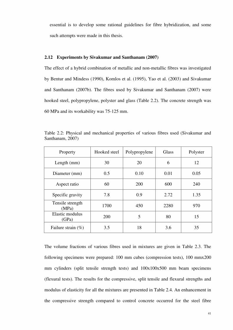
41
essential is to develop some rational guidelines for fibre hybridization, and some
such attempts were made in this thesis.
2.12 Experiments by Sivakumar and Santhanam (2007)
The effect of a hybrid combination of metallic and non-metallic fibres was investigated
by Bentur and Mindess (1990), Komlos et al. (1995), Yao et al. (2003) and Sivakumar
and Santhanam (2007b). The fibres used by Sivakumar and Santhanam (2007) were
hooked steel, polypropylene, polyster and glass (Table 2.2). The concrete strength was
60 MPa and its workability was 75-125 mm.
Table 2.2: Physical and mechanical properties of various fibres used (Sivakumar and Santhanam, 2007)
The volume fractions of various fibres used in mixtures are given in Table 2.3. The
following specimens were prepared: 100 mm cubes (compression tests), 100 mmx200
mm cylinders (split tensile strength tests) and 100x100x500 mm beam specimens
(flexural tests). The results for the compressive, split tensile and flexural strengths and
modulus of elasticity for all the mixtures are presented in Table 2.4. An enhancement in
the compressive strength compared to control concrete occurred for the steel fibre
Property Hooked steel Polypropylene Glass Polyster
Length (mm) 30 20 6 12
Diameter (mm) 0.5 0.10 0.01 0.05
Aspect ratio 60 200 600 240
Specific gravity 7.8 0.9 2.72 1.35
Tensile strength (MPa)
1700 450 2280 970
Elastic modulus (GPa)
200 5 80 15
Failure strain (%) 3.5 18 3.6 35

42
concrete and all hybrid fibre concretes. The maximum increase in the compressive
strength was only of the order of 15%. The concretes with individual non-metallic fibres
did not register any increase in the compressive strength. For all fibre concrete mixtures,
there was a corresponding increase in the modulus of elasticity as compared to the
control concrete. The split tensile strengths of hybrid fibre concretes were found to be
higher as compared to reference and mono-steel fibre concrete. The hybrid fibre
concretes containing steel and polypropylene (HSPP3 and HSPP6) showed the highest
split tensile strength among all concretes. The glass fibres, possibly owing to their short
lengths did not perform as well as the other two non-metallic fibres.
Table 2.3: Dosage of different fibre combination used (Sivakumar and Santhanam, 2007)
Mixture
Volume fraction of hooked end
(%)
Volume fraction of
non-metalic fibre (%)
Fibre dosage (kg/mᶾ) Total fibre
dosage
(kg/m³) S PP PO G
C1 - - - - - - -
HST2 0.50 - 39.98 - - - 39.98
HSPP3 0.38 0.12 27.22 1.34 - - 28.56
HSP04 0.38 0.12 27.22 - 1.82 - 29.04
HSGL5 0.38 0.12 27.22 - - 3.84 31.06
HSPP6 0.25 0.25 19.44 2.26 - - 21.70
HSPO7 0.25 0.25 19.44 - 3.36 - 22.8
HSGL8 0.25 0.25 19.44 - - 6.77 26.21
HSPP9 0.12 0.38 9.36 3.41 - - 12.77
HSPO10 0.12 0.38 9.36 - 5.14 - 14.50
HSGL11 0.12 0.38 9.36 - - 10.32 19.68
PP12 - 0.50 - 4.5 - - 4.5
PO13 - 0.50 - - 6.72 - 6.72
GL14 - 0.50 - - - 13.62 13.62
Note: S-steel fibre, PP- polypropylene fibre, PO- polyster fibre, G- glass fibre.
The flexural testing results are presented in Figure 2.8 and Table 2.4. Compared to
concrete without fibres, all fibre-reinforced concretes showed an appreciable increase in
flexural strength. Among all fibre concretes, a hybrid combination of steel and polyester
showed the maximum flexural strength. The reason could be due to a smaller length and

43
high aspect ratio of polyester fibres, which gave a high reinforcement index. A steel-
polypropylene and steel glass combination showed a reasonable increase in the flexural
strength compared to plain and mono-steel fibre concrete.
Figure 2.8: Flexural strength of various hybrid fibre contents (Sivakumar and Santhanam, 2007)

44
Table 2.4: Compressive loading tests of various fibre contents (Sivakumar and Santhanam, 2007)
Mixture Mean compressive
strength (MPa)
Mean split tensile strength
(MPa)
Mean modulus of elasticity
(GPa)
Ultimate flexural strength (MPa)
C1 56.1 4.1 31.1 5.2
HST2 59.2 5.2 33.2 6.0
HSPP3 61.1 5.3 34.8 6.7
HSP04 62.4 5.2 35.2 7.1
HSGL5 59.2 5.3 34.1 6.3
HSPP6 64.7 5.5 35.1 7.3
HSPO7 58.6 5.4 35.6 6.6
HSGL8 60.3 4.9 34 7.1
HSPP9 63.4 4.9 35.5 6.8
HSPO10 64.2 5 35.6 7.1
HSGL11 62 4.8 34.8 6.2
PP12 56.1 4.4 33.1 5.6
PO13 55.1 4.7 34.8 6.3
GL14 57.8 4.3 33.7 6.0
2.13 Dynamic Experiments
There are laboratory tests available for determining the dynamic properties and impact
resistance of steel-fibre-reinforced concrete. These may be broadly categorized into
drop weight impact tests and projectile impact tests (Suaris and Shah 1984). A number
of experimental studies on the impact behaviour of SFRC have been carried out and all

45
of these studies, regardless of the test method employed, demonstrated that the impact
resistance of SFRC is, in general, substantially higher than that of plain concrete. Song
et al. (2004) applied the drop weight impact test method to evaluate the impact
resistance of concrete and found that, by adding 1.5% by volume of steel fibres to plain
concrete, the average number of blows required to produce the first crack could be
increased by 418% and the average number of blows required to cause failure could be
increased by 518%. On the other hand, Ong et al. (1999) applied the projectile impact
test method using a projectile with a hemispherical nose and found that the amounts of
impact energy required to cause failure of concrete slabs, each containing 1% or 2% by
volume of steel fibres, were respectively 100% and 136% higher than that of plain
concrete.
According to Bonzel and Dahms (1981), the impact resistance of fibrous concrete is
significantly higher (Figure 2.9). It grows with increasing fibre dosage.
Figure 2.9: Increase of impact resistance with respect to plain concrete and different volume fraction of steel fibres (Bonzel and Dahms, 1981)
0
50
100
150
200
250
300
350
400
450
First crack Failure
Incr
ease
of
imp
act
res
ista
nce
[
%]
30 kg/mᶾ
60 kg/mᶾ

46
3.0 MATERIALS AND METHODOLOGY
3.1 Introduction
In the Strategic Highway Research Program (SHRP), high performance concrete (HPC)
was initially defined by three requirements:
• Maximum water-cementitious material ratio of 0.35
• Minimum durability factor of 80% after 300 cycles of freezing and thawing
• Minimum compressive strength of either:
(a) 21 MPa within 4 hours after placement;
(b) 34 MPa within 24 hours;
(c) 69 MPa within 28 days,
“High performance” in high performance concrete may imply high strength, high
durability and/or other characteristics needed for a specific application. In this context,
toughness is another property implying high performance, specifically for fibre
reinforced concrete and the toughness tests provide a quantitative measure of this
property.
3.2 Materials
In the process of fibre-reinforced concrete (FRC) production, all raw materials have to
be careful inspected to avoid any flaws or defects. The properties of main raw material
such as nylon fibre, polypropylene fibre, steel fibre, cement, silica fume, coarse
aggregate, fine aggregate, water, and superplasticizer have been identified. There are
two main section of testing including the fresh and hardened concrete tests. The
procedures of tests, the essential apparatus and the properties of materials are given in
detail below, as shown in Figure 3.1.

47
Figure 3.1: The Flow Chart of Materials and Methodology
3.2.1 Cement
For the research work, cement used in the mixing is Ordinary Portland Cement Type
1 (OPC). The cement was manufactured by Tasek Corporation Berhad. The brand of
the cement is Tasek Cement which has fulfilled the requirement stated in Malaysian
Standard MS 522 which is loosely based on the British standard BS 12. It is a leading
brand in the construction industry and is extensively used in projects of all sizes. The
colour of it is brownish grey. It is stored in an airtight steel drum to prevent from
moisturization before use. A typical chemical composition of cement is shown in
Table 3.1.
Mixture design

48
3.2.2 Coarse Aggregate
Coarse aggregates make up about 70-80% of volume of concrete. Particle from rock
fragments are the most common of aggregate. Therefore, its selection and
proportioning should be concerned properly in order to control the quality of the
concrete. The aggregate material must be strong, durable and inert to give
satisfactory performance and the sizes must be appropriate to fulfill the intended
application. The coarse aggregate used during the experiment was crushed granite
with maximum size of 19 mm (3/4”) obtained from a quarry site. It was angular in
shape and rough surface texture. In this study, coarse aggregate was obtained in
Selangor from Hanson Quarry of Cheras. The crushed granite was kept inside
laboratory which are sheltered from rain or other humid source. This is to ensure that
the moisture content does not vary in each casting. To get the maximum size of 19
mm coarse aggregate, a 19 mm sieve was used to remove the unwanted materials
such as leaves, branches of tree and larger size of aggregate. Then, it was dried in an
open air for not less than 24 hours. It is to prevent the moisture content in the
aggregate affecting the concrete production.
Table 3.1: A typical chemical composition of cement used below
Compositions and properties of cement Ordinary Portland Cement (OPC)
SiO2 (% by wt) 21.28
CaO (% by wt) 5.60
Al2 O3 (% by wt) 3.36
Fe2O3 (% by wt) 64.64
MgO (% by wt) 2.06
SO3 (% by wt) 2.14
Total Alkalis 0.05
Insoluble Residue 0.22
Loss on Ignition 0.64
Modulus
Lime Saturation Factor 0.92
Silica Modulus 2.38
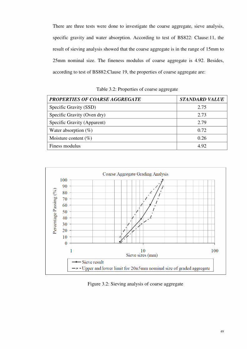
49
There are three tests were done to investigate the coarse aggregate, sieve analysis,
specific gravity and water absorption. According to test of BS822: Clause:11, the
result of sieving analysis showed that the coarse aggregate is in the range of 15mm to
25mm nominal size. The fineness modulus of coarse aggregate is 4.92. Besides,
according to test of BS882:Clause 19, the properties of coarse aggregate are:
Figure 3.2: Sieving analysis of coarse aggregate
Table 3.2: Properties of coarse aggregate
PROPERTIES OF COARSE AGGREGATE STANDARD VALUE
Specific Gravity (SSD) 2.75
Specific Gravity (Oven dry) 2.73
Specific Gravity (Apparent) 2.79
Water absorption (%) 0.72
Moisture content (%) 0.26
Finess modulus 4.92

50
3.2.3 Fine Aggregate
The fine aggregate used in the experiment is mining sand available from Hanson
Quarry Selangor. The mining sand with a maximum size of 5 mm was used as fine
aggregate. The sand was stored in a shaded area and sheltered from rain to ensure
that the sand was saturated surface dry. After sieving using size of 4.75 mm and
below, the fine aggregate was dried in an open air before use.
Several tests were done to determine the properties of the fine aggregate. These
included specific gravity and water absorption, and the sieve analysis. According to
BS812:Clause 21, the fine aggregates was certified in Zone 2 as shown in Figure 3.3.
The finess modulus is 3.00. Besides, according to BS812:Clause 28, and
BS822:Clause 11, the properties of t fine aggregate are :
Table 3.3: Properties of fine aggregate PROPERTIES OF FINE AGGREGATE STANDARD VALUE
Specific Gravity (SSD) 2.52
Specific Gravity (Oven Dry) 2.48
Specific Gravity (Apparent) 2.58
Water absorption (%) 1.45
Mositure content (%) 0.62
Finess modulus 3.00
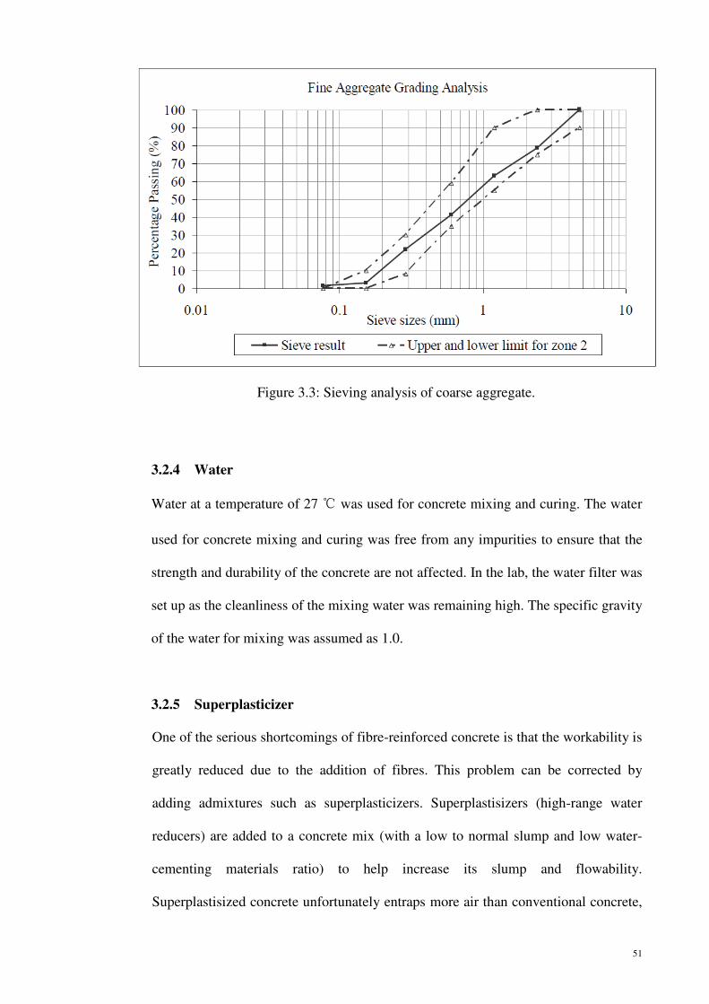
51
Figure 3.3: Sieving analysis of coarse aggregate.
3.2.4 Water
Water at a temperature of 27 ℃ was used for concrete mixing and curing. The water
used for concrete mixing and curing was free from any impurities to ensure that the
strength and durability of the concrete are not affected. In the lab, the water filter was
set up as the cleanliness of the mixing water was remaining high. The specific gravity
of the water for mixing was assumed as 1.0.
3.2.5 Superplasticizer
One of the serious shortcomings of fibre-reinforced concrete is that the workability is
greatly reduced due to the addition of fibres. This problem can be corrected by
adding admixtures such as superplasticizers. Superplastisizers (high-range water
reducers) are added to a concrete mix (with a low to normal slump and low water-
cementing materials ratio) to help increase its slump and flowability.
Superplastisized concrete unfortunately entraps more air than conventional concrete,

52
but most of this air is generally lost during transportation and casting using vibrators.
In this study, GLENIUM ACE 388 (RM) SURETEC procured from BASF Company
was used to increase the workability of fresh concrete and to aid in the strength
improvement of the hardened concrete.
For historical reasons, polynaphthalene sulfonate superplastisizers have been most
commonly used in North America and Japan, while polymelamine superplasticizers
are commonly used in Europe (Aitcin and Mindess, 1988). In the case of high
strength concrete, where fine mineral admixtures such as silica fume are used, it is
very important to have an effective superplasticizer which would accommodate the
high demand of workability in the mix.
For this study a superplasticizer added during the casting is an innovative based
superplasticiser with super retention technology. Due to a specifically tailored
constitution of the active material, this admixture shows formerly unknown
adsorption characteristics to cement. As a result, polycarboxylic ether (PCE)
provides exceptional good early strength development. While conventional
admixture for high early strength concomitantly suffer from high workability loss
over time and eventually lower final strength, polycarboxylic ether (PCE) overcomes
this dependency and provides much improved slump retention and vastly increased
final strength of concrete. It is formulated to comply with ASTM C494 (1998) for
Type F and G admixtures.
The normally recommended dosage rate is 0.75-1.2. litres per 100 kg of cement. To
ensure proper handling and storage of the material, the superplasticizer must be
stored in a place where the temperature is not below 0℃. In case the product freezes,

53
increase the temperature of the product to 30 ℃ and remix. The storage
incompatibility of the material is with strong oxidising agents, alkalis and acids. It
must avoid contact with metal such as iron. The superplasticizer was diluted before
mixing with the concrete. Polycarboxylic ether (PCE) is a liquid admixture to be
added to the concrete during the mixing process. The best results are obtained when
the admixture is added after all the other components are already in the mixer and
after the addition of at least 80% of the total water. Furthermore it is not
recommended to add superplasticizer together with dry aggregate or cement, as it
lowers the plasticising effect or water reduction ability.
3.2.6 Mineral Admixtures- Silica Fume
High-strength concretes generally contain one or more supplementary cementitious
materials such as fly ash, silica fume, blast furnace slag, metakaolin, etc. Until a few
years ago, 40 MPa concrete was considered to be high strength, but today, using
silica fume, concrete with compressive strength in excess of 100 MPa can be readily
produced. It enables to achieve very flowable concrete without segregation and very
high compressive strengths in the range of 70-120 MPa. Silica fume also lubricates
the concrete and increases pumpability. The advantages of using additives such as
silica fume facilitate production, cost saving benefit, and increases durability. It is
interesting to note that the use of about 10% silica fume in high-performance
concretes with very low water/binder ratios results in a significant decrease in the
superplastisizer dosage required for a given workability (Rougerson and Aitcin,
1994). The silica fume used for this research investigation was procured from
Scancem Materials Sdn. Bhd.

54
Silica fume is a filtered powder generated from the reduction of high purity quartz –
ferrosilicon metals or silicon metals. Silica fume consists primarily of very fine
smooth spherical silicon dioxide particles with an extremely high surface area. Silica
fume’s chemical and physical typical composition is shown in Table 3.4 in
comparison with OPC cement and fly ash.
Silica fume improves concrete through two mechanisms:-
1) Pozzolanic effect:
When water is added to OPC, hydration occurs forming two products, as shown
below:
In the presence of silica fume, the silicon dioxide from the silica fume will react
with the calcium hydroxide to produce more aggregate binding CSH as follows:-
The reaction reduces the amount of calcium hydroxide in the concrete. The
weaker calcium hydroxide does not contribute to strength. When combine with
carbon dioxide, it forms a soluble salt which will leach through the concrete
causing efflorescence, a familiar architectural problem. Concrete is also more
Table 3.4: Chemical and physical composition of cementitious materials
Unit OPC Fly Ash Silica Fume
SiO2 % 17-25 40-55 90-98
CaO % 60-67 1-5 0.2-0.7
Al�O� % 2-8 20-30 0.4-0.9
Fe�O� % 0-6 5-10 1-2
Other % 1-8 4-15 2-3
S.G - 3150 2100 2200
Bulk density Kg/m3 1400 900-1000 550-650
Surface Area m2/kg 200-500 200-600 20,000
OPC + H2O CSH (Calcium silicate hydrate) + Ca (OH)2 (3.1)
Ca(OH)2 + SiO2 + H2O CSH (3.2)

55
vulnerable to sulphate attack, chemical attack and adverse alkali-aggregate
reactions when high amounts of calcium hydroxide is present in concrete.
2) Microfiller effect:
Silica fume is an extremely fine material, with an average diameter 100x finer
than cement (Figure 3.4). At a typical dosage of 8% by weight of cement,
approximately 100,000 particles for each grain of cement will fill the water
spaces in fresh concrete (Figure 3.5). This eliminates bleed and the weak
transition zone between aggregate and paste found in normal concrete. This
microfiller effect will greatly reduced permeability and improves the paste-to-
aggregate bond of silica fume concrete compared to conventional concrete.
Figure 3.4: Silica Fume is 100x finer than cement and the particles are spherical (SEM
photo)

56
Figure 3.5: Approximately 100,000 Silica Fume particles fill the space between cement grains
The silica reacts rapidly (Figure 3.6) providing high early age strengths and
durability. The efficiency of silica fume is 3-5 times that of OPC and consequently
vastly improved concrete performance can be obtained.
Figure 3.6: Silica fume contributes predominantly to strength between 3-28 days

57
3.2.7 Fibre (Steel, Nylon and Polypropylene)
3.2.7.1 Steel Fibre (Fig 3.7)
The steel fibre used during casting is obtained from Scancem Materials. The steel
fibres are made from hard drawn low carbon steel, in accordance to ASTM A820.90
Type 1 and have a tensile strength of 1200 MPa. It has a length of 35 mm and aspect
ratio of 65. The specific gravity of the steel fibres is 7.84. There are hooks at both
ends of the steel fibre to enhance the bonding between steel and concrete. The
percentage volume fraction of nylon, polypropylene and steel fibres were added into
the concrete based on the optimum fibre content in the proportion of 0.1% to 0.4%
and 0.1% to 0.9%. The steel fibre used for this research investigation was procured
from Scancem Materials Sdn. Bhd.
3.2.7.2 Nylon Synthetic Fibre (Fig 3.8)
Nylon fibre is 100% pure virgin nylon 6 fibre, supplied as a filamentized fibre bundle.
Its ability to absorb about 4% moisture (i.e. 25 ml of water per cubic metre of
concrete at recommended dosage) gives an enhanced bond to the concrete matrix.
Nylon has a tensile strength which is 896 MPa. For concrete, the length of nylon
fibres used is 19mm. The specific gravity and modulus of elasticity of nylon are 1.14
and 5.17 GPa, respectively. The melting temperature of nylon is about 225˚C. The
main application for synthetic fibres is to eliminate early age cracking and any
resultant long-term problems. The Nycon fibres called nylon 6 used for this research
investigation were procured from Scancem Materials Sdn. Bhd.
3.2.7.3 Polypropylene Synthetic Fibre (Fig 3.9)
Polypropylene fibres are produced from homopolymer polypropylene resin.
Polypropylene has a tensile strength of 413 MPa. For concrete, the length of
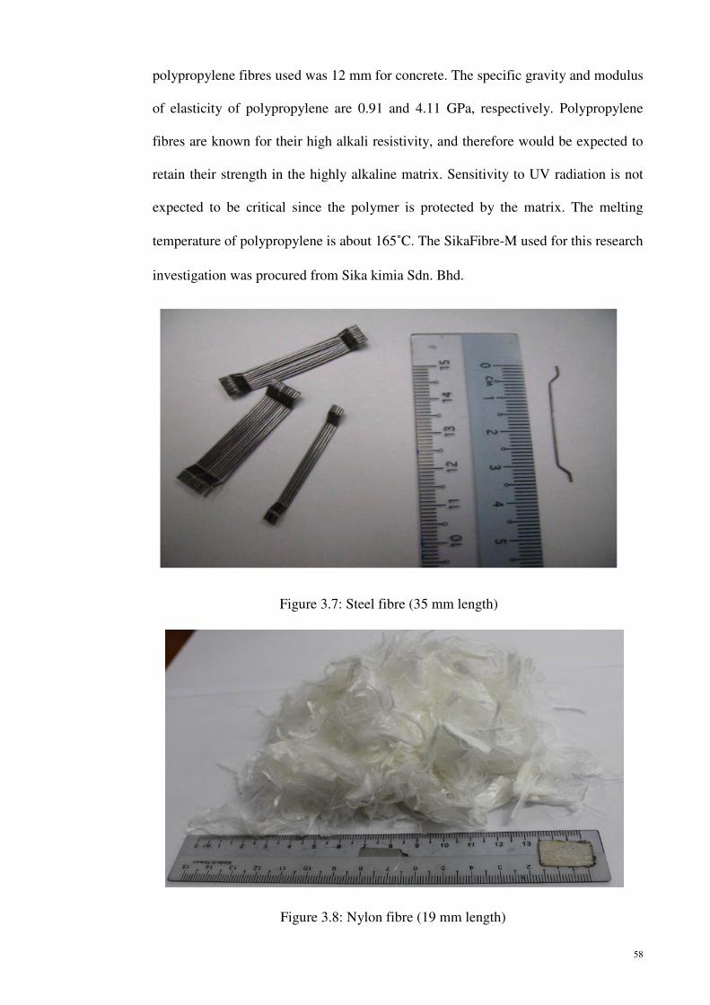
58
polypropylene fibres used was 12 mm for concrete. The specific gravity and modulus
of elasticity of polypropylene are 0.91 and 4.11 GPa, respectively. Polypropylene
fibres are known for their high alkali resistivity, and therefore would be expected to
retain their strength in the highly alkaline matrix. Sensitivity to UV radiation is not
expected to be critical since the polymer is protected by the matrix. The melting
temperature of polypropylene is about 165˚C. The SikaFibre-M used for this research
investigation was procured from Sika kimia Sdn. Bhd.
Figure 3.7: Steel fibre (35 mm length)
Figure 3.8: Nylon fibre (19 mm length)

59
3.2.8 Fibre Distribution of Nylon and Polypropylene
The in-concrete distribution of nylon and polypropylene fibres was approximated
through the distribution of these fibres in the mixing water. To approximate the
distribution, 3 g of nylon and polypropylene fibres were respectively introduced into
a 6 x 80 cm cylindrical glass measure filled with 1000 g of the mixing water. After
the introduction, the measure was stoppered, vigorously agitated, and allowed to
stand for 3 hours as shown in Figure 3.10, It was observed that the nylon fibres had a
more marked dispersion in the mixing water compared to polypropylene, implying
that the nylon fibres distributed themselves more thoroughly throughout the concrete.
Figure 3.9: Polypropylene fibre (12 mm length)

60
3.3 Mix Design
Mix design can be defined as the selection of ingredients and their proportions. It
involves the process of choosing the correct proportion of cement, chemical and mineral
admixtures, fine and coarse aggregate and water to produce concrete that is as
economical as possible with certain minimum properties such as strength, durability and
a required consistency.
Department of Environment, (DOE) method was used to determine the properties of
concrete such as workability, strength, density, thermal characteristics, and durability
requirements. In DOE method the properties most usually specified are:
1) The workability of the fresh concrete
2) The compressive strength at a specific age
Figure 3.10: Nylon (left) and polypropylene (right) fibres distribution

61
3) The durability, by means of specifying the minimum cement content and/ or
maximum free-water/ cement ratio, and in some cases requiring the use of
selected types of materials
The concrete mix was designed to achieve Grade 100 at 28 days. The workability was
maintained in the range of 20-220 mm slump. To make sure the concrete achieve the
required workability, superplasticizer was added into the concrete mix without changing
the water content. Thus, the water-to-cement ratio could be maintained and the strength
of the concrete would be more consistent.
3.4 Sample Preparation
In concrete sample preparation, the work can be divided into three phases. The first
phase is mixing the plain concrete without fibre as it achieved 97 MPa. For the second
phase, the concrete trial mix was done to determine the optimum proportion of nylon
fibre to give the highest value of strength. Then, the optimum percentage of nylon fibre
was carried on from phase II to the real mix of phase III. In the real mix of phase III, the
steel fibre was added to enhance the ability of the nylon fibre in concrete where it could
offer better engineering properties to the concrete. The proportions of both fibres were
different as to obtain the better quality of FRC through several concrete investigation
tests. All ingredients of the concrete mixes were prepared according to the calculated
mix design proportion and mixed with a laboratory 190 litres capacity concrete drum
mixer.
3.4.1 Sample Preparation of Plain Concrete (Phase I)
In the first stage of the concrete preparation, the plain concrete without fibres
achieved the compressive strength of 97 MPa at 28 days. The workability is to meet

62
the requirement in the range 180-220 mm in slump test. The mix proportions is as
shown in the Table 3.5:
3.4.2 Sample Preparation of Hybrid Fibres Trial Mix (Phase II)
For the mixing in phase II, nylon, polypropylene and steel fibres were added into the
concrete at different percentages such as 0.1%, and 0.2% volume fraction of nylon
and polypropylene fibres and 0.8% and 0.9% steel fibres volume fraction of the
concrete. At the early stage, the work was focused on the workability of the concrete.
Then it was followed by the compressive strength, flexural strength and splitting
tensile tests. For each of the concrete cube the compressive strength was tested at 1, 3,
7 and 28 days. The flexural strength and splitting tensile strength for different
percentage of fibres were tested at 28 days. Type of test and details are shown in
Table 3.6.
Table 3.5: Design mixture of Grade 97
Item Trial Mix 1 (kg/m³)
Cement Content 406
Silica Fume 45
Free Water Requirement 131
Fine Aggregate Content 903
19mm Aggregate Content 935
Superplastisizer Polycarboxylic ether (PCE) (0.45-0.82 litre)
Water/(cement + silica fume) ratio 0.29
Table 3.6: Hardened test carried out for each mixture of concrete
No. Test Specimen Type Dimension Testing age
(Days)
1 3 7 28
1 Compressive cube 100x100x100 mm 4 4 4 4
2 Flexural prism 100x100x500 mm - - - 8
3 Splitting tensile split cylinder Ø=150xL=300 mm - - - 8

63
3.4.3 Sample Preparation of Real Mix (Phase III)
For real mix in phase III, the steel fibres was added as supplement to nylon fibres. In
the first stage, the concrete was casted based on the optimum content of nylon and
polypropylene fibres resulting from phase II. The optimum of 0.1% volume fraction
of the nylon and polypropylene fibres were determined and added to 0.4% and 0.9%
volume fraction of steel fibre of the concrete volume. In the second stage, the
concrete was casted using the optimum content of hybrid fibres that was determined
from the result of 0.5% and 1.0% volume fraction of HyFRCs. At the early stage of
study, the fresh concrete properties of workability (slump test and Vebe test) and
density were determined. In this phase, the samples that were prepared are shown in
Table 3.7.

64
3.4.4 Final Stage of Sample Preparation
In this stage slabs with dimension of 600×600×50 mm were casted with plain
concrete content of 0% fibre and 0.1% Vf of nylon and polypropylene fibres to 0.4%
and 0.9% Vf of steel fibres of the hybrid fibres reinforced concrete. The slabs were
used for impact test using a modified concrete panel drop test machine. The test for
the fibre-reinforced concrete with different fibre content was carried out at 28 days
from the date of the concrete was casted. In this phase, details of the slabs are shown
in Table 3.8.
Table 3.7: Type of tests and samples for the real mix concrete (Phase III)
No. Tests Specimen
shape Size(mm)
Testing age
(Days)
1 3 7 28
I. Non-destructive Tests
1 Ultrasonic pulse
velocity cube 150 x 150 x 150 4 4 4 4
2 Dynamic modulus of
elasticity prism 100 x 100 x 500 - - - 3
3 Static modulus of
elasticity cylinder
150 dia x 300 length
- - - 3
II. Destructive Tests
1 Compressive strength cube 100 x 100 x 100 4 4 4 4
2 Modulus of rupture prism 100 x 100 x 500 - - - 8
3 Modified cube
compressive strength portion of
broken prism - - - - 8
4 Tensile splitting
strength cylinder
150 dia x 300 length
- - - 8
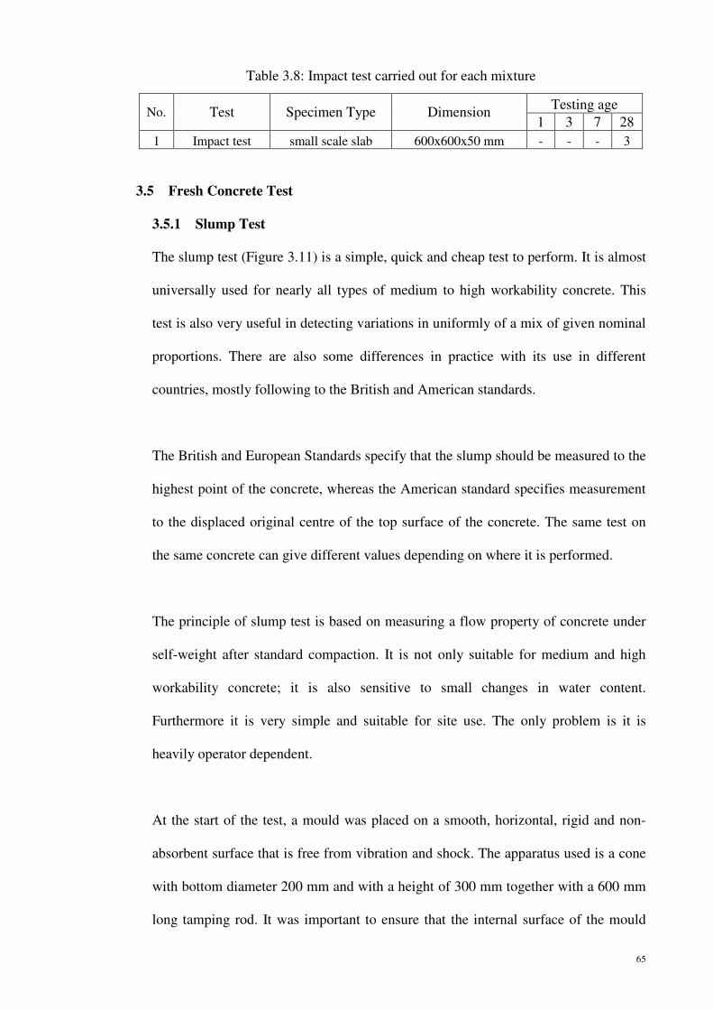
65
3.5 Fresh Concrete Test
3.5.1 Slump Test
The slump test (Figure 3.11) is a simple, quick and cheap test to perform. It is almost
universally used for nearly all types of medium to high workability concrete. This
test is also very useful in detecting variations in uniformly of a mix of given nominal
proportions. There are also some differences in practice with its use in different
countries, mostly following to the British and American standards.
The British and European Standards specify that the slump should be measured to the
highest point of the concrete, whereas the American standard specifies measurement
to the displaced original centre of the top surface of the concrete. The same test on
the same concrete can give different values depending on where it is performed.
The principle of slump test is based on measuring a flow property of concrete under
self-weight after standard compaction. It is not only suitable for medium and high
workability concrete; it is also sensitive to small changes in water content.
Furthermore it is very simple and suitable for site use. The only problem is it is
heavily operator dependent.
At the start of the test, a mould was placed on a smooth, horizontal, rigid and non-
absorbent surface that is free from vibration and shock. The apparatus used is a cone
with bottom diameter 200 mm and with a height of 300 mm together with a 600 mm
long tamping rod. It was important to ensure that the internal surface of the mould
Table 3.8: Impact test carried out for each mixture
No. Test Specimen Type Dimension Testing age
1 3 7 28
1 Impact test small scale slab 600x600x50 mm - - - 3

66
was clean and damp but free from superfluous moisture. Firstly the cone was filled
with concrete in three equal layers, and each layer is compacted with 25 strokes of
the tamping rod. Then the cone is slowly raised and the concrete is allowed to slump
under its own weight. The slump is measured using the upturned cone and slump rod
as a guide. (Figure 3.11) In the test, the BS 1881 Part 102 was followed and hence
the slump is measured to the highest point of the concrete. The apparatus of slump
test is shown in Figure 3.12.
Figure 3.11: The slump test (BS 1881 Part 102: 1983; BS EN 12350-2: 2000; ASTM C143-90a).

67
3.5.2 Vebe Test
Vebe test is shown in Figure 3.11 BS 1881: Part 104: 1983 described the method for
determination of Vebe time. It measures the amount of work (time at constant
vibration) for full compaction.
It is suitable for very low and low workability mixes and it shows a greater relation
to concrete placing conditions than slump. Vebe test is more complex than other
methods which requires standard vibrating equipment and sometimes difficult to
define end point.
In this test, the time for the concrete shape to change from cone shape to compacted
concrete is taken. The duration time is defined as Vebe time and it is stated in the
nearest 0.5 second. This test is very sensitive to the consistency, flow and
compactable changes of the concrete. Therefore, there is a relationship between the
Figure 3.12: Determination of slump using the slump test

68
concrete workability of this test at lab with that on site. This test is similar with the
method of concrete casting at site.
The mould was hold firmly against the surface below with the funnel, that in position
at the top whilst it was filled in three layers of concrete, each approximately one-third
of the height of the mould when tamped. Each layer was tamped with 25 strokes by
using a 16 mm diameter, 600 mm long tamping steel rod in a way of gravity falling.
Each layer was tamper to its full depth, ensuring that the tamping rod through the
second and top layers into the layer immediately below. After the top layer has been
tamped, the funnel was removed and the concrete level striked off with the top of the
mould with a sawing and rolling motion of the tamping rod. With the mould still held
down, from the surface below was cleaned off any concrete which may have fallen
onto it or leaked from the lower edge of the mould.
When the filling was completed, the top surface was leveled. The cone was removed
from the concrete by raising it vertically, slowly, and carefully, in 5-10 seconds
without any lateral or twisting motions. Immediately after the cone was removed, the
glass plate holder was put onto the concrete in gentle motion. This was then vibrated
at a controlled frequency and amplitude until the lower surface of the transparent disc
was completely covered with grout. The duration time of the concrete to be
compacted was taken as Vebe time. The apparatus of Vebe test is shown in Figure
3.14.

69
Figure 3.13: The Vebe test (BS 1881 Part 104: 1983, BS EN 12350-3: 2000)
Figure 3.14: Apparatus of Vebe test

70
3.5.3 Density of Fresh Concrete
Density of fresh concrete can be measured in accordance with BS1881: Part
107:1983. It can be obtained by weighing the compact fresh concrete in a standard
container of known volume and mass. The top of the container was cleaned of any
excess concrete. The concrete density of fresh concrete was determined as follows:
=�� (3.1)
Where, =density of fresh concrete in kg/��
m= mass of fresh concrete in unit kg
V= in unit ��
3.6 Hardened Concrete Test (Non-Destructive Tests)
3.6.1 Ultrasonic Pulse Velocity Test
The test procedure is given in BS1881: Part 203:1986. The Ultrasonic Pulse Velocity
(UPV) Test is based on the measurement of speed of a sound wave with the density
of its propagation. Generally, the speed of ultrasonic pulses traveling in a solid
material depends on the elastic properties and density of the specimen.
Before the test can be started, a zero reading should established for the apparatus,
since the indicated measurement was influenced by a time delay due to both
transmission of the pulse through the transducers material and transmission of
electrical signal along the transducer cables. Concrete cubes of size 150mm x 150mm
x 150mm were tested at 1, 3, 7 and 28 days.
The apparatus incorporated a suitable time delay adjustment so that the indicated
readings may be made independent of this effect. The time delay adjustment was

71
made while the transducers were coupled to the opposite ends of a reference bar for
which the transit time was accurately known (bar with transit time 26µs was used).
Then, the transducers were arranged in direct transmission. The direct transmission
arrangement was used since the transfer of energy between the transducers was at its
maximum and the accuracy of velocity determination was therefore governed
principally by the accuracy of the path length measurement. The ultrasonic pulses
generated at the transmitting transducer were ensured to pass into the concrete and
were then detected by the receiving transducer. It was essential that there was
adequate acoustical coupling between the concrete surfaces; the finish was
sufficiently smooth to ensure good acoustical contact by the use of a coupling
medium and by pressing the transducer against the concrete surface. Thus, grease
was used in this test. The apparatus of UPV test is shown in Figure 3.15.
Generally, a pulse of longitudinal vibrations is produced by an electroacoustical
transducer which was held in contact with one surface of the concrete under test.
After traversing a known path length, L in concrete, the pulse of vibrations is
converted into an electrical signal by a second transducer. Electronic timing circuits
enable the transit time, T of the pulse to be measured. Ultrasonic Pulse Velocity, V,
in km/s for the concrete could be calculated as given below:
Ultrasonic Pulse Velocity, =
'( (3.2)
Where, L = length of specimen, mm
T = time taken to travel from the transmitter to the receiver, in μs

72
3.6.2 Dynamic Modulus of Elasticity Test
Dynamic modulus of elasticity, (DME) was tested according to BS1881: Part 209:
1990. Concrete prisms with dimension of 100mm x 100mm x 500mm were used and
tested by using an "ERUDITE"-Resonant Frequency Tester at the age of 28 days.
Before running the DME test, the length and density were tested immediately just
after removal from water, whilst still saturated. The surface water and grit were
wiped off the specimen. Later the prism was clamped and balanced at its canter on
the fixed support. After that, contact was made between the vibrating part of the
exciter and the center of one end face of the specimen by means of a weak adhesive.
The contact was made between a piezo-electric vibration pick-up and the opposite
end of the specimen in a similar way, as shown in Figure 3.16. The axis of the
transducers was ensured in the centre and normal to the end faces of the specimen.
Figure 3.15: Apparatus of Ultrasonic Pulse Velocity test

73
The frequency at which this vibration occurs relates largely on the dynamic modulus
of density, elasticity and length of the specimen. The exciter was driven by a variable
frequency oscillator with a range of 100-10000 Hz imparts an alternative force to the
specimen, and the response was sensed by pick-up, amplified, and their amplitude
was measured by an appropriate indicator. The amplitude of vibration was monitored
by the indicator until the resonant frequency was obtained at the maximum deflection
of the indicator.
The dynamic modulus of elasticity in kN/mm ² is given by the equation:
Dynamic modulus of elasticity, Ed =
)*+'+,��-. (3.3)
Where, n= frequency at maximum deflection of indicator (Hz)
L= length of the specimen (mm)
= density of the specimen (kg/��)
Figure 3.16: Apparatus of dynamic modulus of elasticity test

74
3.6.3 Static Modulus of Elasticity Test
Static modulus of elasticity was tested according to BS1881:Part121:1983. The
concrete cylinders used for this test were 150 mm diameter and 300 mm in length
and tested at 28 days. An extensometer was attached to the test cylinder. Then, the
concrete cylinder was placed centrally on the lower platen of the testing machine as
shown in Figure 3.17. The upper block slowly bear on the specimen, and the block
gently rotated by hand so that uniform seating was obtained.
Before the test started, reading at dial gauge should set to zero first. Then, load was
applied at a pace of 4.418 kN/s. Upon reaching a load of about 20% of ultimate load,
the load was reduced to zero, and the dial gauge reading noted. If the dial gauge
reading was not zero, the loading of 20% steps were repeated until the dial gauge,
upon unloading, was zero. The final loading cycle was started and the loading was
continued until maximum. The dial gauge was read when it reached the basic stress,
Sa and the upper loading stress, Sb.
The static modulus of elasticity is given as:
Static modulus of elasticity, ��=
/01/!2012! (3.4)
Where, S4= upper loading stress, N/mm ² (Sa = Fc/3)
S5 = basic stress, N / mm ² (0.5 N/mm ²)
ε7 = mean strain under the upper loading stress, mm
ε5 = mean strain under the basic stress, mm
F8 = Compression load, N

75
3.7 Hardened Concrete Test (Destructive Tests)
3.7.1 Compressive Test
The compressive strength test of 100×100×100 mm cube specimens at 1, 3, 7 and 28
days was determined according to BS1881:Part116:1983 by using an ELE
(Engineering Laboratory Equipment) testing machine with a load capacity of 3000kN.
According to the BS1881:Part116:1983, the cube, sample was placed with the cast
faces in contact with the platens of the testing machine as shown in Figure 3.18. The
Figure 3.17: Apparatus for static modulus of elasticity test

76
load on the cube was applied at a constant rate of stress (2.4 KN/s) until the specimen
failed.
Concrete is a material with non-linearity in the stress-strain relation. At high stress
rate, the strain increased progressively. At near failure state, the movement of the
pressure plate of the testing machine was increased. Failure on the sample
approached when the loading rate was decreased. The maximum load applied to the
cube was recorded. By dividing the load at failure by surface area of the sample, the
compressive strength was obtained. Compressive strength formula was indicated as:
Compressive strength, P=9: (3.5)
Where, F= failure load (KN)
Asurface = area of loading surface (mm²)
Figure 3.18: Apparatus of cube compressive test

77
3.7.2 Modulus of Rupture Test
Modulus of rupture (MOR) or flexural strength test was carried out in accordance
with BS1881:Part118:1983. According to the code a plain concrete beam
(100mm×100mm×500mm) is subjected to flexure using symmetrical two-point
loading until failure occurs. Figure 3.19 shows the point loads are spaced at one-third
of the span; hence the test for both of apparatus is also called a third-point loading
test or two-point loading. An ELE machine of 3000 KN capacity was used to
determine the average of MOR. Whilst, INSTRON 5582 was used to evaluate the
results by comparing flexural strengths of plain concrete prisms with hybrid fibre
reinforced concrete prisms by plotting curves of Flexure Load (KN) versus Flexure
Extension (mm).
For two-point loading a constant bending moment is produced in the zone between
the upper roller bearings. Hence this induces a symmetrical triangular stress
distribution along vertical sections from compression above the neutral axis at mid-
height to tension below the neutral axis. The maximum tensile stress at the bottom of
the test beam is known as the modulus of rapture or flexural strength.
All the specimens subjected to water curing were tested immediately on removal
from the water whilst they were still wet. Specimens for testing at 24 hours were
tested in the moist condition. Specimens previously used for non-destructive tests
were not remain out of water for more than 15 minutes and were returned to water
curing for at least 15 minutes before testing.
The surfaces of the support and loading rollers were wiped clean. Surface water and
grit on the specimens were also wiped off. The test specimen was placed in the

78
flexural machine correctly with the longitudinal axis of the specimen centered at right
angles to the rollers. A sawn specimen was placed in the machine so that the original
finished surface was in tension. The original surface may not therefore be oriented
with its position in the structure. After that, that packing was not used between the
specimen and the roller. Furthermore, load was not applied to the specimen until all
loading and supporting rollers were in even contact with the test specimen.
Then, the load was applied steadily and without shock at such a rate as to increase the
stress at a rate of 0.05 mm/min (INSTRON 5582-100 KN capacity) or 0.067 KN/s
(ELE 3000 KN capacity) respectively. The loading rates were applied based on the
strength of the concrete. If the concrete is categorise as low strength concrete the
lower rate was used. Similarly high strength concrete will require higher loading rate.
Once adjusted, the rate of loading was maintained without change until failure
occured. The maximum load read on the scale was recorded as the breaking load.
Modulus of rupture, fcr, = ;<=�2 (3.6)
Where, F= maximum breaking load (KN)
L= distance between the lower supporting rollers (mm)
b= breadth of the specimen (mm)
d = depth of the specimen (mm)

79
3.7.3 Modified Cube Compressive Strength Test
The failure parts from the prism beam after flexural strength test were used in the
modified cube test. This test was done according to BS1881: Part119: 1983. Test
specimen of part of beam was placed between the additional plates, and load was
applied without any shock, continuously increased at a pace of 2.4 KN/s. The
specimen was carefully marked and placed in a suitable jig such as that shown in
Figure 3.20. The specimen and auxiliary platens were ensured to be located correctly.
The specimen was centered carefully on the lower platen of the machine so that it did
not touch the jig supports.
Equivalent cube compressive strength was determined as follows:
Modified Cube Compressive Strength = 9:? (3.7)
Where, F = maximum load, in KN
Ac = area of contact of the additional platens, in mm�
Figure 3.19: Apparatus of ELE 3000 KN capacity (left) and INSTRON 5582-100 KN capacity (right) used for prism flexural tests

80
3.7.4 Splitting Tensile Test
The tensile splitting strength was tested according to BS1881: Part 117:1983. The
specimen used was concrete cylinder of 150mm in diameter and 300 mm in length
and placed with its horizontal axis between the platens of the machine. A narrow
strip of plywood as shown in Figure 3.21 was placed between concrete cylinder and
the platen to prevent high local compressive stresses at load lines. Without shock, the
load was applied and increased continuously at a nominal rate within the range 0.02
N/ (mm².s). The rate was maintained, once adjusted, until failure. The maximum load
applied to the specimen was recorded.
This method was simple to perform and produce more uniform results compared to
other tensile strength tests. Load was increased slowly until by indirect tension in the
form of splitting along the vertical diameter at a pace of 1.767 kN/s. The horizontal
tensile splitting strength in N/mm ² is expressed as follows:
Figure 3.20: Apparatus of modified cube compressive strength test

81
Tensile splitting strength, f s = �AB�� (3.8)
Where, P= compressive load on the cylinder (KN)
l= length of the cylinder, (mm)
d= diameter (mm)
3.8 Impact Test
There are no standard test method to evaluate the impact properties of fibre-reinforced
concrete and plain concrete, although there are many test procedures used in different
laboratories such as instrumented drop weight impact tests using machines of various
sizes.
A repeated drop weight impact test was conducted. It is the simplest test among all the
impact tests. A weight is dropped repetitively on the same spot on the specimen as
shown in Figure 3.22. Test is based on the modification of ACI Committee 544,
‘Measurement of properties of fibre-reinforced concrete’. A steel rammer which weighs
Figure 3.21: Apparatus of cylinder splitting tensile strength test

6.50 kg was put to a height
fall from the height repeatedly. The number
when the small scale slab
specimens absorbed until it
� = ∑ �D*EF�
Where, m = mass of steel rammer
g = gravity acceleration as 9.81
h = drop height to the surface of small scale slab
n = number of drop
kg was put to a height of 64.0 cm from the small scale slab surface and let to free
e height repeatedly. The number of drops when the
small scale slab breaks respectively were recorded. The energy that the
ecimens absorbed until it broke was calculated as:
�DG
Where, m = mass of steel rammer (kg)
g = gravity acceleration as 9.81ms-²
h = drop height to the surface of small scale slab (m)
n = number of drops
Figure 3.22: Apparatus of concrete panel drop test
82
of 64.0 cm from the small scale slab surface and let to free
first crack occurs and
. The energy that the
(3.9)
Apparatus of concrete panel drop test

83
4.0 RESULTS AND DISCUSSION
4.1 Introduction
In this chapter, fresh and hardened properties of various fibre reinforced composites are
described and tested. To characterize their strength properties and test behaviour, the
compressive strength test, splitting tensile strength test, modified cube compressive
strength test, flexural strength test, impact resistance test and comparison of flexural
load-flexure extension curves were carried out and the results were analyzed.
4.2 Mixture Design
The first part of this research study involves the development of an initial mixture
design based on traditional concrete mix formulations with compensation for expected
behaviour (increased water demand, reduced aggregate size, etc). From this base mix,
adjustments were then made in order to optimize the strength. The variables include the
types of materials being used in the matrix, and the mixture proportions. The mixtures
were evaluated based on compressive strength, as determined according to
BS1881:Part116:1983 using an ELE (Engineering Laboratory Equipment) testing
machine with a load capacity of 3000 KN. The mixtures were also evaluated
qualitatively based on rheological properties. The addition of the fibres tends to
decrease the workability of the concrete, but the workability must remain within
practical limits to ensure proper placement. The proportioning of the initial mixture
involved many trials in order to develop a material that would be workable without
segregation.
The initial mixture design was Trial Mix 1 containing standard Type 1 cement
interground with silica fume. Silica fume has been used to improve the bond pullout

84
energy of fibres in high performance concrete by Chan and Chu (2004). Other benefits
of silica fume concrete include lower permeability, and higher compressive strength
(Holland, 2005). From the initial mixture design, influence of superplasticizer type and
dosage on the workability and strength play an important role in this investigation
(Mahmud, et al., 2007). Therefore, different types of superplasticizer were used.
In Trial Mix 2, Viscocrete-2077 superplasticizer was added to the mixture in order to
improve the workability. The second refinement to the mixture design was a reduction
in the water to cement ratio to 0.43. In order to maintain the desired workability in Trial
Mix 3, a high grade superplasticizer, Viscocrete-2088 was used. By decreasing the
water to cement ratio to 0.36, the concrete strength, including the bond and compressive
strength were increased (Mahmud, et al., 2009). Trial Mix 3 was then utilized for all of
the initial testing. However, as the project progressed, the water to cement ratio was
again reduced to 0.29. This was done because even with the lower water to cement ratio
of Trial Mix 3, the fibres were still failing to bond. The bonding could be improved by
reducing the water to cement ratio, further improving the performance of the material.
However, there is a practical limit at which a lower water to cement ratio results in a
concrete that is not workable. It was determined through this research program that the
limit for this mixture occurs around a water to cement ratio of 0.29. The resulting
mixture design, Trial Mix 4 which utilizes GLENIUM ACE 388 (RM) SURETEC was
used for the later testing in this project. The mixture designs for percentage of
superplasticizer used and workability attained for all of these variations are shown in
Table 4.1.
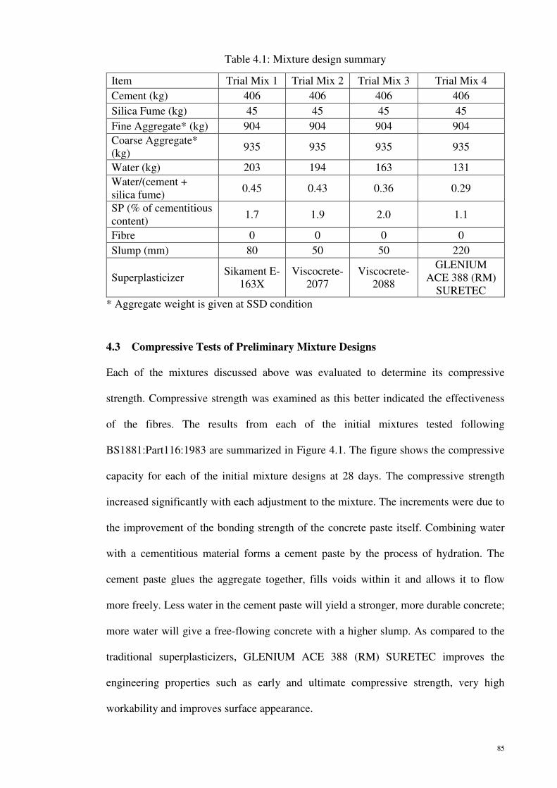
85
4.3 Compressive Tests of Preliminary Mixture Designs
Each of the mixtures discussed above was evaluated to determine its compressive
strength. Compressive strength was examined as this better indicated the effectiveness
of the fibres. The results from each of the initial mixtures tested following
BS1881:Part116:1983 are summarized in Figure 4.1. The figure shows the compressive
capacity for each of the initial mixture designs at 28 days. The compressive strength
increased significantly with each adjustment to the mixture. The increments were due to
the improvement of the bonding strength of the concrete paste itself. Combining water
with a cementitious material forms a cement paste by the process of hydration. The
cement paste glues the aggregate together, fills voids within it and allows it to flow
more freely. Less water in the cement paste will yield a stronger, more durable concrete;
more water will give a free-flowing concrete with a higher slump. As compared to the
traditional superplasticizers, GLENIUM ACE 388 (RM) SURETEC improves the
engineering properties such as early and ultimate compressive strength, very high
workability and improves surface appearance.
Table 4.1: Mixture design summary
Item Trial Mix 1 Trial Mix 2 Trial Mix 3 Trial Mix 4
Cement (kg) 406 406 406 406
Silica Fume (kg) 45 45 45 45
Fine Aggregate* (kg) 904 904 904 904
Coarse Aggregate* (kg)
935 935 935 935
Water (kg) 203 194 163 131
Water/(cement + silica fume)
0.45 0.43 0.36 0.29
SP (% of cementitious content)
1.7 1.9 2.0 1.1
Fibre 0 0 0 0
Slump (mm) 80 50 50 220
Superplasticizer Sikament E-
163X Viscocrete-
2077 Viscocrete-
2088
GLENIUM ACE 388 (RM)
SURETEC
* Aggregate weight is given at SSD condition

4.4 Properties of Fresh Concrete Test
4.4.1 Fresh Concrete Density
As shown in Table 4.2
ranged between 243
0.1% nylon + 0.9% steel fibres has the highest
to 0.1% polypropylene
phenomenon is due to t
that of polypropylene fibre (910 kg/m³).
Figure 4.1
Table 4.2: The properties of fresh concrete with different percentage of fibres
Type of concrete and pof fibre (%)
OPC
0.1% Nylon + 0.4% SF
0.1% Polypropylene + 0.4% SF
0.1% Nylon + 0.9% SF
0.1% Polypropylene + 0.9% SF
64
0
20
40
60
80
100
120
Co
mp
ress
ive
Str
ength
(M
Pa)
Preliminary Compressive Strength (MPa) at 28 days
Properties of Fresh Concrete Test
Fresh Concrete Density
Table 4.2, the fresh concrete density with different percentage of fibre is
2437 kg/m³ to 2562 kg/m³. The hybrid fibre-reinforced concrete with
0.9% steel fibres has the highest density value (2562
0.1% polypropylene + 0.9% steel fibre reinforced concrete
phenomenon is due to the density of nylon fibre (1140 kg/m³)
polypropylene fibre (910 kg/m³).
4.1: Compressive capacity of preliminary mixture designs
The properties of fresh concrete with different percentage of fibres
Type of concrete and percentage fibre (%)
Density (kg/m³) Temperature (°C)
2437
0.1% Nylon + 0.4% SF 2486
0.1% Polypropylene + 0.4% SF 2480
0.1% Nylon + 0.9% SF 2562
0.1% Polypropylene + 0.9% SF 2551
6468
79
97
Preliminary Compressive Strength (MPa) at 28 days
Preliminary Compressive Strength (MPa) at 28 days
86
with different percentage of fibre is
reinforced concrete with
(2562 kg/m³) compared
concrete (2551 kg/m³). This
fibre (1140 kg/m³) which is higher than
inary mixture designs
The properties of fresh concrete with different percentage of fibres
Temperature (°C)
30.0
29.0
29.0
28.5
28.5
Preliminary Compressive Strength (MPa) at 28 days
Preliminary Compressive Strength (MPa) at 28 days
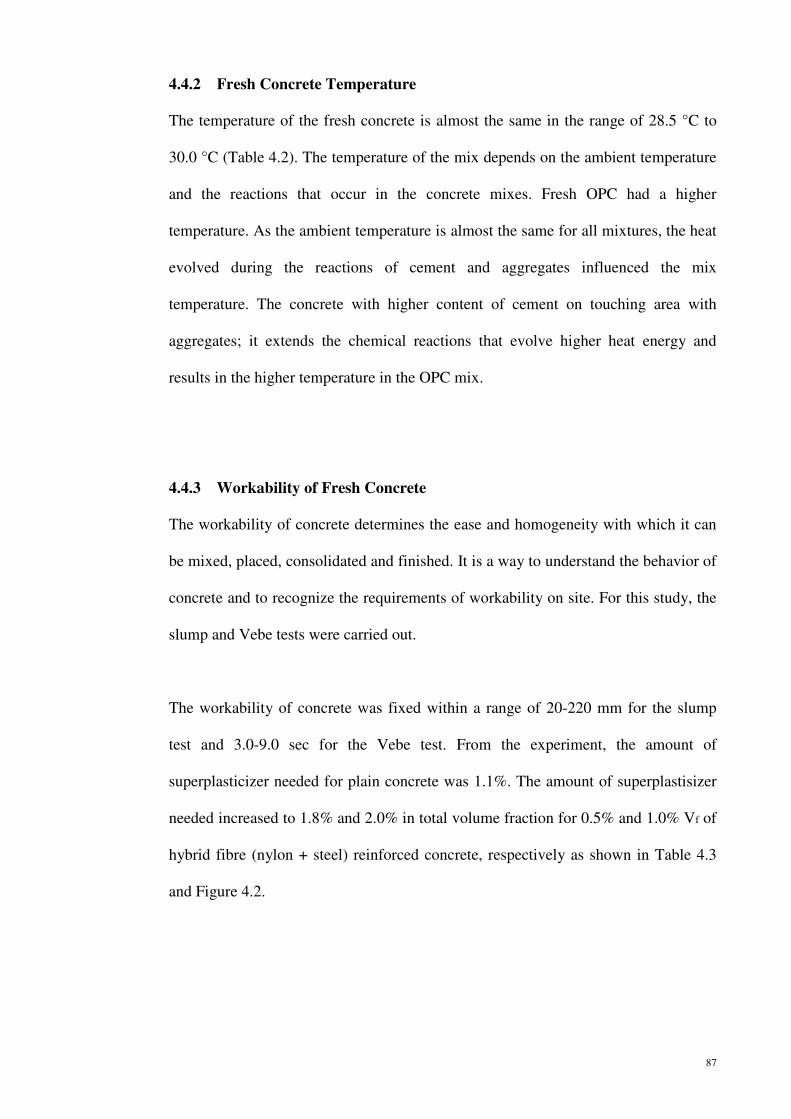
87
4.4.2 Fresh Concrete Temperature
The temperature of the fresh concrete is almost the same in the range of 28.5 °C to
30.0 °C (Table 4.2). The temperature of the mix depends on the ambient temperature
and the reactions that occur in the concrete mixes. Fresh OPC had a higher
temperature. As the ambient temperature is almost the same for all mixtures, the heat
evolved during the reactions of cement and aggregates influenced the mix
temperature. The concrete with higher content of cement on touching area with
aggregates; it extends the chemical reactions that evolve higher heat energy and
results in the higher temperature in the OPC mix.
4.4.3 Workability of Fresh Concrete
The workability of concrete determines the ease and homogeneity with which it can
be mixed, placed, consolidated and finished. It is a way to understand the behavior of
concrete and to recognize the requirements of workability on site. For this study, the
slump and Vebe tests were carried out.
The workability of concrete was fixed within a range of 20-220 mm for the slump
test and 3.0-9.0 sec for the Vebe test. From the experiment, the amount of
superplasticizer needed for plain concrete was 1.1%. The amount of superplastisizer
needed increased to 1.8% and 2.0% in total volume fraction for 0.5% and 1.0% Vf of
hybrid fibre (nylon + steel) reinforced concrete, respectively as shown in Table 4.3
and Figure 4.2.
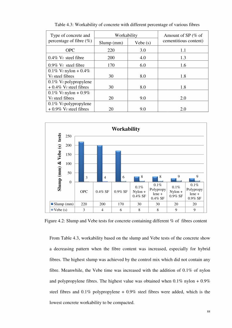
From Table 4.3, workability based on
a decreasing pattern
fibres. The highest slump wa
fibre. Meanwhile, the V
and polypropylene
steel fibres and 0.1%
lowest concrete workability
Table 4.3: Workability of concrete with different percentage of various fibres
Type of concrete and percentage of fibre (%)
OPC
0.4% Vf steel fibre
0.9% Vf steel fibre0.1% Vf nylon + 0.4% Vf steel fibres
0.1% Vf polypropylene + 0.4% Vf steel fibres0.1% Vf nylon + 0.9% Vf steel fibres
0.1% Vf polypropylene + 0.9% Vf steel fibres
Figure 4.2: Slump and Vebe tests for
OPC
Slump (mm) 220
Vebe (s) 3
0
50
100
150
200
250
Slu
mp
(m
m)
& V
ebe
(s)
tes
ts
workability based on the slump and Vebe tests of the concrete
a decreasing pattern when the fibre content was increased,
highest slump was achieved by the control mix which
. Meanwhile, the Vebe time was increased with the addition of
and polypropylene fibres. The highest value was obtained when
steel fibres and 0.1% polypropylene + 0.9% steel fibres were
concrete workability to be compacted.
Workability of concrete with different percentage of various fibres
Type of concrete and ercentage of fibre (%)
Workability Amount of SP (%cementitious contentSlump (mm) Vebe (s)
220 3.0
steel fibre 200 4.0
steel fibre 170 6.0 nylon + 0.4%
30 8.0
polypropylene steel fibres 30 8.0
nylon + 0.9% 20 9.0
polypropylene steel fibres 20 9.0
Slump and Vebe tests for concrete containing different % of
OPC 0.4% SF 0.9% SF0.1%
Nylon + 0.4% SF
0.1% Polypropy
lene + 0.4% SF
220 200 170 30 30
3 4 6 8 8
3 4 6 8 8
Workability
88
the slump and Vebe tests of the concrete show
the fibre content was increased, especially for hybrid
s achieved by the control mix which did not contain any
addition of 0.1% of nylon
was obtained when 0.1% nylon + 0.9%
were added, which is the
Workability of concrete with different percentage of various fibres
Amount of SP (% of cementitious content)
1.1
1.3
1.6
1.8
1.8
2.0
2.0
concrete containing different % of fibres content
0.1% Nylon + 0.9% SF
0.1% Polypropy
lene + 0.9% SF
20 20
9 9
9 9
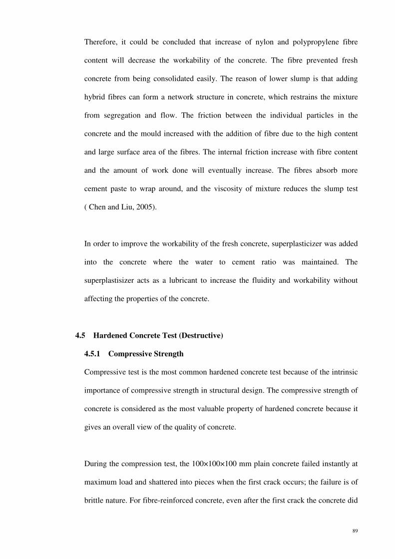
89
Therefore, it could be concluded that increase of nylon and polypropylene fibre
content will decrease the workability of the concrete. The fibre prevented fresh
concrete from being consolidated easily. The reason of lower slump is that adding
hybrid fibres can form a network structure in concrete, which restrains the mixture
from segregation and flow. The friction between the individual particles in the
concrete and the mould increased with the addition of fibre due to the high content
and large surface area of the fibres. The internal friction increase with fibre content
and the amount of work done will eventually increase. The fibres absorb more
cement paste to wrap around, and the viscosity of mixture reduces the slump test
( Chen and Liu, 2005).
In order to improve the workability of the fresh concrete, superplasticizer was added
into the concrete where the water to cement ratio was maintained. The
superplastisizer acts as a lubricant to increase the fluidity and workability without
affecting the properties of the concrete.
4.5 Hardened Concrete Test (Destructive)
4.5.1 Compressive Strength
Compressive test is the most common hardened concrete test because of the intrinsic
importance of compressive strength in structural design. The compressive strength of
concrete is considered as the most valuable property of hardened concrete because it
gives an overall view of the quality of concrete.
During the compression test, the 100×100×100 mm plain concrete failed instantly at
maximum load and shattered into pieces when the first crack occurs; the failure is of
brittle nature. For fibre-reinforced concrete, even after the first crack the concrete did

90
not disintegrate and was still able to sustain compressive forces because the concrete
was held together by the fibres.
By visual inspection, it was found that some of the tested HyFRC and plain concrete
specimens had cubical failure. The pattern of plain concrete failure was symmetrical
and regular. Failure was explosive. On the other hand, fibre-reinforced concrete is
more ductile compared to plain concrete as shown in Figure 4.3. The compressive
strength versus various percentages of fibre content is presented in Figure 4.4.
Figure 4.3: Failed 100×100×100 mm cube specimens
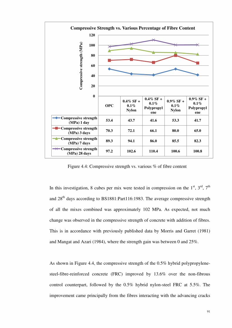
91
In this investigation, 8 cubes per mix were tested in compression on the 1st, 3rd, 7th
and 28th days according to BS1881:Part116:1983. The average compressive strength
of all the mixes combined was approximately 102 MPa. As expected, not much
change was observed in the compressive strength of concrete with addition of fibres.
This is in accordance with previously published data by Morris and Garret (1981)
and Mangat and Azari (1984), where the strength gain was between 0 and 25%.
As shown in Figure 4.4, the compressive strength of the 0.5% hybrid polypropylene-
steel-fibre-reinforced concrete (FRC) improved by 13.6% over the non-fibrous
control counterpart, followed by the 0.5% hybrid nylon-steel FRC at 5.5%. The
improvement came principally from the fibres interacting with the advancing cracks
Figure 4.4: Compressive strength vs. various % of fibre content
OPC
0.4% SF +
0.1%
Nylon
0.4% SF +
0.1%
Polypropyl
ene
0.9% SF +
0.1%
Nylon
0.9% SF +
0.1%
Polypropyl
ene
Compressive strength
(MPa) 1 day53.4 43.7 41.6 53.3 41.7
Compressive strength
(MPa) 3 days70.3 72.1 66.1 80.0 65.0
Compressive strength
(MPa) 7 days89.3 94.1 86.0 85.5 82.3
Compressive strength
(MPa) 28 days97.2 102.6 110.4 100.6 100.8
0
20
40
60
80
100
120
Co
mp
ress
ive
stre
ng
th (
MP
a)
Compressive Strength vs. Various Percentage of Fibre Content

92
and showed the highest values of compressive strength compared to 1.0% hybrid
polypropylene-steel and nylon-steel FRC. It is even higher compared to OPC control
concrete, which is 3.7% and 3.5% improvement compared to 1.0% hybrid
polypropylene-steel and nylon-steel FRC, respectively. The increment of fibre
content is not significant and it was proved that the addition of fibres may not
increase much compressive strength of the concrete. This may be due to the fibre
balling or clogging within the 1.0% hybrid polypropylene-steel and nylon-steel FRCs.
The higher fibre content might have caused voids resulting in decreased compressive
strength.
When withstanding an increasing compression load, several distinct stages can be
defined. During the first stage, micro-crack kinks develop randomly throughout the
specimen. It is due to the heterogeneity of the specimen. Since the hardened cement
paste and aggregates have different stiffness, local tensile stresses develop and
further micro cracking occurs. Next, these micro-cracks join together forming macro-
cracks that run parallel to the direction of the applied stress, thus blocking the
forward propagation of the crack. The blunting, blocking, and even diverting of the
crack allowed the fibrous concrete cubes to withstand additional compressive load,
thus upgrading its compressive strength over the non-fibrous control concrete.
4.5.2 Second Stage of Compressive Strength
The purpose of the test is to evaluate whether the addition of fibres to a concrete mix
adversely affects the compressive strength. Especially for HyFRC cubes, there are
two stages of recording of compressive strength. The first stage of record is termed as
“First Crack”, explicitly the ultimate compressive strength. The second stage of

record is the record of “Residual Strength”, specifically to continue loading after
first crack until failure. Figure 4.5 shows the results of residual comp
From Figure 4.5, it could be noted
OPC is zero while
nylon fibre, the
compared to the first stage of recording compressive strength respectively.
Addition of fibres increases the ease of concrete compression
the hybrid fibres. This result in drastic
strength compared to plain concrete. The improvement
surface bonding of the fibres in t
helps in the mechanical bonding between the fibre and the cement matrix. Hence it
will enhance the compressive toughness
Figure 4.5:
Compressive strength (MPa)
Residual strength (MPa)
Co
mp
ress
ive
stre
ng
th (
MP
a)
Comparison of Compressive Strength vs. Residual Strength
record is the record of “Residual Strength”, specifically to continue loading after
first crack until failure. Figure 4.5 shows the results of residual comp
.5, it could be noted that the second stage of compressive strength
OPC is zero while for HyFRC with 0.5% and 1.0% steel-polypr
second stage of compressive strength is approximately 71.4%
first stage of recording compressive strength respectively.
Addition of fibres increases the ease of concrete compression due to the flexibility of
rid fibres. This result in drastic improvements in the
h compared to plain concrete. The improvement is due to the shape and
surface bonding of the fibres in the concrete. The steel fibres have
anical bonding between the fibre and the cement matrix. Hence it
will enhance the compressive toughness of the HyFRC.
Comparison of compressive strength vs. residual strength
OPC0.4%SF + 0.1%Nylo
n
0.4%SF + 0.1%Polypropylene
Compressive strength (MPa) 96.59 102.55 110.40
Residual strength (MPa) 0.00 73.02 78.72
0.00
20.00
40.00
60.00
80.00
100.00
120.00
Comparison of Compressive Strength vs. Residual Strength
93
record is the record of “Residual Strength”, specifically to continue loading after the
first crack until failure. Figure 4.5 shows the results of residual compressive strength.
second stage of compressive strength of
polypropylene and steel-
strength is approximately 71.4%
first stage of recording compressive strength respectively.
due to the flexibility of
the residual compressive
is due to the shape and
s have hooks which may
anical bonding between the fibre and the cement matrix. Hence it
Comparison of compressive strength vs. residual strength
0.9%SF + 0.1%Nylo
n
0.9%SF + 0.1%Polypropylene
100.60 100.83
71.93 72.09
Comparison of Compressive Strength vs. Residual Strength

94
4.5.3 Modulus of Rupture (MOR)
The tensile stress that is reached at the bottom fibre, known as modulus of rupture, is
an important requirement to understand the tensile strength of fibre-reinforced
concrete compared to plain concrete. When a concrete specimen is subjected to
bending, the tensile behaviour will govern its strength because concrete is a tension-
weak material. In the first stage, micro-cracks become randomly distributed
throughout the specimen and eventually, they begin to join together to form macro-
cracks, cracking being localized. The final stage begins when the newly formed
macro-cracks start to propagate and then quickly lead to unstable propagation and
failure.
In this study, even though no definite increase in the compressive strength was noted
with the addition of hybrid fibres, there was a clear increase in the MOR of the
material under two point bending. In Figure 4.5, the MOR of hybrid mixes are
compared with their corresponding control. It proves that HyFRC concrete had
significantly increased modulus of rupture.

95
Figure 4.6 shows the flexural strength at 28 days, there was some variation in the
flexural strength of the mixes, ranging from a maximum of 10.74 MPa to a minimum
of 8.85 MPa. The HyFRC mixes had higher flexural strength compared to OPC
control concrete. The highest value of MOR of the 1.0% hybrid nylon-steel FRC was
a 21.4% increase over the nonfibrous control concrete. The increase resulted
primarily from the fibres intersecting the cracks in the tension half of the reinforced
prism. These fibres accommodated the crack face separation by stretching themselves,
thus providing an additional energy-absorbing mechanism and also stress relaxing
the micro- and macro-cracked region neighboring the crack-tip.
The MOR of 0.5% and 1.0% hybrid nylon-steel-fibre-reinforced concrete (FRC)
slightly higher over the 0.5% and 1.0% hybrid polypropylene-steel FRC. It could be
found that, hybrid nylon-steel has higher tensile strength properties compared to
hybrid polypropylene-steel FRC. Factors that affect the flexural strength are length-
diameter ratio, volume fraction, bond strength and orientation of fibre (Hannant, et
Figure 4.6: Effect of different fibre content on flexural strength of concrete
OPC
0.4% SF + 0.1%
polypropylene
0.4% SF+ 0.1% Nylon
0.9% SF + 0.1%
polypropylene
0.9% SF + 0.1% Nylon
Modulus of Rupture (MPa) 8.85 9.30 9.57 10.20 10.74
0.00
2.00
4.00
6.00
8.00
10.00
12.00
Mo
du
lus
of
Ru
ptu
re
(MP
a)
Modulus of Rupture vs. Various Percentage of Fibre Content

96
al., 1978). Virtually the surface of fibre was observed to be mechanically treated (e.g.
crimped, hooked-end, indented etc.); hence the bonding between the cement matrix
and the fibre was strong. As a result, the strength of the concrete was improved. The
tensile stress is also improved with increasing fibre content. As stated for
compressive strength, the hybrid fibre additions made bearable differences in the
variability carried by the MOR for 1.0% Vf of HyFRC, compared to the plain
concrete and 0.5% Vf of HyFRC counterpart.
Fibres are added to inhibit a propagation of cracks in concrete which occur due to its
low tensile strength. Plain concrete specimens usually fail catastrophically by a
single crack which results in separation into two pieces (Figure 4.7a). The flexural
strength of hybrid steel-nylon fibres concrete showed some improvement.
Figure 4.7b shows a HyFRC can be effective in arresting cracks at both micro and
macro-levels. It demonstrates the ways in which hybrid fibres act to absorb energy
and control the crack growth.
Figure 4.7: (a) Crack in concrete element subjected to bending without fibres and (b) with fibres
4.5.4 Comparison of Flexure Load-Flexure Extension Plots
One of the defining points on the load-deflection curve of FRC under flexure is the
point of first crack, which corresponds to the modulus of rupture. This is the point at

97
which the load-deflection curve first becomes nonlinear (ASTM C 1018-97). Fibre
reinforcement is effective only after the point of first-crack (Furlan and Hanai, 1997).
Flexure load-flexure extension plot for plain concrete is presented in Figure 4.8. The
instability during testing occurs due to the sudden release of energy after a specimen
reaches the peak load. The figure shows that the curve is consistent.
Specimen
Name
Width
(mm)
Thickness
(mm)
Maximum
Flex Load
(kN)
Extension at
Max Flex Load
(mm)
Modulus
of Rupture
(MPa)
1 Plain
concrete
100.3 100.5 29.5 1.7 8.7
Mean* 100.3 100.5 29.5 1.7 8.7
S.Dev* ----- ----- ----- ----- -----
Minimum* 100.3 100.5 29.5 1.7 8.7
*The results is computerised.
Figure 4.8: Flexure load vs. flexure extension- plain concrete
0
10
20
30
0.0 0.1 0.2 0.3 0.4 0.5 0.6 0.7 0.8 0.9 1.0 1.1 1.2 1.3 1.4 1.5 1.6 1.7
Flexure load (kN)
Flexure extension (mm)
Flex Test
Specimen #
1

98
Specimen
Name
Width
(mm)
Thickness
(mm)
Maximum
Flex Load
(kN)
Extension at
Max Flex Load
(mm)
Modulus
of
Rupture
(MPa)
1 0.4% SF +
0.1%
polypropylene
101.2 100.8 30.2 2.9 8.8
Mean* 101.2 100.8 30.2 2.9 8.8
S.Dev* ----- ----- ----- ----- -----
Minimum* 101.2 100.8 30.2 2.9 8.8
Figure 4.9: Flexure load vs. flexure extension- 0.5% HyFRC of steel-polypropylene
0
10
20
30
40
0.0 1.0 2.0 3.0
Flexure load (kN)
Flexure extension (mm)
Flex Test
Specimen #
1

99
Figures 4.9 and 4.10 show the response of 0.5% HyFRCs mixes. The load carrying
capacity (after the peak) of 0.5% HyFRC is quite similar to plain concrete. However,
HyFRC with 0.5% steel-nylon and 0.5% steel-polypropylene both showed slightly
higher MOR compared to plain concrete.
Specimen Name Width
(mm)
Thickness
(mm)
Maximum
Flex Load
(kN)
Extension at
Max Flex
Load
(mm)
Modulus of
Rupture
(MPa)
1 0.4% SF + 0.1%
nylon
101.4 100.8 31.9 1.8 9.3
Mean* 101.4 100.8 31.9 1.8 9.3
S.Dev* ----- ----- ----- ----- -----
Minimum* 101.4 100.8 31.9 1.8 9.3
Figure 4.10: Flexure load vs. flexure extension- 0.5% HyFRC of steel-nylon
0
10
20
30
40
0.0 0.1 0.2 0.3 0.4 0.5 0.6 0.7 0.8 0.9 1.0 1.1 1.2 1.3 1.4 1.5 1.6 1.7
Flexure load (kN)
Flexure extension (mm)
Flex Test
Specimen #
1
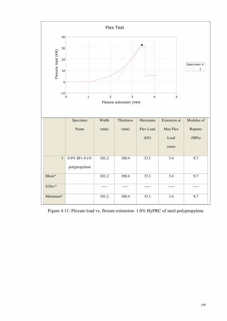
100
Specimen
Name
Width
(mm)
Thickness
(mm)
Maximum
Flex Load
(kN)
Extension at
Max Flex
Load
(mm)
Modulus of
Rupture
(MPa)
1 0.9% SF+ 0.1%
polypropylene
101.2 100.4 33.1 3.4 9.7
Mean* 101.2 100.4 33.1 3.4 9.7
S.Dev* ----- ----- ----- ----- -----
Minimum* 101.2 100.4 33.1 3.4 9.7
Figure 4.11: Flexure load vs. flexure extension- 1.0% HyFRC of steel-polypropylene
-10
0
10
20
30
40
0 1 2 3 4 5
Flexure load (kN)
Flexure extension (mm)
Flex Test
Specimen #
1

101
The content of steel macro fibres was further increased to 0.9% for 1.0% volume
fraction of HyFRC and the flexure load-flexure extension plots are presented in
Figures 4.11 and 4.12. It can be noted that the amount of instability after the peak
reduced drastically with 0.9% steel fibre by volume. A further increase in the volume
fraction resulted in load carrying capacities exceeding the peak load with large
extensions. Large improvements in the flexural response were observed when 1.0%
Vf of HyFRC was compared with OPC and 0.5% Vf of HyFRC, respectively.
Specimen Name Width
(mm)
Thickness
(mm)
Maximum
Flex Load
(kN)
Extension at
Max Flex
Load
(mm)
Modulus
of Rupture
(MPa)
1 0.9% SF + 0.1%
nylon
100.2 100.4 35.2 2.5 10.5
Mean* 100.2 100.4 35.2 2.5 10.5
S.Dev* ----- ----- ----- ----- -----
Minimum* 100.2 100.4 35.2 2.5 10.5
Figure 4.12: Flexure load vs. flexure extension-1.0% HyFRC of steel-nylon
-10
0
10
20
30
40
0 1 2 3 4 5
Flexure load (kN)
Flexure extension (mm)
Flex Test
Specimen #
1
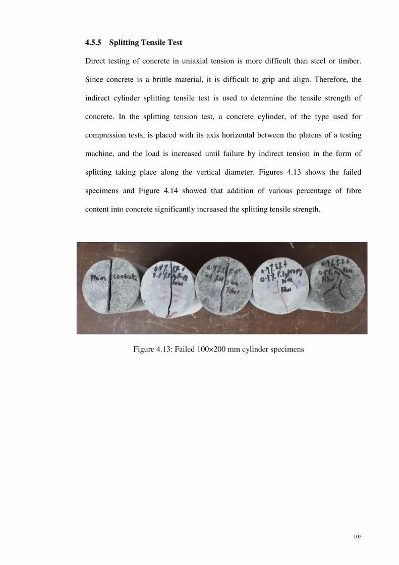
102
4.5.5 Splitting Tensile Test
Direct testing of concrete in uniaxial tension is more difficult than steel or timber.
Since concrete is a brittle material, it is difficult to grip and align. Therefore, the
indirect cylinder splitting tensile test is used to determine the tensile strength of
concrete. In the splitting tension test, a concrete cylinder, of the type used for
compression tests, is placed with its axis horizontal between the platens of a testing
machine, and the load is increased until failure by indirect tension in the form of
splitting taking place along the vertical diameter. Figures 4.13 shows the failed
specimens and Figure 4.14 showed that addition of various percentage of fibre
content into concrete significantly increased the splitting tensile strength.
Figure 4.13: Failed 100×200 mm cylinder specimens

Figure 4.14 showed that the
the 1.0% hybrid nylon
respectively than that of the unreinforced control concrete.
percentage improvement of
was 32.0% and 28.1%
continued, the fibres bridging across the split portions of the matrix acted through the
stress transfer from the matrix to the
load. The stress transfer improved the tensile strain capacity of the hybrid fibre
reinforced concretes
nylon-steel- and polypropylene
compared to the unreinforced control counterpart.
During the splitting tensile test, it could be o
cleanly into two pieces
indicates that the HyFRC have better performance com
is consistent with the statement that the splitting tensile strength of fibre
Figure 4.14: Splitting tensile strength vs. % of
Cylinder splitting tensile strength (MPa)
Figure 4.14 showed that the percentage improvement in splitting tensile strengths of
the 1.0% hybrid nylon-steel- and polypropylene-steel FRCs were 52.4% and 46.0 %
than that of the unreinforced control concrete. On the other hand
percentage improvement of 0.5% hybrid nylon-steel- and polypropylene
32.0% and 28.1% at the 28th day, respectively. Once the splitting occurred and
continued, the fibres bridging across the split portions of the matrix acted through the
stress transfer from the matrix to the fibres, and thus, gradually supported the entire
load. The stress transfer improved the tensile strain capacity of the hybrid fibre
reinforced concretes. Therefore, reinforced concrete with the addition of hybrid
and polypropylene-steel fibres had increased splitting tensile strength
the unreinforced control counterpart.
During the splitting tensile test, it could be observed that the OPC specimen broke
cleanly into two pieces while HyFRC specimens were still h
that the HyFRC have better performance compared to
s consistent with the statement that the splitting tensile strength of fibre
Splitting tensile strength vs. % of concrete containing
OPC
0.4% S.F + 0.1%
Polypropylene
0.4% S.F + 0.1% Nylon
0.9% S.F + 0.1%
Polypropyl
Cylinder splitting tensile strength (MPa)
4.94 6.33 6.52 7.21
0
1
2
3
4
5
6
7
8
Str
ess
(M
Pa)
Cylinder Splitting Tensile Strength (MPa)
103
splitting tensile strengths of
s were 52.4% and 46.0 %,
On the other hand, the
and polypropylene-steel FRCs
. Once the splitting occurred and
continued, the fibres bridging across the split portions of the matrix acted through the
thus, gradually supported the entire
load. The stress transfer improved the tensile strain capacity of the hybrid fibre-
the addition of hybrid
splitting tensile strength
bserved that the OPC specimen broke
still held together. This
pared to the OPC. This result
s consistent with the statement that the splitting tensile strength of fibre-reinforced
concrete containing various fibre content
0.9% S.F + 0.1%
Polypropylene
0.9% S.F + 0.1% Nylon
7.21 7.53
Cylinder Splitting Tensile Strength (MPa)

104
concrete behaved in proportion to the number of fibres intersecting the fracture
surfaces (Potrzebowski, 1983).
According to Chen et al. (2002), reinforcement of concrete with fibres leads to
improvements in the tensile strength of the materials. This is due to the tendency of
propagating macro-cracks in cementitious matrices to be arrested or deflected by
fibres. From the Figure 4.14, it could be found that the tensile strength of concrete
with nylon-steel FRC is higher than concrete with polypropylene-steel FRC. It is
because the nylon fibre has higher tensile strength than the polypropylene fibre
referring to the Table 2.1. In addition, It could be concluded that the nylon-steel
FRCs are providing the better bonding compare to the polypropylene-steel FRCs in
concrete.
4.5.6 Modified Cube Compressive Strength
The modified cube test is a compression test to determine the development of
compressive strength with age, using portions of beams broken in flexural. The end
parts of the beam were left unbroken and they were usually square in cross-section.
An ‘equivalent’ cube can be obtained by applying load through a square steel plate of
the same size as the cross section of the beam.
Table 4.4: Modified cube compressive strength of FRC with different % of fibres
Concrete Type and Fibre content (%)
Actual Cube Strength (MPa)
Modified Cube Strength
(Mpa)
Actual Cube Strength
Modified Cube Strength
OPC 97.2 101.3 0.96
0.4% SF + 0.1% Nylon 102.6 103.3 0.99
0.4% SF + 0.1% Polypropylene 110.4 114.5 0.96
0.9% SF + 0.1% Nylon 100.6 101.9 0.99
0.9% SF + 0.1% Polypropylene 100.8 103.3 0.98

From Table 4.4 and Figure 4.15, it
compressive strength is slightly
compressive strength.
Compared to plain OPC the fibre
difference in compressive strength usi
strength of OPC wa
nylon-steel- and polypropylene
respectively. Besides that,
FRCs the strength
the strength for most of the cubes
cube test. Nevile (1996) stated that the average compression strength of modified
cube test is 5% higher than that of a cast cube of the same specimen size.
Figure 4.15: The modified cube compressive strength of
Actual cube strength (MPa)
Modified cube strength (MPa)
Co
mp
ress
ive
stre
ngth
(M
Pa)
Modified cube compressive strength (MPa) vs. Various
Table 4.4 and Figure 4.15, it was found that the value of modified cube
compressive strength is slightly higher compared to the value of ordinary
compressive strength.
to plain OPC the fibre reinforced concrete does not show significant
difference in compressive strength using this test. By the 28IJ day
strength of OPC was 101.3 MPa. Strength for low volume fraction (0.5%) of hybrid
and polypropylene-steel- FRCs was 103.3 MPa and 114.5
. Besides that, for 1.0% hybrid nylon-steel- and polypropylene
the strength were 101.9 MPa and 103.3 MPa, respectively
the strength for most of the cubes were slightly increased comp
cube test. Nevile (1996) stated that the average compression strength of modified
cube test is 5% higher than that of a cast cube of the same specimen size.
The modified cube compressive strength of concrete containing fibres content
OPC0.4% SF +
0.1% Nylon
0.4% SF + 0.1%
Polypropylene
Actual cube strength (MPa) 97.2 102.6 110.4
Modified cube strength (MPa) 101.3 103.3 114.5
85.0
90.0
95.0
100.0
105.0
110.0
115.0
120.0
Co
mp
ress
ive
stre
ngth
(M
Pa)
Modified cube compressive strength (MPa) vs. Various
Percentage of Fibres Content
105
found that the value of modified cube
the value of ordinary
reinforced concrete does not show significant
day, the modified cube
fraction (0.5%) of hybrid
3 MPa and 114.5 MPa,
and polypropylene-steel-
, respectively. It was found that
slightly increased compared to the actual
cube test. Nevile (1996) stated that the average compression strength of modified
cube test is 5% higher than that of a cast cube of the same specimen size. The
concrete containing various % of
0.9% SF + 0.1% Nylon
0.9% SF + 0.1%
Polypropylene
100.6 100.8
101.9 103.3
Modified cube compressive strength (MPa) vs. Various

106
measured strength of specimen with a larger cross-sectional area is greater than the
strength of actual cube strength due to the so called wall effect. For HyFRCs, the
improvements came principally from the fibres interacting with the advancing cracks.
Both the ability to hold the matrix together and the compression toughness were
increased. The ratio between actual cube strength and modified cube strength
determined in Table 4.4 can be used as reference in estimating the actual cube
strength based on an unbroken part of a beam.
4.5.7 Ultrasonic Pulse Velocity
The UPV method is known as the transit time method which involves measuring the
time taken for an ultrasonic pulse to travel through a known distance in concrete,
from which the velocity is calculated. It is one of the non-destructive tests frequently
used to predict strength of concrete by detection of the voids inside the concrete.
The method consists of measuring the time of travel of an ultrasonic pulse passing
through the concrete being tested. Comparatively higher velocity is obtained when
concrete quality is good in terms of density, uniformity, homogeneity etc.
The quality of concrete in terms of uniformity, incidence or absence of internal flaws,
cracks segregation is characterized as shown in Table 4.5. The guidelines have been
evolved for characterizing the quality of concrete in structures in terms of the
ultrasonic pulse velocity.
Table 4.5: Characterizing the quality of concrete (after Neville 1996)
Pulse Velocity (Km/s) Concrete Quality (Grading)
Above 4.5 Excellent 3.5 to 4.5 Good
3.0 to 3.5 Medium Below 3.0 Doubtful

107
Figure 4.16 shows that the FRC with hybrid 0.9% steel and 0.1% nylon fibres has the
highest value of UPV at 5.02 km/s on the 28th day. The results indicate that the FRCs
with hybrid 1.0% fibres have the lowest voids content compared to the other concrete
mixes. The steel, nylon and polypropylene fibres with its flexibility and low aspect
ratio enable the concrete to be compacted well and have low voids content. The
Table 4.6: Ultrasonic Pulse Velocity of concrete with different % of fibres
Type of concrete and percentage of fibres
Ultrasonic pulse velocity (Km/s)
Age of Testing (days)
1 3 7 28
OPC 4.15 4.19 4.53 4.75
0.4% SF + 0.1% polypropylene 4.08 4.20 4.66 4.93
0.4% SF + 0.1% nylon 4.10 4.56 4.70 4.95
0.9% SF + 0.1% polypropylene 4.11 4.63 4.68 4.98
0.9% steel + 0.1% nylon 4.13 4.70 4.93 5.02
Figure 4.16: Development of UPV f concrete with different percentage of fibres content
OPC0.4% SF +
0.1% polypropylene
0.4% SF + 0.1% nylon
0.9% SF + 0.1%
polypropylene
0.9% SF + 0.1% nylon
1st 4.15 4.08 4.1 4.11 4.13
3rd 4.19 4.2 4.56 4.63 4.7
7th 4.53 4.66 4.7 4.68 4.93
28th 4.75 4.93 4.95 4.98 5.02
0
1
2
3
4
5
6
UP
V (
Km
/s)
Ultrasonic Pulse Velocity (Km/s) VS. Different % of Fibres Content

108
hybrid FRC with 0.4% steel + 0.1% nylon fibres and 0.4% steel + 0.1%
polypropylene fibres had UPV values of 4.95 km/s and 4.93 km/s, respectively.
However, the lowest UPV value is that of OPC at 4.75 km/s.
The results show that the UPV of all the concrete mixes increases with the age of the
concrete. The increase in UPV with age is closely related to the ratio of gel to space
ratio phenomenon. After period of hydration, it produces much gel that may fill up
the void space. The ratio of gel to space thus increased consequently. Since the pulse
of velocity through voids is slower than through solid matter, therefore, the UPV of
the concrete is increased with age. Furthermore, it is important that efficient curing
is necessary to get a good concrete.
4.5.8 Dynamic Modulus of Elasticity
The dynamic modulus of elasticity is a function of compressive strength and concrete
density. This is a laboratory test on prepared specimens, and can be used to assess
progressive changes in the specimen.
The test is used to determine the deterioration of concrete after freezing or thaw
damage. It also acts as a test to determine the sulfate resistance of concrete. The
dynamic modulus of elasticity can be used for studying specimens which undergo
chemical attack. It is therefore particularly useful for generating data in durability
testing.

109
According to Figure 4.17, the HyFRC with 0.5% polypropylene-steel fibres exhibits
the highest value of dynamic modulus of elasticity at 56.1 kN/mm² at 28th day. The
results of the test range from 54.8 kN/mm² to 56.1 kN/mm². Like compressive
strength, the dynamic modulus of elasticity depends on the porosity of concrete.
Since the hybrid fibres are thin and short, it could be dispersed randomly in the
concrete. Thus, the concrete with hybrid fibres could be compacted well without
much porous spaces compared to non-fibrous control concrete. On the other hand,
HyFRCs with 1.0% fibres showed a lower dynamic modulus of elasticity compared
Table 4.7: Dynamic modulus of elasticity of concrete with different % of fibres
Type of concrete and percentage of fibres Dynamic modulus of elasticity,
Ed (GPa) (28 days)
OPC 54.8
0.4% SF + 0.1% polypropylene 56.1
0.4% SF+ 0.1% nylon 55.7
0.9% SF + 0.1% polypropylene 55.2
0.9% SF + 0.1% nylon 54.9
Figure 4.17: The dynamic modulus of elasticity with various % of fibres
OPC
0.4% SF + 0.1%
polypropylen
e
0.4% SF+ 0.1% Nylon
0.9% SF + 0.1%
polypropylen
e
0.9% SF + 0.1% Nylon
Dynamic Modulus of Elasticity, Ed (GPa)
54.79 56.07 55.66 54.98 54.93
54.00
54.50
55.00
55.50
56.00
56.50
Dy
na
mic
Mo
du
lus
of
Ea
stic
ity
(GP
a)
Dynamic Modulus of Elasticity vs. % of Fibres

110
to 0.5% HyFRCs. As the addition of hybrid fibres may reduce the workability of the
mix and will cause balling or mat. It was found that the inclusion of 1.0% Vf of
HyFRCs led to fibres balling. However, the value of dynamic modulus of elasticity
of 1.0% HyFRCs is still higher compared to OPC.
Dynamic modulus of elasticity is affected by the porosity of the concrete. The
dimension of fibres is thin and short. Therefore, fibres can be dispersed randomly
within the concrete and compacted easily. Hence the void in the concrete would be
small. From the Figure 4.17, it could be found that for nylon-steel and
polypropylene-steel at higher dosage (e.g. 1.0%), the dynamic modulus value
decreased because of the fibre content increase, fibre balling may occur and this will
reduce workability because the compaction was difficult to achieve. As a result gaps
or voids can be developed in the concrete matrix.
4.5.9 Static Modulus of Elasticity
The static modulus of elasticity of concrete is largely controlled by the volume and
modulus of aggregate. It is a static loading test to check the quality of the concrete.
Cylinder-shaped specimens are used for the test.
Table 4.8: Static modulus of elasticity of concrete with different % of fibres
Type of concrete and percentage of fibres (%) Static modulus of elasticity (GPa)
OPC 52.7
0.4% SF + 0.1% polypropylene 51.6
0.4% SF + 0.1% nylon 48.0
0.9% SF + 0.1% polypropylene 45.4
0.9% SF + 0.1% nylon 45.1

111
From Table 4.8, it can be noted that the values of static modulus of elasticity ranges
from 48.0 kN/mm² to 52.7 kN/mm². Figure 4.18 shows that the OPC has the highest
modulus value of 52.7 kN/mm² with reference to 97.2 MPa compressive strength at
28 days. The value of modulus of elasticity of hybrid fibres with reference to
compressive strength is proportional when the hybrid fibres content increase from 0.5%
to 1.0%. However, the value of static modulus of elasticity decreases when the
hybrid fibres are added into the concrete. Referring to Figure 4.17 and Figure 4.18,
the average of static modulus of elasticity of 0.5% HyFRCs are showing the highest
value. When the hybrid fibres content increase to 1.0%, it reduces the value of static
modulus of elasticity. This may be due to the inclusion of nylon and propylene fibres
with low modulus of elasticity which caused the concrete to become less elastic.
Figure 4.18: Static modulus of elasticity of concrete with various % of fibres
OPC
0.4% SF + 0.1%
polypropylen
e
0.4% SF+ 0.1% Nylon
0.9% SF + 0.1%
polypropylen
e
0.9% SF + 0.1% Nylon
Staticc Modulus of Elasticity, Ed (GPa)
52.7 51.6 48.0 45.4 45.1
40.00
42.00
44.00
46.00
48.00
50.00
52.00
54.00
Dy
na
mic
Mo
du
lus
of
Ea
stic
ity
(Gp
a)
Dynamic Modulus of Elasticity vs. % of Fibres

4.6 Impact Test
Fibre is usually added to concrete so that the concrete is able to sustain high impact load
and energy. In this test,
on the top surface and failure mode occurs were
the FRC were calculated by
*All the tests were carried out
Figure 4.19: The results of impact resis
The evaluation of the 15 slabs in this work is shown in Table 4.9 and Figure 4.19.
According to the evaluation, the
0
500
1000
4
Num
ber
of
Blo
ws
Table 4.9: Results of impact test for concrete with different % of fibre content
Type of concrete and percentage of steel
fibre (%)
OPC
0.4% SF + 0.1% polypropylene
0.4% SF + 0.1% nylon
0.9% SF + 0.1% polypropylene
0.9% SF + 0.1% nylon
added to concrete so that the concrete is able to sustain high impact load
and energy. In this test, the numbers of blows until the first crack on the side, first crack
on the top surface and failure mode occurs were determined. The energies absorbed by
e FRC were calculated by assuming friction effects are negligible.
*All the tests were carried out on the 28th day after the concrete has been cast
Figure 4.19: The results of impact resistance of concrete with different % of fibre
The evaluation of the 15 slabs in this work is shown in Table 4.9 and Figure 4.19.
According to the evaluation, the number of blows for mean first
3240
539 582
Impact Resistance
Results of impact test for concrete with different % of fibre content
Type of concrete and ercentage of steel
Number of blows (Mean)
First-crack (side of slabs)
First-crack (top surface of
slabs)
3 4
0.4% SF + 0.1% polypropylene 14 16
0.4% SF + 0.1% nylon 32 33
0.9% SF + 0.1% polypropylene 305 306
0.9% SF + 0.1% nylon 321 323
112
added to concrete so that the concrete is able to sustain high impact load
numbers of blows until the first crack on the side, first crack
determined. The energies absorbed by
assuming friction effects are negligible.
after the concrete has been cast
with different % of fibre content
The evaluation of the 15 slabs in this work is shown in Table 4.9 and Figure 4.19.
mean first-crack (side of slabs)
582
Results of impact test for concrete with different % of fibre content
Number of blows (Mean) Energy
absorbed (Joule) Failure
4 163
32 1305
40 1632
539 21996
582 23751

113
and at failure for the HyFRC slabs with 0.5% nylon-steel increased 967% and 900%,
respectively, over the plain control slabs, whereas for the hybrid FRC slabs with 0.5%
polypropylene-steel the increase were 367% and 700%, respectively. The mean first-
crack (side of slabs) and failure strengths of HyFRC slabs with 1.0% nylon-steel
increased 10600% and 14450%, respectively, over the plain control slabs, whereas the
improvement percentage of 1.0% HyFRC slabs with polypropylene-steel were 10067%
and 13375%, respectively. All these figures emphasize the benefit of hybrid fibre
additions and showed that the hybrid nylon-steel FRC outperforms the hybrid
polypropylene-steel FRC.
The impact test results showed that the plain OPC concrete could only sustain 4 blows
before breaking into three big pieces. The slab did not show any plastic deformation and
failed instantly on the 4IJ blow. The failure pieces were not interconnected with each
other after failure.
For HyFRC with 0.5% polypropylene-steel and nylon-steel fibre content, the small scale
slab developed the first crack on the side of the slab on the 14th and 32nd blow,
respectively and the first surface crack was detected on the 16th and 32nd and blow,
respectively. The HyFRC with 0.5% nylon-steel was able to receive 40 blows before
failure fully occurred compared to 32 blows for HyFRC with 0.5% polypropylene-steel.
When failure occurred, the fractured small scale slab was still interconnected by the
fibres. The FRC is said to exhibit ductile failure as shown in Figure 4.20. It is clearly
seen that the small scale slab could still receivw impact after post-cracking; hence
inclusion of hybrid fibres greatly improved the toughness of the small scale slab.

114
The FRC slab with hybrid 1.0% nylon-steel and polypropylene-steel fibre content
developed the first crack on the side of the slab on the 321st and 305th blow, respectively
while the first surface crack was detected on the 582nd and 539th blow, respectively.
However, the 1.0% hybrid nylon-steel fibre slab was still able to receive 259 blows
before failure compared to 233 blows for the 1.0% hybrid polypropylene-steel slab. This
is due to the smaller dimensions of the nylon and polypropylene fibres, which bridge
micro-cracks and therefore controls their growth and delays coalescence as shown
clearly in Figure 4.7. This enables the composite to have higher tensile strength. At the
same time, the hooked end of the steel fibre is larger and is intended to arrest the
propagation of macro-cracks and therefore results in a substantial improvement in the
fracture toughness of the composite. The mean value for nylon-steel HyFRC was higher
than that of the polypropylene-steel HyFRC, indicating that the hybrid nylon-steel fibres
addition was more effective than its polypropylene-steel counterpart in delaying the
ultimate failure.

115

116
Figure 4.20, continued: Failure mode of plain concrete and different percentage of HyFRCs

117
5.0 CONCLUSIONS AND RECOMMENDATIONS
5.1 Conclusions
The primary objective of this research program which was to develop high
performance hybrid fibre reinforced composites with desirable fresh and hardened
properties was obtained. Through analysis of the results, the fibre content used in
the FRC has played an important role in enhancing the strength properties of
concrete. Hybrid fibre-reinforced concrete utilizes two complementary fibres to
improve the properties of concrete. Hybrid fibres of nylon-steel and polypropylene-
steel concrete are used to provide improved engineering properties in HyFRCs.
There is a positive interaction between the fibres and the resulting hybrid
performance exceeds the sum of plain concrete performance. The result showed that
the hybrid nylon-steel FRC may give better performance compared to hybrid
polypropylene-steel FRC. Within the scope of the work in this study, the following
conclusions can be drawn:
1. Workability
The slump and the Vebe time of the mixes were measured as indicators of
workability in terms of miscibility, placeability, and property improvements. As the
fibre content increases, a lower slump and also higher Vebe time were measured.
Thus, for a fixed volume fraction of fibres, the use of micro fibres in the hybrid
composites adversely affected the workability. This is expected because the micro
fibres have a larger surface area for a given volume fraction than macro fibres.
2. Compressive strength
Some inconsistencies in the compressive strengths were noticed. HyFRC provided
the highest value of compressive which is slightly higher than OPC. However, the

118
concrete strength is decreased much when the hybrid fibre content is more than
1.0%. Therefore, in order to maintain a particular compressive strength level.
Hybrid fibre concentration in concrete must be controlled.
3. Modified cube test
In the modified cube test, addition of different content of fibre did not improve the
compressive strength of the equivalent concrete cube. However, HyFRCs modified
cubes with nylon-steel and polypropylene-steel developed higher strength compared
to actual cube and plain OPC concrete. This is due to the superior mechanical
bonding with cement matrix in HyFRC.
4. Splitting tensile strength
The HyFRCs of nylon-steel and polypropylene-steel clearly show improvement in
terms of splitting tensile strength compared to plain concrete. It can be concluded
that the increase of fibre content is consistent to the improvement in the splitting
tensile strength. The splitting tensile strength of HyFRC was clearly enhanced with
the increase of hybrid fibre content. In the primary stage of cracking of concrete,
there are numerous nylon and polypropylene fibres bridging the micro-cracks and
preventing the expansion of the cracks. When the tensile stress is applied to the
specimens, the stress was transferred to the steel fibres, which are geometrical and
stronger and have hooked ends, so they can arrest the propagating macro-cracks and
substantially improve the splitting tensile strength.
5. Modulus of Rupture (MOR)
Although the addition of micro fibres did not have any effect on the compressive
strength of the mix, there was a clear improvement in the MOR of the material

119
under two point loading. Most of the hybrid composites when compared with non-
fibrous control concrete showed an increase in the value of MOR by about 12.5%.
6. Comparison of flexure load vs. flexure extension plots
The instability at the peak load is a function of the matrix strength in the flexure
load vs. flexure extension curve tests. This unstable release of energy was reduced
when fibres were present. It can be concluded that the post peak response of the
hybrid composites was reduced.
For HyFRC mixes containing 0.5% volume fraction of nylon-steel and
polypropylene-steel, the flexure load vs. flexure extension response followed a
softening trend after the peak load. This was expected because of the low modulus
of the fibre content that require large strains to attain stresses approaching the
strength, as the cracks become wider.
For HyFRC with 1.0% volume fraction of nylon-steel and polypropylene-steel, there
was an increase in the load carrying capacity after the peak. The results indicated
that the instability at the peak load reduced with the addition of higher amounts of
fibre. A high volume fraction of the fibres may be responsible for increasing the
effort required for compaction which, in turn, adversely affected the strength and
flexural response of the material.
7. Impact Test
The use of HyFRC significantly increases the energy required to cause failure under
the impact resistance test when compared with non-fibrous control concrete. HyFRC
is more effective at resisting spalling, and more resistant to permanent deflection. It
120
has the ability to absorb energy and also to sustain a higher number of drops till
failure. Consequently, it can be concluded that the impact resistance of concrete was
significantly improved by addition of different fibre content.
8. Static and dynamic modulus of elasticity
The inclusion of hybrid nylon-steel and polypropylene-steel fibres in concrete may
give a negative impact to the elastic modulus of concrete. Increasing the fibre
content affected the static and dynamic modulus of elasticity of HyFRC such that it
has either an increasing or decreasing trend having strengths greater or smaller as
compared to that of plain concrete. It could be concluded that, the value of static
modulus of elasticity is proportional to HyFRC specimens with reference of
compressive strength at 28 days. However, they increase the strength properties and
minimize potential for early cracking in the concrete.
9. Ultrasonic pulse velocity
From the results of the tests carried out, it could be concluded that the grade of
concrete meets the requirement of excellent concrete quality. The ultrasonic pulse
velocity of the OPC and HyFRCs were both 4.5 Km/s.
5.2 Recommendations for Further Research
This project also leads to the conclusion that more research is required in order to fully
understand the behaviour of this material.
1. In this investigation, the effect of denier size of the micro fibres on toughness
could not clearly be established. Future studies must explore this aspect further.
2. Introduce different shapes and aspect ratio of fibres into concrete to get better
performance in strength properties,

121
3. Greater synergy may also be expected at low matrix strengths, and this aspect
needs to be explored.
4. Study on the durability aspects of the hybrid FRC. Durability of concrete in
many structures has been a major concern, and durability of concrete is
intimately related to its permeability, porosity and sorptivity.
5. Investigate the fire resistance of the hybrid FRC as the nylon, polypropylene and
steel fibres may be softened or melted at high temperatures.
6. Investigate the impact resistance of the OPC and the hybrid FRC such as
vibration or seismic impacts.
7. Toughness test should be carried out to determine the ability of the hybrid FRC
to carry load after failure. The hybrid fibres were observed to be able to carry
load after the first crack during the flexural test. Hence this work can determine
the amount of strength it can carry post-cracking.
8. Study the effect of different fibre combinations or dosage on improving the
mechanical properties of hybrid fibre-reinforced concrete. `

122
REFERENCES
ACI Committee 544. (1988). Measurement of Properties of Fibre Reinforced Concrete.
ACI Material Journal, 85(6), 583-593. ACI Committee 544. (1993). Guide For Specifying Proportioning Mixing Placing and
Finishing Steel Fibre Reinforced Concrete. ACI Material Journal, 90(1), 94-101. Aitcin, P. C., & Mindess, S. (1998). High-Performance Concrete: Science and
Applications. Materials Science of Concrete, 5, 477-511. ASTM C143-90(a). 1998. Standard Test Method for Slump of Hydraulic Cement
Concrete. Annual Book of ASTM Standards, 4. ASTM C 494-98. (1998). Standard Specification for Chemical Admixtures for Concrete.
American Society of Testing and Materials, 04.02, 253-261. ASTM C 1399-98. (1998). Test Method For Obtaining Average Residual Strength of
Fibre Reinforced Concrete. Annual Book of ASTM Standards, 04.02. ASTM C 1018-97. (1998). Standard Test Method for Flexural Toughness and First
Crack Strength of Fibre-Reinforced Concrete (Using Beam with Third-point Loading). American Society of Testing and Materials, 04.02, 506-513.
ASTM A820-90. (1990). Standard Specification For Steel Fibres for Fibre Reinforced
Concrete. Annual Book of ASTM Standards, 01.04, 564-566. Balendran, R. V., Zhou, F. P., Nadeem, A., & Leung, A. Y. T. (2002). Influence of steel
fibres on strength and ductility of normal and lightweight high strength concrete. Building and Environment, 37(12), 1361-1367.
Banthia, N., Djeridane, S., & Pigeon, M. (1992). Electrical resistivity of carbon and
steel micro-fibre reinforced cements. Cement and Concrete Research, 22(5), 804-814.
Banthia, N., Moncef, A., Chokri, K., & Sheng, J. (1995). Uniaxial Tensile Response of
Microfibre Reinforcement Cement Composites. Journal of Materials and
Structures RILEM, 183(28), 507-517.

123
Banthia, N., & Nandakumar, N. (2001). Crack growth resistance of concrete reinforced with low volume fractions of polymeric fibre. Journal of Materials Science
Letters, 20, 1651-1653. Batson, G. (1976). Steel fibre reinforced concrete. Materials Science and Engineering,
25, 53-58. Bentur, A., & Mindess, S. (1990). Fibre Reinforced Cementitious Composites. (Elsevier
Applied Science, London) Bentur, A., & Mitchell, D. (2008). Material performance lessons. Cement and Concrete
Research, 38(2), 259-272. Betterman, L. R., Ouyang, C., & Shah, S. P. (1995). Fibre-matrix interaction in micro
fibre-reinforced mortar. Advanced Cement Based Materials, 2(2), 53-61. Bonzel, J., & Dahms, J. (1981). Schlagfestigkeit von faserbewehrten Beton. Beton, 31. Brandt, A. M. (2008). Fibre reinforced cement-based (FRC) composites after over 40
years of development in building and civil engineering. Composite Structures,
86(1-3), 3-9. British Standard Institution. (1991). Specifications for Portland Cement. London, BS12. BS 1881: Part 102. (1983). Testing concrete. Method for determination of Slump,
London, British Standard Institution. BS 1881: Part 104. (1983). Testing concrete. Method for determination of Vebe time,
London, British Standard Institution. BS 1881: Part 116. (1983). Testing concrete. Method for determination of compressive
strength of concrete cubes. London, British Standard Institution. BS 1881: Part 117. (1983). Testing concrete. Method for determination of splitting
tensile strength. London, British Standard Institution. BS 1881: Part 118. (1983). Testing concrete. Method for determination of flexural
strength. London, British Standard Institution.

124
BS 1881: Part 119. (1983). Testing concrete. Method for determination of Compressive Strength using Portions of beams broken in Flexure, British Standard Institution.
BS 1881: Part 121. (1983). Testing concrete. Method for determination of static
modulus of elasticity in compression. London, British Standard Institution. BS 1881: Part 203. (1986). Testing concrete: Recommendations for measurement of
velocity of ultrasonic pulses in concrete. London, British Standard Institution. BS 1881: Part 209. (1990). Testing concrete: Recommendations for measurement of
dynamic modulus of elasticity. London, British Standard Institution. Cachim, P. B., Figueiras, J. A., & Pereira, P. A. A. (2002). Fatigue behavior of fibre-
reinforced concrete in compression. Cement and Concrete Composites, 24(2), 211-217.
Chan, Y.-W., & Chu, S.H. (2004). Effect of silica fume on steel fibre bond
characteristics in reactive powder concrete. Cement and Concrete Research,
34(7), 1167-1172. Chen, B., & Liu, J. (2005). Contribution of hybrid fibres on the properties of the high-
strength lightweight concrete having good workability. Cement and Concrete
Research, 35(5), 913-917. Chen, G., Lee, H., Young, K. L., Yue, P. L., Wong, A., Tao, T. (2002). Glass recycling
in cement production--an innovative approach. Waste Management, 22(7), 747-753.
Choi, O. C., Chen, G. H., Lee, et al. (2002). Glass recycling in cement production--an
innovative approach. Waste Management, 22(7), 747-753. Dave, N. J., & Ellis, D. G. (1979). Polypropylene fibre reinforced cement. The
International Journal of Cement Composites, 1(1), 19-28. de Andrade, S. A. L., Vellasco, P. C. G. d. S., da Silva, J. G. S., & Takey, T. H. (2004).
Standardized composite slab systems for building constructions. Journal of
Constructional Steel Research, 60(3-5), 493-524. Department of the Environment - DOE (1975). Design of normal concrete mixes.
Watford. British Department of the Environment. The Building Research and Establishment (BRE) Publication.

125
Ding, Y., & Kusterle, W. (2000). Compressive stress-strain relationship of steel fibre-
reinforced concrete at early age. Cement and Concrete Research, 30(10), 1573-1579.
Ding, Y., You, Z., & Jalali, S. (2010). Hybrid fibre influence on strength and toughness
of RC beams. Composite Structures, 92(9), 2083-2089. Farhat, F. A., Nicolaides, D., Kanellopoulos, A., & Karihaloo, B. L. (2007). High
performance fibre-reinforced cementitious composite (CARDIFRC) - Performance and application to retrofitting. Engineering Fracture Mechanics,
74(1-2), 151-167. Feldman, D., & Zheng, A. (1991). Synthetic Fibres for Fibre Concrete Composites.
Materials Research Society Symposia proceedings, 211,123-128. Furlan, S., and de Hanai, J. B. (1997). Shear Behaviour of Fibre Reinforced Concrete
Beams. Cement and Concretes Composites, 19, 359-366. Fischer, G., & Li, V. C. (2007). Effect of fibre reinforcement on the response of
structural members. Engineering Fracture Mechanics, 74(1-2), 258-272. Glavind, M. and Aarre, T. (1991). High-strength concrete with increased fracture-
toughness, in ‘Fibre-reinforced cementitious materials: symposium, Boston, Massachusetts, 1990/editors, Sidney Mindness, Jan Skalny’ in Materials
Research Society Symposia Proceedings (Materials Research Society, Pittsburgh), 211, 39-46.
Gokoz, U. N., & Naaman, A. E. (1981). Effect of strain-rate on the pull-out behaviour
of fibres in mortar. International Journal of Cement Composites and
Lightweight Concrete, 3(3), 187-202. Graybeal Benjamin A. (2006). Material Property Characterization of Ultra-High-
Performance Concrete. Federal Highway Association, Report No. FHWA-HRT-06-103.
Grote, D. L., Park, S. W., & Zhou, M. (2001). Dynamic behavior of concrete at high
strain rates and pressures: I. experimental characterization. International Journal
of Impact Engineering, 25(9), 869-886. Group 6. (2002). Industrial Floor Design. Course Civil 321, Department of Civil
Engineering, University of British Columbia.

126
Gupta, R., Majdzadeh, F., Soleimani, S. M. and Banthia, N. (2002). Hybrid fibre
reinforced concrete (HyFRC) for bridges, in Proc. 6th International Conference on Short and Medium Span Bridges, Brett, P., Banthia, N. and Buckland, P. (Eds.) (Canadian Society for Civil Engineering, SMSB-VI, Vancouver), 297-304.
Hannant, D. J., Zonsveld, J. J., & Hughes, D. C. (1978). Polypropylene film in cement
based materials. Composites, 9(2), 83-88. Hannant, D. J., Roy, D. M., Majumdar, A. J., Shah, S. P., & Manson, J. A. (1980).
Polymer fibre reinforced cement and concrete. Advances in Cement-Matrix
Composites, Proc. Symp. L, Materials Research Society, Pittsburgh, PA, 171-180.
High Performance Concretes. (1991). A State of The Art Report. Report No. SHRP-
C/CF-91-103, Strategic Highway Research Program, National Research
Council, Washington, DC. Holland, Terence. (April 2005). Silica Fume User’s Manual. FHWA-IF-05-016. Horiguchi, T., & Sakai, K. (1997). Hybrid Effects of Fibre-Reinforced Concrete on
Fracture Toughness. Third ACI International Conference (SP-172). Malaysia, 535-548.
Hsie, M., Tu, C., & Song, P. S. (2008). Mechanical properties of polypropylene hybrid
fibre-reinforced concrete. Materials Science and Engineering: A, 494(1-2), 153-157.
Karihaloo, B. L., Abdalla, H. M., & Xiao, Q. Z. (2006). Deterministic size effect in the
strength of cracked concrete structures. Cement and Concrete Research, 36(1), 171-188.
Kartini, K., Zakiah, A., & Hamidah, M. S. (2002). Strength characteristics of fibre
reinforced concrete. The Proceedings of World Conference of Concrete
Materials and Structures (WCCMS), Malaysia, 14-16 May 2002, 131-139. Kim, W., & Sakai, K. (1997). Hybrid Effects of Fibre-reinforced Concrete on Fracture
Toughness. Third ACI International Conference (SP-172). Malaysia, 535-548. Kim, D. J., Naaman, A. E., & El-Tawil, S. (2008). Comparative flexural behavior of
four fibre reinforced cementitious composites. Cement and Concrete Composites,
30(10), 917-928.

127
Koehler, E. P., Fowler, D. W. (2003). ICAR 105: measuring the workability of high
fines concrete for aggregate. International Center for Aggregate Research, University of Texas at Austin.
Komlos, K., Babál, B., & Nürnbergerová, T. (1995). Hybrid fibre-reinforced concrete
under repeated loading. Nuclear Engineering and Design, 156(1-2), 195-200. Krenchel, H., & Jensen, H. W. (1980). Organic reinforcing fibres for cement and
concrete. In Fibrous Concrete, Proc. Symp. On Fibrous Concrete, The Concrete Society, The Construction Press, Lancaster, England, 87-98.
Krenchel, H., & Shah, S. P. (1985). Applications of polypropylene fibres in Scandinavia.
Concrete International Design & Construction, 7 (3), 32-34. Larsen, E. S., & Krenchel, H. (1991). Durability of FRC-Materials. Materials Research
Society Symposia Proceedings, 211, 119-124. Lawler, J. S., Zampini, D., & Shah, S. P. (2002). Permeability of cracked hybrid fibre
reinforced mortar under load. ACI Materials Journal. 99 (4), 379-385. Li, V. C., & Maalej, M. (1996). Toughening in cement based composites. Part II: Fibre
reinforced cementitious composites. Cement and Concrete Composites, 18(4), 239-249.
Mahmud, H. B., Koting, S., & Karim, M. R. (2007). Influence of superplastisizer type
and dosage on the workability and strength of cementitious grout for semi-flexible pavement application. Journal of East Asian Society for Transportation
Studies, 7, 2156-2167. Mahmud, H. B., Malik, M. F. A., Zain, M. F. M., & Raman, S. N. (2009). Mechanical
properties and durability of normal and water reduced high strength grade 60 concrete containing rice husk ash. Journal of Advanced Concrete Technology, 7(1), 21-30.
Mangat, P. S., & Azari, M. M. (1984). Influence of steel fibre reinforcement on the
fracture behaviour of concrete in compression. International Journal of Cement
Composites and Lightweight Concrete, 6(4), 219-232. MCKee, D. C. (1969). The properties of expansive cement mortar reinforced with
random wire fibres, Phd Thesis, University of Illinois, Urbana.
128
Mindess, S., & Young, J. F. (1981). Concrete, Prentice-Hall, Inc., Englewood Cliffs,
NJ. Mindess, S., Banthia, N., & Bentur, A. (1986). The response of reinforced concrete
beams with a fibre concrete matrix to impact loading. International Journal of
Cement Composites and Lightweight Concrete, 8(3), 165-170. Mindess, S., & Boyd, A. J. (2002). Oxford: Elsevier. High performance fibre reinforced
concrete. In M. Anson, J. M. Ko & E. S. S. Lam (Eds.). Advances in Building
Technology, 873-880. Mindess S., Young J. F. and Darwin D. (2003). Concrete, 2nd Edition, Prentice Hall,
USA. Morris, A. D., & Garrett, G. G. (1981). A comparative study of the static and fatigue
behaviour of plain and steel fibre reinforced mortar in compression and direct tension. International Journal of Cement Composites and Lightweight Concrete,
3(2), 73-91. Naaman, A. E. (2003). Engineered Steel Fibres with Optimal Properties for
Reinforcement of Cement Composites. Journal of Advanced Concrete
Technology, 3(1), 241-250. Naaman, A. E. & Reinhardt, H. W. Eds (2003). High Performance Fibre Reinforced
Cement Composites. HPFRCC 4. Pro 30, RILEM Publication, S.A.R.L. Nawy, E. G. (2008). Reinforced Concrete. (6th edition), Prentice Hall, USA. Naik, T. R., Singh, S. S., Huber, C. O., & Brodersen, B. S. (1996). Use of post-consumer waste plastics in cement-based composites. Cement and Concrete Research,
26(10), 1489-1492. Nevile, A.M. (1996). Properties of Concrete, New York, Wiley. Ong, K.C.G., Basheerkhan, M., Paramasivam, P. (1999). Resistance of fibre concrete
slabs to low velocity projectile impact. Cement and Concrete Composites 21(5-
6), 391-401.

129
Potrzebowski, J. (1983). The splitting test applied to steel fibre reinforced concrete. International Journal of Cement Composites and Lightweight Concrete, 5(1), 49-53.
Qi, H. B., Hua, Y., Jiang, Z. Q., Huang, S. Z., & Zhang, S. B. (2000). Microstructure of
the Carbon and Polypropylene Hybrid Fibre Reinforced Concrete Acted by Bending and Tensile Stress. Key Engineering Materials,183, 881-886.
Qian, C. X., & Stroeven, P. (2000). Development of hybrid polypropylene-steel fibre-
reinforced concrete. Cement and Concrete Research, 30(1), 63-69. Ramana, V. P. V., Kant, T., Morton, S. E., Dutta, P. K., Mukherjee, A., & Desai, Y. M.
(2000). Behavior of CFRPC strengthened reinforced concrete beams with varying degrees of strengthening. Composites Part B: Engineering, 31(6-7), 461-470.
Ramanalingam, N., Paramasivan, P., Mansur, M. A., & Maalej, M. (2001). Flexural
Behavior of Hybrid Fibre-Reinforced Cement Composites Containing High-volume Fly Ash. Seventh ACI/CANMET Conference on Fly Ash, Silica Fume
(SP-199), 147-162. Reimschuessel H. K. (1978). Journal Polymer Science, Polymer Chemical Edition 16,
1229. Richardson, J. (2003). Precast concrete structural elements. In N. John & C. Ban Seng
(Eds.). Oxford: Butterworth-Heinemann. Advanced Concrete Technology Set., 3-46.
Richardson, M., Ferreira, J. M., & H. Silva, et al. (2005). Stress analysis of lap joints
involving natural fibre reinforced interface layers. Composites Part B:
Engineering, 36(1), 1-7. Romualdi, J. P. (1974). The strengthening of Brittle Materials. Materials Science and
Engineering, 15(1), 31-37. Rossi, P. (1982). Ultra-high-performance fibre-reinforced concretes. Concrete
international, 46–52. Rougerson, P., & Aitcin, P. C. (1994). Optimization of the Composition of a high-
Performance Concrete, Cement Concrete Aggregates, 16(2), 115-24.

130
Sahmaran, M., Yurtseven, A., & Ozgur Yaman, I. (2005). Workability of hybrid fibre reinforced self-compacting concrete. Building and Environment, 40(12), 1672-1677.
Schaumann, E., Vallée, T., & Keller, T. (2008). Direct load transmission in hybrid FRP
and lightweight concrete sandwich bridge deck. Composites Part A: Applied
Science and Manufacturing, 39(3), 478-487. Shah, S. P., Lawler, J. S., & Rapoport, J. (2001). Reinforcing fibres and the
permeability of cracked concrete with implications of duability. Proceedings of
3th International Conference under Severe Conditions, Vancouver, 38-47. Shah, S. P. and Rangan, V. B. (1971). Fibre reinforced concrete properties, J.American
Concrete Institute, 68, 126-135. Shah, S. P. (1991). Do Fibres Increase the Tensile Strength of Cement-Based Matrixes.
ACI Materials Journal, 88(6), 595-602. SHRP, 1994. Level one mix design: materials selection, compaction, and conditioning,
Report SHRP-A-408, Strategic Highway Research Program. National Research
Council, Washington, DC. Silica Fume Association, http://www.silicafume.org/general-silicafume.html
Silva, D. A., Betioli, A. M., Gleize, P. J. P., Roman, H. R., Gómez, L. A., & Ribeiro, J. L. D. (2005). Degradation of recycled PET fibres in Portland cement-based materials. Cement and Concrete Research, 35(9), 1741-1746.
Sivakumar, A., & Santhanam, M. (2007). Mechanical properties of high strength
concrete reinforced with metallic and non-metallic fibres. Cement and Concrete
Composites, 29(8), 603-608. Somayaji Shan. (1995). Civil Engineering Material, Prentice-Hall. Song, P. S., Hwang, S., Sheu, B. (2004). Statistical evaluation for impact resistance of
steel-fibre-reinforced concretes. Magazine of Concrete Research, 56(8), 437-442.
Soroushian, P., Tlili, A., & Khan, A. (1993). Development and Characterization of Hybrid Polyethylene fibre Reinforced Cement Composites. ACI Materials
Journal, 90(2),182-190.

131
Suaris, W., & Shah, S. P. (1982). Strain-rate effects in fibre-reinforced concrete subjected to impact and impulsive loading. Composites, 13(2), 153-159.
Suaris, W., Shah, S. P. (1984). Test methods for impact resistance of fibre reinforced
concrete. In: Hoff, G. C. (ed). Proceedings of an International Symposium on
Fibre Reinforced Concrete, American Concrete Institute, Detroit, 81, 247-265. Sun, W., Chen, H., Luo, X., & Qian, H. (2001). The effect of hybrid fibres and
expansive agent on the shrinkage and permeability of high-performance concrete. Cement and Concrete Research, 31(4), 595-601.
Tu, L., Kruger, D., & Carstens, P. A. B. (1999). Effects of the increased surface
wettability on the polypropylene-concrete interfacial bonding and the properties of the polypropylene fibre reinforced concrete. In Y.Ohama and M. Puterman (eds) Adhesion between Polymers and Concrete, RILEM Proceedings PRO 9, RILEM Publications, Bagneux, 267-284.
Walton, P. L., & Majumdar, A. J. (1975). Cement-based composites with mixtures of
different types of fibres. Composites, 6(5), 209-216. Xu, G., Magnani, S., & Hannant, D. J. (1998). Durability of hybrid polypropylene-glass
fibre cement corrugated sheets. Cement and Concrete Composites, 20(1), 79-84. Yao, W., Li, J., & Wu, K. (2003). Mechanical properties of hybrid fibre-reinforced
concrete at low fibre volume fraction. Cement and Concrete Research, 33(1), 27-30.
Yew, M. K., & Othman, I. (2011). Mechanical properties of hybrid nylon-steel- and
steel-fibre-reinforced high strength concrete at low fibre volume fraction. Advanced Materials Research, Vol. 168-170, 1704-1707.
Zhang, C., Gopallaratnam, V. S., & Yasuda, H. K. (2000). Plasma treatment of
polymeric fibres for improved performance in cement matrices. J. Appl. Polym.
Sci, 76, 1985-1996. Zielinski, Z. A., Pekau, O. A., & Rohadi, M. A. (1988). Flexural capacity of thin wall
fibre reinforced cement. Construction and Building Materials, 2(3), 120-130. Zollo, R. F. (1997). Fibre-reinforced concrete: an overview after 30 years of
development. Cement and Concrete Composites, 19(2), 107-122.

132
APPENDICES
1.0 Compressive Strength
Plain Concrete
1 day b d t Mass
(kg)
Max Load Stress 1 Stress 2 Density
(kg/mᶾ) sample (mm) (mm) (mm) (kN) (N/mm2) (N/mm2)
1 101.20 101.40 101.40 2.50 546.6 53.27 NA 2402.61
2 100.60 101.51 101.30 2.50 545.8 53.45 NA 2416.71
3 100.20 101.00 101.24 2.50 531.8 52.55 NA 2440.05
4 100.20 101.12 101.48 2.50 549.6 54.24 NA 2431.34
Average 53.38 NA 2422.68
3 days b d t Mass
(kg)
Max Load Stress 1 Stress 2 Density
(kg/mᶾ) sample (mm) (mm) (mm) (kN) (N/mm2) (N/mm2)
1 100.20 101.40 101.25 2.50 706.1 69.50 NA 2430.18
2 100.20 101.20 101.00 2.50 698.0 68.83 NA 2441.01
3 100.40 101.35 101.30 2.50 727.6 71.50 NA 2425.34
4 100.31 101.10 101.10 2.50 702.2 69.24 NA 2438.34
Average 69.77 NA 2433.72
7 days b d t Mass
(kg)
Max Load Stress 1 Stress 2 Density
(kg/mᶾ) sample (mm) (mm) (mm) (kN) (N/mm2) (N/mm2)
1 100.10 100.30 101.00 2.50 896.2 89.26 NA 2465.38
2 100.21 101.50 101.30 2.50 913.4 89.80 NA 2426.35
3 100.30 100.80 101.20 2.50 910.3 90.04 NA 2443.42
4 100.20 100.70 101.40 2.50 868.3 86.05 NA 2443.46
Average 88.79 NA 2444.65
28
days b d t Mass (kg)
Max Load Stress 1 Stress 2 Density
(kg/mᶾ) sample (mm) (mm) (mm) (kN) (N/mm2) (N/mm2)
1 100.10 101.10 101.20 2.50 1001.1 98.92 NA 2441.04
2 100.20 101.00 101.00 2.50 972.9 96.13 NA 2445.85
3 100.10 100.80 101.00 2.50 944.6 93.62 NA 2453.15
4 100.20 100.90 101.10 2.50 987.1 97.63 NA 2445.85
Average 96.58 NA 2446.47

133
0.4% SF + 0.1% nylon
0.4% SF + 0.1% polypropylene
1 day b d t Mass
(kg)
Max Load Stress 1 Stress 2 Density
(kg/mᶾ) sample (mm) (mm) (mm) (kN) (N/mm2) (N/mm2)
1 100.10 100.80 101.20 2.53 450.3 44.63 - 2477.68
2 100.30 101.20 101.00 2.52 430.9 42.45 - 2458.09
3 100.20 101.20 101.20 2.53 450.6 44.44 - 2465.42
4 100.30 101.00 100.40 2.52 441.5 43.58 - 2477.68
Average 43.77 - 2469.72
3 days b d t Mass
(kg)
Max Load Stress 1 Stress 2 Density
(kg/mᶾ) sample (mm) (mm) (mm) (kN) (N/mm2) (N/mm2)
1 100.12 100.20 101.20 2.53 740.3 73.79 - 2492.02
2 100.10 100.40 101.00 2.52 716.8 71.32 - 2482.63
3 100.21 100.40 101.10 2.53 721.8 71.74 - 2487.28
4 100.10 100.40 101.20 2.52 721.6 71.80 - 2477.72
Average 72.16 - 2484.91
7 days b d t Mass
(kg)
Max Load Stress 1 Stress 2 Density
(kg/mᶾ) sample (mm) (mm) (mm) (kN) (N/mm2) (N/mm2)
1 100.10 100.20 101.10 2.53 952.5 94.96 - 2494.98
2 100.21 100.30 101.00 2.52 936.6 93.18 - 2482.37
3 100.10 100.20 100.80 2.53 949.4 94.66 - 2502.41
4 100.30 100.20 100.60 2.52 938.7 93.40 - 2492.49
Average 94.05 - 2493.06
28
days b d t Mass (kg)
Max Load Stress 1 Stress 2 Density
(kg/mᶾ) sample (mm) (mm) (mm) (kN) (N/mm2) (N/mm2)
1 100.30 100.10 100.40 2.53 1024.1 102.00 72.61 2509.87
2 100.10 100.30 101.00 2.52 1036.8 103.27 73.55 2485.10
3 100.40 100.10 100.50 2.52 1013.4 100.84 71.77 2494.98
4 100.12 100.10 101.00 2.53 1043.1 104.08 74.13 2499.45
Average 102.55 73.02 2497.35
1 day b d t Mass
(kg)
Max Load Stress 1 Stress 2 Density
(kg/mᶾ) sample (mm) (mm) (mm) (kN) (N/mm2) (N/mm2)
1 100.10 100.80 101.20 2.53 419.4 41.57 - 2477.68
2 100.30 101.00 101.00 2.53 426.4 42.09 - 2472.73
3 100.20 101.10 101.20 2.53 437.0 43.14 - 2467.86
4 100.20 101.00 100.40 2.52 405.8 40.10 - 2480.15
Average 41.72 - 2474.61

134
0.9% SF + 0.1% nylon
3 days b d t Mass
(kg)
Max Load Stress 1 Stress 2 Density
(kg/mᶾ) sample (mm) (mm) (mm) (kN) (N/mm2) (N/mm2)
1 100.55 100.20 101.00 2.53 698.5 69.33 - 2486.28
2 100.21 100.60 101.00 2.53 680.1 67.46 - 2484.79
3 100.10 100.80 100.80 2.53 652.1 64.63 - 2487.51
4 100.20 100.60 100.40 2.52 641.2 63.61 - 2490.01
Average 66.26 - 2487.15
7 days b d t Mass
(kg)
Max Load Stress 1 Stress 2 Density
(kg/mᶾ) sample (mm) (mm) (mm) (kN) (N/mm2) (N/mm2)
1 100.20 100.50 101.20 2.53 861.3 85.53 - 2482.60
2 100.10 100.40 101.00 2.53 889.1 88.47 - 2492.48
3 100.10 100.80 101.20 2.53 867.4 85.97 - 2477.68
4 100.10 100.70 100.40 2.52 859.0 85.22 - 2490.02
Average 86.30 - 2485.69
28
days b d t Mass (kg)
Max Load Stress 1 Stress 2 Density
(kg/mᶾ) sample (mm) (mm) (mm) (kN) (N/mm2) (N/mm2)
1 102.00 100.30 101.20 2.53 1141.7 111.60 79.55 2443.65
2 100.10 100.60 101.00 2.52 1087.0 107.94 76.98 2477.69
3 100.30 100.20 101.20 2.53 1118.8 111.32 79.35 2487.55
4 100.30 101.00 100.40 2.53 1121.8 110.74 78.98 2487.51
Average 110.40 78.72 2474.10
1 day b d t Mass
(kg)
Max Load Stress 1 Stress 2 Density
(kg/mᶾ) sample (mm) (mm) (mm) (kN) (N/mm2) (N/mm2)
1 100.20 100.30 100.20 2.60 531.9 52.93 - 2581.89
2 100.30 101.20 100.30 2.60 545.2 53.71 - 2553.82
3 100.20 101.20 100.20 2.60 532.8 52.54 - 2558.92
4 100.20 101.00 100.40 2.59 547.5 54.10 - 2549.04
Average 53.32 - 2560.92
3 days b d t Mass
(kg)
Max Load Stress 1 Stress 2 Density
(kg/mᶾ) sample (mm) (mm) (mm) (kN) (N/mm2) (N/mm2)
1 101.00 100.20 100.20 2.60 803.2 79.37 - 2563.99
2 100.20 101.10 100.30 2.60 817.5 80.70 - 2558.90
3 100.10 101.00 100.20 2.60 819.4 81.05 - 2566.55
4 100.20 100.60 100.40 2.58 796.7 79.04 - 2549.30
Average 80.04 - 2559.69

135
0.9% SF + 0.1% polypropylene
7 days b d t Mass
(kg)
Max Load Stress 1 Stress 2 Density
(kg/mᶾ) sample (mm) (mm) (mm) (kN) (N/mm2) (N/mm2)
1 100.30 100.80 100.20 2.60 851.7 84.24 - 2566.52
2 100.20 100.10 101.30 2.60 884.4 88.18 - 2558.95
3 100.10 100.20 100.20 2.59 844.5 84.20 - 2577.09
4 100.10 101.00 100.40 2.60 862.8 85.34 - 2561.44
Average 85.49 - 2566.00
28
days b d t Mass (kg)
Max Load Stress 1 Stress 2 Density
(kg/mᶾ) sample (mm) (mm) (mm) (kN) (N/mm2) (N/mm2)
1 102.00 100.30 100.20 2.60 1057.8 103.40 73.91 2536.32
2 100.10 101.00 100.40 2.60 1016.1 100.50 71.85 2561.44
3 100.20 100.20 100.20 2.59 981.9 97.80 69.95 2574.52
4 100.10 101.00 100.40 2.60 1018.1 100.70 72.01 2561.44
Average 100.60 71.93 2558.43
1 day b d t Mass
(kg)
Max Load Stress 1 Stress 2 Density
(kg/mᶾ) sample (mm) (mm) (mm) (kN) (N/mm2) (N/mm2)
1 100.20 100.10 100.20 2.59 435.2 43.39 - 2577.09
2 100.20 101.00 100.70 2.59 417.1 41.21 - 2541.45
3 100.10 100.20 100.15 2.59 426.7 42.54 - 2578.38
4 100.20 101.00 100.30 2.58 402.8 39.80 - 2541.73
Average 41.74 - 2559.66
3 days b d t Mass
(kg)
Max Load Stress 1 Stress 2 Density
(kg/mᶾ) sample (mm) (mm) (mm) (kN) (N/mm2) (N/mm2)
1 101.00 100.10 100.30 2.58 655.1 64.80 - 2544.27
2 100.10 101.10 101.00 2.59 670.0 66.20 - 2533.92
3 100.20 101.00 100.28 2.59 678.6 67.05 - 2552.09
4 100.30 100.40 100.20 2.58 624.6 62.03 - 2556.92
Average 65.02 - 2546.80
7 days b d t Mass
(kg)
Max Load Stress 1 Stress 2 Density
(kg/mᶾ) sample (mm) (mm) (mm) (kN) (N/mm2) (N/mm2)
1 100.10 100.20 100.60 2.59 846.9 84.44 - 2566.85
2 100.30 100.10 101.00 2.59 835.1 83.18 - 2554.13
3 100.10 100.30 101.20 2.58 815.7 81.24 - 2539.24
4 100.10 100.40 100.35 2.58 807.4 80.34 - 2558.20
Average 82.30 - 2554.61

136
2.0 Comparison of compressive strength vs. residual strength
3.0 Modulus of Rupture (MOR)
*Result of flexural load vs. flexure extension
*Result of flexural load vs. flexure extension
28
days b d t Mass (kg)
Max Load Stress 1 Stress 2 Density
(kg/mᶾ) sample (mm) (mm) (mm) (kN) (N/mm2) (N/mm2)
1 100.10 100.30 101.20 2.59 1026.1 102.20 73.09 2549.08
2 100.10 101.00 101.00 2.59 1016.1 100.50 71.84 2536.43
3 100.30 100.20 101.20 2.58 994.7 98.97 70.79 2536.71
4 100.20 101.00 100.40 2.59 1028.8 101.66 72.67 2549.04
Average 100.83 72.09 2542.82
Fibre content (%)
Compressive strength
(Mpa) Residual strength (Mpa)
OPC 96.59 0.00
0.4%SF + 0.1%Nylon 102.55 73.02
0.4%SF + 0.1%Polypropylene 110.40 78.72
0.9%SF + 0.1%Nylon 100.60 71.93
0.9%SF + 0.1%Polypropylene 100.83 72.09
Plain Concrete Specimen Name Width (mm)
Thickness (mm)
Maximum Flex Load (KN)
Stress (Nmm-2)
1 OPC 1 101.74 100.6 31.49 9.18
2 OPC 2 101.23 100.52 31.10 9.12
3 OPC 3 102.25 100.62 30.15 8.74
4 OPC 4 101.74 100.45 30.22 8.83
5 OPC 5 101.33 100.25 30.00 8.84
6 OPC 6 101.45 100.54 29.4 8.60
7 OPC 7 101.64 100.64 29.95 8.73
8* OPC 8 100.30 100.50 29.516 8.74
Average 8.85
0.4% SF + 0.1%
Nylon
Specimen Name Width (mm)
Thickness (mm)
Maximum Flex Load (KN)
Stress (Nmm-2)
1 0.4 SF + 0.1 N 101.16 100.3 35.16 10.36
2 0.4 SF + 0.1 N 101.32 100.4 31.67 9.30
3 0.4 SF + 0.1 N 102.21 100.55 33.08 9.60
4 0.4 SF + 0.1 N 101.24 100.35 31.96 9.40
5 0.4 SF + 0.1 N 101.22 100.20 32.25 9.52
6 0.4 SF + 0.1 N 101.35 100.42 31.92 9.37
7 0.4 SF + 0.1 N 101.25 100.54 33.20 9.73
8* 0.4 SF + 0.1 N 101.40 100.80 31.88 9.28
Average 9.57

137
*Result of flexural load vs. flexure extension
*Result of flexural load vs. flexure extension
*Result of flexural load vs. flexure extension
0.4% SF + 0.1%
Polypropylene
Specimen Name Width (mm)
Thickness (mm)
Maximum Flex Load (KN)
Stress (Nmm-2)
1 0.4 SF + 0.1 P 101.12 100.35 32.08 9.45
2 0.4 SF + 0.1 P 101.22 100.25 31.12 9.18
3 0.4 SF + 0.1 P 102.10 100.40 31.38 9.15
4 0.4 SF + 0.1 P 101.33 100.30 31.46 9.26
5 0.4 SF + 0.1 P 101.20 100.20 32.45 9.58
6 0.4 SF + 0.1 P 101.42 100.32 31.26 9.19
7 0.4 SF + 0.1 P 101.24 100.44 32.20 9.46
8* 0.4 SF + 0.1 P 101.20 100.80 31.28 9.13
Average 9.30
0.9% SF + 0.1%
Nylon
Specimen Name Width (mm)
Thickness (mm)
Maximum Flex Load (KN)
Stress (Nmm-2)
1 0.9 SF + 0.1 N 101.12 100.32 35.36 10.42
2 0.9 SF + 0.1 N 101.22 100.64 36.66 10.73
3 0.9 SF + 0.1 N 101.31 100.45 35.46 10.41
4 0.9 SF + 0.1 N 100.84 100.25 36.24 10.73
5 0.9 SF + 0.1 N 101.22 100.26 37.30 11.00
6 0.9 SF + 0.1 N 100.94 100.43 36.62 10.79
7 0.9 SF + 0.1 N 101.32 100.24 36.60 10.79
8* 0.9 SF + 0.1 N 100.20 100.40 37.16 11.04
Average 10.74
0.9% SF + 0.1%
Polypropylene
Specimen Name Width (mm)
Thickness (mm)
Maximum Flex Load (KN)
Stress (Nmm-2)
1 0.9 SF + 0.1P 101.11 100.38 35.16 10.35
2 0.9 SF + 0.1P 101.12 100.56 34.12 10.01
3 0.9 SF + 0.1P 101.13 100.65 35.06 10.27
4 0.9 SF + 0.1P 100.34 100.66 35.12 10.36
5 0.9 SF + 0.1P 101.12 100.46 35.23 10.36
6 0.9 SF + 0.1P 100.76 100.42 34.22 10.10
7 0.9 SF + 0.1P 101.12 100.44 34.30 10.09
8 0.9 SF + 0.1P 101.20 100.40 34.26 10.08
Average 10.20

138
4.0 Splitting Tensile Strength
Plain Concrete
No diameter (mm) Averag
e
Height (mm) Average Load
Stress (Nmm-2) 1 2 3 4 1 2
1 100.96 99.60 98.24 100.10 99.73 200.10 200.00 200.05 160.70 5.13
2 100.24 101.08 99.72 101.92 100.74 200.00 210.00 205.00 154.20 4.75
3 99.65 99.28 100.28 98.08 99.32 200.00 200.50 200.25 160.10 5.12
4 100.17 99.74 100.40 98.92 99.81 201.00 200.00 200.50 154.20 4.91
5 99.00 100.20 98.80 101.00 99.75 200.00 199.00 199.50 153.20 4.90
6 101.50 97.10 98.50 100.90 99.50 199.00 200.00 199.50 154.20 4.95
7 101.03 99.20 100.16 99.73 100.03 200.90 200.50 200.70 153.20 4.86
8 102.33 100.21 99.19 101.12 100.71 197.80 198.00 197.90 154.50 4.93
Average 4.94
0.4% SF + 0.1% polypropylene
No diameter (mm)
Average Height (mm)
Average Load (KN)
Stress (Nmm-2) 1 2 3 4 1 2
1 100.50 100.10 98.88 100.10 99.90 210.00 200.00 205.00 198.90 6.18
2 100.20 100.30 99.98 101.12 100.40 200.00 199.00 199.50 201.20 6.39
3 99.86 99.88 100.18 100.02 99.99 200.00 200.50 200.25 199.20 6.33
4 99.89 99.94 100.20 99.89 99.98 200.00 199.00 199.50 200.20 6.39
5 99.96 100.10 99.90 100.60 100.14 200.50 200.00 200.25 198.80 6.31
6 100.50 98.70 99.80 100.60 99.90 200.00 200.50 200.25 200.30 6.37
7 100.30 99.70 99.89 100.30 100.05 200.20 200.50 200.35 198.60 6.31
8 100.20 100.30 100.02 100.12 100.16 198.00 199.00 198.50 199.40 6.38
Average 6.33
0.4% SF + 0.1% nylon
No diameter (mm)
Average Height (mm)
Average Load (KN)
Stress (Nmm-2) 1 2 3 4 1 2
1 100.10 100.12 99.88 99.96 100.02 200.00 205.00 202.50 208.20 6.54
2 100.12 99.96 99.99 100.10 100.04 200.00 200.00 200.00 206.20 6.56
3 100.02 100.12 100.10 100.20 100.11 200.00 200.30 200.15 199.80 6.35
4 100.01 99.98 100.20 99.90 100.02 200.00 200.05 200.03 203.10 6.46
5 99.98 100.04 100.10 99.90 100.01 200.50 200.00 200.25 205.80 6.54
6 99.97 98.90 100.20 100.12 99.80 199.90 200.05 199.98 200.20 6.39
7 100.10 99.79 99.97 100.30 100.04 200.10 199.90 200.00 208.60 6.64
8 100.15 99.98 99.98 100.10 100.05 200.10 200.00 200.05 209.40 6.66
Average 6.52

139
0.9% SF + 0.1% polypropylene
No diameter (mm) Averag
e
Height (mm) Average
Load (KN)
Stress (Nmm-2) 1 2 3 4 1 2
1 100.20 100.15 98.80 100.05 99.80 205.00 200.20 202.60 233.20 7.34
2 100.10 100.20 99.90 100.12 100.08 200.00 199.80 199.90 220.60 7.02
3 99.86 99.88 100.18 100.02 99.99 200.00 200.15 200.08 231.50 7.37
4 99.89 99.94 100.20 99.89 99.98 205.00 199.00 202.00 221.10 6.97
5 99.96 100.10 99.90 100.60 100.14 200.50 200.00 200.25 225.20 7.15
6 100.50 98.70 99.80 100.60 99.90 199.90 200.20 200.05 231.00 7.36
7 100.30 99.70 99.89 100.30 100.05 199.60 200.00 199.90 230.20 7.33
8 100.20 100.30 100.02 100.12 100.16 198.00 199.00 198.50 224.10 7.18
Averag
e 7.21
0.9% SF + 0.1% nylon
No diameter (mm)
Average Height (mm)
Average Load (KN)
Stress (Nmm-2) 1 2 3 4 1 2
1 99.98 100.10 100.20 99.98 100.07 199.95 200.10 200.03 236.80 7.53
2 100.10 99.80 99.96 100.12 100.00 200.00 199.99 200.00 234.50 7.46
3 100.10 99.90 99.98 100.10 100.02 199.96 200.10 200.03 235.60 7.50
4 100.20 99.70 100.10 99.96 99.99 200.10 199.98 200.04 237.80 7.57
5 100.10 99.90 99.98 99.98 99.99 199.99 200.04 200.02 235.60 7.50
6 100.10 98.99 99.90 100.13 99.78 200.10 200.04 200.07 231.00 7.37
7 100.06 99.75 99.96 100.23 100.00 200.06 199.98 200.02 240.60 7.66
8 100.05 99.96 99.70 99.98 99.92 199.98 200.05 200.02 241.10 7.68
Average 7.53

140
5.0 Calculation of Static Modulus of Elasticity in Compression (Code: BS1881:Part121:1983)
Specimen: Plain concrete
Average compressive strength from Cube Test (28 days) , fcu 96.60 N/mm2
Height of Cylinder, H 298.80 mm
Dia of Cylinder, d 149.90 mm
Area of Cylinder (3.14 x d2/4) 17647.90 mm
2
Basic Stress(Minimun Stress), σb 0.50 N/mm2
Maximun Applied Stress, σa= (1/3fcu) *0.8 25.76 N/mm2
Minimum Applied Load (σb x Area), Pb 8.82 kN Maximun Applied Load ( σa x Area), Pa 454.61 kN
Load Increment, c = (Pa-Pb) /8 (Interval = 8) 55.72 kN
Strain Coefficient, (0.002/150) x 1/2 6.667E-06
Load Load
Estimated (kN)
Applied Load (kN)
Gauge Reading Gauge Reading Stress
(N/mm2) Strain
Modulus fo Elasticity, Ec
(N/mm2) 1st cycle 2nd cycle
Pb 8.82 8.8
0 Sec 1.00 0 Sec 0.00
0.50 0.000003 52734.90 30 Sec 1.00 30 Sec 0.00
60 Sec 1.00 60 Sec 0.00
Pb+c 64.55 64.1 9 11.00 3.63 0.000067
Pb+2c 120.27 120 19 22.00 6.80 0.000137
Pb+3c 175.99 176 28 32.50 9.97 0.000202
Pb+4c 231.72 231 37 41.00 13.09 0.000260
Pb+5c 287.44 290 46 49.50 16.43 0.000318
Pb+6c 343.16 343 55 56.00 19.44 0.000370
Pb+7c 398.89 399 64.5 64.50 22.61 0.000430
Pa 454.61 455
0 Sec 74.50 0 Sec 70.00
25.78 0.000483 30 Sec 74.50 30 Sec 70.50
60 Sec 74.50 60 Sec 70.50

141
Specimen: 0.4% SF + 0.1% nylon
Average compressive strength from Cube Test (28 days) , fcu 102.55 N/mm2
Height of Cylinder, H 299.70 mm
Dia of Cylinder, d 150.61 mm
Area of Cylinder (3.14 x d2/4) 17815.48 mm
2
Basic Stress(Minimun Stress), σb 0.50 N/mm2
Maximun Applied Stress, σa= (1/3fcu) *0.8 27.35 N/mm2
Minimum Applied Load (σb x Area), Pb 8.91 kN
Maximun Applied Load ( σa x Area), Pa 487.19 kN
Load Increment, c = (Pa-Pb) /8 (Interval = 8) 59.79 kN
Strain Coefficient, (0.002/150) x 1/2 6.667E-06
Load Load
Estimated (kN)
Applied Load (kN)
Gauge Reading Gauge Reading Stress
(N/mm2) Strain
Modulus fo Elasticity, Ec
(N/mm2) 1st cycle 2nd cycle
Pb 8.91 8.91
0 Sec 1.00 0 Sec 1.00
0.50 0.000007 48035.16 30 Sec 1.00 30 Sec 1.00
60 Sec 1.00 60 Sec 1.00
Pb+c 68.69 68.7 10 9.50 3.86 0.000065
Pb+2c 128.48 128.5 19 19.00 7.21 0.000127
Pb+3c 188.27 188.2 28 29.00 10.56 0.000190
Pb+4c 248.05 248 40 40.50 13.92 0.000268
Pb+5c 307.84 307 53.5 50.50 17.23 0.000347
Pb+6c 367.62 367.6 65.5 62.00 20.63 0.000425
Pb+7c 427.41 427.6 76 73.00 24.00 0.000497
Pa 487.19 487.19
0 Sec 85.00 0 Sec 84.00
27.35 0.000566 30 Sec 85.00 30 Sec 85.00
60 Sec 85.00 60 Sec 85.00

142
Specimen: 0.4% SF + 0.1% polypropyle
Average compressive strength from Cube Test (28 days) , fcu 110.40 N/mm2
Height of Cylinder, H 299.60 mm
Dia of Cylinder, d 149.80 mm
Area of Cylinder (3.14 x d2/4) 17624.37 mm
2
Basic Stress(Minimun Stress), σb 0.50 N/mm2
Maximun Applied Stress, σa= (1/3fcu) *0.8 29.44 N/mm2
Minimum Applied Load (σb x Area), Pb 8.81 kN
Maximun Applied Load ( σa x Area), Pa 518.86 kN
Load Increment, c = (Pa-Pb) /8 (Interval = 8) 63.76 kN
Strain Coefficient, (0.002/150) x 1/2 6.667E-06
Load Load
Estimated (kN)
Applied Load (kN)
Gauge Reading Gauge Reading Stress
(N/mm2) Strain
Modulus fo Elasticity, Ec
(N/mm2) 1st cycle 2nd cycle
Pb 8.81 8.8
0 Sec 1.00 0 Sec 1.00
0.50 0.000007 51643.77 30 Sec 1.00 30 Sec 1.00
60 Sec 1.00 60 Sec 1.00
Pb+c 72.57 72 10 10.00 4.09 0.000067
Pb+2c 136.32 136 20 20.00 7.72 0.000133
Pb+3c 200.08 300 29 29.00 17.02 0.000193
Pb+4c 263.84 263 41 40.00 14.92 0.000270
Pb+5c 327.59 327 54 55.00 18.55 0.000363
Pb+6c 391.35 391 65 64.00 22.19 0.000430
Pb+7c 455.11 455 76 75.00 25.82 0.000503
Pa 518.86 518
0 Sec 85.00 0 Sec 84.50
29.39 0.000566 30 Sec 85.00 30 Sec 85.00
60 Sec 85.00 60 Sec 85.00

143
Specimen: 0.9% SF + 0.1% polypropylene
Average compressive strength from Cube Test (28 days) , fcu 100.83 N/mm2
Height of Cylinder, H 299.80 mm
Dia of Cylinder, d 149.96 mm
Area of Cylinder (3.14 x d2/4) 17662.04 mm
2
Basic Stress(Minimun Stress), σb 0.50 N/mm2
Maximun Applied Stress, σa= (1/3fcu) *0.8 26.89 N/mm2
Minimum Applied Load (σb x Area), Pb 8.83 kN
Maximun Applied Load ( σa x Area), Pa 474.90 kN
Load Increment, c = (Pa-Pb) /8 (Interval = 8) 58.26 kN
Strain Coefficient, (0.002/150) x 1/2 6.667E-06
Load Load
Estimated (kN)
Applied Load (kN)
Gauge Reading Gauge Reading Stress
(N/mm2) Strain
Modulus fo Elasticity, Ec
(N/mm2) 1st cycle 2nd cycle
Pb 8.83
0 Sec 1.00 0 Sec 1.00
0.00 0.000007 45411.74 30 Sec 1.00 30 Sec 1.00
60 Sec 1.00 60 Sec 1.00
Pb+c 67.09 67 10 10.00 3.79 0.000067
Pb+2c 125.35 125 21 21.00 7.08 0.000140
Pb+3c 183.61 183 31 31.00 10.36 0.000207
Pb+4c 241.86 241 43 43.00 13.65 0.000287
Pb+5c 300.12 300 55 54.00 16.99 0.000363
Pb+6c 358.38 358 66 65.00 20.27 0.000437
Pb+7c 416.64 416 77 76.00 23.55 0.000510
Pa 474.90 475
0 Sec 89.00 0 Sec 90.00
26.89 0.000599 30 Sec 90.00 30 Sec 90.00
60 Sec 90.00 60 Sec 90.00

144
Specimen: 0.9% SF + 0.1% nylon
Average compressive strength from Cube Test (28 days) , fcu 100.60 N/mm2
Height of Cylinder, H 299.60 mm
Dia of Cylinder, d 149.98 mm
Area of Cylinder (3.14 x d2/4) 17666.75 mm
2
Basic Stress(Minimun Stress), σb 0.50 N/mm2
Maximun Applied Stress, σa= (1/3fcu) *0.8 26.83 N/mm2
Minimum Applied Load (σb x Area), Pb 8.83 kN
Maximun Applied Load ( σa x Area), Pa 473.94 kN
Load Increment, c = (Pa-Pb) /8 (Interval = 8) 58.14 kN
Strain Coefficient, (0.002/150) x 1/2 6.667E-06
Load Load
Estimated (kN)
Applied Load (kN)
Gauge Reading Gauge Reading Stress
(N/mm2) Strain
Modulus fo Elasticity, Ec
(N/mm2) 1st cycle 2nd cycle
Pb 8.83 8.8
0 Sec 1.00 0 Sec 1.00
0.50 0.000007 45054.68 30 Sec 1.00 30 Sec 1.00
60 Sec 1.00 60 Sec 1.00
Pb+c 66.97 67 11 11.00 3.79 0.000073
Pb+2c 125.11 125 22 22.00 7.08 0.000147
Pb+3c 183.25 183 33 33.00 10.36 0.000220
Pb+4c 241.39 241 44 44.00 13.64 0.000293
Pb+5c 299.52 299 55 54.00 16.92 0.000363
Pb+6c 357.66 357 65 64.00 20.21 0.000430
Pb+7c 415.80 415 76 76.00 23.49 0.000507
Pa 473.94 474
0 Sec 88.00 0 Sec 88.00
26.83 0.000591 30 Sec 89.00 30 Sec 89.00
60 Sec 89.00 60 Sec 89.00

145
6.0 Dynamic Modulus of Elasticity
Dynamic Modulus of Elasticity (GPa)
Hz Average Ed (GPa)
Plain concrete 4738 4741 4746 4742 54.79
0.4% SF +Polypropylene 4753 4754 4757 4755 56.07
0.4% SF +Nylon 4730 4730 4734 4731 55.66
0.9% SF +Polypropylene 4644 4640 4643 4642 54.98
0.9% SF +Nylon 4635 4627 4628 4630 54.93

146
7.0 The Results of Impact Resistance With Different % of fibres
Percentage of fibre (%)
Number of blows Energy
absorb (Joule) First crack (side of small cube)
Average
First crack (surface of small cube)
Average Failure mode Average
OPC 3 2 4 3 4 4 4 4 4 4 4 4 163
0.4% SF + 0.1% P 13 14 15 14 15 16 17 16 31 33 32 32 1305
0.4% SF + 0.1% N 32 30 34 32 34 32 36 34 41 40 39 40 1632
0.9% SF + 0.1% P 306 301 308 305 305 306 307 306 535 540 542 539 21996
0.9% SF + 0.1% N 322 320 321 321 324 322 323 323 579 586 581 582 23751

147
Academic Journals
Yew, M. K., Othman, I., Yew, M. C, Yeo, S.H., & Mahmud, H.B. (2011). Strength properties of hybrid nylon-steel and polypropylene-steel fibre-reinforced high strength concrete at low volume fraction. International Journal of the Physical Sciences, Vol. 6(33), 7584 – 7588. doi: 10.5897/IJPS11.736 (ISI-Cited Publication) Yew, M. K., & Othman, I. (2011). Mechanical properties of hybrid nylon-steel- and steel-fibre-reinforced high strength concrete at low fibre volume fraction. Advanced
Materials Research, Vol. 168-170, 1704-1707. doi: 10.4028/www.scientific.net/AMR. 168-170. 1704 ( SCOPUS-Cited Publication)
Conference Papers
Yew, M. K., & Othman, I. (2010). Mechanical properties of hybrid nylon-steel- and steel-fibre-reinforced high strength concrete at low fibre volume fraction, Proceedings of the International Conference on Structures and Building Materials (ICSBM 2010). Yew, M. K., & Othman, I. (2009). Steel Fibre Reinforced High Strength Concrete Under Impact Test, Proceeding of International Conference for Technical Postgraduates (TECHPOS 2009), Kuala Lumpur, Malaysia.
AWARDS AND RECOGNITIONS
N.H. Ramli Sulong, Yew Ming Chian, Yew Ming Kun, Yeo Shih Horng, ECO Intumescent Fire resistive Coatings , Gold Medal ITEX2011, 20-22 May 2011, KLCC., The Malaysian Invention and Design Society (MINDS), 2011
Yew Ming Chian, N.H. Ramli Sulong, Yew Ming Kun, Innovative Intumescent Fire
Protective Coatings for Wood, Steel and Concrete, Bronze Medal MTE2011, 17-19 Feb
2011, KLCC., MTE 2011, 2011
Dr. Nor Hafizah Ramli@Sulong, Prof. Dr. Hilmi Mahmud, Dr. Chong Wen Tong,Yew
Ming Chian, Yew Ming Kun,Yeo Shih Horng, 4 IN 1 ECO COATING , PECIPTA
2011, Bronze medal, 13-15 Sept 2011, KLCC., UiTM, 2011