Recent advances in fibre-hybrid composites - Lirias
54
Swolfs Y., Gorbatikh L., Verpoest I., International Materials Reviews 64 (2019) p. 181-215. https://doi.org/10.1080/09506608.2018.1467365 1 Recent advances in fibre-hybrid composites: Materials selection, opportunities and applications Yentl Swolfs a* , Ignaas Verpoest a , Larissa Gorbatikh a a Department of Materials Engineering, KU Leuven, Kasteelpark Arenberg 44 box 2450, 3001 Leuven, Belgium * Corresponding author: [email protected], +3216373616, ORCID: 0000-0001- 7278-3022, Twitter: @yentlswolfs. Abstract Fibre-hybrid composites are composed of two or more fibre types in a matrix. Such composites offer more design freedom than non-hybrid composites. The aim is often to alleviate the drawbacks of one of the fibre types while keeping the benefits of the other. Hybridisation can also lead to synergetic effects or to properties that neither of the constituents possess. Even though fibre-hybrid composites are attractive, they also pose more challenges in terms of materials selection than conventional, single fibre type composites. This review analyses the mechanisms for synergetic effects, provides guidance on the fibre and matrix selection and describes recent opportunities and trends. It finishes by describing the current applications, and by contrasting how the industrial use is different from the academic research. Keywords: Fibre-hybridisation; Polymer composites; Synergetic effects; Fibres; Composite applications; Materials selection 1 Introduction Fibre-reinforced polymer composites are a family of materials consisting of a polymer matrix reinforced by fibres with diameters ranging from a few micrometres to several tens of micrometres. Although this depends on their orientation relative to the principal loading direction, the reinforcing fibres typically provide stiffness and strength to the composite. The matrix also has a vital role, as it binds the fibres together and makes them act as one entity. Fibre-reinforced polymer composites are attractive due to their high stiffness and strength in combination with their low density. They, however, also offer many other benefits that can be equally important in specific applications, such as their corrosion resistance or excellent fatigue life. In general, the combination of fibres with a matrix offers designers, scientists and engineers a plethora of design options. The design freedom of composites is not only reflected in the choice of fibres and matrices, but also in aspects such as the fibre orientations, stacking sequence, and preform types. Three well-known examples of this design freedom are listed below: Unidirectional composites are significantly stiffer and stronger in the fibre direction than similar composites with fibres in multiple directions. Placing 0° plies on the outside of a 0°/90° laminate increases the longitudinal flexural stiffness without changing the tensile stiffness.
-
Upload
khangminh22 -
Category
Documents
-
view
0 -
download
0
Transcript of Recent advances in fibre-hybrid composites - Lirias

Swolfs Y., Gorbatikh L., Verpoest I., International Materials Reviews 64 (2019) p. 181-215. https://doi.org/10.1080/09506608.2018.1467365
1
Recent advances in fibre-hybrid composites: Materials selection,
opportunities and applications
Yentl Swolfsa*, Ignaas Verpoesta, Larissa Gorbatikha
aDepartment of Materials Engineering, KU Leuven, Kasteelpark Arenberg 44 box 2450, 3001 Leuven, Belgium *Corresponding author: [email protected], +3216373616, ORCID: 0000-0001-7278-3022, Twitter: @yentlswolfs.
Abstract Fibre-hybrid composites are composed of two or more fibre types in a matrix. Such composites offer more design freedom than non-hybrid composites. The aim is often to alleviate the drawbacks of one of the fibre types while keeping the benefits of the other. Hybridisation can also lead to synergetic effects or to properties that neither of the constituents possess. Even though fibre-hybrid composites are attractive, they also pose more challenges in terms of materials selection than conventional, single fibre type composites. This review analyses the mechanisms for synergetic effects, provides guidance on the fibre and matrix selection and describes recent opportunities and trends. It finishes by describing the current applications, and by contrasting how the industrial use is different from the academic research.
Keywords: Fibre-hybridisation; Polymer composites; Synergetic effects; Fibres; Composite applications; Materials selection
1 Introduction Fibre-reinforced polymer composites are a family of materials consisting of a polymer matrix reinforced by fibres with diameters ranging from a few micrometres to several tens of micrometres. Although this depends on their orientation relative to the principal loading direction, the reinforcing fibres typically provide stiffness and strength to the composite. The matrix also has a vital role, as it binds the fibres together and makes them act as one entity. Fibre-reinforced polymer composites are attractive due to their high stiffness and strength in combination with their low density. They, however, also offer many other benefits that can be equally important in specific applications, such as their corrosion resistance or excellent fatigue life. In general, the combination of fibres with a matrix offers designers, scientists and engineers a plethora of design options. The design freedom of composites is not only reflected in the choice of fibres and matrices, but also in aspects such as the fibre orientations, stacking sequence, and preform types. Three well-known examples of this design freedom are listed below:
Unidirectional composites are significantly stiffer and stronger in the fibre direction than similar composites with fibres in multiple directions.
Placing 0° plies on the outside of a 0°/90° laminate increases the longitudinal flexural stiffness without changing the tensile stiffness.

Swolfs Y., Gorbatikh L., Verpoest I., International Materials Reviews 64 (2019) p. 181-215. https://doi.org/10.1080/09506608.2018.1467365
2
Choosing between unidirectional plies, textiles or random mats influences the impact behaviour1,2.
Given that design freedom is a key benefit of composites over other material families3, designers, scientists and engineers are constantly aiming to further extend their design space. The logical next step is to use two fibre types instead of just one, the result of which is often called a fibre-hybrid composite. It is suggested to avoid the word hybrid composite, as this broader term applies to all materials consisting of three or more constituents. It also applies to (1) nano-engineered composites, which are composed of fibres, matrix and nanoparticles, (2) nanocomposites, which are composed of a matrix and two different nanoparticles, and (3) fibre-metal laminates, which are composed of fibres, matrix and thin metallic sheets. To distinguish such composites from the ones of interest here, this review proposes to consistently use the terminology ‘fibre-hybrid’ composite, as it emphasises the hybridisation of the fibres. Fibre-hybrids can be constructed in three different configurations. Figure 1 illustrates the three options: intrayarn, intralayer and interlayer)4-6. These three configurations are sometimes also referred to as fibre-by-fibre, intermingled or commingled, yarn-by-yarn and layer-by-layer or interlaminated, respectively5-8. We suggest to avoid such terminology for the following reasons:
Fibre-by-fibre implies that fibres are very well dispersed, which is not necessarily needed for an intrayarn hybrid.
Intermingled and commingled refers to the manufacturing process instead of the microstructure. As section ‘4.2.3 Commingling’ will show, those processes often lead to microstructures that are closer to intralayer than to intrayarn7,9.
Interlaminated explicitly refers to the process of laminating, which is not necessarily needed to achieve an interlayer configuration.
Figure 1: Three different fibre-hybrid configurations, illustrated for unidirectional composites: (a)
intrayarn, (b) intralayer, and (c) interlayer. There are, however, two caveats to this simple categorisation. Firstly, even though Figure 1 only shows unidirectional fibre-hybrids, they can also be multidirectional. One commercially available example is a woven fabric with carbon fibre yarns in the weft direction and glass fibre yarns in the warp direction. Such a fabric would be an intralayer fibre-hybrid. Secondly, these fibre-hybrid configurations can be combined together, for example by co-weaving an intrayarn fibre-hybrid yarn with a non-hybrid yarn. The categorisation proposed here is particularly common and useful, as it distinguishes one of the key features of fibre-hybrid composites: the degree of dispersion4,5,10,11. This degree is a measure for how well the fibre types are mixed. The degree of dispersion is crucial for the magnitude of synergetic effects (see section ‘2 Mechanisms’), for the way

Swolfs Y., Gorbatikh L., Verpoest I., International Materials Reviews 64 (2019) p. 181-215. https://doi.org/10.1080/09506608.2018.1467365
3
damage progresses11,12, and for challenges in the manufacturability13. Despite its importance, the literature never rigorously defined the ‘dispersion’ terminology. We therefore propose the following definition: dispersion is the ratio of the low-elongation fibre radius LER over the average centre-to-centre distance id from a low-elongation fibre
LE to the six nearest high-elongation fibres iHE . This ratio then needs to be averaged
over all the LE fibres, as indicated by the symbol. Mathematically, this can be written
as:
(1) By measuring the centre-to-centre distance from one low-elongation fibre to multiple high-elongation fibres, this definition measures how closely the low-elongation fibre can interact with the other fibres. By focusing on the distance from low-elongation to high-elongation fibres instead of vice versa, it reflects the idea that the majority of synergies stem from changes in the failure development of low-elongation fibres. It is also vital to measure more than just the nearest neighbour distance, as otherwise Figure 2a and b would have the same dispersion. This would be insufficient, as it has been proven that the dispersion in Figure 2a leads to larger synergies than the one in Figure 2b14,15. The choice for six neighbours is arbitrary to some extent, as the definition should apply equally to random and regular packings.
Figure 2: Schematic illustration of different fibre dispersions and the newly proposed definition for this term: (a) perfect isolation, (b) single fibre low-elongation layer, and (c) a thicker low-elongation
layer. The larger design freedom of fibre-hybrid composites also carries the drawback of a more complex selection and design process. This review therefore starts by analysing the mechanisms controlling the mechanical properties of fibre-hybrid composites. The next section describes fibre and matrix selection. Selecting the best possible constituent materials is a particularly complex challenge to tackle. This review therefore aims to provide guidance and the necessary information so that the reader is aware of all relevant considerations in selecting the most suitable combination of fibres and matrix. Then, recent trends in the field of fibre-hybrid composites will be described, alongside several opportunities that have not been fully exploited yet. Finally, the review will provide an overview of where fibre-hybrid composites are currently being used.
2 Mechanisms When two fibres are combined, the mechanical properties of the fibre-hybrid composite often end up lying in between the properties of the constituent composites. Synergetic

Swolfs Y., Gorbatikh L., Verpoest I., International Materials Reviews 64 (2019) p. 181-215. https://doi.org/10.1080/09506608.2018.1467365
4
effects are found when the properties of the fibre-hybrid composite are higher or lower than expected. In some cases, this implies that a certain property remains constant irrespective of how many hybridisation fibres are added. This is for example the case for the failure strain of the low-elongation fibre4,5. In most cases however, the expectation is based on a rule-of-mixtures containing the relative volume fraction of the two fibre types. Such rules-of-mixtures are commonly used for impact resistance12,16. A vital consequence of this approach is that the magnitude of the synergetic effect depends on the sophistication of the expectation. Synergetic effects have been reported for a wide variety of properties, ranging from tensile strength17,18, flexural strength19, impact resistance12, fatigue27,56,59 to open hole tensile strength8.
The next sections will describe the fundamental mechanisms governing synergies in fibre-hybridisation for a range of mechanical properties. Generally speaking, these synergies are governed by interactions between the fibres and they therefore show the following trend: they grow stronger when the fibres are more finely dispersed4,5. Similarly, the synergies tend to strengthen when the volume fraction of the low-elongation fibres is lowered4,5. This is partially the consequence of dispersion as well: a lower fibre volume fraction of low-elongation fibres tends to improve dispersion according to equation (1).
2.1 Initial failure strain in tension Based on first order approximations, the failure strain of the low-elongation component in a fibre-hybrid composite should remain the same in longitudinal tension irrespective of how many high-elongation fibres are added. Many authors, however, reported that this initial failure strain actually increases in a fibre-hybrid composites compared to the one in a composite with only low-elongation fibres17,18,20. This has been attributed to three mechanisms: thermal residual stresses, changes in fracture propagation, and dynamic effects.
Thermal residual stresses can build up due to differences in the coefficients of longitudinal thermal expansion of the two fibre types. This can create compressive stresses into the low-elongation component, which counteract the applied stresses during a tensile test. For carbon/glass fibre-hybrid composites, however, these stresses have been shown to be relatively small compared to the experimentally measured synergies4,17. Note that this effect can also cause negative synergies if the coefficient of thermal expansion of the low-elongation fibre is larger than that of the high-elongation fibre.
Changes in fracture propagation are generally considered to be the main reason for the synergetic effects on initial failure strain. Tensile failure of a unidirectional composite in longitudinal tension is controlled by the development of fibre breaks21,22. When a fibre break develops, that fibre locally sheds its load to the nearby fibres. This causes stress concentrations in the nearby fibres23, increasing their failure probability and causing a tendency for clusters of fibre breaks to develop. These clusters further increase the stress concentrations and hence the probability for more fibre breaks in their vicinity24. At some point, a critical cluster emerges that grows unstably and causes failure of the entire composite. The presence of high-elongation fibres hampers the development of these clusters and therefore delays the fracture propagation scheme10,25.
Swolfs Y., Gorbatikh L., Verpoest I., International Materials Reviews 64 (2019) p. 181-215. https://doi.org/10.1080/09506608.2018.1467365
5
The third mechanism is closely related to fracture propagation. When a fibre breaks, it releases its strain energy and springs back. This causes dynamic stress concentrations to propagate through the composite23. In case of fibre-hybrids, the difference in longitudinal stiffness will cause the stress waves to propagate at different speeds in both fibre types. Xing et al.26 showed that the stress waves in both fibre types in a fibre-hybrid composite are smaller than in their respective non-hybrid reference composites. It remains difficult to assess how large the contribution of dynamic phenomena to the synergetic effects is, as they have not been incorporated into strength models yet21.
2.2 Ultimate tensile strength The ultimate tensile strength of fibre-hybrid composites is generally expected to follow a bilinear rule-of-mixtures4,27,28. This is schematically illustrated in Figure 3. The relative volume fractions of the fibre types will determine whether the failure of the high or the low-elongation plies/bundles (see Figure 3b and d) corresponds to the ultimate failure strength of the fibre-hybrid composite. Deviations from this bilinear rule-of-mixtures can occur for several reasons:
The reasons mentioned in section ‘2.1 Initial failure strain in tension’ can delay the failure of the low-elongation component. This would lead to positive synergies for high volume fractions in Figure 3.
The strength of the high-elongation plies/bundles can be lowered due to damage introduced when the low-elongation plies/bundles fail. This would lead to negative synergies for low volume fractions in Figure 3.
Figure 3: The tensile strength of fibre-hybrid composites: (a) the bilinear rule-of-mixtures, and
example stress-strain diagrams (b) for low volume fractions of low elongation fibre composite, (c) at the minimum of tensile strength, and (d) for high volume fractions of low elongation fibre
composite.
Swolfs Y., Gorbatikh L., Verpoest I., International Materials Reviews 64 (2019) p. 181-215. https://doi.org/10.1080/09506608.2018.1467365
6
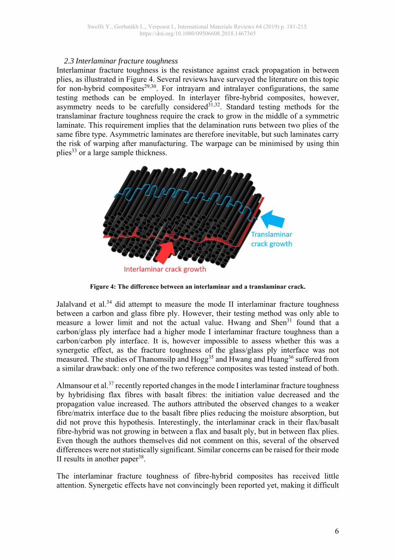
2.3 Interlaminar fracture toughness Interlaminar fracture toughness is the resistance against crack propagation in between plies, as illustrated in Figure 4. Several reviews have surveyed the literature on this topic for non-hybrid composites29,30. For intrayarn and intralayer configurations, the same testing methods can be employed. In interlayer fibre-hybrid composites, however, asymmetry needs to be carefully considered31,32. Standard testing methods for the translaminar fracture toughness require the crack to grow in the middle of a symmetric laminate. This requirement implies that the delamination runs between two plies of the same fibre type. Asymmetric laminates are therefore inevitable, but such laminates carry the risk of warping after manufacturing. The warpage can be minimised by using thin plies33 or a large sample thickness.
Figure 4: The difference between an interlaminar and a translaminar crack. Jalalvand et al.34 did attempt to measure the mode II interlaminar fracture toughness between a carbon and glass fibre ply. However, their testing method was only able to measure a lower limit and not the actual value. Hwang and Shen31 found that a carbon/glass ply interface had a higher mode I interlaminar fracture toughness than a carbon/carbon ply interface. It is, however impossible to assess whether this was a synergetic effect, as the fracture toughness of the glass/glass ply interface was not measured. The studies of Thanomsilp and Hogg35 and Hwang and Huang36 suffered from a similar drawback: only one of the two reference composites was tested instead of both.
Almansour et al.37 recently reported changes in the mode I interlaminar fracture toughness by hybridising flax fibres with basalt fibres: the initiation value decreased and the propagation value increased. The authors attributed the observed changes to a weaker fibre/matrix interface due to the basalt fibre plies reducing the moisture absorption, but did not prove this hypothesis. Interestingly, the interlaminar crack in their flax/basalt fibre-hybrid was not growing in between a flax and basalt ply, but in between flax plies. Even though the authors themselves did not comment on this, several of the observed differences were not statistically significant. Similar concerns can be raised for their mode II results in another paper38.
The interlaminar fracture toughness of fibre-hybrid composites has received little attention. Synergetic effects have not convincingly been reported yet, making it difficult
Swolfs Y., Gorbatikh L., Verpoest I., International Materials Reviews 64 (2019) p. 181-215. https://doi.org/10.1080/09506608.2018.1467365
7
to pinpoint the mechanisms governing those effects. More work is needed to clarify these mechanisms.
2.4 Translaminar fracture toughness Translaminar fracture toughness is the resistance to crack propagation perpendicular to the fibres/plies (see Figure 4)39. In contrast to interlaminar fracture toughness, this fracture mode requires breaking the fibres/plies. Translaminar fracture can occur either in tension or in compression, but the focus here is on the tensile mode. In composites reinforced by brittle fibres, this toughness has two major energy contributions: the fibre/matrix debonding energy and the pull-out energy40,41. Only a few studies have reported results on the translaminar fracture toughness of fibre-hybrid composites.
Donadon et al.42 tested carbon/glass woven fibre-hybrids, and found that the architecture of the intralayer woven fibre-hybrid fabric caused a more tortuous crack path. This added a mode II component to a test that is supposed to be mode I-dominated, and could potentially contribute to improved toughness values. Donadon et al.42, however, did not test the reference carbon or glass fibre composite. Without such a reference, it is impossible to assess whether the mode II component actually improved the toughness or whether they found any synergies.
Ortega et al.43 tried different combinations of woven glass, woven carbon and unidirectional carbon plies. They found minimal changes to the translaminar fracture toughness, apart from when multiple unidirectional plies were blocked together. This blocking of unidirectional plies, which effectively increases ply thickness, is known to increase the translaminar fracture toughness44. Ortega et al.43 claimed that this is caused by increased matrix cracking and larger delaminations, whereas Teixeira et al.44 and Pimenta and Pinho41 attributed it to the possibility of creating longer pull-out lengths. Swolfs et al.12 found that the layup in their woven carbon/glass fibre-hybrids influenced the pull-out lengths, and therefore also the translaminar fracture toughness. The reported synergies were either +15% or -15%, depending on the layup. The positive effect was found for layups were the carbon plies were blocked together, which allowed longer pull-out lengths to be created.
Given the limited data on translaminar fracture toughness of fibre-hybrid composites, there is much more to be examined. From research up to now, it is clear that increasing pull-out lengths contributes to increasing the translaminar fracture toughness. Fibre-hybridisation can have both negative and positive effects on these pull-out lengths, making an intelligent microstructural design vital.
2.5 Impact resistance The impact resistance of fibre-hybrid composites has been extensively investigated. Understanding the mechanisms contributing to synergies, however, is particularly difficult for this mechanical property for several reasons:
There are different definitions used in the literature for the term ‘impact resistance’, such as the energy required for penetration, residual properties after impact and the size of the damaged area due to impact45. Positive effects for one type often do not extend to another type of impact performance4.
The impact velocity is a key parameter that can change the failure mechanisms as well as the performance4,45.

Swolfs Y., Gorbatikh L., Verpoest I., International Materials Reviews 64 (2019) p. 181-215. https://doi.org/10.1080/09506608.2018.1467365
8
Impact resistance tends to be sensitive to the geometry of the impactor and clamping device45,46. Compression-after-impact tests are well standardised and comparing values from different sources is reliable. For penetration impact resistance, however, different standards are being used, and they allow different impactor and clamping geometries46. This makes it difficult to compare results from different sources.
Most studies on the impact resistance of fibre-hybrid composites have limited themselves to relatively general statements and observations, with limited fractographic observations or supporting characterisation tests.
A first key observation is that synergies for the mechanical properties explained in earlier subsections can all affect impact performance. An increase of the initial failure strain or ultimate tensile strength of the composite can increase the penetration impact resistance by delaying fibre/ply fracture. An improvement of the interlaminar fracture toughness can limit the damaged area, and therefore improve residual properties after impact but limit absorbed energy upon penetration impact45,47. An increased translaminar fracture toughness can be linked to increases in the penetration impact resistance12. Many impact studies on fibre-hybrid composites in the past focused on the influence of layup. It has for example been found that placing the low-elongation fibres towards the middle increased the penetration impact resistance12,48-50. The literature has not reached a consensus yet on how this trend can be explained. Several potential explanations have been suggested:
Placing low-elongation plies on the inside allows larger deflections prior to fracture onset49, as the outer plies are subjected to larger strains.
Sevkat et al.50 reported that delaminations were more extensive when the low-elongation plies are placed on the inside. They remarked that fibre-hybrids delaminate more extensively due to incompatibility between the layers, but did not explain how delaminations were influenced by the layup of the fibre-hybrid composite.
The translaminar fracture toughness is affected by the layup, and contributes to the energy absorption during penetration impact12. However, it remains unclear how placing low-elongation plies on the inside would affect the translaminar fracture toughness.
The direct link between these effects and improved penetration impact resistance, however, remains unclear. Other effects are even less clear in the literature. The damaged area for example was found to increase by placing the low-elongation plies towards the middle by some authors50,51. Gonzalez et al.52, however, contradicted this trend and found a decrease in damaged area. It therefore seems that the basic mechanisms of impact resistance of fibre-hybrid composites are insufficiently understood.
2.6 Fatigue Fatigue is the property degradation or damage development in a material when it is subjected to repeated loading. In composites, repeated loading often creates internal damage, such as matrix cracking, fibre-matrix debonding, delamination and fibre breaks53. This internal damage development progresses and may lead to a stiffness reduction, which is important for practical applications54. This reduction has been studied extensively in non-hybrid composites, but received little attention for fibre-hybrid
Swolfs Y., Gorbatikh L., Verpoest I., International Materials Reviews 64 (2019) p. 181-215. https://doi.org/10.1080/09506608.2018.1467365
9
composites. This is likely due to the fact that many fatigue studies on fibre-hybrids were performed on unidirectional composites27,55-59. Since the initial stiffness reduction is primarily caused by off-axis ply cracks60,61, studies on unidirectional composites would not reveal significant stiffness reductions.
Compared to stiffness reduction, the fatigue life has received more attention in the literature on fibre-hybrid composites. Many authors measured an increased fatigue life when carbon fibres were added to a glass fibre composites27,55-59. Several studies compared the fatigue life of fibre-hybrid composites to that of their non-hybrid reference composites, and found synergetic effects27,56,59. Dickson et al.56 and Shan and Liao27 both gave the following justification for the observed positive synergies. The imposed displacement-controlled conditions imply that the glass and carbon fibres are subjected to the same strain level. Due to their higher static failure strain, the glass fibre plies or bundles are at a strain level that is further away from their fatigue limit than for the carbon fibre plies or bundles. In most cases, the fatigue performance of the carbon/glass fibre-hybrids was therefore dominated by the carbon fibre composite. Since carbon fibre composites tend to perform better in tension-tension fatigue27,59, adding carbon fibres to a glass fibre composite improves the fatigue life. Note that a similar effect is also present in multidirectional non-hybrid composites: stiffer 0° plies will reduces the stresses in the 90° plies and therefore delay the onset of cracking in those 90° plies.
Shan and Liao27 also found that increased dispersion enlarged the synergies in tension-tension fatigue of unidirectional carbon/glass fibre-hybrid composites. They attributed this to improved crack arrest when the carbon fibres are dispersed better. This confirms the importance of fibre dispersion even for more complex loading scenarios than tension.
These studies have one important caveat: they all focused on tension-tension fatigue. The results for tension-compression fatigue are significantly less promising. Bach62 observed a reduced tension-compression fatigue life when carbon fibres were added to a glass fibre composite. Dai and Mishnaevsky63 confirmed this finding numerically. Both sources attributed this to the poorer compressive strength of carbon fibre composites relative to that of glass fibre composites.
2.7 Summary Synergies in fibre-hybrid composites have been achieved for many different mechanical properties. For a basic mechanical property, such as tension in the fibre direction, the mechanisms are reasonably well understood. For more complex properties, such as interlaminar fracture toughness or impact resistance, the level of understanding is significantly more limited. This is partially attributed to the fact that many authors do not test both reference composites, making it impossible to assess whether any synergetic effects occurred.
3 Materials selection This section focuses on fibre-hybrid composites in a polymer matrix, which is by far the most common combination. There is some limited information on fibre-hybrid composites in ceramic and metal matrix composites, but not enough to provide useful guidelines on materials selection for those types of composites. Nevertheless, this section will also draw upon knowledge from metal and ceramic matrix composites.

Swolfs Y., Gorbatikh L., Verpoest I., International Materials Reviews 64 (2019) p. 181-215. https://doi.org/10.1080/09506608.2018.1467365
10
A previous review4 went in great detail on the fundamental mechanisms controlling synergetic effects for mechanical properties, so this will not be repeated here. In general, the majority of the mechanical synergies can be explained as interactions between the failure mechanisms (see section ‘2 Mechanisms’). It is therefore essential to understand how different fibres and matrices fail, and how those mechanisms can interact. In some cases, this allows fibre-hybrid composites to demonstrate behaviour that neither of the constituent composites have. An excellent example is pseudo-ductile behaviour which can be obtained by combining carbon and glass fibre composites, both of which are brittle on their own. Even though this does not increase the ultimate failure strain compared to the glass fibre reference composite, it does lead to a more desirable, gradual failure. This example and others will be described in section ‘5.1 Pseudo-ductile and ductile fibre-hybrids’. For functional and physical properties, the properties of both fibre types can differ by several orders of magnitudes, see Table 2. Aspects, such as thermal and electrical conductivity, damping behaviour or electromagnetic properties, have received significantly less attention . The improvements that can be achieved in this type of properties is larger than for mechanical properties, but unfortunately have also been explored much less in the literature. To help the reader in his/her materials selection, this section is split up into two sections: one on fibre selection and one on matrix selection. Since the topic is fibre-hybridisation, the focus lies on the selection of the fibres. The importance of the matrix should, however, not be underestimated as it plays a vital role in determining the failure mechanisms, and hence the interactions between the fibres. Through the combined choice of fibre and matrix, one can also control the fibre/matrix interface properties. These properties govern the extent to which the intrinsic fibre properties are exploited in the composite. For a more detailed review on interface properties, the reader is referred to a recent review article by Karger-Kocsis et al.64
3.1 Fibre selection The fibre selection process does not only involve selecting the most suitable fibres, but also the most suitable fibre combination for the given requirements. The fibre selection is hence often a challenging task that strongly depends on the specific application at hand. This section provides an overview of the properties that are relevant for fibre-hybridisation. It is important that not only the benefits but also the drawbacks are identified, so fibre-hybridisation can be used to mitigate some of those drawbacks. For each fibre type, the micro- or nano-structure will be described, as this governs the mechanical and physical properties, as well as the failure behaviour of the composite. Getting a clear understanding of this structure is therefore the key in understanding the fibre behaviour and hence in selecting the right fibre types. At the end, Table 2 presents an overview of the mechanical, physical and functional properties of common reinforcement fibres. This table can be used as a starting point for selecting fibre types.
3.1.1 Carbon fibres Most commercial carbon fibres are either polyacrylonitrile (PAN) or pitch-based. The production processes for both fibres starts from a different base material, which lead to a different microstructure and hence different mechanical, thermal and electrical properties.

Swolfs Y., Gorbatikh L., Verpoest I., International Materials Reviews 64 (2019) p. 181-215. https://doi.org/10.1080/09506608.2018.1467365
11
PAN-based carbon fibres contain graphite planes that are oriented preferentially in the fibre direction, but are strongly folded, see Figure 5. Pitch-based carbon fibres on the other hand contain much less folding of the graphite planes65,66. Pitch-based carbon fibres are typically rather uniform over their diameter, whereas PAN-based carbon fibres tend to have a skin-core gradient (see Figure 5)66-68. The skin tends to have a higher modulus than the core, with differences reported of about 20%69. The core constitutes between 25 and 45% of the fibre diameter, depending on the temperature history68,69.
Figure 5: Example of a typical microstructure of a PAN-based carbon fibre (adapted from
Bennett14). This microstructure has been confirmed by other authors65,66, and similar schematic figures can be found in Qin et al.65.
Pitch-based carbon fibres typically have very high moduli, ranging from 400-940 GPa, with accompanying low failure strains, ranging from 0.3-0.8%. The potential property range is, however, much broader than for PAN-based carbon fibres. The pitch-based XN-05 fibre for example has a stiffness of only 41 GPa and a failure strain of 2.82%70. This range is more limited for PAN-based carbon fibres, with a typical longitudinal stiffness of 200-400 GPa, and some fibres going up to 700 GPa71. A vital consequence of the aligned graphite planes is that carbon fibres are transversely isotropic. While the longitudinal stiffness of standard carbon fibres ranges between 200 and 400 GPa, their transverse stiffness ranges between 5 and 30 GPa, depending on the fibre type, source and measurement method71,72. This has several implications:
The stress concentrations around carbon fibres in transverse loading are significantly lower than for isotropic fibres like glass or steel fibres73.
The transverse stiffness of a unidirectional carbon fibre ply is lower than for for a similar ply with isotropic fibres74. For typical values71,75 and using Chamis’ formulae74, the transverse stiffness of a carbon fibre ply is about two times lower than that of a glass fibre ply.
The lower transverse stiffness, however, also has a beneficial effect: it results in smaller longitudinal laminate stiffness reductions when the off-axis plies start cracking76.
Swolfs Y., Gorbatikh L., Verpoest I., International Materials Reviews 64 (2019) p. 181-215. https://doi.org/10.1080/09506608.2018.1467365
12
Although these implications may be obvious to many researchers in the field of composites, to the best of our knowledge, they have not yet been exploited in fibre-hybridisation. Table 2 reveals that carbon fibres are expensive compared to most other fibres. They hence tend to be used in areas that are more performance-driven than cost-driven77,78. Many approaches are actively pursued to reduce the price, such as alternative precursors, heavier yarns and process optimisation79. Fibre-hybridisation does not change the price of carbon fibre itself, but can reduce the amount of carbon fibre needed in a composite and contribute to reducing the overall cost of the composite.
3.1.2 Glass and basalt fibres Glass and basalt fibres are amorphous and unoriented fibres75,80. Both fibre types are relatively similar in terms of mechanical and physical properties, and mainly differ in atomistic composition80. E-glass fibres have been the default glass fibre type for many decades75. The second most well-known type is S-glass, which offers higher stiffness and strength and better corrosion resistance than E-glass75,81. Its atomic composition, however, leads to poor drawability and hence increased cost75. Glass fibre manufacturers are constantly improving their fibre compositions, and current E- and S-glass compositions and properties are not the same as they were thirty years ago75,81. As a consequence, many new glass fibre types have entered the market, most notably:
EC-R-glass: This fibre type is similar to E-glass, but with lower fractions of boron, which helps to reduce costs and undesirable emissions during production. Advantex from Owens-Corning is the most well-known commercial example of this glass fibre type81.
AR-glass: This fibre type has a better resistance against alkali environments, making it particularly suited for reinforcing concrete82.
R-, C- and T-glass: These three fibre types are specifically designed for increased chemical resistance75.
Basalt fibres are often considered to be a separate class of fibres, as they are made from a different natural source80. Basalt fibres are made from crushed basalt, typically without any additional components. Basalt fibres are more difficult to spin than most glass fibres, and hence more expensive80. The strength and modulus of basalt fibres are however higher than E-glass (see Table 2), and they also offer excellent chemical and heat resistance80. A drawback is that their density is slightly higher: 2800 kg/m³ compared to 2400-2700 kg/m³ for most glass fibre types83. A drawback of glass and basalt fibre composites relative to carbon fibre composites is that they are more sensitive to moisture81. Glass fibre strength is known to depend on moisture exposure75, whereas this is not the case for carbon fibres84. A second consequence of moisture is that it deteriorates the fibre/matrix interface85. Both effects affect glass fibre composites more than carbon fibre composites85,86. Several authors87,88 reported 15-25% reductions in flexural strength for glass/polyester and glass/vinylester composites after being immersed in sea water. When the glass fibre composites were loaded during immersion, the strength loss increased to up to 36%87. These drawbacks

Swolfs Y., Gorbatikh L., Verpoest I., International Materials Reviews 64 (2019) p. 181-215. https://doi.org/10.1080/09506608.2018.1467365
13
can be successfully overcome, as there is a wide range of glass fibre-based boat hulls that are constantly immersed in water. Successful strategies include matrix selection89 and the use of coatings90. Moisture absorption in glass fibre composites can, however, also have benefits. Zenasni and Saadi91 for example found an increase in interlaminar fracture toughness for glass fibre composites exposed to moisture, whereas the opposite was found for carbon fibre composites. A common feature for all types of glass and basalt fibres is that they are isotropic: their tensile moduli are the same in all directions. This has two important implications:
In transverse loading, their composites have higher stress concentrations around the broken fibre than for carbon fibres73, which are transversely isotropic.
The relative contribution of the off-axis plies to the modulus of a multidirectional composite is larger, but this also means that damage in the off-axis plies can lead to earlier onset of non-linear behaviour during tensile loading.
These two implications reinforce each other: the higher stress concentrations lead to earlier and more pronounced damage development, which further enhances the non-linearity. A final consideration in terms of fibre-hybridisation is the thermal behaviour. The coefficient of thermal expansion for glass fibres ranges between 1.6 and 7.3 10-6/K75, depending on the glass fibre type. This is significantly higher than for carbon fibres, for which the range is -1 to +0.5 10-6/K71. During the cooling down from the curing or moulding temperature, the glass fibres want to shrink significantly more than the carbon fibres. The presence of the matrix, which is now solid, forces both fibre types to shrink to the same extent. This creates thermal residual stresses in carbon/glass fibre-hybrids: compressive stresses in the carbon fibres and tensile stresses in the glass fibres. These stresses contribute to delaying the initial failure strain of the carbon fibre plies or bundles, although the fracture propagation effects are more significant (see section ‘2.1 Initial failure strain in tension’ for more details).
3.1.3 Polymer fibres Polymer fibres contain molecular chains that are preferentially oriented in the fibre direction. This orientation is typically achieved by drawing, and imparts improved stiffness and strength compared to isotropic polymers. Polymer fibres typically have densities similar to the isotropic polymer, which implies that they are lighter than traditional reinforcement fibres such as carbon and glass (see Table 2). In some cases, such as highly drawn polyproyplene, they can even be lighter than the isotropic polymer92. There are essentially two categories of polymer fibres: standard and high-performance polymer fibres. The first category is very diverse, as nearly every thermoplastic polymer can be drawn into fibres. Depending on the molecular backbone, the maximum draw ratio strongly varies, which has direct implications on the molecular orientation and hence the mechanical performance. Common fibres in this category include polypropylene (PP), polyamide (PA) and poly(ethylene terephthalate) (PET). Typical stiffnessess for these fibres range from 5 to 15 GPa93-95. High-performance polymer fibres have a stiffness and strength above 50 GPa and 2000 MPa respectively. An overview is presented in Table 1. The two most well-known
Swolfs Y., Gorbatikh L., Verpoest I., International Materials Reviews 64 (2019) p. 181-215. https://doi.org/10.1080/09506608.2018.1467365
14
examples are aramid or polypara p-phenyl terephtalamine (PPTA) fibres and ultrahigh molecular weight polyethylene (UHMWPE). Aramid, polybenzobisoxazole (PBO), and polyarylate (PAR) are all liquid-crystal polymers, which implies that they can exhibit molecular orientation in the liquid state. This also implies that it is easier to achieve high molecular orientation when they are subsequently drawn into fibres. Table 1: Overview of high-performance polymer fibres with their technical name, tradename and manufacturer. Endumax is an exception in this table, as it is not available in fibre form but only in
tape form. Technical name Tradename Manufacturer
Aramid or polypara p-phenyl terephtalamine (PPTA)
Kevlar Dupont Twaron Teijin
Ultrahigh molecular weight polyethylene (UHMWPE)
Dyneema DSM Spectra Honeywell
Endumax Teijin Polybenzobisoxazole (PBO) Zylon Toyobo Corporation
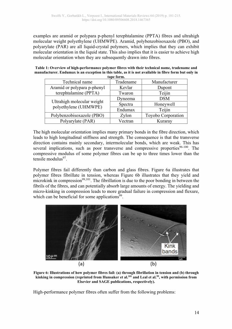
Polyarylate (PAR) Vectran Kuraray The high molecular orientation implies many primary bonds in the fibre direction, which leads to high longitudinal stiffness and strength. The consequence is that the transverse direction contains mainly secondary, intermolecular bonds, which are weak. This has several implications, such as poor transverse and compressive properties96-100. The compressive modulus of some polymer fibres can be up to three times lower than the tensile modulus97. Polymer fibres fail differently than carbon and glass fibres. Figure 6a illustrates that polymer fibres fibrillate in tension, whereas Figure 6b illustrates that they yield and microkink in compression99,101. The fibrillation is due to the poor bonding in between the fibrils of the fibres, and can potentially absorb large amounts of energy. The yielding and micro-kinking in compression leads to more gradual failure in compression and flexure, which can be beneficial for some applications99.
Figure 6: Illustrations of how polymer fibres fail: (a) through fibrillation in tension and (b) through
kinking in compression (reprinted from Hunsaker et al.101 and Leal et al.99, with permission from Elsevier and SAGE publications, respectively).
High-performance polymer fibres often suffer from the following problems:

Swolfs Y., Gorbatikh L., Verpoest I., International Materials Reviews 64 (2019) p. 181-215. https://doi.org/10.1080/09506608.2018.1467365
15
Low axial compressive modulus and strength96,97,99,100 Poor transverse and shear properties96,102,103 Poor fibre/matrix adhesion100,104,105 Poor ultraviolet light resistance for PBO, PPTA and PAR fibres96,102 Significant moisture absorption for aramid fibres96,106
The first two points are particularly important, as they have limited the use of high-performance polymer fibres in structural applications. Instead, they have mainly been used in rope and impact applications96,102. Fibre-hybridisation, however, offers opportunities to partially resolve those problems.
3.1.4 Metal fibres Metal fibres have a higher density than most other fibre types. They, however, possess a feature that is impossible in other fibre types: the strength and failure strain can be significantly altered without changing the stiffness. A cold-drawn steel fibre for example has a high dislocation density and a fine microstructure, leading to a high strength, but limited failure strain. During annealing, the dislocation density reduces and the microstructure coarsens, which can increase the failure strain to 30% without changing the stiffness107. This is, however, accompanied by a drop in yield stress and tensile strength108. The number of different metal fibres that have been used in composite applications is rather limited. There is a wide body of research on steel wire-reinforced rubbers109, which is relevant to car and truck tires. Similarly, there is a large body of research on steel-wire reinforced concrete and steel-wire reinforced polymers110. In these cases, the correct terminology is wires instead of fibres, as they have diameters of 100 µm or more. When fibres/wires with large diameters break, they require a long length to recover stresses in them, which limits composite performance. Such fibre diameters also create other issues: the handleability in textile processes is reduced and achieving layer thicknessess comparable to traditional fibre ply thicknesses is challenging. Research on metal fibres with diameters well below 100 µm is more scarce. Zou et al.111 and Sabine-Netto et al.112 used short steel fibres with diameters of 40-50 µm, whereas they were 25 µm in Fu et al.113. Fu et al. and Sabino-Netto et al. investigated friction and wear properties, and only Zou et al. reported mechanical properties. Continuous stainless steel fibres with a 30 µm diameter were used by Callens et al.108,114,115, Allaer et al.116 and McBride et al.117. These stainless steel fibres have been annealed and achieved a failure strain of 13-20% for the fibres and the composites. The ductility of the matrix is vital to achieve these values, as Callens et al.115 reported that a brittle epoxy matrix resulted in a composite failure strain of 8%, compared to 14% for a ductile polyamide-6 matrix. The 8% failure of the epoxy-based composite is remarkable, as the epoxy used in this study had a failure strain of a mere 4%. Hannemann et al.107 also used annealed stainless steel fibres, reaching failure strains of 32% for the fibres. In their epoxy composites however, they only achieved failure strains of 14%. The high toughness and ductility is an additional benefit of metal fibres compared to conventional fibres. This can lead to penetration impact resistance of up to 68 J per mm of panel thickness114, compared to 9-30 J/mm for carbon and glass fibre-reinforced composites tested on the same setup12. Metal fibres also offer significant scope due to

Swolfs Y., Gorbatikh L., Verpoest I., International Materials Reviews 64 (2019) p. 181-215. https://doi.org/10.1080/09506608.2018.1467365
16
their physical properties being different from other fibre types. The high electrical conductivity of some metal fibres, such as copper or aluminium, is commonly exploited in airplanes for lightning strike protection118 (see section ‘4.1 New fibre types’). A peculiar effect of metal fibres is that they do not always have a circular cross-section. The bundle drawing process, which is used for many of the fine metal fibres, leads to polygonal cross-sections115, allowing them to reach very high local fibre volume fractions. However, this also increases the stress concentrations for transverse loading scenarios73,119, but its effect on longitudinal strength and failure development remains unknown.
3.1.5 Natural fibres A wide range of natural fibres has been available for centuries or even millennia. Most of them were however used for making textiles instead of composites. In the last two decades, the number of natural fibres specifically for composite applications has strongly increased120,121. The most important group of natural fibres are plant-based, and have cellullose as their main load carrying component. In its crystalline form, cellullose has a theoretical axial stiffness of 130-165 GPa122. The elementary fibres in plant-based natural fibres are essentially composites made of cellullose as reinforcing elements and pectin, lignin and hemicellullose as matrix. On the next hierarchical level, a pectine-rich layer binds the elementary fibres together to form the technical fibres. It is these technical fibres that are extracted from the plants and used as reinforcing fibres in composites. Natural fibres offer a very wide range of properties, which are governed by the relative fractions of the constituent materials as well as the orientation of the crystalline cellullose. Coir and flax fibres are good illustrations of the potential range of mechanical properties. The ranges of stiffness, strength and failure strain for flax fibre is 50-90 GPa, 350-1000 MPa and 1,5-4%, respectively122-128. In contrast, the range for coir fibre is 1-6 GPa, 50-350 MPa and 26-60%, respectively126,129,130. These ranges seem relatively large, but this does not reflect a large scatter in the properties of natural fibres. The ranges were set up based on data from different sources, meaning that the fibres came from different species and were processed differently. For the same species processed in the same manner, the scatter is much smaller. Property variations based on varying climate each year are also limited131,132. Just like polymer and metal fibres, natural fibres often display non-linear tensile behaviour122-124. The exact reason for this non-linearity is not clear for all natural fibre types. Different authors have attributed this to different reasons: microscale damage122,124, viscoplasticity of the amorphous constituents133, shear deformation of the elementary fibres133, and reorientation of fibrils124,133. Natural fibres are transversely isotropic: their transverse stiffness and strength are significantly lower than their longitudinal stiffness and strength123,134. This sometimes leads to transverse failure of the composite through the fibres134. This is significantly different from conventional composites, where transverse failure normally occurs by a combination of matrix cracking and fibre/matrix interface failure.

Swolfs Y., Gorbatikh L., Verpoest I., International Materials Reviews 64 (2019) p. 181-215. https://doi.org/10.1080/09506608.2018.1467365
17
Two reviews are available that go into greater detail on the available works in the area of natural fibre-hybrids: Jawaid and Abdul Khalil135 and Nunna et al.136. Two common themes in many of these works is the reduction in moisture absorption and limiting the variability in properties. All natural fibres are prone to moisture absorption, which causes swelling issues as well as changes in mechanical properties121,137-139. The modulus typically decreases with increased moisture absorption, but the strength and failure strain can increase124,139.
3.1.6 Summary Fibre-hybridisation offers a unique opportunity to alleviate some of the drawbacks of one fibre type by adding a second fibre type. The range of fibre types is extensive, and the above discussion provided better insight into the fundamental differences between the fibres. The fibre stiffness and failure strain is an important factor in the fibre selection process. Figure 7 therefore presents an overview of the balance between stiffness and failure strain, showing that most fibres are either stiff but brittle or ductile but compliant.
Figure 7: The failure strain as a function of stiffness of a wide range of reinforcing fibres for
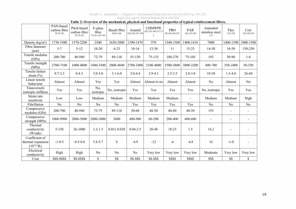
composites (modified from Callens140). An overview of the mechanical, physical and functional properties is provided in Table 2. This table has to be interpreted with care, as most fibre types can have a diverse range of properties, depending on the specific type that is chosen. Several properties are also known to depend on the testing conditions, making it difficult to compare literature sources. The fibre strength is one such example:
For glass fibres, pristine fibres are known to be stronger than fibres coming from a bobbin75,141.
The fibre strength depends on the gauge length, which is particularly important for natural fibres due to their hierarchical structure124.
Table 2 was set up to help in the fibre selection for fibre-hybridisation by providing information on a broad range of fibres. The table also contains properties, such linearity of the tensile behaviour and fibrillation, which are not commonly found in similar tables

Swolfs Y., Gorbatikh L., Verpoest I., International Materials Reviews 64 (2019) p. 181-215. https://doi.org/10.1080/09506608.2018.1467365
18
in text books. Such properties are often important for fibre selection in fibre-hybrids. Fibres that have significantly different mechanical or physical properties provide the largest scope for synergetic effects and achieving unique property combinations. The cost will often serve as a first criterion to select or eliminate certain fibre types. It also provides a first idea on whether any cost benefit can be expected through fibre-hybridisation.
Swolfs Y., Gorbatikh L., Verpoest I., International Materials Reviews 64 (2019) p. 181-215. https://doi.org/10.1080/09506608.2018.1467365
19
Table 2: Overview of the mechanical, physical and functional properties of typical reinforcement fibres.
PAN-based carbon fibre
70,79,142
Pitch-based carbon fibre
70,79,142
E-glass fibre
75,141,143-145
Basalt fibre80,83,146
Aramid 102,142,147-150
UHMWPE 102,142,148,151,15
2
PBO 98,142,148,153
PAR 142,147,148
Annealed stainless steel
115
Flax 122-128
Coir 126,129,130
Density (kg/m³) 1730-1980 1570-2200 2540 2630-2800 1390-1470 970 1540-1560 1400-1410 7800 1400-1500 1000-1300Fibre diameter
(µm) 5-7 5-12 10-20 6-23 10-14 12-30 11 15-25 14-50 10-50 150-250
Tensile modulus (GPa)
200-700 40-940 72-79 89-110 55-150 75-135 180-270 75-105 193 50-90 1-6
Tensile strength (MPa)
2700-7100 1000-4000 1600-3500 2800-4840 2700-3400 2100-4000 5500-5800 3000-3200 400-700 350-1000 50-350
Tensile failure strain (%)
0.7-2.2 0.4-3 3.0-5.0 3.1-6.0 2.0-4.4 2.9-4.1 2.5-3.5 2.8-3.8 10-20 1.5-4.0 26-60
Linear tensile behaviour
Almost Almost Yes Yes Almost Almost to no Almost Almost No Almost No
Transversely isotropic stiffness
Yes Yes No,
isotropic No, isotropic Yes Yes Yes Yes No, isotropic Yes Yes
Strain rate sensitivity
Low Low Medium Medium Medium Medium Medium - Medium Medium High
Fibrillation No No No No Yes Yes Yes Yes No No No Compressive
modulus (GPa) 200-700 40-940 72-79 89-110 30-60 40-50 40-80 40-50 193 - -
Compressive strength (MPa)
1000-9900 2000-3000 2000-3000 3800 400-900 60-200 200-400 400-600 - - -
Thermal conductivity
(W/mK) 5-150 26-1000 1.2-1.5 0.031-0.038 0.04-2.5 20-40 18-23 1.5 16.2 - -
Coefficient of thermal expansion
(10-6/°K) -1-0.5 -0.5-0.0 5.4-5.7 8 -4.9 -12 -6 -4.8 16 -1-0 -
Electrical conductivity
High High No No No Very low Very low Very low Moderate Very low Very low
Cost $$$-$$$$ $$-$$$$ $ $$ $$-$$$ $$-$$$ $$$$ $$$$ $$$ $$ $
Swolfs Y., Gorbatikh L., Verpoest I., International Materials Reviews 64 (2019) p. 181-215. https://doi.org/10.1080/09506608.2018.1467365
20
3.2 Matrix selection Even though the focus of fibre-hybrids is on the selection of the fibres, the matrix also influences the performance of fibre-hybrid composites. The selection of the matrix is therefore an often underestimated problem in fibre-hybrid composites. There is a large body of knowledge on choosing the optimal matrix for a given fibre type. In fibre-hybrid composites, however, the matrix is typically the same for both fibre types.
The choice between a thermoplastic and thermoset composite is an important one. This not only has strong implications on the manufacturing route, but also on the matrix and hence composite properties. Thermoplastic composites not only offer shorter cycle times, but also improved toughness and recyclability compared to thermoset composites154. The drawbacks of thermoplastic composites lie in impregnation difficulties due to higher viscosities, and their poorer fibre/matrix interface due to the lack of chemical bonds154.
3.2.1 Mechanical properties Some fibres work better with one matrix system than with another. For ductile steel fibres for example, it has been shown that a ductile matrix leads to a composite failure strain of 12.7% compared to 7.3% for the same fibres in a brittle matrix115. These results imply that a matrix that is optimal for one fibre type, may be suboptimal for the other one.
The mechanical properties are often an important factor in matrix selection155,156. The matrix stiffness contributes to the overall composite stiffness, but this contribution is small in the fibre direction for most fibre types74. Conventional polymer matrix systems have a stiffness ranging between 1 and 4 GPa, which is significantly lower than most fibre stiffnesses in Table 2. While the contribution of the matrix stiffness to the transverse stiffness of a unidirectional composite is more significant74, the primary effect of the matrix lies in the way damage develops and propagates. In off-axis loading for example, the ratio of transverse fibre stiffness over matrix stiffness ratio determines the magnitude of the stress concentrations around the fibres73. This stress concentration together with the matrix strength and fibre/matrix interface strength will determine the onset of damage and composite strength157. Most of these off-axis loading studies have been performed on non-hybrids, with studies on fibre-hybrids being rare158.
For on-axis loading, the matrix properties also play a significant role in the damage development and composite strength. A stiffer matrix with higher shear strength leads to more localised stress concentrations around fibre breaks, which will increase the longitudinal tensile strength21. While many models have analysed the longitudinal tensile strength of fibre-hybrid composites (see section ‘4.3 Simulation tools’), their focus was on the influence of fibre rather than matrix properties. Studies on the influence of matrix properties on on-axis fibre-hybrid performance are rare.
3.2.2 Compatibility The compatibility issues depend on whether prepregs are used or the resin is impregnating all plies at once. When combining two different prepregs, the compatibility of the resins should be considered. For thermoset prepregs, this compatibility has three vital requirements:

Swolfs Y., Gorbatikh L., Verpoest I., International Materials Reviews 64 (2019) p. 181-215. https://doi.org/10.1080/09506608.2018.1467365
21
The curing cycle should be similar for both resins, so the prepregs can be cured together in one process. If they are too dissimilar, the curing process risks being too severe for one prepreg or insufficient for the other.
The curing cycle of the resin should not degrade the performance of the reinforcing fibres.
The resins should be chemically compatible. Since the resins are not cured yet, they can blend with each other and significantly alter their properties159.
The first and second point can often be evaluated from the material data sheets. Special care should be taken when natural or polymer fibres are being used. In an oxidative environment, most natural fibres start degrading at about 200°C135. Unless oxidising circumstances can be avoided, this strongly limits the choice of thermoplastic matrices120. The maximum temperature that natural fibres can withstand, however, also depends on the dwell time and moisture content120,135. It should be noted that the maximum processing temperature of polymer fibres may be well below their melting temperature. Molecular relaxation and/or shrinkage can onset at a lower temperature and strongly deteriorate the mechanical properties. In some cases, this can be overcome by high pressures or constraining the polymer fibres, as this stabilises the molecules and increases their melting temperature160. The above considerations can impose limits on the temperature window for processing of fibre-hybrid composites containing natural or polymer fibres. The third point is much more difficult to evaluate. Czél et al.161 for example combined Skyflex USN 020 A carbon fibre/epoxy prepregs with HexPly 913 glass fibre/epoxy prepregs. Both prepregs require a 125°C cure, implying that their curing cycles were compatible. The authors, however, also mentioned that both resins were found to be compatible, but they did not evaluate that compatibility in terms of chemistry or mechanical properties. To the best of our knowledge, no other works in the field of fibre-hybrid composites reported on resin compatibility issues. Although rarely used in composites, it is possible to combine two resins with different polymer chemistry. This could happen at the interface between two different prepreg plies in fibre-hybrids, but can also be done on purpose in non-hybrids. Turcsan and Meszaros159 for example mixed different thermoset resins, such as unsaturated polyester/epoxy or vinylester/epoxy. These hybrid resins can offer improved damping due to their interpenetrating polymer network162. Such resins have to be used with great care, as their complex morphologies depend on the mixing and thermal history, and this in turn changes their mechanical and physical properties159,162,163. These changes can be positive or negative.
3.2.3 Functional properties The matrix bonds the fibres together and makes them deform as whole. The matrix can also impart functional properties to the composite, such as electrical conductivity or fire retardancy. In case of fibre-hybrid composites, however, many of these functional properties can be added via fibre selection as well. A careful analysis should be performed to decide which strategy is most suitable to achieve the desired functional properties. The scientific literature contains little information on imparting functional properties through matrix selection in fibre-hybrid composites. In industry, fibre-hybridisation often

Swolfs Y., Gorbatikh L., Verpoest I., International Materials Reviews 64 (2019) p. 181-215. https://doi.org/10.1080/09506608.2018.1467365
22
has the direct aim to add a functionality (see section ‘5.2 Functional properties’). There is, however, a wide body of research on imparting functional properties in non-hybrid composites through matrix selection or adding particles to the matrix. The electrical conductivity for example can be strongly improved by adding carbon nanotubes to the epoxy matrix164. Such composites can then be used as damage sensors165. Similar damage sensing functionalities can be imparted through selection of the fibre types: Wisnom et al.166 exploited the visual appearance of damage in carbon/glass fibre-hybrid composites to create an overload sensor. Such sensors can be tailored to trigger at a desired strain level by choosing the right fibre types. Fire resistance is another example that can be resolved through matrix selection as well as fibre selection167,168. The fire resistance of polymer matrix composites can be improved through the addition of fillers or choosing a different matrix altogether167. Phenolic resins are often used to improve fire resistance, as they create a char that prevents spreading of the fire. Similar improvements in fire properties can be achieved by replacing conventional reinforcement fibres by aramid fibres, as they have no melting point and create a similar char as phenolic resins168.
3.2.4 Summary Matrix selection in non-hybrid composites is a very active topic, with many researchers aiming to modify matrices to obtain better or new composite properties. Matrix selection in fibre-hybrid composites however, has received relatively little attention. Special care should be taken so that the resin is compatible with both fibre types, in terms of both processing and interfacial bonding. The compatibility issues for fibre-hybrid composites mainly follow the same guidelines as for non-hybrid composites. When the matrix selection is performed based on the desired functional properties, it should be considered whether the same properties can be achieved more efficiently through intelligent selection of the fibres.
4 Recent developments in materials, preforms and simulation tools Compared to the early research on fibre-hybridisation in the seventies and eighties, several key technologies have significantly improved. This opens up new avenues for improved fibre-hybrid composites. This section therefore reviews the latest developments in fibre types, preforming technologies and simulation tools for fibre-hybrid composites.
4.1 New fibre types Carbon169-171 and glass fibres155 were already available before fibre-hybridisation took off in the seventies and eighties5. Nevertheless, there have been significant improvements in the mechanical properties. Standard carbon fibres like Toray’s T300 and Hexcel’s AS4 have been in production for over 30 years172-175. Newer fibre types like Toray’s T1000G offer better combinations of stiffness (294 GPa), strength (6370 MPa) and failure strain (2.2%)176. In the past decades, many new high-performance polymer fibres have been developed, such as PAR and PBO (see section ‘3.1.3 Polymer fibres’). These fibres have excellent mechanical properties in tension, and can even compete with carbon fibres in the case of PBO fibres (see Table 2). Many of these fibres are primarily used in rope and ballistic applications, where their poor compressive properties are less of an issue102,149. A limited number of fibre-hybridisation studies have been reported. There have only been a few

Swolfs Y., Gorbatikh L., Verpoest I., International Materials Reviews 64 (2019) p. 181-215. https://doi.org/10.1080/09506608.2018.1467365
23
studies that hybridised PAR and PBO fibres with other fibres. Yusuff et al.177 studied the low velocity impact behaviour of carbon/PBO/epoxy fibre-hybrids and found strong improvements compared all-carbon fibre composites. Sohn et al.178 and Walker et al.179 proved that 6 mm long PBO fibres are effective interlaminar reinforcements, as the reduced damaged area after impact and increases energy absorption. UHMWPE and aramid fibres have been around longer than most other high-performance polymer fibres, and there is hence a richer body of research available. Peijs et al.180-184 for example performed an extensive study of carbon fibre/UHMWPE composites, and a range of authors studies carbon/aramid fibre-hybrid composites14,177,185-188. Many of these studies focused on impact performance, and found significant improvements relative to all-carbon fibre reference composites177,182,183,185,186,188. High-performance polymer fibres can also impart functional properties to the fibre-hybrid composites. Many of these fibres offer excellent thermal, fire retardancy and chemical properties (see Table 2). They can also improve vibration damping. In aramid/epoxy composites for example, it has been proven that the loss factor is 10 times higher than for carbon/epoxy and 6 times better than glass/epoxy156. This loss factor indicates how much intrinsic damping the material offers. Functional properties of fibre-hybrid composites are, however, rarely examined in the literature, so it is difficult to evaluate how they are carried over into fibre-hybrid properties. Metal wires have been around for many decades, but fibres with diameters below 100 µm have only become available more recently189,190. The key development in metal fibres was the technological progress in bundle drawing, allowing the production of fibres with diameters below 100 µm. While a few studies on metal fibres were reported in the eighties189,190, much more studies have appeared in the past decade107,108,111,112,114,115,191. Much of the metal fibre composite work so far has focused on trying to understand the failure behavior of non-hybrid composites140,191,192 (see section ‘3.1.4 Metal fibres’). There have been some limited studies on fibre-hybridisation, but this is still in its early stages107,117,193. These studies reported significant improvements in penetration impact resistance107,193 and notch sensitivity107,117. Natural fibres have made significant progress in the last two decades120. The main progress has been in the improvement of the extraction processes, a better control and understanding of the fibre-matrix interface, and the development of new textiles and preforms that are optimised for composite applications120,123. The natural fibre technology has reached a point where many researchers are trying fibre-hybridisation. This can either be combinations of natural fibres with each other194-196 or with glass fibres197-200. Mitigating the moisture problems is a common driver for fibre-hybridisation of natural fibres. By adding a thin glass or basalt fibre layer on the outside, the moisture absorption can be delayed and its associated problems can be reduced201-203. This is true in spite of glass and basalt fibres being sensitive to moisture (see section ‘3.1.2 Glass and basalt fibres’). Their performance, however, is affected less than natural fibres201-203. Carbon nanotube fibres are perhaps the most recent addition to the list of promising new fibre types, with the first report appearing in 2000204 and many more since then205-207. The quantity of material available, however, is currently limited, and, to the best of the authors’ knowledge, hybridisation of these fibres with conventional fibres has not been
Swolfs Y., Gorbatikh L., Verpoest I., International Materials Reviews 64 (2019) p. 181-215. https://doi.org/10.1080/09506608.2018.1467365
24
performed yet. Once they are available in larger quantities, they would be an interesting candidate for fibre-hybridisation studies.
4.2 Preforming technologies With the increased performance and reliability of design tools for fibre-hybrid composites, there is now also an increased drive to improve preforming technologies6,7,208. Four preforming technologies will be described here: thin plies, co-weaving, commingling, and aligning discontinuous fibres.
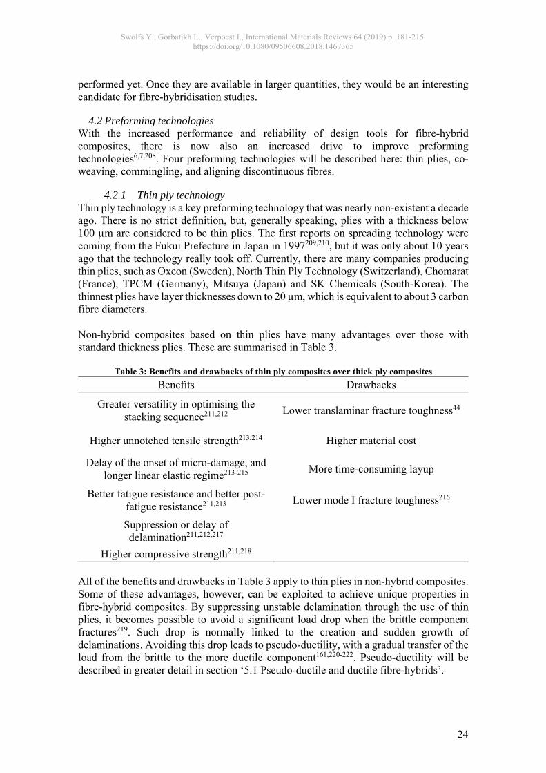
4.2.1 Thin ply technology Thin ply technology is a key preforming technology that was nearly non-existent a decade ago. There is no strict definition, but, generally speaking, plies with a thickness below 100 µm are considered to be thin plies. The first reports on spreading technology were coming from the Fukui Prefecture in Japan in 1997209,210, but it was only about 10 years ago that the technology really took off. Currently, there are many companies producing thin plies, such as Oxeon (Sweden), North Thin Ply Technology (Switzerland), Chomarat (France), TPCM (Germany), Mitsuya (Japan) and SK Chemicals (South-Korea). The thinnest plies have layer thicknesses down to 20 µm, which is equivalent to about 3 carbon fibre diameters. Non-hybrid composites based on thin plies have many advantages over those with standard thickness plies. These are summarised in Table 3.
Table 3: Benefits and drawbacks of thin ply composites over thick ply composites
Benefits Drawbacks
Greater versatility in optimising the stacking sequence211,212
Lower translaminar fracture toughness44
Higher unnotched tensile strength213,214 Higher material cost
Delay of the onset of micro-damage, and longer linear elastic regime213-215
More time-consuming layup
Better fatigue resistance and better post-fatigue resistance211,213
Lower mode I fracture toughness216
Suppression or delay of delamination211,212,217
Higher compressive strength211,218 All of the benefits and drawbacks in Table 3 apply to thin plies in non-hybrid composites. Some of these advantages, however, can be exploited to achieve unique properties in fibre-hybrid composites. By suppressing unstable delamination through the use of thin plies, it becomes possible to avoid a significant load drop when the brittle component fractures219. Such drop is normally linked to the creation and sudden growth of delaminations. Avoiding this drop leads to pseudo-ductility, with a gradual transfer of the load from the brittle to the more ductile component161,220-222. Pseudo-ductility will be described in greater detail in section ‘5.1 Pseudo-ductile and ductile fibre-hybrids’.
Swolfs Y., Gorbatikh L., Verpoest I., International Materials Reviews 64 (2019) p. 181-215. https://doi.org/10.1080/09506608.2018.1467365
25
Thin plies are also an effective strategy to achieve good dispersion (see section ‘1 Introduction’). This dispersion allows strong interactions between fibres, and can lead to synergetic effects for the initial failure strain in tension (see section ‘2.1 Initial failure strain in tension’). Synergies of 10-40% have been described in the literature for carbon/glass fibre-hybrid composites4, although some of those measurements were likely affected by gripping artefacts223. More reliable measurement methods recently found synergetic effects of up to 20% for a 29 µm thick carbon fibre ply sandwiched in between 155 µm thick glass fibre plies17.
4.2.2 Co-weaving Co-weaving technology is, in principle, the same as regular weaving. Instead of using weft and warp yarns that are all of the same fibre type, some yarns are replaced by yarns of another fibre type. The versatility in the weft direction is greater than in the warp direction224. In the warp direction, the desired yarns need to be set up on the loom, which is a time-consuming task. In the weft direction, only one or a few of the weft shuttles or insertion systems need to be changed, and there is no technical need for the yarn carried by the shuttle to be of the same type as the warp yarns. Replacing only a part of the weft yarns is also possible, but is technologically slightly more difficult. Fibre-hybrid weaves therefore tend to have the two distinct weft yarns, but only one warp yarn. Hybrid weaves can be commercially sourced from many manufacturers225,226 or can be custom-made227-230. In some cases, these are quasi-UD fabrics, where a weft yarn with a low linear density holds together the main reinforcing fibres in the warp direction193. The mechanical contribution of the weft yarns is hence limited. Balanced fibre-hybrid fabrics are, however, also available on the market. Fibre-hybrid woven fabrics using spread tows are commercially available as well231. Such fabrics combine co-weaving and thin ply technology in a single product. 3D weaves are another category of co-woven fabrics. The additional z-yarns hinder the development of delaminations and yield an improved damage tolerance86,232. Fibre-hybrid composites are relatively common in 3D weaves225,229,230,233, most likely due to the different requirements for the different yarns. The z-yarns, which are the ones that go through the thickness, have different property requirements than the other yarns232. One of their key functions is to hinder or prevent delaminations224,232. Selecting a tough fibre for the z-yarns is therefore more beneficial than a brittle fibre in preventing delaminations.
4.2.3 Commingling Commingling is a composite preforming technology that intimately blends yarns of fibres together. The technology has been around since the eighties234, and is used on a regular basis to combine carbon or glass fibres with polymer fibres7,235,236. In most cases however, the polymer fibre is sacrificial: its goal is only to melt to form the matrix7,9,234-236. Commingling hence serves to minimise impregnation length by creating the polymer matrix in between the reinforcement fibres9. Commingling of two structural fibres is challenging. The traditional commingling technology is based on air-texturing, which mixes yarns by blowing air through them using air jets. This process typically leads to a dispersion that is not on the fibre level, but more on the yarn level. Figure 8 shows a typical example.

Swolfs Y., Gorbatikh L., Verpoest I., International Materials Reviews 64 (2019) p. 181-215. https://doi.org/10.1080/09506608.2018.1467365
26
Figure 8: Microstructure of commingled glass (white) and PP (black) fibres, revealing a low degree
of dispersion (reprinted from Selver et al.7). Several other technologies are available: co-wrapping, core-spinning and stretch breaking9. Co-wrapping wraps the polymer fibres around the reinforcement fibre, which is of less interest to fibre-hybrid composites. Core-spinning is similar to co-wrapping, but uses short thermoplastic fibres instead of continuous ones. This process is often referred to as ‘Dref spinning’237. Stretch-breaking involves breaking the reinforcement fibres. When these fibres break, they spring back, leading to intimate mixing with the polymer fibres. A potential disadvantage of commingling is that it can introduce damage to the fibres9,238. This reduces the strength of the fibres, which offsets potential positive synergies. One solution to reduce the inflicted damage could be the approach proposed by Mäder et al.239, which is to spin the polymer fibres while commingling. This led to a glass fibre yarn tensile strength of 1100 MPa, which was significantly higher than the air-textured yarns with a 700-800 MPa strength. As commingling equipment is mainly available in industry and only rarely in academia, there is little quantitative information available on the introduced damage.
4.2.4 Aligning discontinuous fibres In the past 5 years, there has been a two-sided push for better alignment processes for discontinuous fibres. Firstly, finely dispersing two fibre types is a very challenging task for continuous fibres. Achieving a fine dispersion is relatively straightforward for discontinuous fibres, as (1) they are much less entangled than continuous fibres and (2) their processes often anyway involve a mixing step. To achieve high performance from discontinuous fibre-reinforced composites, however, the fibres need to be well-aligned. Secondly, the high growth rates of composites in the past decades has led to a strong increase in composite parts that are nearing their end-of-life240. This implies a strong push for improved recycling strategies. Now that recycling can yield short carbon fibres with nearly no degradation in stiffness and strength241, the focus has turned to maximising the performance of recycled composites. Aligning recycled, discontinuous fibres has therefore become a crucial issue to be tackled240. Several approaches have been developed at different universities and companies. The HiPerDiF process by the University of
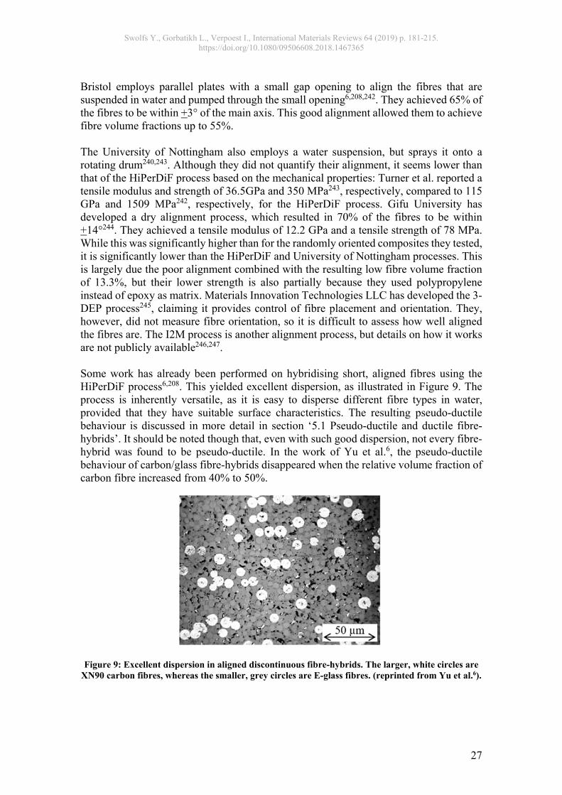
Swolfs Y., Gorbatikh L., Verpoest I., International Materials Reviews 64 (2019) p. 181-215. https://doi.org/10.1080/09506608.2018.1467365
27
Bristol employs parallel plates with a small gap opening to align the fibres that are suspended in water and pumped through the small opening6,208,242. They achieved 65% of the fibres to be within +3° of the main axis. This good alignment allowed them to achieve fibre volume fractions up to 55%. The University of Nottingham also employs a water suspension, but sprays it onto a rotating drum240,243. Although they did not quantify their alignment, it seems lower than that of the HiPerDiF process based on the mechanical properties: Turner et al. reported a tensile modulus and strength of 36.5GPa and 350 MPa243, respectively, compared to 115 GPa and 1509 MPa242, respectively, for the HiPerDiF process. Gifu University has developed a dry alignment process, which resulted in 70% of the fibres to be within +14°244. They achieved a tensile modulus of 12.2 GPa and a tensile strength of 78 MPa. While this was significantly higher than for the randomly oriented composites they tested, it is significantly lower than the HiPerDiF and University of Nottingham processes. This is largely due the poor alignment combined with the resulting low fibre volume fraction of 13.3%, but their lower strength is also partially because they used polypropylene instead of epoxy as matrix. Materials Innovation Technologies LLC has developed the 3-DEP process245, claiming it provides control of fibre placement and orientation. They, however, did not measure fibre orientation, so it is difficult to assess how well aligned the fibres are. The I2M process is another alignment process, but details on how it works are not publicly available246,247. Some work has already been performed on hybridising short, aligned fibres using the HiPerDiF process6,208. This yielded excellent dispersion, as illustrated in Figure 9. The process is inherently versatile, as it is easy to disperse different fibre types in water, provided that they have suitable surface characteristics. The resulting pseudo-ductile behaviour is discussed in more detail in section ‘5.1 Pseudo-ductile and ductile fibre-hybrids’. It should be noted though that, even with such good dispersion, not every fibre-hybrid was found to be pseudo-ductile. In the work of Yu et al.6, the pseudo-ductile behaviour of carbon/glass fibre-hybrids disappeared when the relative volume fraction of carbon fibre increased from 40% to 50%.
Figure 9: Excellent dispersion in aligned discontinuous fibre-hybrids. The larger, white circles are XN90 carbon fibres, whereas the smaller, grey circles are E-glass fibres. (reprinted from Yu et al.6).

Swolfs Y., Gorbatikh L., Verpoest I., International Materials Reviews 64 (2019) p. 181-215. https://doi.org/10.1080/09506608.2018.1467365
28
4.3 Simulation tools It is well recognised that the microstructure governs the mechanical and functional properties of fibre-hybrid composites. Design tools can help to more efficiently determine the optimal structure10,63,221,222,248. There has been significant progress in this area in recent years. Most models that were not specifically developed for fibre-hybrid composites fail to predict synergetic effects between fibre types. The most interesting tools for this review are hence the ones that were developed specifically for fibre-hybrid composites. Essentially, the models can be split up into two categories. Category 1 are fibre break models that model individual fibre breaks and how they develop into clusters of fibre breaks, eventually leading to final failure21. Category 2 are ply level models, which make abstraction of the damage development inside a ply, and instead focus on predicting what happens when one or several plies have failed. The initial developments of fibre break models date back to the twenties and forties of last century with the work of Peirce249 and Daniels250, respectively. These models assumed that a fibre, when it breaks, losses its load carrying capacity over its entire length. This is a simplification that can be overcome by applying shear lag theory to capture the stress recovery in the broken fibre. Rosen251 and Zweben252 were the first to incorporate these shear lag theories into a strength model. The first models for fibre-hybrid composites were reported in the seventies and eighties by Zweben253 and Fukuda et al.254,255, and were based on Zweben’s non-hybrid model252. These models used 1D packings, which is essentially a single row of parallel fibres. This is a rather severe simplification, as the stress concentrations around fibre breaks in such packings are much higher than in 2D packings256. From the nineties onwards, models for non-hybrids therefore started using more realistic 2D packings combined with more accurate representation of the physical mechanism257-259. Fibre break models for continuous fibre-hybrid composites only caught up recently with developments by Mishnaevsky and Dai63,248 and Swolfs et al.10,17,25,260. The model of Mishnaevsky and Dai248 uses direct finite element simulations, which limits the number of fibres that can be modelled to 10-20. The key benefit of their model, however, is that it captures fibre misalignment as well as fatigue in tension and compression. Dai and Mishnaevsky63 also developed a micromechanical model, based on simple load redistribution mechanisms with misaligned fibres. This allowed them to model the tensile behaviour of fibre-hybrid composites with several hundreds of fibres. The model of Swolfs et al.10,17,25,260 uses finite element simulations, but only to capture stress concentrations around single fibre breaks in fibre-hybrid packings. This information is then used in a numerical simulation with thousands of fibres. Fibre break models have led to valuable insights into the potential synergetic effects offered by fibre-hybrid composites. It is now well understood which parameters can help to maximise such synergetic effects, and such conclusions can be used to guide materials and process selection4. Models can also be used to guide fibre/preform selection and manufacturing decisions10. The importance of the dispersion and hence microstructure has long been recognised in the literature261-264, although it was often thought that

Swolfs Y., Gorbatikh L., Verpoest I., International Materials Reviews 64 (2019) p. 181-215. https://doi.org/10.1080/09506608.2018.1467365
29
commingled yarns were the optimal route for achieving this. Detailed modelling studies, however, revealed that thin ply hybrids can yield larger hybrid effects than commingled hybrids10. Similarly, it was shown that the relative fractions of both fibres strongly influence synergetic effects14,25,265, which is important information for manufacturers. The second category of models for fibre-hybrid composites, namely ply level models, can be readily adapted from models for non-hybrid composites. These models ignore the micromechanical features, such as matrix cracking and fibre breaks, but investigate ply level features. Their main focus is predicting what happens after the first failure of the ply with the lowest failure strain. Essentially, there are four different options: Immediate fracture of the entire composite. A growing delamination that detaches the broken ply from the rest of the plies. Fragmentation of that ply, with a limited delamination around the ply fracture
locations. Fragmentation of that ply without any delamination around the ply fracture locations.
The largest progress in this area has been made by the University of Bristol161,220-222. They developed the concept of damage mode maps221, which are useful to predict the type of behaviour that is expected. Figure 10 illustrates how this damage mode map typically looks like. For interlayer fibre-hybrids, these maps predict the maximum carbon fibre layer thickness and relative volume fraction that results in fragmentation, and hence pseudo-ductility. Another example of ply level models is the work of Dong et al.19,266,267. They developed finite element models to predict flexural strength of fibre-hybrid composites. This was achieved by implementing failure models for tensile and compressive failure of the plies.
Figure 10: Example of a damage mode map for carbon/glass fibre-hybrid composites, based on the
equations and E-glass/TR30 properties of Jalalvand et al.268, 160 mm gauge length and 20 mm width.

Swolfs Y., Gorbatikh L., Verpoest I., International Materials Reviews 64 (2019) p. 181-215. https://doi.org/10.1080/09506608.2018.1467365
30
There is still significant scope for further improvements in simulation tools. Detailed fibre break models are sometimes limited to predicting the failure strain of the ply or bundle type with the lowest failure strain10,17,25. Other models do capture the entire stress-strain diagram, but achieve this by ignoring the effects of ply fragmentation, delaminations and bundle debonding260,269,270. There is hence great benefit in combining both approaches: by incorporating delamination or fragmentation, it should become possible to reliably predict the entire stress-strain diagram of fibre-hybrid composites. Similarly, ply level models tend to ignore micromechanical effects that are known to be important. A good example is size scaling effects. Many ply level models assume a constant, uniform strength for the plies19,266,267, whereas, in reality, that strength is size-dependent271. The size effect automatically arises in fibre break models271,272. Such models are, however, often limited by the size of the model. A key challenge for the future will therefore be to incorporate the micromechanical effects into ply level models.
Advanced model development could push new developments in fibre-hybridisation. Another significant step forward would be to include such models into structural design tools273. At the moment, such design tools completely ignore synergetic effects, which also leads to suboptimal materials selection and design of the fibre-hybrid composite microstructure.
4.4 Summary The field of fibre-hybrid composites is rapidly evolving, especially in the last 10 years. New fibre types offer many opportunities for achieving new combinations of properties. Design tools have strongly improved and can provide useful guidelines for material/preform selection and manufacturing choices. The range of possible preforming/manufacturing technologies has strongly expanded in the last decade, which opens up new avenues for manufacturing intelligently designed microstructures.
5 Recent trends in fibre-hybridisation In recent years, several trends have developed that hardly received attention a decade ago. These include pseudo-ductile and ductile composites, functional properties and environmental impact. These three areas can have a strong effect on boosting the use of fibre-hybrid composites in applications.
5.1 Pseudo-ductile and ductile fibre-hybrids Toughness is a major problem for many composite applications: most composite materials are stiff and strong, but brittle. Breaking through this stiffness-toughness dilemma could be possible by using fibre-hybridisation. One strategy for achieving this is through pseudo-ductility. Even though the pseudo-ductile terminology has been around for more than twenty years274-276, the past five years showed a strong revival6,8,161,166,208,219,220,222,277-282. There is no clear definition for what constitutes pseudo-ductility, although it can be quantified using the pseudo-ductile strain. The pseudo-ductile strain is defined as the strain difference between the final failure strain and the strain at the same stress level, but on the extrapolated linear elastic region222. This definition is illustrated in Figure 11.

Swolfs Y., Gorbatikh L., Verpoest I., International Materials Reviews 64 (2019) p. 181-215. https://doi.org/10.1080/09506608.2018.1467365
31
Figure 11: Schematic definition of pseudo-ductile strain.
Pseudo-ductility can address some of the key drawbacks of composite materials. Firstly, composite materials show no or little warning prior to final failure. This lack of warning leads to large safety factors and hence sub-optimal design relative to more ductile materials8,161. Secondly, linear elastic materials such as carbon fibre composites tend to be highly notch-sensitive8,283, as they fail to blunt the stress concentrations like ductile materials do284. This has made the open-hole tensile strength, which measures notch sensitivity, an important design driver in the aerospace sector285,286. Pseudo-ductility has been proven to improve the open hole tension strength of composites8. Thirdly, fibre-hybrid composites often show a strong vertical stress drop when the low-elongation layers fail20,219. Such loss in load-carrying capacity is unacceptable in certain applications, and hence would require pseudoductility161.
Pseudo-ductility also received extensive attention in concrete276,287. Pseudo-ductile concrete is often referred to as engineered cementitiuous composites. Pseudo-ductility is achieved by careful addition of short fibres as well as by deliberate control of the fibre-matrix adhesion276. The key is not to suppress cracks, but rather to engineer the material to develop distributed microcracks, thereby allowing much larger failure strains, as revealed in Figure 12. The example of pseudo-ductile concrete illustrates the general requirement for achieving pseudo-ductility: a careful control of the damage mechanisms. Several different mechanisms have been proposed for pseudo-ductile fibre-hybrids: ply fragmentation through the use of thin plies8,161,220, fibre reorientation280,282,288,289, interfacial slip278, fibre fragmentation6,208, or combinations thereof. Ply and fibre fragmentation are the two most commonly exploited mechanisms relevant to fibre-hybrids.

Swolfs Y., Gorbatikh L., Verpoest I., International Materials Reviews 64 (2019) p. 181-215. https://doi.org/10.1080/09506608.2018.1467365
32
Figure 12: Concrete can allow large deflections in flexure, but only if the fibre-reinforcements are engineered to create distributed microcracks (taken from Li287, with permission from the author).
Ply fragmentation is sometimes considered to be a mechanism that is exclusively observed in thin ply fibre-hybrids290. While this is certainly the most common composite type where fragmentation has been observed8,161,219,220, ply fragmentation can also occur in other composite types. One key requirement is having a relatively thin low-elongation ply, as this reduces the strain energy release rate for the delamination161. This either prevents a delamination from occurring, or it limits the extent of the delamination221. The requirement for thin plies, however, only applies to the low-elongation component. The high-elongation plies can be thick plies. In fact, thicker high-elongation plies make fragmentation more likely to occur, as can be seen in Figure 10. Finally, it should be noted that ply fragmentation can also occur in non-hybrid composites. Fuller et al.280 showed that [+θ/0]s carbon fibre composites can also achieve 0° ply fragmentation. This proves that the key requirement for ply fragmentation is that low-elongation thin plies are surrounded by higher elongation plies that are sufficiently thick. The higher elongation plies can achieve that higher elongation through using different fibre types8,161,220, but also through being oriented at a different angle280. Fibre fragmentation occurs in continuous22,291 and discontinuous6,208 fibre-reinforced composites. The term fibre fragmentation merely implies that the fibres break, which is the expected damage mechanism for longitudinal tensile loading of a 0° ply21. This mechanism itself, however, is not enough to achieve pseudo-ductility. The fibre break density needs to be sufficiently high to result in non-linear tensile behaviour. In non-hybrid composites, the degree of non-linearity is typically very small and hard to detect, as a critical cluster of fibre breaks develops before significant non-linearity can develop. To achieve pseudo-ductility through fibre fragmentation, two requirements need to be satisfied6,208: (1) the low-elongation fibres need to be well dispersed in between the high-elongation fibres, and (2) the fraction of high-elongation fibres needs to be large enough. Realising truly ductile fibre-hybrids has only been achieved through the use of ductile constituent composites or fibres. Ductile composites are not common, and ductile fibre-hybrids have, to the best of the authors’ knowledge, only been described in one study, namely where ductile steel fibres were combined with self-reinforced polypropylene193. There are only a limited number of fibres that could lead to ductile composites: certain metal fibres114,116,292 and certain polymer fibres95,293. Highly drawn metal fibres lose their ductility and they need to be annealed to regain their ductility. Similarly, high-

Swolfs Y., Gorbatikh L., Verpoest I., International Materials Reviews 64 (2019) p. 181-215. https://doi.org/10.1080/09506608.2018.1467365
33
performance polymer fibres like aramid, PBO and PAR are brittle (see Table 2). Only certain lower stiffness and strength polymer fibres, such as PP95, PA94 or PET93 fibres, can yield ductile composites. Swolfs et al.193 hybridised woven self-reinforced composites with quasi-unidirectional steel fibre/PP composites, both of which are ductile on their own. The achieved failure strains ranged from 10% to 14%. Such high strains also yielded additional effects due to differences in the Poisson contractions. The low Poisson contraction of the steel fibre/PP layers constrained the contractions of the self-reinforced composite layers. This created a triaxial stress state, which led to a higher longitudinal stress than expected at a given strain.
5.2 Functional properties As shown in Table 2, the mechanical properties of the common reinforcement fibres typically differ by one to two orders of magnitude. The functional properties however, can differ by many orders of magnitudes. These large differences create opportunities as well as challenges.
A composite can easily be made electrically conductive by adding one electrically conductive fibre type294. A glass fibre composite can be made electrically conductive by hybridisation with carbon fibres295. If done intelligently, the opposite is also possible: a carbon fibre composite can be made electrically insulating in the through-the-thickness direction by adding glass fibre layers. In that case, the path for electrical conductivity would be interrupted, and this approach is already being used to avoid galvanic corrosion between carbon fibre composites and aluminium in airplanes296,297. Another common exploitation of fibre-hybridisation for electrical conductivity is the addition of a metal fibre mesh on carbon fibre laminates in airplanes118. This mesh creates a Faraday cage, protecting the airplanes against lightning strikes and contributing to electromagnetic interference shielding. A similar effect can be achieved by incorporating metal fibres into a carbon fibre laminate298. Vibration damping is very limited in carbon fibre-reinforced composites, and leads to:
Discomfort in some sports applications and in some cases even repetitive strain injuries299,300.
Lower control when skiing or snowboarding at high speeds301,302. Lower maneuvring accuracy in fishing rods and archery301.
A well-known example of fibre-hybridisation to improve damping is the use of flax fibres in carbon fibre-reinforced bicycle parts300,303. The non-linear behaviour of flax fibres results in energy dissipation, which leads to good vibration damping. The coefficients of thermal expansion of different fibre types can vary significantly (see Table 2). The highly anisotropic nature of carbon fibres and polymer fibres can even lead to negative coefficients of thermal expansion (see Table 2). These differences are important to consider in the manufacture of fibre-hybrid composites. In some cases, this leads to unwanted thermal residual stresses304. They can be avoided or reduced by changing the curing cycle for thermosets304 or process temperature and cooling rate for thermoplastics305. In other cases, the differences in thermal expansion can be exploited to achieve synergetic effects (see section ‘2.1 Initial failure strain in tension’). In the case of

Swolfs Y., Gorbatikh L., Verpoest I., International Materials Reviews 64 (2019) p. 181-215. https://doi.org/10.1080/09506608.2018.1467365
34
carbon/glass fibre-hybrids, however, simple analytical equations can be used to show that the thermal residual stresses are limited4,17. Table 2, however, shows that larger differences in coefficients of thermal expansion can be achieved by combining other fibre types. Fire resistance is a functional property that can also be easily improved through fibre-hybridisation306-308. Some of the high-performance polymer fibres described earlier offer excellent fire resistance96,308. Aramid fibres for example often do not melt309, but are carbonised when exposed to fire. This creates a char layer, similar to that generated by phenolic resins168,309. Kim et al.168 exploited this effect by adding aramid fibre layers to a sandwich made with glass fibre/phenolic skins. This increased the post-fire tensile strength of the skins by 95% and the post-fire flexural strength of the sandwich by 240%. The layup also plays an important role: aramid/glass/aramid had a significantly lower fire growth rate than glass/aramid/glass308. Moisture absorption can yield problems in most natural fibres120,310 and some polymer fibres311,312, such as strength degradation120,310-312, toughness degradation120, and swelling. These problems can be mitigated to a large extent by replacing the outer layers by a fibre type that is not sensitive to moisture. Several authors have shown that the moisture resistance of natural fibre-reinforced composites can be significantly improved through hybridisation with glass or basalt fibres201-203,313. Such effects are more important in interlayer fibre-hybrids than in intrayarn fibre-hybrids, but also depend on edge effects314: through-the-thickness moisture diffusion can be drastically reduced by adding a glass fibre layer, but would hardly help for moisture diffusion from the edge. Another possibility is to use fibre-hybrid composites as damage sensors. One method would be to exploit the visual appearance of fragmentation of the more brittle fibres in fibre-hybrids, as illustrated in Figure 13. This visual indication can be used to create damage sensors. Wisnom et al.166 revealed that the sensors can be activated at different strain levels by selecting the right fibre combinations. Such sensors would not require any operator training, as they are straighforward to inspect, provided the outside, non-fragmenting plies are semi-transparent. Their design can be supported by using damage mode maps, such as the one in Figure 10.
Figure 13: Fragmentation visible on the surface of fibre-hybrid composites can be used as damage sensor: (a) in carbon fibre/self-reinforced polypropylene fibre-hybrid composites (reprinted from Swolfs et al.219, with permission from Elsevier), and (b) in carbon/glass fibre-hybrid composites
(reprinted from Czél et al.161).

Swolfs Y., Gorbatikh L., Verpoest I., International Materials Reviews 64 (2019) p. 181-215. https://doi.org/10.1080/09506608.2018.1467365
35
5.3 Environmental impact The environmental impact of composites is rapidly gaining more interest. Typically, composite components can be made lighter than when competing material families are used, which implies that they often have a lower environmental impact during the use phase77. There are however still significant challenges in the production and recycling phases315. The production of carbon fibres requires large amounts of energy71. These environmental impacts during production need to be offset by a significantly lower impact of the use phase. Fibre-hybridisation of carbon fibre composites can help in several ways. Firstly, fibre-hybrid composites can yield improved mechanical properties (see section ‘2 Mechanisms’). Parts can hence be made lighter, which further reduces the impact of the use phase. Secondly, fibre-hybridisation of carbon fibre composites inherently reduces the amount of carbon fibre composite being used. This reduces the contribution of the production phase to the overall environmental impact, as most other fibres have a lower environmental impact316. The production of glass fibres, for example, has an enviromental impact that is at least five times lower than the production of carbon fibres71,77,315-318. Thirdly, there are significant developments in the area of carbon fibres with reduced environmental impact319,320. This can be done either through reducing the process temperature and time321,322 or through developing new precursors319. Such carbon fibres often have lower tensile strength than conventional PAN-based carbon fibres319,320. The different process parameters would also be expected to lead to large strength scatter, although that remains unproven to date. The lower strength and higher strength scatter both open opportunities for fibre-hybridisation, as this can partially offset these drawbacks4. The increased focus of research and funding organisations on environmental impact is likely to create additional opportunities for fibre-hybrid composites323. Environmental aspects should therefore be considered when developing new applications or technologies for fibre-hybrid composites.
5.4 Summary Despite the strong progress in the last decade, much more work is needed to thoroughly understand fibre-hybrid composites. The work on pseudo-ductile fibre-hybrid composites has seen strong developments, but ductile fibre-hybrid composites remain largely unexplored. Even though functional properties have great potential in fibre-hybrid composites, they have received limited attention. The environmental impact of fibre-hybrid composites should be carefully monitored, as this is becoming an increasingly important driver for research and development.
6 Applications Although it is often not obvious, fibre-hybrid composites are widely being used in industry. A key reason for fibre-hybridisation is often a better balance between cost and performance. An important consideration however is that companies continuously need to innovate to attract customers. Especially in sports applications, the commercial

Swolfs Y., Gorbatikh L., Verpoest I., International Materials Reviews 64 (2019) p. 181-215. https://doi.org/10.1080/09506608.2018.1467365
36
argument of having implemented a new material technology is sometimes more important than the actual performance improvement.
6.1 Windsurf boards Nearly all windsurf boards consist of a core material, which is wrapped by a fibre-reinforced skin. The core often consists of polyvinylchloride (PVC), polyurethane (PU) or expanded polystyrene (EPS). The dominating fibre type for the skin is E-glass fibre, typically in woven form. For higher performance boards and boards used in more extreme conditions however, fibre-hybridisation is common. Table 4 presents examples of windsurf boards made of fibre-hybrid composites. The examples are a mixture of intralayer and interlayer fibre-hybrids. Very often, the carbon fibre plies will only be placed in the locations where they are needed the most, such as in the rails in Figure 14. PP fibres are typically not placed on the outside, as they are more difficult to sand.
Figure 14: (a) Top view of the Starboard Atom IQ Reflex Wood windsurf board, with the
unidirectional carbon fibre plies and the carbon-PP rail highlighted, (b) the board in action (reprinted from www.star-board-windsurfing.com, with permission from Starboard), and (c) a
carbon/bamboo fibre-hybrid composite mast: Powerex Bamboo NP. The mast comes in two pieces, with the majority of the bamboo fibre being at the thicker base piece (reprinted with permission
from Powerex). Manufacturers often do not mention the technical reason for fibre-hybridisation. For adding carbon fibre to glass fibre, the obvious reason is the increase in stiffness and strength, which implies that a thinner skin is required. For PP fibre, the quoted reason is often the increased toughness, which can help to reduce the overall weight of the board or improve the durability324,325.
Swolfs Y., Gorbatikh L., Verpoest I., International Materials Reviews 64 (2019) p. 181-215. https://doi.org/10.1080/09506608.2018.1467365
37
Table 4: Examples of windsurf boards made of fibre-hybrid composites. Manufacturer Board name Fibre types
Tabou Rocket Ltd Carbon-glass Exocet X-Longboard Carbon-glass Fanatic Skate TE Carbon-PP
LostSurfboards V3 Rocket Carbon-glass JP Australia Wave Slate Pro Carbon-glass
Roberto Ricci Designs Hardcore Wave Ltd V6 Carbon-PP Starboard Atom IQ Reflex Wood Carbon-glass-PP
6.2 Masts High-performance masts for sailboats are now commonly manufactured using carbon fibres. These masts are, however, expensive, which is why several companies have developed carbon/glass fibre-hybrid masts. These are in between aluminum and carbon fibre masts, in terms of both cost and performance. In windsurfing, glass fibre masts used to dominate the market. Nowadays, most masts are composed of carbon/glass fibre-hybrid composites. Full-carbon fibre masts do exist and they are the lightest on the market, but they are expensive and prone to impact damage. Adding glass fibres makes the masts more durable and affordable326. In fact, the fraction of carbon/glass is the key technical specification for windsurfers looking to buy a new mast. Typical carbon/glass fractions range between 60/40 and 80/20. Not all windsurfings masts are carbon/glass fibre-hybrid composites, and several different fibre combinations exist,see Table 5. Aramid fibres are mainly added to the bottom of windsurfing masts and the boom region, see Figure 14c. These areas are most prone to impact damage and wear.
Table 5: Examples of masts made of fibre-hybrid composites with a different combination than carbon and glass fibres.
Manufacturer Mast name Fibre types Powerex Masts Bamboo NP Carbon-bamboo
STX C60 RDM Bamboo Carbon-bamboo Maui Sails Race 100-K Carbon-aramid
Cheeky Windsurf Cheeky Reflexx Carbon-aramid Tushingham Carbon 100 Carbon-aramid
6.3 Wind turbine blades Wind turbine manufacturers are always aiming to reduce the cost of wind energy, and making larger blades is a vital part of that strategy. This is especially true for off-shore wind turbines, which tend to be larger than their on-shore counterparts327,328. Current state-of-the-art blades are composed of a load-carrying beam and an aerofoil, both of which are made of glass fibre composites327. To make blades larger than the conventional ones, a shift to carbon fibre composites would be required. Such a shift could save about 20-30% of the weight compared to a glass fibre composite blade328,329. Such savings also have secondary weight saving effects on other components, such as the gear box and tower. Furthermore, carbon fibre blades offer increased aerodynamic performance329.

Swolfs Y., Gorbatikh L., Verpoest I., International Materials Reviews 64 (2019) p. 181-215. https://doi.org/10.1080/09506608.2018.1467365
38
The cost of a full carbon fibre blade however would be prohibitive. Manufacturers are therefore shifting towards carbon/glass fibre-hybrid composites for blades over 50 m, see Table 6329. The record for longest blade is currently held by LM Windpower, with their 88.4m long blade330.
Table 6: Examples of wind turbines using carbon/glass fibre-hybrid blades. Manufacturer Name Blade length (m) Rotor diameter (m) Capacity (MW)
LM Windpower/Adwen 88.4 P 88.4 180 8 Vestas V136 66.7 136 3.45 Nordex N117/3000 n/a 116.8 3 Siemens SWT-3.6-130 63 130 3.3 Gamesa G132 64.5 132 5
Adding carbon fibres to wind turbine blades creates three issues:
Carbon fibres are more difficult to impregnate due to their smaller diameter and hence smaller interfibre spacings.
Due to their higher stiffness and anisotropy, carbon fibres are more sensitive to misalignment.
Carbon fibre composites are more brittle and more sensitive to impact damage than glass fibre composites.
There are also several challenges in terms of fibre-hybridisation. Wind turbine blades face compressive and fatigue loads, which are poorly understood for fibre-hybrids. Studies on the compression and fatigue of fibre-hybrids are scarce331-333. Some studies on fatigue exist, but reviews indicated limited understanding and even some contradictions in the literature4,5 (see section ‘2.6 Fatigue’).
6.4 Bicycles The use of carbon fibre composites in high-end bicycle frames is well known to laymen. The high stiffness and strength lead to weight reductions that can make the difference between winning and losing a race. Examples of using fibre-hybrid composites are not very common, but a few stand out. Carbon fibre bikes have higher performance, but they also offer less damping than traditional metal frames. This leads to lower comfort and earlier fatigue of the rider. By adding flax fibres to a carbon fibre frame, the bicycle can absorb more shocks and vibrations. This leads to a more comfortable ride, especially during races on cobble stones. The manufacturer that pioneered these fibre-hybrid frames is Museeuw Bicycles. It should be noted that these claims are not only supported by coupon testing303,334,335, but also by full bicycle tests300. The Cat Cheetah time trial bike contains carbon-aramid in the frames, fork and wheels. Their main reason for including aramid fibres is to reduce the risk of fractures. Other types of polymer fibres are also gradually being introduced. DSM for example recently presented their UHMWPE-carbon fibre-hybrid bicycle frame336. They claimed 100% improvement in impact energy absorption compared to a full-carbon fibre frame. Additionally, the fibre-hybrid frame offers better vibration damping and reduces the risk of splinters harming the rider. Carbon fibre bicycle forks hybridised with steel fibres also

Swolfs Y., Gorbatikh L., Verpoest I., International Materials Reviews 64 (2019) p. 181-215. https://doi.org/10.1080/09506608.2018.1467365
39
showed strong improvements in structural integrity compared to an all-carbon fibre equivalent fork337.
6.5 Skis and snowboards Skis and snowboards are essentially composite sandwich constructions to provide torsional and flexural stiffness302. Additionally, a top sheet is added for two reasons: to print graphics and protect against UV radiation. A bottom sheet is added for smooth sliding over snow. When a ski or snowboard is bent, the compressive stresses can cause local buckling and debonding of the composite skin. This problem is more severe when carbon fibre skins are used: their higher stiffness allows them to be thinner, which reduces the dent resistance. Due to this delicate balance between lightweight and dent resistance, many manufacturers tend to use fibre-hybrid composites. Carbon/glass is the most common fibre-hybrid composite, but Table 7 reveals that other combinations are used to achieve specific goals. Flax fibres are added to carbon fibre boards to improve damping. In some cases, such as Xboard’s Bioboard or Desmond Ski Works skis, the flax fibres are the only reinforcing fibres. Aramid fibres are added for improved damping as well, with the added benefit of improved impact performance. UHMWPE fibres are added for extra protection against sharp rocks.
Table 7: Examples of skis and snowboards made of fibre-hybrid composites. Manufacturer Type Brandname Fibre types
Salomon Ski MTN Lab Carbon-flax Lonely Mountain Skis Ski Ord Carbon-flax
Rossignol Snowboard XV Magtek Carbon-aramid Pathron Snowboards Snowboard Play Carbon-aramid
Powder Factory Ski Deep Carbon-aramid Forest Skis Ski BigMountain Carbon-UHMWPE
Zai Ski Testa Carbon-UHMWPE
6.6 Rackets Tennis, squash and badminton rackets were originally made from wood. In the search for lighter rackets that can hit the ball or shuttle harder and more precisely, carbon fibre rackets were introduced in the early eighties. This shift had several vital consequences:
The design freedom of composite materials relative to wood allowed the manufacturers to gain more control over the flexural behaviour of the racket, allowing for more stability and fine-tuning to different types of players.
The racket shape could be made more aerodynamic and lighter, allowing the player to swing the racket faster338.
The higher strength allowed the rackets to be larger, creating a larger sweet spot338.
Carbon fibre composites have therefore become the dominating material technology for rackets. An important aspect in the design of rackets is the damping behaviour. If the rackets offer insufficient damping, it increases the probability for fatigue and repetitive strain injuries. The main reason for fibre-hybridisation is therefore to improve the damping properties. Table 8 presents some examples of commercially available fibre-hybrid rackets.

Swolfs Y., Gorbatikh L., Verpoest I., International Materials Reviews 64 (2019) p. 181-215. https://doi.org/10.1080/09506608.2018.1467365
40
Table 8: Examples of rackets made of fibre-hybrid composites. Manufacturer Brandname Sport Fibre types
Artengo TR 890 Flax fiber Tennis Carbon-flax Head Ignition Squash Carbon-PP
Wilson Pro Staff Tennis Carbon-aramid Wilson Blade Tennis Carbon-basalt
Talbot-Torro Isoforce 1011.6 Badminton Carbon-aramid Head Youtek IG Prestige Tennis Carbon-PP
Unsquashable Y-TEC 8005 C4 Squash Carbon-aramid
6.7 Formula 1 cars Formula 1 teams have large budgets, and the differences between teams are often very small. Technological innovations can make the difference between winning or losing a race. Formula 1 is hence often a good field for testing the newest material technologies. Some of these innovations are coming from the teams themselves, whereas others are imposed by regulations. Starting in the 2007 season, the inside of all carbon fibre cockpits have to be reinforced with PBO fibres. This is not only to increase their crash performance339, but also to prevent splinters from entering the cockpit and hurting the pilot. The Formula 1 helmets have an advanced fibre-hybrid composite design. Prior to the 2011 season, they consisted of carbon and aramid fibres. This combination provided an excellent impact resistance in combination with fire resistance and a very low weight of around 1250 g. Starting in the 2011 season, all helmets also have to contain a strip of PBO fibres in the visor for improving impact resistance339, see Figure 15. This new regulation was the consequence of the 2009 accident, where pilot Felipe Massa was severely injured by a detached suspension spring that fractured his skull.
Figure 15: Formula 1 racing helmet use fibre-hybrid composites: (a) the helmet of Lewis Hamilton (reprinted from Bell Helmets), and (b) detail of the visor with the carbon fibres on the front of the
strip and PBO fibres on the back (reprinted from www.discoveryparts.com).

Swolfs Y., Gorbatikh L., Verpoest I., International Materials Reviews 64 (2019) p. 181-215. https://doi.org/10.1080/09506608.2018.1467365
41
Carbon/aramid fibre-hybrids are compulsory in some parts of Formula 1 cars. The carbon fibre wings for example have to be covered by at least one layer of aramid fibres to hold the fragments together in the event of a crash. The seat of the pilot is also composed of carbon and aramid fibres, helping to protect the pilot from impact and fragments. Carbon/PP fibre-hybrids have also been used in Formula 1. The Brawn GP team has used the increased toughness of this fibre-hybrid over carbon/aramid composites to make a lighter and more crash-resistant car. One of the key benefits of this combination is that the PP fibres keep the component together, thereby reducing splintering and shattering325.
6.8 Summary Fibre-hybrid composites are relatively common in industrial and sports applications. Their primary use is linked to impact resistance, damping and functional properties. In some cases, scientific evidence exists to support claims made by the manufacturers, but in most cases, these claims are vaguely or not supported. Of all the described applications, wind turbine blades were the only application where the fatigue strength was the main driver for fibre-hybridisation. In terms of volume however, this is expected to become a key market for fibre-hybridisation328.
7 Conclusions This review provides guidance on the materials selection, and identifies that the selection should be based on more than just fibre stiffness and strength. The selected fibres and matrix should also be compatible, not only in terms of interfaces, but also in terms of physical, functional and thermal properties. Synergies in non-mechanical properties have hardly been exploited in the literature, even though they offer a large potential. Newly developed materials, design tools and technologies have strongly extended the potential of fibre-hybrid composites. More work is needed to develop a better understanding of the fundamental mechanisms and to setup design guidelines for the use in industry. There is a significant difference between the reasons for using fibre-hybrid composites in industry and the type of research performed at universities and research institutes. Damping is a property that is vital in many of the described applications, but has received little attention in the scientific literature. Impact is also often cited as the reason for using fibre-hybrids in industry, and this topic has received significant attention in the literature. The literature has however focused more on penetration impact resistance and damaged area after impact. There has been relatively little attention for structural integrity and splintering, which is vital in many of the described applications.
8 Acknowledgments The authors would like to acknowledge the useful discussions with Kevin Hendrickx, Francisco Mesquita, Yoran Geboes, Kathleen Schuurbiers and Jonas Claus. YS acknowledges the support of the European Commission for his Marie Skłodowska-Curie Individual European Fellowship ‘HierTough’ and FWO Flanders for his postdoctoral fellowship. Ignaas Verpoest holds, as emeritus, the Toray Chair in Composite Materials at KU Leuven.

Swolfs Y., Gorbatikh L., Verpoest I., International Materials Reviews 64 (2019) p. 181-215. https://doi.org/10.1080/09506608.2018.1467365
42
9 References 1. J.-K. Kim and M.-L. Sham, Compos. Sci. Technol., 2000, 60(5), 745-761. 2. R. W. Rydin, M. B. Bushman, and V. M. Karbhari, J. Reinf. Plast. Compos., 1995,
14(2), 113-127. 3. A. I. C. Soler, Reinforced Plastics, 2017, 61(3), 176-178. 4. Y. Swolfs, L. Gorbatikh, and I. Verpoest, Composites Part A, 2014, 67, 181-200. 5. G. Kretsis, Composites, 1987, 18(1), 13-23. 6. H. Yu, M. L. Longana, M. Jalalvand, M. R. Wisnom, and K. D. Potter, Composites
Part A, 2015, 73, 35-44. 7. E. Selver, P. Potluri, P. Hogg, and C. Soutis, Composites Part B, 2016, 91, 522-
538. 8. G. Czél, T. Rev, M. Jalalvand, M. Fotouhi, M. L. Longana, O. J. Nixon-Pearson,
and M. R. Wisnom, Composites Part A, 2018, 104(Supplement C), 151-164. 9. N. Svensson, R. Shishoo, and M. Gilchrist, Journal of Thermoplastic Composite
Materials, 1998, 11(1), 22-56. 10. Y. Swolfs, R. M. McMeeking, L. Gorbatikh, and I. Verpoest, Composites Part A,
2015, 69, 279-287. 11. A. Pegoretti, E. Fabbri, C. Migliaresi, and F. Pilati, Polymer International, 2004,
53(9), 1290-1297. 12. Y. Swolfs, Y. Geboes, L. Gorbatikh, and S. T. Pinho, Composites Part A, 2017,
103, 1-8. 13. P. J. Hine, M. J. Bonner, I. M. Ward, Y. Swolfs, and I. Verpoest, Composites Part
A, 2017, 95, 141-151. 14. K. D. Jones and A. T. Dibenedetto, Compos. Sci. Technol., 1994, 51(1), 53-62. 15. J. Finley, H. Yu, M. L. Longana, S. Pimenta, M. S. P. Shaffer, and K. D. Potter,
Composites Part A, 2018, 107, 592-606. 16. L. Onal and S. Adanur, Journal of Industrial Textiles, 2002, 31(4), 255-271. 17. M. R. Wisnom, G. Czel, Y. Swolfs, M. Jalalvand, L. Gorbatikh, and I. Verpoest,
Composites Part A, 2016, 88, 131-139. 18. T. Hayashi: 'On the improvement of mechanical properties of composites by
hybrid composition', Proc. 8th Intl. Reinforced Plastics Conference, Brighton, UK, 10-12 October 1972, 1972, 149-152.
19. C. Dong, Sudarisman, and I. J. Davies, Journal of Materials Engineering and Performance, 2013, 22(1), 41-49.
20. A. R. Bunsell and B. Harris, Composites, 1974, 5(4), 157-164. 21. Y. Swolfs, I. Verpoest, and L. Gorbatikh, Compos. Struct., 2016, 150, 153-172. 22. A. E. Scott, M. Mavrogordato, P. Wright, I. Sinclair, and S. M. Spearing, Compos.
Sci. Technol., 2011, 71, 1471-1477. 23. J. M. Hedgepeth, NASA TN, 1961, D-882( ), 1-36. 24. Y. Swolfs, R. M. McMeeking, I. Verpoest, and L. Gorbatikh, Compos. Sci.
Technol., 2015, 108, 16-22. 25. Y. Swolfs, I. Verpoest, and L. Gorbatikh, Materials & Design, 2016, 93, 39-45. 26. J. Xing, G. C. Hsiao, and T. W. Chou, J. Compos. Mater., 1981, 15(SEP), 443-
461. 27. Y. Shan and K. Liao, Int. J. Fatigue, 2002, 24(8), 847-859. 28. P. W. Manders and M. G. Bader, J. Mater. Sci., 1981, 16(8), 2233-2245.

Swolfs Y., Gorbatikh L., Verpoest I., International Materials Reviews 64 (2019) p. 181-215. https://doi.org/10.1080/09506608.2018.1467365
43
29. A. J. Brunner, B. R. K. Blackman, and P. Davies, Engineering Fracture Mechanics, 2008, 75(9), 2779-2794.
30. P. Davies, B. R. K. Blackman, and A. J. Brunner, Applied Composite Materials, 1998, 5(6), 345-364.
31. S.-F. Hwang and B.-C. Shen, Compos. Sci. Technol., 1999, 59(12), 1861-1869. 32. S. F. Hwang and F. G. Hwang, Journal of the Chinese society of mechanical
engineers, 2001, 22(2), 113-120. 33. S. W. Tsai. 'Improving laminates through anisotropy and homogenization', 2011
[viewed December 2017]; 34. M. Jalalvand, G. Czél, J. D. Fuller, M. R. Wisnom, L. P. Canal, C. D. González,
and J. Llorca, Compos. Sci. Technol., 2016, 134, 115-124. 35. C. Thanomsilp and P. J. Hogg, Compos. Sci. Technol., 2005, 65(10), 1547-1563. 36. S.-F. Hwang and C.-C. Huang, Polymer Composites, 1998, 19(5), 514-526. 37. F. A. Almansour, H. N. Dhakal, and Z. Y. Zhang, Compos. Struct., 2017, 168,
813-825. 38. F. A. Almansour, H. N. Dhakal, Z. Y. Zhang, and H. Ghasemnejad, Polymer
Composites, 2015, n/a-n/a. 39. M. J. Laffan, S. T. Pinho, P. Robinson, and A. J. McMillan, Polymer Testing,
2012, 31(3), 481-489. 40. A. Kelly, Proceedings of the Royal Society of London. A. Mathematical and
Physical Sciences, 1970, 319(1536), 95-116. 41. S. Pimenta and S. T. Pinho, J. Mech. Phys. Solids, 2014, 66(0), 78-102. 42. M. V. Donadon, B. G. Falzon, L. Iannucci, and J. M. Hodgkinson, Composites
Part A, 2007, 38(6), 1597-1611. 43. A. Ortega, P. Maimí, E. V. González, J. R. Sainz de Aja, F. M. de la Escalera, and
P. Cruz, Compos. Sci. Technol., 2017, 143, 1-12. 44. R. F. Teixeira, S. T. Pinho, and P. Robinson, Composites Part A, 2016, 90, 33-44. 45. M. O. W. Richardson and M. J. Wisheart, Composites Part A, 1996, 27(12), 1123-
1131. 46. Y. Meerten, Y. Swolfs, J. Baets, L. Gorbatikh, and I. Verpoest, Composites Part
A, 2014, 68, 289-295. 47. Y. H. Tang, L. Ye, Z. Zhang, and K. Friedrich, Compos. Sci. Technol., 2013, 86,
26-37. 48. M. V. Kowsika and P. R. Mantena, Journal of Thermoplastic Composite
Materials, 1999, 12(2), 121-132. 49. A. Enfedaque, J. M. Molina-Aldareguia, F. Galvez, C. Gonzalez, and J. Llorca, J.
Compos. Mater., 2010, 44(25), 3051-3068. 50. E. Sevkat, B. Liaw, F. Delale, and B. B. Raju, Composites Part A, 2009, 40(8),
1090-1110. 51. N. K. Naik, R. Ramasimha, H. Arya, S. V. Prabhu, and N. ShamaRao, Composites
Part B, 2001, 32(7), 565-574. 52. E. V. González, P. Maimí, J. R. Sainz de Aja, P. Cruz, and P. P. Camanho,
Compos. Struct., 2014, 108, 319-331. 53. R. Talreja, P. Roy. Soc. Lond. A. Mat., 1981, 378(1775), 461-475. 54. L. Mishnaevsky, P. Brøndsted, R. Nijssen, D. J. Lekou, and T. P. Philippidis,
Wind Energy, 2012, 15(1), 83-97. 55. P. A. Joosse, D. R. V. van Delft, C. Kensche, D. Soendergaard, R. M. van den
Berg, and F. Hagg, Journal of Solar Energy Engineering, 2002, 124(4), 412-418.

Swolfs Y., Gorbatikh L., Verpoest I., International Materials Reviews 64 (2019) p. 181-215. https://doi.org/10.1080/09506608.2018.1467365
44
56. R. F. Dickson, G. F. Fernando, T. Adam, H. Reiter, and B. Harris, J. Mater. Sci., 1989, 24(1), 227-233.
57. Y. Shan and K. Liao, Composites Part B, 2001, 32(4), 355-363. 58. Y. Shan, K. F. Lai, K. T. Wan, and K. Liao, J. Compos. Mater., 2002, 36(2), 159-
172. 59. Z. S. Wu, X. Wang, K. Iwashita, T. Sasaki, and Y. Hamaguchi, Composites Part
B, 2010, 41(5), 396-402. 60. K. M. Jespersen, J. Zangenberg, T. Lowe, P. J. Withers, and L. P. Mikkelsen,
Compos. Sci. Technol., 2016, 136, 94-103. 61. M. Quaresimin, P. A. Carraro, and L. Maragoni, Compos. Sci. Technol., 2016,
128, 147-154. 62. P. W. Bach, Fatigue properties of glass- and glass/carbon-polyester composites
for wind turbines. 1992, Netherlands Energy Research Foundation. 63. G. Dai and L. Mishnaevsky Jr, Compos. Sci. Technol., 2014, 94, 71-79. 64. J. Karger-Kocsis, H. Mahmood, and A. Pegoretti, Progress in Materials Science,
2015, 73, 1-43. 65. X. Qin, Y. Lu, H. Xiao, Y. Wen, and T. Yu, Carbon, 2012, 50(12), 4459-4469. 66. Y. Huang and R. J. Young, Carbon, 1995, 33(2), 97-107. 67. R. A. Coyle, L. M. Gillin, and B. J. Wicks, Nature, 1970, 226(5242), 257-259. 68. D. Loidl, O. Paris, H. Rennhofer, M. Mueller, and H. Peterlik, Carbon, 2007,
45(14), 2801-2805. 69. X. Liu, C. Zhu, J. Guo, Q. Liu, H. Dong, Y. Gu, R. Liu, N. Zhao, Z. Zhang, and
J. Xu, Materials Letters, 2014, 128, 417-420. 70. K. Naito, Y. Tanaka, J.-M. Yang, and Y. Kagawa, Carbon, 2008, 46(2), 189-195. 71. A. Shindo: 'Polyacrylonitrile (PAN)-based carbon fibers', in 'Comprehensive
composite materials', (eds. A. Kelly, et al.), 1-33; 2000, Amsterdam, Elsevier. 72. H. Miyagawa, T. Mase, C. Sato, E. Drown, L. T. Drzal, and K. Ikegami, Carbon,
2006, 44(10), 2002-2008. 73. B. Sabuncuoglu, S. Orlova, L. Gorbatikh, S. V. Lomov, and I. Verpoest, J.
Compos. Mater., 2015, 49(9), 1057-1069. 74. C. C. Chamis: 'Simplified Composite Micromechanics Equations for Hygral,
Thermal and Mechanical Properties', NASA, Houston, United States, 1983. 75. D. W. Dwight: 'Glass fiber reinforcements', in 'Comprehensive composite
materials', (eds. A. Kelly, et al.), 1-31; 2000, Amsterdam, Elsevier. 76. M. Kashtalyan and C. Soutis, Composites Part A, 2007, 38(4), 1262-1269. 77. I. Verpoest, S. Lomov, Y. Swolfs, P. Jacquet, V. Michaud, J.-A. Manson, J.
Hobdell, P. Hine, P. Marquette, H. Herten, and H. Vasiliadis, SAMPE Journal, 2014, 50(3), 30-37.
78. P. Martensson, D. Zenkert, and M. Akermo, Polymer Composites, 2017, 38(10), 2174-2181.
79. B. A. Newcomb, Composites Part A, 2016, 91, 262-282. 80. V. Fiore, T. Scalici, G. Di Bella, and A. Valenza, Composites Part B, 2015, 74,
74-94. 81. M. L. Korwin-Edson, D. A. Hofmann, and P. B. McGinnis, International Journal
of Applied Glass Science, 2012, 3(2), 107-121. 82. C. Scheffler, T. Förster, E. Mäder, G. Heinrich, S. Hempel, and V. Mechtcherine,
Journal of Non-Crystalline Solids, 2009, 355(52), 2588-2595.
Swolfs Y., Gorbatikh L., Verpoest I., International Materials Reviews 64 (2019) p. 181-215. https://doi.org/10.1080/09506608.2018.1467365
45
83. D. R. Hartman, M. E. Greenwood, and D. M. Miller: 'High strength glass fibres', Owens Corning Corp., 1996.
84. E. Pérez-Pacheco, J. I. Cauich-Cupul, A. Valadez-González, and P. J. Herrera-Franco, J. Mater. Sci., 2013, 48(5), 1873-1882.
85. R. D. Adams and M. M. Singh, Compos. Sci. Technol., 1996, 56(8), 977-997. 86. A. P. Mouritz, M. K. Bannister, P. J. Falzon, and K. H. Leong, Composites Part
A, 1999, 30(12), 1445-1461. 87. E. P. Gellert and D. M. Turley, Composites Part A, 1999, 30(11), 1259-1265. 88. A. Kootsookos and A. P. Mouritz, Compos. Sci. Technol., 2004, 64(10), 1503-
1511. 89. P. K. Mungamurugu, P. Marru, H. H. Sardar, and S. Neogi, Fibers and Polymers,
2017, 18(1), 122-130. 90. P. Castaing and L. Lemoine, Polymer Composites, 1995, 16(5), 349-356. 91. R. Zenasni and B. A. Saadi, Journal of Thermoplastic Composite Materials, 2006,
19(6), 715-729. 92. B. Alcock, N. O. Cabrera, N. M. Barkoula, and T. Peijs, European Polymer
Journal, 2009, 45(10), 2878-2894. 93. C. Schneider, S. Kazemahvazi, M. Åkermo, and D. Zenkert, Polymer Testing,
2012, 32, 221-230. 94. P. J. Hine and I. M. Ward, Journal of Applied Polymer Science, 2006, 101(2),
991-997. 95. Y. Swolfs, W. Van den fonteyne, J. Baets, and I. Verpoest, Composites Part A,
2014, 65, 100-107. 96. H. G. Chae and S. Kumar, Journal of Applied Polymer Science, 2006, 100(1),
791-802. 97. A. Andres Leal, J. M. Deitzel, and J. W. Gillespie Jr, Compos. Sci. Technol., 2007,
67(13), 2786-2794. 98. F. J. McGarry and J. E. Moalli, Polymer, 1991, 32(10), 1811-1815. 99. A. A. Leal, J. M. Deitzel, and J. John W. Gillespie, J. Compos. Mater., 2009,
43(6), 661-674. 100. C. L. So, J. A. Bennett, J. Sirichaisit, and R. J. Young, Plastics Rubber and
Composites, 2003, 32(5), 199-205. 101. M. E. Hunsaker, G. E. Price, and S. J. Bai, Polymer, 1992, 33(10), 2128-2135. 102. M. Afshari, D. J. Sikkema, K. Lee, and M. Bogle, Polymer Reviews, 2008, 48(2),
230-274. 103. Y. K. Huang, P. H. Frings, and E. Hennes, Composites Part B-Engineering, 2002,
33(2), 109-115. 104. A. Andres Leal, J. M. Deitzel, S. H. McKnight, and J. W. Gillespie Jr, Polymer,
2009, 50(5), 1228-1235. 105. F. Bedoui, N. S. Murthy, and F. M. Zimmermann, J. Mater. Sci., 2008, 43(16),
5585-5590. 106. A. A. Leal, J. M. Deitzel, S. H. McKnight, and J. W. Gillespie Jr, Polymer, 2009,
50(13), 2900-2905. 107. B. Hannemann, S. Backe, S. Schmeer, F. Balle, U. P. Breuer, and J. Schuster,
Compos. Struct., 2017, 172, 374-382. 108. M. G. Callens, L. Gorbatikh, E. Bertels, B. Goderis, M. Smet, and I. Verpoest,
Composites Part A, 2015, 69, 208-218.

Swolfs Y., Gorbatikh L., Verpoest I., International Materials Reviews 64 (2019) p. 181-215. https://doi.org/10.1080/09506608.2018.1467365
46
109. W. J. Vanooij, J. Giridhar, and J. H. Ahn, Kautschuk Gummi Kunststoffe, 1991, 44(4), 348-359.
110. X. Huang, V. Birman, A. Nanni, and G. Tunis, Composites Part B-Engineering, 2005, 36(1), 73-82.
111. J. P. Zou, J. M. Ruan, Z. C. Zhou, B. Y. Huang, and Q. Y. Chen, Journal of Inorganic Materials, 2007, 22(5), 1001-1006.
112. A. C. Sabino-Netto, G. V. Salmoria, C. H. Ahrens, and A. S. Pouzada: 'Friction Properties of Steel Fibre Reinforced Epoxy Composites Used in Moulding Blocks of Hybrid Moulds', in 'Advanced Materials Forum IV', (eds. A. T. Marques, et al.), 217-221; 2008, Stafa-Zurich, Trans Tech Publications Ltd.
113. H. Fu, B. Liao, F. J. Qi, B. C. Sun, A. P. Liu, and D. L. Ren, Composites Part B-Engineering, 2008, 39(4), 585-591.
114. M. G. Callens, P. De Cuyper, L. Gorbatikh, and I. Verpoest, Compos. Struct., 2014, 119, 528-533.
115. M. G. Callens, L. Gorbatikh, and I. Verpoest, Composites Part A, 2014, 61, 235-244.
116. K. Allaer, I. De Baere, P. Lava, W. Van Paepegem, and J. Degrieck, Compos. Sci. Technol., 2014, 100, 34-43.
117. A. McBride, S. Turek, A. Zaghi, and K. Burke, Polymers, 2017, 9(4), 151. 118. M. Gagné and D. Therriault, Progress in Aerospace Sciences, 2014,
64(Supplement C), 1-16. 119. B. Sabuncuoglu, J. Reinf. Plast. Compos., 2014, 33(21), 1941-1953. 120. K. L. Pickering, M. G. A. Efendy, and T. M. Le, Composites Part A, 2016, 83,
98-112. 121. P. Wambua, J. Ivens, and I. Verpoest, Compos. Sci. Technol., 2003, 63(9), 1259-
1264. 122. T. Nilsson and P. J. Gustafsson, Composites Part A, 2007, 38(7), 1722-1728. 123. J. Baets, D. Plastria, J. Ivens, and I. Verpoest, J. Reinf. Plast. Compos., 2014,
33(5), 493-502. 124. C. Baley, Composites Part A, 2002, 33(7), 939-948. 125. H. Lilholt and J. M. Lawther: 'Natural organic fibers', in 'Comprehensive
composite materials', (eds. A. Kelly, et al.), 1-23; 2000, Amsterdam, Elsevier. 126. A. K. Bledzki and J. Gassan, Progress in Polymer Science, 1999, 24(2), 221-274. 127. F. R. Cichocki and J. L. Thomason, Compos. Sci. Technol., 2002, 62(5), 669-678. 128. M. F. Omar, H. Md Akil, Z. A. Ahmad, A. A. M. Mazuki, and T. Yokoyama,
Materials & Design, 2010, 31(9), 4209-4218. 129. N. Defoirdt, S. Biswas, L. D. Vriese, L. Q. N. Tran, J. V. Acker, Q. Ahsan, L.
Gorbatikh, A. V. Vuure, and I. Verpoest, Composites Part A, 2010, 41(5), 588-595.
130. N. Mathura and D. Cree, Journal of Applied Polymer Science, 2016, 133(29). 131. A. Lefeuvre, A. Bourmaud, L. Lebrun, C. Morvan, and C. Baley, Industrial Crops
and Products, 2013, 50, 400-407. 132. A. Lefeuvre, A. Bourmaud, C. Morvan, and C. Baley, Materials Letters, 2014,
130, 289-291. 133. F. Bensadoun, I. Verpoest, J. Baets, J. Müssig, N. Graupner, P. Davies, M.
Gomina, A. Kervoelen, and C. Baley, J. Reinf. Plast. Compos., 2017, 36(13), 942-957.

Swolfs Y., Gorbatikh L., Verpoest I., International Materials Reviews 64 (2019) p. 181-215. https://doi.org/10.1080/09506608.2018.1467365
47
134. C. Baley, Y. Perrot, F. Busnel, H. Guezenoc, and P. Davies, Materials Letters, 2006, 60(24), 2984-2987.
135. M. Jawaid and H. Khalil, Carbohydrate Polymers, 2011, 86(1), 1-18. 136. S. Nunna, P. R. Chandra, S. Shrivastava, and A. K. Jalan, J. Reinf. Plast. Compos.,
2012, 31(11), 759-769. 137. W. Wang, M. Sain, and P. A. Cooper, Compos. Sci. Technol., 2006, 66(3–4), 379-
386. 138. H. N. Dhakal, Z. Y. Zhang, and M. O. W. Richardson, Compos. Sci. Technol.,
2007, 67(7–8), 1674-1683. 139. C. Baley, A. Le Duigou, A. Bourmaud, and P. Davies, Composites Part A, 2012,
43(8), 1226-1233. 140. M. G. Callens: 'Development of ductile stainless steel fibre composites', PhD
thesis, KU Leuven, Leuven, 2014. 141. L. Yang and J. L. Thomason, J. Mater. Sci., 2013, 48(5), 1947-1954. 142. 'High-Performance and Specialty Fibers: Concepts, Technology and Modern
Applications of Man-Made Fibers for the Future'; 2016, Tokyo, Japan, Springer. 143. H. Murase and K. Yabuki: 'History of Super Fibers: Adventures in Quest of the
Strongest Fiber', in 'High-Performance and Specialty Fibers: Concepts, Technology and Modern Applications of Man-Made Fibers for the Future', (eds. Y. Kimura, et al.), 83-93; 2016, Tokyo, Japan, Springer.
144. B. Weidenfeller, M. Höfer, and F. R. Schilling, Composites Part A, 2004, 35(4), 423-429.
145. W. H. Otto, Journal of the American Ceramic Society, 1961, 44(2), 68-72. 146. H. Jamshaid and R. Mishra, Journal of the Textile Institute, 2016, 107(7), 923-
937. 147. 'Properties of Vectran fibre', 2017 [viewed January 2017]; 148. K. Naito, Journal of Applied Polymer Science, 2013, 128(2), 1185-1192. 149. D. J. Sikkema, M. G. Northolt, and B. Pourdeyhimi, Mrs Bulletin, 2003, 28(8),
579-584. 150. Y. Wang and Y. M. Xia, Composites Part A, 1998, 29(11), 1411-1415. 151. T. Peijs, M. J. N. Jacobs, and P. J. Lemstra: 'High performance polyethylene
fibers', in 'Comprehensive composite materials', (eds. A. Kelly, et al.), 1-39; 2000, Amsterdam, Elsevier.
152. M. Yazici, J. Reinf. Plast. Compos., 2009, 28(15), 1869-1880. 153. C. A. Gunnarsson, T. Weerasooriya, and P. Moy: 'The Effect of Loading Rate on
the Tensile Behavior of Single Zylon Fiber', in 'Dynamic Behavior of Materials, Volume 1: Proceedings of the 2011 Annual Conference on Experimental and Applied Mechanics', (ed. T. Proulx), 195-204; 2011, New York, NY, Springer New York.
154. A. R. Offringa, Composites Part A, 1996, 27(4), 329-336. 155. G. D. Sims and W. R. Broughton: 'Glass Fiber Reinforced Plastics - Properties',
in 'Comprehensive composite materials', (eds. A. Kelly, et al.), 1-46; 2000, Amsterdam, Elsevier.
156. M. W. Wardle: 'Aramid fiber reinforced plastics - properties', in 'Comprehensive composite materials', (eds. A. Kelly, et al.), 1-31; 2000, Amsterdam, Elsevier.
157. C. González, J. J. Vilatela, J. M. Molina-Aldareguía, C. S. Lopes, and J. Llorca, Progress in Materials Science, 2017, 89(Supplement C), 194-251.
158. S. Banerjee and B. V. Sankar, Composites Part B, 2014, 58(0), 318-327.

Swolfs Y., Gorbatikh L., Verpoest I., International Materials Reviews 64 (2019) p. 181-215. https://doi.org/10.1080/09506608.2018.1467365
48
159. T. Turcsan and L. Meszaros, Compos. Sci. Technol., 2017, 141, 32-39. 160. N. M. Barkoula, T. Peijs, T. Schimanski, and J. Loos, Polymer Composites, 2005,
26(1), 114-120. 161. G. Czél and M. R. Wisnom, Composites Part A, 2013, 52, 23-30. 162. M.-S. Lin, C.-C. Liu, and C.-T. Lee, Journal of Applied Polymer Science, 1999,
72(4), 585-592. 163. G. Y. Wang, M. Q. Zhu, and C. P. Hu, Journal of Polymer Science Part A:
Polymer Chemistry, 2000, 38(1), 136-144. 164. E. Bekyarova, E. T. Thostenson, A. Yu, H. Kim, J. Gao, J. Tang, H. T. Hahn, T.
W. Chou, M. E. Itkis, and R. C. Haddon, Langmuir, 2007, 23(7), 3970-3974. 165. T.-W. Chou, L. Gao, E. T. Thostenson, Z. Zhang, and J.-H. Byun, Compos. Sci.
Technol., 2010, 70(1), 1-19. 166. M. R. Wisnom, G. Czel, M. Jalalvand, and K. D. Potter: 'Pseudo-ductile hybrid
composites with overload sensing capability', 31st Technical Conference of the American Society for Composites, Williamsburg, USA, 2016, DESTech publications.
167. P. M. Hergenrother, C. M. Thompson, J. G. Smith, J. W. Connell, J. A. Hinkley, R. E. Lyon, and R. Moulton, Polymer, 2005, 46(14), 5012-5024.
168. M. Kim, J. Choe, and D. G. Lee, Compos. Struct., 2016, 158, 227-234. 169. A. Shindo, Carbon, 1964, 1(3), 391-392. 170. M. M. Tang and R. Bacon, Carbon, 1964, 2(3), 211-220. 171. R. Moreton, Fibre Science and Technology, 1969, 1(4), 273-284. 172. 'T300 carbon fibre data sheet', 2016 [viewed October 2016]; 173. M. W. Hyer, C. T. Herakovich, S. M. Milkovich, and J. S. Short, Composites,
1983, 14(3), 276-280. 174. L. A. Carlsson, J. W. Gillespie, and B. R. Trethewey, J. Reinf. Plast. Compos.,
1986, 5(3), 170-187. 175. M. Cirino, R. B. Pipes, and K. Friedrich, J. Mater. Sci., 1987, 22(7), 2481-2492. 176. 'T1000G carbon fibre data sheet', 2018 [viewed March 2018]; 177. K. Yusuff, M. Mahinfalah, A. Salehi-Khojin, M. Alimi, and Asme: 'Low velocity
imapact of carbon/Zylon and carbon/Kevlar composite laminates', Proceedings of the ASME International Mechanical Engineering Congress and Exposition, Florida, USA, 2005, ASME, 115-124.
178. M. S. Sohn, X. Z. Hu, J. K. Kim, and L. Walker, Composites Part B, 2000, 31(8), 681-691.
179. L. Walker, M.-S. Sohn, and X.-Z. Hu, Composites Part A, 2002, 33(6), 893-902. 180. A. Peijs and J. M. M. Dekok, Composites, 1993, 24(1), 19-32. 181. A. Peijs and E. J. Vanklinken, Journal of Materials Science Letters, 1992, 11(8),
520-522. 182. A. Peijs and R. W. Venderbosch, Journal of Materials Science Letters, 1991,
10(19), 1122-1124. 183. A. Peijs, R. W. Venderbosch, and P. J. Lemstra, Composites, 1990, 21(6), 522-
530. 184. A. Peijs, P. Catsman, L. E. Govaert, and P. J. Lemstra, Composites, 1990, 21(6),
513-521. 185. G. Dorey, G. R. Sidey, and J. Hutchings, Composites, 1978, 9(1), 25-32. 186. M. Bulut, A. Erkliğ, and E. Yeter, Composites Part B, 2016, 98, 9-22.

Swolfs Y., Gorbatikh L., Verpoest I., International Materials Reviews 64 (2019) p. 181-215. https://doi.org/10.1080/09506608.2018.1467365
49
187. G. Fernando, R. F. Dickson, T. Adam, H. Reiter, and B. Harris, J. Mater. Sci., 1988, 23(10), 3732-3743.
188. Y. Z. Wan, Y. L. Wang, F. He, Y. Huang, and H. J. Jiang, Composites Part A, 2007, 38(2), 495-504.
189. T. Goto and K. Nishio, J. Mater. Sci., 1987, 22(7), 2357-2362. 190. T. Goto and H. Tsubouchi, J. Mater. Sci., 1988, 23(10), 3630-3635. 191. T. J. Ahmed: 'Hybrid composite structures: multifunctionality through metal
fibres', PhD thesis, TU Delft, Delft, 2009. 192. A. McBride: 'Mechanical Behavior of Hybrid Glass/Steel Reinforced Epoxy
Composites', Master's thesis, University of Connecticut, Connecticut, 2016. 193. Y. Swolfs, P. De Cuyper, M. G. Callens, I. Verpoest, and L. Gorbatikh,
Composites Part A, 2017, 100, 48-54. 194. N. Venkateshwaran, A. Elayaperumal, and G. K. Sathiya, Composites Part B,
2012, 43(2), 793-796. 195. P. N. Khanam, G. R. Reddy, K. Raghu, and S. V. Naidu, J. Reinf. Plast. Compos.,
2010, 29(14), 2124-2127. 196. M. Jawaid, H. P. S. A. Khalil, and A. Abu Bakar, Materials Science and
Engineering A, 2011, 528(15), 5190-5195. 197. J. H. S. Almeida Jr, S. C. Amico, E. C. Botelho, and F. D. R. Amado, Composites
Part B, 2013, 55, 492-497. 198. S. C. Amico, C. C. Angrizani, and M. L. Drummond, J. Reinf. Plast. Compos.,
2010, 29(2), 179-189. 199. Y. Zhang, Y. Li, H. Ma, and T. Yu, Compos. Sci. Technol., 2013, 88, 172-177. 200. C. Santulli, M. Janssen, and G. Jeronimidis, J. Mater. Sci., 2005, 40(13), 3581-
3585. 201. E. H. Saidane, D. Scida, M. Assarar, H. Sabhi, and R. Ayad, Composites Part A,
2016, 87, 153-160. 202. R. V. Silva, E. M. F. Aquino, L. P. S. Rodrigues, and A. R. F. Barros, J. Reinf.
Plast. Compos., 2009, 28(15), 1857-1868. 203. V. Fiore, T. Scalici, F. Sarasini, J. Tirilló, and L. Calabrese, Composites Part B,
2017, 116, 99-112. 204. B. Vigolo, A. Penicaud, C. Coulon, C. Sauder, R. Pailler, C. Journet, P. Bernier,
and P. Poulin, Science, 2000, 290(5495), 1331-1334. 205. W. B. Lu, M. Zu, J. H. Byun, B. S. Kim, and T. W. Chou, Advanced Materials,
2012, 24(14), 1805-1833. 206. A. S. Wu and T. W. Chou, Materials Today, 2012, 15(7-8), 302-310. 207. L. Gorbatikh, B. L. Wardle, and S. V. Lomov, Mrs Bulletin, 2016, 41(9), 672-
677. 208. M. L. Longana, H. Yu, M. Jalavand, M. R. Wisnom, and K. D. Potter, Compos.
Sci. Technol., 2017, 143, 13-21. 209. K. Kawabe, S. Tomoda, and T. Matsuo: 'A pneumatic process for spreading
reinforcing fiber tow', Proceedings of the 42nd International SAMPE USA, Anaheim, CA, USA, 4-8 May 1997, 1997, 65-76.
210. H. Sasayama, K. Kawabe, S. Tomoda, I. Ohsawa, K. Kageyama, and N. Ogata, Journal of the Japan Society for Composite Materials, 2004, 30(4), 142-148.
211. R. Amacher, J. Cugnoni, J. Botsis, L. Sorensen, W. Smith, and C. Dransfeld, Compos. Sci. Technol., 2014, 101, 121-132.
Swolfs Y., Gorbatikh L., Verpoest I., International Materials Reviews 64 (2019) p. 181-215. https://doi.org/10.1080/09506608.2018.1467365
50
212. G. Guillamet, A. Turon, J. Costa, J. Renart, P. Linde, and J. A. Mayugo, Compos. Sci. Technol., 2014, 98, 44-50.
213. S. Sihn, R. Y. Kim, K. Kawabe, and S. W. Tsai, Compos. Sci. Technol., 2007, 67(6), 996-1008.
214. H. Saito, M. Morita, K. Kawabe, M. Kanesaki, H. Takeuchi, M. Tanaka, and I. Kimpara, J. Reinf. Plast. Compos., 2011, 30(13), 1097-1106.
215. A. Arteiro, G. Catalanotti, A. R. Melro, P. Linde, and P. P. Camanho, Composites Part A, 2015, 79, 127-137.
216. G. Frossard, J. Cugnoni, T. Gmür, and J. Botsis, Composites Part A, 2016, 91, 1-8.
217. A. Wagih, P. Maimí, E. V. González, N. Blanco, J. R. S. de Aja, F. M. de la Escalera, R. Olsson, and E. Alvarez, Composites Part A, 2016, 87, 66-77.
218. T. Yokozeki, Y. Aoki, and T. Ogasawara, Compos. Struct., 2008, 82(3), 382-389. 219. Y. Swolfs, Y. Meerten, P. J. Hine, I. M. Ward, I. Verpoest, and L. Gorbatikh,
Compos. Struct., 2015, 131, 259-265. 220. G. Czél, M. Jalalvand, and M. R. Wisnom, Compos. Struct., 2016, 143, 362-370. 221. M. Jalalvand, G. Czél, and M. R. Wisnom, Compos. Sci. Technol., 2014, 94, 39-
47. 222. M. Jalalvand, G. Czél, and M. R. Wisnom, Composites Part A, 2015, 69, 83-93. 223. Y. Swolfs, I. Verpoest, and L. Gorbatikh, IOP Conference Series: Materials
Science and Engineering, 2016, 139, 1-12. 224. R. Alagirusamy, R. Fangueiro, V. Ogale, and N. Padaki, Textile Progress, 2006,
38(4), 1-71. 225. A. K. Bandaru, V. K. Mittal, S. Ahmad, and N. Bhatnagar, Polymer Testing, 2017,
61, 396-403. 226. R. Munoz, F. Martinez-Hergueta, F. Galvez, C. Gonzalez, and J. Llorca, Compos.
Struct., 2015, 127, 141-151. 227. Y. Swolfs, L. Crauwels, E. Van Breda, L. Gorbatikh, P. Hine, I. Ward, and I.
Verpoest, Composites Part A, 2014, 59, 78-84. 228. Y. Swolfs, J. Shi, Y. Meerten, P. Hine, I. Ward, I. Verpoest, and L. Gorbatikh,
Composites Part A, 2015, 76, 299-308. 229. B. K. Behera and B. P. Dash, Journal of the Textile Institute, 2013, 104(12), 1337-
1344. 230. A. K. Bandaru, S. Patel, Y. Sachan, R. Alagirusamy, N. Bhatnagar, and S. Ahmad,
Materials & Design, 2016, 105, 323-332. 231. S. Black. 'www.compositesworld.com/blog/post/infusion-enthusiasm', 2015
[viewed January 2018]; 232. L. Dickinson, M. Salama, and D. Stobbe: 'Design approach for 3D woven
composites: Cost vs. performance', in '2001: A Materials and Processes Odyssey, Books 1 and 2', (eds. L. Repecka, et al.), 765-778; 2001.
233. R. Seltzer, C. González, R. Muñoz, J. Llorca, and T. Blanco-Varela, Composites Part A, 2013, 45, 49-60.
234. C. T. Hua and F. K. Ko: 'Properties of 3D braided commingled PEEK/carbon composites', 688-699; 1989,
235. C. Thanomsilp and P. J. Hogg, Compos. Sci. Technol., 2003, 63(3-4), 467-482. 236. B. Z. Jang, L. C. Chen, L. R. Hwang, J. E. Hawkes, and R. H. Zee, Polymer
Composites, 1990, 11(3), 144-157.

Swolfs Y., Gorbatikh L., Verpoest I., International Materials Reviews 64 (2019) p. 181-215. https://doi.org/10.1080/09506608.2018.1467365
51
237. K. B. Cheng, T. W. Cheng, K. C. Lee, T. H. Ueng, and W. H. Hsing, Composites Part A, 2003, 34(10), 971-978.
238. E. Mäder, J.-W. Liu, J. Hiller, W. Lu, Q. Li, S. Zhandarov, and T.-W. Chou, Frontiers in Materials, 2015, 2.
239. E. Mäder, J. Rausch, and N. Schmidt, Composites Part A, 2008, 39(4), 612-623. 240. S. J. Pickering, Z. Liu, T. A. Turner, and K. H. Wong, IOP Conference Series:
Materials Science and Engineering, 2016, 139(1), 012005. 241. G. Jiang, S. J. Pickering, E. H. Lester, T. A. Turner, K. H. Wong, and N. A.
Warrior, Compos. Sci. Technol., 2009, 69(2), 192-198. 242. H. Yu, K. D. Potter, and M. R. Wisnom, Composites Part A, 2014, 65, 175-185. 243. T. A. Turner, N. A. Warrior, and S. J. Pickering, Plastics Rubber and Composites,
2010, 39(3-5), 151-156. 244. T. Miyake and S. Imaeda, Advanced Manufacturing: Polymer & Composites
Science, 2016, 2(3-4), 117-123. 245. M. Janney, E. Geiger Jr, and N. Baitcher: 'Fabrication of chopped fiber preforms
by the 3-DEP process', Proceedings of the Composites & Polycon Conference, Tampa, USA, 2007.
246. O. Mantaux, D. Leray, and A. Gillet: 'Procédé de détissage et de réalignement de fibres de carbone', Patent, 2013.
247. G. Oliveux, J.-L. Bailleul, A. Gillet, O. Mantaux, and G. A. Leeke, Compos. Sci. Technol., 2017, 139, 99-108.
248. L. Mishnaevsky Jr and G. Dai, Comput. Mater. Sci., 2014, 81, 630-640. 249. F. T. Peirce, Journal of the Textile Institute, 1926, 17, 355-368. 250. H. E. Daniels, Proceedings of the Royal Society of London Series A: Mathematical
Physical and Engineering Sciences, 1945, 183(995), 405-435. 251. B. W. Rosen, AIAA Journal, 1964, 2(11), 1985-1991. 252. C. Zweben, AIAA Journal, 1968, 6(12), 2325-2331. 253. C. Zweben, J. Mater. Sci., 1977, 12(7), 1325-1337. 254. H. Fukuda and T. W. Chou, J. Compos. Mater., 1982, 16(SEP), 371-385. 255. H. Fukuda and T. W. Chou, Journal of Applied Mechanics - Transactions of the
ASME, 1983, 50(4A), 845-848. 256. J. M. Hedgepeth and P. Van Dyke, J. Compos. Mater., 1967, 1(3), 294-309. 257. T. Okabe, H. Sekine, K. Ishii, M. Nishikawa, and N. Takeda, Compos. Sci.
Technol., 2005, 65(6), 921-933. 258. C. M. Landis, I. J. Beyerlein, and R. M. McMeeking, J. Mech. Phys. Solids, 2000,
48(3), 621-648. 259. W. A. Curtin and N. Takeda, J. Compos. Mater., 1998, 32(22), 2042-2059. 260. Y. Swolfs, R. M. McMeeking, V. P. Rajan, F. W. Zok, I. Verpoest, and L.
Gorbatikh, J. Mech. Phys. Solids, 2015, 84, 380-394. 261. H. Fukunaga, T. W. Chou, and H. Fukuda, Compos. Sci. Technol., 1989, 35(4),
331-345. 262. D. G. Harlow, Reliability Engineering & System Safety, 1997, 56(3), 197-208. 263. N. Pan and R. Postle, Philosophical Transactions of the Royal Society of London
Series a-Mathematical Physical and Engineering Sciences, 1996, 354(1714), 1875-1897.
264. S. J. Fariborz and D. G. Harlow, J. Compos. Mater., 1987, 21(9), 856-875. 265. H. Fukunaga, T. W. Chou, and H. Fukuda, J. Reinf. Plast. Compos., 1984, 3(2),
145-160.

Swolfs Y., Gorbatikh L., Verpoest I., International Materials Reviews 64 (2019) p. 181-215. https://doi.org/10.1080/09506608.2018.1467365
52
266. C. S. Dong, J. Duong, and I. J. Davies, Polymer Composites, 2012, 33(5), 773-781.
267. C. Dong and I. J. Davies, Composites Part B, 2015, 72(0), 65-71. 268. M. Jalalvand, G. Czél, and M. R. Wisnom, Composites Part A, 2015,
74(Supplement C), 123-131. 269. V. P. Rajan and W. A. Curtin, Compos. Sci. Technol., 2015, 117, 199-207. 270. S. Pimenta and P. Robinson: 'Modelling the tensile response of unidirectional
hybrid composites', Proceedings of the 16th European Conference on Composite Materials, Seville, Spain, 2014, 2014.
271. T. Okabe and N. Takeda, Compos. Sci. Technol., 2002, 62(15), 2053-2064. 272. Y. Swolfs, I. Verpoest, and L. Gorbatikh, Compos. Sci. Technol., 2015, 114, 42-
49. 273. J. Llorca, C. Gonzalez, J. M. Molina-Aldareguia, J. Segurado, R. Seltzer, F. Sket,
M. Rodriguez, S. Sadaba, R. Munoz, and L. P. Canal, Advanced Materials, 2011, 23(44), 5130-5147.
274. F. Lamouroux, M. Steen, and J. L. Vallés, Journal of the European Ceramic Society, 1994, 14(6), 529-537.
275. D. Sherman, J. Lemaitre, and F. A. Leckie, Acta Metallurgica et Materialia, 1995, 43(12), 4483-4493.
276. V. C. Li, Journal of Advanced Concrete Technology, 2003, 1(3), 215-230. 277. R. P. Tavares, A. R. Melro, M. A. Bessa, A. Turon, W. K. Liu, and P. P. Camanho,
Computational Mechanics, 2016, 1-17. 278. G. Czél, S. Pimenta, M. R. Wisnom, and P. Robinson, Compos. Sci. Technol.,
2015, 106(0), 110-119. 279. R. Malkin, M. Yasaee, R. S. Trask, and I. P. Bond, Composites Part A, 2013,
54(0), 107-116. 280. J. D. Fuller, M. Jalalvand, and M. R. Wisnom, Compos. Struct., 2016,
142(Supplement C), 155-166. 281. H. Shi, W. Liu, H. Fang, Y. Bai, and D. Hui, Composites Part B, 2017,
108(Supplement C), 364-376. 282. Y. Yuan, S. Wang, H. Yang, X. Yao, and B. Liu, Compos. Struct., 2017,
180(Supplement C), 876-882. 283. A. Arteiro, G. Catalanotti, J. Xavier, and P. P. Camanho, Compos. Sci. Technol.,
2013, 79(Supplement C), 97-114. 284. X. Xu, M. R. Wisnom, K. Chang, and S. R. Hallett, Composites Part A, 2016,
90(Supplement C), 296-305. 285. K. Wood. 'Virtual testing of composites: Beyond make & break', 2012 [viewed
November 2017]; 286. D5766-11 Standard Test Method for Open-Hole Tensile Strength of Polymer
Matrix Composite Laminates, ASTM International, West Conshohocken, USA, 2011.
287. V. C. Li, American Scientist, 2012, 100(6), 484-493. 288. J. D. Fuller and M. R. Wisnom, Composites Part A, 2015, 69(Supplement C), 64-
71. 289. J. D. Fuller and M. R. Wisnom, Compos. Sci. Technol., 2015, 112(Supplement
C), 8-15. 290. M. R. Wisnom, IOP Conference Series: Materials Science and Engineering,
2016, 139(1), 012010.

Swolfs Y., Gorbatikh L., Verpoest I., International Materials Reviews 64 (2019) p. 181-215. https://doi.org/10.1080/09506608.2018.1467365
53
291. Y. Swolfs, H. Morton, A. E. Scott, L. Gorbatikh, P. A. S. Reed, I. Sinclair, S. M. Spearing, and I. Verpoest, Composites Part A, 2015, 77, 106-113.
292. A. Kelly and W. R. Tyson, J. Mech. Phys. Solids, 1965, 13(6), 329-350. 293. I. M. Ward and P. J. Hine, Polymer, 2004, 45(5), 1413-1427. 294. M. Y. Zakaria, A. B. Sulong, J. Sahari, and H. Suherman, Composites Part B,
2015, 83(Supplement C), 75-80. 295. A. Markov, B. Fiedler, and K. Schulte, Composites Part A, 2006, 37(9), 1390-
1395. 296. M. M. Shokrieh and M. J. Omidi, J. Compos. Mater., 2005, 39(8), 723-744. 297. B. P. Cai, Y. H. Liu, C. K. Ren, Z. K. Liu, X. J. Tian, and A. B. B. Abulimiti,
Corrosion Engineering, Science and Technology, 2012, 47(4), 289-296. 298. B. Hannemann, S. Backe, S. Schmeer, F. Balle, and U. P. Breuer,
Materialwissenschaft und Werkstofftechnik, 2016, 47(11), 1015-1023. 299. P. Woodhouse: 'Sea Kayaking: A Guide for Sea Canoeists'; 2013, Bloomington,
USA, Balboa Press. 300. A. K. Ghosh, I. De Baere, J. Van Walleghem, J. De Thaeye, W. Van Paepegem,
and J. Degrieck: 'Effect of flax fibre reinforcement on the riding comfort of composite racing bicycle frames', in 'Engineering of Sport 8: Engineering Emotion - 8th Conference of the International Sports Engineering Association', (eds. A. Sabo, et al.), 3435-3435; 2010.
301. L. Pil, F. Bensadoun, J. Pariset, and I. Verpoest, Composites Part A, 2016, 83, 193-205.
302. C. Fischer, L. S. Overney, M. Fauve, O. Blanke, H. Rhyner, M. H. Herzog, P. E. Bourban, and J. A. E. Manson, Journal of Sports Sciences, 2007, 25(14), 1567-1576.
303. J. Flynn, A. Amiri, and C. Ulven, Materials & Design, 2016, 102, 21-29. 304. N. Soohyun, L. Dongyoung, C. Ilbeom, and L. Dai Gil, Compos. Struct., 2015,
120(Supplement C), 107-116. 305. I. Taketa, J. Ustarroz, L. Gorbatikh, S. V. Lomov, and I. Verpoest, Composites
Part A, 2010, 41(8), 927-932. 306. N. Z. M. Zuhudi, R. J. Lin, and K. Jayaraman, Journal of Thermoplastic
Composite Materials, 2016, 29(9), 1210-1228. 307. S. Rao, A. Bhardwaj, A. Beehag, and D. Bhattacharyya, Advanced Materials
Research, 2012, 410, 114-117. 308. M. R. Rashid and B. K. Kandola, AATCC Review, 2010, 10(4), 51-56. 309. H. H. Yang: 'Aramid fibers', in 'Comprehensive composite materials', (eds. A.
Kelly, et al.), 1-31; 2000, Amsterdam, Elsevier. 310. M. M. Kabir, H. Wang, K. T. Lau, and F. Cardona, Composites Part B, 2012,
43(7), 2883-2892. 311. P. J. Hine and I. M. Ward, Journal of Applied Polymer Science, 2004, 91(4), 2223-
2233. 312. J. Chin, A. Forster, C. Clerici, L. Sung, M. Oudina, and K. Rice, Polymer
Degradation and Stability, 2007, 92(7), 1234-1246. 313. S. Panthapulakkal and M. Sain, J. Compos. Mater., 2007, 41(15), 1871-1883. 314. E. Adda-Bedia, W. S. Han, and G. Verchery, Polymers & Polymer Composites,
1998, 6(4), 189-203. 315. R. A. Witik, R. Teuscher, V. Michaud, C. Ludwig, and J.-A. E. Månson,
Composites Part A, 2013, 49(0), 89-99.

Swolfs Y., Gorbatikh L., Verpoest I., International Materials Reviews 64 (2019) p. 181-215. https://doi.org/10.1080/09506608.2018.1467365
54
316. R. A. Witik, J. Payet, V. Michaud, C. Ludwig, and J.-A. E. Månson, Composites Part A, 2011, 42(11), 1694-1709.
317. T. Corbière-Nicollier, B. Gfeller Laban, L. Lundquist, Y. Leterrier, J. A. E. Månson, and O. Jolliet, Resources, Conservation and Recycling, 2001, 33(4), 267-287.
318. S. V. Joshi, L. T. Drzal, A. K. Mohanty, and S. Arora, Composites Part A, 2004, 35(3), 371-376.
319. E. Frank, L. M. Steudle, D. Ingildeev, J. M. Sporl, and M. R. Buchmeiser, Angewandte Chemie-International Edition, 2014, 53(21), 5262-5298.
320. D. A. Baker and T. G. Rials, Journal of Applied Polymer Science, 2013, 130(2), 713-728.
321. A. Centeno, R. Santamaría, M. Granda, R. Menéndez, and C. Blanco, Journal of Analytical and Applied Pyrolysis, 2009, 86(1), 28-32.
322. M. S. A. Rahaman, A. F. Ismail, and A. Mustafa, Polymer Degradation and Stability, 2007, 92(8), 1421-1432.
323. T. Karjalainen, A. Hoeveler, and R. Draghia-Akli, Environment International, 2017, 103(Supplement C), 51-60.
324. G. Gardiner. 'www.compositesworld.com/articles/tougher-surfboards-and-stand-up-paddleboards', 2009 [viewed November 2016];
325. G. Savage. 'Evaluation of polypropylene fiber composites for use in accident debris retention', 2009 [viewed November 2016];
326. 'Studio Wave Buyer's guide - RDM masts for autumn & winter', 2012 [viewed March 2017];
327. L. P. Mikkelsen, IOP Conference Series: Materials Science and Engineering, 2016, 139(1), 012038.
328. K. Wood. 'Wind turbine blades: Glass vs. carbon fiber', 2012 [viewed November 2016];
329. C. Monk: 'Carbon Fibre – Challenges and Benefits for use in Wind Turbine Blade Design', GO Carbon conference, Manchester, UK, 26–28 October 2015, 2015.
330. 'LM Wind Power sets record for the world's longest blade, again!', 2016 [viewed May 2017];
331. H. Ikbal, Q. Wang, A. Azzam, and W. Li, Fibers and Polymers, 2016, 17(1), 117-129.
332. M. H. Ikbal and L. Wei, Textile Research Journal, 2016. 333. J. Zhang, K. Chaisombat, S. He, and C. H. Wang, Materials & Design, 2012, 36,
75-80. 334. M. J. Le Guen, R. H. Newman, A. Fernyhough, G. W. Emms, and M. P. Staiger,
Composites Part B, 2016, 89, 27-33. 335. F. Duc, P. E. Bourban, C. J. G. Plummer, and J. A. E. Månson, Composites Part
A, 2014, 64, 115-123. 336. H. Caliendo. 'Dyneema Carbon is prepared to handle all impacts', 2016 [viewed
January 2016]; 337. M. G. Callens: 'Ductile Composites and the Road to Safe Carbon Bicycles',
Cyclitech 2016, Newport Beach, USA, 2016. 338. S. Miller, British Journal of Sports Medicine, 2006, 40(5), 401-405. 339. 'Official Formula 1 website', 2017 [viewed January 2017];