mechanical properties and fibre density of steel fibre ...
9
JOURNAL OF CIVIL ENGINEERING AND MANAGEMENT ISSN 1392-3730 / eISSN 1822-3605 2017 Volume 23(5): 604–612 https://doi.org/10.3846/13923730.2016.1217922 Corresponding author: Tomasz Ponikiewski E-mail: [email protected] 604 Copyright © 2017 Vilnius Gediminas Technical University (VGTU) Press www.tandfonline.com/tcem MECHANICAL PROPERTIES AND FIBRE DENSITY OF STEEL FIBRE REINFORCED SELF-COMPACTING CONCRETE SLABS BY DIA AND XCT APPROACHES Tomasz PONIKIEWSKI a , Jacek KATZER b a Department of Building Materials and Processes Engineering, Faculty of Civil Engineering, Silesian University of Technology, Akademicka 5 Street, 44-100 Gliwice, Poland b Department of Construction and Building Materials, Faculty of Civil Engineering Environmental and Geodetic Sciences, Koszalin University of Technology, Śniadeckich 2 Street, 45-453 Koszalin, Poland Received 29 Mar 2016; accepted 16 Jun 2016 Abstract. The aim of the research programme was to investigate flexural behaviour of steel fibre reinforced self-com- pacting concrete (SFRSCC). The specimens were in a form of slabs reinforced with steel fibres (of three lengths and two shapes) by volumes of 1.0% and 1.5%. Two methods of casting slabs were examined. The experimental tests per- formed on 80 specimens cut from slabs (1.2×1.2×0.15 m) involved tests of mechanical properties, digital image analysis (DIA), and X-ray computed tomography (XCT) procedures. Determination of distribution of fibres by DIA and XCT was required to assess relationships between mechanical properties and the casting methods. The tests were conducted according to RILEM TC 162-TDF (2002) and EN 14651:2005+A1:2007(E) recommendations. The study confirmed the technological problems associated with uneven distribution of steel fibres in SCC matrix. Based on the performed analy- sis, the flexural tensile strength of SFRSCC cannot be described with the formulas used for SFRC. Fibres are generally oriented parallel to the direction of concrete mixture flow in a mould. This phenomenon is influenced by fibre length and the location of concrete casting point (CCP). It was also demonstrated that the flexural behaviour of tested elements is influenced by CCP. Keywords: concrete, steel fibres, SCC, XCT, DIA. Introduction Nowadays, the use of steel fibres for reinforcing concrete instead of traditional rebars is commonly met in pave- ments (Sorelli et al. 2006), tunnel linings (Orbe et al. 2012), and flat slabs (Destrée, Mandl 2008; Salehian, Barros 2015). It is well known that the benefits of add- ing fibres to concrete (mainly the improvements in the post-peak response) are influenced by the fibre type, fi- bre content, fibre orientation, mix composition and com- pressive strength of concrete matrix (Zerbino et al. 2012; Jiaping et al. 2013). Fibre distribution is an important aspect to be considered for designing and analysis of the structural response of fibre reinforced concrete elements (Goremikins et al. 2017). Several authors dealing with specific structural steel fibre reinforced concrete (SFRC) applications have recognized the correlation between fi- bre distribution and properties of SFRCs in both fresh and hardened-state (Bywalski, Kamiński 2013; Ferrara, Meda 2006; Katzer, Domski 2012). One can differentiate influence of fibre distribution on properties of SFRC due to: fibre orientation (1-dimensional, 2-dimensional and 3-dimensional) of uniformly distributed fibre and non- homogeneous spacing of randomly distributed fibre. In majority of cases the non-homogeneous spacing of ran- domly distributed fibre caused by number of factors such as: mixing sequence procedures, concrete mix materials, concrete mix proportions, fibre volume, fibre aspect ratio and fibre material is the key technological issue. It influ- ences the mechanical properties of specific elements cast from the same batch and make the creation of structural fibre reinforced concrete challenging. In case of ordinary concrete with fibre addition it is possible to limit the risk of occurring non-homogeneous spacing of randomly dis- tributed fibre by careful mix design, preparation and com- paction. The use of steel fibre reinforced self-compacting concrete (SFRSCC) calls for the whole new analysis of fibre distribution, especially in case of thin elements (Corinaldesi, Moriconi 2011; Khayat et al. 1997). Experi- ments conducted with the aim of analysing the orientation of fibres in different thin SFRSCC structural elements were described by Orbe et al. (2012). These results show that the fibre distribution in SFRSCC structural elements
-
Upload
khangminh22 -
Category
Documents
-
view
1 -
download
0
Transcript of mechanical properties and fibre density of steel fibre ...

JOURNAL OF CIVIL ENGINEERING AND MANAGEMENTISSN 1392-3730 / eISSN 1822-3605
2017 Volume 23(5): 604–612
https://doi.org/10.3846/13923730.2016.1217922
Corresponding author: Tomasz PonikiewskiE-mail: [email protected]
604 Copyright © 2017 Vilnius Gediminas Technical University (VGTU) Presswww.tandfonline.com/tcem
MECHANICAL PROPERTIES AND FIBRE DENSITY OF STEEL FIBRE REINFORCED SELF-COMPACTING CONCRETE SLABS BY DIA AND
XCT APPROACHES
Tomasz PONIKIEWSKIa, Jacek KATZERb aDepartment of Building Materials and Processes Engineering, Faculty of Civil Engineering,
Silesian University of Technology, Akademicka 5 Street, 44-100 Gliwice, Poland bDepartment of Construction and Building Materials, Faculty of Civil Engineering Environmental and Geodetic
Sciences, Koszalin University of Technology, Śniadeckich 2 Street, 45-453 Koszalin, Poland
Received 29 Mar 2016; accepted 16 Jun 2016
Abstract. The aim of the research programme was to investigate flexural behaviour of steel fibre reinforced self-com-pacting concrete (SFRSCC). The specimens were in a form of slabs reinforced with steel fibres (of three lengths and two shapes) by volumes of 1.0% and 1.5%. Two methods of casting slabs were examined. The experimental tests per-formed on 80 specimens cut from slabs (1.2×1.2×0.15 m) involved tests of mechanical properties, digital image analysis (DIA), and X-ray computed tomography (XCT) procedures. Determination of distribution of fibres by DIA and XCT was required to assess relationships between mechanical properties and the casting methods. The tests were conducted according to RILEM TC 162-TDF (2002) and EN 14651:2005+A1:2007(E) recommendations. The study confirmed the technological problems associated with uneven distribution of steel fibres in SCC matrix. Based on the performed analy-sis, the flexural tensile strength of SFRSCC cannot be described with the formulas used for SFRC. Fibres are generally oriented parallel to the direction of concrete mixture flow in a mould. This phenomenon is influenced by fibre length and the location of concrete casting point (CCP). It was also demonstrated that the flexural behaviour of tested elements is influenced by CCP. Keywords: concrete, steel fibres, SCC, XCT, DIA.
Introduction
Nowadays, the use of steel fibres for reinforcing concrete instead of traditional rebars is commonly met in pave-ments (Sorelli et al. 2006), tunnel linings (Orbe et al. 2012), and flat slabs (Destrée, Mandl 2008; Salehian, Barros 2015). It is well known that the benefits of add-ing fibres to concrete (mainly the improvements in the post-peak response) are influenced by the fibre type, fi-bre content, fibre orientation, mix composition and com-pressive strength of concrete matrix (Zerbino et al. 2012; Jiaping et al. 2013). Fibre distribution is an important aspect to be considered for designing and analysis of the structural response of fibre reinforced concrete elements (Goremikins et al. 2017). Several authors dealing with specific structural steel fibre reinforced concrete (SFRC) applications have recognized the correlation between fi-bre distribution and properties of SFRCs in both fresh and hardened-state (Bywalski, Kamiński 2013; Ferrara, Meda 2006; Katzer, Domski 2012). One can differentiate influence of fibre distribution on properties of SFRC due to: fibre orientation (1-dimensional, 2-dimensional and
3-dimensional) of uniformly distributed fibre and non-homogeneous spacing of randomly distributed fibre. In majority of cases the non-homogeneous spacing of ran-domly distributed fibre caused by number of factors such as: mixing sequence procedures, concrete mix materials, concrete mix proportions, fibre volume, fibre aspect ratio and fibre material is the key technological issue. It influ-ences the mechanical properties of specific elements cast from the same batch and make the creation of structural fibre reinforced concrete challenging. In case of ordinary concrete with fibre addition it is possible to limit the risk of occurring non-homogeneous spacing of randomly dis-tributed fibre by careful mix design, preparation and com-paction. The use of steel fibre reinforced self-compacting concrete (SFRSCC) calls for the whole new analysis of fibre distribution, especially in case of thin elements (Corinaldesi, Moriconi 2011; Khayat et al. 1997). Experi-ments conducted with the aim of analysing the orientation of fibres in different thin SFRSCC structural elements were described by Orbe et al. (2012). These results show that the fibre distribution in SFRSCC structural elements

Journal of Civil Engineering and Management, 2017, 23(5): 604–612 605
varies depending on the mix flow rate, the wall effect, the thickness of the elements and the proximity to the bottom of the moulds. The work conducted by Prasanth and Get-tu (2008) on 4×5.3×0.10 m slabs, draws attention to the possible distortions of fibre distribution due to the way in which concrete is poured, the workers’ actions, and the wall effects. In the field of SFRSCC, several authors dis-cussed the influence of the casting process on fibres’ ori-entation (Martinie, Roussel 2011; Laranjeira et al. 2012; Kulasegaram, Karihaloo 2013). Other researchers studied the impact of fibre orientation on the mechanical response of structural elements (Zerbino et al. 2012; Boulekbache et al. 2010; Ferrara et al. 2011; Stähli et al. 2007). It was concluded that the casting procedure can signifi-cantly affect the fibres’ distribution and consequently the mechanical performance of the composite (Ferrara et al. 2011; Akcay, Tasdemir 2012; Hedebratt, Silfwerbrand 2014; Michels et al. 2012; Bywalski, Kamiński 2011). Švec et al. (2014) demonstrated that the orientation of immersed steel fibres evolve in response to the flow of the SCC within the slab formwork. All described research programmes were limited by utilized methods of fibre distribution assessment. Accuracy of these methods influ-enced conclusions drawn from the research programmes and subsequent modelling. In authors’ opinion a more comprehensive approach is needed for assessing fibre dis-tribution in SCC matrix to achieve more accurate and ho-mogenised results. Only complete knowledge about real fibre distribution will enable the development of efficient modelling procedures. These issues were addressed in the conducted research programme by combining two differ-ent testing methods. The conducted tests were focused on assessing distribution of fibres in thin SFRSCC structural elements. There were harnessed two independent meth-ods: digital image analysis (DIA) and X-ray computed tomography (XCT). The tests were focused on SFRSCC slabs. The slabs were created using different fibre types, fibre volume and dosage of superplasticizer. The way of casting the slabs was also differentiated by location of concrete casting point (CCP). Multiple mechanical prop-erties of hardened SFRSCCs were tested. The changes of the residual mechanical characteristics were of special interest. The distribution of fibre assessed using both DIA and XCT methods was compared with mechanical prop-erties and locations of CCP.
1. Experimental programme
The research programme was conducted on SFRSCC mixes reinforced by three different types of produced on
mass scale and commercially available steel fibres. The composition of the mixes was fixed (namely the propor-tions of aggregate, binder and water). The only variable was the volume of fibre. The amounts of used binder, aggregate, superplasticizer and stabilizer per one cubic meter were equal to 490 kg/m3, 1614.6 kg/m3, from 9.8 to 17.2 kg/m3, 1.96 kg/m3 respectively. Half of the ag-gregate was in a form of fine aggregate (0–2 mm) and the other half was in a form of coarse aggregate (2–8 mm). Both used aggregates were of natural origin. The water/cement ratio was equal to 0.41 for all mixes. Portland ce-ment CEM I 42.5R was utilized as a binder. The cement was characterized by compressive strength of 24±2 MPa, 41±2 MPa and 52±3 MPa after 2, 7 and 28 days of curing respectively. Curing took place in lab conditions: temp. +20 °C ± 2 °C, r.h. 50% ± 5%. Initial setting time was equal to 170 minutes and final setting time was equal to 250 minutes. Other properties of this cement were thoroughly described in the previous publication (Poni-kiewski, Katzer 2016). The superplasticizer was based on polycarboxylate ether (concentration: 20%). The base constituent of the stabilizer was synthetic co-polymer. The density of the superplasticizer and stabilizer were equal to 1.07 g/cm3 and 1.01 g/cm3 respectively. The su-perplasticizer was dosed in the amount of 2.0% and 3.5% (by weight of cement) in order to fit the slump flow range from 730 mm to 820 mm. A mix proportioning system proposed by Okamura and Ozawa (1995) was used. The system assumes a mix supply from ready-mixed concrete plant. The mixing procedure was as follows: 0 min – both aggregates were added; 1 min – cement was added; 2 min – 70% of water and fibres were added; 3 min – 20% of water and superplasticizer were added; 5 min – 10% of water and stabilizer were added; 7 min – end of mixing. The research programme was carried out on crimped and hooked steel fibres as the most popular types of com-mercially available engineered steel fibres (Katzer, Dom-ski 2012). The geometrical and mechanical properties of used steel fibres are presented in Table 1.
All three fibre types were characterized by very similar modulus of elasticity ranging from 201 GPa to 210 GPa. Two different volume fractions of steel fi-bres were added to SCC mix. These volumes of 1.02% and 1.53% (corresponding to dosages of 80 kg/m3 and 120 kg/m3, respectively) cover most popular fibre addi-tions used for reinforcing concrete in civil and structural engineering. The design of experiment consisted of six slabs (with dimensions of 150×1210×1240 mm) num-bered 00, CI, CII, CIII, CIV and CV. Slab 00 was cast as an unreinforced matrix. Slabs CI and CII were reinforced
Table 1. Properties of used steel fibres
Fibre code name Length [mm]
Width [mm] Cross section Shape Tensile strength
[N/mm2] № fibres per kg
F 20 20±10% 1.70±0.17 Rectangular hooked 770±0.115 7 280F 35 35±10% 2.30÷2.95 Segment of a circle crimped 800±15% 2 884F 50 50±10% 2.30÷2.95 Segment of a circle crimped 800±15% 1 128
606 T. Ponikiewski, J. Katzer. Mechanical properties and fibre density of steel fibre reinforced self-compacting...
by 1.02% of fibre F 50. Slabs CIII and CIV were rein-forced by 1.53% of fibre F 20. Slab CV was reinforced by 1.53% of fibre F 35. In order to characterize the flow and workability of the fresh SFRSCC, the traditional slump-flow test was performed according to RILEM TC 145-WSM (2002). The test enabled the confirmation of flowability of all mixes. Two parameters were measured during the test: the slump-flow diameter (SFD) and time to reach 500 mm spread (T500). In this way the dosage of superplasticizer was “approved”. The amount of added superplasticizer and properties of fresh SFRSCC mixes are summarized in Table 2.
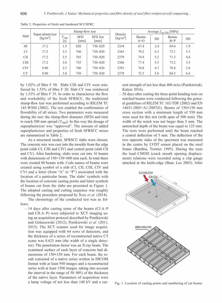
As a structural model, SFRSCC slabs were chosen. The concrete mix was cast into the moulds from the edge point (slab CI, CIII and CIV) and central point (slab CII and CV). After hardening, slabs were cut into 16 beams with dimensions of 150×150×600 mm each. In total there were created 80 beams with. Code names of beams were created using symbol of a slab (CI, CII, CIII, CIV and CV) and a letter (from “A” to “P”) associated with the location of a particular beam. The slabs’ symbols with the location of concrete casting points and letter symbols of beams cut from the slabs are presented in Figure 1. The adopted casting and cutting sequence was roughly following the procedure proposed by Švec et al. (2014).
The chronology of the conducted test was as fol-lows:
– 14 days after casting some of the beams (CI.A–P and CII.A–P) were subjected to XCT imaging us-ing an acquisition protocol described by Ponikiewski and Gołaszewski (2012), Ponikiewski et al. (2011, 2015). The XCT scanner used for image acquisi-tion was equipped with 64 rows of detectors, and the thickness of a series of reconstructed native CT scans was 0.625 mm (the width of a single detec-tor). The penetration factor was an X-ray beam. The examined surface of each layer of concrete had di-mensions of 150×150 mm. For each beam, the re-sult consisted of a native series written in DICOM format with at least 950 images and a reconstructed series with at least 1500 images, taking into account the interval in the range of 50–80% of the thickness of the native layer. Parameters of acquisition were a lamp voltage of not less than 140 kV and a cur-
rent strength of not less than 400 mAs (Ponikiewski, Katzer 2016).
– 28 days after casting the three-point bending tests on notched beams were conducted following the gener-al guidelines of RILEM TC 162-TDF (2002) and EN 14651:2005+A1:2007(E). Beams of 150×150 mm cross section with a minimum length of 550 mm were used for this test (with span of 500 mm). The width of the notch was not larger than 5 mm. The unnotched depth of the beam was equal to 125 mm. The tests were performed until the beam reached a central deflection of 5 mm. The deflection of the two opposite sides of the specimen was measured in the centre by LVDT sensor placed on the steel frame (Banthia, Trottier 1995). During the tests the load–CMOD (crack mouth opening displace-ment) relations were recorded using a clip gauge attached at the knife-edge (Baar, Lee 2003). After
Table 2. Properties of fresh and hardened SCCSFRC
Slab Super-plasticizer [kg/m3]
Slump-flow testDensity [kg/m3]
Average fcm,28d [MPa]T500[s]
SFD SFD lim [mm] [mm]
Beams A÷O SD Beams
B÷P SD
00 17.2 1.5 820 730–820 2334 67.4 2.4 69.4 1.9CI 17.2 2.5 760 730–820 2363 79.2 6.3 72.1 5.3CII 17.2 2.5 765 730–820 2379 74.9 5.2 71.3 4.6CIII 17.2 2.0 755 730–820 2386 77.4 5.5 73.2 3.5CIV 9.80 2.5 740 730–820 2391 74.8 4.7 78.4 2.8CV 9.80 3.0 730 730–820 2378 72.3 5.8 84.5 6.4
Fig. 1. Location of casting points and numbering of cut beams

Journal of Civil Engineering and Management, 2017, 23(5): 604–612 607
the three-point bending test, the beams were cut into 150×150×150 mm cubes and the compressive strength was tested. The compressive tests were per-formed using 3000 kN hydraulic compression test-ing machine with a constant strain rate
– 30 days after casting, some of the beams (CIII.A–P to CV.A–P) destroyed during three-point bending tests, were subjected to DIA. Specimens were prepared by cutting the beams in two and taking digital pictures of the achieved cross-sections. In order to assess the distribution of steel fibres, a special programme was adopted (Ponikiewski, Gołaszewski 2012) which de-fines the cut fibres’ ends and describes their position in the specimen. The computing procedure consists of: creation of a virtual table of colours, elimination of those meshes which represent the values under the assumed limit, transformation of the table of col-ours into logic values (0 or 1), filling and rounding the contours of fibres and highlighting the results of image analysis (the values determining the amount of fibres present in every square are generated).
2. Test results and discussion
Test results of average compressive strength of SFRSCC and values of standard deviation (SD) associated with them are presented in Table 2. The average compres-sive strength of SCC matrix was equal to 67.4 MPa and 69.4 MPa (fulfilling requirements for concrete strength class C50/60 according to EN 206-1). SFRSCCs were characterized by average compressive strength ranging from 71.3 MPa to 84.5 MPa (fulfilling requirements for concrete strength class from C55/67 to C60/75 accord-ing to EN 206-1). The increase of the average compres-sive strength, comparing to SCC matrix, was from 2.7% to 21.7%. Exemplary load–CMOD curves for beams cut from slabs CI, CIII and CV are presented in Figures 2–4.
The behaviour of SCC matrix specimens (slab 00) is typical for brittle material, with almost linear pre-peak parts of the load–CMOD curves. In the post-peak parts of the curves, the rapid decrease in load with increasing deflection was observed. In case of reinforced beams, the length of steel fibres did not significantly influence the flexural behaviour of the tested beams. The maximum load is observed in CCP (F 20 fibres – beams CIII.A and CIII.B) and increases with the growing distance from the CCP (F 50 fibres – beams CI.J, CI.K, CI.L, CI.M, CII.A, and CII.B, F 35 fibres – beams CV.O and CV.P, and F 20 fibres – beams CIV.O and CIV.P). Generally, the specimens with fibres F 50 show higher maximum load than those with fibres F 20 and F 35. This dependency increases as the distance from the CCP increases. The largest deflection at the maximum load (0.82 mm), was noted for specimens with fibres F 50 – slab CII (beams CII.A and CII.D) and slab CI (beam CI.A). The deflec-tion at the maximum load in these cases was equal to 0.81 mm. The post-peak part of the load–CMOD curve differs greatly between three types of fibres. The beams
Fig. 2. Load–CMOD curves of beams cut from slab CI (F 50, Vf = 1.0%)
Fig. 3. Load–CMOD curves of beams cut from slabs CIII (F 20, Vf = 1.5%)

608 T. Ponikiewski, J. Katzer. Mechanical properties and fibre density of steel fibre reinforced self-compacting...
CIII.A and CIII.B (with F 20 fibres) and beams CV.O and CV.P (with F 35 fibres) show a gradual decrease in load after achieving the peak load. The beams CIII.C–CIII.P (with F 20 fibres) show a sudden drop in load after the peak load.
The flexural tensile strength σcc was obtained on notched beams according to RILEM TC 162-TDF (2002), EN 14651:2005+A1:2007(E) and following the work of other researchers (Akcay, Tasdemir 2012; Kang et al. 2010). It was calculated using the following equation:
( )20
3
2max
ccP L
b h aσ =
−, (1)
where: Pmax – maximum load; L, b, h – span, width, depth of a beam; a0 – notch depth.
During the flexural tensile strength tests multiple pa-rameters of SFRSCC were determined:
– flexural tensile strength at the limit of proportional-ity (fct,L – EN 14651:2005+A1:2007(E));
– residual flexural tensile strengths (fR,1, fR,2, fR,3 and fR,4 – EN 14651:2005+A1:2007(E));
– equivalent tensile strengths (feq,2, feq,3 – RILEM TC 162-TDF 2002).In case of tested composites the type of steel fibre
and distance from the CCP have a pronounced effect on the post-peak parameters. For almost all tested beams, the F 50 and F 35 steel fibres are more effective in improv-ing the post-peak parameters than the F 20 fibres. Bar-ros et al. (2005) suggested a linear relationship between the equivalent tensile strengths feq,2 and feq,3 while testing SFRC characterized by compressive strength greater than 25 MPa and reinforced by hooked steel fibre (l/d = 80 and l/d = 65) from 0.125% to 0.5%. A linear trend between feq,2 and feq,3 was also obtained by the authors. The value of feq,3 is ranging from 48% to 89% of feq,2. These rela-tions are presented in Figure 5.
Only in case of slab CII the value of feq,3/feq,2 ratio (89%) is close to these achieved by Barros et al. (2005) (ratio 99%). It means that up to the deflection δ3, the energy absorption capacity of tested SFRSCC is smaller
than the energy absorption capacity of SFRC created by Barros et al. (2005).
Contrary to SFRC cast by Barros et al. (2005), in case of tested SFRSCC one cannot assume that the observations attributable to feq,2 can be also applied to feq,3. Further considerations made by Barros et al. (2005) also suggested a linear trend between fR,1 and fR,4 (with fR,4 being at 93% of fR,1). The residual flexural tensile strength fR,4 of SFRSCC in question is from 20% to 59% of fR,1 (see Fig. 6). The scatter in the feq,3–feq,2 and fR,1– fR,4 relationships is clearly visible while analysing value of R2. It was ranging from 0.734 to 0.980 and 0.196 to 0.861 for the feq,3–feq,2 and fR,1–fR,4 relationships respec-tively. The value of R2 achieved by Barros et al. (2005) for SFRC was equal to 0.933 for feq,3– feq,2 and 0.821 for fR,1–fR,4 relationships.
Fig. 4. Load–CMOD curves of beams cut from slabs CV (F 35, Vf = 1.5%)
Fig. 5. Relationship between equivalent flexural tensile strengths feq,2 and feq,3
Fig. 6. Relationship between residual flexural tensile strengths fR,1 and fR,4

Journal of Civil Engineering and Management, 2017, 23(5): 604–612 609
It indicates that fR parameters of both types of fibre composites (SFRC and SFRSCC) are more susceptible to local irregularities of the F–δ curve. Comparing the R2 values for SFRC and SFRSCC one can see that for feq,3–feq,2 relationships between both types of fibre com-posite are characterised by similar scatter. The scatter for fR,1–fR,4 relationships is much higher for SFRSCC (in some cases 4 times larger than for SFRC). In general the relationship between residual and equivalent flexural tensile strengths for SFRSCC is similar, but noticeably different from the one obtained by Barros et al. (2005)
for SFRC. In case of feq,3–feq,2 and fR,1–fR,4 relationships, Barros et al. (2005) achieved following equations:
feq,3 = 0.9926 · feq,2; (2)
fR,4 = 0.926 · fR,1. (3)
For the tested SFRSCCs, in case of feq,3–feq,2 rela-tionship the value of linear function ranges from 0.48 to 0.89, in case of fR,1–fR,4 relationship the value of linear function ranges from 0.205 to 0.590. Thus both sets of
Fig. 7. Residual strengths fR,1 and fR,4 versus fibre density at the fracture surfaces

610 T. Ponikiewski, J. Katzer. Mechanical properties and fibre density of steel fibre reinforced self-compacting...
relationships characterizing SFRCC are less steep than those describing SFRC created by Barros et al. (2005).
The last stage of the research programme consisted of DIA and XCT tests on beams. DIA test was based on scanning polished surfaces of cross-sections of cut beams. At first the analysed part of the digital image was delineated and virtual palette of colours was created. Sec-ondly the palette of colours was transformed into logic table containing only “0” or “1”. In this way part of steel fibres were identified. In case of XCT method X-ray com-puted tomography scanner was harnessed to scan whole beams. The utilized scanner was equipped with 64 rows of detectors, 140 kV lamp voltage and 400 mA current strength. The penetration factor was an X-ray beam. For each tested beam the result consisted of 950 images writ-ten in DICOM (Digital Imaging and Communications in Medicine) format. Acquired images were processed by in-house built software. Both methods and performed fibre density computing following the testing procedure was thoroughly described by Ponikiewski et al. (2011, 2015) and Rudzki et al. (2013). In Figure 7 plots of the residual strengths fR,1 and fR,4 against the fibre density on the fracture surfaces (measured by DIA and XCT) are presented. As expected, a good relationship was found between these parameters. Both residual strengths in-crease with fibre density.
Comparing those strengths for pairs of slabs CI – CII and CIII – CIV one may note that slabs cast using cen-tral CCP are characterized by smaller scatter. Fibre den-sity and strength class calculated according to “fib Model Code 2010” are presented in Table 3. The strength class consists of two symbols – a number (from 1.0 to 8.0) and a letter (“a”, “b”, “c” or “d”). The number defines the strength interval in MPa – namely residual strength fR1k. The letter corresponds to the residual strength ratio fR3k/fR1k ranging from 0.5 to 1.4 and representing most com-mon cases of softening of fibre reinforced concrete. One has to keep in mind that both residual strengths are de-termined according to EN 14651:2005+A1:2007(E). The residual strengths fR1k and fR3k characterize the SFRC re-sidual strength for SLS and ULS calculations respectively (di Prisco et al. 2009).
Only in case of slab CII all 16 individual beams could be described using strength class ranging from 3a to 6b. The average strength class (calculated using all results) is 5b. Slab CI differentiated from CII only by
location of CCP is characterized by 6a average strength class but only 10 individual beams could be described us-ing strength class (ranging from 4a to 7a). Only one beam cut from slabs CIII and CIV (reinforced by the shortest of the used fibre F20) is with strength class. This phe-nomenon is notable because the volume of fibre in slabs CIII and CIV is higher (Vf = 1.5%) than in slabs CI and CII (Vf = 1.0%). Fibre density is also higher in slabs CIII and CIV (0.93 № fibres/cm2 and 0.87 № fibres/cm2, re-spectively) than in slabs CI and CII (0.61 № fibres/cm2 and 0.53 № fibres/cm2 respectively). A similar situation is taking place in case of fibre F 35. Slab CV (Vf = 1.5%) is characterized by average strength class of 4a which is lower than strength classes of slabs CI and CII which are reinforced by smaller volume of fibre. Strength class-wise it can be stated that longer fibre is better for reinforc-ing SFRCSCC. Central location of CCP allows achiev-ing more homogenised composites characterized by more uniform strength properties. It is worth noticing that in case of slab CI with strength class 6a and slab CII with strength class 5b the densities of fibre at the fracture sur-faces are equal to 0.61 № fibres/cm2 and 0.53 № fibres/cm2, respectively.
Conclusions
The following conclusions can be drawn based on the experimental data obtained during this investigation:
– The location of CCP influences fibre distribution in the cast SFRSCC slabs. In case of tested compos-ites central location of CCP allows to achieve more homogenised composites characterized by more uni-form strength properties.
– The length of steel fibres and distance from the CCP have noticeable effects on the post-peak behaviour of SCC flexural beams. The deflection-hardening re-sponse was observed in the case of SCC reinforced with F 50 steel fibres.
– The relationship between the residual and equivalent tensile strengths proposed by Barros et al. (2005) for SFRC was not confirmed for the tested SFRSCC.
– The density of fibres, achieved through DIA and XCT methods, proportionally reflects residual strength characteristics of all tested SFRSCCs.
– Fibre type influences fibre density and variation of achieved density.
Table 3. Fibre density and strength class in compliance to “fib Model Code 2010”
Slab Fibre density [№ fibres/cm2]
Average strength class
Beams with strength class
Beams without strength class
Reinforcement substitution
CI 0.61 6a 10 4 enabledCII 0.53 5b 16 0 enabledCIII 0.93 – 0 16 disabledCIV 0.87 – 1 15 disabledCV 0.57 4a 10 6 enabled

Journal of Civil Engineering and Management, 2017, 23(5): 604–612 611
– SFRSCCs with fibre F20 were characterized by the largest variation of fibre density (ranging from 0.5 to 1.5).
– SFRSCCs with fibre F35 were characterized by the smallest variation of fibre density (ranging from 0.4 to 0.7).
References Akcay, B.; Tasdemir; M. A. 2012. Mechanical behaviour and
fibre dispersion of hybrid steel fibre reinforced self-com-pacting concrete, Construction and Building Materials 28(1): 287–293.
https://doi.org/10.1016/j.conbuildmat.2011.08.044Baar, B. I. G.; Lee, M. K. 2013. Round-robin analysis of the
RILEM TC 162-TDF beam – bending test: Part 2 – ap-proximation of d from the CMOD response, Material Structures 36: 621–630.
https://doi.org/10.1007/BF02483282Banthia, N.; Trottier, J.-F. 1995. Test methods for flexural
toughness characterization of fiber reinforced concrete: some concerns and a propositions, ACI Materials Journal 92(1): 48–57.
Barros, J. A. O.; Cunha, V. M. C. F.; Ribeiro, A. F.; An-tunes, J. A. B. 2005. Post-cracking behavior of steel fibre reinforced concrete, Material Structures 38: 47–56.
https://doi.org/10.1007/BF02480574Boulekbache, B.; Hamrat, M.; Chemrouk, M.; Amziane, S.
2010. Flowability of fibre-reinforced concrete and its ef-fect on the mechanical properties of the material, Con-struction and Building Materials 24(9): 1664–1671.
https://doi.org/10.1016/j.conbuildmat.2010.02.025Bywalski, C.; Kamiński, M. 2011. Estimation of the bending
stiffness of rectangular reinforced concrete beams made of steel fibre reinforced concrete, Archives of Civil and Mechanical Engineering 11(3): 553–571.
https://doi.org/10.1016/S1644-9665(12)60101-0Bywalski, C.; Kamiński, M. 2013. Rheological strains in con-
crete modified with steel fibre reinforcement, Journal of Civil Engineering and Management 19(5): 656–664.
https://doi.org/10.3846/13923730.2013.803497Corinaldesi, V.; Moriconi, G. 2011. Characterization of self-
compacting concretes prepared with different fibers and mineral additions, Cement and Concrete Composites 33(5): 596–601.
https://doi.org/10.1016/j.cemconcomp.2011.03.007Destrée, X.; Mandl, J. 2008. Steel fibre only reinforced con-
crete in free suspended elevated slabs: case studies, design assisted by testing route, comparison to the latest SFRC standard documents, in Taylor Made Concrete Structures. CRC Press, 437–443.
EN 14651:2005+A1:2007(E) Test method for metallic fibre con-crete – measuring the flexural tensile strength (limit of proportionality (LOP), residual). CEN European Commit-tee for Standardization.
Ferrara, L.; Meda, A. 2006. Relationships between fibre dis-tribution, workability and the mechanical properties of SFRC applied to precast roof elements, Materials and Structures 39(4): 411–420.
https://doi.org/10.1617/s11527-010-9613-9Ferrara, L.; Ozyurt, N.; di Prisco, M. 2011. High mechanical
performance of fiber reinforced cementitious composites: the role of “casting-flow” induced fiber orientation, Mater Structures 44(1): 109–128.
https://doi.org/10.1617/s11527-010-9613-9Goremikins, V.; Šejnoha, J.; Wald, F.; Bednář, J. 2017. Analyti-
cal model of composite floors with steel fibre reinforced
concrete slab subjected to fire, Journal of Civil Engineer-ing and Management 23(2): 204–212.
https://doi.org/10.3846/13923730.2015.1027260Hedebratt, J.; Silfwerbrand, J. 2014. Full-scale test of a pile sup-
ported steel fibre concrete slab, Materials and Structures 47(4): 647–666.
https://doi.org/10.1617/s11527-013-0086-5Jiaping, L.; Changfeng, L.; Jianzhong, L.; Gong, C.; Zhiqian, Y.
2013. Study on 3D spatial distribution of steel fibers in fib-er reinforced cementitious composites through micro-CT technique, Construction and Building Materials 48: 656–661. https://doi.org/10.1016/j.conbuildmat.2013.07.052
Kang, S. T.; Lee, Y.; Park, Y. D.; Kim, J. K. 2010. Tensile frac-ture properties of an Ultra High Performance Fiber Rein-forced Concrete (UHPRFC) with steel fiber, Composite Structures 92(1): 61–71.
https://doi.org/10.1016/j.compstruct.2009.06.012Katzer, J.; Domski, J. 2012. Quality and mechanical properties
of engineered steel fibres used as reinforcement for con-crete, Construction and Building Materials 34: 243–248. https://doi.org/10.1016/j.conbuildmat.2012.02.058
Khayat, K. H.; Manai, K.; Trudel, A. 1997. In suit mechanical properties of wall elements cast using self-consolidating concrete, ACI Materials Journal 94(6): 491–500.
Kulasegaram, S.; Karihaloo, B. 2013. Fibre-reinforced, self-compacting concrete flow modelled by smooth particle hydrodynamics, Proceedings of the Institution of Civil Engineers – Engineering and Computational Mechanics 166(1): 22–31. https://doi.org/10.1680/eacm.11.00004
Laranjeira, F.; Aguado, A.; Molins, C.; Grunewald, S.; Wal-raven, J.; Cavalaro, S. 2012. Framework to predict the orientation of fibers in FRC: a novel philosophy, Cement and Concrete Research 42(6): 752–768.
https://doi.org/10.1016/j.cemconres.2012.02.013Martinie, L.; Roussel, N. 2011. Simple tools for fiber orienta-
tion prediction in industrial practice, Cement and Concrete Research 41(10): 993–1000.
https://doi.org/10.1016/j.cemconres.2011.05.008Michels, J.; Waldmann, D.; Maas, S.; Zürbes, A. 2012. Steel
fibers as only reinforcement for flat slab construction – Experimental investigation and design, Construction and Building Materials 26(1): 145–155.
https://doi.org/10.1016/j.conbuildmat.2011.06.004Okamura, H.; Ozawa, K. 1995. Mix design for self-compacting
concrete, Concrete Library International JSCE 25: 107–120.
Orbe, A.; Cuadrado, J.; Losada, R.; Rojí, E. 2012. Framework for the design and analysis of steel fiber reinforced self-compacting concrete structures, Construction and Build-ing Materials 35: 676–686.
https://doi.org/10.1016/j.conbuildmat.2012.04.135Ponikiewski, T.; Gołaszewski, J. 2012. The new approach to
the study of random distribution of fibres in high perfor-mance self-compacting concrete, Cement Wapno Beton 79: 165–176.
Ponikiewski, T.; Katzer, J. 2016. X-ray computed tomography of fibre reinforced self-compacting concrete as a tool of assessing its flexural behaviour, Materials and Structures 49(6): 2131–2140.
https://doi.org/10.1617/s11527-015-0638-yPonikiewski, T.; Cygan, G.; Kmita, T. 2011. Evaluation of ho-
mogenous distribution of steel fibres in the fine grained self-compacting concrete with help of L-box test, Cement Wapno Beton 78: 3–9.
Ponikiewski, T.; Gołaszewski, J.; Rudzki, M.; Bugdol, M. 2015. Determination of steel fibres distribution in self-compact-ing concrete beams using X-ray computed tomography, Archives of Civil and Mechanical Engineering 15(2): 558–568. https://doi.org/10.1016/j.acme.2014.08.008

612 T. Ponikiewski, J. Katzer. Mechanical properties and fibre density of steel fibre reinforced self-compacting...
Prasanth, T. N. D.; Gettu, R. 2008. On the distribution of fibres in self-compacting concrete, in Proceedings of 7th Interna-tional RILEM Symposium on Fibre Reinforced Concrete, 2008, India, Chennai, 1147–1153.
di Prisco, M.; Plizzari, G.; Vandewalle, L. 2009. Fibre rein-forced concrete: new design perspectives, Materials and Structures 42(9): 1261–1281.
https://doi.org/10.1617/s11527-009-9529-4RILEM TC 162-TDF. 2002. Test and design methods for steel
fibre reinforced concrete, final recommendations, Materi-als and Structures 35(9): 579–582.
RILEM TC 145-WSM. 2002. Workability and rheology of fresh concrete: compendium of tests, in Report of RILEM tech-nical committee TC 145-WSM. Workability of special con-cretes. Cachan: RILEM Publications.
Rudzki, M.; Bugdol, M.; Ponikiewski, T. 2013. Determination of steel fibers orientation in SCC using computed tomog-raphy and digital image analysis methods, Cement Wapno Beton 80: 257–263.
Salehian, H.; Barros, J. A. O. 2015. Assessment of the perfor-mance of steel fibre reinforced self-compacting concrete in
elevated slabs, Cement and Concrete Composites 55: 268–280. https://doi.org/10.1016/j.cemconcomp.2014.09.016
Sorelli, L. G.; Meda, A.; Plizzari, G. A. 2006. Steel fiber con-crete slabs on ground: a structural matter, ACI Structural Journal 103(4): 551–558.
Stähli, P.; Custer, R.; Mier, J. G. M. 2007. On flow properties, fibre distribution, fibre orientation and flexural behaviour of FRC, Materials and Structures 41(1): 189–196.
https://doi.org/10.1617/s11527-007-9229-xŠvec, O.; Žirgulis, G.; Bolander, J. E.; Stang, H. 2014. Influence
of formwork surface on the orientation of steel fibres with-in self-compacting concrete and on the mechanical prop-erties of cast structural elements, Cement and Concrete Composites 50: 60–72.
https://doi.org/10.1016/j.cemconcomp.2013.12.002Zerbino, R.; Tobes, J. M.; Bossio, M. E.; Giaccio, G. 2012. On
the orientation of fibres in structural members fabricated with self-compacting fibre reinforced concrete, Cement and Concrete Composites 34(2): 191–200.
https://doi.org/10.1016/j.cemconcomp.2011.09.005
Tomasz PONIKIEWSKI. DSc, PhD qualified, highly experienced technologist of concrete. He has wide experience as a concrete researcher, mix designer and concrete technology lecturer. His main research fields include the rheology of cement-based materials, the use of fibres in concrete and the technology of high performance concrete, self-compacting concrete, Non Destructive Testing of Concrete (wide range of different methods), designing concrete mixtures, concrete and mortar mixes based on waste materials (high-calcium fly ash, waste steel fibre). Currently working as a Assistance Professor at Silesian University of Technology in Poland.
Jacek KATZER. DSc, PhD qualified, highly experienced technologist of concrete. He has wide experience as a concrete researcher, mix designer, quality controller of concrete production (both ready-mix and precast elements) and concrete technology lecturer. Areas in which he scientifically specializes are: Steel Fibre Reinforced Concrete (SFRC), Non Destructive Testing of Concrete (wide range of different methods), designing concrete mixtures, concrete and mortar mixes based on waste materials (e.g. waste sand, raw silica fume, waste steel fibre, recycled aggregate). Currently working as a professor of Koszalin University of Technology in Poland.