1stReading - Lirias
19
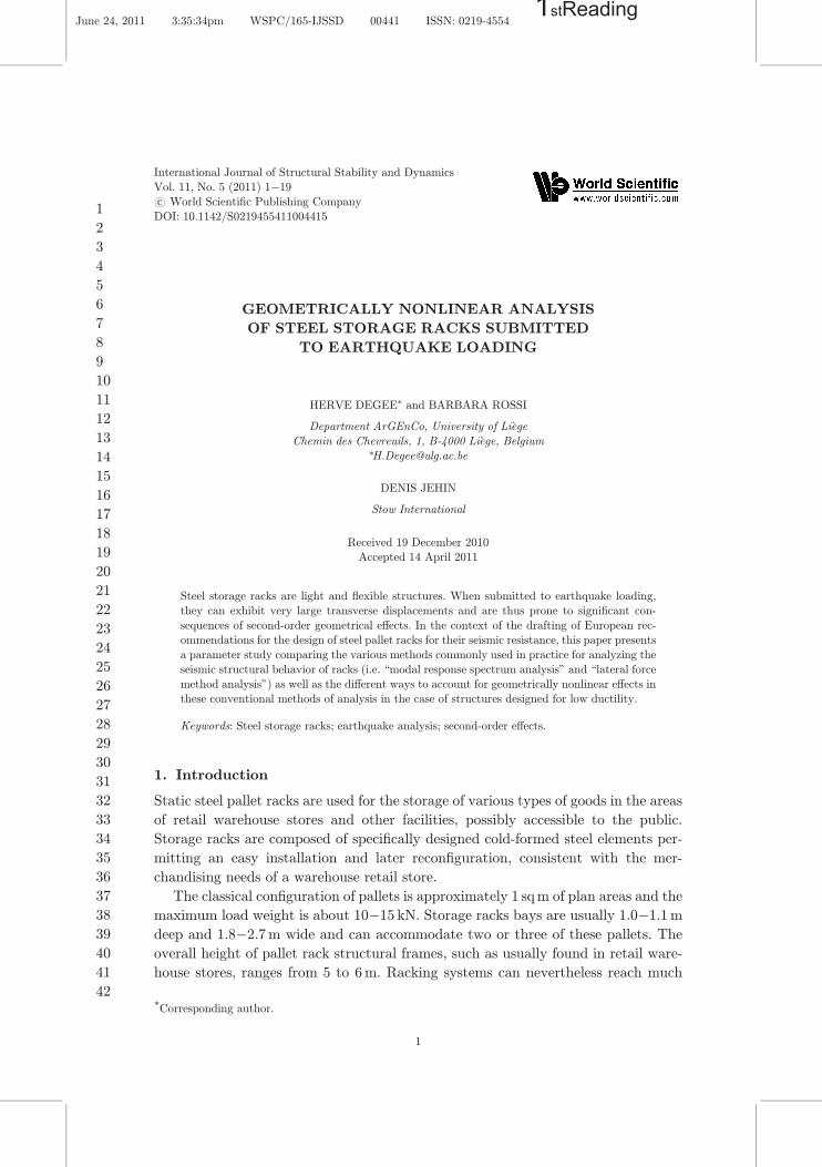
GEOMETRICALLY NONLINEAR ANALYSIS OF STEEL STORAGE RACKS SUBMITTED TO EARTHQUAKE LOADING HERVE DEGEE * and BARBARA ROSSI Department ArGEnCo, University of Li ege Chemin des Chevreuils, 1, B-4000 Li ege, Belgium * [email protected] DENIS JEHIN Stow International Received 19 December 2010 Accepted 14 April 2011 Steel storage racks are light and °exible structures. When submitted to earthquake loading, they can exhibit very large transverse displacements and are thus prone to signi¯cant con- sequences of second-order geometrical e®ects. In the context of the drafting of European rec- ommendations for the design of steel pallet racks for their seismic resistance, this paper presents a parameter study comparing the various methods commonly used in practice for analyzing the seismic structural behavior of racks (i.e. \modal response spectrum analysis" and \lateral force method analysis") as well as the di®erent ways to account for geometrically nonlinear e®ects in these conventional methods of analysis in the case of structures designed for low ductility. Keywords: Steel storage racks; earthquake analysis; second-order e®ects. 1. Introduction Static steel pallet racks are used for the storage of various types of goods in the areas of retail warehouse stores and other facilities, possibly accessible to the public. Storage racks are composed of speci¯cally designed cold-formed steel elements per- mitting an easy installation and later recon¯guration, consistent with the mer- chandising needs of a warehouse retail store. The classical con¯guration of pallets is approximately 1 sq m of plan areas and the maximum load weight is about 1015 kN. Storage racks bays are usually 1.01.1 m deep and 1.82.7 m wide and can accommodate two or three of these pallets. The overall height of pallet rack structural frames, such as usually found in retail ware- house stores, ranges from 5 to 6 m. Racking systems can nevertheless reach much * Corresponding author. International Journal of Structural Stability and Dynamics Vol. 11, No. 5 (2011) 119 # . c World Scienti¯c Publishing Company DOI: 10.1142/S0219455411004415 1 June 24, 2011 3:35:34pm WSPC/165-IJSSD 00441 ISSN: 0219-4554 1stReading 1 2 3 4 5 6 7 8 9 10 11 12 13 14 15 16 17 18 19 20 21 22 23 24 25 26 27 28 29 30 31 32 33 34 35 36 37 38 39 40 41 42
-
Upload
khangminh22 -
Category
Documents
-
view
1 -
download
0
Transcript of 1stReading - Lirias
GEOMETRICALLY NONLINEAR ANALYSIS
OF STEEL STORAGE RACKS SUBMITTED
TO EARTHQUAKE LOADING
HERVE DEGEE* and BARBARA ROSSI
Department ArGEnCo, University of Li�ege
Chemin des Chevreuils, 1, B-4000 Li�ege, Belgium*[email protected]
DENIS JEHIN
Stow International
Received 19 December 2010Accepted 14 April 2011
Steel storage racks are light and °exible structures. When submitted to earthquake loading,
they can exhibit very large transverse displacements and are thus prone to signi¯cant con-
sequences of second-order geometrical e®ects. In the context of the drafting of European rec-ommendations for the design of steel pallet racks for their seismic resistance, this paper presents
a parameter study comparing the various methods commonly used in practice for analyzing the
seismic structural behavior of racks (i.e. \modal response spectrum analysis" and \lateral force
method analysis") as well as the di®erent ways to account for geometrically nonlinear e®ects inthese conventional methods of analysis in the case of structures designed for low ductility.
Keywords: Steel storage racks; earthquake analysis; second-order e®ects.
1. Introduction
Static steel pallet racks are used for the storage of various types of goods in the areas
of retail warehouse stores and other facilities, possibly accessible to the public.
Storage racks are composed of speci¯cally designed cold-formed steel elements per-
mitting an easy installation and later recon¯guration, consistent with the mer-
chandising needs of a warehouse retail store.
The classical con¯guration of pallets is approximately 1 sqm of plan areas and the
maximum load weight is about 10�15 kN. Storage racks bays are usually 1.0�1.1m
deep and 1.8�2.7m wide and can accommodate two or three of these pallets. The
overall height of pallet rack structural frames, such as usually found in retail ware-
house stores, ranges from 5 to 6m. Racking systems can nevertheless reach much
*Corresponding author.
International Journal of Structural Stability and DynamicsVol. 11, No. 5 (2011) 1�19
#.c World Scienti¯c Publishing Company
DOI: 10.1142/S0219455411004415
1
June 24, 2011 3:35:34pm WSPC/165-IJSSD 00441 ISSN: 0219-45541stReading
1
2
3
4
5
6
7
8
9
10
11
12
13
14
15
16
17
18
19
20
21
22
23
24
25
26
27
28
29
30
31
32
33
34
35
36
37
38
39
40
41
42
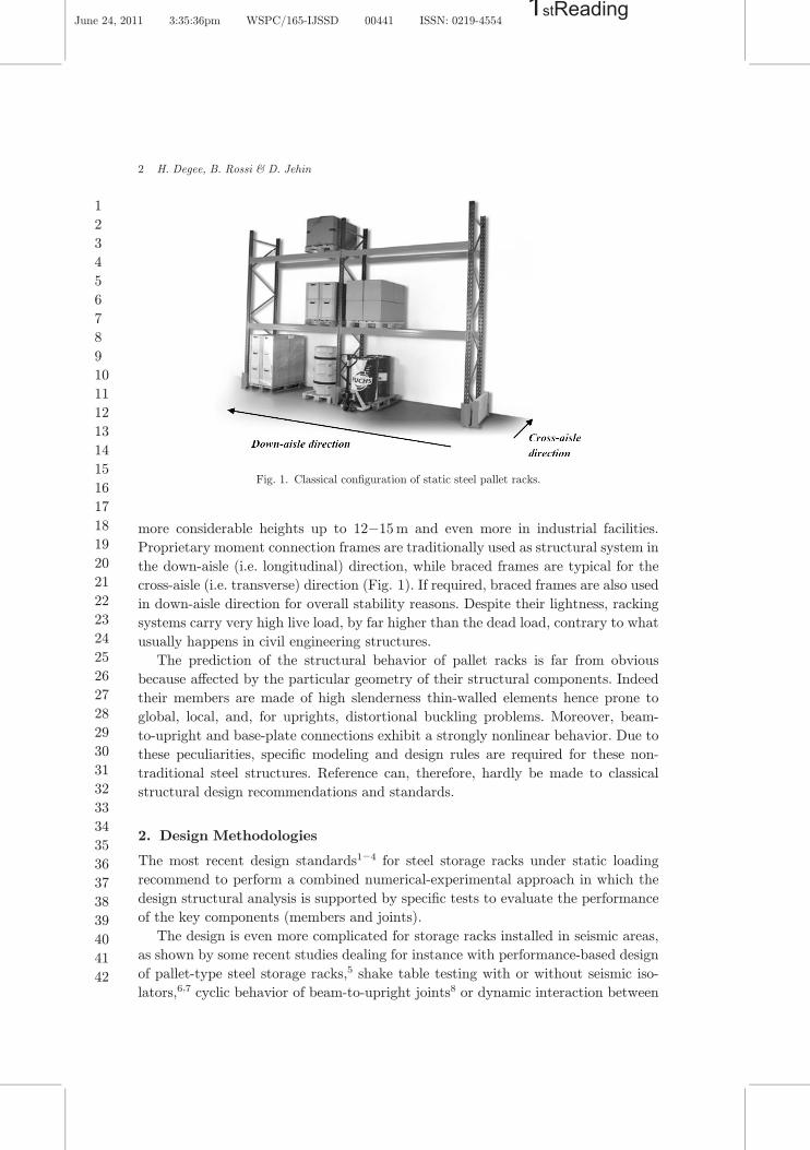
more considerable heights up to 12�15m and even more in industrial facilities.
Proprietary moment connection frames are traditionally used as structural system in
the down-aisle (i.e. longitudinal) direction, while braced frames are typical for the
cross-aisle (i.e. transverse) direction (Fig. 1). If required, braced frames are also used
in down-aisle direction for overall stability reasons. Despite their lightness, racking
systems carry very high live load, by far higher than the dead load, contrary to what
usually happens in civil engineering structures.
The prediction of the structural behavior of pallet racks is far from obvious
because a®ected by the particular geometry of their structural components. Indeed
their members are made of high slenderness thin-walled elements hence prone to
global, local, and, for uprights, distortional buckling problems. Moreover, beam-
to-upright and base-plate connections exhibit a strongly nonlinear behavior. Due to
these peculiarities, speci¯c modeling and design rules are required for these non-
traditional steel structures. Reference can, therefore, hardly be made to classical
structural design recommendations and standards.
2. Design Methodologies
The most recent design standards1�4 for steel storage racks under static loading
recommend to perform a combined numerical-experimental approach in which the
design structural analysis is supported by speci¯c tests to evaluate the performance
of the key components (members and joints).
The design is even more complicated for storage racks installed in seismic areas,
as shown by some recent studies dealing for instance with performance-based design
of pallet-type steel storage racks,5 shake table testing with or without seismic iso-
lators,6,7 cyclic behavior of beam-to-upright joints8 or dynamic interaction between
Fig. 1. Classical con¯guration of static steel pallet racks.
2 H. Degee, B. Rossi & D. Jehin
June 24, 2011 3:35:36pm WSPC/165-IJSSD 00441 ISSN: 0219-45541stReading
1
2
3
4
5
6
7
8
9
10
11
12
13
14
15
16
17
18
19
20
21
22
23
24
25
26
27
28
29
30
31
32
33
34
35
36
37
38
39
40
41
42
the rack structure and the stored goods.9 In particular, it is worth mentioning a
research project funded by the European Commission from 2004 to 2007 that covered
a wide amount of topics10: cyclic behavior of connections, sliding of pallets, assess-
ment of behavior factors, etc.
Conventional seismic design of structures implies the veri¯cation of two types of
limit states: (i) ultimate limit states (ULS), associated with the structure collapse or
with other forms of structural failure that may endanger the safety of people and (ii)
damage limitation states (DLS) associated with damage beyond which the speci¯ed
requirements are no longer met. In general, ULS are based on resistance veri¯cation
whereas DLS are related to displacements limitation. According to a decision of the
FEM 10.2.0811 drafting committee (European Recommendations for the design of
racks under seismic conditions), DLS have been replaced by a posteriori assessment
of damage, meaning that DLS no longer need to be considered in the design. In fact,
after a seismic event, the damages caused by the earthquake to the structural
elements must be assessed before continuing the usage of the rack. In practice, it
results in no sway displacements limitation under seismic action. Moreover, since
rack structures are highly °exible, ULS requirements (stability and resistance) can be
ful¯lled even if sway displacements are signi¯cant. However, this requires of course
that the second-order geometrical e®ects be duly taken into account in the global
structural analysis. Currently, static steel pallet racks can be considered as part of
the most °exible structures constructed nowadays, in particular for what concerns
the down-aisle behavior.
Under static conditions, the designer may refer to EN155122 for instance, where it
is stated that a second-order analysis must be performed or, alternatively, that a
¯rst-order analysis may be used, provided internal forces be ampli¯ed by an
appropriate coe±cient (in a similar way to the ampli¯ed sway moment method of the
Eurocode 3).
The situation is somehow di®erent under seismic action because of two main
reasons:
(1) Seismic action on a given structure depends on the dynamic properties of this
structure and in particular on its ¯rst natural period of vibration. The geo-
metrical second order e®ects tend to decrease the average lateral sti®ness of the
structure, leading to increased values of the period. In the usual range of periods
for racks (see Sec. 4), the spectral acceleration — and consequently the seismic
action on structure — decreases when the period increases. Therefore, the
second-order geometrical e®ects are likely to reduce the action applied by the
earthquake to the rack.
(2) When assessing the safety level of structures submitted to static loading, it is
implicitly supposed that all loads (i.e. vertical and horizontal) increase in a
proportional way. In other words, increasing horizontal loads are applied on a
structure whose lateral sti®ness is progressively degraded due to the increasing
compressive loads acting vertically. On the contrary, in the event of an
Geometrically Nonlinear Analysis of Steel Storage Racks 3
June 24, 2011 3:35:38pm WSPC/165-IJSSD 00441 ISSN: 0219-45541stReading
1
2
3
4
5
6
7
8
9
10
11
12
13
14
15
16
17
18
19
20
21
22
23
24
25
26
27
28
29
30
31
32
33
34
35
36
37
38
39
40
41
42
earthquake, the seismic safety is assessed by considering ¯rst the vertical gravity
loads and second the horizontal loads representative of the seismic action. The
°exibility of the structure is thus higher than the one of the nonloaded structures
but is considered constant during the whole seismic event.
These two statements evidence the fact that the second-order geometrical e®ects
should be treated in a di®erent way for earthquake loading than for normal static
loading.
In practice, regarding rack structures, two main references are available:
(1) Very recently, the American Rack Manufacturer Institute (RMI) has issued an
update of its document \Speci¯cation for the Design, Testing, and Utilization of
Industrial Steel Storage Racks".1 These recommendations obviously require a
due account for the second-order e®ects and, regarding the earthquake situation,
make reference to the FEMA 46012 report. In this report, it is suggested to carry
out a ¯rst-order analysis then to account for P-Delta e®ects by amplifying the
results. The ampli¯cation factor depends on the rotational sti®ness of the beam-
to-upright and base plate connections. This approach is, therefore, implicitly
dedicated to unbraced frame structures.
(2) In Europe, the main document is the draft version of FEM 10.2.08
\Recommendations for the design of static steel pallet racks under seismic con-
ditions" issued by the European Racking Federation. The recommendations of
this document are mainly based upon the philosophy of EN 1998-1 (Eurocode
8)13 although the peculiar dynamic behavior of racking structures and their
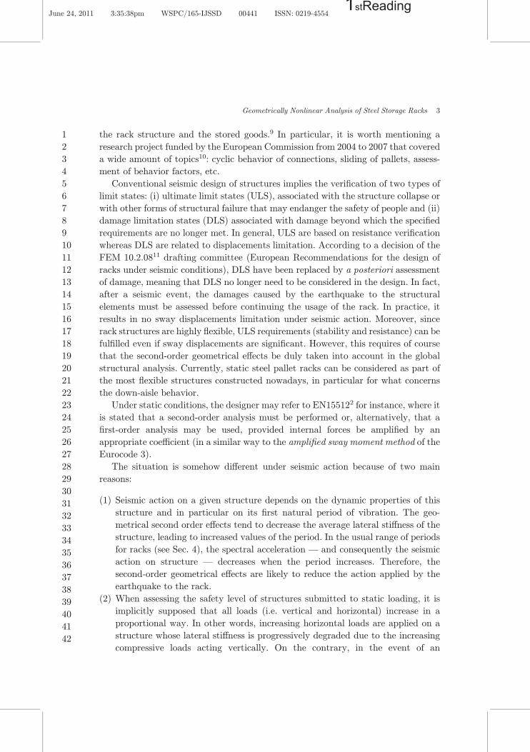
stored unit loads is included. Given that the rules take root in the Eurocode 8,
the management of the P-Delta e®ects is based on the so-called � parameter
(interstory drift sensitivity coe±cient) de¯ned according to Eq. (1) and Fig. 2.
� ¼ PtotdrVtoth
ð1Þ
where Ptot is the total gravity load at and above the considered story; dr is the
design interstory drift evaluated as the di®erence of the average lateral dis-
placement at the top and bottom of the considered story. This displacement is
Fig. 2. Parameters used to calculate the interstory drift sensitivity coe±cient �.
4 H. Degee, B. Rossi & D. Jehin
June 24, 2011 3:35:39pm WSPC/165-IJSSD 00441 ISSN: 0219-45541stReading
1
2
3
4
5
6
7
8
9
10
11
12
13
14
15
16
17
18
19
20
21
22
23
24
25
26
27
28
29
30
31
32
33
34
35
36
37
38
39
40
41
42
obtained using a ¯rst-order elastic analysis and multiplied by the behavior factor
q considered in the design; Vtot is the total seismic story shear; and h is the
interstory height.
It is reminded that the behavior factor q accounts for energy dissipation in the
structure through a reduction of the elastic spectrum (see also Sec. 4). According to
FEM 10.2.08, this factor ranges between 1.5 and 4 for rack structures, according to
the choice of nondissipative or dissipative designs and to the structural typology.
The parameter � is thus characteristic of each story and should be managed in a
di®erentiated way for each level. In practice, a conservative approach consisting in
considering a single value of � for the whole structure (i.e. the highest obtained from
the whole set of stories) is often followed.
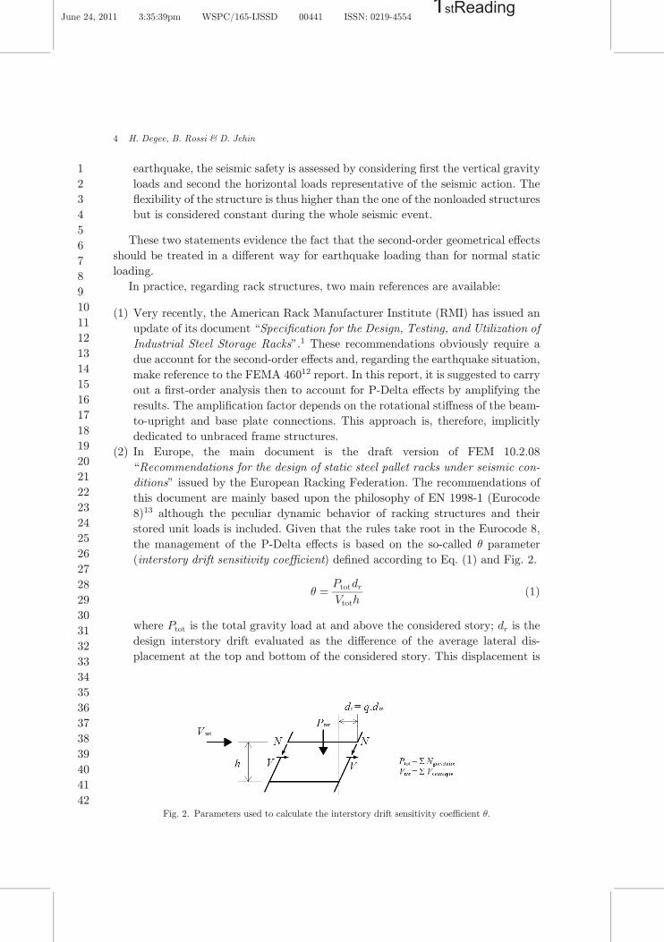
According to the Eurocode 8, the consequences on the structural analysis corre-
sponding to a given range of � can be summarized as in Table 1(a). However, in view
of the usual values of � obtained for rack structures (see Sec. 4), Table 1(a) has been
quali¯ed as highly severe by rack designers and producers. In particular, the absolute
upper limit of 0.30 was proven to be a very strong design criterion implying sig-
ni¯cant longitudinal bracings to ful¯ll this requirement only. Therefore, the limit
values have been adapted in FEM 10.2.08 leading to Table 1(b). Additionally, if the
structure is designed to behave elastically under seismic action — following Euro-
code 8 principles, it means that the structure is designed according to DCL concept
(ductility class low), resulting in a behavior factor q ranging between 1.5 and 2.0,
FEM 10.2.08 allows to use the \ampli¯ed ¯rst-order method" up to � ¼ 0:50.
Table 1(a). Impact of � values on the structural analysis according to Eurocode 8.
� value Consequences
� � 0:10 Second-order e®ects do not need to be taken into account
0:10 < � � 0:20 Second-order e®ects may approximately be taken into account
by multiplying the relevant seismic action by a factor equal to 1=ð1� �Þ0:20 < � � 0:30 Design action e®ects must be obtained by a nonlinear method of analysis
(\pushover" or nonlinear time-history analysis)
� > 0:30 Not allowed
Table 1(b). Impact of � values on the structural analysis according to FEM 10.2.08.
� value Consequences
� � 0:10 Second-order e®ects do not need to be taken into account
0:10 < � � 0:30 Second-order e®ects may approximately be taken into account by multiplyingthe relevant seismic action obtained from a ¯rst-order analysis
by a factor equal to 1=ð1� �Þ0:30 < � � 0:50 Design action e®ects must be obtained by a nonlinear static method
of analysis (\pushover" analysis)
� > 0:50 Time-history analysis including large displacements and nonlinear behavior
of material and connections is required
Geometrically Nonlinear Analysis of Steel Storage Racks 5
June 24, 2011 3:35:41pm WSPC/165-IJSSD 00441 ISSN: 0219-45541stReading
1
2
3
4
5
6
7
8
9
10
11
12
13
14
15
16
17
18
19
20
21
22
23
24
25
26
27
28
29
30
31
32
33
34
35
36
37
38
39
40
41
42
3. Objectives
The study presented in this paper takes place in the above general context, the aim of
which is assessing the prescriptions proposed in FEM 10.2.08. More precisely, the
paper deals with down-aisle frames and follows three de¯nite objectives:
(1) Evaluate the sensitivity parameter � for rack structures such as designed in
practice;
(2) Evaluate the actual impact of the second-order e®ects in seismic context for such
°exible structures; and
(3) Compare di®erent methods of global analysis and, in particular, assess the
accuracy of the simpli¯ed approach proposed by FEM 10.2.08 for intermediate
values of �.
The results presented herein constitute the ¯rst part of the study and deal with
analyses in the elastic domain. The geometrical second-order e®ects (P-Delta) are
considered independently of any material nonlinearities or plastic dissipation. These
results have been elaborated in the frame of a master thesis realized at the University
of Liège.14 The interaction between the sensitivity factor � and the behavior factor q
is currently under study and will be published later on.
Section 4 presents the elaboration of a structural database comprising nine
structures without longitudinal bracing (unbraced frame structures) and nine
structures with longitudinal bracing designed according to EN 15512 and FEM
10.2.08. For each structure, the sensitivity parameter � and the fundamental period
of vibration are evaluated. Section 5 describes the di®erent methods of elastic
analysis that will be considered for comparison purpose and Sec. 6 presents the
results obtained when applying the di®erent methods on the 18 case studies.
4. Structural Database
In the present work, only down-aisle behavior is considered. Regarding the cross-aisle
direction, structural systems of pallet racks are commonly made of Z, D or X trusses
and these systems are known to be less sensitive to second-order e®ects.
A set of 18 rack structures is designed under the following geometrical assump-
tions (see also Fig. 3):
—The pallet mass equals 0.66 tons;
—The beams are 2.7m length (three pallets per bay); the total length equals the
number of bays (NbBays) times 2.7m; and
—The cell is 1.5m height; the total height equals the number of stories (NbStories)
times 1.5m.
The seismic action is de¯ned according to the Eurocode 8.12 The fundamental period
of °exible structures and of rack structure in particular is rather high. Type 1
spectrum is thus chosen since it is characterized by a less decreasing branch in the
6 H. Degee, B. Rossi & D. Jehin
June 24, 2011 3:35:41pm WSPC/165-IJSSD 00441 ISSN: 0219-45541stReading
1
2
3
4
5
6
7
8
9
10
11
12
13
14
15
16
17
18
19
20
21
22
23
24
25
26
27
28
29
30
31
32
33
34
35
36
37
38
39
40
41
42
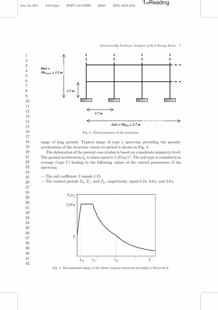
range of long periods. Typical shape of type 1 spectrum providing the pseudo-
acceleration of the structure versus its period is shown in Fig. 4.
The elaboration of the present case studies is based on a moderate seismicity level.
The ground acceleration ag is taken equal to 1.25m/s2. The soil type is considered as
average (type C) leading to the following values of the control parameters of the
spectrum:
—The soil coe±cient S equals 1.15.
—The control periods TB, TC, and TD, respectively, equal 0.2 s, 0.6 s, and 2.0 s.
Fig. 4. Recommended shape of the elastic response spectrum according to Eurocode 8.
2.7 m
1.5 m
Ltot = NbBays x 2.7 m
Htot = NbStories x 1.5 m
Fig. 3. Global geometry of the structures.
Geometrically Nonlinear Analysis of Steel Storage Racks 7
June 24, 2011 3:35:41pm WSPC/165-IJSSD 00441 ISSN: 0219-45541stReading
1
2
3
4
5
6
7
8
9
10
11
12
13
14
15
16
17
18
19
20
21
22
23
24
25
26
27
28
29
30
31
32
33
34
35
36
37
38
39
40
41
42
According to FEM 10.2.08, it is allowed to account for limited energy dissipation in
down-aisle frames submitted to earthquake provided that:
— For moment frame structures, the members contributing to the seismic resistance
of the structure by working in compression and/or bending are made of class 1–3
pro¯les.
— For braced structures, the bracings are made of class 1–3 pro¯les and composed of
diagonals acting in tension and compression (X bracings).
The above conditions are assumed to be veri¯ed in the design examples. Under these
conditions, the energy dissipation, although moderate, may be accounted for by the
use of a behavior factor q equal to 2.0 reducing the acceleration obtained from the
elastic spectrum. As a counterpart, the displacements obtained from the ¯rst-order
analysis will have to be multiplied by 2 to calculate the value of the sensitivity
parameter � (see Eq. (1)).
The set of case studies has been de¯ned to target a wide range of sensitivity
coe±cients. For this purpose, di®erent combinations of bays and stories were con-
sidered. By way of consistency, the pro¯les have been chosen in the catalog of the
Stow International company with geometrical and mechanical properties duly vali-
dated according to the EN 15512 prescriptions. Upright sections are classical rack
open sections with dimensions ranging from 85� 65mm to 120� 92mm according
to the con¯guration. Racks beams are characterized by a rectangular hollow section
realized from two C pro¯les. Their dimensions are ranging from 100� 50mm to
120� 50mm.
The beam-to-upright and upright-base connections semi-rigid properties have
also been characterized according to the same standard, including a due account for
the in°uence of the vertical compression on the sti®ness and the resistance of the
upright-base connections. Last, the properties of longitudinal X-bracings have also
been determined similarly. However, none of these properties is explicitly provided in
the present paper because of con¯dentiality reasons.
For structures without longitudinal bracings, various combinations of pro¯les for
the beams and uprights were also considered for given combinations of bays and
stories, leading to complementary structural variants.
In this design stage, the seismic structural e®ects are determined using an
ampli¯ed lateral force method (see Sec. 5 for the methodology), whatever the value
of the sensitivity coe±cient and considering the initial lateral sti®ness for the esti-
mation of the fundamental period.
Two load combinations are considered for the design checks, i.e. the weighted
gravity load and the nominal gravity load combined with the seismic action. For
both combinations, the following veri¯cations are made:
— upright stability;
— beam de°ection;
8 H. Degee, B. Rossi & D. Jehin
June 24, 2011 3:35:47pm WSPC/165-IJSSD 00441 ISSN: 0219-45541stReading
1
2
3
4
5
6
7
8
9
10
11
12
13
14
15
16
17
18
19
20
21
22
23
24
25
26
27
28
29
30
31
32
33
34
35
36
37
38
39
40
41
42
— connection resistance (beam-to-upright and upright-base); and
— bracing resistance when relevant.
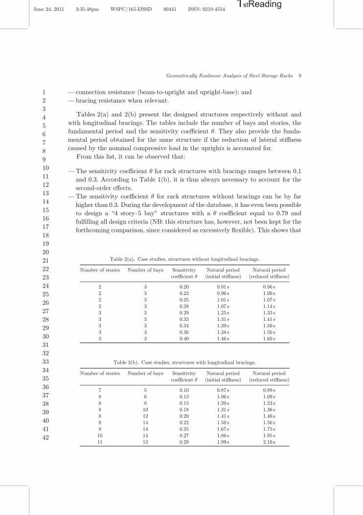
Tables 2(a) and 2(b) present the designed structures respectively without and
with longitudinal bracings. The tables include the number of bays and stories, the
fundamental period and the sensitivity coe±cient �. They also provide the funda-
mental period obtained for the same structure if the reduction of lateral sti®ness
caused by the nominal compressive load in the uprights is accounted for.
From this list, it can be observed that:
—The sensitivity coe±cient � for rack structures with bracings ranges between 0.1
and 0.3. According to Table 1(b), it is thus always necessary to account for the
second-order e®ects.
—The sensitivity coe±cient � for rack structures without bracings can be by far
higher than 0.3. During the development of the database, it has even been possible
to design a \4 story–5 bay" structures with a � coe±cient equal to 0.79 and
ful¯lling all design criteria (NB: this structure has, however, not been kept for the
forthcoming comparison, since considered as excessively °exible). This shows that
Table 2(a). Case studies, structures without longitudinal bracings.
Number of stories Number of bays Sensitivitycoe±cient �
Natural period(initial sti®ness)
Natural period(reduced sti®ness)
2 3 0.20 0.91 s 0.96 s
2 3 0.23 0.96 s 1.00 s
2 3 0.25 1.01 s 1.07 s
2 3 0.28 1.07 s 1.14 s3 3 0.29 1.25 s 1.33 s
3 3 0.33 1.31 s 1.41 s
3 3 0.34 1.39 s 1.50 s
3 3 0.36 1.38 s 1.50 s3 3 0.40 1.46 s 1.60 s
Table 2(b). Case studies, structures with longitudinal bracings.
Number of stories Number of bays Sensitivitycoe±cient �
Natural period(initial sti®ness)
Natural period(reduced sti®ness)
7 5 0.10 0.87 s 0.89 s8 6 0.13 1.06 s 1.09 s
8 8 0.15 1.20 s 1.23 s
8 10 0.18 1.31 s 1.36 s8 12 0.20 1.41 s 1.46 s
8 14 0.22 1.50 s 1.56 s
9 14 0.25 1.67 s 1.75 s
10 14 0.27 1.86 s 1.95 s11 13 0.29 1.99 s 2.10 s
Geometrically Nonlinear Analysis of Steel Storage Racks 9
June 24, 2011 3:35:48pm WSPC/165-IJSSD 00441 ISSN: 0219-45541stReading
1
2
3
4
5
6
7
8
9
10
11
12
13
14
15
16
17
18
19
20
21
22
23
24
25
26
27
28
29
30
31
32
33
34
35
36
37
38
39
40
41
42
the absolute limit on � (0.3) proposed by the Eurocode 8 can govern the design
and lead to the use of longitudinal bracings signi¯cantly increasing the structural
cost.
—Even in a situation of moderate seismicity and with a behavior factor of 2, it is
hardly possible to design a rack structure with more than three levels without
longitudinal bracings.
—The fundamental period of rack structures range between 1.0 and 2.0 s.
—The reduction of the lateral sti®ness due to compression of the uprights can lead to
a signi¯cant elongation of the fundamental period (up to 10%), even for braced
structures. Indeed, braced rack structures can actually be considered as hybrid
structures (in opposition to pure trusses) since the horizontal forces are partly
transmitted by the bracing system and partly by a frame e®ect. The loss of
bending sti®ness of the uprights due to compression consequently in°uences the
global structural sti®ness through its \frame" component. Therefore, the increase
of fundamental period also appears in the case of braced structures. This type of
hybrid resisting system is chosen by rack designers to reduce the cost by limiting
the bracings to the very necessary minimum.
5. Methods of Analysis
As previously announced in the objectives, this paper exclusively deals with struc-
tures designed for low ductility (q ¼ 1:5 to 2.0). It is thus assumed that their
behavior is elastic under seismic action.
Three classes of methods can be considered for the seismic analysis of linear elastic
structures:
(1) According to most design codes, the reference method for determining the seismic
e®ect shall be the \modal response spectrum analysis" (MRSA) using a linear
elastic model of the structure. This method provides the dynamic response of the
structure by using appropriate combinations of its natural modes of vibrations.
(2) For structures the response of which is not signi¯cantly a®ected by contributions
from modes of vibration higher than the fundamental mode in each principal
direction, it is allowed to substitute MRSA by the use of equivalent static forces
(\lateral force method of analysis" — LFMA). The conditions under which
LFMA can be used are explicitly given in most seismic codes and in the Eurocode
8 in particular.
(3) It is of course also possible to perform a dynamic time-history analysis of the
system (THA). In this case, the procedure consists in de¯ning a set of ground
motion time-histories (accelerograms) representative of the seismic action at a
given location. These accelerograms can be either natural (provided that ade-
quate databases are available) or arti¯cial. In the present paper, only arti¯cial
ground motions are considered and a set of seven time-histories compatible with
the reference spectrum of Fig. 4 is generated with the software GOSCA.15
10 H. Degee, B. Rossi & D. Jehin
June 24, 2011 3:35:49pm WSPC/165-IJSSD 00441 ISSN: 0219-45541stReading
1
2
3
4
5
6
7
8
9
10
11
12
13
14
15
16
17
18
19
20
21
22
23
24
25
26
27
28
29
30
31
32
33
34
35
36
37
38
39
40
41
42
In the case of linear elastic structures and if the three methods are used under all
the required assumptions (in particular for LFMA), the average of the structural
responses obtained using THA based on all the set of considered time-histories should
yield the same results as MRSA, while LFMA yields a reasonably safe approximation
of the response and thus slightly higher values of the displacements and internal
forces.
Coming now to geometrically nonlinear analysis, the three above methods should
appropriately be modi¯ed to account for the second-order e®ects.
5.1. MRSA
As described in Sec. 3, the main second-order e®ect in rack structures is a loss of
bending sti®ness of the uprights due to compression induced by the weight of stored
goods. It means that the earthquake action should be applied on a structure with
reduced sti®ness. A ¯rst possibility would thus be to perform a two-step procedure:
¯rst, analyze the structure submitted to the gravity loads and deduce the com-
pression level in the uprights, on the basis of which an update of their transverse
sti®ness can be carried out; second, perform an MRSA on the structure with reduced
sti®ness. This procedure is, however, not considered herein because of the following
reason: MRSA is based on a superposition of the normalized modal shapes factored
by coe±cients that depend on the modal mass (and thus indirectly on the modal
shape) and on the spectral acceleration (and thus on the period). It can be shown
that, when modifying the uprights sti®ness, the periods associated to the vibration
modes vary but the modal shapes remain more or less unchanged. Therefore, the only
consequence of the ¯rst step of the method is to elongate the period, accounting thus
only for the bene¯cial e®ects of second-order.
An alternative solution is to follow the proposal of the Eurocode 8 and of FEM
10.2.08, i.e. ¯rst perform a linear elastic MRSA and then amplify the results in terms
of internal forces by 1=ð1� �Þ, where � is de¯ned by Eq. (1). It is worth pointing that
for structures designed for low ductility, the behavior factor q can be taken equal to
1.5�2.0 to account for some energy dissipation. However, the source of this dis-
sipation is not explicit plastic dissipation that would necessarily require an ampli¯-
cation of the displacements dr. Consequently, in the next comparisons, two
hypotheses are considered:
(1) The MRSA results are ampli¯ed by 1=ð1� �Þ where dr is obtained from the linear
elastic analysis and multiplied by q;
(2) The MRSA results are ampli¯ed by 1=ð1� �Þ where dr is directly obtained from
the linear elastic analysis without the use of the factor q.
5.2. LFMA
For this type of analysis, the restriction expressed above regarding the use of reduced
sti®ness does not hold. Indeed, earthquake actions are modeled by equivalent forces
Geometrically Nonlinear Analysis of Steel Storage Racks 11
June 24, 2011 3:35:49pm WSPC/165-IJSSD 00441 ISSN: 0219-45541stReading
1
2
3
4
5
6
7
8
9
10
11
12
13
14
15
16
17
18
19
20
21
22
23
24
25
26
27
28
29
30
31
32
33
34
35
36
37
38
39
40
41
42

applied on a structure for which the reduction of sti®ness has a direct in°uence on the
calculated e®ects. The following di®erent hypotheses are considered in the next
paragraphs:
(1) The results obtained by conventional linear elastic analysis are factored by
1=ð1� �Þ. As for MRSA, two assumptions are made for the calculation of � (drampli¯ed or not by q).
(2) The internal forces are calculated using a two-step procedure: the structure is
¯rst submitted to gravity loads and a linear elastic analysis is performed; the
uprights sti®ness is then updated using classical stability functions in which the
calculated level of compression is considered. Equivalent lateral forces are ¯nally
linearly applied on the sti®ness-reduced structure to derive the seismic e®ects.
(3) A fully nonlinear elastic analysis is carried out on the structure considering the
actions of both gravity and lateral seismic forces.
5.3. THA
In order to serve as reference, some of the presently considered structures are also
studied using nonlinear time-history dynamic analysis with the set of seven accel-
erograms previously mentioned.
Table 3 summarizes the approaches that are further compared in Sec. 6. All the
analyses are performed with the nonlinear ¯nite element software FineLg.16
6. Results and Comparisons
Comparison between the di®erent approaches is achieved based on the signi¯cant
internal forces taking place in the structure. No comparison is performed in terms of
displacement since the Damage Limit States are not to be considered for storage
structures.
Table 3. Summary of the methods of analysis.
Reference Description
MRSA-a Modal response spectral analysis ampli¯ed by 1=ð1� �Þ with � based on ampli¯ed
displacementsMRSA-b Modal response spectral analysis ampli¯ed by 1=ð1� �Þ with � based on nonampli¯ed
displacements
LFMA-1-a Lateral force method analysis assuming a linear elastic behavior of the structureampli¯ed by 1=ð1� �Þ with � based on ampli¯ed displacements
LFMA-1-b Lateral force method analysis assuming a linear elastic behavior of the structure
ampli¯ed by 1=ð1� �Þ with � based on nonampli¯ed displacements
LFMA-2 Lateral force method analysis assuming a linear elastic behavior of the structure withsti®ness reduced by compression due to gravity loads
LFMA-3 Lateral force method analysis assuming a nonlinear elastic behavior of the structure
NLTHA-M Nonlinear time-history analysis considering the maximum response obtained from the
seven accelerograms
NLTHA-m Nonlinear time-history analysis considering the mean response obtained from the seven
accelerograms
12 H. Degee, B. Rossi & D. Jehin
June 24, 2011 3:35:49pm WSPC/165-IJSSD 00441 ISSN: 0219-45541stReading
1
2
3
4
5
6
7
8
9
10
11
12
13
14
15
16
17
18
19
20
21
22
23
24
25
26
27
28
29
30
31
32
33
34
35
36
37
38
39
40
41
42
For structures without longitudinal bracings, the monitored forces are the
bending moments at the base of the most loaded upright MBase and at the most
loaded beam-to-upright connection MBeam�to�upright (in practice corresponding to the
beams of the ¯rst story). For braced structures, the monitored forces are the bending
moment at the base of the most loaded upright MBase and the tension force in the
most loaded diagonal bracing NBrace (in practice corresponding to the diagonals of
the ¯rst story).
Since the reference method is MRSA, the results are always expressed as the ratio
of the internal force obtained with a given analysis method to the value of the same
internal force obtained with nonampli¯ed MRSA. The results plotted in the di®erent
graphs are thus the values of the ampli¯cation factor of the corresponding internal
force.
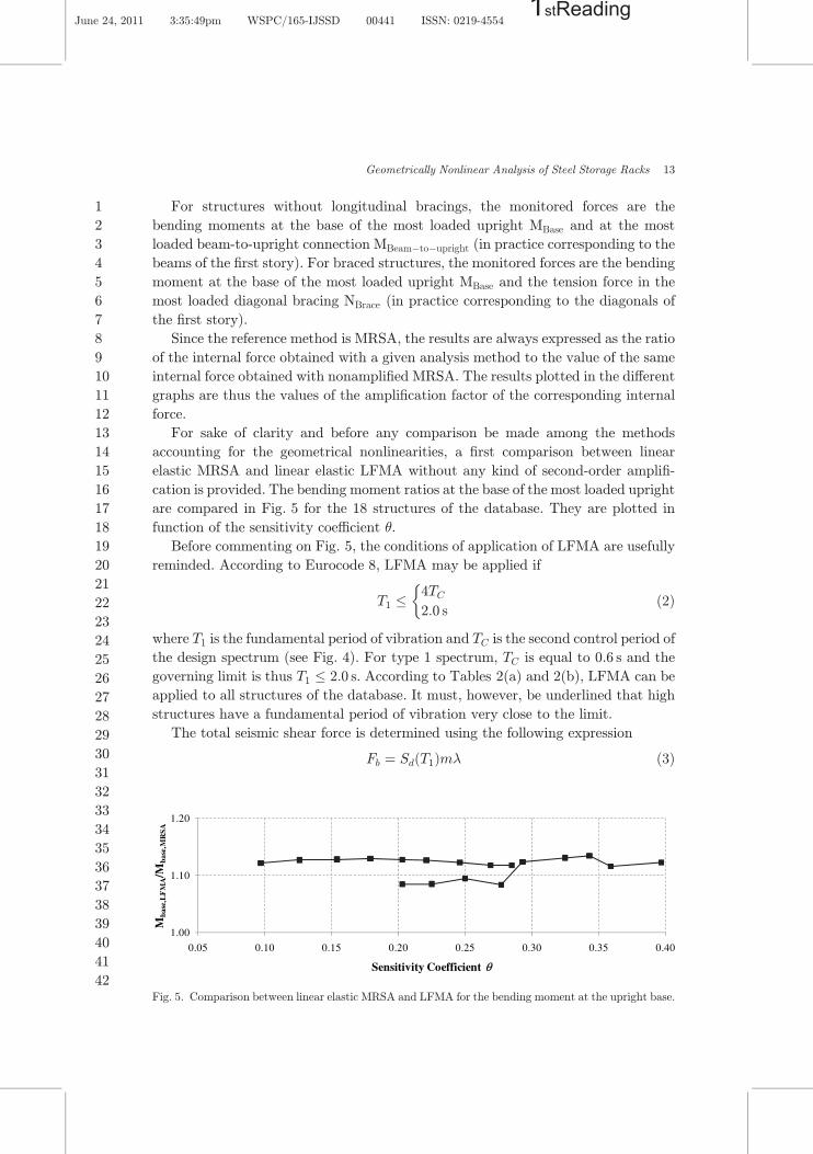
For sake of clarity and before any comparison be made among the methods
accounting for the geometrical nonlinearities, a ¯rst comparison between linear
elastic MRSA and linear elastic LFMA without any kind of second-order ampli¯-
cation is provided. The bending moment ratios at the base of the most loaded upright
are compared in Fig. 5 for the 18 structures of the database. They are plotted in
function of the sensitivity coe±cient �.
Before commenting on Fig. 5, the conditions of application of LFMA are usefully
reminded. According to Eurocode 8, LFMA may be applied if
T1 �4TC
2:0 s
�ð2Þ
where T1 is the fundamental period of vibration and TC is the second control period of
the design spectrum (see Fig. 4). For type 1 spectrum, TC is equal to 0.6 s and the
governing limit is thus T1 � 2:0 s. According to Tables 2(a) and 2(b), LFMA can be
applied to all structures of the database. It must, however, be underlined that high
structures have a fundamental period of vibration very close to the limit.
The total seismic shear force is determined using the following expression
Fb ¼ SdðT1Þm� ð3Þ
1.00
1.10
1.20
0.05 0.10 0.15 0.20 0.25 0.30 0.35 0.40
Mba
se,L
FM
A/M
base
,MR
SA
Sensitivity Coefficient θ
Fig. 5. Comparison between linear elastic MRSA and LFMA for the bending moment at the upright base.
Geometrically Nonlinear Analysis of Steel Storage Racks 13
June 24, 2011 3:35:49pm WSPC/165-IJSSD 00441 ISSN: 0219-45541stReading
1
2
3
4
5
6
7
8
9
10
11
12
13
14
15
16
17
18
19
20
21
22
23
24
25
26
27
28
29
30
31
32
33
34
35
36
37
38
39
40
41
42
where SdðT1Þ is the ordinate of the design spectrum at period T1, m is the total mass
of the structure, and � is a correction factor depending in the fundamental period T1.
If T1 � 2TC (i.e. 1.2 s), the correction factor is equal to 1.0, which is the case for most
structures of the database.
Figure 5 clearly shows that, under the above assumptions, LFMA constitutes a
conservative simpli¯cation of MRSA with a safety margin ranging from 8% to 13%
according to the actual modal mass of the structure.
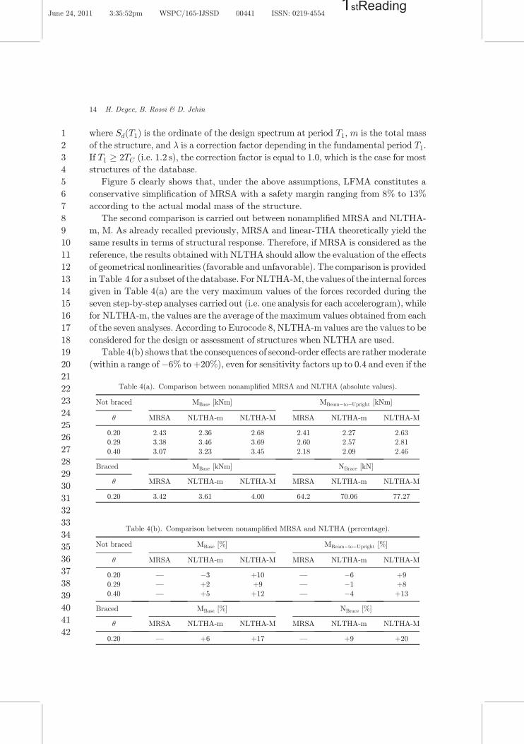
The second comparison is carried out between nonampli¯ed MRSA and NLTHA-
m, M. As already recalled previously, MRSA and linear-THA theoretically yield the
same results in terms of structural response. Therefore, if MRSA is considered as the
reference, the results obtained with NLTHA should allow the evaluation of the e®ects
of geometrical nonlinearities (favorable and unfavorable). The comparison is provided
inTable 4 for a subset of the database. ForNLTHA-M, the values of the internal forces
given in Table 4(a) are the very maximum values of the forces recorded during the
seven step-by-step analyses carried out (i.e. one analysis for each accelerogram), while
for NLTHA-m, the values are the average of the maximum values obtained from each
of the seven analyses. According to Eurocode 8, NLTHA-m values are the values to be
considered for the design or assessment of structures when NLTHA are used.
Table 4(b) shows that the consequences of second-order e®ects are rather moderate
(within a range of�6% toþ20%), even for sensitivity factors up to 0.4 and even if the
Table 4(a). Comparison between nonampli¯ed MRSA and NLTHA (absolute values).
Not braced MBase [kNm] MBeam�to�Upright [kNm]
� MRSA NLTHA-m NLTHA-M MRSA NLTHA-m NLTHA-M
0.20 2.43 2.36 2.68 2.41 2.27 2.63
0.29 3.38 3.46 3.69 2.60 2.57 2.81
0.40 3.07 3.23 3.45 2.18 2.09 2.46
Braced MBase [kNm] NBrace [kN]
� MRSA NLTHA-m NLTHA-M MRSA NLTHA-m NLTHA-M
0.20 3.42 3.61 4.00 64.2 70.06 77.27
Table 4(b). Comparison between nonampli¯ed MRSA and NLTHA (percentage).
Not braced MBase [%] MBeam�to�Upright [%]
� MRSA NLTHA-m NLTHA-M MRSA NLTHA-m NLTHA-M
0.20 — �3 þ10 — �6 þ9
0.29 — þ2 þ9 — �1 þ8
0.40 — þ5 þ12 — �4 þ13
Braced MBase [%] NBrace [%]
� MRSA NLTHA-m NLTHA-M MRSA NLTHA-m NLTHA-M
0.20 — þ6 þ17 — þ9 þ20
14 H. Degee, B. Rossi & D. Jehin
June 24, 2011 3:35:52pm WSPC/165-IJSSD 00441 ISSN: 0219-45541stReading
1
2
3
4
5
6
7
8
9
10
11
12
13
14
15
16
17
18
19
20
21
22
23
24
25
26
27
28
29
30
31
32
33
34
35
36
37
38
39
40
41
42

extreme value obtained from the full set of groundmotions is considered. This is due to
the compensating e®ects of period elongation and increase of structural °exibility.
It can also be underlined that, based on the comparison of Table 4 and Fig. 5 and
if only the mean value of the time-history results is of concern, the nonlinear
1.00
1.10
1.20
1.30
1.40
1.50
1.60
1.70
1.80
1.90
0.2 0.225 0.25 0.275 0.3 0.325 0.35 0.375 0.4
Mba
se/M
base
,MR
SA
Sensitivity Coefficient θ
LFMA-1-A LFMA-1-b
LFMA-2 LFMA-3
MRSA-a MRSA-b
(a)
1.00
1.10
1.20
1.30
1.40
1.50
1.60
1.70
1.80
1.90
0.2 0.225 0.25 0.275 0.3 0.325 0.35 0.375 0.4
Mb
eam
-to-
up
righ
t/Mb
eam
-to-
up
righ
t,M
RSA
Sensitivity Coefficient θ
LFMA-1-A LFMA-1-b
LFMA-2 LFMA-3
MRSA-a MRSA-b
(b)
Fig. 6. (a) Comparison among the analysis methods for the bending moment at the upright base
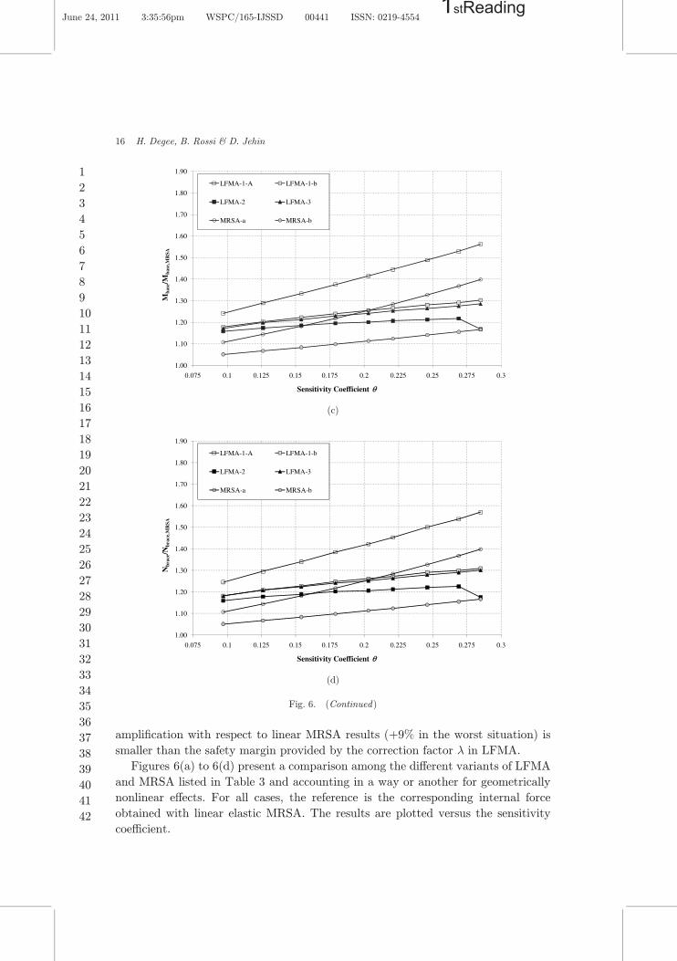
(structures without bracings), (b) comparison among the analysis methods for the bending moment atbeam-to-upright connection (structures without bracings), (c) comparison among the analysis methods for
the bending moment at the upright base (braced structures) and (d) comparison among the analysis
methods for the tension forces in the diagonal bracings (braced structures).
Geometrically Nonlinear Analysis of Steel Storage Racks 15
June 24, 2011 3:35:52pm WSPC/165-IJSSD 00441 ISSN: 0219-45541stReading
1
2
3
4
5
6
7
8
9
10
11
12
13
14
15
16
17
18
19
20
21
22
23
24
25
26
27
28
29
30
31
32
33
34
35
36
37
38
39
40
41
42
ampli¯cation with respect to linear MRSA results (þ9% in the worst situation) is
smaller than the safety margin provided by the correction factor � in LFMA.
Figures 6(a) to 6(d) present a comparison among the di®erent variants of LFMA
and MRSA listed in Table 3 and accounting in a way or another for geometrically
nonlinear e®ects. For all cases, the reference is the corresponding internal force
obtained with linear elastic MRSA. The results are plotted versus the sensitivity
coe±cient.
1.00
1.10
1.20
1.30
1.40
1.50
1.60
1.70
1.80
1.90
0.075 0.1 0.125 0.15 0.175 0.2 0.225 0.25 0.275 0.3
Mba
se/M
base
,MR
SA
Sensitivity Coefficient θ
LFMA-1-A LFMA-1-b
LFMA-2 LFMA-3
MRSA-a MRSA-b
(c)
1.00
1.10
1.20
1.30
1.40
1.50
1.60
1.70
1.80
1.90
0.075 0.1 0.125 0.15 0.175 0.2 0.225 0.25 0.275 0.3
Nbr
ace/N
brac
e,M
RSA
Sensitivity Coefficient θ
LFMA-1-A LFMA-1-b
LFMA-2 LFMA-3
MRSA-a MRSA-b
(d)
Fig. 6. (Continued)
16 H. Degee, B. Rossi & D. Jehin
June 24, 2011 3:35:56pm WSPC/165-IJSSD 00441 ISSN: 0219-45541stReading
1
2
3
4
5
6
7
8
9
10
11
12
13
14
15
16
17
18
19
20
21
22
23
24
25
26
27
28
29
30
31
32
33
34
35
36
37
38
39
40
41
42
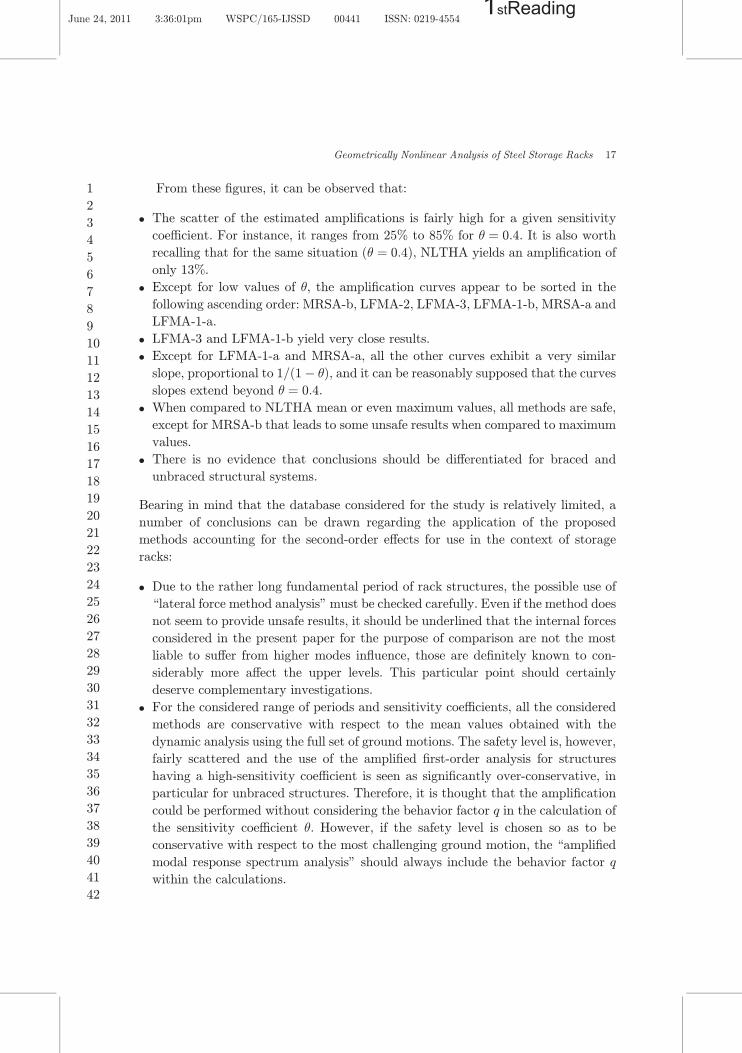
From these ¯gures, it can be observed that:
. The scatter of the estimated ampli¯cations is fairly high for a given sensitivity
coe±cient. For instance, it ranges from 25% to 85% for � ¼ 0:4. It is also worth
recalling that for the same situation (� ¼ 0:4), NLTHA yields an ampli¯cation of
only 13%.
. Except for low values of �, the ampli¯cation curves appear to be sorted in the
following ascending order: MRSA-b, LFMA-2, LFMA-3, LFMA-1-b, MRSA-a and
LFMA-1-a.
. LFMA-3 and LFMA-1-b yield very close results.
. Except for LFMA-1-a and MRSA-a, all the other curves exhibit a very similar
slope, proportional to 1=ð1� �Þ, and it can be reasonably supposed that the curves
slopes extend beyond � ¼ 0:4.
. When compared to NLTHA mean or even maximum values, all methods are safe,
except for MRSA-b that leads to some unsafe results when compared to maximum
values.
. There is no evidence that conclusions should be di®erentiated for braced and
unbraced structural systems.
Bearing in mind that the database considered for the study is relatively limited, a
number of conclusions can be drawn regarding the application of the proposed
methods accounting for the second-order e®ects for use in the context of storage
racks:
. Due to the rather long fundamental period of rack structures, the possible use of
\lateral force method analysis" must be checked carefully. Even if the method does
not seem to provide unsafe results, it should be underlined that the internal forces
considered in the present paper for the purpose of comparison are not the most
liable to su®er from higher modes in°uence, those are de¯nitely known to con-
siderably more a®ect the upper levels. This particular point should certainly
deserve complementary investigations.
. For the considered range of periods and sensitivity coe±cients, all the considered
methods are conservative with respect to the mean values obtained with the
dynamic analysis using the full set of ground motions. The safety level is, however,
fairly scattered and the use of the ampli¯ed ¯rst-order analysis for structures
having a high-sensitivity coe±cient is seen as signi¯cantly over-conservative, in
particular for unbraced structures. Therefore, it is thought that the ampli¯cation
could be performed without considering the behavior factor q in the calculation of
the sensitivity coe±cient �. However, if the safety level is chosen so as to be
conservative with respect to the most challenging ground motion, the \ampli¯ed
modal response spectrum analysis" should always include the behavior factor q
within the calculations.
Geometrically Nonlinear Analysis of Steel Storage Racks 17
June 24, 2011 3:36:01pm WSPC/165-IJSSD 00441 ISSN: 0219-45541stReading
1
2
3
4
5
6
7
8
9
10
11
12
13
14
15
16
17
18
19
20
21
22
23
24
25
26
27
28
29
30
31
32
33
34
35
36
37
38
39
40
41
42
7. Conclusions
The structural database elaborated for the speci¯c objectives of the study presented
in this paper aimed at validating the recommendations of FEM 10.2.08 for steel
pallet rack structures regarding the analysis methods. The structures experienced in
the present research study are highly °exible structures so as evidenced by their long
fundamental periods (up to 2 s) and the high values of sensitivity coe±cients to
second-order e®ects (� from 0.1 to 0.4).
Di®erent methods of analysis accounting in various ways for geometrically
nonlinear e®ects are described and their results in terms of internal forces ratios are
then duly compared.
A ¯rst comment drawn using the results of time-history nonlinear analysis
(although performed on a limited amount of con¯gurations) is that the ampli¯cation
of the internal forces induced by second-order e®ects is relatively limited (up to 20%),
partly thank to the favorable in°uence of the period elongation.
Another major comment that should be underlined is that all conventional
methods (i.e. \modal response spectrum analysis" and \lateral force method ana-
lysis") are conservative with respect to nonlinear dynamic analysis whatever the type
of structural system (braced or unbraced), partly because the behavior factor q is
included in the calculation of the sensitivity coe±cient. The level of conservatism is
nevertheless highly varying from an approach to another.
Acknowledgments
H. Deg�ee and B. Rossi acknowledge for the support received from the Belgian
National Fund for Scienti¯c Research (F.R.S.-FNRS).
References
1. RMI, Speci¯cation for the design, testing and utilization of industrial steel storage racks,Rack Manufacturers Institute, Charlotte, NC. (2007).
2. CEN, EN15512, Steel static storage systems — Adjustable pallet racking systems —
Principles for structural design (2008).3. RAL, Storage and Associated Equipment, Deutsches Institut für Gutersicherung und
Kennzeichnung (German Institute for Quality Assurance and Marketing) (1990).4. AS, A.S. 4084, Steel Storage Racking, Australian Standards (1993).5. A. Filiatrault, R. E. Bachman and M. G. Mahoney, Performance-based seismic design of
pallet-type steel storage racks, Earthquake Spectra 22 (2006) 47�64.6. A. Filiatrault, A. Wanitkorkul and P. Higgins, Experimental sti®ness and seismic
response of pallet-type steel storage rack connectors, ASCE Practice Periodical onStructural Design and Construction 11 (2006) 161�170.
7. C. A. Castiglioni, Dynamic tests on steel pallet racks, Costruzioni Metalliche 55 (2003)35�44.
8. C. Bernuzzi and C. A. Castiglioni, Experimental analysis on the cyclic behaviour ofbeam-to-column joints in steel storage pallet racks, Thin-Walled Structures 39 (2001)841�859.
18 H. Degee, B. Rossi & D. Jehin
June 24, 2011 3:36:01pm WSPC/165-IJSSD 00441 ISSN: 0219-45541stReading
1
2
3
4
5
6
7
8
9
10
11
12
13
14
15
16
17
18
19
20
21
22
23
24
25
26
27
28
29
30
31
32
33
34
35
36
37
38
39
40
41
42

9. H. Degee, V. Denoel and C. A. Castiglioni, Seismic behaviour of storage racks made ofthin-walled members, Proceedings of the 7th European Conference on StructuralDynamics (Southampton, UK, 2008), paper E253, pp. 12.
10. I. Rosin et al., Storage racks in seismic areas (Seisracks), European Commission —
Research Fund for Coal and Steel, RFS-PR-03114, Final Report (2007).11. FEM, Recommendations for the design of static steel pallet racks under seismic conditions
(Draft version), FEM 10.2.08, Federation Europeenne de la Manutention (2008).12. FEMA 460— Seismic Considerations for Steel Storage Racks Located in Areas Accessible
to the Public, Federal Emergency Management Agency, Washington D.C. (2005).13. CEN, EN 1998-1, Eurocode 8 — Design of structures for earthquake resistance — Part 1:
General rules, seismic action and rules for building (2004).14. C. Dufoing, Prise en compte des e®ets geometriquement non lineaires dans les ossatures
de rayonnages soumises a seisme, Master Thesis, University of Liege (2009).15. V. Denoël, Generation of Spectrum Compatible Accelergorams, Research Report, Uni-
versity of Liège (2001).16. FineLg, User's Manual, V9.2, Greisch Engineering — Department ArGEnCo, University
of Liège (2003).
Geometrically Nonlinear Analysis of Steel Storage Racks 19
June 24, 2011 3:36:01pm WSPC/165-IJSSD 00441 ISSN: 0219-45541stReading
1
2
3
4
5
6
7
8
9
10
11
12
13
14
15
16
17
18
19
20
21
22
23
24
25
26
27
28
29
30
31
32
33
34
35
36
37
38
39
40
41
42