Delft University of Technology Process Intensification ... - Lirias
169
Delft University of Technology Process Intensification of Microwave Assisted Methane Dry Reforming Gangurde, Lalit DOI 10.4233/uuid:7372f079-4bb5-46eb-b203-315afb8781c8 Publication date 2018 Document Version Publisher's PDF, also known as Version of record Citation (APA) Gangurde, L. (2018). Process Intensification of Microwave Assisted Methane Dry Reforming DOI: 10.4233/uuid:7372f079-4bb5-46eb-b203-315afb8781c8 Important note To cite this publication, please use the final published version (if applicable). Please check the document version above. Copyright Other than for strictly personal use, it is not permitted to download, forward or distribute the text or part of it, without the consent of the author(s) and/or copyright holder(s), unless the work is under an open content license such as Creative Commons. Takedown policy Please contact us and provide details if you believe this document breaches copyrights. We will remove access to the work immediately and investigate your claim. This work is downloaded from Delft University of Technology. For technical reasons the number of authors shown on this cover page is limited to a maximum of 10.
-
Upload
khangminh22 -
Category
Documents
-
view
0 -
download
0
Transcript of Delft University of Technology Process Intensification ... - Lirias

Delft University of Technology
Process Intensification of Microwave Assisted Methane Dry Reforming
Gangurde, Lalit
DOI10.4233/uuid:7372f079-4bb5-46eb-b203-315afb8781c8Publication date2018Document VersionPublisher's PDF, also known as Version of record
Citation (APA)Gangurde, L. (2018). Process Intensification of Microwave Assisted Methane Dry Reforming DOI:10.4233/uuid:7372f079-4bb5-46eb-b203-315afb8781c8
Important noteTo cite this publication, please use the final published version (if applicable).Please check the document version above.
CopyrightOther than for strictly personal use, it is not permitted to download, forward or distribute the text or part of it, without the consentof the author(s) and/or copyright holder(s), unless the work is under an open content license such as Creative Commons.
Takedown policyPlease contact us and provide details if you believe this document breaches copyrights.We will remove access to the work immediately and investigate your claim.
This work is downloaded from Delft University of Technology.For technical reasons the number of authors shown on this cover page is limited to a maximum of 10.


Process Intensification of Microwave
Assisted Methane Dry Reforming
Proefschrift
ter verkrijging van de graad van doctor
aan de Technische Universiteit Delft,
op gezag van de Rector Magnificus prof.dr.ir. T.H.J.J. van der Hagen,
voorzitter van het College voor Promoties,
in het openbaar te verdedigen op woensdag 12 December 2018 om 10:00 uur
door
Lalit Sayaji Gangurde
Masters in Inorganic Chemistry
University of Pune, Pune, India.
geboren te Ghodegaon, Maharashtra, India.


Process Intensification of Microwave
Assisted Methane Dry Reforming
Dissertation
for the purpose of obtaining the degree of doctor
at Delft University of Technology
by the authority of the Rector Magnificus prof.dr.ir. T.H.J.J. van der Hagen,
chair of the Board for Doctorates
to be defended publicly on Wednesday 12 December 2018 at 10:00 o’clock
by
Lalit Sayaji Gangurde
Masters in Inorganic Chemistry
University of Pune, Pune, India.
Born in Ghodegaon, Maharashtra, India.

This dissertation has been approved by the promotors:
Prof.dr.ir. A.I. Stankiewicz and Prof.dr.ir. G.D. Stefanidis
Composition of the doctoral committee:
Rector Magnificus Chairperson
Prof.dr.ir. A.I. Stankiewicz Delft University of Technology, promotor
Prof.dr.ir. G.D. Stefanidis Katholieke Universiteit Leuven, promotor
Independent Members:
Prof.dr.ir. K.M. Van Geem Ghent University, Belgium
Dr.ir. T. Durka Yara Sluiskil B.V, the Netherlands.
Prof.dr.ir. J.R. van Ommen Delft University of Technology
Dr. P.V. Aravind Delft University of Technology
Prof.dr. J. Santamaria Zaragoza University, Spain
Prof.dr.ir. W. de Jong Delft University of Technology, reserve member
ISBN: 978-94-6375-229-9
The research leading to this Ph.D. dissertation has received funding from the European Research
Council under the European Union's Seventh Framework Programme (FP7/2007-2013) / ERC
grant agreement no. 267348.
Copyright©2018 by Lalit Sayaji Gangurde1
All rights reserved. No part of the material protected by this copyright notice may be reproduced
or utilized in any form or by any means, electronic or mechanical, including photocopying,
recording or by any information storage and retrieval system, without the prior written permission
from the author.
Cover designed by Lalit Sayaji Gangurde
Published by Lalit Sayaji Gangurde, TU Delft
Printed in the Netherlands by: Ridderprint BV | www.ridderprint.nl 1Author email address: [email protected]

Dedicated to my family and friends who supported me during
this Journey


Summary
---------------------------------------------------------------------------------------------------------------------
------------------------------------------------------------------------------------------------------------------i
Process Intensification of Microwave-Assisted Methane Dry Reforming
Summary
Resource- and energy-efficient methane (CH4) transformation to fuels and chemicals is a research
topic with societal, environmental and industrial relevance owing to the great variety of methane
sources, including existing gas networks, small natural gas fields, shale gas, coal beds, agricultural
biogas, deep-sea methane hydrates and the pressing issue of methane flaring in remote locations.
In addition, CH4 and carbon dioxide (CO2) are the two greenhouse gases contributing majorly to
global warming and their effect is expected to increase in years to come due to the continuously
increasing energy demand worldwide. In this frame, CH4 reforming by CO2 (dry methane
reforming) by means of different catalytic materials and technologies has been investigated over
the years as a potential route for valorisation of the two molecules.
In this doctoral work, dry methane reforming has been carried out in a custom designed microwave
reactor to obtain syngas (H2+CO), a building block for several fuels and chemicals. The aim of the
research is to address certain challenges in process intensification of microwave-assisted
heterogeneous catalytic reactions at high temperatures (>700 °C) in general and microwave-
assisted methane dry reforming in particular. The thesis is divided into six chapters. In the first
Chapter, a general introduction on the globally increasing energy demand is given and possibilities
to meet this demand are discussed. Further, the motivation for the investigation of methane dry
reforming is presented, and the challenges to improve the process under microwave heating are
highlighted. The second Chapter describes the custom designed microwave reactor setup used for
experiments in this work. The setup has been designed such that it provides concentrated
microwave heating to the solid catalytic materials, maximizes the microwave energy utilization
efficiency and enables measurement and monitoring of the spatiotemporal temperature distribution
in the quartz tube fixed bed reactor where methane dry reforming is carried out.
Chapter 3 reports on the complexity and challenges in non-contact temperature measurements
inside microwave-heated catalytic reactors. A methodology to monitor the temperature distribution
inside a catalytic bed by using a thermal camera in combination with a thermocouple for a
heterogeneous catalytic reaction (methane dry reforming) under microwave heating has been
demonstrated. The effects of various variables that affect the accuracy of temperature recordings
are discussed in detail. Coke formation and catalyst volume reduction are observed to be the major
issues with carbon-based catalysts.
The limitations of carbon-based catalysts for microwave-assisted methane dry reforming have
motivated the development of alternative catalysts that combine high activity, good microwave
absorption capacity, thermal stability and resistance to coke. To that end, a series of ruthenium-
doped strontium titanate (SrTiO3) perovskite catalysts have been synthesized by conventional and
microwave-assisted hydrothermal methods. Significant synthesis temperature and time reduction

Summary
---------------------------------------------------------------------------------------------------------------------
ii-----------------------------------------------------------------------------------------------------------------
Process Intensification of Microwave-Assisted Methane Dry Reforming
from 220 °C for 24 h in conventional heating to 180 °C for 1 h under microwave heating were
achieved. The synthesized catalysts were characterized with respect to their dielectric properties in
a dual mode cylindrical cavity as well as their physicochemical properties by means of various
analytical methods (XRD, BET, ICP-OES and high-angle annular dark-field scanning transmission
electron microscopy (HAADF-STEM) coupled to energy dispersive X-ray (EDX) analysis). Based
on the outcome of the characterization procedures, a 7 wt. % ruthenium-doped SrTiO3 catalyst was
selected for further testing of its catalytic activity for methane dry reforming under microwave
heating in a custom fixed-bed quartz reactor. Microwave power, CH4:CO2 vol. % feed ratio and
gas hourly space velocity (GHSV) were varied to determine the best operating conditions.
Maximum conversions of ~99.5% and ~94% for CH4 and CO2, respectively, were achieved during
a 3h stability test at 9000 cm3g-1hr-1 GHSV, with the selected 7 wt. % Ru-doped SrTiO3 catalyst,
which was exposed at maximum temperatures in the vicinity of 940 °C. Scale-up calculations on
the basis of 1 m3h-1 CH4 inlet flow rate on the perovskite catalyst show significant improvement in
H2 production capability compared to carbon-based catalysts.
Considering further scale-up and industrial implementation, the Ru-based catalyst might be
expensive. Therefore, in Chapter 5, combinations of four commercial and relatively cheap nickel-
supported metal oxide catalysts (Ni/Al2O3, Ni/CaAl2O4, Ni/Al2MgO4, and Ni/SiO2-Al2O3) with a 7
wt. % Ruthenium (Ru)-doped SrTiO3 perovskite catalyst were tested, as hybrid catalytic systems,
for syngas production by microwave-assisted methane dry reforming. The experimental results
showed that the introduction of the Ru-doped perovskite catalyst improves the microwave heating
ability of the hybrid systems under typical dry reforming temperatures (up to 850 °C). The four
catalytic systems were also evaluated under dry reforming reaction conditions in terms of CH4 and
CO2 conversion and H2/CO ratio as a function of MW power, gas hourly space velocity (GHSV)
and time on stream. The combination of Ru/SrTiO3 and Ni/Al2O3 was found to form the best hybrid
catalyst system in terms of microwave absorption ability, syngas production capacity and catalytic
stability. A comparative theoretical scale-up study showed improvement in H2 production capacity
in case of a combination of Ni/Al2O3 and Ru/SrTiO3 as compared to the combination of Ni/Al2O3
and FY5.
Finally, the last chapter (Chapter 6) summarizes the findings of the entire research activity and
provides recommendations for future work on the subject.

Samenvatting
---------------------------------------------------------------------------------------------------------------------
-----------------------------------------------------------------------------------------------------------------iii
Process Intensification of Microwave-Assisted Methane Dry Reforming
Samenvatting
Bron en energie-efficiënte methaan (CH4) transformatie naar brandstoffen en chemicaliën is een
onderzoeksthema met maatschappelijke, ecologische en industriële relevantie. Dit is vanwege de
grote verscheidenheid aan methaanbronnen, waaronder bestaande gasnetwerken, kleine
aardgasvelden, schaliegas, kolengoten, landbouwbiogas, diepzee methaanhydraten en de dringende
kwestie van methaan verbranding op afgelegen locaties. Bovendien zijn CH4 en koolstofdioxide
(CO2) de twee broeikasgassen die in belangrijke mate bijdragen tot het broeikaseffect en hun effect
zal naar verwachting in de komende jaren toenemen als gevolg van de wereldwijd voortdurend
toenemende vraag naar energie. Binnen deze kader is CH4 hervorming met CO2 (droge methaan
hervorming) met behulp van verschillende katalytische materialen en technologieën door de jaren
heen onderzocht als een mogelijke route voor valorisatie van de twee moleculen.
In dit promotieonderzoek is een droge methaan hervorming uitgevoerd in een speciaal ontworpen
magnetron reactor om syngas (H2+CO) te verkrijgen, een bouwsteen voor verschillende
brandstoffen en chemicaliën. Het doel van het onderzoek is om bepaalde uitdagingen aan te pakken
bij intensivering van het proces van microgolf-geassisteerde heterogene katalytische reacties bij
hoge temperaturen (>700 °C) in het algemeen en in het bijzonder microgolf-geassisteerde methaan-
droge hervorming. De scriptie is verdeeld in zes hoofdstukken. In het eerste hoofdstuk wordt een
algemene inleiding gegeven over de wereldwijd stijgende energievraag en worden mogelijkheden
besproken om aan deze vraag te voldoen. Verder wordt de motivatie voor het onderzoek naar
methaan droog reformeren gepresenteerd en worden de uitdagingen om het proces onder
microgolfverwarming te verbeteren benadrukt. Het tweede hoofdstuk beschrijft de op maat
ontworpen opstelling van de magnetron reactor die voor experimenten in dit werk wordt gebruikt.
De opstelling is zodanig ontworpen dat het geconcentreerde microgolfverwarming aan de vaste
katalytische materialen verschaft, de efficiëntie van de microgolfenergiebenutting maximaliseert,
met daarnaast meting en bewaking van de spatio-temporele temperatuurverdeling in de bed-reactor
met kwartsbuizen mogelijk maakt, waar methaan droog wordt gereformeerd.
Hoofdstuk 3 omvat de complexiteit en uitdagingen in contactloze temperatuurmetingen in
microgolfverwarmde katalytische reactoren. Een methode om de temperatuurverdeling in een
katalytisch bed te bewaken met behulp van een thermische camera in combinatie met een
thermokoppel voor een heterogene katalytische reactie (methaan droog reformeren) onder
verwarming met microgolven, is aangetoond. De effecten van verschillende variabelen die de
nauwkeurigheid van temperatuuropnames beïnvloeden, worden in detail besproken. Cokesvorming
en afname van het katalysatorvolume zijn de belangrijkste problemen met katalysatoren op basis
van koolstof.
De beperkingen van op koolstof gebaseerde katalysatoren voor microgolf-geassisteerd methaan
droog reformeren hebben de ontwikkeling van alternatieve katalysatoren gemotiveerd die hoge
activiteit, goede microgolfabsorptiecapaciteit, thermische stabiliteit en weerstand tegen cokes
combineren. Daartoe is een reeks met ruthenium gedoteerde strontiumtitanaat (SrTiO3)
perovskietkatalysatoren gesynthetiseerd met behulp van conventionele en met microgolven

Samenvatting.
---------------------------------------------------------------------------------------------------------------------
iv-----------------------------------------------------------------------------------------------------------------
Process Intensification of Microwave-Assisted Methane Dry Reforming
ondersteunde hydrothermische werkwijzen. Aanzienlijke synthese temperatuur en tijdverkorting
van 220 °C gedurende 24 uur bij conventionele verwarming tot 180 °C gedurende 1 uur onder
verwarming met microgolven werden bereikt. De gesynthetiseerde katalysatoren werden
gekarakteriseerd met betrekking tot hun diëlektrische eigenschappen in een tweevoudige modus
cilindrische holte evenals hun fysisch-chemische eigenschappen door middel van verschillende
analytische werkwijzen (XRD, BET, ICP-OES en hooghoekige ringvormige donkerveldscanning
transmissie-elektronenmicroscopie (HAADF-STEM) gekoppeld aan energie-dispersieve röntgen
(EDX) analyse). Op basis van de uitkomst van de karakteriseringsprocedures, werd een 7 gew. %
ruthenium-gedoteerde SrTiO3 katalysator geselecteerd voor het verder testen van zijn katalytische
activiteit voor methaan droog reformeren onder microgolfverwarming in een op maat gemaakte
quartz reactor met een bed-reactor. Magnetronvermogen, CH4: CO2 vol. % voedingsverhouding en
gasruimtesnelheid per uur (GHSV) werden gevarieerd om de beste omstandigheden te bepalen.
Maximale omzettingen van ~ 99,5% en ~ 94% voor respectievelijk CH4 en CO2 werden bereikt
tijdens een 3 uur stabiliteitstest bij 9000 cm3g-1hr-1 GHSV, met het geselecteerde 7 gew. % Ru-
gedoteerde SrTiO3-katalysator, die werd blootgesteld aan maximale temperaturen in de buurt van
940 °C. Opschalingsberekeningen op basis van 1 m3per uur van CH4 inlaatstroomsnelheid op de
perovskietkatalysator tonen, een significante verbetering in H2-productievermogen vergeleken met
op koolstof gebaseerde katalysatoren.
Rekening houdend met verdere schaalvergroting en industriële implementatie, kan de op Ru
gebaseerde katalysator duur zijn. In hoofdstuk 5 wordt er daarom, combinaties van vier
commerciële en relatief goedkope nikkel gedragen metaaloxide katalysatoren (Ni/Al2O3,
Ni/CaAl2O4, Ni/Al2MgO4 en Ni/SiO2-Al2O3) met een 7 gew. % Ruthenium (Ru) -gedoteerde
SrTiO3-perovskietkatalysator, getest als hybride katalytische systemen voor syngasproductie door
microgolf-geassisteerde methaan-droge reformering. De experimentele resultaten toonden aan dat
de introductie van de Ru-gedoteerde perovskietkatalysator het microgolfverwarmingsvermogen
van de hybride systemen onder typische droge reformatietemperaturen (tot 850 °C) verbetert.
De vier katalytische systemen werden ook geëvalueerd onder droge reformerende
reactieomstandigheden in termen van CH4- en CO2-omzetting en H2/CO-verhouding als functie
van MW-vermogen, gasruimtesnelheid per uur (GHSV) en tijd-in-stroom. De combinatie van
Ru/SrTiO3 en Ni/Al2O3 bleek het beste hybride katalysatorsysteem te zijn in termen van
microgolfabsorptievermogen, syngas-productiecapaciteit en katalytische stabiliteit. Een
vergelijkende theoretische opschalingsstudie toonde verbetering in de H2-productiecapaciteit aan
in het geval van een combinatie van Ni/Al2O3 en Ru/SrTiO3 in vergelijking met de combinatie van
Ni/Al2O3 en FY5
Ten slotte vat het laatste hoofdstuk (hoofdstuk 6) de bevindingen van de gehele
onderzoeksactiviteit samen en geeft het aanbevelingen voor toekomstige werk met betrekking tot
dit onderwerp.
Table of Contents
--------------------------------------------------------------------------------------------------------------------
-----------------------------------------------------------------------------------------------------------------v
Process Intensification of Microwave-Assisted Methane Dry Reforming
Table of Contents
Contents
Summary ....................................................................................................................................................................... i
Samenvatting ............................................................................................................................................................. iii
Table of Contents ......................................................................................................................................................... v
1. Introduction ........................................................................................................................................................ 1
1.1. Energy demand and feasible solutions ....................................................................................................... 3
1.2. Global concern for CO2 and CH4 mitigation ................................................................................................ 4
1.3. Microwave technology and its applications ............................................................................................... 6
1.4. The motivation for methane dry reforming process ................................................................................... 9
1.5. Challenges for microwave-assisted dry reforming of methane ................................................................ 11
1.6. The scope of the thesis.............................................................................................................................. 12
1.7. Research Questions .................................................................................................................................. 12
1.8. Outline of the thesis .................................................................................................................................. 13
1.9. Graphical abstract of Ph.D. Thesis ............................................................................................................ 15
2. Design and development of the microwave reactor system .......................................................................... 17
2.1. Introduction .............................................................................................................................................. 19
2.2. Gas flow control ........................................................................................................................................ 19
2.3. Microwave reactor assembly .................................................................................................................... 23
2.4. Solid state microwave generator .............................................................................................................. 25
2.5. Temperature measurement techniques ................................................................................................... 26
2.6. Product gas analysis ................................................................................................................................. 27
2.7. Reactor control system ............................................................................................................................. 28
2.8. Reactor operating procedure and safety .................................................................................................. 32
2.8.1. Experimental start-up procedure ........................................................................................................ 32
2.8.2. Shut down procedure .......................................................................................................................... 33
2.9. Summary and recommendations for further improvement...................................................................... 34
3. Complexity and challenges in non-contact high-temperature measurements in microwave-assisted
catalytic reactors ........................................................................................................................................................ 35
3.1. Introduction .............................................................................................................................................. 39

Table of Contents
---------------------------------------------------------------------------------------------------------------------
vi-----------------------------------------------------------------------------------------------------------------
Process Intensification of Microwave-Assisted Methane Dry Reforming
3.2. Experimental Section ................................................................................................................................ 41
3.2.1. Schematic diagram of the microwave reactor ..................................................................................... 41
3.2.2. Catalyst loading for microwave heating .............................................................................................. 42
3.2.3. Thermal camera working principle ...................................................................................................... 44
3.2.4. Dry reforming reaction testing procedure under microwave heating ................................................ 45
3.3. Results and Discussion .............................................................................................................................. 45
3.3.1. Dielectric properties of catalyst measured at high temperature ........................................................ 45
3.3.2. Radial temperature and emissivity differences by optical fibers ........................................................ 46
3.3.3. Effect of camera range and heating system used ................................................................................ 48
3.3.4. Effect of gases on emissivity and detection of hot spots ..................................................................... 50
3.3.5. Catalyst performance evaluation and microwave absorption efficiency ............................................ 53
3.3.6. Emissivity matching during the reaction ............................................................................................. 55
3.3.7. Factors affecting the emissivity and overall temperature distribution during the reaction ............... 55
3.3.8. Axial and radial temperature distribution during the reaction ........................................................... 58
3.4. Conclusions ............................................................................................................................................... 59
3.5. Supporting Information: ........................................................................................................................... 60
3.5.1. Challenges to reproduce experimental results and risk factors involved ............................................ 60
4. Synthesis, characterization, and application of ruthenium-doped SrTiO3 perovskite catalyst for
microwave-assisted methane dry reforming ........................................................................................................... 65
4.1. Introduction .............................................................................................................................................. 69
4.2. Experimental ............................................................................................................................................. 71
4.2.1. Reagents and materials ....................................................................................................................... 71
4.2.2. Conventional hydrothermal (CHT) synthesis ....................................................................................... 71
4.2.3. Microwave-assisted hydrothermal (MWHT) synthesis ........................................................................ 71
4.2.4. Characterization methods ................................................................................................................... 72
4.2.5. Microwave-assisted dry reforming of methane (DRM) ....................................................................... 73
4.3. Results and discussion .............................................................................................................................. 74
4.3.1. Catalyst characterization ..................................................................................................................... 74
4.3.2. Catalytic reactor performance ............................................................................................................. 79
4.3.3. Hotspot detection and temperature gradient analysis ....................................................................... 84
4.3.4. Energy consumption comparison ........................................................................................................ 85
4.4. Conclusions ............................................................................................................................................... 87
4.5. Supporting Information ............................................................................................................................ 88
5. CO2 reforming of CH4 under microwave heating over hybrid catalytic systems of ruthenium-doped
SrTiO3 and nickel supported catalysts .................................................................................................................... 91
5.1. Introduction .............................................................................................................................................. 95
5.2. Experimental section ................................................................................................................................ 96
5.2.1. Catalytic systems and dielectric properties measurement method .................................................... 96
5.2.2. Microwave reactor system .................................................................................................................. 96
5.2.3. Methane dry reforming reaction conditions ....................................................................................... 97

Table of Contents
--------------------------------------------------------------------------------------------------------------------
-----------------------------------------------------------------------------------------------------------------vii
Process Intensification of Microwave-Assisted Methane Dry Reforming
5.3. Results and discussion .............................................................................................................................. 99
5.3.1. Dielectric properties and the need of a hybrid catalytic system ......................................................... 99
5.3.2. Thermal response of the catalytic materials under microwave heating ........................................... 101
5.3.3. Evolution of microwave power and reactants conversion ................................................................ 102
5.3.4. Gas hourly space velocity study ......................................................................................................... 104
5.3.5. Reactor performance as a function of time-on-stream (TOS) ........................................................... 106
5.4. Conclusions ............................................................................................................................................. 109
5.5. Supporting Information: ......................................................................................................................... 110
6. Conclusions and Recommendations ............................................................................................................. 117
6.1. Conclusions ............................................................................................................................................. 119
6.2. Recommendations .................................................................................................................................. 120
References ................................................................................................................................................................ 121
Appendix .................................................................................................................................................................. 129
List of Publications .................................................................................................................................................. 137
Doctoral Education Program ................................................................................................................................. 139
Curriculum Vitae..................................................................................................................................................... 143
Acknowledgments .................................................................................................................................................... 145
Propositions .............................................................................................................................................................. 149

Table of Contents
---------------------------------------------------------------------------------------------------------------------
viii-----------------------------------------------------------------------------------------------------------------
Process Intensification of Microwave-Assisted Methane Dry Reforming

Chapter1: Introduction
---------------------------------------------------------------------------------------------------------------------
-----------------------------------------------------------------------------------------------------------------1
Process Intensification of Microwave-Assisted Methane Dry Reforming
1 1. Introduction
---------------------------------------------------------------------------------------------------------------------
This chapter aims to provide a brief overview on the subjects of globally increasing energy demand,
the concern for CO2 and CH4 mitigation, the microwave technology and its applications. The
motivation for developing an efficient microwave-driven methane dry reforming process is
presented along with challenges that need to be addressed to achieve this goal. In this context, the
scope of the doctoral work, the specific research questions addressed and the outline of the thesis
along with a graphical abstract are presented at the end of the chapter.
---------------------------------------------------------------------------------------------------------------------

Chapter1: Introduction
---------------------------------------------------------------------------------------------------------------------
2-----------------------------------------------------------------------------------------------------------------
Process Intensification of Microwave-Assisted Methane Dry Reforming

Chapter1: Introduction
---------------------------------------------------------------------------------------------------------------------
-----------------------------------------------------------------------------------------------------------------3
Process Intensification of Microwave-Assisted Methane Dry Reforming
1.1. Energy demand and feasible solutions
In years to come, the way we live, travel and communicate worldwide will change. The energy
demand has been predicted to significantly increase due to the increase in population,
industrialization and our dependence on energy demanding technologies [1][6]. International
energy outlook 2017 reports that between 2015 and 2040, the world energy consumption will
increase by 28% [2]. Global renewables status of 2013 reports that around 78% of the energy comes
from fossil fuels (Petroleum, coal and natural gas)[3]. Despite the high rate at which the planet's
resources have been exploited [4], oil, gas, and coal will constitute a large share of the global energy
budget for several decades ahead.
Figure 1.1 Estimated Renewable Energy Share of Global Final Energy Consumption [3]
Considering the negative impact of fossil fuels burning on the climate and the ongoing debate on
the high rate of their utilization and their inevitable depletion in the short or long run, the transition
from fossil fuels to sustainable and renewable energy resources is a global necessity. It is necessary
for developing countries to realize the importance of efficient and clean technologies for the global
goal of energy conservation and emissions reduction [5][6]. Alternative renewable energy sources
such as solar, hydro and wind energy are contributing to meet the increasing global energy demand.
However, as shown in Fig. 1.1, the renewable energy share of global energy consumption is only
~ 19% at present. Hence, the usage of renewable energy sources and fuels producing minimum
carbon emissions needs to increase in every possible way worldwide. The annual energy outlook
for 2018 by the U.S. Energy Information Administration reports that wind and solar generation
lead the growth in renewable energy sources, accounting for 64% of the total electric generation
growth in the reference case of 2050 projection [7]. In the European Union, renewables, mostly
solar photovoltaics (PV) and wind power, account for almost 80% of the new additions to the global
electric capacity. The World energy outlook 2017 reports that the wind power will become the
leading source of electricity soon after 2030 due to its strong growth both onshore and offshore [8].

Chapter1: Introduction
---------------------------------------------------------------------------------------------------------------------
4-----------------------------------------------------------------------------------------------------------------
Process Intensification of Microwave-Assisted Methane Dry Reforming
In this thesis, microwave technology has been explored, as a technology with the potential to be
driven by renewable electricity, to convert two important greenhouse gases, CO2 and CH4, into
syngas (CO+H2), a building block for many fuels and chemicals.
1.2. Global concern for CO2 and CH4 mitigation
As shown in Fig 1.2, carbon dioxide (CO2) release from burning fossil fuels, power generation, the
transportation sector, and industries is a significant anthropogenic contributor to the greenhouse
effect [9][10]. Greenhouse gases (GHGs) generated from the consumption of fossil fuels, and
human activity have severe environmental implications [11][12]. CO2 accounts for an estimated
77% of GHGs[13]. The concentration of carbon dioxide (CO2) in the atmosphere has increased
from approximately 277 parts per million (ppm) in 1750, the beginning of the Industrial Era, to
402.8 ± 0.1 ppm in 2016 [14]. The six largest emitting countries/regions (with their share in 2012
between brackets) were: China (29%), the United States (15%), the European Union (EU271)
(11%), India (6%), the Russian Federation (5%) and Japan (4%). Remarkable trends were seen in
the top three emitting countries/regions, which account for 55% of the total global CO2 emissions
[15].
Figure 1.2 Schematic representation of the overall perturbation of the global carbon cycle caused
by anthropogenic activities, averaged globally for the decade 2007-2016. The arrows represent
emissions from fossil fuels and industry (EFF); emissions from deforestation and other land-use
change (ELUC); the growth rate in atmospheric CO2 concentration (GATM) and the uptake of
carbon by the ‘sinks’ in the ocean (SOCEAN) and land (SLAND) reservoirs. The budget imbalance
(BIM) is also shown. All fluxes are in units of GtC yr-1, with uncertainties reported as ±1σ (68%
confidence that the real value lies within the given interval) as described in the text. This figure is
an update of one prepared by the International Geosphere-Biosphere Programme for the GCP,
using diagrams created with symbols from the Integration and Application Network, University of
Maryland Center for Environmental Science (ian.umces.edu/symbols/), first presented in Le Quéré
(2009) [14].

Chapter1: Introduction
---------------------------------------------------------------------------------------------------------------------
-----------------------------------------------------------------------------------------------------------------5
Process Intensification of Microwave-Assisted Methane Dry Reforming
Minimising CO2 emissions is a very challenging multifaceted task that should be accomplished in
a safe, reliable and affordable manner. The large storage capacity of the planet (1000-20000 Gt) in
CO2 can help neutralize the CO2 emission budget for a few decades. However, CO2 storage is
limited by the energetic waste required for CO2 capture and compression. In addition, CO2 storage
may become unsafe and risky in the long term due to potential leaks. Utilization of CO2 as a raw
material at large scale is, therefore, more attractive than CO2 storage. However, its utilization
involves thermodynamic barriers; CO2 is a very stable molecule, and accordingly, energy must be
supplied to drive the desired transformation. Therefore, potential renewable electricity-based
energy sources may be exploited to carry out the carbon dioxide reactions.
Figure. 1.3 Methane emissions from four source categories: natural wetlands, fossil fuels, agriculture and
waste, and biomass and biofuel burning for the 2003–2012 decade in mgCH4 m-2day-1. The wetland
emission map represents the mean daily emission average over the 11 biogeochemical models listed in
Table 1 of ref. [16] and over the 2003–2012 decade. Fossil fuel and agriculture and waste emission maps
are derived from the mean estimates of EDGARv4.2FT2010 and GAINS models. The biomass and biofuel
burning map results from the mean of the biomass burning inventories listed in Table 1 of Ref. [16] added
to the mean of the biofuel estimate from EDGARv4.2FT2010 and GAINS models [16].
Atmospheric CH4 is the second most impactful anthropogenic greenhouse gas after carbon dioxide
(CO2) in terms of radiative forcing. It is 21 times more potent than CO2 in terms of increasing the
atmospheric temperature [17]. There are five vital anthropogenic sources: agriculture, coal,
landfills, oil and gas operations and wastewater together emit 68% of the total CH4 emissions [11].
The vast quantities of methane available all over the world have a high potential value as a source

Chapter1: Introduction
---------------------------------------------------------------------------------------------------------------------
6-----------------------------------------------------------------------------------------------------------------
Process Intensification of Microwave-Assisted Methane Dry Reforming
of clean fossil energy or as a raw material [18][19]. Fig 1.3 highlights the areas of methane
emissions worldwide from four source categories: natural wetlands, fossil fuels, agriculture and
waste, and biomass and biofuel burning for the 2003–2012 decade in mg CH4 m-2day-1. The large
volume of methane resources available, as compared to petroleum, has driven considerable
research efforts towards the conversion of methane into liquid fuels or high hydrocarbons [20].
Therefore, methane valorization has become a popular research topic in the chemical engineering
field.
The correlation of mean global temperature rise due to the emission of CH4 in the atmosphere from
the source categories mentioned in Fig 1.3 and the concentration of CO2 in the atmosphere due to
burning fossil fuels has resulted in drastic changes in the annual temperature cycle of the northern
hemisphere and in increased volatility of the global weather patterns. There has been increased
interest in better understanding of methane (CH4) and carbon-dioxide (CO2) removal, disposal, and
utilization as well as their effect on the atmosphere [21]. The development of processes and reactor
systems to valorise CH4 by CO2 reforming to value-added chemicals or liquid fuels at the local
level will help avoid flaring, which will, in turn, contribute towards a decrease in the greenhouse
effect. Recent developments in Power-to-X (chemicals) technologies utilizing CO2 focus on the
development of processes that use renewable electricity for the generation of chemical energy
carriers, such as, hydrogen or methane (Power-to-Gas), liquid fuels (Power-to-Liquid), and base
chemicals (Power-to-Chemicals) [22]. Electrification of chemical reactors using microwave
heating as a process intensification tool can be one of the enabling approaches to the Power-to-X
technologies.
1.3. Microwave technology and its applications
Microwave technology has had many application in different areas of chemical processing, such
as organic synthesis, gas-solid heterogeneous catalytic reactions, polymerization, extraction,
distillation, crystallization, and adsorbent regeneration/dehydration [23]. The non-contact, rapid,
and selective heating are the main advantages of microwave energy as compared to conventional
heating. Microwaves are electromagnetic radiation situated between radio waves and infrared
frequencies. The wavelength lies between 1 mm and 1 m, corresponding to frequencies between
0.3 GHz and 300 GHz. The most common frequencies available for chemical processes are 915
MHz, 2.45 GHz, and 5.85 GHz [24][25]; they are selected to avert interferences with radar and
telecommunication frequencies.
When the material is exposed to a microwave field, microwave radiation can either be absorbed
causing heating (e.g., carbon), or can penetrate through the material (e.g., quartz glass), or can be
reflected from the material surface (highly conductive materials, e.g., aluminum). Materials which
absorb microwaves and dissipate them to heat are called microwave absorbers or dielectrics. In
order to apply microwave energy to chemical process, one of the components must be a good

Chapter1: Introduction
---------------------------------------------------------------------------------------------------------------------
-----------------------------------------------------------------------------------------------------------------7
Process Intensification of Microwave-Assisted Methane Dry Reforming
microwave absorber. It should be noted that only a few materials are either pure reflectors, pure
absorbers or completely transparent to microwaves. Some materials are composites of materials
with different lossiness, and thus partially absorb microwaves. The lossy dielectrics exhibit
dielectric losses, which in turn result in heat generation in an oscillating electromagnetic field. The
behavior of a material in a microwave field depends on its chemical composition and the physical
shape and size.
Microwaves, as an energy source, produce heat through their interaction with materials at the
molecular level without altering the molecular structure [26]. The capability of a material to be
heated in the presence of a microwave field is expressed by its dielectric loss tangent tanδ = ε’’/ε’
[27][28]. The dielectric loss tangent comprises two parameters: the dielectric constant, or the real
permittivity ε’, which signifies the ability to propagate microwaves into the material and the
dielectric loss factor, or imaginary permittivity ε’’, which represents the ability of the material to
dissipate the energy in the form of heat.
Microwave heating in materials synthesis and heterogeneous catalytic processes is getting more
attention due to their ability to reduce the processing time [25][29][30]. For example, Malghe et al.
synthesized nanosized SrTiO3 at low temperature from an oxalate precursor employing microwave
heating. The SrTiO3 precursor in combination with microwaves yielded pure cubic nanosized
SrTiO3 at temperatures as low as 500 °C within 30 min [31]. In [32], the authors prepared a
BaZnNbO3 phase through microwave heating (at 1000 °C) of a mixture of BaCO3, ZnO, and Nb2O5
powders in 26 min; rather, the same process in an electric furnace had a holding time of 60 min at
1000 °C [32]. Further, Jhung et al. [33] synthesized BaTiO3 crystals by hydrothermal and
microwave. Similar morphologies were obtained with the two heating methods. However, smaller
crystals were obtained under microwave heating while the crystallization time was reduced from
hours to minutes [33].
Table 1.1 presents selected applications of microwave energy to different heterogeneous catalytic
processes. Zhang et al. tested various catalysts for microwave-assisted methane dry reforming
(DRM) and reported the following order of activity ½Pt-La2O3-Al2O3 > ½Pt-CeO2-Al2O3 > ½Pt-
Al2O3. Besides, higher reactants conversion and syngas selectivity were obtained under microwave
heating; the effect was attributed to the formation of hot spots occurring at temperatures higher
than the measured bulk one [34]. In [35], the authors demonstrated that selective microwave energy
absorption by CuO in a ternary CuO/ZnO/Al2O3 oxide precursor for Cu/ZnO/Al2O3 catalysts over
a short irradiation time (5-10 min) resulted in intensified catalytic activity for methanol steam
reforming. The effect was attributed to microstructural modification at the Cu-ZnO interface and
the creation of highly strained Cu crystals in the active catalyst[35]. Ferna et al. reported that
constant removal of carbon deposits, which can be understood as an “in situ” regeneration of the
catalyst, was favored under MW heating [36]. Fidalgo et al. reported that methane dry reforming
using activated carbon as a catalyst is enhanced under microwave heating as compared to
conventional heating due to the generation of microplasmas. The authors also remarked that in the

Chapter1: Introduction
---------------------------------------------------------------------------------------------------------------------
8-----------------------------------------------------------------------------------------------------------------
Process Intensification of Microwave-Assisted Methane Dry Reforming
ideal temperature range of 700 – 800 °C, the active catalyst sites are continuously regenerated
through gasification of the highly reactive carbon deposits by the CO2 [37]. Chen et al. reported
faster water gas shift reaction (WGSR) with microwave heating as compared to conventional
heating due to the double-absorption of microwaves both by the catalyst and the water [38]. Further,
microwave double absorption by microwave active metal oxide catalysts, such as CuO as well as
reactants, e.g., water and methanol, were responsible for improving the overall reaction
performance under microwave heating [39]. Finally, Deng et al. showed that faster methane
decomposition under microwave heating is attained over a pyrolysis residue of sewage sludge
(PRSS), compared to activated carbon, as PRSS is a better microwave receptor. In addition, the
authors claim that the microwave heating performance of the two materials is affected by the
composition of the gaseous environment (N2, CH4, or H2) [40].
Table 1.1: Selected microwave-assisted heterogeneous catalytic processes
Reaction or
process studied
under MW heating
Catalyst used Study type/reactor used/temperature
measurement technique
Dielectric properties
reported (or
not)/testing conditions
References
CO2 reforming of
methane
Pt-alumina. Cylindrical microwave cavity and
conventional tubular furnace
No
[34]
Steam reforming
of methanol
Cu/ZnO/Al2O3 Domestic microwave oven
No
Power: 500W
F: 2.45GHz
[35]
Dry reforming of
methane
Rich potassium char Electric furnace and single-mode
microwave oven
No
T: 800 °C
[36]
Decomposition of
methane
Activated carbon
(Filtracarb FY5),
0.5–2 mm
Electric furnace and single-mode
microwave oven, quartz reactor
(45cm ×2.2cm i.d.)
No
T: 900 °C
[41]
Dry reforming of
methane
Commercial activated
carbon (Filtracarb FY5),
0.5- 2 mm
Single mode microwave oven, quartz
reactor (45 cm × 2.2cm i.d.),
thermocouple
No
T: 700-800 °C
[37]
Water gas shift
reaction
High-temperature Fe-
Cr-based catalyst (3
mm)
K-type thermocouple (shielded by an
alumina tube)
No
F: 2.45 GHz,
Power: 800 W
T: 350-550 °C
[38]
Methanol steam
reforming
CuO/ZnO/Al2O3
Quartz reactor tube (2.2 mm i.d.),
K-type thermocouple (shielded by an
alumina shell)
No
F: 2.45 GHz
Max Power: 800 W
[39]
Methane
decomposition
Pyrolysis residue of
sewage sludge (PRSS),
12 g
Quartz tube (40 cm × 2.2 cm i.d.),
multimode microwave oven and electric
furnace, IR sensor
No
F: 2.450 GHz,
Max power: 800 W
[40]
Dry reforming Carbon catalyst Tubular quartz reactor (15 mm O.D) No
F:2.450 MHz
Total power: 10 kW
P: 500 W
[42]
Accuracy and
reproducibility of
temperature
measurements
CeO2–ZrO2 and Al2O3
particles
Fiber optic probes (FO) and infrared (IR)
sensors
No
[43]
Methanol steam
reforming
CuZnO/ Al2O3 and
PdZnO/Al2O3
Monomode microwave applicator
(Discover, CEM Corporation),
FO probes (FISO L-BA thermocouple)
No
[44]

Chapter1: Introduction
---------------------------------------------------------------------------------------------------------------------
-----------------------------------------------------------------------------------------------------------------9
Process Intensification of Microwave-Assisted Methane Dry Reforming
Durka et al. studied the accuracy and reproducibility of fiber optic (FO) and infrared (IR)
temperature sensors during microwave heating of solid materials [43]. For temperature
measurement under MW heating, fiber optic (FO) measurements are reported to be realistic, but
temperature variations were observed with respect to the location of the FO sensor. In contrast, IR
sensors measure surface temperatures and consistently underestimated the real temperature inside
the reactor [43]. Due to uneven heat distribution in solid materials, single-point temperature
measurements may lead to incorrect conclusions concerning MW effects [44]. Therefore,
development of a microwave reactor system that can provide concentrated MW field and allow for
monitoring of temperature distribution over a catalytic bed are important challenges to address in
the study of any microwave-assisted heterogeneous catalytic process.
1.4. The motivation for methane dry reforming process
The methane dry reforming reaction is important as it consumes two major greenhouse gases (CH4
and CO2), which can help reduce carbon footprint and limit global warming. In addition, the
conversion of CH4 and CO2 to chemicals, such as syngas, methanol, and hydrogen, is an approach
to store energy in chemical form. Reforming of methane with carbon dioxide has the potential for
application at large scale as it produces syngas with a theoretical H2/CO ratio of one. A brief
overview of applications of syngas, being a building block for value-added commercial products,
is illustrated in Fig. 1.4. Syngas with a rich CO content could be used as a direct feed for the
synthesis of Dimethyl ether (DME), aldehydes, alcohols and olefin/gasoline by Fischer-Tropsch
synthesis [45][46][47].
Figure 1.4 Use of syngas in the chemical industry (DME, DiMethyl Ether; DMFC, Direct-
Methanol Fuel Cell; i-C4, isobutane; M85, a mixture of 15% methanol in benzine; M100,
pure methanol; MTBE, MethylTertiary-Butyl Ether) [45].

Chapter1: Introduction
---------------------------------------------------------------------------------------------------------------------
10-----------------------------------------------------------------------------------------------------------------
Process Intensification of Microwave-Assisted Methane Dry Reforming
Dry reforming of methane is an endothermic process. Thermodynamic analysis indicates that
temperatures as high as 800 °C - 900 °C are required to achieve high syngas yields [46]. Both
methane cracking and carbon dioxide gasification occur at high temperatures. The most common
side reaction is the reverse water gas shift reaction (RWGS), which occurs at temperatures lower
than 820 °C, and the Boudouard reaction, which occurs below 700 °C, and results in the formation
of carbon deposits (Table 1.2). A number of studies have been done on the dry reforming reaction,
but the process has not yet implemented at commercial scale. The obstacles preventing
commercialization is the high energy demand (247 kJ/mol) and catalyst deactivation due to coke
formation.
Table 1.2: Upper and lower temperature limits of reactions involved in the global dry
reforming reaction [48]
Reaction Upper-temperature
limit (oC)
Lower-temperature
limit (oC)
Dry Reforming Reaction 640
Methane decomposition 557
Carbon Gasification 700
Reverse water gas shift reaction 820
Boudouard Reaction 700
Global DRM Reaction: CH4 + CO2 2CO + 2H2 ∆H298K = +247 kJ mol-1 (1.1)
Intermediate Steps:
Methane Cracking: CH4 C + 2H2 ∆H298K = +75.6 kJ mol-1 (1.2)
Carbon Gasification: C + CO2 2CO ∆H298K = +172 kJ mol-1 (1.3)
(Reverse Boudouard reaction)
Side Reactions:
RWGS reaction: H2 + CO2 CO + H2O ∆H298K = +41.2 kJ mol-1 (1.4)
Boudouard reaction: 2CO CO2 + C ∆H298K = -171 kJ mol-1 (1.5)
The activation of CH4 is the rate-limiting step in the methane dry reforming process. It primarily
occurs on active metal sites and thus having a high dispersion of the metal in the catalytic materials
is very important. Activation of CO2 is a relatively faster process and occurs mainly on the support
or the metal–support interface in case of acidic and basic supports of catalytic materials; hence,
most catalysts with acidic or basic supports follow a bi-functional pathway where CH4 and CO2
are activated on different sites, and the reaction intermediates react at the metal–support interfacial
sites. In case of inert supports, activation of CH4 and CO2 occurs on the metal alone (uni-functional
pathway), and thus the inert support catalysts are more prone to deactivation by carbon deposition

Chapter1: Introduction
---------------------------------------------------------------------------------------------------------------------
-----------------------------------------------------------------------------------------------------------------11
Process Intensification of Microwave-Assisted Methane Dry Reforming
than acidic or basic supports. Consequently, selecting an appropriate catalyst and operating
temperature is vital in avoiding deactivation and stable catalytic performance [49]. Noble metals
such as Pt, Ru, and Rh are highly active for methane dry reforming, do not suffer from sintering
and are more resistant to carbon formation compared to common metals. On the downside, they
significantly increase the catalyst cost.
1.5. Challenges for microwave-assisted dry reforming of methane
Microwave-assisted methane dry reforming has already been studied by several authors as shown
in Table 1.1. However, there are still some challenges to be addressed for overall process
intensification or improvement; these are discussed in this section.
Convective/conductive heat transfer heats up the whole catalytic reactor instead of the catalyst
material only, resulting in excess of energy supply and wastage of energy. Energy consumption
measurements of microwave heated processes have shown that lower energy consumption and
higher heating rates can be attained in comparison to conventionally heated processes [50][51].
However, the available commercial microwave ovens are mostly general-purpose devices that
cannot distribute the microwave field homogeneously over gas-solid catalytic reactors. This is due
to the dependence of microwave heating on many factors, such as the dielectric properties, the
chemical composition, the physical properties, the size and shape of the materials and the power
range of the MW equipment. Therefore, the first challenge is the need for the development of a
microwave reactor system that can provide a concentrated microwave field on the catalytic bed and
high microwave utilization energy efficiency.
The second challenge concerns temperature measurement in heterogeneous catalytic beds under
microwave heating. There are some available techniques or sensors, but they come with limitations.
For instance, optical fibers can measure up to 300 °C - 350 °C and IR sensors or pyrometers can
measure surface temperatures only. For the dry reforming process, the optimum temperature is
rather high, above 800 °C [52], where optical fibers cannot be used. Even though sensors like
optical fibers may be available to measure high temperatures in the future, a point temperature
measurement will not be able to provide much insight into temperature distribution inside a catalyst
bed under microwave heating [53]. Therefore, a provision for, at least, 2D temperature monitoring
is necessary to rationalize reactor performance and avoid thermal runaway and reactor damage.
The third challenge is the development of a catalyst that can operate at high temperatures (> 800 oC) [52] without undergoing deactivation due to carbon deposition. Methane needs high
temperatures to dissociate, and so a catalyst with high thermal stability, high catalytic activity, and
excellent microwave absorption capacity to reach the optimum high reaction temperatures is
necessary.

Chapter1: Introduction
---------------------------------------------------------------------------------------------------------------------
12-----------------------------------------------------------------------------------------------------------------
Process Intensification of Microwave-Assisted Methane Dry Reforming
Not all catalysts active for steam reforming or dry reforming under conventional heating can
directly be used for microwave-assisted methane dry reforming due to their different dielectric
properties, some of which do not allow effective heating of the material up to reaction temperatures
in a microwave field. Therefore, finding ways to increase the microwave absorption ability of
commercial catalysts is imperative for their application to methane dry reforming under microwave
heating. To this end, development of hybrid catalytic systems consisting of microwave inactive
commercial catalysts mixed with microwave active catalysts could be the fourth challenge that
needs to be addressed.
1.6. The scope of the thesis
The aim of this doctoral work is to study methane dry reforming using a customized microwave
reactor and address the aforementioned challenges. The complex nature of microwave-catalyst
interaction and its sensitivity to different variables render every microwave-heated process
essentially unique. Therefore, insight into microwave and heat transport phenomena, the specific
chemistry under consideration, catalysis and hardware of microwave equipment is necessary to
ensure safe, stable and efficient operation of microwave heated catalytic processes. On the basis of
the literature reviewed and past work of the group, the following specific research questions were
formulated and tackled in the course of the Ph.D. study.
1.7. Research Questions
1. What are the most important challenges for application of the microwave technology to dry
reforming of methane? (Chapter 1). How can concentrated microwave field be applied to
heterogeneous catalytic systems? How can we monitor temperature distribution over a catalytic
bed in 2D fashion and avoid overheating? (Chapter 2).
2. Which is the correct way to measure high temperatures in microwave-assisted heterogeneous
catalytic processes? Why is it complex and challenging to reproduce temperature profiles in
microwave-heated processes? (Chapter 3).
3. Can we develop new catalysts combining high microwave dissipation rates, high catalytic
activity, and stability at high temperatures for microwave-assisted methane dry reforming? Can
microwave heating be helpful to synthesize such catalytic materials? (Chapter 4).
4. Can common commercial catalytic materials for methane reforming processes be heated directly
by microwave energy and how can we maximize their maximum absorption ability? (Chapter
5).

Chapter1: Introduction
---------------------------------------------------------------------------------------------------------------------
-----------------------------------------------------------------------------------------------------------------13
Process Intensification of Microwave-Assisted Methane Dry Reforming
1.8. Outline of the thesis
The thesis is divided into six chapters including; a general introduction (Chapter 1), a description
of the custom microwave reactor setup used (Chapter 2), a methodology for temperature
monitoring in catalytic beds by means of temperature sensors and thermal camera (Chapter 3),
reporting on synthesis, characterization and catalytic performance evaluation of a series of
ruthenium-doped SrTiO3 catalysts (Chapter 4), the application of hybrid catalytic systems,
comprising microwave inactive commercial catalysts and highly active and microwave absorbing
in-house catalysts, to methane dry reforming under microwave heating (Chapter 5), and, finally,
conclusions and recommendations for future work in this field (Chapter 6). A brief description of
the content of each chapter is given below.
In Chapter 1, a general introduction to the increasing societal energy demand and possibilities to
meet the global energy challenge are discussed. The need for utilization of renewable energy
sources and different possibilities to increase their contribution to the total energy budget are
highlighted. The concept of electrification of chemical reactors and the motivation for CO2 and
CH4 utilization to convert them into value-added chemicals, such as syngas, methanol, and
hydrogen, are explained. The advantages of microwave technology in general and the challenges
of microwave-assisted methane dry reforming, in particular, are presented. Finally, the research
questions for overall improvement or intensification of microwave-assisted methane dry reforming
are formulated.
Chapter 2 addresses the first challenge related to the need for a custom-designed microwave
reactor system. A new microwave reactor assembly has been designed and developed in this work.
It is able to provide concentrated microwave field onto the heterogeneous catalytic materials inside
the microwave applicator. The overall setup design enables monitoring of the temperature
distribution of the catalytic bed in 2D fashion with the help of non-contact temperature
measurement by a thermal camera. The relevant theory and technical details of the microwave
reactor setup are given. The standard experimental operating procedure to conduct microwave
experiments are also provided.
Chapter 3 addresses the temperature measurement challenge in microwave heated heterogeneous
catalytic reactors. A methodology to study the temperature distribution inside a catalytic bed under
microwave heating by using a thermal camera in combination with a thermocouple is demonstrated.
Methods for calibrating the thermal camera and the effects of various parameters on the accuracy
of temperature recordings are discussed in detail.
Chapter 4 reports on the development of catalysts that are susceptible to microwave heating, stable
at temperatures up to 1000 °C and catalytically active for methane dry reforming. The advantages
of microwave heating compared to conventional heating for catalyst preparation are presented. A
series of ruthenium-doped strontium titanate (SrTiO3) perovskite catalysts were synthesized by
Chapter1: Introduction
---------------------------------------------------------------------------------------------------------------------
14-----------------------------------------------------------------------------------------------------------------
Process Intensification of Microwave-Assisted Methane Dry Reforming
conventional and microwave-assisted hydrothermal methods. Characterization of the synthesized
catalysts was done by X-ray powder diffraction (XRD), N2 adsorption-desorption (BET Surface
area), inductively coupled plasma optical emission spectrometry (ICP-OES), high-angle annular
dark-field scanning transmission electron microscopy (HAADF-STEM) images, energy dispersive
spectroscopy (EDX) elemental maps and particle size distribution. A 7 wt. % ruthenium-doped
SrTiO3 catalyst showed the best dielectric properties, and thus its catalytic activity was evaluated
for the methane dry reforming reaction under microwave heating. Microwave power, CH4:CO2
feed ratio and the gas hourly space velocity (GHSV) were varied in order to determine the optimal
conditions for high reactants conversions and H2/CO ratio. Finally, a theoretical scale-up study was
done to compare the H2 production capacity of the perovskite catalyst with a carbon-based catalyst
reported in the literature.
Chapter 5 is concerned with the challenge of enhancing the microwave heating ability of
microwave-insensitive Ni-based commercial catalysts. Particularly, we tested the individual
(pairwise) combinations of four commercial nickel-supported metal oxide catalysts (Ni/Al2O3,
Ni/CaAl2O4, Ni/Al2MgO4 and Ni/SiO2-Al2O3) with a 7 wt. % Ruthenium (Ru)-doped SrTiO3
perovskite catalyst, developed in Chapter 4, as hybrid catalytic systems for methane dry reforming
under microwave heating. First, the dielectric properties of the nickel-based commercial catalysts
were investigated to determine their microwave absorption ability and potential for microwave
heating. The experimental results showed that the introduction of the Ru-doped perovskite catalyst
plays an essential role in improving the microwave heating ability of the hybrid systems under
typical dry reforming temperatures (up to 850 °C). The four catalytic systems were also evaluated
under dry reforming reaction conditions in terms of reactants conversion and H2/CO ratio as a
function of microwave power, gas hourly space velocity and time on stream. The combination of
Ru/SrTiO3 and Ni/Al2O3 was found to form the best hybrid catalyst system in terms of microwave
absorption ability, syngas production capacity and catalytic stability.
Chapter 6 (last chapter) summarizes the findings of the research work done and provides
recommendations for future research on the subject.

Chapter1: Introduction
---------------------------------------------------------------------------------------------------------------------
-----------------------------------------------------------------------------------------------------------------15
Process Intensification of Microwave-Assisted Methane Dry Reforming
1.9. Graphical abstract of Ph.D. Thesis

Chapter1: Introduction
---------------------------------------------------------------------------------------------------------------------
16-----------------------------------------------------------------------------------------------------------------
Process Intensification of Microwave-Assisted Methane Dry Reforming

Chapter 2: Design and development of the microwave reactor system
---------------------------------------------------------------------------------------------------------------------
-----------------------------------------------------------------------------------------------------------------17
Process Intensification of Microwave-Assisted Methane Dry Reforming
2 2. Design and development of the
microwave reactor system
---------------------------------------------------------------------------------------------------------------------
This chapter aims to explain the motivation behind the development of a custom-designed
microwave reactor to be used for the study of methane dry reforming. It provides a description of
the gas flow control system, the custom-designed microwave reactor assembly and the solid state
microwave generator. It also gives a brief overview of the temperature measurement techniques
used, the reactor control system, the reactor operating procedure, and safety considerations. A
summary and recommendations for further improvements are given at the end.
---------------------------------------------------------------------------------------------------------------------

Chapter 2: Design and development of the microwave reactor system
---------------------------------------------------------------------------------------------------------------------
18-----------------------------------------------------------------------------------------------------------------
Process Intensification of Microwave-Assisted Methane Dry Reforming

Chapter 2: Design and development of the microwave reactor system
---------------------------------------------------------------------------------------------------------------------
-----------------------------------------------------------------------------------------------------------------19
Process Intensification of Microwave-Assisted Methane Dry Reforming
2.1. Introduction
In this chapter, we discuss the details of the microwave reactor setup that was designed and
developed to evaluate the application of the microwave technology to high temperature gas-solid
catalytic reactions in general and methane dry reforming in particular, the latter being the reaction
under study in this doctoral work. The microwave setup has been designed such that it can 1)
provide concentrated microwave heating to the solid catalytic materials, 2) maximize the
microwave energy utilization efficiency and 3) enable measurement and monitoring of the
spatiotemporal temperature distribution in a quartz tube fixed bed reactor, where methane dry
reforming takes place. The most important components and operation aspects of the entire
microwave setup namely, gas flow control, microwave reactor assembly, solid state microwave
generator, temperature measurement techniques, product gas analysis, reactor control and
operating procedure, including start up and shut down, are discussed in different sections, which,
together with a summary of the main features of the microwave reactor assembly and some
recommendations for its further improvement, comprise this chapter.
2.2. Gas flow control
The overall setup configuration is composed of two reactors; a microwave catalytic reactor and a
gas phase microwave plasma reactor that is not part of this work. The system has been designed in
such a way that most gas lines and other components be used for both the reactors. Fig. 2.1 shows
the P&ID of the common gas supply for the two reactors. Fig. 2.2a and b show digital images of
the main gas supply switches and gas supply control panel. As shown on the left side of Fig. 2.1,
and in the digital image of the gas line control panel in Fig. 2.2, all the gases in use come from the
main gas lines of the Process and Energy Department of TU Delft. These valves need to be opened
manually as per gas requirements. As shown in Fig. 2.1 and Fig. 2b, in order for better control of
the gas flows (Air, Ar, N2, H2, CH4, O2, CO2, and CO) towards the reactors, first ball valves and
then pressure reducers and pneumatic ball valves are added. After the pneumatic valves, shared
mass flow controllers (MFCs) are placed. MFC 152 is for air, Ar, and N2; MFC 153 is for H2 and
CH4. MFC 154 is for O2 and CO2 and MFC 155 is for CO gas only.
Table 2.1 shows the maximum flow rates of MFCs along with their calibration gases. Fig. 2.1
shows that MFCs 152 to 154 are used for multiple gasses. The gas flow control is designed in such
a way that only a selected gas line valve gets open while other lines connected to the MFCs are
closed. The mass flow controllers are calibrated for one gas only as shown in Table 2.1. Therefore,
a conversion factor is used to convert the mass flow rate of the calibrated gas to the mass flow rate
of the process gas that flows through the particular MFC.

Chapter 2: Design and development of the microwave reactor system
---------------------------------------------------------------------------------------------------------------------
20-----------------------------------------------------------------------------------------------------------------
Process Intensification of Microwave-Assisted Methane Dry Reforming
Figure 2.1 P&ID of gas supply control valves.

Chapter 2: Design and development of the microwave reactor system
---------------------------------------------------------------------------------------------------------------------
-----------------------------------------------------------------------------------------------------------------21
Process Intensification of Microwave-Assisted Methane Dry Reforming
Figure 2.2 (a) Digital image of the main gas line controls and (b) control valves along with MFCs.
Table 2.1: Mass flow controllers and evaporator (Bronkhorst).
Tag Address Array
position
Calibrated
for
Gas 1 Gas 2 Gas 3 Max.
Range
Unit Type
MFC
152
3 0 Ar Air Ar N2 6.5 ln/min F-201CV-5K0-AAD-22-V
MFC
153
4 1 H2 H2 CH4 - 1000 mln/min F-201CV-1K0-RAD-33-V
MFC
154
5 2 CO2 O2 CO2 - 340 mln/min F-201CV-1K0-RAD-33-V
MFC
155
6 3 CO CO - - 500 mln/min F-201-CV-1K0-RAD-33-V
MFC
156
7 4 Water Water - - 100 g/h L13-AAD-11-K-30S
EVAP 8 5 Temp. - - - 200 °C W-202A-122-K
Table 2.2: Used conversion factors, 20 °C, 1 atm.
Gas Conversion factor Used factors
Air 1 0.7143
Ar 1.4 1
N2 1 0.7143
CH4 1.01 1
O2 0.98 1.3243
CO2 0.74 1
CO 1 1

Chapter 2: Design and development of the microwave reactor system
---------------------------------------------------------------------------------------------------------------------
22-----------------------------------------------------------------------------------------------------------------
Process Intensification of Microwave-Assisted Methane Dry Reforming
Figure 2.3 P&ID of the catalytic reactor setup.

Chapter 2: Design and development of the microwave reactor system
---------------------------------------------------------------------------------------------------------------------
-----------------------------------------------------------------------------------------------------------------23
Process Intensification of Microwave-Assisted Methane Dry Reforming
Table 2.2 shows the conversion factors used, at 20 ºC and 1 atm (Source: Bronkhorst
documentation). The ‘Used factors’ are obtained by dividing the conversion factor of the used gas
by the conversion factor of the gas that the mass flow controller is calibrated for. The conversion
is done in the software running on the Compact Rio. The conversion number is updated every time
a valve is opened. The conversion numbers are stored in the subsystem ‘ValveControl.'
As shown in Fig. 2.1, all the MFCs are connected to one common line L001 (Stainless steel, ⌀6mm
or ⌀1/4''). For CO, only copper piping ⌀6mm, or ⌀1/4'', is used. Along with the inlet gas line, some
other parts like thermostats, a microwave generator, and the analysis instruments are shared
between both the (microwave catalytic and plasma) reactors. The P&ID of the plasma setup is not
included in this chapter as it is not relevant to our work. Therefore, in this chapter, we will discuss
the details of the catalytic setup only. Fig. 2.1 shows that valve V124 gets open when the catalytic
setup is selected, and valve V123 remains closed.
Fig. 2.3 shows the P&ID of the catalytic setup. The catalytic reactor receives a gas mixture from
line D once valve V124 is open. For the microwave heating and heterogeneous catalytic reaction
experiments, a quartz tube with a length of 290 mm, 1 mm wall thickness, 10 mm outer diameter
and 8 mm internal diameter is used. As our target reaction occurs at atmospheric pressure, a
pressure sensor (PRI 301, range < 2000 mbar) is installed at the inlet line. At a pressure higher than
2000 mbar, the sensor gives an alarm and stops the inlet gas flow automatically to prevent breakage
of the quartz reactor. Two N-type thermocouples, TRI 304 and TR 303 (temperature range, ̶ 200 to
+1250 °C), with 0.5 mm diameter are used for high-temperature measurements. These
thermocouples are placed at positions where thermocouple-microwave interaction, possibly
leading to thermocouples failure, cannot occur.
2.3. Microwave reactor assembly
A custom-designed microwave reactor assembly (MRA) has been developed considering the
process requirements with variable reflector and tuner possibilities. The objectives of the MRA
design are: (1) to focus the electromagnetic field on the catalytic bed. The cavity geometry was
optimized for this purpose; (2) to enable contact-free temperature measurements in the catalytic
bed by means of a thermal camera. Therefore, the temperature distribution can be monitored in a
2D fashion, as opposed to temperature measurement at one position only. A germanium window
(50 mm Dia. x 2 mm thick, 8 ̶ 12μm range) is installed in the split shell waveguide (Sairem MW
circuitry) as shown in Fig. 2.4. The purpose of adding an IR window is to allow infrared radiation
to travel towards the thermal camera and avoid MW leakage on the window side. Two conical
blocks are placed at the top and bottom part of the microwave cavity. These blocks consist of
bushings with Teflon supports to hold a quartz tube inside the cavity. These bushings are very
helpful to adjust the catalytic bed position up or down as per requirement.

Chapter 2: Design and development of the microwave reactor system
---------------------------------------------------------------------------------------------------------------------
24-----------------------------------------------------------------------------------------------------------------
Process Intensification of Microwave-Assisted Methane Dry Reforming
Fig. 2.4 shows a digital image of the developed MRA. Three WR340 manual sliding short circuit
- impedance tuners are included in the MRA to tune the MW field and concentrate it as much as
possible on the catalytic bed only. The purpose of adding the sliding short circuit is to minimize
the reflected power (RP) to ~ 0. During microwave heating, if RP >0 W, the manual sliding circuits
need to be slid towards or outwards the reactor in order to get the minimum RP value. Once RP ~0
W is achieved, then the forwarded power, transferred from the microwave generator to the reactor,
can be increased to the desired level. This exercise allows repeating the tuning until the lowest
level of reflected power is obtained for the selected forwarded power. As shown in Fig. 2.4, tuners
(WR340 sliding short circuit) have a readable scale to record the value at which matching is
achieved. Once the required positions are reached, these particular locations can be locked by a
blocking screw. Further, there are four cooling zones around the cavity, two on each side. Each
zone has inlet and outlet lines, which are cooled by ethylene glycol and water at 2:1 ratio in order
to remove the heat from the cavity and maintain a low temperature. The split-shell waveguide has
an endplate on the opposite side of the germanum window. This endplate is replaceable and useful
during loading and unloading of the catalytic quartz tube, as it allows for visual access to it and to
check whether it has been adequately placed.
Figure 2.4 In-house custom designed Microwave Reactor Assembly (MRA).
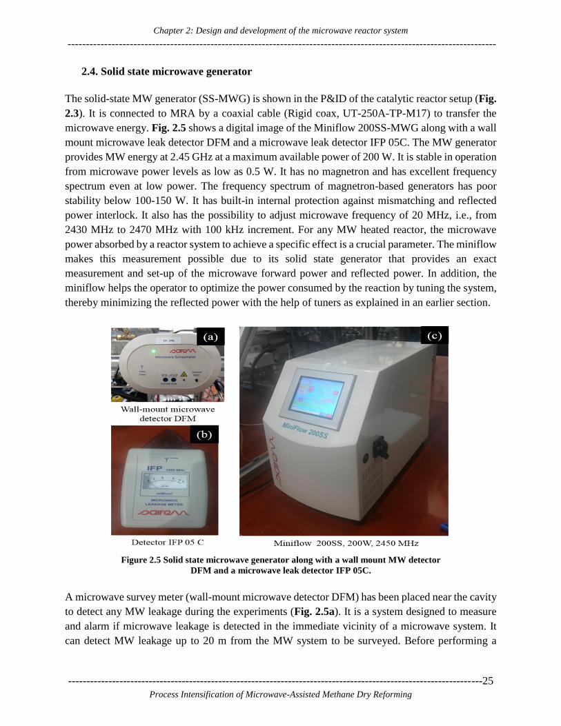
Chapter 2: Design and development of the microwave reactor system
---------------------------------------------------------------------------------------------------------------------
-----------------------------------------------------------------------------------------------------------------25
Process Intensification of Microwave-Assisted Methane Dry Reforming
2.4. Solid state microwave generator
The solid-state MW generator (SS-MWG) is shown in the P&ID of the catalytic reactor setup (Fig.
2.3). It is connected to MRA by a coaxial cable (Rigid coax, UT-250A-TP-M17) to transfer the
microwave energy. Fig. 2.5 shows a digital image of the Miniflow 200SS-MWG along with a wall
mount microwave leak detector DFM and a microwave leak detector IFP 05C. The MW generator
provides MW energy at 2.45 GHz at a maximum available power of 200 W. It is stable in operation
from microwave power levels as low as 0.5 W. It has no magnetron and has excellent frequency
spectrum even at low power. The frequency spectrum of magnetron-based generators has poor
stability below 100-150 W. It has built-in internal protection against mismatching and reflected
power interlock. It also has the possibility to adjust microwave frequency of 20 MHz, i.e., from
2430 MHz to 2470 MHz with 100 kHz increment. For any MW heated reactor, the microwave
power absorbed by a reactor system to achieve a specific effect is a crucial parameter. The miniflow
makes this measurement possible due to its solid state generator that provides an exact
measurement and set-up of the microwave forward power and reflected power. In addition, the
miniflow helps the operator to optimize the power consumed by the reaction by tuning the system,
thereby minimizing the reflected power with the help of tuners as explained in an earlier section.
Figure 2.5 Solid state microwave generator along with a wall mount MW detector
DFM and a microwave leak detector IFP 05C.
A microwave survey meter (wall-mount microwave detector DFM) has been placed near the cavity
to detect any MW leakage during the experiments (Fig. 2.5a). It is a system designed to measure
and alarm if microwave leakage is detected in the immediate vicinity of a microwave system. It
can detect MW leakage up to 20 m from the MW system to be surveyed. Before performing a
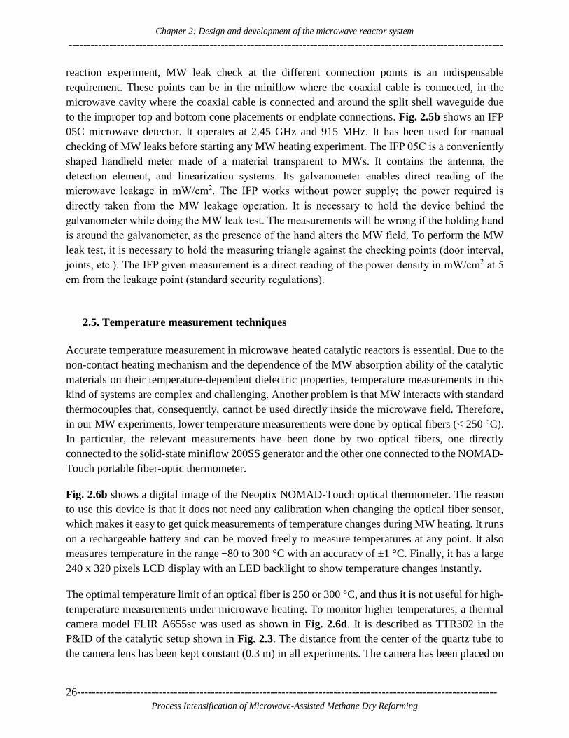
Chapter 2: Design and development of the microwave reactor system
---------------------------------------------------------------------------------------------------------------------
26-----------------------------------------------------------------------------------------------------------------
Process Intensification of Microwave-Assisted Methane Dry Reforming
reaction experiment, MW leak check at the different connection points is an indispensable
requirement. These points can be in the miniflow where the coaxial cable is connected, in the
microwave cavity where the coaxial cable is connected and around the split shell waveguide due
to the improper top and bottom cone placements or endplate connections. Fig. 2.5b shows an IFP
05C microwave detector. It operates at 2.45 GHz and 915 MHz. It has been used for manual
checking of MW leaks before starting any MW heating experiment. The IFP 05C is a conveniently
shaped handheld meter made of a material transparent to MWs. It contains the antenna, the
detection element, and linearization systems. Its galvanometer enables direct reading of the
microwave leakage in mW/cm2. The IFP works without power supply; the power required is
directly taken from the MW leakage operation. It is necessary to hold the device behind the
galvanometer while doing the MW leak test. The measurements will be wrong if the holding hand
is around the galvanometer, as the presence of the hand alters the MW field. To perform the MW
leak test, it is necessary to hold the measuring triangle against the checking points (door interval,
joints, etc.). The IFP given measurement is a direct reading of the power density in mW/cm2 at 5
cm from the leakage point (standard security regulations).
2.5. Temperature measurement techniques
Accurate temperature measurement in microwave heated catalytic reactors is essential. Due to the
non-contact heating mechanism and the dependence of the MW absorption ability of the catalytic
materials on their temperature-dependent dielectric properties, temperature measurements in this
kind of systems are complex and challenging. Another problem is that MW interacts with standard
thermocouples that, consequently, cannot be used directly inside the microwave field. Therefore,
in our MW experiments, lower temperature measurements were done by optical fibers (< 250 °C).
In particular, the relevant measurements have been done by two optical fibers, one directly
connected to the solid-state miniflow 200SS generator and the other one connected to the NOMAD-
Touch portable fiber-optic thermometer.
Fig. 2.6b shows a digital image of the Neoptix NOMAD-Touch optical thermometer. The reason
to use this device is that it does not need any calibration when changing the optical fiber sensor,
which makes it easy to get quick measurements of temperature changes during MW heating. It runs
on a rechargeable battery and can be moved freely to measure temperatures at any point. It also
measures temperature in the range ̶ 80 to 300 °C with an accuracy of ±1 °C. Finally, it has a large
240 x 320 pixels LCD display with an LED backlight to show temperature changes instantly.
The optimal temperature limit of an optical fiber is 250 or 300 °C, and thus it is not useful for high-
temperature measurements under microwave heating. To monitor higher temperatures, a thermal
camera model FLIR A655sc was used as shown in Fig. 2.6d. It is described as TTR302 in the
P&ID of the catalytic setup shown in Fig. 2.3. The distance from the center of the quartz tube to
the camera lens has been kept constant (0.3 m) in all experiments. The camera has been placed on

Chapter 2: Design and development of the microwave reactor system
---------------------------------------------------------------------------------------------------------------------
-----------------------------------------------------------------------------------------------------------------27
Process Intensification of Microwave-Assisted Methane Dry Reforming
its stand in front of a germanium window as shown in Fig. 2.4b. It operates in the 7.5 –14 μm
spectral range and measures temperature from ̶ 40 to 2000 °C. The FLIR ResearchIR Max software
is used to record and collect thermal data during the experimental work. 2D monitoring of the
catalytic bed temperature was done to track hotspot locations and control the MW power in order
to avoid thermal runaway conditions. As the thermal camera-based temperature measurement is a
non-contact technique, the critical factor for accurate measurements is the correct emissivity value.
To correct the emissivity value and track temperature, N-type thermocouples were used during
microwave heating. The full details on the combined use of the thermal camera and thermocouples
for temperature monitoring can be found in [54].
Figure 2.6 Temperature measurement techniques used: (a) optical fiber, (b) NOMAD-Touch optical
thermometer, (c) N-type thermocouple and (d) thermal camera mode A655sc.
2.6. Product gas analysis
Due to the generation and migration of hotspots during MW heating, it is difficult to reproduce the
temperature values, unlike the case of conventional heating experiments. Therefore, it is
indispensable to continuously monitor the reaction progress or analyze the product gases with
respect to MW power input while studying MW heated reactions. Fig. 2.7 shows that two analytical
instruments, a mass spectrometer, and a micro GC, are part of the P&ID for product gas analysis.
In this project, we used only the Varian CP4900 micro-GC. It is equipped with a TCD detector and
uses two columns, 20 m MS5A and 10 m PPU, for analysis.
During our reaction studies, there is the possibility of water generation due to reverse water gas
shift reaction at low MW power inputs. Therefore, before analysis of the product gas, it is essential
Chapter 2: Design and development of the microwave reactor system
---------------------------------------------------------------------------------------------------------------------
28-----------------------------------------------------------------------------------------------------------------
Process Intensification of Microwave-Assisted Methane Dry Reforming
first to cool it down to avoid moisture content in the μGC. To that end, a condenser (CND), as
shown in Fig. 2.3, is placed at the exit of the reactor to avoid condensation in the line towards the
μGC. Two thermostats are used to pump the coolant (a mixture of ethylene glycol and water in a
2:1 ratio). TST 1, a Lauda Thermostat RE 304 is used to maintain the MW cavity and condenser
temperatures. TST 2, a Lauda RE 620 is used to maintain the gas wash bottle temperature. The gas
wash bottle (GWB2), as shown in Fig. 2.3, is filled with calcium oxide (CaO), an adsorption agent,
to dewater the remaining moisture present in the outlet gas line. A Whatman FP050/1 filter holder
with 50 mm filter paper (FLT3), as shown in Fig 2.3 and a genie membrane (GMB) as shown in
Fig. 2.7, are placed after the gas wash bottle to avoid any impurities towards the μGC.
In order to do a comparative study of microwave heated reactions with their conventional
counterparts, a tubular furnace, described as FNC in Fig 2.8, has also been installed. It is a Carbolite
tubular furnace (FNC) MTF 10/15/130, 1000 °C, 15 mmØ x 130 mm heated length. In the present
setup configuration, only the MRA is replaced by the tubular furnace while the other setup parts
remain the same. Both the MRA and the tubular furnace are placed in the specially designed
enclosure shown in Fig. 2.3. The enclosure has three holes with fringes on to adjust the reflector
positions during the reaction. The enclosure has an interlock, which does not allow the flow of
gases when the enclosure is open. On the top side of the enclosure, a ventilation system with a flow
sensor (FT391) is placed to check the ventilation flow speed; if the flow is less than the set value,
then the electric cabinet shows a red signal and does not allow operation of the reactor. The shared
gas sensors (XT380, 381, 382 and 383) are placed inside the enclosure. These are gas alarm sensors
for CO, CO2, O2 and explosion limit, respectively.
2.7. Reactor control system
The LabVIEW interface, the µGC software, and the thermal camera software are installed on
separate computers and are connected to one screen using a KVM switch to control the various
functions of the reactor. Aten CS1708A 8-Port PS/2-USB KVMP Switch is used for this purpose.
A single CS1708A unit can control up to 8 computers. The LabVIEW interface along with an NI-
9074 cRIO controller is used to control the setup and take care of data acquisition. The controller
interfaces with; 1. valves and valve status readouts, 2. mass flow controllers (Bronkhorst) to
regulate gas flows, 3. pressure sensors and 4. N-type thermocouples.

Chapter 2: Design and development of the microwave reactor system
---------------------------------------------------------------------------------------------------------------------
-----------------------------------------------------------------------------------------------------------------29
Process Intensification of Microwave-Assisted Methane Dry Reforming
Figure 2.7 P&ID part with GC and mass spectrometer details
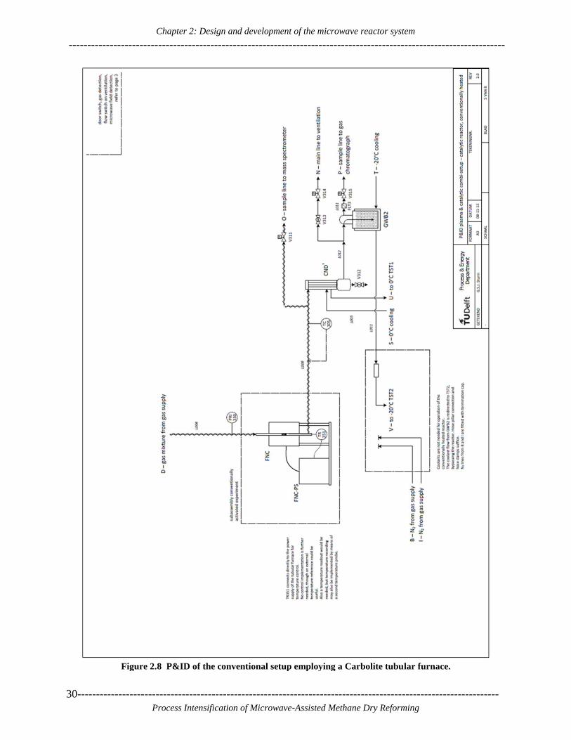
Chapter 2: Design and development of the microwave reactor system
---------------------------------------------------------------------------------------------------------------------
30-----------------------------------------------------------------------------------------------------------------
Process Intensification of Microwave-Assisted Methane Dry Reforming
Figure 2.8 P&ID of the conventional setup employing a Carbolite tubular furnace.

Chapter 2: Design and development of the microwave reactor system
---------------------------------------------------------------------------------------------------------------------
-----------------------------------------------------------------------------------------------------------------31
Process Intensification of Microwave-Assisted Methane Dry Reforming
Through the control interface, the valves on the gas supply lines can be opened. The valves that
control the flow of gas to and from the different setups are controlled by the selector switch on the
cabinet. The status (open or closed) of all valves is read out by the controller. The system for gas
selection has a security system that prevents the different supply lines connected to one mass flow
controller from opening at the same time. The system also inputs a new conversion factor to the
mass flow controller interface when a valve is opened. The valve control subsystem communicates
through three notifiers with other subsystems. It receives the digital inputs and system states
through the notifier ‘DI_Signals.' Commands are received through ‘ValveControl,' and the
conversion factors are sent through ‘MFC_Conv.’ The system uses five mass flow controllers and
an evaporation system from Bronkhorst (Table 2.1). Commands to this system are sent over the
flow bus through the chassis RS-232 port of the Compact Rio.
Figure 2.9 (a) cabinet of the control system and (b) manual buttons for reactor selection along
with safety indicators
Fig. 2.9a shows the control cabinet for both microwave catalytic and plasma setups. Fig 2.9b shows
the manual selection buttons for the reactors along with safety indicators. The top blue button is an
emergency stop reset button. The three green buttons in the middle are for the plasma reactor, the
neutral state, and the microwave catalytic reactor, respectively. The standard black and white color
button allow for N2 flow even when the enclosure is open, to perform the reactor leak test after
reactor loading. Four green indicators are installed for each reactor to ensure that; 1st the coolant
flow is ON or OFF, 2nd to indicate whether the enclosure is closed or open, 3rd to indicate whether
the airflow of ventilation is ON or OFF and 4th to indicate the position of the microwave generator
to plasma or catalytic reactor.

Chapter 2: Design and development of the microwave reactor system
---------------------------------------------------------------------------------------------------------------------
32-----------------------------------------------------------------------------------------------------------------
Process Intensification of Microwave-Assisted Methane Dry Reforming
Digital inputs: Digital inputs are used to get the system status from the control cabinet and to read
the valve state indicators. The signals are read out in the FPGA and then processed by the digital
input subsystem. The result is transmitted through the notifier ‘DI_Signals.' The system state is
determined using the elements mentioned in Table 2.3. The inputs for ‘Emergency stop’ and
‘Alarm’ can overrule the other inputs. So if DI 0 switches to a low state then the state of the other
inputs are ignored. In ‘Emergency stop’ and ‘Alarm’ states, all set points are set back to zero, and
the gas supply valves are closed. It is essential to use the buttons on the control cabinet first, as
shown in Fig. 2.9, to switch from the neutral state to the catalytic state. When this selection is
made, the valves connecting the setup (V-124, V-314, V-315) get open.
Table 2.3: Digital input states and resulting system states.
L is a low signal, H high signal.
DI 0 1 2 3 State
L Emergency stop
L Alarm
L L Alarm
H H Neutral
L H Plasma
H L Catalytic
2.8. Reactor operating procedure and safety
2.8.1. Experimental start-up procedure
To work safely and avoid manual errors, a standard methodology to work with the reactor was
developed. The methodology comprises the steps below that are carried out in the given order (i.e.,
stepping from the first to the last bullet point):
Fill in the quartz tube reactor with the desired amount of catalyst and introduce it inside MRA.
Connect inlet and outlet line Swagelok connections.
Insert thermocouples to the top and bottom part of the catalytic bed (the thermocouples should
not be placed inside the MRA to avoid interaction with MW).
Set the thermal camera position such that it focuses on the catalytic bed inside the MRA for
collecting thermal images during experiments.
Check the ventilation flow switch indicator.
Set the flow rates for thermostats 1 and 2 at the required temperatures and start both thermostat
flows.
Do leak tests at inlet and outlet connections under N2 flow with a trace detector before sending
reactant gases.
Connect the MW generator to MRA using a coaxial cable. Open the source valves of the carrier
and reactant gases lines from the main gas line supply.

Chapter 2: Design and development of the microwave reactor system
---------------------------------------------------------------------------------------------------------------------
-----------------------------------------------------------------------------------------------------------------33
Process Intensification of Microwave-Assisted Methane Dry Reforming
Turn on the control unit for mass flow controllers and pneumatic valves from the LabVIEW
interface. Check whether all thermocouples and thermal camera are connected or not to the
temperature control system and thermal camera software.
Close the enclosure while performing the reaction experiment and switch on the microwave
survey meter to check for microwave leakage during experiments.
Start the Mini-Flow 200SS and first set the minimum power to check the heating behavior of
the catalytic material. Increase MW power as per the temperature response of the material. Test
the heating behavior of the catalyst up to 1000 °C. Bring back the temperature to the required
level by tuning power and feed the reactant gases.
Record gas-solid temperature differences when the reactant gases flow through the catalytic
bed. Try to maintain temperature with varying power. Note down forward and reflected power
for each temperature interval. Feed a small amount of sample to GWB2 and then to micro GC
for product gas analysis. Maintain ~15-20 ml/min flow towards GC with the help of the manual
ball valve V313 and direct the rest of the product gas to ventilation. Monitor pressure on
PRI301; it will increase in the case of catalyst sintering or block of inlet flow due to excessive
coke formation. If the reactor pressure reaches ~2 bar, then the reactant gas flow will be
automatically stopped by the reactor control system in order to avoid quartz tube damage.
Thermocouple values, gas flow values towards GC and forward and reflected MW powers
should continuously be recorded in the log book while performing the MW experiments.
2.8.2. Shut down procedure
After finishing a MW experiment, it is imperative to shut off the entire MW reactor system
properly. This comprises the following steps:
The first essential thing is to shut down the microwave generator in case of MW heating and
the furnace in case of conventional heating experiments and allow the reactors to cool down
naturally under N2 flow and coolant flow.
Set the temperature of the furnace to ambient and allow it to cool down.
Set the flow of reactant gases to zero and allow only N2 to flow through the reactor until it
reaches room temperature. Switch off both thermostats after the system is at room temperature.
Save a) thermal videos to a self-viewing file format for post-processing; b) LabVIEW login
data files to retrieve thermocouple temperature values; c) GC data in drive folder.
Disconnect the camera from its software and then remove it.
Set N2 flow to zero and turn off the control system for the mass flow controller and evaporator.
Keep GC for conditioning overnight to clean the GC columns. If all necessary experiments
have been performed, then remove the quartz tube and unload the catalyst. Always keep the
enclosure closed when the set up is not in use.

Chapter 2: Design and development of the microwave reactor system
---------------------------------------------------------------------------------------------------------------------
34-----------------------------------------------------------------------------------------------------------------
Process Intensification of Microwave-Assisted Methane Dry Reforming
2.9. Summary and recommendations for further improvement
In this project, we have designed and developed a microwave reactor assembly (MRA) and built a
new microwave reactor setup. We have successfully verified that the MRA can effectively heat
several catalytic materials up to high temperatures (1000 oC) and be used to carry out relevant
heterogeneous catalytic reactions, such as methane dry reforming that has experimentally been
studied in this project. The MRA can provide concentrated microwave energy to the catalytic bed
leading to >95% energy utilization efficiency and minimization of wasted MW energy. The
provision to measure or monitor temperature with the help of a thermal camera provides a better
understanding of the temperature changes inside the catalytic bed. In particular, the thermal camera
helps detect hotspot formation during MW heating, or chemical reaction experiments in the static
microwave-heated fixed bed quartz tube reactor. This approach allows for adjustment of the
microwave power input to avoid reactor damage due to thermal runaway. However, it is sometimes
difficult to manually control uneven heat or temperature distribution inside the catalytic bed.
Therefore, devising an automated temperature-to-power control system for the existing reactor is
recommended for future projects. It will also be useful to develop a parallel technique, which will
record thermocouple temperatures and input them to the thermal camera calculator that will
instantly update the emissivity value according to the actual thermocouple temperature; this will,
in turn, enable the immediate update of the 2D temperature distribution inside the reactor in the
course of the experiment. Finally, during the experimental work, it was observed that not all
materials could be effectively heated in this reactor, as different materials have different dielectric
properties. Therefore replacing the existing MW generator with a higher power MW generator
could be helpful to heat up the weakly MW absorbing materials.

Chapter 3: Complexity and challenges in non-contact high temperature measurements in microwave-assisted
catalytic reactors
---------------------------------------------------------------------------------------------------------------------
-----------------------------------------------------------------------------------------------------------------35
Process Intensification of Microwave-Assisted Methane Dry Reforming
3 3. Complexity and challenges in non-
contact high-temperature measurements
in microwave-assisted catalytic reactors
---------------------------------------------------------------------------------------------------------------------
This Chapter is published as:
Lalit S. Gangurde, Guido S.J. Sturm, Tushar J. Devadiga, A. I. Stankiewicz, Georgios Stefanidis,
Complexity and challenges in non-contact high-temperature measurements in microwave-assisted
catalytic reactors, Industrial and Engineering Chemistry Research, 56 (45), 13379–13391, 2017.
---------------------------------------------------------------------------------------------------------------------

Chapter 3: Complexity and challenges in non-contact high temperature measurements in microwave-assisted
catalytic reactors
---------------------------------------------------------------------------------------------------------------------
36-----------------------------------------------------------------------------------------------------------------
Process Intensification of Microwave-Assisted Methane Dry Reforming

Chapter 3: Complexity and challenges in non-contact high temperature measurements in microwave-assisted
catalytic reactors
---------------------------------------------------------------------------------------------------------------------
-----------------------------------------------------------------------------------------------------------------37
Process Intensification of Microwave-Assisted Methane Dry Reforming
Abstract
The complexity and challenges in non-contact temperature measurements inside microwave-
heated catalytic reactors are presented in this chapter. A custom-designed microwave cavity has
been used to focus the microwave field on the catalyst and enable monitoring of the temperature
field in 2D. A methodology to study the temperature distribution in the catalytic bed by using a
thermal camera in combination with a thermocouple for a heterogeneous catalytic reaction
(methane dry reforming) under microwave heating has been demonstrated. The effect of various
variables that affect the accuracy of temperature recordings are discussed in detail. The necessity
of having at least one contact sensor, such as a thermocouple, or some other microwave
transparent sensor, is recommended to keep track of the temperature changes occurring in the
catalytic bed during the reaction under microwave heating.
Graphical Abstract:

Chapter 3: Complexity and challenges in non-contact high temperature measurements in microwave-assisted
catalytic reactors
---------------------------------------------------------------------------------------------------------------------
38-----------------------------------------------------------------------------------------------------------------
Process Intensification of Microwave-Assisted Methane Dry Reforming
Chapter 3: Complexity and challenges in non-contact high temperature measurements in microwave-assisted
catalytic reactors
---------------------------------------------------------------------------------------------------------------------
-----------------------------------------------------------------------------------------------------------------39
Process Intensification of Microwave-Assisted Methane Dry Reforming
3.1. Introduction
The history of microwave (MW) technology confirms its rapid development after the thermal
effects of microwave heating were discovered in the 1940s [55][56]. Since then microwave heating
has been applied to food processing, polymer processing, plasma processing, organic chemistry,
sintering of metals, inorganic material synthesis and various industrial and research applications.
Microwave heating in catalytic material synthesis, multiphase catalysis like gas-solid and solid-
liquid reactions, has shown performance improvements as compared to conventional heating mode,
due to its rapid, selective and volumetric nature [23][29][30]. Along with its thermal effects, non-
thermal microwave effects have also been reported to be responsible for increased catalytic
activities resulting in overall improved process performance [30]. In some works, energy
consumption measurements of microwave heated processes have shown that lower energy
consumption and higher heating rates are obtained compared to conventionally heated processes
[57][58]. Recent developments in the wind, solar, plasma and microwave technologies have shown
the importance of microwave energy as a renewable, clean and exergetically efficient form of
energy [59][60].
To use microwave energy efficiently for any chemical process requires a good understanding of
process parameters and knowledge of materials response under their exposure to microwaves.
Dielectric properties measurements provide insight into the heating ability of any material under
microwave exposure [61][62]. The dielectric properties of any material or fluid are described by
their complex permittivity (ɛ*). The complex permittivity (ɛ*) is divided into two parts; a) the
dielectric constant (𝜀′), or real part of the dielectric permittivity, represents the ability of the
material to store electric energy in its structure; b) the loss factor (𝜀′′), or imaginary part of the
dielectric permittivity, indicates the ability of the material to dissipate the stored electric energy in
the form of heat. The ratio of the loss factor to the dielectric constant is called loss tangent (tan δ).
Along with dielectric properties, the physics of electromagnetism involved during MW heating,
the wave nature of microwave field and its high degree of control are also essential to consider
[63]. Therefore, it is important to know the dielectric properties of catalytic materials, preferably
in the real reaction conditions, or at least in the expected temperature range of the catalytic
application.
Horikoshi et al. reported generation of hot spots (electric discharges) and their impact on
heterogeneous Suzuki-Miyaura coupling reaction for the synthesis of 4-methylbiphenyl in toluene
solvent in the presence of Pd/AC catalyst [64]. Zhang et al. studied microwave assisted sulfur
dioxide reduction using methane over MoS2 catalyst and reported that the enhanced reaction
performance was a result of hotspot generation within the catalyst itself [65]. To generalize, non-
uniform microwave and hot spots formation at particle or reactor scale frequently determine reactor
performance. Hence, it is important to track these temperature patterns experimentally.

Chapter 3: Complexity and challenges in non-contact high temperature measurements in microwave-assisted
catalytic reactors
---------------------------------------------------------------------------------------------------------------------
40-----------------------------------------------------------------------------------------------------------------
Process Intensification of Microwave-Assisted Methane Dry Reforming
The major technical challenge for a detailed investigation of temperature distribution is the
unsuitability of conventional methods and their limitations in measuring temperature under
microwave heating. The tutorial review on temperature measurement in microwave-heated
transformations, by Kappe, reports that accurate temperature measurement in microwave heated
system is a complex and non-trivial affair [66]. The review is concerned with external temperature
measurements and reports that surface measurements will always be problematic and will not
adequately record temperature variations inside the reactor, although proper calibration for non-
contact methods might provide realistic approximate temperature values. In the earlier work of our
group, fiber optic sensors were used to record temperature non-uniformities in solid catalytic beds
in the axial and radial directions [43][44]. Significant temperature gradients were found in a small
amount of sample heated in a mono-mode cavity. Recently, in the Ramirez group, a dual
temperature measurement method of thermography combined with optical fiber was developed to
investigate gas-solid temperature differences in a low-temperature range (100 to 250 °C), under
microwave heating [67][68]. In this method, the importance of corrected emissivity values to get
accurate thermographic temperature readings from a thermal camera was demonstrated. These
findings, however, were obtained in the low-temperature range (0 to 300 °C), where common
optical fibers can be used. As optical fibers cannot be used above 300 °C, reliable temperature
measurements under microwave heating above 300 °C becomes a major technical challenge to
resolve.
A literature study reveals a confusion regarding the direct use of metallic thermocouples in
microwave reactions. Pert et al. reported that the presence of thermocouples in microwave reactors
can locally distort the electromagnetic field, induce thermal instabilities and lead to serious
measurement errors [69]. Will et al. quickly inserted a thermocouple inside the catalytic bed when
MW was turned off, to avoid thermocouple-microwave interaction resulting in sparks [70]. In
contrast, Li et al. directly used a thermocouple under microwave heating for methane mixed
reforming [71]. They reported that the interaction of the thermocouple with microwaves could be
avoided by placing it in a 1-mm-thick quartz tube. Quartz, however, would theoretically not be
expected to shield a microwave field in this case, since its relative permittivity is 3.78‒0.001i,
which is not nearly sufficient to attenuate a microwave field over 1 mm distance.
Overall, direct use of a thermocouple inside a microwave reactor is risky, but its placement at the
position where it would not come in contact with microwaves is a better experimental approach.
Nonetheless, detection of hot spots and thermal gradients inside catalytic reactors are difficult to
measure with this approach. Previous simulation studies done in our group show that local
geometric and/or operating parameter variation at one point affects the microwave field over the
entire volume in a microwave coupled system [72]. Temperature measurement at one point inside
the reactor is insufficient in heterogeneous catalytic processes [43]. Therefore, an approach for
simultaneous temperature measurements inside a reactor and on the reactor wall needs to be
developed for high-temperature microwave-heated reactors.

Chapter 3: Complexity and challenges in non-contact high temperature measurements in microwave-assisted
catalytic reactors
---------------------------------------------------------------------------------------------------------------------
-----------------------------------------------------------------------------------------------------------------41
Process Intensification of Microwave-Assisted Methane Dry Reforming
The aim in this work is to develop such an approach for heterogeneous catalytic reactions occurring
under microwave heating in the range 300 to 1000 °C. The methane dry reforming (CH4 + CO2
2H2 + 2CO) reaction is taken as an illustrative example to study temperature distribution in the
catalytic bed under microwave heating. First, dielectric properties of 10 wt. % loading of platinum
on an activated carbon support (PtC) from room temperature to 850 °C are measured. A tailored
microwave cavity has been constructed and used to focus the microwave field on the loaded reactor
and collect thermal data in a 2D fashion. The factors affecting the thermal measurements are
explained and demonstrated by means of an approach combining the use of a thermal camera and
simultaneous thermocouple measurements. The existence of hot spots and their dislocations due to
different gas environments under MW heating are shown. Thermal gradient differences in axial
and radial positions in the catalytic bed are explained using thermal data post-processing.
3.2. Experimental Section
3.2.1. Schematic diagram of the microwave reactor
A schematic diagram of the microwave reactor system is shown in Fig. 3.1. The most important
parts of this schematic are the custom-designed microwave reactor and quartz tube for the catalyst
loading. The LabVIEW interface along with an NI-9074 cRIO controller is used to control the
setup operation and perform data acquisition. The controller interfaces with valve status readouts,
mass-flow controllers (Bronkhorst) to regulate gas flows, pressure sensor, and N-type
thermocouples. For non-contact temperature measurements, the thermal camera model FLIR
A655sc is used. It operates in the 7.5 – 14 μm spectral range and measures temperature from ‒40
to 2000 °C. Thermal data from the experiments was collected via a PC using the FLIR ResearchIR
Max software. A solid-state microwave generator (SAIREM Miniflow 200 SS) is used to supply
the MW energy at 2.45 GHz. The maximum available power is 200W.
A condenser is added at the exit of the reactor to avoid condensation in the ventilation line and the
line towards the GC. Two thermostats are used to pump the coolant as a mixture of ethylene glycol
and water at a ratio of 2:1 (EG: H2O). One is used to maintain the gas wash bottle temperature at ‒
8 °C. The second one maintains the MW cavity and condenser temperature at +8 °C. The gas wash
bottle is filled with CaO, as adsorption agent, to dewater the remaining moisture in the outlet gas
line. A Whatman FP050/1 filter holder with 50 mm filter paper and Genie membrane are placed
after the gas wash bottle to avoid any impurities towards the chromatogram. A Varian CP4900
micro-GC is used for product gas analysis. It is equipped with a TCD detector. It uses two columns,
20 m MS5A and 10 m PPU, for analysis. The LabVIEW interface, the µGC software, and the
thermal camera software were controlled by separate computers connected to one screen using a
KVM switch.
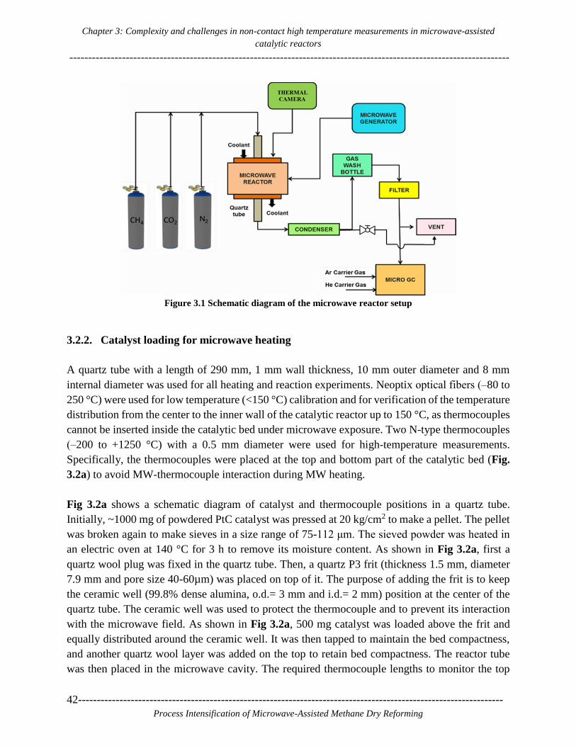
Chapter 3: Complexity and challenges in non-contact high temperature measurements in microwave-assisted
catalytic reactors
---------------------------------------------------------------------------------------------------------------------
42-----------------------------------------------------------------------------------------------------------------
Process Intensification of Microwave-Assisted Methane Dry Reforming
Figure 3.1 Schematic diagram of the microwave reactor setup
3.2.2. Catalyst loading for microwave heating
A quartz tube with a length of 290 mm, 1 mm wall thickness, 10 mm outer diameter and 8 mm
internal diameter was used for all heating and reaction experiments. Neoptix optical fibers (‒80 to
250 °C) were used for low temperature (<150 °C) calibration and for verification of the temperature
distribution from the center to the inner wall of the catalytic reactor up to 150 °C, as thermocouples
cannot be inserted inside the catalytic bed under microwave exposure. Two N-type thermocouples
(‒200 to +1250 °C) with a 0.5 mm diameter were used for high-temperature measurements.
Specifically, the thermocouples were placed at the top and bottom part of the catalytic bed (Fig.
3.2a) to avoid MW-thermocouple interaction during MW heating.
Fig 3.2a shows a schematic diagram of catalyst and thermocouple positions in a quartz tube.
Initially, ~1000 mg of powdered PtC catalyst was pressed at 20 kg/cm2 to make a pellet. The pellet
was broken again to make sieves in a size range of 75-112 μm. The sieved powder was heated in
an electric oven at 140 °C for 3 h to remove its moisture content. As shown in Fig 3.2a, first a
quartz wool plug was fixed in the quartz tube. Then, a quartz P3 frit (thickness 1.5 mm, diameter
7.9 mm and pore size 40-60µm) was placed on top of it. The purpose of adding the frit is to keep
the ceramic well (99.8% dense alumina, o.d.= 3 mm and i.d.= 2 mm) position at the center of the
quartz tube. The ceramic well was used to protect the thermocouple and to prevent its interaction
with the microwave field. As shown in Fig 3.2a, 500 mg catalyst was loaded above the frit and
equally distributed around the ceramic well. It was then tapped to maintain the bed compactness,
and another quartz wool layer was added on the top to retain bed compactness. The reactor tube
was then placed in the microwave cavity. The required thermocouple lengths to monitor the top

Chapter 3: Complexity and challenges in non-contact high temperature measurements in microwave-assisted
catalytic reactors
---------------------------------------------------------------------------------------------------------------------
-----------------------------------------------------------------------------------------------------------------43
Process Intensification of Microwave-Assisted Methane Dry Reforming
and bottom position of the catalytic bed were already measured and then inserted into the ceramic
well to avoid microwave‒thermocouple interaction.
Figure 3.2 (a) Schematic diagram of catalyst and thermocouple positions in the quartz tube,
(b) Digital image of the custom-designed MW reactor with a quartz tube inside.

Chapter 3: Complexity and challenges in non-contact high temperature measurements in microwave-assisted
catalytic reactors
---------------------------------------------------------------------------------------------------------------------
44-----------------------------------------------------------------------------------------------------------------
Process Intensification of Microwave-Assisted Methane Dry Reforming
3.2.3. Thermal camera working principle
The main advantages of non-contact infrared thermal cameras are their speed and their ability to
measure in broad temperature ranges. As a non-contact measurement technique, the thermal camera
detector does not measure temperature directly; it calculates the temperature using the Stefan-
Boltzmann law and the emissivity value of the object or area of interest. The emissivity (ɛ) is a
measure of an objects ability to emit infrared radiation. Eq. 3.1 describes the relation between
irradiation flux, temperature and emissivity value [67].
J = ɛ.σ.T4 (3.1)
Where, J is the irradiance flux,
ɛ is the emissivity,
σ is Stefan-Boltzmann constant (5.6×10⁻⁸m-2K-4).
The emissivity change with temperature is a primary source of error in temperature measurements
[73]. The emissivity also gets affected by structural or physical changes in the materials [74].
Inaccurate estimation of emissivity using table values incorrectly can also result in significant
temperature measurement errors [75]. The emissivity of quartz glass has been reported to decrease
with increasing temperature [76], and the emissivity of metals or metallic powders increases
parabolically with temperature [73]. The extraction of accurate temperatures using a thermal
camera is not possible without corrected emissivity of the heated load [75].
Figure 3.3 Schematic representation of the different media affecting the irradiance flux
before reaching to the thermal camera (where T is the temperature and τ is the
transmittance)
In our case, the heated load (catalytic reactor) is a combination of Pt, carbon and quartz tube of 1
mm thickness. As shown in Fig. 3.3, the infrared radiation of the catalytic bed has to travel through
different mediums and through the germanium window from the microwave cavity to the camera
detector. Therefore, it is imperative to consider medium changes during the emissivity calculation

Chapter 3: Complexity and challenges in non-contact high temperature measurements in microwave-assisted
catalytic reactors
---------------------------------------------------------------------------------------------------------------------
-----------------------------------------------------------------------------------------------------------------45
Process Intensification of Microwave-Assisted Methane Dry Reforming
procedure to ensure its correct value. Overall, in our case, infrared radiation received by the thermal
camera gets affected by (1) the microwave field distribution in the catalyst bed, (2) changes in
transmittance of the quartz tube, (3) the microwave cavity wall temperature (8 °C) as a first
medium, (4) the anti-reflected coated germanium window and (5) the conditions of external
atmospheric (22 °C), as a second medium. As the cavity wall to quartz tube distance is ~70 mm,
the average temperature inside the cavity during microwave heating is expected to be higher than
its wall temperature (8 °C) even with the application of cooling. However, in our case, the actual
target temperature, as measured by the inside thermocouple, is provided to the camera software,
which then automatically adjusts the apparent emissivity value according to the actual temperature
given; therefore, the apparent emissivity value calculated is not affected by the temperature
gradient outside the reactor.
3.2.4. Dry reforming reaction testing procedure under microwave heating
It is difficult to control and provide MW energy when the selective heating behavior of a complex
catalytic system is unknown. Hence, first, a MW heating test under real reaction conditions was
performed by increasing power from 0 to 200 W. From this heating test and reaction performance
evaluation, 150 W of MW power was found to give the maximum reactants conversions for the
PtC catalyst used. Therefore, we performed methane dry reforming at 150 W, 34 ml/min total
reactant gas flow at 1:1 volume ratio of CH4:CO2 and atmospheric pressure. Once the catalyst
reached a stable temperature under N2 flow with 150 W, methane and carbon dioxide reactant gases
were fed to the reactor. After 1000 s of MW heating time, the product gases were repetitively
analyzed by the chromatogram (GC) every 400 s of reaction time intervals to evaluate the reaction
progress.
3.3. Results and Discussion
3.3.1. Dielectric properties of catalyst measured at high temperature
Dielectric properties of 10 wt. % Platinum on carbon (PtC) were measured in specially designed
equipment at the ITACA Institute of Valencia University, Spain. The methodologies mentioned in
the refs [77] and [78] have been followed for the measurements. The PtC sample was placed in a
quartz tube, which was located inside the specially designed setup. The dielectric properties were
measured while simultaneously the sample was heated at 20 °C/min under N2 atmosphere. The
used methodology is based on the shift of the center resonant frequency and the alteration of the
quality factor of the microwave cavity in the presence of PtC catalyst as compared to the empty
cavity. The measurements were done in the range 20‒850 °C. The accuracy of dielectric
measurements was estimated as 3% for the dielectric constant and 10% for the loss factor in the
entire measured range.

Chapter 3: Complexity and challenges in non-contact high temperature measurements in microwave-assisted
catalytic reactors
---------------------------------------------------------------------------------------------------------------------
46-----------------------------------------------------------------------------------------------------------------
Process Intensification of Microwave-Assisted Methane Dry Reforming
Figure 3.4 (a) Dielectric constant (ε’) and loss factor (ε’’) vs temperature. (b) Loss tangent (δ) vs
temperature.
Three cycles of heating up to 850 °C with a heating rate of 20 °C/min followed by natural cooling
using 0.507 g of PtC catalyst were performed. The evolution of the dielectric properties of the
catalyst with temperature in the third cycle is shown in Fig. 3.4. Fig. 3.4a and b show that the
materials dielectric properties have an overall increasing trend in the examined temperature range,
but this trend is not monotonic.
The pre-processing or pre-heating of some materials may result in a change of their physical or
chemical properties, e.g., density, which can also affect their dielectric properties. The observed
decrease in the dielectric properties values at 360‒375 °C is due to sample volume reduction as
shown in Fig. 3.13(supporting information). This volume reduction could be attributed to moisture
removal, and the shrinking of the material occurred during the heating up to 850 °C. The possibility
of sample reduction due to moisture removal was not expected to happen after the first
measurement cycle, as the sample tube was not open to absorb water before the second and third
cycles. Therefore, volume reduction in the second and third cycles was majorly due to shrinking
of the sample, which is responsible for the density change of the material and hence of the dielectric
properties in the temperature range 360‒375 °C. However, the effect of platinum might be
predominant at temperatures higher than 600 °C, which results in increasing dielectric property
values at temperatures above 600 ºC.
3.3.2. Radial temperature and emissivity differences by optical fibers
As thermocouples cannot be inserted directly inside the microwave field, we performed low
temperature heating tests using optical fibers to calculate emissivities at the center and inner wall
optical fiber positions. Fig. 3.5a shows the catalyst loaded quartz tube that is placed inside the
microwave cavity along with two optical fibers kept in glass capillaries. The first sensor is placed
at the center of the reactor and the second one at the inner wall of the quartz tube. Optical fiber 1
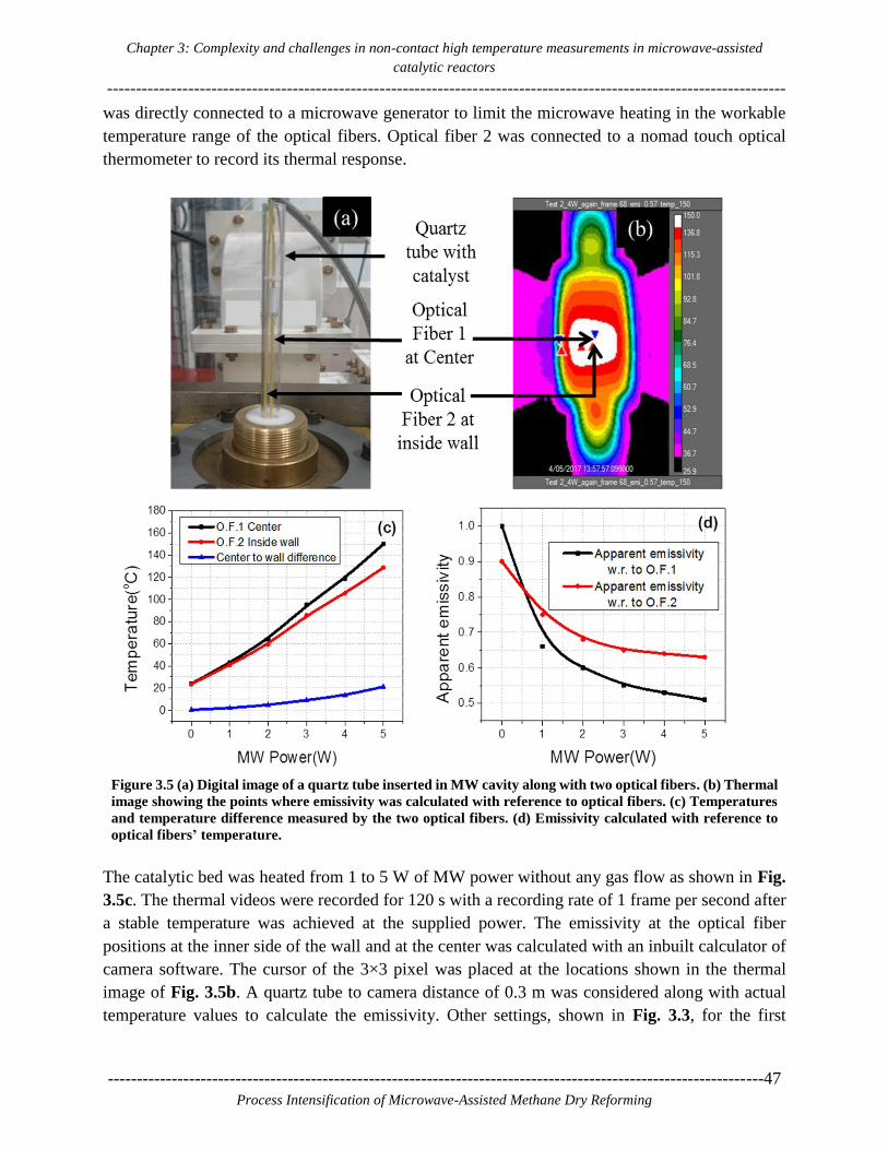
Chapter 3: Complexity and challenges in non-contact high temperature measurements in microwave-assisted
catalytic reactors
---------------------------------------------------------------------------------------------------------------------
-----------------------------------------------------------------------------------------------------------------47
Process Intensification of Microwave-Assisted Methane Dry Reforming
was directly connected to a microwave generator to limit the microwave heating in the workable
temperature range of the optical fibers. Optical fiber 2 was connected to a nomad touch optical
thermometer to record its thermal response.
Figure 3.5 (a) Digital image of a quartz tube inserted in MW cavity along with two optical fibers. (b) Thermal
image showing the points where emissivity was calculated with reference to optical fibers. (c) Temperatures
and temperature difference measured by the two optical fibers. (d) Emissivity calculated with reference to
optical fibers’ temperature.
The catalytic bed was heated from 1 to 5 W of MW power without any gas flow as shown in Fig.
3.5c. The thermal videos were recorded for 120 s with a recording rate of 1 frame per second after
a stable temperature was achieved at the supplied power. The emissivity at the optical fiber
positions at the inner side of the wall and at the center was calculated with an inbuilt calculator of
camera software. The cursor of the 3×3 pixel was placed at the locations shown in the thermal
image of Fig. 3.5b. A quartz tube to camera distance of 0.3 m was considered along with actual
temperature values to calculate the emissivity. Other settings, shown in Fig. 3.3, for the first

Chapter 3: Complexity and challenges in non-contact high temperature measurements in microwave-assisted
catalytic reactors
---------------------------------------------------------------------------------------------------------------------
48-----------------------------------------------------------------------------------------------------------------
Process Intensification of Microwave-Assisted Methane Dry Reforming
medium cavity environment; (temperature 8 °C, 100% transmittance), second medium (air at
temperature 22 °C, 100% transmittance) and germanium window (temperature of 22 °C, 96%
transmittance) were also adjusted in the camera software aside from the calculation of emissivity.
As shown in the emissivity graphs of Fig. 3.5c and d, the emissivity values at the center optical
fiber 1 and at the inside wall optical fiber 2 can help obtain the direct center-to-inner surface
temperature differences at the same quartz surface location. Fig. 3.5d clearly shows a decreasing
trend of emissivity with an increase in temperature in both the center and surface cases. The
emissivity value at the center is observed to be lower than the inside wall emissivity as temperature
increases. These low-temperature heating experiments showed that center temperature emissivity
and inside wall emissivity are very helpful to finding the radial temperature differences. Fig. 3.5c
clearly shows that as the temperature inside the catalytic bed increases, the center-to-inner wall
temperature difference also increases. The temperature measurement just at the surface of the
catalytic bed will provide a lower temperature value than the actual center temperature value.
Therefore, a thermal camera or any other IR measuring system should be directly calibrated with
respect to a center temperature sensor, or a surface temperature sensor, to ensure the accuracy of
the apparent emissivity at the respective point.
3.3.3. Effect of camera range and heating system used
The thermal camera has three different ranges to measure temperature. These temperature ranges
have shown some influence on the emissivity calculations. Therefore, a separate heating
experiment for each range was performed, and the emissivity was calculated accordingly. To
ensure the accuracy of thermocouple temperature measurement, a heating test was done by placing
a thermocouple and an optical fiber together at the top part of the catalytic bed. Heating was
performed without N2 gas flow. The temperatures shown by both sensors were very close to each
other as shown in Table 3.1(supporting information). This test also confirmed that microwaves do
not interact with the thermocouple during heating. To study the effect of camera range, the catalytic
material was microwave-heated in the temperature range 120-140 °C for 60 min under a N2 flow
of 34 ml/min to remove the moisture absorbed during the loading procedure. After this initial
heating for 60 min, the MW generator was switched OFF, and the system was allowed to cool
down to room temperature. Once the system reached a stable room temperature, temperature
measurement with the thermocouple and thermal frame capturing were started, and recording was
done every 120 s to collect data simultaneously after MW was ON until the end of the MW heating
experiment. The MW generator was switched ON with a power of 1 W increase per 120 s for the
first (‒40 to 150 °C) range of data collection and increased 5 W per 120 s for the second (100 to
650 °C) and third (300 to 2000 °C) ranges of data collection. During post-processing of thermal
data, the emissivity was calculated for each range with reference to the actual inside temperature
shown by a thermocouple.

Chapter 3: Complexity and challenges in non-contact high temperature measurements in microwave-assisted
catalytic reactors
---------------------------------------------------------------------------------------------------------------------
-----------------------------------------------------------------------------------------------------------------49
Process Intensification of Microwave-Assisted Methane Dry Reforming
Fig. 3.6 compares the effect of camera range on emissivity values in microwave heating. Fig. 3. 6a
shows that in the first range of ‒40 to 150 °C, emissivity changes from 0.97 at 25 °C to 0.41 at 140
°C. Fig. 3.6b shows that in the second range 100 to 650 °C, emissivity decreases from 0.41 at 134
°C to 0.24 at 630 °C. In the third temperature range of 300 to 2000 °C, emissivity starts from a very
low value of 0.16 at 390 °C and reaches a local maximum of ~0.22 at ~575 °C; then it remains ~0.2
up to 850 °C and finally increases monotonically up to 0.29 at 1000 °C.
As thermal cameras are factory calibrated for particular ranges, it is imperative to use them in their
specified ranges only. The selection of suitable camera range as per temperature of interest, e.g.,
600 to 1000 °C for dry reforming of methane, suggests that the third camera range is suitable.
Therefore, while comparing experimental results, use of the same camera range can minimize the
error due to different camera ranges as shown in Fig. 3.6e in 300‒600 °C common scale. Two
different ranges have different color or scale bars, which again creates a problem for visual
comparison. In addition, hot spots that may be occurring at higher temperatures than the maximum
limit of the camera range, during MW heating, may form another reason for inaccuracies in
temperature calculation.
Figure 3.6 Effect of camera range and heating mode on emissivity. (a) First camera range (‒40 to 150°C), (b)
second camera range (100‒650 °C), (c) Third camera range (300‒2000 °C) (d) Emissivity calculated in
conventional heating with the third camera range (300‒2000 °C) and (e) Three camera ranges together.
Comparison of Fig. 3.6b and c on a common temperature interval 300‒650 °C shows a clear effect
of the camera range on the emissivity and temperature values. For example, the emissivity values
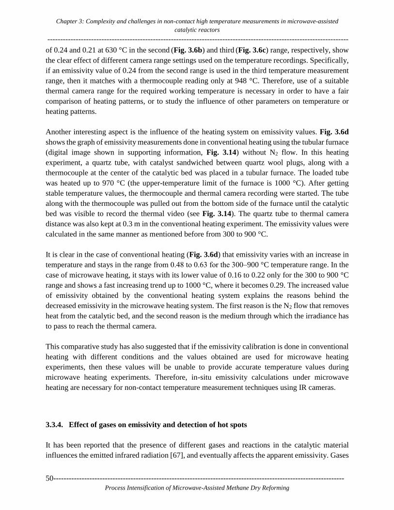
Chapter 3: Complexity and challenges in non-contact high temperature measurements in microwave-assisted
catalytic reactors
---------------------------------------------------------------------------------------------------------------------
50-----------------------------------------------------------------------------------------------------------------
Process Intensification of Microwave-Assisted Methane Dry Reforming
of 0.24 and 0.21 at 630 °C in the second (Fig. 3.6b) and third (Fig. 3.6c) range, respectively, show
the clear effect of different camera range settings used on the temperature recordings. Specifically,
if an emissivity value of 0.24 from the second range is used in the third temperature measurement
range, then it matches with a thermocouple reading only at 948 °C. Therefore, use of a suitable
thermal camera range for the required working temperature is necessary in order to have a fair
comparison of heating patterns, or to study the influence of other parameters on temperature or
heating patterns.
Another interesting aspect is the influence of the heating system on emissivity values. Fig. 3.6d
shows the graph of emissivity measurements done in conventional heating using the tubular furnace
(digital image shown in supporting information, Fig. 3.14) without N2 flow. In this heating
experiment, a quartz tube, with catalyst sandwiched between quartz wool plugs, along with a
thermocouple at the center of the catalytic bed was placed in a tubular furnace. The loaded tube
was heated up to 970 °C (the upper-temperature limit of the furnace is 1000 °C). After getting
stable temperature values, the thermocouple and thermal camera recording were started. The tube
along with the thermocouple was pulled out from the bottom side of the furnace until the catalytic
bed was visible to record the thermal video (see Fig. 3.14). The quartz tube to thermal camera
distance was also kept at 0.3 m in the conventional heating experiment. The emissivity values were
calculated in the same manner as mentioned before from 300 to 900 °C.
It is clear in the case of conventional heating (Fig. 3.6d) that emissivity varies with an increase in
temperature and stays in the range from 0.48 to 0.63 for the 300‒900 °C temperature range. In the
case of microwave heating, it stays with its lower value of 0.16 to 0.22 only for the 300 to 900 °C
range and shows a fast increasing trend up to 1000 °C, where it becomes 0.29. The increased value
of emissivity obtained by the conventional heating system explains the reasons behind the
decreased emissivity in the microwave heating system. The first reason is the N2 flow that removes
heat from the catalytic bed, and the second reason is the medium through which the irradiance has
to pass to reach the thermal camera.
This comparative study has also suggested that if the emissivity calibration is done in conventional
heating with different conditions and the values obtained are used for microwave heating
experiments, then these values will be unable to provide accurate temperature values during
microwave heating experiments. Therefore, in-situ emissivity calculations under microwave
heating are necessary for non-contact temperature measurement techniques using IR cameras.
3.3.4. Effect of gases on emissivity and detection of hot spots
It has been reported that the presence of different gases and reactions in the catalytic material
influences the emitted infrared radiation [67], and eventually affects the apparent emissivity. Gases
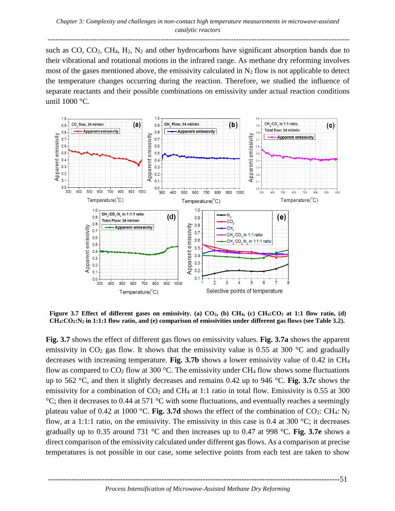
Chapter 3: Complexity and challenges in non-contact high temperature measurements in microwave-assisted
catalytic reactors
---------------------------------------------------------------------------------------------------------------------
-----------------------------------------------------------------------------------------------------------------51
Process Intensification of Microwave-Assisted Methane Dry Reforming
such as CO, CO2, CH4, H2, N2 and other hydrocarbons have significant absorption bands due to
their vibrational and rotational motions in the infrared range. As methane dry reforming involves
most of the gases mentioned above, the emissivity calculated in N2 flow is not applicable to detect
the temperature changes occurring during the reaction. Therefore, we studied the influence of
separate reactants and their possible combinations on emissivity under actual reaction conditions
until 1000 °C.
Figure 3.7 Effect of different gases on emissivity. (a) CO2, (b) CH4, (c) CH4:CO2 at 1:1 flow ratio, (d)
CH4:CO2:N2 in 1:1:1 flow ratio, and (e) comparison of emissivities under different gas flows (see Table 3.2).
Fig. 3.7 shows the effect of different gas flows on emissivity values. Fig. 3.7a shows the apparent
emissivity in CO2 gas flow. It shows that the emissivity value is 0.55 at 300 °C and gradually
decreases with increasing temperature. Fig. 3.7b shows a lower emissivity value of 0.42 in CH4
flow as compared to CO2 flow at 300 °C. The emissivity under CH4 flow shows some fluctuations
up to 562 °C, and then it slightly decreases and remains 0.42 up to 946 °C. Fig. 3.7c shows the
emissivity for a combination of CO2 and CH4 at 1:1 ratio in total flow. Emissivity is 0.55 at 300
°C; then it decreases to 0.44 at 571 °C with some fluctuations, and eventually reaches a seemingly
plateau value of 0.42 at 1000 °C. Fig. 3.7d shows the effect of the combination of CO2: CH4: N2
flow, at a 1:1:1 ratio, on the emissivity. The emissivity in this case is 0.4 at 300 °C; it decreases
gradually up to 0.35 around 731 °C and then increases up to 0.47 at 998 °C. Fig. 3.7e shows a
direct comparison of the emissivity calculated under different gas flows. As a comparison at precise
temperatures is not possible in our case, some selective points from each test are taken to show

Chapter 3: Complexity and challenges in non-contact high temperature measurements in microwave-assisted
catalytic reactors
---------------------------------------------------------------------------------------------------------------------
52-----------------------------------------------------------------------------------------------------------------
Process Intensification of Microwave-Assisted Methane Dry Reforming
direct comparison (values are given in Table 3.2 of supporting information). This comparison
reveals that there are no big differences in the apparent emissivities under CO2 and CH4 flow.
However, the emissivity under CO2 flow has higher values among all tested gases up to 690.35 °C.
The decrease in the emissivity of CO2 past 690.35 °C is due to migration of hot spots in the catalytic
bed. A continuous fluctuation in the apparent emissivities is observed due to the continuous
migration of the hot spots during the experiments shown in Fig. 3.7e. Aside from the different heat
removal properties of different gases, another possible reason for the different emissivity values
under pure and combined gas conditions could be the change in the total dielectric properties of
the catalytic material due to pyrolytic carbon formation or direct structural changes in catalytic
materials.
The different trends of the gas emissivity lines at high temperatures, past point 6 in Fig. 3.7e, may
be due to dissociation of reactant gases and the formation of product gases, which would affect the
resultant irradiation flux. This comparison confirms that using only N2 flow values will provide
inaccurate information on temperature changes inside the bed.
Figure 3.8. (a) Catalyst loaded quartz tube and detection of hot spots in the catalytic bed under different gas
flows shown by thermal images in (b) N2, (c) CO2, (d) CH4, (e) CH4: CO2 at a 1:1 ratio, and (f) CH4:CO2:N2
in 1:1:1 ratio.
Along with finding emissivities for different gases, it is necessary to study 2D heat distribution in
the catalytic bed in order to get insight into possible hotspots generation and non-uniform heating
under MW exposure. The existence of hot spots in solid-liquid reactions has already been shown
by high-speed cameras [64]. Studies done by Chen et al. for methane thermocatalytic
decomposition showed that there was a 125 °C difference between the reactor inside and outside

Chapter 3: Complexity and challenges in non-contact high temperature measurements in microwave-assisted
catalytic reactors
---------------------------------------------------------------------------------------------------------------------
-----------------------------------------------------------------------------------------------------------------53
Process Intensification of Microwave-Assisted Methane Dry Reforming
temperatures in microwave-heated heterogeneous catalytic systems [79]. Zhang et al. have also
reported that hot-spots temperatures were found to be 100‒200 °C higher than the temperatures
measured by optical thermometer [34]. Therefore, getting precise information on hot spot
formation under microwave heating can support the discussion on possible factors determining
process intensification. The thermal camera gives the advantage of finding out the exact locations
of these hot spots in the catalytic bed, thanks to its rainbow pellet option to show hot spot positions
inside the catalytic bed. Fig. 3.8a and b show the loaded quartz tube along with the N2 flow thermal
image. This thermal image shows that, in the case of the N2 flow test, the temperature is higher at
the center of the catalytic bed. It also reveals that the temperature where the emissivity has been
calculated is lower than the center temperature of the catalytic bed (see the scale bar of the thermal
image in Fig. 3.8b). The camera does not only provide a range of hot zones but also gives the
highest temperature point present in the catalytic bed which is 1151 °C under N2 flow.
The thermal images shown in Fig. 3.8 confirm the presence of hot spots or zones and their shift or
dislocation inside the catalytic bed with different gas flows. In addition, the thermal images in Fig
3.8 can explain the fluctuations of emissivity values observed under different gas flows. It is clear
in the thermal images that hot spots can migrate or split with respect to different gases present in
the bed and with the duration of heating. Indeed hotspot locations change during MW heating due
to the interaction of these gases with the catalyst, or homo-heterogeneous reactions.
The live streaming and recording option of the thermal camera allows for monitoring, in real time,
changes in the heating patterns inside the catalytic bed. In most of the literature on heterogeneous
catalysis in the temperature range 700‒1000 °C under microwave heating, clear evidence on
temperature differences between hot spots and average temperature is missing. This dual approach
of matching internal and external temperature values with the help of thermal camera provides the
most accurate values for temperature differences.
3.3.5. Catalyst performance evaluation and microwave absorption efficiency
The dry reforming of methane is a highly endothermic reaction (Eq. 1.1, chapter 1). It involves a
combination of the two intermediate reactions; catalytic CH4 cracking or decomposition (Eq. 1.2)
and CO2 gasification (Eq. 1.3)[36]. Fig. 3.9a shows CH4 and CO2 conversion over the PtC catalyst
with 150 W of microwave power for 270 min of total reaction run. The conversion of methane and
carbon dioxide were calculated by using the following equations.
CH4 Conversion, % = 100 × [(𝐻2)𝑂𝑢𝑡
2]/[(𝐶𝐻4)𝑜𝑢𝑡 +
(𝐻2)𝑜𝑢𝑡
2] (3.2)
CO2 Conversion, % = 100 × [(𝐶𝑂)𝑜𝑢𝑡
2]/[(𝐶𝑂2)𝑜𝑢𝑡 +
(𝐶𝑂)𝑂𝑢𝑡
2] (3.3)
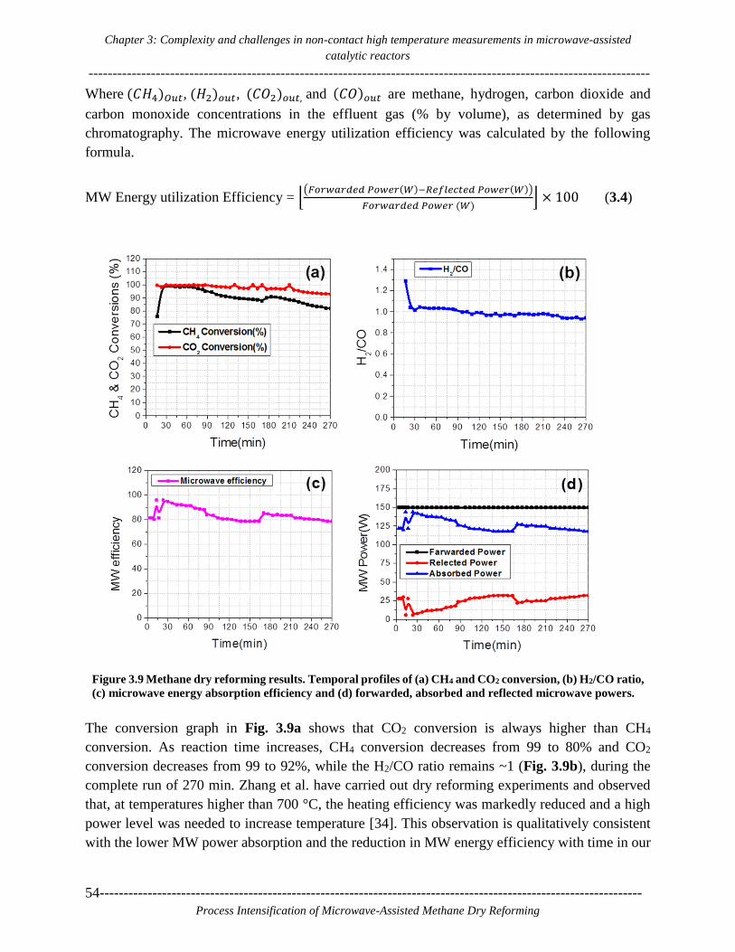
Chapter 3: Complexity and challenges in non-contact high temperature measurements in microwave-assisted
catalytic reactors
---------------------------------------------------------------------------------------------------------------------
54-----------------------------------------------------------------------------------------------------------------
Process Intensification of Microwave-Assisted Methane Dry Reforming
Where (𝐶𝐻4)𝑂𝑢𝑡, (𝐻2)𝑜𝑢𝑡, (𝐶𝑂2)𝑜𝑢𝑡, and (𝐶𝑂)𝑜𝑢𝑡 are methane, hydrogen, carbon dioxide and
carbon monoxide concentrations in the effluent gas (% by volume), as determined by gas
chromatography. The microwave energy utilization efficiency was calculated by the following
formula.
MW Energy utilization Efficiency = ⌊(𝐹𝑜𝑟𝑤𝑎𝑟𝑑𝑒𝑑 𝑃𝑜𝑤𝑒𝑟(𝑊)−𝑅𝑒𝑓𝑙𝑒𝑐𝑡𝑒𝑑 𝑃𝑜𝑤𝑒𝑟(𝑊))
𝐹𝑜𝑟𝑤𝑎𝑟𝑑𝑒𝑑 𝑃𝑜𝑤𝑒𝑟 (𝑊)⌋ × 100 (3.4)
Figure 3.9 Methane dry reforming results. Temporal profiles of (a) CH4 and CO2 conversion, (b) H2/CO ratio,
(c) microwave energy absorption efficiency and (d) forwarded, absorbed and reflected microwave powers.
The conversion graph in Fig. 3.9a shows that CO2 conversion is always higher than CH4
conversion. As reaction time increases, CH4 conversion decreases from 99 to 80% and CO2
conversion decreases from 99 to 92%, while the H2/CO ratio remains ~1 (Fig. 3.9b), during the
complete run of 270 min. Zhang et al. have carried out dry reforming experiments and observed
that, at temperatures higher than 700 °C, the heating efficiency was markedly reduced and a high
power level was needed to increase temperature [34]. This observation is qualitatively consistent
with the lower MW power absorption and the reduction in MW energy efficiency with time in our

Chapter 3: Complexity and challenges in non-contact high temperature measurements in microwave-assisted
catalytic reactors
---------------------------------------------------------------------------------------------------------------------
-----------------------------------------------------------------------------------------------------------------55
Process Intensification of Microwave-Assisted Methane Dry Reforming
case too. Fig. 3.9c shows that the microwave absorption efficiency at 30 min is ~94%; it decreases
to ~78% after 270 min of reaction time. The main reason for the decrease in conversion with time
is the deactivation of the catalyst. As the reaction runs for a long time, the formation of a pyrolytic
carbon layer becomes significant on the inside wall of the quartz tube. The graphitic character of
this deposited layer is responsible for the increase in the reflected power and hence compromises
the overall microwave absorption ability of the catalytic bed [37]. As less MW energy is getting
absorbed by the catalytic bed, the temperature in the catalytic bed decreases and results in a
decrease in conversion with time.
3.3.6. Emissivity matching during the reaction
Fig. 3.10a shows the emissivity matching with thermocouple reading during the dry reforming
process and its sensitivity to changes occurring in the catalytic system. First, the already calibrated
emissivity value of 0.421 for a 1:1 ratio of CH4:CO2 was used. However, this emissivity was not
matching with the actual temperature changes shown by the thermocouple. To get more realistic
temperature values, we took actual temperature values shown by the thermocouple as a reference
and recalculated the emissivity. After several trial-and-error attempts, a value of 0.737 was found
to be the correct match for the stable temperature of ~800 °C in the time interval of 100 to 166 min.
At 166 min, due to a technical reason, the MW generator turned OFF, and then the reactor did not
receive MW supply for 30 s until the generator was restarted again. Once the MW was ON again,
we observed that the emissivity value was changed and decreased to 0.687, which was matching
with the thermocouple temperature values. In continuous MW heating experiments, if the dielectric
properties of the catalytic bed change due to physical or chemical properties changes in the catalytic
bed itself (resulting from high processing temperatures), then migration or shift of hot spots will
also happen.
3.3.7. Factors affecting the emissivity and overall temperature distribution during the
reaction
Fig. 3.11a shows the graph of temperature profiles with factors affecting the emissivity and
temperature fluctuations during the reaction. As the reaction proceeds and reactant gases get
converted to product gases, fluctuations in the intensity of emitted irradiation occur. A
thermocouple remains unaffected by these changes and becomes the reference for emissivity
correction at any time during the reaction. In Fig. 3.11a, the black line represents the temperature
shown by the thermocouple. As it is not possible to change emissivity manually at every point, we
selected the emissivity value of 0.737 after the emissivity match test reported earlier (see Fig.
3.10a).

Chapter 3: Complexity and challenges in non-contact high temperature measurements in microwave-assisted
catalytic reactors
---------------------------------------------------------------------------------------------------------------------
56-----------------------------------------------------------------------------------------------------------------
Process Intensification of Microwave-Assisted Methane Dry Reforming
Figure 3.10. (a) Emissivity matching with actual temperature shown by a thermocouple during the methane dry
reforming reaction. (b) The thermal image at 166 min; temperature values are extracted from the thermal video
at C1(top), C2(center), C3(bottom), C4(Left), and C5(right) positions to study temperature distribution at these
points. (c) The shift of hot spot or zone due to MW supply discontinuity.
Fig. 3.11a shows that after switching on the microwave generator, the catalyst reaches a
temperature above 700 °C in 70 s under a N2 gas flow. After 600 s, CH4 and CO2 were fed to the
reactor at a flow rate of 17 ml/min for each gas. MW tuning was done to minimize the reflected
power and to focus all forward power to catalyst only. After reactant feeding, a decrease in
temperature is observed (see black line in Fig. 3.11a). This decrease in temperature could be due
to an increase in the reflected power, which means that lower microwave energy is absorbed, and
due to the endothermic nature of the reaction. As the reaction proceeds, more energy is utilized due

Chapter 3: Complexity and challenges in non-contact high temperature measurements in microwave-assisted
catalytic reactors
---------------------------------------------------------------------------------------------------------------------
-----------------------------------------------------------------------------------------------------------------57
Process Intensification of Microwave-Assisted Methane Dry Reforming
to the endothermic nature of reaction; this lowers the overall temperature of the catalytic bed and
hence emits less infrared radiation that reaches the camera detector.
At 13, 16 and 23 min interval, reflector tuning was done to maximize utilization of MW energy.
Therefore, sudden high peaks at the surface temperatures are shown by the thermal camera values,
but the thermocouple shows a decrease in temperature until 16 min (Fig. 3.11a). This mismatch is
a result of two reasons: (1) the change in infrared radiation occurring due to reaction progress and
(2) the emissivity value used for this analysis is not applicable for these initial temperature changes.
Figure 3.11. (a) Factors affecting temperature distribution in the catalytic bed during the
reforming reaction, (b) effect of MW supply discontinuity on emissivity and temperature
distribution.
A big drop in temperature from ~780 to 600 °C within 30 s was observed at ~166 min (Fig. 3.11b).
Once the MW was ON again, a sudden increase in temperature was observed after this gap. This

Chapter 3: Complexity and challenges in non-contact high temperature measurements in microwave-assisted
catalytic reactors
---------------------------------------------------------------------------------------------------------------------
58-----------------------------------------------------------------------------------------------------------------
Process Intensification of Microwave-Assisted Methane Dry Reforming
incident changed the emissivity after 166 min. The temperature profiles at top, middle and bottom
are separated after 166 min, but the temperature differences were observed to decrease until 270
min. In order to get a good match again with the temperature values shown by the thermocouple, a
new emissivity was calculated with new thermocouple readings after 166 min. The reason for this
change in temperature and emissivity values can be explained by the thermal images shown in Fig.
3.10b and c. The shift of hot spot or zone from the left side of the catalytic bed (Fig. 3.10b) to the
top of the bed, where the thermocouple is placed (Fig. 3.10c), clearly explains the sudden increase
in temperature as the hot spot is very close to the thermocouple and the location where it is
calculated. The physical reason behind the change in emissivity is the sudden increase in
temperature or shift of hot spot in the catalytic bed. This increase in temperature happened because
of two things; first, when MW power was OFF, the temperature dropped from 780 to 600 °C, while
reactant gases were still flowing through the bed. Now, due to the sudden interruption of microwave
energy input, reactant conversions were decreased and the concentration levels of H2, CO, CO2,
and CH4 changed in the catalytic bed after 30 s. Therefore, in this complex gas mixture
environment, the dielectric properties of the whole catalytic bed changed. The second reason was
that when MW power was switched ON again, the catalyst was already at a temperature ~600 °C,
and so its dielectric properties were higher than at room temperature, resulting in different response
to absorb MW.
3.3.8. Axial and radial temperature distribution during the reaction
Fig. 3.12a shows temperature values at the center, left, right, top and bottom positions extracted
after thermal data post-processing. If a corrected emissivity is provided to the thermal camera, then
the temperature measurements in a 2D fashion will provide insight into the temperature distribution
and heating patterns.
Fig. 3.10b shows the locations at which the temperature data have been extracted from the thermal
video of the reaction run. It is particularly interesting to map the axial and radial temperature
distributions that occurred during the reaction run. Fig. 3.12a shows the stable temperature
differences at different points of the catalytic bed before the MW OFF issue and the clear shift, or
separation, of temperature differences after MW ON after 30 s of time gap. Fig. 3.12b shows the
differences in temperature in the mentioned location. In the case of stable temperature before 166
min, the center and left point difference is 5 ̶ 10 °C. The center-top and center-bottom temperature
differences are in the range of 50 ̶ 60 °C. The center-right temperature difference is ~120 °C, as the
hot spot is on left side only; hence there is a significant temperature difference between the center
and right positions. After 166 min, the hot zone shifts to the top part of the catalytic bed and
influences the temperature distribution inside the catalytic bed. In this case, a clear separation of
temperature differences is observed in Fig. 3.12b. The ̶ 180 °C deference around 167 min shows
that now the top part of the catalytic bed is hotter than the center part, which was indicated by the
thermocouple reading and clearly shown in the thermal image (Fig. 3.10c).

Chapter 3: Complexity and challenges in non-contact high temperature measurements in microwave-assisted
catalytic reactors
---------------------------------------------------------------------------------------------------------------------
-----------------------------------------------------------------------------------------------------------------59
Process Intensification of Microwave-Assisted Methane Dry Reforming
After this change in location of the hot spot, the top-center difference became 180 °C. The center-
left temperature difference became ~10 ̶ 15 °C. The center-right temperature difference decreased
from 120 to 100 °C, and the center-bottom one increased to 80 ̶ 90 °C. A very big difference of
~280 °C from top to bottom after 167 min was observed. This top-bottom temperature difference
decreased with an increase in time and eventually became ~50 °C at the end of 300 min.
Figure 3.12. (a) Temperature distribution in the catalytic bed during the reaction with an emissivity value of
0.737. (b) Differences in temperature values at different locations of the catalytic bed with an emissivity value
of 0.737.
3.4. Conclusions
The thermal camera-thermocouple dual temperature measurement method developed in this work
allows for real-time high temperature (300 ̶ 1000 °C) measurements in MW-heated catalytic
reactors. This method was applied for a temperature distribution study in a platinum-on-carbon
catalytic bed used for methane dry reforming. For this purpose, a custom-designed microwave
cavity was employed to focus the microwave field on the catalyst bed and monitor its temperature
in a 2D fashion by means of a thermal camera. The effect of different factors affecting the
temperature measurements and emissivity values under microwave heating were investigated. The
effects of camera range, the presence of different media and reactant gases in the process domain,
object-to-camera distance, heating system and microwave field distribution were discussed in
detail. The multiparameter emissivity dependence in such a complex reaction system does not
ensure correct temperature recording by the thermal camera alone; therefore, at least one contact
sensor is highly recommended. The developed method successfully detected hot spot generation
and provided an explanation for the non-homogeneous heating profiles during MW processing.
Careful handling and continued temperature monitoring with a thermal camera is very helpful to
avoid potential risk hazards in MW-heated catalytic reactors.

Chapter 3: Complexity and challenges in non-contact high temperature measurements in microwave-assisted
catalytic reactors
---------------------------------------------------------------------------------------------------------------------
60-----------------------------------------------------------------------------------------------------------------
Process Intensification of Microwave-Assisted Methane Dry Reforming
3.5. Supporting Information:
3.5.1. Challenges to reproduce experimental results and risk factors involved
The problem of system failure due to pyrolytic carbon formation has already been reported in the
literature for high-temperature reactions in a quartz tube under microwave heating. In our work,
over a period of ~15 hrs of MW heating, the quartz tube eventually broke. As shown in Fig. 3.15
a, the black-colored fresh catalyst is readily visible through a fresh transparent quartz tube.
However, after several heating and reaction experiments for nearly 15 hours, a solid layer of white
and black color was formed on the inside of the quartz tube wall (Fig 3.15c). Analysis of this layer
has not been done, as it is not within the scope of this work; it could be a pyrolytic layer as reported
already, degradation of the quartz tube due to heating above its thermal stability limit or
combination of both, damaging the tube both from the interior and the exterior. The thermal camera
helps in case of reactor damage and reveals tube breakage, as shown in Fig. 3.15d, which is
impossible to know when using point sensors or pyrometers.
Reproducibility of heating profiles under microwaves is another major issue. During microwave
heating, catalyst physical properties and composition may change resulting in different dielectric
properties and eventually different heating patterns during future experiments. In addition,
emissivity changes with temperature, different gases in the catalytic bed and surface properties of
the quartz tube due to pyrolytic layer formation as mentioned earlier. Further, for given
experimental settings, a sudden decrease in the reflected power may be observed, resulting in an
unwanted steep temperature increase. Then, tuning of control elements can in principle adjust the
reflected power, but doing so manually during the experiment involves the risk to overheat the
catalytic bed and to damage the reactor and temperature sensor. Further, such tuning would be
based on the heated load properties at the time; therefore, it is highly impossible to reproduce the
same results if tuning is done every time.
Besides, microwave heating involves changes in hot spot location inside the reactor and affects the
overall infrared radiation towards a thermal camera. A thermal camera is a very good option for
non-contact measurements; however, in cases of uneven heating behavior of the system, emissivity
values at different hot spots will change; this will compromise accurate temperature monitoring if
the camera settings are not adjusted. Collectively, proper monitoring of high-temperature reactions
under microwaves requires particular caution. To avoid any random behavior during the
experiments, it is recommended to first check the thermal behavior of the system before planning
and optimizing the actual experiments.

Chapter 3: Complexity and challenges in non-contact high temperature measurements in microwave-assisted
catalytic reactors
---------------------------------------------------------------------------------------------------------------------
-----------------------------------------------------------------------------------------------------------------61
Process Intensification of Microwave-Assisted Methane Dry Reforming
Table 3.1 Thermocouple and optical fiber temperature measurement comparison.
Time
(sec)
MW power
(W)
Thermocouple
Temperature ( °C)
Optical fiber
Temperature ( °C)
0 0 26.02 25.21
120 1 39.60 38.32
240 2 54.77 55.78
360 3 73.31 72.31
480 4 89.66 90.11
600 5 103.57 105.57
720 6 118.23 116.23
840 7 131.18 135.18
960 8 145.357 143.57
Table 3.2: Effect of gases on emissivity under microwave heating.
Pt.
No
N2 Flow CO2 Flow CH4 Flow CH4:CO2_1:1 CH4:CO2:N2_1:1:1
Temp.
(oC)
Emi. Temp.
(oC)
Emi. Temp.
(oC)
Emi. Temp.
(oC)
Emi. Temp.
(oC)
Emi.
1 230.71 0.132 300.28 0.551 302.91 0.428 307.89 0.557 303.60 0.408
2 390.7 0.168 397.29 0.513 402.22 0.482 395.55 0.463 404.82 0.398
3 496.9 0.205 517.26 0.473 499.56 0.461 500.37 0.442 519.90 0.388
4 631.23 0.208 600.26 0.459 613.16 0.439 611.82 0.433 617.80 0.380
5 730.01 0.195 690.35 0.457 703.17 0.429 706.35 0.436 714.28 0.361
6 815.6 0.193 817.90 0.419 820.03 0.433 826.48 0.419 809.65 0.369
7 917.96 0.227 923.16 0.375 886.25 0.430 915.37 0.412 907.83 0.448
8 1001.71 0.29 1000.28 0.400 946.72 0.422 1002.82 0.423 998.46 0.477
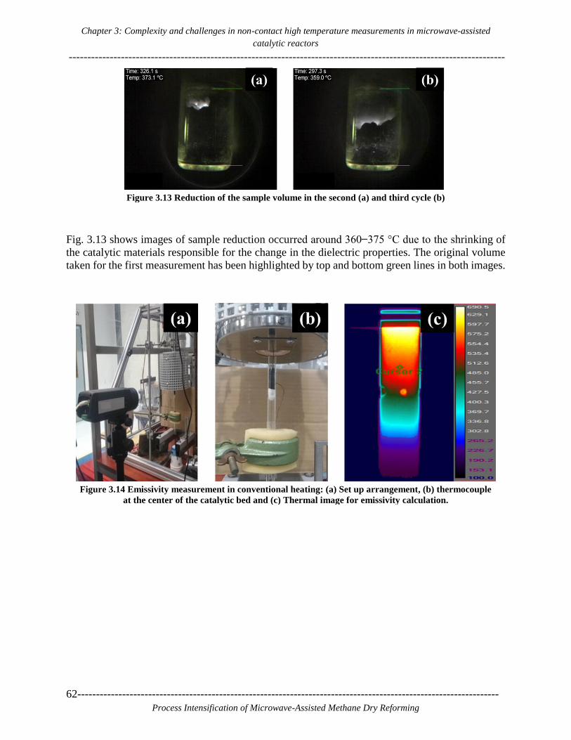
Chapter 3: Complexity and challenges in non-contact high temperature measurements in microwave-assisted
catalytic reactors
---------------------------------------------------------------------------------------------------------------------
62-----------------------------------------------------------------------------------------------------------------
Process Intensification of Microwave-Assisted Methane Dry Reforming
Figure 3.13 Reduction of the sample volume in the second (a) and third cycle (b)
Fig. 3.13 shows images of sample reduction occurred around 360 ̶ 375 °C due to the shrinking of
the catalytic materials responsible for the change in the dielectric properties. The original volume
taken for the first measurement has been highlighted by top and bottom green lines in both images.
Figure 3.14 Emissivity measurement in conventional heating: (a) Set up arrangement, (b) thermocouple
at the center of the catalytic bed and (c) Thermal image for emissivity calculation.
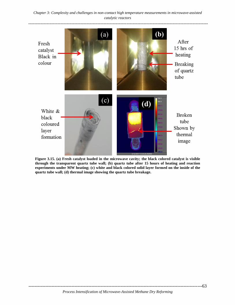
Chapter 3: Complexity and challenges in non-contact high temperature measurements in microwave-assisted
catalytic reactors
---------------------------------------------------------------------------------------------------------------------
-----------------------------------------------------------------------------------------------------------------63
Process Intensification of Microwave-Assisted Methane Dry Reforming
Figure 3.15. (a) Fresh catalyst loaded in the microwave cavity; the black colored catalyst is visible
through the transparent quartz tube wall; (b) quartz tube after 15 hours of heating and reaction
experiments under MW heating; (c) white and black colored solid layer formed on the inside of the
quartz tube wall; (d) thermal image showing the quartz tube breakage.

Chapter 3: Complexity and challenges in non-contact high temperature measurements in microwave-assisted
catalytic reactors
---------------------------------------------------------------------------------------------------------------------
64-----------------------------------------------------------------------------------------------------------------
Process Intensification of Microwave-Assisted Methane Dry Reforming

Chapter 4: Synthesis, characterization, and application of ruthenium-doped SrTiO3 perovskite catalyst for
microwave-assisted methane dry reforming
---------------------------------------------------------------------------------------------------------------------
-----------------------------------------------------------------------------------------------------------------65
Process Intensification of Microwave-Assisted Methane Dry Reforming
4
4. Synthesis, characterization, and
application of ruthenium-doped SrTiO3
perovskite catalyst for microwave-assisted
methane dry reforming
---------------------------------------------------------------------------------------------------------------------
This Chapter is published as:
Lalit S. Gangurde, Guido S. J. Sturm, M. J. Valero-Romero, Reyes Mallada, Jesus Santamaria,
Andrzej I. Stankiewicz, Georgios D. Stefanidis, Synthesis, characterization, and application of
ruthenium-doped SrTiO3 perovskite catalyst for microwave-assisted methane dry reforming,
Chemical Engineering and Processing: Process Intensification, 127, 178-190, 2018.
---------------------------------------------------------------------------------------------------------------------

Chapter 4: Synthesis, characterization, and application of ruthenium-doped SrTiO3 perovskite catalyst for
microwave-assisted methane dry reforming
---------------------------------------------------------------------------------------------------------------------------------------------
66-----------------------------------------------------------------------------------------------------------------
Process Intensification of Microwave-Assisted Methane Dry Reforming

Chapter 4: Synthesis, characterization, and application of ruthenium-doped SrTiO3 perovskite catalyst for
microwave-assisted methane dry reforming
---------------------------------------------------------------------------------------------------------------------
-----------------------------------------------------------------------------------------------------------------67
Process Intensification of Microwave-Assisted Methane Dry Reforming
Abstract
A series of ruthenium-doped strontium titanate (SrTiO3) perovskite catalysts were synthesized by
conventional and microwave-assisted hydrothermal methods. The structure was analyzed by X-
Ray diffraction (XRD) confirming the formation of the perovskite phase with some TiO2 anatase
phase in all the catalysts. Microwave irradiation decreases the temperature and time of synthesis from
220 °C for 24 h (conventional heating) to 180 °C for 1 h, without affecting the formation of perovskite.
A 7 wt. % ruthenium-doped SrTiO3 catalyst showed the best dielectric properties, and thus its
catalytic activity was evaluated for the methane dry reforming reaction under microwave heating
in a custom fixed-bed quartz reactor. Microwave power, CH4:CO2 vol. % feed ratio and gas hourly
space velocity (GHSV) were varied in order to determine the best conditions for performing dry
reforming with high reactants conversions and H2/CO ratio. Stable maximum CH4 and CO2
conversions of ~99.5% and ~94%, respectively, at H2/CO ~0.9 were possible to reach with the 7
wt. % ruthenium-doped SrTiO3 catalyst exposed to maximum temperatures in the vicinity of 940
°C. A comparative theoretical scale-up study shows significant improvement in H2 production
capability in the case of the perovskite catalyst compared to carbon-based catalysts.
Graphical Abstract:

Chapter 4: Synthesis, characterization, and application of ruthenium-doped SrTiO3 perovskite catalyst for
microwave-assisted methane dry reforming
---------------------------------------------------------------------------------------------------------------------------------------------
68-----------------------------------------------------------------------------------------------------------------
Process Intensification of Microwave-Assisted Methane Dry Reforming
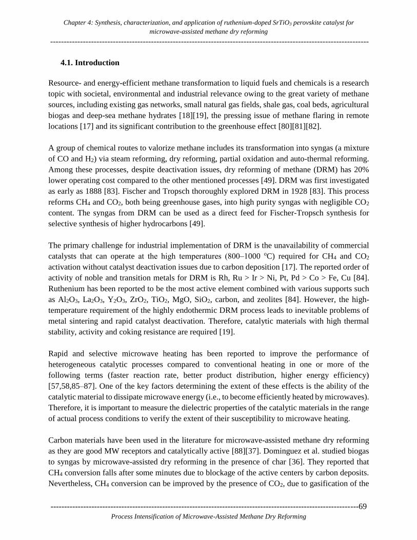
Chapter 4: Synthesis, characterization, and application of ruthenium-doped SrTiO3 perovskite catalyst for
microwave-assisted methane dry reforming
---------------------------------------------------------------------------------------------------------------------
-----------------------------------------------------------------------------------------------------------------69
Process Intensification of Microwave-Assisted Methane Dry Reforming
4.1. Introduction
Resource- and energy-efficient methane transformation to liquid fuels and chemicals is a research
topic with societal, environmental and industrial relevance owing to the great variety of methane
sources, including existing gas networks, small natural gas fields, shale gas, coal beds, agricultural
biogas and deep-sea methane hydrates [18][19], the pressing issue of methane flaring in remote
locations [17] and its significant contribution to the greenhouse effect [80][81][82].
A group of chemical routes to valorize methane includes its transformation into syngas (a mixture
of CO and H2) via steam reforming, dry reforming, partial oxidation and auto-thermal reforming.
Among these processes, despite deactivation issues, dry reforming of methane (DRM) has 20%
lower operating cost compared to the other mentioned processes [49]. DRM was first investigated
as early as 1888 [83]. Fischer and Tropsch thoroughly explored DRM in 1928 [83]. This process
reforms CH4 and CO2, both being greenhouse gases, into high purity syngas with negligible CO2
content. The syngas from DRM can be used as a direct feed for Fischer-Tropsch synthesis for
selective synthesis of higher hydrocarbons [49].
The primary challenge for industrial implementation of DRM is the unavailability of commercial
catalysts that can operate at the high temperatures (800‒1000 oC) required for CH4 and CO2
activation without catalyst deactivation issues due to carbon deposition [17]. The reported order of
activity of noble and transition metals for DRM is Rh, Ru > Ir > Ni, Pt, Pd > Co > Fe, Cu [84].
Ruthenium has been reported to be the most active element combined with various supports such
as Al2O3, La2O3, Y2O3, ZrO2, TiO2, MgO, SiO2, carbon, and zeolites [84]. However, the high-
temperature requirement of the highly endothermic DRM process leads to inevitable problems of
metal sintering and rapid catalyst deactivation. Therefore, catalytic materials with high thermal
stability, activity and coking resistance are required [19].
Rapid and selective microwave heating has been reported to improve the performance of
heterogeneous catalytic processes compared to conventional heating in one or more of the
following terms (faster reaction rate, better product distribution, higher energy efficiency)
[57,58,85–87]. One of the key factors determining the extent of these effects is the ability of the
catalytic material to dissipate microwave energy (i.e., to become efficiently heated by microwaves).
Therefore, it is important to measure the dielectric properties of the catalytic materials in the range
of actual process conditions to verify the extent of their susceptibility to microwave heating.
Carbon materials have been used in the literature for microwave-assisted methane dry reforming
as they are good MW receptors and catalytically active [88][37]. Dominguez et al. studied biogas
to syngas by microwave-assisted dry reforming in the presence of char [36]. They reported that
CH4 conversion falls after some minutes due to blockage of the active centers by carbon deposits.
Nevertheless, CH4 conversion can be improved by the presence of CO2, due to gasification of the

Chapter 4: Synthesis, characterization, and application of ruthenium-doped SrTiO3 perovskite catalyst for
microwave-assisted methane dry reforming
---------------------------------------------------------------------------------------------------------------------------------------------
70-----------------------------------------------------------------------------------------------------------------
Process Intensification of Microwave-Assisted Methane Dry Reforming
carbon deposits. This effect was more noticeable in microwave heating than in conventional
heating. It was also reported that constant removal of the carbon deposits was favored by the high
K content in the char [36]. Most of the metal catalysts (e.g., Ni/Al2O3) that are active for DRM in
conventional heating cannot be used directly for MW-assisted DRM because of their inability to
reach the optimum reaction temperature due to their low dielectric properties. To address this issue,
Fidalgo et al. mixed activated carbon with a metal-based catalyst to heat the latter up to the
temperature required for MW-assisted DRM [89].
However, in our experiments, on microwave-assisted methane dry reforming over platinum on
carbon catalyst, the amount of carbon catalyst decreased over a period of time (~ 270 min) and
formed a carbon layer on the inner surface of the quartz wall of the reactor, thereby softening and
eventually breaking the quartz tube wall [54]. Collectively, there is a room for the development of
catalysts for MW-assisted methane dry reforming; such catalysts must have good microwave
absorption ability, should be resistant to coke formation, should not get consumed during the
reaction and produce high syngas yield.
Perovskite (ABO3) materials have become attractive catalysts as they prevent the agglomeration of
metal ions by retaining their structure during high temperature reforming reactions [90]. They have
potential applications in oxygen separators, solid oxide fuel cells and membrane reactors [91]. A
typical perovskite is a structure with general composition type ABO3. Perovskite oxides contain
lanthanide elements at ‘A’ sites (for example, Ce, La, Pr) and a transition element at ‘B’ sites, such
as Ni, Rh, Pt, etc. The significant advantages of the perovskite structure from the catalysis point of
view are (1) its well-defined bulk structure with good oxygen storage capacity, (2) compositions at
A and B cationic sites can be widely varied, (3) better thermal stability with valency control and
(4) excellent redox properties [13]. Liu et al. studied several low-cost perovskite catalysts for auto-
thermal reforming of n-dodecane and concluded that ruthenium-doped perovskite catalysts have
superior reforming efficiency with good resistance to sulfur as compared to perovskite catalysts
without ruthenium [92].
In this work, we have synthesized a series of Ru-doped SrTiO3 perovskite catalysts by conventional
and microwave-assisted hydrothermal methods. The catalysts have been characterized by X-ray
diffraction (XRD), N2 physisorption (BET surface area), inductively coupled plasma optical
emission spectrometry (ICP-OES) and high-angle annular dark-field scanning transmission
electron microscopy (HAADF-STEM) coupled to energy dispersive X-ray (EDX) analysis. The
dielectric properties have been measured in the temperature range 20‒850 °C. The catalyst with
the best dielectric properties was selected for application to DRM in a custom-built microwave
reactor system. An experimental parametric study was carried out to investigate the role of
microwave power, CO2 concentration in the reaction mixture and gas hourly space velocity, as well
as the catalyst stability. In this study, two-dimensional (2D) temperature monitoring was applied
using an approach combining a thermal camera and thermocouples [54]. Finally, a comparison in
terms of H2 production between the synthesized perovskite catalyst and a carbon-based catalyst

Chapter 4: Synthesis, characterization, and application of ruthenium-doped SrTiO3 perovskite catalyst for
microwave-assisted methane dry reforming
---------------------------------------------------------------------------------------------------------------------
-----------------------------------------------------------------------------------------------------------------71
Process Intensification of Microwave-Assisted Methane Dry Reforming
from the literature has been carried out for a theoretical scale-up scenario of the MW-assisted
methane dry reforming process.
4.2. Experimental
4.2.1. Reagents and materials
Strontium nitrate (Sr(NO3)2, 99% ACS reagent), ruthenium(III) nitrosyl nitrate solution
(Ru(NO)(NO3)x(OH)y, x + y = 3), titanium dioxide (TiO2, 99 %) and potassium hydroxide (KOH,
99%) were purchased from Sigma-Aldrich. All chemicals were used without any further
purification.
4.2.2. Conventional hydrothermal (CHT) synthesis
A series of Ru-doped strontium titanate (SrTiO3) perovskite catalysts were synthesized by
conventional (C) and microwave-assisted (MW) hydrothermal methods. In the case of conventional
hydrothermal method, stoichiometric amounts of Sr(NO3)2 (5.77, 5.70, 5.64 and 5.57 gm) and TiO2
(2.18, 2.07, 1.96 and 1.85 gm), respectively, were separately dissolved in deionized water under
stirring until complete solution. Subsequently, 0, 7.26, 14.36 and 21.29 ml of ruthenium (III)
nitrosyl nitrate solution was added. The colloidal solution was stirred at room temperature for 10‒
20 min, and then a solution of 9M of KOH was added dropwise and kept for 6 h under stirring. The
reaction mixture was then transferred to a teflon-lined stainless steel autoclave for hydrothermal
treatment at 220 °C for 24 h [93]. After cooling down, the precipitates obtained were filtered off,
washed with deionized water several times and dried at 80 °C for 6 h. The resulting solids were
calcined at 800 ºC for 3 h to obtain the perovskite phase [94]. A heating rate of 5 ºC min−1 and
static air conditions were applied to all the drying and calcination steps mentioned above. The
samples prepared by conventional hydrothermal synthesis are denoted as yRu/SrTiO3-C-zh, where
y is the Ru content in wt. %, C stands for conventional heating, and z is the heating time in hours.
4.2.3. Microwave-assisted hydrothermal (MWHT) synthesis
In the case of microwave-assisted hydrothermal synthesis, the reaction mixture was prepared in a
similar way to that mentioned in the conventional hydrothermal synthesis section. The only
difference here is that the reaction mixture is placed in a teflon-lined autoclave inside a
MILESTONE ETHOS Plus microwave cavity with automatic temperature control. The synthesis
was performed at 220 °C for 6 h without stirring. Microwave synthesis while stirring the solution
at a temperature of 180 °C for 1 h was also performed in order to reduce synthesis time and
temperature. For 1 h MW synthesis with stirring, a MW setup (Mycrosynth plus model ACT38)
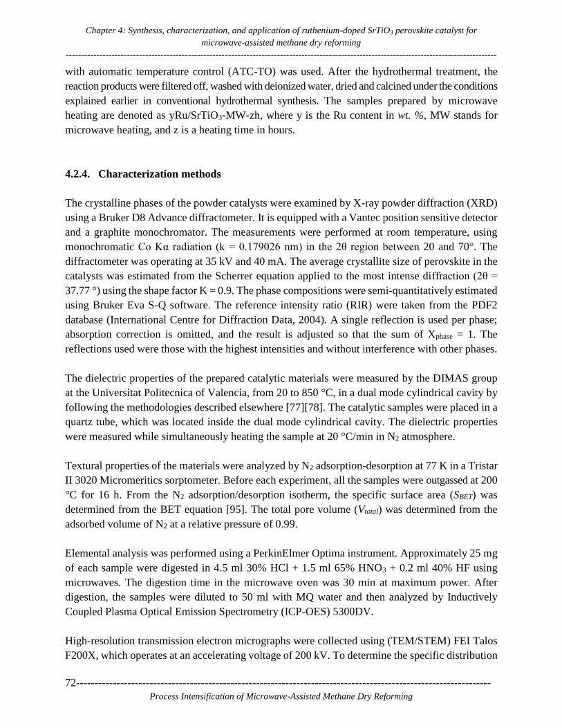
Chapter 4: Synthesis, characterization, and application of ruthenium-doped SrTiO3 perovskite catalyst for
microwave-assisted methane dry reforming
---------------------------------------------------------------------------------------------------------------------------------------------
72-----------------------------------------------------------------------------------------------------------------
Process Intensification of Microwave-Assisted Methane Dry Reforming
with automatic temperature control (ATC-TO) was used. After the hydrothermal treatment, the
reaction products were filtered off, washed with deionized water, dried and calcined under the conditions
explained earlier in conventional hydrothermal synthesis. The samples prepared by microwave
heating are denoted as yRu/SrTiO3-MW-zh, where y is the Ru content in wt. %, MW stands for
microwave heating, and z is a heating time in hours.
4.2.4. Characterization methods
The crystalline phases of the powder catalysts were examined by X-ray powder diffraction (XRD)
using a Bruker D8 Advance diffractometer. It is equipped with a Vantec position sensitive detector
and a graphite monochromator. The measurements were performed at room temperature, using
monochromatic Co Kα radiation (k = 0.179026 nm) in the 2θ region between 20 and 70°. The
diffractometer was operating at 35 kV and 40 mA. The average crystallite size of perovskite in the
catalysts was estimated from the Scherrer equation applied to the most intense diffraction (2θ =
37.77 °) using the shape factor K = 0.9. The phase compositions were semi-quantitatively estimated
using Bruker Eva S-Q software. The reference intensity ratio (RIR) were taken from the PDF2
database (International Centre for Diffraction Data, 2004). A single reflection is used per phase;
absorption correction is omitted, and the result is adjusted so that the sum of Xphase = 1. The
reflections used were those with the highest intensities and without interference with other phases.
The dielectric properties of the prepared catalytic materials were measured by the DIMAS group
at the Universitat Politecnica of Valencia, from 20 to 850 °C, in a dual mode cylindrical cavity by
following the methodologies described elsewhere [77][78]. The catalytic samples were placed in a
quartz tube, which was located inside the dual mode cylindrical cavity. The dielectric properties
were measured while simultaneously heating the sample at 20 °C/min in N2 atmosphere.
Textural properties of the materials were analyzed by N2 adsorption-desorption at 77 K in a Tristar
II 3020 Micromeritics sorptometer. Before each experiment, all the samples were outgassed at 200
°C for 16 h. From the N2 adsorption/desorption isotherm, the specific surface area (SBET) was
determined from the BET equation [95]. The total pore volume (Vtotal) was determined from the
adsorbed volume of N2 at a relative pressure of 0.99.
Elemental analysis was performed using a PerkinElmer Optima instrument. Approximately 25 mg
of each sample were digested in 4.5 ml 30% HCl + 1.5 ml 65% HNO3 + 0.2 ml 40% HF using
microwaves. The digestion time in the microwave oven was 30 min at maximum power. After
digestion, the samples were diluted to 50 ml with MQ water and then analyzed by Inductively
Coupled Plasma Optical Emission Spectrometry (ICP-OES) 5300DV.
High-resolution transmission electron micrographs were collected using (TEM/STEM) FEI Talos
F200X, which operates at an accelerating voltage of 200 kV. To determine the specific distribution

Chapter 4: Synthesis, characterization, and application of ruthenium-doped SrTiO3 perovskite catalyst for
microwave-assisted methane dry reforming
---------------------------------------------------------------------------------------------------------------------
-----------------------------------------------------------------------------------------------------------------73
Process Intensification of Microwave-Assisted Methane Dry Reforming
of elements present in the synthesized materials, energy dispersive X-ray (EDX) elemental maps
were analyzed. Particle size distribution histograms were also obtained by counting around 100
particles from each sample.
4.2.5. Microwave-assisted dry reforming of methane (DRM)
Eq. 1.1(chapter 1) represents the global DRM reaction that involves intermediate steps and side
reactions. The intermediate steps (Eqs. 1.2 and 1.3) of methane cracking and carbon dioxide
gasification both occur at high temperatures [36]. The most common side reactions (Eqs. 1.4 and
1.5) are the reverse water gas shift reaction (RWGS) (Eq. 1.4), which occurs at temperatures lower
than 820 °C and the Boudouard reaction (Eq. 1.5), which occurs below 700 °C, contributing to the
formation of carbon deposits [49].
The methane dry reforming experiments were performed in a specially developed microwave
reactor system as discussed in Chapter 2. Fig. 3.1(Chapter 3) shows the schematic diagram of the
microwave reactor setup. For all the experiments, 1 g of 7Ru/SrTiO3-MW-1h (425-850 μm particle
size), the catalyst with the highest loss tangent value among the tested series, was used to perform
the DRM tests. The catalyst was loaded in a quartz tube (290 mm length × 8 mm i.d.) as shown in
Fig. 3.2a. Two N-type thermocouples ( ̶ 200 to +1250 °C) were placed at the top and bottom part
of a catalyst bed to measure the emperature at these positions. The quartz tube loaded with the
catalyst was then inserted into the custom-designed microwave reactor, as shown in Fig.3.2b.
The feed consisted of a mixture of CH4 and CO2. The total flow rate was varied from 50 to
225 ml min−1 to achieve variable CH4 and CO2 conversion levels according to the residence time
of the reactants. The conversions of CH4 and CO2 were calculated by Eqs. 3.2 and 3.3, respectively
(Chapter 3), considering the global DRM reaction (Eq. 1.1, Chapter 1) only. Approximately 100%
of the MW power forwarded by the solid state generator to the sample is converted to heat; i.e.,
negligible reflected power is detected. MW power is mostly dissipated in the reactor itself, but, as
reported by Cherbanski et al. [96], part of it may also be dissipated in the cavity walls, or in the
hardware elements around the reactor.
The temperature of the catalytic material depends on its microwave heating ability under real
process conditions. Therefore, methane dry reforming experiments were performed first with
different MW powers to find out the optimum temperature response. After finding the optimum
MW power, the influence of CO2 concentration in the feed and of the total gas hourly space velocity
(GHSV) on CH4 conversion and overall reaction performance was studied. The total GHSV is
defined by the ratio of total flow rate (cm3h-1)/mass of catalyst (g), where the total flow rate is the
sum of the flow rates of CH4 and CO2. Finally, a stability test was performed at the optimum
conditions of MW power, CH4 to CO2 ratio and GHSV for 3 h.

Chapter 4: Synthesis, characterization, and application of ruthenium-doped SrTiO3 perovskite catalyst for
microwave-assisted methane dry reforming
---------------------------------------------------------------------------------------------------------------------------------------------
74-----------------------------------------------------------------------------------------------------------------
Process Intensification of Microwave-Assisted Methane Dry Reforming
4.3. Results and discussion
4.3.1. Catalyst characterization
Fig. 4.1a and b show the XRD patterns of Ru-doped SrTiO3 perovskite catalysts synthesized by
different methods, over different heating times, at different temperatures with or without stirring.
Fig. 4.1a shows a comparison of XRD patterns of all the yRu/SrTiO3-C-24h conventionally
synthesized catalysts with the 7Ru/SrTiO3-MW-1h catalyst. Fig. 4.1b shows a comparison of all
the yRu/SrTiO3-MW-6h microwave synthesized catalysts with the 7Ru/SrTiO3-MW-1h catalyst.
Bare SrTiO3 (Fig. 4.1a) prepared by the conventional hydrothermal method exhibits diffractions
at 37.8, 46.6, 54.4 and 68.2°, resulting from the presence of a perovskite cubic phase (PDF 73-
0661). Ru-doped SrTiO3 (3, 5 and 7 wt. % Ru) prepared by both conventional and microwave-
assisted methods also exhibit perovskite reflections as the predominant phase (Fig. 4.1a and b).
However, those samples prepared under conventional heating also exhibit diffractions attributed to
the anatase phase of TiO2 as an impurity. These diffractions included intense peaks at 29.5 and
56.8º resulting from the presence of the anatase (101) and (200) crystal planes, respectively (PDF
78-2486).
Table 4.1 summarizes the semi-quantitative phase composition and the crystallite sizes of SrTiO3
in the catalysts based on the Scherrer equation. The values of the specific surface area obtained by
the BET method and the total pore volume derived from the N2 adsorption data are also reported
in Table 4.1. In general, the composition of SrTiO3 is above 70 wt. % in all the catalysts; however,
the presence of anatase increases for those samples prepared by microwave heating at the lowest
reaction time and temperature, 7Ru/SrTiO3-MW-1h. Furthermore, the anatase composition
decreases with increasing Ru loading and with increasing MW irradiation time and temperature;
for example, it decreases from 26 wt.% for the bare SrTiO3 (0Ru/SrTiO3-C-24h) to 14 wt.% for the
7 wt.% Ru-doped SrTiO3 (7Ru/SrTiO3-C-24h) catalyst. The average crystallite sizes of bare SrTiO3
and Ru-doped SrTiO3 samples also showed differences, with smaller particles being formed in the
samples with higher Ru loading. For instance, the average SrTiO3 crystallite size decreases from
36.1 nm for 0Ru/SrTiO3-MW-6h to 29.6 nm for 7Ru/SrTiO3-MW-6h. These results suggest that
the incorporation of Ru to SrTiO3 could prevent particles sintering during the calcination step at
800 ºC. It is thus confirmed that the microwave-assisted preparation method can save energy and
time due to the faster kinetics of crystallization [97].
Interestingly, the XRD of all the Ru-doped SrTiO3 samples do not show any peak shifting or
reflections corresponding to RuO2 oxide formation, as reported before for Ru supported on SrTiO3
[84]. This fact points out the high dispersion of ruthenium in SrTiO3 prepared by hydrothermal
methods, both under conventional and microwave heating, despite the low BET surface areas and
pore volume obtained.

Chapter 4: Synthesis, characterization, and application of ruthenium-doped SrTiO3 perovskite catalyst for
microwave-assisted methane dry reforming
---------------------------------------------------------------------------------------------------------------------
-----------------------------------------------------------------------------------------------------------------75
Process Intensification of Microwave-Assisted Methane Dry Reforming
Figure 4.1. XRD patterns of (a) Ru-doped perovskite samples prepared by conventional HT synthesis for 24
h compared to MWHT for 1 h, and (b) Ru-doped perovskite samples prepared by MWHT synthesis for 6 h
compared to MWHT 1 h.
Table 4.1: Physical and chemical properties of all synthesized Ru-doped SrTiO3 catalysts.
Catalyst XRD N
2 isotherm ICP-OES
dSrTiO3
(nm)
S-QTiO2
a
(wt %)
S-Qa
SrTiO3
(wt %)
SBET
(m2
/g)
Vtotal
(cm3
/g)
Ru
(wt%)
0Ru/SrTiO3-C-24h 37.9 26.2 73.8 5 0.022 0
3Ru/SrTiO3-C-24h 36.6 19.5 80.5 6 0.001 2.2
5Ru/SrTiO3-C-24h 37.6 18.4 81.6 6 0.001 4.4
7Ru/SrTiO3-C-24h 31.3 14.1 85.9 6 0.001 6.8
0Ru/SrTiO3-MW-6h 36.1 1.9 98.1 8 0.032 0
3Ru/SrTiO3-MW-6h 37.5 0.8 99.2 6 0.025 2.4
5Ru/SrTiO3-MW-6h 30.0 1 99 6 0.020 4.8
7Ru/SrTiO3-MW-6h 29.6 2.2 97.8 4 0.014 6.3
7Ru/SrTiO3-MW-1h 29.8 22.2 77.8 8 0.026 7.2
a
Semi-quantitative (S-Q) weight percentage of the phases obtained from XRD.
The dielectric properties of the yRu/SrTiO3-C-24h series samples have been measured and
presented in Fig. 4.2, while the specified weights and densities are presented in Table 4.2. The
primary purpose of the dielectric properties measurements was to find a suitable catalyst for
microwave heating and then use it for further characterization and the methane dry reforming
reaction. Therefore, the dielectric properties of yRu-/SrTiO3-MW-6h series and 7Ru/SrTiO3-MW-
1h catalyst were not measured. The dielectric properties measurement procedure was explained in
our recent work [54]. Specifically, heating up to 850 °C with a heating rate of 20 °C/min was
carried out. In Fig. 4.2a and b, the variation of the dielectric constant and loss factor with increasing
temperature is presented for the yRu/SrTiO3-C-24h series. For all the samples, the dielectric
constant decreases with increasing temperature, whereas the loss factor increases with increasing

Chapter 4: Synthesis, characterization, and application of ruthenium-doped SrTiO3 perovskite catalyst for
microwave-assisted methane dry reforming
---------------------------------------------------------------------------------------------------------------------------------------------
76-----------------------------------------------------------------------------------------------------------------
Process Intensification of Microwave-Assisted Methane Dry Reforming
temperature. Further, the dielectric constant and dielectric loss factor values increase with an
increase in Ru content. From this comparison, it is clear that the 7Ru/SrTiO3-C-24h catalyst has
the highest dielectric properties in the tested series.
On the basis of the dielectric characterization presented, the 7 wt. % Ru/SrTiO3-C-24h catalyst was
selected for further microwave-assisted synthesis study. To study the role of reduction of synthesis
temperature, time and stirring, microwave synthesis of this catalyst has been done at 220 °C for 6
h without stirring and at 180 °C for 1 h with stirring. As explained earlier, 1 h microwave
hydrothermal synthesis with stirring has shown similar XRD peaks and confirmed the perovskite
phase formation. The obtained catalyst is denoted as 7Ru/SrTiO3-MW-1h. Only the 7Ru/SrTiO3-
C-24h and 7Ru/SrTiO3-MW-1h catalysts have been considered for further characterization and
comparison purpose. Table 4.1 shows the elemental analysis results by ICP-OES. It indicates that
higher concentration of the Ru element is present in the MW-synthesized catalyst (7Ru/SrTiO3-
MW-1h) as compared to the conventionally synthesized catalyst (7Ru/SrTiO3-C-24h).
Table 4.2: Weights and densities of yRu/SrTiO3-C-24h series used
for dielectric properties measurements.
Sample Catalyst Code Weight(g) Density(g/cm3)
1 0Ru/SrTiO3-C-24h 1.498 1.2734
2 3Ru/SrTiO3-C-24h 1.361 1.1673
3 5Ru/SrTiO3-C-24h 1.271 1.0921
4 7Ru/SrTiO3-C-24h 1.398 1.2120
To determine the dispersion of the different elements in the 7Ru/SrTiO3-C-24h and 7Ru/SrTiO3-
MW-1h samples, high-angle annular dark-field scanning transmission electron microscopy
(HAADF-STEM) images and energy dispersive X-ray (EDX) elemental maps have been produced.
Fig. 4.3 and 4.4 show the HAADF-STEM and EDX mapping of the 7Ru/SrTiO3-C-24h and
7Ru/SrTiO3-MW-1h catalysts, respectively. As shown in Fig. 4.3, for 7Ru/SrTiO3-C-24h, the
distribution of Ru, Sr, Ti and O elements is non-homogeneous indicating the random dispersion of
the Ru element over the perovskite support. On the other hand, the 7Ru/SrTiO3-MW-1h catalyst
(Fig. 4.4) shows a homogeneous dispersion of all the elements, suggesting that stirring the mixture
during the hydrothermal synthesis is crucial for proper dispersion of Ru. Therefore, not only MW
irradiation improved the catalyst preparation in terms of time and energy, but also stirring enables
good dispersion of the elements.
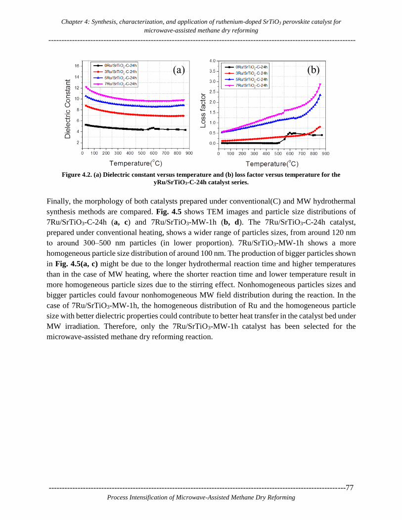
Chapter 4: Synthesis, characterization, and application of ruthenium-doped SrTiO3 perovskite catalyst for
microwave-assisted methane dry reforming
---------------------------------------------------------------------------------------------------------------------
-----------------------------------------------------------------------------------------------------------------77
Process Intensification of Microwave-Assisted Methane Dry Reforming
Figure 4.2. (a) Dielectric constant versus temperature and (b) loss factor versus temperature for the
yRu/SrTiO3-C-24h catalyst series.
Finally, the morphology of both catalysts prepared under conventional(C) and MW hydrothermal
synthesis methods are compared. Fig. 4.5 shows TEM images and particle size distributions of
7Ru/SrTiO3-C-24h (a, c) and 7Ru/SrTiO3-MW-1h (b, d). The 7Ru/SrTiO3-C-24h catalyst,
prepared under conventional heating, shows a wider range of particles sizes, from around 120 nm
to around 300‒500 nm particles (in lower proportion). 7Ru/SrTiO3-MW-1h shows a more
homogeneous particle size distribution of around 100 nm. The production of bigger particles shown
in Fig. 4.5(a, c) might be due to the longer hydrothermal reaction time and higher temperatures
than in the case of MW heating, where the shorter reaction time and lower temperature result in
more homogeneous particle sizes due to the stirring effect. Nonhomogeneous particles sizes and
bigger particles could favour nonhomogeneous MW field distribution during the reaction. In the
case of 7Ru/SrTiO3-MW-1h, the homogeneous distribution of Ru and the homogeneous particle
size with better dielectric properties could contribute to better heat transfer in the catalyst bed under
MW irradiation. Therefore, only the 7Ru/SrTiO3-MW-1h catalyst has been selected for the
microwave-assisted methane dry reforming reaction.

Chapter 4: Synthesis, characterization, and application of ruthenium-doped SrTiO3 perovskite catalyst for
microwave-assisted methane dry reforming
---------------------------------------------------------------------------------------------------------------------------------------------
78-----------------------------------------------------------------------------------------------------------------
Process Intensification of Microwave-Assisted Methane Dry Reforming
Figure 4.3. HAADF-STEM image and EDX elemental maps of O, Ru, Sr, and Ti for the
7Ru/SrTiO3-C-24h catalyst.
Figure 4.4. HAADF-STEM image and EDX elemental maps of O, Ru, Sr, and Ti for the 7Ru/SrTiO3-
MW-1h catalyst.

Chapter 4: Synthesis, characterization, and application of ruthenium-doped SrTiO3 perovskite catalyst for
microwave-assisted methane dry reforming
---------------------------------------------------------------------------------------------------------------------
-----------------------------------------------------------------------------------------------------------------79
Process Intensification of Microwave-Assisted Methane Dry Reforming
Figure 4.5. TEM images and particle size distributions of 7Ru/SrTiO3-C-24h (a, c) and 7Ru/SrTiO3-MW-
1h (b, d)
4.3.2. Catalytic reactor performance
4.3.2.1 Reactor thermal response at varying MW input
A parametric study with variable MW power input was performed to a) obtain understanding of
the thermal response of the catalytic bed as function of MW power at real reaction conditions and
avoid any kind of quartz reactor damage due to overheating [63,98]; b) find the power settings at
which reactor temperature is high enough to maximize reactants conversion. Fig. 4.6 shows (a)
CH4 and CO2 conversion and (b) H2/CO ratio and temperature of the catalytic bed under real
reaction conditions of the methane dry reforming process as function of MW power in the range
30 to 90 W. Each MW power was tested for 20 min and then increased by 10 W up to 90 W.
Fig. 4.6a shows that CH4 and CO2 conversions expectedly increase with increasing MW power
and CO2 conversion is always lower than that of CH4. Fig. 4.6b shows that the H2/CO ratio

Chapter 4: Synthesis, characterization, and application of ruthenium-doped SrTiO3 perovskite catalyst for
microwave-assisted methane dry reforming
---------------------------------------------------------------------------------------------------------------------------------------------
80-----------------------------------------------------------------------------------------------------------------
Process Intensification of Microwave-Assisted Methane Dry Reforming
increased from 0.60 to 0.89 and remained ~0.86 at ~90 W where the top bed temperature observed
was 1067.6 °C (Fig. 4.6b). Fig. 4.6b shows that the temperature at the top of the catalytic bed
increased with increasing MW power from 414.9 °C at 30 W to 1067.6 °C at 90 W. As temperature
distribution is not homogeneous in the catalytic bed, the reaction will not be occurring
homogeneously over the catalytic bed. Therefore, it was found from this study that in order to reach
a temperature of ~1000 °C or get maximum reactants conversions, a minimum power of 90 W is
required.
Figure 4.6. Effect of microwave power on (a) CH4 and CO2 conversion, (b) H2/CO ratio and temperature at
the top of the bed for the 7Ru/SrTiO3-MW-1h catalyst. (Reaction conditions: CH4:CO2 vol. % feed ratio
50:50, GHSV = 3000 cm3g-1h-1)
4.3.2.2 Effect of CO2 concentration in the feed
Fig. 4.7 shows the effect of CO2 concentration in the gas feed on the reactants conversion and the
temperature at the top of the reactor filled with the 7Ru/SrTiO3-MW-1h catalyst. The total flow of
reactant gas mixture was 50 ml/min with a constant MW power of 90 W. The CO2 concentrations
(vol. %) applied were 45, 50, 55 and 60 % in total flow. Each flow has been applied for 30 min. It
has been reported in the literature that CH4 conversion decreases after a long reaction time due to
carbon deposition [99][100]. Carbon deposition or coke formation during the DRM process is the
major reason for deactivation of the catalytic sites in conventional heating.
Dry reforming of methane (CH4 + CO2 2H2 + 2CO) involves combination of two reactions
namely, catalytic methane decomposition (CH4 C + 2H2) and CO2 gasification (C + CO2
2CO) [36]. It has been reported that under microwave heating, increasing concentration of CO2 in
the reaction mixture results in increased gasification rate of the deposited carbon and thereby faster
regeneration of the active sites and increase in CH4 conversion [36][37][101]. This is in agreement
with our experimental results too. Fig. 4.7a and b show that as CO2 concentration (vol. %) increases
from 45 to 60% at constant MW power input of 90 W, CH4 conversion increases from 69.37 to
93.91%, while H2/CO ratio decreases from 0.97 to 0.81 and the temperature at the top of the bed
decreases from 702 to 657.5 °C.

Chapter 4: Synthesis, characterization, and application of ruthenium-doped SrTiO3 perovskite catalyst for
microwave-assisted methane dry reforming
---------------------------------------------------------------------------------------------------------------------
-----------------------------------------------------------------------------------------------------------------81
Process Intensification of Microwave-Assisted Methane Dry Reforming
Figure 4.7. Effect of CO2 concentration (vol. %) on (a) CH4 and CO2 conversion, (b) H2/CO ratio and
temperature at the top of the bed for the 7Ru/SrTiO3-MW-1h catalyst. (Reaction Conditions: GHSV = 3000
cm3g-1h-1, MW power: 90 W)
4.3.2.3 Gas hourly space velocity (GHSV) study
Fig. 4.8 shows the effect of total GHSV on (a) CH4 and CO2 conversion, (b) H2/CO ratio and the
temperature at the top of the catalytic bed for the 7Ru/SrTiO3-MW-1h catalyst. Increase in the total
flow requires higher MW power input to maintain a targeted top bed temperature and high
conversions. The GHSV and corresponding powers applied are reported in Table 4.3. As we
observed that a temperature of ~700 °C at the top of the catalytic bed was the optimum one to get
maximum conversions, we tried to maintain that temperature, and therefore power has been
increased or decreased as per the behavior of the catalytic material to maintain the targeted top
catalytic bed temperature.
Each flow has been applied for 30 min. Fig. 4.8a shows that CH4 and CO2 conversions were high
up to a total GHSV of 10500 cm3g-1h-1, but at 12000 cm3g-1h-1, the conversions dropped at ~61.78%
and ~63.57% for CH4 and CO2, respectively. Lower conversions accompanied by a simultaneous
increase in temperature, as the reaction is endothermic, were observed for the last two (highest)
GHSV tests, which indicates that the reactants residence time is not sufficient to reach the high
conversions (>90%) obtained at GHSVs <10500 cm3g-1h-1. Finally, Fig. 4.8b shows that an
increase in the total GHSV does not have much influence on the H2/CO ratio, which remained in
the range from 0.85 to 0.9.

Chapter 4: Synthesis, characterization, and application of ruthenium-doped SrTiO3 perovskite catalyst for
microwave-assisted methane dry reforming
---------------------------------------------------------------------------------------------------------------------------------------------
82-----------------------------------------------------------------------------------------------------------------
Process Intensification of Microwave-Assisted Methane Dry Reforming
Table 4.3: GHSV study with CH4:CO2 vol. % feed ratio 45:55
and corresponding MW powers applied.
Test. No. Total flow
(ml/min)
MW Power
used (W)
Total GHSV
(cm3g-1h-1)
1 50 90 3000
2 75 105 4500
3 100 110 6000
4 125 120 7500
5 150 135 9000
6 175 150 10500
7 200 165 12000
8 225 160 13500
Figure 4.8. Effect of total GHSV on (a) CH4 and CO2 conversion, (b) H2/CO ratio and temperature at the top
of the catalytic bed for the 7Ru/SrTiO3-MW-1h catalyst. (Reaction conditions: CH4:CO2 vol. % feed ratio
45:55; corresponding MW powers applied are specified in Table 4.3)
4.3.2.4 Catalyst stability study
Fig. 4.9 shows time-on-stream (TOS) evolution of (a) CH4 and CO2 conversions, (b) top and
bottom thermocouple temperatures of the catalyst bed, (c) MW power and the H2/CO ratio and (d)
% MW energy utilization efficiency during methane dry reforming on the 7Ru/SrTiO3-MW-1h
catalyst. The TOS study has been performed at GHSV = 9000 cm3g-1h-1, MW Power 150 W and
CH4:CO2 vol. % feed ratio of 45:55. It was concluded from the GHSV study presented in Table
4.3 that maximum conversion at 9000 cm3g-1h-1 GHSV requires MW power of 135 W. Therefore,
the reaction was initially started with 135 W, and after some time, the MW power was increased
to 150 W, corresponding to a top thermocouple temperature of ~500 °C, as shown in Fig. 4.9b, to
maintain maximum conversions of reactants.

Chapter 4: Synthesis, characterization, and application of ruthenium-doped SrTiO3 perovskite catalyst for
microwave-assisted methane dry reforming
---------------------------------------------------------------------------------------------------------------------
-----------------------------------------------------------------------------------------------------------------83
Process Intensification of Microwave-Assisted Methane Dry Reforming
Fig. 4.9a and c show that the CH4 and CO2 conversions depend on the MW power applied. Fig.
4.9d shows that 100% microwave energy utilization efficiency was achieved during 180 min of
TOS due to the excellent MW absorption ability of the catalyst and the reactor configuration that
allows for concentration of the MW field on the catalyst itself. Both reactants conversions increased
with increase in the MW power and reached maximum values at 150 W. Fig. 4.9a shows that CO2
conversion was lower than CH4, due to the excess of CO2 in the feed (CH4:CO2 vol. % feed ratio
45:55) during the stability test. As a result, the H2/CO product ratio was lower than one (~ 0.9).
Figure 4.9. Time-on-stream (TOS) evolution of (a) CH4 and CO2 conversions, (b) top and bottom
thermocouple temperature of the catalyst bed, (c) MW power and the H2/CO ratio, and (d) % MW energy
utilization efficiency during methane dry reforming over the 7Ru/SrTiO3-MW-1h catalyst. (Reaction
conditions: CH4:CO2 vol. % feed ratio 45:55, GHSV = 9000 cm3g-1h-1, MW Power: 150 W)
Zhang et al. studied CO2 reforming of methane on Pt-based catalysts using microwave heating [34].
They reported that the higher reactants conversions under microwave heating, compared to
conventional heating, is attributed to the formation of hot spots, which are at a higher temperature
than the average catalytic bed temperature [34]. Therefore, to verify such temperature gradients
during the stability test, the temperature distribution in the catalytic bed was monitored by a thermal
camera in a 2D fashion. The following section (4.3.3) provides a more detailed explanation of
hotspots generation and the induced spatial temperature deferences.

Chapter 4: Synthesis, characterization, and application of ruthenium-doped SrTiO3 perovskite catalyst for
microwave-assisted methane dry reforming
---------------------------------------------------------------------------------------------------------------------------------------------
84-----------------------------------------------------------------------------------------------------------------
Process Intensification of Microwave-Assisted Methane Dry Reforming
In addition to MW hotspot effect, placement of Ru in the perovskite structure also plays an essential
role as it prevents metal sintering at high temperatures (~800 °C)[84]. The improved catalytic
behavior of the Ru-containing catalysts could be related to the participation of bulk oxygen during
the reaction that enhances reactants adsorption [90]. Further, the constant removal of carbon
deposits under MW heating promotes catalyst regeneration. Therefore, the stable high conversions
observed at relatively low top bed temperature ~500 °C are due to the presence of hot spots in the
catalyst bed, the stability of perovskite structure that prevents sintering, the good redox properties
of the perovskite catalyst, and, possibly, the regeneration of the active catalytic sites due to
continuous coke removal through CO2 gasification under MW heating [37].
4.3.3. Hotspot detection and temperature gradient analysis
Fig. 4.10 shows the migration of hot spots at (a) 5, (b) 15, (c) 85 and (d) 180 min in the 7Ru/SrTiO3-
MW-1h catalyst bed during the stability test. As thermocouples are placed at the top and bottom
part of the catalytic bed, they cannot measure hot spot temperatures inside the catalytic bed.
Therefore, we have used the thermocouple and thermal camera dual approach to measure or track
the thermal changes occurring in the catalytic bed [54]. Table 4.4 presents the calculated
differences in the hot spot temperatures and the top and average bed temperatures corresponding
to the thermal images of Fig. 4.10. All the average bed temperatures and average hot spot
temperatures are calculated with a constant emissivity value of 0.8. A more detailed presentation
of the thermal camera measurements is given in our recently published article [54].
Fig. 4.10a shows that, during the stability test, hotspot generation starts from the bottom part of
the catalytic bed (first 5 minutes). At 15 min, the hotspot position is detected at the center of the
catalytic bed (Fig. 4.10b) and at 85 minutes, two hotspots are observed, one at the center and one
at the bottom part of the catalytic bed (Fig. 4.10c). Finally, at 180 min, one extended hotspot is
observed at the bottom part of the catalytic bed (Fig. 4.10d). The change in the position of the
maximum temperature area inside the reactor results in a change in the temperature readings of the
top and bottom thermocouples, but, as expected based on Fig. 4.10, the temperature measured by
the top thermocouple is always lower than that of the bottom one (Fig. 4.9b).
As specified in Table 4.4, the top thermocouple temperatures reported at 5, 15, 85 and 180 min are
192.5, 370.6, 504.1 and 514.7 °C, respectively. The average catalytic bed temperatures calculated
by thermal camera analysis are 474.8, 736.37, 849.07 and 828.04 °C. Therefore, it is clear that one-
point measurement in case of microwave heating will always provide local temperature values.
Hence the comparison of MW heated reactions with conventionally heated reactions using point
sensors like thermocouples or optical fibers can be misleading. The temperature difference
observed between the average hotspot temperature, and the average catalytic bed temperature is in
the range of 77 to 117 °C. The average hotspot and (top) thermocouple temperature difference is
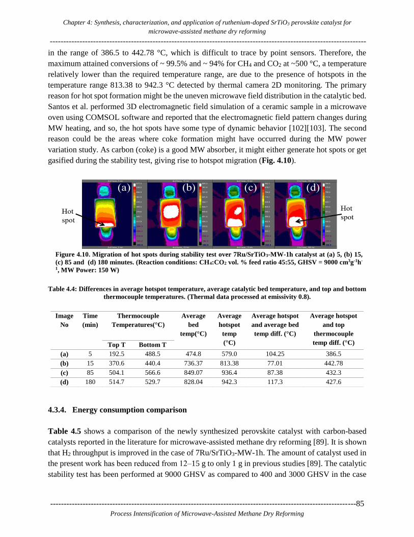
Chapter 4: Synthesis, characterization, and application of ruthenium-doped SrTiO3 perovskite catalyst for
microwave-assisted methane dry reforming
---------------------------------------------------------------------------------------------------------------------
-----------------------------------------------------------------------------------------------------------------85
Process Intensification of Microwave-Assisted Methane Dry Reforming
in the range of 386.5 to 442.78 °C, which is difficult to trace by point sensors. Therefore, the
maximum attained conversions of ~ 99.5% and ~ 94% for CH4 and CO2 at ~500 °C, a temperature
relatively lower than the required temperature range, are due to the presence of hotspots in the
temperature range 813.38 to 942.3 °C detected by thermal camera 2D monitoring. The primary
reason for hot spot formation might be the uneven microwave field distribution in the catalytic bed.
Santos et al. performed 3D electromagnetic field simulation of a ceramic sample in a microwave
oven using COMSOL software and reported that the electromagnetic field pattern changes during
MW heating, and so, the hot spots have some type of dynamic behavior [102][103]. The second
reason could be the areas where coke formation might have occurred during the MW power
variation study. As carbon (coke) is a good MW absorber, it might either generate hot spots or get
gasified during the stability test, giving rise to hotspot migration (Fig. 4.10).
Figure 4.10. Migration of hot spots during stability test over 7Ru/SrTiO3-MW-1h catalyst at (a) 5, (b) 15,
(c) 85 and (d) 180 minutes. (Reaction conditions: CH4:CO2 vol. % feed ratio 45:55, GHSV = 9000 cm3g-1h-
1, MW Power: 150 W)
Table 4.4: Differences in average hotspot temperature, average catalytic bed temperature, and top and bottom
thermocouple temperatures. (Thermal data processed at emissivity 0.8).
4.3.4. Energy consumption comparison
Table 4.5 shows a comparison of the newly synthesized perovskite catalyst with carbon-based
catalysts reported in the literature for microwave-assisted methane dry reforming [89]. It is shown
that H2 throughput is improved in the case of 7Ru/SrTiO3-MW-1h. The amount of catalyst used in
the present work has been reduced from 12‒15 g to only 1 g in previous studies [89]. The catalytic
stability test has been performed at 9000 GHSV as compared to 400 and 3000 GHSV in the case
Image
No
Time
(min)
Thermocouple
Temperatures(°C)
Average
bed
temp(°C)
Average
hotspot
temp
(°C)
Average hotspot
and average bed
temp diff. (°C)
Average hotspot
and top
thermocouple
temp diff. (°C) Top T Bottom T
(a) 5 192.5 488.5 474.8 579.0 104.25 386.5
(b) 15 370.6 440.4 736.37 813.38 77.01 442.78
(c) 85 504.1 566.6 849.07 936.4 87.38 432.3
(d) 180 514.7 529.7 828.04 942.3 117.3 427.6

Chapter 4: Synthesis, characterization, and application of ruthenium-doped SrTiO3 perovskite catalyst for
microwave-assisted methane dry reforming
---------------------------------------------------------------------------------------------------------------------------------------------
86-----------------------------------------------------------------------------------------------------------------
Process Intensification of Microwave-Assisted Methane Dry Reforming
of FY5 (activated carbon) and activated carbon mixed with Ni/Al2O3 catalyst, respectively (Table
4.5). The scale-up energy consumption and H2 production values based on our experimental results
are calculated in a similar way (included as supporting information) as in Fidalgo et al. [89] and
compared with the results in [89]. Table 4.6 presents a comparison on H2 production and energy
consumption in the case of perovskite catalyst and the carbon-based catalysts. Calculations are
done on the basis of 1 m3h-1 CH4 flow rate. The H2 throughput produced by FY5 is 0.3 m3h-1kg-1
vs. 8.1 m3h-1kg-1 (27 times higher) in the case of 7Ru/SrTiO3-MW-1h. The estimated energy
consumption is 44.4 kW h m-3 of H2 produced for FY5 vs. 18.58 kW h m-3 of H2 produced (2.38
times less) for 7Ru/SrTiO3-MW-1h.
Table 4.5: Catalytic performance comparison of the perovskite catalyst with carbon-based catalysts reported
in the literature for microwave-assisted methane dry reforming.
Catalyst
used
Thermo
-couple
Temp.
(oC)
Feed
composition
(vol. %)
Amount
of
catalyst
(g)
Flow of
CH4
(ml/min)
Total
GHSV
cm3h-1 g-1
Total
VHSV
Lh-1 g-1
MW
Power
(kW) used
at 2.45
GHz
Reactant
conversions
in %
Reference
CH4 CO2 CH4 CO2
FY5
(Activated
carbon)
700 40 60 15 40 400 0.4 13.5 96.2 97 [89]
50%FY5
+ 50%
Ni/Al2O3
800 50 50 12 300 3000 3 11.8 88.1 93.3 [89]
7Ru/SrTiO3-
MW-1h
500 45 55 1 67.5 9000 9 0.150 99.5 94 This
work.
Table 4.6: Energy consumption and H2 production comparison of the perovskite catalyst with carbon-based
catalysts reported in the literature.
Catalyst FY5
(Activated
carbon)
50%FY5
+
50%Ni/Al2O3
7Ru/SrTiO3-
MW-1h
Units
Reference [89] [89] This work -
Calculation basis 1 1 1 m3 h-1 of CH4
Volume of reactor 912.73 912.73 58.27 cm3
Amount of catalyst 6.25 0.7 0.2466 kg
Mass inflow rate of CH4 0.72 0.72 0.72 kg h-1
Mass outflow rate of H2 0.17 0.16 0.18 kg h-1
Volume outflow rate of H2 1.92 1.762 1.99 m3 h-1
Volume outflow rate of H2 per
kg of catalyst
0.3 2.6 8.1 m3 h-1kg-1
H2/CO ratio 0.66 1 0.9 -
Supplied power to the reactor 84.4 8.3 36.99 kW
Energy consumption w.r.to
CH4 flow
84.4 8.3 36.99 kW h m-3 of CH4
Energy consumption w.r.to H2
flow
44.4 4.6 18.58 kW h m-3 of H2

Chapter 4: Synthesis, characterization, and application of ruthenium-doped SrTiO3 perovskite catalyst for
microwave-assisted methane dry reforming
---------------------------------------------------------------------------------------------------------------------
-----------------------------------------------------------------------------------------------------------------87
Process Intensification of Microwave-Assisted Methane Dry Reforming
4.4. Conclusions
In this work, a series of ruthenium-doped strontium titanate perovskite catalysts were synthesized
by conventional and microwave-assisted hydrothermal methods. Significant synthesis temperature
and time reduction from 220 °C for 24 h in conventional heating to 180 °C for 1 h under microwave
heating were achieved. XRD analysis of the catalyst powder confirmed the presence of Ru in the
SrTiO3 perovskite structure in all synthesized catalysts. Increase in the dielectric property values
were observed with increase in ruthenium content and temperature. Higher dielectric property
values were obtained for the 7 wt. % Ru-doped SrTiO3 catalyst in a tested catalyst series with
variable Ru content. Further, ICP-OES analysis and HRTEM+EDX elemental mapping showed
improved Ru dispersion and more homogeneous distribution of particle sizes, respectively, in the
case of MW-assisted hydrothermal synthesis as compared to the conventional hydrothermal
synthesis.
Based on the aforementioned dielectric and chemical characterization study, microwave-assisted
methane dry reforming was performed on the 7 wt. % Ru-doped SrTiO3 perovskite catalyst
(7Ru/SrTiO3-MW-1h). The influence of different CH4:CO2 vol. % feed ratios were studied with
respect to their impact on CH4 conversion. The CH4:CO2 vol. % feed ratio 45:55 was found to
maximize methane conversion. Different gas hourly space velocities (GHSVs) of total reactant
flows were investigated too. Maximum conversions of ~99.5% and ~94% for CH4 and CO2,
respectively, were achieved during a 3h stability test at 9000 cm3g-1hr-1 GHSV, with the selected 7
wt. % Ru-doped SrTiO3 catalyst, which was exposed at maximum temperatures in the vicinity of
940 °C. Scale-up calculations on the basis of 1 m3h-1 CH4 inlet flow rate, as previously set in the
literature Ref. [89], on the 7Ru/SrTiO3-MW-1h catalyst show significant improvement in H2
production capability as compared to carbon-based catalysts.

Chapter 4: Synthesis, characterization, and application of ruthenium-doped SrTiO3 perovskite catalyst for
microwave-assisted methane dry reforming
---------------------------------------------------------------------------------------------------------------------------------------------
88-----------------------------------------------------------------------------------------------------------------
Process Intensification of Microwave-Assisted Methane Dry Reforming
4.5. Supporting Information
Energy Consumption calculations
Table 4.7: Experimental testing conditions with different units for comparison purpose.
Total Flow rate 150 ml/min 9 Lh-1 9000 cm3h-1
CH4 Flow rate 67.5 ml/min 4.05 Lh-1 4050 cm3h-1
CO2 Flowrate 82.5 ml/min 4.95 Lh-1 4950 cm3h-1
Weight of Catalyst used 1 g 0.001 kg 0.001 kg
MW Power Supplied 150 W 0.150 kW 0.150 kW
GHSV - 9 Lg-1h-1 9000 cm3g-1h-1
CH4:CO2 Volume % ratio used - - 45:55
CH4 conversion - - 99.5 %
CO2 conversion - - 94%
The volume of quartz reactor used in reference [89]
The volume of quartz tube = 𝜋 × (𝐷𝑖𝑎𝑚𝑒𝑡𝑒𝑟)2 × 𝐿𝑒𝑛𝑔𝑡ℎ
= 𝜋 × (2.6 𝑐𝑚)2 × 43 𝑐𝑚 = 𝟗𝟏𝟐. 𝟕𝟑 𝒄𝒎𝟑
The volume of quartz reactor used in our work
The volume of quartz tube = 𝜋 × (𝐷𝑖𝑎𝑚𝑒𝑡𝑒𝑟)2 × 𝐿𝑒𝑛𝑔𝑡ℎ
= 𝜋 × (0.8 𝑐𝑚)2 × 29 𝑐𝑚 = 𝟓𝟖. 𝟐𝟕 𝒄𝒎𝟑
Scale up calculations
For 1 m3h-1 of CH4 reforming:
To perform the reforming of 1 m3h-1 of CH4 inlet flow rate at 9 Lg-1h-1 VHSV space velocity, the
required amount of catalyst is calculated as follows
Note: we need to consider 45:55 volume % of CH4: CO2 ratio. Therefore, the total flow rate of the
reactants becomes 2.22 m3h-1.
VHSV = 𝑇𝑜𝑡𝑎𝑙 𝑓𝑙𝑜𝑤(𝑚3ℎ−1)
𝐴𝑚𝑜𝑢𝑛𝑡 𝑜𝑓 𝑐𝑎𝑡𝑎𝑙𝑦𝑠𝑡(𝑘𝑔)= 9 𝐿ℎ−1𝑔−1 =
2.22 𝑚3ℎ−1
𝐴𝑚𝑜𝑢𝑛𝑡 𝑜𝑓 𝑐𝑎𝑡𝑎𝑙𝑦𝑠𝑡(𝑘𝑔)
𝐴𝑚𝑜𝑢𝑛𝑡 𝑜𝑓 𝑐𝑎𝑡𝑎𝑙𝑦𝑠𝑡 = 2.22 𝑚3ℎ−1
9 𝐿ℎ−1𝑔−1 = 0.2466 𝑘𝑔
Chapter 4: Synthesis, characterization, and application of ruthenium-doped SrTiO3 perovskite catalyst for
microwave-assisted methane dry reforming
---------------------------------------------------------------------------------------------------------------------
-----------------------------------------------------------------------------------------------------------------89
Process Intensification of Microwave-Assisted Methane Dry Reforming
Therefore, 0.2466 kg of 7Ru/SrTiO3-MW-1h catalyst will be needed to process a total flow rate of
2.22 𝑚3ℎ−1 of 45%CH4-55%CO2.
We used 150 W of MW power for 1 g of the catalyst at 9 𝐿ℎ−1𝑔−1 GHSV. The power needed to
keep the reaction system running at 2.22 m3h-1 total flow is calculated as
Specific Power = 𝑃𝑜𝑤𝑒𝑟 𝑟𝑒𝑞𝑢𝑖𝑟𝑒𝑑 𝑓𝑜𝑟 2.22 𝑚3ℎ−1
𝐴𝑚𝑜𝑢𝑛𝑡 𝑜𝑓 𝐶𝑎𝑡𝑎𝑙𝑦𝑠𝑡 𝑢𝑠𝑒𝑑
Therefore if we assume our specific power is 150 kWkg-1.
150 (kWk𝑔−1) = 𝑃𝑜𝑤𝑒𝑟 𝑅𝑒𝑞𝑢𝑖𝑟𝑒𝑑(𝑘𝑊)
0.2466 𝑘𝑔
Then, the power required for 1m3h-1 CH4 conversion is 36.99 kW.
The hydrogen flowrate based on 1 m3 hr-1 CH4 flowrate and experimentally obtained CH4
conversion is calculated as
Flow rate of hydrogen = inlet CH4 flow rate × % CH4 Conversion × 2
Flow rate of hydrogen = 1 m3hr-1×0.995×2 = 1.99 m3hr-1
Energy Consumption w.r.t 1 m3 hr-1 CH4 flow keeping VHSV constant
Energy Consumption w. r. t 𝐶𝐻4 flow = 𝑃𝑜𝑤𝑒𝑟 𝑟𝑒𝑞𝑢𝑖𝑟𝑒𝑑(𝑘𝑊)
𝐹𝑙𝑜𝑤𝑟𝑎𝑡𝑒 𝑜𝑓 𝑚𝑒𝑡ℎ𝑎𝑛𝑒(𝑚3ℎ−1) =
36.99
1 =
36.99 kW h m−3
Energy Consumption w. r. t 𝐻2 flow keeping VHSV constant
Energy Consumption w. r. t. 𝐻2 flow = 𝑃𝑜𝑤𝑒𝑟 𝑅𝑒𝑞𝑢𝑖𝑟𝑒𝑑(𝑘𝑊)
𝐹𝑙𝑜𝑤𝑟𝑎𝑡𝑒 𝑜𝑓 𝐻𝑦𝑑𝑟𝑜𝑔𝑒𝑛(𝑚3ℎ−1) =
36.99
1.99= 18.58 kW h m−3
The density of CH4 at NTP is 0.668 and at STP is 0.717 kg/m3
The density of H2 at NTP is 0.0899 and at STP is 0.0899 kg/m3
Therefore, the inlet flow rate of CH4 in terms of kg h-1 is calculated by its density
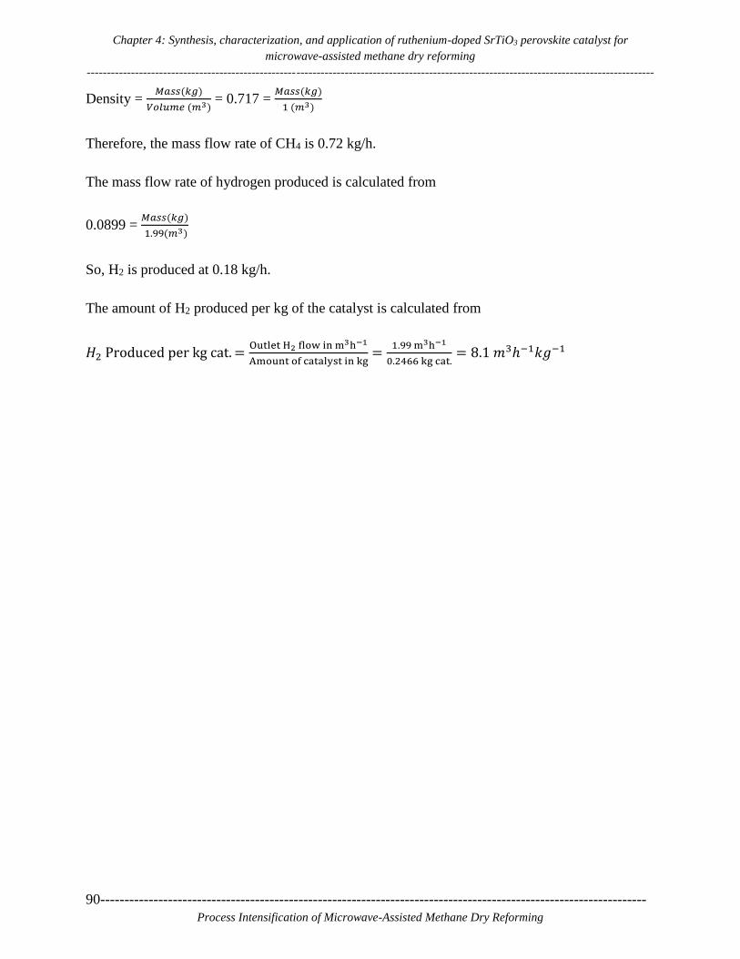
Chapter 4: Synthesis, characterization, and application of ruthenium-doped SrTiO3 perovskite catalyst for
microwave-assisted methane dry reforming
---------------------------------------------------------------------------------------------------------------------------------------------
90-----------------------------------------------------------------------------------------------------------------
Process Intensification of Microwave-Assisted Methane Dry Reforming
Density = 𝑀𝑎𝑠𝑠(𝑘𝑔)
𝑉𝑜𝑙𝑢𝑚𝑒 (𝑚3) = 0.717 =
𝑀𝑎𝑠𝑠(𝑘𝑔)
1 (𝑚3)
Therefore, the mass flow rate of CH4 is 0.72 kg/h.
The mass flow rate of hydrogen produced is calculated from
0.0899 = 𝑀𝑎𝑠𝑠(𝑘𝑔)
1.99(𝑚3)
So, H2 is produced at 0.18 kg/h.
The amount of H2 produced per kg of the catalyst is calculated from
𝐻2 Produced per kg cat. =Outlet H2 flow in m3h−1
Amount of catalyst in kg =
1.99 m3h−1
0.2466 kg cat.= 8.1 𝑚3ℎ−1𝑘𝑔−1

Chapter 5: CO2 reforming of CH4 under microwave heating over hybrid catalytic systems of ruthenium-doped
SrTiO3 and nickel supported catalysts
---------------------------------------------------------------------------------------------------------------------
-----------------------------------------------------------------------------------------------------------------91
Process Intensification of Microwave-Assisted Methane Dry Reforming
5 5. CO2 reforming of CH4 under
microwave heating over hybrid catalytic
systems of ruthenium-doped SrTiO3 and
nickel supported catalysts

Chapter 5: CO2 reforming of CH4 under microwave heating over hybrid catalytic systems of ruthenium-doped
SrTiO3 and nickel supported catalysts
--------------------------------------------------------------------------------------------------------------------------------------- ------
92-----------------------------------------------------------------------------------------------------------------
Process Intensification of Microwave-Assisted Methane Dry Reforming
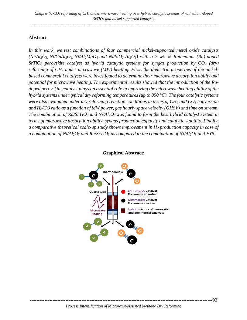
Chapter 5: CO2 reforming of CH4 under microwave heating over hybrid catalytic systems of ruthenium-doped
SrTiO3 and nickel supported catalysts
---------------------------------------------------------------------------------------------------------------------
-----------------------------------------------------------------------------------------------------------------93
Process Intensification of Microwave-Assisted Methane Dry Reforming
Abstract
In this work, we test combinations of four commercial nickel-supported metal oxide catalysts
(Ni/Al2O3, Ni/CaAl2O4, Ni/Al2MgO4 and Ni/SiO2-Al2O3) with a 7 wt. % Ruthenium (Ru)-doped
SrTiO3 perovskite catalyst as hybrid catalytic systems for syngas production by CO2 (dry)
reforming of CH4 under microwave (MW) heating. First, the dielectric properties of the nickel-
based commercial catalysts were investigated to determine their microwave absorption ability and
potential for microwave heating. The experimental results showed that the introduction of the Ru-
doped perovskite catalyst plays an essential role in improving the microwave heating ability of the
hybrid systems under typical dry reforming temperatures (up to 850 °C). The four catalytic systems
were also evaluated under dry reforming reaction conditions in terms of CH4 and CO2 conversion
and H2/CO ratio as a function of MW power, gas hourly space velocity (GHSV) and time on stream.
The combination of Ru/SrTiO3 and Ni/Al2O3 was found to form the best hybrid catalyst system in
terms of microwave absorption ability, syngas production capacity and catalytic stability. Finally,
a comparative theoretical scale-up study shows improvement in H2 production capacity in case of
a combination of Ni/Al2O3 and Ru/SrTiO3 as compared to the combination of Ni/Al2O3 and FY5.
Graphical Abstract:

Chapter 5: CO2 reforming of CH4 under microwave heating over hybrid catalytic systems of ruthenium-doped
SrTiO3 and nickel supported catalysts
--------------------------------------------------------------------------------------------------------------------------------------- ------
94-----------------------------------------------------------------------------------------------------------------
Process Intensification of Microwave-Assisted Methane Dry Reforming

Chapter 5: CO2 reforming of CH4 under microwave heating over hybrid catalytic systems of ruthenium-doped
SrTiO3 and nickel supported catalysts
---------------------------------------------------------------------------------------------------------------------
-----------------------------------------------------------------------------------------------------------------95
Process Intensification of Microwave-Assisted Methane Dry Reforming
5.1. Introduction
Microwave (MW)-assisted dry reforming of methane (DRM) is a chemical process of interest in
the context of power-to-chemical technologies [22] due to its high potential for methane and carbon
dioxide valorization in an economic and sustainable manner [104][21][105]. The primary product
of this reaction is syngas, which can be converted to a variety of chemicals through the Fischer-
Tropsch process [106][107][108]. Due to the high temperatures required for the DRM reaction
(700‒1000 °C) [109][110][111], a catalyst with both good reactivity and dielectric properties
(capacity to absorb microwaves and convert it into heat) are required. Carbon-based catalysts are
commonly used for microwave-heated methane reforming reactions due to their excellent
microwave absorption properties and good catalytic activity [107][111][48][112]. For these
reasons, the combination of activated carbons with more active metal-based catalysts, such as
nickel and platinum on various oxide supports has also been investigated. Hotspot generation and
fast regeneration of active catalytic sites are the majorly reported effects in the literature responsible
for higher CH4 and CO2 conversions under microwave heating as compared to conventional heating
at similar reaction temperatures [37][71][34][56][36].
The main challenge with most of the common metal catalysts (e.g., Ni/Al2O3, Ni/CaAl2O4,
Ni/Al2MgO4 and Ni/SiO2-Al2O3) is that they cannot reach optimum reaction temperatures under
MW exposure due to their poor dielectric properties [48]. In addition, they would not heat up
comparably in a microwave reactor, which in turn hinders an accurate comparison among them
and limits their eligibility for being used in a microwave reaction process. Further, an issue with
carbon-based catalysts is that they form a pyrolytic carbon layer and, unavoidably, they are
consumed during the reaction [37][112][54][113]. Noble metal-based catalysts like Pt and Ru are
known to be good microwave absorbers, catalytically active and resistant to carbon formation, but
also rather expensive and thus less attractive for industrial applications [54][114].
In an effort to intensify microwave-assisted dry reforming, we have investigated a hybrid catalytic
approach in which different commercial and relatively inexpensive Ni-based catalysts, having poor
microwave absorption capacity, are individually mixed with an in-house developed 7 wt. % Ru-
doped perovskite catalyst (Ru/SrTiO3) that has excellent microwave properties and catalytic
activity. Mixing of the commercial and in-house catalyst particles can improve the heating of the
catalyst bed as a whole, reduce susceptibility to coke formation, promote the activity of Ni-
supported catalysts with a noble metal (Ru) and reduce the cost involved, as compared to using
high content noble metal-based catalysts only [114]. The different combinations of the commercial
Ni-based catalysts with the Ru-doped perovskite catalyst have been compared. The best catalyst
pair has been selected, and the optimal heating and flow conditions have been identified. Finally,
a catalyst performance test as a function of time on stream (TOS) has been carried out.

Chapter 5: CO2 reforming of CH4 under microwave heating over hybrid catalytic systems of ruthenium-doped
SrTiO3 and nickel supported catalysts
--------------------------------------------------------------------------------------------------------------------------------------- ------
96-----------------------------------------------------------------------------------------------------------------
Process Intensification of Microwave-Assisted Methane Dry Reforming
5.2. Experimental section
5.2.1. Catalytic systems and dielectric properties measurement method
Four different commercial Ni-supported metal oxide catalysts were used as received. Table 5.1
summarizes the catalysts composition, the catalysts notation, and their supplier. In short, the
selected commercial samples consist of nickel oxide supported on different inorganic supports such
as alpha alumina (Katalco23) and calcium aluminate (Katalco57), provided by Johnson Matthey,
magnesium aluminate (R-67-7H), supplied by Haldor Topsoe, and, finally, silica/alumina
(Ni/SiO2-Al2O3) purchased from Sigma Aldrich. The dielectric properties of these catalysts were
measured in specially designed equipment at the Institute of Information and Communication
Technologies (ITACA) of the University of Valencia, Spain [77]. The catalysts were heated from
20 °C to 850 °C with a heating rate of 20 °C/min under continuous N2 flow. The dielectric
properties were then determined based on the shift of the center of the resonant frequency and the
quality factor of the microwave cavity due to the presence of material inside it with respect to an
empty cavity [115–118]. In our previous work, an in-house developed 7 wt. % ruthenium-doped
SrTiO3 catalyst (Ru/SrTiO3) was found to be an excellent heterogeneous catalyst for DRM under
microwave heating [119]. Therefore, this catalyst was also used in the present work for comparison.
Table 5.1: Commercial catalysts used
Catalyst Notation Company/Supplier Composition
Ni/Al2O3 Katalco23 Johnson Matthey Nickel oxide(10-25%) on alpha alumina
Ni/CaAl2O4 Katalco57 Johnson Matthey Nickel oxide(10-25%) on calcium aluminate
Ni/Al2MgO4 R-67-7H Haldor Topsoe Nickel oxide (>15 wt. %) on magnesium aluminate
Ni/SiO2-Al2O3 Ni-SiO2/Al2O3 Sigma Aldrich Nickel (61-69 wt. %) on silica/alumina
5.2.2. Microwave reactor system
A schematic and photos of the parts comprising the custom microwave setup developed for the
experiments are shown in the supporting information document (Figure S5.1a and S5.1b). For all
experiments, 1 g of hybrid (mixed) catalyst (425‒850 μm particle size) was fixed inside the reactor
quartz tube (290 mm length × 8 mm i.d.) using quartz wool plugs. A solid-state microwave
generator (Miniflow 200 SS, 2.45 GHz, 200 W max.) was used to deliver MW energy to the
catalytic bed. Two N-type thermocouples (‒200 to +1250 °C) were placed at the top and at the
bottom part of the catalyst bed to measure the temperature at these positions. The surface
temperature of the catalytic bed was monitored in 2D by a thermal camera, model FLIR A655sc
(7.5‒14 μm, ‒40 to 2000 °C). The temperature was recorded every 5 min during the experiments.

Chapter 5: CO2 reforming of CH4 under microwave heating over hybrid catalytic systems of ruthenium-doped
SrTiO3 and nickel supported catalysts
---------------------------------------------------------------------------------------------------------------------
-----------------------------------------------------------------------------------------------------------------97
Process Intensification of Microwave-Assisted Methane Dry Reforming
The reactants and products in the gas phase were analyzed online by a Varian CP4900 micro-GC,
equipped with two columns, 20 m MS5A and 10 m PPU, and analyzed by a TCD detector. The
conversion of CH4 and CO2 were calculated by equations (5.2) and (5.3), respectively, considering
only the global dry reforming of methane reaction (DRM) (eq. 5.1), after 5 min of time on stream.
Global DRM Reaction: CH4 + CO2 2CO + 2H2 ∆H298K = +247 kJ.mol-1 (5.1)
CH4 Conversion, % = 100 × [(𝐻2)𝑂𝑢𝑡
2]/[(𝐶𝐻4)𝑜𝑢𝑡 +
(𝐻2)𝑜𝑢𝑡
2] (5.2)
CO2 Conversion, % = 100 × [(𝐶𝑂)𝑜𝑢𝑡
2]/[(𝐶𝑂2)𝑜𝑢𝑡 +
(𝐶𝑂)𝑂𝑢𝑡
2] (5.3)
Where (𝐶𝐻4)𝑂𝑢𝑡, (𝐻2)𝑜𝑢𝑡, (𝐶𝑂2)𝑜𝑢𝑡 and (𝐶𝑂)𝑜𝑢𝑡 are methane, hydrogen, carbon dioxide and
carbon monoxide concentrations in the effluent gas (% by volume), respectively. H2 and CO
production in moles are calculated by equations (4) and (5), respectively.
H2 in moles = CH4 inlet flow in L × % CH4 conversion × 2 × 22.414 L (5.4)
CO in moles = CO2 inlet flow in L × % CO2 conversion × 2 × 22.414 L (5.5)
The combination of both a thermal camera and two thermocouples placed at the top and at the
bottom of the catalyst bed is used in all experiments performed. This dual approach is used for
three reasons; 1) the thermocouples alone can only measure temperature at a single point outside
of the catalytic bed due to the risk of thermocouple damage by formation of hot-spots in which
temperature may exceed 1250 °C (the maximum thermocouple limit); 2) due to the formation and
migrating nature of hot spots in the catalytic bed, recording of the spatial temperature distribution
is necessary and this can only be enabled by the use of a thermal camera; 3) the emissivities of the
quartz tube and the catalyst change during the reaction, resulting in inaccuracies in temperature
measurements by the thermal camera alone [54]. Therefore, a feedback mechanism by
thermocouples is needed. To this end, simultaneous temperature monitoring by a thermal camera
and thermocouples was used to analyze temperature evolution and distribution during microwave-
assisted DRM. The details of the approach are given in previous work (Ref. [54]).
5.2.3. Methane dry reforming reaction conditions
Table 5.2 summarizes the reaction conditions applied during microwave-assisted DRM over the
four hybrid catalytic systems (Ru/SrTiO3 + Ni-supported catalysts). Four different test series have
been carried out, denoted by series numbers 1 to 4 in Table 5.2; 1) thermal response of the catalytic
materials under microwave heating, 2) evolution of microwave power and reactants conversion, 3)

Chapter 5: CO2 reforming of CH4 under microwave heating over hybrid catalytic systems of ruthenium-doped
SrTiO3 and nickel supported catalysts
--------------------------------------------------------------------------------------------------------------------------------------- ------
98-----------------------------------------------------------------------------------------------------------------
Process Intensification of Microwave-Assisted Methane Dry Reforming
gas hourly space velocity (GHSV) study and 4) reactor performance test as a function of time on
stream. The standard reaction conditions are described in series number 0 (Table 5.2). All methane
dry reforming reactions were performed at atmospheric pressure. It is important to note that the
microwave power absorption response of each hybrid catalytic system is different, leading to
different catalytic bed temperatures. The endothermic nature of the reaction and possible hot spot
migration makes it very challenging to maintain the same stable temperature in different hybrid
catalytic systems in order to compare them. Therefore, reactant conversions in each case were
monitored until the highest conversions were attained, or temperatures ~1000 °C were reached.
Hence different settings of MW power, temperature, and GHSV values are required for different
hybrid catalytic systems in order for each of them to reach the best performance.
Table 5.2. Operating conditions for microwave-assisted methane dry reforming over the four hybrid catalytic
systems of the four Ni-based commercial catalysts mixed in 1:1 ratio with 7 wt. % ruthenium-doped SrTiO3
perovskite catalyst
Sr. No. Test Description Ru/SrTiO3 + Ni-supported
catalyst
0 Standard
reaction
conditions
Catalyst amount / g 1
particle size / μm 425‒850
Pressure / atm ~1
CH4:CO2 vol. % ratio 45:55
CH4:CO2 feed ratio 0.82
1 Thermal response of the
catalytic materials under
microwave heating
Nitrogen feed / cm3STP/min 50
MW power / W 0‒100
2 Evolution of microwave
power and reactants
conversion
CH4:CO2 vol. % ratio 45:55
Total flow rate / cm3STP/min 50
MW power / W 40-140
3 Gas hourly space velocity
(GHSV) study
Total flow rate / cm3STP/min 50‒150
GHSV / cm3STP/h g cat 3000‒9000
MW power / W 100‒140
4 Reactor performance as a
function of time on stream
Total flow rate / cm3STP/min 50‒75
GHSV / cm3STP/h g cat 3000‒4500
MW power / W 100‒140
Total reaction time / min 180

Chapter 5: CO2 reforming of CH4 under microwave heating over hybrid catalytic systems of ruthenium-doped
SrTiO3 and nickel supported catalysts
---------------------------------------------------------------------------------------------------------------------
-----------------------------------------------------------------------------------------------------------------99
Process Intensification of Microwave-Assisted Methane Dry Reforming
The first test “thermal response of the catalytic materials under microwave heating” was a heating
test conducted under nonreactive conditions (N2 flow of 50 cm3STP/min) to approximately verify
the power level at which the reaction temperature range was attained. In this test, power was
increased by 5 W every 5 min. The second test (“evolution of microwave power and reactants
conversion”) was carried out to determine the power at which the catalysts were showing the
highest CH4 and CO2 conversions for DRM. In this case, the microwave power was increased by
10 W every 20 min. The third test “gas hourly space velocity (GHSV) study” was carried out to
determine the optimal total flow rate to reach maximum conversions. The GHSV test was carried
out at the constant power determined in the “evolution of microwave power and reactants
conversion” test. For each flow rate, the conversion was monitored for 30 min. The fourth test
conducted was the “reactor performance test as a function of time on stream.” This test was done
under the optimal operating conditions for each catalyst, obtained from the previous experiments
(tests 1, 2 and 3 described in Table 5.2), to determine catalyst stability over longer reaction times
(~180 min) and verify possible catalyst deactivation.
5.3. Results and discussion
5.3.1. Dielectric properties and the need of a hybrid catalytic system
The dielectric properties of the catalytic materials were measured up to 850 °C. Figure 5.1a shows
a comparison of the dielectric constants of the Ni-based commercial catalysts and Ru/SrTiO3. It
can be seen that the Ni/Al2O3 catalyst is outperforming the other commercially available catalysts
at higher temperatures. When comparing all commercial catalysts with the Ru/SrTiO3 catalyst, it
can be seen that Ru/SrTiO3 has a much higher dielectric constant across the whole temperature
range. Figure 5.1b shows the dielectric loss factor of the four commercial catalysts and Ru/SrTiO3.
The loss factor of Ni/Al2O3 is almost zero at room temperature, but increases with temperature to
around 1. The other three catalysts maintain a loss factor close to zero up to ~400 °C; at higher
temperatures, the loss factor starts to slowly increase up to 0.2‒0.3. Thus, only a negligible amount
of microwave power is dissipated as heat in the commercially available catalysts, and very little
heating can be achieved. In comparison to the four commercial catalysts, Ru/SrTiO3 has the highest
dielectric loss factor, ranging from 0.57 at room temperature to 2.25 at 800 °C. Overall, Figure
5.1 confirms that the dielectric properties of the commercial catalysts are not suitable to heat them
up to the required reaction temperature with 200 W of microwave power (max. power limit of the
solid-state microwave generator used). Therefore, they are not good candidates for direct heating
in microwave-assisted heterogeneous catalytic reactions.
In a previous work of our group, a series of ruthenium-doped strontium titanate (SrTiO3) perovskite
catalysts, with different ruthenium loadings, were synthesized by a microwave-assisted
hydrothermal method [119]. It was observed that the increase in ruthenium content in SrTiO3

Chapter 5: CO2 reforming of CH4 under microwave heating over hybrid catalytic systems of ruthenium-doped
SrTiO3 and nickel supported catalysts
--------------------------------------------------------------------------------------------------------------------------------------- ------
100-----------------------------------------------------------------------------------------------------------------
Process Intensification of Microwave-Assisted Methane Dry Reforming
perovskite improved its dielectric properties. A 7 wt. % Ru-doped SrTiO3 catalyst, denoted in the
present work as Ru/SrTiO3, was found to be the best catalyst for microwave-assisted methane dry
reforming among the tested samples. However, use of the ruthenium-based catalyst only would be
expensive for large-scale operations. On the other hand, its combination with a Ni-based
commercial catalyst would enable the latter to reach the required reaction temperature while
reducing the total cost on scale up.
Figure 5.1. Comparison of dielectric properties of Ni-based commercial catalysts and 7 wt.
% Ru-doped SrTiO3 (Ru/SrTiO3) perovskite catalysts: (a) dielectric constant versus
temperature and (b) loss factor versus temperature.
Overall, in order to improve the microwave heating ability of the commercial Ni-based catalysts,
different synthetic strategies were investigated. The first one consisted of impregnating Ni/Al2O3
catalyst with 6 wt. % of Ru via incipient wetness impregnation with aqueous ruthenium (III)
nitrosyl nitrate solution. After impregnation, samples were calcined at 400 °C for 3h under static
air conditions. 1 g of 6 wt% Ru-impregnated Ni/Al2O3, denoted as 6Ru@Ni/Al2O3, was sieved to
obtain 425‒850 μm particles and loaded into the quartz reactor tube. The sample was then heated
in the microwave reactor under N2 flow. It was not possible to heat this impregnated catalyst above
300 °C using the maximum microwave power of 200 W.
Kumar et al. [120] have reported that metals like aluminum and nickel when dispersed on titanium
(IV) oxide (TiO2) nanoparticles increase their overall dielectric properties. Therefore, the second
approach was the mixing of TiO2 powder (425‒850 μm) with 6Ru@Ni/Al2O3 of the same particle
size at a ratio of 1:1 (0.5 g of TiO2 and 0.5 g of 6Ru@Ni/Al2O3). No significant improvement in
the heating profile was found after TiO2 addition and testing in the microwave reactor. The third
approach consisted of adding strontium oxide to the samples prepared in the first two approaches
(6Ru@Ni/Al2O3 and 6Ru@Ni/Al2O3 + TiO2) at a ratio of 1:1. Upon heating in the microwave
reactor, no increment in the heating profile was observed after addition of the strontium oxide.
Finally, the fourth and last synthesis procedure was based on mixing Ru/SrTiO3 (in the perovskite
form) with the Ni-based catalysts. The Ru/SrTiO3 catalyst was directly mixed with each

Chapter 5: CO2 reforming of CH4 under microwave heating over hybrid catalytic systems of ruthenium-doped
SrTiO3 and nickel supported catalysts
---------------------------------------------------------------------------------------------------------------------
-----------------------------------------------------------------------------------------------------------------101
Process Intensification of Microwave-Assisted Methane Dry Reforming
commercial Ni-based catalyst at a ratio 1:1 (0.5 g of Ru/SrTiO3 and 0.5 g of Ni-supported catalyst)
all having particle sizes 425-850 μm. This approach was successful in attaining the required
temperature range within the available MW power limit (200 W). Therefore, these samples were
used for methane dry reforming as described in the following sections.
5.3.2. Thermal response of the catalytic materials under microwave heating
As the catalysts have different chemical compositions, they will not obtain the same temperatures
when heated inside a microwave reactor at a given applied power. For this reason, a study on the
relation between microwave power and catalyst bed temperature using both the top bed
thermocouple and the thermal camera was performed for each catalytic system under a N2 flow
rate of 50 cm3STP/min. The information from this study was later used to determine the microwave
power needed for each hybrid catalyst to reach the desired reaction temperature during DRM.
Figure 5.2a presents the top catalyst bed temperature as a function of MW power for each hybrid
catalytic system; Figures 5.2b, c, d, and e show the temperature contours produced by the thermal
camera for the Ru/SrTiO3+Ni/SiO2-Al2O3 sample at applied MW powers of 70, 75, 80 and 85 W,
respectively.
Figure 5.2. (a) Top bed temperature measurement in each hybrid catalytic system comprising each
of the four commercial catalysts and the in-house developed Ru/SrTiO3 catalyst in the power range
from 0 to 100 W. (b-e) Migration of hotspot inside the Ru/SrTiO3+Ni/SiO2-Al2O3 catalyst sample
with increase in MW power; (b) 70 W, (c) 75 W, (d) 80 W and (e) 85 W.
In Figure 5.2a, ascending temperature trends with increasing power input are presented. Although
these general trends are expected, some abrupt temperature changes are also recorded, e.g., for
Ru/SrTiO3+Ni/SiO2-Al2O3 at ~80 W and for Ru/SrTiO3+Ni/CaAl2O4 at ~35 W, manifesting
hotspot migration inside the catalyst bed. Indeed, this is confirmed by the thermal images in
Figures 5.2b-e, which show that the hottest (white) zone inside the reactor moves towards the top
of the bed (closer to the inlet), at higher powers (80‒85 W, Figures 5.2d and e) compared to lower

Chapter 5: CO2 reforming of CH4 under microwave heating over hybrid catalytic systems of ruthenium-doped
SrTiO3 and nickel supported catalysts
--------------------------------------------------------------------------------------------------------------------------------------- ------
102-----------------------------------------------------------------------------------------------------------------
Process Intensification of Microwave-Assisted Methane Dry Reforming
ones (70‒75 W, Figures 5.2b and c). As the thermocouple is located at the top of the bed, its
temperature reading is affected by hotspot migration. Overall, these results confirm that 2D
temperature monitoring in the catalyst bed is necessary to track the location of hot spots and avoid
materials damage during a microwave heating process.
5.3.3. Evolution of microwave power and reactants conversion
The effect of different microwave powers on the overall reactor performance was experimentally
determined. Figures 5.3a-f show methane conversion, carbon dioxide conversion, H2/CO ratio, top
catalyst bed temperature, bottom catalyst bed temperature and average catalyst bed temperature,
respectively, after 20 min of TOS, as a function of MW power (40‒140 W) at a CH4/CO2 inlet ratio
of 0.82 and 3000 cm3g‒1h‒1 GHSV (50 cm3STP/min). The reaction was performed either until
conversions were stabilized to maximum values or until the top catalytic bed temperature reached
~1000 °C; in the latter case, the reaction was stopped to avoid thermocouple damage.
Based on the heating experiments discussed in Section 5.3.2, it was decided to perform all reactant
conversion tests starting from 40 W. As shown in Figures 5.3a and b, up to 60 W, the conversions
of CH4 and CO2 with Ru/SrTiO3+Ni/Al2O3 are higher compared to the other three catalysts, despite
the lowest top bed temperature reached (172.52 ºC at 60 W with Ru/SrTiO3+Ni/Al2O3; Figure 5.3d
and Table S5.2). In the 60-120 W range, Ru/SrTiO3+Ni/CaAl2O4 gives higher conversions than
Ru/SrTiO3+Ni/Al2O3. At powers higher than 120 W, Ru/SrTiO3+Ni/Al2O3 and
Ru/SrTiO3+Ni/CaAl2O4 give nearly equal conversions for CH4 and CO2. The maximum
conversions achieved by the two catalysts were ~99% for CH4 and ~92% for CO2 at 140 W.
According to these results, it was decided that 140 W be the maximum applied MW power for all
the experiments since the CH4 conversion achieved with Ru/SrTiO3+Ni/Al2O3 and
Ru/SrTiO3+Ni/CaAl2O4 was ~99%. Interestingly, the Ru/SrTiO3+Ni/Al2MgO4 catalyst had a top
catalyst bed temperature value in excess of 550 °C at 40 W and reached 1000 °C at 110 W (see
Figure 5.3d and S5.5); therefore, no higher power levels were tested in order to avoid damage of
the thermocouple. In the case of Ru/SrTiO3+Ni/SiO2-Al2O3 catalyst, rapid temperature rise was
also observed from 400 °C at 110 W to 1027 °C at 130 W (Table S5.2). Hence the experiment was
stopped at 130 W to avoid thermocouple damage.
The conversions achieved by Ru/SrTiO3+Ni/Al2MgO4 are lower than those of
Ru/SrTiO3+Ni/Al2O3 and Ru/SrTiO3+Ni/CaAl2O4, but higher than the conversions with the
Ru/SrTiO3+Ni/SiO2-Al2O3 catalyst in the range (40‒100 W). At higher powers (100‒130 W range),
Ru/SrTiO3+Ni/SiO2-Al2O3 has shown an increase in conversion up to 88% for CH4 and 82% for
CO2 at 130 W. This increase in conversion could be associated with the drastic increase in the top
bed temperature at 130 W (Figure 5.3d) due to hotspot migration close to the top thermocouple
(inlet side where reactants concentration is high) (see Figure S5.6). Figure 5.3c shows that for
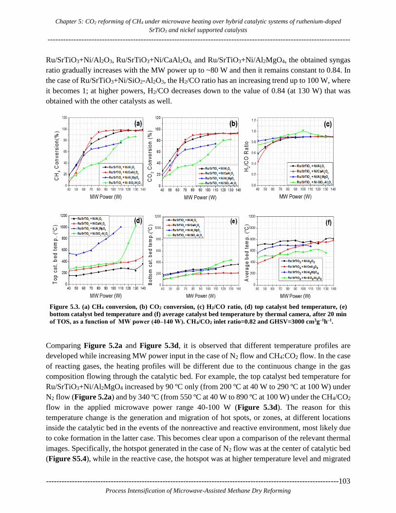
Chapter 5: CO2 reforming of CH4 under microwave heating over hybrid catalytic systems of ruthenium-doped
SrTiO3 and nickel supported catalysts
---------------------------------------------------------------------------------------------------------------------
-----------------------------------------------------------------------------------------------------------------103
Process Intensification of Microwave-Assisted Methane Dry Reforming
Ru/SrTiO3+Ni/Al2O3, Ru/SrTiO3+Ni/CaAl2O4, and Ru/SrTiO3+Ni/Al2MgO4, the obtained syngas
ratio gradually increases with the MW power up to ~80 W and then it remains constant to 0.84. In
the case of Ru/SrTiO3+Ni/SiO2-Al2O3, the H2/CO ratio has an increasing trend up to 100 W, where
it becomes 1; at higher powers, H2/CO decreases down to the value of 0.84 (at 130 W) that was
obtained with the other catalysts as well.
Figure 5.3. (a) CH4 conversion, (b) CO2 conversion, (c) H2/CO ratio, (d) top catalyst bed temperature, (e)
bottom catalyst bed temperature and (f) average catalyst bed temperature by thermal camera, after 20 min
of TOS, as a function of MW power (40‒140 W). CH4/CO2 inlet ratio=0.82 and GHSV=3000 cm3g‒1h‒1.
Comparing Figure 5.2a and Figure 5.3d, it is observed that different temperature profiles are
developed while increasing MW power input in the case of N2 flow and CH4:CO2 flow. In the case
of reacting gases, the heating profiles will be different due to the continuous change in the gas
composition flowing through the catalytic bed. For example, the top catalyst bed temperature for
Ru/SrTiO3+Ni/Al2MgO4 increased by 90 ºC only (from 200 ºC at 40 W to 290 ºC at 100 W) under
N2 flow (Figure 5.2a) and by 340 ºC (from 550 ºC at 40 W to 890 ºC at 100 W) under the CH4/CO2
flow in the applied microwave power range 40-100 W (Figure 5.3d). The reason for this
temperature change is the generation and migration of hot spots, or zones, at different locations
inside the catalytic bed in the events of the nonreactive and reactive environment, most likely due
to coke formation in the latter case. This becomes clear upon a comparison of the relevant thermal
images. Specifically, the hotspot generated in the case of N2 flow was at the center of catalytic bed
(Figure S5.4), while in the reactive case, the hotspot was at higher temperature level and migrated

Chapter 5: CO2 reforming of CH4 under microwave heating over hybrid catalytic systems of ruthenium-doped
SrTiO3 and nickel supported catalysts
--------------------------------------------------------------------------------------------------------------------------------------- ------
104-----------------------------------------------------------------------------------------------------------------
Process Intensification of Microwave-Assisted Methane Dry Reforming
from the centre to the top side of the catalytic bed (Figure S5.5) where the thermocouple is placed
(compare Figure S5.4 and S5.5 in power range 40 to 100 W). In addition to the thermocouple
readings and the 2D temperature contours provided by the thermal camera, average temperature
values based on the 2D contours have also been calculated to further characterize the thermal
environment in each experiment, as in our previous works [54,119]. Figure S5.2 shows a thermal
image of the Ru/SrTiO3+Ni/Al2O3 catalytic bed at 180 min of operation during the time-on-stream
(TOS) study along with the statistics viewer window. The 2D box with the red borderline in Figure
S5.2 is used to calculate the average (mean) catalytic bed temperature. The statistics viewer shows
the average (mean), maximum and minimum temperature values present in the box.
Figure 5.3f shows the average bed temperature values for all the hybrid catalytic systems as a
function of power (the maximum and minimum temperature values are presented in Figure S5.3).
The average catalytic bed temperature values of Ru/SrTiO3+Ni/Al2O3 are higher than the other
three catalytic systems in agreement with the dielectric properties measurements shown in Figure
5.1. From the thermal point of view, this is also consistent with the higher CH4 and CO2 conversions
obtained with Ru/SrTiO3+Ni/Al2O3 compared to Ru/SrTiO3+Ni/Al2MgO4 and
Ru/SrTiO3+Ni/SiO2-Al2O3 (Figures 5.3a and b). On the other hand, the average temperature value
of Ru/SrTiO3+Ni/CaAl2O4 increases with increasing MW power input, but it is quantitatively lower
compared to Ru/SrTiO3+Ni/Al2O3 in the range 60-120 W (Figure 5.3f), while reactant conversions
are somewhat higher for Ru/SrTiO3+Ni/CaAl2O4 in this power range (Figures 5.3a and b). At
microwave powers higher than 120 W, similar conversions and average temperatures have been
obtained for both catalysts. It should be remarked therefore that the average, minimum and
maximum temperatures, as well as the 2D temperature contours, reported herein and in the
supporting information document, are meant to give as much insight as possible into the thermal
response of the system in the different experiments. Nevertheless, in order for full justification of
the relative differences in the conversion values obtained with the four catalysts, information on
the varying 3D temperature distribution (given the strong non-linear reaction rate dependence on
temperature) and the activity of the catalysts themselves at different temperature levels is also
required.
5.3.4. Gas hourly space velocity study
The effect of different gas hourly space velocities on the overall catalyst performance was
experimentally determined. Figures 5.4a and b present CH4 and CO2 conversions, respectively,
after 30 min of TOS as a function of the GHSV, from 3000‒9000 cm3g‒1h‒1 (total flow rate: 50‒
150 cm3/min) at an inlet CH4/CO2 ratio of 0.82 and varying MW power (140 W for
Ru/SrTiO3+Ni/Al2O3 and Ru/SrTiO3+Ni/CaAl2O4, 100 W for Ru/SrTiO3+Ni/Al2MgO4 and 120 W
for Ru/SrTiO3+Ni/SiO2-Al2O3). Figures 5.4c-f show the H2/CO ratio, the top bed temperature, the

Chapter 5: CO2 reforming of CH4 under microwave heating over hybrid catalytic systems of ruthenium-doped
SrTiO3 and nickel supported catalysts
---------------------------------------------------------------------------------------------------------------------
-----------------------------------------------------------------------------------------------------------------105
Process Intensification of Microwave-Assisted Methane Dry Reforming
bottom bed temperature and the average bed temperature, respectively, as a function of GHSV, for
the four catalytic systems.
Figure 5.4. (a) CH4 conversion, (b) CO2 conversion, (c) H2/CO ratio, (d) top catalyst bed temperature, (e)
bottom catalyst bed temperature and (f) average catalyst bed temperature, after 30 min of TOS, as a
function of the GHSV (3000‒9000 cm3g‒1h‒1). CH4/CO2 inlet ratio=0.82. The power input was 140 W for
Ru/SrTiO3+Ni/Al2O3 and Ru/SrTiO3+Ni/CaAl2O4, 100 W for Ru/SrTiO3+Ni/Al2MgO4 and 120 W for
Ru/SrTiO3+Ni/SiO2-Al2O3.
A decreasing trend in CH4 and CO2 conversions vs. GHSV is obtained for all catalytic systems. For
example, Ru/SrTiO3+Ni/Al2O3 gives conversions of 98.36% and 91.90% for CH4 and CO2,
respectively, at 3000 cm3g‒1h‒1, which decrease to 83.58% and 83.41%, respectively, at 9000 cm3g‒
1h‒1. As shown in Fig. 5.4c, the H2/CO ratio was in all cases between 0.8 and 0.9 in the range 3000
to 9000 cm3g‒1h‒1. Ru/SrTiO3+Ni/Al2O3 produces the highest H2/CO ratio (0.9) across the whole
GHSV range study. In general, Ru/SrTiO3+Ni/Al2O3 gives relatively higher conversions across the
whole GHSV range, despite Ru/SrTiO3+Ni/Al2MgO4 and Ru/SrTiO3+Ni/SiO2-Al2O3 reaching
higher catalyst top bed temperatures. These higher temperatures are again due to hotspots present
near the top thermocouple positions (see Figures S5.7c and S5.7d). However, Figure 5.4f shows
that the average temperature values of Ru/SrTiO3+Ni/CaAl2O4, Ru/SrTiO3+Ni/Al2MgO4, and
Ru/SrTiO3+Ni/SiO2-Al2O3 were lower than in the case of Ru/SrTiO3+Ni/Al2O3. Moreover, a
decrease in reactants conversions is observed with increase in GHSV due to the decrease in the
catalyst contact time.

Chapter 5: CO2 reforming of CH4 under microwave heating over hybrid catalytic systems of ruthenium-doped
SrTiO3 and nickel supported catalysts
--------------------------------------------------------------------------------------------------------------------------------------- ------
106-----------------------------------------------------------------------------------------------------------------
Process Intensification of Microwave-Assisted Methane Dry Reforming
5.3.5. Reactor performance as a function of time-on-stream (TOS)
Figures 5.5a-f present CH4 conversion, CO2 conversion, H2/CO ratio, top bed temperature, bottom
bed temperature and average bed temperature as a function of TOS. The conditions applied to these
180 min tests were chosen based on the tests 1, 2 and 3 mentioned in Table 5.2 namely,
Ru/SrTiO3+Ni/Al2O3 at 4500 cm3g‒1h‒1 GHSV and 140 W microwave power and
Ru/SrTiO3+Ni/CaAl2O4, Ru/SrTiO3+Ni/Al2MgO4 and Ru/SrTiO3+Ni/SiO2-Al2O3 at 3000 cm3g‒
1h‒1 GHSV and 140 W, 100 W and 120 W of microwave power, respectively. The CH4/CO2 inlet
ratio was 0.82.
Figure 5.5. (a) CH4 conversion, (b) CO2 conversion, (c) H2/CO ratio, (d) top catalyst bed temperature, (e)
bottom catalyst bed temperature and (f) average catalyst bed temperature as a function of TOS for the four
hybrid catalytic systems. GHSV=4500 cm3g‒1h‒1 for Ru/SrTiO3+Ni/Al2O3 and 3000 cm3g‒1h‒1 for the other
three catalysts. The applied MW power was 140 W for Ru/SrTiO3+Ni/Al2O3 and Ru/SrTiO3+Ni/CaAl2O4,
100 W for Ru/SrTiO3+Ni/Al2MgO4 and 120 W for Ru/SrTiO3+Ni/SiO2-Al2O3. The CH4/CO2 inlet ratio was
0.82.
As shown in Figures 5.5a and b, Ru/SrTiO3+Ni/Al2O3, Ru/SrTiO3+Ni/CaAl2O4, and
Ru/SrTiO3+Ni/SiO2-Al2O3 reached steady state conversions after 30 minutes of TOS. For
Ru/SrTiO3+Ni/Al2O3, CH4 and CO2 conversions (4500 cm3g‒1h‒1 GHSV) increased from 78.69%
and 76.35%, respectively, at 30 min, to 85.33% and 83.35%, respectively, at 180 min. For
Ru/SrTiO3+Ni/CaAl2O4, CH4 and CO2 conversions (3000 cm3g‒1h‒1 GHSV) were 93.23% and
89.70%, respectively, at 30 min, and remained quite stable with time, 94.52% and 90.55%,
respectively, at 180 min. On the other hand, CH4 and CO2 conversions gradually increase from
47.76% and 45.73%, respectively, to 67.47% and 69.58%, respectively, in the case of the
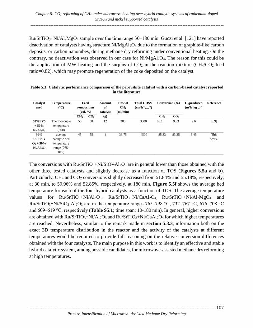
Chapter 5: CO2 reforming of CH4 under microwave heating over hybrid catalytic systems of ruthenium-doped
SrTiO3 and nickel supported catalysts
---------------------------------------------------------------------------------------------------------------------
-----------------------------------------------------------------------------------------------------------------107
Process Intensification of Microwave-Assisted Methane Dry Reforming
Ru/SrTiO3+Ni/Al2MgO4 sample over the time range 30‒180 min. Guczi et al. [121] have reported
deactivation of catalysts having structure Ni/MgAl2O4 due to the formation of graphite-like carbon
deposits, or carbon nanotubes, during methane dry reforming under conventional heating. On the
contrary, no deactivation was observed in our case for Ni/MgAl2O4. The reason for this could be
the application of MW heating and the surplus of CO2 in the reaction mixture (CH4/CO2 feed
ratio=0.82), which may promote regeneration of the coke deposited on the catalyst.
Table 5.3: Catalytic performance comparison of the perovskite catalyst with a carbon-based catalyst reported
in the literature
Catalyst
used
Temperature
(oC)
Feed
composition
(vol. %)
Amount
of
catalyst
(g)
Flow of
CH4
(ml/min)
Total GHSV
(cm3h-1gcat-1)
Conversion (%) H2 produced
(m3h-1kgcat-1)
Reference
CH4 CO2 CH4 CO2
50%FY5
+ 50%
Ni/Al2O3
Thermocouple
temperature
(800)
50 50 12 300 3000 88.1 93.3 2.6 [89]
50%
Ru/SrTi
O3 + 50%
Ni/Al2O3
average
catalytic bed
temperature
range (765-
815)
45 55 1 33.75 4500 85.33 83.35 3.45 This
work.
The conversions with Ru/SrTiO3+Ni/SiO2-Al2O3 are in general lower than those obtained with the
other three tested catalysts and slightly decrease as a function of TOS (Figures 5.5a and b).
Particularly, CH4 and CO2 conversions slightly decreased from 51.84% and 55.18%, respectively,
at 30 min, to 50.96% and 52.85%, respectively, at 180 min. Figure 5.5f shows the average bed
temperature for each of the four hybrid catalysts as a function of TOS. The average temperature
values for Ru/SrTiO3+Ni/Al2O3, Ru/SrTiO3+Ni/CaAl2O4, Ru/SrTiO3+Ni/Al2MgO4 and
Ru/SrTiO3+Ni/SiO2-Al2O3 are in the temperature ranges 765‒798 °C, 732‒767 °C, 676‒708 °C
and 609‒619 °C, respectively (Table S5.1; time span: 10-180 min). In general, higher conversions
are obtained with Ru/SrTiO3+Ni/Al2O3 and Ru/SrTiO3+Ni/CaAl2O4 for which higher temperatures
are reached. Nevertheless, similar to the remark made in section 5.3.3, information both on the
exact 3D temperature distribution in the reactor and the activity of the catalysts at different
temperatures would be required to provide full reasoning on the relative conversion differences
obtained with the four catalysts. The main purpose in this work is to identify an effective and stable
hybrid catalytic system, among possible candidates, for microwave-assisted methane dry reforming
at high temperatures.

Chapter 5: CO2 reforming of CH4 under microwave heating over hybrid catalytic systems of ruthenium-doped
SrTiO3 and nickel supported catalysts
--------------------------------------------------------------------------------------------------------------------------------------- ------
108-----------------------------------------------------------------------------------------------------------------
Process Intensification of Microwave-Assisted Methane Dry Reforming
Figure 5.6. Formation rate of (a) H2 and (b) CO as a function of TOS at a CH4/CO2 inlet ratio of 0.82 and
GHSV = 4500 cm3 STP/h g cat for Ru/SrTiO3+Ni/Al2O3 and 3000 cm3 STP/h g cat for other 3 catalysts with MW
powers 140W for Ru/SrTiO3+Ni/Al2O3 and Ru/SrTiO3+Ni/CaAl2O4, 100 W for Ru/SrTiO3+Ni/Al2MgO4 and
120W for Ru/SrTiO3+Ni/SiO2-Al2O3.
Figure 5.6 shows the formation rate of H2 and CO for each catalytic system as a function of TOS.
Ru/SrTiO3+Ni/Al2O3 has shown higher CH4, and CO2 conversions with ~1.3 and ~1.5 moles of H2
and CO produced min-1gcat-1, as compared to the other three hybrid catalysts. The syngas production
rate order of the hybrid catalytic systems is as follows: Ru/SrTiO3+Ni/Al2O3 >
Ru/SrTiO3+Ni/CaAl2O4 > Ru/SrTiO3+Ni/Al2MgO4 > Ru/SrTiO3+Ni/SiO2-Al2O3. Therefore,
among the tested materials, Ru/SrTiO3+Ni/Al2O3 has been found to be the best catalyst due to its
good microwave absorption ability and its ability to operate at higher GHSVs producing higher
syngas flow rates. Table 5.3 compares the combination of 50% Ni/Al2O3 with 50% activated
carbon (FY5) to that of 50% Ni/Al2O3 with 50% Ru/SrTiO3. CH4 and CO2 conversions of ~85%
and ~83%, respectively, at a GHSV of 4500 cm3g‒1h‒1 were attained with 1 g of 50% Ru/SrTiO3 +
50% Ni/Al2O3. In the case of 50% FY5 + 50% Ni/Al2O3, CH4 and CO2 conversions of ~88% and
~93%, respectively, have been reported, at a GHSV of 3000 cm3g‒1h-1 and 12 g of catalyst mixture.
The scale-up potential of the two catalysts has been evaluated according to the approach described
by Fidalgo et al. [89] concluding that the hybrid catalytic system of 50% Ru/SrTiO3 + 50%
Ni/Al2O3 is able to produce 3.45 m3 H2 h-1kgcat
-1, as compared to 2.6 m3 H2 h-1kgcat
-1 in the case of
the carbon-based catalyst comprising 50% FY5 + 50% Ni/Al2O3 [89].
Chapter 5: CO2 reforming of CH4 under microwave heating over hybrid catalytic systems of ruthenium-doped
SrTiO3 and nickel supported catalysts
---------------------------------------------------------------------------------------------------------------------
-----------------------------------------------------------------------------------------------------------------109
Process Intensification of Microwave-Assisted Methane Dry Reforming
5.4. Conclusions
We evaluated four different hybrid catalytic systems, containing commercial nickel supported on
metal oxide catalysts and 7 wt. % Ru-doped SrTiO3 perovskite catalyst, in terms of syngas
production via CO2 (dry) reforming of CH4 under microwave heating. The four hybrid catalytic
systems are: Ru/SrTiO3+Ni/Al2O3, Ru/SrTiO3+Ni/CaAl2O4, Ru/SrTiO3+Ni/Al2MgO4 and
Ru/SrTiO3+Ni/SiO2-Al2O3. First, the dielectric properties of the commercial nickel-based catalysts
were measured up to 850 °C to get insight into their microwave heating ability at realistic dry
reforming temperatures. It was found that incorporation of the Ru/SrTiO3 perovskite catalyst
improves the microwave heating properties of the microwave-inactive Ni-supported metal oxide
commercial catalysts. The thermal response of the hybrid catalytic systems and their performance,
in terms of reactants conversions and syngas production rate, have been monitored as a function of
microwave power and gas hourly space velocity. It can be concluded that ~100% CH4 conversion
can be attained if the reaction conditions are appropriately selected. The order of the four hybrid
catalytic systems tested in terms of their total syngas production rate capacity is:
Ru/SrTiO3+Ni/Al2O3 > Ru/SrTiO3+Ni/CaAl2O4 > Ru/SrTiO3+Ni/Al2MgO4 > Ru/SrTiO3+Ni/SiO2-
Al2O3. Based on scale-up calculations, 50% Ru/SrTiO3 + 50% Ni/Al2O3 is able to produce 3.45 m3
H2 h-1kgcat
-1 as compared to 2.6 m3 H2 h
-1kgcat-1 that has been reported in the literature [89] for a
carbon-based catalyst of 50% FY5 + 50% Ni/Al2O3.

Chapter 5: CO2 reforming of CH4 under microwave heating over hybrid catalytic systems of ruthenium-doped
SrTiO3 and nickel supported catalysts
--------------------------------------------------------------------------------------------------------------------------------------- ------
110-----------------------------------------------------------------------------------------------------------------
Process Intensification of Microwave-Assisted Methane Dry Reforming
5.5. Supporting Information:
Figure S5.1a: Schematic of the microwave reactor system used.
Figure S5.1b: Digital image of the microwave reactor system. It includes (I) a gas supply
unit, (II) a solid state MW generator, (III) a microwave reactor assembly, (IV) a quartz
tube loaded with a catalyst and a ceramic well, (V) a thermal camera, (VI) a thermostat
for cooling, (VII) gas detectors, (VIII) ventilation, and (IX) a micro GC for product
analysis.

Chapter 5: CO2 reforming of CH4 under microwave heating over hybrid catalytic systems of ruthenium-doped
SrTiO3 and nickel supported catalysts
---------------------------------------------------------------------------------------------------------------------
-----------------------------------------------------------------------------------------------------------------111
Process Intensification of Microwave-Assisted Methane Dry Reforming
Figure S5.2: Thermal image of the Ru/SrTiO3+Ni/Al2O3 catalytic bed at 180 min
of operation during the time-on-stream (TOS) study along with the statistics
viewer window. The 2D box with the red borderline is used to calculate the
average (mean) catalytic bed temperature. The statistics viewer shows the
average (mean), maximum and minimum temperature values present in the box.
The temperature distribution in the four tested hybrid catalytic beds has been
calculated in 2D using thermal camera videos at an emissivity value of 0.9.
Figure S5.3: Top and bottom bed temperatures as well as maximum, minimum and
average bed temperatures as a function of microwave power during dry reforming
experiments with the four hybrid catalysts tested.

Chapter 5: CO2 reforming of CH4 under microwave heating over hybrid catalytic systems of ruthenium-doped
SrTiO3 and nickel supported catalysts
--------------------------------------------------------------------------------------------------------------------------------------- ------
112-----------------------------------------------------------------------------------------------------------------
Process Intensification of Microwave-Assisted Methane Dry Reforming
Figure S5.4: Thermal images of Ru/SrTiO3 + Ni/Al2MgO4 catalyst during microwave heating
under N2 flow. Migration of hot spot (white area) occurs when varying the power input from
10 to 100 W.
Figure S5.5: Thermal images of Ru/SrTiO3 + Ni/Al2MgO4 catalyst during
microwave heating under CH4/CO2 reactant mixture flow (dry reforming
experiment). Migration of hot spot (white area) occurs when varying the power
input from 40 to 100 W.

Chapter 5: CO2 reforming of CH4 under microwave heating over hybrid catalytic systems of ruthenium-doped
SrTiO3 and nickel supported catalysts
---------------------------------------------------------------------------------------------------------------------
-----------------------------------------------------------------------------------------------------------------113
Process Intensification of Microwave-Assisted Methane Dry Reforming
Figure S5.6: Thermal images of Ru/SrTiO3 + Ni-SiO2/Al2O3 catalyst during microwave
heating under CH4/CO2 reactant mixture flow (dry reforming experiment). Migration of
hot spot (white area) occurs when varying the power input from 40 to 130 W.
Figure S5.7: Thermal images of (a) Ru/SrTiO3+Ni/Al2O3, (b) Ru/SrTiO3+Ni/CaAl2O4, (c)
Ru/SrTiO3+Ni/Al2MgO4 and (d) Ru/SrTiO3+Ni/SiO2-Al2O3 during the GHSV parametric study. The images
were taken at 9000 cm3g‒1h‒1 GHSV.
Figure S5.8: Thermal images of (a) Ru/SrTiO3+Ni/Al2O3 at 4500 cm3g‒1h‒1 GHSV and (b)
Ru/SrTiO3+Ni/CaAl2O4, (c) Ru/SrTiO3+Ni/Al2MgO4 and (d) Ru/SrTiO3+Ni/SiO2-Al2O3 at 3000 cm3g‒1h‒1
GHSV during the time-on-stream (TOS) study.
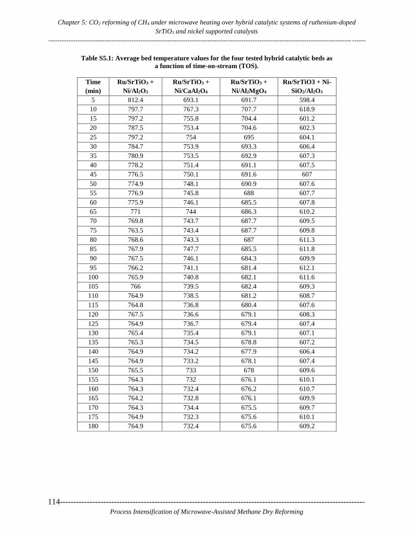
Chapter 5: CO2 reforming of CH4 under microwave heating over hybrid catalytic systems of ruthenium-doped
SrTiO3 and nickel supported catalysts
--------------------------------------------------------------------------------------------------------------------------------------- ------
114-----------------------------------------------------------------------------------------------------------------
Process Intensification of Microwave-Assisted Methane Dry Reforming
Table S5.1: Average bed temperature values for the four tested hybrid catalytic beds as
a function of time-on-stream (TOS).
Time
(min)
Ru/SrTiO3 +
Ni/Al2O3
Ru/SrTiO3 +
Ni/CaAl2O4
Ru/SrTiO3 +
Ni/Al2MgO4
Ru/SrTiO3 + Ni-
SiO2/Al2O3
5 812.4 693.1 691.7 598.4
10 797.7 767.3 707.7 618.9
15 797.2 755.8 704.4 601.2
20 787.5 753.4 704.6 602.3
25 797.2 754 695 604.1
30 784.7 753.9 693.3 606.4
35 780.9 753.5 692.9 607.3
40 778.2 751.4 691.1 607.5
45 776.5 750.1 691.6 607
50 774.9 748.1 690.9 607.6
55 776.9 745.8 688 607.7
60 775.9 746.1 685.5 607.8
65 771 744 686.3 610.2
70 769.8 743.7 687.7 609.5
75 763.5 743.4 687.7 609.8
80 768.6 743.3 687 611.3
85 767.9 747.7 685.5 611.8
90 767.5 746.1 684.3 609.9
95 766.2 741.1 681.4 612.1
100 765.9 740.8 682.1 611.6
105 766 739.5 682.4 609.3
110 764.9 738.5 681.2 608.7
115 764.8 736.8 680.4 607.6
120 767.5 736.6 679.1 608.3
125 764.9 736.7 679.4 607.4
130 765.4 735.4 679.1 607.1
135 765.3 734.5 678.8 607.2
140 764.9 734.2 677.9 606.4
145 764.9 733.2 678.1 607.4
150 765.5 733 678 609.6
155 764.3 732 676.1 610.1
160 764.3 732.4 676.2 610.7
165 764.2 732.8 676.1 609.9
170 764.3 734.4 675.5 609.7
175 764.9 732.3 675.6 610.1
180 764.9 732.4 675.6 609.2
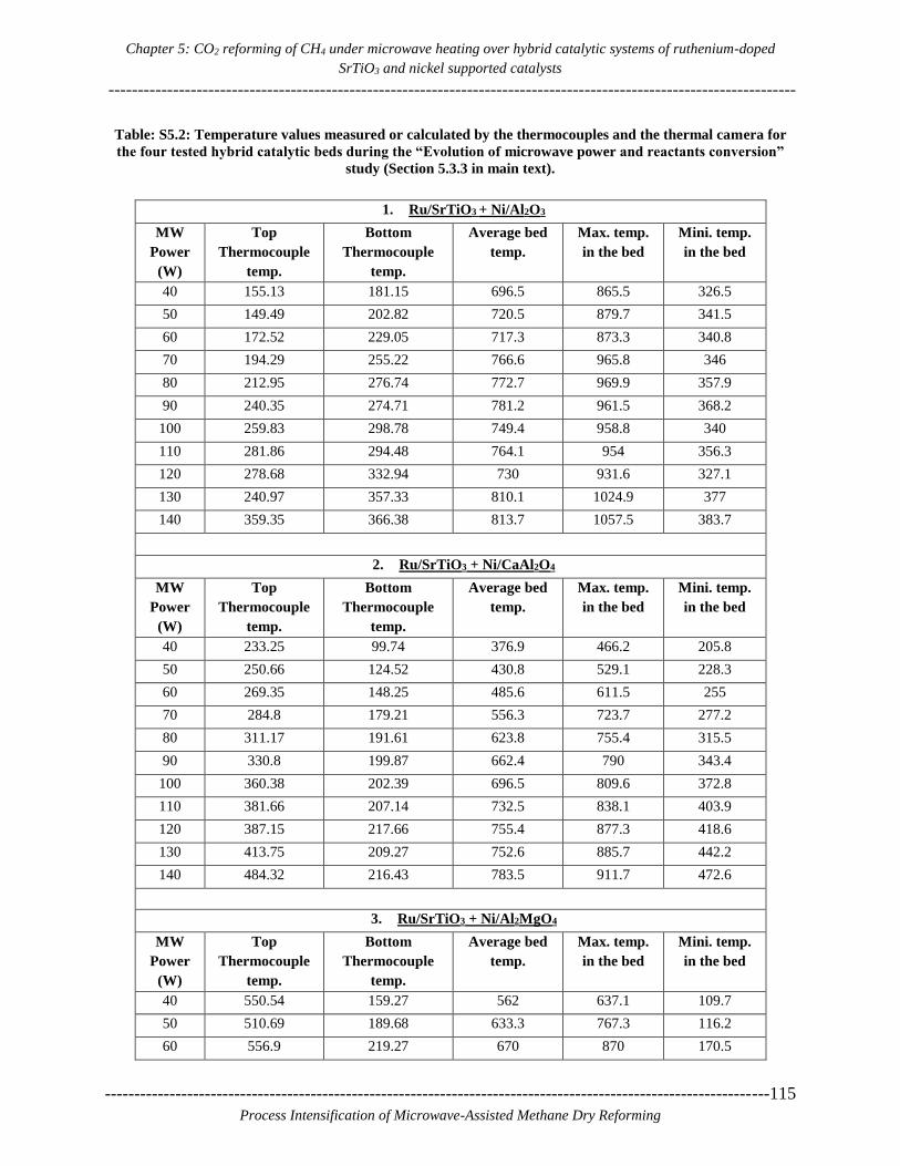
Chapter 5: CO2 reforming of CH4 under microwave heating over hybrid catalytic systems of ruthenium-doped
SrTiO3 and nickel supported catalysts
---------------------------------------------------------------------------------------------------------------------
-----------------------------------------------------------------------------------------------------------------115
Process Intensification of Microwave-Assisted Methane Dry Reforming
Table: S5.2: Temperature values measured or calculated by the thermocouples and the thermal camera for
the four tested hybrid catalytic beds during the “Evolution of microwave power and reactants conversion”
study (Section 5.3.3 in main text).
1. Ru/SrTiO3 + Ni/Al2O3
MW
Power
(W)
Top
Thermocouple
temp.
Bottom
Thermocouple
temp.
Average bed
temp.
Max. temp.
in the bed
Mini. temp.
in the bed
40 155.13 181.15 696.5 865.5 326.5
50 149.49 202.82 720.5 879.7 341.5
60 172.52 229.05 717.3 873.3 340.8
70 194.29 255.22 766.6 965.8 346
80 212.95 276.74 772.7 969.9 357.9
90 240.35 274.71 781.2 961.5 368.2
100 259.83 298.78 749.4 958.8 340
110 281.86 294.48 764.1 954 356.3
120 278.68 332.94 730 931.6 327.1
130 240.97 357.33 810.1 1024.9 377
140 359.35 366.38 813.7 1057.5 383.7
2. Ru/SrTiO3 + Ni/CaAl2O4
MW
Power
(W)
Top
Thermocouple
temp.
Bottom
Thermocouple
temp.
Average bed
temp.
Max. temp.
in the bed
Mini. temp.
in the bed
40 233.25 99.74 376.9 466.2 205.8
50 250.66 124.52 430.8 529.1 228.3
60 269.35 148.25 485.6 611.5 255
70 284.8 179.21 556.3 723.7 277.2
80 311.17 191.61 623.8 755.4 315.5
90 330.8 199.87 662.4 790 343.4
100 360.38 202.39 696.5 809.6 372.8
110 381.66 207.14 732.5 838.1 403.9
120 387.15 217.66 755.4 877.3 418.6
130 413.75 209.27 752.6 885.7 442.2
140 484.32 216.43 783.5 911.7 472.6
3. Ru/SrTiO3 + Ni/Al2MgO4
MW
Power
(W)
Top
Thermocouple
temp.
Bottom
Thermocouple
temp.
Average bed
temp.
Max. temp.
in the bed
Mini. temp.
in the bed
40 550.54 159.27 562 637.1 109.7
50 510.69 189.68 633.3 767.3 116.2
60 556.9 219.27 670 870 170.5

Chapter 5: CO2 reforming of CH4 under microwave heating over hybrid catalytic systems of ruthenium-doped
SrTiO3 and nickel supported catalysts
--------------------------------------------------------------------------------------------------------------------------------------- ------
116-----------------------------------------------------------------------------------------------------------------
Process Intensification of Microwave-Assisted Methane Dry Reforming
70 592.56 241.57 698.8 919.6 185.6
80 716.71 247.17 696.2 917.4 185.5
90 792.86 261.26 694.2 909.4 183.9
100 890.92 270.02 703.9 940.5 189.5
110 1004.6 280.84 679.9 866.6 182.8
4. Ru/SrTiO3 + Ni-SiO2/Al2O3
MW
Power
(W)
Top
Thermocouple
temp.
Bottom
Thermocouple
temp.
Average bed
temp.
Max. temp.
in the bed
Mini. temp.
in the bed
40 258.96 110.47 470.4 584.3 155.1
50 297.48 122.02 514.6 622.4 179.5
60 305.37 146.77 508.3 610.3 182.1
70 321.88 170.74 537.8 635.7 191.7
80 349.26 195.82 536.7 647.5 201.8
90 361.06 231.41 585.7 701 222
100 371.08 297.06 576.5 707.5 221.3
110 399.86 359.46 608.3 686.3 232.9
120 717.31 416.5 624.5 691.4 251.2
130 1027.13 441.73 563.5 734.9 234.9

Chapter 6: Conclusions and Recommendations
---------------------------------------------------------------------------------------------------------------------
-----------------------------------------------------------------------------------------------------------------117
Process Intensification of Microwave-Assisted Methane Dry Reforming
6 6. Conclusions and Recommendations

Chapter 6: Conclusions and Recommendations
---------------------------------------------------------------------------------------------------------------------------------------------
118-----------------------------------------------------------------------------------------------------------------
Process Intensification of Microwave-Assisted Methane Dry Reforming

Chapter 6: Conclusions and Recommendations
---------------------------------------------------------------------------------------------------------------------
-----------------------------------------------------------------------------------------------------------------119
Process Intensification of Microwave-Assisted Methane Dry Reforming
6.1. Conclusions
The most important conclusions obtained from this work are collectively summarized in this
section.
First, a custom-designed microwave reactor assembly (MRA) was designed and developed to
enable effective microwave heating of catalytic materials to high temperatures (up to 1000 °C) for
methane dry reforming. It was found that in order to capture the dynamic temperature changes
inside the catalytic bed during the reaction, a combination of a thermal camera with at least one
contact sensor for in situ emissivity calculations is necessary. On the reaction side, microwave-
assisted methane dry reforming experiments over platinum on carbon catalyst were performed first.
It was found that although nearly complete CH4 and CO2 conversions were obtained in the first 30
min, the amount of carbon catalyst decreased with time and formed a carbon layer on the inner
surface of the quartz wall of the reactor, which resulted in softening and eventually melting of the
quartz tube wall.
Further, a series of ruthenium-doped strontium titanate perovskite catalysts were synthesized by
conventional and microwave-assisted hydrothermal methods. Significant synthesis temperature
and time reduction were achieved when microwaves were applied; specifically, from 220 °C for
24 h in conventional heating to 180 °C for 1h under microwave heating. In addition, ICP-OES
analysis and HRTEM+EDX elemental mapping showed that higher Ru dispersion and more
homogeneous distribution of particle sizes are obtained in the case of MW-assisted hydrothermal
synthesis as compared to conventional hydrothermal synthesis. Based on the results of the dielectric
and chemical characterization of the different catalysts prepared, a 7 wt. % Ru-doped SrTiO3
perovskite catalyst prepared over 1h of microwave-assisted hydrothermal synthesis was selected
for application to methane dry reforming under microwave heating over a range of CH4/CO2 inlet
ratio, power input and gas hourly space velocity (GHSV). Stable maximum conversions of ~99.5%
and ~94% for CH4 and CO2, respectively, were achieved during a 3h stability test at CH4:CO2
vol.%=45:55, GHSV=9000 cm3g-1hr-1 and forward power input of 150 W. Besides, scale-up
calculations on the basis of 1 m3h-1 CH4 inlet flow rate through the 7Ru/SrTiO3-MW-1h catalyst
bed show significant improvement in H2 production capability as compared to carbon-based
catalysts previously reported in the literature.
In an effort to decrease the cost of the catalytic system, four different hybrid catalytic systems,
containing relatively inexpensive commercial metal-oxide supported nickel catalysts and 7 wt. %
Ru-doped SrTiO3 perovskite, were evaluated for methane dry reforming. The four hybrid catalytic
systems are: Ru/SrTiO3+Ni/Al2O3, Ru/SrTiO3+Ni/CaAl2O4, Ru/SrTiO3+Ni/Al2MgO4 and
Ru/SrTiO3+Ni/SiO2-Al2O3. Dielectric and thermal characterization of the catalysts in heating
experiments showed that incorporation of the Ru/SrTiO3 perovskite improves the microwave
heating properties of the microwave-inactive Ni-supported metal oxides. As regards the dry
Chapter 6: Conclusions and Recommendations
---------------------------------------------------------------------------------------------------------------------------------------------
120-----------------------------------------------------------------------------------------------------------------
Process Intensification of Microwave-Assisted Methane Dry Reforming
reforming process, it was found that ~100% CH4 conversion (stable over 3 hours of time on stream)
can be attained with proper selection of gas hourly space velocity and power. The order of the four
hybrid catalytic systems tested in terms of their total syngas production rate capacity is:
Ru/SrTiO3+Ni/Al2O3 > Ru/SrTiO3+Ni/CaAl2O4 > Ru/SrTiO3+Ni/Al2MgO4 > Ru/SrTiO3+Ni/SiO2-
Al2O3. Based on scale-up calculations, 50% Ru/SrTiO3 + 50% Ni/Al2O3 is able to produce 3.45 m3
H2 h-1kgcat
-1 as compared to 2.6 m3 H2 h
-1kgcat-1 that has been reported in the literature for a carbon-
based catalyst of 50% FY5 + 50% Ni/Al2O3.
6.2. Recommendations
The custom-made MRA has proven able to concentrate the microwave field to catalytic materials,
but the generation of hotspots cannot be avoided. This makes it challenging to control uneven
heating and temperature distribution due to the change in the dielectric properties of the catalytic
materials with a change in temperature. A rapid temperature increase in a catalytic bed is sometimes
very challenging to control manually. Therefore, an automated temperature-to-power control
system for the existing reactor is recommended for future works. It is also important to develop a
parallel technique to record thermocouple temperatures and automatically update them in the
thermal camera calculator to instantly get the most accurate temperature distribution.
The Ru-doped SrTiO3 catalyst has some advantages, compared to the Pt-C catalyst tested, such as
stable volume, weight, and structure during the reaction at very high temperatures and reduced
coke formation. Therefore, the Ru-doped SrTiO3 perovskite catalyst was selected to form hybrid
catalytic systems with Ni-based catalysts. Some of the hybrid materials though were not able to
perform well in terms of CH4 and CO2 conversions at similar reaction conditions. One reason is
the poor dielectric properties, but, further characterization of the physical and chemical properties
of the fresh and spent catalysts as well as well as activity tests for all selected catalysts should be
carried out to reach complete conclusions on this matter.
Finally, although some good catalysts for microwave-assisted methane dry reforming have been
found, such as the Ru-doped SrTiO3 catalyst and its hybrid formulation with Ni/Al2O3 and
Ni/CaAl2O4, it is also recommended that the respective conventionally-heated dry reforming
experiments with these catalysts be also performed. These experiments in combination with heat
transfer simulations at reactor and particle scale will enable conclusive comparison of the two
heating modes on the process performance itself and identify the reasoning behind the differences
that will be obtained.

References
---------------------------------------------------------------------------------------------------------------------
-----------------------------------------------------------------------------------------------------------------121
Process Intensification of Microwave-Assisted Methane Dry Reforming
References
[1] X. Li, Diversification and localization of energy systems for sustainable development and
energy security, Energy Policy. 33 (2005) 2237–2243. doi:10.1016/j.enpol.2004.05.002.
[2] EIA, International Energy Outlook 2017 Overview, U.S. Energy Inf. Adm. IEO2017 (2017)
143. doi:www.eia.gov/forecasts/ieo/pdf/0484(2016).pdf.
[3] REN21, Renewables 2013 Global Status Report, 2013. doi:ISBN 978-3-9815934-0-2.
[4] I. Carolina, D.L. Rios, F.J.S. Charnley, Skills and capabilities for a sustainable and circular
economy : The changing role of design, J. Clean. Prod. 160 (2017) 109–122.
doi:10.1016/j.jclepro.2016.10.130.
[5] G.Q. Chen, X.F. Wu, Energy overview for globalized world economy: Source, supply chain
and sink, Renew. Sustain. Energy Rev. 69 (2017) 735–749. doi:10.1016/j.rser.2016.11.151.
[6] N. Abas, A. Kalair, N. Khan, Review of fossil fuels and future energy technologies, Futures.
69 (2015) 31–49. doi:10.1016/j.futures.2015.03.003.
[7] U.S.E.I. Administration, Annual Energy Outlook 2018 with projections to 2050 Table of
contents, (n.d.).
[8] E. Summary, World Energy Outlook, (2017).
[9] C.A. Miller, E.P.A. Of, 3 . 02 Energy Resources and Policy : Vulnerability of Energy
Resources and Resource Availability – Fossil Fuels ( Oil , Coal , Natural Gas , Oil Shale ),
Elsevier, 2013. doi:10.1016/B978-0-12-384703-4.00304-X.
[10] A.E. MacDonald, C.T.M. Clack, A. Alexander, A. Dunbar, J. Wilczak, Y. Xie, Future cost-
competitive electricity systems and their impact on US CO2 emissions, Nat. Clim. Chang.
6 (2016) 4–7. doi:10.1038/nclimate2921.
[11] C. Xiaoli, D.J. Tonjes, D. Mahajan, Methane emissions as energy reservoir : Context , scope
, causes and mitigation strategies, Prog. Energy Combust. Sci. 56 (2016) 33–70.
doi:10.1016/j.pecs.2016.05.001.
[12] C.A. Miller, E.P.A. Of, 3 . 02 Energy Resources and Policy : Vulnerability of Energy
Resources and Resource Availability – Fossil Fuels ( Oil , Coal , Natural Gas , Oil Shale ),
Elsevier, 2013. doi:10.1016/B978-0-12-384703-4.00304-X.
[13] F.A. Rahman, M.M.A. Aziz, R. Saidur, W.A.W.A. Bakar, M.R. Hainin, R. Putrajaya, N.A.
Hassan, Pollution to solution: Capture and sequestration of carbon dioxide (CO2) and its
utilization as a renewable energy source for a sustainable future, Renew. Sustain. Energy
Rev. 71 (2017) 112–126. doi:10.1016/j.rser.2017.01.011.
[14] G.C. Project, Global carbon budget, (2014).
http://www.globalcarbonproject.org/carbonbudget/index.htm.
[15] B. Studies, Trends in global co 2 emissions 2013 report, 2013.
[16] M. Saunois, P. Bousquet, B. Poulter, A. Peregon, P. Ciais, J.G. Canadell, E.J. Dlugokencky,
G. Etiope, D. Bastviken, S. Houweling, G. Janssens-Maenhout, F.N. Tubiello, S. Castaldi,
R.B. Jackson, M. Alexe, V.K. Arora, D.J. Beerling, P. Bergamaschi, D.R. Blake, G.
Brailsford, V. Brovkin, L. Bruhwiler, C. Crevoisier, P. Crill, K. Covey, C. Curry, C.
Frankenberg, N. Gedney, L. Höglund-Isaksson, M. Ishizawa, A. Ito, F. Joos, H.S. Kim, T.
Kleinen, P. Krummel, J.F. Lamarque, R. Langenfelds, R. Locatelli, T. Machida, S.
Maksyutov, K.C. McDonald, J. Marshall, J.R. Melton, I. Morino, V. Naik, S. O’Doherty,
F.J.W. Parmentier, P.K. Patra, C. Peng, S. Peng, G.P. Peters, I. Pison, C. Prigent, R. Prinn,
M. Ramonet, W.J. Riley, M. Saito, M. Santini, R. Schroeder, I.J. Simpson, R. Spahni, P.

References
----------------------------------------------------------------------------------------------------------------------------- ----------------
122-----------------------------------------------------------------------------------------------------------------
Process Intensification of Microwave-Assisted Methane Dry Reforming
Steele, A. Takizawa, B.F. Thornton, H. Tian, Y. Tohjima, N. Viovy, A. Voulgarakis, M.
Van Weele, G.R. Van Der Werf, R. Weiss, C. Wiedinmyer, D.J. Wilton, A. Wiltshire, D.
Worthy, D. Wunch, X. Xu, Y. Yoshida, B. Zhang, Z. Zhang, Q. Zhu, The global methane
budget 2000-2012, Earth Syst. Sci. Data. 8 (2016) 697–751. doi:10.5194/essd-8-697-2016.
[17] S. Arora, R. Prasad, An overview on dry reforming of methane: strategies to reduce
carbonaceous deactivation of catalysts, RSC Adv. 6 (2016) 108668–108688.
doi:10.1039/C6RA20450C.
[18] J.M.F. Iii, The Different Catalytic Routes for Methane Liquid Fuels The Different Catalytic
Routes for Methane Valorization : An Assessment of Processes for liquid Fuels, 4940
(2016). doi:10.1080/01614949308014605.
[19] A.I. Olivos-suarez, A. Sze, E.A. Pidko, J. Gascon, Strategies for the Direct Catalytic
Valorization of Methane Using Heterogeneous Catalysis : Challenges and Opportunities,
(2016). doi:10.1021/acscatal.6b00428.
[20] T. da Silva Veras, T.S. Mozer, D. da Costa Rubim Messeder dos Santos, A. da Silva César,
Hydrogen: Trends, production and characterization of the main process worldwide, Int. J.
Hydrogen Energy. 42 (2017) 2018–2033. doi:10.1016/j.ijhydene.2016.08.219.
[21] C. Xiaoli, D.J. Tonjes, D. Mahajan, Methane emissions as energy reservoir : Context , scope
, causes and mitigation strategies, Prog. Energy Combust. Sci. 56 (2016) 33–70.
doi:10.1016/j.pecs.2016.05.001.
[22] L. Mennicken, A. Janz, S. Roth, The German R&D Program for CO2 Utilization—
Innovations for a Green Economy, Environ. Sci. Pollut. Res. 23 (2016) 11386–11392.
doi:10.1007/s11356-016-6641-1.
[23] G.D. Stefanidis, A.N. Muñoz, G.S.J. Sturm, A. Stankiewicz, A helicopter view of
microwave application to chemical processes: reactions, separations, and equipment
concepts, Rev. Chem. Eng. 30 (2014) 1–26. doi:10.1515/revce-2013-0033.
[24] R.J. (Roger J.. Meredith, Institution of Electrical Engineers., Engineers’ handbook of
industrial microwave heating, Institution of Electrical Engineers, 1998.
[25] G.D. Stefanidis, A.N. Muñoz, G.S.J. Sturm, A. Stankiewicz, A helicopter view of
microwave application to chemical processes: reactions, separations, and equipment
concepts, Rev. Chem. Eng. 30 (2014) 1–26. doi:10.1515/revce-2013-0033.
[26] V. Gnaneswar Gude, P. Patil, E. Martinez-Guerra, S. Deng, N. Nirmalakhandan, Microwave
energy potential for biodiesel production, (n.d.).
[27] D.M. Pozar, Microwave Engineering, Wiley, 1997.
https://books.google.be/books?id=IDxTAAAAMAAJ (accessed November 22, 2016).
[28] J. Hunt, A. Ferrari, A. Lita, M. Crosswhite, B. Ashley, A.E. Stiegman, Microwave-Specific
Enhancement of the Carbon − Carbon Dioxide ( Boudouard ) Reaction, (2013).
[29] W. Yunpu, D.A.I. Leilei, F.A.N. Liangliang, S. Shaoqi, L.I.U. Yuhuan, Journal of Analytical
and Applied Pyrolysis Review of microwave-assisted lignin conversion for renewable fuels
and chemicals, J. Anal. Appl. Pyrolysis. 119 (2016) 104–113.
doi:10.1016/j.jaap.2016.03.011.
[30] Y. Pang, H. Lei, Degradation of p-nitrophenol through microwave-assisted heterogeneous
activation of peroxymonosulfate by manganese ferrite, Chem. Eng. J. 287 (2016) 585–592.
doi:10.1016/j.cej.2015.11.076.
[31] Y.S. Malghe, Nanosized SrTiO3 powder from oxalate precursor microwave aided synthesis
and thermal characterization, J. Therm. Anal. Calorim. 102 (2010) 831–836.
doi:10.1007/s10973-010-0786-9.
[32] K. Asadian, T. Ebadzadeh, Synthesis of Nanosized Ba(Zn1/3Nb2/3)O3 Using Microwave

References
---------------------------------------------------------------------------------------------------------------------
-----------------------------------------------------------------------------------------------------------------123
Process Intensification of Microwave-Assisted Methane Dry Reforming
Heating Process, J. Mater. Eng. Perform. 22 (2012) 898–902. doi:10.1007/s11665-012-
0328-7.
[33] S.H. Jhung, J.-H. Lee, J.W. Yoon, Y.K. Hwang, J.-S. Hwang, S.-E. Park, J.-S. Chang,
Effects of reaction conditions in microwave synthesis of nanocrystalline barium titanate,
Mater. Lett. 58 (2004) 3161–3165. doi:10.1016/j.matlet.2004.06.006.
[34] X. Zhang, C.S. Lee, D.M.P. Mingos, D.O. Hayward, Carbon dioxide reforming of methane
with Pt catalysts using microwave dielectric heating, 88 (2003) 129–139.
[35] X.-R. Zhang, L.-C. Wang, Y. Cao, W.-L. Dai, H.-Y. He, K.-N. Fan, A unique microwave
effect on the microstructural modification of Cu/ZnO/Al2O3 catalysts for steam reforming
of methanol., Chem. Commun. (Camb). (2005) 4104–6. doi:10.1039/b502997j.
[36] A. Domínguez, Y. Fernandez, B. Fidalgo, J.J. Pis, J.A. Menendez, Biogas to Syngas by
Microwave-Assisted Dry Reforming in the Presence of Char, Energy & Fuels. 21 (2007)
2066–2071. doi:10.1021/ef070101j.
[37] B. Fidalgo, a Dominguez, J. Pis, J. Menendez, Microwave-assisted dry reforming of
methane, Int. J. Hydrogen Energy. 33 (2008) 4337–4344.
doi:10.1016/j.ijhydene.2008.05.056.
[38] W.-H. Chen, J.-G. Jheng, a. B. Yu, Hydrogen generation from a catalytic water gas shift
reaction under microwave irradiation, Int. J. Hydrogen Energy. 33 (2008) 4789–4797.
doi:10.1016/j.ijhydene.2008.06.059.
[39] W.-H. Chen, B.-J. Lin, Effect of microwave double absorption on hydrogen generation from
methanol steam reforming, Int. J. Hydrogen Energy. 35 (2010) 1987–1997.
doi:10.1016/j.ijhydene.2009.12.147.
[40] W. Deng, Y. Su, S. Liu, H. Shen, Microwave-assisted methane decomposition over pyrolysis
residue of sewage sludge for hydrogen production, Int. J. Hydrogen Energy. 39 (2014)
9169–9179. doi:10.1016/j.ijhydene.2014.04.033.
[41] a Dominguez, B. Fidalgo, Y. Fernandez, J. Pis, J. Menendez, Microwave-assisted catalytic
decomposition of methane over activated carbon for CO2CO2-free hydrogen production,
Int. J. Hydrogen Energy. 32 (2007) 4792–4799. doi:10.1016/j.ijhydene.2007.07.041.
[42] Y. Xu, Z. Tian, Z. Xu, L. Lin, Reactions in a Mixture of CH 4 and CO 2 under the Action
of Microwave Discharge at Atmospheric Pressure, 11 (2002) 28–32.
[43] T. Durka, G. D Stefanidis, T. Van Gerven, A. Stankiewicz, On the accuracy and
reproducibility of fiber optic (FO) and infrared (IR) temperature measurements of solid
materials in microwave applications, Meas. Sci. Technol. 21 (2010) 045108.
doi:10.1088/0957-0233/21/4/045108.
[44] T. Durka, G.D. Stefanidis, T. Van Gerven, A.I. Stankiewicz, Microwave-activated methanol
steam reforming for hydrogen production, Int. J. Hydrogen Energy. 36 (2011) 12843–12852.
doi:10.1016/j.ijhydene.2011.07.009.
[45] T.L. Roussière, Catalytic Reforming of Methane in the Presence of CO 2 and H 2 O at High
Pressure, (2013).
[46] D. Pakhare, J. Spivey, A review of dry (CO2) reforming of methane over noble metal
catalysts, Chem. Soc. Rev. 43 (2014). doi:10.1039/c3cs60395d.
[47] P. Gangadharan, K.C. Kanchi, H.H. Lou, Evaluation of the economic and environmental
impact of combining dry reforming with steam reforming of methane, Chem. Eng. Res. Des.
90 (2012) 1956–1968. doi:10.1016/j.cherd.2012.04.008.
[48] B. Fidalgo, J.A. Menéndez, SYNGAS PRODUCTION BY CO 2 REFORMING OF CH 4
UNDER MICROWAVE HEATING – CHALLENGES AND OPPORTUNITIES, (2013)
121–149.

References
----------------------------------------------------------------------------------------------------------------------------- ----------------
124-----------------------------------------------------------------------------------------------------------------
Process Intensification of Microwave-Assisted Methane Dry Reforming
[49] D. Pakhare, J. Spivey, A review of dry (CO2) reforming of methane over noble metal
catalysts., Chem. Soc. Rev. (2014). doi:10.1039/c3cs60395d.
[50] M. Oghbaei, O. Mirzaee, Microwave versus conventional sintering : A review of
fundamentals , advantages and applications, J. Alloys Compd. 494 (2010) 175–189.
doi:10.1016/j.jallcom.2010.01.068.
[51] M. Omran, T. Fabritius, R. Mattila, Thermally assisted liberation of high phosphorus oolitic
iron ore : A comparison between microwave and conventional furnaces, Powder Technol.
269 (2015) 7–14. doi:10.1016/j.powtec.2014.08.073.
[52] D. Li, Y. Nakagawa, K. Tomishige, Methane reforming to synthesis gas over Ni catalysts
modified with noble metals, Appl. Catal. A Gen. 408 (2011) 1–24.
doi:10.1016/j.apcata.2011.09.018.
[53] T. Durka, T. Van Gerven, A. Stankiewicz, Microwaves in Heterogeneous Gas-Phase
Catalysis: Experimental and Numerical Approaches, Chem. Eng. Technol. 32 (2009) 1301–
1312. doi:10.1002/ceat.200900207.
[54] L.S. Gangurde, G.S.J. Sturm, T.J. Devadiga, A.I. Stankiewicz, G.D. Stefanidis, Complexity
and Challenges in Noncontact High Temperature Measurements in Microwave-Assisted
Catalytic Reactors, Ind. Eng. Chem. Res. 56 (2017) 13379–13391.
doi:10.1021/acs.iecr.7b02091.
[55] J.M. Osepchuk, A History of Microwave Heating Applications, IEEE Trans. Microw.
Theory Tech. 32 (1984) 1200–1224. doi:10.1109/TMTT.1984.1132831.
[56] J. Sun, W. Wang, Q. Yue, C. Ma, J. Zhang, X. Zhao, Z. Song, Review on microwave-metal
discharges and their applications in energy and industrial processes, Appl. Energy. 175
(2016). doi:10.1016/j.apenergy.2016.04.091.
[57] M. Omran, T. Fabritius, R. Mattila, Thermally assisted liberation of high phosphorus oolitic
iron ore : A comparison between microwave and conventional furnaces, Powder Technol.
269 (2015) 7–14. doi:10.1016/j.powtec.2014.08.073.
[58] M. Oghbaei, O. Mirzaee, Microwave versus conventional sintering : A review of
fundamentals , advantages and applications, J. Alloys Compd. 494 (2010) 175–189.
doi:10.1016/j.jallcom.2010.01.068.
[59] L. Acevedo, S. Usón, J. Uche, Exergy transfer analysis of microwave heating systems,
Energy. 68 (2014) 349–363. doi:10.1016/j.energy.2014.02.041.
[60] L. Acevedo, S. Usón, J. Uche, Numerical study of cullet glass subjected to microwave
heating and SiC susceptor effects . Part II : Exergy transfer analysis, Energy Convers.
Manag. 97 (2015) 458–469. doi:10.1016/j.enconman.2015.03.065.
[61] S. Chandrasekaran, S. Ramanathan, T. Basak, Microwave Material Processing — A Review,
58 (2012). doi:10.1002/aic.
[62] J. Goyette, R. Chahine, T.K. Bose, C. Akyel, R. Bosisio, Importance of the Dielectric
Properties of Materials for Microwave Heating, Dry. Technol. 8 (1990) 1111–1121.
doi:10.1080/07373939008959938.
[63] G.S.J. Sturm, M.D. Verweij, A.I. Stankiewicz, G.D. Stefanidis, Microwaves and
microreactors: Design challenges and remedies, Chem. Eng. J. 243 (2014) 147–158.
doi:10.1016/j.cej.2013.12.088.
[64] S. Horikoshi, A. Osawa, M. Abe, N. Serpone, On the generation of hot-spots by microwave
electric and magnetic fields and their impact on a microwave-assisted heterogeneous
reaction in the presence of metallic Pd nanoparticles on an activated carbon support, J. Phys.
Chem. C. 115 (2011) 23030–23035. doi:10.1021/jp2076269.
[65] X. Zhang, D.O. Hayward, C. Lee, D.M.P. Mingos, Microwave assisted catalytic reduction

References
---------------------------------------------------------------------------------------------------------------------
-----------------------------------------------------------------------------------------------------------------125
Process Intensification of Microwave-Assisted Methane Dry Reforming
of sulfur dioxide with methane over MoS2 catalysts, Appl. Catal. B Environ. 33 (2001) 137–
148. doi:10.1016/S0926-3373(01)00171-0.
[66] C.O. Kappe, How to measure reaction temperature in microwave-heated transformations,
Chem. Soc. Rev. 42 (2013) 4977–4990. doi:10.1039/c3cs00010a.
[67] A. Ramirez, J.L. Hueso, R. Mallada, J. Santamaria, In situ temperature measurements in
microwave-heated gas-solid catalytic systems. Detection of hot spots and solid-fluid
temperature gradients in the ethylene epoxidation reaction, (2017).
doi:10.1016/j.cej.2017.01.077.
[68] A. Ramírez, J.L. Hueso, R. Mallada, J. Santamaría, Ethylene epoxidation in microwave
heated structured reactors, Catal. Today. (2016). doi:10.1016/j.cattod.2016.01.007.
[69] E. Pert, Y. Carmel, A. Birnboim, T. Olorunyolemi, D. Gershon, J. Calame, I.K. Lloyd, O.C.
Wilson, Temperature measurements during microwave processing: the significance of
thermocouple effects, J. Am. Ceram. Soc. 84 (2001) 1981–1986. doi:10.1111/j.1151-
2916.2001.tb00946.x.
[70] H. Will, P. Scholz, B. Ondruschka, Heterogeneous gas-phase catalysis under microwave
irradiation - A new multi-mode microwave applicator, Top. Catal. 29 (2004) 175–182.
http://www.scopus.com/inward/record.url?eid=2-s2.0-
3042801191&partnerID=40&md5=1b040fcfcddd920fdf20148d4c579fc1.
[71] L. Li, X. Jiang, H. Wang, J. Wang, Z. Song, X. Zhao, C. Ma, Title: Methane dry and mixed
reforming on the mixture of bio-char and nickel-based catalyst with microwave assistance
Methane dry and mixed reforming on the mixture of bio-char and nickel-based catalyst with
microwave assistance, J. Anal. Appl. Pyrolysis. (2017). doi:10.1016/j.jaap.2017.03.009.
[72] G.S.J. Sturm, A.Q. Van Braam Houckgeest, M.D. Verweij, T. Van Gerven, A.I.
Stankiewicz, G.D. Stefanidis, Exploration of rectangular waveguides as a basis for
microwave enhanced continuous flow chemistries, Chem. Eng. Sci. 89 (2013) 196–205.
doi:10.1016/j.ces.2012.11.039.
[73] S.D. Luo, Y.F. Yang, G.B. Schaffer, M. Qian, Calibration of Temperature Measurement by
Infrared Pyrometry in Microwave Heating of Powder Materials : an Exothermic Reaction
Based Approach, 47 (2013) 5–11.
[74] X. Shen, G. Xu, C. Shao, C. Cheng, Temperature dependence of infrared emissivity of doped
manganese oxides in different wavebands (3–5 and 8–14μm), J. Alloys Compd. 479 (2009)
420–422. doi:10.1016/j.jallcom.2008.12.090.
[75] R.P. Madding, Emissivity measurement and temperature correction accuracy
considerations, Spie Conf. Thermosense XXI. 3700 (1999) 393–401.
doi:10.1117/12.342307.
[76] H.T. Pressures, V.A. Petrov, Measurement of the emissivity of quartz glass, (2016).
[77] J.M. Catalá-Civera, A.J. Canós, P. Plaza-González, J.D. Gutiérrez, B. García-Baños, F.L.
Peñaranda-Foix, Dynamic Measurement of Dielectric Properties of Materials at High
Temperature during Microwave Heating in a Dual Mode Cylindrical Cavity, IEEE Trans.
Microw. Theory Tech. 63 (2015) 2905–2914. doi:10.1109/TMTT.2015.2453263.
[78] F.L. Penaranda-Foix, M.D. Janezic, J.M. Catala-Civera, A.J. Canos, Full-wave analysis of
dielectric-loaded cylindrical waveguides and cavities using a new four-port ring network,
IEEE Trans. Microw. Theory Tech. 60 (2012) 2730–2740.
doi:10.1109/TMTT.2012.2206048.
[79] W.-H. Chen, H.-J. Liou, C.-I. Hung, A numerical approach of interaction of methane
thermocatalytic decomposition and microwave irradiation, Int. J. Hydrogen Energy. 38
(2013) 13260–13271. doi:10.1016/j.ijhydene.2013.07.107.

References
----------------------------------------------------------------------------------------------------------------------------- ----------------
126-----------------------------------------------------------------------------------------------------------------
Process Intensification of Microwave-Assisted Methane Dry Reforming
[80] A. Gvakharia, E.A. Kort, A. Brandt, J. Peischl, T.B. Ryerson, J.P. Schwarz, M.L. Smith, C.
Sweeney, Methane, Black Carbon, and Ethane Emissions from Natural Gas Flares in the
Bakken Shale, North Dakota, Environ. Sci. Technol. 51 (2017) 5317–5325.
doi:10.1021/acs.est.6b05183.
[81] L. Höglund-Isaksson, Bottom-up simulations of methane and ethane emissions from global
oil and gas systems 1980 to 2012, Environ. Res. Lett. 12 (2017) 024007. doi:10.1088/1748-
9326/aa583e.
[82] R. Heede, Tracing anthropogenic carbon dioxide and methane emissions to fossil fuel and
cement producers, 1854-2010, Clim. Change. 122 (2014) 229–241. doi:10.1007/s10584-
013-0986-y.
[83] M.C.J. Bradford, M. a. Vannice, CO 2 Reforming of CH 4, Catal. Rev. 41 (1999) 1–42.
doi:10.1081/CR-100101948.
[84] H.R. Gurav, R. Bobade, V.L. Das, S. Chilukuri, Carbon dioxide reforming of methane over
ruthenium substituted strontium titanate perovskite catalysts, Indian J. Chem. - Sect. A
Inorganic, Phys. Theor. Anal. Chem. 51 (2012) 1339–1347.
[85] D. Stuerga, P. Gaillard, Microwave heating as a new way to induce localized enhancements
of reaction rate. Non-isothermal and heterogeneous kinetics, Tetrahedron. 52 (1996) 5505–
5510. doi:10.1016/0040-4020(96)00241-4.
[86] H.J. Yang, B.P. Mathew, D.G. Oh, K. Myung, J.H. Kwak, S.Y. Hong, Efficient copper
catalysts for C[sbnd]H bond arylation under microwave heating: Direct access to multi-
substituted pivanilides, Catal. Commun. 90 (2017) 83–86.
doi:10.1016/j.catcom.2016.11.022.
[87] F. Karimi, B.A. Peppley, Comparison of conventional versus microwave heating for polyol
synthesis of supported iridium based electrocatalyst for polymer electrolyte membrane water
electrolysis, Int. J. Hydrogen Energy. 42 (2017) 5083–5094.
doi:10.1016/j.ijhydene.2017.01.090.
[88] B. Fidalgo, a. Arenillas, J. a. Menéndez, Influence of porosity and surface groups on the
catalytic activity of carbon materials for the microwave-assisted CO2 reforming of CH4,
Fuel. 89 (2010) 4002–4007. doi:10.1016/j.fuel.2010.06.015.
[89] B. Fidalgo, J. a. Menéndez, Study of energy consumption in a laboratory pilot plant for the
microwave-assisted CO2 reforming of CH4, Fuel Process. Technol. 95 (2012) 55–61.
doi:10.1016/j.fuproc.2011.11.012.
[90] R.M. Navarro, M.C. Alvarez-Galvan, J.A. Villoria, I.D. González-Jiménez, F. Rosa, J.L.G.
Fierro, Effect of Ru on LaCoO3 perovskite-derived catalyst properties tested in oxidative
reforming of diesel, Appl. Catal. B Environ. 73 (2007) 247–258.
doi:10.1016/j.apcatb.2006.12.013.
[91] J. Sunarso, S.S. Hashim, N. Zhu, W. Zhou, Perovskite oxides applications in high
temperature oxygen separation, solid oxide fuel cell and membrane reactor: A review, Prog.
Energy Combust. Sci. 61 (2017) 57–77. doi:10.1016/j.pecs.2017.03.003.
[92] D.J. Liu, M. Krumpelt, Activity and structure of perovskites as diesel-reforming catalysts
for solid oxide fuel cell, Int. J. Appl. Ceram. Technol. 2 (2005) 301–307.
doi:10.1111/j.1744-7402.2005.02032.x.
[93] A. Karaphun, S. Hunpratub, T. Putjuso, E. Swatsitang, Characterization and dielectric
properties of SrTi 1− x Mn x O 3 ceramics, Jpn. J. Appl. Phys. 54 (2015) 06FH09.
doi:10.7567/JJAP.54.06FH09.
[94] A. Karaphun, S. Hunpratub, E. Swatsitang, Effect of annealing on magnetic properties of
Fe-doped SrTiO3 nanopowders prepared by hydrothermal method, Microelectron. Eng. 126

References
---------------------------------------------------------------------------------------------------------------------
-----------------------------------------------------------------------------------------------------------------127
Process Intensification of Microwave-Assisted Methane Dry Reforming
(2014) 42–48. doi:10.1016/j.mee.2014.05.001.
[95] S. Sartipi, S. Xiaohui, T. Cordero, Supporting Information-Carbon / H-ZSM-5 composites
as supports for bi-functional Fischer-Tropsch, Catal. Sci. Technol. 5 (2016) 20–23.
[96] R. Cherbański, Calculation of critical efficiency factors of microwave energy conversion
into heat, Chem. Eng. Technol. 34 (2011) 2083–2090. doi:10.1002/ceat.201100405.
[97] F. Matei-Rutkovska, G. Postole, C.G. Rotaru, M. Florea, V.I. Pârvulescu, P. Gelin,
Synthesis of ceria nanopowders by microwave-assisted hydrothermal method for dry
reforming of methane, Int. J. Hydrogen Energy. 41 (2016) 2512–2525.
doi:10.1016/j.ijhydene.2015.12.097.
[98] G.S.J. Sturm, M.D. Verweij, T. Van Gerven, A.I. Stankiewicz, G.D. Stefanidis, On the
parametric sensitivity of heat generation by resonant microwave fields in process fluids, Int.
J. Heat Mass Transf. 57 (2013) 375–388. doi:10.1016/j.ijheatmasstransfer.2012.09.037.
[99] M.A. Goula, N.D. Charisiou, G. Siakavelas, L. Tzounis, I. Tsiaoussis, P. Panagiotopoulou,
G. Goula, I. V. Yentekakis, Syngas production via the biogas dry reforming reaction over
Ni supported on zirconia modified with CeO2 or La2O3 catalysts, Int. J. Hydrogen Energy.
42 (2017) 13724–13740. doi:10.1016/j.ijhydene.2016.11.196.
[100] V. Pawar, D. Ray, C. Subrahmanyam, V.M. Janardhanan, Study of Short-Term Catalyst
Deactivation Due to Carbon Deposition during Biogas Dry Reforming on Supported Ni
Catalyst, Energy and Fuels. 29 (2015) 8047–8052. doi:10.1021/acs.energyfuels.5b01862.
[101] J. a. Menéndez, a. Arenillas, B. Fidalgo, Y. Fernández, L. Zubizarreta, E.G. Calvo, J.M.
Bermúdez, Microwave heating processes involving carbon materials, Fuel Process. Technol.
91 (2010) 1–8. doi:10.1016/j.fuproc.2009.08.021.
[102] T. Santos, L.C. Costa, M. Valente, J. Monteiro, J. Sousa, 3D Electromagnetic Field
Simulation in Microwave Ovens : a Tool to Control Thermal Runaway, Proc. COMSOL
Conf. (2010) 1–7.
[103] T. Santos, M.A. Valente, J. Monteiro, J. Sousa, L.C. Costa, Electromagnetic and thermal
history during microwave heating, Appl. Therm. Eng. 31 (2011) 3255–3261.
doi:10.1016/j.applthermaleng.2011.06.006.
[104] J.-M. Lavoie, Review on dry reforming of methane, a potentially more environmentally-
friendly approach to the increasing natural gas exploitation., Front. Chem. 2 (2014) 81.
doi:10.3389/fchem.2014.00081.
[105] F. Wang, L. Xu, J. Yang, J. Zhang, L. Zhang, H. Li, Y. Zhao, H.X. Li, K. Wu, G.Q. Xu, W.
Chen, Enhanced catalytic performance of Ir catalysts supported on ceria-based solid
solutions for methane dry reforming reaction, Catal. Today. 281 (2017) 295–303.
doi:10.1016/j.cattod.2016.03.055.
[106] L. Xu, L. Duan, M. Tang, P. Liu, X. Ma, Y. Zhang, H.G. Harris, M. Fan, Catalytic CO2
reforming of CH4 over Cr-promoted Ni/char for H2 production, Int. J. Hydrogen Energy.
39 (2014) 10141–10153. doi:10.1016/j.ijhydene.2014.04.172.
[107] G. Zhang, A. Su, Y. Du, J. Qu, Y. Xu, Catalytic performance of activated carbon supported
cobalt catalyst for CO2 reforming of CH4, J. Colloid Interface Sci. 433 (2014) 149–155.
doi:10.1016/j.jcis.2014.06.038.
[108] S.S. Itkulova, G.D. Zakumbaeva, Y.Y. Nurmakanov, A.A. Mukazhanova, A.K.
Yermaganbetova, Syngas production by bireforming of methane over Co-based alumina-
supported catalysts, Catal. Today. 228 (2014) 194–198. doi:10.1016/j.cattod.2014.01.013.
[109] M.-S. Fan, A.Z. Abdullah, S. Bhatia, Hydrogen production from carbon dioxide reforming
of methane over Ni–Co/MgO–ZrO2 catalyst: Process optimization, Int. J. Hydrogen Energy.
36 (2011) 4875–4886. doi:10.1016/j.ijhydene.2011.01.064.

References
----------------------------------------------------------------------------------------------------------------------------- ----------------
128-----------------------------------------------------------------------------------------------------------------
Process Intensification of Microwave-Assisted Methane Dry Reforming
[110] J.M. Bermúdez, a. Arenillas, J. a. Menéndez, Syngas from CO2 reforming of coke oven
gas: Synergetic effect of activated carbon/Ni–γAl2O3 catalyst, Int. J. Hydrogen Energy. 36
(2011) 13361–13368. doi:10.1016/j.ijhydene.2011.07.124.
[111] G. Zhang, L. Hao, Y. Jia, Y. du, Y. Zhang, CO2 reforming of CH4 over efficient bimetallic
Co–Zr/AC catalyst for H2 production, Int. J. Hydrogen Energy. 40 (2015) 12868–12879.
doi:10.1016/j.ijhydene.2015.07.011.
[112] B. Fidalgo, J.A. Menéndez, Syngas Production By Co2 Reforming of Ch4 Under Microwave
Heating – Challenges and Opportunities, Syngas Prod. Appl. Environ. Impact. (2011) 1–28.
[113] L. Li, X. Jiang, H. Wang, J. Wang, Z. Song, X. Zhao, C. Ma, Methane dry and mixed
reforming on the mixture of bio-char and nickel-based catalyst with microwave assistance,
J. Anal. Appl. Pyrolysis. 125 (2017) 318–327. doi:10.1016/j.jaap.2017.03.009.
[114] D. Pakhare, J. Spivey, A review of dry (CO2) reforming of methane over noble metal
catalysts, Chem. Soc. Rev. 43 (2014). doi:10.1039/c3cs60395d.
[115] F.L. Penaranda-Foix, M.D. Janezic, J.M. Catala-Civera, A.J. Canos, Full-Wave Analysis of
Dielectric-Loaded Cylindrical Waveguides and Cavities Using a New Four-Port Ring
Network, IEEE Trans. Microw. Theory Tech. 60 (2012) 2730–2740.
doi:10.1109/TMTT.2012.2206048.
[116] A.J. Canos-Marin, F.L. Penaranda-Foix, J.M. Catala-Civera, B. Garcia-Banos,
Measurement of dielectric properties at high-temperatures in real-time with cylindrical
cavity, in: 2010 IEEE MTT-S Int. Microw. Symp., IEEE, 2010: pp. 1–1.
doi:10.1109/MWSYM.2010.5518314.
[117] J.M. Catala-Civera, A.J. Canos, P. Plaza-Gonzalez, J.D. Gutierrez, B. Garcia-Banos, F.L.
Penaranda-Foix, Dynamic Measurement of Dielectric Properties of Materials at High
Temperature During Microwave Heating in a Dual Mode Cylindrical Cavity, IEEE Trans.
Microw. Theory Tech. 63 (2015) 2905–2914. doi:10.1109/TMTT.2015.2453263.
[118] ASTM D2520 - 13 Standard Test Methods for Complex Permittivity (Dielectric Constant)
of Solid Electrical Insulating Materials at Microwave Frequencies and Temperatures to
1650oC, (n.d.).
[119] L.S. Gangurde, G.S.J. Sturm, M.J. Valero-Romero, R. Mallada, J. Santamaria, A.I.
Stankiewicz, G.D. Stefanidis, Synthesis, characterization, and application of ruthenium-
doped SrTiO3perovskite catalysts for microwave-assisted methane dry reforming, Chem.
Eng. Process. - Process Intensif. 127 (2018) 178–190. doi:10.1016/j.cep.2018.03.024.
[120] A. Kumar, V. Agarwala, D. Singh, Microwave absorbing behavior of metal dispersed TiO2
nanocomposites, Adv. Powder Technol. 25 (2014) 483–489. doi:10.1016/j.apt.2013.07.006.
[121] L. Guczi, G. Stefler, O. Geszti, I. Sajó, Z. Pászti, A. Tompos, Z. Schay, Methane dry
reforming with CO2: A study on surface carbon species, Appl. Catal. A Gen. 375 (2010)
236–246. doi:10.1016/j.apcata.2009.12.040.
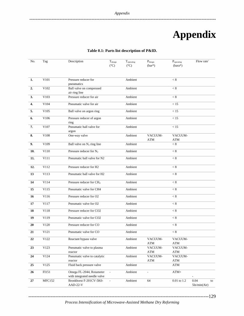
Appendix
---------------------------------------------------------------------------------------------------------------------
-----------------------------------------------------------------------------------------------------------------129
Process Intensification of Microwave-Assisted Methane Dry Reforming
Appendix
Table 0.1: Parts list description of P&ID.
No. Tag Description Tdesign
(°C)
Toperating
(°C)
Pdesign
(bar*)
Poperating
(bara*)
Flow rate+
1. V101 Pressure reducer for
pneumatics
Ambient < 8
2. V102 Ball valve on compressed
air ring line
Ambient < 8
3. V103 Pressure reducer for air Ambient < 8
4. V104 Pneumatic valve for air Ambient < 15
5. V105 Ball valve on argon ring Ambient < 15
6. V106 Pressure reducer of argon
ring
Ambient < 15
7. V107 Pneumatic ball valve for
argon
Ambient < 15
8. V108 One-way valve Ambient VACUUM-
ATM
VACUUM-
ATM
9. V109 Ball valve on N2 ring line Ambient < 8
10. V110 Pressure reducer for N2 Ambient < 8
11. V111 Pneumatic ball valve for N2 Ambient < 8
12. V112 Pressure reducer for H2 Ambient < 8
13 V113 Pneumatic ball valve for H2 Ambient < 8
14 V114 Pressure reducer for CH4 Ambient < 8
15 V115 Pneumatic valve for CH4 Ambient < 8
16 V116 Pressure reducer for O2 Ambient < 8
17 V117 Pneumatic valve for O2 Ambient < 8
18 V118 Pressure reducer for CO2 Ambient < 8
19 V119 Pneumatic valve for CO2 Ambient < 8
20 V120 Pressure reducer for CO Ambient < 8
21 V121 Pneumatic valve for CO Ambient < 8
22 V122 Reactant bypass valve Ambient VACUUM-
ATM
VACUUM-
ATM
23 V123 Pneumatic valve to plasma
reactor
Ambient VACUUM-
ATM
VACUUM-
ATM
24 V124 Pneumatic valve to catalytic
reactor
Ambient VACUUM-
ATM
VACUUM-
ATM
25 V125 Fluid back pressure valve Ambient ATM
26 FI151 Omega FL-2044, Rotameter
with integrated needle valve
- Ambient - ATM+
-
27 MFC152 Bronkhorst F-201CV-5K0-
AAD-22-V
- Ambient 64 0.01 to 1.2 0.04 to
5ln/min(Air)
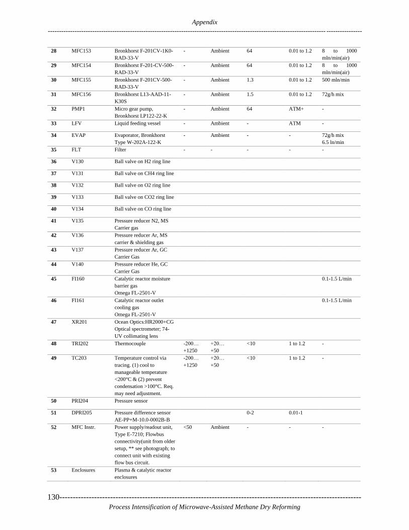
Appendix
----------------------------------------------------------------------------------------------------------------------------- ----------------
130-----------------------------------------------------------------------------------------------------------------
Process Intensification of Microwave-Assisted Methane Dry Reforming
28 MFC153 Bronkhorst F-201CV-1K0-
RAD-33-V
- Ambient 64 0.01 to 1.2 8 to 1000
mln/min(air)
29 MFC154 Bronkhorst F-201-CV-500-
RAD-33-V
- Ambient 64 0.01 to 1.2 8 to 1000
mln/min(air)
30 MFC155 Bronkhorst F-201CV-500-
RAD-33-V
- Ambient 1.3 0.01 to 1.2 500 mln/min
31 MFC156 Bronkhorst L13-AAD-11-
K30S
- Ambient 1.5 0.01 to 1.2 72g/h mix
32 PMP1 Micro gear pump,
Bronkhorst LP122-22-K
- Ambient 64 ATM+ -
33 LFV Liquid feeding vessel - Ambient - ATM -
34 EVAP Evaporator, Bronkhorst
Type W-202A-122-K
- Ambient - - 72g/h mix
6.5 ln/min
35 FLT Filter - - - - -
36 V130 Ball valve on H2 ring line
37 V131 Ball valve on CH4 ring line
38 V132 Ball valve on O2 ring line
39 V133 Ball valve on CO2 ring line
40 V134 Ball valve on CO ring line
41 V135 Pressure reducer N2, MS
Carrier gas
42 V136 Pressure reducer Ar, MS
carrier & shielding gas
43 V137 Pressure reducer Ar, GC
Carrier Gas
44 V140 Pressure reducer He, GC
Carrier Gas
45 FI160 Catalytic reactor moisture
barrier gas
Omega FL-2501-V
0.1-1.5 L/min
46 FI161 Catalytic reactor outlet
cooling gas
Omega FL-2501-V
0.1-1.5 L/min
47 XR201 Ocean Optics:HR2000+CG
Optical spectrometer; 74-
UV collimating lens
48 TRI202 Thermocouple -200…
+1250
+20…
+50
<10 1 to 1.2 -
49 TC203 Temperature control via
tracing. (1) cool to
manageable temperature
<200°C & (2) prevent
condensation >100°C. Req.
may need adjustment.
-200…
+1250
+20…
+50
<10 1 to 1.2 -
50 PRI204 Pressure sensor
51 DPRI205 Pressure difference sensor
AE-PP+M-10.0-0002B-B
0-2 0.01-1
52 MFC Instr. Power supply/readout unit,
Type E-7210; Flowbus
connectivity(unit from older
setup, ** see photograph; to
connect unit with existing
flow bus circuit.
<50 Ambient - - -
53 Enclosures Plasma & catalytic reactor
enclosures

Appendix
---------------------------------------------------------------------------------------------------------------------
-----------------------------------------------------------------------------------------------------------------131
Process Intensification of Microwave-Assisted Methane Dry Reforming
(To keep reactors in
continuously ventilated
volume, total air flow
through lab ventilation
dilute CO conc. Below
TLV)
54 Calib. Gases Calibration gas bottles of
appropriate composition for
GC calibration
55
56
TR211 to TR-N Four N-type Thermocouples -200…
+1250
-200…
+1250
57 FLT2 & FLT3 Whatman FP050/1 Filter
holder with 50 mm paper
filter
58 SS-MWG Solid-state MW generator
assembled out of generator
module and power supply. It
is swappable between both
reactors
59 SRF Surfatron plasma generator
60 TST1 Lauda Thermostat RE304
Ethylene Glycol solution
coolant
61 CMP2 KNF SC 920 (Pressure
regulation)
62 CMP3 KNF N838.3 KT.18
(Compressor to feed gas
chromatograph with sample
gas)
63 TT230, TT309 Two thermocouples -200…
+1250
-20…+20
64 FT231, FT310 Flowswitch depends on
TST1/TST2
~ 1 L/min
65 V250 Pneumatic ball valve
66 V251 Pneumatic ball valve
67 V252 Membrane valve, manual
(to choke CPM3 to reduce
flow)
ambient VACUUM-
ATM
68 V253 Pneumatic ball valve
69 PRI301 Pressure sensor ~ 0.75 – 1.5
bara
0.75 – 1.5
70 TTR302 Thermal Camera, FLIR
A645 SC(Image processing
required)
71 TR303 Thermocouple, 0.5 mm
diameter
(Tmeas. Below catalytic bed
but has to remain outside
MW field)
-200…
+1250
0 to 1000
72 TC304/
TRI304
Controls tracing embedded
in reactor 0.5 mm(To
prevent condensation of
moisture)
-200…
+1250
0 to 200
73 TC305 Temperature control on
tracing
-200…
+1250
74 V311 Pneumatic ball valve Ambient <8
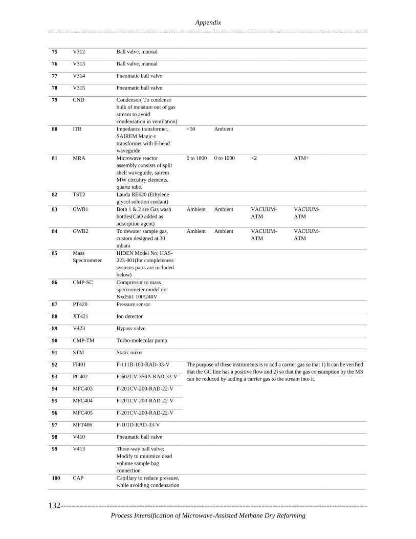
Appendix
----------------------------------------------------------------------------------------------------------------------------- ----------------
132-----------------------------------------------------------------------------------------------------------------
Process Intensification of Microwave-Assisted Methane Dry Reforming
75 V312 Ball valve, manual
76 V313 Ball valve, manual
77 V314 Pneumatic ball valve
78 V315 Pneumatic ball valve
79 CND Condensor( To condense
bulk of moisture out of gas
stream to avoid
condensation in ventilation)
80 ITR Impedance transformer,
SAIREM Magic-t
transformet with E-bend
waveguide
<50 Ambient
81 MRA Microwave reactor
assembly consists of split
shell waveguide, sairem
MW circuitry elements,
quartz tube.
0 to 1000 0 to 1000 <2 ATM+
82 TST2 Lauda RE620 (Ethylene
glycol solution coolant)
83 GWB1 Both 1 & 2 are Gas wash
bottles(CaO added as
adsorption agent)
Ambient Ambient VACUUM-
ATM
VACUUM-
ATM
84 GWB2 To dewater sample gas,
custom designed at 30
mbara
Ambient Ambient VACUUM-
ATM
VACUUM-
ATM
85 Mass
Spectrometer
HIDEN Model No: HAS-
223-001(for completeness
systems parts are included
below)
86 CMP-SC Compressor to mass
spectrometer model no:
Nxd561 100/240V
87 PT420 Pressure sensor
88 XT421 Ion detector
89 V423 Bypass valve
90 CMP-TM Turbo-molecular pump
91 STM Static mixer
92 FI401 F-111B-100-RAD-33-V The purpose of these instruments is to add a carrier gas so that 1) It can be verified
that the GC line has a positive flow and 2) so that the gas consumption by the MS
can be reduced by adding a carrier gas to the stream into it. 93 PC402 P-602CV-350A-RAD-33-V
94 MFC403 F-201CV-200-RAD-22-V
95 MFC404 F-201CV-200-RAD-22-V
96 MFC405 F-201CV-200-RAD-22-V
97 MFT406 F-101D-RAD-33-V
98 V410 Pneumatic ball valve
99 V413 Three-way ball valve;
Modify to minimize dead
volume sample bag
connection
100 CAP Capillary to reduce pressure,
while avoiding condensation

Appendix
---------------------------------------------------------------------------------------------------------------------
-----------------------------------------------------------------------------------------------------------------133
Process Intensification of Microwave-Assisted Methane Dry Reforming
of moisture(also ref.to
V415)
101 Gas Chromat. Varian CP4900 (Labview
Interface available in EZ-
Chrom)
102 L001 Stainless Steel or copper
piping Ø 6mm or Ø 1/4'’
103 L002 Copper piping Ø 6 mm or Ø
1/4’’
104 L003 Stainless steel, copper
piping, PE or pneumatic
tubing ~Ø6mm or Ø1/4’’
105 L004 Traced piping ~ Ø 6mm or
Ø 1/4’’, CO compatible (e.g.
copper)
100-105 or
90-100
106 L005 Ø 6mm pneumatic tubing
107 L006 Traced line, CO compatible,
see TC203
100-105 or
50-60
108 L007 Rigid coax, UT-250A-TP-
M17
(Avoid hexagonal
connecting nut to prevent
overtightening)
109 L008 Piping ~ Ø 6mm or ~ Ø
1/4’’, CO compatible (e.g.
copper)
110 L009 Traced line, CO compatible,
see TC304
100-105
111 L010 Piping ~Ø 6mm, CO
compatible (e.g. copper)
112 L011 Silicone tube, hose
connections to glassware
and ethylene glycol
compatible
113 L012 6 mm stainless steel or
copper
114 L013 Any type of hosepipe Øi 10
mm suffices
115 Computers Various computers
connected to KVM Switch
116 i/o device(s) National instruments
devices for LabVIEW
interfacing
Real-time embedded controller, cRIO, required due to unsupervised operation.
117 XT290 Door Switch
118 FT291 Flow switch on interlock,
SL5101(Interlock on
ventilation failure)
119 XT292 Microwave survey meter on
interlock, Sairem, DFM
M24DC 2450MHZ
120 XT293 Magnetic position switch
121 XT390 Door switch
122 FT391 Flow switch on interlock,
SL5101
123 XT392 Microwave survey meter,
ref. to XT292

Appendix
----------------------------------------------------------------------------------------------------------------------------- ----------------
134-----------------------------------------------------------------------------------------------------------------
Process Intensification of Microwave-Assisted Methane Dry Reforming
124 XT393 Magnetic position switch
(To verify where SS-MWG
is placed)
125 XT380 - Gas alarm sensors for CO,
CO2,
126 XT383 O2 and explosion limit resp.
127 FNC Tubular furnace, carbolite
MTF 10/15/130
1000 max
128 FNC-PS Power supply of tubular
furnace
129 PRI350 Pressure sensor 0.075 – 1.5
bar
130 TR351 N-Type thermocouple -200…
+1250
600- 1000
131 V415 5 Way valve
132 LT142 Level verification to protect
PMP1
133 TC141 Tracing regulator
134 TC300 Tracing regulator

List of publications, Curriculum Vitae and Acknowledgments
---------------------------------------------------------------------------------------------------------------------
-----------------------------------------------------------------------------------------------------------------135
Process Intensification of Microwave-Assisted Methane Dry Reforming
List of Publications
Curriculum Vitae
Acknowledgments

List of publications, Curriculum Vitae and Acknowledgments
----------------------------------------------------------------------------------------------------------------------------- ----------------
136-----------------------------------------------------------------------------------------------------------------
Process Intensification of Microwave-Assisted Methane Dry Reforming
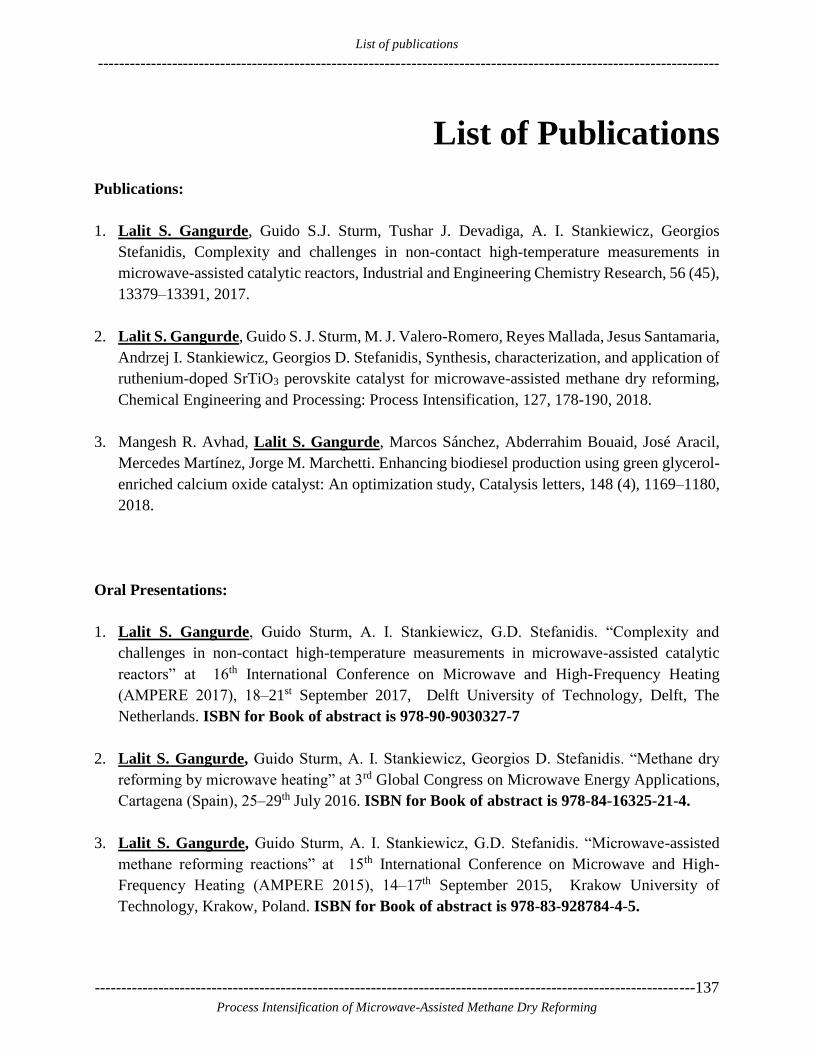
List of publications
---------------------------------------------------------------------------------------------------------------------
-----------------------------------------------------------------------------------------------------------------137
Process Intensification of Microwave-Assisted Methane Dry Reforming
List of Publications
Publications:
1. Lalit S. Gangurde, Guido S.J. Sturm, Tushar J. Devadiga, A. I. Stankiewicz, Georgios
Stefanidis, Complexity and challenges in non-contact high-temperature measurements in
microwave-assisted catalytic reactors, Industrial and Engineering Chemistry Research, 56 (45),
13379–13391, 2017.
2. Lalit S. Gangurde, Guido S. J. Sturm, M. J. Valero-Romero, Reyes Mallada, Jesus Santamaria,
Andrzej I. Stankiewicz, Georgios D. Stefanidis, Synthesis, characterization, and application of
ruthenium-doped SrTiO3 perovskite catalyst for microwave-assisted methane dry reforming,
Chemical Engineering and Processing: Process Intensification, 127, 178-190, 2018.
3. Mangesh R. Avhad, Lalit S. Gangurde, Marcos Sánchez, Abderrahim Bouaid, José Aracil,
Mercedes Martínez, Jorge M. Marchetti. Enhancing biodiesel production using green glycerol-
enriched calcium oxide catalyst: An optimization study, Catalysis letters, 148 (4), 1169–1180,
2018.
Oral Presentations:
1. Lalit S. Gangurde, Guido Sturm, A. I. Stankiewicz, G.D. Stefanidis. “Complexity and
challenges in non-contact high-temperature measurements in microwave-assisted catalytic
reactors” at 16th International Conference on Microwave and High-Frequency Heating
(AMPERE 2017), 18‒21st September 2017, Delft University of Technology, Delft, The
Netherlands. ISBN for Book of abstract is 978-90-9030327-7
2. Lalit S. Gangurde, Guido Sturm, A. I. Stankiewicz, Georgios D. Stefanidis. “Methane dry
reforming by microwave heating” at 3rd Global Congress on Microwave Energy Applications,
Cartagena (Spain), 25‒29th July 2016. ISBN for Book of abstract is 978-84-16325-21-4.
3. Lalit S. Gangurde, Guido Sturm, A. I. Stankiewicz, G.D. Stefanidis. “Microwave-assisted
methane reforming reactions” at 15th International Conference on Microwave and High-
Frequency Heating (AMPERE 2015), 14‒17th September 2015, Krakow University of
Technology, Krakow, Poland. ISBN for Book of abstract is 978-83-928784-4-5.

List of publications
----------------------------------------------------------------------------------------------------------------------------- ----------------
138-----------------------------------------------------------------------------------------------------------------
Process Intensification of Microwave-Assisted Methane Dry Reforming
4. Lalit S. Gangurde, Guido Sturm, A. I. Stankiewicz, G.D. Stefanidis. “New approach in
microwave assisted reforming reactions” at Delft Process Technology Institute (DPTI) 2015
Annual Event, 5th June 2015, Den Haag, The Netherlands.
5. Lalit S. Gangurde, Guido Sturm, A. I. Stankiewicz, G.D. Stefanidis. “New approach in
microwave-assisted reforming reactions” in Jubilee Symposium at Jagiellonian University,
28th April 2014, Krakow, Poland
Poster Presentations:
1. 5th European Process Intensification Conference, 27th Sept to 1th Oct 2015, Nice, France
2. 2nd Annual Event of the TU Delft Process Technology Institute, 7th Nov. 2014, SS Rotterdam,
the Netherlands.
3. Netherlands Process Technology Symposium (NPS14), 3‒5th Nov. 2014, Utrecht, the
Netherlands.
4. 1st Delft Process Technology Institute (DPTI) Annual Event, 14th November 2013, Den Haag,
the Netherlands.
Conferences attended
1. 4th TU Delft process technology annual event on 21st June 2016, Rotterdam, the Netherlands.
2. 3rd European Young Engineers Conference on 30th April 2014, Warsaw, Poland.
3. COMSOL Conference, 23‒25 October 2013, Rotterdam. the Netherlands.
4. 9th European Congress of Chemical Engineering(ECCE9) on 21‒25th April 2013, Den Haag,
Netherlands
Doctoral Education Program
---------------------------------------------------------------------------------------------------------------------
-----------------------------------------------------------------------------------------------------------------139
Process Intensification of Microwave-Assisted Methane Dry Reforming
Doctoral Education Program
Discipline-related skills
1. Course: Chemical Product-Centric Process Design, 30 & 31st May 2017, TU Delft.
2. Course: Fundamentals and Practice of Process Intensification, 2‒3 April 2014, Process and
Energy Department, TU Delft.
3. Summer School: High Energy Processing Ultrasound and Microwave Technologies, 9‒12
September 2015, Krakow University of Technology, Krakow Poland
4. Course: Gas-Phase Processing of Nanostructured Solids, 3‒5 September 2013, ChemE
Department, TU Delft.
5. Course: Computational Fluid Dynamics for Chemical Engineers, 8‒12 July 2013, TU Delft.
6. Course: COMSOL Multiphysics Intensive Training, 13‒14 May 2013, Zoetermeer, the
Netherlands.
7. Workshop on crystalline materials, diffraction, and databases, 23rd March 2017, TU Delft.
8. Scientific Visit to ASML Company, 23rd October 2014, Veldhoven, the Netherlands.
9. A trip to the world leading steel production company TATA Steel, 15th March 2017,
IJmuiden, The Netherlands.
Research-related skills
1. R1.A2 The informed researcher: Information and data skills, 14th & 28th March 2017, TU
Delft.
Learning on the Job
2. Teaching assistant for WB3560 Process Technique II course in academic years 2012‒13,
13‒14 & 14‒15 (including attending lectures, answering to students doubts, supervision,
and checking of exams) 3ME, TU Delft.

Doctoral Education Program
----------------------------------------------------------------------------------------------------------------------------- ----------------
140-----------------------------------------------------------------------------------------------------------------
Process Intensification of Microwave-Assisted Methane Dry Reforming
3. Supervised a M.Sc. & a B.Sc. Student. (Including correcting thesis), 28th April to 14th Dec.
2016 and 15th April to 5th Sept 2017, P&E department, TU Delft.
4. Seminar ‘Are you ready to publish? Understanding the publishing process’ 5th February
2015, Science Centre, TU Delft, The Netherlands.
5. Writing the first journal article, 6th September 2017, Industrial and Engineering Chemistry
Research Journal.
6. Oral Presentation addressed a major international audience in 15th International Conference
on Microwave and High-Frequency Heating (AMPERE 2015), 14‒17 September 2015,
Krakow University of Technology, Krakow, Poland.
7. Oral Presentation addressed a major international audience in the 3rd Global Congress on
Microwave Energy Applications (3GCMEA), 25‒29 July 2016, Cartagena, Spain.
8. Oral presentation, addressed a small International Audience at Delft Process Technology
Institute (DPTI) 2015 Annual Event, 5th June 2015, Den Haag, The Netherlands.
9. Oral Presentation, addressing a major international audience in Jubilee Symposium at
Jagiellonian University, 28th April 2014, Krakow, Poland.
10. Poster presentation, the major international audience at Netherlands Process Symposium
(NPS14), 3‒5 November 2014, Utrecht, The Netherlands.
11. Poster presentation, small audience at 1st Delft Process Technology Institute (DPTI) Annual
Event, 14th November 2013, Den Haag, The Netherlands.
12. Poster Presentation: the small audience at the 2nd Annual Event of DPTI, Rotterdam, 7th
November 2014.
Transferable skills
1. C9. M1. Ph.D. Startup Course, 18, 21 & 28th June 2013, Art Centre Delft,
2. C8.M1. Communication, Coping-strategies & Awareness, 28th May & 4th June 2014,
Industrial Design Department, TU Delft.
3. C11. M1. How to manage your research information, 9th & 15th May 2014, Library, TU
Delft,

Doctoral Education Program
---------------------------------------------------------------------------------------------------------------------
-----------------------------------------------------------------------------------------------------------------141
Process Intensification of Microwave-Assisted Methane Dry Reforming
4. How to write a scientific paper (and Get It Published), 9th Jan 2017, Aula Building, TU
Delft.
5. T1.B3 Writing a Dissertation (PROM-3), 2nd May to 13th June 2017, TPM, Room 'I, TU
Delft.
6. C8.M5. How to become effective in a network conversation, 4th April 2014, Faculty of
Technology, Policy and Management(TPM), TU Delft.
7. C8. M3. Self-management Strategies, 16th & 23rd April 2014, Library, TU Delft.
8. C9. M2. Time Management, 19th September & 30th October 2014, Library, TU Delft.
9. C13. M6. Self-presentation: Presenting yourself and your work, 12th June & 26th June 2013,
Industrial Design, TU Delft.
10. C9. M4. How to keep motivated after your GO? Regain your flow! 7th & 14th April 2014,
Library, TU Delft.
11. C13. M7. Lead a better (academic) life, 29th September 2014, Library, TU Delft.
12. C12. M6. Self-presentation 2 - storyline and presentation slides, 22nd & 29th June & 6th July
2016, Faculty of EEMSC & Library, TU Delft.

Doctoral Education Program
----------------------------------------------------------------------------------------------------------------------------- ----------------
142-----------------------------------------------------------------------------------------------------------------
Process Intensification of Microwave-Assisted Methane Dry Reforming

Curriculum Vitae
---------------------------------------------------------------------------------------------------------------------
-----------------------------------------------------------------------------------------------------------------143
Process Intensification of Microwave-Assisted Methane Dry Reforming
Curriculum Vitae
Lalit Sayaji Gangurde was born on 27th September 1988,
in Ghodegaon, a small village in Malegaon, district Nasik
of Maharashtra state, India. He completed his schooling
from Ravalgaon English School, Ravalgaon, India. He
finished his Junior and senior college studies from K.B.H.
Jr. College Malegaon, India. In 2009, he graduated with
Bachelors of science degree in chemistry from M.S.G.
College Malegaon, India.
To acquire profound knowledge of catalysis and material science, in July 2009, he joined master’s
program in the Department of chemistry, University of Pune, Pune, India. He obtained his
master’s degree in April 2011 with specialization in inorganic chemistry. This master’s program
inspired him to get more insight into the exciting field of catalysis. So, after completing master’s
program, he started working as a Project Assistant in the heterogeneous catalysis Division,
National Chemical Laboratory, Pune, India. He worked in NCL from 13th July 2011 to 9th
November 2012 on the project entitled “Development of internal reforming catalysts for 500 W
Solid Oxide Fuel Cell Stack.” During this Project work, he learned various catalyst preparation
methods to prepare various mixed metal oxide catalysts with different supports and active phases.
He learned various characterization techniques to investigate physical and chemical properties of
prepared materials. He was also involved in the performance evaluation of prepared catalysts for
steam reforming of methane and water gas shift reactions. This experience has developed an
interest in him to do further doctoral studies.
Since Dec. 2012, he started working as a Ph.D. researcher in Process and energy department of
the Delft University of Technology, the Netherlands. His doctoral work is the part of a project
entitled Towards Perfect Chemical Reactor, funded by European Research Council. His Ph.D.
research dealt with the process intensification of microwave-assisted methane dry reforming
process. This process converts two greenhouse gases, CH4 and CO2 into syngas (H2 + CO) which
can be used as a renewable source of energy. The results obtained in his research work have been
published as research articles. The results have also been presented at various national and
international conferences. Besides this, he has worked as a teaching assistant for Process
technology course for bachelor's student. He has also supervised masters and bachelors project
students. Currently, he has been appointed as a postdoctoral researcher in the Delaware Energy
Institute (DEI) at the University of Delaware (USA) effective from October 1, 2018.
For More information: https://www.linkedin.com/in/lalit-gangurde-948b9560/
Email: [email protected]

Curriculum Vitae
---------------------------------------------------------------------------------------------------------------------------------------------
144-----------------------------------------------------------------------------------------------------------------
Process Intensification of Microwave-Assisted Methane Dry Reforming

Acknowledgements
---------------------------------------------------------------------------------------------------------------------
-----------------------------------------------------------------------------------------------------------------145
Process Intensification of Microwave-Assisted Methane Dry Reforming
Acknowledgments
While writing the acknowledgments, my thought process is taking me to the flashback of my
journey from sending my application for this Ph.D. position to at this moment, now writing this
acknowledgment section. The one significant observation I have about myself is that the way I was
thinking and seeing the world before starting Ph.D. and now while completing my Ph.D. This
Journey has really been an unexpectedly long, filled with a lot of emotional ups and downs.
Completion of a Ph.D. demands a lot of skills on the personal and professional level. When I joined,
I knew very little about it, so this journey has taught me a lot of things. Even though I was a driver
on this journey, but it could not have been possible to complete it without the tremendous support
and motivation which I received from various people at different levels. This support acted as a
fuel to drive myself safely through this long doctoral journey.
Firstly, I am thankful to my first Promoter Andrzej Stankiewicz for giving me an opportunity to
become a part of this very interdisciplinary group at the Delft University of technology, the
Netherlands. Starting from my first interaction with him until the end of Ph.D., He was always a
great support, encouragement, and inspiration to carry out the research work. His suggestions and
comments during various meeting and interactions helped me a lot to improve the quality of the
research work. The research work done in this doctoral thesis has received funding from the
European Research Council under the European Union's Seventh Framework Programme
(FP7/2007-2013) / ERC grant agreement no. 267348. I am thankful to ERC for trusting on all the
people involved in this project as the outcome of this research activities came out a bit late in terms
of research articles.
I would like to thank with a lot of gratitude to my daily supervisor and second promotor Professor
Georgios Stefanidis for helping me throughout my Ph.D. Journey. Even though the journey has
been extended and stressful, he guided me to keep myself in the correct direction. He helped me to
improve in various skills required to be a good researcher. He taught me to be calm and compose
to face the unexpected challenges came during the experimental work or dealing with any other
kind of stressful situations. He has helped me a lot to improve my scientific writing skills and
guided me at a very minute level. He also gave me the necessary guidance to improve my
presentation skills at various national and international conferences. I am very grateful for his
significant contribution in improving and providing correct suggestions to write the quality
research articles, conference abstracts and at the end for final Ph.D.thesis. Thank you, Georgios
once again for everything you did for me.
Special thanks to Dr. Guido Sturm for helping me in designing the P&ID of my reactor setup. He
has significantly contributed to designing and developing the custom designed microwave cavity
for this work. Without his help, it would have been impossible to build a completely new

Acknowledgements
---------------------------------------------------------------------------------------------------------------------------------------------
146-----------------------------------------------------------------------------------------------------------------
Process Intensification of Microwave-Assisted Methane Dry Reforming
microwave reactor system. I have learned a lot of things from you Guido so thank you very much
again for everything. I would like to thank Prof. Santamaria and Reyes Malada for allowing me to
work at the University of Zaragoza, Spain for catalyst synthesis and characterization work. It was
really pleasant and excellent learning experience to stay in Zaragoza and learn new things from
experts in the microwave catalysis field. Thanks to Diego, Nuria, Marta and Hema for helping me
in the Analytical Lab and other relevant work in Zaragoza University. I would also like to thank
Prof. Jorge Gascon for allowing me to work in the Chemical Engineering department of TU Delft
for catalyst synthesis and characterization purpose. Thank you very much, Maria Jose, for teaching
me some more inside details of catalyst synthesis and characterization. You were always energetic
and ready to help me in every possible way, I really appreciate everything you did for our
collaborative work in terms of improving the quality of research results and writing it more
correctly in a scientific language.
A special appreciation goes to all the technicians in the DEMO staff for helping and guiding me
for all the technical aspects during the reactor development time phase. I would like to thank Michel
van den Brink for helping me in the Analytical lab related problems, safety-related issues,
correcting and approving my safety report. Aad beeloo and Rob Van den Boogaard for arranging
the meetings to speed up the reactor construction work. Jaap van Raamt for ordering all the
necessary materials and helping me to solve the reactor construction related problems. Martijn
Karsten, who designed and constructed the electrical cabinet of the whole reactor set up and his
help for all the electrical technical issues. Bas Overtoom and Gerard van de Sande for construction
of reactor setup and minor modifications in the setup whenever it's needed. Lennart Middelplaats,
who designed the Labview interface for reactor control system and helped me afterword’s also in
some problems related to the reactor control system.
I would like to thank my Master’s project student Tushar Devadiga for his contribution to work
with me in various technical challenges to start the operation of newly developed microwave
reactor assembly. His contribution as a Masters student was really very helpful for me to plan my
further research work. I would also like to thank my bachelor's student, Diederik S. van Roemburg,
who worked on a comparative study of commercial catalysts. The results of his work are a
significant contribution to my Ph.D. thesis. Leslie Van Leeuwen and Helma Duijndam-
Nieuwpoort, Our group secretaries and most important persons in the group. Thank you very much
for helping me in all the documental work and any other kind of small problems, doubts or issues
from starting till the end of my Ph.D. time. Thank you Prof. Dr. P.V. Aravind for becoming the
part of my go no go committee and assessment.
Joining as a Ph.D. student at TU Delft, gave me an opportunity to expand my friendship with more
international colleagues in our process and energy department. My first office mates Iza Franssen,
Maryum Khodadadian, and Daniel Irimia thanks for being such a sweet and helpful colleagues in
my initial days. It was a great experience and learning to attend all our Intensified reaction and
separation systems group meetings and to get to know about the research progress of all the people

Acknowledgements
---------------------------------------------------------------------------------------------------------------------
-----------------------------------------------------------------------------------------------------------------147
Process Intensification of Microwave-Assisted Methane Dry Reforming
working in the group. I would like to thanks to Rohit Kacker, Javier Fernandez, George Krintiras,
Sergio Moreno, Fatemeh Anisi. Marloes Reus, Weiwei Li, Fatma Ibis, Rumen Georgiev for having
interesting discussions during drinks and snacks session after these group meetings. I would like
to thank Meng wang, Xuan Tao, Peng Yan, Uttiya Sengupta, Mahinder Ramdin, Nikolaos
Chrysochoidis-Antsos, Metin Çelik, Tim Becker, Karsten Baumgarten for a nice time and fun
activities during our P&E outings and short visits to different places. Thanks to some newly joined
people in our group, Vinay Mahajan, Vikrant Verma, and Sathish Sanjeevi for coffee break
conversations on life after Ph.D. topic. Thanks to my current office mates, Ali Poursaeidesfahani,
Farnaz Eghbal Sarabi and Hirad Seyed Salehi for tolerating my all-time silent nature in the office.
Thanks to Hakan Nigar for your help, suggestions, and discussion for some future simulation study
possibilities with the results obtained in this work. I would also like to thank Hanaa for translating
summary in Dutch. I would like to thank the graduate school for organizing a doctoral education
program, and various interactive events among all the new Ph.D.’s in the TU Delft. The different
courses organized by 3ME Graduate school in discipline-related skills, research-related skills, and
transferable skills have really helped me to improve not only as a researcher but also on the personal
and professional level.
Thank you, Jitendra Khairnar to provide me accommodation in the Netherlands. Jagdish Thibe for
helping me financially whenever I needed. Bhaskar Patil, for introducing me to Ramerstraat
friends. The stay at Ramaerstraat made me happy and engaged me in all kind of parties, social
events, outing, box cricket matches, Ganesh Utsav, etc. Special thanks to Rajat Bharadwaj for the
invitation to his marriage, it gave me a chance to meet your family and visit the most important
touristic places in Delhi. You both Rajat and Rupali are always a great support to me at my time in
Delft. Thanks to Purvil Khakharia for your help and support whenever I needed. Thanks to Sumit
Sachdeva for being a very good friend and always ready to help me with the small doubts or
problems in professional and personal life. Trinath for being such a nice friend, organizer, and
guide on our trips. Thank you very much to all my dear friends in the Netherlands, Aditya thallam
thattai, Hrishikesh Patel, Ajith-Vaishnavi, Shreyash-Gunjan, Navin-Mitwa, Vyankatesh Session,
Vasudevan Lakshminarayanan, Sushil-Jaymala Gaikwad, Bhaskar-Mohini, Manas Manohar,
Prathna Chandrasekaran, Edwin Gnanakumar, Jalindar Padwal, Ashwinikumar Sharma for nice
dinners and exciting conversations. Thank you very much, Samir and Shruti Kulkarni for all the
necessary support from providing me food and helping me to call home on my first day in the
Netherlands. It was amazing to see Netherlands Marathi Mandal and Rashmin group, celebrating
our own culture and festivals miles away from our native place even in the more elaborative way
and giving the opportunity to meet some of the great people in various art forms. thanks for
organizing all these events.
I think it could not have been possible for me to come to the Netherlands if I would not have got
the opportunity to work as a project assistant in National Chemical Laboratory Pune, India. I would
like to thank Dr.C.V.V Satyanarayana for giving me the opportunity to work under his guidance in
his research group. I would like to thank the friends I made during my stay at NCL, and then they

Acknowledgements
---------------------------------------------------------------------------------------------------------------------------------------------
148-----------------------------------------------------------------------------------------------------------------
Process Intensification of Microwave-Assisted Methane Dry Reforming
became friends forever. Hanmant Gurav, Mangesh Avhad, Gajanan Kale, Reji NK, Aditya
Dharanipragada, Narasimharao Kanna, Richa Bobade, Nishita Lucas, Dama Srikanth,
Lakshmiprasad ane nenu, Chandan Das, Vineetha Lakshmi Das, Atul Nagpure, Swanand Patange,
James Violet. Tushar Sakpal. Sonali Katkar for being such a lovely friend at NCL and Pune
University, Pune. Thanks to all my Masters, Bachelors and Ravalgaon English school friends for
always being with me and supporting me all the time. Special thanks to some of the very close
friends from my school days, Prashant Lokhande, Pradip Jagdale, Swapnil Nikumbh, Swapnil
Kulkarni, Umesh Nikam, and Kishor Patil for our entertaining conversations. Thanks to both my
paternal uncles Chandrashekhar Jadhav and Vijay Jadhav for their tremendous support from
childhood till date. Thanks to the Jadhav and Suryawanshi families for their love and affection gave
to me.
Special thanks to Mangesh Avhad for always caring about me and always there for me to know
about my research progress and helping me in every possible way. Your friendship is indeed
unconditional. Thank you very much for offering me a co-authorship in your publication and
having collaboration between the Netherlands and Norway. I would also like to thank Tejansh
Chandole, your always there for me in all my personal and professional issues. Our conversations
were always giving me positive energy and motivating me to do my best. I am fortunate to have a
friend like you. Thanks to Avinash Bansode, Yogesh More, Abhijeet Chaudhari, Mayur More to
share the various aspects of life.
I could not have existed without getting the unconditional love, affection, and care from my parents.
I would like to pay special thanks to my father for his efforts to provide me all the necessary things
to the best of his abilities since childhood till my college time and supporting me in every decision
on personal and professional front. My mother for understanding me in every situation, her constant
support and motivating words whenever I speak to her have boosted my confidence and inspired
me to be realistic and nice to everyone I meet. My two pillar of strength and great support at any
time are my both brothers Lakhan and Kishor Gangurde, without you guys I could not have thought
to come to the Netherlands as you were always there to take care of our parents and support them
and me in all the critical situations. Kishor, you came almost all the time to drop and receive me at
the airport and always there for me irrespective of your own busy schedule and work. Lakhan, I
know you're also going through a very tough time of your life, but still, you did not have any
complaints, and you was always there with parents. I would like to thank also to Gayatri Kulkarni
and her family for the warm welcome all the time I come to the home. Special thanks to Rohini
More and her family to keep patience and faith in me. Thanks to all relatives for understanding me
as I was absent almost for 6 years for all the most important life events of all my near and dear
relatives.
Lalit Gangurde,
Delft, April 2018.

Propositions
---------------------------------------------------------------------------------------------------------------------
-----------------------------------------------------------------------------------------------------------------149
Process Intensification of Microwave-Assisted Methane Dry Reforming
Propositions
Accompanying the thesis
Process Intensification of Microwave-Assisted Methane Dry
Reforming
Lalit Sayaji Gangurde
Delft University of Technology
1. Reproducibility of temperature profiles in microwave heated heterogeneous catalytic
systems is unachievable, since it is sensitive to many factors that vary under real reaction
conditions.
2. The best way to evaluate the performance of microwave-heated catalytic reactions is to
monitor microwave power consumption, product composition and temperature by both
point sensors (e.g., optical fiber’s or thermocouples) and thermal camera.
3. The limitations of carbon-based catalysts for microwave-assisted methane dry reforming
can be overcome with the ruthenium doped SrTiO3 perovskite catalyst (chapter 4).
4. Small, compact and optimized microwave reactors with improved hybrid catalytic systems
would be able to provide higher CH4 and CO2 conversions as compared to large-scale
carbon-based catalytic microwave reactors.
5. In order to be successful in what you do, control of your own thoughts, and motivation
towards your work is much more important than money, time, and previous knowledge.
6. Freedom of research comes when you have authority, experience, and power to take your
own decisions.
7. Political leaders and civilians of developing countries should only focus on development.
8. To avoid the consequences of personal data leakage from the social networking sites, one
must limit their data feed to these sites.
9. Your own philosophy about life changes with every new experience.
10. Unawareness about the unpredictable nature of research success rate increases self-doubt
and depression in Ph. D. researchers.
These propositions are considered opposable and defendable and as such has been
approved by the promotor, Prof.dr.ir. A.I. Stankiewicz.

Propositions
------------------------------------------------------------------------------------------------------------------------- --------------------
150-----------------------------------------------------------------------------------------------------------------
Process Intensification of Microwave-Assisted Methane Dry Reforming