materials A Miniaturized Antenna with Negative Index Metamaterial Based on Modified SRR and CLS Unit...
16
Materials 2015, 8, 392-407; doi:10.3390/ma8020392 materials ISSN 1996-1944 www.mdpi.com/journal/materials Article A Miniaturized Antenna with Negative Index Metamaterial Based on Modified SRR and CLS Unit Cell for UWB Microwave Imaging Applications Md. Moinul Islam 1, *, Mohammad Tariqul Islam 2 , Md. Samsuzzaman 2 , Mohammad Rashed Iqbal Faruque 1 , Norbahiah Misran 2 and Mohd Fais Mansor 2 1 Space Science Centre (ANGKASA), Research Centre Building, Universiti Kebangsaan Malaysia, 43600 UKM, Bangi, Selangor, Malaysia; E-Mail: [email protected] 2 Department of Electrical, Electronic and Systems Engineering, Faculty of Engineering and Built Environment, Universiti Kebangsaan Malaysia, 43600 UKM, Bangi, Selangor, Malaysia; E-Mails: [email protected] (M.T.I.); [email protected] (M.S.); [email protected] (N.M.); [email protected] (M.F.M.) * Author to whom correspondence should be addressed; E-Mail: [email protected]; Tel.: +60-389-214-730; Fax: +60-389-216-856. Academic Editor: Jordi Sort Received: 17 October 2014 / Accepted: 12 January 2015 / Published: 23 January 2015 Abstract: A miniaturized antenna employing a negative index metamaterial with modified split-ring resonator (SRR) and capacitance-loaded strip (CLS) unit cells is presented for Ultra wideband (UWB) microwave imaging applications. Four left-handed (LH) metamaterial (MTM) unit cells are located along one axis of the antenna as the radiating element. Each left-handed metamaterial unit cell combines a modified split-ring resonator (SRR) with a capacitance-loaded strip (CLS) to obtain a design architecture that simultaneously exhibits both negative permittivity and negative permeability, which ensures a stable negative refractive index to improve the antenna performance for microwave imaging. The antenna structure, with dimension of 16 ×21 ×1.6 mm 3 , is printed on a low dielectric FR4 material with a slotted ground plane and a microstrip feed. The measured reflection coefficient demonstrates that this antenna attains 114.5% bandwidth covering the frequency band of 3.4–12.5 GHz for a voltage standing wave ratio of less than 2 with a maximum gain of 5.16 dBi at 10.15 GHz. There is a stable harmony between the simulated and measured results that indicate improved nearly omni-directional radiation characteristics within the operational frequency band. The stable surface current distribution, negative refractive index characteristic, considerable OPEN ACCESS
-
Upload
independent -
Category
Documents
-
view
0 -
download
0
Transcript of materials A Miniaturized Antenna with Negative Index Metamaterial Based on Modified SRR and CLS Unit...

Materials 2015, 8, 392-407; doi:10.3390/ma8020392
materials ISSN 1996-1944
www.mdpi.com/journal/materials
Article
A Miniaturized Antenna with Negative Index Metamaterial
Based on Modified SRR and CLS Unit Cell for
UWB Microwave Imaging Applications
Md. Moinul Islam 1,*, Mohammad Tariqul Islam 2, Md. Samsuzzaman 2,
Mohammad Rashed Iqbal Faruque 1, Norbahiah Misran 2 and Mohd Fais Mansor 2
1 Space Science Centre (ANGKASA), Research Centre Building, Universiti Kebangsaan Malaysia,
43600 UKM, Bangi, Selangor, Malaysia; E-Mail: [email protected] 2 Department of Electrical, Electronic and Systems Engineering,
Faculty of Engineering and Built Environment, Universiti Kebangsaan Malaysia,
43600 UKM, Bangi, Selangor, Malaysia; E-Mails: [email protected] (M.T.I.);
[email protected] (M.S.); [email protected] (N.M.); [email protected] (M.F.M.)
* Author to whom correspondence should be addressed; E-Mail: [email protected];
Tel.: +60-389-214-730; Fax: +60-389-216-856.
Academic Editor: Jordi Sort
Received: 17 October 2014 / Accepted: 12 January 2015 / Published: 23 January 2015
Abstract: A miniaturized antenna employing a negative index metamaterial with modified
split-ring resonator (SRR) and capacitance-loaded strip (CLS) unit cells is presented for
Ultra wideband (UWB) microwave imaging applications. Four left-handed (LH)
metamaterial (MTM) unit cells are located along one axis of the antenna as the radiating
element. Each left-handed metamaterial unit cell combines a modified split-ring resonator
(SRR) with a capacitance-loaded strip (CLS) to obtain a design architecture that simultaneously
exhibits both negative permittivity and negative permeability, which ensures a stable negative
refractive index to improve the antenna performance for microwave imaging. The antenna
structure, with dimension of 16 × 21 × 1.6 mm3, is printed on a low dielectric FR4 material with
a slotted ground plane and a microstrip feed. The measured reflection coefficient demonstrates
that this antenna attains 114.5% bandwidth covering the frequency band of 3.4–12.5 GHz for a
voltage standing wave ratio of less than 2 with a maximum gain of 5.16 dBi at 10.15 GHz.
There is a stable harmony between the simulated and measured results that indicate improved
nearly omni-directional radiation characteristics within the operational frequency band.
The stable surface current distribution, negative refractive index characteristic, considerable
OPEN ACCESS
Materials 2015, 8 393
gain and radiation properties make this proposed negative index metamaterial antenna
optimal for UWB microwave imaging applications.
Keywords: microwave imaging; metamaterial; negative index; UWB
1. Introduction
Microwave imaging systems have recently been used extensively for medical imaging applications.
Usually, these imaging systems are constructed with a circular cylindrical array antenna and used to
detect cancerous tissue. These systems have gradually attracted great interest in medical applications.
The ultra-wideband signal provides good resolution and penetration properties. The use of such microwave
imaging systems has been proposed to detect breast cancer [1–3]. In these studies, compact directional
ultra-wideband antennas are used to transmit and receive short duration pulses that are directed into the
breast tissues. The tumor detection capability originates from the considerable contrast between the electrical
properties (conductivity and permittivity) of normal and cancerous tissues. A tumor causes the scattering
of an electromagnetic wave as a reflecting object due to the differences in those properties. A negative-index
metamaterial is a left-handed metamaterial that contains an engineered electromagnetic structure with
some extraordinary properties such as negative permittivity, and negative permeability, as well as a negative
refractive index over a specific frequency band that is not usually found in nature. Metamaterials have
created a new era in microwave imaging applications because of their great potentials for the production
of effective microwave devices, such as antennas. Veselago made the first theoretical speculation of the
existence of a material that could exhibit negative permeability and negative permittivity simultaneously [4].
Then, Pendry constructed metamaterials with the help of the split ring resonator (SRR) where the
electromagnetic (EM) wave is conducted via a route that opposes the convectional path [5]. Finally,
in 2000, Smith successfully exhibited and validated this concept by constructing a new artificial material
known as a left-handed metamaterial in which both ɛ and µ were negative [6]. Different types of LHMs
have been proposed using various structures such as SRRs [7], spiral resonators [8], fishnet structures [9],
double-sided SRRs [10], double-bowknot shaped resonators [11], transmission-line based structures [12],
periodic arrays of H-shaped pairs [13], SRR pairs [14], cut wire pairs [15], broad side coupled SRRs [16]
and complementary electric field-coupled resonator (CLEC) [17]. The field of LHM research has been
expanded by adopting various techniques. These studies face difficulties such as their narrow bandwidth,
which limits the range and spectrum of their applications. They also have limited utility in antenna design
and fabrication, as these materials are difficult to fabricate and use. Therefore, there is a rise in the demand
for research to overcome these difficulties and broaden the fields of metamaterial applications.
A left-handed metamaterial structure is proposed to increase the gain of a microstrip antenna [18].
The performance of the antenna was studied by placing the LHM structure in front of the patch antenna.
The results demonstrate that this antenna structures exhibits higher gain and a greater directional
characteristic because of the placement of the LHM. However, this design technique leads to larger
antenna dimensions. An elliptical tapered slot antenna of 50 mm × 50 mm is proposed for UWB medical
imaging systems [19]. A compact metamaterial antenna is presented for UWB applications covering
from the 5.2–13.9 GHz frequency band, where the optimum gain is 1.2–3.85 dBi and the directivity is
Materials 2015, 8 394
1.95–5.45 dB [20]. The results demonstrate that the reported metamaterial is effectively applicable to
the production of materials with negative indices at low cost. However, the resulting antenna dimensions
are large, gain and directivity are small, and the reported metamaterial antenna does not completely cover
the UWB band. TEM horn antennas based on aperture raster scanning have been reported for near-field
microwave imaging [21]. The horn antenna features a high gain and excellent decoupling from the outside
environment. However, the large sizes of the antenna and high cost due to its fabrication complexity must
be considered. A compact metamaterial antenna was reported using two transmission lines metamaterial
arms [22]. Each metamaterial arm consists of a microstrip transmission-line loaded with five spiral inductors.
The reported antenna delivers a bandwidth of 100 MHz with a radiation efficiency of 65.8% at 3.30 GHz.
A microstrip-fed Dark Eyes antenna of 22.25 mm × 20 mm was designed for near-field microwave
sensing [23]. A compact UWB metamaterial antenna was proposed that used a modified split-ring
resonator (SRR) and capacitively loaded strips (CLS) [24]. Three unit cells were used as the radiating
element. This antenna provide 2.9–9.9 GHz bandwidth (below −10 dB) not completely covering the UWB
band. A resistively loaded ultra-compact broadband antenna was designed for microwave breast cancer
detection [25]. Larger dimensions were considered while operating in the same frequency band. A microstrip
antenna that employed left-handed metamaterials in conjunction with one dipole and six LHM unit cells
was presented [26]. The antenna provides 3 dB directivity and −1 dBi maximum gain, along with radiation
efficiency of 40% at 2.50 GHz. Several UWB antenna designs with different shapes, low distortion
and compact size have been proposed for use in microwave imaging systems [27–29]. Each has its own
merits and drawbacks. Some of the proposed antennas lack a planar structure, whereas others have
low-gain and/or low radiation efficiency. Electrically small antenna has been explained to improve overall
performance where near-field resonant parasitic (NFRP) Egyptian axe dipole elements are used [30].
In this research, a negative index metamaterial antenna with modified SRR and CLS that attains a
compact UWB profile omni-directional radiation characteristics, favorable gain and reasonable current
distribution is presented. The described metamaterial antenna consists of four left-handed (LH) metamaterial
(MTM) unit cells with a partial ground plane containing a rectangular slot on the upper portion, generating
an ultra-wide bandwidth ranging from 3.40 to 12.5 GHz. The antenna formation is smooth with simple
design and comfortable fabrication. Metamaterial unit cells are installed on the radiating patch with a
modified SRR and a CLS to obtain design architecture that simultaneously exhibits both negative permittivity
and negative permeability, a stable negative refractive index to improve the antenna performance for
microwave imaging.
2. The Metamaterial Unit Cell Configuration
The proposed metamaterial antenna design starts with a metamaterial unit cell for UWB microwave
imaging application. The unit cell is designed with its resonance within the UWB range of 3.1–10.6 GHz.
There are well-known methods of metamaterial design to provide simultaneous negative permittivity
and permeability using SRRs [5,6]. The SRR is constructed using two loops that are structured as
two opposing concentric split rings [5]. The SRR is a magnetically resonant structure that leads to a
perpendicular magnetic field whose application generates negative permeability. A split gap is added to
the inner ring, allowing capacitance to be introduced, which also controls the resonant properties of the
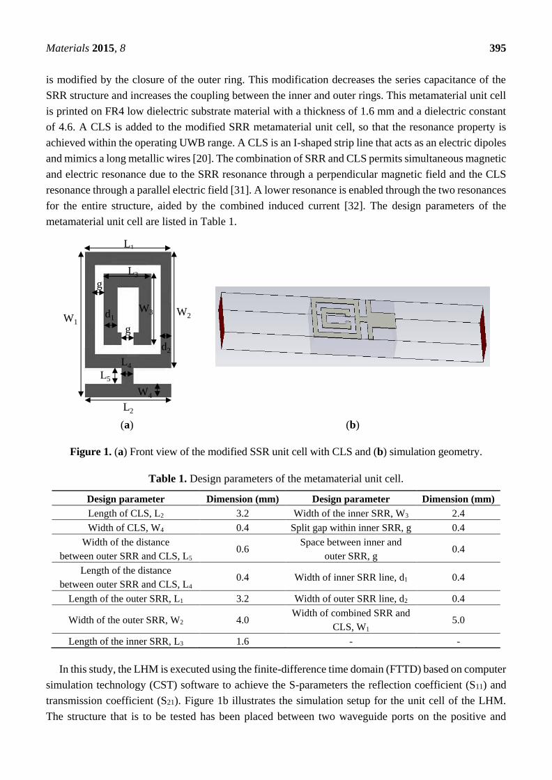
structure. Figure 1a shows the front view of the modified SRR with a CLS structure. The proposed design
Materials 2015, 8 395
is modified by the closure of the outer ring. This modification decreases the series capacitance of the
SRR structure and increases the coupling between the inner and outer rings. This metamaterial unit cell
is printed on FR4 low dielectric substrate material with a thickness of 1.6 mm and a dielectric constant
of 4.6. A CLS is added to the modified SRR metamaterial unit cell, so that the resonance property is
achieved within the operating UWB range. A CLS is an I-shaped strip line that acts as an electric dipoles
and mimics a long metallic wires [20]. The combination of SRR and CLS permits simultaneous magnetic
and electric resonance due to the SRR resonance through a perpendicular magnetic field and the CLS
resonance through a parallel electric field [31]. A lower resonance is enabled through the two resonances
for the entire structure, aided by the combined induced current [32]. The design parameters of the
metamaterial unit cell are listed in Table 1.
(a) (b)
Figure 1. (a) Front view of the modified SSR unit cell with CLS and (b) simulation geometry.
Table 1. Design parameters of the metamaterial unit cell.
Design parameter Dimension (mm) Design parameter Dimension (mm)
Length of CLS, L2 3.2 Width of the inner SRR, W3 2.4
Width of CLS, W4 0.4 Split gap within inner SRR, g 0.4
Width of the distance
between outer SRR and CLS, L5 0.6
Space between inner and
outer SRR, g 0.4
Length of the distance
between outer SRR and CLS, L4 0.4 Width of inner SRR line, d1 0.4
Length of the outer SRR, L1 3.2 Width of outer SRR line, d2 0.4
Width of the outer SRR, W2 4.0 Width of combined SRR and
CLS, W1 5.0
Length of the inner SRR, L3 1.6 - -
In this study, the LHM is executed using the finite-difference time domain (FTTD) based on computer
simulation technology (CST) software to achieve the S-parameters the reflection coefficient (S11) and
transmission coefficient (S21). Figure 1b illustrates the simulation setup for the unit cell of the LHM.
The structure that is to be tested has been placed between two waveguide ports on the positive and
L1
W1
W2
L3
g
W3d1
g
d2
L4
L5
W4
L2

Materials 2015, 8 396
negative x-axis and is excited by an electromagnetic wave in the direction of the x-axis. A perfect electric
conductor (PEC) boundary condition has been defined along the walls perpendicular to the y axes, and
the walls perpendicular to z-axes are defined to be perfect magnetic conductor boundaries, the simulation
arrangement is displayed in Figure 1b. The incident wave propagates in the x-axis direction, while the
E-field of the incident wave is polarized along the y- axis, and the H-field of the incident wave is
polarized along the z-axis. For the simulation, a frequency domain solver was used. The normalized
impedance was set to 50 Ω. The simulation was performed over the frequency range of 2–16 GHz. The
S parameters that were obtained from the simulation were exported to Math CAD software. Figure 2
shows that a transmission peak occurs at a frequency of 9.4 GHz, which denotes a left-handed band. The
principal augmentation is the enhanced production of the proposed metamaterial magnetic response from
the larger overall current, self-resonance and overlapping responses in comparison with conventional
SRRs designs. To verify the electromagnetic characteristic of the proposed left-handed metamaterials, the
retrieval algorithm provided in [33,34] is applied to achieve the constitutive effective parameters depending
on the transmission and reflection coefficient properties. These equations are applied individually.
2
21
2
11
2
21
2
11
)1(
1
SS
SSz
(1)
)1( 2)( 0 AjAedjnk
(2)
)2(
)1(
21
2
21
2
11
S
SSA
(3)
n/z (4)
n z (5)
where, z, the impedance; ε, the relative effective permittivity; μ, the permeability; n, the refractive index;
k0, the wavenumber of the incident wave in the free space; d, the slab thickness of the metamaterial.
Figure 2. Simulation results of S-parameters for the unit cell plotted in Figure 1.
To retrieve the effective parameters, Equations (1)–(5) provided above are used. Figure 3 shows the
retrieved effective parameters, such as the permeability, permittivity and refractive index of the proposed

Materials 2015, 8 397
LHM unit cell. Table 2 summarizes the details of the negative refractive index frequency band. It can be
seen from Table 2 that the LHM unit cell has a different resonance bandwidth in the negative refractive index
frequency regions. This behavior indicates improved effective of LHM structures parameters compared
to the LHMs described in [9,10,12,15,16,20] enabling negative values over a broad band frequency.
(a) (b)
(c)
Figure 3. The observed effective parameters such as (a) permeability (b) permittivity
(c) refractive index of the proposed unit cell.
Table 2. Negative index frequency region of the retrieved effective parameters.
Parameter Negative index frequency region (GHz)
Permeability, µ 5.28–6.61, 10.31–13.92
Permittivity, ɛ 5.3–6, 7.27–7.37, 10.31–13.26
Refractive index, n 4.52–5.18, 6.61–10.22, 11.26–12.78
3. The MTM Antenna
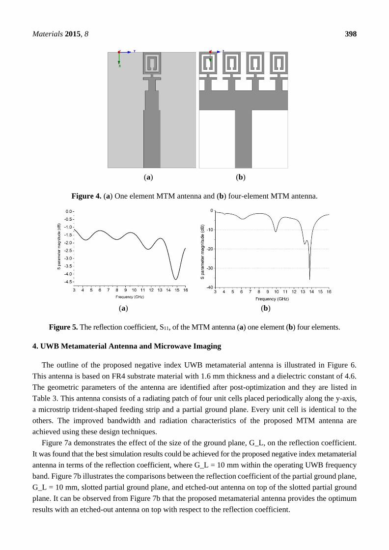
The structural design of the proposed metamaterial UWB antenna starts with the use of one unit cell
as the radiating element. Figure 4 illustrates the MTM antenna with one element and four elements. The
dimensions of the MTM antenna are 16 mm × 21 mm. An impedance of 50 Ω is provided by the port.
The MTM antenna structure is simulated using the EM solver Computer Simulation Technology (CST).
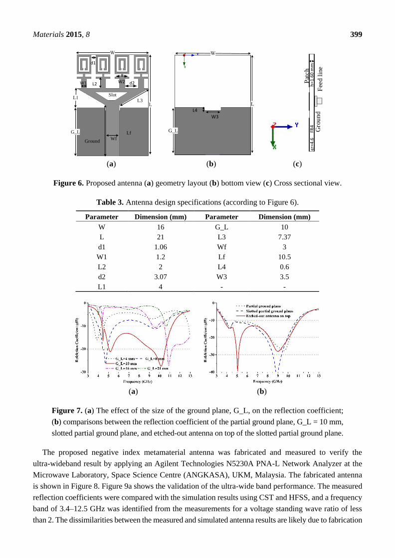
The reflection coefficient of the MTM is plotted in Figure 5 with one element and four elements. It can
be observed from Figure 5 that the antenna is better matched at the higher resonance frequencies in the
cases of both one element and four elements. The objective is to obtain an UWB frequency range for a
MTM antenna with negative index metamaterial characteristics to be used in microwave imaging.
Materials 2015, 8 398
(a) (b)
Figure 4. (a) One element MTM antenna and (b) four-element MTM antenna.
(a) (b)
Figure 5. The reflection coefficient, S11, of the MTM antenna (a) one element (b) four elements.
4. UWB Metamaterial Antenna and Microwave Imaging
The outline of the proposed negative index UWB metamaterial antenna is illustrated in Figure 6.
This antenna is based on FR4 substrate material with 1.6 mm thickness and a dielectric constant of 4.6.
The geometric parameters of the antenna are identified after post-optimization and they are listed in
Table 3. This antenna consists of a radiating patch of four unit cells placed periodically along the y-axis,
a microstrip trident-shaped feeding strip and a partial ground plane. Every unit cell is identical to the
others. The improved bandwidth and radiation characteristics of the proposed MTM antenna are
achieved using these design techniques.
Figure 7a demonstrates the effect of the size of the ground plane, G_L, on the reflection coefficient.
It was found that the best simulation results could be achieved for the proposed negative index metamaterial
antenna in terms of the reflection coefficient, where G_L = 10 mm within the operating UWB frequency
band. Figure 7b illustrates the comparisons between the reflection coefficient of the partial ground plane,
G_L = 10 mm, slotted partial ground plane, and etched-out antenna on top of the slotted partial ground
plane. It can be observed from Figure 7b that the proposed metamaterial antenna provides the optimum
results with an etched-out antenna on top with respect to the reflection coefficient.
Materials 2015, 8 399
(a) (b) (c)
Figure 6. Proposed antenna (a) geometry layout (b) bottom view (c) Cross sectional view.
Table 3. Antenna design specifications (according to Figure 6).
Parameter Dimension (mm) Parameter Dimension (mm)
W 16 G_L 10
L 21 L3 7.37
d1 1.06 Wf 3
W1 1.2 Lf 10.5
L2 2 L4 0.6
d2 3.07 W3 3.5
L1 4 - -
(a) (b)
Figure 7. (a) The effect of the size of the ground plane, G_L, on the reflection coefficient;
(b) comparisons between the reflection coefficient of the partial ground plane, G_L = 10 mm,
slotted partial ground plane, and etched-out antenna on top of the slotted partial ground plane.
The proposed negative index metamaterial antenna was fabricated and measured to verify the
ultra-wideband result by applying an Agilent Technologies N5230A PNA-L Network Analyzer at the
Microwave Laboratory, Space Science Centre (ANGKASA), UKM, Malaysia. The fabricated antenna
is shown in Figure 8. Figure 9a shows the validation of the ultra-wide band performance. The measured
reflection coefficients were compared with the simulation results using CST and HFSS, and a frequency
band of 3.4–12.5 GHz was identified from the measurements for a voltage standing wave ratio of less
than 2. The dissimilarities between the measured and simulated antenna results are likely due to fabrication
G_L
GroundWf
d1
L
W1 W2 d2
Lf
Slot
L3
L2
G_L
L
W3
L4
ϵr=
4.6
FR4
h
=1
.60
mm
Pat
ch
Gro
un
dF
eed l
ine

Materials 2015, 8 400
and soldering faults. Figure 9b shows the measured gain and radiation efficiency of the proposed UWB
MTM antenna. It can be found from Figure 9b that the radiation efficiency is 88%, the average gain is
3.95 dBi and the maximum gain is 5.16 dBi.
Figure 8. Fabricated prototype of the proposed negative index UWB MTM antenna.
(a) (b)
Figure 9. (a) Comparison between the simulated and measured reflection coefficient and
(b) measured gain and radiation efficiency of the proposed UWB MTM antenna.
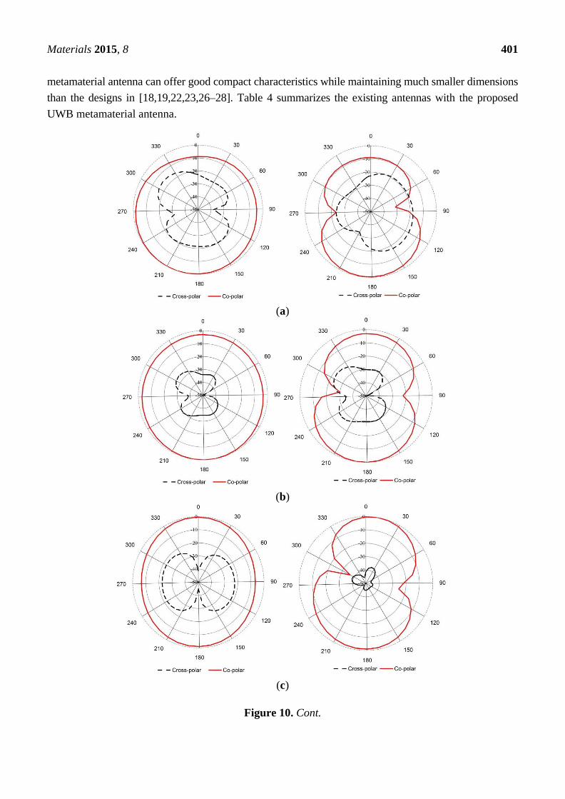
The measured radiation pattern of the proposed negative index UWB metamaterial antenna is plotted
in Figure 10 at 4 GHz, 6 GHz, 9 GHz and 12 GHz in the xz plane (E-plane) and yz plane (H-plane). It can
be observed from Figure 10 that a nearly omni-directional radiation pattern exists over the 3.4–12.5 GHz
frequency range. The cross polarization level is lower than the co-polarization level, which is the desired
result. The surface current distributions of the proposed UWB negative index metamaterial are demonstrated
in Figure 11 at 4 GHz, 6 GHz, 9 GHz and 12 GHz. It can be observed from Figure 11 that the currents
are flowing dominantly along the x-axis. This flow indicates an omni-directional antenna attitude. It can
also be observed that the flow of currents is strong at the metamaterial unit cell because of its negative
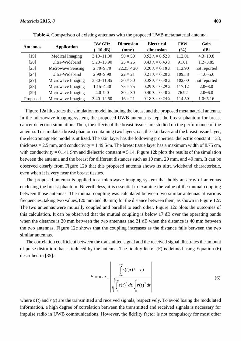
index frequency band. To ensure an equitable comparison between the proposed antenna and the antenna
design studied [18,19,22,23,26–28] (all reference antennas cover the UWB spectrum); their performances
parameters, such as the 10-dB bandwidth, dimensions, electrical dimensions, fractal bandwidth and gain
are discussed. Although the proposed antenna may not have a better gain than of the references [18,27,28],
a good FBW (114.50%) with a smaller electrical dimension is exhibited. Therefore, the proposed UWB
Materials 2015, 8 401
metamaterial antenna can offer good compact characteristics while maintaining much smaller dimensions
than the designs in [18,19,22,23,26–28]. Table 4 summarizes the existing antennas with the proposed
UWB metamaterial antenna.
(a)
(b)
(c)
Figure 10. Cont.

Materials 2015, 8 402
(d)
Figure 10. Measured radiation pattern of the proposed antenna at (a) 4 GHz; (b) 6 GHz;
(c) 9 GHz and (d) 12 GHz.
(a) (b)
(c) (d)
Figure 11. The surface current distribution at (a) 4 GHz; (b) 6 GHz; (c) 9 GHz and (d) 12 GHz.
Materials 2015, 8 403
Table 4. Comparison of existing antennas with the proposed UWB metamaterial antenna.
Antennas Application BW GHz
(−10 dB)
Dimension
(mm2)
Electrical
dimension
FBW
(%)
Gain
dBi
[19] Medical Imaging 3.10–11.00 50 × 50 0.52 λ × 0.52 λ 112.01 4.3~10.8
[20] Ultra-Wideband 5.20–13.90 25 × 25 0.43 λ × 0.43 λ 91.01 1.2~3.85
[23] Microwave Sensing 2.70–9.70 22.25 × 20 0.20 λ × 0.18 λ 112.90 not reported
[24] Ultra-Wideband 2.90–9.90 22 × 21 0.21 λ × 0.20 λ 109.38 −1.0~5.0
[27] Microwave Imaging 3.80–11.85 30 × 30 0.38 λ × 0.38 λ 102.00 not reported
[28] Microwave Imaging 1.15–4.40 75 × 75 0.29 λ × 0.29 λ 117.12 2.0~8.0
[29] Microwave Imaging 4.0–9.0 30 × 30 0.40 λ × 0.40 λ 76.92 2.0~6.0
Proposed Microwave Imaging 3.40–12.50 16 × 21 0.18 λ × 0.24 λ 114.50 1.0~5.16
Figure 12a illustrates the simulation model including the breast and the proposed metamaterial antenna.
In the microwave imaging system, the proposed UWB antenna is kept the breast phantom for breast
cancer detection simulation. Then, the effects of the breast tissues are studied on the performance of the
antenna. To simulate a breast phantom containing two layers, i.e., the skin layer and the breast tissue layer,
the electromagnetic model is utilized. The skin layer has the following properties: dielectric constant = 38,
thickness = 2.5 mm, and conductivity = 1.49 S/m. The breast tissue layer has a maximum width of 8.75 cm,
with conductivity = 0.141 S/m and dielectric constant = 5.14. Figure 12b plots the results of the simulation
between the antenna and the breast for different distances such as 10 mm, 20 mm, and 40 mm. It can be
observed clearly from Figure 12b that this proposed antenna shows its ultra wideband characteristic,
even when it is very near the breast tissues.
The proposed antenna is applied to a microwave imaging system that holds an array of antennas
enclosing the breast phantom. Nevertheless, it is essential to examine the value of the mutual coupling
between those antennas. The mutual coupling was calculated between two similar antennas at various
frequencies, taking two values, (20 mm and 40 mm) for the distance between them, as shown in Figure 12c.
The two antennas were mutually coupled and parallel to each other. Figure 12c plots the outcomes of
this calculation. It can be observed that the mutual coupling is below 17 dB over the operating bands
when the distance is 20 mm between the two antennas and 21 dB when the distance is 40 mm between
the two antennas. Figure 12c shows that the coupling increases as the distance falls between the two
similar antennas.
The correlation coefficient between the transmitted signal and the received signal illustrates the amount
of pulse distortion that is induced by the antenna. The fidelity factor (F) is defined using Equation (6)
described in [35]:
maxF
dttrdtts
trts
22 )(.)(
)()(
(6)
where s (t) and r (t) are the transmitted and received signals, respectively. To avoid losing the modulated
information, a high degree of correlation between the transmitted and received signals is necessary for
impulse radio in UWB communications. However, the fidelity factor is not compulsory for most other

Materials 2015, 8 404
telecommunication systems. The time domain characteristics of this proposed UWB antenna were also
determined. Two configurations as face-to-face and side-by-side orientations were chosen.
(a)
(b) (c)
Figure 12. (a) Simulation model depicting the breast and the proposed metamaterial antenna;
(b) reflection coefficient variation with frequency from the breast at various distances;
(c) mutual coupling variation between two similar antennas with respect to frequency at
two different lengths.
A narrow pulse was sent from the broadcasting antenna and the received pulse was calculated at
the receiving antenna at a distance d1 of 300 mm from the sender. Figure 13 illustrates the shapes of the
received and transmitted pulses. The received pulse and the transmitted pulse were normalized by their
maximum levels. This graph demonstrates the negligible pulse distortion with respect to the peak value
of 1. The fidelity factor is 0.87 for the face-to-face and 0.79 for the side-by-side configurations. As a result,
the proposed antenna supports a narrow distortion less pulse for operation.

Materials 2015, 8 405
(a) (b)
Figure 13. Transmitted and received pulses (a) side by side and (b) face to face.
5. Conclusions
A miniaturized UWB metamaterial antenna with a negative index characteristic for use in
microwave imaging applications has been proposed. The complete design technique is described for the
negative index unit cells and the antenna. The fabricated negative index metamaterial antenna provides
114.5% bandwidth covering the frequency band of 3.4–12.5 GHz for a voltage standing wave ratio of
less than 2 with a maximum gain of 5.16 dBi at 10.15 GHz. The overall antenna dimensions are
16 mm × 21 mm × 1.6 mm. From the simulated results, it can be shown that the proposed metamaterial
antenna exhibits UWB characteristic when it is very close to the breast phantom with only a small
distortion of the time domain characteristics. Mutual coupling was simulated between two closely
positioned similar UWB antennas, and low mutual coupling was observed. The directive gain,
low mutual coupling, considerable VSWR, negative refractive index characteristic, and stable surface
current distribution ensure that the proposed antenna is a promising candidate for UWB microwave
breast cancer imaging applications.
Acknowledgements
This work was supported by the Ministry of Education (MOE), Malaysia under grant
No. LEP 2.0/14/UKM/TH/01/1.
Author Contributions
Md. Moinul Islam and Md. Samsuzzaman made substantial contributions to conception, design and
analysis. Norbahiah Misran, and Mohd Fais Mansor provided necessary instructions for experimental
purpose. Mohammad Tariqul Islam and Mohammad Rashed Iqbal Faruque participated in revising the
article critically for important intellectual contents.
Conflicts of Interest
The authors declare no conflict of interest.
Time (ns)
Materials 2015, 8 406
References
1. Fear, E.C.; Li, X.; Hagness, S.C.; Stuchly, M.A. Confocal microwave imaging for breast cancer
detection: Localization of tumors in three dimensions. IEEE Trans. Biomed. Eng. 2002, 49, 812–822.
2. Scapaticci, R.; Catapano, I.; Crocco, L. Wavelet-based adaptive multiresolution inversion for
quantitative microwave imaging of breast tissues. IEEE Trans. Antennas Propag. 2012, 60, 3717–3726.
3. Abbosh, A.; Crozier, S. Strain imaging of the breast by compression microwave imaging.
IEEE Antennas Wirel. Propag. Lett. 2010, 9, 1229–1232.
4. Veselago, V.G. The electrodynamics of substances with simultaneously negative values of ϵ and μ.
Phys. Uspekhi 1968, 10, 509–514.
5. Pendry, J.B.; Holden, A.J.; Robbins, D.; Stewart, W. Magnetism from conductors and enhanced
nonlinear phenomena. IEEE Trans. Microw. Theory Tech. 1999, 47, 2075–2084.
6. Smith, D.R.; Padilla, W.J.; Vier, D.; Nemat-Nasser, S.C.; Schultz, S. Composite medium with
simultaneously negative permeability and permittivity. Phys. Rev. Lett. 2000, 84, 4184–4187.
7. Shelby, R.A.; Smith, D.R.; Schultz, S. Experimental verification of a negative index of refraction.
Science 2001, 292, 77–79.
8. Isik, O.; Esselle, K.P. Analysis of spiral metamaterials by use of group theory. Metamaterials 2009,
3, 33–43.
9. Alici, K.B.; Ozbay, E. A planar metamaterial: Polarization independent fishnet structure.
Photonics Nanostruct. Fundam. Appl. 2008, 6, 102–107.
10. Ekmekci, E.; Turhan-Sayan, G. Comparative investigation of resonance characteristics and
electrical size of the double-sided SRR, BC-SRR and conventional SRR type metamaterials for
varying substrate parameters. Prog. Electromagn. Res. B 2009, 12, 35–62.
11. Zhou, X.; Liu, Y.; Zhao, X. Low losses left-handed materials with optimized electric and magnetic
resonance. Appl. Phys. A 2010, 98, 643–649.
12. Eleftheriades, G.V.; Iyer, A.K.; Kremer, P.C. Planar negative refractive index media using periodically
LC loaded transmission lines. IEEE Trans. Microw. Theory Tech. 2002, 50, 2702–2712.
13. Zhou, J.; Koschny, T.; Zhang, L.; Tuttle, G.; Soukoulis, C.M. Experimental demonstration of negative
index of refraction. Appl. Phys. Lett. 2006, 88, 221103:1–221103:7.
14. Wang, J.; Qu, S.; Xu, Z.; Zhang, J.; Ma, H.; Yang, Y.; Gu, C. Broadband planar left-handed
metamaterials using split-ring resonator pairs. Photonics Nanostruct. Fundam. Appl. 2009, 7, 108–113.
15. Huang, C.; Zhao, Z.; Feng, Q.; Cui, J.; Luo, X. Metamaterial composed of wire pairs exhibiting
dual band negative refraction. Appl. Phys. B 2010, 98, 365–370.
16. Wang, J.; Qu, S.; Zhang, J.; Ma, H.; Yang, Y.; Gu, C.; Wu, X.; Xu, Z. A tunable left-handed
metamaterial based on modified broadside-coupled split-ring resonators. Prog. Electromagn. Res. Lett.
2009, 6, 35–45.
17. Odabasi, H.; Teixeira, F.; Guney, D. Electrically small, complementary electric-field-coupled resonator
antennas. J. Appl. Phys. 2013, 113, 084903:1–084903:4.
18. Majid, H.A.; Rahim, M.K.A.; Masri, T. Microstrip antenna’s gain enhancement using left-handed
metamaterial structure. Prog. Electromagn. Res. M 2009, 8, 235–247.
19. Abbosh, A.M. Directive antenna for ultrawideband medical imaging systems. Int. J. Antennas Propag.
2008, 2008, 854012:1–854012:6.

Materials 2015, 8 407
20. Alhawari, A.R.H.; Ismail, A.; Mahdi, M.A.; Abdullah, R.S.A.R. Miniaturized ultra-wideband antenna
using microstrip negative index metamaterial. Electromagnetics 2011, 31, 404–418.
21. Amineh, R.K.; Ravan, M.; Trehan, A.; Nikolova, N.K. Near-field microwave imaging based on
aperture raster scanning with TEM horn antennas. IEEE Trans. Antennas Propag. 2011, 59, 928–940.
22. Zhu, J.; Eleftheriades, G.V. A compact transmission-line metamaterial antenna with extended
bandwidth. IEEE Antennas Wirel. Propag. Lett. 2009, 8, 295–298.
23. Kanj, H.; Popovic, M. Miniaturized microstrip-fed “Dark Eyes” antenna for near-field microwave
sensing. IEEE Antennas Wirel. Propag. Lett. 2005, 4, 397–401.
24. Nordin, M.A.W.; Islam, M.T.; Misran, N. Design of a compact ultrawideband metamaterial
antenna based on the modified split-ring resonator and capacitively loaded strips unit cell.
Prog. Electromagn. Res. 2013, 136, 157–173.
25. Kanj, H.; Popovic, M. A novel ultra-compact broadband antenna for microwave breast tumor
detection. Prog. Electromag. Res. 2008, 86, 169–198.
26. Palandoken, M.; Grede, A.; Henke, H. Broadband microstrip antenna with left-handed metamaterials.
IEEE Trans. Antennas Propag. 2009, 57, 331–338.
27. Hossain, I.; Noghanian, S.; Pistorius, S. A diamond shaped small planar ultra wide band (UWB)
antenna for microwave imaging purpose. In Proceedings of the IEEE Antennas and Propagation
Society International Symposium, Honolulu, HI, USA, 10–15 June 2007; pp. 5713–5716.
28. Wu, B.; Ji, Y.; Fang, G. Design and measurement of compact tapered slot antenna for UWB
microwave imaging radar. In Proceedings of the Conference on 9th International Electronic
Measurement & Instruments 2009 (ICEMI 09), Beijing, China, 6–19 August 2009; IEEE: New York,
NY, USA, pp. 2:226–2:229.
29. Adnan, S.; Abd-Alhameed, R.; Hraga, H.; Elfergani, I.; Noras, J.; Halliwell, R. Microstrip antenna
for microwave imaging application. In Proceedings of the PIERS, Marrakesh, Morocco, 20–23 March
2011; pp. 431–434.
30. Tang, M.-C.; Ziolkowski, R.W.; Xiao, S.; Li, M. A high-directivity, wideband, efficient, electrically
small antenna system. IEEE Trans. Antennas Propag. 2014, 62, 6541–6547.
31. Tang, W.X.; Cheng, Q.; Cui, T.J. Electric and magnetic responses from metamaterial unit cells at
Terahertz. Terahertz Sci. Technol. 2009, 2, 244–247.
32. Li, L.-W.; Yao, H.-Y.; Wu, Q.; Chen, Z.-N. Broad-bandwidth and low-loss metamaterials:
Theory, design and realization. J. Zhejiang Univ. Sci. A 2006, 7, 5–23.
33. Chen, X.; Grzegorczyk, T.M.; Wu, B.-I.; Pacheco, J., Jr.; Kong, J.A. Robust method to retrieve the
constitutive effective parameters of metamaterials. Phys. Rev. E 2004, 70, 016608:1–016608:7.
34. Smith, D.; Vier, D.; Koschny, T.; Soukoulis, C. Electromagnetic parameter retrieval from
inhomogeneous metamaterials. Phys. Rev. E 2005, 71, 036617:1–036617:11.
35. Ojaroudi, N.; Ojaroudi, M.; Ebazadeh, Y. UWB/omni-directional microstrip monopole antenna for
microwave imaging applications. Prog. Electromagn. Res. C 2014, 47, 139–146.
© 2015 by the authors; licensee MDPI, Basel, Switzerland. This article is an open access article
distributed under the terms and conditions of the Creative Commons Attribution license
(http://creativecommons.org/licenses/by/4.0/).