Mark VIeS Safety Controller Block Library - Login | GE Digital ...
92
GEI-100691K Mark* VIeS Safety Controller Block Library These instructions do not purport to cover all details or variations in equipment, nor to provide for every possible contingency to be met during installation, operation, and maintenance. The information is supplied for informational purposes only, and GE makes no warranty as to the accuracy of the information included herein. Changes, modifications, and/or improvements to equipment and specifications are made periodically and these changes may or may not be reflected herein. It is understood that GE may make changes, modifications, or improvements to the equipment referenced herein or to the document itself at any time. This document is intended for trained personnel familiar with the GE products referenced herein. Public – This document is approved for public disclosure. GE may have patents or pending patent applications covering subject matter in this document. The furnishing of this document does not provide any license whatsoever to any of these patents. GE provides the following document and the information included therein as is and without warranty of any kind, expressed or implied, including but not limited to any implied statutory warranty of merchantability or fitness for particular purpose. For further assistance or technical information, contact the nearest GE Sales or Service Office, or an authorized GE Sales Representative. Revised: July 2018 Issued: Aug 2006 © 2006 – 2018 General Electric Company. ___________________________________ * Indicates a trademark of General Electric Company and/or its subsidiaries. All other trademarks are the property of their respective owners. We would appreciate your feedback about our documentation. Please send comments or suggestions to [email protected] For public disclosure
-
Upload
khangminh22 -
Category
Documents
-
view
3 -
download
0
Transcript of Mark VIeS Safety Controller Block Library - Login | GE Digital ...

GEI-100691K
Mark* VIeS Safety ControllerBlock LibraryThese instructions do not purport to cover all details or variations in equipment, nor to provide for every possiblecontingency to be met during installation, operation, and maintenance. The information is supplied for informationalpurposes only, and GE makes no warranty as to the accuracy of the information included herein. Changes, modifications,and/or improvements to equipment and specifications are made periodically and these changes may or may not be reflectedherein. It is understood that GE may make changes, modifications, or improvements to the equipment referenced herein or tothe document itself at any time. This document is intended for trained personnel familiar with the GE products referencedherein.
Public – This document is approved for public disclosure.
GE may have patents or pending patent applications covering subject matter in this document. The furnishing of thisdocument does not provide any license whatsoever to any of these patents.
GE provides the following document and the information included therein as is and without warranty of any kind,expressed or implied, including but not limited to any implied statutory warranty of merchantability or fitness forparticular purpose.
For further assistance or technical information, contact the nearest GE Sales or Service Office, or an authorized GE SalesRepresentative.
Revised: July 2018Issued: Aug 2006
© 2006 – 2018 General Electric Company.___________________________________* Indicates a trademark of General Electric Company and/or its subsidiaries.All other trademarks are the property of their respective owners.
We would appreciate your feedback about our documentation.Please send comments or suggestions to [email protected]
For public disclosure

Document UpdatesRevision Location Description
K
IntroductionAdded a Note to notify users that the Mark VIeS control does not supportstatus options
Clamp (CLAMP)
New blocks
Dual Select Version 2 (DUALSEL_S2)
Function Generator (FUNGEN)
Interpolator Version 2 (INTERP_V2)
Median Select Version 2 (MEDSEL_S2)
Vote (VOTE)
JController Monitor (CTRLR_MON) Updated Mark VIeS Platforms table to include UCSC controller
Temperature Status (TEMP_STATUS)Updated TEMP_STATUS Inputs and TEMP_STATUS Outputs tables toinclude UCSC controller
H
Cause and Effect Matrix New special task
Counter This block is not in the legacy categoryBlack Channel Receiver (BLACK_RX)Black Channel Transmitter (BLACK_TX)Black Channel Example
New SIGNATURE2
G
Temperature Status (TEMP_STATUS) Updated to better explain functionality based on controller platformLegacy Category Blocks New sectionCapture Data (CAPTURE)
New blocks
Logic Builder State Change (LOGIC_BUILDER_SC)
On Off Delay (ON_OFF_DELAY)
Timer Version 2 (TIMER_V2)
2 GEI-100691K Mark VIeS Safety Controller Block LibraryFor public disclosure
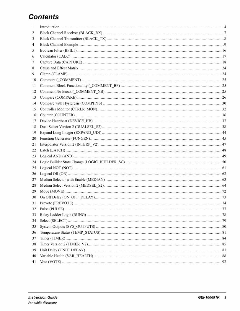
Contents1 Introduction............................................................................................................................................42 Black Channel Receiver (BLACK_RX) .......................................................................................................73 Black Channel Transmitter (BLACK_TX)....................................................................................................84 Black Channel Example ............................................................................................................................95 Boolean Filter (BFILT) ........................................................................................................................... 166 Calculator (CALC) ................................................................................................................................ 177 Capture Data (CAPTURE) ...................................................................................................................... 188 Cause and Effect Matrix.......................................................................................................................... 249 Clamp (CLAMP)................................................................................................................................... 2410 Comment (_COMMENT) ....................................................................................................................... 2511 Comment Block Functionality (_COMMENT_BF) ...................................................................................... 2512 Comment No Break (_COMMENT_NB) ................................................................................................... 2513 Compare (COMPARE) ........................................................................................................................... 2614 Compare with Hysteresis (COMPHYS) ..................................................................................................... 3015 Controller Monitor (CTRLR_MON).......................................................................................................... 3216 Counter (COUNTER)............................................................................................................................. 3617 Device Heartbeat (DEVICE_HB) ............................................................................................................. 3718 Dual Select Version 2 (DUALSEL_S2) ...................................................................................................... 3819 Expand Long Integer (EXPAND_UDI) ...................................................................................................... 4420 Function Generator (FUNGEN)................................................................................................................ 4521 Interpolator Version 2 (INTERP_V2)......................................................................................................... 4722 Latch (LATCH) ..................................................................................................................................... 4823 Logical AND (AND).............................................................................................................................. 4924 Logic Builder State Change (LOGIC_BUILDER_SC) .................................................................................. 5025 Logical NOT (NOT)............................................................................................................................... 6126 Logical OR (OR) ................................................................................................................................... 6227 Median Selector with Enable (MEDIAN) ................................................................................................... 6328 Median Select Version 2 (MEDSEL_S2) .................................................................................................... 6429 Move (MOVE)...................................................................................................................................... 7230 On Off Delay (ON_OFF_DELAY)............................................................................................................ 7331 Prevote (PREVOTE) .............................................................................................................................. 7432 Pulse (PULSE)...................................................................................................................................... 7733 Relay Ladder Logic (RUNG) ................................................................................................................... 7834 Select (SELECT) ................................................................................................................................... 7935 System Outputs (SYS_OUTPUTS) ........................................................................................................... 8036 Temperature Status (TEMP_STATUS) ....................................................................................................... 8137 Timer (TIMER)..................................................................................................................................... 8438 Timer Version 2 (TIMER_V2).................................................................................................................. 8539 Unit Delay (UNIT_DELAY).................................................................................................................... 8740 Variable Health (VAR_HEALTH) ............................................................................................................. 8841 Vote (VOTE) ........................................................................................................................................ 92
Instruction Guide GEI-100691K 3For public disclosure
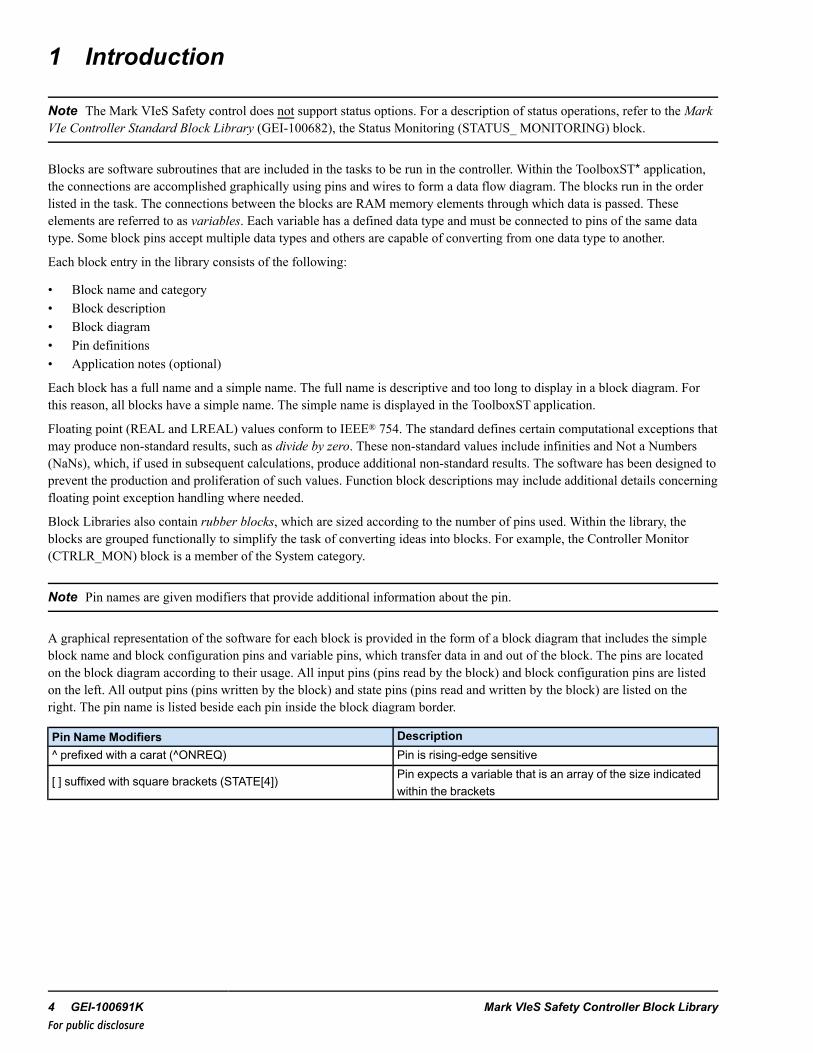
1 Introduction
Note The Mark VIeS Safety control does not support status options. For a description of status operations, refer to theMarkVIe Controller Standard Block Library (GEI-100682), the Status Monitoring (STATUS_ MONITORING) block.
Blocks are software subroutines that are included in the tasks to be run in the controller. Within the ToolboxST* application,the connections are accomplished graphically using pins and wires to form a data flow diagram. The blocks run in the orderlisted in the task. The connections between the blocks are RAM memory elements through which data is passed. Theseelements are referred to as variables. Each variable has a defined data type and must be connected to pins of the same datatype. Some block pins accept multiple data types and others are capable of converting from one data type to another.
Each block entry in the library consists of the following:
• Block name and category• Block description• Block diagram• Pin definitions• Application notes (optional)
Each block has a full name and a simple name. The full name is descriptive and too long to display in a block diagram. Forthis reason, all blocks have a simple name. The simple name is displayed in the ToolboxST application.
Floating point (REAL and LREAL) values conform to IEEE® 754. The standard defines certain computational exceptions thatmay produce non-standard results, such as divide by zero. These non-standard values include infinities and Not a Numbers(NaNs), which, if used in subsequent calculations, produce additional non-standard results. The software has been designed toprevent the production and proliferation of such values. Function block descriptions may include additional details concerningfloating point exception handling where needed.
Block Libraries also contain rubber blocks, which are sized according to the number of pins used. Within the library, theblocks are grouped functionally to simplify the task of converting ideas into blocks. For example, the Controller Monitor(CTRLR_MON) block is a member of the System category.
Note Pin names are given modifiers that provide additional information about the pin.
A graphical representation of the software for each block is provided in the form of a block diagram that includes the simpleblock name and block configuration pins and variable pins, which transfer data in and out of the block. The pins are locatedon the block diagram according to their usage. All input pins (pins read by the block) and block configuration pins are listedon the left. All output pins (pins written by the block) and state pins (pins read and written by the block) are listed on theright. The pin name is listed beside each pin inside the block diagram border.
Pin Name Modifiers Description^ prefixed with a carat (^ONREQ) Pin is rising-edge sensitive
[ ] suffixed with square brackets (STATE[4]) Pin expects a variable that is an array of the size indicatedwithin the brackets
4 GEI-100691K Mark VIeS Safety Controller Block LibraryFor public disclosure
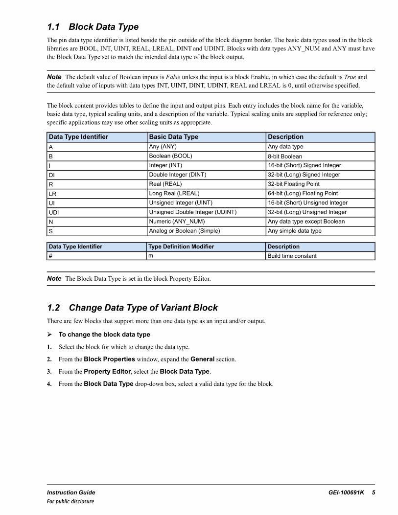
1.1 Block Data TypeThe pin data type identifier is listed beside the pin outside of the block diagram border. The basic data types used in the blocklibraries are BOOL, INT, UINT, REAL, LREAL, DINT and UDINT. Blocks with data types ANY_NUM and ANY must havethe Block Data Type set to match the intended data type of the block output.
Note The default value of Boolean inputs is False unless the input is a block Enable, in which case the default is True andthe default value of inputs with data types INT, UINT, DINT, UDINT, REAL and LREAL is 0, until otherwise specified.
The block content provides tables to define the input and output pins. Each entry includes the block name for the variable,basic data type, typical scaling units, and a description of the variable. Typical scaling units are supplied for reference only;specific applications may use other scaling units as appropriate.
Data Type Identifier Basic Data Type DescriptionA Any (ANY) Any data typeB Boolean (BOOL) 8-bit BooleanI Integer (INT) 16-bit (Short) Signed IntegerDI Double Integer (DINT) 32-bit (Long) Signed Integer
R Real (REAL) 32-bit Floating Point
LR Long Real (LREAL) 64-bit (Long) Floating PointUI Unsigned Integer (UINT) 16-bit (Short) Unsigned IntegerUDI Unsigned Double Integer (UDINT) 32-bit (Long) Unsigned IntegerN Numeric (ANY_NUM) Any data type except BooleanS Analog or Boolean (Simple) Any simple data type
Data Type Identifier Type Definition Modifier Description# m Build time constant
Note The Block Data Type is set in the block Property Editor.
1.2 Change Data Type of Variant BlockThere are few blocks that support more than one data type as an input and/or output.
➢➢ To change the block data type
1. Select the block for which to change the data type.
2. From the Block Properties window, expand the General section.
3. From the Property Editor, select the Block Data Type.
4. From the Block Data Type drop-down box, select a valid data type for the block.
Instruction Guide GEI-100691K 5For public disclosure
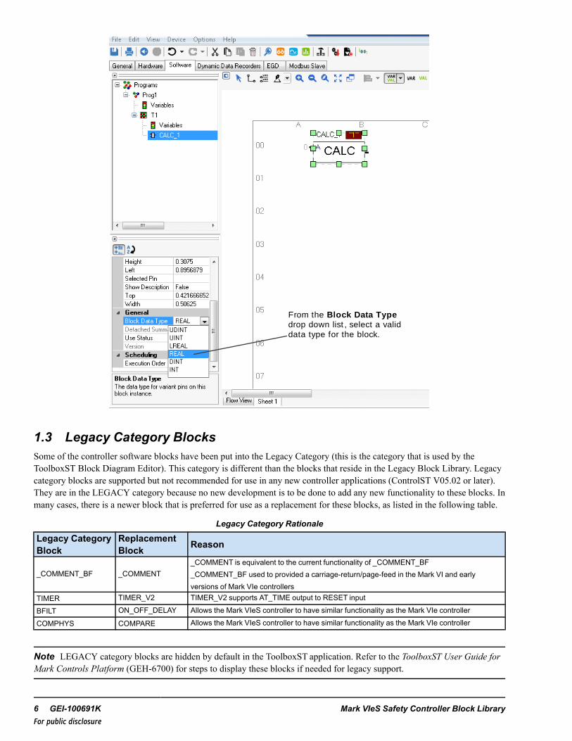
From the Block Data Typedrop down list , select a valid data type for the block.
1.3 Legacy Category BlocksSome of the controller software blocks have been put into the Legacy Category (this is the category that is used by theToolboxST Block Diagram Editor). This category is different than the blocks that reside in the Legacy Block Library. Legacycategory blocks are supported but not recommended for use in any new controller applications (ControlST V05.02 or later).They are in the LEGACY category because no new development is to be done to add any new functionality to these blocks. Inmany cases, there is a newer block that is preferred for use as a replacement for these blocks, as listed in the following table.
Legacy Category Rationale
Legacy CategoryBlock
ReplacementBlock Reason
_COMMENT_BF _COMMENT_COMMENT is equivalent to the current functionality of _COMMENT_BF_COMMENT_BF used to provided a carriage-return/page-feed in the Mark VI and earlyversions of Mark VIe controllers
TIMER TIMER_V2 TIMER_V2 supports AT_TIME output to RESET input
BFILT ON_OFF_DELAY Allows the Mark VIeS controller to have similar functionality as the Mark VIe controller
COMPHYS COMPARE Allows the Mark VIeS controller to have similar functionality as the Mark VIe controller
Note LEGACY category blocks are hidden by default in the ToolboxST application. Refer to the ToolboxST User Guide forMark Controls Platform (GEH-6700) for steps to display these blocks if needed for legacy support.
6 GEI-100691K Mark VIeS Safety Controller Block LibraryFor public disclosure

2 Black Channel Receiver (BLACK_RX)Block Category: Communications
The Black Channel Receiver (BLACK_RX) blockis a rubber block that allows for the connection ofup to 32 input variables of heterogeneous datatypes with rubber pins. By default, the block isdisplayed with only one variable input but may beexpanded as necessary for the application. If morethan 32 variables are required, the user may addadditional BLACK_RX blocks to the application.
The BLACK_RX block validates the integrity of the Mark VIeS Safety controller data signed by a corresponding BlackChannel Transmitter (BLACK_TX) block running in the transmitting device. The user configures the running rate of theBLACK_RX block on the receiving device to greater than or equal to the rate of the incoming Black Channel EGD page fromthe referenced transmitting device. The BLACK_RX block receives the Connection ID (CONN_ID), Sequence number(SEQ), Signature (SIGNATURE and SIGNATURE2), and variable data consumed from the referenced EGD page as inputs.The block also receives an Expected Connection ID (CONN_ID_EXP) input value used to validate the transmitted CONN_IDvalue. The user configures a corresponding CONN_ID input on the BLACK_TX block and the CONN_ID_EXP constantinput on the matching BLACK_RX block.
InputsName Data Type DescriptionCONN_ID_EXP Constant UDINT Expected connection IDCONN_ID UDINT Connection IDSEQ UDINT Sequence number
STALE_CNT Constant UDINT
The Stale Count (STALE_CNT) input is a Constant pin used to configure the number times theblock can run without the SEQ input value changing. If the number of times the block ran withoutthe SEQ value incrementing exceeds the STALE_CNT value, LINK_OK is driven to False andthe STALE_CNT pin defaults to 1. The value zero may be applied to the STALE_CNT pin todisable driving LINK_OK False due to stale sequence number transmission completely. Thisprovides the flexibility to monitor for stale data externally in the application code if necessary.
SIGNATURE UDINT Signature
SIGNATURE2 UDINT Second Signature
VAR01 ANY Input variable 1↓ ANY ↓
VAR32 ANY Input variable 32
OutputName Data Type Description
LINK_OK BOOL
The output pin, LINK_OK, is a single Boolean value that denotes the integrity of the control datareceived from the Black Channel. If any of the inputs from the Black Channel are corrupt, theSignature calculation will not match the SIGNATURE and SIGNATURE2 input values from thetransmitter (BLACK_TX) and LINK_OK will be driven False.If the CONN_ID value from the Black Channel does not match the CONN_ID_EXP value, LINK_OK output will also be driven False.
The BLACK_RX block also checks for out-of-order reception of SEQ values. If the sequence number does not monotonicallyincrease, LINK_OK will be driven False until the sequence number resumes increasing from the point at which theout-of-order reception was encountered. The block takes sequence number roll-over into account during run time.
Instruction Guide GEI-100691K 7For public disclosure

3 Black Channel Transmitter (BLACK_TX)Block Category: Communications
The Black Channel Transmitter (BLACK_TX) block is arubber block that allows for the connection of up to 32input variables of heterogeneous data types. By default,the block is displayed with only one variable input butmay be expanded as necessary for the application. If morethan 32 variables are required, the user may add additionalBLACK_TX blocks to the application.
The block receives a Connection ID (CONN_ID) input used to uniquely identify a Black Channel connection between aspecific BLACK_TX block in the transmitting device and a specific Black Channel Receiver (BLACK_RX) block configuredin the receiving device. The Sequence Number (SEQ) output of the block monotonically increases each time the block runs.The BLACK_TX block creates a Signature that the BLACK_RX block uses for a data integrity check. The Signature output(SIGNATURE and SIGNATURE2) is calculated using the values of the CONN_ID, Sequence number (SEQ), and input dataof the variables connected to the block and transmitted to the receiver (BLACK_RX).
Each of the variables connected to the BLACK_TX block must be placed on a dedicated Black Channel EGD dedicated pagethat is configured for production at a rate tuned for the application. All of these variables should not only exist on the sameEGD page but must also exist on the same EGD exchange to provide coherency on the receiving end of the Black Channel. Ifthe number of the variables required by the application exceeds the length of the EGD exchange, additional BLACK_TXblocks, EGD pages, and exchanges may be used to scale the application.
Inputs
Name Data Type DescriptionCONN_ID UDINT Connection IDVAR01 ANY Input variable 1↓ ANY ↓VAR32 ANY Input variable 32
Outputs
Name Data Type DescriptionSEQ UDINT Sequence number
SIGNATURE UDINT Signature
SIGNATURE2 UDINT Second Signature
8 GEI-100691K Mark VIeS Safety Controller Block LibraryFor public disclosure
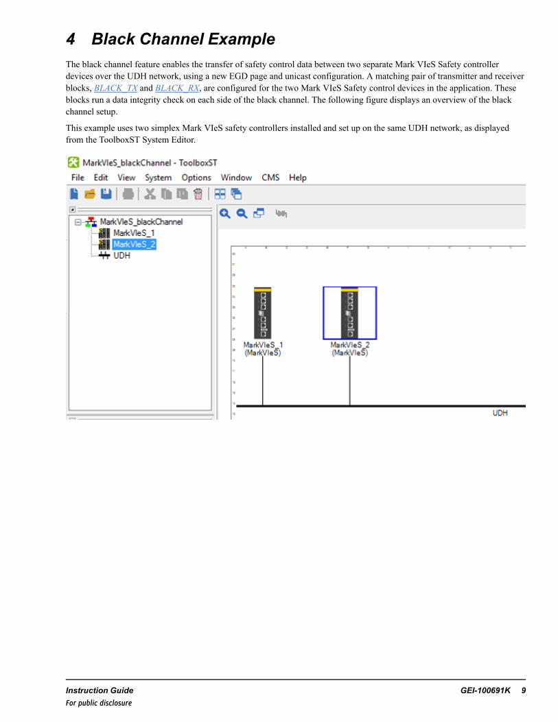
4 Black Channel ExampleThe black channel feature enables the transfer of safety control data between two separate Mark VIeS Safety controllerdevices over the UDH network, using a new EGD page and unicast configuration. A matching pair of transmitter and receiverblocks, BLACK_TX and BLACK_RX, are configured for the two Mark VIeS Safety control devices in the application. Theseblocks run a data integrity check on each side of the black channel. The following figure displays an overview of the blackchannel setup.
This example uses two simplex Mark VIeS safety controllers installed and set up on the same UDH network, as displayedfrom the ToolboxST System Editor.
Instruction Guide GEI-100691K 9For public disclosure
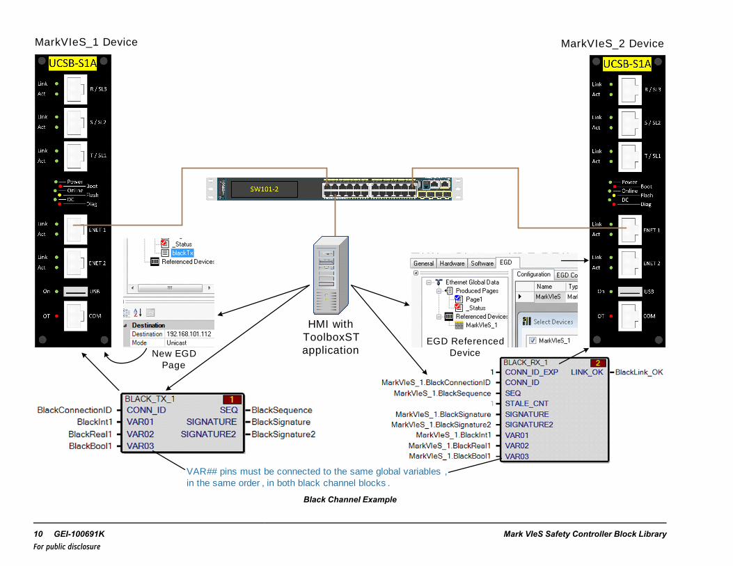
HMI with ToolboxST application
MarkVIeS_1 Device MarkVIeS_2 Device
New EGD Page
VAR## pins must be connected to the same global variables , in the same order , in both black channel blocks .
EGD Referenced Device
Black Channel Example
10 GEI-100691K Mark VIeS Safety Controller Block LibraryFor public disclosure
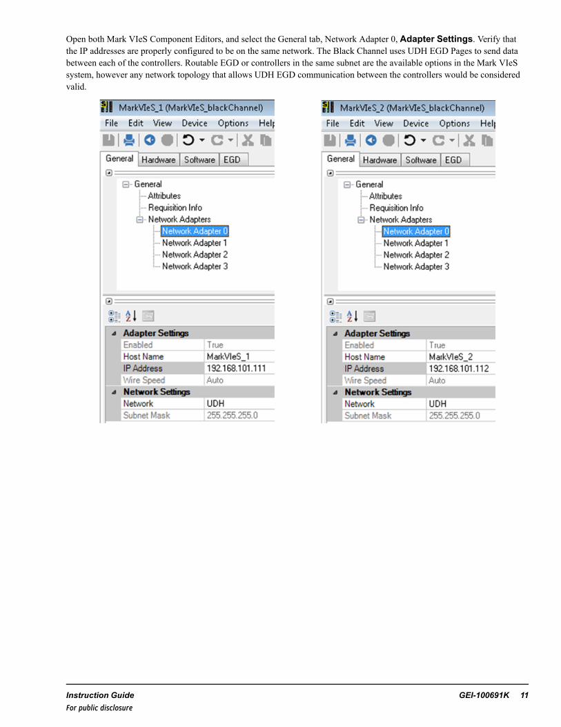
Open both Mark VIeS Component Editors, and select the General tab, Network Adapter 0, Adapter Settings. Verify thatthe IP addresses are properly configured to be on the same network. The Black Channel uses UDH EGD Pages to send databetween each of the controllers. Routable EGD or controllers in the same subnet are the available options in the Mark VIeSsystem, however any network topology that allows UDH EGD communication between the controllers would be consideredvalid.
Instruction Guide GEI-100691K 11For public disclosure

➢➢ To configure the Mark VIeS safety controllers for Black Channel communications
1. Verify that the controllers have been properly installed and configured for UDH network IP addresses.
2. From the first Mark VIeS Component Editor, EGD tab, right-click Produced Pages and select Add Page. Enter aname for this page (for example blackTx).
3. Set the Destination to be the IP address of the second Mark VIeS controller and set theMode to be Unicast.
4. From the Software tab of the first Mark VIeS device, create a Program and Task, then insert the Black_TX block.
5. From the Software tab Tree View, select the Variables for the Task. From the Data Grid, create global variables for allBlack_TX block pins.
a. Create up to 32 VAR## variables as needed for the data to be transmitted from the first controller to the secondcontroller.
Note Use another pair of transmitter and receiver blocks if more than 32 variables are needed.
b. Select data types as are needed for the data to be transmitted or as are required for the block pins.
c. Select the EGD Page for each of these variables to be the black channel page created in step 2.
12 GEI-100691K Mark VIeS Safety Controller Block LibraryFor public disclosure
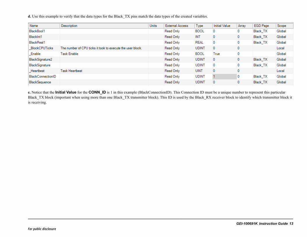
d. Use this example to verify that the data types for the Black_TX pins match the data types of the created variables.
e. Notice that the Initial Value for the CONN_ID is 1 in this example (BlackConnectionID). This Connection ID must be a unique number to represent this particularBlack_TX block (important when using more than one Black_TX transmitter block). This ID is used by the Black_RX receiver block to identify which transmitter block itis receiving.
GEI-100691K Instruction Guide 13For public disclosure
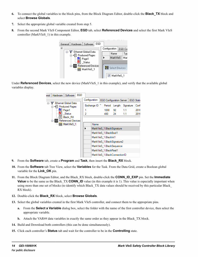
6. To connect the global variables to the block pins, from the Block Diagram Editor, double-click the Black_TX block andselect Browse Globals.
7. Select the appropriate global variable created from step 5.
8. From the second Mark VIeS Component Editor, EGD tab, select Referenced Devices and select the first Mark VIeScontroller (MarkVIeS_1) in this example.
Under Referenced Devices, select the new device (MarkVIeS_1 in this example), and verify that the available globalvariables display.
9. From the Software tab, create a Program and Task, then insert the Black_RX block.
10. From the Software tab Tree View, select the Variables for the Task. From the Data Grid, create a Boolean globalvariable for the Link_OK pin.
11. From the Block Diagram Editor, and the Black_RX block, double-click the CONN_ID_EXP pin. Set the ImmediateValue to be the same as the Black_TX CONN_ID value (in this example it is 1). This value is especially important whenusing more than one set of blocks (to identify which Black_TX data values should be received by this particular Black_RX block).
12. Double-click the Black_RX block, select Browse Globals.
13. Select the global variables created in the first Mark VIeS controller, and connect them to the appropriate pins.
a. From the Select a Variable dialog box, select the folder with the name of the first controller device, then select theappropriate variable.
b. Attach the VAR## data variables in exactly the same order as they appear in the Black_TX block.
14. Build and Download both controllers (this can be done simultaneously).
15. Click each controller’s Status tab and wait for the controller to be in the Controlling state.
14 GEI-100691K Mark VIeS Safety Controller Block LibraryFor public disclosure

➢➢ To test the communication
1. Unlock the first controller.
2. From the Black_TX block, double-click a value for one of the VAR## pins (tiny green value).
3. From the Set Value dialog, change the Next Value and click Send & Close.
4. From the second controller’s Black_RX, notice that the data value of the matching VAR## pin has changed to match thesent value from the first controller.
5. Disconnect the UDH cable from the transmitter end (Mark VIeS controller).
6. From the Black_RX block, notice that the LINK_OK pin connected variable changes to False.
Instruction Guide GEI-100691K 15For public disclosure

5 Boolean Filter (BFILT)Block Category: Boolean Operations
Note This block is not recommended for use in any new controller applications (ControlST V05.02 or later). Refer to thesection Legacy Category Blocks.
The Boolean Filter (BFILT) block passes a rising True value on the IN pin to the OUT pin if IN remains True for PU_DEL (inmilliseconds) time. The block passes a falling False value on the IN pin to the OUT pin if IN remains False for DO_DEL (inmilliseconds).
BFILT Block
Inputs
Name Data Type DescriptionPU_DEL UDINT Pick-up delay in millisecondsIN BOOL Identifies the variable to filterDO_DEL UDINT Drop-out delay in milliseconds
Output
Name Data Type DescriptionOUT BOOL Filtered output
StateName Data Type DescriptionPREVOUT BOOL Last filtered output (hidden pin) that can be viewed or changed by right-clicking the
block and selecting Edit Block Pins. Writing to this variable is not recommended,but can be used to preset block states.
16 GEI-100691K Mark VIeS Safety Controller Block LibraryFor public disclosure
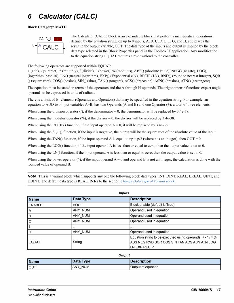
6 Calculator (CALC)Block Category: MATH
The Calculator (CALC) block is an expandable block that performs mathematical operations,defined by the equation string, on up to 8 inputs, A, B, C, D, E, F, G, and H, and places theresult in the output variable, OUT. The data type of the inputs and output is implied by the blockdata type selected in the Block Properties panel in the ToolboxST application. Any modificationto the equation string EQUAT requires a re-download to the controller.
The following operators are supported within EQUAT:+ (add), - (subtract), * (multiply), / (divide), ^ (power), % (modulus), ABS() (absolute value), NEG() (negate), LOG()(logarithm, base 10), LN() (natural logarithm), EXP() (Exponential e^x), RECIP (1/x), RND() (round to nearest integer), SQR() (square root), COS() (cosine), SIN() (sine), TAN() (tangent), ACS() (arccosine), ASN() (arcsine), ATN() (arctangent).
The equation must be stated in terms of the operators and the A through H operands. The trigonometric functions expect angleoperands to be expressed in units of radians.
There is a limit of 64 elements (Operands and Operators) that may be specified in the equation string. For example, anequation to ADD two input variables A+B, has two Operands (A and B) and one Operator (+): a total of three elements.
When using the division operator (/), if the denominator = 0, the denominator will be replaced by 3.4e-38.
When using the modulus operator (%), if the divisor = 0, the divisor will be replaced by 3.4e-38.
When using the RECIP() function, if the input operand A = 0, it will be replaced by 3.4e-38.
When using the SQR() function, if the input is negative, the output will be the square root of the absolute value of the input.
When using the TAN() function, if the input operand A is equal to np + p/2 (where n is an integer), then OUT = 0.
When using the LOG() function, if the input operand A is less than or equal to zero, then the output value is set to 0.
When using the LN() function, if the input operand A is less than or equal to zero, then the output value is set to 0.
When using the power operator (^), if the input operand A = 0 and operand B is not an integer, the calculation is done with therounded value of operand B.
Note This is a variant block which supports any one the following block data types: INT, DINT, REAL, LREAL, UINT, andUDINT. The default data type is REAL. Refer to the section Change Data Type of Variant Block.
Inputs
Name Data Type DescriptionENABLE BOOL Block enable (default is True)A ANY_NUM Operand used in equationB ANY_NUM Operand used in equationC ANY_NUM Operand used in equation↓ ↓ ↓H ANY_NUM Operand used in equation
EQUAT StringEquation string to be executed using operands: + - * / ^ %ABS NEG RND SQR COS SIN TAN ACS ASN ATN LOGLN EXP RECIP
Output
Name Data Type DescriptionOUT ANY_NUM Output of equation
Instruction Guide GEI-100691K 17For public disclosure
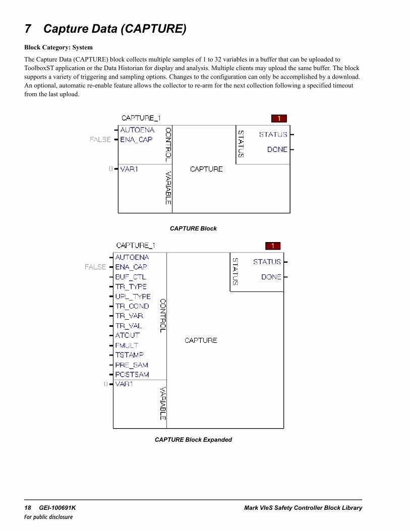
7 Capture Data (CAPTURE)Block Category: System
The Capture Data (CAPTURE) block collects multiple samples of 1 to 32 variables in a buffer that can be uploaded toToolboxST application or the Data Historian for display and analysis. Multiple clients may upload the same buffer. The blocksupports a variety of triggering and sampling options. Changes to the configuration can only be accomplished by a download.An optional, automatic re-enable feature allows the collector to re-arm for the next collection following a specified timeoutfrom the last upload.
CAPTURE Block
CAPTURE Block Expanded
18 GEI-100691K Mark VIeS Safety Controller Block LibraryFor public disclosure
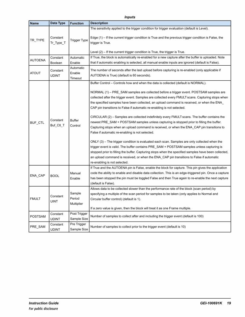
InputsName Data Type Function Description
TR_TYPEConstantTr_Type_T
Trigger Type
The sensitivity applied to the trigger condition for trigger evaluation (default is Level).
Edge (1) – If the current trigger condition is True and the previous trigger condition is False, thetrigger is True.
Level (2) – If the current trigger condition is True, the trigger is True.
AUTOENAConstantBoolean
AutomaticEnable
If True, the block is automatically re-enabled for a new capture after the buffer is uploaded. Notethat if automatic enabling is selected, all manual enable inputs are ignored (default is False).
ATOUTConstantUDINT
AutomaticEnableTimeout
The number of seconds after the last upload before capturing is re-enabled (only applicable ifAUTOENA is True) (default is 60 seconds).
BUF_CTLConstantBuf_Ctl_T
BufferControl
Buffer Control – Controls how and when the data is collected (default is NORMAL).
NORMAL (1) – PRE_SAM samples are collected before a trigger event. POSTSAM samples arecollected after the trigger event. Samples are collected every FMULTscans. Capturing stops whenthe specified samples have been collected, an upload command is received, or when the ENA_CAP pin transitions to False if automatic re-enabling is not selected.
CIRCULAR (2) – Samples are collected indefinitely every FMULTscans. The buffer contains thenewest PRE_SAM + POSTSAM samples unless capturing is stopped prior to filling the buffer.Capturing stops when an upload command is received, or when the ENA_CAP pin transitions toFalse if automatic re-enabling is not selected.
ONLY (3) – The trigger condition is evaluated each scan. Samples are only collected when thetrigger event is valid. The buffer contains PRE_SAM + POSTSAM samples unless capturing isstopped prior to filling the buffer. Capturing stops when the specified samples have been collected,an upload command is received, or when the ENA_CAP pin transitions to False if automaticre-enabling is not selected.
ENA_CAP BOOLManualEnable
If True and the AUTOENA pin is False, enable the block for capture. This pin gives the applicationcode the ability to enable and disable data collection. This is an edge-triggered pin. Once a capturehas been stopped the pin must be toggled False and then True again to re-enable the next capture(default is False).
FMULTConstantUINT
SamplePeriodMultiplier
Allows data to be collected slower than the performance rate of the block (scan period) byspecifying a multiple of the scan period for samples to be taken (only applies to Normal andCircular buffer control) (default is 1).
If a zero value is given, then the block will treat it as one Frame multiple.
POSTSAMConstantUDINT
Post TriggerSample Size
Number of samples to collect after and including the trigger event (default is 100)
PRE_SAMConstantUDINT
Pre TriggerSample Size
Number of samples to collect prior to the trigger event (default is 10)
Instruction Guide GEI-100691K 19For public disclosure
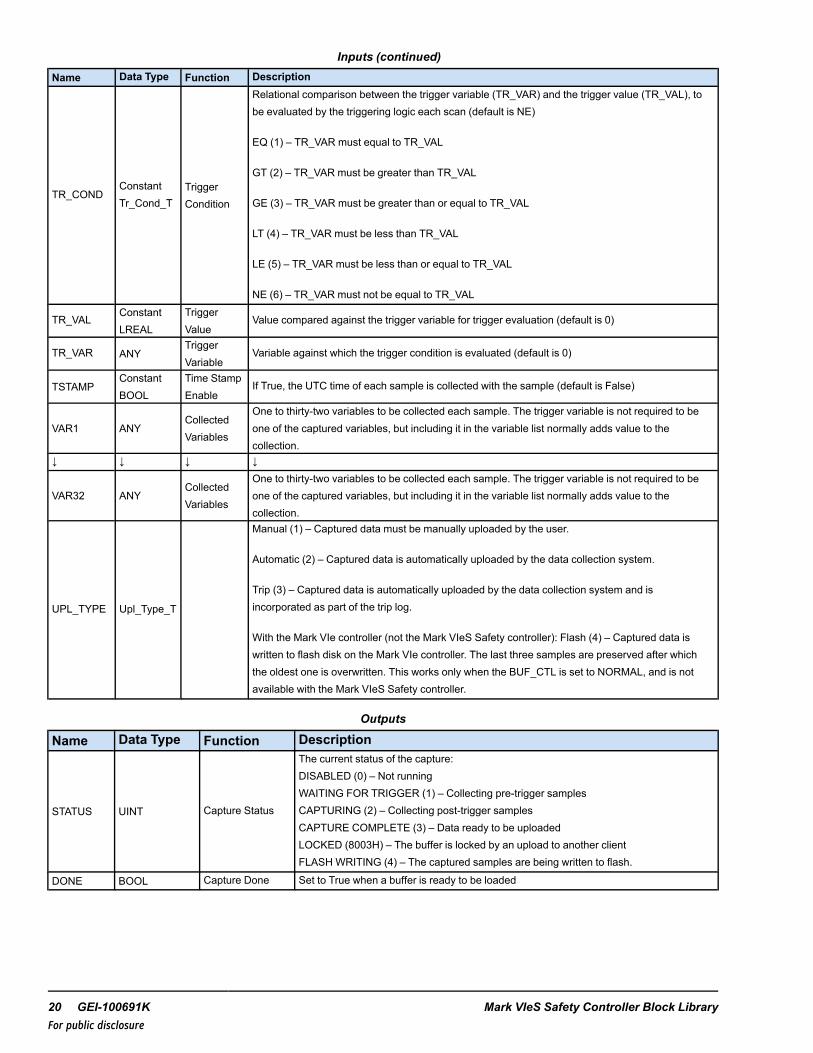
Inputs (continued)Name Data Type Function Description
TR_CONDConstantTr_Cond_T
TriggerCondition
Relational comparison between the trigger variable (TR_VAR) and the trigger value (TR_VAL), tobe evaluated by the triggering logic each scan (default is NE)
EQ (1) – TR_VAR must equal to TR_VAL
GT (2) – TR_VAR must be greater than TR_VAL
GE (3) – TR_VAR must be greater than or equal to TR_VAL
LT (4) – TR_VAR must be less than TR_VAL
LE (5) – TR_VAR must be less than or equal to TR_VAL
NE (6) – TR_VAR must not be equal to TR_VAL
TR_VALConstantLREAL
TriggerValue
Value compared against the trigger variable for trigger evaluation (default is 0)
TR_VAR ANYTriggerVariable
Variable against which the trigger condition is evaluated (default is 0)
TSTAMPConstantBOOL
Time StampEnable
If True, the UTC time of each sample is collected with the sample (default is False)
VAR1 ANYCollectedVariables
One to thirty-two variables to be collected each sample. The trigger variable is not required to beone of the captured variables, but including it in the variable list normally adds value to thecollection.
↓ ↓ ↓ ↓
VAR32 ANYCollectedVariables
One to thirty-two variables to be collected each sample. The trigger variable is not required to beone of the captured variables, but including it in the variable list normally adds value to thecollection.
UPL_TYPE Upl_Type_T
Manual (1) – Captured data must be manually uploaded by the user.
Automatic (2) – Captured data is automatically uploaded by the data collection system.
Trip (3) – Captured data is automatically uploaded by the data collection system and isincorporated as part of the trip log.
With the Mark VIe controller (not the Mark VIeS Safety controller): Flash (4) – Captured data iswritten to flash disk on the Mark VIe controller. The last three samples are preserved after whichthe oldest one is overwritten. This works only when the BUF_CTL is set to NORMAL, and is notavailable with the Mark VIeS Safety controller.
Outputs
Name Data Type Function Description
STATUS UINT Capture Status
The current status of the capture:DISABLED (0) – Not runningWAITING FOR TRIGGER (1) – Collecting pre-trigger samplesCAPTURING (2) – Collecting post-trigger samplesCAPTURE COMPLETE (3) – Data ready to be uploadedLOCKED (8003H) – The buffer is locked by an upload to another clientFLASH WRITING (4) – The captured samples are being written to flash.
DONE BOOL Capture Done Set to True when a buffer is ready to be loaded
20 GEI-100691K Mark VIeS Safety Controller Block LibraryFor public disclosure

Capture Block Theory of Operation
The Capture block is a software function used to collect application variables in real-time for offline display and analysis. Thecore software is shared between the Capture block and Dynamic Data Recorders (DDRs). The main differences between themare:
• Capture blocks require an application code download to configure, while DDRs are configured by an independentdownload mechanism.
• Capture blocks are embedded in the application code and can be used to catch events that occur between application codeblocks. DDRs perform outside of the application code and can only sample data after all of the application code hasperformed in a particular frame.
• Capture blocks perform at the same priority as the other application code and so insure the highest data fidelity. DDRsperform at a lower priority than the application code and are not guaranteed to catch data transitioning at frame rate.
The Capture block collects data sets of variables, known as samples and stores them in a local buffer. The buffer may beuploaded to one or more client devices. Once uploaded the block may be re-armed to take another collection. Typically, forclients other than ToolboxST application the status pin must be mapped to EGD so that it can be monitored outside thecontroller. Once an upload is in progress, the buffer is locked to prevent it from being re-armed during the data transfer.Multiple clients may upload the buffer simultaneously. The block ignores the transitions of its ENA_CAP pin until all clientshave been serviced.
Data collection is managed by specifying a buffer control mode and a trigger event. There are three buffer control modes. ANORMAL collection is one where a specified number of samples are collected prior to a trigger event and a specified numberof samples are collected after the trigger event. Once the trigger event has been found to be satisfied it is no longer evaluated.A CIRCULAR collection is one where no trigger event is specified and samples are taken indefinitely until the collection ishalted by requesting an upload or disabling the block. An ONLY collection is one where samples are only collected if thespecified trigger event is True each opportunity the block has to collect a sample. This is useful when collecting data aroundan event that occurs sporadically.
A trigger event is completely specified by selecting a trigger condition, a trigger type, a trigger variable, and a trigger value.The trigger variable is an application variable that the block monitors. It is compared against a trigger value using therelational specifications of the trigger condition, and the sensitivity of the trigger type. Acceptable trigger conditions includeEQUALTO, NOT EQUALTO, GREATER THAN, GREATER THAN OR EQUALTO, LESS THAN, and LESS THAN OREQUALTO. Acceptable trigger types include LEVEL or EDGE. A level trigger is one that is satisfied at present, regardlessof past values. An edge trigger is one that is satisfied at present but was not satisfied at the previous evaluation.
Capture Block Configuration
The Capture block may be re-configured by either an offline or online download. Downloading causes the states of ALLCapture blocks in the controller to be re-initialized, invalidating any data that may be in the process of being collected.Therefore, if external blockware is used to sequence to collection of data, it must be sufficiently robust to recover from such are-initialization. This may be accomplished by examining the DONE and STATUS pins or through timeouts.
Capture Block Enabling Collections
Note Avariable needs to be connected to the Status pin to enable the automatic upload functionality of the CAPTURE blockin the WorkstationST* application.
A new collection may be enabled manually through blockware, or automatically, if so configured. If manual enabling isselected, the application code must toggle the ENA_CAP to False for at least one frame then back to True to re-enable acollection. Additionally, the block ignores all transitions of the ENA_CAP pin while the buffer is locked for uploading so thistoggling must occur when the buffer is unlocked. If automatic enabling is selected, the block is initially enabled and alltransitions of the ENA_CAP pin are ignored. The block will re-enable a capture after at least one upload occurs, and no newupload requests are received within ATOUT seconds following the completion of the last upload. Uploading a collection thatis not complete automatically changes the block status to complete. Another upload is not necessary to re-enable the nextcollection.
Instruction Guide GEI-100691K 21For public disclosure
Capture Block Triggering Issues
The trigger event is evaluated differently for each of the buffer control modes. For the NORMAL and CIRCULAR modes thesample period multiplier pin, FMULT allows the block to collect samples at rates slower than the block performs, therebyextending its range. A sample is only collected every FMULT scans. Using the NORMAL mode, the trigger event is evaluatedevery scan regardless of the value of FMULT. When the event occurs, the sample is collected and post-trigger samples arecollected every FMULT scans away from the trigger sample. Note that because the trigger sample may not occur on anFMULT boundary, the time between the last pre-trigger sample and the trigger sample may not be the same when FMULT isnot equal to one.
Capture Block NORMAL
NORMAL mode is used to collect samples before and after a specified trigger event.
Once enabled, the block begins collecting pre-trigger samples, retaining the most recent PRE_SAM samples before a triggerevent occurs. Once the trigger occurs, the block collects POSTSAM more samples before changing the STATUS pin toComplete. The trigger sample is included in the post sample count. Typically the buffer will contain PRE_SAM + POSTSAMtotal samples. If the trigger occurs prior to collecting all of the pre-trigger samples, or the collection is halted prior tocapturing all of the post trigger samples this may not be the case.
Capture Block CIRCULAR
CIRCULAR mode is used to collect samples continuously until the buffer is manually stopped. Specifying a trigger event ismeaningless in this mode.
Once enabled, the block begins collecting samples, retaining the most recent PRE_SAM + POSTSAM total samples. It ispossible for the buffer to contain fewer samples if the collection is halted prematurely.
Capture Block ONLY
ONLY mode is used to collect samples only when the trigger event is True. The FMULT pin is ignored in this mode.
Once enabled, the block begins looking for trigger events every scan but only collects samples on the scans where the triggerevent is True. The block collects the first PRE_SAM + POSTSAM trigger samples before changing the STATUS pin toComplete. It is possible for the buffer to contain fewer samples if the collection is halted prematurely.
Capture Block Time Stamping
The TSTAMP pin specifies whether wall clock time (in UTC format) is collected with each sample, or whether it is collectedonly at the trigger event and all other sample times are extrapolated from the block performance period modified by FMULT.
It is recommended that TSTAMP always be left True, to insure that trends are displayed with the most accurate timestampinformation.
22 GEI-100691K Mark VIeS Safety Controller Block LibraryFor public disclosure

Capture Block Status
The state of each collection is expressed through the DONE and STATUS output pins. The DONE pin may be monitored byapplication code to drive manual reset algorithms. The STATUS pin provides more detailed state information and is usuallypublished on EGD for use by external clients. The definition of the states is affected by the specified buffer control mode andis provided in the following table.
Buffer Control Mode Affected StatesStatus BUF_CTL DescriptionDISABLED All Prior to being enabled for the first time (manual enable mode only)
WAITINGNORMAL Collecting pre-trigger samples while looking for a triggerCIRCULAR Does not occurONLY Waiting for a trigger to occur
CAPTURINGNORMAL Collecting post-trigger samples
CIRCULAR Collecting samples
ONLY Collecting a trigger sample
COMPLETE All No longer collecting, ready to be uploaded, ready to be re-enabled
FLASHWRITINGNORMAL Writing the pre-trigger and post-trigger samples to flash.CIRCULAR Does not occurONLY Does not occur
Capture Block Redundancy Issues
Like all application code blocks configured in a redundant controller system, the Capture block is replicated faithfully in eachcontroller. However, unlike other blocks, the Capture block maintains un-voted internal state information in each controller.This independence allows the block to trigger on and capture data that may be different in each controller (for example,anti-voted data). Likewise the communication channel established between the block and an external client (for example,ToolboxST application) for an upload is not replicated to any redundant controllers. The STATUS and DONE pins are notvoted and as a result may not always track between controllers. This is normal if a capture is terminated early by an uploadrequest or anti-voted data is used in the trigger specification. Application writers who want to monitor these pins throughblockware should be aware of this discrepancy.
Capture Block Memory Use
Capture blocks consume RAM memory from the system memory pool to create the capture buffers. The allocation of memoryin the controller is a compromise that must be made considering the amount of real RAM available, the amount required forapplication code, the amount needed for data collection (for example, Capture blocks and DDRs), and a free pool necessaryfor support services, such as ToolboxST application and HMI connections.
The amount of memory required for a particular CAPTURE block may be calculated as the number of samples times the sumof the size of each collected variable. If time-stamping is enabled add 8 bytes times the number of samples. For example, if aCAPTURE block is configured to collect 1000 total samples where each sample contains two REAL, three INT, and fiveBOOL data types, and time-stamping is enabled, the amount of memory required for the captured data is:1000 x ((2 x 4) + (3 x 2) + (5 x 1) + 8) = 27,000 bytes
Data Type Size (Bytes)BOOL 1INT 2UINT 2DINT 4UDINT 4REAL 4LREAL 8
Instruction Guide GEI-100691K 23For public disclosure
8 Cause and Effect MatrixThe Cause and Effect Matrix is a new special task for the Mark VIeS Safety controller. This feature requires ToolboxSTV06.02 or later with the Mark VIeS Safety controller firmware V05.03 or later. Refer to the ToolboxST User Guide for MarkControls Platform (GEH-6700) for detailed instructions.
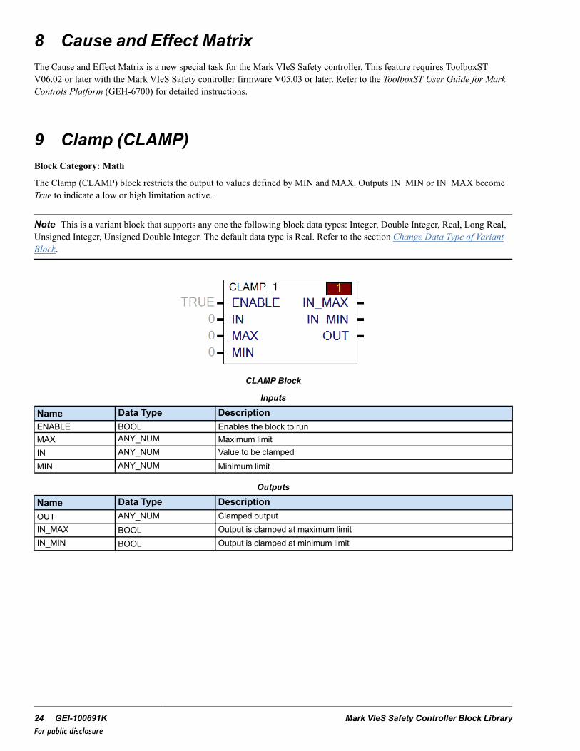
9 Clamp (CLAMP)Block Category: Math
The Clamp (CLAMP) block restricts the output to values defined by MIN and MAX. Outputs IN_MIN or IN_MAX becomeTrue to indicate a low or high limitation active.
Note This is a variant block that supports any one the following block data types: Integer, Double Integer, Real, Long Real,Unsigned Integer, Unsigned Double Integer. The default data type is Real. Refer to the section Change Data Type of VariantBlock.
CLAMP Block
Inputs
Name Data Type DescriptionENABLE BOOL Enables the block to runMAX ANY_NUM Maximum limitIN ANY_NUM Value to be clampedMIN ANY_NUM Minimum limit
Outputs
Name Data Type DescriptionOUT ANY_NUM Clamped outputIN_MAX BOOL Output is clamped at maximum limitIN_MIN BOOL Output is clamped at minimum limit
24 GEI-100691K Mark VIeS Safety Controller Block LibraryFor public disclosure

10 Comment (_COMMENT)Block Category: System
The Comment (_COMMENT) block adds comment text in the block diagram. The _COMMENT block inserts a page breakas viewed from the tool and on the printed page. The comment will appear on the left side of the page on the next line afterthe previous block. The text of the comment is added in the Property View on the lower left side of the screen. The ShowDescription property must be True to display the entire text of the comment.
The _COMMENT block also controls the mode (flow mode or list mode) of the diagram to the next comment block (or endof the code if there are no subsequent comment blocks).
11 Comment Block Functionality (_COMMENT_BF)Block Category: System
Note This block is not recommended for use in any new controller applications (ControlST V05.02 or later). Refer to thesection Legacy Category Blocks.
The Comment Block Functionality (_COMMENT_BF) block adds comment text in the block diagram. The block inserts aline break as viewed from the tool and on the printed page. The comment will display on the left side of the page on the nextline after the previous block. The text of the comment is added in the Property View on the lower left side of the screen. TheShow Description property must be set to True to display the entire text of the comment.
The COMMENT_BF block also controls the mode (Flow or List mode) of the diagram to the next comment block (or end ofthe code if there are no subsequent comment blocks).
12 Comment No Break (_COMMENT_NB)Block Category: System
The Comment No Break (_COMMENT_NB) block adds comment text in the block diagram without causing a page break.The comment will appear after the next break in connected blocks. The text of the comment is added in the Property View onthe lower left side of the screen. The Show Description property must be True to display the entire text of the comment.
The _COMMENT_NB block also controls the mode (flow mode or list mode) of the diagram to the next Comment block (orend of the code if there are no subsequent comment blocks).
Instruction Guide GEI-100691K 25For public disclosure
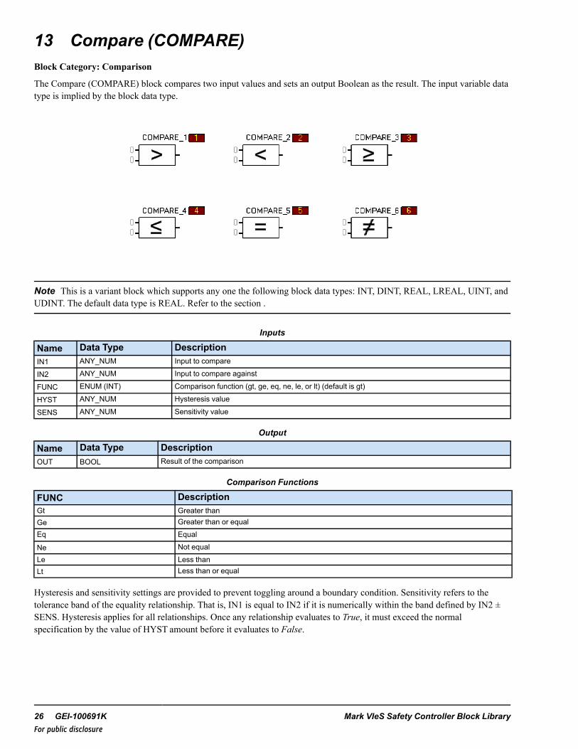
13 Compare (COMPARE)Block Category: Comparison
The Compare (COMPARE) block compares two input values and sets an output Boolean as the result. The input variable datatype is implied by the block data type.
Note This is a variant block which supports any one the following block data types: INT, DINT, REAL, LREAL, UINT, andUDINT. The default data type is REAL. Refer to the section .
Inputs
Name Data Type DescriptionIN1 ANY_NUM Input to compare
IN2 ANY_NUM Input to compare against
FUNC ENUM (INT) Comparison function (gt, ge, eq, ne, le, or lt) (default is gt)
HYST ANY_NUM Hysteresis value
SENS ANY_NUM Sensitivity value
Output
Name Data Type DescriptionOUT BOOL Result of the comparison
Comparison Functions
FUNC DescriptionGt Greater thanGe Greater than or equalEq Equal
Ne Not equalLe Less thanLt Less than or equal
Hysteresis and sensitivity settings are provided to prevent toggling around a boundary condition. Sensitivity refers to thetolerance band of the equality relationship. That is, IN1 is equal to IN2 if it is numerically within the band defined by IN2 ±SENS. Hysteresis applies for all relationships. Once any relationship evaluates to True, it must exceed the normalspecification by the value of HYST amount before it evaluates to False.
26 GEI-100691K Mark VIeS Safety Controller Block LibraryFor public disclosure
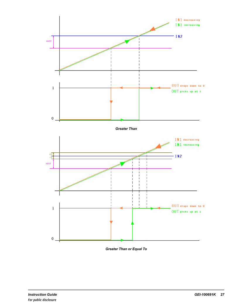
Greater Than
Greater Than or Equal To
Instruction Guide GEI-100691K 27For public disclosure

Equal To
Not Equal
28 GEI-100691K Mark VIeS Safety Controller Block LibraryFor public disclosure

Less Than or Equal To
Less Than
Instruction Guide GEI-100691K 29For public disclosure

14 Compare with Hysteresis (COMPHYS)Block Category: Comparison
Note This block is not recommended for use in any new controller applications (ControlST V05.02 or later). Refer to thesection Legacy Category Blocks.
The Compare with Hysteresis (COMPHYS) block compares two floating point values and sets an output Boolean reflectingthe result. Hysteresis. Sensitivity settings are provided to prevent toggling around a boundary condition. The supportedfunctions include: greater than (gt), greater than or equal to (ge), equal to (eq), less than (lt), or less than or equal to (le).
Sensitivity refers to the thickness of the equality relationship. That is, IN1 is equal to IN2 if it is numerically within the banddefined by IN2 ± SENS. Hysteresis applies for all relationships. Once any relationship evaluates to True it must exceed thenormal specification by the HYST amount before it evaluates to False.
Floating Point Exception Handling
If a NaN is present on an input pin, the COMPHYS block replaces it internally with the most positive or most negativerepresentable number based on its sign, for the purpose of the comparison.
Note This block is a variant block that supports the following block data types: Real and Long Real. To modify the datatype, refer to the section Change Data Type of Variant Block.
COMPHYS Block
30 GEI-100691K Mark VIeS Safety Controller Block LibraryFor public disclosure

Inputs
Name Data Type DescriptionIN1 REAL, LREAL Input to compareFUNC Constant CompFnL_T Comparison function (gt, lt, ge, le, eq) (default is gt)IN2 REAL, LREAL Value to compare againstHYST REAL, LREAL Hysteresis valueSENS REAL, LREAL Sensitivity value
Output
Name Data Type Description
OUT BOOL Result of the comparison
Instruction Guide GEI-100691K 31For public disclosure
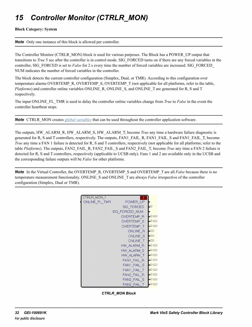
15 Controller Monitor (CTRLR_MON)Block Category: System
Note Only one instance of this block is allowed per controller.
The Controller Monitor (CTRLR_MON) block is used for various purposes. The Block has a POWER_UP output thattransitions to True 5 sec after the controller is in control mode. SIG_FORCED turns on if there are any forced variables in thecontroller, SIG_FORCED is set to False for 2 s every time the number of forced variables are increased. SIG_FORCED_NUM indicates the number of forced variables in the controller.
The block detects the current controller configuration (Simplex, Dual, or TMR). According to this configuration overtemperature alarms OVERTEMP_R, OVERTEMP_S, OVERTEMP_T (not applicable for all platforms, refer to the table,Platforms) and controller online variables ONLINE_R, ONLINE_S, and ONLINE_T are generated for R, S and Trespectively.
The input ONLINE_FL_TMR is used to delay the controller online variables change from True to False in the event thecontroller heartbeat stops.
Note CTRLR_MON creates global variables that can be used throughout the controller application software.
The outputs, HW_ALARM_R, HW_ALARM_S, HW_ALARM_T, become True any time a hardware failure diagnostic isgenerated for R, S and T controllers, respectively. The outputs, FAN1_FAIL_R, FAN1_FAIL_S and FAN1_FAIL_T, becomeTrue any time a FAN 1 failure is detected for R, S and T controllers, respectively (not applicable for all platforms; refer to thetable Platforms). The outputs, FAN2_FAIL_R, FAN2_FAIL_S and FAN2_FAIL_T, become True any time a FAN 2 failure isdetected for R, S and T controllers, respectively (applicable to UCSB only). Fans 1 and 2 are available only in the UCSB andthe corresponding failure outputs will be False for other platforms.
Note In the Virtual Controller, the OVERTEMP_R, OVERTEMP_S and OVERTEMP_T are all False because there is notemperature measurement functionality. ONLINE_S and ONLINE_T are always False irrespective of the controllerconfiguration (Simplex, Dual or TMR).
CTRLR_MON Block
32 GEI-100691K Mark VIeS Safety Controller Block LibraryFor public disclosure

InputsName Description Type Initial
ValueVisibility Usage
ONLINE_FL_TMR Online Fail Triple Modular Redundancy UDINT 5000 ms Parameter Input
OutputsName Description Type Initial
ValueVisibility Usage
HW_ALARM_R R controller hardware failure alarm BOOL False Always OutputHW_ALARM_S † S controller hardware failure alarm BOOL False Always OutputHW_ALARM_T †† Tcontroller hardware failure alarm BOOL False Always OutputFAN1_FAIL_R R controller Fan1 failure BOOL False Always OutputFAN1_FAIL_S † S controller Fan1 failure BOOL False Always OutputFAN1_FAIL_T †† Tcontroller Fan1 failure BOOL False Always OutputFAN2_FAIL_R R controller Fan2 failure BOOL False Always OutputFAN2_FAIL_S † S controller Fan2 failure BOOL False Always OutputFAN2_FAIL_T †† Tcontroller Fan2 failure BOOL False Always OutputPOWER_UP Controller powered up BOOL 0 Always OutputSIG_FORCED Signal forced in controller BOOL False Always OutputSIG_FORCED_NUM Number of forced signals INT 0 Always OutputOVERTEMP_R R controller over temperature BOOL False Always OutputOVERTEMP_S † S controller over temperature BOOL False Always OutputOVERTEMP_T †† Tcontroller over temperature BOOL False Always OutputONLINE_S † R controller online BOOL False Always OutputONLINE_R S controller online BOOL False Always OutputONLINE_T †† Tcontroller online BOOL False Always Output† Exists only when the controller’s redundancy is DUAL or TMR†† Exists only when the controller’s redundancy is TMR
Instruction Guide GEI-100691K 33For public disclosure

Global VariablesGlobal Pin Name Description Alarm Alarm
ClassEvent EGD Default
PageExternalAccess
HW_ALARM_R R controller hardware failure alarm Alarmed Diag False $Default Read OnlyHW_ALARM_S† S controller hardware failure alarm Alarmed Diag False $Default Read OnlyHW_ALARM_T †† Tcontroller hardware failure alarm Alarmed Diag False $Default Read OnlyFAN1_FAIL_R R controller Fan1 failure Alarmed Diag False $Default Read OnlyFAN1_FAIL_S† S controller Fan1 failure Alarmed Diag False $Default Read OnlyFAN1_FAIL_T †† Tcontroller Fan1 failure Alarmed Diag False $Default Read OnlyFAN2_FAIL_R R controller Fan2 failure Alarmed Diag False $Default Read OnlyFAN2_FAIL_S† S controller Fan2 failure Alarmed Diag False $Default Read OnlyFAN2_FAIL_T †† Tcontroller Fan2 failure Alarmed Diag False $Default Read OnlyPOWER_UP Controller powered up Not Alarmed N/A False N/A Read OnlySIG_FORCED Signal forced in controller Alarmed Diag False N/A Read OnlySIG_FORCED_NUM
Number of forced signals Not Alarmed N/A False N/A Read Only
OVERTEMP_R R controller over temperature Alarmed Diag False $Default Read OnlyOVERTEMP_S† S controller over temperature Alarmed Diag False $Default Read OnlyOVERTEMP_T †† Tcontroller over temperature Alarmed Diag False $Default Read OnlyONLINE_R R controller online Not Alarmed N/A False $Default Read OnlyONLINE_S† S controller online Not Alarmed N/A False $Default Read OnlyONLINE_T †† Tcontroller online Not Alarmed N/A False $Default Read Only† Exists only when the controller’s redundancy is DUAL or TMR†† Exists only when the controller’s redundancy is TMR
34 GEI-100691K Mark VIeS Safety Controller Block LibraryFor public disclosure

Mark VIeS PlatformsOutput Pins UCCC UCSB UCSC
POWER_UPTrue: Controller has been powered up and is controllingFalse: Controller not reached controlling state
SIG_FORCEDTrue: At least one signal is forcedFalse: No forced signals or set to False for 2 sec every time the number of forced variables areincreased
SIG_FORCED_NUM Number of forced signals in the application
OVERTEMP_RTrue: CPU temperature too highFalse: CPU temperature normal
OVERTEMP_STrue: CPU temperature too highFalse: CPU temperature normal
OVERTEMP_TTrue: CPU temperature too highFalse: CPU temperature normal
ONLINE_R True: R controller is onlineFalse: R controller is not online
ONLINE_S True: S controller is onlineFalse: S controller is not online
ONLINE_T True: Tcontroller is onlineFalse: Tcontroller is not online
HW_ALARM_R True: R controller hardware failure has occurredFalse: No R controller hardware failure
HW_ALARM_S True: S controller hardware failure has occurredFalse: No S controller hardware failure
HW_ALARM_T True: Tcontroller hardware failure has occurredFalse: No Tcontroller hardware failure
FAN1_FAIL_R Not Applicable (False)FAN1_FAIL_S Not Applicable (False)FAN1_FAIL_T Not Applicable (False)FAN2_FAIL_R Not Applicable (False)FAN2_FAIL_S Not Applicable (False)FAN2_FAIL_T Not Applicable (False)
Instruction Guide GEI-100691K 35For public disclosure

16 Counter (COUNTER)Block Category: Timers and Counters
The Counter (COUNTER) block accumulates rising edges of the INC pin into CUR_CNTwhile the RUN is True and CUR_CNT is less than MAX_CNT. When CUR_CNT is equal to MAX_CNT, AT_CNT transitions to True. If RUN is False thencounting is suspended, but CUR_CNT holds its value. If RESET is True then CUR_CNT is set to zero and counting issuspended. If MAX_CNT is less than one, each rising edge of INC sets AT_CNT True and increments CUR_CNT.
COUNTER Block
Inputs
Name Data Type DescriptionINC BOOL Triggers another count on its rising edgeMAX_CNT DINT The maximum count valueRESET BOOL Zeros the counterRUN BOOL Enables the counter
Outputs
Name Data Type DescriptionAT_CNT BOOL Indicates the counter has reached the maximum count valueCUR_CNT DINT Current count value (always ≤ MAX_CNT)
StatesName Data Type Description
LAST_CURCNT DINT
This is the variable that holds the current count. It is a hidden pin thatcan be viewed or changed by right-clicking the block and selecting EditBlock Pins. Writing to this variable is not recommended, but can beused to preset block states.
LAST_ATCNT BOOL
This is the variable that holds the state, indicating the counter hasreached the maximum count value. This is a hidden pin. It can beviewed or changed by right-clicking the block and selecting Edit BlockPins. Writing to this variable is not recommended, but can be used topreset block states.
36 GEI-100691K Mark VIeS Safety Controller Block LibraryFor public disclosure

17 Device Heartbeat (DEVICE_HB)Block Category: System
The Device Heartbeat (DEVICE_HB) block outputs an incrementing value to drive the heartbeat signal on a protection I/Omodule, such as PPRO. This block follows the internal frame counter, which is synchronized in the three controllers of aTMR system.
The DEVICE_HB block provides a voted variable representation of the controller scheduler frame number (anotherfree-running counter). It is normally used to drive the heartbeat input into the protection I/O packs. Because the variable is thesame in all controllers in a redundant set. It does not cause a potential voter disagreement diagnostic in the packs (couldhappen with ControllerStateHeartbeat_R/S/T). The protection I/O pack trips the unit after five frames if no updates aredetected. After the unit trips, it must detect 60 frames of incrementing heartbeat before it allows the unit to go back online.
Note The OUT value freezes if the associated task/user block stops running.
DEVICE_HB Block
Output
Name Data Type DescriptionOUT DINT Device heartbeat
Instruction Guide GEI-100691K 37For public disclosure

18 Dual Select Version 2 (DUALSEL_S2)Block Category: Analog Operations
The Dual Select Version 2 (DUALSEL_S2) block transfers the average, minimum, or maximum of two analog signals tooutput ({Device}). The user has the option to disable one transmitter. If one transmitter is disabled, the output will be the valueof the remaining transmitter.
This block is similar to the Mark VIe DUALSEL_V2 block but functionality differs in the following ways:
• The DUALSEL_S2 block does not support the status option.• The Auto Enable (AU_EN_P) feature is not supported.• Control commands for disabling and enabling transmitters are supported in the DUALSEL_S2 bock; however, the
push-button reset functionality must be implemented in another device. For further details, refer to the description ofcontrol word (CTL_EXT) in the section Control Word.
Block Configuration
Disabling Transmitters
When the quality status of transmitter A (IN_ABQ) is BAD (False), ABQ and AD become True and transmitter A isautomatically disabled. Once the quality status of transmitter A becomes GOOD (True), ABQ becomes False. If the qualitystatus of transmitter A becomes GOOD (True) and the value of input A is within the deviation limits set by the user, ADbecomes False and A is automatically enabled. This concept also applies to input B.
A transmitter can be manually disabled using the CTL_EXT input. If input A and B are both enabled and have a GOODquality status and A is manually disabled, then the corresponding output, AD, becomes True to indicate that input A isdisabled. If input A is enabled and B is disabled, then BD is True.
Output Bad Quality Indication (OBQ)
When two transmitters are disabled and/or in a BAD quality state, OBQ becomes True, the default value, DF, is automaticallytransferred to output, and MODE is set to DEFAULT. OBQ becomes False when the quality status of either input becomesGOOD. The GOOD quality input will be enabled and transferred to the output.
Control Word
Control word (CTL_EXT) is used by the HMI operator for manual control. The manual commands from the HMI allow eachinput to be enabled or disabled. A manually disabled transmitter can be manually enabled, regardless of its deviation status.The command enumerations are defined in the following table.
CTL_EXT Enumerations
Enumeration CommandNO_CMD No CommandEN_A_CMD Enable Input A CommandDIS_A_CMD Disable Input A CommandEN_B_CMD Enable Input B CommandDIS_B_CMD Disable Input B Command
Note Operation of the CTL_EXT pin in the Mark VIeS control differs from that in other Mark VIe control products. In theMark VIeS control, the variable attached to the CTL_EXT pin must be from a consumed EGD page. The EGD producerdevice driving the variable must implement the necessary push-button reset logic.
38 GEI-100691K Mark VIeS Safety Controller Block LibraryFor public disclosure
Commands are only accepted by the block if a transition from NO_CMD to a command value is detected while the CTL_EXT input is healthy. After a command is accepted by the block, the CTL_EXT pin is ignored for a period of two secondsafter which a valid transition from NO_CMD must be detected to accept another command. An example configuration is asfollows:
Example Configuration
An HMI faceplate is created to display data from the DUALSEL_S2 block from a Mark VIeS control. EGD signals areconsumed by the HMI from the Mark VIeS control and are used to drive the faceplate. The control word from the MarkVIeS control is used for feedback. Control commands are sent to an EGD signal driven from a Mark VIe device. Forexample, after adding the DUALSEL_S2 block to the Mark VIeS control system and attaching the EGD signals to thefaceplate, the following configuration is required:
In a Mark VIe device:• Create a control word variable.• Add the control word variable to a produced EGD page.• Add push-button reset logic in the blockware to reset the control word value to NO_CMD (0). The control word should
be reset after one second of it being non-zero.
In the HMI:• Attach the control word variable from the Mark VIe control to the control word logic in the appropriate DUALSEL_S2
faceplate.
In the Mark VIeS device:• Attach the control word variable from the Mark VIe control to the CTL_EXT pin of the appropriate DUALSEL_S2
block.
Block Function Enumerations
Dual Select (DS) mode defines the block function mode. The function mode enumerations are defined in the following table.
DS Mode EnumerationsEnumeration FunctionAVG Average of A and BMIN Minimum of A and BMAX Maximum of A and B
Operating mode (MODE) is a block-operating mode that depends on DS and the quality status of the inputs. The operatingmode enumerations are defined in the following table.
MODE EnumerationsEnumeration Operating ModeAVG Average of A and BMIN_A-B Minimum of A and BMAX_A-B Maximum of A and BA Input AB Input BDEFAULT Input DF
Instruction Guide GEI-100691K 39For public disclosure

Examples
• AVG,MIN_A-B, orMAX_A-B is the operating mode when both transmitters are not BAD quality and are enabled.• A mode is selected when transmitter B is manually disabled or determined to be BAD quality.• B mode is selected when transmitter A is manually disabled or determined to be BAD quality.• DEFAULT is the operating mode selected automatically when both transmitters are determined to be bad quality and/or
disabled.
Deviation Alarms
A and B values are compared to determine if the absolute value of their difference is greater than or equal to the deviationlimit, DL. If so, the deviation high alarm, ODH, becomes True, delayed by the deviation time delay, DT. The deviation alarmwill not become False until the absolute difference between A and B is less than the value of DL minus DLDB (deviationlimit dead band)or either input is disabled.
Note The deviation high output, ODH, becomes True when at least one transmitter is in deviation. Also, if a transmitterinput is disabled, the deviation alarm for that transmitter is disabled.
In general, the deviation alarm only sets Boolean outputs and has no influence on the functionality of the block (that is, thetransmitter in deviation with the output is not automatically disabled, and the block mode does not change).
Note Refer to the section Alarm and Event Configuration for more information.
Rate of Change Restriction
The rate of change of OUT is only restricted by the value of RATE when the block operating mode changes.
RATE is in engineering units per second. For example, if RATE = 1, A = 10 (enabled), and B = 25 (disabled), so MODE = A,and the mode of the block is changed by enabling input B and disabling input A. Now, MODE = B and output will increasefrom 10 to 25 engineering units in 15 seconds. At this point, output equals B, the block operating mode transition from A to Bis complete and the rate of change restriction on output is removed until the block operating mode changes, again.
ToolboxST Configuration
Inserting this block into the application program will generate the window displayed in the following figure. This prompts theuser to Enter Device Description, Enter Device Name, and Enter Format Specification in the Values column.
Changing Default Attributes
40 GEI-100691K Mark VIeS Safety Controller Block LibraryFor public disclosure

When the user clicks OK, the block will automatically set the appropriate attributes for each variable (for example, Type andFormat Specification). Any variables that need to be on EGD will be automatically placed on the $Default EGD page.
Note Each Device Name used in a controller must be unique.
The block and pin connections are configured automatically. The object will display in the ToolboxST application.
DUALSEL_S2 Block
Pin names are in the form Device Value.Pin Name, where Device Value has the attribute value 00DUALSEL_S21000 and pinName is the block input/output pin name. (Refer to the table Global Variables.) The description, DUALSEL_S2 Description,becomes the prefix of the block input/output descriptions. The FormatSp Attribute Name Value, TempFS, is the formatspecification of the block output. The DLFormatSp Attribute Name Value, TempDiffFS, is the format specification of theblock DL pin output.
Note The only exception to the rule is the output pin ({Device}) where the global pin name is in the form Device Value pinname without the " ".
Inputs
Name Global Description Data Type Initial Value VisibilityA Yes {Desc} Trans A input REAL 0 Always
B Yes {Desc} Trans B input REAL 0 AlwaysCTL_EXT Yes {Desc} Control word UINT (ENUM) NO_CMD Always
DF NoDefault output if bothtransmitters are bad
REAL 0 Parameter
DL No Deviation alarm limit REAL 5 Parameter
DLDB NoDeviation alarm limitdeadband
REAL 2 Parameter
DS No Dual Select Mode property UINT (ENUM) AVG ParameterDT No Deviation alarm delay UDINT 1000 ParameterIN_ABQ No Trans A bad quality BOOL False AlwaysIN_BBQ No Trans B bad quality BOOL False Always
RATE No Selection change rate limit REAL 1 Parameter
Instruction Guide GEI-100691K 41For public disclosure

Outputs
Name Global Description Data Type Initial Value Visibility{Device} Yes {Desc} REAL 0 AlwaysABQ Yes {Desc} Trans A bad quality BOOL False Always
AD Yes {Desc} Trans A disabled BOOL False AlwaysBBQ Yes {Desc} Trans B bad quality BOOL False Always
BD Yes {Desc} Trans B disabled BOOL False Always
MODE Yes {Desc} Block mode UINT (ENUM) AVG_AB AlwaysOBQ Yes {Desc} Bad quality BOOL False Always
ODH Yes {Desc} High deviation BOOL False AlwaysSEL_P Yes {Desc} Select type property UINT (ENUM) DUAL Internal
Global VariablesPin Name Description Alarm Alarm
ClassEvent EGD Page External
AccessDUALSEL_S21001 DUALSEL_S2 1001 Not Alarmed — False $Default ReadOnly
DUALSEL_S21001.ADUALSEL_S2 1001Trans A input Not Alarmed — False $Default ReadOnly
DUALSEL_S21001.ABQDUALSEL_S2 1001Trans A bad quality Not Alarmed — False $Default ReadOnly
DUALSEL_S21001.AD DUALSEL_S2 1001Trans A deselected
Not Alarmed — True $Default ReadOnly
DUALSEL1001.BDUALSEL_S2 1001Trans B input Not Alarmed — False $Default ReadOnly
DUALSEL_S21001.BBQDUALSEL_S2 1001Trans B bad quality Not Alarmed — False $Default ReadOnly
DUALSEL_S21001.BD DUALSEL_S2 1001Trans B deselected
Not Alarmed — True $Default ReadOnly
DUALSEL_S21001.CTL_EXT DUALSEL_S2 1001Control word
Not Alarmed — False $Default ReadOnly
DUALSEL_S21001.MODE DUALSEL_S2 1001Block mode
Not Alarmed — False $Default ReadOnly
DUALSEL_S21001.OBQDUALSEL_S2 1001Bad quality Not Alarmed — False $Default ReadOnly
DUALSEL_S21001.ODHDUALSEL_S2 1001High deviation Alarmed Alert False $Default ReadOnly
DUALSEL_S21001.SEL_PDUALSEL_S2 1001Select type property Not Alarmed — False $Default ReadOnly
42 GEI-100691K Mark VIeS Safety Controller Block LibraryFor public disclosure

Alarm and Event Configuration
The following guidelines apply to DUALSEL_S2 alarm and event configuration:
• The ODH variable is configured as an alarm.• AD and BD variables are configured as events.• Only Boolean variables can be configured as alarms.
Enabling Alarms on Signal
Instruction Guide GEI-100691K 43For public disclosure

19 Expand Long Integer (EXPAND_UDI)Block Category: Boolean operations
The Expand Long Integer (EXPAND_UDI) block moves each bit of the input into 32 individual Boolean outputs. The leastsignificant input bit is placed in OUT0 and the most significant bit is placed in OUT31.
EXPAND_UDI Block
Input
Name Data Type DescriptionIN UDINT Input 32 bit integer to expand
Outputs
Name Data Type DescriptionOUT0 BOOL Contains the results of the expansion process (least significant binary digit)↓ ↓ ↓OUT31 BOOL Contains the results of the expansion process (most significant binary digit)
44 GEI-100691K Mark VIeS Safety Controller Block LibraryFor public disclosure

20 Function Generator (FUNGEN)Block Category: Math
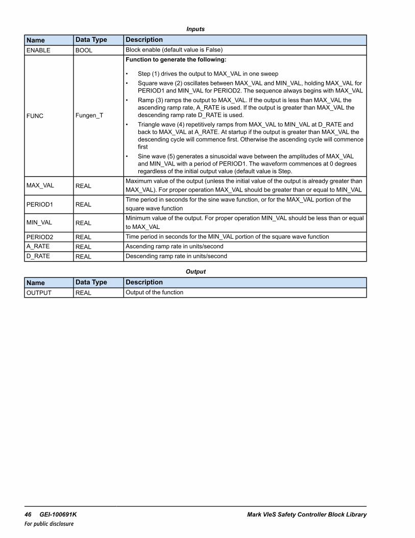
The Function Generator (FUNGEN) block creates common variable functions for test and verification. The function and/orany of its parameters may be dynamically changed to generate the wave forms, STEP, SQUARE, RAMP, TRIANGLE andSINE. Only a subset of the pins are required to configure each function type.
Pin Usage Combination for Generating Respective Functions
Function MAX_VAL MIN_VAL PERIOD1 PERIOD2 A_RATE D_RATE
Step
Square
Sine
Ramp
Triangular
FUNGEN Block
Instruction Guide GEI-100691K 45For public disclosure
Inputs
Name Data Type DescriptionENABLE BOOL Block enable (default value is False)
FUNC Fungen_T
Function to generate the following:
• Step (1) drives the output to MAX_VAL in one sweep• Square wave (2) oscillates between MAX_VAL and MIN_VAL, holding MAX_VAL for
PERIOD1 and MIN_VAL for PERIOD2. The sequence always begins with MAX_VAL• Ramp (3) ramps the output to MAX_VAL. If the output is less than MAX_VAL the
ascending ramp rate, A_RATE is used. If the output is greater than MAX_VAL thedescending ramp rate D_RATE is used.
• Triangle wave (4) repetitively ramps from MAX_VAL to MIN_VAL at D_RATE andback to MAX_VAL at A_RATE. At startup if the output is greater than MAX_VAL thedescending cycle will commence first. Otherwise the ascending cycle will commencefirst
• Sine wave (5) generates a sinusoidal wave between the amplitudes of MAX_VALand MIN_VAL with a period of PERIOD1. The waveform commences at 0 degreesregardless of the initial output value (default value is Step.
MAX_VAL REALMaximum value of the output (unless the initial value of the output is already greater thanMAX_VAL). For proper operation MAX_VAL should be greater than or equal to MIN_VAL
PERIOD1 REALTime period in seconds for the sine wave function, or for the MAX_VAL portion of thesquare wave function
MIN_VAL REALMinimum value of the output. For proper operation MIN_VAL should be less than or equalto MAX_VAL
PERIOD2 REAL Time period in seconds for the MIN_VAL portion of the square wave functionA_RATE REAL Ascending ramp rate in units/secondD_RATE REAL Descending ramp rate in units/second
Output
Name Data Type DescriptionOUTPUT REAL Output of the function
46 GEI-100691K Mark VIeS Safety Controller Block LibraryFor public disclosure

21 Interpolator Version 2 (INTERP_V2)Block Category: Controls (Basic)
The Interpolator Version 2 (INTERP_V2) block generates an output as a function of IN by linear interpolation. The argumenttable X[N] is searched using IN as the key. OUT is calculated from the function table Y[N] using the search index from theargument table and interpolating between the values:
OUT = Y[i] + ((Y[i+1] - Y[i]) x ((IN - X[i]) / (X[i+1] - X[i]))),where i is the index resulting from the binary search of the argument table.
The array sizes of the variables attached to X[ ] and Y[ ] must be equal to or greater than the table size specified by N and thetable size must be greater than or equal to 2. If either of these conditions is not met, a build error is generated. OUT isclamped to either the first or last element in the function table if IN is not within the range of the argument table elements.When IN is within the limits of the argument table, the slope, M, is calculated as follows; otherwise, M is defined to be theslope of a line between the nearest function table end point element and the element next to it:
ERROR is False under normal operation but is set to True if an error is detected. If the value of IN is a NaN or if the elementsof X[] are not monotonically increasing, ERROR is set to True. If ERROR is True, OUT is not updated.
INTERP_V2 Block
Inputs
Name Data Type DescriptionENABLE BOOL Block enable (default is True)IN REAL Input valueN UDINT Number of elements in argument and function tables (must be ≥ 2)X[ ] REAL Argument table (values must be monotonically increasing)Y[ ] REAL Function table
Outputs
Name Data Type DescriptionOUT REAL Interpolated outputM REAL Slope of output functionERROR BOOL Error detected in input value or argument table
Instruction Guide GEI-100691K 47For public disclosure

22 Latch (LATCH)Block Category: Sequencing
The Latch (LATCH) block emulates an SR flip-flop; it sets or resets OUT based on the current values of SET and RESET, andthe previous value of OUT according to the following Truth table:
where X = either state, t = current state, and t+1 = next state
RDOM SET(t) RESET(t) OUT(t) OUT(t+1)X 0 0 0 0X 0 0 1 1X 0 1 0 0X 0 1 1 0X 1 0 0 1X 1 0 1 11 1 1 X 00 1 1 X 1
LATCH Block
Inputs
Name Data Type Description
SET BOOL Set inputRESET BOOL Reset input (default is False)
RDOM BOOLIf True, RESET dominates the latch, else SET dominates (default is False, SETdominates).
Output
Name Data Type DescriptionOUT BOOL Output of the latch
State
Name Data Type Description
STATUS BOOLThis is the status variable for storing the trigger status, a hidden pin. It can be viewed orchanged by right-clicking the block and selecting Edit Block Pins. Writing to this variableis not recommended but can be used to preset block states.
48 GEI-100691K Mark VIeS Safety Controller Block LibraryFor public disclosure

23 Logical AND (AND)Block Category: Boolean Operations
The Logical AND (AND) block is an expandable block that performs a logical AND of up to 16 inputs.
AND Block
LogicINPUT01 INPUT02 OUT1 1 11 0 00 1 00 0 0OUTwill be 1 only if all inputs are 1. Otherwise, OUTwill be 0.
Inputs
Name Data Type DescriptionINPUT01 BOOL First input↓ ↓ ↓INPUTnm BOOL N’th input
Output
Name Data Type DescriptionOUT BOOL Output
Instruction Guide GEI-100691K 49For public disclosure
24 Logic Builder State Change (LOGIC_BUILDER_SC)Block Category: Permits and Overrides
This block allows up to 32 inputs to be configured with the AND, OR, and NOT blocks to create a PERMIT, OVERRIDE,FORCE, or TRACK type block. Unlike the normal PERMIT, OVERRIDE, FORCE, or TRACK blocks that essentiallyfunction as either an AND or OR block, this block allows the user to create unique logic scenarios that can contain up to 32individual inputs and up to six logic blocks in series of depth using any combination of AND, OR, and NOT blocks.
The LOGIC_BUILDER_SC block provides a simple, versatile, and effective solution to provide FORCE, OVERRIDE orPERMIT applications for complex situations. Each of the 32 inputs has a corresponding attribute set by the programmer,which, when changed, must be downloaded to the controller. The input attribute either permits or does not permit theoperator’s ability to enable or disable the associated input using the CIMPLICITY graphical interface. The LOGIC_BUILDER_SC block type, PERMIT, OVERRIDE, FORCE, or TRACK is controlled by an enumerated input, TYP, which isset by the programmer. The enumeration selected for the TYP input determines the enumerations the block will output fromthe OUT block output. The output enumerations will correspond to the type of block specified by the TYP input enumeration.
Each input has the capability of inheriting the description of a connected global variable or a global variable connectedthrough a NOT block. When a connection is made to one of the input pins, the description of the global variable is inheritedby default. If this description is undesirable, it must be disabled by setting the Inherit Description option to False in the inputvariable properties. The description can be replaced with a desirable description by entering an appropriate description in thedescription field of the input variable of the LOGIC_BUILDER_SC block (replace LOGIC_BUILDER_SC #1 with thedesired override description for the source connected to IN1). The description is not copied from the connected variableimmediately; the input’s description is set when the library or device containing the input is validated or built.
50 GEI-100691K Mark VIeS Safety Controller Block LibraryFor public disclosure

TYP Input Enumerations
Name DescriptionAU_PMT Auto PermitCL_PMT Close PermitOP_PMT Open PermitINT_PMT Intermediate PermitON_PMT On PermitOFF_PMT Off PermitSTR_PMT Start PermitSTP_PMT Stop PermitHI_PMT High PermitLO_PMT Low Permit
REV_PMT Reverse Permit
RDY1 Ready 1 Permit
RDY2 Ready 2 Permit
RDY3 Ready 3 Permit
RDY4 Ready 4 Permit
RDY5 Ready 5 Permit
SFC_TRANS_PMTSFC Transition Permit is only available in the Mark VIecontroller (not in the Mark VIeS)
MOD_PMT Modulate Permit
CMD_FRC Command Force
CL_FRC Close Force
OP_FRC Open Force
INT_FRC Intermediate Force
ON_FRC On Force
OFF_FRC Off Force
STR_FRC Start Force
STP_FRC Stop Force
HI_FRC High Force
LO_FRC Low Force
REV_FRC Reverse Force
CMD_OVR Command Override
CL_OVR Close Override
OP_OVR Open Override
INT_OVR Intermediate Override
TRP_OVR Trip Override
STP_OVR Stop Override
MN_REJ Manual Reject
CMD_TRK Command Track
Instruction Guide GEI-100691K 51For public disclosure

Permit Type Enumerations and Use
Enumeration When UsedAU_PMT Auto permit enumeration output is requiredCL_PMT Close permit enumeration output is requiredOP_PMT Open permit enumeration output is requiredINT_PMT Intermediate permit enumeration output is required.ON_PMT On permit enumeration output is requiredOFF_PMT Off permit enumeration output is requiredSTR_PMT Start permit enumeration output is requiredSTP_PMT Stop permit enumeration output is requiredHI_PMT High permit enumeration output is requiredLO_PMT Low permit enumeration output is requiredREV_PMT Reverse permit enumeration output is requiredRDY1 Ready 1 permit enumeration output is requiredRDY2 Ready 2 permit enumeration output is requiredRDY3 Ready 3 permit enumeration output is requiredRDY4 Ready 4 permit enumeration output is requiredRDY5 Ready 5 permit enumeration output is required
SFC_TRANS_PMTSEQUENTIAL FUNCTION CHART TRANSITION permit enumeration output is requiredThis is only available with the Mark VIe controller (not the Mark VIeS Safety controller)
MOD_PMT Modulate permit enumeration output is required
Force Type Enumerations and Use
Enumeration When UsedCMD_OVR Command override enumeration output is requiredCL_OVR Close override enumeration output is requiredOP_OVR Open override enumeration output is requiredINT_OVR Intermediate override enumeration output is requiredTRP_OVR Trip override enumeration output is requiredSTP_OVR Stop override enumeration output is requiredMN_REJ Manual Reject enumeration output is required
Track Type enumeration, CMD_TRK is used when a Command track enumeration output is required.
52 GEI-100691K Mark VIeS Safety Controller Block LibraryFor public disclosure
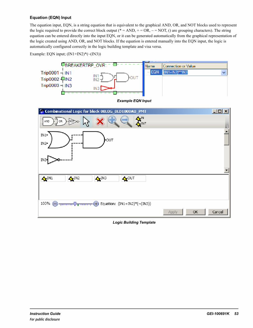
Equation (EQN) Input
The equation input, EQN, is a string equation that is equivalent to the graphical AND, OR, and NOT blocks used to representthe logic required to provide the correct block output (* = AND, + = OR, ~ = NOT, () are grouping characters). The stringequation can be entered directly into the input EQN, or it can be generated automatically from the graphical representation ofthe logic created using AND, OR, and NOT blocks. If the equation is entered manually into the EQN input, the logic isautomatically configured correctly in the logic building template and visa versa.
Example: EQN input; (IN1+IN2)*(~(IN3))
Example EQN Input
Logic Building Template
Instruction Guide GEI-100691K 53For public disclosure

IN1, IN1TP, IN1TE, and IN1T (1-32) Inputs
Inputs IN1 through IN32 are manipulated by AND, OR, and NOT logic to create the desired output.
Input toggle permits, IN1TP through IN32TP , are set by the programmer and can only be changed in the controller byperforming a Build and Download of the modified code. If the toggle permit input for a corresponding input is True, theoperator is able to toggle the value of the associated logical input, IN1TE through IN32TE, using the CIMPLICITY graphicalinterface.
Inputs IN1TE through IN32TE are toggle enable inputs that are controlled by the operator using the CIMPLICITY graphicalinterface. The operator can toggle each permitted input from True to False, or False to True.
The toggle input values, IN1T through IN32T, track the values of IN1 through IN32, respectively, when toggle mode is notenabled for its input. The toggle input value, IN1T through IN32T, is the actual value that is used in the AND, OR, and NOTprogrammed logic. The toggle value, IN1T, for the IN1 input is defined as a combination of the toggle input permit, IN1TPbeing equal to True, and the toggle enable input from the CIMPLICITY graphical interface, IN1TE being equal to True. Thistoggle value concept is True for all 32 inputs, IN1 through IN32.
Output (OUT) Enumerations
The output, OUT, is an enumerated output. The enumerations for OUT are based on the block type dictated by the inputenumeration assigned to the input TYP, and will be a PERMIT, OVERRIDE, FORCE, or TRACK type enumerations. OUToutput enumerations are defined by type, either PERMIT, FORCE, OVERRIDE or TRACK.
OUT Permit Type Output Enumerations
Name DescriptionNO_PERM-NO_BYPASS No Permit and no Permit is bypassedPERM-NO_BYPASS Permit OK and no Permit is bypassedNO_PERM-BYPASS No Permit and a Permit is bypassedPERM-BYPASS Permit OK and a Permit is bypassed
NO_PERM— indicates all permits have not been met.
PERM— indicates all permits have been met.
NO-BYPASS— indicates the operator has not invoked a toggle of any of the associated logic driven inputs to the permit typeblock.
BYPASS— indicates the operator has invoked a toggle of at least one of the associated logic driven inputs to the permit typeblock.
OUT Force Type Output Enumerations
Name DescriptionNO_FORCE-NO_BLOCK No Force and no Force is blockedFORCE-NO_BLOCK Force active and no Force is blockedNO_FORCE-BLOCK No Force and a Force is blockedFORCE-BLOCK Force active and a Force is blocked
NO_FORCE— indicates no force command is active.
FORCE— indicates a force command is active.
NO-BLOCK— indicates the operator has not invoked a toggle of any of the associated logic driven inputs to the force typeblock.
BLOCK— indicates the operator has invoked a toggle of at least one of the associated logic driven inputs to the force typeblock.
54 GEI-100691K Mark VIeS Safety Controller Block LibraryFor public disclosure

OUT Override Type Output Enumerations
Name DescriptionNO_OVR-NO_BLOCK No Override and no Override is blockedOVR-NO_BLOCK Override active and no Override is blockedNO_OVR-BLOCK No Override and an Override is blockedOVR-BLOCK Override active and an Override is blocked
NO_OVR— indicates no override command is active.
OVR— indicates an override command is active.
NO-BLOCK— indicates the operator has not invoked a toggle of any of the associated logic driven inputs to the overridetype block.
BLOCK— indicates the operator has invoked a toggle of at least one of the associated logic driven inputs to the overridetype block.
OUT Track Command Type Enumerations
Name DescriptionNO_TRACK-NO_BLOCK No Track and no Track is blockedTRACK-NO_BLOCK Track active and no Track is blockedNO_TRACK-BLOCK No Track and a Track is blockedTRACK-BLOCK Track active and a Track is blocked
NO_TRACK— indicates no track command is active.
TRACK— indicates a track command is active.
NO-BLOCK— indicates the operator has not invoked a toggle of any of the associated logic driven inputs to the track typeblock.
BLOCK— indicates the operator has invoked a toggle of at least one of the associated logic driven inputs to the track typeblock.
Outputs OUT_TGL and OUT_VAL
The output, OUT_TGL, indicates one or more of the inputs are in toggle-enabled mode. OUT_TGL is True when at least oneIN1TP and IN1TE through IN32TP and IN32TE pair is True. When OUT_TGL is True, the OUT enumeration containsBYPASS or BLOCK based on the enumeration chosen for the block by the input TYP.
OUT_VAL, the Boolean output status, is driven by the logical output of the user-defined equation input, EQN. When OUT_VAL is True, the OUT enumeration contains either PERM, OVR, FORCE or TRACK based on the enumeration chosen forthe block input TYP.
Instruction Guide GEI-100691K 55For public disclosure
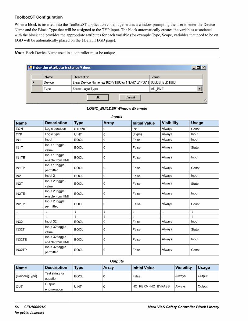
ToolboxST Configuration
When a block is inserted into the ToolboxST application code, it generates a window prompting the user to enter the DeviceName and the Block Type that will be assigned to the TYP input. The block automatically creates the variables associatedwith the block and provides the appropriate attributes for each variable (for example Type, Scope, variables that need to be onEGD will be automatically placed on the $Default EGD page).
Note Each Device Name used in a controller must be unique.
LOGIC_BUILDERWindow Example
Inputs
Name Description Type Array Initial Value Visibility UsageEQN Logic equation STRING 0 IN1 Always ConstTYP Logic type UINT 0 {Type} Always Input
IN1 Input 1 BOOL 0 False Always Input
IN1TInput 1 togglevalue
BOOL 0 False Always State
IN1TEInput 1 toggleenable from HMI
BOOL 0 False Always Input
IN1TPInput 1 togglepermitted
BOOL 0 False Always Const
IN2 Input 2 BOOL 0 False Always Input
IN2TInput 2 togglevalue
BOOL 0 False Always State
IN2TEInput 2 toggleenable from HMI
BOOL 0 False Always Input
IN2TPInput 2 togglepermitted
BOOL 0 False Always Const
↓ ↓ ↓ ↓ ↓ ↓ ↓↓ ↓ ↓ ↓ ↓ ↓ ↓IN32 Input 32 BOOL 0 False Always Input
IN32TInput 32 togglevalue
BOOL 0 False Always State
IN32TEInput 32 toggleenable from HMI
BOOL 0 False Always Input
IN32TPInput 32 togglepermitted
BOOL 0 False Always Const
Outputs
Name Description Type Array Initial Value Visibility Usage
{Device}{Type}Test string forequation
BOOL 0 False Always Output
OUTOutputenumeration
UINT 0 NO_PERM -NO_BYPASS Always Output
56 GEI-100691K Mark VIeS Safety Controller Block LibraryFor public disclosure
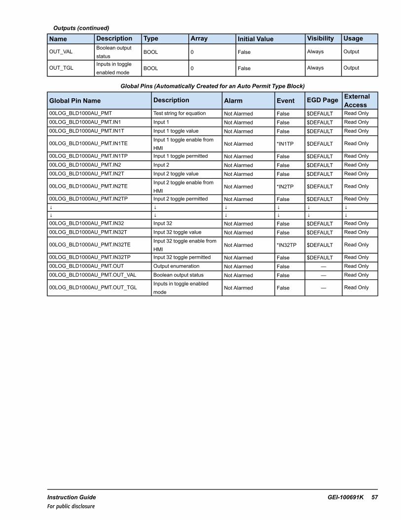
Outputs (continued)
Name Description Type Array Initial Value Visibility Usage
OUT_VALBoolean outputstatus
BOOL 0 False Always Output
OUT_TGLInputs in toggleenabled mode
BOOL 0 False Always Output
Global Pins (Automatically Created for an Auto Permit Type Block)
Global Pin Name Description Alarm Event EGD Page ExternalAccess
00LOG_BLD1000AU_PMT Test string for equation Not Alarmed False $DEFAULT Read Only00LOG_BLD1000AU_PMT.IN1 Input 1 Not Alarmed False $DEFAULT Read Only00LOG_BLD1000AU_PMT.IN1T Input 1 toggle value Not Alarmed False $DEFAULT Read Only
00LOG_BLD1000AU_PMT.IN1TEInput 1 toggle enable fromHMI
Not Alarmed *IN1TP $DEFAULT Read Only
00LOG_BLD1000AU_PMT.IN1TP Input 1 toggle permitted Not Alarmed False $DEFAULT Read Only00LOG_BLD1000AU_PMT.IN2 Input 2 Not Alarmed False $DEFAULT Read Only00LOG_BLD1000AU_PMT.IN2T Input 2 toggle value Not Alarmed False $DEFAULT Read Only
00LOG_BLD1000AU_PMT.IN2TEInput 2 toggle enable fromHMI
Not Alarmed *IN2TP $DEFAULT Read Only
00LOG_BLD1000AU_PMT.IN2TP Input 2 toggle permitted Not Alarmed False $DEFAULT Read Only↓ ↓ ↓ ↓ ↓ ↓↓ ↓ ↓ ↓ ↓ ↓00LOG_BLD1000AU_PMT.IN32 Input 32 Not Alarmed False $DEFAULT Read Only00LOG_BLD1000AU_PMT.IN32T Input 32 toggle value Not Alarmed False $DEFAULT Read Only
00LOG_BLD1000AU_PMT.IN32TEInput 32 toggle enable fromHMI
Not Alarmed *IN32TP $DEFAULT Read Only
00LOG_BLD1000AU_PMT.IN32TP Input 32 toggle permitted Not Alarmed False $DEFAULT Read Only00LOG_BLD1000AU_PMT.OUT Output enumeration Not Alarmed False — Read Only00LOG_BLD1000AU_PMT.OUT_VAL Boolean output status Not Alarmed False — Read Only
00LOG_BLD1000AU_PMT.OUT_TGLInputs in toggle enabledmode
Not Alarmed False — Read Only
Instruction Guide GEI-100691K 57For public disclosure

HMI Configuration (CIMPLICITY)
The following figure is an example of the CIMPLICITY graphical interface with a permit type block, with six permit enabledinputs and input 2 is toggled.
Typical HMI Object for LOGIC_BUILDER with a Permit Type Block
The following figure is an example of the common usage of a LOGIC_BUILDER block. This example displays the LOGIC_BUILDER block sharing the same name as the M_O_V block that it is controlling. The ToolboxST application requires thatall blocks have unique names. The LOGIC_BUILDER blocks avoid this by adding the block type to the block name. Thismakes them unique, links them to the block they control in the HMI, and indicates their function.
58 GEI-100691K Mark VIeS Safety Controller Block LibraryFor public disclosure
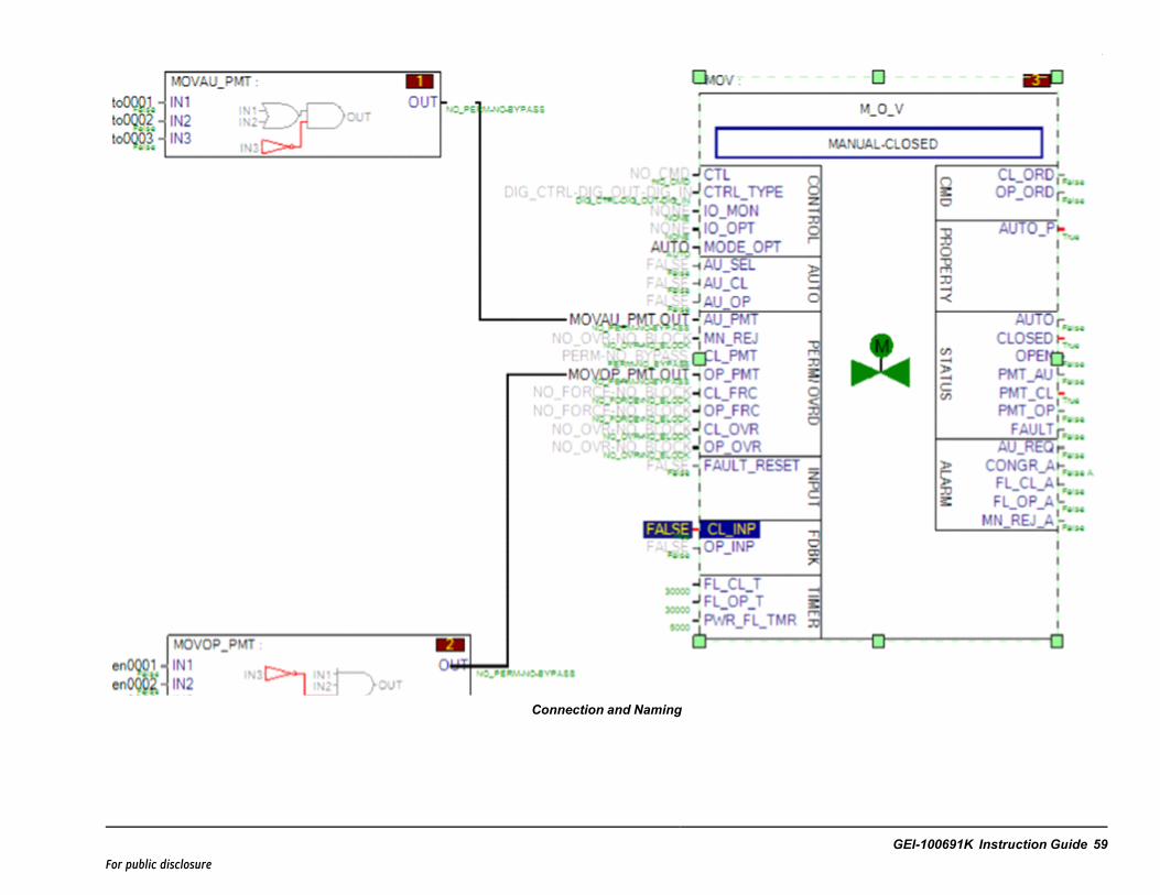
Connection and Naming
GEI-100691K Instruction Guide 59For public disclosure

State Change
The State Change feature performs a First In-First Out (FIFO) operation for all 32 inputs. It latches input values for thecurrent and previous frames when the output transitions to a Not Permitted, Forced, Override, or Track state. Indication isprovided that a State Change has occurred and acts as a reset dominant latch.
Each input has the capability of inheriting the description of a connected global variable or a global variable connectedthrough a NOT block. When a connection is made to one of the input pins, the description of the global variable is inheritedby default. If this description is undesirable, it must be disabled by setting the Inherit Description option to False in the inputvariable properties. The description can be replaced with a desirable description by entering an appropriate description in thedescription field of the input variable of the LOGIC_BUILDER_SC block (replace LOGIC_BUILDER_SC #1 with thedesired override description for the source connected to IN1). The description is not copied from the connected variableimmediately; the input’s description is set when the library or device containing the input is validated or built.
The State Change feature adds the input pins SCA_ENABLE, RESET, and RESET_PB. The SCA_ENABLE pin must beTrue for the State Change feature to operate. This would typically be connected to device I/O to prevent recording a StateChange while the equipment is not operating. For example, it may not be desired to record a process trip to a pump if thepump was already off when the trip signal was sent.
The RESET pin is available for control logic to reset the SCA pin. While the RESET pin is held True, the SCA pin willremain False. It might be desirable to set this input True for one frame when a sequence or system is initially started.
The RESET_PB pin is intended for use by the CIMPLICITY graphical interface. When the RESET_PB pin is set to True theSCA pin is set to False, then RESET_PB is set to False by the LOGIC_BUILDER_SC block.
The State Change feature adds the outputs pins SCA, SCA_CUR, and SCA_PRV. The SCA pin changes from False to Truewhen the OUT pin transitions to a Not Permitted, Forced, Override, or Track state. The SCA pin acts as a reset dominantlatch. The RESET and RESET_PB pins reset the SCA latch. The SCA_ENABLE pin prevents the SCA latch from being set,but will not reset the SCA latch.
The SCA_CUR pin holds a 32-bit un-signed integer. The value of each bit of this integer represents the value of thecorresponding input, for the frame the OUT pin transitioned to a Not Permitted, Forced, Override, or Track state.
The SCA_PRV pin holds a 32-bit un-signed integer. The value of each bit of this integer represents the value of thecorresponding input, one frame before the OUT pin transitioned to a Not Permitted, Forced, Override, or Track state.
60 GEI-100691K Mark VIeS Safety Controller Block LibraryFor public disclosure
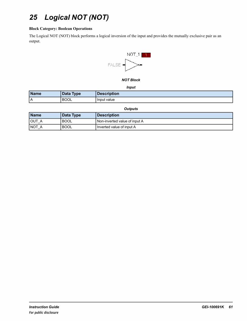
25 Logical NOT (NOT)Block Category: Boolean Operations
The Logical NOT (NOT) block performs a logical inversion of the input and provides the mutually exclusive pair as anoutput.
NOT Block
Input
Name Data Type DescriptionA BOOL Input value
Outputs
Name Data Type DescriptionOUT_A BOOL Non-inverted value of input ANOT_A BOOL Inverted value of input A
Instruction Guide GEI-100691K 61For public disclosure
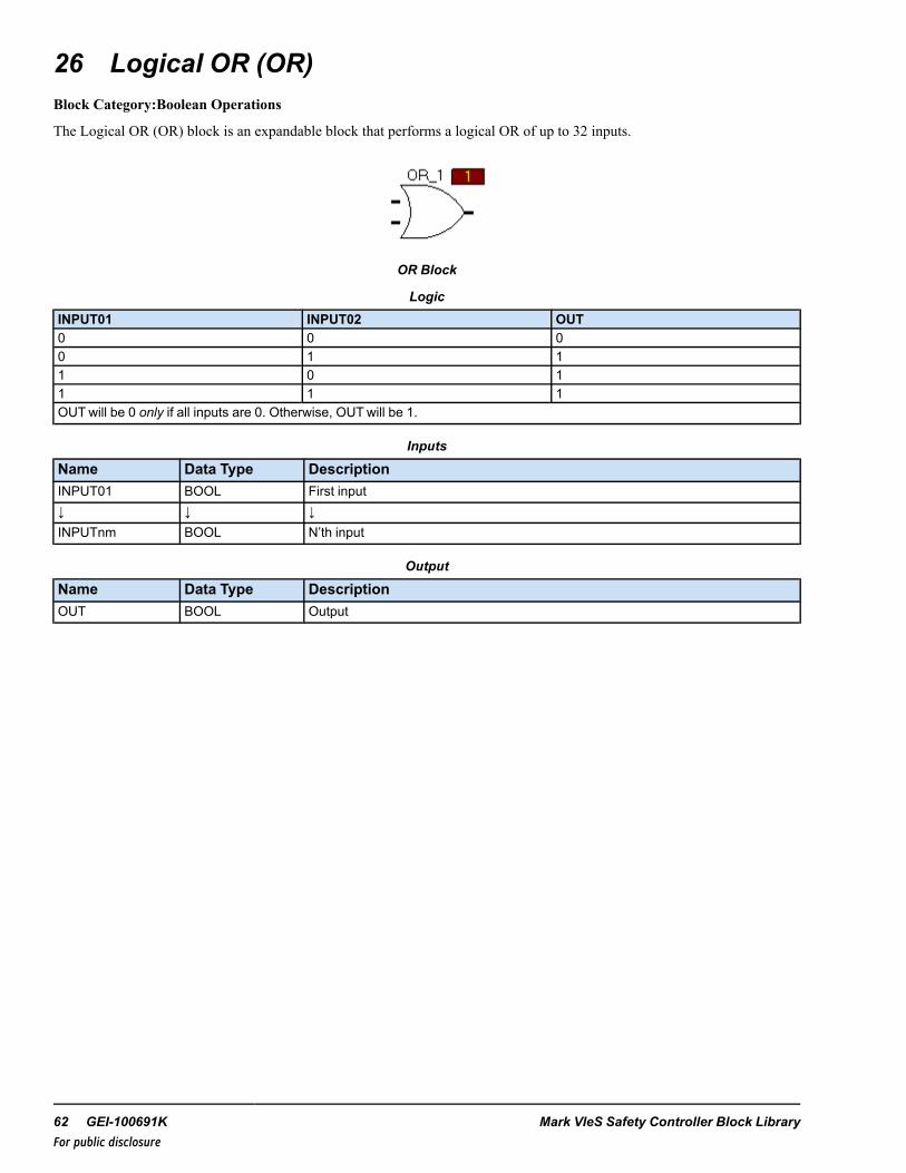
26 Logical OR (OR)Block Category:Boolean Operations
The Logical OR (OR) block is an expandable block that performs a logical OR of up to 32 inputs.
OR Block
LogicINPUT01 INPUT02 OUT0 0 00 1 11 0 11 1 1OUTwill be 0 only if all inputs are 0. Otherwise, OUTwill be 1.
Inputs
Name Data Type DescriptionINPUT01 BOOL First input↓ ↓ ↓INPUTnm BOOL N’th input
Output
Name Data Type DescriptionOUT BOOL Output
62 GEI-100691K Mark VIeS Safety Controller Block LibraryFor public disclosure
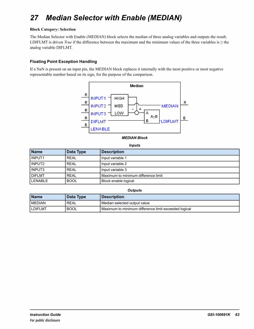
27 Median Selector with Enable (MEDIAN)Block Category: Selection
The Median Selector with Enable (MEDIAN) block selects the median of three analog variables and outputs the result.LDIFLMT is driven True if the difference between the maximum and the minimum values of the three variables is ≥ theanalog variable DIFLMT.
Floating Point Exception Handling
If a NaN is present on an input pin, the MEDIAN block replaces it internally with the most positive or most negativerepresentable number based on its sign, for the purpose of the comparison.
MEDIAN Block
Inputs
Name Data Type DescriptionINPUT1 REAL Input variable 1INPUT2 REAL Input variable 2INPUT3 REAL Input variable 3DIFLMT REAL Maximum to minimum difference limitLENABLE BOOL Block enable logical
Outputs
Name Data Type DescriptionMEDIAN REAL Median selected output valueLDIFLMT BOOL Maximum to minimum difference limit exceeded logical
Instruction Guide GEI-100691K 63For public disclosure
28 Median Select Version 2 (MEDSEL_S2)Block Category: Analog Operations
The Median Select Version 2 (MEDSEL_S2) block selects the median or average of three analog signals based on theenumerated value of the input TS and transfers the selection to the output ({Device}). The user has the option to disable up totwo transmitters. If one transmitter is disabled, the output will be either the minimum, maximum, or average of the tworemaining transmitters based on the enumerated value of the input, DS. If the one transmitter allowed property, 1XMTR_P, isTrue, two transmitters can be disabled and the output will be the value of the remaining transmitter.
This block is similar to the Mark VIe block MEDSEL_V2 but functionality differs in the following ways:
• The MEDSEL_S2 block does not support the status option.• The Auto Enable (AU_EN_P) feature is not supported.• Control commands for disabling and enabling transmitters are supported in the MEDSEL_S2 bock; however, the
push-button reset functionality must be implemented in another device. For further details, refer to the description ofcontrol word (CTL_EXT) in the section Control Word.
Block Configuration
Disabling Transmitters
When the quality status of transmitter A is BAD (False), then ABQ and AD become True and transmitter A is automaticallydisabled. Also, depending on the DS enumeration selected, the average, minimum, or maximum of inputs B and C istransferred to OUT. Once the quality status of transmitter A becomes GOOD (True), ABQ becomes False. If the quality statusof transmitter A becomes GOOD (True) and the value of input A is within the deviation limits set by the user, AD becomesFalse and A is automatically enabled. This concept also applies to inputs B and C.
A transmitter can be manually disabled through the CTL_EXT input. If input A, B, and C are all enabled and have a GOODquality status, and A is manually disabled, then the corresponding output, AD, becomes True to indicate that input A isdisabled. If input A is enabled and B is disabled, then BD is True. If input B is enabled and C is disabled, then CD is True.
Output Bad Quality Indication (OBQ) functionality is as follows:
If 1XMTR_P is True, when three transmitters are disabled and/or in a BAD quality state, OBQ becomes True, the defaultvalue, DF, is automatically transferred to the output, and MODE is set to DEFAULT.
OBQ becomes False when the quality status of any input becomes GOOD. The GOOD quality input will be enabled andtransferred to the output.
If 1XMTR_P is False, when two or three transmitters are disabled and/or in a BAD quality state, OBQ becomes True, thedefault value, DF, is automatically transferred to output, and MODE is set to DEFAULT.
OBQ becomes False when the quality status of two inputs become GOOD. The GOOD quality inputs will be enabled andbased on the DS enumeration selected, the average, minimum, or maximum of the GOOD quality inputs is transferred to theoutput.
Control Word
Control word (CTL_EXT) is used by the HMI operator for manual control. The manual commands from the HMI allow eachinput to be enabled or disabled. A manually disabled transmitter can be manually enabled, regardless of its deviation status.The command enumerations are defined in the following table.
Note A manually disabled transmitter may be manually enabled, regardless of its deviation status, unless the block is inAverage mode. For further details, refer to the section Deviation Alarms.
64 GEI-100691K Mark VIeS Safety Controller Block LibraryFor public disclosure
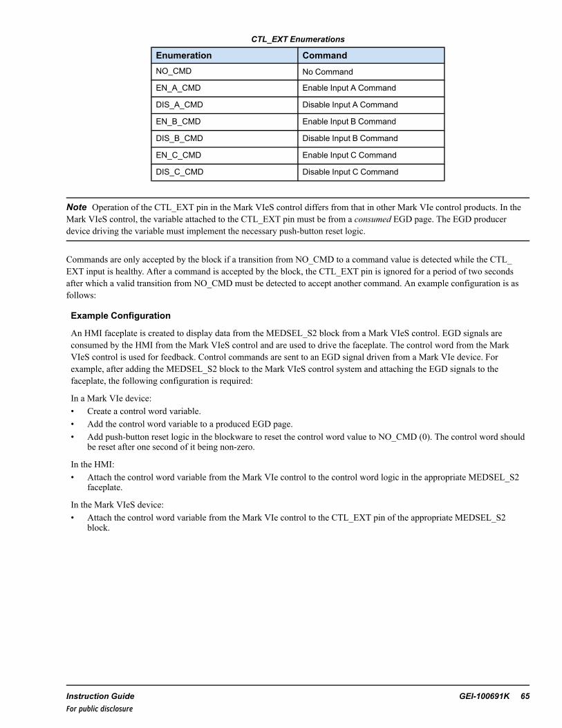
CTL_EXT Enumerations
Enumeration CommandNO_CMD No Command
EN_A_CMD Enable Input A Command
DIS_A_CMD Disable Input A Command
EN_B_CMD Enable Input B Command
DIS_B_CMD Disable Input B Command
EN_C_CMD Enable Input C Command
DIS_C_CMD Disable Input C Command
Note Operation of the CTL_EXT pin in the Mark VIeS control differs from that in other Mark VIe control products. In theMark VIeS control, the variable attached to the CTL_EXT pin must be from a consumed EGD page. The EGD producerdevice driving the variable must implement the necessary push-button reset logic.
Commands are only accepted by the block if a transition from NO_CMD to a command value is detected while the CTL_EXT input is healthy. After a command is accepted by the block, the CTL_EXT pin is ignored for a period of two secondsafter which a valid transition from NO_CMD must be detected to accept another command. An example configuration is asfollows:
Example Configuration
An HMI faceplate is created to display data from the MEDSEL_S2 block from a Mark VIeS control. EGD signals areconsumed by the HMI from the Mark VIeS control and are used to drive the faceplate. The control word from the MarkVIeS control is used for feedback. Control commands are sent to an EGD signal driven from a Mark VIe device. Forexample, after adding the MEDSEL_S2 block to the Mark VIeS control system and attaching the EGD signals to thefaceplate, the following configuration is required:
In a Mark VIe device:• Create a control word variable.• Add the control word variable to a produced EGD page.• Add push-button reset logic in the blockware to reset the control word value to NO_CMD (0). The control word should
be reset after one second of it being non-zero.
In the HMI:• Attach the control word variable from the Mark VIe control to the control word logic in the appropriate MEDSEL_S2
faceplate.
In the Mark VIeS device:• Attach the control word variable from the Mark VIe control to the CTL_EXT pin of the appropriate MEDSEL_S2
block.
Instruction Guide GEI-100691K 65For public disclosure

Block Function Enumerations
Function is defined by two modes:
• Dual Select (DS) mode• Three Select (TS) mode
DS Enumerations
Enumeration FunctionAVG Average of A and B
MIN Minimum of A and B
MAX Maximum of A and B
TS Mode Enumerations
Enumeration FunctionAVG Average of A, B and C
MEDIAN Median of A, B and C
Operating mode (MODE) is the block-operating mode that depends on DS, TS, and the quality status of the inputs. Theoperating mode enumerations are defined in the following table.
MODE Enumerations
Enumeration Operating Mode
MIN_B-C Minimum of B and C
MIN_A-B Minimum of A and B
MIN_A-C Minimum of A and C
MAX_B-C Maximum of B and C
MAX_A-B Maximum of A and B
MAX_A-C Maximum of A and C
AVG_A-B Average of A and B
AVG_A-C Average of A and C
AVG_B-C Average of B and C
AVG_ABC Average of A, B, and C
MEDIAN Median of A, B, and C
A Input A
B Input B
C Input C
DEFAULT Input DF
66 GEI-100691K Mark VIeS Safety Controller Block LibraryFor public disclosure

Examples
• MEDIAN or AVG_ABC mode is selected when none of the transmitters have a BAD quality status.• AVG_A-B mode is selected when a BAD quality is detected on transmitter C or when C is manually disabled, and the DS
enumeration is AVG.• MIN_A-B mode is selected when a BAD quality is detected on transmitter C or when C is manually disabled, and the DS
enumeration is MIN.• MAX_A-B mode is selected when a BAD quality is detected on transmitter C or when C is manually disabled, and the
DS enumeration is MAX.• A mode is selected when 1XMTR_P is True and B and C transmitters are disabled.• DEFAULT mode is selected when all transmitters are BAD quality and/or disabled or 1XMTR_P is False, and two
transmitters are BAD quality and/or disabled.
Deviation Alarms
Each transmitter value is compared with the output to determine if it is outside of the deviation limit, DL. If so, the deviationhigh alarm for the deviant input DA, DB, or DC, for transmitters A, B, or C respectively, and ODH become True, delayed bythe deviation time delay, DT.
The deviation alarms will not become False until the absolute difference between the deviant input and the output is less thanthe value of DL minus Deviation Limit Deadband (DLDB), or the deviant input is disabled.
Note The Deviation High output, ODH, becomes True when at least one transmitter is in deviation. Also, if a transmitterinput is disabled, the deviation alarm for that transmitter is disabled.
In general, the deviation alarm only sets Boolean outputs and has no influence on the functionality of the block (for example,the transmitter in deviation with the output is not automatically disabled, and the block mode does not change).
However, if the block is calculating the average of all three transmitters (all three transmitters are enabled and TS = AVG), atransmitter that gets a high deviation will be automatically disabled immediately (ignoring the value of DT). The highdeviation alarm will be True for a single block execution. It will be enabled when the absolute difference between the deviantinput and the output is less than the value of DL minus DLDB.
Rate of Change Restriction
The rate of change of the output is only restricted by the value of RATE when the block operating mode changes.
RATE is in engineering units per second. For example, if 1XMTR_P = True, RATE = 1, A = 10 (enabled), B = 25 (disabled),and C = 50 (disabled), so MODE = A, and the mode of the block is changed by enabling input B and disabling input A. Now,MODE = B and the output increases from 10 to 25 engineering units in 15 seconds. At this point, the output equals B, theblock operating mode transition from A to B is complete and the rate of change restriction on the output is removed until theblock operating mode changes again.
ToolboxST Configuration
Inserting the MEDSEL_S2 block in the application program displays the Enter the Attribute Instance Values window,prompting the user to enter the device description, device name, and format specification in the Values column. The blockthen automatically creates the variables associated with the block and provide the appropriate attributes for each variable (forexample, Type and Format Spec variables that need to be on EGD will automatically be placed on the $Default EGD page,and so forth).
Note Each Device Name used in a controller must be unique.
Instruction Guide GEI-100691K 67For public disclosure

Enter the Attribute Instance Values Window
For this example, accept the default options for these attributes. The Device Name is 00MEDSEL_S21000, the description isMEDSEL_S2 Description, and the format specification is TempFS.
When the user clicks OK, the block and pin connections are automatically configured and Global pins are generated. Pinnames are in the form Device Value.pin Name, where Device Value has the attribute value 00MEDSEL_S21000 and Input_Name is the block input/output name. (Refer to the table Global Variables.) For this example, the descriptionMEDSEL_S2Description becomes the prefix of the block input/output descriptions. The FormatSp Attribute Name Value in the previousexample, TempFS, is the format specification of the block output. The DLFormatSp Attribute Name Value, TempDiffFS, is theformat specification of the block DL pin output.
Note The only exception to this rule is the output pin ({Device}), where the global pin name is in the form Device Value.pinName without the " ".
Once the object has been added successfully, the block displays in the ToolboxST application as displayed in the followingfigure.
MEDSEL_S2 Block
68 GEI-100691K Mark VIeS Safety Controller Block LibraryFor public disclosure
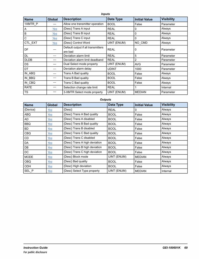
Inputs
Name Global Description Data Type Initial Value Visibility1XMTR_P — Allow one transmitter operation BOOL False ParameterA Yes {Desc} Trans A input REAL 0 Always
B Yes {Desc} Trans B input REAL 0 Always
C Yes {Desc} Trans C input REAL 0 AlwaysCTL_EXT Yes {Desc} Control Word UINT (ENUM) NO_CMD Always
DF — Default output if all transmittersare bad
REAL 0 Parameter
DL — Deviation alarm limit REAL 5 ParameterDLDB — Deviation alarm limit deadband REAL 2 ParameterDS — Dual Select mode property UINT (ENUM) AVG ParameterDT — Deviation alarm delay UDINT 1000 ParameterIN_ABQ — Trans A Bad quality BOOL False AlwaysIN_BBQ — Trans B Bad quality BOOL False AlwaysIN_CBQ — Trans C Bad quality BOOL False AlwaysRATE — Selection change rate limit REAL 1 InternalTS — 3-XMTR Select mode property UINT (ENUM) MEDIAN Parameter
Outputs
Name Global Description Data Type Initial Value Visibility{Device} Yes {Desc} REAL 0 AlwaysABQ Yes {Desc} Trans A Bad quality BOOL False Always
AD Yes {Desc} Trans A disabled BOOL False AlwaysBBQ Yes {Desc} Trans B Bad quality BOOL False Always
BD Yes {Desc} Trans B disabled BOOL False AlwaysCBQ Yes {Desc} Trans C Bad quality BOOL False Always
CD Yes {Desc} Trans C disabled BOOL False Always
DA Yes {Desc} Trans A high deviation BOOL False Always
DB Yes {Desc} Trans B high deviation BOOL False Always
DC Yes {Desc} Trans C high deviation BOOL False Always
MODE Yes {Desc} Block mode UINT (ENUM) MEDIAN AlwaysOBQ Yes {Desc} Bad quality BOOL False Always
ODH Yes {Desc} High deviation BOOL False AlwaysSEL_P Yes {Desc} Select Type property UINT (ENUM) MEDIAN Internal
Instruction Guide GEI-100691K 69For public disclosure

Global Variables
Pin Name Description Alarm AlarmClass Event EGD Page External
AccessMEDSEL_S21001 MEDSEL_S2 1001 Not Alarmed — False $Default ReadOnly
MEDSEL_S21001.AMEDSEL_S2 1001 Trans Ainput Not Alarmed — False $Default ReadOnly
MEDSEL_S21001.ABQMEDSEL_S2 1001 Trans Abad quality Not Alarmed — False $Default ReadOnly
MEDSEL_S21001.AD MEDSEL_S2 1001 Trans Adeselected
Not Alarmed — True $Default ReadOnly
MEDSEL_S21001.BMEDSEL_S2 1001 Trans Binput Not Alarmed — False $Default ReadOnly
MEDSEL_S21001.BBQMEDSEL_S2 1001 Trans Bbad quality Not Alarmed — False $Default ReadOnly
MEDSEL_S21001.BD MEDSEL_S2 1001 Trans Bdeselected
Not Alarmed — True $Default ReadOnly
MEDSEL_S21001.CMEDSEL_S2 1001 Trans Cinput Not Alarmed — False $Default ReadOnly
MEDSEL_S21001.CBQMEDSEL_S2 1001 Trans Cbad quality Not Alarmed — False $Default ReadOnly
MEDSEL_S21001.CD MEDSEL_S2 1001 Trans Cdeselected
Not Alarmed — True $Default ReadOnly
MEDSEL_S21001.CTL_EXT
MEDSEL_S2 1001 ControlWord
Not Alarmed — False $Default ReadOnly
MEDSEL_S21001.DAMEDSEL_S2 1001 Trans Ahigh deviation Alarmed Alert False $Default ReadOnly
MEDSEL_S21001.DBMEDSEL_S2 1001 Trans Bhigh deviation Alarmed Alert False $Default ReadOnly
MEDSEL_S21001.DCMEDSEL_S2 1001 Trans Chigh deviation Alarmed Alert False $Default ReadOnly
MEDSEL_S21001.MODE MEDSEL_S2 1001 Blockmode
Not Alarmed — False $Default ReadOnly
MEDSEL_S21001.OBQMEDSEL_S2 1001 Badquality Not Alarmed — False $Default ReadOnly
MEDSEL_S21001.ODH MEDSEL_S2 1001 Highdeviation
Alarmed Alert False $Default ReadOnly
MEDSEL_S21001.SEL_PMEDSEL_S2 1001 Selecttype property Not Alarmed — False $Default ReadOnly
70 GEI-100691K Mark VIeS Safety Controller Block LibraryFor public disclosure
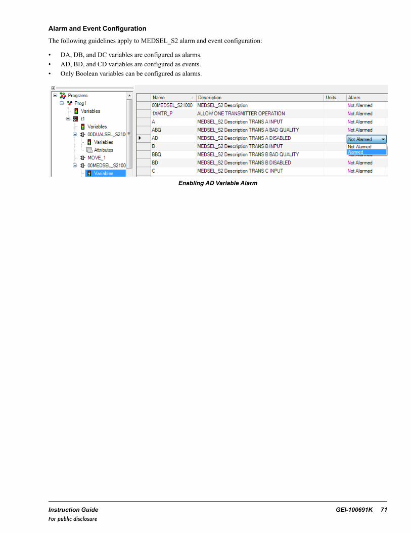
Alarm and Event Configuration
The following guidelines apply to MEDSEL_S2 alarm and event configuration:
• DA, DB, and DC variables are configured as alarms.• AD, BD, and CD variables are configured as events.• Only Boolean variables can be configured as alarms.
Enabling AD Variable Alarm
Instruction Guide GEI-100691K 71For public disclosure

29 Move (MOVE)Block Category: Type Conversion
The Move (MOVE) block transfers the value of the input variable, SRC, into the output variable, DEST. The data transferoccurs each time the block runs and the ENABLE pin is True. The analog variants of the block can be used to perform datatype conversions, as well as memory move operations. The Boolean variant of MOVE is used to move only a logical state andcannot convert the data type.
The MOVE blocks are useful for taking snapshots of data that are shared between tasks in separate modules. Moving thevariable to local copies guarantees that a high priority task cannot change the shared data while the low priority task isprocessing it.
Floating Point Exception Handling
The MOVE block does not allow a NaN to pass through it. If a NaN is encountered on an input pin, it is replaced at the outputwith either the most positive or most negative representable number, based on the sign of the NaN.
Note This is a variant block that supports any one the following block data types: BOOL, INT, DINT, REAL, LREAL,UINT, and UDINT. The data type of the DEST pin must match the selected data type of the block. Refer to the section .
MOVE Block
Inputs
Name Data Type DescriptionENABLE BOOL Block enable (default is True)SRC ANY Source variable
Output
Name Data Type DescriptionDEST ANY Destination variable (data type enforced by the block type)
72 GEI-100691K Mark VIeS Safety Controller Block LibraryFor public disclosure
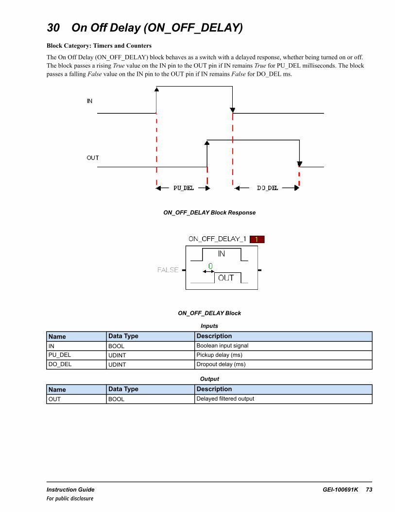
30 On Off Delay (ON_OFF_DELAY)Block Category: Timers and Counters
The On Off Delay (ON_OFF_DELAY) block behaves as a switch with a delayed response, whether being turned on or off.The block passes a rising True value on the IN pin to the OUT pin if IN remains True for PU_DEL milliseconds. The blockpasses a falling False value on the IN pin to the OUT pin if IN remains False for DO_DEL ms.
ON_OFF_DELAY Block Response
ON_OFF_DELAY Block
Inputs
Name Data Type DescriptionIN BOOL Boolean input signalPU_DEL UDINT Pickup delay (ms)DO_DEL UDINT Dropout delay (ms)
Output
Name Data Type DescriptionOUT BOOL Delayed filtered output
Instruction Guide GEI-100691K 73For public disclosure

31 Prevote (PREVOTE)Block Category: System
The Prevote (PREVOTE) block allows a user to transfer prevoted input values to blockware. The block prevotes any analogvariable into the block data type rounding any fractional value to the nearest integer (if block data type is INT) or into asingle/double precision floating point variable (if block data type is REAL). The boundary check and conversion is doneautomatically.
Note This block is a variant block that supports any one of the following block data types: BOOL, INT, DINT, REAL,LREAL, UINT, and UDINT. To modify the data type, refer to the section Change Data Type of Variant Block.
PREVOTE Block
PREVOTE Block Expanded
74 GEI-100691K Mark VIeS Safety Controller Block LibraryFor public disclosure
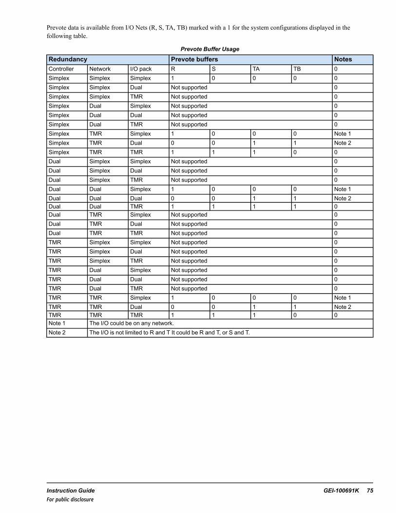
Prevote data is available from I/O Nets (R, S, TA, TB) marked with a 1 for the system configurations displayed in thefollowing table.
Prevote Buffer Usage
Redundancy Prevote buffers NotesController Network I/O pack R S TA TB 0Simplex Simplex Simplex 1 0 0 0 0Simplex Simplex Dual Not supported 0Simplex Simplex TMR Not supported 0Simplex Dual Simplex Not supported 0Simplex Dual Dual Not supported 0Simplex Dual TMR Not supported 0Simplex TMR Simplex 1 0 0 0 Note 1Simplex TMR Dual 0 0 1 1 Note 2Simplex TMR TMR 1 1 1 0 0Dual Simplex Simplex Not supported 0Dual Simplex Dual Not supported 0Dual Simplex TMR Not supported 0Dual Dual Simplex 1 0 0 0 Note 1Dual Dual Dual 0 0 1 1 Note 2Dual Dual TMR 1 1 1 1 0Dual TMR Simplex Not supported 0Dual TMR Dual Not supported 0Dual TMR TMR Not supported 0TMR Simplex Simplex Not supported 0TMR Simplex Dual Not supported 0TMR Simplex TMR Not supported 0TMR Dual Simplex Not supported 0TMR Dual Dual Not supported 0TMR Dual TMR Not supported 0TMR TMR Simplex 1 0 0 0 Note 1TMR TMR Dual 0 0 1 1 Note 2TMR TMR TMR 1 1 1 0 0Note 1 The I/O could be on any network.Note 2 The I/O is not limited to R and T It could be R and T, or S and T.
Instruction Guide GEI-100691K 75For public disclosure
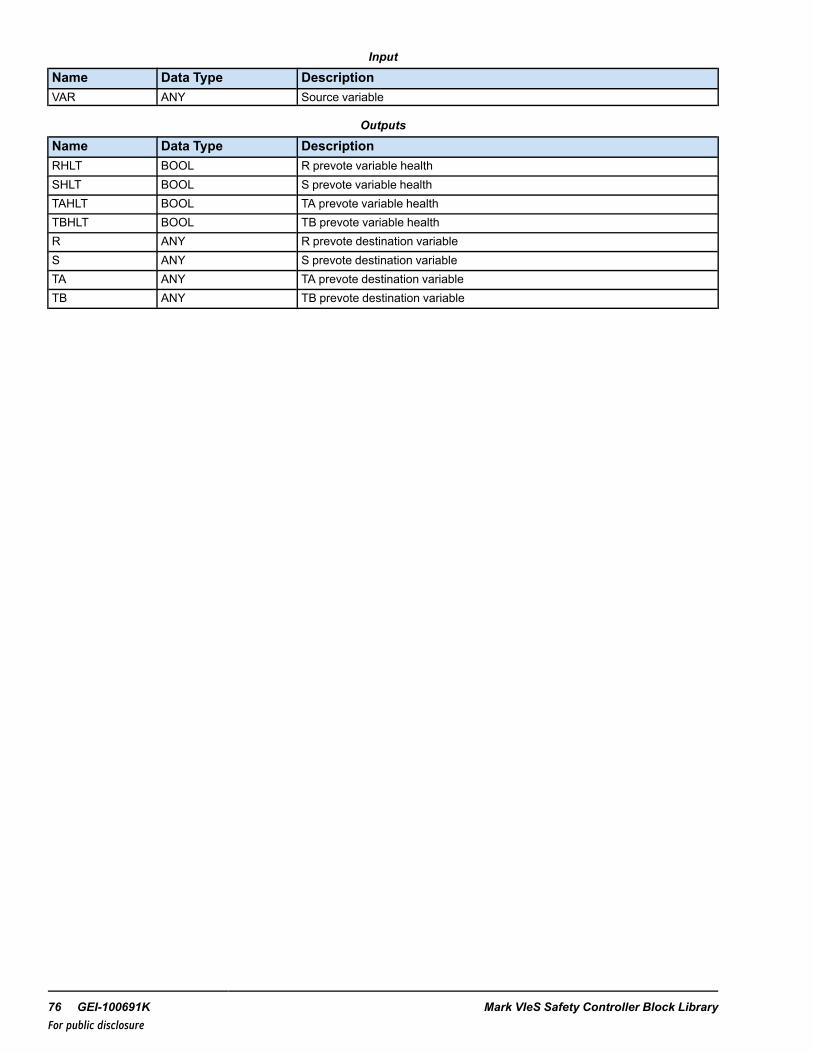
Input
Name Data Type DescriptionVAR ANY Source variable
Outputs
Name Data Type DescriptionRHLT BOOL R prevote variable healthSHLT BOOL S prevote variable healthTAHLT BOOL TA prevote variable healthTBHLT BOOL TB prevote variable healthR ANY R prevote destination variableS ANY S prevote destination variableTA ANY TA prevote destination variableTB ANY TB prevote destination variable
76 GEI-100691K Mark VIeS Safety Controller Block LibraryFor public disclosure

32 Pulse (PULSE)Block Category: Sequencing
The Pulse (PULSE) block generates a Boolean one-shot of the specified width (WIDTH in milliseconds) at the output pin onthe rising edge of the trigger. Once the pulse is initiated, it persists until it times out regardless of the value of the trigger. Theprevious state of the trigger is stored with each execution sweep so the falling edge of the next trigger may be seen prior to theend of the pulse. A specified pulse width of 0 results in a one sweep pulse. The Pulse width is always a multiple of the frameexecution period set in the ToolboxST application. For accurate execution of the block, set WIDTH as a multiple of the frameexecution period.
PULSE Block
Inputs
Name Data Type DescriptionTRIG BOOL Triggers a new pulse on its rising edgeWIDTH UDINT Period of the pulse in milliseconds (default is 0, 1 sweep)
Output
Name Data Type DescriptionOUT BOOL Pulse output
State
Name Data Type Description
CWIDTH UDINT Elapsed time since the pulse began in milliseconds
ISTRIGGERED BOOL
This is the state pin for storing the trigger status of the block, a hidden pin, It canbe viewed or changed by right-clicking the block and selecting Edit Block Pins.Writing to this variable is not recommended, but can be used to preset blockstates.
Instruction Guide GEI-100691K 77For public disclosure

33 Relay Ladder Logic (RUNG)Block Category: Boolean Operations
The Relay Ladder Logic (RUNG) block solves a Boolean equation of up to 16 inputs. The equation is specified as a characterstring or can it be configured through the Relay Ladder Logic editor in the ToolboxST application. The equation may consistof up to 64 elements, or combinations of operators and operands. For example, the equation A + B contains two operands andone operator for a total of three elements.
Supported Operators
Operation OperatorParenthesis ( )NOT ~OR +AND *
RUNG Block
Inputs
Name Data Type DescriptionEQN Constant String Boolean equationA BOOL Required Boolean input used in equation↓ ↓ ↓P BOOL Boolean input used in the equation
Output
Name Data Type DescriptionOUT BOOL The result of the equation
78 GEI-100691K Mark VIeS Safety Controller Block LibraryFor public disclosure

34 Select (SELECT)Block Category: Selection
The Select (SELECT) block is an expandable block that moves one of the 8 inputs, or the CASC into the output, based on theprioritized evaluation of the selection pins. Working in ascending order from SEL1 the first True value encountered causes thecorresponding input to be moved to the output. If none of the selection pins are True then the CASC is moved to the output.
Floating Point Exception Handling
If a NaN (Not a Number) is encountered on an input pin it is replaced at the output by either the most positive or negativerepresentable number, based on the sign of the NaN.
Note This is a variant block that supports any one the following block data types: BOOL, INT, DINT, REAL, LREAL,UINT, and UDINT. The default data type is REAL. To modify the data type, refer to the section Change Data Type of VariantBlock.
SELECT Block
Inputs
Name Data Type DescriptionENABLE BOOL Block enable (default is True)CASC ANY Default (cascade) selectionIN1 ANY First input variableSEL1 BOOL First selection input↓ ↓ ↓INn ANY N'th input variableSELn BOOL N'th selection input
Output
Name Data Type DescriptionOUT ANY Selected output
Instruction Guide GEI-100691K 79For public disclosure
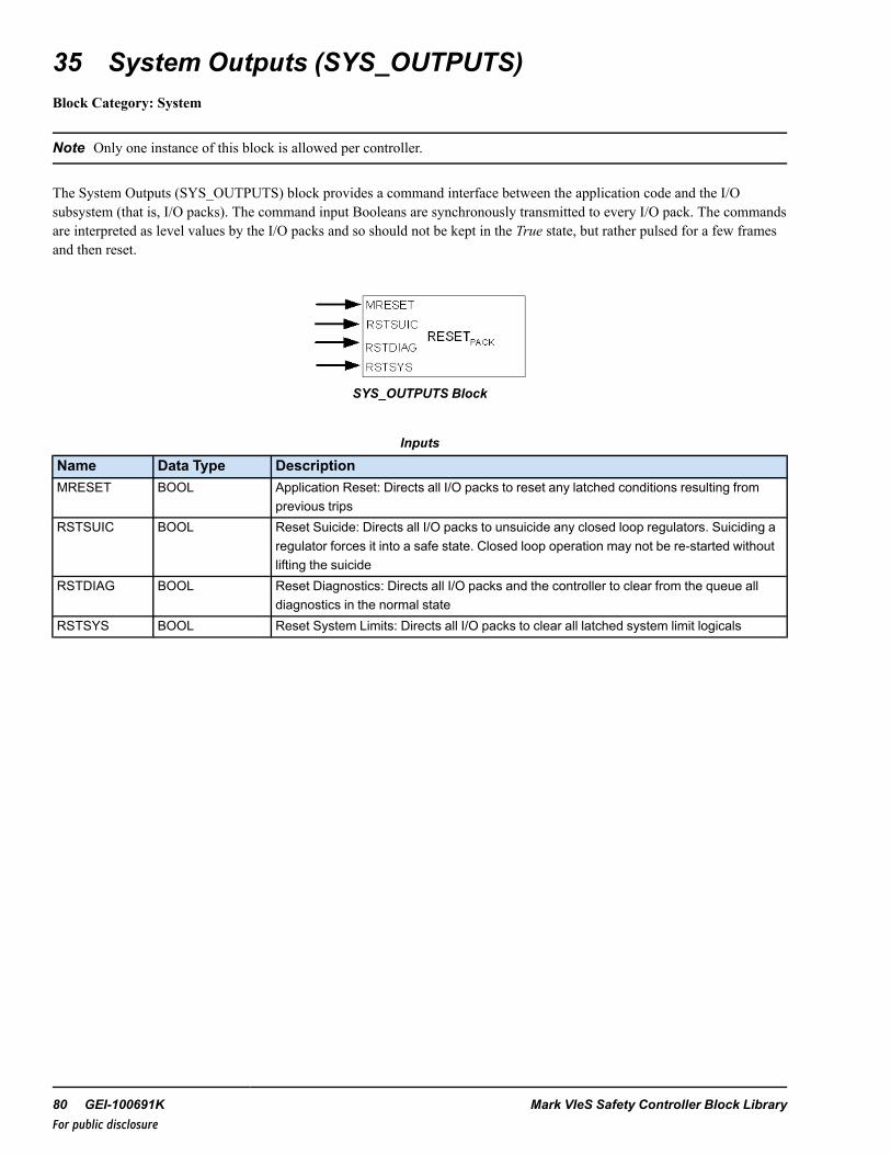
35 System Outputs (SYS_OUTPUTS)Block Category: System
Note Only one instance of this block is allowed per controller.
The System Outputs (SYS_OUTPUTS) block provides a command interface between the application code and the I/Osubsystem (that is, I/O packs). The command input Booleans are synchronously transmitted to every I/O pack. The commandsare interpreted as level values by the I/O packs and so should not be kept in the True state, but rather pulsed for a few framesand then reset.
SYS_OUTPUTS Block
Inputs
Name Data Type DescriptionMRESET BOOL Application Reset: Directs all I/O packs to reset any latched conditions resulting from
previous tripsRSTSUIC BOOL Reset Suicide: Directs all I/O packs to unsuicide any closed loop regulators. Suiciding a
regulator forces it into a safe state. Closed loop operation may not be re-started withoutlifting the suicide
RSTDIAG BOOL Reset Diagnostics: Directs all I/O packs and the controller to clear from the queue alldiagnostics in the normal state
RSTSYS BOOL Reset System Limits: Directs all I/O packs to clear all latched system limit logicals
80 GEI-100691K Mark VIeS Safety Controller Block LibraryFor public disclosure
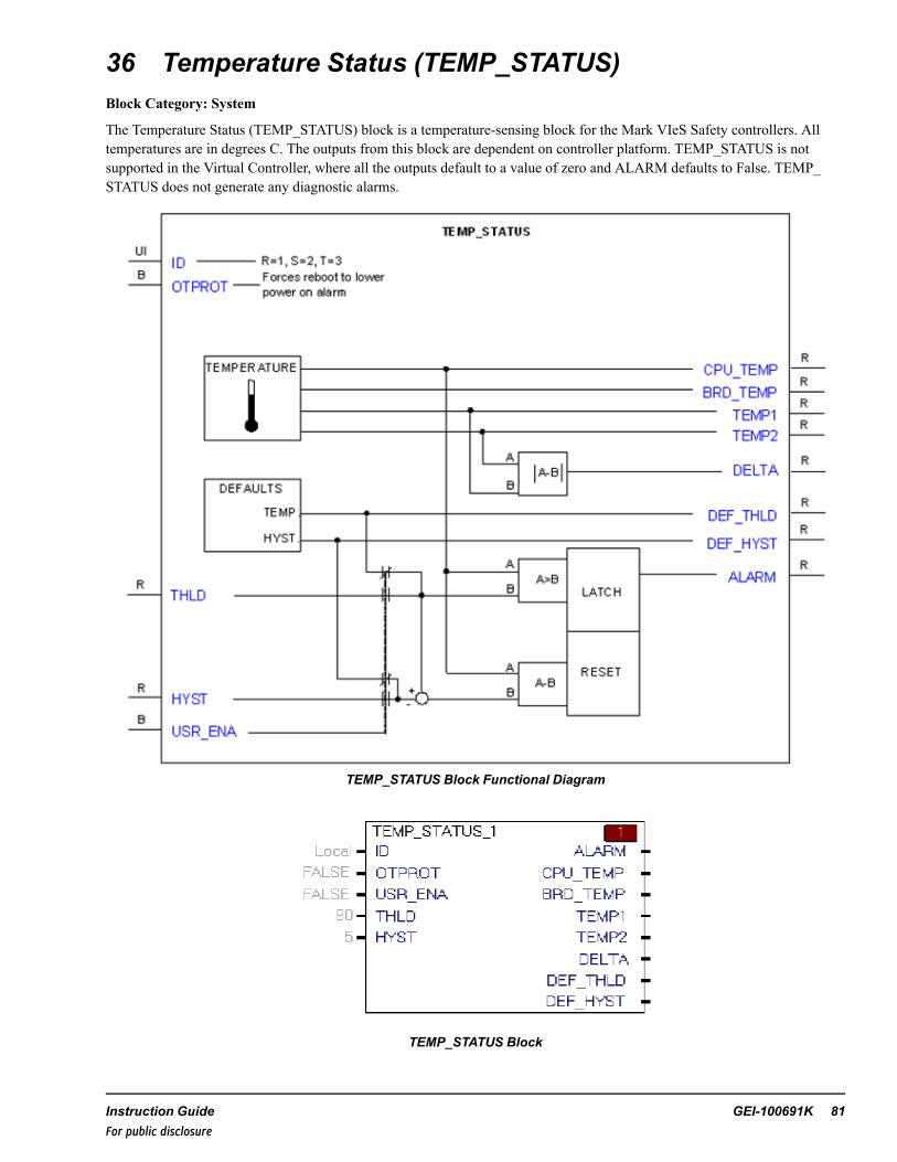
36 Temperature Status (TEMP_STATUS)Block Category: System
The Temperature Status (TEMP_STATUS) block is a temperature-sensing block for the Mark VIeS Safety controllers. Alltemperatures are in degrees C. The outputs from this block are dependent on controller platform. TEMP_STATUS is notsupported in the Virtual Controller, where all the outputs default to a value of zero and ALARM defaults to False. TEMP_STATUS does not generate any diagnostic alarms.
TEMP_STATUS Block Functional Diagram
TEMP_STATUS Block
Instruction Guide GEI-100691K 81For public disclosure

TEMP_STATUS Inputs
Input Pin Data Type Platform Functionality
ID UINT All
ID of the controller being monitored/controlled; 1 for R, 2 for S, and 3 for Tcontroller. 0 forLocal means the block monitors/controls the controller executing the block (backwardcompatibility)
OTPROT BOOL
UCSB, UCSC Not applicable
UCCCWhen True, forces the controller to reboot into a low power failure mode (in which theapplication will not run) when a temperature alarm condition is detected
THLD REALUCSB, UCSC Not applicable
UCCC Setpoint for declaring the alarm. Ignored unless USR_ENA is True
HYST REALUCSB, UCSC Not applicable
UCCCHysteresis value to be considered for clearing the alarm. Ignored unless USR_ENA isTrue
USR_ENA BOOLUCSB, UCSC Not applicable
UCCC Used to enable user supplied temperature limits
TEMP_STATUS Outputs
Output Pin Data Type Platform Functionality
ALARM BOOL
UCSB, UCSC Remains False, is not applicable
UCCC
Is False if CPU_TEMP is within limitsIf USR_ENA is False, then ALARM is True if CPU_TEMP is greater than or equal to DEF_THLD.If USR_ENA is True, then ALARM is True if CPU_TEMP is greater than or equal to THLD.If ALARM is True and if OTPROT is True, then the controller reboots to a lower powerstate
CPU_TEMP REALUCSB, UCSC Not Applicable; has a value of 0
UCCC Provides the CPU temperature in °C
BRD_TEMP REALUCSC Not Applicable; has a value of 0
UCSB Processor board hot spot temperature in °C
UCCC Motherboard temperature in °C
TEMP1 REALUCSC Temperature value of sensor on Carrier Board in °C
UCSB Processor board ambient temperature in °C
UCCC Temperature value of sensor #1 near resistor on EPMC in °C
TEMP2 REALUCSB, UCSC Not Applicable; has a value of 0
UCCC Temperature value of sensor #2 at bottom of EPMC in °C
DELTA REALUCSB, UCSC Not ApplicableUCCC TEMP1 - TEMP2 in °C
DEF_THLD REAL
UCSB, UCSC Not used
UCCC90°C (194 °F) is the default value of CPU temperature limit for alarm, °C.Used when USR_ENA is False.
DEF_HYST REAL
UCSB, UCSC Not used
UCCC5°C (9 °F) is the default value of CPU temperature hysteresis.Used to determine alarm reset value when USR_ENA is False.
82 GEI-100691K Mark VIeS Safety Controller Block LibraryFor public disclosure

Notes on Legacy Controller Functionality
With UCCC controllers, the CPU_TEMP pin outputs the CPU core temperature. The BRD_TEMP pin outputs themotherboard temperature. two temperature sensors are embedded in the processor card as well, TEMP1 and TEMP2. Onesensor is placed near a resistor so that it is constantly warmed above the ambient temperature. The other is placed away fromany heat-producing elements. When the fan is on, the airflow provides cooling around both sensors and a relatively constanttemperature difference, DELTA, measures the difference between the two. When the fan is off the warmed sensor experiencesa much larger rise in temperature than does the ambient sensor. All three variables, TEMP1, TEMP2, and DELTA are outputfor diagnostic purposes and backward compatibility, but they no longer contribute to the alarm logic.
With UCCC controllers, the TEMP_STATUS block uses a default temperature, DEF_THLD, to determine an uppertemperature alarm limit. This limit can be replaced with a user configurable limit, THLD, if the user enables Boolean inputUSR_ENA. Once in ALARM, the Boolean condition will not reset until the CPU temperature falls below the uppertemperature alarm limit less a hysteresis value. This hysteresis value defaults to a supplied value DEF_HYST, unless theBoolean input USR_ENA overrides this value with the input HYST. Default temperature limits are determined by GE for theparticular platform. Current EPMC values are: DEF_THLD = 90, DEF_HYST = 5°C. The user is given another Booleaninput pin, OTPROT, to control action when an alarm condition is detected. If an alarm condition latches when OTPROT isTrue, the controller automatically reboots into a low power failure mode. The application will not run in this mode, but toolconnectivity is maintained. After a subsequent reboot, the application will run again.
Instruction Guide GEI-100691K 83For public disclosure

37 Timer (TIMER)Block Category: LEGACY, Timers and Counters
Note This block is not recommended for use in any new controller applications (ControlST V05.02 or later). Refer to thesection Legacy Category Blocks.
The Timer (TIMER) block accumulates incremental time into CURTIME while RUN is True. When CURTIME is equal toMAXTIME, AT_TIME transitions to True. If RUN is False then timing is suspended but CURTIME holds its value. IfRESET is True then CURTIME is set to zero and counting is suspended. The AUTO_RS flag can reset the timer after itreaches MAXTIME. In this mode, AT_TIME will be True for one scan and the CURTIME will be set to the residual count sothat no time is lost.
The time period taken by the output pin AT_TIME to transition is always a multiple of the frame execution period set in theToolboxST application. For accurate execution of the block, set MAX_TIME as a multiple of the frame execution period.
The maximum value of mCurTime in the TIMER block can be 4294967295ms (0xFFFFFFFF).
TIMER Block
Inputs
Name Data Type DescriptionMAXTIME UDINT Maximum time value in millisecondsRESET BOOL Zeros the timerAUTO_RS BOOL Automatically zeros the timer when AT_TIME is set. Maintains
residual count.RUN BOOL Enables the timer
Outputs
Name Data Type DescriptionAT_TIME BOOL Indicates the timer has reached the maximum time valueCURTIME UDINT Current time value in milliseconds
StateName Data Type DescriptionLAST_CURTIME UDINT This is the last current time value in milliseconds, a hidden pin. It can
be viewed or changed by right-clicking the block and selecting EditBlock Pins. Writing to this variable is not recommended, but can beused to preset block states.
84 GEI-100691K Mark VIeS Safety Controller Block LibraryFor public disclosure
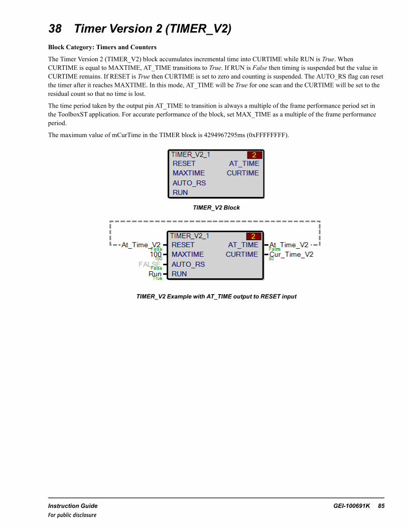
38 Timer Version 2 (TIMER_V2)Block Category: Timers and Counters
The Timer Version 2 (TIMER_V2) block accumulates incremental time into CURTIME while RUN is True. WhenCURTIME is equal to MAXTIME, AT_TIME transitions to True. If RUN is False then timing is suspended but the value inCURTIME remains. If RESET is True then CURTIME is set to zero and counting is suspended. The AUTO_RS flag can resetthe timer after it reaches MAXTIME. In this mode, AT_TIME will be True for one scan and the CURTIME will be set to theresidual count so that no time is lost.
The time period taken by the output pin AT_TIME to transition is always a multiple of the frame performance period set inthe ToolboxST application. For accurate performance of the block, set MAX_TIME as a multiple of the frame performanceperiod.
The maximum value of mCurTime in the TIMER block is 4294967295ms (0xFFFFFFFF).
TIMER_V2 Block
TIMER_V2 Example with AT_TIME output to RESET input
Instruction Guide GEI-100691K 85For public disclosure
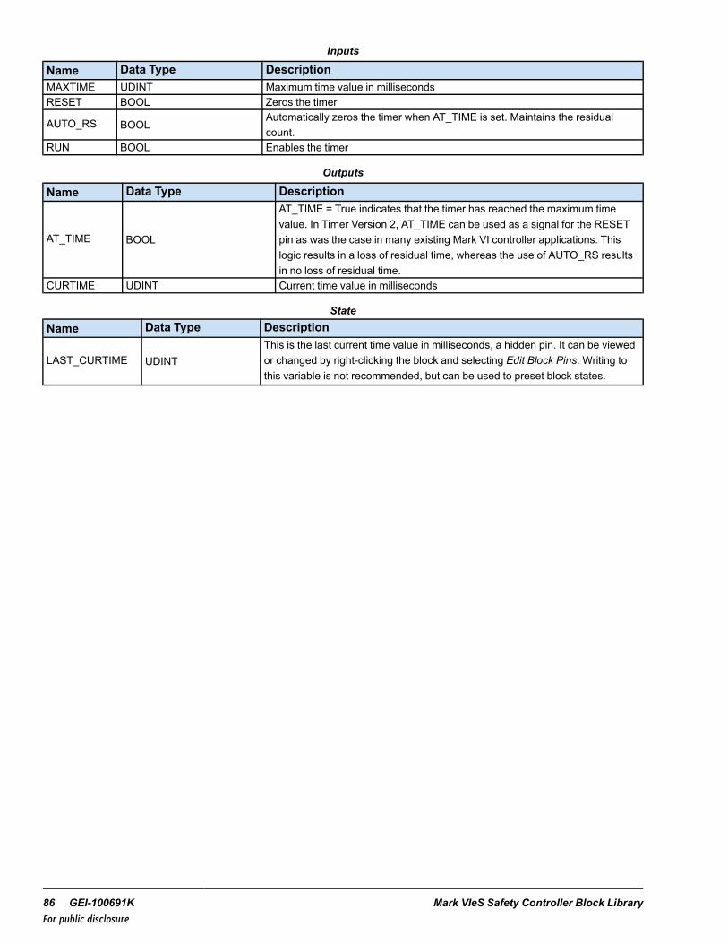
Inputs
Name Data Type DescriptionMAXTIME UDINT Maximum time value in millisecondsRESET BOOL Zeros the timer
AUTO_RS BOOLAutomatically zeros the timer when AT_TIME is set. Maintains the residualcount.
RUN BOOL Enables the timer
Outputs
Name Data Type Description
AT_TIME BOOL
AT_TIME = True indicates that the timer has reached the maximum timevalue. In Timer Version 2, AT_TIME can be used as a signal for the RESETpin as was the case in many existing Mark VI controller applications. Thislogic results in a loss of residual time, whereas the use of AUTO_RS resultsin no loss of residual time.
CURTIME UDINT Current time value in milliseconds
StateName Data Type Description
LAST_CURTIME UDINTThis is the last current time value in milliseconds, a hidden pin. It can be viewedor changed by right-clicking the block and selecting Edit Block Pins. Writing tothis variable is not recommended, but can be used to preset block states.
86 GEI-100691K Mark VIeS Safety Controller Block LibraryFor public disclosure
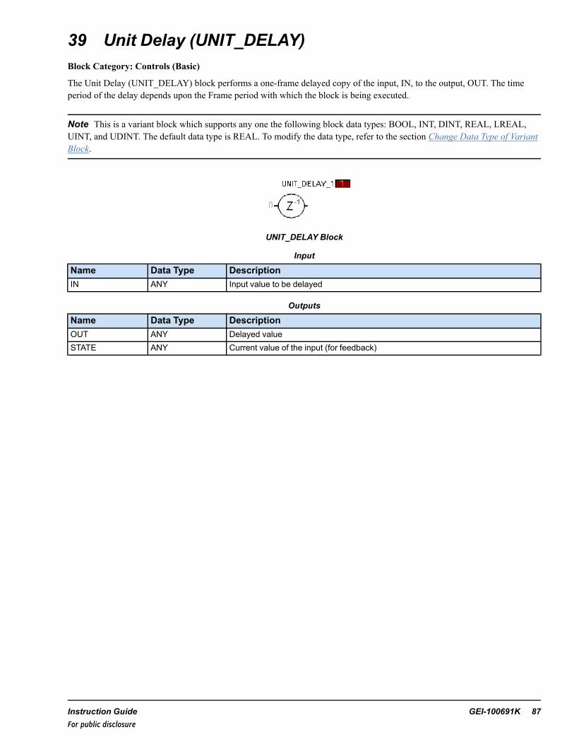
39 Unit Delay (UNIT_DELAY)Block Category: Controls (Basic)
The Unit Delay (UNIT_DELAY) block performs a one-frame delayed copy of the input, IN, to the output, OUT. The timeperiod of the delay depends upon the Frame period with which the block is being executed.
Note This is a variant block which supports any one the following block data types: BOOL, INT, DINT, REAL, LREAL,UINT, and UDINT. The default data type is REAL. To modify the data type, refer to the section Change Data Type of VariantBlock.
UNIT_DELAY Block
Input
Name Data Type DescriptionIN ANY Input value to be delayed
Outputs
Name Data Type DescriptionOUT ANY Delayed valueSTATE ANY Current value of the input (for feedback)
Instruction Guide GEI-100691K 87For public disclosure
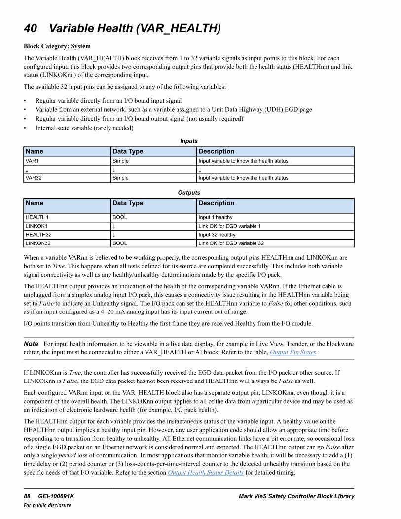
40 Variable Health (VAR_HEALTH)Block Category: System
The Variable Health (VAR_HEALTH) block receives from 1 to 32 variable signals as input points to this block. For eachconfigured input, this block provides two corresponding output pins that provide both the health status (HEALTHnn) and linkstatus (LINKOKnn) of the corresponding input.
The available 32 input pins can be assigned to any of the following variables:
• Regular variable directly from an I/O board input signal• Variable from an external network, such as a variable assigned to a Unit Data Highway (UDH) EGD page• Regular variable directly from an I/O board output signal (not usually required)• Internal state variable (rarely needed)
Inputs
Name Data Type DescriptionVAR1 Simple Input variable to know the health status↓ ↓ ↓VAR32 Simple Input variable to know the health status
Outputs
Name Data Type Description
HEALTH1 BOOL Input 1 healthyLINKOK1 ↓ Link OK for EGD variable 1HEALTH32 ↓ Input 32 healthyLINKOK32 BOOL Link OK for EGD variable 32
When a variable VARnn is believed to be working properly, the corresponding output pins HEALTHnn and LINKOKnn areboth set to True. This happens when all tests defined for its source are completed successfully. This includes both variablesignal connectivity as well as any healthy/unhealthy determinations made by the specific I/O pack.
The HEALTHnn output provides an indication of the health of the corresponding variable VARnn. If the Ethernet cable isunplugged from a simplex analog input I/O pack, this causes a connectivity issue resulting in the HEALTHnn variable beingset to False to indicate an Unhealthy signal. The I/O pack can set the HEALTHnn variable to False for other conditions, suchas if an input configured as a 4–20 mA analog input has its input current out of range.
I/O points transition from Unhealthy to Healthy the first frame they are received Healthy from the I/O module.
Note For input health information to be viewable in a live data display, for example in Live View, Trender, or the blockwareeditor, the input must be connected to either a VAR_HEALTH or AI block. Refer to the table, Output Pin States.
If LINKOKnn is True, the controller has successfully received the EGD data packet from the I/O pack or other source. IfLINKOKnn is False, the EGD data packet has not been received and HEALTHnn will always be False as well.
Each configured VARnn input on the VAR_HEALTH block also has a separate output pin, LINKOKnn, even though it is acomponent of the overall health. The LINKOKnn output applies to all of the data from a particular device and may be used asan indication of electronic hardware health (for example, I/O pack health).
The HEALTHnn output for each variable provides the instantaneous status of the variable input. A healthy value on theHEALTHnn output implies a healthy input pin. However, any user application code should allow an appropriate time beforeresponding to a transition from healthy to unhealthy. All Ethernet communication links have a bit error rate, so occasional lossof a single EGD packet on an Ethernet network is considered normal and expected. The HEALTHnn output can go False afteronly a single period loss of communication. In most applications that monitor variable health, it will be necessary to add a (1)time delay or (2) period counter or (3) loss-counts-per-time-interval counter to the detected unhealthy transition based on thespecific needs of that I/O variable. Refer to the section Output Health Status Details for detailed timing.
88 GEI-100691K Mark VIeS Safety Controller Block LibraryFor public disclosure
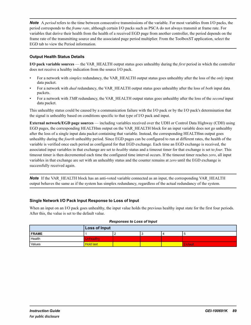
Note A period refers to the time between consecutive transmissions of the variable. For most variables from I/O packs, theperiod corresponds to the frame rate, although certain I/O packs such as PSCA do not always transmit at frame rate. Forvariables that derive their health from the health of a received EGD page from another controller, the period depends on theframe rate of the transmitting source and the associated page period multiplier. From the ToolboxST application, select theEGD tab to view the Period information.
Output Health Status Details
I/O pack variable sources— the VAR_HEALTH output status goes unhealthy during the first period in which the controllerdoes not receive a healthy indication from the source I/O pack.
• For a network with simplex redundancy, the VAR_HEALTH output status goes unhealthy after the loss of the only inputdata packet.
• For a network with dual redundancy, the VAR_HEALTH output status goes unhealthy after the loss of both input datapackets.
• For a network with TMR redundancy, the VAR_HEALTH output status goes unhealthy after the loss of the second inputdata packet.
This unhealthy status could be caused by a communication failure with the I/O pack or by the I/O pack's determination thatthe signal is unhealthy based on conditions specific to that type of I/O pack and input.
External network/EGD page sources— including variables received over the UDH or Control Data Highway (CDH) usingEGD pages, the corresponding HEALTHnn output on the VAR_HEALTH block for an input variable does not go unhealthyafter the loss of a single input data packet containing that variable. Instead, the corresponding HEALTHnn output goesunhealthy during the fourth unhealthy period. Since EGD pages can be configured to run at different rates, the health of thevariable is verified once each period as configured for that EGD exchange. Each time an EGD exchange is received, theassociated input variables in that exchange are set to healthy status and a timeout timer for that exchange is set to four. Thistimeout timer is then decremented each time the configured time interval occurs. If the timeout timer reaches zero, all inputvariables in that exchange are set with an unhealthy status and the counter remains at zero until the EGD exchange issuccessfully received again.
Note If the VAR_HEALTH block has an anti-voted variable connected as an input, the corresponding VAR_HEALTHoutput behaves the same as if the system has simplex redundancy, regardless of the actual redundancy of the system.
Single Network I/O Pack Input Response to Loss of Input
When an input on an I/O pack goes unhealthy, the input value holds the previous healthy input state for the first four periods.After this, the value is set to the default value.
Responses to Loss of Input
Loss of InputFRAME 1 2 3 4 5Health UnhealthyValues Hold last Default
Instruction Guide GEI-100691K 89For public disclosure
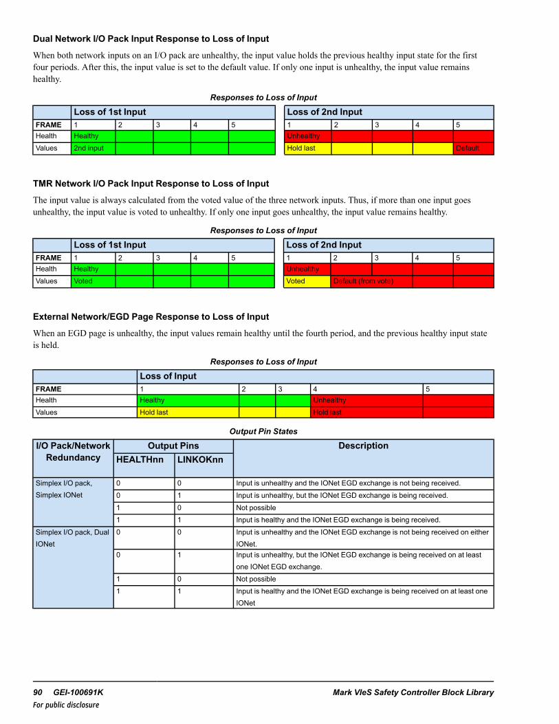
Dual Network I/O Pack Input Response to Loss of Input
When both network inputs on an I/O pack are unhealthy, the input value holds the previous healthy input state for the firstfour periods. After this, the input value is set to the default value. If only one input is unhealthy, the input value remainshealthy.
Responses to Loss of Input
Loss of 1st Input Loss of 2nd InputFRAME 1 2 3 4 5 1 2 3 4 5Health Healthy UnhealthyValues 2nd input Hold last Default
TMR Network I/O Pack Input Response to Loss of Input
The input value is always calculated from the voted value of the three network inputs. Thus, if more than one input goesunhealthy, the input value is voted to unhealthy. If only one input goes unhealthy, the input value remains healthy.
Responses to Loss of Input
Loss of 1st Input Loss of 2nd InputFRAME 1 2 3 4 5 1 2 3 4 5Health Healthy UnhealthyValues Voted Voted Default (from vote)
External Network/EGD Page Response to Loss of Input
When an EGD page is unhealthy, the input values remain healthy until the fourth period, and the previous healthy input stateis held.
Responses to Loss of Input
Loss of InputFRAME 1 2 3 4 5Health Healthy UnhealthyValues Hold last Hold last
Output Pin States
I/O Pack/NetworkRedundancy
Output Pins DescriptionHEALTHnn LINKOKnn
Simplex I/O pack,Simplex IONet
0 0 Input is unhealthy and the IONet EGD exchange is not being received.0 1 Input is unhealthy, but the IONet EGD exchange is being received.1 0 Not possible1 1 Input is healthy and the IONet EGD exchange is being received.
Simplex I/O pack, DualIONet
0 0 Input is unhealthy and the IONet EGD exchange is not being received on eitherIONet.
0 1 Input is unhealthy, but the IONet EGD exchange is being received on at leastone IONet EGD exchange.
1 0 Not possible1 1 Input is healthy and the IONet EGD exchange is being received on at least one
IONet
90 GEI-100691K Mark VIeS Safety Controller Block LibraryFor public disclosure
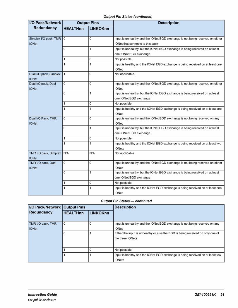
Output Pin States (continued)
I/O Pack/NetworkRedundancy
Output Pins DescriptionHEALTHnn LINKOKnn
Simplex I/O pack, TMRIONet
0 0 Input is unhealthy and the IONet EGD exchange is not being received on eitherIONet that connects to this pack
0 1 Input is unhealthy, but the IONet EGD exchange is being received on at leastone IONet EGD exchange
1 0 Not possible1 1 Input is healthy and the IONet EGD exchange is being received on at least one
IONetDual I/O pack, SimplexIONet
1 0 Not applicable.
Dual I/O pack, DualIONet
0 0 Input is unhealthy and the IONet EGD exchange is not being received on eitherIONet
0 1 Input is unhealthy, but the IONet EGD exchange is being received on at leastone IONet EGD exchange
1 0 Not possible1 1 Input is healthy and the IONet EGD exchange is being received on at least one
IONetDual I/O Pack, TMRIONet
0 0 Input is unhealthy and the IONet EGD exchange is not being received on anyIONet
0 1 Input is unhealthy, but the IONet EGD exchange is being received on at leastone IONet EGD exchange
1 0 Not possible1 1 Input is healthy and the IONet EGD exchange is being received on at least two
IONetsTMR I/O pack, SimplexIONet
N/A N/A Not applicable
TMR I/O pack, DualIONet
0 0 Input is unhealthy and the IONet EGD exchange is not being received on eitherIONet
0 1 Input is unhealthy, but the IONet EGD exchange is being received on at leastone IONet EGD exchange
1 0 Not possible1 1 Input is healthy and the IONet EGD exchange is being received on at least one
IONet
Output Pin States — continued
I/O Pack/NetworkRedundancy
Output Pins DescriptionHEALTHnn LINKOKnn
TMR I/O pack, TMRIONet
0 0 Input is unhealthy and the IONet EGD exchange is not being received on anyIONet
0 1 Either the input is unhealthy or else the EGD is being received on only one ofthe three IONets
1 0 Not possible1 1 Input is healthy and the IONet EGD exchange is being received on at least tow
IONets
Instruction Guide GEI-100691K 91For public disclosure
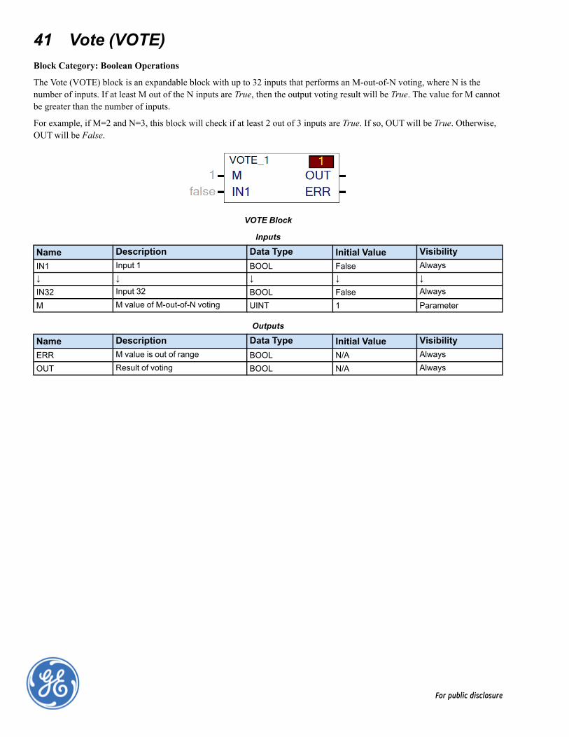
41 Vote (VOTE)Block Category: Boolean Operations
The Vote (VOTE) block is an expandable block with up to 32 inputs that performs an M-out-of-N voting, where N is thenumber of inputs. If at least M out of the N inputs are True, then the output voting result will be True. The value for M cannotbe greater than the number of inputs.
For example, if M=2 and N=3, this block will check if at least 2 out of 3 inputs are True. If so, OUTwill be True. Otherwise,OUTwill be False.
VOTE Block
Inputs
Name Description Data Type Initial Value VisibilityIN1 Input 1 BOOL False Always↓ ↓ ↓ ↓ ↓IN32 Input 32 BOOL False Always
M M value of M-out-of-N voting UINT 1 Parameter
Outputs
Name Description Data Type Initial Value VisibilityERR M value is out of range BOOL N/A Always
OUT Result of voting BOOL N/A Always
For public disclosure