Service Manual - Secure Login
149
Service Manual Precision™ Series 400 line TRM400-14 Treadmills
-
Upload
khangminh22 -
Category
Documents
-
view
7 -
download
0
Transcript of Service Manual - Secure Login
Service Manual
Precision™ Series 400 line
TRM400-14 Treadmills

Contents
Introduction 1
Service manual contents 1
Additional Service Documentation and Videos 2
Service Safety Guidelines 3
Safety guideline you need to know and follow: 3
General Information 5
Features 5
Model and Serial Numbers 6
Model Numbers 6
Serial Numbers 7
About 7
Serial Number Label Location 8
Orientation 8
Tools and Supplies 9
Specification Summary 10
Fastener Torque Specification 10
Calibration Specification 11
Belt Tension Specification 11
Bolt Grade Identification 11
Bolt Grade Markings Chart 12
Parts 12
Lubricants 13
Cleaning Procedure 13
Approved Cleaning Products 13
Cleaning Procedure 14
Power Requirements 14
Equipment Power Requirements 14
Contact Precor Customer Support at [email protected] or 800.786.8404 withany questions.
Page ii
Equipment Spacing Requirement 15
How To Safely Move A Treadmill 16
Treadmill Moving Procedure Using a Movers Dolly 16
Tool required 16
Procedure 17
Operation Verification 20
R40 Operation Verification Test 20
R20 Operation Verification Test 23
Standard Service Menus 28
About 28
Service Menu Access Codes 28
R40 Service Menu Access Codes 28
R20 Service Menu Access Codes 29
How to Access the Standard Service Menus 29
R40 How To Access Standard Service menus 29
R20 How To Access Standard Service menus 31
Standard Service Menus 32
R40 Standard Service Menus 32
Hardware Validation (51765761) 32
Information Display (65) 33
My Settings Menu (5671) 34
R20 Standard Service Menus 34
Hardware Validation (51765761) 34
Information Display (65) 35
My Settings Menu (5671) 36
DEMOMode (R40) 37
Enter DEMOmode: 37
Disable DEMOmode 38
Standard Service Menus 39
Contact Precor Customer Support at [email protected] or 800.786.8404 withany questions.
Page iii

About 39
Service Menu Access Codes 39
How to Access the Standard Service Menus 40
Standard Service Menus 43
R40 Standard Service Menus 43
R20 Standard Service Menus 45
Information Display (65) 46
My Settings Menu (5671) 47
DEMOMode (R40) 48
Adjustment Procedures 50
Available Adjustment Procedures 50
Drive Belt Tension Adjustment 51
About 51
Specifications 51
Drive Belt Tension Adjustment 51
Running Belt Tension and Tracking Adjustment 55
About 55
Videos 55
Tools 55
Specification 55
Procedure 55
Running belt alignment and tracking adjustment 58
Lift Motor Calibration 61
About 61
Specifications 61
Videos 61
Lift Motor Calibration 61
Replacement Procedures 65
Available Replacement Procedures 65
Contact Precor Customer Support at [email protected] or 800.786.8404 withany questions.
Page iv
Drive Belt Replacement 66
About 66
Procedure 66
Drive Motor Replacement 68
Procedure 68
Drive Motor Brushes Replacement 70
Procedure 70
Speed Sensor Replacement 72
Procedure 72
Drive Roller Replacement 74
About 74
Procedure 74
Take-up Roller Replacement 77
About 77
Procedure 77
Installation 78
Running Belt and Deck Replacement Procedure 80
About 80
Procedure 80
Lift Motor Replacement 83
Videos 83
Procedure 83
Lift Platform Replacement 86
Procedure 86
Lower PCA (LPCA) Replacement 89
Procedure 90
Troubleshooting 95
About 95
Introduction to Troubleshooting 95
Contact Precor Customer Support at [email protected] or 800.786.8404 withany questions.
Page v

Basic Troubleshooting Steps 95
Validate the customer reported issue 96
Verify Input Power 96
Verify (reproduce) the customer issue 97
Verify My Settings parameter values 97
Verify service bulletin and software update incorporation 97
Verify console operation 98
Verify that there are no current active error codes 98
Verify hardware validation diagnostic tests 99
Verify that there are no new error codes 99
Error Log Display 100
About 100
Accessing the Error Log 100
Error Log Parameter Descriptions 100
Clearing the Error Log 101
Error Code Troubleshooting Guide 101
Troubleshooting with Error Codes 102
Getting Starting 102
Troubleshooting with Error Codes 102
Viewing Error Codes 102
Quick Reference 102
System Troubleshooting Procedures 105
AC Input Power Troubleshooting 106
Heart Rate Monitor Troubleshooting 108
LIft System Troubleshooting 109
LPCA Fan Troubleshooting 113
Speed Sensor Troubleshooting 115
Running Belt Troubleshooting 117
Preventive Maintenance (PM) 120
Contact Precor Customer Support at [email protected] or 800.786.8404 withany questions.
Page vi

About 120
PM Tasks and Schedule 120
Running Belt and Deck Cleaning Procedure 122
Videos 122
Procedure 122
System Wiring Diagram 124
Product Literature & Videos 125
Service & Maintenance Documentation 125
Precor Websites 125
Service Videos 126
Parts 127
About 127
Precor Connect Partner's website 127
Exploded View Diagrams and Parts List 130
Exploded View Diagram 131
Parts List 137
Appendix A : Edition Information i
Edition i
Additional Documentation i
Copyright i
Appendix B : Notices and Safety ii
Trademarks ii
Intellectual Property ii
Warranty ii
Safety Notices iii
Service Safety Guidelines iii
Contact Precor Customer Support at [email protected] or 800.786.8404 withany questions.
Page vii

Introduction
Only Precor certified technicians are authorized to service Precor equipment. If you are nota Precor certified servicer, you must not attempt to service any Precor product. Call yourdealer for service information
WARNING: This service documentation is for use by Precor certified servicer pro-viders only. Personal injury can result from electrical shock and/or mechanical movingparts.
This service manual applies to the TRM400-14 Precision™ Series 400 Line treadmillsincluding the 120 VAC1 and 240 VACmodels.
Model Configuration
TRM425 TRM400-14 base with R20 console: speed: 0.5 - 12 mph (0.8-19.2 kph),incline: 2% Decline - 15% Incline
TRM445 TRM445-14 base with R40 console: speed: 0.5 - 12 mph (0.8-19.2 kph),incline: 2% Decline - 15% Incline
Service manual contents
The service manual contains information to service, repair, troubleshoot, and maintain themachine base.
This manual does not include console service and repair information, for console serviceand repair information, refer to the console service manual.
1voltage in an alternating current circuit
Contact Precor Customer Support at [email protected] or 800.786.8404 withany questions.
Page 1
1 Introduction
Service manual contents

However, the service manual does include information about how to use the console stand-ard service menus, diagnostic tests and error code log to help troubleshoot and repairmachine issues.
Additional Service Documentation and VideosThere are additional literature and video resources available that can help you to use, ser-vice, troubleshoot, and repair the machine. Refer to Product Literature & Videos topic:
l "Product Literature & Videos" on page 125
See Also
"Product Literature & Videos" on page 125
"General Information" on page 5
"Operation Verification" on page 20
"Standard Service Menus" on page 39
"Adjustment Procedures" on page 50
"Replacement Procedures" on page 65
"Troubleshooting" on page 95
"Preventive Maintenance (PM)" on page 120
"SystemWiring Diagram" on page 124
"Parts " on page 127
"Service Safety Guidelines" on the facing page
Contact Precor Customer Support at [email protected] or 800.786.8404 withany questions.
Page 2
1 Introduction
Additional Service Documentation and Videos

Service Safety Guidelines
WARNING: Only Precor certified servicers and technicians are permitted to ser-vice Precor products. Personal injury can result from electrical shock and/or mech-anical moving parts.
Review the following safety information prior to servicing the equipment. This safety inform-ation will help to prevent personal injury or damage to the equipment while servicing theequipment.
Safety guideline you need to know and follow:l Read and follow allWarning notices to protect yourself from personal injury.l Read and follow all Caution notices to prevent damage to the equipment.l Read the owner’s manual and follow all operating instructions.l Operate the equipment on a solid, level surface.l Visually check the equipment before beginning service or maintenance operations. Ifit is not completely assembled or is damaged in anyway, do not attempt to operate theequipment.
l Never place liquids on any part of the equipment while performing service.l To prevent electrical shock, keep all electrical components away from water andother liquids.
l Do not use accessory attachments that are not recommended by the manufacturer.Non-OEM accessories can cause injuries.
l Do not stand or climb on the handlebars, display enclosure or cover.l On a self-powered unit, it will either be necessary to either equip the unit with theoptional external power supply or have an assistant pedal on the unit while voltagemeasurements are being taken. Because of the danger of working on the unit while itis in motion using the optional external power supply is strongly recommended.
l On AMT1 units when the stairarms are in motion; the generator will operate and pro-duce potentially hazardous voltages even when the battery is disconnected.
l On AMT units with Cardio Theater PVS2 units will have external power supply andcoaxial cable routed through the bottom of the unit to the top of the display console.Cord management must be maintained
l On AMT units, a pinching hazard exists when the unit is operated. It is possible to ser-iously pinch a finger. The AMT can be mechanically locked by inserting a screwdriverthrough the primary sheave and frame.
1Adaptive Motion Trainer2Personal Viewing System display.
Contact Precor Customer Support at [email protected] or 800.786.8404 withany questions.
Page 3
1 Introduction
Service Safety Guidelines
l On treadmills, removing the hood exposes high voltage components and potentiallydangerous machinery. Exercise extreme caution when you perform maintenance pro-cedures with the hood removed.
When servicing the equipment:
l During service operations you will be very close to moving machinery and voltagebearing components:
o Remove jewelry (especially from ears and neck).o Tie up long hair.o Remove neck ties.o Do not wear loose clothing.
See Also
"Notices and Safety" on page ii
"Safety Notices" on page iii
Contact Precor Customer Support at [email protected] or 800.786.8404 withany questions.
Page 4
1 Introduction
Service Safety Guidelines

General Information
The following information provides general equipment and service information that will helpyou to use this manual to properly repair and maintain the treadmill.
Features
The equipment operating specifications.
Feature Specification
Consoles R20 and R40 consoles*R40 supports smart phone charging.
Incline
Elevation system generates up to 1000 lb / 453.6 kg of thrust andoperated in compression for reliable operation.
Range: 2% Decline - 15% Incline
Levels: 0 - 15
Speed Range: 0.0 - 12 mph in 0.5 increments (0.0 - 19.3 kph in 0.1 kphincrements)
Belt/DeckThe running belt is lubricated, the deck is reversible and not lub-ricated..Running surface: 22" x 56" (56 x 142 cm)
Drive Motor
3 hp 120 Volt DC1 continuous duty motor.
The motor controller (MC2) implements Integrated Foot PlantTechnology™ and Pulse Width Modulated (PWM) drive tech-nology for high reliability and accurate speed control.
Emergency Stop
(ESTOP3)Exersicer safety clip and lanyard connected to the stop switch toimmediately switch off power bringing the treadmill to a stop.
Heart RateTwo Heart Rate sensor types:
l Touch Handheld Handlebar Heart Rate sensors (HHHR4).
1Direct Current: electrical current that only flows in one direction.2Motor controller, motor controller unit, or motor controller module: used on treadmills, con-tains the LPCA and motor controller functionality.3Emergency Stop: Safety clip and lanyard attached to the stop switch to immediately turnoff power bringing the machine to a stop.4Handheld Handlebar Heart Rate
Contact Precor Customer Support at [email protected] or 800.786.8404 withany questions.
Page 5
2 General Information
Features
Feature Specification
l Telemetry equipped for wireless chest strap heart rate mon-itoring.
Ground Effects®Impact Control Sys-tem (GFX1®)
Progressive shock absorption system that absorbs high impactmovements and supports a solid and controlled push off.
Power 120V, 60Hz, dedicated 15A circuit
Max User Weight Maximum exerciser weight: 350 lbs (159 kgs)
Dimension/Weight
Weight: 358 lb / 161 kg
Dimensions:Length 79 in / 204 cmWidth 34 in / 86 cmHeight 59,5 in / 151 cm
Model and Serial Numbers
Model and Serial Numbers
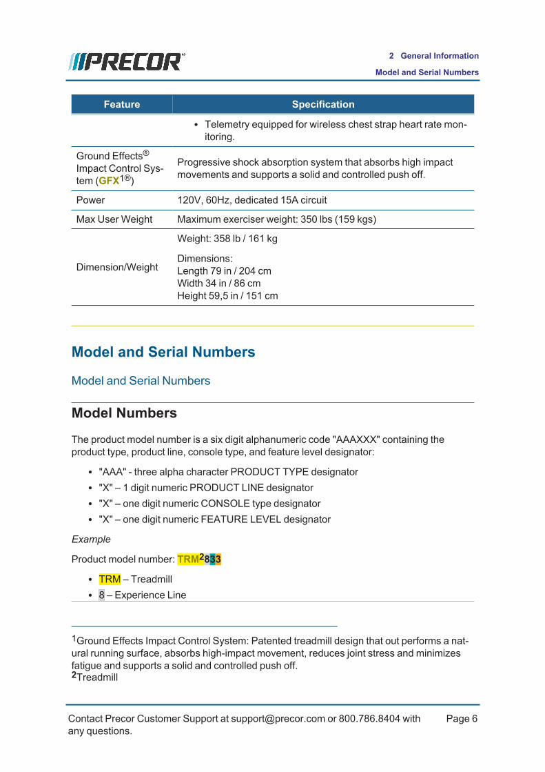
Model NumbersThe product model number is a six digit alphanumeric code "AAAXXX" containing theproduct type, product line, console type, and feature level designator:
l "AAA" - three alpha character PRODUCT TYPE designatorl "X" – 1 digit numeric PRODUCT LINE designatorl "X" – one digit numeric CONSOLE type designatorl "X" – one digit numeric FEATURE LEVEL designator
Example
Product model number: TRM2833
l TRM – Treadmilll 8 – Experience Line
1Ground Effects Impact Control System: Patented treadmill design that out performs a nat-ural running surface, absorbs high-impact movement, reduces joint stress and minimizesfatigue and supports a solid and controlled push off.2Treadmill
Contact Precor Customer Support at [email protected] or 800.786.8404 withany questions.
Page 6
2 General Information
Model and Serial Numbers

l 3 – P30 consolel 3 – Fixed ramp
Product Model Number Designator Definitions
PRODUCT TYPE PRODUCT LINE CONSOLE FEATURE LEVELTRM: treadmillEFX1: ellipticalAMT2: AMTUBK3: UprightRBK4: Recumbent
SCL StairClimber
8-ExperiencePremium7-Experience Stand-ard6-ExperienceGood6-Assurance Stand-ard4-Precision, Con-sumer2-Energy, Consumer
8-P80, P826-P624-R403-P30, P312-P20/R201-P10
7 EFX: Mov Ramp/CnvrtArms
5 TRM: High Speed/De-clineAMT: Moving Step HeightEFX: Mov Ramp/MovArmsRBK: Standard featuresUBK: Standard featuresSBK5 Standard features
3 TRM: Fixed RampAMT: Fixed Step HeightEFX: Moving Ramp/FixedArms
2 EFX: Man Ramp/MovArms
1 EFX: Fixed Ramp/MovingArms
Serial Numbers
AboutThe serial number uniquely identifies each machine. The serial number is an alphanumericcode comprised of a four character model designator, a 1 letter build month code, a 2 digitday built, a 2 digit year built and a four digit consecutive daily build number.
1Elliptical Fitness Crosstrainer2Adaptive Motion Trainer3Upright Bike4Recumbent Bike5Spinner Indoor Cycle
Contact Precor Customer Support at [email protected] or 800.786.8404 withany questions.
Page 7
2 General Information
Serial Numbers
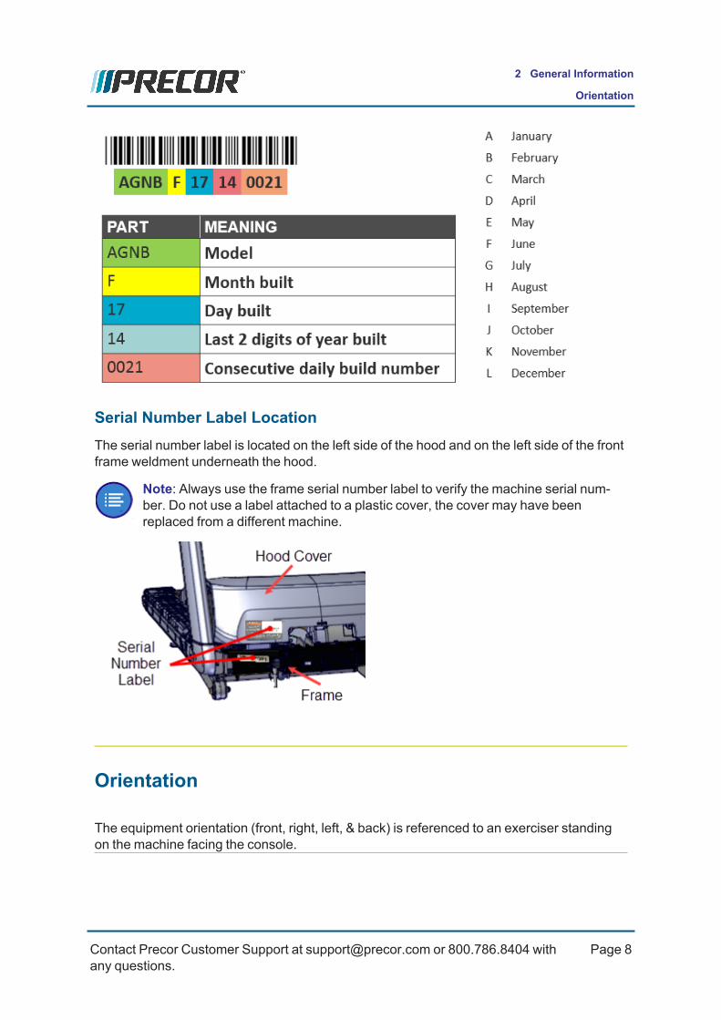
Serial Number Label LocationThe serial number label is located on the left side of the hood and on the left side of the frontframe weldment underneath the hood.
Note: Always use the frame serial number label to verify the machine serial num-ber. Do not use a label attached to a plastic cover, the cover may have beenreplaced from a different machine.
Orientation
The equipment orientation (front, right, left, & back) is referenced to an exerciser standingon the machine facing the console.
Contact Precor Customer Support at [email protected] or 800.786.8404 withany questions.
Page 8
2 General Information
Orientation

Tools and Supplies
Tools and supplies required to complete the machine service and repair.
Tools
• US and Metric Hex Key set • Standard straight slot tip screw drive set
• US and Metric socket set • Philips tip screw driver set
• Us and Metric wrench set • US & metric Allen wrench set
• Cutters • 7/16” Allen key, socket mounted
• Rubber mallet • Pliers
• Tape measure /Straight edge ruler • Inner and outer snap ring pliers
• DVMmeter • Torque1Wrenches: 9 in lbs to 100 in - lbs(83 ft-lbs)
• AC2 Clamp-on averting current meter • DVMMultimeter
1Torque is a measure of the force that can cause an object to rotate about an axis. Bolt/nutexample: 5 NM torque is equivalent to 5 newton's of force applied one meter from the centerof the bolt, 6 ft-lb is equivalent to 6 lbs of force applied 1 foot away from the center of thebolt.2Alternating Current: electric current which periodically reverses direction between positiveand negative polarity.
Contact Precor Customer Support at [email protected] or 800.786.8404 withany questions.
Page 9
2 General Information
Tools and Supplies

• ESD1 wrist strap and pad • Compatible HR2 chest strap or Polar HRMsimulator xmitter (Precor PN:PPP000000020045101)
• 12 " wonder bar • Vacuum cleaner (recommend ESD safemodel)
• 2 - Running Belt tension gauge – OTCTools Model #: 6673 (Precor PN:PPP000000020007101)
• Drive Belt tension Gauge (Kent-Moore BT-33-73-F
Supplies
• Super Lube Gel with Teflon by Permatex(1)
• Cleaning rags
• Loctite 243 Blue Medium Strength Thread-locker
• Cleaner Degreaser (see "" on page 13)
• Cable tie assortment (1 3/4", 3", 4"lengths)(1) or equivalent synthetic teflon based grease (Mobil 1, NLGI 2 Teflon Synthetic Grease).
Specification Summary
Fastener Torque SpecificationSystem component fastener torque specification:
System Component Specification
RF3 coax connector 2.4 in-lbs (0.271 Nm)
Display mounting fasteners 180 in-lbs (20 Nm
Set screws 300 in-lbs (34 Nm)
Plastite screw fasteners 20 in-lbs (2.3 Nm)
1Electrostatic Discharge or Electrostatic Sensitive Device.2Heart Rate3Radio Frequency: Identifies electromagnetic signals with frequency spectrum between the3 kHz (3,000 hertz) to 300 GHz (300 billion hertz) range.
Contact Precor Customer Support at [email protected] or 800.786.8404 withany questions.
Page 10
2 General Information
Specification Summary

System Component Specification
Flathead screws 25 in-lbs (2.8 Nm)
Drive Motor bolts 180 in-lbs (15 ft-lbs, 20.4 N-m)
Calibration SpecificationSystem calibration specification:
System Component Specification
Lift Motor Jackscrew Calibration Distance 1 in (2.54 cm)
Incline Level A/D1 Calibration Incline angle A/D values:l Nominal value: 13 ±5@ -2%incline
l Nominal value: 37 ±5@0%incline
l Nominal value: 242 ±5@ 15%incline
Belt Tension Specification.Belt tension specification:
System Component Specification
Drive Belt Tension 70-90 lbs (32-41 kgs)
Running Belt: tension gauge dial reading (per-cent %)
3.55 (0.55%)(1)
(1) Referenced to belt gauge set to 3.0 (0.0%)with no belt tension.
Bolt Grade Identification
Bolt grade markings are used to categorize bolts according to the bolt material, man-ufacturing process, and mechanical properties. The grade of the bolt is stamped on thehead of the bolt.
1analog to digital converter
Contact Precor Customer Support at [email protected] or 800.786.8404 withany questions.
Page 11
2 General Information
Bolt Grade Identification

US SAE bolts: The bolt grade markings are determined by the number of the lines stampedon the head of the bolt. The number of lines is always two less than the grade of the bolt.Count the lines, add two, and you can determine the grade of the bolt.
Metric bolts: On metric bolts, the bolt grade is identified by a bolt grade number stampedon the head of the bolt.
CAUTION: Always replace bolts with the same grade bolt. If you don’t know thegrade of the replacement bolt – DO NOT USE THE BOLT.
Bolt Grade Markings ChartExample bolt grades used on Precor equipment (may not represent all bolt grades). Alwaysmatch the replacement bolt grade marking to the removed bolt grade marking.
Parts
PartsIMPORTANT: Always purchase OEM replacement parts and hardware from Pre-cor. If you use parts not approved by Precor, you could void the Precor Limited War-ranty. Use of parts not approved by Precor may cause injury.
There is a copy of the parts Exploded View Diagram and Parts Identification List included inthe Parts chapter (see Parts)that you can use as a quick reference. It is recommended thatyou go to the servicer partners Precor Connect (or Precor Connection) website to viewthe most current parts information including the Exploded View Diagram and Parts Iden-tification List.
Contact Precor Customer Support at [email protected] or 800.786.8404 withany questions.
Page 12
2 General Information
Parts

Online parts information using Precor Connect
l Precor Connect Partner website
Local hard copies
l Exploded View Diagram and Parts List, see "Parts " on page 127.
Lubricants
Only use products from the following list of approved lubricants:
Lubricant DescriptionGrease Use only NLGI class 2 PTFE synthetic grade grease. Use of unapproved
lubricants may void the product warranty.Recommended brands (or equivalent): • Mobil 1® synthetic grease • Super Lube® with Teflon
CAUTION: Do not use petroleum based lubricants on mechanical componentssuch as the lift, as this may result in degradation of nylon gearing mechanisms.Use only synthetic lubricants such as "Super Lube with Teflon" or "Mobile OneSynthetic" grease (RED).CAUTION: Do not apply any lubricants or wax to the deck and belt. Do not useWax Blast, silicon sprays, or other applied lubricants. The use of these lubricantswill quickly degrade the low-friction surface of the deck.
Cleaning Procedure
Only use the following approved cleaning products and procedures to safely clean and pre-vent damage to the machine surfaces.
Approved Cleaning ProductsApproved equipment and console cleaning products:
l General Equipment Surfaces:o 1 part mild soap to 30 parts water (recommend Simple Green® cleaner or equi-valent).
o Athletic equipment cleaner, 9x7 pre-saturated wipes (ATHLETIX PRODUCTS).o Enivir O Safe oxygen enhanced cleaner or Enviro Safe glass and multitaskcleaner concentrate.
Contact Precor Customer Support at [email protected] or 800.786.8404 withany questions.
Page 13
2 General Information
Lubricants

l Consoles and PVS1 displays: a diluted solution of one part 91% Isopropyl alcoholto one part water.
Cleaning ProcedureGeneric cleaning procedure applicable to all Precor equipment:
TIP: There are many product specific PREVENTATIVE MAINTENANCE cleaningvideos available on the Precor Connect SERVICE VIDEOS web page. Log in toyour Precor Connect servicer account and select SERVICE VIDEOS, see
SERVICE VIDEOS.
1. Wipe down equipment using a soft lint-free cloth using only the recommended clean-ing solution. Always spray cleaning solution directly onto the cleaning cloth and notdirectly onto the equipment surface to avoid equipment damage due to excessivemoisture.
CAUTION: Do not use acidic cleaners and do not spray directly onto the equipmentsurfaces.
2. Rinse surfaces using a clean lint-free cloth dampened with water only.3. Then completely dry with another clean lint-free cloth.
Power Requirements
Equipment Power RequirementsThe equipment input power from the wall outlet receptacle must be a good quality andstable power signal (not fluctuating or intermittent) to insure the best performance andtrouble free operation.
Power Specification
l 120 VAC2 60 Hz3modelso Operating voltage: 90 VAC to 132 VAC.o AC frequency range: 47 - 65 Hzo 15 amp individual branch circuit
1Personal Viewing System display.2voltage in an alternating current circuit3The hertz (symbol: Hz) is the derived unit of frequency in the International System of Units(SI) and is defined as one cycle per second.
Contact Precor Customer Support at [email protected] or 800.786.8404 withany questions.
Page 14
2 General Information
Cleaning Procedure
l 240 VAC 60 Hz modelso Rated operating voltage range: 180 VAC - 264 VAC.o Frequency: 47- 65 Hzo 15 amp individual branch circuit
Frame Grounding Requirement
For operator safety and to minimize electrostatic discharge conditions have a certified elec-trician verify that the AC frame ground continuity to be a low resistance connection to the ACdistribution ground bar
CAUTION: To avoid electrostatic discharge shock, make sure that there is ACframe ground continuity.
Individual branch circuit requirement
(US and Canada installations)
Also each Precor treadmill must be connected to a separate 15 amp individual branch cir-cuit outlet. That means that no other devices can be connected to the same circuit outletreceptacle.
l Individual branch circuit: An individual branch circuit provides a hot conductor andneutral conductor to a receptacle. The conductors must not be looped, "daisy-chained", or connected to any other conductors or receptacles. The circuit must begrounded according to NEC guidelines or local region electric codes.
CAUTION: All NEC (National Electric Code) guidelines or local region electriccodes must be complied with.
Equipment Spacing Requirement
The minimum side to side spacing between treadmills is 23.6 in (0.6 m) and the minimumfront to back spacing is 79 in (2 m).
Contact Precor Customer Support at [email protected] or 800.786.8404 withany questions.
Page 15
2 General Information
Equipment Spacing Requirement

How To Safely Move A Treadmill
Treadmill Moving Procedure Using a Movers DollyTypically you would lift the back and use the front wheels to move and position the treadmill.
However, situations may occur when space is tight and it may become very difficult to safelylift and use the front wheels to move the treadmill. This procedure provides an alternativemethod using a 4-caster movers dolly to safely move a treadmill with minimal effort, risk ofmuscle strain, or injury. This moving procedure does not requiring the technician to lift thetreadmill.
Tool requiredMovers Dolly Hardwood rubber end dolly with 4-swivel casters (recommended: Uline
Contact Precor Customer Support at [email protected] or 800.786.8404 withany questions.
Page 16
2 General Information
How To Safely Move A Treadmill

H-1792, 750 lb capacity)Dimensions: Length 30” (76 cm) XWidth 14 – 18” (36 – 46 cm) X Height6.25” (15 cm)Load Capacity: minimum 600 lbs (272 kgs).
Procedure1. Access the INCLINE Hardware Diagnostic Test (Hardware Diagnostic Test
51765761 > INCLINE test) and raise the level to 15.0.
2. Slide the movers dolly under the treadmill. Ensure the rubber ends are evenly spacedunder the left and right frame rails. Lift the front end of the dolly and position the dollyas close as possible midway between the front and back ends of the treadmill.
Contact Precor Customer Support at [email protected] or 800.786.8404 withany questions.
Page 17
2 General Information
Treadmill Moving Procedure Using a Movers Dolly

3. Lower the INCLINE to 0.0. Then verify the rear leveling feet are not contacting thefloor. If the feet are touching the floor, reposition the movers dolly.
4. Use the side arms to easily move and position the treadmill as needed.
5. Reverse the steps to install the dolly and remove the dolly.
6. Verify and level the treadmill as need.
Contact Precor Customer Support at [email protected] or 800.786.8404 withany questions.
Page 18
2 General Information
Treadmill Moving Procedure Using a Movers Dolly

7. Verify operation and return to service.
Contact Precor Customer Support at [email protected] or 800.786.8404 withany questions.
Page 19
2 General Information
Treadmill Moving Procedure Using a Movers Dolly

Operation Verification
The Operation Verification tests verify that the machine is operating correctly and can bereturned to service. Do these operation verification tests at the end of a maintenance pro-cedure or whenever it is necessary to ensure that the machine is operating properly. Thereare separate procedures for the R40 and R20 consoles
R40 Operation Verification Test
The Operation Verification Test applies to equipment configured with the R40 console. Com-plete each test to verify the equipment operation.
Error Code Verification TestVerify that there are no current active logged error codes:
1. Access the Error Log and record any current active logged error codes:l From the Home screen press Settings > Information > Error Log. Takenote of all the errors starting with C – 001. Also note the error odometerinformation which can help determine the age and relevance of the error.
2. Resolve any current active logged error code issues.3. Press HOME to exit the Error Log.4. Clear error codes and Reset the Error Log:
l Access the Hardware Validation (51765761) service menu, see "StandardService Menus" on page 39.
l Use the down arrow softkey to scroll down and select the Error LogReset softkey.
l Select Test > Start. The screen will transition to the System Settingsmenu. The test will run but there will no messages or indicators showingthat it has completed.
5. Verify that all active error codes have been cleared from the Error Log.
l Cycle the power OFF/ON.
l Wait for the power-up sequence to complete, then go to the Error Log andverify that all active error codes errors starting with C – 001) have beencleared (press Settings > Information > Error Log).
l Press Home to exit.Hardware Validation Tests VerificationVerify that each ot following Hardware Validation tests are successfully completed.
Contact Precor Customer Support at [email protected] or 800.786.8404 withany questions.
Page 20
3 Operation Verification
R40 Operation Verification Test

1. Access the Hardware Validation service menu (51765761) and perform the fol-lowing tests, see "Standard Service Menus" on page 39.Select Test to start the test and Stop Test to exit.
l Display GUI/Metric Testso Backlight brightness changes.o Numerals cycle properly.
l Key Testo Keys all function.
l Heart Rate Testo Heart rate is acquired and displayed.
l Belt Speed Testo Running belt moves and is controlled from 0.5 mph to 12.0 mph in0.1 increments.
l Incline Testo Use the incline controls to raise/lower incline to verify the followingincline angle A/D1 values:
n Nominal A/D value: 13 ±5@ -2% incline.n NominalA/D value: 37 ±5@0% incline.n Nominal A/D value: 242 ±5@ 15% incline.
2. Exit the Hardware Validation Diagnostic Test menu (press the Home softkey).Machine Operation TestThis test verifies the console functionality (motion controls & metric indicators) andmachine operation.
SPEED control test:
1. Do this test while walking on the machine and the INCLINE set to 0% incline.2. SelectQUICKSTART to begin a manual workout.3. Operate the SPEEDmotion control from minimum to maximum range while veri-
fying the machine operation.l Make sure that the console SPEED paddle control operation is smoothand working correctly.
l Verify that the running belt can reach the maximum speed and thenreturns to the minimum speed level.
l Make sure that the running belt speed change is smooth and that there are
1analog to digital converter
Contact Precor Customer Support at [email protected] or 800.786.8404 withany questions.
Page 21
3 Operation Verification
R40 Operation Verification Test

no unusual noises.l Verify that the console SPEED indicators and workout metric displays areshowing correct information.
INCLINE control test
4. Set the SPEED between 2-3 mph and walk on the belt while performing this test.5. Operate the INCLINEmotion controls from minimum to maximum range while
verifying the machine operation.l Make sure that the console INCLINE paddle control operation is smoothand working correctly.
l Verify that the running deck can reach the +15%maximum incline andthen return to the -2%minimum incline level.
l Verify that the lift motor operation is smooth while changing the INCLINEfromminimum to maximum levels.
l Verify that the console INCLINE level indicators and user workout displaysare showing correct information.
Running Belt Operational Test
Verify the running belt condition
1. Visually Inspect the belt condition; no surface rips, tears, or frayed edges. Alsocheck the seam for damage.
INSPECTING THE RUNNING BELT CONDITION
Verify the running belt alignment and tracking.
1. Step off the running belt and operate the treadmill at 12 mph (19 kph) for oneminute.
2. Verify the running belt alignment and tracking remains centered.
RUNNING BELT ALIGNMENT AND TRACKING PROCEDURE
ESTOP1 Switch TestVerify the ESTOP emergency stop switch operation.
1. While walking on the treadmill, press the emergency STOP button and verify thatthe running belt immediately slows to a stop.
2. While walking on the treadmill, pull the ESTOP lanyard and make sure the run-ning belt immediately slows to a stop.
3. Inspect the condition of the ESTOP lanyard clip, that the spring is in place andthat the clip will firmly hold when attached to the runner.
1Emergency Stop: Safety clip and lanyard attached to the stop switch to immediately turnoff power bringing the machine to a stop.
Contact Precor Customer Support at [email protected] or 800.786.8404 withany questions.
Page 22
3 Operation Verification
R40 Operation Verification Test

4. Make sure that the clip is properly stowed and not wrapped around the handle-bars.
Heart Rate Monitor TestVerify the Handheld Heart Rate function.
1. Access the Hardware Validation Test (51765761) and do the Heart Rate Test.Return to service
1. Verify that there are no new error codes.2. Switch the power OFF.3. Make sure that the machine is setting level and stable.
machine leveling procedure
4. Make sure that any external power cords or interface cables are properly routed,connected, and safe from being damaged.
5. On successful completion of all verification tests, return to service.
R20 Operation Verification Test
R20 Operation Verificaiton Test
The Operation Verification Test applies to equipment configured with the R20 console. Com-plete each test to verify the equipment operation.
Error Code Verification TestVerify that there are no current active logged error codes:
1. Access the Error Log and record any current active logged error codes:l From the Home screen press and hold the PAUSE key for 5-6 seconds.
o If there are no errors, the STUCK KEYmessage will scroll acrossthe display.
o If there are any logged errors, the error code will be displayed.Make note of all the error codes and associated odometer andhour meter readings. This information will help you determine therelevance of the error.Use the left and right arrow keys to scroll through multiple errorcodes.
2. Resolve any current active logged error code issues.3. PressWORKOUTS or PAUSE to exit the Error Log.4. Verify that all active error codes have been cleared from the Error Log.
Contact Precor Customer Support at [email protected] or 800.786.8404 withany questions.
Page 23
3 Operation Verification
R20 Operation Verification Test

l Cycle the power OFF/ON.
l Wait for the power-up sequence to complete, then go to the Error Logand verify that all active error codes errors have been cleared (press andhold the PAUSE key for 5-6 seconds).
l PressWORKOUTS or PAUSE to exit the Error Log.Hardware Validation Tests VerificationVerify that each of the service menu Hardware Validation tests are successfully com-pleted.
1. Access the Hardware Validation service menu (51765761) and perform the fol-lowing tests, see "R20 How To Access Standard Service menus" on page 42.Select Test to start the test and Stop Test to exit.
l Beepero Beep sounds once every second.
l Keypad Testo Press all keys and verify change to the pattern. The test will exitwhen all keys have been pressed. Pressing downWorkouts for 5seconds also exits the test.
l LCD Testo Test will light up all segments and sections of the display.
l Heart Rate Testo Heart rate is acquired and displayed
l Machine Tests - PressGo to access the machine testso Belt Speed Test:
Range: 0.5 mph to 12.0 mph in 0.1 increments. in 0.1 increments.
n PressGo to start the Belt Speed Test (IMPORTANT the run-ning belt will start movint):
n Use the SPEED control to verify operation through the min-imum and maximum speed limits.
Range: 0.5 mph to 12.0 mph in 0.1 increments. in 0.1 incre-ments.
o Incline Test:
Use the incline control to raise/lower incline to verify the followingincline angle A/D values
n Nominal A/D value: [[[Undefined variable Spe-
Contact Precor Customer Support at [email protected] or 800.786.8404 withany questions.
Page 24
3 Operation Verification
R20 Operation Verification Test

cifications.TRM40014-R20Incline0%]]]
n Nominal A/D value: 200 ±5@ 15% incline
l Stop Key Testo Tests the STOP button (press STOP to test) and lanyard ESTOPfunctions (pull the lanyard to test ESTOP). PressingWorkouts willexit the Stop Key test.
2. Exit the Hardware Validation Diagnostic Test menu (press the Home softkey).Machine Operation TestThis test verifies the console functionality (motion controls & metric indicators) andmachine operation.
SPEED control test:
1. Do this test while walking on the machine and the INCLINE set to 0% incline.2. SelectGO to begin a manual workout.3. Operate the SPEEDmotion control from minimum to maximum range while
verifying the machine operation.l Make sure that the console SPEED paddle control operation is smoothand working correctly.
l Verify that the running belt can reach the maximum speed and thenreturns to the minimum speed level.
l Make sure that the running belt speed change is smooth and that thereare no unusual noises.
l Verify that the console SPEED indicators and workout metric displaysare showing correct information.
INCLINE control test
4. Set the SPEED between 2-3 mph and walk on the belt while performing thistest.
5. Operate the INCLINEmotion controls from minimum to maximum range whileverifying the machine operation.
l Make sure that the console INCLINE paddle control operation is smoothand working correctly.
l Verify that the running deck can reach the +15%maximum incline andthen return to the -2%minimum incline level.
l Verify that the lift motor operation is smooth while changing the INCLINEfromminimum to maximum levels.
l Verify that the console INCLINE level indicators and user workout dis-plays are showing correct information.
Running Belt Operational Test
Contact Precor Customer Support at [email protected] or 800.786.8404 withany questions.
Page 25
3 Operation Verification
R20 Operation Verification Test
Verify the running belt condition
1. Visually Inspect the belt condition; no surface rips, tears, or frayed edges. Alsocheck the seam for damage.
INSPECTING THE RUNNING BELT CONDITION
Verify the running belt alignment and tracking.
1. Step off the running belt and operate the treadmill at 12 mph (19 kph) for oneminute.
2. Verify the running belt alignment and tracking remains centered.
RUNNING BELT ALIGNMENT AND TRACKING PROCEDURE
ESTOP Switch TestVerify the ESTOP emergency stop switch operation.
1. While walking on the treadmill, press the emergency STOP button and verifythat the running belt immediately slows to a stop.
2. While walking on the treadmill, pull the ESTOP lanyard and make sure the run-ning belt immediately slows to a stop.
3. Inspect the condition of the ESTOP lanyard clip, that the spring is in place andthat the clip will firmly hold when attached to the runner.
4. Make sure that the clip is properly stowed and not wrapped around the handle-bars.
Heart Rate Monitor TestVerify the Handheld Handlebar Heart Rate (HHHR1) function.
1. Access the Hardware Validation Test (51765761) and do the Heart Rate Test.Return to service
1. Verify that there are no new error codes.2. Switch the power OFF.3. Make sure that the machine is setting level and stable.
machine leveling procedure
4. Make sure that any external power cords or interface cables are properlyrouted, connected, and safe from being damaged.
5. On successful completion of all verification tests, return to service.
1Handheld Handlebar Heart Rate
Contact Precor Customer Support at [email protected] or 800.786.8404 withany questions.
Page 26
3 Operation Verification
R20 Operation Verification Test

Contact Precor Customer Support at [email protected] or 800.786.8404 withany questions.
Page 27
3 Operation Verification
R20 Operation Verification Test

Standard Service Menus
(Applies To: R20 & R40 consoles)
AboutThe R20 and R40 consoles provide standard service menus that allow you to configure userworkout settings, view equipment usage information; and service hardware validation dia-gnostic tests. Review the following R20 and R40 console service menu access codes topicsfor specific standard service menu options.
Service Menu Access Codes
R40 Service Menu Access Codes
SERVICE MENUACCESS CODE SERVICE MENU FUNCTION
51765761(536*)
Hardware Validation Diagnostics
Set of automated diagnostic testsused to troubleshoot, calibrate, andverify machine operation.
65 Information Display 1) Information page; providesproduct software/hardware versionand equipment usage information2) Display Error Log; provides his-tory of event error codes and dia-gnostics used for maintenance andtroubleshooting.
5671 My Settings Customizable user workout set-tings.
5555** DEMO mode** DEMOmode is used to demon-strate the R40 console Workout pro-gram screens. DEMOmodecontinuously cycles through eachWorkout program until DEMOmode is exited**, see "DEMOMode" on page 37.Important: DEMOmode can easilyfool you into believing that the con-sole is not operating correctly.DEMOmode locks-out the use ofall operating hardkey and softkey
Contact Precor Customer Support at [email protected] or 800.786.8404 withany questions.
Page 28
4 Standard Service Menus
About

SERVICE MENUACCESS CODE SERVICE MENU FUNCTION
menu controls. Tne console con-trols cannot be used until DEMOmode is exited**.
* Access code "536" can be used to access the Hardware Validation" menu.
** To disable DEMOmode, press and hold the bottom right softkey for 5-8 seconds.Unless disabled, demo mode will resume after 15 minutes. DEMOmode (5555) must bedisabled (turned OFF), see DEMOmode.
R20 Service Menu Access CodesR20 Service Menu Access Codes
SERVICE MENUACCESS CODE SERVICE MENU FUNCTION
51765761 Hardware Validation Diagnostics
Set of automated diagnostic testsused to troubleshoot, calibrate, andverify machine operation.
65 Information Display Provides equipment usage inform-ation, hardware & software pn/ver-sion information, and Error Logaccess.
5671 My Settings Allows you to customize the equip-ment user interface localization andWorkouts default settings.
* Access code "536" can be used to access the Hardware Validation" menu.
How to Access the Standard Service Menus
R40 How To Access Standard Service menus
R40 console standard service menu access
Contact Precor Customer Support at [email protected] or 800.786.8404 withany questions.
Page 29
4 Standard Service Menus
How to Access the Standard Service Menus
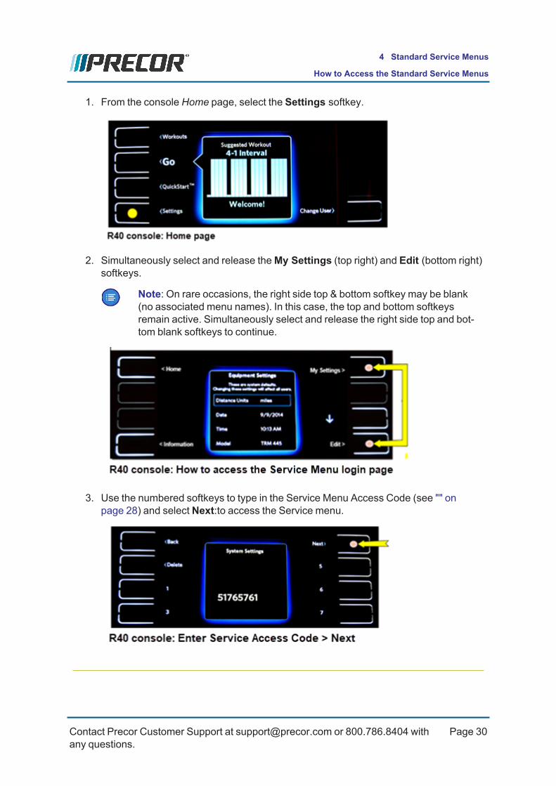
1. From the console Home page, select the Settings softkey.
2. Simultaneously select and release theMy Settings (top right) and Edit (bottom right)softkeys.
Note: On rare occasions, the right side top & bottom softkey may be blank(no associated menu names). In this case, the top and bottom softkeysremain active. Simultaneously select and release the right side top and bot-tom blank softkeys to continue.
3. Use the numbered softkeys to type in the Service Menu Access Code (see "" onpage 28) and select Next:to access the Service menu.
Contact Precor Customer Support at [email protected] or 800.786.8404 withany questions.
Page 30
4 Standard Service Menus
How to Access the Standard Service Menus

R20 How To Access Standard Service menusR20 How To Access Standard Service menus
R20 console standard service menu access
1. Select/Release the Reset/Pause key.
2. Type in the service access code using the USER keys.
Note: Use the Left & Right arrow keys to scroll.
3. PressGO to enter the access code.
Contact Precor Customer Support at [email protected] or 800.786.8404 withany questions.
Page 31
4 Standard Service Menus
How to Access the Standard Service Menus

Standard Service Menus
R40 Standard Service Menus
R40 Standard Service Menus
The Standard Service Menus include the Hardware Validation, Information, and My Set-tings service menus.
TIP: To learn additional information about the R40 console standard service menus,refer to the
TRM445 Owners Manual, see
Owners Manual.
Hardware Validation (51765761)Service Access Code: 51765761 (see "" on page 29)
The Hardware Validation menu provides a set of automated hardware diagnostic tests andcalibration procedures used to troubleshoot, calibrate, and verify machine operation. Thediagnostic tests are customized for the particular equipment type and console configuration.
How to run a test
Select Test to start the test, follow prompts to execute the test, and select Stop Test to exit.
Hardware Validation diagnostic tests
DIAGNOSTIC TEST TEST DESCRIPTION
Display GUI/MetricTest
Test console LED lights and backlight:o Backlight brightness changeso Numerals cycle properly
KEY Test Test hard keys.
Heart Rate Test Heart rate is acquired and displayed.
Belt Speed Test Running belt moves and is controlled from 0.5 mph to 12.0 mphin 0.1 increments.
Incline Test Use controls to raise/lower incline to verify the following inclineangle A/D1 values:
l Nominal value: 13 ±5@ -2% incline
l Nominal value: 37 ±5@0% incline
1analog to digital converter
Contact Precor Customer Support at [email protected] or 800.786.8404 withany questions.
Page 32
4 Standard Service Menus
Standard Service Menus

DIAGNOSTIC TEST TEST DESCRIPTION
l Nominal value: 242 ±5@ 15% incline
Information Display (65)menu: Settings > Information.
Service Access Code: 65 (see "" on page 29)
The Information Display provides the equipment usage, hardware, software, error code,and maintenance information:
INFORMATION DISPLAY DESCRIPTION
Softkeys
Home softkey Select Home to exit and return to the Home page.
Error Log softkey Select Error Log to open the Error Log table, see ."ErrorLog Display" on page 100
Information Parameters
ODOMETER The total number of accumulated miles (or kilometers) onthe unit.This value is stored in the upper PCA1 in the console so ifthe PCA is replaced the accumulated miles would startagain from "0".
USAGE The total machine usage hours (hours : min).This value is stored in the upper PCA in the console so ifthat PCA is replaced the hours of use would start againfrom "0".
SW Release P'N The operating system software part number.
Hardware Version Hardware version.
Console S/N Console serial number.
LPCA2 VersionSW The LPCA software version.
uPA BOOT SW The console upper boot software version information.
1Printed circuit assembly, generally referred to as either an upper PCA or lower PCA.2Lower Printed Circuit Assembly board; also refered to as the Lower PCA or simply as thelower board. On treadmills, it is the console to base function interface and the motor con-troller unit (MCU). On self-powered units, it is the lower PCA console to base function inter-face.
Contact Precor Customer Support at [email protected] or 800.786.8404 withany questions.
Page 33
4 Standard Service Menus
R40 Standard Service Menus

INFORMATION DISPLAY DESCRIPTION
uPA current Version The console upper current software version information.
CPA1 Boot Version The CPA boot up software version.
CPA Current Version The CPA current operating software version.
GUI Current Version The graphic userI interface software version.
GUI Restore Version The graphic userI interface restore software version.
My Settings Menu (5671)menu: Settings > My Settings.
The My Settings menu is used to customize the equipment user interface localization andWorkouts default settings.
To learn about the R40 consoleMy Settings service menu, see the TRM445 OwnersManual:
l
Owners Manual.
R20 Standard Service Menus
R20 Standard Service Menus
The Standard Service Menus include the Hardware Validation, Information, and My Set-tings service menus.
TIP: To learn additional information about the R20 console standard service menus,refer to the TRM425 Owners Manual, see
Owners Manual.
Hardware Validation (51765761)Service Access Code: 51765761 (see "R20 How To Access Standard Service menus" onpage 31)
The Hardware Validation menu provides a set of automated hardware diagnostic tests andcalibration procedures used to troubleshoot, calibrate, and verify machine operation. Thediagnostic tests are customized for the particular equipment type and console configuration.
1Touchscreen console Control Processing Assembly.
Contact Precor Customer Support at [email protected] or 800.786.8404 withany questions.
Page 34
4 Standard Service Menus
R20 Standard Service Menus

DIAGNOSTIC TEST TEST DESCRIPTION
Beeper Test Beeper sounds once every second.
Keypad Test Press all hard keys and verify change to the pattern. The test willexit when all keys have been pressed. Pressing downWorkoutsfor 5 seconds also exits the test.
LCD Test Test will light up all segments and sections of the display.
Heart Rate Test Heart rate is acquired and displayed.
Belt Speed Test Menu:Machine Test > Belt Speed Test
Range: 0.5 mph to 12.0 mph in 0.1 increments.
l PressGo to start the Belt Speed Test (IMPORTANT therunning belt will start movint).
l Use the SPEED control to very speed.
Incline Test Use controls to raise/lower incline to verify the following inclineangle A/D values:
l Nominal value: 13 ±5@ -2% incline
l Nominal value: 37 ±5@0% incline
l Nominal value: 242 ±5@ 15% incline
Information Display (65)Service Access Code: 65 (see "R20 How To Access Standard Service menus" on page 31)
The Information Display provides the equipment usage information, software pn/versioninformation, and Error Log access.
INFORMATION DISPLAY DESCRIPTION
ODOMETER The total number of accumulated miles (or kilometers) onthe unit.This value is stored in the upper PCA in the console so ifthe PCA is replaced the accumulated miles would startagain from "0".
HOUR METER The total number of hours that the unit took to accumulateunit miles.This value is stored in the upper PCA in the console so ifthat PCA is replaced the hours of use would start againfrom "0".
Contact Precor Customer Support at [email protected] or 800.786.8404 withany questions.
Page 35
4 Standard Service Menus
Information Display (65)

INFORMATION DISPLAY DESCRIPTION
U-BOOT SW The console upper boot software version information.
U-BASE SW The console upper base software version information.
USAGE LOG Shows workout usage information for each individualworkout including the number of times and the total accu-mulated time the workout was used.
Error Log List of the equipment stored error event codes (stores amaximum of 30 error codes).
My Settings Menu (5671)Service Access Code: 5671 (see "R20 How To Access Standard Service menus" onpage 31)
The My Settings service menu is used to customize the equipment user interface loc-alization andWorkouts default settings.
To learn about the R20 consoleMy Settings service menu, refer to the TRM425 OwnersManual:
l
Owners Manual.
MY SETTINGS DESCRIPTION
SAFETY CODE Enabled or disabled. When enabled, a user password (xxxx) isrequired to use the machine.Factory default: disabled
SET UNITS Sets units of measure to US Standard or Metric.Default: U.S.
SET DEFAULTWORKOUT TIME
Controls whether workouts start with a default session time that isdifferent from the maximum session time.Default: ON, 30 minutesRange: 1 to 90 min
Use State: ON or OFFIf ON use must set a Default workout time in minutes.Range: 1 to 240 min, NO LIMITDefault: 60 min
SET MAXWORKOUT TIME
Sets the maximum workout sesstion time.Range: 1 - 90 minDefault: 90 min
Contact Precor Customer Support at [email protected] or 800.786.8404 withany questions.
Page 36
4 Standard Service Menus
My Settings Menu (5671)

MY SETTINGS DESCRIPTION
NOTE: A setting of 90 min allows unlimited workout session time.
SET MAX SPEED Sets the equipment maximum workout speed.Range: 0.5 - 12 mph (0.8 - 19.3 kph)Default: 12 mph (19.3 kph)
SET MAX PAUSETIME
Sets how long the equipment remains in a paused workout ban-ner state (the time waiting for the user to continue the pausedworkout) before exiting the workout and resetting to the defaultWelcome state.Range: none, 30 sec - 5 minDefault 30 sec.
DEMO Mode (R40)
DEMOMode
(R40 consoles only)
DEMOmode is used to demonstrate the R40 console Workout program screens. DEMOmode continuously cycles through eachWorkout program until DEMOmode is exited.
IMPORTANT: DEMOmode locks out “disables” all motion controls and menusoftkeys and may make you think the console is not working properly. Make surethat the console is not in DEMOmode: go to service access DEMO mode (code5555) > select “Turn Demo OFF” > Save.
Enter DEMO mode:How to enter service software access DEMOmode:
1. From the console default Home page select the Settings softkey.
2. Simultaneously press and release the My Settings (upper right) and Edit (lowerright) softkeys.
Note: The My Settings (upper right) and Edit (lower right) softkeys might be blank"OFF" however they remain active softkeys. Simultaneously press and release theupper and lower right side softkeys to access the System Settings page.
3. Type in the DEMO Software Access Code “5555” > select Next.
4. Select “Turn Demo On” > Save.
Contact Precor Customer Support at [email protected] or 800.786.8404 withany questions.
Page 37
4 Standard Service Menus
DEMO Mode (R40)

5. The DEMOmode will begin to slowly cycle betweenWorkout program screens andthe audio control lights will switch ON “illuminate” (no audio player connected).
Note: The Save softkey must be selected to start DEMOmode.
Disable DEMO modeHow to disable (turn OFF) DEMOmode.
1. Press and hold down the lower right softkey for 5 seconds and release.
2. This will exit the DEMO screen and return to the Home page. All softkey functionalitywill be enabled, and the audio player control lights will be switched OFF (no audioplayer connected).
3. From the Home page, select the Settings softkey.
4. Simultaneously press and release theMy Settings (upper right) and Edit (lowerright) softkeys.
5. Type in the DEMO Software Access Code “5555” > select Next.
6. Select “Turn Demo Off” > Save.
IMPORTANT: The Save softkeyMUST be selected to exit DEMOmode. If notsaved within 5 minutes, DEMOmode will resume.
Contact Precor Customer Support at [email protected] or 800.786.8404 withany questions.
Page 38
4 Standard Service Menus
DEMO Mode (R40)

Standard Service Menus(Applies To: R20 & R40 consoles)
AboutThe R20 and R40 consoles provide standard service menus that allow you to configure userworkout settings, view equipment usage information; and service hardware validation dia-gnostic tests. Review the following R20 and R40 console service menu access codes topicsfor specific standard service menu options.
Service Menu Access Codes
R40 Service Menu Access Codes
SERVICE MENUACCESS CODE SERVICE MENU FUNCTION
51765761(536*)
Hardware Validation Diagnostics
Set of automated diagnostic testsused to troubleshoot, calibrate, andverify machine operation.
65 Information Display 1) Information page; providesproduct software/hardware versionand equipment usage information2) Display Error Log; provides his-tory of event error codes and dia-gnostics used for maintenance andtroubleshooting.
5671 My Settings Customizable user workout set-tings.
5555** DEMO mode** DEMOmode is used to demon-strate the R40 console Workout pro-gram screens. DEMOmodecontinuously cycles through eachWorkout program until DEMOmode is exited**, see "DEMOMode" on page 48.Important: DEMOmode can easilyfool you into believing that the con-sole is not operating correctly.DEMOmode locks-out the use ofall operating hardkey and softkeymenu controls. Tne console con-trols cannot be used until DEMO
Contact Precor Customer Support at [email protected] or 800.786.8404 withany questions.
Page 39
4 Standard Service Menus
Standard Service Menus

SERVICE MENUACCESS CODE SERVICE MENU FUNCTION
mode is exited**.
* Access code "536" can be used to access the Hardware Validation" menu.
** To disable DEMOmode, press and hold the bottom right softkey for 5-8 seconds.Unless disabled, demo mode will resume after 15 minutes. DEMOmode (5555) must bedisabled (turned OFF), see DEMOmode.
R20 Service Menu Access Codes
R20 Service Menu Access CodesSERVICE MENUACCESS CODE SERVICE MENU FUNCTION
51765761 Hardware Validation Diagnostics
Set of automated diagnostic testsused to troubleshoot, calibrate, andverify machine operation.
65 Information Display Provides equipment usage inform-ation, hardware & software pn/ver-sion information, and Error Logaccess.
5671 My Settings Allows you to customize the equip-ment user interface localization andWorkouts default settings.
* Access code "536" can be used to access the Hardware Validation" menu.
How to Access the Standard Service Menus
R40 How To Access Standard Service menus
R40 console standard service menu access
Contact Precor Customer Support at [email protected] or 800.786.8404 withany questions.
Page 40
4 Standard Service Menus
Standard Service Menus

1. From the console Home page, select the Settings softkey.
2. Simultaneously select and release theMy Settings (top right) and Edit (bottom right)softkeys.
Note: On rare occasions, the right side top & bottom softkey may be blank(no associated menu names). In this case, the top and bottom softkeysremain active. Simultaneously select and release the right side top and bot-tom blank softkeys to continue.
3. Use the numbered softkeys to type in the Service Menu Access Code (see "" onpage 39) and select Next:to access the Service menu.
Contact Precor Customer Support at [email protected] or 800.786.8404 withany questions.
Page 41
4 Standard Service Menus
Standard Service Menus

R20 How To Access Standard Service menus
R20 How To Access Standard Service menus
R20 console standard service menu access
1. Select/Release the Reset/Pause key.
2. Type in the service access code using the USER keys.
Note: Use the Left & Right arrow keys to scroll.
3. PressGO to enter the access code.
Contact Precor Customer Support at [email protected] or 800.786.8404 withany questions.
Page 42
4 Standard Service Menus
Standard Service Menus

Standard Service Menus
R40 Standard Service MenusR40 Standard Service Menus
The Standard Service Menus include the Hardware Validation, Information, and My Set-tings service menus.
TIP: To learn additional information about the R40 console standard service menus,refer to the
TRM445 Owners Manual, see
Owners Manual.
Hardware Validation (51765761)
Service Access Code: 51765761 (see "" on page 40)
The Hardware Validation menu provides a set of automated hardware diagnostic tests andcalibration procedures used to troubleshoot, calibrate, and verify machine operation. Thediagnostic tests are customized for the particular equipment type and console configuration.
How to run a test
Select Test to start the test, follow prompts to execute the test, and select Stop Test to exit.
Hardware Validation diagnostic tests
DIAGNOSTIC TEST TEST DESCRIPTION
Display GUI/MetricTest
Test console LED lights and backlight:o Backlight brightness changeso Numerals cycle properly
KEY Test Test hard keys.
Heart Rate Test Heart rate is acquired and displayed.
Belt Speed Test Running belt moves and is controlled from 0.5 mph to 12.0 mphin 0.1 increments.
Contact Precor Customer Support at [email protected] or 800.786.8404 withany questions.
Page 43
4 Standard Service Menus
Standard Service Menus

DIAGNOSTIC TEST TEST DESCRIPTION
Incline Test Use controls to raise/lower incline to verify the following inclineangle A/D1 values:
l Nominal value: 13 ±5@ -2% incline
l Nominal value: 37 ±5@0% incline
l Nominal value: 242 ±5@ 15% incline
Information Display (65)
menu: Settings > Information.
Service Access Code: 65 (see "" on page 40)
The Information Display provides the equipment usage, hardware, software, error code,and maintenance information:
INFORMATION DISPLAY DESCRIPTION
Softkeys
Home softkey Select Home to exit and return to the Home page.
Error Log softkey Select Error Log to open the Error Log table, see ."ErrorLog Display" on page 100
Information Parameters
ODOMETER The total number of accumulated miles (or kilometers) onthe unit.This value is stored in the upper PCA2 in the console so ifthe PCA is replaced the accumulated miles would startagain from "0".
USAGE The total machine usage hours (hours : min).This value is stored in the upper PCA in the console so ifthat PCA is replaced the hours of use would start againfrom "0".
SW Release P'N The operating system software part number.
Hardware Version Hardware version.
Console S/N Console serial number.
1analog to digital converter2Printed circuit assembly, generally referred to as either an upper PCA or lower PCA.
Contact Precor Customer Support at [email protected] or 800.786.8404 withany questions.
Page 44
4 Standard Service Menus
Standard Service Menus
INFORMATION DISPLAY DESCRIPTION
LPCA1 VersionSW The LPCA software version.
uPA BOOT SW The console upper boot software version information.
uPA current Version The console upper current software version information.
CPA2 Boot Version The CPA boot up software version.
CPA Current Version The CPA current operating software version.
GUI Current Version The graphic userI interface software version.
GUI Restore Version The graphic userI interface restore software version.
My Settings Menu (5671)
menu: Settings > My Settings.
The My Settings menu is used to customize the equipment user interface localization andWorkouts default settings.
To learn about the R40 consoleMy Settings service menu, see the TRM445 OwnersManual:
l
Owners Manual.
R20 Standard Service MenusR20 Standard Service Menus
The Standard Service Menus include the Hardware Validation, Information, and My Set-tings service menus.
TIP: To learn additional information about the R20 console standard service menus,refer to the TRM425 Owners Manual, see
Owners Manual.
1Lower Printed Circuit Assembly board; also refered to as the Lower PCA or simply as thelower board. On treadmills, it is the console to base function interface and the motor con-troller unit (MCU). On self-powered units, it is the lower PCA console to base function inter-face.2Touchscreen console Control Processing Assembly.
Contact Precor Customer Support at [email protected] or 800.786.8404 withany questions.
Page 45
4 Standard Service Menus
Standard Service Menus

Hardware Validation (51765761)
Service Access Code: 51765761 (see "R20 How To Access Standard Service menus" onpage 42)
The Hardware Validation menu provides a set of automated hardware diagnostic tests andcalibration procedures used to troubleshoot, calibrate, and verify machine operation. Thediagnostic tests are customized for the particular equipment type and console configuration.
DIAGNOSTIC TEST TEST DESCRIPTION
Beeper Test Beeper sounds once every second.
Keypad Test Press all hard keys and verify change to the pattern. The test willexit when all keys have been pressed. Pressing downWorkoutsfor 5 seconds also exits the test.
LCD Test Test will light up all segments and sections of the display.
Heart Rate Test Heart rate is acquired and displayed.
Belt Speed Test Menu:Machine Test > Belt Speed Test
Range: 0.5 mph to 12.0 mph in 0.1 increments.
l PressGo to start the Belt Speed Test (IMPORTANT therunning belt will start movint).
l Use the SPEED control to very speed.
Incline Test Use controls to raise/lower incline to verify the following inclineangle A/D values:
l Nominal value: 13 ±5@ -2% incline
l Nominal value: 37 ±5@0% incline
l Nominal value: 242 ±5@ 15% incline
Information Display (65)Service Access Code: 65 (see "R20 How To Access Standard Service menus" on page 42)
The Information Display provides the equipment usage information, software pn/versioninformation, and Error Log access.
INFORMATION DISPLAY DESCRIPTION
ODOMETER The total number of accumulated miles (or kilometers) onthe unit.This value is stored in the upper PCA in the console so ifthe PCA is replaced the accumulated miles would start
Contact Precor Customer Support at [email protected] or 800.786.8404 withany questions.
Page 46
4 Standard Service Menus
Standard Service Menus

INFORMATION DISPLAY DESCRIPTION
again from "0".
HOUR METER The total number of hours that the unit took to accumulateunit miles.This value is stored in the upper PCA in the console so ifthat PCA is replaced the hours of use would start againfrom "0".
U-BOOT SW The console upper boot software version information.
U-BASE SW The console upper base software version information.
USAGE LOG Shows workout usage information for each individualworkout including the number of times and the total accu-mulated time the workout was used.
Error Log List of the equipment stored error event codes (stores amaximum of 30 error codes).
My Settings Menu (5671)Service Access Code: 5671 (see "R20 How To Access Standard Service menus" onpage 42)
The My Settings service menu is used to customize the equipment user interface loc-alization andWorkouts default settings.
To learn about the R20 consoleMy Settings service menu, refer to the TRM425 OwnersManual:
l
Owners Manual.
MY SETTINGS DESCRIPTION
SAFETY CODE Enabled or disabled. When enabled, a user password (xxxx) isrequired to use the machine.Factory default: disabled
SET UNITS Sets units of measure to US Standard or Metric.Default: U.S.
SET DEFAULTWORKOUT TIME
Controls whether workouts start with a default session time that isdifferent from the maximum session time.Default: ON, 30 minutesRange: 1 to 90 min
Use State: ON or OFF
Contact Precor Customer Support at [email protected] or 800.786.8404 withany questions.
Page 47
4 Standard Service Menus
Standard Service Menus

MY SETTINGS DESCRIPTION
If ON use must set a Default workout time in minutes.Range: 1 to 240 min, NO LIMITDefault: 60 min
SET MAXWORKOUT TIME
Sets the maximum workout sesstion time.Range: 1 - 90 minDefault: 90 minNOTE: A setting of 90 min allows unlimited workout session time.
SET MAX SPEED Sets the equipment maximum workout speed.Range: 0.5 - 12 mph (0.8 - 19.3 kph)Default: 12 mph (19.3 kph)
SET MAX PAUSETIME
Sets how long the equipment remains in a paused workout ban-ner state (the time waiting for the user to continue the pausedworkout) before exiting the workout and resetting to the defaultWelcome state.Range: none, 30 sec - 5 minDefault 30 sec.
DEMO Mode (R40)DEMOMode
(R40 consoles only)
DEMOmode is used to demonstrate the R40 console Workout program screens. DEMOmode continuously cycles through eachWorkout program until DEMOmode is exited.
IMPORTANT: DEMOmode locks out “disables” all motion controls and menusoftkeys and may make you think the console is not working properly. Make surethat the console is not in DEMOmode: go to service access DEMO mode (code5555) > select “Turn Demo OFF” > Save.
Enter DEMO mode:
How to enter service software access DEMOmode:
1. From the console default Home page select the Settings softkey.
2. Simultaneously press and release the My Settings (upper right) and Edit (lowerright) softkeys.
Note: The My Settings (upper right) and Edit (lower right) softkeys might be blank"OFF" however they remain active softkeys. Simultaneously press and release theupper and lower right side softkeys to access the System Settings page.
Contact Precor Customer Support at [email protected] or 800.786.8404 withany questions.
Page 48
4 Standard Service Menus
Standard Service Menus

3. Type in the DEMO Software Access Code “5555” > select Next.
4. Select “Turn Demo On” > Save.
5. The DEMOmode will begin to slowly cycle betweenWorkout program screens andthe audio control lights will switch ON “illuminate” (no audio player connected).
Note: The Save softkey must be selected to start DEMOmode.
Disable DEMO mode
How to disable (turn OFF) DEMOmode.
1. Press and hold down the lower right softkey for 5 seconds and release.
2. This will exit the DEMO screen and return to the Home page. All softkey functionalitywill be enabled, and the audio player control lights will be switched OFF (no audioplayer connected).
3. From the Home page, select the Settings softkey.
4. Simultaneously press and release theMy Settings (upper right) and Edit (lowerright) softkeys.
5. Type in the DEMO Software Access Code “5555” > select Next.
6. Select “Turn Demo Off” > Save.
IMPORTANT: The Save softkeyMUST be selected to exit DEMOmode. If notsaved within 5 minutes, DEMOmode will resume.
Contact Precor Customer Support at [email protected] or 800.786.8404 withany questions.
Page 49
4 Standard Service Menus
Standard Service Menus
Adjustment Procedures
Adjustment procedures provide you with the step-by-step adjustment instructions to bringsystems and components into specification. Perform the adjustment procedures whenevera trouble symptom points to a particular component and after a major component isremoved/replaced.
Available Adjustment Procedures"Drive Belt Tension Adjustment" on the facing page
"Running Belt Tension and Tracking Adjustment" on page 55
"Lift Motor Calibration" on page 61
Contact Precor Customer Support at [email protected] or 800.786.8404 withany questions.
Page 50
5 Adjustment Procedures
Available Adjustment Procedures

Drive Belt Tension Adjustment
AboutThis procedure provides instruction to verify and make adjustments to the Drive Belt align-ment and tension. The Drive Belt alignment and tension should be verified anytime theDrive Belt is replaced or when there are any belt related issues (unusual noises, drive beltslippage, etc.) during normal operation.
Specifications
Component Drive Belt Tension
Drive Belt Tension 70-90 lbs (32-41 kgs)
Drive Motor Mounting BoltTorque1
180 in-lbs (15 ft-lbs, 20.4 N-m)
Drive Belt Tension AdjustmentReview entire procedure before starting.
1. Set the treadmill circuit breaker to “OFF” and unplug2 the power cord from the walloutlet.
2. Remove the hood.
3. Place the drive belt tension gauge on the drive belt.
1Torque is a measure of the force that can cause an object to rotate about an axis. Bolt/nutexample: 5 NM torque is equivalent to 5 newton's of force applied one meter from the centerof the bolt, 6 ft-lb is equivalent to 6 lbs of force applied 1 foot away from the center of thebolt.2Disconnect a device power cord plug or cable connector from the power receptacle or out-let.
Contact Precor Customer Support at [email protected] or 800.786.8404 withany questions.
Page 51
5 Adjustment Procedures
Drive Belt Tension Adjustment
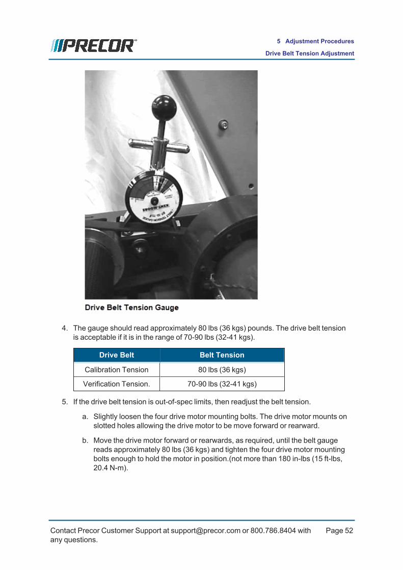
4. The gauge should read approximately 80 lbs (36 kgs) pounds. The drive belt tensionis acceptable if it is in the range of 70-90 lbs (32-41 kgs).
Drive Belt Belt Tension
Calibration Tension 80 lbs (36 kgs)
Verification Tension. 70-90 lbs (32-41 kgs)
5. If the drive belt tension is out-of-spec limits, then readjust the belt tension.
a. Slightly loosen the four drive motor mounting bolts. The drive motor mounts onslotted holes allowing the drive motor to be move forward or rearward.
b. Move the drive motor forward or rearwards, as required, until the belt gaugereads approximately 80 lbs (36 kgs) and tighten the four drive motor mountingbolts enough to hold the motor in position.(not more than 180 in-lbs (15 ft-lbs,20.4 N-m).
Contact Precor Customer Support at [email protected] or 800.786.8404 withany questions.
Page 52
5 Adjustment Procedures
Drive Belt Tension Adjustment

c. Momentarily remove the drive belt tension gauge and move the drive belt a fewrotations. Install the drive belt tension gauge and remeasure the belt tension. Ifthe measured tension is out-of-spec, repeat procedure and adjust the drive belttension to be within the specification limits.
d. Torque the four drive motor mounting bolts to 180 in-lbs (15 ft-lbs, 20.4 N-m).
.
6. Re-install the hood.
7. Plug1 in the power cord to the wall outlet and switch the treadmill power “ON”.
8. Access the Hardware Validation service menu (51765761) and select the SpeedTest, see ."Standard Service Menus" on page 39.
a. While walking on the running belt, operate the SPEED and INCLINE controlsfrom minimum to maximum ranges while verifying the drive belt operation.
l Make sure that the there are no unusual noised or squeaking soundsemanating from the drive belt.
l Verify that the running belt can reach the maximum speed and thenreturns to the minimum speed level.
l Make sure that the running belt speed change is smooth and the drivebelt is not slipping.
9. Verify operation and return to service, see ("Operation Verification" on page 20).
1Device power cord connector or electrical cable male connector that is inserted into anelectrical receptacle "outlet" (also called the plug-in).
Contact Precor Customer Support at [email protected] or 800.786.8404 withany questions.
Page 53
5 Adjustment Procedures
Drive Belt Tension Adjustment

Contact Precor Customer Support at [email protected] or 800.786.8404 withany questions.
Page 54
5 Adjustment Procedures
Drive Belt Tension Adjustment

Running Belt Tension and Tracking Adjustment
AboutThis procedure provides instructions to adjust the running belt tension and tracking align-ment to manufacturer specification. The running belt tension and tracking should be adjus-ted anytime the running belt is replaced, removed/installed, or when there are anydetectable belt or tracking issues.
VideosRUNNING BELT ALIGNMENT PROCEDURE
Tools
QTY TOOL
1 1/4" Hex Key Socket and Ratchet
2 Belt Tension Gauge1 (PPP000000020007101 or equivalent)
(1) Proper tensioning of the belt requires the use of two tensioning gauges, Precor partnumber PPP000000020007101or equivalent.
Specification
Running Belt Specification
Forbo brand running belt tension(2) 3.55 (0.55%)(1)
Notes: 1) Referenced to gauge reading 3.0 (0.0%)
Procedure
Running belt tension adjustment
CAUTION: 1) ONLY use hand tools for belt tension adjustment.2) Final belt tension adjustments should only be done in 1/4 turn incre-ments.
Review entire procedure before starting.
1. Clean the running belt and deck, see "Running Belt and Deck Cleaning Procedure"on page 122.
Contact Precor Customer Support at [email protected] or 800.786.8404 withany questions.
Page 55
5 Adjustment Procedures
Running Belt Tension and Tracking Adjustment
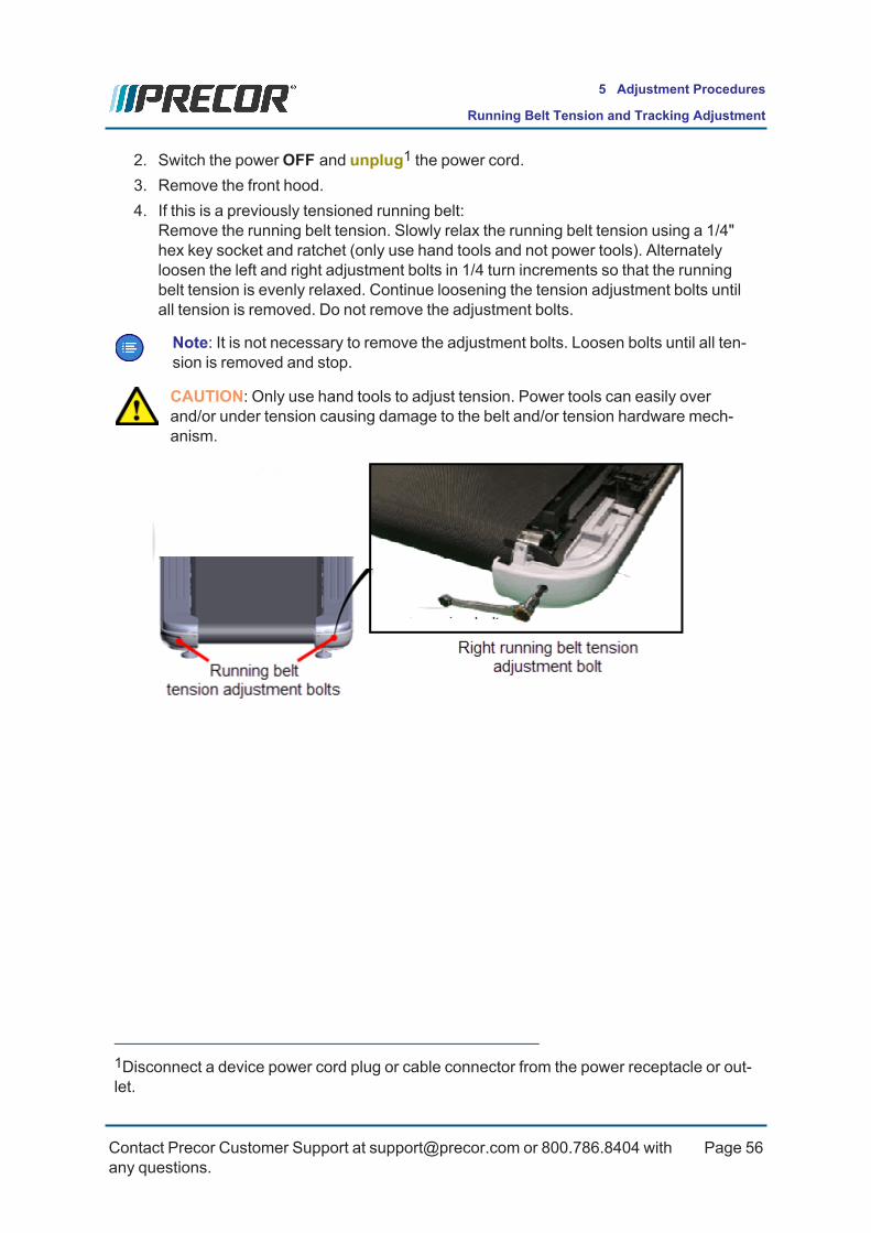
2. Switch the powerOFF and unplug1 the power cord.3. Remove the front hood.4. If this is a previously tensioned running belt:
Remove the running belt tension. Slowly relax the running belt tension using a 1/4"hex key socket and ratchet (only use hand tools and not power tools). Alternatelyloosen the left and right adjustment bolts in 1/4 turn increments so that the runningbelt tension is evenly relaxed. Continue loosening the tension adjustment bolts untilall tension is removed. Do not remove the adjustment bolts.
Note: It is not necessary to remove the adjustment bolts. Loosen bolts until all ten-sion is removed and stop.
CAUTION: Only use hand tools to adjust tension. Power tools can easily overand/or under tension causing damage to the belt and/or tension hardware mech-anism.
1Disconnect a device power cord plug or cable connector from the power receptacle or out-let.
Contact Precor Customer Support at [email protected] or 800.786.8404 withany questions.
Page 56
5 Adjustment Procedures
Running Belt Tension and Tracking Adjustment

5. Center and square the running belt on the deck and on the Drive and Take-up rollers.
6. Move the running belt so that the seam is positioned on the bottom underside of thedeck.
7. Attach two running belt tension gauges, one on each side of the running belt and posi-tioned so that they are opposite each other. Place the gauges so that the trim landingmounting brackets do not interfere with the gauge movement.
8. Slide the gauge dial to set the dial needle as close as possible to 3.0 (0.0%) and thenclip the gauge onto the belt edge. Then use your fingers to rotate the outer gauge dialto fine adjust the needle to precisely 3.0 (0.0%).
Note: Setting the gauge to a 3.0 reference value centers the gauge needle at a pos-ition that allows unhindered gauge movement.
9. Tension the belt to OEM specification:a. First remove the belt slack by alternately tightening the right and left 1/4” hex
key belt tension adjustment bolts to the point where the belt tension just startsto exceed 3.0 (0 % ref) for each gauge. Do not exceed 3.0 (0 %) reference.
Contact Precor Customer Support at [email protected] or 800.786.8404 withany questions.
Page 57
5 Adjustment Procedures
Running Belt Tension and Tracking Adjustment

b. At this point the tension pressure has increased significantly and care must betaken to not damage the adjustment hardware and/or belt. The tension gaugewill be used to determine when to alternate the left and right bolt tension adjust-ment rather than the alternating 1/4 turn bolt method. Alternately adjust the leftand right side tension in increments of 0.2 (0.2%) gauge divisions until the man-ufacturer tension specification is reached.
Running Belt Specification
Running belt tension 3.55 (0.55%)*
Notes: * Referenced to gauge reading 3.0 (0.0%)
10. Remove the tension gauges.11. Verify the running belt alignment and tracking, continue with the "Running belt align-
ment and tracking adjustment" below.
Running belt alignment and tracking adjustmentWhat is a centered and properly tracking running belt
A properly centered belt does not mean that the belt is perfectly centered on the deck androllers. It is a belt that tracks steady and does not touch or rub the landing trim or any otherframe or hardware parts. Always attempt to position the belt as close as possible to the cen-ter of the deck and rollers.
Contact Precor Customer Support at [email protected] or 800.786.8404 withany questions.
Page 58
5 Adjustment Procedures
Running Belt Tension and Tracking Adjustment

CAUTION: 1) ONLY use hand tools for belt tracking adjustment2) The tracking adjustments should only be done in 1/4 turn incre-ments.3) ONLY use the right side tension bolt to adjust tracking.
Video
RUNNING BELT ALIGNMENT PROCEDURE
Review entire procedure before starting.
1. Connect the power cord and switch the powerON.2. Start the manual workout and set the speed to 3 mph (5 kph).3. Observe and verify that the running belt tracking remains centered. If not, make minor
adjustments to the right tension adjustment bolt to center the belt tracking. Only usethe right tension adjustment bolt to adjust the tracking as follows:
a. Belt drifts right:Slowly turn the right side tension adjustment bolt clockwise in ¼ turn incre-ments until the drifting stops. You may need to recenter the belt by carefullybumping the belt to the left.
b. Belt drifts left:Slowly turn the right side tension adjustment bolt counterclockwise in ¼ turnincrements until the drifting stops. You may need to recenter the belt by care-fully bumping the belt to the right.
Contact Precor Customer Support at [email protected] or 800.786.8404 withany questions.
Page 59
5 Adjustment Procedures
Running Belt Tension and Tracking Adjustment
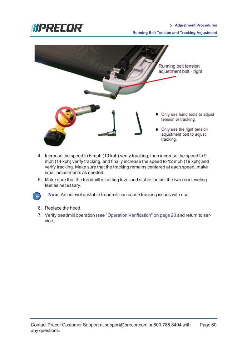
4. Increase the speed to 6 mph (10 kph) verify tracking, then increase the speed to 9mph (14 kph) verify tracking, and finally increase the speed to 12 mph (19 kph) andverify tracking. Make sure that the tracking remains centered at each speed, makesmall adjustments as needed.
5. Make sure that the treadmill is setting level and stable, adjust the two rear levelingfeet as necessary.
Note: An unlevel unstable treadmill can cause tracking issues with use.
6. Replace the hood.7. Verify treadmill operation (see "Operation Verification" on page 20 and return to ser-
vice.
Contact Precor Customer Support at [email protected] or 800.786.8404 withany questions.
Page 60
5 Adjustment Procedures
Running Belt Tension and Tracking Adjustment

Lift Motor Calibration
AboutThis procedure provides instruction to verify and calibrate the Lift Motor and Incline system.The Lift Motor calibration should be verified any time the lift motor is replaced, the lift motorfuse fails, or any incline system component is replaced.
Specifications
System Component Specification
Lift Motor Jackscrew CalibrationDistance*
1 in (2.54 cm)
Incline Level A/D1 Calibration Incline angle A/D values:l Nominal value: 13 ±5@ -2% inclinel Nominal value: 37 ±5@0% inclinel Nominal value: 242 ±5@ 15% incline
Note: * Calibration distance is specified at incline level 0.
VideosService Video Link
TRM2 400 Lift Motor Calibration Lift Motor Calibration
Lift Motor CalibrationReview entire procedure before starting.
1. Set the incline to level 0.
2. Switch the treadmill circuit breaker to “OFF” and unplug3 the power cord.
3. Remove the hood.
4. Place the treadmill on its right side.
5. Remove the hitch and clevis pins that secure the lift tube to the lift platform.
1analog to digital converter2Treadmill3Disconnect a device power cord plug or cable connector from the power receptacle or out-let.
Contact Precor Customer Support at [email protected] or 800.786.8404 withany questions.
Page 61
5 Adjustment Procedures
Lift Motor Calibration
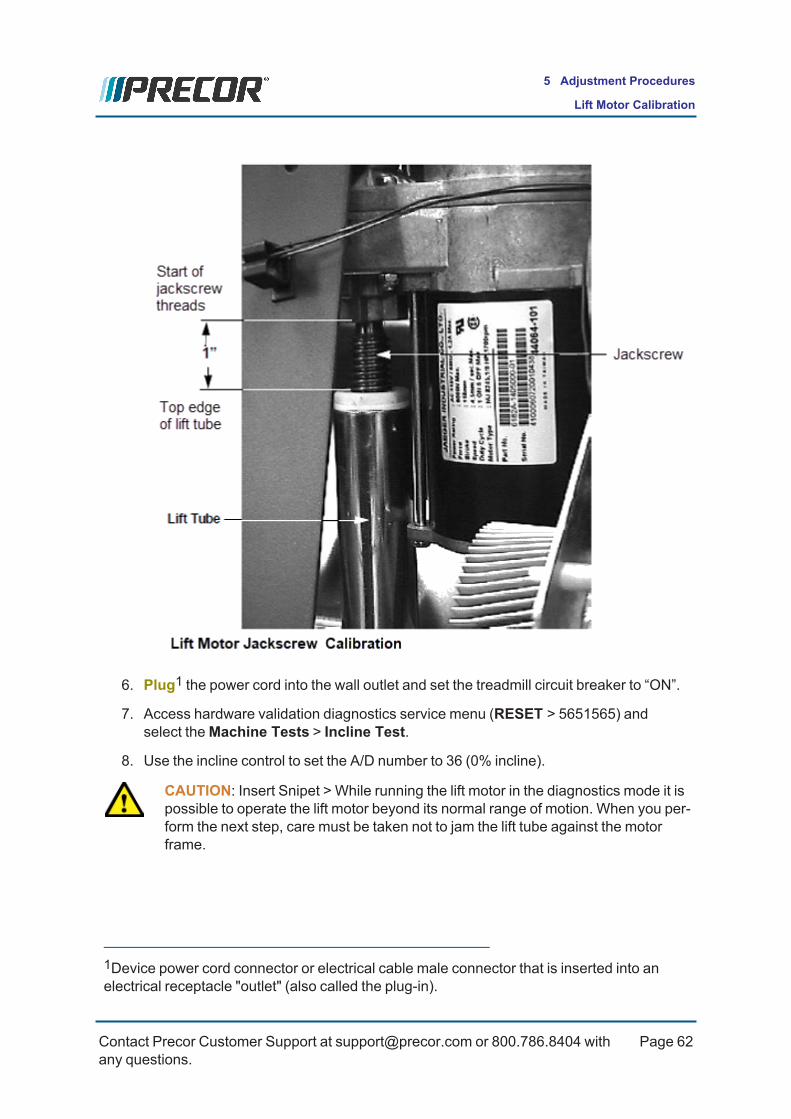
6. Plug1 the power cord into the wall outlet and set the treadmill circuit breaker to “ON”.
7. Access hardware validation diagnostics service menu (RESET > 5651565) andselect theMachine Tests > Incline Test.
8. Use the incline control to set the A/D number to 36 (0% incline).
CAUTION: Insert Snipet > While running the lift motor in the diagnostics mode it ispossible to operate the lift motor beyond its normal range of motion. When you per-form the next step, care must be taken not to jam the lift tube against the motorframe.
1Device power cord connector or electrical cable male connector that is inserted into anelectrical receptacle "outlet" (also called the plug-in).
Contact Precor Customer Support at [email protected] or 800.786.8404 withany questions.
Page 62
5 Adjustment Procedures
Lift Motor Calibration

9. Press the RESET key to exit.
10. Switch the treadmill circuit breaker “OFF” and unplug the power cord from the wall out-let.
Lift tube calibration
11. Hand rotate the lift tube clockwise as far as possible. With one hand hold the jacks-cew from rotating while using the other hand to rotate the lift tube counterclockwiseuntil the distance from the top edge of the lift tube to the start of the jackscrew threadsis 1 in (2.54 cm). While rotating the lift tube, make sure that the lift motor jackscrewdoes not rotate. If the jackscrew does rotate, repeat the adjustment process.The jackscrew mounting hole may not exactly align with the frame mounting bracketat the 1 in (2.54 cm) calibration distance. Rotate the tube in the direction that willcause the least amount of rotation (least amount of jackscrew extension distance)from 1 in (2.54 cm).
12. Replace the clevis and hitch pins.
Contact Precor Customer Support at [email protected] or 800.786.8404 withany questions.
Page 63
5 Adjustment Procedures
Lift Motor Calibration
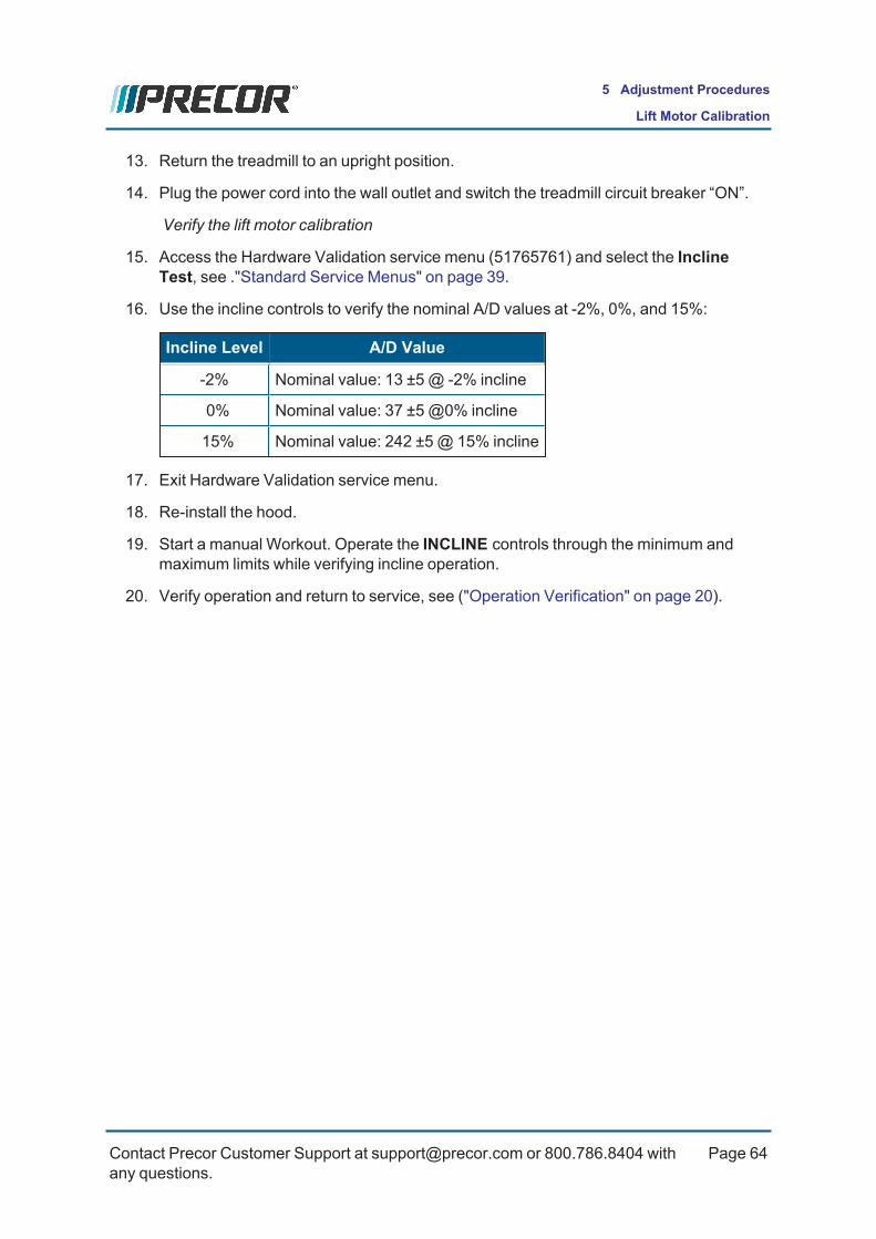
13. Return the treadmill to an upright position.
14. Plug the power cord into the wall outlet and switch the treadmill circuit breaker “ON”.
Verify the lift motor calibration
15. Access the Hardware Validation service menu (51765761) and select the InclineTest, see ."Standard Service Menus" on page 39.
16. Use the incline controls to verify the nominal A/D values at -2%, 0%, and 15%:
Incline Level A/D Value
-2% Nominal value: 13 ±5@ -2% incline
0% Nominal value: 37 ±5@0% incline
15% Nominal value: 242 ±5@ 15% incline
17. Exit Hardware Validation service menu.
18. Re-install the hood.
19. Start a manual Workout. Operate the INCLINE controls through the minimum andmaximum limits while verifying incline operation.
20. Verify operation and return to service, see ("Operation Verification" on page 20).
Contact Precor Customer Support at [email protected] or 800.786.8404 withany questions.
Page 64
5 Adjustment Procedures
Lift Motor Calibration

Replacement Procedures
Replacement procedures provide you with the step-by-step instructions to remove andinstall system components.
Available Replacement Procedures"Drive Belt Replacement" on the next page
"Drive Motor Replacement" on page 68
"Drive Motor Brushes Replacement" on page 70
"Speed Sensor Replacement" on page 72
"Drive Roller Replacement" on page 74
"Take-up Roller Replacement" on page 77
"Running Belt and Deck Replacement Procedure" on page 80
"Lift Motor Replacement" on page 83
"Lift Platform Replacement" on page 86
"Lower PCA (LPCA) Replacement" on page 89
Contact Precor Customer Support at [email protected] or 800.786.8404 withany questions.
Page 65
6 Replacement Procedures
Available Replacement Procedures

Drive Belt Replacement
AboutThis procedure provides instruction to remove and install the Drive Belt
ProcedureReview entire procedure before starting.
Removal
1. Switch the powerOFF and unplug1 the power cord.2. Remove the hood cover, see .3. Use a 1/4" hex key socket and ratchet to relax the running belt tension by alternately
loosening the left and right belt tension adjustment bolts in 1/4 turn increments. Usethis method to evenly remove the left and right belt tension. Do not use power toolswhich can make it difficult to control the left/right 1/4 turn incremental bolt looseningrequirment. Uneven belt tension removal can cause damage to the running belt or ten-sion adjustment hardware.
CAUTION: Only use hand tools to adjust tension. Power tools can easily overand/or under tension causing damage to the belt and/or tension hardware mech-anism.
4. Use a 1/2" socket with 6" extension to loosen the four Drive Motor mount boltsenough so that the motor can slide forward and rearward in the mounting tray.
5. Loosen the 1/2" drive belt tension adjustment bolt to remove the drive belt tension.Then walk the belt off the drive motor pulley.
6. Lift the drive roller from the frame mounting brackets and remove the belt off the driveroller pulley. Remove the drive motor belt and reinstall the roller into the frame mount-ing brackets.
Installation
1. Lift the drive roller from the frame mounting brackets enough to install the belt ontothe drive roller pulley. Reinstall the drive roller into the frame left and rignt mounting
1Disconnect a device power cord plug or cable connector from the power receptacle or out-let.
Contact Precor Customer Support at [email protected] or 800.786.8404 withany questions.
Page 66
6 Replacement Procedures
Drive Belt Replacement

brackets.
2. Square the running belt on the running deck. drive roller, and take-up roller and ten-sion the running belt to specification, see "Running Belt Tension and Tracking Adjust-ment" on page 55.DO NOT apply power or verify the running belt tracking at this step in the process, therunning belt tracking will be verified after the Drive Belt is installed.
IMPORTANT: It is necessary to tension the running belt prior to tensioning thedrive belt.
3. Install the drive belt onto the drive motor pulley (walk the belt onto the drive motor pul-ley).
4. Make sure the drive belt is properly aligned by verifying that the drive belt is parallel tothe left frame rail. Measure the drive belt-to-frame rail distance at the drive roller pul-ley and at the drive motor pulley. The drive belt is correctly aligned when the twomeasured distances are the same.
CAUTION: A misaligned drive belt can cause high pitch belt noises, damage to thebelt, and possible drive motor pulley or drive roller pulley hardware damage.
5. Tension the drive belt to specification, see "Drive Belt Tension Adjustment" onpage 51.
Drive BeltCondition
(1)Drive BeltTension Verification Belt Tension
New(1) 110 lbs +/- 10 (50 kgs +/- 4.5) 100-120 lbs (45-54 kgs)
Used(1) 85 lbs +/- 5 (39 kgs +/- 2) 80-90 lbs (36-41 kgs)
(1) New belt tension applies to new belt first time installations. Used belt tensionapplies to reinstalling an existing belt or re-tensioning an existing used belt.
6. Complete the running belt installation by verifying the running belt alignment andtracking, see "Running belt alignment and tracking adjustment" on page 58.
7. Reinstall the hood cover, see .8. Do the Operation Verification tests (see "Operation Verification" on page 20) and
return to service.
Contact Precor Customer Support at [email protected] or 800.786.8404 withany questions.
Page 67
6 Replacement Procedures
Drive Belt Replacement

Drive Motor ReplacementThis procedure provides instruction to replace the Drive Motor.
IMPORTANT: The drive motor and flywheel are balanced as a matched pair. Sincethe flywheel is balanced to a specific motor, flywheels should not be removed fromone and installed on a different motor. If the drive motor is replaced, the drive motorand flywheel should be replaced as a unit.
ProcedureReview entire procedure before starting.
Removal
1. Switch the power "OFF" and unplut the power cord.
2. Remove the hood cover.
3. Remove the speed sensor and chopper wheel from the drive motor. Retain part(s)and/or fastener(s) for installation.
4. Disconnect the red and black drive motor wires from the inline connectors.
5. Remove the drive belt from the drive motor pulley. Retain part(s) and/or fastener(s)for installation.
6. Loosen and remove the four bolts that fasten the drive motor to the mounting base.Remove the drive motor from the treadmill. 1 in (2.54 cm)
Installation
1. Set the drive motor in the mounting position. Replace and hand tighten the four drivemotor mounting bolts.
2. Place the drive belt on the drive motor and drive roller pulleys. Tension the drive beltand fully tighten bolts to specification, see ."Drive Belt Tension Adjustment" onpage 51.
3. Connect the black and red drive motor wires to the mating black and red connectorson the inline connectors.
4. Set the speed sensor and chopper wheel in position on the drive motor and fastenwith the removed screws.
5. Plug1 in the power cord and switch the power "ON".
1Device power cord connector or electrical cable male connector that is inserted into anelectrical receptacle "outlet" (also called the plug-in).
Contact Precor Customer Support at [email protected] or 800.786.8404 withany questions.
Page 68
6 Replacement Procedures
Drive Motor Replacement

6. Start a manual test and operate the SPEEDmotion control from minimum to max-imum range while verifying the machine operation.
l Make sure that the console SPEED paddle control operation is smooth andworking correctly.
l Verify that the running belt can reach the maximum speed and then returns tothe minimum speed level.
l Make sure that the running belt speed change is smooth and that there are nounusual noises.
l Verify that the console SPEED indicators and workout metric displays are show-ing correct information
7. When completed, go to the Error Log and make sure that there are no active errorcodes. Clear the Error Log.
8. Do the Operation Verification tests (see ) and return to service.
Contact Precor Customer Support at [email protected] or 800.786.8404 withany questions.
Page 69
6 Replacement Procedures
Drive Motor Replacement

Drive Motor Brushes ReplacementThis procedure provides instruction to replace the Drive Motor Brushes.
ProcedureReview entire procedure before starting.
1. Switch the treadmill power “OFF” and unplug1 the treadmill’s power cord.
2. Remove the hood.
3. Use a flat blade screw driver to remove the drive motor brush cover.
4. Remove the brush from the brush holder.
5. Slide the replacement brush into the brush holder. Be sure that the edge of the brushis inserted so that the brush face makes full contact with the motor commutator.
6. Push the brush spring and cable down against the brush. Then quickly press thecover into place.
7. Repeat procedure and replace the remaining drive motor brush.
8. Plug2 in the machine power cord and switch the power "ON".
1Disconnect a device power cord plug or cable connector from the power receptacle or out-let.2Device power cord connector or electrical cable male connector that is inserted into anelectrical receptacle "outlet" (also called the plug-in).
Contact Precor Customer Support at [email protected] or 800.786.8404 withany questions.
Page 70
6 Replacement Procedures
Drive Motor Brushes Replacement

9. Start a manual test and operate the SPEEDmotion control from minimum to max-imum range while verifying the machine operation.
10. Make sure that the console SPEED paddle control operation is smooth and workingcorrectly.
11. Verify that the running belt can reach the maximum speed and then returns to the min-imum speed level.
12. Make sure that the running belt speed change is smooth and that there are nounusual noises.
13. Verify that the console SPEED indicators and workout metric displays are showingcorrect information
14. When completed, go to the Error Log and make sure that there are no active errorcodes. Clear the Error Log.
15. Do the Operation Verification tests (see ) and return to service.
Contact Precor Customer Support at [email protected] or 800.786.8404 withany questions.
Page 71
6 Replacement Procedures
Drive Motor Brushes Replacement
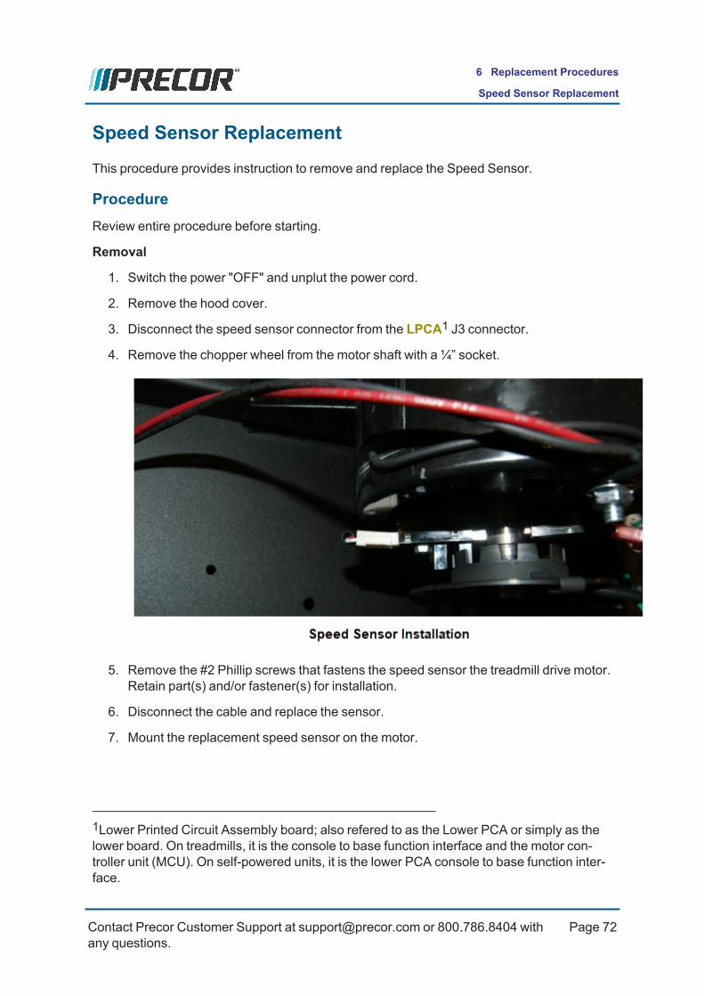
Speed Sensor ReplacementThis procedure provides instruction to remove and replace the Speed Sensor.
ProcedureReview entire procedure before starting.
Removal
1. Switch the power "OFF" and unplut the power cord.
2. Remove the hood cover.
3. Disconnect the speed sensor connector from the LPCA1 J3 connector.
4. Remove the chopper wheel from the motor shaft with a ¼” socket.
5. Remove the #2 Phillip screws that fastens the speed sensor the treadmill drive motor.Retain part(s) and/or fastener(s) for installation.
6. Disconnect the cable and replace the sensor.
7. Mount the replacement speed sensor on the motor.
1Lower Printed Circuit Assembly board; also refered to as the Lower PCA or simply as thelower board. On treadmills, it is the console to base function interface and the motor con-troller unit (MCU). On self-powered units, it is the lower PCA console to base function inter-face.
Contact Precor Customer Support at [email protected] or 800.786.8404 withany questions.
Page 72
6 Replacement Procedures
Speed Sensor Replacement

8. Mount the chopper wheel on the drive motor with the #2 Phillip screws.
9. Reconnect the speed sensor connector to the LPCA J3 connector.
10. Reinstall the hood cover.
11. Plug1 in the machine power cord and switch the power "ON".
12. Start a manual test and operate the SPEEDmotion control from minimum to max-imum range while verifying the machine operation.
l Make sure that the console SPEED paddle control operation is smooth andworking correctly.
l Verify that the running belt can reach the maximum speed and then returns tothe minimum speed level.
l Make sure that the running belt speed change is smooth and that there are nounusual noises.
l Verify that the console SPEED indicators and workout metric displays are show-ing correct information
13. Do the Operation Verification tests (see ) and return to service.
1Device power cord connector or electrical cable male connector that is inserted into anelectrical receptacle "outlet" (also called the plug-in).
Contact Precor Customer Support at [email protected] or 800.786.8404 withany questions.
Page 73
6 Replacement Procedures
Speed Sensor Replacement

Drive Roller Replacement
AboutThis procedure is to be used to replace the Drive Roller while maintaining the current DriveBelt tension and Drive Roller install position.
Specialized Tools
Two running belt tension gauges, Precor part number 20007-101, are required.
CAUTION: Only use hand tools to adjust tension. Power tools can easily overand/or under tension causing damage to the belt and/or tension hardware mech-anism.
ProcedureReview entire procedure before starting.
Removal
1. Switch the powerOFF and unplug1 the power cord.2. Remove the hood cover. Retain part(s) and/or fastener(s) for installation.
3. Remove the endcaps and belt guards from the rear of treadmill to expose the take-uproller mounting bolts. Retain part(s) and/or fastener(s) for installation.
4. Relax the running belt tension by loosening the left and right 1/4" hex key tensionadjustment bolts. Alternately loosen the left and right adjustment bolts in 1/4 turnincrements so that the running belt tension is evenly removed. Only use hand toolsand not power tools which could cause damage to the take-up roller tension mech-anism.
CAUTION: Only use hand tools to adjust tension. Power tools can easily overand/or under tension causing damage to the belt and/or tension hardware mech-anism.
1Disconnect a device power cord plug or cable connector from the power receptacle or out-let.
Contact Precor Customer Support at [email protected] or 800.786.8404 withany questions.
Page 74
6 Replacement Procedures
Drive Roller Replacement

5. Walk the drive belt off the drive motor pulley. Remove the drive belt off the drive roller.
6. Measure the front of the drive roller to the edge of the dust shield "Drive Roller Align-ment Distance". Record the measurement which will be required for installation.
IMPORTANT: Do NOT continue without recording the "Drive Roller AlignmentDistance" measurement.
7. Remove the drive roller mounting bolt and remove the drive roller. Retain part(s)and/or fastener(s) for installation.
Installation
1. Slide the replacement Drive Roller through the running belt and into the frame mount-ing brackets.
2. Center and square the running belt onto the Take-up and Drive rollers
Contact Precor Customer Support at [email protected] or 800.786.8404 withany questions.
Page 75
6 Replacement Procedures
Drive Roller Replacement

3. Hand start the drive roller adjustment bolt and then continue tightening the bolt untilthe measurement from the front of the drive roller to the edge of the dust shieldexactly reaches the previously recorded "Drive Roller Alignment Distance" meas-urement.Note: A properly adjusted drive roller is positioned perpendicular (90 degs) to theframe rails. If the drive roller tracking does not remain centered, you will need to read-just the drive roller position.
4. Install the drive belt. Place the drive belt onto the drive roller pulley and then walk thebelt onto the drive motor pulley. Make sure that the drive belt is fully seated and cor-rectly aligned on the drive roller and drive motor pulleys.
5. Verify the drive belt tension, see "Drive Belt Tension Adjustment" on page 51.6. Plug1 in the power cord and switch the powerON.7. Tension running belt to specification and verify tracking alignment, see "Running Belt
Tension and Tracking Adjustment" on page 55.
8. Reinstall the endcaps and belt guards.
9. Reinstall the hood cover.10. Do the Operation Verification tests (see "Operation Verification" on page 20) and
return to service.
1Device power cord connector or electrical cable male connector that is inserted into anelectrical receptacle "outlet" (also called the plug-in).
Contact Precor Customer Support at [email protected] or 800.786.8404 withany questions.
Page 76
6 Replacement Procedures
Drive Roller Replacement
Take-up Roller Replacement
AboutThis procedure is to be used to replace the Take-up Roller while maintaining the currentDrive Belt tension and Drive Roller install position.
Specialized Tools
Two running belt tension gauges, Precor part number 20007-101, are required.
CAUTION: Only use hand tools to adjust tension. Power tools can easily overand/or under tension causing damage to the belt and/or tension hardware mech-anism.
ProcedureReview entire procedure before starting.
Removal
1. Switch the powerOFF and unplug1 the power cord.2. Remove the hood cover. Retain part(s) and/or fastener(s) for installation.
3. Remove the endcaps and belt guards from the rear of treadmill to expose the take-uproller mounting bolts. Retain part(s) and/or fastener(s) for installation.
4. Slowly relax the running belt tension using a 1/4" hex key driver and ratchet (only usehand tools and not power tools). Alternately loosen the left and right adjustment boltsin 1/4 turn increments so that the running belt tension is evenly relaxed.
CAUTION: Only use hand tools to adjust tension. Power tools can easily overand/or under tension causing damage to the belt and/or tension hardwaremechanism.
1Disconnect a device power cord plug or cable connector from the power receptacle or out-let.
Contact Precor Customer Support at [email protected] or 800.786.8404 withany questions.
Page 77
6 Replacement Procedures
Take-up Roller Replacement

5. Continue to loosen and remove the Take-up roller tension adjustment bolts .6. For Take-up rollers that will be reinstalled. Use a pen or tape to mark and identify the
left and right sides of the roller prior to removal. The roller must be reinstalled with thesame left/right orientation.
IMPORTANT: Make sure to identify the left and right ends of the roller prior toremoval.
7. Remove the left and right roller bridges. Retain part(s) and/or fastener(s) for install-ation.
8. Remove the take-up roller from the inside of the running belt. Lift the take-up rollerwhile removing from the inside of the running belt. The roller is heavy, so be careful tonot scratch the deck surface or belt while removing the roller..
CAUTION: Make sure the Take-up roller does not drag across the deck surfacewhile removing causing damage to the deck surface.
Installation1. Insert the roller through the inside of the running belt and set the Take-up roller into
the left and right mounting brackets.
IMPORTANT: For used Take-up roller replacement, make sure the left/right ori-entation is maintaned (same as originally installed).
CAUTION: Make sure the Take-up roller does not drag across the deck surfacewhile inserting through the running belt causing damage to the deck surface.
2. Reinstall the left and right roller bridges.3. Hand start and reinstall the left and right running belt tension adjustment bolts. Hand
tighten the bolts, do not fully tighten.
Contact Precor Customer Support at [email protected] or 800.786.8404 withany questions.
Page 78
6 Replacement Procedures
Take-up Roller Replacement
4. Plug1 in the power cord and switch the powerON.5. Tension running belt to specification and verify tracking alignment, see "Running Belt
Tension and Tracking Adjustment" on page 55.
6. Reinstall the endcaps and belt guards.
7. Reinstall the hood cover.8. Do the Operation Verification tests (see "Operation Verification" on page 20) and
return to service..
1Device power cord connector or electrical cable male connector that is inserted into anelectrical receptacle "outlet" (also called the plug-in).
Contact Precor Customer Support at [email protected] or 800.786.8404 withany questions.
Page 79
6 Replacement Procedures
Take-up Roller Replacement

Running Belt and Deck Replacement Procedure
AboutThis procedure provides instruction to remove and replace the Running Belt and Deck.
Belt and Deck
The running belt is a lubricated type belt and is used with a non-waxed deck. The deck isreversible and not waxed.
CAUTION: Do not apply any lubricants or wax to the deck and belt. Do not useWax Blast, silicon sprays, or other applied lubricants. The use of these lubricantswill quickly degrade the low-friction surface of the deck.
ProcedureReview entire procedure before starting.
Removal
1. Switch the powerOFF and unplug1 the power cord.2. Remove the hood cover. Retain part(s) and/or fastener(s) for installation.
3. Remove the endcaps and belt guard covers from the rear of treadmill. Retain part(s)and/or fastener(s) for installation.
4. Remove the left and right landing trim covers. Retain part(s) and/or fastener(s) forinstallation.
5. Remove the left and right roller bridges. Retain part(s) and/or fastener(s) for install-ation.
6. Remove the Take-up Roller, see "Take-up Roller Replacement" on page 77.7. Remove the Drive Roller, see "Drive Roller Replacement" on page 74.8. Carefully lift the deck and belt out of the treadmill frame.9. Remove the running belt from the deck and discard.
A new deck surface must be used with each new belt replacement.l If both sides of the deck are used, discard the deck, and replace with a newdeck.
l If the bottom side of the deck has not been used (new), flip and use new side ofthe deck.
Installation
1Disconnect a device power cord plug or cable connector from the power receptacle or out-let.
Contact Precor Customer Support at [email protected] or 800.786.8404 withany questions.
Page 80
6 Replacement Procedures
Running Belt and Deck Replacement Procedure

CAUTION: A new deck surface must used with each new running belt replace-ment.
10. Use a dry clean cloth and wipe the inside of the belt and the top surface of the deckclean of any dirt, dust, or debris.
11. Insert the deck, new side on top, into the running belt with the correct belt/deck dir-ection of travel. The deck mounting holes indicate the back of the deck. Make sure therunning belt direction is installed correctly. There are two direction indicator arrowlogos printed on the inside of the belt right edge.
12. Make sure the running belt direction is correct (direction logos) and set the runningbelt and deck onto the frame mounting brackets. Make sure that the deck to frameside spacing is equal distance on both sides.
Take-up roller installation
13. Insert the Take-up roller through the inside of the running belt and set the roller intothe left and right mounting brackets.
IMPORTANT: For used Take-up roller replacement, make sure the left/right ori-entation is maintained (same as originally installed).
CAUTION: Make sure the Take-up roller does not drag across the deck surfacewhile inserting through the running belt causing damage to the deck surface.
14. Hand start and reinstall the left and right running belt tension adjustment bolts. Handtighten the bolts, do not fully tighten.
15. Reinstall the left and right roller bridges. Fully tighten fasteners.
Drive roller installation
16. Reinstall the Drive Roller and Drive Belt, see "Drive Roller Replacement" on page 74.Do not do the Operation Verification test requirement in the "Drive Roller and DriveBelt installation procedures.
17. Tension the running belt to specification and verify tracking, see "Running Belt Ten-sion and Tracking Adjustment" on page 55.
18. Verify the drive belt tension, see "Drive Belt Tension Adjustment" on page 51.
19. Reinstall the left and right landing trim covers.
20. Reinstall the endcap and belt guard covers.
21. Reinstall the hood cover.
22. Do the Operation Verification tests (see "Operation Verification" on page 20) andreturn to service.
Contact Precor Customer Support at [email protected] or 800.786.8404 withany questions.
Page 81
6 Replacement Procedures
Running Belt and Deck Replacement Procedure

Contact Precor Customer Support at [email protected] or 800.786.8404 withany questions.
Page 82
6 Replacement Procedures
Running Belt and Deck Replacement Procedure

Lift Motor ReplacementThis procedure provides instruction to remove and replace the Lift Motor.
Videos
Service Video Link
TRM400 Lift Motor Replacement LIft Motor Replacement
ProcedureReview entire procedure before starting.
Note: The replacement lift motor must be calibrated prior to installation.
1. If not already set to 0% incline, set the incline to 0%.
2. Switch the treadmill power “OFF” and unplug1 the power cord.
3. Disconnect the lift motor cable connectors from LPCA2 J1 and J7 connectors.
4. Remove the lift motor’s green frame ground wire from the frame.
1Disconnect a device power cord plug or cable connector from the power receptacle or out-let.2Lower Printed Circuit Assembly board; also refered to as the Lower PCA or simply as thelower board. On treadmills, it is the console to base function interface and the motor con-troller unit (MCU). On self-powered units, it is the lower PCA console to base function inter-face.
Contact Precor Customer Support at [email protected] or 800.786.8404 withany questions.
Page 83
6 Replacement Procedures
Lift Motor Replacement

5. Lay the replacement lift motor on the floor in front of the treadmill and connect the liftmotor two cable connectors to the J1 & J7 LPCA connectors.
6. Calibrate the lift motor, see "Lift Motor Calibration" on page 61.
7. Disconnect the lift motor cable connectors from the LPCA and switch the power OFF.
8. Set the treadmill on either its left or right side as convenient.
9. Remove the extension tube hitch pin, clevis pin, and nylon spacers (2) fastener hard-ware from the lift platform mounting bracket. Hold the lift motor and remove the liftmotor actuator housing mount hitch pin and clevis pin hardware from the frame panmounting bracket. Remove the lift motor from the treadmill.
10. Install the replacement calibrated lift motor. Insert the actuator mount into the framemounting bracket and secure using the clevis pin and hitch pin.
11. Next install the extension tube into the lift platform bracket and secure using the nylonspacers (2), clevis pin, and hitch pin hardware. It may be necessary to slightly rotatethe extension tube to align the clevis pin mounting holes so that the clevis pin can beinserted. Rotate the tube in the direction that will cause the least amount of rotation(least amount of to the jackscrew extension distance).
12. Route the lift motor cables to the LPCA. Plug1 the lift motor cable connectors into theLPCA J1 & J7.
13. Return the machine to the normal upright position on the floor. Make sure themachine is setting level and stable.
14. Reinstall the hood cover.
15. Plug in the machine power cord and switch the power "ON"..
16. Start a manual test and operate the INCLINEmotion controls from minimum to max-imum range while verifying the machine operation:
l Make sure that the console INCLINE paddle control operation is smooth andworking correctly.
l Verify that the running deck can reach the +15%maximum incline and thenreturn to the -2%minimum incline level.
l Verify that the lift motor operation is smooth while changing the INCLINE fromminimum to maximum levels.
l Verify that the console INCLINE level indicators and user workout displays areshowing correct information.
1Device power cord connector or electrical cable male connector that is inserted into anelectrical receptacle "outlet" (also called the plug-in).
Contact Precor Customer Support at [email protected] or 800.786.8404 withany questions.
Page 84
6 Replacement Procedures
Lift Motor Replacement

17. When completed, go to the Error Log and make sure that there are no active errorcodes. Clear the Error Log.
18. Do the Operation Verification tests (see "Operation Verification" on page 20) andreturn to service.
Contact Precor Customer Support at [email protected] or 800.786.8404 withany questions.
Page 85
6 Replacement Procedures
Lift Motor Replacement
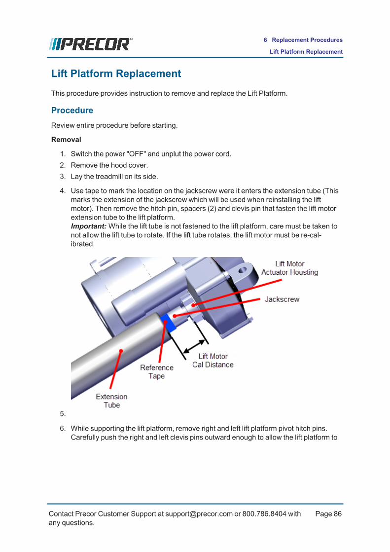
Lift Platform ReplacementThis procedure provides instruction to remove and replace the Lift Platform.
ProcedureReview entire procedure before starting.
Removal
1. Switch the power "OFF" and unplut the power cord.2. Remove the hood cover.3. Lay the treadmill on its side.
4. Use tape to mark the location on the jackscrew were it enters the extension tube (Thismarks the extension of the jackscrew which will be used when reinstalling the liftmotor). Then remove the hitch pin, spacers (2) and clevis pin that fasten the lift motorextension tube to the lift platform.Important:While the lift tube is not fastened to the lift platform, care must be taken tonot allow the lift tube to rotate. If the lift tube rotates, the lift motor must be re-cal-ibrated.
5.
6. While supporting the lift platform, remove right and left lift platform pivot hitch pins.Carefully push the right and left clevis pins outward enough to allow the lift platform to
Contact Precor Customer Support at [email protected] or 800.786.8404 withany questions.
Page 86
6 Replacement Procedures
Lift Platform Replacement

be removed. Retain part(s) and/or fastener(s) for installation.
Installation
1. Install the lift platform left and right pivot brackets into position and insert the right andleft clevis pins. Add the spacer to the left clevis pin and secure using the hitch pin.Secure the right clevis pin with the hitch pin.
2. Make sure that the jackscrew reference tape remained positioned at the bottom of theextension tube. Remove the tape and place the extension tube into the lift platformmounting bracket and secure using the hitch pin, nylon washers (2), and clevis pin. Itmay be necessary to slightly rotate the extension tube to align the clevis pin mountinghole. It may be necessary to slightly rotate the extension tube to align the clevis pinmounting hole. Choose an adjustment direction that will minimize the change to theextension tube calibration distance. Firmly hold the jackscrew from turning whileadjusting (rotating) the extension tube
3. If the extension tube has been rotated during or after it was removed, recalibrate thelift motor prior to installation, see "Lift Motor Calibration" on page 61.
4. Return the machine to the normal upright position on the floor. Make sure themachine is setting level and stable.
5. Reinstall the hood cover.
6. Plug1 in the power cable and switch the power "ON".
7. Start a manual test and verify the treadmill incline operation fromminimum to max-imum levels. When completed, go to the Error Log and make sure that there are noactive Incline function related error codes.
1Device power cord connector or electrical cable male connector that is inserted into anelectrical receptacle "outlet" (also called the plug-in).
Contact Precor Customer Support at [email protected] or 800.786.8404 withany questions.
Page 87
6 Replacement Procedures
Lift Platform Replacement

8. Do the Operation Verification tests (see "Operation Verification" on page 20) andreturn to service.
Contact Precor Customer Support at [email protected] or 800.786.8404 withany questions.
Page 88
6 Replacement Procedures
Lift Platform Replacement

Lower PCA (LPCA) ReplacementThis procedure provides instruction to replace the Lower PCA1 (LPCA2).
LPCA I/O3 Connectors
1Lower Printed Circuit Assembly board; also refered to as the Lower PCA or simply as thelower board. On treadmills, it is the console to base function interface and the motor con-troller unit (MCU). On self-powered units, it is the lower PCA console to base function inter-face.2Lower Printed Circuit Assembly board; also refered to as the Lower PCA or simply as thelower board. On treadmills, it is the console to base function interface and the motor con-troller unit (MCU). On self-powered units, it is the lower PCA console to base function inter-face.3Input and Output Interface.
Contact Precor Customer Support at [email protected] or 800.786.8404 withany questions.
Page 89
6 Replacement Procedures
Lower PCA (LPCA) Replacement
Connector Description
M3/M4 AC1-IN: M3-blue, M4-Brown
J1 Lift Drive Motor
J2 Safety Breaker
J3 Speed Sensor(J4)
J4 FAN
J6 Data Comm (serial connection to UPCA2)
J8 Lift Potentiometer
M7/M8 Drive motor power Red (M7) Blk (M8)
ProcedureReview entire procedure before starting.
Removal
1. Switch the powerOFF and unplug3 the power cord.2. Remove the hood cover.
1Alternating Current: electric current which periodically reverses direction between positiveand negative polarity.2Upper PCA board3Disconnect a device power cord plug or cable connector from the power receptacle or out-let.
Contact Precor Customer Support at [email protected] or 800.786.8404 withany questions.
Page 90
6 Replacement Procedures
Lower PCA (LPCA) Replacement

3. Loosen the two LPCAmounting screws and then slide and lift the LPCA off thescrews but do not remove. Then disconnect the I/O cable connections and remove.The freedom of movement will make it easier to reach and disconnect the various I/Oconnectors. Be careful to firmly hold and not allow damage to the LPCA while dis-connecting the cable connectors. Disconnect the following LPCA cable connections:
l Drive Motor power cable, red (M7) and black (M8), connectors to the drivemotor.
l AC input blue wire (M1) and brown wire M2) cable connectors.
l Two lift motor connections: the Lift Drive (J1) connector and the Lift Pot (J8)connector.
l Safety Breaker (J2) connector.
l Speed sensor (J3) connection.
l CommCable (J6) connection.
Contact Precor Customer Support at [email protected] or 800.786.8404 withany questions.
Page 91
6 Replacement Procedures
Lower PCA (LPCA) Replacement

Installation
1. Hold the LPCA in the mounting position but do not install into the mounting screws.Then reconnect the LPCA I/O cable connections: It is easier to make LPCA I/O con-nections before securing the LPCA into the mounting screws. Be careful not to dam-age the LPCA connectors. Reconnect the following LPCA cable connections:
l Drive Motor power cable, red (M7) and black (M8), connectors to the drivemotor.
l AC input blue wire (M1) and brown wire M2) cable connectors.
l Two lift motor connections: the Lift Drive (J1) connector and the Lift Pot (J8)connector.
l Safety Breaker (J2) connector.
l Speed sensor (J3) connection.
l CommCable (J6) connection.
Contact Precor Customer Support at [email protected] or 800.786.8404 withany questions.
Page 92
6 Replacement Procedures
Lower PCA (LPCA) Replacement
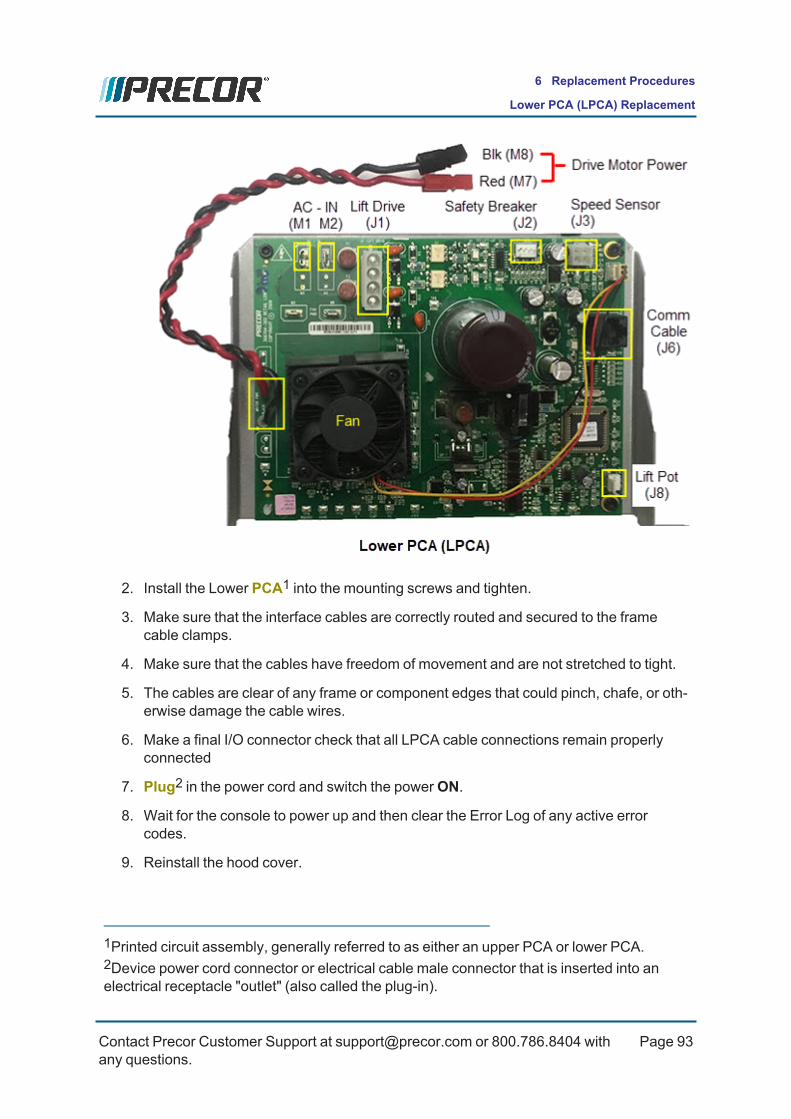
2. Install the Lower PCA1 into the mounting screws and tighten.
3. Make sure that the interface cables are correctly routed and secured to the framecable clamps.
4. Make sure that the cables have freedom of movement and are not stretched to tight.
5. The cables are clear of any frame or component edges that could pinch, chafe, or oth-erwise damage the cable wires.
6. Make a final I/O connector check that all LPCA cable connections remain properlyconnected
7. Plug2 in the power cord and switch the powerON.
8. Wait for the console to power up and then clear the Error Log of any active errorcodes.
9. Reinstall the hood cover.
1Printed circuit assembly, generally referred to as either an upper PCA or lower PCA.2Device power cord connector or electrical cable male connector that is inserted into anelectrical receptacle "outlet" (also called the plug-in).
Contact Precor Customer Support at [email protected] or 800.786.8404 withany questions.
Page 93
6 Replacement Procedures
Lower PCA (LPCA) Replacement
10. Do the machine Operation Verification tests (see "Operation Verification" on page 20)and return to service.
Contact Precor Customer Support at [email protected] or 800.786.8404 withany questions.
Page 94
6 Replacement Procedures
Lower PCA (LPCA) Replacement

Troubleshooting
AboutThis section contains troubleshooting information to help you identify, isolate, and resolvecomponent and system issues.
Review the Introduction To Troubleshooting section below to learn about the troubleshoot-ing process, troubleshooting best practices, and other pertinent information that will helpyou efficiently troubleshoot issues and return the equipment to service.
Information that will help you troubleshoot:
l Review the Introduction To Troubleshooting section below, see "Introduction toTroubleshooting" below.
l Review the machine diagnostics Error Log for any current active error codes, see"Error Log Display" on page 100.
l Refer to the Error Code Troubleshooting Guide for error code description andtroubleshooting repair information, see Error Code Troubleshooting Guide.
l Review the System Troubleshooting Procedures topic for possible related issue fixesor repairs, see "System Troubleshooting Procedures" on page 105.
l Make sure that the machine has incorporated all machine specific service bulletins,tech-tips, and software updates, see "Verify service bulletin and software updateincorporation" on page 97.
Introduction to TroubleshootingTroubleshooting issues is an investigative process best implemented utilizing a systematicapproach that efficiently targets the issue cause allowing correct equipment repairs andreturn to service. The following basic troubleshooting steps will help you to systematicallytroubleshoot and resolve issues.
Basic Troubleshooting StepsAlways begin troubleshooting using the most common simplest possible solution first andthen systematically trying the next more complex solution until the issue is finally resolved.Use the following basic troubleshooting steps to help guide you through a systematicapproach to troubleshoot and resolve equipment issues:
l "Validate the customer reported issue" on the next page
l "Verify Input Power" on the next page
l "Verify (reproduce) the customer issue" on page 97
Contact Precor Customer Support at [email protected] or 800.786.8404 withany questions.
Page 95
7 Troubleshooting
About
l "Verify My Settings parameter values" on the facing page
l "Verify service bulletin and software update incorporation" on the facing page
l "Verify console operation" on page 98
l "Verify that there are no current active error codes" on page 98
l "Verify hardware validation diagnostic tests" on page 99
l "Verify that there are no new error codes" on page 99
Validate the customer reported issueThe failure that is reported may differ from your observations as a trained technician. Manyreported failure are not true failures and can be fixed without a customer visit.
For example, start the troubleshooting process by asking the customer the following ques-tions:
l Powered units only: Always ask the customer if there is power to the machine (powercord connected, circuit breaker ON) and is the machine switched ON.
l Further interrogate the customer to determine if this is the real issue requiring an on-site visit or possibly a different issue that can be simply resolved over the phone.
Verify Input PowerAlways make sure that the customer has the power properly connected and the equipmentis switched "ON".
If the machine power is connected and switched ON, but the machine does not power up orruns poorly, verify the following conditions:
l Make sure there is power at the outlet receptacle and that the power is within the spe-cified voltage and current limits. If not, review the following possible causes:
o Outlet voltage to low: Low out-of-spec outlet voltage can be caused by a largevoltage drop in the facility circuit panel-to-wall outlet circuit due to an extremelylong circuit wire run. For power requirement information, refer to the PowerRequirements topic.
o Input current to low: The power outlet circuit wire gauge may be too small tocarry the required machine load current (20 amps/machine).
l Make sure that the outlet receptacle power is good quality (the input power is NOTintermittent or has fluctuating voltage levels or frequency). Poor quality input powercan cause operational failures in the machine or powered console. For power require-ment information, refer to the Power Requirements topic.
l Make sure that each Precor treadmill is connected to a separate 15 amp individualbranch circuit outlet. No other devices can be connected to the same circuit outlet
Contact Precor Customer Support at [email protected] or 800.786.8404 withany questions.
Page 96
7 Troubleshooting
Basic Troubleshooting Steps

except for one optional PVS1 (Personal Viewing System) display if installed. Forpower requirement information, refer to the Power Requirements topic.IMPORTANT: Always make sure the input power is good quality beforetroubleshooting the machine. A poor quality input power signal may be the cause ofthe machine issue or operating failure.
Verify (reproduce) the customer issueOperate the unit in normal user mode and attempt to reproduce the reported failureDetermine if the error is a repeatable or intermittent type failure Make note of any additionalobservations (noises, vibrations, etc.) that occur at the time of the failure which may then beused to help resolve the issue.
Note: It is important to keep in mind that some issues are weight (load) related.You may need to test the unit at minimum and maximum load Limits to reproducethe failure.
Verify My Settings parameter valuesVerify that one of the workout limit settings are not causing a failure. If a failure is observedwhile using the machine but passes the hardware validation system tests, this could be anindication that one of the club parameters Limits settings is causing the issue.
Verify service bulletin and software update incorporationMake sure that the machine is up to date with all released service bulletins, tech-tips, andsoftware updates before troubleshooting an issue. The list of current service bulletins, tech-tips, and software updates can be viewed and downloaded from the Precor Connect web-site. Make sure that all released service bulletins/Tech-Tips and software updates havebeen incorporated.
SERVICE BULLETINS: How to find and download service bulletins and tech-tips:
1. Log in to your Precor Connect Servicer account ( Precor Connect Partner's ).
2. From the Connect Home page, select the DOCUMENTATION pane > SERVICEBULLETINS link to view the list of the equipment service bulletins and Tech-Tips.
Note: .There may or may not be service bulletins or tech-tips released for thismachine.
SOFTWARE UPDATES: How to find and download software updates:
1Personal Viewing System display.
Contact Precor Customer Support at [email protected] or 800.786.8404 withany questions.
Page 97
7 Troubleshooting
Basic Troubleshooting Steps

1. Log in to your Precor Connect Servicer account ( Precor Connect Partner's ).
2. From the Connect Home page, select the DOCUMENTATION pane > CONSOLESOFTWARE to view the list of available equipment console "UPCA1" and/orMC2"LPCA3" software updates.
Use the following software access login Username and Password:
Username: software Password: D0wnl0ads!
Note: .There may or may not be software updates for this machine.
Verify console operation1. Make sure the console powers up and is working correctly, perform the following veri-
fication tests:a. If the console does not power up, make sure the Data COMM cable is properly
connected at the console and LPCA and in good condition.b. Run the console Display, and Keypad Hardware Validation diagnostic tests
(see "Standard Service Menus" on page 39). Resolve any failures.
Note: Keep in mind that if a key on the console keypad does not function, the LPCAwill not receive a user initiated request for action. For failed console key problems,the machine failure is not caused by a problem with the LPCA or the machine base,In these types of console failures, no error codes will be triggered and logged.
Verify that there are no current active error codesAlways review the Error Log when troubleshooting an issue, see "Error Log Display" onpage 100. The error log will contain any triggered error code events and related information.You can then refer to the Error Code Troubleshooting Guide for information to help resolvethe issue. Also, when calling Precor customer service for assistance, refer to the Error Logfor additional information to help the representative resolve the issue.
Refer to Error Code Troubleshooting Guide the for error code descriptions and repair inform-ation.
IMPORTANT: Error code descriptions and troubleshooting information can be foundin the Error Code Troubleshooting Guide, see Error Code Guide TroubleshootingGuide.
1Upper PCA board2Motor controller, motor controller unit, or motor controller module: used on treadmills, con-tains the LPCA and motor controller functionality.3Lower Printed Circuit Assembly board; also refered to as the Lower PCA or simply as thelower board. On treadmills, it is the console to base function interface and the motor con-troller unit (MCU). On self-powered units, it is the lower PCA console to base function inter-face.
Contact Precor Customer Support at [email protected] or 800.786.8404 withany questions.
Page 98
7 Troubleshooting
Basic Troubleshooting Steps
Note: Not all failures trigger an error event code. Many issues are purely mech-anical in nature and therefore cannot trigger an error event code.
Verify hardware validation diagnostic testsPerform the equipment Hardware Validation Tests (see "Standard Service Menus" onpage 39) to help isolate the cause of the issue. These tests will help identify failed systemcomponents. Resolve any resulting failures.
Verify that there are no new error codesAfter correcting the issue, reopen the Error Log (see "Error Log Display" on the next page)and verify that there are no remaining active error codes. This will verify that the originalerror codes are not reoccurring and that there are no new error code issues. If the errorcode is reoccurring, the issue may be mileage related, review the error code odometer his-tory to verify if the error event is related to mileage intervals.
Note: If there is no logged error codes and the issue persists, you will need to useobservable and audible indicators to identify the source of the failure. Also makesure that there are no related service bulletins that may resolve the issue. Browsethe list of available Troubleshooting procedures for related Troubleshootinginformation.
Contact Precor Customer Support at [email protected] or 800.786.8404 withany questions.
Page 99
7 Troubleshooting
Basic Troubleshooting Steps

Error Log Display
AboutThe Error Log stores equipment error events codes and related fault information useful fordiagnostics and troubleshoot issues. Error Log information is also useful when contactingPrecor Service to resolve an issue.
Accessing the Error LogFrom the Home page, select Settings > Information > Error Log.
Error Log Parameter Descriptions
Parameter Description
Error
Sequentially generated number indicating the order in which the errorcode events occurred in time, 001 is the first listed event code (oldest)to be logged continuing to the last number “nnn” (most recent) errorcode to be logged.
Code
The alpha-numeric code “C-001-nnn” representing the error event.Where the C-001 prefix identifies valid service error codes and “nnn”is the code number, Disregard any other code prefix error codes. SeeError Codes for listing of error codes and description.
Data Disregard this entry.
Odometer Odometer reading when the error event occurred.
Time Time the error event occurred.
Date Date the error event occurred
Contact Precor Customer Support at [email protected] or 800.786.8404 withany questions.
Page 100
7 Troubleshooting
Error Log Display

Clearing the Error LogThe Error Log history is cleared by 1) running the Hardware Validation “Error Log Reset”systems test and 2) cycling the input power.
1. Go to the Hardware Validation Systems Tests page (Service Access Code51765761), see Accessing Service Software.
2. Use Up/Down arrow softkeys to select the Error Log Reset > Test.
3. Select Start to reset the Error Log.
4. Cycle the input power (OFF/ON).
5. Go to the Display Error Log page and verify that all error codes have been cleared,select Settings > Information > Error Log).
6. Select Home to exit and return to the Home page.
Error Code Troubleshooting GuideThere is a set of standard error codes implemented across Precor exercise equipment.Error codes are system generated error codes designed to detect and report fault con-ditions. Each error code is associated with a particular system or component fault condition.The maintenance software monitors error code event conditions, when a fault is detected,the error code is stored in the Error Log along with the event mileage, hours, and motor cur-rent.
This document does not contain the Error Code troubleshooting information. All ErrorCodes and related troubleshooting information is in the “Error Code TroubleshootingGuide”, see Error Code Troubleshooting Guide.
.
Contact Precor Customer Support at [email protected] or 800.786.8404 withany questions.
Page 101
7 Troubleshooting
Error Log Display

Troubleshooting with Error Codes
Getting StartingYou will need a copy of the “Error Code Troubleshooting Guide” which contains all currenterror codes and related troubleshooting information. Go to the Precor Connect website anddownload a copy of the:
Error Code Troubleshooting Guide: Error Code Troubleshooting Guide
Troubleshooting with Error CodesAccess the Error Log to view any current or past error code events. Next go to the “ErrorCode Troubleshooting Guide” to learn Information about the error code including the codedescription, related issues/symptoms, troubleshooting, and repair information.
Viewing Error CodesError codes are viewed in the Error Log (see "Error Log Display" on page 100):
Home page > Settings > Information > Error Log
Quick ReferenceThe following information can be used as a quick reference. Refer to the “Error CodeTroubleshooting Guide” for complete details.
Non-Fatal Error Codes
Error Code Description
05 Stuck Key
10 AC1 Frequency
40 Lift error: lift won’t move
42 Lift error: bad pot reading
4 Lift error: non commanded lift motion
45 Lift error: lift going in the wrong direction
1Alternating Current: electric current which periodically reverses direction between positiveand negative polarity.
Contact Precor Customer Support at [email protected] or 800.786.8404 withany questions.
Page 102
7 Troubleshooting
Troubleshooting with Error Codes
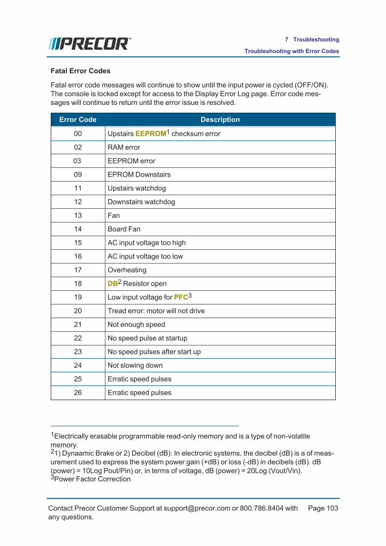
Fatal Error Codes
Fatal error code messages will continue to show until the input power is cycled (OFF/ON).The console is locked except for access to the Display Error Log page. Error code mes-sages will continue to return until the error issue is resolved.
Error Code Description
00 Upstairs EEPROM1 checksum error
02 RAM error
03 EEPROM error
09 EPROMDownstairs
11 Upstairs watchdog
12 Downstairs watchdog
13 Fan
14 Board Fan
15 AC input voltage too high
16 AC input voltage too low
17 Overheating
18 DB2 Resistor open
19 Low input voltage for PFC3
20 Tread error: motor will not drive
21 Not enough speed
22 No speed pulse at startup
23 No speed pulses after start up
24 Not slowing down
25 Erratic speed pulses
26 Erratic speed pulses
1Electrically erasable programmable read-only memory and is a type of non-volatilememory.21) Dynaamic Brake or 2) Decibel (dB): In electronic systems, the decibel (dB) is a of meas-urement used to express the system power gain (+dB) or loss (-dB) in decibels (dB). dB(power) = 10Log Pout/Pin) or, in terms of voltage, dB (power) = 20Log (Vout/Vin).3Power Factor Correction
Contact Precor Customer Support at [email protected] or 800.786.8404 withany questions.
Page 103
7 Troubleshooting
Troubleshooting with Error Codes

Error Code Description
27 Tread error: too much output (to motor) current
28 Tread error: motor controller limit
29 Tread error: too much input (from AC outlet) current
30 Communications error: downstairs to upstairs
31 Incorrect communication Downstairs to Upstairs
32 Communications error: upstairs to downstairs
33 Incorrect communications Upstairs to Downstairs
Contact Precor Customer Support at [email protected] or 800.786.8404 withany questions.
Page 104
7 Troubleshooting
Troubleshooting with Error Codes

System Troubleshooting ProceduresSystem Troubleshooting procedures provide information and procedures to help youtroubleshoot and repair treadmill system issues .
Available Troubleshooting Procedures
l "AC Input Power Troubleshooting" on the next pagel "Heart Rate Monitor Troubleshooting" on page 108l "LIft System Troubleshooting" on page 109l "LPCA Fan Troubleshooting" on page 113l "Speed Sensor Troubleshooting" on page 115
See Also
"Troubleshooting" on page 95
"Introduction to Troubleshooting" on page 95
"Basic Troubleshooting Steps" on page 95
"Error Log Display" on page 100
"Troubleshooting with Error Codes" on page 102
"System Troubleshooting Procedures" above
Contact Precor Customer Support at [email protected] or 800.786.8404 withany questions.
Page 105
7 Troubleshooting
System Troubleshooting Procedures

AC Input Power TroubleshootingInformation to hellp troubleshoot and repair AC1. input power issues.
Precor consumer treadmills must be connected to a individual branch circuit. A 15-amp indi-vidual branch circuit is required, but a 20-ampindividual branch circuit is recommended, see"Power Requirements" on page 14. The power outlet must have the same configuration asthe plug. No adapter should be used with this product.
A treadmill operating from a non-dedicated circuit or a circuit breaker of less than 15 ampscapacity will not have the necessary power to operate normally under higher load con-ditions. The lack of available power can cause any number of symptoms ranging fromnumerous intermittent (seemingly inexplicable) error conditions, poor speed control, or trip-ping the house circuit breaker.
If any of the above symptoms exist, the external A.C. circuit must be checked and confirmedto be a 15-amp dedicated circuit before troubleshooting the treadmill.
WARNING: Corrective actions should only be performed by a licensed elec-trician. Electrical shock could cause personel injury.
Probable Causes
The most common problems found are:
l The circuit breaker is less than 15-amp capacity (minimum).
l The outlet circuit wiring is not a dedicated branch circuit (the circuit has shared neutralwires or hot power wires).
l The power circuit wire length from the circuit breaker panel to the outlet receptacle isto long causing a drop in delivered outlet power.
l The power circuit wire gauge is smaller than required to carry the necessary 15-ampload current causing a drop in delivered outlet power
l Multiple treadmills plugged into the same outlet receptacle.
NOTE: Corrective actions should only be performed by a licensed electrician.
See Also
1Alternating Current: electric current which periodically reverses direction between positiveand negative polarity.
Contact Precor Customer Support at [email protected] or 800.786.8404 withany questions.
Page 106
7 Troubleshooting
System Troubleshooting Procedures

Contact Precor Customer Support at [email protected] or 800.786.8404 withany questions.
Page 107
7 Troubleshooting
System Troubleshooting Procedures

Heart Rate Monitor TroubleshootingThe heart rate monitor system is a dual system, it can accept a heart rate signal from eitherthe handheld heart rate sensors on the unit’s handlebar or from a Polar heart rate cheststrap transmitter. The PCA1 is configured for handheld priority. That is, if both a handheldsensor and chest strap heart rate signal are being received, the system will accept the hand-held signal and ignore the chest strap signal. If a handheld signal is not being received, thesystem will accept the chest strap signal.
There are four typical failure modes for the handheld and chest strap heart rate system.They are:
l Handheld is normal - no chest strap no HR2 reading.
l No handheld HR reading - chest strap normal.
l No handheld or chest strap HR reading.
l Intermittent HR reading when neither handheld or chest strap are in use.
Normal handheld HR reading - No chest strap HR reading
l Verify that a chest strap signal is not being accepted with either a Polar heart rate testtransmitter or a known good chest strap transmitter. If this reading is good, skip thenext step.
l Using a known good Polar heart rate chest strap, verify that the heart rate operateswith the known good chest strap. If the known good Polar chest strap does correct theproblem, replace the original chest strap transmitter.
l If the above procedures did not correct the problem, replace console.
No handheld HR reading - Normal chest strap HR reading
l Verify that a handheld signal is not being accepted by firmly grasping both the rightand left handheld contacts on the handlebars. Cover as much of the contact surfacearea with your hands as possible (without moving your hands), you should receive aheart rate reading within ten seconds.
l If the handheld signal is now being accepted, something in the near vicinity is radi-ating RF3 (radio frequency) energy that is being received by the chest strap portion ofthe heart rate PCA.
l If a handheld signal still not being accepted, replace the console
1Printed circuit assembly, generally referred to as either an upper PCA or lower PCA.2Heart Rate3Radio Frequency: Identifies electromagnetic signals with frequency spectrum between the3 kHz (3,000 hertz) to 300 GHz (300 billion hertz) range.
Contact Precor Customer Support at [email protected] or 800.786.8404 withany questions.
Page 108
7 Troubleshooting
System Troubleshooting Procedures

No handheld HR reading - No chest strap HR reading
l Verify that neither the chest strap signal nor the handheld signal is being acceptedwith either a heart rate test transmitter or a chest strap transmitter.
l If neither a chest strap signal or a handheld signal is being accepted, replace the con-sole
Constant or intermittent HR readings when neither the handheld or cheststrap is in use
l Replace the console
See Also
"Troubleshooting" on page 95
"System Troubleshooting Procedures" on page 105
LIft System TroubleshootingInformation to hellp troubleshoot and repair Lift System issues.
Lift System Description:
The lift system on these units consists of an AC1 line voltage driven lift motor (120 VDC),and an internal 1 KΩ potentiometer for lift position identification. The lift motor contains twomotor windings, one to operate the motor in an “upward” direction and the other to operatethe motor in a “downward” direction. As the lift motor is operated, the motor also rotates thepotentiometer via an internal gear system. Therefore, the position of the lift system can bedetermined by monitoring the value of the internal potentiometer. The lift motor is initially setat a known starting position and then subsequent motor movement is tracked via the poten-tiometer resistance reading.
Note: All resistance measurements must be performed with power removed fromthe treadmill and the load disconnected from the circuit. Performing resistancemeasurements with voltage applied and connected to the circuit it will give erro-neous readings and may damage your ohmmeter.
1Alternating Current: electric current which periodically reverses direction between positiveand negative polarity.
Contact Precor Customer Support at [email protected] or 800.786.8404 withany questions.
Page 109
7 Troubleshooting
System Troubleshooting Procedures

Procedure
1. If the lift motor operates but creates a lift error (error 40 or 42) go to Inspect Lift MotorConnection. If the lift motor will not move continue.
2. Set the treadmill’s circuit breaker in the “OFF” position and remove the AC line cordfrom the AC outlet.
3. Remove the F2 (Lift AC) fuse from the lower PCA1. Using an ohmmeter, check theresistance of the F2 fuse. The fuse should measure approximately 0.1 W or less. Ifthe fuse is open or high resistance, replace the fuse.>
4. Insert the treadmill’s line in the AC outlet and set the circuit breaker in the “ON” pos-ition. Set the treadmill in the manual program and press the LIFT key. If the liftmotor operates normally, test treadmill operation. If the lift motor still does not oper-ate, retest the lift fuse. If the fuse is open again, go to Replace Fuse. If the fuse isgood continue.
1Printed circuit assembly, generally referred to as either an upper PCA or lower PCA.
Contact Precor Customer Support at [email protected] or 800.786.8404 withany questions.
Page 110
7 Troubleshooting
System Troubleshooting Procedures

5. Connect an AC voltmeter between terminals 1 & 4 of the J1 connector. Set the tread-mill in the manual program and press the LIFT key. The AC voltmeter should readAC line voltage (120 VDC) and the red UP LED should illuminate. Note that the ACline voltage reading will only be present before an error condition is displayed.
6. If the F2 fuse is good and the UP LED illuminates and the AC voltmeter does not readthe presence of AC line voltage replace the lower logic PCA.
7. If the UP LED does not illuminate and the display indicates that the lift should be mov-ing upward, replace the upper PCA.
8. If the AC voltmeter reads the presence of AC line voltage and an error 40 is displayed,go to Lift motor connector resistance check.
9. If the AC voltmeter reads the presence of AC line voltage and an error 42 is displayed,go to Inspect lift motor connector.
Lift motor connector resistance check
10. Set the treadmill’s circuit breaker in the “OFF” position and remove the AC line cordfrom the AC outlet. Remove the lift motor connector from the J1 connector on thelower PCA. Visually inspect the lift motor connector for broken or improperly crimpedconnections. Using an ohmmeter, read the resistance between terminals 1 & 4 andbetween terminals 3 & 4. Both readings should be approximately 12 W. If either read-ing is open or very high resistance, replace the lift motor.
Inspect lift motor connectors
11. Set the treadmill’s circuit breaker in the “OFF” position and remove the AC line cordfrom the AC outlet. Remove the lift motor connector from the J7 connector on thelower PCA. Visually inspect the lift motor connector for broken or improperly crimpedconnections. Using an ohmmeter, measure between terminals 1 & 3, 1 & 2 and 2 & 3of the lift motor connector. Terminals 1 and 3 should read approximately 1 KW. Thesum of the two readings between terminals 2 & 3 and 1 & 2 should total approximately1 KW. If either reading is open or very high resistance, replace the lift motor.
12. Set the treadmill’s circuit breaker in the “OFF” position and remove the AC line cordfrom the AC outlet. Remove the lift motor connector from the J1 connector on thelower PCA. Visually inspect the lift motor connector for broken, frayed or improperlycrimped connections. Using an ohmmeter, read the resistance between terminals 1 &4, 3 & 4 and 1 & 3. The readings should be approximately 12 Ω, 12 Ω, and 24 Ωrespectively. If the reading is significantly low, replace the lift moto.
LPCA1 Replacement
1Lower Printed Circuit Assembly board; also refered to as the Lower PCA or simply as thelower board. On treadmills, it is the console to base function interface and the motor con-troller unit (MCU). On self-powered units, it is the lower PCA console to base function inter-face.
Contact Precor Customer Support at [email protected] or 800.786.8404 withany questions.
Page 111
7 Troubleshooting
System Troubleshooting Procedures

13. If the measured resistance is normal, replace the lower logic PCA.
14. If you have performed all of the procedures above and have been unable to correctthe problem, call Precor customer service.
See Also
"Troubleshooting" on page 95
"System Troubleshooting Procedures" on page 105
Contact Precor Customer Support at [email protected] or 800.786.8404 withany questions.
Page 112
7 Troubleshooting
System Troubleshooting Procedures
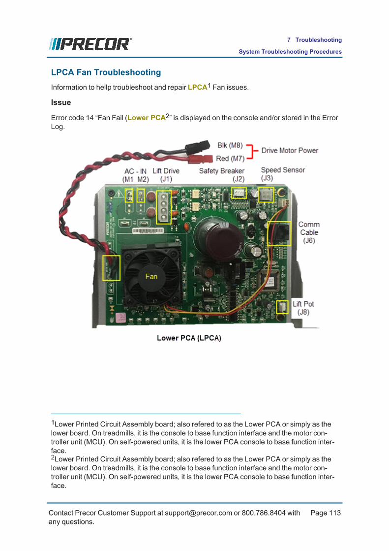
LPCA Fan TroubleshootingInformation to hellp troubleshoot and repair LPCA1 Fan issues.
Issue
Error code 14 “Fan Fail (Lower PCA2” is displayed on the console and/or stored in the ErrorLog.
1Lower Printed Circuit Assembly board; also refered to as the Lower PCA or simply as thelower board. On treadmills, it is the console to base function interface and the motor con-troller unit (MCU). On self-powered units, it is the lower PCA console to base function inter-face.2Lower Printed Circuit Assembly board; also refered to as the Lower PCA or simply as thelower board. On treadmills, it is the console to base function interface and the motor con-troller unit (MCU). On self-powered units, it is the lower PCA console to base function inter-face.
Contact Precor Customer Support at [email protected] or 800.786.8404 withany questions.
Page 113
7 Troubleshooting
System Troubleshooting Procedures

Cause
Rotation of the lower PCA1 cooling fan is monitored. If the fan is not rotating or rotating tooslowly an error 14 will be logged. Typical symptoms include the heatsink by the fan can get-ting clogged with dust and/or dirt, the fan connector/cable becoming disconnected or dam-aged, the drive motor cable routed such that it is preventing the fan from turning, or the fanitself is failed..
Solution
1. Visually inspect the fan
2. Clear the error log.
3. Turn off unit.
4. Remove any debris from the fan and adjacent components.
5. Verify the motor cable connector/connection.
6. Turn on unit, test when running the belt.
7. Inspect the fan connector
8. Turn off unit.
9. Inspect and reconnect the fan connector.
10. Visually inspect the drive motor cable for clearance away from the fan
11. Visually inspect the fan for movement during operation
12. If the fan does not move, replace the lower PCA.
See Also
"Troubleshooting" on page 95
"System Troubleshooting Procedures" on page 105
1Printed circuit assembly, generally referred to as either an upper PCA or lower PCA.
Contact Precor Customer Support at [email protected] or 800.786.8404 withany questions.
Page 114
7 Troubleshooting
System Troubleshooting Procedures

Speed Sensor TroubleshootingTroubleshooting the Speed Sensor system.
Note: The speed sensor is an IR1 transmitter/receiver through sensor. The signalto the processor is pulsed by a chopper wheel with crenellations that break the sig-nal in the sensor as the motor rotates. The signals are 5VDC pulses, and give theprocessor the indication that there is motor movement, and the rate of speed.These pulses are used by the processor to vary the drive to the motor, thus con-trolling the speed. The sensor is attached to the drive motor via a mounting platesecured by a single hex head screw.
If the sensor needs to be replaced it is recommended that the chopper wheel be removedfrom the motor shaft, thus allowing easier access to the sensor mounting screw. The chop-per wheel is secured by a single Phillips head screw.
Initial speed sensor voltage mesurements: Set the treadmill circuit breaker in the “ON” pos-ition. Using a DC2 voltmeter, measure the speed sensor voltage between terminal 3 of J3(white wire) and terminal 4 of J3 (black wire) on the LPCA3. Slowly, rotate the drive motorflywheel. The voltage should read approximately 0.25 Vdc when a lobe is between thespeed sensor “legs” and approximately 5 Vdc when a lobe is not between the speed sensor“legs”.
1Infrared Radiation: Electromagnetic radiation with wavelengths longer than those of visiblelight. It is therefore invisible to the human eye. IR is generally understood to encompasswavelengths from the nominal red edge of the visible spectrum around 700 nanometers (fre-quency 430 THz), to 1 millimeter (300 GHz).2Direct Current: electrical current that only flows in one direction.3Lower Printed Circuit Assembly board; also refered to as the Lower PCA or simply as thelower board. On treadmills, it is the console to base function interface and the motor con-troller unit (MCU). On self-powered units, it is the lower PCA console to base function inter-face.
Contact Precor Customer Support at [email protected] or 800.786.8404 withany questions.
Page 115
7 Troubleshooting
System Troubleshooting Procedures

If the initial speed sensor voltages are correct, go Contact Precor Customer Service. If theinitial speed sensor voltage is 0 Vdc or significantly low when a flywheel lobe is between thespeed sensor “legs’, continue.
Measure the LPCA voltage between J3 connector terminals 1 (red wire) and terminal 4(black wire). The voltage should measure approximately 5 Vdc. If the voltage is missing orsignificantly low, disconnect the speed sensor plug from the lower PCA1. Measure thevoltage between the J3 connector terminal pins 1 & 4. If the voltage is approximately 5 Vdc,replace the speed sensor. If the voltage is missing or significantly low, replace the lowerlogic PCA.
Contact Precor customer service
If you have performed all of the above procedures and have been unable to correct the prob-lem, call Precor Customer Support.
See Also
1Printed circuit assembly, generally referred to as either an upper PCA or lower PCA.
Contact Precor Customer Support at [email protected] or 800.786.8404 withany questions.
Page 116
7 Troubleshooting
System Troubleshooting Procedures

Running Belt TroubleshootingThis procedure is to be used to determine the condition of the running belt and deck.
A clamp-on ammeter will be used to measure the treadmill’s AC1 input current draw underload. The AC input current is a direct indication of the loading effects placed on the drivemotor system; heavier loading requires more input current. Treadmill loading consists ofseveral factors: the exerciser's weight, treadmill speed, incline level, and condition of therunning belt and deck.
Test conditions:
The AC input current measurement should be performed at 8 mph (13 kph) and 0% inclinefor 10 sec minimum workout.
Creating personal input current benchmarks
The Precor typical belt condition input current ratings are based on a loading weight of 220lbs (100 kgs). A lighter weight exerciser produces less loading effects resulting in lowerinput current values for the same belt/deck condition. Therefore, it is recommended that youshould create a personal benchmark or reference input current value for three belt/deck con-ditions: a new deck/belt condition, a used good belt/deck condition, and a worn replacementbelt/deck condition. These benchmarks will help you to quickly determine the correct con-dition of the belt and deck.
l New belt/deck condition benchmark: Make the input current measurement on amachine with a new belt and deck.
l Used good belt/deck condition benchmark: Repeat the input current measurement ona machine with a known used good condition belt and deck (for a 220 lb (100 kg) load,the typical input current should be within the 8-12 amp range).
l Worn replacement belt/deck condition benchmark: Repeat the input current meas-urement on a machine with a known worn replacement condition belt and deck (for a220 lb (100 kg) load, the typical input current should be 19-20 amps or greater).
Analog Clamp-on Ammeter and Digital Clamp Meters
Because the AC input current will spike (pulse) during foot plants, we suggest the use of ananalog clamp-on ammeter to obtain more accurate measurements. An analog ammetermakes it very easy to see the AC current spikes and measure the true AC average input cur-rent. Less expensive Digital Clamp meters may not make accurate AC average currentmeasurements due to the current spikes. If using a digital clamp meter, make sure that themeter provides True RMS AC current measurement capability (recommend the Fluke 289True RMSmultimeter or equivalent). You can use the meter AC peak hold feature (if avail-able) to obtain the largest current spike within the measurement span (some AC currentspikes may exceed the 20 amp max spec. limit).
1Alternating Current: electric current which periodically reverses direction between positiveand negative polarity.
Contact Precor Customer Support at [email protected] or 800.786.8404 withany questions.
Page 117
7 Troubleshooting
System Troubleshooting Procedures

Specialized Tool
l Analog AC Clamp-on Ammeter or Digital Clamp Meter with True RMS current meas-urement capability (recommend the Fluke 289 True RMSmultimeter or equivalent).
Procedure
Read the entire procedure before beginning.
TIP: You may find it difficult to read the AC current reading while also walking on thetreadmill. You may need a second person to read the AC clamp meter while per-forming this test. Or, if using a DMMwith clamp probe, you can use extra-long testleads (approx. 1.5 m) that will allow you to set the DMM on the dash while performingthe test.
1. Clean the belt and deck surfaces.2. Remove the treadmill hood cover.3. Place the AC clamp probe over the brown (hot or line) wire between the AC. input
module (or AC. power cord) and the circuit breaker ON/OFF switch.
4. Start a manual workout and set the treadmill speed to 8 mph (13 kph) and 0% incline.Walk on the treadmill for a minimum of 10 sec and read the AC average (True RMS)input current. Typical AC. average current for a good condition running belt/deck isbetween 8 to 12 amps on 120 VAC1machines (4 to 6 amps on 240 VACmachines).A new belt/deck may read less current draw. Note that during foot plants, you could
1voltage in an alternating current circuit
Contact Precor Customer Support at [email protected] or 800.786.8404 withany questions.
Page 118
7 Troubleshooting
System Troubleshooting Procedures
measure peak amp spikes as high as 20 amps, even on a new belt/deck. The higherthe AC input current is, the more worn the belt/deck condition is
a. If the average AC input current is less than 16 amps, the belt/deck is in goodcondition, do not replace.
b. If the average AC current is between 16-18 amps on 120 VACmachines (8-9amps on 240VACmachines), the belt and deck needs to be serviced. Be awarethat lighter weight exercisers may not be heavy enough to cause these higherAC input current values.
i. If not already cleaned, clean the belt/deck surfaces and repeat the ACinput current draw measurement.
ii. If the current draw decreases below 16 A 120 VAC (8 A 240 VAC), do notreplace the belt and deck. Otherwise, replace the belt and deck. If theother side of the deck is new condition, flip the deck and reuse.
iii. Also review the error log, if there are recurring motor current overloadrelated error codes, replace the deck and belt. .
c. If the average input current reaches 19-20 amps or greater on 120 VACmachines (9.5-10 amps or greater on 240 VACmachines), the running belt anddeck needs to be replaced. If the other side of the deck is new condition, flip thedeck and reuse.
5. Repeat the AC input amp draw test after replacing the running belt and deck. Damageto the Motor Controller (MC1) can occur if the machine has been operated in an over-load/high current condition for prolonged periods of time. This type of damage wouldnot generate an error code, but would cause the input breaker to trip intermittently. Anamp draw test will confirm this condition. If the amp draw test is comfirmed, replacethe MC.
NOTE: Repeat the AC input amp draw test after replacing a running belt and deck.Damage to the Motor Controller (MC) can occur if the unit has been operated in anoverload/high current condition for prolonged periods of time. This type of damagewould not generate an error code, but would cause the input breaker to trip inter-mittently. An amp draw test will comfirm this condition.
See Also
"System Troubleshooting Procedures" on page 105
1Motor controller, motor controller unit, or motor controller module: used on treadmills, con-tains the LPCA and motor controller functionality.
Contact Precor Customer Support at [email protected] or 800.786.8404 withany questions.
Page 119
7 Troubleshooting
System Troubleshooting Procedures

Preventive Maintenance (PM)
AboutPreventative maintenance is proven to extend the life of the equipment, improve the userexperience, and keep maintenance problems and service calls to a minimum.
IMPORTANT: It is the responsibility of the owner to maintain equipment in accord-ance with the Precor recommended preventative maintenance schedule. Followingthe preventative maintenance schedule is required to maintain warranty coverage.
Preventative maintenance (PM1) tasks are grouped into Weekly, Monthly, Quarterly, andSemi-annual scheduled maintenance tasks, see "PM Tasks and Schedule" below.
Precor Customer PM Plans
Precor also offers PM service plans for customer purchase, see Preventative MaintenancePlans.
PM Tasks and ScheduleRefer to the Cardio Equipment Quick Reference Maintenance Guide (download from Preco.-com) for the equipment scheduled preventative maintenance tasks:
l Cardio Equipment Quick Reference Maintenance Guide
1Preventative Maintenance: Daily, Weekly, Monthly, and Quarterly scheduled main-tenance.
Contact Precor Customer Support at [email protected] or 800.786.8404 withany questions.
Page 120
8 Preventative Maintenance
About

Contact Precor Customer Support at [email protected] or 800.786.8404 withany questions.
Page 121
8 Preventative Maintenance
PM Tasks and Schedule
Running Belt and Deck Cleaning ProcedureUse this procedure to clean the running belt and deck. It is also recommended that youwatch the Belt and Deck Cleaning video.(missing or bad snippet)
Videos(Internet access required)
RUNNING BELT AND DECK CLEANING PROCEDURE
ProcedureReview the entire procedure before beginning.
1. Verify the proper operation of the safety Stop key.a. Stand to one side of the treadmill – Do not stand or allow others to stand on the
treadmill running belt during this procedure. Ensure that the stop key tether ishanging straight down and is not wrapped around the handlebars.
b. SelectQuick Start and wait for the running belt to begin movingc. When the running belt is moving, push the SAFETY STOP key.d. Ensure the running belt stops moving, then reset the SAFETY STOP key.e. Turn the power switch to OFF. TheON/OFF switch is located at the front of the
treadmill.
WARNING: If the running belt does not stop, turn off the power using the ON/OFFswitch at the front of the treadmill and unplug1 the power cord. The treadmill mustremain out of service until the stop switch is repaired.
2. Get a clean, dry cotton towel that is at least 36 inches (1 meter) in length and fold it inhalf lengthwise.
a. Lift the running belt and push the towel through to the other side so that bothends of the towel extend an equal distance over the deck trim on both sides.
b. Push the towel forward to the front of the machine so it is located beneath theSAFETY STOP key.
c. Turn the power switch toON.3. Stand on the machine straddling the running belt placing your feet on the left and right
trim landings. Attach the stop key tether clip. Do not stand on the running belt at anytime. Stand firmly on both ends of the towel keeping your feet off the treadmill running
1Disconnect a device power cord plug or cable connector from the power receptacle or out-let.
Contact Precor Customer Support at [email protected] or 800.786.8404 withany questions.
Page 122
8 Preventative Maintenance
Running Belt and Deck Cleaning Procedure

belt. Brace yourself using the handlebars or side handrails. Push theQuick Start but-ton once in position.
CAUTION: You have approximately 3 seconds before the treadmill running beltbegins to move after pressing Quick Start. Ensure you are in the proper position.
WARNING: Press the safety stop key if the towel becomes loose to prevent it frombeing pulled into the treadmill’s rollers.
4. The treadmill will begin to run at 1 mph. Allow the treadmill to run for one minute whilekeeping the towel firmly in place.
WARNING: Do not adjust the treadmill’s speed or run it higher than 1 mph.
5. After one minute, stop the treadmill by pressing the STOP button.6. When the belt has fully stopped moving, remove the STOP key tether, exit the tread-
mill, and turn the power switch toOFF.7. Grasp both sides of the towel and run it up and down the length of the belt several
times to clean the top of the deck.8. Remove the towel from beneath the belt.9. Turn the power switch toON.10. Verify operation and return to service.
Contact Precor Customer Support at [email protected] or 800.786.8404 withany questions.
Page 123
8 Preventative Maintenance
Running Belt and Deck Cleaning Procedure

System Wiring Diagram
SystemWire Diagram
Contact Precor Customer Support at [email protected] or 800.786.8404 withany questions.
Page 124
9 System Wiring Diagram

Product Literature & Videos
Additional product literature and videos that will help you to service and maintain the equip-ment.
l "Service & Maintenance Documentation" below
l "Precor Websites" below
l "Service Videos" on the next page
Service & Maintenance Documentation
Document Link
TRM400-14 Base Service Manual (online version) Service Manual
Cardio Equipment PM1Guide Cardio Equipment PM Guide
TRM425 Owners Manual (R20 console) TRM425 Owners Manual
TRM2 445 Owners Manual (R40 console) TRM445 Owners Manual
Precor Websites
Precor Websites Link
Precor.com product home page.Available information: • Product Specifications • Assembly Guides • Preventative Maintenance Guides • Console Install & PM Guides
Precor.com
Precor Connect servicer home page*.Available Product information: • Part Numbers • Exploded View Diagrams
Connect Login
1Preventative Maintenance: Daily, Weekly, Monthly, and Quarterly scheduled main-tenance.2Treadmill
Contact Precor Customer Support at [email protected] or 800.786.8404 withany questions.
Page 125
10 Product Literature & Videos
Service & Maintenance Documentation

Precor Websites Link
• Service Bulletins • Software Updates • Service Videos
Precor Technician Certification Training Service & Install Training
Precor E-Learning Center E-Learning System
SalesForce Login SalesForce Login
* Always log in to Precor connect using your Precor Connect account login information.
Service Videos
Service Video Link
Preventative Maintenance Videos for all products: • Login to Precor Connect*. • select SERVICE VIDEOS• Navigate to the product equipment PM videos
available on Precor Con-nect
Connect Login
Running Belt & Deck Cleaning procedure Running Belt & Deck Clean-ing
Machine Leveling procedure Machine Leveling Pro-cedure
TRM 400 Lift Motor Calibration Lift Motor Calibration
TRM400 Lift Motor Replacement LIft Motor Replacement
* Always log in to your Precor connect servicer account. Guest login users do not haveaccess to all features.
Contact Precor Customer Support at [email protected] or 800.786.8404 withany questions.
Page 126
10 Product Literature & Videos
Service Videos
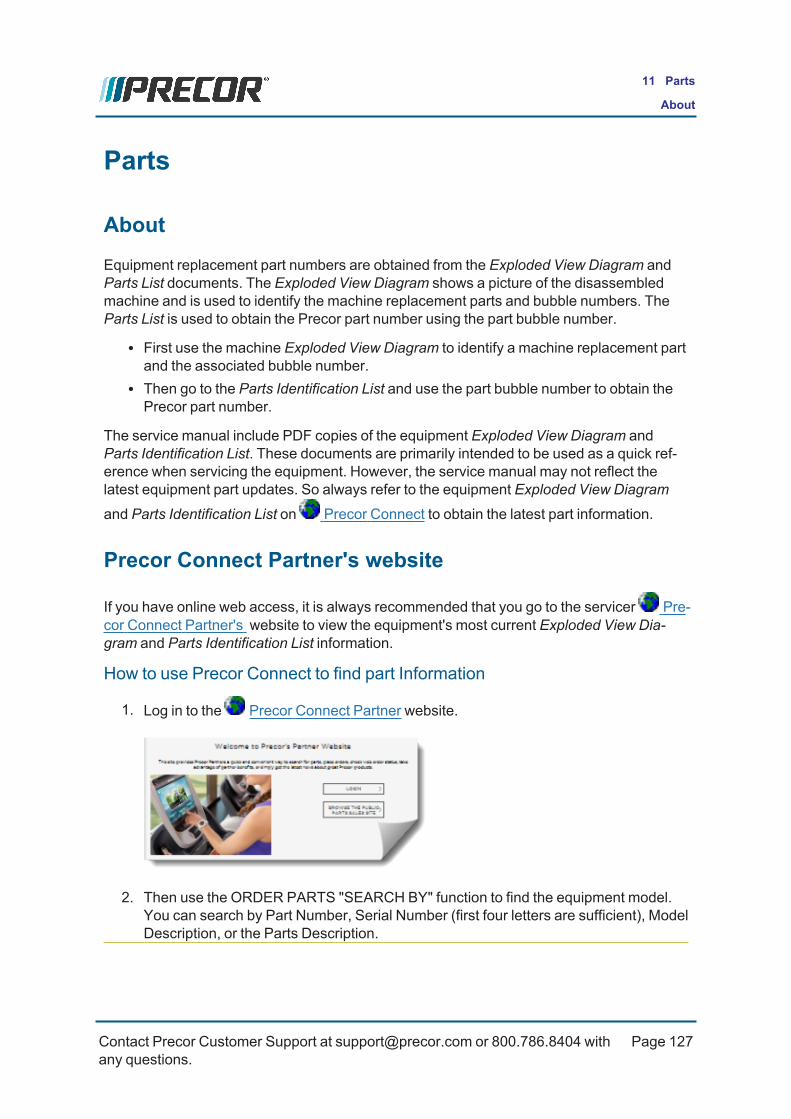
Parts
AboutEquipment replacement part numbers are obtained from the Exploded View Diagram andParts List documents. The Exploded View Diagram shows a picture of the disassembledmachine and is used to identify the machine replacement parts and bubble numbers. TheParts List is used to obtain the Precor part number using the part bubble number.
l First use the machine Exploded View Diagram to identify a machine replacement partand the associated bubble number.
l Then go to the Parts Identification List and use the part bubble number to obtain thePrecor part number.
The service manual include PDF copies of the equipment Exploded View Diagram andParts Identification List. These documents are primarily intended to be used as a quick ref-erence when servicing the equipment. However, the service manual may not reflect thelatest equipment part updates. So always refer to the equipment Exploded View Diagram
and Parts Identification List on Precor Connect to obtain the latest part information.
Precor Connect Partner's website
If you have online web access, it is always recommended that you go to the servicer Pre-cor Connect Partner's website to view the equipment's most current Exploded View Dia-gram and Parts Identification List information.
How to use Precor Connect to find part Information
1. Log in to the Precor Connect Partner website.
2. Then use the ORDER PARTS "SEARCH BY" function to find the equipment model.You can search by Part Number, Serial Number (first four letters are sufficient), ModelDescription, or the Parts Description.
Contact Precor Customer Support at [email protected] or 800.786.8404 withany questions.
Page 127
11 Parts
About

3. Select the equipment model from the list of found search results.
4. Finding equipment part numbers:
a. Verify the MODEL Description and SERIAL CODE .
b. Open the Exploded View Diagram (click the Exploded View link ) and findthe part bubble number.
c. Then go to the Parts Identification Table, locate the bubble number in the
"BUBBLE #" column and the associated part number in the "PART #"
column .
Contact Precor Customer Support at [email protected] or 800.786.8404 withany questions.
Page 128
11 Parts
Precor Connect Partner's website

ID Description ID Description
Model Description Service Manual Link
Serial Code Bubble Numbers
Exploded View Link Part Numbers
Contact Precor Customer Support at [email protected] or 800.786.8404 withany questions.
Page 129
11 Parts
Precor Connect Partner's website

Exploded View Diagrams and Parts List
TIP: It is recommended that you go to the Precor Connect servicer website toobtain the most current version of the Exploded View Diagram and part numberinformation.
Exploded View Diagram:
l "Exploded View Diagram" on the facing page
Parts List:
l " Parts List" on page 137
Contact Precor Customer Support at [email protected] or 800.786.8404 withany questions.
Page 130
11 Parts
Exploded View Diagrams and Parts List

Exploded View Diagram
10/2
2/14
SIZE
A06
AB
CD
4 3 2 1
CSTRM4
00-14
, 445
/425
DRAWING TEMPLATE REV: C
3032
40-10
1 6
ADW
G. N
O.PA
GEDR
WN
BY11
/5/1
4KA
WSU
BREV
BG1 O
F
PROD
UCT:
Contact Precor Customer Support at [email protected] or 800.786.8404 withany questions.
Page 131
11 Parts
Exploded View Diagram

Exploded View Diagram
4X
81
82
907
8X903
6X 908
6X
96
76
2
A06
PAGE
3032
40-10
1DW
G. N
O.SU
BREV
34
6
AB
CD
2 OF
1
Contact Precor Customer Support at [email protected] or 800.786.8404 withany questions.
Page 132
11 Parts
Exploded View Diagram

Exploded View Diagram
SUBR
EV
A06
PAGE
3032
40-10
1DW
G. N
O.
234
6
AB
CD
4 OF
1
144
3
2
19
2X94
2X64
20
60
61
101
2X 94
2X632X97
101
Contact Precor Customer Support at [email protected] or 800.786.8404 withany questions.
Page 133
11 Parts
Exploded View Diagram

Exploded View Diagram
SUBR
EV
A06
PAGE
3032
40-10
1DW
G. N
O.
234
6
AB
CD
4 OF
1
144
3
2
19
2X94
2X64
20
60
61
101
2X 94
2X632X97
101
Contact Precor Customer Support at [email protected] or 800.786.8404 withany questions.
Page 134
11 Parts
Exploded View Diagram

Exploded View Diagram
2X
136
141
GR
EE
N/Y
ELL
OW
BR
OW
N
YE
LLO
W
115
23 116
4X
139
122
95
4X
2425
117
2X10
0
2X
9 95
4X 934X
50
101
6X
138
52
75B
RO
WN
/BLU
E
PU
RP
LE/Y
ELL
OW
90
BR
OW
NB
LUE
GR
EE
N/
139
140
140
137
141
BLU
E (R
EF)
80
16
6X89
88
79
2X 98
4X 10²
2X 85
2X 91
4X
84
99
2X 72
4X74
2X732X
270
2X
269 26
2
266
268
261
260
263
265
270
267
10
SUBR
EV
A06
PAGE
3032
40-10
1DW
G. N
O.
234
6
AB
CD
5 OF
1
Contact Precor Customer Support at [email protected] or 800.786.8404 withany questions.
Page 135
11 Parts
Exploded View Diagram

Exploded View Diagram
PAGE
A06
SUBR
EV
3032
40-10
1DW
G. N
O.
234
6
AB
CD
6 OF
1
6X
87
58
2X
2X 922X 14
3
2X14
2
4X77
57
92
4X 95
2X 562X 55
2X
109
52
8X95
4X59
2X78
54
A
100
4X2X
DE
TAIL
A
CO
NN
EC
TOR
S
95
GR
OU
ND
WIR
E
53
Contact Precor Customer Support at [email protected] or 800.786.8404 withany questions.
Page 136
11 Parts
Exploded View Diagram

Parts List
Precision Series TRM400-14 Series Treadmill Page 1 of 2
Part Number Description Bubble NumberPPP000000059120101 DECK WITH SHIPPER, 9.3X-07 2PPP000000036355130 RUNNING BELT, SIEGLING, 120 X 22, N 3PPP000000300745102 ASSEMBLY, LOWER PCA 9PPP000000058275101 TRM400 LPCA FAN REPLACEMENT 9PPP000000059125102 KIT, DRIVE MOTOR W/PACKAGING, 9.3X- 10PPP000000020113101 SENSOR, TACHOMETER, MCMILLAN 11PPP000000013537103 LIFT ACTUATOR, 120V 16PPP000000035673104 ASSEMBLY, FRONT ROLLER 9.3X-07 19PPP000000035677106 ASSEMBLY, REAR ROLLER 9.3X-07 20PPP000000302881101 HANDLEBAR, OVERMOLD, LH 21PPP000000302881102 HANDLEBAR, OVERMOLD, RH 22PPP000000046985144 PWR CORD,125VAC,15A,NEMA 5-15RA/IEC 23PPP000000010435101 CKT BRKR,250V,MAGNETIC,ROCKER, 24PPP000000011224104 FILTER, POWER LINE, 250VAC, 16A, GE 25PPP000000038819103 TRANSMITTER, POLAR T34, HEARTRATE,W 31PPP000000035700104 GRIP, HHHR, TOP, PACIFIC BLUE, TRM4 33PPP000000035701104 GRIP, HHHR, BOTTOM, PACIFIC BLUE, T 34PPP000000302872101 BRACKET, BUCKET, DASH, LH 37PPP000000302872102 BRACKET, BUCKET, DASH, RH 38PPP00000MGCN016050 SCREW,MCH,8-32X1/2,PANHD,PHIL, 39PPP00000WACN016005 WASHER,FLAT,TYPA,#8,STL,CLR ZN 40PPP0000WALCN016004 WASHER,SPLIT LOCK,#8,STL,CLR ZN 41PPP000000302853101 ASSEMBLY, SAFETY STOP 42PPP00000CATE019050 SHCS,10-24 X .50,NYLOCK,STL,BLK SHR 43PPP00000TATE025050 SCREW,BTHD,1/4-20X1/2,BLK SHRPRZD 44PPP00000WBZN019005 WASHER,FLAT,SAE TYPA,#10,STL,BLK CV 45PPP000000302869101 COVER, BUCKET, DASH, LH 46PPP000000302869102 COVER, BUCKET, DASH, RH 47PPP000000302868101 BUCKET, DASH, OVERMOLD, LH 48PPP000000302868102 BUCKET, DASH, OVERMOLD, RH 49PPP000000010217144 BELT, DRIVE, POLY V (JASON INDUSTRI 50PPP000000011278101 CABLE CLAMP,INSERT 52PPP000000033984101 LABEL, SAFETY, GROUND SYMBOL 53PPP000000012861101 DISK, FELT, 1/8 THICK X 3/4 OD, ACR 54PPP000000035671101 STRAP, GFX 9.3X-07 55PPP000000035672101 SPRING, GFX 9.3X-07 56PPP000000035686101 TRIM, SIDERAIL, LEFT 57PPP000000035686102 TRIM, SIDERAIL, RIGHT 58PPP000000035813101 SUPPORT, SIDERAIL TRIM, STEEL BRACK 59PPP000000035690101 BRIDGE, ROLLER, LEFT 60PPP000000035690102 BRIDGE, ROLLER, RIGHT 61PPP000000035693101 PIVOT, DECK MOUNT, 9.3X-07 63PPP000000035695102 GUARD, BELT, BLACK 64PPP000000302880101 BRACKET, CONSOLE 65PPP00000HCTN050250 SCREW,HEX,GR 5,1/2-13X2-1/2,BLK SHA 72PPP00000KACN050019 LOCKNUT,HALF,1/2-13,ZN 73
Contact Precor Customer Support at [email protected] or 800.786.8404 withany questions.
Page 137
11 Parts
Parts List

Parts List
Precision Series TRM400-14 Series Treadmill Page 2 of 3
PPP00000WBZN050008 WASHER, FLAT,1/2,.086 BLK CVS 74PPP000000035731018 ASSY,CBL 2COND,14AWG,QK DISC,18" 75PPP000000303074102 ASSY, HOOD, NEW LOGO, PACIFIC BLUE 76PPP000000303075102 ASSY, ENDCAP, PACIFIC BLUE 77PPP000000035744101 FOOT, ADJUSTABLE 78PPP000000010043113 BEARING,FLANGE,OD=.62 ID=.5 79PPP000000044270101 WHEEL, LIFT 80PPP000000035804101 ASSEMBLY, TARGA, RIGHT 81PPP000000035669101 TARGA, LEFT 82PPP000000302892101 ASSEMBLY, LIFT PLATFORM 84PPP000000035778101 BUMPER, LIFT PLATFORM 85PPP00000TCNN025050 SCREW,BTHD,1/4-20X1/2,SS 86PPP000000035750101 COVER, TARGA BRACKET 9.3X-07 87PPP000000010401106 PIN,CLEVIS, 3/8 X 1.75, ZINC 88PPP000000045669107 PIN, LIFT PIVOT, 3.34, MUSHROOM HEA 89PPP000000044532018 ASSY,CBL,2 COND,22 AWG,MOLEX, 18" 90PPP000000045669111 PIN, LIFT PIVOT, MUSHROOM HEAD, .49 91PPP00000CATN025100 SCREW,SKHD,1/4-20X1,BLK SHARPERIZED 92PPP00000HCCN031075 SCREW, HEX HD, GRADE 5, 5/16-18 X . 93PPP00000CARB031150 SHCS,5/16-18 X 1.50,STL,SILVER ZNCO 94PPP00000PLCN019075 SCREW,S/T,#10X3/4,WSHRHXHD,ZN, TYPE 95PPP00000TCNN031075 SCREW,BTHD,5/16-18X.75,SS 96PPP0000WABCN031006 WASHER, FEN, 5/16, ID=.331, 97PPP0000WACNN038009 WASHER, NYLON, .375 I.D.X.75O.D. X 98PPP0000WACNN050006 WASHER, NYLON, .50 I.D.X.75 99PPP0000WAMCN019002 WASHER, LOCK, EXT TOOTH, #10 100PPP00000WBCN031007 WASHER,FLT,5/16X.688X.065, ZN 101PPP000000010400103 PIN, HITCH, .093 DIA, ZINC, #203 102PPP000000302897015 TRIM, EDGE, 1/4", 1.5" LONG 109PPP000000035727103 PLATE, POWER ENTRY 115PPP00000MGCN019050 SCREW, MACHINE, 10-24X1/2, PANHD, P 116PPP00000KGCN013011 LOCKNUT, STARWASHER 6-32, #6 117PPP000000045381101 IEC 16/20A POWER CORD INLET 122PPP000000302850101 ASSY, STOP SWITCH 125PPP000000048761101 CLAMP, POWER CORD 136PPP00000MGCN013038 SCREW,MCH,6-32X3/8,PANHD,PHIL, 137PPP000000037436101 LABEL, CHASIS NEUTRAL 138PPP000000044528005 ASSY,CBL,1 C0ND,14AWG,QK DISC,5",BR 139PPP000000044534006 ASSY,CBL,1COND,14AWG,QK DISC,6" 140PPP000000035730007 ASSY,CBL,1 C0ND,14AWG,QK DISC, 7" , 141PPP00000CNNN025100 SCREW, CAP, FLAT HEAD, STAINLESS, H 142PPP00000WBCN025006 WASHER,FLT,1/4X..500X.063,ZN (MECH 143PPP00000CARB031200 SHCS,5/16-18 X 2.00,STL,SILVER ZNCO 144PPP000000302860101 WELDMENT, CROSS TUBE, CONSOLE 161PPP000000302865101 WELDMENT, CROSS TUBE, HANDLE 162PPP000000302875024 ASSY, CABLE, HHHR GRIP, W/SHIELD,24 163PPP00000TCNN016075 SCREW, BTHD, 8-32X.75,SS 164
Contact Precor Customer Support at [email protected] or 800.786.8404 withany questions.
Page 138
11 Parts
Parts List

Parts List
Precision Series TRM400-14 Series Treadmill Page 3 of 3
PPP000000302876010 CBL,1C,20AWG,#10 RING/250X032 QD RE 167PPP000000049809069 ASSY,CBL,MOD,8P8C,1-1,SLEEVED,69" 168PPP00000EGGN025025 SCREW, SET, STL, CONE PNT, 1/4-20, 169PPP00000PKCN019075 SCREW,S/T,#10X.75,WSHHXHD,ZN 170PPP000000302890101 KIT, HARDWARE, TRM400-14 200PPP000000057051101 9.3X BRACKET REPLACEMENT KIT 201PPP000000020002114 BRUSH W/ LEAD ASSY, RED, MCMILLAN S 260PPP000000020002115 BRUSH W/ LEAD ASSY, BLACK, MCMILLAN 261PPP000000020111101 GROUND BRUSH ASSY, MCMILLAN S3456B3 262PPP000000020112101 BRUSH COVER, MCMILLAN S3456B3329 263PPP000000020114101 INTERRUPTER, 10 TOOTH, TACHOMETER, 265PPP000000020115101 CABLE, TACHOMETER, MCMILLAN 266PPP000000020116101 BRACKET, TACHOMETER SENSOR, MCMILLA 267PPP000000020117101 BASE, MOTOR, MCMILLAN 268PPP000000020118101 GROUND WIRE, 7.5 INCH, MCMILLAN 269PPP000000058117101 CS KIT, LIFT MOTOR VIBRATION NOISE 271PPP000000010186119 WRENCH, ALLEN, 3/16 X 4.5" 901PPP000000010186122 WRENCH, ALLEN, 1/4 X 3.5" X 6.0" 902PPP00000CAMN031075 SCREW,SKHD,5/16-18X0.75,ZN (MECH PL 903PPP00000TCNN031075 SCREW,BTHD,5/16-18X.75,SS 907PPP0000WALCN031008 WASHER, 5/16 SPLIT LOCK, ZINC 908PPP000000010186101 WRENCH, ALLEN, 5/32 909PPP000000303031111 KIT, LITERATURE, TRM 4XX, EN 999
Contact Precor Customer Support at [email protected] or 800.786.8404 withany questions.
Page 139
11 Parts
Parts List

Appendix A : Edition Information
EditionTitle: Precision Series TRM400-14 Series Treadmill Service ManualP/N: 20081-123Publish Date: Dec 2020
Additional DocumentationYou can also view the service manual online at Online Service Manual
CopyrightCopyright 2014 Precor Incorporated
No part of this manual may be reproduced in any form or by any means (including electronicstorage and retrieval or translation into a foreign language) without prior agreement and writ-ten consent from Precor Incorporated as governed by United States and international copy-right laws.
Precor Incorporated20031 142nd Ave. NEP.O.Box 7202Woodinville, WA. 98072-4002Ph: 1-800-347-4404
Contact Precor Customer Support at [email protected] or 800.786.8404 withany questions.
Page i
A Edition Information

Appendix B : Notices and Safety
TrademarksPrecor, AMT1, EFX2, and Preva are registered trademarks of Precor Incorporated. Othernames in this document may be the trademarks or registered trademarks of their respectiveowners.
The Spinner Family of bikes—Spin®, Spinner®, Spinning®, Spin Fitness®, and the Spin-ning logo® are registered trademarks owned by Mad Dogg Athletics, Inc., a California cor-poration.
SPD3 is a registered trademark of Shimano American Corporation.
Intellectual PropertyAll rights, title, and interests in and to the software of the Preva Business Suite, the accom-panying printed materials, any copies of such software, and all data collected via the PrevaBusiness Suite, are exclusively owned by Precor or its suppliers, as the case may be.
Precor is widely recognized for its innovative, award-winning designs of exercise equip-ment. Precor aggressively seeks U.S. and foreign patents for both the mechanical con-struction and the visual aspects of its product design. Any party contemplating the use ofPrecor product designs is hereby forewarned that Precor considers the unauthorized appro-priation of its proprietary rights to be a very serious matter. Precor will vigorously pursue allunauthorized appropriation of its proprietary rights.
WarrantyThe material contained in this document is provided "as is," and is subject to being changed,without notice, in future editions. Further, to the maximum extent permitted by applicablelaw, Precor disclaims all warranties, either expressed or implied, with regard to this manualand any information contained herein, including but not limited to the implied warranties ofmerchantability and fitness for a particular purpose. Precor shall not be liable for errors orfor incidental or consequential damages in connection with the furnishing, use, or per-formance of this document or of any information contained herein. Should Precor and theuser have a separate written agreement with warranty terms covering the material in thisdocument that conflict with these terms, the warranty terms in the separate agreement shallcontrol.
1Adaptive Motion Trainer2Elliptical Fitness Crosstrainer3speed
Contact Precor Customer Support at [email protected] or 800.786.8404 withany questions.
Page ii
B Appendix B: Notices and Safety

Safety NoticesWarning and Caution notices indicate an activity that could be dangerous and cause per-sonal injury and/or equipment damage if not adhered to. Always followWarning and Cau-tion instructions.
Warning
AWARNING notice denotes a hazard. It calls attention to an operating procedure,practice, or the like that, if not correctly performed or adhered to, could result in per-sonal injury or death. Do not proceed beyond aWARNING notice until the indicatedconditions are fully understood.
Caution
A CAUTION notice denotes a hazard. It calls attention to an operating procedure,practice, or the like that, if not correctly performed or adhered to, could result in dam-age to the product or loss of important data. Do not proceed beyond a CAUTIONnotice until the indicated conditions are fully understood.
Service Safety GuidelinesPrior to doing any machine service, review the Service Safety Guidelines, see "ServiceSafety Guidelines" on page 3.
Contact Precor Customer Support at [email protected] or 800.786.8404 withany questions.
Page iii
B Appendix B: Notices and Safety
Service Safety Guidelines