
GigaVUE TA Series Hardware Installation Guide - Secure Login
102
GigaVUE TA Series Hardware Installation Guide GigaVUE TA Series Product Version: 5.8.00 Document Version: 1.0
-
Upload
khangminh22 -
Category
Documents
-
view
0 -
download
0
Transcript of GigaVUE TA Series Hardware Installation Guide - Secure Login

GigaVUE TA SeriesHardware Installation
GuideGigaVUE TA Series
Product Version: 5.8.00
Document Version: 1.0

Copyright 2019 Gigamon Inc.. All rights reserved.
Information in this document is subject to change without notice. The software described in thisdocument is furnished under a license agreement or nondisclosure agreement. No part of this publicationmay be reproduced, transcribed, translated into any language, stored in a retrieval system, or transmittedin any form or any means without the written permission of Gigamon Inc..
Trademark Attributions
Copyright © 2019 Gigamon Inc. All rights reserved. Gigamon and the Gigamon logo are trademarks ofGigamon in the United States and/or other countries. Gigamon trademarks can be found atwww.gigamon.com/legal-trademarks. All other trademarks are the trademarks of their respective owners.
Gigamon Inc.3300 Olcott StreetSanta Clara, CA 95054408.831.4000

CONTENTSIntroducing the GigaVUE TA Series 9
About the GigaVUE Family 9GigaVUE TA Series Features and Benefits 9
Standard H Series Features 10GigaVUE TA Series Overview 11GigaVUE TA Series Nodes 12
Air Flow Direction 13Displaying Power and Voltage Information 13
Introducing the GigaVUE-TA40 Chassis 14Air Flow Direction 16AC and DC-Powered GigaVUE-TA40Models 16
Introducing the GigaVUE-TA100 Chassis 16Chassis Cooling 18Power LEDs 20System LED 20Port Status LEDs 20Global Fan LED 20Individual Fan LEDs 21Individual Power LEDs 21GigaVUE-TA100 Notes and Rules 21Dual BIOS Images 22Software Upgrade using USB Drive 23Air Flow Direction 23AC and DC-Powered GigaVUE-TA100Models 23Battery Caution 23
Introducing the GigaVUE-TA100-CXP Chassis 23Chassis Cooling 26

Power LEDs 27System LED 27QSFP28 Port Status LEDs 27CXP Port Status LEDs 28Global Fan LED 28Individual Fan LEDs 28Individual Power LEDs 28GigaVUE-TA100-CXPNotes and Rules 28Dual BIOS Images 29Software Upgrade using USB Drive 29Air Flow Direction 30AC and DC-Powered GigaVUE-TA100-CXPModels 30Battery Caution 30
Introducing the GigaVUE-TA200 Chassis 30Chassis Cooling 33Power LEDs 35System LED 35Port Status LEDs 35Global Fan LED 35Individual Fan LEDs 36Individual Power LEDs 36GigaVUE-TA200 Notes and Rules 36AMI BIOS Images 37Air Flow Direction 37AC and DC-Powered GigaVUE-TA200Models 37Battery Caution 37
Configure the Card Mode – 40Gb/10Gb Support 38Configuring the Card Mode on GigaVUE-TA10 38
Configure the Port Mode 39Breakout Panels 40
4│GigaVUE TA Series Hardware Installation Guide

Installation and Setup Roadmap 41Getting Unpacked, Racked, Installed and Connected 41
Rack-Mounting GigaVUE TA Series 42Unpacking the GigaVUE Traffic Aggregator 42Rack-Mounting the GigaVUE TA Series 42
Two-Post Rack Methods: 43Four-Post Rack Methods: 44
Basic Connections and Configuration 47Grounding the GigaVUE TA Series Chassis 47
Avoid Electrostatic Damage! 48Connecting Power to the GigaVUE TA Series 48
Connecting -48V DC Power Supplies 50Replacing Fans 51Connecting Serial Console and Mgmt Ports 51Configuring Basic Settings 52
Access the Command-Line Interface over the console Port 53Port Licensing 57
GigaVUE-TA10A 57GigaVUE-TA100 57GigaVUE-TA200 58Enabling Additional Ports 58
Advanced Features Licensing 59Command-Line Basics 59
Command-Line Modes 59Entering Commands in the CLI 60
The Basic Commands 63Completing the Initial Setup 66
Enter the Configure Command-Line Mode 67SSH2 67Initial User Account Configuration 68
CONTENTS│5

Configuring the GigaVUE TA Series Host Name 70Configuring GigaVUE TA Series Node’s Time Options 70Enabling the Web Server 72Configuring Automatic Email Notifications 74Using a Custom Banner 75Saving Changes 76
Connecting Ports on GigaVUE TA Series 77Transceiver—Rules and Notes 77BiDi Optics Considerations 77Transceiver Installation Instructions 78
Installing Transceivers 78Removing Transceivers 78
Cabling 78MPO/MTP 12 Position Fiber Cable for Use with SR4 Transceivers 79MTP/APC Fiber Cable for Use with QSFP+ PLR4 Transceivers 79MPO/MTP 24 Position Fiber Cable for Use with SR10 Transceivers 80
TA Series Specifications 81Physical Dimensions and Weight 81Power Requirements 82
Fan Tray Specification for GigaVUE-TA100 and TA100-CXP 83Fan Tray Specification for GigaVUE-TA200 83
Environmental Specifications 83Standards and Protocols 84Compliance 84
Safety 85Emissions 85Immunity 85Environmental 85Security 86BSMI RoHS 86
6│GigaVUE TA Series Hardware Installation Guide

VCCI 86Warranty 87Regulatory Labels 87
GigaVUE-TA10 87GigaVUE-TA40 88GigaVUE-TA100 88GigaVUE-TA100-CXP 89GigaVUE-TA200 89
Console Port Signaling and Cabling 91NEBS Level 3 Compliance 94
Installation Instructions GigaVUE-TA10, TA40, TA100, TA200 94Intrabuilding or Intra-connection for GigaVUE-TA10 94Intrabuilding or Intra-connection for GigaVUE-TA40 94Intrabuilding or Intra-connection for GigaVUE-TA100 94Intrabuilding or Intra-connection for GigaVUE-TA200 95Intrabuilding Ports (RJ45) 95Class A2 Voltage Accessibility 95Class B Voltage Accessibility 95Equipment Grounding Systems 95Communication Equipment Grounding 96Bonding of Battery Return (BR) Input Terminals 96Connections 96Input AC/DC Voltage 97Commercial Power Ports 97Maintenance 97
Additional Sources of Information 98Documentation 98Documentation Feedback 101Contact Technical Support 101Contact Sales 101
CONTENTS│7

The Gigamon Community 101
8│GigaVUE TA Series Hardware Installation Guide

Introducing the GigaVUE TA SeriesThis chapter introduces the GigaVUE TA Series nodes, describes their features and functions, andprovides an orientation to the physical layout of each node.
Refer to the following sections for details:• About the GigaVUE Family on page 9• GigaVUE TA Series Overview on page 11• GigaVUE TA Series Nodes on page 12• GigaVUE TA Series Features and Benefits on page 9
• Introducing the GigaVUE-TA40 Chassis on page 14• Introducing the GigaVUE-TA100 Chassis on page 16• Introducing the GigaVUE-TA100-CXP Chassis on page 23• Introducing the GigaVUE-TA200 Chassis on page 30• Configure the Card Mode – 40Gb/10Gb Support on page 38• Configure the Port Mode on page 39
About the GigaVUE FamilyGigamon’s TA Series and H Series of GigaVUE Visibility Platform nodes deliver unprecedentedswitching capacity, port density, and from 1Gb up to 100Gb support. The GigaVUE H Series andGigaVUE TA Series include the following models that run GigaVUE-OS:
• GigaVUE-HC1• GigaVUE-HC2• GigaVUE-HC3• GigaVUE-TA40• GigaVUE-TA100• GigaVUE-TA100-CXP• GigaVUE-TA200• Certified Traffic Aggregation White Boxes
GigaVUE TA Series Features and BenefitsGigaVUE TA Series nodes allow you to aggregate traffic from multiple network links from 1Gb up to100Gb. The GigaVUE TA Series can pre-filter traffic for monitoring or be integrated into the GigaVUEH Series cluster for end-to-end Flow Mapping and management. The GigaVUE H Series andTA Series products share the same GigaVUE-OS software and are managed by GigaVUE-FM FabricManager for simplified operations. Traffic from any of these ports can be processed by GigaSMARTtraffic intelligence functions in GigaVUE H Series devices to further optimize the traffic before it issent to the tools.
About the GigaVUE Family | GigaVUE TA Series Hardware Installation Guide 9

GigaVUE TA Series nodes offer the following features and benefits:• High-density visibility for 1Gb, 10Gb, 40Gb, and 100Gb.• Low profile 1RU (2RU for GigaVUE-TA200) design offers easy deployment at the top of rack orend of row in data centers.
• Depending on the model, the GigaVUE TA Series supports a wide variety of Gigamon®transceivers. Transceivers purchased from other vendors are not supported.
• Optional patch panel or breakout panel allows use of 40Gb ports as four individual 10Gb portson all the GigaVUE TA Series nodes, or 100Gb ports as four individual 25Gb ports on GigaVUE-TA200.
• All ports of same type and speed can be used to create GigaStream.• Front to back cooling.• Fan modules.• AC or DC power supply. Included with each node is the redundant second power supply.
NOTE: Clustering is not supported on the GigaVUE-TA100-CXP.
Standard H Series FeaturesIn addition to the features described above, the GigaVUE TA Series offers many standard featuresfrom the GigaVUE H Series nodes:
Benefit Descriptions
Remote Management Configure the GigaVUE Traffic Aggregator’s operations from a command-line interface:
• Local access over the serial console port.• Remote network access using SSH2 over the10/100/1000 EthernetMgmt port.
• Secure access to the CLI, either through localauthentication or optional RADIUS/TACACS+/LDAPsupport.
• Powerful and flexible logging, including eventnotification via syslog, email, and SNMP traps.
Aggregate Links Send the data frommultiple different network ports to a tool port orGigaStream, allowing you to combine traffic frommultiple access pointsinto a single stream for uplink to the Gigamon Visibility Platform.
The GigaVUE TA Series nodes feature a common CLI with other GigaVUEH Series nodes.
GigaVUE TA Series Features and Benefits | GigaVUE TA Series Hardware Installation Guide 10

Benefit Descriptions
CommandAbbreviation
Type only as many letters of a command as are needed to positivelydifferentiate from other available commands. For example, you only need totype con t to enter Config mode, not the full configure terminal command.
SNMP Support Rely on secure SNMP v3 access to the onboard SNMP agent as well asv1/v2 SNMP traps.
Email Notifications Use email alerts for proactive notification of a wide variety of GigaVUETA Series node events, helping you keep tabs on system status in real time.
Scalable Port Density The GigaVUE-TA10 can have either twenty-four (24) or forty-eight (48)1Gb/10Gb ports enabled. The 24-port GigaVUE-TA10 is called the GigaVUE-TA10A. A license is available to expand the GigaVUE-TA10A to include all 481Gb/10Gb ports as well as the four (4) 40Gb ports.The GigaVUE-TA100 can have either sixteen (16), twenty-four (24), or thirty-two (32) 100Gb ports enabled. Licenses are available for the additional twosets of 8 ports.The GigaVUE-TA200 can have either thirty-two (32) or sixty-four (64) 100Gbports enabled. A license is available for the additional 32 ports.The GigaVUE TA Series nodes make it easy to leverage the system’s 10Gb or40Gb port density, aggregating multiple underused 40Gb/10Gb/1Gbnetwork ports to 40Gb/10Gb tool ports for uplink to the Gigamon VisibilityPlatform.
Clustering The GigaVUE-TA10, GigaVUE-TA40, GigaVUE-TA100, and GigaVUE-TA200nodes can cluster with other GigaVUE H Series nodes. This allows you totake advantage of the benefits of features such as GigaSMART.
Ingress VLAN Tagging VLAN Tags can be added to the ingress packets on a per-port basis. Thiscan help identify, differentiate or track incoming sources of traffic.
GigaVUE-FM(CentralizedManagement System)
Use the centralized GigaVUE Fabric Management System to review,configure, and update GigaVUE TA Series just like other GigaVUE H Series.
GigaVUE TA Series OverviewGigamon’s TA Series nodes allow you to aggregate the traffic from multiple low-utilization linksbefore sending the traffic to the GigaVUE H Series or G Series nodes that form your GigamonVisibility Platform.
IMPORTANT: The GigaVUE TA Series support network, tool, clustering, and stack port connections toother GigaVUE nodes, including both GigaVUE H Series nodes or G Series (for example, a GigaVUE-2404 node, a GigaVUE-HD8 node).
GigaVUE TA Series Overview | GigaVUE TA Series Hardware Installation Guide 11

GigaVUE TA Series NodesGigaVUE TA Series includes the following models:
• GigaVUE-TA40• GigaVUE-TA100• GigaVUE-TA100-CXP• GigaVUE-TA200
GigaVUE TA Series Nodes | GigaVUE TA Series Hardware Installation Guide 12

GigaVUE-TA40
• 1RU Footprint• 32 40Gb ports• Optional patch orbreakout panelsupport
• Cluster with HSeries nodes
GigaVUE-TA100
• 1RU Footprint• 32 100Gb/40Gbports
• Optional patch orbreakout panelsupport
• Cluster with HSeries nodes
GigaVUE-TA100-CXP
• 1RU Footprint• 20 100Gb CXPports,8 100Gb/40GbQSFP28 ports
GigaVUE-TA200
• 2RU Footprint• 64 100Gb/40Gbports
• Optional patch orbreakout panelsupport
• Cluster with HSeries nodes
Air Flow DirectionThe air flow direction is from the front of the GigaVUE chassis to the rear. The rear-mounted fanspull air from the front to the back of the chassis. For environments with hot/cold aisles, install thechassis so the intake air at the front of the chassis is cold.
Displaying Power and Voltage InformationThe output of the following show commands display power information on a GigaVUE-TA10 node:
GigaVUE TA Series Nodes | GigaVUE TA Series Hardware Installation Guide 13

• show chassis
• show environment type psu
• show environment type psu psu-detail [all | psu-id]
NOTE: To increase the i2c stability in a GigaVUE-TA10 node, the frequency of updating thepower supply module information is reduced. As a result, GigaVUE-TA10 PSU informationdisplayed in the CLI output is not real time.
Introducing the GigaVUE-TA40 ChassisThis section describes the physical layout of the GigaVUE-TA40 chassis, including a description of allports and connectors. The GigaVUE-TA40 chassis consists of a 1RU, rack-mountable, 19”-wide chassiswith management, network, and tool ports at the front and power connections at the rear. Figure 1:The GigaVUE-TA40 Chassis shows the ports at the front of the GigaVUE-TA40 chassis. Refer to Table1: GigaVUE-TA40 Ports for a description of each of the ports.
Introducing the GigaVUE-TA40 Chassis | GigaVUE TA Series Hardware Installation Guide 14

Figure 1: The GigaVUE-TA40 Chassis
Port Description
Mgmt Use theMgmt port for remote configuration of the GigaVUE-TA40 Traffic Aggregator over a10/100/1000 Ethernet network.
Console Use the console port for local configuration of the GigaVUE-TA40 Traffic Aggregator over a serialconnection.
Table 1: GigaVUE-TA40 Ports
Introducing the GigaVUE-TA40 Chassis | GigaVUE TA Series Hardware Installation Guide 15

Port Description
Ports q1..q32 GigaVUE-TA40 includes 32 40Gb ports (q1..q32). The 40Gb ports can be used as a 40Gb ingressport, or, as a high-speed tool port for aggregated output to a matching 40Gb port on a GigaVUEH Series node.From software version 5.5, GigaVUE-TA40 supports 4x10G breakout at port level. Port breakoutmode in GigaVUE-TA40 is configured as follows:
• 24 out of the 32 ports provide 4x10Gb breakout support. The first 12 ports and the last 12ports provide support for breakout functionality (with 96 sub-ports operating as 10Gbports:)Ports q1 to q12 and q21 to q32 support breakout functionalityPorts q13 to q20 do not support breakout functionality
• After breakout, sub-ports (breakout ports) are named as q1x1….q1x4, q2x1...q2x4 (similarto other hardware platforms) to support the breakout functionality.
Transceivers For details about the supported transceivers and cable type, refer to the “GigaVUE-OSCompatibility and Interoperability Matrix”.
Air Flow DirectionThe air flow direction is from the front of the GigaVUE-TA40 chassis to the rear. The rear-mountedfans pull air from the front to the back of the chassis. Install the chassis so the intake air at the frontof the chassis is cold.
AC and DC-Powered GigaVUE-TA40 ModelsGigamon provides both AC and DC-powered versions of the GigaVUE-TA40. Refer to Connecting -48V DC Power Supplies on page 50.
Introducing the GigaVUE-TA100 ChassisThis section describes the physical layout of the GigaVUE-TA100 chassis, including a description ofall ports and connectors. The GigaVUE-TA100 chassis consists of a 1RU, rack-mountable, 19”-widechassis with management, network, and tool ports at the front and power connections and fans atthe rear. Figure 2: The GigaVUE-TA100 Chassis Front View shows the ports at the front of theGigaVUE-TA100 chassis. Refer to Table 2: GigaVUE-TA100 Ports for a description of each of theports. Figure 3: The GigaVUE-TA100 Chassis Rear View shows the fan modules and power supplyunits at the rear of the GigaVUE-TA100 chassis. Refer to Chassis Cooling on page 18 for informationon fans and temperature monitoring.
The GigaVUE-TA100 provides thirty-two ports, supporting high-density aggregation. Depending onthe transceiver, QSFP+ or QSFP28, the ports run at speeds of either 40Gb or 100Gb. With QSFP+transceivers, a 40Gb port can be broken out into four 10Gb ports, called 4x10Gmode.
The 100Gb/40Gb ports on GigaVUE-TA100 can be used as network, tool, hybrid, or stack-link ports.
Introducing the GigaVUE-TA100 Chassis | GigaVUE TA Series Hardware Installation Guide 16

The GigaVUE-TA100 node in standalone mode must be running software version 4.6.01 or higher.The GigaVUE-TA100 node in a cluster environment must be running software version 4.8 or higher.
Figure 2: The GigaVUE-TA100 Chassis Front View
Port Description
Mgmt Use theMgmt port for remote configuration of the GigaVUE-TA100 Traffic Aggregator over a10/100/1000 Ethernet network.
Console Use the console port for local configuration of the GigaVUE-TA100 Traffic Aggregator over aserial connection.
USB Use the USB port to upgrade software on the GigaVUE-TA100 using a software image on anexternal USB drive. Refer to Software Upgrade using USB Drive on page 23.
Table 2: GigaVUE-TA100 Ports
Introducing the GigaVUE-TA100 Chassis | GigaVUE TA Series Hardware Installation Guide 17

Port Description
Ports c1..c32orc1x1..c1x4,c2x1..c2x4,c3x1..c3x4, ...
GigaVUE-TA100 includes 32 100Gb ports (c1..c32). These ports also support 40Gb speeds.Any of the 100Gb ports on the GigaVUE-TA100 can operate at 40Gb with a QSFP+ transceiver.With a QSFP+ transceiver, a port can be broken out into 4 10Gb ports, called subports. Thesubports will all have the same speed (10Gb). Subports will have x1 to x4 appended to their portID, for example, 1/1/c2x1. For details, refer to Configure the Port Mode on page 39.Once a 40Gb port has been configured to operate as four 10Gb ports, cable it to an optical patchpanel or breakout panel, such as PNL-M341, which takes a 40Gb QSFP+ input from the GigaVUE-TA100 and splits it to four independent 10Gb output ports. Refer to Breakout Panels on page 40.The ports accept 40Gb QSFP+ connections using QSFP+ SR or PLR4 transceivers.The ports accept 40Gb BiDi transceivers (RX-only or full duplex). RX-only BiDi only supports RXon network ports. Full Duplex (RX/TX) supports network and tool ports.
Transceivers For details about the supported transceivers and cable type, refer to the “GigaVUE-OSCompatibility and Interoperability Matrix”.
Figure 3: The GigaVUE-TA100 Chassis Rear View
Chassis CoolingThe fans on the GigaVUE-TA100 run at 100% of their maximum speed on power up, then drop toapproximately 60% during normal operations. The temperatures of four components: transceivers,exhaust, CPU, and switch CPU, are monitored. When a component crosses a pre-defined threshold,the fan speed is adjusted dynamically, in increments of approximately 10%.
Introducing the GigaVUE-TA100 Chassis | GigaVUE TA Series Hardware Installation Guide 18

An SNMP trap is sent when a component reaches the threshold for warning, alert, or criticaltemperature conditions. Refer to Table 3: Component Temperature Thresholds and Actions for thetemperatures at which the warning, alert, and critical traps are sent and any additional action thatoccurs at a threshold.
Table 3: Component Temperature Thresholds and Actions
Transceiver TemperatureExhaustTemperature
CPU TemperatureSwitch CPUTemperature
70ºCWarning trap sent
85ºCWarning trap sent
90ºCWarning trap sent
105ºCWarning trap sent
80ºCAlert trap sent; Transceiverpower disabled
90ºCAlert trap sent
95ºCAlert trap sent
115ºCAlert trap sent;Switch CPU put in reset
95ºCCritical trap sent
95ºCCritical trap sent
100ºCCritical trap sent
140ºCCritical trap sent
The output of the following CLI command displays the current exhaust, CPU, and switch CPUtemperatures, as well as the intake temperature:(config) show environment...Card 1 (TA100-C32):Intake temperature : 40 CExhaust temperature : 45 CCPU temperature : 32 CSwitch_CPU temperature : 54 C
The output of the following CLI command displays the transceiver temperature:(config) show port params port-list 1/1/c1..c2
Parameter 1/1/c1 1/1/c2====================== =============== ===============...SFP type: qsfp28 sr qsfp28 sr...SFP Power (1-2) (dBm): -40.00 -40.00 -40.00 -40.00SFP Power (3-4) (dBm): -40.00 -40.00 -40.00 -40.00SFP Power (5-6) (dBm): - - - -SFP Power (7-8) (dBm): - - - -SFP Power (9-10)(dBm): - - - -SFP Temperature (C): 20.94 21.12...
The output of the following CLI command displays the fan speed in RPM (the normal operationalspeed is approximately 12000 RPM; the maximum speed is approximately 19000 RPM):(config) show environment...
Introducing the GigaVUE-TA100 Chassis | GigaVUE TA Series Hardware Installation Guide 19

Fan tray 1 (FAN-TAC00):1st fan : 12136 RPM2nd fan : 12288 RPM3rd fan : 12136 RPM4th fan : 11988 RPM...
Power LEDsThe power LEDs on the front of the chassis (PWR1 and PWR2) are as follows:
• Solid GREEN indicates that the power supply unit (PSU) has power and is operating normally• Solid AMBER indicates a Power-On Self-Test (POST) is in progress• Blinking AMBER indicates that the PSU is present but without power.• Off indicates that the PSU is not inserted in the chassis.
System LEDThe system LED on the front of the chassis is as follows:
• Off indicates no power• Blinking GREEN indicates the node is booting or the system is in diagnostic mode• Solid GREEN indicates normal operation• Solid RED indicates a critical alarm• Blinking RED indicates a non-critical alarm
Port Status LEDsFor each port, there are four (4) port status LEDs on the front of the chassis. At 40Gb and 100Gbspeeds, only the first LED operates as follows:
• AMBER indicates the port is administratively disabled• GREEN indicates the link is operationally up• Off indicates the link is operationally down• Blinking GREEN indicates the port is operationally up and there is traffic flowing through theport
The other three LEDs operate when ports are in breakout mode as follows:• Off indicates the port is in non-breakout mode• GREEN indicates the link is operationally up• AMBER indicates the port is administratively disabled
Global Fan LEDThe global fan LED on the front of the chassis is as follows:
Introducing the GigaVUE-TA100 Chassis | GigaVUE TA Series Hardware Installation Guide 20

• GREEN indicates all fans are operating normally• AMBER indicates one or more fans have failed
Individual Fan LEDsThe individual fan LEDs on the rear of the chassis are as follows:
• GREEN indicates the fan is operating normally• AMBER indicates the fan has failed
Individual Power LEDsThe individual power LEDs on the rear of the chassis are as follows:
• GREEN indicates the PSU is operating normally• Off indicates the PSU is not operational
GigaVUE-TA100 Notes and RulesKeep in mind the following notes and rules when using the GigaVUE-TA100:
GigaVUE-TA100 Notes
Transceivers For details about the supported transceivers and cable type, refer to the “GigaVUE-OSCompatibility and Interoperability Matrix”.
Network, Tool, Hybrid,or Stack-Link Port
The 100Gb/40Gb ports on GigaVUE-TA100 can be used as network, tool, hybrid, or stack-link ports. Subports created from 4x10G mode on the GigaVUE-TA100 can function asnetwork, tool, hybrid, or stack-link ports.
Stack-Links at 10Gb The 10G stacking to other GigaVUE nodes is supported when 40Gb ports on GigaVUE-TA100 are fanned out to 4x10G mode, but only in the following combinations:
• GigaVUE-HC1 to GigaVUE-TA100• GigaVUE-HC2 control card version 1 (CCv1) to GigaVUE-TA100• All modules on GigaVUE-HC2 control card version 2 (CCv2),except the PRT-HC0-C02 module, to GigaVUE-TA100
• GigaVUE-TA10 to GigaVUE-TA100• PRT-H00-Q02X32 on GigaVUE HD Series to GigaVUE-TA100• GigaVUE-TA100 to GigaVUE-TA100
Stack-Links at 40Gb The GigaVUE-TA100 can connect to all GigaVUE nodes that support 40Gb through a40Gb stack-link, using SR4 and LR4 optics, with the following exception:
• PRT-HC0-C02 on GigaVUE-HC2
Introducing the GigaVUE-TA100 Chassis | GigaVUE TA Series Hardware Installation Guide 21

Stack-Links at 100Gb The GigaVUE-TA100 can connect to the following nodes, modules, and line cardsthrough a 100Gb stack-link:
• GigaVUE-TA100 (SR4, LR4, and CWDM4)• GigaVUE-TA200 (SR4, LR4, and CWDM4)• PRT-HC3-C08Q08, PRT-HC3-C16, and SMT-HC3-C05 onGigaVUE-HC3 (SR4, LR4, and CWDM4)
• PRT-HD0-C06X24 on GigaVUE HD Series (LR4 and CWDM4 onlyon C06 ports)
Stack-Links to OtherNode Types
To ensure the stack-links become operationally up when the GigaVUE-TA100 isconnected to a node of a different type:
• Configure specified ports as stack ports.• Configure the stack-link between the stack ports.
Map Rules and PortFilters
The GigaVUE-TA100 supports 256 map rules per chassis, by default and 20 egress portfilters per chassis.For details about the maximummap rules, refer to the "MaximumMap Rules" table in theGigaVUE-FM Users Guide.
Port Licensing On the GigaVUE-TA100, only the first 16 out of 32 ports are enabled. Two port licensesare available to enable an additional 8 or 16 ports. Refer to Port Licensing on page 63 forlicense information to expand from 16 ports to 24 or 32 ports.
Advanced FeaturesLicense
Connecting a GigaVUE-TA100 to a cluster requires the Advanced Features License.
Dual BIOS ImagesThe GigaVUE-TA100 has a dual Basic Input/Output System (BIOS). The BIOS image is packaged withthe software image, starting in software version 4.6.01. The BIOS contents are stored in flashmemory, allowing the BIOS to be upgraded. There are two flash components, a primary and asecondary.
The following CLI command displays the two flash components and indicates the BIOS image fromwhich the system booted using asterisks:(config) show version...1st flash version: coreboot-ta100-1.0.0 Wed Aug 23 16:10:34 CST 2017 **2nd flash version: coreboot-ta100-1.0.0 Wed Aug 23 16:10:34 CST 2017...
If there is a component failure in the primary flash, the GigaVUE-TA100 boots from a backup goldenBIOS image in the secondary flash. An SNMP trap can be configured to be sent when the system hasbooted from the secondary flash. The trap may indicate that the primary flash component needs tobe serviced. The trap is as follows:2ndflashboot: Secondary flash boot notification
Introducing the GigaVUE-TA100 Chassis | GigaVUE TA Series Hardware Installation Guide 22

If a BIOS upgrade is needed for enhancements in future releases, the BIOS can be manually upgradedfrom the CLI using the coreboot install command.
Software Upgrade using USB DriveIf a GigaVUE-TA100 does not have network access, there is a USB port on the front of the chassis.
A software image can be downloaded to a USB drive, the drive can be inserted into the USB port onthe GigaVUE-TA100, and the software image can be installed from the drive. Use the format, fat32,for the USB drive.
The following are ways to download a software image to a USB drive:• Insert the drive into your computer or laptop and drag and drop the software image onto thedrive.
• Insert the drive into a GigaVUE-TA100 with network access and use the image fetch CLIcommand with the usb parameter.
Air Flow DirectionThe air flow direction is from the front of the GigaVUE-TA100 chassis to the rear. The rear-mountedfans pull air from the front to the back of the chassis. Install the chassis so the intake air at the frontof the chassis is cold.
AC and DC-Powered GigaVUE-TA100 ModelsGigamon provides both AC and DC-powered versions of the GigaVUE-TA100. Refer to Connecting -48V DC Power Supplies on page 54.
Battery CautionA disposable, non-rechargeable, Real Time Clock (RTC) Lithium metal coin cell battery is in theGigaVUE-TA100. Note the following:
• There is a risk of fire if the battery is replaced with an incorrect type.• Use only CR-2032L type Lithium metal coin cell battery and replace with the same.
Introducing the GigaVUE-TA100-CXP ChassisThis section describes the physical layout of the GigaVUE-TA100-CXP chassis, including a descriptionof all ports and connectors. The GigaVUE-TA100-CXP chassis consists of a 1RU, rack-mountable, 19”-wide chassis with management, network, and tool ports at the front and power connections and fansat the rear. Figure 4: The GigaVUE-TA100-CXP Chassis Front View shows the ports at the front of theGigaVUE-TA100-CXP chassis. Refer to Table 4: GigaVUE-TA100-CXP Ports for a description of eachof the ports. Figure 5: The GigaVUE-TA100-CXP Chassis Rear View shows the fan modules and powersupply units at the rear of the GigaVUE-TA100-CXP chassis.
Introducing the GigaVUE-TA100-CXP Chassis | GigaVUE TA Series Hardware Installation Guide 23

The GigaVUE-TA100-CXP provides twenty-eight 100Gb ports, supporting high-density aggregation.Twenty (20) ports are 100Gb CXP ports. Eight (8) ports are 100Gb QSFP28 ports. Depending on thetransceiver inserted in the eight ports, QSFP+ or QSFP28, the eight ports run at speeds of either40Gb or 100Gb. With QSFP+ transceivers, a 40Gb port can be broken out into four 10Gb ports, called4x10Gmode.
The QSFP28 and CXP ports on GigaVUE-TA100-CXP can be used as network, tool, or hybrid ports.They cannot be used as stack ports. Subports created from 4x10Gmode can function as network,tool, or hybrid ports. They cannot be used as stack ports.
The GigaVUE-TA100-CXP node must be running software version 5.0 or higher.
Figure 4: The GigaVUE-TA100-CXP Chassis Front View
Port Description
Mgmt Use theMgmt port for remote configuration of the GigaVUE-TA100-CXP over a 10/100/1000Ethernet network.
Table 4: GigaVUE-TA100-CXP Ports
Introducing the GigaVUE-TA100-CXP Chassis | GigaVUE TA Series Hardware Installation Guide 24

Port Description
Console Use the console port for local configuration of the GigaVUE-TA100-CXP over a serial connection.
USB Use the USB port to upgrade software on the GigaVUE-TA100-CXP using a software image on anexternal USB drive. Refer to Software Upgrade using USB Drive on page 29.
Ports c1..c20,c21..c28orc21x1..c21x4,c22x1..c22x4,c23x1..c23x4, ...
GigaVUE-TA100-CXP includes twenty-eight (28) 100Gb ports (c1..c28). Twenty (20) ports (c1..c20)are 100Gb CXP ports. Eight (8) ports (c21..c28) are 100Gb QSFP28 ports. Depending on thetransceiver inserted in the eight ports, either QSFP+ or QSFP28, the ports run at speeds of either40Gb or 100Gb.With a QSFP+ transceiver, the QSFP28 ports can be broken out into four 10Gb ports, calledsubports. The subports will all have the same speed (10Gb). Subports will have x1 to x4 appendedto their port ID, for example, 1/1/c21x1. For details, refer to Configure the Port Mode on page 39.Once a 40Gb port has been configured to operate as four 10Gb ports, cable it to an optical patchpanel or breakout panel, such as PNL-M341, which takes a 40Gb QSFP+ input from the GigaVUE-TA100-CXP and splits it to four independent 10Gb output ports. Refer to Breakout Panels on page40.In software version 5.3, port breakout is only supported on 40Gb QSFP+ 40GBASE-SR4.
Transceivers For details about the supported transceiver, cable type, and connectivity specifications, refer to“GigaVUE-OS Compatibility and Interoperability Matrix”.
Figure 5: The GigaVUE-TA100-CXP Chassis Rear View
Introducing the GigaVUE-TA100-CXP Chassis | GigaVUE TA Series Hardware Installation Guide 25

Chassis CoolingThe fans on the GigaVUE-TA100-CXP run at 100% of their maximum speed on power up, then dropto approximately 60% during normal operations. The temperatures of four components: transceivers,exhaust, CPU, and switch CPU, are monitored. When a component crosses a pre-defined threshold,the fan speed is adjusted dynamically, in increments of approximately 10%.
An SNMP trap is sent when a component reaches the threshold for warning, alert, or criticaltemperature conditions. Refer to Table 5: Component Temperature Thresholds and Actions for thetemperatures at which the warning, alert, and critical traps are sent and any additional action thatoccurs at a threshold.
Table 5: Component Temperature Thresholds and Actions
TransceiverTemperature
ExhaustTemperature
CPUTemperature
Switch CPU Temperature
70ºCWarning trap sent
85ºCWarning trap sent
90ºCWarning trap sent
105ºCWarning trap sent
80ºCAlert trap sent;Transceiver powerdisabled
90ºCAlert trap sent
95ºCAlert trap sent
115ºCAlert trap sent;Switch CPU put in reset
95ºCCritical trap sent
95ºCCritical trap sent
100ºCCritical trap sent
140ºCCritical trap sent
The output of the following CLI command displays the current exhaust, CPU, and switch CPUtemperatures, as well as the intake temperature:(config) show environment...Card 1 (TACX-C28):Intake temperature : 31 CExhaust temperature : 39 CCPU temperature : 30 CSwitch_CPU temperature : 52 C
The output of the following CLI command displays the transceiver temperature:(config) # show port params port-list 1/1/c1...SFP type: cxp sr
SFP vendor name: GIGAMONSFP vendor PN: FTLD10CE3C-GMSFP vendor SN: XWG0J50
SFP Power (1-2) (dBm): -40.00 -40.00SFP Power (3-4) (dBm): -40.00 -40.00SFP Power (5-6) (dBm): -40.00 -40.00
Introducing the GigaVUE-TA100-CXP Chassis | GigaVUE TA Series Hardware Installation Guide 26

SFP Power (7-8) (dBm): -40.00 -40.00SFP Power (9-10)(dBm): -40.00 -40.00SFP Temperature (C): 23.88
The output of the following CLI command displays the fan speed in RPM (the normal operationalspeed is approximately 12000 RPM; the maximum speed is approximately 19000 RPM):(config) show environment...Fan tray 1 (FAN-TAC00):1st fan : 12136 RPM2nd fan : 12288 RPM3rd fan : 12136 RPM4th fan : 11988 RPM...
Power LEDsThe power LEDs on the front of the chassis (PWR1 and PWR2) are as follows:
• Solid GREEN indicates that the power supply unit (PSU) has power and is operating normally.• Solid AMBER indicates a Power-On Self-Test (POST) is in progress.• Blinking AMBER indicates that the PSU is present but without power.• Off indicates that the PSU is not inserted in the chassis.
System LEDThe system LED on the front of the chassis is as follows:
• Solid GREEN indicates normal operation• Blinking GREEN indicates the node is booting or the system is in diagnostic mode• Solid RED indicates a critical alarm• Blinking RED indicates a non-critical alarm• Off indicates no power
QSFP28 Port Status LEDsFor each QSFP28 port, there are four (4) port status LEDs on the front of the chassis. At 40Gb and100Gb speeds, only the first LED operates as follows:
• AMBER indicates the port is administratively disabled• GREEN indicates the link is operationally up• Off indicates the link is operationally down• Blinking GREEN indicates the port is operationally up and there is traffic flowing through theport
The other three LEDs operate when ports are in breakout mode as follows:
Introducing the GigaVUE-TA100-CXP Chassis | GigaVUE TA Series Hardware Installation Guide 27

• Off indicates the port is in non-breakout mode• GREEN indicates the link is operationally up• AMBER indicates the port is administratively disabled
CXP Port Status LEDsEach CXP port on the front of the chassis is as follows:
• AMBER indicates the port is administratively disabled• GREEN indicates the link is operationally up
Global Fan LEDThe global fan LED on the front of the chassis is as follows:
• Solid GREEN indicates all fans are operating normally• Solid AMBER indicates one or more fans have failed
Individual Fan LEDsThe individual fan LEDs on the rear of the chassis are as follows:
• Solid GREEN indicates the fan is operating normally• Solid AMBER indicates the fan has failed
Individual Power LEDsThe individual power LEDs on the rear of the chassis are as follows:
• GREEN indicates the PSU is operating normally• Off indicates the PSU is not operational
GigaVUE-TA100-CXP Notes and RulesKeep in mind the following notes and rules when using the GigaVUE-TA100-CXP:
GigaVUE-TA100-CXP Notes
Transceivers For details about the supported transceiver, cable type, and connectivity specifications,refer to “GigaVUE-OS Compatibility and Interoperability Matrix”.
Network, Tool, orHybrid Ports
The QSFP28 and CXP ports on GigaVUE-TA100-CXP can be used as network, tool, orhybrid ports.
Introducing the GigaVUE-TA100-CXP Chassis | GigaVUE TA Series Hardware Installation Guide 28

Map Rules and PortFilters
The GigaVUE-TA100-CXP supports 256 map rules per chassis and 20 egress port filtersper chassis.
Port Licensing There is no port licensing on GigaVUE-TA100-CXP. All 28 ports are enabled.
Clustering The GigaVUE-TA100-CXP does not support clustering.
Dual BIOS ImagesThe GigaVUE-TA100-CXP has a dual Basic Input/Output System (BIOS). The BIOS image is packagedwith the software image, starting in software version 4.8.01. The BIOS contents are stored in flashmemory, allowing the BIOS to be upgraded. There are two flash components, a primary and asecondary.
The following CLI command displays the two flash components and indicates the BIOS image fromwhich the system booted using asterisks:(config) show version...1st flash version: coreboot-ta100cxp-1.0.0_20170110 Tues Jan 10 08:55:30 UTC 2017 **2nd flash version: coreboot-ta100cxp-1.0.0_20170110 Tues Jan 10 08:55:30 UTC 2017...
If there is a component failure in the primary flash, the GigaVUE-TA100-CXP boots from a backupgolden BIOS image in the secondary flash. An SNMP trap can be configured to be sent when thesystem has booted from the secondary flash. The trap may indicate that the primary flash componentneeds to be serviced. The trap is as follows:2ndflashboot: Secondary flash boot notification
If a BIOS upgrade is needed for enhancements in future releases, the BIOS can be manually upgradedfrom the CLI using the coreboot install command.
Software Upgrade using USB DriveIf a GigaVUE-TA100-CXP does not have network access, there is a USB port on the front of thechassis.
A software image can be downloaded to a USB drive, the drive can be inserted into the USB port onthe GigaVUE-TA100-CXP, and the software image can be installed from the drive. Use the format,fat32, for the USB drive.
The following are ways to download a software image to a USB drive:• Insert the drive into your computer or laptop and drag and drop the software image onto thedrive.
• Insert the drive into a GigaVUE-TA100-CXP with network access and use the image fetch CLIcommand with the usb parameter.
Introducing the GigaVUE-TA100-CXP Chassis | GigaVUE TA Series Hardware Installation Guide 29

Air Flow DirectionThe air flow direction is from the front of the GigaVUE-TA100-CXP chassis to the rear. The rear-mounted fans pull air from the front to the back of the chassis. Install the chassis so the intake air atthe front of the chassis is cold.
AC and DC-Powered GigaVUE-TA100-CXP ModelsGigamon provides both AC and DC-powered versions of the GigaVUE-TA100-CXP.
Battery CautionA disposable, non-rechargeable, Real Time Clock (RTC) Lithium metal coin cell battery is in theGigaVUE-TA100-CXP. Note the following:
• There is a risk of fire if the battery is replaced with an incorrect type.• Use only CR-2032L type Lithium metal coin cell battery and replace with the same.
Introducing the GigaVUE-TA200 ChassisThis section describes the physical layout of the GigaVUE-TA200 chassis, including a description ofall ports and connectors. The GigaVUE-TA200 chassis consists of a 2RU, rack-mountable, 19”-widechassis with management, network, and tool ports at the front and power connections and fans atthe rear. Figure 6: The GigaVUE-TA200 Chassis Front View shows the ports at the front of theGigaVUE-TA200 chassis. Refer to Table 6: GigaVUE-TA200 Ports for a description of each of theports. Figure 7: The GigaVUE-TA200 Chassis Rear View shows the fan modules and power supplyunits at the rear of the GigaVUE-TA200 chassis. Refer to Chassis Cooling on page 33 for informationon fans and temperature monitoring.
The GigaVUE-TA200 provides sixty-four ports, supporting high-density aggregation. Depending onthe transceiver, QSFP+ or QSFP28, the ports run at speeds of either 40Gb or 100Gb. With QSFP28SR4 transceivers, a 100Gb port can be broken out into four 25Gb ports, called 4x25Gmode. With40G SR4, 40Gb ESR4 and PLR4 QSFP+ transceivers (QSF-502, QSF-507, and QSF-506, respectively), a40Gb port can be broken out into four 10Gb ports, called 4x10Gmode.
Introducing the GigaVUE-TA200 Chassis | GigaVUE TA Series Hardware Installation Guide 30

Figure 6: The GigaVUE-TA200 Chassis Front View
Port Description
Mgmt Use theMgmt port for remote configuration of the GigaVUE-TA200 Traffic Aggregator over a10/100/1000 Ethernet network.
Console Use the console port for local configuration of the GigaVUE-TA200 Traffic Aggregator over aserial connection.
USB The USB port is not supported in software version 5.3.
Table 6: GigaVUE-TA200 Ports
Introducing the GigaVUE-TA200 Chassis | GigaVUE TA Series Hardware Installation Guide 31

Port Description
Ports c1..c64orc1x1..c1x4 toc10x1..c10x4andc23x1..c23x4 toc32x1..c32x4
GigaVUE-TA200 includes 64 100Gb ports (c1..c64). These ports also support 40Gb speeds.The 40Gb/100Gb ports on the GigaVUE-TA200 can be broken out into four 10Gb/25Gb ports,called subports. The subports will all have the same speed (10Gb/25Gb). Subports will have x1 tox4 appended to their port ID, for example, 1/1/c2x1. Port breakout is supported on the first 32ports (ports c1 .. c32). On the first and last 10 ports of the top two rows (ports c1 .. c10 and c23 ..c32), there is no impact on the lower ports. When you break out the middle 12 ports, there is animpact on the lower ports. Refer to “Ports c11..c22” below. For details on 4x25G port breakoutmode, refer to Configure the Port Mode on page 39.Once a 40Gb/100Gb port has been configured to operate as four 10Gb/25Gb ports, cable it to anoptical patch panel or breakout panel, such as PNL-M341, which takes input from the GigaVUE-TA200 and splits it to four independent 10Gb/25Gb output ports. Refer to Breakout Panels onpage 40.
Ports c11..c22
orc11x1..c11x4 toc22x1..c22x4
When you use ports c11 .. c22 for port breakout, there is an impact on the ports in the lower rowof the GigaVUE-TA200. In the following list, ensure that the ports on the right do not have anyconfigurations when you use the port on the left for port breakout:
c11à c33, c34
c12à c40, c41, c42
c13à c43, c44, c45
c14à c35, c36
c15à c37, c38, c39
c16à c46, c47, c48
c17à c49, c50
c18à c52, c57, c59
c19à c60, c61, c62
c20à c51, c53
c21à c54, c55, c56
c22à c58, c63, c64For example, if you use c11 for port breakout, ports c33 and c34 will be inactive.Ensure that the ports on the right are disabled. You will receive an error message, if you try, forexample, to breakout port c11 when c33 or c34 are enabled.
Transceivers For details about the supported transceiver, cable type, and connectivity specifications, refer to“GigaVUE-OS Compatibility and Interoperability Matrix”.
Introducing the GigaVUE-TA200 Chassis | GigaVUE TA Series Hardware Installation Guide 32

Figure 7: The GigaVUE-TA200 Chassis Rear View
Chassis CoolingThe fans on the GigaVUE-TA200 run at 100% of their maximum speed on power up, then drop toapproximately 40% during normal operations. The temperatures of four components: transceivers,exhaust, CPU, and switch CPU, are monitored. When a component crosses a pre-defined threshold,the fan speed is adjusted dynamically, in increments of approximately 15%.
An SNMP trap is sent when a component reaches the threshold for warning, alert, or criticaltemperature conditions. Refer to Table 7: Component Temperature Thresholds and Actions for thetemperatures at which the warning, alert, and critical traps are sent and any additional action thatoccurs at a threshold.
Table 7: Component Temperature Thresholds and Actions
TransceiverTemperature
ExhaustTemperature
CPUTemperature
Switch CPU Temperature
75ºCWarning trap sent
70ºCWarning trap sent
95ºCWarning trap sent
100ºCWarning trap sent
Introducing the GigaVUE-TA200 Chassis | GigaVUE TA Series Hardware Installation Guide 33

TransceiverTemperature
ExhaustTemperature
CPUTemperature
Switch CPU Temperature
80ºCAlert trap sent;Transceiver powerdisabled
75ºCAlert trap sent
100ºCAlert trap sent
105ºCAlert trap sent;Switch CPU put in reset
85ºCCritical trap sent
80ºCCritical trap sent
105ºCCritical trap sent
110ºCCritical trap sent
The output of the following CLI command displays the current exhaust, CPU, and switch CPUtemperatures, as well as the intake temperature:(config) show environment...Card 1 (TA200-C64):Intake temperature : 29 CExhaust temperature : 28 CCPU temperature : 36 CSwitch CPU temperature : 54 C
The output of the following CLI command displays the transceiver temperature:(config) show port params port-list 3/1/c1
Parameter 3/1/c1====================== ===============...SFP type: qsfp28 sr...SFP Power (1-2) (dBm): -40.00 -40.00SFP Power (3-4) (dBm): -40.00 -40.00SFP Power (5-6) (dBm): - -SFP Power (7-8) (dBm): - -SFP Power (9-10)(dBm): - -SFP Temperature (C): 19.75...
The output of the following CLI command displays the fan speed in RPM (the normal operationalspeed is approximately 5000 RPM; the maximum speed is approximately 12500 RPM):(config) show environment...-----------------------------------------------------------Fan tray 1 (FAN-TAC20):1st fan : 12136 RPM2nd fan : 12522 RPM-----------------------------------------------------------Fan tray 2 (FAN-TAC20):1st fan : 12173 RPM2nd fan : 12443 RPM-----------------------------------------------------------
Introducing the GigaVUE-TA200 Chassis | GigaVUE TA Series Hardware Installation Guide 34

Fan tray 3 (FAN-TAC20):1st fan : 12249 RPM2nd fan : 12404 RPM-----------------------------------------------------------Fan tray 4 (FAN-TAC20):1st fan : 12288 RPM2nd fan : 12326 RPM-----------------------------------------------------------...
Power LEDsThe power LEDs on the front of the chassis (PWR1 and PWR2) are as follows:
• Solid GREEN indicates that the power supply unit (PSU) has power and is operating normally.• Blinking AMBER indicates that the PSU is not inserted in the chassis.• Off indicates that the PSU is present but without power.
System LEDThe system LED on the front of the chassis (SYS) is as follows:
• Off indicates no power• Blinking GREEN indicates the node is booting or the system is in diagnostic mode• Solid GREEN indicates normal operation• Solid RED indicates the system has failed
Port Status LEDsFor each port, there are four (4) port status LEDs on the front of the chassis. At 40Gb and 100Gbspeeds, only the first LED operates as follows:
• AMBER indicates the port is administratively disabled• GREEN indicates the link is operationally up• Off indicates the link is operationally down• Blinking GREEN indicates the port is operationally up and there is traffic flowing through theport
The other three LEDs operate when ports are in breakout mode as follows:• Off indicates the port is in non-breakout mode• GREEN indicates the link is operationally up• AMBER indicates the port is administratively disabled
Global Fan LEDThe global fan LED on the front of the chassis (FAN) is as follows:
Introducing the GigaVUE-TA200 Chassis | GigaVUE TA Series Hardware Installation Guide 35

• Solid GREEN indicates all fans are operating normally• Solid AMBER indicates one or more fans have failed
Individual Fan LEDsThe individual fan LEDs on the rear of the chassis are as follows:
• GREEN indicates the fan is operating normally• AMBER indicates the fan has failed
Individual Power LEDsThe individual power LEDs on the rear of the chassis (PWR1 and PWR2) are as follows:
• GREEN indicates the PSU is operating normally• AMBER indicates the input cord is unplugged, the input power has been lost, or there is acritical event that has caused the PSU to shutdown
GigaVUE-TA200 Notes and RulesKeep in mind the following notes and rules when using the GigaVUE-TA200:
GigaVUE-TA200 Notes
Transceivers For details about the supported transceiver, cable type, and connectivity specifications,refer to “GigaVUE-OS Compatibility and Interoperability Matrix”.
Network, Tool, Hybrid,or Stack Port
The 100Gb/40Gb ports on GigaVUE-TA200 can be used as network, tool, hybrid, or stack-link ports.For stack-link support, refer to Stack-Links on page 36.
Stack-Links • Stack-Links at 10Gb/25Gb—When ports on the GigaVUE-TA200are broken out into 4x10Gmode or 4x25Gmode, they supportstack-links.
• Stack-Links at 100Gb—PRT-HD0-C06X24 on GigaVUE HD Series(LR4 and CWDM4 only on C06 ports) and not supported withSR4 transceivers.
For details about the supported 10Gb/25Gb/40Gb/100Gb stack-links, refer to “GigaVUE-OS Compatibility and Interoperability Matrix”.
Map Rules and PortFilters
The GigaVUE-TA200 supports 256 map rules per chassis, by default and 20 egress portfilters per chassis.For details about the maximummap rules, refer to the "MaximumMap Rules" table in theGigaVUE-FM Users Guide.
Introducing the GigaVUE-TA200 Chassis | GigaVUE TA Series Hardware Installation Guide 36

Port Licensing On the GigaVUE-TA200, only the first 32 out of 64 ports are enabled. A port license isavailable to enable an additional 32 ports. Refer to Port Licensing on page 63.
Cluster Licensing Connecting a GigaVUE-TA200 to a cluster requires the Advanced Features License.
AMI BIOS ImagesThe GigaVUE-TA200 has an AMI Basic Input/Output System (BIOS). The BIOS image is packaged withthe software image, starting in software version 5.3. The BIOS contents are stored in flash memory,allowing the BIOS to be upgraded. There are two flash components, a primary and a secondary.
The following CLI command displays the two flash components and indicates the BIOS image fromwhich the system booted using asterisks:(config) show version...1st flash version: amibios-ta200-1.0.9 Fri Feb 9 04:52:22 UTC 2018**2nd flash version: amibios-ta200-1.0.9 Fri Feb 9 04:52:22 UTC 2018SW BIOS version: amibios-ta200-1.0.9 Fri Feb 9 04:52:22 UTC 2018...
If there is a component failure in the primary flash, the GigaVUE-TA200 boots from a backup goldenBIOS image in the secondary flash. An SNMP trap can be configured to be sent when the system hasbooted from the secondary flash. The trap may indicate that the primary flash component needs tobe serviced. The trap is as follows:2ndflashboot: Secondary flash boot notification
Air Flow DirectionThe air flow direction is from the front of the GigaVUE-TA200 chassis to the rear. The rear-mountedfans pull air from the front to the back of the chassis. Install the chassis so the intake air at the frontof the chassis is cold.
AC and DC-Powered GigaVUE-TA200 ModelsGigamon provides both AC and DC-powered versions of the GigaVUE-TA200. Refer to Connecting -48V DC Power Supplies.
Battery CautionA disposable, non-rechargeable, Real Time Clock (RTC) Lithium metal coin cell battery is in theGigaVUE-TA200. Note the following:
• There is a risk of fire if the battery is replaced with an incorrect type.• Use only CR-2032L type Lithium metal coin cell battery and replace with the same.
Introducing the GigaVUE-TA200 Chassis | GigaVUE TA Series Hardware Installation Guide 37

Configure the Card Mode – 40Gb/10Gb SupportGigaVUE-TA10 also enable the first four 40Gb ports (q1..q4). By default, these ports are available foruse as single, logical 40Gb ports.
Refer to Configuring the Card Mode on GigaVUE-TA10 on page 38 and Breakout Panels on page 40.
Changing the card mode resets all port and packet distribution settings, therefore, set the cardmode during the initial configuration.
NOTE: The GigaVUE-TA100, GigaVUE-TA100-CXP, and GigaVUE-TA200 do not support thecard mode, but support the port mode. Refer to Configure the Port Mode on page 39. Thenrefer to Breakout Panels on page 40.
Configuring the Card Mode on GigaVUE-TA10The following card modes are available for the GigaVUE-TA10:
• 48x (default) – Four 40Gb ports (q1..q4) and 48 10Gb ports (x1..x48)• 56x (use with patch panel or breakout cables) – Two 40Gb ports (q3..q4) and 56 10Gb ports.Port q1 is used as x49..x52 on the patch panel. Port q2 is used as x53..56 on the patch panel.
• 64x (use with patch panel or breakout cables) – 64 10Gb ports (x1..x64). Port q1..q4 areconnected at the patch panel as follows:• q1 – x49..x52• q2 – x53..x56• q3 – x57..x60• q4 – x61..x64
To specify card modes use the following procedure:
1. Deconfigure the card with the following command:
no card slot 1
NOTE: This removes all port and traffic settings for the system.
2. To set the new card mode for GigaVUE-TA10:
card slot 1 mode <48x | 56x | 64x>
The settings for each available mode are summarized in Table 8: 40Gb Port Settings by CardMode on GigaVUE-TA10:
Configure the Card Mode – 40Gb/10Gb Support | GigaVUE TA Series Hardware Installation Guide 38

CardMode
Physical 40Gb Interface on GigaVUE-TA10
q1 q2 q3 q4
48x(default)
40Gb (q1) 40Gb (q2) 40Gb (q3) 40Gb (q4)
56x 10Gb (x49..x52) 10Gb (x53..x56) 40Gb (q3) 40Gb (q4)
64x 10Gb (x49..x52) 10Gb (x53..x56) 10Gb (x57..x60) 10Gb (x61..x64)
Table 8: 40Gb Port Settings by Card Mode on GigaVUE-TA10
Notes on GigaVUE-TA10 Card Modes• The default card mode is 48x.• When a 40Gb port is used as four 10Gb ports, removing the QSFP+ will affect the connectionsfor all four 10Gb ports. For example, removing the QSFP from q1 results in a loss of signalevent for x49..x52.
• The q1..q4 40Gb ports include a single link LED on the GigaVUE-TA10 faceplate. When aphysical 40Gb interface is used as four 10Gb ports, the 40Gb port LED indicates the status ofthe first of the four 10Gb ports on the patch panel (for example x49 in the x49..x52 group, x53in the x53..x56 group, and so on). The other three ports in the group do not affect the link LEDfor the 40Gb port on the GigaVUE-TA10 faceplate.
Once the card mode has been configured, refer to Breakout Panels on page 40.
Configure the Port ModeThe port breakout modes are as follows:
• 4x10G—Specifies the 4x10G port breakout mode. This mode applies to GigaVUE-TA40,GigaVUE-TA100 and GigaVUE-TA200 nodes and to QSFP28 ports on GigaVUE-TA00-CXPnodes. This mode provides a 4 x 10Gb breakout option for 40Gb ports.
• 4x25G—Specifies the 4x25G port breakout mode. This mode applies to GigaVUE-TA200nodes. This mode provides a 4 x 25Gb breakout option for 100Gb ports.
• none—Specifies no port breakout mode. This is the default mode for GigaVUE nodes.
Any of the 100Gb ports on the GigaVUE-TA100 (1/1/c1 to 1/1/c32), the first 32 ports on theGigaVUE-TA200 (1/1/c1 to 1/1/c32), or the eight QSFP28 ports (1/1/c21 to1/1/c28) on the GigaVUE-TA100-CXP can operate at 40Gb with QSFP+ SR transceivers. A 40Gb portcan be broken out into four 10Gb ports, called subports.
The subports will all have the same speed (10Gb). Subports will have x1 to x4 appended to their portID, for example, when port 1/1/c2 on GigaVUE-TA100 is configured to 4x10Gmode, the subportswill be: 1/1/c2x1, 1/1/c2x2, 1/1/c2x3, and1/1/c2x4. When port 1/1/c21 on GigaVUE-TA100-CXP is configured to 4x10Gmode, the subportswill be: 1/1/c21x1, 1/1/c21x2, 1/1/c21x3, and 1/1/c21x4.
Configure the Port Mode | GigaVUE TA Series Hardware Installation Guide 39

In 4x10Gmode, the subports can function as network, tool, or hybrid ports, as well as GigaStreamport members. Subports on GigaVUE-TA100 and GigaVUE-TA200 can also function as stack ports. Inaddition, the first 12 and the last 12 ports in GigaVUE-TA40 can also function as stack ports.
• The maximum number of 10Gb subports on a GigaVUE-TA100 is 128 (32 x 4).• The maximum number of 10Gb subports on a GigaVUE-TA100-CXP is 32 (8 x 4).• The maximum number of 10G subports on a GigaVUE-TA200 is 128 (32 x 4).• The maximum number of 10G subports on a GigaVUE-TA40 is 96 (24 x 4).
The 100Gb QSFP28 ports (1/1/c1 to 1/1/c10 and 1/1/c23 to 1/1/c32) on the GigaVUE-TA200 can bebroken out into four 25Gb ports, called subports.
The subports will all have the same speed (25Gb). Subports will have x1 to x4 appended to their portID, for example, when port 1/1/c2 on GigaVUE-TA200 is configured to 4x25Gmode, the subportswill be: 1/1/c2x1, 1/1/c2x2, 1/1/c2x3, and1/1/c2x4.
In 4x25Gmode, the subports can function as network, tool, or hybrid ports, as well as GigaStreamport members. They cannot function as stack ports.
The maximum number of 25Gb subports on a GigaVUE-TA200 is 128 (32 x 4).
There are rules for configuring parent ports and subports. For more information, refer to the portcommand in the reference section of the GigaVUE-OS CLI Reference Guide.
Once the port breakout mode has been configured, refer to Breakout Panels on page 40.
Breakout PanelsBreakout panels let you connect ports on a GigaVUE node to a tool or network port or TAP for portbreakout or aggregation.
The following breakout panels are available:• PNL-M341• PNL-M343
Refer to G-TAP M Series Hardware Guide for details.
Configure the Port Mode | GigaVUE TA Series Hardware Installation Guide 40

Installation and Setup RoadmapThis chapter provides the steps needed to unpack, rack-mount, and connect a GigaVUE TrafficAggregator. It also describes how to perform the initial configuration setup.
Refer to the following section for details:• Getting Unpacked, Racked, Installed and Connected on page 41
Getting Unpacked, Racked, Installed and ConnectedFigure 1: Getting Started shows the steps required to get a GigaVUE Traffic Aggregator mountedand running:V
Figure 1: Getting Started
Getting Unpacked, Racked, Installed and Connected | GigaVUE TA Series Hardware InstallationGuide
41

Rack-Mounting GigaVUE TA SeriesThis chapter describes how to unpack and rack-mount the GigaVUE Traffic Aggregation nodes. Referto the following sections for details:
• Unpacking the GigaVUE Traffic Aggregator on page 42• Rack-Mounting the GigaVUE TA Series on page 42
Unpacking the GigaVUE Traffic AggregatorUnpack the GigaVUE Traffic Aggregator and inspect the box it was shipped in. If the carton wasdamaged, please file a claim with the carrier who delivered it.
Remove the protective shipping covers and screws. Save the protective shipping covers and replacethe screws in the holes on the system so that they are easily saved in case you need to ship thesystem again.
Next, select a suitable location for the rack unit that will hold the GigaVUE Traffic Aggregation node.Choose a location that is clean, dust free, and well ventilated. You will need access to a groundedpower outlet. Avoid areas where heat, electrical wire, and electromagnetic fields are generated.
Plan for enough clearance in front of a rack so you can open the front door completely(approximately 25in) and enough clearance in the back of the rack to allow sufficient airflow.
Rack-Mounting the GigaVUE TA SeriesSafety Precautions
There are a wide variety of racks available on the market. Consult the instructions provided by therack vendor for detailed mounting instructions before installing the GigaVUE Traffic Aggregationnode.
NOTE: Before rack-mounting the GigaVUE TA Series, please read the following safetyprecautions:
• Install any stabilizers provided for the rack before installing the chassis. Unsecured racks cantip over.
• Install boxes in the rack from the bottom up with the heaviest boxes at the bottom.• Ensure adequate ventilation to the systems installed in the rack.
This section describes how to rack-mount the GigaVUE Traffic Aggregation node in a standard 1RUrack space using the hardware provided with the chassis. The node mounts in an EIA-standard 19in or24in telco rack or equipment cabinet, up to 39in deep.
Unpacking the GigaVUE Traffic Aggregator | GigaVUE TA Series Hardware Installation Guide 42

GigaVUE Traffic Aggregation nodes are shipped with rack ears for front-mounting or rear-mounting(Figure 1: GigaVUE Traffic Aggregator Rack Ears in Front-Mount Position) in either a two-post orfour-post rack.
Two-Post Rack Methods:Most GigaVUE Traffic Aggregation nodes can either be front mounted or rear mounted using therack ears as shown below. GigaVUE-TA200 can only be front mounted.
Figure 1: GigaVUE Traffic Aggregator Rack Ears in Front-Mount Position
To mount the GigaVUE Traffic Aggregation node in a rack:
1. Attach the orange rack ears to the front or rear of the unit (rear mounting does not apply toGigaVUE-TA200) using the supplied screws.
Rack-Mounting the GigaVUE TA Series | GigaVUE TA Series Hardware Installation Guide 43

As shown in Figure 1: GigaVUE Traffic Aggregator Rack Ears in Front-Mount Position, the rackears can be attached for a front-mount or rear-mount installation. Select the installation thatbest fits the needs. For example, one position may provide better clearance for rack doors atthe front of the chassis.
2. While one person supports the weight of the unit with the rack ears flush to the chassis, asecond person can attach the ears to the rack with the supplied screws.
Four-Post Rack Methods:GigaVUE Traffic Aggregation nodes also come with a pair of full length mounting rails. These railscan be used for four point mounting on four-post racks. The keyhole rivets on the sides of eachnode can be used to adjust the fit of the node to the desired position or dimension on the rack.
Figure 2: GigaVUE Traffic Aggregator with Rail Mounting for Four-Post Racks
To mount the GigaVUE Traffic Aggregation node in a four-post rack:
1. Attach the orange rack ears to the front of the unit using the supplied screws.
Rack-Mounting the GigaVUE TA Series | GigaVUE TA Series Hardware Installation Guide 44

Figure 3: Front View of theMounted Node to the Four-Post Rack
2. Slide in the provided rails on to the node. The position of the rails can be adjusted to fit thedimensions of the rack by sliding over the rivets and placing them securely over the rivetsonce set in the desired position.
Rack-Mounting the GigaVUE TA Series | GigaVUE TA Series Hardware Installation Guide 45

Figure 4: Rear View of theMounted Node and Rails on the Four-Post Rack
3. Last, tighten the rails to the rear posts using the supplied screws.
Rack-Mounting the GigaVUE TA Series | GigaVUE TA Series Hardware Installation Guide 46

Basic Connections and ConfigurationThis chapter describes how to establish your first configuration session with the GigaVUE TrafficAggregator and set the basic initial configuration options necessary to get you up and running.
Refer to the following sections for details:• Grounding the GigaVUE TA Series Chassis on page 47• Connecting Power to the GigaVUE TA Series on page 48• Replacing Fans on page 51• Connecting Serial Console and Mgmt Ports on page 51• Configuring Basic Settings on page 52• Port Licensing on page 57• Advanced Features Licensing on page 59• Command-Line Basics on page 59• The Basic Commands on page 63• Completing the Initial Setup on page 66
Grounding the GigaVUE TA Series Chassis
1. Locate the grounding holes at the rear of the chassis. Refer to Figure 1: Ground Screws(GigaVUE-TA10 Shown) or Figure 2: Ground Screws (GigaVUE-TA200 Shown).
Figure 1: Ground Screws (GigaVUE-TA10 Shown)
Grounding the GigaVUE TA Series Chassis | GigaVUE TA Series Hardware Installation Guide 47

Figure 2: Ground Screws (GigaVUE-TA200 Shown)
2. Install ground screws meeting the following specifications:#8 Panhead, Phillips-drive, Exterior SEM screwThread size = 32Length = 1/2in (1.27cm)
3. Connect grounding wire with spade lugs both to the ground screws and to earth ground. Thespecifications for the ground wire and lugs are as follows:Standard Wire 14 (AWG); Stud Size #6 (0.138in/0.351cm); Spade Width0.32in/0.813cm
4. Tighten the screws to secure both the chassis ground screws and the earth ground screws.
Avoid Electrostatic Damage!IMPORTANT: Always take precautions to avoid electrostatic damage:
• Always use an ESD-preventive wrist or ankle strap and ensure that it makes good skin contact.The strap can be connected to one of the following:• Captive installation screws on chassis.• Any unpainted surface on the chassis.
• Avoid contact between the cards and clothing. The wrist strap protects only the chassis fromESD voltages on the body. ESD voltages on clothing can still cause damage.
Connecting Power to the GigaVUE TA SeriesThe procedure below describes how to supply power to the GigaVUE TA Series node.
1. Plug an approved C13 power cable into each of the power supplies at the rear of the GigaVUETA Series as shown in Figure 3: Connecting AC Power to Figure 5: Connecting AC Power on aGigaVUE-TA200.
NOTE: For information on connecting the optional DC power supplies, Refer to Connecting -48V DC Power Supplies on page 50.
Connecting Power to the GigaVUE TA Series | GigaVUE TA Series Hardware Installation Guide 48

Figure 3: Connecting AC Power
Figure 4: Connecting AC Power on a GigaVUE-TA100
Figure 5: Connecting AC Power on a GigaVUE-TA200
2. Plug the other end of the power cable(s) into a power source that can supply adequate power.
NOTE: If you are using the optional second power supply provided with the node, plug thetwo power supplies into separate circuits for optimal power protection.
For information on the GigaVUE TA Series power requirements, refer to Power Requirementson page 90.
NOTE: The GigaVUE TA Series does not have power switches – once you connect the systemto power, it automatically powers on.
Connecting Power to the GigaVUE TA Series | GigaVUE TA Series Hardware Installation Guide 49

Refer to Connecting Serial Console and Mgmt Ports on page 51 for information on how to connectto the GigaVUE TA Series command-line interface (CLI).
Connecting -48V DC Power SuppliesThe GigaVUE Traffic Aggregator is available with two DC power supplies instead of the standard ACpower supply. This section provides instructions for connecting a -48V DC power source to the DCpower supplies.
To connect a -48V DC input to the DC power supply:
Figure 6: Connecting -48V DC Power Cable Adapter
1. Plug the DC power cable adapter into the DC power supply.
NOTE: Terminal block supports 10AWG.
2. If PSM grounding is required, connect earth ground to the SAFETY GROUND (green/yellow)terminal using a straight blade screwdriver.
3. Connect the positive and negative power wires to the appropriate terminals using a straightblade screwdriver.
Connecting Power to the GigaVUE TA Series | GigaVUE TA Series Hardware Installation Guide 50

• Connect the positive source wire to the + RETURN (black) terminal using a straight bladescrewdriver.
• Connect the -48V source wire to the -48V (blue) terminal using a straight bladescrewdriver.
IMPORTANT: The leads to the DC power supply modules on the GigaVUE-TA Series nodeshould attach from the side of the chassis away from the terminal block. Run the wires toavoid obstructing airflow for the adjacent fans.
4. Repeat Step 1 through Step 3 for the other power supply modules.
Replacing FansFans are field-replaceable. If a fan fails, you can replace it. Identify the fan that failed, and replace itwith a working fan using the procedures in this section.
To remove a fan:
1. Locate lever and handle as shown in Figure 7: Replacing a Fan (GigaVUE-TA10 Shown).
Figure 7: Replacing a Fan (GigaVUE-TA10 Shown)
2. Push lever towards handle.
3. Pull on handle to remove the fan from the slot.
To insert a fan:
1. Place fan in empty slot.
2. Use handle to slide fan into slot.
3. When fan is fully inserted, it locks in place.
Connecting Serial Console and Mgmt Ports
To make basic connections (serial console and Mgmt ports):
Replacing Fans | GigaVUE TA Series Hardware Installation Guide 51

1. Locate the DB9-to-RJ45 serial cable provided with the GigaVUE TA Series node. This cable iscalled a console cable.
NOTE: This cable is Cisco-compatible. Refer to B Console Port Signaling and Cabling onpage 99 for pinout details.
2. Connect the RJ45 end of the console cable to the console port.
Figure 8: Connecting the Console and Management Ports
3. Connect the DB9 end of the console cable to a PC’s COM port.
4. Connect a standard Ethernet cable (Cat5 or better) to the 10/100/1000Mgmt port.
5. Connect the other end of the Ethernet cable to an Ethernet network.
Configuring Basic SettingsThis section describes how to perform the initial configuration of basic settings over a serial terminalconnection to the console port.
The system administrator must initially log in with a default admin account using a default password,and then must immediately change the password through the jump-start script. Refer to Access theCommand-Line Interface over the console Port on page 53.
Once you have used the console port to configure the Mgmt port’s network properties, you canconfigure the GigaVUE TA Series node remotely using the Mgmt port’s network connection.
NOTE: The same commands are available in the command-line interface regardless of howyou connect.
Configuring Basic Settings | GigaVUE TA Series Hardware Installation Guide 52

Access the Command-Line Interface over the console Port1. Make the basic power and console cable connections described in Connecting Serial Console
and Mgmt Ports on page 51 and power on the GigaVUE TA Series node.
2. Start a terminal application on the PC. Common terminal applications include TeraTerm,PuTTY, and Hyperterminal.
3. Select the COM port connected to the console cable attached to the console port. Forexample, COM1.
4. Configure the port settings for the console connection as follows:
• Bits per second – 115,200• Data bits – 8• Parity – None• Stop bits – 1• Flow control – None
NOTE: On the GigaVUE-TA10 and GigaVUE-TA40, you can change the console port’s speed ifyou need to by using the procedure in Changing the Console Port’s Speed on page 54.
If you experience problems connecting to a Cisco Terminal Server, try changing the consolePort’s speed to 9600 bps using the procedure in Changing the Console Port’s Speed on page54 and reconnecting.
NOTE: The GigaVUE-TA100, GigaVUE-TA100-CXP, and GigaVUE-TA200 support only a fixedserial baud rate of 115,200bps.
Figure 9: Setting COM Port Properties for the Console Connection
5. Start the terminal connection. You may need to press Enter a few times before you see thelogin: prompt.
Configuring Basic Settings | GigaVUE TA Series Hardware Installation Guide 53

6. Log in to the command-line interface with the following default user account and password:
UseradminPasswordadmin123A!
Starting in software version 4.7, the configuration jump-start automatically starts and forces apassword change.
The system administrator must change the password on the default admin account through thejump-start script. The default password (admin123A!) is no longer allowed. Refer to Run the Jump-Start Script on page 54 for details.
A password must meet the following standards:• include 8-30 characters• include at least one numeral• include at least one upper case letter• include at least one lower case letter• include at least one special character (for example, !, @, #, $, %, ^, &, or * –, ASCII 0x21, 0x2F,0x3A, 0x40, 0x5B, 0x5F, 0x7B, 0x7E)
At the Admin password? prompt in the jump-start script, enter a new password that meets thestandards, then confirm the password.
Changing the Console Port’s SpeedBy default, the console port operates at 115,200bps. You can change the speed of the console portto 9600bps on the GigaVUE-TA10 and GigaVUE-TA40 with the serial baudrate <9600 | 115200>command.
Keep in mind the following points when changing the console port’s speed:• After changing the console port’s speed, you must save the active configuration and reload thesystem for the change to take effect.
• After setting the console port to 9600bps, the u-boot output will appear correctly on theconnected serial console. However, you will need to press the spacebar once or twice for theCLI login prompt to appear.
• You can use the show serial baudrate command to view the currently configured consoleport speed.
Run the Jump-Start ScriptGigamon provides the GigaVUE nodes with a jump-start script that walks you through the processof configuring basic settings. Run this script as follows:
1. Switch to Config mode.
There are three command entry modes, each with increasingly powerful rights – Standard,Enable, and Config. The jump-start script is only available in config mode:
Configuring Basic Settings | GigaVUE TA Series Hardware Installation Guide 54

a. Type en <Enter> to switch to Enable mode.
The system prompt changes from [hostname] > to [hostname] #.
b. Type config t <Enter> to switch to Config mode.
The system prompt changes from [hostname] # to [hostname] (config) #.
2. Reset the terminal settings to match the current window with the following command:terminal resize
3. Type config jump-start to run the jump-start script.
4. Follow the jump-start script’s prompts to set each of the settings listed below.
NOTE: If you change your mind about a particular setting, you’ll have a chance to change it atthe end of the script.
Hostname The hostname appears in the system prompt and is usedto identify the chassis in SNMP traps.
Management Port Network Settings Use either DHCP or specify a static IP address andnetmask. If you do not use DHCP, you are prompted toconfigure the following additional options:• Default GatewaySupply the IP address of the default gateway for thenode.• DNS ServerSupply the IP address of the DNS server for the node.Note that a valid DNS server is required for successful useof TACACS+.• Domain NameSupply the domain name for the node (for example,mycompany.com).
Default Gateway Supply the IP address of the default gateway for thesystem.
DNS Server Supply the IP address of the DNS server for the system.Note that a valid DNS server is required for successful useof TACACS+.
Domain Name Supply the domain name for the system (for example,mycompany.com).
Enable IPv6? You can enable the use of IPv6 for the management port.IPv6 is used in addition to IPv4 if you enable this option.If you enable the IPv6 you have the option of enablingIPv6 autoconfiguration or specifying a static address.
Configuring Basic Settings | GigaVUE TA Series Hardware Installation Guide 55

Security Settings Enable the following security settings:• secure cryptography mode• secure passwords mode• minimum password length
Refer to the GigaVUE-OS CLI Reference Guide forinformation on security.
Admin Password The password for the admin account must be changed toa non-default password.
Cluster Enable? Enable cluster support if this node will be a part of acluster of connected GigaVUE nodes. If you enablecluster support, the jump-start script prompts you tosupply the Cluster ID, Cluster Name, and Cluster MgmtVirtual IP Address. You can join an existing cluster bysupplying values that match existing settings.If clustering is enabled, you will not be prompted for abox ID in the next step.Refer to the GigaVUE-OS CLI Reference Guide forinformation on setting up a cluster.
NOTE: Connecting a Traffic Aggregator to acluster requires a license.
Box ID for the Node Supply a numerical box ID for the node. This box ID isused to identify network/tool ports in the node – theformat is box ID/ slot ID/port ID.You will be prompted for a box ID only if clustering wasnot enabled in the previous step.
5. Review your settings. You can change a setting by specifying its listed line number and re-entering the setting.
6. When you are satisfied with your settings, exit the script as prompted. The systemautomatically saves your settings.
7. Restart the system with the reload command.
Need to Change Any Settings?If you need to change any of the settings you made in the jump-start script, you can either run thescript again or change individual settings using the following commands in the Configure commandmode:
• Use the hostname command to change the system’s hostname.• Use the interface eth0 command to reconfigure or fine-tune Mgmt port settings, includingbasic IP settings (DHCP or static address and subnet mask) and physical parameters (duplex,MTU, and speed).
• Use the ip command to change the default gateway, DNS server, and domain name.
Configuring Basic Settings | GigaVUE TA Series Hardware Installation Guide 56

• You can also use the username admin password <password> command to change theadmin user’s password. Refer to Changing the admin Account Password on page 68.
Refer to Completing the Initial Setup on page 66 for a quick summary of the available GigaVUEcommands for TA Series nodes.
Port LicensingGigaVUE-TA10, GigaVUE-TA40, and GigaVUE-100-CXP have all ports enabled.
Additional ports are available through licenses for the following GigaVUE products:• GigaVUE-TA10A on page 57• GigaVUE-TA100 on page 57• GigaVUE-TA200 on page 58
Contact your Sales representative for port licenses. Refer to Contacting Sales on page 107.
GigaVUE-TA10AThe GigaVUE-TA10 has all forty-eight (48) 1Gb/10Gb ports and four (4) 40Gb ports enabled. It hasserial numbers Dxxxx and does not require a port license.
A twenty-four (24) port GigaVUE-TA10 version, called the GigaVUE-TA10, is available with only thefirst 24 1Gb/10Gb ports enabled. The GigaVUE-TA10A has serial numbers Gxxxx and product code132-00D1. A license is needed to expand a GigaVUE-TA10A to include all 48 1Gb/10Gb ports as wellas the four (4) 40Gb ports.
Use the following CLI command to display the GigaVUE-TA10A chassis information:# show chassis Chassis: Box ID : 5* Hostname : BAT-ta10 Config : yes Mode : normal Oper Status : upHW Type : TA10A-Chassis
Vendor : GigamonProduct Code : 132-00D1Serial Num : G1234
HW Rev : 1.0 SW Rev : 4.6.01
GigaVUE-TA100On the GigaVUE-TA100, only the first 16 out of 32 100Gb ports are enabled. Two port licenses areavailable to enable an additional 8 or 16 ports to expand from 16 ports to 24 ports or from 16 portsto 24 ports and then to 32 ports.
Port Licensing | GigaVUE TA Series Hardware Installation Guide 57

GigaVUE-TA200On the GigaVUE-TA200, only the first 32 out of 64 100Gb ports are enabled. A port license isavailable to enable an additional 32 ports to expand from 32 ports to 64 ports.
Enabling Additional PortsContact your Sales Representative for information on obtaining a license key. Once you haveobtained the license key for additional ports on GigaVUE-TA10A, GigaVUE-TA100, or GigaVUE-TA200, use the following command:(config) # license install box-id <box ID> key <license key>
where:• box ID is the box ID of the GigaVUE TA Series node• license key is the license key obtained for the purposes of enabling additional ports
Use the following procedure to enable ports before starting to issue commands in the CLI:
1. Connect to the console port as described in the previous section.
2. Wait at least two minutes after the system prompt appears for the system to be initialized andthen switch to Configure mode.
The GigaVUE TA Series node provides three command entry modes, each with increasinglypowerful rights – Standard, Enable, and Configure. The jump-start script is only available inConfigure mode:
a. Type en <Enter> to switch to Enable mode.
The system prompt changes from [hostname] > to [hostname] #.
b. Type config t <Enter> to switch to Config mode.
The system prompt changes from [hostname] # to [hostname] (config) #.
3. Reset the terminal settings to match the current window with the following command:terminal resize
4. Use the port command with the admin argument to enable ports. For example, the followingtwo commands enable all available ports on a fully licensed GigaVUE-TA10A:
(config) # port 1/1/q1..q4 params admin enable(config) # port 1/1/x24..x48 params admin enable
5. Save your changes so that ports come up automatically at the next reboot:write memory
Port Licensing | GigaVUE TA Series Hardware Installation Guide 58

Advanced Features LicensingGigaVUE-TA10, GigaVUE-TA40, GigaVUE-TA100, and GigaVUE-TA200 nodes can be clustered withGigaVUE H Series nodes. Clustering is enabled with an Advanced Features License.
Contact your Sales representative for Advanced Features Licenses. Refer to Contacting Sales onpage 107.
Command-Line BasicsThis section provides a quick orientation to the GigaVUE TA Series command-line interface – how toenter commands, how to get help, and so on.
Command-Line ModesThe GigaVUE-OS can operate in one of three modes, each with its own set of available commands –Standard, Enable, and Configure. When you first launch the CLI, you start in Standard mode withaccess to a limited amount of commands used to review system status. As you move from Standardmode to Enable mode to Configure mode, both the power and the number of commands availableincrease, as summarized in Figure 10: GigaVUE-OS Command-Line Modes.
NOTE: If you are working simultaneously with multiple GigaVUE nodes, you may want toassign each a separate hostname so its easy to identify separate terminal sessions from thesystem prompt. Admin users can do this in Configure mode with the hostname <name>command.
Advanced Features Licensing | GigaVUE TA Series Hardware Installation Guide 59

Figure 10: GigaVUE-OS Command-LineModes
Entering Commands in the CLIThe GigaVUE CLI provides several conventions that make it easy to identify available commands andenter them quickly:
Command-Line Basics | GigaVUE TA Series Hardware Installation Guide 60

Technique Description
Context-Sensitive Help The ? symbol is the key to receiving help wherever you are inthe CLI:
• Type the ? by itself to see a list of allavailable commands.
• Word Help – Type a partial word with a ?mark immediately following the partially-typed word to see a list of all possiblecommands using the word entered so far.
For example, if you typed i? in Configure mode, the CLIwould return the following possible commands based onwhat you’ve entered so far:image interface ip
• Command Help – Type a commandfollowed by a question mark to see allpossible arguments for the command asentered. If the system returns <cr>, thatmeans the command can be entered as-is.
For example, if you entered gigastream ?, you would seealias. You can build your way through the entire commandtree by entering ? after each new argument. For example,after entering gigastream alias myalias ?, you would see thenext valid argument – port-list.
NOTE: Typing ? accesses the help system immediately – you donot need to press <Enter>.
Partial CommandEntry
For all GigaVUE commands and arguments, you only need toenter enough characters to distinguish the command from allother available commands. So, for example, you do not have toenter the full command username – there is only one commandstarting with the letter u, so you only have to enter u.
Command Completion If you have partially typed a command, you can press Tab andthe CLI will attempt to complete the command for you based onwhat’s been entered so far.It is helpful to use the Command Completion feature togetherwith partial command entry – you can press Tab while enteringa command to see a list of all available commands matchingwhat you’ve entered so far. For example, you can press p<Tab>and the system will return:pass-all ping port port-pair
Based on this information, you know that you only need toenter the letter pa to uniquely identify what you’ve entered aspass-all.
Command-Line Basics | GigaVUE TA Series Hardware Installation Guide 61

Command-Line Syntax – Entering CommandsYou enter configuration commands for the GigaVUE node in the command-line interface by typingenough characters to uniquely identify the command and pressing <Enter>.
When entering commands, keep in mind the following rules:• Successful commands return no response in the CLI; commands with errors return an errorresponse beginning with%, followed by a short error description.
• All commands are case-sensitive and entered in lower case.• Port numbers are entered in <box ID>/<slot ID>/<port ID> format. For the GigaVUE TASeries nodes, the chassis ID and slot number are always 1.
• Strings must consist entirely of alphanumeric characters with no spaces. The only exceptionsare the underscore (_), hyphen (-), exclamation point (!), “at” symbol (@), and period (.)characters. Those are allowed.
For example, in Config mode, port 1/1/q12 alias My_Alias is legal, but port 1/1/q12 alias MyAlias is not.
NOTE: Some string fields do accept spaces provided the input is made inside quotation marks
Config Mode SyntaxWhen using the GigaVUE CLI, the “config” part of the command is implied whenever you areworking in Configure mode. The system prompt helps you remember this by including the word(config) in parentheses. For example:
(config) #
So, instead of entering config map to connect a network port to a tool port, you just entermapfollowed by the necessary arguments. The config part is implied because you are already working inthe Configure command mode. For example:
(config) # map alias myTA40map from 1/1/q1 to 1/1/q5
Paging through CLI OutputBy default, the GigaVUE CLI returns output exceeding the configured terminal length in pages. TheCLI provides the same features for working through the paged output as the Linux programs less andmore. Press the h key to see paging options – Figure 11: Viewing Paging Options provides anexample.
If you prefer, you can disable paging either for the current session or by default:• Disable for Current Session
(config) # no cli session paging enable
• Disable for All Sessions (Default)(config) # no cli default paging enable
Command-Line Basics | GigaVUE TA Series Hardware Installation Guide 62

Figure 11: Viewing Paging Options
The Basic CommandsThe following table lists each of the top level commands for the GigaVUE-OS CLI in Configuremode. Most commands have multiple supported arguments. You can see the exact argumentsavailable at any point of command entry by typing it into the CLI followed by ?.
Command Description
aaa Configure authentication, authorization, and accounting settings.
banner Set a system login banner.
bond Configure bonded interface settings.
boot Configure system boot parameters.
card Configure a card.On TA Series nodes, use the card command to enable additional ports on GigaVUE TA Seriesnodes.
chassis Configure the chassis.
clear Reset statistics or clear caches.
cli Configure CLI shell options.
clock Set the system clock or timezone.
cluster Configure a cluster of connected nodes.
The Basic Commands | GigaVUE TA Series Hardware Installation Guide 63

Command Description
configuration Manage configuration files.
configure Enter Configure mode.
coreboot Upgrades the BIOS image on GigaVUE-TA100, GigaVUE-TA100-CXP, GigaVUE-HC1, and GigaVUE-HC3.
crypto Manage X.509 certificates for the node’s Web server.
debug Generate a dump file for use in debugging issues with Gigamon Technical Support.
disable Leave Enable mode and return to Standard mode.
email Configure email and event notification via email.
enable Enter Enable mode.
exit Leave Configure mode and return to Enable mode or log out of the CLI.
file Manage TCP and debug dump files on disk.
filter-template Configures flexible filter templates on GigaVUE-HC3 and GigaVUE-TA100.
gigasmart Configures a stack port interface to provide Internet connectivity for a GigaSMART card or module.
gigastream Configure a GigaStream – a group of ports acting as a single addressable tool port destination or stack-link.
halt Shut down the system without powering it off.
help View a description of the interactive help system.
hostname Specify the system's hostname. The hostname appears in the system prompt and in SNMP traps.
ib-pathway Reserved for future use.
image Manage system software images.
interface Configure network interfaces.
ip Configure IP settings for the eth0 Mgmt port.
ipv6 Configure IPv6 settings for the eth0 Mgmt port.
job Configure scheduled jobs.
ldap Configure LDAP server settings for authentication.
license Activate features using license keys. On GigaVUE-TA10A and GigaVUE-TA100, use this commandto enable additional ports. (GigaVUE-TA10, 0GigaVUE-TA40, and GigaVUE-TA100-CXP have allports enabled.)Use this command to enable clustering on the following TA Series nodes: GigaVUE-TA10,GigaVUE-TA40, and GigaVUE-TA100.
logging Configure event logging.
The Basic Commands | GigaVUE TA Series Hardware Installation Guide 64

Command Description
map Configure maps and map rules to manage GigaVUE traffic distribution.
map-passall Create a pass-all map to send all traffic on a network port to a tool port irrespective of the other packetdistribution in place on the port.
map-scollector Configure shared collector map parameters.
map-template Create a map template.
no Delete or clear certain configuration options.
notifications Configures notification settings.
ntp Enable and disable the use of NTP, as well as add NTP servers.
ntpdate Set system clock once from a remote server using NTP.
pcap Configures packet capture.
ping Send ICMP echo requests to a specified host.
ping6 Send ICMPv6 echo requests to a specified host.
policy Configures an active visibility policy.
port Configure port type, parameters, and filters.
port-group Create a group of ports.
port-pair Configure a port-pair on a pair of network ports within the same node. A port-pair is a bidirectionalconnection in which traffic arriving on one port in the pair is transmitted out the other (and vice-versa) as a passthrough TAP.
radius-server Configure RADIUS server settings for authentication.
reload(reboot) Reboot or shut down the node.
reset Reset specified portions of the system configuration to their factory states.
serial Set options for the serial console port.
sfp Reserved for future use.
show Display configuration and status information for a wide variety of settings and entities.
sleep Sleep for a specified number of seconds.
snmp-server Configure SNMP settings, including the local SNMP server, notification events, and notificationdestinations.
spine-link Configures spine links in a cluster with a leaf and spine architecture.
ssh Enable and disable SSH access, as well as manage settings.
The Basic Commands | GigaVUE TA Series Hardware Installation Guide 65

Command Description
stack-link Configure a stack-link between two nodes in a cluster. Stack-links are used to carry data trafficbetween nodes in a cluster.
system Change system settings.
system-health Configures system health behaviors.
tacacs-server Configure TACACS+ server settings for authentication.
tcpdump Display packets from any ethx port in the node on a network.
terminal Set terminal parameters, including width and length.
tool-mirror Configures a tool-mirror connection between two tool ports. A tool-mirror connection sends allpackets arriving on one tool port to a second tool port on the same node.
traceroute Trace the route packets take to a destination.
tunnel Reserved for future use.
uboot Installs new uboot software.
username Manage user accounts.
web Configure the Web server used for GigaVUE-FM GUI support on the node.
write Save the running configuration to persistent storage.
Completing the Initial SetupAt this point, you have logged in to the command-line interface using the admin account,configured the Mgmt port’s network properties for SSH access, and have explored the command-line interface.
There are a few more steps you should perform to complete the initial configuration before you setup network ports, tool ports, and aggregate traffic. These tasks include:
• Switch to the Configure mode.Refer to Enter the Configure Command-Line Mode on page 67.
• Configure SSH access to the node.Refer to SSH2 on page 67.
• Configure some basic user accounts.Refer to Initial User Account Configuration on page 68.
• Configure the node name.Refer to Configuring the GigaVUE TA Series Host Name on page 70.
• Configure time and date options for the node.Refer to Configuring GigaVUE TA Series Node’s Time Options on page 70.
• Enable the Web server for Web-based GUI access.Refer to Enabling the Web Server on page 72.
Completing the Initial Setup | GigaVUE TA Series Hardware Installation Guide 66

• Save your changes!Refer to Saving Changes on page 76.
Enter the Configure Command-Line ModeKeep in mind that the GigaVUE-OS have three different command modes for the CLI – Standard,Enable, and Configure. The commands described in the sections below are all only available inConfigure mode. Switch to configure mode as follows:
Command Notes
> enable You only need to supply enough of each command topositively identify it among the other availablecommands. So, in this example, you could just type enaand press Enter.
# configureterminal
Similarly, this command can be entered as con t.
(config) # Notice how the system prompt changes with eachcommand mode. Command modes offer greater controlover the box as you ascend from Standard to Enable toConfigure.
SSH2SSH2 is available for remote connections to the GigaVUE Traffic Aggregator’sMgmt port. By default,SSH2 is enabled. Use the ssh commands in Configure mode to enable or disable the correspondingconnections. To disable the corresponding connection, you include no before the command, asdemonstrated in the table below. For example:
Command Notes
Enable:(config) # ssh server enableDisable:(config) # no ssh server enable
When SSH2 is enabled, you can use any compliant SSH2 client to connect tothe command-line interface remotely. For example, to connect using the SSH2client, PuTTY:
a. Start PuTTY and enter the GigaVUE Traffic Aggregator’s IP address inthe Host Name field.
b. Click the SSH protocol radio button.c. Click Open to open a connection.
If this is your first connection PuTTY warns you that the host keypresented by the GigaVUE node is not in your cache. You can add thekey, connect without adding the key, or cancel the connection. Referto Verifying Host Keys During Connection on page 68 for informationon how to verify that the host key shown is the correct one.
d. Log in with GigaVUE credentials.
Completing the Initial Setup | GigaVUE TA Series Hardware Installation Guide 67

Advantages of SSH2SSH2 is a secure choice for remote connections, providing an encrypted channel instead of relyingon clear text. It also provides stronger user authentication capabilities, including the use of a publichost key. Host keys uniquely identify a server, helping guarantee that the server you’re connecting tois the server you think it is.
The GigaVUE nodes also include default RSA v1/v2 and DSAv2-encrypted public host keys (SSH2supports both RSA and DSA encryption algorithms). The first time you connect to the GigaVUE TASeries node with an SSH2 client, the client will warn you that the host keys are not in your local cacheand show you the actual host key presented by the node. Your client will most likely give you theoption of trusting the key, adding it to your local cache. Once you’ve trusted the key, your client willalert you during connection if a different key is presented.
IMPORTANT: Telnet server functionality is no longer supported as of GigaVUE-OS 5.7.00.
Verifying Host Keys During Connection
To verify that the host key presented during an SSH2 connection is in fact the GigaVUE node’s, youcan connect over the console port (refer to Access the Command-Line Interface over the consolePort on page 53) and use the show ssh server host-keys command to see the current public hostkeys and fingerprints for the GigaVUE node. Paste these in a file and keep them nearby when youconnect via SSH2 the first time. This way, you’ll be able to compare the actual host key to what yourSSH2 client says is being presented. Once you’ve verified that they are the same, you can choose totrust the host key, allowing future connections to take place seamlessly.
Changing Host KeysYou can use the ssh server host-key generate command to change the default host keys providedwith the GigaVUE TA Series node. The command has the following syntax:
ssh server host-key <rsa1 | rsa2 |dsa2> <private-key | public-key> generate
For example, to configure a new RSAv1 public hostkey, you could use the following command:(config) # ssh server host-key rsa1 public-key generate
Initial User Account ConfigurationBefore you start mapping traffic, you must change the password for the admin account and add afew other accounts for use by different level users. (You may have already used the jump-start scriptto change the password for the admin account.)
Changing the admin Account Password
1. To change the password for the admin account using the username command, refer to thefollowing:(config) # username admin password <password>
Passwords must meet the following standards:
Completing the Initial Setup | GigaVUE TA Series Hardware Installation Guide 68

• Include 8-30 characters.• Include at least one numeral• Include at least one capital letter• Include at least one special character (for example, !,@, #, $, %, ^, &, or * – ASCII [0x21,0x2F], [0x3A, 0x40], [0x5B, 0x5F], [0x7B,0x7E]).
Enter a new password that meets the standards and confirm the password.
Setting Up Some Basic Accounts
1. The TA Series node has a local account database that can optionally integrate with an LDAP,RADIUS, or TACACS+ server for authentication. Any account you want to authenticate using anexternal AAA server must have a matching account name in the local database.
Authentication, user levels, and roles are discussed in detail in the GigaVUE-OS CLI User’s Guide. Fornow, however, it is easiest to simply create a few basic user accounts with different privilege levels.In general, user privileges are as follows:
• Admin users have access to all command modes, including Standard, Enable, andConfigure. They also have full permissions for all network, tool, and stack ports.
• Operator users have access to all command modes, including Standard, Enable, andConfigure. However, they only have access to the network and tool ports associated withtheir user group. New users are created with the operator role by default. You can addadditional roles with the username <username> roles add <roles> command.
• Monitor users have access to the Standard and Enable command modes. They cannotconfigure packet distribution (or any other global GigaVUE TA Series node options), butthey can use the show command to review many of the settings in place on the node.
The following username commands create a new admin user and a new operator user:
Command Comments
(config) # usernamepsandoval passwordNine9.Eight8!
(config) # usernamepsandoval roles addadmin
Creates a new account named psandovalwith apassword and grants it admin privileges.
(config) # usernamebcrawford passwordSeven7.Six6!
Creates a new account named bcrawfordwith apassword. New users are automatically created withdefault operator level privileges, so there is no need togrant an additional role.
2. Once you have configured these basic user accounts, use the show usernames command toreview your settings. Figure 12: Reviewing the User List shows some sample show usernamesoutput after several users have been added.
Completing the Initial Setup | GigaVUE TA Series Hardware Installation Guide 69

Figure 12: Reviewing the User List
Configuring the GigaVUE TA Series Host NameIt is generally a good idea to configure the GigaVUE node’s name, date, and time as part of yourinitial configuration. The following command shows how to set the system name. Refer toConfiguring GigaVUE TA Series Node’s Time Options on page 70 for information on setting optionsrelated to time and date.
Setting the System Name
1. Use the hostname command to specify the system name. For example:(config) # hostname GigaVUE-Customer
Configuring GigaVUE TA Series Node’s Time OptionsThe GigaVUE TA Series nodes include a variety of features for setting the time, including:
Method CLI Command For more information:
System Clock clock set hh:mm:ssyyyy/mm/dd
Setting Time Manually on page 71
One-Time NTPSynchronization
ntpdate <ntpserver address> Performing One-Time NTP ServerSynchronization on page 71
Persistent NTPSynchronization
Add server using ntp server command.Enable use of ntp with ntp enablecommand.
Using NTP Time Server for System ClockSynchronization on page 71
Completing the Initial Setup | GigaVUE TA Series Hardware Installation Guide 70

Setting Time ManuallyThe easiest way to set the GigaVUE node’s time is manually with the clock set command. Forexample:
(config) # clock set 05:18:38 2011/05/24
NOTE: Even if you are using NTP/SNTP, It is a good idea to configure time manually as well.The GigaVUE node will automatically fall back to the manual time setting if it is unable tosynchronize with the specified time server.
The show ntp will show the current state of the NTP server in use; the show clock command showsthe current GigaVUE node’s time.
Performing One-Time NTP Server SynchronizationYou can perform a one-time synchronization with an NTP server using the ntpdate command. Forexample:
(config) # ntpdate time.nist.gov
Note that this method does not provide updates to correct clock drift over time. It is generallypreferable to use persistent NTP synchronization with the ntp commands.
Using NTP Time Server for System Clock SynchronizationThe GigaVUE nodes can optionally use one or more NTP servers for its time setting. Use thefollowing procedure to add an NTP server to the GigaVUE node’s list and enable the use of NTP.
1. Specify the address of the time server. For example, if the time server is on 192.168.1.10, youwould use the following command:
(config) # ntp server 192.168.1.10
NOTE: There are many public NTP servers available on the Internet.
2. Turn on NTP with the following command:(config) # ntp enable
3. The GigaVUE node connects to the specified NTP server and synchronizes to its time.
4. NTP reports times in UTC. Because of this, It is a good idea to specify the GigaVUE node’stimezone so that UTC can be converted to the local timezone.
You specify the timezone in terms of the offset from UTC (either plus or minus). For example,to set the timezone for a GigaVUE node in the United States for Pacific Standard Timezone,you would use the following command:
(config) # clock timezone America North United_States Pacific
Completing the Initial Setup | GigaVUE TA Series Hardware Installation Guide 71

Once you’ve finished configuring NTP options, use the show ntp command to check the statusof clock synchronization (Figure 13: Checking NTP Status and Configuration).
Figure 13: Checking NTP Status and Configuration
Enabling the Web ServerGigaVUE-FM is Gigamon’s Web-based management interface for the GigaVUE-OS, including theGigaVUE TA Series nodes. You can use GigaVUE-FM for many system configuration, management,and operations tasks.
To use GigaVUE-FM with a GigaVUE node, you must enable its Web server with the web enablecommand. For example:
(config) # web enable
Check the status of the Web server using the show web command. Make sure thatWeb-basedmanagement console enabled: is set to yes, indicating that the Web server is enabled. For example:
Completing the Initial Setup | GigaVUE TA Series Hardware Installation Guide 72

Connecting to GigaVUE-OS from H-VUE
After you enable the GigaVUE node’s Web server, it automatically listens for connections from H-VUEusing either HTTP on port 80 or HTTPS on port 443. Use the following procedure to connect to aGigaVUE node using H-VUE.
NOTE: You can configure whether the GigaVUE node redirects all incoming HTTPconnections to the HTTPS port with the web http redirect command.
1. Open a supported browser. For the list of the latest browser support available, refer to theGigaVUE-OS CLI Reference Guide for the release you have installed on the GigaVUE node.
2. Enter one of the following URLs:https://<GigaVUE Node IP Address>http://<GigaVUE Node IP Address>
3. The first time you connect to H-VUE, your browser will prompt you regarding an invalidsecurity certificate. Depending on the browser you are using, you can avoid these warningseither by installing a certificate or adding an exception.
NOTE: Gigamon provides the nodes with self-signed certificates for use with GigaVUE-FM; youcan also create and install a third-party certificate on these nodes.
Add an exception in Firefox as follows:
a. Click the Or you can add an exception link.
b. Click the Add Exception button.
c. Click the Get Certificate button.
d. Click the Confirm Security Exception button.
The GigaVUE-FM login page appears.
4. Enter a valid user name and password and click Login.
Configuring Internet Explorer for Use with GigaVUE-FM
H-VUE works best in Internet Explorer when the browser is configured to check for newer versions ofstored pages every time pages are visited. Enable this option as follows:
1. Open Internet Explorer.
2. Select the Tools > Internet Options command.
3. In the General tab, locate the Browsing history section and click its Settings button.
4. Set the Check for newer version of stored pages: option to Every time I visit the webpage.
5. Click OK on the Temporary Internet Files and History Settings dialog.
Completing the Initial Setup | GigaVUE TA Series Hardware Installation Guide 73

6. Click OK on the Internet Options dialog.
Configuring Automatic Email NotificationsThe GigaVUE nodes provide powerful email notification capabilities, automatically sending emails tospecified addresses when any of a wide variety of events take place on the system. Gigamon stronglyrecommends that you configure this feature so you have immediate visibility of events affectingsystem health.
You configure automatic email notifications with the email command and its arguments. Start bymaking sure the CLI is in Configure mode. If the (config) entry appears in the system prompt, youare in Configure mode. If not, use the enable and configure terminal commands sequentially tochange to Configure mode. Then, configure email notifications as follows:
Description Command
First, use the email mailhubcommand to specify the mail serverto use for notification emails. In thisexample, the email server namedsmtp.emailsrvr.com is used. IPaddress can be used instead of ahostname.
(config) # email mailhubsmtp.emailsrvr.com
Next, use the email auth commandto supply the email accountusername and password. In thisexample, [email protected] shown with a password ofmypassword123.
(config) # email auth [email protected]
(config) # email auth passwordmypassword123
Once account is setup turn on emailauthentication.
(config) # email auth enable
Now that the settings areconfigured, let the system sendemails. Set up who to send them toand when to send them. Use emailnotify recipient to configure thedestinations for event notificationemails. Multiple destinations can bespecified by separating by commaswith no spaces.
(config) # email notify [email protected],[email protected]
Completing the Initial Setup | GigaVUE TA Series Hardware Installation Guide 74

Description Command
The email notify event commandlets you configure which events willtrigger automatic emails. There arequite a few events available – startby entering email notify event ? tosee the list of available events. Youcan either enable individual events,or, use the all argument to enablethem all.
(config) # email notify event all
It is a good idea to check yoursettings and make sure emails aresent successfully. You can do thatwith the email send-test command.If you do not receive the email,check the show log output to makesure the email was sent. Then,reconfigure email settings, ifnecessary.
(config) # email send-test
You may also want to configure andenable autosupport emails.Autosupport emails are sent directlyto Gigamon’s Technical Supportdepartment when specified eventstake place, enabling proactiveproblem resolution. The GigaVUE TASeries is preconfigured with thecorrect destination address – youjust need to enable the feature withthe following command.Use show email events to see the listof events for which autosupportemails will be sent. You can changethe list with the (no) emailautosupport event command.
(config) email autosupport enable
That’s it! Emails will now be sent automatically to the configured addresses when any of the selectedevents take place.There are many other options for fine-tuning automatic email settings, including how to handle“dead letters” (emails that did not reach their recipient), how the email address of the GigaVUE TASeries should appear, the port for the email server, the reply-to address, and so on.
Using a Custom BannerThe GigaVUE nodes can display a customizable text banner at system startup before a user logs in.This way, users connecting to the system see the banner before they log in, giving them an idea ofwhich system they are logging in to. The banner also appears after a user logs outs.
Completing the Initial Setup | GigaVUE TA Series Hardware Installation Guide 75

Use the banner login “<string>” command to configure the login banner. For example:(config) # banner login "Pacific Call Center"
NOTE: You only need to use quotation marks for the <string> if it includes spaces.
The next time you log in or out of the GigaVUE node, you will see the customizable banner.
Saving ChangesIt is a good idea to get into the habit of using the write memory command to save changes as youmake them. Later on, when you start setting up packet distribution, your changes will added to theactive configuration right away but would not be saved across a system reboot unless you use thewrite memory command to save your changes to flash.
NOTE: The name of the factory-provided configuration file is initial. You can refer to thename of the most recently booted configuration file by using the show running-configuration command (or show configuration) and look for the ## Running databaseentry.
Completing the Initial Setup | GigaVUE TA Series Hardware Installation Guide 76

Connecting Ports on GigaVUE TA SeriesThis chapter provides information on the transceivers supported for use with the GigaVUE TA Series.
Refer to the following sections for details:• Transceiver—Rules and Notes on page 77• BiDi Optics Considerations on page 77• Transceiver Installation Instructions on page 78• Cabling on page 78
Transceiver—Rules and NotesKeep in mind the following rules and notes when you connect and use GigaVUE TA Series nodeswith transceivers:
• Always use transceivers purchased from Gigamon to ensure interoperability and performance.Gigamon does not support transceivers purchased from other vendors.
• After removing an optical transceiver, the best practice is to wait ten (10) or more secondsbefore re-inserting the same or different optical transceiver.
• Use the show port params all command to see transceiver type information for each of thenetwork/tool ports in the GigaVUE TA Series nodes. Check the value of the SFP type field forthe ports in question.
• Following are the nomenclatures for the GigaVUE TA Series node port numbers:• Port numbers starting with a c (for example, c1) are 100Gb.• Port numbers starting with a q (for example, q1) are 40Gb.• Port numbers starting with an x (for example, x10) are 10Gb or 1Gb depending on thetransceiver installed.
NOTE: The 40Gb QSFP+ SR BiDi Full Duplex (RX/TX) transceiver is not supported inconjunction with a BiDi TAP.
• For details about the supported transceivers, cable types, and connectivity specifications, referto “GigaVUE-OS Compatibility and Interoperability Matrix”.
BiDi Optics ConsiderationsThere are several nuances to consider due to the complexity in 40Gb BiDi technology.
Because of the nature of 40Gb BiDi technology, the same BiDi optic (Full Duplex or RX-only) cannotbe used in all of the following situations. For example:
• On SPAN sessions, RX-only BiDi optics cannot be used. Full Duplex BiDi optics must be used.
Transceiver—Rules and Notes | GigaVUE TA Series Hardware Installation Guide 77

• When receiving traffic from network links, RX-only BiDi optics must be used due to the waytraffic is multiplexed over the fiber pair in 40Gb BiDi technology.
• When deploying over inline 40Gb BiDi links, Full Duplex BiDi optics must be used.• When connecting two GigaVUE nodes through a cascade connection, Full Duplex BiDi opticsmust be used for the tool port. The network port may be either Full Duplex or RX-only BiDioptics.
• When stacking multiple GigaVUE nodes, 40Gb BiDi optics must not be used on stack linksbecause the 40Gb BiDi technology is not compatible with the Gigamon stack protocol.
Transceiver Installation InstructionsGigamon transceivers are keyed and can only be installed in one direction. Transceivers are hot-swappable – they can be installed or removed with the power on or off. Use the followingprocedures to install and remove SFPs from GigaVUE node.
IMPORTANT: Always use an ESD-preventive wrist or ankle strap and ensure that it makes good skincontact when installing or removing transceivers.
Installing Transceivers1. Remove the dust cap from the port if present.
2. Orient the transceiver with the opening and insert it into the slot.
3. Push gently but firmly until the transceiver is seated in the slot.
4. Close the latch on the SFP to lock it into the slot.
Removing Transceivers1. Disconnect the cable (if any) from the transceiver.
2. If you are removing a fiber-optic transceiver, install dust caps in the transceiver to protect theoptical interfaces.
3. Open the latch on the transceiver and gently remove it from the slot.
4. If you are not installing a new transceiver, install a dust cap in the open slot.
CablingRefer to the following sections for cabling:
• MPO/MTP 12 Position Fiber Cable for Use with SR4 Transceivers on page 79• MTP/APC Fiber Cable for Use with QSFP+ PLR4 Transceivers on page 79• MPO/MTP 24 Position Fiber Cable for Use with SR10 Transceivers on page 80
Transceiver Installation Instructions | GigaVUE TA Series Hardware Installation Guide 78

• For details about the supported transceiver, cable type, and connectivity specifications, referto “GigaVUE-OS Compatibility and Interoperability Matrix”.
• For details about how to cable GigaVUE nodes, refer to “GigaVUE-OS Cabling Quick ReferenceGuide”.
MPO/MTP 12 Position Fiber Cable for Use with SR4 Trans-ceiversThis is a female to female Multi-fiber Push On (MPO) / Ultra Polished Connector (UPC) of cable typeB. Figure 1: MPO/MTP 12 Position Fiber Cable on page 79 provides cabling details for MPO/MTP12 position fiber cable for use with 40Gb SR4 QSFP+, 40Gb ESR4 QSFP+, and 100Gb ER4 QSFP28and 100Gb SR4 QSFP28 transceivers.
Figure 1: MPO/MTP 12 Position Fiber Cable
MTP/APC Fiber Cable for Use with QSFP+ PLR4 TransceiversThe MTP cable is a high performance MPO connector. This is a female to female Angled PolishedConnector (APC) of cable type B with an 8-degree angled end-face and a diameter of 9/125µm.Figure 2: MTP/APC Cable provides details for MTP/APC cable for use with 40Gb QSFP+ PLR4transceivers on the GigaVUE-TA10, GigaVUE-TA40, or GigaVUE-TA100 node.
Figure 2: MTP/APC Cable
Cabling | GigaVUE TA Series Hardware Installation Guide 79

MPO/MTP 24 Position Fiber Cable for Use with SR10 Trans-ceiversThis is a female to female Ultra Polished Connector (UPC) of cable type B. Figure 3: MPO/MTP 24Position Fiber Cable provides cabling details for MPO/MTP 24 position fiber cable for use with100Gb SR10 CXP transceivers.
Figure 3: MPO/MTP 24 Position Fiber Cable
Cabling | GigaVUE TA Series Hardware Installation Guide 80

TA Series SpecificationsThis appendix provides the physical specifications, power requirements and environmentalspecifications for the GigaVUE Traffic Aggregation nodes, . Compliance for safety, emissions andimmunity are also provided.
Refer to the following sections for details:• Physical Dimensions and Weight on page 81• Power Requirements on page 82• Environmental Specifications on page 83• Standards and Protocols on page 84• Compliance on page 84• Warranty on page 87• Regulatory Labels on page 87
Physical Dimensions and WeightThe following table summarizes the dimensions for the GigaVUE Traffic Aggregation nodes,GigaVUE-TA40, GigaVUE-TA100, :
Product Height Width DepthWeight
(AC Version)
GigaVUE-TA40 withmounting brackets
1.74in (1RU)(4.42cm)
19.00in (48.26cm)with ears17.32in (44cm)without ears
Metal to Metal18.12in (46.0cm)Including latches19.25in (48.89cm)
20.15lb/(9.14kg)
GigaVUE-TA100 withmounting brackets
1.74in (1RU)(4.42cm)
19.00in (48.26cm)with ears17.32in (44cm)without ears
Metal to Metal18.12in (46.0cm)Including latches19.25in (48.89cm)
22.99lb(10.43kg)
GigaVUE-TA100-CXP withmounting brackets
1.74in (1RU)(4.42cm)
19.00in (48.26cm)with ears17.32in (44cm)without ears
Metal to Metal18.12in (46.0cm)Including latches19.25in (48.89cm)
24.89lb(11.29kg)
GigaVUE-TA200 with twopower supplies
3.48in (2RU)(8.84cm)
19.00in (48.26cm)with ears17.32in (44cm)without ears
Metal to Metal19.68in (50cm)Including latches21.25in (54cm)
33.6lb(15.24kg)
Physical Dimensions and Weight | GigaVUE TA Series Hardware Installation Guide 81
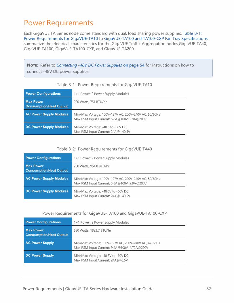
Power RequirementsEach GigaVUE TA Series node come standard with dual, load sharing power supplies. Table B-1:Power Requirements for GigaVUE-TA10 to GigaVUE-TA100 and TA100-CXP Fan Tray Specificationssummarize the electrical characteristics for the GigaVUE Traffic Aggregation nodes,GigaVUE-TA40,GigaVUE-TA100, GigaVUE-TA100-CXP, and GigaVUE-TA200.
NOTE: Refer to Connecting -48V DC Power Supplies on page 54 for instructions on how toconnect -48V DC power supplies.
Power Configurations 1+1 Power: 2 Power Supply Modules
Max PowerConsumption/Heat Output
220Watts; 751 BTU/hr
AC Power Supply Modules Min/Max Voltage: 100V–127V AC, 200V–240V AC, 50/60HzMax PSM Input Current: 5.8A@100V, 2.9A@200V
DC Power Supply Modules Min/Max Voltage: -40.5 to -60V DCMax PSM Input Current: 24A@ -40.5V
Table B-1: Power Requirements for GigaVUE-TA10
Power Configurations 1+1 Power: 2 Power Supply Modules
Max PowerConsumption/Heat Output
280Watts; 954.8 BTU/hr
AC Power Supply Modules Min/Max Voltage: 100V–127V AC, 200V–240V AC, 50/60HzMax PSM Input Current: 5.8A@100V, 2.9A@200V
DC Power Supply Modules Min/Max Voltage: -40.5V to -60V DCMax PSM Input Current: 24A@ -40.5V
Table B-2: Power Requirements for GigaVUE-TA40
Power Configurations 1+1 Power: 2 Power Supply Modules
Max PowerConsumption/Heat Output
550Watts; 1892.7 BTU/hr
AC Power Supply Min/Max Voltage: 100V–127V AC, 200V–240V AC, 47-63HzMax PSM Input Current: 9.4A@100V, 4.72A@200V
DC Power Supply Min/Max Voltage: -40.5V to -60V DCMax PSM Input Current: [email protected]
Power Requirements for GigaVUE-TA100 and GigaVUE-TA100-CXP
Power Requirements | GigaVUE TA Series Hardware Installation Guide 82

Power Configurations 1+1 Power: 2 Power Supply Modules
Max PowerConsumption/Heat Output
1069Watts; 3645.29 BTU/hr
AC Power Supply Min/Max Voltage: 100V–127V AC, 200V–240V AC, 47-63HzMax PSM Input Current: 13.8A@100V, 8.5A@200V
DC Power Supply Min/Max Voltage: -36V to -72V DCMax PSM Input Current: 42A@-36V
Power Requirements for GigaVUE-TA200
Fan Tray Specification for GigaVUE-TA100 and TA100-CXPThe GigaVUE-TA100 and GigaVUE-TA100-CXP use a fan tray for cooling. GigaVUE-TA100 and TA100-CXP Fan Tray Specifications summarizes the characteristics of the fan tray.
Rated Voltage 12V DC
Input Power Maximum 18W
Maximum Speed 19000 RPM
Type Dual axial flow fans
GigaVUE-TA100 and TA100-CXP Fan Tray Specifications
Fan Tray Specification for GigaVUE-TA200The GigaVUE-TA200 uses a fan tray for cooling. GigaVUE-TA200 Fan Tray Specifications summarizesthe characteristics of the fan tray.
Rated Voltage 12V DC
Input Power Maximum 96W
Maximum Speed 13200 RPM
Type Tubeaxial (dual) 80mm x 80mm
GigaVUE-TA200 Fan Tray Specifications
Environmental SpecificationsEnvironmental Specifications for GigaVUE-TA10 and GigaVUE-TA40 summarizes the environmentalspecifications for the GigaVUE Traffic Aggregation nodes, GigaVUE-TA40. EnvironmentalSpecifications for GigaVUE-TA100, TA100-CXP, and TA200 summarizes the environmentalspecifications for the GigaVUE-TA100, GigaVUE-TA100-CXP, and GigaVUE-TA200.
Environmental Specifications | GigaVUE TA Series Hardware Installation Guide 83

Specification Value
Operating Temperature 32ºF to 104ºF(0ºC to 40ºC)
Operating Relative Humidity 20% to 80%, non-condensing
Recommended StorageTemperature
-4ºF to 158ºF(-20ºC to 70ºC)
Recommended StorageRelative Humidity
15% to 85%, non-condensing
Altitude Up to 10000ft (3.05km)
Environmental Specifications for GigaVUE-TA10 and GigaVUE-TA40
Specification Value
Operating Temperature 32ºF to 104ºF(0ºC to 40ºC)
Operating Relative Humidity 10% to 90%, non-condensing
Recommended StorageTemperature
-4ºF to 158ºF(-20ºC to 70ºC)
Recommended StorageRelative Humidity
15% to 85%, non-condensing
Altitude Up to 10000ft (3.05km) for GigaVUE-TA100 andGigaVUE-TA100-CXPUp to 16405ft (5.00km) for GigaVUE-TA200
Environmental Specifications for GigaVUE-TA100, TA100-CXP, and TA200
Standards and ProtocolsIEEE 802.3-2012, IEEE 802.1Q VLAN, IEEE 802.3 10BASE-T, IEEE 802.3u 100BASE-TX, IEEE 802.3ab1000BASE-T, IEEE 802.3z 1000BASE-X, IEEE 802.3ae 10000BASE-X, IEEE 802.3ba, RFC 783 TFTP, RFC 791IP, RFC 793, TCP, RFC 826 ARP, RFC 768 UDP, RFC 792 ICMP, SNMP v1/v2c, RFC 2131 DHCP client,RFC 1492 TACACS+, and support for IPv4 and IPv6.
ComplianceThis section provides compliance information for GigaVUE Traffic Aggregation nodes,.
Standards and Protocols | GigaVUE TA Series Hardware Installation Guide 84

SafetyGigaVUE Traffic Aggregation nodes are compliant with the following safety regulations:
• UL 60950-1, 2nd Edition• CAN/CSA C22.2 No. 60950-1-07, 2nd Edition• EN 60950-1:2006/A11:2009/A1:2010/A12:2011/A2:2013• IEC 60950-1:2005 (2nd Edition) + Am 1:2009 + Am 2:2013• BSMI (GigaVUE-TA100 and GigaVUE-TA200)• CCC, EAC (GigaVUE-TA100 and GigaVUE-TA200)
EmissionsGigaVUE Traffic Aggregation nodes are compliant with the following emissions regulations:
• FCC Part 15, Class A• VCCI Class A. Refer to VCCI on page 86. (not applicable on GigaVUE-TA100-CXP)• EN 55032/CISPR 32 Class A• Australia/New Zealand AS/NZS CISPR-32 Class A (not applicable on GigaVUE-TA100-CXP)• KCC Class A (not applicable on GigaVUE-TA100-CXP)• BSMI (GigaVUE-TA100 and GigaVUE-TA200)• CCC, EAC (GigaVUE-TA100 and GigaVUE-TA200)
ImmunityGigaVUE Traffic Aggregation nodes are compliant with the following immunity regulations:
• ETSI EN300 386 V1.6.1:2012 (not applicable on GigaVUE-TA200)• EN61000-4-2• EN61000-4-3• EN61000-4-4• EN61000-4-5• EN61000-4-6• EN61000-4-8• EN61000-4-11• EN61000-3-2• EN61000-3-3
EnvironmentalGigaVUE Traffic Aggregation nodes are compliant with the following environmental regulations:
• EU RoHS 6, EU directive 2011/65/EU• NEBS Level 3 (GigaVUE-TA10, GigaVUE-TA40, and GigaVUE-TA100). Refer to C NEBS Level 3Compliance on page 101.
Compliance | GigaVUE TA Series Hardware Installation Guide 85

SecurityGigaVUE Traffic Aggregation nodes are compliant with the following security certifications:
• FIPS 140-2 (GigaVUE-TA10, GigaVUE-TA40, GigaVUE-TA100, and GigaVUE-TA100-CXP). Refer to“FIPS 140-2 Compliance” in the GigaVUE-OS CLI User's Guide.
• UC APL (option available for GigaVUE-TA10 and GigaVUE-TA40). Refer to “UC APL Compliance”in the GigaVUE-OS CLI User's Guide.
• Common Criteria (option available for GigaVUE-TA10 and GigaVUE-TA40). Refer to “CommonCriteria” in the GigaVUE-OS CLI User's Guide.
BSMI RoHSThe RoHS label for Taiwan BSMI for GigaVUE-TA200 is as follows:
VCCIThe Class A Information Technology Equipment (ITE) label for Japan is as follows:
Compliance | GigaVUE TA Series Hardware Installation Guide 86

Translation of Statement for Class A VCCI-certified Equipment
This is a Class A product based on the standard of the Voluntary Control Council for Interference byInformation Technology Equipment (VCCI). If this equipment is used in a domestic environment,radio disturbance may occur, in which case, the user may be required to take corrective action.
WarrantyGigamon offers a range of premium support and extended services. For details regarding warranty,visit:https://www.gigamon.com/support-and-services/warranty
Regulatory LabelsThis section provides regulatory labels for nodes.
GigaVUE-TA10
Warranty | GigaVUE TA Series Hardware Installation Guide 87

GigaVUE-TA40
GigaVUE-TA100
Regulatory Labels | GigaVUE TA Series Hardware Installation Guide 88

GigaVUE-TA100-CXP
GigaVUE-TA200
Regulatory Labels | GigaVUE TA Series Hardware Installation Guide 89

Regulatory Labels | GigaVUE TA Series Hardware Installation Guide 90

Console Port Signaling and CablingThis appendix provides the pinouts for the RJ-45-to-RJ-45 rollover cable and RJ-45-to-DB-9 adapterprovided with the GigaVUE Traffic Aggregator for connections from the system’s console port to aPC’s COM port.
The figure below shows how to connect the RJ-45-to-RJ-45 rollover cable from the GigaVUE TrafficAggregator’s console port to a COM port on a PC using the RJ-45-to-DB-9 adapter.
The table below lists the pinouts for the connection illustrated above.
| GigaVUE TA Series Hardware Installation Guide 91

Console Port from RJ45Jack
RJ-45-to-RJ-45 RolloverCable
RJ-45-to-DB-9Terminal Adapter
Console Deviceon PC
Signal RJ-45 Pin RJ-45 Pin DB-9 Pin Signal
N/A 1 8 8 N/A
N/A 2 7 6 N/A
TxD 3 6 2 RxD
GND 4 5 5 GND
GND 5 4 5 GND
RxD 6 3 3 TxD
N/A 7 2 4 N/A
N/A 8 1 7 N/A
| GigaVUE TA Series Hardware Installation Guide 92

| GigaVUE TA Series Hardware Installation Guide 93

NEBS Level 3 ComplianceThis appendix provides installation instructions for GigaVUE-TA10, GigaVUE-TA40, GigaVUE-TA100,and GigaVUE-TA200 Network Equipment-Building System (NEBS) Level 3 compliance. Refer to thefollowing:
• Installation Instructions GigaVUE-TA10, TA40, TA100, TA200 on page 94
Installation Instructions GigaVUE-TA10, TA40, TA100,TA200The following sections detail installation instructions for GigaVUE-TA10, GigaVUE-TA40, GigaVUE-TA100, and GigaVUE-TA200.
Intrabuilding or Intra-connection for GigaVUE-TA10WARNING: The intra-building ports:
• RJ45: Management port, Console port• 1G/10G SFP/SFP+: X1 - X48• 40G QSFP+: Q1-Q4
GigaVUE-TA10 equipment or subassembly are suitable for connection to intrabuilding or unexposedwiring or cabling only. The intra-building port(s) of the equipment or subassembly MUST NOT bemetallically connected to interfaces that connect to the OSP or its wiring. These interfaces aredesigned for use as intra-building interfaces only (Type 2 or Type 4 ports as described in GR-1089-CORE, Issue 6) and require isolation from the exposed OSP cabling. The addition of PrimaryProtectors is not sufficient protection in order to connect these interfaces metallically to OSP wiring.
Intrabuilding or Intra-connection for GigaVUE-TA40WARNING: The intra-building ports:
• RJ45: Management port, Console port• 40G QSFP+: Q1-Q32
GigaVUE-TA40 equipment or subassembly are suitable for connection to intrabuilding or unexposedwiring or cabling only. The intra-building port(s) of the equipment or subassembly MUST NOT bemetallically connected to interfaces that connect to the OSP or its wiring. These interfaces aredesigned for use as intra-building interfaces only (Type 2 or Type 4 ports as described in GR-1089-CORE, Issue 6) and require isolation from the exposed OSP cabling. The addition of PrimaryProtectors is not sufficient protection in order to connect these interfaces metallically to OSP wiring.
Intrabuilding or Intra-connection for GigaVUE-TA100WARNING: The intra-building ports:
Installation Instructions GigaVUE-TA10, TA40, TA100, TA200 | GigaVUE TA Series HardwareInstallation Guide
94

• RJ45: Management port, Console port• 100G QSFP28: C1-C32• 40G QSFP+: C1-C32
GigaVUE-TA100 equipment or subassembly are suitable for connection to intrabuilding orunexposed wiring or cabling only. The intra-building port(s) of the equipment or subassembly MUSTNOT be metallically connected to interfaces that connect to the OSP or its wiring. These interfacesare designed for use as intra-building interfaces only (Type 2 or Type 4 ports as described in GR-1089-CORE, Issue 6) and require isolation from the exposed OSP cabling. The addition of PrimaryProtectors is not sufficient protection in order to connect these interfaces metallically to OSP wiring.
Intrabuilding or Intra-connection for GigaVUE-TA200WARNING: The intra-building ports:
• RJ45: Management port, Console port• 100G QSFP28: C1-C64• 40G QSFP+: C1-C64
GigaVUE-TA200 equipment or subassembly are suitable for connection to intrabuilding orunexposed wiring or cabling only. The intra-building port(s) of the equipment or subassembly MUSTNOT be metallically connected to interfaces that connect to the OSP or its wiring. These interfacesare designed for use as intra-building interfaces only (Type 2 or Type 4 ports as described in GR-1089-CORE, Issue 6) and require isolation from the exposed OSP cabling. The addition of PrimaryProtectors is not sufficient protection in order to connect these interfaces metallically to OSP wiring.
Intrabuilding Ports (RJ45)WARNING: The intrabuilding ports (RJ45) shall be connected to shielded and grounded cables atboth ends.
Class A2 Voltage AccessibilityThe GigaVUE-TA10, GigaVUE-TA40, GigaVUE-TA100, or GigaVUE-TA200 shall be located in arestricted access location where only crafts personnel are allowed access.
Class B Voltage AccessibilityThe GigaVUE-TA10, GigaVUE-TA40, GigaVUE-TA100, or GigaVUE-TA200 shall be located in arestricted access location where only crafts personnel are allowed access.
Equipment Grounding SystemsThe GigaVUE-TA10, GigaVUE-TA40, GigaVUE-TA100, or GigaVUE-TA200 shall be installed andconnected to the (CBN).
Installation Instructions GigaVUE-TA10, TA40, TA100, TA200 | GigaVUE TA Series HardwareInstallation Guide
95

Communication Equipment GroundingThe GigaVUE-TA10, GigaVUE-TA40, GigaVUE-TA100, or GigaVUE-TA200 is suitable for connection tothe (Central Office and CPE).
Bonding of Battery Return (BR) Input TerminalsThe battery returns of the GigaVUE-TA10, GigaVUE-TA40, GigaVUE-TA100, or GigaVUE-TA200 shallbe connected as (DC-I).
Connectionsa. The GigaVUE-TA10, GigaVUE-TA40, GigaVUE-TA100, or GigaVUE-TA200 shall be grounded
via a copper ground conductor #6 AWG for CPE installation.
b. All bare grounding connection points to the GigaVUE-TA10, GigaVUE-TA40, GigaVUE-TA100, or GigaVUE-TA200 shall be cleaned and coated with an antioxidant solution beforeconnections are made.
c. All surfaces on the GigaVUE-TA10, GigaVUE-TA40, GigaVUE-TA100, or GigaVUE-TA200 thatare unplated shall be brought to a bright finish and treated with an antioxidant solutionbefore connections are made.
d. All non-conductive surfaces on the GigaVUE-TA10, GigaVUE-TA40, GigaVUE-TA100, orGigaVUE-TA200 shall be removed from all threads and connection points to ensureelectrical continuity.
e. Multiple connectors shall not be secured by the same bolt assemblies.
f. Unplated connection surfaces that are to be intentionally joined to form a bonding orgrounding path shall be brought to a bright finish and then coated with an antioxidantbefore they are joined (electrical connections).
g. Listing fasting hardware shall be compatible with materials being joined and shall precludeloosening deterioration, and electrochemical corrosion of the hardware and joinedmaterials.
h. Non-conductive coatings (such as paint, lacquer, and enamel) on the equipment to bebonded or grounded shall be removed from threads and other contact surfaces to assureelectrical continuity.
i. GigaVUE-TA10, GigaVUE-TA40, GigaVUE-TA100, or GigaVUE-TA200 utilizes a Spade width0.32in/.81cm with a Standard Wire 14-16 (AWG) that utilizes 5in-lbs of torque to secure itto the frame and EUT. Only listed two-hole compression-type connectors shall be used in
Installation Instructions GigaVUE-TA10, TA40, TA100, TA200 | GigaVUE TA Series HardwareInstallation Guide
96

making connection to flat surfaces (such as bus bars, frames, racks, or cabinets). Torquingand bolts assembly requirements for securing the connector shall be as specified by theconnector supplier.
j. Anti-rotation devices, such as lock washers, will be used on grounding lugs to minimizethe possibility of loosening from rotation during installation and maintenance activities.
Input AC/DC VoltageThe GigaVUE-TA10, GigaVUE-TA40, GigaVUE-TA100, and GigaVUE-TA200 is capable of operatinginput 100-240V AC or -48V DC.
Commercial Power PortsThe manufacturer recommends that Surge Protection Device (SPD) is intended to be used with AC-power equipment. The SPD, if used, is installed at the AC power entrance (Refer to definition in theNEC).
MaintenanceCAUTION: Remove all power sources before servicing. (TO COMPLETELY REMOVE POWER FROMTHE UNIT, FIRST TURN OFF THE POWER SWITCH AND REMOVE BOTH POWER CABLES).
Installation Instructions GigaVUE-TA10, TA40, TA100, TA200 | GigaVUE TA Series HardwareInstallation Guide
97

Additional Sources of InformationThis appendix provides additional sources of information. Refer to the following sections for details:
• Documentation• Documentation Feedback• Contact Technical Support• Contact Sales• The Gigamon Community
DocumentationThe following table provides a list of the additional documentation provided for GigaVUE H Seriesand TA Series nodes. "*" indicates new documents in this release.
TIP: If you keep all PDFs for a particular release in common folder, you can easily searchacross the doc set by opening one of the files in Acrobat and choosing Edit > AdvancedSearch from the menu. This opens an interface that allows you to select a directory andsearch across all PDFs in a folder.
Table 1: Documentation Suite for Gigamon Products
Summary Document
• complete doc set for the respective release, minus ReleaseNotes, in a zip file
All-Documents Zip
• new features, resolved issues, and known issues in thisrelease
• important notes regarding installing and upgrading to thisrelease
NOTE: In 5.7.00, the Release Notes documents combinesGigaVUE-OS, GigaVUE-FM, and GigaVUE Cloud Suite intoone document.
GigaVUE-OS, GigaVUE-FM, GigaVUE-VM, and GigaVUECloud Suite Release Notes
NOTE: Registered Customers can download the ReleaseNotes from the Software & Docs page on to MyGigamon. Refer to How to Download PDFs fromMyGigamon.
Hardware Installation Guides
Additional Sources of Information | GigaVUE TA Series Hardware Installation Guide 98

Summary Document
• how to unpack, assemble, rack-mount, connect, andinitially configure the respective GigaVUE devices
• reference information and specifications for the respectiveGigaVUE devices
GigaVUE-HC1 Hardware Installation Guide
GigaVUE-HC2 Hardware Installation Guide
GigaVUE-HC3 Hardware Installation Guide
GigaVUE TA Series Hardware Installation Guide
Software Installation and Upgrade Guides
• how to migrate GigaVUE-FM on VMware ESXi, HardwareAppliance, and AWS.
*GigaVUE-FMMigration Guide
• how to install and upgrade GigaVUE-FM on VMware ESXi,MS Hyper-V, and KVM
GigaVUE-FM Installation and Upgrade Guide
• how to upgrade the embedded GigaVUE-OS on GigaVUE HSeries and GigaVUE TA Series nodes
GigaVUE-OS Upgrade Guide
Administration Guide
• how to administer the GigaVUE-OS and GigaVUE-FMsoftware
GigaVUE-OS and GigaVUE-FMAdministration Guide
Configuration and Monitoring Guides
• how to install, deploy, and operate GigaVUE-FM• how to configure GigaSMART operations
GigaVUE-FMUser’s Guide
• how to deploy the GigaVUE Cloud Suite solution in anycloud platform
GigaVUE Cloud Suite for AnyCloud Configuration Guide
• how to configure the GigaVUE Cloud Suite componentsand set up traffic monitoring sessions for the respectivecloud platform
GigaVUE Cloud Suite for AWS Configuration Guide
GigaVUE Cloud Suite for AWS QuickStart Guide
*GigaVUE Cloud Suite for AWS Secret RegionsConfiguration Guide
GigaVUE Cloud Suite for Azure Configuration Guide
GigaVUE Cloud Suite for Kubernetes ConfigurationGuide
*GigaVUE Cloud Suite for Nutanix Configuration Guide
GigaVUE Cloud Suite for OpenStack ConfigurationGuide
GigaVUE Cloud Suite for VMware Configuration Guide
Additional Sources of Information | GigaVUE TA Series Hardware Installation Guide 99

Summary Document
Reference Guides
• library of GigaVUE-OS CLI (Command Line Interface)commands used to configure and operate GigaVUE HSeries and TA Series devices
GigaVUE-OS CLI Reference Guide
• guidelines for the different types of cables used toconnect Gigamon devices
GigaVUE-OS Cabling Quick Reference Guide
• compatibility information and interoperabilityrequirements for Gigamon devices
GigaVUE-OS Compatibility and Interoperability Matrix
• samples uses of the GigaVUE-FM Application ProgramInterfaces (APIs)
NOTE: Content will be merged into the GigaVUE-FM User’sGuide in a future release.
GigaVUE-FM REST API Getting Started Guide
In-Product Help
• how to install, deploy, and operate GigaVUE-FM. Providedfrom the GigaVUE-FM interface.
GigaVUE-FMOnline Help
• the web-based GUI for the GigaVUE-OS. Provided from theGigaVUE-OS H-VUE interface.
GigaVUE-OS H-VUE Online Help
NOTE: Registered customers can log in to My Gigamon to download documentation forspecific releases under Software & Documentation Downloads. Refer to How to DownloadPDFs from My Gigamon.
How to Download PDFs from My Gigamon
To download release-specific PDFs:
1. Log in to My Gigamon2. Click on the Software & Documentation link.3. Use the Product and Release filters to find documentation for the current release. For
example, select Product: "GigaVUE-FM" and Release: "5.7," enter "pdf" in the search box, andthen click GO to view all PDF documentation for GigaVUE-FM 5.7.xx.
Additional Sources of Information | GigaVUE TA Series Hardware Installation Guide 100

Documentation FeedbackTo send feedback and report issues in our documentation, complete the short survey at thefollowing link:
https://www.surveymonkey.com/r/gigamondocumentationfeedback
Contact Technical SupportSee https://www.gigamon.com/support-and-services/contact-support for Technical Support hoursand contact information. You can also email Technical Support at [email protected].
Contact SalesUse the following information to Gigamon channel partner or Gigamon sales representatives.
Telephone: +1.408.831.4025
Sales: [email protected]
Partners: www.gigamon.com/partners.html
Premium Support
Email Gigamon at [email protected] for information on purchasing 24x7 Premium Support.Premium Support entitles you to round-the-clock phone support with a dedicated Support Engineerevery day of the week.
The Gigamon CommunityThe Gigamon Community is a technical site where Gigamon users, partners, security and networkprofessionals and Gigamon employees come together to share knowledge and expertise, askquestions, build their network and learn about best practices for Gigamon products.
Visit the Gigamon Community site to:
• Find knowledge base articles and documentation• Ask and answer questions and learn best practices from other members.• Join special-interest groups to have focused collaboration around a technology, use-case,vertical market or beta release
• Take online learning lessons and tutorials to broaden your knowledge of Gigamon products.
Additional Sources of Information | GigaVUE TA Series Hardware Installation Guide 101

• Submit and vote on feature enhancements and share product feedback. (Customers only)• Open support tickets (Customers only)• Download the latest product updates and documentation (Customers only)
The Gigamon Community is a great way to get answers fast, learn from experts and collaboratedirectly with other members around your areas of interest.
Register today at community.gigamon.com
Questions? Contact our Community team at community.gigamon.com
Additional Sources of Information | GigaVUE TA Series Hardware Installation Guide 102