Technical Bulletin UTAX / TA UTAX / TA 3262i 4062i
142
1/2 Technical Bulletin UTAX / TA UTAX / TA 3262i 4062i TB-01B 2V6-I057/M Date: 08-03-2018 Priority: …A highest priority / …B second priority / …C other / …S Service Information Firmware Upgrade (Upgrade Pack V 1.01) Model: 3262i, 4062i TOPIC: The firmware is upgraded as follows. CONTENT OF CHANGES: - Corrective measures for lock-up when cancel copying. Under the condition of high HDD access load *1 and executing copy, and canceling operation while scanning; job can’t complete and lock-up occurs *1: The condition of high HDD load both job accounting function and Data Security Kit are enabled. - Improving the performance when HyPAS application and Data Security Kit are installed. When sending the print job while HyPAS application and Data Security Kit are installed, print speed becomes lower than half. - Support for system error F248. If print a certain PDF file through [Preview] of Mac OS 10.13, system error F248 might occur. - Change is made at the drum refresh with paper. When performing the drum refresh with paper, there might be the possibility to finish it even remaining time is displayed. - Corrective measures for not getting sound of TEL reception buzzer. There might be the possibility that TEL reception buzzer might not sound in FAX/TEL auto switch at Quick Recovery sleep mode. - Support for the display mistake of the “Reception Date/Time” in Traditional Chinese. When using Traditional Chinese, if FAX is received under the “Reception Date/Time” ON, “Reception Date/Time” displays “Data/hora recep”]. - Support for displaying the optional language in Google Cloud Print. In the print setting screen for Google Cloud Print, English is displayed without displaying in the indicated option language. - Corrective measures for the lock-up when executing maintenance mode U251/U981. When executing maintenance mode U251 “Clear Maintenance Counter” / U981 “Set/Check CBM Alert Data”, there might be the possibility to lock-up. - DF-7120: Corrective measure for excess current of the main tray lift motor. 1. Service call error C8250 which is the detection of excess current is not detected 2. Change the detection condition of service call error C8250 In case of detecting the lock detection signal for 10 seconds continuously change is made when detecting 1 second. 3. If the upper surface of the ejected paper can’t be detected correctly, the main tray lift motor might continue operation. Therefore, change is made to stop the operation at a certain time (550ms) if it is lifted up additionally. 4. DF operates the initial operation by opening/closing the DF cover even while service call error is detected. Therefore, change is made not to operate. FIRMWARE UPGRADE PACK Type Model File Remarks MAIN 3262i, 4062i 2V6_2000.001.105 NEW MMI 3262i, 4062i 2V6_7000.001.104 NEW PANEL MAIN 3262i, 4062i 2ND_7200.001.015 ENGINE 3262i, 4062i 2V6_1000.001.041 LANGUAGE MLT 3262i, 4062i 2V6_81XM.001.013 NEW BROWSER 3262i, 4062i 2ND_F000.002.002 OCR 3262i, 4062i 2R6_L000.002.004 SCANNER 3262i, 4062i 2RH_1200.003.001 DICTIONARY MLT 3262i, 4062i 2ND_CA00.001.002 ESPECIAL 3262i, 4062i ES_SKIP.ON
-
Upload
khangminh22 -
Category
Documents
-
view
1 -
download
0
Transcript of Technical Bulletin UTAX / TA UTAX / TA 3262i 4062i

1/2
Technical Bulletin UTAX / TA UTAX / TA
3262i 4062i
TB-01B 2V6-I057/M Date: 08-03-2018
Priority: …A highest priority / …B second priority / …C other / …S Service Information
Firmware Upgrade (Upgrade Pack V 1.01)
Model: 3262i, 4062i
TOPIC:
The firmware is upgraded as follows.
CONTENT OF CHANGES:
- Corrective measures for lock-up when cancel copying. Under the condition of high HDD access load *1 and executing copy, and canceling operation while scanning; job can’t complete and lock-up occurs *1: The condition of high HDD load both job accounting function and Data Security Kit are enabled.
- Improving the performance when HyPAS application and Data Security Kit are installed. When sending the print job while HyPAS application and Data Security Kit are installed, print speed becomes lower than half.
- Support for system error F248. If print a certain PDF file through [Preview] of Mac OS 10.13, system error F248 might occur.
- Change is made at the drum refresh with paper. When performing the drum refresh with paper, there might be the possibility to finish it even remaining time is displayed.
- Corrective measures for not getting sound of TEL reception buzzer. There might be the possibility that TEL reception buzzer might not sound in FAX/TEL auto switch at Quick Recovery sleep mode.
- Support for the display mistake of the “Reception Date/Time” in Traditional Chinese. When using Traditional Chinese, if FAX is received under the “Reception Date/Time” ON, “Reception Date/Time” displays “Data/hora recep”].
- Support for displaying the optional language in Google Cloud Print. In the print setting screen for Google Cloud Print, English is displayed without displaying in the indicated option language.
- Corrective measures for the lock-up when executing maintenance mode U251/U981. When executing maintenance mode U251 “Clear Maintenance Counter” / U981 “Set/Check CBM Alert Data”, there might be the possibility to lock-up.
- DF-7120: Corrective measure for excess current of the main tray lift motor. 1. Service call error C8250 which is the detection of excess current is not detected 2. Change the detection condition of service call error C8250 In case of detecting the lock detection signal for 10 seconds continuously change is made when detecting 1 second. 3. If the upper surface of the ejected paper can’t be detected correctly, the main tray lift motor might continue operation. Therefore, change is made to stop the operation at a certain time (550ms) if it is lifted up additionally. 4. DF operates the initial operation by opening/closing the DF cover even while service call error is detected. Therefore, change is made not to operate.
FIRMWARE UPGRADE PACK
Type Model File Remarks
MAIN 3262i, 4062i 2V6_2000.001.105 NEW
MMI 3262i, 4062i 2V6_7000.001.104 NEW
PANEL MAIN 3262i, 4062i 2ND_7200.001.015
ENGINE 3262i, 4062i 2V6_1000.001.041
LANGUAGE MLT 3262i, 4062i 2V6_81XM.001.013 NEW
BROWSER 3262i, 4062i 2ND_F000.002.002
OCR 3262i, 4062i 2R6_L000.002.004
SCANNER 3262i, 4062i 2RH_1200.003.001
DICTIONARY MLT 3262i, 4062i 2ND_CA00.001.002
ESPECIAL 3262i, 4062i ES_SKIP.ON

2/2
FIRMWARE UPGRADE PACK
Type Model File Remarks
Enhancement units
DP-7100 3R7_9500.002.002
DP-7110 3R8_9500.004.001
DP-7120 3RJ_9500.002.002
PF-791 3N4_9000.004.001
PF-810 3PC_9000.002.004
DF-791 3NB_9200.024.002 DF-7120 3RW_9200.005.002 NEW
PH-7A/B/C/D 3NK_9A00.004.003
MT-730(B) 3N0_9800.004.001
FAX System 12 3R2_5400.003.012
When upgrading firmware or replacing board etc., please upgrade each firmware to the latest version at the same time. Download: 3262i, 4062i Firmware Upgrade Pack V 1.01
Classification: At Set Up
X Next Visit / Service Call
Next Periodic Maintenance
Information only
No modification necessary
Field Measure: Upgrade the new firmware when the phenomenon occurs. Serial Nos.: 3262i
4062i
From possible timing of February 2018 production

1/1
Technical Bulletin UTAX / TA UTAX / TA
3262i 4062i
TB-02S A3LM2018v2-I022/M Date: 11-05-2018
Priority: …A highest priority / …B second priority / …C other / …S Service Information
DP-772, DP-7110: Part number information (Fig.6 Paper Feed Sec.2)
Model:
DP-772 3555i, 3060i, 3560i, 4555i, 5555i
2500ci, 3005ci, 3505ci, 4505ci, 5505ci
DP-7110 3061i, 3561i, 3262i, 4056i, 4062i, 5056i, 6056i
2506ci, 3206ci, 4006ci, 5006ci, 6006ci
TOPIC:
Set DP feed belt shaft A (No.1) as a service part in the field.
PARTS TABLE
No. Old Part No.
New Part No. Description Q’ty Compatibility Remarks
Old New Old New
1 ---------- 303M407070 SHAFT PF - 1 - O
Classification: At Set Up
Next Visit / Service Call
Next Periodic Maintenance
X Information only
No modification necessary
Field Measure: --------------------------
Serial Nos.: DP-7720 DP-7110
FIG. 6 Paper Feed Section 2
SHAFT PF No.1-
SHAFT PF No.1-
Service information only

1/2
Technical Bulletin UTAX / TA UTAX / TA
3262i 4062i
TB-03B UDör/M Date: 12-06-2018
Priority: …A highest priority / …B second priority / …C other / …S Service Information
Firmware Upgrade (Upgrade Pack V 1.02)
Model: 3262i, 4062i
TOPIC:
The firmware is upgraded as follows.
CONTENT OF CHANGES:
- Corrective measures for system error F245.System error F245 might occur.
FIRMWARE UPGRADE PACK
Type Model File Remarks
MAIN 3262i, 4062i 2V6_2000.E01.101 NEW
MMI 3262i, 4062i 2V6_7000.001.104
PANEL MAIN 3262i, 4062i 2ND_7200.001.015
ENGINE 3262i, 4062i 2V6_1000.001.041
LANGUAGE MLT 3262i, 4062i 2V6_81XM.001.013
BROWSER 3262i, 4062i 2ND_F000.002.002
OCR 3262i, 4062i 2R6_L000.002.004
SCANNER 3262i, 4062i 2RH_1200.003.001
DICTIONARY MLT 3262i, 4062i 2ND_CA00.001.002
ESPECIAL 3262i, 4062i ES_SKIP.ON
Enhancement units
DP-7100 3R7_9500.002.002
DP-7110 3R8_9500.004.001
DP-7120 3RJ_9500.002.002
PF-791 3N4_9000.004.001
PF-810 3PC_9000.002.004
DF-791 3NB_9200.024.002
DF-7120 3RW_9200.005.002
PH-7A/B/C/D 3NK_9A00.004.003
MT-730(B) 3N0_9800.004.001
FAX System 12 3R2_5400.003.012
When upgrading firmware or replacing board etc., please upgrade each firmware to the latest version at the same time.
Download: 3262i, 4062i Firmware Upgrade Pack V 1.02

2/2
Classification: At Set Up
X Next Visit / Service Call
Next Periodic Maintenance
Information only
No modification necessary
Field Measure: Upgrade the new firmware when the phenomenon occurs. Serial Nos.: 3262i
4062i
To be informed later

1/2
Technical Bulletin UTAX / TA UTAX / TA
3262i 4062i
TB-04S 2V6-I113/M Date: 02-07-2018
Priority: …A highest priority / …B second priority / …C other / …S Service Information
Additional of the UFP countermeasure filter in the maintenance kit
Model: 4062i
TOPIC:
The UFP countermeasure filter (302V633010: Note1) is additionally bundled in the maintenance kit for 4062i model. The UFP countermeasure filter is used in the 4062i main unit from the first production.
Note1: UFP is the abriviation of [Ultrafine Particles] and it refers to the particles 0,1 micrometer or less in diameter (One thousandth of 0,1mm). UFP emission standard from the product is one of the certification criteria for the European new BAM standard. The UFP countermeasure filter is attached in the exit fan motor section from the first production for 4062i model.
UFP FILTER REPLACEMENT PROCEDURE:
* This procedure will be added in the service manual at the next revision (Current version is Rev.2).
1.) Remove three screws. Open the upper section of the rear upper cover and remove it in the arrow direction.
Unpacking condition of the maintenance kit
UFP countermeasure filter packed in the plastic bag.
Rear upper cover
Screw
Screw Screw

2/2
2.) Detach the sponge at the exhaust section of the inside rear upper cover.
3.) Replace the UFP countermeasure filter.
When replacing the UFP countermeasure filter, attach the white arrow side of the filter on the upper side and align it in the direction of the white arrow. After that, reattach the sponge, the rear upper cover and screws in the original position.
SERIAL NO. OF AFFECTED MAINTENANCE KIT:
Product name Item code no. Affected serial no.
(UFP countermeasure filter bundled)
MK-7125 1702V68NL0 R3X8600202
Classification: At Set Up
Next Visit / Service Call
X Next Periodic Maintenance
X Information only
No modification necessary
Field Measure: When performing the periodical maintenance, in case of using the maintenance kit that does not have the UFP countermeasure filter bundled, obtain the UFP countermeasure filter (302V633010) separately and replace it.
Serial Nos.: 3262i 4062i
Service information only
Sponge
UFP countermeasure filter
White arrow: Attach the UFP countermeasure filter where the leading edge of the arrow faces in the
outside of the machine

1/2
Technical Bulletin UTAX / TA UTAX / TA
3262i 4062i
TB-05B 2V6-I130/M Date: 06-07-2018
Priority: …A highest priority / …B second priority / …C other / …S Service Information
Firmware Upgrade (Upgrade Pack V 1.03)
Model: 3262i, 4062i
TOPIC:
The firmware is upgraded as follows.
CONTENT OF CHANGES:
- Support for KFS1.6. - Corrective measures for system error F245. When using KNM, MyQ, PaperCut, etc., system error F245 might occur.
- Corrective measures for system error F245. If requesting the error information of the main unit from KFS, system error F245 might occur.
- Corrective measures for the fuser failure under a certain condition. There might be the concern to occur the fuser failure under a certain condition. -Fuser failure when starting to print. -Re-job reception output from the job cancellation. -When turn off and on the power repeatedly.
- DP-7110 Firmware: Support for service call error C3210 “CIS lamp error”. The value at the time of turning on the CIS lamp might not go over the threshold. Therefore, widen the lighting check detection area to improve the smoothness of the value.
FIRMWARE UPGRADE PACK
Type Model File Remarks
MAIN 3262i, 4062i 2V6_2000.001.206 NEW
MMI 3262i, 4062i 2V6_7000.001.202 NEW
PANEL MAIN 3262i, 4062i 2ND_7200.001.015
ENGINE 3262i, 4062i 2V6_1000.001.043 NEW
LANGUAGE MLT 3262i, 4062i 2V6_81XM.001.201 NEW
BROWSER 3262i, 4062i 2ND_F000.002.002
OCR 3262i, 4062i 2R6_L000.002.004
SCANNER 3262i, 4062i 2RH_1200.003.001
DICTIONARY MLT 3262i, 4062i 2ND_CA00.001.002
ESPECIAL 3262i, 4062i ES_SKIP.ON
Enhancement units
DP-7100 3R7_9500.002.002
DP-7110 3R8_9500.005.001 NEW
DP-7120 3RJ_9500.002.002
PF-791 3N4_9000.004.001
PF-810 3PC_9000.002.004
DF-791 3NB_9200.024.002 DF-7120 3RW_9200.005.002
PH-7A/B/C/D 3NK_9A00.004.003
MT-730(B) 3N0_9800.004.001
FAX System 12 3R2_5400.003.012
When upgrading firmware or replacing board etc., please upgrade each firmware to the latest version at the same time. Download: 3262i, 4062i Firmware Upgrade Pack V 1.03

2/2
Classification: At Set Up
X Next Visit / Service Call
Next Periodic Maintenance
Information only
No modification necessary
Field Measure: Upgrade the new firmware when the phenomenon occurs. Serial Nos.: 3262i
4062i
From July 2018 production.

1/2
Technical Bulletin UTAX / TA UTAX / TA
3262i 4062i
TB-05B 2V6-I156/M Date: 24-08-2018
Priority: …A highest priority / …B second priority / …C other / …S Service Information
Firmware Upgrade (Upgrade Pack V 1.04)
Model: 3262i, 4062i
TOPIC:
The firmware is upgraded as follows.
CONTENT OF CHANGES:
- Corrective measures for lock-up while performing U130 “Set toner install”. If interrupting maintenance mode U130 by opening the front cover while performing maintenance mode U130 and go out from maintenance mode and re-enter maintenance mode U130 to execute, the panel shows it is performing though the main unit does not start driving.
- Corrective measures for service call error C0550 “Engine firmware unanticipated control detection 2”. Depending on timing of pressing the power off key when closing the cover under the condition of cover open (within 2 to 4 seconds after closing the cover), service call error C0550 might occur. *As the power is off, nothing is displayed in the operation panel screen but recorded in the report. And there will be no damage on the main unit.
- Corrective measures for the image distortion on the leading edge (only 3262i). As corrective measures for the noise for 32PPM model, the polygon motor is driven with the low speed during ready mode. Under this condition, once printing request comes in and drive with normal printing speed (full speed), before the speed of the polygon motor becomes stable in the main scanning direction of the laser while the speed is going up, the exposure starts and the image distortion on the leading edge of the printing start section might occur. Change: If the above phenomenon occurs, change is made to start exposure after the polygon motor become stable. Refer to the sample below.
FIRMWARE UPGRADE PACK
Type Model File Remarks
MAIN 3262i, 4062i 2V6_2000.001.206
MMI 3262i, 4062i 2V6_7000.001.202
PANEL MAIN 3262i, 4062i 2ND_7200.001.015
ENGINE 3262i, 4062i 2V6_1000.001.045 NEW
LANGUAGE MLT 3262i, 4062i 2V6_81XM.001.201
BROWSER 3262i, 4062i 2ND_F000.002.002
OCR 3262i, 4062i 2R6_L000.002.004
SCANNER 3262i, 4062i 2RH_1200.003.001
DICTIONARY MLT 3262i, 4062i 2ND_CA00.001.002
ESPECIAL 3262i, 4062i ES_SKIP.ON
Enhancement units
DP-7100 3R7_9500.002.002
DP-7110 3R8_9500.005.001
DP-7120 3RJ_9500.002.002
PF-791 3N4_9000.004.001
PF-810 3PC_9000.002.004
DF-791 3NB_9200.024.002 DF-7120 3RW_9200.005.002
PH-7A/B/C/D 3NK_9A00.004.003
MT-730(B) 3N0_9800.004.001
FAX System 12 3R2_5400.003.012
When upgrading firmware or replacing board etc., please upgrade each firmware to the latest version at the same time. Download: 3262i, 4062i Firmware Upgrade Pack V 1.04

2/2
Image sample (Image distortion on the leading edge)
Classification: At Set Up
X Next Visit / Service Call
Next Periodic Maintenance
Information only
No modification necessary
Field Measure: Upgrade the new firmware when the phenomenon occurs. Serial Nos.: 3262i
4062i
From August 2018 production.
Distortion section (Printing start section)

1/5
Technical Bulletin UTAX / TA UTAX / TA
3262i 4062i
TB-07B 2V6-I041/M Date: 28-08-2018
Priority: …A highest priority / …B second priority / …C other / …S Service Information
DF-791: Corrective measures for jam J6310 and J6510 (3262i / 4262i)
Model: DF-791 3060i, 3061i, 3262i, 3560i, 3561i, 4062i
TOPIC:
In case paper curl occurs with DF-791 installed in 3262i / 4062i (*) the leading edge of the curled paper contacts the process tray and there might occur jam J6310 (DF middle sensor stay JAM) or J6510 (DF exit sensor stay JAM). Therefore, change is made as follows. * There might be the possibility to occur with the low stiffness paper but paper which might curl is different depending on the
paper weight, moisture condition, etc. CONTENT OF CHANGES:
1.) Affix 2 films (No.1) in GUIDE MIDDLE CONVEYING UPPER (Not the service part). By affixing 2 films to extend the distance t hat paper reaches the process tray (Figure below) and improves the paper curl. 2.) Set above 2 films (No.1) as the service part in the field. CAUSE:
In order to support the energy saver, the fuser control for 3262i / 4062i has changed from the current models (lower the fuser temperature to increase the fuser pressure), there might be the possibility to occur paper curl with the low stiffness paper.
Affix the film
Some parts are not described
DF main tray
Main tray exit roller
The leading edge of the curled paper contacts the process tray
X
Conveying surface of the GUIDE MIDDEL UPPER
Film No.1-
Affix 2 films (No.1) on the red circled section. (Refer to the following page for the standard affixing position.) (Film affixing procedure step 12))

2/5
FILM AFFIXING PROCEDURE:
1) Remove the upper cover of the finisher (Procedure 1 to 4)
Detach the front lid (2) and the rear lid (3) located at the upper part of the finisher (1) with a flat-blade screwdriver, etc.
2) Remove 4 screws that fix the finisher upper
cover
3) Release the hooks (2 positions) of the
finisher upper cover
4) Lift up the finisher upper cover a little and
disconnect the connector and detach the finisher upper cover
5) Remove GUIDE MIDDLE CONVEYING
UPPER (Procedure 5 to 10)
Remove the fixing screw of the upper stay located at the front side of the finisher
Finisher upper cover Screws
Finisher upper cover
DF front upper cover
Screw
DF front upper cover

3/5
6) Remove the screw at the rear side of the finisher
7) Lift the upper stay diagonally (in the
direction of the arrow in the photo)
8) Remove 4 fixing screws of the DF sub tray
9) Shift guide D2 in the main tray direction
Figure 1 Push the DF sub tray in the arrow direction and release the catch in position Figure 2 Lift up the DF sub tray and place it on the main tray with the wire connected (Refer to the arrow view X) Figure 3 Place the guide D2 back to the original position
10) Loosen the screw for the spring hooked
which is attached to the rear side of GUIDE MIDDEL UPPER
Figure 1 Figure 2
Figure 3
Arrow view X
Screw
Viewing from the rear side of the finisher
Upper stay
Left photo is the upper stay lifted up condition.
Screws
Upper stay
Catch in position
Guide D2 DF sub tray
X

4/5
11) Remove GUIDE MIDDEL UPPER
Detach the fulcrum section of GUIDE MIDDEL UPPER and remove it in the arrow direction Caution
Make sure not to lose the spring which is attached at the rear side of GUIDE MIDDEL UPPER (Framed part of the right figure)
12) Affix the film
Clean the affixing surface of GUIDE MIDDEL UPPER with alcohol Peel off the mount of the double-sided tape of the film (No.1) and affix it to the cleaned surface (Refer to the affixing position at the right figure) A direction: Contact the rib to affix B direction: Matching the starting line of R between inside of the poron and GUIDE MIDDEL UPPER to affix
Fulcrum section
Vising from inside of the DF
B
A
1 1
Poron
Rib
Film No.1-
Starting line of R

5/5
13) Reattach the removed parts
Reattach the removed parts to the original position Caution
When reattaching GUIDE MIDDLE CONVEYING, the spring located at the rear side of GUIDE MIDDLE UPPER which is removed in the procedure 11 should be attached as in the figure 1 When reattaching the DF sub tray, the wire should be attached as in the figure 2 After reattaching all the parts, perform the following 3 points and make sure to confirm if there is no problem. Paper output to the main tray and the sub tray Perform the manual staple (Any staple position is OK) Confirm the tray full detection of the DF sub tray (Figure 3) Hold the DF sub tray full detection sensor by hand Set the output direction to the [Tray B] at the copy screen Confirm if [Paper is overflow in the tray B. remove paper] is displayed
PARTS TABLE
No. Old Part No.
New Part No. Description Q’ty Compatibility Affected model
Remarks Old New Old New
1 ---------- 303PG94010 FILM CONVEYING UPPER SET SP - 1 - O Set item for 2 films
Classification: At Set Up
X Next Visit / Service Call
Next Periodic Maintenance
Information only
No modification necessary
Field Measure: If the above phenomenon occurs with DF-791 installed in TASKalfa 4012i/3212i, perform the following. 1) Check if the DF firmware is 3NB_9200.024.002 or newer. 2) Affix the film (No.1) in GUIDE MIDDLE CONVEYING UPPER And also, the DF which has changed can be installed to the current models.
Serial Nos.: DF-791 Units with "81" or later of the 4th and 5th digit of the serial no.
DF sub tray full detection sensor
Figure 1
Figure 2
Figure 3
DF sub tray

1/6
Technical Bulletin UTAX / TA UTAX / TA
3262i 4062i
TB-08B 2ND-I131/M Date: 28-08-2018
Priority: …A highest priority / …B second priority / …C other / …S Service Information
DP-7100: Service call error C9040 (DP lift motor ascend error)
Model: DP-7100 3061i, 3262i, 3561i, 4062i, 4056i, 5056i, 6056i 2506ci, 3206ci, 4006ci, 5006ci, 6006ci
TOPIC:
As we informed with the service bulletin TB-06B for DP-7100 (Corrective measures for service call error C9040 (DP lift motor ascend error), change is made as follows for further improvement. CONTENT OF CHANGES:
1.) To increase the strength, change the material of the original lift plate fulcrum section from the resin material to metal material.
2.) Based on the change No.1, change the shape of the original lift plate fulcrum section. 3.) Based on the change No.1 and 2, set the original lift plate assy (No.1: Assy of the original lift plate, metal pin and pad) as
a service part in the field.
Viewing the original lift plate assy (No.1) from the lower side of the DP
Rear side of DP
PARTS LIFT GUIDE ASSY SP No.1-
NEW
Metal pin

2/6
PHENOMENON OCCURRENCE MECHANISM:
The failure this time is occurred when the jam occurs, the jam is cleared while the original lift plate is in descending operation. * The following figure 1 to 4 shows the new original lift plate Jam clearance flow if the jam occurs (OK condition)
1.) After completing the descending operation of the original lift plate, open the DP cover for clearing the jam. (Figure 1) 2.) In order to remove paper, open the reverse guide. (Figure 2)
Jam clearance flow if the jam occurs (NG condition)
1.) Open the DP cover while the original lift plate in the descending operation (Origina lift plate stops at the position where is not descending to the bottom) (Figure 3)
2.) Open the reverse guide for removing paper. 3.) The reverse guide interferes with the original lift plate (Figure 4: Red circled section) and the load is given on the fulcrum
section of the reverse guide and it is get damaged (Figure 4)
REPLACEMENT PROCEDURE:
1.) Perform maintenance mode U243 (Check DP motor) “Lift Motor” to make the cum in the ascending condition (Right figure) and open the DP top cover to stop driving.
Figure 1 Figure 2
Reverse guide Original lift plate
Figure 3 Figure 4
Reverse guide Original lift plate Fulcrum section (damage position)
Interference
DP top cover
Cum ascending condition

3/6
2.) Open the lid and detach the DP rear middle cover. Remove the screw and detach the DP rear right cover.
3.) Remove the screw and detach the DP
rear left cover.
4.) Remove two (2) screws and detach the
DP front cover.
Lid DP rear right cover
DP rear middle cover Screw
Screw
DP rear left cover
Screws
DP Front cover

4/6
5.) Detach two (2) wire stoppers. Disconnect the connector and detach the original tray.
6.) Stand the original lift plate and detach the
fulcrum shaft from the front side of the main unit
Front side of the main unit Rear side of the main unit
Connector
Wire stopper
Original tray Pull the wire out
from the hole
Original lift plate
Fulcrum shaft
Inserting hole of the original lift plate shaft
Spring inserting hole

5/6
7.) Release three (3) hooks of the original lift plate and detach the sensor cover and the wire cover.
8.) Detach the sensor and the wire, and
replace the original lift plate.
9.) Reattach the parts in the reverse procedure.
Front side Hook
Original lift plate
Back side
Wire cover Sensor cover
Sensor Original lift plate
Wire

6/6
PARTS TABLE
No. Old Part No.
New Part No. Description Q’ty Compatibility Remarks
Old New Old New
1 303R707021 303R794110 PARTS LIFT GUIDE ASSY SP 1 1 X O *1
*1: Assy of the new original lift plate, metal pin and pad.
Classification: At Set Up
X Next Visit / Service Call
Next Periodic Maintenance
Information only
No modification necessary
Field Measure: When the above phenomenon occurs, replace the original lift plate with the original lift plate assy (No.1)
Serial Nos.: DP-7100 VGB8639860
Metal pin
Pad (303JX06260)
PARTS LIFT GUIDE ASSY SP No.1-

1/3
Technical Bulletin UTAX / TA UTAX / TA
3262i 4062i
TB-09S 2NL-I170/M Date: 02-10-2018
Priority: …A highest priority / …B second priority / …C other / …S Service Information
Note when detaching / attaching the drum unit Model:256i, 306i, 3060i, 3061i, 3262i, 3560i, 3561i, 4062i, P-2540iMFP
CD 5025, CD 5025P, CD 5030 / DC 6025, DC 6025P, DC 6030
CAUTION:
The drum unit has to be removed under the condition that the right cover should be opened 45 degrees or more (The figure OK below) If the drum unit is removed under the condition that the right cover is opened slightly (The figure NG below), the rear cover of the drum unit comes off and if the drive gear or the shaft in the drum unit drops off, reattach them with the procedure in the page 2/3.
Depending on the opening angle of the right cover, the rear cover (A) of the drum unit interferes the transfer roller drive gear (B) and if pulling the drum unit out forcibly, the rear cover of the drum unit comes off and the drive gear (C ) or the shaft (D)in the rear cover might drop off in the main unit. (refer to the next page for the figure (A), (B), (C), (D))Note: If the drive gear or the shft drops off, there might be the possibility to occur recovery failure of the developer unit that
is separated when removing the drum unit caused by the cleaning failure (Abnormal image) due to the drum cleaning screw does not rotate or the dropped parts are caught in the machine.
OK NG
Right cover Drum unit
Right cover is just slightly opened * If it is difficult to work with the right
cover open as the installationenvironment is narrow, move themachine to the position where it ispossible to open the right cover 45degrees or more to work
X

2/3
Positioning of the rear cover of the drum unit (A) and the drive gear of the transfer roller (B) Viewing inside of X (NG condition) from the rear side of the machine
The rear cover of the drum unit (A) is dropped off
PROCEDURE:
Refer to the service manual chapter 4 for the procedure of “Detaching/attaching the drum unit” 1) Assemble the drive gear (C) and the shaft
(D) dropped off in the machine as shown on the right.
Drive gear of the transfer roller (B) (Machine rear side of the conveying unit in the right cover)
A cover of the drum unit
B drive gear of the transfer roller
Direction to remove the drum unit
Interfere A-B
C D
A
B
C
D
E

3/3
2) Insert the D-cut shape (G) of the shaft of the assy (E) (procedure 1) matching the D-cut shape (F) of the inside hole of the machine rear side of the drum unit.
3) Fix 3 position of the hook (H) of the rear
cover (A) of the drum unit and install it.
Classification: At Set Up
Next Visit / Service Call
Next Periodic Maintenance
X Information only
No modification necessary
Field Measure: -------------------------- CD 5025P
CD 5025P CD 5030P
/ DC 6025P / DC 6025P / DC 6030P
Serial Nos.: 256i 306i
3060i 3061i 3262i 3560i 3561i 4062i
P-2540iMFP
Service information only.
A
E
F
G
E
H
Hook (H) fixing section

1/3
Technical Bulletin UTAX / TA UTAX / TA
3262i 4062i
TB-10S COM-I171r2/M Date: 08-01-2019
Priority: …A highest priority / …B second priority / …C other / …S Service Information
How to replace the main PWB with the data security kit is installed
Model: 3061i, 3262i, 3561i, 4056i, 4062i, 5056i, 6056i, 7056i, 8056i 2506ci, 3206ci, 4006ci, 5006ci, 6006ci, 7006ci, 8006ci
TOPIC:
If it is necessary to replace the main PWB with the data security kit installed, perform the following. If replacing it without performing the following, service call error C0660 (Hard Disk encryption key error) or C0640 (Hard Disk error) occurs and there might be the possibility that the machine might not be able to recover. OUTLINE:
X. Standard Procedure (In case of not replacing the main PWB yet) - Prepare another new main PWB (C) - Install the official firmware in the main unit - Perform the maintenance mode - Input encryption code of the data security kit Y. Special Procedure (In case of replacing the main PWB (B) already) - Replace with the original main PWB (A) - Backup the data - Replace the main PWB (B) - Perform the maintenance mode to reactivate the data security kit - Import the backup data - Re-install the HyPAS application, font, macro, etc. Refer to the flow chart in the following page for the details.

2/3
X The main PWB not replaced yet
Y The main PWB (B) already replaced
Z
In case of the main PWB replaced already, procedure X is available with further one more
spare part main PWB(C).
Replace with the new main PWB (C)
Replace with the original main PWB (A)
Install a USB drive with official firmware in the main unit
Execute: U917 (Export) U026 (SSD-Backup) (Export data)
Turn power on (turn off after installing official firmware)
Replace the main PWB
(maybe (B)already used) ⇒ C0660/C0640
Disconnect the USB drive and turn power on ⇒ C0660/C0640
Execute: U026 (Flash-Restore) (SSD Main PWB)
U026 (Flash-Restore) (SSD to Main PWB)
Execute: U004: Machine no.
U004 Normal start-up
Execute: U024 (Initialize SSD/HDD)
Input encryption code of the data
security kit
Reactivation of the data security kit
Execute: U917 (Import)
U026 (SSD-Restore) (Restore data)
Re-install the HyPAS application
finish
Re-install the font, macro, etc. Z: In case of procedure X, image data saved in the HDD is deleted from the HDD standard model and HDD option installed model. HDD standard model HDD as option
4062i / 4056i / 5056i / 6056i / 7056i / 8056i 3061i / 3262i / 3561i 4006ci / 5006ci / 6006ci / 7006ci / 8006ci 2560ci / 3206ci Remarks: Main PWB C0640: “Hard Disk error” (HDD Model) (A) Original PWB C0660: “Hard Disk encryption key error” (SSD Model) (B) Spare part PWB installed in the main unit and power supplied U004: “Machine Number” (C) New spare part PWB not yet replaced U024: “Format HDD” (HDD Format / SSD Format) U026: “Pulling Backup Data” (Backup / Restore) U917: “Read/Write Backup HDD Data(USB)” (Import / Export)
Applicable official firmware (Upgraded firmware table)
Model Upgrade Pack Applicable Main Firmware Model Upgrade Pack Applicable Main Firmware
3061i Upgrade Pack V 4.02 2RH_2000.004.132 2506ci Upgrade Pack V 4.02 2ND_2000.004.132
3262i Upgrade Pack V 1.04 2V6_2000.001.323 3206ci
3061i Upgrade Pack V 4.02 2RH_2000.004.132 4006ci
Upgrade Pack V 4.02 2RL_2000.004.132 4062i Upgrade Pack V 1.04 2V6_2000.001.323 5006ci
4056i
Upgrade Pack V 4.02 2NK_2000.004.132
6006ci
5056i 7006ci Upgrade Pack V 4.03 2NH_2000.004.132
6056i 8006ci
7056i Upgrade Pack V 4.03 2NJ_2000.004.132
8056i

3/3
Classification: At Set Up
Next Visit / Service Call
Next Periodic Maintenance
X Information only
No modification necessary
Field Measure: ---------------------------------
Serial Nos.: 3061i 3262i 3561i 4056i 4062i 5056i 6056i 7056i 8056i 2506ci 3206ci 4006ci 5006ci 6006ci 7006ci 8006ci
Service information only

1/3
Technical Bulletin UTAX / TA UTAX / TA
3262i 4062i
TB-11S 2RH-I080/M Date: 16-10-2018
Priority: …A highest priority / …B second priority / …C other / …S Service Information
Abnormal noise from duplex conveying sec./vertical conveying sec.
Model:
PF-470 PF-471
256i, 306i, P-2540iMFP 206ci, 256ci, P-C2480iMFP CD 5025, CD 5025P, CD 5030 /DC 6025, DC 6025P, DC 6030 CDC 5520, CDC 5525 / DCC 6520, DCC 6525
PF-791 3060i, 3061i, 3262i, 3560i, 3561, 4062i
2500ci
TOPIC:
When the inner diameter of the bearing is scraped due to abrasion and the resin powder is generated, there might be the possibility to occur the abnormal noise (sliding sound) (refer to the above sound sample) from the shaft section of the conveying roller at the time of conveying paper (Note 1). (Note 2)
Note 1: The main unit includes the duplex conveying section Note 2: The number of the roller rotation and the average print volume for the following models with the same series are the
different from the above affected models. Therefore, we expect that there is less possibility to occur the abnormal noise and we do not coat the grease to the main unit and the right cover assy for the field service parts, etc.
Models not to coat the grease 256i, 306i, 3060i, 3560i, CD 5025, CD 5025P, CD 5030 / DC 6025, DC 6025P, DC 6030 CONTENT OF CHANGES:
To improve the sliding capability, coat the Hanal in the whole area of the duplex conveying section/shaft section (drawing X in the following page) of the conveying rollor of the vertical conveying section, and the inner diameter of the bearing (Y). (Refer picture for the position of coating the Hanal) Main unit + Option paper feeder (Photo below is 3561i + PF-791)
Conveying rollor of the duplex conveying section and bushing (3 positions)
Conveying roller of the PF vertical conveying section and bushing (1 position*)
Conveying rollor of the vertical conveying section and bushing (2 positions*)
X
Y
* 3061i / 3561i / 3262i / 4062i only Y
X
* 2 positions for PF-471 X
Y

2/3
POSITION TO COAT THE HANAL:
X: The edge section of the main unit front side of each conveying roller Y: Bearing
Note: The Hanal should not adhere on the rubber roller
Position to attach the conveying roller and the bearing
PARTS TABLE
No. Old Part No.
New Part No. Description Q’ty Compatibility Affected model
Remarks Old New Old New
1 ----------- 302LV94550 GREASE HANARL KS-39M (10G) - 1 - X
Duplex conveying roller
Coat the Hanal on the whole shaft section
Vertical conveying roller
Coat the Hanal on the whole shaft section
Bearing
Coat the Hanal on the whole inner diameter
Main unit
Duplex conveying section at the inner side of right cover 1 Vertical conveying section at the inner side of right cover
Option paper feeder PF-470 / PF-471: PF upper vertical conveying section PF-471 / PF-790: PF lower vertical conveying section

3/3
Classification: At Set Up
Next Visit / Service Call
Next Periodic Maintenance
X Information only
No modification necessary
Field Measure: When the above phenomenon occurs, coat the Hanal (302LV94550) on the necessary position. Be careful when handling the Hanal. - Before coating the Hanal, shake and mix it well before using it. - After coating the Hanal, leave it for 30 seconds to dry it then, attach it..
Serial Nos.: 256i No production now 306i No production now 3060i No production now 3061i VFV7Y04690 3262i R887Z00001 3560i No production now 3561i No production now 4062i R897Z00001 P-2540iMFP R657Z00424 206ci No production now 256ci No production now 2500ci No production now P-C2480iMFP Units with "86" or later of the 4th and 5th digit of the serial no. CD 5025P - DC 6025P No production now CD 5025P - DC 6025P No production now CD 5030P - DC 6030P No production now CDC 5520 - DCC 6520 No production now CDC 5525 - DCC 6525 No production now PF-470 N198120357 PF-471 Units with "86" or later of the 4th and 5th digit of the serial no. PF-791 LUF7Z09892

1/2
Technical Bulletin UTAX / TA UTAX / TA
3262i 4062i
TB-12S 2RH-I139/M Date: 30-10-2018
Priority: …A highest priority / …B second priority / …C other / …S Service Information
Notice of the part supply discontinuation (EEPROM on the engine PWB)
Model: 3061i, 3262i, 3561i, 4062i
TOPIC:
Supply of EEPROM on the engine PWB described in the parts list (FIG.28 Ref No. 7/20) is discontinued. The description of EEPROM in the latest parts list (3061i / 3561i, Rev.5.0D and 3262i / 4062i, Rev.4.0D) has been deleted.
PARTS TABLE
No. Old Part No.
New Part No. Description Q’ty Compatibility Remarks
Old New Old New
1 302LF94510 ---------- PARTS IC EEPROM SP - - - - Stop supplying it as
a service part
EEPROM on the engine PWB
Parts list FIG.28 (Before revised)
Engine PWB
EEPROM No.1- --- Supplying as a service part

2/2
Classification: At Set Up
Next Visit / Service Call
Next Periodic Maintenance
X Information only
No modification necessary
Field Measure: When replacing the engine PWB, replace the EEPROM on the old PWB in the new engine PWB. (Refer to the service manual chapter 4 [Note when replacing the engine PWB] In case of the EEPROM failure necessary to replace, report to us.
Serial Nos.: 3061i 3262i 3561i 4062i
Service information only

1/6
Technical Bulletin UTAX / TA UTAX / TA
3262i 4062i
TB-13S 2ND-I148/M Date: 05-12-2018
Priority: …A highest priority / …B second priority / …C other / …S Service Information
DP-7100: Corrective measures for ticking sound from the DP feed sec.
Model: DP-7100 2506ci, 3206ci, 4006ci, 5006ci, 6006ci
3061i, 3561, 3262i, 4056i, 4062i, 5056i, 6056i
TOPIC:
Due to the variation of the parts, if there are burrs in the gate position (Note1) of the DP feed belt tension pulley edge section and also the DP feed belt tension pulley is attached in the one side (either front or back of the DP), when rotating the DP feed belt tension pulley, a burr conflicts with the rib of the DP feed holder and ticking sound might occur. Therefore, change is made as follows. Note1: The position where the resin is injected when molding the DP feed belt tension pulley. CONTENT OF CHANGES:
In order to avoid interference, add one shim each in between both edges of the DP feed belt tension pulley and the DP feed holder rib (No.2: thickness 0.13mm).
DP feed folder rib
DP feed folder rib Interference section of burrs of the pulley edge
surface and rib (Ticking sound occurrence position)
DP feed belt tension pulley
Add 2 shims No.2-
Before change
After change DP feed holder rib
Burrs of the DP belt tension pulley (gate position)
Ticking sound occurs in the pulley rotation interval
(EX: Burrs of the DP feed belt tension pulley edge section

2/6
PROCEDURE OF ADDING SHIMS:
1.) Detaching/attaching the DP feed unit: Procedure 1, 2 Open the DP top cover (a). Pull the release lever (b) and open the fixing cover (c).
2.) Rotate the DP feed unit (a) and pull out in
the arrow direction. * Attach the DP feed unit in the reverse procedure of 1, 2.
3.) Add the shims:
Release the rib (c) that fixes the DP feed holder assy (b) of the DP feed unit (a) and lift up the DP feed folder (b) to remove the stop ring (d).
d
a
b
c
a
b c b
a

3/6
4.) Pull out the drive shaft (b) of the DP feed belt drive pulley (small) (a) in the arrow direction.
5.) Remove the spring (a).
Note: When removing it, be careful not to lose the spring.
6.) Incline the edge section of the D-cut side of
the drive shaft (a) (position where the spring is removed in the procedure 5) in the arrow A direction and pull out the drive shaft (a) from the DP feed holder in the arrow B direction, and then, remove the DP feed belt tension pulley (b) and the drive shaft (a).
7.) Insert the edge section of the D cut side of
the drive shaft (b) in the fixing hole (a) of the DP feed holder and attach the shim (c: No.2)
b
a
a
Arrow view C
a A
D-cut
b B
C
b
c
b D cut section
a

4/6
8.) Attach DP fee belt tension pulley (b) and shim (c: No.2) in the drive shaft (a) in order.
9.) Incline the edge section of the D cut side of
the drive shaft (a) in the direction of arrow A and insert it into the fixing hole (b).
10.) While lifting up the whole part of the drive
shaft (a), attach the spring (b) in the lower side of the drive shaft. Note: After the attachment, make sure the DP feed belt tension pulley (c) rotates smoothly. (Refer to the FIG.1 )
FIG.1
a
c
b
A
b
a
a
c
b

5/6
11.) Attach the DP feed belt drive pulley (small) (a) in the DP feed belt (b). Then, match the position between the fixing hole (c) of the DP feed holder assy and inner diameter (d) of the DP feed belt drive pulley (small) (Refer to arrow view A), and insert the edge section of the D-cut side (e: Groove available) of the drive shaft (a) in the fixing hole (c).
12.) If the drive shaft stops in the middle of
insertion, rotate the drive shaft that D-cut (a) of the drive shaft should match D-cut (b) of the fixing hole of the DP feed holder and insert.
13.) Attach the stop ring (a).
14.) Push down the DP feed holder assy (a) and
fix the hook (b).
Arrow view A
a
A
b
a c
e
d
c
b
a
a
b
a

6/6
PARTS TABLE
No. Old Part No.
New Part No. Description Q’ty Compatibility Affected model
Remarks Old New Old New
1 303R794100 303R794101 PARTS PAPER FEED ROLLER ASSY 1 1 X O
2 ---------- C2803050 +POLYESTER SLIDER WASHER
3.1X5.4X0.13T - 2 - O
"+"mark at the beginning of the part name means it is a component part.
Classification: At Set Up
Next Visit / Service Call
Next Periodic Maintenance
X Information only
No modification necessary
Field Measure: When the above phenomenon occurs, if opening the DP top cover, turning the DP feed belt by hand, and the abnormal sound reappears, remove the DP feed unit and replace with the new DP feed unit (New No.1) or insert 2 shims (No.2) into the drive shaft of the DP feed belt tension pulley. (Regarding detaching/attaching the DP feed unit, refer to the following procedure 1, 2, and procedure 3 and after for the procedure of the addition of shims.
Serial Nos.: DP-7100 VGB8741851

1/6
Technical Bulletin UTAX / TA UTAX / TA
3262i 4062i
TB-14S 2ND-I189/M Date: 05-12-2018
Priority: …A highest priority / …B second priority / …C other / …S Service Information
DP-7100: Corrective measures for the DP reg. sensor stay jam (J9210)
Model: DP-7100 2506ci, 3206ci, 4006ci, 5006ci, 6006ci
3061i, 3561, 3262i, 4056i, 4062i, 5056i, 6056i
TOPIC:
Due to variation of the parts, if the fulcrum section for the DP upper cover of the DP conveying housing (X: C shape at the rear side of the main unit) is deformed in the left direction of the main unit, the DP upper cover also shifts in the left direction of the main unit depending on the way of setting the original or the media type so that the tip of the original conflicts with the conveying rib (Y) of the BASE DP and there might be the possibility to occur the DP regist. sensor stay jam (J9210). Therefore, change is made as follows. CONTENT OF CHANGES:
After August 24, 2018, strengthen the control of the parallelism of the fulcrum section for the DP upper cover of the DP conveying housing. (Due to supporting the inspection in the factory, there is no part number change. And also there is no plan to inform the affected serial numbers.) MEASURES IN THE FIELD (SUPPORT BY THE SERVICE PERSON):
When this phenomenon occurs, affix the paper feed film on the paper feeding surface of the GUIDE PRESS where located at the upper part of the conveying rib of BASE DP. Refer to the page 2 and after for alignment. Based on the above, Paper feed film (2 films as one set) is set as a service part in the field.
Positioning of the DP upper cover and the fulcrum boss (X) of the DP conveying housing
* If the fulcrum box (X) is deformed in the left direction of the main unit, main unit rear side of the DP upper cover also shifts in the left direction of the main unit.
2 paper feed films No.1-
Condition that the DP upper cover is open
GUIDE PRESS (303R707080) Main unit left direction
DP upper cover
X

2/6
DETAILS OF THE FIELD MEASURES:
AFFIXING PROCEDURE:
1) Open the DP upper cover (a) Remove two screws and detach the DP front cover (c).
Original conveying section after passing the DP regist section
Sectional drawin
GUIDE FEED (DP upper cover side)
BASE DP
:Original conveying path
Shift the position of the DP upper cover Normal condition
Y: Conveying rib of BASE DP
Z: Conveying rib of GUIDE FEED Z: position shifts to
the left as well
Y
Shift the position (Left)
GUIDE PRESS
Paper feed film (Yellow in the figure)
When shifting the DP upper cover position + affixing the paper feed film
GUIDE PRESS Paper feed film
:Original conveying path
a
b
b
c

3/6
2) Remove the stopper (d) located inside the DP front cover (c) and release the strap (e)
3) Pulling the main unit rear side of the DP
upper cover in the left direction and release the boss (f) of the DP upper cover from the fulcrum section (g) of the DP conveying housing. Then, Pulling the DP upper cover (a) in the main unit rear direction and pull out the boss (h) located at the main unit front side from the fulcrum section (i) of the DP conveying housing.
Arrow view A
d
A
e
Main unit rear side of the DP upper cover
Main unit front side
Main unit left direction
f
g
Main unit rear direction
i
a
h

4/6
4) Place the DP upper cover on the work table Remove 4 screws (j)
5) Insert the flathead screw driver in between
COVER PF (k) at both main unit front and rear side and GUIDE FEED (l) and release each 2 positions of the claw (m)
6) Pulling GUIDE FEED (l) in the arrow
direction and release 4 positions of the hook (n) and detach.
j
(Main unit front side) (Main unit rear side)
k
l
k
l
m
After separation
n
l
l COVER PF (k)

5/6
7) Remove the spring (p) at the center of GUIDE PRESS (o) Note: When attaching the spring (p), insert the inner diameter of the spring in the cross boss (q) to fix the spring of GUIDE FEED, and fix it. After attaching the spring, turn over GUIDE FEED (l) and make sure to confirm it recovers if pressing the paper feed surface of GUIDE PRESS (o)
8) Push and bend the near position of the
fulcrum boss (r) of GUIDE PRESS (o) in the direction of the arrow in the figure, release the fulcrum (r) and detach GUIDE PRESS (o) from GUIDE FEED (l). Note: When attaching GUIDE PRESS (o), make sure to confirm the hook A (s) is located at the front side of the work person and the hook B (t) is located at the rear side of the rib of GUIDE FEED (l) (paper feeding side). And pressing both left and right of the fulcrum boss (r) and fix it. If the paper feed film in the procedure 9 is affixed to GUIDE PRESS (o), make sure to confirm the tip of the paper feed film is in the rear side of the rib of GUIDE FEED (l)
p
o q
i
o
r r o l
l t t s

6/6
9) Clean the affixing surface (u) of the GUIDE PRESS (o) by alcohol and affix the paper feed film (v) (2 films in No.1) according to the alignment showing in the right figure
10) Reattach all the parts in the reverse
procedures. Note: When attaching GUIDE FEED in COVER PF, (Refer to the procedure 4 to 6) if the actuator (w) comes off, reattach it.
PARTS TABLE
No. Old Part No.
New Part No. Description Q’ty Compatibility Affected model
Remarks Old New Old New
1 ---------- 303R794120 PARTS FILM PF GUIDE SET SP - 1 - O Parts for the field
service (2 paper feed films as one set)
Classification: At Set Up
Next Visit / Service Call
Next Periodic Maintenance
X Information only
No modification necessary
Field Measure: When this phenomenon occurs, affix the paper feed film on the paper feeding surface of the GUIDE PRESS where located at the upper part of the conveying rib of BASE DP.
Serial Nos.: DP-7100 Service information only.
Affix position
Alignment
0mm
0,5mm
u
o
v
w

1/5
Technical Bulletin UTAX / TA UTAX / TA
3262i 4062i
TB-15B 2V6-I1215/M Date: 12-12-2018
Priority: …A highest priority / …B second priority / …C other / …S Service Information
Firmware Upgrade (Upgrade Pack V 1.05)
Model: 3262i, 4062i
TOPIC:
The firmware is upgraded as follows.
CONTENT OF CHANGES:
- Support for KFS1.6.5. Support for the remote panel (internet version). (Refer to the Page 3 to 5.)
- Corrective measures for the failure of printing from the Job Box. In case of sending heavy data from the Job Box, memory full might occur or print speed might become slow.
- Corrective measures for the failure when printing a specific PS data. In case of printing a certain PS data, all pages might not printed or some part of the font might get overlapped.
- Support for the failure with the Internet FAX. For the customer who sets the Internet FAX and E-mail (Scan to E-mail), it is no problem to use Scan to E-mail but the error 1102 occurs when sending the Internet FAX and the Internet FAX might not be received.
- Corrective measures for lock-up when scanning. Lock-up might occur at Scan to SMB..
- Corrective measures for the PS error with a certain PDF file. In case of printing a certain PDF file from the USB memory, PS error might occur.
- Corrective measures for service call error C0660 “Hard Disk encryption key error” / C0640 “Hard Disk error”. In case of replacing the main PWB for the field service in the main unit with the data security kit E installed, service call error C0660/C0640.ccurs.
- Corrective measures for USB memory not working. There might be the possibility that a certain USB memory might not work with the HyPAS application.
- Corrective measures for the abnormal image with a certain file. When printing a certain file including HPGL, unnecessary extra line is drawn.
- Corrective measures 2 for the abnormal image with a certain file. There might be the possibility to display the colored section in a certain file as box shape in separated colors.
- Corrective measures for system error F248 with printing from MAC. In case of printing from Mac, system error F248 might occur.
- Corrective measures for the failure with Command Center. In case of connecting to the custom box with password from Command Center, after checking the property and reconnect, there might be the possibility that the password request screen might not be displayed.
- Corrective measures for the failure with OCR scan. In case of making OCR scan (Send SMB) continuously or FAX RX transfer with OCR (Transfer to NAS by SMB) remains in [Processing] and does not complete, or after that, system error F237 might occur.
- Corrective measures for system error F485. In case of printing the FAX document received in other than 600dpi and separated into multiple sheets, system error F485 might occur.
- Corrective measures for not reflecting the LDAP settings. Even if adding the user defined file name with the LDAP setting in Command Center, it does not work with its setting.
- Corrective measures for system error F246 when using the ID card. In case of scan the ID card in the card reader quickly and repeatedly, system error F246 might occur.
- Support for missing image. In case of printing a certain file, some part of the image is missing.
- Corrective measures for the lock-up when entering a certain letters. When connecting to the network, if a certain letters are entered, the lock-up might occur.
- Corrective measures for system error F56B. When starting the main unit with the FAX board installed, the error occurs at the initializing process and F56B might occur.
- Corrective measures for the operation panel black out. The operation panel is blacked out and it might not be recovered unless turning the power off and on.
- Corrective measures for not displaying the FAX number in Command Center. In case of opening the receiving (print) history detail screen sorted by the [FAX] at the [Print job history] screen in Command Center, the column of the [Destination] is blank and FAX number is not displayed.
- Corrective measures for i-FAX RX error from the certain model. For i-Fax reception, RX from Ricoh model SL-3400 becomes error.
- Corrective measures for system error F435. System error F435 might occur.
- Corrective measures for system error F186. In case of closing the cassette after loading paper in the cassette, system error F186 might occur.
- Correcting the counting failure in PaperCut. When using PaperCut, the count might not be counted correctly such as counting 2 counts for 1 job or no count, etc..
- Corrective measures for system error F248. In case of printing from a certain HyPAS application, system error F248 might occur.
- Corrective measures for rotating the font 90 degrees. In case of printing a certain file, the font is rotated 90 degrees.

2/5
- Corrective measures for system error F248 with a certain file. In case of printing a certain file, system error F248 might occur.
- Support for output performance from the user box. When printing the document after storing it in the user box, the printing speed might become slower.
- Corrective measures for system error F57B. System error F57B might occur.
- Corrective measures for system error F248 at the time of the direct print. In case of direct print with a certain PDF file, system error F248 might occur.
- Corrective measures for the color difference depending on the page. When printing a certain file, the printing color should be the same for the odd page and even page after the page 2 but they might be different.
- Corrective measures for system error F248 when printing a large amount. When printing a large amount, system error F248 might occur.
- Corrective measures for outputting the job cancelled by MyQ. When using MyQ, there might be the possibility to output the cancelled job at the timing between the server side and the main unit controller side.
- Improving the performance when installing HyPAS application, Data Security Kit. When sending the printing job to the machine that HyPAS application, Data Security Kit are installed, there might be the possibility to drop down the print speed of the main unit to less than half speed.
- Corrective measures for output failure with a certain file. When printing a certain file, some part of the text letters or the bar code is printed on the next page.
- Translation mistake in Portuguese. There are some mistakes of Portuguese in the Command Center.
- Corrective measures for the failure with a certain HUB. Print data communication with a certain HUB connection might be cut off in the middle of communication.
- Corrective measures for the failure with a certain file. In case of printing a certain file, the position where the graph is originally printed is blacked out.
- Corrective measures for the abnormal output with a certain file. When printing a certain file, first one job does not have any problem but same data is printed again, colored marker might not be printed.
- Corrective measures for missing image with a certain PDF file. When making a certain PDF file from USB memory through the PDF direct print, some part of the image might be missing.
- Corrective measures for the failure with the extended authentication application. After logging in the extended authentication application, it might not be able to log out even pressing the log-out button of the hardware key.
- Change control of the optical motor when upgrading the firmware. When upgrading the firmware, in case of requesting to download the firmware with certain timing, the operation of the optical related motor might not stop and contact/vibrate the frame, therefore, change is made not to operate the optical motor when upgrading the firmware.
- Change the condition of the detection of service call error C3200 “LED lamp start error”. In cased of driving the initial operation of the optical related motor under the condition of the original cover open/DP open, it affects the white reference value by the external light and service call error C3200 might occur. Therefore, change is made not to detect service call error C3200 under the condition of the original cover open/DP open.
- DF-7120: Change for common use. Firmware version is changed for supporting DF-7110 (there is no affection to DF-7120)
FIRMWARE UPGRADE PACK
Type Model File Remarks
MAIN 3262i, 4062i 2V6_2000.001.323 NEW
MMI 3262i, 4062i 2V6_7000.001.318 NEW
PANEL MAIN 3262i, 4062i 2ND_7200.001.015
ENGINE 3262i, 4062i 2V6_1000.001.045
LANGUAGE MLT 3262i, 4062i 2V6_81XM.001.302 NEW
BROWSER 3262i, 4062i 2ND_F000.002.002
OCR 3262i, 4062i 2R6_L000.002.004
SCANNER 3262i, 4062i 2RH_1200.004.001 NEW
DICTIONARY MLT 3262i, 4062i 2ND_CA00.001.002
ESPECIAL 3262i, 4062i ES_SKIP.ON
Enhancement units
DP-7100 3R7_9500.002.002
DP-7110 3R8_9500.005.001
DP-7120 3RJ_9500.002.002
PF-791 3N4_9000.004.001
PF-810 3PC_9000.002.004
DF-791 3NB_9200.024.002 DF-7120 3RW_9200.006.001 NEW
PH-7A/B/C/D 3NK_9A00.004.003
MT-730(B) 3N0_9800.004.001
FAX System 12 3R2_5400.003.012
When upgrading firmware or replacing board etc., please upgrade each firmware to the latest version at the same time.

3/5
Download: 3262i, 4062i Firmware Upgrade Pack V 1.05 Support for KFS1.6.5 (Support for the remote panel (Internet version)
Procedure to support the remote panel (Internet version)
Main unit settings Method / explanation CCRX screen
Set “Connection Mode” to ”Manage” Panel: System Menu System/Network Remote service settings Connection Mode CCRX: Management setting Remote service Connection Mode
Set “Remote Operation” to ”On” Panel: System Menu System/Network Remote service settings Remote operation Note: Rmote operation under System/Network is the settings For the intranet CCRX: Management setting Remote service Remote operation
Set remote operation approver Panel: Select the user who can permit the connection of the remote operation CCRX: Management setting Remote service Approver for the remote operation

4/5
Main unit settings Method / explanation CCRX screen
Set “SSL” to ”On” Panel: System Menu System/Network Network settings Security settings SSL CCRX: Security settings Network security Secure protocol setting SSL
“TLS Version” check mark in the ”TLS1.2” “Hash” check mark in the ”SHA2(256/384)” CCRX: Security settings Network security Secure protocol setting Setting at the client function TLS version and Hash
Add the Enhanced VNC (RFB) over SSL certificate
Restart the network after finish settings CCRX: Network settings Protocol Enhanced VNC (RFB) over SSL certificate
Check/Set by the KFS Manager CCRX screen / Panel
Confirm if the device is connected. Select device Status
Start the remote panel from the KFS screen. Select target model Task Details Remote panel To start remote panel, press [Start remote panel] button
Approve from the operation panel of the target model. Approval check screen on the panel of the target model is displayed. Press [Agree] button.
Connect to the remote panel. If the [Remote operation approver] is [All users], immediately connected. However, if the authentication is set, log-in screen is displayed. If the setting is [Administrator only], log-in screen is displayed. Therefore, it is necessary to log-in.
Disconnect Panel: Once ▼ mark at the upper part is pressed, [Disconnect] button is displayed. Then press it.

5/5
Disconnect KFS Manager: Press “Stop remote panel” button.
Classification: At Set Up
X Next Visit / Service Call
Next Periodic Maintenance
Information only
No modification necessary
Field Measure: Upgrade the new firmware when the phenomenon occurs. Serial Nos.: 3262i
4062i
From December 2018 production

1/1
Technical Bulletin UTAX / TA UTAX / TA
3262i 4062i
TB-16S A3HMv1-J017/M Date: 21-02-2019
Priority: …A highest priority / …B second priority / …C other / …S Service Information
DP-7100: Part number information Fig.4 >HOUSING CONVEYING<
Model: DP-7100 2506ci, 3206ci, 4006ci, 5006ci, 6006ci
3061i, 3561, 3262i, 4056i, 4062i, 5056i, 6056i
TOPIC:
The HOUSING CONVEYING is set as a service part in the field.
PARTS TABLE
No. Old Part No.
New Part No. Description Q’ty Compatibility Affected model
Remarks Old New Old New
1 ---------- 303R724010 HOUSING CONVEYING - 1 - O
Classification: At Set Up
Next Visit / Service Call
Next Periodic Maintenance
X Information only
No modification necessary
Field Measure: --------------------------------
Serial Nos.: DP-7100 Service information only.
HOUSING CONVEYING No.1-
FIG. 4 Paper Conveying Section

1/2
Technical Bulletin UTAX / TA UTAX / TA
3262i 4062i
TB-17B 2V6-J068/M Date: 13-05-2019
Priority: …A highest priority / …B second priority / …C other / …S Service Information
Firmware Upgrade (Upgrade Pack V 1.06)
Model: 3262i, 4062i
TOPIC:
The firmware is upgraded as follows.
CONTENT OF CHANGES:
- Change the opening screen.Change is made for the part of the branding strategy support. -When starting up the machine, the opening screen is changed to logo.
- Support for the PTS Rubber Test PTS Rubber Test.One of the PTS Authentication Tests (Security related test) in Germany. Fusing capability of toner is tested by using a test rubber. In case of setting below, change is made for matching the control supporting the PTS test - Custom 5/ Media weight: Heavy 3 (Change to the half speed control and add the correction of the control temperature of + 35ºC.) - Custom 6/ Media weight: Heavy 3 (Change to the half speed control and together with adding the correction of the control temperature of + 35ºC, add to change the transfer and
developer control.)
- Corrective measures for a HyPAS application supporting the language in the Croatian spoken area.HyPAS application (Display/operation) supporting the language in the Croatian spoken area is not supported by the main unit side.
- Corrective measures for ID recognition error.When scanning ID Card through HyPAS application with ID Card Reader connected, the 1st digit of ID might be erased and sent which might make ID recognition error.
- Corrective measures for the failure when using the water mark.When printing a certain file including macro using the water mark function, the text part of the macro after second page might get light.
- Corrective measures for PS error with a certain file.When printing a certain file, PS error might occur.
- Corrective measures for system error F248.When an invalid code is used for UTF-8 character code in the user name, system error F248 might occur.
- Corrective measures for the method to generate the custom box.When using a certain tool, it might be possible to access to the custom box which is not authorized.
- Corrective measures for the time synchronization shift.The time synchronization might not be automatically performed but may be shifted even though the NTP server is allocated.
- Corrective measures for executing Command Center with a certain code.In case of sending the print job with a certain JavaScript code, this JavaScript code might be executed by Command Center.
- Corrective measures for wrong notice of the toner replacement.The toner container that has been detected as genuine might be detected as non-genuine at an unexpected timing, and if it is overlapped with the timing of the container replacement determination process, the notification of the toner replacement might be sent to KFS even if the toner container has not been replaced.
- Corrective measures for system error F245.System error F245 might occur at standby due to memory leak of the KFS communication module.
- Corrective measures for the remote panel connection failure in KFS.Due to acquiring wrong information of the proxy server, it might not be possible of the remote panel connection in KFS.
- PH-7A/B/C/D Firmware: 3NK_9A00.005.001.Other model support.
FIRMWARE UPGRADE PACK
Type Model File Remarks
MAIN 3262i, 4062i 2V6_2000.001.409 NEW
MMI 3262i, 4062i 2V6_7000.001.403 NEW
PANEL MAIN 3262i, 4062i 2ND_7200.001.015
ENGINE 3262i, 4062i 2V6_1000.002.001 NEW
LANGUAGE MLT 3262i, 4062i 2V6_81XM.001.401 NEW
BROWSER 3262i, 4062i 2ND_F000.002.002
OCR 3262i, 4062i 2R6_L000.002.004
SCANNER 3262i, 4062i 2RH_1200.003.001
DICTIONARY MLT 3262i, 4062i 2ND_CA00.001.002
ESPECIAL 3262i, 4062i ES_SKIP.ON

2/2
FIRMWARE UPGRADE PACK
Type Model File Remarks
Enhancement units
DP-7100 3R7_9500.002.002
DP-7110 3R8_9500.005.001
DP-7120 3RJ_9500.002.002
PF-791 3N4_9000.004.001
PF-810 3PC_9000.002.004
DF-791 3NB_9200.024.002
DF-7120 3RW_9200.005.002
PH-7A/B/C/D 3NK_9A00.005.001 NEW
MT-730(B) 3N0_9800.004.001
FAX System 12 3R2_5400.003.012
When upgrading firmware or replacing board etc., please upgrade each firmware to the latest version at the same time.
Download: 3262i, 4062i Firmware Upgrade Pack V 1.06
Classification: At Set Up
X Next Visit / Service Call
Next Periodic Maintenance
Information only
No modification necessary
Field Measure: Upgrade the new firmware when the phenomenon occurs. Serial Nos.: 3262i
4062i
From May 2019 production.

1/4
Technical Bulletin UTAX / TA UTAX / TA
3262i 4062i
TB-18S 2ND-I201r2/M Date: 22-11-2018
Priority: …A highest priority / …B second priority / …C other / …S Service Information
Prevent the “Home” key sink on the operation panel Model:
2506ci, 3206ci, 4006ci, 5006ci, 6006ci, 7006ci, 8006ci 3061, 3262i, 3561i, 4056i, 4062i, 5056i, 6056i, 7056i, 8056i
PHENOMENON:
In case of pressing the hardware key other than the “Home” key while operating the LCD on the operation panel (ex: Press “Start” key), there might be the possibility to display the home screen on the operation panel unintentionally.
CAUSE:
Depending on the variation of parts, in case of pressing the “Home” key on the operation panel, “Home” key gets inclined and the upper left side sinks and it does not recover so that “Home” key might stay as ON condition. In this condition, it is possible to operate the LCD of the operation panel but if pressing other hardware key, “Home” key that is detected ON at first become valid then, the home screen is displayed.
CONTENT OF CHANGES: (This is the temporary measures. Permanent measures will be informed later)
Change is made that the 2 ribs of the “Home” key (”X” below) go over the rib (Y) of the operation panel cover so that it does not sink. Temporary measures: Cut 2 ribs of the “Home” key.
Example of occurrence:
There is a possibility that sinking may have occurred when pressing the [HOME] key before the above eration
Before After
Cut rib “X” ** [Home] key as a single part is not the service part in the
Hard key (Key that physically possible to press)
Press hardware key (”Start” key) while operating the FAX/Send function, etc.
Home screen is displayed unintentionally (Initially, press “Home” key to display)
Where to sink
HOME key
Back side of the left figure:
Y
X
Normal condition When sinking
Rib X interfere the rib Y
Direction of the operation panel sub PWB

2/4
PROCEDURE FOR THE FIELD MEASURES (CUT THE RIB OF THE “HOME” KEY):
1.) Detach the operation unit (b) from the main unit and detach the rear upper cover (c), the lid (d) and the rear lower cover (e). * Refer to the procedure of the service manual chapter 4 [Detaching/attaching the operation panel PWB]
2.) Remove 6 screws (h).
Detach the plate (p)
3.) Shift the wire guide (i) in the arrow A direction to
release and lift it up.
a
a
c
b
f
d g
e
g
p
h h
A
i

3/4
4.) Widen the 2 position s of the hook (i) in the arrow B direction and release it. And next, lift up the upper section shown on the right figure of the operation panel sub PWB (k) and detach the operation panel sub PWB (k) and turn it over. It is not necessary to disconnect the FFC (l) at this time. Note: When attaching, fix the operation panel sub PWB (k) with the 6 positions of the hook (j, m) and 6 screws (h). (Refer to the procedure 2 for the screw (h)
5 Detach the “Home” key (n) and cut the 2 ribs(X)
near the root of the key
6.) Reattach the “Home” key (n).
When reattaching it, reattach the “Home” key as the rib cutting side of the “Home” key (n) or the cross rib (positioning the lower side of the key center) should be positioned at the “Stop” key (o) side. After that, reattach all the parts in the reverse procedures * Refer to the procedure of the service manual chapter 4 [Detaching/attaching the operation panel PWB] Note: In case of attaching the “Home” key (n) upside down, the pressing force on the operation panel sub PWB is not enough so that there might be the possibility that the “Home” key might become difficult to react. Therefore, reattach it in the correct direction.
B B
j j
m k
C
l
n
X
Key center
Cross rib
n
o
Rib cutting side

4/4
Classification: At Set Up
Next Visit / Service Call
Next Periodic Maintenance
X Information only
No modification necessary
Field Measure: When the above phenomenon occurs, follow the procedure shown in the following pages that detach the “Home” key and cut 2 ribs that might be the cause by the nipper.
Serial Nos.: 3061i No production 3262i R888902753 3561i No production 4056i VQ18Y03636 4062i R898Y01336 5056i VFZ8902623
6056i VFS8901773 7056i VU28X00282 8056i VU38X00451 2506ci VFL8X21599
3206ci VG38X22940 4006ci VG68X09218 5006ci VG88X05618 6006ci VFP8901607 7006ci VTX8900301 8006ci VTY8Y00127

1/12
Technical Bulletin UTAX / TA UTAX / TA
3262i 4062i
TB-19S 2ND-J179/M Date: 09-01-2020
Priority: …A highest priority / …B second priority / …C other / …S Service Information
DP-7120: Corrective measures for paper jam J9110 / J9410
Model: DP-7120 2506ci, 2507ci, 3206ci, 3207ci,
3061i, 3262i, 3561i, 4062i
TOPIC:
If the position of the main unit and DP shifts due to vibration or impact to the main unit with the DP in transit, SHEET LEFT GUIDE F/R (A in the figure below) affixed to the paper conveying surface of the DP might deform and J9110 (DP feed sensor double feed jam) or J9410 (DP timing sensor stay jam) might occur. The following is changed. (Refer to page 2 for the cause of occurrence.) CONTENT OF CHANGES:
Spacer (No.1) is affixed to the DP right hinge to prevent the DP position shift.
FIELD MEASURE:
Execute the following when the above phenomenon occurs. 1.) Affix the spacer (No1) to the DP right hinge. (Refer to page 3.) 2.) Replace SHEET LEFT GUIDE F/R (Machine front side: 303M82417_, Machine rear side: 303M82418_), FILM READING
LEFT (303PH0202_, B in the above figure). (Refer to page 10.) / (Note 1) 3.) Adjust the squareness. (Note 2)
Execute the following before moving the unpacked main unit. Before moving the main unit with the DP, place A2 size paper on the contact glass and close the DP. (When shipping from factory, (when unpacked), A2 size paper is placed on the contact glass as in the figure above and utilize it if necessary.) *Apply this treatment to the main unit after this change.
Note 1: FILM READING LEFT (B) is affixed under SHEET LEFT GUIDE F/R (A) with double sided tape and replace it together. Note 2: Refer to the leading edge and trailing edge skew in the DP-7120 installation guide.
Deformed A
A B
A2 size paper
SPACER HINGE No.1-
DP right hinge

2/12
OCCURRENCE MECHANISM (SHEET LEFT GUIDE F/R: DEFORMED A):
The position of the DP might shift in the clockwise direction at the DP left hinge as fulcrum due to the backlash of the DP right hinge as influenced by the impact in transit of the main unit and repeated DP open/close. (Note 3) As the result, SHEET LEFT GUIDE F/R (A) might be caught up by the parts (C, D) opposing to it at the main unit side. If the DP open/close is repeated at this state, SHEET LEFT GUIDE F/R (A) might deform. Note 3: No backlash is generated at the DP left hinge with the stress of the spring attached to keep standing still when the DP is opened.
Figure 1
Deformed SHEET LEFT GUIDE F/R
Arrow view X when DP closed (OK state)
View of original caught up
A
C
D
X
C D
A Original
Deform
Caught up
Figure 1
Spring to stand still when DP

3/12
ALIGNMENT TO AFFIX SPACER (NO.1):
Side view
Spacer
DP right hinge
0mm 1mm
0-1mm (Align to the fold of the spacer)
SPACER HINGE No.1-
Double-sided tape
Fold

4/12
Procedures to replace SHEET LEFT GUIDE F/R, FILM READING LEFT
1) Open the DP and remove the screw (a). Close the DP.
2) Insert a flat-blade screwdriver into the gap of the
DP front cover (a) and detach the DP front cover in the direction of the arrow in the figure.
3) Release 3 hooks (a).
a
a
a
a
a

5/12
4) Release 2 hooks (a) and detach the DP rear cover (b) from the DP (c).
5) Remove the stop ring (a).
6) Insert a flat-blade screw driver into the fulcrum of
the stopper (a) (circled area) and detach the stopper.
7) Detach the DP upper cover (a).
b
a
c
a
a
a

6/12
8) Disconnect all the connectors (a) from the DP PWB (e). Remove 2 screws (b, c) and detach the wire guide (d).
9) Disconnect 2 connectors (a, b).
(The figure to the right is the view from the DP rear side.)
a
b d
e
c a
a a
a
b

7/12
10) Open the DP (a) and lift it up. Detach it from the main unit (b). Caution Take care for the connector disconnected from the DP PWB not to be caught up by the DP left/right hinge (c).
11) Detach the hook (b) while pushing the DP front
frame (a) in the direction of the arrow in the figure and detach the DP original tray (c).
12) Disconnect the connector (a) connected to the
LED PWB at the front side of the DP. (The figure to the right shows the connector disconnected)
b
a
c
c
a
c
b
a

8/12
13) Detach the wire saddle (a).
14) Remove 5 screws (a).
View from the DP front side
View from the DP rear side
a
a
a

9/12
15) Detach the DP conveying unit (a).
16) Remove 4 screws (a: circled area) and detach the
lower conveying guide (b).
17) Peel off SHEET LEFT GUIDE F/R(A) and FILM
READING LEFT(B).
a
a
b
a
A B

10/12
18) Clean with alcohol the position where to affix SHEET LEFT GUIDE F/R(A). Peel off the carrier sheet of the double sided tape and affix new SHEET LEFT GUIDE F/R(A)to DP base (a). (Refer to the figure to the right for alignment.)
19) Turn over the DP base.
Clean with alcohol the position where to affix FILM READING LEFT (B).
DP rear side
A
a
0mm +0,5mm
0mm
0mm
+0,5mm
+0,5mm
Clean with alcohol

11/12
20) Peel off the carrier sheet of the double sided tape and affix new FILM READING LEFT (B) to the position. (Refer to the figure to the right for alignment.)
21) Reattach the parts detached in the reverse
procedures. Caution when reattaching the parts Turn over the DP conveying unit before reattaching it to ascend the DP shift guide (b) by rotating the gear (a) in the direction of the arrow in the figure. (The figure to the right shows ascending state.)
PARTS TABLE
No. Old Part No.
New Part No. Description Q’ty Compatibility Affected model
Remarks Old New Old New
1 ---------- 303RJ02040 SPACER HINGE - 1 - O Spacer
X: double sided tape edge
Equally spaced
X
X
B
B
Double sided tape area
1mm
0mm
b
a

12/12
Classification: At Set Up
Next Visit / Service Call
Next Periodic Maintenance
X Information only
No modification necessary
Field Measure: Execute the following when the above phenomenon occurs. 1.) Affix the spacer (No1) to the DP right hinge. 2.) Replace SHEET LEFT GUIDE F/R (Machine front side: 303M82417_, Machine rear side: 303M82418_), FILM
READING LEFT (303PH0202_, B in the above figure). / (Note 1) 3.) Adjust the squareness. (Note 2)
Execute the following before moving the unpacked main unit. Before moving the main unit with the DP, place A2 size paper on the contact glass and close the DP. (When shipping from factory, (when unpacked), A2 size paper is placed on the contact glass as in the figure above and utilize it if necessary.) *Apply this treatment to the main unit after this change.
Note 1: FILM READING LEFT (B) is affixed under SHEET LEFT GUIDE F/R (A) with double sided tape and replace it together. Note 2: Refer to the leading edge and trailing edge skew in the DP-7120 installation guide.
Serial Nos.: DP-7120c VGG9827203

1/2
Technical Bulletin UTAX / TA UTAX / TA
3262i 4062i
TB-20S 2ND-J204/M Date: 09-01-2020
Priority: …A highest priority / …B second priority / …C other / …S Service Information
DP-7100: Abnormal sound (creaking sound) when opening and closing the DP
Model: DP-7100 2506ci, 2507ci, 3206ci, 3207ci, 4006ci, 4007ci, 5006ci, 5007ci, 6006ci, 6007ci
3061i, 3262i, 3561i, 4056, 4062i, 5056i, 5057i, 6056i, 6057i
TOPIC:
If the DP rear left cover shifts in the direction of arrow X or Y in the figure below due to variation in assembly or repeated opening and closing the DP, it might contact the left hinge cover and the abnormal sound (creaking sound) might be generated when opening or closing the DP. Execute “Field Measure” below when this phenomenon occurs. As the permanent measure, the shape of the left hinge cover is changed. (Planned to implement in January 2020 or after, refer to the next page for detail) FIELD MEASURE:
1.) Check contact between the DP rear left cover and left hinge cover (If no contact, other factor than this content). 2.) If contact, reattach the DP rear left cover and left hinge cover without contact. (Refer to “Detail of Measure 2” to attach
the DP rear left cover.)
Detail of Measure2: attaching the DP rear left cover - Open the DP upper cover (a) and remove or loosen the screw to enable the DP rear left cover (c) movable. - Shift the DP rear left cover (c) in the direction of X or Y to adjust the position where no contact with the left hinge cover.
Tighten the screw (b). (Fig.2)
(DP front side) Circled area in the figure to the left
(DP rear left cover shifted in the direction of Y: NG)
DP rear left cover
X Y
Left hinge cover DP rear left cover Left hinge cover
Contact
Fig.1 Fig.2 a
b
c
X Y
c
Contact: NG
Left hinge cover

2/2
CONTENT OF CHANGE:
The shape of the left hinge cover (303R70406_) is changed to avoid the contact with the DP rear left cover. The part number remains unchanged at this change.
Left hinge cover viewed from the DP front side
Classification: At Set Up
Next Visit / Service Call
Next Periodic Maintenance
X Information only
No modification necessary
Field Measure: Check contact between the DP rear left cover and left hinge cover (If no contact, other factor than this content) If contact, reattach the DP rear left cover and left hinge cover without contact. (Refer to [Detail of Measure 2] to attach the DP rear left cover.)
Serial Nos.: DP-7100c Service information only
Before: After:
NEW
Cut contact point

1/2
Technical Bulletin UTAX / TA UTAX / TA
3262i 4062i
TB-21S 2V6-J081r2/M Date: 27-01-2020
Priority: …A highest priority / …B second priority / …C other / …S Service Information
Corrective measures for the wrong display of “Job separator tray is full of paper”
Model: 3060i, 3061i, 3262i, 3560i, 3561i, 4062i, P-2540i MFP
PHENOMENON:
If eject to the job separator tray is not frequent, the trailing edge of paper might reside at the eject section of the job separator tray and the message of “Job separator tray is full of paper” might be displayed. CAUSE:
Depending on variation of parts, the JS discharger brush at the eject section of the job separator tray might not be loosened and remain hard at the main unit just after installation (where eject to the job separator tray is not frequent). In this case, pressure might be applied to paper from the leading edge of the brush and the paper might not be ejected completely to cause the paper residing at the eject section of the job separator tray when ejecting to the job separator tray. The job separator paper full sensor does not descend due to residing paper and it is detected as paper overflow. Thus, the above phenomenon might occur. CONTENT OF CHANGE:
Adhesive to align the JS discharger brush is disused to prevent the brush from hardened. The discharger brush commonly used at the main tray eject is also changed. (No8 in Parts Table) Note: When ejecting to the main tray, there is a level gap between the eject and tray and no paper trailing edge resides
there. There is no concern of this phenomenon.
Eject section of the job separator tray
*The above shows the state without the job separator tray
PARTS TABLE
No. Old Part No.
New Part No. Description Q’ty Compatibility Affected model
Remarks Old New Old New
1 302K328250 302K328251 STATIC-ELIMINATOR EXIT 2 2 O O
Before: After:
Discharger brush (No.1)
NG state
Unloosened
NEW JS paper full sensor
JS paper full sensor cannot descend
Paper trailing edge resides

2/2
Classification: At Set Up
Next Visit / Service Call
Next Periodic Maintenance
X Information only
No modification necessary
Field Measure: When setting up the main unit or the above phenomenon occurs, loosen the leading edge of the JS discharger brush JS by finger several times. If this treatment eliminates the cause, no part replacement is necessary. (Replace the part depending on the situation.)
Serial Nos.: 3060i No production 3061i No production 3262i R889605294 3560i No production 3561i No production 4062i R899602572 P-2540iMFP R659602565

1/2
Technical Bulletin UTAX / TA UTAX / TA
3262i 4062i
TB-22S 2V6-J198/M Date: 27-01-2020
Priority: …A highest priority / …B second priority / …C other / …S Service Information
Parts list correction (Fig.4 Frames 2)
Model: 3262i, 4062i
TOPIC:
The part codes and part names in the Fig.4 parts table of the parts list (Rev.6 and former revisions) are corrected as follows.
Fig.4 Frames 2
Before After
Ref No. Part code Part name Part code Part name
24 302P194220 PARTS PWB ZENER ASSY SP 302RH94110 PARTS THERMOPILE ASSY SP
43 302RH94110 PARTS THERMOPILE ASSY SP 302P194220 PARTS PWB ZENER ASSY SP
Extract from the Fig.4 illustration
"+" mark at the beginning of the part name means it is a component parts.
Ref No.43
Correct
Ref. No.43-
Ref. No.24-

2/2
Classification: At Set Up
Next Visit / Service Call
Next Periodic Maintenance
X Information only
No modification necessary
Field Measure: ------------------------------------- Serial Nos.: 3262i Information only
4062i Information only

1/4
Technical Bulletin UTAX / TA UTAX / TA
3262i 4062i
TB-23B 2V6-J227r1/M Date: 11-06-2020 Revised issue 1 Corrective measures for the KFS offline issue
Priority: …A highest priority / …B second priority / …C other / …S Service Information
Firmware Upgrade (V 1.07)
Model: 3262i, 4062i
TOPIC:
The firmware is upgraded as follows. CONTENT OF CHANGES:
- CC certification support. The user executing job cancel or continuation at job error when turning the certification on is changed as follows. Before: All users can cancel or continue After: Continue=user only, Cancel=user and administrator only
- Software keyboard change. Character conversion (dictionary) process is limited to Japan, Korea, China and Taiwan version only. Accordingly, the conversion key is eliminated from the software keyboard.
- Changing the time to detect service call error C0950 “FAX job stay error”. Time to detect service call error C0950 is fixed and it is changed to variable as follows. Change: U695 “FAX function customize”: add “Detection Time” “Detection Time”: Possible to register 1, 2, 3 as a value (1: 1 hour, 2: 2 hours, 3: 3 hours) (Default: 3)
- Reliability improvement. Change is made to support point outs from the external testing and research bodies.
- Common Test Page output from U089. Test Page output from U089 is communized as follows. (U089---MIP-PG pattern output) White, Mono Belt, Sample Set
- FAX paper dedicate cassette support. FAX paper dedicate cassette can be set. System Menu FAX Reception Basic Cassette
- Corrective measures for the failure in KNV. A message “Unable to register the main unit in KFS” might appear via KNV.
- Corrective measures for no listing of the coverage counter. The coverage counter might not be listed in the maintenance mail text.
- Corrective measures for undesired lines printed with a certain file. Black lines might be printed on the image when printing a certain PS data.
- Corrective measures for the report failure via KFS. A part of information might not be described in the maintenance report of ECOSYSNET linked via KFS.
- Corrective measures for system error F248 with a certain file. System error F248 might occur when printing a certain file.
- Corrective measures for the packet addition even after deleting the KFS registration. If once registered in the KFS and deleted in the monitoring mode, communication is attempted in the monitoring mode even after deleting and the packet might be added with network communication error.
- Correct German translation displayed on the operation panel. Correct German for suggesting to replace toner with the panel display Before: Use toner box we designate After: Use new toner Translation: Before: Benutzen Sie "unseren" freigegebenen Tonerbehälter. After : Benutzen Sie "einen neuen" freigegebenen Tonerbehälter.
- Corrective measures for unable to restart when system error F60A occurs. When system error F60A occurs, it might not be able to restart the main unit.
- Corrective measures for an error with a certain PDF file. “PDFConversionError” might occur when printing a certain PDF file (PDF file with UTF16 encoded).
- Corrective measures for the image position shift with a certain file. The image position might shift with a certain data from the margin setting factor at PCL initialization.
- Corrective measures for system error F248. System error F248 might occur while multiple sheets are printed from a form application (SVF).
- Corrective measures for the automatic time synchronization setting. There might be the possibility that it might not be automatically synchronized even though the automatic time synchronization is set (NTP protocol).
- Corrective measures for lock-up when printing a certain data. Lock-up might occur with [Processing] message when printing a certain data from Mac Illustrator.
- Corrective measures for the mail data printing failure. Umlaut characters might not be printed normally when printing the mail data via POP3.
- Corrective measures for failure in the certain Prescribe U command. Cursor moving unit does not return and part of objects might disappear when using in the certain Prescribe U command.

2/4
- Corrective measures for the failure when executing U415 “Auto scan position adjustment”. The adjustment result is not reflected normally due to mistake in the read data calculation process and auto adjustment is not completed in maintenance mode U415 “Auto scan position adjustment”.
- Corrective measures for inability to register in DHCP server. DHCPv6 Option 39 function is not installed. An error occurs at the FQDN communication and the device is not registered in the DHCP server.
- Corrective measures for system error F246. System error F246 might occur if an ID card is detected in certain timing after releasing it.
- Corrective measures for system error F345. System error F345 might occur when cancelling data just after scanned from the user box via TWAIN.
- Change “Send and Forward” function. Since “Send and Forward” can be set by other than administrator, change is made that login screen is displayed and only administrator can set it.
- Correct Czech translation. Translation of the panel message of "Low power" (English) in Czech is not correct.
- Corrective measures for character dropout with a certain file. Characters might drop out since the symbol set flag is reset and proper font is not found due to the process error depending on user data when printing certain data (main system PCL data).
- Corrective measures for the black lines becoming blue in a certain mode. Black lines might be blue due to initialization process error in HPGL mode of PCL5.
- Corrective measures for the software numeric keypad display failure. The software numeric keypad might not be popped up when pressing the numeric key button on the HyPAS application.
- Corrective measures for the color inversion with certain data. Colors might be inversed in a part of image due to processing error in imaging when printing certain data (main system PCL data).
- Change system error F60A detection. System error F60A is an error that occurs when the device and KFS Server detect offline and it is not recovered. Since it occurs from a user factor like hub power shutoff at night, change is made that no excessive error detection is made.
- Corrective measures for print position shift. Character print position might shift when printing a certain file.
- Corrective measures for memory full. Memory full might occur with problem in data read process when printing from Custom Box.
- Corrective measures for wrong FAX transmission. Wrong FAX transmission might occur after power off and on if all the following conditions occur though it is a rare case. Condition: 1. Power is shut off momentarily during FAX transmission from external factors (thunderbolt, etc.). 2. After the above occurs, an error requiring the power reset occurs during FAX transmission or standby, when not turning the power off and on. 3. Above 2. occurs and the destination information in the machine matches the document ID of the document information.
- Corrective measures for unintended font color. Characters might be black with the improper RVCD command behavior when printing by using a macro.
- Corrective measures for inability to receive FAX in Energy Saver Sleep mode (only 3262i). Even if receiving FAX in Energy Saver Sleep mode, it might not be recovered and FAX reception might fail. This is depending on ringer pattern of each country. -Temporary measure is available as below. Set Sleep mode to Quick Recovery. Execute 1) and 2) below for it. 1) Set to Less Energy Save in U346 “Selecting Sleep Mode” Set U346 Timer/Sleep Level Less Energy Save 2) Set Sleep Level to Quick Recovery. Operation panel setting Set “System Menu/Counter” key “Date/Timer/Energy Saver” “Sleep Level” “Quick Recovery” CCRX setting “Administrator login” Device Settings “Energy Saver/Timer” “Sleep Level” “Quick Recovery” (Changeable via KFS)
- Correct KFS device log display. Non-genuine black and color toners might be displayed in the KFS device log of the BW model.
- Corrective measures for service call error C0950. Service call error C0950 might occur since the original job end cannot be notified while it is stopped by other process.
- Corrective measures for the panel lock-up. The panel lock-up might occur if pressing “Page#” in Copy function, or in the setting screen in “System Menu” “Common Settings” “System Stamp”.
- Corrective measures for system error F279. System error F279 might occur if sending data containing FRPO INIT when the main unit is in Sleep mode.
- Corrective measures for difficulty to distinguish characters. It is difficult to distinguish small letter l and capital letter I with the password displayed when using the WiFi direct function. Therefore, small letter l is changed as follows.
Small letter l: l Capital letter l: l - Performance improvement when scanning certain originals.
It might take time to scan certain originals and the performance might be degraded when creating PDF with the OCR function turned on.
- Corrective measures for the failure at the logical printer setting. There was a problem on the behavior of the some part of the logical printer port with the combination of the API program and the logical printer.
- Corrective measures for system error F245. System error F245 might occur with network stop during data receiving and processing when using Enhanced WSD protocol.
- Corrective measures for system error F186. System error F186 might occur after outputting the color belts at U089.
- Corrective measures for inability of LAN connection at a certain user. The wired LAN might not be connected at a certain user system.
- Corrective measures for 7101 error at “Scan to SMB”. 7101 error might occur at “Scan to SMB” by the internal module mount error.
- Corrective measures for the form-overlay failure with a certain file. Form-overlay of a certain file (PS data) save in a HDD might not be printed properly.

3/4
- Corrective measures for jam (J0512) of double feed from cassette 2. J0512 jam “Double feed jam from cassette 2” might occur. Change 1: Since paper interval with the preceded paper is not enough, if paper bundle is fed to the feed pulley and penetrates the feed nip, the feed clutch
and middle clutch are stopped to increase the paper interval at detection of the double feed with the vertical conveying sensor. Change 2: Time to remove the bound of the vertical conveying sensor might not be enough even in the case effected and it is reviewed.
- DP-7110 Firmware: Next model support. Banner paper is supported in the next model. (No effect to this series model.)
- PH-7 Firmware: Corrective measures for service call error C8420. The punch motor might not stop and service call error C8420 “PH slide motor error 2” might occur if the adjustment value is -2 or less at U246 punch width adjustment.
- DF-7120 Firmware: Common firmware. Changed for the corrective measures for other series model. (No effect to this series model.)
- Security reinforcement measures. For the items of the following CVE Reference No. (Indicated vulnerability content), the security enhancement is proceeded by adding / enhancing check of data and files, adding access authority logic, etc.
CVE Reference No.: CVE-2019-13204* Multiple buffer overflow at IPP service CVE-2019-13201* Buffer overflow at LPD service CVE-2019-13196 Multiple buffer overflow at Web server CVE-2019-13197 Multiple buffer overflow at Web server CVE-2019-13202 Multiple buffer overflow at Web server CVE-2019-13203 Multiple buffer overflow at Web server CVE-2019-13206 Multiple buffer overflow at Web server CVE-2019-13195 Path traversal CVE-2019-13205 Access privilege elevation CVE-2019-13198 Vulnerability against multiple cross-site scripting CVE-2019-13200 Vulnerability against multiple cross-site scripting CVE-2019-13199 Inadequate measures for the cross-site quest forgeries
**This content supported since the 1st production.
- Corrective measures for the KFS offline issue. (Rev.1 / 11-06-2020) 1) Offline due to the communication module (TCM Library) stuck during communication is resolved. 2) Offline due to the memory error during the network module communication is resolved.
FIRMWARE UPGRADE PACK
Type Model File Remarks
MAIN 3262i, 4062i 2V6_2000.001.512 NEW
MMI 3262i, 4062i 2V6_7000.001.504 NEW
PANEL MAIN 3262i, 4062i 2ND_7200.001.015
ENGINE 3262i, 4062i 2V6_1000.002.102 NEW
LANGUAGE MLT 3262i, 4062i 2V6_81XM.001.502 NEW
BROWSER 3262i, 4062i 2ND_F000.002.002
OCR 3262i, 4062i 2R6_L000.002.004
SCANNER 3262i, 4062i 2RH_1200.003.001
DICTIONARY MLT 3262i, 4062i 2ND_CA00.001.002
ESPECIAL 3262i, 4062i ES_SKIP.ON
DP-7100 3R7_9500.002.002
DP-7110 3R8_9500.006.001 NEW
DP-7120 3RJ_9500.002.002
PF-791 3N4_9000.004.001
Enhancement units PF-810 3PC_9000.002.004
DF-791 3NB_9200.024.002 DF-7120 3RW_9200.006.002 NEW
PH-7A/B/C/D 3NK_9A00.006.001 NEW
MT-730(B) 3N0_9800.004.001
FAX System 12 3R2_5400.003.012
When upgrading firmware or replacing board etc., please upgrade each firmware to the latest version at the same time. Download: 3262i, 4062i Firmware Upgrade Pack V 1.07

4/4
Classification: At Set Up
X Next Visit / Service Call
Next Periodic Maintenance
Information only
No modification necessary
Field Measure: Upgrade the firmware to the new version at setup, user visit and when replacing the controller PWB. Serial Nos.: 3262i
4062i
Planned in October 2019 production

1/6
Technical Bulletin UTAX / TA UTAX / TA
3262i 4062i
TB-24S 2V6-J101/M Date: 07-02-2020
Priority: …A highest priority / …B second priority / …C other / …S Service Information
Corrective measures for JAM421x (Exit sensor stay jam)
Model: 3262i, 4062i, P-2540iMFP
TOPIC:
If executing print while meeting in all the conditions of A to C, the paper leading edge might curl largely down toward the lower side of the main unit. In this case, the paper trailing edge resides in the fuser unit and JAM421x (Exit sensor stay jam) might occur. Therefore, the following are changed. (Refer to Page 2 for the detail mechanism of occurrence). CONDITION:
A) Use of thin paper with low stiffness B) Copy/Print of high coverage (solid image, map, etc.) C) Duplex print CONTENT OF CHANGES:
1.) The shape of the feed-shift guide (No.4) is changed to narrow the conveying path and to prevent stay of the paper trailing edge.
2.) The convex shape is imprinted beside “2RH” for identification of the old and new item at change 1 above. 3.) Feed-shift guide ASSY (No.3) is set up for field measure.
Before: After:
Feed-shift guide (No.4) Right cover ASSY No.1- and No.2-
GUIDE EXIT PUSH JS
Spring (X)
Spring (X)
GUIDE EXIT PUSH JS
Circle in the figure
Change the 12-rib shape (protruded)
Convex added beside the imprint

2/6
MECHANISM OF OCCURRENCE OF THE PHNOMENON:
When the paper leading edge curled downward to the lower side of the main unit enters into the job separator tray exit, it might pressed by GUIDE EXIT PUSH JS and it might contact the roller. (Note 7) In this case, the paper trailing edge resides in the fuser unit and JAM421x (“Exit sensor stay jam”) might occur.
Note 7: The name in the service manual varies by model. 3262i, 4062i Exit roller B P-2540iMFP JS exit pulley
: Pressure
GUIDE EXIT PUSH JS Spring (X)
Roller (Note 7)
GUIDE EXIT RIGHT
Fuser unit
Paper

3/6
FIELD MEASURE1. PROCEDURE TO DETACH THE SPRING (X):
1) Detach the fuser unit.
Refer to the service manual chapter 4 “Detaching/attaching the fuser unit” 2) 3262i / 4062i only
Tilt up the operation panel. Remove the screw (a) and detach the lower operation panel cover (b) in the direction of the arrow.
3) Detach the upper front cover.
Refer to the service manual chapter 4 “Detaching/attaching the upper front cover” 4) Disconnect the fuser exit sensor connector (c) above
the power switch.
5) Release the lock lever (d) and detach the job
separator tray (e).
6) Detach the upper rear cover.
Refer to the service manual chapter 4 “Detaching/attaching the upper rear cover”
a
b
c
e
d

4/6
7) Disconnect the connector (f). (The figure to the right for 3262i / 4062i and execute the same for other product)
8) 3262i / 4062i
Disconnect connectors YC7 (marked in red) and YC8 (marked in blue) on the engine PWB.
P-2540iMFP Disconnect connectors YC17 (marked in red) and YC16 (marked in blue) on the engine PWB.エ
9) Remove two screws (g) and detach the exit unit. (The
figure to the right is with the right cover open)
f
YC7
YC8
YC17
YC16
g

5/6
10) Remove the screw (h) securing FRAME EXIT UPPER (i) of the exit unit and detach FRAME EXIT UPPER (i).
11) Press the hook (k) of GUIDE EXIT PUSH JS (j) by
finger and it. Remove the spring (X) attached to GUIDE EXIT PUSH JS
12) Reattach all the parts other than the spring (X) in the reverse procedures.
FIELD MEASURE 2. HOW TO SET THE CURL REDUCTION MODE:
Execute 1.) and 2.) below. 1.) “System Menu” key “Common Settings” “Original/Paper Settings” “Media Type Settings” “Custom 7” “Paper Weight”: Light 2.) “System Menu” key “Cassette /MP Tray Settings” Select Cassette “Media Type” “Custom 7” FIELD MEASURE 4. REPLACEMENT PROCDURE: FEED-SHIFT GUIDE ASSY (NO.3):
1) Open the right cover and detach the feed-shift guide in the direction of the arrow in the figure while holding the hook of it by finger. Replace it with new feed-shift guide ASSY (No4).
Exit unit
GUIDE EXIT PUSH JS
h
i
j
k
X
Feed-shift guide assy No.3-

6/6
PARTS TABLE
No. Old Part No.
New Part No. Description Q’ty Compatibility Affected model
Remarks Old New Old New
1 302V694100 302V694101 PARTS RIGHT COVER UNIT SP 1 1 X O *1
2 302P194300 302P194301 PARTS RIGHT COVER UNIT SP 1 1 X O *2
3 ---------- 302V694120 +PARTS GUIDE EXIT RIGHT ASSY SP - 1 - O *1-*2 common *3
4 302RH29010 302RH29011 ++GUIDE EXIT RIGHT 1 1 O O *1-*2 common
*1: 3262i / 4062i *2: P-2540iMFP *3: Composed of new feed-shift guide ( No.4), PULLEY DU (302K32902_) x2, SPRING DU FEED (302K32903_) x2, and
FILM GUIDE EXIT (302P12901_) x2
Classification: At Set Up
X Next Visit / Service Call
Next Periodic Maintenance
Information only
No modification necessary
Field Measure: Execute procedure 1 to 3 below as the field measures when the above phenomenon occurs. *If the phenomenon is not resolved after executing 1 to 3, execute procedure 4
1.) Detach 3 springs (X) pressing GUIDE EXIT PUSH JS. (Note 1) (Note 2) 2.) Set the curl reduction mode. (Note 3) 3.) Set the value to lowered by 10 from the displayed in U161 “Fuser temperature adjustment” “Warm Up” “Print(Center)” / “Print(C)”. (Note 4) 4.) Replace the feed-shift guide ASSY (No.3) (Note 5) (Note 6) Note 1: Refer to Page 3 for the procedure to detach the spring (X). Note 2: If detaching the spring (X), low stiffness paper might be wound up at the exit to the job separator tray, but this measure is recommended since the Condition of occurrence of the phenomenon is limited. Note 3: Refer to Page 5 for how to set the curl reduction mode. Note 4: The operation panel display after U161 “Fuser temperature adjustment” “Warm Up” varies by model. - Print(Center 3262i / 4062i - Print(C) P-2540iMFP Note 5: Refer to Page 5 for the procedure to replace the feed-shift guide ASSY (No.3). Note 6: No need to undo the content of procedure 1 to 3 after replacing the feed-shift guide ASSY (No.3).
Serial Nos.: 3262i R889404874 4062i R899502230 P-2540iMFP R659402456

1/2
Technical Bulletin UTAX / TA UTAX / TA
3062i 4062i
TB-25S 2ND-K013/M Date: 20-02-2020
Priority: …A highest priority / …B second priority / …C other / …S Service Information
Corrective measures when C0680 “SSD error” occurs Model: 3262i, 4056i, 4062i, 5056i, 5057i, 6056i, 6057i,
2506ci, 2507ci, 3206ci, 3207ci, 4006ci, 4007ci, 5006ci, 5007ci, 6006ci, 6007ci
TOPIC:
If C0680 “SSD error” occurs, it might be cleared by turning the power switch off and on. In this case, set C0XXX to On in U287 to prevent C0680 error with the same factor. By this setting, if the factor is recoverable by turning the power switch off and on, it is automatically recovered without C0680. Action when C0680 is turned on
1.) C0680 occurs 2.) Turn the power switch off and on 3.) C0680 is cleared* 4.) Turn C0XXX On in U287 [Auto Reset Function] *If C0680 is not cleared, Replace SSD or Main PWB.
U287 dispaly
Turn C0XXX
On

2/2
Classification: At Set Up
Next Visit / Service Call
Next Periodic Maintenance
X Information only
No modification necessary
Field Measure: ------------------------------- Serial Nos.: 3262ic
4056ic 4062ic 5056ic 5057ic 6056ic 6057ic 2506ci 2507ci Service information only 3206ci 3207ci 4006ci 4007ci 5006ci 5007ci 6006ci 6007ci
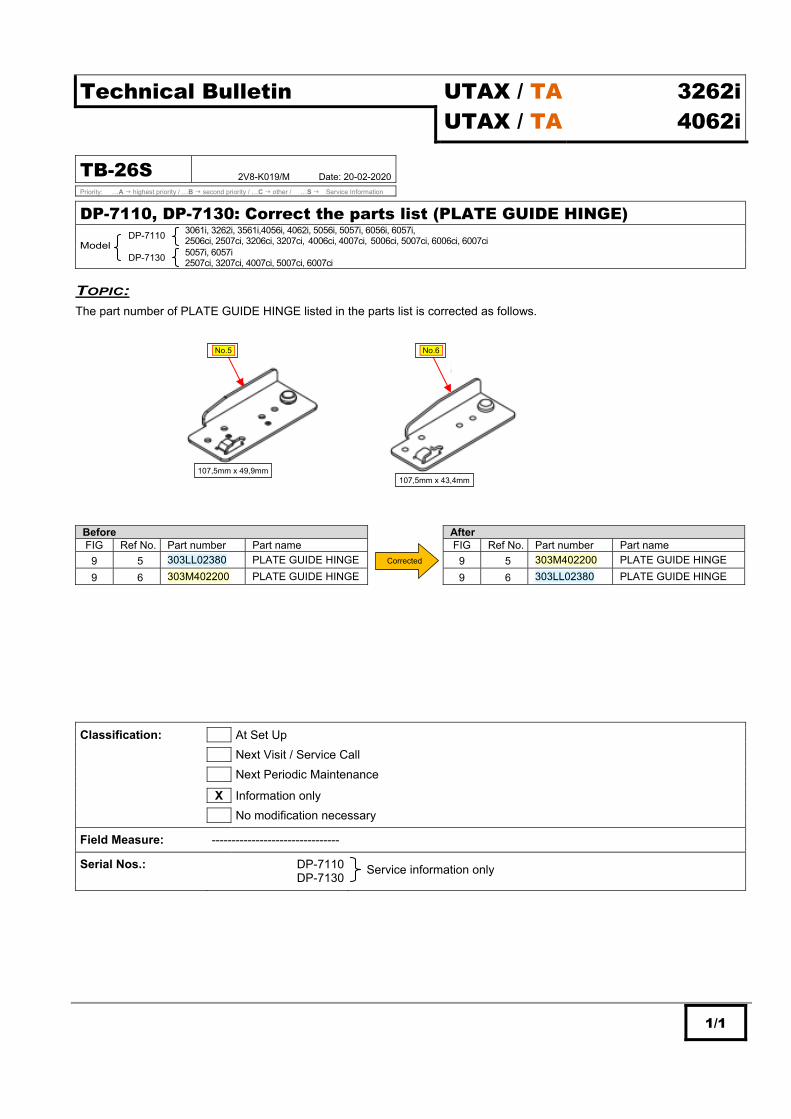
1/1
Technical Bulletin UTAX / TA UTAX / TA
3262i 4062i
TB-26S 2V8-K019/M Date: 20-02-2020
Priority: …A highest priority / …B second priority / …C other / …S Service Information
DP-7110, DP-7130: Correct the parts list (PLATE GUIDE HINGE)
Model
DP-7110
3061i, 3262i, 3561i,4056i, 4062i, 5056i, 5057i, 6056i, 6057i, 2506ci, 2507ci, 3206ci, 3207ci, 4006ci, 4007ci, 5006ci, 5007ci, 6006ci, 6007ci
DP-7130 5057i, 6057i
2507ci, 3207ci, 4007ci, 5007ci, 6007ci
TOPIC:
The part number of PLATE GUIDE HINGE listed in the parts list is corrected as follows.
Before After FIG Ref No. Part number Part name FIG Ref No. Part number Part name
9 5 303LL02380 PLATE GUIDE HINGE 9 5 303M402200 PLATE GUIDE HINGE
9 6 303M402200 PLATE GUIDE HINGE 9 6 303LL02380 PLATE GUIDE HINGE
Classification: At Set Up
Next Visit / Service Call
Next Periodic Maintenance
X Information only
No modification necessary
Field Measure: -------------------------------- Serial Nos.: DP-7110
DP-7130
107,5mm x 49,9mm 107,5mm x 43,4mm
No.5- No.6-
Corrected
Service information only

Confidential! For internal use by authorized Dealers only. Distribution or disclosure in full or in part to non-authorized third parties is prohibited. For authorized TA / UTAX technician only. Do not distribute to non-authorized parties 1/2
Technical Bulletin UTAX / TA UTAX / TA
3262i 4062i
TB-27S A3HM-19v6-J017/M Date: 19-03-2020
Priority: …A highest priority / …B second priority / …C other / …S Service Information
Change the DP separator pulley
Model: 6555i, 7056i, 7057i, 8055i, 8056i, 8057i, CD 1465, CD 1480 / DC 2465, DC 2480 6505ci, 7006ci, 7505ci, 8006ci, CDC 1965, CDC 1970 / DCC 2965, DCC 2970
DP-770 3060i, 3555i, 3560i, 4555i, 5555i, CD 1435, CD 1445, CD 1455 / DC 2435, DC 2445, DCC 2455
2500ci, 3005ci, 3505ci, 4505ci, 5505ci, CDC 1930, CDC 1935, CDC 1945, CDC 1950 / DCC 2930, DCC 2935, DCC 2945, DCC 2950
DP-770(B) 3060i, 3555i, 3560i, 4555i, 5555i, CD 1435, CD 1445, CD 1455 / DC 2435, DC 2445, DCC 2455
2500ci, 3005ci, 3505ci, 4505ci, 5505ci, CDC 1930, CDC 1935, CDC 1945, CDC 1950 / DCC 2930, DCC 2935, DCC 2945, DCC 2950
DP-771 CD 1445, CD 1455 / DC 2435, DC 2445, DCC 2455
CDC 1930, CDC 1935, CDC 1945, CDC 1950 / DCC 2930, DCC 2935, DCC 2945, DCC 2950
DP-772 3060i, 3555i, 3560i, 4555i, 5555i
2500ci, 3005ci, 3505ci, 4505ci, 5505ci
DP-7100 3061i, 3262i, 3561i, 4056i, 4062i, 5056i, 5057i, 6056i, 6057i
2506ci, 2507ci, 3206ci, 3207ci, 4006ci, 4007ci, 5006ci, 5007ci, 6006ci, 6007ci
DP-7110 3061i, 3262i, 3561i, 4056i, 4062i, 5056i, 5057i, 6056i, 6057i
2506ci, 2507ci, 3206ci, 3207ci, 4006ci, 4007ci, 5006ci, 5007ci, 6006ci, 6007ci
DP-7130 3061i, 3262i, 3561i, 4056i, 4062i
2506ci, 2507ci, 3206ci, 3207ci
TOPIC:
The external color of the DP separator pulley (No1) is changed for stabilizing the external appearance quality. The material and performance are equal between the new and old.
CONTENT OF CHANGE:
(Below shows DP-7100)
PARTS TABLE
No. Old Part No.
New Part No. Description Q’ty Compatibility Affected model
Remarks Old New Old New
1 303LL07190 303LL07191 PULLEY SEPARATION 1 1 O O
The part number for the DP UNIT SP (302NH9316_) at 7056i / 7057i / 8056i / 7006ci /8006ci / 8057i is unchanged at this change.
Before: After:
DP separator pulley (No.1)
NEW

Confidential! For internal use by authorized Dealers only. Distribution or disclosure in full or in part to non-authorized third parties is prohibited. For authorized TA / UTAX technician only. Do not distribute to non-authorized parties 2/2
Classification: At Set Up
Next Visit / Service Call
Next Periodic Maintenance
X Information only
X No modification necessary
Field Measure: ---------------------------- Serial Nos.: 6555i
7056i 7057i 8055i 8056i 8057i CD 1465 - DC 2465 CD 1480 - DC 2480 6505ci 7006ci 7505ci 8006ci CDC 1965 - DCC 2965 CDC 1970 - DCC 2970 DP-770 DP-770(B) DP-771 DP-772 DP-7100 DP-7110 DP-7130
After using up the old stock

Confidential! For internal use by authorized Dealers only. Distribution or disclosure in full or in part to non-authorized third parties is prohibited. For authorized TA / UTAX technician only. Do not distribute to non-authorized parties 1/3
Technical Bulletin UTAX / TA UTAX / TA
3262i 4062i
TB-28S COM-J151/M Date: 26-03-2020
Priority: …A highest priority / …B second priority / …C other / …S Service Information
Note when replacing the parts (Change the assist pulley / Assists pulley holder)
Model: 4555i, 5555i, 6555i, 7056i, 8055i, 8056i, CD 1445, CD 1455, CD 1465, CD 1480 / DC 2445, DC 2455, DC 2465, DC 2480 4505ci, 5505ci, 6505ci, 7006ci, 7505ci, 8006ci, CDC 1945, CDC 1950, CDC 1965, CDC 1970 / DCC 2945, DCC 2950, DCC 2965, DCC 2970 P-C4580DN, P-C5580DN
PF-730
3555i, 4555i, 5555i, 6555i, 7056i, 7057i, 8055i, 8056i, 8057i, CD 1435, CD 1445, CD 1455, CD 1465, CD 1480 / DC 2435, DC 2445, DCC 2455, CD 1465, CD 1480 3005ci, 3505ci, 4505ci, 5505ci, 6505ci, 7505ci, 7006ci, 8006ci, CDC 1930, CDC 1935, CDC 1945, CDC 1950, CDC 1965, CDC 1970 / DCC 2930, DCC 2935, DCC 2945, DCC 2950, DCC 2965, DCC 2970 P-C4580DN, P-C5580DN
PF-730(B)
3555i, 4555i, 5555i, 6555i, 7056i, 7057i, 8055i, 8056i, 8057i, CD 1435, CD 1445, CD 1455, CD 1465, CD 1480 / DC 2435, DC 2445, DCC 2455, CD 1465, CD 1480 3005ci, 3505ci, 4505ci, 5505ci, 6505ci, 7505ci, 7006ci, 8006ci, CDC 1930, CDC 1935, CDC 1945, CDC 1950, CDC 1965, CDC 1970 / DCC 2930, DCC 2935, DCC 2945, DCC 2950, DCC 2965, DCC 2970 P-C4580DN, P-C5580DN
PF-740
3555i, 4555i, 5555i, 6555i, 7056i, 7057i, 8055i, 8056i, 8057i, CD 1435, CD 1445, CD 1455, CD 1465, CD 1480 / DC 2435, DC 2445, DCC 2455, CD 1465, CD 1480 3005ci, 3505ci, 4505ci, 5505ci, 6505ci, 7505ci, 7006ci, 8006ci, CDC 1930, CDC 1935, CDC 1945, CDC 1950, CDC 1965, CDC 1970 / DCC 2930, DCC 2935, DCC 2945, DCC 2950, DCC 2965, DCC 2970 P-C4580DN, P-C5580DN
PF-740(B)
3555i, 4555i, 5555i, 6555i, 7056i, 7057i, 8055i, 8056i, 8057i, CD 1435, CD 1445, CD 1455, CD 1465, CD 1480 / DC 2435, DC 2445, DCC 2455, CD 1465, CD 1480 3005ci, 3505ci, 4505ci, 5505ci, 6505ci, 7505ci, 7006ci, 8006ci, CDC 1930, CDC 1935, CDC 1945, CDC 1950, CDC 1965, CDC 1970 / DCC 2930, DCC 2935, DCC 2945, DCC 2950, DCC 2965, DCC 2970 P-C4580DN, P-C5580DN
PF-780 6555i, 8055i,CD 1465, CD 1480 / DC 2465, DC 2480
4505ci, 5505ci, 6505ci, 7505ci, CDC 1945, CDC 1950, CDC1965, CDC 1970 / DCC 2945, DCC 2950, DCC 2965, DCC 2970 P-C4580DN, P-C5580DN
PF-810 3060i, 3061i, 3262i, 3560i, 3561i, 4062i,
2500ci
PF-7130 7056i, 7057i, 8056i, 8057i
7006ci, 8006ci
TOPIC:
The assist pulley (No.1) and assist pulley holder (No.2) at the primary feed section are changed to regulate the backlash. Accordingly, attention is required when replacing the parts and refers to “Field Measure” below. (Refer to the page 2 for content of change).
Primary feed unit viewed from the machine right side (Some parts are not shown)
Where to affix 4 spacers
(Machine rear side)
(Machine rear side)
Assist pulley No.1-
Assist pulley holder No.2-
X

Confidential! For internal use by authorized Dealers only. Distribution or disclosure in full or in part to non-authorized third parties is prohibited. For authorized TA / UTAX technician only. Do not distribute to non-authorized parties 2/3
CONTENT OF CHANGE:
Assist pulley (No.1)
Assist pulley holder (No.2, arrow view X)
PARTS TABLE
No. Old Part No.
New Part No. Description Q’ty Compatibility Affected model
Remarks Old New Old New
1 302F929260 302NH29260 PULLEY DU LOW 5(*1) 5(*1) X(*2) X(*2)
2 302K906700 302K906701 HOLDER PULLEY 1(*1) 1(*1) X(*2) X(*2)
*1: The above is the qty. used in the primary feed unit. Number of cassette varies by model/PF and so the total qty. varies. *2: Use the set of the old or new parts for replacement. If the old assist pulley holder cannot be procured for replacement in
the machine before change, replace the center assist pulley (No.1) and assist pulley holder (No.2) with the new ones. (The rest of 4 pulleys may remain the old parts.) If 4 spacers are inserted besides the center pulley, remove them.
(Refer to the previous page.) Note 2: The part codes of the primary feed units below remain unchanged at this change. (302N49402_, 302N29403_, 303NJ9411_, 302NH9425_, 303S09402_, 303PC9401_)
Before: 18mm After: 17,8+/-0,05mm
Before: 22,9mm After: 17,91mm
Add this shape

Confidential! For internal use by authorized Dealers only. Distribution or disclosure in full or in part to non-authorized third parties is prohibited. For authorized TA / UTAX technician only. Do not distribute to non-authorized parties 3/3
Classification: At Set Up
Next Visit / Service Call
Next Periodic Maintenance
X Information only
X No modification necessary
Field Measure: Use the set of old or new No.1, No.2 when replacing the parts since there is no physical compatibility. However, if the old assist pulley holder cannot be procured for replacement in the machine before change when the stock is used up, replace the center assist pulley (No.1, arrowed in the above figure) and assist pulley holder (No.2) with the new ones. (The rest of 4 pulleys may remain the old parts.) Then, if 4 spacers are inserted besides the center pulley, remove them. (Note 1) Note 1: As the temporary measure for the backlash, they are inserted in the primary feed unit since a part of July 2018 production.
Serial Nos.: 4555i No production now 5555i No production now 6555i No production now 7056i VU29400339 8055i No production now 8056i VU39400525 CD 1445 - DC 2445 No production now CD 1455 - DC 2455 No production now CD 1465 - DC 2465 No production now CD 1480 - DC 2480 No production now 4505ci No production now 5505ci No production now 6505ci No production now 7006ci VTX9400361 7505ci No production now 8006ci VTY9400193 CDC 1945 - DCC 2945 No production now CDC 1950 - DCC 2950 No production now CDC 1965 - DCC 2965 No production now CDC 1970 - DCC 2970 No production now P-C4580DN No production now P-C5580DN No production now PF-730 No production now PF-730(B) “99” of the 4th and 5th digit serial number applies this change PF-740 No production now PF-740(B) “99” of the 4th and 5th digit serial number applies this change PF-780 No production now PF-810 LUG9302157 PF-7130 “99” of the 4th and 5th digit serial number applies this change

Confidential! For internal use by authorized Dealers only. Distribution or disclosure in full or in part to non-authorized third parties is prohibited. For authorized TA / UTAX technician only. Do not distribute to non-authorized parties 1/3
Technical Bulletin UTAX / TA UTAX / TA
3262i 4062i
TB-29A 2V6-K029/M Date: 29-06-2020 Revised issue 1 Update serial number information
Priority: …A highest priority / …B second priority / …C other / …S Service Information
IEC 62368-1 New safety standards compliance
Model: 3062i, 4062i DP-7100, DP-7110, DP-7120
TOPIC:
As the compliance with the IEC 62368-1 new safety standards applied to the products launched in the market on December 20, 2020, the following are changed. Accordingly, refer to the below of the attention at parts replacement and regular maintenance. CONTENT OF CHANGE:
1.) Revise Safety Guide (Booklet) for Europe. Add “Alternating current” mark and comment, etc. (Refer to page 1). 2.) Change the DP hinge caution label (Note 1). Change the design of the DP hinge caution label (No.1) for the document processor. 3.) Revise Safety Guide (A3 leaflet) (Note 1) Revision according change 1 and other items (Refer to page 2).
Note on parts replacement and regular maintenance
Parts usable for replacement and regular maintenance (No.1 in Parts Table) differ depending on date of launch in the market. Before December 20, 2020: Both old and new parts are usable. (No need of distinction of the old and new) On and after December 20, 2020: Make sure to use the new part (Distinction of the old and new needed)
Change 1: Safety Guide for Europe (Booklet)] *Page 1, 5 below are extract from the English descriptions
Cover: New branding (Page 1 of each language: Add “Alternating current” mark and comment)
(Before)
(After : Addition)

Confidential! For internal use by authorized Dealers only. Distribution or disclosure in full or in part to non-authorized third parties is prohibited. For authorized TA / UTAX technician only. Do not distribute to non-authorized parties 2/3
Page 5 of each language: Delete unnecessary descriptions
Change 2: Change the DP hinge caution label (No.1) *Affixed to the document processor (DP-7100 / DP-7110 / DP-7120)
Change 3: Safety Guide (A3 leaflet) - The red frame area shows the additional caution on the high temperature section and sharp edge. (The expanded view is the illustration and English descriptions only) - The unnecessary content at this time is deleted and the current description rules are applied at this revision. - This Safety Guide exist by model and destination, and the content of change this time is equal.
Before: 1st side for MFP After: 1st side for MFP
Before: After: Change the design of the caution label
Delete unnecessary descriptions
[Description on the jam clearance label] (For MFP) (For Printer) (MFP/Printer common)

Confidential! For internal use by authorized Dealers only. Distribution or disclosure in full or in part to non-authorized third parties is prohibited. For authorized TA / UTAX technician only. Do not distribute to non-authorized parties 3/3
PARTS TABLE
No. Old Part No.
New Part No. Description Q’ty Compatibility Affected model
Remarks Old New Old New
1 303R834010 303R834011 LABEL CAUTION HINGE 1 1 *1 O *2
*1: Use the new parts for the product to be launched on and after December 20, 2020. *2: Only new parts are supplied after June 2020.
Classification: At Set Up
Next Visit / Service Call
Next Periodic Maintenance
X Information only
X No modification necessary
Field Measure: Note on parts replacement and regular maintenance
Parts usable for replacement and regular maintenance (No.1 in Parts Table) differ depending on date of launch in the market. Before December 20, 2020: Both old and new parts are usable. (No need of distinction of the old and new) On and after December 20, 2020: Make sure to use the new part (Distinction of the old and new needed)
Serial Nos.: 3262i R880406926 Change 1 Safety Guide (Booklet)
4062i R890404936
Serial Nos.: 3262i R888601882 Change 3 Safety Guide (A3 leaflet)
4062i R898601292
Serial Nos.: DP-7100 VGB8639321 Change 2 DP hinge caution label
DP-7100 VGC8510283 DP-7120 VGG8518389

Confidential! For internal use by authorized Dealers only. Distribution or disclosure in full or in part to non-authorized third parties is prohibited. For authorized TA / UTAX technician only. Do not distribute to non-authorized parties 1/3
Technical Bulletin UTAX / TA UTAX / TA
3262i 4062i
TB-30B 2V6-K068/M Date: 30-03-2020
Priority: …A highest priority / …B second priority / …C other / …S Service Information
Firmware Upgrade (V 1.08)
Model: 3062i, 4062i
TOPIC:
The firmware is upgraded as follows. CONTENT OF CHANGES:
- Original size selection when the original size is not detected. Original size might not be detected when recovering from the sleep mode by opening/closing the DP or platen cover, and the image might drop out or unintended copy is generated. Then, the treatment when original size is not detected is changed as follows.
Change: The following is implemented in the system menu to enable the size selection screen. System Menu Copy Original Size of Undetected Original -Use Default Source Size (default) -Use Size Selection Screen
- Corrective measures for system error F246. System error F246 might occur during scanning depending on original orientation.
- Corrective measures for the failure when placing the original on the table. When placing an original smaller than the regular size on the table just after power-up, the process to handle the undefined original size is improper and original size might not be displayed or output in the unexpected orientation even if the size selection screen is turned on.
- Correct Command Center. When pressing “Submit” button of “IP Filter Settings” and “Logical Printer” on the Command Center setting screen, the message to confirm the change is displayed even if not changing the setting.
- Corrective measures for system error F26F. System error F26F might occur if a large number of some internal events occurs and queues overflow when the communication session is shut off due to the network environmental factor, etc.
- Corrective measures for system error F515. The internal print data already deleted and not existing might be accessed and system error F515 might occur.
- Corrective measures for inability of user login. There might be inconsistency in the login/logout management and browser start-up management and user login might fail.
- Corrective measures for the original size setting failure when the original size is not detected. Size selection screen might not appear after recovering from sleep even if setting “Original Size of Undetected Original” to “Use Size Selection Screen” and it is now displayed.
- Corrective measures for system error F248. When printing the main system PCL data containing color information the print process might not complete due to the error in the color space information process and system error F248 might occur.
- Corrective measures for the ID card login failure. Login might fail due to the login information process error when attempting the ID card login while using multiple applications.
- Corrective measures for the failure in the i-FAX page of CCRX. There is no UI to select or input the authentication account to set the SMTP authentication in the i-FAX page of CCRX.
- Corrective measures for inability to receive FAX. When the HyPAS application requests logout, even if it is specified logout is not available at on-hook, logout might be processed at on-hook and FAX might not be received afterwards.
- Corrective measures for system error F245. The re-connection process error might occur and system error F245 might occur when the KFS connection and disconnection repeat.
- Corrective measures for texts not partially printed. A part of texts might be white or not printed due to the color space process error.
- Corrective measures for the original scan failure. Scan of the previous process might fail if cancelling scan.
- Corrective measures for the abnormal print. When processing the PCL print data in duplex, there is an error in the font orientation logic and a part of fonts at the beginning of the 2nd page of duplex print (1st side of output) might be rotated 90 degrees.
- Corrective measures for system error F485. When scanning in the high compression PDF (text priotized) from the HyPAS application (Fileforce linked application) using the ImageLog function, system error F485 might occur due to omission of this condition.
- Corrective measures for the duplex output failure. Duplex setting from the Linux OS might be printed in simplex.
- Corrective measures for the PostScript I/O error. 16-bit analysis function requested in the imaging process of the JPEG data contained in the PS print data is not implemented in the main unit, and PS (Post Script) I/O error might occur.
- Corrective measures for lock-up with a certain file. A certain file might not be printed with the [Processing] display.
- Corrective measures for the imaging failure. The image position and reduction ration might differ between real size and reduction or layout might corrupt when printing a certain file.

Confidential! For internal use by authorized Dealers only. Distribution or disclosure in full or in part to non-authorized third parties is prohibited. For authorized TA / UTAX technician only. Do not distribute to non-authorized parties 2/3
- Corrective measures for system error F248 / F46F. System error F248 / F46F might occur when printing a certain file.
- Corrective measures for the file damage. The file might be damaged when downloading the document from Custom Box by using the HCL.
- Corrective measures for system error F246. When executing the Scan to File job in the high compression PDF setting, the process to extract texts in the library might access out of image storage area depending on data, and system error F246 might occur.
- Corrective measures for the failure when executing Data Sanitization mode for the security data. "RP code" that should be in the backup data stored when executing Data Sanitization for the security data, is not backed up and all the "RP Code" values become "FFFF" on the service status page after executing above. (RP Code: Encrypted data of the firmware information last two of installed.)
- Corrective measures the failure when recovering from sleep mode. If a print job is directed when entering the sleep mode, the sleep recovery request comes right after and it might recover without shutting off 24V power.
- Scan operation improvement. There is unnecessary conditions to shift to the carriage return operation and carriage return become slow to worse the table scan performance.
FIRMWARE UPGRADE PACK
Type Model File Remarks
MAIN 3262i, 4062i 2V6_2000.001.603 NEW
MMI 3262i, 4062i 2V6_7000.001.603 NEW
PANEL MAIN 3262i, 4062i 2ND_7200.001.015
ENGINE 3262i, 4062i 2V6_1000.003.001 NEW
LANGUAGE MLT 3262i, 4062i 2V6_81XM.001.602 NEW
BROWSER 3262i, 4062i 2ND_F000.002.002
OCR 3262i, 4062i 2R6_L000.002.004
SCANNER 3262i, 4062i 2RH_1200.005.001 NEW
DICTIONARY MLT 3262i, 4062i 2ND_CA00.001.002
ESPECIAL 3262i, 4062i ES_SKIP.ON
DP-7100 3R7_9500.002.002
DP-7110 3R8_9500.006.001
DP-7120 3RJ_9500.002.002
PF-791 3N4_9000.004.001
Enhancement units PF-810 3PC_9000.002.004
DF-791 3NB_9200.024.002 DF-7120 3RW_9200.006.002
PH-7A/B/C/D 3NK_9A00.006.001
MT-730(B) 3N0_9800.004.001
FAX System 12 3R2_5400.003.012
When upgrading firmware or replacing board etc., please upgrade each firmware to the latest version at the same time. Download: 3262i, 4062i Firmware Upgrade Pack V 1.08

Confidential! For internal use by authorized Dealers only. Distribution or disclosure in full or in part to non-authorized third parties is prohibited. For authorized TA / UTAX technician only. Do not distribute to non-authorized parties 3/3
Classification: At Set Up
X Next Visit / Service Call
Next Periodic Maintenance
Information only
No modification necessary
Field Measure: Upgrade the firmware to the new version when the phenomenon occurs. Serial Nos.: 3262i
4062i
Planned in March 2020 production

Confidential! For internal use by authorized Dealers only. Distribution or disclosure in full or in part to non-authorized third parties is prohibited. For authorized TA / UTAX technician only. Do not distribute to non-authorized parties 1/2
Technical Bulletin UTAX / TA UTAX / TA
3262i 4062i
TB-31S COM-J183/M Date: 04-05-2020
Priority: …A highest priority / …B second priority / …C other / …S Service Information
Corrective measures for inability to receive FAX in Energy Saver Sleep mode
Model: 3061i, 3262i, 5057i, 6057i, 7057i, 8057i, 2507ci, 3207ci, 4007ci, 5007ci, 6007ci 7307ci, 8307ci
TOPIC:
Even if receiving FAX in Energy Saver Sleep mode, it might not be recovered and FAX reception might fail. This is depending on ringer pattern of each country.
Execute the field measure below when the phenomenon occurs. FIELD MEASURE:
Set Sleep mode to Quick Recovery. Execute 1) and 2) below for it.
Method 1: Set to Less Energy Save in U346 “Selecting Sleep Mode” Set U346 “Timer/Sleep Level” “Less Energy Save” Method 2: Set Sleep Level to Quick Recovery. Operation panel setting
Set “System Menu/Counter” key “Date/Timer/Energy Saver” “Sleep Level” “Quick Recovery” CCRX setting
“Administrator login” Device Settings “Energy Saver/Timer” “Sleep Level” “Quick Recovery”
*Changeable via KFS (Maintenance mode, device setting)
FUTURE ACTIONS:
The firmware of the applicable models is upgraded to receive FAX in Energy Saver Sleep mode. Plan: to implement in the middle of September to the end of October 2019 Possibility of occurrence of the phenomenon by model and country
Applicable model Country 3061i 3262i 5057i 6057i 7057i 8057i 2507ci 3207ci 4007ci 5007ci 6007ci 7307ci 8307ci Czech O O O O O O X X O O O O O Denmark X X X X X X X X X X X X X Finland O O O O O O X X O O O O O France O O O O O O X X O O O O O Germany O O O O O O X X O O O O O Greece O O O O O O X X O O O O O Hungary O O O O O O X X O O O O O Italy O O O O O O X X O O O O O Netherlands O O O O O O X X O O O O O Norway O O O O O O X X O O O O O Poland O O O O O O X X O O O O O Portugal O O O O X X X X O O O X X Slovakia O O O O O O X X O O O O O Sweden O O O O X X X X O O O X X Switzerland O O O O O O X X O O O O O
X: Possibility of occurrence of the phenomenon: Yes O: Possibility of occurrence of the phenomenon: No
(Only applicable countries are listed)

Confidential! For internal use by authorized Dealers only. Distribution or disclosure in full or in part to non-authorized third parties is prohibited. For authorized TA / UTAX technician only. Do not distribute to non-authorized parties 2/2
Classification: At Set Up
Next Visit / Service Call
Next Periodic Maintenance
X Information only
No modification necessary
Field Measure: ---------------------------- Serial Nos.: 3061ic
3262ic 5057ic 6057ic 7057ic 8057ic 2507ci 3207ci 4007ci 5007ci 6007ci 7307ci 8307ci
Service information only

Confidential! For internal use by authorized Dealers only. Distribution or disclosure in full or in part to non-authorized third parties is prohibited. For authorized TA / UTAX technician only. Do not distribute to non-authorized parties 1/2
Technical Bulletin UTAX / TA UTAX / TA
3262i 4062i
TB-32S COM-K122/M Date: 10-06-2020
Priority: …A highest priority / …B second priority / …C other / …S Service Information
J050x non-feed jam with paper dust adhering to the feed roller and retard roller
Model: 256i, 306i / 3060i, 3560i / 3061i, 3561i / 3262i, 4062i / P-2540iMFP / CD 5025, CD 5025P, CD 5030 / DC 6025, DC 6025P, DC 6030 206ci, 256ci / 2500ci, 2550ci / P-C2480iMFP / CDC 5520, CDC 5525 / DCC 6520, DCC6525
PF-470 256i, 306i / P-2540iMFP/ CD 5025, CD 5025P, CD 5030 / DC 6025, DC 6025P, DC 6030
206ci, 256ci / P-C2480iMFP / CDC 5520, CDC 5525 / DCC 6520, DCC6525
PF-471 256i, 306i / P-2540iMFP / CD 5025, CD 5025P, CD 5030 / DC 6025, DC 6025P, DC 6030
206ci, 256ci / P-C2480iMFP / CDC 5520, CDC 5525 / DCC 6520, DCC6525 PF-790 2550ci
PF-791 3060i, 3560i / 3061i, 3561i / 3262i, 4062i
2500ci
TOPIC:
Paper dust might adhere to the feed roller and retard roller depending on paper, and paper might slip when fed to cause the non-feed jam (*). The material of the feed roller and retard roller is changed from “EPDM” to “Urethane” as the corrective measure and parts for field measure (No.1 - No.3) are set up. Refer to “Note on use of the roller for field measure” below when using the above parts for corrective measures.
*Jam0501 / Jam0502 / Jam0503 / Jam0504 Non-feed jam from cassette 1-4 Note on use of the roller for field measure
If using the feed roller and retard roller for field measure, paper feed failure might occur in use of thick paper at normal temperature or paper conveying performance might be degraded at low temperature regardless of media type. Select the feed roller and retard roller according to the usage.
PARTS TABLE
No. Old Part No.
New Part No. Description Q’ty Compatibility Affected model
Remarks Old New Old New
1 ---------- 302V694150 PARTS ROLLER SET SP - 1 - O *1
(Set of No.2,3)
2 ---------- 302V694130 +PARTS ROLLER FEED ASSY SP - 1 - X*2 *1
(Feed roller)
3 ---------- 302V694140 +PARTS ROLLER RETARD ASSY SP - 1 - X*2 *1
(Retard roller)
"+" mark at the beginning of the part name means it is a component parts. *1: For field measure (For service only)
No.2 standard item: PULLEY FEED ASSY (302F90623_) / No.3 standard: RETARD ROLLER ASSY (302F90917_) *2: Use new No.2, No.3 when replacing the parts.
Identification of the rollers (The figure below is the feed roller).
Standard EPDM: Black
Field measure Urethane: Orange

Confidential! For internal use by authorized Dealers only. Distribution or disclosure in full or in part to non-authorized third parties is prohibited. For authorized TA / UTAX technician only. Do not distribute to non-authorized parties 2/2
Classification: At Set Up
Next Visit / Service Call
Next Periodic Maintenance
X Information only
X No modification necessary
Field Measure: Replace with the roller set (No.1) for field measure if necessary while noting the above. Use the roller set for field measure due to the incompatibility in functionality if individually replaced. (Do not mix up the standard roller and for field measure.)
Serial Nos.: 256i 306i 3060i 3061i 3262i 3560i 3561i 4062i P-2540iMFP CD 5025P - DC 6025P CD 5025P - DC 6025P CD 5030P - DC 6030P 206ci 256ci 2500ci 2550ci P-C2480iMFP CDC 5520 - DCC 6520 CDC 5525 - DCC 6525 PF-470 PF-471 PF-790 PF-791
Service information only

Confidential! For internal use by authorized Dealers only. Distribution or disclosure in full or in part to non-authorized third parties is prohibited. For authorized TA / UTAX technician only. Do not distribute to non-authorized parties 1/2
Technical Bulletin UTAX / TA UTAX / TA
3262i 4062i
TB-33C 2MV-K106/M Date: 11-06-2020
Priority: …A highest priority / …B second priority / …C other / …S Service Information
PF-791: Abnormal sound from the primary feed section or no-feed jam Model: 3060i, 3560i / 3061i, 3561i
2500ci, 2550ci PF-790 2550ci
PF-791 3060i, 3560i / 3061i, 3561i / 3262i, 4062i
2500ci
TOPIC:
The abnormal beep sound from the primary feed section was informed per service bulletin PF-790 TB-01 (Date 22-10-2013), but the corrective measures are not sufficient, and it is turned to be the concern of paper feed performance degraded. Therefore, it is back to the state before change. Change history of the primary feed unit
302MV94060 302MV94061 (Note 3)
No Content No corrective
measures (Note 2) Corrective measures (Note 2)
This change
1 Screw to metal plate 4 points 2 points 4 points
2 Sponge 0 2 pcs 0
3 Seal 0 2 sheets 0
Note 2: Corrective measures last time --- Change as informed per service bulletin PF-790 TB-01 Note 3: Part number of primary feed unit for service (302MV9406_) remains unchanged at this change.
It is recommended to replace the primary feed roller as the field measure when this phenomenon occurs. Therefore, the bundled item kit and individual roller below are set up as service parts for PF-791 and PF-790. (Already set up as service parts for the main unit)
Primary feed unit
Frame
Disuse 2 sponges affixed to the back side (frame side of the metal plate)
Disuse the sheet (2 pcs) and go back to securing with 4 screws.
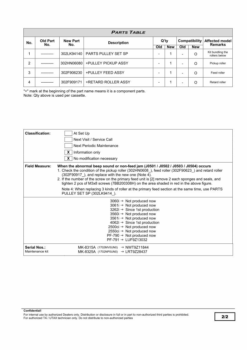
Confidential! For internal use by authorized Dealers only. Distribution or disclosure in full or in part to non-authorized third parties is prohibited. For authorized TA / UTAX technician only. Do not distribute to non-authorized parties 2/2
PARTS TABLE
No. Old Part No.
New Part No. Description Q’ty Compatibility Affected model
Remarks Old New Old New
1 ---------- 302LK94140 PARTS PULLEY SET SP - 1 - O Kit bundling the
rollers below
2 ---------- 302HN06080 +PULLEY PICKUP ASSY - 1 - O Pickup roller
3 ---------- 302F906230 +PULLEY FEED ASSY - 1 - O Feed roller
4 ---------- 302F909171 +RETARD ROLLER ASSY - 1 - O Retard roller
"+" mark at the beginning of the part name means it is a component parts. Note: Qty above is used per cassette.
Classification: At Set Up
Next Visit / Service Call
Next Periodic Maintenance
X Information only
X No modification necessary
Field Measure: When the abnormal beep sound or non-feed jam (J0501 / J0502 / J0503 / J0504) occurs 1. Check the condition of the pickup roller (302HN0608_), feed roller (302F90623_) and retard roller (302F90917_), and replace with the new one (Note 4). 2. If the number of the screw on the primary feed unit is [2] remove 2 each sponges and seals, and tighten 2 pcs of M3x8 screws (7BB200308H) on the area shaded in red in the above figure.
Note 4: When replacing 3 kinds of roller at the primary feed section at the same time, use PARTS PULLEY SET SP (302LK9414_).
3060i Not produced now 3061i Not produced now 3262i Since 1st production 3560i Not produced now 3561i Not produced now 4062i Since 1st production 2500ci Not produced now 2550ci Not produced now PF-790 Not produced now PF-791 LUF9Z13032
Serial Nos.: MK-8315A (1702MV0UN0) NWT9Z11844 Maintenance kit MK-8325A (1702NP0UN0) LRT9Z28437

Confidential! For internal use by authorized Dealers only. Distribution or disclosure in full or in part to non-authorized third parties is prohibited. For authorized TA / UTAX technician only. Do not distribute to non-authorized parties 1/2
Technical Bulletin UTAX / TA UTAX / TA
3262i 4062i
TB-34S 2V8-K138/M Date: 10-07-2020
Priority: …A highest priority / …B second priority / …C other / …S Service Information
DP-7100: Motion failure of the DP exit actuator (J9210 / J9410 / J9610)
Model: DP-7100 2506ci, 3206ci, 4006ci, 5006ci, 6006ci / 2507ci, 3207ci, 4007ci, 5007ci, 6007ci
3061i, 3561i / 3262i, 4062i / 4056i, 5056i, 6056i / 5057i, 6057i
TOPIC:
The cushion at the exit actuator might be sticky as change over time. As a result, the exit actuator motion might be dull and jam (*) might occur, and the following is changed.
*JAM9210 DP registration sensor stay jam JAM9410 DP timing sensor stay jam JAM9610 DP exit sensor stay jam
CONTENT OF CHANGE:
The cushion (No.1) is disused since it is confirmed there is no problem in functionality.
PARTS TABLE
No. Old Part No.
New Part No. Description Q’ty Compatibility Affected model
Remarks Old New Old New
1 303LJ02260 ---------- CUSHION GUIDE 1 - X - disused
*The part number of PARTS HOUSING CONVEYING ASSY SP(303R79413_) remains unchanged at this change.
Machine front side
DP-7100
Exit actuator (303R72408_) Guide (303R72401_)
Cushion No.1-

Confidential! For internal use by authorized Dealers only. Distribution or disclosure in full or in part to non-authorized third parties is prohibited. For authorized TA / UTAX technician only. Do not distribute to non-authorized parties 2/2
Classification: At Set Up
X Next Visit / Service Call
Next Periodic Maintenance
Information only
No modification necessary
Field Measure: Detach the cushion (No.1) when the phenomenon occurs. Serial Nos.: DF-7100 “07” or more of the 4th and 5th digit serial number*
*July 2020 production or later applies this change.

Confidential! For internal use by authorized Dealers only. Distribution or disclosure in full or in part to non-authorized third parties is prohibited. For authorized TA / UTAX technician only. Do not distribute to non-authorized parties 1/3
Technical Bulletin UTAX / TA UTAX / TA
3262i 4062i
TB-35S 2V8-K153/M Date: 15-07-2020
Priority: …A highest priority / …B second priority / …C other / …S Service Information
DP-7120: Measures for the DP frame damage (Service parts support only) Model: DP-7120
2506ci, 3206ci / 2507ci, 3207ci 3061i,3561i / 3262i, 4062i
TOPIC:
If setting a thick book original and pressing the DP with an excess force, the DP frame (left hinge) might be broken. Then, the following set item (No.1) is set up for field measure. In case the DP frame is broken, jam J9000 / J9001 (*) might occur.
*J9000: DP no feed jamJ9001: DP conveying jam.
COMPONENTS OF THE DP FRAME FOR FIELD MEASURE (NO.1):
The figure below is Fig.2 of the parts list (Rev. C).
3 parts below are bundled and the other are assembled with the DP frame (Ref.43).
Ref.1 : SHEET LEFT GUIDE F (303M82417_) Ref.2 : SHEET LEFT GUIDE R (303M82418_) Ref.45 : FILM READING LEFT (303PH0202_)
No.1-
Ref.1
Ref.2
Ref.45

Confidential! For internal use by authorized Dealers only. Distribution or disclosure in full or in part to non-authorized third parties is prohibited. For authorized TA / UTAX technician only. Do not distribute to non-authorized parties 2/3
ALIGNMENT FOR THE SHEET AND FILM BUNDLED:
*Clean the surface to affix.
PARTS TABLE
No. Old Part No.
New Part No. Description Q’ty Compatibility Affected model
Remarks Old New Old New
1 ---------- 303RJ94020 PARTS BASE ASSY SP(7120) - 1 - O Service parts for
field mesure
Ref.45: FILM READING LEFT (303PH0202_)
*Affix on Ref.1,2 equally by about 18mm length each.
Ref.2: SHEET LEFT GUIDE R(303M82418_)
183,5mm
15,2mm 18,8mm
121,8mm
15,4mm 18,8mm
Ref.1: SHEET LEFT GUIDE F (303M82417_)
About 18mm 0mm
40mm
11,5mm
0.5mm
0mm
0mm
0.5mm
0.5mm
0mm
*Affix along with the marking-off line and press firmly.
Ref.2
Ref.1
Frame Ref.43
(View from X in the figure left )
X
Ref.1
Ref.45
Ref.2
Frame Ref.43
Ref.45
0mm
1mm
Ref.45
Affix it on the frame partly (Ref.43)
About 18mm
About 18mm

Confidential! For internal use by authorized Dealers only. Distribution or disclosure in full or in part to non-authorized third parties is prohibited. For authorized TA / UTAX technician only. Do not distribute to non-authorized parties 3/3
Classification: At Set Up
Next Visit / Service Call
Next Periodic Maintenance
X Information only
X No modification necessary
Field Measure: Replace with the set parts (No.1) when the above phenomenon occurs. (Refer to the next page for alignment for affixing the sheet and film bundled.)
Serial Nos.: DP-7120
This is for service parts only and no affected serial number information.

Confidential! For internal use by authorized Dealers only. Distribution or disclosure in full or in part to non-authorized third parties is prohibited. For authorized TA / UTAX technician only. Do not distribute to non-authorized parties 1/2
Technical Bulletin UTAX / TA UTAX / TA
3262i 4062i
TB-36B 2V6-K158/M Date: 16-07-2020
Priority: …A highest priority / …B second priority / …C other / …S Service Information
Firmware Upgrade (V 1.09)
Model: 3062i, 4062i
TOPIC:
The firmware is upgraded as follows. CONTENT OF CHANGES:
- Corrective measures for the error with TWAIN driver. An error might occur when scanning from TWAIN driver.
- Corrective measures for the unnecessary page output with a certain data. An extra page might be output at the 1st page when printing a certain data.
- Corrective measures for system error F345 / F336 / F4F6. When sending the audit log while SMTP is not properly set up, the send might not successful and generating the audit log informtion continues. Then, system error F345 / F336 / F4F6 might occur with memory shortage.
- libTIFF upgrade. The version of the open source document (libTIFF) used in the device is old and the CVE reference No. below apply. Then, it is upgraded. (Change from VER3.7.4 to 4.0.10) - (CVE-2016-6223 / CVE-2015-8870 / CVE-2013-4243 / CVE-2012-5581)
- Corrective measures for the Wi-Fi vulnerability. The vulnerability of the Broadcom and Cypress Wi-Fi chip is resolved. (CVE-2019-15126)
- Resolve KFS offline issue. Offline occurring during the communication of the communication module (TCM Library) is resolved.
FIRMWARE UPGRADE PACK
Type Model File Remarks
MAIN 3262i, 4062i 2V6_2000.001.702 NEW
MMI 3262i, 4062i 2V6_7000.001.603
PANEL MAIN 3262i, 4062i 2ND_7200.001.015
ENGINE 3262i, 4062i 2V6_1000.003.001
LANGUAGE MLT 3262i, 4062i 2V6_81XM.001.602
BROWSER 3262i, 4062i 2ND_F000.002.002
OCR 3262i, 4062i 2R6_L000.002.004
SCANNER 3262i, 4062i 2RH_1200.005.001
DICTIONARY MLT 3262i, 4062i 2ND_CA00.001.002
ESPECIAL 3262i, 4062i ES_SKIP.ON
DP-7100 3R7_9500.002.002
DP-7110 3R8_9500.006.001
DP-7120 3RJ_9500.002.002
PF-791 3N4_9000.004.001
Enhancement units PF-810 3PC_9000.002.004
DF-791 3NB_9200.024.002 DF-7120 3RW_9200.006.002
PH-7A/B/C/D 3NK_9A00.006.001
MT-730(B) 3N0_9800.004.001
FAX System 12 3R2_5400.003.012
When upgrading firmware or replacing board etc., please upgrade each firmware to the latest version at the same time.

Confidential! For internal use by authorized Dealers only. Distribution or disclosure in full or in part to non-authorized third parties is prohibited. For authorized TA / UTAX technician only. Do not distribute to non-authorized parties 2/2
Download: 3262i, 4062i Firmware Upgrade Pack V 1.09
Classification: At Set Up
X Next Visit / Service Call
Next Periodic Maintenance
Information only
No modification necessary
Field Measure: Upgrade the firmware to the new version when the phenomenon occurs. Serial Nos.: 3262i
4062i
Planned in July 2020 production

Confidential! For internal use by authorized Dealers only. Distribution or disclosure in full or in part to non-authorized third parties is prohibited. For authorized TA / UTAX technician only. Do not distribute to non-authorized parties 1/4
Technical Bulletin UTAX / TA UTAX / TA
3262i 4062i
TB-37S 2ND-K240/M Date: 12-11-2020
Priority: …A highest priority / …B second priority / …C other / …S Service Information
DP-7100: DP actuator return failure at the original feed section
Model: DP-7100 2506ci, 3206ci, 4006ci, 5006ci, 6006ci / 2507ci, 3207ci, 4007ci, 5007ci, 6007ci
3061i, 3561i / 3262i, 4062i / 4056i, 5056i, 6056i / 5057i, 6057i
TOPIC:
The actuator [A] might fail to return just after setup and the original length detection might fail due to the static electricity (*) accumulated at the DP section during transportation. When the above phenomenon occurs, once detach the actuator [A] to discharge the static and reattach it. Refer to the procedure in the next page. *The static electricity might accumulate at the actuator depending on (1) the packing condition in transit or (2) state of component packing and assembly work at production. Regarding factor (2) at production, the discharging process is introduced to eliminate the static from the actuator [A] since August 2020 production. Refer to page 4 for the affected serial number.
Length detection actuator [A] at the DP original feed section
X
[A]
A
A
Lower cover
If the static electricity accumulates on the cover, etc., the actuator might stick to the lower cover and fail to return.
Normal
A
Phenomenon occurred
Viewed from X in the figure above
Viewed from X in the figure above
Actuator does not return with static electricity and remains sinking.

Confidential! For internal use by authorized Dealers only. Distribution or disclosure in full or in part to non-authorized third parties is prohibited. For authorized TA / UTAX technician only. Do not distribute to non-authorized parties 2/4
PROCEDURES TO REATTACH THE ACTUATOR:
1) Open the DP top cover (b) of the document processor (a).
2) Remove the screw (a) (M3×8) and detach the DP rear left
cover (b).
3) Open the lid (a) and detach the DP rear middle cover (b).
4) Remove the screw (a) (M3×8) and detach the DP rear right
cover (b).
a b
b
a
b
a
b
a

Confidential! For internal use by authorized Dealers only. Distribution or disclosure in full or in part to non-authorized third parties is prohibited. For authorized TA / UTAX technician only. Do not distribute to non-authorized parties 3/4
5) Disconnect the connector (a).
6) Remove 2 screws (a) (M3×8 BLACK TP) and detach the DP
front cover (b).
7) Detach the DP original tray (a).
a
X
b
b
Viewed from X
a

Confidential! For internal use by authorized Dealers only. Distribution or disclosure in full or in part to non-authorized third parties is prohibited. For authorized TA / UTAX technician only. Do not distribute to non-authorized parties 4/4
8) Remove 4 screws (a) (M3×8 BLACK TP) and detach the lower cover (c) of the DP original tray (b).
9) Detach the actuator (a) and reattach it.
10) Reattach the parts detached in the reverse procedure.
Classification: X At Set Up
Next Visit / Service Call
Next Periodic Maintenance
X Information only
No modification necessary
Field Measure: Reattach the actuator. Serial Nos.: DF-7100 VGB08A6152
a
b
c
a
Unlatch 4 hooks

Confidential! For internal use by authorized Dealers only. Distribution or disclosure in full or in part to non-authorized third parties is prohibited. For authorized TA / UTAX technician only. Do not distribute to non-authorized parties 1/2
Technical Bulletin UTAX / TA UTAX / TA
3262i 4062i
TB-38C 2ND-K264/M Date: 06-01-2021
Priority: …A highest priority / …B second priority / …C other / …S Service Information
DP-7110, DP-7130: Note on replacing the parts (Change the DP drive motor assy)
Model
DP-7110
3061i, 3561i / 3262i, 4062i / 4056i, 5056i, 5056 / 5057i, 6057i, 2506ci, 3206ci, 4006ci, 5006ci, 6006ci, / 2507ci, 3207ci, 4007ci, 5007ci, 6007ci
DP-7130 5057i, 6057i
2507ci, 3207ci, 4007ci, 5007ci, 6007ci
TOPIC:
The following are changed to regulate the pitch between the motor gear shaft and idle gear shaft in the DP drive section. An attention is required at this change and refers to “Field Measure” column.
CONTENT OF CHANGE:
1.) The positioning hole on the mounting plate (No.3) for the motor is enlarged and the assembly of the motor is changed by using a jig.
2.) Supply of the individual part (No.2 - No.4) is discontinued and changed to the assembly (No.1) at the above change.
Replacement parts form
No replacement of the individual part
Machine rear side
Make sure to replace the assembly (No.1)
DP unit
Applied motor
Gear No.4- Mounting plate No.3-
Motor No.2-
NEW

Confidential! For internal use by authorized Dealers only. Distribution or disclosure in full or in part to non-authorized third parties is prohibited. For authorized TA / UTAX technician only. Do not distribute to non-authorized parties 2/2
DETAILS OF CHANGE:
Change the size of the positioning hole for the motor.
PARTS TABLE
No. Old Part No.
New Part No. Description Q’ty Compatibility Affected model
Remarks Old New Old New
1 ---------- 303R894060 PARTS EJECT DRIVE ASSY OP SP - 1 - O Assembly of No.2 - No.4
2 302KY94071 ---------- PARTS MOTOR DU SP - - - - *1
3 303M431200 ---------- MOUNT LOOP DRIVE - - - - *1
4 303M431440 ---------- GEAR EXIT Z43 Z20 - - - - *1
*1: Change from supply of the individual part (No.2-4) to the assembly (No.1).
Classification: At Set Up
Next Visit / Service Call
Next Periodic Maintenance
X Information only
No modification necessary
Field Measure: Make sure to use the assembly (No.1) when replacing. If replacing the motor only with the positioning hole enlarged, the motor mounting position shifts and there might be possibility of gear teeth step-out or large drive sound.
Serial Nos.: DF-7110 VGC08A2614 DF-7130 RGW08A0143
Hole enlarged Diameter: 3,5mm 4,3mm
Hole enlarged Diameter: 3,5mm 4,3mm
Hole enlarged Diameter: 22,04mm 23,10mm

Confidential! For internal use by authorized Dealers only. Distribution or disclosure in full or in part to non-authorized third parties is prohibited. For authorized TA / UTAX technician only. Do not distribute to non-authorized parties 1/2
Technical Bulletin UTAX / TA UTAX / TA
3262i 4062i
TB-39C A3HM-L022v01/M Date: 08-02-2021
Priority: …A highest priority / …B second priority / …C other / …S Service Information
DP-7110, DP-7130: Part number information (DP feed roller assembly)
Model
DP-7110
3061i, 3561i / 3262i, 4062i / 4056i, 5056i, 5056 / 5057i, 6057i, 2506ci, 3206ci, 4006ci, 5006ci, 6006ci, / 2507ci, 3207ci, 4007ci, 5007ci, 6007ci
DP-7130 5057i, 6057i
2507ci, 3207ci, 4007ci, 5007ci, 6007ci
TOPIC:
The DP feed roller assembly (No.1) is set up as a service part.
PARTS TABLE
No. Old Part No.
New Part No. Description Q’ty Compatibility Affected model
Remarks Old New Old New
1 ---------- 303R894080 PARTS PAPER FEED ROLLER ASSY - 1 - O DP feed roller
assembly
Machine front side
The parts lists below list use of 5MVL177DN002 (2 pcs) in Ref.60 but it is correct use of 2BC06910(1 pc). (Use of 1 pc in Ref.60 above) DP-7110: FIG.6 of parts list Rev.5 DP-7130: FIG.6 of parts list Rev.D
DP feed roller assembly (No.1)
The figure below is FIG. 6 Paper Feed Section 2 of DP-7110 (same location for DP-7130)
FIG. 6 Paper Feed Section 2
DP feed roller assembly No.1-

Confidential! For internal use by authorized Dealers only. Distribution or disclosure in full or in part to non-authorized third parties is prohibited. For authorized TA / UTAX technician only. Do not distribute to non-authorized parties 2/2
Classification: At Set Up
Next Visit / Service Call
Next Periodic Maintenance
X Information only
No modification necessary
Field Measure: -------------------------- Serial Nos.: DF-7110
This is service parts information only without affected serial number DF-7130

Confidential! For internal use by authorized Dealers only. Distribution or disclosure in full or in part to non-authorized third parties is prohibited. For authorized TA / UTAX technician only. Do not distribute to non-authorized parties 1/2
Technical Bulletin UTAX / TA UTAX / TA
3262i 4062i
TB-40B 2V6-L110/M Date: 12-07-2021
Priority: …A highest priority / …B second priority / …C other / …S Service Information
Firmware Upgrade (V 1.10)
Model: 3062i, 4062i / DP-7110
TOPIC:
The firmware is upgraded as follows. CONTENT OF CHANGES:
- DP-7110 FW: Support of change of the AFE device. Since it is difficult to procure the AFE device, it is changed to the alternative. Accordingly, the firmware is upgraded since it is necessary to change the communication process and control. *This is the firmware upgrade for change of the control PWB (SHD PWB). When replacing the PWB, it is necessary to upgrade the firmware. The detail follows per another Technical Bulletin.
- DP-7110 FW: Support of change of the AFE device (II). Service call C3310 (CIS AGC error) might occur. (This is for the internal count only and not displayed on the operation panel.)
FIRMWARE UPGRADE PACK
Type Model File Remarks
MAIN 3262i, 4062i 2V6_2000.001.702
MMI 3262i, 4062i 2V6_7000.001.603
PANEL MAIN 3262i, 4062i 2ND_7200.001.015
ENGINE 3262i, 4062i 2V6_1000.003.001
LANGUAGE MLT 3262i, 4062i 2V6_81XM.001.602
BROWSER 3262i, 4062i 2ND_F000.002.002
OCR 3262i, 4062i 2R6_L000.002.004
SCANNER 3262i, 4062i 2RH_1200.005.001
DICTIONARY MLT 3262i, 4062i 2ND_CA00.001.002
ESPECIAL 3262i, 4062i ES_SKIP.ON
DP-7100 3R7_9500.002.002
DP-7110 3R8_9500.007.202 NEW
DP-7120 3RJ_9500.002.002
PF-791 3N4_9000.004.001
Enhancement units PF-810 3PC_9000.002.004
DF-791 3NB_9200.024.002 DF-7120 3RW_9200.006.002
PH-7A/B/C/D 3NK_9A00.006.001
MT-730(B) 3N0_9800.004.001
FAX System 12 3R2_5400.003.012
When upgrading firmware or replacing board etc., please upgrade each firmware to the latest version at the same time. Download: 3262i, 4062i Firmware Upgrade Pack V 1.10

Confidential! For internal use by authorized Dealers only. Distribution or disclosure in full or in part to non-authorized third parties is prohibited. For authorized TA / UTAX technician only. Do not distribute to non-authorized parties 2/2
Classification: At Set Up
Next Visit / Service Call
Next Periodic Maintenance
X Information only
No modification necessary
Field Measure: Upgrade the firmware to the new version when the phenomenon occurs. When using the new SHD PWB (303R894021), check the DP firmware version. If older than 3R8_9500.007.202, upgrade the firmware to the latest version before replacing the SHD PWB. The detail is informed per another Technical Bulletin.
Serial Nos.: 3262i 4062i
Planned in June 2021 production

Confidential! For internal use by authorized Dealers only. Distribution or disclosure in full or in part to non-authorized third parties is prohibited. For authorized TA / UTAX technician only. Do not distribute to non-authorized parties 1/4
Technical Bulletin UTAX / TA UTAX / TA
3262i 4062i
TB-41C 2V6-L103/M Date: 20-07-2021
Priority: …A highest priority / …B second priority / …C other / …S Service Information
DP-7110: Note on replacing the parts (Change SHD PWB / DP PWB) Model:3061i, 3561i / 3262i, 4062i / DP-7110
TOPIC:
The following are changed for the part procurement reason. An attention is required when replacing the parts at this change and refer to “Field Measure” below. A caution leaflet is bundled in the new part No.1 at this change.
CONTENT OF CHANGES:
1.) SHD PWB (No.1) Change SHD PWB -Change the vendor of the AFE device -Change the vendor of the linear regulator and output current from 1A to 1.5A 2.) DP PWB (No.2) Firmware upgrade -Firmware upgrade at change 1 (Related Technical Bulletin 3061i, 3561i TB-47B / 3262i, 4062i TB-40B)
IDENTIFICATION OF THE OLD AND NEW:
SHD PWB (No.1)
Front side of PWB
Before
Front side of PWB
After
NEW

Confidential! For internal use by authorized Dealers only. Distribution or disclosure in full or in part to non-authorized third parties is prohibited. For authorized TA / UTAX technician only. Do not distribute to non-authorized parties 2/4
FIRMWARE UPGRADE:
3061i, 3561i
FIRMWARE UPGRADE PACK
Type Model File Remarks
MAIN 3061i, 3561i 2RH_2000.004.302
MMI 3061i, 3561i 2ND_7000.004.128
PANEL 3061i, 3561i 2ND_7200.001.015
ENGINE 3061i, 3561i 2RH_1000.004.001
LANGUAGE MP 3061i, 3561i 2ND_81XM.004.013
BROWSER 3061i, 3561i 2ND_F000.002.002
OCR 3061i, 3561i 2R6_L000.002.004
SCANNER 3061i, 3561i 2RH_1200.005.001
DICTIONARY MLT 3061i, 3561i 2ND_CA00.001.002
ESPECIAL 3061i, 3561i ES_SKIP.ON
DP-7100 3R7_9500.002.002
DP-7110 3R8_9500.007.202 NEW
DP-7120 3RJ_9500.002.002
PF-791 3N4_9000.004.001
Enhancement units PF-810 3PC_9000.002.004
DF-791 3NB_9200.024.002
DF-7120 3RW_9200.006.002
PH-7A/B/C/D 3NK_9A00.006.001
MT-730(B) 3N0_9800.004.001
FAX System 12 3R2_5400.003.012
When upgrading firmware or replacing board etc., please upgrade each firmware to the latest version at the same time Download: 3061i, 3561i Firmware Upgrade Pack V 4.05
Back side of PWB
Before
NEW
After
Back side of PWB

Confidential! For internal use by authorized Dealers only. Distribution or disclosure in full or in part to non-authorized third parties is prohibited. For authorized TA / UTAX technician only. Do not distribute to non-authorized parties 3/4
3262i, 4062i
FIRMWARE UPGRADE PACK
Type Model File Remarks
MAIN 3262i, 4062i 2V6_2000.001.702
MMI 3262i, 4062i 2V6_7000.001.603
PANEL MAIN 3262i, 4062i 2ND_7200.001.015
ENGINE 3262i, 4062i 2V6_1000.003.001
LANGUAGE MLT 3262i, 4062i 2V6_81XM.001.602
BROWSER 3262i, 4062i 2ND_F000.002.002
OCR 3262i, 4062i 2R6_L000.002.004
SCANNER 3262i, 4062i 2RH_1200.005.001
DICTIONARY MLT 3262i, 4062i 2ND_CA00.001.002
ESPECIAL 3262i, 4062i ES_SKIP.ON
DP-7100 3R7_9500.002.002
DP-7110 3R8_9500.007.202 NEW
DP-7120 3RJ_9500.002.002
PF-791 3N4_9000.004.001
Enhancement units PF-810 3PC_9000.002.004
DF-791 3NB_9200.024.002 DF-7120 3RW_9200.006.002
PH-7A/B/C/D 3NK_9A00.006.001
MT-730(B) 3N0_9800.004.001
FAX System 12 3R2_5400.003.012
When upgrading firmware or replacing board etc., please upgrade each firmware to the latest version at the same time. Download: 3262i, 4062i Firmware Upgrade Pack V 1.10
PARTS TABLE
No. Old Part No.
New Part No. Description Q’ty Compatibility Affected model
Remarks Old New Old New
1 303R894020 303R894021 PARTS PWB SHD ASSY SP 1 1 O *1
2 303R894030 303R894031 PARTS PWB DRIVER ASSY SP 1 1 *1 O
*1: If the DP firmware version is older than 3R8_9500.007.202, upgrade the firmware to the version in the table in “Field Measure” before replacing the SHD PWB.

Confidential! For internal use by authorized Dealers only. Distribution or disclosure in full or in part to non-authorized third parties is prohibited. For authorized TA / UTAX technician only. Do not distribute to non-authorized parties 4/4
Classification: At Set Up
Next Visit / Service Call
Next Periodic Maintenance
X Information only
No modification necessary
Field Measure: When using the new SHD PWB (No.1), check the DP firmware version. If older than 3R8_9500.007.202, upgrade the firmware to the version in the table below before replacing the SHD PWB. If using the new SHD PWB with the old DP firmware, service call error C3210 (CIS lamp error) turns on.
*The combination of the new DP firmware and new/old SHDPWB, or old DP firmware and old SHD PWB can be used. 3061i, 3561i Firmware Upgrade Pack V 4.05 3262i, 4062i Firmware Upgrade Pack V 1.10
Serial Nos.: DP-7110 VGC16B0073

Confidential! For internal use by authorized Dealers only. Distribution or disclosure in full or in part to non-authorized third parties is prohibited. For authorized TA / UTAX technician only. Do not distribute to non-authorized parties 1/2
Technical Bulletin UTAX / TA UTAX / TA
3262i 4062i
TB-42B 2V6-L187/M Date: 01-10-2021
Priority: …A highest priority / …B second priority / …C other / …S Service Information
Firmware Upgrade (V 1.11)
Model: 3062i, 4062i
TOPIC:
The firmware is upgraded as follows. CONTENT OF CHANGES:
- Change the AFE device (CCD + AFE CMOS). Since it is difficult to procure the AFE device used in CCD PWB and SHD PWB, it is changed to the alternative. Accordingly, the firmware is upgraded since it is necessary to change the imaging process and AFE register setting. *This is the firmware upgrade for change of the control PWB. When replacing the ISU unit containing the PWB, it is necessary to upgrade the firmware. The detail follows per another Technical Bulletin.
- Support of the vulnerability of Ghostscript. Change is implemented in the process of the PS files of Ghostscript to disable executing the certain PS command. CVE-2018-16509, CVE-2018-16585, CVE-2018-16802, CVE-2018-17961, CVE-2018-18073, CVE-2018-19475, CVE-2019-10216, CVE-2019-14811, CVE-2019-14812, CVE-2019-14813, CVE-2019-14817, CVE-2019-14869
- Support of the vulnerability of Ghostscript (II). Change is implemented to prevent the illegal process of the PS codes in the PDF file. CVE-2018-19409
- Corrective measures for the PS file output failure. The certain PS file might not be printed properly.
- Corrective measures for wrong operation of the HyPAS application. When using the HyPAS application compatible with the WebKit browser, wrong operation might occur in the HyPAS application.
- Correction at the panel Fax and panel scan. When touching the panel Fax or panel scan, it is not moved to the applicable screen.
- Corrective measures for the sleep mode recovery failure. If the certain HyPAS application is installed, system error F27B might occur when recovering from the sleep mode, or it might take long time to recover from the sleep mode.
- Correct the description of “Original size when not specified”. The description of “Original size when not specified” in the system menu is revised as it is not proper. (System Menu Copy Original size when not specified) Before: Specify the action when original size is not detected. After: Specify the action when an original is not detected.
- Corrective measures for system error F349. If network connection is lost when the HyPAS application is run on the device, system error F349 might occur.
- Corrective measures for inability to import the certificate. The certificate might not be imported from CCRX.
- Corrective measures for lock-up. The main unit might lock up and might not operate when recovering from the sleep mode.
- Corrective measures for inability to print music note. Notes in the music score might not be printed.
- Corrective measures for the double images with the certain font. The double images might be printed when printing vertically the certain font from Mac Illustrator. NG sample
- Corrective measures for dropout of the bi-dimensional barcode image. Part of the bi-dimensional barcode image drops out when printing the certain file.
- Corrective measures for system error F248 with network shutoff. System error F248 might occur when sending is stopped with network shutoff, etc. during print.
- Corrective measures for system error F248 with the certain printable data. System error F248 might occur when printing the certain printable data.
- Corrective measures for system error F248 with the certain PCL file. System error F248 might occur when printing the certain PCL file.

Confidential! For internal use by authorized Dealers only. Distribution or disclosure in full or in part to non-authorized third parties is prohibited. For authorized TA / UTAX technician only. Do not distribute to non-authorized parties 2/2
CVE Reference No. support:
CVE-2018-16509, CVE-2018-16585, CVE-2018-16802, CVE-2018-17961, CVE-2018-18073, CVE-2018-19475, CVE-2019-10216, CVE-2019-14811, CVE-2019-14812, CVE-2019-14813, CVE-2019-14817, CVE-2019-14869, CVE-2018-19409
FIRMWARE UPGRADE PACK
Type Model File Remarks
MAIN 3262i, 4062i 2V6_2000.001.801 NEW
MMI 3262i, 4062i 2V6_7000.001.801 NEW
PANEL MAIN 3262i, 4062i 2ND_7200.001.015
ENGINE 3262i, 4062i 2V6_1000.003.001
LANGUAGE MLT 3262i, 4062i 2V6_81XM.001.801 NEW
BROWSER 3262i, 4062i 2ND_F000.003.001 NEW
OCR 3262i, 4062i 2R6_L000.002.004
SCANNER 3262i, 4062i 2RH_1200.006.002 NEW
DICTIONARY MLT 3262i, 4062i 2ND_CA00.001.002
ESPECIAL 3262i, 4062i ES_SKIP.ON
DP-7100 3R7_9500.002.002
DP-7110 3R8_9500.007.202
DP-7120 3RJ_9500.002.002
PF-791 3N4_9000.004.001
Enhancement units PF-810 3PC_9000.002.004
DF-791 3NB_9200.024.002 DF-7120 3RW_9200.006.002
PH-7A/B/C/D 3NK_9A00.006.001
MT-730(B) 3N0_9800.004.001
FAX System 12 3R2_5400.003.012
When upgrading firmware or replacing board etc., please upgrade each firmware to the latest version at the same time. Download: 3262i, 4062i Firmware Upgrade Pack V 1.11
Classification: At Set Up
Next Visit / Service Call
Next Periodic Maintenance
X Information only
No modification necessary
Field Measure: Upgrade the firmware to the new version when the phenomenon occurs. An attention is required when replacing the parts. The detail is informed per another Technical Bulletin.
Serial Nos.: 3262i 4062i
Planned in October 2021 production

Confidential! For internal use by authorized Dealers only. Distribution or disclosure in full or in part to non-authorized third parties is prohibited. For authorized TA / UTAX technician only. Do not distribute to non-authorized parties 1/12
Technical Bulletin UTAX / TA UTAX / TA
3262i 4062i
TB-43B 2V6-L246r2/M Date: 20-01-2022
Priority: …A highest priority / …B second priority / …C other / …S Service Information
Change the cassette heater from “standard” to “not installed” (installed by service)
Model:
3262i, 4062i
PF-791 3060i, 3560i / 3061i, 3561i / 3262i, 4062i
2500ci
PF-810 3060i, 3560i / 3061i, 3561i / 3262i, 4062i
2500ci
TOPIC:
The cassette heater is changed from “standard” to “not installed” (installed by service). THE FOLLOWING ARE CHANGED AT THE ABOVE CHANGE:
Other changes when the cassette heater is not installed - The cassette heater set is newly set up as a service part. - The identification marks are affixed on the outer case and on tha label of serial number for identification of the main unit
without the cassette heater. - The leaflet supplemental to the operation guide stating ”No cassette heater is installed in the main unit.” is bundled in the
main unit. - PF-791 only: The cable tie with snaps to secure the heater wire is not installed. (*1) - PF-810 only: The connector cover is not installed. (*1)
*1: Bundled in the cassette heater set.
3262i / 4062i PF-791(500-sheet x2 paper feeder) PF-810(3000-sheet paper deck)
Shipped without cassette heater
Shipped without cassette heater Shipped without cassette heater

Confidential! For internal use by authorized Dealers only. Distribution or disclosure in full or in part to non-authorized third parties is prohibited. For authorized TA / UTAX technician only. Do not distribute to non-authorized parties 2/12
PARTS TABLE
No. Old Part No.
New Part No. Description Q’ty Compatibility Affected model
Remarks Old New Old New
Applicable model: 3262i / 4062i
1 ---------- 302P194370 PARTS HEATER DEHUMIDIFIER 240 SET SP
- 1 - O 220-240V
Applicable model: PF-791
2 ---------- 302P394200 PARTS HEATER DEHUMIDIFIER 240 SET SP
- 1 - O 220-240V
Applicable model: PF-810
3 ---------- 303PC94050 PARTS HEATER DEHUMIDIFIER 240 SET SP
- 1 - O 220-240V
* Set up as a service part this time. No.1 - No.2 are a set of heater and necessary parts. Refer to "Procedure to install the cassette heater" (Bundled parts) for the configuration.
IDENTIFICATION OF THE MAIN UNIT WITHOUT THE CASSETTE HEATER:
1.) Machines without cassette heaters are identified as follows.
Outer case
Label of serial number
Shipping label
Add blue marking
4062i
4062i
4062i
4062i
A black dot label is added to “REMARK” column (Same black dot label is added to “REMARK” column on the shipping label of the optional PF)

Confidential! For internal use by authorized Dealers only. Distribution or disclosure in full or in part to non-authorized third parties is prohibited. For authorized TA / UTAX technician only. Do not distribute to non-authorized parties 3/12
PROCEDURES TO INSTALL THE CASSETTE HEATER:
Index A: 3262i / 4062i ---------------------------------------------------------- Page 3-7 B: PF-791 (500-sheet x1 paper feeder) ----------------------------- Page 8-10 C: PF-810 (3000-sheet paper deck) --------------------------------- Page 11-12 A 3262i / 4062i Applicable parts: Heater set 220-240V
Bundled parts: - Heater ----- 1 pc - 4x6B(S)Ⅲ screw ----- 2 pcs
1) Remove 3 screws (circled in red) and detach the
rear upper cover (A).
2) Remove 4 screws (circled in red) and detach the
rear lower cover (A) in the upward direction.
3) Remove the screw (circled in red) and detach the
power supply box cover (A).
A
A
A
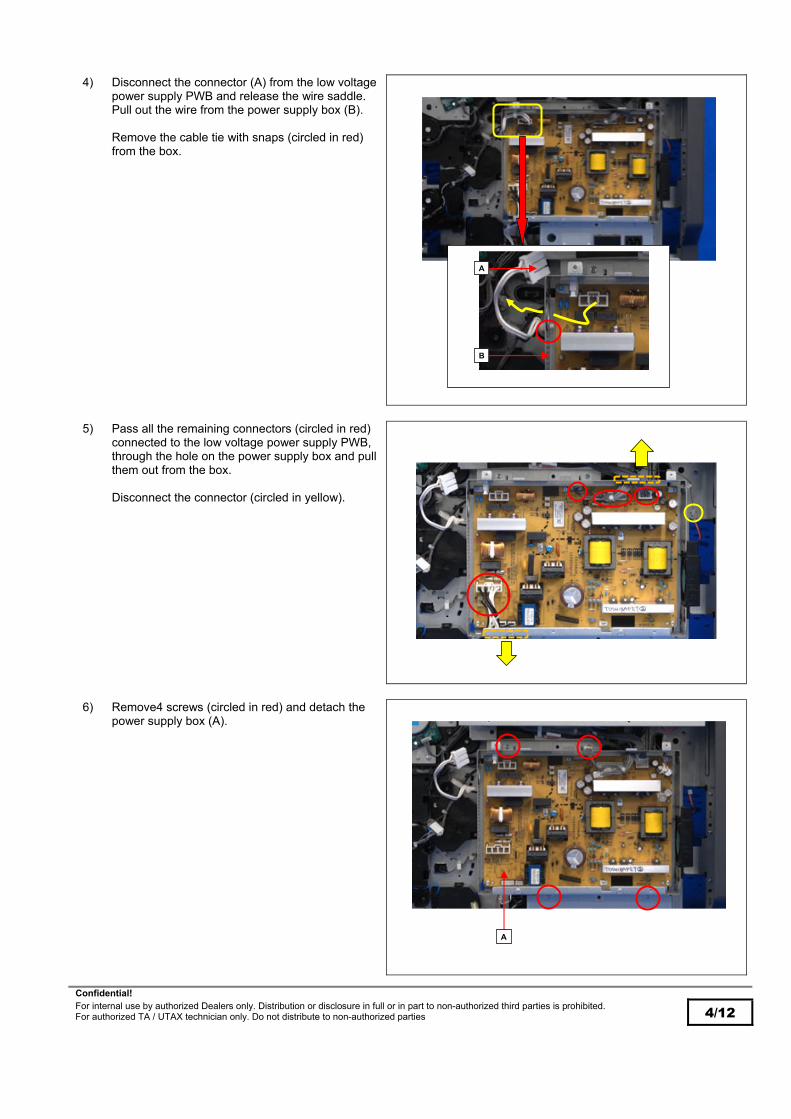
Confidential! For internal use by authorized Dealers only. Distribution or disclosure in full or in part to non-authorized third parties is prohibited. For authorized TA / UTAX technician only. Do not distribute to non-authorized parties 4/12
4) Disconnect the connector (A) from the low voltage power supply PWB and release the wire saddle. Pull out the wire from the power supply box (B). Remove the cable tie with snaps (circled in red) from the box.
5) Pass all the remaining connectors (circled in red)
connected to the low voltage power supply PWB, through the hole on the power supply box and pull them out from the box. Disconnect the connector (circled in yellow).
6) Remove4 screws (circled in red) and detach the
power supply box (A).
A
B
A

Confidential! For internal use by authorized Dealers only. Distribution or disclosure in full or in part to non-authorized third parties is prohibited. For authorized TA / UTAX technician only. Do not distribute to non-authorized parties 5/12
7 Remove 4 screws(circled in red) and detach the inlet mounting plate (A).
8) Pull out cassette1 and 2 and detach them.
A

Confidential! For internal use by authorized Dealers only. Distribution or disclosure in full or in part to non-authorized third parties is prohibited. For authorized TA / UTAX technician only. Do not distribute to non-authorized parties 6/12
9) Open 2 wire saddles (circled in red).
10) Pass the cassette heater connector through the
hole (A) on the rear side plate and align the cassette heater as in the figure to the right.
11) Secure the cassette heater to the frame with 2
screws (circled in red).
A

Confidential! For internal use by authorized Dealers only. Distribution or disclosure in full or in part to non-authorized third parties is prohibited. For authorized TA / UTAX technician only. Do not distribute to non-authorized parties 7/12
12) Secure the cassette heater wire with the wire saddle (circled in red).
13) Connect the connector on the power supply PWB
to the cassette heater connector (circled in red), and secure the cassette heater wire with the wire saddle (A).
14) Reassemble in the reverse procedures.
A

Confidential! For internal use by authorized Dealers only. Distribution or disclosure in full or in part to non-authorized third parties is prohibited. For authorized TA / UTAX technician only. Do not distribute to non-authorized parties 8/12
B PF-791 (500-sheet x1 paper feeder) Applicable parts: Heater set 220-240V
Bundled parts: - Heater ----- 1 pc - 4x8B(S)ⅢSR screw ---- 2 pcs (for set 220-240V) - Cable tie with snaps ----- 1 pc
1) Pull out cassette2.
2) Open 2 wire saddles (circled in red).
3) Pass the cassette heater connector through the
hole (A) on the rear side plate and align the cassette heater as in the figure to the right. Secure the cassette heater to the frame with 2 screws (circled in red). Secure the cassette heater wire with 2 wire saddles (B).
A
B

Confidential! For internal use by authorized Dealers only. Distribution or disclosure in full or in part to non-authorized third parties is prohibited. For authorized TA / UTAX technician only. Do not distribute to non-authorized parties 9/12
4) Reseat the cassette pulled out.
5) Remove 2 screws (circled in red) and detach the
rear cover (A).
6) Connect the cassette heater connector to the
connector (A) and secure the cassette heater wire with the wire saddle (B).
A
A
B

Confidential! For internal use by authorized Dealers only. Distribution or disclosure in full or in part to non-authorized third parties is prohibited. For authorized TA / UTAX technician only. Do not distribute to non-authorized parties 10/12
7) Attach the cable tie with snaps (A) to the rear side plate and secure the cassette heater wire.
8) Cut the cable tie with snaps in excess with
nippers.
9) Reassemble in the reverse procedures.
A

Confidential! For internal use by authorized Dealers only. Distribution or disclosure in full or in part to non-authorized third parties is prohibited. For authorized TA / UTAX technician only. Do not distribute to non-authorized parties 11/12
C PF-810 (3000-sheet paper deck) Applicable parts: Heater set 220-240V
Bundled parts: - Heater ----- 1 pc - Connector cover -------- 1 pc - 4x8B(S)ⅢSR screw ---- 2 pcs (to secure heater) - 4x10B(S)ⅢSR screw -- 1 pc (to secure connector cover)
1) Pull out the left and right cassette.
2) Pull out the horizontal conveying unit (A).
3) Open 3 wire saddles (circled in red).
A

Confidential! For internal use by authorized Dealers only. Distribution or disclosure in full or in part to non-authorized third parties is prohibited. For authorized TA / UTAX technician only. Do not distribute to non-authorized parties 12/12
4) Connect the cassette heater connector and align the cassette heater as in the figure to the right. Secure the cassette heater to the frame with 2 screws (circled in yellow). Secure the cassette heater wire with 3 wire saddles (circled in red).
5) Attach the cassette connector cover (A) with the
screw (circled in red).
6) Reassemble in the reverse procedures.
Classification: At Set Up
Next Visit / Service Call
Next Periodic Maintenance
X Information only
No modification necessary
Field Measure: Order the cassette heater set for service if necessary, and install it. Refer to the below for detail of the part code, and “Procedure to install the cassette heater” for detail of the installation procedures. Refer to “Identification of the main unit without the cassette heater” and “Affected serial number” for identification of the main unit without the cassette heater.
Serial Nos.: 3060i No production now 3560i No production now 3061i No production now 3561i No production now 3262i R881Y10895 4062i “1Z” or more of the 4th and 5th digit serial number * 2500ci No production now PF-791 “1Z” or more of the 4th and 5th digit serial number * PF-810 “1Z” or more of the 4th and 5th digit serial number *
*December 2021 production or later applies this change.
A

Confidential! For internal use by authorized Dealers only. Distribution or disclosure in full or in part to non-authorized third parties is prohibited. For authorized TA / UTAX technician only. Do not distribute to non-authorized parties 1/2
Technical Bulletin UTAX / TA UTAX / TA
3262i 4062i
TB-44B 2V6-M038/M Date: 09-03-2022
Priority: …A highest priority / …B second priority / …C other / …S Service Information
Firmware Upgrade (V 2.00)
Model: 3062i, 4062i
TOPIC:
The firmware is upgraded as follows. CONTENT OF CHANGES:
- Corrective measures for the wrong send destination displayed when replacing the main PWB. Wrong destination might be displayed after replacing the main PWB is overwritten by the one in the job number before replacement. Cause: Job are numbered from 1 after replacing the main PWB, however, the job history stored in the HDD/SDD remains. Due to the above, if the send job number is duplicate before and after replacing the main PWB, they are regarded as the same job number and the destination before replacing the main PWB overwrites the one after replacement. If executing the above procedures, the job number overwrite is cleared, however, the data below are deleted. - FAX communication log information - Job log information - Reserved FAX information - Documents in User Box.
- Prevent FAX sent to the wrong destination. If the destination is multiple (at broadcast), the pop-up message is so displayed before executing the job to send after confirmation to prevent FAX sent to the wrong destination.
- Corrective measures for service call error C0680. If recovery from the sleep mode is interrupted right after transiting to the light sleep mode, there is no time margin until recovery and service call error C0680 might occur with the SSD start-up failure. It is so changed to implement time margin until recovery.
- Correct the copy service screen. The operation panel display does not transit when resetting the copy service display automatically from the operation panel, it is corrected.
- Support the memory-full display. Receiving might not be available if FAX Box has no memory without the memory-full display, and it is so corrected memory-full is displayed.
- TLS1.2 support. TLS1.2 is supported for Equitrac.
- Corrective measures for the error at aQrate. The error might occur when pressing “Easy Scan” button from the operation panel in the aQrate environment.
- Corrective measures for the Magenta background image (DP-7110). The Magenta background image might occur depending on media type and variation of the CIS light distribution, the AGC adjustment timing is corrected to retrieve the correct value at the adjustment.
- Corrective measures for the abnormal sound from the DF at the offset ejecting (DF-791). The abnormal sound might occur with the settings below at the offset ejecting, and the eject speed is changed. Settings: Offset, A4E/LTE, Duplex, Main tray middle: Off Change: The DF eject braking speed is set to 150mm/s at the above settings, and it is changed to 200mm/s below 1,000-sheet count.
- Corrective measures for the abnormal sound from the DF at the straight ejecting in duplex printing (DF-791). The abnormal sound might occur with the settings below at the offset ejecting, and the eject speed is changed. Settings: Offset, A4E/LTE, Duplex, Main tray middle: Off Change: The DF eject braking speed is set to 150mm/s at the above settings, and it is changed to 200mm/s below 1,000-sheet count.
Confirmation screen is displayed

Confidential! For internal use by authorized Dealers only. Distribution or disclosure in full or in part to non-authorized third parties is prohibited. For authorized TA / UTAX technician only. Do not distribute to non-authorized parties 2/2
FIRMWARE UPGRADE PACK
Type Model File Remarks
MAIN 3262i, 4062i 2V6_2000.002.022 NEW
MMI 3262i, 4062i 2V6_7000.002.022 NEW
PANEL MAIN 3262i, 4062i 2ND_7200.001.015
ENGINE 3262i, 4062i 2V6_1000.003.001
LANGUAGE MLT 3262i, 4062i 2V6_81XM.002.021 NEW
BROWSER 3262i, 4062i 2ND_F000.003.001
OCR 3262i, 4062i 2R6_L000.002.004
SCANNER 3262i, 4062i 2RH_1200.006.002
DICTIONARY MLT 3262i, 4062i 2ND_CA00.001.002
ESPECIAL 3262i, 4062i ES_SKIP.ON
DP-7100 3R7_9500.002.002
DP-7110 3R8_9500.007.301 NEW
DP-7120 3RJ_9500.002.002
PF-791 3N4_9000.004.001
Enhancement units PF-810 3PC_9000.002.004
DF-791 3NB_9200.025.001 NEW
DF-7120 3RW_9200.006.002
PH-7A/B/C/D 3NK_9A00.006.001
MT-730(B) 3N0_9800.004.001
FAX System 12 3R2_5400.003.012
When upgrading firmware or replacing board etc., please upgrade each firmware to the latest version at the same time. Download: 3262i, 4062i Firmware Upgrade Pack V 2.00
Classification: At Set Up
X Next Visit / Service Call
Next Periodic Maintenance
Information only
No modification necessary
Field Measure: Upgrade the firmware to the new version when the phenomenon occurs. Serial Nos.: 3262i
4062i
Planned in March 2022 production