Tender Document - Login - Jaipur Development Authority
120
JAIPUR DEVELOPMENT AUTHORITY Tender Document For Rural Water Supply Scheme for Villages of Gram Panchayat Bhapura Cost: Rs 423.00 Lacs NIT No. 01/2017-18 Due On: 18.05.2017 Volume-I (Technical Bid) Executive Engineer (PHE-I) Jaipur Development Authority Jaipur
-
Upload
khangminh22 -
Category
Documents
-
view
0 -
download
0
Transcript of Tender Document - Login - Jaipur Development Authority

JAIPUR DEVELOPMENT AUTHORITY
Tender Document
For
Rural Water Supply Scheme for Villages of Gram Panchayat Bhapura
Cost: Rs 423.00 Lacs
NIT No. 01/2017-18 Due On: 18.05.2017
Volume-I
(Technical Bid)
Executive Engineer (PHE-I) Jaipur Development Authority
Jaipur

t;iqj fodkl izkf/kdj.k] t;iqj jke fd’kksj O;kl Hkou] dejk ua- 135] eq[; Hkou]
bfUnjk lfdZy tokgj yky usg: ekxZ] t;iqj&302004 Øekad tfoizk@vf/k-vfHk- (ih,pbZ&A)/2016-17/D-213 fnukad % 06-04-2017
fufonk lwpuk
fufonkfufonkfufonkfufonk llllwpuk la0wpuk la0wpuk la0wpuk la0 vf/kvf/kvf/kvf/k---- vfHkvfHkvfHkvfHk---- ¼ih,pbZ&A½@¼ih,pbZ&A½@¼ih,pbZ&A½@¼ih,pbZ&A½@00001@2011@2011@2011@2017777&1&1&1&18888
t;iqj fodkl izkf/kdj.k }kjk “xzke iapk;r Hkkiqjk ds xkaoks dh tyiznk; ;kstuk dk dk;Zxzke iapk;r Hkkiqjk ds xkaoks dh tyiznk; ;kstuk dk dk;Zxzke iapk;r Hkkiqjk ds xkaoks dh tyiznk; ;kstuk dk dk;Zxzke iapk;r Hkkiqjk ds xkaoks dh tyiznk; ;kstuk dk dk;Z”
ftldh vuqekfur ykxr : 4-23 djksM ds fy, vkWuykbZu fcM~l fnukad 18.05.2017 dks
lk;a 6%00 cts rd vkefU=r dh tkrh gSA fufonk cksyh dk vkWuykbZu vkosnu o Hkqxrku
tfoizk iksVZy ij djus dh vfUre frFkh 18.05.2017 dks lk;a 6%00 cts rd gSA fufonk
cksyh ds nLrkostksa dk foLr`r fooj.k www.sppp.rajasthan.gov.in,
www.eproc.rajasthan.gov.in and www.jda.urban.rajasthan.gov.in ij ns[kk tk
ldrk gSA
fufofufofufofufonnnnkkkk eeeesasa sasa HkkxHkkxHkkxHkkx ysysysysuuuussss okokokokyyyyksksksks ddddkkkkss ss ffffuuuuEuEuEuEu 'krksZ'krksZ'krksZ'krksZ dhdhdhdh iiiiwwwwffffrrrrZZZZ ddddjjjjuuuuhhhh gksxhAgksxhAgksxhAgksxhA
1- fufonk nkrk t;iqj fodkl izkf/kdj.k dh osclkbZV www.jda.urban.rajasthan.gov.in
iiiijjjj iiiiaaaatttthhhhdddd````rrrr gksgksgksgks ,oa,oa,oa,oa fufofufofufofufonnnnkkkk esaesaesaesa HkkxHkkxHkkxHkkx yyyysusususussss dsdsdsds fy,fy,fy,fy, cksyhnkrkcksyhnkrkcksyhnkrkcksyhnkrk ddddkkkkss ss vvvvkkkkoooosnsnsnsnuuuu ddddjjjjusususus dsdsdsds fy,fy,fy,fy,
nnnnLLLLrrrrkokokokosssstttt 'kqYd]'kqYd]'kqYd]'kqYd] vvvveeeekurkurkurkur jjjjkf’k]kf’k]kf’k]kf’k] vkvkvkvkjjjj----vvvvkkkkbZbZbZbZ----,,,,llll----,,,,yyyy---- iiiizkszkszkszksllllssssffffllllaaaaxxxx 'kqYd'kqYd'kqYd'kqYd vvvvkkkkWWWWuuuuykbZuykbZuykbZuykbZu tektektektek ddddjjjjuuuuhhhh gksxgksxgksxgksxhhhhAAAA
2- vkWuykbZu fufonk izLrqr djus ds fy, fufonk nkrkvksa dk jktLFkku ljdkj ds bZ&izkD;wesaV
iksVZy www.eproc.rajasthan.gov.in ij iaftd`r gksA
vf/k’kk"kh vfHk;ark ¼ih,pbZ&A½ tfoizk] t;iqjA
PHE-I, JDA WSS Village Bhapura
3
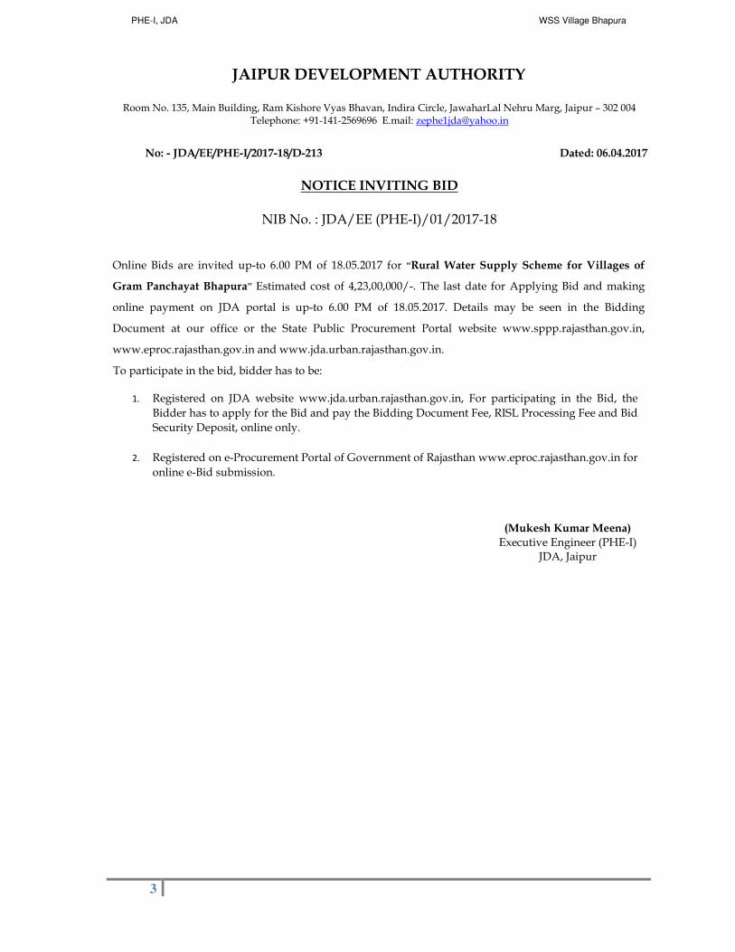
JAIPUR DEVELOPMENT AUTHORITY Room No. 135, Main Building, Ram Kishore Vyas Bhavan, Indira Circle, JawaharLal Nehru Marg, Jaipur – 302 004
Telephone: +91-141-2569696 E.mail: [email protected]
No: - JDA/EE/PHE-I/2017-18/D-213 Dated: 06.04.2017
NOTICE INVITING BID
NIB No. : JDA/EE (PHE-I)/01/2017-18
Online Bids are invited up-to 6.00 PM of 18.05.2017 for “Rural Water Supply Scheme for Villages of
Gram Panchayat Bhapura” Estimated cost of 4,23,00,000/-. The last date for Applying Bid and making
online payment on JDA portal is up-to 6.00 PM of 18.05.2017. Details may be seen in the Bidding
Document at our office or the State Public Procurement Portal website www.sppp.rajasthan.gov.in,
www.eproc.rajasthan.gov.in and www.jda.urban.rajasthan.gov.in.
To participate in the bid, bidder has to be:
1. Registered on JDA website www.jda.urban.rajasthan.gov.in, For participating in the Bid, the
Bidder has to apply for the Bid and pay the Bidding Document Fee, RISL Processing Fee and Bid
Security Deposit, online only.
2. Registered on e-Procurement Portal of Government of Rajasthan www.eproc.rajasthan.gov.in for
online e-Bid submission.
(Mukesh Kumar Meena)
Executive Engineer (PHE-I) JDA, Jaipur

PHE-I, JDA WSS Village Bhapura
4
JAIPUR DEVELOPMENT AUTHORITY
Room No. 135, Main Building, Ram Kishore Vyas Bhavan, Indira Circle, JawaharLal Nehru Marg, Jaipur – 302 004 Telephone: +91-141-2569696 E.mail: [email protected]
Bid No: - JDA/EE/PHE-I/2017-18/D- Dated: 06.04.2017
NOTICE INVITING BID NIB No. : JDA/EE(PHE-I)/01/2017-18
Name & Address of the
Procuring Entity
���� Name: Executive Engineer (PHE-I), Jaipur Development Authority Address: Room No. 135, Main Building, Ram Kishore Vyas Bhavan, Indira Circle, JawaharLal Nehru Marg, Jaipur – 302 004
Telephone: +91-141-2569696 E.mail: [email protected]
Subject Matter of Procurement � Rural Water Supply Scheme for Villages of Gram Panchayat Bhapura.
Job No. : 309/2015-16
Bid Procedure ���� Potential Assessment Tender Method (eg. Single-stage Two part (envelope) open competitive) eBid procedure at http://eproc.rajasthan.gov.in
Bid Evaluation Criteria (Selection Method)
���� Potential Assessment Method L1 (eg.Least Cost Based Selection (LCBS)-L1)
Websites for downloading
Bidding Document,
Corrigendum's, Addendums, etc.
���� Websites: www.sppp.rajasthan.gov.in, www.eproc.rajasthan. gov.in, www.jda.urban.rajasthan.gov.in
Website for online Bid application participation and payment *
���� Website: www.jda.urban.rajasthan.gov.in ���� For participating in the Bid, the Bidder has to apply for this Bid and pay the Bidding Document Fee, RISL Processing Fee and Bid Security Deposit, online only. o Bidding document fee: Rs. 1000/- Rupees (One thousand only) o RISL Processing Fee: Rs. 1000/- (Rupees One Thousand only) Requisite Bid Security Deposit
Estimated Procurement Cost
���� INR 4,23,00,000/- (Rupees Four crore Twenty Three Lacs only)
Bid Security Deposit ���� Amount (INR) : 2% (Rs. 8,46,000/-) of Estimated Procurement Cost, 0.5% (2,11,500/-) of S.S.I. of Rajasthan, 1% for Sick Industries, other than S.S.I., whose cases are pending with Board of Industrial & Financial Reconstruction (* 2% for Bidder who is A and AA class contractor registered in other Government Department/ 0.5% for Bidder registered as contractor AA, A in JDA)
� Micro Small Medium Enterprise Situated in Rajasthan Tender Fee 50% EMD Value 0.5%
� In case of Departments' of the State Government and Undertakings, Corporations, Autonomous bodies, Registered Societies, Cooperative Societies which are owned or controlled or managed by the State Government and Government Undertakings of the Central Government shall submit a bid securing declaration in lieu of bid security.
Date/Time/Place of Pre-Bid ���� NA Applying Bid and making Online Payment on JDA portal (www.jda.urban.rajasthan.gov.in)
���� Start Date: 17.04.2017 at 9.30 AM ���� End Date: 18.05.2017 at 06.00 PM ���� In case EMD in from BG Original Bank Guarantee is to be submitted in Room No MB-SF-225A (Room No. of DD ( E&B) of Main Building, Jaipur Development Authority by 19.05.2017 10.00AM to 25.05.2017 upto 2.00 PM
Bid Submission on e-Procurement Portal of GOR
���� Start Date: 17.04.2017 at 9.30 AM ���� End Date: 18.05.2017 at 06.00 PM
Date/Time/Place of Technical Bid Opening
���� 25.05.2017 at 03.00 PM

PHE-I, JDA WSS Village Bhapura
5
Date/ Time/ Place of Financial Bid Opening
���� Will be intimated later to the Technically qualified bidders in case of Two Bid
Bid Validity ���� 120 days from the bid submission deadline
Completion period of work ���� 09 Months
* Jaipur Development Authority has decided to receive Earnest Money Deposit (EMD) (Bid Security), Tender Fee and RISL processing fee online through JDA Portal. The bid security options available in tender for participants are as mentioned below:
A. Payment Options: Option-1: Bank Guarantee (BG) against EMD / Bid Security Bidder may opt Bank Guarantee (BG) against EMD (Bid Security), for which bidder requires to prepare BG before applying in the tender. The details of BG requires to be fed on JDA portal before paying balance amount (Tender Fee + RISL Processing Fee). This amount will be paid through Payment Gateway only, option to make balance payment through EFT (RTGS/NEFT) will not be available. If bidder does not opt for BG against EMD, options of making complete payment through Payment Gateway or through EFT (NEFT
/ RTGS) will be available. Option-2: Electronic Fund Transfer (EFT: NEFT/RTGS) If the bidder selects payment mode as EFT (NEFT/RTGS), “Paying Slip for EFT (NEFT/RTGS)” will be generated by the system for the complete amount. The payment can be made from any Bank any Branch using this Paying Slip through NEFT/RTGS (Claim against payment made through EFT in any other JDA bank account will not be acceptable and bidder stands disqualified from participation in the bid applied for). After successful transaction through NEFT/RTGS, as per the standard procedures it may take 4 to 24 hours in process of confirmation of EFT through Auto-Process depending on the time of EFT done. Therefore, option to make payment through EFT (NEFT/RTGS) will be available till 48 hours prior to closing date of bid participation. Option-3: Payment Gateway (Aggregator) The facility to make payment through Debit Card, Credit Card, Net banking etc., will be available. User can use this facility from anywhere any time till the closing date & time of bid participation.
B. Bid Participation Receipt After confirming payment, the bidder will get Bid Participation Receipt on the basis of which user will get the payment details along with other details for bidding on e-Procurement portal of GOR.
• In case of BG as the remaining payment will be done through Payment Gateway, on successful transaction the “Bid Participation Receipt” will be generated on real time basis.
• In case complete payment is done through Payment Gateway, on successful transaction the “Bid Participation Receipt” will be generated on real time basis.
• In case complete payment is done through EFT (NEFT/RTGS), on confirmation of payment from ICICI Bank (Auto Process) “Bid Participation Receipt” will be available on Login of Bidder on JDA portal.
Note:
1. Bidder (authorised signatory) shall submit their offer on-line in Electronic formats both for technical and financial proposal.
2. In case, any of the bidders fails to pay the Tender Fee, BSD, and RISL Processing Fee, online (subject to confirmation), its Bid shall not
be accepted.
3. To participate in online bidding process, Bidders must procure a Digital Signature Certificate (Type III) as per Information Technology Act-2000 using which they can digitally sign their electronic bids. Bidders can procure the same from any CCA approved certifying agency, i.e. TCS, Safecrypt, Ncode etc. Bidders who already have a valid Digital Signature Certificate (DSC) need not procure a new DSC. Also, bidders must register on http://eproc.rajasthan.gov.in (bidders already registered on http://eproc.rajasthan.gov.in before 30-09-2011 must register again).
4. JDA will not be responsible for delay in online submission due to any reason. For this, bidders are requested to upload the complete bid well advance in time so as to avoid 11th hour issues like slow speed; choking of web site due to heavy load or any other unforeseen problems.
5. Bidders are also advised to refer "Bidders Manual Kit" available at eProc website for further details about the e-Tendering process.
6. Training for the bidders on the usage of e-Tendering System (eProcurement) is also being arranged by DoIT&C, GoR on a regular basis. Bidders interested for training may contact e-Procurement Cell, DoIT&C for booking the training slot. Contact No: 0141-4022688 (Help desk 10 am to 6 pm on all working days) e-mail: [email protected] Address : e-Procurement Cell, JDA, Yojana Bhawan, Tilak Marg, C-Scheme, Jaipur
7. The procuring entity reserves the complete right to cancel the bid process and reject any or all of the Bids.
8. No contractual obligation whatsoever shall arise from the bidding document/ bidding process unless and until a formal contract is signed and executed between the procuring entity and the successful bidder.
9. Procurement entity disclaims any factual/ or other errors in the bidding document (the onus is purely on the individual bidders to verify such information) and the information provided therein are intended only to help the bidders to prepare a logical bid-proposal.
10. The provisions of RTPPA Act 2012 and Rules 2013 thereto shall be applicable for this procurement. Furthermore, in case of any inconsistency in any of the provisions of this bidding document with the RTPP Act 2012 and Rules thereto, the later shall prevail.
(Mukesh Kumar Meena) Executive Engineer (PHE-I)
JDA, Jaipur

PHE-I, JDA WSS Village Bhapura
6
Annexure: 3
As part of NIB Document
Process for Participation & Depositing Payment Online
JAIPUR DEVELOPMENT AUTHORITY, has decided to receive Bidding document fee, RISL Processing Fee and Bid Security Deposit (BSD) through online mode only for which the bidder has to get registered himself on JDA portal www.jaipurjda.org.
To participate in the bid, bidder has to be:
1. Registered on JDA website www.jaipurjda.org(by depositing Rs. 500.00 online, the validity of
which remains 3 (three) years).
For participating in the Bid, the Bidder has to apply for this Bid and pay the Bid Document Fee, RISL Processing Fee and Bid Security Deposit, online only.
2. Registered on e-Procurement Portal of Government of Rajasthan www.eproc.rajasthan.gov.in for
online e-Bid submission.
Methods for depositing on line amount
� Online through Internet Banking, Debit Card or Credit Card.
� In case the amount exceeds the online payment limit, the payment may be made through RTGS / NEFT / Transfer in Bank Account Number 675401700586 IFSC Code ICIC0006754 of ICICI BANK
Limited, JDA Campus
Jaipur.
In case of RTGS / NEFT / Transfer the bidder is required to deposit the requisite amount in the dedicated bank account number as mentioned above and has to get the UTR / Reference number from the bank. This number requires to be updated whiling applying the bid on JDA portal.
While participation in the bid, a receipt will be generated through the system showing the submission details as per Annexure-4. The bidder is required to fill the instrument numbers for various heads on e-Procurement portal www.eproc.rajasthan.gov.in as mentioned in the receipt.
More details about Registration Process, Terms and Conditions and FAQ along with contact detail is available on JDA website www.jaipurjda.org under eServices>>JDA Tender

PHE-I, JDA WSS Village Bhapura
7
Annexure: 4
Template of Online Receipt as part of NIB Document
Bidder has to submitted as proof of deposited amount against the Bid on eProcurement Protal

PHE-I, JDA WSS Village Bhapura
8
Paper Cutting

PHE-I, JDA WSS Village Bhapura
9
Section A-1 Instructions to Bidders
PHE-I, JDA WSS Village Bhapura
10
JAIPUR DEVELOPMENT AUTHORITY JAIPUR
TECHNICAL BID
(POTENTIAL ASSESMENT)
SCHEDULE AND SPECIFICATIONS
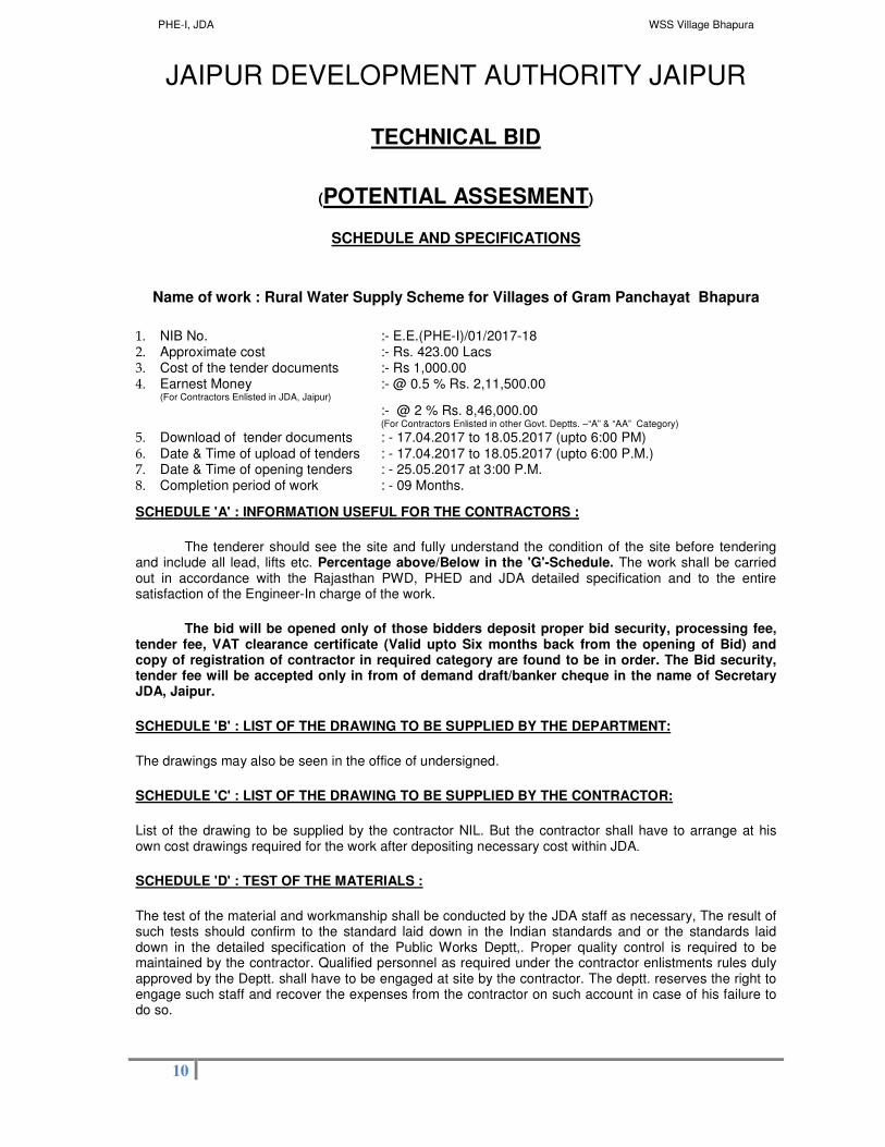
Name of work : Rural Water Supply Scheme for Villages of Gram Panchayat Bhapura
1. NIB No. :- E.E.(PHE-I)/01/2017-18 2. Approximate cost :- Rs. 423.00 Lacs 3. Cost of the tender documents :- Rs 1,000.00 4. Earnest Money :- @ 0.5 % Rs. 2,11,500.00
(For Contractors Enlisted in JDA, Jaipur) :- @ 2 % Rs. 8,46,000.00 (For Contractors Enlisted in other Govt. Deptts. –“A” & “AA” Category)
5. Download of tender documents : - 17.04.2017 to 18.05.2017 (upto 6:00 PM) 6. Date & Time of upload of tenders : - 17.04.2017 to 18.05.2017 (upto 6:00 P.M.) 7. Date & Time of opening tenders : - 25.05.2017 at 3:00 P.M. 8. Completion period of work : - 09 Months.
SCHEDULE 'A' : INFORMATION USEFUL FOR THE CONTRACTORS :
The tenderer should see the site and fully understand the condition of the site before tendering and include all lead, lifts etc. Percentage above/Below in the 'G'-Schedule. The work shall be carried out in accordance with the Rajasthan PWD, PHED and JDA detailed specification and to the entire satisfaction of the Engineer-In charge of the work.
The bid will be opened only of those bidders deposit proper bid security, processing fee, tender fee, VAT clearance certificate (Valid upto Six months back from the opening of Bid) and copy of registration of contractor in required category are found to be in order. The Bid security, tender fee will be accepted only in from of demand draft/banker cheque in the name of Secretary JDA, Jaipur.
SCHEDULE 'B' : LIST OF THE DRAWING TO BE SUPPLIED BY THE DEPARTMENT:
The drawings may also be seen in the office of undersigned.
SCHEDULE 'C' : LIST OF THE DRAWING TO BE SUPPLIED BY THE CONTRACTOR:
List of the drawing to be supplied by the contractor NIL. But the contractor shall have to arrange at his own cost drawings required for the work after depositing necessary cost within JDA.
SCHEDULE 'D' : TEST OF THE MATERIALS :
The test of the material and workmanship shall be conducted by the JDA staff as necessary, The result of such tests should confirm to the standard laid down in the Indian standards and or the standards laid down in the detailed specification of the Public Works Deptt,. Proper quality control is required to be maintained by the contractor. Qualified personnel as required under the contractor enlistments rules duly approved by the Deptt. shall have to be engaged at site by the contractor. The deptt. reserves the right to engage such staff and recover the expenses from the contractor on such account in case of his failure to do so.

PHE-I, JDA WSS Village Bhapura
11
SCHEDULE 'E' : SAMPLES OF THE MATERIALS :
The samples of the material to be used by the contractor shall be deposited 15 days in advance with the Engineer In charge and be got approved by him before use.
SCHEDULE 'F' : TIME OF COMPLETION :
The work should start within Ten days of issue of work order and complete within 09 months.
SCHEDULE 'G' : ATTACHED SEPARATELY BASED ON JDA PHE BSR 2013, JAIPUR.
SCHEDULE 'H' : SPECIAL CONDITION.
SCHEDULE 'I' : SPECIAL TERMS & CONDITION FOR Sewer line work : ATTACHED SEPARATELY.
Specifications and Scope of Work
Annexure A : Compliance with the code of Integrity and No Conflict of Interest
Annexure B : Declaration by the Bidder regarding Qualifications
Annexure C : Grievance Redressal during Procurement Process
Annexure D : Additional Conditions of Contract
SIGNATURE OF CONTRACTOR
With full address & Mobile No. :
EXECUTIVE ENGINNER (PHE-I) Jaipur Development Authority,
Jaipur

PHE-I, JDA WSS Village Bhapura
12
JAIPUR DEVELOPMENT AUTHORITY JAIPUR
SPECIAL CONDITION OF THE CONTRACT FOR POTENTIAL ASSESSMENT OF
CONTRACTORS
Name of work:- Rural Water Supply Scheme for Villages of Gram Panchayat Bhapura
Special conditions of contract for POTENTIAL ASSESSMENT as detailed here under, shall be applicable in addition to all other terms and condition already prescribed under standard agreement forms/rules and regulations to contract.
1. Procedure: Procedure for POTENTIAL ASSESSMENT would be as follow:
(a) Tender documents shall be submitted on line e-procurement website http://www.eproc.rajasthan.gov.in with their digital Signature. The Bid is to be submitted in 2 Covers which shall comprise of –
Cover-1 VAT clearance certificate and contractors Registration Certificate, complete Tender Document along with addendums/ amendments issued and uploaded by the Department on the above website, Tender form and schedules for pre-qualification Bid and scanned copies of supporting Documents as required for qualification as detailed herein after. Cover-2 Financial offer (BOQ).
(b) The technical bid will be opened online only of those bidders whose proper Earnest money, Tender fee, e-procurement fee, VAT clearance certificate (Valid up to Six months back from the opening of Technical Bid) and copy of registration of contractor in required category are found to be in order. The earnest money, bid document fee and RISL processing fee shall be paid online only and shall have to be deposited on or before 01.05.2017 by 6.00 PM.
(c) The Technical Bid would be opened on the date 25.05.2017 at 3:00 PM
(d) The Financial Bid envelope would be opened only of those bidders who fulfill all the POTENTIAL ASSESSMENT criteria.
Note :-
(i) If VAT clearance certificate is not applicable in any State then appropriate proof is to be enclosed by bidder with certificate which is applicable in place of VAT.
2. Criteria:
Criteria for POTENTIAL ASSESSMENT METHOD would be as follows:-
(a) The bidder should have executed following quantities of work in last five financial years. However the bidder may opt current year in the said financial assessment period.
S.No. Items Quantity
1 Providing Laying & Jointing of DI pipe line of size equal to 100 mm and above diameter.
6367.00 Mtrs
2 Construction of RCC OHSR having capacity 34 KL or more 1 No. 3 Construction of RCC CWR having capacity 34 KL or more 1 No. 4 Construction of Pump House along with Installation of pumps,
related electro mechanical works having minimum installed capacity of pumps for water supply works.
15 KW
Note :-
(i) Quantities of all the items mentioned in criteria 2 (a) should be executed in last five financial years.
(ii) Certificate issued by Govt. of India, State Govt., Union Territory, Govt. Undertakings, Autonomous Bodies shall only be considered.

PHE-I, JDA WSS Village Bhapura
13
(b) The bidder should have completed at least one similar nature work in last Five financial year (including current year, if opted by the bidder) of value not less than 1/3
rd of the Estimated Cost of
the work (bid cost) updated to present price level) Note :-
(i) The starting & completion date of the work is to be in between above said financial years. If no then maximum work (70%) is to be completed in above said financial years.
(ii) If bidder submits certificate having different components / nature of work then proper completion certificate of required similar nature components is to be enclosed which should include at least water supply pipe line work and OHSR / CWR work in the work experience certificate. The work shall be considered similar nature of work in totality irrespective of the quantity / capacity and cost of the component in the completion certificate for similar nature work. The completion certificate should be of only water supply works.
(c) The bidder should have achieved an annual financial turnover of at least 1/3rd
of the Estimated Cost of the work (bid cost) in any one of last Five financial years (including current year, if opted by the bidder)
Note :- (i) The bidder should enclose certificate of Turn Over from Chartered Accountant for last five
financial year & audited balance sheet of the year which is considered by the bidder in criteria 2 (c).
(ii) If current year or last year has been opted by bidder whose balance sheet is not submitted till the submission of bid then certificate from Chartered Accountant should be enclosed.
(d) The bidder should give Affidavit to deploy the machinery and equipment as specified in Schedule – III, for the execution of this work.
(e) Bid Capacity: Bidders who meet the minimum qualification criteria will be qualified only if available bid capacity is equal to or more than the total Bid value. The available bid capacity will be calculated as under: Bid Capacity = (A x N x 3 – B)
Where A = Maximum value of civil engineering work executed in any one year during the last 5 financial years (updated to present Price level) taking in to account the completed as well as works in progress. However, the bidder may opt current year in the five year assessment period.
N = Number of year prescribed for completion of the work for which bids are invited. In present case value of N shall be 0.75 B = Value, at present price level of existing commitments and on going works to be executed during 'N' period (period prescribed for completion of the works for which the bids are invited) Note:- (i) Certificate from Chartered Accountant should be enclosed by bidder clearly indicated
maximum value of Civil Engineering Work in one Financial Year.
(f) Litigation History:- Bidder should provide an accurate information on any litigation or arbitration resulting from contracts completed or under execution by him over the last five years. The maximum value ( updated at the present price level) of disputed amount claimed in the litigation / arbitration resulting from contracts executed in last five years shall be deducted from the calculated Bid Capacity of the bidder. The details shall be furnished in Schedule VI.
Note :- (i) The present price level for turnover, cost of completed work & disputed amount of similar nature, the previous years value shall be given weight age of 10% per year as follows :- (a) For current year 1.00
(b) For last year 1.00 (c) For one year before 1.10 (d) For two year before 1.21 (e) For three year before 1.33 (f) For four year before 1.46
3. Documentation :
The bidder should furnish the following documents along with the technical bid: (a) Information regarding financial resources and capability in Schedule –I.

PHE-I, JDA WSS Village Bhapura
14
(b) Information regarding works executed in the last five years in Schedule–II (c) Certificates from the concerned Engineer–In–Charge in support and verification of the information
furnished in Schedule–II. (d) Affidavit regarding machinery and equipment required for deployment, as detailed in scheduled –
III. (e) Information regarding details of maximum value of civil engineering works executed in any one
year during the last five years taking into account the completed as well as works in progress in schedule – IV.
(f) Information regarding existing commitments and ongoing works to be completed in schedule – V. (g) Information regarding details of litigation or arbitration contracts to be furnished in schedule – VI. (h) Calculation of Bid capacity in schedule – VII. (i) Affidavit as per Annexure I (Self attested Identity proof should be enclosed)
4. Important:
(a) The bidder must ensure that all the information required in the Documents is furnished by him complete in all respects. He would not be allowed to withdraw any document, or to rectify any information furnished therein, after submitting the bid.
(b) The bidder should give an affidavit that the information furnished in schedule I to VII is correct. If any information is found incorrect, the offer of the bidder shall be rejected and action be taken as per rules.
(c) Bidders must do paging of all enclosure of bid documents. 5. Rejection of bids
The department reserves the rights to reject any bid or to disqualify any or all the bidders, without assigning any reasons at any stage.
(i) If Bid is not accompanied with the requisite documents mentioned in clauses 3 ( a ) to 3 (i ) or is not in accordance with procedure specified in Para 1, or is not accompanied with earnest money & VAT Clearance Certificate and registration of contractor in required category it would be liable for rejection.
(ii) Furnishing of incorrect or incomplete or concealment of any information required in the bid documents would render the bid liable for rejection.
(iii) If all the copies enclosed in support or affidavit is not duly attested by Notary Public / Gazetted Officer / self attested then bid of the bidder is to be rejected.
Executive Engineer (PHE-I) JDA, Jaipur

PHE-I, JDA WSS Village Bhapura
15
TENDER FOR WORKS
I/We hereby tender for the execution for the Jaipur Development Authority, Jaipur of the work specified in the underwritten memorandum within the time specified in such memorandum at the rates, (in figure) .........% (as well as in words) ........................................................ Percent below/above the amount, entered in the schedule G in all respects in accordance with the specifications, designs, drawings and instructions in writing referred to in Rule I in all respects in accordance conditions with such conditions so far as applicable. I/We have visited the site of work and am/are fully aware of all the difficulties and conditions likely to affect carrying out the work, I/We have fully acquainted myself/ourselves about the conditions in regard to accessibility of site and quarries/kilns nature and the extent of ground, working conditions including stacking, of materials, installation of tools & plant, conditions effecting accommodation and movement of labour etc. required for the satisfactory execution of contract.
Memorandum
(a) General description of work..- : (b) Estimated cost : Rs. 423.00Lacs
(c) Earnest money : Rs. 8,46,000.00 for enlisted contractors outside JDA and
: Rs. 2,11,500.00 @1/2% within JDA enlistment.
(d) Security Deposit :
(i) "The security deposit @ 10% of the gross amount of the running bill shall be deducted from each running bill and shall be refunded as per rules on completion of the contract as per terms and conditions. However, the amount of security deposit deducted from running bills shall not be converted into any mode of securities like bank guarantee. FDR etc. The earned money deposited shall however be adjusted while deducting security deposit from first running bill of the contractor. There will be no maximum limit of security deposit. However, a contractor may elect to deposit of full amount of 10% security deposit in the shape of bank guarantee or any acceptable form of security before or at the time of executing agreement. In that case earnest money may be refunded only after deposition of full 10% as above. However, in case during execution cost of works exceeds as shown at the time of depositing 10% as above, balance security deposit shall be deducted from the Running Account Bills." (ii) Bank Guarantee shall in all cases be payable at the headquarter of the Division or the nearest District Headquarters.
(e) Time allowed for the completion of work (to be reckoned from the 10th day after the date of written order to commence the work) is 9 month Should this tender be accepted in whole or in Part, I/We hereby agree to abide by and fulfill all the terms and provisions of the conditions of contract annexed here to and of the Notice Inviting Tender, or in default thereof, to forfeit and pay to the Governor of Rajasthan or his successors in office, the sum of money mentioned in the said conditions.
Validity of rates 120 days.
A sum of Rs. ................... is forwarded herewith in the form of Cash, Bank Draft, Bankers Cheque as Earnest Money. This amount of earnest money shall absolutely be forfeited to the Governor of Rajasthan or his successor in office without prejudice to any other right or remedies of Governor of Rajasthan or his successor in his office, should I/We
fail to commence the work specified in the above memorandum.
Signature of Witness Signature of Contractor Witness's address & Occupation Address of Contractor Date: The above tender is hereby accepted by me on behalf of the Governor of Rajasthan Date:
Executive Engineer (PHE-I)

PHE-I, JDA WSS Village Bhapura
16
Section A-2
General Conditions of Contract
(Appendix XI of PWF & AR. Govt. of Rajasthan effective up to date shall be applicable)

PHE-I, JDA WSS Village Bhapura
17
Section A3
Special Conditions of Contract

PHE-I, JDA WSS Village Bhapura
18
Special Conditions of Contract
CONTRACT
1.1 Type of Contract
THE WORK DESCRIBED IN THIS TENDER DOCUMENTS CONSIST OF TWO PARTS;
PART “A” CONSTRUCTION OF OHSR, CWR, UNDER WATER SUPPLY SCHEME FOR VILLAGES OF
GRAM PANCHYAT BHAPURA
PART “B” P/L/J & COMMISSIONING OF DI PIPE LINE FOR RISING MAIN, CONSTRUCTION OF PUMP
HOUSE AND CONSTRUCTION OF TUBE WELLS SUPPLY AND INSTALLATION OF
CENTRIFUGAL PUMP SET, ELECTRIC PANEL, VALVES ETC. UNDER WATER SUPPLY SCHEME
FOR VILLAGES OF GRAM PANCHYAT BHAPURA.
PART “C” PROVISION FOR OPERATION AND MAINTENANCE WORKS
1.2 Priority of contract
The documents forming part of the agreement are to be taken as mutually explanatory documents of one another. In case of discrepancies they shall be explained and adjusted by the Engineer In Charge. The priority of the Contract documents shall be as follows:
1. Letter of award 2. Special Conditions of Contract Part A & Part B
Instructions to Bidders 3. General Conditions of Contract 4. Work description/ Scope of works 5. Technical specifications 6. Drawings 7. Bill of quantities
Design And Drawings
2.1 General Design Obligations
The Contractor shall be deemed to have scrutinized, prior to submission of bid, the JDA Requirements (including design criteria and calculations, if any). The Contractor shall be responsible for the design of the following works and for the accuracy of such designs- 1. RCC SR, CWR JDA shall not be responsible for any error, in accuracy or permission of any kind in JDA requirements as originally included in the contract. Any data or information received by the Contractor, from JDA or otherwise, shall not relieve the Contractor from his responsibility for the design and execution of the works. 2.2 Contractor's Documents & Submission Procedure For Detailed Design & Execution Drawings
The Contractor's Documents shall comprise the Technical Documents specified in the JDA requirements, Documents Requirement to satisfy all regulatory approvals, As Built Documents and Operation and Maintenance Manuals. The Contractor's Documents shall be written in the language for communications defined in contract. If errors, omissions, ambiguity, inconsistencies, inadequacies or other defects are found in the Contractors Documents, these and the works shall be corrected at the Contractor's cost, notwithstanding any consent for approval under this clause. The contractor shall carry out the preparatory works such as Topographic survey, soil investigations, geo technical investigations etc to prepare the plans, designs, drawings etc. The contractor is required to submit the detailed design and execution drawings such as site plan, general arrangement drawings, plans, structural drawings and all working drawing of all civil works stated in the above clause 2.1. He will also submit the detailed system and working drawings as well as performance curves and data for all hydraulic, mechanical, Electro-mechanical and electrical equipment. The detailed design & execution drawings shall be submitted only after verification by MNIT. 2.3 Approval procedures
After submission of detailed designs, working drawings and documents etc., the competent authority or his authorized representative shall progressively review them and issue an approval within 15 days. The period of review will be counted after all quarries are replied satisfactorily. The schedule should be such so as not to obstruct the actual construction work. The following shall be the procedure for submission and approval of detailed design and execution drawings: The Contractor shall submit three copies of design/drawings and performance curves etc. to the Engineer in Charge. All the drawings are to be signed by the Contractor or his authorized representatives.
(a) The Engineer in Charge will review the design/drawings etc. and if found in order return one copy duly approved to the Contractor within 15 days.
(b) In case the design/drawings etc. are not found fit for approval, the Engineer in Charge will mark the comments on them and return two copies to the Contractor within 15 days and the same shall be repeated till drawings are finally approved as mentioned in the above clause. The contractor in such cases shall submit the revised and corrected design/drawings within 15 days to the receipt of comments from Engineer-In-Charge.
(c) On request of the Engineer in Charge, the Contractor shall depute the design engineer responsible for the particular design/drawing to discuss with the Engineer in Charge or his Representative.
(d) On receipt of approved designs/drawings as per sub-clause (b) above, the Contractor shall submit four (4) additional copies of the approved designs / drawings to JDA for reference and records. No designs / drawings with corrections made after taking the prints will be accepted. The approval of drawings/designs by the Engineer in Charge shall not relieve the Contractor of his responsibility in terms of the Contract for soundness of the designs. The Contractor shall be responsible for the structural safety of all the components of the Work.

PHE-I, JDA WSS Village Bhapura
19
2.4 Discrepancies between Drawings and Specifications
In case of discrepancies between drawings and specifications or data sheets arising from the meaning, dimensions or quality of the materials and equipment for the due and proper execution of the Work, the discrepancy shall be explained by the Engineer in Charge. His explanation shall be the final decision and the Contractor shall execute the Work accordingly without any extra payment. 3. Pre – Construction, Inspection and testing and review of data for material, plant and equipment
• The contractor shall place order for the material and equipment only after approval of Engineer In Charge. The contractor shall submit the detailed drawings to the Engineer In Charge for approval.
• The contractor shall inform the Engineer In Charge about the likely dates of manufacture, testing and dispatching of the material. The contractor shall notify the Engineer In Charge for inspection and testing, at least twenty eight (28) days prior to packing and shipping and shall supply the manufacturers test results and quality control certificate.
• The inspection and test categories shall be applied prior to delivery of the equipment of various categories as indicated in the technical specifications for each type of equipment.
Category A: The drawing/data sheet has to be approved by the Engineer In Charge before manufacture and testing. The material has to be inspected by inspecting agency at the manufacturers premise before packing and dispatching. Category B: The drawings of the equipment have to be submitted and to be approved by the Engineer In Charge prior to manufacture. The material has to be tested by the manufacture and the manufacturers test certificate are to be submitted and approved by the Engineer In Charge before dispatching of the equipment. Notwithstanding the above, the Engineer In Charge after examination of the test certificates, reserves the right to instruct the contractor for testing, if required, in the presence of the contractors representative. Category C: The material may be manufactured as per standards and deliver to the site.
• For material/equipment under Category ‘A’ and ‘B’ the Engineer In Charges will provide an authorization for packing and shipping after inspection.
• The testing, approval for dispatching shall not absolve the contractors obligations for satisfactory performance of the plant. Inspection Category
S.Nos. Items Category
Related to Rising mains and Distribution System 1. Cast Iron specials B 2 uPVC / DI pipes A 3 Sluice Valves, Reflux valves, Air Valves, Water Meter, Bulk Meter and Pressure sensor,
Magnetic Water Meter B
4 C.I. Joints and rubber rings for joints & couplers B 3.1 Third Party Inspection : The contractor is to contact for third party inspection amongst the CEIL, SGS, RITES on his own. He shall deposit & bear the cost of inspection. The contractor should inform the JDA of the name of agency finalized by him for the contract. The agency finalized by him for the contract. The agency will be same for all items of supply in this contract requiring 3rd party inspection. The manufacturer should be required to call for inspection to the agency under instructions of the Contractor and Engineer In Charge. The Engineer in Charge may depute a representative to witness the inspection. The inspection agency should furnish copies of Inspection Certificate to the manufacturer, Contactor and to the Engineer In Charge directly. All material tested and found satisfactory as per specifications shall be marked distinctly. 3.2 Cost for Inspection
The cost of inspection shall be borne by the contractor. 3.3 Approval of Material and Equipment
The fact that the Contractor has agreed to provide the material prescribed in the Tender Documents does not release him to ask for the final approval of the equipment and material to be used for the Work. The specifications and drawings of each item to be supplied shall be individually scrutinized and its conformity with the technical specifications and the standards shall be verified by the Engineer In Charge. Prior to ordering any material and equipment such as pipes, specials, measuring equipment’s, mechanical and Electro-mechanical equipment, electrical equipment, material for civil works and interior decoration, paints, etc. the Contractor has to supply the detailed specification, drawings, performance curves and data, operation instructions etc., to the Engineer In Charge. If the Contractor has any doubts about the required specifications as prescribed in the Contract, he has to clarify them with the Engineer In Charge. The procedure for the submission of documents, verification, re-submission if necessary and approval of these items is the same as that for the drawings, described in clause 2.3. If equipment or material which the Contractor submitted first is refused in the approval process he has to submit documents of such equipment which corresponds to the specifications of the Tender Documents and which is likely to be approved. Only after approval of the material and equipment, the Contractor can place the order or start the manufacturing or purchasing procedures. Four weeks prior to packing and shipping the Contractor must inform the Engineer In Charge when the material/equipment is ready for inspection and testing. At this date, the Contractor shall supply the results of all manufacturer’s own tests made during or after manufacturing and his own quality control certificates. The Engineer In Charge will decide whether he or his representative will inspect and test the material/ equipment or whether he will approve it on the basis of the supplied documentation. Inspection of bought out items i.e. Sluice valve, Air Valve, or any other Electro-Magnetic, Electrical and Mechanical equipment(s) and other items defined under Category ‘A’ shall done by third party selected by the JDA. The Engineer In Charge will provide an authorization for packing and shipment after inspection and/or approval of the material/equipment. If the Contractor packs and ships material/ equipment without approval or authorization of the Engineer In Charge-in-Charge, it can be refused if it is not matching with the specifications of the Contract. All costs resulting from this are to be borne by the Contractor. The Contractor has then to provide the material/ equipment, which is matching with the Contract. 4. COMPLETION OF THE WORK
4.1 Time for completion
The whole of the work, including mobilization, reconnaissance, construction, installation, testing, commissioning and trial runs, and demobilization has to be completed within a period of 09 months calculated from the commencement date, which is 10 days after the written order to commence the Work.

PHE-I, JDA WSS Village Bhapura
20
4.2 Completion of work and fully commissioning
Once the entire system has been successfully tested and commissioned, and removal of all visible defects to the satisfaction of Engineer In Charge-in-Charge, the work shall be treated as “Completed”. Unless otherwise provided in the contract, after the successful completion Engineer In Charge shall issue a certificate of “Completion of Work”. The date of Certificate notifying “Completion of Work” will be used for the final payment as per clause 6 and 7 of General Conditions of Contract. From this date of issue of certificate for “Completion of Work”, the Operation and Maintenance period shall commence. 4.3 Defects liability period
The defect liability period shall be of 3 years, from the date of the completion. The contractor shall be responsible for satisfactory performance of the work under all design and operation for the duration of the defects liability period. Except for damage due to unprecedented natural calamities. The release of SD amount shall be as per JDA office order no. JDA/Ex.En. (TA to Dir. Eng.-1)/2016/D-29 dated 11.03.16 (Annexure 'E'). 4.4 Cost of water and electricity for testing Water and electricity for construction and testing of scheme purpose shall be arranged by the contractor at his own cost. Electricity for trial and run period shall be provided by JDA. Electric connection and regular electric bill of TW shall be paid by JDA but liaison work shall be carried by contractor with JVVNL, Jaipur. 5 As-Built Drawings The submission of the as-built drawings for the equipment is the precondition for the final payment. The final drawings shall be submitted in one reproducible set and 3 copies on linen bound in an album of an approved size. The contractor shall submit all the completion drawings and approved design calculations on CD ROM / DVD in two copies with proper directory structure. The scale of drawing and the size of drawing shall be as per the direction of the Engineer In Charge. The contractor shall prepare, and keep up to date, a complete set of "as built" records of the execution of the works, showing the exact as built locations, sizes and details of the works as executive. The records shall be kept on the site and shall be used exclusively for the purpose of this sub clause. Two copies shall be supplied to JDA before the commencement of the tests on completion. The Contractor shall obtained the consent of JDA as to their size, the references system, and other relevant details. 6 Progress Of Work All components of works shall ensure a logical sequence of supply, installation, testing, and commissioning. If any supply of a material is made, not in conformity to the logical sequencing of the work component, no payments will be entitled against such supplies and installations. It will be the responsibility of contractor to maintain simultaneous pro-rata progress of civil work, pumping stations, RCC SR. 7 Documents Required For Payment: The contractor shall submit the following documents in duplicate along with the invoice/bill. (i) Invoice indicating details of equipment’s, material manufactured, supplied and installed or work carried out, supply value of
such material or equipment or value of such work carried out and amount claimed. (ii) Inspection reports/ test reports/ reports certifying completion of activity with acceptable results. (iii) Report/certificate of inspections /tests carried out by the supplier of the contractor or by the contractor himself. (iv) Any other such details/documents as may be reasonably specified by the Engineer In Charge-in-Charge from time to time
during execution of the contract. (v) Certificates, as prescribed, regarding payment of Sales Tax, duties etc. legible on supplies made. (vi) Other documents required by the Engineer In Charge-in-charge. 8 Payment Terms 9.1 Breakup of Payment for construction of SR
1 After excavation, laying PCC and casting of foundation tank staging upto GL 20% 2 After completion of first half staging 10% 3 After completion of second half staging including bracing below the ring beam. 10% 4 After completion of bottom dome with ring beam, cone wall and balcony 10% 5 After completion of vertical wall and inside column if any. 10% 6 After completion of top dome, ventilator, stair case and fixing of pipes complete. 20% 7 After fixing of CI fittings, lightening conductor railing painting and miscellaneous works, and satisfactory testing
as per standards 20%
Breakup of Payment for construction of RCC CWR
1 After excavation, laying PCC and casting of foundation slab 15% 2 After completion of outer vertical wall, RCC stair case inside and outside 30% 3 After completion of top dome, Head room, railing 30% 4 After fixing of CI fittings, painting and miscellaneous works, and satisfactory testing as per standards 25%
9.2 Breakup of payment for Supply laying jointing, installation and testing of uPVC pipe line and specials, installation of sluice valve, Air Valves and dismantling joints.
1 After Supply laying jointing, installation and testing of uPVC pipe line and specials, installation of sluice valve, Air Valves and dismantling joints.
80 % payment on providing lowering in trenches, laying installation and jointing etc. complete. Remaining 20 % after satisfactory testing
10. Refund of Performance Guarantee & Security Deposit
The Security Deposit (SD) and Performance Guarantee (PG) shall be refunded after successfully completion of defect liability period of 3 years. 11. The contractor/firm or company while executing the above work will adopt all safety measures on his cost to safeguard
from any loss of life & damage of public & private property. if any loss & damage occurred then they will pay the full compensation from their own pocket. all the consequence will be born by them & JDA will not be responsible in any way.
12. The contractor/firm or company will display necessary signboards & lights from safety point of view during nights at site of work on his own cost as directed by the authorized Engineer In Charge.
PHE-I, JDA WSS Village Bhapura
21
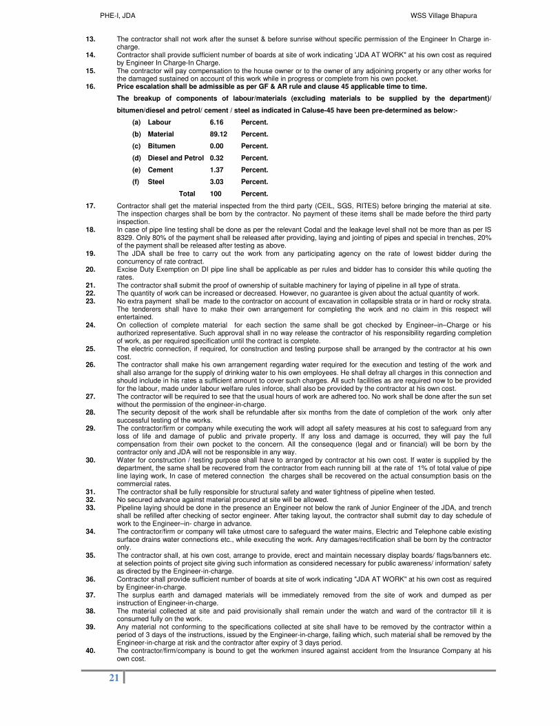
13. The contractor shall not work after the sunset & before sunrise without specific permission of the Engineer In Charge in-charge.
14. Contractor shall provide sufficient number of boards at site of work indicating 'JDA AT WORK" at his own cost as required by Engineer In Charge-In Charge.
15. The contractor will pay compensation to the house owner or to the owner of any adjoining property or any other works for the damaged sustained on account of this work while in progress or complete from his own pocket.
16. Price escalation shall be admissible as per GF & AR rule and clause 45 applicable time to time.
The breakup of components of labour/materials (excluding materials to be supplied by the department)/
bitumen/diesel and petrol/ cement / steel as indicated in Caluse-45 have been pre-determined as below:-
(a) Labour 6.16 Percent.
(b) Material 89.12 Percent.
(c) Bitumen 0.00 Percent.
(d) Diesel and Petrol 0.32 Percent.
(e) Cement 1.37 Percent.
(f) Steel 3.03 Percent.
Total 100 Percent.
17. Contractor shall get the material inspected from the third party (CEIL, SGS, RITES) before bringing the material at site. The inspection charges shall be born by the contractor. No payment of these items shall be made before the third party inspection.
18. In case of pipe line testing shall be done as per the relevant Codal and the leakage level shall not be more than as per IS 8329. Only 80% of the payment shall be released after providing, laying and jointing of pipes and special in trenches, 20% of the payment shall be released after testing as above.
19. The JDA shall be free to carry out the work from any participating agency on the rate of lowest bidder during the concurrency of rate contract.
20. Excise Duty Exemption on DI pipe line shall be applicable as per rules and bidder has to consider this while quoting the rates.
21. The contractor shall submit the proof of ownership of suitable machinery for laying of pipeline in all type of strata. 22. The quantity of work can be increased or decreased. However, no guarantee is given about the actual quantity of work. 23. No extra payment shall be made to the contractor on account of excavation in collapsible strata or in hard or rocky strata.
The tenderers shall have to make their own arrangement for completing the work and no claim in this respect will entertained.
24. On collection of complete material for each section the same shall be got checked by Engineer–in–Charge or his authorized representative. Such approval shall in no way release the contractor of his responsibility regarding completion of work, as per required specification until the contract is complete.
25. The electric connection, if required, for construction and testing purpose shall be arranged by the contractor at his own cost.
26. The contractor shall make his own arrangement regarding water required for the execution and testing of the work and shall also arrange for the supply of drinking water to his own employees. He shall defray all charges in this connection and should include in his rates a sufficient amount to cover such charges. All such facilities as are required now to be provided for the labour, made under labour welfare rules inforce, shall also be provided by the contractor at his own cost.
27. The contractor will be required to see that the usual hours of work are adhered too. No work shall be done after the sun set without the permission of the engineer-in-charge.
28. The security deposit of the work shall be refundable after six months from the date of completion of the work only after successful testing of the works.
29. The contractor/firm or company while executing the work will adopt all safety measures at his cost to safeguard from any loss of life and damage of public and private property. If any loss and damage is occurred, they will pay the full compensation from their own pocket to the concern. All the consequence (legal and or financial) will be born by the contractor only and JDA will not be responsible in any way.
30. Water for construction / testing purpose shall have to arranged by contractor at his own cost. If water is supplied by the department, the same shall be recovered from the contractor from each running bill at the rate of 1% of total value of pipe line laying work, In case of metered connection the charges shall be recovered on the actual consumption basis on the commercial rates.
31. The contractor shall be fully responsible for structural safety and water tightness of pipeline when tested. 32. No secured advance against material procured at site will be allowed. 33. Pipeline laying should be done in the presence an Engineer not below the rank of Junior Engineer of the JDA, and trench
shall be refilled after checking of sector engineer. After taking layout, the contractor shall submit day to day schedule of work to the Engineer–in- charge in advance.
34. The contractor/firm or company will take utmost care to safeguard the water mains, Electric and Telephone cable existing surface drains water connections etc., while executing the work. Any damages/rectification shall be born by the contractor only.
35. The contractor shall, at his own cost, arrange to provide, erect and maintain necessary display boards/ flags/banners etc. at selection points of project site giving such information as considered necessary for public awareness/ information/ safety as directed by the Engineer-in-charge.
36. Contractor shall provide sufficient number of boards at site of work indicating "JDA AT WORK" at his own cost as required by Engineer-in-charge.
37. The surplus earth and damaged materials will be immediately removed from the site of work and dumped as per instruction of Engineer-in-charge.
38. The material collected at site and paid provisionally shall remain under the watch and ward of the contractor till it is consumed fully on the work.
39. Any material not conforming to the specifications collected at site shall have to be removed by the contractor within a period of 3 days of the instructions, issued by the Engineer-in-charge, failing which, such material shall be removed by the Engineer-in-charge at risk and the contractor after expiry of 3 days period.
40. The contractor/firm/company is bound to get the workmen insured against accident from the Insurance Company at his own cost.

PHE-I, JDA WSS Village Bhapura
22
41. Contractor shall be the sole custodian of the men and material at work and will be fully responsible for any loss of life or otherwise occurred during the execution of the works.
42. The submission of the as-built drawings of the water line work is the precondition for the final payment. The final drawings shall be submitted in one reproducible set and 3 copies on linen bound in an album of an approved size. The contractor shall submit all the completion drawings and approved design calculations on CD ROM / DVD in two copies with proper directory structure. The scale of drawing and the size of drawing shall be as per the direction of the Engineer in Charge.
43. If there is any typographical error or otherwise in the 'G' Schedule. The nomenclature and the rates as given in the relevant BSR-2010 and JDA approved items/rates on which schedule 'G' is based, shall prevail.
SPECIAL CONDITIONS OF THE CONTRACT 1. Contractor shall get the material inspected from the third party (CEIL, SGS, RITES) before
bringing the material at site. The inspection charges shall be born by the contractor. No payment of these items shall be made before the third party inspection.
2. In case of pipe line, testing shall be done as per the relevant Code and the leakage level shall not be more than as per IS 8329. Only 80% of the payment shall be released after providing, laying and jointing of pipes and special in trenches. 20% of the payment shall be released after testing as above.
3. According to the alignment of pipe line thrust blocks shall be constructed as per IS code for which no extra payment shall be payable. The cost of thrust blocks shall be deemed to be considered in the rates quoted by bidder.
4. Excise Duty Exemption on DI pipe line shall be applicable as per rules and bidder has to consider this while quoting the rates.
5. Cement concrete roads required to be dismantled for laying of pipe line shall be done by mechanical means / breaker in the manner such that pavement in required width is only dismantled. No extra payment for cutting of payment shall be made and it shall be deemed to be considered in the rates quoted by bidder.
6. The JDA shall be free to carry out the work from any participating agency on the rate of lowest bidder during the concurrency of rate contract.
7. The quantity of work can be increased or decreased. However, no guarantee is given about the actual quantity of work.
8. No extra payment shall be made to the contractor on account of excavation in collapsible strata or in hard or rocky strata. The bidders shall have to make their own arrangement for completing the work and no claim in this respect will entertained.
9. On collection of complete material for each section the same shall be got checked by Engineer–in–Charge or his authorized representative. Such approval shall in no way release the contractor of his responsibility regarding completion of work, as per required specification until the contract is complete.
10. The electric connection, if required, for construction and testing purpose shall be arranged by the contractor at his own cost.
11. The contractor shall make his own arrangement regarding water required for the execution and testing of the work and shall also arrange for the supply of drinking water to his own employees. He shall defray all charges in this connection and should include in his rates a sufficient amount to cover such charges. All such facilities as are required now to be provided for the labour, made under labour welfare rules in force, shall also be provided by the contractor at his own cost.
12. The contractor will be required to see that the usual hours of work are adhered too. No work shall be done after the sun set without the permission of the engineer-in-charge.
13. The security deposit of the work shall be refundable after six months from the date of completion of the work only after successful testing of the works.
14. The contractor/firm or company while executing the work will adopt all safety measures at his cost to safeguard from any loss of life and damage of public and private property. If any loss and damage is occurred, they will pay the full compensation from their own pocket to the concern. All the consequence (legal and or financial) will be born by the contractor only and JDA will not be responsible in any way.
15. Water for construction / testing purpose shall have to arrange by contractor at his own cost. If water is supplied by the department, the same shall be recovered from the contractor from each running bill at the rate of 1% of total value of pipe line laying work, In case of metered connection the charges shall be recovered on the actual consumption basis on the commercial rates.
16. The contractor shall be fully responsible for structural safety and water tightness of pipeline when tested.
17. No secured advance against material procured at site will be allowed. 18. Pipeline laying should be done in the presence an Engineer not below the rank of Junior Engineer
of the JDA, and trench shall be refilled after checking of Assistant engineer. After taking layout, the contractor shall submit day to day schedule of work to the Engineer–in-charge in advance.

PHE-I, JDA WSS Village Bhapura
23
19. The contractor/firm or company will take utmost care to safeguard the water mains, Electric and Telephone cable existing surface drains water connections etc., while executing the work. Any damages/rectification shall be born by the contractor only
20. The contractor shall, at his own cost, arrange to provide, erect and maintain necessary display boards/ flags/banners etc. at selection points of project site giving such information as considered necessary for public awareness/ information/ safety as directed by the Engineer-in-charge.
21. Contractor shall provide sufficient number of boards at site of work indicating "JDA AT WORK" at his own cost as required by Engineer-in-charge.
22. The surplus earth and damaged materials will be immediately removed from the site of work and dumped as per instruction of Engineer-in-charge
23. The material collected at site and paid provisionally shall remain under the watch and ward of the contractor till it is consumed fully on the work.
24. Any material not conforming to the specifications collected at site shall have to be removed by the contractor within a period of 3 days of the instructions, issued by the Engineer-in-charge, failing which, such material shall be removed by the Engineer-in-charge at risk and the contractor after expiry of 3 days period.
25. The contractor/firm/company is bound to get the workmen insured against accident from the Insurance Company at his own cost.
26. Contractor shall be the sole custodian of the men and material at work and will be fully responsible for any loss of life or other wise occurred during the execution of the works.
27. The contractor shall be solely responsible for all kind of liaison before starting the work with PHED/Other JDA zone/JVVNL & BSNL etc. which is required to avoid any damage of already laid pipe lines, Electric, BSNL cables. The contractor shall also liaison for the inter connection work
with existing PHED system. 28. Before start of work contractor has to inform concerned JDA zone officers to avoid/minimize road
damage 29. The follow up / liaison for release of Electric Power connection of TWs from JVVNL Jaipur shall
be in the scope of contractor and shall be deposited the required fess for issue the demand note, which shall be reimbursed by JDA on submission of original receipt. As Built Drawings.
30. The submission of the as-built drawings of the proposed work with old pipe line work is the precondition for the final payment. The final drawings shall be submitted in one reproducible set and 3 copies on linen bound in an album of an approved size. The contractor shall submit all the completion drawings on CD ROM / DVD in two copies with proper directory structure. The scale of drawing and the size of drawing shall be as per the direction of the Engineer in Charge
31. If there is any typographical error or otherwise in the 'G' Schedule. The nomenclature and the rates as given in the relevant BSR-2013 and JDA approved items/rates on which schedule 'G' is based, shall prevail.
Safety aspects associated with the work.
32. Safety And Accident Prevention Officer: Due precautions shall be taken by the Contractor, at his own cost, to ensure the safety and protection against accidents of all staff and Labour engaged on the works, local residents in the vicinity of the works, and the public traveling through the works. The contractor shall deploy at least one officer from his staff, qualified to promote and maintain safe working practices. This/these officer(s) shall has/have authority to issue instructions and shall take protective measures to prevent accidents, including but not limited to the establishment of safe working practices and the training of staff and labor in their implementation. The contractor shall furnish to the department the name(s) of such officer(s) before the start of the work.
33. The contractor/firm or company while executing the work will adopt all safety measures at his cost to safeguard from any loss of life and damage of public and private property. If any loss and damage is occurred, they will pay the full compensation from their own pocket to the concern. All the consequence (legal and or financial) will be borne by the contractor only and JDA will not be responsible in any way.
34. The contractor shall not work before sunrise and after the sunset. 35. The contractor/firm or company will take utmost care to safeguard the water mains, Electric and
Telephone cable existing surface drains water connections etc., while executing the work. Any damages/rectification shall be borne by the contractor only .
36. The contractor/firm/company is bound to get the workmen insured against accident from the Insurance Company at his own cost.
37. The contractor will pay compensation to the house owner or to the owner of any adjoining property or any other works for the damaged sustained on account of this work while in progress or complete from his own pocket.
PHE-I, JDA WSS Village Bhapura
24
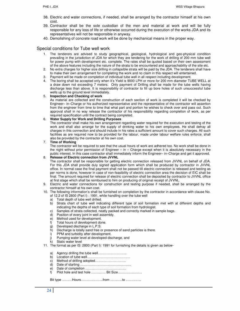
38. Electric and water connections, if needed, shall be arranged by the contractor himself at his own cost.
39. Contractor shall be the sole custodian of the men and material at work and will be fully responsible for any loss of life or otherwise occurred during the execution of the works JDA and its representatives will not be responsible in anyway.
40. Demolishing of concrete road work will be done by mechanical means in the proper way.
Special conditions for Tube well work 1. The tenderers are advised to study geographical, geological, hydrological and geo-physical condition
prevailing in the jurisdiction of JDA for which they are tendering for the work of drilling of 200 mm tube well for power pump with development etc. complete. The rates shall be quoted based on their own assessment of the above features including the nature of the strata to be encountered and approachability of the site etc.
2. No extra charges for higher size drilling in collapsible strata will be paid by the JDA. The tenderers shall have to make their own arrangement for completing the work and no claim in this respect will entertained.
3. Payment will be made on completion of individual tube well in all respect including development. 4. The boring shall be accepted only when it’s Yield is 9000 LPH or more for 200 mm diameter TUBE WELL at
a draw down not exceeding 7 meters. Only payment of Drilling shall be made for the tube wells having discharge less than above. It is responsibility of contractor to fill up bore holes of such unsuccessful tube wells up to the ground level immediately.
5. Inspection and Checking of work As material are collected and the construction of each section of work is completed it will be checked by Engineer– in–Charge or his authorized representative and the representative of the contractor will assertion from the engineer from time to time that what part and portion he wishes to check over and pass out. Such approval shall in no way release the contractor of his responsibility regarding completion of work, as per required specification until the contract being completed.
6. Water Supply for Work and Drilling Purposes The contractor shall make his own arrangement regarding water required for the execution and testing of the work and shall also arrange for the supply of drinking water to his own employees. He shall defray all charges in this connection and should include in his rates a sufficient amount to cover such charges. All such facilities as are required now to be provided for the labour, made under labour welfare rules enforce, shall also be provided by the contractor at his own cost.
7. Time of Working The contractor will be required to see that the usual hours of work are adhered too. No work shall be done in the night without prior permission of Engineer – in – Charge except when it is absolutely necessary in the public interest. In this case contractor shall immediately inform the Engineer– in–Charge and get it approved.
8. Release of Electric connection from JVVNL The contractor shall be responsible for getting electric connection released from JVVNL on behalf of JDA. For this JDA shall provide duly signed application form which shall be produced by contractor in JVVNL office. In normal case the final payment shall not be passed till electric connection is released and testing as per norms is done, however in case of non-feasibility of electric connection area the decision of EIC shall be final. The amount required for release of electric connection shall be deposited by contractor to JVVNL office at first stage which shall be reimbursed to him on producing of original receipt of JVVNL.
9. Electric and water connections for construction and testing purpose if needed, shall be arranged by the contractor himself at his own cost.
10. The following information’s shall be furnished on completion by the contractor in accordance with clause No. of 12.2 of IS 2800 (Part I) : 1991, while handling over the tube well a) Total depth of tube well drilled. b) Strata chart of tube well indicating different type of soil formation met with at different depths and
indicating the depths of each type of soil formation from hydrologist. c) Samples of strata collected, neatly packed and correctly marked in sample bags. d) Position of every joint in well assembly. e) Method used for development. f) Total hours of development done. g) Developed discharge in L.P.S. h) Discharge is totally sand free or presence of sand particles is there. i) PPM and turbidity after development. j) Pumping water level at developed discharge, and k) Static water level
11. The format as per IS: 2800 (Part I): 1991 for furnishing the details is given as below- a) Agency drilling the tube well…………………….. b) Location of tube well………………………………… c) Method of drilling adopted………………………. d) Date of starting ………………………………………. e) Date of completion ………………………………. f) Pilot hole and test hole …………. Bit Size………………….
Bit type ………Hours………………..from ………..to …………..

PHE-I, JDA WSS Village Bhapura
25
g) Coring done …………….Bit size……………. Bit type Hours ……………….recovery………………from………….to……
h) Reaming ……………..Bit Size……………..Bit Type ……………… Hours………………from………………to……………
i) Lithological data From To Formation ………………… ………………….. ……………………. ………………… ………………….. …………………….
………………… ………………….. …………………….
j) Total length of tube well drilled…………………. k) Assembly of production well ………………… Size………………
Length …………………….type ……………………… Perforation per meter ………………………………
Housing pipe …………………………………………….
Blind pipe …………………………………
Strainer pipe……………………………… Bail plug……………………………………..
l) Top of tube well above/below ground level……………… m) Size of gravel…………………… n) Quantity used before ……………………….. o) Development…………Quantity used during development……… p) Method used for development…………
Total hours of testing……………
q) Development discharge…………… r) Turbidity………………………….. s) Further details appended
i) Sample of strata, neatly packed in sample bags ii) Chart of pipe assembly lowered
Results of mechanical analysis of samples of unconsolidated strata. 12. No running payment shall be made for incomplete tube well. Payment shall be made after completion of
development, testing of tube well.
The above conditions may be read very carefully and adhered strictly.
I/we confirm above
Signature of contractor Executive Engineer (PHE-I) JDA, Jaipur

PHE-I, JDA WSS Village Bhapura
26
Section A-4
Scope of work &
Specifications of Work

PHE-I, JDA WSS Village Bhapura
27
Name of work:- Rural Water Supply Scheme for Villages of Gram Panchayat Bhapura
(1) SCOPE OF WORK
1.1 Extent of Scope of Work
The scope of work under this Contract includes construction of 2 No Tube Well’s, Providing,Laying &
Jointing of 100 mm & 150 mm dia DI pipe line, Construction of 100 KL RCC CWR, Construction of 100 KL
RCC OHSR, Construction of Pump Houses along with all EMI works under water supply scheme for
Villages of Gram Panchayat Bhapura. The contractor shall also undertake operation and maintenance of
system developed under this contract for 3 years.
1.2 General Principles
The contractor shall carryout all works, wholly, in accordance with the terms and conditions of the contract to fulfill the requirement of the components. All the material used, and the equipment installed shall be as per the specifications defined in the contract (where the specifications are not mentioned then the respective IS specifications shall be followed) the work shall be executed with good engineering practices.
Generally the following activities shall be carried out for each component of this contract but shall not be limited to:
(i) Submission of all documents required according to the Contract (ii) Submission of Action Plan/Execution Schedule in accordance with the provisions of Special
Conditions Part-A for approval of the Engineer in Charge. (iii) Getting approval of all design and drawings for material to be used, equipment
specifications and the samples, prior to dispatching / installing /commissioning of work on site or submitting the acceptance to department design & drawings.
(iv) Submission of the specifications, catalogs and the technical data sheets of all the equipment, electrical/ instrumentation,
(v) Carrying out the SBC at OHSR & CWR location through MNIT, Jaipur. Review and submission of structural designs and reinforcement drawings for all civil structures of the work (OHSR) /CWR)/ Pump House. The modified structural designs and drawings of CWR/OHSRs, should be submitted to EIC after approval from MNIT, Jaipur . All expenses for this shall be borne by the contractor.
(vi) Preparation and submission of all detailed working drawings on the basis of designs and plans provided/approved by the Engineer-in-Charge in six copies for issuance for execution.
(vii) To co-ordinate with the O&M staff and concerned officers of PHED, PWD, Forest, Mining, electric supply company and personnel of local water supply system (for carrying out the installation of new equipment), with the district administrative offices and other offices for necessary approvals and certificates.
(viii) Construction of pump house and water retaining structures. (ix) Ancillary Civil works, campus development and Buildings as defined herein after. (x) Construction, testing & commissioning of pump house, Civil works as per scope of work, as
per approved drawings & detailed specifications. (xi) The submission of the as-built drawings of the works is the pre condition for the final
payment of execution part. (xii) O & M period:
O&M period shall commence after completion of the works and issuance of completion certificate.
(xiii) Defects liability period:
The defects liability period shall be of 12 months (1 year) from the date of issue of the certificate for completion of works. This 1 year period shall run parallel to the 1
st year of O &
M period. The O & M charges shall be paid in this period however any major defects shall be replaced by contractor at his own cost.
1.3 Major Components of Work
The works under this contract are broadly divided in to the following components:

PHE-I, JDA WSS Village Bhapura
28
(i) Carryout required Topographical & Campus Survey & Geotechnical investigations.
(ii) Construction of 2 no Tube Well’s along with all allied works.
(iii) Providing, Laying & Jointing of 100 mm & 150 mm dia DI pipe line.
(iv) Construction of RCC OHSR of capacity 100 KL at Village Chatarpura, Staging 22 mtr.
(v) Construction of RCC CWR of capacity 100 KL at Village Daulatpura.
(vi) Construction of Pump House along with all EMI works at Village Daulatpura.
(vii) Supply & Installation of Centrifugal Pump sets at Pump House as per the duty conditions given in BOQ.
(viii) Required civil work like boundary wall, Air valve chambers and Meter/ Valve chamber as per items taken in BOQ.
(ix) Operation and Maintenance of works created under this contract for a period of 3 years.
The detailed scope of work and specifications of above components is as under:
(A) Specifications of SR & CWR
1. 0 Location and site Condition WSS Gram Panchayat Bhapura
2.0 Scope / Volume of work for Contractor Job Work for OHSR & CWR
The work consists of construction of RCC Elevated Service reservoirs capacity 100 KL & CWR of 100 KL as per BOQ under Water Supply Scheme for Villages of Gram Panchayat Bhapura:
S. No. Particulars No. Capacity
1
Over Head Service Reservoir of 22 mtr. Staging at Village Chatarpura, Gram Panchayat Bhapura
1
100 KL
2
Clear Water Reservoir of 100 KL at Village Daulatpura, Gram Panchayat Bhapura
1
100 KL
The present work is on Lump Sump. basis, where the responsibility of the contractor will include preparation, execution and testing of
all works as per General arrangement drawings attached and specifications.
The work will include: - To carry out survey using level instruments to find out average ground of site. Reconnaissance and investigation of site is necessary. Detailed soil investigation at the location of tank at site for confirming the safe bearing capacity of so that the contractor is equally responsible for the value adopted in the design. SBC be got conducted through MNIT only. Preparation and submission of detailed drawing and design of OHSR of required particulars. The OHSR shall be of intze type shape, supporting on raft foundation. This shall not include the design of pipes, valves, lightening arrester, conductor, earthing system, which shall be as stipulated in the tender document. The shape of ESR piping arrangements and other functional features shall be as per the drawings enclosed with the document. The structural design and reinforcement design shall be prepared assuming SBC of the site as 10.0 T/Sqm. at 3.0 meter depth in case of OHSR. If the SBC is found to be less than 10.0T/sqm at 3.0 meter depth then the structure shall be designed on the basis of actual SBC found on testing for which no extra payment will be made to the contractor. All the surfaces of the structure below ground level shall be painted with 2 coats of ISI make bituminous paint. Supply and fixing of all ancillary material as stipulated including inlet, outlet, washout, over flow pipe, sluice valves, non-return valves, duck foot bends, other specials, level indicator, lighting arrester, conductor and Earthing, manholes, ventilators, railing, ladders, etc. Construction plinth protection works, overflow pipe chambers, fixing of manhole covers, stair case railings etc. as stipulated and detailed in the set of drawings attached with the document. The testing of tanks for water tightness by filling with water shall be the contractor’s responsibility and shall have to be done in accordance with procedure laid down in the tender document. The entire structure along with all it’s installation shall being finished condition when handed over. All the exposed concrete surfaces should be finished with carborandum stone rubbing.

PHE-I, JDA WSS Village Bhapura
29
Painting of the slogan on vertical wall of Tank as indicated by the Engineer In Charge. Providing ancient Jaipur State Architectural effects on the outside of the container with nice finishing along with water proof paint (Snowcem) of approved shade on complete structure on all exposed surface after smoothing the surface with carborandum stone rubbing. Before handing over the work the site has to be cleared in every respect. The earth has to be leveled at a uniform level and surplus earth, if any, shall be disposed off as per the direction of the engineer in charge. The contractor has to submit 2 sets of as built drawings in bounded form. No separate payments shall be made for reconnaissance, preliminary investigations, surveys, inspections, plinth protection, site clearance, earth works, leveling etc. They shall be included in the L. S. rates. The contractor shall be fully responsible for the soundness of the construction, structural safety and water tightness of the structure based on the specifications, Sound engineering practices and latest IS provisions. The contractor shall also ensure at his level correctness of design and drawing of OHSR and CWR for structural safety. 3. 0 Job Work for OHSR
The shape and scope of work is given in the General Arrangement drawing. The main scope of work is given below-
A. Construction of RCC OHSR (Over Head Service Reservoir) of 22 mtr. Staging at Village Chatarpura,
Gram Panchayat Bhapura
Following are the works covered in the Job of OHSR: • SBC test of the soil for determination of SBC of the site. The structural design of the reservoir shall
be based on the actual SBC or 10 MT/Sqm. whichever is less. • Submission of structural design and drawing as per specification and general arrangement drawing
for the OHSR and get checked from MNIT Jaipur or any other NIT, MBM Engineering College as per approval of EIC
• Construction of RCC OHSR as per design approved. • Providing and fixing of all DI K-9 riser pipes, puddle collars, sluice valves, dismantling piece,
ventilator and level indicator as per specifications. • Size of riser pipes (DI K-9) shall be as below:-
OHSR of 100KL capacity with 22 meter staging Location Size Length Duck foot Band Sluice Valve
Inlet 100 mm 35 M 1 1 Outlet 100 mm 35 M 1 2
Overflow 100 mm As per requirement
1
Washout 100 mm As per Requirement
1
• Plinth protection of the RCC OHSR as per GA drawing. • The Contractor shall be fully responsible for the soundness of the construction, structural
safety & water tightness of the structure based on the specifications, sound engineering practices, and latest I.S. provisions.
• Providing & installation of Two sluice valve (resilient seated soft sealing type) on out let, one ordinary sluice valve each on inlet, washout pipe for reservoir. Inter connection of Inlet and Outlet pipe as shown in drawing of OHSR including installation of vales, dismantling piece etc. shall be made.
• Providing scour / washout pipes & its interconnection with overflow pipe including P/F of sluice valve as shown in detailed drawing of OHSR.
• Valve chamber for valve of out let pipe shall have to be constructed. • Excavation for all structures including working spaces, trench excavation for pipes & other
ancillary works in all sorts of soils, refilling & disposal of surplus earth at suitable site & dressing as per direction of Engineer-in-charge.
• Providing plinth protection works as per specifications and approved drawing. • Providing lightning arrester on the top of OHSR,s. • Providing access to the top and inside the reservoir as per the drawing. • Providing ventilation for the reservoir as per the specifications given in the chapter of
“Specifications for Elevated Service Reservoir & Specifications for Civil Works”.
• Providing 25 mm diameter GI pipe (Class B) in two rows in 50x50x6mm angle iron railing along the top of reservoir, on the sides of the staircase and balcony, and at other suitable points for the requirement of safety of maintenance and execution staff.
• The outer surface of top dome shall be painted with suitable anti-carbonation paint. • Testing of tank for water tightness and structural stability by filling it with water and in
accordance to the procedure laid down in tender document/IS code. • Colour washing using cement paint of approved make & quality as per specifications • Painting the metallic surface & putting slogan on tank as per specifications. • Final clearance of site before handing over the work, including leveling of earth and
disposal of surplus earth as per directions of the Engineer in Charge.

PHE-I, JDA WSS Village Bhapura
30
• Submission of 'As Built' drawings. • Cleaning, washing & disinfecting the reservoir and making its interior free of all foreign
material, loose particles, debris etc and making it fit for storage of potable water, once in a year.
1. PREPARATORY WORK The contractor shall provide and maintain a benchmark with a level at a location approved by the
Engineer In Charge at ESR construction sites. All levels shall be deemed to refer to that benchmark. The Contractor may establish other secondary benchmarks on the site.
2. Soil Investigation
The contractor necessarily has to perform S.B.C. test at site for a permissible settlement of 25mm at the depth of 3.0 mtr for ESR. And accordingly design should be carried out. For estimation purpose SBC may be assumed as 10.0 T/sqm. For design propose and if SBC is less than 10.0 T/Sqm then actual SBC shall be considered for Design no extra payment shall be made for extra foundation. He shall be solely responsible for the overall safety of structure.
3. Location The site for the tanks has been fixed. This may be seen to have a fair idea of the work site. 4 CIVIL WORKS
4.1 General
The construction of service reservoir shall be carried out in accordance with the drawings specification mentioned herein and relevant IS amended up to date. The general arrangement of the piping system shall be as per drawings enclosed with the tender documents. In cases where the specifications given below are silent about any aspects in respect of any item, the work shall be carried out as per the relevant IS code of practice in the latest version and as per sound engineering practice as decided by the Engineer in Charge.
Some of the important IS codes to be referred during execution of the work are as follows:
5. Earth work
- IS 3764 – Safety code for excavation works - IS 3720 – Methods of tests for soils 6. Soil Investigation
- IS – 1888 – Load test on soil IS – 2131 – Standard Penetration Test for soil method
7. Concrete Works & Reinforcement
- IS.280 – Mild steel wire for general engineering purposes IS.1786 – High strength deformed bars and wires for concrete reinforcement - IS.269 – Ordinary & low heat Portland cement - IS.383 – Aggregate, coarse & fine, from natural sources for concrete - IS.456 –plain and reinforced concrete, Code of practice - IS.516 – Methods of testing for strength of concrete - IS.1199 – Method of sampling and analysis of concrete - IS.1566 – Fabric reinforcement - IS. 3370 – Code of practice for concrete structures for the storage of liquids - IS. 7861 – Recommended practice for hot weather concreting (Part-I) - IS. 4082– Recommendation on stacking and storage of construction material on site. 8. General
- IS.875 - Code of practice for structural safety of buildings, loading standards - IS.1911 – Dead loads - IS.1893 – Criteria for earthquake resistant design and structures - IS.2950 – Design & construction of raft foundation, code for practice (part-1) IS-11089- Design & construction of ring foundation, code for practice - IS.1200 – Method of measurements 9. Detailed design
• The detailed design, structural design and drawings (including reinforcement detailing and bar bending schedule) shall have to prepared taking provisions of dead load, water load, live load, seismic load, wind load, point loads due to pipes etc. and shall be checked for most critical condition resulting for various load combinations. The design shall be based on no crack basis for water retaining components.
• For the purpose if design safe bearing capacity of soil shall determine by SBC test at site or as directed by Engineer in Charge.
10. LOADS
Account shall be taken of all loads due to dead loads, live loads, wind loads, seismic loads, water pressure, soil pressure and point loads caused during installation of pipes etc.
The live load for top dome shall be taken as 1.50 KN/sqm. The platforms and stairs shall be designed for a live load of 3.00KN/sqm in addition to other loads.
Full water depth including free board and dead storage shall be considered for structural design of the tank.
The area is situated in seismic zone number II and the seismic load shall be taken accordingly. The wind load shall be taken assuming a basic wind speed of 170 Km/h. 11. CONCRETE MIXES
Cement concrete (plain or reinforced) shall comply with the requirement of specifications of Rajasthan PWD (B&R) Specification and Explanatory Notes for Buildings and House Drainage except in so far as these are not altered or modified by specific stipulations as given in the specifications herein. The

PHE-I, JDA WSS Village Bhapura
31
concrete grades to be used shall not be leaner than following: - Water bearing structure i.e. container, beam top and bottom dome
M-30 - Other structural concrete M25 - Lean concrete in foundation M15 12. CONCRETE COVER AND THICKNESS The minimum clear cover of reinforcement bars shall be as following: - In case of dry surface (shaft, platforms) 25 mm In case of dry surface (foundation) 50 mm
- In case of occasionally wetted surface (roof) 30 mm
- In case of permanently wetted surfaces/walls and bottom of the water chamber, central access shaft, platform in the reservoir) reinforcement dia up to 20 m
35 mm
- In case of permanently wetted surfaces/walls and bottom of the water chamber, central access shaft, platform in the reservoir) reinforcement dia above 20 mm
40 mm
The various dimensions shall not be less than the following - Thickness of top dome 125 mm - Thickness of bottom dome for ESR 150 mm - Thickness of platform, landings 150 mm - Thickness of Water retaining walls, slabs <2m 150 mm - Thickness of Water retaining walls, slabs >2m 200 mm - Thickness of Other structural walls (load bearing) 150 mm - Thickness of Non structural walls 150 mm - Free board depth for ESR 300 mm - Dead storage depth for ESR 250 mm - Thickness of lean concrete below foundation 150 mm - Depth of foundation for ESR 2.50 m - Age factor shall not be more than 1 (one) 13. GENERAL RCC The aggregates and cement shall be proportioned by weight only. The mixing shall invariably be carried
out in mechanical mixer and in such a way so as to avoid any loss of water or cement. No hand mixed concrete will be allowed. It should be conveyed, placed in position and compacted by suitable type of mechanical vibrator as rapidly as practicable but in no case the time of compaction after mixing shall increase 30 minutes. Standby Concrete Mixer and Vibrator shall be available at Site.
The concrete shall be cured properly by keeping it moist constantly until end of three weeks from the date of casting.
Ordinary Portland Cement (OPC) conforming to IS: 269-1976 mark shall only be used. Cement manufactured in mini-cement plants shall not be used.
All reinforcement used shall be of Tor steel (Fe 415) ISI marked shall be clean and free from loose mill scales, rust and coating of oil or other coatings which may destroy or reduce bond. Minimum size of reinforcement bars shall be of 8mm. Only steel shuttering shall be used. Shuttering shall be new or in good condition without holes or dents. It has to be approved by the Engineer in Charge. The individual elements should be in the good shape to ensure a gap free shuttering according to the drawings. The paint used shall have good bonding and shall not stick to the concrete surface. Suitable system have to be provided for keeping the surface in place and keeping the correct distance in case of walls. The construction joints should be minimum and they have to be executed with most care. Before continuing concreting the loose material has to be removed and they have to be cleaned properly. Honey combing has to be avoided by suitable shuttering and proper use of vibrators.
The water used for concreting shall be free from all undesirable salts and other impurities and shall be fit for concreting as per IS : 456.
It is specifically being mentioned that the ground water available in this area may not be potable and not fit for concreting, therefore transportation from nearby safe water source has to be made. For the purpose of concreting and curing only potable water is to be used. For this purpose contractor shall make a temporary masonry/RCC underground water reservoir of 3 days average water consumption storage capacity. He shall provide a diesel pump set and necessary piping arrangement to ensure proper curing.
The exposed surface of concrete shall be kept continuously in a wet condition by ponding or covering with a layer of sackings, canvas, hessain or similar materials and kept continuously wet for at least 21 days from the date of placing of concrete.
To obtain a dense concrete and to reduce chances of honeycombing adequate admixture approved by Engineer In Charge shall be used as integral water proofing compound in concrete work. The quantity of the admixture shall be as prescribed by the manufacturer and as approved by the Engineer in Charge.
14. Testing
Materials and workmanship shall comply with the relevant specifications as described in subsequent clauses and in the Rajasthan PWD(B&R) Specification and Explanatory Notes for Building and House Drainage. Any material or workmanship not covered by the above specifications shall comply with the relevant Indian Standard (with up to date amendments).
15. MATERIAL
The Contractor shall submit to the Engineer In Charge or his representative, samples of the materials which will form part of the permanent works, sufficiently in advance of the start of the work, so that necessary tests can be carried out for the approval of the Engineer In Charge or his representative, before using any such material on site. Samples for the basic materials shall be submitted from every supplier and from each consignment; if materials differ from one consignment to another, the consignment differing from the accepted sample shall be replaced by the Contractor free of cost. The format will be provided by Engineer In Charge.
The testing of materials to be used in the Works, or of the quality of finished items shall generally be done in a laboratory approved by the Engineer In Charge or his representative. All testing charges shall be borne by the Contractor. The following tests shall be carried on a routine basis:
Gradation and specific gravity of coarse and fine aggregate to be used for concrete work.

PHE-I, JDA WSS Village Bhapura
32
Moisture content in fine and course aggregates, bulking of sand of fine aggregate. Determination of fines and deleterious materials, organic impurities and light weight places in course and fine aggregate. Workability tests on concrete by means of slump cone. Determination of the crushing strength, absorption and efflorescence of bricks. Concrete cube crushing strength at 7 days and 28 days. Determination of flakiness index and crushing value for coarse aggregates.
The above tests (a) to (g) inclusive, shall be done on a routine basis as per the provisions of the relevant Indian Standards, or as specified by PMC and explanatory notes shall be kept during the construction period. The following additional tests of materials and workmanship shall also be carried out at contractor’s cost, if the Engineer In Charge or his representative require:-
Chemical tests of fine and coarse aggregates, to determine the sulphate, chlorides and other deleterious material present in the aggregate. Testing of cement (Physical and Chemical), as per IS 269 or IS 485, as the case may be. Tests on steel (High Tensile (Tor) as per IS 1786 to establish the Ultimate tensile strength, yield stress, percentage elongation and chemical composition. Tests for suitability of water for concrete work.
In addition to the above tests, the Engineer In Charge or his representative, may request any other test to be carried out from time to time as per the Indian Standards or the Rajasthan PWD specification, at contractor’s cost.
16. CONCRETE During the progress of construction sampling, preparation of test specimens, curing and testing of
concrete shall be conducted in accordance with IS :1199 and IS : 516, to determine whether the concrete being produced complies with the strength requirements as specified.
At least one slump test shall be carried out for every compressive strength test carried out, or as directed by the Engineer in Charge. Six No.15 cm cubes shall be made for each cubic meter or portion thereof or for each pour per grade of concrete. This number may be increased at the discretion of the Engineer In Charge. Six specimens shall preferably be prepared from different batches, three being tested after 7 days and the remaining three being tested at 28 days. The Contractor shall provide, at his own expense, all apparatus, labour and arrange for testing at a laboratory, approved by the Engineer in Charge.
The concrete tested in accordance with “Testing of Concrete” clause above, shall me the criteria for acceptance of concrete as per IS 456. The strength of concrete shall be the average strength of three specimens tested at 28 days and conform to strength requirements for different grades of concrete. If the advance 7 days tests show crushing strengths that are too low, corrective measures shall be taken at once, at the Engineer’s direction, without waiting for the results of the 28 days tests.
17. Failure to meet Strength Requirements In cases where concrete tested fails to meet the test requirements, the Engineer In Charge shall have the right to require any one or all the following additional tests. These shall be carried out by contractor at his own expense. The Engineer In Charge shall be the finally authority for interpreting the results and shall decide upon the acceptance or otherwise. Curing and load testing of the concrete member concerned represented by the test which failed. Replacement of any such portions of the structure. No payment shall be made for the dismantling of the concrete, relevant form work, or reinforcement. Embedded fixtures and reinforcement of adjoining structures damaged during dismantling shall be made good by the contractor at his own expense. Extended curing of the structure of the concrete represented by the specimen. Collecting and testing of a core specimen from the hardened concrete. The location number and size of such specimen shall be taken as directed by the Engineer In Charge. Any Other tests i.e. ultrasonic/ or rebound hammer tests to be decided by the Engineer In Charge, at the contractors own cost.
18. Check of Reinforcement and Concreting All reinforcement shall be got checked recorded prior to pouring of concrete, by a representative of the Engineer In Charge. Similarly, the entire concrete pouring work shall be done in the presence of an officer not below the rank of Site Engineer. The contractor shall therefore, give a notice of a minimum three days to the Engineer In Charge or his representatives, such that the work can be checked by him or his representative . No work shall be covered before inspection and approval of Engineer In Charge.
19. Final Finishing The contractor shall ensure that the entire structure along with all its installations are in a finished and in new and fully operative condition when handed over. He shall have repaired and remove all signs of damage that might have been done during the course of installation and fixing of equipment. He shall also see that all the exterior finished properly and the entire site is cleared all extra construction material, debris and excavated soil. This shall have to be done to the satisfaction of Engineer In Charge.
20. All flanged Specials
The cast iron flanged specials (all flanged tee, flanged tapers, bends, blank flanges. Puddle collar) shall conform to IS 1538. The specials shall be internally and externally coated with hot applied (dip) bituminous paint. All flanged specials shall be used for nominal pressure of 25 kg/cm2 (2.5 Mps). Flanged specials shall be supplied with the galvanized bolts, nuts and rubber gaskets. The galvanized nut & bolts shall be supplied in jute bag; rubber gasket shall be supplied in polyethylene bags. The rubber gaskets shall conform to IS 5382. The length and size of the puddle collars to be fixed at different places of the structures shall be decided by the Engineer in Charge.
21. Puddle Collar All puddle collars shall be of C.I. The length and size of the puddle collars shall be as shown in drawings.
22. Ladder M. S. ladder 450 mm wide, made up of 50mm x 50mm x 6 mm M. S. angle iron and 25mm M. S. bars
welded at 300mm c/c shall be provided outside from the balcony to top dome. MS cage shall also be provided on this ladder as shown in drawing. The ladder from top dome to inside platform and from platform to button dome in the container shall be of aluminum. Its drawing shall be got approved from EIC

PHE-I, JDA WSS Village Bhapura
33
before dispatch. 23. Railing Hand railing around the platforms, Balcony, stairs and landings shall be consisting of 25mm diameter
medium B class GI pipes in two rows (one at the top and other at middle level) and 1000mm high vertical post 65x65x6 mm angle iron @ 1500mm center to center (At least two vertical angles are to be provided wherever distance is less) with all accessories like elbows, tees etc. including welding, threading and embedding in cement concrete floor. Railing shall be protected against corrosion after welding. The pipe shall pass through hole in the vertical angle.
24. Water level indicator
The level will be transferred at suitable and visible place. 25. Ventilator This shall be 300mm dia MS cowl, 300 mm high with mosquito proof jali of stainless steel as per drawing
shall be fixed at the top Alternatively a CI ventilator may be provided. 26. Lightening arrester Lighting arrester shall be of copper bar of 25mm dia and 2m. long to be provided at the top of ESR. This
is to be connected by a GI strip of 25 mm wide & 3mm thick. This conductor strip shall be connected to a 450mm x 450mm x 450mm x 3mm thick copper plate to be embedded below the average ground level y digging a pit as shown in drawing. The Earthing system shall comply with Indian Electricity Rules and shall confirm to IS 3043. The pit shall be refilled by alternate layers of salt and coke as shown in the drawing and balance shall be filled with loose soil. The 40 mm dia GI watering pipe shall be provided in the pit. Care shall be taken that earth pit does not sink.
27. Painting If not otherwise stated metallic surfaces shall receive one initial coat at the manufacturer’s workshop.
Alter arrival of the equipment on site, the same shall be inspected and damaged portions shall be cleaned and given the primer and under coat of similar paint. After erection all metal work shall be painted as follows:
Painting of metallic surfaces
Primer of red oxide, two under coats and one finishing coat of an approved enamel paint and of approved shades.
28. Plinth Protection Plinth protection works are to be constructed below the Elevated Service Reservoir, it shall be extended
up to 1m from fall of balcony or edge of raft slab, whichever is more all around service reservoir. It shall consist of laying lean concrete 150 mm thick in M10 with CC 1:2:4 60 mm thick flooring over compacted soil. Sectional details shall be as indicated in the drawing including included with the document.
The minimum free space between plinth protection and the first bracing of the ESR shall be 1.60 mtr. 29. Dismantling joints
All valves shall be installed between flanges with a flexible cast iron dismantling joint at one side of the valve. The joint must allow the dismantling without stress to the joints of the attached pipes, the minimum clearance of the dismantling joint shall be 5 Cms. Drawing of the dismantling joint shall be submitted to the Engineer In Charge for approval.
30. Water bars (for SR) PVC water stop of 320 mm. Wide will be fixed between foundation of wall and base slab. pvc water stop of 230 mm wide will be fixed between foundation of columns and base slab & all radial joints and in construction joints of vertical wall as per IS 3370 Part-I1965 Clause 8.5.2.
31. Slogan and logo
The contractor shall paint a area of 6m x 3m on the vertical wall of the tank portion by using 3 coats of plastic emulsion paint of shade as approved by Engineer In Charge to form a base for writing the slogan and logo of “JAL BHI SEEMIT PARIWAR BHI SEEMIT” in Hindi. For writing the slogan the letters shall be of 30 cm size. The size of logo shall be 75 cm. The shade for painting the slogan will be approved and directed by Engineer in Charge.
32. Pipe Clamp The clamp shall be 10 mm thick 55mm wide MS flat fixed on pipe & column as shown in drawing. 33. Man Hole Cover
Square man hole cover 800x800 mm shall be provided. The cover shall be made of 3 mm thick MS flat. The frame shall be made of MS angle 80*80*4. The cover shall be connected to this frame by using two nos. strung hinges. Arrangement shall be provided as shown in drawings.
34. Testing for water tightness The contractor shall carry out a water tightness test for the maximum water head condition i.e. with the
water standing at full supply level. All cost of testing shall be born by the contractor. This test shall be carried out in accordance with the procedure given below:
For water tightness test, before the filling operations are started, the reservoirs shall be jointly inspected by the Engineer In Charge and the representative of the Contractor and condition of surfaces of wall, construction joints etc. shall be inspected and noted and it shall be ensured that jointing material filled in the joints is in position and all openings are closed. The contractor shall make necessary arrangement for ventilation and lighting of reservoir by way of floodlights, circulators etc. for carrying out proper inspection of surface and internal conditions if so desired by the Engineer in Charge.
The water retaining structures shall be filled with water gradually at the rate not exceeding 30 cm. Rise in water level per hour and shall extend for a period of 72 hours. Records of leakages starting at different level of water in the reservoirs, if any, shall be kept.
The reservoirs once filled shall be allowed to remain filled for a period of 7 days before any readings or drop in water level is recorded again at 7 days. The total drop in surface level over a period of 7 days shall be taken as indication of the water tightness of the reservoir, which for all practical purposes shall not exceed 40mm. There shall be no indication of leakages around the puddle collars or on the wall and bottom of the reservoir.
If the structure does not satisfy the test requirements, and the daily drop in water level is decreasing, the

PHE-I, JDA WSS Village Bhapura
34
period of test may be extended for a further seven days and if the specified limit is not exceeded, the structure may be considered as satisfactory.
In case the drop in water level exceed the permissible limit with the stipulated period of test, the Contractor shall carry out such additional works and adopt such measures as may be directed by the Engineer In Charge to reduce the leakage in the permissible limit. The entire rectification work that shall be carried out in this connection shall be at Contractor’s cost.
If the test results are unsatisfactory, the Contractor shall ascertain the cause and make all necessary repairs and repeat the water retaining structure test procedures, at his own cost. Should the re-test results still be unsatisfactory after the repairs, the structure will be condemned and the Contractor will dismantle and reconstruct the structure, to the original specification, at his own cost.
B. Construction of CWR of Capacity 100 KL at Village Daulatpura, Gram Panchayat Bhapura
Following are the works covered in the Job of CWR • SBC test of the soil for determination of SBC of the site. The structural design of the
reservoir shall be based on the actual SBC or 8 MT/sqM, whichever is less.
• Submission of structural design and drawing as per specification and general
arrangement drawing for the CWR and get checked from MNIT Jaipur or any other NIT
as per approval of EIC
• Construction of RCC CWR,s as per design approved.
• Providing and fixing of all puddle collars, valves, ventilator, dismantling piece and level
indicator as per specifications.
• Size of Puddle collars/ DI pipes shall be as below;
Location Pipe/Puddle Size
Length Duck foot Band
Inlet 150 mm Puddle 1 nos 1 Outlet 200 mm 2.75 mtr./1 nos Overflow 200 mm As per requirement
• Plinth protection of the RCC CWR,s as per GA drawing.
• The Contractor shall be fully responsible for the soundness of the construction, structural
safety & water tightness of the structure based on the specifications, sound engineering
practices, and latest I.S. provisions.
• Valve chamber for valve of out let pipe SV shall have to be constructed.
• Excavation for all structures including working spaces, trench excavation for pipes & other
ancillary works in all sorts of soils, refilling & disposal of surplus earth at suitable site &
dressing as per direction of Engineer-in-charge.
• Providing access to the top and inside the reservoir as per the drawing.
• Providing ventilation for the reservoir as per the specifications given in the chapter of
“Specifications for Clear Service Reservoir & Specifications for Civil Works”.
• The outer surface of top dome shall be painted with suitable anti-carbonation paint.
• Testing of tank for water tightness and structural stability by filling it with water and in
accordance to the procedure laid down in tender document/IS code.
• Colour washing using cement paint of approved make & quality as per specifications
• Painting the metallic surface & putting slogan on tank as per specifications.
• Final clearance of site before handing over the work, including leveling of earth and
disposal of surplus earth as per directions of the Engineer in Charge.
• Submission of 'As Built' drawings.
• Cleaning, washing & disinfecting the reservoir and making its interior free of all foreign
material, loose particles, debris etc and making it fit for storage of potable water, once in a
year.

PHE-I, JDA WSS Village Bhapura
35
DESIGN CONDITIONS FOR UNDERGROUND OR PARTLY UNDERGROUND LIQUID RETAINING STRUCTURES Ground or partly underground liquid containing structures shall be designed for the following conditions: Liquid depth up to full height of wall : no relief due to soil pressure from outside to be considered; Structure empty (i.e. empty of liquid, any material, etc.): full earth pressure and surcharge pressure wherever applicable, to be considered; Structures shall be designed for uplift in empty conditions with the water table as indicated in geo-technical report & due care should be taken for seasonal variation on higher side. Walls shall be designed under operating conditions to resist earthquake forces from earth pressure mobilization and dynamic water loads; Ground or partially underground structures shall also be checked against stresses developed due to any combination of full and empty compartments with appropriate ground/uplift pressures from below to base slab. The design shall be such that the minimum gravity weight exceeds the uplift pressure at least by 20%. An increase cover of 15 mm is recommended for walls and roof bottom to account for contract with chlorinated water in side the reservoir. The increase cover is not proposed for the base slab as cement concrete screed topping is proposed to provide protection to the RCC Structure. FOUNDATIONS The minimum depth of foundations for the structures, frame foundations and load bearing walls shall be as per IS 1904. Bearing capacity of soil shall be determined as per IS: 6403. Care shall be taken to avoid the foundations of adjacent buildings or structure foundations, either existing or not within the scope of this contract. Suitable adjustments in depth, location and sizes may have to be made depending on site conditions. No extra claims for such adjustments shall be accepted. A structure subjected to groundwater pressure shall be designed to resist floatation. The dead weight of empty structure shall provide a factor of safety of 1.2 against uplift during construction and service. Where there is level difference between the natural ground level and the foundations of structure or floor slabs, this difference shall be filled up in the following ways In case of liquid retaining structures, the natural topsoil shall be removed as described above and the level difference shall be made up with Plain Cement Concrete not weaker than M 10.
DESIGN REQUIREMENTS The following are the design requirements for all reinforced or plain concrete structures.
a) All blinding and leveling concrete shall be a minimum 75 mm thick in concrete grade M10 unless otherwise specified.
Liquid Retaining Structures:
All structural reinforced concrete shall be of a minimum M25 grade with a maximum 40 mm aggregate size for footings and base slabs and with a maximum 20 mm aggregate size for all other structural members. The reinforced concrete for water retaining structures shall have minimum cement content of 360 kg/m
3 with a
maximum 20 mm size aggregate and 330 kg/m3 with a maximum 40 mm size aggregate.
The minimum reinforcement in walls, floors and roofs in each of two directions of right angles within each surface zone shall be as per 7.1 of IS: 3370 part 2.
a) The nominal cover of concrete for all steel, including stirrups, links, sheathing and spacers shall be as per 7.2 of IS: 3370 Part 2.
b) Structure shall be provided with damp proofing for basement and floors and water proofing for roofs. Any structure or pipeline crossing below roads shall be designed for Class A of IRC loading. All pipes and conduits laid below the structural plinth and road works shall be embedded in reinforced concrete of grade M20 of minimum thickness 150 mm. Suitable admixtures may be used with the approval of Engineer in charge. Construction of floors and walls of Liquid Retaining structures shall be as per 9.4 & 9.5 of IS: 3370 Part 1. The following minimum thickness shall be used for different reinforced concrete members, irrespective of design thickness.
(i) Walls for liquid retaining structures : 150 mm (ii) Roof slabs for liquid retaining structures (other than flat slabs) : 125 mm (iii) Bottom slabs resting on Ground for liquid retaining structures : 150mm (iv) Floor slabs including roof slabs, walkways, canopy slabs : 100 mm (v) Wall of cables/ pipe trenches, underground pits etc. : 150 mm (vi) Column footings : 300 mm (vii) Parapets, Chhajja : 100 mm
CONCRETE MIXES Cement concrete (plain or reinforced) shall comply with the requirement of specifications of Rajasthan PWD (B&R) Specification and Explanatory Notes for Buildings and House Drainage except in so far as these are not altered or modified by specific stipulations as given in the specifications herein. The concrete grades to be used shall not be leaner than following: Water bearing structure i.e. container, beam platform in the M25 reservoir and roof. Other structural concrete M25 Lean concrete in foundation M10

PHE-I, JDA WSS Village Bhapura
36
(B) Specifications of D.I. Pipe line work
The work consists of Providing, Laying & Jointing of 100 mm & 150 mm DI pipe line in approximately 19100.00 mtr length as per BOQ under Water Supply Scheme for Villages of Gram Panchayat Bhapura:
Ductile Iron Pipe:- The pipes will be centrifugally cast (spun) Ductile Iron pipes for Water and Sewage confirming to the IS 8329: 2000. The pipes used will be either with push on joints (Rubber Gasket Joints) or Flanged joints. The class of pipe to be used shall be of the class K-7. The pipes shall be coated with bitumen as per appendix C and have factory provided cement mortar lining in the inside as per the provisions of Appendix B of the IS 8329: 2000. The pipes will be supplied in standard length of 5.50 and 6.00 meters length with suitably rounded or chamfered ends. Each pipe of the push on joint variety will also be supplied with a rubber EPDM gasket. Any change in the stipulated lengths will be approved by the Engineer – in charge. The gaskets will confirm to the IS 5382:1985.
The gaskets should also be supplied by the manufacturer of the pipes. They should preferably be manufactured by the manufacturer of the pipes. In case they are not, it will be the responsibility of the manufacturer of the pipes to have them manufactured from a suitable manufacturer under it’s own supervision and have it tested at his/sub contractors premises as per the contract. The pipe manufacturer will however be responsible for the compatibility and quality of the products. The flanged joints will confirm to the Clause 6.2 of IS 8329. The pipe supply will also include one rubber gaskets for each flange. Inspection and Testing: The pipes will be subjected to following tests for acceptance: Visual and dimensional check as per Clause 13 and 15 of IS 8329 Mechanical Test as per Clause 10 of IS 8329 Hydrostatic Test as per Clause 11 of IS 8329 The test reports for the rubber gaskets shall be as per acceptance tests of the IS 5832 and will be in accordance to Clause 3.8 The sampling shall be as per the provisions of the IS 8329 Marking All pipes will be marked as per Clause 18 of IS 8329 and show as below: Manufacturer name/ stamp Nominal diameter Class reference A white ring line showing length of insertion at spigot end Packing and Transport: The pipes should be preferably transported by road from the factory and stored as per the manufacturer specifications to protect damage.
Specials for Ductile Iron Pipes General This section covers the general requirements for Ductile Iron (DI) fittings suitable for Tyton joints to be used with Ductile Iron pipes with flanged and Tyton jointing system. Types of specials The following types of DI fittings shall be manufactured and tested in accordance with IS: 9523 or BS: 4772. flanged socket
flanged spigot Double socket bends (900, 450, 22 1/2 0, 11 1/4 0) Double socket branch flanged tee All socket tee. Double socket taper. All Flanged Tee. All Flanged taper.
Supply All the DI fittings shall be supplied with one rubber ring for each socket. The rubber ring shall conform to IS: 12820 and IS: 5382 as described in the preceding chapter. Flanged fittings shall be supplied with one rubber gasket per flange and the required number of nuts and bolts. General This section covers the requirements for lubricant for the assembly of Ductile Iron pipes and specials suitable for Tyton push-in rubber ring joints Specification The lubricant has to have the following characteristics:
must have a paste like consistency and be ready for use has to adhere to wet and dry surfaces of DI pipes and rubber rings to be applied in hot and cold weather; ambient temperature 0 - 50 °C, temperature of exposed pipes up to 70 °C must be non toxic
must be water-soluble

PHE-I, JDA WSS Village Bhapura
37
must not affect the properties of the drinking water carried in the pipes must not have an objectionable odour has to inhibit bacterial growth must not be harmful to the skin must have a shelf live not less than 2 years Acceptance tests They shall be conducted in line with the provisions of the IS 9523
Packing All the DI fittings shall be properly packed with jute cloth. Rubber rings shall be packed in polyethylene bags. Rubber rings in PE bags and nuts, bolts etc. shall be supplied in separate jute bags. The fittings should also be supplied by the manufacturer of the pipes. They should preferably be manufactured by the manufacturer of the pipes. In case they are not, it will be the responsibility of the manufacturer of the pipes to have them manufactured from a suitable manufacturer under it’s own supervision and have it tested at his/sub contractors premises as per the contract. The pipe manufacturer will however be responsible for the compatibility and quality of the products. Laying and jointing of DI pipes Pipes should be lowered into the trench with tackle suitable for the weight of pipes. For smaller sizes, up to 200 mm nominal bore, the pipe may be lowered by the use of ropes but for heavier pipes suitable mechanical equipment have to be used. All construction debris should be cleared from the inside of the pipe either before or just after a joint is made. This is done by passing a pull-through in the pipe, or by hand, depending on the size of the pipe. All persons should vacate any section of trench into which the pipe is being lowered On gradients of 1:15 or steeper, precautions should be taken to ensure that the spigot of the pipe being laid does not move into or out of the socket of the laid pipe during the jointing operations. As soon as the joint assembly has been completed, the pipe should be held firmly in position while the trench is back filled over the barrel of the pipe. The designed anchorage shall be provided to resist the thrusts developed by internal pressure at bends, tees, etc. Where a pipeline crosses a watercourse, the design and method of construction should take into account the characteristics of the watercourse to ascertain the nature of bed, scour levels, maximum velocities, high flood levels, seasonal variation, etc. which affect the design and laying of pipeline. The assembly of the pipes shall be made as recommended by the pipe manufacturer and using the suitable tools. The socket and spigot ends of the pipes shall be brushed and cleaned. The chamfered surface and the end of the spigot end have to be coated with a suitable lubricant recommended by the manufacturer of the pipes. Oil, petroleum bound oils, grease or other material which may damage the rubber gasket shall not be used as lubricant. The rubber gasket shall be inserted into the cleaned groove of the socket. It has to be checked for correct positioning. The two pipes shall be aligned properly in the pipe trench and the spigot end shall be pushed axially into the socket either manually or with a suitable tool specially designed for the assembly of pipes and as recommended by the manufacturer. The spigot has to be inserted up to the insertion mark on the pipe spigot. After insertion, the correct position of the socket has to be tested with a feeler blade Deflection of the pipes -if any- shall be made only after they have fully been assembled. The deflection shall not exceed 75 % of the values indicated by the pipe manufacturer. Anchoring of the pipeline Thrust blocks shall be provided at each bend, tee, taper, end piece to prevent undue movements of the pipeline under pressure. They shall be constructed as per design of ENGINEER- IN- CHARGE according to the highest pressure during operation or testing of the pipes, the safe bearing pressure of the surrounding soil and the friction coefficient of the soil. Leakage Test
After laying and jointing the pipeline shall be tested for tightness of barrels and joints, and stability of thrust blocks in sections approved by the Engineer in Charge. The length of the sections depends on the topographical conditions. Preferably the pipeline stretches to be tested shall be between two chambers (air valve, scour valve, bifurcation, other chamber). At the beginning, the Contractor shall test stretches not exceeding 2 km. After successful organization and execution of tests the length may be extended to more than 2 km after approval of the Engineer in Charge. The water required for testing shall be arranged by the contractor himself. The Contractor shall fill the pipe and compensate the leakage during testing. The Contractor shall provide and maintain all requisite facilities, instruments, etc. for the field testing of the pipelines. The testing of the pipelines generally consists in three phases: preparation, pre-test/saturation and test immediately following the pre-test. Generally, the following steps are required which shall be monitored and recorded in a test protocol if required The testing conditions for the pipelines are summarized as follows: Maximum hydrostatic test pressure for DI K-7 pipes shall be 2.0 times of maximum design pressure in the pipeline. Pre test and saturation period with addition of make-up water
Pressure: Test pressure Duration: 3 hrs for DI pipes without cement mortar lining / 24 hrs for DI pipes with
cement mortar lining Pressure test with addition of make-up water
Pressure: Test pressure Duration: 3 hrs
Test criteria for DI pipes: Q = 1 liter per km per 10mm of pipe per 30 m test pressure per 24 hrs.

PHE-I, JDA WSS Village Bhapura
38
All pressure testing at site should be carried out hydrostatically. The pipes shall be accepted to have passed the pressure test satisfactorily, if the quantity of water required to restore the test pressure as per the latest codal provisions does not exceed the amount ‘Q’, calculated by the above formula. If it is required to test a section of a pipeline with a free end, it is necessary to provide temporary support against the considerable end thrust developed by the application of the test pressure. The end support can be provided by inserting a wooden beam or similar strong material in a short trench excavated at right angle to the main trench and inserting suitable packing between the support and pipe end. The pipeline stretch will pass the test if the water added during the test period is not exceeding the admissible limits. No section of the pipe work shall be accepted by the Engineer in charge until all requirements of the test have been obtained. On completion of a satisfactory test any temporary anchor blocks shall be broken out and stop ends removed. Backfilling of the pipeline shall be completed. Failure to pass the test All pipes or joints which are proved to be in any way defective shall be replaced or remade and re-tested as often as may be necessary until a satisfactory test shall have been obtained. Any work, which fails or is proved by test to the unsatisfactory in any way, shall be redone by the Contractor. Flushing and disinfecting of pipelines After testing and commissioning the contractor shall flush the pipes with a velocity not less than 1 m/s or as approved by the Engineer in Charge. Disinfection of drinking water pipelines shall be made by engineer- in charge. Supply of Ductile Iron Pipes:- The Contractor will have to supply DI pipes manufactured by manufacturer who has been in business of supply of DI pipes rubber ring jointed and have proven record of successful supply and testing of pipeline for minimum one year.
(C) Specifications of Tube well Works
The work consists of Construction of 2 no Tube Well’s and allied works as per BOQ under Water Supply Scheme for Villages of Gram Panchayat Bhapura
SPECIFICATIONS FOR TUBE WELL WORK Specification and scope of tube well work
The work of construction of tube wells is to be done in JDA jurisdiction and accordingly G schedule has been prepared. The work of drilling of bores is suitable for 200mm diameter casing pipes and strainer pipes in all type of soils and rocks including fixing of casing and strainer pipes, Gravel Packing, Wrapping coir rope and development by compressor. The boring will be done as per relevant IS : 2800-1979, 4097-1970, 4270-1967, IS : 8110 amended up to date and any other relevant code applicable along with notifications.
Definition of Strata
Rocky area shall mean, area where the strata essentially comprises of the rock formation with over burden of less than 30 M and the aquifer is to be tapped in rock. The rock may be with or without fissures and faults, joints and bedding, Planes may have fractured and weathered zones, Rocks may be soft, medium or hard and may comprise of shales, sand stone, lime stone, dolomite, quarzite, basalts, granite, sciests, fillities slates, cheisses etc. and their intercalation, intrusive and conglomerates of these hut shall exclude clays, sand silts, pebbles cables, murrum and silt stones. The depth of drilling can be increased or decreased as per site conditions.
All alluvium area shall mean, areas where the strata comprises of loose, unconsolidated material like clay, silts, sands, gravel’s, pebbles, cobbles 10 cms. Diameter and 2 M thickness and boulders (Upto beds of 1.0 meter thickness and less than 15 cms. Diameter).

PHE-I, JDA WSS Village Bhapura
39
Installation of well assembly
Aquifer study is to be done by the tenderer and accordingly he has to design the gravel pack, blind pipe, housing pipe and slotted pipe to be used shall be made of mild steel conforming to IS : 4270/1967 and approved class. The pipes may be seamless or electric resistance welded (ERW) with specified threads. The slotted pipe to be used shall be lined slots (Vertical or Horizontal) with an opening area equal to as arrived at is design. The slots size should not exceed the thickness of slotted pipe. This slots size shall be specific depending on the result by actual mechanical analysis of the aquifer samples, which shall have to be done by the tenderer. The length of the slotted pipe/strainer shall normally be not less than 3 M. It shall actually be arrive at from the thickness of the aquifer encountered. It is not necessary to screen the whole part of the aquifer and such depth should be drilled so as to give at least 9000 LPH discharge for 200 mm diameter tube well. The slotted pipe shall be attached to the housing pipe/blind pipe by means of strong M.S. Coupling/reducers as the case may be of quality ad design approved by Engineer-in- charge. The bottom plow shall be such as to suit the design of pipe assembly. The design of well assembly should be got approved from the Engineer-in-Charges before lowering is started.
Painting
Before lowering, coat of approved corrosion resistance paint shall be given to all the mild steel parts of the well
assembly.
Gravel Packing
Gravel to be used shall be confirming with IS : 2800 (Part-II) 1979(latest). These shall be hard, well rounded and of reasonable size free from dust and foreign material as well as flaky particles. The uniformity coefficient should not be more than 2 (uniformity coefficient = D60/D10. The size of gravel shall finally depend on the mechanical analysis of the aquifer. The Gravel will have to be cleaned and washed before use. A tolerance of 10% shall be allotted in respect of grading of Gravel. The Gravel filling of the annular space between the pipe assembly and the bore holes shall start from the bottom of bore holes and shall be done upto ground level. The gravel packing will have to be done as per IS : 2800.
Development of the tube well
The tube well may be developed as per clause 9.3 of IS : 2800 (Part I)-1991 (latest). The water coming out should be silt/sand free after completion of development. The tube shall be developed by using a compressor of minimum capacity 600 cfm and pressure 7.0 kg/cm
2. Final discharge should be totally sand free as per IS: 2800 (Part –I) 1991 (amended
upto date). The payment shall be made for actual working hours for development subject to ceiling of maximum 24 hours for each tube well. The contractor has to bear the cost of development work needed beyond 24hrs, at his own cost.
Lowering of Riser pipe in Tube Well Providing & lowering of G.I. Pipes, flange pipe including rubber washer and nuts of 8 mm dia complete in all respect I.S.1239 Marked. B Class 50/65 mm diameter shall be lowered in required length. The flange shall have required suitable size of holes and slot for cable.
(D) Specifications of Electrical and mechanical works at Pump House
The work consists of Construction of Pump House, Boundary wall along with all EMI works as per BOQ under Water Supply Scheme for Villages of Gram Panchayat Bhapura:
1. Centrifugal Pumps
1.1 General
It is not the intent to specify herein all the details pertaining to the design, drawing, selection of equipment/material, procurement, manufacture, installation, testing & commissioning, however, the same shall be of high standard of engineering and shall comply with all currently applicable standards, regulations & safety codes.
Generally from considerations of reliability, case of operation and maintenance, a split casing centrifugal pumps are proposed.

PHE-I, JDA WSS Village Bhapura
40
1.2 Pump Operation Range:
The pump shall be suitable for operation in a pumping system at the duty points specified for each pump and should be able to satisfactorily operate within the range of operation specified in the tender.
The duty condition of the pumps in the pumping system are as follows:-
a. 2 Nos Pumps Each of Discharge 4.38 lps, 40 mtr. Head.
b. 2 Nos Pumps Each of Discharge 6.11 lps, 40 mtr. Head.
c. 2 Nos Pumps Each of Discharge 3.61 lps, 30 mtr. Head.
d. 2 Nos Pumps Each of Discharge 3.26 lps, 35 mtr. Head.
1.3 Codes And Standards
The design, manufacture and performance of the centrifugal pumps specified herein shall comply with the requirements of the latest edition of the applicable Codes and Standards.
1.4 Design Requirements
The pumps shall be capable of developing the required duty point head at rated capacity for continuous operation. Pumps shall be single stage or two stage in horizontal split case design running at 1450 rpm . Contractor shall select the pumps to operate satisfactorily within the operating rate. The pump shall have to stable bend curve, i.e. the total head.
The material of the various components shall conform to those stipulated in the “Technical Particulars” section.
The power characteristic shall be non overloading and preferably flat for flows higher than the best efficiency flow (BEP).
Specifications / dimensional standards for flanges are mentioned elsewhere in this document. It is Contractor’s responsibility to provide pump suction and discharge flanges as specified. Otherwise contractor must supply correct matching, M.S.plate flanges as per the thickness specified.
Spare parts supplied with the pump shall be identical to respective pump components and shall be from original manufacturer.
Pumps shall run smooth without undue noise or vibration. Noise levels and velocity of vibrations shall be within acceptable limits. Noise level shall be limited to 85 dba at a distance of 2m. Velocity of vibrations shall be within 4.5 mm/s as per relevant Hydraulic Institutes Standards and IS.
1.5 FEATURES OF CONSTRUCTION
1.5.1 Impeller
The impeller shall be an enclosed impeller, made in one piece and securely keyed on the shaft. The installation will include means to prevent loosening of the impeller during operation, including rotating in the reverse direction. The impeller shall be statically and dynamically balanced to prevent vibration.
1.5.2 Casing Ring
The pump shall be provided with a renewable type casing ring, to offer wearing resistance. Hardness of the casing ring shall be lower than the impeller.
1.5.3. Shaft
Single integral shaft, shall be designed to withstand the torque loads throughout the whole range of operating conditions, for the selected particular impeller diameter as well as all the impeller diameters covered between minimum and maximum impeller diameters when coupled to the motor shaft through flexible coupling.
1.5.4. Shaft Sleeves
Replaceable shaft sleeves shall be provided to protect the shaft where it passes through stuffing boxes. The end of the shaft sleeve assembly shall extend through the packing gland. Shaft sleeves shall be securely locked or keyed to the shaft to prevent loosening. Shaft and shaft sleeve assembly shall ensure concentric rotation.
1.5.5. Stuffing Boxes
Stuffing boxes at driving end and non-driving end shall be of such design that they can be re-packed, without removing any part, other than the gland and lantern ring. An axially split gland should be used to facilitate changing the gland packing. Sufficient space shall be available for maintenance purposes.
1.5.6 Air Release Valves
Pump shall be provided with arrangement of valve to vent air which may get accumulated in the pump.
1.5.7. Sealing
Self sealing water connections should be provided.
1.5.8. Flanges
Flanges shall be machined flat, with flange faces vertical and at right angles to the pump mounting surface. Flange drilling shall conform to IS 1538 (table IV & VI) with suction and discharge connections being flanged and drilled to the specified flange table. Pump flanges shall be flat faced and bolt holes shall be spot faced on the back side.

PHE-I, JDA WSS Village Bhapura
41
1.5.9 Bearings
Bearings shall be grease lubricated and should absorb the radial and axial thrusts, under all operating conditions. Anti-friction bearing shall be of standard type and shall be selected to give 20,000 hours continuous operation at rated operating conditions. The rise in bearing grease temperature will continuous running of the pump shall be within the allowable limits. 1.5.10. Base plate
The common base plate for pump and motor shall be provided having sufficient rigidity to resist vibration and distortion. Suitable
holes shall be provided for grouting and they shall be so located that the base will be able to be grouted in place, without disturbing
the pump and motor. The base plate should be of the drain rim type to collect any gland water leakage and lead to drain. All pumps
and motors should be properly and accurately aligned, bolted and doweled to the base plate for installation of minimum 15mm
diameter drain pipe. Foundation bolts shall be complete with nuts and flat and shake proof washers.
1.5.11.Coupling A flexible pinbush type coupling shall be provided, duly bored and keyed to the pump and motor shafts. The coupling and the pump shafts have to be designed such that the breaking load of the coupling system is below that of the shaft.
1.5.12 Accessories
All specified accessories and any other standard accessories required for correct and safe operation of the pump shall be furnished with the pumps. Amild steel fabricated coupling guard shall be provided to provide a safeguard against the open rotating parts of the pump and motor. Eye bolts (as many per pump as required for safety), shall be provided for ease of lifting and installation. 1.6 TECHNICAL PARTICULARS COMMON TO ALL PUMPS 1.6.1 Materials of Construction
1. Casing Cast Iron Gr.260 of IS 210
2. Impeller Bronze Gr. LTB II of IS 318
3. Shaft Carbon Steel 40 C 8 of IS 1570
4. Shaft Sleeve SS AISI 410 of LTB II of IS 318
5. Casing Rings Bronze Gr. I.T.B.II of IS 318
6. Gland Packing Graphited Asbestos
Accessories and services required to be supplied by the Contractor with pump
1. Base Plate Yes
2. Coupling Yes
3. Coupling Guard Yes
4. Foundation Bolts Yes
1.6.2 DRAWINGS AND INFORMATION TO BE PROVIDED
During detailed engineering the Contractor shall submit the following:
1. General arrangement, cross sectional and dimensional drawings/data pertaining to selected models with improvements, if any.
2. General arrangement/dimensional drawing of pump set including motor, base plate and coupling guard..
3. Complete pump performance curve with
a) II-Q curves for complete range of impellers between minimum and maximum size of impellers and efficiency curves super imposed on them, highlighting selected impeller diameter.
b) Shaft Power – Q curves for complete range of impellers.
c) Efficiency – Q curve for Maximum impeller diameter and selected impeller diameter.
d) NPSHR – Q curve for maximum, minimum and selected impeller diameters. 4. Test reports, performance curves and other particulars, as required by the applicable clauses of this specification.

PHE-I, JDA WSS Village Bhapura
42
Instruction Manuals:
a) Instruction manual for erection. b) Instruction for pre-commissioning check up, operation, abnormal conditions, maintenance and repair. c) Write up on Controls and interlocks provided. d) Recommended inspection points and period of inspection. e) Schedule of preventive maintenance. f) Ordering information for all replaceable parts. g) Recommendations for types of lubricants, lubricating points, frequency of lubrication and lubricant changing
schedule. 1.6.3 Inspection and Testing The performance and hydraulic tests of the pumps shall be made with their duty motors. The following inspections/tests shall be executed (ref. To section 4). 1. Material Test Certificate Casing, Impeller & Shaft. – Class B
Casing – Dye penetration test on critical area, Class – A. 2. Hydrostatic Test 1.5 times the shut-off head – Class A 3. Performance Test As per IS 5120 & 9137 at full speed.
Head v Discharge characteristic – Class A Power absorbed v Discharge – Class A Efficiency v Discharge – Class A Readings for the above tests shall be taken at six points on the performance curve at Rated Motor. Speed: as per details below- a) At shut off b) At rated duty point
c) At full open maximum discharge point on the pump curve a) At a point between best efficiency point and full open maximum
discharge point.
4. NPSH TEST “Type” test certificate for the offered model – Class A
5. Strip Test “Type” test certificate for the offered model – Class A
6. Mechanical Balancing As per ISO 1940, Gr 6.3 or better – Class C
7. Field Tests Field performance test required for satisfactory operation – Class A
2.0 Motor Control Center (MCC) 2.1. General requirements :
The Motor control Centre (MCC) required for 2x15 HP 415 Volt 50Hz AC Electric driven pumping sets to be installed at Main Pump House at New Loha Mandi, Jaipur.
2.2. Construction :
i) The Motor Control Center shall be in Conventional cubicle Type formation indoor, floor mounted metal enclosed. ii) MCC shall be dust & vermin proof (Protection Class 1P54) all doors, panels, removable covers etc. are lined all
around with Rubber/PVC gasket in U or rectangular shape. iii) Metal enclosed bus bar compartment running horizontally throughout the length of the Switchgear. iv) Sides of the MCC & front of the Starter Doors of Panel shall be provided with louvers to Facilitate proper circulation
of Air. i) Individual feeder modules (Starters) in Horizontal in conventional cubicle type formation. ii) Metal enclosed unit is comprixed of rigid structural frame of 2 mm thick 14 SWG sheed steel and doors and covers
of 1.6 mm thick 16 SWG cold rolled sheet steel. iii) A 75x40 mm MS channel is provided as the Base Frame of the MCC. iv) All Starters shall be accessible from the front side of the MCC. And the Starters are assembled on separate
removable plate of not less than 16 SWG (1.6mm) thickness. v) All Starters shall have Separate Door. vi) All Aluminium busbars are supported by non-hygroscopic DMC resin cast insulating material. vii) The busbars are minimum 150 sq.mm. Aluminium flat and are designed for carrying rated current continuously. Viii) The Aluminium busbars are insulated by heat shrinkable sleeves of Red/Yellow/Blue & Black colours. For each
Phase & Neutral. Ix) The Incoming Main LT Cable shall be connected to Incoming MCCB only through Busbars with proper support of
DMC Insulators. x) The Ground Aluminium busbar will run throughout the length of the MCC. Xi) Power Control and motor control equipment shall be fixed type execution. Xii) The panel wiring will be executed by PVC insulated 660 Volts grade flexible wires of Grey/Red colours. Xiii) The wiring of CT circuit is executed with 2.5 sq.mm wires. Xiv) Normal control circuit wiring will be executed with 1.5 sq.mm control Cables. 2.3 Metal Treatment and Finish
All steel fabrication work used in the construction of the switchgear should have undergone a rigorous metal treatment process as follows:

PHE-I, JDA WSS Village Bhapura
43
i) The panel is first treated with a NEROLAC’s degreasing, de-rusting, pickling and phosphating emulsion. Ii) Thereafter, passivating in de oxalite solution to retain and augment the effect of phosphating. Iii) Drying with compressed air in a dust free atmosphere. Iv) The panel is then coated with 2 (two) coats of metal primer. v) The pasting be done with automative NC putty. Vi) Finally two coats of Mat finish (Non glazing) synthetic enamel paint is applied and air dried. 2.4. Wiring i) The panel shall be completely factory wired, ready for connection to the equipment at site. Ii) Power wiring for 20 HP starters shall be carried out with 1100 volt grade by 10 sqmm copper conductor Multistrand
single core flexible cable. Iii) Motor side wiring shall be carried out with 1100 volt grade by 6 sqmm copper conductor multistrand single core
flexible cable. Iv) All control wiring shall be carried out with 1100 volt grade single core PVC cable Grey/ Black conforming to IS:694
having stranded copper conductors, of minimum 1.5 sqmm section for potential circuits and 2.5 sqmm section for current transformer circuits.
v) Wiring shall be neatly bunched, adequately supported and properly routed to allow easy access and maintenance. Vi) Wire shall be identified by numbered ferruled at each end. The ferrule shall be of ring type and of non deteriorating
material. They shall be firmly gripped on each wire so as to prevent free movement. Vii) All control circuit of individual starters, metering and indication shall be protected by single pole(SP) MCB not more
then 6 amp. 2.5. Lables: i) A anodized aluminium Danger Plate for 440 volts is provided. Ii) Individual module (Motor Starter or Power Control) shall be labelled by acrylic or anodized 2.6. Earthing terminals
A ground earthing aluminium Busbar of 25 x 6 shall run throughout the length of MCC. 2.7. Water Level Indicators The Motor Control Centre is comprised of the following components:- S.No. Description Make Quantity
1 Moulded case Circuit Breaker (MCCB) of 100 amp TP of 25 KA breaing capacity. Suitable for 415 volt 50 Hz. AC supply with adjustable Thermal current setting
L&T, GE Power, Crompton, (CGL), Havels
1 No.
2 Volt meter, Digital Type (DPM) 1.5 class, 0-700 volt Ac range. 96 sqmm frame size. 31/2 digit LED Display, with selector switch
Meco, AE, Enercon, Agronic, Indotech
1 No.
3 Ampere meter, Digital Type, (DPM) 1.5 class, 100/5 CTR current range., 96 sqmm frame size., 31/2 digit LED display with selector switch
Meco, AE, Enercon, Agronic, Indotech
1 No.
4 Current Transformer BPL type Class –I, 100/5 CTR 5 VA burden.
Alfa, Essma, Indotech 3 Nos.
5. Phasing Indication Light RYB, LED Type. For 230 Volt AC Supply.
Vaishno, Teknic 3 Nos.
6. MCB 2 Amp. SP for Control Circuit.
Protec, Havells, Hager (L&T)
3 Nos.
7. Aluminium Busbar 150 Sq. mm. (25x6mm.) 4 Pole.
Panel Manufacturer 1 Set
8. Cable Gland suitable size for 50 sq.mm. 31/2
Core Armoured nickle plated for Incoming Cable.
Gripwell 1 No.
9. Electroni Digital Type Water Level Indicating Instrument to Indicate Water Level of SR & CWR.
Nivo 2 Nos.
2.8 Outgoing Feeders :
Sr. No. Description Make Quantity
1.
Moulded Case Circuit Breaker (MCCB) of 40 Amps. TP of 16 KA Breaking capacity. Suitable for 415 Volt 50 Hz AC Supply. 35 HP fully Automatic Star Delta Starter with Push Button Starting facility from MCC as well as Remote Push Button Station. Star-delta Starter comprised of 40 Amp. AC 3 Duty Contactors 3 nos. Single Phase Preventer Minilec Make, Pneumatic Timer of BCH Make & Thermal Overload Relay suitable for 20 HP Motor. Star-delta Starter is provided with Ampere Meter Digital Type DPM 1.5 CLASS 50/5 ctr CURRENT Range 96 Sq. mm. Frame size, 31/2 digit
As per List
2 Sets

PHE-I, JDA WSS Village Bhapura
44
LED Display with Ammeter selector Switch & CT’s. Starter ‘ON’ Indication LED type to be provided on MCC as well as Remote Push Button Station. Outgoing Termination of Starter not less than 60 Amp. 6 Way open type Separate Control Terminate 30 Amp. Way for Remote Push Button Station A 7.5 KVAR Capacitor to be provided with each Star-Delta Starter.
2. MCB 6 Amp. TP with 2 HP DOL Starter with Push Button Starting facility from MCC as well as Remote Push Button Station.
As per List
1 no.
3. MCB 32 Amp. TPN.
1 no.
MCB 32 Amp. TPN 2 nos.
2.9 Approved Make of Components :
1. MCCB :
L&T, GE Power, Crompton,, (CGL), Havells (Dorman
Smith)
2. DIGITAL METERS : Meco, IMP, Enercon, Agronic, Indotech.
3. CURRENT TRANSFORMERS : Alfa, Indotech, AE.
4. INDICATING LIGHT & PUSH BUTTON: Teknic, Vaishno, Standard Gold.
5. MCB: Protec, Hager, Standard, Merlin Gerin.
6. SELECTOR SWITCH : Salzer, Kaycee, Standard Gold.
7. CABLEGLAND : Gripwell, Commet.
8. DIGITAL WATER LEVEL INDICATOR : Nivo
9. CONTACTOR, RELLAY : BCH, L&T, Siemens, Telemecanique (Schneider)
10. PNEUMATIC TIMER : BCH
11. TERMINAL STRIPS : Veeco, Essen.
12. CAPACITORS : Dugati (Neptune), L & T
3.0 Cables
3.1 LT Cables
3.1.1 Standards
No. Standard Description
1. IS 1554 PVC insulated electric Cables. 2. IS 8130 Conductors for insulated electric cables. 3. IS 5831 PVC insulation and sheath of electric cables. 4. IS 3975 Mild steel wires, strips and tapes for armouring of cables. 3.1.2 Other Considerations Power cable shall be of Al conductor, whereas control and lighting cables shall be of Cu conductor. The minimum size of Al conductor cable shall be 4 mm2 and Cu conductor cable of 1.5 mm2.The sizes of the cables shall be as per cable list given in Part B7.Control cables of CTs shall be based on the VA burden of CT and relays, meters. 3.2 Technical parameters
LT Cables PVC insulated, taped PVC inner sheath and outer sheath 1100 V grade, with multi-stranded aluminium/copper conductor, armoured
Cable selection Cable shall be selected considering following points Current rating of the load De-rating due to grouping of cables Voltage drop up to 3% in cable due to cable resistance De-rating factor due to ambient temperature. De-rating due to depth in case of buried cables
3.3 Inspection All routine test on cables-class B All type test certificate conducted on similar cables 5.0 Mild Steel Pipes
Pipe work within the battery limits shall be flanged, mild steel (MS) pipes confirming to IS 3589. The pipes shall be manufactured
from fresh mild steel plates confirming to IS 2062 and having minimum tensile strength 410 Mpa . The pipe wall thickness shall not
be less than 6.35mm for pipes from 200 to 500 NB sizes. Pipes of sizes 150mm and below shall be MS black pipes as per IS1239
heavy class.
5.1 MS specials and pipe assemblies

PHE-I, JDA WSS Village Bhapura
45
Should any mild steel (MS) specials (bends, reducers, enlargers, tees, tail pieces and pipe assemblies i.e. headers etc.) , can be
required they shall conform to IS 7322. The overall. Dimensions i,e. Length, radius etc. Of the specials shall be as per IS 1538. The
contractor will submit the design and drawings for each special to be used in any of the Pipe work in the package. After approval by
Engineer in charge, the contractor will take up the manufacturing. The specials shall be manufactured in a workshop and under
conditions approved by Engineer in Charge. Headers with branches and other similar piping, components shall be pre fabricated at
the contractors work shop. Welding at the site shall be limited to a strict minimum after approval of the Engineer in Charge, No
specials shall be manufactured /welded on site. The contractor has to ensure the timely manufacturing of the MS specials so that
they can be installed in synchronization with the pump and equivalent installation.
On completion of the manufacturing the material will be inspected by the Engineer in Charge or his representative. After clearance
and approval, the coating and lining for the specials will be applied by the contractor.
5.2 Flanges All mild steel flanges shall be machined flat with flange faces vertical and at right angles to the mounting surface. The thickness of the flanges shall be as per IS 6392. The drilling of the flanges shall confirm to IS 1538 (part IV and VI) 5.3 Design consideration – MS pipe and specials Pipe fittings of size 50NB and below shall be forged confirming to IS –1239 Part II. Fittings above 50NB upto 200 NB shall be welded/seamless confirming to ASTM A-234 Gr. WPB and dimensional standard ANSI B 16.9 Fittings and specials of size 250 NB and above can be fabricated from pipes of respective specifications. 450 and 900 bends shall be made in mitre construction with 3 piece and 5 piece design respectively. Equal and unequal tees shall be made by direct welding of pipe to pipe with reinforcement pads wherever as per direction of Engineer in Charge 5.4 Nuts, Bolts, Studs and Washers
Nuts and bolts shall be of the best quality bright steel, machined on the shank and under the head and nut. Studs, bolts and nuts shall be galvanised. Bolts shall be of adequate length. Nuts and bolts shall conform to IS 1363 and IS 1367.
Washers, locking devices and anti-vibration arrangements shall be provided where necessary.
Where there is a risk of corrosion, bolts, nuts and studs shall be designed so that the maximum stress does not exceed half the yield stress of the material under any conditions.
The Contractor shall supply all holding down, alignment leveling bolts complete with anchorages, nuts washers and packing required to fix the plant to its foundations, bed plates, frames and other structural parts.
The Contractor shall procure and keep at site, reasonable excess quantities to cover wastage of those materials which will be normally subject to waste during erection, commissioning and setting to work.
6.0 Miscellaneous 6.1.Chairs Steel tubular office chair with cane seat and back made of ERW 1/14 gauge pipe with half hanging arms. 6.2 Stool Wooden stool ordinary size 38x38x45cm 6.3 Tables
Office table of steel tube with sunmica top fitted with 3 drawers one side (automatic lock) and another side cupboard with shelf
having lock and key arrangements of size 150 x 90 x 75 cm round pipe.
SUPPLY OF DI PIPES, SPECIALS, VALVES AND LAYING OF PIPES FOR WATER SUPPLY
General
Standards Except as otherwise specified in this technical specification, the Indian/International Standards and Codes of Practice in their latest version shall be adhered to for the design, manufacturing, inspection, factory testing, packing, handling and transportation of product. Should any product be offered conforming to other standards, the equipment or products shall be equal to or superior to those specified and the documentary confirmation shall be submitted for the prior approval of the Engineer in Charge.
This specification requires a reference to the following standard specifications
IS: 4985 Unplasticized PVC pipes for potable water supplies IS: 10151 PVC and its copolymers for its safe use in contact with foodstuffs, pharmaceuticals, and
drinking water IS: 10500 Drinking water specification IS: 12235 Methods of test for unplasticized PVC pipes for potable water supplies IS: 4669 Methods of test for PVC resin IS: 12818 Unplasticized PVC screen and casing pipes for bore/tube well IS: 3400 Methods of test for vulcanized rubber (part-1 to 22)
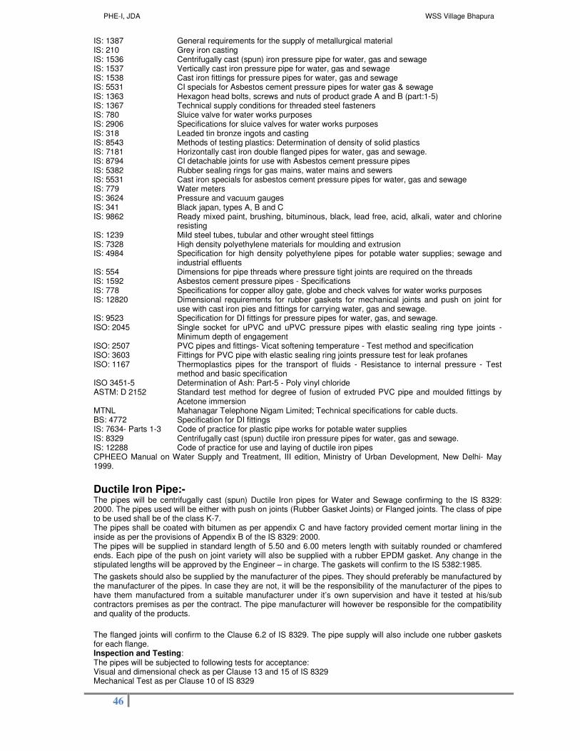
PHE-I, JDA WSS Village Bhapura
46
IS: 1387 General requirements for the supply of metallurgical material IS: 210 Grey iron casting IS: 1536 Centrifugally cast (spun) iron pressure pipe for water, gas and sewage IS: 1537 Vertically cast iron pressure pipe for water, gas and sewage IS: 1538 Cast iron fittings for pressure pipes for water, gas and sewage IS: 5531 CI specials for Asbestos cement pressure pipes for water gas & sewage IS: 1363 Hexagon head bolts, screws and nuts of product grade A and B (part:1-5) IS: 1367 Technical supply conditions for threaded steel fasteners IS: 780 Sluice valve for water works purposes IS: 2906 Specifications for sluice valves for water works purposes IS: 318 Leaded tin bronze ingots and casting IS: 8543 Methods of testing plastics: Determination of density of solid plastics IS: 7181 Horizontally cast iron double flanged pipes for water, gas and sewage. IS: 8794 CI detachable joints for use with Asbestos cement pressure pipes IS: 5382 Rubber sealing rings for gas mains, water mains and sewers IS: 5531 Cast iron specials for asbestos cement pressure pipes for water, gas and sewage IS: 779 Water meters IS: 3624 Pressure and vacuum gauges IS: 341 Black japan, types A, B and C IS: 9862 Ready mixed paint, brushing, bituminous, black, lead free, acid, alkali, water and chlorine
resisting IS: 1239 Mild steel tubes, tubular and other wrought steel fittings IS: 7328 High density polyethylene materials for moulding and extrusion IS: 4984 Specification for high density polyethylene pipes for potable water supplies; sewage and
industrial effluents IS: 554 Dimensions for pipe threads where pressure tight joints are required on the threads IS: 1592 Asbestos cement pressure pipes - Specifications IS: 778 Specifications for copper alloy gate, globe and check valves for water works purposes IS: 12820 Dimensional requirements for rubber gaskets for mechanical joints and push on joint for
use with cast iron pies and fittings for carrying water, gas and sewage. IS: 9523 Specification for DI fittings for pressure pipes for water, gas, and sewage. ISO: 2045 Single socket for uPVC and uPVC pressure pipes with elastic sealing ring type joints -
Minimum depth of engagement ISO: 2507 PVC pipes and fittings- Vicat softening temperature - Test method and specification ISO: 3603 Fittings for PVC pipe with elastic sealing ring joints pressure test for leak profanes ISO: 1167 Thermoplastics pipes for the transport of fluids - Resistance to internal pressure - Test
method and basic specification ISO 3451-5 Determination of Ash: Part-5 - Poly vinyl chloride ASTM: D 2152 Standard test method for degree of fusion of extruded PVC pipe and moulded fittings by
Acetone immersion MTNL Mahanagar Telephone Nigam Limited; Technical specifications for cable ducts. BS: 4772 Specification for DI fittings IS: 7634- Parts 1-3 Code of practice for plastic pipe works for potable water supplies IS: 8329 Centrifugally cast (spun) ductile iron pressure pipes for water, gas and sewage. IS: 12288 Code of practice for use and laying of ductile iron pipes CPHEEO Manual on Water Supply and Treatment, III edition, Ministry of Urban Development, New Delhi- May 1999.
Ductile Iron Pipe:- The pipes will be centrifugally cast (spun) Ductile Iron pipes for Water and Sewage confirming to the IS 8329: 2000. The pipes used will be either with push on joints (Rubber Gasket Joints) or Flanged joints. The class of pipe to be used shall be of the class K-7. The pipes shall be coated with bitumen as per appendix C and have factory provided cement mortar lining in the inside as per the provisions of Appendix B of the IS 8329: 2000. The pipes will be supplied in standard length of 5.50 and 6.00 meters length with suitably rounded or chamfered ends. Each pipe of the push on joint variety will also be supplied with a rubber EPDM gasket. Any change in the stipulated lengths will be approved by the Engineer – in charge. The gaskets will confirm to the IS 5382:1985.
The gaskets should also be supplied by the manufacturer of the pipes. They should preferably be manufactured by the manufacturer of the pipes. In case they are not, it will be the responsibility of the manufacturer of the pipes to have them manufactured from a suitable manufacturer under it’s own supervision and have it tested at his/sub contractors premises as per the contract. The pipe manufacturer will however be responsible for the compatibility and quality of the products.
The flanged joints will confirm to the Clause 6.2 of IS 8329. The pipe supply will also include one rubber gaskets for each flange. Inspection and Testing: The pipes will be subjected to following tests for acceptance: Visual and dimensional check as per Clause 13 and 15 of IS 8329 Mechanical Test as per Clause 10 of IS 8329

PHE-I, JDA WSS Village Bhapura
47
Hydrostatic Test as per Clause 11 of IS 8329 The test reports for the rubber gaskets shall be as per acceptance tests of the IS 5832 and will be in accordance to Clause 3.8 The sampling shall be as per the provisions of the IS 8329 Marking All pipes will be marked as per Clause 18 of IS 8329 and show as below: Manufacturer name/ stamp Nominal diameter Class reference A white ring line showing length of insertion at spigot end Packing and Transport: The pipes should be preferably transported by road from the factory and stored as per the manufacturer specifications to protect damage.
Specials for Ductile Iron Pipes
General This section covers the general requirements for Ductile Iron (DI) fittings suitable for Tyton joints to be used with Ductile Iron pipes with flanged and Tyton jointing system.
Types of specials The following types of DI fittings shall be manufactured and tested in accordance with IS: 9523 or BS: 4772. flanged socket flanged spigot Double socket bends (900, 450, 22 1/2 0, 11 1/4 0) Double socket branch flanged tee All socket tee. Double socket taper. All Flanged Tee. All Flanged taper.
Supply
All the DI fittings shall be supplied with one rubber ring for each socket. The rubber ring shall conform to IS: 12820 and IS: 5382 as described in the preceding chapter. Flanged fittings shall be supplied with one rubber gasket per flange and the required number of nuts and bolts.
General This section covers the requirements for lubricant for the assembly of Ductile Iron pipes and specials suitable for Tyton push-in rubber ring joints
Specification The lubricant has to have the following characteristics:
must have a paste like consistency and be ready for use has to adhere to wet and dry surfaces of DI pipes and rubber rings to be applied in hot and cold weather; ambient temperature 0 - 50 °C, temperature of exposed pipes up to 70 °C must be non toxic must be water-soluble must not affect the properties of the drinking water carried in the pipes must not have an objectionable odour has to inhibit bacterial growth
must not be harmful to the skin must have a shelf live not less than 2 years
Acceptance tests They shall be conducted in line with the provisions of the IS 9523
Packing
All the DI fittings shall be properly packed with jute cloth. Rubber rings shall be packed in polyethylene bags. Rubber rings in PE bags and nuts, bolts etc. shall be supplied in separate jute bags. The fittings should also be supplied by the manufacturer of the pipes. They should preferably be manufactured by the manufacturer of the pipes. In case they are not, it will be the responsibility of the manufacturer of the pipes to have them manufactured from a suitable manufacturer under it’s own supervision and have it tested at his/sub contractors premises as per the contract. The pipe manufacturer will however be responsible for the compatibility and quality of the products. Laying and jointing of DI pipes Pipes should be lowered into the trench with tackle suitable for the weight of pipes. For smaller sizes, up to 200 mm nominal bore, the pipe may be lowered by the use of ropes but for heavier pipes suitable mechanical equipment have to be used. All construction debris should be cleared from the inside of the pipe either before or just after a joint is made. This is done by passing a pull-through in the pipe, or by hand, depending on the size of the pipe. All persons should vacate any section of trench into which the pipe is being lowered On gradients of 1:15 or steeper, precautions should be taken to ensure that the spigot of the pipe being laid does not move into or out of the socket of the laid pipe during the jointing operations. As soon as the joint assembly has been completed, the pipe should be held firmly in position while the trench is back filled over the barrel of the pipe. The designed anchorage shall be provided to resist the thrusts developed by internal pressure at bends, tees, etc. Where a pipeline crosses a watercourse, the design and method of construction should take into account the
PHE-I, JDA WSS Village Bhapura
48
characteristics of the watercourse to ascertain the nature of bed, scour levels, maximum velocities, high flood levels, seasonal variation, etc. which affect the design and laying of pipeline. The assembly of the pipes shall be made as recommended by the pipe manufacturer and using the suitable tools. The socket and spigot ends of the pipes shall be brushed and cleaned. The chamfered surface and the end of the spigot end have to be coated with a suitable lubricant recommended by the manufacturer of the pipes. Oil, petroleum bound oils, grease or other material which may damage the rubber gasket shall not be used as lubricant. The rubber gasket shall be inserted into the cleaned groove of the socket. It has to be checked for correct positioning. The two pipes shall be aligned properly in the pipe trench and the spigot end shall be pushed axially into the socket either manually or with a suitable tool specially designed for the assembly of pipes and as recommended by the manufacturer. The spigot has to be inserted up to the insertion mark on the pipe spigot. After insertion, the correct position of the socket has to be tested with a feeler blade Deflection of the pipes -if any- shall be made only after they have fully been assembled. The deflection shall not exceed 75 % of the values indicated by the pipe manufacturer. Anchoring of the pipeline Thrust blocks shall be provided at each bend, tee, taper, end piece to prevent undue movements of the pipeline under pressure. They shall be constructed as per design of ENGINEER- IN- CHARGE according to the highest pressure during operation or testing of the pipes, the safe bearing pressure of the surrounding soil and the friction coefficient of the soil. Leakage Test
After laying and jointing the pipeline shall be tested for tightness of barrels and joints, and stability of thrust blocks in sections approved by the Engineer in Charge. The length of the sections depends on the topographical conditions. Preferably the pipeline stretches to be tested shall be between two chambers (air valve, scour valve, bifurcation, other chamber). At the beginning, the Contractor shall test stretches not exceeding 2 km. After successful organization and execution of tests the length may be extended to more than 2 km after approval of the Engineer in Charge.
The water required for testing shall be arranged by the contractor himself. The Contractor shall fill the pipe and compensate the leakage during testing. The Contractor shall provide and maintain all requisite facilities, instruments, etc. for the field testing of the pipelines. The testing of the pipelines generally consists in three phases: preparation, pre-test/saturation and test immediately following the pre-test. Generally, the following steps are required which shall be monitored and recorded in a test protocol if required The testing conditions for the pipelines are summarized as follows: Maximum hydrostatic test pressure for DI K-7 pipes shall be 2.0 times of maximum design pressure in the pipeline. Pre test and saturation period with addition of make-up water
Pressure: Test pressure Duration: 3 hrs for DI pipes without cement mortar lining / 24 hrs for DI pipes with
cement mortar lining Pressure test with addition of make-up water
Pressure: Test pressure Duration: 3 hrs
Test criteria for DI pipes: Q = 1 liter per km per 10mm of pipe per 30 m test pressure per 24 hrs. All pressure testing at site should be carried out hydrostatically. The pipes shall be accepted to have passed the pressure test satisfactorily, if the quantity of water required to restore the test pressure as per the latest codal provisions does not exceed the amount ‘Q’, calculated by the above formula. If it is required to test a section of a pipeline with a free end, it is necessary to provide temporary support against the considerable end thrust developed by the application of the test pressure. The end support can be provided by inserting a wooden beam or similar strong material in a short trench excavated at right angle to the main trench and inserting suitable packing between the support and pipe end. The pipeline stretch will pass the test if the water added during the test period is not exceeding the admissible limits. No section of the pipe work shall be accepted by the Engineer in charge until all requirements of the test have been obtained. On completion of a satisfactory test any temporary anchor blocks shall be broken out and stop ends removed. Backfilling of the pipeline shall be completed. Failure to pass the test All pipes or joints which are proved to be in any way defective shall be replaced or remade and re-tested as often as may be necessary until a satisfactory test shall have been obtained. Any work, which fails or is proved by test to the unsatisfactory in any way, shall be redone by the Contractor. Flushing and disinfecting of pipelines After testing and commissioning the contractor shall flush the pipes with a velocity not less than 1 m/s or as approved by the Engineer in Charge. Disinfection of drinking water pipelines shall be made by engineer- in charge. Supply of Ductile Iron Pipes:- The Contractor will have to supply DI pipes manufactured by manufacturer who has been in business of supply of DI pipes rubber ring jointed and have proven record of successful supply and testing of pipeline for minimum one year.
PHE-I, JDA WSS Village Bhapura
49
Valves
General
The sluice valve will confirm to IS: 780/ IS: 2906. The material to be supplied under this sub-section shall include but not be limited to the following: All necessary fittings including bolts, nuts, gaskets, backing rings, counter flanges, jointing material, strainers etc. as required. Sluice Valves Scope This section covers the requirements for non rising stem type sluice valve from 50 mm to 600 mm size. The valves will be used for water supply on line installations in upright positions, up to 450 C working temperature, with double flange and cap or hand wheel, for manual operation. Nominal pressure and dimensions The working pressure of the valves shall be 10 kg/cm2 (1 MPa) The dimension and mass of the sluice valves shall be in accordance with IS: 780 for sizes from 50 to 300 mm and IS: 2906 for sizes 350 to 600 mm. The flanges and their dimensions of drilling shall be in accordance with IS: 1538 (part-I to XXII).
Material
The material for different component parts of sluice valve shall conform to requirements given below:
S No. Component Material Ref. to IS Grade / designation 1 Body, bonnet, wedge,
stuffing box, gland, thrust plate, hand wheel cap. etc.
Grey cast iron 210 FG 200
2 Stem Stainless steel 6603 AISI 431, AISI 410 3 Wedge nut Leaded tin bronze 318 LTB 2 4 Body seat ring, wedge
facing ring Leaded tin bronze 318 LTB 2
5 Bolt Carbon steel 1363 Class 4.6 6 Nut Carbon steel 1363 Class 4 7 Bonnet gasket Compressed fiber
board 2712 C
8 Gland packing Asbestos 4687 Nil
Coating
All sluice valves shall be coated by dipping in a bath of tar base composition as given in Clause 7 of IS: 780 for sizes from 50 mm to 300 mm and Clause 8 of IS: 2906 for sizes from 350 mm to 600.
All components susceptible to corrosion attack shall be coated internally and externally. Protective coating shall always be applied to the individual components before they are assembled, following shot blasting to give good adhesion.
Marking, testing and inspection
The standard marking and packing of the valves shall be done as per Clause 10 and 11 of IS: 780. The direction of rotation for OPEN, CLOSE position shall be marked on the hand wheel and on the bonnet of the valve.
Testing of sluice valve shall be done for close end in accordance with IS: 780 for sizes from 50 mm to 300 mm and IS: 2906 for sizes from 350 mm to 600. All the valves shall be inspected for flaw detection test in accordance with IS: 780. for sizes from 50 mm to 300 mm and IS: 2906 for sizes from 350 mm to 600. The design, construction material, manufacture, inspection, performance and testing shall comply with all applicable Indian Standards and Codes. Nothing in the specification will be construed to relieve the supplier of this responsibility.
Air valves
Scope and general design feature
This section covers the requirements of automatic double ball air valves to be used for evacuation of accumulation of air in water mains under pressure, for the exhaust of air when such mains are being charged with water and for inlet of air when they are emptied of water.

PHE-I, JDA WSS Village Bhapura
50
The Air Valves shall conform to IS14845. The design shall be such that higher the rate of flow the greater the resultant down thrust keeping the ball 'glued' to its seat until the last drop of air is expelled from the pipe system.
The valves shall have an integrated sluice valve. If required, they shall be installed on a flange welded on the MS pipe / special. The possible air velocity (inflow and outflow) must be at least 10 m/s. The working pressure of the air valves shall be 10 kg / cm
2 (1Mpa).
Construction feature
The flow of air should be as unobstructed as possible. The low-pressure orifice shall be in the same axis as the main discharge/incoming airflow and must have a diameter sufficiently large.
The cone angle in the low-pressure (large orifice) chamber should be carefully calculated and there should be adequate height to allow for free movement of the vulcanite ball in the low chamber. The annulus around the low-pressure vulcanite covered ball is to be generously proportioned for discharge of air under various differential pressures.
The orifice shall be carefully profiled to allow the requisite flow of air under varying differential pressure. It shall be in moulded synthetic rubber such that even after extended contact the vulcanite covered ball does not stick to it when the line pressure becomes zero.
In the high-pressure chamber the orifice shall be in profiled in such a manner that the rubber-covered ball is not damaged even after extended contact. There should be machined guide in the chamber, which ensures that the ball travels vertically and makes contact with the nipple and seals off the orifice without fail.
Material
The material for different component parts of the air valve shall conform to requirements given below:
S No. Component Specifications 1 Body Cast Iron conforming to IS: 210 GR FG 200 2 High Pressure Cover Cast Iron confirming to IS 210 GR FG 200 3 Low Pressure Cover Cast Iron confirming to IS 210 GR FG 200 4 Cowl Cast iron confirming to !S 210 GR FG 5 High Pressure Orifice Plug Stain less steel conforming to AISI 410 6 Low pressure ball Vulcanite covered seasoned timber 7 High pressure ball Rubber covered seasoned timber 8 Lower pressure seat ring Dexine (Nitrile rubber) 9 Isolating sluice valve Conforming to IS: 780 – 1984 10 Spindle for sluice valve Stainless steel conforming to AISI 410 11 Bolts and nuts Mild steel
The body and seat of the valve shall withstand a working pressure of 10 kg/cm
2 for at least 15 minutes.
Inspection Third Party Inspection:
The following items of supply will be got inspected from approved inspecting agency (CEIL, SGS. RITES) at manufacturers premises before dispatch at his own cost. 1. Ductile Iron pipes, rubber gaskets & specials

PHE-I, JDA WSS Village Bhapura
51
Specifications for Laying and Jointing of Pipe Line System for Water Supply
Preparatory work
The contractor will inspect the route along which the pipe line is proposed to be laid. He should observe/ find out the existing underground utilities/ construction and propose an alignment along which the pipeline is to be laid. He should make all efforts to keep the pipe as straight as possible with the help of ranging rods. Wherever there is need for deviation, it should be done with the use of necessary specials or by deflection in pipe joints (limited to 75% of permissible deflection as per manufacturer). The alignment as proposed should be marked on ground with a line of white chalk and got approved from Engineer In-Charge. The Contractor will than prepare an L-Section along this alignment showing the location of proposed pipeline. The L-section should be got approved from the site Engineer. The position of fittings, valves, should be shown on the plan.
Alignment and the L-Sections
The alignments, L-section (depth of laying) and location of specials, valves and chambers may be changed at site in co-operation with and after approval of the Engineer in Charge. The minimum cover to the top of the pipe shall be 1 m.
Standards
Except as otherwise specified in this technical specification, the Indian Standards and Codes of Practice in their latest version, National Building code, PWD specification of the state of Rajasthan and Manual of water supply of GOI shall be adhered to for the supply, handling, laying, installation, and site testing of all material and works.
Tools and equipment
The contractor has to provide all the tools and equipment required for the timely, efficient and professional implementation of the work as specified in the various sections of the contract and as specified by the instructions of manufacturers of the pipes and other material to be handled under this contract. On demand he shall provide to the Engineer in Charge a detailed list of tools and equipment available. If in the opinion of the Engineer in Charge the progress or the quality of the work cannot be guaranteed by the available quantity and type of tools and equipment the contractor has to provide additional ones to the satisfaction of the Engineer in Charge. The Contractor will always have a leveling instrument on site.
Handling and laying of pipes
Transportation of pipes and specials & Storage:-
The Contractor has to transport the pipes and other materials from manufacturer to the site of laying as indicated by the Engineer in Charge. Pipes should be handled with care to avoid damage to the surface and the socket and spigot ends, deformation or bending. Pipes shall not be dragged along the ground or the loading bed of a vehicle. Pipes shall be transported on flat bed vehicles/trailers. The bed shall be smooth and free from any sharp objects. The pipes shall rests uniformly on the vehicle bed in their entire length during transportation. Pipes shall be loaded and un-loaded manually or by suitable mechanical means without causing any damage to the stacked pipes.
The transportation and handling of pipes shall be made as per IS 12288. Handling instructions of the manufacturers of the pipes shall be followed. All precautions set out shall be taken to prevent damage to the protective coating, damage of the jointing surfaces or the ends of the pipes.
Whatever method and means of transportation is used, it is essential that the pipes are carefully placed and firmly secured against uncontrolled movement during transportation to the satisfaction of engineer in charge.
Cranes or chain pulley block or other suitable handling and lifting equipment shall be used for loading and un-loading of heavy pipes. However, for pipes up to 400 mm nominal bore, skid timbers and ropes may be used. Where using crane hooks at sockets and spigot ends hooks shall be broad and protected by rubber or similar material, in order to avoid damage to pipe ends and lining. Damage to lining must be repaired before pipe laying according to the instructions of the pipe manufacturer. Pipes shall not be thrown directly on the ground or inside the trench.
When using mechanical handling equipment, it is necessary to employ sufficient personnel to carry out the operation efficiently with safety. The pipes should be lifted smoothly without any jerking motion and pipe movement should be controlled by the use of guide ropes in order to prevent damage caused by pipes bumping together or against surrounding objects.
Rolling or dragging pipes along the ground or over other pipes already stacked shall be avoided.
The pipe should be given adequate support at all times. Pipe should be stored on a reasonably flat surface free from stones and sharp projections so that the pipe is supported through out its length. In storage, pipe racks should provide continuous support and sharp corners of metal racks should be avoided. Socket and Spigot pipes should be stacked in layer with sockets placed in alternate ends of the stack to avoid lop sided stacks.

PHE-I, JDA WSS Village Bhapura
52
Pipes should not be stored inside another pipe. On no account the pipes should be stored in stressed or bent condition or near the sources of heat. Pipes should not be stacked more than 1.5 m high and pipes of different sizes and classes should be stacked separately. The ends of the pipes should be protected from abrasion. The pipes should be protected from U.V. rays and excessive heat at all times. Their storage facility should be well ventilated.
The Contractor shall provide proper and adequate storage facilities to protect all the materials and equipment’s against damage from any cause whatsoever and in case of any such damage/theft, the Contractor shall be held responsible.
The contractor will lay the pipelines along the alignments as per the layout given by the Engineer in Charge. The layout shall be given keeping in view the information available regarding existing services like water lines, sewers, telephone and electric lines/ cables. In the event some services fall in the alignment of lines to be laid, the contractor shall have to shift such services for which a provision has been made in the BOQ. The contractor shall take all due care to avoid damage to any such services and, in case of any damage occurring to them in progressing the work, the Contractor shall make good the same at his own cost. No additional time shall, however, be allowed on this account.
Stringing of pipes along the alignment The pipes shall be laid out properly along the proposed alignment in a manner that they do not create any significant hindrance to the public and that they are not damaged.
Stringing of the pipe end to end along the working width should be done in such a manner that the least interference is caused in the land crossed. Gaps should be left at intervals to permit the passing of equipment across the working area. Pipes shall be laid out that they remain safe where placed and that no damage can occur to the pipes and the coating until incorporated in the pipeline. If necessary, pipes shall be wedged to prevent accidental movement. Precautions shall be made to prevent excessive soil, mud etc. entering the pipe.
Generally, the pipes shall be laid within two weeks from the date of their dispatch from the manufacturer /store . Pipe trench Trench excavation
The trench excavation of pipeline shall be in accordance with IS 12288. Pipe trenches shall be excavated to the lines and levels shown on the drawings or as directed by the Engineer in Charge. The depth of the excavated trench shall be as given in the drawings or as directed by the Engineer in Charge. The width of the trench at bottom between the faces of sheeting shall be such as to provide 200 mm clearance on either side of the Diameter. No pipe shall be laid in a trench until the section of trench in which the pipe is to be laid has been approved by the Engineer in Charge.
The depth should be sufficient to provide a cover not less than 1000 mm. It may be necessary to increase the depth of pipeline to avoid land drains or in the vicinity of roads, railways or other crossings. Care should be taken to avoid the spoil bank causing an accumulation of rainwater.
The bottom of the trench shall be trimmed and leveled to permit even bedding of the pipes. It should be free from all extraneous matter, which may damage the pipe or the pipe coating. Additional excavation shall be made at the joints of the pipes, so that the pipe is supported along its entire length.
All excavated material shall be stacked in such a distance from the trench edge that it will not endanger the work or workmen and it will avoid obstructing footpaths, roads and driveways. Hydrants under pressure, surface boxes, fire or other utility controls shall be left unobstructed and accessible during the construction work. Gutters shall be kept clear or other satisfactory provisions made for street drainage, and natural watercourses shall not be obstructed.
To protect persons from injury and to avoid damage to property, adequate barricades, construction signs, torches, red lanterns and guards, as required, shall be placed and maintained during the progress of the work and until it is safe for traffic to use the roadways. All materials, piles equipment and pipes which may serve as obstruction to traffic shall be enclosed by fences or barricades and shall be protected by illuminating proper lights when the visibility is poor.
As far as possible, the pipe line shall be laid below existing services, like water and gas pipes, cables, cable ducts and drains but not below sewers, which are usually laid at greater depth. Where it is unavoidable, pipeline should be suitably protected. A minimum clearance of 150 mm shall be provided between the pipeline and such other services.
Trees, shrubbery fences, poles, and all other property and surface structures shall be protected. Tree roots shall be cut within a distance of 50 cm from pipe joints in order to prevent roots from entering them. Temporary support, adequate protection and maintenance of all under ground and surface structures, drains, sewers and other obstructions encountered in the progress of the work shall be provided. The structures, which will be disturbed, shall be restored after completion of the work.

PHE-I, JDA WSS Village Bhapura
53
Where water forms or accumulates in any trench the Contractor shall maintain the trench free of water during pipe laying.
Wherever necessary to prevent caving, trench excavations in soils such as sand, gravel and sandy soil shall be adequately sheeted and braced. Where sheeting and bracing are used, the net trench width after sheeting shall not be less than that specified above. The sides of the excavation shall be adequately supported at all times and, except where described as permitted under the Contract, shall be not battered.
The Engineer in Charge in co-operation with the Contractor shall decide about the sheeting/ bracing of the trench according to the soil conditions in a particular stretch and taking into account the safety requirements of the Contractor’s and Engineer- In- Charge’s staff. Generally, safety measures against caving have to be provided for trenches with vertical walls if they are deeper than 2.0 m.
Trench excavation to commensurate with the laying progress
The work of trench excavation should be commensurate with laying and jointing of the pipeline. It should not be dug in advance for a length greater than 500 m ahead of work of laying and jointing of pipeline unless otherwise permitted by the Engineer in Charge. The Contractor has to ensure the following:
• safety protections as mentioned above have to be incorporated in the work process • hindrances to the public have to be minimized • the trench must not be eroded before the pipes are laid • the trench must not be filled with water when the pipes are laid • the trench must not be refilled before laying of the pipes
The bed for the laying of the pipes has to be prepared according to the L-Section immediately before laying of the pipes.
Bedding of the pipes
The trench bottom shall be even compact and smooth so as to provide a proper support for the pipe over its entire length, and shall be free from stones, lumps, roots and other hard objects that may injure the pipe or coating. Holes shall be dug in the trench bottom to accommodate sockets so as to ensure continuous contact between the trench and the entire pipe barrel between socket holes.
Laying and jointing of pipes General
The pipes will be cleaned in the whole length with special care of the spigot and sockets on the inside/ outside to ensure that they are free from dirt and unwarranted projections. The whole of the pipes shall be placed in position singly and shall be laid true to profile and direction of slope indicated on longitudinal sections. The pipes shall be laid without deflection in a straight alignment between bends and between high and low points. Vertical and horizontal deflections between individual pipes need the approval of the Engineer in Charge. In no case the deflection shall be more than 75 % of those recommended by the manufacturer.
Before pipes are jointed they shall be thoroughly cleaned of all earth lumps, stones, or any other objects that may have entered the interior of the pipes, particularly the spigot end and the socket including the groove for the rubber ring.
Pipes and the related specials shall be laid according to the instructions of the manufacturers and using the tools recommended by them.
Cutting of pipes shall be reduced to a minimum required to conform to the drawings. Cutting has to be made with suitable tools and according to the recommendations of the manufacturer. The spigot end has to be chamfered again at the same angle as the original chamfered end. Cutting shall be perpendicular to the Centre line of the pipe. In case of ductile iron pipes the cut and chamfered end shall be painted with two coats of epoxy paint. If there is no mark for the insertion depth on the spigot end of the (cut) pipe it shall be marked again according to the instructions of the manufacturer.
Before pipes are jointed they shall be thoroughly cleaned of all earth lumps, stones, or any other objects that may have entered the interior of the pipes, particularly the spigot end and the socket including the groove for the rubber ring. End caps are removed only just before laying and jointing

PHE-I, JDA WSS Village Bhapura
54
All specials like bends, tees etc. and appurtenances like sluice or butterfly valves etc. shall be laid in synchronization with the pipes. The Contractor has to ensure that the specials and accessories are ready in time to be installed together with the pipes. At the end of each working day and whenever work is interrupted for any period of time, the free ends of laid pipes shall be protected against the entry of dirt or other foreign matter by means of approved plugs or end caps. When pipe laying is not in progress, the open ends of installed pipe shall be closed by approved means to prevent entrance of trench water and dirt into the line. No pipe shall be laid in wet trench conditions that preclude proper bedding, or when, in the opinion of the Engineer in Charge, the trench conditions or the weather are unsuitable for proper installation. The pipeline laid should be absolutely straight unless planned otherwise. The accuracy of alignment should be tested before starting refilling with the help of stretching a string between two ends of the straight stretch of pipes to rectify possible small kinks in laying.
Special Cast Iron fittings and Accessories
Normally when pipeline is laid, a certain number of cast iron fittings such as tees, bends, reducers, etc, and special fittings such as air or sluice valves are required.
Laying of Fittings – All cast iron fittings shall be plain ended to suit the outside diameter of Asbestos cement pressure pipes and to the class and diameter of pipe manufactured. When using such cast iron fittings, they are jointed by cast iron detachable joints only. For cast iron specials having flanges, they are jointed in the pipeline with cast iron flange adaptors having one end flanged and the other plain ended. Anchorages - It should particularly be noted that the cast iron joints do not hold pipe ends within it firmly. During working or test pressure, there will be tendency for the pipe ends or special ends to slip out of the joint, more so with the case of blank end cap used for closure of pipeline and all degree bends and tees. In order to keep them firmly in the pipeline, anchoring of these specials are necessary against the direction of thrust. The anchorage shall consist of either concrete cast-in-situ or masonry built in cement mortar. The anchors shall be extended to the firm soil of the trench side. The shape of the anchors will depend on the kind of specials used. They shall be spread full width of trench and carried vertically by the side and over the special to about 15 cm. The bearing area on sides of the trench will be proportional to the thrust and to bearing capacity of the sides of the trench. Back filling and tamping The soil under the pipe and coupling shall be tamped in order to provide a firm and continuous support or the pipeline. Tamping shall be done either by tamping bars or by using water to consolidate the back fill material.
The initial back fill material used shall be free of large stones and dry lumps. In stony areas the material for initial back fill can be shave from the sides of the trenches. In bogs and marshes, the excavated material is usually little more than vegetable matter and this should not be used for bedding purposes. In such cases, gravel or crushed stone shall be hauled in.
The initial back fill shall be placed evenly in a layer of about 100 mm thick. This shall be properly Consolidated and this shall be continued till there is a cushion of at least 300 mm of cover over the pipe. If it is desired to observe the joint or coupling during the testing of mains they shall be left exposed.
Sufficient back fill shall be placed on the pipe to resist the movement due to pressure while testing.
Balance of the back fill need not be so carefully selected as the initial material. However, care shall be taken to avoid back filling with large stones, which might damage the pipe when spaded into the trench.
Pipes in trenches on a slope shall have extra attention to make certain that the newly placed back fill will not become a blind drain in effect because until back fill becomes completely consolidated, there is a tendency for ground or surface water to move along this looser soil resulting in a loss of support to the pipe. In such cases, the back fill should be tamped with extra care and the tamping continued in 100 mm layers right up to the ground level. Anchoring of the pipeline Thrust blocks shall be provided at each bend, tee, taper, end piece to prevent undue movements of the pipeline under pressure. They shall be constructed as per actual design and approval of Engineer in Charge according to the highest pressure during operation or testing of the pipes, the safe bearing pressure of the surrounding soil and the friction coefficient of the soil.
Sectional tests:- After laying and jointing the pipeline shall be tested for tightness of barrels and joints, and stability of thrust blocks in sections approved by the Engineer in Charge as per IS Code.
Executive Engineer (PHE-I) JDA, Jaipur

PHE-I, JDA WSS Village Bhapura
55
Scope of work and Special Condition Of Contract for Operation & Maintenance Of Newly developed Water Supply assets under this contract for water Supply Scheme for Villages of Gram Panchayat Bhapura 36 Months.
Definitions-
• Equipment- is the contractors machinery and vehicles brought temporarily to the site to construct the works.
• Facilities- Shall mean all works and its equipment(s), components which have been supplied and/ or installed or
designed, and/or constructed in the contract for works.
• Plant- is any integral part of the works, which is to have a mechanical, electrical, electronic, chemical functions.
1 - Administrative Provision
The following additional clauses shall apply only during the Operation and Maintenance period.
1.1 "Maintenance Standard" shall mean the requirements for maintaining, repairing, and renewing the Facility :
a) As set forth in the O & M Manual: bidder shall enclose this with the bid document
b) Required pursuant to applicable law:
c) As may be necessary for keeping the facility in a satisfactory condition such that the
Facility will continuously, comply with the Operation Standard; and
d) As may be necessary to ensure that the Facility shall continuously be in an optimum
condition and state in relation with the lifetime of the Facility.
1.2 "O & M Manual" shall mean the final Manual for the Operation and Maintenance of the Facility to be prepared
in accordance with the Bid Documents.
1.3 Non revenue water shall mean the difference between the volume of water produced through tube wells as
recorded by bulk meter installed on the delivery of each tube well and volume of water distributed, as recorded
through the consumer meters.
Brief scope under this contract will be as described below:
1.4.1 To schedule daily operations
1.4.2 To schedule inspection of machinery viz. lubrication, servicing, etc.
1.4.3 To keep records for daily operation and activities
1.4.4 To keep records of spare parts, equipment, tools, consumables, etc.
1.4.5 Inventory of stores
1.4.6 To keep records of staff in position
1.4.7 To prepare O & M manual
1.4.8 To provide necessary tools, tackles and instruments
2.0 OBJECT OF CONTRACT :
2.1 RISKS AND OBLIGATION OF THE CONTRACTOR :
FOR THE DURATION OF O & M PERIOD, CONTRACTOR SHALL RENDER AND MAKE AVAILABLE TO JDA THE FOLLOWING SERVICES :
2.1.1 Pump water from Tube wells near Newta Dam to CWR’s at Village Daulatpura and further pump water from
pump house at Daulatpura to various OHSR’s at Villages of Gram Panchayat Bhapura. Maintain D.I. Pipe
lines, Pumping machinery of Tube wells and Pump house, Electric panels, valves, flow meters and all the
other assets created under this contract.
2.1.2 Control and Operate the Pumping machinery.
2.1.3 Routine Maintenance of pumping station and HT switch room buildings, electrical, mechanical and
instrumentation installations, equipment and areas;
2.1.4 Management of the plant in administrative and financial operation connected to plant management;

PHE-I, JDA WSS Village Bhapura
56
2.1.5 Supply all spares & consumables for routine, preventive & break down maintenance, No extra payment shall
be made for these supply of spares & consumables.
2.1.6 If any loss or damage happens to the Facility, or any part thereof, or materials or Plant for incorporation
therein, during the period for which the Contractor is responsible for the care thereof, from any cause
whatsoever, other that the risks, the Contractor shall, at his own cost, rectify without loss or damage so that
the Facility conforms in every respect with the provisions of the Contract to the satisfaction of JDA. The
contractor shall also be liable for any loss or damage to the Works occasioned by him in the course of any
operations carried out by him for the purpose of complying with his obligation.
2.1.7 All material for the repair and maintenance of pumping machinery, pipeline, electrical equipment shall be
arranged by the contractor at his own cost.
2.1.8 Power charges shall be borne by JDA. However it shall be responsibility of the contractor to collect the bills
from JVVNL seven days before due date of payment by cheque and handing over to Engineer in charge,
also collecting the cheque from JDA and deposit it in JVVNL within due date. Any late payment, penalty will
be on the part of contractor.
2.1.9 In the event of any damage/ loss of life and property in the SR, CWR and Pump House of Pumping stations,
the contractor shall be solely responsible for compensation and damages as per the rules.
2.1.10 The agency is fully responsible for sweeping and cleaning of complete head works including pump houses,
lawns, plants and office.
2.1.11 In case of any break down of pump machinery or starters, the contractor shall have to inform the JEN/AEN
concerned. In no case the information shall take more than six hours to reach the engineer in charge staff of
JDA. However, simultaneously he shall make the arrangements to install the stand by units to restore the
supply. The contractor shall always keep the stand by readily available units in respect of all important
item/installation Viz. Pump motor, starter ICTP switches etc, originally provided by JDA or supplier under the
contract. The contractor shall keep stores of all essential items as site.
2.1.12 In case of power break down, the contractor shall lodge complaint to the concerned JVVNL office/ station
and get the problem solved. In case of major power problem, the contractor shall immediately inform the
JEN/AEN (PHE-I) concerned for seeking their help. However, it would be responsibility of the contractor to
get the electric problem rectified through proper pursuance. In case, it is unavoidable to restore the water
supply, the contracting agency would arrange to get it properly announce to the public taking advance action
for water storage/alternative arrangement.
2.1.13 As built drawing’ of water supply scheme showing location of tube wells, SR, CWR, Pump House, pipe lines shall be framed and displayed at appropriate place (s) in pump houses/ office building (s).
2.1.14 Necessary tools required in repairing of Tube Wells and conveyance vehicles such as jeep, tractor, mini truck etc. shall be arranged by the contractor at his own cost. No payment in lieu of conveyance or tools shall be admissible.
3.0 Risk & Obligations of the JDA
• For the duration of O & M Period, the employer will be responsible to bear of the costs for electricity.
4. Commencement And Duration Of O & M Contract :
4.1.1 The O & M period shall commence upon issuing of Taking Over Certificate as per clause 4.2 under the
construction phase of the project and shall Continue for a period of Thirty Six (36) months. Should JDA wish
to propose an extension to the O & M Period, after completion of initial 36 moths O & M contract a prior
notice of its intention to exercise such option shall be given to the contractor.
5. Liability:
The contractor will not under any circumstances, be liable for costs or loss of profit that JDA may incur as a
result of the unavailability of the plant on account of force major.
6. Personnel :
The contractor shall depute following minimum staff to carry out the O & M Work efficiently and satisfactorily.
(Contractor may choose to provide more staff if need be as per his assessment)

PHE-I, JDA WSS Village Bhapura
57
DESCRIPTION QUALIFICATION REQUIRED NO.
PUMP OPERATOR cum
Electrician
ITI certificate holder in Electrical/
Mechanical trade or person
having 3 years experience of
operation & maintenance of
pumping machinery.
One person per shift per
pump house.
Watch man cum Helper 8th
Pass and minimum 1 year
Experienced
One person per shift per
pump house.
Fitter ITI certificate holder in Electrical/
Mechanical trade or person
having 3 years experience of
operation & maintenance of
pumping machinery.
1 No.
Helper 12th Pass 3 Nos.
JDA is not liable for any personnel provided by the contractor in any way and cannot be held responsible in
the event of litigation of any sort between the Contractor and members of plant personnel or their
representatives. Round the clock (24 hours) watch and ward shall be the responsibility of contractor
throughout the contract period.
All decisions related to staff numbers and qualifications should be approved by JDA. The number of shifts for
pump operation will be decided by the contractor in accordance with the operations requirements.
The Contractor shall undertake to comply with applicable legislation and the code of labour law on the
matters of health, hygiene and safety, and shall assume responsibility for works required in the event of any
change in applicable regulations.
7. Assignment :
The Contractor will not be entitled to sub-contract any part of his obligation to any third party without prior
approval of JDA.
8. Completion Of The Contract :
On the date of Contract Completion or if the Contract is terminated, all the installations, works and equipment
placed under the Contractor's responsibility shall be handed over to JDA or any agency, orgnisation specified
by it, at no cost, in good working order, except for normal wear and tear. JDA may perform any inspections
tests or expert appraisals as may be considered necessary with a view to checking that the property is in
good working order. If the works, equipment, plant and/or property is not found in working condition or
acceptable condition, the contractor will replace / repair / rectify the same at his own cost to the satisfaction
of JDA or third party inspector to be appointed by JDA at its cost.
At the end of O&M period, the Contractor shall be entitled to receive an Operation and Maintenance
Completion Certificate within twenty-one (21) days, of the completion of the Contract.
The delivery of such Completion Certificate will relieve the Contractor from his responsibility as regard to the
Operation and Maintenance and confirm that the Contractor has fulfilled all of his obligations under the
contract.
9. Technical Provisions
The Contractor shall be responsible for corrective maintenance of civil, mechanical, electrical and measuring
equipment as well as miscellaneous equipment. The contractor shall properly repair during any leakage,
bursts in rising and distribution pipelines, valves, specials etc.. The contractor shall ensure that the water
losses are not more than 5%, in pipe line network of rising main/ distribution system laid by it.
The Contractor shall be responsible for carrying out regular servicing and lubrication of all machinery and
equipment, complying with maintenance instructions as defined in the Operation and Maintenance manual
and ensuring that electromechanical equipment and motors operate correctly at all times.
The brief scope will be:
- Operation, maintenance and repairing as and when required of submersible pumps at TW’s to
provide adequate water to meet the daily demand.

PHE-I, JDA WSS Village Bhapura
58
- Operation, maintenance and repairing as and when required of the centrifugal pumps at Pump
house to pump water from CWR to SR as per the demand of water.
- Weekly, fortnightly, monthly and yearly maintenance and repair of all the electrical, mechanical
instrumentation and civil structures created under this contract. Cost of repair and consumables
shall be born by the contractor.
- To ensure regular operation of chlorinator to provide appropriate doses of sodium hypochlorate
solution to ensure 0.5 PPM residual chlorine in the distribution system. Daily observations like
leakage, bearing temperature, noise, vibration, readings of pressure, voltage and current
- Maintenance of rising and distribution pipe line for leakage free system.
- Semi annual or monthly inspection for items such as gland of stuffing box, cleaning of gland bolts,
inspection of packing, alignment of pump and drive, condition and quantity of grease or oil for
bearings, motors, circuit breakers, ATS, etc., contacts of relay and circuit breakers, level of oil in
transformer, GO/DO contacts and over current relay, settings of over current relay, no volt coil and
tripping mechanism, temperature of oil and windings, connections of equipment etc.
- Annual inspection like checking of shaft sleeves for wear, checking of clearances, pump test, end
play of bearings, impeller condition, calibration of instruments, resistance of earth pit, insulation
resistance of switches, bus bars, auto transformer, phase to earth & phase to phase resistance.
- Watering of lawn & plants in the campus, cutting of lawns every fortnight or earlier, providing
manure as per the requirement to ensure that the grass is maintained green & healthy sweeping &
cleaning of complete head works including Pump House, Lawns, plants etc.
10.0 Performance Standards :
THE CONTRACTOR WILL OPERATE AND MAINTAIN IN A STATE OF CONTINUOUS OPERATIONAL READINESS ALL
PLANT AND SYSTEMS TO MEET THE FLOW REQUIREMENTS. IT SHALL REMAIN THE CONTRACTOR'S
RESPONSIBILITY TO ENSURE THE PLANT SYSTEMS ARE AT ALL TIMES ABLE TO OPERATE TO THE MAXIMUM
CAPACITY OF THE INSTALLED EQUIPMENTS. ALL PLANT AND PLANT INSTALLATION SHALL BE OPERATED WITHIN
THEIR DESIGNED LIMITS. THE CONTRACTOR SHALL OPERATE THE PLANT STRICTLY WITHIN THESE OPERATING
RANGES AND SHALL MANAGE THE OPERATION OF THE PLANT TO ACHIEVE OPTIMUM PERFORMANCE AS FAR AS
POSSIBLE.
11.0 Consumables And Spare Parts:
Unless stipulated otherwise elsewhere in the document, for the duration of O & M period, the
Contractor will be responsible for the supply and control of lubricants, spare parts, chemicals and
consumable materials excluding electrical power charges, necessary for the continuous operation of
the works.
The stores inventory, the issuing and recording of spare parts will be the responsibility of the
Contractor.
The contractor is also responsible for providing spare parts and material required for the operation
and maintenance during the operation period and shall bear the cost for the same, including the
cost of storing and safeguarding.
The contractor will make all necessary arrangements to ensure the continuous supply of spare parts
and material for the works, and the rate of supply of these materials shall be in such quantities and
amounts as would ensure uninterrupted operation.
Spare parts shall be supplied by the Contractor without any additional charge and the same will be
used during O & M period.
12. Documents To Be Provided By The Contractor :
12.1 Operation Log Book :
The Contractor shall keep a permanent record of plant operation (log book). This log book shall be kept at
the site and shall be presented on request to agents approved by JDA.

PHE-I, JDA WSS Village Bhapura
59
The log book shall be provided by the contractor.The contractor shall also indicate any significant
modification to the set-up characteristics of the installation, shut-downs anomalies or incidents that have
occurred with respect to operation.
The log book shall also contain the following :
- Daily report
- Weekly report
- Readings of meters Gauges (voltmeter, ammeter, Flow meter, energy meter, pressure
gauges at TW’s and Pump House
- Record of break down
- Staff attendance `
- Stock of spare parts, lubricants, consumables
- List of tools, tackles and instruments
- Trouble identification for the installation
12.2 MONTHLY REPORT :
The monthly report shall include but not be limited to :
a) volume of water produced and distributed
b) all the problem areas in the facility,
c) the status and progress of the training programs
d) electricity consumed totally and per cum of water produced.
13.0 Reduction in Rates
13.1 On account of poor upkeep of pump house and campus
A token penalty of Rs 100 per day would be levied on account of each day of poor upkeep of the pump house or the campus plantation, lawn etc. Decision of Engineer In Charge shall be final in this regard.
Signature of Contractor Executive Engineer (PHE-I) JDA, Jaipur

PHE-I, JDA WSS Village Bhapura
60
Section A-5 Annexure

PHE-I, JDA WSS Village Bhapura
61
Annexure A:
Compliance with the code of Integrity and No Conflict of Interest Any person participating in a procurement process shall –
(a) Not offer any bribe, reward or gift or any material benefit either directly or indirectly in exchange for an unfair advantage in procurement process or to otherwise influence the procurement process;
(b) Not misrepresent or omit the misleads or attempts to mislead so as to obtain a financial or other benefit or avoid an obligation;
(c) Not indulge in any collusion, Bid rigging or anti-competitive behavior to impair the transparency, fairness and progress of the procurement process;
(d) Not misuse any information shared between the procuring Entity and the Bidders with an intent to gain unfair advantage in the procurement process;
(e) Not indulge in any coercion including impairing or harming or threatening to do the same, directly or indirectly, to any party or to its property to influence the procurement process;
(f) Not obstruct any investigation or audit of a procurement process; (g) Disclose conflict of interest, if any; and (h) Disclose any previous transgressions with any Entity in India or any other country during the last three
years or any debarment by any other procuring entity.
Conflict of Interest :- The Bidder participating in a bidding process must not have a Conflict of interest. A conflict of interest is considered to be a situation in which a party has interests that could improperly influence that party’s performance of official duties or responsibilities, contractual obligations, or compliance with applicable laws and regulations. i. A Bidder may be considered to be in Conflict of Interest with one or more parties in a bidding process if, including but not limited to:
a. Have controlling partners/shareholders in common ; or b. Receive or have received any direct or indirect subsidy from any of them; or c. Have the same legal representative for purposes of the Bid; or d. Have a relationship with each other; directly or through common third parties, that puts them in a position to
have access to information about or influence on the Bid of another Bidder, or influence the decisions of the Procuring Entity regarding the bidding process; or
e. The Bidder participates in more than one Bid in a bidding process. Participation by a Bidder in more than one Bid will result in the disqualification of all Bids in which the Bidder is involved. However, this does not limit the inclusion of the same subcontractor, not otherwise participating as a Bidder, in more than one Bid; or
f. The Bidder or any of its affiliates participated as a consultant in the preparation of the design or technical specifications of the Goods, Works or Services that are the subject of the Bid; or
g. Bidder or any of its affiliates has been hired (or is proposed to be hired) by the Procuring Entity as engineer-in-charge/ consultant for the contract.

PHE-I, JDA WSS Village Bhapura
62
Annexure B :
Declaration by the Bidder regarding Qualifications
Declaration by the Bidder
In relation to my/our Bid submitted to ……………………………….. for procurement of
………………………………………………….. in response to their Notice inviting Bids No. ……………..Dated
…………….. I/We hereby declare under Section 7 of Rajasthan Transparency in Public Procurement Act, 2012, that :
1. I/We possess the necessary professional, technical, financial and managerial resources and competence
required by the Bidding Document issued by the Procuring Entity;
2. I/We have fulfilled my/our obligation to pay such of the taxes payable to the Union and the State Government
or any local authority as specified in the Bidding Document;
3. I/We are not insolvent, in receivership, bankrupt or being wound up, not have my/our affairs administered by
a court or a judicial officer, not have my/our business activities suspended ant not the subject of legal
proceeding for any of the foregoing reasons;
4. I/We do not have, and our directors and officers not have, been convicted of any criminal offence related to
my/our professional conduct or the making of false statements or misrepresentations as to my/our
qualifications to enter into a procurement Contract within a period of three years preceding the
commencement of this procurement process, or not have been otherwise disqualified pursuant to
debarment proceedings;
5. I/We do not have a conflict of interest as specified in the Act, Rules and the Bidding Document, which
materially affects fair competition;
Date : Signature of bidder Place :
Name : Designation : Address :

PHE-I, JDA WSS Village Bhapura
63
Annexure C : Grievance Redressal during Procurement Process
The designation and address of the First Appellate Authority is Executive Committee (E.C.), JDA, Jaipur. The designation and address of the Second Appellate Authority is PS/ACS/UDH, Jaipur.
(1) Filing an appeal If any Bidder or prospective bidder is aggrieved that any decision, action or omission of the Procuring Entity is in contravention to the provisions of the Act or the Rules or the Guidelines issued there under, he may file an appeal to First Appellate Authority, as specified in the Bidding Document within a period of ten days from the date of such decision or action, omission, as the case may be, clearly giving the specific ground or grounds on which he feels aggrieved: Provided that after the declaration of a Bidder as successful the appeal may be filed only by a Bidder who has participated in procurement proceedings: Provided further that in case a Procuring Entity evaluates the Technical Bids before the opening of the Financial Bids, an appeal related to the matter of Financial Bids may be filed only by a Bidder whose Technical Bid is found to be acceptable.
(2) The officer to whom an appeal is filed under para (1) shall deal with the appeal as expeditiously as possible and shall Endeavour to dispose it of within thirty days from the date of the appeal.
(3) If the officer designated under para (1) fails to dispose of the appeal filed within the period specified in para (2), or if the Bidder or prospective bidder or the Procuring Entity is aggrieved by the order passed by the First Appellate Authority, the Bidder or prospective bidder or the Procuring Entity, as the case may be, may file a second appeal to Second Appellate Authority specified in the Bidding Document in this behalf within fifteen days from the expiry of the period specified in para (2) or of the date of receipt of the order passed by the First Appellate Authority, as the case may be.
(4)Appeal not to lie in certain cases No appeal shall lie against any decision of the Procuring Entity relating to the following matters, namely:- (a) Determination of need of procurement; (b) Provisions limiting participation of Bidders in the Bid process; (c) The decision of whether or not to enter into negotiations; (d) Cancellation of a procurement process; (e) Applicability of the provisions of confidentiality.
(5)Form of Appeal (a) An appeal under para (1) or (3) above shall be in the annexed form along with as many copies as there are respondents in the appeal. (b) Every appeal shall be accompanied by an order appealed against, if any, affidavit verifying the facts stated in the appeal and proof of payment of fee. (c) Every appeal may be presented to First Appellate Authority or Second Appellate Authority, as the case may be, in person or through registered post or authorized representative.
(6) Fee for filing appeal (a) Fee for first appeal shall be rupees two thousand five hundred and for second appeal shall be rupees
ten thousand, which shall be non-refundable. (b) The fee shall be paid in the form of bank demand draft or banker’s cheque of a Scheduled Bank in India
payable in the name of Appellate Authority concerned.
(7) Procedure for disposal of appeal (a) The First Appellate Authority or Second Appellate Authority, as the case may be, upon filing of appeal,
shall issue notice accompanied by copy of appeal, affidavit and documents, if any, to the respondents and fix date of hearing.
(b) On the date fixed for hearing, the First Appellate Authority or Second Appellate Authority, as the case may be, shall,- (i) Hear all the parties to appeal present before him; and (ii) Peruse or inspect documents, relevant records or copies there of relating to the matter.
(c) After hearing the parties, perusal or inspection of documents and relevant records or copies thereof relating to the matter, the Appellate Authority concerned shall pass and order in writing and provide the copy of order to the parties to appeal free of cost.
(d) The order passed under sub-clause (c) above shall also be placed on the State Public Procurement Portal.

PHE-I, JDA WSS Village Bhapura
64
FORM No. 1 [See Rule 83]
Memorandum of Appeal under the Rajasthan Transparency in Public Procurement Act, 2012
Appeal No. ……………………………………………… of …………………………………… Before the …………………………..…….. (First/Second Appellate Authority)
1. Particulars of appellant :
(i) Name of the appellant :
(ii) Official address, if any :
(iii) Residential address :
2. Name and address of the respondent (s) :
(i)
(ii)
(iii)
3. Number and date of the order appealed against and name and designation of the officer/authority
who passed the order (enclose copy), or a statement of a decision, action or omission of the
Procuring Entity in contravention to the provisions of the Act by which the appellant is aggrieved:
4. If the Appellant proposes to be represented by a representative, the name and postal address of
the representative:
5. Number of affidavits and documents enclosed with the appeal :
6. Grounds of appeal : ……………………………………………………………………..
(Supported by an affidavit)
7. Prayer : ……………………………………………………………………………………
Place ………………………….. Date ………………………….. Appellant’s Signature
PHE-I, JDA WSS Village Bhapura
65
Annexure D : Additional Conditions of Contract
1. Correction of arithmetical errors Provided that a Financial Bid is substantially responsive, the Procuring Entity will correct arithmetical errors during evaluation of Financial Bids on the following basis:
(i) If there is a discrepancy between the unit price and the total price that is obtained by multiplying the unit price and quantity, the unit price shall prevail and the total price shall be corrected, unless in the opinion of the Procuring Entity there is an obvious misplacement of the decimal point in the unit price, in which case the total price as quoted shall govern and the unit price shall be corrected;
(ii) It there is an error in a total corresponding to the addition or subtraction of subtotals, the subtotals shall prevail and the total shall be corrected ; and
(iii) If there is a discrepancy between words and figures, the amount in words shall prevail, unless the amount expressed in words is related to an arithmetic error, in which case the amount in figures shall prevail subject to (i) and (ii) above. If the Bidder that submitted the lowest evaluated Bid does not accept the correction of errors, its Bid shall be disqualified and its Bid Security shall be forfeited or its Bid Securing Declaration shall be executed.
2. Procuring Entity’s Right to Vary Quantities (i) At the time of award of contract, the quantity of Goods, works or services originally specified in the
Bidding Document may be increased or decreased by a specified percentage, but such increase or decrease shall not exceed twenty percent, of the quantity specified in the Bidding Document. It shall be without any change in the unit prices or other terms and conditions of the Bid and the conditions of contract.
(ii) If the Procuring Entity does not procure any subject matter of procurement or procures less than the quantity specified in the Bidding Document due to change in circumstances, the Bidder shall not be entitled for any claim or compensation except otherwise provided in the Conditions of Contract.
(iii) In case of procurement of Goods or services, additional quantity may be procured by placing a repeat order on the rates and conditions of the original order. However, the additional quantity shall not be more than 25% of the value of Goods of the original contract and shall be within one month from the date of expiry of last supply. If the supplier fails to do so, the Procuring Entity shall be free to arrange for the balance supply by limited Bidding or otherwise and the extra cost incurred shall be recovered from the supplier.
3. Dividing quantities among more than one Bidder at the time of award (In case of procurement of Goods) As a general rule all the quantities of the subject matter of procurement shall be procured from the Bidder, whose Bid is accepted. However, when it is considered that the quantity of the subject matter of procurement to be procured is very large and it may not be in the capacity of the Bidder, whose Bid is accepted, to deliver the entire quantity or when it is considered that the subject matter of procurement to be procured is of critical and vital nature, in such cases, the quantity may be divided between the Bidder, whose Bid is accepted and the second lowest Bidder or even more Bidders in that order, in a fair, transparent and equitable manner at the rates of the Bidder, whose Bid is accepted.
Signature of Contractor Executive Engineer (PHE-I) with full address & Mobile No. JDA, Jaipur

PHE-I, JDA WSS Village Bhapura
66
Annexure E:

PHE-I, JDA WSS Village Bhapura
67

PHE-I, JDA WSS Village Bhapura
68

PHE-I, JDA WSS Village Bhapura
69
SCHEDULE 'H'
SPECIAL CONDITIONS
1. If there is any typographical error or otherwise in the 'G' Schedule the rates given in the relevant BSR on which schedule 'G' has been prepared, shall prevail.
2. The contractor shall follow the contractor labour regulation and abolition Act 1970 & Rule 1971. 3. The JDA shall have right to cause on audit and technical examination of the work and the final bills of the
contractor including all supporting vouchers, abstract etc. to be made within two years after payment of the final bills and if as a result such audit any amount is found to have been over paid/excess in respect of any work done by the contractor under the contract or any work claimed by him to have been done under this contract and found not to have been executed the contractor shall be liable to refund such amount and it shall be lawful ;for the JDA to recover such sum from him in ;the manner prescribed in special condition no. 8 or any other manner legally permissible and if it is found that the contractor was paid less then that was due to him under the contract in respect of any work executed by him under it, the amount of such under payment shall be paid by the JDA to the contractor.
4. The contractor shall not work after the sunset and before sunrise without specific permission of the authority Engineer.
5. Whenever any claim against the contractor for the payment of a sum of money arises out or under the contracts, the JDA shall be entered to recover the sum by appropriating in part or whole of the security deposit of the contractor. In the event of the security being insufficient or if no security has been taken from the contractor then the balance of the total sum recoverable as the case may shall be deducted from any sum then due or which a any time there contract with the JDA should this sum be sufficient to recover the full amount recoverable, the contractor shall pay to JDA on demand the balance remaining due. The JDA shall further have the right to effect such recoveries under P.D.R. Act.
6. The rate quoted by the contractor shall remain valid for a period of 120 days from the date of opening of the tenders.
7. By submission of this tender the contractor agree to abide with all printed conditions provided in the PWD manual from 64 (Chapter 3-para 36) and subsequent modification.
8. No conditions are to be added by the contractor and conditional tender is liable to be rejected. 9. All transaction in the execution of this work and this tender will be liable to sale-tax vide section 2(B) read with
sub clause (4) Sale-tax Rule, 1954. 10. If any Bid withdraws his Bid prior to expiry of said validity period given at S.No. 6 or mutually extended prior or
makes modifications in the rates, terms and conditions of the tender within the said period which are not acceptable to the department or fails to commence the work in the specified period, fails to execute the agreement and fails to furnish performance guarantee the department shall without prejudice to any, other right or remedy, be at liberty to forfeit the amount of earnest money given in any form absolutely. If any contractor, who having submitted a Bid does not execute the agreement or start the work or dose not complete the work and the work has to be put to re-biding, he shall stand debarred from participating in bidding in JDA for Six Months in addition to forfeiture of Earnest Money / Security Deposit /Performance Guarantee and other action under agreement
11. Rules regarding enlistment of contractors provide that work upto five times limit for which they are qualified for tendering can be allotted to them. Therefore, before tender the contractors will keep this in mind, and submit the details of work. Bids with incomplete or incorrect information are liable to be rejected.
12. Any material not conforming to the specifications collected at site shall have to be removed by the contractor within a period of 3 days of the instructions, issued by the Engineer-Incharge in writing. Failing which, such material shall be removed by the Engineer-Incharge at risk and the contractor after expiry of 3 days period.
13. The material collected at site and paid provisionally shall remain under the watch and ward of the contractor till it is consumed, fully on the work.
14. The rates provided in Bid documents are inclusive of all Taxes, royalty. 15. No extra lead of earth/material shall be paid over and above as specified in 'G' schedule. Source/borrow pit area
for earth shall have to be arranged by the Contractor at his own cost. 16. Undersigned has full right to reject any or all Bids without given any reasons. 17. Mortar of Masonry work and lean concrete will be permitted mixer with hopper. 18. As per Supreme Court decision "All contracts with Governments shall require registration of workers under the
building and other construction workers (Regulation of Employment and Conditions of Service) Act, 1996 and extension of benefits to such workers under the act."
19. The Bidder are required to submit copy of their enlistment as contractor. 20. Conditions of RPWA-100 will be mandatory & acceptable to the contractor. 21. Any Bid received with unattested cutting/overwriting in rates shall be rejected and such bidder will be debarred
from Bidding for three months in JDA.
22. All the provisions of THE RAJASTHAN TRANSPARENCY IN PUBLIC PROCUREMENT ACT, 2012 and Rules, 2013 will be applicable. If there is any contradictions in existing special conditions and provisions of THE RAJASTHAN TRANSPARENCY IN PUBLIC PROCUREMENT ACT, 2012 and RULES, 2013 shall be applicable.
Signature of Contractor Executive Engineer (PHE-I)
with full address & Mobile No. JDA, Jaipur

PHE-I, JDA WSS Village Bhapura
70
Schedule – I
FINANCIAL RESOURCES AND CAPABILITY
[Reference clause 3 (a)]
1 Name of Bidder
2. Total financial turnover achieved by the bidder in the last five financial years:
S.no. Year Turnover
(1)
(2)
(3)
(4)
(5)
Note: Balance Sheets and Profit & Loss Accounts is to be enclosed by the bidder which is considered by him as per criteria 2 (a).
3. Total financial Turnover projected in the current financial year
4. Has the bidder ever been debarred from tendering for Central Government / State Government / any Government undertaking?
Yes / No, if yes give details.
5. Has bidder ever been declared insolvent?
Yes/No, if yes give details.
6. Name(s) and Address of Branch/(s) for bidder's Bankers.
I/We hereby certify that the above information is correct to the best of my/our knowledge and belief.
Signature of Bidder
Date : (With Seal wherever applicable)

PHE-I, JDA WSS Village Bhapura
71
SCHEDULE - II
[Reference Clause 3(b)]
DETAILS OF QUANTITIES OF WORKS EXECUTED DURING LAST FIVE FINANCIAL YEARS
S. No.
Name of Works (with agreement
No. & Date)
Client Place (district /
state)
Financial Year
Principal Items of work
As per 2(a)
As per 2(a)
Signature of Bidder
Note: Certificates from concerned Engineers-in-charge should be enclosed in support and verification of the above statement.

PHE-I, JDA WSS Village Bhapura
72
Schedule – III
[Reference Clause 3(d)]
To be given on Non-Judicial stamp Paper of Rs. 10/- only,
AFFIDAVIT
I/We…………………………………………………….. Proprietor/ Partner/ Authorized signatory of M/s
……………………………………… under take the oath that I/We will deploy the machinery and
equipment listed below as and when required in the execution of this work.
No. Name of Machinery Minimum Requirement Availability
Owned Leased
1 Auto level Instrument with stand & staff
1No.
2 Tractor with tanker attach with pump
1No
3 Tractor with Trolly and blade
1No
4 Diesel operated dewatering pump.
1No
5 Mechanical Concrete mixture
2 No
I/We…………………………………………………….. Proprietor/ Partner/ Authorized signatory of M/s
……………………………………… under take the oath that the information furnished by me/us in
schedule-III above is correct to the best of my/our knowledge and nothing has been concealed by me. I
acknowledge that if in future any information furnished by me is found incorrect. I will be solely responsible
and shall be punished as per the law and also any benefits in any form obtained by me shall be
recoverable.
Date: Signature of Bidder
(With seal)
Executive Engineer (PHE-I) JDA, Jaipur
Signed
Photograph of
Applicant
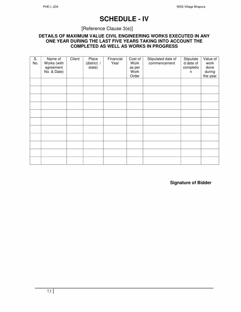
PHE-I, JDA WSS Village Bhapura
73
SCHEDULE - IV
[Reference Clause 3(e)]
DETAILS OF MAXIMUM VALUE CIVIL ENGINEERING WORKS EXECUTED IN ANY ONE YEAR DURING THE LAST FIVE YEARS TAKING INTO ACCOUNT THE
COMPLETED AS WELL AS WORKS IN PROGRESS
S.
No. Name of
Works (with agreement No. & Date)
Client Place (district /
state)
Financial Year
Cost of Work as per Work Order
Stipulated date of commencement
Stipulated date of completio
n
Value of work done
during the year
Signature of Bidder

PHE-I, JDA WSS Village Bhapura
74
SCHEDULE - V
[Reference Clause 3(f)]
DETAILS OF EXISTING COMMITMENTS & ON GOING WORKS TO BE COMPLETED
S.
No. Name of
Works (with agreement No. & Date)
Client Cost of Work as per Work Order
Stipulated date of
commencement
Stipulated date of
completion
Value of balance work on date of tender
Likely date of completion of balance
work
Signature of Bidder

PHE-I, JDA WSS Village Bhapura
75
SCHEDULE - VI
[Reference Clause 3(g)]
DETAILS OF LITIGATION OR ARBITRATION CONTRACTS
S.
No. Name of
Works (with agreement No. & Date)
Client Work Order
Amount
Disputed Amount
Claimed in Litigation / Arbitration
Date of Raising
Disputed Amount
Actual Award
Amount, if the case is Decided
Cause of Litigation & matter in Dispute
Signature of Bidder

PHE-I, JDA WSS Village Bhapura
76
SCHEDULE –VII
[Reference Clause 3(h)]
BID CAPACITY
Name of Bidder: ______________________________
1. A = Maximum value of civil Engineering works
Executed in any one year during the last five
Years (Updated to present price level)
________Lacs
Certified details enclosed at Page No.____________
2. N = Number of years prescribed for completion of
the Work for which bids are invited
----------
3. B = Value, at present price level of existing
Commitments and on going works to be
Completed during the next N Period.
________Lacs
Certified details enclosed at Page No. _____________
Bid Capacity = A x N x 3 - B
= ___________ Lacs
Signature of Bidder

PHE-I, JDA WSS Village Bhapura
77
ANNEXURE- I
[Reference Clause 3(i)]
To be given on Non-Judicial stamp
Paper of Rs. 10/- only,
AFFIDAVIT
I/We…………………………………………………….. Proprietor/ Partner/ Authorized
signatory of M/s ……………………………………… under take the oath that the
information furnished by me/us of the assessment Bid for
………………………………………………………………………………….….. is correct to the best
of my/our knowledge and nothing has been concealed by me. I acknowledge that
if in future any information furnished by me is found incorrect I will be solely
responsible and shall be punished as per the law and also any benefits in any form
obtained by me shall be recoverable.
....................................
Proprietor/ Partner/ Authorized signatory
M/s ……………………………………….
…………………………………………….
Note:-
The applicant has to enclose a self attested photo identity card with the above affidavit.
Signed
Photograph of
Applicant

PHE-I, JDA WSS Village Bhapura
78
ANNEXURE- II
Bank Guarantee Performa for Bid security deposite
Form of (Bank Guarantee) -En cashable at branch of the bank in Jaipur City.
To
Secretary,
Jaipur Development Authority,
Jaipur
Sub:
Bank Guarantee No. _________ dated __________ for [amount of Security in figures] [in words]
on behalf of ________________________________ [Name of the Bidder] against the Security
Deposit for the work of “Rural Water Supply Scheme for Villages of Gram Panchayat
Bhapura”
WHEREAS, _____________________________ [name of Bidder with address] (hereinafter
called “the Bidder”) has submitted his Bid dated ............................. for the work of “Rural
Water Supply Scheme for Villages of Gram Panchayat Bhapura” (Name of Work)
(Hereinafter called “the Bid”).
KNOW ALL PEOPLE by these presents that we ________________________________
________________________________ (Name of Bank) of having our registered office at
_________________________________[name of country] having our registered office at
___________________ (hereinafter called “the Bank”) are bound unto Secretary, Jaipur
Development Authority. (Hereinafter called “the Employer”) in the sum of Rupees
__________________ [Amount of Security in figures] _________________ (in words) only for
which payment will and truly to be made to the said Employer, the Bank binds itself, its
successors, and assigns by these presents.
That on demand of JDA , this Bank Guarantee is encashable at following branch in Jaipur City.
1. Name of Bank:
2. Name of the branch with branch code:
3. Address:
4. E-Mail Id:
5. Telephone No.
6. Fax No.:
SEALED with the Common Seal of the said Bank this ______ day of __________ of 20____.
THE CONDITIONS of this obligation are:
(1) if the Bidder withdraws his Bid during the period of Bid validity specified in the Form of
Bid;
PHE-I, JDA WSS Village Bhapura
79
(2) if the Bidder refuses to accept the correction of errors in his bid;
(3) If the Bidder, having been notified of the acceptance of his Bid by the Employer during the
period of Bid validity;
(a) fails or refuses to execute the Form of Agreement in accordance with the Instructions
to Bidders, or
(b) fails or refuses to furnish the Performance Security, in accordance with the Instructions
to Bidders;
We undertake to pay to the Employer up to the above amount upon receipt of his first written
demand, without the Employer having to substantiate his demand, provided that in his demand
the Employer will note that the amount claimed by him is due to him owing to the occurrence of
one or more of the above conditions, specifying the occurred condition or conditions.
This Guarantee will remain in force up to and including the date 30 days after the date of
expiration of the Bid Validity, as stated in the Instructions to Bidders, or any such extension
thereto as may be agreed by the Bidder, notice of which extension(s) to the Bank is hereby
waived. Any demand in respect of this Guarantee should reach the Bank not later than the
above date.
The amount covered under the above Bank Guarantee shall be automatically be credited in the
accounts of JDA in ICICI Bank, JDA Campus, Jaipur through ISFC code No ICICI 006754. Bank
Account No. 675401700518 on the date of expiry or its validity, unless the agencies get it re-
validated well before its expiry date or produce NOC from JDA in written for its release.
Date __________________________Signature of the Bank________________________
Witness___________________________ Seal _____________________________
[Signature, Name and Address]
[Note: To be furnished on appropriate non-judicial stamps.]

PHE-I, JDA WSS Village Bhapura
80
PAYMENT MECHANISM FOR PARTICIPATING IN TENDER
Jaipur Development Authority has decided to receive Earnest Money Deposit (EMD) (Bid Security) Tender fee online through JDA portal. The bid security options available in tender for participants are as mentioned below : A. Payment Options:
Option-1: Bank Guarantee (BG). against EMD I Bid Security
Bidder may opt Bank Guarantee (BG) against EMD (Bid Security) for which bidder requires to prepare BG before applying in the tender. The details of BG requires to be fed on JDA portal before paying balance amount (Tender Fee). This amount will be paid through Payment Gateway only, option to make balance payment through EFT (RTGS/NEFT) will not be available If bidder does not opt for BG against EMD, options of making complete payment through Payment Gateway or through EFT (NEFT/RTGS) will be available
Option-2: Electronic Fund Transfer (EFT:EFT/RTGS) If the bidder selects payment mode as EFT (NEFT/RTGSL "Paying Slip for EFT
(NEFT/RTGS}" will be generated by the system for the complete amount. The payment can be made from any Bank any Branch using this Paying Slip through NEFT/RTGS (Claim against payment made through EFT in any other JDA bank account will not be acceptable and bidder stands disqualified from participation in the bid applied for). After successful transaction through NEFT/RTGS, as per the standard procedures i t may take 4 to 24 hours in process of confirmation of EFT through Auto-Process depending on the time of EFT done. Therefore, option to make payment t h rough E F T (NEFT/RTGS) w i l l be available till 2 days prior to closing date of bid participation.
Option-3: Payment Gateway (Aggregator) The facility to make payment through Deb i t Card, Credit Card, Net banking etc., will b e available. User can use this facility from anywhere any time till the closing date & time of bid participation
B. Bid Participation Receipt After confirming payment, the bidder will get Bid Participation Receipt on the basis of which user will get the payment details along with other details for bidding on e-Procurement portal of GOR
� In case of BG as the remaining payment will be done through Payment Gateway, on successful transaction the "Bid Participation Receipt"
will be generated on real time basis � In case complete payment is done through Payment Gateway, on
successful transaction the "Bid Participation Receipt" will be generated on real time basis
� In case complete paym ent is done through EFT (NEFTIRTGS), on confirmation of payment from ICICI Bank (Auto Process) "Bid Participation Receipt" will be available on Login of Bidder on JDA portal.
-SD- Executive Engineer (PHE-I)
JDA, Jaipur
PHE-I, JDA WSS Village Bhapura
81
JAIPUR DEVELOPMENT AUTHORITY
Tender Document
For
Name of work : Rural Water Supply Scheme for Villages of Gram Panchayat Bhapura
Cost: Rs 428.00 Lacs
NIT No. 01/2017-18 Due On: 18.05.2017
Volume-II
(BOQ)
Executive Engineer (PHE-I) Jaipur Development Authority
Jaipur

PHE-I, JDA WSS Village Bhapura
82
Item Rate BoQ
Tender Inviting Authority: JAIPUR DEVELOPMENT AUTHORITY, JAIPUR
Name of Work: Rural Water Supply Scheme for Villages of Gram Panchayat Bhapura
Contract No: EE/PHE-I/NIB No.-01/2017-18
Name of the Bidder/ Bidding Firm / Company :
PRICE SCHEDULE (This BOQ template must not be modified/replaced by the bidder and the same should be uploaded after filling the relevent columns, else
the bidder is liable to be rejected for this tender. Bidders are allowed to enter the Bidder Name and Values only )
NUMBER #
TEXT # NUMBER #
TEXT #
NUMBER NUMBER # NUMBER # TEXT #
Sl. No.
Item Description Quantity
Units Estimated Rate
BASIC RATE In Figures To be entered by the
Bidder Rs. P
TOTAL AMOUNT Without Taxes
TOTAL AMOUNT In Words
1 2 4 5 6 13 53 55
1 Design & construction of clear water reservoirs of required capacity including its piping, fittings,etc. complete in all respect as per the scope of work & specificatiions 100.0 KL
1.000 Each 0.00 INR Zero Only

PHE-I, JDA WSS Village Bhapura
83
2 Design & Construction of Over Head service reservoirs of minimum 22 mtr staging,as per specifications including fixing inlet;outlet; washout & overflow pipes, supply and installation of valves on inlet; outlet; washout & overflow pipes, puddle collars, duck foot bends, pipe interconnecting the incoming & outgoing mains with all specials; float valve with auxillary valve, water indicator, plinth protection works ,finishing, testing and commissioning complete as per the specifications and scope of work 100.0 KL.
1.000 Each 0.00 INR Zero Only
Total in Figures
0.00 INR Zero Only
Quoted Rate in Words
INR Zero Only

PHE-I, JDA WSS Village Bhapura
84
Percentage BoQ
Tender Inviting Authority: JAIPUR DEVELOPMENT AUTHORITY, JAIPUR
Name of Work: Rural Water Supply Scheme for Villages of Gram Panchayat Bhapura
Contract No: EE/PHE-I/NIB No.-01/2017-18
Name of the Bidder/ Bidding Firm / Company :
PRICE SCHEDULE (This BOQ template must not be modified/replaced by the bidder and the same should be uploaded after filling the relevent columns,
else the bidder is liable to be rejected for this tender. Bidders are allowed to enter the Bidder Name and Values only )
NUMBER #
TEXT # NUMBER # TEXT # NUMBER NUMBER # TEXT #
Sl. No.
Item Description Quantity Units Estimated Rate
TOTAL AMOUNT Without Taxes
TOTAL AMOUNT In Words
1 2 4 5 6 53 55
1 Supply & Installation of centrifugal pump set coupled with suitable motor (as per required head & discharge) complete in all respect as per the scope of work & specifications.

PHE-I, JDA WSS Village Bhapura
85
1.1 2 nos pumps each of 4.38 lps, 40mtr head, 5.5KW
2.000 Each 42500.00 85000.00 INR Eighty Five Thousand Only
1.2 2 nos pumps each of 6.11 lps, 40mtr head, 5.5KW
2.000 Each 42500.00 85000.00 INR Eighty Five Thousand Only
1.3 2 nos pumps each of 3.61 lps, 30mtr head, 5.5KW
2.000 Each 42500.00 85000.00 INR Eighty Five Thousand Only
1.4 2 nos pumps each of 3.26 lps, 35mtr head, 5.5KW
2.000 Each 42500.00 85000.00 INR Eighty Five Thousand Only
2 Providing, installation ,testing and commissioning of LT MCC with panels housing motor starters relays, MCB/MCCBs, bus-bar for all pump sets including all internal cabling and cable/bus-bar from switchyard, up to panels, capacitor control panels, housing power factor control system panel/capacitors(APFC Panel),Other accessories including all internal cabling and cable/bus-bar from switchyard, up tp panels,soft starters, for each pump-set,complete in all respect as per the scope of work & specifications.
1.000 Each 250000.00 250000.00 INR Two Lakh Fifty Thousand Only
3 Providing, installation, testing and commissioning of DI Sluice v 1.6 rating. The valves shall be resilient seated, bubble-tight, str inside stem screw and electrostatic epoxy powder (EP-P) coate face dimensions shall conform to provisions of IS 14846/EN 55
3.1 100 mm 4.000 Each 10500.00 42000.00 INR Forty Two Thousand Only
3.2 150 mm 3.000 Each 15500.00 46500.00 INR Forty Six Thousand Five Hundred Only

PHE-I, JDA WSS Village Bhapura
86
4 NON RETURN VALVE: Providing, installation, testing and commi valves on delivery side of pumps, complete in all respect as per given in the tender document. Dual plate check valves conform have resilient sealing. The spring action shall optimise the equa when the friction coefficients are uneven due to one plate resti not drag on the seat while opening. The plates shall not vibrate The minimum body-wall thickness shall conform to those given face-to-face dimensions of valves (including valves with ring-joi mentioned in Table 2B of API Standard 594. Pressure rating of surge analysis but in any case it shall not be less than PN-1.6.
4.1 100 mm 4.000 Each 10000.00 40000.00 INR Forty Thousand Only
4.2 150 mm 3.000 Each 15000.00 45000.00 INR Forty Five Thousand Only
5 Providing supplying, erection and commissioning of Electro-ma flow Integrator (with Digital display in Instrument Panel in Cont per the scope of work & specifications of following sizes (in mm
5.1 100 mm 4.000 Each 130000.00 520000.00 INR Five Lakh Twenty Thousand Only
5.2 150 mm 1.000 Each 175000.00 175000.00 INR One Lakh Seventy Five Thousand Only

PHE-I, JDA WSS Village Bhapura
87
6 Supply ,Installation, Testing commissioning of electrically operated metering pump for along with following item- for chlorination of water with required dose-(I)100 liter jar filled with sodium chloride solution, (II) suction and delivery piping in adequate length as per general arrangement drawing (III) Electrical cable and contractor from MCB and control cables from CWR to PMCC to switch On/Off the chlorinator when water if flowing/ not flowing in CWR.
4.000 Each 50000.00 200000.00 INR Two Lakh Only
7 Supply and installation of dewatering pump as per scope of work
1.000 Each 25000.00 25000.00 INR Twenty Five Thousand Only
8 Supplying, erecting, testing & commissioning of Electrically Operated Travelling Crane (EOT) .Main 4.000 Each girder & End Carriage fabricated from Rollled Steel Section, Gear Box for all motion, Electro Magnetic Friction Disc Type Brakes, all safety limit switches, LT wheels EN 9, Double Flanged 4No, with Sq. Cage motor of adequate rating (KW), duly painted mechanical cleaning and one coat of primer and two coat of synthetic paint and as per the direction of the Engineer. 2 MT Capacity. Span 7 M and Lift 6 M.
1.000 Each 350000.00 350000.00 INR Three Lakh Fifty Thousand Only
9 Providing Steel tubular office chair with cane seat and back made of ERW 1/14 gauge pipe with half hanging arms
4.000 Each 1000.00 4000.00 Four Thousand Only
10 Providing table of size 175x90x75 as per detailed specifications.
1.000 Each 5500.00 5500.00 INR Five Thousand Five Hundred Only

PHE-I, JDA WSS Village Bhapura
88
11 Earth work in excavation by mechanical means Excavator )/ manual means in foundation trenches or drains (not exceeding 1.5 m in width or 10 sum on plan) including dressing of sides and ramming of bottoms, lift upto 1.5 m, including taking out the excavated soil and depositing and refilling of jhiri with watering & ramming and disposal of surplus excavated soil as directed with in a lead of 50 meter. All kinds of soils
215.500 CUM 111.60 24049.80 INR Twenty Four Thousand &Forty Nine and Paise Eighty Only
12 Providing and laying in position cement concrete including curing, compaction etc. complete in specified grade excluding the cost of centering and shuttering - All work up to plinth level. CEMENT CONCRETE (CAST-IN-SITU)
12.1 M10 grade Nominal Mix 1: 3: 6 (1 cement : 3 coarse sand : 6 graded stone aggregate
69.920 CUM 2398.50 167703.12 INR One Lakh Sixty Seven Thousand Seven Hundred & Three and Paise Twelve Only
12.2 M15 grade Nominal Mix 1: 2: 4 (1 cement : 2 coarse sand : 4 graded stone aggregate
11.760 CUM 2882.70 33900.55 INR Thirty Three Thousand Nine Hundred and Paise Fifty Five Only
13 Providing and laying damp-proof course with cement concrete grade M-150 (1 : 2 : 4) mortar prepared with 1% solution of water-proof compound complete as per specification. DAMP- PROOF COURSE AND PRECASTCOPING
13.1 50mm thick. 114.080 Sqm. 243.90 27824.11 INR Twenty Seven Thousand Eight Hundred & Twenty Four and Paise
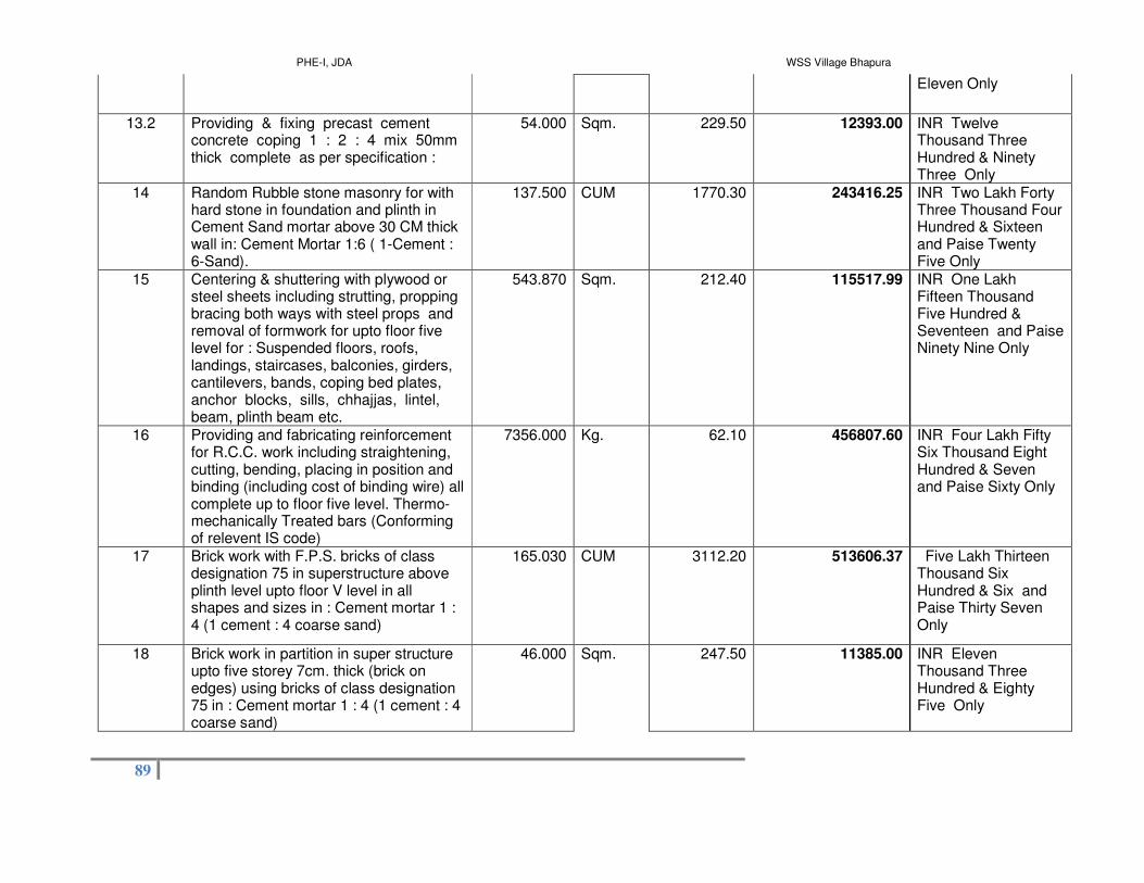
PHE-I, JDA WSS Village Bhapura
89
Eleven Only
13.2 Providing & fixing precast cement concrete coping 1 : 2 : 4 mix 50mm thick complete as per specification :
54.000 Sqm. 229.50 12393.00 INR Twelve Thousand Three Hundred & Ninety Three Only
14 Random Rubble stone masonry for with hard stone in foundation and plinth in Cement Sand mortar above 30 CM thick wall in: Cement Mortar 1:6 ( 1-Cement : 6-Sand).
137.500 CUM 1770.30 243416.25 INR Two Lakh Forty Three Thousand Four Hundred & Sixteen and Paise Twenty Five Only
15 Centering & shuttering with plywood or steel sheets including strutting, propping bracing both ways with steel props and removal of formwork for upto floor five level for : Suspended floors, roofs, landings, staircases, balconies, girders, cantilevers, bands, coping bed plates, anchor blocks, sills, chhajjas, lintel, beam, plinth beam etc.
543.870 Sqm. 212.40 115517.99 INR One Lakh Fifteen Thousand Five Hundred & Seventeen and Paise Ninety Nine Only
16 Providing and fabricating reinforcement for R.C.C. work including straightening, cutting, bending, placing in position and binding (including cost of binding wire) all complete up to floor five level. Thermo-mechanically Treated bars (Conforming of relevent IS code)
7356.000 Kg. 62.10 456807.60 INR Four Lakh Fifty Six Thousand Eight Hundred & Seven and Paise Sixty Only
17 Brick work with F.P.S. bricks of class designation 75 in superstructure above plinth level upto floor V level in all shapes and sizes in : Cement mortar 1 : 4 (1 cement : 4 coarse sand)
165.030 CUM 3112.20 513606.37 Five Lakh Thirteen Thousand Six Hundred & Six and Paise Thirty Seven Only
18 Brick work in partition in super structure upto five storey 7cm. thick (brick on edges) using bricks of class designation 75 in : Cement mortar 1 : 4 (1 cement : 4 coarse sand)
46.000 Sqm. 247.50 11385.00 INR Eleven Thousand Three Hundred & Eighty Five Only

PHE-I, JDA WSS Village Bhapura
90
19 Providing and fixing external grade board solid core single leaf flush door shutters ISI 2202-67 marked using Phenol formal dehyderesin in glue both sides with approved steel fittings complete as per annexure 'A' :
19.1 35 mm thick . Decorative teak veneer both side
10.290 Sqm. 1656.90 17049.50 INR Seventeen Thousand &Forty Nine and Paise Fifty Only
20 Providing and fixing in position collapsible steel shutters with vertical M.S. Channels 20 x 10 x 2mm and bracket with flat iron diagonals 20 x 5mm. size with top and bottom rail of T-iron 40 x 40 x 6mm. with 40mm dia steel pulleys/ball bearing complete with bolts, nuts locking arrangements inside and outside stoppers, handles etc. as per specification including applying a priming coat of approved steel primer. (To be measured and paid as per outer dimension).
11.200 Sqm. 3225.60 36126.72 INR Thirty Six Thousand One Hundred & Twenty Six and Paise Seventy Two Only

PHE-I, JDA WSS Village Bhapura
91
21 Providing and fixing steel glazed doors window and ventilator shutters of standard rolled steel section (IS 1038-1983) joints mitred and welded with steel lugs 13 X 3 mm, 10 cm. long embedded in cement concrete block 15 X 10 X 10 cm . of 1:3:6 (1 cement : 3 coarse sand : 6 graded stone aggregate 20 mm nominal size) or with wooden plugs and screws or rawl plugs and screws with fixing clips or with bolts and nuts as required including providing and fixing of plain glass panes 4 mm thick with cooper glazing clips and special metal sash putty of approved make or metal beading with screws complete including priming coat of approval steel primer, excluding the cost of metal beading and other fitting except necessary higes of pivots steel handles peg stay etc. as required.
21.1 Partly fixed and partly openable [ fixed area not to exceed 33%]
10.000 Sqm. 2159.10 21591.00 Twenty One Thousand Five Hundred & Ninety One Only
22 Supplying and fixing fixed wire gauge of 14 mesh x 24 gauge to the metal frame of rolled section by metal beading 20x3mm with suitable screw at not exceeding 150mm distance.
6.670 Sqm. 385.20 2569.28 INR Two Thousand Five Hundred & Sixty Nine and Paise Twenty Eight Only
23 Providing and fixing Square bars or other flat welded to window, ventilatiors etc.
200.000 Kg. 55.80 11160.00 INR Eleven Thousand One Hundred & Sixty Only
24 Cement Plaster
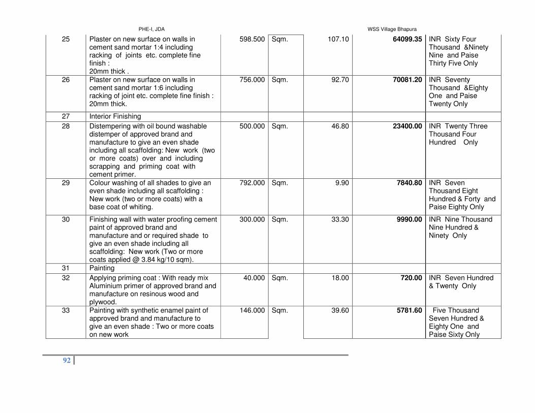
PHE-I, JDA WSS Village Bhapura
92
25 Plaster on new surface on walls in cement sand mortar 1:4 including racking of joints etc. complete fine finish : 20mm thick .
598.500 Sqm. 107.10 64099.35 INR Sixty Four Thousand &Ninety Nine and Paise Thirty Five Only
26 Plaster on new surface on walls in cement sand mortar 1:6 including racking of joint etc. complete fine finish : 20mm thick.
756.000 Sqm. 92.70 70081.20 INR Seventy Thousand &Eighty One and Paise Twenty Only
27 Interior Finishing
28 Distempering with oil bound washable distemper of approved brand and manufacture to give an even shade including all scaffolding: New work (two or more coats) over and including scrapping and priming coat with cement primer.
500.000 Sqm. 46.80 23400.00 INR Twenty Three Thousand Four Hundred Only
29 Colour washing of all shades to give an even shade including all scaffolding : New work (two or more coats) with a base coat of whiting.
792.000 Sqm. 9.90 7840.80 INR Seven Thousand Eight Hundred & Forty and Paise Eighty Only
30 Finishing wall with water proofing cement paint of approved brand and manufacture and or required shade to give an even shade including all scaffolding: New work (Two or more coats applied @ 3.84 kg/10 sqm).
300.000 Sqm. 33.30 9990.00 INR Nine Thousand Nine Hundred & Ninety Only
31 Painting
32 Applying priming coat : With ready mix Aluminium primer of approved brand and manufacture on resinous wood and plywood.
40.000 Sqm. 18.00 720.00 INR Seven Hundred & Twenty Only
33 Painting with synthetic enamel paint of approved brand and manufacture to give an even shade : Two or more coats on new work
146.000 Sqm. 39.60 5781.60 Five Thousand Seven Hundred & Eighty One and Paise Sixty Only

PHE-I, JDA WSS Village Bhapura
93
34 Providing and fixing aluminum work for doors ,windows, ventilators and partition with extruded built up standard tubular / appropriate Z sections and other sections of approved make conforming to IS :733 and IS :1285, fixed with rawl plugs and screws or with fixing clips ,or with expansion hold fasteners including necessary filling up of gap. at junctions , at top ,bottom and sides with required PVC/neoprene felt etc. Aluminium section shall be smooth ,rust free, straight ,mitered and jointed mechanically wherever required including cleat angle Aluminium snap beading for glazing /paneling , C.P. brass/ stainless steel screws Al. Tower bolt & Al. handle & Al. Aldrop etc.,all complete as per architectural drawings and the directions of Engineer- in – charge .(Glazing and paneling to be paid for separately).
34.1 For fixed portion Powder coating aluminum ( minimum thickness of powder coating 50 micron)
702.000 Kg. 282.60 198385.20 INR One Lakh Ninety Eight Thousand Three Hundred & Eighty Five and Paise Twenty Only
35 RIGID PVC SOIL
36 P&F rigid PVC Pipe (IS:4985 mark) class II/ (4 Kg. /Cm2.) approved quality /make including joining the pipe with solvent cement rubber ring and lubricant. 110 mm dia
70.000 Mtr. 156.60 10962.00 INR Ten Thousand Nine Hundred & Sixty Two Only

PHE-I, JDA WSS Village Bhapura
94
37 Construction of chamber in all type of soil with 300 mm thick masonry in CM 1:6 m,10 cm thick C.C. 1:5:10 in foundation, 20mm thick insider plaster in Cm 1:6, finished with floating neat cement, 50mm thick M-15 grade C.C. flooring , earthwork etc. complete as per design including disposal of surplus earth within a lead of 50 mtr. Inside size 600 x 450 mm depth upto 0.5 M Cement cover with frame.
2.000 Each 2142.00 4284.00 INR Four Thousand Two Hundred & Eighty Four Only
38 Construction of septic Tank in all types of soil with 40 Cm .thick masonry in CM 1:6, 15 Cm thick C.C bed of 1:5:10, M-15 grade C.C flooring & over stone slab covering ,80 mm thick slab ,jointing of slab in CM 1:3. Ralthal, Kharanja, 50 mm thick stone partition walls, 20 mm thick plaster in CM 1:6 finished with neat floating cement, 4 Nos C.I foot rests of approved design ,two No. 450 mm dia each Ferro cement cover with frame, earth work etc. complete as per approved drawing including disposal of surplus earth within a lead of 50 mtr:- Size 200x100x130 cm.(for 10 users)
2.000 Each 16830.00 33660.00 Thirty Three Thousand Six Hundred & Sixty Only
39 P & F 1st qualityVitrified Porcelain Polished tiles on floor, skirting and steps etc.in different sizes (thickness to be specified by manufactuer) with water absortion less than 0.08% and conforming to IS 15622 of approved make in all colour and shade, laid with 20 mm thick CM 1 : 4 including grounting the joints with white cement and matching pigment etc complete.
39.1 Size 600 mm X 600 mm 70.500 Sqm. 839.70 59198.85 INR Fifty Nine Thousand One

PHE-I, JDA WSS Village Bhapura
95
Hundred & Ninety Eight and Paise Eighty Five Only
40 Structural steel work in single section fixed with or without connecting plate including cutting, hoisting ( height upto 10 m), fixing in position and applying a priming coat of approved steel primer all complete.
850.000 Kg. 56.70 48195.00 INR Forty Eight Thousand One Hundred & Ninety Five Only
41 Supply and fixing in cement mortar welded hand railing made out of MS round or square bars, flats etc. for staircase or verandah as per design complete in all respect (wooden or PVC hand railing to be paid extra) with priming coat of red oxide.
800.000 Kg. 61.20 48960.00 INR Forty Eight Thousand Nine Hundred & Sixty Only
42 GALVANISED IRON SHEET ROOFING
43 Providing and laying integral cement based water proofing treat (a) Applying and grouting a slurry coat of neat cement using 2 (b) Laying cement concrete using broken bricks/brick bats 25 (c) After two days of proper curing applying a second coat of c (d) Finishing the surface with 20 mm thick jointless cement m (e) The whole terrace so finished shall be flooded with water With average thickness of 120mm and minimum thickness at khurra as 65 mm.
183.000 Sqm. 309.60 56656.80 INR Fifty Six Thousand Six Hundred & Fifty Six and Paise Eighty Only
44 Providing gola 75x75 mm in cement concrete 1:2:4 (1 cement : 2 coarse sand : 4 stone aggregate 10mm and down gauge) including finishing with cement mortar 1:3 (1 cement : 3 fine sand) as per standard design :
65.000 Mtr. 72.90 4738.50 INR Four Thousand Seven Hundred & Thirty Eight and Paise Fifty Only
45 CEMENT CONCRETE FLOORING

PHE-I, JDA WSS Village Bhapura
96
46 Providing and fixing 50mm thick cement concrete flooring with Metallic concrete hardener topping, under layer of 38mm thick cement concrete 1:2:4 (1-cement : 2-coarse sand : 4-graded stone aggregate 20mm thick nominal size) and top layer of 12mm thick metallic concrete hardener consisting of mix 1:2 (1 cement : 2 stone aggregate, 6mm nominal size) by volume & mixed with metallic hardening compound of approved quality @ 2Kg./Sqm including cement slurry, rounding off edges etc. but excluding the cost of nosing of step etc. complete.
75.240 Sqm. 283.50 21330.54 INR Twenty One Thousand Three Hundred & Thirty and Paise Fifty Four Only
47 KOTA STONE FLOORING
48 Kota stone slab flooring 25 mm thick over 20 mm (average) thick base laid over and jointed with grey cement slurry mixed with pigment to match the shade of the slab including rubbing and polishing complete with base of cement mortar 1 : 4 (1 cement : 4 coarse sand) For area of each slab from 901 to 2000 Sq.Cm :
41.380 Sqm. 593.10 24542.48 INR Twenty Four Thousand Five Hundred & Forty Two and Paise Forty Eight Only
49 ROUGH CAST PLASTER

PHE-I, JDA WSS Village Bhapura
97
50 Washed stone grit plaster on exterior walls of height upto 10 M. above level in two layers, under layer 12mm cement plaster 1:4 (1 cement : 4 coarse sand ) furrowing the under layer with scratching tool, applying cement slurry on the under layer @ 2kg of cement per sqm, top layer 15 mm cement plaster 1:1/2:2 ( 1 cement : 1/2 coarse sand : 2 stone chipping size 10 mm nominal size) in panel with groove all around as per approved pattern including scrubbing and washing, the top layer with brushes and water to expose the stone chipping, complete as per specification and direction of Engineer in charge. (Payment for providing grooves shall be made separately)
146.570 Sqm. 288.90 42344.07 INR Forty Two Thousand Three Hundred & Forty Four and Paise Seven Only
51 Wiring of light point/ fan point/ exhaust fan point/ call bell point with 1.5 sq. mm nominal size FR PVC insulated unsheathed flexible copper conductor 1.1 kV grade and 1.5 sq. mm nominal size FR PVC insulated unsheathed flexible copper earth conductor 1.1 kV grade (IS:694) of approved make on surface ISI marked ( IS:14927 P - II ) PVC casing capping & it's accessories, round tiles,18 SWG M.S. box with earth terminal, 6 A switch, 3.0 mm thick ISI marked phenolic laminated sheet, zinc plated / brass screws, cup washers, making connections, testing etc. as required.
51.1 Short point (up to 3 mtr.) 27.000 P. Point 155.20 4190.40 INR Four Thousand One Hundred & Ninety and Paise Forty Only

PHE-I, JDA WSS Village Bhapura
98
51.2 Medium point (up to 6 mtr.) 14.000 P. Point 234.40 3281.60 INR Three Thousand Two Hundred & Eighty One and Paise Sixty Only
51.3 Long point (up to 10 mtr..) 8.000 P. Point 332.00 2656.00 INR Two Thousand Six Hundred & Fifty Six Only
52 Wiring of twin control light / fan / call bell point with 1.5 sq. mm nominal size FR PVC insulated unsheathed flexible copper conductor 1.1 kV grade and 1.5 sq. mm nominal size FR PVC insulated unsheathed flexible copper earth conductor 1.1 kV grade (IS:694) of approved make on surface ISI marked ( IS:14927 P - II ) PVC casing capping & it's accessories, round tles,18 SWG M.S. box with earth terminal, 6 A two way switch, 3.0 mm thick ISI marked phenolic laminated sheet, zinc plated / brass screws, cup washers, making connections, testing etc. as required.
52.1 Long point (up to 10 mtr..) 14.000 P. Point 333.60 4670.40 INR Four Thousand Six Hundred & Seventy and Paise Forty Only
53 Supplying and drawing FR PVC insulated & unsheathed flexible copper conductor ISI marked (IS:694) of 1.1 kV grade and approved make in existing surface or recessed conduit/casing capping including making connections etc. as required.
53.1 2 x 1.5 sq.mm 600.000 Mtr. 20.80 12480.00 INR Twelve Thousand Four Hundred & Eighty Only

PHE-I, JDA WSS Village Bhapura
99
53.2 2 x 4.0 sq.mm 140.000 Mtr. 45.60 6384.00 INR Six Thousand Three Hundred & Eighty Four Only
54 P&F 240/415 V AC MCB with positive isolation of breaking capacity not less than 10 KA (B/ C/ D tripping characteristic) ISI marked IS 8828(1996)]/ conforming to IEC 60898 in existing board/sheets including making connections, testing etc. as required.
54.1 Single pole & neutral MCB 6 A to 32 A rating
14.000 Each 320.80 4491.20 INR Four Thousand Four Hundred & Ninety One and Paise Twenty Only
55 Plate Earthing as per IS : 3043 with G.I. Earth plate of size 600 mm X 600 mm X 6.0 mm by embodying 3 to 4 mtr. below the ground level with 25 mm dia G.I. 'B' class watering pipe including all accessories like nut, bolts, reducer, nipple, wire meshed funnel, and C.C. finished chamber covered with hinged type with locking arrangement C.I. Cover, C.I. Frame of size300mm x 300mm complete with alternate layers of salt and coke/charcoal, testing of earth resistance as required.
2.000 Per Set 3400.00 6800.00 INR Six Thousand Eight Hundred Only
56 S & Laying following size earth wire/strip in horizontal or vertical run in ground/surface/ recess including riveting, soldering, saddles, making connection etc. as required.
56.1 10 SWG copper. Wire 40.000 Mtr. 36.80 1472.00 INR One Thousand Four Hundred & Seventy Two Only

PHE-I, JDA WSS Village Bhapura
100
57 P & F double ball bearing capacitor start, aluminium body & blade ceiling fan with down rod up to 30 cm with 3 x 1.5 sq.mm pvc insulated flexible copper conductor making connection testing etc. as required.
57.1 1200 mm sweep 5.000 Each 1160.80 5804.00 INR Five Thousand Eight Hundred & Four Only
58 P & F Star rated double ball bearing capacitor start, aluminium body & blade ceiling fan with down rod up to 30 cm with 3 x 1.5 sq.mm pvc insulated flexible copper conductor making connection testing etc. as required.
58.1 1200 mm Sweep 5 Star rated 5.000 Each 1516.80 7584.00 INR Seven Thousand Five Hundred & Eighty Four Only
59 P & F 18 swg M.S. Recessed fan box, hexagonal/ round of size 130 mm dia, depth 75mm, 12 mm dia rod fan hook with 100 mm length extended on each side .
5.000 Each 76.00 380.00 INR Three Hundred & Eighty Only
60 P&F of Heavy duty capacitor start, Double ball bearing 900/1400 RPM single phase ISI marked Exhaust fan,IS:2312 marked in existing opening including making connections testing etc. as required.
60.1 300 mm sweep(900/1400 RPM) 6.000 Each 2401.60 14409.60 INR Fourteen Thousand Four Hundred & Nine and Paise Sixty Only

PHE-I, JDA WSS Village Bhapura
101
61 P & F strip type fluorscent tube fitting fabricated from (CRCA sheet and finished with powder coating / stove enamelled paint) / (extruded non corrosive UV resist EP channel) complete with accessories (Low Loss Copper Choke, starter, starter seat) / Electronic Choke with terminal block duly prewired with copper conductor including making connection, testing etc. as required( without tube).
61.1 1 X 36 Watts with OCCB 14.000 Each 315.20 4412.80 Four Thousand Four Hundred & Twelve and Paise Eighty Only
62 P & F Fluorscent tube rod in existing fixtures as required, Flourscent powder coated (minimum 3 star rating)
62.1 36/40 Watts 14.000 Each 50.40 705.60 INR Seven Hundred & Five and Paise Sixty Only
63 WATER CLOSETS
64 P & F European type white glazed vitreous china 1st quality Double syphonic W.C (IS :2556 Mark) with P or S trap including cutting and making good the wall and floor
1.000 Each 3423.60 3423.60 INR Three Thousand Four Hundred & Twenty Three and Paise Sixty Only
65 P & F White Vitreous China Double Syphonic European W.C. (I.S:2556Mark) with mounted W.V.C. flushing cistern of (IS : 2556 Mark) of 10 litre capacity complete with all necessary internal fittings including cutting and making good the wall and floor.
1.000 Each 7654.50 7654.50 INR Seven Thousand Six Hundred & Fifty Four and Paise Fifty Only
66 URINALS

PHE-I, JDA WSS Village Bhapura
102
67 P & F lst quality WVC Urinal (IS:2556 mark) with 25mm dia G.I. waste pipe, dome waste couplings, concealed iron brackets or screws etc complete. Flat Back (large) or half stall size 610x400x80mm.
2.000 Each 2774.70 5549.40 INR Five Thousand Five Hundred & Forty Nine and Paise Forty Only
68 P & F High Level Flushing Cistern of 10 litres capacity of approved make including C.I. brackets duly painted, chain & pull and 32 mm dia G.I. concealed flush pipe with M.S. clamps, 20 mm dia G.I. over flow pipe upto 185 cm long, brass ball cock (IS : 1703 mark) with PVC ball and internal fittings and mosquito proof coupling, complete including cutting and making good the wall. White PVC (IS: 7231 Mark).
2.000 Each 1189.80 2379.60 INR Two Thousand Three Hundred & Seventy Nine and Paise Sixty Only
69 WASH BASING
70 P & F WVC wash basin (1st quality, I.S. : 2556 Mark) of approv 1 No. 15 mm C.P. Pillar cock (IS : 8934 Mark) & 32 mm C.P. brass waste coupling of approved make, 25 mm G.I. waste pipe complete including cutting & making go Size 550 mm x 400 mm
2.000 Each 1557.00 3114.00 INR Three Thousand One Hundred & Fourteen Only
71 P & F Terrazzo (Mosaic) wash hand basin with supporting brackets waste coupling and PVC waste pipe complete, including painting of brackets making good the walls: 550 mm x 400 mm
2.000 Each 747.90 1495.80 INR One Thousand Four Hundred & Ninety Five and Paise Eighty Only
72 MISCELLANEOUS
73 P & F Looking Mirrors with P.V.C. frame of approved make as per direction of Engineer-in-charge Size 500x400mm
1.000 Each 225.00 225.00 INR Two Hundred & Twenty Five Only

PHE-I, JDA WSS Village Bhapura
103
74 Providing and fixing 1st quality MAT finished ceremic tile size 300x300mm confirming to IS : 13755 and IS : 15622 colour such as white, grey, ivory, fume red brown, light green, light blue and other light shades in floors, steps, pillars etc. laid on a bed of neat cement slurry finished with flush pointing in the white cement mixed with pigment to match the shade of the tile complete (including the cost of cement mortar bed 1:4).
13.200 Sqm. 506.70 6688.44 INR Six Thousand Six Hundred & Eighty Eight and Paise Forty Four Only
75 GALVANISED IRON PIPES
76 P & F G.I. pipes (Internal Work) with G.I. Fittings excluding union (IS:1239 Mark) & MS clamps including cutting and making good the walls and floors: Exposed on wall
76.1 15 mm dia nominal bore 'B' Class 20.000 Mtr. 121.50 2430.00 INR Two Thousand Four Hundred & Thirty Only
76.2 25mm dia nominal bore 'B' Class 20.000 Mtr. 207.00 4140.00 Four Thousand One Hundred & Forty Only
77 Making connection of G.I. distribution branch with G.I. main including all fitting. Beyond 25mm & upto 100mm dia
4.000 Each 243.90 975.60 INR Nine Hundred & Seventy Five and Paise Sixty Only
78 P & F G.I. Pipes (External Work) with G.I. fittings excluding union (IS : 1239 Mark) including trenching & refilling earth etc. 65mm dia nominal bore 'B' Class
30.000 Mtr. 381.60 11448.00 INR Eleven Thousand Four Hundred & Forty Eight Only
79 COCKS, MIXERS, DIVERTORS & VALVES Note : (a) The rates are for ISI marked item. (b) If the items are Non-ISI marked, reduce the rate by 25%.

PHE-I, JDA WSS Village Bhapura
104
79.1 P & F Bib Cock (IS : 8931 Mark), Superior quality of approved make: C.P. Brass bib cock,15mm nominal bore.
4.000 Each 466.20 1864.80 INR One Thousand Eight Hundred & Sixty Four and Paise Eighty Only
79.2 P & F Stop Cock (IS :8931 Mark), superior quality & of approved make: Brass 400 gm. 15mm nominal bore.
3.000 Each 207.00 621.00 INR Six Hundred & Twenty One Only
79.3 P & F Ball Cock (IS :1703 Mark) with Rod & P.V.C. Ball complete : Synthetic material (PTMT) of approved make 15mm nominal size.
4.000 Each 193.50 774.00 INR Seven Hundred & Seventy Four Only
80 P & F PVC Storage Tank ISI Marked (IS : 12701) indicating the BIS license No), of approved make with cover, 25mm dia 1M long G.I. over-flow pipe & 25 Cm. long wash out pipe with plug & socket, including making connection etc., complete of approved design: 500 litres capacity.
1.000 Each 2700.00 2700.00 INR Two Thousand Seven Hundred Only
81 P & F Full-way Valve (IS:778 Mark) or wheel valve of approved make : Gun-metal 50mm nominal bore.
5.000 Each 1084.50 5422.50 INR Five Thousand Four Hundred & Twenty Two and Paise Fifty Only
82 STONEWARE PIPES & FITTING
83 Providing Laying & jointing glazed S.W. pipes grade `A` (IS;651 marked) of approved make with spun yarn & stiff mixture of cement mortar 1:1, excavation & refilling of earth in all types of soil upto 1.2m depth, S.W. fittings, including testing of joints etc, complete. 100mm dia
40.000 Mtr. 175.50 7020.00 INR Seven Thousand &Twenty Only
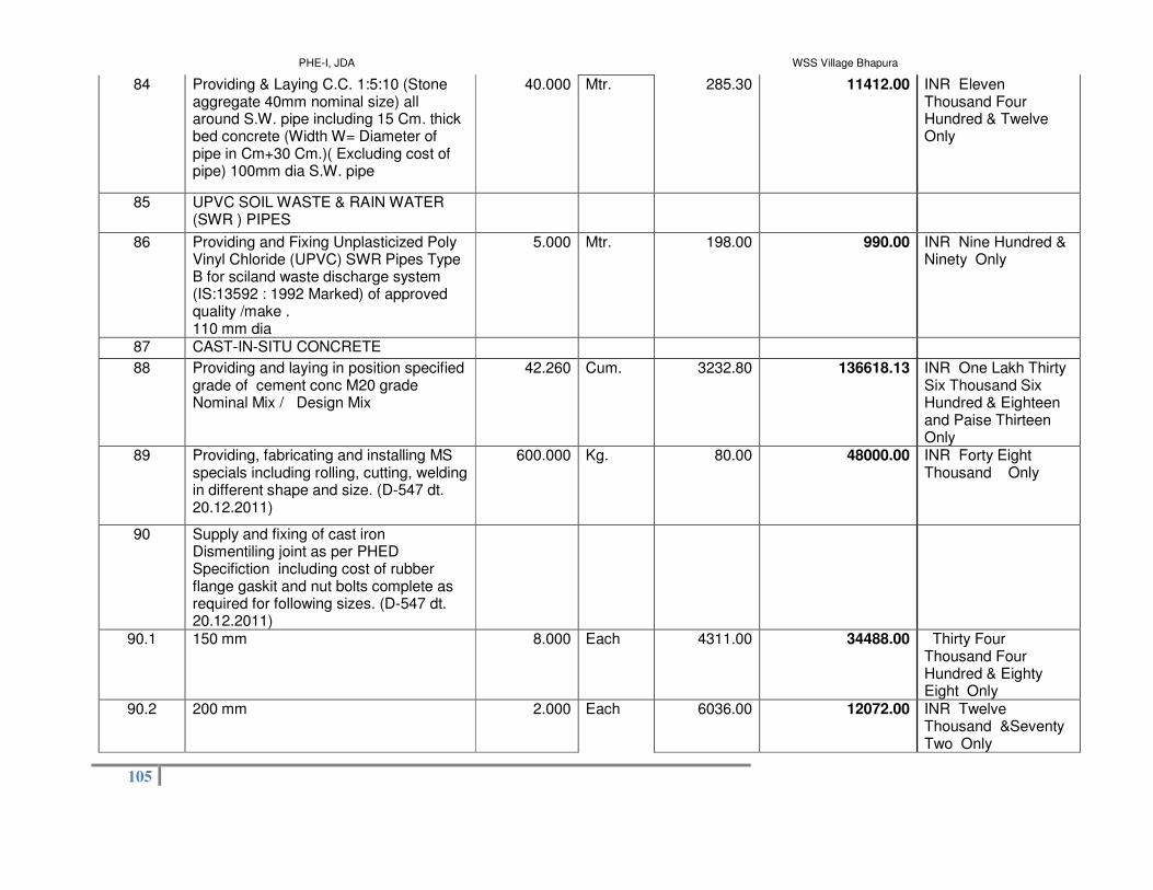
PHE-I, JDA WSS Village Bhapura
105
84 Providing & Laying C.C. 1:5:10 (Stone aggregate 40mm nominal size) all around S.W. pipe including 15 Cm. thick bed concrete (Width W= Diameter of pipe in Cm+30 Cm.)( Excluding cost of pipe) 100mm dia S.W. pipe
40.000 Mtr. 285.30 11412.00 INR Eleven Thousand Four Hundred & Twelve Only
85 UPVC SOIL WASTE & RAIN WATER (SWR ) PIPES
86 Providing and Fixing Unplasticized Poly Vinyl Chloride (UPVC) SWR Pipes Type B for sciland waste discharge system (IS:13592 : 1992 Marked) of approved quality /make . 110 mm dia
5.000 Mtr. 198.00 990.00 INR Nine Hundred & Ninety Only
87 CAST-IN-SITU CONCRETE
88 Providing and laying in position specified grade of cement conc M20 grade Nominal Mix / Design Mix
42.260 Cum. 3232.80 136618.13 INR One Lakh Thirty Six Thousand Six Hundred & Eighteen and Paise Thirteen Only
89 Providing, fabricating and installing MS specials including rolling, cutting, welding in different shape and size. (D-547 dt. 20.12.2011)
600.000 Kg. 80.00 48000.00 INR Forty Eight Thousand Only
90 Supply and fixing of cast iron Dismentiling joint as per PHED Specifiction including cost of rubber flange gaskit and nut bolts complete as required for following sizes. (D-547 dt. 20.12.2011)
90.1 150 mm 8.000 Each 4311.00 34488.00 Thirty Four Thousand Four Hundred & Eighty Eight Only
90.2 200 mm 2.000 Each 6036.00 12072.00 INR Twelve Thousand &Seventy Two Only

PHE-I, JDA WSS Village Bhapura
106
91 Providing and fixing steel gate, grating , and grills made of angles, tees, square bars, flats,or black pipe with holdfast and fittings complete as per design and drawing including cutting welding and fabrication with priming coat of red oxide
2300.000 Kg. 66.60 153180.00 INR One Lakh Fifty Three Thousand One Hundred & Eighty Only
92 Add extra for Square or Rectangular Pillars in Superstructre brick work up to five storey Upto 45 cm length and two corners are free
30.880 Cum. 107.10 3307.25 INR Three Thousand Three Hundred & Seven and Paise Twenty Five Only
93 P/Laying P.V.C. / XLPE insulated & P.V.C. sheathed cable of 1.1 KV grade with aluminium conductor of IS:1554 P-I / IS :7098 P - I of Group 1 of approved make in ground as per IS:1255 including excavation of 30cmx75cm size trench, 25 cm thick under layer of sand,IInd class bricks covering, refilling earth,compaction of earth, making necessary connection, testing etc. as required of size.
93.1 6.0 Sq.mm 4 core 210.000 Mtr. 116.80 24528.00 INR Twenty Four Thousand Five Hundred & Twenty Eight Only
94 S & Laying following size' B ' class G.I. Pipe confirming to IS : 1239 P - 1 ( 1990 ) with accessories for laying earth conductor /strip / cable in ground/surface/recess as required
94.1 40 mm dia. 25.000 Mtr. 219.20 5480.00 INR Five Thousand Four Hundred & Eighty Only

PHE-I, JDA WSS Village Bhapura
107
95 Supply and erection of hot dipped galvanised steel swaged tubular pole conforming to IS: 2713-1980 (part I to II) with galvanised base plate in position including excavation of the pit and filling the same with C.C. of M-20 grade (1:1.5:3) from base plate to 50cm above ground level, with the help of steel frame not less than 40 cm dia up to 114.3mm outer dia and 50 cm beyond 114.3mm outer dia around the pole. Duly finished with cement plaster, earthing terminals , cable entry, GI cable sleeve complete as required. The pole shall be galvanised using ISI mark seamless tube for structural purpose of following height & designation. ( See Table E - 09 for specs. )
95.1 7.5 Mtr. ( 410 SP - 5 ) 4.000 Each 8544.00 34176.00 INR Thirty Four Thousand One Hundred & Seventy Six Only
96 Supply, Erection and Fixing of hot dipped galvanised Overhang (48.3 X 3.25 mm) with cap (400 x 88.9 / 114.3 x 3.25 mm) over the existing poles Single arm overhang
4.000 Mtr. 712.00 2848.00 INR Two Thousand Eight Hundred & Forty Eight Only

PHE-I, JDA WSS Village Bhapura
108
97 P & F IP-65 protected street light luminaire on existing bracket suitable for HPSV/ MH LAMP, made from powder coated single piece pressure die cast aluminium housing, electrochemically brightened and anodized POT optics aluminium reflector, heat resistant and toughened glass cover and accessories like copper ballast, electronic ignitor, capacitor, holder prewired up to terminal block etc. as required including making connection testing etc. as required (without lamp) Street Light
97.1 Suitable for HPSV Lamps 1 X 70 Watt 4.000 Each 2995.20 11980.80 Eleven Thousand Nine Hundred & Eighty and Paise Eighty Only
97.2 Suitable for HPSV Lamps 1 X 150 Watt 4.000 Each 4200.00 16800.00 INR Sixteen Thousand Eight Hundred Only
98 P & F Normal / High Output High pressure sodium vapour/ Metal halide / Halogen lamp as required. HPSV Elliptical lamp Normal Output
98.1 70 Watt (without ignitor) 5600 Lumens 4.000 Each 308.00 1232.00 INR One Thousand Two Hundred & Thirty Two Only
98.2 150 Watt 14500 Lumens 4.000 Each 388.00 1552.00 INR One Thousand Five Hundred & Fifty Two Only
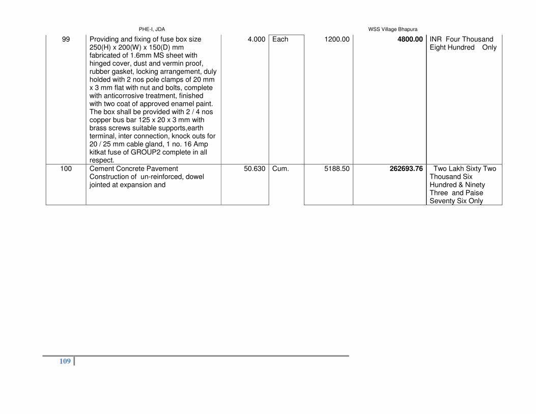
PHE-I, JDA WSS Village Bhapura
109
99 Providing and fixing of fuse box size 250(H) x 200(W) x 150(D) mm fabricated of 1.6mm MS sheet with hinged cover, dust and vermin proof, rubber gasket, locking arrangement, duly holded with 2 nos pole clamps of 20 mm x 3 mm flat with nut and bolts, complete with anticorrosive treatment, finished with two coat of approved enamel paint. The box shall be provided with 2 / 4 nos copper bus bar 125 x 20 x 3 mm with brass screws suitable supports,earth terminal, inter connection, knock outs for 20 / 25 mm cable gland, 1 no. 16 Amp kitkat fuse of GROUP2 complete in all respect.
4.000 Each 1200.00 4800.00 INR Four Thousand Eight Hundred Only
100 Cement Concrete Pavement Construction of un-reinforced, dowel jointed at expansion and
50.630 Cum. 5188.50 262693.76 Two Lakh Sixty Two Thousand Six Hundred & Ninety Three and Paise Seventy Six Only

PHE-I, JDA WSS Village Bhapura
110
101 Providing laying & Jointing of ISI mark centrifugally cast (Spun) ductile iron pressure pipe for water with socket and spigot end and Tyton joint confirming to IS 8329/2000 and departmental specification in standard length (As required) for (Class K-7) suitable for push on joint (rubber gaskets jointing) with side cement mortar lining with cutting of pipe and fixing of C.I. special joint where ever required. This also include the excavation of trench up to 1.5 Meter depth in all type of soil cutting of road surface pavement where required lift up to 1.5 Mt. stacking the soil clear form the edge of excavation and refiling of soil after laying and jointing of pipe line with proper compaction and disposing of all surplus soil as directed with in lead of 30 Meter. This also include getting the pipe line tested and site clearance etc.(D-878 dt.01.09.2008)
101.1 100 mm 9700.000 P. Mtr. 1397.00 13550900.00 INR One Crore Thirty Five Lakh Fifty Thousand Nine Hundred Only
101.2 150 mm 9400.000 P. Mtr. 2013.00 18922200.00 INR One Crore Eighty Nine Lakh Twenty Two Thousand Two Hundred Only
102 Providing/fixing/testing KG of DI specials (K-7) i.e. bend, tees, tail pieces, flanges etc. of various size as per the site condition and requirement including all jointing material in all respects, As per PHED specification. (D-306 dt. 28.04.2009)
600.000 Kg. 90.00 54000.00 INR Fifty Four Thousand Only
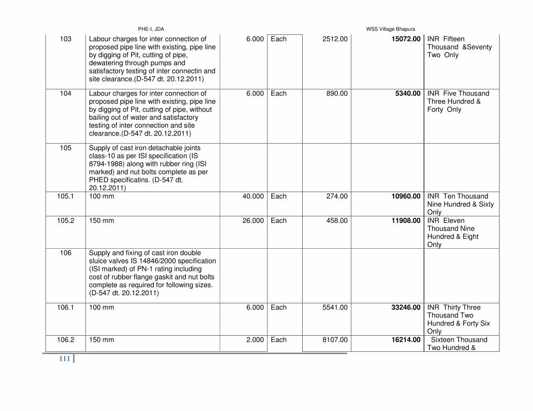
PHE-I, JDA WSS Village Bhapura
111
103 Labour charges for inter connection of proposed pipe line with existing, pipe line by digging of Pit, cutting of pipe, dewatering through pumps and satisfactory testing of inter connectin and site clearance.(D-547 dt. 20.12.2011)
6.000 Each 2512.00 15072.00 INR Fifteen Thousand &Seventy Two Only
104 Labour charges for inter connection of proposed pipe line with existing, pipe line by digging of Pit, cutting of pipe, without bailing out of water and satisfactory testing of inter connection and site clearance.(D-547 dt. 20.12.2011)
6.000 Each 890.00 5340.00 INR Five Thousand Three Hundred & Forty Only
105 Supply of cast iron detachable joints class-10 as per ISI specification (IS 8794-1988) along with rubber ring (ISI marked) and nut bolts complete as per PHED specificatins. (D-547 dt. 20.12.2011)
105.1 100 mm 40.000 Each 274.00 10960.00 INR Ten Thousand Nine Hundred & Sixty Only
105.2 150 mm 26.000 Each 458.00 11908.00 INR Eleven Thousand Nine Hundred & Eight Only
106 Supply and fixing of cast iron double sluice valves IS 14846/2000 specification (ISI marked) of PN-1 rating including cost of rubber flange gaskit and nut bolts complete as required for following sizes. (D-547 dt. 20.12.2011)
106.1 100 mm 6.000 Each 5541.00 33246.00 INR Thirty Three Thousand Two Hundred & Forty Six Only
106.2 150 mm 2.000 Each 8107.00 16214.00 Sixteen Thousand Two Hundred &

PHE-I, JDA WSS Village Bhapura
112
Fourteen Only
107 Supply of cast iron specials (class-10) as per IS : 5531-1988) specification as required. (D-547 dt. 20.12.2011)
107.1 80 mm to 150 mm 700.000 Kg. 58.00 40600.00 INR Forty Thousand Six Hundred Only
108 Construction of Tube-well upto 100 Meter depth and above in all type of rocks by DTH system and over burden, to accommodate casing pipe of following sizes in all types of soils and over burden including lowering of casing pipes, but excluding cost of casing pipes as per IS : 2800 (Part I & II) 1979 specifications. The work would be completed after obtaining sand free water. The tube well should have a throughout bore as per nominal dia of casing pipe:
108.1 200 mm dia Nominal bore. 150.000 R. Mtr. 742.50 111375.00 INR One Lakh Eleven Thousand Three Hundred & Seventy Five Only

PHE-I, JDA WSS Village Bhapura
113
109 Construction of tube-well from ground levels and upto 100 Meter depth and above to accommodate housing and assembly pipe of following sizes in all types of alluvium strata by percussion/ rotary drilling method and with gravel as per IS:4097-1967 and packing as per IS:2800 (Part I -& II) 1979 as amended upto date (the work includes the cost of gravel & its primary packing and packing during development, lowering of housing & strainer assembly pipes, with supply and wrapping of coir-rope, wherever necessary, for arresting fine sand particles. The work will not include cost of housing pipe and strainer pipe assembly and development work, but work would be completed after obtaining sand free water).
109.1 200 mm Nominal Bore. 130.000 R. Mtr. 1089.00 141570.00 One Lakh Forty One Thousand Five Hundred & Seventy Only
110 Development of tube well as per IS specification using suitable compressor to give sand free water for required yield of the gravel packed tube well.
24.000 Hours 445.50 10692.00 INR Ten Thousand Six Hundred & Ninety Two Only
111 Supply of ERW M.S. black casing pipe ISI marked (IS:4270/1992) of grade Fe410 of following sizes at site of work. Nominal bore of pipe (mm)
111.1 200 Nominal bore of pipe (mm) 94.000 Mtr. 1413.00 132822.00 INR One Lakh Thirty Two Thousand Eight Hundred & Twenty Two Only

PHE-I, JDA WSS Village Bhapura
114
112 Supply of strainer pipes made of ERW M.S. black pipe ISI mark of following sizes at the site of work including required size of slotting as per IS:8110-1985.
112.1 200 mm Nominal Bore. 36.000 Mtr. 1638.00 58968.00 INR Fifty Eight Thousand Nine Hundred & Sixty Eight Only
113 Installation of submersible motor pump set in Tube-well/open well complete ( labour charges only) including transportation of tripod, chain pulley block & any other material required for lowering purpose.
2.000 Each 2772.00 5544.00 INR Five Thousand Five Hundred & Forty Four Only
114 P/Laying ISI marked P.V.C. insulated submersible cable confirming to IS:694 with flexible copper conductor including making connection etc. as required.
114.1 2.5 Sq.mm 3 core flat / Round 220.000 Mtr. 72.00 15840.00 INR Fifteen Thousand Eight Hundred & Forty Only
115 P/Laying P.V.C. / XLPE insulated & P.V.C. sheathed cable of 1.1 KV grade with Copper conductor of IS:1554 P-I / IS :7098 P - I of Group 1 of approved make in ground as per IS:1255 including excavation of 30cmx75cm size trench, 25 cm thick under layer of sand,IInd class bricks covering, refilling earth,compaction of earth, making necessary connection, testing etc. as required of size.
115.1 4.0 Sq.mm 3 core 60.000 Mtr. 196.00 11760.00 INR Eleven Thousand Seven Hundred & Sixty Only

PHE-I, JDA WSS Village Bhapura
115
116 SITC of radial / mixed flow submersible motor pump sets ISI marked (IS:8034-1989) of approved make with required accessories including making connection suitable for T.W./ D.C.B./ Open well. The job includes lowering of riser pipe, G.I./ H.D.P.E. pipe with rope, cables, installation of complete fitting and accessories, jointing of electrical cables up to switch board. All labour for testing of submersible pumps set and supply of water to water mains, complete in all respect.
116.1 100 mm diameter Submersible pump shall have following HP Rating, phase, Head, minimum Discharge respectively. 5.0 HP, 3-Ø, (55-150)Mtr, (166-60)LPM
2.000 Each 23184.00 46368.00 Forty Six Thousand Three Hundred & Sixty Eight Only
117 Providing & lowering of G.I. Pipes, flange pipe including rubber washer and nuts of 8 mm dia complete in all respect I.S.1239 Marked. B Class 50 mm dia
216.000 R. Mtr. 369.00 79704.00 INR Seventy Nine Thousand Seven Hundred & Four Only
118 S&F tube well cover (for 200 mm dia pipe) of MS sheet 8 mm thick at top & 5 mm thick 100 mm wide shroud around the edge so as to form a cap on the top end of casing pipe with GI Nipple 45 cm long & two GI flanger at both end in 80 mm sizes passing through a hole in the centre of MS shet A 25 mm socket with end plug shall also be weld over top plate (as per drawing enclosede), A GI nipple having outside thread of size 1/2" (for installation pressure gauge ) shall be provide & welded with GI 80 mm nipple near top plate nipple shall be provided with end plug.) (D-547 dt. 20.12.2011)
2.000 Each 908.00 1816.00 INR One Thousand Eight Hundred & Sixteen Only

PHE-I, JDA WSS Village Bhapura
116
119 Providing fixing and installation of 80 mm dia Woltman type water meter with material (Flanges,Insertion sheet, Nut bolt etc.) &fabrication supply and fixing of meter box made of 10 SWG MS sheetsuitable for 80 mm water meter ( As per drawing including all accessories.) 50 mm to 80 mm dia (D-547 dt. 20.12.2011)
2.000 Each 22997.00 45994.00 INR Forty Five Thousand Nine Hundred & Ninety Four Only
120 Providing and installing of approved make spring loaded dual plate check valve of following dia. Including all taxes , inspection charges, loading and unloading, stacking etc., including cost of all labour, jointing material with nut bolts, rubber mats etc., and giving satisfactory hydraulic field testing, complete as per specifications.(D-547 dt. 20.12.2011)
120.1 50 mm 2.000 Each 1571.00 3142.00 INR Three Thousand One Hundred & Forty Two Only
121 Supply and fixing & testing of feeder type penal board suitable for upto 15 HP electric motor having star delta/ DOL starter ( L&T /BCH), MCB 32 amp.( havals /L&T), capacitor 3 KVR ( L&T/Havals), Single phase priventor( L$T/havals),indicating lamp RYB , Amp. Meter ( 0 to 30Amp) , Volt Meter with slector switch ( 0 to 500 V) size 100 mm, kit kat fuse unit 100 amp,backlite sheet for fixing of 3 phase electric meter of JVVNL electric feeder penal approved as per design and specification mounted on angle iron fram and fixed plain on plain cement concrete plateform, size of feeder penal box 900X 450X1200mm (D-547 dt. 20.12.2011)

PHE-I, JDA WSS Village Bhapura
117
121.1 Star Delta above 5 HP to 15 HP 2.000 Each 24915.00 49830.00 INR Forty Nine Thousand Eight Hundred & Thirty Only
Total in Figures
38762941.46 INR Zero Only
Quoted Rate in Figures Select
0.00 INR Zero Only
Quoted Rate in Words
INR Zero Only

PHE-I, JDA WSS Village Bhapura
118
Item Wise BoQ
Tender Inviting Authority: JAIPUR DEVELOPMENT AUTHORITY, JAIPUR
Name of Work: Rural Water Supply Scheme for Villages of Gram Panchayat Bhapura
Contract No: EE/PHE-I/NIB No.-01/2017-18
Name of the Bidder/ Bidding Firm / Company :
PRICE SCHEDULE (This BOQ template must not be modified/replaced by the bidder and the same should be uploaded after filling the relevent columns, else the bidder is liable to
rejected for this tender. Bidders are allowed to enter the Bidder Name and Values only )
NUMBER #
TEXT # TEXT # NUMBER # TEXT # NUMBER NUMBER # NUMBER # TEXT #
Sl. No.
Item Description Item Code / Make Quantity Units Estimated Rate BASIC RATE In Figures To be entered by the
Bidder Rs. P
TOTAL AMOUNT Without Taxes
TOTAL AMOIn Words
1 2 3 4 5 6 13 53 55
1 Part (C)-Operation & Maintenance
1.01 Operation and maintenance of all the newly developed water supply assets Per Month
36.000 Per Month 0.00 INR Zero Onl

PHE-I, JDA WSS Village Bhapura
119
under this contract as per scope of work including cost of consumable material for maintenance and spares (excluding electrical charges and chemical charges)
Total in Figures
0.00 INR Zero Onl
Quoted Rate in Words
INR Zero Only

PHE-I, JDA WSS Village Bhapura
120