
ESP-AT User Guide - Login
445
ESP-AT User Guide Read the Docs Jan 14, 2022
-
Upload
khangminh22 -
Category
Documents
-
view
1 -
download
0
Transcript of ESP-AT User Guide - Login

ESP-AT User Guide
Read the Docs
Jan 14, 2022


CONTENTS
1 Get Started 31.1 What is ESP-AT . . . . . . . . . . . . . . . . . . . . . . . . . . . . . . . . . . . . . . . . . . . . . 31.2 Hardware Connection . . . . . . . . . . . . . . . . . . . . . . . . . . . . . . . . . . . . . . . . . . 41.3 Downloading Guide . . . . . . . . . . . . . . . . . . . . . . . . . . . . . . . . . . . . . . . . . . . 9
2 AT Binary Lists 192.1 Released Firmware . . . . . . . . . . . . . . . . . . . . . . . . . . . . . . . . . . . . . . . . . . . . 192.2 Released Firmware . . . . . . . . . . . . . . . . . . . . . . . . . . . . . . . . . . . . . . . . . . . . 20
3 AT Command Set 233.1 Basic AT Commands . . . . . . . . . . . . . . . . . . . . . . . . . . . . . . . . . . . . . . . . . . . 233.2 Wi-Fi AT Commands . . . . . . . . . . . . . . . . . . . . . . . . . . . . . . . . . . . . . . . . . . . 443.3 TCP/IP AT Commands . . . . . . . . . . . . . . . . . . . . . . . . . . . . . . . . . . . . . . . . . . 753.4 Bluetooth® Low Energy AT Commands . . . . . . . . . . . . . . . . . . . . . . . . . . . . . . . . 1183.5 [ESP32 Only] Classic Bluetooth® AT Commands . . . . . . . . . . . . . . . . . . . . . . . . . . . 1653.6 MQTT AT Commands . . . . . . . . . . . . . . . . . . . . . . . . . . . . . . . . . . . . . . . . . . 1843.7 HTTP AT Commands . . . . . . . . . . . . . . . . . . . . . . . . . . . . . . . . . . . . . . . . . . 1963.8 [ESP32 Only] Ethernet AT Commands . . . . . . . . . . . . . . . . . . . . . . . . . . . . . . . . . 2023.9 Signaling Test AT Commands . . . . . . . . . . . . . . . . . . . . . . . . . . . . . . . . . . . . . . 2053.10 Web Server AT Commands . . . . . . . . . . . . . . . . . . . . . . . . . . . . . . . . . . . . . . . 2063.11 Driver AT Commands . . . . . . . . . . . . . . . . . . . . . . . . . . . . . . . . . . . . . . . . . . 2073.12 User AT Commands . . . . . . . . . . . . . . . . . . . . . . . . . . . . . . . . . . . . . . . . . . . 2183.13 AT Command Types . . . . . . . . . . . . . . . . . . . . . . . . . . . . . . . . . . . . . . . . . . . 2213.14 AT Commands with Configuration Saved in the Flash . . . . . . . . . . . . . . . . . . . . . . . . . 2223.15 AT Messages . . . . . . . . . . . . . . . . . . . . . . . . . . . . . . . . . . . . . . . . . . . . . . . 222
4 AT Command Examples 2254.1 TCP/IP AT Examples . . . . . . . . . . . . . . . . . . . . . . . . . . . . . . . . . . . . . . . . . . 2254.2 Bluetooth LE AT Examples . . . . . . . . . . . . . . . . . . . . . . . . . . . . . . . . . . . . . . . 2484.3 MQTT AT Examples . . . . . . . . . . . . . . . . . . . . . . . . . . . . . . . . . . . . . . . . . . . 2744.4 [ESP32 Only] Ethernet AT Examples . . . . . . . . . . . . . . . . . . . . . . . . . . . . . . . . . . 2824.5 Web Server AT Example . . . . . . . . . . . . . . . . . . . . . . . . . . . . . . . . . . . . . . . . . 2844.6 HTTP AT Examples . . . . . . . . . . . . . . . . . . . . . . . . . . . . . . . . . . . . . . . . . . . 3064.7 [ESP32 Only] Classic Bluetooth AT Examples . . . . . . . . . . . . . . . . . . . . . . . . . . . . . 3154.8 Sleep AT Examples . . . . . . . . . . . . . . . . . . . . . . . . . . . . . . . . . . . . . . . . . . . . 327
5 How to Compile and Develop Your Own AT Project 3395.1 Compile ESP-AT Project . . . . . . . . . . . . . . . . . . . . . . . . . . . . . . . . . . . . . . . . . 3395.2 How to Set AT Port Pins . . . . . . . . . . . . . . . . . . . . . . . . . . . . . . . . . . . . . . . . . 3435.3 How to add user-defined AT commands . . . . . . . . . . . . . . . . . . . . . . . . . . . . . . . . . 345
i

5.4 How to Improve ESP-AT Throughput Performance . . . . . . . . . . . . . . . . . . . . . . . . . . . 3565.5 How to Generate Factory Parameter Bin . . . . . . . . . . . . . . . . . . . . . . . . . . . . . . . . . 3605.6 How to Customize Bluetooth® LE Services . . . . . . . . . . . . . . . . . . . . . . . . . . . . . . . 3675.7 How to Customize Partitions . . . . . . . . . . . . . . . . . . . . . . . . . . . . . . . . . . . . . . . 3725.8 How to Enable ESP-AT Classic Bluetooth . . . . . . . . . . . . . . . . . . . . . . . . . . . . . . . . 3745.9 How to Enable ESP-AT Ethernet . . . . . . . . . . . . . . . . . . . . . . . . . . . . . . . . . . . . . 3755.10 How to Add Support for a Module . . . . . . . . . . . . . . . . . . . . . . . . . . . . . . . . . . . . 3755.11 ESP32 SDIO AT Guide . . . . . . . . . . . . . . . . . . . . . . . . . . . . . . . . . . . . . . . . . 3785.12 SPI AT Guide . . . . . . . . . . . . . . . . . . . . . . . . . . . . . . . . . . . . . . . . . . . . . . . 3805.13 How to Implement OTA Upgrade . . . . . . . . . . . . . . . . . . . . . . . . . . . . . . . . . . . . 3855.14 How to Update the ESP-IDF Version . . . . . . . . . . . . . . . . . . . . . . . . . . . . . . . . . . 3935.15 ESP-AT Firmware Differences . . . . . . . . . . . . . . . . . . . . . . . . . . . . . . . . . . . . . . 3945.16 How to Download the Latest Temporary Version of AT Firmware from GitHub . . . . . . . . . . . . 3985.17 Customize Bluetooth LE Services Tools . . . . . . . . . . . . . . . . . . . . . . . . . . . . . . . . . 4015.18 How to Generate PKI Files . . . . . . . . . . . . . . . . . . . . . . . . . . . . . . . . . . . . . . . . 4055.19 AT API Reference . . . . . . . . . . . . . . . . . . . . . . . . . . . . . . . . . . . . . . . . . . . . 409
6 Customized AT Commands and Firmware 4216.1 Tencent Cloud IoT AT Commands and Firmware . . . . . . . . . . . . . . . . . . . . . . . . . . . . 421
7 AT FAQ 4237.1 AT Firmware . . . . . . . . . . . . . . . . . . . . . . . . . . . . . . . . . . . . . . . . . . . . . . . 4247.2 AT Commands and Responses . . . . . . . . . . . . . . . . . . . . . . . . . . . . . . . . . . . . . . 4267.3 Hardware . . . . . . . . . . . . . . . . . . . . . . . . . . . . . . . . . . . . . . . . . . . . . . . . . 4287.4 Performance . . . . . . . . . . . . . . . . . . . . . . . . . . . . . . . . . . . . . . . . . . . . . . . 4297.5 Other . . . . . . . . . . . . . . . . . . . . . . . . . . . . . . . . . . . . . . . . . . . . . . . . . . . 430
8 Index of Abbreviations 431
9 About 437
Index 439
ii

ESP-AT User Guide
[]
This is the documentation for the ESP-AT. To view documentation for a specific AT firmware version or chip series,please click the small triangle at the bottom left corner of this page and select.
Get Started AT Binary Lists AT Command Set
AT Command Examples Compile and Develop Customized AT Com-mands and Firmware
CONTENTS 1

ESP-AT User Guide
2 CONTENTS

CHAPTER
ONE
GET STARTED
[]
This Get Started guide provides users with detailed information on what is ESP-AT, how to connect hardware, andhow to download and flash AT firmware. It consists of the following parts:
1.1 What is ESP-AT
[]
ESP-AT is a solution developed by Espressif to integrate connectivity into customers’ products, which can be quicklymoved to mass production. It aims to reduce software development costs and quickly form products. With ESP-ATcommands, you can quickly join the wireless network, connect to the cloud platform, realize data transmission andremote control functions, and realize the interconnection of everything through wireless communication easily.
ESP-AT is a project based on ESP-IDF. It makes an ESP board work as a slave, and an MCU as a host. The hostMCU sends AT commands to the ESP chip and receives AT responses back. ESP-AT provides a wide range of ATcommands with different functions, such as Wi-Fi commands, TCP/IP commands, Bluetooth LE commands, Bluetoothcommands, MQTT commands, HTTP commands, and Ethernet commands.
Fig. 1: ESP-AT Overview
AT commands start with “AT”, which stand for “Attention”, and end with a new line (CR LF). Every time you senda command, you will receive an OK or ERROR, which indicates the final execution status of the current command.
3

ESP-AT User Guide
Please be noted that all commands are executed serially, which means only one AT command can be executed at atime. Therefore, you should wait for the previous command to be executed before sending out the next one. Otherwise,you will receive busy P.... For more details about AT commands, please refer to AT Command Set.
By default, the host MCU connects to the ESP board via UART, and sends/receives AT commands/responses throughUART. But you can also use other interfaces, such as SDIO, according to your actual use scenario.
You can develop your own AT commands based on our ESP-AT project and implement more features according toyour actual use scenario.
1.2 Hardware Connection
[]
This document introduces what hardware you need to prepare and how to connect them in order to download ATfirmware, send AT commands, and receive AT responses. It covers the following four ESP series of modules:
• ESP32 Series
• ESP32-C3 Series
For different series of modules, the commands supported by AT firmware are different. Please refer to ESP-ATFirmware Differences for more details.
1.2.1 What You Need
Table 1: List of Components Required for ESP-AT TestingComponent FunctionESP board Slave MCU.USB cable (ESP borad to PC) Download/Log output connection.PC Act as Host MCU. Download firmware to Slave MCU.USB cable (PC to serial port converter) AT command/response connection.USB to serial port converter Convert between USB signals and TTL signals.Jumper wires (serial port converter to ESP board) AT command/response connection.
Please note that in the above picture, four jump wires are used to connect the ESP board and USB to serial converter.If you don’t use hardware flow control, two wires connecting TX/RX and a simpler converter will be enough.
1.2.2 ESP32 Series
ESP32 AT uses two UART ports: UART0 is used to download firmware and log output; UART1 is used to send ATcommands and receive AT responses. Both UART0 and UART1 use 115200 baud rate for communication by default.
All ESP32 modules use GPIO1 and GPIO3 as UART0, but they use different GPIOs as UART1. The following sectionsillustrate which GPIOs you should connect for each ESP32 series of modules.
For more details of ESP32 modules and boards, please refer to ESP32 Modules and Boards.
4 Chapter 1. Get Started

ESP-AT User Guide
Fig. 2: Connection of Components for ESP-AT Testing
ESP32-WROOM-32 Series
Table 2: ESP32-WROOM-32 Series Hardware Connection PinoutFunction of Connection ESP Board Pins Other Device PinsDownload/Log output 1
UART0• GPIO3 (RX)• GPIO1 (TX)
PC• TX• RX
AT command/response 2UART1
• GPIO16 (RX)• GPIO17 (TX)• GPIO15 (CTS)• GPIO14 (RTS)
USB to serial converter• TX• RX• RTS• CTS
Note 1: Connection between individual pins of the ESP board and the PC is already established internally on the ESPboard. You only need to provide USB cable between the board and PC.
Note 2: Connection between CTS/RTS is optional, depending on whether you want to use hardware flow control.
If you want to connect your device directly with ESP32-WROOM-32 rather than the ESP board that integrates it,please refer to ESP32-WROOM-32 Datasheet for more details.
1.2. Hardware Connection 5

ESP-AT User Guide
Fig. 3: ESP32-WROOM-32 Series Hardware Connection
ESP32-WROVER Series
Table 3: ESP32-WROVER Series Hardware Connection PinoutFunction of Connection ESP Board Pins Other Device PinsDownload/Log output 1
UART0• GPIO3 (RX)• GPIO1 (TX)
PC• TX• RX
AT command/response 2UART1
• GPIO19 (RX)• GPIO22 (TX)• GPIO15 (CTS)• GPIO14 (RTS)
USB to serial converter• TX• RX• RTS• CTS
Note 1: Connection between individual pins of the ESP board and the PC is already established internally on the ESPboard. You only need to provide USB cable between the board and PC.
Note 2: Connection between CTS/RTS is optional, depending on whether you want to use hardware flow control.
If you want to connect your device directly with ESP32-WROVER rather than the ESP board that integrates it, pleaserefer to ESP32-WROVER Datasheet for more details.
6 Chapter 1. Get Started

ESP-AT User Guide
Fig. 4: ESP32-WROVER Series Hardware Connection
ESP32-PICO Series
Table 4: ESP32-PICO Series Hardware Connection PinoutFunction of Connection ESP Board Pins Other Device PinsDownload/Log output 1
UART0• GPIO3 (RX)• GPIO1 (TX)
PC• TX• RX
AT command/response 2UART1
• GPIO19 (RX)• GPIO22 (TX)• GPIO15 (CTS)• GPIO14 (RTS)
USB to serial converter• TX• RX• RTS• CTS
Note 1: Connection between individual pins of the ESP board and the PC is already established internally on the ESPboard. You only need to provide USB cable between the board and PC.
Note 2: Connection between CTS/RTS is optional, depending on whether you want to use hardware flow control.
If you want to connect your device directly with ESP32-PICO-D4 rather than the ESP board that integrates it, pleaserefer to ESP32-PICO-D4 Datasheet for more details.
1.2. Hardware Connection 7

ESP-AT User Guide
Fig. 5: ESP32-PICO Series Hardware Connection
ESP32-SOLO Series
Table 5: ESP32-SOLO Series Hardware Connection PinoutFunction of Connection ESP Board Pins Other Device PinsDownload/Log output 1
UART0• GPIO3 (RX)• GPIO1 (TX)
PC• TX• RX
AT command/response 2UART1
• GPIO16 (RX)• GPIO17 (TX)• GPIO15 (CTS)• GPIO14 (RTS)
USB to serial converter• TX• RX• RTS• CTS
Note 1: Connection between individual pins of the ESP board and the PC is already established internally on the ESPboard. You only need to provide USB cable between the board and PC.
Note 2: Connection between CTS/RTS is optional, depending on whether you want to use hardware flow control.
If you want to connect your device directly with ESP32-SOLO-1 rather than the ESP board that integrates it, pleaserefer to ESP32-SOLO-1 Datasheet for more details.
1.2.3 ESP32-C3 Series
ESP32-C3 AT uses two UART ports: UART0 is used to download firmware and log output; UART1 is used to sendAT commands and receive AT responses. Both UART0 and UART1 use 115200 baud rate for communication bydefault.
8 Chapter 1. Get Started

ESP-AT User Guide
Fig. 6: ESP32-SOLO Series Hardware Connection
Table 6: ESP32-C3 Series Hardware Connection PinoutFunction of Connection ESP Board Pins Other Device PinsDownload/Log output 1
UART0• GPIO20 (RX)• GPIO21 (TX)
PC• TX• RX
AT command/response 2UART1
• GPIO6 (RX)• GPIO7 (TX)• GPIO5 (CTS)• GPIO4 (RTS)
USB to serial converter• TX• RX• RTS• CTS
Note 1: Connection between individual pins of the ESP board and the PC is already established internally on the ESPboard. You only need to provide USB cable between the board and PC.
Note 2: Connection between CTS/RTS is optional, depending on whether you want to use hardware flow control.
If you want to connect your device directly with ESP32-C3-MINI-1 rather than the ESP board that integrates it, pleaserefer to ESP32-C3-MINI-1 Datasheet for more details.
1.3 Downloading Guide
[]
This Guide demonstrates how to download AT firmware and flash it into an ESP device by taking ESP32-WROOM-32as an example. The Guide is also applicable to other ESP modules.
Before you start, please make sure you have already connected your hardware. For more details, see HardwareConnection.
For different series of modules, the commands supported by AT firmware are different. Please refer to ESP-ATFirmware Differences for more details.
1.3. Downloading Guide 9

ESP-AT User Guide
Fig. 7: ESP32-C3 Series Hardware Connection
1.3.1 Download AT Firmware
To download AT firmware to your computer, please do as follows:
• Navigate to AT Binary Lists
• Find the firmware for your device
• Click the link to download it
Here, we download ESP32-WROOM-32_AT_Bin_V2.1 for ESP32-WROOM-32. The list below describes thestructure of this firmware and what each bin file contains. Other AT firmware has similar structure and bin files.
.at_customize.bin // secondary partition tablebootloader // bootloader
bootloader.bincustomized_partitions // AT customized binaries
ble_data.binclient_ca.binclient_cert.binclient_key.binfactory_param.binfactory_param_WROOM-32.binmqtt_ca.binmqtt_cert.binmqtt_key.binserver_ca.binserver_cert.binserver_key.bin
download.config // configuration of downloadingesp-at.bin // AT application binaryfactory // A combined bin for factory downloading
(continues on next page)
10 Chapter 1. Get Started

ESP-AT User Guide
(continued from previous page)
factory_WROOM-32.binfactory_parameter.log
flasher_args.json // flasher argumentsota_data_initial.bin // ota data parameterspartition_table // primary partition table
partition-table.binphy_init_data.bin // phy parameters
The file download.config contains the configuration to flash the firmware into multiple addresses:
--flash_mode dio --flash_freq 40m --flash_size 4MB0x8000 partition_table/partition-table.bin0x10000 ota_data_initial.bin0xf000 phy_init_data.bin0x1000 bootloader/bootloader.bin0x100000 esp-at.bin0x20000 at_customize.bin0x24000 customized_partitions/server_cert.bin0x39000 customized_partitions/mqtt_key.bin0x26000 customized_partitions/server_key.bin0x28000 customized_partitions/server_ca.bin0x2e000 customized_partitions/client_ca.bin0x30000 customized_partitions/factory_param.bin0x21000 customized_partitions/ble_data.bin0x3B000 customized_partitions/mqtt_ca.bin0x37000 customized_partitions/mqtt_cert.bin0x2a000 customized_partitions/client_cert.bin0x2c000 customized_partitions/client_key.bin
• --flash_mode dio means the firmware is compiled with flash DIO mode.
• --flash_freq 40m means the firmware’s flash frequency is 40 MHz.
• --flash_size 4MB means the firmware is using flash size 4 MB.
• 0x10000 ota_data_initial.bin means downloading ota_data_initial.bin into the address0x10000.
1.3.2 Flash AT Firmware into Your Device
Follow the instructions below for your operating system.
Windows
Before starting to flash, you need to download Flash Download Tools for Windows. For more details about the tools,please see readme.pdf or the doc folder in the zip folder.
• Open the ESP Flash Download Tool.
• Select a mode according to your need. (Here, we select Developer Mode.)
• Select a download tool. Here, we select ESP32 DownloadTool because this document takes an ESP32 device asan example. You should select a tool based on what chip you actually use.
• Flash AT firmware into your device. You can select either of the two ways below.
1.3. Downloading Guide 11

ESP-AT User Guide
Fig. 8: Flash Download Tools Modes
– To download one combined factory bin to address 0, select “DoNotChgBin” to use the default configurationof the factory bin.
– To download multiple bins separately to different addresses, set up the configurations according to the filedownload.config and do NOT select “DoNotChgBin”.
In case of flashing issues, please verify what the COM port number of download interface of the ESP board is andselect it from “COM:” dropdown list. If you don’t know the port number, you can refer to Check port on Windows fordetails.
When you finish flashing, please Check Whether AT Works.
Linux or macOS
Before you start to flash, you need to install esptool.py.
You can select either of the two ways below to flash AT firmware into your device.
• To download the bins separately into multiple addresses, enter the following command and replace PORTNAMEand download.config:
esptool.py --chip auto --port PORTNAME --baud 115200 --before default_reset --→˓after hard_reset write_flash -z download.config
Replace PORTNAME with your port name. If you don’t know it, you can refer to Check port on Linux andmacOS for details.
Replace download.config with the content inside the file.
Below is the example command for ESP32-WROOM-32.
esptool.py --chip auto --port /dev/tty.usbserial-0001 --baud 115200 --before→˓default_reset --after hard_reset write_flash -z --flash_mode dio --flash_freq→˓40m --flash_size 4MB 0x8000 partition_table/partition-table.bin 0x10000 ota_→˓data_initial.bin 0xf000 phy_init_data.bin 0x1000 bootloader/bootloader.bin→˓0x100000 esp-at.bin 0x20000 at_customize.bin 0x24000 customized_partitions/→˓server_cert.bin 0x39000 customized_partitions/mqtt_key.bin 0x26000 customized_→˓partitions/server_key.bin 0x28000 customized_partitions/server_ca.bin 0x2e000→˓customized_partitions/client_ca.bin 0x30000 customized_partitions/factory_param.→˓bin 0x21000 customized_partitions/ble_data.bin 0x3B000 customized_partitions/→˓mqtt_ca.bin 0x37000 customized_partitions/mqtt_cert.bin 0x2a000 customized_→˓partitions/client_cert.bin 0x2c000 customized_partitions/client_key.bin
(continues on next page)
12 Chapter 1. Get Started

ESP-AT User Guide
Fig. 9: Flash Download Tools Target Chip
1.3. Downloading Guide 13

ESP-AT User Guide
Fig. 10: Download to One Address
14 Chapter 1. Get Started

ESP-AT User Guide
Fig. 11: Download to Multiple Addresses
1.3. Downloading Guide 15

ESP-AT User Guide
(continued from previous page)
• To download the bins together to one address, enter the following command and replace PORTNAME andFILEDIRECTORY:
esptool.py --chip auto --port PORTNAME --baud 115200 --before default_reset --→˓after hard_reset write_flash -z --flash_mode dio --flash_freq 40m --flash_size→˓4MB 0x0 FILEDIRECTORY
Replace PORTNAME with your port name. If you don’t know it, you can refer to Check port on Linux andmacOS for details.
Replace FILEDIRECTORY with the file directory you would flash to the address 0x0. It is normally fac-tory/XXX.bin.
Below is the example command for ESP32-WROOM-32.
esptool.py --chip auto --port /dev/tty.usbserial-0001 --baud 115200 --before→˓default_reset --after hard_reset write_flash -z --flash_mode dio --flash_freq→˓40m --flash_size 4MB 0x0 factory/factory_WROOM-32.bin
When you finish flashing, please Check Whether AT Works.
1.3.3 Check Whether AT Works
To check whether AT works, do as follows:
• Open a serial port tool, such as SecureCRT;
• Select the Port attached to “AT command/response” line (see Hardware Connection for details);
• Set Baudrate to 115200;
• Set Data Bits to 8;
• Set Parity to None;
• Set Stop Bits to 1;
• Set Flow Type to None;
• Enter the command “AT+GMR” with a new line (CR LF).
If the response is OK as the picture below shows, AT works.
Fig. 12: Response from AT
16 Chapter 1. Get Started

ESP-AT User Guide
Otherwise, you need to check your ESP startup log, which is visible on PC over “Download/Log output connection”.If it is like the log below, it means that ESP-AT firmware have been initalized correctly.
ESP32 startup log:
ets Jun 8 2016 00:22:57rst:0x1 (POWERON_RESET),boot:0x13 (SPI_FAST_FLASH_BOOT)configsip: 0, SPIWP:0xeeclk_drv:0x00,q_drv:0x00,d_drv:0x00,cs0_drv:0x00,hd_drv:0x00,wp_drv:0x00mode:DIO, clock div:2load:0x3fff0030,len:4load:0x3fff0034,len:7184ho 0 tail 12 room 4load:0x40078000,len:13200load:0x40080400,len:4564entry 0x400806f4I (30) boot: ESP-IDF v4.2 2nd stage bootloaderI (31) boot: compile time 11:23:19I (31) boot: chip revision: 0I (33) boot.esp32: SPI Speed : 40MHzI (38) boot.esp32: SPI Mode : DIOI (42) boot.esp32: SPI Flash Size : 4MBI (47) boot: Enabling RNG early entropy source...I (52) boot: Partition Table:I (56) boot: ## Label Usage Type ST Offset LengthI (63) boot: 0 phy_init RF data 01 01 0000f000 00001000I (71) boot: 1 otadata OTA data 01 00 00010000 00002000I (78) boot: 2 nvs WiFi data 01 02 00012000 0000e000I (86) boot: 3 at_customize unknown 40 00 00020000 000e0000I (93) boot: 4 ota_0 OTA app 00 10 00100000 00180000I (101) boot: 5 ota_1 OTA app 00 11 00280000 00180000I (108) boot: End of partition tableI (112) esp_image: segment 0: paddr=0x00100020 vaddr=0x3f400020 size=0x2a300 (172800)→˓mapI (187) esp_image: segment 1: paddr=0x0012a328 vaddr=0x3ffbdb60 size=0x039e8 ( 14824)→˓loadI (194) esp_image: segment 2: paddr=0x0012dd18 vaddr=0x40080000 size=0x00404 ( 1028)→˓loadI (194) esp_image: segment 3: paddr=0x0012e124 vaddr=0x40080404 size=0x01ef4 ( 7924)→˓loadI (206) esp_image: segment 4: paddr=0x00130020 vaddr=0x400d0020 size=0x10a470→˓(1090672) mapI (627) esp_image: segment 5: paddr=0x0023a498 vaddr=0x400822f8 size=0x1c3a0 (115616)→˓loadI (678) esp_image: segment 6: paddr=0x00256840 vaddr=0x400c0000 size=0x00064 ( 100)→˓loadI (695) boot: Loaded app from partition at offset 0x100000I (695) boot: Disabling RNG early entropy source...max tx power=78,ret=02.1.0
ESP32-C3 startup log:
ESP-ROM:esp32c3-20200918Build:Sep 18 2020rst:0x1 (POWERON),boot:0xc (SPI_FAST_FLASH_BOOT)SPIWP:0xeemode:DIO, clock div:2
(continues on next page)
1.3. Downloading Guide 17

ESP-AT User Guide
(continued from previous page)
load:0x3fcd6100,len:0x14load:0x3fcd6114,len:0x179cload:0x403ce000,len:0x894load:0x403d0000,len:0x2bf8entry 0x403ce000I (54) boot: ESP-IDF v4.3-beta1 2nd stage bootloaderI (55) boot: compile time 12:09:42I (55) boot: chip revision: 1I (57) boot_comm: chip revision: 1, min. bootloader chip revision: 0I (64) boot.esp32c3: SPI Speed : 40MHzI (68) boot.esp32c3: SPI Mode : DIOI (73) boot.esp32c3: SPI Flash Size : 4MBI (78) boot: Enabling RNG early entropy source...I (83) boot: Partition Table:I (87) boot: ## Label Usage Type ST Offset LengthI (94) boot: 0 phy_init RF data 01 01 0000f000 00001000I (102) boot: 1 otadata OTA data 01 00 00010000 00002000I (109) boot: 2 nvs WiFi data 01 02 00012000 0000e000I (117) boot: 3 at_customize unknown 40 00 00020000 000e0000I (124) boot: 4 ota_0 OTA app 00 10 00100000 00180000I (132) boot: 5 ota_1 OTA app 00 11 00280000 00180000I (139) boot: End of partition tableI (144) boot: No factory image, trying OTA 0I (149) boot_comm: chip revision: 1, min. application chip revision: 0I (156) esp_image: segment 0: paddr=00100020 vaddr=3c140020 size=29cc8h (171208) mapI (201) esp_image: segment 1: paddr=00129cf0 vaddr=3fc8f000 size=03be8h ( 15336) loadI (205) esp_image: segment 2: paddr=0012d8e0 vaddr=40380000 size=02738h ( 10040) loadI (210) esp_image: segment 3: paddr=00130020 vaddr=42000020 size=135bf0h (1268720) mapI (489) esp_image: segment 4: paddr=00265c18 vaddr=40382738 size=0c778h ( 51064) loadI (502) esp_image: segment 5: paddr=00272398 vaddr=50000000 size=00004h ( 4) loadI (508) boot: Loaded app from partition at offset 0x100000I (544) boot: Set actual ota_seq=1 in otadata[0]I (544) boot: Disabling RNG early entropy source...max tx power=78,ret=02.1.0
To learn more about ESP-AT, please read What is ESP-AT .
To get started with ESP-AT, please read Hardware Connection first to learn what hardware to prepare and how toconnect them. Then, you can download and flash AT firmware into your device according to Downloading Guide.
18 Chapter 1. Get Started

CHAPTER
TWO
AT BINARY LISTS
[]
2.1 Released Firmware
[]
It is recommended to use the lastest version of firmware. Currently, Espressif only releases AT firmware for thefollowing ESP32 series of modules.
Note: If there is no released firmware for your module, you can either use the firmware for the module that has thesame hardware configuration as yours (see ESP-AT Firmware Differences for which module has the same configura-tion), or create a factory parameter bin for your module (see How to Generate Factory Parameter Bin for details).
2.1.1 ESP32-WROOM-32 Series
• v2.2.0.0 ESP32-WROOM-32_AT_Bin_V2.2.0.0.zip (Recommended)
• v2.1.0.0 ESP32-WROOM-32_AT_Bin_V2.1.0.0.zip
• v2.0.0.0 ESP32-WROOM-32_AT_Bin_V2.0.0.0.zip
• v1.1.2.0 ESP32-WROOM-32_AT_Bin_V1.1.2.0.zip
• v1.1.1.0 ESP32-WROOM-32_AT_Bin_V1.1.1.0.zip
• v1.1.0.0 ESP32-WROOM-32_AT_Bin_V1.1.0.0.zip
• v1.0.0.0 ESP32-WROOM-32_AT_Bin_V1.0.0.0.zip
• v0.10.0.0 ESP32-WROOM-32_AT_Bin_V0.10.0.0.zip
19

ESP-AT User Guide
2.1.2 ESP32-MINI-1 Series
• v2.2.0.0 ESP32-MINI-1_AT_Bin_V2.2.0.0.zip (Recommended)
2.1.3 ESP32-WROVER-32 Series
It is not recommended to use the ESP32-WROVER-B module due to hardware limit. Please use other WROVERseries modules.
• v2.2.0.0 ESP32-WROVER_AT_Bin_V2.2.0.0.zip (Recommended)
• v2.1.0.0 ESP32-WROVER_AT_Bin_V2.1.0.0.zip
• v2.0.0.0 ESP32-WROVER_AT_Bin_V2.0.0.0.zip
• v0.10.0.0 ESP32-WROVER_AT_Bin_V0.10.0.0.zip
2.1.4 ESP32-PICO Series
• v2.2.0.0 ESP32-PICO-D4_AT_Bin_V2.2.0.0.zip (Recommended)
• v2.1.0.0 ESP32-PICO-D4_AT_Bin_V2.1.0.0.zip
• v2.0.0.0 ESP32-PICO-D4_AT_Bin_V2.0.0.0.zip
2.1.5 ESP32-SOLO Series
• v2.2.0.0 ESP32-SOLO_AT_Bin_V2.2.0.0.zip (Recommended)
• v2.1.0.0 ESP32-SOLO_AT_Bin_V2.1.0.0.zip
• v2.0.0.0 ESP32-SOLO_AT_Bin_V2.0.0.0.zip
2.2 Released Firmware
[]
It is recommended to use the lastest version of firmware. Currently, Espressif only releases AT firmware for thefollowing ESP32-C3 series of modules.
Note: If there is no released firmware for your module, you can either use the firmware for the module that has thesame hardware configuration as yours (see ESP-AT Firmware Differences for which module has the same configura-tion), or create a factory parameter bin for your module (see How to Generate Factory Parameter Bin for details).
20 Chapter 2. AT Binary Lists
https://download.espressif.com/esp_at/firmware/ESP32/ESP32_PICO_D4/ESP32-PICO-D4_AT_Bin_V2.2.0.0.zip

ESP-AT User Guide
2.2.1 ESP32-C3-MINI-1 Series
• v2.3.0.0 ESP32-C3-MINI-1_AT_Bin_V2.3.0.0.zip (Recommended)
• v2.2.0.0 ESP32-C3-MINI-1_AT_Bin_V2.2.0.0.zip
Each of the linked above ESP-AT firmware contains several binaries dedicated to some specific functions, and thefactory/factory_xxx.bin is the combination of all binaries. So you can either download the factory/factory_xxx.bin to address 0, or several binaries to different addresses according to download.config.Please refer to Download AT Firmware for how to download.
• at_customize.bin provides a user partition table, which lists the starting address and partition size forthe ble_data.bin, SSL certificates, MQTT certificates, factory_param_XXX.bin, and so on. You canread and write contents of the partition listed in this file with the command AT+FS and AT+SYSFLASH.
• factory_param_XXX.bin indicates the hardware configurations for different ESP modules (see the tablebelow). Please make sure the correct bin is used for your specific module.
Note: If you design your own module, please configure and compile with reference to How to Generate FactoryParameter Bin, and the binaries will be automatically generated after compilation. Or you can select firmwarewith similar configuration according to the configuration of UART pins,PSRAM,Flash (The premise is toensure that the hardware meets the requirements. Please refer to ESP-AT Firmware Differences for the firmwareapplicable to your module).
When you flash the firmware into module according to the download.config, thecustomized_partitions/factory_param.bin should be replaced with the actual module-specificcustomized_partitions/factory_param_XXX.bin. UART CTS and RTS pins are optional.
– ESP32 Series
Modules UART Pins (TX, RX, CTS,RTS)
Factory Parameter Bin
ESP32-WROOM-32 Series(ESP32 Default Module) – GPIO17
– GPIO16– GPIO15– GPIO14
factory_param_WROOM-32.bin
ESP32-WROVER Series (Sup-ports Classic Bluetooth) – GPIO22
– GPIO19– GPIO15– GPIO14
factory_param_WROVER-32.bin
ESP32-PICO Series– GPIO22– GPIO19– GPIO15– GPIO14
factory_param_PICO-D4.bin
ESP32-SOLO Series– GPIO17– GPIO16– GPIO15– GPIO14
factory_param_SOLO-1.bin
2.2. Released Firmware 21

ESP-AT User Guide
– ESP32-C3 Series
Modules UART Pins (TX, RX, CTS,RTS)
Factory Parameter Bin
ESP32-C3-MINI Series– GPIO7– GPIO6– GPIO5– GPIO4
factory_param_MINI-1.bin
• ble_data.bin provides Bluetooth LE services when the ESP device works as a Bluetooth LE server;
• server_cert.bin, server_key.bin and server_ca.bin are examples of SSL server’s certificate;
• client_cert.bin, client_key.bin and client_ca.bin are examples of SSL client’s certificate;
• mqtt_cert.bin, mqtt_key.bin and mqtt_ca.bin are examples of MQTT SSL client’s certificate;
If some of the functions are not used, then the corresponding binaries need not to be downloaded into flash.
22 Chapter 2. AT Binary Lists

CHAPTER
THREE
AT COMMAND SET
[]
Here is a list of AT commands. Some of them can only work on the ESP32 series, so they are marked as [ESP32 Only]at the beginning; those without any mark can work on all ESP series, including ESP32, and ESP32-C3.
3.1 Basic AT Commands
[]
• AT: Test AT startup.
• AT+RST: Restart a module.
• AT+GMR: Check version information.
• AT+CMD: List all AT commands and types supported in current firmware.
• AT+GSLP: Enter Deep-sleep mode.
• ATE: Configure AT commands echoing.
• AT+RESTORE: Restore factory default settings of the module.
• AT+UART_CUR: Current UART configuration, not saved in flash.
• AT+UART_DEF: Default UART configuration, saved in flash.
• AT+SLEEP: Set the sleep mode.
• AT+SYSRAM: Query current remaining heap size and minimum heap size.
• AT+SYSMSG: Query/Set System Prompt Information.
• AT+SYSFLASH: Query/Set User Partitions in Flash.
• AT+FS: Filesystem Operations.
• AT+RFPOWER: Query/Set RF TX Power.
• AT+SYSROLLBACK: Roll back to the previous firmware.
• AT+SYSTIMESTAMP: Query/Set local time stamp.
• AT+SYSLOG: Enable or disable the AT error code prompt.
• AT+SLEEPWKCFG: Query/Set the light-sleep wakeup source and awake GPIO.
• AT+SYSSTORE: Query/Set parameter store mode.
• AT+SYSREG: Read/write the register.
23
ESP-AT User Guide
3.1.1 AT: Test AT Startup
Execute Command
Command:
AT
Response:
OK
3.1.2 AT+RST: Restart a Module
Execute Command
Command:
AT+RST
Response:
OK
3.1.3 AT+GMR: Check Version Information
Execute Command
Command:
AT+GMR
Response:
<AT version info><SDK version info><compile time><Bin version>
OK
Parameters
• <AT version info>: information about the esp-at core library version, which is under the directory: esp-at/components/at/lib/. Code is closed source, no plan to open.
• <SDK version info>: information about the esp-at platform sdk version, which is defined in file: esp-at/module_config/module_{platform}_default/IDF_VERSION
• <compile time>: the time to compile the firmware.
• <Bin version>: esp-at firmware version. Version information can be modified in menuconfig.
24 Chapter 3. AT Command Set

ESP-AT User Guide
Note
• If you have any issues on esp-at firmware, please provide AT+GMR version information firstly.
Example
AT+GMRAT version:2.2.0.0-dev(ca41ec4 - ESP32 - Sep 16 2020 11:28:17)SDK version:v4.0.1-193-ge7ac221b4compile time(98b95fc):Oct 29 2020 11:23:25Bin version:2.1.0(MINI-1)
OK
3.1.4 AT+CMD: List all AT commands and types supported in current firmware
Query Command
Command:
AT+CMD?
Response:
+CMD:<index>,<AT command name>,<support test command>,<support query command>,→˓<support set command>,<support execute command>
OK
Parameters
• <index>: AT command sequence number.
• <AT command name>: AT command name.
• <support test command>: 0 means not supported, 1 means supported.
• <support query command>: 0 means not supported, 1 means supported.
• <support set command>: 0 means not supported, 1 means supported.
• <support execute command>: 0 means not supported, 1 means supported.
3.1.5 AT+GSLP: Enter Deep-sleep Mode
Set Command
Command:
AT+GSLP=<time>
Response:
3.1. Basic AT Commands 25

ESP-AT User Guide
<time>
OK
Parameter
• <time>: the duration when the device stays in Deep-sleep. Unit: millisecond. When the time is up, the deviceautomatically wakes up, calls Deep-sleep wake stub, and then proceeds to load the application.
– 0 means restarting right now
– the maximum Deep-sleep time is about 28.8 days (2 31-1 milliseconds)
Notes
• The theoretical and actual time of Deep-sleep may be different due to external factors.
3.1.6 ATE: Configure AT Commands Echoing
Execute Command
Command:
ATE0
or
ATE1
Response:
OK
Parameters
• ATE0: Switch echo off.
• ATE1: Switch echo on.
3.1.7 AT+RESTORE: Restore Factory Default Settings
Execute Command
Command:
AT+RESTORE
Response:
OK
26 Chapter 3. AT Command Set

ESP-AT User Guide
Notes
• The execution of this command will restore all parameters saved in flash to factory default settings of the module.
• The device will be restarted when this command is executed.
3.1.8 AT+UART_CUR: Current UART Configuration, Not Saved in Flash
Query Command
Command:
AT+UART_CUR?
Response:
+UART_CUR:<baudrate>,<databits>,<stopbits>,<parity>,<flow control>
OK
Set Command
Command:
AT+UART_CUR=<baudrate>,<databits>,<stopbits>,<parity>,<flow control>
Response:
OK
Parameters
• <baudrate>: UART baud rate
– For ESP32 and ESP32-C3 devices, the supported range is 80 ~ 5000000.
• <databits>: data bits
– 5: 5-bit data
– 6: 6-bit data
– 7: 7-bit data
– 8: 8-bit data
• <stopbits>: stop bits
– 1: 1-bit stop bit
– 2: 1.5-bit stop bit
– 3: 2-bit stop bit
• <parity>: parity bit
– 0: None
– 1: Odd
3.1. Basic AT Commands 27

ESP-AT User Guide
– 2: Even
• <flow control>: flow control
– 0: flow control is not enabled
– 1: enable RTS
– 2: enable CTS
– 3: enable both RTS and CTS
Notes
• The Query Command will return actual values of UART configuration parameters, which may have minordifferences from the set value because of the clock division.
• The configuration changes will NOT be saved in flash.
• To use hardware flow control, you need to connect CTS/RTS pins of your ESP device. For more de-tails, please refer to Hardware Connection or components/customized_partitions/raw_data/factory_param/factory_param_data.csv.
Example
AT+UART_CUR=115200,8,1,0,3
3.1.9 AT+UART_DEF: Default UART Configuration, Saved in Flash
Query Command
Command:
AT+UART_DEF?
Response:
+UART_DEF:<baudrate>,<databits>,<stopbits>,<parity>,<flow control>
OK
Set Command
Command:
AT+UART_DEF=<baudrate>,<databits>,<stopbits>,<parity>,<flow control>
Response:
OK
28 Chapter 3. AT Command Set

ESP-AT User Guide
Parameters
• <baudrate>: UART baud rate
– For ESP32 and ESP32-C3 devices, the supported range is 80 ~ 5000000.
• <databits>: data bits
– 5: 5-bit data
– 6: 6-bit data
– 7: 7-bit data
– 8: 8-bit data
• <stopbits>: stop bits
– 1: 1-bit stop bit
– 2: 1.5-bit stop bit
– 3: 2-bit stop bit
• <parity>: parity bit
– 0: None
– 1: Odd
– 2: Even
• <flow control>: flow control
– 0: flow control is not enabled
– 1: enable RTS
– 2: enable CTS
– 3: enable both RTS and CTS
Notes
• The configuration changes will be saved in the NVS area, and will still be valid when the chip is powered onagain.
• To use hardware flow control, you need to connect CTS/RTS pins of your ESP device. For more de-tails, please refer to Hardware Connection or components/customized_partitions/raw_data/factory_param/factory_param_data.csv.
Example
AT+UART_DEF=115200,8,1,0,3
3.1. Basic AT Commands 29

ESP-AT User Guide
3.1.10 AT+SLEEP: Set the Sleep Mode
Query Command
Command:
AT+SLEEP?
Response:
+SLEEP:<sleep mode>
OK
Set Command
Command:
AT+SLEEP=<sleep mode>
Response:
OK
Parameter
• <sleep mode>:
– 0: Disable the sleep mode.
– 1: Modem-sleep mode.
* Only Wi-Fi mode.
· RF will be periodically closed according to AP DTIM.
* Only BLE mode.
· RF will be periodically closed according to advertising interval ( BLE state in advertising ).
· RF will be periodically closed according to connection interval ( BLE state in connection ).
– 2: Light-sleep mode.
* Only Wi-Fi mode.
· CPU will automatically sleep and RF will be periodically closed according to listeninterval set by AT+CWJAP.
* Only BLE mode.
· CPU will automatically sleep and RF will be periodically closed according to advertising interval( BLE state in advertising ).
· CPU will automatically sleep and RF will be periodically closed according to connection interval( BLE state in connection ).
– 3: Modem-sleep listen interval mode.
* Only Wi-Fi mode.
30 Chapter 3. AT Command Set

ESP-AT User Guide
· RF will be periodically closed according to listen interval set by AT+CWJAP.
* Only BLE mode.
· RF will be periodically closed according to advertising interval ( BLE state in advertising ).
· RF will be periodically closed according to connection interval ( BLE state in connection ).
Note
• Modem-sleep mode and Light-sleep mode can be set under Wi-Fi mode or BLE mode, but in Wi-Fi mode, thesetwo modes can only be set in station mode.
• Before setting the Light-sleep mode, it is recommended to set the wakeup source in advance through the com-mand AT+SLEEPWKCFG, otherwise ESP devices can’t wake up and will always be in sleep mode.
• After setting the Light-sleep mode, if the Light-sleep wakeup condition is not met, ESP devices will automati-cally enter the sleep mode. When the Light-sleep wakeup condition is met, ESP devices will automatically wakeup from sleep mode.
• For Light-sleep mode in BLE mode, users must ensure external 32KHz crystal oscillator, otherwise the Light-sleep mode will work in Modem-sleep mode. At present, AT only supports Light-sleep of ESP32 to work inModem-sleep without external 32KHz crystal oscillator.
• For more examples, please refer to Sleep AT Examples.
Example
AT+SLEEP=0
3.1.11 AT+SYSRAM: Query Current Remaining Heap Size and Minimum Heap Size
Query Command
Command:
AT+SYSRAM?
Response:
+SYSRAM:<remaining RAM size>,<minimum heap size>OK
Parameters
• <remaining RAM size>: current remaining heap size. Unit: byte.
• <minimum heap size>: minimum heap size that has ever been available. Unit: byte.
3.1. Basic AT Commands 31

ESP-AT User Guide
Example
AT+SYSRAM?+SYSRAM:148408,84044OK
3.1.12 AT+SYSMSG: Query/Set System Prompt Information
Query Command
Function:
Query the current system prompt information state.
Command:
AT+SYSMSG?
Response:
+SYSMSG:<state>OK
Set Command
Function:
Configure system prompt information.
Command:
AT+SYSMSG=<state>
Response:
OK
Parameter
• <state>:
– Bit0: Prompt information when quitting Wi-Fi Passthrough Mode, Bluetooth LE SPP and Bluetooth SPP.
* 0: Print no prompt information when quitting Wi-Fi Passthrough Mode, Bluetooth LE SPP and Blue-tooth SPP.
* 1: Print +QUITT when quitting Wi-Fi Passthrough Mode, Bluetooth LE SPP and Bluetooth SPP.
– Bit1: Connection prompt information type.
* 0: Use simple prompt information, such as XX,CONNECT.
* 1: Use detailed prompt information, such as +LINK_CONN:status_type,link_id,ip_type,terminal_type,remote_ip,remote_port,local_port.
– Bit2: Connection status prompt information for Wi-Fi Passthrough Mode, Bluetooth LE SPP and BluetoothSPP.
32 Chapter 3. AT Command Set

ESP-AT User Guide
* 0: Print no prompt information.
* 1: Print one of the following prompt information when Wi-Fi, socket, Bluetooth LE or Bluetoothstatus is changed:
- "CONNECT\r\n" or the message prefixed with "+LINK_CONN:"- "CLOSED\r\n"- "WIFI CONNECTED\r\n"- "WIFI GOT IP\r\n"- "WIFI GOT IPv6 LL\r\n"- "WIFI GOT IPv6 GL\r\n"- "WIFI DISCONNECT\r\n"- "+ETH_CONNECTED\r\n"- "+ETH_DISCONNECTED\r\n"- the message prefixed with "+ETH_GOT_IP:"- the message prefixed with "+STA_CONNECTED:"- the message prefixed with "+STA_DISCONNECTED:"- the message prefixed with "+DIST_STA_IP:"- the message prefixed with "+BLECONN:"- the message prefixed with "+BLEDISCONN:"
Notes
• The configuration changes will be saved in the NVS area if AT+SYSSTORE=1.
• If you set Bit0 to 1, it will prompt “+QUITT” when you quit Wi-Fi Passthrough Mode.
• If you set Bit1 to 1, it will impact the information of command AT+CIPSTART and AT+CIPSERVER. Itwill supply “+LINK_CONN:status_type,link_id,ip_type,terminal_type,remote_ip,remote_port,local_port” in-stead of “XX,CONNECT”.
Example
// print no promt info when quitting Wi-Fi passthrough mode// print detailed connection prompt info// print no prompt info when the connection status is changedAT+SYSMSG=2
or
// In the transparent transmission mode, a prompt message will be printed when the Wi-→˓Fi, socket, Bluetooth LE or Bluetooth status changesAT+SYSMSG=4
3.1.13 AT+SYSFLASH: Query/Set User Partitions in Flash
Query Command
Function:
Query user partitions in flash.
Command:
3.1. Basic AT Commands 33

ESP-AT User Guide
AT+SYSFLASH?
Response:
+SYSFLASH:<partition>,<type>,<subtype>,<addr>,<size>OK
Set Command
Function:
Read/write the user partitions in flash.
Command:
AT+SYSFLASH=<operation>,<partition>,<offset>,<length>
Response:
+SYSFLASH:<length>,<data>OK
Parameters
• <operation>:
– 0: erase sector
– 1: write data into the user partition
– 2: read data from the user partition
• <partition>: name of user partition
• <offset>: offset of user partition
• <length>: data length
• <type>: type of user partition
• <subtype>: subtype of user partition
• <addr>: address of user partition
• <size>: size of user partition
Notes
• Please make sure that you have downloaded at_customize.bin before using this command. For more details,please refer to How to Customize Partitions.
• Before downloading the secondary user partition, please refer How to Generate PKI Files to generate the binaryuser partition file.
• When erasing the targeted user partition in its entirety, you can omit the parameters <offset> and <length>.For example, command AT+SYSFLASH=0,"ble_data" can erase the entire “ble_data” user partition. Butif you want to keep the two parameters, they have to be 4KB-aligned.
• The introduction to partitions is in ESP-IDF Partition Tables.
34 Chapter 3. AT Command Set

ESP-AT User Guide
• If the operator is write, wrap return > after the write command, then you can send the data that you want towrite. The length should be parameter <length>.
• If the operator is write, please make sure that you have already erased this partition.
• If the operator is write on a PKI bin, the <length> should be 4 bytes aligned.
Example
// read 100 bytes from the "ble_data" partition offset 0.AT+SYSFLASH=2,"ble_data",0,100
// write 10 bytes to the "ble_data" partition offset 100.AT+SYSFLASH=1,"ble_data",100,10
// erase 8192 bytes from the "ble_data" partition offset 4096.AT+SYSFLASH=0,"ble_data",4096,8192
3.1.14 AT+FS: Filesystem Operations
Set Command
Command:
AT+FS=<type>,<operation>,<filename>,<offset>,<length>
Response:
OK
Parameters
• <type>: only FATFS is currently supported.
– 0: FATFS
• <operation>:
– 0: delete file.
– 1: write file.
– 2: read file.
– 3: query the size of the file.
– 4: list files in a specific directory. Only root directory is currently supported.
• <offset>: apply to writing and reading operations only.
• <length>: data length, applying to writing and reading operations only.
3.1. Basic AT Commands 35

ESP-AT User Guide
Notes
• Please make sure that you have downloaded at_customize.bin before using this command. For more details,refer to ESP-IDF Partition Tables and How to Customize Partitions.
• If the length of the read data is greater than the actual file length, only the actual data length of the file will bereturned.
• If the operator is write, wrap return > after the write command, then you can send the data that you want towrite. The length should be parameter <length>.
Example
// delete a file.AT+FS=0,0,"filename"
// write 10 bytes to offset 100 of a file.AT+FS=0,1,"filename",100,10
// read 100 bytes from offset 0 of a file.AT+FS=0,2,"filename",0,100
// list all files in the root directory.AT+FS=0,4,"."
3.1.15 AT+RFPOWER: Query/Set RF TX Power
Query Command
Function:
Query the RF TX Power.
Command:
AT+RFPOWER?
Response:
+RFPOWER:<wifi_power>,<ble_adv_power>,<ble_scan_power>,<ble_conn_power>OK
Set Command
Command:
AT+RFPOWER=<wifi_power>[,<ble_adv_power>,<ble_scan_power>,<ble_conn_power>]
Response:
OK
36 Chapter 3. AT Command Set

ESP-AT User Guide
Parameters
• <wifi_power>: the unit is 0.25 dBm. For example, if you set the value to 78, the actual maximum RF Powervalue is 78 * 0.25 dBm = 19.5 dBm. After you configure it, please confirm the actual value by entering thecommand AT+RFPOWER?.
– For ESP32 devices, the range is [40,84]:
set value get value actual value actual dBm[40,43] 34 34 8.5[44,51] 44 44 11[52,55] 52 52 13[56,59] 56 56 14[60,65] 60 60 15[66,71] 66 66 16.5[72,77] 72 72 18[78,84] 78 78 19.5
– For ESP32-C3 devices, the range is [40,84]:
set value get value actual value actual dBm[40,80] <set value> <set value> <set value> * 0.25[81,84] <set value> 80 20
• <ble_adv_power>: RF TX Power of Bluetooth LE advertising. Range: [0,7].
– For ESP32 devices
* 0: 7 dBm
* 1: 4 dBm
* 2: 1 dBm
* 3: -2 dBm
* 4: -5 dBm
* 5: -8 dBm
* 6: -11 dBm
* 7: -14 dBm
– For ESP32C3 devices
* 0: -27 dBm
* 1: -24 dBm
* 2: -21 dBm
* 3: -18 dBm
* 4: -15 dBm
* 5: -12 dBm
* 6: -9 dBm
* 7: -6 dBm
* 8: -3 dBm
3.1. Basic AT Commands 37
ESP-AT User Guide
* 9: -0 dBm
* 10: 3 dBm
* 11: 6 dBm
* 12: 9 dBm
* 13: 12 dBm
* 14: 15 dBm
* 15: 18 dBm
• <ble_scan_power>: RF TX Power of Bluetooth LE scanning. The parameters are the same as<ble_adv_power>.
• <ble_conn_power>: RF TX Power of Bluetooth LE connecting. The same as <ble_adv_power>.
3.1.16 Note
• Since the RF TX Power is actually divided into several levels, and each level has its own value range, thewifi_power value queried by the esp_wifi_get_max_tx_power may differ from the value set byesp_wifi_set_max_tx_power and is no larger than the set value.
3.1.17 AT+SYSROLLBACK: Roll Back to the Previous Firmware
Execute Command
Command:
AT+SYSROLLBACK
Response:
OK
Note
• This command will not upgrade via OTA. It only rolls back to the firmware which is in the other OTA partition.
3.1.18 AT+SYSTIMESTAMP: Query/Set Local Time Stamp
Query Command
Function:
Query the time stamp.
Command:
AT+SYSTIMESTAMP?
Response:
38 Chapter 3. AT Command Set

ESP-AT User Guide
+SYSTIMESTAMP:<Unix_timestamp>OK
Set Command
Function:
Set local time stamp. It will be the same as SNTP time when the SNTP time is updated.
Command:
AT+SYSTIMESTAMP=<Unix_timestamp>
Response:
OK
Parameter
• <Unix-timestamp>: Unix timestamp. Unit: second.
Example
AT+SYSTIMESTAMP=1565853509 //2019-08-15 15:18:29
3.1.19 AT+SYSLOG: Enable or Disable the AT Error Code Prompt
Query Command
Function:
Query whether the AT error code prompt is enabled or not.
Command:
AT+SYSLOG?
Response:
+SYSLOG:<status>
OK
3.1. Basic AT Commands 39

ESP-AT User Guide
Set Command
Function:
Enable or disable the AT error code prompt.
Command:
AT+SYSLOG=<status>
Response:
OK
Parameter
• <status>: enable or disable
– 0: disable
– 1: enable
Example
// enable AT error code promptAT+SYSLOG=1
OKAT+FAKEERR CODE:0x01090000
ERROR
// disable AT error code promptAT+SYSLOG=0
OKAT+FAKE// No `ERR CODE:0x01090000`
ERROR
The error code is a 32-bit hexadecimal value and defined as follows:
category subcategory extensionbit32 ~ bit24 bit23 ~ bit16 bit15 ~ bit0
• category: stationary value 0x01.
• subcategory: error type.
40 Chapter 3. AT Command Set

ESP-AT User Guide
Table 1: Subcategory of Error CodeError Type Error
CodeDescription
ESP_AT_SUB_OK 0x00 OKESP_AT_SUB_COMMON_ERROR 0x01 reservedESP_AT_SUB_NO_TERMINATOR 0x02 terminator character not found (“rn” ex-
pected)ESP_AT_SUB_NO_AT 0x03 Starting AT not found (or at, At or aT en-
tered)ESP_AT_SUB_PARA_LENGTH_MISMATCH 0x04 parameter length mismatchESP_AT_SUB_PARA_TYPE_MISMATCH 0x05 parameter type mismatchESP_AT_SUB_PARA_NUM_MISMATCH 0x06 parameter number mismatchESP_AT_SUB_PARA_INVALID 0x07 the parameter is invalidESP_AT_SUB_PARA_PARSE_FAIL 0x08 parse parameter failESP_AT_SUB_UNSUPPORT_CMD 0x09 the command is not supportedESP_AT_SUB_CMD_EXEC_FAIL 0x0A the command execution failedESP_AT_SUB_CMD_PROCESSING 0x0B processing of previous command is in
progressESP_AT_SUB_CMD_OP_ERROR 0x0C the command operation type is error
• extension: error extension information. There are different extensions for different subcategory. For moreinformation, please see the components/at/include/esp_at.h.
For example, the error code ERR CODE:0x01090000 means the command is not supported.
3.1.20 AT+SLEEPWKCFG: Set the Light-sleep Wakeup Source and Awake GPIO
Set Command
Command:
AT+SLEEPWKCFG=<wakeup source>,<param1>[,<param2>]
Response:
OK
Parameters
• <wakeup source>:
– 0: wakeup by a timer.
– 1: reserved.
– 2: wakeup by GPIO.
• <param1>:
– If the wakeup source is a timer, it means the time before wakeup. Unit: millisecond.
– If the wakeup source is GPIO, it means the GPIO number.
• <param2>:
3.1. Basic AT Commands 41

ESP-AT User Guide
– If the wakeup source is GPIO, it means the wakeup level:
– 0: low level.
– 1: high level.
Example
// Timer wakeupAT+SLEEPWKCFG=0,1000
// GPIO12 wakeup, low levelAT+SLEEPWKCFG=2,12,0
3.1.21 AT+SYSSTORE: Query/Set Parameter Store Mode
Query Command
Function:
Query the AT parameter store mode.
Command:
AT+SYSSTORE?
Response:
+SYSSTORE:<store_mode>
OK
Set Command
Command:
AT+SYSSTORE=<store_mode>
Response:
OK
Parameter
• <store_mode>:
– 0: command configuration is not stored into flash.
– 1: command configuration is stored into flash. (Default)
42 Chapter 3. AT Command Set

ESP-AT User Guide
Note
• This command affects set commands only. Query commands are always fetched from RAM.
• Affected commands:
– AT+SYSMSG
– AT+CWMODE
– AT+CIPV6
– AT+CWJAP
– AT+CWSAP
– AT+CWRECONNCFG
– AT+CIPAP
– AT+CIPSTA
– AT+CIPAPMAC
– AT+CIPSTAMAC
– AT+CIPDNS
– AT+CIPSSLCCONF
– AT+CIPRECONNINTV
– AT+CIPTCPOPT
– AT+CWDHCPS
– AT+CWDHCP
– AT+CWSTAPROTO
– AT+CWAPPROTO
– AT+CWJEAP
– AT+CIPETH
– AT+CIPETHMAC
– AT+BLENAME
– AT+BTNAME
– AT+BLEADVPARAM
– AT+BLEADVDATA
– AT+BLEADVDATAEX
– AT+BLESCANRSPDATA
– AT+BLESCANPARAM
– AT+BTSCANMODE
3.1. Basic AT Commands 43

ESP-AT User Guide
Examples
AT+SYSSTORE=0AT+CWMODE=1 // Not stored into flashAT+CWJAP="test","1234567890" // Not stored into flash
AT+SYSSTORE=1AT+CWMODE=3 // Stored into flashAT+CWJAP="test","1234567890" // Stored into flash
3.1.22 AT+SYSREG: Read/Write the Register
Set Command
Command:
AT+SYSREG=<direct>,<address>[,<write value>]
Response:
+SYSREG:<read value> // Only in read modeOK
Parameters
• <direct>: read or write register.
– 0: read register.
– 1: write register.
• <address>: (uint32) register address. You can refer to Technical Reference Manuals.
• <write value>: (uint32) write value (only in write mode).
Note
• AT does not check address. Make sure that the registers you are operating on are valid.
3.2 Wi-Fi AT Commands
[]
• AT+CWMODE: Set the Wi-Fi mode (Station/SoftAP/Station+SoftAP).
• AT+CWSTATE: Query the Wi-Fi state and Wi-Fi information.
• AT+CWJAP: Connect to an AP.
• AT+CWRECONNCFG: Query/Set the Wi-Fi reconnecting configuration.
• AT+CWLAPOPT: Set the configuration for the command AT+CWLAP.
• AT+CWLAP: List available APs.
44 Chapter 3. AT Command Set

ESP-AT User Guide
• AT+CWQAP: Disconnect from an AP.
• AT+CWSAP: Query/Set the configuration of an ESP SoftAP.
• AT+CWLIF: Obtain IP address of the station that connects to an ESP SoftAP.
• AT+CWQIF: Disconnect stations from an ESP SoftAP.
• AT+CWDHCP: Enable/disable DHCP.
• AT+CWDHCPS: Query/Set the IP addresses allocated by an ESP SoftAP DHCP server.
• AT+CWAUTOCONN: Connect to an AP automatically when powered on.
• AT+CWAPPROTO: Query/Set the 802.11 b/g/n protocol standard of SoftAP mode.
• AT+CWSTAPROTO: Query/Set the 802.11 b/g/n protocol standard of station mode.
• AT+CIPSTAMAC: Query/Set the MAC address of an ESP station.
• AT+CIPAPMAC: Query/Set the MAC address of an ESP SoftAP.
• AT+CIPSTA: Query/Set the IP address of an ESP station.
• AT+CIPAP: Query/Set the IP address of an ESP SoftAP.
• AT+CWSTARTSMART: Start SmartConfig.
• AT+CWSTOPSMART: Stop SmartConfig.
• AT+WPS: Enable the WPS function.
• AT+MDNS: Configure the mDNS function.
• AT+CWJEAP: Connect to a WPA2 Enterprise AP.
• AT+CWHOSTNAME: Query/Set the host name of an ESP station.
• AT+CWCOUNTRY: Query/Set the Wi-Fi Country Code.
3.2.1 AT+CWMODE: Query/Set the Wi-Fi Mode (Station/SoftAP/Station+SoftAP)
Query Command
Function:
Query the Wi-Fi mode of ESP devices.
Command:
AT+CWMODE?
Response:
+CWMODE:<mode>OK
3.2. Wi-Fi AT Commands 45

ESP-AT User Guide
Set Command
Function:
Set the Wi-Fi mode of ESP devices.
Command:
AT+CWMODE=<mode>[,<auto_connect>]
Response:
OK
Parameters
• <mode>:
– 0: Null mode. Wi-Fi RF will be disabled.
– 1: Station mode.
– 2: SoftAP mode.
– 3: SoftAP+Station mode.
• <auto_connect>: Enable or disable automatic connection to an AP when you change the mode of the ESPdevice from the SoftAP mode or null mode to the station mode or the SoftAP+Station mode. Default: 1. If youomit the parameter, the default value will be used, i.e. automatically connecting to an AP.
– 0: The ESP device will not automatically connect to an AP.
– 1: The ESP device will automatically connect to an AP if the configuration to connect to the AP has alreadybeen saved in flash before.
Note
• The configuration changes will be saved in the NVS area if AT+SYSSTORE=1.
Example
AT+CWMODE=3
3.2.2 AT+CWSTATE: Query the Wi-Fi state and Wi-Fi information
Query Command
Function:
Query the Wi-Fi state and Wi-Fi information of ESP devices.
Command:
AT+CWSTATE?
Response:
46 Chapter 3. AT Command Set

ESP-AT User Guide
+CWSTATE:<state>,<"ssid">
OK
Parameters
• <state>: current Wi-Fi state.
– 0: ESP station has not started any Wi-Fi connection.
– 1: ESP station has connected to an AP, but does not get an IPv4 address yet.
– 2: ESP station has connected to an AP, and got an IPv4 address.
– 3: ESP station is in Wi-Fi connecting or reconnecting state.
– 4: ESP station is in Wi-Fi disconnected state.
• <”ssid”>: the SSID of the target AP.
Note
• When ESP station is not connected to an AP, it is recommended to use this command to query Wi-Fi information;after ESP station is connected to an AP, it is recommended to use AT+CWJAP to query Wi-Fi information.
3.2.3 AT+CWJAP: Connect to an AP
Query Command
Function:
Query the AP to which the ESP Station is already connected.
Command:
AT+CWJAP?
Response:
+CWJAP:<ssid>,<bssid>,<channel>,<rssi>,<pci_en>,<reconn_interval>,<listen_interval>,→˓<scan_mode>,<pmf>OK
Set Command
Function:
Connect an ESP station to a targeted AP.
Command:
AT+CWJAP=[<ssid>],[<pwd>][,<bssid>][,<pci_en>][,<reconn_interval>][,<listen_interval>→˓][,<scan_mode>][,<jap_timeout>][,<pmf>]
Response:
3.2. Wi-Fi AT Commands 47

ESP-AT User Guide
WIFI CONNECTEDWIFI GOT IP
OK[WIFI GOT IPv6 LL][WIFI GOT IPv6 GL]
or
+CWJAP:<error code>ERROR
Execute Command
Function:
Connect an ESP station to a targeted AP with last Wi-Fi configuration.
Command:
AT+CWJAP
Response:
WIFI CONNECTEDWIFI GOT IP
OK[WIFI GOT IPv6 LL][WIFI GOT IPv6 GL]
or
+CWJAP:<error code>ERROR
Parameters
• <ssid>: the SSID of the target AP.
– Escape character syntax is needed if SSID or password contains special characters, such ,, ", or \\.
• <pwd>: password, MAX: 63-byte ASCII.
• <bssid>: the MAC address of the target AP. It cannot be omitted when multiple APs have the same SSID.
• <channel>: channel.
• <rssi>: signal strength.
• <pci_en>: PCI Authentication.
– 0: The ESP station will connect APs with all encryption methods, including OPEN and WEP.
– 1: The ESP station will connect APs with all encryption methods, except OPEN and WEP.
• <reconn_interval>: the interval between Wi-Fi reconnections. Unit: second. Default: 1. Maximum: 7200.
– 0: The ESP station will not reconnect to the AP when disconnected.
48 Chapter 3. AT Command Set

ESP-AT User Guide
– [1,7200]: The ESP station will reconnect to the AP at the specified interval when disconnected.
• <listen_interval>: the interval of listening to the AP’s beacon. Unit: AP beacon intervals. Default: 3. Range:[1,100].
• <scan_mode>:
– 0: fast scan. It will end after finding the targeted AP. The ESP station will connect to the first scanned AP.
– 1: all-channel scan. It will end after all the channels are scanned. The device will connect to the scannedAP with the strongest signal.
• <jap_timeout>: maximum timeout for AT+CWJAP command. Unit: second. Default: 15. Range: [3,600].
• <pmf>: Protected Management Frames. Default: 0.
– 0 means disable PMF.
– bit 0: PMF capable, advertizes support for protected management frame. Device will prefer to connect inPMF mode if other device also advertizes PMF capability.
– bit 1: PMF required, advertizes that protected management frame is required. Device will not associate tonon-PMF capable devices.
• <error code>: (for reference only)
– 1: connection timeout.
– 2: wrong password.
– 3: cannot find the target AP.
– 4: connection failed.
– others: unknown error occurred.
Notes
• The configuration changes will be saved in the NVS area if AT+SYSSTORE=1.
• This command requires Station mode to be enabled.
• After ESP station is connected to an AP, it is recommended to use this command to query Wi-Fi information;when ESP station is not connected to an AP, it is recommended to use AT+CWSTATE to query Wi-Fi informa-tion.
• The parameter <reconn_interval> of this command is the same as <interval_second> of the com-mand AT+CWRECONNCFG. Therefore, if you omit <reconn_interval> when running this command,the interval between Wi-Fi reconnections will use the default value 1.
• If the <ssid> and <password> parameter are omitted, AT will use the last configuration.
• Execute command has the same maximum timeout to setup command. The default value is 15 seconds, but youcan change it by setting the parameter <jap_timeout>.
• To get an IPv6 address, you need to set AT+CIPV6=1.
• Response OK means that the IPv4 network is ready, but not the IPv6 network. At present, ESP-AT is mainlybased on IPv4 network, supplemented by IPv6 network.
• WIFI GOT IPv6 LL represents that the linklocal IPv6 address has been obtained. This address is calculatedlocally through EUI-64 and does not require the participation of the AP. Because of the parallel timing, this printmay be before or after OK.
3.2. Wi-Fi AT Commands 49

ESP-AT User Guide
• WIFI GOT IPv6 GL represents that the global IPv6 address has been obtained. This address is combined bythe prefix issued by AP and the suffix calculated internally, which requires the participation of the AP. Becauseof the parallel timing, this print may be before or after OK, or it may not be printed because the AP does notsupport IPv6.
Example
// If the target AP's SSID is "abc" and the password is "0123456789", the command→˓should be:AT+CWJAP="abc","0123456789"
// If the target AP's SSID is "ab\,c" and the password is "0123456789"\", the command→˓should be:AT+CWJAP="ab\\\,c","0123456789\"\\"
// If multiple APs all have the SSID of "abc", the target AP can be found by BSSID:AT+CWJAP="abc","0123456789","ca:d7:19:d8:a6:44"
// If esp-at is required that connect to a AP by protected management frame, the→˓command should be:AT+CWJAP="abc","0123456789",,,,,,,3
3.2.4 AT+CWRECONNCFG: Query/Set the Wi-Fi Reconnecting Configuration
Query Command
Function:
Query the configuration of Wi-Fi reconnect.
Command:
AT+CWRECONNCFG?
Response:
+CWRECONNCFG:<interval_second>,<repeat_count>OK
Set Command
Function:
Set the configuration of Wi-Fi reconnect.
Command:
AT+CWRECONNCFG=<interval_second>,<repeat_count>
Response:
OK
50 Chapter 3. AT Command Set

ESP-AT User Guide
Parameters
• <interval_second>: the interval between Wi-Fi reconnections. Unit: second. Default: 0. Maximum: 7200.
– 0: The ESP station will not reconnect to the AP when disconnected.
– [1,7200]: The ESP station will reconnect to the AP at the specified interval when disconnected.
• <repeat_count>: the number of attempts the ESP device makes to reconnect to the AP. This parameter onlyworks when the parameter <interval_second> is not 0. Default: 0. Maximum: 1000.
– 0: The ESP station will always try to reconnect to AP.
– [1,1000]: The ESP station will attempt to reconnect to AP for the specified times.
Example
// The ESP station tries to reconnect to AP at the interval of one second for 100→˓times.AT+CWRECONNCFG=1,100
// The ESP station will not reconnect to AP when disconnected.AT+CWRECONNCFG=0,0
Notes
• The parameter <interval_second> of this command is the same as the parameter[<reconn_interval>] of the command AT+CWJAP.
• This command works for passive disconnection from APs, Wi-Fi mode switch, and Wi-Fi auto connect afterpower on.
3.2.5 AT+CWLAPOPT: Set the Configuration for the Command AT+CWLAP
Set Command
Command:
AT+CWLAPOPT=<reserved>,<print mask>[,<rssi filter>][,<authmode mask>]
Response:
OK
or
ERROR
3.2. Wi-Fi AT Commands 51

ESP-AT User Guide
Parameters
• <reserved>: reserved item.
• <print mask>: determine whether the following parameters are shown in the result of AT+CWLAP. Default:0x7FF. If you set them to 1, it means showing the corresponding parameters; if you set them as 0, it means NOTshowing the corresponding parameters.
– bit 0: determine whether <ecn> will be shown.
– bit 1: determine whether <ssid> will be shown.
– bit 2: determine whether <rssi> will be shown.
– bit 3: determine whether <mac> will be shown.
– bit 4: determine whether <channel> will be shown.
– bit 5: determine whether <freq_offset> will be shown.
– bit 6: determine whether <freqcal_val> will be shown.
– bit 7: determine whether <pairwise_cipher> will be shown.
– bit 8: determine whether <group_cipher> will be shown.
– bit 9: determine whether <bgn> will be shown.
– bit 10: determine whether <wps> will be shown.
• [<rssi filter>]: determine whether the result of the command AT+CWLAP will be filtered according to rssifilter. In other words, the result of the command will NOT show the APs whose signal strength is belowrssi filter. Unit: dBm. Default: -100. Range: [-100,40].
• [<authmode mask>]: determine whether APs with the following authmodes are shown in the result ofAT+CWLAP. Default: 0xFFFF. If you set bit x to 1, the APs with the corresponding authmode will be shown.If you set bit x to 0, the APs with the corresponding authmode will NOT be shown;
– bit 0: determine whether APs with OPEN authmode will be shown.
– bit 1: determine whether APs with WEP authmode will be shown.
– bit 2: determine whether APs with WPA_PSK authmode will be shown.
– bit 3: determine whether APs with WPA2_PSK authmode will be shown.
– bit 4: determine whether APs with WPA_WPA2_PSK authmode will be shown.
– bit 5: determine whether APs with WPA2_ENTERPRISE authmode will be shown.
– bit 6: determine whether APs with WPA3_PSK authmode will be shown.
– bit 7: determine whether AP with WPA2_WPA3_PSK authmode will be shown.
– [ESP32-C3 Only] bit 8: determine whether AP with WAPI_PSK authmode will be shown.
52 Chapter 3. AT Command Set

ESP-AT User Guide
Example
// The first parameter is 1, meaning that the result of the command AT+CWLAP will be→˓ordered according to RSSI;// The second parameter is 31, namely 0x1F, meaning that the corresponding bits of→˓<print mask> are set to 1. All parameters will be shown in the result of AT+CWLAP.AT+CWLAPOPT=1,31AT+CWLAP
// Just show the AP which authmode is OPENAT+CWLAPOPT=1,31,-100,1AT+CWLAP
3.2.6 AT+CWLAP: List Available APs
Set Command
Function:
Query the APs with specified parameters, such as the SSID, MAC address, or channel.
Command:
AT+CWLAP=[<ssid>,<mac>,<channel>,<scan_type>,<scan_time_min>,<scan_time_max>]
Execute Command
Function:
List all available APs.
Command:
AT+CWLAP
Response:
+CWLAP:<ecn>,<ssid>,<rssi>,<mac>,<channel>,<freq_offset>,<freqcal_val>,<pairwise_→˓cipher>,<group_cipher>,<bgn>,<wps>OK
Parameters
• <ecn>: encryption method.
– 0: OPEN
– 1: WEP
– 2: WPA_PSK
– 3: WPA2_PSK
– 4: WPA_WPA2_PSK
– 5: WPA2_ENTERPRISE
3.2. Wi-Fi AT Commands 53

ESP-AT User Guide
– 6: WPA3_PSK
– 7: WPA2_WPA3_PSK
– [ESP32-C3 Only] 8: WAPI_PSK
• <ssid>: string parameter showing SSID of the AP.
• <rssi>: signal strength.
• <mac>: string parameter showing MAC address of the AP.
• <channel>: channel.
• <scan_type>: Wi-Fi scan type. Default: 0.
– 0: active scan
– 1: passive scan
• <scan_time_min>: the minimum active scan time per channel. Unit: millisecond. Range [0,1500]. If the scantype is passive, this parameter is invalid.
• <scan_time_max>: the maximum active scan time per channel. Unit: millisecond. Range [0,1500]. If thisparameter is 0, the firmware will use the default time: 120 ms for active scan; 360 ms for passive scan.
• <freq_offset>: frequency offset (reserved item).
• <freqcal_val>: frequency calibration value (reserved item).
• <pairwise_cipher>: pairwise cipher type.
– 0: None
– 1: WEP40
– 2: WEP104
– 3: TKIP
– 4: CCMP
– 5: TKIP and CCMP
– 6: AES-CMAC-128
– 7: Unknown
• <group_cipher>: group cipher type, same enumerated value to <pairwise_cipher>.
• <bgn>: 802.11 b/g/n. If the corresponding bit is 1, the corresponding mode is enabled; if the corresponding bitis 0, the corresponding mode is disabled.
– bit 0: bit to identify if 802.11b mode is enabled or not
– bit 1: bit to identify if 802.11g mode is enabled or not
– bit 2: bit to identify if 802.11n mode is enabled or not
• <wps>: wps flag.
– 0: WPS disabled
– 1: WPS enabled
54 Chapter 3. AT Command Set

ESP-AT User Guide
Example
AT+CWLAP="Wi-Fi","ca:d7:19:d8:a6:44",6,0,400,1000
// Search for APs with a designated SSID:AT+CWLAP="Wi-Fi"
3.2.7 AT+CWQAP: Disconnect from an AP
Execute Command
Command:
AT+CWQAP
Response:
OK
3.2.8 AT+CWSAP: Query/Set the configuration of an ESP SoftAP
Query Command
Function:
Query the configuration parameters of an ESP SoftAP.
Command:
AT+CWSAP?
Response:
+CWSAP:<ssid>,<pwd>,<channel>,<ecn>,<max conn>,<ssid hidden>OK
Set Command
Function:
Set the configuration of an ESP SoftAP.
Command:
AT+CWSAP=<ssid>,<pwd>,<chl>,<ecn>[,<max conn>][,<ssid hidden>]
Response:
OK
3.2. Wi-Fi AT Commands 55

ESP-AT User Guide
Parameters
• <ssid>: string parameter showing SSID of the AP.
• <pwd>: string parameter showing the password. Length: 8 ~ 63 bytes ASCII.
• <channel>: channel ID.
• <ecn>: encryption method; WEP is not supported.
– 0: OPEN
– 2: WPA_PSK
– 3: WPA2_PSK
– 4: WPA_WPA2_PSK
• [<max conn>]: maximum number of stations that ESP SoftAP can connect. Range: [1,10].
• [<ssid hidden>]:
– 0: broadcasting SSID (default).
– 1: not broadcasting SSID.
Notes
• This command works only when AT+CWMODE=2 or AT+CWMODE=3.
• The configuration changes will be saved in the NVS area if AT+SYSSTORE=1.
• The default SSID varies from devices to device as it consists of the MAC address of the device. You can useAT+CWSAP? to query the default SSID.
Example
AT+CWSAP="ESP","1234567890",5,3
3.2.9 AT+CWLIF: Obtain IP Address of the Station That Connects to an ESP SoftAP
Execute Command
Command:
AT+CWLIF
Response:
+CWLIF:<ip addr>,<mac>
OK
56 Chapter 3. AT Command Set

ESP-AT User Guide
Parameters
• <ip addr>: IP address of the station that connects to the ESP SoftAP.
• <mac>: MAC address of the station that connects to the ESP SoftAP.
Note
• This command cannot get a static IP. It works only when DHCP of both the ESP SoftAP and the connectedstation are enabled.
3.2.10 AT+CWQIF: Disconnect Stations from an ESP SoftAP
Execute Command
Function:
Disconnect all stations that are connected to the ESP SoftAP.
Command:
AT+CWQIF
Response:
OK
Set Command
Function:
Disconnect a specific station from the ESP SoftAP.
Command:
AT+CWQIF=<mac>
Response:
OK
Parameter
• <mac>: MAC address of the station to disconnect.
3.2. Wi-Fi AT Commands 57

ESP-AT User Guide
3.2.11 AT+CWDHCP: Enable/Disable DHCP
Query Command
Command:
AT+CWDHCP?
Response:
+CWDHCP:<state>OK
Set Command
Function:
Enable/disable DHCP.
Command:
AT+CWDHCP=<operate>,<mode>
Response:
OK
Parameters
• <operate>:
– 0: disable
– 1: enable
• <mode>:
– Bit0: Station DHCP
– Bit1: SoftAP DHCP
• <state>: the status of DHCP
– Bit0:
* 0: Station DHCP is disabled.
* 1: Station DHCP is enabled.
– Bit1:
* 0: SoftAP DHCP is disabled.
* 1: SoftAP DHCP is enabled.
– Bit2:
* 0: Ethernet DHCP is disabled.
* 1: Ethernet DHCP is enabled.
58 Chapter 3. AT Command Set

ESP-AT User Guide
Notes
• The configuration changes will be saved in the NVS area if AT+SYSSTORE=1.
• This Set Command correlates with the commands that set static IP, such as AT+CIPSTA and AT+CIPAP:
– If DHCP is enabled, static IP address will be disabled;
– If static IP address is enabled, DHCP will be disabled;
– The last configuration overwrites the previous configuration.
Example
// Enable Station DHCP. If the last DHCP mode is 2, the current DHCP mode will be 3.AT+CWDHCP=1,1
// Disable SoftAP DHCP. If the last DHCP mode is 3, the current DHCP mode will be 1.AT+CWDHCP=0,2
3.2.12 AT+CWDHCPS: Query/Set the IP Addresses Allocated by an ESP SoftAPDHCP Server
Query Command
Command:
AT+CWDHCPS?
Response:
+CWDHCPS=<lease time>,<start IP>,<end IP>OK
Set Command
Function:
Set the IP address range of the ESP SoftAP DHCP server.
Command:
AT+CWDHCPS=<enable>,<lease time>,<start IP>,<end IP>
Response:
OK
3.2. Wi-Fi AT Commands 59

ESP-AT User Guide
Parameters
• <enable>:
– 1: Enable DHCP server settings. The parameters below have to be set.
– 0: Disable DHCP server settings and use the default IP address range.
• <lease time>: lease time. Unit: minute. Range [1,2880].
• <start IP>: start IP address of the IP address range that can be obtained from ESP SoftAP DHCP server.
• <end IP>: end IP address of the IP address range that can be obtained from ESP SoftAP DHCP server.
Notes
• The configuration changes will be saved in the NVS area if AT+SYSSTORE=1.
• This AT command works only when both SoftAP and DHCP server are enabled for ESP devices.
• The IP address should be in the same network segment as the IP address of ESP SoftAP.
Example
AT+CWDHCPS=1,3,"192.168.4.10","192.168.4.15"
AT+CWDHCPS=0 // Disable the settings and use the default IP address range.
3.2.13 AT+CWAUTOCONN: Automatically Connect to an AP When Powered on
Set Command
Command:
AT+CWAUTOCONN=<enable>
Response:
OK
Parameters
• <enable>:
– 1: Enable automatic connection to an AP when powered on. (Default)
– 0: Disable automatic connection to an AP when powered on.
60 Chapter 3. AT Command Set

ESP-AT User Guide
Note
• The configuration changes will be saved in the NVS area.
Example
AT+CWAUTOCONN=1
3.2.14 AT+CWAPPROTO: Query/Set the 802.11 b/g/n Protocol Standard of SoftAPMode
Query Command
Command:
AT+CWAPPROTO?
Response:
+CWAPPROTO=<protocol>OK
Set Command
Command:
AT+CWAPPROTO=<protocol>
Response:
OK
Parameters
• <protocol>:
– bit0: 802.11b protocol standard.
– bit1: 802.11g protocol standard.
– bit2: 802.11n protocol standard.
3.2. Wi-Fi AT Commands 61

ESP-AT User Guide
Note
• Currently ESP devices only support 802.11b or 802.11bg or 802.11bgn mode.
• By default, PHY mode of ESP devices is 802.11bgn mode.
3.2.15 AT+CWSTAPROTO: Query/Set the 802.11 b/g/n Protocol Standard of StationMode
Query Command
Command:
AT+CWSTAPROTO?
Response:
+CWSTAPROTO=<protocol>OK
Set Command
Command:
AT+CWSTAPROTO=<protocol>
Response:
OK
Parameters
• <protocol>:
– bit0: 802.11b protocol standard.
– bit1: 802.11g protocol standard.
– bit2: 802.11n protocol standard.
Note
• Currently ESP devices only support 802.11b or 802.11bg or 802.11bgn mode.
• By default, PHY mode of ESP devices is 802.11bgn mode.
• This command is supported since ESP-AT v2.1.0.0
62 Chapter 3. AT Command Set

ESP-AT User Guide
3.2.16 AT+CIPSTAMAC: Query/Set the MAC Address of an ESP Station
Query Command
Function:
Query the MAC address of the ESP Station.
Command:
AT+CIPSTAMAC?
Response:
+CIPSTAMAC:<mac>OK
Set Command
Function:
Set the MAC address of an ESP station.
Command:
AT+CIPSTAMAC=<mac>
Response:
OK
Parameters
• <mac>: string parameter showing MAC address of an ESP station.
Notes
• The configuration changes will be saved in the NVS area if AT+SYSSTORE=1.
• The MAC address of ESP SoftAP is different from that of the ESP Station. Please make sure that you do not setthe same MAC address for both of them.
• Bit 0 of the ESP MAC address CANNOT be 1. For example, a MAC address can be “1a:. . . ” but not “15:. . . ”.
• FF:FF:FF:FF:FF:FF and 00:00:00:00:00:00 are invalid MAC address and cannot be set.
3.2. Wi-Fi AT Commands 63

ESP-AT User Guide
Example
AT+CIPSTAMAC="1a:fe:35:98:d3:7b"
3.2.17 AT+CIPAPMAC: Query/Set the MAC Address of an ESP SoftAP
Query Command
Function:
Query the MAC address of the ESP SoftAP.
Command:
AT+CIPAPMAC?
Response:
+CIPAPMAC:<mac>OK
Set Command
Function:
Set the MAC address of the ESP SoftAP.
Command:
AT+CIPAPMAC=<mac>
Response:
OK
Parameters
• <mac>: string parameter showing MAC address of the ESP SoftAP.
Notes
• The configuration changes will be saved in the NVS area if AT+SYSSTORE=1.
• The MAC address of ESP SoftAP is different from that of the ESP station. Please make sure that you do not setthe same MAC address for both of them.
• Bit 0 of the ESP MAC address CANNOT be 1. For example, a MAC address can be “18:. . . ” but not “15:. . . ”.
• FF:FF:FF:FF:FF:FF and 00:00:00:00:00:00 are invalid MAC and cannot be set.
64 Chapter 3. AT Command Set

ESP-AT User Guide
Example
AT+CIPAPMAC="18:fe:35:98:d3:7b"
3.2.18 AT+CIPSTA: Query/Set the IP Address of an ESP Station
Query Command
Function:
Query the IP address of the ESP Station.
Command:
AT+CIPSTA?
Response:
+CIPSTA:ip:<"ip">+CIPSTA:gateway:<"gateway">+CIPSTA:netmask:<"netmask">+CIPSTA:ip6ll:<"ipv6 addr">+CIPSTA:ip6gl:<"ipv6 addr">
OK
Set Command
Function:
Set the IPv4 address of the ESP station.
Command:
AT+CIPSTA=<"ip">[,<"gateway">,<"netmask">]
Response:
OK
Parameters
• <”ip”>: string parameter showing the IPv4 address of the ESP station.
• <”gateway”>: gateway.
• <”netmask”>: netmask.
• <”ipv6 addr”>: string parameter showing the IPv6 address of the ESP station.
3.2. Wi-Fi AT Commands 65

ESP-AT User Guide
Notes
• For the query command, only when the ESP station is connected to an AP or the static IP address is configuredcan its IP address be queried.
• The configuration changes will be saved in the NVS area if AT+SYSSTORE=1.
• The Set Command correlates with the commands that set DHCP, such as AT+CWDHCP.
– If static IP address is enabled, DHCP will be disabled;
– If DHCP is enabled, static IP address will be disabled;
– The last configuration overwrites the previous configuration.
Example
AT+CIPSTA="192.168.6.100","192.168.6.1","255.255.255.0"
3.2.19 AT+CIPAP: Query/Set the IP Address of an ESP SoftAP
Query Command
Function:
Query the IP address of the ESP SoftAP.
Command:
AT+CIPAP?
Response:
+CIPAP:ip:<"ip">+CIPAP:gateway:<"gateway">+CIPAP:netmask:<"netmask">+CIPAP:ip6ll:<"ipv6 addr">+CIPAP:ip6gl:<"ipv6 addr">
OK
Set Command
Function:
Set the IPv4 address of the ESP SoftAP.
Command:
AT+CIPAP=<"ip">[,<"gateway">,<"netmask">]
Response:
OK
66 Chapter 3. AT Command Set

ESP-AT User Guide
Parameters
• <”ip”>: string parameter showing the IPv4 address of the ESP SoftAP.
• <”gateway”>: gateway.
• <”netmask”>: netmask.
• <”ipv6 addr”>: string parameter showing the IPv6 address of the ESP SoftAP.
Notes
• The configuration changes will be saved in the NVS area if AT+SYSSTORE=1.
• The set command correlates with the commands that set DHCP, such as AT+CWDHCP.
– If static IP address is enabled, DHCP will be disabled;
– If DHCP is enabled, static IP address will be disabled;
– The last configuration overwrites the previous configuration.
Example
AT+CIPAP="192.168.5.1","192.168.5.1","255.255.255.0"
3.2.20 AT+CWSTARTSMART: Start SmartConfig
Execute Command
Function:
Start SmartConfig of the type ESP-TOUCH+AirKiss.
Command:
AT+CWSTARTSMART
Set Command
Function:
Start SmartConfig of a designated type.
Command:
AT+CWSTARTSMART=<type>[,<auth floor>][,<"esptouch v2 key">]
Response:
OK
3.2. Wi-Fi AT Commands 67

ESP-AT User Guide
Parameters
• <type>:
– 1: ESP-TOUCH
– 2: AirKiss
– 3: ESP-TOUCH+AirKiss
– [ESP32-C3 Only] 4: ESP-TOUCH v2
• <auth floor>: Wi-Fi authentication mode floor. ESP-AT will not connect to the AP whose authmode is lowerthan this floor.
– 0: OPEN (Default)
– 1: WEP
– 2: WPA_PSK
– 3: WPA2_PSK
– 4: WPA_WPA2_PSK
– 5: WPA2_ENTERPRISE
– 6: WPA3_PSK
– 7: WPA2_WPA3_PSK
• [ESP32-C3 Only] <”esptouch v2 key”>: ESP-TOUCH v2 decrypt key. It is used to decrypt Wi-Fi passwordand reserved data. Length: 16 bytes.
Notes
• For more details on SmartConfig, please see ESP-TOUCH User Guide.
• SmartConfig is only available in the ESP station mode.
• The message Smart get Wi-Fi info means that SmartConfig has successfully acquired the AP informa-tion. ESP device will try to connect to the target AP.
• Message +SCRD:<length>,<rvd data> means that ESP-Touch v2 has successfully acquired the reserveddata information.
• Message Smartconfig connected Wi-Fi is printed if the connection is successful.
• When AT returns Smartconfig connected Wi-Fi, it is recommended to delay more than 6 secondsbefore executing AT+CWSTOPSMART because the ESP device needs to synchronize the SmartConfig resultsto the mobile phone.
• Use command AT+CWSTOPSMART to stop SmartConfig before running other commands. Please make surethat you do not execute other commands during SmartConfig.
68 Chapter 3. AT Command Set

ESP-AT User Guide
Example
AT+CWMODE=1AT+CWSTARTSMART
3.2.21 AT+CWSTOPSMART: Stop SmartConfig
Execute Command
Command:
AT+CWSTOPSMART
Response:
OK
Note
• Irrespective of whether SmartConfig succeeds or not, please always call AT+CWSTOPSMART before executingany other AT commands to release the internal memory taken up by SmartConfig.
Example
AT+CWMODE=1AT+CWSTARTSMARTAT+CWSTOPSMART
3.2.22 AT+WPS: Enable the WPS Function
Set Command
Command:
AT+WPS=<enable>[,<auth floor>]
Response:
OK
3.2. Wi-Fi AT Commands 69

ESP-AT User Guide
Parameters
• <enable>:
– 1: Enable WPS (Wi-Fi Protected Setup) that uses PBC (Push Button Configuration) mode.
– 0: Disable WPS that uses PBC mode.
• <auth floor>: Wi-Fi authentication mode floor. ESP-AT will not connect to the AP whose authmode is lowerthan this floor.
– 0: OPEN (Default)
– 1: WEP
– 2: WPA_PSK
– 3: WPA2_PSK
– 4: WPA_WPA2_PSK
– 5: WPA2_ENTERPRISE
– 6: WPA3_PSK
– 7: WPA2_WPA3_PSK
Notes
• WPS can only be used when the ESP station is enabled.
• WPS does not support WEP (Wired-Equivalent Privacy) encryption.
Example
AT+CWMODE=1AT+WPS=1
3.2.23 AT+MDNS: Configure the mDNS Function
Set Command
Command:
AT+MDNS=<enable>[,<hostname>,<service_name>,<port>]
Response:
OK
70 Chapter 3. AT Command Set

ESP-AT User Guide
Parameters
• <enable>:
– 1: Enable the mDNS function. The following three parameters need to be set.
– 0: Disable the mDNS function. The following three parameters does not need to be set.
• <hostname>: mDNS host name.
• <service_name>: mDNS service name.
• <port>: mDNS port.
Example
AT+CWMODE=1AT+CWJAP="1234567890","1234567890"AT+MDNS=1,"espressif","_iot",8080AT+MDNS=0
3.2.24 AT+CWJEAP: Connect to a WPA2 Enterprise AP
Query Command
Function:
Query the configuration information of the Enterprise AP to which the ESP station is already connected.
Command:
AT+CWJEAP?
Response:
+CWJEAP:<ssid>,<method>,<identity>,<username>,<password>,<security>OK
Set Command
Function:
Connect to the targeted Enterprise AP.
Command:
AT+CWJEAP=<ssid>,<method>,<identity>,<username>,<password>,<security>[,<jeap_timeout>]
Response:
OK
or
+CWJEAP:TimeoutERROR
3.2. Wi-Fi AT Commands 71

ESP-AT User Guide
Parameters
• <ssid>: the SSID of the Enterprise AP.
– Escape character syntax is needed if SSID or password contains any special characters, such as ,, ", or\\.
• <method>: WPA2 Enterprise authentication method.
– 0: EAP-TLS.
– 1: EAP-PEAP.
– 2: EAP-TTLS.
• <identity>: identity for phase 1. String limited to 1 ~ 32.
• <username>: username for phase 2. Range: 1 ~ 32 bytes. For the EAP-PEAP and EAP-TTLS method, youmust set this parameter. For the EAP-TLS method, you don’t need to.
• <password>: password for phase 2. Range: 1 ~ 32 bytes. For the EAP-PEAP and EAP-TTLS method, youmust set this parameter. For the EAP-TLS method, you don’t need to.
• <security>:
– Bit0: Client certificate.
– Bit1: Server certificate.
• [<jeap_timeout>]: maximum timeout for AT+CWJEAP command. Unit: second. Default: 15. Range: [3,600].
Example
// Connect to EAP-TLS mode Enterprise AP, set identity, verify server certificate and→˓load client certificateAT+CWJEAP="dlink11111",0,"[email protected]",,,3
// Connect to EAP-PEAP mode Enterprise AP, set identity, username and password, not→˓verify server certificate and not load client certificateAT+CWJEAP="dlink11111",1,"[email protected]","espressif","test11",0
Error Code:
The WPA2 Enterprise error code will be prompt as ERR CODE:0x<%08x>.
AT_EAP_MALLOC_FAILED 0x8001AT_EAP_GET_NVS_CONFIG_FAILED 0x8002AT_EAP_CONN_FAILED 0x8003AT_EAP_SET_WIFI_CONFIG_FAILED 0x8004AT_EAP_SET_IDENTITY_FAILED 0x8005AT_EAP_SET_USERNAME_FAILED 0x8006AT_EAP_SET_PASSWORD_FAILED 0x8007AT_EAP_GET_CA_LEN_FAILED 0x8008AT_EAP_READ_CA_FAILED 0x8009AT_EAP_SET_CA_FAILED 0x800AAT_EAP_GET_CERT_LEN_FAILED 0x800BAT_EAP_READ_CERT_FAILED 0x800CAT_EAP_GET_KEY_LEN_FAILED 0x800D
Continued on next page
72 Chapter 3. AT Command Set

ESP-AT User Guide
Table 2 – continued from previous pageAT_EAP_MALLOC_FAILED 0x8001AT_EAP_READ_KEY_FAILED 0x800EAT_EAP_SET_CERT_KEY_FAILED 0x800FAT_EAP_ENABLE_FAILED 0x8010AT_EAP_ALREADY_CONNECTED 0x8011AT_EAP_GET_SSID_FAILED 0x8012AT_EAP_SSID_NULL 0x8013AT_EAP_SSID_LEN_ERROR 0x8014AT_EAP_GET_METHOD_FAILED 0x8015AT_EAP_CONN_TIMEOUT 0x8016AT_EAP_GET_IDENTITY_FAILED 0x8017AT_EAP_IDENTITY_LEN_ERROR 0x8018AT_EAP_GET_USERNAME_FAILED 0x8019AT_EAP_USERNAME_LEN_ERROR 0x801AAT_EAP_GET_PASSWORD_FAILED 0x801BAT_EAP_PASSWORD_LEN_ERROR 0x801CAT_EAP_GET_SECURITY_FAILED 0x801DAT_EAP_SECURITY_ERROR 0x801EAT_EAP_METHOD_SECURITY_UNMATCHED 0x801FAT_EAP_PARAMETER_COUNTS_ERROR 0x8020AT_EAP_GET_WIFI_MODE_ERROR 0x8021AT_EAP_WIFI_MODE_NOT_STA 0x8022AT_EAP_SET_CONFIG_FAILED 0x8023AT_EAP_METHOD_ERROR 0x8024
Note
• The configuration changes will be saved in the NVS area if AT+SYSSTORE=1.
• This command requires Station mode to be active.
• TLS mode will use client certificate. Please make sure it is enabled.
3.2.25 AT+CWHOSTNAME: Query/Set the Host Name of an ESP Station
Query Command
Function:
Query the host name of ESP Station.
Command:
AT+CWHOSTNAME?
Response:
+CWHOSTNAME:<hostname>
OK
3.2. Wi-Fi AT Commands 73

ESP-AT User Guide
Set Command
Function:
Set the host name of ESP Station.
Command:
AT+CWHOSTNAME=<hostname>
Response:
OK
If the Station mode is not enabled, the command will return:
ERROR
Parameters
• <hostname>: the host name of the ESP Station. Maximum length: 32 bytes.
Note
• The configuration changes are not saved in the flash.
Example
AT+CWMODE=3AT+CWHOSTNAME="my_test"
3.2.26 AT+CWCOUNTRY: Query/Set the Wi-Fi Country Code
Query Command
Function:
Query Wi-Fi country code information.
Command:
AT+CWCOUNTRY?
Response:
+CWCOUNTRY:<country_policy>,<country_code>,<start_channel>,<total_channel_count>
OK
74 Chapter 3. AT Command Set

ESP-AT User Guide
Set Command
Function:
Set the Wi-Fi country code information.
Command:
AT+ CWCOUNTRY=<country_policy>,<country_code>,<start_channel>,<total_channel_count>
Response:
OK
Parameters
• <country_policy>:
– 0: will change the county code to be the same as the AP that the ESP device is connected to.
– 1: the country code will not change, always be the one set by command.
• <country_code>: country code. Maximum length: 3 characters.
• <start_channel>: the channel number to start. Range: [1,14].
• <total_channel_count>: total number of channels.
Note
• The configuration changes are not saved in the flash.
Example
AT+CWMODE=3AT+CWCOUNTRY=1,"CN",1,13
3.3 TCP/IP AT Commands
[]
• AT+CIPV6: Enable/disable the network of Internet Protocol Version 6 (IPv6).
• AT+CIPSTATE: Obtain the TCP/UDP/SSL connection information.
• AT+CIPSTATUS (deprecated): Obtain the TCP/UDP/SSL connection status and information.
• AT+CIPDOMAIN: Resolve a Domain Name.
• AT+CIPSTART: Establish TCP connection, UDP transmission, or SSL connection.
• AT+CIPSTARTEX: Establish TCP connection, UDP transmission, or SSL connection with an automaticallyassigned ID.
• [Data Mode Only] +++: Exit from the data mode.
• AT+CIPSEND: Send data in the normal transmission mode or Wi-Fi normal transmission mode.
3.3. TCP/IP AT Commands 75

ESP-AT User Guide
• AT+CIPSENDL: Send long data in paraller in the normal transmission mode.
• AT+CIPSENDLCFG: Set the configuration for the command AT+CIPSENDL.
• AT+CIPSENDEX: Send data in the normal transmission mode in expanded ways.
• AT+CIPCLOSE: Close TCP/UDP/SSL connection.
• AT+CIFSR: Obtain the local IP address and MAC address.
• AT+CIPMUX: Enable/disable the multiple connections mode.
• AT+CIPSERVER: Delete/create a TCP/SSL server.
• AT+CIPSERVERMAXCONN: Query/Set the maximum connections allowed by a server.
• AT+CIPMODE: Query/Set the transmission mode.
• AT+SAVETRANSLINK: Set whether to enter Wi-Fi normal transmission mode on power-up.
• AT+CIPSTO: Query/Set the local TCP Server Timeout.
• AT+CIPSNTPCFG: Query/Set the time zone and SNTP server.
• AT+CIPSNTPTIME: Query the SNTP time.
• AT+CIPSNTPINTV: Query/Set the SNTP time synchronization interval.
• AT+CIUPDATE: Upgrade the firmware through Wi-Fi.
• AT+CIPDINFO: Set “+IPD” message mode.
• AT+CIPSSLCCONF: Query/Set SSL clients.
• AT+CIPSSLCCN: Query/Set the Common Name of the SSL client.
• AT+CIPSSLCSNI: Query/Set SSL client Server Name Indication (SNI).
• AT+CIPSSLCALPN: Query/Set SSL client Application Layer Protocol Negotiation (ALPN).
• AT+CIPSSLCPSK: Query/Set SSL client Pre-shared Key (PSK).
• AT+CIPRECONNINTV: Query/Set the TCP/UDP/SSL reconnection interval for the Wi-Fi normal transmissionmode.
• AT+CIPRECVMODE: Query/Set socket receiving mode.
• AT+CIPRECVDATA: Obtain socket data in passive receiving mode.
• AT+CIPRECVLEN: Obtain socket data length in passive receiving mode.
• AT+PING: Ping the remote host.
• AT+CIPDNS: Query/Set DNS server information.
• AT+CIPTCPOPT: Query/Set the socket options.
76 Chapter 3. AT Command Set

ESP-AT User Guide
3.3.1 AT+CIPV6: Enable/disable the network of Internet Protocol Version 6 (IPv6)
Query Command
Function:
Query whether IPv6 is enabled.
Command:
AT+CIPV6?
Response:
+CIPV6:<enable>
OK
Set Command
Function:
Enable/Disable IPv6 network.
Command:
AT+CIPV6=<enable>
Response:
OK
Parameters
• <enable>: status of IPv6 network. Default: 0.
– 0: disable IPv6 network.
– 1: enable IPv6 network.
Notes
• You should enable IPv6 network before using IPv6 related upper layer AT commands(TCP/UDP/SSL/PING/DNS based on IPv6 network, also known as TCP6/UDP6/SSL6/PING6/DNS6 orTCPv6/UDPv6/SSLv6/PINGv6/DNSv6).
3.3. TCP/IP AT Commands 77

ESP-AT User Guide
3.3.2 AT+CIPSTATE: Obtain the TCP/UDP/SSL Connection Information
Query Command
Command:
AT+CIPSTATE?
Response:
When there is a connection, AT returns:
+CIPSTATE:<link ID>,<"type">,<"remote IP">,<remote port>,<local port>,<tetype>
OK
When there is no connection, AT returns:
OK
Parameters
• <link ID>: ID of the connection (0~4), used for multiple connections.
• <”type”>: string parameter showing the type of transmission: “TCP”, “TCPv6”, “UDP”, “UDPv6”, “SSL”, or“SSLv6”.
• <”remote IP”>: string parameter showing the remote IPv4 address or IPv6 address.
• <remote port>: the remote port number.
• <local port>: the local port number.
• <tetype>:
– 0: ESP device runs as a client.
– 1: ESP device runs as a server.
3.3.3 AT+CIPSTATUS (deprecated): Obtain the TCP/UDP/SSL Connection Statusand Information
Execute Command
Command:
AT+CIPSTATUS
Response:
STATUS:<stat>+CIPSTATUS:<link ID>,<"type">,<"remote IP">,<remote port>,<local port>,<tetype>OK
78 Chapter 3. AT Command Set

ESP-AT User Guide
Parameters
• <stat>: status of the ESP station interface.
– 0: The ESP station is not initialized.
– 1: The ESP station is initialized, but not started a Wi-Fi connection yet.
– 2: The ESP station is connected to an AP and its IP address is obtained.
– 3: The ESP station has created a TCP/SSL transmission.
– 4: All of the TCP/UDP/SSL connections of the ESP device station are disconnected.
– 5: The ESP station started a Wi-Fi connection, but was not connected to an AP or disconnected from anAP.
• <link ID>: ID of the connection (0~4), used for multiple connections.
• <”type”>: string parameter showing the type of transmission: “TCP”, “TCPv6”, “UDP”, “UDPv6”, “SSL”, or“SSLv6”.
• <”remote IP”>: string parameter showing the remote IPv4 address or IPv6 address.
• <remote port>: the remote port number.
• <local port>: the local port number.
• <tetype>:
– 0: ESP device runs as a client.
– 1: ESP device runs as a server.
Notes
• It is recommended to use AT+CWSTATE command to query Wi-Fi state and AT+CIPSTATE command to queryTCP/UDP/SSL state.
3.3.4 AT+CIPDOMAIN: Resolve a Domain Name
Set Command
Command:
AT+CIPDOMAIN=<"domain name">[,<ip network>]
Response:
+CIPDOMAIN:<"IP address">
OK
3.3. TCP/IP AT Commands 79

ESP-AT User Guide
Parameter
• <”domain name”>: the domain name.
• <ip network>: preferred IP network. Default: 1.
– 1: preferred resolution of IPv4 address
– 2: resolve IPv4 address only
– 3: resolve IPv6 address only
• <”IP address”>: the resolved IPv4 address or IPv6 address.
Example
AT+CWMODE=1 // set the station modeAT+CWJAP="SSID","password" // access to the internetAT+CIPDOMAIN="iot.espressif.cn" // Domain Name Resolution function
// Domain Name Resolution Function for IPv4 address onlyAT+CIPDOMAIN="iot.espressif.cn",2
// Domain Name Resolution Function for IPv6 address onlyAT+CIPDOMAIN="ipv6.test-ipv6.com",3
// Domain Name Resolution Function for compatible IP addressAT+CIPDOMAIN="ds.test-ipv6.com",1
3.3.5 AT+CIPSTART: Establish TCP Connection, UDP Transmission, or SSL Con-nection
Establish TCP Connection
Set Command
Command:
// Single connection (AT+CIPMUX=0):AT+CIPSTART=<"type">,<"remote host">,<remote port>[,<keep alive>][,<"local IP">]
// Multiple Connections (AT+CIPMUX=1):AT+CIPSTART=<link ID>,<"type">,<"remote host">,<remote port>[,<keep alive>][,<"local→˓IP">]
Response:
For single connection, it returns:
CONNECT
OK
For multiple connections, it returns:
80 Chapter 3. AT Command Set

ESP-AT User Guide
<link ID>,CONNECT
OK
Parameters
• <link ID>: ID of network connection (0~4), used for multiple connections.
• <”type”>: string parameter showing the type of transmission: “TCP”, or “TCPv6”. Default: “TCP”.
• <”remote host”>: IPv4 address, IPv6 address, or domain name of remote host.
• <remote port>: the remote port number.
• <keep alive>: TCP keep-alive interval. Default: 0.
– 0: disable TCP keep-alive function.
– 1 ~ 7200: detection interval. Unit: second.
• <”local IP”>: the local IPv4 address or IPv6 address that the connection binds. This parameter is useful whenyou are using multiple network interfaces or multiple IP addresses. By default, it is disabled. If you want to useit, you should specify it first. Null is also valid.
Notes
• If you want to establish TCP connection based on IPv6 network, set AT+CIPV6=1 first, and ensure the con-nected AP by AT+CWJAP supports IPv6 and esp-at got the IPv6 address which you can check it by AT+CIPSTA.
• <keep alive> parameter will eventually be configured to the socket option TCP_KEEPIDLE. As for othersocket options of keepalive, TCP_KEEPINTVLwill use 1 by default, and TCP_KEEPCNTwill use 3 by default.
Example
AT+CIPSTART="TCP","iot.espressif.cn",8000AT+CIPSTART="TCP","192.168.101.110",1000AT+CIPSTART="TCP","192.168.101.110",2500,60AT+CIPSTART="TCP","192.168.101.110",1000,,"192.168.101.100"AT+CIPSTART="TCPv6","test-ipv6.com",80AT+CIPSTART="TCPv6","fe80::860d:8eff:fe9d:cd90",1000,,"fe80::411c:1fdb:22a6:4d24"
// esp-at has obtained an IPv6 global address by AT+CWJAP beforeAT+CIPSTART="TCPv6","2404:6800:4005:80b::2004",80,,→˓"240e:3a1:2070:11c0:32ae:a4ff:fe80:65ac"
3.3. TCP/IP AT Commands 81

ESP-AT User Guide
Establish UDP Transmission
Set Command
Command:
// Single connection (AT+CIPMUX=0):AT+CIPSTART=<"type">,<"remote host">,<remote port>[,<local port>,<mode>,<"local IP">]
// Multiple connections (AT+CIPMUX=1):AT+CIPSTART=<link ID>,<"type">,<"remote host">,<remote port>[,<local port>,<mode>,<→˓"local IP">]
Response:
For single connection, it returns:
CONNECT
OK
For multiple connections, it returns:
<link ID>,CONNECT
OK
Parameters
• <link ID>: ID of network connection (0~4), used for multiple connections.
• <”type”>: string parameter showing the type of transmission: “UDP”, or “UDPv6”. Default: “TCP”.
• <”remote host”>: IPv4 address, IPv6 address, or domain name of remote host.
• <remote port>: remote port number.
• <local port>: UDP port of ESP devices.
• <mode>: In the UDP Wi-Fi passthrough, the value of this parameter has to be 0.
– 0: After UDP data is received, the parameters <"remote host"> and <remote port> will stayunchanged (default).
– 1: Only the first time that UDP data is received from an IP address and port that are different from theinitially set value of parameters <remote host> and <remote port>, will they be changed to theIP address and port of the device that sends the data.
– 2: Each time UDP data is received, the <"remote host"> and <remote port> will be changed tothe IP address and port of the device that sends the data.
• <”local IP”>: the local IPv4 address or IPv6 address that the connection binds. This parameter is useful whenyou are using multiple network interfaces or multiple IP addresses. By default, it is disabled. If you want to useit, you should specify it first. Null is also valid.
82 Chapter 3. AT Command Set
ESP-AT User Guide
Notes
• If the remote host over the UDP is an IPv4 multicast address (224.0.0.0 ~ 239.255.255.255), the ESP device willsend and receive the UDPv4 multicast.
• If the remote host over the UDP is an IPv4 broadcast address (255.255.255.255), the ESP device will send andreceive the UDPv4 broadcast.
• If the remote host over the UDP is an IPv6 multicast address (FF00:0:0:0:0:0:0:0 ~FFFF:FFFF:FFFF:FFFF:FFFF:FFFF:FFFF:FFFF), the ESP device will send and receive the UDP multi-cast based on IPv6 network.
• To use the parameter <mode>, parameter <local port> must be set first.
• If you want to establish UDP connection based on IPv6 network, set AT+CIPV6=1 first, and ensure the con-nected AP by AT+CWJAP supports IPv6 and esp-at got the IPv6 address which you can check it by AT+CIPSTA.
Example
// UDP unicastAT+CIPSTART="UDP","192.168.101.110",1000,1002,2AT+CIPSTART="UDP","192.168.101.110",1000,,,"192.168.101.100"
// UDP unicast based on IPv6 networkAT+CIPSTART="UDPv6","fe80::32ae:a4ff:fe80:65ac",1000,,,"fe80::5512:f37f:bb03:5d9b"
// UDP multicast based on IPv6 networkAT+CIPSTART="UDPv6","FF02::FC",1000,1002,0
Establish SSL Connection
Set Command
Command:
// Single connection (AT+CIPMUX=0):AT+CIPSTART=<"type">,<"remote host">,<remote port>[,<keep alive>,<"local IP">]
// Multiple connections (AT+CIPMUX=1):AT+CIPSTART=<link ID>,<"type">,<"remote host">,<remote port>[,<keep alive>,<"local IP→˓">]
Response:
For single connection, it returns:
CONNECT
OK
For multiple connections, it returns:
<link ID>,CONNECT
OK
3.3. TCP/IP AT Commands 83

ESP-AT User Guide
Parameters
• <link ID>: ID of network connection (0~4), used for multiple connections.
• <”type”>: string parameter showing the type of transmission: “SSL”, or “SSLv6”. Default: “TCP”.
• <”remote host”>: IPv4 address, IPv6 address, or domain name of remote host.
• <remote port>: the remote port number.
• <keep alive>: reserved item for SSL. Default: 0.
• <”local IP”>: the local IPv4 address or IPv6 address that the connection binds. This parameter is useful whenyou are using multiple network interfaces or multiple IP addresses. By default, it is disabled. If you want to useit, you should specify it first. Null is also valid.
Notes
• The number of SSL connections depends on available memory and the maximum number of connections.
• SSL connection needs a large amount of memory. Insufficient memory may cause the system reboot.
• If the AT+CIPSTART is based on an SSL connection and the timeout of each packet is 10 s, the total timeoutwill be much longer depending on the number of handshake packets.
• If you want to establish SSL connection based on IPv6 network, set AT+CIPV6=1 first, and ensure the connectedAP by AT+CWJAP supports IPv6 and esp-at got the IPv6 address which you can check it by AT+CIPSTA.
• <keep alive> parameter will eventually be configured to the socket option TCP_KEEPIDLE. As for othersocket options of keepalive, TCP_KEEPINTVLwill use 1 by default, and TCP_KEEPCNTwill use 3 by default.
Example
AT+CIPSTART="SSL","iot.espressif.cn",8443AT+CIPSTART="SSL","192.168.101.110",1000,,"192.168.101.100"
// esp-at has obtained an IPv6 global address by AT+CWJAP beforeAT+CIPSTART="SSLv6","240e:3a1:2070:11c0:6972:6f96:9147:d66d",1000,,→˓"240e:3a1:2070:11c0:55ce:4e19:9649:b75"
3.3.6 AT+CIPSTARTEX: Establish TCP connection, UDP transmission, or SSL con-nection with an Automatically Assigned ID
This command is similar to AT+CIPSTART except that you don’t need to assign an ID by yourself in multiple connec-tions mode (AT+CIPMUX=1). The system will assign an ID to the new connection automatically.
84 Chapter 3. AT Command Set

ESP-AT User Guide
3.3.7 [Data Mode Only] +++: Exit from Data Mode
Special Execute Command
Function:
Exit from Data Mode and enter the Command Mode.
Command:
// Only for data mode+++
Notes
• This special execution command consists of three identical + characters (0x2b ASCII), and no CR-LF appendsto the command tail.
• Make sure there is more than 20 ms interval before the first + character, more than 20 ms interval after the third+ character, less than 20 ms interval among the three + characters. Otherwise, the + characters will be sent outas normal data.
• This command returns no reply.
• Please wait for at least one second before sending the next AT command.
3.3.8 AT+CIPSEND: Send Data in the Normal Transmission Mode or Wi-FiPassthrough Mode
Set Command
Function:
Set the data length to be send in the Normal Transmission Mode. If the length of data you need to send exceeds 8192bytes, please use the AT+CIPSENDL command.
Command:
// Single connection: (AT+CIPMUX=0)AT+CIPSEND=<length>
// Multiple connections: (AT+CIPMUX=1)AT+CIPSEND=<link ID>,<length>
// Remote host and port can be set for UDP transmission:AT+CIPSEND=[<link ID>,]<length>[,<"remote host">,<remote port>]
Response:
OK
>
This response indicates that AT is ready for receiving serial data. You should enter the data, and when the data lengthreaches the <length> value, the transmission of data starts.
If the connection cannot be established or is disrupted during data transmission, the system returns:
3.3. TCP/IP AT Commands 85
ESP-AT User Guide
ERROR
If data is transmitted successfully, the system returns:
SEND OK
Execute Command
Function:
Enter the Wi-Fi Passthrough Mode.
Command:
AT+CIPSEND
Response:
OK>
or
ERROR
Enter the Wi-Fi Passthrough Mode. The ESP devices can receive 8192 bytes and send 2920 bytes at most each time.If the length of the currently received data is greater than the maximum number of bytes that can be sent, AT willsend the received data immediately; Otherwise, the received data will be sent out within 20 ms. When a single packetcontaining +++ is received, the ESP device will exit the data sending mode under the Wi-Fi Passthrough Mode. Pleasewait for at least one second before sending the next AT command.
This command can only be used for single connection in the Wi-Fi Passthrough Mode. For UDP Wi-Fi passthrough,the <mode> parameter has to be 0 when using AT+CIPSTART .
Parameters
• <link ID>: ID of the connection (0~4), for multiple connections.
• <length>: data length. Maximum: 8192 bytes.
• <”remote host”>: IPv4 address, IPv6 address, or domain name of remote host. It can be set in UDP transmis-sion.
• <remote port>: the remote port number.
Notes
• You can use AT+CIPTCPOPT command to configure socket options for each TCP connection. For example,setting <so_sndtimeo> to 5000 will enable TCP send to return results within 5 seconds, whether it succeeds orfails. This can save the time that the MCU waits for AT command response.
86 Chapter 3. AT Command Set

ESP-AT User Guide
3.3.9 AT+CIPSENDL: Send Long Data in Paraller in the Normal Transmission Mode.
Set Command
Function:
In the Normal Transmission Mode, set the data length to be sent, and then send data to remote host in parallel(the AT command port receives data in parallel with the AT sending data to the remote host). You can use theAT+CIPSENDLCFG command to configure this command. If the length of data you need to send is less than 8192bytes, you also can use the AT+CIPSEND command.
Command:
// Single connection: (AT+CIPMUX=0)AT+CIPSENDL=<length>
// Multiple connections: (AT+CIPMUX=1)AT+CIPSENDL=<link ID>,<length>
// Remote host and port can be set for UDP transmission:AT+CIPSENDL=[<link ID>,]<length>[,<"remote host">,<remote port>]
Response:
OK
>
This response indicates that AT enters the Data Mode and AT command port is ready to receive data. You can enterthe data now. Once the port receives data, it will be pushed to underlying protocol stack and the transmission starts.
If the transmission starts, the system reports message according to AT+CIPSENDLCFG configuration:
+CIPSENDL:<had sent len>,<port recv len>
If the transmission is cancelled by +++ command, the system returns:
SEND CANCELLED
If not all the data has been sent out, the system finally returns:
SEND FAIL
If all the data is transmitted successfully, the system finally returns:
SEND OK
When the connection is disconnected, you can send +++ command to cancel the transmission, then the ESP devicewill exit from the Data Mode, otherwise, the Data Mode will not end until the AT command port receives all the dataof the specified <length>.
3.3. TCP/IP AT Commands 87

ESP-AT User Guide
Parameters
• <link ID>: ID of the connection (0~4), for multiple connections.
• <length>: data length. Maximum: 2 31 - 1 bytes.
• <”remote host”>: IPv4 address, IPv6 address, or domain name of remote host. It can be set in UDP transmis-sion.
• <remote port>: the remote port number.
• <had sent len>: the length of data successfully sent to the underlying protocol stack.
• <port recv len>: data length received by AT command port.
Notes
• You can use AT+CIPTCPOPT command to configure socket options for each TCP connection. For example,setting <so_sndtimeo> to 5000 will enable TCP send to return results within 5 seconds, whether it succeeds orfails. This can save the time that the MCU waits for AT command response.
3.3.10 AT+CIPSENDLCFG: Set the Configuration for the Command AT+CIPSENDL
Query Command
Function:
Query the configuration of AT+CIPSENDL.
Command:
AT+CIPSENDLCFG?
Response:
+CIPSENDLCFG:<report size>,<transmit size>
OK
Set Command
Function:
Set the configuration of AT+CIPSENDL.
Command:
AT+CIPSENDLCFG:<report size>[,<transmit size>]
Response:
OK
88 Chapter 3. AT Command Set

ESP-AT User Guide
Parameters
• <report size>: report block size for AT+CIPSENDL. Default: 1024. Range: [100,2 20]. For example, set<report size> to 100, <had sent len> report sequence in the response of AT+CIPSENDL will be(100, 200, 300, 400, . . . ). The final <had sent len> report is always equal to the data length that had beensent out.
• <transmit size>: transmit block size of AT+CIPSENDL. It specifies the size of the data block sent to theunderlying protocol stack. Default: 2920. Range: [100,2920]. If the received data length is greater than or equalto <transmit size>, it is pushed to the underlying protocol stack immediately, otherwise, the data waitsfor 20 ms and then is pushed to the protocol stack.
Note
• For devices with small throughput but high real-time requirements, it is recommended to set a smaller<transmit size>. It is also recommended to set TCP_NODELAY by AT+CIPTCPOPT command.
• For devices with large throughput, it is recommended to set a larger <transmit size>. It is also recom-mended to read How to Improve ESP-AT Throughput Performance first.
3.3.11 AT+CIPSENDEX: Send Data in the Normal Transmission Mode in ExpandedWays
Set Command
Function:
Set the data length to be send in Normal Transmission Mode, or use \0 (0x5c, 0x30 ASCII) to trigger data transmis-sion.
Command:
// Single connection: (AT+CIPMUX=0)AT+CIPSENDEX=<length>
// Multiple connections: (AT+CIPMUX=1)AT+CIPSENDEX=<link ID>,<length>
// Remote host and port can be set for UDP transmission:AT+CIPSENDEX=[<link ID>,]<length>[,<"remote host">,<remote port>]
Response:
OK
>
This response indicates that AT is ready for receiving data. You should enter the data of designated length. When thedata length reaches the <length> value, or when the string \0 appears in the data, the transmission starts.
If the connection cannot be established or gets disconnected during transmission, the system returns:
ERROR
If the data are successfully transmitted, the system returns:
3.3. TCP/IP AT Commands 89

ESP-AT User Guide
SEND OK
Parameters
• <link ID>: ID of the connection (0~4), for multiple connections.
• <length>: data length. Maximum: 8192 bytes.
• <”remote host”>: IPv4 address, IPv6 address, or domain name of remote host. It can be set in UDP transmis-sion.
• <remote port>: remote port can be set in UDP transmission.
Notes
• When the requirement of data length is met, or when the string \0 (0x5c, 0x30 in ASCII) appears, the transmis-sion of data starts. Go back to the normal command mode and wait for the next AT command.
• If the data contains the \<any>, it means that drop backslash symbol and only use <any> character.
• When sending \0, please use a backslash to escape it as \\0.
• You can use AT+CIPTCPOPT command to configure socket options for each TCP connection. For example,setting <so_sndtimeo> to 5000 will enable TCP send to return results within 5 seconds, whether it succeeds orfails. This can save the time that the MCU waits for AT command response.
3.3.12 AT+CIPCLOSE: Close TCP/UDP/SSL Connection
Set Command
Function:
Close TCP/UDP/SSL connection in the multiple connections mode.
Command:
AT+CIPCLOSE=<link ID>
Response:
<link ID>,CLOSED
OK
Execute Command
Function:
Close TCP/UDP/SSL connection in the single connection mode.
AT+CIPCLOSE
Response:
90 Chapter 3. AT Command Set

ESP-AT User Guide
CLOSED
OK
Parameter
• <link ID>: ID of the connection that you want to close. If you set it to 5, all connections will be closed.
3.3.13 AT+CIFSR: Obtain the Local IP Address and MAC Address
Execute Command
Command:
AT+CIFSR
Response:
+CIFSR:APIP,<"APIP">+CIFSR:APIP6LL,<"APIP6LL">+CIFSR:APIP6GL,<"APIP6GL">+CIFSR:APMAC,<"APMAC">+CIFSR:STAIP,<"STAIP">+CIFSR:STAIP6LL,<"STAIP6LL">+CIFSR:STAIP6GL,<"STAIP6GL">+CIFSR:STAMAC,<"STAMAC">+CIFSR:ETHIP,<"ETHIP">+CIFSR:ETHIP6LL,<"ETHIP6LL">+CIFSR:ETHIP6GL,<"ETHIP6GL">+CIFSR:ETHMAC,<"ETHMAC">
OK
Parameters
• <”APIP”>: IPv4 address of Wi-Fi softAP interface
• <”APIP6LL”>: Linklocal IPv6 address of Wi-Fi softAP interface
• <”APIP6GL”>: Global IPv6 address of Wi-Fi softAP interface
• <”APMAC”>: MAC address of Wi-Fi softAP interface
• <”STAIP”>: IPv4 address of Wi-Fi station interface
• <”STAIP6LL”>: Linklocal IPv6 address of Wi-Fi station interface
• <”STAIP6GL”>: Global IPv6 address of Wi-Fi station interface
• <”STAMAC”>: MAC address of Wi-Fi station interface
• <”ETHIP”>: IPv4 address of ethernet interface
• <”ETHIP6LL”>: Linklocal IPv6 address of ethernet interface
• <”ETHIP6GL”>: Global IPv6 address of ethernet interface
• <”ETHMAC”>: MAC address of ethernet interface
3.3. TCP/IP AT Commands 91

ESP-AT User Guide
Note
• Only when the ESP device has the valid interface information can you query its IP address and MAC address.
3.3.14 AT+CIPMUX: Enable/disable Multiple Connections
Query Command
Function:
Query the connection type.
Command:
AT+CIPMUX?
Response:
+CIPMUX:<mode>OK
Set Command
Function:
Set the connection type.
Command:
AT+CIPMUX=<mode>
Response:
OK
Parameter
• <mode>: connection mode. Default: 0.
– 0: single connection.
– 1: multiple connections.
Notes
• This mode can only be changed after all connections are disconnected.
• If you want to set the multiple connections mode, ESP devices should be in the Normal Transmission Mode(AT+CIPMODE=0).
• If you want to set the single connection mode when the TCP/SSL server is running, you should delete the serverfirst. (AT+CIPSERVER=0).
92 Chapter 3. AT Command Set

ESP-AT User Guide
Example
AT+CIPMUX=1
3.3.15 AT+CIPSERVER: Delete/create a TCP/SSL Server
Query Command
Function:
Query the TCP/SSL server status.
Command:
AT+CIPSERVER?
Response:
+CIPSERVER:<mode>[,<port>,<"type">][,<CA enable>]
OK
Set Command
Command:
AT+CIPSERVER=<mode>[,<param2>][,<"type">][,<CA enable>]
Response:
OK
Parameters
• <mode>:
– 0: delete a server.
– 1: create a server.
• <param2>: It means differently depending on the parameter <mode>:
• If <mode> is 1, <param2> represents the port number. Default: 333.
• If <mode> is 0, <param2> represents whether the server closes all connections. Default: 0.
– 0: shutdown the server and keep existing connections.
– 1: shutdown the server and close all connections.
• <”type”>: server type: “TCP”, “TCPv6”, “SSL”, or “SSLv6”. Default: “TCP”.
• <CA enable>:
– 0: disable CA.
– 1: enable CA.
3.3. TCP/IP AT Commands 93

ESP-AT User Guide
Notes
• A TCP/SSL server can only be created when multiple connections are activated (AT+CIPMUX=1).
• A server monitor will be created automatically when the server is created. Only one server can be created atmost.
• When a client is connected to the server, it will take up one connection and be assigned an ID.
• If you want to create a TCP/SSL server based on IPv6 network, set AT+CIPV6=1 first, and obtain an IPv6address.
• Parameters <"type"> and <CA enable> must be omitted when delete a server.
Example
// To create a TCP serverAT+CIPMUX=1AT+CIPSERVER=1,80
// To create an SSL serverAT+CIPMUX=1AT+CIPSERVER=1,443,"SSL",1
// To create an SSL server based on IPv6 networkAT+CIPMUX=1AT+CIPSERVER=1,443,"SSLv6",0
// To delete an server and close all clientsAT+CIPSERVER=0,1
3.3.16 AT+CIPSERVERMAXCONN: Query/Set the Maximum Connections Allowedby a Server
Query Command
Function:
Obtain the maximum number of clients allowed to connect to the TCP/SSL server.
Command:
AT+CIPSERVERMAXCONN?
Response:
+CIPSERVERMAXCONN:<num>OK
94 Chapter 3. AT Command Set

ESP-AT User Guide
Set Command
Function:
Set the maximum number of clients allowed to connect to the TCP/SSL server.
Command:
AT+CIPSERVERMAXCONN=<num>
Response:
OK
Parameter
• <num>: the maximum number of clients allowed to connect to the TCP/SSL server.
Note
• You should call the command AT+CIPSERVERMAXCONN=<num> before creating a server.
Example
AT+CIPMUX=1AT+CIPSERVERMAXCONN=2AT+CIPSERVER=1,80
3.3.17 AT+CIPMODE: Query/Set the Transmission Mode
Query Command
Function:
Query the transmission mode.
Command:
AT+CIPMODE?
Response:
+CIPMODE:<mode>OK
3.3. TCP/IP AT Commands 95
ESP-AT User Guide
Set Command
Function:
Set the transmission mode.
Command:
AT+CIPMODE=<mode>
Response:
OK
Parameter
• <mode>:
– 0: Normal Transmission Mode.
– 1: Wi-Fi Passthrough Receiving Mode, or called transparent receiving transmission, which can only beenabled in TCP single connection mode, UDP mode when the remote host and port do not change, or SSLsingle connection mode.
Notes
• The configuration changes will NOT be saved in flash.
Example
AT+CIPMODE=1
3.3.18 AT+SAVETRANSLINK: Set Whether to Enter Wi-Fi Passthrough Mode onPower-up
For TCP/SSL Single Connection
Set Command
Command:
AT+SAVETRANSLINK=<mode>,<"remote host">,<remote port>[,<"type">,<keep alive>]
Response:
OK
96 Chapter 3. AT Command Set

ESP-AT User Guide
Parameters
• <mode>:
– 0: ESP will NOT enter Wi-Fi Passthrough Mode on power-up.
– 1: ESP will enter Wi-Fi Passthrough Mode on power-up.
• <”remote host”>: IPv4 address, IPv6 address, or domain name of remote host.
• <remote port>: the remote port number.
• <”type”>: string parameter showing the type of transmission: “TCP”, “TCPv6”, “SSL”, or “SSLv6”. Default:“TCP”.
• <keep alive>: TCP keep-alive interval. Default: 0.
– 0: disable the keep-alive function.
– 1 ~ 7200: detection interval. Unit: second.
Notes
• This command will save the Wi-Fi Passthrough Mode configuration in the NVS area. If <mode> is set to 1,ESP device will enter the Wi-Fi Passthrough Mode in any subsequent power cycles. The configuration will takeeffect after ESP reboots.
• As long as the remote host and port are valid, the configuration will be saved in flash.
• If you want to establish TCP/SSL connection based on IPv6 network, set AT+CIPV6=1 first, and ensure the con-nected AP by AT+CWJAP supports IPv6 and esp-at got the IPv6 address which you can check it by AT+CIPSTA.
Example
AT+SAVETRANSLINK=1,"192.168.6.110",1002,"TCP"AT+SAVETRANSLINK=1,"www.baidu.com",443,"SSL"AT+SAVETRANSLINK=1,"240e:3a1:2070:11c0:55ce:4e19:9649:b75",8080,"TCPv6"AT+SAVETRANSLINK=1,"240e:3a1:2070:11c0:55ce:4e19:9649:b75",8080,"SSLv6"
For UDP Transmission
Set Command
Command:
AT+SAVETRANSLINK=<mode>,<"remote host">,<remote port>,[<"type">,<local port>]
Response:
OK
3.3. TCP/IP AT Commands 97

ESP-AT User Guide
Parameters
• <mode>:
– 0: ESP will NOT enter Wi-Fi Passthrough Mode on power-up.
– 1: ESP will enter Wi-Fi Passthrough Mode on power-up.
• <”remote host”>: IPv4 address, IPv6 address, or domain name of remote host.
• <remote port>: the remote port number.
• <”type”>: string parameter showing the type of transmission: “UDP” or “UDPv6”. Default: “TCP”.
• <local port>: local port when UDP Wi-Fi passthrough is enabled on power-up.
Notes
• This command will save the Wi-Fi Passthrough Mode configuration in the NVS area. If <mode> is set to 1,ESP device will enter the Wi-Fi Passthrough Mode in any subsequent power cycles. The configuration will takeeffect after ESP reboots.
• As long as the remote host and port are valid, the configuration will be saved in flash.
• If you want to establish UDP transmission based on IPv6 network, set AT+CIPV6=1 first, and ensure the con-nected AP by AT+CWJAP supports IPv6 and esp-at got the IPv6 address which you can check it by AT+CIPSTA.
Example
AT+SAVETRANSLINK=1,"192.168.6.110",1002,"UDP",1005AT+SAVETRANSLINK=1,"240e:3a1:2070:11c0:55ce:4e19:9649:b75",8081,"UDPv6",1005
3.3.19 AT+CIPSTO: Query/Set the local TCP/SSL Server Timeout
Query Command
Function:
Query the local TCP/SSL server timeout.
Command:
AT+CIPSTO?
Response:
+CIPSTO:<time>OK
98 Chapter 3. AT Command Set

ESP-AT User Guide
Set Command
Function:
Set the local TCP/SSL server timeout.
Command:
AT+CIPSTO=<time>
Response:
OK
Parameter
• <time>: local TCP/SSL server timeout. Unit: second. Range: [0,7200].
Notes
• When a TCP/SSL client does not communicate with the ESP server within the <time> value, the server willterminate this connection.
• If you set <time> to 0, the connection will never timeout. This configuration is not recommended.
• When the client initiates a communication with the server within the set time, the timer will restart. After thetimeout expires, the client is closed. During the set time, if the server initiate a communication with the client,the timer will not restart. After the timeout expires, the client is closed.
Example
AT+CIPMUX=1AT+CIPSERVER=1,1001AT+CIPSTO=10
3.3.20 AT+CIPSNTPCFG: Query/Set the Time Zone and the SNTP Server
Query Command
Command:
AT+CIPSNTPCFG?
Response:
+CIPSNTPCFG:<enable>,<timezone>,<SNTP server1>[,<SNTP server2>,<SNTP server3>]OK
3.3. TCP/IP AT Commands 99

ESP-AT User Guide
Set Command
Command:
AT+CIPSNTPCFG=<enable>,<timezone>[,<SNTP server1>,<SNTP server2>,<SNTP server3>]
Response:
OK
Parameters
• <enable>: configure the SNTP server:
– 1: the SNTP server is configured.
– 0: the SNTP server is not configured.
• <timezone>: support the following two formats:
– The first format range is [-12,14]. It marks most of the time zones by offset from Coordinated UniversalTime (UTC) in whole hours (UTC–12:00 to UTC+14:00).
– The second format is UTC offset. The UTC offset specifies the time value you must add to the UTCtime to get a local time value. It has syntax like [+|-][hh]mm. This is negative if the local time zone ison the west of the Prime Meridian and positive if it is on the east. The hour(hh) must be between -12 and14, and the minute(mm) between 0 and 59. For example, if you want to set the timezone to New Zealand(Chatham Islands) which is in UTC+12:45, you should set the parameter <timezone> to 1245. Pleaserefer to UTC offset wiki for more information.
• [<SNTP server1>]: the first SNTP server.
• [<SNTP server2>]: the second SNTP server.
• [<SNTP server3>]: the third SNTP server.
Note
• If the three SNTP servers are not configured, one of the following default servers will be used: “cn.ntp.org.cn”,“ntp.sjtu.edu.cn”, and “us.pool.ntp.org”.
• For the query command, <timezone> parameter in the response may be different from the <timezone>parameter in set command. Because the <timezone> parameter supports the second UTC offset format,for example, set AT+CIPSNTPCFG=1,015, for query command, ESP-AT ignores the leading zero of the<timezone> parameter, and the valid value is 15. It does not belong to the first format, so it is parsedaccording to the second UTC offset format, that is, UTC+00:15, that is, timezone is 0 in the response.
100 Chapter 3. AT Command Set

ESP-AT User Guide
Example
// Enable SNTP server, set timezone to China (UTC+08:00)AT+CIPSNTPCFG=1,8,"cn.ntp.org.cn","ntp.sjtu.edu.cn"orAT+CIPSNTPCFG=1,800,"cn.ntp.org.cn","ntp.sjtu.edu.cn"
// Enable SNTP server, set timezone to New York of the United States (UTC-05:00)AT+CIPSNTPCFG=1,-5,"0.pool.ntp.org","time.google.com"orAT+CIPSNTPCFG=1,-500,"0.pool.ntp.org","time.google.com"
// Enable SNTP server, set timezone to New Zealand (Chatham Islands, UTC+12:45)AT+CIPSNTPCFG=1,1245,"0.pool.ntp.org","time.google.com"
3.3.21 AT+CIPSNTPTIME: Query the SNTP Time
Query Command
Command:
AT+CIPSNTPTIME?
Response:
+CIPSNTPTIME:<asctime style time>OK
Note
• The asctime style time is defined at asctime man page.
Example
AT+CWMODE=1AT+CWJAP="1234567890","1234567890"AT+CIPSNTPCFG=1,8,"cn.ntp.org.cn","ntp.sjtu.edu.cn"AT+CIPSNTPTIME?+CIPSNTPTIME:Tue Oct 19 17:47:56 2021OK
or
AT+CWMODE=1AT+CWJAP="1234567890","1234567890"AT+CIPSNTPCFG=1,530AT+CIPSNTPTIME?+CIPSNTPTIME:Tue Oct 19 15:17:56 2021OK
3.3. TCP/IP AT Commands 101

ESP-AT User Guide
3.3.22 AT+CIPSNTPINTV: Query/Set the SNTP time synchronization interval
Query Command
Command:
AT+CIPSNTPINTV?
Response:
+CIPSNTPINTV:<interval second>
OK
Set Command
Command:
AT+CIPSNTPINTV=<interval second>
Response:
OK
Parameters
• <interval second>: the SNTP time synchronization interval. Unit: second. Range: [15,4294967].
Example
AT+CIPSNTPCFG=1,8,"cn.ntp.org.cn","ntp.sjtu.edu.cn"
OK
// synchronize SNTP time every hourAT+CIPSNTPINTV=3600
OK
3.3.23 AT+CIUPDATE: Upgrade Firmware Through Wi-Fi
ESP-AT upgrades firmware at runtime by downloading the new firmware from a specific server through Wi-Fi andthen flash it into some partitions.
102 Chapter 3. AT Command Set

ESP-AT User Guide
Query Command
Function:
Query ESP device upgrade status.
Command:
AT+CIUPDATE?
Response:
+CIPUPDATE:<state>
OK
Execute Command
Function:
Upgrade OTA the latest version of firmware via TCP from the server in blocking mode.
Command:
AT+CIUPDATE
Response:
Please refer to the response in the set command.
Set Command
Function:
Upgrade the specified version of firmware from the server.
Command:
AT+CIUPDATE=<ota mode>[,<version>][,<firmware name>][,<nonblocking>]
Response:
If OTA succeeds in blocking mode, the system returns:
+CIPUPDATE:1+CIPUPDATE:2+CIPUPDATE:3+CIPUPDATE:4
OK
If OTA succeeds in non-blocking mode, the system returns:
OK+CIPUPDATE:1+CIPUPDATE:2+CIPUPDATE:3+CIPUPDATE:4
3.3. TCP/IP AT Commands 103

ESP-AT User Guide
If OTA fails in blocking mode, the system returns:
+CIPUPDATE:<state>
ERROR
If OTA fails in non-blocking mode, the system returns:
OK+CIPUPDATE:<state>+CIPUPDATE:-1
Parameters
• <ota mode>:
– 0: OTA via HTTP.
– 1: OTA via HTTPS. If it does not work, please check whether ./build.py menuconfig >Component config > AT > OTA based upon ssl is enabled. For more information, please referto Compile ESP-AT Project.
• <version>: AT version, such as, v1.2.0.0, v1.1.3.0, v1.1.2.0.
• <firmware name>: firmware to upgrade, such as, ota, mqtt_ca, client_ca or other custom partition inat_customize.csv.
• <nonblocking>:
– 0: OTA by blocking mode (In this mode, you can not send AT command until OTA completes successfullyor fails.)
– 1: OTA by non-blocking mode (You need to manually restart after upgrade done (+CIPUPDATE:4).)
• <state>:
– 1: Server found.
– 2: Connected to the server.
– 3: Got the upgrade version.
– 4: Upgrade done.
– -1: OTA fails in non-blocking mode.
Notes
• The speed of the upgrade depends on the network status.
• If the upgrade fails due to unfavorable network conditions, AT will return ERROR. Please wait for some timebefore retrying.
• If you use Espressif’s AT BIN, AT+CIUPDATE will download a new AT BIN from the Espressif Cloud.
• If you use a user-compiled AT BIN, you need to implement your own AT+CIUPDATE FOTA function or useAT+USEROTA or AT+WEBSERVER command. ESP-AT project provides an example of FOTA.
• After you upgrade the AT firmware, you are suggested to call the command AT+RESTORE to restore the factorydefault settings.
• The timeout of OTA process is 3 minutes.
104 Chapter 3. AT Command Set

ESP-AT User Guide
• The response OK in non-blocking mode does not necessarily come before the response+CIPUPDATE:<state>. It may be output before +CIPUPDATE:<state> or after it.
• Upgraded to an older version is not recommended.
• Please refer to How to Implement OTA Upgrade for more OTA commands.
Example
AT+CWMODE=1AT+CWJAP="1234567890","1234567890"AT+CIUPDATEAT+CIUPDATE=1AT+CIUPDATE=1,"v1.2.0.0"AT+CIUPDATE=1,"v2.2.0.0","mqtt_ca"AT+CIUPDATE=1,"v2.2.0.0","ota",1AT+CIUPDATE=1,,,1AT+CIUPDATE=1,,"ota",1AT+CIUPDATE=1,"v2.2.0.0",,1
3.3.24 AT+CIPDINFO: Set “+IPD” Message Mode
Query Command
Command:
AT+CIPDINFO?
Response:
+CIPDINFO:trueOK
or
+CIPDINFO:falseOK
Set Command
Command:
AT+CIPDINFO=<mode>
Response:
OK
3.3. TCP/IP AT Commands 105

ESP-AT User Guide
Parameters
• <mode>:
– 0: does not show the remote host and port in “+IPD” and “+CIPRECVDATA” messages.
– 1: show the remote host and port in “+IPD” and “+CIPRECVDATA” messages.
Example
AT+CIPDINFO=1
3.3.25 AT+CIPSSLCCONF: Query/Set SSL Clients
Query Command
Function:
Query the configuration of each connection where the ESP device runs as an SSL client.
Command:
AT+CIPSSLCCONF?
Response:
+CIPSSLCCONF:<link ID>,<auth_mode>,<pki_number>,<ca_number>OK
Set Command
Command:
// Single connection: (AT+CIPMUX=0)AT+CIPSSLCCONF=<auth_mode>[,<pki_number>][,<ca_number>]
// Multiple connections: (AT+CIPMUX=1)AT+CIPSSLCCONF=<link ID>,<auth_mode>[,<pki_number>][,<ca_number>]
Response:
OK
Parameters
• <link ID>: ID of the connection (0 ~ max). For multiple connections, if the value is max, it means all connec-tions. By default, max is 5.
• <auth_mode>:
– 0: no authentication. In this case <pki_number> and <ca_number> are not required.
– 1: the client provides the client certificate for the server to verify.
– 2: the client loads CA certificate to verify the server’s certificate.
106 Chapter 3. AT Command Set

ESP-AT User Guide
– 3: mutual authentication.
• <pki_number>: the index of certificate and private key. If there is only one certificate and private key, the valueshould be 0.
• <ca_number>: the index of CA. If there is only one CA, the value should be 0.
Notes
• If you want this configuration to take effect immediately, run this command before establishing an SSL connec-tion.
• The configuration changes will be saved in the NVS area. If you set the command AT+SAVETRANSLINK toenter SSL Wi-Fi Passthrough Mode on power-up, the ESP device will establish an SSL connection based on thisconfiguration when powered up next time.
3.3.26 AT+CIPSSLCCN: Query/Set the Common Name of the SSL Client
Query Command
Function:
Query the common name of the SSL client of each connection.
Command:
AT+CIPSSLCCN?
Response:
+CIPSSLCCN:<link ID>,<"common name">OK
Set Command
Command:
// Single connection: (AT+CIPMUX=0)AT+CIPSSLCCN=<"common name">
// Multiple connections: (AT+CIPMUX=1)AT+CIPSSLCCN=<link ID>,<"common name">
Response:
OK
3.3. TCP/IP AT Commands 107

ESP-AT User Guide
Parameters
• <link ID>: ID of the connection (0 ~ max). For the single connection, the link ID is 0. For multiple connections,if the value is max, it means all connections. Max is 5 by default.
• <”common name”>: this parameter is used to verify the Common Name in the certificate sent by the server.The maximum length of common name is 64 bytes.
Note
• If you want this configuration to take effect immediately, run this command before establishing the SSL con-nection.
3.3.27 AT+CIPSSLCSNI: Query/Set SSL Client Server Name Indication (SNI)
Query Command
Function:
Query the SNI configuration of each connection.
Command:
AT+CIPSSLCSNI?
Response:
+CIPSSLCSNI:<link ID>,<"sni">OK
Set Command
Command:
Single connection: (AT+CIPMUX=0)AT+CIPSSLCSNI=<"sni">
Multiple connections: (AT+CIPMUX=1)AT+CIPSSLCSNI=<link ID>,<"sni">
Response:
OK
108 Chapter 3. AT Command Set

ESP-AT User Guide
Parameters
• <link ID>: ID of the connection (0 ~ max). For the single connection, the link ID is 0. For multiple connections,if the value is max, it means all connections. Max is 5 by default.
• <”sni”>: the Server Name Indication in ClientHello. The maximum length of sni is 64 bytes.
Notes
• If you want this configuration to take effect immediately, run this command before establishing the SSL con-nection.
3.3.28 AT+CIPSSLCALPN: Query/Set SSL Client Application Layer Protocol Nego-tiation (ALPN)
Query Command
Function:
Query the ALPN configuration of each connection where the ESP device runs as an SSL client.
Command:
AT+CIPSSLCALPN?
Response:
+CIPSSLCALPN:<link ID>[,<"alpn">][,<"alpn">][,<"alpn">]
OK
Set Command
Command:
// Single connection: (AT+CIPMUX=0)AT+CIPSSLCALPN=<counts>[,<"alpn">][,<"alpn">][,<"alpn">]
// Multiple connections: (AT+CIPMUX=1)AT+CIPSSLCALPN=<link ID>,<counts>[,<"alpn">][,<"alpn">][,<"alpn">]
Response:
OK
3.3. TCP/IP AT Commands 109
ESP-AT User Guide
Parameters
• <link ID>: ID of the connection (0 ~ max). For the single connection, the link ID is 0. For multiple connections,if the value is max, it means all connections. Max is 5 by default.
• <counts>: the number of ALPNs. Range: [0,5].
• 0: clean the ALPN configuration.
• [1,5]: set the ALPN configuration.
• <”alpn”>: a string paramemter showing the ALPN in ClientHello. The maximum length of alpn is limited bythe command length.
Note
• If you want this configuration to take effect immediately, run this command before establishing the SSL con-nection.
3.3.29 AT+CIPSSLCPSK: Query/Set SSL Client Pre-shared Key (PSK)
Query Command
Function:
Query the PSK configuration of each connection where the ESP device runs as an SSL client.
Command:
AT+CIPSSLCPSK?
Response:
+CIPSSLCPSK:<link ID>,<"psk">,<"hint">OK
Set Command
Command:
// Single connection: (AT+CIPMUX=0)AT+CIPSSLCPSK=<"psk">,<"hint">
// Multiple connections: (AT+CIPMUX=1)AT+CIPSSLCPSK=<link ID>,<"psk">,<"hint">
Response:
OK
110 Chapter 3. AT Command Set

ESP-AT User Guide
Parameters
• <link ID>: ID of the connection (0 ~ max). For single connection, <link ID> is 0. For multiple connections, ifthe value is max, it means all connections, max is 5 by default.
• <”psk”>: PSK identity. Maximum length: 32.
• <”hint”>: PSK hint. Maximum length: 32.
Notes
• If you want this configuration to take effect immediately, run this command before establishing the SSL con-nection.
3.3.30 AT+CIPRECONNINTV: Query/Set the TCP/UDP/SSL reconnection Interval forthe Wi-Fi Passthrough Mode
Query Command
Function:
Query the automatic connect interval for the Wi-Fi Passthrough Mode.
Command:
AT+CIPRECONNINTV?
Response:
+CIPRECONNINTV:<interval>OK
Set Command
Function:
Set the automatic reconnecting interval when TCP/UDP/SSL transmission breaks in the Wi-Fi Passthrough Mode.
Command:
AT+CIPRECONNINTV=<interval>
Response:
OK
3.3. TCP/IP AT Commands 111

ESP-AT User Guide
Parameter
• <interval>: the duration between automatic reconnections. Unit: 100 milliseconds. Default: 1. Range:[1,36000].
Note
• The configuration changes will be saved in the NVS area if AT+SYSSTORE=1.
Example
AT+CIPRECONNINTV=10
3.3.31 AT+CIPRECVMODE: Query/Set Socket Receiving Mode
Query Command
Function:
Query the socket receiving mode.
Command:
AT+CIPRECVMODE?
Response:
+CIPRECVMODE:<mode>OK
Set Command
Command:
AT+CIPRECVMODE=<mode>
Response:
OK
Parameter
• <mode>: the receive mode of socket data. Default: 0.
– 0: active mode. ESP-AT will send all the received socket data instantly to the host MCU with header“+IPD”.
– 1: passive mode. ESP-AT will keep the received socket data in an internal buffer (socket receive window,5760 bytes by default), and wait for the host MCU to read. If the buffer is full, the socket transmission willbe blocked for TCP/SSL connections, or data will be lost for UDP connections.
112 Chapter 3. AT Command Set

ESP-AT User Guide
Notes
• The configuration can not be used in the Wi-Fi Passthrough Mode. If it is a UDP transmission in passive mode,data will be lost when the buffer is full.
• When ESP-AT receives socket data in passive mode, it will prompt the following messages in different scenarios:
– For multiple connections mode (AT+CIPMUX=1), the message is +IPD,<link ID>,<len>.
– For single connection mode (AT+CIPMUX=0), the message is +IPD,<len>.
• <len> is the total length of socket data in the buffer.
• You should read data by running AT+CIPRECVDATA once there is a +IPD reported. Otherwise, the next +IPDwill not be reported to the host MCU until the previous +IPD has been read.
• In case of disconnection, the buffered socket data will still be there and can be read by the MCU until yousend AT+CIPCLOSE (AT as client) or AT+CIPSERVER=0,1 (AT as server). In other words, if +IPD hasbeen reported, the message CLOSED of this connection will never come until you send AT+CIPCLOSE orAT+CIPSERVER=0,1 or read all data by command AT+CIPRECVDATA.
Example
AT+CIPRECVMODE=1
3.3.32 AT+CIPRECVDATA: Obtain Socket Data in Passive Receiving Mode
Set Command
Command:
// Single connection: (AT+CIPMUX=0)AT+CIPRECVDATA=<len>
// Multiple connections: (AT+CIPMUX=1)AT+CIPRECVDATA=<link_id>,<len>
Response:
+CIPRECVDATA:<actual_len>,<data>OK
or
+CIPRECVDATA:<actual_len>,<"remote IP">,<remote port>,<data>OK
3.3. TCP/IP AT Commands 113

ESP-AT User Guide
Parameters
• <link_id>: connection ID in multiple connections mode.
• <len>: the max value is 0x7fffffff. If the actual length of the received data is less than len, the actual lengthwill be returned.
• <actual_len>: length of the data you actually obtain.
• <data>: the data you want to obtain.
• <”remote IP”>: string parameter showing the remote IPv4 address or IPv6 address, enabled by the commandAT+CIPDINFO=1.
• <remote port>: the remote port number, enabled by the command AT+CIPDINFO=1.
Example
AT+CIPRECVMODE=1
// For example, if host MCU gets a message of receiving 100-byte data in connection→˓with No.0,// the message will be "+IPD,0,100".// Then you can read those 100-byte data by using the command below.AT+CIPRECVDATA=0,100
3.3.33 AT+CIPRECVLEN: Obtain Socket Data Length in Passive Receiving Mode
Query Command
Function:
Query the length of the entire data buffered for the connection.
Command:
AT+CIPRECVLEN?
Response:
+CIPRECVLEN:<data length of link0>,<data length of link1>,<data length of link2>,→˓<data length of link3>,<data length of link4>OK
Parameters
• <data length of link>: length of the entire data buffered for the connection.
114 Chapter 3. AT Command Set

ESP-AT User Guide
Note
• For SSL connections, ESP-AT will return the length of the encrypted data, so the returned length will be largerthan the real data length.
Example
AT+CIPRECVLEN?+CIPRECVLEN:100,,,,,OK
3.3.34 AT+PING: Ping the Remote Host
Set Command
Function:
Ping the remote host.
Command:
AT+PING=<"host">
Response:
+PING:<time>
OK
or
+PING:TIMEOUT // esp-at returns this response only when the domain name resolution→˓failure or ping timeout
ERROR
Parameters
• <”host”>: string parameter showing the host IPv4 address or IPv6 address or domain name.
• <time>: the response time of ping. Unit: millisecond.
Notes
• If you want to ping a remote host based on IPv6 network, set AT+CIPV6=1 first, and ensure the connected APby AT+CWJAP supports IPv6 and esp-at got the IPv6 address which you can check it by AT+CIPSTA.
• If the remote host is a domain name string, ping will first resolve the domain name (IPv4 address preferred)from DNS (domain name server), and then ping the remote IP address.
3.3. TCP/IP AT Commands 115

ESP-AT User Guide
Example
AT+PING="192.168.1.1"AT+PING="www.baidu.com"
// China Future Internet Engineering CenterAT+PING="240c::6666"
3.3.35 AT+CIPDNS: Query/Set DNS Server Information
Query Command
Function:
Query the current DNS server information.
Command:
AT+CIPDNS?
Response:
+CIPDNS:<enable>[,<"DNS IP1">][,<"DNS IP2">][,<"DNS IP3">]OK
Set Command
Function:
Set DNS server information.
Command:
AT+CIPDNS=<enable>[,<"DNS IP1">][,<"DNS IP2">][,<"DNS IP3">]
Response:
OK
or
ERROR
Parameters
• <enable>: configure DNS server settings
– 0: Enable automatic DNS server settings from DHCP. The DNS will be restored to 208.67.222.222and 8.8.8.8. Only when the ESP station completes the DHCP process, the DNS server of the ESPstation could be updated.
– 1: Enable manual DNS server settings. If you do not set a value for <DNS IPx>, it will use 208.67.222.222 and 8.8.8.8 by default.
116 Chapter 3. AT Command Set

ESP-AT User Guide
• <”DNS IP1”>: the first DNS server IP address. For the set command, this parameter only works when you set<enable> to 1, i.e. enable manual DNS settings. If you set <enable> to 1 and a value for this parameter, theESP-AT will return this parameter as the current DNS setting when you run the query command.
• <”DNS IP2”>: the second DNS server IP address. For the set command, this parameter only works when youset <enable> to 1, i.e. enable manual DNS settings. If you set <enable> to 1 and a value for this parameter, theESP-AT will return this parameter as the current DNS setting when you run the query command.
• <”DNS IP3”>: the third DNS server IP address. For the set command, this parameter only works when youset <enable> to 1, i.e. enable manual DNS settings. If you set <enable> to 1 and a value for this parameter, theESP-AT will return this parameter as the current DNS setting when you run the query command.
Notes
• The configuration changes will be saved in the NVS area if AT+SYSSTORE=1.
• The three parameters cannot be set to the same server.
• When <enable> is set to 1, the DNS server may change according to the configuration of the router which theESP device is connected to.
Example
AT+CIPDNS=0AT+CIPDNS=1,"208.67.222.222","114.114.114.114","8.8.8.8"
// first DNS Server based on IPv6: China Future Internet Engineering Center// second DNS Server based on IPv6: google-public-dns-a.google.com// third DNS Server based on IPv6: main DNS Server based on IPv6 in JiangSu Province,→˓ChinaAT+CIPDNS=1,"240c::6666","2001:4860:4860::8888","240e:5a::6666"
3.3.36 AT+CIPTCPOPT: Query/Set the Socket Options
Query Command
Function:
Query current socket options.
Command:
AT+CIPTCPOPT?
Response:
+CIPTCPOPT:<link_id>,<so_linger>,<tcp_nodelay>,<so_sndtimeo>OK
3.3. TCP/IP AT Commands 117

ESP-AT User Guide
Set Command
Command:
// Single TCP connection (AT+CIPMUX=0):AT+CIPTCPOPT=[<so_linger>],[<tcp_nodelay>],[<so_sndtimeo>]
// Multiple TCP Connections (AT+CIPMUX=1):AT+CIPTCPOPT=<link ID>,[<so_linger>],[<tcp_nodelay>],[<so_sndtimeo>]
Response:
OK
or
ERROR
Parameters
• <link_id>: ID of the connection (0 ~ max). For multiple connections, if the value is max, it means all connec-tions. By default, max is 5.
• <so_linger>: configure the SO_LINGER options for the socket. Unit: second. Default: -1.
– = -1: off
– = 0: on, linger time = 0
– > 0: on, linger time = <so_linger>
• <tcp_nodelay>: configure the TCP_NODELAY option for the socket. Default: 0.
– 0: disable TCP_NODELAY
– 1: enable TCP_NODELAY
• <so_sndtimeo>: configure the SO_SNDTIMEO option for socket. Unit: millisecond. Default: 0.
3.4 Bluetooth® Low Energy AT Commands
[]
Currently, both ESP32 and ESP32-C3 support Bluetooth LE commands. AT firmware for ESP32 seriesand ESP32-C3 series supports Bluetooth® Core Specification Version 4.2. Next AT firmware for ESP32-C3 will support Bluetooth® Core Specification Version 5.0.
• AT+BLEINIT: Bluetooth LE initialization.
• AT+BLEADDR: Query/Set Bluetooth LE device address.
• AT+BLENAME: Query/Set Bluetooth LE device name.
• AT+BLESCANPARAM: Query/Set parameters of Bluetooth LE scanning.
• AT+BLESCAN: Enable Bluetooth LE scanning.
• AT+BLESCANRSPDATA: Set Bluetooth LE scan response.
• AT+BLEADVPARAM: Query/Set parameters of Bluetooth LE advertising.
118 Chapter 3. AT Command Set

ESP-AT User Guide
• AT+BLEADVDATA: Set Bluetooth LE advertising data.
• AT+BLEADVDATAEX: Automatically set Bluetooth LE advertising data.
• AT+BLEADVSTART: Start Bluetooth LE advertising.
• AT+BLEADVSTOP: Stop Bluetooth LE advertising.
• AT+BLECONN: Establish Bluetooth LE connection.
• AT+BLECONNPARAM: Query/Update parameters of Bluetooth LE connection.
• AT+BLEDISCONN: End Bluetooth LE connection.
• AT+BLEDATALEN: Set Bluetooth LE data packet length.
• AT+BLECFGMTU: Set Bluetooth LE MTU length.
• AT+BLEGATTSSRVCRE: Generic Attributes Server (GATTS) creates services.
• AT+BLEGATTSSRVSTART: GATTS starts services.
• AT+BLEGATTSSRVSTOP: GATTS Stops Services.
• AT+BLEGATTSSRV: GATTS discovers services.
• AT+BLEGATTSCHAR: GATTS discovers characteristics.
• AT+BLEGATTSNTFY: Notify a client of the value of a characteristic value from the server.
• AT+BLEGATTSIND: Indicate the characteristic value from the server to a client.
• AT+BLEGATTSSETATTR: GATTS sets characteristics.
• AT+BLEGATTCPRIMSRV: Generic Attributes Client (GATTC) discovers primary services.
• AT+BLEGATTCINCLSRV: GATTC discovers included services.
• AT+BLEGATTCCHAR: GATTC discovers characteristics.
• AT+BLEGATTCRD: GATTC reads characteristics.
• AT+BLEGATTCWR: GATTC writes characteristics.
• AT+BLESPPCFG: Query/Set Bluetooth LE SPP parameters.
• AT+BLESPP: Enter Bluetooth LE SPP mode.
• AT+BLESECPARAM: Query/Set Bluetooth LE encryption parameters.
• AT+BLEENC: Initiate Bluetooth LE encryption request.
• AT+BLEENCRSP: Respond to the pairing request from the peer device.
• AT+BLEKEYREPLY: Reply the key value to the peer device.
• AT+BLECONFREPLY: Reply the confirm value to the peer device in the legacy connection stage.
• AT+BLEENCDEV: Query bonded Bluetooth LE encryption device list.
• AT+BLEENCCLEAR: Clear Bluetooth LE encryption device list.
• AT+BLESETKEY: Set Bluetooth LE static pair key.
• AT+BLEHIDINIT: Bluetooth LE Human Interface Device (HID) profile initialization.
• AT+BLEHIDKB: Send Bluetooth LE HID keyboard information.
• AT+BLEHIDMUS: Send Bluetooth LE HID mouse information.
• AT+BLEHIDCONSUMER: Send Bluetooth LE HID consumer information.
3.4. Bluetooth® Low Energy AT Commands 119

ESP-AT User Guide
• AT+BLUFI: Start or Stop BluFi.
• AT+BLUFINAME: Query/Set BluFi device name.
3.4.1 AT+BLEINIT: Bluetooth LE Initialization
Query Command
Function:
Check the initialization status of Bluetooth LE.
Command:
AT+BLEINIT?
Response:
If Bluetooth LE is initialized, AT will return:
+BLEINIT:<role>OK
If Bluetooth LE is not initialized, AT will return:
+BLEINIT:0OK
Set Command
Function:
Initialize the role of Bluetooth LE.
Command:
AT+BLEINIT=<init>
Response:
OK
Parameter
• <init>:
– 0: deinit Bluetooth LE
– 1: client role
– 2: server role
120 Chapter 3. AT Command Set

ESP-AT User Guide
Notes
• When using Bluetooth LE function, if you do not need to use SoftAP mode, it is recommended that you candisable the mode through AT+CWMODE.
• The file “at_customize.bin” has to be downloaded, so that the relevant commands can be used. Please refer toHow to Customize Bluetooth® LE Services for more details.
• Before using other Bluetooth LE AT commands, you should run this command first to trigger the initializationprocess.
• After the initialization, the Bluetooth LE role cannot be changed unless you run AT+RST to restart the systemfirst and then re-initialize the Bluetooth LE role.
• If you use an ESP device as a Bluetooth LE server, a service bin should be downloaded into flash.
– To learn how to generate a service bin, please refer to esp-at/tools/readme.md.
– The download address of the service bin is the “ble_data” address in esp-at/module_config/module_${platform}_default/at_customize.csv.
Example
AT+BLEINIT=1
3.4.2 AT+BLEADDR: Query/Set Bluetooth LE Device Address
Query Command
Function:
Query the Bluetooth LE Public Address.
Command:
AT+BLEADDR?
Response:
+BLEADDR:<BLE_public_addr>OK
Set Command
Function:
Set the Bluetooth LE address type.
Command:
AT+BLEADDR=<addr_type>[,<random_addr>]
Response:
OK
3.4. Bluetooth® Low Energy AT Commands 121

ESP-AT User Guide
Parameter
• <addr_type>:
– 0: Public Address
– 1: Random Address
Note
• A Static Address should meet the following requirements:
– The two most significant bits of the address should be equal to 1.
– At least one bit of the random part of the address should be 0.
– At least one bit of the random part of the address should be 1.
Example
AT+BLEADDR=1,"f8:7f:24:87:1c:7b" // Set Random Device Address, Static AddressAT+BLEADDR=1 // Set Random Device Address, Private AddressAT+BLEADDR=0 // Set Public Device Address
3.4.3 AT+BLENAME: Query/Set Bluetooth LE Device Name
Query Command
Function:
Query the Bluetooth LE device name.
Command:
AT+BLENAME?
Response:
+BLENAME:<device_name>OK
Set Command
Function:
Set the Bluetooth LE device name.
Command:
AT+BLENAME=<device_name>
Response:
OK
122 Chapter 3. AT Command Set

ESP-AT User Guide
Parameter
• <device_name>: the Bluetooth LE device name. The maximum length is 32. Default: “ESP_AT”.
Note
• The configuration changes will be saved in the NVS area if AT+SYSSTORE=1.
• After setting the device name with this command, it is recommended that you execute the AT+BLEADVDATAcommand to add the device name into the advertising data.
Example
AT+BLENAME="esp_demo"
3.4.4 AT+BLESCANPARAM: Query/Set Parameters of Bluetooth LE Scanning
Query Command
Function:
Query the parameters of Bluetooth LE scanning.
Command:
AT+BLESCANPARAM?
Response:
+BLESCANPARAM:<scan_type>,<own_addr_type>,<filter_policy>,<scan_interval>,<scan_→˓window>OK
Set Command
Function:
Set the parameters of Bluetooth LE scanning.
Command:
AT+BLESCANPARAM=<scan_type>,<own_addr_type>,<filter_policy>,<scan_interval>,<scan_→˓window>
Response:
OK
3.4. Bluetooth® Low Energy AT Commands 123

ESP-AT User Guide
Parameters
• <scan_type>:
– 0: passive scan
– 1: active scan
• <own_addr_type>:
– 0: Public Address
– 1: Random Address
– 2: RPA Public Address
– 3: RPA Random Address
• <filter_policy>:
– 0: BLE_SCAN_FILTER_ALLOW_ALL
– 1: BLE_SCAN_FILTER_ALLOW_ONLY_WLST
– 2: BLE_SCAN_FILTER_ALLOW_UND_RPA_DIR
– 3: BLE_SCAN_FILTER_ALLOW_WLIST_PRA_DIR
• <scan_interval>: scan interval. It should be more than or equal to the value of <scan_window>. The rangeof this parameter is [0x0004,0x4000]. The scan interval equals this parameter multiplied by 0.625 ms, so therange for the actual scan interval is [2.5,10240] ms.
• <scan_window>: scan window. It should be less than or equal to the value of <scan_interval>. The rangeof this parameter is [0x0004,0x4000]. The scan window equals this parameter multiplied by 0.625 ms, so therange for the actual scan window is [2.5,10240] ms.
Example
AT+BLEINIT=1 // role: clientAT+BLESCANPARAM=0,0,0,100,50
3.4.5 AT+BLESCAN: Enable Bluetooth LE Scanning
Set Command
Function:
Enable/disable scanning.
Command:
AT+BLESCAN=<enable>[,<interval>][,<filter_type>,<filter_param>]
Response:
+BLESCAN:<addr>,<rssi>,<adv_data>,<scan_rsp_data>,<addr_type>OK
124 Chapter 3. AT Command Set
ESP-AT User Guide
Parameters
• <enable>:
– 1: enable continuous scanning.
– 0: disable continuous scanning.
• [<interval>]: optional parameter. Unit: second.
– If you want to disable the scanning, this parameter should be omitted.
– If you want to enable the scanning, set a value for this parameter:
– When you set it to 0, it means that scanning is continuous.
– When set it to a value other than 0, for example, AT+BLESCAN=1,3, it means that scanning will last for3 seconds and then stop automatically. The scanning results will be returned.
• [<filter_type>]: filtering option.
– 1: “MAC”.
– 2: “NAME”.
• <filter_param>: filtering parameter showing the remote device MAC address or remote device name.
• <addr>: Bluetooth LE address.
• <rssi>: signal strength.
• <adv_data>: advertising data.
• <scan_rsp_data>: scan response data.
• <addr_type>: the address type of broadcasters.
Notes
• The response OK does not necessarily come before the response +BLESCAN:<addr>,<rssi>,<adv_data>,<scan_rsp_data>,<addr_type>. It may be output before +BLESCAN:<addr>,<rssi>,<adv_data>,<scan_rsp_data>,<addr_type> or after it.
Example
AT+BLEINIT=1 // role: clientAT+BLESCAN=1 // start scanningAT+BLESCAN=0 // stop scanningAT+BLESCAN=1,3,1,"24:0A:C4:96:E6:88" // start scanning, filter type is MAC addressAT+BLESCAN=1,3,2,"ESP-AT" // start scanning, filter type is device name
3.4. Bluetooth® Low Energy AT Commands 125

ESP-AT User Guide
3.4.6 AT+BLESCANRSPDATA: Set Bluetooth LE Scan Response
Set Command
Function:
Set scan response.
Command:
AT+BLESCANRSPDATA=<scan_rsp_data>
Response:
OK
Parameter
• <scan_rsp_data>: scan response data is a HEX string. For example, if you want to set the response data to“0x11 0x22 0x33 0x44 0x55”, the command should be AT+BLESCANRSPDATA="1122334455".
Example
AT+BLEINIT=2 // role: serverAT+BLESCANRSPDATA="1122334455"
3.4.7 AT+BLEADVPARAM: Query/Set Parameters of Bluetooth LE Advertising
Query Command
Function:
Query the parameters of advertising.
Command:
AT+BLEADVPARAM?
Response:
+BLEADVPARAM:<adv_int_min>,<adv_int_max>,<adv_type>,<own_addr_type>,<channel_map>,→˓<adv_filter_policy>,<peer_addr_type>,<peer_addr>OK
126 Chapter 3. AT Command Set

ESP-AT User Guide
Set Command
Function:
Set the parameters of advertising.
Command:
AT+BLEADVPARAM=<adv_int_min>,<adv_int_max>, <adv_type>,<own_addr_type>,<channel_map>[,→˓<adv_filter_policy>][,<peer_addr_type>] [,<peer_addr>]
Response:
OK
Parameters
• <adv_int_min>: minimum advertising interval. The range of this parameter is [0x0020,0x4000]. The actual ad-vertising interval equals this parameter multiplied by 0.625 ms, so the range for the actual minimum intervalis [20, 10240] ms. It should be less than or equal to the value of <adv_int_max>.
• <adv_int_max>: maximum advertising interval. The range of this parameter is [0x0020,0x4000]. The ac-tual advertising interval equals this parameter multiplied by 0.625 ms, so the range for the actual maximuminterval is [20, 10240] ms. It should be more than or equal to the value of <adv_int_min>.
• <adv_type>:
– 0: ADV_TYPE_IND
– 1: ADV_TYPE_DIRECT_IND_HIGH
– 2: ADV_TYPE_SCAN_IND
– 3: ADV_TYPE_NONCONN_IND
– 4: ADV_TYPE_DIRECT_IND_LOW
• <own_addr_type>: own Bluetooth LE address type.
– 0: BLE_ADDR_TYPE_PUBLIC
– 1: BLE_ADDR_TYPE_RANDOM
• <channel_map>: channel of advertising.
– 1: ADV_CHNL_37
– 2: ADV_CHNL_38
– 4: ADV_CHNL_39
– 7: ADV_CHNL_ALL
• [<adv_filter_policy>]: filter policy of advertising.
– 0: ADV_FILTER_ALLOW_SCAN_ANY_CON_ANY
– 1: ADV_FILTER_ALLOW_SCAN_WLST_CON_ANY
– 2: ADV_FILTER_ALLOW_SCAN_ANY_CON_WLST
– 3: ADV_FILTER_ALLOW_SCAN_WLST_CON_WLST
• [<peer_addr_type>]: remote Bluetooth LE address type.
3.4. Bluetooth® Low Energy AT Commands 127

ESP-AT User Guide
– 0: PUBLIC
– 1: RANDOM
• [<peer_addr>]: remote Bluetooth LE address.
Example
AT+BLEINIT=2 // role: serverAT+BLEADVPARAM=50,50,0,0,4,0,0,"12:34:45:78:66:88"
3.4.8 AT+BLEADVDATA: Set Bluetooth LE Advertising Data
Set Command
Function:
Set advertising data.
Command:
AT+BLEADVDATA=<adv_data>
Response:
OK
Parameter
• <adv_data>: advertising data in HEX string. For example, to set the advertising data to “0x11 0x22 0x33 0x440x55”, the command should be AT+BLEADVDATA="1122334455".
Note
• If advertising data is preset by command AT+BLEADVDATAEX=<dev_name>,<uuid>,<manufacturer_data>,<include_power>,it will be overwritten by this command.
• If you run this command to modify the device name, it is recommended to also execute the AT+BLENAMEcommand to set the same device name afterwards.
Example
AT+BLEINIT=2 // role: serverAT+BLEADVDATA="1122334455"
128 Chapter 3. AT Command Set
ESP-AT User Guide
3.4.9 AT+BLEADVDATAEX: Automatically Set Bluetooth LE Advertising Data
Query Command
Function:
Query the parameters of advertising data.
Command:
AT+BLEADVDATAEX?
Response:
+BLEADVDATAEX:<dev_name>,<uuid>,<manufacturer_data>,<include_power>
OK
Set Command
Function:
Set the advertising data and start advertising.
Command:
AT+BLEADVDATAEX=<dev_name>,<uuid>,<manufacturer_data>,<include_power>
Response:
OK
Parameters
• <dev_name>: string parameter showing a device name. For example, if you want to set the de-vice name to “just-test”, the command should be AT+BLEADVSTARTEX="just-test",<uuid>,<manufacturer_data>,<include_power>.
• <uuid>: string parameter. For example, if you want to set the UUID to “0xA002”, the command should beAT+BLEADVSTARTEX=<dev_name>,"A002",<manufacturer_data>,<include_power>.
• <manufacturer_data>: manufacturer data in HEX string. For example, if you set the manufacturer data to“0x11 0x22 0x33 0x44 0x55”, the command should be AT+BLEADVSTARTEX=<dev_name>,<uuid>,"1122334455",<include_power>.
• <include_power>: If you need to include the TX power in the advertising data, you should set the parameter to1. Otherwise, set it to 0.
3.4. Bluetooth® Low Energy AT Commands 129

ESP-AT User Guide
Note
• If advertising data is preset by command AT+BLEADVDATA=<adv_data>, it will be overwritten by this com-mand.
Example
AT+BLEINIT=2 // role: serverAT+BLEADVDATAEX="ESP-AT","A002","0102030405",1
3.4.10 AT+BLEADVSTART: Start Bluetooth LE Advertising
Execute Command
Function:
Start advertising.
Command:
AT+BLEADVSTART
Response:
OK
Notes
• If advertising parameters are NOT set by command AT+BLEADVPARAM=<adv_parameter>, the default pa-rameters will be used.
• If advertising data is NOT set by command AT+BLEADVDATA=<adv_data>, the advertising playload will beempty.
• If advertising data is preset by command AT+BLEADVDATA=<adv_data>, it will be overwritten byAT+BLEADVDATAEX=<dev_name>,<uuid>,<manufacturer_data>,<include_power> and vice versa.
Example
AT+BLEINIT=2 // role: serverAT+BLEADVSTART
130 Chapter 3. AT Command Set

ESP-AT User Guide
3.4.11 AT+BLEADVSTOP: Stop Bluetooth LE Advertising
Execute Command
Function:
Stop advertising.
Command:
AT+BLEADVSTOP
Response:
OK
Note
• After the start of advertising, if the Bluetooth LE connection is established successfully, it will stop advertisingautomatically. In such a case, this command does NOT need to be called.
Example
AT+BLEINIT=2 // role: serverAT+BLEADVSTARTAT+BLEADVSTOP
3.4.12 AT+BLECONN: Establish Bluetooth LE Connection
Query Command
Function:
Query the Bluetooth LE connection.
Command:
AT+BLECONN?
Response:
+BLECONN:<conn_index>,<remote_address>OK
If the connection has not been established, there will be no <conn_index> and <remote_address> in the response.
3.4. Bluetooth® Low Energy AT Commands 131

ESP-AT User Guide
Set Command
Function:
Establish the Bluetooth LE connection.
Command:
AT+BLECONN=<conn_index>,<remote_address>[,<addr_type>,<timeout>]
Response:
If the connection is established successfully, it will prompt:
+BLECONN:<conn_index>,<remote_address>
OK
If the connection fails, it will prompt:
+BLECONN:<conn_index>,-1
ERROR
If the connection fails due to parameters error or other reasons, it will prompt:
ERROR
Parameters
• <conn_index>: index of Bluetooth LE connection. Range: [0,2].
• <remote_address>: remote Bluetooth LE address.
• [<addr_type>]: the address type of broadcasters.
• [<timeout>]: the timeout for the connection command. Unit: second. Range: [3,30].
Notes
• It is recommended to scan devices by running AT+BLESCAN before initiating a new connection to ensure thatthe target device is in the broadcast state.
• The maximum timeout for connection is 30 seconds.
• If the Bluetooth LE server is initialized and the connection is established successfully, you can use this commandto discover the services in the peer device (GATTC). The following GATTC commands can also be used:
– AT+BLEGATTCPRIMSRV
– AT+BLEGATTCINCLSRV
– AT+BLEGATTCCHAR
– AT+BLEGATTCRD
– AT+BLEGATTCWR
– AT+BLEGATTSIND
132 Chapter 3. AT Command Set

ESP-AT User Guide
• If the AT+BLECONN? is executed when the Bluetooth LE is not initialized (AT+BLEINIT=0), the system willnot output +BLECONN:<conn_index>,<remote_address> .
Example
AT+BLEINIT=1 // role: clientAT+BLECONN=0,"24:0a:c4:09:34:23",0,10
3.4.13 AT+BLECONNPARAM: Query/Update Parameters of Bluetooth LE Connec-tion
Query Command
Function:
Query the parameters of Bluetooth LE connection.
Command:
AT+BLECONNPARAM?
Response:
+BLECONNPARAM:<conn_index>,<min_interval>,<max_interval>,<cur_interval>,<latency>,→˓<timeout>OK
Set Command
Function:
Update the parameters of Bluetooth LE connection.
Command:
AT+BLECONNPARAM=<conn_index>,<min_interval>,<max_interval>,<latency>,<timeout>
Response:
OK
If the setting fails, it will prompt the message below:
+BLECONNPARAM: <conn_index>,-1
3.4. Bluetooth® Low Energy AT Commands 133

ESP-AT User Guide
Parameters
• <conn_index>: index of Bluetooth LE connection. Range: [0,2].
• <min_interval>: minimum connecting interval. It should be less than or equal to the value of<max_interval>. The range of this parameter is [0x0006,0x0C80]. The actual connecting interval equalsthis parameter multiplied by 1.25 ms, so the range for the actual minimum interval is [7.5,4000] ms.
• <max_interval>: maximum connecting interval. It should be more than or equal to the value of<min_interval>. The range of this parameter is [0x0006,0x0C80]. The actual connecting interval equalsthis parameter multiplied by 1.25 ms, so the range for the actual maximum interval is [7.5,4000] ms.
• <cur_interval>: current connecting interval.
• <latency>: latency. Range: [0x0000,0x01F3].
• <timeout>: timeout. The range of this parameter is [0x000A,0x0C80]. The actual timeout equals this parametermultiplied by 10 ms, so the range for the actual timeout is [100,32000] ms.
Note
• This command only supports the client role when updating its connection parameters. Of course, the connectionhas to be established first.
Example
AT+BLEINIT=1 // role: clientAT+BLECONN=0,"24:0a:c4:09:34:23"AT+BLECONNPARAM=0,12,14,1,500
3.4.14 AT+BLEDISCONN: End Bluetooth LE Connection
Execute Command
Function:
End the Bluetooth LE connection.
Command:
AT+BLEDISCONN=<conn_index>
Response:
OK // The AT+BLEDISCONN command is received.+BLEDISCONN:<conn_index>,<remote_address> // The command is successful.
134 Chapter 3. AT Command Set

ESP-AT User Guide
Parameters
• <conn_index>: index of Bluetooth LE connection. Range: [0,2].
• <remote_address>: remote Bluetooth LE address.
Note
• Only clients can call this command to terminate the connection.
Example
AT+BLEINIT=1 // role: clientAT+BLECONN=0,"24:0a:c4:09:34:23"AT+BLEDISCONN=0
3.4.15 AT+BLEDATALEN: Set Bluetooth LE Data Packet Length
Set Command
Function:
Set the length of Bluetooth LE data packet.
Command:
AT+BLEDATALEN=<conn_index>,<pkt_data_len>
Response:
OK
Parameters
• <conn_index>: index of Bluetooth LE connection. Range: [0,2].
• <pkt_data_len>: data packet’s length. Range: [0x001B,0x00FB].
Note
• The Bluetooth LE connection has to be established first.
3.4. Bluetooth® Low Energy AT Commands 135

ESP-AT User Guide
Example
AT+BLEINIT=1 // role: clientAT+BLECONN=0,"24:0a:c4:09:34:23"AT+BLEDATALEN=0,30
3.4.16 AT+BLECFGMTU: Set Bluetooth LE MTU Length
Query Command
Function:
Query the length of the maximum transmission unit (MTU).
Command:
AT+BLECFGMTU?
Response:
+BLECFGMTU:<conn_index>,<mtu_size>OK
Set Command
Function:
Set the length of the maximum transmission unit (MTU).
Command:
AT+BLECFGMTU=<conn_index>,<mtu_size>
Response:
OK // The command is received.
Parameters
• <conn_index>: index of Bluetooth LE connection. Range: [0,2].
• <mtu_size>: MTU length.
Notes
• Bluetooth LE connection has to be established first.
• Only the client can call this command to set the length of MTU.
• The actual length of MTU needs to be negotiated. The OK response only indicates an attempt to negotiatethe length. The actual length may not be the value you set. Therefore, it is recommended to run commandAT+BLECFGMTU? to query the actual length.
136 Chapter 3. AT Command Set

ESP-AT User Guide
Example
AT+BLEINIT=1 // role: clientAT+BLECONN=0,"24:0a:c4:09:34:23"AT+BLECFGMTU=0,300
3.4.17 AT+BLEGATTSSRVCRE: GATTS Creates Services
Execute Command
Function:
The Generic Attributes Server (GATTS) creates Bluetooth LE services.
Command:
AT+BLEGATTSSRVCRE
Response:
OK
Notes
• If you are using an ESP device as a Bluetooth LE server, a service bin should be downloaded into flash in orderto provide services.
– To learn how to generate a service bin, please refer to esp-at/tools/readme.md.
– The download address of the service bin is the “ble_data” address in esp-at/module_config/module_${platform}_default/at_customize.csv.
• This command should be called immediately to create services, right after the Bluetooth LE server is initialized;If a Bluetooth LE connection is established first, the service creation will fail.
• If the Bluetooth LE client is initialized, you can use this command to create local services. Some GATTScommands can also be used, such as those to start and stop services, set attribute values, and send notifica-tions/indications. See the list below for the specific commands.
– AT+BLEGATTSSRVCRE (It is recommended to execute this command before the connection is estab-lished)
– AT+BLEGATTSSRVSTART (It is recommended to execute this command before the connection is estab-lished)
– AT+BLEGATTSSRV
– AT+BLEGATTSCHAR
– AT+BLEGATTSNTFY
– AT+BLEGATTSIND
– AT+BLEGATTSSETATTR
3.4. Bluetooth® Low Energy AT Commands 137

ESP-AT User Guide
Example
AT+BLEINIT=2 // role: serverAT+BLEGATTSSRVCRE
3.4.18 AT+BLEGATTSSRVSTART: GATTS Starts Services
Execute Command
Function:
GATTS starts all services.
Command:
AT+BLEGATTSSRVSTART
Set Command
Function:
GATTS starts a specific service.
Command:
AT+BLEGATTSSRVSTART=<srv_index>
Response:
OK
Parameter
• <srv_index>: service’s index starting from 1.
Example
AT+BLEINIT=2 // role: serverAT+BLEGATTSSRVCREAT+BLEGATTSSRVSTART
3.4.19 AT+BLEGATTSSRVSTOP: GATTS Stops Services
Execute Command
Function:
GATTS stops all services.
Command:
138 Chapter 3. AT Command Set

ESP-AT User Guide
AT+BLEGATTSSRVSTOP
Set Command
Function:
GATTS stops a specific service.
Command:
AT+BLEGATTSSRVSTOP=<srv_index>
Response:
OK
Parameter
• <srv_index>: service’s index starting from 1.
Example
AT+BLEINIT=2 // role: serverAT+BLEGATTSSRVCREAT+BLEGATTSSRVSTARTAT+BLEGATTSSRVSTOP
3.4.20 AT+BLEGATTSSRV: GATTS Discovers Services
Query Command
Function:
GATTS discovers services.
Command:
AT+BLEGATTSSRV?
Response:
+BLEGATTSSRV:<srv_index>,<start>,<srv_uuid>,<srv_type>OK
3.4. Bluetooth® Low Energy AT Commands 139

ESP-AT User Guide
Parameters
• <srv_index>: service’s index starting from 1.
• <start>:
– 0: the service has not started.
– 1: the service has already started.
• <srv_uuid>: service’s UUID.
• <srv_type>: service’s type.
– 0: not primary service.
– 1: primary service.
Example
AT+BLEINIT=2 // role: serverAT+BLEGATTSSRVCREAT+BLEGATTSSRV?
3.4.21 AT+BLEGATTSCHAR: GATTS Discovers Characteristics
Query Command
Function:
GATTS discovers characteristics.
Command:
AT+BLEGATTSCHAR?
Response:
The response for a characteristic:
+BLEGATTSCHAR:"char",<srv_index>,<char_index>,<char_uuid>,<char_prop>
The response for a descriptor:
+BLEGATTSCHAR:"desc",<srv_index>,<char_index>,<desc_index>OK
140 Chapter 3. AT Command Set

ESP-AT User Guide
Parameters
• <srv_index>: service’s index starting from 1.
• <char_index>: characteristic’s index starting from 1.
• <char_uuid>: characteristic’s UUID.
• <char_prop>: characteristic’s properties.
• <desc_index>: descriptor’s index.
• <desc_uuid>: descriptor’s UUID.
Example
AT+BLEINIT=2 // role: serverAT+BLEGATTSSRVCREAT+BLEGATTSSRVSTARTAT+BLEGATTSCHAR?
3.4.22 AT+BLEGATTSNTFY: Notify a Client of the Value of a Characteristic Valuefrom the Server
Set Command
Function:
Notify a client of the value of a characteristic value from the server.
Command:
AT+BLEGATTSNTFY=<conn_index>,<srv_index>,<char_index>,<length>
Response:
>
The symbol > indicates that AT is ready for receiving serial data, and you can enter data now. When the requirementof data length determined by the parameter <length> is met, the notification starts.
If the data transmission is successful, AT returns:
OK
Parameters
• <conn_index>: index of Bluetooth LE connection. Range: [0,2].
• <srv_index>: service’s index. It can be fetched with command AT+BLEGATTSCHAR?.
• <char_index>: characteristic’s index. It can be fetched with command AT+BLEGATTSCHAR?.
• <length>: data length.
3.4. Bluetooth® Low Energy AT Commands 141

ESP-AT User Guide
Example
AT+BLEINIT=2 // Role: server.AT+BLEGATTSSRVCREAT+BLEGATTSSRVSTARTAT+BLEADVSTART // Start advertising. After the client is connected, it must be→˓configured to receive notifications.AT+BLEGATTSCHAR? // Query the characteristics which the client will be notified of.// For example, to notify of 4-byte data using the 6th characteristic in the 3rd→˓service, use the following command:AT+BLEGATTSNTFY=0,3,6,4// After the symbol ">" shows, enter the 4-byte data, such as "1234". Then the data→˓will be transmitted automatically.
3.4.23 AT+BLEGATTSIND: Indicate the Characteristic Value from the Server to aClient
Set Command
Function:
Indicate the characteristic value from the server to a client.
Command:
AT+BLEGATTSIND=<conn_index>,<srv_index>,<char_index>,<length>
Response:
>
The symbol > indicates that AT is ready for receiving serial data and you can enter data now. When the requirementof data length determined by the parameter <length> is met, the indication starts.
If the data transmission is successful, AT returns:
OK
Parameters
• <conn_index>: index of Bluetooth LE connection. Range: [0,2].
• <srv_index>: service’s index. It can be fetched with command AT+BLEGATTSCHAR?.
• <char_index>: characteristic’s index; it can be fetched with command AT+BLEGATTSCHAR?.
• <length>: data length.
142 Chapter 3. AT Command Set

ESP-AT User Guide
Example
AT+BLEINIT=2 // Role: serverAT+BLEGATTSSRVCREAT+BLEGATTSSRVSTARTAT+BLEADVSTART // Start advertising. After the client is connected, it must be→˓configured to receive indications.AT+BLEGATTSCHAR? // Query the characteristics which the client can receive→˓indications.// For example, to indicate 4 bytes of data using the 7th characteristic in the 3rd→˓service, use the following command:AT+BLEGATTSIND=0,3,7,4// After the symbol ">" shows, input 4 bytes of data, such as "1234". Then the data→˓will be transmitted automatically.
3.4.24 AT+BLEGATTSSETATTR: GATTS Sets Characteristics
Set Command
Function:
GATTS sets its characteristic (descriptor).
Command:
AT+BLEGATTSSETATTR=<srv_index>,<char_index>,[<desc_index>],<length>
Response:
>
The symbol > indicates that AT is ready for receiving serial data and you can enter data now. When the requirementof data length determined by the parameter <length> is met, the setting starts.
If the setting is successful, AT returns:
OK
Parameters
• <srv_index>: service’s index. It can be fetched with command AT+BLEGATTSCHAR?.
• <char_index>: characteristic’s index; it can be fetched with command AT+BLEGATTSCHAR?.
• [<desc_index>]: descriptor’s index.
– If it is set, this command is used to set the value of the descriptor.
– Otherwise, this command is used to set the value of the characteristic.
• <length>: data length.
3.4. Bluetooth® Low Energy AT Commands 143

ESP-AT User Guide
Note
• If the value of <length> is larger than the maximum length allowed, the setting will fail. The service table isdefined in components/customized_partitions/raw_data/ble_data.
Example
AT+BLEINIT=2 // Role: server.AT+BLEGATTSSRVCREAT+BLEGATTSSRVSTARTAT+BLEGATTSCHAR?// For example, to set 1 byte of data of the 1st characteristic in the 1st service,→˓use the following command:AT+BLEGATTSSETATTR=1,1,,1// After the symbol ">" shows, input 1 byte of data, such as "8". Then the setting→˓starts.
3.4.25 AT+BLEGATTCPRIMSRV: GATTC Discovers Primary Services
Query Command
Function:
Generic Attributes Client (GATTC) discovers primary services.
Command:
AT+BLEGATTCPRIMSRV=<conn_index>
Response:
+BLEGATTCPRIMSRV:<conn_index>,<srv_index>,<srv_uuid>,<srv_type>OK
Parameters
• <conn_index>: index of Bluetooth LE connection. Range: [0,2].
• <srv_index>: service’s index starting from 1.
• <srv_uuid>: service’s UUID.
• <srv_type>: service’s type.
– 0: not primary service.
– 1: primary service.
144 Chapter 3. AT Command Set

ESP-AT User Guide
Note
• The Bluetooth LE connection has to be established first.
Example
AT+BLEINIT=1 // role: clientAT+BLECONN=0,"24:12:5f:9d:91:98"AT+BLEGATTCPRIMSRV=0
3.4.26 AT+BLEGATTCINCLSRV: GATTC Discovers Included Services
Set Command
Function:
GATTC discovers included services.
Command:
AT+BLEGATTCINCLSRV=<conn_index>,<srv_index>
Response:
+BLEGATTCINCLSRV:<conn_index>,<srv_index>,<srv_uuid>,<srv_type>,<included_srv_uuid>,→˓<included_srv_type>OK
Parameters
• <conn_index>: index of Bluetooth LE connection. Range: [0,2].
• <srv_index>: service’s index. It can be fetched with command AT+BLEGATTCPRIMSRV=<conn_index>.
• <srv_uuid>: service’s UUID.
• <srv_type>: service’s type.
– 0: not primary service.
– 1: primary service.
• <included_srv_uuid>: included service’s UUID.
• <included_srv_type>: included service’s type.
– 0: not primary service.
– 1: primary service.
3.4. Bluetooth® Low Energy AT Commands 145

ESP-AT User Guide
Note
• The Bluetooth LE connection has to be established first.
Example
AT+BLEINIT=1 // role: clientAT+BLECONN=0,"24:12:5f:9d:91:98"AT+BLEGATTCPRIMSRV=0AT+BLEGATTCINCLSRV=0,1 // set a specific index according to the result of the→˓previous command
3.4.27 AT+BLEGATTCCHAR: GATTC Discovers Characteristics
Set Command
Function:
GATTC discovers characteristics.
Command:
AT+BLEGATTCCHAR=<conn_index>,<srv_index>
Response:
The response for a characteristic:
+BLEGATTCCHAR:"char",<conn_index>,<srv_index>,<char_index>,<char_uuid>,<char_prop>
The response for a descriptor:
+BLEGATTCCHAR:"desc",<conn_index>,<srv_index>,<char_index>,<desc_index>,<desc_uuid>OK
Parameters
• <conn_index>: index of Bluetooth LE connection. Range: [0,2].
• <srv_index>: service’s index. It can be fetched with command AT+BLEGATTCPRIMSRV=<conn_index>.
• <char_index>: characteristic’s index starting from 1.
• <char_uuid>: characteristic’s UUID.
• <char_prop>: characteristic’s properties.
• <desc_index>: descriptor’s index.
• <desc_uuid>: descriptor’s UUID.
146 Chapter 3. AT Command Set

ESP-AT User Guide
Note
• The Bluetooth LE connection has to be established first.
Example
AT+BLEINIT=1 // role: clientAT+BLECONN=0,"24:12:5f:9d:91:98"AT+BLEGATTCPRIMSRV=0AT+BLEGATTCCHAR=0,1 // set a specific index according to the result of the previous→˓command
3.4.28 AT+BLEGATTCRD: GATTC Reads Characteristics
Set Command
Function:
GATTC reads a characteristic or descriptor.
Command:
AT+BLEGATTCRD=<conn_index>,<srv_index>,<char_index>[,<desc_index>]
Response:
+BLEGATTCRD:<conn_index>,<len>,<value>OK
Parameters
• <conn_index>: index of Bluetooth LE connection. Range: [0,2].
• <srv_index>: service’s index. It can be fetched with command AT+BLEGATTCPRIMSRV=<conn_index>.
• <char_index>: characteristic’s index; it can be fetched with commandAT+BLEGATTCCHAR=<conn_index>,<srv_index>.
• [<desc_index>]: descriptor’s index.
– If it is set, the value of the target descriptor will be read.
– if it is not set, the value of the target characteristic will be read.
• <len>: data length.
• <value>: <char_value> or <desc_value>.
• <char_value>: characteristic’s value. String format is read by commandAT+BLEGATTCRD=<conn_index>,<srv_index>,<char_index>. For example, if the response is+BLEGATTCRD:0,1,0, it means that the value length is 1, and the content is “0”.
• <desc_value>: descriptor’s value. String format is read by commandAT+BLEGATTCRD=<conn_index>,<srv_index>,<char_index>,<desc_index>. For example, if the response is+BLEGATTCRD:0,4,0123, it means that the value length is 4, and the content is “0123”.
3.4. Bluetooth® Low Energy AT Commands 147

ESP-AT User Guide
Notes
• The Bluetooth LE connection has to be established first.
• If the target characteristic cannot be read, it will return “ERROR”.
Example
AT+BLEINIT=1 // Role: client.AT+BLECONN=0,"24:12:5f:9d:91:98"AT+BLEGATTCPRIMSRV=0AT+BLEGATTCCHAR=0,3 // Set a specific index according to the result of the previous→˓command.// For example, to read 1st descriptor of the 2nd characteristic in the 3rd service,→˓use the following command:AT+BLEGATTCRD=0,3,2,1
3.4.29 AT+BLEGATTCWR: GATTC Writes Characteristics
Set Command
Function:
GATTC writes characteristics or descriptors.
Command:
AT+BLEGATTCWR=<conn_index>,<srv_index>,<char_index>[,<desc_index>],<length>
Response:
>
The symbol > indicates that AT is ready for receiving serial data and you can enter data now. When the requirementof data length determined by the parameter <length> is met, the writing starts.
If the setting is successful, AT returns:
OK
Parameters
• <conn_index>: index of Bluetooth LE connection. Range: [0,2].
• <srv_index>: service’s index. It can be fetched with command AT+BLEGATTCPRIMSRV=<conn_index>.
• <char_index>: characteristic’s index; it can be fetched with commandAT+BLEGATTCCHAR=<conn_index>,<srv_index>.
• [<desc_index>]: descriptor’s index.
– If it is set, the value of the target descriptor will be written.
– If it is not set, the value of the target characteristic will be written.
• <length>: data length.
148 Chapter 3. AT Command Set

ESP-AT User Guide
Notes
• The Bluetooth LE connection has to be established first.
• If the target characteristic cannot be written, it will return “ERROR”.
Example
AT+BLEINIT=1 // Role: client.AT+BLECONN=0,"24:12:5f:9d:91:98"AT+BLEGATTCPRIMSRV=0AT+BLEGATTCCHAR=0,3 // Set a specific index according to the result of the previous→˓command.// For example, to write 6 bytes of data to the 4th characteristic in the 3rd service,→˓ use the following command:AT+BLEGATTCWR=0,3,4,,6// After the symbol ">" shows, input 6 bytes of data, such as "123456". Then the→˓writing starts.
3.4.30 AT+BLESPPCFG: Query/Set Bluetooth LE SPP Parameters
Query Command
Function:
Query the parameters of Bluetooth LE Serial Port Profile (SPP).
Command:
AT+BLESPPCFG?
Response:
+BLESPPCFG:<tx_service_index>,<tx_char_index>,<rx_service_index>,<rx_char_index>,→˓<auto_conn>OK
Set Command
Function:
Set or reset the parameters of Bluetooth LE SPP.
Command:
AT+BLESPPCFG=<cfg_enable>[,<tx_service_index>,<tx_char_index>,<rx_service_index>,<rx_→˓char_index>][,<auto_conn>]
Response:
OK
3.4. Bluetooth® Low Energy AT Commands 149

ESP-AT User Guide
Parameters
• <cfg_enable>:
– 0: all the SPP parameters will be reset, and the following parameters don’t need input.
– 1: you should input the following parameters.
• <tx_service_index>: tx service’s index. It can be fetched with commandAT+BLEGATTCPRIMSRV=<conn_index> and AT+BLEGATTSSRV?.
• <tx_char_index>: tx characteristic’s index. It can be fetched with commandAT+BLEGATTCCHAR=<conn_index>,<srv_index> and AT+BLEGATTSCHAR?.
• <rx_service_index>: rx service’s index. It can be fetched with commandAT+BLEGATTCPRIMSRV=<conn_index> and AT+BLEGATTSSRV?.
• <rx_char_index>: rx characteristic’s index. It can be fetched with commandAT+BLEGATTCCHAR=<conn_index>,<srv_index> and AT+BLEGATTSCHAR?.
• <auto_conn>: Bluetooth LE SPP auto-reconnection flag. By default, automatic reconnection is enabled.
– 0: disable Bluetooth LE SPP automatic reconnection.
– 1: enable Bluetooth LE SPP automatic reconnection
Notes
• In Bluetooth LE client, the property of tx characteristic must be write with response or writewithout response, and the property of rx characteristic must be indicate or notify.
• In Bluetooth LE server, the property of tx characteristic must be indicate or notify, and the property of rxcharacteristic must be write with response or write without response.
• If the automatic reconnection function is disabled, when the connection is disconnected, a disconnection mes-sage is displayed (depending on AT+SYSMSG), you need to send the connection command again; If this func-tion is enabled, the connection will be automatically reconnected after disconnection, and the MCU side willnot be aware of the disconnection. If the MAC of the peer end changes, the connection will fail.
Example
AT+BLESPPCFG=0 // reset Bluetooth LE SPP parametersAT+BLESPPCFG=1,3,5,3,7 // set Bluetooth LE SPP parametersAT+BLESPPCFG? // query Bluetooth LE SPP parameters
3.4.31 AT+BLESPP: Enter Bluetooth LE SPP Mode
Execute Command
Function:
Enter Bluetooth LE SPP mode.
Command:
AT+BLESPP
Response:
150 Chapter 3. AT Command Set

ESP-AT User Guide
OK
>
This response indicates that AT has entered Bluetooth LE SPP mode and can send and receive data.
If the Bluetooth LE SPP status is wrong ( Notifications are not enabled at the opposite end after the Bluetooth LEconnection is established ), the system returns:
ERROR
Notes
• During the SPP transmission, AT will not prompt any exit the Bluetooth LE SPP passthrough mode informationunless Bit0 of AT+SYSMSG is 1.
• During the SPP transmission, AT will not prompt any connection status changes unless Bit2 of AT+SYSMSG is1.
• When the packet which only contains +++ is received, the device returns to normal command mode. Please waitfor at least one second before sending the next AT command.
Example
AT+BLESPP // enter Bluetooth LE SPP mode
3.4.32 AT+BLESECPARAM: Query/Set Bluetooth LE Encryption Parameters
Query Command
Function:
Query the parameters of Bluetooth LE SMP.
Command:
AT+BLESECPARAM?
Response:
+BLESECPARAM:<auth_req>,<iocap>,<enc_key_size>,<init_key>,<rsp_key>,<auth_option>OK
3.4. Bluetooth® Low Energy AT Commands 151

ESP-AT User Guide
Set Command
Function:
Set the parameters of Bluetooth LE SMP.
Command:
AT+BLESECPARAM=<auth_req>,<iocap>,<enc_key_size>,<init_key>,<rsp_key>[,<auth_option>]
Response:
OK
Parameters
• <auth_req>: authentication request.
– 0: NO_BOND
– 1: BOND
– 4: MITM
– 8: SC_ONLY
– 9: SC_BOND
– 12: SC_MITM
– 13: SC_MITM_BOND
• <iocap>: input and output capability.
– 0: DisplayOnly
– 1: DisplayYesNo
– 2: KeyboardOnly
– 3: NoInputNoOutput
– 4: Keyboard display
• <enc_key_size>: encryption key size. Range: [7,16]. Unit: byte.
• <init_key>: initial key represented in bit combinations.
• <rsp_key>: response key represented in bit combinations.
• <auth_option>: authentication option of security.
– 0: Select the security level automatically.
– 1: If it cannot follow the preset security level, the connection will disconnect.
152 Chapter 3. AT Command Set

ESP-AT User Guide
Note
• The bit pattern for parameters <init_key> and <rsp_key> is:
– Bit0: Used to exchange the encryption key in the init key & response key.
– Bit1: Used to exchange the IRK key in the init key & response key.
– Bit2: Used to exchange the CSRK key in the init key & response key.
– Bit3: Used to exchange the link key (only used in the Bluetooth LE & BR/EDR coexist mode) in the initkey & response key.
Example
AT+BLESECPARAM=1,4,16,3,3,0
3.4.33 AT+BLEENC: Initiate Bluetooth LE Encryption Request
Set Command
Function:
Start a pairing request
Command:
AT+BLEENC=<conn_index>,<sec_act>
Response:
OK
Parameters
• <conn_index>: index of Bluetooth LE connection. Range: [0,2].
• <sec_act>:
– 0: SEC_NONE
– 1: SEC_ENCRYPT
– 2: SEC_ENCRYPT_NO_MITM
– 3: SEC_ENCRYPT_MITM
3.4. Bluetooth® Low Energy AT Commands 153

ESP-AT User Guide
Note
• Before running this command, please set the security parameters and connection with remote devices.
Example
AT+RESTOREAT+BLEINIT=2AT+BLEGATTSSRVCREAT+BLEGATTSSRVSTARTAT+BLEADDR?AT+BLESECPARAM=1,0,16,3,3AT+BLESETKEY=123456AT+BLEADVSTART// Use your Bluetooth LE debugging app as a client to establish a Bluetooth LE→˓connection with the ESP deviceAT+BLEENC=0,3
3.4.34 AT+BLEENCRSP: Respond to the Pairing Request from the Peer Device
Set Command
Function:
Respond to the pairing request from the peer device.
Command:
AT+BLEENCRSP=<conn_index>,<accept>
Response:
OK
Parameters
• <conn_index>: index of Bluetooth LE connection. Range: [0,2].
• <accept>:
– 0: reject
– 1: accept
154 Chapter 3. AT Command Set

ESP-AT User Guide
Note
• After running this command, AT will output the pairing result at the end of the pairing process.
+BLEAUTHCMPL:<conn_index>,<enc_result>
• <conn_index>: index of Bluetooth LE connection. Range: [0,2].
• <enc_result>:
– 0: encryption succeeded
– 1: encryption failed
Example
AT+BLEENCRSP=0,1
3.4.35 AT+BLEKEYREPLY: Reply the Key Value to the Peer Device
Set Command
Function:
Reply a pairing key.
Command:
AT+BLEKEYREPLY=<conn_index>,<key>
Response:
OK
Parameters
• <conn_index>: index of Bluetooth LE connection. Range: [0,2].
• <key>: pairing key.
Example
AT+BLEKEYREPLY=0,649784
3.4. Bluetooth® Low Energy AT Commands 155

ESP-AT User Guide
3.4.36 AT+BLECONFREPLY: Reply the Confirm Value to the Peer Device in theLegacy Connection Stage
Set Command
Function:
Reply a pairing result.
Command:
AT+BLECONFREPLY=<conn_index>,<confirm>
Response:
OK
Parameters
• <conn_index>: index of Bluetooth LE connection. Range: [0,2].
• <confirm>:
– 0: No
– 1: Yes
Example
AT+BLECONFREPLY=0,1
3.4.37 AT+BLEENCDEV: Query Bonded Bluetooth LE Encryption Device List
Query Command
Function:
Query bonded Bluetooth LE encryption device list.
Command:
AT+BLEENCDEV?
Response:
+BLEENCDEV:<enc_dev_index>,<mac_address>OK
156 Chapter 3. AT Command Set

ESP-AT User Guide
Parameters
• <enc_dev_index>: index of the bonded devices. This parameter is not necessarily equal to the conn_indexparameter in the Bluetooth LE connection list queried by the command AT+BLECONN. Range: [0,14].
• <mac_address>: MAC address.
Note
• ESP-AT allows a maximum of 15 devices to be bonded. If the number of bonded devices exceeds 15, the newlybonded device information will sequentially (from 0 to 14) overwrite the previous device information accordingto the binding order.
Example
AT+BLEENCDEV?
3.4.38 AT+BLEENCCLEAR: Clear Bluetooth LE Encryption Device List
Set Command
Function:
Remove a device from the security database list with a specific index.
Command:
AT+BLEENCCLEAR=<enc_dev_index>
Response:
OK
Execute Command
Function:
Remove all devices from the security database.
Command:
AT+BLEENCCLEAR
Response:
OK
3.4. Bluetooth® Low Energy AT Commands 157

ESP-AT User Guide
Parameter
• <enc_dev_index>: index of the bonded devices.
Example
AT+BLEENCCLEAR
3.4.39 AT+BLESETKEY: Set Bluetooth LE Static Pair Key
Query Command
Function:
Query the Bluetooth LE static pair key. If it is not set, AT will return -1.
Command:
AT+BLESETKEY?
Response:
+BLESETKEY:<static_key>OK
Set Command
Function:
Set a Bluetooth LE static pair key for all Bluetooth LE connections.
Command:
AT+BLESETKEY=<static_key>
Response:
OK
Parameter
• <static_key>: static Bluetooth LE pair key.
158 Chapter 3. AT Command Set

ESP-AT User Guide
Example
AT+BLESETKEY=123456
3.4.40 AT+BLEHIDINIT: Bluetooth LE HID Profile Initialization
Query Command
Function:
Query the initialization status of Bluetooth LE HID profile.
Command:
AT+BLEHIDINIT?
Response:
If Bluetooth LE HID device profile is not initialized, AT will return:
+BLEHIDINIT:0OK
If Bluetooth LE HID device profile is initialized, AT will return:
+BLEHIDINIT:1OK
Set Command
Function:
Initialize the Bluetooth LE HID profile.
Command:
AT+BLEHIDINIT=<init>
Response:
OK
Parameter
• <init>:
– 0: deinit Bluetooth LE HID profile
– 1: init Bluetooth LE HID profile
3.4. Bluetooth® Low Energy AT Commands 159

ESP-AT User Guide
Note
• The Bluetooth LE HID command cannot be used at the same time with general GATT/GAP commands.
Example
AT+BLEHIDINIT=1
3.4.41 AT+BLEHIDKB: Send Bluetooth LE HID Keyboard Information
Set Command
Function:
Send keyboard information.
Command:
AT+BLEHIDKB=<Modifier_keys>,<key_1>,<key_2>,<key_3>,<key_4>,<key_5>,<key_6>
Response:
OK
Parameters
• <Modifier_keys>: modifier keys mask
• <key_1>: key code 1
• <key_2>: key code 2
• <key_3>: key code 3
• <key_4>: key code 4
• <key_5>: key code 5
• <key_6>: key code 6
Note
• For more information about key codes, please refer to the chapter Keyboard/Keypad Page of Universal SerialBus HID Usage Tables.
• To use this command to interact with iOS products, your devices need to pass MFI certification first.
160 Chapter 3. AT Command Set

ESP-AT User Guide
Example
AT+BLEHIDKB=0,4,0,0,0,0,0 // input the string "a"
3.4.42 AT+BLEHIDMUS: Send Bluetooth LE HID Mouse Information
Set Command
Function:
Send mouse information.
Command:
AT+BLEHIDMUS=<buttons>,<X_displacement>,<Y_displacement>,<wheel>
Response:
OK
Parameters
• <buttons>: mouse button
• <X_displacement>: X displacement
• <Y_displacement>: Y displacement
• <wheel>: wheel
Note
• For more information about HID mouse, please refer to the section Generic Desktop Page, and ApplicationUsages of Universal Serial Bus HID Usage Tables.
• To use this command to interact with iOS products, your devices need to pass MFI certification first.
Example
AT+BLEHIDMUS=0,10,10,0
3.4.43 AT+BLEHIDCONSUMER: Send Bluetooth LE HID Consumer Information
Set Command
Function:
Send consumer information.
Command:
3.4. Bluetooth® Low Energy AT Commands 161

ESP-AT User Guide
AT+BLEHIDCONSUMER=<consumer_usage_id>
Response:
OK
Parameter
• <consumer_usage_id>: consumer ID, such as power, reset, help, volume and so on. See chapter ConsumerPage (0x0C) of HID Usage Tables for Universal Serial Bus (USB) for more information.
Note
• To use this command to interact with iOS products, your devices need to pass MFI certification first.
Example
AT+BLEHIDCONSUMER=233 // volume up
3.4.44 AT+BLUFI: Start or Stop BluFi
Query Command
Function:
Query the status of BluFi.
Command:
AT+BLUFI?
Response:
If BluFi is not started, it will return:
+BLUFI:0
OK
If BluFi is started, it will return:
+BLUFI:1
OK
162 Chapter 3. AT Command Set

ESP-AT User Guide
Set Command
Function:
Start or stop BluFi.
Command:
AT+BLUFI=<option>[,<auth floor>]
Response:
OK
Parameter
• <option>:
– 0: stop BluFi
– 1: start BluFi
• <auth floor>: Wi-Fi authentication mode floor. ESP-AT will not connect to the AP whose authmode is lowerthan this floor.
– 0: OPEN (Default)
– 1: WEP
– 2: WPA_PSK
– 3: WPA2_PSK
– 4: WPA_WPA2_PSK
– 5: WPA2_ENTERPRISE
– 6: WPA3_PSK
– 7: WPA2_WPA3_PSK
Note
• You can only start or stop BluFi when Bluetooth LE is not initialized (AT+BLEINIT=0).
Example
AT+BLUFI=1
3.4. Bluetooth® Low Energy AT Commands 163

ESP-AT User Guide
3.4.45 AT+BLUFINAME: Query/Set BluFi Device Name
Query Command
Function:
Query the BluFi name.
Command:
AT+BLUFINAME?
Response:
+BLUFINAME:<device_name>OK
Set Command
Function:
Set the BluFi device name.
Command:
AT+BLUFINAME=<device_name>
Response:
OK
Parameter
• <device_name>: the name of BluFi device.
Notes
• If you need to set BluFi name, please set it before command AT+BLUFI=1. Otherwise, it will use the defaultname BLUFI_DEVICE.
• The maximum length of BluFi name is 29 bytes.
Example
AT+BLUFINAME="BLUFI_DEV"AT+BLUFINAME?
164 Chapter 3. AT Command Set

ESP-AT User Guide
3.5 [ESP32 Only] Classic Bluetooth® AT Commands
[]
ESP32 AT firmware supports Bluetooth® Core Specification Version 4.2.
• [ESP32 Only] AT+BTINIT: Classic Bluetooth initialization.
• [ESP32 Only] AT+BTNAME: Query/Set Classic Bluetooth device name.
• [ESP32 Only] AT+BTSCANMODE: Set Classic Bluetooth scan mode.
• [ESP32 Only] AT+BTSTARTDISC: Start Classic Bluetooth discovery.
• [ESP32 Only] AT+BTSPPINIT: Classic Bluetooth SPP profile initialization.
• [ESP32 Only] AT+BTSPPCONN: Query/Establish SPP connection.
• [ESP32 Only] AT+BTSPPDISCONN: End SPP connection.
• [ESP32 Only] AT+BTSPPSTART: Start Classic Bluetooth SPP profile.
• [ESP32 Only] AT+BTSPPSEND: Send data to remote Classic Bluetooth SPP device.
• [ESP32 Only] AT+BTA2DPINIT: Classic Bluetooth A2DP profile initialization.
• [ESP32 Only] AT+BTA2DPCONN: Establish A2DP connection.
• [ESP32 Only] AT+BTA2DPDISCONN: End A2DP connection.
• [ESP32 Only] AT+BTA2DPSRC: Query/Set the audio file URL.
• [ESP32 Only] AT+BTA2DPCTRL: Control the audio play.
• [ESP32 Only] AT+BTSECPARAM: Query/Set the Classic Bluetooth security parameters.
• [ESP32 Only] AT+BTKEYREPLY: Input the Simple Pair Key.
• [ESP32 Only] AT+BTPINREPLY: Input the Legacy Pair PIN Code.
• [ESP32 Only] AT+BTSECCFM: Reply the confirm value to the peer device in the legacy connection stage.
• [ESP32 Only] AT+BTENCDEV: Query Classic Bluetooth encryption device list.
• [ESP32 Only] AT+BTENCCLEAR: Clear Classic Bluetooth encryption device list.
• [ESP32 Only] AT+BTCOD: Set class of devices.
• [ESP32 Only] AT+BTPOWER: Query/Set power of Classic Bluetooth.
3.5.1 [ESP32 Only] AT+BTINIT: Classic Bluetooth Initialization
Query Command
Function:
Query the initialization status of Classic Bluetooth.
Command:
AT+BTINIT?
Response:
If Classic Bluetooth is initialized, AT will return:
3.5. [ESP32 Only] Classic Bluetooth® AT Commands 165

ESP-AT User Guide
+BTINIT:1OK
If Classic Bluetooth is not initialized, AT will return:
+BTINIT:0OK
Set Command
Function:
Initialize or deinitialize Classic Bluetooth.
Command:
AT+BTINIT=<init>
Response:
OK
Parameter
• <init>:
– 0: deinitialize Classic Bluetooth.
– 1: initialize Classic Bluetooth.
Example
AT+BTINIT=1
3.5.2 [ESP32 Only] AT+BTNAME: Query/Set Classic Bluetooth Device Name
Query Command
Function:
Query the Classic Bluetooth device name.
Command:
AT+BTNAME?
Response:
+BTNAME:<device_name>OK
166 Chapter 3. AT Command Set

ESP-AT User Guide
Set Command
Function:
Set the Classic Bluetooth device name.
Command:
AT+BTNAME=<device_name>
Response:
OK
Parameter
• <device_name>: the Classic Bluetooth device name. The maximum length is 32.
Notes
• The configuration changes will be saved in the NVS area if AT+SYSSTORE=1.
• The default Classic Bluetooth device name is “ESP32_AT”.
Example
AT+BTNAME="esp_demo"
3.5.3 [ESP32 Only] AT+BTSCANMODE: Set Classic Bluetooth Scan Mode
Set Command
Function:
Set the scan mode of Classic Bluetooth.
Command:
AT+BTSCANMODE=<scan_mode>
Response:
OK
3.5. [ESP32 Only] Classic Bluetooth® AT Commands 167

ESP-AT User Guide
Parameter
• <scan_mode>:
– 0: Neither discoverable nor connectable.
– 1: Connectable but not discoverable.
– 2: Both discoverable and connectable.
– 3: Discoverable but not connectable.
Example
AT+BTSCANMODE=2 // both discoverable and connectable
3.5.4 [ESP32 Only] AT+BTSTARTDISC: Start Classic Bluetooth Discovery
Set Command
Function:
Start Classic Bluetooth discovery.
Command:
AT+BTSTARTDISC=<inq_mode>,<inq_len>,<inq_num_rsps>
Response:
+BTSTARTDISC:<bt_addr>,<dev_name>,<major_dev_class>,<minor_dev_class>,<major_srv_→˓class>,<rssi>
OK
Parameters
• <inq_mode>:
– 0: general inquiry mode.
– 1: limited inquiry mode.
• <inq_len>: inquiry duration. Range: 0x01 ~ 0x30.
• <inq_num_rsps>: number of inquiry responses that can be received. If you set it to 0, AT will receive anunlimited number of responses.
• <bt_addr>: Classic Bluetooth address.
• <dev_name>: device name.
• <major_dev_class>:
– 0x0: miscellaneous.
– 0x1: computer.
– 0x2: phone (cellular, cordless, pay phone, modem).
168 Chapter 3. AT Command Set

ESP-AT User Guide
– 0x3: LAN, Network Access Point.
– 0x4: audio/video (headset, speaker, stereo, video display, VCR).
– 0x5: peripheral (mouse, joystick, keyboard).
– 0x6: imaging (printer, scanner, camera, display).
– 0x7: wearable.
– 0x8: toy.
– 0x9: health.
– 0x1F: uncategorized device.
• <minor_dev_class>: please refer to Minor Device Class field.
• <major_srv_class>:
– 0x0: an invalid value.
– 0x1: Limited Discoverable Mode.
– 0x8: positioning (location identification).
– 0x10: networking, such as LAN, Ad hoc.
– 0x20: rendering, such as printing, speakers.
– 0x40: capturing, such as scanner, microphone.
– 0x80: object transfer, such as v-Inbox, v-Folder.
– 0x100: audio, such as speaker, microphone, headerset service.
– 0x200: telephony, such as cordless telephony, modem, headset service.
– 0x400: information, such as WEB-server, WAP-server.
• <rssi>: signal strength.
Example
AT+BTINIT=1AT+BTSCANMODE=2AT+BTSTARTDISC=0,10,10
3.5.5 [ESP32 Only] AT+BTSPPINIT: Classic Bluetooth SPP Profile Initialization
Query Command
Function:
Query the initialization status of Classic Bluetooth SPP profile.
Command:
AT+BTSPPINIT?
Response:
If Classic Bluetooth SPP profile is initialized, it will return:
3.5. [ESP32 Only] Classic Bluetooth® AT Commands 169

ESP-AT User Guide
+BTSPPINIT:1OK
If Classic Bluetooth SPP profile is not initialized, it will return:
+BTSPPINIT:0OK
Set Command
Function:
Initialize or deinitialize Classic Bluetooth SPP profile.
Command:
AT+BTSPPINIT=<init>
Response:
OK
Parameter
• <init>:
– 0: deinitialize Classic Bluetooth SPP profile.
– 1: initialize Classic Bluetooth SPP profile, the role is master.
– 2: initialize Classic Bluetooth SPP profile, the role is slave.
Example
AT+BTSPPINIT=1 // masterAT+BTSPPINIT=2 // slave
3.5.6 [ESP32 Only] AT+BTSPPCONN: Query/Establish SPP Connection
Query Command
Function:
Query Classic Bluetooth SPP connection.
Command:
AT+BTSPPCONN?
Response:
+BTSPPCONN:<conn_index>,<remote_address>OK
170 Chapter 3. AT Command Set

ESP-AT User Guide
If the connection has not been established, AT will return:
+BTSPPCONN:-1
Set Command
Function:
Establish the Classic Bluetooth SPP connection.
Command:
AT+BTSPPCONN=<conn_index>,<sec_mode>,<remote_address>
Response:
OK
If the connection is established successfully, AT will return:
+BTSPPCONN:<conn_index>,<remote_address>
Otherwise, AT will return:
+BTSPPCONN:<conn_index>,-1
Parameters
• <conn_index>: index of Classic Bluetooth SPP connection. Only 0 is supported for the single connection rightnow.
• <sec_mode>:
– 0x0000: no security.
– 0x0001: authorization required (only needed for out going connection).
– 0x0036: encryption required.
– 0x3000: Man-In-The-Middle protection.
– 0x4000: Min 16 digit for pin code.
• <remote_address>: remote Classic Bluetooth SPP device address.
Example
AT+BTSPPCONN=0,0,"24:0a:c4:09:34:23"
3.5. [ESP32 Only] Classic Bluetooth® AT Commands 171

ESP-AT User Guide
3.5.7 [ESP32 Only] AT+BTSPPDISCONN: End SPP Connection
Execute Command
Function:
End the Classic Bluetooth SPP connection.
Command:
AT+BTSPPDISCONN=<conn_index>
Response:
OK
If the command is successful, it will prompt:
+BTSPPDISCONN:<conn_index>,<remote_address>
If the command is fail, it will prompt:
+BTSPPDISCONN:-1
Parameters
• <conn_index>: index of Classic Bluetooth SPP connection. Only 0 is supported for the single connection rightnow.
• <remote_address>: remote Classic Bluetooth A2DP device address.
Example
AT+BTSPPDISCONN=0
3.5.8 [ESP32 Only] AT+BTSPPSEND: Send Data to Remote Classic Bluetooth SPPDevice
Execute Command
Function:
Enter Classic Bluetooth SPP mode.
Command:
AT+BTSPPSEND
Response:
>
172 Chapter 3. AT Command Set

ESP-AT User Guide
Set Command
Function:
Send data to the remote Classic Bluetooth SPP device.
Command:
AT+BTSPPSEND=<conn_index>,<data_len>
Response:
OK
Parameters
• <conn_index>: index of Classic Bluetooth SPP connection. Only 0 is supported for the single connection rightnow.
• <data_len>: the length of the data which is ready to be sent.
Notes
• The wrap return is > after this command is executed. Then, the ESP device enters UART Bluetooth passthroughmode. When the packet which only contains +++ is received, the device returns to normal command mode.Please wait for at least one second before sending the next AT command.
Example
AT+BTSPPSEND=0,100AT+BTSPPSEND
3.5.9 [ESP32 Only] AT+BTSPPSTART: Start Classic Bluetooth SPP Profile
Execute Command
Function:
Start Classic Bluetooth SPP profile.
Command:
AT+BTSPPSTART
Response:
OK
3.5. [ESP32 Only] Classic Bluetooth® AT Commands 173

ESP-AT User Guide
Note
• During the SPP transmission, AT will not prompt any connection status changes unless bit2 of AT+SYSMSG is1.
Example
AT+BTSPPSTART
3.5.10 [ESP32 Only] AT+BTA2DPINIT: Classic Bluetooth A2DP Profile Initialization
Query Command
Function:
Query the initialization status of Classic Bluetooth A2DP profile.
Command:
AT+BTA2DPINIT?
Response:
If Classic Bluetooth A2DP profile is initialized, AT will return:
+BTA2DPINIT:<role>
OK
Otherwise, AT will return:
+BTA2DPINIT:0
OK
Set Command
Function:
Initialize or deinitialize Classic Bluetooth A2DP profile.
Command:
AT+BTA2DPINIT=<role>
Response:
OK
174 Chapter 3. AT Command Set

ESP-AT User Guide
Parameters
• <role>: role
– 0: deinitialize Classic Bluetooth A2DP profile.
– 1: source.
– 2: sink.
Example
AT+BTA2DPINIT=2
3.5.11 [ESP32 Only] AT+BTA2DPCONN: Query/Establish A2DP Connection
Query Command
Function:
Query Classic Bluetooth A2DP connection.
Command:
AT+BTA2DPCONN?
Response:
+BTA2DPCONN:<conn_index>,<remote_address>OK
If the connection has not been established, AT will NOT return the parameter <conn_index> and <remote_address>.
Set Command
Function:
Establish the Classic Bluetooth A2DP connection.
Command:
AT+BTA2DPCONN=<conn_index>,<remote_address>
Response:
OK
If the connection is established successfully, it will prompt the message below:
+BTA2DPCONN:<conn_index>,<remote_address>
Otherwise, it will return:
+BTA2DPCONN:<conn_index>,-1
3.5. [ESP32 Only] Classic Bluetooth® AT Commands 175

ESP-AT User Guide
Parameters
• <conn_index>: index of Classic Bluetooth A2DP connection. Only 0 is supported for the single connectionright now.
• <remote_address>: remote Classic Bluetooth A2DP device address.
Example
AT+BTA2DPCONN=0,0,0,"24:0a:c4:09:34:23"
3.5.12 [ESP32 Only] AT+BTA2DPDISCONN: End A2DP Connection
Execute Command
Function:
End the Classic Bluetooth A2DP connection.
Command:
AT+BTA2DPDISCONN=<conn_index>
Response:
+BTA2DPDISCONN:<conn_index>,<remote_address>OK
Parameters
• <conn_index>: index of Classic Bluetooth A2DP connection. Only 0 is supported for the single connectionright now.
• <remote_address>: remote Classic Bluetooth A2DP device address.
Example
AT+BTA2DPDISCONN=0
3.5.13 [ESP32 Only] AT+BTA2DPSRC: Query/Set the Audio File URL
Query Command
Function:
Query the audio file URL.
Command:
AT+BTA2DPSRC?
Response:
176 Chapter 3. AT Command Set

ESP-AT User Guide
+BTA2DPSRC:<url>,<type>OK
Execute Command
Function:
Set the audio file URL.
Command:
AT+BTA2DPSRC=<conn_index>,<url>
Response:
OK
Parameters
• <conn_index>: index of Classic Bluetooth A2DP connection. Only 0 is supported for the single connectionright now.
• <url>: the path of the source file. HTTP, HTTPS and FLASH are currently supported.
• <type>: the type of audio file, such as “mp3”.
Note
• Only mp3 format is currently supported.
Example
AT+BTA2DPSRC=0,"https://dl.espressif.com/dl/audio/ff-16b-2c-44100hz.mp3"AT+BTA2DPSRC=0,"flash://spiffs/zhifubao.mp3"
3.5.14 [ESP32 Only] AT+BTA2DPCTRL: Control the Audio Play
Execute Command
Function:
Control the audio play.
Command:
AT+BTA2DPCTRL=<conn_index>,<ctrl>
Response:
OK
3.5. [ESP32 Only] Classic Bluetooth® AT Commands 177
ESP-AT User Guide
Parameters
• <conn_index>: index of Classic Bluetooth A2DP connection. Only 0 is supported for the single connectionright now.
• <ctrl>: types of control.
– 0: A2DP Sink, stop play.
– 1: A2DP Sink, start play.
– 2: A2DP Sink, forward.
– 3: A2DP Sink, backward.
– 4: A2DP Sink, fastward start.
– 5: A2DP Sink, fastward stop.
– 0: A2DP Source, stop play.
– 1: A2DP Source, start play.
– 2: A2DP Source, suspend.
Example
AT+BTA2DPCTRL=0,1 // start play audio
3.5.15 [ESP32 Only] AT+BTSECPARAM: Query/Set the Classic Bluetooth SecurityParameters
Query Command
Function:
Query Classic Bluetooth security parameters.
Command:
AT+BTSECPARAM?
Response:
+BTSECPARAM:<io_cap>,<pin_type>,<pin_code>OK
Set Command
Function:
Set the Classic Bluetooth security parameters.
Command:
AT+BTSECPARAM=<io_cap>,<pin_type>,<pin_code>
Response:
178 Chapter 3. AT Command Set

ESP-AT User Guide
OK
Parameters
• <io_cap>: input and output capability.
– 0: DisplayOnly.
– 1: DisplayYesNo.
– 2: KeyboardOnly.
– 3: NoInputNoOutput.
• <pin_type>: use variable or fixed PIN.
– 0: variable.
– 1: fixed.
• <pin_code>: Legacy Pair PIN Code. Maximum: 16 bytes.
Note
• If you set the parameter <pin_type> to 0, <pin_code> will be ignored.
Example
AT+BTSECPARAM=3,1,"9527"
3.5.16 [ESP32 Only] AT+BTKEYREPLY: Input the Simple Pair Key
Execute Command
Function:
Input the Simple Pair Key.
Command:
AT+BTKEYREPLY=<conn_index>,<Key>
Response:
OK
3.5. [ESP32 Only] Classic Bluetooth® AT Commands 179

ESP-AT User Guide
Parameters
• <conn_index>: index of Classic Bluetooth connection. Currently, only 0 is supported for the single connection.
• <Key>: the Simple Pair Key.
Example
AT+BTKEYREPLY=0,123456
3.5.17 [ESP32 Only] AT+BTPINREPLY: Input the Legacy Pair PIN Code
Execute Command
Function:
Input the Legacy Pair PIN Code.
Command:
AT+BTPINREPLY=<conn_index>,<Pin>
Response:
OK
Parameters
• <conn_index>: index of Classic Bluetooth connection. Currently, only 0 is supported for the single connection.
• <Pin>: the Legacy Pair PIN Code.
Example
AT+BTPINREPLY=0,"6688"
3.5.18 [ESP32 Only] AT+BTSECCFM: Reply the Confirm Value to the Peer Device inthe Legacy Connection Stage
Execute Command
Function:
Reply the confirm value to the peer device in the legacy connection stage.
Command:
AT+BTSECCFM=<conn_index>,<accept>
Response:
180 Chapter 3. AT Command Set

ESP-AT User Guide
OK
Parameters
• <conn_index>: index of Classic Bluetooth connection. Currently, only 0 is supported for the single connection.
• <accept>: reject or accept.
– 0: reject.
– 1: accept.
Example
AT+BTSECCFM=0,1
3.5.19 [ESP32 Only] AT+BTENCDEV: Query Classic Bluetooth Encryption DeviceList
Query Command
Function:
Query the bound devices.
Command:
AT+BTENCDEV?
Response:
+BTENCDEV:<enc_dev_index>,<mac_address>OK
Parameters
• <enc_dev_index>: index of the bound devices.
• <mac_address>: MAC address.
Example
AT+BTENCDEV?
3.5. [ESP32 Only] Classic Bluetooth® AT Commands 181

ESP-AT User Guide
3.5.20 [ESP32 Only] AT+BTENCCLEAR: Clear Classic Bluetooth Encryption DeviceList
Set Command
Function:
Remove a device from the security database list with a specific index.
Command:
AT+BTENCCLEAR=<enc_dev_index>
Response:
OK
Execute Command
Function:
Remove all devices from the security database.
Command:
AT+BLEENCCLEAR
Response:
OK
Parameter
• <enc_dev_index>: index of the bound devices.
Example
AT+BTENCCLEAR
3.5.21 [ESP32 Only] AT+BTCOD: Set Class of Devices
Set Command
Function:
Set the Classic Bluetooth class of devices.
Command:
AT+BTCOD=<major>,<minor>,<service>
Response:
182 Chapter 3. AT Command Set

ESP-AT User Guide
OK
Parameters
• <major>: major class.
• <minor>: minor class.
• <service>: service class.
Example
AT+BTCOD=6,32,32 // the printer
3.5.22 [ESP32 Only] AT+BTPOWER: Query/Set TX power of Classic Bluetooth
Query Command
Function:
Query Classic Bluetooth tx power level.
Command:
AT+BTPOWER?
Response:
+BTPOWER:<min_tx_power>,<max_tx_power>OK
Set Command
Function:
Set the Classic Bluetooth tx power.
Command:
AT+BTPOWER=<min_tx_power>,<max_tx_power>
Response:
OK
3.5. [ESP32 Only] Classic Bluetooth® AT Commands 183
ESP-AT User Guide
Parameters
• <min_tx_power>: The minimum power level. Range: [0,7].
• <max_tx_power>: The maximum power level. Range: [0,7].
Example
AT+BTPOWER=5,6 // set Classic Bluetooth tx power.
3.6 MQTT AT Commands
[]
• AT+MQTTUSERCFG: Set MQTT user configuration
• AT+MQTTCLIENTID: Set MQTT client ID
• AT+MQTTUSERNAME: Set MQTT username
• AT+MQTTPASSWORD: Set MQTT password
• AT+MQTTCONNCFG: Set configuration of MQTT connection
• AT+MQTTALPN: Set MQTT Application Layer Protocol Negotiation (ALPN)
• AT+MQTTCONN: Connect to MQTT Brokers
• AT+MQTTPUB: Publish MQTT Messages in string
• AT+MQTTPUBRAW: Publish MQTT messages in binary
• AT+MQTTSUB: Subscribe to MQTT topics
• AT+MQTTUNSUB: Unsubscribe from MQTT topics
• AT+MQTTCLEAN: Close MQTT connections
• MQTT AT Error Codes
• MQTT AT Notes
3.6.1 AT+MQTTUSERCFG: Set MQTT User Configuration
Set Command
Function:
Set MQTT User Configuration.
Command:
AT+MQTTUSERCFG=<LinkID>,<scheme>,<"client_id">,<"username">,<"password">,<cert_key_ID>→˓,<CA_ID>,<"path">
Response:
OK
184 Chapter 3. AT Command Set

ESP-AT User Guide
Parameters
• <LinkID>: currently only supports link ID 0.
• <scheme>:
– 1: MQTT over TCP.
– 2: MQTT over TLS (no certificate verify).
– 3: MQTT over TLS (verify server certificate).
– 4: MQTT over TLS (provide client certificate).
– 5: MQTT over TLS (verify server certificate and provide client certificate).
– 6: MQTT over WebSocket (based on TCP).
– 7: MQTT over WebSocket Secure (based on TLS, no certificate verify).
– 8: MQTT over WebSocket Secure (based on TLS, verify server certificate).
– 9: MQTT over WebSocket Secure (based on TLS, provide client certificate).
– 10: MQTT over WebSocket Secure (based on TLS, verify server certificate and provide client certificate).
• <client_id>: MQTT client ID. Maximum length: 256 bytes.
• <username>: the username to login to the MQTT broker. Maximum length: 64 bytes.
• <password>: the password to login to the MQTT broker. Maximum length: 64 bytes.
• <cert_key_ID>: certificate ID. Currently, ESP-AT only supports one certificate for ID 0.
• <CA_ID>: CA ID. Currently, ESP-AT only supports one CA for ID 0.
• <path>: the path of the resource. Maximum length: 32 bytes.
Note
• The length of the entire AT command should be less than 256 bytes.
3.6.2 AT+MQTTCLIENTID: Set MQTT Client ID
Set Command
Function:
Set MQTT Client ID.
Command:
AT+MQTTCLIENTID=<LinkID>,<"client_id">
Response:
OK
3.6. MQTT AT Commands 185

ESP-AT User Guide
Parameters
• <LinkID>: currently only supports link ID 0.
• <client_id>: MQTT client ID.
Notes
• The length of the entire AT command should be less than 256 bytes.
• The command AT+MQTTUSERCFG can also set MQTT client ID. The differences between the two commandsinclude:
– You can use AT+MQTTCLIENTID to set a relatively long client ID since there is a limitation on the lengthof the AT+MQTTUSERCFG command.
– You should set AT+MQTTCLIENTID after setting the AT+MQTTUSERCFG command.
3.6.3 AT+MQTTUSERNAME: Set MQTT Username
Set Command
Function:
Set MQTT username.
Command:
AT+MQTTUSERNAME=<LinkID>,<"username">
Response:
OK
Parameters
• <LinkID>: only supports link ID 0 currently.
• <username>: the username to login to the MQTT broker.
Notes
• The length of the entire AT command should be less than 256 bytes.
• The command AT+MQTTUSERCFG can also set MQTT username. The differences between the two commandsinclude:
– You can use AT+MQTTUSERNAME to set a relatively long username since there is a limitation on the lengthof the AT+MQTTUSERCFG command.
– You should set AT+MQTTUSERNAME after setting the command AT+MQTTUSERCFG.
186 Chapter 3. AT Command Set

ESP-AT User Guide
3.6.4 AT+MQTTPASSWORD: Set MQTT Password
Set Command
Function:
Set MQTT password.
Command:
AT+MQTTPASSWORD=<LinkID>,<"password">
Response:
OK
Parameters
• <LinkID>: only supports link ID 0 currently.
• <password>: the password to login to the MQTT broker.
Notes
• The length of the entire AT command should be less than 256 bytes.
• The command AT+MQTTUSERCFG can also set MQTT password. The differences between the two commandsinclude:
– You can use AT+MQTTPASSWORD to set a relatively long password since there is a limitation on the lengthof the AT+MQTTUSERCFG command.
– You should set AT+MQTTPASSWORD after setting the command AT+MQTTUSERCFG.
3.6.5 AT+MQTTCONNCFG: Set Configuration of MQTT Connection
Set Command
Function:
Set configuration of MQTT Connection.
Command:
AT+MQTTCONNCFG=<LinkID>,<keepalive>,<disable_clean_session>,<"lwt_topic">,<"lwt_msg">,→˓<lwt_qos>,<lwt_retain>
Response:
OK
3.6. MQTT AT Commands 187

ESP-AT User Guide
Parameters
• <LinkID>: only supports link ID 0 currently.
• <keepalive>: timeout of MQTT ping. Unit: second. Range [0,7200]. The default value is 0, which will beforce-changed to 120 s.
• <disable_clean_session>: set MQTT clean session. For more details about this parameter, please refer to thesection Clean Session in MQTT Version 3.1.1.
– 0: enable clean session.
– 1: disable clean session.
• <lwt_topic>: LWT (Last Will and Testament) message topic. Maximum length: 128 bytes.
• <lwt_msg>: LWT message. Maximum length: 64 bytes.
• <lwt_qos>: LWT QoS, which can be set to 0, 1, or 2. Default: 0.
• <lwt_retain>: LWT retain, which can be set to 0 or 1. Default: 0.
3.6.6 AT+MQTTALPN: Set MQTT Application Layer Protocol Negotiation (ALPN)
Set Command
Function:
Set MQTT Application Layer Protocol Negotiation (ALPN).
Command:
AT+MQTTALPN=<LinkID>,<alpn_counts>[,<"alpn">][,<"alpn">][,<"alpn">]
Response:
OK
Parameters
• <LinkID>: only supports link ID 0 currently.
• <alpn_counts>: the number of <”alpn”> parameters. Range: [0,5].
• 0: clean the MQTT ALPN configuration.
• [1,5]: set the MQTT ALPN configuration.
• <”alpn”>: you can send more than one ALPN in ClientHello to the server.
188 Chapter 3. AT Command Set

ESP-AT User Guide
Notes
• The length of the entire AT command should be less than 256 bytes.
• MQTT ALPN will only be effective if the MQTT connection is based on TLS or WSS.
• You should set AT+MQTTALPN after setting the command AT+MQTTUSERCFG.
Example
AT+CWMODE=1AT+CWJAP="ssid","password"AT+CIPSNTPCFG=1,8,"ntp1.aliyun.com","ntp2.aliyun.com"AT+MQTTUSERCFG=0,5,"ESP32","espressif","1234567890",0,0,""AT+MQTTALPN=0,2,"mqtt-ca.cn","mqtt-ca.us"AT+MQTTCONN=0,"192.168.200.2",8883,1
3.6.7 AT+MQTTCONN: Connect to MQTT Brokers
Query Command
Function:
Query the MQTT broker that ESP devices are connected to.
Command:
AT+MQTTCONN?
Response:
+MQTTCONN:<LinkID>,<state>,<scheme><"host">,<port>,<"path">,<reconnect>OK
Set Command
Function:
Connect to an MQTT broker.
Command:
AT+MQTTCONN=<LinkID>,<"host">,<port>,<reconnect>
Response:
OK
3.6. MQTT AT Commands 189

ESP-AT User Guide
Parameters
• <LinkID>: only supports link ID 0 currently.
• <host>: MQTT broker domain. Maximum length: 128 bytes.
• <port>: MQTT broker port. Maximum: port 65535.
• <path>: path. Maximum length: 32 bytes.
• <reconnect>:
– 0: MQTT will not reconnect automatically.
– 1: MQTT will reconnect automatically. It takes more resources.
• <state>: MQTT state.
– 0: MQTT uninitialized.
– 1: already set AT+MQTTUSERCFG.
– 2: already set AT+MQTTCONNCFG.
– 3: connection disconnected.
– 4: connection established.
– 5: connected, but did not subscribe to any topic.
– 6: connected, and subscribed to MQTT topics.
• <scheme>:
– 1: MQTT over TCP.
– 2: MQTT over TLS (no certificate verify).
– 3: MQTT over TLS (verify server certificate).
– 4: MQTT over TLS (provide client certificate).
– 5: MQTT over TLS (verify server certificate and provide client certificate).
– 6: MQTT over WebSocket (based on TCP).
– 7: MQTT over WebSocket Secure (based on TLS, verify no certificate).
– 8: MQTT over WebSocket Secure (based on TLS, verify server certificate).
– 9: MQTT over WebSocket Secure (based on TLS, provide client certificate).
– 10: MQTT over WebSocket Secure (based on TLS, verify server certificate and provide client certificate).
3.6.8 AT+MQTTPUB: Publish MQTT Messages in String
Set Command
Function:
Publish MQTT messages in string to a defined topic. If you need to publish messages in binary, please use theAT+MQTTPUBRAW command.
Command:
AT+MQTTPUB=<LinkID>,<"topic">,<"data">,<qos>,<retain>
190 Chapter 3. AT Command Set

ESP-AT User Guide
Response:
OK
Parameters
• <LinkID>: only supports link ID 0 currently.
• <topic>: MQTT topic. Maximum length: 128 bytes.
• <data>: MQTT message in string.
• <qos>: QoS of message, which can be set to 0, 1, or 2. Default: 0.
• <retain>: retain flag.
Notes
• The length of the entire AT command should be less than 256 bytes.
• This command cannot send data \0. If you need to send \0, please use the command AT+MQTTPUBRAWinstead.
Example
AT+CWMODE=1AT+CWJAP="ssid","password"AT+MQTTUSERCFG=0,1,"ESP32","espressif","1234567890",0,0,""AT+MQTTCONN=0,"192.168.10.234",1883,0AT+MQTTPUB=0,"topic","\"{\"timestamp\":\"20201121085253\"}\"",0,0
3.6.9 AT+MQTTPUBRAW: Publish MQTT Messages in Binary
Set Command
Function:
Publish MQTT messages in binary to a defined topic.
Command:
AT+MQTTPUBRAW=<LinkID>,<"topic">,<length>,<qos>,<retain>
Response:
OK>
The symbol > indicates that AT is ready for receiving serial data, and you can enter the data now. When the requirementof message length determined by the parameter <length> is met, the transmission starts.
If the transmission is successful, AT returns:
+MQTTPUB:OK
3.6. MQTT AT Commands 191

ESP-AT User Guide
Otherwise, it returns:
+MQTTPUB:FAIL
Parameters
• <LinkID>: only supports link ID 0 currently.
• <topic>: MQTT topic. Maximum length: 128 bytes.
• <length>: length of MQTT message. The maximum length is limited by available memory.
• <qos>: QoS of the published message, which can be set to 0, 1, or 2. Default is 0.
• <retain>: retain flag.
3.6.10 AT+MQTTSUB: Subscribe to MQTT Topics
Query Command
Function:
List all MQTT topics that have been already subscribed.
Command:
AT+MQTTSUB?
Response:
+MQTTSUB:<LinkID>,<state>,<"topic1">,<qos>+MQTTSUB:<LinkID>,<state>,<"topic2">,<qos>+MQTTSUB:<LinkID>,<state>,<"topic3">,<qos>...OK
Set Command
Function:
Subscribe to defined MQTT topics with defined QoS. It supports subscribing to multiple topics.
Command:
AT+MQTTSUB=<LinkID>,<"topic">,<qos>
Response:
OK
When AT receives MQTT messages of the subscribed topic, it will prompt:
+MQTTSUBRECV:<LinkID>,<"topic">,<data_length>,data
If the topic has been subscribed before, it will prompt:
192 Chapter 3. AT Command Set

ESP-AT User Guide
ALREADY SUBSCRIBE
Parameters
• <LinkID>: only supports link ID 0 currently.
• <state>: MQTT state.
– 0: MQTT uninitialized.
– 1: already set AT+MQTTUSERCFG.
– 2: already set AT+MQTTCONNCFG.
– 3: connection disconnected.
– 4: connection established.
– 5: connected, but subscribe to no topic.
– 6: connected, and subscribed to MQTT topics.
• <topic>: the topic that is subscribed to.
• <qos>: the QoS that is subscribed to.
3.6.11 AT+MQTTUNSUB: Unsubscribe from MQTT Topics
Set Command
Function:
Unsubscribe the client from defined topics. This command can be called multiple times to unsubscribe from differenttopics.
Command:
AT+MQTTUNSUB=<LinkID>,<"topic">
Response:
OK
If the topic has not been subscribed, AT will prompt:
NO UNSUBSCRIBE
OK
3.6. MQTT AT Commands 193

ESP-AT User Guide
Parameters
• <LinkID>: only supports link ID 0 currently.
• <topic>: MQTT topic. Maximum length: 128 bytes.
3.6.12 AT+MQTTCLEAN: Close MQTT Connections
Set Command
Function:
Close the MQTT connection and release the resource.
Command:
AT+MQTTCLEAN=<LinkID>
Response:
OK
Parameter
• <LinkID>: only supports link ID 0 currently.
3.6.13 MQTT AT Error Codes
The MQTT Error code will be prompted as ERR CODE:0x<%08x>.
Error Type Error CodeAT_MQTT_NO_CONFIGURED 0x6001AT_MQTT_NOT_IN_CONFIGURED_STATE 0x6002AT_MQTT_UNINITIATED_OR_ALREADY_CLEAN 0x6003AT_MQTT_ALREADY_CONNECTED 0x6004AT_MQTT_MALLOC_FAILED 0x6005AT_MQTT_NULL_LINK 0x6006AT_MQTT_NULL_PARAMTER 0x6007AT_MQTT_PARAMETER_COUNTS_IS_WRONG 0x6008AT_MQTT_TLS_CONFIG_ERROR 0x6009AT_MQTT_PARAM_PREPARE_ERROR 0x600AAT_MQTT_CLIENT_START_FAILED 0x600BAT_MQTT_CLIENT_PUBLISH_FAILED 0x600CAT_MQTT_CLIENT_SUBSCRIBE_FAILED 0x600DAT_MQTT_CLIENT_UNSUBSCRIBE_FAILED 0x600EAT_MQTT_CLIENT_DISCONNECT_FAILED 0x600FAT_MQTT_LINK_ID_READ_FAILED 0x6010AT_MQTT_LINK_ID_VALUE_IS_WRONG 0x6011AT_MQTT_SCHEME_READ_FAILED 0x6012AT_MQTT_SCHEME_VALUE_IS_WRONG 0x6013AT_MQTT_CLIENT_ID_READ_FAILED 0x6014
Continued on next page
194 Chapter 3. AT Command Set

ESP-AT User Guide
Table 3 – continued from previous pageError Type Error CodeAT_MQTT_CLIENT_ID_IS_NULL 0x6015AT_MQTT_CLIENT_ID_IS_OVERLENGTH 0x6016AT_MQTT_USERNAME_READ_FAILED 0x6017AT_MQTT_USERNAME_IS_NULL 0x6018AT_MQTT_USERNAME_IS_OVERLENGTH 0x6019AT_MQTT_PASSWORD_READ_FAILED 0x601AAT_MQTT_PASSWORD_IS_NULL 0x601BAT_MQTT_PASSWORD_IS_OVERLENGTH 0x601CAT_MQTT_CERT_KEY_ID_READ_FAILED 0x601DAT_MQTT_CERT_KEY_ID_VALUE_IS_WRONG 0x601EAT_MQTT_CA_ID_READ_FAILED 0x601FAT_MQTT_CA_ID_VALUE_IS_WRONG 0x6020AT_MQTT_CA_LENGTH_ERROR 0x6021AT_MQTT_CA_READ_FAILED 0x6022AT_MQTT_CERT_LENGTH_ERROR 0x6023AT_MQTT_CERT_READ_FAILED 0x6024AT_MQTT_KEY_LENGTH_ERROR 0x6025AT_MQTT_KEY_READ_FAILED 0x6026AT_MQTT_PATH_READ_FAILED 0x6027AT_MQTT_PATH_IS_NULL 0x6028AT_MQTT_PATH_IS_OVERLENGTH 0x6029AT_MQTT_VERSION_READ_FAILED 0x602AAT_MQTT_KEEPALIVE_READ_FAILED 0x602BAT_MQTT_KEEPALIVE_IS_NULL 0x602CAT_MQTT_KEEPALIVE_VALUE_IS_WRONG 0x602DAT_MQTT_DISABLE_CLEAN_SESSION_READ_FAILED 0x602EAT_MQTT_DISABLE_CLEAN_SESSION_VALUE_IS_WRONG 0x602FAT_MQTT_LWT_TOPIC_READ_FAILED 0x6030AT_MQTT_LWT_TOPIC_IS_NULL 0x6031AT_MQTT_LWT_TOPIC_IS_OVERLENGTH 0x6032AT_MQTT_LWT_MSG_READ_FAILED 0x6033AT_MQTT_LWT_MSG_IS_NULL 0x6034AT_MQTT_LWT_MSG_IS_OVERLENGTH 0x6035AT_MQTT_LWT_QOS_READ_FAILED 0x6036AT_MQTT_LWT_QOS_VALUE_IS_WRONG 0x6037AT_MQTT_LWT_RETAIN_READ_FAILED 0x6038AT_MQTT_LWT_RETAIN_VALUE_IS_WRONG 0x6039AT_MQTT_HOST_READ_FAILED 0x603AAT_MQTT_HOST_IS_NULL 0x603BAT_MQTT_HOST_IS_OVERLENGTH 0x603CAT_MQTT_PORT_READ_FAILED 0x603DAT_MQTT_PORT_VALUE_IS_WRONG 0x603EAT_MQTT_RECONNECT_READ_FAILED 0x603FAT_MQTT_RECONNECT_VALUE_IS_WRONG 0x6040AT_MQTT_TOPIC_READ_FAILED 0x6041AT_MQTT_TOPIC_IS_NULL 0x6042AT_MQTT_TOPIC_IS_OVERLENGTH 0x6043AT_MQTT_DATA_READ_FAILED 0x6044AT_MQTT_DATA_IS_NULL 0x6045
Continued on next page
3.6. MQTT AT Commands 195

ESP-AT User Guide
Table 3 – continued from previous pageError Type Error CodeAT_MQTT_DATA_IS_OVERLENGTH 0x6046AT_MQTT_QOS_READ_FAILED 0x6047AT_MQTT_QOS_VALUE_IS_WRONG 0x6048AT_MQTT_RETAIN_READ_FAILED 0x6049AT_MQTT_RETAIN_VALUE_IS_WRONG 0x604AAT_MQTT_PUBLISH_LENGTH_READ_FAILED 0x604BAT_MQTT_PUBLISH_LENGTH_VALUE_IS_WRONG 0x604CAT_MQTT_RECV_LENGTH_IS_WRONG 0x604DAT_MQTT_CREATE_SEMA_FAILED 0x604EAT_MQTT_CREATE_EVENT_GROUP_FAILED 0x604FAT_MQTT_URI_PARSE_FAILED 0x6050AT_MQTT_IN_DISCONNECTED_STATE 0x6051AT_MQTT_HOSTNAME_VERIFY_FAILED 0x6052
3.6.14 MQTT AT Notes
• In general, AT MQTT commands responds within 10 s, except the command AT+MQTTCONN. For example, ifthe router fails to access the Internet, the command AT+MQTTPUB will respond within 10 s. But the commandAT+MQTTCONN may need more time due to packet retransmission in a bad network environment.
• If the AT+MQTTCONN is based on a TLS connection, the timeout of each packet is 10 s, and the total timeoutwill be much longer depending on the handshake packets count.
• When the MQTT connection ends, it will prompt the message +MQTTDISCONNECTED:<LinkID>.
• When the MQTT connection established, it will prompt the message +MQTTCONNECTED:<LinkID>,<scheme>,<"host">,port,<"path">,<reconnect>.
3.7 HTTP AT Commands
[]
• AT+HTTPCLIENT: Send HTTP Client Request
• AT+HTTPGETSIZE: Get HTTP Resource Size
• AT+HTTPCGET: Get HTTP Resource
• AT+HTTPCPOST: Post HTTP data of specified length
• AT+HTTPURLCFG: Set/Get long HTTP URL
• HTTP AT Error Codes
196 Chapter 3. AT Command Set

ESP-AT User Guide
3.7.1 AT+HTTPCLIENT: Send HTTP Client Request
Set Command
Command:
AT+HTTPCLIENT=<opt>,<content-type>,<"url">,[<"host">],[<"path">],<transport_type>[,<→˓"data">][,<"http_req_header">][,<"http_req_header">][...]
Response:
+HTTPCLIENT:<size>,<data>
OK
Parameters
• <opt>: method of HTTP client request.
– 1: HEAD
– 2: GET
– 3: POST
– 4: PUT
– 5: DELETE
• <content-type>: data type of HTTP client request.
– 0: application/x-www-form-urlencoded
– 1: application/json
– 2: multipart/form-data
– 3: text/xml
• <”url”>: HTTP URL. The parameter can override the <host> and <path> parameters if they are null.
• <”host”>: domain name or IP address.
• <”path”>: HTTP Path.
• <transport_type>: HTTP Client transport type. Default: 1.
– 1: HTTP_TRANSPORT_OVER_TCP
– 2: HTTP_TRANSPORT_OVER_SSL
• <”data”>: If <opt> is a POST request, this parameter holds the data you send to the HTTP server. If not, thisparameter does not exist, which means there is no need to input a comma to indicate this parameter.
• <http_req_header>: you can send more than one request header to the server.
3.7. HTTP AT Commands 197

ESP-AT User Guide
Notes
• If the length of the entire command containing the URL exceeds 256 bytes, please use the AT+HTTPURLCFGcommand to preset the URL first, and then set the <”url”> parameter of this command to "".
• If the url parameter is not null, HTTP client will use it and ignore the host parameter and path parameter;If the url parameter is omited or null string, HTTP client will use host parameter and path parameter.
• In some released firmware, HTTP client commands are not supported (see ESP-AT Firmware Differences), butyou can enable it by ./build.py menuconfig > Component config > AT > AT http commandsupport and build the project (see Compile ESP-AT Project).
Example
// HEAD RequestAT+HTTPCLIENT=1,0,"http://httpbin.org/get","httpbin.org","/get",1
// GET RequestAT+HTTPCLIENT=2,0,"http://httpbin.org/get","httpbin.org","/get",1
// POST RequestAT+HTTPCLIENT=3,0,"http://httpbin.org/post","httpbin.org","/post",1,"field1=value1&→˓field2=value2"
3.7.2 AT+HTTPGETSIZE: Get HTTP Resource Size
Set Command
Command:
AT+HTTPGETSIZE=<"url">
Response:
+HTTPGETSIZE:<size>
OK
Parameters
• <”url”>: HTTP URL. It is a string parameter and should be enclosed with quotes.
• <size>: HTTP resource size.
198 Chapter 3. AT Command Set

ESP-AT User Guide
Note
• If the length of the entire command containing the URL exceeds 256 bytes, please use the AT+HTTPURLCFGcommand to preset the URL first, and then set the <”url”> parameter of this command to "".
• In some released firmware, HTTP client commands are not supported (see ESP-AT Firmware Differences), butyou can enable it by ./build.py menuconfig > Component config > AT > AT http commandsupport and build the project (see Compile ESP-AT Project).
Example
AT+HTTPGETSIZE="http://www.baidu.com/img/bdlogo.gif"
3.7.3 AT+HTTPCGET: Get HTTP Resource
Set Command
Command:
AT+HTTPCGET=<"url">[,<tx size>][,<rx size>][,<timeout>]
Response:
+HTTPCGET:<size>,<data>OK
Parameters
• <”url”>: HTTP URL. It is a string parameter and should be enclosed with quotes.
• <tx size>: HTTP send buffer size. Unit: byte. Default: 2048. Range: [0,10240].
• <rx size>: HTTP receive buffer size. Unit: byte. Default: 2048. Range: [0,10240].
• <timeout>: Network timeout. Unit: millisecond. Default: 5000. Range: [0,180000].
Note
• If the length of the entire command containing the URL exceeds 256 bytes, please use the AT+HTTPURLCFGcommand to preset the URL first, and then set the <”url”> parameter of this command to "".
3.7.4 AT+HTTPCPOST: Post HTTP data of specified length
Set Command
Command:
AT+HTTPCPOST=<"url">,<length>[,<http_req_header_cnt>][,<http_req_header>..<http_req_→˓header>]
Response:
3.7. HTTP AT Commands 199

ESP-AT User Guide
OK
>
The symbol > indicates that AT is ready for receiving serial data, and you can enter the data now. When the requirementof message length determined by the parameter <length> is met, the transmission starts.
If the transmission is successful, AT returns:
SEND OK
Otherwise, it returns:
SEND FAIL
Parameters
• <”url”>: HTTP URL. It is a string parameter and should be enclosed with quotes.
• <length>: HTTP data length to POST. The maximum length is equal to the system allocable heap size.
• <http_req_header_cnt>: the number of <http_req_header> parameters.
• [<http_req_header>]: you can send more than one request header to the server.
Note
• If the length of the entire command containing the URL exceeds 256 bytes, please use the AT+HTTPURLCFGcommand to preset the URL first, and then set the <”url”> parameter of this command to "".
3.7.5 AT+HTTPURLCFG: Set/Get long HTTP URL
Query Command
Command:
AT+HTTPURLCFG?
Response:
[+HTTPURLCFG:<url length>,<data>]OK
Set Command
Command:
AT+HTTPURLCFG=<url length>
Response:
200 Chapter 3. AT Command Set

ESP-AT User Guide
OK
>
This response indicates that AT is ready for receiving serial data. You should enter the URL now, and when the URLlength reaches the <url length> value, the system returns:
SET OK
Parameters
• <url length>: HTTP URL length. Unit: byte.
– 0: clean the HTTP URL configuration.
– [8,8192]: set the HTTP URL configuration.
• <data>: HTTP URL data.
3.7.6 HTTP AT Error Codes
• HTTP Client:
HTTP Client Error Code Description0x7000 Failed to Establish Connection0x7190 Bad Request0x7191 Unauthorized0x7192 Payment Required0x7193 Forbidden0x7194 Not Found0x7195 Method Not Allowed0x7196 Not Acceptable0x7197 Proxy Authentication Required0x7198 Request Timeout0x7199 Conflict0x719a Gone0x719b Length Required0x719c Precondition Failed0x719d Request Entity Too Large0x719e Request-URI Too Long0x719f Unsupported Media Type0x71a0 Requested Range Not Satisfiable0x71a1 Expectation Failed
• HTTP Server:
3.7. HTTP AT Commands 201

ESP-AT User Guide
HTTP Server Error Code Description0x71f4 Internal Server Error0x71f5 Not Implemented0x71f6 Bad Gateway0x71f7 Service Unavailable0x71f8 Gateway Timeout0x71f9 HTTP Version Not Supported
• HTTP AT:
– The error code of command AT+HTTPCLIENT will be 0x7000+Standard HTTP Error Code(For more details about Standard HTTP/1.1 Error Code, see RFC 2616).
– For example, if AT gets the HTTP error 404 when calling command AT+HTTPCLIENT, it will respondwith error code of 0x7194 (hex(0x7000+404)=0x7194).
3.8 [ESP32 Only] Ethernet AT Commands
[]
• Prerequisite
• [ESP32 Only] AT+CIPETHMAC: Query/Set the MAC address of the ESP Ethernet.
• [ESP32 Only] AT+CIPETH: Query/Set the IP address of the ESP Ethernet.
3.8.1 Prerequisite
Before you run any Ethernet AT Commands, please make the following preparations:
Note: This prerequisite takes ESP32-Ethernet-Kit as an example. If you use other modules or development boards,please refer to corresponding datasheets for RX/TX pins.
• Change AT UART pins (because default AT UART pins are in conflict with the Ethernet function pins):
– Open factory_param_data.csv file.
– In the row of module WROVER-32, change uart_tx_pin from GPIO22 to GPIO2, uart_rx_pinfrom GPIO19 to GPIO4, uart_cts_pin from GPIO15 to GPIO1, and uart_rts_pin from GPIO14to GPIO1 (flow control is optional and is not used here). See How to Set AT Port Pins for more information.
• Enable AT ethernet support. See How to Enable ESP-AT Ethernet for more information.
• Compile and flash the project onto ESP32-Ethernet-Kit.
• Connect your hardware:
– Connect Host MCU (PC with USB to serial converter) to GPIO2 (TX) and GPIO4 (RX) of ESP32-Ethernet-Kit when the flow control function is not enabled.
– Connect ESP32-Ethernet-Kit with Ethernet network.
202 Chapter 3. AT Command Set

ESP-AT User Guide
3.8.2 [ESP32 Only] AT+CIPETHMAC: Query/Set the MAC Address of the ESP Ether-net
Query Command
Function:
Query the MAC address of the ESP Ethernet.
Command:
AT+CIPETHMAC?
Response:
+CIPETHMAC:<"mac">OK
Set Command
Function:
Set the MAC address of the ESP Ethernet.
Command:
AT+CIPETHMAC=<"mac">
Response:
OK
Parameter
• <”mac”>: string parameter showing the MAC address of the Ethernet interface.
Notes
• The default firmware does not support Ethernet AT commands (see ESP-AT Firmware Differences), but you canenable it by ./build.py menuconfig > Component config > AT > AT ethernet support andcompile the project (see Compile ESP-AT Project).
• The configuration changes will be saved in the NVS area if AT+SYSSTORE=1.
• Please make sure the MAC address of Ethernet interface you set is different from those of other interfaces.
• Bit0 of the ESP MAC address CANNOT be 1. For example, a MAC address can be “1a:. . . ” but not “15:. . . ”.
• FF:FF:FF:FF:FF:FF and 00:00:00:00:00:00 are invalid MAC addresses and cannot be set.
3.8. [ESP32 Only] Ethernet AT Commands 203

ESP-AT User Guide
Example
AT+CIPETHMAC="1a:fe:35:98:d4:7b"
3.8.3 [ESP32 Only] AT+CIPETH: Query/Set the IP Address of the the ESP Ethernet
Query Command
Function:
Query the IP address of the ESP Ethernet.
Command:
AT+CIPETH?
Response:
+CIPETH:ip:<ip>+CIPETH:gateway:<gateway>+CIPETH:netmask:<netmask>OK
Set Command
Function:
Set the IP address of the ESP Ethernet.
Command:
AT+CIPETH=<ip>[,<gateway>,<netmask>]
Response:
OK
Parameters
• <ip>: string parameter showing the IP address of the ESP Ethernet.
• [<gateway>]: gateway.
• [<netmask>]: netmask.
204 Chapter 3. AT Command Set

ESP-AT User Guide
Notes
• The default firmware does not support Ethernet AT commands (see ESP-AT Firmware Differences), but you canenable it by ./build.py menuconfig > Component config > AT > AT ethernet support andcompile the project (see Compile ESP-AT Project).
• The configuration changes will be saved in the NVS area if AT+SYSSTORE=1.
• This Set Command correlates with DHCP commands, such as AT+CWDHCP:
– If static IP is enabled, DHCP will be disabled.
– If DHCP is enabled, static IP will be disabled.
– The last configuration overwrites the previous configuration.
Example
AT+CIPETH="192.168.6.100","192.168.6.1","255.255.255.0"
3.9 Signaling Test AT Commands
[]
• AT+FACTPLCP: Send with long or short PLCP (Physical Layer Convergence Procedure)
3.9.1 AT+FACTPLCP: Send with Long or Short PLCP
Set Command
Command:
AT+FACTPLCP=<enable>,<tx_with_long>
Response:
OK
Parameters
• <enable>: Enable or disable manual configuration.
– 0: Disable manual configuration. The default value for the parameter <tx_with_long> will be used.
– 1: Enable manual configuration. The type of PLCP that AT sends depends on <tx_with_long>.
• <tx_with_long>: Send with long PLCP or short PLCP.
– 0: Send with short PLCP (default).
– 1: Send with long PLCP.
3.9. Signaling Test AT Commands 205

ESP-AT User Guide
3.10 Web Server AT Commands
[]
• AT+WEBSERVER: Enable/disable Wi-Fi connection configuration via Web server.
3.10.1 AT+WEBSERVER: Enable/disable Wi-Fi connection configuration via Webserver
Set Command
Command:
AT+WEBSERVER=<enable>,<server_port>,<connection_timeout>
Response:
OK
Parameters
• <enable>: Enable or disable Web server.
– 0: Disable the Web server and release related resources.
– 1: Enable Web server, which means that you can use WeChat or a browser to configure Wi-Fi connectioninformation.
• <server_port>: The Web server port number.
• <connection_timeout>: The timeout for the every connection. Unit: second. Range:[21,60].
Notes
• There are two ways to provide the HTML files needed by the Web server. One is to use FAT file system, andyou need to enable AT FS command at this time. The other one is to use embedded files to store HTML files(default setting).
• Please make sure that the maximum number of open sockets is not less than 12, you may change the numberby ./build.py menuconfig > Component config > LWIP > Max bumber of open socketsand compile the project (see Compile ESP-AT Project).
• The default firmware does not support Web server AT commands (see ESP-AT Firmware Differences), butyou can enable it by ./build.py menuconfig > Component config > AT > AT WEB Servercommand support and compile the project (see Compile ESP-AT Project).
• ESP-AT supports captive portals in ESP32 and ESP32-C series of devices. See example.
• For more examples, please refer to Web Server AT Example.
• The command implementation is open-source. See the source code in at/src/at_web_server_cmd.c.
• Please refer to How to Implement OTA Upgrade for more OTA commands.
206 Chapter 3. AT Command Set

ESP-AT User Guide
Example
// Enable the Web server with port 80, and the timeout for the every connection is 50→˓secondsAT+WEBSERVER=1,80,50
// Disable the Web serverAT+WEBSERVER=0
3.11 Driver AT Commands
[]
• AT+DRVADC: Read ADC channel value.
• AT+DRVPWMINIT: Initialize PWM driver.
• AT+DRVPWMDUTY: Set PWM duty.
• AT+DRVPWMFADE: Set PWM fade.
• AT+DRVI2CINIT: Initialize I2C master driver.
• AT+DRVI2CRD: Read I2C data.
• AT+DRVI2CWRDATA: Write I2C data.
• AT+DRVI2CWRBYTES: Write no more than 4 bytes I2C data.
• AT+DRVSPICONFGPIO: Configure SPI GPIO.
• AT+DRVSPIINIT: Initialize SPI master driver.
• AT+DRVSPIRD: Read SPI data.
• AT+DRVSPIWR: Write SPI data.
3.11.1 AT+DRVADC: Read ADC Channel Value
Set Command
Command:
AT+DRVADC=<channel>,<atten>
Response:
+DRVADC:<raw data>
OK
3.11. Driver AT Commands 207

ESP-AT User Guide
Parameters
• <channel>: ADC1 channel.
– For ESP32 devices, the range is [0,7].
CHANNEL GPIO0 GPIO361 GPIO372 GPIO383 GPIO394 GPIO325 GPIO336 GPIO347 GPIO35
– For ESP32-C3 devices, the range is [0,4].
CHANNEL GPIO0 GPIO01 GPIO12 GPIO23 GPIO34 GPIO4
• <atten>: attenuation.
– For ESP32 devices:
* 0: 0 dB attenuation, effective measurement range is [100, 950] mV.
* 1: 2.5 dB attenuation, effective measurement range is [100, 1250] mV.
* 2: 6 dB attenuation, effective measurement range is [150, 1750] mV.
* 3: 11 dB attenuation, effective measurement range is [150, 2450] mV.
– For ESP32-C3 devices:
* 0: 0 dB attenuation, effective measurement range is [0, 750] mV.
* 1: 2.5 dB attenuation, effective measurement range is [0, 1050] mV.
* 2: 6 dB attenuation, effective measurement range is [0, 1300] mV.
* 3: 11 dB attenuation, effective measurement range is [0, 2500] mV.
• <raw data>: ADC channel value.
208 Chapter 3. AT Command Set

ESP-AT User Guide
Notes
• ESP-AT only supports ADC1.
• ESP32 and ESP32-C3 support 12-bit width.
• For details on how to convert the channel value into voltage, please refer to ADC Conversion for ESP32 devicesand ADC Conversion for ESP32-C3 devices.
Example
// For ESP32, 0 dB attenuation, effective measurement range is [100, 950] mV// The returned 2048 means the voltage is 2048 / 4095 * 950 = 475.12 mVAT+DRVADC=0,0+DRVADC:2048
OK
// For ESP32-C3, 0 dB attenuation, effective measurement range is [0, 750] mV// The returned 2048 means the voltage is 2048 / 4095 * 750 = 375.09 mVAT+DRVADC=0,0+DRVADC:2048
OK
3.11.2 AT+DRVPWMINIT: Initialize PWM Driver
Set Command
Command:
AT+DRVPWMINIT=<freq>,<duty_res>,<ch0_gpio>[,...,<ch3_gpio>]
Response:
OK
Parameters
• <freq>: LEDC timer frequency. Unit: Hz. Range: 1 Hz ~ 8 MHz.
• <duty_res>: LEDC channel duty resolution. Range: 0 ~ 20 bits.
• <chx_gpio>: LEDC output GPIO number of channel x. For example, if you want to use GPIO16 as channel 0,set <ch0_gpio> to 16.
3.11. Driver AT Commands 209

ESP-AT User Guide
Notes
• AT can support a maximum of 4 channels.
• The number of channels that you initialize using this command will determine how many channels you can setusing other PWM commands, including AT+DRVPWMDUTY and AT+DRVPWMFADE. For example, if youinitialize two channels, you can only change the two channels’ PWM duty using command AT+DRVPWMDUTY.
• The frequency and the duty resolution are interdependent. See Supported Range of Frequency and Duty Reso-lutions for more details.
Example
AT+DRVPWMINIT=5000,13,17,16,18,19 // set 4 channels; frequency: 5 kHz; duty→˓resolution: 13 bitsAT+DRVPWMINIT=10000,10,17 // only use channel 0, frequency: 10 kHz; duty→˓resolution: 10 bits; other PMW commands can only set one channel
3.11.3 AT+DRVPWMDUTY: Set PWM Duty
Set Command
Command:
AT+DRVPWMDUTY=<ch0_duty>[,...,<ch3_duty>]
Response:
OK
Parameter
• <duty>: LEDC channel duty. Range: [0,2 duty_resolution].
Notes
• AT can support a maximum of 4 channels.
• If you do not want to set <duty> for a specific channel, just omit it.
Example
AT+DRVPWMDUTY=255,512 // set channel 0 to duty 255, set channel 1 to duty 512AT+DRVPWMDUTY=,,0 // set channel 2 to duty 0
210 Chapter 3. AT Command Set

ESP-AT User Guide
3.11.4 AT+DRVPWMFADE: Set PWM Fade
Set Command
Command:
AT+DRVPWMFADE=<ch0_target_duty>,<ch0_fade_time>[,...,<ch3_target_duty>,<ch3_fade_time>→˓]
Response:
OK
Parameters
• <target_duty>: target duty of fading. Range: [0, 2 duty_resolution–1].
• <fade_time>: the maximum time of fading. Unit: millisecond.
Notes
• AT can support a maximum of 4 channels.
• If you do not want to set <target_duty> and <fade_time> for a specific channel, just omit them.
Example
AT+DRVPWMFADE=,,0,1000 // use one second to change channel 1 duty to 0AT+DRVPWMFADE=1024,1000,0,2000, // use one second time to change channel 0 duty to→˓1024, two seconds to change channel 1 duty to 0
3.11.5 AT+DRVI2CINIT: Initialize I2C Master Driver
Set Command
Command:
AT+DRVI2CINIT=<num>,<scl_io>,<sda_io>,<clock>
Response:
OK
3.11. Driver AT Commands 211

ESP-AT User Guide
Parameters
• <num>: I2C port number. Range: 0 ~ 1. If the following parameters are not set, AT will deinitialize the I2Cport.
• <scl_io>: GPIO number for I2C SCL signal.
• <sda_io>: GPIO number for I2C SDA signal.
• <clock>: I2C clock frequency for master mode. Unit: Hz. Maximum: 1 MHz.
Note
• This command only supports I2C masters.
Example
AT+DRVI2CINIT=0,25,26,1000 // initialize I2C0; GPIO25 is SCL; GPIO26 is SDA; I2C→˓clock is 1 kHzAT+DRVI2CINIT=0 // deinitialize I2C0
3.11.6 AT+DRVI2CRD: Read I2C Data
Set Command
Command:
AT+DRVI2CRD=<num>,<address>,<length>
Response:
+DRVI2CRD:<read data>OK
Parameters
• <num>: I2C port number. Range: 0 ~ 1.
• <address>: I2C slave device address.
– 7-bit address: 0 ~ 0x7F.
– 10-bit address: The first seven bits of the first byte are the combination 1111 0XX of which the last two bits(XX) are the two Most Significant Bits (MSBs) of the 10-bit address. For example, if the 10-bit address is0x2FF (b’1011111111), the input address should be 0x7AFF (b’111101011111111).
• <length>: I2C data length. Range: 1 ~ 2048.
• <read data>: I2C data.
212 Chapter 3. AT Command Set

ESP-AT User Guide
Note
• I2C transmission timeout is one second.
Example
AT+DRVI2CRD=0,0x34,1 // I2C0 reads one byte data from address 0x34AT+DRVI2CRD=0,0x7AFF,1 // I2C0 reads one byte data from 10-bit address 0x2FF
// I2C0 reads address 0x34, register address 0x27, read 2 bytesAT+DRVI2CWRBYTES=0,0x34,1,0x27 // I2C0 first writes device address 0x34, register→˓address 0x27AT+DRVI2CRD=0,0x34,2 // I2C0 reads 2 bytes
3.11.7 AT+DRVI2CWRDATA: Write I2C Data
Set Command
Command:
AT+DRVI2CWRDATA=<num>,<address>,<length>
Response:
OK>
This response indicates that you should enter the data you want to write. When the requirement of data length is met,the data transmission starts.
If the data is transmitted successfully, AT returns:
OK
If the data transmission fails, AT returns:
ERROR
Parameters
• <num>: I2C port number. Range: 0 ~ 1.
• <address>: I2C slave device address.
– 7-bit address: 0 ~ 0x7F.
– 10-bit address: The first seven bits of the first byte are the combination 1111 0XX of which the last two bits(XX) are the two Most Significant Bits (MSBs) of the 10-bit address. For example, if the 10-bit address is0x2FF (b’1011111111), the input address should be 0x7AFF (b’111101011111111).
• <length>: I2C data length. Range: 1 ~ 2048.
3.11. Driver AT Commands 213

ESP-AT User Guide
Note
• I2C transmission timeout is one second.
Example
AT+DRVI2CWRDATA=0,0x34,10 // I2C0 writes 10 bytes data to address 0x34
3.11.8 AT+DRVI2CWRBYTES: Write No More Than 4 Bytes I2C Data
Set Command
Command:
AT+DRVI2CWRBYTES=<num>,<address>,<length>,<data>
Response:
OK
Parameters
• <num>: I2C port number. Range: 0 ~ 1.
• <address>: I2C slave device address.
– 7-bit address: 0 ~ 0x7F.
– 10-bit address: The first seven bits of the first byte are the combination 1111 0XX of which the last two bits(XX) are the two Most Significant Bits (MSBs) of the 10-bit address. For example, if the 10-bit address is0x2FF (b’1011111111), the input address should be 0x7AFF (b’111101011111111).
• <length>: the length of the I2C data you want to write. Range: 1 ~ 4 bytes.
• <data>: the data of <length> long. Range: 0 ~ 0xFFFFFFFF.
Note
• I2C transmission timeout is one second.
Example
AT+DRVI2CWRBYTES=0,0x34,2,0x1234 // I2C0 writes 2 bytes data 0x1234 to address→˓0x34AT+DRVI2CWRBYTES=0,0x7AFF,2,0x1234 // I2C0 writes 2 bytes data 0x1234 to 10-bit→˓address 0x2FF
// I2C0 writes address 0x34; register address: 0x27; data: c0xFFAT+DRVI2CWRBYTES=0,0x34,2,0x27FF
214 Chapter 3. AT Command Set

ESP-AT User Guide
3.11.9 AT+DRVSPICONFGPIO: Configure SPI GPIO
Set Command
Command:
AT+DRVSPICONFGPIO=<mosi>,<miso>,<sclk>,<cs>
Response:
OK
Parameters
• <mosi>: GPIO pin for Master Out Slave In signal.
• <miso>: GPIO pin for Master In Slave Out signal, or -1 if not used.
• <sclk>: GPIO pin for SPI Clock signal.
• <cs>: GPIO pin for slave selection signal, or -1 if not used.
3.11.10 AT+DRVSPIINIT: Initialize SPI Master Driver
Set Command
Command:
AT+DRVSPIINIT=<clock>,<mode>,<cmd_bit>,<addr_bit>,<dma_chan>[,bits_msb]
Response:
OK
Parameters
• <clock>: Clock speed, divisors of 80 MHz. Unit: Hz. Maximum: 40 MHz.
• <mode>: SPI mode. Range: 0 ~ 3.
• <cmd_bit>: Default amount of bits in command phase. Range: 0 ~ 16.
• <addr_bit>: Default amount of bits in address phase. Range: 0 ~ 64.
• <dma_chan>: Either channel 1 or 2, or 0 in the case when no DMA is required.
• <bits_msb>: SPI data format:
– Bit0:
* 0: Transmit MSB first (default).
* 1: Transmit LSB first.
– Bit1:
* 0: Receive data MSB first (default).
* 1: Receive data LSB first.
3.11. Driver AT Commands 215

ESP-AT User Guide
Note
• You should configure SPI GPIO before SPI initialization.
Example
AT+DRVSPIINIT=102400,0,0,0,0,3 // SPI clock: 100 kHz; mode: 0; both command and→˓address bits are 0; not use DMA; transmit and receive LSB firstOKAT+DRVSPIINIT=0 // delete SPI DriverOK
3.11.11 AT+DRVSPIRD: Read SPI Data
Set Command
Command:
AT+DRVSPIRD=<data_len>[,<cmd>,<cmd_len>][,<addr>,<addr_len>]
Response:
+DRVSPIRD:<read data>OK
Parameters
• <data_len>: length of SPI data you want to read. Range: 1 ~ 4092 bytes.
• <cmd>: command data. The length of the data is set in <cmd_len>.
• <cmd_len>: command length in this transaction. Range: 0 ~ 2 bytes.
• <addr>: command address. The length of the address is set in <addr_len>.
• <addr_len>: The address length in this transaction. Range: 0 ~ 4 bytes.
Note
• If you don’t use DMA, the maximum <data_len> you can set is 64 bytes each time.
Example
AT+DRVSPIRD=2 // read 2 bytes data+DRVI2CREAD:ffffOK
AT+DRVSPIRD=2,0x03,1,0x001000,3 // read 2 bytes data; <cmd> is 0x03; <cmd_len> is 1→˓byte; <addr> is 0x1000; <addr_len> is 3 bytes+DRVI2CREAD:ffffOK
216 Chapter 3. AT Command Set

ESP-AT User Guide
3.11.12 AT+DRVSPIWR: Write SPI Data
Set Command
Command:
AT+DRVSPIWR=<data_len>[,<cmd>,<cmd_len>][,<addr>,<addr_len>]
Response:
When <data_len> is larger than 0, AT returns:
OK>
This response indicates that you should enter the data you want to write. When the requirement of data length is met,the data transmission starts.
If the data is transmitted successfully, AT returns:
OK
When <data_len> is equal to 0, which means AT transmits commands and addresses only, and no SPI data, ATreturns:
OK
Parameters
• <data_len>: SPI data length. Range: 0 ~ 4092.
• <cmd>: command data. The length of the data is set in <cmd_len>.
• <cmd_len>: command length in this transaction. Range: 0 ~ 2 bytes.
• <addr>: command address. The length of the address is set in <addr_len>.
• <addr_len>: The address length in this transaction. Range: 0 ~ 4 bytes.
Note
• If you don’t use DMA, the maximum <data_len> you can set is 64 bytes each time.
Example
AT+DRVSPIWR=2 // write 2 bytes dataOK> // begin receiving serial dataOK
AT+DRVSPIWR=0,0x03,1,0x001000,3 // write 0 byte data; <cmd> is 0x03; <cmd_len> is 1→˓byte; <addr> is 0x1000; <addr_len> is 3 bytesOK
3.11. Driver AT Commands 217

ESP-AT User Guide
3.12 User AT Commands
[]
• AT+USERRAM: Operate user’s free RAM.
• AT+USEROTA: Upgrade the firmware according to the specified URL.
3.12.1 AT+USERRAM: Operate user’s free RAM
Query Command
Function:
Query the current available user’s RAM size.
Command:
AT+USERRAM?
Response:
+USERRAM:<size>OK
Set Command
Function:
Operate user’s free RAM
Command:
AT+USERRAM=<operation>,<size>[,<offset>]
Response:
+USERRAM:<length>,<data> // esp-at returns this response only when the operator is→˓``read``
OK
Parameters
• <operation>:
– 0: release user’s RAM
– 1: malloc user’s RAM
– 2: write user’s RAM
– 3: read user’s RAM
– 4: clear user’s RAM
• <size>: the size to malloc/read/write
218 Chapter 3. AT Command Set

ESP-AT User Guide
• <offset>: the offset to read/write. Default: 0
Notes
• Please malloc the RAM size before you perform any other operations.
• If the operator is write, wrap return > after the write command, then you can send the data that you want towrite. The length should be parameter <length>.
• If the operator is read and the length is bigger than 1024, ESP-AT will reply multiple times in the same format,each reply can carry up to 1024 bytes of data, and eventually end up with \r\nOK\r\n.
Example
// malloc 1 KB user's RAMAT+USERRAM=1,1024
// write 500 bytes to RAM (offset: 0)AT+USERRAM=2,500
// read 64 bytes from RAM offset 100AT+USERRAM=3,64,100
// free the user's RAMAT+USERRAM=0
3.12.2 AT+USEROTA: Upgrade the Firmware According to the Specified URL
ESP-AT upgrades firmware at runtime by downloading the new firmware from a specific URL.
Set Command
Function:
Upgrade to the firmware version specified by the URL.
Command:
AT+USEROTA=<url len>
Response:
OK
>
This response indicates that AT is ready for receiving URL. You should enter the URL, and when the URL lengthreaches the <url len> value, the system returns:
Recv <url len> bytes
After AT outputs the above information, the upgrade process starts. If the upgrade process is complete, the systemreturn:
3.12. User AT Commands 219

ESP-AT User Guide
OK
If the parameter is wrong or firmware upgrades fails, the system returns:
ERROR
Parameters
• <url len>: URL length. Maximum: 8192 bytes.
Note
• The speed of the upgrade depends on the network status.
• If the upgrade fails due to unfavorable network conditions, AT will return ERROR. Please wait for some timebefore retrying.
• After you upgrade the AT firmware, you are suggested to call the command AT+RESTORE to restore the factorydefault settings.
• AT+USEROTA supports HTTP and HTTPS.
• After AT outputs the > character, the special characters in the URL does not need to be escaped through theescape character, and it does not need to end with a new line(CR-LF).
• When the URL is HTTPS, SSL verification is not recommended. If SSL verification is required, you need togenerate your own PKI files and download them into the corresponding partition, and then load the certificatesin the code implemented by the AT+USEROTA command. Please refer to How to Generate PKI Files for PKIfiles. For AT+USEROTA command, ESP-AT project provides an example of USEROTA.
• Please refer to How to Implement OTA Upgrade for more OTA commands.
Example
AT+USEROTA=36
OK
>Recv 36 bytes
OK
It is strongly recommended to read the following sections for some common information on AT commands before youdive into the details of each command.
• AT Command Types
• AT Commands with Configuration Saved in the Flash
• AT Messages
220 Chapter 3. AT Command Set

ESP-AT User Guide
3.13 AT Command Types
Generic AT command has four types:
Type Command Format DescriptionTest Command AT+<CommandName>=?Query the Set Commands’ internal parameters and their range
of values.Query Command AT+<CommandName>?Return the current value of parameters.Set Command AT+<CommandName>=<. . . >Set the value of user-defined parameters in commands, and
run these commands.Execute Command AT+<CommandName>Run commands with no user-defined parameters.
• Not all AT commands support all of the four types mentioned above.
• Currently, only strings and integer numbers are supported as input parameters in AT commands.
• Angle brackets < > designate parameters that can not be omitted.
• Square brackets [ ] designate optional parameters that can be omitted. The default value of the parameter will beused instead when you omit it. Below are examples of entering the command AT+CWJAP with some parametersomitted.
AT+CWJAP="ssid","password"AT+CWJAP="ssid","password","11:22:33:44:55:66"
• If the parameter you want to omit is followed by a parameter(s), you must give a , to indicate it.
AT+CWJAP="ssid","password",,1
• String values need to be included in double quotation marks.
AT+CWSAP="ESP756290","21030826",1,4
• Escape character syntax is needed if a string contains special characters, such as ,, ", or \:
– \\: escape the backslash itself
– \,: escape comma which is not used to separate each parameter
– \": escape double quotation mark which is not used to mark string input
– \<any>: escape <any> character means that drop backslash symbol and only use <any> character
• Escape is needed in AT commands only, not elsewhere. For example, when AT command port prints > and waitfor your input, the input does not need to be escaped.
AT+CWJAP="comma\,backslash\\ssid","1234567890"AT+MQTTPUB=0,"topic","\"{\"sensor\":012}\"",1,0
• The default baud rate of AT command is 115200.
• The length of each AT command should be no more than 256 bytes.
• AT commands end with a new-line (CR-LF), so the serial tool should be set to “New Line Mode”.
• Definitions of AT command error codes are provided in AT API Reference:
– esp_at_error_code
– esp_at_para_parse_result_type
– esp_at_result_code_string_index
3.13. AT Command Types 221

ESP-AT User Guide
3.14 AT Commands with Configuration Saved in the Flash
Configuration settings entered by the following AT Commands will always be saved in the flash NVS Area, so theycan be automatically restored on reset:
• AT+UART_DEF: AT+UART_DEF=115200,8,1,0,3
• AT+SAVETRANSLINK: AT+SAVETRANSLINK=1,"192.168.6.10",1001
• AT+CWAUTOCONN: AT+CWAUTOCONN=1
Saving of configuration settings by several other commands can be switched on or off with AT+SYSSTORE command,which is mentioned in the Note section of these commands.
3.15 AT Messages
There are two types of ESP-AT messages returned from the ESP-AT command port:
• ESP-AT Response Messages (passive)
Each ESP-AT command input returns response messages to tell the sender the result of the ESP-AT command.The last message in the response is either OK or ERROR.
Table 4: ESP-AT Response MessagesAT Response Messages DescriptionOK AT command process done and return OKERROR AT command error or error occurred during the executionSEND OK Data has been sent to the protocol stack (specific to
AT+CIPSEND and AT+CIPSENDEX command). It doesn’tmean that the data has been sent to the opposite end
SEND FAIL Error occurred during sending the data to the protocol stack(specific to AT+CIPSEND and AT+CIPSENDEX command
SET OK The URL has been set successfully (specific toAT+HTTPURLCFG command)
+<Command Name>:... Response to the sender that describes AT command process re-sults in details
• ESP-AT Message Reports (active)
ESP-AT will report important state changes or messages in the system.
Table 5: ESP-AT Message ReportsESP-AT Message Report Descriptionready The ESP-AT firmware is readybusy p. . . Busy processing. The system is in process of han-
dling the previous command, thus CANNOT acceptthe new input
ERR CODE:<0x%08x> Error code for different commandsWill force to restart!!! Module restart right nowsmartconfig type:<xxx> Smartconfig typeSmart get wifi info Smartconfig has got the SSID and PASSWORD in-
formationContinued on next page
222 Chapter 3. AT Command Set

ESP-AT User Guide
Table 5 – continued from previous pageESP-AT Message Report Description+SCRD:<length>,``<reserved data>`` ESP-Touch v2 has got the reserved informationsmartconfig connected wifi Smartconfig done. ESP-AT has connected to the Wi-
FiWIFI CONNECTED Wi-Fi station interface has connected to an APWIFI GOT IP Wi-Fi station interface has got the IPv4 addressWIFI GOT IPv6 LL Wi-Fi station interface has got the IPv6 LinkLocal
addressWIFI GOT IPv6 GL Wi-Fi station interface has got the IPv6 Global ad-
dressWIFI DISCONNECT Wi-Fi station interface has disconnected from an AP+ETH_CONNECTED Ethernet interface has connected+ETH_GOT_IP Ethernet interface has got the IPv4 address+ETH_DISCONNECTED Ethernet interface has disconnected[<conn_id>,]CONNECT A network connection of which ID is <conn_id>
is established (ID=0 by default)[<conn_id>,]CLOSED A network connection of which ID is <conn_id>
ends (ID=0 by default)+LINK_CONN Detailed connection information of TCP/UDP/SSL+STA_CONNECTED: <sta_mac> A station has connected to the Wi-Fi softAP interface
of ESP-AT+DIST_STA_IP: <sta_mac>,<sta_ip> The Wi-Fi softAP interface of ESP-AT distributes an
IP address to the station+STA_DISCONNECTED: <sta_mac> A station disconnected from the Wi-Fi softAP inter-
face of ESP-AT> ESP-AT is waiting for more data to be receivedRecv <xxx> bytes ESP-AT has already received <xxx> bytes from the
ESP-AT command port+IPD ESP-AT received the data from the networkSEND Canceled Cancel to send in Wi-Fi normal sending modeHave <xxx> Connections Has reached the maximum connection counts for
server+QUITT ESP-AT quits from the Wi-Fi Passthrough ModeNO CERT FOUND No valid device certificate found in custom partitionNO PRVT_KEY FOUND No valid private key found in custom partitionNO CA FOUND No valid CA certificate found in custom partition+MQTTCONNECTED MQTT connected to the broker+MQTTDISCONNECTED MQTT disconnected from the broker+MQTTSUBRECV MQTT received the data from the broker+MQTTPUB:FAIL MQTT failed to publish data+MQTTPUB:OK MQTT publish data done+BLECONN A Bluetooth LE connection established+BLEDISCONN A Bluetooth LE connection ends+READ A read operation from Bluetooth LE connection+WRITE A write operation from Bluetooth LE connection+NOTIFY A notification from Bluetooth LE connection+INDICATE An indication from Bluetooth LE connection+BLESECNTFYKEY Bluetooth LE SMP key+BLESECREQ:<conn_index> Received encryption request which index is
<conn_index>+BLEAUTHCMPL:<conn_index>,<enc_result> Bluetooth LE SMP pairing completed
3.15. AT Messages 223

ESP-AT User Guide
224 Chapter 3. AT Command Set

CHAPTER
FOUR
AT COMMAND EXAMPLES
[]
4.1 TCP/IP AT Examples
[]
This document provides detailed command examples to illustrate how to utilize TCP/IP AT Commands on ESP devices.
• ESP device as a TCP client in single connection
• ESP device as a TCP server in multiple connections
• UDP transmission with fixed remote IP address and port
• UDP transmission with changeable remote IP address and port
• ESP device as an SSL client in single connection
• ESP device as an SSL server in multiple connections
• ESP device as an SSL client to create a single connection with two-way authentication
• ESP device as an SSL server to create multiple connection with two-way authentication
• UART Wi-Fi passthrough transmission when the ESP device works as a TCP client in single connection
• UART Wi-Fi passthrough transmission when the ESP device works as a softAP in UDP transparent transmis-sion
4.1.1 ESP device as a TCP client in single connection
1. Set the Wi-Fi mode to station.
Command:
AT+CWMODE=1
Response:
OK
2. Connect to the router.
225

ESP-AT User Guide
Command:
AT+CWJAP="espressif","1234567890"
Response:
WIFI CONNECTEDWIFI GOT IP
OK
Note:
• The SSID and password you entered may be different from those in the above command. Please replacethe SSID and password with those of your router settings.
3. Query the device’s IP address.
Command:
AT+CIPSTA?
Response:
+CIPSTA:ip:"192.168.3.112"+CIPSTA:gateway:"192.168.3.1"+CIPSTA:netmask:"255.255.255.0"
OK
Note:
• The query results you obtained may be different from those in the above response.
4. Connect the PC to the same router which ESP device is connected to.
Use a network tool on the PC to create a TCP server. For example, the TCP server on PC is 192.168.3.102,and the port is 8080.
5. ESP device is connected to the TCP server as a client over TCP. The server’s IP address is 192.168.3.102,and the port is 8080.
Command:
AT+CIPSTART="TCP","192.168.3.102",8080
Response:
CONNECT
OK
6. Send 4 bytes of data.
Command:
AT+CIPSEND=4
Response:
226 Chapter 4. AT Command Examples

ESP-AT User Guide
OK
>
Input 4 bytes, for example, test, then AT will respond the following message.
Recv 4 bytes
SEND OK
Note:
• If the number of bytes inputted are more than the length (n) set by AT+CIPSEND, the system will replybusy p..., and send the first n bytes. And after sending the first n bytes, the system will reply SENDOK.
7. Receive 4 bytes of data.
Assume that the TCP server sends 4 bytes of data (data is test), the system will prompt:
+IPD,4:test
4.1.2 ESP device as a TCP server in multiple connections
When ESP device works as a TCP server, multiple connections should be enabled by AT+CIPMUX=1 command,because in most cases more than one client needs to be connected to the ESP server.
Below is an example showing how a TCP server is established when ESP device works in the softAP mode. If ESPdevice works as a station, you can set up a server in the same way mentioned above after connecting ESP device to therouter.
1. Set the Wi-Fi mode to softAP.
Command:
AT+CWMODE=2
Response:
OK
2. Enable multiple connections.
Command:
AT+CIPMUX=1
Response:
OK
3. Set softAP.
Command:
AT+CWSAP="ESP32_softAP","1234567890",5,3
Response:
4.1. TCP/IP AT Examples 227

ESP-AT User Guide
OK
4. Query softAP information.
Command:
AT+CIPAP?
Response:
AT+CIPAP?+CIPAP:ip:"192.168.4.1"+CIPAP:gateway:"192.168.4.1"+CIPAP:netmask:"255.255.255.0"
OK
Note:
• The address you obtained may be different from that in the above response.
5. Set up a TCP server, the default port is 333.
Command:
AT+CIPSERVER=1
Response:
OK
6. Connect the PC to the ESP device softAP.
7. Use a network tool on PC to create a TCP client and connect it to the TCP server that ESP device has created.
8. Send 4 bytes of data to connection link 0.
Command:
228 Chapter 4. AT Command Examples

ESP-AT User Guide
AT+CIPSEND=0,4
Response:
OK
>
Input 4 bytes, for example, test, then AT will respond the following messages.
Recv 4 bytes
SEND OK
Note:
• If the number of bytes inputted are more than the length (n) set by AT+CIPSEND, the system will replybusy p..., and send the first n bytes. And after sending the first n bytes, the system will reply SENDOK.
9. Receive 4 bytes of data from connection link 0.
Assume that the TCP server sends 4 bytes of data (data is test), the system will prompt:
+IPD,0,4:test
10. Close TCP connection.
Command:
AT+CIPCLOSE=0
Response:
0,CLOSED
OK
4.1.3 UDP transmission with fixed remote IP address and port
1. Set the Wi-Fi mode to station.
Command:
AT+CWMODE=1
Response:
OK
2. Connect to the router.
Command:
AT+CWJAP="espressif","1234567890"
Response:
4.1. TCP/IP AT Examples 229

ESP-AT User Guide
WIFI CONNECTEDWIFI GOT IP
OK
Note:
• The SSID and password you entered may be different from those in the above command. Please replacethe SSID and password with those of your router settings.
3. Query the device’s IP address.
Command:
AT+CIPSTA?
Response:
+CIPSTA:ip:"192.168.3.112"+CIPSTA:gateway:"192.168.3.1"+CIPSTA:netmask:"255.255.255.0"
OK
Note:
• The query results you obtained may be different from those in the above response.
4. Connect the PC to the same router which ESP device is connected to.
Use a network tool on the PC to create UDP transmission. For example, the PC’s IP address is 192.168.3.102, and the port is 8080.
5. Enable multiple connections.
Command:
AT+CIPMUX=1
Response:
OK
6. Create a UDP transmission. The connection link is 4, the remote host’s IP address is 192.168.3.102, theremote port is 8080, the local port is 1112, and the mode is 0.
Important: In UDP transmission, whether the remote IP address and port are fixed or not is determined by themode parameter of AT+CIPSTART. If the parameter is 0, a specific connection link ID will be given to ensurethat the remote IP address and port are fixed and the data sender and receiver will not be replaced by otherdevices.
Command:
AT+CIPSTART=4,"UDP","192.168.3.102",8080,1112,0
Response:
230 Chapter 4. AT Command Examples

ESP-AT User Guide
4,CONNECT
OK
Note:
• "192.168.3.102" and 8080 are the remote IP address and port of UDP transmission on the remoteside, i.e., the UDP configuration set by PC.
• 1112 is the local port number of ESP device. You can define this port number, or else, a random port willbe used.
• 0 means that the remote IP address and port are fixed and cannot be changed. For example, when there isanother PC creating a UDP entity and sending data to ESP device port 1112, ESP device will still receivethe data from UDP port 1112, and if the AT command AT+CIPSEND=4,X is used, the data will still besent to the first PC end. However, if the parameter is not set as 0, the data will be sent to the new PC.
7. Send 7 bytes of data to connection link 4.
Command:
AT+CIPSEND=4,7
Response:
OK
>
Input 7 bytes, for example, abcdefg, then AT will respond the following messages.
Recv 7 bytes
SEND OK
Note:
• If the number of bytes inputted are more than the length (n) set by AT+CIPSEND, the system will replybusy p..., and send the first n bytes. And after sending the first n bytes, the system will reply SENDOK.
8. Receive 4 bytes of data from connection link 4.
Assume that the PC sends 4 bytes of data (data is test), the system will prompt:
+IPD,4,4:test
9. Close UDP connection link 4.
Command:
AT+CIPCLOSE=4
Response:
4,CLOSED
OK
4.1. TCP/IP AT Examples 231

ESP-AT User Guide
4.1.4 UDP transmission with changeable remote IP address and port
1. Set the Wi-Fi mode to station.
Command:
AT+CWMODE=1
Response:
OK
2. Connect to the router.
Command:
AT+CWJAP="espressif","1234567890"
Response:
WIFI CONNECTEDWIFI GOT IP
OK
Note:
• The SSID and password you entered may be different from those in the above command. Please replacethe SSID and password with those of your router settings.
3. Query the device’s IP address.
Command:
AT+CIPSTA?
Response:
+CIPSTA:ip:"192.168.3.112"+CIPSTA:gateway:"192.168.3.1"+CIPSTA:netmask:"255.255.255.0"
OK
Note:
• The query results you obtained may be different from those in the above response.
4. Connect the PC to the same router which ESP device is connected to.
Use a network tool on the PC to create UDP transmission. For example, the PC’s IP address is 192.168.3.102, and the port is 8080.
5. Enable single connections.
Command:
AT+CIPMUX=0
Response:
232 Chapter 4. AT Command Examples

ESP-AT User Guide
OK
6. Create a UDP transmission. The remote host’s IP address is 192.168.3.102, the remote port is 8080, thelocal port is 1112, and the mode is 2.
Command:
AT+CIPSTART="UDP","192.168.3.102",8080,1112,2
Response:
CONNECT
OK
Note:
• "192.168.3.102" and 8080 are the remote IP address and port of UDP transmission on the remoteside, i.e., the UDP configuration set by PC.
• 1112 is the local port number of ESP device. You can define this port number, or else, a random port willbe used.
• 2 means the opposite terminal of UDP transmission can be changed. The remote IP address and port willbe automatically changed to those of the last UDP connection to ESP device.
7. Send 4 bytes of data.
Command:
AT+CIPSEND=4
Response:
OK
>
Input 4 bytes, for example, test, then AT will respond the following messages.
Recv 4 bytes
SEND OK
Note:
• If the number of bytes inputted are more than the length (n) set by AT+CIPSEND, the system will replybusy p..., and send the first n bytes. And after sending the first n bytes, the system will reply SENDOK.
8. Send data to any other UDP terminal. For example, you can send 4 bytes of data with the remote host’s IPaddress as 192.168.3.103 and the remote port as 1000.
If you want to send data to any other UDP terminal, please designate the IP address and port of the targetterminal in the command.
Command:
AT+CIPSEND=4,"192.168.3.103",1000
Response:
4.1. TCP/IP AT Examples 233
ESP-AT User Guide
OK
>
Input 4 bytes, for example, test, then AT will respond the following messages.
Recv 4 bytes
SEND OK
9. Receive 4 bytes of data.
Assume that the PC sends 4 bytes of data (data is test), the system will prompt:
+IPD,4:test
10. Close UDP connection.
Command:
AT+CIPCLOSE
Response:
CLOSED
OK
4.1.5 ESP device as an SSL client in single connection
1. Set the Wi-Fi mode to station.
Command:
AT+CWMODE=1
Response:
OK
2. Connect to the router.
Command:
AT+CWJAP="espressif","1234567890"
Response:
WIFI CONNECTEDWIFI GOT IP
OK
Note:
• The SSID and password you entered may be different from those in the above command. Please replacethe SSID and password with those of your router settings.
234 Chapter 4. AT Command Examples
ESP-AT User Guide
3. Query the device’s IP address.
Command:
AT+CIPSTA?
Response:
+CIPSTA:ip:"192.168.3.112"+CIPSTA:gateway:"192.168.3.1"+CIPSTA:netmask:"255.255.255.0"
OK
Note:
• The query results you obtained may be different from those in the above response.
4. Connect the PC to the same router which ESP device is connected to.
5. Use the OpenSSL command on the PC to create an SSL server. For example, the SSL server on PC is 192.168.3.102, and the port is 8070.
Command:
openssl s_server -cert /home/esp-at/components/customized_partitions/raw_data/→˓server_cert/server_cert.crt -key /home/esp-at/components/customized_partitions/→˓raw_data/server_key/server.key -port 8070
Response:
ACCEPT
6. Connect the ESP device to the SSL server as a client over SSL. The server’s IP address is 192.168.3.102,and the port is 8070.
Command:
AT+CIPSTART="SSL","192.168.3.102",8070
Response:
CONNECT
OK
7. Send 4 bytes of data.
Command:
AT+CIPSEND=4
Response:
OK
>
Input 4 bytes, for example, test, then AT will respond the following message.
4.1. TCP/IP AT Examples 235

ESP-AT User Guide
Recv 4 bytes
SEND OK
Note:
• If the number of bytes inputted are more than the length (n) set by AT+CIPSEND, the system will replybusy p..., and send the first n bytes. And after sending the first n bytes, the system will reply SENDOK.
8. Receive 4 bytes of data.
Assume that the SSL server sends 4 bytes of data (data is test), the system will prompt:
+IPD,4:test
4.1.6 ESP device as an SSL server in multiple connections
When ESP device works as an SSL server, multiple connections should be enabled by AT+CIPMUX=1 command,because in most cases more than one client needs to be connected to the ESP server.
Below is an example showing how an SSL server is established when ESP device works in the softAP mode. If ESPdevice works as a station, after connecting to the router, follow the steps for establishing a connection to an SSL serverin this example.
1. Set the Wi-Fi mode to softAP.
Command:
AT+CWMODE=2
Response:
OK
2. Enable multiple connections.
Command:
AT+CIPMUX=1
Response:
OK
3. Configure the ESP softAP.
Command:
AT+CWSAP="ESP32_softAP","1234567890",5,3
Response:
OK
4. Query softAP information.
Command:
236 Chapter 4. AT Command Examples

ESP-AT User Guide
AT+CIPAP?
Response:
AT+CIPAP?+CIPAP:ip:"192.168.4.1"+CIPAP:gateway:"192.168.4.1"+CIPAP:netmask:"255.255.255.0"
OK
Note:
• The address you obtained may be different from that in the above response.
5. Set up an SSL server.
Command:
AT+CIPSERVER=1,8070,"SSL"
Response:
OK
6. Connect the PC to the ESP device softAP.
7. Use the OpenSSL command on PC to create an SSL client and connect it to the SSL server that ESP device hascreated.
Command:
openssl s_client -host 192.168.4.1 -port 8070
Response on the ESP device:
4.1. TCP/IP AT Examples 237

ESP-AT User Guide
CONNECT
8. Send 4 bytes of data to connection link 0.
Command:
AT+CIPSEND=0,4
Response:
OK
>
Input 4 bytes, for example, test, then AT will respond the following messages.
Recv 4 bytes
SEND OK
Note:
• If the number of bytes inputted are more than the length (n) set by AT+CIPSEND, the system will replybusy p..., and send the first n bytes. And after sending the first n bytes, the system will reply SENDOK.
9. Receive 4 bytes of data from connection link 0.
Assume that the SSL server sends 4 bytes of data (data is test), the system will prompt:
+IPD,0,4:test
10. Close SSL connection.
Command:
AT+CIPCLOSE=0
Response:
0,CLOSED
OK
4.1.7 ESP device as an SSL client to create a single connection with two-way au-thentication
The certificate used in the example is the default certificate in esp-at. You can also generate and flash yourown the certificate, then you need replace the SSL server certificate path below with your certificate path. Toobtain the SSL certificate, please refer to tools/README.md for how to generate the certificate bin and esp-at/module_config/module_name/at_customize.csv for where to flash it.
1. Set the Wi-Fi mode to station.
Command:
AT+CWMODE=1
238 Chapter 4. AT Command Examples

ESP-AT User Guide
Response:
OK
2. Connect to the router.
Command:
AT+CWJAP="espressif","1234567890"
Response:
WIFI CONNECTEDWIFI GOT IP
OK
Note:
• The SSID and password you entered may be different from those in the above command. Please replacethe SSID and password with those of your router settings.
3. Set the SNTP server.
Command:
AT+CIPSNTPCFG=1,8,"cn.ntp.org.cn","ntp.sjtu.edu.cn"
Response:
OK
Note:
• You can set the SNTP server according to your country’s time zone.
4. Query the SNTP time.
Command:
AT+CIPSNTPTIME?
Response:
+CIPSNTPTIME:Mon Oct 18 20:12:27 2021OK
Note:
• You can check whether the SNTP time matches the real-time time to determine whether the SNTP serveryou set takes effect.
5. Query the device’s IP address.
Command:
AT+CIPSTA?
Response:
4.1. TCP/IP AT Examples 239

ESP-AT User Guide
+CIPSTA:ip:"192.168.3.112"+CIPSTA:gateway:"192.168.3.1"+CIPSTA:netmask:"255.255.255.0"
OK
Note:
• The query results you obtained may be different from those in the above response.
6. Connect the PC to the same router which ESP device is connected to.
7. Use the OpenSSL command on the PC to create an SSL server. For example, the SSL server on PC is 192.168.3.102, and the port is 8070.
Command:
openssl s_server -CAfile /home/esp-at/components/customized_partitions/raw_data/→˓server_ca/server_ca.crt -cert /home/esp-at/components/customized_partitions/raw_→˓data/server_cert/server_cert.crt -key /home/esp-at/components/customized_→˓partitions/raw_data/server_key/server.key -port 8070 -verify_return_error -→˓verify_depth 1 -Verify 1
Response on the ESP device:
CONNECT
Note:
• The certificate path in the command can be adjusted according to the location of your certificate.
8. The ESP device sets up the SSL client two-way authentication configuration.
Command:
AT+CIPSSLCCONF=3,0,0
Response:
OK
9. Connect the ESP device to the SSL server as a client over SSL. The server’s IP address is 192.168.3.102,and the port is 8070.
Command:
AT+CIPSTART="SSL","192.168.3.102",8070
Response:
CONNECT
OK
10. Send 4 bytes of data.
Command:
AT+CIPSEND=4
Response:
240 Chapter 4. AT Command Examples

ESP-AT User Guide
OK
>
Input 4 bytes, for example, test, then AT will respond the following message.
Recv 4 bytes
SEND OK
Note:
• If the number of bytes inputted are more than the length (n) set by AT+CIPSEND, the system will replybusy p..., and send the first n bytes. And after sending the first n bytes, the system will reply SENDOK.
11. Receive 4 bytes of data.
Assume that the SSL server sends 4 bytes of data (data is test), the system will prompt:
+IPD,4:test
4.1.8 ESP device as an SSL server to create multiple connection with two-way au-thentication
When ESP device works as an SSL server, multiple connections should be enabled by AT+CIPMUX=1 command,because in most cases more than one client needs to be connected to the ESP server.
Below is an example showing how an SSL server is established when ESP device works in the station mode. If ESPdevice works as a softAP, refer to the example of ESP device as an SSL server in multiple connections.
1. Set the Wi-Fi mode to station.
Command:
AT+CWMODE=1
Response:
OK
2. Connect to the router.
Command:
AT+CWJAP="espressif","1234567890"
Response:
WIFI CONNECTEDWIFI GOT IP
OK
Note:
• The SSID and password you entered may be different from those in the above command. Please replacethe SSID and password with those of your router settings.
4.1. TCP/IP AT Examples 241

ESP-AT User Guide
3. Query the device’s IP address.
Command:
AT+CIPSTA?
Response:
+CIPSTA:ip:"192.168.3.112"+CIPSTA:gateway:"192.168.3.1"+CIPSTA:netmask:"255.255.255.0"
OK
Note:
• The query results you obtained may be different from those in the above response.
4. Enable multiple connections.
Command:
AT+CIPMUX=1
Response:
OK
5. Set up an SSL server.
Command:
AT+CIPSERVER=1,8070,"SSL",1
Response:
OK
6. Connect the PC to the ESP device softAP.
7. Use the OpenSSL command on PC to create an SSL client and connect it to the SSL server that ESP device hascreated.
Command:
openssl s_client -CAfile /home/esp-at/components/customized_partitions/raw_data/→˓client_ca/client_ca_00.crt -cert /home/esp-at/components/customized_partitions/→˓raw_data/client_cert/client_cert_00.crt -key /home/esp-at/components/customized_→˓partitions/raw_data/client_key/client_key_00.key -host 192.168.3.112 -port 8070
Response on the ESP device:
0,CONNECT
8. Send 4 bytes of data to connection link 0.
Command:
AT+CIPSEND=0,4
Response:
242 Chapter 4. AT Command Examples

ESP-AT User Guide
OK
>
Input 4 bytes, for example, test, then AT will respond the following messages.
Recv 4 bytes
SEND OK
Note:
• If the number of bytes inputted are more than the length (n) set by AT+CIPSEND, the system will replybusy p..., and send the first n bytes. And after sending the first n bytes, the system will reply SENDOK.
9. Receive 4 bytes of data from connection link 0.
Assume that the SSL server sends 4 bytes of data (data is test), the system will prompt:
+IPD,0,4:test
10. Close SSL connection.
Command:
AT+CIPCLOSE=0
Response:
0,CLOSED
OK
11. Close SSL server.
Command:
4.1. TCP/IP AT Examples 243

ESP-AT User Guide
AT+CIPSERVER=0
Response:
OK
4.1.9 UART Wi-Fi passthrough transmission when the ESP device works as a TCPclient in single connection
1. Set the Wi-Fi mode to station.
Command:
AT+CWMODE=1
Response:
OK
2. Connect to the router.
Command:
AT+CWJAP="espressif","1234567890"
Response:
WIFI CONNECTEDWIFI GOT IP
OK
Note:
• The SSID and password you entered may be different from those in the above command. Please replacethe SSID and password with those of your router settings.
3. Query the device’s IP address.
Command:
AT+CIPSTA?
Response:
+CIPSTA:ip:"192.168.3.112"+CIPSTA:gateway:"192.168.3.1"+CIPSTA:netmask:"255.255.255.0"
OK
Note:
• The query results you obtained may be different from those in the above response.
4. Connect the PC to the same router which ESP device is connected to.
Use a network tool on the PC to create a TCP server. For example, the TCP server on PC is 192.168.3.102,and the port is 8080.
244 Chapter 4. AT Command Examples

ESP-AT User Guide
5. Connect the ESP device to the TCP server as a TCP client over TCP. The server’s IP address is 192.168.3.102, and the port is 8080.
Command:
AT+CIPSTART="TCP","192.168.3.102",8080
Response:
CONNECT
OK
6. Enable the UART Wi-Fi transmission mode.
Command:
AT+CIPMODE=1
Response:
OK
7. Send data in Passthrough Mode.
Command:
AT+CIPSEND
Response:
OK
>
8. Stop sending data.
When receiving a packet that contains only +++, the UART Wi-Fi passthrough transmission process will bestopped. Then please wait at least 1 second before sending next AT command. Please be noted that if you input+++ directly by typing, the +++ may not be recognised as three consecutive + because of the prolonged typingduration. For more details, please refer to [Passthrough Mode Only] +++.
Important: The aim of ending the packet with +++ is to exit transparent transmission and to accept normalAT commands, while TCP still remains connected. However, you can also use command AT+CIPSEND to goback into transparent transmission.
9. Exit the UART Wi-Fi passthrough mode.
Command:
AT+CIPMODE=0
Response:
OK
10. Close TCP connection.
Command:
4.1. TCP/IP AT Examples 245

ESP-AT User Guide
AT+CIPCLOSE
Response:
CLOSED
OK
4.1.10 UART Wi-Fi passthrough transmission when the ESP device works as a sof-tAP in UDP transparent transmission
1. Set the Wi-Fi mode to softAP.
Command:
AT+CWMODE=2
Response:
OK
2. Set softAP.
Command:
AT+CWSAP="ESP32_softAP","1234567890",5,3
Response:
OK
3. Connect the PC to the ESP device softAP.
4. Create a UDP endpoint.
246 Chapter 4. AT Command Examples
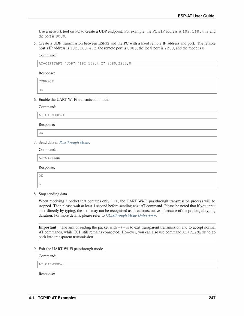
ESP-AT User Guide
Use a network tool on PC to create a UDP endpoint. For example, the PC’s IP address is 192.168.4.2 andthe port is 8080.
5. Create a UDP transmission between ESP32 and the PC with a fixed remote IP address and port. The remotehost’s IP address is 192.168.4.2, the remote port is 8080, the local port is 2233, and the mode is 0.
Command:
AT+CIPSTART="UDP","192.168.4.2",8080,2233,0
Response:
CONNECT
OK
6. Enable the UART Wi-Fi transmission mode.
Command:
AT+CIPMODE=1
Response:
OK
7. Send data in Passthrough Mode.
Command:
AT+CIPSEND
Response:
OK
>
8. Stop sending data.
When receiving a packet that contains only +++, the UART Wi-Fi passthrough transmission process will bestopped. Then please wait at least 1 second before sending next AT command. Please be noted that if you input+++ directly by typing, the +++ may not be recognised as three consecutive + because of the prolonged typingduration. For more details, please refer to [Passthrough Mode Only] +++.
Important: The aim of ending the packet with +++ is to exit transparent transmission and to accept normalAT commands, while TCP still remains connected. However, you can also use command AT+CIPSEND to goback into transparent transmission.
9. Exit the UART Wi-Fi passthrough mode.
Command:
AT+CIPMODE=0
Response:
4.1. TCP/IP AT Examples 247

ESP-AT User Guide
OK
10. Close TCP connection.
Command:
AT+CIPCLOSE
Response:
CLOSED
OK
4.2 Bluetooth LE AT Examples
[]
This document provides an introduction and detailed command examples to illustrate how to utilize Bluetooth® LowEnergy AT Commands on ESP devices.
• Introduction
• Bluetooth LE client reads and write services
• Bluetooth LE server read and write services
• Encrypt Bluetooth LE connection
• Establish SPP connection between two ESP32 development boards and transmit data in UART-Bluetooth LEPassthrough Mode
• Establish SPP connection between ESP32 and mobile phone and transmit data in UART-Bluetooth LEpassthrough mode
4.2.1 Introduction
ESP-AT currently only supports Bluetooth LE 4.2 protocol specification, and the description in this document isonly for Bluetooth LE 4.2 protocol specification. Please refer to Core Specification 4.2 for more details.
Bluetooth LE protocol architecture
Bluetooth LE protocol stack is divided into several layers from bottom to top: Physical Layer (PHY), LinkLayer (LL), Host Controller Interface (HCI), Logical Link Control and AdaptationProtocol Layer (L2CAP), Attribute Protocol (ATT), Security Manager Protocol(SMP), Generic Attribute Profile (GATT), Generic Access Profile (GAP).
• PHY: the PHY layer is responsible for transmitting and receiving packets of information on the physical channel.Bluetooth LE uses 40 RF channels. Frequency Range: 2402 MHz to 2480 MHz.
• LL: the LL layer is responsible for the creation, modification and release of logical links (and, if required, theirassociated logical transports), as well as the update of parameters related to physical links between devices.
248 Chapter 4. AT Command Examples
ESP-AT User Guide
It controls the Link Layer state machine in one of the five states of standby, advertising, scanning,initiating and connected.
• HCI: the HCI layer provides a standardized interface to host and controller. This layer can be implemented bysoftware API or controlled by hardware interfaces UART, SPI and USB.
• L2CAP: the L2CAP layer is responsible for protocol multiplexing capability, segmentation, and reassemblyoperation for data exchanged between the host and the protocol stack.
• ATT: the ATT layer implements the peer-to-peer protocol between an attribute server and an attribute client. TheATT client sends commands, requests, and confirmations to the ATT server. The ATT server sends responses,notifications and indications to the client.
• SMP: the SMP layer is the peer-to-peer protocol used to generate encryption keys and identity keys. The SMPalso manages storage of the encryption keys and identity keys and is responsible for generating random addressesand resolving random addresses to known device identities.
• GATT: the GATT layer represents the functionality of the attribute server and, optionally, the attribute client.The profile describes the hierarchy of services, characteristics and attributes used in the attribute server. Thelayer provides interfaces for discovering, reading, writing and indicating of service characteristics and attributes.
• GAP: the GAP represents the base functionality common to all Bluetooth devices such as modes and accessprocedures used by the transports, protocols and application profiles. GAP services include device discovery,connection modes, security, authentication, association models and service discovery.
Bluetooth LE role division
There are different roles in different levels of the Bluetooth LE protocol architecture. These divisions are not affectedby each other.
• LL: devices can be divided into master and slave, the slave advertises, and the master initiates a connection.
• GAP: GAP defines four specific roles: broadcaster, observer, peripheral, and central.
• GATT: devices can be divided into server and client.
Important:
• The Bluetooth LE server and Bluetooth LE client described in this document are both GATTlayer roles.
• At present, ESP-AT supports the existence of Bluetooth LE server and Bluetooth LE client atthe same time.
• No matter ESP-AT is initialized as Bluetooth LE server or Bluetooth LE client, the maximum number of devicesconnected at the same time is 3.
GATT is actually an attribute transmission protocol, which can be regarded as an application layer protocol for attributetransmission. The structure of this attribute is very simple. It is composed of services, each service is composedof different numbers of characteristics, and each characteristic is composed of many other elements.
GATT server and GATT client roles exist after the Bluetooth LE connection is established. The GATT serverstores the data transported over the Attribute Protocol and accepts Attribute Protocol requests, commands and confir-mations from the GATT client. In short, the end that provides data is called GATT server, and the end that accessesdata is called GATT client.
Important:
4.2. Bluetooth LE AT Examples 249

ESP-AT User Guide
• The ESP32 Bluetooth LE server needs to download a ble_data.bin into flash to provide Bluetooth LEservices.
– To learn how to generate a ble_data.bin, please refer to Customize Bluetooth LE Services Tools.
– The download address of the ble_data.bin is the address of ble_data in at_customize.csv,or described in build/download.config.
4.2.2 Bluetooth LE client reads and write services
Below is an example of using two ESP32 development boards, one as a Bluetooth LE server (only as Bluetooth LEserver role), the other one as a Bluetooth LE client (only as Bluetooth LE client role). The example shows how to useBluetooth LE functions with AT commands.
Important: In the following steps, the operations starting with ESP32 Bluetooth LE server only need to beexecuted at ESP32 Bluetooth LE server, and the operations starting with ESP32 Bluetooth LE client onlyneed to be executed at ESP32 Bluetooth LE client.
1. Bluetooth LE initialization.
ESP32 Bluetooth LE server:
Command:
AT+BLEINIT=2
Response:
OK
ESP32 Bluetooth LE client:
Command:
AT+BLEINIT=1
Response:
OK
2. ESP32 Bluetooth LE server gets Bluetooth LE address.
Command:
AT+BLEADDR?
Response:
+BLEADDR:"24:0a:c4:d6:e4:46"OK
Note:
• The address you obtain may be different from that in the above response. Keep yours handy as you willneed it in one of the following steps.
250 Chapter 4. AT Command Examples

ESP-AT User Guide
3. ESP32 Bluetooth LE server creates services.
Command:
AT+BLEGATTSSRVCRE
Response:
OK
4. ESP32 Bluetooth LE server starts services.
Command:
AT+BLEGATTSSRVSTART
Response:
OK
5. ESP32 Bluetooth LE server discovers characteristics.
Command:
AT+BLEGATTSCHAR?
Response:
+BLEGATTSCHAR:"char",1,1,0xC300,0x02+BLEGATTSCHAR:"desc",1,1,1,0x2901+BLEGATTSCHAR:"char",1,2,0xC301,0x02+BLEGATTSCHAR:"desc",1,2,1,0x2901+BLEGATTSCHAR:"char",1,3,0xC302,0x08+BLEGATTSCHAR:"desc",1,3,1,0x2901+BLEGATTSCHAR:"char",1,4,0xC303,0x04+BLEGATTSCHAR:"desc",1,4,1,0x2901+BLEGATTSCHAR:"char",1,5,0xC304,0x08+BLEGATTSCHAR:"char",1,6,0xC305,0x10+BLEGATTSCHAR:"desc",1,6,1,0x2902+BLEGATTSCHAR:"char",1,7,0xC306,0x20+BLEGATTSCHAR:"desc",1,7,1,0x2902+BLEGATTSCHAR:"char",1,8,0xC307,0x02+BLEGATTSCHAR:"desc",1,8,1,0x2901+BLEGATTSCHAR:"char",2,1,0xC400,0x02+BLEGATTSCHAR:"desc",2,1,1,0x2901+BLEGATTSCHAR:"char",2,2,0xC401,0x02+BLEGATTSCHAR:"desc",2,2,1,0x2901
OK
6. ESP32 Bluetooth LE server starts advertising, then the ESP32 Bluetooth LE client starts scanning and lasts for3 s.
ESP32 Bluetooth LE server:
Command:
AT+BLEADVSTART
Response:
4.2. Bluetooth LE AT Examples 251

ESP-AT User Guide
OK
ESP32 Bluetooth LE client:
Command:
AT+BLESCAN=1,3
Response:
OK+BLESCAN:"5b:3b:6c:51:90:49",-87,02011a020a0c0aff4c001005071c3024dc,,1+BLESCAN:"c4:5b:be:93:ec:66",-84,0201060303111809095647543147572d58020a03,,0+BLESCAN:"24:0a:c4:d6:e4:46",-29,,,0
Note:
• The scan results you obtain may be different from those in the above response.
7. Establish the Bluetooth LE connection.
ESP32 Bluetooth LE client:
Command:
AT+BLECONN=0,"24:0a:c4:d6:e4:46"
Response:
+BLECONN:0,"24:0a:c4:d6:e4:46"
OK
Note:
• When entering the above command, replace the address with your ESP Bluetooth LE server address.
• If the Bluetooth LE connection is established successfully, message +BLECONN:0,"24:0a:c4:d6:e4:46 will be prompted.
• If the Bluetooth LE connection is broken, message +BLECONN:0,-1 will be prompted.
8. ESP32 Bluetooth LE client discovers services.
Command:
AT+BLEGATTCPRIMSRV=0
Response:
+BLEGATTCPRIMSRV:0,1,0x1801,1+BLEGATTCPRIMSRV:0,2,0x1800,1+BLEGATTCPRIMSRV:0,3,0xA002,1+BLEGATTCPRIMSRV:0,4,0xA003,1
OK
Note:
• When discovering services, the ESP32 Bluetooth LE client will get two more default services (UUID:0x1800 and 0x1801) than what the ESP32 Bluetooth LE server will get. So, for the same service,
252 Chapter 4. AT Command Examples

ESP-AT User Guide
the <srv_index> received by the ESP32 Bluetooth LE client equals the <srv_index> received by theESP32 Bluetooth LE server + 2. For example, for service 0xA002, the <srv_index> queried on theESP32 Bluetooth LE client is 3, if the ESP32 Bluetooth LE server is queried through the commandAT+BLEGATTSSRV?, then <srv_index> is 1.
9. ESP32 Bluetooth LE client discovers characteristics.
Command:
AT+BLEGATTCCHAR=0,3
Response:
+BLEGATTCCHAR:"char",0,3,1,0xC300,0x02+BLEGATTCCHAR:"desc",0,3,1,1,0x2901+BLEGATTCCHAR:"char",0,3,2,0xC301,0x02+BLEGATTCCHAR:"desc",0,3,2,1,0x2901+BLEGATTCCHAR:"char",0,3,3,0xC302,0x08+BLEGATTCCHAR:"desc",0,3,3,1,0x2901+BLEGATTCCHAR:"char",0,3,4,0xC303,0x04+BLEGATTCCHAR:"desc",0,3,4,1,0x2901+BLEGATTCCHAR:"char",0,3,5,0xC304,0x08+BLEGATTCCHAR:"char",0,3,6,0xC305,0x10+BLEGATTCCHAR:"desc",0,3,6,1,0x2902+BLEGATTCCHAR:"char",0,3,7,0xC306,0x20+BLEGATTCCHAR:"desc",0,3,7,1,0x2902+BLEGATTCCHAR:"char",0,3,8,0xC307,0x02+BLEGATTCCHAR:"desc",0,3,8,1,0x2901
OK
10. ESP32 Bluetooth LE client reads a characteristic.
Command:
AT+BLEGATTCRD=0,3,1
Response:
+BLEGATTCRD:0,1,0
OK
Note:
• Please note that the target characteristic’s property has to support the read operation.
• If the ESP32 Bluetooth LE client reads the characteristic successfully, message +READ:0,"7c:df:a1:b3:8d:de" will be prompted on the ESP32 Bluetooth LE Server side.
11. ESP32 Bluetooth LE client writes a characteristic.
Command:
AT+BLEGATTCWR=0,3,3,,2
Response:
>
4.2. Bluetooth LE AT Examples 253

ESP-AT User Guide
The symbol > indicates that AT is ready for receiving serial data and you can enter data now. When the require-ment of data length determined by the parameter <length> is met, the writing starts.
OK
Note:
• If the ESP32 Bluetooth LE client writes the characteristic successfully, message+WRITE:<conn_index>,<srv_index>,<char_index>,[<desc_index>],<len>,<value> will be prompted on the ESP32 Bluetooth LE server side.
12. Indicate a characteristic.
ESP32 Bluetooth LE client:
Command:
AT+BLEGATTCWR=0,3,7,1,2
Response:
>
The symbol > indicates that AT is ready for receiving serial data and you can enter data now. When the require-ment of data length determined by the parameter <length> is met, the writing starts.
To receive data from ESP32 Bluetooth LE server (through the notify or the indicate method), the ESP32Bluetooth LE client needs to register with the server in advance. Write the value 0x0001 to use the notifymethod, and 0x0002 to use the indicate method. This example writes the 0x0002 to use the indicatemethod.
OK
Note:
• If the ESP32 Bluetooth LE client writes the descriptor successfully, message +WRITE:<conn_index>,<srv_index>,<char_index>,<desc_index>,<len>,<value> will be prompted on theESP32 Bluetooth LE server side.
ESP32 Bluetooth LE server:
Command:
AT+BLEGATTSIND=0,1,7,3
Response:
>
The symbol > indicates that AT is ready for receiving serial data and you can enter data now. When the require-ment of data length determined by the parameter <length> is met, the indication starts.
OK
Note:
• If the ESP32 Bluetooth LE client receives the indication, message +INDICATE:<conn_index>,<srv_index>,<char_index>,<len>,<value> will be prompted.
• For the same service, the <srv_index> on the ESP32 Bluetooth LE client side equals the <srv_index> onthe ESP32 Bluetooth LE server side + 2.
254 Chapter 4. AT Command Examples
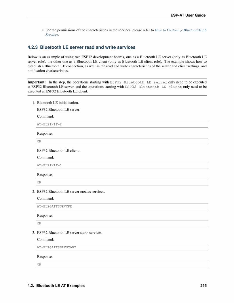
ESP-AT User Guide
• For the permissions of the characteristics in the services, please refer to How to Customize Bluetooth® LEServices.
4.2.3 Bluetooth LE server read and write services
Below is an example of using two ESP32 development boards, one as a Bluetooth LE server (only as Bluetooth LEserver role), the other one as a Bluetooth LE client (only as Bluetooth LE client role). The example shows how toestablish a Bluetooth LE connection, as well as the read and write characteristics of the server and client settings, andnotification characteristics.
Important: In the step, the operations starting with ESP32 Bluetooth LE server only need to be executedat ESP32 Bluetooth LE server, and the operations starting with ESP32 Bluetooth LE client only need to beexecuted at ESP32 Bluetooth LE client.
1. Bluetooth LE initialization.
ESP32 Bluetooth LE server:
Command:
AT+BLEINIT=2
Response:
OK
ESP32 Bluetooth LE client:
Command:
AT+BLEINIT=1
Response:
OK
2. ESP32 Bluetooth LE server creates services.
Command:
AT+BLEGATTSSRVCRE
Response:
OK
3. ESP32 Bluetooth LE server starts services.
Command:
AT+BLEGATTSSRVSTART
Response:
OK
4.2. Bluetooth LE AT Examples 255

ESP-AT User Guide
4. ESP32 Bluetooth LE server gets its MAC address.
Command:
AT+BLEADDR?
Response:
+BLEADDR:"24:0a:c4:d6:e4:46"OK
Note:
• The address you obtain may be different from that in the above response. Keep yours handy as you willneed it in one of the following steps.
5. Set Bluetooth LE advertising data.
Command:
AT+BLEADVDATA="0201060A09457370726573736966030302A0"
Response:
OK
6. ESP32 Bluetooth LE server starts advertising.
Command:
AT+BLEADVSTART
Response:
OK
7. ESP32 Bluetooth LE client creates services.
Command:
AT+BLEGATTSSRVCRE
Response:
OK
8. ESP32 Bluetooth LE client starts services.
Command:
AT+BLEGATTSSRVSTART
Response:
OK
9. ESP32 Bluetooth LE client gets Bluetooth LE address.
Command:
256 Chapter 4. AT Command Examples

ESP-AT User Guide
AT+BLEADDR?
Response:
+BLEADDR:"24:0a:c4:03:a7:4e"OK
Note:
• The address you obtain may be different from that in the above response. Keep yours handy as you willneed it in one of the following steps.
10. ESP32 Bluetooth LE client enables a scanning for three seconds.
Command:
AT+BLESCAN=1,3
Response:
OK+BLESCAN:"5b:3b:6c:51:90:49",-87,02011a020a0c0aff4c001005071c3024dc,,1+BLESCAN:"c4:5b:be:93:ec:66",-84,0201060303111809095647543147572d58020a03,,0+BLESCAN:"24:0a:c4:d6:e4:46",-29,,,0
Note:
• The scan results you obtain may be different from those in the above response.
11. Establish the Bluetooth LE connection.
ESP32 Bluetooth LE client:
Command:
AT+BLECONN=0,"24:0a:c4:d6:e4:46"
Response:
+BLECONN:0,"24:0a:c4:d6:e4:46"
OK
Note:
• When entering the above command, replace the address with your ESP Bluetooth LE server address.
• If the Bluetooth LE connection is established successfully, message +BLECONN:0,"24:0a:c4:d6:e4:46 will be prompted.
• If the Bluetooth LE connection is broken, message +BLECONN:0,-1 will be prompted.
ESP32 Bluetooth LE server:
Command:
AT+BLECONN=0,"24:0a:c4:03:a7:4e"
Response:
4.2. Bluetooth LE AT Examples 257
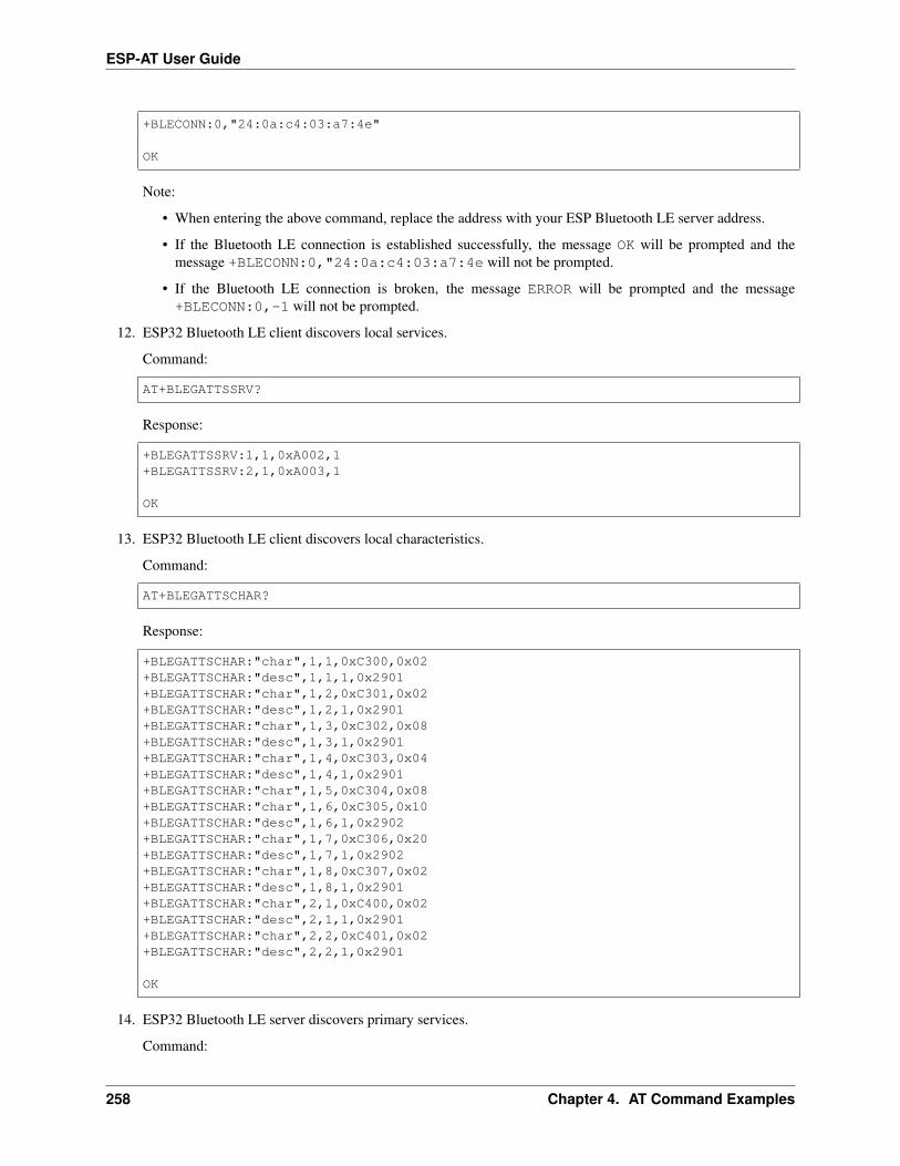
ESP-AT User Guide
+BLECONN:0,"24:0a:c4:03:a7:4e"
OK
Note:
• When entering the above command, replace the address with your ESP Bluetooth LE server address.
• If the Bluetooth LE connection is established successfully, the message OK will be prompted and themessage +BLECONN:0,"24:0a:c4:03:a7:4e will not be prompted.
• If the Bluetooth LE connection is broken, the message ERROR will be prompted and the message+BLECONN:0,-1 will not be prompted.
12. ESP32 Bluetooth LE client discovers local services.
Command:
AT+BLEGATTSSRV?
Response:
+BLEGATTSSRV:1,1,0xA002,1+BLEGATTSSRV:2,1,0xA003,1
OK
13. ESP32 Bluetooth LE client discovers local characteristics.
Command:
AT+BLEGATTSCHAR?
Response:
+BLEGATTSCHAR:"char",1,1,0xC300,0x02+BLEGATTSCHAR:"desc",1,1,1,0x2901+BLEGATTSCHAR:"char",1,2,0xC301,0x02+BLEGATTSCHAR:"desc",1,2,1,0x2901+BLEGATTSCHAR:"char",1,3,0xC302,0x08+BLEGATTSCHAR:"desc",1,3,1,0x2901+BLEGATTSCHAR:"char",1,4,0xC303,0x04+BLEGATTSCHAR:"desc",1,4,1,0x2901+BLEGATTSCHAR:"char",1,5,0xC304,0x08+BLEGATTSCHAR:"char",1,6,0xC305,0x10+BLEGATTSCHAR:"desc",1,6,1,0x2902+BLEGATTSCHAR:"char",1,7,0xC306,0x20+BLEGATTSCHAR:"desc",1,7,1,0x2902+BLEGATTSCHAR:"char",1,8,0xC307,0x02+BLEGATTSCHAR:"desc",1,8,1,0x2901+BLEGATTSCHAR:"char",2,1,0xC400,0x02+BLEGATTSCHAR:"desc",2,1,1,0x2901+BLEGATTSCHAR:"char",2,2,0xC401,0x02+BLEGATTSCHAR:"desc",2,2,1,0x2901
OK
14. ESP32 Bluetooth LE server discovers primary services.
Command:
258 Chapter 4. AT Command Examples

ESP-AT User Guide
AT+BLEGATTCPRIMSRV=0
Response:
+BLEGATTCPRIMSRV:0,1,0x1801,1+BLEGATTCPRIMSRV:0,2,0x1800,1+BLEGATTCPRIMSRV:0,3,0xA002,1+BLEGATTCPRIMSRV:0,4,0xA003,1
OK
Note:
• When discovering services, the ESP32 Bluetooth LE server will get two more default services (UUID:0x1800 and 0x1801) than what the ESP32 Bluetooth LE client will get. So, for the same service,the <srv_index> received by the ESP32 Bluetooth LE server equals the <srv_index> received by theESP32 Bluetooth LE client + 2. For example, for service 0xA002, the <srv_index> queried on theESP32 Bluetooth LE client is 3, if the ESP32 Bluetooth LE server is queried through the commandAT+BLEGATTSSRV?, then <srv_index> is 1.
15. ESP32 Bluetooth LE server discovers primary characteristics.
Command:
AT+BLEGATTCCHAR=0,3
Response:
+BLEGATTCCHAR:"char",0,3,1,0xC300,0x02+BLEGATTCCHAR:"desc",0,3,1,1,0x2901+BLEGATTCCHAR:"char",0,3,2,0xC301,0x02+BLEGATTCCHAR:"desc",0,3,2,1,0x2901+BLEGATTCCHAR:"char",0,3,3,0xC302,0x08+BLEGATTCCHAR:"desc",0,3,3,1,0x2901+BLEGATTCCHAR:"char",0,3,4,0xC303,0x04+BLEGATTCCHAR:"desc",0,3,4,1,0x2901+BLEGATTCCHAR:"char",0,3,5,0xC304,0x08+BLEGATTCCHAR:"char",0,3,6,0xC305,0x10+BLEGATTCCHAR:"desc",0,3,6,1,0x2902+BLEGATTCCHAR:"char",0,3,7,0xC306,0x20+BLEGATTCCHAR:"desc",0,3,7,1,0x2902+BLEGATTCCHAR:"char",0,3,8,0xC307,0x02+BLEGATTCCHAR:"desc",0,3,8,1,0x2901
OK
16. ESP32 Bluetooth LE client sets characteristics.
Select the service characteristic that supports the write operation (characteristic) to set the characteristic.
Command:
AT+BLEGATTSSETATTR=1,8,,1
Response:
>
Command:
4.2. Bluetooth LE AT Examples 259
ESP-AT User Guide
Write 1 byte ``9``
Response:
OK
17. ESP32 Bluetooth LE server reads characteristics.
Command:
AT+BLEGATTCRD=0,3,8,
Response:
+BLEGATTCRD:0,1,9
OK
18. ESP32 Bluetooth LE client write characteristics.
Select the service characteristic that supports the write operation to write the characteristics.
Command:
AT+BLEGATTCWR=0,3,6,1,2
Response:
>
Command:
Write 2 bytes ``12``
Response:
OK
Note:
• If the Bluetooth LE server successfully writes the service characteristic value, the Bluetooth LE client willprompt +WRITE:0,1,6,1,2,12.
19. ESP32 Bluetooth LE client notify characteristics.
Command:
AT+BLEGATTSNTFY=0,1,6,10
Response:
>
Command:
Write 10 bytes ``1234567890``
Response:
260 Chapter 4. AT Command Examples

ESP-AT User Guide
OK
Note:
• If the ESP32 Bluetooth LE client’s notify characteristic is successfully sent to the server, the Bluetooth LEserver +NOTIFY:0,3,6,10,1234567890 will be prompt.
4.2.4 Encrypt Bluetooth LE connection
Below is an example of using two ESP32 development boards, one as a Bluetooth LE server (only as Bluetooth LEserver role), the other one as a Bluetooth LE client (only as Bluetooth LE client role). The example shows how toencrypt Bluetooth LE connection.
Important:
• In the following steps, the operations starting with ESP32 Bluetooth LE server only need to be exe-cuted at ESP32 Bluetooth LE server, and the operations starting with ESP32 Bluetooth LE client onlyneed to be executed at ESP32 Bluetooth LE client.
• Encryption and bonding are two different concepts. bonding is just a long-term key stored locally aftersuccessful encryption.
• ESP-AT allows a maximum of 10 devices to be bonded.
1. Bluetooth LE initialization.
ESP32 Bluetooth LE server:
Command:
AT+BLEINIT=2
Response:
OK
ESP32 Bluetooth LE client:
Command:
AT+BLEINIT=1
Response:
OK
2. ESP32 Bluetooth LE server gets Bluetooth LE address.
Command:
AT+BLEADDR?
Response:
+BLEADDR:"24:0a:c4:d6:e4:46"OK
4.2. Bluetooth LE AT Examples 261

ESP-AT User Guide
Note:
• The address you obtain may be different from that in the above response. Keep yours handy as you willneed it in one of the following steps.
3. ESP32 Bluetooth LE server creates services.
Command:
AT+BLEGATTSSRVCRE
Response:
OK
4. ESP32 Bluetooth LE server starts services.
Command:
AT+BLEGATTSSRVSTART
Response:
OK
5. ESP32 Bluetooth LE server discovers characteristics.
Command:
AT+BLEGATTSCHAR?
Response:
+BLEGATTSCHAR:"char",1,1,0xC300,0x02+BLEGATTSCHAR:"desc",1,1,1,0x2901+BLEGATTSCHAR:"char",1,2,0xC301,0x02+BLEGATTSCHAR:"desc",1,2,1,0x2901+BLEGATTSCHAR:"char",1,3,0xC302,0x08+BLEGATTSCHAR:"desc",1,3,1,0x2901+BLEGATTSCHAR:"char",1,4,0xC303,0x04+BLEGATTSCHAR:"desc",1,4,1,0x2901+BLEGATTSCHAR:"char",1,5,0xC304,0x08+BLEGATTSCHAR:"char",1,6,0xC305,0x10+BLEGATTSCHAR:"desc",1,6,1,0x2902+BLEGATTSCHAR:"char",1,7,0xC306,0x20+BLEGATTSCHAR:"desc",1,7,1,0x2902+BLEGATTSCHAR:"char",1,8,0xC307,0x02+BLEGATTSCHAR:"desc",1,8,1,0x2901+BLEGATTSCHAR:"char",2,1,0xC400,0x02+BLEGATTSCHAR:"desc",2,1,1,0x2901+BLEGATTSCHAR:"char",2,2,0xC401,0x02+BLEGATTSCHAR:"desc",2,2,1,0x2901
OK
6. ESP32 Bluetooth LE server starts advertising, then the ESP32 Bluetooth LE client starts scanning and lasts for3 s.
ESP32 Bluetooth LE server:
Command:
262 Chapter 4. AT Command Examples

ESP-AT User Guide
AT+BLEADVSTART
Response:
OK
ESP32 Bluetooth LE client:
Command:
AT+BLESCAN=1,3
Response:
OK+BLESCAN:"5b:3b:6c:51:90:49",-87,02011a020a0c0aff4c001005071c3024dc,,1+BLESCAN:"c4:5b:be:93:ec:66",-84,0201060303111809095647543147572d58020a03,,0+BLESCAN:"24:0a:c4:d6:e4:46",-29,,,0
Note:
• The scan results you obtain may be different from those in the above response.
7. Establish the Bluetooth LE connection.
ESP32 Bluetooth LE client:
Command:
AT+BLECONN=0,"24:0a:c4:d6:e4:46"
Response:
+BLECONN:0,"24:0a:c4:d6:e4:46"
OK
Note:
• When entering the above command, replace the address with your ESP Bluetooth LE server address.
• If the Bluetooth LE connection is established successfully, message +BLECONN:0,"24:0a:c4:d6:e4:46 will be prompted.
• If the Bluetooth LE connection is broken, message +BLECONN:0,-1 will be prompted.
8. ESP32 Bluetooth LE client discovers services.
Command:
AT+BLEGATTCPRIMSRV=0
Response:
+BLEGATTCPRIMSRV:0,1,0x1801,1+BLEGATTCPRIMSRV:0,2,0x1800,1+BLEGATTCPRIMSRV:0,3,0xA002,1+BLEGATTCPRIMSRV:0,4,0xA003,1
OK
4.2. Bluetooth LE AT Examples 263

ESP-AT User Guide
Note:
• When discovering services, the ESP32 Bluetooth LE client will get two more default services (UUID:0x1800 and 0x1801) than what the ESP32 Bluetooth LE server will get. So, for the same service,the <srv_index> received by the ESP32 Bluetooth LE client equals the <srv_index> received by theESP32 Bluetooth LE server + 2. For example, for service 0xA002, the <srv_index> queried on theESP32 Bluetooth LE client is 3, if the ESP32 Bluetooth LE server is queried through the commandAT+BLEGATTSSRV?, then <srv_index> is 1.
9. ESP32 Bluetooth LE client discovers characteristics.
Command:
AT+BLEGATTCCHAR=0,3
Response:
+BLEGATTCCHAR:"char",0,3,1,0xC300,0x02+BLEGATTCCHAR:"desc",0,3,1,1,0x2901+BLEGATTCCHAR:"char",0,3,2,0xC301,0x02+BLEGATTCCHAR:"desc",0,3,2,1,0x2901+BLEGATTCCHAR:"char",0,3,3,0xC302,0x08+BLEGATTCCHAR:"desc",0,3,3,1,0x2901+BLEGATTCCHAR:"char",0,3,4,0xC303,0x04+BLEGATTCCHAR:"desc",0,3,4,1,0x2901+BLEGATTCCHAR:"char",0,3,5,0xC304,0x08+BLEGATTCCHAR:"char",0,3,6,0xC305,0x10+BLEGATTCCHAR:"desc",0,3,6,1,0x2902+BLEGATTCCHAR:"char",0,3,7,0xC306,0x20+BLEGATTCCHAR:"desc",0,3,7,1,0x2902+BLEGATTCCHAR:"char",0,3,8,0xC307,0x02+BLEGATTCCHAR:"desc",0,3,8,1,0x2901
OK
10. Set Bluetooth LE encryption parameters. Set auth_req to SC_MITM_BOND, server’s iocap toKeyboardOnly, client’s iocap to KeyboardDisplay, key_size to 16, init_key to 3, rsp_keyto 3.
ESP32 Bluetooth LE server:
Command:
AT+BLESECPARAM=13,2,16,3,3
Response:
OK
ESP32 Bluetooth LE client:
Command:
AT+BLESECPARAM=13,4,16,3,3
Response:
OK
Note:
264 Chapter 4. AT Command Examples

ESP-AT User Guide
• In this example, ESP32 Bluetooth LE server enters the pairing code and ESP32 Bluetooth LE client dis-plays the pairing code.
• ESP-AT supports Legacy Pairing and Secure Connections encryption methods, but the latterhas a higher priority. If the peer also supports Secure Connections, then Secure Connectionswill be used for encryption.
11. ESP32 Bluetooth LE client initiates encryption request.
Command:
AT+BLEENC=0,3
Response:
OK
Note:
If the ESP32 Bluetooth LE server successfully receives the encryption request, message +BLESECREQ:0 willbe prompted on the ESP32 Bluetooth LE server side.
12. ESP32 Bluetooth LE server responds to the pairing request.
Command:
AT+BLEENCRSP=0,1
Response:
OK
Note:
• If the ESP32 Bluetooth LE client successfully receives the pairing response, a 6-digit pairing code willgenerate on the ESP32 Bluetooth LE client side.
• In this example, message +BLESECNTFYKEY:0,793718 will be prompted on the ESP32 Bluetooth LEclient side. Pairing code is 793718.
13. ESP32 Bluetooth LE server replies pairing code.
Command:
AT+BLEKEYREPLY=0,793718
Response:
OK
After running this command, there will be corresponding messages prompt on both the ESP32 Bluetooth LEserver and the ESP32 Bluetooth LE client.
ESP32 Bluetooth LE server:
+BLESECKEYTYPE:0,16+BLESECKEYTYPE:0,1+BLESECKEYTYPE:0,32+BLESECKEYTYPE:0,2+BLEAUTHCMPL:0,0
ESP32 Bluetooth LE client:
4.2. Bluetooth LE AT Examples 265

ESP-AT User Guide
+BLESECNTFYKEY:0,793718+BLESECKEYTYPE:0,2+BLESECKEYTYPE:0,16+BLESECKEYTYPE:0,1+BLESECKEYTYPE:0,32+BLEAUTHCMPL:0,0
You can ignore the message starting with +BLESECKEYTYPE. In terms of the second parameter in the message+BLEAUTHCMPL:0,0, 0 means encryption is successful, and 1 means encryption fails.
4.2.5 Establish SPP connection between two ESP32 development boards andtransmit data in UART-Bluetooth LE Passthrough Mode
Below is an example of using two ESP32 development boards, one as a Bluetooth LE server (only as Bluetooth LEserver role), the other one as a Bluetooth LE client (only as Bluetooth LE client role). The example shows how tobuild Bluetooth LE SPP (Serial Port Profile, UART-Bluetooth LE passthrough mode) with AT commands.
Important: In the following steps, the operations starting with ESP32 Bluetooth LE server only need to beexecuted at ESP32 Bluetooth LE server, and the operations starting with ESP32 Bluetooth LE client onlyneed to be executed at ESP32 Bluetooth LE client.
1. Bluetooth LE initialization.
ESP32 Bluetooth LE server:
Command:
AT+BLEINIT=2
Response:
OK
ESP32 Bluetooth LE client:
Command:
AT+BLEINIT=1
Response:
OK
2. ESP32 Bluetooth LE server creates services.
Command:
AT+BLEGATTSSRVCRE
Response:
OK
3. ESP32 Bluetooth LE server starts services.
Command:
266 Chapter 4. AT Command Examples
ESP-AT User Guide
AT+BLEGATTSSRVSTART
Response:
OK
4. ESP32 Bluetooth LE server gets Bluetooth LE address.
Command:
AT+BLEADDR?
Response:
+BLEADDR:"24:0a:c4:d6:e4:46"OK
Note:
• The address you obtain may be different from that in the above response. Keep yours handy as you willneed it in one of the following steps.
5. Set Bluetooth LE advertising data.
Command:
AT+BLEADVDATA="0201060A09457370726573736966030302A0"
Response:
OK
6. ESP32 Bluetooth LE server starts advertising.
Command:
AT+BLEADVSTART
Response:
OK
7. ESP32 Bluetooth LE client enables a scanning for three seconds.
Command:
AT+BLESCAN=1,3
Response:
OK+BLESCAN:"24:0a:c4:d6:e4:46",-78,0201060a09457370726573736966030302a0,,0+BLESCAN:"45:03:cb:ac:aa:a0",-62,0201060aff4c001005441c61df7d,,1+BLESCAN:"24:0a:c4:d6:e4:46",-26,0201060a09457370726573736966030302a0,,0
Note:
• The scan results you obtain may be different from those in the above response.
4.2. Bluetooth LE AT Examples 267

ESP-AT User Guide
8. Establish the Bluetooth LE connection.
ESP32 Bluetooth LE client:
Command:
AT+BLECONN=0,"24:0a:c4:d6:e4:46"
Response:
+BLECONN:0,"24:0a:c4:d6:e4:46"
OK
Note:
• When entering the above command, replace the address your ESP Bluetooth LE server address.
• If the Bluetooth LE connection is established successfully, message +BLECONN:0,"24:0a:c4:d6:e4:46 will be prompted.
• If the Bluetooth LE connection is broken, message +BLECONN:0,-1 will be prompted.
9. ESP32 Bluetooth LE server discovers local services.
Command:
AT+BLEGATTSSRV?
Response:
+BLEGATTSSRV:1,1,0xA002,1+BLEGATTSSRV:2,1,0xA003,1
OK
10. ESP32 Bluetooth LE server discovers local characteristics.
Command:
AT+BLEGATTSCHAR?
Response:
+BLEGATTSCHAR:"char",1,1,0xC300,0x02+BLEGATTSCHAR:"desc",1,1,1,0x2901+BLEGATTSCHAR:"char",1,2,0xC301,0x02+BLEGATTSCHAR:"desc",1,2,1,0x2901+BLEGATTSCHAR:"char",1,3,0xC302,0x08+BLEGATTSCHAR:"desc",1,3,1,0x2901+BLEGATTSCHAR:"char",1,4,0xC303,0x04+BLEGATTSCHAR:"desc",1,4,1,0x2901+BLEGATTSCHAR:"char",1,5,0xC304,0x08+BLEGATTSCHAR:"char",1,6,0xC305,0x10+BLEGATTSCHAR:"desc",1,6,1,0x2902+BLEGATTSCHAR:"char",1,7,0xC306,0x20+BLEGATTSCHAR:"desc",1,7,1,0x2902+BLEGATTSCHAR:"char",1,8,0xC307,0x02+BLEGATTSCHAR:"desc",1,8,1,0x2901+BLEGATTSCHAR:"char",2,1,0xC400,0x02+BLEGATTSCHAR:"desc",2,1,1,0x2901
(continues on next page)
268 Chapter 4. AT Command Examples

ESP-AT User Guide
(continued from previous page)
+BLEGATTSCHAR:"char",2,2,0xC401,0x02+BLEGATTSCHAR:"desc",2,2,1,0x2901
OK
11. ESP32 Bluetooth LE client discovers services.
Command:
AT+BLEGATTCPRIMSRV=0
Response:
+BLEGATTCPRIMSRV:0,1,0x1801,1+BLEGATTCPRIMSRV:0,2,0x1800,1+BLEGATTCPRIMSRV:0,3,0xA002,1+BLEGATTCPRIMSRV:0,4,0xA003,1
OK
Note:
• When discovering services, the ESP32 Bluetooth LE client will get two more default services (UUID:0x1800 and 0x1801) than what the ESP32 Bluetooth LE server will get. So, for the same service,the <srv_index> received by the ESP32 Bluetooth LE client equals the <srv_index> received by theESP32 Bluetooth LE server + 2. For example, for service 0xA002, the <srv_index> queried on theESP32 Bluetooth LE client is 3, if the ESP32 Bluetooth LE server is queried through the commandAT+BLEGATTSSRV?, then <srv_index> is 1.
12. ESP32 Bluetooth LE client discovers characteristics.
Command:
AT+BLEGATTCCHAR=0,3
Response:
+BLEGATTCCHAR:"char",0,3,1,0xC300,0x02+BLEGATTCCHAR:"desc",0,3,1,1,0x2901+BLEGATTCCHAR:"char",0,3,2,0xC301,0x02+BLEGATTCCHAR:"desc",0,3,2,1,0x2901+BLEGATTCCHAR:"char",0,3,3,0xC302,0x08+BLEGATTCCHAR:"desc",0,3,3,1,0x2901+BLEGATTCCHAR:"char",0,3,4,0xC303,0x04+BLEGATTCCHAR:"desc",0,3,4,1,0x2901+BLEGATTCCHAR:"char",0,3,5,0xC304,0x08+BLEGATTCCHAR:"char",0,3,6,0xC305,0x10+BLEGATTCCHAR:"desc",0,3,6,1,0x2902+BLEGATTCCHAR:"char",0,3,7,0xC306,0x20+BLEGATTCCHAR:"desc",0,3,7,1,0x2902+BLEGATTCCHAR:"char",0,3,8,0xC307,0x02+BLEGATTCCHAR:"desc",0,3,8,1,0x2901
OK
13. ESP32 Bluetooth LE client Configures Bluetooth LE SPP.
Set a characteristic that enables writing permission to TX channel for sending data. Set another characteristicthat supports notification or indication to RX channel for receiving data.
4.2. Bluetooth LE AT Examples 269

ESP-AT User Guide
Command:
AT+BLESPPCFG=1,3,5,3,7
Response:
OK
14. ESP32 Bluetooth LE client enables Bluetooth LE SPP.
Command:
AT+BLESPP
Response:
OK
>
This response indicates that AT has entered Bluetooth LE SPP mode and can send and receive data.
Note:
• After the ESP32 Bluetooth LE client enables Bluetooth LE SPP, data received from serial port will betransmitted to the Bluetooth LE server directly.
15. ESP32 Bluetooth LE server Configures Bluetooth LE SPP.
Set a characteristic that supports notification or indication to TX channel for sending data. Set another charac-teristic that enables writing permission to RX channel for receiving data.
Command:
AT+BLESPPCFG=1,1,7,1,5
Response:
OK
16. ESP32 Bluetooth LE server enables Bluetooth LE SPP.
Command:
AT+BLESPP
Response:
OK
>
This response indicates that AT has entered Bluetooth LE SPP mode and can send and receive data.
Note:
• After the ESP32 Bluetooth LE server enables Bluetooth LE SPP, the data received from serial port will betransmitted to the Bluetooth LE client directly.
• If the ESP32 Bluetooth LE client does not enable Bluetooth LE SPP first, or uses other device as BluetoothLE client, then the Bluetooth LE client needs to listen to the notification or indication first. For example,if the ESP32 Bluetooth LE client does not enable Bluetooth LE SPP first, then it should use command
270 Chapter 4. AT Command Examples

ESP-AT User Guide
AT+BLEGATTCWR=0,3,7,1,1 to enable listening function first, so that the ESP32 Bluetooth LE servercan transmit successfully.
• For the same service, the <srv_index> on the ESP32 Bluetooth LE client side equals the <srv_index> onthe ESP32 Bluetooth LE server side + 2.
4.2.6 Establish SPP connection between ESP32 and mobile phone and transmitdata in UART-Bluetooth LE passthrough mode
The example shows how to establish SPP connection between an ESP32 development board (only serving as theBluetooth LE server role) and a mobile phone (only serve as the Bluetooth LE client role) and how to transmit databetween them in UART-Bluetooth LE passthrough mode.
Important: In the following steps, the operations starting with ESP32 Bluetooth LE server only need tobe executed at ESP32 Bluetooth LE server, and those Bluetooth LE client only need to be executed at the Bluetoothdebugging assistant of the mobile phone.
1. First, you need to download the Bluetooth LE debugging assistant on the mobile phone, such as nRF Connectapp (Android) and LightBlue (iOS).
2. Bluetooth LE initialization.
ESP32 Bluetooth LE server:
Command:
AT+BLEINIT=2
Response:
OK
3. ESP32 Bluetooth LE server creates services.
Command:
AT+BLEGATTSSRVCRE
Response:
OK
4. ESP32 Bluetooth LE server starts services.
Command:
AT+BLEGATTSSRVSTART
Response:
OK
5. ESP32 Bluetooth LE server gets its MAC address.
Command:
4.2. Bluetooth LE AT Examples 271

ESP-AT User Guide
AT+BLEADDR?
Response:
+BLEADDR:"24:0a:c4:d6:e4:46"OK
Note:
• The address you obtain may be different from that in the above response. Keep yours handy as you willneed it in one of the following steps.
6. Set Bluetooth LE advertising data.
Command:
AT+BLEADVDATA="0201060A09457370726573736966030302A0"
Response:
OK
7. ESP32 Bluetooth LE server starts advertising.
Command:
AT+BLEADVSTART
Response:
OK
8. Establish the Bluetooth LE connection.
Open the nRF debugging assistant on your mobile phone, and open SCAN to start scanning. When you findthe MAC address of the ESP32 Bluetooth LE server, click CONNECT. Then, ESP32 should print the log similarto +BLECONN:0,"60:51:42:fe:98:aa", which indicates that Bluetooth LE connection has been estab-lished.
9. ESP32 Bluetooth LE server discovers local services.
Command:
AT+BLEGATTSSRV?
Response:
+BLEGATTSSRV:1,1,0xA002,1+BLEGATTSSRV:2,1,0xA003,1
OK
10. ESP32 Bluetooth LE server discovers local characteristics.
Command:
AT+BLEGATTSCHAR?
Response:
272 Chapter 4. AT Command Examples

ESP-AT User Guide
+BLEGATTSCHAR:"char",1,1,0xC300,0x02+BLEGATTSCHAR:"desc",1,1,1,0x2901+BLEGATTSCHAR:"char",1,2,0xC301,0x02+BLEGATTSCHAR:"desc",1,2,1,0x2901+BLEGATTSCHAR:"char",1,3,0xC302,0x08+BLEGATTSCHAR:"desc",1,3,1,0x2901+BLEGATTSCHAR:"char",1,4,0xC303,0x04+BLEGATTSCHAR:"desc",1,4,1,0x2901+BLEGATTSCHAR:"char",1,5,0xC304,0x08+BLEGATTSCHAR:"char",1,6,0xC305,0x10+BLEGATTSCHAR:"desc",1,6,1,0x2902+BLEGATTSCHAR:"char",1,7,0xC306,0x20+BLEGATTSCHAR:"desc",1,7,1,0x2902+BLEGATTSCHAR:"char",1,8,0xC307,0x02+BLEGATTSCHAR:"desc",1,8,1,0x2901+BLEGATTSCHAR:"char",2,1,0xC400,0x02+BLEGATTSCHAR:"desc",2,1,1,0x2901+BLEGATTSCHAR:"char",2,2,0xC401,0x02+BLEGATTSCHAR:"desc",2,2,1,0x2901
OK
11. Bluetooth LE client discovers services.
Click UnKnown Service of UUID:0xA002 on the mobile phone nRF debugging assistant client.
12. ESP32 Bluetooth LE client discovers characteristics.
In the next-level option of UnKnown Service of UUID:0xA002 of the mobile phone nRF debugging assis-tant client, click the right button of the service feature whose Properties is NOTIFY or INDICATE (here ESP-ATdefault Properties The service characteristics of NOTIFY or INDICATE are 0xC305 and 0xC306) and start tolisten for the service characteristics of NOTIFY or INDICATE.
13. ESP32 Bluetooth LE server configures Bluetooth LE SPP.
Set a characteristic that supports notification or indication to TX channel for sending data. Set another charac-teristic that enables writing permission to RX channel for receiving data.
Command:
AT+BLESPPCFG=1,1,7,1,5
Response:
OK
14. ESP32 Bluetooth LE server enables Bluetooth LE SPP.
Command:
AT+BLESPP
Response:
OK
>
This response indicates that AT has entered Bluetooth LE SPP mode and can send and receive data.
4.2. Bluetooth LE AT Examples 273

ESP-AT User Guide
15. Bluetooth LE client sends data.
In the nRF debugging assistant client, select the 0xC304 service characteristic value and send the data test tothe ESP32 Bluetooth LE server. Then, the ESP32 Bluetooth LE server can receive the test.
16. ESP32 Bluetooth LE server sends data.
The ESP32 Bluetooth LE server sends test, and then the nRF debugging assistant client can receive test.
4.3 MQTT AT Examples
[]
This document provides detailed command examples to illustrate how to utilize MQTT AT Commands on ESP devices.
• MQTT over TCP (with a local MQTT broker)(suitable for a small amount of data)
• MQTT over TCP (with a local MQTT broker)(suitable for large amounts of data)
• MQTT over TLS (with a local MQTT broker)
• MQTT over WSS
Important:
• The examples described in this document are based on the situation that Wi-Fi has been connected.
4.3.1 MQTT over TCP (with a local MQTT broker)(suitable for a small amount ofdata)
Below is an example of using two ESP32 development boards, one as a MQTT publisher (only as MQTT publisherrole), the other one as a MQTT subscriber (only as MQTT subscriber role).
The example shows how to establish MQTT connections over TCP. You need to first create a local MQTT broker. Forexample, the MQTT broker’s IP address is 192.168.3.102, and the port is 8883.
Important: In the step, the operations starting with ESP32 MQTT publisher only need to be executed at ESP32MQTT publisher, and the operations starting with ESP32 MQTT subscriber only need to be executed at ESP32MQTT subscriber. If the operation is not specified on which side it is executed, it needs to be executed on both thepublisher side and the subscriber side.
1. Set MQTT user configuration.
ESP32 MQTT publisher:
Command:
AT+MQTTUSERCFG=0,1,"publisher","espressif","123456789",0,0,""
Response:
OK
274 Chapter 4. AT Command Examples

ESP-AT User Guide
ESP32 MQTT subscriber:
Command:
AT+MQTTUSERCFG=0,1,"subscriber","espressif","123456789",0,0,""
Response:
OK
2. Connect to MQTT brokers.
Command:
AT+MQTTCONN=0,"192.168.3.102",8883,1
Response:
+MQTTCONNECTED:0,1,"192.168.3.102","8883","",1
OK
Note:
• The MQTT broker domain or MQTT broker IP address you enter may be different from those in the abovecommand.
3. Subscribe to MQTT topics.
ESP32 MQTT subscriber:
Command:
AT+MQTTSUB=0,"topic",1
Response:
OK
4. Publish MQTT messages in string.
ESP32 MQTT publisher:
Command:
AT+MQTTPUB=0,"topic","test",1,0
Response:
OK
Note:
• If the ESP32 MQTT publisher successfully publishes the message, following message will be promptedon the ESP32 MQTT subscriber.
+MQTTSUBRECV:0,"topic",4,test
5. Close MQTT connections.
Command:
4.3. MQTT AT Examples 275

ESP-AT User Guide
AT+MQTTCLEAN=0
Response:
OK
4.3.2 MQTT over TCP (with a local MQTT broker)(suitable for large amounts of data)
Below is an example of using two ESP32 development boards, one as a MQTT publisher (only as MQTT publisherrole), the other one as a MQTT subscriber (only as MQTT subscriber role).
The example shows how to establish MQTT connections over TCP. You need to first create a local MQTT broker. Forexample, the MQTT broker’s IP address is 192.168.3.102, and the port is 8883.
If the amount of data you publish is relatively large, and the length of a single AT command has exceeded the thresholdof 256, it is recommended that you use the AT+MQTTPUBRAW command.
Important: In the step, the operations starting with ESP32 MQTT publisher only need to be executed at ESP32MQTT publisher, and the operations starting with ESP32 MQTT subscriber only need to be executed at ESP32MQTT subscriber. If the operation is not specified on which side it is executed, it needs to be executed on both thepublisher side and the subscriber side.
1. Set MQTT user configuration.
ESP32 MQTT publisher:
Command:
AT+MQTTUSERCFG=0,1,"publisher","espressif","123456789",0,0,""
Response:
OK
ESP32 MQTT subscriber:
Command:
AT+MQTTUSERCFG=0,1,"subscriber","espressif","123456789",0,0,""
Response:
OK
2. Connect to MQTT brokers.
Command:
AT+MQTTCONN=0,"192.168.3.102",8883,1
Response:
+MQTTCONNECTED:0,1,"192.168.3.102","8883","",1
OK
276 Chapter 4. AT Command Examples

ESP-AT User Guide
Note:
• The MQTT broker domain or MQTT broker IP address you enter may be different from those in the abovecommand.
3. Subscribe to MQTT topics.
ESP32 MQTT subscriber:
Command:
AT+MQTTSUB=0,"topic",1
Response:
OK
4. Publish MQTT messages in string.
Assume the data you want to publish is as follows, length is 427 bytes.
{"headers": {"Accept": "application/json","Accept-Encoding": "gzip, deflate",→˓"Accept-Language": "en-US,en;q=0.9,zh-CN;q=0.8,zh;q=0.7","Content-Length": "0",→˓"Host": "httpbin.org","Origin": "http://httpbin.org","Referer": "http://httpbin.→˓org/","User-Agent": "Mozilla/5.0 (X11; Linux x86_64) AppleWebKit/537.36 (KHTML,→˓like Gecko) Chrome/91.0.4472.114 Safari/537.36","X-Amzn-Trace-Id": "Root=1-→˓6150581e-1ad4bd5254b4bf5218070413"}}
ESP32 MQTT publisher:
Command:
AT+MQTTPUBRAW=0,"topic",427,0,0
Response:
OK
>
This response indicates that AT is ready for receiving serial data. You should enter the data, and when the datalength reaches the <length> value, the transmission of data starts.
+MQTTPUB:OK
Note:
• After AT outputs the > character, the special characters in the data does not need to be escaped through theescape character, and it does not need to end with a new line(CR-LF).
• If the ESP32 MQTT publisher successfully publishes the message, following message will be promptedon the ESP32 MQTT subscriber.
+MQTTSUBRECV:0,"topic",427,{"headers": {"Accept": "application/json","Accept-→˓Encoding": "gzip, deflate","Accept-Language": "en-US,en;q=0.9,zh-CN;q=0.8,→˓zh;q=0.7","Content-Length": "0","Host": "httpbin.org","Origin": "http://→˓httpbin.org","Referer": "http://httpbin.org/","User-Agent": "Mozilla/5.0→˓(X11; Linux x86_64) AppleWebKit/537.36 (KHTML, like Gecko) Chrome/91.0.4472.→˓114 Safari/537.36","X-Amzn-Trace-Id": "Root=1-6150581e-→˓1ad4bd5254b4bf5218070413"}}
4.3. MQTT AT Examples 277

ESP-AT User Guide
5. Close MQTT connections.
Command:
AT+MQTTCLEAN=0
Response:
OK
4.3.3 MQTT over TLS (with a local MQTT broker)
Below is an example of using two ESP32 development boards, one as a MQTT publisher (only as MQTT publisherrole), the other one as a MQTT subscriber (only as MQTT subscriber role).
The example shows how to establish MQTT connections over TLS. You need to first create a local MQTT broker. Forexample, the MQTT broker’s IP address is 192.168.3.102, and port is 8883.
Important: In the step, the operations starting with ESP32 MQTT publisher only need to be executed at ESP32MQTT publisher, and the operations starting with ESP32 MQTT subscriber only need to be executed at ESP32MQTT subscriber. If the operation is not specified on which side it is executed, it needs to be executed on both thepublisher side and the subscriber side.
1. Set the time zone and the SNTP server.
Command:
AT+CIPSNTPCFG=1,8,"ntp1.aliyun.com"
Response:
OK
2. Query the SNTP time.
Command:
AT+CIPSNTPTIME?
Response:
+CIPSNTPTIME:Thu Sep 2 18:57:03 2021OK
Note:
• The time you obtained may be different from that in the above response.
• Please make sure that the SNTP time must be a real and valid time and cannot be the time in 1970 orbefore.
• The purpose of setting the time is to verify the validity period of the certificates during TLS authentication.
3. Set MQTT user configuration.
ESP32 MQTT publisher:
Command:
278 Chapter 4. AT Command Examples

ESP-AT User Guide
AT+MQTTUSERCFG=0,4,"publisher","espressif","123456789",0,0,""
Response:
OK
ESP32 MQTT subscriber:
Command:
AT+MQTTUSERCFG=0,4,"subscriber","espressif","123456789",0,0,""
Response:
OK
4. Set configuration of MQTT connection.
Command:
AT+MQTTCONNCFG=0,0,0,"lwtt","lwtm",0,0
Response:
OK
5. Connect to MQTT brokers.
Command:
AT+MQTTCONN=0,"192.168.3.102",8883,1
Response:
+MQTTCONNECTED:0,4,"192.168.3.102","8883","",1
OK
Note:
• The MQTT broker domain or MQTT broker IP address you enter may be different from those in the abovecommand.
6. Subscribe to MQTT topics.
ESP32 MQTT subscriber:
Command:
AT+MQTTSUB=0,"topic",1
Response:
OK
7. Publish MQTT messages in string.
ESP32 MQTT publisher:
Command:
4.3. MQTT AT Examples 279

ESP-AT User Guide
AT+MQTTPUB=0,"topic","test",1,0
Response:
OK
Note:
• If the ESP32 MQTT publisher successfully publishes the message, following message will be promptedon the ESP32 MQTT subscriber.
+MQTTSUBRECV:0,"topic",4,test
8. Close MQTT connections.
Command:
AT+MQTTCLEAN=0
Response:
OK
4.3.4 MQTT over WSS
Below is an example of using two ESP32 development boards, one as a MQTT publisher (only as MQTT publisherrole), the other one as a MQTT subscriber (only as MQTT subscriber role).
The example shows how to establish MQTT connections over WSS and how to communicate with a MQTT broker.For example, the MQTT broker’s domain name is test.mosquitto.org, and the port is 8081.
Important: In the step, the operations starting with ESP32 MQTT publisher only need to be executed at ESP32MQTT publisher, and the operations starting with ESP32 MQTT subscriber only need to be executed at ESP32MQTT subscriber. If the operation is not specified on which side it is executed, it needs to be executed on both thepublisher side and the subscriber side.
1. Set the time zone and the SNTP server.
Command:
AT+CIPSNTPCFG=1,8,"ntp1.aliyun.com"
Response:
OK
2. Query the SNTP time.
Command:
AT+CIPSNTPTIME?
Response:
+CIPSNTPTIME:Thu Sep 2 18:57:03 2021OK
280 Chapter 4. AT Command Examples

ESP-AT User Guide
Note:
• The time you obtained may be different from that in the above response.
• Please make sure that the SNTP time must be a real and valid time and cannot be the time in 1970 orbefore.
• The purpose of setting the time is to verify the validity period of the certificates during TLS authentication.
3. Set MQTT user configuration.
ESP32 MQTT publisher:
Command:
AT+MQTTUSERCFG=0,7,"publisher","espressif","1234567890",0,0,""
Response:
OK
ESP32 MQTT subscriber:
Command:
AT+MQTTUSERCFG=0,7,"subscriber","espressif","1234567890",0,0,""
Response:
OK
4. Connect to MQTT brokers.
Command:
AT+MQTTCONN=0,"test.mosquitto.org",8081,1
Response:
+MQTTCONNECTED:0,7,"test.mosquitto.org","8081","/",1
OK
Note:
• The MQTT broker domain or MQTT broker IP address you enter may be different from those in the abovecommand.
5. Subscribe to MQTT topics.
ESP32 MQTT subscriber:
Command:
AT+MQTTSUB=0,"topic",1
Response:
OK
6. Publish MQTT messages in string.
ESP32 MQTT publisher:
4.3. MQTT AT Examples 281

ESP-AT User Guide
Command:
AT+MQTTPUB=0,"topic","test",1,0
Response:
OK
Note:
• If the ESP32 MQTT publisher successfully publishes the message, following message will be promptedon the ESP32 MQTT subscriber.
+MQTTSUBRECV:0,"topic",4,test
7. Close MQTT connections.
Command:
AT+MQTTCLEAN=0
Response:
OK
4.4 [ESP32 Only] Ethernet AT Examples
[]
This document provides an introduction and detailed command examples to illustrate how to utilize [ESP32 Only]Ethernet AT Commands on ESP devices.
• Establish a TCP connection on Ethernet network
Important:
• Before you run any Ethernet AT commands, please make sure you have followed the Prerequisite.
• The examples described in this document are based on the situation that network cable has been plugged in.
4.4.1 Establish a TCP connection on Ethernet network
1. Enable multiple connections.
Command:
AT+CIPMUX=1
Response:
OK
282 Chapter 4. AT Command Examples

ESP-AT User Guide
2. Create a TCP server.
Command:
AT+CIPSERVER=1,8081
Response:
OK
3. Obtain the IP address of the server.
Command:
AT+CIPETH?
Response:
+CIPETH:ip:192.168.105.24+CIPETH:gateway:192.168.105.1+CIPETH:netmask:255.255.255.0OK
Note:
• The address you obtain may be different from that in the above response.
4. Use a network tool on PC to create a TCP client and connect to the TCP server by the step 2, which IP addressis 192.168.105.24, port is 8081.
5. Send 4 bytes of data to transmission link 0 in Normal Transmission Mode.
Command:
AT+CIPSEND=0,4
Response:
OK
>
Input 4 bytes, for example, test, then AT will respond the following messages.
Recv 4 bytes
SEND OK
Note:
• If the number of bytes input exceeds the length (n) set by AT+CIPSEND, the system will reply busyp..., and send the first n bytes. After sending the first n bytes, the system will reply SEND OK.
6. Receive 4 bytes of data from transmission link 0 in Normal Transmission Mode.
Assume that the TCP server received 4 bytes of data (data is test), the system would be prompt as:
+IPD,0,4:test
7. Close TCP connection.
Command:
4.4. [ESP32 Only] Ethernet AT Examples 283

ESP-AT User Guide
AT+CIPCLOSE=0
Response:
0,CLOSED
OK
8. Delete the TCP server.
Command:
AT+CIPSERVER=0
Response:
OK
Note:
• The AT+CIPSERVER=0 command will only shutdown the server, but will keep the existing connection.If you want to close all client connections to the server at the same time, please execute the commandAT+CIPSERVER=0,1.
4.5 Web Server AT Example
[]
This document mainly introduces the use of AT web server, mainly involving the following applications:
• Wi-Fi Provisioning Using a Browser
• OTA Firmware Upgrade Using a Browser
• Wi-Fi Provisioning Using a WeChat Applet
• OTA Firmware Upgrade Using a WeChat Applet
• [ESP32][ESP32-C Series] Using Captive Portal
Note: The default firmware does not support web server AT commands, please refer to Web Server AT Commands toenable the web server.
284 Chapter 4. AT Command Examples

ESP-AT User Guide
4.5.1 Wi-Fi Provisioning Using a Browser
Introduction
With the web server, mobile phone or PC is able to control ESP device’s Wi-Fi provisioning service. You can usea mobile phone or computer to connect to the SoftAP of the ESP device, open the web pages via browser, startprovisioning service, and then the ESP device can connect to the target router as you set.
Introduction to Operation Steps
The whole process can be divided into the following three steps:
• Use STA Device to Connect to ESP Device
• Use the Browser to Send Wi-Fi Connection Information
• Get the Result of Wi-Fi Connection
Use STA Device to Connect to ESP Device
Firstly, ESP device needs to be configured to softAP + STA mode, and creates a web server to wait for Wi-Fi provi-sioning messages. In this case, a mobile phone or a PC can connect to the ESP softAP as a station. The correspondingAT commands are as follows:
1. Clear the previous Wi-Fi provisioning information.
• Command
AT+RESTORE
2. Set the Wi-Fi mode to Station+SoftAP.
• Command
AT+CWMODE=3
3. Set the configuration of an ESP SoftAP. (For example, set the default connection ssid to “pos_softap”, Wi-Fiwithout password.)
• Command
AT+CWSAP="pos_softap","",11,0,3
4. Enable multiple connections.
• Command
AT+CIPMUX=1
5. Create a web server, port: 80, connection timeout: 25 s (default maximum is 60 s).
• Command
AT+WEBSERVER=1,80,25
4.5. Web Server AT Example 285

ESP-AT User Guide
After starting the web sever according to the above commands, you can turn on the Wi-Fi connection function on yourSTA device, and connect it to the softAP of the ESP device:
Fig. 1: The browser connects to the ESP AP
Use the Browser to Send Wi-Fi Connection Information
After your STA device connected to the ESP softAP, it can send Wi-Fi connection information to ESP in an HTTPrequest. Please note that if your target AP is the hotspot of the device which opens the web pages, you may not receivethe Wi-Fi connection result. You can enter the default IP address of the web server in the browser (the default IP is192.168.4.1, or you can query the current SoftAP IP address by command AT+CIPAP?), open the Wi-Fi provisioninginterface, and enter the ssid and password of the router to be connected, click “Connect” to let ESP device startconnecting to the router:
Or you can click the drop-down box of SSID to list all APs nearby, select the target AP and enter the password, andthen click “Connect” to let the ESP device start connecting to the router:
Get the Result of Wi-Fi Connection
After the Wi-Fi connection is established successfully, the web page will be displayed as follows:
Note 1: After the Wi-Fi connection is established successfully, the webpage will be closed automatically. If you wantto continue to access the webpage, please re-enter the IP address of the ESP device and reopen the webpage.
At the same time, the following messages will be returned from the ESP-AT command port:
+WEBSERVERRSP:1 // meaning that ESP device has received Wi-Fi connection→˓informationWIFI CONNECTED // meaning that ESP device is connectingWIFI GOT IP // meaning that ESP device connect successfully to the→˓destination rounter+WEBSERVERRSP:2 // meaning that STA device has received Wi-Fi connection result,→˓and web resources can be released
If the ESP device fails to connect to the router, the web page will display:
At the same time, the following messages will be returned from the ESP-AT command port:
+WEBSERVERRSP:1 // meaning that ESP device has received Wi-Fi connection→˓information, but failed to connect to the rounter.
286 Chapter 4. AT Command Examples

ESP-AT User Guide
Fig. 2: The browser opens the Wi-Fi provisioning interface
4.5. Web Server AT Example 287

ESP-AT User Guide
Fig. 3: Schematic diagram of browser obtaining Wi-Fi AP list
288 Chapter 4. AT Command Examples

ESP-AT User Guide
Fig. 4: Wi-Fi connection is established successfully
4.5. Web Server AT Example 289

ESP-AT User Guide
Fig. 5: ESP device fails to connect to the router
290 Chapter 4. AT Command Examples

ESP-AT User Guide
Troubleshooting
Note 1: The network configuration page received a prompt “Connection failed”. Please check whether the Wi-Fi APof the ESP module is correctly turned on, and the relevant configuration of the AP, and confirm that the correct ATcommand has been entered to successfully enable the web server.
4.5.2 OTA Firmware Upgrade Using a Browser
Introduction
After the browser opens the web page of the web server, you can choose to enter the OTA upgrade page to upgradethe firmware of the ESP device through the web page.
Introduction to Operation Steps
• Open the OTA Configuration Page
• Select and Send the New Firmware
• Get the Result of OTA
Open the OTA Configuration Page
As shown in the figure, click on the “OTA” option in the lower right corner of the web page, and after opening theOTA configuration page, you can view the current firmware version and AT Core version:
Note 1: The configuration interface can only be opened when the STA device is connected to the AP of the ESP device,or the STA device accessing the OTA configuration page is connected to the ESP device in the same subnet.
Note 2: The “current app version” displayed on the webpage is the version number of the application. You can changethe version number through ./build.py menuconfig –> Component config –> AT –> AT firmwareversion (see Compile ESP-AT Project). In this case, you can manage your application firmware version.
Select and Send the New Firmware
As shown in the figure, click the “Browse” button on the page and select the new firmware to be sent:
Note 1: Before sending the new firmware, the system will check the selected firmware. The suffix of the firmwarename must be .bin, and its size should not exceed 2M.
4.5. Web Server AT Example 291

ESP-AT User Guide
Fig. 6: OTA configuration page
292 Chapter 4. AT Command Examples

ESP-AT User Guide
Fig. 7: Select the new version of firmware to be sent
Get the Result of OTA
As shown in the figure, if the ESP device OTA successfully, it will prompt “OTA Succeeded”:
At the same time, the following messages will be returned from the ESP-AT command port:
+WEBSERVERRSP:3 // meaning that ESP device begin to receive ota data+WEBSERVERRSP:4 // meaning that ESP device has received all firmware data, and→˓you can choose to restart the ESP device to apply the new firmware
If the received firmware data verification fails, the following message will be received on the serial port:
+WEBSERVERRSP:3 // meaning that ESP device begin to receive ota data+WEBSERVERRSP:5 // meaning that the received OTA data verification failed. You→˓can choose to reopen the OTA configuration interface and follow the above steps to→˓restart the firmware upgrade
4.5. Web Server AT Example 293

ESP-AT User Guide
Fig. 8: The new firmware was sent successfully
4.5.3 Wi-Fi Provisioning Using a WeChat Applet
Introduction
The WeChat applet can automatically connect to the WiFi AP of the ESP device, and then send the ssid and passwordrequired by the ESP device to connect to the network.
Introduction to Operation Steps
The whole process can be divided into the following four steps:
• Configure ESP Device Parameters
• Load WeChat Applet
• Target AP Selection
• Use the WeChat Applet to Send Wi-Fi Connection Information
294 Chapter 4. AT Command Examples

ESP-AT User Guide
Configure ESP Device Parameters
Firstly, ESP device needs to be configured to softAP + STA mode, and creates a web server to wait for Wi-Fi provi-sioning messages. In this case, a mobile phone or a PC can connect to the ESP softAP as a station. The correspondingAT commands are as follows:
1. Clear the previous Wi-Fi provisioning information.
• Command
AT+RESTORE
2. Set the Wi-Fi mode to Station+SoftAP.
• Command
AT+CWMODE=3
3. Set the configuration of an ESP SoftAP. (For example, set the default connection ssid to “pos_softap”, andpassword to “espressif”.)
• Command
AT+CWSAP="pos_softap","espressif",11,3,3
Note: By default, the WeChat applet initiates a connection to the SoftAP whose ssid is pos_softap andpassword is espressif. Please make sure to set the parameters of the ESP device according to the aboveconfiguration.
1. Enable multiple connections.
• Command
AT+CIPMUX=1
2. Create a web server, port: 80, connection timeout: 40 s (default maximum is 60 s).
• Command
AT+WEBSERVER=1,80,40
Load WeChat Applet
Open the mobile phone WeChat, scan the following QR code:
Open the WeChat applet and enter the Wi-Fi provisioning interface:
4.5. Web Server AT Example 295

ESP-AT User Guide
Fig. 9: Get the QR code of the applet
Fig. 10: Wi-Fi provisioning interface
296 Chapter 4. AT Command Examples

ESP-AT User Guide
Target AP Selection
After loading the WeChat applet, there are two situations according to different target AP:
Situation 1. If your target AP is the hotspot of the mobile phone which running the WeChat applet, please select the“Local phone hotspot” option box on the WeChat applet page.
Situation 2. If your target AP is just another AP, not as the special situation one as above, then please do not select the“Local phone hotspot” option box.
Use the WeChat Applet to Send Wi-Fi Connection Information
The target AP to be accessed is not the hotspot provided by the mobile phone which loading theWeChat applet.
Here, take connecting to a router as an example, the process of Wi-Fi Connection configuration is introduced:
1.Turn on the mobile Wi-Fi and connect to the router:
Fig. 11: connect to the rounter
2.Open the WeChat applet, you can see that the applet page has automatically displayed the ssid of the current routeras “FAST_FWR310_02”.
Note: If the ssid of the connected router is not displayed on the current page, please click “Re-enter applet” in thefollowing figure to refresh the current page:
3.After entering the password of the router, click “Connect”.
4.After the Wi-Fi connection is established successfully, the web page will be displayed as follows:
At the same time, the following messages will be returned from the ESP-AT command port:
+WEBSERVERRSP:1 // meaning that ESP device has received Wi-Fi connection→˓informationWIFI CONNECTED // meaning that ESP device is connectingWIFI GOT IP // meaning that ESP device connect successfully to the→˓destination rounter+WEBSERVERRSP:2 // meaning that STA device has received Wi-Fi connection result,→˓and web resources can be released
5.If the ESP device fails to connect to the router, the page will display:
At the same time, the following messages will be returned from the ESP-AT command port:
4.5. Web Server AT Example 297

ESP-AT User Guide
Fig. 12: The applet obtains the information of the router to be connected
298 Chapter 4. AT Command Examples
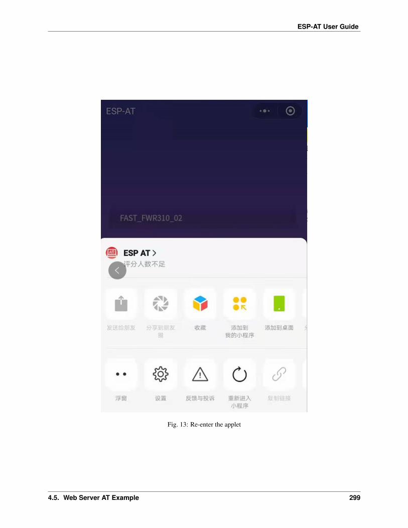
ESP-AT User Guide
Fig. 13: Re-enter the applet
4.5. Web Server AT Example 299

ESP-AT User Guide
Fig. 14: The applet starts the ESP device to connect to the router
300 Chapter 4. AT Command Examples

ESP-AT User Guide
Fig. 15: The applet Wi-Fi provisioning is successful
4.5. Web Server AT Example 301

ESP-AT User Guide
Fig. 16: The applet Wi-Fi provisioning is failed
302 Chapter 4. AT Command Examples

ESP-AT User Guide
+WEBSERVERRSP:1 // meaning that ESP device has received Wi-Fi connection→˓information, but failed to connect to the rounter.
The target AP to be accessed is the hotspot provided by the mobile phone which loading the WeChatapplet.
If the target AP to be accessed is the hotspot provided by the mobile phone which loading the WeChat applet, it isnot necessary to enter the ssid, but only needs to enter the password of the AP, and turn on the mobile AP in timeaccording to the prompts.
1.Select the “Local phone hotspot” option box on the WeChat applet page, enter the password of the local hotspot, andclick “Connect”.
Fig. 17: Enter the password of the AP
2.After receiving the prompt “Connecting to the mobile phone hotspot”, please check that the local mobile phonehotspot is turned on. At this time, the ESP device will automatically scan the surrounding hotspots and initiate aconnection.
4.5. Web Server AT Example 303

ESP-AT User Guide
Fig. 18: Start to connect to the AP
304 Chapter 4. AT Command Examples

ESP-AT User Guide
3.The display of the WiFi connection results on the applet page and the data output from the serial port are the sameas the above-mentioned “The target AP to be accessed is not the hotspot provided by the mobile phone which loadingthe WeChat applet.”, please refer to the above.
Troubleshooting
Note 1: The Wi-Fi provisioning page received a prompt “Data transmission failed”. Please check whether the Wi-FiAP of the ESP device is correctly turned on, and the relevant configuration of the AP, and confirm that the correct ATcommand has been entered to successfully enable the web server.
Note 2: The Wi-Fi provisioning page receives a prompt “Failed to connect to the AP”. Please check whether the Wi-Fi connection function of the mobile phone is turned on, check whether the Wi-Fi AP of the ESP device is correctlyturned on, and whether the ssid and password of the AP are configured according to the above steps.
Note 3: The Wi-Fi provisioning page receives a prompt “The Wi-Fi provisioning saved by the system expired”. Pleasemanually connect the ESP device AP with a mobile phone, and confirm that the ssid and password of the ESP modulehave been configured according to the above steps.
4.5.4 OTA Firmware Upgrade Using a WeChat Applet
The WeChat applet support online firmware upgrade , please refer to the above-described Configure ESP DeviceParameters specific steps performed ESP device configuration (if the configuration has been completed, do not repeatconfiguration). Once configured, the device performs OTA firmware upgrade processes is similar as OTA FirmwareUpgrade Using a Browser .
4.5.5 [ESP32][ESP32-C Series] Using Captive Portal
Introduction
Captive Portal is commonly used to present a specified page to newly connected devices of a Wi-Fi or wired network.For more information about Captive Portal, please refer to Captive Portal Wiki .
Note: The default firmware does not support web server Captive Portal, you may enable it by ./build.pymenuconfig > Component config > AT > AT WEB Server command support > AT WEB captiveportal support and build the project (see Compile ESP-AT Project). In addition, enabling this feature may causepage skipping when using wechat applet for Wi-Fi provisioning or OTA firmware upgrade. It is recommended thatthis feature be enabled only when accessing at web using browser.
Introduction to Operation Steps
After Enable Captive Portal support, please refer to Use STA Device to Connect to ESP Device to complete theconfiguration of the ESP device, and then connect to the AP of the ESP device:
As shown in the figure above, after the Station device is connected to the AP of the ESP device with the Captive Portalfunction enabled, it will prompt “requires login/authentication”, and then the browser will automatically open andjump to the main interface of AT Web. If it cannot be redirected automatically, please follow the instructions of theStation device, click “Authentication” or click the name of the “pos_softap” hotspot in the figure above to manuallytrigger the Captive Portal to automatically open the browser and enter the main interface of AT Web.
4.5. Web Server AT Example 305

ESP-AT User Guide
Fig. 19: Connect to the AP with Captive Portal enabled
Troubleshooting
Note 1: Both Station device and AP device support the Captive Portal function to ensure the normal use of this func-tion. Therefore, if the device is connected to the AP of the ESP device, but it does not prompt “Login/Authentication”,it may be that the Station device does not support this function. In this case, please refer to the specific steps of Usethe Browser to Send Wi-Fi Connection Information above to open the main interface of AT Web.
4.6 HTTP AT Examples
[]
This document provides detailed command examples to illustrate how to utilize HTTP AT Commands on ESP devices.
• The HEAD method of HTTP client
• The GET method of HTTP client
• The POST method of HTTP client (suitable for POST small amount of data)
• The POST method of HTTP client (recommended method)
• The PUT method of HTTP client
• The DELETE method of HTTP client
Important: Currently ESP-AT only supports some HTTP client functions.
4.6.1 The HEAD method of HTTP client
In this example, the HTTP server is http://httpbin.org.
1. Restore factory default settings of the module.
Command:
AT+RESTORE
Response:
306 Chapter 4. AT Command Examples

ESP-AT User Guide
OK
2. Set the Wi-Fi mode to station.
Command:
AT+CWMODE=1
Response:
OK
3. Connect to the router.
Command:
AT+CWJAP="espressif","1234567890"
Response:
WIFI CONNECTEDWIFI GOT IP
OK
Note:
• The SSID and password you entered may be different from those in the above command. Please replacethe SSID and password with those of your router settings.
4. Send an HTTP HEAD request. Set opt to 1 (HEAD method), url to http://httpbin.org/get andtransport_type to 1 (HTTP_TRANSPORT_OVER_TCP).
Command:
AT+HTTPCLIENT=1,0,"http://httpbin.org/get",,,1
Response:
+HTTPCLIENT:35, Date: Sun, 26 Sep 2021 06:59:13 GMT+HTTPCLIENT:30, Content-Type: application/json+HTTPCLIENT:19, Content-Length: 329+HTTPCLIENT:22, Connection: keep-alive+HTTPCLIENT:23, Server: gunicorn/19.9.0+HTTPCLIENT:30, Access-Control-Allow-Origin: *+HTTPCLIENT:38, Access-Control-Allow-Credentials: true
OK
Note:
• The HTTP header information you obtain may be different from those in the above response.
4.6. HTTP AT Examples 307

ESP-AT User Guide
4.6.2 The GET method of HTTP client
This example describes how to download an image file in JPG format. The image link is https://www.espressif.com/sites/all/themes/espressif/images/about-us/solution-platform.jpg.
1. Restore factory default settings of the module.
Command:
AT+RESTORE
Response:
OK
2. Set the Wi-Fi mode to station.
Command:
AT+CWMODE=1
Response:
OK
3. Connect to the router.
Command:
AT+CWJAP="espressif","1234567890"
Response:
WIFI CONNECTEDWIFI GOT IP
OK
Note:
• The SSID and password you entered may be different from those in the above command. Please replacethe SSID and password with those of your router settings.
4. Send an HTTP GET request. Set opt to 2 (GET method), url to https://www.espressif.com/sites/all/themes/espressif/images/about-us/solution-platform.jpg andtransport_type to 2 (HTTP_TRANSPORT_OVER_SSL).
Command:
AT+HTTPCLIENT=2,0,"https://www.espressif.com/sites/all/themes/espressif/images/→˓about-us/solution-platform.jpg",,,2
Response:
+HTTPCLIENT:512,<0xff><0xd8><0xff><0xe2><0x0c>XICC_PROFILE<break><0x01><0x01><break><break><0x0c>HLino<0x02><0x10><break><break>mntrRGB XYZ <0x07><0xce><break>
(continues on next page)
308 Chapter 4. AT Command Examples

ESP-AT User Guide
(continued from previous page)
<0x02><break>...+HTTPCLIENT:512,<0xeb><0xe2>v<0xcb><0x98>-<0xf8><0x8a><0xae><0xf3><0xc8><0xb6>→˓<0xa8><0x86><0x02>j<0x06><0xe2>"<0xaa>*p<0x7f>2",h<0x12>N<0xa5><0x1e><0xd2>bp<0xea><0x1e><0xf5><0xa3>x<0xa6>J→˓<0x14>Ti<0xc3>m<0x1a>m<0x94>T<0xe1>I<0xb6><0x90><0xdc>_<0x11>QU;<0x94><0x97>→˓<0xcb><0xdd><0xc7><0xc6><0x85><0xd7>U<0x02><0xc9>W<0xa4><0xaa><0xa1><0xa1><0x08>→˓hB<0x1a><0x10><0x86><0x84>!<0xa1><0x08>hB<0x1a><0x10><0x9b><0xb9>K<0xf5>5<0x95>→˓5-=<0x8a><0xcb><0xce><0xe0><0x91><0xf0>m<0xa9><0x04>C<0xde>k<0xe7><0xc2>v<H|→˓<0xaf><0xb8>L<0x91>=<0xda>_<0x94><0xde><0xd0><0xa9><0xc0><0xdd>8<0x9a>B<0xaa>→˓<0x1a><0x10><0x86><0x84>$<0xf4><0xd6><0xf2><0xa3><0x92><0xe7><0xa8>I<0xa3>b→˓<0x1f>)<0xe1>z<0xc4>y<0xae><0xca><0xed><0xec><0x1e>|^<0xd7>E<0xa2>_<0x13><0x9e>;→˓{|<0xb5>Q<0x97><0xa5>P<0xdf><0xa1>#3vn<0x1b><0xc3>-<0x92><0xe2>dIn<0x9c><0xb8><0xc7><0xa9><0xc6>(<0xe0><0xd3>i-<0x9e>@<0xbb><0xcc><0x88><0xd5>K<0xe3><0xf0>O→˓<0x9f>Km<0xb3>h<0xa8>omR<0xfe><0x8b><0xf9><0xa4><0xa6><0xff><break>aU<0xdf><0xf3><0xa3>:A<0xe2>UG<0x04>k<0xaa>*<0xa1><0xa1><0x0b><0xca><0xec><0xd8>Q→˓<0xfb><0xbc>yqY<0xec><0xfb>?<0x16>CM<0xf6>|}<0xae><0xf3><0x1e><0xdf>%<0xf8>→˓<0xe8><0xb1>B<0x8f>[<0xb3>><0x04><0xec><0xeb>f<0x06><0x1c><0xe8><0x92><0xc9>→˓<0x8c><0xb0>I<0xd1><0x8b>%<0x99><0x04><0xd0><0xbb>s<0x8b>xj<0xe2>4f<0xa0><0x8e>→˓+E<0xda><0xab><0xc7>=<0xab><0xc7><0xb9>xz1f<0xba><0xfd>_e6<0xff><break>(w<0xa7>b<0xe3>m<0xf0>|<0x82><0xc9><0xfb><0x8b><0xac>r<0x95><0x94><0x96><0xd9>i→˓<0xe9>RVA<0x91><0x83><0x8b>M'<0x86><0x8f><0xa3>A<0xd8><0xd8>"r"<0x8a><0xa8>→˓<0x9e>zl=<0xcd><0x16><0x07>D<0xa2><0xd0>u(<0xc2><0x8b><0x0b><0xc4><0xf1><0x87>→˓<0x9c><0x93><0x8f><0xe3><0xd5>U<0x12>]<0x8e><0x91>]<0x91><0x06>#l<0xbe><0xf4>t0?→˓<0xd7><0x85><GEM<0xb1>%<0xee>UUT<0xe7><0xdf><0xa0><0xb9><0xce><0xe2>U@<0x03>→˓<0x82>S<0xe9>*<0xa8>hB<0x1a><0x10><0xa1><0xaf>V<0x19>U<0x9d><0xb3>x<0xa6><0xc7>→˓<0xe2><0x86><0x8e>d[<0x89>e<0x05>l<0x80>H<0x91>#<0xd2><0x8c><0xe1>j<0x1b>rH→˓<0x04><0x89><0x98><0xd3>lZW]q><0xc2><';<0x93><0xb4><0xf5>&<0x9d><0xa0>^Wp<0xa9>→˓6`<0xe2>T<0xa2><0xc2><0xb1>*<0xbc><0x13><0x13><0xa0><0xc4>)<0x83><0xb6><0xbe>→˓<0x86><0xb9><0x88>-<0x1a>
OK
4.6.3 The POST method of HTTP client (suitable for POST small amount of data)
In this example, the HTTP server is http://httpbin.org and the data type is application/json.
1. Restore factory default settings of the module.
Command:
AT+RESTORE
Response:
OK
2. Set the Wi-Fi mode to station.
Command:
AT+CWMODE=1
Response:
4.6. HTTP AT Examples 309

ESP-AT User Guide
OK
3. Connect to the router.
Command:
AT+CWJAP="espressif","1234567890"
Response:
WIFI CONNECTEDWIFI GOT IP
OK
Note:
• The SSID and password you entered may be different from those in the above command. Please replacethe SSID and password with those of your router settings.
4. Send an HTTP POST request. Set opt to 3 (POST method), url to http://httpbin.org/post,content-type to 1 (application/json) and transport_type to 1 (HTTP_TRANSPORT_OVER_TCP).
Command:
AT+HTTPCLIENT=3,1,"http://httpbin.org/post",,,1,"{\"form\":{\"purpose\":\"test\"}}→˓"
Response:
+HTTPCLIENT:282,{"args": {},"data": "{\"form\":{\"purpose\":\"test\"}}","files": {},"form": {},"headers": {
"Content-Length": "27","Content-Type": "application/json","Host": "httpbin.org","User-Agent": "ESP32 HTTP Client/1.0","X-Amzn-Trace-Id": "Root=
+HTTPCLIENT:173,1-61503a3f-4b16b71918855b97614c5dfb"},"json": {
"form": {"purpose": "test"
}},"origin": "20.187.154.207","url": "http://httpbin.org/post"
}
OK
Note:
• The results you obtain may be different from those in the above response.
310 Chapter 4. AT Command Examples

ESP-AT User Guide
4.6.4 The POST method of HTTP client (recommended method)
If the amount of data you post is relatively large, and the length of a single AT command has exceeded the thresholdof 256, it is recommended that you use the AT+HTTPCPOST command.
In this example, the HTTP server is http://httpbin.org and the data type is application/json.
1. Restore factory default settings of the module.
Command:
AT+RESTORE
Response:
OK
2. Set the Wi-Fi mode to station.
Command:
AT+CWMODE=1
Response:
OK
3. Connect to the router.
Command:
AT+CWJAP="espressif","1234567890"
Response:
WIFI CONNECTEDWIFI GOT IP
OK
Note:
• The SSID and password you entered may be different from those in the above command. Please replacethe SSID and password with those of your router settings.
4. Post HTTP data of specified length. The command specifies that the number of HTTP header fields is 2,which are connection field and content-type field respectively. connection is keep-alive andcontent-type is application/json.
Assume the JSON data you want to post is as follows, length is 472 bytes.
{"headers": {"Accept": "application/json","Accept-Encoding": "gzip, deflate",→˓"Accept-Language": "en-US,en;q=0.9,zh-CN;q=0.8,zh;q=0.7","Content-Length": "0",→˓"Host": "httpbin.org","Origin": "http://httpbin.org","Referer": "http://httpbin.→˓org/","User-Agent": "Mozilla/5.0 (X11; Linux x86_64) AppleWebKit/537.36 (KHTML,→˓like Gecko) Chrome/91.0.4472.114 Safari/537.36","X-Amzn-Trace-Id": "Root=1-→˓6150581e-1ad4bd5254b4bf5218070413"}}
Command:
4.6. HTTP AT Examples 311

ESP-AT User Guide
AT+HTTPCPOST="http://httpbin.org/post",427,2,"connection: keep-alive","content-→˓type: application/json"
Response:
OK
>
This response indicates that AT is ready for receiving serial data. You should enter the data, and when the datalength reaches the <length> value, the transmission of data starts.
+HTTPCPOST:281,{"args": {},"data": "{\"headers\": {\"Accept\": \"application/json\",\"Accept-Encoding\": \
→˓"gzip, deflate\",\"Accept-Language\": \"en-US,en;q=0.9,zh-CN;q=0.8,zh;q=0.7\",\→˓"Content-Length\": \"0\",\"Host\": \"httpbin.org\",\"Origin\": \"http://httpbin.→˓org\",\"Referer\": \"htt+HTTPCPOST:512,p://httpbin.org/\",\"User-Agent\": \"Mozilla/5.0 (X11; Linux x86_→˓64) AppleWebKit/537.36 (KHTML, like Gecko) Chrome/91.0.4472.114 Safari/537.36\",→˓\"X-Amzn-Trace-Id\": \"Root=1-6150581e-1ad4bd5254b4bf5218070413\"}}","files": {},"form": {},"headers": {
"Content-Length": "427","Content-Type": "application/json","Host": "httpbin.org","User-Agent": "ESP32 HTTP Client/1.0","X-Amzn-Trace-Id": "Root=1-61505e76-278b5c267aaf55842bd58b32"
},"json": {
"headers": {
+HTTPCPOST:512,"Accept": "application/json","Accept-Encoding": "gzip, deflate","Accept-Language": "en-US,en;q=0.9,zh-CN;q=0.8,zh;q=0.7","Content-Length": "0","Host": "httpbin.org","Origin": "http://httpbin.org","Referer": "http://httpbin.org/","User-Agent": "Mozilla/5.0 (X11; Linux x86_64) AppleWebKit/537.36 (KHTML,
→˓like Gecko) Chrome/91.0.4472.114 Safari/537.36","X-Amzn-Trace-Id": "Root=1-6150581e-1ad4bd5254b4bf5218070413"
}},"origin": "20.187.154
+HTTPCPOST:45,.207","url": "http://httpbin.org/post"
}
SEND OK
Note:
• After AT outputs the > character, the special characters in the HTTP body does not need to be escapedthrough the escape character, and it does not need to end with a new line(CR-LF).
312 Chapter 4. AT Command Examples

ESP-AT User Guide
4.6.5 The PUT method of HTTP client
In this example, the HTTP server is http://httpbin.org. PUT request supports Query String Parameters mode.
1. Restore factory default settings of the module.
Command:
AT+RESTORE
Response:
OK
2. Set the Wi-Fi mode to station.
Command:
AT+CWMODE=1
Response:
OK
3. Connect to the router.
Command:
AT+CWJAP="espressif","1234567890"
Response:
WIFI CONNECTEDWIFI GOT IP
OK
Note:
• The SSID and password you entered may be different from those in the above command. Please replacethe SSID and password with those of your router settings.
4. Send an HTTP PUT request. Set opt to 4 (PUT method), url to http://httpbin.org/put, andtransport_type to 1 (HTTP_TRANSPORT_OVER_TCP).
Command:
AT+HTTPCLIENT=4,0,"http://httpbin.org/put?user=foo",,,1
Response:
+HTTPCLIENT:282,{"args": {
"user": "foo"},"data": "","files": {},"form": {},"headers": {
"Content-Length": "0",
(continues on next page)
4.6. HTTP AT Examples 313

ESP-AT User Guide
(continued from previous page)
"Content-Type": "application/x-www-form-urlencoded","Host": "httpbin.org","User-Agent": "ESP32 HTTP Client/1.0","X-Amzn-Trace-Id": "R
+HTTPCLIENT:140,oot=1-61503d41-1dd8cbe0056190f721ab1912"},"json": null,"origin": "20.187.154.207","url": "http://httpbin.org/put?user=foo"
}
OK
Note:
• The results you obtain may be different from those in the above response.
4.6.6 The DELETE method of HTTP client
In this example, the HTTP server is http://httpbin.org. The DELETE method is used to delete resources on a server.The exact use of DELETE requests depends on the server implementation.
1. Restore factory default settings of the module.
Command:
AT+RESTORE
Response:
OK
2. Set the Wi-Fi mode to station.
Command:
AT+CWMODE=1
Response:
OK
3. Connect to the router.
Command:
AT+CWJAP="espressif","1234567890"
Response:
WIFI CONNECTEDWIFI GOT IP
OK
Note:
314 Chapter 4. AT Command Examples

ESP-AT User Guide
• The SSID and password you entered may be different from those in the above command. Please replacethe SSID and password with those of your router settings.
4. Send an HTTP DELETE request. Set opt to 5 (DELETE method), url to http://httpbin.org/delete, and transport_type to 1 (HTTP_TRANSPORT_OVER_TCP).
Command:
AT+HTTPCLIENT=5,0,"https://httpbin.org/delete",,,1
Response:
+HTTPCLIENT:282,{"args": {},"data": "","files": {},"form": {},"headers": {
"Content-Length": "0","Content-Type": "application/x-www-form-urlencoded","Host": "httpbin.org","User-Agent": "ESP32 HTTP Client/1.0","X-Amzn-Trace-Id": "Root=1-61504289-468a41
+HTTPCLIENT:114,737b0d251672acec9d"},"json": null,"origin": "20.187.154.207","url": "https://httpbin.org/delete"
}
OK
Note:
• The results you obtain may be different from those in the above response.
4.7 [ESP32 Only] Classic Bluetooth AT Examples
[]
This document provides detailed command examples to illustrate how to utilize [ESP32 Only] Classic Bluetooth® ATCommands on ESP devices.
• Establish SPP connection between phone (or PC) and ESP32 in Normal Transmission mode with IO capa-bility set to NoInputNoOutput
• Establish SPP connection between phone (or PC) and ESP32 in Passthrough mode with IO capability set toNoInputNoOutput
• Establish SPP connection between phone (or PC) and ESP32 with IO capability set to KeyboardOnly
• Establish SPP connection between two ESP32 development boards
• Establish A2DP connection and enable A2DP Sink to play music
• Query and clear Classic Bluetooth encryption device list
4.7. [ESP32 Only] Classic Bluetooth AT Examples 315

ESP-AT User Guide
Important: The default firmware does not support Classic Bluetooth commands, please refer to How to EnableESP-AT Classic Bluetooth to enable Classic Bluetooth commands.
4.7.1 Establish SPP connection between phone (or PC) and ESP32 in Normal Trans-mission mode with IO capability set to NoInputNoOutput
In this example, mobile phone or PC is master and ESP32 is slave. The example shows how to establish SPP connec-tion.
1. Classic Bluetooth initialization.
Command:
AT+BTINIT=1
Response:
OK
2. Classic Bluetooth SPP profile initialization, and the role is set to slave.
Command:
AT+BTSPPINIT=2
Response:
OK
3. Set Classic Bluetooth device name.
Command:
AT+BTNAME="EXAMPLE"
Response:
OK
4. Set Classic Bluetooth scan mode to discoverable and connectable.
Command:
AT+BTSCANMODE=2
Response:
OK
5. Set Classic Bluetooth security parameters. Set io_cap to NoInputNoOutput, pin_type to fixed,pin_code to 9527.
Command:
AT+BTSECPARAM=3,1,"9527"
Response:
316 Chapter 4. AT Command Examples

ESP-AT User Guide
OK
6. Start Classic Bluetooth SPP profile.
Command:
AT+BTSPPSTART
Response:
OK
7. The mobile phone or PC initiates the connection.
The mobile phone or PC should be able to find the Bluetooth device with name “EXAMPLE”. If the mobilephone or PC initiates a connection and the connection is established successfully, ESP32 will prompt:
+BTSPPCONN:0,"e0:24:81:47:90:bc"
Note:
• The address you obtained may be different from that in the above response.
8. Send 4 bytes of data.
Command:
AT+BTSPPSEND=0,4
Response:
>
The symbol > indicates that AT is ready for receiving serial data and you can enter data now. When the require-ment of data length determined by the parameter <data_len> is met, the writing starts.
Input 4 bytes, for example, test, then AT will respond the following message.
OK
Note:
• If the number of bytes inputted are more than the length (n) set by AT+BTSPPSEND, the system will replybusy p..., and send the first n bytes. And after sending the first n bytes, the system will reply OK.
• After AT outputs the > character, the special characters in the data does not need to be escaped through theescape character, and it does not need to end with a new line (CR-LF).
9. Receive 4 bytes of data.
Assume that mobile phone or PC sends 4 bytes of data (data is test), the system will prompt:
+BTDATA:4,test
10. Terminate Classic Bluetooth SPP connection.
Command:
AT+BTSPPDISCONN=0
Response:
4.7. [ESP32 Only] Classic Bluetooth AT Examples 317

ESP-AT User Guide
+BTSPPDISCONN:0,"e0:24:81:47:90:bc"
OK
Note:
• The address you obtained may be different from that in the above response.
4.7.2 Establish SPP connection between phone (or PC) and ESP32 in Passthroughmode with IO capability set to NoInputNoOutput
In this example, mobile phone or PC is master and ESP32 is slave. The example shows how to establish SPP connec-tion.
1. Classic Bluetooth initialization.
Command:
AT+BTINIT=1
Response:
OK
2. Classic Bluetooth SPP profile initialization, and the role is set to slave.
Command:
AT+BTSPPINIT=2
Response:
OK
3. Set Classic Bluetooth device name.
Command:
AT+BTNAME="EXAMPLE"
Response:
OK
4. Set Classic Bluetooth scan mode to discoverable and connectable.
Command:
AT+BTSCANMODE=2
Response:
OK
5. Set Classic Bluetooth security parameters. Set io_cap to NoInputNoOutput, pin_type to fixed,pin_code to 9527.
Command:
318 Chapter 4. AT Command Examples

ESP-AT User Guide
AT+BTSECPARAM=3,1,"9527"
Response:
OK
6. Start Classic Bluetooth SPP profile.
Command:
AT+BTSPPSTART
Response:
OK
7. The mobile phone or PC initiates the connection.
The mobile phone or PC should be able to find the Bluetooth device with name “EXAMPLE”. If the mobilephone or PC initiates a connection and the connection is established successfully, ESP32 will prompt:
+BTSPPCONN:0,"e0:24:81:47:90:bc"
Note:
• The address you obtained may be different from that in the above response.
8. Send data in Passthrough Mode.
Command:
AT+BTSPPSEND
Response:
OK
>
This response indicates that AT has entered Passthrough Mode.
Note:
• After the AT enters Passthrough Mode, data received from serial port will be transmitted to the mobilephone or PC.
9. Stop sending data.
When receiving a packet that contains only +++, the Passthrough Mode will be stopped. Then please wait atleast 1 second before sending next AT command. Please be noted that if you input +++ directly by typing, the+++ may not be recognised as three consecutive + because of the prolonged typing duration. For more details,please refer to AT+BTSPPSEND.
Important: The aim of ending the packet with +++ is to exit Passthrough Mode and to accept normal ATcommands. However, you can also use command AT+BTSPPSEND to go back into Passthrough Mode.
10. Terminate Classic Bluetooth SPP connection.
Command:
4.7. [ESP32 Only] Classic Bluetooth AT Examples 319

ESP-AT User Guide
AT+BTSPPDISCONN=0
Response:
+BTSPPDISCONN:0,"e0:24:81:47:90:bc"
OK
Note:
• The address you obtained may be different from that in the above response.
4.7.3 Establish SPP connection between phone (or PC) and ESP32 with IO capabil-ity set to KeyboardOnly
The process is basically the same as in the Establish SPP connection between phone (or PC) and ESP32 in Nor-mal Transmission mode with IO capability set to NoInputNoOutput. The only difference lies in security parameterssettings.
1. Classic Bluetooth initialization.
Command:
AT+BTINIT=1
Response:
OK
2. Classic Bluetooth SPP profile initialization, and the role is set to slave.
Command:
AT+BTSPPINIT=2
Response:
OK
3. Set Classic Bluetooth device name.
Command:
AT+BTNAME="EXAMPLE"
Response:
OK
4. Set Classic Bluetooth scan mode to discoverable and connectable.
Command:
AT+BTSCANMODE=2
Response:
320 Chapter 4. AT Command Examples

ESP-AT User Guide
OK
5. Set Classic Bluetooth security parameters. Set io_cap to KeyboardOnly, pin_type to variable,pin_code to 9527.
Command:
AT+BTSECPARAM=2,0,"9527"
Response:
OK
6. Start Classic Bluetooth SPP profile.
Command:
AT+BTSPPSTART
Response:
OK
7. The mobile phone or PC initiates the connection.
The mobile phone or PC can initiate a connection and generate a PIN code, then you can enter the PIN code onthe ESP32.
AT+BTKEYREPLY=0,676572
If the connection is established successfully, the system will prompt:
+BTSPPCONN:0,"e0:24:81:47:90:bc"
Note:
• The PIN code you entered may be different from those in the above command. Please use the real PINinstead.
• The address you obtained may be different from that in the above response.
8. Terminate Classic Bluetooth SPP connection.
Command:
AT+BTSPPDISCONN=0
Response:
+BTSPPDISCONN:0,"e0:24:81:47:90:bc"
OK
Note:
• The address you obtained may be different from that in the above response.
4.7. [ESP32 Only] Classic Bluetooth AT Examples 321
ESP-AT User Guide
4.7.4 Establish SPP connection between two ESP32 development boards
Below is an example of using two ESP32 development boards, one as master, the other one as slave.
Important: In the following steps, the operations starting with Master only need to be executed at master, and theoperations starting with Slave only need to be executed at slave. If the operation is not specified on which side it isexecuted, it needs to be executed on both the master side and the slave side.
1. Classic Bluetooth initialization.
Command:
AT+BTINIT=1
Response:
OK
2. Classic Bluetooth SPP profile initialization.
Master:
Command:
AT+BTSPPINIT=1
Response:
OK
Slave:
Command:
AT+BTSPPINIT=2
Response:
OK
3. Set Classic Bluetooth device name.
Slave:
Command:
AT+BTNAME="EXAMPLE"
Response:
OK
4. Set Classic Bluetooth scan mode to discoverable and connectable.
Slave:
Command:
322 Chapter 4. AT Command Examples
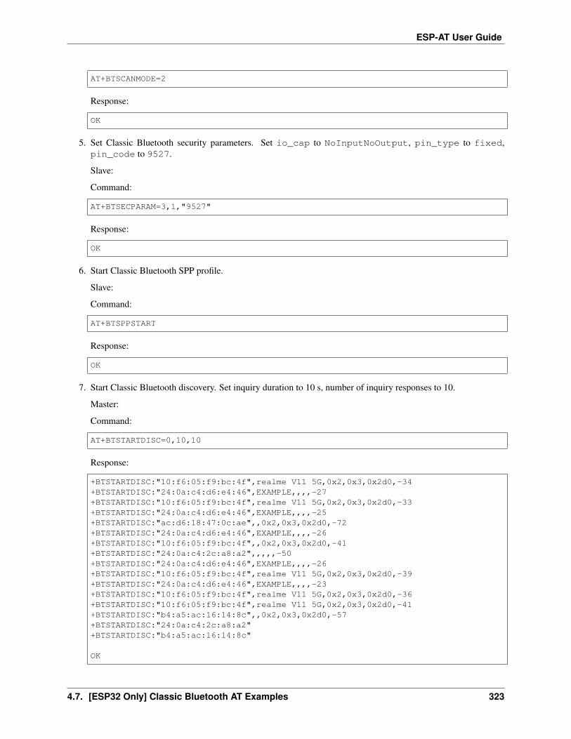
ESP-AT User Guide
AT+BTSCANMODE=2
Response:
OK
5. Set Classic Bluetooth security parameters. Set io_cap to NoInputNoOutput, pin_type to fixed,pin_code to 9527.
Slave:
Command:
AT+BTSECPARAM=3,1,"9527"
Response:
OK
6. Start Classic Bluetooth SPP profile.
Slave:
Command:
AT+BTSPPSTART
Response:
OK
7. Start Classic Bluetooth discovery. Set inquiry duration to 10 s, number of inquiry responses to 10.
Master:
Command:
AT+BTSTARTDISC=0,10,10
Response:
+BTSTARTDISC:"10:f6:05:f9:bc:4f",realme V11 5G,0x2,0x3,0x2d0,-34+BTSTARTDISC:"24:0a:c4:d6:e4:46",EXAMPLE,,,,-27+BTSTARTDISC:"10:f6:05:f9:bc:4f",realme V11 5G,0x2,0x3,0x2d0,-33+BTSTARTDISC:"24:0a:c4:d6:e4:46",EXAMPLE,,,,-25+BTSTARTDISC:"ac:d6:18:47:0c:ae",,0x2,0x3,0x2d0,-72+BTSTARTDISC:"24:0a:c4:d6:e4:46",EXAMPLE,,,,-26+BTSTARTDISC:"10:f6:05:f9:bc:4f",,0x2,0x3,0x2d0,-41+BTSTARTDISC:"24:0a:c4:2c:a8:a2",,,,,-50+BTSTARTDISC:"24:0a:c4:d6:e4:46",EXAMPLE,,,,-26+BTSTARTDISC:"10:f6:05:f9:bc:4f",realme V11 5G,0x2,0x3,0x2d0,-39+BTSTARTDISC:"24:0a:c4:d6:e4:46",EXAMPLE,,,,-23+BTSTARTDISC:"10:f6:05:f9:bc:4f",realme V11 5G,0x2,0x3,0x2d0,-36+BTSTARTDISC:"10:f6:05:f9:bc:4f",realme V11 5G,0x2,0x3,0x2d0,-41+BTSTARTDISC:"b4:a5:ac:16:14:8c",,0x2,0x3,0x2d0,-57+BTSTARTDISC:"24:0a:c4:2c:a8:a2"+BTSTARTDISC:"b4:a5:ac:16:14:8c"
OK
4.7. [ESP32 Only] Classic Bluetooth AT Examples 323

ESP-AT User Guide
Note:
• The discovery results you obtain may be different from those in the above response.
8. Establish SPP connection.
Master:
Command:
AT+BTSPPCONN=0,0,"24:0a:c4:d6:e4:46"
Response:
+BTSPPCONN:0,"24:0a:c4:d6:e4:46"
OK
Note:
• When entering the above command, replace the address with slave address.
• If the SPP connection is established successfully, message +BTSPPCONN:0,"30:ae:a4:80:06:8e"will be prompted on the slave.
9. Terminate Classic Bluetooth SPP connection.
Slave:
Command:
AT+BTSPPDISCONN=0
Response:
+BTSPPDISCONN:0,"30:ae:a4:80:06:8e"
OK
Note:
• Both master and slave can actively terminate the SPP connection.
• If the SPP connection is ended successfully, message +BTSPPDISCONN:0,"24:0a:c4:d6:e4:46"will be prompted on the master.
4.7.5 Establish A2DP connection and enable A2DP Sink to play music
Important:
• To use A2DP Sink, you need to add the code of the I2S part by yourself. For the code to initialize the I2Spart, please refer to a2dp sink example.
• The driver code of the decoder chip part also needs to be added by yourself or use an off-the-shelf developmentboard.
1. Classic Bluetooth initialization.
Command:
324 Chapter 4. AT Command Examples

ESP-AT User Guide
AT+BTINIT=1
Response:
OK
2. Classic Bluetooth A2DP profile initialization, and the role is set to sink.
Command:
AT+BTA2DPINIT=2
Response:
OK
3. Set Classic Bluetooth device name.
Command:
AT+BTNAME="EXAMPLE"
Response:
OK
4. Set Classic Bluetooth scan mode to discoverable and connectable.
Command:
AT+BTSCANMODE=2
Response:
OK
5. Establish connection.
The source role should be able to find the Bluetooth device with name “EXAMPLE”. In this example, you canuse your mobile phone to initiate a connection. If the connection is established successfully, ESP32 will prompt:
+BTA2DPCONN:0,"e0:24:81:47:90:bc"
Note:
• The address you obtained may be different from that in the above response.
6. Start playing music.
Command:
AT+BTA2DPCTRL=0,1
Response:
OK
Note:
• For more types of control, please refer to AT+BTA2DPCTRL.
4.7. [ESP32 Only] Classic Bluetooth AT Examples 325

ESP-AT User Guide
7. Stop playing music.
Command:
AT+BTA2DPCTRL=0,0
Response:
OK
Note:
• For more types of control, please refer to AT+BTA2DPCTRL.
8. Terminate A2DP connection.
Command:
AT+BTA2DPDISCONN=0
Response:
OK+BTA2DPDISCONN:0,"e0:24:81:47:90:bc"
4.7.6 Query and clear Classic Bluetooth encryption device list
1. Get the encryption device list.
Command:
AT+BTENCDEV?
Response:
+BTA2DPDISCONN:0,"e0:24:81:47:90:bc"OK
Note:
• If no device has been successfully bound before, AT will only prompt OK.
2. Clear Classic Bluetooth encryption device list.
There are two ways to clear encryption device list.
1. Remove a device from the encryption device list with a specific index.
Command:
AT+BTENCCLEAR=0
Response:
OK
2. Remove all devices from the encryption device list.
Command:
326 Chapter 4. AT Command Examples

ESP-AT User Guide
AT+BTENCCLEAR
Response:
OK
4.8 Sleep AT Examples
[]
This document provides an introduction and detailed command examples to illustrate how to utilize AT commands toset sleep modes on ESP32 and ESP32-C3 series of products.
• Introduction
• Set Modem-sleep mode in Wi-Fi mode
• Set Light-sleep mode in Wi-Fi mode
• Set Modem-sleep mode in Bluetooth LE advertising mode
• Set Modem-sleep mode in Bluetooth LE connection mode
• Set Light-sleep mode in Bluetooth LE advertising mode
• Set Light-sleep mode in Bluetooth LE connection mode
• Set Deep-sleep mode
4.8.1 Introduction
With the use of advanced power-management technologies, ESP32 and ESP32-C3 series can switch between differentpower modes. Currently, ESP-AT supports the following four power consumption modes (for more sleep modes,please refer to the datasheet):
1. Active Mode: CPU and chip radio are powered on. The chip can receive, transmit, or listen.
2. Modem-sleep Mode: The CPU is operational and the clock speed can be reduced. Wi-Fi baseband, BluetoothLE baseband, and radio are disabled, but Wi-Fi and Bluetooth LE connection can remain active.
3. Light-sleepMode: The CPU is paused. Any wake-up events (MAC, host, RTC timer, or external interrupts)will wake up the chip. Wi-Fi and Bluetooth LE connection can remain active.
4. Deep-sleep Mode: CPU and most peripherals are powered down. Only the RTC memory is powered on.
By default, ESP32 and ESP32-C3 will enter Active mode after system reset. When the CPU does not need to workall the time, such as waiting for external activities to wake up, the system can enter low-power modes.
For current consumption of ESP32 and ESP32-C3, please refer to ESP32 Series Datasheet and ESP32-C3 SeriesDatasheet.
Note:
• Setting ESP32 and ESP32-C3 to sleep modes in Wi-Fi mode and Bluetooth LE mode will be described sepa-rately.
4.8. Sleep AT Examples 327

ESP-AT User Guide
• In single Wi-Fi mode, only station mode supports Modem-sleep mode and Light-sleep mode.
• For Light-sleep mode in Bluetooth LE mode, please ensure that there is an external 32 KHz crystal oscillator. Ifthere is no external 32 KHz crystal oscillator, ESP-AT will work as the Modem-sleep mode.
Measurement Method
In order to avoid some unnecessary interference during the power consumption test process, it is recommended to usethe Espressif modules that integrate the chip for the test.
Refer to the following for hardware connection.
1. ESP32 series
Fig. 20: ESP32 Hardware Connection
2. ESP32-C3 series
328 Chapter 4. AT Command Examples

ESP-AT User Guide
Fig. 21: ESP32-C3 Hardware Connection
4.8. Sleep AT Examples 329

ESP-AT User Guide
4.8.2 Set Modem-sleep mode in Wi-Fi mode
1. Set the Wi-Fi mode to station mode.
Command:
AT+CWMODE=1
Response:
OK
2. Connect to an router.
Command:
AT+CWJAP="espressif","1234567890"
Response:
WIFI CONNECTEDWIFI GOT IP
OK
Note:
• The SSID and password you entered may be different from those in the above command. Please replacethe SSID and password with those of your router settings.
3. Set the sleep mode to Modem-sleep mode.
Command:
AT+SLEEP=1
Response:
OK
Note:
• RF will be periodically closed according to AP DTIM (routers generally set DTIM to 1).
• When the CPU frequency of ESP32 is 80 MHz and the module is in single Wi-Fi mode, the average current inModem-sleep mode is about 21 mA.
• When the CPU frequency of ESP32-C3 is 160 MHz and the module is in single Wi-Fi mode, the average currentin Modem-sleep mode is about 20 mA.
330 Chapter 4. AT Command Examples

ESP-AT User Guide
4.8.3 Set Light-sleep mode in Wi-Fi mode
1. Set the Wi-Fi mode to station mode.
Command:
AT+CWMODE=1
Response:
OK
2. Connect to an router. Set listen interval to 3.
Command:
AT+CWJAP="espressif","1234567890",,,,3
Response:
WIFI CONNECTEDWIFI GOT IP
OK
Note:
• The SSID and password you entered may be different from those in the above command. Please replacethe SSID and password with those of your router settings.
3. Set the sleep mode to Light-sleep mode.
Command:
AT+SLEEP=2
Response:
OK
Note:
• CPU will automatically sleep and RF will be periodically closed according to listen interval set by AT+CWJAP.
• When the module of ESP32 is in single Wi-Fi mode, the average current in Light-sleep mode is about 0.8 mA.
• When the module of ESP32-C3 is in single Wi-Fi mode, the average current in Light-sleep mode is about 130uA.
4.8. Sleep AT Examples 331

ESP-AT User Guide
4.8.4 Set Modem-sleep mode in Bluetooth LE advertising mode
1. Initialize the role of Bluetooth LE as server.
Command:
AT+BLEINIT=2
Response:
OK
2. Set parameters of Bluetooth LE advertising. Set Bluetooth LE advertising interval to 1 s.
Command:
AT+BLEADVPARAM=1600,1600,0,0,7,0,0,"00:00:00:00:00:00"
Response:
OK
3. Start Bluetooth LE advertising.
Command:
AT+BLEADVSTART
Response:
OK
4. Disable Wi-Fi.
Command:
AT+CWMODE=0
Response:
OK
5. Set the sleep mode to Modem-sleep mode.
Command:
AT+SLEEP=1
Response:
OK
Note:
• When the CPU frequency of ESP32 is 80 MHz and the module in single Bluetooth LE advertising mode, theaverage current in Modem-sleep mode is about 23 mA.
• When the CPU frequency of ESP32-C3 is 160 MHz and the module in single Bluetooth LE advertising mode,the average current in Modem-sleep mode is about 20 mA.
332 Chapter 4. AT Command Examples

ESP-AT User Guide
4.8.5 Set Modem-sleep mode in Bluetooth LE connection mode
1. Initialize the role of Bluetooth LE as server.
Command:
AT+BLEINIT=2
Response:
OK
2. Start Bluetooth LE advertising.
Command:
AT+BLEADVSTART
Response:
OK
3. Waiting for connection.
If the connection is established successfully, AT will prompt:
+BLECONN:0,"47:3f:86:dc:e4:7d"+BLECONNPARAM:0,0,0,6,0,500+BLECONNPARAM:0,0,0,24,0,500
OK
Note:
• In this example, Bluetooth LE client address is 47:3f:86:dc:e4:7d.
• For prompt information (+BLECONN and +BLECONNPARAM), please refer to AT+BLECONN andAT+BLECONNPARAM for more details.
4. Update parameters of Bluetooth LE connection. Set Bluetooth LE connection interval to 1 s.
Command:
AT+BLECONNPARAM=0,800,800,0,500
Response:
OK
If the connection parameters are updated successfully, AT will output:
+BLECONNPARAM:0,800,800,800,0,500
Note:
• For prompt information (+BLECONNPARAM), please refer to AT+BLECONNPARAM for more details.
5. Disable Wi-Fi.
Command:
4.8. Sleep AT Examples 333

ESP-AT User Guide
AT+CWMODE=0
Response:
OK
6. Set the sleep mode to Modem-sleep mode.
Command:
AT+SLEEP=1
Response:
OK
Note:
• When the CPU frequency of ESP32 is 80 MHz and the module in single Bluetooth LE connection mode, theaverage current in Modem-sleep mode is about 23 mA.
• When the CPU frequency of ESP32-C3 is 160 MHz and the module in single Bluetooth LE connection mode,the average current in Modem-sleep mode is about 20 mA.
4.8.6 Set Light-sleep mode in Bluetooth LE advertising mode
1. Initialize the role of Bluetooth LE as server.
Command:
AT+BLEINIT=2
Response:
OK
2. Set parameters of Bluetooth LE advertising. Set Bluetooth LE advertising interval to 1 s.
Command:
AT+BLEADVPARAM=1600,1600,0,0,7,0,0,"00:00:00:00:00:00"
Response:
OK
3. Start Bluetooth LE advertising.
Command:
AT+BLEADVSTART
Response:
OK
334 Chapter 4. AT Command Examples

ESP-AT User Guide
4. Disable Wi-Fi.
Command:
AT+CWMODE=0
Response:
OK
5. Set the sleep mode to Light-sleep mode.
Command:
AT+SLEEP=2
Response:
OK
Note:
• When the module of ESP32 in single Bluetooth LE advertising mode, the average current in Light-sleep modeis about 0.8 mA.
• When the module of ESP32-C3 in single Bluetooth LE advertising mode, the average current in Light-sleepmode is about 130 uA.
4.8.7 Set Light-sleep mode in Bluetooth LE connection mode
1. Initialize the role of Bluetooth LE as server.
Command:
AT+BLEINIT=2
Response:
OK
2. Start Bluetooth LE advertising.
Command:
AT+BLEADVSTART
Response:
OK
3. Waiting for connection.
If the connection is established successfully, AT will prompt:
4.8. Sleep AT Examples 335

ESP-AT User Guide
+BLECONN:0,"47:3f:86:dc:e4:7d"+BLECONNPARAM:0,0,0,6,0,500+BLECONNPARAM:0,0,0,24,0,500
OK
Note:
• In this example, Bluetooth LE client address is 47:3f:86:dc:e4:7d.
• For prompt information (+BLECONN and +BLECONNPARAM), please refer to AT+BLECONN andAT+BLECONNPARAM for more details.
4. Update parameters of Bluetooth LE connection. Set Bluetooth LE connection interval to 1 s.
Command:
AT+BLECONNPARAM=0,800,800,0,500
Response:
OK
If the connection parameters are updated successfully, AT will output:
+BLECONNPARAM:0,800,800,800,0,500
Note:
• For prompt information (+BLECONNPARAM), please refer to AT+BLECONNPARAM for more details.
5. Disable Wi-Fi.
Command:
AT+CWMODE=0
Response:
OK
6. Set the sleep mode to Light-sleep mode.
Command:
AT+SLEEP=2
Response:
OK
Note:
• When the module of ESP32 in single Bluetooth LE connection mode, the average current in Light-sleep modeis about 0.8 mA.
• When the module of ESP32-C3 in single Bluetooth LE connection mode, the average current in Light-sleepmode is about 130 uA.
336 Chapter 4. AT Command Examples

ESP-AT User Guide
4.8.8 Set Deep-sleep mode
1. Set the sleep mode to Deep-sleep mode. Set the deep-sleep time to 3600000 ms.
Command:
AT+GSLP=3600000
Response:
OK
Note:
• When the time is up, the device automatically wakes up, calls Deep-sleep wake stub, and then proceeds toload the application.
• For Deep-sleep mode, the only wake-up method is timed wake-up.
Note:
• When the module of ESP32 in Deep-sleep mode, the average current in Deep-sleep mode is about 10 uA.
• When the module of ESP32-C3 in Deep-sleep mode, the average current in Deep-sleep mode is about 5 uA.
4.8. Sleep AT Examples 337

ESP-AT User Guide
338 Chapter 4. AT Command Examples

CHAPTER
FIVE
HOW TO COMPILE AND DEVELOP YOUR OWN AT PROJECT
[]
5.1 Compile ESP-AT Project
[]
This document details how to build your own ESP-AT project and flash the generated firmware into your ESP devices,including ESP32, and ESP32-C3. It comes in handy when the official released fimware cannot meet your needs, forexample, to customize the AT port pins, Bluetooth LE services, and partitions, and so on.
The structure of this document is as follows:
• Overview: Overview of the steps to build an ESP-AT project.
• ESP32 and ESP32-C3 Series: Details steps to build a project for ESP32, and ESP32-C3 series.
5.1.1 Overview
Before compiling an ESP-AT project, you need first get started with ESP-IDF and set up the environment for ESP-IDF,because ESP-AT is based on ESP-IDF.
After the environment is ready, install the tools and ESP-AT SDK. Then, connect your ESP device to PC. Use ./build.py menuconfig to set up some configuration for the project. Build the project and flash the generated binfiles onto your ESP device.
Note: Please pay attention to possible conflicts of pins. If choosing AT through HSPI, you can get the informa-tion of the HSPI pin by ./build.py menuconfig –> Component config –> AT –> AT hspi settings.
5.1.2 ESP32 and ESP32-C3 Series
This section describes how to compile an ESP-AT project for ESP32 and ESP32-C3 series.
339

ESP-AT User Guide
Get Started with ESP-IDF
Get started with ESP-IDF before compiling an ESP-AT project, because ESP-AT is developed based on ESP-IDF, andthe supported version varies from series to series:
Table 1: ESP-IDF Versions for Different SeriesProject IDF Version IDF Documentation VersionESP32 ESP-AT release/v4.2 ESP-IDF Get Started Guide v4.2ESP32-C3 ESP-AT release/v4.3 ESP-IDF Get Started Guide v4.3
First, set up the development environment for ESP-IDF according to Step 1 to 4 of ESP-IDF Get Started Guide (clickthe corresponding link in the table above to navigate to the documentation).
Then, start a simple project of hello_world according to Step 5 to 10 of ESP-IDF Get Started Guide to make sureyour environment works and familiarize yourself with the process of starting a new project based on ESP-IDF. It isnot a must, but you are strongly recommended to do so.
After finishing all the ten steps (if not, at least the first four steps), you can move onto the following steps that areESP-AT specific.
Note: Please do not set IDF_PATH during the process, otherwise, you would encounter some unexpected issueswhen compiling ESP-AT projects later.
Get ESP-AT
To compile an ESP-AT project, you need the software libraries provided by Espressif in the ESP-AT repository.
To get ESP-AT, navigate to your installation directory and clone the repository with git clone, following instructionsbelow specific to your operating system.
• Linux or macOS
cd ~/espgit clone --recursive https://github.com/espressif/esp-at.git
• Windows
– For ESP32 series of modules, it is recommended that you run ESP-IDF 4.2 CMD as an administrator first.
– For ESP32-C3 series of modules, it is recommended that you run ESP-IDF 4.3 CMD as an administratorfirst.
cd %userprofile%\espgit clone --recursive https://github.com/espressif/esp-at.git
If you are located in China or have difficulties to access GitHub, you can also use git clone https://gitee.com/EspressifSystems/esp-at.git to get ESP-AT, which may be faster.
ESP-AT will be downloaded into ~/esp/esp-at on Linux or macOS, or %userprofile%\esp\esp-at onWindows.
Note: This guide uses the directory ~/esp on Linux or macOS, or %userprofile%\esp on Windows as aninstallation folder for ESP-AT. You can use any directory, but you will need to adjust paths for the commands respec-tively. Keep in mind that ESP-AT does not support spaces in paths.
340 Chapter 5. How to Compile and Develop Your Own AT Project

ESP-AT User Guide
Connect Your Device
Connect your device to the PC with a USB cable to download firmware and log output. See Hardware Connection formore information. Note that you do not need to set up the “AT command/response” connection if you do not send ATcommands and receive AT responses during the compiling process. You can change default port pins referring to Howto Set AT Port Pins.
Configure
In this step, you will clone the esp-idf folder into the esp-at folder, set up the development environment in thenewly cloned folder, and configure your project.
1. Navigate to ~/esp/esp-at directory.
2. Run the project configuration utility menuconfig to configure.
./build.py menuconfig
3. Select the following configuration options for your ESP device if it is your first time.
• Select the Platform name for your ESP device. For example, select PLATFORM_ESP32 for ESP32 se-ries of products, PLATFORM_ESP32C3 for ESP32-C3 series of products. Platform name is defined infactory_param_data.csv .
• Select the Module name for your ESP device. For example, select WROOM-32 for the ESP32-WROOM-32Dmodule. Module name is defined in factory_param_data.csv .
• Enable or disable silence mode. If enabled, it will remove some logs and reduce the firmware size. Gener-ally, it should be disabled.
• The above three option items will not appear if the file build/module_info.json exists. So please deleteit if you want to reconfigure the module information.
4. Now, the esp-idf folder is created in esp-at folder. This esp-idf is different from that in Get Startedwith ESP-IDF.
If you encounter any of the cases below, please proceed with the next step to set up the develop environ-ment in the esp-at/esp-idf.
• The terminal prompt an error message like the following:
The following Python requirements are not satisfied:...Please follow the instructions found in the "Set up the tools" section→˓of ESP-IDF Get Started Guide.
• If you have compiled an ESP-AT project for an ESP series before and want to switch to anotherseries, you must run rm -rf esp-idf to remove the old esp-idf and then proceed with the nextstep.
• Your esp-idf is upgraded.
5. Set up the development environment in the esp-at/esp-idf.
• Set up the tools in the folder if it is the first time you compile the ESP-AT project. See Step 3 of ESP-IDF GetStarted Guide.
• Set up environment variables in the folder every time you compile an ESP-AT project. See Step 4 of ESP-IDFGet Started Guide.
• Install pyyaml and xlrd packages with pip in the folder if you have not done it.
5.1. Compile ESP-AT Project 341
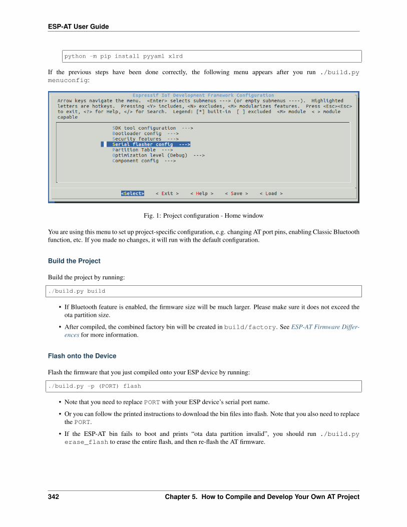
ESP-AT User Guide
python -m pip install pyyaml xlrd
If the previous steps have been done correctly, the following menu appears after you run ./build.pymenuconfig:
Fig. 1: Project configuration - Home window
You are using this menu to set up project-specific configuration, e.g. changing AT port pins, enabling Classic Bluetoothfunction, etc. If you made no changes, it will run with the default configuration.
Build the Project
Build the project by running:
./build.py build
• If Bluetooth feature is enabled, the firmware size will be much larger. Please make sure it does not exceed theota partition size.
• After compiled, the combined factory bin will be created in build/factory. See ESP-AT Firmware Differ-ences for more information.
Flash onto the Device
Flash the firmware that you just compiled onto your ESP device by running:
./build.py -p (PORT) flash
• Note that you need to replace PORT with your ESP device’s serial port name.
• Or you can follow the printed instructions to download the bin files into flash. Note that you also need to replacethe PORT.
• If the ESP-AT bin fails to boot and prints “ota data partition invalid”, you should run ./build.pyerase_flash to erase the entire flash, and then re-flash the AT firmware.
342 Chapter 5. How to Compile and Develop Your Own AT Project

ESP-AT User Guide
5.2 How to Set AT Port Pins
[]
This document introduces how to modify AT port pins in the firmware for ESP32 and ESP32-C3 series of products.By default, ESP-AT uses two UART interfaces as AT ports: one is to output logs (named as log port below) and theother to send AT commands and receive responses (named as command port below).
To modify the AT port pins of your ESP device, you should:
• clone the ESP-AT project;
• modify the pins either in the menuconfig utility or the factory_param_data.csv table;
• compile the project to generate the new bin in build/customized_partitions/factory_param.bin;
• flash the new bin to your device.
This document focuses on modifying the pins. Click the links above for details of other steps. Below is the documentstructure:
• ESP32 Series
• ESP32-C3 Series
Note: To use other interfaces as the AT command port, please refer to AT through SDIO , AT through SPI , or ATthrough socket for more details.
5.2.1 ESP32 Series
The log port and command port pins of ESP32 AT firmware can be user-defined to other pins. Refer to ESP32Technical Reference Manual for the pins you can use.
Modify Log Port Pins
By default, the ESP32 AT firmware provided by Espressif uses the following UART0 pins to output log:
• TX: GPIO1
• RX: GPIO3
When compiling your ESP-AT project, you can modify them to other pins with the menuconfig utitlity:
• ./build.py menuconfig –> Component config –> Common ESP-related –> UART forconsole output
• ./build.py menuconfig –> Component config –> Common ESP-related –> UART TX onGPIO#
• ./build.py menuconfig –> Component config –> Common ESP-related –> UART RX onGPIO#
5.2. How to Set AT Port Pins 343

ESP-AT User Guide
Modify Command Port Pins
By default, UART1 is used to send AT commands and receive AT responses, and its pins are defined inColumn uart_port, uart_tx_pin, uart_rx_pin, uart_cts_pin, and uart_rts_pin of the fac-tory_param_data.csv .
You can change them directly in your factory_param_data.csv table:
• Open your local factory_param_data.csv file.
• Locate the row of your module.
• Set uart_port as needed.
• Set uart_tx_pin and uart_rx_pin as needed.
• Set uart_cts_pin and uart_rts_pin to be -1 if you do not use the hardware flow control function.
• Save the table.
5.2.2 ESP32-C3 Series
The log port and command port pins of ESP32-C3 AT firmware can be user-defined to other pins. ESP32-C3 TechnicalReference Manual for the pins you can use.
Modify Log Port Pins
By default, the ESP32-C3 AT firmware provided by Espressif uses the following UART0 pins to output log:
• TX: GPIO21
• RX: GPIO20
When compiling your ESP-AT project, you can modify them to other pins with the menuconfig utitlity:
• ./build.py menuconfig –> Component config –> Common ESP-related –> UART forconsole output
• ./build.py menuconfig –> Component config –> Common ESP-related –> UART TX onGPIO#
• ./build.py menuconfig –> Component config –> Common ESP-related –> UART RX onGPIO#
Modify Command Port Pins
By default, UART1 is used to send AT commands and receive AT responses, and its pins are defined inColumn uart_port, uart_tx_pin, uart_rx_pin, uart_cts_pin, and uart_rts_pin of the fac-tory_param_data.csv .
You can change them directly in your factory_param_data.csv table:
• Open your local factory_param_data.csv file.
• Locate the row of your module.
• Set uart_port as needed.
• Set uart_tx_pin and uart_rx_pin as needed.
• Set uart_cts_pin and uart_rts_pin to be -1 if you do not use the hardware flow control function.
344 Chapter 5. How to Compile and Develop Your Own AT Project

ESP-AT User Guide
• Save the table.
5.3 How to add user-defined AT commands
[]
This document details how to add a user-defined AT command based on the ESP-AT project. It uses the AT+TESTcommand as an example to show the sample code for each step.
Customizing a basic and well-functioned command requires at least the two steps below:
• Define AT Commands
• Register AT Commands
This step checks how the newly defined command works out.
• Give it a try
The remaining steps are for relatively complex AT commands and are optional depending on your needs.
• Define Return Values
• Access Command Parameters
• Omit Command Parameters
• Block Command Execution
• Access Input Data from AT Command Port
The source code of AT command set is not open-source, and is provided in the form of library file . It is also the basisto parse user-defined AT commands.
5.3.1 Define AT Commands
Before defining any AT command, you should first decide on the name and type of the command.
Command naming rules:
• It should start with the + character.
• Alphabetic characters (A~Z, a~z), numeric characters (0~9), and some other characters (!, %, -, ., /, :, _)are supported. See AT Command Types for more information.
Command types:
Each AT command can have up to four types: Test Command, Query Command, Set Command, and Execute Com-mand. See AT Command Types for more information.
Then, define desired type of command. Assuming that AT+TEST supports all the four types. Below is the samplecode to define each type.
Test Command:
uint8_t at_test_cmd_test(uint8_t *cmd_name){
uint8_t buffer[64] = {0};
snprintf((char *)buffer, 64, "this cmd is test cmd: %s\r\n", cmd_name);
(continues on next page)
5.3. How to add user-defined AT commands 345

ESP-AT User Guide
(continued from previous page)
esp_at_port_write_data(buffer, strlen((char *)buffer));
return ESP_AT_RESULT_CODE_OK;}
Query Command:
uint8_t at_query_cmd_test(uint8_t *cmd_name){
uint8_t buffer[64] = {0};
snprintf((char *)buffer, 64, "this cmd is query cmd: %s\r\n", cmd_name);
esp_at_port_write_data(buffer, strlen((char *)buffer));
return ESP_AT_RESULT_CODE_OK;}
Set Command:
uint8_t at_setup_cmd_test(uint8_t para_num){
int32_t para_int_1 = 0;uint8_t *para_str_2 = NULL;uint8_t num_index = 0;uint8_t buffer[64] = {0};
if (esp_at_get_para_as_digit(num_index++, ¶_int_1) != ESP_AT_PARA_PARSE_→˓RESULT_OK) {
return ESP_AT_RESULT_CODE_ERROR;}
if (esp_at_get_para_as_str(num_index++, ¶_str_2) != ESP_AT_PARA_PARSE_RESULT_→˓OK) {
return ESP_AT_RESULT_CODE_ERROR;}
snprintf((char *)buffer, 64, "this cmd is setup cmd and cmd num is: %u\r\n", para_→˓num);
esp_at_port_write_data(buffer, strlen((char *)buffer));
memset(buffer, 0, 64);snprintf((char *)buffer, 64, "first parameter is: %d\r\n", para_int_1);esp_at_port_write_data(buffer, strlen((char *)buffer));
memset(buffer, 0, 64);snprintf((char *)buffer, 64, "second parameter is: %s\r\n", para_str_2);esp_at_port_write_data(buffer, strlen((char *)buffer));
return ESP_AT_RESULT_CODE_OK;}
Execute Command:
uint8_t at_exe_cmd_test(uint8_t *cmd_name){
uint8_t buffer[64] = {0};(continues on next page)
346 Chapter 5. How to Compile and Develop Your Own AT Project

ESP-AT User Guide
(continued from previous page)
snprintf((char *)buffer, 64, "this cmd is execute cmd: %s\r\n", cmd_name);
esp_at_port_write_data(buffer, strlen((char *)buffer));
return ESP_AT_RESULT_CODE_OK;}
Finally, call esp_at_cmd_struct to define the name and type(s) that your AT command supports. The samplecode below defined the name +TEST (omitting AT) and all the four types.
static esp_at_cmd_struct at_custom_cmd[] = {{"+TEST", at_test_cmd_test, at_query_cmd_test, at_setup_cmd_test, at_exe_cmd_test}
→˓,};
If you do not want to define a particular type, set it to NULL.
5.3.2 Register AT Commands
Call API esp_at_custom_cmd_array_regist() to register your AT command. Below is the sample code toregister AT+TEST:
esp_at_custom_cmd_array_regist(at_custom_cmd, sizeof(at_custom_cmd) / sizeof(at_→˓custom_cmd[0]));
Note: esp_at_custom_cmd_array_regist is recommended to be added to the at_custom_init() inapp_main().
5.3.3 Give it a try
If you have finished the above two steps, the command should work after you build the ESP-AT project and flash thefirmware to your device. Give it a try!
Below is how AT+TEST works out.
Test Command:
AT+TEST=?
Response:
AT+TEST=?this cmd is test cmd: +TEST
OK
Query Command:
AT+TEST?
Response:
5.3. How to add user-defined AT commands 347

ESP-AT User Guide
AT+TEST?this cmd is query cmd: +TEST
OK
Set Command:
AT+TEST=1,"espressif"
Response:
AT+TEST=1,"espressif"this cmd is setup cmd and cmd num is: 2first parameter is: 1second parameter is: espressif
OK
Execute Command:
AT+TEST
Response:
AT+TESTthis cmd is execute cmd: +TEST
OK
5.3.4 Define Return Values
ESP-AT has defined return values in esp_at_result_code_string_index. See AT Messages for more returnvalues.
In addition to output return values through the return mode, you can also use API esp_at_response_result()to output the execution result of the command. ESP_AT_RESULT_CODE_SEND_OK andESP_AT_RESULT_CODE_SEND_FAIL can be used with the API in code.
For example, when you send data to the server or MCU with the Execute Command of AT+TEST, you can useesp_at_response_result() to output the sending result, and the return mode to output the command executionresult. Below is the sample code:
uint8_t at_exe_cmd_test(uint8_t *cmd_name){
uint8_t buffer[64] = {0};
snprintf((char *)buffer, 64, "this cmd is execute cmd: %s\r\n", cmd_name);
esp_at_port_write_data(buffer, strlen((char *)buffer));
// user-defined operation of sending data to server or MCUsend_data_to_server();
// output SEND OKesp_at_response_result(ESP_AT_RESULT_CODE_SEND_OK);
(continues on next page)
348 Chapter 5. How to Compile and Develop Your Own AT Project

ESP-AT User Guide
(continued from previous page)
return ESP_AT_RESULT_CODE_OK;}
How it works out:
AT+TESTthis cmd is execute cmd: +TEST
SEND OK
OK
5.3.5 Access Command Parameters
ESP-AT provides two APIs to access command parameters:
• esp_at_get_para_as_digit() obtains digital parameters.
• esp_at_get_para_as_str() obtains string parameters.
See Set Command for an example.
5.3.6 Omit Command Parameters
This section describes how to provide optional command parameters:
• Omit the First or Middle Parameter
• Omit the Last Parameter
Omit the First or Middle Parameter
Let’s say you want to make <param_2> and <param_3> of AT+TEST optional. <param_2> is a digital parameter,and <param_3> a string parameter.
AT+TEST=<param_1>[,<param_2>][,<param_3>],<param_4>
Below is the sample code to achieve it:
uint8_t at_setup_cmd_test(uint8_t para_num){
int32_t para_int_1 = 0;int32_t para_int_2 = 0;uint8_t *para_str_3 = NULL;uint8_t *para_str_4 = NULL;uint8_t num_index = 0;uint8_t buffer[64] = {0};esp_at_para_parse_result_type parse_result = ESP_AT_PARA_PARSE_RESULT_OK;
snprintf((char *)buffer, 64, "this cmd is setup cmd and cmd num is: %u\r\n", para_→˓num);
esp_at_port_write_data(buffer, strlen((char *)buffer));
parse_result = esp_at_get_para_as_digit(num_index++, ¶_int_1);
(continues on next page)
5.3. How to add user-defined AT commands 349

ESP-AT User Guide
(continued from previous page)
if (parse_result != ESP_AT_PARA_PARSE_RESULT_OK) {return ESP_AT_RESULT_CODE_ERROR;
} else {memset(buffer, 0, 64);snprintf((char *)buffer, 64, "first parameter is: %d\r\n", para_int_1);esp_at_port_write_data(buffer, strlen((char *)buffer));
}
parse_result = esp_at_get_para_as_digit(num_index++, ¶_int_2);if (parse_result != ESP_AT_PARA_PARSE_RESULT_OMITTED) {
if (parse_result != ESP_AT_PARA_PARSE_RESULT_OK) {return ESP_AT_RESULT_CODE_ERROR;
} else {// sample code// user needs to customize the operationmemset(buffer, 0, 64);snprintf((char *)buffer, 64, "second parameter is: %d\r\n", para_int_2);esp_at_port_write_data(buffer, strlen((char *)buffer));
}} else {
// sample code// the second parameter is omitted// user needs to customize the operationmemset(buffer, 0, 64);snprintf((char *)buffer, 64, "second parameter is omitted\r\n");esp_at_port_write_data(buffer, strlen((char *)buffer));
}
parse_result = esp_at_get_para_as_str(num_index++, ¶_str_3);if (parse_result != ESP_AT_PARA_PARSE_RESULT_OMITTED) {
if (parse_result != ESP_AT_PARA_PARSE_RESULT_OK) {return ESP_AT_RESULT_CODE_ERROR;
} else {// sample code// user needs to customize the operationmemset(buffer, 0, 64);snprintf((char *)buffer, 64, "third parameter is: %s\r\n", para_str_3);esp_at_port_write_data(buffer, strlen((char *)buffer));
}} else {
// sample code// the third parameter is omitted// user needs to customize the operationmemset(buffer, 0, 64);snprintf((char *)buffer, 64, "third parameter is omitted\r\n");esp_at_port_write_data(buffer, strlen((char *)buffer));
}
parse_result = esp_at_get_para_as_str(num_index++, ¶_str_4);if (parse_result != ESP_AT_PARA_PARSE_RESULT_OK) {
return ESP_AT_RESULT_CODE_ERROR;} else {
memset(buffer, 0, 64);snprintf((char *)buffer, 64, "fourth parameter is: %s\r\n", para_str_4);esp_at_port_write_data(buffer, strlen((char *)buffer));
}
(continues on next page)
350 Chapter 5. How to Compile and Develop Your Own AT Project

ESP-AT User Guide
(continued from previous page)
return ESP_AT_RESULT_CODE_OK;}
Note: If the string parameter input is "", it is not omitted.
Omit the Last Parameter
Let’s say you want to make the string parameter <param_3> of AT+TEST optional, which is also the last parameter.
AT+TEST=<param_1>,<param_2>[,<param_3>]
There are two cases of omission:
• AT+TEST=<param_1>,<param_2>
• AT+TEST=<param_1>,<param_2>,
Below is the sample code to achieve it:
uint8_t at_setup_cmd_test(uint8_t para_num){
int32_t para_int_1 = 0;uint8_t *para_str_2 = NULL;uint8_t *para_str_3 = NULL;uint8_t num_index = 0;uint8_t buffer[64] = {0};esp_at_para_parse_result_type parse_result = ESP_AT_PARA_PARSE_RESULT_OK;
snprintf((char *)buffer, 64, "this cmd is setup cmd and cmd num is: %u\r\n", para_→˓num);
esp_at_port_write_data(buffer, strlen((char *)buffer));
parse_result = esp_at_get_para_as_digit(num_index++, ¶_int_1);if (parse_result != ESP_AT_PARA_PARSE_RESULT_OK) {
return ESP_AT_RESULT_CODE_ERROR;} else {
memset(buffer, 0, 64);snprintf((char *)buffer, 64, "first parameter is: %d\r\n", para_int_1);esp_at_port_write_data(buffer, strlen((char *)buffer));
}
parse_result = esp_at_get_para_as_str(num_index++, ¶_str_2);if (parse_result != ESP_AT_PARA_PARSE_RESULT_OK) {
return ESP_AT_RESULT_CODE_ERROR;} else {
memset(buffer, 0, 64);snprintf((char *)buffer, 64, "second parameter is: %s\r\n", para_str_2);esp_at_port_write_data(buffer, strlen((char *)buffer));
}
if (num_index == para_num) {memset(buffer, 0, 64);snprintf((char *)buffer, 64, "third parameter is omitted\r\n");esp_at_port_write_data(buffer, strlen((char *)buffer));
(continues on next page)
5.3. How to add user-defined AT commands 351

ESP-AT User Guide
(continued from previous page)
} else {parse_result = esp_at_get_para_as_str(num_index++, ¶_str_3);if (parse_result != ESP_AT_PARA_PARSE_RESULT_OMITTED) {
if (parse_result != ESP_AT_PARA_PARSE_RESULT_OK) {return ESP_AT_RESULT_CODE_ERROR;
} else {// sample code// user needs to customize the operationmemset(buffer, 0, 64);snprintf((char *)buffer, 64, "third parameter is: %s\r\n", para_str_
→˓3);esp_at_port_write_data(buffer, strlen((char *)buffer));
}} else {
// sample code// the third parameter is omitted// user needs to customize the operationmemset(buffer, 0, 64);snprintf((char *)buffer, 64, "third parameter is omitted\r\n");esp_at_port_write_data(buffer, strlen((char *)buffer));
}}
return ESP_AT_RESULT_CODE_OK;}
Note: If the string parameter input is "", it is not omitted.
5.3.7 Block Command Execution
Sometimes you want to block the execution of one command to wait for another execution result, and the system mayreturn different values according to the result.
Generally, this kind of command needs to synchronize the results of other tasks.
semaphore is recommended to handle synchronization.
The sample code is as follows:
xSemaphoreHandle at_operation_sema = NULL;
uint8_t at_exe_cmd_test(uint8_t *cmd_name){
uint8_t buffer[64] = {0};
snprintf((char *)buffer, 64, "this cmd is execute cmd: %s\r\n", cmd_name);
esp_at_port_write_data(buffer, strlen((char *)buffer));
// sample code// users don't have to create semaphores hereat_operation_sema = xSemaphoreCreateBinary();assert(at_operation_sema != NULL);
(continues on next page)
352 Chapter 5. How to Compile and Develop Your Own AT Project

ESP-AT User Guide
(continued from previous page)
// block command execution// wait for another execution result// other tasks can call xSemaphoreGive to release the semaphorexSemaphoreTake(at_operation_sema, portMAX_DELAY);
return ESP_AT_RESULT_CODE_OK;}
5.3.8 Access Input Data from AT Command Port
ESP-AT supports accessing input data from AT Command port. It provides two APIs for this purpose.
• esp_at_port_enter_specific() sets the callback function which will be called by AT port after re-ceiving the input data.
• esp_at_port_exit_specific() deletes the callback function set byesp_at_port_enter_specific.
Approaches to access the data vary depending on whether the data length has been specified or not.
Input Data of Specified Length
Assuming that you have specified the data length in <param_1> as follows:
AT+TEST=<param_1>
Below is the sample to access the input data of <param_1> length from AT Command Port:
static xSemaphoreHandle at_sync_sema = NULL;
void wait_data_callback(void){
xSemaphoreGive(at_sync_sema);}
uint8_t at_setup_cmd_test(uint8_t para_num){
int32_t specified_len = 0;int32_t received_len = 0;int32_t remain_len = 0;uint8_t *buf = NULL;uint8_t buffer[64] = {0};
if (esp_at_get_para_as_digit(0, &specified_len) != ESP_AT_PARA_PARSE_RESULT_OK) {return ESP_AT_RESULT_CODE_ERROR;
}
buf = (uint8_t *)malloc(specified_len);if (buf == NULL) {
memset(buffer, 0, 64);snprintf((char *)buffer, 64, "malloc failed\r\n");esp_at_port_write_data(buffer, strlen((char *)buffer));
}
// sample code
(continues on next page)
5.3. How to add user-defined AT commands 353

ESP-AT User Guide
(continued from previous page)
// users don't have to create semaphores hereif (!at_sync_sema) {
at_sync_sema = xSemaphoreCreateBinary();assert(at_sync_sema != NULL);
}
// output input prompt ">"esp_at_port_write_data((uint8_t *)">", strlen(">"));
// set the callback function which will be called by AT port after receiving the→˓input data
esp_at_port_enter_specific(wait_data_callback);
// receive input datawhile(xSemaphoreTake(at_sync_sema, portMAX_DELAY)) {
received_len += esp_at_port_read_data(buf + received_len, specified_len -→˓received_len);
if (specified_len == received_len) {esp_at_port_exit_specific();
// get the length of the remaining input dataremain_len = esp_at_port_get_data_length();if (remain_len > 0) {
// sample code// if the remaining data length > 0, the actual input data length is
→˓greater than the specified received data length// users can customize the operation to process the remaining data// here is just a simple print out of the remaining dataesp_at_port_recv_data_notify(remain_len, portMAX_DELAY);
}
// sample code// output received datamemset(buffer, 0, 64);snprintf((char *)buffer, 64, "\r\nreceived data is: ");esp_at_port_write_data(buffer, strlen((char *)buffer));
esp_at_port_write_data(buf, specified_len);
break;}
}
free(buf);
return ESP_AT_RESULT_CODE_OK;}
So, if you set AT+TEST=5 and the input data is 1234567890, the ESP-AT output is as follows.
AT+TEST=5>67890received data is: 12345OK
354 Chapter 5. How to Compile and Develop Your Own AT Project

ESP-AT User Guide
Input Data of Unspecified Length
This scenario is similar to the Wi-Fi Passthrough Mode. You do not specify the data length.
AT+TEST
Assuming that ESP-AT ends the execution of the command and returns the execution result, the sample code is asfollows:
#define BUFFER_LEN (2048)static xSemaphoreHandle at_sync_sema = NULL;
void wait_data_callback(void){
xSemaphoreGive(at_sync_sema);}
uint8_t at_exe_cmd_test(uint8_t *cmd_name){
int32_t received_len = 0;int32_t remain_len = 0;uint8_t *buf = NULL;uint8_t buffer[64] = {0};
buf = (uint8_t *)malloc(BUFFER_LEN);if (buf == NULL) {
memset(buffer, 0, 64);snprintf((char *)buffer, 64, "malloc failed\r\n");esp_at_port_write_data(buffer, strlen((char *)buffer));
}
// sample code// users don't have to create semaphores hereif (!at_sync_sema) {
at_sync_sema = xSemaphoreCreateBinary();assert(at_sync_sema != NULL);
}
// output input prompt ">"esp_at_port_write_data((uint8_t *)">", strlen(">"));
// set the callback function which will be called by AT port after receiving the→˓input data
esp_at_port_enter_specific(wait_data_callback);
// receive input datawhile(xSemaphoreTake(at_sync_sema, portMAX_DELAY)) {
memset(buf, 0, BUFFER_LEN);
received_len = esp_at_port_read_data(buf, BUFFER_LEN);// check whether to exit the mode// the exit condition is the "+++" string receivedif ((received_len == 3) && (strncmp((const char *)buf, "+++", 3)) == 0) {
esp_at_port_exit_specific();
// sample code// if the remaining data length > 0, it means that there is still data
→˓left in the buffer to be processed (continues on next page)
5.3. How to add user-defined AT commands 355
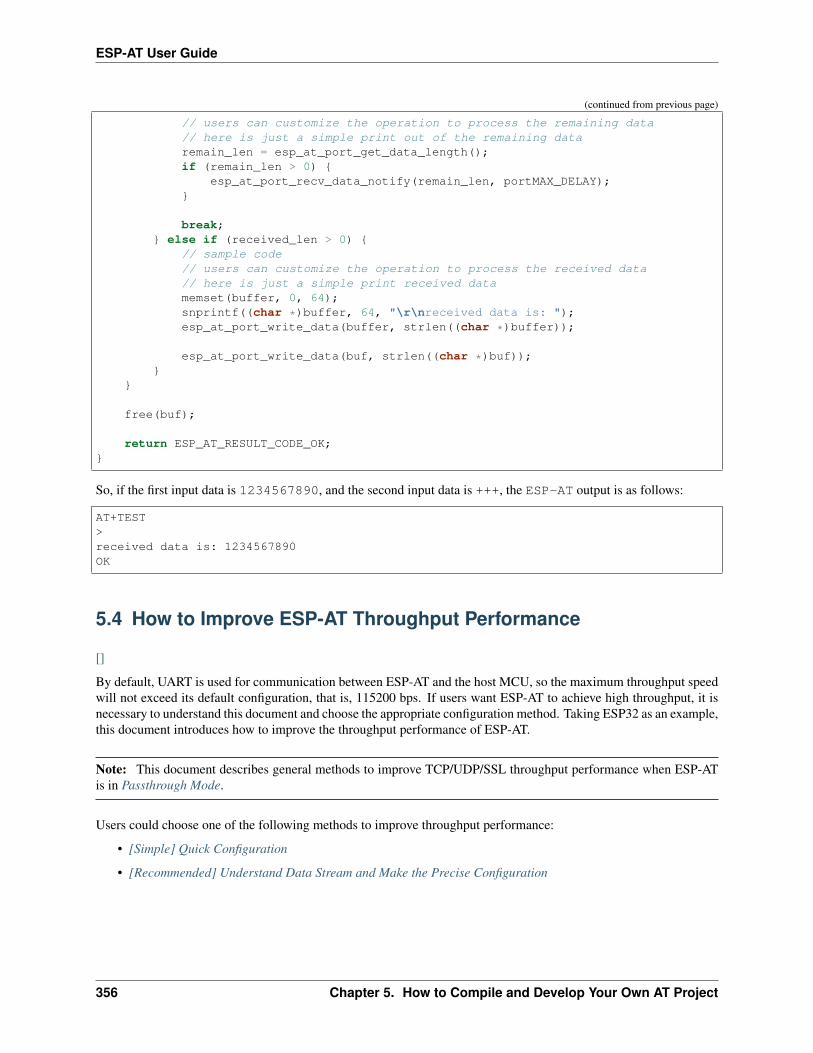
ESP-AT User Guide
(continued from previous page)
// users can customize the operation to process the remaining data// here is just a simple print out of the remaining dataremain_len = esp_at_port_get_data_length();if (remain_len > 0) {
esp_at_port_recv_data_notify(remain_len, portMAX_DELAY);}
break;} else if (received_len > 0) {
// sample code// users can customize the operation to process the received data// here is just a simple print received datamemset(buffer, 0, 64);snprintf((char *)buffer, 64, "\r\nreceived data is: ");esp_at_port_write_data(buffer, strlen((char *)buffer));
esp_at_port_write_data(buf, strlen((char *)buf));}
}
free(buf);
return ESP_AT_RESULT_CODE_OK;}
So, if the first input data is 1234567890, and the second input data is +++, the ESP-AT output is as follows:
AT+TEST>received data is: 1234567890OK
5.4 How to Improve ESP-AT Throughput Performance
[]
By default, UART is used for communication between ESP-AT and the host MCU, so the maximum throughput speedwill not exceed its default configuration, that is, 115200 bps. If users want ESP-AT to achieve high throughput, it isnecessary to understand this document and choose the appropriate configuration method. Taking ESP32 as an example,this document introduces how to improve the throughput performance of ESP-AT.
Note: This document describes general methods to improve TCP/UDP/SSL throughput performance when ESP-ATis in Passthrough Mode.
Users could choose one of the following methods to improve throughput performance:
• [Simple] Quick Configuration
• [Recommended] Understand Data Stream and Make the Precise Configuration
356 Chapter 5. How to Compile and Develop Your Own AT Project
ESP-AT User Guide
5.4.1 [Simple] Quick Configuration
1. Configure system, LWIP, Wi-Fi parameters
Copy the following code snippet and append to tail of mod-ule_config/module_esp32_default/sdkconfig.defaults file. For other ESP series devices, please modifythe sdkconfig.defaults file in the corresponding folder.
# SystemCONFIG_ESP_SYSTEM_EVENT_TASK_STACK_SIZE=4096CONFIG_FREERTOS_UNICORE=nCONFIG_FREERTOS_HZ=1000CONFIG_ESP32_DEFAULT_CPU_FREQ_240=yCONFIG_ESP32_DEFAULT_CPU_FREQ_MHZ=240CONFIG_ESPTOOLPY_FLASHMODE_QIO=yCONFIG_ESPTOOLPY_FLASHFREQ_80M=y
# LWIPCONFIG_LWIP_TCP_SND_BUF_DEFAULT=65534CONFIG_LWIP_TCP_WND_DEFAULT=65534CONFIG_LWIP_TCP_RECVMBOX_SIZE=12CONFIG_LWIP_UDP_RECVMBOX_SIZE=12CONFIG_LWIP_TCPIP_RECVMBOX_SIZE=64
# Wi-FiCONFIG_ESP32_WIFI_STATIC_RX_BUFFER_NUM=16CONFIG_ESP32_WIFI_DYNAMIC_RX_BUFFER_NUM=64CONFIG_ESP32_WIFI_DYNAMIC_TX_BUFFER_NUM=64CONFIG_ESP32_WIFI_TX_BA_WIN=32CONFIG_ESP32_WIFI_RX_BA_WIN=32CONFIG_ESP32_WIFI_AMPDU_TX_ENABLED=yCONFIG_ESP32_WIFI_AMPDU_RX_ENABLED=y
2. Enlarge UART buffer size
Copy the following code snippet and replace the uart_driver_install() line of at_uart_task.c file.
uart_driver_install(esp_at_uart_port, 1024 * 16, 1024 * 16, 100, &esp_at_→˓uart_queue, 0);
3. Delete, Build, Flash, Run
rm -rf build sdkconfig./build.py build./build.py flash monitor
4. Increase UART baud rate before entering passthrough mode
A typical ESP-AT commands sequence is as follows:
AT+CWMODE=1AT+CWJAP="ssid","password"AT+UART_CUR=3000000,8,1,0,3AT+CIPSTART="TCP","192.168.105.13",3344AT+CIPSEND// data transmission
This simple and quick configuration method can improve the throughput to a certain extent, but sometimes it might notmeet the expectations of users. In addition, some configurations may not hit the bottleneck of throughput. Higher con-
5.4. How to Improve ESP-AT Throughput Performance 357

ESP-AT User Guide
figurations may sacrifice memory resources or power consumption. Therefore, users could also familiarize themselveswith the following recommended method and make the precise configuration.
5.4.2 [Recommended] Understand Data Stream and Make the Precise Configura-tion
The factors that generally affect ESP-AT throughput are illustrated in the following figure:
Fig. 2: Data Stream in Throughput
As shown by the arrows in the figure:
• The Data stream sent by ESP-AT is (TX): S1 -> S2 -> S3 -> S4 -> S5 -> S6 -> S7 -> S8
• The Data stream received by ESP-AT is (RX): R8 -> R7 -> R6 -> R5 -> R4 -> R3 -> R2 -> R1
The data stream of throughput is similar to water flow. In order to improve throughput, it is necessary to consideroptimizing between nodes with low data flow rate rather than making additional configuration between nodes withexpected data flow rate, so as to avoid unnecessary waste of resources. In actual products, usually, users only need toimprove the throughput of one data stream. So here, users need to configure it according to the following instructions.
Note: The following configurations are based on sufficient available memory. Users can query the available memorythrough the AT command: AT+SYSRAM.
1. G0 throughput optimization
G0 is a part of the system that can be optimized. The recommended configuration is as follows:
CONFIG_ESP_SYSTEM_EVENT_TASK_STACK_SIZE=4096CONFIG_FREERTOS_UNICORE=nCONFIG_FREERTOS_HZ=1000
(continues on next page)
358 Chapter 5. How to Compile and Develop Your Own AT Project
ESP-AT User Guide
(continued from previous page)
CONFIG_ESP32_DEFAULT_CPU_FREQ_240=yCONFIG_ESP32_DEFAULT_CPU_FREQ_MHZ=240CONFIG_ESPTOOLPY_FLASHMODE_QIO=yCONFIG_ESPTOOLPY_FLASHFREQ_80M=y
2. S1, R1 throughput optimization
Generally, S1 and R1 are the key to the throughput of ESP-AT. Because UART is used for communicationbetween ESP-AT and the host MCU by default, and the baud rate is 115200. On the hardware, the baudrate upper limit is 5 Mbps. Therefore, if the throughput is expected to be less than 5 Mbps, the user canuse the default UART as the communication medium with the host MCU, and the following optimizationmethods can be carried out.
2.1 Enlarge UART buffer size
Copy the following code snippet and replace the uart_driver_install() line of at_uart_task.c file.
• Improve UART TX throughput
uart_driver_install(esp_at_uart_port, 1024 * 16, 8192, 100, &esp_at_uart_→˓queue, 0);
• Improve UART RX throughput
uart_driver_install(esp_at_uart_port, 2048, 1024 * 16, 100, &esp_at_uart_→˓queue, 0);
• Improve UART TX and RX throughput
uart_driver_install(esp_at_uart_port, 1024 * 16, 1024 * 16, 100, &esp_at_→˓uart_queue, 0);
2.2 Increase UART baud rate before entering passthrough mode
A typical ESP-AT commands sequence is as follows:
AT+CWMODE=1AT+CWJAP="ssid","password"AT+UART_CUR=3000000,8,1,0,3AT+CIPSTART="TCP","192.168.105.13",3344AT+CIPSEND// data transmission
Note: The user needs to ensure that the UART of the host MCU can support such a high rate, and the UARTconnection between the host MCU and ESP-AT is as short as possible.
Note: If the user expects the throughput rate to be greater than or close to 5 Mbps, then SPI, SDIO, Socket or othermethods can be considered. Please refer to:
• SPI: SPI AT Guide
• SDIO: SDIO AT Guide
• Socket: Socket AT Guide
3. S2, R2, R3, S3 throughput optimization
5.4. How to Improve ESP-AT Throughput Performance 359

ESP-AT User Guide
Generally, S2, R2, R3, S3 are not the bottleneck of ESP-AT throughput. Because AT core transfers databetween UART buffer and the transport layer of communication protocol, where has minimal and non-time-consuming application logic, there is no need to optimize them.
4. S4, R4, S5, R5, S6, R6 throughput optimization
If UART is used for communication between ESP-AT and host MCU, S4, R4, S5, R5, S6, R6 need notbe optimized. If other transmission media are used, S4, R4, S5, R5, S6, R6 should be a factor affectingthroughput.
S4, R4, S5, R5, S6, R6 is the data stream between the transport layer, network layer and data link layerof the communication protocol. Users need to read How to improve Wi-Fi performance in ESP-IDF tounderstand the principle and make reasonable configuration. These configurations can be configured in./build.py menuconfig.
• Improve throughput of S4 -> S5 -> S6: TX direction
• Improve throughput of R6 -> R5 -> R4: RX direction
5. S6, R6 throughput optimization
S6 and R6 are the data link layers of the communication protocol. ESP32 can use Wi-Fi or ethernet asthe transmission medium. In addition to the optimization methods described above, Wi-Fi throughputoptimization may also need users’ attention:
• Improve RF Power
The default RF power is usually not the bottleneck of throughput. Users could query and set RFpower through AT command: AT+RFPOWER.
• Set 802.11 b/g/n protocol
The default Wi-Fi mode is 802.11 b/g/n protocol. Users could query and set 802.11 b/g/n proto-col through AT command: AT+CWSTAPROTO. The configuration is bidirectional. Therefore, it isrecommended that the Wi-Fi mode of AP is configured as 802.11 b/g/n protocol and the bandwidthmode of AP is configured as HT20/HT40 (20/40 MHz) mode.
6. S7, R7, S8, R8 throughput optimization
Generally, S7, R7, S8, R8 are not the scope of ESP-AT throughput optimization because this is related tothe actual network bandwidth, network routing, physical distance, etc.
5.5 How to Generate Factory Parameter Bin
[]
This document explains how to generate a customized ESP-AT factory parameter bin file (fac-tory_MODULE_NAME.bin) for your module. For example, you may want to self-define the country code,RF restriction, or UART pins in your ESP-AT firmware. The two tables below allow you to define such parameters.
• factory_param_type.csv
• factory_param_data.csv
The following describes how to generate a customized factory parameter bin by modifying the two tables.
• Add a Customized Module
• Add a Customized Parameter
• Modify Factory Parameter Data on an Existing Module
360 Chapter 5. How to Compile and Develop Your Own AT Project

ESP-AT User Guide
5.5.1 factory_param_type.csv
The factory_param_type.csv table lists all the parameters that you can define as well as the offset, type, and size ofeach parameter. It is located in customized_partitions/raw_data/factory_param/factory_param_type.csv.
The table below provides some information about each parameter.
param_name Notedescription Additional information of the module, which is prompted when you are building the ESP-AT
project.magic_flag The value must be 0xfcfc.version The version of factory parameter management for internal use. The current version is 3. It is
not recommended to modify it.reserved1 Reserved.tx_max_power Wi-Fi maximum tx power for ESP32 and ESP32-C3: [40,84]. See ESP32 and ESP32-C3 tx
power setting range for details.uart_port The UART port that is used to send AT commands and receive AT responses.start_channel Wi-Fi start channel.channel_num The total channel number of Wi-Fi.country_code Country code.uart_baudrate UART baudrate.uart_tx_pin UART tx pin.uart_rx_pin UART rx pin.uart_cts_pin UART cts pin; it should be set to -1 if not used.uart_rts_pin UART rts pin; it should be set to -1 if not used.tx_control_pin For some boards, the tx pin needs to be separated from MCU when power on; it should be set
to -1 if not used.rx_control_pin For some boards, the rx pin needs to be separated from MCU when power on; it should be set
to -1 if not used.reserved2 Reserved.platform The platform (or called chip series) that the current firmware runs on.module_name The module that the current firmware runs on.
5.5.2 factory_param_data.csv
This factory_param_data.csv table holds the values for all the parameters defined in factory_param_type.csv. It coversthe modules of ESP32 and ESP32-C3 series. You can customize your factory parameter bin by modifying the valuesin the table. It is located in customized_partitions/raw_data/factory_param/factory_param_data.csv.
5.5.3 Add a Customized Module
This section demonstrates how to add a customized module in factory_param_data.csv and generate the factory pa-rameter bin for it with an example. Assuming that you want to generate the factory parameter bin for an ESP32 modulenamed as MY_MODULE, its country code is JP, Wi-Fi channel is from 1 to 14, and other parameters stay the same withWROOM-32 module of PLATFORM_ESP32, you can do as follows:
• Modify factory_param_data.csv
• Modify esp_at_module_info Structure
• Recompile the Project and Select the Customized Module
5.5. How to Generate Factory Parameter Bin 361

ESP-AT User Guide
Modify factory_param_data.csv
Set all parameter values for MY_MODULE in the factory_param_data.csv table.
Firstly, insert a row at the bottom of the table, and then enter the following parameter values:
• param_name: value
• platform: PLATFORM_ESP32
• module_name: MY_MODULE
• description: MY_DESCRIPTION
• magic_flag: 0xfcfc
• version: 3
• reserved1: 0
• tx_max_power: 78
• uart_port: 1
• start_channel: 1
• channel_num: 14
• country_code: JP
• uart_baudrate: 115200
• uart_tx_pin: 17
• uart_rx_pin: 16
• uart_cts_pin: 15
• uart_rts_pin: 14
• tx_control_pin: -1
• rx_control_pin: -1
The modified factory_param_data.csv file is as follows.
platform,module_name,description,magic_flag,version,reserved1,tx_max_power,uart_port,→˓start_channel,channel_num,country_code,uart_baudrate,uart_tx_pin,uart_rx_pin,uart_→˓cts_pin,uart_rts_pin,tx_control_pin,rx_control_pinPLATFORM_ESP32,WROOM-32,,0xfcfc,3,0,78,1,1,13,CN,115200,17,16,15,14,-1,-1...PLATFORM_ESP32,MY_MODULE,MY_DESCRIPTION,0xfcfc,3,0,78,1,1,14,JP,115200,17,16,15,14,-1,→˓-1
Modify esp_at_module_info Structure
Add customized module information in the esp_at_module_info structure in at/src/at_default_config.c.
The esp_at_module_info structure provides OTA upgrade verification token:
typedef struct {char* module_name;char* ota_token;char* ota_ssl_token;
} esp_at_module_info_t;
362 Chapter 5. How to Compile and Develop Your Own AT Project

ESP-AT User Guide
If you do not want to use OTA features, member 2 ota_token and member 3 ota_ssl_token should be set toNULL. Member 1 module_name must correspond to the field module_name in the factory_param_data.csv file.
The modified esp_at_module_info structure is as follows:
static const esp_at_module_info_t esp_at_module_info[] = {#if defined(CONFIG_IDF_TARGET_ESP32)
{"WROOM-32", CONFIG_ESP_AT_OTA_TOKEN_WROOM32, CONFIG_ESP_AT_OTA_SSL_→˓TOKEN_WROOM32 }, // default:ESP32-WROOM-32
{"WROOM-32", CONFIG_ESP_AT_OTA_TOKEN_WROOM32, CONFIG_ESP_AT_OTA_SSL_→˓TOKEN_WROOM32 }, // ESP32-WROOM-32
{"WROVER-32", CONFIG_ESP_AT_OTA_TOKEN_WROVER32, CONFIG_ESP_AT_OTA_SSL_→˓TOKEN_WROVER32 }, // ESP32-WROVER
{"PICO-D4", CONFIG_ESP_AT_OTA_TOKEN_ESP32_PICO_D4, CONFIG_ESP_AT_OTA_SSL_→˓TOKEN_ESP32_PICO_D4}, // ESP32-PICO-D4
{"SOLO-1", CONFIG_ESP_AT_OTA_TOKEN_ESP32_SOLO_1, CONFIG_ESP_AT_OTA_SSL_→˓TOKEN_ESP32_SOLO_1 }, // ESP32-SOLO-1
{"MINI-1", CONFIG_ESP_AT_OTA_TOKEN_ESP32_MINI_1, CONFIG_ESP_AT_OTA_SSL_→˓TOKEN_ESP32_MINI_1 }, // ESP32-MINI-1
{"ESP32-D2WD", NULL, NULL }, // ESP32-D2WD{"ESP32_QCLOUD", CONFIG_ESP_AT_OTA_TOKEN_ESP32_QCLOUD, CONFIG_ESP_AT_OTA_SSL_
→˓TOKEN_ESP32_QCLOUD }, // ESP32-QCLOUD{"MY_MODULE", CONFIG_ESP_AT_OTA_TOKEN_MY_MODULE, CONFIG_ESP_AT_OTA_SSL_
→˓TOKEN_MY_MODULE }, // MY_MODULE#endif
#if defined(CONFIG_IDF_TARGET_ESP32C3){"MINI-1", CONFIG_ESP_AT_OTA_TOKEN_ESP32C3_MINI, CONFIG_ESP_AT_OTA_
→˓SSL_TOKEN_ESP32C3_MINI },{"ESP32C3_QCLOUD", CONFIG_ESP_AT_OTA_TOKEN_ESP32C3_MINI_QCLOUD, CONFIG_ESP_AT_OTA_
→˓SSL_TOKEN_ESP32C3_MINI_QCLOUD },#endif};
Macro CONFIG_ESP_AT_OTA_TOKEN_MY_MODULE and macro CONFIG_ESP_AT_OTA_SSL_TOKEN_MY_MODULEare defined in the header file at/private_include/at_ota_token.h.
#if defined(CONFIG_IDF_TARGET_ESP32)...#define CONFIG_ESP_AT_OTA_TOKEN_MY_MODULE CONFIG_ESP_AT_OTA_TOKEN_DEFAULT
...#define CONFIG_ESP_AT_OTA_SSL_TOKEN_MY_MODULE CONFIG_ESP_AT_OTA_SSL_TOKEN_→˓DEFAULT
Recompile the Project and Select the Customized Module
After adding the customized module information, recompile the whole project according to Compile ESP-AT Projectand select the customized module when configuring the project:
Platform name:1. PLATFORM_ESP322. PLATFORM_ESP32C3choose(range[1,2]):1
Module name:1. WROOM-32
(continues on next page)
5.5. How to Generate Factory Parameter Bin 363

ESP-AT User Guide
(continued from previous page)
2. WROVER-323. PICO-D44. SOLO-15. MINI-1 (description: ESP32-U4WDH chip inside)6. ESP32-D2WD (description: 2MB flash, No OTA)7. ESP32_QCLOUD (description: QCLOUD TX:17 RX:16)8. MY_MODULE (description: MY_DESCRIPTION)choose(range[1,8]):8
You can find the factory parameter bin generated in esp-at/build/customized_partitions folder after thebuild is completed.
5.5.4 Add a Customized Parameter
This section demonstrates how to add a customized parameter with an example. Assuming that you want to add theparameter date for MY_MODULE and set it to 20210603, you should do as follows:
• Modify factory_param_type.csv
• Modify factory_param_data.csv
• Process a Customized Parameter
• Recompile the Project
Modify factory_param_type.csv
Define the parameter date in the factory_param_type.csv.
Firstly, insert a row at the end of the table, and then set the name, offset, type, and size of the parameter:
param_name offset type sizedescription -1 String 0. . . . . . . . . . . .date 88 String 9
Modify factory_param_data.csv
In the factory_param_data.csv, insert a column named as date to the right of the last column, then set its value to20210603 for MY_MODULE.
The modified CSV table is as follows:
platform,module_name,description,magic_flag,version,reserved1,tx_max_power,uart_port,→˓start_channel,channel_num,country_code,uart_baudrate,uart_tx_pin,uart_rx_pin,uart_→˓cts_pin,uart_rts_pin,tx_control_pin,rx_control_pin,datePLATFORM_ESP32,WROOM-32,,0xfcfc,3,0,78,1,1,13,CN,115200,17,16,15,14,-1,-1...PLATFORM_ESP32,MY_MODULE,MY_DESCRIPTION,0xfcfc,3,0,78,1,1,14,JP,115200,17,16,15,14,-1,→˓-1,20210603
364 Chapter 5. How to Compile and Develop Your Own AT Project

ESP-AT User Guide
Process a Customized Parameter
You can customize processing functions to process the customized parameter date. This section is just a simpleoutput:
static void esp_at_factory_parameter_date_init(void){
const esp_partition_t * partition = esp_at_custom_partition_find(0x40, 0xff,→˓"factory_param");
char* data = NULL;char* str_date = NULL;
if (!partition) {printf("factory_parameter partition missed\r\n");return;
}
data = (char*)malloc(ESP_AT_FACTORY_PARAMETER_SIZE); // Notesassert(data != NULL);if(esp_partition_read(partition, 0, data, ESP_AT_FACTORY_PARAMETER_SIZE) != ESP_
→˓OK){free(data);return;
}
if ((data[0] != 0xFC) || (data[1] != 0xFC)) { // check magic flag, should be 0xfc→˓0xfc
return;}
// sample code// users can customize the operation of processing date// here is just a simple print out of the date parameterstr_date = &data[88]; // date field offset addressprintf("date is %s\r\n", str_date);
free(data);
return;}
Recompile the Project
Recompile the whole project according to Compile ESP-AT Project.
You can find the factory parameter bin generated in esp-at/build/customized_partitions folder after thebuild is completed.
5.5. How to Generate Factory Parameter Bin 365

ESP-AT User Guide
5.5.5 Modify Factory Parameter Data on an Existing Module
Assuming that you need to modify the factory parameter data of an existing module in factory_param_data.csv, youchoose one of the following options:
• Recompile the Whole Project
• Only Recompile the Factory Parameter Bin
• Directly Modify Factory Parameter Bin
Recompile the Whole Project
Open the factory_param_data.csv and modify the parameters as needed.
Recompile the ESP-AT project according to Compile ESP-AT Project to generate the factory parameter bin inesp-at/build/customized_partitions folder.
Only Recompile the Factory Parameter Bin
Firstly, clone the entire ESP-AT project.
Secondly, navigate to the root directory of ESP-AT project, enter the following command, and replace some parame-ters:
python tools/factory_param_generate.py --platform PLATFORM --module MODULE --define_→˓file DEFINE_FILE --module_file MODULE_FILE --bin_name BIN_NAME --log_file LOG_FILE
• Replace PLATFORM with the platform of your module. It must correspond to the platform in the fac-tory_param_data.csv.
• Replace MODULE with your module name. It must correspond to the module_name in the fac-tory_param_data.csv.
• Replace DEFINE_FILE with the relative path of factory_param_type.csv.
• Replace MODULE_FILE with the relative path of factory_param_data.csv.
• Replace BIN_NAME with factory parameter bin file name.
• Replace LOG_FILE with the file name stored the module name.
Below is the example command for MY_MODULE:
python tools/factory_param_generate.py --platform PLATFORM_ESP32 --module MY_MODULE --→˓define_file components/customized_partitions/raw_data/factory_param/factory_param_→˓type.csv --module_file components/customized_partitions/raw_data/factory_param/→˓factory_param_data.csv --bin_name ./factory_param.bin --log_file ./factory_→˓parameter.log
After the above command is executed, the three files will be generated in the current directory:
• factory_param.bin
• factory_parameter.log
• factory_param_MY_MODULE.bin
366 Chapter 5. How to Compile and Develop Your Own AT Project

ESP-AT User Guide
Download the new factory_param_MY_MODULE.bin into flash. ESP-AT provides esptool.py to do it. Executethe following command under the root directory of ESP-AT project and replace some parameters:
python esp-idf/components/esptool_py/esptool/esptool.py -p PORT -b BAUD --before→˓default_reset --after hard_reset --chip auto write_flash --flash_mode dio --flash_→˓size detect --flash_freq 40m ADDRESS FILEDIRECTORY
• Replace PORT with the port name
• Replace BAUD with baud rate
• Replace ADDRESS with the start address in flash. ESP-AT has strict requirements on the ADDRESS parameter.The address of factory parameter bin varies from firmware to firmware. Please refer to the table below:
Table 2: factory parameter bin download addressesPlatform Firmware AddressPLATFORM_ESP32 All firmware 0x30000PLATFORM_ESP32C3 MINI-1 Bin 0x31000PLATFORM_ESP32C3 QCLOUD Bin 0x30000
• Replace FILEDIRECTORY with the relative path of the factory parameter bin.
Below is the example command to flash the generated factory parameter bin to MY_MODULE:
python esp-idf/components/esptool_py/esptool/esptool.py -p /dev/ttyUSB0 -b 921600 --→˓before default_reset --after hard_reset --chip auto write_flash --flash_mode dio --→˓flash_size detect --flash_freq 40m 0x30000 ./factory_param_MY_MODULE.bin
Directly Modify Factory Parameter Bin
Open the factory parameter bin with a binary tool, and directly modify the parameters in the corresponding positionaccording to the parameters offset in factory_param_type.csv.
Download the new factory_param.bin into flash (see Downloading Guide).
5.6 How to Customize Bluetooth® LE Services
[]
This document describes how to customize Bluetooth LE services on your ESP device with the Bluetooth LE servicesource file provided by ESP-AT.
• Bluetooth LE Service Source File
• Customize Bluetooth LE Services
– Modify the Bluetooth LE Service Source File
– Generate ble_data.bin
– Download ble_data.bin
The Bluetooth LE services are defined as a multivariate array of GATT structures, and the array contains at least oneprimary service whose attribute type is defined as 0x2800. Each service always consists of a service definition and
5.6. How to Customize Bluetooth® LE Services 367

ESP-AT User Guide
several characteristics. Each characteristic always consists of a value and optional descriptors. Please refer to PartGeneric Attribute Profile (GATT) of Bluetooth Core Specification for more information.
5.6.1 Bluetooth LE Service Source File
The ESP-AT project creates Bluetooth LE services based on its Bluetooth LE service source file. It is located incomponents/customized_partitions/raw_data/ble_data/example.csv. The table below shows the default source file.
index uuid_len uuid perm val_max_len val_cur_len value0 16 0x2800 0x01 2 2 A0021 16 0x2803 0x01 1 1 22 16 0xC300 0x01 1 1 303 16 0x2901 0x11 1 1 30. . . . . . . . . . . . . . . . . . . . .
Below are descriptions of the table above.
• perm field describes the permission. Its definition in the ESP-AT project is as follows:
/* relate to BTA_GATT_PERM_xxx in bta/bta_gatt_api.h *//*** @brief Attribute permissions
*/#define ESP_GATT_PERM_READ (1 << 0) /* bit 0 - 0x0001 */→˓ /* relate to BTA_GATT_PERM_READ in bta/bta_gatt_api.h */#define ESP_GATT_PERM_READ_ENCRYPTED (1 << 1) /* bit 1 - 0x0002 */→˓ /* relate to BTA_GATT_PERM_READ_ENCRYPTED in bta/bta_gatt_api.h */#define ESP_GATT_PERM_READ_ENC_MITM (1 << 2) /* bit 2 - 0x0004 */→˓ /* relate to BTA_GATT_PERM_READ_ENC_MITM in bta/bta_gatt_api.h */#define ESP_GATT_PERM_WRITE (1 << 4) /* bit 4 - 0x0010 */→˓ /* relate to BTA_GATT_PERM_WRITE in bta/bta_gatt_api.h */#define ESP_GATT_PERM_WRITE_ENCRYPTED (1 << 5) /* bit 5 - 0x0020 */→˓ /* relate to BTA_GATT_PERM_WRITE_ENCRYPTED in bta/bta_gatt_api.h */#define ESP_GATT_PERM_WRITE_ENC_MITM (1 << 6) /* bit 6 - 0x0040 */→˓ /* relate to BTA_GATT_PERM_WRITE_ENC_MITM in bta/bta_gatt_api.h */#define ESP_GATT_PERM_WRITE_SIGNED (1 << 7) /* bit 7 - 0x0080 */→˓ /* relate to BTA_GATT_PERM_WRITE_SIGNED in bta/bta_gatt_api.h */#define ESP_GATT_PERM_WRITE_SIGNED_MITM (1 << 8) /* bit 8 - 0x0100 */→˓ /* relate to BTA_GATT_PERM_WRITE_SIGNED_MITM in bta/bta_gatt_api.h */#define ESP_GATT_PERM_READ_AUTHORIZATION (1 << 9) /* bit 9 - 0x0200 */#define ESP_GATT_PERM_WRITE_AUTHORIZATION (1 << 10) /* bit 10 - 0x0400 */
• The first line of table is the service definition with a UUID of 0xA002.
• The second line is the declaration of a characteristic. UUID 0x2803 means the characteristic declaration.The value 2 sets the permission. The length of permission is 8 bits, and each bit represents permission for anoperation. 1 indicates that the operation is supported, and 0 indicates not supported.
368 Chapter 5. How to Compile and Develop Your Own AT Project

ESP-AT User Guide
Bit Permission0 BROADCAST1 READ2 WRITE WITHOUT RESPONSE3 WRITE4 NOTIFY5 INDICATE6 AUTHENTICATION SIGNED WRITES7 EXTENDED PROPERTIES
• The third line defines a characteristic of the service. UUID of this line is the characteristic’s UUID, and value isthe characteristic’s value.
• The fourth line defines a descriptor of the characteristic (optional).
For more information about UUID, please refer to Bluetooth Special Interest Group (SIG) Assigned Numbers.
If you use the default source file on your ESP device without any modification and establish a Bluetooth LE connection,you will get the following result after querying the server service on the client side.
5.6.2 Customize Bluetooth LE Services
If you want to customize the Bluetooth LE services, follow the steps below.
• Modify the Bluetooth LE Service Source File
• Generate ble_data.bin
• Download ble_data.bin
5.6. How to Customize Bluetooth® LE Services 369

ESP-AT User Guide
Modify the Bluetooth LE Service Source File
You can define more than one service. For example, if you want to define three services (Server_A, Server_B andServer_C), these three services need to be arranged in order. Since the definition of each service is similar, here wedefine one service as an example, and then you can define others one by one accordingly.
1. Add the service definition.
In this example, we define a primary service with a value of 0xFF01.
index uuid_len uuid perm val_max_len val_cur_len value31 16 0x2800 0x01 2 2 FF01
2. Add the characteristic declaration and characteristic value.
In this example, we define a readable and writable characteristic with UUID 0xC300, and set its value to 0x30.
index uuid_len uuid perm val_max_len val_cur_len value32 16 0x2803 0x11 1 1 0A33 16 0xC300 0x11 1 1 30
3. Add the characteristic descriptor (optional).
In this example, we add client characteristic configuration. Its value 0x0000 represents notifications and indica-tions are disabled.
index uuid_len uuid perm val_max_len val_cur_len value34 16 0x2902 0x11 2 2 0000
After the above steps, the customized Bluetooth LE service has been defined as follows.
index uuid_len uuid perm val_max_len val_cur_len value31 16 0x2800 0x01 2 2 FF0132 16 0x2803 0x11 1 1 0A33 16 0xC300 0x11 1 1 3034 16 0x2902 0x11 2 2 0000
Generate ble_data.bin
You can generate ble_data.bin in either of the following ways:
• Recompile the ESP-AT project to generate ble_data.bin. See Build the Project for more information.
• Execute the BLEService.py script to generate ble_data.bin
The path of BLEService.py is tools/BLEService.py. You can execute the following command in theroot directory of ESP-AT to generate ble_data.bin.
python ./tools/BLEService.py components/customized_partitions/raw_data/ble_data/→˓example.csv
370 Chapter 5. How to Compile and Develop Your Own AT Project

ESP-AT User Guide
Download ble_data.bin
You can download ble_data.bin in either of the following ways, corresponding to the ways to generate bin files in theGenerate ble_data.bin section.
• Download recompiled ESP-AT firmware. See Flash onto the Device for more information.
• Download ble_data.bin only. This way only updates the ble_data area in the device.
You can execute the following command in the root directory of ESP-AT to download ble_data.bin.
esptool.py --chip auto --port PORTNAME --baud 921600 --before default_reset --→˓after hard_reset write_flash -z --flash_mode dio --flash_freq 40m --flash_size→˓4MB ADDRESS ble_data.bin
Replace PORTNAME with your port name and replace ADDRESS with download ble_data.bin address. Theble_data.bin has different addresses in different modules.
– ESP32: 0x21000
– ESP32-C3: 0x1F000
– ESP32-C3 QCLOUD: 0x21000
After the download is complete, re-establish the Bluetooth LE connection. Query the server service on the client sideas follows:
5.6. How to Customize Bluetooth® LE Services 371

ESP-AT User Guide
5.7 How to Customize Partitions
[]
This document describes how to customize the partitions in your ESP device by modifying the at_customize.csv tableprovided by ESP-AT. There are two partition tables: the primary partition and the secondary partition table.
The primary partition table partitions_at.csv is for system usage, based on which the partitions_at.bin file is generated.If the primary partition table goes wrong, the system will fail to startup. Therefore, it is not recommended to modifythe partitions_at.csv.
ESP-AT provides a secondary partition table at_customize.csv that you can customize to store self-defined blocks ofdata. It is based on the primary partition table.
To modify the partition in your ESP device, please follow the first three steps. The fourth section illustrates the threesteps with an example.
• Modify at_customize.csv
• Generate at_customize.bin
• Flash at_customize.bin into ESP Device
• Example
5.7.1 Modify at_customize.csv
Find the at_customize.csv for your module with reference to the following table.
Table 3: at_customize.csv pathsPlatform Module PathsESP32
• WROOM-32• PICO-D4• SOLO-1• MINI-1
module_esp32_default/at_customize.csv
ESP32 WROVER-32 module_wrover-32/at_customize.csv
ESP32 ESP32-D2WD module_esp32-d2wd/at_customize.csv
ESP32 ESP32_QCLOUD module_esp32_qcloud/at_customize.csvESP32-C3 MINI-1 module_esp32c3_default/at_customize.csvESP32-C3 ESP32C3_QCLOUD module_esp32c3_qcloud/at_customize.csv
Then, follow the rules below when modifying at_customize.csv.
• Do not change the Name and Type of the user partitions that have already been defined in it, while SubType,Offset, and Size can be changed.
• If you need to add a new user partition, please check if it has already been defined in the ESP-IDF(esp_partition.h) first.
– If yes, you should keep the Type value the same as that of ESP-IDF.
– If no, please set the Type to 0x40.
• A user partition’s Name should not be longer than 16 bytes.
372 Chapter 5. How to Compile and Develop Your Own AT Project

ESP-AT User Guide
• The default size of the entire at_customize partition is defined in the partitions_at.csv table. Please do notexceed the range when adding new user partitions.
5.7.2 Generate at_customize.bin
After having modified the at_customize.csv, you can either recompile the ESP-AT project to generate theat_customize.bin file, or use the python script gen_esp32part.py.
If you use the script, execute the following command under the root directory of ESP-AT project and replace INPUTand OUTPUT:
python esp-idf/components/partition_table/gen_esp32part.py <INPUT> [OUTPUT]
• Replace INPUT with the path to at_customize.csv or the binary file to parse.
• Replace OUTPUT with the path to output converted binary or CSV file. Stdout will be used if omitted.
5.7.3 Flash at_customize.bin into ESP Device
Download the at_customize.bin into flash. Please refer to Flash AT Firmware into Your Device for how to flash binfiles into ESP and the following table for the download address for your module.
Table 4: at_customize.bin download address of modulesPlatform Module Address SizeESP32
• WROOM-32• WROVER-32• PICO-D4• SOLO-1• MINI-1• ESP32-D2WD• ESP32_QCLOUD
0x20000 0xE0000
ESP32-C3 MINI-1 0x1E000 0x42000ESP32-C3 ESP32C3_QCLOUD 0x20000 0xE0000
There are cases where at_customize.bin must be downloaded to flash in order to use certain AT commands:
• AT+SYSFLASH: Query/Set User Partitions in Flash
• AT+FS: Filesystem Operations
• SSL server relevant commands
• BLE server relevant commands
5.7. How to Customize Partitions 373

ESP-AT User Guide
5.7.4 Example
The section demonstrates how to add a 4 KB partition named test into the ESP32-WROOM-32 module.
Firstly, find the at_customize.csv table for ESP32-WROOM-32 and set the Name, Type, Subtype, Offset, andSize of the new partition:
# Name,Type,SubType,Offset,Size... ...test,0x40,15,0x3D000,4Kfatfs,data,fat,0x70000,576K
Secondly, recompile the ESP-AT project, or execute the python script in the ESP-AT root directory to generateat_customize.bin.
python esp-idf/components/partition_table/gen_esp32part.py -q ./module_config/module_→˓esp32_default/at_customize.csv at_customize.bin
Then, the at_customize.bin will be generated in the ESP-AT root directory.
Thirdly, download the at_customize.bin to flash.
Execute the following command under the root directory of ESP-AT project and replace PORT and BAUD.
python esp-idf/components/esptool_py/esptool/esptool.py -p PORT -b BAUD --before→˓default_reset --after hard_reset --chip auto write_flash --flash_mode dio --flash_→˓size detect --flash_freq 40m 0x20000 ./at_customize.bin
• Replace PORT with your port name.
• Replace BAUD with the baud rate.
5.8 How to Enable ESP-AT Classic Bluetooth
[]
By default, Classic Bluetooth AT commands are disabled in the ESP32 series AT firmware. If you want to use themon ESP32 devices, please follow the steps below. The commands supported by AT are classified into three categories,general Bluetooth commands, SPP commands, and A2DP commands and each category may be enabled and disabledseparately.
1. Clone the ESP-AT project.
2. Run the configuration utility by executing ./build.py menuconfig (Linux or macOS) or build.pymenuconfig (Windows).
3. Enable the commands you need.
• Enable general Bluetooth commands.
Component config -> AT -> AT bt command support.
• Enable SPP commands.
Component config -> AT -> AT bt command support -> AT bt spp commandsupport.
• Enable A2DP commands.
Component config -> AT -> AT bt command support -> AT bt a2dp commandsupport.
374 Chapter 5. How to Compile and Develop Your Own AT Project

ESP-AT User Guide
4. Compile the project to generate the new firmware in build/esp-at.bin.
5. Flash the new firmware to your device.
5.9 How to Enable ESP-AT Ethernet
[]
5.9.1 Overview
This document is intended to help you enable ESP-AT Ethernet. After that, a simple test will show you how to confirmwhether the enablement is successful.
5.9.2 Step 1. Configure and Flash
1. ./build.py menuconfig -> Component config -> AT -> AT ethernet support to enable theEthernet interface.
2. ./build.py menuconfig -> Component config -> AT -> Ethernet PHY to choose the PHYmodel. For more details see PHY Configuration.
3. Recompile the esp-at project (see Compile ESP-AT Project), download AT bin into flash.
PHY Configuration
Use ./build.py menuconfig to set the PHY model. These configuration items will vary depending on thehardware configuration you are using.
The default configuration is correct for Espressif’s Ethernet board with TP101 PHY. ESP32 AT supports up to fourEthernet PHY: LAN8720, IP101, DP83848 and RTL8201. TLK110 PHY is no longer supported because TI stopedproduction. If you want to use other PHY, follow the ESP32-Ethernet-Kit V1.2 Getting Started Guide to design.
5.9.3 Step 2. Connect the Board and Test
Now connect the board to the router via a ethernet cable, the board will automatically send a DHCP request and try toobtain an IP address. If the device obtains the IP address successfully, you can use the PC connected to the router toping the board.
5.10 How to Add Support for a Module
[]
The ESP-AT project supports multiple modules, and provides configuration for them in the factory_param_data.csvtable and the files in the module_config folder. See the table below for the supported platforms (chip series) and
modules, as well as locations of the default configuration files.
5.9. How to Enable ESP-AT Ethernet 375
ESP-AT User Guide
Table 5: default configuration filesPlatform Module DefaultESP32
• WROOM-32
• PICO-D4• SOLO-1• MINI-1
• module_config/module_esp32_default/sdkconfig.defaults• module_config/module_esp32_default/sdkconfig_silence.defaults
ESP32 WROVER-32• module_config/module_wrover-32/sdkconfig.defaults• module_config/module_wrover-32/sdkconfig_silence.defaults
ESP32 ESP32-D2WD• module_config/module_esp32-d2wd/sdkconfig.defaults• module_config/module_esp32-d2wd/sdkconfig_silence.defaults
ESP32 ESP32_QCLOUD• module_config/module_esp32_qcloud/sdkconfig.defaults• module_config/module_esp32_qcloud/sdkconfig_silence.defaults
ESP32-C3
MINI-1• module_config/module_esp32c3_default/sdkconfig.defaults• module_config/module_esp32c3_default/sdkconfig_silence.defaults
ESP32-C3
ESP32C3_QCLOUD• module_config/module_esp32c3_qcloud/sdkconfig.defaults• module_config/module_esp32c3_qcloud/sdkconfig_silence.defaults
Note:
• When the silence mode in ./build.py menuconfig is 0, the default sdkconfig corresponding to themodule is sdkconfig.defaults.
• When the silence mode in ./build.py menuconfig is 1, the default sdkconfig corresponding to themodule is sdkconfig_silence.defaults.
If you want to add support for an ESP module in your ESP-AT project, you need to modify those configuration files.The “ESP module” here means:
• Modules that the ESP-AT project has not supported yet, including those of supported platform and not supportedplatform. However, adding support for the latter requires extra huge work, thus not recommended and notexplained in this document.
• Modules that the ESP-AT project supports, but you want to modify the default configuration.
The document uses an example to explain how to add support for an ESP module in the ESP-AT project. The examplemodule is ESP32-WROOM-32 that uses SDIO instead of the default UART interface.
376 Chapter 5. How to Compile and Develop Your Own AT Project

ESP-AT User Guide
5.10.1 Add Module to factory_param_data.csv
Open your local factory_param_data.csv , insert a new row at the end, set the parameters as needed. In the example, weset platform to PLATFORM_ESP32, module_name to WROOM32-SDIO, as well as other parameters as follows(see factory_param_type.csv for what each parameter represents):
• platform: PLATFORM_ESP32
• module_name: WROOM32-SDIO
• description:
• magic_flag: 0xfcfc
• version: 3
• reserved1: 0
• tx_max_power: 78
• uart_port: 1
• start_channel: 1
• channel_num: 13
• country_code: CN
• uart_baudrate: -1
• uart_tx_pin: -1
• uart_rx_pin: -1
• uart_cts_pin: -1
• uart_rts_pin: -1
• tx_control_pin: -1
• rx_control_pin: -1
5.10.2 Modify esp_at_module_info Structure
Refer to Modify esp_at_module_info Structure for details.
5.10.3 Configure the Module
Firstly, enter module_config folder, and create a new folder to store all the configuration files for your module.Note that the folder name should be in lower case. Then, add the configuration files in the new folder: IDF_VERSION,at_customize.csv, partitions_at.csv, sdkconfig.defaults, and sdkconfig_silence.defaults.
In this example, we copy the module_esp32_default folder as well as the files within it and rename it asmodule_wroom32-sdio. The copied IDF_VERSION, at_customize.csv, and partitions_at.csv do not need anymodification in our case. We only need to modify the sdkconfig.defaults and sdkconfig_silence.defaults:
• Modify the two files to use the partition table in the module_wroom32-sdio folder as follows:
5.10. How to Add Support for a Module 377

ESP-AT User Guide
CONFIG_PARTITION_TABLE_CUSTOM_FILENAME="module_config/module_wroom32-sdio/→˓partitions_at.csv"CONFIG_PARTITION_TABLE_FILENAME="module_config/module_wroom32-sdio/partitions_at.→˓csv"CONFIG_AT_CUSTOMIZED_PARTITION_TABLE_FILE="module_config/module_wroom32-sdio/at_→˓customize.csv"
• Modify the two files to use the SDIO configuration and remove the UART configuration as follows:
– Remove the UART configuration
CONFIG_AT_BASE_ON_UART=n
– Add the SDIO configuration
CONFIG_AT_BASE_ON_SDIO=y
After finishing the above steps, you can recompile the ESP-AT project to generate the firmware for your module.In this example, we choose PLATFORM_ESP32 and WROOM32-SDIO when configuring the project to generate thefirmware for it.
5.11 ESP32 SDIO AT Guide
[]
5.11.1 Introduction
ESP32 SDIO AT uses SDIO rather than UART as the communication interface between ESP32 (SDIO slave) and thehost MCU.
SDIO can use either 1-bit or 4-bit data transfer mode.
• For 1-bit mode at least 4 pins are required: CMD, CLK, DAT0, DAT1; where DAT1 runs as the interrupt pin.
• For 4-bit mode, two more pins (DAT2 and DAT3) are needed.
The SDIO slave pins are as below:
• CLK is GPIO14
• CMD is GPIO15
• DAT0 is GPIO2
• DAT1 is GPIO4
• DAT2 is GPIO12 (for 4-bit mode only)
• DAT3 is GPIO13 (for 4-bit mode only)
378 Chapter 5. How to Compile and Develop Your Own AT Project
ESP-AT User Guide
5.11.2 Implement SDIO AT
Before testing SDIO AT communication, please configure ESP32 hardware according to SD Pull-up Requirements,otherwise, exceptions may occur during SDIO communication.
SDIO Slave
By default, the ESP-AT project uses UART as the the communication interface. When ESP32 serves as the SDIOslave, please go to ./build.py menuconfig -> Component config -> AT -> communicate methodfor AT command -> AT via SDIO to switch to the SDIO interface. Then, recompile the ESP-AT project, flashand run the new bin.
SDIO MCU
ESP-AT provides the at_sdio_host example for ESP32 or STM32 serving as the SDIO host. For ESP32 serving as thehost, you can use the esp-idf of the AT project to compile and flash; for STM32, as the provided solution is based onSTM32F103ZET, please use Keil5 to compile and flash as the application.
For other devices working as SDIO hosts, you can develop based on the above example.
5.11.3 SDIO Data Transimission
SDIO Host
1. Initialize the SDIO host
• The SDIO host initialization is mainly the initialization of the SDIO protocol, including setting 1-bit or4-bit transfer mode, SDIO frequency, and SD mode.
2. Negotiate SDIO communication
• Negotiate SDIO parameters with the slave according to the SDIO specification. Please note that if the hostand slave reboot at the same time, the host must wait until the slave startup is done to start the negotiation.Usually, the host needs to add a delay at boot time to achieve it.
3. Receive data
• When the SDIO host detects an interrupt from DAT1 and determines that the slave sends new packets, thehost will read those data by CMD53.
4. Send data
• In SDIO AT demo, the data inputs from a serial port. When the SDIO host gets the data, it will transfer itto the slave through SDIO by CMD53.
• Please note that if the sending time out, there may be something wrong with the slave, please re-initiateboth the host and slave.
• After AT+RST or AT+RESTORE is called, both the host and slave should be initialized again.
5.11. ESP32 SDIO AT Guide 379

ESP-AT User Guide
SDIO Slave
When the SDIO slave receives data from the SDIO host, it will inform the AT core and give the data to the AT core tohandle. After the AT core finishes the work, the slave will send data to the host as feedback.
1. Initialize the SDIO slave
• Call sdio_slave_initialize to initialize the SDIO slave driver.
• Call sdio_slave_recv_register_buf to register receiving buffer. To make it faster to receivedata, you can register multiple buffers.
• Call sdio_slave_recv_load_buf to load the receiving buffer to receive data.
• Call sdio_slave_set_host_intena to set host interrupts, of which theSDIO_SLAVE_HOSTINT_SEND_NEW_PACKET is used to notify that a new packet is sent fromthe host.
• Call sdio_slave_start to start SDIO hardware transmission.
2. Send data
• Since the SDIO slave data transmission is via DMA, you need to copy the data from AT core to the memorywhich DMA can read firstly. Call sdio_slave_transmit to send the data.
3. Receive data
• To speed up the data transmission, after receiving data by sdio_slave_recv, a circular linked list isused to transmit the received data to the AT core.
5.12 SPI AT Guide
This document mainly introduces the implementation and use of SPI AT, mainly involving the following aspects:
• Overview
• How to Use SPI AT?
• SPI AT Throughput
Note: This document mainly introduces the implementation and use of SPI AT for ESP32-C and ESP32-S series.Due to hardware limit, it is not recommended to implement SPI AT on ESP32 series. Instead, use SDIO SPI AT onESP32 series.
5.12.1 Overview
SPI AT is based on ESP-AT project and uses SPI protocol for data communication. When SPI AT is used, MCUworks as SPI master and ESP AT device works as SPI slave. Both sides of communication exchange data based on ATcommand through SPI protocol.
380 Chapter 5. How to Compile and Develop Your Own AT Project

ESP-AT User Guide
Why SPI AT?
ESP-AT project uses UART protocol for data communication by default, but UART protocol is not applicable in someapplication scenarios that need high-speed data transmission. In this case, the SPI protocol which supports a highertransmission rate is a better choice.
How to enable SPI AT?
You can configure and enable SPI AT through the following steps:
1. ./build.py menuconfig -> Component config -> AT -> communicate method for ATcommand -> AT through HSPI to enable SPI AT.
2. ./build.py menuconfig -> Component config -> AT -> communicate method for ATcommand -> AT SPI Data Transmission Mode to choose the SPI data transmission mode.
3. ./build.py menuconfig -> Component config -> AT -> communicate method for ATcommand -> AT SPI GPIO settings to change the default pin assignments for SPI AT.
4. ./build.py menuconfig -> Component config -> AT -> communicate method for ATcommand -> AT SPI driver settings to choose the SPI slave mode, and config the buffer size fordata transmission.
5. Recompile the esp-at project(see Compile ESP-AT Project), download AT bin into flash.
The Default Pin Assignment
The following pin assignments are used by default:
Table 6: The Default Pins for SPI ATSignal GPIO Number (ESP32-C3)SCLK 6MISO 2MOSI 7CS 10HANDSHAKE 3GND GNDQUADWP (qio/qout):sup:1 8QUADHD (qio/qout):sup:1 9
Note 1: QUADWP and QUADHD signals are only used for 4-bit (qio/qout) transactions.
You can change the default pin assignments by ./build.py menuconfig > Component config > AT >communicate method for AT command > AT through HSPI > AT SPI GPIO settings and com-pile the project (see Compile ESP-AT Project).
5.12. SPI AT Guide 381

ESP-AT User Guide
5.12.2 How to Use SPI AT?
When SPI AT is used, ESP device works in SPI half-duplex mode as a slave. Usually, when SPI protocol works inhalf-duplex mode, it is the SPI master that starts the read/write operation. However, when AT command is used fordata interaction, ESP device (slave) is required to actively report some information. Therefore, we add a handshakeline between SPI master and slave to realize the purpose. The specific methods of using handshake line are as follows:
• When master sends AT commands to slave via SPI, the workflow with an extra handshake line is as follows:
1. The master sends a request for data transmission to the slave, and then waits for the signal sent by the slaveto the handshake line to allow data transmission.
2. After the master detects the permission signal sent by the slave on the handshake line, it starts to send data.
3. After sending the data, the master notifies slave that the data transmission is finished.
• When slave sends AT responses to master via SPI, the workflow with an extra handshake line is as follows:
1. The slave sends a signal through the handshake line to inform the master to start receiving data.
2. The master receives data and notifies slave that the data transmission is finished after receiving all data.
Communication Formats
The communication format used by SPI AT is CMD+ADDR+DUMMY+DATA (Read or Write). When using SPI AT,some communication messages used by SPI master are described as follows:
• The message used by the master to send data to slave:
Table 7: Master write data to slaveCMD (1 byte) ADDR (1 byte) DUMMY (1
byte)DATA (Up to 4092 bytes)
0x3 0x0 0x0 data_buffer
• The message used by the master to inform the slave all data has been sent:
Table 8: Master write data doneCMD (1 byte) ADDR (1 byte) DUMMY (1
byte)DATA
0x7 0x0 0x0 null
• The message used by the master to receive data from the slave:
Table 9: Master read data from slaveCMD (1 byte) ADDR (1 byte) DUMMY (1
byte)DATA (Up to 4092 bytes)
0x4 0x0 0x0 data_buffer
• The message used by the master to inform the slave all data has been received:
Table 10: Master read data doneCMD (1 byte) ADDR (1 byte) DUMMY (1
byte)DATA
0x8 0x0 0x0 null
• The message used by the master to send a request to send data:
382 Chapter 5. How to Compile and Develop Your Own AT Project

ESP-AT User Guide
Table 11: Master request to send dataCMD (1 byte) ADDR (1 byte) DUMMY (1
byte)DATA (4 bytes)
0x1 0x0 0x0 data_info
The 4-byte length data_info contains the information about the packet to be sent. The specific format is as follows:
1. 0~15 bits: the length of the data that the master want to send to the slave.
2. 16~23 bits: the sequence number of the packet sent by the master to the slave.
3. 24~31 bits: the magic num, and default value is 0xFE.
• After receiving the signal from the handshake line, the master can send the message to query the read or writestatus of the slave:
Table 12: Master query the read/write status of the slaveCMD (1 byte) ADDR (1 byte) DUMMY (1
byte)DATA (4 bytes)
0x2 0x4 0x0 slave_status
After sending the query request, the slave’s status returned will be stored in the 4-byte length slave_status, thespecific format is as follows:
1. 0~15 bits: the length of the data the slave want to sent to the master. This field is valid only when the slave isreadable.
2. 16~23 bits: the sequence number of the packet to been sent. The maximum sequence number is 0xFF, and if thenumber is reached, the sequence number is incremented by 1 from 0.
3. 24~31 bits: the slave status(readable/writable).
SPI AT Workflow
The workflows mainly includes two aspects:
• When master sends AT commands to slave, the workflow is as follows:
| SPI master | | SPI slave || || -------step 1: request to send----> || || <------step 2: GPIO interrupt------ || || -------step 3: read slave status--> || || -------step 4: send data----------> || || -------step 5: send done----------> |
The specific description of each step is as follows:
step 1. The master sends a request for data transmission to the slave. step 2. The slave receives the request from themaster. If the master is allowed to send data, the slave sets the status register, and then triggers the GPIO interrupt onthe master through the handshake line. step 3. After receiving the interrupt, master will query the status register ofslave. If the query result shows that the slave is in the writable state, the master starts to send data. step 4. The mastersend data to the slave. step 5. After sending the data, the master notifies slave that the data transmission is finished.
5.12. SPI AT Guide 383

ESP-AT User Guide
• When master receives AT responses from slave, the workflow is as follows:
| SPI master | | SPI slave || || <------step 1: GPIO interrupt------ || || -------step 2: read slave status--> || || <------step 3: send data----------- || || -------step 4: receive done-------> |
The specific description of each step is as follows:
step 1. The slave sets the status register, and then triggers the GPIO interrupt on the master through the handshakeline. step 2. After receiving the interrupt, master will query the status register of slave. If the query result shows thatthe slave is in the readable state, the master starts to receive data. step 3. The master receives the data send by theslave. step 4. After receiving all data, the master notifies the slave that the data transmission is finished.
Sample Code of SPI AT Master
A code example of SPI AT master can be found under the directory :example:` AT ESP32 SPI Master Example<at_spi_master/spi/esp32_c_series>`.
5.12.3 SPI AT Throughput
Introduction of the Test
• An ESP32-DevKitC development board is been used as SPI master. The application runs in the board can befound under the directory at_spi_master/spi/esp32_c_series of the ESP-AT project. Some related configurationsare described below:
1. Hardware configuration: The frequency of CPU is 240 MHz, flash SPI mode is in QIO mode with 40 MHz.
2. Software configuration: The ESP-IDF version is v4.3. The size of streambuffer is 8192 bytes.
• An ESP32-C3-DevKitC development board is been used as SPI slave. Please refer to Compile ESP-AT Projectto build your own ESP-AT project and flash the generated binary files into the board. The board works in theTCP passthrough mode, and some related configurations are described below:
1. Hardware configuration: The frequency of CPU is 160 MHz.
2. Software configuration: The size of streambuffer is 8192 bytes, the sdkconfig is sdkconfig.defaults.esp32c3.
Reference Results
The table below shows the throughput results we got in a shield box.
384 Chapter 5. How to Compile and Develop Your Own AT Project

ESP-AT User Guide
Table 13: SPI AT Wi-Fi TCP ThroughputClock SPI mode master->slave slave->master10 M Standard 0.95 MByte/s 1.00 MByte/s10 M Dual 1.37 MByte/s 1.29 MByte/s10 M Quad 1.43 MByte/s 1.31 MByte/s20 M Standard 1.41 MByte/s 1.30 MByte/s20 M Dual 1.39 MByte/s 1.30 MByte/s20 M Quad 1.39 MByte/s 1.30 MByte/s40 M Standard 1.37 MByte/s 1.30 MByte/s40 M Dual 1.40 MByte/s 1.31 MByte/s40 M Quad 1.48 MByte/s 1.31 MByte/s
Note 1: When SPI clock frequency is high, due to the limitation of upper network components, the communicationrate of Dual or Quad mode is not significantly improved compared with Standard mode.
Note 2: For more information about SPI communication, please refer to the Technical Reference Manuals.
5.13 How to Implement OTA Upgrade
[]
This document introduces how to implement OTA upgrade on ESP32 and ESP32-C3 series of modules. Currently,ESP-AT provides the following three OTA commands targeting at different scenarios. You could choose one commandaccording to your needs.
1. AT+USEROTA
2. AT+CIUPDATE
3. AT+WEBSERVER
The structure of this document is as follows:
• Comparison Among OTA Commands and Their Application Scenarios
• Perform OTA Upgrade with ESP-AT OTA Commands
5.13.1 Comparison Among OTA Commands and Their Application Scenarios
AT+USEROTA
This command implements OTA upgrade through a URL. You can upgrade to the firmware placed on the HTTP server.Currently, the command only supports the upgrade of app partitions. For more information on this command, pleaserefer to AT+USEROTA for more details.
Since this command is a user-defined command, you can modify the implementation of this command by modifyingthe at/src/at_user_cmd.c source code.
The application scenarios of this command are as follows:
1. You have your own HTTP server.
2. You need to specify the URL.
Important:
5.13. How to Implement OTA Upgrade 385
ESP-AT User Guide
• If the firmware you upgrade is not officially released by Espressif, you may no longer be able to useAT+CIUPDATE command to upgrade after the upgrade is complete, unless you create your own device ac-cording to OTA Upgrade with AT+CIUPDATE.
AT+CIUPDATE
This command uses iot.espressif.cn as the default HTTP server. It can upgrade both the app partition and the user-defined partitions that are defined in the at_customize.csv. If you are using the version released by Espressif,it will only upgrade to the version released by Espressif. For more information on this command, please refer toAT+CIUPDATE for more details.
To upgrade the customized bin file with this command, please select one of the following ways.
1. replace iot.espressif.cn with the your own HTTP server and implement the interactive process. For howto implement your own AT+CIUPDATE command, please refer to at/src/at_ota_cmd.c.
2. create a devices on iot.espressif.cn and upload customized AT firmware on it. (The premise is that thefirmware running in the module already corresponds to the device you created on the Espressif server.)For more information, please refer to OTA Upgrade with AT+CIUPDATE.
The application scenarios of this command are as follows:
1. You only use the firmware released by Espressif, and only want to upgrade to the firmware released byEspressif.
2. You want to upgrade the customized bin file, but do not have an HTTP server.
3. You have your own HTTP server. In addition to the app partition, you also want to upgrade the user-defined partitions in at_customize.csv.
AT+WEBSERVER
This command upgrades AT firmware with a browser or WeChat applet. Currently, this command only supports theupgrade of app partitions. Before starting the upgrade, please enable the web server command and copy the ATfirmware to the computer or mobile phone in advance. For more information, you can refer to AT+WEBSERVER andWeb Server AT Example.
To implement your own HTML page, please refer to the example of fs_image/index.html. To implement your ownAT+WEBSERVER command, please refer to the example of at/src/at_web_server_cmd.c.
The application scenarios of this command are as follows:
1. You need a more convenient and faster OTA upgrade that does not rely on network status.
Important:
• If the firmware you upgrade is not officially released by Espressif, you may no longer be able to useAT+CIUPDATE command to upgrade after the upgrade is complete, unless you create your own device ac-cording to OTA Upgrade with AT+CIUPDATE.
386 Chapter 5. How to Compile and Develop Your Own AT Project
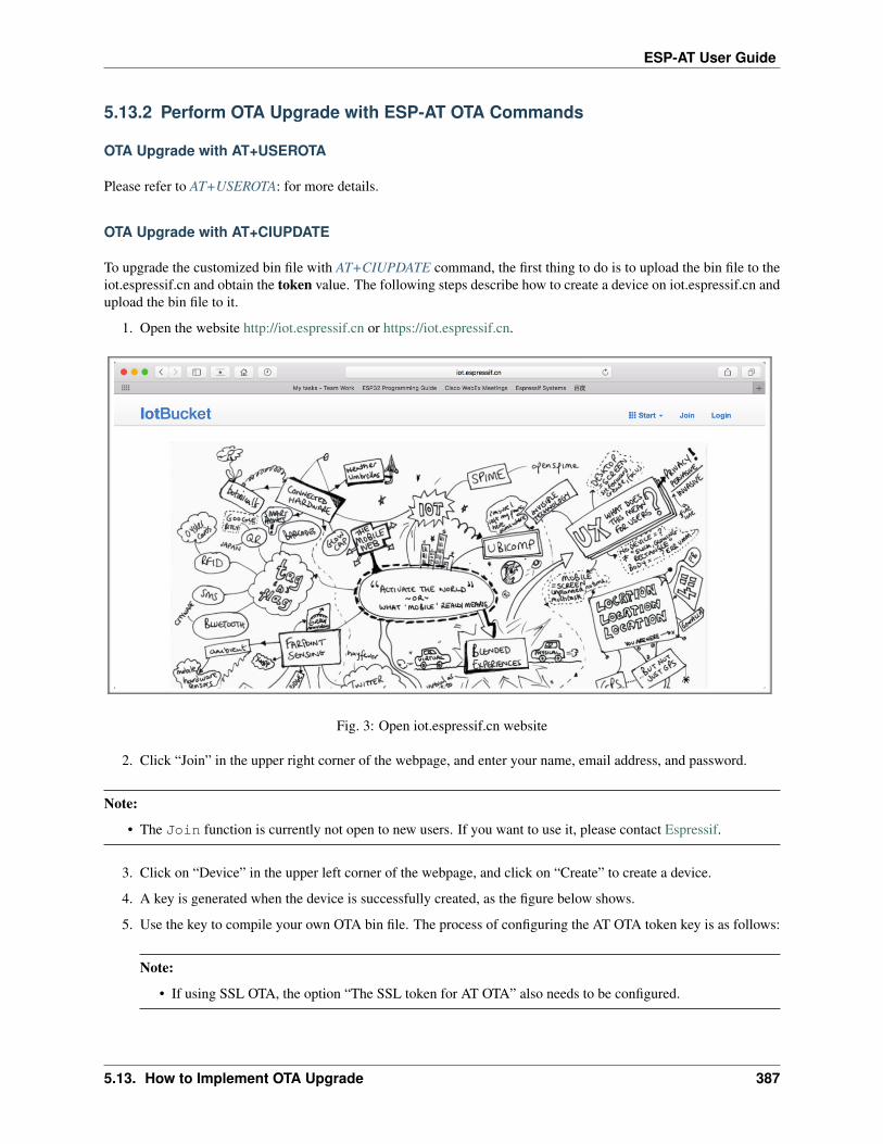
ESP-AT User Guide
5.13.2 Perform OTA Upgrade with ESP-AT OTA Commands
OTA Upgrade with AT+USEROTA
Please refer to AT+USEROTA: for more details.
OTA Upgrade with AT+CIUPDATE
To upgrade the customized bin file with AT+CIUPDATE command, the first thing to do is to upload the bin file to theiot.espressif.cn and obtain the token value. The following steps describe how to create a device on iot.espressif.cn andupload the bin file to it.
1. Open the website http://iot.espressif.cn or https://iot.espressif.cn.
Fig. 3: Open iot.espressif.cn website
2. Click “Join” in the upper right corner of the webpage, and enter your name, email address, and password.
Note:
• The Join function is currently not open to new users. If you want to use it, please contact Espressif.
3. Click on “Device” in the upper left corner of the webpage, and click on “Create” to create a device.
4. A key is generated when the device is successfully created, as the figure below shows.
5. Use the key to compile your own OTA bin file. The process of configuring the AT OTA token key is as follows:
Note:
• If using SSL OTA, the option “The SSL token for AT OTA” also needs to be configured.
5.13. How to Implement OTA Upgrade 387

ESP-AT User Guide
Fig. 4: Join iot.espressif.cn website
Fig. 5: Click on “Device”
388 Chapter 5. How to Compile and Develop Your Own AT Project

ESP-AT User Guide
Fig. 6: Click on “Create”
Fig. 7: A key has been generated
5.13. How to Implement OTA Upgrade 389

ESP-AT User Guide
Fig. 8: Configuring the AT OTA token key - Step 1
6. Click on “Product” to enter the webpage, as shown below. Click on the device created. Enter version andcorename under “ROM Deploy”. Rename the bin file in Step 5 as “ota.bin” and save the configuration.
Note:
• If you want to upgrade the user-defined partition defined in the at_customize.csv, just replace ota.bin with the bin of the user-defined partition.
• For the field corename, the purpose of this field is only to help you distinguish bin files.
7. Click on the ota.bin to save it as the current version.
8. Run the command AT+USEROTA on the ESP device. If the network is connected, OTA upgrade will begin.
Important:
• When setting the name of bin files uploaded to the iot.espressif.cn, please follow the rules below:
– If you upgrade app partitions, set the bin file name to ota.bin.
– If you upgrade a user-defined partition, set the bin file name as the Name field in the at_customize.csv. For example, if you upgrade factory_Param partition, please set it to factory_ param.bin.
• ESP-AT stores the new firmware in a spare OTA partition. In this way, even if OTA fails due to unexpectedreasons, the original ESP-AT firmware can still run. But for user-defined partitions, because ESP-AT has nobackup measures, please upgrade it carefully.
• If you intend to upgrade only customized bin file at the beginning, please set the OTA token to your owntoken value when the initial version is released.
390 Chapter 5. How to Compile and Develop Your Own AT Project

ESP-AT User Guide
Fig. 9: Configuring the AT OTA token key - Step 2 and 3
5.13. How to Implement OTA Upgrade 391

ESP-AT User Guide
Fig. 10: Enter version and corename
392 Chapter 5. How to Compile and Develop Your Own AT Project

ESP-AT User Guide
Fig. 11: Save the current version of ota.bin
OTA Upgrade with AT+WEBSERVER
Please refer to AT+WEBSERVER and Web Server AT Example for more details.
5.14 How to Update the ESP-IDF Version
[]
ESP-AT firmware is based on the Espressif IoT Development Framework (ESP-IDF), and each version of ESP-ATfirmware corresponds to a specific ESP-IDF version. It is strongly recommended to use the default ESP-IDF versionof the ESP-AT project, and NOT recommended to update it, because the inconsistency between the underlying ESP-IDF versions of libesp_*_at_core.a and the ESP-AT project may cause incorrect operation of the firmware.
However, in some special cases, a minor updated ESP-IDF version may be also able to work with the ESP-AT project.In case you should update it, this document can be a reference.
The ESP-IDF version that a specific ESP-AT firmware corresponds to is recorded in the IDF_VERSION files, whichare distributed in different module folders under the module_config folder. The file describes the branch, commit ID,and repository URL of the ESP-IDF that a module firmware is based on.
For example, the IDF_VERSION of the WROOM-32 module of PLATFORM_ESP32 platform is located at mod-ule_config/module_esp32_default/IDF_VERSION.
If you want to update the ESP-IDF version for your ESP-AT firmware, please follow the steps:
• Find the IDF_VERSION file for your module.
• Update the branch, commit ID, repository as needed.
5.14. How to Update the ESP-IDF Version 393

ESP-AT User Guide
• Delete the original esp-idf under the esp-at root directory, so that the ESP-IDF of the version specified inIDF_VERSION will be cloned first in the next compilation.
• Recompile the ESP-AT project.
Note that when the ESP-AT version and the ESP-IDF version do not match, the following error will be reported whencompiling:
Please wait for the update to complete, which will take some time
5.15 ESP-AT Firmware Differences
[]
This document compares the differences among AT firmwares of a certain ESP series in terms of the supported com-mands set, hardware, and supported modules.
5.15.1 ESP32 Series
This section describes the differences among AT firmwares of ESP32 series, including
• ESP32-WROOM-32_AT_Bin (referred to as WROOM Bin in this section);
• ESP32-WROVER-32_AT_Bin (referred to as WROOM Bin in this section);
• ESP32-PICO-D4_AT_Bin (referred to as PICO-D4 Bin in this section);
• ESP32-SOLO-1_AT_Bin (referred to as SOLO-1 Bin in this section);
• ESP32-MINI-1_AT_Bin (referred to as MINI-1 Bin in this section);
• ESP32-D2WD_AT_Bin (referred to as D2WD Bin in this section);
• ESP32-QLOUD_AT_Bin (referred to as QCLOUD Bin in this section).
Supported Command Set
The table lists which command set is supported by default in the official AT firmware applicable to ESP32 series ofmodules (marked with ), which is not supported by default but can be supported after configuration of the ESP-AT project (marked with ), and which is not supported at all (marked with ). Note that the command set thatis not shown in this table is not supported either. Applicable firmware that has not been officially released requirescompilation by yourself. Those self-compiled firmware cannot be upgraded OTA from Espressif official server.
394 Chapter 5. How to Compile and Develop Your Own AT Project

ESP-AT User Guide
CommandSet
WROOMBin
WROVERBin
PICO-D4Bin
SOLO-1Bin
MINI-1Bin
D2WDBin
QCLOUDBin
baseuserwifinetMDNSWPSsmartconfigpingMQTThttpbleble hidblufibt sppbt a2dpethernetFSdriverWPA2WEBOTAqcloud IoT
Hardware Differences
Hardware WROOMBin
WROVERBin
PICO-D4Bin
SOLO-1Bin
MINI-1Bin
D2WD Bin QCLOUDBin
Flash 4 MB 4 MB 4 MB 4 MB 4 MB 2 MB 4 MBPSRAM 8 MBUARTPins1
TX: 17RX: 16CTS: 15RTS: 14
TX: 22RX: 19CTS: 15RTS: 14
TX: 22RX: 19CTS: 15RTS: 14
TX: 17RX: 16CTS: 15RTS: 14
TX: 22RX: 19CTS: 15RTS: 14
TX: 22RX: 19CTS: 15RTS: 14
TX: 17RX: 16CTS: 15RTS: 14
1 UART pins can be customized. See How to Set AT Port Pins for details.
5.15. ESP-AT Firmware Differences 395

ESP-AT User Guide
Supported Modules
The table lists the ESP modules or chips that each AT firmware supports.
Module/Chip WROOMBin
WROVERBin
PICO-D4Bin
SOLO-1Bin
MINI-1Bin
D2WDBin
QCLOUDBin
ESP32-WROOM-32EESP32-WROOM-32UEESP32-WROOM-32DESP32-WROOM-32UESP32-WROOM-32ESP32-WROOM-32SEESP32-WROVER-EESP32-WROVER-IEESP32-WROVER-BESP32-WROVER-IBESP32-WROVERESP32-WROVER-IESP32-SOLO-1ESP32-D2WDESP32-MINI-1ESP32-PICO-D4
5.15.2 ESP32-C3 Series
This section describes the differences among the ESP32-C3 Series of AT firmware, including
• ESP32-C3-MINI-1_AT_Bin (referred to as MINI-1 Bin in this section);
• ESP32-C3-QCLOUD_AT_BIN (referred to as QCLOUD Bin in this section).
396 Chapter 5. How to Compile and Develop Your Own AT Project

ESP-AT User Guide
Supported Command Set
The table lists which command set is supported by default in the official AT firmware applicable to ESP32-C3 seriesof modules (marked with ), which is not supported by default but can be supported after configuration of the ESP-AT project (marked with ), and which is not supported at all (marked with ). Note that the command set thatis not shown in this table is not supported either. Applicable firmware that has not been officially released requirescompilation by yourself. Those self-compiled firmware cannot be upgraded OTA from Espressif official server.
Command Set MINI-1 Bin QCLOUD BinbaseuserwifinetMDNSWPSsmartconfigpingMQTThttpFSdriverWPA2WEBOTAqcloud IoT
Hardware Differences
Hardware MINI-1 QCLOUDFlash 4 MB 4 MBPSRAMUART Pins2
TX: 7RX: 6CTS: 5RTS: 4
TX: 7RX: 6CTS: 5RTS: 4
2 UART pins can be customized. See How to Set AT Port Pins for details.
5.15. ESP-AT Firmware Differences 397

ESP-AT User Guide
Firmware Supported Modules
The table lists the ESP modules or chips that each AT firmware supports.
Module/Chip MINI-1 Bin QCLOUD BinESP32-C3-MINI-1
5.16 How to Download the Latest Temporary Version of AT Firmwarefrom GitHub
[]
As ESP-AT enables CI (Continuous Integration) on GitHub, temporary versions of ESP-AT firmware is generatedevery time when the code is pushed to GitHub.
Note: The temporary version of AT firmware is only for testing, and Espressif is not responsible for it. Youneed to test and save the firmware by yourself.
The following steps guide you on how to download the latest temporary version of AT firmware from GitHub. Beforeyou start, please sign in your GitHub account, as you need login permission to download firmware.
1. Open the website https://github.com/espressif/esp-at.
Fig. 12: ESP-AT GitHub Home Page
2. Click “Actions” to enter the “Actions” page.
3. Click the latest workflow and enter the latest workflow page.
398 Chapter 5. How to Compile and Develop Your Own AT Project

ESP-AT User Guide
Fig. 13: Click Actions
Fig. 14: Actions Page
5.16. How to Download the Latest Temporary Version of AT Firmware from GitHub 399

ESP-AT User Guide
Fig. 15: Click the Latest Workflow
Fig. 16: Latest Workflow Page
400 Chapter 5. How to Compile and Develop Your Own AT Project

ESP-AT User Guide
If you want to download the temporary firmware of the specified branch, click “Branch” to enter the workflowpage of the specified branch.
Fig. 17: Click the Branch
4. Scroll the page to the end, select the corresponding module on the Artifacts page.
5. Click to download the temporary version of AT firmware for modules.
Note: If you do not find the firmware of the corresponding module on the Artifacts page, you can refer to ESP-ATFirmware Differences to select a similar firmware to download.
5.17 Customize Bluetooth LE Services Tools
[]
ESP-AT provides python script BLEService.py to convert customized Bluetooth LE services into ble_data.bin. For more information on customizing Bluetooth LE services, please refer to How to Customize Bluetooth® LEServices.
• Generate Bin File
• Download or Update Bin File
5.17. Customize Bluetooth LE Services Tools 401
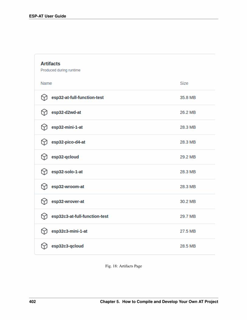
ESP-AT User Guide
Fig. 18: Artifacts Page
402 Chapter 5. How to Compile and Develop Your Own AT Project

ESP-AT User Guide
5.17.1 Generate Bin File
Select one of the following ways to generate ble_data.bin.
• Script Generation
• Generation During Compilation
Script Generation
The path of BLEService.py is tools/BLEService.py. You can get help information of the script through the -hoption. You can also generate ble_data.bin directly through the following commands.
python <SCRIPT_PATH> [-t TARGET_FILE_NAME] <source_file>
• SCRIPT_PATH: the path the script. If you’re in “tools” folder of ESP-AT project, SCRIPT_PATH isBLEService.py.
• TARGET_FILE_NAME: the target file which you want to save the generated bin (absolute address or relativeaddress of the target file); if not specified, it will generate ATBleService.bin in the same directory withsource_file.
• source_file: the source file which you defines your Bluetooth LE GATT services (absolute address orrelative address of the source file).
For example, you can execute the following directory to generate ble_data.bin in the tools directory:
python BLEService.py -t ble_data.bin ../components/customized_partitions/raw_data/ble_→˓data/example.csv
Generation During Compilation
The storage path of Bluetooth LE GATT service files in ESP-AT is compo-nents/customized_partitions/raw_data/ble_data/example.csv.
For how to customize Bluetooth LE services, you can refer to How to Customize Bluetooth® LE Services.
For how to compile ESP-AT project, you can refer to Compile ESP-AT Project.
5.17.2 Download or Update Bin File
The script BLEService.py is only responsible for converting example.csv file to bin file. You can downloadbin files to the corresponding flash partition in the following ways:
1. Download bin file with tools
1. Windows
Please download Flash Download Tools for Windows.
For more details about the Tools, please see readme.pdf or the doc folder in the zip folder.
2. Linux or macOS
Please use esptool.py.
You can refer to How to Customize Bluetooth® LE Services for more details.
5.17. Customize Bluetooth LE Services Tools 403

ESP-AT User Guide
esptool.py --chip auto --port PORTNAME --baud 921600 --before default_reset --→˓after hard_reset write_flash -z --flash_mode dio --flash_freq 40m --flash_size→˓4MB ADDRESS FILEDIRECTORY
Replace PORTNAME with your port name. Replace ADDRESS with the the download address. ReplaceFILEDIRECTORY with the file directory of the bin.
2. Update bin file with commands
1. AT+SYSFLASH
Taking ESP32 module as an example, you can execute the following command to upgrade the ble_datapartition. Please refer to AT+SYSFLASH for more details.
1. Query user partitions in flash
Command:
AT+SYSFLASH?
Response:
+SYSFLASH:"ble_data",64,1,0x21000,0x3000+SYSFLASH:"server_cert",64,2,0x24000,0x2000+SYSFLASH:"server_key",64,3,0x26000,0x2000+SYSFLASH:"server_ca",64,4,0x28000,0x2000+SYSFLASH:"client_cert",64,5,0x2a000,0x2000+SYSFLASH:"client_key",64,6,0x2c000,0x2000+SYSFLASH:"client_ca",64,7,0x2e000,0x2000+SYSFLASH:"factory_param",64,8,0x30000,0x1000+SYSFLASH:"wpa2_cert",64,9,0x31000,0x2000+SYSFLASH:"wpa2_key",64,10,0x33000,0x2000+SYSFLASH:"wpa2_ca",64,11,0x35000,0x2000+SYSFLASH:"mqtt_cert",64,12,0x37000,0x2000+SYSFLASH:"mqtt_key",64,13,0x39000,0x2000+SYSFLASH:"mqtt_ca",64,14,0x3b000,0x2000+SYSFLASH:"fatfs",1,129,0x70000,0x90000
OK
2. Erase ble_data sector
Command:
AT+SYSFLASH=0,"ble_data"
Response:
OK
3. Update ble_data sector
Command:
AT+SYSFLASH=1,"ble_data",0,6487
Response:
>
404 Chapter 5. How to Compile and Develop Your Own AT Project

ESP-AT User Guide
If the operator is write, wrap return > after the write command, then you can send the datathat you want to write. The length should be parameter <length>. When the write operation iscompleted, the system will prompt the following information.
OK
2. AT+CIUPDATE
For example, you can execute the following command to upgrade the ble_data partition (The premise is thatyou must use the Wi-Fi function). Please refer to AT+CIUPDATE for more details.
Important: If you want to update the ble_data partition in this way, you must implement your own OTAdevice, please refer to How to Implement OTA Upgrade.
AT+CIUPDATE=1,"v2.2.0.0","ble_data"
Note: You must ensure that the download address is correct, otherwise the ESP-AT firmware may not work. Thesimplest way to view the download address is to execute the command AT+SYSFLASH?.
5.18 How to Generate PKI Files
[]
ESP-AT provides python script AtPKI.py to convert SSL server certificates, SSL client certificates, MQTT certifi-cates, and WPA2 certificates files (including CA, cert, and private key files) into bin files.
• Certificate Bin Files Format
• Generate Certificate Bin Files
• Download or Update Certificate Bin Files
5.18.1 Certificate Bin Files Format
In addition to converting the certificate file into a bin file, the script AtPKI.py adds some additional information tothe bin file.
When converting a single certificate file, the script will add 12 bytes in little-endian format to the header and 4 bytesaligned at the end.
5.18. How to Generate PKI Files 405

ESP-AT User Guide
Field Descriptionmagic code (2 bytes) 0xF1 0xF1list size (2 bytes) the number of certificate fileslength (4 bytes) remaining file size = total file size - magic code size - list size -
length sizetype (1 bytes)
ca: 0x01certificate: 0x02key: 0x03
ID (1 bytes) used to match certificate filescontent len (2 bytes) the size of the certificate file converted to the bin file
Taking the client_cert.bin generated in the Generate Certificate Bin Files section as an example, the 12 bytesin little-endian format at the beginning of the file are:
Field Descriptionmagic code (2 bytes) 0xF1 0xF1list size (2 bytes) 0x02 0x00length (4 bytes) 0x20 0x09 0x00 0x00type (1 bytes) 0x02ID (1 bytes) 0x00content len (2 bytes) 0x8C 0x04
When converting multiple certificate files, the script AtPKI.py inserts 4 bytes at the beginning of every file exceptthe first one. The 4 bytes in little-endian format at the beginning of the file are:
Field Descriptiontype (1 bytes)
ca: 0x01certificate: 0x02key: 0x03
ID (1 bytes) used to match certificate filescontent len (2 bytes) the size of the certificate file converted to the bin file
Taking the client_cert.bin generated in the Generate Certificate Bin Files section as an example, the 4 bytes inlittle-endian format at the beginning of the file are:
Field Descriptiontype (1 bytes) certificate: 0x02ID (1 bytes) 0x01content len (2 bytes) 0x8C 0x04
406 Chapter 5. How to Compile and Develop Your Own AT Project
ESP-AT User Guide
5.18.2 Generate Certificate Bin Files
Select one of the following ways to generate certificate bin files.
• Script Generation
• Generation During Compilation
Script Generation
The path of AtPKI.py is tools/AtPKI.py. You can get help information of the script through the -h option. You canalso generate bin files directly through the following commands.
python <SCRIPT_PATH> generate_bin [-b OUTPUT_BIN_NAME] <PKI_LIST> <source_file>
• SCRIPT_PATH: the path the script. If you’re in “tools” folder of ESP-AT project, SCRIPT_PATH is AtPKI.py.
• OUTPUT_BIN_NAME: the target file which you want to save the generated bin (absolute address or relativeaddress of the target file); if -b OUTPUT_BIN_NAME is omitted, it will generate PKI.bin in the currentdirectory.
• PKI_LIST: must be equal to one of ca, cert, key.
• source_file: the certificate source file which you want to convert (absolute address or relative address ofthe source file).
Taking the SSL client certificate files of ESP-AT as an example, you can execute the following command to generateclient_cert.bin in the tools directory:
python AtPKI.py generate_bin -b ./client_cert.bin cert ../components/customized_→˓partitions/raw_data/client_cert/client_cert_00.crt cert ../components/customized_→˓partitions/raw_data/client_cert/client_cert_01.crt
Generation During Compilation
The storage path of certificate files in ESP-AT is components/customized_partitions/raw_data.
Taking the SSL client certificate files of ESP-AT as an example. If you want to generate your own SSL client cer-tificates files, you must replace the CA certificate in the client_ca directory with your own CA certificate, the certcertificate in the client_cert directory with your own cert certificate, and the private key in the client_key directory with your own private key.
If you have multiple sets of certificate files, please place them in the corresponding directory according to your certifi-cate chain. It is recommended that you end the file name with a number to ensure the parsing order of the certificatefiles.
After replacement, You can refer to Compile ESP-AT Project to compile the ESP-AT project.
5.18. How to Generate PKI Files 407

ESP-AT User Guide
5.18.3 Download or Update Certificate Bin Files
The script AtPKI.py is only responsible for converting the certificate files to bin files. You can download bin files tothe corresponding flash partition in one of the following ways:
Download with Tools
• Windows
Please download Flash Download Tools for Windows.
For more details about the Tools, please see readme.pdf or the doc folder in the zip folder.
• Linux or macOS
Please use esptool.py.
You can execute the following command in the root directory of ESP-AT to download bin files.
esptool.py --chip auto --port PORTNAME --baud 921600 --before default_reset --→˓after hard_reset write_flash -z --flash_mode dio --flash_freq 40m --flash_size→˓4MB ADDRESS FILEDIRECTORY
Replace PORTNAME with your port name. Replace ADDRESS with the the download address. ReplaceFILEDIRECTORY with the file directory of the bin.
Update with Commands
• AT+SYSFLASH
Taking ESP32 module as an example, you can execute the following command to upgrade the client_certpartition. Please refer to AT+SYSFLASH for more details.
1. Query user partitions in flash
Command:
AT+SYSFLASH?
Response:
+SYSFLASH:"ble_data",64,1,0x21000,0x3000+SYSFLASH:"server_cert",64,2,0x24000,0x2000+SYSFLASH:"server_key",64,3,0x26000,0x2000+SYSFLASH:"server_ca",64,4,0x28000,0x2000+SYSFLASH:"client_cert",64,5,0x2a000,0x2000+SYSFLASH:"client_key",64,6,0x2c000,0x2000+SYSFLASH:"client_ca",64,7,0x2e000,0x2000+SYSFLASH:"factory_param",64,8,0x30000,0x1000+SYSFLASH:"wpa2_cert",64,9,0x31000,0x2000+SYSFLASH:"wpa2_key",64,10,0x33000,0x2000+SYSFLASH:"wpa2_ca",64,11,0x35000,0x2000+SYSFLASH:"mqtt_cert",64,12,0x37000,0x2000+SYSFLASH:"mqtt_key",64,13,0x39000,0x2000+SYSFLASH:"mqtt_ca",64,14,0x3b000,0x2000+SYSFLASH:"fatfs",1,129,0x70000,0x90000
OK
408 Chapter 5. How to Compile and Develop Your Own AT Project

ESP-AT User Guide
2. Erase client_cert sector
Command:
AT+SYSFLASH=0,"client_cert"
Response:
OK
3. Update client_cert sector
Command:
AT+SYSFLASH=1,"client_cert",0,2344
Response:
>
If the operator is write, wrap return > after the write command, then you can send the datathat you want to write. The length should be parameter <length>. When the write operation iscompleted, the system will prompt the following information.
OK
• AT+CIUPDATE
For example, you can execute the following command to upgrade the client_ca partition. Please refer toAT+CIUPDATE for more details.
Important: If you want to update the client_ca partition in this way, you must implement your own OTAdevice, please refer to How to Implement OTA Upgrade.
AT+CIUPDATE=1,"v2.2.0.0","client_ca"
Note: You must ensure that the download address is correct, otherwise the ESP-AT firmware may not work. Thesimplest way to view the download address is to execute the command AT+SYSFLASH?.
5.19 AT API Reference
5.19.1 Header File
• at/include/esp_at_core.h
5.19. AT API Reference 409

ESP-AT User Guide
5.19.2 Functions
void esp_at_module_init(uint32_t netconn_max, const uint8_t *custom_version)This function should be called only once, before any other AT functions are called.
Parameters
• netconn_max: the maximum number of the link in the at module
• custom_version: version information by custom
esp_at_para_parse_result_type esp_at_get_para_as_digit(int32_t para_index, int32_t *value)Parse digit parameter from command string.
Return
• ESP_AT_PARA_PARSE_RESULT_OK : succeed
• ESP_AT_PARA_PARSE_RESULT_FAIL : fail
• ESP_AT_PARA_PARSE_RESULT_OMITTED : this parameter is OMITTED
Parameters
• para_index: the index of parameter
• value: the value parsed
esp_at_para_parse_result_type esp_at_get_para_as_str(int32_t para_index, uint8_t **result)Parse string parameter from command string.
Return
• ESP_AT_PARA_PARSE_RESULT_OK : succeed
• ESP_AT_PARA_PARSE_RESULT_FAIL : fail
• ESP_AT_PARA_PARSE_RESULT_OMITTED : this parameter is OMITTED
Parameters
• para_index: the index of parameter
• result: the pointer that point to the result.
void esp_at_port_recv_data_notify_from_isr(int32_t len)Calling the esp_at_port_recv_data_notify_from_isr to notify at module that at port received data. When receivedthis notice,at task will get data by calling get_data_length and read_data in esp_at_device_ops. This functionMUST be used in isr.
Parameters
• len: data length
bool esp_at_port_recv_data_notify(int32_t len, uint32_t msec)Calling the esp_at_port_recv_data_notify to notify at module that at port received data. When received thisnotice,at task will get data by calling get_data_length and read_data in esp_at_device_ops. This function MUSTNOT be used in isr.
Return
• true : succeed
410 Chapter 5. How to Compile and Develop Your Own AT Project

ESP-AT User Guide
• false : fail
Parameters
• len: data length
• msec: timeout time,The unit is millisecond. It waits forever,if msec is portMAX_DELAY.
void esp_at_transmit_terminal_from_isr(void)terminal transparent transmit mode,This function MUST be used in isr.
void esp_at_transmit_terminal(void)terminal transparent transmit mode,This function MUST NOT be used in isr.
bool esp_at_custom_cmd_array_regist(const esp_at_cmd_struct *custom_at_cmd_array,uint32_t cmd_num)
regist at command set, which defined by custom,
Parameters
• custom_at_cmd_array: at command set
• cmd_num: command number
void esp_at_device_ops_regist(esp_at_device_ops_struct *ops)regist device operate functions set,
Parameters
• ops: device operate functions set
bool esp_at_custom_net_ops_regist(int32_t link_id, esp_at_custom_net_ops_struct *ops)
bool esp_at_custom_ble_ops_regist(int32_t conn_index, esp_at_custom_ble_ops_struct *ops)
void esp_at_custom_ops_regist(esp_at_custom_ops_struct *ops)regist custom operate functions set interacting with AT,
Parameters
• ops: custom operate functions set
uint32_t esp_at_get_version(void)get at module version number,
Return at version bit31~bit24: at main version bit23~bit16: at sub version bit15~bit8 : at test version bit7~bit0: at custom version
void esp_at_response_result(uint8_t result_code)response AT process result,
Parameters
• result_code: see esp_at_result_code_string_index
int32_t esp_at_port_write_data(uint8_t *data, int32_t len)write data into device,
Return
• >= 0 : the real length of the data written
5.19. AT API Reference 411

ESP-AT User Guide
• others : fail.
Parameters
• data: data buffer to be written
• len: data length
int32_t esp_at_port_read_data(uint8_t *data, int32_t len)read data from device,
Return
• >= 0 : the real length of the data read from device
• others : fail
Parameters
• data: data buffer
• len: data length
bool esp_at_port_wait_write_complete(int32_t timeout_msec)wait for transmitting data completely to peer device,
Return
• true : succeed,transmit data completely
• false : fail
Parameters
• timeout_msec: timeout time,The unit is millisecond.
int32_t esp_at_port_get_data_length(void)get the length of the data received,
Return
• >= 0 : the length of the data received
• others : fail
bool esp_at_base_cmd_regist(void)regist at base command set. If not,you can not use AT base command
bool esp_at_user_cmd_regist(void)regist at user command set. If not,you can not use AT user command
bool esp_at_wifi_cmd_regist(void)regist at wifi command set. If not,you can not use AT wifi command
bool esp_at_net_cmd_regist(void)regist at net command set. If not,you can not use AT net command
bool esp_at_mdns_cmd_regist(void)regist at mdns command set. If not,you can not use AT mdns command
bool esp_at_driver_cmd_regist(void)regist at driver command set. If not,you can not use AT driver command
412 Chapter 5. How to Compile and Develop Your Own AT Project

ESP-AT User Guide
bool esp_at_wps_cmd_regist(void)regist at wps command set. If not,you can not use AT wps command
bool esp_at_smartconfig_cmd_regist(void)regist at smartconfig command set. If not,you can not use AT smartconfig command
bool esp_at_ping_cmd_regist(void)regist at ping command set. If not,you can not use AT ping command
bool esp_at_http_cmd_regist(void)regist at http command set. If not,you can not use AT http command
bool esp_at_mqtt_cmd_regist(void)regist at mqtt command set. If not,you can not use AT mqtt command
bool esp_at_ble_cmd_regist(void)regist at ble command set. If not,you can not use AT ble command
bool esp_at_ble_hid_cmd_regist(void)regist at ble hid command set. If not,you can not use AT ble hid command
bool esp_at_blufi_cmd_regist(void)regist at blufi command set. If not,you can not use AT blufi command
bool esp_at_bt_cmd_regist(void)regist at bt command set. If not,you can not use AT bt command
bool esp_at_bt_spp_cmd_regist(void)regist at bt spp command set. If not,you can not use AT bt spp command
bool esp_at_bt_a2dp_cmd_regist(void)regist at bt a2dp command set. If not,you can not use AT bt a2dp command
bool esp_at_fs_cmd_regist(void)regist at fs command set. If not,you can not use AT fs command
bool esp_at_eap_cmd_regist(void)regist at WPA2 Enterprise AP command set. If not,you can not use AT EAP command
bool esp_at_eth_cmd_regist(void)regist at ethernet command set. If not,you can not use AT ethernet command
bool esp_at_custom_cmd_line_terminator_set(uint8_t *terminator)Set AT command terminator, by default, the terminator is “\r\n” You can change it by calling this function, butit just supports one character now.
Return
• true : succeed,transmit data completely
• false : fail
Parameters
• terminator: the line terminator
uint8_t *esp_at_custom_cmd_line_terminator_get(void)Get AT command line terminator,by default, the return string is “\r\n”.
Return the command line terminator
5.19. AT API Reference 413

ESP-AT User Guide
const esp_partition_t *esp_at_custom_partition_find(esp_partition_type_t type,esp_partition_subtype_t subtype, constchar *label)
Find the partition which is defined in at_customize.csv.
Return pointer to esp_partition_t structure, or NULL if no partition is found. This pointer is valid for thelifetime of the application
Parameters
• type: the type of the partition
• subtype: the subtype of the partition
• label: Partition label
void esp_at_port_enter_specific(esp_at_port_specific_callback_t callback)Set AT core as specific status, it will call callback if receiving data. for example:
static void wait_data_callback (void){
xSemaphoreGive(sync_sema);}
void process_task(void* para){
vSemaphoreCreateBinary(sync_sema);xSemaphoreTake(sync_sema,portMAX_DELAY);esp_at_port_write_data((uint8_t *)">",strlen(">"));esp_at_port_enter_specific(wait_data_callback);while(xSemaphoreTake(sync_sema,portMAX_DELAY)) {
len = esp_at_port_read_data(data, data_len);// TODO:
}}
Parameters
• callback: which will be called when received data from AT port
void esp_at_port_exit_specific(void)Exit AT core as specific status.
const uint8_t *esp_at_get_current_cmd_name(void)Get current AT command name.
5.19.3 Structures
struct esp_at_cmd_structesp_at_cmd_struct used for define at command
414 Chapter 5. How to Compile and Develop Your Own AT Project

ESP-AT User Guide
Public Members
char *at_cmdNameat command name
uint8_t (*at_testCmd)(uint8_t *cmd_name)Test Command function pointer
uint8_t (*at_queryCmd)(uint8_t *cmd_name)Query Command function pointer
uint8_t (*at_setupCmd)(uint8_t para_num)Setup Command function pointer
uint8_t (*at_exeCmd)(uint8_t *cmd_name)Execute Command function pointer
struct esp_at_device_ops_structesp_at_device_ops_struct device operate functions struct for AT
Public Members
int32_t (*read_data)(uint8_t *data, int32_t len)read data from device
int32_t (*write_data)(uint8_t *data, int32_t len)write data into device
int32_t (*get_data_length)(void)get the length of data received
bool (*wait_write_complete)(int32_t timeout_msec)wait write finish
struct esp_at_custom_net_ops_structesp_at_custom_net_ops_struct custom socket callback for AT
Public Members
int32_t (*recv_data)(uint8_t *data, int32_t len)callback when socket received data
void (*connect_cb)(void)callback when socket connection is built
void (*disconnect_cb)(void)callback when socket connection is disconnected
struct esp_at_custom_ble_ops_structesp_at_custom_ble_ops_struct custom ble callback for AT
5.19. AT API Reference 415

ESP-AT User Guide
Public Members
int32_t (*recv_data)(uint8_t *data, int32_t len)callback when ble received data
void (*connect_cb)(void)callback when ble connection is built
void (*disconnect_cb)(void)callback when ble connection is disconnected
struct esp_at_custom_ops_structesp_at_ops_struct some custom function interacting with AT
Public Members
void (*status_callback)(esp_at_status_type status)callback when AT status changes
void (*pre_deepsleep_callback)(void)callback before enter deep sleep
void (*pre_restart_callback)(void)callback before restart
5.19.4 Macros
at_min(x, y)
at_max(x, y)
ESP_AT_ERROR_NO(subcategory, extension)
ESP_AT_CMD_ERROR_OKNo Error
ESP_AT_CMD_ERROR_NON_FINISHterminator character not found (“\r\n” expected)
ESP_AT_CMD_ERROR_NOT_FOUND_ATStarting “AT” not found (or at, At or aT entered)
ESP_AT_CMD_ERROR_PARA_LENGTH(which_para)parameter length mismatch
ESP_AT_CMD_ERROR_PARA_TYPE(which_para)parameter type mismatch
ESP_AT_CMD_ERROR_PARA_NUM(need, given)parameter number mismatch
ESP_AT_CMD_ERROR_PARA_INVALID(which_para)the parameter is invalid
ESP_AT_CMD_ERROR_PARA_PARSE_FAIL(which_para)parse parameter fail
ESP_AT_CMD_ERROR_CMD_UNSUPPORTthe command is not supported
416 Chapter 5. How to Compile and Develop Your Own AT Project

ESP-AT User Guide
ESP_AT_CMD_ERROR_CMD_EXEC_FAIL(result)the command execution failed
ESP_AT_CMD_ERROR_CMD_PROCESSINGprocessing of previous command is in progress
ESP_AT_CMD_ERROR_CMD_OP_ERRORthe command operation type is error
5.19.5 Type Definitions
typedef void (*esp_at_port_specific_callback_t)(void)AT specific callback type.
5.19.6 Enumerations
enum esp_at_status_typeesp_at_status some custom function interacting with AT
Values:
ESP_AT_STATUS_NORMAL = 0x0Normal mode.Now mcu can send AT command
ESP_AT_STATUS_TRANSMITTransparent Transmition mode
enum esp_at_modulemodule number,Now just AT module
Values:
ESP_AT_MODULE_NUM = 0x01AT module
enum esp_at_error_codesubcategory number
Values:
ESP_AT_SUB_OK = 0x00OK
ESP_AT_SUB_COMMON_ERROR = 0x01reserved
ESP_AT_SUB_NO_TERMINATOR = 0x02terminator character not found (“\r\n” expected)
ESP_AT_SUB_NO_AT = 0x03Starting “AT” not found (or at, At or aT entered)
ESP_AT_SUB_PARA_LENGTH_MISMATCH = 0x04parameter length mismatch
ESP_AT_SUB_PARA_TYPE_MISMATCH = 0x05parameter type mismatch
ESP_AT_SUB_PARA_NUM_MISMATCH = 0x06parameter number mismatch
5.19. AT API Reference 417

ESP-AT User Guide
ESP_AT_SUB_PARA_INVALID = 0x07the parameter is invalid
ESP_AT_SUB_PARA_PARSE_FAIL = 0x08parse parameter fail
ESP_AT_SUB_UNSUPPORT_CMD = 0x09the command is not supported
ESP_AT_SUB_CMD_EXEC_FAIL = 0x0Athe command execution failed
ESP_AT_SUB_CMD_PROCESSING = 0x0Bprocessing of previous command is in progress
ESP_AT_SUB_CMD_OP_ERROR = 0x0Cthe command operation type is error
enum esp_at_para_parse_result_typethe result of AT parse
Values:
ESP_AT_PARA_PARSE_RESULT_FAIL = -1parse fail,Maybe the type of parameter is mismatched,or out of range
ESP_AT_PARA_PARSE_RESULT_OK = 0Successful
ESP_AT_PARA_PARSE_RESULT_OMITTEDthe parameter is OMITTED.
enum esp_at_result_code_string_indexthe result code of AT command processing
Values:
ESP_AT_RESULT_CODE_OK = 0x00“OK”
ESP_AT_RESULT_CODE_ERROR = 0x01“ERROR”
ESP_AT_RESULT_CODE_FAIL = 0x02“ERROR”
ESP_AT_RESULT_CODE_SEND_OK = 0x03“SEND OK”
ESP_AT_RESULT_CODE_SEND_FAIL = 0x04“SEND FAIL”
ESP_AT_RESULT_CODE_IGNORE = 0x05response nothing, just change internal status
ESP_AT_RESULT_CODE_PROCESS_DONE = 0x06response nothing, just change internal status
ESP_AT_RESULT_CODE_OK_AND_INPUT_PROMPT = 0x07
ESP_AT_RESULT_CODE_MAX
418 Chapter 5. How to Compile and Develop Your Own AT Project

ESP-AT User Guide
5.19.7 Header File
• at/include/esp_at.h
5.19.8 Functions
const char *esp_at_get_current_module_name(void)get current module name
const char *esp_at_get_module_name_by_id(uint32_t id)get module name by index
uint32_t esp_at_get_module_id(void)get current module id
void esp_at_board_init(void)init peripheral and default parameters in factory_param.bin
bool esp_at_web_server_cmd_regist(void)regist WiFi config via web command. If not,you can not use web server to config wifi connect
5.19.9 Macros
ESP_AT_PORT_TX_WAIT_MS_MAX
ESP_AT_FACTORY_PARAMETER_SIZE
5.19. AT API Reference 419

ESP-AT User Guide
420 Chapter 5. How to Compile and Develop Your Own AT Project

CHAPTER
SIX
CUSTOMIZED AT COMMANDS AND FIRMWARE
6.1 Tencent Cloud IoT AT Commands and Firmware
6.1.1 Tencent Cloud IoT AT Command Set
Please refer to [Chinese version]. The English version is not provided since the firmware and commands are applicableto the Chinese market (Tencent).
6.1.2 Tencent Cloud IoT AT Firmware
ESP32
• TODO
ESP32-C3
• TODO
421

ESP-AT User Guide
422 Chapter 6. Customized AT Commands and Firmware

CHAPTER
SEVEN
AT FAQ
[]
• AT Firmware
– There is no released firmware for my module. Where can I get the firmware for it?
– How to get the source code of AT firmware?
– How to download the AT firmware on Espressif’s official website?
– How to combine all the bin files compiled by ESP-AT?
– Why is the error “flash read err,1000” printed on the serial port after powering up the newly purchasedESP32-WROVE-E module? How to use AT commands for this module?
– Does the AT firmware shipped in modules support flow control?
– I am new to ESP-AT firmware. Which AT firmware version shall I choose for ESP8266, NONOS orRTOS?
• AT Commands and Responses
– What is the reason why AT prompts busy?
– Why does the ESP-AT firmware always return the following message after the I powered up the deviceand sent the first command?
– What commands are supported by the default ESP-AT firmware on different modules, and from whichversion are they supported?
– When the host MCU sends an AT command to the ESP32 device (AT firmware version: V2.1.0.0), thereis no response. What is the reason?
– Do AT commands support ESP-WIFI-MESH?
– Does AT support websocket commands?
– Can AT command set Bluetooth LE transmit power?
– Is it possible to set the ESP32-WROOM-32 module to HID keyboard mode with AT commands?
– How to support commands that are not supported by the default firmware but can be supported afterconfiguring and compiling the ESP-AT project?
– How to handle special characters in AT commands?
– Can the serial port baudrate be modified in AT Commands? (Default: 115200)
423
ESP-AT User Guide
– After ESP32 enters the passthrough mode using AT commands, can ESP32 give a message if the con-nected hotspot is disconnected?
– How to set ADV broadcast parameters after it exceeds 32 bytes?
– After I migrate from ESP8266 NONOS AT to RTOS AT (v2.0.0.0 and above), flash the firmware suc-cessfully, and start up AT, why no “ready” is returned?
• Hardware
– How big is the chip flash required for ESP-AT firmware on different modules?
– How does the ESP32 AT communicate through the UART0 port?
– How to view the error log of AT firmware?
– The UART1 communication pin used by ESP-AT on the ESP32 module is inconsistent with the defaultUART1 pin described in the ESP32 module’s datasheet?
• Performance
– How long does it take for the AT to connect to Wi-Fi?
– Is it possible to change the TCP send window size in AT firmware?
– How to test and optimize the throughput of ESP32 AT?
– What is the maximum rate of ESP32 AT default firmware Bluetooth LE UART transparent transmission?
• Other
– What interfaces of ESP chips can be used to transmit AT commands?
– How to use the Ethernet function of the ESP32 AT?
– How does ESP-AT conduct BQB certification?
– How do I specify the TLS protocol version for ESP32 AT?
– How to modify the number of TCP connections in AT?
7.1 AT Firmware
7.1.1 There is no released firmware for my module. Where can I get the firmwarefor it?
If there is no released fimware for your module in the AT Binary Lists chapter, please consider the following options:
• Use the firmware for the module that has the same hardware configuration as yours (see ESP-AT FirmwareDifferences for which module has the same configuration).
• Create a factory parameter bin and compile the firmware for your module by yourself.
424 Chapter 7. AT FAQ
ESP-AT User Guide
7.1.2 How to get the source code of AT firmware?
ESP-AT firmware is partially open-source. See esp-at for the open-source repository.
7.1.3 How to download the AT firmware on Espressif’s official website?
• Download the flash tool: Flash Download Tools.
• See AT Downloading Guide for the download address.
7.1.4 How to combine all the bin files compiled by ESP-AT?
You can use the combine button of the Flash Download Tools.
7.1.5 Why is the error “flash read err,1000” printed on the serial port after poweringup the newly purchased ESP32-WROVE-E module? How to use AT commandsfor this module?
• The ESP32-WROVER-E module is shipped without AT firmware, so the error “flash read err” appears.
• If you want to use the AT command function of ESP32-WROVER-E, please refer to the following links to getthe firmware and flash it.
– Download firmware;
– Connect hardware;
– Flash firmware.
7.1.6 Does the AT firmware shipped in modules support flow control?
• Hardware flow control is supported, but software flow control is not.
• To enable or disable hardware flow control, run AT+UART_CUR or AT+UART_DEF.
• See Hardware connection for more details.
7.1.7 I am new to ESP-AT firmware. Which AT firmware version shall I choose forESP8266, NONOS or RTOS?
• It is recommended to use the RTOS version, which is being actively maintained now. NONOS is an older ATversion.
• The two versions are quite different in terms of logic. Besides, RTOS supports more features and fixes the bugsthat exist in NONOS version. RTOS version is now and will be our focus in the long run. We will fix bugs moretimely and constantly add new features in this version.
• Please download RTOS AT bin.
7.1. AT Firmware 425

ESP-AT User Guide
7.2 AT Commands and Responses
7.2.1 What is the reason why AT prompts busy?
• The “busy” prompt indicates that the previous command is being executed, and the system cannot respond tothe current input. The processing mechanism of the AT commands is serial, i.e. one command at a time.
• Any input through serial ports is considered to be a command input, so the system will also prompt “busy” or“ERROR” when there is any extra invisible character input.
– Serial input AT+GMR (change character CR LF) (space character), because AT+GMR (change characterCR LF) is already a complete AT command, the system will execute the command. At this time, if thesystem has not completed the AT+GMR operation, it has received the following space character, whichwill be regarded as a new command input, and the system will prompt “busy”. But if the system hascompleted the AT+GMR operation, and then receives the following space character, the space characterwill be regarded as an error command, and the system will prompt “ERROR”.
– After the MCU sends AT+CIPSEND and receives the busy p.. response, the MCU needs to resend thedata. Because busy p.. represents the previous command is being executed, the current input is invalid. Itis recommended to wait for the response of the last AT command before the MCU sends a new commandagain.
7.2.2 Why does the ESP-AT firmware always return the following message after theI powered up the device and sent the first command?
ERR CODE:0x010b0000busy p...
• This message means that the previous command is being executed.
• Normally only “busy p. . . ” is displayed. The ERR CODE is displayed because the error code promptis enabled.
• If you receive this message after sending the first command on power-up, the possible reasons are:the command is followed by the unnecessary newline/space/other symbols; or two or more AT com-mands are sent in succession.
7.2.3 What commands are supported by the default ESP-AT firmware on differentmodules, and from which version are they supported?
• To learn what commands are supported by the default ESP-AT firmware on different modules, please refer toESP-AT Firmware Differences and How to understand the differences of each type of module.
• To learn from which version a command is supported and what issues are fixed in each version, please refer torelease notes.
426 Chapter 7. AT FAQ

ESP-AT User Guide
7.2.4 When the host MCU sends an AT command to the ESP32 device (AT firmwareversion: V2.1.0.0), there is no response. What is the reason?
A terminator (“ATrn”) must be added after an AT command when the host MCU sending AT commandsto an ESP32 device. Please see Check Whether AT Works.
7.2.5 Do AT commands support ESP-WIFI-MESH?
Currently, AT commands do not support ESP-WIFI-MESH.
7.2.6 Does AT support websocket commands?
• Not supported in the default firmware.
• It can be implemented by custom commands. See websocket and How to add user-defined AT commands formore information.
7.2.7 Can AT command set Bluetooth LE transmit power?
Yes, the AT+RFPOWER command can set Bluetooth LE transmit power. ESP32 and ESP32-C3 Wi-Fiand Bluetooth LE share the same antenna.
7.2.8 Is it possible to set the ESP32-WROOM-32 module to HID keyboard mode withAT commands?
Yes, please refer to Bluetooth LE AT Commands.
7.2.9 How to support commands that are not supported by the default firmware butcan be supported after configuring and compiling the ESP-AT project?
For example, if you need to support the Bluetooth function on the ESP32-WROOM series, configureand compile the firmware by yourself. Open the Bluetooth function in menuconfig when compiling:./build.py menuconfig > Component config > AT > [*]AT bt command support.
7.2.10 How to handle special characters in AT commands?
Please refer to the escape character syntax described in the AT Command Types section.
7.2.11 Can the serial port baudrate be modified in AT Commands? (Default:115200)
Yes, you can use either of the two ways below to modify it:
• Use the command AT+UART_CUR or AT+UART_DEF.
• Re-compile the AT firmware: establish the compiling environment and change the UART baudrate.
7.2. AT Commands and Responses 427

ESP-AT User Guide
7.2.12 After ESP32 enters the passthrough mode using AT commands, can ESP32give a message if the connected hotspot is disconnected?
• Yes, you can configure it with AT+SYSMSG, i.e., set AT+SYSMSG=4. In this way, the serial port will report“WIFI DISCONNECTrn” when the connected hotspot is disconnected.
• Note that this command is added after AT v2.1.0. It is not available for v2.1.0 and earlier versions.
7.2.13 How to set ADV broadcast parameters after it exceeds 32 bytes?
The AT+BLEADVDATA command supports up to 32 bytes of ADV broadcast parameters. If you need toset a bigger parameter, please use command AT+BLESCANRSPDATA.
7.2.14 After I migrate from ESP8266 NONOS AT to RTOS AT (v2.0.0.0 and above),flash the firmware successfully, and start up AT, why no “ready” is returned?
• AT communication pins of the ESP8266 RTOS version have been changed to GPIO13 and GPIO15.
• See Hardware connection for more details.
7.3 Hardware
7.3.1 How big is the chip flash required for ESP-AT firmware on different modules?
• For ESP32 and ESP32-C3 series modules, please refer to ESP-AT Firmware Differences.
• For ESP8266 series modules, please refer to How to understand the differences of each type of module.
7.3.2 How does the ESP32 AT communicate through the UART0 port?
The default AT firmware communicates through the UART1 port. If you want to communicate throughUART0, please download and compile the ESP-AT project.
• Refer to Compile ESP-AT Project to set up the compiling environment;
• Modify the module’s UART pins in your factory_param_data.csv , i.e. change uart_tx_pin to GPIO1,and uart_tx_pin to GPIO3;
• Configure your esp-at project: ./build.py menuconfig > Component config > Common ESP-related> UART for console output(Custom) > Uart peripheral to use for console output(0-1)(UART1) >(1)UART TX on GPIO# (NEW) > (3)UART TX on GPIO# (NEW).
428 Chapter 7. AT FAQ

ESP-AT User Guide
7.3.3 How to view the error log of AT firmware?
• For ESP32, the error log is output through the download port. By default, UART0 is GPIO1 and GPIO3.
• For ESP32-C3, the error log is output through the download port. By default, UART0 is GPIO21 and GPIO20.
• For ESP8266, it is output from UART1 TX, which is GPIO2 by default.
• See Hardware Connection for more details.
7.3.4 The UART1 communication pin used by ESP-AT on the ESP32 module isinconsistent with the default UART1 pin described in the ESP32 module’sdatasheet?
• ESP32 supports IO matrix. When compiling ESP-AT, you can configure UART1 pins in menuconfig, so theymay be inconsistent with the pins described in the module datasheet.
• See factory_param_data.csv for more details.
7.4 Performance
7.4.1 How long does it take for the AT to connect to Wi-Fi?
• In an office scenario, the connection time is 5 seconds. However, in actual practice, Wi-Fi connection timedepends on the router performance, network environment, module antenna performance, etc.
• The maximum timeout time can be set by the <jap_timeout> parameter of AT+CWJAP.
7.4.2 Is it possible to change the TCP send window size in AT firmware?
• Currently, it cannot be changed by AT commands, but you can configure and compile the ESP-AT project togenerate a new firmware.
• You can configure the menuconfig parameter: Component config > LWIP > TCP > Default sendbuffer size.
7.4.3 How to test and optimize the throughput of ESP32 AT?
• Many factors are affecting the AT throughput test. It is recommended to use the iperf example in esp-idf fortesting. While testing, please use the passthrough mode, adjust the data length to 1460 bytes, and send datacontinuously.
• If the test rate does not meet your requirements, please refer to How to Improve ESP-AT Throughput Perfor-mance.
7.4. Performance 429

ESP-AT User Guide
7.4.4 What is the maximum rate of ESP32 AT default firmware Bluetooth LE UARTtransparent transmission?
In an open office environment, when the serial port baud rate is 2000000, the average transmission rateof ESP-AT Bluetooth is 0.56 Mbps, and the average transmission rate of ESP-AT Bluetooth LE is 0.101Mbps.
7.5 Other
7.5.1 What interfaces of ESP chips can be used to transmit AT commands?
• ESP8266 can transmit AT commands through UART. ESP32 can transmit AT commands through SDIO, SPI,and UART. ESP32-C3 can transmit AT commands through SPI and UART.
• The default firmware uses UART for transmission. If you need SDIO or SPI interface to transmit AT commands,you can configure it through ./build.py menuconfig -> Component config -> AT when com-piling the ESP-AT project by yourself.
• See AT through SDIO , AT through SPI , or AT through socket for more details.
7.5.2 How to use the Ethernet function of the ESP32 AT?
The Ethernet function is disable in AT default firmware, if you need to enable the Ethernet function, pleaserefer to How to Enable ESP-AT Ethernet.
7.5.3 How does ESP-AT conduct BQB certification?
Please contact Espressif for solutions.
7.5.4 How do I specify the TLS protocol version for ESP32 AT?
When compiling the esp-at project, you can disable the unwanted versions in the ./build.py menuconfig-> Component config -> mbedTLS.
7.5.5 How to modify the number of TCP connections in AT?
• At present, the maximum number of TCP connections of the AT default firmware is 5.
• The ESP32 AT supports a maximum of 16 TCP connections, which can be configured in menuconfig as follows:
– ./build.py menuconfig—> Component config—> AT—> (16)AT socket maximum connection number
– ./build.py menuconfig—> LWIP—> (16)Max number of open sockets
• The ESP8266 AT supports a maximum of 5 TCP connections, which can be configured in menuconfig as follows:
– ./build.py menuconfig—> Component config—> AT—> (5)AT socket maximum connection number
– ./build.py menuconfig—> LWIP—> (10)Max number of open sockets
430 Chapter 7. AT FAQ

CHAPTER
EIGHT
INDEX OF ABBREVIATIONS
A2DP Advanced Audio Distribution Profile
ADC Analog-to-Digital Converter
ALPN Application Layer Protocol Negotiation
AT AT stands for “attention”.
AT attention
AT command port The port that is used to send AT commands and receive responses. More details are in the AT portintroduction.
AT AT AT AT
AT log port The port that is used to output log. More details are in the AT port introduction.
AT AT AT AT
AT port AT port is the general name of AT log port (that is used to output log) and AT command port (that is used tosend AT commands and receive responses). Please refer to Hardware Connection for default AT port pins andHow to Set AT Port Pins for how to customize them.
AT AT AT AT AT Hardware Connection AT How to Set AT Port Pins AT
Bluetooth LE Bluetooth Low Energy
BluFi Wi-Fi network configuration function via Bluetooth channel
BluFi Wi-Fi
Command Mode Default operating mode of AT. In the command mode, any character received by the AT commandport will be treated as an AT command, and AT returns the command execution result to the AT command port.AT enters Data Mode from Command Mode in the following cases.
• After sending the AT+CIPSEND set command successfully and returns >.
• After sending the AT+CIPSEND execute command successfully and returns >.
• After sending the AT+CIPSENDL set command successfully and returns >.
• After sending the AT+CIPSENDEX set command successfully and returns >.
• After sending the AT+SAVETRANSLINK set command successfully and sending the AT+RST commandand restart the module.
• After sending the AT+BTSPPSEND execute command successfully and returns >.
• After sending the AT+BLESPP execute command successfully and returns >.
In the data mode, send the +++ command, AT will exit from Data Mode and enter the Command Mode.
431

ESP-AT User Guide
AT AT AT AT AT
• AT+CIPSEND >
• AT+CIPSEND >
• AT+CIPSENDL >
• AT+CIPSENDEX >
• AT+SAVETRANSLINK (AT+RST)
• AT+BTSPPSEND >
• AT+BLESPP >
+++
Data Mode In the data mode, any character received by the AT command port will be treated as data (except forspecial +++) instead of the AT command, and these data will be sent to the opposite end without modification.AT enters Data Mode from Command Mode in the following cases.
• After sending the AT+CIPSEND set command successfully and returns >.
• After sending the AT+CIPSEND execute command successfully and returns >.
• After sending the AT+CIPSENDL set command successfully and returns >.
• After sending the AT+CIPSENDEX set command successfully and returns >.
• After sending the AT+SAVETRANSLINK set command successfully and sending the AT+RST commandand restart the module.
• After sending the AT+BTSPPSEND execute command successfully and returns >.
• After sending the AT+BLESPP execute command successfully and returns >.
In the data mode, send the +++ command, AT will exit from Data Mode and enter the Command Mode.
AT +++ AT AT
• AT+CIPSEND >
• AT+CIPSEND >
• AT+CIPSENDL >
• AT+CIPSENDEX >
• AT+SAVETRANSLINK AT+RST
• AT+BTSPPSEND >
• AT+BLESPP >
+++
DHCP Dynamic Host Configuration Protocol
DNS Domain Name System
DTIM Delivery Traffic Indication Map
GATTC Generic Attributes client
GATT
GATTS Generic Attributes server
GATT
432 Chapter 8. Index of Abbreviations

ESP-AT User Guide
HID Human Interface Device
I2C Inter-Integrated Circuit
ICMP Intemet Control Message Protocol
LWT Last Will and Testament
MAC Media Access Control
MAC
mDNS Multicast Domain Name System
DNS
MSB Most Significant Bit
MTU maximum transmission unit
NVS Non-Volatile Storage
Normal Transmission Mode Default Transmission Mode
In normal transmission mode, users can send AT commands. For examples, users can send MCU data receivedby AT command port to the opposite end of transmission by AT+CIPSEND; and the data received from theopposite end of transmission will also be returned to MCU through AT command port with additional prompt:+IPD.
During a normal transmission, if the connection breaks, ESP devices will give a prompt and will not attempt toreconnect.
More details are in Transmission Mode Shift Diagram.
AT AT+CIPSEND AT MCU AT MCU +IPD
ESP
Transmission Mode Shift Diagram
Passthrough Mode Also called as “Passthrough Sending & Receiving Mode”.
In passthrough mode, users cannot send AT commands except special +++ command. All MCU data receivedby AT command port will be sent to the opposite end of transmission without any modification; and the datareceived from the opposite end of transmission will also be returned to MCU through AT command port withoutany modification.
During the Wi-Fi passthrough transmission, if the connection breaks, ESP devices will keep trying to reconnectuntil +++ is input to exit the passthrough transmission.
More details are in Transmission Mode Shift Diagram.
“”
AT +++ AT MCU AT MCU
Wi-Fi ESP +++
Transmission Mode Shift Diagram
Transmission Mode Shift Diagram
More details are in the following introduction.
• Normal Transmission Mode ()
• Passthrough Receiving Mode ()
433

ESP-AT User Guide
Fig. 1: Transmission Mode Shift Diagram
• Passthrough Mode ()
• AT+CIPMODE
• AT+CIPSEND
• +++
• AT+SAVETRANSLINK
Passthrough Receiving Mode The temporary mode between Normal Transmission Mode and Passthrough Mode.
In passthrough receiving mode, AT cannot send any data to the opposite end of transmission; but the datareceived from the opposite end of transmission can be returned to MCU through AT command port without anymodification. More details are in Transmission Mode Shift Diagram.
AT AT AT MCU Transmission Mode Shift Diagram
PBC Push Button Configuration
PCI Authentication Payment Card Industry Authentication. In ESP-AT project, it refers to all Wi-Fi authenticationmodes except OPEN and WEP.
PCI ESP-AT OPEN WEP Wi-Fi
PKI A public key infrastructure (PKI) is a set of roles, policies, hardware, software and procedures needed to create,manage, distribute, use, store and revoke digital certificates and manage public-key encryption.
More details are in Public Key Infrastructure.
PKI
PLCP Physical Layer Convergence Procedure
PLCP
PMF protected management frame
PSK Pre-shared Key
PWM Pulse-Width Modulation
QoS Quality of Service
RTC Real Time Controller. A group of circuits in SoC that keeps working in any chip mode and at any time.
SoC
SMP Security Manager Protocol
SNI Server Name Indication
SNTP Simple Network Time Protocol
434 Chapter 8. Index of Abbreviations

ESP-AT User Guide
SPI Serial Peripheral Interface
SPP Serial Port Profile
SPP
SSL Secure Sockets Layer
SSL
TLS Transport Layer Security
TLS
URC Unsolicited Result Code
MCU
UTC Coordinated Universal Time
UUID universally unique identifier
WEP Wired-Equivalent Privacy
WEP
WPA Wi-Fi Protected Access
Wi-Fi
WPA2 Wi-Fi Protected Access II
Wi-Fi II
WPS Wi-Fi Protected Setup
Wi-Fi
435

ESP-AT User Guide
436 Chapter 8. Index of Abbreviations

CHAPTER
NINE
ABOUT
[]
This is documentation of ESP-AT, a solution developed by Espressif to quickly and easily interface with ESP products.
Espressif Wi-Fi and Bluetooth chipsets are often used as add-on modules to seamlessly integrate wireless connectivityfeatures into new and existing products. In an effort to facilitate this and cut down on engineering costs, EspressifSystems has developed AT firmware as well as a rich set of AT commands that can be used to interface with Espressifproducts.
Fig. 1: ESP-AT Solution
The AT firmware allows for rapid integration by providing:
• In-built TCP/IP stack and data buffering
• Easy integration with resource-constrained host platforms
• Easy-to-parse command-response protocols
• Customized, user-defined AT commands
• genindex
437

ESP-AT User Guide
Fig. 2: ESP-AT Commands
438 Chapter 9. About

INDEX
AA2DP, 431ADC, 431ALPN, 431AT, 431AT command port, 431AT log port, 431AT port, 431at_max (C macro), 416at_min (C macro), 416
BBluetooth LE, 431BluFi, 431
CCommand Mode, 431
DData Mode, 432DHCP, 432DNS, 432DTIM, 432
Eesp_at_base_cmd_regist (C++ function), 412esp_at_ble_cmd_regist (C++ function), 413esp_at_ble_hid_cmd_regist (C++ function),
413esp_at_blufi_cmd_regist (C++ function), 413esp_at_board_init (C++ function), 419esp_at_bt_a2dp_cmd_regist (C++ function),
413esp_at_bt_cmd_regist (C++ function), 413esp_at_bt_spp_cmd_regist (C++ function), 413ESP_AT_CMD_ERROR_CMD_EXEC_FAIL (C macro),
416ESP_AT_CMD_ERROR_CMD_OP_ERROR (C macro),
417ESP_AT_CMD_ERROR_CMD_PROCESSING (C
macro), 417
ESP_AT_CMD_ERROR_CMD_UNSUPPORT (C macro),416
ESP_AT_CMD_ERROR_NON_FINISH (C macro), 416ESP_AT_CMD_ERROR_NOT_FOUND_AT (C macro),
416ESP_AT_CMD_ERROR_OK (C macro), 416ESP_AT_CMD_ERROR_PARA_INVALID (C macro),
416ESP_AT_CMD_ERROR_PARA_LENGTH (C macro), 416ESP_AT_CMD_ERROR_PARA_NUM (C macro), 416ESP_AT_CMD_ERROR_PARA_PARSE_FAIL (C
macro), 416ESP_AT_CMD_ERROR_PARA_TYPE (C macro), 416esp_at_cmd_struct (C++ class), 414esp_at_cmd_struct::at_cmdName (C++ mem-
ber), 415esp_at_cmd_struct::at_exeCmd (C++ mem-
ber), 415esp_at_cmd_struct::at_queryCmd (C++ mem-
ber), 415esp_at_cmd_struct::at_setupCmd (C++ mem-
ber), 415esp_at_cmd_struct::at_testCmd (C++ mem-
ber), 415esp_at_custom_ble_ops_regist (C++ func-
tion), 411esp_at_custom_ble_ops_struct (C++ class),
415esp_at_custom_ble_ops_struct::connect_cb
(C++ member), 416esp_at_custom_ble_ops_struct::disconnect_cb
(C++ member), 416esp_at_custom_ble_ops_struct::recv_data
(C++ member), 416esp_at_custom_cmd_array_regist (C++ func-
tion), 411esp_at_custom_cmd_line_terminator_get
(C++ function), 413esp_at_custom_cmd_line_terminator_set
(C++ function), 413esp_at_custom_net_ops_regist (C++ func-
tion), 411
439

ESP-AT User Guide
esp_at_custom_net_ops_struct (C++ class),415
esp_at_custom_net_ops_struct::connect_cb(C++ member), 415
esp_at_custom_net_ops_struct::disconnect_cb(C++ member), 415
esp_at_custom_net_ops_struct::recv_data(C++ member), 415
esp_at_custom_ops_regist (C++ function), 411esp_at_custom_ops_struct (C++ class), 416esp_at_custom_ops_struct::pre_deepsleep_callback
(C++ member), 416esp_at_custom_ops_struct::pre_restart_callback
(C++ member), 416esp_at_custom_ops_struct::status_callback
(C++ member), 416esp_at_custom_partition_find (C++ func-
tion), 413esp_at_device_ops_regist (C++ function), 411esp_at_device_ops_struct (C++ class), 415esp_at_device_ops_struct::get_data_length
(C++ member), 415esp_at_device_ops_struct::read_data
(C++ member), 415esp_at_device_ops_struct::wait_write_complete
(C++ member), 415esp_at_device_ops_struct::write_data
(C++ member), 415esp_at_driver_cmd_regist (C++ function), 412esp_at_eap_cmd_regist (C++ function), 413esp_at_error_code (C++ enum), 417ESP_AT_ERROR_NO (C macro), 416esp_at_eth_cmd_regist (C++ function), 413ESP_AT_FACTORY_PARAMETER_SIZE (C macro),
419esp_at_fs_cmd_regist (C++ function), 413esp_at_get_current_cmd_name (C++ function),
414esp_at_get_current_module_name (C++ func-
tion), 419esp_at_get_module_id (C++ function), 419esp_at_get_module_name_by_id (C++ func-
tion), 419esp_at_get_para_as_digit (C++ function), 410esp_at_get_para_as_str (C++ function), 410esp_at_get_version (C++ function), 411esp_at_http_cmd_regist (C++ function), 413esp_at_mdns_cmd_regist (C++ function), 412esp_at_module (C++ enum), 417esp_at_module_init (C++ function), 410ESP_AT_MODULE_NUM (C++ enumerator), 417esp_at_mqtt_cmd_regist (C++ function), 413esp_at_net_cmd_regist (C++ function), 412
ESP_AT_PARA_PARSE_RESULT_FAIL (C++ enu-merator), 418
ESP_AT_PARA_PARSE_RESULT_OK (C++ enumera-tor), 418
ESP_AT_PARA_PARSE_RESULT_OMITTED (C++enumerator), 418
esp_at_para_parse_result_type (C++ enum),418
esp_at_ping_cmd_regist (C++ function), 413esp_at_port_enter_specific (C++ function),
414esp_at_port_exit_specific (C++ function),
414esp_at_port_get_data_length (C++ function),
412esp_at_port_read_data (C++ function), 412esp_at_port_recv_data_notify (C++ func-
tion), 410esp_at_port_recv_data_notify_from_isr
(C++ function), 410esp_at_port_specific_callback_t (C++
type), 417ESP_AT_PORT_TX_WAIT_MS_MAX (C macro), 419esp_at_port_wait_write_complete (C++
function), 412esp_at_port_write_data (C++ function), 411esp_at_response_result (C++ function), 411ESP_AT_RESULT_CODE_ERROR (C++ enumerator),
418ESP_AT_RESULT_CODE_FAIL (C++ enumerator),
418ESP_AT_RESULT_CODE_IGNORE (C++ enumerator),
418ESP_AT_RESULT_CODE_MAX (C++ enumerator), 418ESP_AT_RESULT_CODE_OK (C++ enumerator), 418ESP_AT_RESULT_CODE_OK_AND_INPUT_PROMPT
(C++ enumerator), 418ESP_AT_RESULT_CODE_PROCESS_DONE (C++
enumerator), 418ESP_AT_RESULT_CODE_SEND_FAIL (C++ enumer-
ator), 418ESP_AT_RESULT_CODE_SEND_OK (C++ enumera-
tor), 418esp_at_result_code_string_index (C++
enum), 418esp_at_smartconfig_cmd_regist (C++ func-
tion), 413ESP_AT_STATUS_NORMAL (C++ enumerator), 417ESP_AT_STATUS_TRANSMIT (C++ enumerator), 417esp_at_status_type (C++ enum), 417ESP_AT_SUB_CMD_EXEC_FAIL (C++ enumerator),
418ESP_AT_SUB_CMD_OP_ERROR (C++ enumerator),
418
440 Index

ESP-AT User Guide
ESP_AT_SUB_CMD_PROCESSING (C++ enumerator),418
ESP_AT_SUB_COMMON_ERROR (C++ enumerator),417
ESP_AT_SUB_NO_AT (C++ enumerator), 417ESP_AT_SUB_NO_TERMINATOR (C++ enumerator),
417ESP_AT_SUB_OK (C++ enumerator), 417ESP_AT_SUB_PARA_INVALID (C++ enumerator),
417ESP_AT_SUB_PARA_LENGTH_MISMATCH (C++
enumerator), 417ESP_AT_SUB_PARA_NUM_MISMATCH (C++ enumer-
ator), 417ESP_AT_SUB_PARA_PARSE_FAIL (C++ enumera-
tor), 418ESP_AT_SUB_PARA_TYPE_MISMATCH (C++ enu-
merator), 417ESP_AT_SUB_UNSUPPORT_CMD (C++ enumerator),
418esp_at_transmit_terminal (C++ function), 411esp_at_transmit_terminal_from_isr (C++
function), 411esp_at_user_cmd_regist (C++ function), 412esp_at_web_server_cmd_regist (C++ func-
tion), 419esp_at_wifi_cmd_regist (C++ function), 412esp_at_wps_cmd_regist (C++ function), 412
GGATTC, 432GATTS, 432
HHID, 433
II2C, 433ICMP, 433
LLWT, 433
MMAC, 433mDNS, 433MSB, 433MTU, 433
NNormal Transmission Mode, 433NVS, 433
PPassthrough Mode, 433Passthrough Receiving Mode, 434PBC, 434PCI Authentication, 434PKI, 434PLCP, 434PMF, 434PSK, 434PWM, 434
QQoS, 434
RRTC, 434
SSMP, 434SNI, 434SNTP, 434SPI, 435SPP, 435SSL, 435
TTLS, 435Transmission Mode Shift Diagram, 433
UURC, 435UTC, 435UUID, 435
WWEP, 435WPA, 435WPA2, 435WPS, 435
Index 441