3 TELNET REMOTE LOGIN Obyektif Mengerti Dasar kerja Telnet dan Remote Login
Upload
khangminh22Category
view
2download
0

Construction of IPD Tower and Institute of Cardiology Building at S.M.S Hospital, Jaipur on Design, Engineering, Procurement and Construction
(EPC) basis
JAIPUR DEVELOPMENT AUTHORITY Jawahar Lal Nehru Marg , Jaipur , Rajasthan - 302004
EPC Contract
NOTICE INVITING e- TENDER / PREQUALIFICATION DOCUMENT
VOLUME- I
Signature of Contractor 1 J.D.A

Construction of IPD Tower and Institute of Cardiology Building at S.M.S Hospital, Jaipur on Design, Engineering, Procurement and Construction
(EPC) basis
JAIPUR DEVELOPMENT AUTHORITY
Room No. CCC-313 BRam Kishore Vyas Bhavan, Indira Circle,
Jawahar Lal Nehru Marg, Jaipur – 302004, Telephone: +91-141-2569696 Email: [email protected]
No:- JDA/EE/ROB/RUB-IV/2021-22/D-135 Dated:- 01.07.2021
NOTICE INVITING BID NIBNo.:- JDA/EE (ROB/RUB-IV)/01/2021-22
1.0 JDA invites online open e-tenders in two bid system from experienced and eligible Contractors for “Construction of IPD Tower and Institute of Cardiology Building at S.M.S Hospital, Jaipur on Design , Engineering , Procurement and Construction (EPC) basis and as per schedule as under:
Tendering Document No. JDA/EE (ROB/RUB-IV)/01/2021-22 dated 01.07.2021
Name & Address of Procuring Entity
the Name : Executive Engineer (ROB/RUB-IV), Jaipur Development Authority
Address : Room No. Room No. CCC-313 B, IIIrd floor, CCC Building, JDA Campus, Indira Circle, Jawahar Lal Nehru Marg, Jaipur- 302004 (Rajasthan)
Email :[email protected]
Subject Matter of Procurement
“Construction of IPD Tower and Institute of Cardiology building at SMS Hospital, Jaipur on Engineering, Procurement & Construction (EPC) basis"
Bid Procedure Post qualification open competitive bidding as per e-Bid procedure at http ://eproc.rajastha.gov.in
Bid evaluation Criteria Selection Method)
( L1 (eg. Least Cost based Selection ( LCBS)-L1)
Websites for downloading Bidding Document, Corrigendum’s, Addendums, etc.
Websites : www.sppp.rajasthan.gov.in, www.eproc.rajasthan.gov.in, www.jda.urban.rajasthan.gov.in
Brief Scope of Work The Engineering Design, Procurement and Construction (EPC) finishing works & internal finishing works flooring, false roofing, wall finishing, flooring processing etc. of Framed Structure building based on architectural design given by Consultant (Architect) appointed by S.M.S. including civil works, external (façade) & internal electrical works, internal plumbing works, fire fighting works, Air conditioning works, Horticulture, landscaping and external development etc. as per scope of work and tender documents including preparation of coordinated drawings for all services and make all necessary co- ordination for satisfactory execution of all works/activities in time bound manner. Develop various activities including Air ambulance landing
Construction of IPD Tower and Institute of Cardiology Building at S.M.S Hospital, Jaipur on Design, Engineering, Procurement and Construction
(EPC) basis
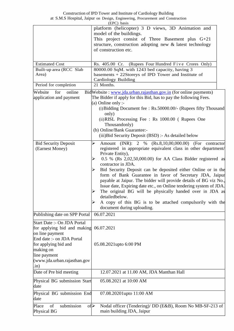
platform (helicopter) 3 D views, 3D Animation and model of the buildings. This project consist of Three Basement plus G+21 structure, construction adopting new & latest technology of construction etc.
Estimated Cost Rs. 405.00 Cr. (Rupees Four Hundred F i v e Crores Only) Built-up area (RCC Slab Area)
80000.00 SqM. with 1243 bed capacity, having 3 basements + 22 Storeys of IPD Tower and Institute of Cardiology Building
Period for completion 21 Months.
Website for online Bid application and payment
Website : www.jda.urban.rajasthan.gov.in (for online payments) The Bidder if apply for this Bid, has to pay the following Fees. (a) Online only :-
(i) Bidding Document fee : Rs.50000.00/- (Rupees fifty Thousand only)
(ii) RISL Processing Fee : Rs 1000.00 ( Rupees One Thousand only)
(b) Online/Bank Guarantee:- (iii)Bid Security Deposit (BSD) :- As detailed below
Bid Security Deposit (Earnest Money)
Amount (INR): 2 % (Rs.8,10,00,000.00) (For contractor registered in appropriate equivalent class in other department/ Private Entity),
0.5 % (Rs 2,02,50,000.00) for AA Class Bidder registered as contractor in JDA.
Bid Security Deposit can be deposited either Online or in the form of Bank Guarantee in favor of Secretary JDA, Jaipur payable at Jaipur. The bidder will provide details of BG viz No., Issue date, Expiring date etc., on Online tendering system of JDA.
The original BG will be physically handed over in JDA as detailed below.
A copy of this BG is to be attached compulsorily with the document during uploading.
Publishing date on SPP Portal 06.07.2021
Start Date :- On JDA Portal for applying bid and making on line payment End date :- on JDA Portal for applying bid and making on line payment (www.jda.urban.rajasthan.gov .in)
06.07.2021
05.08.2021upto 6:00 PM
Date of Pre bid meeting 12.07.2021 at 11.00 AM, JDA Manthan Hall
Physical BG submission Start date
05.08.2021 at 10:00 AM
Physical BG submission End date
07.08.20201upto 11:00 AM
Place of submission of Physical BG
Nodal officer (Tendering)/ DD (E&B), Room No MB-SF-213 of main building JDA, Jaipur

Construction of IPD Tower and Institute of Cardiology Building at S.M.S Hospital, Jaipur on Design, Engineering, Procurement and Construction
(EPC) basis Date/Time Place of Technical Bid Opening
07.08.2021at 1.00 PM in Room No. 309, CCCIIIrd Floor Building Ram Kishore Vyas Bhavan, Indira Circle,Jawahar Lal Nehru Marg, Jaipur- 302004 (Rajasthan)
Date/Time/Place of Financial Bid Opening
Will be intimated later to the technically qualified bidders onE-proc portal.
Room No. 309, CCC IIIrd Floor Building, Ram Kishore VyasBhavan, Indira Circle, Jawahar Lal Nehru Marg, Jaipur- 302004(Rajasthan)
Bid Validity 120 days from the bid submission deadline
Mobilization Advance Mobilization Advance may be given to the EPC Contractor on his / their written request for the grant of M.A. The M.A. shall be given as mentioned below: 1st Installment – 5% - against Bank Guarantee 2nd Installment – 5% -Machinery, start-up and mobilization of material against bank Guarantee (after recovery of 1st installment).
Interest Rate of Mobilization Advance
Simple Interest Rate of 10.5 % (Per Annum)
Security Deposit/ Retention Money
As per the orders issued by Gov. of Rajasthan
Price escalation Price escalation shall not be applicable on this Contract
GST To be paid extra.

Construction of IPD Tower and Institute of Cardiology Building at S.M.S Hospital, Jaipur on Design, Engineering, Procurement and Construction
(EPC) basis
Jaipur development authority has decided to receive earnest money deposit (EMD) (BidSecurity), Tender fee and RISL processing fee online through JDA portal. The bid securityoptions available in tender for participants are as mentioned below :-
Payment Options: Option-1: Bank Guarantee (BG) against EMD / Bid Security in favor of Secretary JDA,
Jaipur payable at JaipurBidder may opt Bank Guarantee (BG) against EMD (Bid Security), for which bidder requires to prepare BG before applying in the tender. The details of BG requires to be fed on JDA portal before paying balance amount (Tender Fee + RISL Processing Fee). This amount will be paid through Payment Gateway only, option to make balance payment through EFT (RTGS/NEFT) will not be available. If bidder does not opt for BG against EMD, options of making complete payment through Payment Gateway or through EFT (NEFT / RTGS) will be available. Option-2: Electronic Fund Transfer (EFT: NEFT/RTGS) If the bidder selects payment mode as EFT (NEFT/RTGS), “Paying Slip for EFT(NEFT/RTGS)” will be generated by the system for the complete amount. The payment can be made from any Bank any Branch using this Paying Slip through NEFT/RTGS (Claim against payment made through EFT in any other JDA bank account will not be acceptable and bidder stands disqualified from participation in the bid applied for). After successful transaction through NEFT/RTGS, as per the standard procedures it may take 4 to 24 hours in process of confirmation of EFT through Auto-Process depending on the time of EFT done. Therefore, option to make payment through EFT (NEFT/RTGS) will be available till 48 hours prior to closing date of bid participation.The payment may be made through RTGS / NEFT / Transfer in Bank Account Number 675401700586 IFSC Code ICIC0006754 of ICICI BANK Limited, JDA Campus Jaipur.
Option-3: Payment Gateway (Aggregator)The facility to make payment through Debit Card, Credit Card, Net banking etc., will be available. User can use this facility from anywhere any time till the closing date & time of bid participation. B. Bid Participation ReceiptAfter confirming payment, the bidder will get Bid Participation Receipt on the basis of which user will get the payment details along with other details for bidding on e-Procurement portal of GOR. In case of BG as the remaining payment will be done through Payment Gateway, onsuccessful transaction the “Bid Participation Receipt” will be generated on real time basis. In case complete payment is done through Payment Gateway, on successful transactionthe “Bid Participation Receipt” will be generated on real time basis. In case complete payment is done through EFT (NEFT/RTGS), on confirmation ofpayment from ICICI Bank (Auto Process) “Bid Participation Receipt” will be available on Login of Bidder JDA portal.
Note: 1. Bidder (authorized signatory) shall submit their offer on-line in Electronic formats both for
technical and financial proposal.2. In case, any of the bidders fails to pay the Tender Fee, Bid Security Deposit, and RISL
Processing Fee, online (subject to confirmation), its Bid shall not be accepted and liable torejection.
3. To participate in online bidding process, Bidders must procure a Digital Signature Certificate(Type III) as per Information Technology Act-2000 using which they can digitally sign theirelectronic bids. Bidders can procure the same from any CCA approved certifying agency, i.e.TCS, Safe crypt, Ncode etc. Bidders who already have a valid Digital Signature Certificate(DSC) need not procure a new DSC. Also, bidders must register on http://eproc.rajasthan.gov.in(bidders already registered on http://eproc.rajasthan.gov.in before 30-09-2011 must registeragain).

Construction of IPD Tower and Institute of Cardiology Building at S.M.S Hospital, Jaipur on Design, Engineering, Procurement and Construction
(EPC) basis
4. JDA will not be responsible for delay in online submission due to any reason. For this, bidders are requested to upload the complete bid well advance in time so as to avoid 11th hour issues like slow speed; choking of web site due to heavy load or any other unforeseen problems.
5. Bidders are also advised to refer "Bidders Manual Kit" available at eProc website for further details about the e-Tendering process.
6. Training for the bidders on the usage of e-Tendering System (eProcurement) is also being arranged by DoIT&C, GoR on a regular basis. Bidders interested for training may contact e- Procurement Cell, DoIT&C for booking the training slot. Contact No: 0141-4022688 (Help desk 10 am to 6 pm on all working days) e-mail: [email protected] Address : e-Procurement Cell, JDA, Yojana Bhawan, Tilak Marg, C- Scheme, Jaipur
7. The procuring entity reserves the complete right to cancel the bid process and reject any or all of the Bids without assigning any reason.
8. No contractual obligation whatsoever shall arise from the bidding document/ bidding process unless and until a formal contract is signed and executed between the procuring entity and the successful bidder.
9. Procurement entity disclaims any factual/ or other errors in the bidding document (the onus is purely on the individual bidders to verify such information) and the information provided therein are intended only to help the bidders to prepare a logical bid-proposal.
10. The provisions of RTPPA Act 2012 and Rules 2013 thereto shall be applicable for this procurement. Furthermore, in case of any inconsistency in any of the provisions of this bidding document with the RTPP Act 2012 and Rules 2013 thereto, the later shall prevail.
The tender document can be downloaded from website www.jda.urban.rajasthan.gov.in and www.eproc.rajasthan.gov.in. “Corrigendum, if any, would appear only on the website and not to be published in any News Paper”.
Minimum Eligibility Criteria
A. Technical Criteria
i) Bidders registered in Gov. as ‘AA Class’ contractor or Private agency having experience as a prime contractor for govt./semi govt./PSU for the complete minimum eligibility criteria will be eligible for participation in the bid.
NOTE:“Similar Work” shall mean Construction of Multi-storey Medical College/ Hospital Building/Institutional/ Memorial Building /Office Building including Finishing Works, Internal & External Water Supply, Plumbing & Sanitary Installations, Internal & External Electrification Works, Air- Conditioning, Fire Fighting, I.T. Networking & Lifts executed under one agreement.
ii) The bidder should have successfully completed at least two similar works each costing not less
than 60 % of the estimated project cost during the last 5 years ending previous day of the last date of submission of tenders.
iii) The Bidder should have additional technical Qualifying Criteria as under.
Additional Qualifying Criteria ( for the works in last 5 years ending previous day of the last date of submission of tenders).
a. In addition to the above Bidder should have completed one high rise Framed Structure where height is
minimum 35 mtrs. without Basement, mumty & lift machine room. b. Completed at least one work Construction of 200 bedded Hospital building during the last 5 years. c. Experience in Operation Theatre, Medical Gases Manifold System & Construction of Auditorium in one
work during the last 5 years in any work. d. The bidder must have successfully completed at least one work of fabrication and erection of structural

Construction of IPD Tower and Institute of Cardiology Building at S.M.S Hospital, Jaipur on Design, Engineering, Procurement and Construction
(EPC) basis
steel work 1000 MT. e. The bidder should have completed or substantially completed one construction of 3 storey Basements,
having area at least 7000 Sqm. for each basement f. The bidder should have completed one multi storey building work or having one multi storey building
work under construction on EPC Mode costing not less than 50% of the estimated cost(for 5 years as per escalation factor below).
g. The bidder should have completed one multi storey building work or having one multi storey building work under construction, considering design life of structures as 100 years which should be mentioned in tender condition of the work.
h. Should have minimum 2 multi storey building works under construction of major hospitals of reputed medical institute with modern technology in past 5 years including escalation factor of minimum cost of Rs. 200 Crores. The present value of the order will be ascertained as per the following escalation factors:-
Year Escalation 2020-21 1.00
2019-20 1.10
2018-19 1.21
2017-18 1.33
2016-17 1.46
Note: Because of COVID and extension given by Govt. of India, provisional balance sheet duly signed and certified by CA will be acceptable for the year 2020-2021.
iv).The bidder should have the experience of constructing at least 350 meter perimeter and Depth minimum 16 meter of Diaphragm Wall in a completed multi storey building work or having multi storey building work under construction for 3 Basement Structure. v). The bidder should have relevant experience in last 5 years of Heritage Street/Buildings in Heritage Architecture including sand stone and marble craft in a project of minimum Rs. 100 Crores including escalation factor.
NOTE 1. The experience certificates of works having executed and claimed as experience should be issued by the Government Organizations / Semi Government Organizations / State Government/ Central Government / Public Sector Undertakings. NOTE 2. Inspection of works will be done by JDA/ Client - Architects at the cost of the Bidder only and assessment of satisfactory performance will be ascertained for considering the relevant experience/performance.
vi) The value of executed works during last five years shall be brought to current costing level by enhancing the actual value of work at simple rate of 10 % per annum; calculated from the date of completion to the previous day of last date of submission of tenders.
vii) Joint-venture or consortium of firms / companies shall not be allowed and the bidders should meet the above criteria themselves.
viii) Any company/firm while submitting tender can use the work experience of its subsidiary company to the extent of its ownership in the subsidiary company. However, the companies/firms which intend to get qualified on the basis of experience of the parental company/group company/ Own works, shall not be considered. In case of a Company/firm, formed after merger and/ or acquisition of other companies/firms, past experience and other antecedents of the merged/ acquired companies/firms will be considered for qualification of such Company/firm provided such Company/firm continues to own the requisite assets and resources of the merged/ acquired companies/firms relevant to the claimed experience.
B. Financial Criteria:
i) Should have had average annual financial turnover of Rs. 250.00 Crore of Civil Engineering Works during the immediate last three consecutive financial year ending 31st March 2021.

Construction of IPD Tower and Institute of Cardiology Building at S.M.S Hospital, Jaipur on Design, Engineering, Procurement and Construction
(EPC) basis
ii) The Bidder should have minimum Net-worth of Rs. 60.00 Crore at the close of preceding financial year. A certificate should be submitted from Chartered Accountant for the same for the immediate last three consecutive financial year ending 31st March 2021.
iii) The Bidder shall submit audited balance sheets of last five years.
iv) Self certified copy of Bank Solvency Certificate issued from Nationalized or any Scheduled Bank of minimum or equal to Rs. 100 Cr of Sanctioned Project Cost should be submitted. The certificate should have been issued within 6 months from the last date of the submission of the tender.
The bidders are required to upload and submit summarized page of Balance Sheet of last Financial Year (Audited) and also page of summarized Profit & Loss Account (Audited) for last three years.
3.0 The intending bidder must read the terms and conditions of Bid carefully. He should only
submit his tender if he considers himself eligible and he is in possession of all the documents required. Information and Instructions for Bidders posted on Website(s) shall form part of Tender Document.
Set of Contract/ Bid Documents:
The following documents will constitute set of bid documents:
a) Notice Inviting e-Tender – Volume 1 b) Instructions to Bidders & General Conditions of Contract (GCC) – Volume II c) Special Conditions of Contract – Volume III d) Design Basis Report (DBR)– Volume IV
i. General Instructions ii. Finishing Schedule
iii. Drawings e). Safety, Health and Environment (SHE) document.- Vol-V.
iv. List of approved makes of materials- General instructions of Volume IV (i)
v. Payment Schedule- SCC
vi. Acceptance of Tender Conditions (Annexure-I) - GCC vii. Integrity pact (Annexure-II) (To be signed and stamped by the contractors and
scanned copy to be uploaded with the bid) - GCC f). Quoting Sheet for Bidders.
5.0 he bidders are required to quote strictly as per terms and conditions, specifications, standards given in the tender documents and not to stipulate any deviations.
The bidders are advised to submit complete details with their bids as Technical Bid Evaluation will be done on the basis of documents uploaded on website by the bidders with the bids. The information should be submitted in the prescribed Performa. Bids with Incomplete /Ambiguous/Conditional information will be rejected.
The Bank Guarantee if submitted for EMD submitted by the bidders shall be strictly in the format prescribed. In case, EMD is not found verbatim in the prescribed format, the bid will be liable for rejection.
6.0 The bidders are advised in their own interest to submit their bid documents well in advance
from last date/time of submission of bids so as to avoid problems which the bidders may face in submission at last moment /during rush hours.

Construction of IPD Tower and Institute of Cardiology Building at S.M.S Hospital, Jaipur on Design, Engineering, Procurement and Construction
(EPC) basis
However, after submission of the bid the bidders can re-submit revised bid any number of times only through on-line process but before last time and date of submission of tender as notified.
7.0 When it is desired by JDA to submit revised financial offer/ negotiation bidder then it shall be mandatory to submit revised financial bid /Negotiation.
8.0 Contractor can upload documents in the form of JPG format and PDF format.
9.0 Contractor to upload scanned copies of all the documents including valid GST registration /EPF registration/ PAN No. as stipulated in the b i d document.
10.0 If the contractor is found ineligible after opening of tenders, his tender shall
become invalid and cost of tender document and processing fee shall not be refunded.
11.0 If any discrepancy is noticed between the documents as uploaded at the time of submission of tender and hard copies as submitted physically by the contractor the tender shall become invalid and cost of tender document and processing fee shall not be refunded.
12.0 Notwithstanding anything stated above, JDA reserves the right to assess the capabilities and capacity of the tenderer to perform the contract, in the overall interest of JDA. In case, tenderer’s capabilities and capacities are not found satisfactory, JDA reserves the right to reject the tender.
13.0 Certificate of Financial Turnover: At the time of submission of tender, the tender shall
upload Affidavit/Certificate from Chartered Accountant mentioning Audited Financial Turnover of last 3 years ending as on 31st March 2021. There is no need to upload entire voluminous balance sheet. However, one page of summarized Balance Sheet (Audited) and one page of summarized Profit &Loss Account (Audited) for last 03 years shall be uploaded and submitted in hard copy if demanded also.
14.0 The tenderer(s) if required, may submit queries, if any, through E-mail and in writing to the tender inviting authority to seek clarifications but latest by so as to reach JDA office not less than 2 days prior to the date and time of Pre-bid meeting (if to be held as per NIT). JDA will reply only those queries which are essentially required for submission of bids. JDA will not reply the queries received after pre bid meeting and which are not considered fit like replies of which can be implied /found in the NIT/ Tender Documents or which are not relevant or in contravention to NIT/Tender Documents, queries received after 7 days from the date of uploading of Tender on website, request for extension of time for opening of technical bids, etc. Technical Bids are to be opened on the scheduled dates. Requests for Extension of opening of Technical Bids will not be entertained.
The Pre-Bid meeting shall be attended by the intending bidders only and not by vendors/manufacturers. Further, the intending bidders should depute their authorized person with authorization letter in original to attend the pre-bid meeting.
Independent External Monitors
(i) In case of any representation/complaint from agencies regarding the tendering, the
matter may be referred to Independent External Monitors as decided by JDA for review and redressal.
List of Documents to be scanned, uploaded within the period of tender submission:
a) Original Bank Guarantee of any Nationalized or all Commercial Scheduled Bank against EMD. Validity of EMD in terms of Bank Guarantee shall be minimum period of 180 (One Hundred Eighty) days from the last day of submission of Tender as detailed in NIT failing which the bid is liable to be rejected.
Construction of IPD Tower and Institute of Cardiology Building at S.M.S Hospital, Jaipur on Design, Engineering, Procurement and Construction
(EPC) basis
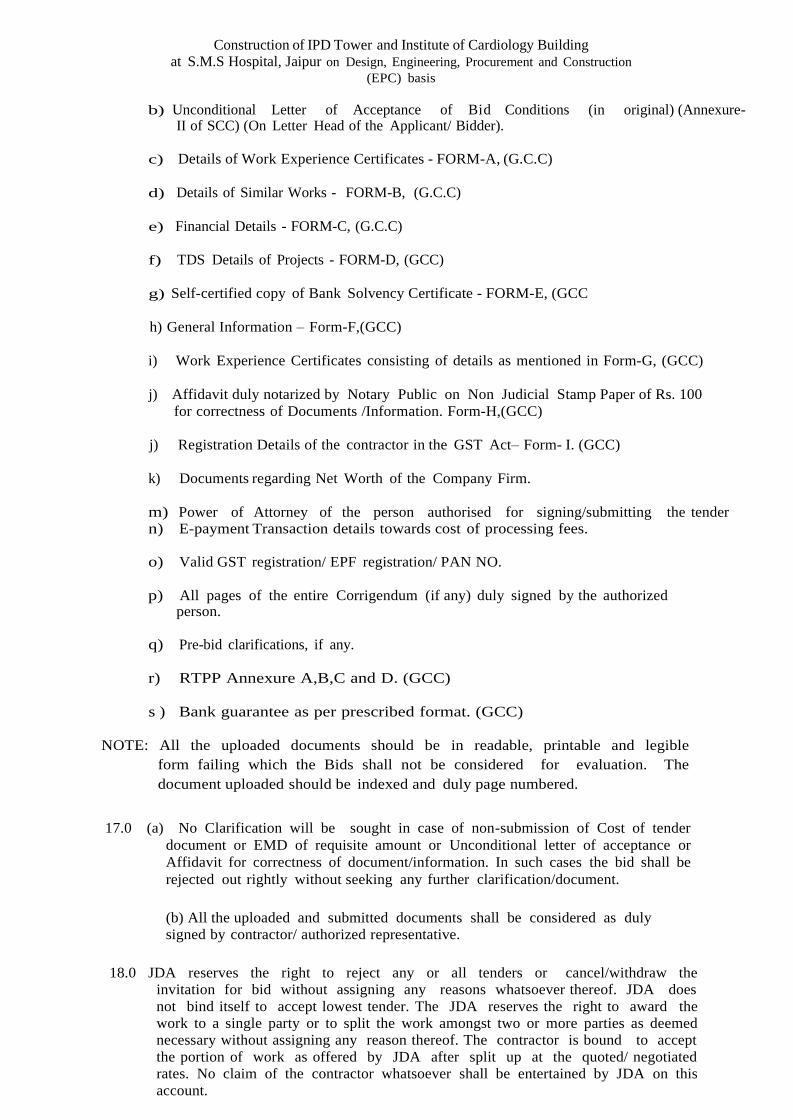
b) Unconditional Letter of Acceptance of Bid Conditions (in original) (Annexure-
II of SCC) (On Letter Head of the Applicant/ Bidder).
c) Details of Work Experience Certificates - FORM-A, (G.C.C)
d) Details of Similar Works - FORM-B, (G.C.C)
e) Financial Details - FORM-C, (G.C.C)
f) TDS Details of Projects - FORM-D, (GCC)
g) Self-certified copy of Bank Solvency Certificate - FORM-E, (GCC
h) General Information – Form-F,(GCC)
i) Work Experience Certificates consisting of details as mentioned in Form-G, (GCC)
j) Affidavit duly notarized by Notary Public on Non Judicial Stamp Paper of Rs. 100 for correctness of Documents /Information. Form-H,(GCC)
j) Registration Details of the contractor in the GST Act– Form- I. (GCC)
k) Documents regarding Net Worth of the Company Firm.
m) Power of Attorney of the person authorised for signing/submitting the tender n) E-payment Transaction details towards cost of processing fees.
o) Valid GST registration/ EPF registration/ PAN NO.
p) All pages of the entire Corrigendum (if any) duly signed by the authorized
person.
q) Pre-bid clarifications, if any.
r) RTPP Annexure A,B,C and D. (GCC)
s ) Bank guarantee as per prescribed format. (GCC)
NOTE: All the uploaded documents should be in readable, printable and legible form failing which the Bids shall not be considered for evaluation. The document uploaded should be indexed and duly page numbered.
17.0 (a) No Clarification will be sought in case of non-submission of Cost of tender
document or EMD of requisite amount or Unconditional letter of acceptance or Affidavit for correctness of document/information. In such cases the bid shall be rejected out rightly without seeking any further clarification/document.
(b) All the uploaded and submitted documents shall be considered as duly signed by contractor/ authorized representative.
18.0 JDA reserves the right to reject any or all tenders or cancel/withdraw the
invitation for bid without assigning any reasons whatsoever thereof. JDA does not bind itself to accept lowest tender. The JDA reserves the right to award the work to a single party or to split the work amongst two or more parties as deemed necessary without assigning any reason thereof. The contractor is bound to accept the portion of work as offered by JDA after split up at the quoted/ negotiated rates. No claim of the contractor whatsoever shall be entertained by JDA on this account.

Construction of IPD Tower and Institute of Cardiology Building at S.M.S Hospital, Jaipur on Design, Engineering, Procurement and Construction
(EPC) basis
19.0 Canvassing in connection with the tender is strictly prohibited, and such
canvassed tenders submitted by the contractor will be liable to be rejected and his earnest money shall be absolutely forfeited.
NOTE: 1. THE BIDDER HAS TO UPLOAD THE COMPLETE BID
DOCUMENTS ALONG WITH OTHER DESIRED DOCUMENTS REQUIRED FOR THE BID WITH HIS DIGITAL SIGNATURE MANDATORY , FAILING WHICH THE BID MAY BE REJECTED 2. The RTPP Act 2012 and Rules 2013 are being followed for keeping financial proprietary and transparency in procurement.
***

JAIPUR DEVELOPMENT AUTHORITY Jawahar Lal Nehru Marg , Jaipur , Rajasthan - 302004
INSTRUCTIONS TO BIDDERS (ITB)
& GENERAL CONDITIONS
OF CONTRACT
VOLUME-II

JAIPUR DEVELOPMENT AUTHORITY
Jawahar Lal Nehru Marg , Jaipur , Rajasthan - 302004
INSTRUCTIONS TO BIDDERS
& GENERAL CONDITIONS OF CONTRACT
VOLUME – II
ISSUED TO: M/S ---------------------------------------------------- ---------------------------------------------------- ---------------------------------------------------- ----------------------------------------------------
Month...............
Year..................

INDEXJ.D.A
333
Signature of Contractor JDA
I N D E X VOLUME – II
CLAUSE
NO. DESCRIPTION PAGE NO.
SECTION – 1
Instructions to Bidders (ITB) 09 – 24
SECTION - 2 GENERAL CONDITIONS OF CONTRACT
Acceptance of Tender Conditions (Annexure – I) 25
Integrity Pact (Annexure – II) 26 – 32
Forms (A to I) 33 – 41
SECTION - 3 CLAUSES OF CONTRACT
1.0 Definitions 43 – 44
2.0 Performance Guarantee 45
3.0 Security Deposit/ Retention Money 46
4.0 Mobilization Advance 46
5.0 Secured Advance Against Non-Perishable Materials 47
6.0 Deviations / Variations Extent and Pricing 47 – 48
7.0 Price Escalation 48
8.0 Compensation for Delay 48
9.0 Action in Case Work Not Done As Per Specifications 48 – 49
10.0 Action in Case of Bad Work 49
11.0 Cancellation/Determination of Contract in Full or Part 50 – 52
12.0 Contractor Liable to Pay Compensation Even if Action Not Taken Under Clause 11.0
52

INDEXJ.D.A
444
Signature of Contractor JDA
13.0 Carrying Out Part Work at Risk & Cost of Contractor 52 – 53
14.0 Suspension of Works 52 – 54
15.0 Termination of Contract on Death of Contractor 54
16.0 Time Essence of Contract & Extension for Delay 54 – 55
17.0 Time Schedule & Progress 55
18.0 Taxes and Duties 55
19.0 Service Tax (Deleted) 55
20.0 Income Tax Deduction (TDS) 55– 56
21.0 Royalty on Materials 56
22.0 Insurance of Works etc. 56– 57
23.0 Payments 57– 58
24.0 Measurements of Works 58– 59
25.0 Computerized Measurement Books 59– 60
26.0 Withholding and Lien in Respect of Sums Due from Contractor 60– 61
27.0 Work to be Executed in Accordance with Specifications, Drawings, and Orders etc.
61
28.0 Materials to be Provided by the Contractor 62
29.0 Materials and Samples 62– 63
30.0 Materials Procured with the Assistance of JDA 64
31.0 Mobilization of Men, Materials and Machinery 64
32.0 Quality Assurance Programme 64– 65
33.0 Contract Coordination Procedures, Coordination Meetings and Progress Reporting
65– 66
34.0 Completion Certificate and Completion Plans 66

INDEXJ.D.A
555
Signature of Contractor JDA
35.0 Prohibition of Unauthorized Construction & Occupation 66– 67
36.0 Foreclosure of Contract by HSCC / Owner 67– 68
37.0 Defects Liability Period 68
38.0 Subletting / Sub-Contracting 68
39.0 Force Majeure 68
40.0 No Compensation Clause 69
41.0 Direction for Works 69
42.0 Work in Monsoon and Rain 69
43.0 Work on Sundays, Holidays and During Night 69
44.0 Water and Electricity 69
45.0 Land for Labour Huts/ Site Office and Storage Accommodation 70
46.0 Watch, Ward and Lighting of Work Place 70
47.0 Cement and Cement Go-down 70
48.0 Steel & Steel Stockyard 70
49.0 Indian Standards 70
50.0 Centering & Shuttering 70
51.0 Records of Consumption of Cement & Steel 71
52.0 Tests and Inspection 71
53.0 Works to be Open to Inspection 71
54.0 Borrow Areas 71– 72
55.0 Care of Works 72
57.0 Co-Ordination with Other Agencies 72
INDEXJ.D.A
66 Signature of Contractor J.D.A
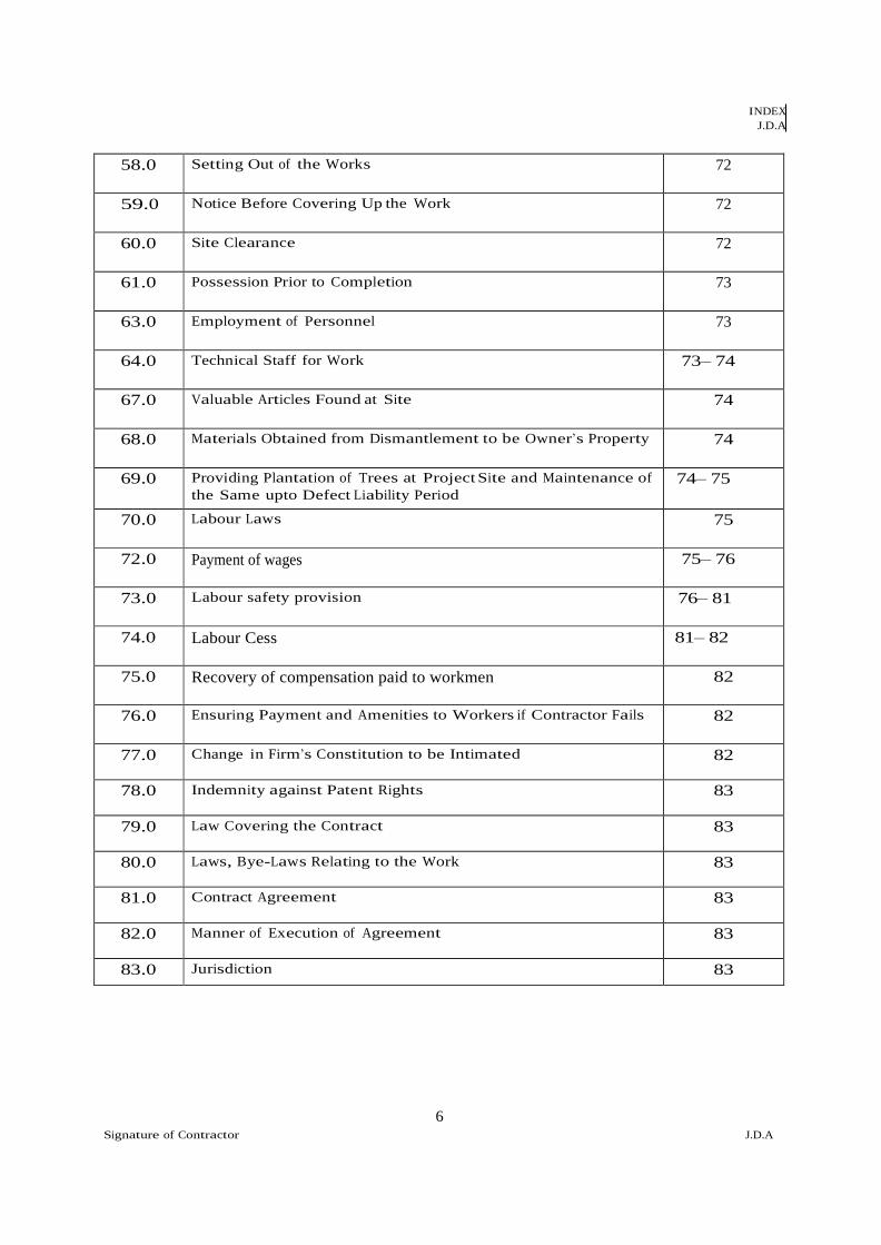
58.0 Setting Out of the Works 72
59.0 Notice Before Covering Up the Work 72
60.0 Site Clearance 72
61.0 Possession Prior to Completion 73
63.0 Employment of Personnel 73
64.0 Technical Staff for Work 73– 74
67.0 Valuable Articles Found at Site 74
68.0 Materials Obtained from Dismantlement to be Owner’s Property 74
69.0 Providing Plantation of Trees at Project Site and Maintenance of the Same upto Defect Liability Period
74– 75
70.0 Labour Laws 75
72.0 Payment of wages 75– 76
73.0 Labour safety provision 76– 81
74.0 Labour Cess 81– 82
75.0 Recovery of compensation paid to workmen 82
76.0 Ensuring Payment and Amenities to Workers if Contractor Fails 82
77.0 Change in Firm’s Constitution to be Intimated 82
78.0 Indemnity against Patent Rights 83
79.0 Law Covering the Contract 83
80.0 Laws, Bye-Laws Relating to the Work 83
81.0 Contract Agreement 83
82.0 Manner of Execution of Agreement 83
83.0 Jurisdiction 83

INDEXJ.D.A
7 Signature of Contractor J.D.A
SECTION –4
FORMS AND FORMATS 85 – 97

General Conditions of Contract - Section - 2 J.D.A
8
Section-1
INSTRUCTIONS TO BIDDERS

General Conditions of Contract - Section - 2 J.D.A
9
Section-I : Instruction to Bidders (ITB) Important Instruction: - The Law relating to procurement “The Rajasthan Transparency in Public Procurement Act, 2012” [hereinafter called the Act] and the “Rajasthan Public Procurement Rules, 2013”
and modified thereof from time to time [hereinafter called the Rules] under the said Act have come into force which are available on the website of State Public Procurement Portal http://sppp.raj.nic.in. Therefore, the Bidders are advised to acquaint themselves with the provisions of the Act and the Rules before participating in the Bidding process. If there is any discrepancy between the provisions of the Act and the Rules and this Bidding Document, the provisions of the Act and the Rules shall prevail.
1. General
1.1 Scope of Bid In support of the Invitation to Bid the Procuring Entity issues this Bidding Document for the procurement of works as named and as Specified in the bid documents.
1.2 Interpretation Throughout this Bidding Document: (a) The term “in writing” means communicated in
written Form through letter, fax, e-mail etc. with proof of receipt.
(b) If the context so requires, singular means plural and Vice versa; and “Day” means calendar day.
1.3 Code of Integrity 1.3.1 Any person participating in the procurement process shall: - i. Not offer any bribe, reward or gift or any material benefit either directly or indirectly in exchange for an unfair advantage in procurement process or to otherwise influence the procurement process; ii. Not misrepresent or omit that misleads or attempts to mislead so as to obtain a financial or other benefit or avoid an obligation; iii. Not indulge in any collusion, bid rigging or anti- competitive behaviour to impair the transparency, fairness and progress of the procurement process; iv. Not misuse any information shared between the Procuring Entity and the Bidders with an intent to gain unfair advantage in the procurement process; v. Not indulge in any coercion including impairing or harming or threatening to do the same, directly or indirectly, to any party or to its property to influence the procurement process; vi. Not obstruct any investigation or audit of a procurement process; vii. Disclose conflict of interest, if any; and viii. Disclose any previous transgressions with any Entity in India or any other country during the last three years or any debarment by any other Procuring Entity.
1.3.2 Conflict of Interest: A conflict of interest is considered to be a situation in which a party has interests that could improperly influence that party’s performance of official duties or responsibilities, contractual obligations, or compliance with applicable laws and regulations. A Bidder may be considered to be in conflict of interest with one or more parties in this bidding process if,

General Conditions of Contract - Section - 2 J.D.A
10
including but not limited to: have controlling partners/ shareholders in common; or receive or have received any direct or in direct subsidy from any of them; or have the same legal representative for purposes of this Bid; or have a relationship with each other, directly or through common third parties, that puts them in a position to have access to information about or influence on the Bid of another Bidder, or influence the decisions of the Procuring Entity regarding this bidding process; or The Bidder participates in more than one Bid in this bidding process. Participation by a Bidder in more than one Bid will result in the disqualification of all Bids in which the Bidder is involved. However, this does not limit the inclusion of the same subcontractor, not otherwise participating as a Bidder, in more than one Bid; or the Bidder or any of its affiliates participated as a consultant in the preparation of the design or technical specifications of the Works that are the subject of the Bid; or The Bidder or any of its affiliates has been hired (or is proposed to be hired) by the Procuring Entity as Engineer-in-charge/ consultant for the Contract.
1.3.3 The Bidder shall have to give a declaration regarding compliance of the Code of Integrity prescribed in the Act, the Rules and stated above in this Clause along with its Bid.
1.3.4 Breach of Code of Integrity by the Bidder: - Without prejudice to the provisions of Chapter IV of the Rajasthan Transparency in Public Procurement Act, in case of any breach of the Code of Integrity by a Bidder or prospective Bidder, as the case may be, the Procuring Entity may take appropriate action in accordance with the provisions of sub-section (3) of section 11 and section 46 of the Act.
1.4 Eligible Bidders 1.4.1 As per NIB Clause 2
1.4.2 JOINT VENTURE: Not Applicable
1.4.3 DELETED 1.4.4 A Bidder should not have a conflict of interest in the
procurement in question as stated in the RTPP Rule 81 and this Bidding document.
1.4.5 A Bidder debarred under section 46 of the RTPP Act shall not be eligible to participate in any procurement process undertaken by any Procuring Entity, if debarred by the State Government; and a Procuring Entity, if debarred by such Procuring Entity.
1.4.6 The Bidder must be a registered Contractor in appropriate
class with the Department/ Organization or any other
Department/ Organization. He shall furnish necessary
proof for the same. PSU can participate in tender. r
1.4.7 (i) Any change in the constitution of the firm, etc., shall be notified forth with by the Bidder in writing to the Procuring Entity and such change shall not relieve any former partner/ member of the firm, etc. from any liability under the Contract.

General Conditions of Contract - Section - 2 J.D.A
11
(ii) No new partner/partners shall be accepted in the firm by the Bidder in respect of the contract unless he/they agree to abide by all its terms, conditions and deposit with the Procuring Entity a written agreement to this effect. The Bidder’s receipt for acknowledgement or that of any partners subsequently accepted as above shall bind all of them and will be sufficient discharge for any of the purpose of the Contract. (iii) DELETED
1.4.8 DELETED 1.4.9 Bidder should be registered under the GST Act and
submit the proof of registration before signing the Contract agreement. He is also required to provide proof of Permanent Account Number (PAN) given by Income Tax Department.
2 BID DOCUMENT 2.1 Sections of the
Bidding Document
2.1.1 The Bidding Document consists of five volumes (volume I to V). Volume I comprises of NIB and Pre Qualification Criteria. Volume-II comprises of Instructions to Bidders and General Conditions of Contract Volume-III comprises of Special Conditions of Contract Volume-IV comprises of General instructions , Finishing Schedule and Drawings Volume-V comprises of Safety Health and Environmental Clause (SHE Management Clause) Financial Bid : Lump sum Rate to be quoted by the bidder on the basis of Specification and the scope of work defined in the bid document
2.1.2 The Invitation for Bids (NIB) issued by the Procuring Entity is also part of the Bidding Document.
2.1.3 The Bidding Document shall be uploaded on the e- procurement portal, eproc.raj.nic.in along with the Notice Inviting Bids. The complete Bidding Document shall also be placed on the State Public Procurement Portal, sppp.raj.nic.in. The prospective Bidders may download the bidding document from these portals. The price of the Bidding Document and processing fee of e-bid shall have to be paid to the Procuring Entity in the amount and manner as specified in NIB and e-procurement portal.
2.1.4 The Procuring Entity is not responsible for the completeness of the Bidding Document and its addenda, if they were not downloaded correctly from the e-procurement portal or the State Public Procurement Portal
2.1.5 The Bidder is expected to examine all instructions, forms, terms and specifications in the Bidding Document. Failure to furnish all information or authentic documentation required by the Bidding Document may result in the rejection of the Bid.
2.2 Clarification of Bidding
Document and Pre-Bid Meeting
2.2.1 As Per Clause 14 of NIB- Volume 1 2.2.2 The Bidder or his authorized representative may attend
the pre bid meeting on the specified date and time as mentioned in NIB. The purpose of pre bid meeting will be to clarify issues and to answer question on any matter related to this procurement that may be raised. If required, site visit may be arranged by the procuring
General Conditions of Contract - Section - 2 J.D.A
12
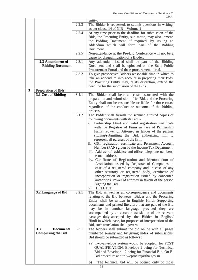
entity. 2.2.3 The Bidder is requested, to submit questions in writing,
as per clause 14 of NIB – Volume 1 2.2.4 At any time prior to the deadline for submission of the
Bids, the Procuring Entity, suo motto, may also amend the Bidding Document, if required, by issuing an addendum which will form part of the Bidding Document
2.2.5 Non-attendance at the Pre-Bid Conference will not be a cause for disqualification of a Bidder.
2.3 Amendment of Bidding Document
2.3.1 Any addendum issued shall be part of the Bidding Document and shall be uploaded on the State Public Procurement Portal and the e-procurement portal.
2.3.2 To give prospective Bidders reasonable time in which to take an addendum into account in preparing their Bids, the Procuring Entity may, at its discretion, extend the deadline for the submission of the Bids.
3 Preparation of Bids 3.1 Cost of Bidding 3.1.1 The Bidder shall bear all costs associated with the
preparation and submission of its Bid, and the Procuring Entity shall not be responsible or liable for those costs, regardless of the conduct or outcome of the bidding process.
3.1.2 The Bidder shall furnish the scanned attested copies of following documents with its Bid: - i. Partnership Deed and valid registration certificate
with the Registrar of Firms in case of Partnership Firms. Power of Attorney in favour of the partner signing/submitting the Bid, authorizing him to represent all partners of the firm.
ii. GST registration certificate and Permanent Account Number (PAN) given by the Income Tax Department.
iii. Address of residence and office, telephone numbers, e-mail address
iv. Certificate of Registration and Memorandum of Association issued by Registrar of Companies in case of a registered company and in case of any other statutory or registered body, certificate of incorporation or registration issued by concerned authorities. Power of attorney in favour of the person signing the Bid.
v. DELETED 3.2 Language of Bid 3.2.1 The Bid, as well as all correspondence and documents
relating to the Bid between Bidder and the Procuring Entity, shall be written in English/ Hindi. Supporting documents and printed literature that are part of the Bid may be in another language provided they are accompanied by an accurate translation of the relevant passages duly accepted by the Bidder in English/ Hindi in which case, for purposes of interpretation of the Bid, such translation shall govern
3.3 Documents Comprising the Bid
3.3.1 The bidders shall submit the bid online with all pages numbered serially and by giving index of submissions. Bid should be submitted as follows :
(a) Two-envelope system would be adopted, for POST QUALIFICATION. Envelope-1 being for Technical Bid and Envelope - 2 being for Financial Bid. On E-Bid procedure at http ://eproc.rajastha.gov.in
(b) The technical bid will be opened only of those
General Conditions of Contract - Section - 2 J.D.A
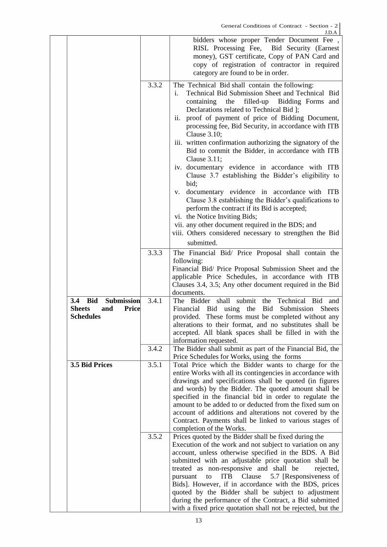
13
bidders whose proper Tender Document Fee , RISL Processing Fee, Bid Security (Earnest money), GST certificate, Copy of PAN Card and copy of registration of contractor in required category are found to be in order.
3.3.2 The Technical Bid shall contain the following: i. Technical Bid Submission Sheet and Technical Bid
containing the filled-up Bidding Forms and Declarations related to Technical Bid ];
ii. proof of payment of price of Bidding Document, processing fee, Bid Security, in accordance with ITB Clause 3.10;
iii. written confirmation authorizing the signatory of the Bid to commit the Bidder, in accordance with ITB Clause 3.11;
iv. documentary evidence in accordance with ITB Clause 3.7 establishing the Bidder’s eligibility to
bid; v. documentary evidence in accordance with ITB
Clause 3.8 establishing the Bidder’s qualifications to
perform the contract if its Bid is accepted; vi. the Notice Inviting Bids; vii. any other document required in the BDS; and
viii. Others considered necessary to strengthen the Bid submitted.
3.3.3 The Financial Bid/ Price Proposal shall contain the following: Financial Bid/ Price Proposal Submission Sheet and the applicable Price Schedules, in accordance with ITB Clauses 3.4, 3.5; Any other document required in the Bid documents.
3.4 Bid Submission Sheets and Price Schedules
3.4.1 The Bidder shall submit the Technical Bid and Financial Bid using the Bid Submission Sheets provided. These forms must be completed without any alterations to their format, and no substitutes shall be accepted. All blank spaces shall be filled in with the information requested.
3.4.2 The Bidder shall submit as part of the Financial Bid, the Price Schedules for Works, using the forms
3.5 Bid Prices 3.5.1 Total Price which the Bidder wants to charge for the entire Works with all its contingencies in accordance with drawings and specifications shall be quoted (in figures and words) by the Bidder. The quoted amount shall be specified in the financial bid in order to regulate the amount to be added to or deducted from the fixed sum on account of additions and alterations not covered by the Contract. Payments shall be linked to various stages of completion of the Works.
3.5.2 Prices quoted by the Bidder shall be fixed during the Execution of the work and not subject to variation on any account, unless otherwise specified in the BDS. A Bid submitted with an adjustable price quotation shall be treated as non-responsive and shall be rejected, pursuant to ITB Clause 5.7 [Responsiveness of Bids]. However, if in accordance with the BDS, prices quoted by the Bidder shall be subject to adjustment during the performance of the Contract, a Bid submitted with a fixed price quotation shall not be rejected, but the

General Conditions of Contract - Section - 2 J.D.A
14
price adjustment shall be treated as zero. 3.5.3 All duties, taxes and other levies payable by the Bidder
under the contract, or for any other cause, shall be included in the rates and prices, and the total Bid Price submitted by the Bidder. However, GST will be paid extra.
3.6 Currencies of Bid 3.6.1 The rates quoted by the Bidder shall be in Indian Rupees. All payments shall be made in Indian Rupees only.
3.7 Documents Establishing the
Eligibility of the Bidder
3.7.1 To establish their eligibility in accordance with ITB Clause 1.4 [Eligible Bidders], Bidders shall: complete the eligibility declarations in the Bid Submission Sheet and Declaration Form.
3.8 Documents Establishing the Qualifications of the Bidder
3.8.1 To establish its qualifications to perform the Contract, the Bidder shall submit as part of its Technical Proposal the documentary evidence indicated for each qualification criteria specified the Bid Document.
3.9 Period of Validity of Bids
3.9.1 Bids shall remain valid for 120 days after the Bid submission deadline date as specified by the Procuring Entity. A Bid valid for a shorter period shall be rejected by the Procuring Entity as non-responsive
3.9.2 In exceptional circumstances, prior to the expiration of the Bid validity period, the Procuring Entity may request Bidders to extend the period of validity of their Bids. The request and the responses shall be made in writing. The Bid Security or a Bid Securing Declaration in accordance with ITB Clause 3.10 [Bid Security] shall also be got extended for thirty days beyond the dead line of the extended validity period. A Bidder may refuse the request without forfeiting its Bid Security or a Bid Securing Declaration. A Bidder granting the request shall not be permitted to modify its Bid.
3.10 Bid Security 3.10.1 The Bidder shall furnish as part of its Bid, a Bid Security for the amount specified in the BDS.
3.10.2 Bid Security shall be as specified in the NIB– Volume 1
3.10.3 Bid Security Deposit can be deposited either Online or in the form of Bank Guarantee in favor of Secretary JDA, Jaipur payable at Jaipur. The bidder will provide details of BG viz No., Issue date, Expiring date etc., on Online tendering system of JDA.
3.10.4 In lieu of Bid Security, a Bid Securing Declaration shall be taken from Government Departments and State Government Public Sector Enterprises, Autonomous bodies, Registered Societies, Cooperative Societies which are owned or controlled or managed by the State Government, Public Sector Enterprises of Central Government. For the Bid Securing Declaration.
3.10.5 Scanned copy of Bid Security instrument or a Bid Securing Declaration shall necessarily accompany the sealed Bid. Any Bid not accompanied by Bid Security or Bid Securing Declaration shall be liable to be rejected.
3.10.6 Bid Security of a Bidder lying with the Procuring Entity in respect of other Bids awaiting decision shall not be adjusted towards Bid Security for this Bid. The Bid Security originally deposited may, however be

General Conditions of Contract - Section - 2 J.D.A
15
taken into consideration in case Bids are re-invited. 3.10.7 The issuer of the Bid Security and the confirmer, if any,
of the Bid Security, as well as the form and terms of the Bid Security, must be acceptable to the Procuring Entity.
3.10.8 Prior to submitting its Bid, a Bidder may request the Procuring Entity to confirm the acceptability of a proposed issuer of a Bid Security or of a proposed confirmer, if different than as specified in ITB Clause 3.10.3. The Procuring Entity shall respond promptly to such a request.
3.10.9 The bank guarantee presented as Bid Security shall be got confirmed from the concerned issuing bank. However, the confirmation of the acceptability of a proposed issuer or of any proposed confirmer does not preclude the Procuring Entity from rejecting the Bid Security on the ground that the issuer or the confirmer, as the case may be, has become insolvent or is under liquidation or has otherwise ceased to be creditworthy.
3.10.10 The Bid Security of unsuccessful Bidders shall be refunded soon after final acceptance of successful Bid and signing of Contract Agreement and submitting Performance Security by successful Bidder.
3.10.11 The Bid Security taken from a Bidder shall be forfeited in the following cases namely :- (a) When the Bidder withdraws, or modifies his Bid after
opening of Bids; or (b) when the Bidder does not execute the agreement in
accordance with ITB Clause 6.3 [Signing of Contract] after issue of letter of acceptance/ placement of Work order within the specified time period; or
(c) when the Bidder fails to commence the Works as per Work Order within the time specified; or
(d) DELETED (e) if the Bidder breaches any provision of the Code of
Integrity prescribed for Bidders in the Act and Chapter VI of the Rules or as specified in ITB Clause 1.3 [Code of Integrity]; or
(f) if the Bidder does not accept the correction of its Bid Price pursuant to ITB Sub-Clause 5.5 [Correction of Arithmetical Errors].
3.10.12 In case of the successful bidder, the amount of Bid Security may be adjusted in arriving at the amount of the Performance Security, or refunded if the successful bidder furnishes the full amount of Performance Security. No interest will be paid by the Procuring Entity on the amount of Bid Security.
3.10.13 The Procuring Entity shall promptly refund the Bid Security of the Bidders at the earliest of any of the following events, namely: - (a) The expiry of validity of Bid Security; (b) The execution of agreement for procurement and
Performance Security is furnished by the successful bidder;
(c) The cancellation of the procurement process; Or The withdrawal of Bid prior to the deadline for presenting Bids, unless the Bidding Document stipulates that no such withdrawal is permitted.
3.10.14 DELETED 3.11 Format and 3.11.1 All pages of the Technical and Financial Bid shall be

General Conditions of Contract - Section - 2 J.D.A
16
Signing of Bid digitally signed by the Bidder or authorized signatory on behalf of the Bidder. This authorization shall consist of a written confirmation and shall be attached to the Bid.
4 Submission and Opening of Bids 4.1 Sealing and
Marking of Bids 4.1.1 Bidders shall submit their Bids to the Procuring Entity
electronically only on the e-procurement portal, www.eproc.rajasthan.gov.in. In submission of their Bids, the Bidders should follow the step by step instructions given on the e-procurement portal
4.1.2 The Bidder shall enclose the Technical Bid and the Financial Bid in separate covers. The proof of payment of price of Bidding Document, processing fee and Bid Security shall be enclosed in third cover. The price of Bidding Document and Bid Security shall be paid in the name of the Procuring Entity and the processing fee shall be paid in the name of RISL.
4.2 Deadline for Submission of Bids
4.2.1 Bids shall be submitted electronically only up to the time and date specified in the Notice Inviting Bids and BDS or an extension issued thereof.
4.3 Withdrawal, Substitution and Modification of Bids
4.3.1 A Bidder may withdraw, substitute or modify its Bid after it has been submitted by submitting electronically on the e-procurement portal. A written Withdrawal/ Substitutions/ Modifications etc. Notice on the e- procurement portal, duly digitally signed by the Bidder or his authorized representative, and shall include a copy of the authorization in accordance with ITB Sub- Clause 3.11.1 [Format and Signing of Bid]. The corresponding Withdrawal, Substitution or Modification of the Bid must accompany the respective written Notice. All Notices must be received by the Procuring Entity on the e-procurement portal prior to the deadline specified for submission of Bids in accordance with ITB Sub-Clause 4.2. [Deadline for Submission of Bids].
4.3.2 No Bid shall be withdrawn, substituted or modified in the interval between the deadline for submission of the Bid and the expiration of the period of Bid validity specified in ITB Clause 3.9. [Period of Validity of Bids] or any extension thereof.
4.4 Bid Opening 4.4.1 The electronic Technical Bids shall be opened by the Bid opening committee constituted by the Procuring Entity at the time, date and place specified in the Bid Data Sheet in the presence of the Bidders or their authorized representatives, who choose to be present.
4.4.2 The Bidders may choose to witness the electronic Bid opening procedure online.
4.4.3 The Financial Bids shall be kept unopened until the time of opening of the Financial Bids. The date, time and location of electronic opening of the Financial Bids shall be intimated to the bidders who are found qualified by the Procuring Entity in evaluation of their Technical Bids.
4.4.4 The Bid opening committee shall prepare a list of the Bidders or their representatives attending the opening of Bids and obtain their signatures on the same. The list shall also contain the representative’s name and telephone number and corresponding Bidders’ names and addresses. The authority letters brought by the representatives shall be attached to the list. The list shall be signed by all the members of Bids opening committee with date and time of opening of the Bids.
4.4.5 DELETED

General Conditions of Contract - Section - 2 J.D.A
17
4.4.6 All other covers containing the Technical Bids shall be opened one at a time and the following read out the name of the Bidder, whether there is a modification or substitution; whether proof of payment of Bid Security or Bid Securing Declaration, if required, payment of price of the Bidding Document and processing fee have been enclosed Any other details as the Bids opening committee may consider appropriate
4.4.7 After all the Bids have been opened, their hard copies shall be printed and shall be initialled and dated on the first page and other important papers of each Bid by the members of the Bids opening committee. Only Technical Bids shall be read out and recorded at the bid opening and shall be considered for evaluation. No Bid shall be rejected at the time of opening of Technical Bids except Alternative Bids (if not permitted) and Bids not accompanied with the proof of payment of the required price of Bidding Document, processing fee and Bid Security.
4.4.8 The Bids opening committee shall prepare a record of opening of Technical Bids that shall include, as a minimum: the name of the Bidder and whether there is a withdrawal, substitution, modification, or alternative offer (if they were permitted), any conditions put by Bidder and the presence or absence of the price of Bidding Document, processing fee and Bid Security. The Bidders or their representatives, who are present, shall sign the record. The members of the Bids opening committee shall also sign the record with date.
4.4.9 After completion of the evaluation of the Technical Bids, the Procuring Entity shall invite Bidders who have submitted substantially responsive Technical Bids and who have been determined as being qualified to attend the electronic opening of the Financial Bids. The date, time, and location of the opening of Financial Bids will be intimated in writing by the Procuring Entity. Bidders shall be given reasonable notice of the opening of Financial Bids.
4.4.10 The Procuring Entity shall notify Bidders in writing whose Technical Bids have been rejected on the grounds of being substantially non-responsive and not qualified in accordance with the requirements of the Bidding Document
4.4.11 The Bids opening committee shall conduct the electronic opening of Financial Bids of all Bidders who submitted substantially responsive Technical Bids and have qualified in evaluation of Technical Bids, in the presence of Bidders or their representatives who choose to be present at the address, date and time specified by the Procuring Entity.
4.4.12 All covers containing the Financial Bids shall be opened at the time & date and the following read out and recorded- the name of the Bidder; whether there is a modification or substitution; the Bid Prices; any other details as the Bids opening committee may consider appropriate After all the Bids have been opened, their hard copies shall be printed and shall be initialed and dated on the first page of each Bid by the members of the Bids opening committee. All the pages of the Price Schedule

General Conditions of Contract - Section - 2 J.D.A
18
and letters, Bill of Quantities attached shall be initialed and dated by the members of the committee. Key information shall be encircled and unfilled spaces in the Bids shall be marked and signed with date by the members of the Bids opening committee.
4.1.13 The Bids opening committee shall prepare a record of opening of Financial Bids that shall include as a minimum: the name of the Bidder and whether there is a withdrawal, substitution, or modification, the Bid Price, any conditions, any discounts and alternative offers (if they were permitted). The Bidders or their representatives, who are present, shall sign the record. The members of the Bids opening committee shall also sign the record with date.
5. Evaluation and Comparison of Bids
5.1 Confidentiality 5.1.1 Information relating to the examination, evaluation, comparison, and post-qualification of Bids, and recommendation of contract award, shall not be disclosed to Bidders or any other persons not officially concerned with such process until information on Contract award is communicated to all Bidders.
5.1.2 Any attempt by a Bidder to influence the Procuring Entity in its examination of qualification, evaluation, comparison of the Bids or Contract award decisions may be resulting in the rejection of its Bid, in addition to the legal action which may be taken by the Procuring Entity under the Act and the Rules.
5.2 Clarification of Technical or Financial Bids
5.2.1 To assist in the examination, evaluation, comparison and qualification of the Technical or Financial Bids, the Bid evaluation committee may, at its discretion, ask any Bidder for a clarification regarding his Bid. The committee’s request for clarification and the response of the Bidder shall be in writing.
5.2.2 Any clarification submitted by a Bidder with regard to His Bid that is not in response to a request by the Bid evaluation committee shall not be considered.
5.2.3 No change in the prices or substance of the Bid shall be sought, offered, or permitted, except to confirm the correction of arithmetical errors discovered by the Bid evaluation committee in the evaluation of the financial Bids.
5.2.4 No substantive change to qualification information or to a submission, including changes aimed at making an unqualified Bidder, qualified or an unresponsive submission, responsive shall be sought, offered or permitted.
5.3 Deviations, Reservations and Omissions in Technical or Financial Bids
5.3.1 During the evaluation of Technical or Financial Bids, the following definitions apply: i.) “Deviation” is a departure from the requirements specified in the Bidding Document; ii.) “Reservation” is the setting of limiting conditions or withholding from complete acceptance of the requirements specified in the Bidding Document; and iii.) “Omission” is the failure to submit part or all of the information or documentation required in the Bidding Document.
5.4 Nonmaterial Non-conformities in Technical or
5.4.1 Provided that a Technical or Financial Bid is substantially responsive, the Procuring Entity may waive any non-conformities (with recorded reasons) in

General Conditions of Contract - Section - 2 J.D.A
19
Financial Bids the Bid that do not constitute a material deviation, reservation or omission.
5.4.2 Provided that a Technical or Financial Bid is substantially responsive, the Procuring Entity may request the Bidder to submit the necessary information or documentation, within a reasonable period of time, to rectify nonmaterial nonconformities or omissions in the Bid related to documentation requirements. Request for information or documentation on such nonconformities shall not be related to any aspect of the Financial Proposal of the Bid. Failure of the Bidder to comply with the request may result in the rejection of its Bid.
5.5 Correction of Arithmetical Errors in Financial Bid
5.5.1 Provided that a Financial Bid is substantially responsive, the Bid evaluation committee shall correct arithmetical errors during evaluation of Financial Bid on the following basis: i. if there is a discrepancy between the unit price and
the total price that is obtained by multiplying the unit price and quantity, the unit price shall prevail and the total price shall be corrected, unless in the opinion of the Procuring Entity there is an obvious misplacement of the decimal point in the unit price, in which case the total price as quoted shall govern and the unit price shall be corrected;
ii. if there is an error in a total corresponding to the addition or subtraction of subtotals, the subtotals shall prevail and the total shall be corrected; and
iii. if there is a discrepancy between words and figures, the amount in words shall prevail, unless the amount expressed in words is related to an arithmetic error, in which case the amount in figures shall prevail subject to (i) and (ii) above.
5.5.2 If the Bidder that submitted the lowest evaluated Bid does not accept the correction of errors, its Bid shall be disqualified and its Bid Security shall be forfeited or its Bid Securing Declaration shall be executed.
5.6 Preliminary Examination of Technical or Financial Bids
5.6.1 The Procuring Entity shall examine the Technical or Financial Bids to confirm that all documents and technical documentation requested in ITB Sub-Clause 3.3 [Documents Comprising the Bid] have been provided, and to determine the completeness of each document submitted.
5.6.2 The Procuring Entity shall confirm, following the opening of the Technical or Financial Bids, that the following documents and information have been provided:
i. Bid is signed, as per the requirements listed in the Bidding documents;
ii. Bid has been sealed as per instructions provided in the Bidding documents;
iii. Bid is valid for the period, specified in the Bidding documents;
iv. Bid is accompanied by Bid Security or Bid securing declaration;
v. Bid is unconditional and the Bidder has agreed to give the required performance Security;
vi. Price Schedules in the Financial Bids are in accordance with ITB Clause 3.4 [Bid Submission Sheets and Price Schedules];

General Conditions of Contract - Section - 2 J.D.A
20
vii. written confirmation of authorization to commit the Bidder;
viii. Declaration by the bidder as specified in the bid document; and
ix. Other conditions, as specified in the Bidding Document are fulfilled.
5.7 Responsiveness of Technical or Financial Bids
5.7.1 The Procuring Entity’s determination of the Responsiveness of a Technical or Financial Bid is to be based on the contents of the Bid itself, as defined in ITB Sub-Clause 3.3 [Documents Comprising the Bid].
5.7.2 A substantially responsive Technical or Financial Bid is one that meets without material deviation, reservation, or omission to all the terms, conditions, and specifications of the Bidding Document. A material deviation, reservation, or omission is one that: if accepted, would- i. affect in any substantial way the scope, quality, or performance of the Goods and Related Services specified in BID, Schedule of Supply; or limits in any substantial way, inconsistent with the Bidding Document, the Procuring Entity’s rights or the Bidder’s obligations under the proposed Contract; or (b) if rectified, would unfairly affect the competitive position of other Bidders presenting substantially responsive Bids.
5.7.3 The Procuring Entity shall examine the technical aspects of the Bid in particular, to confirm that requirements of Section IV, Procuring Entity’s Requirements have been met without any material Deviation, reservation, or omission.
5.7.4 If a Technical or Financial Bid is not substantially responsive to the Bidding Document, it shall be rejected by the Procuring Entity and may not subsequently be made responsive by the Bidder by Correction of the material deviation, reservation, or omissions.
5.8Examination of Terms and Conditions of the Technical or Financial Bids
5.8.1 The Procuring Entity shall examine the Bids to confirm that all terms and conditions specified in the NIB ,GCC ,SCC and DBR have been accepted by the Bidder without any material deviation or reservation.
5.8.3 The Procuring Entity shall evaluate the technical aspects of the Bid submitted in accordance with ITB Clauses 3.3 [Documents Comprising the Bid] and to confirm that all requirements specified in Section IV [Procuring Entity’s Requirements] of the Bidding Document and all amendments or changes requested by the Procuring Entity in accordance with ITB clause 2.3 [Amendment of Bidding Document] have been met without any material deviation or reservation.
5.9 Evaluation of Qualification of Bidders in Technical Bids
5.9.1 The determination of qualification of a Bidder in evaluation of Technical Bids shall be based upon an examination of the documentary evidence of the Bidder’s qualifications submitted by the Bidder, pursuant to ITB Clause 3.8 [Documents Establishing the Qualifications of the Bidder] and in accordance with the qualification criteria indicated in Section III [Evaluation and Qualification Criteria]. Factors not included in Section III, shall not be used in the Evaluation of the Bidder’s qualification.
5.10 Evaluation of Financial Bids
5.10.1 The Procuring Entity shall evaluate each Financial Bid, the corresponding Technical Bid of which has been

General Conditions of Contract - Section - 2 J.D.A
21
determined to be substantially responsive 5.10.2 To evaluate a Financial Bid, the Procuring Entity shall
only use all the criteria and methodologies defined in this Clause and in Section III, Evaluation and Qualification Criteria. No other criteria or methodology shall be permitted.
5.10.3 To evaluate a Financial Bid, the Procuring Entity shall consider the following: i). the Bid Price quoted in the Financial Bid; ii) price adjustment for correction of arithmetical errors in accordance with ITB Clause 5.5[Correction of Arithmetical Errors]; iii) Adjustment of bid prices due to rectification of nonmaterial nonconformities or omissions in accordance with ITB Sub Clause 5.4.3 [Nonmaterial Nonconformities in Bids], if applicable.
5.10.14 If the Bid, which results in the lowest evaluated Bid Price, is considered to be seriously unbalanced, or front loaded, in the opinion of the Procuring Entity, the Procuring Entity may require the Bidder to produce detailed rate analysis for any or all items of the Bill of Quantities, to demonstrate the internal consistency of those rates with the construction methods and schedule proposed. If the rate justification is not satisfactory submitted by the bidder, the bid of such bidder may be rejected.
5.12 Negotiations 5.12.1 To the extent possible, no clarifications shall be
Conducted after the pre-Bid stage. All clarifications needed to be sought shall be sought in the pre-Bid stage itself.
5.12.2 Negotiations may be undertaken only with the lowest Bidder when the rates quoted are considered much higher than the prevailing market rates.
5.12.3 The Competent committee shall have full powers to undertake negotiations. Detailed reasons and results of negotiations shall be recorded in the proceedings.
5.12.4 The lowest Bidder shall be informed about negotiations in writing either through messenger or by registered letter and e-mail (if available). A minimum time of seven days shall be given for calling negotiations. In case of urgency, the competent committee, after recording reasons, may reduce the time, provided the lowest Bidder has received the intimation and consented to holding of negotiations.
5.12.5 Negotiations shall not make the original offer made by the Bidder inoperative. The competent committee shall have option to consider the original offer in case the Bidder decides to increase rates originally quoted or imposes any new terms or conditions.
5.12.6 In case of non-satisfactory achievement of rates from lowest Bidder, the Bid evaluation committee may choose to make a written counter offer to the lowest Bidder and if this is not accepted by him, the committee may decide to reject and re-invite Bids or to make the same counter-offer first to the second lowest Bidder, then to the third lowest Bidder and so on in the order of their initial standing in the bid evaluation and work order be awarded to the Bidder who accepts the counter-offer.
General Conditions of Contract - Section - 2 J.D.A
22
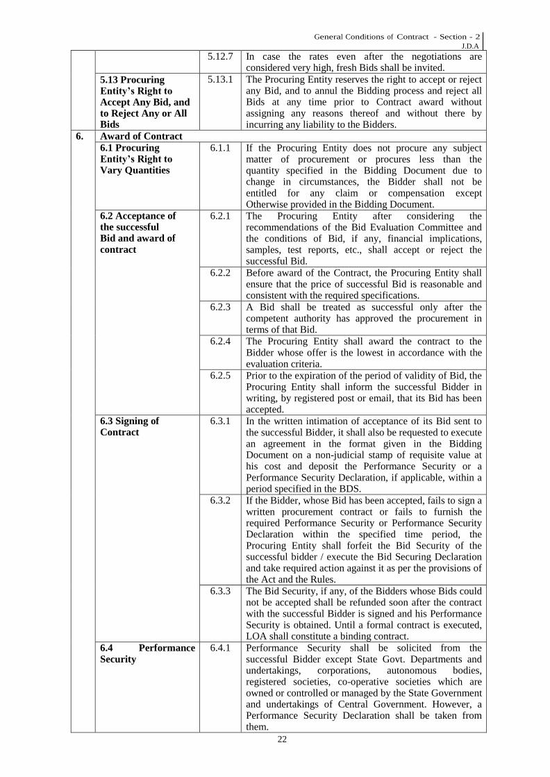
5.12.7 In case the rates even after the negotiations are considered very high, fresh Bids shall be invited.
5.13 Procuring Entity’s Right to Accept Any Bid, and to Reject Any or All Bids
5.13.1 The Procuring Entity reserves the right to accept or reject any Bid, and to annul the Bidding process and reject all Bids at any time prior to Contract award without assigning any reasons thereof and without there by incurring any liability to the Bidders.
6. Award of Contract 6.1 Procuring Entity’s Right to Vary Quantities
6.1.1 If the Procuring Entity does not procure any subject matter of procurement or procures less than the quantity specified in the Bidding Document due to change in circumstances, the Bidder shall not be entitled for any claim or compensation except Otherwise provided in the Bidding Document.
6.2 Acceptance of the successful Bid and award of contract
6.2.1 The Procuring Entity after considering the recommendations of the Bid Evaluation Committee and the conditions of Bid, if any, financial implications, samples, test reports, etc., shall accept or reject the successful Bid.
6.2.2 Before award of the Contract, the Procuring Entity shall ensure that the price of successful Bid is reasonable and consistent with the required specifications.
6.2.3 A Bid shall be treated as successful only after the competent authority has approved the procurement in terms of that Bid.
6.2.4 The Procuring Entity shall award the contract to the Bidder whose offer is the lowest in accordance with the evaluation criteria.
6.2.5 Prior to the expiration of the period of validity of Bid, the Procuring Entity shall inform the successful Bidder in writing, by registered post or email, that its Bid has been accepted.
6.3 Signing of Contract
6.3.1 In the written intimation of acceptance of its Bid sent to the successful Bidder, it shall also be requested to execute an agreement in the format given in the Bidding Document on a non-judicial stamp of requisite value at his cost and deposit the Performance Security or a Performance Security Declaration, if applicable, within a period specified in the BDS.
6.3.2 If the Bidder, whose Bid has been accepted, fails to sign a written procurement contract or fails to furnish the required Performance Security or Performance Security Declaration within the specified time period, the Procuring Entity shall forfeit the Bid Security of the successful bidder / execute the Bid Securing Declaration and take required action against it as per the provisions of the Act and the Rules.
6.3.3 The Bid Security, if any, of the Bidders whose Bids could not be accepted shall be refunded soon after the contract with the successful Bidder is signed and his Performance Security is obtained. Until a formal contract is executed, LOA shall constitute a binding contract.
6.4 Performance Security
6.4.1 Performance Security shall be solicited from the successful Bidder except State Govt. Departments and undertakings, corporations, autonomous bodies, registered societies, co-operative societies which are owned or controlled or managed by the State Government and undertakings of Central Government. However, a Performance Security Declaration shall be taken from them.

General Conditions of Contract - Section - 2 J.D.A
23
6.4.2 (i) The amount of Performance Security shall be as per prevailing Gov. of Rajasthan norms.
6.4.3 Performance Security shall be furnished in one of the following forms as applicable- a). Deposit through eGRAS; or b). Bank Draft or Banker's Cheque of a Scheduled Bank in India in favour of Secretary, JDA, Jaipur; or c). National Savings Certificates and any other script/ instrument under National Savings Schemes for promotion of small savings issued by a Post Office in Rajasthan, if the same can be pledged under the relevant rules. They shall be accepted at their surrender value at the time of Bid and formally transferred in the name of the Procuring Entity with the approval of Head Post Master; or d). Bank guarantee in favour of Secretary JDA, Jaipur payable at Jaipur. It shall be got verified from the issuing bank. Other conditions regarding bank guarantee shall be same as specified in ITB Sub-Clause 3.10 [Bid Security]; or e). Fixed Deposit Receipt (FDR) of a Scheduled Bank. It shall be in the name of the Procuring Entity on account of Bidder and discharged by the Bidder in advance. The Procuring Entity shall ensure before accepting the Fixed Deposit Receipt that the Bidder furnishes an undertaking from the bank to make payment/ premature payment of the Fixed Deposit Receipt on demand to the Procuring Entity without requirement of consent of the Bidder concerned. In the event of forfeiture of the Performance Security, the Fixed Deposit shall be forfeited along with interest earned on such Fixed Deposit. f). The successful Bidder at the time of signing of the Contract agreement, may submit option for deduction of Performance Security from each running and final bill as per prevailing GOR orders.
6.4.4 Performance Security furnished in the form of a document mentioned at options (a) to (e) of Sub-Clause 6.4.3 above, shall remain valid for a period of sixty days beyond defect liability period.
6.4.5 Failure of the successful Bidder to submit the Performance Security in accordance to 6.4.3 above and sign the Contract accordingly shall constitute sufficient grounds for the annulment of the award and forfeiture of the Bid Security. In that event, the Procuring Entity may either cancel the procurement process or if deemed appropriate, award the Contract at the rates of the lowest Bidder, to the next lowest evaluated Bidder whose offer is substantially responsive and is determined by the Procuring Entity to be qualified to perform the Contract satisfactorily.
6.4.6 Forfeiture of Performance Security: Amount of Performance Security in full or part may be forfeited in the following cases: - when the Bidder does not execute the agreement in accordance with ITB Clause 6.3 [Signing of Contract] within the specified time; after issue of letter of acceptance; or when the Bidder fails to commence the Works as per Work order within the time specified; or when the Bidder fails to complete Contracted Works

General Conditions of Contract - Section - 2 J.D.A
24
satisfactorily within the time specified; or when any terms and conditions of the contract is breached; or to adjust any established dues against the Bidder from any other contract with the Procuring Entity; or if the Bidder breaches any provision of the Code of Integrity prescribed for the Bidders specified in the Act, Chapter VI of the Rules and this Bidding Document. Notice of reasonable time will be given in case of forfeiture of Performance Security. The decision of the Procuring Entity in this regard shall be final.
Forming part of the contract, the following shall prevail in order of precedence. i) NIB/ Pre Qualification Criteria ii) General Conditions of Contract iii) Special Conditions of Contract iv) Design Brief Report v) SHE Management Clause vi) Financial Bid
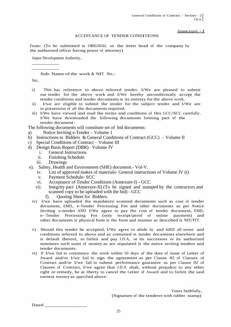
General Conditions of Contract - Section - 2 J.D.A
25
ACCEPTANCE OF TENDER CONDITIONS
Annexure - I
From: (To be submitted in ORIGINAL on the letter head of the company by the authorized officer having power of attorney)
Jaipur Development Authority,
Sub: Name of the work & NIT No.:
Sir,
i) This has reference to above referred tender. I/We are pleased to submit our tender for the above work and I/We hereby unconditionally accept the tender conditions and tender documents in its entirety for the above work.
ii) I/we are eligible to submit the tender for the subject tender and I/We are in possession of all the documents required.
iii) I/We have viewed and read the terms and conditions of this GCC/SCC carefully. I/We have downloaded the following documents forming part of the tender document:
The following documents will constitute set of bid documents: a) Notice Inviting e-Tender – Volume 1 b) Instructions to Bidders & General Conditions of Contract (GCC) – Volume II c) Special Conditions of Contract – Volume III d) Design Basis Report (DBR)– Volume IV
i. General Instructions ii. Finishing Schedule
iii. Drawings e). Safety, Health and Environment (SHE) document.- Vol-V.
iv. List of approved makes of materials- General instructions of Volume IV (i) v. Payment Schedule- SCC
vi. Acceptance of Tender Conditions (Annexure-I) - GCC vii. Integrity pact (Annexure-II) (To be signed and stamped by the contractors and
scanned copy to be uploaded with the bid) - GCC f). Quoting Sheet for Bidders.
iv) I/we have uploaded the mandatory scanned documents such as cost of tender document, EMD, e-Tender Processing Fee and other documents as per Notice Inviting e-tender AND I/We agree to pay the cost of tender document, EMD, e- Tender Processing Fee (only receipt/proof of online payment) and other documents in physical form in the form and manner as described in NIT/ITT.
v) Should this tender be accepted, I/We agree to abide by and fulfill all terms and
conditions referred to above and as contained in tender documents elsewhere and in default thereof, to forfeit and pay J.D.A, or its successors or its authorized nominees such sums of money as are stipulated in the notice inviting tenders and tender documents.
vi) If I/we fail to commence the work within 10 days of the date of issue of Letter of Award and/or I/we fail to sign the agreement as per Clause 82 of Clauses of Contract and/or I/we fail to submit performance guarantee as per Clause 02 of Clauses of Contract, I/we agree that J.D.A shall, without prejudice to any other right or remedy, be at liberty to cancel the Letter of Award and to forfeit the said earnest money as specified above.
Yours faithfully, (Signature of the tenderer with rubber stamp)
Dated
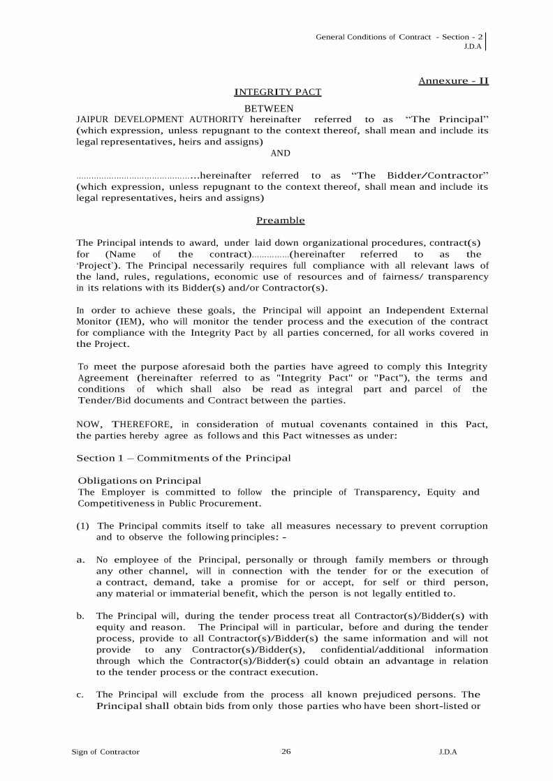
General Conditions of Contract - Section - 2 J.D.A
Sign of Contractor 2626
J.D.A
INTEGRITY PACT
BETWEEN
Annexure - II
JAIPUR DEVELOPMENT AUTHORITY hereinafter referred to as “The Principal” (which expression, unless repugnant to the context thereof, shall mean and include its legal representatives, heirs and assigns)
AND
………………………………………...hereinafter referred to as “The Bidder/Contractor”
(which expression, unless repugnant to the context thereof, shall mean and include its legal representatives, heirs and assigns)
Preamble
The Principal intends to award, under laid down organizational procedures, contract(s) for (Name of the contract)……………(hereinafter referred to as the ‘Project’). The Principal necessarily requires full compliance with all relevant laws of the land, rules, regulations, economic use of resources and of fairness/ transparency in its relations with its Bidder(s) and/or Contractor(s).
In order to achieve these goals, the Principal will appoint an Independent External Monitor (IEM), who will monitor the tender process and the execution of the contract for compliance with the Integrity Pact by all parties concerned, for all works covered in the Project.
To meet the purpose aforesaid both the parties have agreed to comply this Integrity Agreement (hereinafter referred to as "Integrity Pact" or "Pact"), the terms and conditions of which shall also be read as integral part and parcel of the Tender/Bid documents and Contract between the parties.
NOW, THEREFORE, in consideration of mutual covenants contained in this Pact, the parties hereby agree as follows and this Pact witnesses as under:
Section 1 – Commitments of the Principal
Obligations on Principal The Employer is committed to follow the principle of Transparency, Equity and Competitiveness in Public Procurement.
(1) The Principal commits itself to take all measures necessary to prevent corruption
and to observe the following principles: -
a. No employee of the Principal, personally or through family members or through any other channel, will in connection with the tender for or the execution of a contract, demand, take a promise for or accept, for self or third person, any material or immaterial benefit, which the person is not legally entitled to.
b. The Principal will, during the tender process treat all Contractor(s)/Bidder(s) with
equity and reason. The Principal will in particular, before and during the tender process, provide to all Contractor(s)/Bidder(s) the same information and will not provide to any Contractor(s)/Bidder(s), confidential/additional information through which the Contractor(s)/Bidder(s) could obtain an advantage in relation to the tender process or the contract execution.
c. The Principal will exclude from the process all known prejudiced persons. The
Principal shall obtain bids from only those parties who have been short-listed or

General Conditions of Contract - Section - 2 J.D.A
Sign of Contractor 2727
J.D.A
pre-qualified or through a process of open advertisement/ web publishing or any combination thereof.
(2) If the Principal obtains information on the conduct of any of its employees,
Contractor(s) and/or Bidder(s), which is a criminal offence under the IPC/PC Act, or if there be a substantive suspicion in this regard, the Principal will inform the Chief Vigilance Officer or the principal will take remedial actions as per department/conduct rules and subject to its discretion, can additionally initiate disciplinary actions.
(3) The Principal will enter into agreements with identical conditions with all
Contractor(s)/Bidder(s) for the different Work Packages in the aforesaid Project.
(4) The Principal will disqualify from the tender process all Contractor(s)/Bidder(s)
with estimated cost of work put to tender of Rs 5.0 crores and above, who do not sign this Pact or violate its provisions.
Section 2 – Commitments of the Bidder(s) / Contractor(s)
Obligations on Bidder/Contractor To accept and comply with the Integrity Agreement in letter and spirit and further agree that execution of the said Integrity Agreement shall be separate and distinct from the main contract, which will come into existence when tender/bid is finally accepted by Employer. Duration of the Integrity Agreement shall be in the line with section 8 of the Integrity Agreement.
Bidder/Contractor acknowledge that in the event of breach of the Integrity Agreement Employer shall have unqualified, absolute and unfettered right to take action under section 3.
(1) It is required that each Bidder/Contractor (including their respective officers,
employees and sub-contractors) adhere to the highest ethical standards, and report to the Government / Department all suspected acts of fraud or corruption or Coercion or Collusion of which it has knowledge or becomes aware, during the tendering process and throughout the negotiation or award of a contract.
(2) The Bidder(s) / Contractor(s) commit(s) itself/themselves to take all
measures necessary to prevent corruption. He commits himself to observe the following principles during his participation in the tender process and during the contract execution.
(a) The Bidder(s) / Contractor(s) will not, directly or through any other person or
firm offer, promise or give to any of the Principal’s employees involved in the tender process or the execution of the contract any material or other benefit which he/she is not legally entitled to, in order to obtain in exchange any advantage, of any kind whatsoever, during the tender process or during the execution of the contract.
(b) The Bidder(s)/Contractor(s) will not enter with other Bidders into
any undisclosed agreement or understanding, whether formal or informal. This applies in particular to prices, specifications, certifications, subsidiary contracts, submission or non-submission of bids or any other actions to restrict competitiveness or to introduce cartelization in the bidding process.
(c) The Bidder(s)/Contractor(s) will not commit any offence under the relevant
IPC/PC Act. Further the Bidder(s)/Contractor(s) will not use improperly, for

General Conditions of Contract - Section - 2 J.D.A
Sign of Contractor 2828
J.D.A
purpose of competition or personal gain, or pass on to others, any information or document provided by the Principal as part of the business relationship, regarding plans, technical proposals and business details, including information contained or transmitted electronically.
(d) The Bidder(s) / Contractor(s) of foreign origin shall disclose the name
and address of the Agents/representatives in India, if any. Similarly the Bidder(s) / Contractor(s) of Indian Nationality shall furnish the name and address of the foreign principals, if any. Either the Indian agent on behalf of the foreign principal or the foreign principal directly could bid in a tender but not both. It shall be incumbent on the Indian agent and the foreign principal to Adhere to the relevant guidelines of Government of India, issued from Time to time regarding availing services of Indian Agents for foreign Suppliers.
Further details as mentioned in the “Guidelines on Indian Agents of Foreign Suppliers” shall be disclosed by the Bidder(s) / Contractor(s). Further, as mentioned in the Guidelines all the payments made to the Indian agent/representative have to be in Indian Rupees only.
(e) The Bidder(s) / Contractor(s) will, when submitting his bid, disclose any and
all payments he has made, is committed to or intends to make to agents, brokers or any other intermediaries in connection with the award of the contract.
(f) The Bidder(s) / Contractor(s) to disclose any transgression with any other
company that may impinge on the anti-corruption principle.
(3) The Bidder(s) / Contractor(s) will not instigate third persons to commit offences outlined above or be an accessory to such offences.
(4) The Bidder(s)/Contractor(s) will not, directly or through any other person or firm
indulge in fraudulent practice means a willful misrepresentation or omission of facts or submission of fake/forged documents in order to induce public official to act in reliance thereof, with the purpose of obtaining unjust advantage by or causing damage to justified interest of others and/or to influence the procurement process to the detriment of the Government interests.
(5) The Bidder(s)/Contractor(s) will not, directly or through any other person or firm
use Coercive Practices (means the act of obtaining something, compelling an action or influencing a decision through intimidation, threat or the use of force directly or indirectly, where potential or actual injury may befall upon a person, his/ her reputation or property to influence their participation in the tendering process).
(6) The Bidder(s)/Contractor(s) signing IP shall not approach the Courts while
representing the matters to IEM and he/she will await their decision in the matter.
(7) The Bidder(s)/Contractor(s), in case of sub-contracting, the Principal contractor shall take the responsibility of the adoption of IP by the sub-contractor.
Section 3: Disqualification from tender process and/or exclusion from future
contracts.
Without prejudice to any rights that may be available to the Employer under law or the Contract or its established policies and laid down procedures, the Employer shall have the following rights in case of breach of this Integrity Pact by the

General Conditions of Contract - Section - 2 J.D.A
Sign of Contractor 2929
J.D.A
Bidder(s)/Contractor(s) and the Bidder/ Contractor accepts and undertakes to respect and uphold the Employer absolute right:
(1) If the Bidder(s) / Contractor(s), before awarding the Project or during execution
has committed a transgression by violating Section 2 above or in any other form so as to put his reliability or credibility in question, the Principal, at its sole discretion, after giving proper opportunity to the bidder is entitled to disqualify the Bidder(s) / Contractor(s) from the tender process or terminate the contract, if already awarded or exclude the Bidder/Contractor from future contract award processes, for that reason, without prejudice to any other legal rights or remedies available to the Principal under the relevant clauses of GCC/SCC of the tender/contract. The imposition and duration of the exclusion will be determined by the severity of transgression and determined by the Principal. Such exclusion may be forever or for a limited period as decided by the Principal.
(2) If the Contractor(s)/Bidder(s) has committed a transgression through a violation
of any of the terms under Section 2 above or in any other form such as to put his reliability or credibility into question, the Principal will also be entitled to exclude such Contractor(s)/Bidder(s) from future tenders/contract award processes. The imposition and duration of the exclusion will be determined by the Principal, keeping in view the severity of the transgression. The severity will be det ermined by the circumstances of the case, in particular, the number of transgressions and/or the amount of the damage.
(3) If it is observed after payment of final bill but before the expiry of validity
of Integrity Pact that the contractor has committed a transgression, through a violation of any of the terms under Section 2 above or any other term(s) of this Pact, during the execution of contract, the Principal will be entitled to exclude the contractor from further tender/contract award processes.
(4) The exclusion will be imposed for a minimum period of six (6) months and a
maximum period of three (3) years.
(5) If the Contractor(s)/Bidder(s) can prove that he has restored/recouped the damage to the Principal caused by him and has installed a suitable corruption prevention system, the Principal may, at its sole discretion, revoke or reduce the exclusion period before the expiry of the period of such exclusion.
Section 4: Compensation for Damages
(1) If the Principal has disqualified the Bidder(s)/Contractor(s) from the tender
process prior to the awarding of the Project according to Section 3, the Earnest Money Deposit (EMD)/ Bid Security furnished, if any, along with the offer, as per terms of the Invitation of Tender, shall also be forfeited. The Bidder(s)/Contractor(s) understands and agrees that this will be in addition to the disqualification and exclusion of the Contractor(s)/Bidder(s) as may be imposed by the Principal, in terms of Section 3 above.
(2) If, at any time after the awarding of the Project, the Principal has terminated the
contract according to Section 3, or if the Principal is entitled to terminate the contract according to Section 3, the Security Deposit/Performance Bank Guarantee furnished by the contractor, if any, as per the terms of the NIT/Contract shall be forfeited without prejudice to any other legal rights and remedies available to the Principal under the relevant clauses of General/ Special Conditions of Contract.
The Contractor(s)/Bidder(s) understands and agrees that this will be in addition to the disqualification and exclusion of the Bidder(s)/Contractor(s), as may be imposed by the Principal in terms of Section 3 above.

General Conditions of Contract - Section - 2 J.D.A
Sign of Contractor 3030
J.D.A
Section 5: Previous transgression
(1) The Bidder(s)/Contractor(s) herein declares that it has committed no transgressions in the last 5 years with any other Company in any country conforming to the anti-corruption approach as detailed herein or with government/ Central Government or State Government or any other Public Sector Enterprise in India that could justify its exclusion from the tender process.
(2) If at any point of time during the tender process or after the awarding of
the Contract, it is found that the Bidder(s)/Contractor(s) has made an incorrect statement on this subject, he can be disqualified from the tender process or if, as the case may be, that the Contract, is already awarded, it will be terminated for such reason and the Bidder(s)/Contractor(s) can be black listed in terms of Section 3 above.
(3) If the Bidder/Contractor can prove that he has resorted / recouped the damage
caused by him and has installed a suitable corruption prevention system, the Employer may, at its own discretion, revoke the exclusion prematurely.
Section 6: Independent External Monitor / Monitors
(1) The Principal shall, in case where the Project Value is in excess of Rs 5.0 crore
and above, appoint competent and credible Independent External Monitor(s) with clearance from Central Vigilance Commission. The Monitor shall review independently, the cases referred to it to assess whether and to what extent the parties concerned comply with the obligations under this Integrity Pact.
(2) In case of non-compliance of the provisions of the Integrity Pact, the complaint/
non-compliance is to be lodged by the aggrieved party with the Nodal Officer only, as shall be appointed by the JDC , J.D.A. The Nodal Officer shall refer the complaint/ non-compliance so received by him to the aforesaid Monitor.
(3) The Monitor will not be subject to any instructions by the representatives of the
parties and will perform its functions neutrally and independently. The Monitor shall report to the Chairman-cum-Managing Director, J.D.A.
(4) The Bidder(s) / Contractor(s) accepts that the Monitor shall have the right
to access, without restriction, all Project documentation of the Principal including that provided by the Contractor. The Contractor will also grant the Monitor, upon his/her request and demonstration of a valid interest, unrestricted and unconditional access to its project documentation. The Monitor is under contractual obligation to treat the information and documents of the Bidder(s) / Contractor(s) with confidentiality.
(5) The Principal will provide to the Monitor, sufficient information about all meetings
among the parties related to the Project, provided such meetings could have an impact on the contractual relations between the Principal and the Contractor.
(6) As soon as the Monitor notes, or believes to note, a violation of this Pact, he will
so inform the Principal and request the Principal to discontinue and/or take corrective action, or to take other relevant action(s). The Monitor can in this regard submit non-binding recommendations. However, beyond this, the Monitor

General Conditions of Contract - Section - 2 J.D.A
Sign of Contractor 3131
J.D.A
has no right to demand from the parties that they act in a specific manner and/or refrain from action and/or tolerate action.
(7) The Monitor will submit a written report to the JDC , J.D.A within 4 to 6 weeks
from the date of reference or intimation to it and, should the occasion arise, submit proposals for corrective actions for the violation or the breaches of the provisions of the agreement noticed by the Monitor.
(8) If the Monitor has reported to the JDC , J.D.A of a substantiated suspicion of an
offence under relevant IPC/PC Act, and the JDC, J.D.A, has not, within the reasonable time taken visible action to proceed against such offence or reported it to the Chief Vigilance Officer, the Monitor may also transmit this information directly to the Chief Vigilance Officer, J.D.A.
(9) The word ‘Monitor’ means Independent External Monitor and includes
both singular and plural forms.
(10) For ensuring the desired transparency and objectivity in dealing with the complaints arising out of any tendering process, the matter should be examined by the full panel of IEMs jointly as far as possible, who would look into the records, conduct an investigation, and submit their joint recommendations to the Management.
(11) IEM should examine the process integrity, they are not expected to concern
themselves with fixing of responsibility of officers. Complaints alleging malafide on the part of any officer of the organization should be looked into by the CVO of the concerned organization.
(12) The role of IEM is advisory, would not be legally binding and it is restricted
to resolving issued raised by an intending bidder regarding any aspect of the tender which allegedly restricts competition or bias towards some bidders. At the same time, it must be understood that IEMs are not consultants to the Management. Their role is independent in nature and the advice once tendered would not be subject to review at the request of the organizations.
(13) Issues like warranty / guarantee etc. should be outside the purview of IEMs.
(14) The role of the CVO of the organization shall remain unaffected by the presence
of IEMs. A matter being examined by the IEMs can be separately investigated by the CVO in terms of the provisions of the CVC Act or Vigilance Manual, If a complaint is received by him/her or directed to him/her by the commission
Section 7 – Criminal charges against violating Bidder(s)/Contractor(s)/
Subcontractor(s)
If the Principal obtains knowledge of conduct of a Bidder/Contractor or any employee or a representative or an associate of a Bidder/Contractor, which constitutes a criminal offence under the IPC/PC Act, or if the Principal has substantive suspicion in this regard, the Principal will forthwith inform the same to the Chief Vigilance Officer, J.D.A.
Section 8 – Duration of the Integrity Pact
This Pact shall come into force when both parties have legally signed it. The Pact shall expire, in case of the Contractor(s), 3 (three) months after the last payment under the Contract is made and in case of the unsuccessful Bidder(s), 2 (two) months after the contract for the project has been awarded.
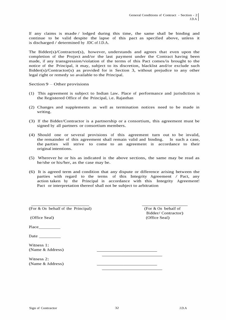
General Conditions of Contract - Section - 2 J.D.A
Sign of Contractor 3232
J.D.A
If any claims is made / lodged during this time, the same shall be binding and continue to be valid despite the lapse of this pact as specified above, unless it is discharged / determined by JDC of J.D.A.
The Bidder(s)/Contractor(s), however, understands and agrees that even upon the completion of the Project and/or the last payment under the Contract having been made, if any transgression/violation of the terms of this Pact comes/is brought to the notice of the Principal, it may, subject to its discretion, blacklist an d/or exclude such Bidder(s)/Contractor(s) as provided for in Section 3, without prejudice to any other legal right or remedy so available to the Principal.
Section 9 – Other provisions
(1) This agreement is subject to Indian Law. Place of performance and jurisdiction is
the Registered Office of the Principal, i.e. Rajasthan
(2) Changes and supplements as well as termination notices need to be made in writing.
(3) If the Bidder/Contractor is a partnership or a consortium, this agreement must be
signed by all partners or consortium members.
(4) Should one or several provisions of this agreement turn out to be invalid, the remainder of this agreement shall remain valid and binding. In such a case, the parties will strive to come to an agreement in accordance to their original intentions.
(5) Wherever he or his as indicated in the above sections, the same may be read as
he/she or his/her, as the case may be.
(6) It is agreed term and condition that any dispute or difference arising between the parties with regard to the terms of this Integrity Agreement / Pact, any action taken by the Principal in accordance with this Integrity Agreement! Pact or interpretation thereof shall not be subject to arbitration
(For & On behalf of the Principal) (For & On behalf of Bidder/ Contractor)
(Office Seal) (Office Seal)
Place
Date
Witness 1: (Name & Address)
Witness 2: (Name & Address)
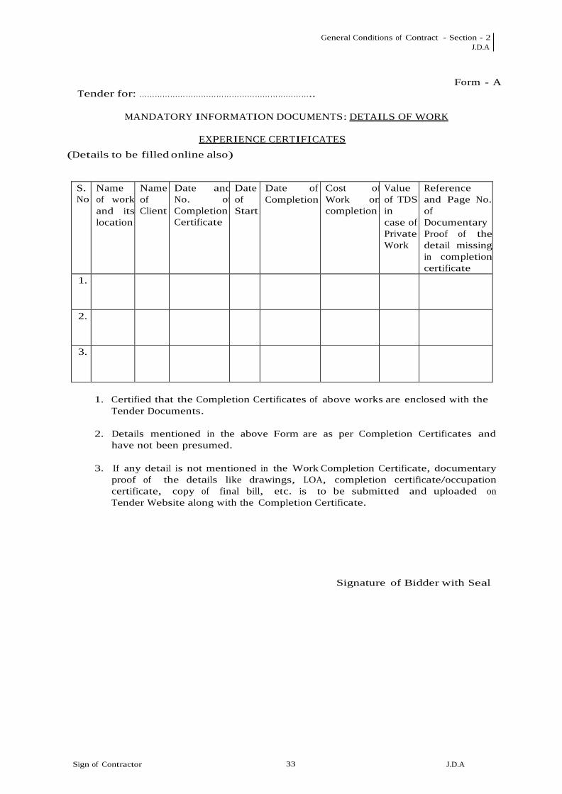
General Conditions of Contract - Section - 2 J.D.A
Sign of Contractor 3333
J.D.A
Tender for: …………………………………………………………..
MANDATORY INFORMATION DOCUMENTS: DETAILS OF WORK
Form - A
EXPERIENCE CERTIFICATES
(Details to be filled online also)
S. No
Name of work and its location
Name of Client
Date and No. of Completion Certificate
Date of Start
Date of Completion
Cost of Work on completion
Value of TDS in case of Private Work
Reference and Page No. of Documentary Proof of the detail missing in completion certificate
1.
2.
3.
1. Certified that the Completion Certificates of above works are enclosed with the
Tender Documents.
2. Details mentioned in the above Form are as per Completion Certificates and have not been presumed.
3. If any detail is not mentioned in the Work Completion Certificate, documentary
proof of the details like drawings, LOA, completion certificate/occupation certificate, copy of final bill, etc. is to be submitted and uploaded on Tender Website along with the Completion Certificate.
Signature of Bidder with Seal

General Conditions of Contract - Section - 2 J.D.A
Sign of Contractor 3434
J.D.A
Tender for: ………………………………………………….
MANDATORY INFORMATION DOCUMENTS:
DETAILS OF SIMILAR WORKS
FORM - B
(Details to be filled online also)
S. N o
Name of Work for which Experienc e Certificate has been submitted
Name of Client s
Date and No. of Completio n Certificate
Type of Work i.e. Residenti al / Non Residenti al Building
No. of Basement s
No. of Storey s
Height of Buildin g
Ref.& Page No. of Docu- mentary Proof of the detail missing in completio n certificate
1
2
3
If any detail is not mentioned in the Work Completion Certificate, documentary proof of detail is to be submitted and uploaded on Tender Website along with the Completion Certificate.
Signature of Bidder with Seal

General Conditions of Contract - Section - 2 J.D.A
Sign of Contractor 3535
J.D.A
FORM-C
FINANCIAL DETAILS
(Details to be filled online also)
Tender For: ……………………………………………………
MANDATORY INFORMATION DOCUMENTS:
1st FY Rs. (In Lacs)
2nd FY Rs (In Lacs)
3rd FY Rs. (In Lacs)
4th FY Rs. (In Lacs)
5th(& last) FY Rs. (In Lacs)
a b c i.) Profit/Loss
ii.) Gross Annual Turnover of Previous 3 financial years ending as on 31st March of last FY
iii.) Average Annual Turnover for previous 3 financial years (Rs. In Lacs) = (a+b+c)/3
iv.) Net Worth (paid up capital+reserves) as on 31st March of last FY
v.) Bank Solvency amount as mentioned in the Bank Solvency Certificate
1. Summarised page of Audited Profit & Loss Account of previous five Financial Years duly certified by the chartered account, is to be submitted.
2. Summarised page of Audited Balance Sheet of last Financial Year (ending 31st
March of preceding FY) duly certified by the chartered account, is to be submitted.
Note: This Form-C is to be submitted in original.
Signature of Chartered Seal and Signature of bidder Accountant with Seal

General Conditions of Contract - Section - 2 J.D.A
Sign of Contractor J.D.A
36
FORM-D
TDS DETAILS FOR PRIVATE SECTOR PROJECTS
(Details to be filled online also)
S. No.
Name of Work
Name of Clients
Project Cost in Crores
No. And Date of Completion Certificate
Cost of the work on completion in Crores
Payments Received as per TDS In Crores
TDS Corresponding to the Payments
Year wise TDS as per Form- 26AS/Form 16A relating to the work
1.
2.
3.
Note: Value of Work done will be considered commensurate with value of TDS Certificates.
In case of multiple contracts undertaken from a Client, details of TDS/Form- 26AS for each work mentioned above need to be segregated and given separately.
This form need to be supported with Form-26AS taken in HTML format or Form -16A.
Signature of Bidder with Seal
Signature of Chartered Accountant with Stamp and Membership Number

General Conditions of Contract - Section - 2 J.D.A
Sign of Contractor J.D.A
37
FORM-E
Dispatch number of bank/ Date
SOLVENCY CERTIFICATE ON LETTER HEAD OF BANK
This is to state that to the best of our knowledge and information that
M/s……………………… having/registered office address………………………….. ……………………………………………………...…………………..is customer of bank and has been maintaining his accounts with our branch since……………. . As per records available with the bank, M/s……………………………………………………………….. can be treated as solvent up to a limit of Rs………………………(Rupees in words…………………………………….).
It is clarified that the above information is furnished and this certificate is being issued at the specific request of the customer.
Name, designation, Signature with seal
Notes:-
1. The certificate should have been issued within 6 months from original last date of the submission of the tender.

General Conditions of Contract - Section - 2 J.D.A
Sign of Contractor J.D.A
38
GENERAL INFORMATION
FORM - F
1. Name of Applicant/Company
2. Address for correspondence
3. Official e-mail for communication
4. Contact Person:
Telephone Nos.
Fax Nos.
Mobile
5. Type of Organization: a) An individual
b) A proprietary firm
c) A firm in partnership
(Attach copy of Partnership) d) A Limited Company
(Attach copy of Article of Association) e) Any other (mention the type)
6. Place and Year of Incorporation
7. Name of Directors/Partners in the organization
8. Name(s) and Designation of the persons , who is authorized to deal with J.D.A (Attach copy of power of Attorney)
9. Bank Details : Name of Bank, Address of Bank Branch, Account No., RTGS, IFS Code
Signature of Bidder with Seal

General Conditions of Contract - Section - 2 J.D.A
Sign of Contractor J.D.A
39
FORM- G
Name of the Client with Address, email & phone no.
Dispatch No.................. Date: .....................
WORK EXPERIENCE CERTIFICATE
Name of Contractor_
1 Name of work / project & Location
2 Name and Address of the Clients
3 Agreement Amount
4 Cost of work on completion
5 Date of start
6 Stipulated date of completion
7 Actual date of completion
8 Amount of compensation levied for
delayed completion, if any
9 Type of Work: Residential/ Non
Residential Building
10 No. of Basements in any Building of
this work
11 Maximum Height of any Building of
this work
12 Maximum No. of storeys of any
Building of this work
13 Performance report Outstanding Very Good Good Poor
(a) Quality of work
(b) Resourcefulness
(c) Financial soundness
(d) Technical proficiency
(e) General behaviour
Date Name & Designation Signature with Seal of issuing Authority

General Conditions of Contract - Section - 2 J.D.A
Sign of Contractor J.D.A
40
Form-H
AFFIDAVIT
(To be submitted by bidder on non-judicial stamp paper of Rs.100/(Rupees Hundred only) duly attested by Notary Public)
Affidavit of Mr. ...............................................S/o ............................................. R/o .............................................
I, the deponent above named do hereby solemnly affirm and declare as under:
1. That I am the Proprietor/Authorized signatory of M/s ………………………………………. Having its Head Office/Regd. Office at ………………………………………………………………..
2. That the information/documents/Experience certificates submitted by
M/s…………………………. along with the tender for …………………… (Name of work)…………
To J.D.A are genuine and true and nothing has been concealed.
3. I shall have no objection in case J.D.A verifies them from issuing authority(ies). I shall also have no objection in providing the original copy of the document(s), in case J.D.A demands so for verification.
4. I hereby confirm that in case, any document, information & / or certificate
submitted by me found to be incorrect / false / fabricated, J.D.A at its discretion may disqualify / reject / terminate the bid/contract and also forfeit the EMD / All dues.
5. I shall have no objection in case J.D.A verifies any or all Bank Guarantee(s) under
any of the clause(s) of Contract including those issued towards EMD and Performance Guarantee from the Zonal / Branch office of issuing Bank and I/We shall have no right or claim on my submitted EMD before J.D.A receives said verification.
6. That the Bank Guarantee issued against the EMD issued by (name and address of
the Bank) is genuine and if found at any stage to be incorrect / false / fabricated, J.D.A shall reject my bid, cancel pre-qualification and debar me from participating in any future tender for three years.
7. I hereby confirm that our firm /company is not blacklisted/ barred /banned from
tendering by J.D.A. If this information is found incorrect, J.D.A at its discretion may disqualify / reject / terminate the bid/contract.
8. The person who has signed the tender documents is our authorized
representative. The Company is responsible for all of his acts and omissions in the tender.
I, ....................................., the Proprietor / Authorised signatory of M/s....................................... do hereby confirm that the contents of the above Affidavit are true to my knowledge and nothing has been concealed there from.................... and that no part of it is false.
DEPONENT
Verified at ................this.................day of .....................
DEPONENT
ATTESTED BY (NOTARY PUBLIC)

General Conditions of Contract - Section - 2 J.D.A
Sign of Contractor J.D.A
41
FORM-I
GST Registration Details of Contractor/Vender
Name
Address (As per registration with GST)
City
Postal Code
Region/State (Complete State Name)
Permanent Account Number
GSTIN ID/Provisional ID No.: (copy of Acknowledgement required)
Type of Business (As per registration with GST)
Service Accounting Code/HSN Code:
Contact Person
Phone Number and Mobile Number
Email ID
Compliance Rating (if updated by GSTN)

General Conditions of Contract - Section - 3 J.D.A
Sign of Contractor 4242
J.D.A
Section-3
CLAUSES OF CONTRACT

General Conditions of Contract - Section - 3 J.D.A
Sign of Contractor 4343
J.D.A
CLAUSES OF CONTRACT (CC)
1.0 DEFINITIONS The Contract means the documents forming the tender and acceptance thereof and the formal agreement executed between the competent authority on behalf of Jaipur Development Authority and the contractor, together with the documents referred to therein including these conditions, the specifications, designs, drawings and instructions issued from time to time by the Engineer-in-Charge and all these documents taken together, shall be deemed to form one contract and shall be complementary to one another.
1.1 Jaipur Development Authority, hereinafter called 'J.D.A' propose to get the
works executed as mentioned in the Contract on behalf of Owner/ Client as Implementing agency/Executing Agency.
1.2 In the contract, the following expressions shall, unless the
context otherwise requires, have the meanings, hereby respectively assigned to them: -
a) APPROVAL means approved in writing including subsequent written
confirmation of previous verbal approval.
b) BILL OF QUANTITIES or SCHEDULE OF QUANTITIES means the priced and completed Bill of Quantities or Schedule of Quantities forming part of the tender.
c) CONTRACTOR shall mean the individual, firm, LLP or company, whether
incorporated or not, undertaking the works and shall include the legal personal representative of such individual or the persons composing such firm or LLP or company, or the successors of such firm or company and the permitted assignees of such individual, firm or company.
d) CONTRACT VALUE means the sum for which the tender is accepted as per the
letter of Award.
e) DRAWINGS mean the drawings referred to in the contract document including modifications if any and such other drawings as may from time to time be furnished and/ or approved by J.D.A.
f) DATE OF COMMENCEMENT OF WORK: The date of start of contract shall be
reckoned from 10 days after the date of issue of letter of Award.
g) ENGINEER-IN-CHARGE means the Engineer of J.D.A who shall supervise and be in-charge of the work.
h) LANGUAGE: All documents and correspondence in respect of this contract
shall be in English Language.
i) “LETTER OF AWARD” shall mean J.D.A’s letter or notification conveying its acceptance of the tender subject to such conditions as may have been stated therein.

General Conditions of Contract - Section - 3 J.D.A
Sign of Contractor 4444
J.D.A
j) MONTH means English Calendar month ‘Day’ means a Calendar day of 24 Hrs
each.
k) “J.D.A” shall means J.D.A (India) Limited with its Corporate office at Jawahar Lal Nehru Marg , Jaipur , Rajasthan - 302004 or its Administrative officers or its engineer or other employees authorized to deal with any matter with which these persons are concerned and authorized on its behalf.
l) OWNER/ CLIENT means the Government, Organization, Ministry, Department, Society, Cooperative, JV Entities (whether incorporated or unincorporated or registered as the case may be) etc. who has awarded the work/ project to J.D.A and/ or appointed J.D.A as Implementing / Executing Agency/ Project Manager and/ or for whom J.D.A is acting as an agent and on whose behalf J.D.A is entering into the contract and getting the work executed.
m) SCHEDULE(s) referred to in these conditions shall mean the standard schedule of rates of the government mentioned in the Memorandum (Annexure-I) with the amendments thereto issued up to the date of receipt of the tender.
n) SITE means the lands and other places on, under, in or through which the works are to be executed or carried out and any other lands or places provided by J.D.A/client/owner or used for the purpose of the contract.
o) TENDER means the Contractor’s priced offer to J.D.A for the execution and completion of the work and the remedying of any defects therein in accordance with the provisions of the Contract, as accepted by the Letter of Award or Award letter. The word TENDER is synonymous with Tender and the word TENDER DOCUMENTS with “Tendering Documents” or “offer documents”.
p) WRITING means any manuscript typed written or printed statement under or over signature and/or seal as the case may be.
q) Works or Work shall unless there be something either in the subject or context repugnant to such construction, be construed and taken to mean the works by or by virtue of the contract contracted to be executed whether temporary or permanent, and whether original, altered, substituted or additional.
r) Headings in the clauses/ conditions of tender documents is for convenience only and shall not be used for interpretation of the clause/condition.
s) Words imparting the singular meaning only also include the plurals and
vice versa where the context requires. Words importing persons or parties shall include firms and corporations and organizations having legal capacities.
t) Excepted Risk are risks due to riots (other than those on account of
contractor’s employees), war (whether declared or not) invasion, act of foreign enemies, hostilities, civil war, rebellion revolution, insurrection, military or usurped power, any acts of Government, damages from aircraft, acts of God, such as earthquake, lightening and unprecedented floods, and other causes over which the contractor has no control and accepted as such by the J.D.A or causes solely due to use or occupation by Government of the part of the works in respect of which a certificate of completion has been issued or a cause solely due to J.D.A’s faulty design of works.
u) Market Rate shall be the rate as decided by the Engineer-in-Charge on the
basis of the prevailing cost of materials and labour at the site where the work is to be executed plus the percentage mentioned elsewhere in the tender document to cover, all overheads and profits.

General Conditions of Contract - Section - 3 J.D.A
Sign of Contractor 4545
J.D.A
2.0 PERFORMANCE GUARANTEE: 2.1 “Within 14 days from the date of issue of letter of Award or within such
extended time as may be granted by J.D.A in writing, the contractor shall submit to J.D. irrevocable performance bank guarantee in the form appended or Fixed Deposit Receipt (FDR) pledged in favour of J.D.A, from any Nationalized Bank or all Commercial schedule bank @5% of the contract value for the due and proper execution of the Contract. In case FDR of any bank is furnished by the contractor to J.D.A as Performance Guarantee(s) and the bank is unable to make payment against the said FDR, the loss caused thereby shall fall on the contractor and the contractor shall forthwith on demand furnish additional security to J.D.A to make good the deficit. All the Performance Guarantees shall be initially valid up to the stipulated date of completion plus 60 days beyond that. In case the time for completion of works gets extended, the contractor shall get the validity of Performance Guarantee extended to cover such extended time for completion of work.
2.2 J.D.A reserve the right of forfeiture of the one or more performance
guarantee(s) on the pro-rata basis of the elapsed contract period in the event of the contractor’s failure to fulfill any of the milestones/ contractual obligations i.e. defaults in commencing the work, fails to maintain the required progress in terms of relevant clause of GCC & SCC, in case of bad work or work not done as per specifications etc. or all performance guarantees in the event of termination of contract as per terms and conditions of contract..
If the Contractor commits any default as aforesaid, the J.D.A shall without prejudice to any other right or remedy available in law, be at liberty to forfeit the performance guarantee(s) absolutely (not withstanding and/or without prejudice to any other provisions in the contract) by giving the notice in writing in addition to action taken under other provisions contained in this contract or otherwise.
2.3 In case where the delay is compensated by the contractor during the
completion of next milestone(s), the amount towards forfeited bank guarantee(s)/FDR shall be refunded to the contractor on production of the fresh bank guarantee/FDR of the equivalent amount. Such amount will not accrue any interest to the contractor. Further, such balance/PBG/FD can also be forfeited in case of any failure by contractor to fulfil any contractual obligation in future..
2.4 In case a bank guarantee/FDR is forfeited for recovery, unforfeited PBGs/FDRs
will remain with J.D.A which shall be returned after successful completion/ testing/ commissioning and handing over the project to the client up to the entire satisfaction of J.D.A/ Client.
2.5 In case the contractor fails to submit the performance guarantee(s) of the
requisite amount within the stipulated period or extended period, letter of Award automatically will stand withdrawn and EMD of the contractor shall be forfeited.
2.6 In case part scope of work has been satisfactorily completed and handed over
to Client/J.D.A by the contractor and the remaining work/buildings are under hold/suspended for more than 3 months due to some hindrance beyond control of contractor/J.D.A or due to non-availability of site/clearance from Client/J.D.A, the un-forfeited performance bank guarantee(s)/FDR(s)

General Conditions of Contract - Section - 3 J.D.A
Sign of Contractor 4646
J.D.A
submitted by the contractor and available with J.D.A as on date, on specific request of the contractor, may be released and returned back to the contractor in lieu of submission and due verification of a fresh PBG/FDR of the equivalent amount towards balance work.
3.0 SECURITY DEPOSIT/ RETENTION MONEY 3.1 The Security deposit or the retention money shall be deducted from each
running/ final bill of the contractor @AS per prevailing Gov of Raj. Orders and its amendments time to time of the gross value of the Running Account/ final bill.
3.2 Deleted.
3.3 The release/refund of security deposit of the contractor shall be subject to
the observance/compliance of the conditions as under and whichever is later:
a) Expiry of the defect liability period in conformity with provisions
contained in clause 38.0 (Defect liability clause). The expiry of defect liability period shall be extended from time to time depending upon extension of time granted by J.D.A.
b) The contractor produces a clearance certificate from the labour office. As soon
as the work is virtually completed, the contractor shall apply for the labour clearance certificate to the Labour Officer under intimation to the Engineer-in- Charge. The Engineer-in-Charge, on receipt of the said communication, shall write to the Labour Officer to intimate if any complaint is pending against the contractor in respect of the work. If no complaint is pending, on record till after 3 months after completion of the work and/or no communication is received from the Labour Officer to this effect till six months after the date of completion, it will be deemed to have received the clearance certificate.
3.4 J.D.A reserves the right of part or full forfeiture of security deposit in addition to
other claims in the event of contractor’s failure to fulfill any of the contractual obligations or in the event of termination of contract as per terms and conditions of contract.
4.0 MOBILIZATION ADVANCE
Mobilization Advance will be given @ simple interest rate of 10.5% (per annum) to the EPC Contractor on his / their written request for the grant of M.A. The M.A. shall be given as mentioned below:
1st Installment – 5% - against Bank Guarantee 2nd Installment – 5% -Machinery, start-up and mobilization of material against bank
Guarantee(after recovery of 1st installment). The mobilization advance will be recovered in 8 (Eight) monthly equal installments

General Conditions of Contract - Section - 5 J.D.A
Sign of Contractor 47 J.D.A
5.0 SECURED ADVANCE AGAINST NON-PERISHABLE MATERIALS Interest free secured advance up-to a maximum of 75 % (seventy five percent) of the cost/Market Value of the Materials or the 75 % (seventy five percent) cost of materials as derived from the tendered item rate of the contractor, whichever is less, required for incorporation in the permanent works and brought to site and duly certified by J.D.A site Engineer shall be paid to the Contractor for all non-perishable items as per GOR norms. The advance will be paid only on submission of Indemnity Bond in the prescribed pro-forma. The advance shall be recovered on pro-rata basis from the Running Account bill as and when the material is utilized in the works. The contractor shall construct suitable go-down at the site of work for safe storage of the materials against any possible damages due to sun, rain, dampness, fire, theft etc. at his own cost. He shall also employ necessary watch & ward establishment for the purpose at his costs and risks.
Such secured advance shall also be payable on other items of perishable nature, fragile and combustible with the approval of the Engineer-in-Charge provided the contractor provides a comprehensive insurance cover for the full cost of such materials. The decision of the Engineer-in-Charge shall be final and binding on the contractor in this matter. No secured advance shall however, be paid on high risk materials such as ordinary glass, sand, petrol, diesel etc. Each secured advance will be recovered as per consumption of material. The recovery will be made within 90 days or consumption of the material, whichever is earlier.
6.0 DEVIATIONS / VARIATIONS EXTENT AND PRICING The Engineer-in-Charge shall have power (i) to make any alterations in, omissions from, additions to or substitutions for, the original specifications, drawings, designs and instructions that may appear to him to be necessary during the progress of the work, (ii) to omit part of the works in case of non-availability of a portion of the site or for any other reasons and the contractor shall be bound to carry out the works in accordance with any instructions given to him in writing signed by the Engineer-in-Charge and such alterations, omissions, additions, or substitutions shall form part of the contract as if originally provided therein and any altered, additions or substituted works which the contractor may be directed to do in the manner specified above as part of the work, shall be carried out by the contractor on the same conditions in all respects including price on which he agreed to do the main work except as hereunder provided:
6.1 Deleted 6.2 Deleted 6.3 Deleted 6.4 D e l e t e d 6.5 D e l e t e d 6.6 D e l e t e d . 6.7 Deleted. 6.8 Variation due to change in built up area (RCC Slab area) : The built up
(RCC Slab area) area (80000.00 SqM.) has been calculated on the basis of conceptual plans for which the rates are to be quoted by the bidder. However, in the event of any variation plus or minus upto 2% no change in the quoted Lump Sum price will be considered. In the event of variation more than 2%, the pro rata value calculated on the basis of area given in the

General Conditions of Contract - Section - 5 J.D.A
Sign of Contractor 48 J.D.A
bid and the lump sum price quoted by the bidder will be given extra or deducted, as the case may be.
6.9 Variation due to change in specifications : In the event of change in specification the rates will be calculated on the basis of prevailing market rates for the original and substituted items, both and difference of amount thus calculated will be adjustable accordingly.
7.0 PRICE ESCALATION – Price Escalation/Price Variation is payable as per
norms decided by JDA.
8.0 COMPENSATION FOR DELAY If the contractor fails to maintain the required progress in terms of clause 16.0 or relevant clause of GCC & Special Conditions of Contract, to complete the work and clear the site on or before the contract or extended date of completion, he shall, without prejudice to any other right or remedy available under the law to the J.D.A on account of such breach, pay as agreed compensation the amount calculated at the rates stipulated below as the Engineer in charge (whose decision in writing shall be final and binding) may decide on the amount of tendered value of the work for every completed day / week (as applicable) that the progress remains below that specified in Clause 16.0 or the relevant clause in GCC & Special Conditions of Contract or that the work remains incomplete. This will also apply to items or group of items for which a separate period of completion has been specified
i) Compensation for delay of work @ 0.5% per week of contract amount.
Provided always that the total amount of compensation for delay to be paid under this Condition shall not exceed 10% of the Tendered Value of work or of the Tendered Value of the item or group of items of work for which a separate period of completion is originally given. The amount of compensation may be adjusted or set-off against any sum payable to the Contractor under this or any other contract with J.D.A.
In case, the contractor does not achieve a particular milestone mentioned elsewhere in the tender document or the re-scheduled milestone(s), the amount shown against that milestone shall be withheld, to be adjusted against the compensation levied at the final grant of Extension of Time. With-holding of this amount or failure to achieve a milestone, shall be automatic without any notice to the Contractor. However, if the contractor catches up with the progress of work on the subsequent milestone(s), the withheld amount shall be released. In case the contractor fails to make up for the delay in subsequent milestone(s), amount mentioned against each milestone missed subsequently also shall be withheld. However, no interest, whatsoever, shall be payable on such withheld amount.
9.0 ACTION IN CASE WORK NOT DONE AS PER SPECIFICATIONS
All works under or in course of execution or executed in pursuance of the contract, shall at all times be open and accessible to the inspection and supervision of the Engineer-in-charge, his authorized subordinates in charge of the work and all the superior officers, officer of the Quality Assurance Unit of the J.D.A or any organization engaged by the J.D.A for Quality Assurance and of the Chief Technical Examiner’s Office, and the contractor shall, at all times, during the usual working hours and at all other times at which reasonable notice of the visit of such officers has been given to the contractor, either himself be present to receive orders and instructions or have a responsible agent duly accredited in writing, present

General Conditions of Contract - Section - 5 J.D.A
Sign of Contractor 49 J.D.A
for that purpose. Orders given to the Contractor’s agent shall be considered to have the same force as if they had been given to the contractor himself.
If it appears to the Engineer-in-charge or his authorized subordinates in-charge of the work or to the officer of Quality Assurance or his subordinate officers or the officers of the organization engaged by the J.D.A for Quality Assurance or to the Executive Engineer or his subordinate officers, that any work has been executed with unsound, imperfect, or unskillful workmanship, or with materials or articles provided by him for the execution of the work which are unsound or of a quality inferior to that contracted or otherwise not in accordance with the contract, the contractor shall, on demand in writing which shall be made within twelve months of the completion of the work from the Engineer-in-Charge specifying the work, materials or articles complained of notwithstanding that the same may have been passed, certified and paid for forthwith rectify, or remove and reconstruct the work so specified in whole or in part, as the case may require or as the case may be, remove the materials or articles so specified and provide other proper and suitable materials or articles at his own charge and cost. In the event of the failing to do so within a period specified by the Engineer-in-Charge in his demand aforesaid, then the contractor shall be liable to pay compensation at the same rate as under clause 8.0 of the contract (for non- completion of the work in time) for this default. In such case the Engineer-in- Charge may not accept the item of work at the rates applicable under the contract but may accept such items at reduced rates as the Engineer in charge may consider reasonable during the preparation of on account bills or final bill if the item is so acceptable without detriment to the safety and utility of the item and the structure or he may reject the work outright without any payment and/or get it and other connected and incidental items rectified, or removed and re-executed at the risk and cost of the contractor. Decision of the Engineer-in-Charge to be conveyed in writing in respect of the same will be final and binding on the contractor.
10.0 ACTION IN CASE OF BAD WORK
If it shall appear to the Engineer-in-Charge or his authorized representative in charge of the work or to the Executive Engineer or to any other inspecting agency of Government/ State Government/ Owner where the work is being executed, that any work has been executed with unsound, imperfect, or unskillful workmanship or with materials of any inferior description, or that any materials or articles provided by him for the execution of the work are unsound or of a quality inferior to that contracted for or otherwise not in accordance with the contract, the contractor shall on demand in writing which shall be made within twelve months of the completion of the work from the Engineer-in-Charge specifying the work, materials or articles complained of notwithstanding that the same may have been passed, Certified and paid for forthwith rectify, or remove and reconstruct the work so specified in whole or in part as the case may require or as the case may be, remove the materials or articles so specified and provide other proper and suitable materials or articles at his own proper charge and cost, and in the event of his failing to do so within a period to be specified by the Engineer-in-Charge in his demand aforesaid while the contractor failure to do so shall continue, the Engineer-in-Charge may rectify or remove and re-execute the work or remove and replace with others, the material or articles complained of as the case may be at the risk and expense in all respects of the contractor.

General Conditions of Contract - Section - 5 J.D.A
Sign of Contractor 50 J.D.A
11.0 CANCELLATION/DETERMINATION OF CONTRACT IN FULL OR PART 11.1 Subject to other provisions contained in this clause the Engineer-in-Charge
may, without prejudice to his any other rights or remedy against the contractor in respect of any delay, inferior workmanship, any claims for damages and / or any other provisions of this contract or otherwise, and whether the date of completion has or has not elapsed, by notice in writing absolutely determine the contract in any of the following cases:
i) If the contractor having been given by the Engineer-in-Charge a notice
in writing to rectify, reconstruct or replace any defective work or that the work is being performed in an inefficient or otherwise improper or un- workmanlike manner shall omit to comply with the requirement of such notice for a period of seven days thereafter; or
ii) If the contractor has, without reasonable cause, suspended the progress
of the work or has failed to proceed with the work with due diligence so that in the opinion of the Engineer-in-Charge (which shall be final and binding) he will be unable to secure completion of the work by the date for completion and continues to do so after a notice in writing of seven days from the Engineer-in-Charge; or
iii) If the contractor fails to complete the work within the stipulated date
or items of work with individual date of completion, if any stipulated, on or before such date(s) of completion and does not complete them within the period specified in a notice given in writing in that behalf by the Engineer- in-Charge; or
iv) If the contractor persistently neglects to carry out his obligations under
the contract and / or commits default in complying with any of the terms and conditions of the contract and does not remedy it or take effective steps to remedy it within 7 days after a notice in writing is given to him in that behalf by the Engineer-in-Charge; or
v) If the contractor shall offer or give or agree to give to any person in J.D.A service or to any other person on his behalf any gift or consideration of any kind as an inducement or reward for doing or forbearing to do or for having done or forborne to do any action relation to the obtaining or execution of this or any other contract for J.D.A; or
vi) If the contractor shall enter into a contract with J.D.A in connection
with which commission has been paid or agreed to be paid by him or to his knowledge, unless the particulars of any such commission and the terms of payment thereof have been previously disclosed in writing to the Engineer- in-Charge; or
vii) If the contractor shall obtain a contract with J.D.A as a result of
wrong tendering or other non-bona-fide methods of competitive tendering or commits breach of Integrity Pact; or
viii) If the contractor being an individual, or if a firm, any partner thereof
shall at any time be adjudged insolvent or have a receiving order or order for administration of his estate made against him or shall take any proceedings for liquidation or composition (other than a voluntary liquidation for the purpose of amalgamation or reconstruction) under any Insolvency Act for the time being in force or make any conveyance or assignment of his effects or composition or arrangement for the benefit of his creditors or purport so to do, or if any application be made under any Insolvency Act

General Conditions of Contract - Section - 5 J.D.A
Sign of Contractor 51 J.D.A
for the time being in force for the sequestration of his estate or if a trust deed be executed by him for benefit of his creditors; or
ix) If the contractor being a company, shall pass a resolution or the
Court shall make an order for the winding up of the company, or a receiver or manager on behalf of the debenture holders or otherwise shall be appointed or circumstances shall arise which entitle the Court or debenture holders to appoint a receiver or manager; or
x) If the contractor shall suffer an execution being levied on his goods
and allow it to be continued for a period of 21 days, or.
xi) If the contractor assigns, transfers, sublets (engagement of labour on a piece-work basis or of the labour with materials not to be incorporated in the work, shall not be deemed to be subletting) or otherwise parts with or attempts to assign, transfer sublet or otherwise parts with the entire works or any portion thereof without and prior written approval of the Engineer- in-Charge.
When the contractor has made himself liable for action under any of the cases aforesaid, the Engineer-in-Charge may without prejudice to any other right or remedy which shall have accrued or shall accrue hereafter to J.D.A, by a notice in writing to cancel the contract as whole o r only such items of work in default from the Contract, the Engineer-in-charge shall have powers:
a) To determine or rescind the contract as aforesaid in full or part (of
which termination or rescission notice in writing to the contractor under the hand of the Engineer-in-Charge shall be conclusive evidence) and get the same executed at the risk & cost of the contractor. Upon such determination or rescission the already retained security deposit recovered under the contract and performance guarantee shall be liable to be forfeited and un- used materials, construction plants, implements, temporary buildings, etc. shall be taken over and shall be absolutely at the disposal of the J.D.A. or
b) To employ labour and to supply materials to carry out the work or any
part of the work debiting the contractor with the cost of the labour and the price of the materials of the amount of which cost and price certified by the Engineer-in-Charge shall be final and conclusive) and/ or
c) After giving notice to the contractor to measure up the work of
the contractor and to take such whole, or the balance or part thereof as shall be un-executed or delayed with reference to the General Conditions of Contract clause no. 24.0 and/ or relevant clause of Special Conditions of Contract, out of his hands and to give it to another contractor to complete.
11.2 Any sums in excess of the amounts due to J.D.A and unsold
materials, constructional plant etc. shall be returned to the contractor, provided always that if cost or anticipated cost of completion by J.D.A of the works or part of the works is less than the amount which the contractor would have been paid had he completed the works or part of the works, such benefit shall not accrue to the contractor.
11.3 In the event of anyone or more of the above courses being adopted by
the Engineer-in-Charge the contractor shall have no claim to
General Conditions of Contract - Section - 5 J.D.A
Sign of Contractor 52 J.D.A
compensation for any loss sustained by him by reasons of his having purchased or procured any materials or entered into any engagements or made any advances on account or with a view to the execution of the work or the performance of the contract. And in case action is taken under any of the provision aforesaid the contractor shall not be entitled to recover or be paid any sum for any work thereof or actually performed under this contract unless and until the Engineer-in-Charge has certified in writing the performance of such work and the value payable in respect thereof and he shall only be entitled to be paid the value so certified.
12.0 CONTRACTOR LIABLE TO PAY COMPENSATION EVEN IF ACTION NOT TAKEN UNDER CLAUSE 11.0 In any case in which any of the powers conferred upon the Engineer-in- Charge by relevant clause thereof, shall have become exercisable and the same are not exercised, the non-exercise thereof shall not constitute a waiver of any of the conditions hereof and such powers shall notwithstanding be exercisable in the event of any future case of default by the contractor and the liability of the contractor for compensation shall remain unaffected. In the event of the Engineer-in-Charge putting in force all or any of the powers vested in him under any clause he may, if he so desires after giving a notice in writing to the contractor, take possession of (or at the sole discretion of the Engineer-in-Charge which shall be final and binding on the contractor) use as on hire (the amount of the hire money being also in the final determination of the Engineer-in-Charge) all or any tools, plant, materials and stores, in or upon the works, or the site thereof belonging to the contractor, or procured by the contractor and intended to the used for the execution of the work/or any part thereof, paying or allowing for the same in account at the contract rates, or in the case of these not being applicable, at current market rates to be certified by the Engineer-in-Charge, whose certificate thereof shall be final and binding on the contractor and/or direct the contractor, clerk of the works, foreman or other authorized agent to remove such tools, plant, materials, or stores from the premises (within a time to be specified in such notice) in the event of the contractor failing to comply with any such requisition, the Engineer-in-Charge may remove them at the contractor’s expense or sell them by auction or private sale on account of the contractor and his risk in all respects and the certificate of the Engineer-in-Charge as to the expenses of any such removal and the amount of the proceeds and expenses of any such sale shall be final and conclusive against the contractor.
13.0 CARRYING OUT PART WORK AT RISK & COST OF CONTRACTOR
If c ontractor: (i) At any time makes default during currency of work or does not
execute any part of the work with due diligence and continues to do so even after giving a notice in writing of 7 days in this respect from the Engineer-in- Charge; or
(ii) Commits default in complying with any of the terms and conditions of
the contract and does not remedy it or takes effective steps to remedy it within 7 days even after a notice in writing is given in that behalf by the Engineer-in-Charge; or
(iii) Fails to complete the work(s) or items of work with individual dates
of completion, on or before the date(s) so determined, and does not complete them within the period specified in the notice given in writing in that behalf by the Engineer-in-Charge.

General Conditions of Contract - Section - 5 J.D.A
Sign of Contractor 53 J.D.A
The Engineer-in-Charge without invoking action under clause 11.0 of contract may, without prejudice to any other right or remedy against the contractor which have either accrued or accrue thereafter to J.D.A, by a notice in writing to take the part work/part incomplete work of any item(s) out of his hands and shall have powers to:
(a) Take possession of the site and any materials, constructional
plant, implements, stores, etc., thereon; and/or
(b) Carry out the part work / part incomplete work of any item(s) by any means at the risk and cost of the contractor.
The Engineer-in-Charge shall determine the amount, if any, is recoverable from the contractor for completion of the part work/ part incomplete work of any item(s) taken out of his hands and execute at the risk and cost of the contractor, the liability of contractor on account of loss or damage suffered by J.D.A because of action under this clause shall not exceed 10% of the tendered value of the work.
In determining the amount, credit shall be given to the contractor with the value of work done in all respect in the same manner and at the same rate as if it had been carried out by the original contractor under the terms of his contract, the value of contractor's materials taken over and incorporated in the work and use of plant and machinery belonging to the contractor. The certificate of the Engineer-in-Charge as to the value of work done shall be final and conclusive against the contractor provided always that action under this clause shall only be taken after giving notice in writing to the contractor. Provided also that if the expenses incurred by the department are less than the amount payable to the contractor at his agreement rates, the difference shall not be payable to the contractor.
Any excess expenditure incurred or to be incurred by J.D.A in completing the part work/ part incomplete work of any item(s) or the excess loss of damages suffered or may be suffered by J.D.A as aforesaid after allowing such credit shall without prejudice to any other right or remedy available to J.D.A in law or per as agreement be recovered from any money due to the contractor on any account, and if such money is insufficient, the contractor shall be called upon in writing and shall be liable to pay the same within 30 days.
If the contractor fails to pay the required sum within the aforesaid period of 30 days, the Engineer-in-Charge shall have the right to sell any or all of the contractors' unused materials, constructional plant, implements, temporary building at site etc. and adjust the proceeds of sale thereof towards the dues recoverable from the contractor under the contract and if thereafter there remains any balance outstanding, it shall be recovered in accordance with the provisions of the contract.
In the event of above course being adopted by the Engineer-in-Charge, the contractor shall have no claim to compensation for any loss sustained by him by reason of his having purchased or procured any materials or entered into any engagements or made any advance on any account or with a view to the execution of the work or the performance of the contract.
14.0 SUSPENSION OF WORKS
a) The contractor shall, on receipt of the order in writing of the Engineer-in- charge, suspend the progress of the works or any part thereof for such time and in such manner as the Engineer-in-charge may consider necessary for any of the following reasons:

General Conditions of Contract - Section - 5 J.D.A
Sign of Contractor 54 J.D.A
i) On account of any default on part of the contractor, or
ii) For proper execution of the works or part thereof for reason other than the default of the contractor, or
iii) For safety of the works or part thereof.
The contractor shall, during such suspension, properly protect and secure the works to the extent necessary and carry out the instructions given in that behalf by the Engineer-in-charge.
(b) If the suspension is ordered for reasons (ii) and (iii) in sub-para (a) above.
i) The contractor shall be entitled to an extension of the time equal to the period of every such suspension plus 25% for completion period. No adjustment in contract price will be allowed for reasons of such suspension.
ii) In the event of the Contractor treating the suspension as an abandonment of the Contract by J.D.A, he shall have no claim to payment of any compensation on account of any profit or advantage which he may have derived from the execution of the work in full.
15.0 TERMINATION OF CONTRACT ON DEATH OF CONTRACTOR
Without prejudice to any of the right or remedies under this contract if the contractor dies, the Engineer in-charge shall have the option of terminating the contract without compensation to the contractor.
16.0 TIME ESSENCE OF CONTRACT & EXTENSION FOR DELAY 16.1 The time allowed for execution of the Works as specified in the
Memorandum (Annexure-I) or the extended time in accordance with these conditions shall be the essence of the contract. The execution of the works shall commence from such time period as mentioned in MEMORANDUM (ANNEXURE – I) or the date on which the Engineer-in-Charge issues written orders to commence the work. If the Contractor commits default in commencing the execution of the work as aforesaid, the J.D.A shall without prejudice to any other right or remedy available in law, be at liberty to forfeit the earnest money & performance guarantee absolutely.
16.2 If the work(s) be delayed by:
i) force-majeure or
ii) Serious loss or damage by fire, or
iii) Any other cause which, in the absolute discretion of the J.D.A, considered beyond the Contractor’s control.
Then upon the happening of any such event causing delay, the Contractor shall immediately give notice thereof in writing to the Engineer-in-Charge within 07 days but shall nevertheless use constantly his best endeavor to prevent or make good the delay and shall do all that may be reasonably required to the satisfaction of the Engineer-in-Charge to proceed with the works.
16.3 Request for extension of time, to be eligible for consideration, shall be made by the Contractor in writing within fourteen days of the happening of the event causing delay in the prescribed form. The Contractor may also, if practicable, indicate in such a request the period for which extension is desired. In any such case J.D.A may give a fair and reasonable extension of time for completion of work. Such extension shall be communicated to the Contractor by the Engineer-in-Charge in writing within a reasonable
General Conditions of Contract - Section - 5 J.D.A
Sign of Contractor 55 J.D.A
time from the receipt of such request. Non application by the contractor for extension of time shall not be a bar for giving a fair and reasonable extension by the Engineer-in-Charge and the extension of time so given by the Engineer-in-Charge shall be binding on the contractor.
17.0 TIME SCHEDULE & PROGRESS 17.1 Time allowed for carrying out all the works as entered in the tender
shall be as mentioned in the “Memorandum (Annexure-I)” which shall be reckoned from the 10th day from the date on which the letter of Award is issued to the Contractor. Time shall be the essence of the contract and contractor shall ensure the completion of the entire work within the stipulated time of completion.
17.2 The contractor shall also furnish of date of issue of letter of Award a CPM network/ PERT chart/ Bar Chart for completion of work within stipulated time. This will be duly got approved from J.D.A. This approved Network/ PERT Chart shall form a part of the agreement. Achievement of milestones as well as total completion has to be within the time period allowed.
17.3 Contractor shall mobilize and employ sufficient resources for completion
of all the works as indicated in the agreed BAR CHART/PERT Network. No additional payment will be made to the contractor for any multiple shift work or other incentive methods contemplated by him in his work schedule even though the time schedule is approved by the Engineer-in-Charge.
17.4 During the currency of the work the contractor is expected to adhere to
the time schedule on mile stone and total completion and this adherence will be a part of Contractor’s performance under the contract. During the execution of the work contractor is expected to participate in the review and updating of the Network/BAR CHART undertaken by the J.D.A. These reviews may be undertaken at the discretion of Engineer-in-charge either as a periodical appraisal measure or when the quantum of work order on the contractor is substantially changed through deviation orders or amendments. The review shall be held at site or any of the offices of J.D.A/owner /consultant at the sole discretion of J.D.A. The contractor will adhere to the revised schedule thereafter. The approval to the revised schedule resulting in a completion date beyond the stipulated date of completion shall not automatically amount to a grant of extension of time to the contractor.
17.5 Contractor shall submit (as directed by Engineer-in-Charge) progress
reports on a computer based program (program and software to be approved by Engineer-in-Charge) highlighting status of various activities and physical completion of work. The contractor shall send completion report with as built drawings to the office of Engineer-in-Charge, of J.D.A in writing within a period of 30 days of completion of work.
The photographs of the project taken on last day of every month indicating progress of work (in soft copies) shall be attached along with the physical progress reports to be submitted to Engineer-in-charge.
18.0 TAXES AND DUTIES 18.1 GST shall be paid extra..
19.0 Deleted.
20.0 INCOME TAX DEDUCTION (TDS)

General Conditions of Contract - Section - 5 J.D.A
Sign of Contractor 56 J.D.A
Income tax deductions shall be made from all payments made to the contractor including advances, in respect of the work/ project undertaken by the contractor, in accordance with the provisions of the Income Tax Act and Rules made thereunder prevailing and in force from time to time.
21.0 ROYALTY ON MATERIALS: 21.1 The contractor shall deposit royalty and obtain necessary permit for
supply of bajri, stone, kankar, sand and other materials etc. from the local authorities and quoted rates shall be inclusive of royalty.
21.2 The contractor shall be deemed to have inspected the site, its surrounding and acquainted itself with the nature of the ground, accessibility of the site and full extent and nature of all operations necessary for the full and proper execution of the contract, space for storage of materials, constructional plant, temporary works, restrictions on the plying of heavy vehicles in area, supply and use of labour, materials, plant, equipment and laws, rules and regulations, if any, imposed by the local authorities.
21.3 The rates and prices to be tendered in the bill of quantities are for completed and finished items of works and complete in all respects. It will be deemed to include all constructional plant, labour, supervision, materials, transport, all temporary works, erection, maintenance, contractor’s profit and establishment/overheads, together with preparation of designs & drawings pertaining to casting yard, shop drawing, fabrication drawing (if required), staging form work, stacking yard, etc. all general risk, all taxes, royalty, duties, cess, octroi and other levies, insurance liabilities and obligations set out or implied in the tender documents and contract.
21.4 If any temporary/ permanent structure is encountered or safety of such structure in the vicinity is endangered due to execution of the project, the contractor has to protect the structures by any means as per direction of Engineer-in–Charge. If any damage is caused to any temporary or permanent structure(s) in the vicinity due to execution of the project, the contractor has to make good the same by any means as per direction of Engineer-in–Charge. The contractor should inspect the site of work from this point of view. The cost to be incurred in this regard shall be deemed to be included in his quoted rates of BOQ items and the contractor shall not be entitled for any extra payment in this regard.
22.0 INSURANCE OF WORKS ETC 22.1 Contractor is required to take contractor’s all risk policy or erection all
risk policy (as the case may be) from an approved insurance company in the joint name with first name of J.D.A and bear all costs towards the same for the full period of execution of works including the defect liability period for the full amount of contract against all loss of damage from whatever cause arising other than excepted risks for which he is responsible under the terms of the contract and in such manner that the J.D.A and the contractor are covered during the period of construction of works and/or also covered during the period of defect liability for loss or damage
a. The work and the temporary works to the full value of such works.
b. The materials, constructional plant, centering, shuttering and scaffolding materials and other things brought to the site for their full value.

General Conditions of Contract - Section - 5 J.D.A
Sign of Contractor 57 J.D.A
Whenever required by J.D.A, the contractor is required to submit the original policy document and the receipt for the payment of the current premium to J.D.A .
22.2 INSURANCE UNDER WORKMEN COMPENSATION ACT
Contractor is required to take insurance cover under the Workman Compensation Act, 1923 amended from time to time from an approved insurance company and pay premium charges thereof. Wherever required by J.D.A the contractor shall produce the policy or the policies of Insurance and the receipt of payment of the current premiums.
22.3 THIRD PARTY INSURANCE
Contractor is required to take third party insurance cover for an amount of 5%(five percent) of contract value from an approved insurance company for insurance against any damage, injury or loss which may occur to any person or property including that of J.D.A/owner/client, arising out of the execution of the works or temporary works. Wherever required by J.D.A the contractor shall produce the policy or the policies of Insurance and the receipt of payment of the current premiums.
In case of failure of the contractor to obtain contractors all risk policy, insurance under workman compensation act and third party insurance as described above within one month from the date of commencement of work, running account payments of the contractor shall be withheld till such time the aforesaid insurance covers are obtained by the contractor.
If the Contractor could not effect a comprehensive insurance cover against risks which he may be required to effect under the terms of the contract, then he shall give his attention to get the best insurance cover available and even in case of effecting a wider insurance cover than the one which the subsidiary of the General Insurance Company could offer, such an insurance is ought to be done after the J.D.A’s approval, by or through the subsidiary of the General Insurance Company.
22.4 (Refer clause 73.2) The contractor shall at all times indemnify J.D.A
and Owner against all claims, damages or compensation under the provision of Payment of wages act-1936, Minimum Wages Act-1948, Employer’s liability Act-1938, the workmen’s compensation Act-1947, Industrial Disputes Act-1947 and Maternity Benefit Act-1961 or any modifications thereof or any other law in force or as consequence of any accident or injury to any workman or other persons in or about the works, whether in the employment of the contractor or not, against all costs, charges and expenses of any suit, action or proceedings arising out of such incident or injury and against all sum or sums which may with the consent of the contractor be paid to compromise or compound any such claim. Without limiting his obligations and liabilities as above provided, the contractor shall insure against all claims, damages or compensation payable under the Workmen’s Compensation Act 1923 or any modification thereof or any other law relating thereto.
23.0 PAYMENTS 23.1 All running payments shall be regarded as payments by way of
advance against the final payment only and not as payments for work actually done and completed and/or accepted by J.D.A and shall not preclude the recovery for bad, unsound and imperfect or unskilled work to be removed and taken away and reconstructed or re-erected or be considered as an admission of the due performance of the Contract, or any part thereof, in this respect, or the accruing of any claim, nor shall it conclude, determine or affect in any way the powers of the J.D.A

General Conditions of Contract - Section - 5 J.D.A
Sign of Contractor 58 J.D.A
under these conditions or any of them as to the final settlement and adjustments of the accounts or otherwise, or in any other way vary/ affect the contract. The final bill shall be submitted by the contractor within three months of the completion of work, otherwise J.D.A’s certificate of the measurement and of the total amount payable for the work accordingly shall be final and binding on contractor. Each Running Bills should be accompanied by two sets of at- least 20 (twenty) photographs as per direction of Engineer-in-charge taken from various points depicting status of work as on Report/ Bill date an d Monthly Progress Report for the concerned month in the pro-forma to be given/ approved by Engineer-in-Charge and tax invoices as per applicable tax laws. Intermittent progress Photographs as and when required shall also be provided by the Contractor at his own cost as per direction of Engineer-in- Charge. No payment of running account bill shall be released unless it is accompanied by photographs, Monthly Progress Report and tax invoices as above.
23.2 It is clearly agreed and understood by the Contractor that
notwithstanding anything to the contrary that may be stated in the agreement between J.D.A and the contractor; the contractor shall become entitled to payment only after J.D.A has received the corresponding payment(s) from the client/Owner for the work done by the contractor. Any delay in the release of payment by the client/ Owner to J.D.A leading to a delay in the release the corresponding payment by J.D.A to the contractor shall not entitle the contractor to any compensation/ interest from J.D.A.
23.3 All payments shall be released by way of e-transfer through RTGS in
India directly at their Bank account by J.D.A.
23.4 DELETED 23.4.1 DELETED 23.4.2 DELETED 23.4.3 DELETED 23.5.4 DELETED
24.0 MEASUREMENTS OF WORKS Engineer-in-charge shall, except as otherwise provided, ascertain and determine by measurement, the value of work done in accordance with the contract.
Except where any general or detailed description of the work expressly shows to the contrary, measurement shall be taken in accordance with the procedure set forth in the RUIDP Specification. In the case of items which are not covered by specifications, mode of measurement as specified in the Technical Specifications of the contract and if for any item no such technical specification is available, then a relevant standard method of measurement issued by the Bureau of Indian Standard shall be followed.
Provided further that, In case of Cancellation/Determination of Contract in Full or in Part in accordance with clause 11.0 (and its sub-clauses), following methodology shall be adopted in respect of measurements in addition to what has been mentioned in foregoing: -
All measurements and levels shall be taken jointly by the Engineer-
in- Charge or his authorized representative and by the contractor

General Conditions of Contract - Section - 5 J.D.A
Sign of Contractor 59 J.D.A
or his authorized representative from time to time during the progress of the work and such measurements shall be signed and dated by the Engineer-in- Charge and the contractor or their representatives in token of their acceptance. If the contractor objects to any of the measurements recorded, a note shall be made to that effect with reason and signed by both the parties.
If for any reason the contractor or his authorized representative is
not available and the work of recording measurements is suspended by the Engineer-in-Charge or his representative, the Engineer-in-Charge and J.D.A shall not entertain any claim from contractor for any loss or damages on this account. If the contractor or his authorized representative does not remain present at the time of such measurements after the contractor or his authorized representative has been given a notice in writing three (3) days in advance or fails to countersign or to record objection within a week from the date of the measurement, then such measurements recorded in his absence by the Engineer-in-Charge or his representative shall be deemed to be accepted by the Contractor. The contractor shall, without extra charge, provide all assistance with every appliance, labour and other things necessary for measurements and recording levels.
25.0 COMPUTERISED MEASUREMENT BOOKS
Engineer-in-Charge shall, except as otherwise provided, ascertain and determine by measurement the value of work done in accordance with the contract. All measurements of all items having financial value shall be entered by the contractor and compiled in the shape of the Computerized Measurement Book as per the format of J.D.A so that a complete record is obtained of all the items of works performed under the contract. All such measurements and levels recorded by the contractor or his authorized representative from time to time, during the progress of the work, shall be got checked by the contractor from the Engineer-in-Charge or his authorized representative as per interval or program fixed in consultation with Engineer-in-Charge or his authorized representative.
After the necessary corrections made by the Engineer-in-Charge, the measurement sheets shall be returned to the contractor for incorporating the corrections and for resubmission to the Engineer-in- Charge for the dated signatures by the Engineer-in-Charge and the contractor or their representatives in token of their acceptance.
Whenever bill is due for payment, the contractor would initially submit draft computerized measurement sheets and these measurements would be got checked/test checked from the Engineer-in-Charge and/or his authorized representative. The contractor will, thereafter, incorporate such changes as may be done during these checks/test checks in his draft computerized measurements, and submit it to J.D.A.
The contractor shall, without extra charge, provide all assistance with every appliance, labour and other things necessary for checking of measurements/levels by the Engineer-in-Charge or his representative.
The contractor shall give not less than seven days’ notice to the Engineer- in-Charge or his authorized representative in charge of the work before covering up or otherwise placing beyond the reach of checking and/or test checking the measurement of any work in order that the same may be checked and/or test checked and correct dimensions thereof be taken before the same is covered up or placed
General Conditions of Contract - Section - 5 J.D.A
Sign of Contractor 60 J.D.A
beyond the reach of checking and/or test checking measurement and shall not cover up and place beyond reach of measurement any work without consent in writing of the Engineer-in-Charge or his authorized representative in charge of the work who shall within the aforesaid period of seven days inspect the work, and if any work shall be covered up or placed beyond the reach of checking and/or test checking measurements without such notice having been given or the Engineer-in- Charge’s consent being obtained in writing the same shall be uncovered at the Contractor’s expense, or in default thereof no payment or allowance shall be made for such work or the materials with which the same was executed.
Engineer-in-Charge or his authorized representative may cause either themselves or through another officer of the J.D.A to check the measurements recorded by contractor and all provisions stipulated herein above or anywhere in the tender document shall be applicable to such checking of measurements or levels.
It is also a term of this contract that checking and/or test checking the measurements of any item of work in the measurement book and/or its payment in the interim, on account of final bill shall not be considered as conclusive evidence as to the sufficiency of any work or material to which it relates nor shall it relieve the contractor from liabilities from any over measurement or defects noticed till completion of the defects liability period.
26.0 WITHHOLDING AND LIEN IN RESPECT OF SUMS DUE
FROM CONTRACTOR 26.1 Whenever any claim or claims for payment of a sum of money arises
out of or under the contract or against the contractor, J.D.A shall be entitled to withhold and also have a lien to retain such sum or sums in whole or in part from the security, if any, deposited by the contractor and for the purpose aforesaid, J.D.A shall be entitled to withhold the security deposit, if any, furnished as the case may be and also have a lien over the same pending finalization or adjudication of any such claim. In the event of the security being insufficient to cover the claimed amount or amounts or if no security has been taken from the contractor, J.D.A shall be entitled to withhold and have a lien to retain to the extent of such claimed amount or amounts referred to above, from any sum or sums found payable or which may at any time thereafter become payable to the contractor under the same contract or any other contract pending finalization of adjudication of any such claim.
26.2 It is an agreed term of the contract that the sum of money or moneys
so withheld or retained under the lien referred to above by the Engineer-in- Charge or J.D.A will be kept withheld or retained as such by the Engineer- in-Charge or J.D.A till the claim arising out of or under the contract is determined by the competent court and that the contractor will have no claim for interest or damages whatsoever on any account in respect of such withholding or retention under the lien referred to above and duly notified as such to the contractor. For the purpose of this clause, where the contractor is a partnership firm or a limited company, the Engineer-in- Charge or the J.D.A shall be entitled to withhold and also have a lien to retain towards such claimed amount or amounts in whole or in part from any sum found payable to any partner/limited company, as the case may be whether in his individual capacity or otherwise. J.D.A shall have the right to cause an audit and technical examination of the works and the

General Conditions of Contract - Section - 5 J.D.A
Sign of Contractor 61 J.D.A
final bills of the contractor including all supporting vouchers, abstract, etc, to be made after payment of the final bill and if as a result of such audit and technical examination any sum is found to have been overpaid in respect of any work done by the contractor under the contract or any work claimed to have been done by him under the contract and found not to have been executed, the contractor shall be liable to refund the amount of over-payment and it shall be lawful for J.D.A to recover the same from him in the manner prescribed in sub-clause 26.1 of this clause or in any other manner legally permissible; and if it is found that the contractor was paid less than what was due to him under the contract in respect of any work executed by him under it, the amount of such under payment shall be duly paid by J.D.A to the contractor, without any interest thereon whatsoever.
26.3 LIEN IN RESPECT OF CLAIMS IN OTHER CONTRACTS
Any sum of money due and payable to the contractor (including the security deposit returnable to him) under the contract may be withheld or retained by way of lien by the Engineer-in-Charge or by J.D.A against any claim of the Engineer-in-Charge or J.D.A in respect of payment of a sum of money arising out of or under any other contract made by the contractor with the Engineer- in-Charge or the J.D.A. It is an agreed term of the contract that the sum of money so withheld or retained under this clause by the Engineer-in-Charge or the J.D.A will be kept withheld or retained as such by the Engineer-in-Charge or the J.D.A or till his claim arising out of the same contract or any other contract is either mutually settled or determined by the competent court, as the case may be, and that the contractor shall have no claim for interest or damages whatsoever on this account or on any other ground in respect of any sum of money withheld or retained under this clause and duly notified as such to the contractor.
27.0 WORK TO BE EXECUTED IN ACCORDANCE WITH
SPECIFICATIONS, DRAWINGS, AND ORDERS ETC. All items of work in the bill of quantities/ schedule of quantities shall be carried out as per the RUIDP/ MORTH (as the case may be) specifications, drawings and instructions of the Engineer-in-Charge of J.D.A and the rates shall include for supply of required materials including proper storage, consumables, skilled & unskilled labour, supervision and tools, tackles, plant & machinery complete as called for in the detailed specifications and conditions of the contract. Latest updated RUIDP specification shall be followed for execution of work.
The contractor shall execute the whole and every part of the work in the most substantial and workman like manner both as regards materials and otherwise in every respect in strict accordance with the specifications. The contractor shall also conform exactly, fully and faithfully to the design, drawings and instructions in writing in respect of the work assigned by the Engineer-in-Charge.
The contractor shall comply with the provisions of the contract and execute the works with care and diligence and maintain the works and provide all labour and materials, tools and plants including for measurements and supervision of all works, structural plans and other things of temporary or permanent nature required for such execution and maintenance in so far as the necessity for providing these, is specified or is reasonably inferred from the contract. The contractor shall take full responsibility for adequacy, suitability and safety of all the works and methods of construction.

General Conditions of Contract - Section - 5 J.D.A
Sign of Contractor 62 J.D.A
28.0 MATERIALS TO BE PROVIDED BY THE CONTRACTOR
The contractor shall, at his own expense, provide all materials, required including Cement & Steel for the works. The contractor shall at his own expense and without delay; supply to the Engineer-in-Charge samples materials to be used on the work and shall get the same approved in advance. All such materials to be provided by the Contractor shall be in conformity with the specifications laid down or referred to in the contract. The contractor shall, if requested by the Engineer-in-Charge furnish proof, to the satisfaction of the Engineer-in-Charge regarding compliance of the material so procured. The contractor shall at his risk and cost, submit the samples of materials to be tested or analyzed and bear all charges and cost of testing unless specifically provided for otherwise elsewhere in the contract or specifications. The Engineer-in-Charge or his authorized representative shall at all times have access to the works and to all workshops and places where work is being prepared or from where materials, manufactured articles or machinery are being obtained for the works and the contractor shall afford every facility and every assistance and cost in obtaining the right and visit to such access. The Engineer-in-Charge shall have full powers to require the removal from the premises of all materials which in his opinion are not in accordance with the specifications and in case of default, the Engineer-in-Charge shall be at liberty to employ at the expense of the contractor, other persons to remove the same without being answerable or accountable for any loss or damage that may happen or arise to such materials. The Engineer-in-Charge shall also have full power to require other proper materials to be substituted thereof and in case of default, the Engineer-in-Charge may cause the same to the supplies and all costs which may require such removal and substitution shall be borne by the contractor.
The contractor shall ensure that the materials are brought to site in original sealed containers or packing bearing manufacturer's markings and brands (except where the quantity required is a fraction of the smallest packing). Materials not complying with this requirement I shall be rejected. The empty containers of such materials shall not be destroyed, disposed-off without the permission of J.D.A.
The contractor shall produce receipted vouchers showing quantities of the materials to satisfy Engineer-In-Charge that the materials comply with the specifications. These vouchers shall ·1 be endorsed, dated and signed by the contractor. A certified copy of in each such vouchers signed both by J.D.A and the Contractor shall be kept on record.
29.0 MATERIALS AND SAMPLES 29.1 The materials/products used on the works shall be one of the
approved make/ brands out of list of manufacturers / brands /makes given in the tender documents. The contractor shall submit samples/ specimens out of approved makes of materials/ products to the Engineer-in-Charge for prior approval. In exceptional circumstances Engineer-in-Charge may allow alternate equivalent makes/brands of products/ materials at his sole discretion. The final choice of brand / make shall remain with the Engineer- in-Charge, whose decision in this matter shall be final and binding and nothing extra on this account shall be payable to the Contractor. In case single brand/ make are mentioned, other equivalent makes/ brands may be considered by the Engineer-in-Charge. In case of variance in RUIDP/IS/BIS Specifications from approved products/makes specification, the specification of approved product/make shall prevail for which nothing shall be paid extra to the Contractor. In
General Conditions of Contract - Section - 5 J.D.A
Sign of Contractor 63 J.D.A
case no make or brand of any materials, articles, fittings and accessories etc. is specified, the same shall comply with the relevant Indian Standard Specifications and shall bear the ISI/BIS mark. The Engineer of J.D.A and the owner shall have the discretion to check quality of materials and equipments to be incorporated in the work, at source of supply or site of work and even after incorporation in the work.
They shall also have the discretion to check the workmanship of various items of work to be executed in this work. The contractor shall provide the necessary facilities and assistance for this purpose.
29.2 The above provisions shall not absolve the contractor from the quality
of final product and in getting the material and workmanship quality checked and approved from the Engineer-in-Charge of J.D.A.
29.3 The contractor shall well in advance, produce samples of all materials,
articles, fittings, accessories etc. that he proposes to use and get them approved in writing by J.D.A. The materials, articles etc. as approved shall be labelled as such and shall be signed by J.D.A and the Contractor’s representative.
29.4 The approved samples shall be kept in the custody of the Engineer-in- Charge
of J.D.A till completion of the work. Thereafter the samples except those destroyed during testing shall be returned to the contractor. No payment will be made to the contractor for the samples or samples destroyed in testing.
29.5 The brands of all materials, articles fittings etc. approved together with
the names of the manufacturers and firms from which supplies have been arranged shall be recorded in the site order book.
29.6 The contractor shall set up and maintain at his cost, a field
testing laboratory for all day to day tests at his own cost to the satisfaction of the Engineer-in-Charge. This field testing laboratory shall be provided with equipment and facilities to carry out all mandatory field tests as per MORTH/RUIDP (as the case may be) specifications. The laboratory building shall be constructed and installed with the appropriate facilities, Temperature and humidity controls shall be available wherever necessary during testing of samples. All equipments shall be provided by the Contractor so as to be compatible with the testing requirements specified. The Contractor shall maintain all the equipments in good working condition for the duration of the contract. The Contractor shall provide approved qualified personnel to run the laboratory for the duration of the Contract. The number of staff and equipment available must at all times be sufficient to keep pace with the sampling and testing programme as required by the Engineer-in-charge. The Contractor shall fully service the site laboratory and shall supply everything necessary for its proper functioning, including all transport needed to move equipment and samples to and from sampling points on the site, etc. The Contractor shall re-calibrate all measuring devices whenever so required by the Engineer-in-charge and shall submit the results of such calibration without delay. All field test shall be carried out in the presence of J.D.A’s representative. All costs towards samples, materials, collection, transport, manpower, testing etc. shall be borne by the Contractor and are deemed to be included in the rates quoted by him in the .
The contractor(s) shall display the calibration certificate of each equipment at the location of equipment & shall get recalibrated at least one week before its expiry date.

General Conditions of Contract - Section - 5 J.D.A
Sign of Contractor 64 J.D.A
30.0 MATERIALS PROCURED WITH THE ASSISTANCE OF J.D.A If any material for the execution of this contract is procured with the assistance of J.D.A either by issue from its stores or purchase made under orders or permits or licenses obtained by J.D.A, the contractor shall hold and use the said materials economically and solely for the purpose of this contract and shall not dispose them without the permission of Engineer-in- charge. The contractor, if required by the J.D.A, shall return all such surplus or unserviceable materials that may be left with him after the completion of the contract or at its termination on whatsoever reason, on being paid or credited such price as the Engineer-in-charge shall determine having due regard to the conditions of materials. The price allowed to the contractor, however, shall not exceed the amount charged to him excluding the element of storage charges which shall be 10% of the cost charged to contractor. The decision of the Engineer-in-charge shall be final and conclusive. Contractor(s) has / have to deploy security personnel for safeguarding of materials procured at site.
31.0 CONTRACTOR TO SUPPLY TOOLS & PLANTS
The contractor shall provide at his own cost all materials, machinery, tools & plants as require for completion of work. In addition to this, appliances, implements, other plants, ladders, cordage, tackle, scaffolding and temporary works required for the proper execution of the work, whether original, altered or substituted and whether included in the specifications or other documents forming part of the contract or referred to in these conditions or not, or which may be necessary for the purpose of satisfying or complying with the requirements of the Engineer-in-Charge as to any matter as to which under these conditions he is entitled to be satisfied, or which he is entitled to require together with carriage therefore to and from the work. The contractor shall also supply without charge the requisite number of persons with the means and materials, necessary for the purpose of setting out works, and counting, weighing and assisting the measurement or examination at any time and from time to time of the work or materials. Failing his so doing, the same may be provided by the Engineer-in-Charge at the expense of the contractor and the expenses may be deducted, from any money due to the contractor, under this contract or otherwise and/or from his security deposit or the proceeds of sale thereof, or of a sufficient portions thereof.
32.0 MOBILIZATION OF MEN, MATERIALS AND MACHINERY: 32.1 All expenses towards mobilization at site and de-mobilization including
bringing in equipment, work force, materials, dismantling the equipments, clearing the site etc. shall be deemed to be included in prices quoted and no separate payment on account of such expenses shall be entertained.
32.2 It shall be entirely the Contractor’s responsibility to provide, operate
and maintain all necessary construction equipments, scaffoldings and safety, gadget, lifting tackles, tools and appliances to perform the work in a workman like and efficient manner and complete all jobs as per the specifications and within the schedule time of completion of work. Further, contractor shall also be responsible for obtaining temporary electric Connection and water connection(Provided by the client) for all purposes. The contractor shall also make standby arrangement for water & electricity to ensure un-interrupted supply.
32.3 It shall be the responsibility of the contractor to obtain the approval for
any revision and/or modification desired by him from J.D.A before implementation.

General Conditions of Contract - Section - 5 J.D.A
Sign of Contractor 65 J.D.A
32.4 The procurement and supply in sequence and at the appropriate time of all materials and consumable shall be entirely the contractor’s responsibilities and his rates for execution of work shall be inclusive of supply of all these items.
32.5 It is mandatory for the contractor to provide safety equipments and gadgets
to his all workers, supervisory and Technical staff engaged in the execution of the work while working. The minimum requirement (but not limited to) shall be gum boots, safety helmets, Rubber hand gloves, face masks, safety nets, safety belts, goggles etc. as per work requirements. Sufficient nos. of these equipments and gadgets shall also be provided to J.D.A by the contractor at his own cost for use of J.D.A Officials and/ or workforce while working/supervision of work at site. No staff/ worker shall be allowed to enter the site without these equipments/ gadgets.
The cost of the above equipments/ gadgets are deemed to be included in the rates quoted by the contractor for the items & works as per Bill of Quantities and contractor shall not be entitled for any extra payment in these regard. The above norm is to be strictly complied with at site. In case the contractor is found to be deficient in providing Safety Equipments/ Gadgets in the opinion of Engineer-in-charge, the Engineer-in-charge at his option can procure the same at the risk & cost of contractor and provide the same for the use of worksite and shall make the recoveries from the bills of the contractor for the same. The contractor shall abide by all rules & regulations pertaining to Health, Safety and Environment.
32.6 All designs, drawings, bill of quantities, etc., Bar Bending Schedule, Shop
& Fabrication drawings, for all works shall be supplied by the contractor for their scope of work all buildings services and development works to J.D.A in phased manner as the works progress. However, it shall be the duty and responsibility of the contractor to bring to the notice of the Consultant (Architect) appointed by S.M.S. in writing as to any variation, discrepancy or any other changes required and to obtain revised drawings and designs and / or approval of the Consultant (Architect) appointed by S.M.S. in writing for the same.
32.7 One copy of contract documents including drawings furnished to
the contractor shall be kept at the site and the same shall at all reasonable times be available for inspection.
32.8 J.D.A shall supply Work Force in the various categories to assist
the contractor in execution of the works on recoverable basis as per provision mentioned elsewhere in the contract.
32.9 All contractors’ plant, machinery and equipment shall be kept in
perfect condition during currency of the contract.
33.0 QUALITY ASSURANCE PROGRAMME
To ensure that the services under the scope of this contract are in accordance with the specifications, the Contractor shall adopt Quality Assurance Programme to control such activities at the necessary points. The contractor shall prepare and finalize such Quality Assurance Programme within 15 days from date of issue Letter of Award. J.D.A shall also carryout quality audit and quality surveillance of systems and procedures of Contractor’s quality control activities. A Quality Assurance Programme of Contractor shall generally cover the following:
General Conditions of Contract - Section - 5 J.D.A
Sign of Contractor 66 J.D.A
a) His organization structure for the management and implementation of the proposed Quality Assurance Program.
b) Documentation control system.
c) The procedure for purpose of materials and source inspection.
d) System for site controls including process controls.
e) Control of non-conforming items and systems for corrective
actions.
f) Inspection and test procedure for site activities.
g) System for indication and appraisal of inspection status.
h) System for maintenance of records.
i) System for handling, storage and delivery.
j) A quality plan detailing out quality practices and procedures, relevant standards and acceptance levels for all types of work under the scope of this contract.
All the quality reports (i.e. checklists & registers) shall be maintained /submitted by the Contractor as per J.D.A QA-QC manual. Checklists & Registers enclosed in the QA-QC manual shall be followed while carrying out Construction activities (items). If any item is not covered by the Checklist/Register, the Format for the same may be developed and submitted to Engineer-in-Charge for approval and the same shall be adopted. These filled in reports shall be duly signed by representatives of contractor and J.D.A. All the costs associated with Printing of Formats and testing of materials required as per technical specifications or by Engineer-in-charge shall be included in the Contractor’s quoted rates in the Schedule .
34.0 CONTRACT COORDINATION PROCEDURES,
COORDINATION MEETINGS AND PROGRESS REPORTING The Contractor shall prepare and finalize in consultation with J.D.A, a detailed contract coordination procedure within 15 days from the date of issue of Letter of Award for the purpose of execution of the Contract. The Contractor shall have to attend all the meetings at any place in India at his own cost with J.D.A, Owners/ Clients or Consultants of J.D.A/ Owner/ Client during the currency of the Contract, as and when required and fully cooperate with such personal and agencies involved during these discussions. The Contractor shall not deal in any way directly with the Clients/ Owners or Consultants of J.D.A/Owner/ Clients and any dealing/correspondence if required at any time with Clients/ Owners/ Consultants shall be through J.D.A only. During the execution of the work, Contractor shall submit at his own cost a detailed Monthly progress & programme report to the Engineer-in-charge of J.D.A by 5th of every month. The format of monthly progress & programme report shall be as approved by Engineer-in-Charge of J.D.A.
35.0 COMPLETION CERTIFICATE AND COMPLETION PLANS
Within ten days of the completion of the work, the contractor shall give notice of such completion to the Engineer-in-Charge and within thirty days of the receipt of such notice, the Engineer-in-Charge shall inspect the work and if there is no defect in the work, shall furnish the

General Conditions of Contract - Section - 5 J.D.A
Sign of Contractor 67 J.D.A
contractor with a final certificate of completion, otherwise a provisional certificate of physical completion indicating defects (a) to be rectified by the contractor and/or (b) for which payment will be made at reduced rates, shall be issued. But no final certificate of completion shall be issued, nor shall the work be considered to be complete until the contractor shall have removed from the premises on which the work shall be executed all scaffolding, surplus materials, rubbish and all huts and sanitary arrangements required for his/their work people on the site in connection with the execution of the works as shall have been erected or constructed by the contractor(s) and cleaned off the dirt from all wood work, doors, windows, walls, floor or other parts of the building, in, upon, or about which the work is to be executed or of which he may have had possession for the purpose of the execution; thereof, and not until the work shall have been measured by the Engineer-in-Charge. If the contractor shall fail to comply with the requirements of this Clause as to removal of scaffolding, surplus materials and rubbish and all huts and sanitary arrangements as aforesaid and cleaning off dirt on or before the date fixed for the completion of work, the Engineer-in-Charge may at the expense of the contractor remove such scaffolding, surplus materials and rubbish etc., and the contractor shall have no claim in respect of scaffolding or surplus materials as aforesaid except for any sum actually realized by the sale thereof less actual cost incurred on removal of materials / debris / malba etc.
The Contractor shall be responsible for handing over of project including signing of inventories by the client and shall obtain final work completion certificate in favour of Jaipur Development Authority from client in the attached format at Annexure- 4.8A. Necessary support for the same, shall however, be provided by J.D.A. No payment of final bill shall be released to the contractor until final work completion certificate is obtained from client.
The contractor shall submit completion plan as required vide General Specifications for Electrical works as applicable within thirty days of the completion of the work. In case, the contractor fails to submit the completion plan as aforesaid, he shall be liable to pay a sum equivalent to 2.5% of the value of the work subject to a ceiling of Rs.5,00,000 (Rs. Five Lakhs only) as may be fixed by the Engineer-in-charge concerned and in this respect the decision of the Engineer-in-charge shall be final and binding on the contractor.
36.0 PROHIBITION OF UNAUTHORISED CONSTRUCTION & OCCUPATION
No unauthorized buildings, construction of structures should be put up by the contractor anywhere on the project site, neither any building built by him shall be occupied in un-authorized manner by him or his staff.
It shall be the responsibility of the contractor to see that the building under construction is not occupied by anybody in un-authorized manner during construction, and is handed over to the Engineer-in-Charge with vacant possession of complete building. If such building though completed is occupied illegally, then the Engineer-in-Charge shall have the option to refuse to accept the said building/buildings in that position. Any delay in acceptance on this account will be treated as the delay in completion and for such delay, a levy of compensation up to 5% of tendered value of work may be imposed by the Engineer-in-Charge whose decision shall be final both with regard to the justification and quantum and shall be binding on the contractor.

General Conditions of Contract - Section - 5 J.D.A
Sign of Contractor 68 J.D.A
However, the Engineer-in-Charge, through a notice, may require the contractor to remove the illegal occupation any time on or before construction and delivery.
37.0 FORECLOSURE OF CONTRACT BY J.D.A/OWNER
If at any time after the commencement of the work the J.D.A shall for any reason whatsoever is required to abandon the work or is not require the whole work thereof as specified in the tender to be carried out, the Engineer-in-Charge shall give notice in writing of the fact to the contractor, who shall have no claim to any payment of compensation whatsoever on account of any profit or advantage which he might have derived from the execution of the work in full, but which he did not derive in consequence of the foreclosure of the whole or part of the works.
38.0 DEFECTS LIABILITY PERIOD
The contractor shall be responsible for the rectification of defects in the works for a period thirtysix (36) months from the date of taking over of the works by the J.D.A or clients whichever is later. Any defects discovered and brought to the notice of the contractor forthwith shall be attended to and rectified by him at his own cost and expense. In case the contractor fails to carry out these rectifications, the same may without prejudice to any other right or remedy available, be got rectified by J.D.A at the cost and expense of the contractor
39.0 SUBLETTING / SUB-CONTRACTING 39.1 The sub-contracting, excluding design work shall be limited to 40% of
the contract value. The value of a sub-contract, other than for design work and bought out items as and when awarded, should be intimated by the Contractor to the Engineer-in-Charge and it should also be certified that the cumulative value of the sub-contracts awarded so far is within the aforesaid limit of 40%. A copy of the contract between the Contractor and sub-contractor shall be given to the Engineer-in-Charge within 15 days of signing and in any case not later than 7 days before the sub-contractor starts the work and thereafter the Contractor shall not carry any modification without the consent in writing of the Engineer-in-Charge. The terms and conditions of sub-contracts and the payments that have to be made to the sub-contractors shall be the sole responsibility of the contractor. Payments to be made to such sub-contractors will be deemed to have been included in the contract price of the Contractor. However, for major sub-contracts (each costing Rs. 50 Lacs or above), it will be obligatory on the part of the Contractor to obtain consent of J.D.A. J.D.A will give its consent after assessing and satisfying itself of the capability, experience and equipment resources of the sub-contractor. In case J.D.A intends to withhold its consent, then J.D.A will inform the Contractor within 15 days to enable the Contractor to make alternative arrangement to fulfil his programme. Sub-contracting any part of work, however, does not absolve contractor from his responsibility for quality of final product.
39.2 The terms & conditions applicable to the contractor in respect of the proposed
sub-contract, the same terms & conditions shall be imposed on the
sub- contractor to enable the contractor to comply with his obligations under the contract with J.D.A.
The sub-contractor should fulfil the qualifying criteria for contractor for the proposed value of sub-contract similarly provided in the NIT of the project.

General Conditions of Contract - Section - 5 J.D.A
Sign of Contractor 69 J.D.A
39.3 Notwithstanding any consent to sub-contract given by the Engineer-in-Charge if in his opinion it is considered necessary, the Engineer-in-Charge shall have full authority to order the removal of any sub-contractor from the site or off- site place of manufacture or storage.
40.0 FORCE MAJEURE Any delay in or failure to perform of either party, shall not constitute default so as to give rise to any claim for damages, to the extent such delay or failure to perform is caused by an act of God, or by fire, explosion, flood or other natural catastrophe, governmental legislation, orders or regulation etc. Failure of the client / owner to hand over the entire site and / or release funds for the project, to J.D.A, shall also constitute force majeure. The time for performance of the obligation by the parties shall be deemed to be extended for a period equal to the duration of the force majeure event. Both parties shall make their best efforts to minimize the delay caused by the force majeure event. If the failure / delay of the client /owner in handing over the entire site and / or in releasing the funds continues even on the expiry of the stipulated date of completion, J.D.A, may, at the request of the contractor, foreclose the contract without any liability to either party. In the event of such foreclosure, the contractor shall not be entitled to any compensation whatsoever. If prior to such foreclosure the contractor has brought any materials to the site, the Engineer-in-Charge shall always have the option of taking over of all such materials at their purchase price or at the local current rates, whichever is lower.
41.0 DIRECTION FOR WORKS 41.1 All works under the contract shall be executed under the direction and
subject to approval in all respect of the Engineer-in-Charge of J.D.A who shall be entitled to direct at whatever point or points and in whatever manner works are to be commenced and executed.
42.0 The Engineer-in-Charge and his representative shall communicate or confirm their instructions to the contractor in respect of the execution of work during their site inspection in a ‘Works Site Order Book’ maintained at the site office of Engineer-in-Charge. The contractor or his authorized representative shall confirm receipt of such instructions by signing against the relevant orders in the book.
43.0 WORK IN MONSOON AND RAIN The execution of the work may entail working in the monsoon also. The contractor must maintain labour force as may be required for the job and plan and execute the construction and erection according to the prescribed schedule. No special/ extra rate will be considered for such work in monsoon. The contractors’ rate shall be considered inclusive of cost of dewatering due to rains required if any and no extra rate shall be payable on this account. The stipulated period for completion of project includes the monsoon period, holidays & festivals.
44.0 WORK ON SUNDAYS, HOLIDAYS AND DURING NIGHT
For carrying out work on Sunday and Holidays or during night, the contractor will approach the Engineer-in-Charge or his representative at least two days in advance and obtain his permission. The Engineer-in-Charge at his discretion can refuse such permission. The contractor shall have no claim on this account whatsoever. If work demand, the contractor shall make arrangements to carry out the work on Sundays, Holidays and in two, three shifts with the approval of Engineer-in-Charge at no extra cost to J.D.A.

General Conditions of Contract - Section - 5 J.D.A
Sign of Contractor 70 J.D.A
45.0 WATER AND ELECTRICITY Contractor shall also be responsible for obtaining temporary electric Connection and water connection at his own for all purposes. The
contractor shall also make standby arrangement for water & electricity to ensure un- interrupted supply
46.0 WATCH, WARD AND LIGHTING OF WORK PLACE The contractor shall at his own cost take all precautions to ensure safety of life and property by providing necessary barriers, OBSTRUCTIONS, lights, watchmen etc. during the progress of work as directed by Engineer-in- charge.
47.0 CEMENT AND CEMENT GODOWN
Cement shall be procured by Contractor confirming to BIS: 8112 and / or BIS: 1489 Specification latest edition or higher Grade as per approved list attached. The cement shall be procured directly from the reputed manufacturers/ stockiest as per approved list of J.D.A. Relevant vouchers and test certificates will be produced as and when required. The cement shall be stored by the contractor in such suitable covered and lockable stores, well protected from climate and atmospheric effects. The cement go-down shall be constructed by the contractor as per the drawing in RUIDP specifications at his own cost. The cement will remain under double lock, one from J.D.A and other from Contractor. The cement in bags shall be stored in go-downs in easy countable position. Cement bags shall be used on first in first out basis. Cement stored for beyond 90 days will be required to be tested at contractors cost, before use in works.
48.0 STEEL & STEEL STOCKYARD
Steel confirming to BIS specifications (latest edition) shall be procured by the contractor directly from reputed manufacturers/producers as per approved list of J.D.A. Relevant vouchers & test certificates will be produced by the contractor. Reinforcement steel, structural steel shall be stored and stacked in such manner so as to facilitate easy identification, removal etc. The contractor shall take proper care to prevent direct contact between the steel and the ground/water for which he shall provide necessary arrangement at his own cost including ensuring proper drainage of area to prevent water logging as per directions of the Engineer-in-Charge. Steel shall also be protected, by applying a coat of neat cement slurry over the bars for which no extra payment shall be made. Test certificates for each consignment of steel shall be furnished and tests to be got carried out from the authorized laboratory as per the directions of Engineer-in-Charge, before incorporating the materials in the work.
49.0 INDIAN STANDARDS Wherever any reference is made to any IS in any particular specifications, drawings or bill of quantities, it means the Indian Standards editions with up to date amendments issued till last date of receipt of tender documents.
50.0 CENTERING & SHUTTERING
Marine plywood or steel plates or any material mentioned elsewhere in the tender document or as approved by Engineer-in-Charge shall be used for formwork. The shuttering plates shall be cleaned and oiled before every repetition and shall be used only after obtaining approval of J.D.A’s Engineers at site. The number of repetitions allowed for plywood and steel shuttering shall be at the discretion of Engineer-in-Charge of J.D.A depending upon the condition of shuttering surface after each use and the

General Conditions of Contract - Section - 5 J.D.A
Sign of Contractor 71 J.D.A
decision of Engineer-in- Charge in this regard shall be final and binding on the contractor. No claim whatsoever on this account shall be admissible.
51.0 RECORDS OF CONSUMPTION OF CEMENT & STEEL
51.1 For the purpose of keeping a record of cement and steel received at site and consumed in works, the contractor shall maintain a properly bound register in the form approved by the J.D.A, showing columns like quantity received and used in work and balance in hand etc. This register shall be signed daily by the contractor’s representative and J.D.A’s representative.
51.2 The register of cement & steel shall be kept at site in the safe custody
of J.D.A’s Engineer during progress of the work. This provision will not, however, absolve the contractor from the quality of the final product.
51.3 In case cement or steel quantity consumed is lesser as compared to
the theoretical requirement of the same as per MORTH/RUIDP (as the case may be) specifications/ norms, the work will be devalued and/ or a penal rate (i.e. double the rate at which cement/ steel purchased last) recovery for lesser consumption of cement/ steel shall be made in the item rates of the work done subject to the condition that the tests results fall within the acceptable criteria as per MORTH/RUIDP (as the case may be) specifications otherwise the work shall have to be dismantled and redone by the contractor at no extra cost. In case of cement, if actual consumption is less than 98% of the theoretical consumption, a recovery shall be effected from the contractors’ bills at the penal rate for the actual quantity which is lower than 98% of theoretical consumption.
52.0 TESTS AND INSPECTION 52.1 The contractor shall carry out the various mandatory tests as
per specifications and the technical documents that will be furnished to him during the performance of the work. All the tests on materials, as recommended by RUIDP, MORTH , GOR and relevant Indian Standard Codes or other standard specifications (including all amendments current at the last date of submission of tender documents) shall be got carried out by the contractor at the field testing laboratory or any other recognized institution/ laboratory, at the direction of the J.D.A. All testing charges, expenses etc. shall be borne by the contractor. All the tests, either on the field or outside laboratories concerning the execution of the work and supply of materials shall be got carried out by the contractor or J.D.A at the cost of the Contractor.
53.0 WORKS TO BE OPEN TO INSPECTION
All works executed or under the course of execution in pursuance of this contract shall at all times be open to inspection and supervision of the J.D.A.
The work during its progress or after its completion may also be inspected, by Executive Engineer of Government of India (CTE) and/ or an inspecting authority of State Government of State in which work is executed and/or by third party checks by owner/ clients. The compliance of observations/improvements as suggested by the inspecting officers of J.D.A/CTE/ State authorities/ Owners shall be obligatory on the part of the Contractor at the cost of contractor.
54.0 BORROW AREAS

General Conditions of Contract - Section - 5 J.D.A
Sign of Contractor 72 J.D.A
The contractor shall make his own arrangements for borrow pits and borrow disposal areas including their approaches and space for movement of man, machinery, other equipments as required for carrying out the works. The contractor shall be responsible for taking all safety measures, getting approval, making payment of royalties, charges etc. and nothing extra shall be paid to the contractor on this account and unit rates quoted by the contractor for various items of shall deemed to include the same.
55.0 CARE OF WORKS From the commencement to the completion of works and handing over, the contractor shall take full responsibility for care thereof all the works and in case of any damage/loss to the works or to any part thereof or to any temporary works due to lack of precautions or due to negligence on part of Contractor, the same shall be made good by the Contractor.
57.0 CO-ORDINATION WITH OTHER AGENCIES
Work shall be carried out in such a manner that the work of other Agencies operating at the site is not hampered due to any action of the Contractor. Proper Co-ordination with other Agencies will be Contractor’s responsibility. In case of any dispute, the decision of J.D.A shall be final and binding on the contractor. No claim whatsoever shall be admissible on this account.
58.0 SETTING OUT OF THE WORKS
The contractor shall be responsible for the true and proper setting out of the works and for the correctness of the position, levels, dimensions and alignment of all parts of the works. If at any time during the progress of works, shall any error appear or arise in the position, levels, dimensions or alignment of any part of the works, the contractor shall at his own expenses rectify such error to the satisfaction of Engineer-in-charge. The checking of any setting out or of any line or level by the engineers of J.D.A shall not in any way relieve the contractor of his responsibility for the correctness.
59.0 NOTICE BEFORE COVERING UP THE WORK
The contractor shall give not less than seven day notice before covering up or otherwise placing beyond the reach of measurement any work, to the Engineer-in-charge in order that the same may be inspected and measured. If any work is covered up or placed beyond the reach of inspection/measurement without such notice or his consent being obtained the same shall be uncovered at the contractor expenses and he shall have to make it good at his own expenses.
60.0 SITE CLEARANCE 60.1 The contractor shall ensure that the working site is kept clean and free of
obstructions for easy access to job site and also from safety point of view. Before handing over the work to the J.D.A the contractor shall remove all temporary structures like the site offices, cement go-down, stores, labour hutments etc., scaffolding rubbish, debris etc. left over materials tools and plants, equipments etc., clean the site to the entire satisfaction of the Engineer-in-charge. If this is not done the same will be got done by J.D.A at his risk and cost.
60.2 The contractor shall clean all floors, remove cement/ lime/ paint drops
and deposits, clean joinery, glass panes etc., touching all painter’s works and carry out all other necessary items of works to make the

General Conditions of Contract - Section - 5 J.D.A
Sign of Contractor 73 J.D.A
premises clean and tidy before handing over the building, and the rates quoted by the contractor shall be deemed to have included the same.
61.0 POSSESSION PRIOR TO COMPLETION 61.1 J.D.A shall have the right to take possession of or use any completed
or partially completed work or part of the work. Such possession or use shall not be deemed to be any acceptance of any work not completed in accordance with the contract agreement. If such prior possession or use by J.D.A delays the progress of work an equitable adjustment in the time of completion will be made and the contract agreement shall be deemed to be modified accordingly. The decision of J.D.A in such case shall be final binding and conclusive.
61.2 When the whole of the works or the items or the groups of items of
work have been completed the contractor will give a notice to that effect to the Engineer in writing. The Engineer shall within 7 days of the date of receipt of such notice inspect the works and give instructions in writing to the contractor specifying the balance items of work which are required to be done by the contractor and shall also notify the contractor of any defect in the works affecting completion.
62.0 The contractor shall during the course of execution prepare and keep updated a
complete set of ‘as built’ drawings to show each and every change from the contract drawings, changes recorded shall be countersigned by the Engineer- in-Charge and the contractor. Four copies of ‘as built’ drawings shall be supplied to J.D.A by the contractor within 30 days of the completion. All costs incurred in this respect shall be borne by the contractor.
63.0 EMPLOYMENT OF PERSONNEL 63.1 The contractor shall employ only Indian Nationals as his
representatives, servants and workmen after verifying their antecedents and loyalty. He shall ensure that no personnel of doubtful antecedents and any other nationality in any way is associated with the works.
63.2 In case J.D.A observed misconduct negligence or incompetence etc. on
the part of any representative, agent, servant and workmen or employees etc. of the contractor, the J.D.A shall have full power and without giving any reason to the contractor, instruct the contractor to remove such engineer / staff / worker from site and provide suitable replacements. The decision of the Engineer-in-charge shall be final and binding on the contractor. The contractor shall not be allowed any compensation on this account.
64.0 TECHNICAL STAFF FOR WORK 64.1 The contractor shall employ at his cost the adequate number of technical
staff during the execution of this work depending upon the requirement of work. For this purpose, the numbers to be deployed, their qualification, experience as decided by J.D.A shall be final and binding on contractor. The contractor shall not be entitled for any extra payment in this regard. The technical staff should be available at site, whenever required by J.D.A to take instructions.
64.2 Within 15 days of Letter of Award, the contractor shall submit a
site organizational chart and resume including details of experience of the Project- in-Charge and other staff proposed to be deputed by him and the technical team shall be deputed by them on the Project after

General Conditions of Contract - Section - 5 J.D.A
Sign of Contractor 74 J.D.A
getting approval from Engineer-in-Charge. If desired by the contractor at later date, the Project-in-Charge and other staff whose resume is approved by J.D.A can be replaced with prior written approval of J.D.A and replacement shall be with equivalent or superior candidate only. Decision of Engineer-in-Charge shall be final and binding on the contractor.
65.0 Even after approving the site organizational chart, the Engineer-in-
Charge due to technical reasons and exigency of work can direct the contractor to depute such additional staff as in view of Engineer-in-Charge is necessary and having qualification and experience as approved by the Engineer-in- Charge. The removal of such additional staff from the site shall only be with the prior written approval of Engineer-in-Charge. The contractor shall not be paid anything extra whatsoever on account of deployment of additional staff and decision of the Engineer-in-Charge shall be final and binding on the contractor.
66.0 In case the contractor fails to employ the staff as aforesaid he shall be liable
to pay a reasonable amount not exceeding a sum of Rs.50,000 (Rupees Fifty Thousand only) for each month of default in the case of each person. The decision of the Engineer-in-charge as to number of Technical Staff to be adequate for the project and the period for which the desired strength of technical staff was not employed by the contractor and as to the reasonableness of the amount to be deducted on this account shall be final and binding on the contractor as to the amount and the contractor’s liability to pay the said amount.
67.0 VALUABLE ARTICLES FOUND AT SITE
All gold, silver and other minerals of any description and all precious stones, coins, treasure, relics, antiques and all other similar things which shall be found in, under or upon the site, shall be the property of the owner/ J.D.A.
68.0 MATERIALS OBTAINED FROM DISMANTLEMENT TO BE OWNER’S
PROPERTY All materials like stone, boulders and other materials obtained during the work of dismantling, excavation etc. will be considered J.D.A/owner property and such materials shall be disposed-off to the best advantage of J.D.A/owner according to the instructions in writing issued by the Engineer-in-charge.
69.0 PROVIDING PLANTATION OF TREES AT PROJECT SITE AND MAINTENANCE OF THE SAME UPTO DEFECT LIABLITY PERIOD The contractor at his own cost shall plant Trees including Ornamental of height not less than 05 ft. of different varieties at the project site or in any specified area within the radius of 20 kms from the project site, if the space is not available at the project site, with the approval of Engineer in charge w i t h i n 6 m o n t h s f r o m t h e h a n d i n g o v e r o f s i t e t o t h e c o n t r a c t o r b y JDA . The contractor shall maintain the same in healthy condition up to defect liability period. Numbers of trees/plants are given below:
S.No. Value of the project as per agreement
(Rs. In crores) Number of Trees / Plant of various categories
1. Above Rs.25 crore to 100 crore 5 trees for each Rs. 1 Crore value
General Conditions of Contract - Section - 5 J.D.A
Sign of Contractor 75 J.D.A
2. Above Rs.100 crore to 300 crore 300 trees plus 2 trees for each Rs. 1 Crore value above Rs. 100 Crores
3. Above Rs.300 crore to any value 500 trees plus 1 tree for each Rs. 1 Crore value above Rs. 300 Crores
Note: In case of change in layout/fouling with facilities/structure, the same may be replanted & their survival growth shall be ensured by the Contractor.
70.0 LABOUR LAWS 70.1 LABOUR LAWS TO BE COMPLIED BY THE CONTRACTOR
The contractor shall obtain a valid license under the contract labour (Regulation & Abolition) Act 1970 and the contract labour Act (Regulation & Abolition) Central Rules 1971 and amended from time to time, and continue to have a valid license until the completion of the work including defect liability period. The contractor shall also adhere by the provision of the child labour (Prohibition and Regulation) Act. 1986 and as amended from time to time.
The contractor shall also comply with the provisions of the building and other Construction Workers (Regulation of Employment & Conditions of Service) Act, 1996 and the building and other Construction Workers Welfare Cess Act, 1996.
Any failure to fulfil above requirement shall attract the penal provisions of this contract arising out the resultant for non-execution of the work before the commencement of work. No labour below the age of 18 years shall be employed on the work.
72.0 Payment of wages:
(i) The contractor shall pay to labour employed by him either directly or through subcontractors, wages not less than fair wages as defined in the J.D.A Contractor’s Labour Regulations or as per the provisions of the Contract Labour (Regulation and Abolition) Act, 1970 and the contract Labour (Regulation and Abolition) Central Rules, 1971, wherever applicable.
(ii) The contractor shall, notwithstanding the provisions of any contract to
the contrary, cause to be paid fair wage to labour indirectly engaged on the work, including any labour engaged by his sub-contractors in connection with the said work, as if the labour had been immediately employed by him.
(iii) The contractor shall transfer/ credit the wages/salary of
all labourers/workers preferably in their bank accounts. He shall be responsible for opening of bank accounts of all la bourers/workers employed by the contractor at work site in this regard.
(iv) In respect of all labour directly or indirectly employed in the works
for performance of the contractor’s part of this contract, the contractor shall comply with or cause to be complied with the J.D.A contractor’s Labour Regulations in regard to payment of wages, wage period, deductions from wages recovery of wages not paid and deductions unauthorisedly made, maintenance of wage books or wage slips,

General Conditions of Contract - Section - 5 J.D.A
Sign of Contractor 76 J.D.A
publication of scale of wages and other terms of employment, inspection and submission of periodical returns and all other matters of the like nature or as per the provisions of the Contract Labour (Regulation and Abolition) Act, 1970, and the Cont ract Labour (Regulation and Abolition) Central Rules, 1971, wherever applicable.
(v) (a) The Engineer-in-Charge concerned shall have the right to deduct
from the moneys due to the contractor any sum required or estimated to be required for making good the loss suffered by a worker or workers by reason of non-fulfilment of the conditions of the contract for the benefit of the workers, non-payment of wages or of deductions made from his or their wages which are not justified by their terms of the contract or non- observance of the Regulations.
(b) Under the provision of Minimum Wages (Central) Rules, 1950,
the contractor is bound to allow to the labours directly or indirectly employed in the works one-day rest for 6 days continuous work and pay wages at the same rate as for duty. In the event of default, the Engineer-in-Charge shall have the right to deduct the sum or sums not paid on account of wages for weekly holidays to any labours and pay the same to the persons entitled thereto from any money due to the contractor by the Engineer-in-Charge concerned
(vi) The contractor shall comply with the provisions of the Payment of
Wages Act, 1936, Minimum Wages Act, 1948, Employees Liability Act, 1938, Workmen’s Compensation Act, 1923, Industrial Disputes Act, 1947, Maternity Benefits Act, 1961, and the Contractor’s Labour (Regulation and Abolition) Act 1970, or the modifications thereof or any other laws relating thereto and the rules made there under from time to time.
(vii) The contractor shall indemnify and keep indemnified J.D.A against payments to be made under and for the observance of the laws aforesaid and the J.D.A Contractor’s Labour Regulations without prejudice to his right to claim indemnity from his sub-contractors.
(viii) The laws aforesaid shall be deemed to be a part of this contract and any breach thereof shall be deemed to be a breach of this contract.
73.0 LABOUR SAFETY PROVISION
The contractor shall be fully responsible to observe the labour safety provisions:
The contractor shall at his own cost take all precautions to ensure safety of life and property by providing necessary barriers, lights, watchmen etc. during the progress of work as directed by Engineer-in- charge
In case of all labour directly or indirectly employed in work for the performance on the contractor’s part of this contract, the contractor shall comply with all rules framed by Govt. from time to time for the protection of health and sanitary arrangements for workers.
73.0 OBSERVANCE OF LABOUR LAWS 73.1 The contractor shall be fully responsible for observance of all labour laws
applicable including local laws and other laws applicable in this matter and shall indemnify and keep indemnified J.D.A against effect or non-observance of any such laws. The contractor shall be liable to make payment to all its employees, workers and sub-contractors and make compliance with labour laws. If J.D.A or the client/ owner is held liable as “Principal Employer” to pay contributions etc. under legislation of

General Conditions of Contract - Section - 5 J.D.A
Sign of Contractor 77 J.D.A
Government or Court decision in respect of the employees of the contractor, then the contractor would reimburse the amount of such payments, contribution etc. to J.D.A and/ or same shall be deducted from the payments, security deposit etc. of the contractor.
73.2 The Contractor shall submit proof of having valid EPF registration certificate. He shall within 7 days of the close of every month, submit to J.D.A a statement showing the recoveries of contributions in respect of each employee employed by or through him and shall furnish to J.D.A such information as the J.D.A is required to furnish under the provisions of para 36 B of the EPF scheme 1952 to the EPF authorities and other information required by EPFO authorities from time to time. He shall also submit a copy of challan every month in token of proof of having deposited the subscription and contribution of workers engaged on the project.
The contractor shall also ensure the compliance of EPF & MP Act, 1952 by the sub-contractors, if any, engaged by the contractor for the above said work.
The contractor shall submit affidavit to indemnify and save harmless the Corporation from and against all actions, suits, proceedings, losses, costs, damages, charges, claims and demands of every nature and description brought or recovered against the Corporation by reasons of any act or omission of the Contractor, his agents or employees in connection with complying the provisions of the Employees Provident Fund & Miscellaneous Provisions Act, 1952 as amended from time to time. All sums payable by way of compensation / penalty / damages / interest on the outstanding amounts payable by the Contractor shall be considered as reasonable and be payable by the Contractor to the Corporation immediately and if the Contractor does not pay the amount immediately the same will be deducted from the security deposit or earnest money or any other amount available with the Corporation or any money payable to the Contractor by the Corporation.
Contractor should submit a Compliance Certificate along with the details of employees and recoveries made to the JAIPUR DEVELOPMENT AUTHORITY as per the proforma (Section-5) mentioned in every bill as per the provisions of the EPF and ESI Act as amended from time to time.
73.3 The Contractor shall submit proof of having valid ESI registration for Construction site workers located in the ESI implemented areas for every construction site worker before his/her engagement on the J.D.A site of works as per requirement of ESI act, 1948 amended up to date and rules made there under. The contractors are required to ensure that in ESI implemented areas, every construction site worker has been registered online and they are required to ensure that these workers and their families have got their photography and capturing of biometrics at nearest ESIC branch office and got their respective Pehchan cards (from ESIC office) issued for extension of ESI benefits to all the engaged construction site workers.
The contractors are required to submit proof of having registered / got issued Pehchan cards in respect of every Construction site worker in ESI implemented areas before engagement on J.D.A site of works.
The contractors are required to comply with all the relevant provisions of ESI act, 1948 as amended from time to time and deposit of his contribution as may be required under the above said act to the ESI

General Conditions of Contract - Section - 5 J.D.A
Sign of Contractor 78 J.D.A
authorities at required intervals / time of deposit and submit the proof to J.D.A.
The contractor shall at all times indemnify J.D.A and Owner against all claims, damages or compensation under the provision of ESI Act, 1948 or any modifications thereof or as consequence of any accident or injury to any workman or other persons in or about the works, whether in the employment of the contractor or not, against all costs, charges and expenses of any suit, action or proceedings arising out of such incident or injury and against all sum or sums which may with the consent of the contractor be paid to compromise or Compound any such claim.
73.4 MINIMUM WAGES ACT
The contractor shall comply with all the provisions of the minimum wages Act, 1948, contract labour Act (Regulation & Abolition) 1970, and rules framed there under and other labour laws/local laws affecting contract labour that may be brought into force from time to time.
73.5 LABOUR RECORDS
The contractor shall submit by the 4th & 19th of every month to the Engineer-in-Charge of J.D.A a true statement, showing in respect of the second half of the proceeding month and the first half of the current month, respectively, of the following data:
a) The number of the labour employed by him (category-wise).
b) Their working hours.
c) The wages paid to them. d) The accidents that occurred during the said fortnight showing
the circumstances under which they happened and the extent of damage and injury caused.
e) The number of female workers who have been allowed Maternity Benefits
and the amount paid to them.
f) Any other information required by Engineer-in-Charge
Failing which the contractor shall be liable to pay to J.D.A, a sum not exceeding Rs.200/- for each default or materially incorrect statement. The decision of the J.D.A shall be final in deducting from any bill due to the contractor; the amount levied as fine and is binding on the contractor.
73.6 In respect of all labour directly or indirectly employed in the works for
the performance of the contractor’s part of this contract, the contractor shall comply with or cause to be complied with all the rules framed by Government from time to time for the protection of health and sanitary arrangements for workers employed by the J.D.A and its contractors.
73.7 Leave and pay during leave shall be regulated as follows: -
1. Leave:
(i) In the case of delivery - maternity leave not exceeding 8 weeks, 4 weeks up to and including the day of delivery and 4 weeks following that day,
General Conditions of Contract - Section - 5 J.D.A
Sign of Contractor 79 J.D.A
(ii) In the case of miscarriage – up to 3 weeks from the date of miscarriage. 2. Pay:
(i) in the case of delivery - leave pay during maternity leave will be at the rate of the women’s average daily earnings, calculated on total wages earned on the days when full time work was done during a period of three months immediately preceding the date on which she gives notice that she expects to be confined or at the rate of Rupee one only a day whichever is greater.
(ii) In the case of miscarriage - leave pay at the rate of average daily earning calculated on the total wages earned on the days when full time work was done during a period of three months immediately preceding the date of such miscarriage.
3. Conditions for the grant of Maternity Leave:
No maternity leave benefit shall be admissible to a woman unless she has been employed for a total period of not less than six months immediately preceding the date on which she proceeds on leave.
4. The contractor shall maintain a register of Maternity (Benefit) in
the Prescribed Form and the same shall be kept at the place of work.
73.8 In the event of the contractor(s) committing a default or breach of any of the provisions of the J.D.A’s Labour Regulations and Model Rules for the protection of health and sanitary arrangements for the workers as amended from time to time or furnishing any information or submitting or filing any statement under the provisions of the above Regulations an d’ Rules which is materially incorrect, he/they shall, without prejudice to any other liability, pay to J.D.A a sum not exceeding Rs. 50000/- for every default, breach or furnishing, making, submitting, filing such materially incorrect statements and in the event of the contractor(s) defaulting continuously in this respect, the penalty may be enhanced to Rs. 50000/- per day for each day of default subject to a maximum of 5 per cent of the estimated cost of the work put to tender. The decision of the Engineer-in- Charge shall be final and binding on the parties.
Should it appear to the Engineer-in-Charge that the contractor(s) is/are not properly observing and complying with the provisions of the J.D.A Contractor’s Labour Regulations and Model Rules and the provisions of the Contract Labour (Regulation and Abolition) Act 1970, and the Contract Labour (R&A) Central Rules 1971, for the protection of health and sanitary arrangements for work-people employed by the contractor(s) (hereinafter referred as “the said Rules”) the Engineer-in-Charge shall have power to give notice in writing to the contractor(s) requiring that the said Rules be complied with and the amenities prescribed therein be provided to the work-people within a reasonable time to be specified in the notice. If the contractor(s) shall fail within the period specified in the notice to comply with and/observe the said Rules and to provide the amenities to the work- people as aforesaid, the Engineer-in-Charge shall have the power to provide the amenities hereinbefore mentioned at the cost of the contractor(s). The contractor(s) shall erect, make and maintain at his/their own expense and to approved standards all necessary huts and sanitary arrangements required for his/their work-people on the site in connection with the execution of the works, and if the same shall not have been erected or constructed, according to approved standards, the Engineer-in-Charge shall have power to give notice in writing to the contractor(s) requiring that the said

General Conditions of Contract - Section - 5 J.D.A
Sign of Contractor 80 J.D.A
huts and sanitary arrangements be remodeled and/or reconstructed according to approved standards, and if the contractor(s) shall fail to remodel or reconstruct such huts and sanitary arrangements according to approved standards within the period specified in the notice, the Engineer-in-Charge shall have the power to remodel or reconstruct such huts and sanitary arrangements according to approved standards at the cost of the contractor(s).
73.9 The contractor(s) shall at his/their own cost provide his/their labour with
a sufficient number of huts (hereinafter referred to as the camp) of the following specifications on a suitable plot of land to be approved by the Engineer-in-Charge.
(i) (a) The minimum height of each hut at the eaves level shall be 2.10m (7
ft.) and the floor area to be provided will be at the rate of 2.7 sq.m. (30 sq.ft.) for each member of the worker’s family staying with the labourer.
(b) The contractor(s) shall in addition construct suitable cooking
places having a minimum area of 1.80m x 1.50m (6’x5') adjacent to the hut for each family.
c) The contractor(s) shall also construct temporary latrines and urinals
for the use of the labourers each, on the scale of not less than four per each one hundred of the total strength, separate latrines and urinals being provided for women.
(d) The contractor(s) shall construct sufficient number of bathing
and washing places, one unit for every 25 persons residing in the camp. These bathing and washing places shall be suitably screened.
(ii) (a) All the huts shall have walls of sun-dried or burnt-bricks laid in
mud mortar or other suitable local materials as may be approved by the Engineer-in-Charge. In case of sun-dried bricks, the walls should be plastered with mud gobri on both sides. The floor may be kutcha but plastered with mud gobri and shall be at least 15 cm (6") above the surrounding ground. The roofs shall be laid with thatch or any other materials as may be approved by the Engineer-in-Charge and the contractor shall ensure that throughout the period of their occupation, the roofs remain water-tight.
(b) The contractor(s) shall provide each hut with proper ventilation.
(c) All doors, windows, and ventilators shall be provided with
suitable leaves for security purposes.
(d) There shall be kept an open space of at least 7.2m (8 yards) between the rows of huts which may be reduced to 6m (20 ft.) according to the availability of site with the approval of the Engineer-in-Charge. Back to back construction will be allowed.
(iii) Water Supply - The contractor(s) shall provide adequate supply of
water for the use of labourers. The provisions shall not be less than two gallons of pure and wholesome water per head per day for drinking purposes and three gallons of clean water per head per day for bathing and washing purposes. Where piped water supply is available, supply shall be at stand posts and where the supply is from wells or river, tanks which may be of metal or masonry, shall be provided. The

General Conditions of Contract - Section - 5 J.D.A
Sign of Contractor 81 J.D.A
contractor(s) shall also at his/ their own cost make arrangements for laying pipe lines for water supply to his/ their labour camp from the existing mains wherever available, and shall pay all fees and charges thereof.
(iv) The site selected for the camp shall be high ground, removed from
jungle.
(v) Disposal of Excreta- The contractor(s) shall make necessary arrangements for the disposal of excreta from the latrines by trenching or incineration which shall be according to the requirements laid down by the Local Health Authorities. If trenching or incineration is not allowed, the contractor(s) shall make arrangements for the removal of the excreta through the Municipal Committee/authority and inform it about the number of labourers employed so that arrangements may be made by such Committee/authority for the removal of the excreta. All charges on this account shall be borne by the contractor and paid direct by him to the Municipality/authority. The contractor shall provide one sweeper for every eight seats in case of dry system.
(vi) Drainage - The contractor(s) shall provide efficient arrangements
for drainage away sullage water so as to keep the camp neat and tidy.
(vii) The contractor(s) shall make necessary arrangements for keeping the camp area sufficiently lighted to avoid accidents to the workers.
(viii) Sanitation - The contractor(s) shall make arrangements for
conservancy and sanitation in the labour camps according to the rules of the Local Public Health and Medical Authorities.
74.0 LABOUR CESS
The rates of the contractor shall be inclusive of labour cess. J.D.A shall make a recovery @ 1% on account of labour cess from each RA bill of the contractor and labour cess so recovered/deducted shall be deposited with the Labour Board of the concerned state. In case the Labour Board is not established in the state, recovery made by J.D.A on account of labour cess shall be retained under suspense account and will be deposited with the Labour Board at later date as & when the Labour Board is constituted in the state.
Every contractor, sub-contractor, affiliates, their legal assigns or heirs as the case may, shall be responsible for registration of every Building worker who has completed eighteen years of age but has not completed sixty years of age and who has been engaged in any Building or Other Construction Work for not less than Ninety Days during the preceding twelve months; with the Board / Funds as applicable under various sections of “THE BUILDINGS AND OTHER CONSTRUCTION WORKERS (REGULATION OF EMPLOYMENT AND CONDITIONS OF SERVICE) ACT, 1996 and THE BUILDING AND OTHER CONSTRUCTIONWORKERS’ WELFARE CESS ACT, 1996.
The contractor shall also be responsible for maintaining register of beneficiaries i.e. the workers in such form as may be prescribed by the competent authority & the same shall be kept open at all reasonable times for inspection of relevant authority and officials of client / J.D.A.
The contractor shall be further responsible for maintaining such register & records; giving such particulars of Building workers employed by him, the work performed by them, the number of hours of work which

General Conditions of Contract - Section - 5 J.D.A
Sign of Contractor 82 J.D.A
shall constitute a normal working day, the wages paid to them, the receipts given by them and, such other particulars in such form as may be prescribed by the authority or J.D.A.
In the event of contractor failing to comply with the above clause(s) in part or in full, J.D.A, without prejudice to any other rights or remedy available under law or any other clause(s) of contract, shall be at absolute liberty to forfeit any sum or sums that are payable or could become payable on account of execution of contract work and decision of Engineer-in-charge shall be final & binding in this regard on the contractor.
75.0 RECOVERY OF COMPENSATION PAID TO WORKMEN
In every case in which by virtue of the provisions sub-section (1) of Section 12, of the Workmen’s Compensation Act, 1923, J.D.A is obliged to pay compensation to a workman employed by the contractor, in execution of the works, J.D.A will recover from the contractor, the amount of the compensation so paid; and, without prejudice to the rights of the J.D.A under sub-section (2) of Section 12, of the said Act, J.D.A shall be at liberty to recover such amount or any part thereof by deducting it from the security deposit or from any sum due to the contractor whether under this contract or otherwise. J.D.A shall not be bound to contest any claim made against it under sub-section (1) of Section 12, of the said Act, except on the written request of the contractor and upon his giving to J.D.A full security for all costs for which J.D.A might become liable in consequence of contesting such claim.
76.0 ENSURING PAYMENT AND AMENITIES TO WORKERS IF
CONTRACTOR FAILS In every case in which by virtue of the provisions of the Contract Labour (Regulation and Abolition) Act, 1970, and of the Contract Labour (Regulation and Abolition) Central Rules, 1971, J.D.A is obliged to pay any amounts of wages to a workman employed by the contractor in execution of the works, or to incur any expenditure in providing welfare and health amenities required to be provided under the above said Act or under the J.D.A Contractor’s Labour Regulations, or under the Rules framed by Government from time to time for the protection of health and sanitary arrangements for workers employed by J.D.A’s Contractors, J.D.A will recover from the contractor, the amount of wages so paid or the amount of expenditure so incurred; and without prejudice t o any other right or remedy available under this contract, J.D.A shall be at liberty to recover such amount or any part thereof by deducting it from the security deposit or from any sum due by J.D.A to the contractor whether under this contract or otherwise J.D.A shall not be bound to contest any claim made against it under sub-section (1) of Section 20, sub-section (4) of Section 21, of the said Act, except on the written request of the contractor and upon his giving to the J.D.A full security for all costs for which J.D.A might become liable in contesting such claim.
77.0 CHANGE IN FIRM’S CONSTITUTION TO BE INTIMATED
Where the contractor is a partnership firm, the prior approval in writing of the Engineer-in-Charge shall be obtained before any change is made in the constitution of the firm. Where the contractor is an individual or a Hindu undivided family business concern such approval as aforesaid shall likewise be obtained before the contractor enters into any partnership agreement where under the partnership firm would have the right to carry out the works hereby undertaken by the contractor. If prior approval as aforesaid is not obtained, the contract shall be deemed to have been assigned in contravention of Clause 64.0

General Conditions of Contract - Section - 5 J.D.A
Sign of Contractor 83 J.D.A
hereof and the same action may be taken, and the same consequences shall ensue as provided in the said Clause 64.0.
78.0 INDEMNITY AGAINST PATENT RIGHTS The contractor shall fully indemnify the J.D.A from and against all claims and proceedings for or on account of any infringement of any patent rights, design, trademark or name or other protected rights in respect of any construction plant, machine, work or material used for in connection with the works or temporary works.
79.0 LAW COVERING THE CONTRACT This contract shall be governed by the Indian laws for the time being in force.
80.0 LAWS, BYE-LAWS RELATING TO THE WORK
JDA will facilitate electric connection however charges for electric connection will be paid by the executing agency. Water supply connection for construction will be provided by JDA.
81.0 CONTRACT AGREEMENT
The Contractor shall enter into a Contract Agreement with the J.D.A within 45 (forty five) days from the date of Letter of Award or within s uch extended time, as may be granted by the J.D.A failing which no payment shall be released to the contractor. The cost of stamp papers, stamp duty, registration, if applicable on the contract, shall be borne by the Contractor. In case, the contractor does not sign the agreement as above or start the work within 10 (Ten) days of the issue of letter of Award, his earnest money is liable to be forfeited and Letter of award consequently will stand withdrawn.
82.0 MANNER OF EXECUTION OF AGREEMENT
i. The agreement as per prescribed Performa as enclosed shall be signed at the office of the J.D.A within 45 (Forty-Five days) days from the date of issue of Letter of Award. The Contractor shall provide for signing of the Contract, appropriate Power of Attorney and the requisite documents/ materials. Unless and until a formal contract is prepared and executed, the Letter of Award read in conjunction with the Tendering Documents will constitute a binding contract.
ii. The agreement will be signed in five originals and the Contractor shall be provided with one signed original and the other four originals will be retained by the J.D.A
iii. The Contractor shall provide free of cost to the J.D.A all the Engineering data, drawings and descriptive materials submitted along with the tender, in at least three (3) copies to form an integral part of the Agreement within seven 7 days after issuing of Letter of Award.
iv. Subsequent to signing of the Agreement, the Contractor at his own cost shall provide to the J.D.A with at least five (5) true hard bound copies of Agreement within thirty (30) days of its signing.
83.0 JURISDICTION
The agreement shall be executed at Jaipur on non-judicial stamp paper purchased in Jaipur and the courts in Rajasthan alone will have jurisdiction to deal with matters arising there from, to the exclusion of all other courts.

General Conditions of Contract - Section - 5 J.D.A
Sign of Contractor 84 J.D.A
Section-4
FORMS AND FORMATS

General Conditions of Contract - Section - 5 J.D.A
Sign of Contractor 85 J.D.A
APLICATION FOR EXTENSION OF TIME
(To be completed by the Contractor)
P A R T –I
1. Name of Contractor
2. Name of the work as given in the Agreement
3. Agreement No.
4. Estimated amount put to tender
5. Date of commencement work as per agreement
6. Period allowed for completion of work as per agreement
7. Date of completion stipulated as per agreement
8. Period for which extension of time has been given previously
Extension granted
a) First extension vide Engineer-in- charge letter No… ……date
Months
Days
b) 2nd extension vide Engineer-in- charge letter No……… date
Months
Days
c) 3rd extension vide Engineer-in- charge letter No………. date
Months
Days
d) 4th extension vide engineer-in- charge letter No………. date
Months
Days
Total extension previously given
9. Reasons for which extension have been previously given (copies of the previous application should be attached)
Period for which extension is applied for:
10. Hindrances on account of which extension is applied for with dates on which
hindrances occurred, and the period for which these are likely to last.
a) Serial No.
b) Nature of hindrance
b) Date of Occurrence
c) Period for which it is likely to last

General Conditions of Contract - Section - 5 J.D.A
Sign of Contractor 86 J.D.A
e) Period for which extension required for this particular hindrance.
f) Over lapping period, if any, with reference to item
g) Net extension applied for
h) Remarks, if any
Total period for which extension is now applied for on account of hindrances mentioned above …………. Month/ days.
12. Extension of time required for extra work.
13. Details of extra work and on the amount involved:
a) Total value of extra work
b) Proportionate period of extension of time based on estimated amount put to tender on account of extra work.
14. Total extension of time required for 11 & 12
Submitted to the Engineer-in-Charges office.
SIGNATURE OF CONTRACTOR
DATE

General Conditions of Contract - Section - 5 J.D.A
Sign of Contractor 87 J.D.A
APPLICATION FOR EXTENSION OF TIME
(PART – II)
1. Date of receipt of application from Contractor
for the work in the Engineer-in-charge office. 2. Acknowledgement issued by Engineer-in-charge vide
his letter No. dated 3. Engineer-in-charge remarks regarding hindrances mentioned by
the Contractor.
i) Serial No.
ii) Nature of hindrance
iii) Date of occurrence of hindrance
iv) Period for which hindrance, is likely to last
v) Extension of time period applied for by the contractor
vi) Over lapping period, if any, giving reference to items which over lap
vii) Net period for which extension is recommended.
viii) Remarks as to why the hindrance occurred and justification for extension recommended.
4. Engineer-in-charge recommendations.
The present progress of the work should be stated and whether the work is likely to be completed by the date up to which extension has been applied for. If extension of time is not recommended, what compensation is proposed to be levied under the agreement.
SIGNATURTE OF ENGINEER-IN-CHARGE
APPROVAL OF ZONAL HEAD

General Conditions of Contract - Section - 5 J.D.A
Sign of Contractor 88 J.D.A
PROFORMA FOR EXTENSION OF TIME
P A R T –III
To
NAME ADDRESS OF THE CONTRACTOR
SUBJECT:
Dear Sir(s)
Reference your letter No dated , in connection with the grant of extension of time for completion of e work…..
The date of completion for the above mentioned work, is ……… as stipulated in the agreement, dated …………
Extension of time for completion of the above mentioned work is granted up to _, without prejudice to the right of the J.D.A to recover compensation for delay in accordance with the provision made in Clause of the said agreement dated the _ / _/ _. It is also clearly understood that the J.D.A shall not consider any revision in contract price or any other compensation whatsoever due to grant of this extension.
Provided that notwithstanding the extension hereby granted, time is and shall still continue to be the essence of the said agreement.
Yours faithfully,
FOR J.D.A , Jaipur

General Conditions of Contract - Section - 5 J.D.A
Sign of Contractor 89 J.D.A
(Format of the Bank Guarantee Bond)
En cashable at branch of the bank in Jaipur City). The Secretary, Jaipur Development Authority Jaipur. Whereas Jaipur Development Authority through Executive Engineer RRP-II, (hereinafter called ‘The Jaipur Development Authority’) has called for tenders for execution of work
"Construction of IPD Tower and Institute of Cardiology at S.M.S Hospital , Jaipur on EPC basis “estimated to cost Rs. …………….(Rupees……………….only) on ………………
(Date) or any extended date as per normal rules. 1. In consideration of Jaipur Development Authority having made such a stipulation in
Rules and M/s ……………………….(name of contractors) are desirous of depositing
Earnest Money Rs. ………….. (Rupees ……..only) in the form of Bank Guarantee as Earnest Money in order to participate in the tender for work abovementioned as per Rules and will be so permitted on production of a Bank Guarantee for Rs. ……..
(Rupees………….only) We….........(name and address fo Bank) having Registered
office hereinafter referred to as the Bank at the request of M/s …………………
Contractor (s), do hereby undertake to pay to Secretary, Jaipur Development Authority an amount not exceeding Rs. ................../- (Rupees .....................only) on demand.
2. We ………….........(name and address of bank)..........................., do hereby undertake to pay Rs. ......................./- (Rupees .............. Only) The amount due and payable under this guarantee without any demur or delay, merely on a demand from Secretary, Jaipur Development Authority any such demand made on the bank by the Jaipur Development Authority shall be conclusive and payable by the Bank under the guarantee. The Bank Guarantee shall be completely at the disposal of Secretary, Jaipur Development Authority and We .......(name and address of bank )........., bound ourselves with all directions given by Jaipur Development Authority regarding this Bank Guarantee However our Liability under this guarantee shall be restricted to an amount not exceeding Rs. ........................./- (Rupees ......................Only).
3. We the .........(Name and address of Bank) ....., undertake to pay Jaipur Development Authority any money so demanded notwithstanding any dispute or disputes raised by the contractor (s) any suit or proceeding pending before any Court or Tribunal or Arbitrator etc. Relating thereto our liability under these presents being absolute, unequivocal and unconditional.
4. We .........(Name and address of Bank) ...., further agree with Jaipur Development Authority that the Jaipur Development Authority shall have the fullest liberty without our consent and without affecting in any manner our obligations hereunder to vary any of the terms and conditions of the said Agreement or to extend time of performance by the said Contractor (s) from time to time or to postpone for any time or from time to time any of the powers exercisable by the Jaipur Development Authority against the said Contractor (s) and to forbear or enforce any of the terms and conditions relating to said agreement and we shall not be relieved from our liability by reason of any such variation, or extension being granted to the said Contractor (s) or for any forbearance, act or omission on the part of the Jaipur Development Authority or any indulgence by the Jaipur Development Authority or the said Contractor (s) or by any such matter or thing whatsoever which would but for this provision have effect of so relieving us.

General Conditions of Contract - Section - 5 J.D.A
Sign of Contractor 90 J.D.A
5. The liability of us ......... (Name and address of Bank) ...., under this guarantee will not be discharged due to the change in the constitution of the Bank or the Contractor (s).
6. We .........(Name and address of Bank) ...., lastly undertake not to revoke this guarantee except with the consent of Jaipur Development Authority in writing.
7. This Bank Guarantee shall remain valid and in full effect, until it is decided to be discharged by the Jaipur Development Authority. Notwithstanding anything mentioned above, our liability against this guarantee is restricted to Rs...................
8. It shall not be necessary for Jaipur Development Authority to proceed against the contractor before proceeding against the guarantee herein contained shall be enforceable against the Bank not withstanding any security which Jaipur Development Authority may have obtained or obtain from the Contractor.
9. That on demand of JDA, this Bank Guarantee is encashable at following branch in Jaipur City.
1. Name of Bank: 2. Name of the branch with branch code: 3. Address: 4. E-Mail Id: 5. Telephone No. 6. Fax No.:
If the last date of expiry of the Bank Guarantee happens to be a holiday of the Bank, the Bank Guarantee shall expire on the close of the next working day.
10. We .........(Name and address of Bank) ...., undertake that the amount covered under the above Bank Guarantee shall be automatically be credited in the accounts of JDA in ICICI Bank, JDA Campus, Jaipur through IFSC Code No ICIC0006754, Bank Account No. 675401700518 on the date of expiry or its validity, unless the agencies get it re-validated well before its expiry date or produce NOC from JDA in written for its release.
11. All claims under the guarantee will be payable at Jaipur. This guarantee will be returned to us as soon as the purpose for which it is issued is fulfilled’ The BG Confirmation letter No is an integral part of the BG No.
Date __________________________Signature of the Bank________________________ Witness___________________________ Seal _____________________________ [Signature, Name and Address] [Note: To be furnished on appropriate non-judicial stamps.]

General Conditions of Contract - Section - 5 J.D.A
Sign of Contractor 91 J.D.A
FORM FOR GUARANTEE BOND FOR ANTI-TERMITE TREATMENT _ THIS AGREEMENT made this
day of Two thousand------------between
M/s (hereinafter called the guarantor of the one part and M/s J.D.A (India) Limited, hereinafter called the J.D.A hereinafter called the OWNER of the other part.
Whereas this agreement is supplementary to the contract hereinafter called the contract dated _ made between the guarantor of the one part and J.D.A (India) Ltd., of the other part whereby the contractor inter-alia, understood to render the buildings and structures in the said contract recited, completed, termite proof. And whereas the guarantor agreed to give a guarantee to the effect that the said structure will remain termite proof for TEN YEARS to be so reckoned from the date after the maintenance period prescribed in the contract expires.
During this period of guarantee the guarantor shall make good all defects and for that matter shall replace at his risk and cost such wooden member as may be damaged by termite and in case of any other defect being found, he shall render the building termite proof at his cost to the satisfaction of the Engineer-in-charge and shall commence the works of such rectification within seven days from date of issuing notice from the Engineer-in-Charge calling upon him to rectify the defects falling which the work shall be got done by J.D.A/ OWNER by some other contractor at the guarantor's cost and risk and in the later case the decision of the Engineer-in- charge as to the cost recoverable from the guarantor shall be final and binding.
That if the Guarantor fails to execute the Anti-Termite treatment or commits breaches hereunder then the Guarantor will indemnify J.D.A against all losses damages, cost expenses or otherwise which may be incurred by him by reasons of any default on the part of the guarantor in performance and observance of this supplemental Agreement. As to the amount of loss and or damage and/or cost incurred by J.D.A/ OWNER decision of the Engineer-in-charge will be final and binding on the parties.
In witness where of these presents have been executed by the
Guarantor = and by for and on behalf of J.D.A
on the day of month and year first above written.
Signed sealed and delivered by
(Guarantor) IN THE PRESENCE OF: 1
2.
Signed for and on behalf of J.D.A by/ in presence of:
1 2

General Conditions of Contract - Section - 5 J.D.A
Sign of Contractor 92 J.D.A
PROFORMA OF INDENTURE FOR SECURED ADVANCE OR CREDIT
THIS INDENTURE made this day of Between
(hereinafter called the contractor) which expression shall where the Context as admits or implies be deemed to include his executor/administrators and assign of the one part and J.D.A having its Office at Jawahar Lal Nehru Marg , Jaipur , Rajasthan - 302004 (hereinafter called the Engineer) which expression shall where the context so admits or implies be deemed to include its successors and assign of the other part.
Whereas by an agreement dated (hereinafter called the said agreement). The Contractor has agreed to construct..............................
And whereas the Contractor has applied to the Engineer that he may be or be given credited for materials brought by him to the site of the work subject to the said agreement for use in construction of the work.
NOW THIS INDENTURE WITNESSETH that in pursuance of the said agreement and in consideration of the sum of Rs. (Rupees _ only) paid to the contractor by the Engineer. The receipt where the Contractor hereb y acknowledges and of such advance or credited (if any) as may be made to him as aforesaid the Contractor hereby covenants and agrees with The Engineer and declares as follows:
1. That all sums given as advance or credit by The Engineer to the Contractor as
aforesaid shall be employed by the Constructor in or toward the execution of the said works and for no other purpose whatsoever.
2. That the material for which the advance or credit is given are offered to and
accepted by The Engineer as security and are absolutely the Contractor's own property and free from encumbrances of any kind the Contractor will not make any application for or receives further advance or credit on the security or material which are not absolutely his own property and free from encumbrances of any kind and the Contractor shall indemnify The Engineer against any claims to any material in respect of which advance or credit has been made to him as aforesaid.
3. That the said material and all other material on the security of which any furth er
advance or advances or credit may be given as aforesaid (hereinafter called the said materials) shall be used by the Contractor s solely in the execution of the said works in accordance with the direction of the Engineer and in terms of said agreement.
4. That the Contractor shall make at his own cost all necessary and adequate
arrangement for the proper safe custody and protection against all risks of the said material and that until used in the construction as aforesaid the material shall remain at the site of the said works in Contractor's custody and on his responsibility and shall at all times be open to inspection by The Engineer. In the events of the materials or any part thereof being stolen, destroyed or damaged or becoming deteriorated in greater degree than in due to reasonable use and wear thereof the Contractor will replace the same with other materials of like quality of repair and make good the same as required by The Engineer.
5. That said material shall not on any account be removed from the site of
work expect with the written permission of The Engineer.

General Conditions of Contract - Section - 5 J.D.A
Sign of Contractor 93 J.D.A
6. That the advance shall be repayable in full when or before Contractor receives
payment from The Engineer of the price payable to him for the said work under the term and provisions of the said agreement. Provided that if any intermediate payments are made to the Contractor on account of work done then on the occasion of each payment The Engineer will be at liberty to make a recovery from the Contractor's bill from such payments by deducting there from the value of the said materials than actually used in the contraction and in respect of which recovery has not been made previously. The value of this purpose being determined in respect of each description of materials at the rates at which the amounts of the advance as made under these presents was calculated.
7. That if the Contractor shall at any time make at any default in the performance
of observance in respect of any of the terms and provisions of the said agreement or of that provisions the total amount of the advance or advances that may still be owing to The Engineer, shall immediately on the happening of such default be repayable by the Contractor to The Engineer together with interest thereon at 12% p.a. from the date of respective dated to such advance or advances to the date of payment and with all costs. Damages and expenses incurred by The Engineer in or for recovery hereof or the Contractor hereby covenants and agrees with The Engineer to repay and pay the same respective to him accordingly.
8. That the Contractor hereby charges all the said materials with the repayment to
The Engineer of all sums advances or credit as aforesaid and all costs. Charges, damages and expenses payable under these presents PROVIDED ALWAYS it is hereby agreed and declared that notwithstanding anything in the said agreement and without prejudice to the powers contained therein if and wherever the covenant for payment and repayment herein before contained shall be become enforceable and the money owing shall not be paid in accordance therewith. The Engineer may at any time thereafter adopt all or any of the following courses he may deem best:
a. Seize the utilize the said material or any part thereof in the completion of the
said works in accordance with the provision in that behalf contained in the said agreement debating the Contractor with the actual cost of effecting such completion and the amount due in respect of advance or credit under these presents and crediting the Contractor with value of work done as if he has carried it out in accordance with the said agreement and the rates thereby provided if the balance is against the Contractor is to pay the same to the engineer on demand.
b. Remove and sell by public action the seized materials or any part thereof and
out of the money arising from the sale repay the engineer under these presents and pay over the surplus (if any) to the Contractor.
c. Deduct all or any part of the moneys owing from any sums due to the
contractor under said agreement. 9. Expect in the event of such default on the part of contractor as aforesaid,
interest or the said advance shall not be payable. 10. That in the event of conflict between the provisions of these presents and the
said agreements, the provision of these presents shall prevail and in the event of any dispute or difference arising over the construction or effect of these presents, the settlement of which has not been hereinbefore expressly provided for the same shall so far as is lawful be subject to jurisdiction of Rajasthan courts only.

IN WITNESS whereof the said the engineer and the contractor hereunto set their respective hands and seals the day year first above written.
Signed Sealed and delivered by
Contractor The Engineers

AGREEMENT FORM This agreement made this day of (Month) (Year), between the J.D.A, having its Office at Jawahar Lal Nehru Marg , Jaipur , Rajasthan - 302004 (hereinafter referred to as the “J.D.A” which expression shall include its administrators, successors, executors and assigns) of the one part and M/s (NAMEOF CONTRACTOR) (hereinafter referred to as the ‘Contractor’ which expression shall unless the context requires otherwise include its administrators, successors, executors and permitted assigns) of the other part.
WHEREAS, J.D.A, has desirous of construction of (NAME OF WORK) (hereinafter referred to as the “PROJECT”) on behalf of the (NAME OF OWNER/MINISTRY) (hereinafter referred to as “OWNER”), had invited tenders as per Tender documents vide NIT No. .
AND WHEREAS (NAME OF CONTRACTOR) had participated in the above referred tender vide their tender dated and J.D.A has accepted their aforesaid tender and award the contract for the work namely Construction of IPD Tower and Institute of Cardiology Building at SMS Hospital, Jaipur, on EPC basis. on the terms and conditions contained in its Letter of Acceptance No. and the documents referred to therein, which have been unequivocally accepted by (NAME OF CONTRACTOR) vide their acceptance letter dated resulting into a contract.
NOW THEREFORE THIS DEED WITNESSETH AS UNDER:
ARTICLE 1.0 – AWARD OF CONTRACT
1.1 SCOPE OF WORK
J.D.A has awarded the contract to (NAME OF CONTRACTOR) for the work of (NAME OF WORK) on the terms and conditions in its letter of intent No. dated and the documents referred to therein. The award has taken effect from (DATE) i.e. the date of issue of aforesaid letter of intent. The terms and expressions used in this agreement shall have the same meanings as are assigned to them in the “Contract Documents” referred to in the succeeding Article.
ARTICLE 2.0 – CONTRACT DOCUMENTS
2.1 The contract shall be performed strictly as per the terms and conditions
stipulated herein and in the following documents attached herewith (hereinafter referred to as “Contract Documents”).
a) Bid document Vol 1 : Notice Inviting Tender
b) Bid Document Vol-II : General Conditions of Contract (GCC)
c) Bid document Vol-III : Special Conditions of Contract. (SCC).
d) Bid document Vol- IV: Design Based Report (DBR).
e) Bid Document Vol-V: Safety, Health and Environmental Management (SHE)
f) Financial bid.
g) Minutes of Pre bid meeting
h) Letter of acceptance
i) work Order.

2.2 All the aforesaid contract documents referred to in Para 2.1 and 2.2 above shall
form an integral part of this Agreement, in so far as the same or any part thereof column, to the tender documents and what has been specifically agreed to by J.D.A in its Letter of Intent. Any matter inconsistent therewith, contrary or repugnant thereto or deviations taken by the Contractor in its “TENDER” but not agreed to specifically by J.D.A in its Letter of Intent, shall be deemed to have been withdrawn by the Contractor without any cost implication to J.D.A. For the sake of brevity, this Agreement along with its aforesaid contract documents and Letter of Intent shall be referred to as the “Contract”.
ARTICLE 3.0 – CONDITIONS & CONVENANTS
3.1 The scope of Contract, Consideration, terms of payments, advance, security
deposits, taxes wherever applicable, insurance, agreed time schedule, compensation for delay and all other terms and conditions contained in J.D.A’s Letter of Acceptance no. ………………….. dated ………… are to be read in conjunction with other aforesaid contract documents. The contract shall be duly performed by the contractor strictly and faithfully in accordance with the terms of this contract.
3.2 The scope of work shall also include all such items which are not specifically
mentioned in the Contract Documents but which are reasonably implied for the satisfactory completion of the entire scope of work envisaged under this contract unless otherwise specifically excluded from the scope of work in the Letter of Intent.
3.3 Contractor shall adhere to all requirements stipulated in the Contract
documents. 3.4 Time is the essence of the Contract and it shall be strictly adhered to. The
progress of work shall conform to agreed works schedule/contract documents and Letter of Intent.
3.5 This agreement constitutes full and complete understanding between the parties
and terms of the presents. It shall supersede all prior correspondence to the extent of inconsistency or repugnancy to the terms and conditions contained in Agreement. Any modification of the Agreement shall be effected only by a written instrument signed by the authorized representative of both the parties.
3.6 The total contract price for the entire scope of this contract as detailed in Letter
of Intent is Rs. (Rupees only), which shall be governed by the stipulations of the contract documents.
ARTICLE 4.0 – NO WAIVER OF RIGHTS
4.1 Neither the inspection by J.D.A or the Engineer-in-Charge or Owner or any of
their officials, employees or agents nor order by J.D.A or the Engineer-in- Charge for payment of money or any payment for or acceptance of, the whole or any part of the work by J.D.A or the Engineer-in-Charge nor any extension of time nor any possession taken by the Engineer-in-Charge shall operate as waiver of any provisions of the contract, or of any power herein reserved to J.D.A, or any right to damage herein provided, nor shall any waiver of any breach in the contract be held to be a waiver or any other or subsequent breach.

ARTICLE 5.0 – GOVERNING LAW AND JURISDICTION
5.1 The Laws applicable to this contract shall be the laws in force in India and
jurisdiction of J a i p u r , Rajasthan Court (s) only. 5.2 Notice of Default
Notice of default given by either party to the other party under the Agreement shall be in writing and shall be deemed to have been duly and properly served upon the parties hereto, if delivered against acknowledgment due or by FAX or by registered mail duly addressed to the signatories at the address mentioned herein above.
IN WITNESS WHEREOF, the parties through their duly authorized representatives have executed these presents (execution whereof has been approved by the Competent Authorities of both the parties) on the day, month and year first above mentioned at Jaipur.
For and on behalf of: For and on behalf of: (NAME OF
CONTRACTOR) Jaipur Development Authority
WITNESS: WITNESS:
1. 1.

Sign of Bidder Sign of JDA
JAIPUR DEVELOPMENT AUTHORITY Jawahar Lal Nehru Marg , Jaipur , Rajasthan - 302004
Construction of IPD Towers and Institute of Cardiology building at S.M.S. Hospital,
Jaipur on Design, Engineering, Procurement and Construction (EPC) basis
SPECIAL CONDITIONS OF CONTRACT (SCC)
VOLUME -III

Sign of Bidder Sign of JDA
1. Interpretation 1.1 In interpreting these Conditions of Contract, singular also means plural, male also means female or neuter,
and the other way around. Headings have no significance. Words have their normal meaning under the language of the Contract unless specifically defined. The Engineer will provide instructions clarifying queries about the Conditions of the Contract.
1.2 If sectional completion is specified in the Contract Data, references in the Conditions of Contract to the
Works, the Completion Date, and the Intended Completion Date apply to any Section of the Works (other than references to the Completion Date and Intended Completion date for the whole of the Works).
1.3 The documents forming the Contract Agreement shall be interpreted in the following order of priority: 1) NIB and Pre Qualification Criteria 2) Instruction to Bidder and General Conditions of Contract 3) Special Conditions of Contract 4)Design Based Report 5)Safety , Health and Environmental Management 6) Any Corrigendum , Addendum , Minutes of Pre Bid Meeting etc 2. Language and Law 2.1 The language of the Contract and the law governing the Contract are stated in the
Contract Data. 3. EIC Decisions
Except where otherwise specifically stated, the EIC shall decide contractual matters between the Employer and the Contractor in the role representing the Employer. Any clarifications on the Contract Data shall be given by the EIC.
4. Delegation
The Employer may delegate any of his duties and responsibilities to other person after notifying the Contractor and may cancel any delegation after notifying the Contractor.
5. Communications 5.1 Communications between parties which are referred to in the conditions are effective only when in
writing. A notice shall be effective only when they are delivered 6. Deleted 7. PAYMENT CERTIFICATES 7.1 The Contractor shall submit to the Engineer monthly statements/bills of the estimated value of the work
completed less the cumulative amount certified previously, along with copies of the following documents:- (i) Measurements and quantities of items of work done since last bill. (ii) Copies of quality control tests in specified format covering the work done since last bill. (iii) Copies of instructions recorded in the instruction book containing the instructions and
compliance made thereof, covering the work done since last bill.

Sign of Bidder Sign of JDA
The contractor shall submit all bills on the printed forms to be had on applications from the office of the Engineer.
7.2 The Engineer shall check the Contractor's monthly statements within 15 days and certify the amount to
be paid to the Contractor after taking into account any deductions for previous bill payments, retention, other recoveries in terms of the contract and taxes at source, as applicable under the law, and the credit or debit for the month in question in respect of materials for the works in the relevant amounts and under conditions set forth in clause 48. The Contractor shall be required to sign the corrections made, if any, in token of acceptance of the same, before release of payment.
7.3 The value of work executed shall be determined by the Engineer. 7.4 The value of work executed shall include the valuation of Variations and Compensation Events. The
Contractor shall be deemed to have waived off all claims not included in such bills/statements and will have no right to enforce any claim not so included, whatsoever be the circumstances.
7.5 The Engineer may exclude any item certified in a previous certificate or reduce the proportion of any
item previously certified in any certificate in light of later information in consultation with Architect of the Client.
8. PAYMENTS 8.1 The Engineer on behalf of Employer shall pay the Contractor the amounts Certified by the Engineer. 8.2 Items of the Project/Work, for which no rate or price or percentage of lump sum rate has been entered in,
will not be paid for by the Employer and shall be deemed covered by other rates and prices in the Contract. 8.3 Any excess payment made to the contractor inadvertently or otherwise under this contract or on
any account whatsoever and any other sum found to be due to the government by the contractor in respect of this contract or any other contract or work order or any account whatsoever may be deducted from any sum payable by the Government to the contractor either in respect of this contract or any work order or contract or any other account by any other department of the Government.
8.4 The Engineer may refuse or suspend payments on account of a work when executed by a firm or by a
contractor described in his bid as a firm, unless receipts are signed by all the partners, or one of the partners or an authorized representative of the contractor who produces a valid authority in writing enabling him to give effectual receipts on behalf of the firm.
8.5 All the intermediate payments shall be regarded as payments by way of advance against the final
payment only and not as payments for work actually done and completed ; and shall not preclude the requiring of bad, unsound , imperfect or unskilled work to be removed and taken away and reconstructed or re-erected or be considered as an admission of the performance of the contract or any part thereof in any respect of the occurring of any claim , nor shall it conclude , determine or effect in any way the powers of the Engineer under these conditions or any of them as to the final settlement and adjustment of the accounts or otherwise or in any other way , vary or affect the contract.
8.6 The receipt of the Accountant or Clerk for any money paid by the contractor to the department will not
be considered as a receipt of payment to the Engineer and the contractor shall be responsible for ensuring that he procures a receipt duly signed by the Engineer or his Sub Divisional Engineer.
8.7 Deleted. 8.8 Deleted. 8.9 Quoted Rate shall be exclusive of GST. 9. Cash Flow Forecasts

Sign of Bidder Sign of JDA
When the Programme is updated, the Contractor is to provide the Engineer with an updated cash flow forecast.
10. DELETED 10.1 DELETED 10.2 DELETED 10.3 DELETED 10.4 DELETED 11. Currencies
All payments shall be made in Indian Rupees. 12. Price Escalation - Applicable in the contract as per norms decided by JDA. 12.1 DELETED 12.2 DELETED 13 Possession of site will be given within 15 days . All the utilities , underground services shall have to be
shifted ensuring proper functioning of the utilities after shifting , by the bidder at his own cost which will be deemed to be included in the rates quoted.
14 Retention 14.1 The Engineer on behalf of the Employer shall retain from each payment due to the Contractor the
proportion stated in the Contract Data until Completion of the whole of the project/Works to cover the cost that may be involved in removal of defects, imperfections, or taking remedial measures in the work executed.
The release of SD retention amount shall be as following table after finalization of the contract:-
S.No. Released SD
DLP period Year wise refund %
1 At the end of 1 year 20 % 2 At the end of 2 Years 30 % 3 At the end of 3 Years 50 %
NOTE: During DLP period if contractor fails to repair any work even after issue of 7 days written notice, same work shall be got executed by respective Executive Engineer at the contractor’s risk and cost and the double of actual expenditure shall be recovered from his performance security/security deposit. This process shall be applicable throughout the DLP period. In case of failure of any obligation under part of contractor during DLP should be debarred and blacklisted from JDA for three years as per RTPP Rule 2012 and 2013 where he defaults twice in a single agreement or in two different works. 14.2 DELEATED 14.3 EMD will be adjusted in retention. 15. Disputes Resolution Mechanism 15.1 The procedure for arbitration will be as follows: a) In case of any dispute or difference arising between the Employer and the Contractor relating to any
matter arising out of or connected with this agreement, such disputes or differences shall be settled in accordance with the provisions of Arbitration and Conciliation Act, 1996 along with its subsequent amendments. The parties shall make efforts to agree on a Sole Arbitrator and only if such an attempt does not succeed, a Arbitral Tribunal consisting of 3 arbitrators, one nominee arbitrator each to be appointed by

Sign of Bidder Sign of JDA
the Employer and the Contractor and the third arbitrator to be chosen by the two arbitrators so appointed by the parties to act as Presiding Arbitrator shall be considered. In such a situation, the party invoking the arbitration clause shall first provide the name of its nominee arbitrator and thereafter the other party shall provide the name of its nominee arbitrator.
b) The venue for arbitration proceedings shall Jaipur, Rajasthan and the language of the arbitration
proceedings and that of all documents and communication between the parties shall be English. c) The decision of the majority arbitrators shall be final and binding upon both the parties. The cost and
expenses of arbitration proceedings including fee of the Arbitral Tribunal will be paid as determined by the Arbitral Tribunal. However, the expenses incurred by each party in connection with the preparation, presentation etc. of its pleadings, replies etc. as also the fees and expenses paid to the counsel appointed by such party shall be borne by each party itself.
d) Performance under the Contract shall continue during the arbitration proceedings and payments due to the Contractor by the Employer shall not be withheld, unless they are subject matter of arbitration proceedings.
NOTE: Wherever there is conflict or inconsistency between the “Special Conditions of Contract” and the other
Conditions of Contract, the provisions stipulated in the “Special Conditions of Contract” shall prevail over and
supersede those appearing in the other Conditions of Contract. 16. SCOPE OF WORK
(a) Total RCC slab area of IPD tower with 3 basements + 22 floors and Institute of Cardiology will be 8.50 Lakh Sq. Ft. (7.50 Lakh Sq. Ft. for IPD Tower + 1.00 Lakh Sq. Ft. for Institute of Cardiology),
(b) 16 lifts (8 stretcher/bed lifts, 2 service lifts of 1500 Kg. each, 6 lifts for 15 passengers each) will be provided from basement to required floor and 6 escalators will be provided at Ground Floor.
(c) Air conditioning from Ground Floor to Top Floor, Fire Fighting (fire hydrant system), all the machinery and equipments BMS compatible, internal electrification, internal plumbing, diaphragm wall as retaining wall of basement, terrace storm drainage, fire alarm.
(d) Provision for IT work (laying of pipe), CCTV system for entrance & exit, provision for nurse call bell system, internal & external finishing of building as per schedule attached and as per specification of this tender.
(e) Provision for landing/ take off of air-ambulance on top terrace slab. (f) Internal finishing of floor, false roofing, wall paneling as per architectural design without furnishing. (g) (i) The architectural pillars in front of façade (GF) will be done with stone craft pillars in Jaipur
architectural system as per design; (ii) Medical Martyrs Memorial in granite rock and gun metal will be developed (GF); (iii) Internal paneling work of glass mosaic craft will be done as per architectural design (GF); (iv) Architectural lights & chandelier lights in lobby, decorative poles outside building for lighting shall also be part of this development (GF).
(h) Earth work in excavation in foundations, trenches, basement etc. in all kinds of soil where pick jumper work is not involved upto 2.0 meters and exceeding 2.0 meters depth including dressing of bottom and sides of trenches, stacking the excavated soil clear from the edge of excavation and subsequent filling around masonry in 15 cm. layers with compaction including disposal of all surplus as directed within a lead of 30 meters.
(i) Detailed scope of work has been defined in the DBR- Volume 4 and works to be taken care of also are as under:
i. Detailed structural design of the proposed structure. The structure shall be of Steel,RCC and shall be designed as per the relevant IS (BIS) , British Standards (BS) and ASTM codes.
ii. Protection of adjoining property/ structure especially are in bidders’ scope. Any loss to property or
human being will be sole responsibility of the bidder. iii. Protection by piling/Diaphragm wall around the excavated area is to be done.

Sign of Bidder Sign of JDA
iv.All the statuary clearances are in bidders’ scope. Authority will provide assistance only. v.All necessary NOC (fire, Pollution, electrical etc.) required in bidders’ scope.
No extra charges will be paid by employer for the same. vi. All the structural drawings and designs shall be prepared by the bidder get it proof checked by IIT/NIT
or equivalent institution as directed by engineer in charge. The bidder shall submit the same to JDA. All cost of proof checking shall be borne by the bidder.
vii. Carriage of all excavated/ dismantled material up-to the site designated by engineer in-charge is in bidders’ scope.
viii. The bidder shall subject to applicable laws and with assistance of the authority is liable to shifting of utilities including electric lines, water supply lines and telephone cables to an appropriate location or alignment within or outside the site if and only if such utility comes or shall cause a material adverse effect on the construction, operation and maintenance of the project. The cost of such shifting is within the bidder’s scope.
ix. The Contractor shall appoint one Engineer In-charge holding senior management position in the organization. He shall be assisted on full time basis by sufficient no. of Architect , Civil , electrical, mechanical, Structural , IT engineers , senior supervisors , Drafts man , Auto Cad Operator and Surveyor etc. The entire staff shall be posted at site on full time basis. Separate ID card to be given by the Contractor to each worker working on site.
x. The project management shall be through modern technique. The Contractor’s office at site shall be fully equipped with fax, computers & plotter and shall prepare proper bar chart and completion schedules to be submitted & ensure timely completion. Erection engineer and supervisors shall be provided with mobile communication system so that they can always be reached.
xi. The bidder shall procure clean earth excavated at site and refill the clean earth on top of the upper basement slab up to minimum 1.0 m height. Refilling of clean earth is within the scope of work and no extra payment shall be made.
xii. The contractor shall provide two vehicles (Four wheeler) one seven seater and one five seater vehicle including the cost of POL, maintenance and driver for the supervision of the work to Engineer in charge and his staff.
xiii. The contractor will provide office at site fully equipped with fax, Internet, computers, printers and operators for engineer in Charge.
xiv. External development will include Martyrs Monument, PHE & Fire fighting, Sewerage, drainage, Horticulture, Civil & Electrical works, Landscaping, utility shifting, Mortuary, etc.
Note1: The Scope of work may be modified by the employer in consultation with the architect appointed by the SMS Medical College and Hospital. Note2: Above scope is indicative only. All the activities including NOC or any other permission/ approval from departments, for work execution or to make the system operational in all respect are in bidders’ scope. No extra charges will be paid for the same.
17. Bidders are required to complete the work in Phase manner. The phase wise completion period
are mentioned below:
Milestone Internal
Activity to be completed
Completion Period
1. Submission of GFC drawings duly vetted by Jaipur Development Authority (JDA) appointed consultant and proof checked by an institution approved by JDA.
2 month from date of start
2. 100 % work completion of RCC work upto plinth level
7 month from date of start

Sign of Bidder Sign of JDA
3. Completion of RCC work upto Floor level 2 and Brickwork upto Floor Level 1
Within 9 months from date of start
4. Preparation of Sample Toilet. Within 13 Month from date of start
5. Completion of all RCC works upto Terrance level including mumty & machine room etc. and Brickwork upto Floor Level 5.
Within 18 months from date of start
6. Completion of all brick work & all Internal plaster, fixing of doors & Windows frames
Within 19 Months from date of start
7. Completion of all Sanitary Piping, Internal Plumbing Piping & Electrical Conduiting and AC ducting works.
Within 20 Months from date of start
8. Completion of work in all respects including all civil, electrical , plumbing and AC works, development works.
Within 21 Months from date of start
The contractor will be essentially required to adhere the phase wise completion of above component individually apart from overall completion of project as a whole. Non completion of work of a particular component shall attract levy of LD i n the same. Proportion as mentioned in GCC for corresponding value of work under a particular phase. The bidders will suitably plan and steer the processes, so that the construction activities could progress faster, so as to facilitate building's completion in a phased manner as per above.
18. During construction as mentioned above Phasing of the building shall be done
with 1.8 M High barricading to separate the building under construction with Completed building. The barricading of 1.8-meter height along from road side and outer boundary the' periphery of the project site shall be constructed by contractor as per direction by Engineer-in-charge. The barricading constructed and shall be aesthetically maintained by regular cleaning and painting by the contractor as directed by the Engineer-in-charge. The expenditure Incurred for barricading and maintenance of barricading shall be borne by the contractor.
19. After award of work, the Contractor, under its own expenses, shall appoint consultants for
architecture, structure, MEP Works and other related services. 20. The Engineering, Design, Procurement and Construction (EPC) of Pre-Engineered Steel
Structure & RCC Framed Structure building including civil works, external(façade) & internal electrical works, internal plumbing works, firefighting works, AC works, Horticulture, landscaping and external development etc. as per scope of work and tender documents including preparation of coordinated drawings for all services and make all necessary co-ordination for satisfactory execution of all works/activities in time bound manner. Develop various 3 D views and model of the buildings.
Sign of Bidder Sign of JDA
21. The efforts will be made by the JDA pursuing with Client to handover the site to the Contractor free of encumbrances. However, in case of any delay in handing over of the site to the Contractor by the Client then JDA shall only consider suitable extension of time for the execution of the work. It should be clearly understood that the contractor will not be entitled for any extra claim on such account and JDA shall not consider any revision in contract price or any other compensation whatsoever. The contractor shall be responsible to obtain statuary approval, clearances , license , for execution of work during the entire construction period from all statuary authority/Departments at his own cost which will be deemed to be included in the rates quoted.
22. DELETED
23. Clause-1.0'Definitions'
The following definition is added, as under:
i) Execution shall mean carrying out /cause to carry out every work by the contractor
so as to fulfil his contractual obligation as per his Scope of Work commencing from the
issue of Letter of Award including (but not limited to) Design, preparation of
Drawings, Construction activities, approval processes etc. till completion/handing
over of work also including Defects liability period & maintenance.
ii) Employer/JDA: shall means Jaipur Development Authority.
iii) Employer's Engineer shall means Engineer-In-charge of JDA
iv) Project M a n a g e r shall means representative of Engineer-In-charge of contractor
v) Bidder/Agency shall means contractor
vi) The words Tenderer , Bidder, Applicant shall have the same meaning.
vii) The Words bid, tender shall have the same meaning
24. Work Program : A) Within 10 days of the issue of LOA the contractor shall submit detailed work program to the employer covering the following aspects. Part I : Covering safety of workers and all the staff, contractors, supervisors, visitors, etc. Part. II: Quality Assurance, Monitoring and Supervision system mechanism and records and documents, Methodology Monthly Progress Report Test Part III: The program for completion of all major stages and project mile stone of the work as specified in project completion schedule. The program is required format such as MS project or other software as specified in the bid/ tender document shall include: (i) The order in which the contractor intend to carry out the work including the anticipated time of each stage of design and major stage of works. (ii) The period of review.
(iii) The sequence and timing of inspection and test specified in the contract. The contractor shall submit a revised program whenever the previous program is inconsistent with the actual progress or with the contractors obligations.
B) Mile stone:
The Tentative milestone for the execution of the project which will finalized in consultation with the Engineering in charge (EIC) and Architect Appointed by the Client , after award of the work without changing the project duration(phase wise).
Sign of Bidder Sign of JDA
The decision of EIC shall be final and binding on the contractor in this regard. The Contractor has to achieve the agreed milestone during the execution of this contract. Failure to achieve these milestones shall invite withholding of appropriate amount from the Running Account bill. The withheld amount against the non-achievement of any milestone can be released if delay is covered and subsequent milestone is achieved.
The amount withheld against the non-achievement of milestone shall be adjusted against Liquidated Damages (LD)/compensation for delay, if any levied on final completion. ·If Extension of Time is granted without any LD, the withheld amount shall be released to the contractor. However, the decision of JDA shall be final and binding in this matter.
25. Stage Payment Statement for Works
i) Annexed separately at Annexure- A
ii) The EPC agency shall base its claim for interim payment for the work executed till the end of the month for which the payment is claimed, supported with necessary particulars and documents in accordance with this Agreement. The basis of payment on "Pro rata basis" shall be worked out on the percentage of work done of total scope of work under their activity/item.
iii) The proportion assigned to an item will apply only to the Awarded Contract Price.
It shall not apply to any additions or reductions to the Contract Price arising from the issue of any Change of Scope Order. A change of Scope Order shall specify the stages of interim payments for the works covered by such order.
iv) DELETED
v) Within 14 (fourteen) days of the receipt of the Stage Payment Statement,
the Engineer-in-charge shall determine the amount due and payable to the Contractor, after adjusting the payments already released to the Contractor against the said statement. In cases where there is a difference of opinion as to the value of any stage, the Engineer-in-charge's view shall prevail.
vii) Balance payment 'against IPC shall be made to contractor by the Employer within 28 (twenty eight) days of submission of Stage Payment Statement to the Engineer-incharge. Payment by the Employer shall not be deemed to indicate the Employer's acceptance, approval, consent or satisfaction with the work done.
viii) certificate and shall not by itself be conclusive evidence that any work or materials to which it relates is/are in accordance with the contract and s pecifications. Any such interim payment, or any . part thereof shall not in any respect conclude, determine or affect in any way powers of the Engineer-in-charge under the contract or any of such payments be treated as final settlement and adjustment of accounts or in any way vary or affect the contract.
(B) Final Bill Payment:
(i) Within 60 (Sixty) days after receiving of the Completion Certificates and upon completion of all incomplete and outstanding works, the Contractor shall submit to the" Engineer-in-charge for consideration six copies of a Final Payment

Sign of Bidder Sign of JDA
Statement (the "Final Payment Statement") for Works, with supporting documents showing in detail, in the form prescribed by the Engineer-in-charge.
a) the summary of Contractor's Stage Payment bills for Works
b) the amounts received from the Employer against each bill; and
c) any further sums which the Contractor considers due to it from the Employer.
If the Engineer-in-charge disagrees with or cannot verify any part of the Final Payment Statement, the Contractor shall submit such further information as the Engineer-in-charge may reasonably require. The Engineer-in-charge shall deliver to the Employer: (a) an IPC for those parts of the Final Payment Statement which are not in dispute, along with a list of disputed items which shall then be settled in accordance with the provisions of contract; or (b) a Final Payment Certificate if there are no disputed items.
(c) Final Payment Certificate:
(I) Within 90 (Ninety) days after receipt of the Final Payment Statement for Works, and the written discharge, and there being no disputed items of claim, the Engineer-in-charge shall deliver to the Employer, with a copy to the Contractor, a final payment certificate (the "Final Payment Certificate") stating
a) the amount which, in the opinion of the Engineer-in-charge, is finally due
under this Agreement or otherwise; and
b) after giving credit to the Employer for all amounts previously paid by the Employer and for all sums to which the Employer is entitled, the balance, if any, due from the Employer to the Contractor or from the Contractor to the Employer as the case may be.
(ii) The Employer shall pay to the Contractor the amount which is finally
due, less all amounts previously paid by the Employer and any deductions for the amounts the Employer considers itself to be entitled jn accordance with this Agreement, and shall provide the particulars thereof to the Contractor.
(iii) Payment against Final Payment Certificate shall be made not later than 60 (sixty) days from the date of issue of the Final Payment Certificate for Works.
~D) Production of Records:
a) The Contractor shall, whenever required by the Engineer, produce or cause to be produced for examination by the Engineer, any quotation, invoice, cost or other account books, vouchers, receipts, letters, memoranda or any copy of or extract from any such documents and also furnish information and returns, as may be required, relating to the execution of this Contract or relevant for verifying ascertaining the cost of execution of this Contract or ascertaining the Materials supplied Contractor are in accordance with the Specifications laid down in the contract. The Engineers in charge’s decision on the question of relevancy of any document information or returns

Sign of Bidder Sign of JDA
b) If any part or item of the work is allowed to be carried out by a subcontractor, assignee or any subsidiary or allied firm, the Engineer-in-charge shall have power to secure the books of such sub- Contractor, assignee or any subsidiary or allied firm through the Contractor, and shall have power to examine and inspect the same. The above obligations are without prejudice to the obligations of the Contractor under any statute, rules or order.
26. DELETED 27. DELETED
28. Tenderers are advised to inspect and examine the site and its surroundings and satisfy themselves before submitting their tenders as to the nature of the ground and sub-soil (so far as is practicable), the form and nature of the site, the means of access to the site, the accommodation they may require and in general shall themselves obtain all necessary information as to risks, contingencies and other circumstances which may influence or affect their tender. A bidder shall be deemed to have full knowledge of the site whether he inspects it or not and no extra charges consequent on any misunderstanding or otherwise shall be allowed/payable. The bidder shall be responsible for arranging and maintaining at its own cost all materials, tools & plants, water, electricity, access, facilities for workers and all other services required for executing the work unless otherwise specifically provided for in the contract documents. Submission of a tender by a bidder implies that he has read this notice and all other contract documents and has made himself aware of the scope and specifications of the work to be done and of conditions and rates at which stores, tools and plant, etc. will be issued to him by the Government and local conditions and other factors having a bearing on the execution of the work.
29. Testing facilities
The Contractor shall, at his own cost, provide testing facilities as per NABH standards ,JCI
Standards , IS Codes and CPWD scale , at site as directed by the Executing Agency/Engineer-in-
charge.
Field Laboratory :
The Contractor shall establish the testing laboratory with desired number of testing equipments for carrying out various test on site as per relevant codes. The laboratory shall be equipped and manned by the Contractor at his own cost . Contractor/EPC agency shall bear the cost of six (06) nos. qualified engineer having experience of 3 years for execution of works like Civil, PHE, Fire, Elect. & AC etc. The same may be replaced/terminate as per discretion of JDA. Third Party Testing:
Third Party inspection for quality assurance and testing shall have to be conducted as per norms during the entire construction period at the cost of the bidder from NABL accredited laboratory, Reputed Institutions like IIT , NIT.
30. Site Office Well Furnished Air conditioned Site office with sitting capacity of 10 persons with attached toilet, pantry , board room , guard room with computers , Laser colored printer and Wifi facility shall have to be provided by the contractor for the entire construction period at his own cost including
maintenance.

Sign of Bidder Sign of JDA
31. Safety Heath and Environmental Management:
The contractor will have to strictly adhere to the all the safety, health and environmental management guidelines mentioned under Vol-V of the bid document for which a separate qualified safety manager along with necessary staff will have to be appointed at his own cost. It will be the sole responsibility of the contractor to adopt sufficient safety measures on day to day basis to avoid any miss happening/accidents. In the event of any unpleasant event all the responsibility will be of the contractor only.

Annexure-A
SCHEDULE OF STAGE PAYMENT OF WORKS Payment Schedule : The gross bifurcation of the payment schedule is as follows.
S.No. Description Component of contract
value in %age
Cumulative in %age
1 Part 1: Completion of IPD Tower and Institute of Cardiology with all services as per scope of work given.
90.0% 90.0%
2 Part 2: External Development: Martyrs Monument, PHE & Fire fighting, Sewerage, drainage, Horticulture, Civil & Electrical works, Landscaping, utility shifting, Mortuary, etc.
10.00% 100.00%
Further bifurcation of part 1 at S.No.1 is as follows.
S. No.
Description of Item Break up of total % payable cost
Item Sub Group
Part 1: Completion of IPD Tower and Institute of Cardiology with all services as per scope of work given.
a) Civil works 73.5.00%
73.50%
i. Completion of RCC work upto Plinth including 1st Basement Slab 9.00%
ii. Completion of 3rd & 2nd Basement Slab 15.00%
iii. Super Structure Work of the entire building from ground floor to stair roof etc.
40.00%
iv. Brick work & partitioning including brick work 1.00%
v. Finishing work i/c painting (inside) 0.50%
vi. Flooring, skirting , dado, wall lining work 1.50%
vii. Doors & Windows i/c windows to meet Acoustical requirement 1.50%
viii. External Glazing & External Cladding & external finishing etc. 3.50%
ix. False Ceiling Work, Other Works, viz. Steel work, railing (Internal )
1.50%

ii.
Services
b). AC : Supply & Erection 7.00%
7.00% i. Air Conditioning & Heating System and related electrical work 5.0%
ii. Mechanical Ventilation System 2.00%
c). Electrical Works / OT and MGMS 7.00%
7.00%
i. Internal Electrical Works, rising mains and DB other related works 5.50%
ii. Earthing cabling & Lightening Protection System 0.15%
iii. Nurse Call System, OT&MGMS 0.75%
iv. UPS System 0.10%
v. Light Fixtures, Fans etc. 0.50%
d). Water Supply, Sanitary & Sewerage 5.00%
5.00%
i. Water Supply system 2.00%
ii. Sanitary & Sewerage System 2.00%
iii. Storm Water Drainage 0.50%
iv. Fitting & Fixtures 0.50%
e). Fire Protection System 2.00%
2.00% i. Wet Riser System / Down Comer System with water tank 0.80%
ii. Automatic Sprinkler System 1.0%
iii. Fire Extinguishers 0.20%
f). Lifts & Escalators 3.00% 3.00%
g). Testing & Handover 2.50% 2.50%
Note : The payment schedule may be bifurcated floor wise as decided by Engineer in charge.

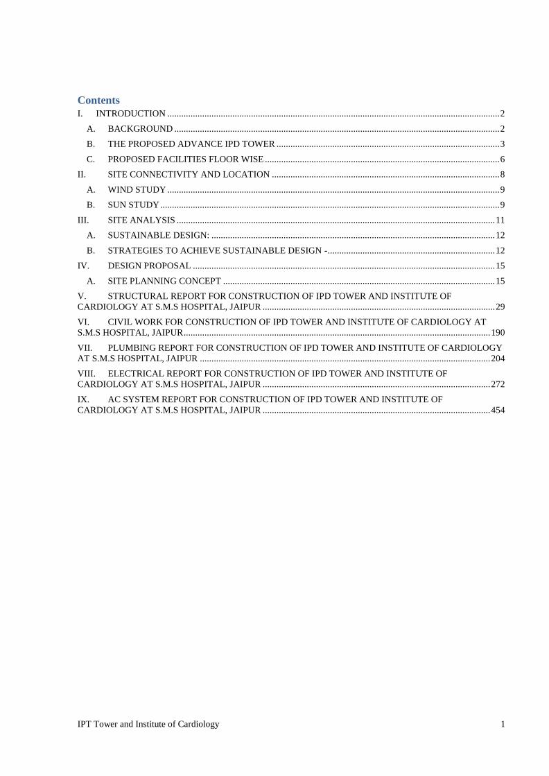
IPT Tower and Institute of Cardiology 1
Contents I. INTRODUCTION ............................................................................................................................................... 2
A. BACKGROUND ............................................................................................................................................ 2
B. THE PROPOSED ADVANCE IPD TOWER ................................................................................................ 3
C. PROPOSED FACILITIES FLOOR WISE ..................................................................................................... 6
II. SITE CONNECTIVITY AND LOCATION .................................................................................................. 8
A. WIND STUDY ............................................................................................................................................... 9
B. SUN STUDY .................................................................................................................................................. 9
III. SITE ANALYSIS ......................................................................................................................................... 11
A. SUSTAINABLE DESIGN: .......................................................................................................................... 12
B. STRATEGIES TO ACHIEVE SUSTAINABLE DESIGN - ........................................................................ 12
IV. DESIGN PROPOSAL .................................................................................................................................. 15
A. SITE PLANNING CONCEPT ..................................................................................................................... 15
V. STRUCTURAL REPORT FOR CONSTRUCTION OF IPD TOWER AND INSTITUTE OF CARDIOLOGY AT S.M.S HOSPITAL, JAIPUR .................................................................................................... 29
VI. CIVIL WORK FOR CONSTRUCTION OF IPD TOWER AND INSTITUTE OF CARDIOLOGY AT S.M.S HOSPITAL, JAIPUR .................................................................................................................................... 190
VII. PLUMBING REPORT FOR CONSTRUCTION OF IPD TOWER AND INSTITUTE OF CARDIOLOGY AT S.M.S HOSPITAL, JAIPUR ............................................................................................................................. 204
VIII. ELECTRICAL REPORT FOR CONSTRUCTION OF IPD TOWER AND INSTITUTE OF CARDIOLOGY AT S.M.S HOSPITAL, JAIPUR .................................................................................................. 272
IX. AC SYSTEM REPORT FOR CONSTRUCTION OF IPD TOWER AND INSTITUTE OF CARDIOLOGY AT S.M.S HOSPITAL, JAIPUR .................................................................................................. 454
INTRODUCTION

IPT Tower and Institute of Cardiology 2
I. INTRODUCTION
A. BACKGROUND Sawai Man Singh Hospital is the major hospital of Jaipur and Rajasthan state of India. The construction of the hospital building began in 1934. The hospital is named after Sawai Man Singh II, then King of Jaipur. The hospital also provides practical training to the students of the Sawai Man Singh Medical College. SMS hospital is under pressure due to a large number of patients and rare disease patients from across the state as it is one of the few government super specialty hospitals.
Sawai Man Singh Hospital is the major hospital of Jaipur and Rajasthan state of India. This government hospital is staffed with 1500 doctors and 4000 nurses with 6251 beds in 43 wards and daily more than 10000 OPD. Infact it surpassed AIIMS Delhi in terms of number of patients in OPD and surgeries. There are more than 25 departments in SMS hospital.
Considering the ongoing pressure and amount of patient influx there is a dire need to increase the number of beds and state of the art technology in medical treatment and infrastructure. Also there are many other departments have been included under various sponsored schemes and various budget announcement by Honorable Chief Minister, space for the same is also to be required in the hospital campus. Apart from IPD tower and institute of cardiology there is also Construction of new mortuary of double the capacity of the existing mortuary and development of medical martyr memorial to pay gratitude to the doctors, para medics, health workers who laid their life in service of humanity.
In view the foregoing, an agreement was entered into between the Directore- Sawai Man Singh Hospital, jaipur and Jaipur Development Authority, jaipur for construction of IPD Tower and institute of Cardiology center in SMS campus.
As a part of the Agreement, The Detailed project Report (DPR) has been prepared for setting up an IPD Tower and Institute of Cardiology Center along with related infrastructure facilities at SMS, and provides salient information such as capital outlay, concept plan, design concepts, implementation schedule amongst others.
It is expected that establishment of the proposed Center (along with related infrastructural facilities) shall enable the Institute to offer advance IPD tower and Institute of Cardiology center in addition to the existing services.

IPT Tower and Institute of Cardiology 3
B. THE PROPOSED ADVANCE IPD TOWER 1) General
The Center would aim to provide state of the art facilities in hospital functioning and treatment. It will suffice the shortage of beds and improve the diagnosis with advance mechanism, additional facilities that would be provided shall include air ambulance, advance diagnostic treatment, VIP suites etc. It will also act as a face of SMS hospital and its supreme legacy.
The proposed IPD tower is going to be state of the art building which not only would be an example in the field of hospital architecture but would also set standards for the engineering and technology integration into operations of building. Being a highly advanced and technical processed based function, the building will be equipped with complete IBMS system, smart sensing technology, state of the art, fire-fighting systems. As the building is proposed to be a vertical tower of approximately 100 m height, the vertical transportation system would require almost 18 elevators including bed elevators, service elevators and visitor elevators. Special provision is also being given for elevators to cater to the air ambulance service on the rooftop.
The project will have all inbuilt facilities including in house F & B services, laundry and other support systems required for an international class IPD tower. The project has also considered highway connectivity to all the existing blocks of the SMS hospital including connectivity to the trauma hospital across the road.
The project requirements are summarized as under:
S.No. AREAS DESCRIPTION
A. IPD
1 General Wards 800 General Ward Beds
2
VIP Wards 100beds
3 Cottage Wards (Single Sharing) 100 beds
4 Cottage Wards (Double Sharing) 100 beds
5 ICU 100 beds
B. OTCOMPLEX

IPT Tower and Institute of Cardiology 4
1 OT 20OTstobeprovided OT Complex to be divided in two parts,
each parthaving10OTs
2 Post-Operative Care 40postoperativebedstobeprovided In the OT complex
3 Blood bank
A Collection counter to be provided in the in the diagnostic center
A cold storage requirement in the OT complex
C.OPD
1 OPD Registration
100 registration counter to be provided in the IPD tower -50 to be counseling and 50 to be digital self-registration kiosks
registration are to be provided with cloak room and other public services
2 DDC
For OPD patients - existing DDCs has to be developed
For IPD tower one DDC has to be Provided for every two IPD floors.
D.MORTUARY
1 Mortuary To be provided under ground at the
existing OPD registration land
2 Storage Freezers, Autopsy tables, Demo
rooms To be discussed
E.DIAGNOSTICS
1 Diagnostic Facilities/ Sample
Collection/CT/MRI and other Diagnostics
2 CT Scan, 2 MRI, x-ray, ultrasound ,Radiology, pathology, ECG, ECO has to be provided in the diagnostic center of IPD tower
50 blood collection beds to be provided
F.MEDICALINFRASTRUCTURE
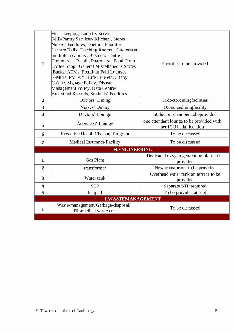
IPT Tower and Institute of Cardiology 5
1
Housekeeping, Laundry Services , F&B/Pantry Services/ Kitchen , Stores , Nurses’ Facilities, Doctors’ Facilities,
Lecture Halls, Teaching Rooms , Cafeteria at multiple locations , Business Centre , Commercial Retail , Pharmacy , Food Court , Coffee Shop , General Miscellaneous Stores ,Banks/ ATMs, Premium Paid Lounges E-Mitra, PMJAY , Life Line etc. , Baby Crèche, Signage Policy, Disaster Management Policy, Data Centre/ Analytical Records, Students’ Facilities
Facilities to be provided
2 Doctors’ Dining 50doctordiningfacilities
3 Nurses’ Dining 100nursediningfacility
4 Doctors’ Lounge 50doctor'schamberstobeprovided
5 Attendees’ Lounge one attendant lounge to be provided with
per ICU bedal location
6 Executive Health Checkup Program To be discussed
7 Medical Insurance Facility To be discussed
H.ENGINEERING
1 Gas Plant Dedicated oxygen generation plant to be
provided 2 transformer New transformer to be provided
3 Water tank Overhead water tank on terrace to be
provided 4 STP Separate STP required 5 helipad To be provided at roof
I.WASTEMANAGEMENT
1 Waste-management/Garbage-disposal/
Biomedical waste etc. To be discussed
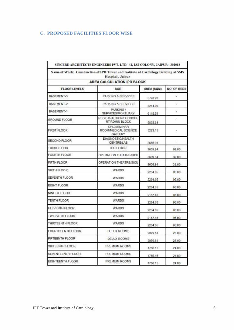
IPT Tower and Institute of Cardiology 6
C. PROPOSED FACILITIES FLOOR WISE

IPT Tower and Institute of Cardiology 7

IPT Tower and Institute of Cardiology 8
II. SITE CONNECTIVITY AND LOCATION

IPT Tower and Institute of Cardiology 9
A. WIND STUDY Wind rose
The wind rose for Jaipur shows how many hours per year the wind blows from the indicated direction. Example SW: Wind is blowing from South-West (SW) to North-East (NE). Cape Horn, the southernmost land point of South America, has a characteristic strong west-wind, which makes crossings from East to West very difficult especially for sailing boat.
B. SUN STUDY JAIPUR, INDIA – Sun path diagram
JAIPUR, INDIA – Seasons Graph and Earth’s orbit
IPT Tower and Institute of Cardiology 10

IPT Tower and Institute of Cardiology 11
III. SITE ANALYSIS

IPT Tower and Institute of Cardiology 12
A. SUSTAINABLE DESIGN: Sustainable design concepts have been incorporated in different aspects of the
building design starting from sustainable site planning to simulation and analysis of various alternatives, leading to optimization of building envelope, thereby reducing external solar gains.
All the design and documents prepared for Civil, Structural, MEP, HVAC, and Firefighting Systems etc. have been in conformity to sustainable aspects. Incorporates principles of energy efficiency and sustainability Incorporated renewable energy measures like
Roof top solar panels Rain water harvesting STP - use of recycled water
B. STRATEGIES TO ACHIEVE SUSTAINABLE DESIGN - a) WATER MANAGEMENT b) ELECTRICAL MANAGEMENT c) WASTE MANAGEMENT
1. WATER MANAGEMENT
By Planning Water Catchment Areas to harness Rainwater. By STP treated water which can be used for Irrigation, flushing.
Balancing these two sources to target a self-sustaining system. Drip Irrigation Methods.
DRIP IRRIGATION
Super-efficient use of water No runoff water, No Evaporation, No Wastage

IPT Tower and Institute of Cardiology 13
2. ELECTRICAL MANAGEMENT

IPT Tower and Institute of Cardiology 14
3. WASTE MANAGEMENT

IPT Tower and Institute of Cardiology 15
IV. DESIGN PROPOSAL
A. SITE PLANNING CONCEPT Site pic
1. Rectangular building is designed for very efficient use of site available.
2. Segregated entries for emergency, campus connectivity, medical staff and for patient are designed for ease of traffic movement and to avoid congestion.
3. High rise courtyard planning to allow mutual shading and wind cooling effect.
Road Width Project Components EXTERIORS
Combination of stone finishes ACP and Structural glazing in Glass. Structural glazing in reflective double glass unit.
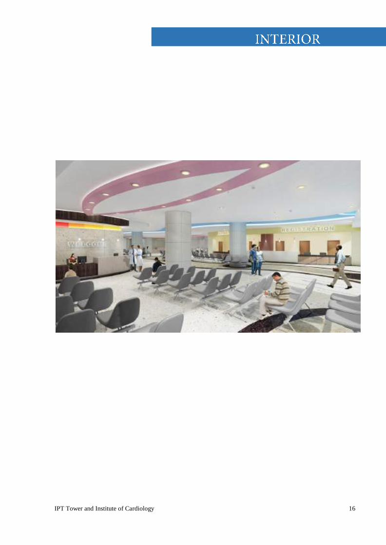
IPT Tower and Institute of Cardiology 16

IPT Tower and Institute of Cardiology 17
FLOORING- As per General Finishing Schedule
DADO - As per General Finishing Schedule

IPT Tower and Institute of Cardiology 18
Derived a color palette from surrounding nature
Contrasting colors help in distinguishing spaces
Using simple forms and contrasting colors to create calming interiors
Using design elements to evoke nature
Derived a color palette from surrounding nature
Contrasting colors help in distinguishing spaces
Using simple forms and contrasting colors to create calming interiors
Using design elements to evoke nature
ARCHITECTURAL FINISHES
Flooring- As per General Finishing Schedule
Wall finish- As per General Finishing Schedule
Ceiling- As per General Finishing Schedule
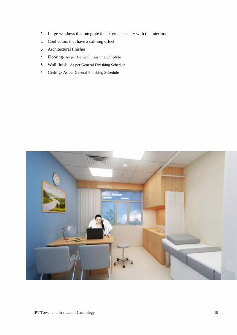
IPT Tower and Institute of Cardiology 19
Large windows that integrate the external scenery with the interiors
Cool colors that have a calming effect
Architectural finishes
Flooring- As per General Finishing Schedule
Wall finish- As per General Finishing Schedule
Ceiling- As per General Finishing Schedule

IPT Tower and Institute of Cardiology 20
Simulating nature for positive
Restoration and reduce stress levels
Colors and organic forms derived from nature
Architectural finishes
Flooring- As per General Finishing Schedule
Wall finish- As per General Finishing Schedule
Ceiling- As per General Finishing Schedule

IPT Tower and Institute of Cardiology 21
Architectural finishes
Flooring- As per General Finishing Schedule
Wall finish- As per General Finishing Schedule
ceiling- As per General Finishing Schedule
Large windows providing a view of the outside
Reduces stress and need for medication
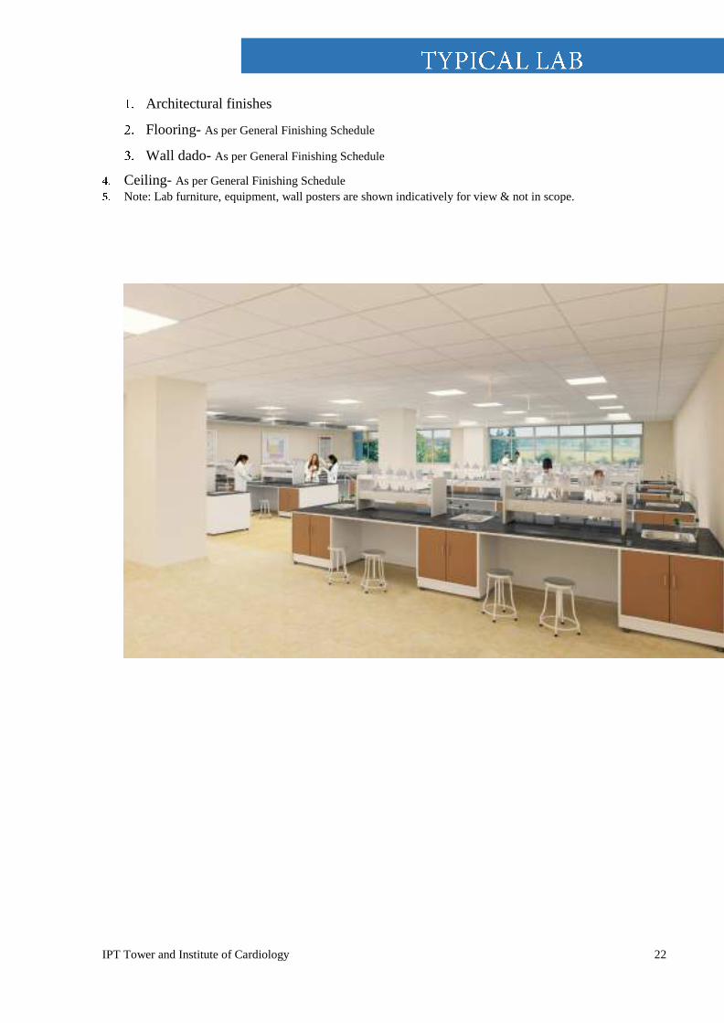
IPT Tower and Institute of Cardiology 22
Architectural finishes
Flooring- As per General Finishing Schedule
Wall dado- As per General Finishing Schedule
Ceiling- As per General Finishing Schedule Note: Lab furniture, equipment, wall posters are shown indicatively for view & not in scope.

IPT Tower and Institute of Cardiology 23
Use of natural stone
Color palette drawn from the rich visible ecology
Architectural finishes
Flooring- As per General Finishing Schedule
Wall finish- As per General Finishing Schedule
Marble & lacquered glass.
Ceiling- As per General Finishing Schedule
Gypsum board
IPT Tower and Institute of Cardiology 24

IPT Tower and Institute of Cardiology 25

IPT Tower and Institute of Cardiology 26
SITE PLANNING
Careful site planning – the arrangement of facilities on the land – is fundamental to the character of a place. No site exists in isolation. Each relates to others, and to the larger environment. These relationships determine a facilities impact on the land and its place on the overall campus fabric. To ensure that new facilities fit harmoniously with the existing campus careful site planning is essential. Facilities relate to the environment. Environmental factors such as sun angle, rainfall, and prevailing winds operate at a global or regional scale. Other factors such as soil, existing vegetation, slope are site specific. An outdoor space responsive to these environmental factors will provide appropriate sun and shade, orient activity areas to capture beneficial breeze while protecting the site from harsh winds, preserve significant trees, give shelter from rain, conserve topsoil, and protect delicate slopes. Site planning also considers the relationship of buildings to outdoor spaces. Important site factors include circulation(pedestrian and vehicular), parking, views, common spaces, compatibility of neighboring uses, massing and scale. The projects response to these factors will ensure clear connection between destinations and comfortable transition from buildings to community spaces. No site exists in isolation but is a part of the whole environment. Over subsequent years the hospital will put development pressure on the areas adjoining the site and the areas abutting the site. Any such change will mar the serene landscape settings the site currently enjoys. It is suggested that at the master plan level such change of settings be not permitted.
GUIDELINES Employ site planning principles – both environmental and architectural – to create facilities responsive to the local climate. The facilities would be in durable materials, and contemporary in aspect. Employ vistas to create a sense of direction and unify the campus
Create sequential spaces, from arrival to destination, parking, and departure. This orients travelers as they move around the campus. A series of landmarks, and accents may be introduced at strategic locations to facilitate orientation.
Link the campus through physical as well as visual means. By connecting different academic and non academic areas the campus will remain as one unified community.
The landscape program would attempt to integrate the campus through connected pedestrian pathways and nodes, outdoor lighting system, landmarks and signage's, parks, and woodlands.
Design outdoor spaces for public use as community oriented areas with a small market, place, space for quiet congregation, sacred groves etc., in a green setting. These spaces will cater to the patients and their families undergoing treatment and will be clearly separated from the academic spaces.

IPT Tower and Institute of Cardiology 27
Design outdoor spaces for students and faculty to accommodate sports, amphitheater, multipurpose hall, reading zones and various other forms of active and passive
Recreation that makes the campus more versatile and dynamic while supporting a diversity of individual needs.
Integrate the campus further with a unity and continuity of details and materials in the landscape.

IPT Tower and Institute of Cardiology 28

IPT Tower and Institute of Cardiology 29
V. STRUCTURAL REPORT FOR CONSTRUCTION OF IPD TOWER AND
INSTITUTE OF CARDIOLOGY AT S.M.S HOSPITAL, JAIPUR
IPT Tower and Institute of Cardiology 30
STRUCTURAL DESIGN BASIS REPORT
CONTENTS 1. Introduction
2. Preambles
3. Particular specifications
4. Unit
5. Special requirement
6. Structural Design Basis
7. Material in general
8. Mechanical Couplers
9. Code & standards

IPT Tower and Institute of Cardiology 31
1.0 INTRODUCTION
This chapter provides specifications related to Civil and Structural work for the PROPOSED CONSTRUCTION OF IPD TOWERS AND INSTITUTE OF CARDIOLOGY at SMS HOSPITAL, JAIPUR.
The structural design and drawings shall be primarily based on the latest Indian Codes of practice, National Building Codes (NBC) including NDMG - 2016 guidelines for Hospital Safety as applicable.
2.0 PREAMBLE
On award of the contract, the contractor will carry out the topography survey work by using Total station equipment.
The contractor will transfer the bench mark to be provided by the Employer and a permanent bench mark will be established at the project site(s).
On completion of the survey work, a detailed layout plan will be prepared by the contractor showing all buildings and other associated structures etc. complete.
The contractor will also prepare a separate layout plan including location of site office, batching plant, godown, steel yard, store, workshop etc., complete. Engineer in charge will approve both the layout prior to commencement of construction work.
Soil investigation will be taken up on approval of the layout plans. Various preliminary works are to be carried out as per the following details.
2.1 Topographical Survey and Soil Investigation
The proposals presented in this tender are based on the surveys and available details. Detailed surveys and soil investigations are required to be carried out by the contractor as given below for preparation of detailed design.
Contractor will carry out his own survey in the area ear-marked for IPD Tower and subequent works, as shown in the tender drawings enclosed, by using total station equipment. Guidelines for details of survey to be carried out are as follows:
i) Preparation of contour plan of the sites using a grid of 5m x 5m
iii) Collection of details for all features such as utilities, existing roads, electric and telephone poles and lines, sewer lines and water mains, huts, buildings, or any other structure, fencing and trees ( with girth greater than 0.15 m ) etc, falling within the extent of survey.
The Contractor in co-ordination with the Engineer in Charge has to determine at each location of a building or a UGT structure the soil characteristics (safe bearing capacity, angle of friction, cohesion) in order to calculate the dimensions of the foundations. It is also important to assess the
potential of changes in water table, erosion and exposure of foundations and the stability of the soil with view to the lateral resistance to be taken into account.

IPT Tower and Institute of Cardiology 32
On finalization of the layout, the contractor will conduct additional soil investigation to find out actual soil condition at the site. The number of boreholes to be taken for soil investigation shall be decided in consultation with engineer in charge and his decisions in this regards will be final. The contractor shall submit the report to Employer for their comments/approval. In case there is a discrepancy between the two reports lower of the values of the safe bearing capacity shall be considered for the design.
a) Penetration Tests
Standard penetration test to a depth corresponding to at least 1.5 times the width of the building/foundation; distance between the penetration points less than 20m.
b) Plate load tests (Where ever directed):
to assess soil bearing capacity at the foundation level (Plate test) to take samples for laboratory analyses
c) Laboratory Analyses for granulometry cohesion angle of friction proctor density
d) Ground water quality test
e) Soil resistivity test
At least 3 test boreholes shall be made for each building/tank/structure, preferably after having fixed the location of the building. The distance should be more than 50 m.
In addition the following soil data have to be obtained from the test borehole/pits:
Composition and classification of the soil (sand, clay, silt, organic matter etc., soft,
medium, hard, decomposed rock, rock etc.) with view to: excavation need to support walls of trenches compacting permanent or temporary groundwater (water logging) hard pans below the sand (depth, thickness, type of layer) clay lenses
The results of the survey, the sampling, the laboratory analyses and the calculations have to be presented in a report in three copies to the Engineer in Charge. The execution of the foundations shall be started only after approval of the Engineer in Charge. The contractor however will be responsible for design of the structures based on these investigations.

IPT Tower and Institute of Cardiology 33
Along with the excavation for the buildings and storage structures the Contractor has to assess / complete the type of soil, the strata, the level of groundwater and other parameters important for design. He has to establish soil profiles and submit these to the Engineer in Charge for approval.
3.0 PARTICULAR SPECIFICATIONS
In addition to the General specification for Civil work, contractor shall carryout various works as per the following details:
3.1 Layout Plan and Finished Ground Level (FGL)
a) Layout Plan
As mentioned earlier, the contractor should prepare layout keeping in mind the utilization of minimum space. The contractor should also consider relevant building byelaws for the preparation of layout plan.
b) Finished Ground Level
Site grading shall be done as specified in Technical Specifications of Civil Works.
f) Finished ground Level (FGL) shall be maintained as given in bid documents elsewhere or
will be decided in consultation with Engineer in charge and engineer-in-charge decision will be final. No extra payment/claims shall be entertained in this regards.
3.2 Building Work
3.2.1 Mud mat concrete
All binding and leveling concrete shall be of minimum 75 mm thickness of concrete mix M7.5 (min), unless otherwise specified.
3.2.2 Plinth
a) Plinth level (Finished Floor Level) of the building shall be at least 0.6 m above the
outside formation level for building having no basement and 1.20m for buildings having basement. However plinth level shall be decided in consultation with Engineer in charge and engineer-in-charge decision will be final. No extra payment/claims shall be entertained in this regards.
The grade slab (ground floor in buildings, if required) shall comprise of the following layers:
a) 75mm thick M-7.5 cement concrete layer.

IPT Tower and Institute of Cardiology 34
b) 150mm thick M-20 RCC reinforced with single layer 8mm dia 200mm C/C reinforcement
bars in each direction.
c) Floor finish as per specifications. 4.0 UNIT
This Standard is based on International System of Units (SI) except where otherwise specified. 5.0 SPECIAL REQUIREMENTS
5.1 Design & Drawings
In respect of the Contractor’s obligations with respect to the design and Drawings of the Project Works, the following shall apply:
5.1.1 The Contractor shall prepare and submit, with reasonable promptness and in such sequence as is
consistent with the Project Completion Schedule, three copies each of the design and Drawings, duly certified by the Proof Consultant, to the Employer’s Engineer for review. Provided, however, that the Employer’s Engineer may require additional drawings for its review in accordance with Good Industry Practice;
5.1.2 By submitting the Drawings for review to the Employer’s Engineer, the Contractor shall be
deemed to have represented that it has determined and verified that the design and engineering, including field construction criteria related thereto, are in conformity with the Scope of the Project, the Specifications and Standards and the Applicable Laws;
5.1.3 Within 15 (fifteen) days of the receipt of the Drawings, the Employer’s Engineer shall review the
same and convey its observations to the Contractor with particular reference to their conformity or otherwise with the Scope of the Project and the Specifications and Standards. The Contractor shall not be obliged to await the observations of the Employer’s Engineer on the Drawings submitted pursuant hereto beyond the said period of 15 (fifteen) days and may begin or continue Works at its own discretion and risk;
5.1.4 If the aforesaid observations of the Employer’s Engineer indicate that the Drawings are not in
conformity with the Scope of the Project or the Specifications and Standards, such Drawings shall be revised by the Contractor in conformity with the provisions of this Agreement and resubmitted to the Employer’s Engineer for review. The Employer’s Engineer shall give its observations, if any, within 10 (ten) days of receipt of the revised Drawings;

IPT Tower and Institute of Cardiology 35
5.1.5 No review and/or observation of the Employer’s Engineer and/or its failure to review and/or
convey its observations on any Drawings shall relieve the Contractor of its obligations and liabilities under this Agreement in any manner nor shall the Employer’s Engineer or the Employer be liable for the same in any manner; and if errors, omissions, ambiguities, inconsistencies, inadequacies or other Defects are found in the Drawings, they and the construction works shall be corrected at the Contractor's cost;
5.1.6 The Contractor shall be responsible for delays in submitting the Drawing as set forth in relevant
clause caused by reason of delays in surveys and field investigations, and shall not be entitled to seek any relief in that regard from the Employer; and
5.1.7 The Contractor warrants that its designers, including any third parties engaged by it, shall have
the required experience and capability in accordance with Good Industry Practice and it shall indemnify the Employer against any damage, expense, liability, loss or claim, which the Employer might incur, sustain or be subject to arising from any breach of the Contractor’s design responsibility and/or warranty set out in this Clause.
5.1.8 Any cost or delay in construction arising from review by the Employer’s Engineer shall be borne
by the Contractor.
5.1.9 Works shall be executed in accordance with the Drawings provided by the Contractor in
accordance with the provisions of above clause and the observations of the Employer’s Engineer thereon as communicated pursuant to the provisions of Clause
5.1.10 Such Drawings shall not be amended or altered without prior written notice to the Employer’s
Engineer. If a Party becomes aware of an error or defect of a technical nature in the design or Drawings, that Party shall promptly give notice to the other Party of such error or defect.
5.1.11 Within 90 (ninety) days of the Project Completion Date, the Contractor shall furnish to the
Employer and the Employer’s Engineer a complete set of as-built Drawings, in 5 (five) hard copies and in micro film form or in such other medium as may be acceptable to the Employer, reflecting the Project Works as actually designed, engineered and constructed, including an as- built survey illustrating the layout of the Project Works and setback lines, if any, of the buildings and structures forming part of Project Facilities.
5.2 Design Standards
All designs shall be based on the latest Indian Standard (I.S.) Specifications or Codes of Practice. The design standards adopted shall follow the best modern engineering practice in the field based on any other international standard or specialist literature subject to such standard reference or extract of such literature in the English language being supplied to and approved by the Employer's Representative. In case of any variation or contradiction between the provisions of the
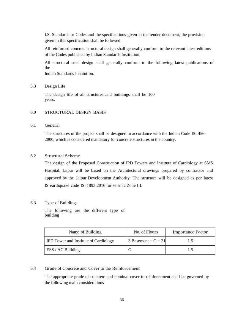
36
I.S. Standards or Codes and the specifications given in the tender document, the provision given in this specification shall be followed.
All reinforced concrete structural design shall generally conform to the relevant latest editions of the Codes published by Indian Standards Institution.
All structural steel design shall generally conform to the following latest publications of the Indian Standards Institution.
5.3 Design Life
The design life of all structures and buildings shall be 100 years.
6.0 STRUCTURAL DESIGN BASIS
6.1 General
The structures of the project shall be designed in accordance with the Indian Code IS: 456-2000, which is considered mandatory for concrete structures in the country.
6.2 Structural Scheme
The design of the Proposed Construction of IPD Towers and Institute of Cardiology at SMS
Hospital, Jaipur will be based on the Architectural drawings prepared by contractor and
approved by the Jaipur Development Authority. The structure will be designed as per latest
IS earthquake code IS: 1893:2016 for seismic Zone III.
6.3 Type of Buildings
The following are the different type of building
Name of Building No. of Floors Importance Factor
IPD Tower and Institute of Cardiology 3 Basement + G + 21 1.5
ESS / AC Building G 1.5 6.4 Grade of Concrete and Cover to the Reinforcement
The appropriate grade of concrete and nominal cover to reinforcement shall be governed by the following main considerations

37
i) Durability of Concrete
ii) Corrosion Protection of the Reinforcement
iii) Bar Size
iv) Nominal maximum aggregate size
v) Nominal cover as per IS: 456 and NBC-2016
The minimum grade of concrete shall be for foundation - M25, columns – M35 and all other structural element - M30 otherwise noted elsewhere. All water retaining and/or containing structures shall be in minimum M30 grade of concrete.
6.5 Reinforcement
The following types of reinforcement bars are to be used:
High Strength Deformed Bars (IS: 1786 – 2008) –
Fe550D
Reinforcement Bars of 8, 10, 12, 16, 20, 25 and 32mm dia only are used for the project. Mainly lapped splices shall be used. Welded splices or mechanical couplers shall be used for splicing of reinforcement, if required. Designed Rebar System & Shear Connectors if required, are to be used as per manufacturer specification & technique.
Reinforced cement Works SCOPE OF SPECIFICATIONS
The item Specifications give a general description of the Works to be executed. For detailed description, of the materials to be used and workmanship the “Detailed Specifications and Explanatory Notes” shall be followed unless specifically mentioned otherwise. All the relevant codes and standards published by the Indian Standards Institution and all other codes/standards which may be published by them shall apply and govern in respect of design, workmanship quality and materials and testing. Application codes for Specification of Civil Works IS-73 Specification for paving bitumen. IS-226 Specification for structural steel IS-269 Specification for ordinary and low heat Portland cement IS-383 Specifications for Coarse and Fine aggregates from natural
sources for concrete. IS-427 Distemper, dry, color as required. IS-428 Distemper, oil emulsion color as required IS-432 Part-I & II -Mild and medium tensile steel bars and hard
drawn steel wire, for concrete, reinforcement. IS-456 Code of Practice for Plain & Reinforced Cement
Concrete IS-460 Specification for Test Sieves
38
IS-516 Methods of test for strength of concrete IS-650 Specification for Standards sand for testing of cement IS-777 Glazed earth ware tiles IS-783 Code for practice for laying concrete pipes IS-1003 Timber paneled and glazed shutters Part I & II IS-1038 Steel doors, windows and ventilators IS-1077 Common burnt clay-building bricks IS-1081 Code of practice for fixing and glazing of metal windows
and ventilators. IS-1199 Method of sampling and analysis of concrete. IS-1200 Method of measurement of building works (steel &
aluminum) doors, IS-1322 Bitumen felts for water proofing and damp proofing. IS-1346 Code of practice for water proofing of roofs with bitumen
felts. IS-1443 Code of practice for laying and finishing of cement
concrete flooring tiles IS-1477 Code of practice for painting of ferrous metals in building
and allied finishes (Part-I & III) IS-1489 Specification for Portland pozzolana cement. IS-1580 Bituminous compounds for water proofing purposes. IS-1597 Code for practice for construction of stone masonry (Part-I) IS-1786 Specification for cold twisted steel bars for concrete
reinforcement IS-1905 Structural safety of building
IS-2114 Code of practice for laying in situ terrazzo floor finish. IS-2180 Burnt clay bricks
(Building) heavy duty. IS-2185 Load bearing hollow concrete blocks IS-2202 Wooden flush door shutters (solid core) type (Part-I) IS-2204 Code of practice for construction of reinforced concrete shell
roof. IS-2210 Criteria for design of R.C. shell structures and folded plates. IS-2212 Code of practice for brick work IS-2338 Code of practice for finishing of wood and wood base
materials (Part-I) IS-2386 Parts I to VII - Methods of test for aggregates IS-2394 Code of practice for application of lime plaster finish IS-2395 Code of practice for painting concrete, masonry and
plaster surfaces IS-2502 Code of practice for bending & fixing of concrete
reinforcement IS-2505 Specification for concrete vibrators, immersion type IS-2645 Specification for integral cement water proofing compound IS-2691 Burnt clay facing bricks IS-2720 Part-II - Determination of moisture content.
Part-VII Determination of moisture content, dry density relation using light
compaction.

39
Part-XXVIII-Determination of dry density of soils, in place by the said
replacement method. Part-XXIX - Determination of dry density of soils in
place by the core cutter method. IS-2750 Specification for steel scaffoldings. IS-2835 Flat transparent sheet glass for glazing and framing
purposes. IS-3025 Method of sampling and test for water.
IS-3102 Classification of burnt clay bricks IS-3115 Lime - Cement - Cinder solid blocks IS-3370 Part-I to IV - Code of practice for concrete structural for
storage of Liquids. IS-3384 Bitumen primer for use in water proofing and damp
proofing IS-3385 Code of practice for measurement of civil egg. works. IS-3414 Code of practice for design and installation of joints in
buildings. IS-3495 Methods of sampling and testing clay building bricks (Part-I to IV) IS-3764 Safety code for excavation work
IS-4014 Part-I & II - Code of practice for steel tubular scaffolding IS-4020 Method of tests for wooden flush doors. IS-4021 Timber door, window and ventilator frames, IS-4031 Method of physical tests for hydraulic cement. IS-4351
Steel doors frames IS-4990 Specification for plywood for concrete shuttering works IS-5498 Lime -Cement - cinder hollow concrete blocks IS-9013 Specification for admixtures for concrete National Building Code of India - 2016 (All parts)
Applicable Codes The following codes and standards are made a part of the Specifications. All
standards, codes of practices referred to herein shall be the latest edition including all applicable
official amendments and revisions. International code shall be applicable if unavailability of any
Indian codes. In case of discrepancy between this specification and those referred to
herein, this specification shall prevail.
(a) Materials

40
IS 269: Specification for ordinary, rapid hardening and low heat Portland cement.
IS 455: Specification for Portland blast furnace slag. IS 1489: Specification for Portland pozzolana cement. IS 4031: Methods of physical tests for hydraulic cement. IS 650: Specification for standard sand for testing of cement. IS 383: Specification for coarse and fine aggregates from natural
sources for concrete. IS 2386 (Parts I to VIII): Methods of test for aggregates for concrete. IS 516: Methods of test for strength of concrete. IS 1199: Methods of sampling and analysis of concrete. IS 2396(I) IS 5640 Flakiness Index of aggregates IS 3025: Methods of sampling and test (physical and chemical water
used in industry. IS 432: (Part I & II): Specification for mild steel and medium tensile
steel bars and hard drawn steel wire for concrete reinforcement.
IS 1139: Specification for hot rolled mild steel and medium tensile steel deformed bars for
concrete reinforcement. IS 1566: Specification for plain hard drawn steel wire fabric for
concrete reinforcement. IS 1785: Specification for plain hard drawn (Part I) steel wire for pre-
stressed concrete. IS 1786: Specification for cold twisted steel bars for concrete
reinforcement. IS 2090: Specification for high tensile steel bars used in prestressed
concrete. IS 4990: Specification for plywood for concrete shuttering work. IS 2645: Specification for integral cement water-proofing
compounds.
(b) Equipment IS 1791: Specification for batch type concrete mixers. IS 2438: Specification for roller pan mixer. IS 2505: Specification for concrete vibrators immersion type. IS 2506: Specification f o r screed board concrete vibrators. IS 2514: Specification for concrete vibrating tables. IS 3366: Specification for pan vibrators. IS 4656: Specification for form vibrators for concrete. IS 2722: Specification for portable swing weigh-batchers for
concrete (single and double bucket type). IS 2750: Specification for steel scaffoldings.
(c) Codes of Practice
41
IS 456: Code of practice for plain and reinforced concrete. IS 1343: Code of practice for pre-stressed concrete. IS 457: Code of practice for general construction of plain and
reinforced concrete for dams and other massive structures.
IS 3370: Code of practice for concrete (Part I to IV) structures for storage of liquids.
IS 3935: Code of practice for composite construction. IS 3201: Criteria for design and construction of pre-cast concrete
trusses. IS 2204: Code of practice for construction of reinforced concrete
shell roof. IS 2210: Criteria for the design of RC shell structures and folded
plates. IS 2751: Code of practice for welding of mild steel bars used: For
reinforced concrete construction. IS 2502: Code of practice for bending and fixing of bars for
concrete reinforcement. IS 3558: Code of practice for use of immersion vibrators for
consolidating concrete. IS 3414: Code of practice for design and installation of joints in
buildings. IS 4014: Code of practice for steel tubular, (Part I&II) scaffolding. IS 2571: Code of practice for laying in situ cement concrete
flooring.
(d) Construction Safety IS 3696: Safety code for scaffolds and ladders
(e) Measurement 1) IS 3385: Code of practice for measurement of civil engineering works. The above mode of measurements shall be applicable only if it is not
given specifically in the Tender document.
2.2 General The quality of materials, method and control of manufacture and
transportation of all concrete work irrespective of mix, whether reinforced or otherwise shall conform to the applicable portions of this specification.
Engineer-in-Charge shall have the right to inspect the source/s of material/s,
the layout and operation of procurement and storage of materials, the concrete batching and mixing equipment, and the quality control system. Such an inspection shall be arranged, and engineer's approval obtained, prior to starting of concrete work.
2.3 Materials

42
The ingredients to be used in the manufacture of standard concrete shall
consist solely of standard type Portland cement, clean sand, natural coarse aggregate, clean water and admixtures.
2.3.1 Cement a) If the Contractor is instructed to supply cement, then the following
points shall be applicable: i) Unless otherwise specified the cement shall be Ordinary Portland cement in 50 kg bags of 43/53 Gr. as applicable. The use of bulk cement will be permitted only
with the approval of Engineer-in-Charge. For t his the contractor will be r e q u i r e d to construct proper storage facility.
ii) A certified report attesting to the conformance of the cement to IS
specifications by the cement manufacturer's chemist shall be furnished to Engineer-in-Charge, if demanded.
Cement held in storage for a period of ninety (90) day or longer shall be tested. Should at any time Engineer-in- Charge have reasons to consider that any cement is defective, then irrespective of its origin, and/or manufacturers test certificate, such cement s h a l l b e tes ted immediately at contractor's cost at a National Test Laboratory/approved laboratory and until the results of such tests are found satisfactory, it shall not be used in any work. Contractor shall not be entitled to any claim of any nature on this account.
b) If the cement is supplied by the Engineer-in-Charge i) Contractor will have to make his own arrangements for the storage of
minimum 10000 bags of cement. If supplies are arranged by Engineer-in-Charge,
cement will be issued in quantities to cover work requirements o f one month or more, as deemed fit by Engineer and it will be the responsibility of contractor to ensure adequate and proper storage. Cement in bulk may be stored in bins or silos, which will p r o v i d e c o m p l e t e p r o t e c t i o n f r o m d a m p n e s s contamination and minimize caking and false set. Cement bags shall be stored in a dry enclosed shed (storage under tarpaulins will not be permitted), well away from the outer walls and insulated from the floor to avoid contact with moisture from ground and so arranged as to provide ready access damaged or reclaimed or partly set cement will not be permitted to be used and shall be removed from the site. The storage bins and storage arrangements shall be such that there is no dead storage. Not more than 12 bags shall be stacked in any tier. The storage arrangement shall be approved by Engineer-in-Charge. Consignments of cement shall be stored as received and shall be consumed in the order of their delivery. Different types of cement shall not be mixed together. Incase more than one type of cement is used in any work; a record shall be kept showing the location and the types of cement used.
2.3.2 Aggregates a) Unless otherwise the aggregates shall conform to the requirements as per IS:
383 -1970. Aggregate in general designates both fine and coarse inert materials used in the manufacture of concrete. Fine aggregate is aggregate

43
all of which passes through 4.75 mm IS sieve. Coarse aggregate is aggregate most of which is retained on 4.75 mm sieve.
b) All fine and coarse aggregates proposed for use in the work shall be subject
to Engineer-in-Charge approval and after specific materials have been accepted the source of supply of such materials should not be changed without prior approval of Engineer-in-Charge.
c) Aggregates shall, except as noted above, consist of natural sands, crushed
stone and gravel from a source known to produce satisfactory aggregate for concrete
and shall be chemically inert, strong, hard, durable against weathering, of limited porosity and free from deleterious materials that may cause corrosion of the reinforcement or may impair the strength and/or durability of concrete. The grading of aggregates shall be such as to produce a dense concrete of specified strength and consistency that will work readily into position without segregation and shall be based on the mix design and preliminary tests on concrete specified later.
d) Sampling and testing, Samples of the aggregates for mix design and
determination of suitability shall be taken under the supervision of Engineer-in-Charge and delivered to the laboratory, well in advance of the scheduled placing of concrete. Records of tests which have been made on proposed aggregates and on concrete made from this source of aggregates shall be furnished to Engineer-in-Charge in advance of the work for use in determining aggregate suitability. The costs of all such tests, sampling etc. shall be borne by contractor.
e) Storage of Aggregates, All coarse and fine aggregates shall be stacked in
stock separately in stock piles in the material yard near the work site in bins properly constructed to avoid inter mixing of different aggregates. Contamination with foreign materials and with earth during storage and while heaping the materials shall be avoided. The aggregate must be of specified quality not only at the time of receiving at site but more so at the time of loading into mixer. Rockers shall be used for lifting the coarse aggregates from bins or stockpiles. Coarse aggregate shall be piled in layers not exceeding 1.20 meters in height to prevent coning or segregation. Each layer shall cover the entire area of the stockpile before succeeding layers are started. Aggregates that have become segregated shall be rejected.
f) Specific Gravity, Aggregate except as noted above, and for other than light
weight concrete shall consist of natural or crushed sand and shall conform to IS 383.The sand shall be clean sharp, hard, strong and durable and shall be free from dust, vegetable substances, adherent coating, clay, alkali, organic matter, mica, salt or other deleterious substances, which can be injurious to the setting qualities/strength/ durability of concrete.
2.3.3 Machine made Sand, Machine made sand will be acceptable, provided the
constituent rock/gravel composition shall be sound, hard dense, non-organic un-coated, durable against weathering and subject to conformity with gradation as given in the table.
i) Screening and Washing Sand shall be prepared for use for such screening
or washing, or both, as necessary, to remove all objectionable foreign matter while separating the sand grains to the required size fractions.
ii) Gradation, Unless otherwise directed or approved, the grading of sand shall
be within the limits indicated here under:
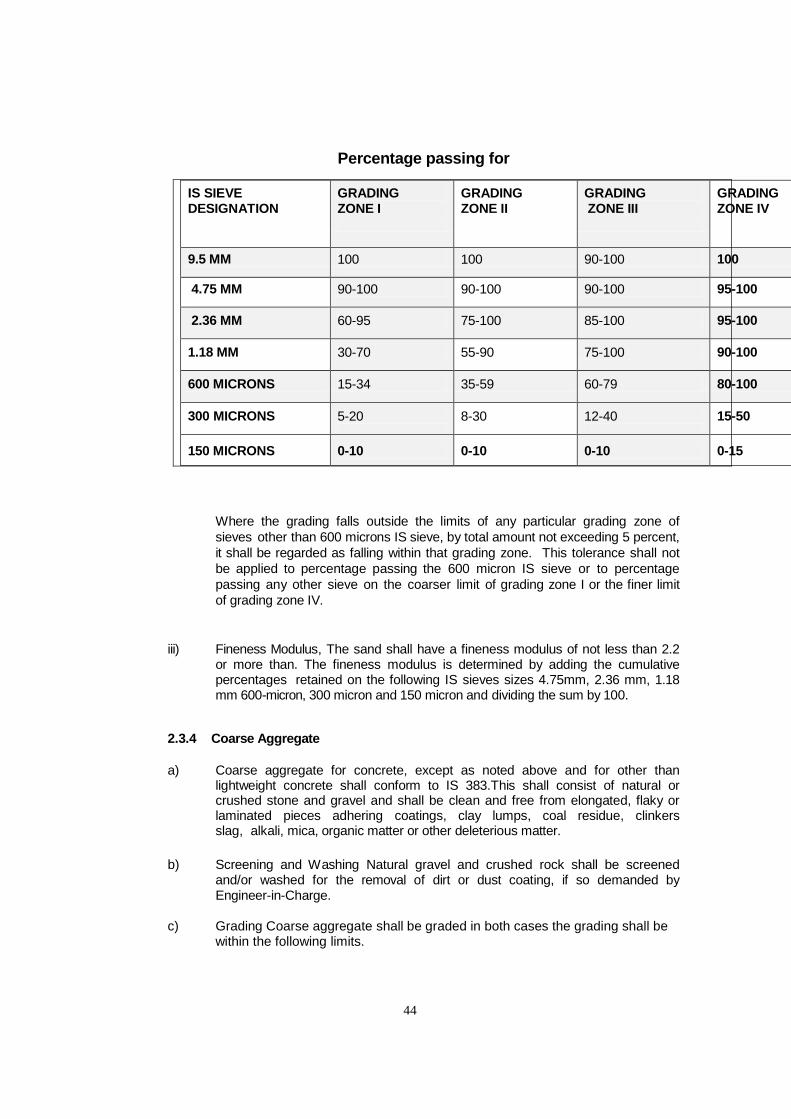
44
Percentage passing for
IS SIEVE DESIGNATION
GRADING ZONE I
GRADING ZONE II
GRADING ZONE III
GRADING ZONE IV
9.5 MM 100 100 90-100 100
4.75 MM 90-100 90-100 90-100 95-100
2.36 MM 60-95 75-100 85-100 95-100
1.18 MM 30-70 55-90 75-100 90-100
600 MICRONS 15-34 35-59 60-79 80-100
300 MICRONS
5-20
8-30
12-40
15-50
150 MICRONS
0-10
0-10
0-10
0-15
Where the grading falls outside the limits of any particular grading zone of
sieves other than 600 microns IS sieve, by total amount not exceeding 5 percent, it shall be regarded as falling within that grading zone. This tolerance shall not be applied to percentage passing the 600 micron IS sieve or to percentage passing any other sieve on the coarser limit of grading zone I or the finer limit of grading zone IV.
iii) Fineness Modulus, The sand shall have a fineness modulus of not less than 2.2
or more than. The fineness modulus is determined by adding the cumulative percentages retained on the following IS sieves sizes 4.75mm, 2.36 mm, 1.18 mm 600-micron, 300 micron and 150 micron and dividing the sum by 100.
2.3.4 Coarse Aggregate a) Coarse aggregate for concrete, except as noted above and for other than
lightweight concrete shall conform to IS 383.This shall consist of natural or crushed stone and gravel and shall be clean and free from elongated, flaky or laminated pieces adhering coatings, clay lumps, coal residue, clinkers slag, alkali, mica, organic matter or other deleterious matter.
b) Screening and Washing Natural gravel and crushed rock shall be screened
and/or washed for the removal of dirt or dust coating, if so demanded by Engineer-in-Charge.
c) Grading Coarse aggregate shall be graded in both cases the grading shall be
within the following limits.

45
Sieve Size (mm)
63 mm 40 mm 20 mm 16 mm 12.5 mm 10 mm
(Percentage of Passing)
80 – – – – –
63 85 to 100 100 – – – –
40 0 to 30 85 to 100 100 – – –
20 0 to 5 0 to 20 85 to 100 100 – –
16 – – – 85 to 100 100 –
12.5 – – – – 85 to 100 100
10 0 to 5 0 to 5 0 to 20 0 to 30 0 to 45 85 to 100
4.75 – – 0 to 5 0 to 5 0 to 10 0 to 20
2.36 – – – – – 0 to 5
The pieces shall be angular in shape and shall have granular or crystalline
surfaces, Friable, flack and laminated pieces, mica and shale, if present, shall be only in such quantities that will not, is the opinion of Engineer affect adversely the strength and/or durability of concrete. The maximum size of coarse aggregate shall be in no case greater than 1/4 of the minimum thickness of the member, provided that the concrete can be placed without difficulty so as to surround all reinforcement thoroughly and fill the corners of the form. Plums above 150 mm and up to any reasonable size can be used in plain mass concrete work of large dimensions up to a maximum limit of 20% of volume of concrete when specifically approved by Engineer-in- Charge. For heavily reinforced concrete members the nominal maximum size of the aggregate shall be 5 mm less than the minimum clear distance between the reinforcing main bars or 5mm less than the minimum cover to the reinforcement whichever is smaller. The amount of fine particles occurring in the free state or as loose adherent shall not exceed 1% when determined by laboratory sedimentation tests as per IS 2386. After 24 hours immersion in water, a previously dried sample shall not have gained more than 10% of its oven dry weight in air, as determined by IS 2386.

46
d) Foreign Materials Limitations The percentages of deleterious substance in the coarse aggregate delivered to
the mixer shall be limited in conformity with IS-383-1970.
2.3.5 Water Unless otherwise stated the water quality & requirements for concrete will
be in conformity wi th IS:456 -1978. a) Water used for both mixing and curing shall be free from injurious amounts of
deleterious materials. Potable waters are generally satisfactory for mixing and curing concrete.
b) In case of doubt, the suitability of water for making concrete shall be
ascertained by the compressive strength and initial setting time test specified in IS-456. The sample of water taken for testing shall be typical of the water proposed to be used for concreting, due account being paid to seasonal variation. The sample shall not receive any treatment before testing other than that envisaged in the regular supply of water proposed for use in concrete. The sample shall be stored in a clean container previously rinsed out with similar water.
c) Average 28 days compressive strength of at least three 15 cm concrete cubes
prepared with water proposed to be used shall not be less than 90% of the average
strength of three similar concrete cubes prepared with distilled water. d) The initial setting time or test block made with the appropriate set cement and
the water proposed to be used shall not be less than 30 minutes and shall not differ by more than
plus minus 30 seconds from the initial setting time of control test block prepared with the appropriate test cement and distilled water. The test blocks shall be prepared and tested in accordance with the requirements of IS 4031. e) Where water can be shown to contain an excess of acid, alkali sugar or salt,
engineer may refuse to permit its use. As a guide, the following concentrations represent the maximum permissible values:
i) To neutralize 200 ml sample of water, using phenolphthalein as indicator, it
should not require more than 2 ml of 0.1 normal NaOH. The details of test shall be as given in IS 3025.
ii) To neutralize 900 ml sample of water using methyl orange as an indicator, it
should not require more than 10 ml of 0.1 normal HCl. The details of test shall be given in IS 3025.
iii) Percentage of solids when tested in accordance with the method indicated below
shall not exceed the following:
Percent Method of Test (Ref. to clause no.
in IS 3025-1964)

47
Organic
0.02
10 and 11 (organic solids =
total solids minus ignited residue)
Inorganic Sulphate
(as SO4 Alkali Chlorides
(as CI)
0.30
0.05
11 (Ignited residue) 20
0.10 24
Suspended matter 0.20 -

48
2.3.6 Reinforcement Steel a) All MS reinforcing bars shall conform strictly to IS:432- 1982 and high strength deformed steel (Tor
Steel/TMT) bars IS:1786-2008. All reinforcement shall be clean and free from loose mill scales, cost, loose rust, coats of paints, oil or other coatings, which may destroy or reduce bond.
b) All reinforcing bars shall conform to drawings and dimensions shown on the drawing or where required to
carry out intent of drawings or specifications. Reinforcement shall not be bent or straightened in a manner injurious to the materials.
Bars containing cracks or splits shall be rejected. They shall be bent cold, except bars of over 25mm in
diameter which may be bent hot if specifically approved by the Engineer-in-Charge. Bars which depend for their strength on cold working, shall not be bent hot. Bars bent hot shall not be heated beyond cherry red color (nor exceeding 845 Deg. C) and after bending the same shall be allowed to cool slowly without quenching. No reinforcement shall be bent when in position in the work without approval, whether or not it is partially embedded in hardened concrete. Bars with kinks or bends not shown on drawings shall not be used.
Reinforcing bars supplied bent or in coils, shall be straightened before they are cut to size. Straightening of
bars shall be done in cold and without damaging the bars. This is considered as a part of reinforcement bending fabrication work.
Laps and splices for reinforcement shall be as shown on the drawings. The locations of all splices except
those specified on the drawings shall be approved by the Engineer- in- Charge. Reinforcement shall not be spliced at points of maximum stresses. Splices shall have sufficient lap, to transfer the full stress by bond. Unless otherwise stated laps for bars in tension shall have minimum length of 45 times diameter and for those in compression shall have minimum length of 35 times diameter. Wherever possible, laps shall be staggered. Reinforcing bars shall be held rigidly in position before concreting and ensure correct clearances as indicated on the drawings. All end hooks and anchorage bends shall be dimensioned in accordance with IS:2502-1963. Welding of reinforcement shall not be permitted unless authorized by the Engineer-in-Charge.
The Contractor shall see that the reinforcement is laid out correctly. Bars intended to be in contact at crossing
points shall be securely bound together at all such points with number 16 gauge annealed soft iron wire. The vertical distances required between successive layers of bar in beams or similar members shall be maintained by the provision of spacer bars at such intervals that the main bars do not perceptibly sag between adjacent spacer bars. The contractor shall provide any temporary gang- ways, platforms, other means of access which may be necessary to prevent men walking on the reinforcement bars. Fully cured concrete chairs or blocks not leaner than 1:2 part of cement and sand shall be used to obtain the correct cover to the reinforcing bars. Brick, timber block, pebble or stone shall not be used for this purpose. Erected and secured reinforcement shall be inspected and approved by the Engineer-in-Charge prior to placement of concrete.
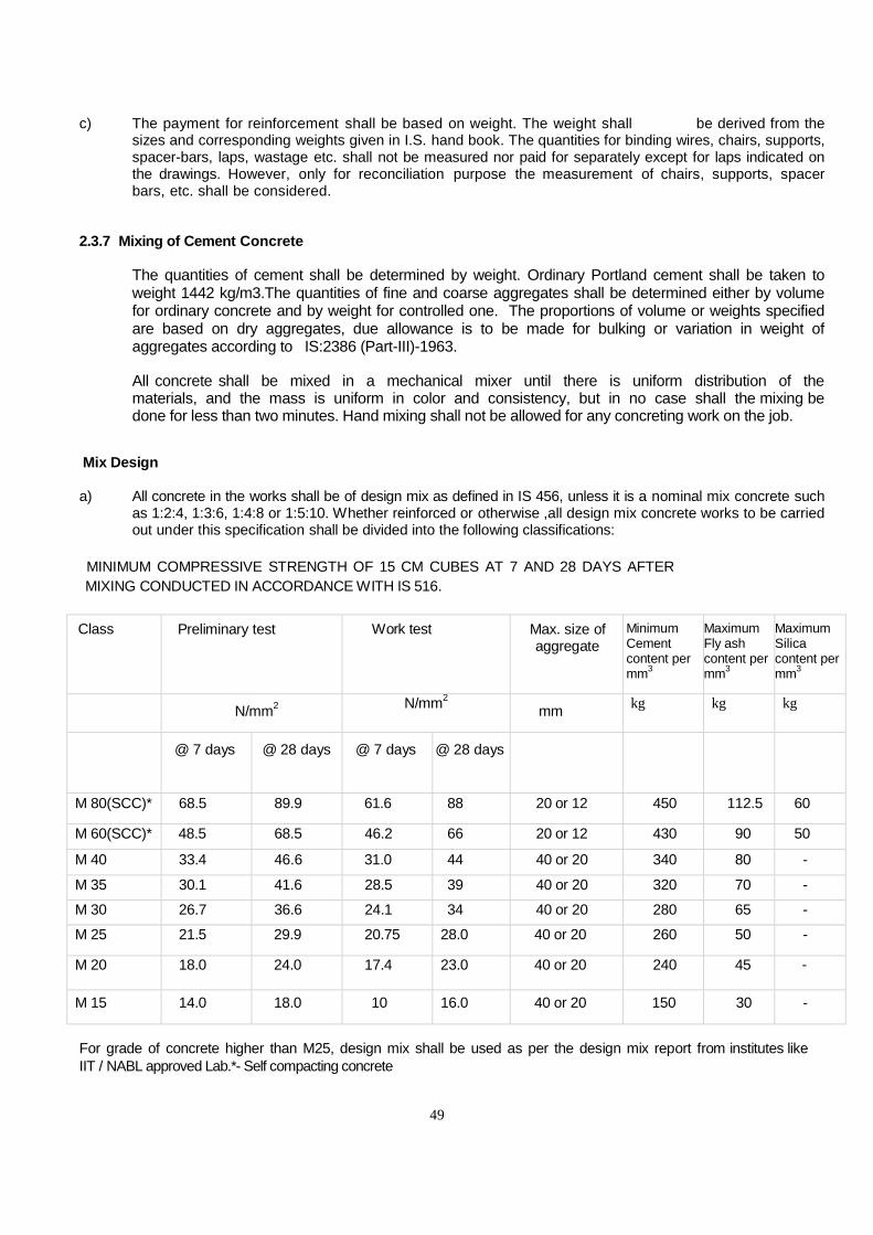
49
c) The payment for reinforcement shall be based on weight. The weight shall be derived from the sizes and corresponding weights given in I.S. hand book. The quantities for binding wires, chairs, supports, spacer-bars, laps, wastage etc. shall not be measured nor paid for separately except for laps indicated on the drawings. However, only for reconciliation purpose the measurement of chairs, supports, spacer bars, etc. shall be considered.
2.3.7 Mixing of Cement Concrete The quantities of cement shall be determined by weight. Ordinary Portland cement shall be taken to
weight 1442 kg/m3.The quantities of fine and coarse aggregates shall be determined either by volume for ordinary concrete and by weight for controlled one. The proportions of volume or weights specified are based on dry aggregates, due allowance is to be made for bulking or variation in weight of aggregates according to IS:2386 (Part-III)-1963.
All concrete shall be mixed in a mechanical mixer until there is uniform distribution of the
materials, and the mass is uniform in color and consistency, but in no case shall the mixing be done for less than two minutes. Hand mixing shall not be allowed for any concreting work on the job.
Mix Design a) All concrete in the works shall be of design mix as defined in IS 456, unless it is a nominal mix concrete such
as 1:2:4, 1:3:6, 1:4:8 or 1:5:10. Whether reinforced or otherwise ,all design mix concrete works to be carried out under this specification shall be divided into the following classifications:
MINIMUM COMPRESSIVE STRENGTH OF 15 CM CUBES AT 7 AND 28 DAYS AFTER MIXING CONDUCTED IN ACCORDANCE WITH IS 516.
Class Preliminary test Work test Max. size of aggregate
Minimum Cement content per mm3
Maximum Fly ash content per mm3
Maximum Silica content per mm3
N/mm2 N/mm2 mm kg kg kg
@ 7 days @ 28 days @ 7 days @ 28 days
M 80(SCC)* 68.5 89.9 61.6 88 20 or 12 450 112.5 60
M 60(SCC)* 48.5 68.5 46.2 66 20 or 12 430 90 50
M 40 33.4 46.6 31.0 44 40 or 20 340 80 -
M 35 30.1 41.6 28.5 39 40 or 20 320 70 -
M 30 26.7 36.6 24.1 34 40 or 20 280 65 -
M 25 21.5 29.9 20.75 28.0 40 or 20 260 50 -
M 20 18.0 24.0 17.4 23.0 40 or 20 240 45 -
M 15 14.0 18.0 10 16.0 40 or 20 150 30 -
For grade of concrete higher than M25, design mix shall be used as per the design mix report from institutes like IIT / NABL approved Lab.*- Self compacting concrete

50
b) It shall be very clearly understood that whenever the class of concrete such as M 20 is specified it shall
be the Contractor's responsibility to ensure that min. crushing strength stipulated for the respective class of concrete is obtained at works. The maximum total quantity of aggregate by weight per 50 kg of cement shall not exceed 450 kg except when otherwise specifically permitted by Engineer-in-Charge.
c) To fix the grading of aggregates, water cement ratio, workability and the quantity of cement required to
give preliminary and works cubes of the minimum strength specified, the proportions of the mix shall be determined by weight. Adjustment o f aggregate proportions due to moisture present in the aggregate shall be made. Mix proportioning shall be carried out according to Indian Standard Specifications.
d) Whenever there is a change either in required strength of concrete or water cement ratio or workability or the
source of aggregates and/or cement, preliminary tests shall be repeated to determine the revised proportions, of the mix to suit the altered conditions.
e) While fixing the value for water cement ratio for preliminary mixes, assistance may be derived from the
graph (appendix IS 456 showing the relationship between the 28 days compressive strengths of concrete mixes with different water cement ratios and the 7 days compressive strength of cement tested in accordance with IS 269.
51
2.3.8 Preliminary tests of Concrete (Cube Test) a) Test specimens shall be prepared with at least two different water/cement ratios for concrete, consistent
with workability required for the nature of the work. The materials and proportions used in making preliminary tests shall be similar in all respects to those to be actually employed in the works as the object of these tests is to d e t e r m i n e the p r o p o r t i o n s o f cement, aggregates and water necessary to produce concrete of required consistency and to give the specified strength. It will be the Contractor's sole responsibility to carry out these tests and he shall therefore furnish to Engineer a statement of proportions proposed to be used for the various concrete mixes.
b) Materials shall be brought to the room temperature and all materials shall be in a dry condition. The quantities of water, cement and aggregates for each mix shall be determined by
weight/volume to an accuracy of 1 part in 1000 parts. c) Mixing shall be done by a mixer machine as per I S 516 in such a manner as to avoid loss of water. The
cement and fine aggregate shall first be mixed dry until the mixture is uniform in colour. The coarse aggregate shall then be added, mixed and water added and mixed thoroughly for a period of not less than 3 minutes until the resulting concrete is uniform in appearance. Each mix of concrete shall be of such a quantity as to leave about 10% excess concrete after molding the desired number of test specimens.
d) The consistency o f each mix of concrete shall b e measured immediately after mixing, by the slump test
in accordance with IS 1199. If in the slump test, care is taken to ensure t h a t no water or other materials is lost, the materials used for the slump test may be remixed with the reminder of the concrete for making the specimen test cubes. The period of re-mixing shall be as short as possible yet sufficient to produce a h o m o g e n e o u s mass.
e) Compression tests of concrete cubes shall be made as per IS 516 on 15 cm cubes. Each mould shall be
provided with a metal base having a plane surface so as to support the mould during filling without leakage. The base plate shall be preferably attached to the mould by springs or screws. The parts of the mould when assembled shall be positively and rigidly held together. Before placing concrete, the mould and base plate shall be cleaned and oiled. The dimensions and internal faces of the mould shall be a c c u r a t e within the following limits:
Height and distance between the opposite faces of the mould shall be of specified size plus minus 0.2mm.
The angle between the adjacent internal faces and between internal faces and top and bottom planes of mould shall be 900 + 50. The interior faces of the mould shall be plane surfaces with a permissible variation of 0.03mm.
f) Concrete test cubes shall be moulded by placing fresh concrete in the mould and compacted as specified
in IS 516.

52
g) Curing shall be as specified in IS 516. The cubes shall be kept in moist air of at least 90% relative humidity at a temp. of 270C + 20C for 24 hours plus minus half hour from the time of adding
water to the dry ingredients. Thereafter they shall be removed from the moulds and kept immersed in clean, fresh water and kept at 270C+20C temperature until required for test. Curing water shall be renewed every seven days. A record of maximum and minimum temperatures at the place of storage of the cubes shall be maintained during the period they remain in storage.
h) Testing of specimens The strength shall be determined based on not less than five cubes test specimens for each age and
each water cement ratio. All these laboratory test results shall be tabulated and furnished to Engineer. The test result shall be accepted by Engineer if the average compressive strengths of the specimens are tested subject to the condition that only one out of the five consecutive test may give a value less than the specified strength for that age. The Engineer may direct the Contractor to repeat the tests if the results are not satisfactory and also to make such changes as he considers necessary to meet the requirements specified. All these preliminary tests shall be conducted by the Contractor at his own cost in an approved laboratory.
2.3.9 Proportioning consistency, batching and mixing of concrete Proportioning
a) Aggregate
The proportions which shall be decided by conducting preliminary test shall be by volume. These proportions of cement, fine and coarse aggregates shall be maintained during subsequent concrete mixing. The supply of properly graded aggregate of uniform quality shall be maintained over the period of work, the grading of aggregates shall be controlled by obtaining the coarse aggregate in different sizes and blending them in the right proportions. The different sizes shall be stocked in separate stock piles. The grading of coarse and fine aggregate shall be checked as frequently as possible as determined by Engineer, to ensure maintaining of grading in accordance with the samples used in preliminary mix design. The material shall be stock piled well in advance of use.
b) Cement The cement shall be measured by volume in normal cases. However, in case of central weight
batching plants. Cement may be weighed for each batch if so desired by Engineer-in- Charge.

53
c) Water Only such quantity of water shall be added to the cement and aggregates in the concrete mix as to
ensure dense concrete, specified surface finish, satisfactory workability, consistent with the strength stipulated for each class of concrete. The water added to the mix shall be such as not to cause segregation of material or the collection of excessive free water on the surface of the concrete.
The water cement (W/C) ratio is defined as the volume of water in the mix (including the surface moisture of the aggregates) divided by the volume of cement in the mix. The actual water cement
ratio to be adopted shall be determined in each instance by the Contractor and approved by the Engineer-in-Charge.
d) Proportioning by water/Cement ratio The W/C ratio specified for use by Engineer shall be maintained. The Contractor shall determine the
water content of the aggregates as frequently as directed by Engineer as the work progress and as specified in IS 2386 (Part-III) and the amount of water added at the mixer shall be adjusted as directed by Engineer so as to maintain the specified W/C ratio. To allow for the variation in volume of aggregates due to variation in their moisture content suitable adjustments in the volume of aggregates shall also be made.
e) Consistency and slump Concrete shall be of a consistency and workability suitable for the conditions of the job. After the
amount of water required is determined, the consistency of the mix shall be maintained throughout the progress of the corresponding parts of the work and approved tests e.g. slump tests, compacting factor tests, in accordance with IS 1199 shall be conducted from time to time to ensure the maintenance of such consistency.
The following tabulation gives a range of slumps which shall generally be used for various types of
construction unless otherwise instructed by the Engineer. SLUMPS FOR VARIOUS TYPES OF CONSTRUCTION Only sufficient quantity of water shall be added to concrete during mixing to produce a mix of sufficient
workability to enable it to be well consolidated, to be worked in to the corners of the shuttering and around the reinforcement, to give the specified surface finish, and to have the specified surface strength. The following slumps shall be adopted for different kinds of works: -
Name of Work Slump Size/Flowability
Mass concrete in foundations, footings,
retaining walls, Beam, slab and pavements.
50 mm – 120 mm.
Column and Shear wall, 500 mm - 600 mm Diaphragm wall and Piles 500 mm - 600 mm Thin Shell and folded Plates 120 mm – 150 mm
2.3.10 Sampling and testing concrete in the field

54
a) Facilities required for sampling materials and concrete in the field shall be provided by the Contractor at
no extra cost. The following equipment with operator shall be made available at Engineer-in-Charge's request (all must be in serviceable condition):
i) One concrete cube testing machine suitable for 15 cm cubes of 100 ton capacity with proving calibration
ring. ii) Six cast iron cube moulds of 15 cm size. iii) One Lab. balance to weigh up to 5 kg with sensitivity of 10. iv) One set of sieves for coarse and fine aggregates. v) One set of slump cone complete with tamping rod. vi) A set of measures from 0.1 litre to 5 litre. vii) One electric oven with thermostat upto120⁰C. viii) One flakiness gauge. ix) One elongation index gauge. x) One sedimentation pipette. xi) One Pycnometer. xii) Two calibrated glass jar of 1litre capacity Arrangement can be made by the contractor to have the cubes tested in an approved laboratory in lieu of
a testing machine at site at his expense, with the prior consent of the Engineer-in-Charge. b)
Sr.No.
Quantity
No. of set
1
0-5
3 or 1 in every batch
2
5-15
2 or 1 in every batch
3
15-30
3 or 1 in every batch
4
30-50
4 or 1 in every batch
5
50-100
4 or 1 in every batch
Such samples shall be drawn on each day for each type of concrete. Of each set
of 6 cubes, three shall be tested at 7 days age and three at 28 days age. The laboratory test results shall be tabulated and furnished to Engineer-in-Charge. Engineer will pass the concrete if average strength of the specimens tested is not less than the strength specified, subject to the condition that only one out of three consecutive tests may give a value less than the specified strength but this shall not be less than 90% of the specified strength. The cubes shall be tested on 7th and 28th day from the day of casting of the cubes. Contractor should maintain a register indicating proportion of mix number of test cubes, date of casting cubes, date of testing, test results and signature of testing authority and Engineer-in-Charge.

55
2.3.11 Admixtures a) Admixtures may be used in concrete only with the approval of Engineer based upon evidence that, with the
passage of time, neither the compressive strength nor its durability reduced. Calcium chloride shall not be used for accelerating setting of the cement for any concrete containing reinforcement, or embedded steel parts. When calcium chloride is permitted to be used, such as in mass concrete works, it shall be dissolved in water and added to the mixing water in an amount not to exceed 1.5% of the volume of the cement in concrete. When admixtures are used, the designed concrete mix shall be corrected accordingly. Admixtures shall be used as per manufacturer's instructions and in the manner and with the control specified by Engineer-in-Charge.
b) Air entraining agents Where specified and approved by Engineer-in-Charge, neutralized vinyl resin or any other approved air-
entraining agent may be used to produce the specified amount of air in the concrete mix and these agents shall conform to the requirements of ASTM standard 6260 air entraining admixtures for concrete. The recommended total air content of the concrete is 4% plus minus 1%. The method of measuring air content shall be as per IS 1199.
c) Water reducing admixtures Where specified and approved by Engineer-in-Charge water reducing mixture shall be added in quantities
specified by Engineer-in-Charge. The admixtures shall be added in the form of a solution. d) Retarding admixtures Where specified and approved by Engineer, retarding agents shall be added to the concrete mix in
quantities specified by Engineer-in-Charge. f) Water proofing agent Where specified and approved by Engineer, water proofing agent conforming to IS:2645 shall be added in quantities specified by Engineer-in-Charge.
2.3.12 Optional tests a) Engineer may order tests to be carried out on cement, sand, coarse aggregate and water in accordance with the relevant Indian Standards. Tests on cement shall include (i) fineness test. (ii) test for normal consistency. (iii) test for setting time. (iv) test for soundness. (v) test for tensile strength. (vi) test for compressive strength (vii) test for heat of hydration by experiment and by calculations in accordance with IS:269. Tests on fine
aggregate and coarse aggregate cover under IS:2386 Part-I & VIII. Any or all these tests would normally be ordered to be carried out only if Engineer feels the materials are not in accordance with the specifications or if the specified c o n c r e t e strengths are not obtained and shall be performed by contractor at site or at an approved test laboratory. If the tests are successful, Engineer-in-Charge shall pay for all such optional tests otherwise the Contractor shall have to pay for them.

56
b) If the cubes do not give the stipulated strengths Engineer- in-charge. reserves the right to ask contractor to dismantle such portions of the work, which in his opinion are unacceptable and re-do the work to the standard stipulated at contractor's cost in the manner and schedule approved by Engineer-in-Charge.
c) Load test on members or any other tests The Engineer-in-Charge may instruct for a load test or other test to be carried out on any structure if in his
opinion such a test is deemed necessary for any of the following reasons: i) The concrete test cube made at work site failing to attain the specified strength. ii) Shuttering being either prematurely removed or not being according to the specifications.
iii) Curing of the concrete is inadequate or improperly carried out. In case of results of load test being unsatisfactory, the Engineer-in-Charge shall have the right to ask the
contractor to demolish and reconstruct the structure or part thereof at the contractor's cost. ADDITIONAL TESTS FOR CONCRETE
In case the concrete fails when tested, one or more of the following check tests may be carried out at the discretion of Engineer-in-Charge to satisfy the strength of the concrete laid. All testing expenditure shall be borne by the contractor. The number of additional tests to be carried out shall be determined by the Engineer-in-Charge. He shall be the final authority for interpreting the results of additional tests and shall decide upon the acceptance or otherwise. His decision in this regard shall be final and binding. For the purpose of payment, the Hammering test result only shall be the criteria. Some of the tests are outlined below:

57
Cutting Cores This method involves drilling and testing cores from the concrete for determination of compressive
strength. In suitable circumstances the compressive strength of the concrete in the structure may be assessed by drilling cores from the concrete and testing. The procedure used shall comply with the requirements of IS-1199-1959 and IS-516-1959.
The points from which cores shall be taken shall be representative of the whole concrete and at least three cores shall be obtained and tested. If the average of the strength of all cores cut from the structure is less than the specified strength, the concrete represented by the cores shall be liable to rejection and shall be rejected if a static load test either cannot be carried out or is not permitted by the Engineer-in-Charge.
Ultrasonic Pulse Velocity Test If an ultrasonic apparatus is regularly used by trained personnel in accordance with IS 13311 (Part-I)-1992 and continuously maintained individual charts are kept showing a large number
of readings & the relation between the reading and strength of cubes made from the same batch of concrete, such charts may be used to obtain approximate indications of the strength of concrete in the structures. In case of suspected lack of compaction or low cube strength the results obtained from the ultrasonic test results on adjacent acceptable sections of the structures may be used for the purpose of assessing the strength of concrete in the suspected portion.
Concrete in alkali soils and alkaline water Where concrete is liable to attack from alkali salts or alkaline water, special cements containing low
amount of tricalcium aluminate shall be used, if so specified in the drawings. Such concrete shall have a minimum 28 days compressive strength of 250 kg per sq.cm and shall contain not less than 370 kg of cement per cubic meter of concrete. If specified, additional p r o t e c t i o n shall be obtained by the use of a c h e m i c a l l y resistant stone facing or a layer of plaster of Paris covered with suitable fabric, such as jute
thoroughly impregnated with tar. 2.3.14 Preparation prior to concrete placement a) Before the concrete is actually placed in position, the insides of the form work shall be inspected to see that they have been cleaned and oiled. Temporary openings shall be provided to
facilitate inspection, especially at bottom of columns and walls forms to permit removal of saw dust, wood shavings, binding wire, rubbish dirt etc. Openings shall be placed or holes drilled so that these materials and water can be removed easily. Such openings/holes shall be later suitably plugged.
b) The various agencies shall be permitted ample time to install drainage and plumbing lines in floor
and trench drains, conduits, hangers, anchors, inserts, sleeves, bolts, frames and other miscellaneous embedment to be cast in the

58
concrete as indicated on the drawings or as is necessary for the proper execution of the work. Contractor shall cooperate fully with all such agencies and shall permit the use of scaffolding, form work etc. by other agencies at no extra cost.
c) All embedded parts, inserts etc. supplied by Engineer-in-Charge or Contractor shall be correctly positioned
and securely held in the forms to prevent displacement during depositing and vibrating of concrete d) Anchor bolts shall be positioned and kept in place with the help of proper manufactured templates.
The use of all such templates, fixture etc. shall be deemed to be included in the rates. No extra payment will be made for making or providing templates.
e) Slots, openings, holes, pockets etc. shall be provided in the concrete work in the positions indicated in the
drawings or as directed by Engineer-in-Charge. f) Prior to concrete placement all work shall be inspected and approved by Engineer and if found unsatisfactory, concrete shall not be poured until after all defects have been corrected at
Contractor's cost. Cat ladders shall be provided on the reinforcement to facilitate labour movement. g) Approval by Engineer for all materials and work as required herein shall not relieve contractor from his
obligation to produce finished concrete in accordance with the drawings and specifications. h) No concrete shall be placed in wet weather or on water covered surface. Any concrete that has been
washed by heavy rains, the work shall be entirely removed, if there is any sign of cement and sand having been washed from the concrete mixture. To guard against damage which may be caused by rains, the works shall be covered with tarpaulins immediately after the concrete has been placed and compacted. Any water accumulating on the surface of the newly placed concrete shall be removed by approved means and no further concrete shall be placed thereon until such water is removed. To avoid flow of water over/around freshly placed concrete, suitable drains and sumps shall be provided.
I) Immediately before concrete placement begins, proposed surfaces except formwork, which will come
in contact with the concrete to be placed, shall be covered with approved bonding. 2.3.15 Transportation a) All buckets, containers or conveyors used for transporting concrete shall be mortar tight. Irrespective of the method of transportation adopted, concrete shall be delivered with the
required consistency and plasticity without segregation or loss of slump. However, chutes shall not be used for transport of concrete without the written permission of Engineer and concrete shall not be re-handled before placing.
b) Concrete must be placed in its final position before it becomes too stiff to work. On no account, water shall be added after the initial mixing concrete which has become stiff or has been
contaminated with foreign materials shall be rejected and disposed off as directed by Engineer. c) All equipment used for mixing, transporting and placing of concrete shall be maintained in clean
condition. All pans, buckets, hoppers, chutes, pipelines and other equipment shall be thoroughly cleaned after each period of placement.
2.3.16 Procedure for placing of concrete

59
a) Before any concrete is placed, the entire placing program, consisting of equipment, layout proposed procedures and methods shall be submitted to engineer for approval if so demanded by Engineer and no concrete shall be placed until Engineer's approval has been received.
Conveyor for conveying concrete shall be of such size and design as to ensure a practically continuous flow of concrete during depositing without segregation of materials, considering the size of the job and placement location.
b) Concrete shall be placed in its final position before the cement shall normally be compacted in its final
position within thirty minutes of leaving the mixer and once compacted it shall not be disturbed. c) Concrete, in all cases, be deposited as nearly as practicable directly in its final position, and shall not be
re-handled or caused to flow in a manner which will cause segregation, loss of materials, displacement of reinforcement, shuttering or embedded inserts or imparities strength. For locations where direct placement is not possible, and i n narrow forms, contractor shall provide suitable drop and elephant trunks to confine the movement of concrete. Special care shall be taken when concrete is dropped from a height especially if reinforcement is in the way, particularly in columns and thin walls.
d) Except when otherwise approved by Engineer, concrete shall be placed in shovels or other approved implements and shall not be dropped from a height more than 1.5 M or handled in a manner
which will cause segregation.

60
e) The following specification shall apply when placing of concrete by use of mechanical equipment is
specifically called for while inviting bids or is warranted considering the nature of work involved. The control of placing shall begin at the mixer discharger, concrete shall be discharged by a vertical drop into the middle of the bucket or hopper and this principle of a vertical discharge of concrete shall be adhered to throughout all stages of delivery until the concrete comes to rest in its final position.
f) Central bottom dump buckets of a type that provides for positive regulation of the amount and rate of
deposition of concrete in all dumping position, shall be employed. g) In placing concrete in large open areas, the bucket shall be spotted directly over the position designated and
then lowered for dumping. The open bucket shall clear the concrete already in place and the height of drop shall not exceed 1.5 M. The bucket shall be opened slowly to avoid high vertical bounce. Dumping of buckets on the swing or in any manner which results in separation of ingredients or disturbance of previously placed concrete will not be permitted.
h) Concrete placed in restricted forms by wheel barrows, buggies, cars, short chutes or hand shoveling shall be subject to the requirement for vertical delivery of limited height to avoid
segregation and shall be deposited as nearly as practicable in its final position. i) Where it is necessary to use transfer chutes, specific approval of Engineer must be obtained to the type,
length, slopes, baffles, vertical terminals and timing of operations, the discharge and without segregation. To allow for the loss of mortar against the sides of the chutes, the first mix shall have less coarse aggregate. During cleaning of chutes the waste water shall be kept clear of the forms. Concrete shall not be permitted to fall from the end of the chutes by more than 1.5 M. Chutes when approved for use shall have slopes not flatter than 1:3 and steeper than 1:2 chutes shall be of metal or metal lined and of rounded cross section. The slopes of all chutes sections shall be approximately the same. The discharge end of the chutes shall be maintained above the surface of the concrete in the forms.
j) Concrete may be conveyed and placed by mechanically operated equipment e.g. pumps or pneumatic
placers only with the written permission of Engineer. The slump shall be held to the minimum necessary for conveying concrete by this method.
k) When pumping is adopted, before pumping of concrete is started, the pipeline shall be lubricated with one or two batches of mortar composed of one part cement and two parts sand. The
concrete mix shall be specially designed to suit pumping. Care shall be taken to avoid stoppages in work once pumping has started.

61
l) When pneumatic placer is used, the manufacturer's advice on layout of pipeline shall be followed to avoid blockages and excessive wear. Restraint shall be provided at the
discharge box to cater for the reaction at this end. Manufacturer's advice shall be followed regarding concrete quality and all other related matters when pumping or pneumatic placing equipment is used.
m) Concreting, once started, shall be continuous until the pour is completed. Concrete shall be placed in successive horizontal layers of uniform thickness ranging from 15 to 90 mm as
directed by Engineer. These shall be placed as rapidly practicable to prevent the formation of cold joints or planes of weakness between each succeeding layer within the pour. The thickness of each layer shall be such that it can be deposited before the previous layer has stiffened. The bucket loads or other units of deposit shall be spotted progressively along the face of the layer with such overlap as will facilitate spreading the layer to uniform depth and texture with a minimum of shoveling. Any tendency to segregation shall be corrected by shoveling stones into mortar rather than mortar on to stones. Such a condition shall be corrected by redesign of mix or other means, as directed by Engineer.
n) The top surface of each pour and bedding planes shall be approximately horizontal unless otherwise
instructed. The contractor should arrange the tarpaulins ready before starting of placing of concrete during rainy seasons. During cold weather, concreting shall not be done when the temperature falls below 4.50C. The concrete placed shall be protected against frost by suitable covering. Concrete damaged by frost shall be removed and work redone. During hot weather, precaution shall be taken to see that the temperature of wet concrete does not exceed 300C. No concrete shall be laid within half an hour of the closing time of the day, unless permitted by Engineer-in-Charge.
o) Compaction concrete shall be judged to be properly compacted, when the mortar fills the spaces between the coarse aggregate and begins to cream-up to form an even surface. When this
condition has been attained, the vibrator shall be stopped in case of vibrating tables & external vibrators. Particular care shall be taken to ensure that all concrete placed against the forms faces and into corners of
forms or against hardened concrete at joints is free from voids or cavities. The use of vibrators shall be consistent with the concrete mix and caution exercised
not to over-vibrate the concrete to the point that segregation results. No concrete work should be allowed to start unless adequate numbers of vibrators are at hand.
ii) Vibrators shall conform to IS specifications. Type of vibrator to be used shall depend on the structure
where concrete is to be placed. Shutter vibrators, to be effective, shall be firmly secured to the formwork which must be sufficiently rigid to transmit the vibration and strong enough not to be damaged by it. Immersion vibrators shall have no load frequency, amplitude and acceleration as per IS 2505 depending on the size of vibrator. Immersion vibrators in sufficient numbers and each of adequate size shall be used to properly consolidate all concrete. Tapping or external vibrating of forms by hand tools or immersion vibrators will not be permitted.
iii) The exact manner of application and the most suitable machines for the purpose must be carefully considered and operated by experienced men. Immersion vibrators shall be inserted
vertically at points not more than 450 mm apart and withdrawn when air bubbles cease to come to the surface. Immersion vibrators shall be withdrawn very slowly. In no case shall immersion vibrators be used to transport concrete inside the forms. Particular attention shall be paid to vibration at the top of a lift e.g. in a column or wall.
iv) When placing concrete in layers, which are advancing horizontally as the work progress, great care shall
be exercised to ensure adequate vibration, blending and mixing of the concrete between the succeeding layers.
v) The immersion vibrator shall penetrate the layer being placed and also penetrate the layer below with the under layer is still plastic to ensure good bond and homogeneity between the
two layers and prevent the formation of cold joints.

62
vi) Care shall be taken to prevent contact of immersion vibrators against reinforcement steel. Immersion
vibrators shall not be allowed to come in contact with reinforcement steel after start of initial set. They shall also not be allowed to come in contact with forms or finished surfaces.
vii) Form attached vibrators shall be used only with specific authorization of Engineer-in-Charge. viii) The surface vibrators will not be permitted under normal conditions. However for thin slabs vibration by
specially designed vibrators may be permitted upon approval of Engineer-in-Charge. ix) The formation of stone pockets or mortar bondages in corner and against faces of forms shall not be permitted. Should these occur, they shall be dug out, reformed and refilled to sufficient
depth and shape for through bonding, as directed by Engineer-in- Charge. p) Placement interval Except when placing with slip forms each placement of concrete in multiple lift work, shall be allowed to set
for at least 24 hours after the final set of concrete and before the start of a subsequent placement. q) Special provision in placing When placing concrete in walls with openings and in floors of integral slab and beam construction
and other similar conditions, the placing shall stop when the concrete reaches the top of the opening in walls and bottom horizontal surface of the slab, as the case may be. Placing shall be resumed before the concrete in place takes initial set, but not until it has time to settle as determined by Engineer-in-Charge.
r) Construction Joints Concreting shall be carried out continuously up to construction joints. The position and details of which
shall be predetermined by the Engineer-in-Charge. When the work has to be resumed on a surface which has hardened such surfaces shall be roughened, cleaned and wetted with a coat of neat cement grout immediately before placing of new concrete. Shear keys as indicated on the drawings shall be provided at all construction joints.
Joints shall be kept at places where the shear forces is minimum and these joints shall be at right
angles to the direction of the main reinforcement. In the case of columns, the joints shall be horizontal at 150mm below the bottom of the deepest beam framing into the column head or as directed and the portion of the column between these joints and the top of the slab shall be concreted along with the beams. when stopping the concrete on a vertical plane in slabs and beams an approved and reasonably water tight stop-board shall be placed with necessary slots for reinforcement bars to pass freely without bending or any other obstructions and by providing a rectangular or trapezoidal fillet nailed on the stop board for shear key.
Where paper or card board joints are required as shown on the drawings, the paper used shall be
waterproof. The concreting rate shall include providing any such joint material. s) While placing of architecture concrete to a wall, trim must be used until complete casting of the same and
joints of form work shall be as per architecture drawings.
2.3.17 Curing, protecting, repairing and finishing
a) Curing
i) All concrete shall be cured by keeping it continuously damp for the period required for complete hydration and hardening to take place. Preference shall be given to the use of continuous sprays or ponded water continuously saturated covering of sacks, canvas, Hessian or other absorbent materials, or approved effective curing compounds applied with spraying equipment capable of producing a smooth, even textured coat. Extra precautions shall be exercised in curing concrete during cold and hot water as outlined hereinafter. The quality of curing water shall be the same as that used for mixing concrete.
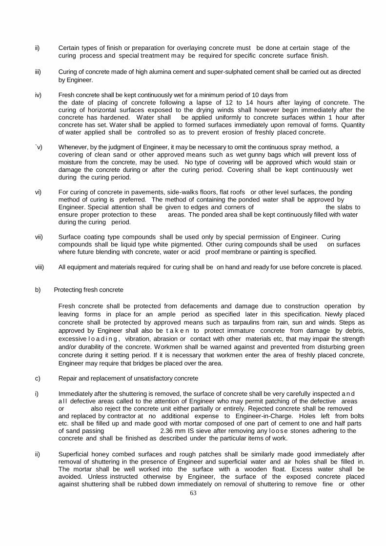
63
ii) Certain types of finish or preparation for overlaying concrete must be done at certain stage of the curing process and special treatment may be required for specific concrete surface finish.
iii) Curing of concrete made of high alumina cement and super-sulphated cement shall be carried out as directed
by Engineer. iv) Fresh concrete shall be kept continuously wet for a minimum period of 10 days from the date of placing of concrete following a lapse of 12 to 14 hours after laying of concrete. The
curing of horizontal surfaces exposed to the drying winds shall however begin immediately after the concrete has hardened. Water shall be applied uniformly to concrete surfaces within 1 hour after concrete has set. Water shall be applied to formed surfaces immediately upon removal of forms. Quantity of water applied shall be controlled so as to prevent erosion of freshly placed concrete.
`v) Whenever, by the judgment of Engineer, it may be necessary to omit the continuous spray method, a
covering of clean sand or other approved means such as wet gunny bags which will prevent loss of moisture from the concrete, may be used. No type of covering will be approved which would stain or damage the concrete during or after the curing period. Covering shall be kept continuously wet during the curing period.
vi) For curing of concrete in pavements, side-walks floors, flat roofs or other level surfaces, the ponding
method of curing is preferred. The method of containing the ponded water shall be approved by Engineer. Special attention shall be given to edges and corners of the slabs to ensure proper protection to these areas. The ponded area shall be kept continuously filled with water during the curing period.
vii) Surface coating type compounds shall be used only by special permission of Engineer. Curing
compounds shall be liquid type white pigmented. Other curing compounds shall be used on surfaces where future blending with concrete, water or acid proof membrane or painting is specified.
viii) All equipment and materials required for curing shall be on hand and ready for use before concrete is placed. b) Protecting fresh concrete Fresh concrete shall be protected from defacements and damage due to construction operation by
leaving forms in place for an ample period as specified later in this specification. Newly placed concrete shall be protected by approved means such as tarpaulins from rain, sun and winds. Steps as approved by Engineer shall also be t a k e n to protect immature concrete from damage by debris, excessive l o a d i n g , vibration, abrasion or contact with other materials etc, that may impair the strength and/or durability of the concrete. Workmen shall be warned against and prevented from disturbing green concrete during it setting period. If it is necessary that workmen enter the area of freshly placed concrete, Engineer may require that bridges be placed over the area.
c) Repair and replacement of unsatisfactory concrete i) Immediately after the shuttering is removed, the surface of concrete shall be very carefully inspected a n d
a l l defective areas called to the attention of Engineer who may permit patching of the defective areas or also reject the concrete unit either partially or entirely. Rejected concrete shall be removed and replaced by contractor at no additional expense to Engineer-in-Charge. Holes left from bolts etc. shall be filled up and made good with mortar composed of one part of cement to one and half parts of sand passing 2.36 mm IS sieve after removing any loose stones adhering to the concrete and shall be finished as described under the particular items of work.
ii) Superficial honey combed surfaces and rough patches shall be similarly made good immediately after
removal of shuttering in the presence of Engineer and superficial water and air holes shall be filled in. The mortar shall be well worked into the surface with a wooden float. Excess water shall be avoided. Unless instructed otherwise by Engineer, the surface of the exposed concrete placed against shuttering shall be rubbed down immediately on removal of shuttering to remove fine or other

64
irregularities and necessary care being taken to avoid damage to the surface. Surface irregularities shall be removed by grinding.
iii) If reinforcement is exposed or the honeycombing occurs at vulnerable positions e.g. ends of beams or
columns it may be necessary to cut out the member completely or in part and reconstruct. The decision of Engineer shall be final in this regard. If only patching is necessary, the defective concrete shall be cut out till solid concrete is reached (or to a minimum depth of 25mm), the edges being cut perpendicular to the affected surface or with small under cut if possible. Anchors, tees or dovetail slots shall be provided whenever necessary to attach the new concrete securely in place an area extending several centimeters beyond the edges and the surfaces of the prepared voids shall be saturated with water for 24 hours immediately before the patching material is placed.
iv) The use of epoxy for bonding fresh concrete used for repairs will be permitted upon written approval of
Engineer. Epoxy shall be applied in strict accordance with the instructions of the manufacturer. v) Small size holes having surface dimensions about equal to the depth of the hole, holes left after removal
of form bottom, grout insert holes and slots cut for repair of cracks shall be repaired as follows: The hole to be patched shall be roughened and thoroughly soaked with clean water until absorption
stops. A 5mm thick layer of grout of equal parts of cement and sand shall be well brushed into the surface to be patched, followed immediately by the patching concrete which shall be well consolidated with a wooden float. The concrete patch shall be built up in 10mm thick layers. After an hour or more, depending upon weather conditions, it shall be worked off flush with a wooden float and smooth finish obtained by wiping with Hessian. A steel trowel shall be used for this purpose. The mix for patching shall be of same material and in the same proportions as that used in the concrete being repaired, although some reduction in the maximum size of the coarse aggregates may be necessary and the mix shall be kept as dry as possible. Mortar filling by air pressure (geniting) shall be used for repairing of areas too large and/or too shallow for patching with mortar. Patched surfaces shall be given a final treatment to match the color and texture of the surrounding concrete. White cement shall be substituted for ordinary cement, if so directed by Engineer, to match the shade of the p a t c h with original concrete.
vi) The patched area shall be covered immediately with an approved non-staining water saturated material
such as gunny bag which shall be kept continuously wet and protected against sun and wind for a period of 24 hours. Thereafter, the patched area shall be kept wet continuously by fine spray of sprinkling for not less than 10 days.
vii) All materials, procedures and operations used in the repairing of concrete and also the finished repair work
shall be subject to the approval of Engineer. All fillings shall be tightly bonded to the concrete and shall be sound, free from shrinkage cracks after the fillings have been cured and finished.
d) Self-Finishing i) The type of finish for formed concrete surface shall be as follows, unless, otherwise specified by the
Engineer-in- Charge: For surfaces against which backfill or concrete is to be placed, no treatment is required except
repairing of defective areas. For surface below grade which will receive waterproofing treatment the concrete shall be free of surface
irregularities which would interfere with proper application of the waterproofing material which is specified for use.
Unless specified, surfaces which will be exposed when the structure is in service shall receive no
special finish, except repairing of damage or defective concrete removal of fins and abrupt irregularities, fillings of holes left by form ties and rods and clean up of loose or adhering debris.

65
ii) Surfaces which will be exposed to the weather and which would normally be level shall be sloped for drainage. Unless the drawing specifies such as stair treads, walls shall be sloped across the width approximately 1 in 30 broader surface such as walkways., roads, parking areas and platforms shall be sloped about 1 in 50. Surface irregularities shall not exceed 6mm. Surfaces which will not be covered by backfill, concrete or tile toppings such as outside decks, floors of galleries and sumps, parapets, gutters, sidewalks floors and slabs shall be consolidated. Excess water and laitance shall be removed before finishing. Floating may be done with hand or power tools and started as the surface has attained a stiffness to permit finishing operation and these shall be the minimum required to produce a surface uniform in texture and free from marks or other imperfections. Joints, edges, panels and forms, linings shall be of uniform size. Upon removal of forms the joint marks shall be smoothed off and all blemishes, projections etc. removed leaving the surfaces reasonably smooth and unmarred.
iv) Exposed Concrete finish/Rendering A rubbed finish shall be provided only on exposed concrete surfaces as specified on the drawings.
Upon removal of forms, all fins and other projections on the surfaces shall be carefully removed, off-sets levelled and voids and damaged sections be immediately saturated with water and repaired by filling with a concrete or mortar of the same composition as was used in the surface. Then surface shall be thoroughly wetted and rubbed with carborundrum or other abrasive. Cement mortar may be used in the rubbing, but the finished surface shall be brush coated with either cement grout after rubbing. The finished surfaces shall present a uniform and smooth appearance.
Mode of Measurement It shall be measured in cubic mtr. or as per the item schedule. The unit rate for precast concrete members
shall include formwork, concrete of appropriate grade, moldings, finishing, hoisting and setting in position including mortar bed & jointing, provision of lifting arrangement, exposed concrete finish etc. complete. Only reinforcement, inserts, bolts etc. shall be paid under respective items.
2.6 Form Work 2.6.1 F o r m work shall include all temporary or permanent forms or molds required for
forming the concrete which is cast- in- situ, together with all temporary construction required for their supports.
Design & Tolerance in Construction Form work shall be designed and constructed to the shapes, lines and dimensions shown on the drawings with the tolerances given below: - a) Deviation from specified dimensions of cross section of columns and beams = +12 mm b) Deviation from dimensions of footings = +12 mm
c) Dimension in Plan = +50 mm
d) Eccentricity in plan:- 0.02 time the width of the footings in the direction of deviation but not more than 50mm.
e) Thickness: -
+0.05 times the specified thickness

66
(Note - Tolerance apply to concrete dimensions only, and not to positioning of vertical steel or dowels).
General Requirement It shall be strong enough to withstand the dead and live loads and forces caused by ramming and vibrations
of concrete and other incidental loads, imposed upon it during and after casting of concrete. It shall be made sufficiently rigid by using adequate number of ties and braces, Screw jacks or hard board wedges where required shall be provided to make up any settlement in the form work either before or during the placing of concrete.
Forms shall be so constructed as to be removable in sections in the desired sequence, without damaging
the surface of concrete or disturbing the surface of concrete or disturbing other sections. Care shall be taken to see that no piece is keyed into the concrete.
Material for form work a) Propping and centering All propping and centering should be either of steel tubes with extension pieces or built up sections of
rolled steel. Centering/Staging Staging should be as designed with required extension pieces as approved by
Engineer-in-Charge to ensure proper slopes, as per design for slabs/beams etc. and as per levels as shown in drawings. All the staging to be either of Tubular steel structure with adequate bracing as approved or made of built up structural sections made from rolled structural steel sections.
In case of structures with two or more floors, the weight of concrete, centering and shuttering of any
upper floor being cast shall be suitably supported on one floor below the top most floor already cast. Form work and concreting of upper floor shall not be done until concrete of lower floor has set at least for
14 days.
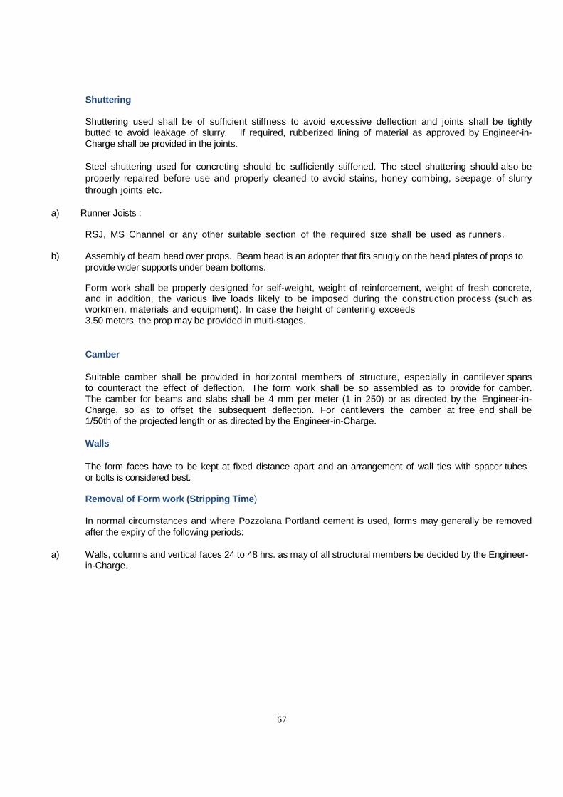
67
Shuttering Shuttering used shall be of sufficient stiffness to avoid excessive deflection and joints shall be tightly
butted to avoid leakage of slurry. If required, rubberized lining of material as approved by Engineer-in-Charge shall be provided in the joints.
Steel shuttering used for concreting should be sufficiently stiffened. The steel shuttering should also be
properly repaired before use and properly cleaned to avoid stains, honey combing, seepage of slurry through joints etc.
a) Runner Joists : RSJ, MS Channel or any other suitable section of the required size shall be used as runners. b) Assembly of beam head over props. Beam head is an adopter that fits snugly on the head plates of props to
provide wider supports under beam bottoms. Form work shall be properly designed for self-weight, weight of reinforcement, weight of fresh concrete,
and in addition, the various live loads likely to be imposed during the construction process (such as workmen, materials and equipment). In case the height of centering exceeds
3.50 meters, the prop may be provided in multi-stages. Camber Suitable camber shall be provided in horizontal members of structure, especially in cantilever spans
to counteract the effect of deflection. The form work shall be so assembled as to provide for camber. The camber for beams and slabs shall be 4 mm per meter (1 in 250) or as directed by the Engineer-in-Charge, so as to offset the subsequent deflection. For cantilevers the camber at free end shall be 1/50th of the projected length or as directed by the Engineer-in-Charge.
Walls The form faces have to be kept at fixed distance apart and an arrangement of wall ties with spacer tubes
or bolts is considered best. Removal of Form work (Stripping Time) In normal circumstances and where Pozzolana Portland cement is used, forms may generally be removed
after the expiry of the following periods: a) Walls, columns and vertical faces 24 to 48 hrs. as may of all structural members be decided by the Engineer-
in-Charge.
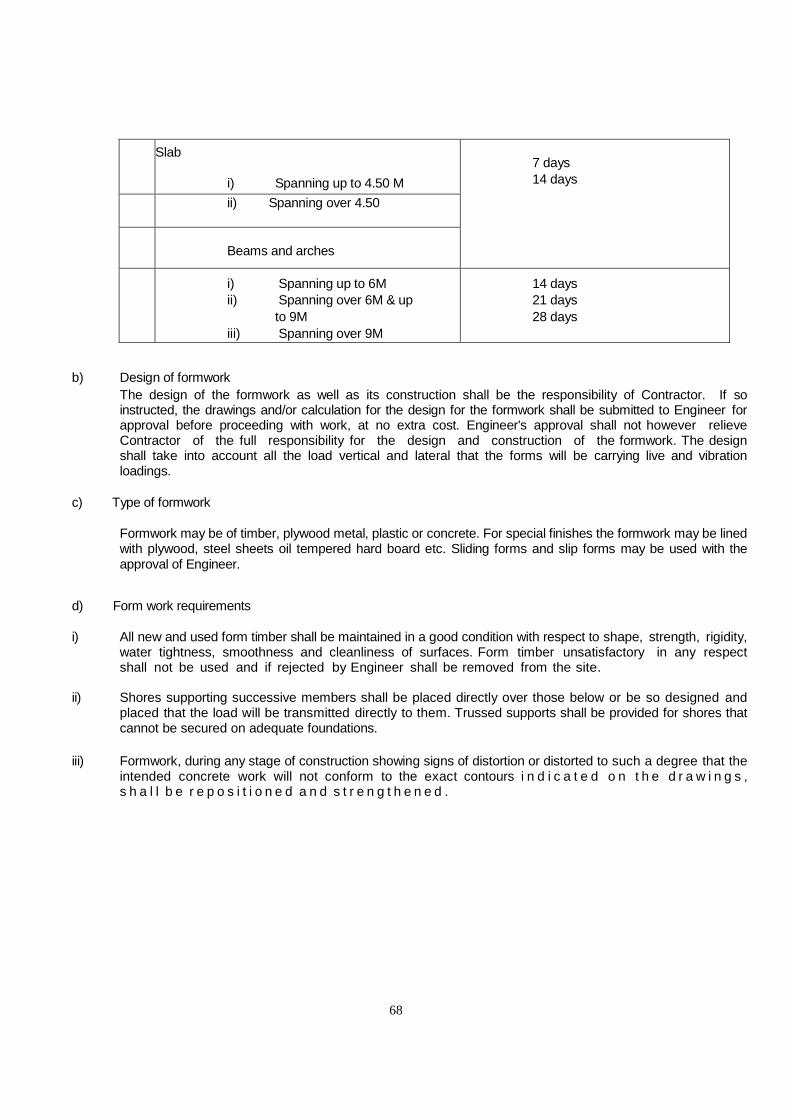
68
b)
Slab i) Spanning up to 4.50 M
7 days 14 days
ii) Spanning over 4.50
c
)
Beams and arches
i) Spanning up to 6M ii) Spanning over 6M & up
to 9M iii) Spanning over 9M
14 days 21 days 28 days
b) Design of formwork The design of the formwork as well as its construction shall be the responsibility of Contractor. If so
instructed, the drawings and/or calculation for the design for the formwork shall be submitted to Engineer for approval before proceeding with work, at no extra cost. Engineer's approval shall not however relieve Contractor of the full responsibility for the design and construction of the formwork. The design shall take into account all the load vertical and lateral that the forms will be carrying live and vibration loadings.
c) Type of formwork Formwork may be of timber, plywood metal, plastic or concrete. For special finishes the formwork may be lined
with plywood, steel sheets oil tempered hard board etc. Sliding forms and slip forms may be used with the approval of Engineer.
d) Form work requirements i) All new and used form timber shall be maintained in a good condition with respect to shape, strength, rigidity,
water tightness, smoothness and cleanliness of surfaces. Form timber unsatisfactory in any respect shall not be used and if rejected by Engineer shall be removed from the site.
ii) Shores supporting successive members shall be placed directly over those below or be so designed and
placed that the load will be transmitted directly to them. Trussed supports shall be provided for shores that cannot be secured on adequate foundations.
iii) Formwork, during any stage of construction showing signs of distortion or distorted to such a degree that the
intended concrete work will not conform to the exact contours i n d i c a t e d o n t h e d r a w i n g s , s h a l l b e r e p o s i t i o n e d a n d s t r e n g t h e n e d .

69
Poured concrete affected by the faulty formwork, shall be removed completely and the formwork be
corrected prior to placing of new concrete at contractors own cost. iv) Excessive construction camber to compensate for shrinkage, settlement which may impair the structural
strength of members shall not be permitted. v) Forms shall be so designed that their removal will not damage the concrete. Face formwork shall provide
true vertical and horizontal joints, conform to the architectural features of the structure as to location of joints and be as directed by engineer.
vi) Where exposed smooth or rendered concrete finishes are required the forms shall be constructed with
special care so that the resulting concrete surfaces require a minimum finish. e) Formwork for Slope Surfaces i) Forms for sloped surfaces shall be built so that the formwork can be placed board-by-board immediately
ahead of concrete placement so as to enable ready access for placement, vibration inspection and repair of the concrete.
ii) The formwork shall also be built so that the boards can be removed one by one from the bottom up as soon
as the concrete has attained sufficient stiffness to prevent sagging. Surfaces of construction joints and finished surfaces with slopes steeper than 4 horizontal: 1 vertical shall be provided with top shuttering if required.
f) Formwork for Curved Surfaces i) The contractor shall interpolate intermediate sections as necessary and shall construct the forms so
that the curvature will be continuous between sections. Where necessary to meet requirements for curvature, the form timber shall be built up of laminated sheets cut to make tight, smooth form surfaces.
ii) After the forms have been constructed, all surface imperfections shall be corrected and all surface
irregularities at matching faces of form material shall be dressed to the specified curvature. g) Form work F o r Exposed Concrete Surfaces (Wrought Form Work) i) Where it is desired, directed or shown on the drawings to have original fair face finish of concrete surface without any rendering or plastering, formwork shall be carried out by using wood
planks, plywood or steel plates of approved quality size and pattern as per direction of the Engineer. ii) The contractor shall use one type of material for all such exposed concrete faces

70
and the forms shall be constructed so as to produce uniform and consistent texture and pattern on the face of the concrete. Patches or forms for these surfaces will not be permitted. The formwork shall be placed so that all horizontal formworks are continuous across the entire surface.
iii) To achieve a finish which shall be free of board marks, the formwork shall be faced with plywood or equivalent material in large sheets. The sheets shall be arranged in an approved pattern.
Wherever possible, joints between sheets shall be arranged to coincide with architectural features, cills, window heads or change in direction of the surface. All joints between shuttering plates or panels shall be vertical or horizontal unless otherwise directed. Suitable joints shall be provided between sheets. The joints shall be arranged and fitted so that no blemish or mark is imparted to the finished surfaces.
iv) To achieve a finish which shall give the rough appearance of concrete cast against sawn boards, formwork
boards unless otherwise stated shall be of 150 mm wide, securely jointed with tongue and grooved joints if required to prevent grout loss with tie rod positions and direction of boards carefully controlled. Sawn boards shall be set horizontally, vertically or at an inclination shown in the drawings. All shuttering bolt holes shall be accurately aligned horizontal and vertical and shall be filled with matching mortar recessed 5mm back from the surrounding concrete face.
v) Forms for exposed concrete surfaces shall be constructed with grade strips (the underside of which indicate
top of pour) at horizontal construction joints, unless the use of groove strips is specified on the drawings. Such forms shall be removed and reset from lift to lift , they shall not be continuous from lift to lift. Sheeting of reset forms shall be tightened against the concrete so that the forms will not be spread and permit erupting irregularities or loss of mortar. Supplementary form ties shall be used as necessary to hold the reset forms tight against the concrete.
vi) For fair faced concrete (exposed concrete face), the position of through bolts will be restricted and generally
indicated on the drawings. vii) Chamfer strips shall be placed in the corners of forms for exposed exterior corners so as to produce 20 mm
beveled edges except where otherwise shown in the drawings. Interior corners and edges at formed joints shall not be beveled unless shown on the drgs. Mouldings for grooves, drip courses and bands shall be made in the form itself.
viii) The wood planks, plywood and steel plates used in formwork for obtaining exposed surfaces shall not be
used for more than 3 times in case of wood planks, 6 times for plywood and 10 times for steel plates respectively. However, no forms will be allowed for reuse, if in the opinion of the Engineer it is doubtful to produce desired texture of exposed concrete.

71
ix) In order to obtain exposed concrete work of uniform colour it shall be necessary to ensure that the sand
used for all exposed concrete work shall be of approved uniform colour. Moreover the cement used in the concrete for any complete element shall be from single consignment.
x) No exposed concrete surface shall be rendered or painted with cement or otherwise. Plastering of defective concrete as a means of achieving the required finish shall not be permitted, except
in the case of minor porosity on the surface, the Engineer may allow a surface treatment by rubbing down with cement and sand mortar of the same richness and colour as for the concrete. This treatment shall be made immediately after removing the formwork.
xi) The contractor shall also take all precautionary measures to prevent breaking and chipping of corners and
edges of completed work until the building is handed over. h) Bracings struts and props i) Shuttering shall be braced, strutted, propped and so supported that it shall not deform under weight and
pressure of the concrete and also due to the movement of men and other materials. Bamboos shall not be used as props or cross bearers.
ii) The shuttering for beams and slabs shall be so erected that the shuttering on the sides of the beams and under the soffit of slabs can be removed without disturbing the beam bottoms.
Repropping of beams shall not be done except when props have to be reinstated to take care of construction loads anticipated to be in excess of the design load. Vertical props shall be supported on wedges or other measures shall be taken whereby the props can be gently lowered vertically while striking the shuttering. If the shuttering for a column, is erected for the full height of the column, one side shall be left open and built up in sections as placing of concrete from the sides to limit the drop of concrete to 3M or as directed by engineer.
i) Mould Oil Shuttering gives much longer service life if the surfaces are coated with suitable mould oil which acts both as
a parting agent and also gives surface protections. A typical mould oil is heavy mineral oil or purified cylinder oil containing not less than 5% pentachlorophenol
conforming to IS 716-1987 well mixed to a viscosity of 70-80 centipoise. After 3-4 uses and also in cases when shuttering has been stored for a long time, it should be re-coated with
mould oil before the next use. The design of form work shall conform to sound Engineering practices and relevant IS Code. j) Reuse of forms Number of repeated usage of shuttering materials shall be depended upon the quality of shuttering
materials and to be as approved by the Engineer-in-Charge. Before reuse, all forms shall be thoroughly scraped, cleaned, nails removed, holes that may leak suitably
plugged and joints examined and when necessary, repaired and the inside retreated to prevent adhesion, to the satisfaction of Engineer. Warped lumber shall be resized.
Contractor shall equip himself with enough shuttering material to complete the job in the stipulated time. Measurement
Measurement shall be done on the basis of square meter of the actual area in contact
with concrete. Formwork required for providing cutouts and openings in concrete work

72
shall be measured as per IS-1200 but however formwork necessary for construction joint
shall not be measured and paid for separately.
Design Mix Concrete Design mix concrete is that concrete in which the design of mix (i.e.) the determination of proportions of
cement, aggregate & water is arrived as to have target mean strength for specified grade of concrete. It will be designed based on the principles given in IS:456 & SP-23.
In order to ensure that not more than the specified proportions of test results are likely to fall below the characteristic strength, the concrete mix has to be designed for higher average compressive strength and this higher average compressive strength for a specified grade of concrete is defined a target mean strength.
Providing And Mixing Of Plasticizer The plasticizer to be used shall be of approved make like BASF/SIKA/ FOSROC/STP or equivalent as per
IS:9103-1979 material will be used as per manufacturer's specification. The payment will be in litres basis of actual material used as per manufacturer's specification.
NOTE: Clean-up
i) Upon the completion of concrete work, all forms, equipment, construction tools protective coverings and any debris resulting from the work shall be removed from the premises.
ii) All debris, i.e. empty containers, wooden pieces etc. shall be removed. iii) The finished concrete surfaces shall be left in a clean condition to the entire satisfaction of Engineer-in-Charge.

73
SECTION - IX LIST OF APPROVED MAKE / BRANDS
S.No.
ITEM DESCRIPTION
IS CODE
BRAND
MANUFACTURER
1
CEMENT
a
Ordinary Portland
Cement 43 Grade
IS: 8112/ 1989
Ultratech
Ultratech Co.
Vikram
Grassim Industries Ltd.
J.K.Laxmi
J.K.Cement
ACC
ACC
b
White Cement
IS: 8042
Birla White
Grassim Industries Ltd.
J.K.White
J.K.Cement
2
STEEL
a
Reinforcement Steel (TMT)of
Grade Fe550D
IS:456
SAIL,TATA,JSPL,TISCO
b
Structural Steel sections- Plate beams, channels, tee, flats, Angles bars(Round, Square & Hexagonal) of Grade 450.
IS:226
TATA, SAIL, JSPL
c
Structural Hollow steel sections of Grade 355
TATA STEEL
THE TATA IRON STEEL Co. Ltd
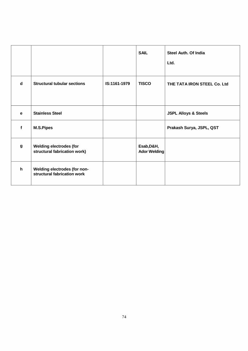
74
SAIL
Steel Auth. Of India
Ltd.
d
Structural tubular sections
IS:1161-1979
TISCO THE TATA IRON STEEL Co. Ltd
e
Stainless Steel
JSPL Alloys & Steels
f
M.S.Pipes
Prakash Surya, JSPL, QST
g
Welding electrodes (for structural fabrication work)
Esab,D&H, Ador Welding
h
Welding electrodes (for non- structural fabrication work
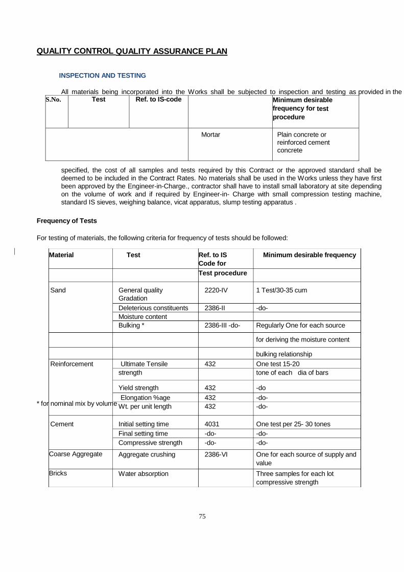
75
Material Test Ref. to IS Code for
Minimum desirable frequency
Test procedure
Sand
General quality Gradation
2220-IV
1 Test/30-35 cum
Deleterious constituents 2386-II -do- Moisture content Bulking * 2386-III -do- Regularly One for each source
for deriving the moisture content
bulking relationship
Reinforcement Ultimate Tensile 432 One test 15-20 strength tone of each dia of bars
Yield strength 432 -do
Elongation %age 432 -do- Wt. per unit length 432 -do-
Cement
Initial setting time
4031
One test per 25- 30 tones Final setting time -do- -do- Compressive strength -do- -do-
Coarse Aggregate Aggregate crushing
2386-VI One for each source of supply and value
Bricks Water absorption Three samples for each lot compressive strength
QUALITY CONTROL QUALITY ASSURANCE PLAN
INSPECTION AND TESTING All materials being incorporated into the Works shall be subjected to inspection and testing as provided in the conditions of Contract. The Contractor shall arrange to get the materials and/or portion of Works tested by a test house analyst approved by Owner or Engineer-in-Charge at his own cost including transportation. Unless otherwise
specified, the cost of all samples and tests required by this Contract or the approved standard shall be deemed to be included in the Contract Rates. No materials shall be used in the Works unless they have first been approved by the Engineer-in-Charge., contractor shall have to install small laboratory at site depending on the volume of work and if required by Engineer-in- Charge with small compression testing machine, standard IS sieves, weighing balance, vicat apparatus, slump testing apparatus .
Frequency of Tests For testing of materials, the following criteria for frequency of tests should be followed:
* for nominal mix by volume
S.No. Test Ref. to IS-code Minimum desirable frequency for test procedure
Mortar Plain concrete or
reinforced cement concrete
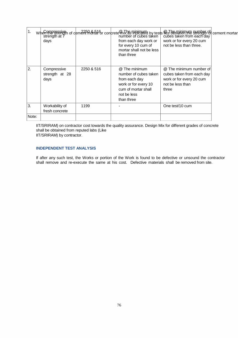
76
When the strength of cement mortar or concrete mix as indicated by tests lies between the strength of cement mortar or concrete mix for any 2 grades such concrete shall be classified for all purposes as a concrete belonging to the lower of the grades between which the strength lies. Materials need to get tested from reputed labs (Like
IIT/SRIRAM) on contractor cost towards the quality assurance. Design Mix for different grades of concrete shall be obtained from reputed labs (Like
IIT/SRIRAM) by contractor. INDEPENDENT TEST ANALYSIS If after any such test, the Works or portion of the Work is found to be defective or unsound the contractor
shall remove and re-execute the same at his cost. Defective materials shall be removed from site.
1. Compressive strength at 7 days
2250 & 516 @ The minimum number of cubes taken from each day work or for every 10 cum of mortar shall not be less than three
@ The minimum number of cubes taken from each day work or for every 20 cum not be less than three.
2. Compressive strength at 28 days
2250 & 516 @ The minimum number of cubes taken from each day work or for every 10 cum of mortar shall not be less than three
@ The minimum number of cubes taken from each day work or for every 20 cum not be less than three
3. Workability of fresh concrete
1199 - One test/10 cum
Note:

77
ACCESS FOR INSPECTION The Contractor is to provide at all times during the progress of the Works and
maintenance period, proper means of access, with ladder, gangways, etc. and the necessary attendant to move and adapt as directed for the inspection or measurement of the works by Engineer-in-Charge.
LABORATORY EQUIPMENTS REQUIRED AT SITE a) Cube testing machine including set of 6 cube moulds b) Slump test apparatus. c) Sieve test analysis (set of 6 sieves). d) Weigh balance (20 kg. capacity) e) Silt test apparatus (graduated measuring glass cylinder) SAMPLES Samples of all the materials to be incorporated in the work shall be submitted to the
Engineer-in-Charge for their prior written approval without any extra cost. The approved samples will be kept with the Engineer-in- Charge till the completion of the Works and any material not strictly conforming to such samples will be liable to be rejected at any time without assigning any reasons whatsoever.
The Contractor shal l pay all the necessary charges for transporting &
testing of any materials intended to be incorporated in the Works required by the Owner
Structural Steel Works
1.0 SCOPE This specification covers the technical requirements of
fabrication, erection of Structural steel works for various structures under this project
1.1 Fabrication The scope of work under fabrication includes the following: a) Procurement and supply of all steel materials including
loading, transportation, unloading and stacking and storing on skids or supports.
b) Procurement and collection of all consumables like bolts, nuts, washers, electrodes, paints, shims, packs, etc., including allowance for spares and wastage.

78
c) Preparation and submission of fabrication drawings, modification/rectification, sketches, as made drawings, erection drawings, bill of materials, bolts lists and shipping documents for approval of purchaser.
d) Preparation of design calculations for non-standard connections, temporary bracings etc. for approval of purchaser.
e) Cold straightening of section and plates, whenever they are bent and kicked.
f) Fabrication of all steel structural components covered in design drawings and generally described under the scope of the project.
g) In case of inability to produce material certificate for the material procured by him, the Contractor has to make arrangements and bear the cost of conducting tests, such as chemical analysis, physical and mechanical tests of raw materials.
h) Making arrangements for providing all facilities for conducting ultrasonic, X-ray or gamma ray tests of welds; getting the tests carried out at reputed testing laboratories making available test films/graphs, reports and interpretation.
i) Control assembly of fabricated structural components at shop, wherever required.
j) Preparation of steel structural surfaces for painting as provided in the Specifications/drawings.
k) Application for one primer coat of painting at shop, as specified in the design drawing/ specifications.
l) Loading, transportation from fabrication workshop to site of erection and unloading of all steel structural components/units/assemblies.
m) Preparation of “As-built” drawings. 2.0 GENERAL REQUIREMENTS 2.1 The Structural Steel Contractor shall furnish all structural steel
material, labour, plant, equipment, scaffolding, tools, tackles, all materials and consumables such as welding electrodes, bolt sand nuts, oxygen and acetylene gases, oils for cleaning etc. of approved quality as per relevant Indian Standards any everything that is required for complete execution of the work on schedule in accordance with the drawings and as described herein and/or as directed by the
2.2 Fabrication, Erection and approval of Steel Structures shall be
in compliance with;

79
These General Specifications, IS: 800 and other relevant Indian Standards
as applicable and listed in clause 4.00 hereunder. Drawings and supplementary drawings to be supplied to the
Structural Steel contractor by CONSULTANT during execution of the work. 3.0 Material supply and Samples
Steel materials shall comply with the specifications laid down
under clause 5.0 and/or as called for in the design drawings. All materials used shall be new, unused and free from defects.
All steel and other material shall be procured and supplied by the Structural Steel contractor, from the reputed sources as approved by and shall conform to the following:
Structural Steel contractor shall use materials for fabrication as specified in the approved drawings. All materials supplied by the Structural Steel Contractor shall be in sound condition, of recent manufacture, free from defects such as mill scales, slag intrusions, laminations, pitting, flaky, rust etc. and be of full weight and thickness as specified.
The Structural Steel contractor shall furnish the mill /
manufacturer's test reports, along with the materials and satisfactorily demonstrates the specific grade and quality. Material test certificate shall be original.
All materials required for the work shall be correlated with
manufactures test certificates. In the absence of test certificates, Structural Steel Contractor shall test materials through reputed laboratory approved by for establishing quality at his cost and as directed.
Material supplied against these Test Certificates (TC) should
have identification stamped or stenciled on them. All such identification markings shall be authenticated by the inspection agency, which has inspected and approved the material.
They shall have the right to test random samples to prove
authenticity of the test certificates produced by the Contractor at the Contractor's cost. Any material found not meeting the required specification would be rejected.

80
Whenever the Contractor desires to substitute structural members / shapes, plates for the sizes shown on the drawings, for want of availability of requisite materials, such substitutions shall be made only after authorization in writing by the may also direct that substitution be made, when he considers such substitution to be necessary.
Samples for checking the quality of materials procured by the
Structural Steel Contractor and workmanship in the execution of the works may be called for at any time by the. In case such samples are found to be of substandard/unacceptable quality, the Structural Steel Contractor shall immediately discontinue use of such materials and workmanship and get fresh samples approved by the nothing shall affect the liberty of the to reject whole or portions of structures where such defective materials and workmanship has already been used before detection.
3.1 Test at works The Structural Steel Contractor shall submit Mill /
Manufacturers test certificates for all the materials procured by him. If test certificates are not available or identification marks are not clear, the Structural Steel Contractor shall arrange for such materials to be tested at an approved laboratory as and when required by the.
If material is supplied by the Clients, the Clients shall furnish a
mill certified report of the tests for each grade of steel from which the material is to be fabricated. In both the cases (material supplied by the contractor or the client) the certification shall contain the results of chemical and physical tests required by the specification for the material. In the event the results of any test are not in conformance with the requirements of these specifications, the clients shall conduct additional mill and laboratory tests. The additional costs of furnishing, cutting and machining additional test specimens shall be borne by the client.
Structural steel not conforming to the requirements of any of
the above standards may be used only if permitted in writing by the Structural Consultant. This permission may be granted after the steel is tested for yield point stress, ultimate tensile stress, elongation, ductility, weld ability or any other property as

81
required by the Structural Consultant. For structural steel test samples shall be cut out of the materials
from the locations indicated by the and samples shall be prepared in accordance with the requirements of Indian Standards Specifications for conducting such tests. One set of tests will include test of three individual specimens of samples.
4.0 CODES AND STANDARDS 4.1 Except where otherwise specified herein or authorized by the
Consultant , all items of work shall conform to the requirements of relevant latest Indian standards. Any item of work, for which there is no India Standard available, shall conform to the latest British standard (B.S.) and American Standards. The item of work shall be best of its kind and subject to approval of the Consultant. In case of conflict between this specification and those referred to in the standard, the former shall prevail.
4.2 The pertinent clauses and sections of the following codes,
standards and specifications (latest editions including all applicable official amendments and revisions) shall apply to the material, design, detailing, fabrication, inspection of the work and painting covered by this specification and as specified in the other sections of this specification. In the event of the conflict of certain requirements of this specification with the details shown in drawings, the decision of the Consultant shall be final.
All structural steel shall conform to the requirements of anyone
of the following Indian Standards as specified. The list of some important IS codes and standards applicable to the structural steel work for the aforesaid project.
However, the applicable standards and codes shall be as per but not limited to the list given below.
IS: 228 Methods of chemical analysis of steels. IS:432 Mild steel and medium tensile steel bars and hard drawn steel wire
for (parts I & II) concrete reinforcement. IS: 800 Code of practice for general construction in steel. IS : 801 Code of practice for use of cold formed light gauge steel structural
members in general building construction.
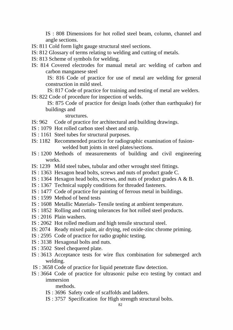
82
IS : 808 Dimensions for hot rolled steel beam, column, channel and angle sections.
IS: 811 Cold form light gauge structural steel sections. IS: 812 Glossary of terms relating to welding and cutting of metals. IS: 813 Scheme of symbols for welding. IS: 814 Covered electrodes for manual metal arc welding of carbon and
carbon manganese steel IS: 816 Code of practice for use of metal are welding for general
construction in mild steel. IS: 817 Code of practice for training and testing of metal are welders. IS: 822 Code of procedure for inspection of welds. IS: 875 Code of practice for design loads (other than earthquake) for
buildings and structures. IS: 962 Code of practice for architectural and building drawings. IS : 1079 Hot rolled carbon steel sheet and strip. IS : 1161 Steel tubes for structural purposes. IS: 1182 Recommended practice for radiographic examination of fusion- welded butt joints in steel plates/sections. IS : 1200 Methods of measurements of building and civil engineering
works. IS: 1239 Mild steel tubes, tubular and other wrought steel fittings. IS : 1363 Hexagon head bolts, screws and nuts of product grade C. IS : 1364 Hexagon head bolts, screws, and nuts of product grades A & B. IS : 1367 Technical supply conditions for threaded fasteners. IS : 1477 Code of practice for painting of ferrous metal in buildings. IS : 1599 Method of bend tests IS : 1608 Metallic Materials- Tensile testing at ambient temperature. IS : 1852 Rolling and cutting tolerances for hot rolled steel products. IS : 2016 Plain washers. IS : 2062 Hot rolled medium and high tensile structural steel. IS: 2074 Ready mixed paint, air drying, red oxide-zinc chrome priming. IS : 2595 Code of practice for radio graphic testing. IS : 3138 Hexagonal bolts and nuts. IS : 3502 Steel chequered plate. IS : 3613 Acceptance tests for wire flux combination for submerged arch
welding. IS : 3658 Code of practice for liquid penetrate flaw detection. IS : 3664 Code of practice for ultrasonic pulse eco testing by contact and
immersion methods. IS : 3696 Safety code of scaffolds and ladders. IS : 3757 Specification for High strength structural bolts.

83
IS : 3954 Specification for Hot Rolled Channel IS : 4218 ISO metric screw threads IS : 4353 Recommendations for submerged arc welding of mild steel
and low alloy steels. IS : 5334 Code of practice for magnetic particle flaw detection of
welds. IS: 5369 General requirements for plain washers and lock washers IS : 5372 Taper washers for channels (ISMC) IS : 5374 Taper washers for I-beams (ISMB) IS : 5624 Foundation bolts IS : 6610 Heavy washers for steel structures IS: 6639 Hexagonal bolts for steel structures IS : 7205 Safety code for erection of structural steel work. IS: 7215 Tolerances for fabrication of steel structures. IS : 7293 Safety code for working with construction machinery. IS : 7318 Approval test for welders when welding procedure is not
required IS : 7973 Code of practice for architectural building and working
drawings IS : 8500 Structural steel- micro alloyed (medium and high strength
qualities) IS: 9595 (Metal arc welding of carbon and carbon manganese steel
Recommendations); IS : 10720Technical drawings for structural metal works IS : 10748 Hot - cold steel scalp / strips for welded tubes and pipes IS : 10842 Evaluation procedure for Y groove weld crack ability
test in structural steel. IS : 12843 Tolerances for erection of structural steel. SP: 6 ISI Hand book for structural engineers (Part 1 to 7)
British/American codes and standards. EUROCODE-4/AISC-16 Design of composite steel and concrete
structures. BS EN 10346 Continuously Hot Dip Coated Steel Flat Products. BS EN 10143 Continuously Hot Dip Coated Steel Sheet and Strip – Tolerances on Dimension and shape.
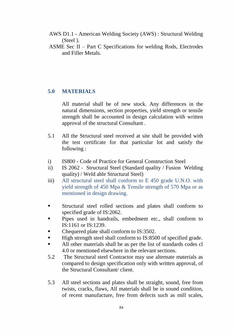
84
AWS D1.1 - American Welding Society (AWS) : Structural Welding (Steel ).
ASME Sec II – Part C Specifications for welding Rods, Electrodes and Filler Metals.
5.0 MATERIALS All material shall be of new stock. Any differences in the
natural dimensions, section properties, yield strength or tensile strength shall be accounted in design calculation with written approval of the structural Consultant .
5.1 All the Structural steel received at site shall be provided with
the test certificate for that particular lot and satisfy the following :
i) IS800 - Code of Practice for General Construction Steel ii) IS 2062 - Structural Steel (Standard quality / Fusion Welding
quality) / Weld able Structural Steel) iii) All structural steel shall conform to E 450 grade U.N.O. with
yield strength of 450 Mpa & Tensile strength of 570 Mpa or as mentioned in design drawing.
Structural steel rolled sections and plates shall conform to
specified grade of IS:2062. Pipes used in handrails, embedment etc., shall conform to
IS:1161 or IS:1239. Chequered plate shall conform to IS:3502. High strength steel shall conform to IS:8500 of specified grade. All other materials shall be as per the list of standards codes cl
4.0 or mentioned elsewhere in the relevant sections. 5.2 The Structural steel Contractor may use alternate materials as
compared to design specification only with written approval, of the Structural Consultant/ client.
5.3 All steel sections and plates shall be straight, sound, free from
twists, cracks, flaws, All materials shall be in sound condition, of recent manufacture, free from defects such as mill scales,

85
slag intrusions, laminations, pitting, flaky, rust etc. and be of full weight and thickness as specified.)
5.4 In case any defect like laminations is noticed in the steel
sections and plates during fabrication and erection, the same shall be brought to the notice of the Consultant. These sections and plates shall be rejected unless specifically approved for acceptance by the Consultant.
5.5 Rolled Steel Sections All Hot Rolled Medium & High Tensile Structural Steel shall
conform to IS 2062 Gr "B". 5.6 Rolled Steel Sections - Brands. The approved brands for the structural steel shall be one of the
following... i) SAIL, ii) TISCO/ TATA, iii) JSW and iv) JSPL 5.6 Dimensions and Tolerances
The dimensions, form, weight, and tolerances of all hot rolled
shapes (and other members) shall conform to the following
Indian Standards and other relevant standards:
IS:1852-1985 Specifications for rolling and cutting tolerance for hot rolled Steel products.
IS: 808-1989 Dimensions for hot rolled steel Sections IS: 1730-1989 Dimensions for steel plate, sheet and strip for
structural and general engineering purposes. IS:1732-1989 Dimensions for round and square steel bars for
structural & general engineering purpose. IS: 7215-1974 Tolerances for fabrication of steel structures. 5.7 Cold Formed Sections All cold formed light gauge steel section with thickness less
than 10mm shall be confirmed by IS 811-1987. Steel Sheet and strip used for making these sections shall conform to IS 1079 - 1994 Specifications

86
5.8 Steel Plate and Protection Angles Steel plate and protection angles required for the protection of
concrete work shall be erected true to line and grade within the tolerances. The edges of exposed faces may have a vertical or horizontal distortion from a straight line not greater than 3 mm per meter of length, provided, that distortion for any single piece shall not exceed 1 mm and provided, that when the warp is greater than 1.6 mm an extra anchor hole shall be drilled near the proper corner and the piece drawn into position thereby.
5.9 Receipt and Storing of Materials: Each rolled section must be marked for identification and each
lot should be accompanied by Manufacturer's quality certificate, confirming chemical analysis and mechanical characteristics.
All steel parts furnished by Supplier shall be checked, sorted
out, straightened and arranged by grades and qualities in stores. Structural steel with surface defects such as pitting, cracks,
laminations etc. shall be rejected if the defects exceed the allowable tolerances specified in relevant Standards.
Welding electrodes shall be stored separately by qualities and
lots inside a dry and enclosed room, in compliance with IS: 816 and as per instructions given by CONSULTANT. Electrodes shall be perfectly dry and draw from an Electrode oven, if required.
Checking of quality of bolts of any kinds as well as storage of same shall be made conforming to relevant standards.
Each lot of electrodes, bolts, nuts etc. shall be accompanied by
Manufacturer's test certificates. Structural steel shall be stored consignment wise and size off
the ground by at least 150 mm above protected by suitable cover as desired by Consultant. The steel shall be protected from rusting, oil, grease, distortion and deterioration.
The Passage and space between the stacks shall be enough for
inspection, identification and rigging operations and the stacks

87
shall be easily measurable.
5.10 Material Tests: Structural Steel Contractor /Fabricator shall be required to
produce Manufacturer's quality certificate for the material or wherever quality certificates are missing or incomplete or when material quality differs from standard Specifications the Structural steel Contractor shall conduct all appropriate tests as directed by the CONSULTANT, at no extra cost, in test houses approved by Consultant.
Manufacturer certifications for structural steel shall contain at
least the following information: Heat analysis or heat number Chemical Composition Results of visual inspection/ultrasonic testing Statement of compliance with code To verify the submitted Material TC, raw material shall be
tested as per code requirement. Frequency of testing shall be 1 randomly selected sample per heat/batch no.
In case of non-availability of heat no. / lot no. on the raw
material, the following tests be carried out at the discretion of client/Structural Consultant & the inspecting agency.
Chemical Composition Mechanical Properties Weldability Test
Materials for which Test Certificates are not available or for
which test results do not comply with relevant standard Specification, shall not be used.
5.11 Material for Shear Connectors (Headed Shear Studs) Stud materials shall meet the requirements of AWS D1.1,
Sections 7.2 and 7.3. Contractor shall submit the following:

88
Stud Manufacturer's Certification that the studs, as supplied, meet the
Requirements of AWS D1.1, Sections 7.2 and 7.3. Certified copies of the stud manufacturer’s test reports of
mechanical tests for the diameter supplied Certified material test reports from the steel supplier indicating
diameter, chemical properties and grade on each heat number supplied.
5.12 BOLTS AND NUTS: All Bolts shall conform to high strength 10.9 grade U.N.O.
with yield strength of 900 Mpa & Tensile strength of 1000 Mpa or as mentioned in design drawing.
All bolts and nuts shall conform to the requirements of: IS: 1367 (Part 3)- Technical Supply Conditions for Threaded
Fasteners. The bolts unless noted otherwise shall be of Grade 10.9 which shall have a tensile strength of not less than 80 kg/mm2, and a minimum elongation of 12 percent on a gauge length of 3.65√A.
The dimensions and tolerances of all bolts, nuts and washers shall conform to the requirements of the following Indian Standards.
IS 4000 : Code of practice for high strength bolts in steel structures.
IS 6623: Specifications for High strength structural nuts . IS 3757 -Specifications for High strength structural bolts, IS 1367(Part 2) – Tolerances for fasteners – bolts ,screw and
nuts
5.12.1 WASHERS
Plain flat washers shall be used .Washers shall be as per IS 6649 – Specifications for washers for high strength bolts and nuts.
5.12.2 Fastening Material Test Certificates The Contractor supplying fastener products shall submit, for
record, copies of all Manufacturer's Certifications for all
89
fastener components, including bolts, nuts, washers, and direct tension indicators.
Manufacturer certifications for bolts shall contain at least the
following: Heat analysis, heat number, and a statement certifying that
heats having prohibited elements intentionally added were not used to produce the bolts.
Results of hardness, tensile and proof load tests, as required
and performed, If galvanized, the results of rotational capacity tests, including the test method used (solid plate or tension measuring device) and the lubricant present,
If galvanized, measured zinc coating weight or thickness,
Results of visual inspection for bursts, Statement of compliance with dimensional and thread fit
requirements, Lot number and purchase order number, To cross verify the submitted Material TC, raw material shall
be tested as per code requirement. Frequency of testing shall be 1 randomly selected sample per heat/batch no.
In case of non-availability of heat no./ lot no. on the raw
material, extend of testing shall be mutually agreed between the client, the contractor, the Structural Consultant & the inspecting agency.
All materials shall conform to their respective specifications.
The use of Equivalent or higher grade or alternate materials shall be considered only in special cases.
5.13 Welding Materials (Electrodes, filler wires and flux) Electrodes, filler wires and flux used for welding shall be from
approved manufacturers / Suppliers. When requested by the CONSULTANT, the contractor shall furnish certification that electrode or electrode flux combination will meet the requirements of classification. The classification and size of

90
electrode, arc length voltage & amperage shall be suited to type and thickness of material, type of groove, welding positions and other circumstances attending work.
The Contractor shall also submit the manufacturer's product
data sheets for all welding material to be used. The data sheets shall describe the product, limitations of use, recommended welding parameters, and storage and exposure requirements, including baking and rebaking, if applicable.
The contractor should also submit the Material test certificate
of all the welding consumable at site. 5.13.1 Electrodes Covered electrodes for arc welding shall conform to IS:814.
Electrode to be used for submerged arc welding shall conform to specification IS:7280 .
Coding of electrodes shall be as follows: ER 421 ‘ C’ x for mild steel Grade A and Grade B as per
IS:2062 Where ‘ C’ is the value of current as specified by the electrode
manufacturer. Only low hydrogen electrodes shall be used for welding. All
electrodes having low hydrogen covering shall conform to AWS A5. 1 / AWS A5.5 or relevant acceptable standards. These electrodes shall be purchased in hermetically sealed containers or baked by the user as recommended by electrode manufacturer. Electrode flux coating shall be sound and unbroken.
Some of the approved brands for the electrodes shall as
follows. i) ESAB ii) D & H – Sechron iii) Ador iv) Honawar v)
Weldwell vi) Royal Arc

91
The electrodes shall be dried in an electric oven as per the recommendations of manufacturers. Only DC current shall be used for welding and the Contractor shall make his own arrangements of all welding power and for equipment.
The electrodes used for welding shall be suitable type and size
depending upon specifications of the parent materials, the method of welding, the position of welding and quality of welds desired e.g. normal penetration welds or deep penetration welds. However, only low Hydrogen electrodes shall be used for plates conforming to IS: 2062 steel and for all thickness of high strength steel conforming to IS: 8500.
All low hydrogen type electrodes shall be baked and stored
before use as per manufacturer's recommendation. The electrodes shall be re-baked at 2500 3000C for one hour minimum and later on stored in the oven to 1000C. It shall be transferred to a holding oven maintained at 600C - 700C. The electrodes shall be drawn from this oven for use.
Where bare electrodes are used these shall correspond to
specification of the parent material. The electrodes shall be stored properly and the flux shall be baked before use in an oven in accordance with the manufacturer's requirements as stipulated.
Specific approval shall be taken by the Structural Steel Contractor for various Electrodes proposed to be used on work before any welding is started.
Electrodes for all welding shall be procured as envisaged in the welding procedure sheet predetermined before actual welding operation starts.
Electrodes shall bear the IS/BS/ AWS or equivalent Certification mark.
The approval for all the consumables for welding shall be specifically obtained beforehand.
5.13.2 Filler Wire & Flux The filler wire & flux combination for submerged arc welding
shall conform to the requirements for the desired application as laid down in IS 3613 - 1974, acceptance tests for wire flux combination for submerged arc welding.

92
The filler wire and flux combination for submerged arc
welding shall conform to the requirements of ASME Section II, Part C or relevant acceptable standards. The weld metal deposited by the submerged arc process shall have mechanical properties not less than that of base material specification. The flux used for SAW process shall be dry and free of contamination from dirt, mill scale or foreign material. The flux purchased in packages shall be stored in dry place. Flux shall be dried in case of damaged package at the temperature of 260°C for 1 hour prior to welding operation. Flux shall be placed in dispensing system immediately upon opening a package.
5.14 Materials for Embedded Parts
The materials shall be in accordance with the relevant clauses
of technical Specification for the respective works which shall
be deemed to form a part of the specification. Mild steel pipes
shall conform to IS:1161. Unless otherwise specified, medium
class pipes shall be provided.
5.15 Materials for Foundation Bolts
Foundation bolts shall generally conform to IS:5624. Mild steel bars
used for the fabrication of bolt assembly shall conform to grade - 1 of IS:
432, IS : 2062 or any other material including high carbon / high tensile
steel as specified.
Hexagonal nuts and lock nuts shall conform to IS: 1363 (Part-3) and IS:
1364 up to M-63 dia. And IS: 3138 for M-42 to M-150 dia.
Flat plain washers shall be of mild steel and punched / machined type
conforming to IS : 5369. Steel pipe sleeves shall conform to medium
class of IS : 1161.
5.16 Chequered Plates
Chequered Plate shall confirm to IS: 3502.

93
5.17 Metal Decking Sheet.
The cold roll formed galvanized profiled sheet shall be manufactured
products of M/s. JSW -SMD (TR 60/TR80) or M/s. Tata Steel
(CF60/CF80) or M/s Netverk SR-D60/D-80 equivalent and shall be as
per the specifications as given below:
Galvanized MS metal decking shall be Grade S350 as per BS EN
10346:2009 (for Yield strength, Chemical & Mechanical Properties) and
BS EN10143: 2006 (For tolerances in Dimension & Shape). Nominal
thickness of decking shall be 0.9mm/1.0/1.2 thick or as mentioned in
drawing. Total galvanization shall be 275 gms/sm on both sides. The
decking shall have minimum of 60 /80 mm profile depth.
The decking profile is designed to satisfy the stresses and requirements
specified by the BS:5950 to support wet concrete loads, superimposed
live loads, dead loads (including self-weight of slab). The design will
also specify the minimum reinforcement required to sustain 3-hour fire
rating as specified. The decking along with the concrete and required
shear studs is also included in the composite design of steel members.
Edge Trims of 1.2 mm x girth up to 275 mm of yield strength 250/350
Mpa and with 120 gsm galvanization are used to bind the periphery of
the slab and also cutouts for 150 mm slab However for different slab
thicknesses different trim sizes shall be used.
5.18 Spray applied Fire coating
Supplying & installing of non-corrosive, Spray Applied Cementitious Fireproofing Vermiculite/perlite consisting of factory controlled premixed cement with minimum dry density of 350 kg/cum. Spray shall be done in one or more coats of approved make for 3 hour/180min fire protection rating on structural steel members/sections of different shapes and sizes at all locations. The thickness of fireproofing to be dependent on Hp/A or W/D or A/P as case may be & as calculated by manufacturer & approved by Engineer In charge. Minimum thickness of fire protection coating to be applied on structural steel of different shape and sizes shall be 22 mm with mesh reinforcement as per UL specification and above irrespective of as

94
calculated by manufacturer to achieve three hour fire protection and to withstand thermal shocks up to 550 Degree Centigrade .Structural steel surface members shall be manually cleaned by wire brush to ensure all it is free of oil, grease, loose mill scale, dirt, dust or other materials that would impair bond of coating to the surface before the application of the fire protection coating. The fire protection coating of specified thickness shall be achieved by applying the material to structural steel surface by spraying method after mixing the material in recommended quantity of water to achieve the targeted density. The material shall confirm to fire protection requirements of either UL 263 or ASTM E119 or EN. The contractor shall furnish test report from International Test Laboratory of material before execution of work. Item includes cost of all tools, tackles, machineries; scaffolding, proper storage of material etc. required to complete activity & nothing shall be paid extra. Actual surface area of structural steel members shall only be measured for payment. Contractor shall furnish certificate for material & workmanship and fire protection rating for three hours. Approved makes:279 of Bovia, Isolatek, Esscoat, Z146 of Grace, Minimum performance characteristics of materials shall be as under;
Physical Properties Requirement Test Method Dry Density >350 Kg/m³ (minimum) ASTM E605 Bond Strength >90 K Pa (minimum) ASTM E736 Air Erosion 0.02 g/m² (maximum) ASTM E859 Compressive Strength
>650 KPa (minimum) ASTM E761
Corrosion Does not promote corrosion of steel
ASTM E937
Bond Impact No cracking, spalling or delamination
ASTM E760
Deflection No cracking, spalling or delamination
ASTM E759
5.19 Intumescent Paint.
Providing & applying intumescent fire retarding coating of Taikalitt 100 of Nippon/Interchar 1160 of AKZONOBEL/Carboline make in required thickness as per design for fire rating of 3 hour/ 180 minutes to exposed steel work at any height in its finally erected position as per manufacturer’s recommendations for surface treatment and application including primer cross beams sprayed in position & at site including all scaffolding, primer, finish coat & ancillary tools machinery required all as per manufacturers recommendation & certification, etc. all completed to the entire satisfaction of PM. Intumescent coating shall be very low VOC, waterborne, high performance providing very effective fire barrier due to high active solid content of minimum 70%, char strength and nano fillers and shall have minimum density of 1.35. Intumescent coating shall be such which shall provide fast

95
development of stable, low heat transfer so as to provide effective and long term protection to flammable and non-flammable substrates. Intumescent coating shall have comply to EN 13381-4, shall have European Technical Approval as per ETA 17 for passive fire protection of steel structures and DOP (Declaration of performance). Intumescent coating shall have following minimum properties:
1. Density : 1.3 2. Solid Content : 70% minimum 3. Colour : White 4. Spreading Rate : 0.5MM DFT with 1 kg/sqm wet film thickness 5. Application : By air less spray. For small area or retouching , brush
or roller can be used. 6. Minimum & Maximum Application Temperature : 5 deg Celsius and
45 deg Celsius.
Intumescent coatings shall be done over primer surface. Primer shall be selected based on exposure. For indoor exposure (most common for an intumescent system), one pack phenolic alkyd primer shall be used and primer shall provide anti corrosive properties and good adhesion to steel and zinc coated steel. For aggressive environment, where higher corrosion protection is required, 2 pack epoxy primer shall be used. Phenolic Alkyd primer shall have following minimum properties :Density : 1.5 ; Solid Content : 70%; Colour : RAL 7038. For 2 pack epoxy primer shall have following minimum properties (i) Density 1.5; Solid Content : 70% minimum; Intumescent coating manufacturer shall provide intumescent sealant for fireproofing of joints, gaps and penetrations. Intumescent sealant shall have European Certification tested according to EN 1363-1:2012” Fire Resistance Tests: General Requirements”; EN 1366-3:2009 “Fire Resistance Tests for service installation, EN 1366-4:2006 “Fire Resistance tests for service installations.
Suitable acrylic paint top coat is recommended over intumescent coating and is useful in internal environment to improve aesthetics and reduce dirt pick up. For moist surfaces and outdoor exposure, top coat is recommended of solvent borne 2 component polyurethane.
6.0 FABRICATION DRAWING & ITS APPROVAL: Preparation of fabrication and erection drawings:

96
Fabrication drawings shall be prepared based on design drawings of steel structures.
Drawing shall be prepared in metric system as per IS:696-1972
and IS:813-1986. The fabrication drawings shall specify the following details. Type, size and length of welds in case of welded connections,
(specifying clearly shop or site weld). Length of weld specified shall be effective length (excluding end crates).
In case of bolted joints, arrangement of bolts and specification of bolts, nuts etc. (specifying clearly shop or site bolts).
Specification of electrode/wire flux.
If required special provision to be mentioned in the drawings for handling of structures during and after fabrication.
Specification of paint and corresponding surface preparation for painting.
General arrangement/marking plan.
Reference to design drawings.
Material list indicating mark number-wise material requirement giving size, weight, material specification, identification number of each items, number of pieces required etc.
Layout with all connecting members with blown up joint details wherever required, in order to specify clearly various fabrication and erection requirements as per design drawings.
Specification of preparation of mating surfaces in case of connection by HSFG bolts.
Appropriate edge preparation in case of butt/groove welds in accordance with IS: 9595-1980, for all plates and sections having thickness greater than 8mm.
Erection clearances in order to facilitate smooth erection at site (ref clause no. 17.2.2. of IS: 800-1984).

97
Each erection piece shall be clearly identified by an erection mark in these drawings. All loose members shall be given part mark, which shall be ‘wired on’ the main erection piece of
dispatch.
Fabrication drawings shall be prepared in such a manner that structures can be dispatched from fabrication shop to erection site with maximum economic transportable size, so as to reduce work involved at site to a minimum.
Bracings shall be connected for 50%of the capacity of the member or the force specified in the design drawing, whichever is more. (for single angle bracing member, consider full area as effective for this purpose).
Standard simple beam connections, unless otherwise stated in the drawings, shall be designed and detailed for 60% beam shear/moment carrying capacity.
Wherever there is risk of nuts becoming loose due to vibration, lock nuts shall be provided, or nuts shall be welded after alignment and tightening.
For all connections by permanent bolts, two no. of washers shall be used. One washer bearing against the head and the other bearing against the nut.
Detailing of structural steel members subject to dynamic loading shall be such as to ensure smooth transition of load load, as well as best behaviour under stress due to fatigue. Welding across tension flange of crane girders is not permitted.
For detailing connection, the allowable stress for materials, welds, bolts etc, shall be as per IS: 800-1984 and IS:816-1969, or as specified in the drawing.
The contractor shall be responsible for design and detailing all connections. The design of connection shall provide adequate strength for transfer of force in the structural elements, as indicated on design drawings. Detailing shall be such that erection shall be convenient and free from all interfaces, drilling and cutting at site.
7.0 FABRICATION 7.1 General Structural steel shall be shop fabricated in accordance with IS:
800, and AWS D1.1, as modified by the provisions of the

98
contract documents. High-strength structural steel shall be identified according to grade.
Members shall be marked and match-marked as needed for field assembly. Members shall be fabricated for delivery in a sequence that will expedite erection and minimize field handling of structural steel.
Cuts, holes, and openings in structural steel members, shown
on the design drawings, shall also be shown on the shop drawings for structural steel and shall be done in the shop.
Fabricator, when performing shop assembly work, shall not
exceed the tolerance specified as per IS: 7215 All pieces shall be clearly marked with permanent
identification mark number. Weld backing removal shall also be performed where required
by the Contract Documents. When weld backing must be removed for test verification, inspection must be performed in a timely manner so as not manner so as
not to hinder production nor require duplication of effort. The Contractor shall conduct all necessary corrections of
deficiencies in material and workmanship. Repair procedures shall be submitted to the Inspection Agency for review and acceptance.
The Contractor shall comply with requests to correct
deficiencies, when such corrections are required by the Inspection Agency. The Inspection Agency shall check the repairs with relevant NDT Technique.
7.2 Straightening All steel material shall be straight and free from bends or
twists. If the sections are distorted or twisted during transit, storage, etc. they shall be straightened and/or flattened by straightening machine at ambient temperature, though minor kinks or bends may be corrected by limited heating under careful supervision.
99
All materials before being laid off or worked shall be straight and free from twist. If rectification is necessary, it shall be affected by cold working and applying pressure, but not by hammering or any other method that will affect or injure the metal. Material with kinks or bends shall be rejected.
Surfaces of members that are to be joined by lap or filet
welding or bolting shall be even so that there is no gap between overlapping surfaces.
7.3 Marking: Marking of Members shall be made on horizontal platforms or
on appropriate racks or supports in order to ensure horizontal and straight placement of such Members.
Marking accuracy shall be within ± 1 mm. 7.4 Bending The bending of plates and sections to specially required shapes
shall be done either on appropriate machine or by angle smithy and black smithy processes.
Bending of plates, flats and sections shall be carried out on bending rolls or in presses.
Cold bending may be accepted when bending radius is equal to or more than:
25 times member thickness for plates and flats or pipes. 25h or 25b for rolled steel beams and channels according to
bending Plane. 45b for angle
Where h = section height and b = flange width. When bending radius is less than that indicated in 7.4(c),
bending shall be done by heating the member up to 850 - 900°C (light red radiance). Cooling shall be done slowly as directed by CONSULTANT.
Bending shall be discontinued when temperature drops below 500°C.
Accuracy of bending operations shall be checked by means of Templates and the clearance between member and template shall not be more than 1 mm.

100
Bent members shall not have cracks or deep indentations from bending equipment
7.5 Cutting Cutting may be effected by shearing, cropping, sawing or by
gas cutting by mechanically controlled torch and shall be reasonably square and free from distortion with all burrs removed. Gas cutting by hand may only be used when specifically authorized in writing by the No electric metal arc cutting shall be allowed. If directed by the Structural Consultant the edges shall be ground afterwards.
The edges of all plates shall be perfectly straight and uniform
throughout. Shearing, cropping and gas cutting shall be clean, square and free from distortion and burrs, and should the CONSULTANT find it necessary the edges shall be ground afterwards by the Structural Steel Contractor. Cutting tolerances shall be as follows.
For members connected at both ends ± 1 mm and elsewhere +
3 mm For gas cutting high tensile steel, sufficient metal shall be left
beyond the required profile so that all metal that has been flame hardened cube removed later by machining. Except where the material is subsequently joined by welding, no load-transmitting surface shall be gas cut.
Plates in built-up members shall be end and edge planed,
except where flats with square edges are used. Plates specified to be planed, milled or chipped, shall be cut in the first instance to such size as to allow 3 mm to be planed, milled or chipped, from the sides and ends.
Edges of gussets up to and including 8 mm in thickness may be sheared in a machine, which can take the full side in one cut. Plaining, milling or grinding shall prepare edges of gussets of greater thickness. Edge preparation for surfaces to be welded shall be carried out by grinding plaining but not shearing or cropping.

101
7.6 Grinding
All the edges cut by flame shall be ground before they are welded. Ends of all bearing stiffeners shall be ground to fit tightly at both top and bottom. The maximum permissible gap between the bearing stiffeners and the flanges shall not be more than 0.2 mm locally.
In case of gantry girders, the bottom of the knife-edge support
shall be accurately ground to provide effective bearing on the column bracket with a clearance not exceeding 0.2 mm locally at any place. The top surface of the column bracket shall also be ground similarly. The column splices and butt joints of struts and compression members shall be accurately ground and closely butted over the whole section with tolerance not exceeding 0.2 mm locally at any place. Notwithstanding the above, full load shall be transferred through welds.
The ends of shafts together with attached gussets, angles,
channels, etc. after welding together shall be accurately ground so that the parts connected, butt over the entire surface of contact. Care shall be taken to see that these connecting angles or channels are fixed with such accuracy that they are not reduced in thickness by grinding by more than 1 mm.
The slab bases shall be similarly ground over the bearing
surface and shall have effective contact with the end of the shaft. The bearing face which is to be grouted direct to a foundation need not be ground if such face is true and parallel to the upper face. To facilitate grouting and escape of air, holes shall be provided wherever necessary in column bases.
Column ends bearing on each other, resting on base plates,
compression joints designed for bearing, base plates coming in contact with column end and cap plat shall be ground smooth to ensure 90% contact with local gap not exceeding 0.10 mm (filler gauge shall be used to check this gap). All ground surfaces shall be protected from dirt and mechanical damages till the assembly is completed. However the underside of base plate bearing on grout need not be machined.
7.7 BOLTING

102
a) Preparation of Members for Bolting:
The Members shall be assembled for bolting with proper jigs
and fixtures to sustain the assemblies without deformation and
bending.
Before assembly, all sharp edges, shaving, rust, direct etc. shall
be removed. Before assembly, the contacting surfaces of the
members shall be cleaned and given a coat of primer as
specified.
The members which are bolt assembled shall be set according
to drawings and temporarily fastened with erection bolts
(minimum 4 pieces) to check the coaxially of the holes.
The members shall be finally bolted after the deviations have
been corrected. Before assembly, the member shall be checked
and got approved.
7.8 Drilling / Punching
Holes through more than one thickness of material for members, such as compound stanchion and girders, flanges, shall where possible, be drilled after the members are assembled and tightly clamped or bolted together. Sub-punching may be permitted before assembly, provided the holes are punched 3 mm less in diameter than the required size and reamed after assembly to the full size. Punching shall not be adopted where the thickness of metal exceed 16 mm.
Drilled or reamed holes shall be cylindrical and perpendicular
to the surface. They shall not be more than 1.5 mm larger than the specified diameter of bolts up to and
including 25 mm in diameter. When holes are being drilled in one operation through two or
more separable parts, those parts, when so specified by the CONSULTANT, shall be separated after drilling and burrs removed.
Holes in connecting angles and plates, other than splices, also

103
in roof members and light framing, may be punched full size through material not over 13 mm thick, except where required for close tolerance or barrel bolts.
Matching holes for and black bats shall register with each other so that a gauge of 1.5 mm or 2.0 mm (as the case may be, depending on whether the diameter of the bolt is less than or more than 25 mm) less in diameter than the diameter of the hole will pass freely through the assembled members in a direction at right angles to such members. Finished holes shall not be more than 1.5 or 2.0 mm (as the case may be) larger in diameter than the diameter of the black bolt passing through them unless otherwise specified by the CONSULTANT.
Holes for bolts shall not be formed by a gas cutting process, except in special cases with specific permission of the CONSULTANT. Wherever a horizontal member is likely to collect water, suitable holes for drainage shall be provided.
Bolt holes shall be drilled. Materials of thickness up to 16 mm, may be punched.
Drilling shall be made to the diameter specified in drawings. No enlarging of holes by filing, man drilling, or oxyacetylene flame shall be allowed.
Allowable variations for holes (out of roundness, eccentricity,
plumb-line deviation) shall be as per IS : 800.
- Maximum deviation for spacing of two holes on the same axis shall be ± 1 mm.
- Two perpendicular diameters of any oval hole shall not differ by more than 1mm.
Drilling faults in holes may be rectified by reaming holes to the
next upper diameter, provided that spacing of new hole centers and distance of hole centers to the edges of members are not less than allowed and that the increase of hole diameter does not impair the structural strength. Hole reaming shall be allowed if the number of faulty holes does not exceed 15% of the total number of holes for one joint.
Unless otherwise noted in the - Pitch of holes - 3D drawing
Edge distance - shear edge - 1.5 D Rolled edge - 1.25 D

104
Holes for turned and fitted bolts shall be drilled to a diameter equal to the nominal diameter of the shank or barrel subject to H8 tolerance specified in IS: 919-1959 Recommendations for Limits and Fits for Engineering. Preferably, parts to be connected with close tolerance or barrel bolts shall be firmly held together by tacking bolts on clamps and the holes drilled through all the thickness at one operation and subsequently reamed to size. All holes not drilled through all thickness at one operation shall be drilled to a smaller size and reamed out after assembly. Where this is not practicable, the parts shall drill and reamed separately through hard bushed steel jigs.
A gas cutting process shall not form holes for bolts. All holes
shall be free of burrs, fins and other defects. No holes shall be drilled in structural members at locations other than those indicated on the drawings unless approved in writing by the Structural Consultant.
7.9 Headed Shear Studs Shear studs shall be welded in accordance with AWS D1.1,
Section 7, and the manufacturer's recommendations. Procedure for the same shall be qualified as per AWS D1-1 requirement prior to welding. Qualification of operator for stud welding shall be done in accordance with AWS D1.1.
7.10 Fabrication shop at project site In case the Structural Steel Contractor prefers to fabricate the
structural steel work put to tender at site, Fabrication shop of the Structural Steel Contractor at the project site shall have all facilities required for carrying out the work. The Structural Steel Contractor shall get the details of the shop approved by the Consultant.
Any approval, instructions, permission, checking, review, etc.
whatsoever by the CONSULTANT shall not relieve the Structural Steel Contractor of his responsibility and obligation regarding adequacy, correctness, completeness, safety, strength, workmanship etc.
7.11 Fabrication at contractor's yard, away from the site:

105
Fabrication of the structural members shall be partially
fabricated at the contractor's workshop and then, the balance work shall be completed at the site. Till this approval is sought no work of steel cutting shall proceed. In the event the contractor wishes to deviate from the sequencing, in the interest and pace of work shall submit his remarks, suggestions for Client, Consultant’s review.
7.12 Labeling & Packing
Prior to transportation of the steelwork all projecting plates or bars, and all ends of members at joints shall be stiffened. All straight bars and plates shall be bundled, all screwed ends and machined surfaces shall be suitably packed. All rivets, bolts, nuts, washers and small loose parts shall be packed separately in cases so as to prevent damage or distortion during transit.
7.13 Codes & Testing standards: The structural steel contractor code of construction for steel
shall be using AWS D 1.1 and Fabrication tolerances shall be as per NSSS 5th Edition.
Welding and Inspection shall be as per AWS Standards. The welding procedure shall be SMAW, GNAW, SAW &
FCAW. The inspection shall be as per AWS D 1.1.- WPS and WQT shall be in line with AWS D 1.1. Procedure
and performance shall be qualified as per AWS D1.1 latest edition.
All NDT procedure and acceptance criteria shall comply with AWS D 1.1.
7.14 Fabrication for Embedded Parts
The Structural Steel Contractor shall fabricate, transport to site
and erect accurately in position all embedded steel parts either
by welding, bolting or any other means as approved by the
Consultant. Exposed surfaces of embedded parts other than
holding down bolts, unless otherwise stated, are to be painted

106
with two coats of approved anticorrosive paint (as per IS:2074)
and/or or bituminous paint as directed. The threads of holding
down bolts shall be greased and protected with water proof
tape.
7.15 Fabrication for Foundation Bolt Assembly
The fabrication and erection of bolt assemblies shall include
threading, cutting, grinding, drilling, welding, etc. complete.
All bolts, bolts assemblies, etc. shall be fabricated by the
Structural Steel Contractor to the correct dimensions and
shapes as shown on drawings, supplied by the
CONSULTANT. The bolts shall have coarse pitch screw
thread in the diameter rang, 8 to 64 and 6 mm pitch screw for
diameter >64 mm as per IS : 4218.
For fabrication of any particular size of bolt indicated on the
drawing, the diameter of the threaded portion of the bolt shall
be considered as the diameter of the bolt.
Every bolt shall be provided with steel washer, under the nut.
The washer shall be flat and min. outside circle have a diameter
2.50 times that of the bolt and of suitable thickness. All nuts
shall be of steel with well-formed hexagonal heads unless
specified otherwise, forged from solid metal and shall be
dipped in hot boiled linseed oil as soon as these are made. The
nuts shall fit good on the bolts.
7.16 STAIRS, RAILINGS AND LADDERS
All stairs and intermediate landings shall be constructed to size
dimensions and design, as indicated on the detailed drawings.

107
Such stairway shall be fabricated as a complete unit which
shall include struts, hangers, posts, cross bracings, stringers,
treats, cleats and accessories, as required for connection to
structural steel framing and concrete.
a) Stair treads shall be furnished complete with punched and
slotted carrier plates attached ready to bolt to stair stringers.
Treads shall be provided with anti-slip nosing using chequered
plate and set flush with the stair treads.
b) Pipe handrails, as specified in detailed drawings. Shall be
assembled with flush type fittings and welded joints, ground
and polished smooth. Railings shall be provided with all
necessary fittings posts brackets, bolts, plates and similar
accessories as shown on the approved drawings and as required
for proper installation.
c) Hand rails shall be of medium weight black steel pipes of flush
welded construction, ground smooth using 32 mm nominal
bore medium class pipes with double rail about 1 metre above
platform level and pipe posts spread not more than 1.5 meters
apart.
d) Smooth uniform curves and bends are to be provided at stair
returns and also wherever specified/required. The open ends of
all pipe posts shall be plugged and welded. A minimum radius
of 3 times the pipe diameter shall be provided at all points of
direction changes in the hand rails.
e) Vertical ladders shall be as called for on the approved
drawings. The ladders shall be provided with support arms and
cage formed of bent steel plate or clip angles. Where shown on
the drawings the ladders shall have loose neck supports,
designed to form hand grabs and end brackets for fastening to

108
abutting construction. Maximum deviation in the linear
dimensions of railings, stars and ladders, from the approved
dimensions, shall not exceed 12 mm.
8.0 Important Notes 8.1 Holding down Templates, Sleeves & Assemblies The responsibility of confirmation on positioning & correct
placement of holding down bolts, templates, sleeves, assemblies shall lie with the Civil contractor & the structural steel contractor.
8.2 Site welding Site welding cannot be eliminated totally. However, contractor
shall ensure that occurrence of site welding is minimal. 8.3 Pre-Cambering Pre cambering, if any shall be as specified in the structural
Consultants drawings. 9.0 STEEL STRUCTURES ASSEMBLY, INSPECTION AT
SHOP: 9.1 Shop Test Pre-assembly i) For Steel Structures that have the same type of welding the
shop test preassembly shall be performed on one out of every 10 members minimum.
ii) In case one member does not meet the limiting deviations
specified in the general specification in pre-assembly shop test, all members shall be shop tested.
iii) For bolted Steel Structures, shop test pre-assembly is
mandatory for all elements as well as for the entire structure in conformity with clauses mentioned in the Code.
9.2 Shop Inspection and Approval

109
i) General:
The Consultant or his representative shall have free access at all reasonable times to the Structural Steel Contractor's Fabrication Shop and shall be afforded all reasonable facilities for satisfying him that the fabrication is being undertaken in accordance with Drawings and Specifications.
ii) Technical approval of the Steel Structure in the shop by the Consultant or his representative is mandatory.
iii) The Structural Steel Contractor shall not limit the number and kinds of Tests, final as well as intermediate ones, or extra tests requested by the Consultant
.iv) The Structural Steel Contractor shall furnish necessary tools, gauges, instrument etc. and technical and non-technical personnel for shop tests if required by Consultant, free of cost.
9.3 Shop Acceptance The Consultant shall inspect and approve at the following
stages. i) The following approvals may be given when: - Intermediate approvals of work that cannot be inspected later. - Partial approvals. - Final approvals.
ii) Intermediate approvals of work shall be given when - a part of the work is performed later -Inspection would be difficult to perform and results may not
be satisfactory. - Cannot be inspected later iii) Partial approval in the shop is given on members and
assemblies of Steel Structures before the primer coat is applied and includes:
- Approval of field joints - Approval of part with planed surface - Test Erection - Approval of members - Approval of markings

110
- Inspection and approvals of special features, like rollers, loading
platform mechanism etc. iv) During the partial approval, intermediate approvals as well as
former approvals Shall be taken into consideration. 9.4 Final Approval in the Shop
The final approval refer to all elements and assemblies of the Steel Structures with shop primer coat, ready for delivery from shop, to be loaded for transportation or stored.
The final approval comprises:
Stagewise approvals. Approvals for shop primer coat. Approval of mode of loading and transport. Approval of storage (for materials stored).
Inspection by Consultant shall be only at random and on critical factors and shall not absolve the Structural Steel Contractor of the responsibility to fabricate the structures as per the specified standards & specifications.
10.0 ASSEMBLY 10.1 The component parts shall be assembled in such a manner that
they are neither twisted nor otherwise damaged and shall be so prepared that the specified camber, if any, is provided. In order to minimize distortion in a member the component parts shall be positioned by using clamps, clips, dogs, fixtures and other suitable means and fasteners (bolts and welds) shall be placed in a balanced pattern. If the individual components are to be bolted, parallel and tapered drifts shall be used to align the parts so that the bolts can be accurately positioned.
10.2 Items like roof trusses, galleries, plate girders etc. shall be trial
assembled keeping in view the actual site conditions, prior to dispatch to site for erection so that they can be conveniently preassembled before erection. Necessary match marks shall be

111
made on these components before disassembly in the shop and dispatching.
10.3 For columns which are fabricated in two or more parts,
Controlled assembly shall be carried out in the fabrication yard before dispatch to the erection site.
10.4 Corrective Work Structural elements having fabrication errors or which do not
satisfy tolerance limits shall be repaired. Submit drawings showing reasons for, and details of, proposed corrective work for approval by the Consultant prior to performing corrective work. Corrective work shall be performed in accordance with the requirements of the Contract Documents. Pre-approved repair and correction procedures may be used when authorized by the Consultant for specific conditions.
10.5 Thermal Cutting
Thermal cutting torches may be used in the field for cutting raw material
as well as correcting fabrication errors in structural framing only with the approval of the Inspection Agency. When thermal cutting is permitted, cutting shall be done only with a mechanically guided torch or a torch controlled using a guide bar, except as permitted below:
1) Thermal-cut edges that are not welded and will be free of
substantial stresses, may be cut manually with an unguided torch provided the specified AISC edge distances to holes are maintained.
2) Other thermal-cut edges and edges to be welded may be cut
manually with an unguided torch to a line within 1/8 in. of the finished dimension, with final removal of material completed by chipping or grinding to produce a surface quality equal to that of the base metal edges.
3) Cuts shall be smooth and regular in contour, and free of
notches. The radius of reentrant corners shall be no less than

112
one-half inch. Cuts performed to modify beam copes may be made with a smaller radius, but shall not be cut square.
10.6 Supplemental Welding Requirements 10.6.1 Electrode Storage and Exposure Limits All the consumable shall be received and stored in the original,
undamaged manufacturer packaging, until ready for use. Electrodes in packages that have had the internal plastic wrapping damaged shall not be used. Modification or lubrication of an electrode after manufacture is not permitted, except that drying is permitted as recommended by the manufacturer.
Mother Oven shall be used for backing/drying of electrode
along with a portable oven for mobility. Temperature of backing shall be taken as per manufacturer's recommendation and/or as per AWS D 1.1.
10.6.2 Minimum Preheat and Interpass Temperature Minimum preheat and interposes temperatures shall be
provided for all welds, including tack welds, in accordance with AWS D1.1, Table 3.2. The Contractor may specify higher minimum temperatures, if desired, as a part of the WPS for a particular application. In such cases, the WPS minimum preheats and interpass temperatures shall be provided.
Preheat and interpass temperatures lower than those required
by AWS D1.1, Table 3.2, are permitted provided the WPS has been qualified by test, and the WPS and PQR have been accepted by the Structural Consultant.
Minimum preheat and interpass temperatures shall be verified
at a distance of 3 in. from the weld, at the point of arc initiation or for materials over 3 in. in thickness, at a distance equal to the thickness of the part.
For further details refer to Table-1 cl 11.9.
113
10.6.3 Maximum Preheat and Interpass Temperature
The minimum preheat 20 deg C and maximum interpass temperature permitted is 250 deg C, measured at a distance of 1 in. from the point of arc initiation. This maximum temperature may not be increased by the WPS, regardless of qualification testing.
Non-fusible Backing
The use of non-fusible backing materials, including ceramic and copper, is
permitted only with satisfactory welder qualification testing performed using the type of backing proposed for use, using the test plate shown in AWS D 1.1, Figure 4.21, except that groove dimensions shall be as provided in the WPS and PQR. Should the joint to be welded include welding a beam flange to a column flange through an access hole, the Supplementary Welder Qualification Test shall be performed using the type of backing proposed for use.
For non-fusible weld tabs and short segments of non-fusible
backing bars used at the ends of welds between shear tabs and column faces, or at the ends of continuity plate welds, special welding personnel and welding procedure qualification testing is not required. The welder shall be trained in the proper welding techniques for using such non-fusible weld tabs and backing bars prior to performing such welding on the project.
10.6.4 Peening
The use of peening is permitted at the Contractor's option, but is not required. Refer AWS D1.1, Section 5.27. If the Contractor elects to use peening, a written procedure for performing peening shall be incorporated into the WPS for the joints to be peened.
10.6.5 Controlled Cooling The use of controlled cooling is permitted at the Contractor's
option, but is not required. If the Contractor elects to use controlled cooling, a written procedure for controlling cooling after welding shall be incorporated into the WPS for the joints to receive such treatment. The procedure shall include the

114
method of heating, the maximum temperature permitted, cooling rate range to be provided, and the method and frequency of temperature measurements.
The use of insulating blankets after completion of welding,
without the addition of heat, is permitted at the Contractor's option, but is not required. For the use of insulating blankets only, a written procedure and temperature measurements are not required.
11.0 WELDING 11.1 General Welding shall be carried out as per following Indian Standards
as applicable. IS 816 Code of Practice for use of metal arc welding for
general construction in Mild steel. IS 822 Code of practice for inspection of welds
IS 1024 Code for practice for use of welding in bridges and Structures
subject to dynamic loading. IS 1323 Code of practice for oxy-acetylene welding for
Structural work in mild steel. IS 9595 Recommendations for metal-arc welding of carbon and
carbon manganese steels. For welding for any particular type of joint, welders shall
submit evidence acceptable to the Structural Consultant of having satisfactorily completed appropriate tests as described in the following relevant Indian Standards.
IS: 7307 Approval tests for welding procedure. IS 7310 Approval tests for welders working to approved
welding procedure. In addition AWS D1.1 shall be followed as mentioned for
relevant items.

115
All welding procedures shall be arranged, to suit the details of joints indicated on the drawings. Welding shall be carried out shall be such as to ensure that the weld metal is full and satisfactorily deposited throughout the length and thickness of all joints.
Members to be welded shall be securely held in their relative
position during welding, either by jigs or tack welding. Profile of fusion faces may be prepared by shearing, chipping, or gas cutting. In all cases the faces should be dressed by chipping, filling or grinding and made regular.
Vertical down welding shall not be permitted. All welds shall
be back-gouged and welded from the backside unless specifically approved otherwise. All welds shall be carried out in such a sequence and manner as to cause minimum distortion of the welded parts.
Multiple run welds shall be carried out with each run closely
following the previous run, but so that sufficient time is allowed for slag removal. Welds shall on completion present an even, smooth and regular finish free from defects. The weld metal shall be solid throughout with complete fusion between weld metal and parent metal and between successive runs throughout the joints. Caulking shall not be used to correct defects.
The electrodes shall be dried in an electric oven as per the
recommendations of manufacturers. Only DC current shall be used for welding and the Contractor shall make his own arrangements of all welding power and for equipment.
11.2 Surface Cleaning Prior to Welding Surfaces to be welded shall be free from loose scale, slag, rust,
grease, paint and other foreign materials. Surfaces need not be cleaned of Zinc Silicate primer if present prior to welding.
116
11.3 Surface Cleaning after Welding Upon completion of each welding pass, the weld shall be
cleaned of spatter, slag and flux deposits. The weld must show a good clean contour and on
a cut specimen good fusion with the parent metal. After welding is complete, adjacent surfaces shall be thoroughly cleaned of all
spatter and deposits. 11.4 Size of Welds All structural welds shall be continuous around all mating faces
and edges of the members being connected. If not detailed on the drawings welds shall be sized to develop the full strength of the smaller of the two members being joined and not less than 6 mm.
In joints connected only by fillet welds, the minimum size of
fillet weld to be used shall be as shown in the following table unless otherwise specified in the drawing.
Material thickness of Thicker part
Minimum size of fillet weld (leg
joined (mm) dimension of fillet weld)
(mm) Up to 6 4 Over 6 to 12 9 Over 12 to 18 13 Over 18 14
Fillet welds 5 mm or larger in size for SMAW and 10mm for
SAW shall be made with two or more passes. Welding rods shall be 3.15 in diameter maximum for root passes, and 4 mm and above in diameter for subsequent passes. Complete penetration butt well shall be terminated at the ends of the joint in manner that will ensure their soundness. Where abutting parts are 20mm or more in thickness, suitable run-on and run-
117
off plates with similar edge preparation and having a width not less than the thickness of the thicker part shall be used. These extension pieces shall be removed after completion of weld and the end of the weld made smooth and flush with the abutting parts.
11.5 Automatic Welding Automatic and semi-automatic welding processes may be
employed provided they are approved by the Engineer and conform to the requirements of these specifications. All equipment for automatic and semi-automatic welding shall be subject to approval by the Structural Consultant. Pre-heating will be required, where any section thickness exceeds 30mm. Requirements for, and method of, pre-heating shall be submitted to the Consultant for approval.
11.6 Compatibility of Welds All welds shall develop the strength and ductility specified for
the steel being welded. Welds forming connections between steel of different grades shall develop at least the same unit strength as that specified for the higher strength steel.
11.7 Welding procedure specification Before the start of the work, welding procedure shall be
submitted to the Consultant for approval. Welding shall be entrusted to only qualified and experienced welders who shall be periodically tested and graded as per relevant standards.
Welding procedure (PQR & WPS) shall be prepared in line
with ANSD1.1 and Qualification of weld procedure (QWP) shall be done in accordance with the requirements, AWS D 1.1 or as per approved standards as and where specified. Welders employed shall also be qualified as per above standards prior to taking up fabrication. Contractor shall obtain approval from the Consultant before the start of the work.
11.8 Following pre-qualified welding process shall be employed for
fabrication, erection and repair Submerged Arc Welding (SAW).

118
Shield Metal Arc Welding (SMAW). Gas Metal Arc Welding (GMAW). Gas Tungsten Arc Welding (GTAW). All welds shall be free from defects like blowholes, lack of
penetration, undercutting, cracks etc. All welds shall be cleaned of slag or flux and show sections, smoothness of weld metal, featheredges without overlap and freedom from porosity.
50 mm on either side of the surfaces on which weld metal is to
be deposited shall be smooth, uniform, free from fins, tears burrs cracks and absolutely free from grease, paint, loose scale, moisture or any other substance which would adversely affect quality and strength of weld.
Machining, thermal cutting or grinding may be employed for
joint preparation of removal of unacceptable work or metal. The weld edges shall be smooth & regular surface free from cracks & notches. Flame cut material above 50mm thick shall be pre-heated to 1000C prior to flame cutting.
All weld fit-up shall comply with tolerances specified in the
design drawing and/or relevant standards. The parts to be joined by fillet welds shall be brought into close contact as practicable. The root gap in no event shall be greater than 3 mm for SMAW process and 1.5mm for SAW process. If the separation is greater
than 1.5mm the leg of the fillet weld shall be increased by the amount of root opening. This shall apply only in the case of continuous welds. Abutting parts to be butt-welded shall be carefully aligned and correct root gap shall be maintained throughout the weld operation. The fit up of joints at contact surfaces that are not completely sealed by welds shall be close enough to exclude water after painting. The separation between laying surfaces of lap joint and butt joints with backing plate shall not exceed 1.5mm.
Tack welds shall be made using qualified procedure and
qualified welders. Any preheat requirement specified in the welding procedure shall also apply to tack welds. All tack welds shall be examined visually for defects and if found defective, shall be removed.

119
Welding of temporary attachment/fixtures to retain fit up is allowed in case the parts have nominal thickness of at least 5mm. Temporary attachments are welded at the minimum distance of at least 50 mm for the weld seam. Welding of temporary attachments/fixtures in to the joint slot is not allowed. All temporary fixtures to be removed after welding by grinding them to weaken the welded portion and hammering thereafter followed by grinding the portion of any weld remaining on the base metal. A dye check at the discretion of the quality surveyor shall be done to detect any crack/defect at the point of fixture temporary weld.
It is not allowed to turn over and carry over heavy assemblies
in tacking condition in order control the geometric dimensions to the requirements of the drawings.
During the installation of the structural steel members care shall be taken to prevent damage of the sheets and of the welding seams. The work shall be positioned for flat welding wherever practicable and overhead weld shall be avoided as far as possible.
In the joints of the parts with dissimilar thickness smooth
transition of one part to the other must be provided by way of the gradual decreasing of the thickness of the thicker part with the slope of the surface not exceeding 15 degree.
Welding shall not be done when the surface of the members is
wet or exposed to rain, or high wind velocities unless the welding operator and the work are properly protected.
In case of full penetration butt welds without backing, root
weld shall be back gouged to sound metal before second side welding for complete fusion throughout the entire cross section. However, in case of square around butt welds done in flat position from both sides and with thickness of parts joined less than 8mm and root opening not less than half the thickness of the thinner part, gouging can be dispensed with.
Preheating for welding of steel shall conform to relevant
acceptable standards. No stress relief using oxyacetylene flame is permitted.

120
In assembling & joining parts of a structure or built-up members and in reinforcing parts to members, the procedure and sequence shall be such as to minimize distortion and shrinkage. The fabricator shall prepare a welding sequence for a member of structure, which in conjunction with WPS and overall fabrication method will produce members or structure meeting the quality requirement specified. The welding sequence and distortion control programmed shall be submitted to for approval before start of welding such programmed shall include, besides other appropriate details, full particulars in regard to the following:
Proposed pre-bending tubes and components, pre-setting of
joints to offset expected distortion. Make up of sub-assemblies proposed to be welded before
including in final assembly . Proposed joint forms, classification of wire and flux or covered
electrodes, welding process including fit up and welding sequence with directions in which freedom of movement is to be allowed.
Proposed number, spacing and type of storage backs and
details of jigs and fixtures for maintaining proper fit up and alignment during welding.
Any other special features like assembling similar members
back to back stress relieving procedure. For sections made of rolled sections with cover plates, the ends
of the plate shall be seal welded or alternatively flange cover plate terminated 25mm short of the full length and welded across to the beam for proper and sealing and/or as directed by the CONSULTANT.
If so desired by the Consultant, mock up welding shall be
carried out at Contractor's cost to establish the efficiency of the proposed programmed, with any modification suggested by the CONSULTANT limiting distortion or / and residual stress to acceptable levels.

121
Welds shall be defect free and surfaces shall be thoroughly cleaned to remove all visible weld defects and extra material. All welds shall be stamped / identified with System / Joint No / Welder punch etc. as per approved procedure at a distance of 30-35 mm from the weld seam.
For all built up sections such as Columns, Girders etc welding
between web and flange plates shall be carried out by submerged arc welding process. Especially for girders full penetration of weld between top web plate and top flange shall be ensured. Welding shall be continuous and shall be both sides of the connecting member. One side fillet weld is not acceptable.
11.9 PRE-HEATING AND POST WELD HEAT TREATMENT Preheating inter-pass temperature and post weld heat treatment Mild steel plates conforming to 15:2062 and thicker than 20
mm, may require preheating of the parent plate prior to welding as mentioned in Table - 1, hereunder. For high strength steel conforming to 15:8500 the minimum preheat temperature shall be as specified in Table-1. However, higher preheat temperature may be required as per approved welding procedure and same shall be followed. In welding materials of unequal thickness, the thicker part shall be considered for this purpose.
Base metal shall be preheated not withstanding provisions of
IS:9595 to the temperature given in Table-1, hereunder prior to welding or tack welding. When base metal not otherwise required to be preheated is at a temperature below 0 deg C it shall be preheated to at least 20 deg C, prior to tack welding or welding. Preheating shall bring the surface of the base metal to the specified preheat temperature and this temperature shall be maintained as minimum interposes temperature while welding is in progress.
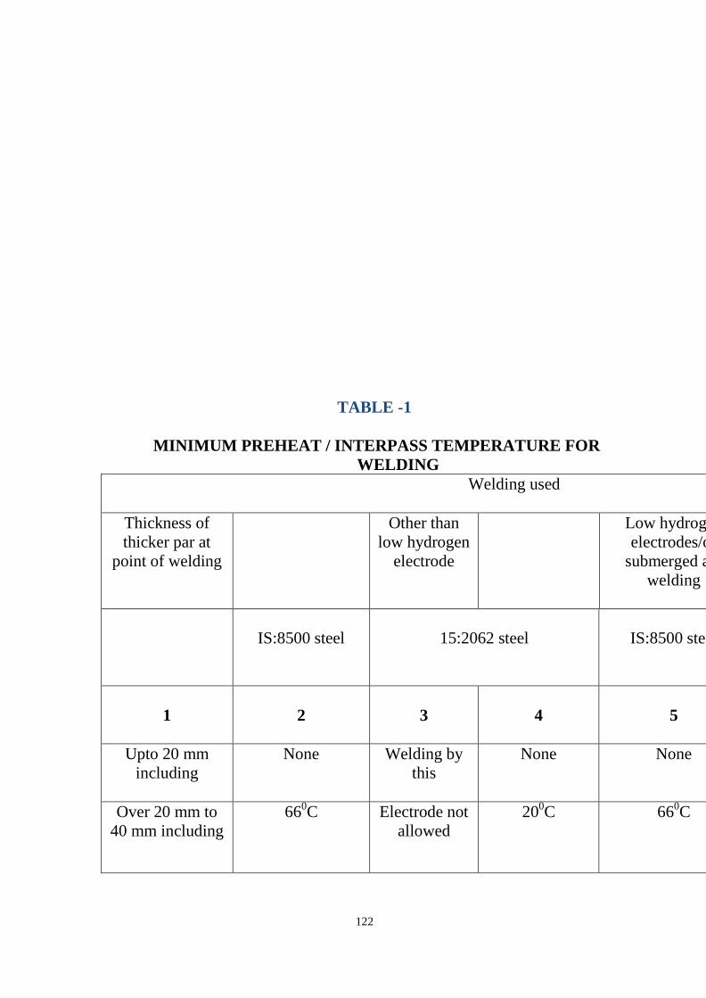
122
TABLE -1
MINIMUM PREHEAT / INTERPASS TEMPERATURE FOR WELDING
Welding used
Thickness of thicker par at
point of welding
Other than low hydrogen
electrode
Low hydrogen electrodes/or
submerged arc welding
IS:8500 steel
15:2062 steel
IS:8500 steel
1
2
3
4
5
Upto 20 mm including
None Welding by this
None None
Over 20 mm to 40 mm including
660C Electrode not allowed
200C 660C

123
Over 40 m to 63 mm including
not allowed - 660C 1100C
Over 63 mm not allowed - 1100C 1500C
Preheating may be applied by external flame which is non-
carbonizing like LPG, by electric resistance or electric
induction process such that uniform heating of the surface
extending up to a distance of four times the thickness of the
plate on either side of the welded joint is obtained.
Thermo-chalk, thermo-couple or other approved methods shall
be used for measuring the plate temperature.
All butt welders with section or plate thicker than 40 mm require post weld heat treatment as per procedure given in AWS D-1.1 Post heating shall be done up to 600 deg c and rate of heating shall be 200 deg C per hour. The post heat temperature shall be maintained for 60 minutes per 2.5 cm thickness. For maintaining slow and uniform cooling, asbestos pads shall be used for covering the heated areas. The Structural Steel Contractor shall submit and finalize post weld heat treatment procedure at the time of finalization of quality plans.
11.10 PREPARATION OF MEMBERS FOR WELDING Assembly of structural members shall be made with proper jigs
and fixtures to ensure correct positioning of members (angles, axes, nodes, etc.)
Sharp edges, rust of cut edges, notches, irregularities and
fissures due to faulty cutting shall be chipped or ground or filed over the length of the affected area, deep enough to remove faults completely.
Edge preparation for welding: i. Proper edge preparation shall be made for jointing of materials

124
before welding. The edge preparation for welding shall be carefully and accurately made so as to facilitate a good joint.
ii. Type of edge preparation shall depend on the thickness of parent materials that are to be joined. Generally no special edge preparation shall be required for members under 8 mm thick.
iii. The edge forms shall be chosen to suit the design, technology and production conditions and shall be subject to the approval of the CONSULTANT.
iv. The edge form of weldments shall be prepared either by machines or by automatic gas cutting with surface roughness of the welding area not exceeding 50%.
v. All edges cut by flame shall be ground before they are welded. vi. Edge preparation (beveling) denotes cutting so as to result in V,
X K or U seam shapes as per IS: 816. Unless otherwise noted in the drawing: ≤ 6 mm - Square Butt 8 - 11 mm - Single
V ≥ 12 mm - Double V vii. The members to be assembled shall be clean and dry on the
welding edges. Under no circumstances shall wet, greasy, rust or dirt covered parts be assembled. Joints shall be kept free from any foreign matter, likely to get into the gaps between members to be welded.
viii. Before assembly the edges to be welded as well as adjacent
areas extending for at least 20 mm shall be cleaned (until metallic polish in achieved.)
ix. When assembling members, proper care shall be taken of
welding shrinkage and distortions, as the drawing dimensions cover finished dimensions of the Structure.
x. The elements shall be got checked and approved by the
Consultant or his authorized representative before assembly. xi. The permissible Tolerances for assembly of members
preparatory to welding shall be as per IS: 816. xii. After the assembly has been checked temporary tack welding
in position shall be done by electric welding, keeping in view finished dimensions of the Structure.

125
xiii. Preheating of members to be joined to be carried out as per
standards wherever necessary. 11.11 Welding Procedures Welding shall be carried out only by fully trained and
experienced welders as tested and approved by the Consultant or his representative or the Inspectors. The cost involved for such tests shall be borne by the Structural Steel Contractor himself.
Qualification tests for Welders as well as tests for approval of
electrodes will be carried out as per IS: 816. The nature of test for performance qualification of welders shall commensurate with quality of welding required on this work as judged by the CONSULTANT.
The Steel structures shall be automatically, semi-automatically
or manually welded. Welding shall begin only after the checks shown under 8.02 have been carried out.
Welding procedures and tests for welders skill shall be
conducted as per IS : 816 and approved by the CONSULTANT. The welder shall mark his identification mark on each element welded by him.
When welding is carried out in open air, steps shall be taken to
protect the place of welding against wind or rain. The electrodes, wires and parts being welded shall be dry.
Before beginning the welding operation, each joint shall be
checked to ensure that the part to be welded are clean and root gaps provided as per IS : 816.
For continuing the welding of seam discontinued due to some
reason, the end of the discontinued seam shall be malted in order to obtain a good continuity.
Before resuming the welding operation, the groove as well as
the adjacent parts shall be well cleaned for a length of approximately 50mm.
126
For single butt welds (in V,1/2V or U) and double butt welds (in K, double U, etc) the re-welding of the root butt is mandatory but only after the metal deposition on the root has been cleaned by back gouging or chipping.
The welding seams shall be left to cool slowly. The Structural
Steel Contractor shall not be allowed to force cool the welds. For multi-layer welding, before welding the following layer,
the preceding layer shall be cleaned by light chipping and wire brushing. Backing strips shall not be allowed.
The order and method of welding shall be so that: No unacceptable deformation appears in the welded parts Due margin is provided to compensate for contraction due to
welding in order to avoid any high permanent stresses. The defects in welds must be rectified according to IS: 816 and
as per instructions of CONSULTANT. Procedure for welding of Headed Shear Studs Shear studs shall be welded in accordance with AWS D1.1,
Section 7, and the manufacturer's recommendations. Procedure for the same shall be qualified as per AWS D1-1 requirement prior to welding. Qualification of operator for stud welding shall be done in accordance with AWS D1.1
11.12 End Plate Moment Connections 11.12.1 Flange Welds Beam-flange-to-end-plate welds shall be detailed and welded
as CJP groove welds, except that in the area of the flange directly above and below the beam web, back gouging and back welding of the weld root is not required.
The groove weld detail shall be such that the root of the weld is
located on the beam web side of the joint. Following back gouging and back welding of the groove weld root, a 5/16-inch

127
reinforcing fillet weld shall be placed on the inside portion of the flange weld, at the groove root.
Alternatively, the 5/16-inch reinforcing fillet weld located on
the beam web side of the beam flanges may serve as a backing weld. The root of the fillet must then be back gouged to solid weld metal, and the groove weld placed. No backing is provided in the vicinity of the beam web.
Using either method, no MT of the back gouged area is
required prior to placement of the back weld or the groove weld.
11.12.2 Web Welds The beam web shall be welded full length to the end plate
using fillet welds on each side of the beam web. Alternatively, groove welds may be substituted for the fillet welds.
The weld detail limitations of this specification regarding the k-
area are not applicable to this connection, but MT following completion of all welds in this area is required.
a) Stiffener Welds When Bolted Stiffened End Plate (BSEP) connections are used,
the stiffener shall be welded to the end plate and the beam flange using groove welds. A stiffener clip (snipe) shall be provided at the intersection of beam flange and end plate.
b) Weld Access Hole Weld access holes are permitted at the intersection of beam
web, beam flange and end plate. c) NDT Requirements The, beam flange to end plate welds, and the welds between
stiffener and beam flange and end plate, shall be inspected using MT and UT as QC/QA Category.

128
11.13 Sequence of Welding
The sequence of welding shall be carefully chosen to ensure
that the components assembled by welding are free from
distortion and large residual stresses are not developed. The
distortion should be effectively controlled either by a counter
effect or by a counter distortion. The direction of welding
should be away from the point of restraint and towards the
point of maximum freedom.
Each case shall be carefully studied before finally following a
particular sequence of welding.
Butt weld in flange plates and/or web plates shall be completed
before the flanges and webs are welded together.
The beam and column stiffeners shall preferably be welded to
the webs before the web and flanges are assembled unless the
web and flanges are assembled by automatic welding process.
Approval of welding sequence and procedure shall not relieve
the Structural Steel Contractor of the responsibility for the
correct welding and for minimizing the distortion in the
finished structure which in no case shall exceed that laid down
in Indian Standards.
All welds shall be finished full and made with correct number
of runs, the welds being kept free from slag and other
inclusions, all adhering slag being removed from exposed faces
immediately after each run.
Current shall be appropriate for the type of electrode used. To
ensure complete fusion, the welding procedure should go
proper and rate of arc advancement should not be so rapid as to
leave the edges un-melted.

129
Pudding shall be sufficient to enable the gases to escape from
the molten metal before it solidifies.
Non-uniform heating and cooling should be avoided to ensure
that excessive stresses are not locked up resulting ultimately in
cracks.
The welding shrinkage shall be minimized by adopting the
correct welding procedure and method. In long and slender
members extra length should be provided, at the time of
fabrication, for shrinkage.
The ends of butt welds shall have full throat thickness. This
shall be obtained on all main butt welds by the use of run off
and run on pieces adequately secured on either side of main
plates. Additional metal remaining after the removal of
extension pieces shall be removed by grinding or by other
approved means and the ends and surface of the welds shall be
smoothly finished.
The fusion faces shall be carefully aligned. Angle shrinkage
shall be controlled by presenting. Correct gap and alignment
shall be maintained during the welding operation.
All main butt welds shall have complete penetration and except
where it is impracticable they shall be welded from both sides,
back surface of the weld being gauged out clean before first run
of the weld is given from the second side. However, partial
penetration butt weld shall be permitted, when specifically
shown in the fabrication drawings.
Intermittent welds shall not be permitted without the approval
of the IE & PMC. These shall be permitted only when
specifically approved in the fabrication drawings.
11.14 Testing of Welders

130
Each welder working on the project shall be assigned an identification no.
& card. Each welder shall mark or stamp this identification symbol at each weldment completed. Stamps, if used, shall be the low-stress type.
Welding personnel shall be qualified in accordance with AWS
D1.1, Section 4, Parts A and C. Welders whose work routinely exhibits poor workmanship shall be re-qualified before performing further welding.
WPSs shall be available to welders and inspectors prior to and
during the welding process. Prior to welding, joint fit-up shall be verified by the welder for conformance with the WPS and AWS D1.1.
11.15 Inspection of welds
11.15.1 Weld Inspection The weld seams shall satisfy the following: shall correspond to design shapes and dimensions shall not have any defects such as cracks, incomplete
penetration and fusion, under cuts, rough surfaces, burns, blow holes inclusion, porosity etc. beyond permissible limits.
During the welding operation and approval of finished
elements, inspections and tests shall be made as per specification.
The mechanical characteristics of the welded joints shall be as
in IS: 816.
11.15.2
Inspection of the structural works - The inspection / checking
of the structural
steel fabrication work shall be done in various stages as
mentioned herein...
Regular testing & checking of material received at site.

131
Qualification of the welders & conducting their tests.
All butt welds shall be have 100% radiographic test conducted
and the fillet welds shall be 100% ultrasonically tested.
Keeping of proper, appropriate & regular record of the day-to-
day proceedings.
Client's Authority Welds or portions of welds that fail to meet the acceptance
criteria of AWS D1.1 shall be repaired or replaced. The Contractor may request acceptance by the client of a weld discontinuity, without repair or replacement, when it can be determined that the effect of the discontinuity will not be detrimental to the performance of
the structure. The client is the final authority for acceptance of such welds.
12.0 Quality Control and Quality Assurance 12.1 Specifications The specifications and standards listed in this Section govern
the execution of Quality Control and Quality Assurance, including nondestructive testing, except as noted otherwise in this document.
12.2 Codes AWS D1.1 structural welding code-Steel 12.3 Nondestructive Testing Personnel Qualification
ASNT Recommended Practice No. SNT-TC-1A, Personnel Qualification & Certification in Nondestructive Testing, 1995
12.4 Quality Check List
This list gives minimum requirements/additional points that may be necessary to meet the requirements of the codes or the Quality Assurance Plan.
Review and understand the applicable portions of the specifications, the Contract Documents and the shop drawings

132
for the project.
Verify that all applicable welder qualifications, welding
operator qualifications and tack welder qualifications are available, current and accurate.
Require requalification of any welder, welding operator or tack
welder who has, for a period of six months, not used the process for which the person was qualified.
Verify welder identification and qualification. Verify that any
required supplemental welder qualification testing, if required for the joint, has been executed and that the welder has passed.
Verify that each welder has a unique identification mark or die
stamp to identify welds. Verify that all applicable Welding Procedure Specifications
(WPSs), with Procedure Qualification Records (PQRs) as needed, are available, current and accurate.
Verify that an approved Welding Procedure Specification
(WPS) has been provided and that each welder performing the weld has reviewed the WPS. A copy of the appropriate WPSs shall be available for each joint, although need not be present at each joint location.
Review mill test reports for all main member and designated
connection base material for compliance with the project requirements.
Verify base material identification with the approved shop
drawings and specifications. Verify the electrode, flux and shielding gas certifications for
compliance with the Contract Documents. Verify welding consumables with the approved shop drawings
and approved WPSs. Verify that electrodes are used only in the permitted positions
and within the welding parameters specified in the WPS. Verify that electrodes and fluxes are properly stored, and that
exposure limits for the welding materials are satisfied.
133
At suitable intervals, observe joint preparation, assembly practice, preheat temperatures, interpass temperatures, welding techniques, welder performance and any post weld-controlled cooling or heat treatment to ensure that the applicable requirements of the WPS and Code are satisfied.
At suitable intervals, verify proper current and voltage of the welding equipment in application of the WPS, if needed, by using a hand-held calibrated amp and volt meter. Current and voltage shall be measured near the arc with this equipment.
Inspect the work to ensure compliance with AWS D1.1 or the specified weld acceptance criteria. Size and contour of welds shall be measured with suitable gauges. A strong light, magnifiers, or other devices as needed may be used to aid visual inspection.
Schedule NDT technicians in a timely manner, after the visual inspection s complete and the assembly has cooled. The final NDT on a specific weld shall not be performed sooner than 24 hours after the welding has been completed.
Mark the welds, parts, and joints that have been inspected, and accepted, with a distinguishing mark or die stamp, or maintain records indicating the specific welds inspected by each inspector.
Document the accepted and rejected items in a written report. Transmit the report to the designated recipients in a timely manner.
Review all NDT procedure before testing. Check for level III approval on all the procedures.
Perform stage wise inspection at every stage of the fabrication like material, fit-up, weld visual, NDT, painting & coating and final inspection.
Review procedure in reference to paint spec, fire rating, green building, requirement etc for painting & coating before starting painting operation.
Coating & Painting inspection must be performed for all the painted structure.
On successful acceptance of the job Inspection agency shell give release note to the contractor.
Any Nonconformance (NC ) raised by the inspection agency shall be addressed by the contractor on priority basis.
Fabrication & Erection tolerances shall be derived from,

134
i. AWS D1.1 (Latest Revision) : Structural Welding code. ii. IS 12843 (Latest Revision) : Erection Tolerances.
iii. IS 7215 (Latest Revision) : Fabrication Tolerances. iv. AISC 303-05 : Code of Standard Practices of Steel Buildings
& Bridges.
The Client shall appoint an independent agency to conduct all
necessary tests as per approved Quality Assurance Plan (QAP)
and/or Inspection and Testing Plan (ITP) which shall typically
include material identification and testing, setup inspection,
weld visual inspection with relevant NDT method like
radiographic (RT), ultra-sonic (UT), Magnetic particle (MT),
Penetrant Test (PT) and if required for other non- destructive
tests on the structural steel during various states of work
starting from material procurement, material testing, weld test,
qualifying he welding procedure and welders, checking
fabrication and erection work and checking of fire proofing
works etc.
The specialized checking agency shall ensure that the
requirements as detailed in the relevant codes, specifications
and drawings are satisfied. Any rectification and/or
replacement of faulty material or workmanship shall be at the
Contractors expense. Remedial work shall not be carried out
without prior approval of the Engineer.
Costs of satisfactory testing shall be to the employer's expense.
Costs of re-testing areas, which are unsatisfactory, or of
extensive testing to isolate unsatisfactory areas will be charged
to the Contractor.

135
Thus, and experienced third party for checking, inspecting &
maintaining work quality of the structural steel works. The
scope of thirds party shall include right from checking &
approving material received structural steel up to checking the
painting work. Certification of the structural steel quality shall
be the responsibility of the Third part.
13.0 Inspection/Tests & Acceptance Criteria
13.1 Visual Inspection
100 percent of the welds shall be inspected visually by naked
eye or lens for external defects. Dimensions of welds shall be
checked. The lengths and size of weld shall be as per approved
fabrication drawings. It may be slightly oversized but should
not be undersized. The profile of weld is affected by the
position of the joint but it should be uniform. The welds should
have regular height and width of beads. The height and spacing
of ripples shall be uniform. The joints in the weld run shall as
far as possible be smooth and should not show any humps or
craters in the weld surface. Welds shall be free from unfilled
craters on the surface, under-cuts, slags on the surface and
visible cracks. Such inspection shall be done after cleaning the
weld surface with steel wire brushes and chisel to remove the
spatter metal, scales, slag etc. If external defects mentioned
above are noticed, there is every possibility of internal defects
and further radiographic/ultrasonic examination shall be
undertaken as per Indian Standards. Weld gauges shall be used
to measure the size of the welds.
13.2 Mechanical testing

136
Test plates shall be incorporated on either side of 10% of main
butt welds and the weld shall be continuous over the test plate.
The test plate shall be cut from extensions of the main plates
and shall be fixed so that metal lies in
the same direction as that of the main plate. Test plates shall be
prepared and tested in accordance with the accepted Standards,
in the presence of the on his authorized representative. All
testing equipment and facilities for carrying out these tests shall
be provided by the Structural Steel Contractor. Should any of
these tests fail further radiographic examination of the welds in
question on the main members, shall be undertaken. These tests
for the test plates and radiographic examination are additional
to those contemplated under routine inspection and testing. The
Structural Steel Contractor shall carry out these additional
radiographic tests as per normal testing procedure.
13.3 Non-destructive and special testing
In addition to the normal supervision and testing procedure,
radiographic / ultrasonic or other non-destructive examination
shall be carried out, as stipulated in the Fabrication/Erection
checklist on butt or fillet welded joints and / or on test
specimens, as per Table in section13.7. All test of welds shall
be carried out by the Structural Steel Contractor at his own cost
as per Annexure-A. However, for checking the quality of weld,
the Employer/ shall carry out additional tests at his own cost.
The Structural Steel Contractor shall provide necessary
supporting facilities free of cost, as may be required by the
including cordoning of radiation zone while Radiography
testing is in progress. Prepared etched section of the welds may

137
be required for examination. The Structural Steel Contractor
shall, at his own cost provide these prepared sections.
13.4 Magnetic Particle Testing If a surface discontinuity or near-surface discontinuity, within
1/8 inch of the surface, is detected, the discontinuity shall be rejected and removed. If the separation from the surface cannot be determined, the discontinuity shall be categorized as a surface flaw, rejected and removed.
Regions of welds that cannot be inspected shall be identified
and recorded, and the Engineer shall be notified. All partial penetration joints (PPJ) & fillet joints shall be
checked using MT. Procedure for MT shall be made & approved by ASNT level III personnel. MT shall be performed only by ASNT level II in MT as per SNT-TC-IA requirement. Extend of testing for PPJ & fillet weld shall be as per QAP. .
13.5 Ultrasonic Testing - Flaw Detection When ultrasonic testing is required, the joint shall be scanned
for flaw detection purposes following the procedures prescribed in AWS D1.1, Annex K, with exceptions as noted below. Joints that fail the acceptance criteria described below may be inspected using the Ultrasonic Testing - Flaw Sizing methods as prescribed in Section 13.6 of this specification, or, at the Contractor's option, may be excavated for further investigation and repaired, then re-inspected using these Flaw Detection procedures.
When ultrasonic testing is required, CJP and PJP groove welds
in Seismic Weld Demand Categories A, B and C shall be scanned for flaw detection. Acceptance criteria shall be as for statically loaded welds in Annex K, Table K-1, of AWS D1.1.

138
Commentary: As an alternative, the engineer may elect to permit CJP and PJP groove welds in Seismic Weld Demand Categories A, B and C to be scanned for flaw detection purposes using AWS D1.1, Table 6.2 as the acceptance criteria. In this case, Note 3 regarding "tension welds" is not applicable. Joints with backing bars remaining in place shall not be rejected on the basis of indication ratings (db values) from the interfaces between backing bar and base metal or backing bar and weld. The UT Procedure shall prescribe methods for distinguishing between backing bar indications and root discontinuities.
PJP groove weld joints shall not be rejected on the basis of
indication ratings (db values) from the root area of the weld. Notches within the weld, located a distance more than 1/8 inch from the as-welded root, shall be scanned for acceptance using the criteria above.
Regions of welds that cannot be inspected shall be identified
and recorded, and the Engineer shall be notified. Regions of welds adjacent to cope holes may be inspected with multiple probe techniques.
13.6 Ultrasonic Testing - Flaw Sizing Ultrasonic testing for flaw sizing shall be performed following
written procedures as required by AWS D1.1, Annex K. When flaw-sizing techniques are implemented, the following acceptance criteria apply to groove welds:
If a surface flaw or near-surface flaw (within 1/8 inch of the
surface) is detected, the flaw shall be rejected and removed. If the separation from the surface cannot be measured, the flaw shall be categorized as a surface flaw, rejected and removed.
When backing bars remain in place, the position of notch tips
that extend into the weld metal shall be determined. The notch shall be rejected if it extends greater than 1/8-inch into the thickness of the weld. The weld present between the backing bar and column face shall not be considered a part of the weld thickness in determining the depth of notch or thickness of weld.

139
Embedded flaws, defined as those that do not come within 1/8 inch of the surface, shall be rejected if their height exceeds ¼ inch.
Embedded flaws shall be rejected if their area, as calculated by
multiplying the maximum discontinuity height by the maximum discontinuity length, exceeds the thickness of the thinner parent metal multiplied by the thickness of the thicker parent metal.
Embedded flaws, either individually or as a group within a
length of weld 12 inches or less, shall be rejected if they exceed a total area (the sum of the areas of individual discontinuities) equal to 10% of the thickness of the thinner parent metal multiplied by the weld length.
The weld length used for this calculation shall not exceed 12
inches, with longer welds being evaluated in multiple parts. Aligned discontinuities of lengths L1 and L2 separated by less
than (L1 +L2)/2 shall be evaluated as continuous.
Parallel discontinuities of heights H1 and H2 separated by less than (H1 +H2)/2 shall be evaluated as continuous.
All full penetration joints (FPJ) shall be checked using UT.
Procedure for UT shall be made & approved by ASNT Level III personnel. UT shall be performed only by ASNT Level II in UT as per SNT-TC-1A requirement. Extend of testing for FPJ shall be as per approved QAP.
In case of failure of any of the tests, the cost of re-test of the
potion shall be recovered from the Structural Steel Contractor,
Rectification of such components shall also be carried out by
the Structural Steel Contractor at his own cost.
Rectification of defective welding work wherever defects like
improper penetration, presence of blow holes, undercuts,
cracking, slag inclusion, etc. 'are noticed by visual
inspection/other tests, the welds, in such location shall be

140
removed by gouging process. The joints shall be prepared
again by cleaning the burrs and residual matters with wire
bushes and grinding, if necessary, and re-welded. The gouging
shall as far as possible be done using gouging electrodes.
Flame gouging shall be resorted to only in special cases with
specific permission of the EIC.
13.7 Quality assurance Plan (QAP) A QAP sheet is attached which lays down plan and extent for
various tests to be carried out and to be followed in absence of any separate instruction by client/Consultant. However, the frequency of each test shall be as finalized by the Third Party appointed for testing, in consultation with the structural Consultant.
13.8 Special testing/Inspection
In addition to tests/Inspection on welding, following
tests/inspection shall be carried out:
Foundation bolt testing.
Column verticality per lift.
Column verticality from bottom to top.
Column displacement from reference building reference.
Line Gap between the matting surface.
Alignment of column.
Lift Level of beams.
Alignment of beams.
Fastener testing.
Bolting test (preloaded or non-preloaded connection).
Quality Deck sheet MTC verification.
Visual inspection of decks sheet to confirm the size, thickness
and shape Stud MTC verification.

141
Visual inspection of stud to confirm the size, thickness and
shape Stud welding qualification as per actual site welding
condition Checking of first two stud every day for weld quality.
Final paint inspection to confirm 'Dft' or any special
requirement.
14.0 ACCEPTANCE OF WELDED STRUCTURES
The acceptance of the welded work shall depend upon correct
dimensions and alignment, absence of distortion in the
structure, satisfactory results from the inspection and testing of
the joints and the test specimens as per quality check list and
upon general workmanship being good, meeting the tolerance
list & requirements given in the quality check list as per
Annexure - A, as Typical Welding Procedure Data Sheet,
attached at the end of this document.
14.1 Dimensional Tolerances for Structural Work
Dimensions shall be measured by means of an approved
calibrated steel tape of same temperature as the structure at the
time of measurement. An allowable variation of 1 mm is
permissible in the overall length of members with both
ends milled. Members without milled ends, which are to be
assembled to other steel parts of the structures, shall not deviate
from the dimensions shown on the drawings by more than 1.8
mm for members 10 meters or less in length, and by not more
than 3 mm for members over 10 meters in length.
The erection clearance for cleared ends of members connecting
steel to steel should preferably be not greater than 2.0 mm at
each end. The erection clearance at ends of beams without web
cleats should be not more than 3 mm at each end, but where,

142
for practicable reasons, greater clearance is necessary, suitably
designed seating should be provided.
15.0 PACKING AND DELIVERY
15.1
After final shop acceptance and marking, the item shall be
packed and loaded for transportation. Packing must be
adequate to protect items against warping during loading and
unloading and should have slinging marks.
Proper lifting devices shall be used for loading, in order to
protect items against warping.
Slender projecting parts shall be braced with additional steel
bars before loading for protection against warping during
transportation.
Items must be carefully loaded on platforms for transportation
with adequate means to prevent warping, bending or falling
during transportation. Small parts such as fish plates, gussets
etc. shall be securely tied with wire to their respective parts.
Bolts, nuts and washers shall be packed and transported in
crates or bags.
The parts shall be delivered in the order stipulated by the
CONSULTANT and shall be accompanied by documents
showing:
Quality and quantity of structure of members
Position of member in the structure
Particulars of structure
Identification number / job symbol
16.0 Marking of identification
All elements and members prior to dispatch for erection shall
143
be shop marked.
ii) The size and thickness of the numbers shall be so chosen as
to facilitate the identification of members.
For the small members that are delivered in bundles or crates,
the required marking shall be done on small metal tags securely
tied to the handle, while the crates shall be marked directly.
Each bundle or crate shall be packed with members for one and
the same assembly. In the same bundle or crate, general utility
members such as bolts, gussets etc. may be packed.
All bills of materials showing weight, quality and dimension of
contents shall be placed in the crates.
The members shall be marked with a durable paint, in a visible
location, preferably at one end of the member so that these may
be easily checked during storage and erection.
The members shall be marked in the shop before inspection
and acceptance.
17.0 TRANSPORT, HANDLING AND STORAGE
Steel shall be handled and transported with care, and in such a
manner that parts will not suffer strain, distortion or abrasion.
The Engineer shall reject distorted or damaged steelwork. All
steel shall be stored above the ground by supported on timber.
Lifting and handling of all steel, whether painted or not shall be
done with synthetic webbing flat slings or bagged chains. All
slings shall comply with the local work place, health and safety
acts.
Warehouse In charge is responsible for delivering all materials
and documentation to the job site in good condition.
144
Under no circumstances shall unprotected chains be used for
lifting steel.
Paintwork damaged during transport and erection shall be
rectified as specified in the Surface Treatment Section of the
Specification.
All material and documentation will be inspected immediately
upon receipt by buyer. All bolts, washers & nuts shall be
packaged and delivered in rigid, weatherproof container.
Loading and transportation shall be done in compliance with
transportation rules. If certain parts cannot be transported in the
lengths stipulated in the Design, the position and type of
additional splice joints shall be approved by CONSULTANT.
17.1 Protection against Damage in Transit
All steel work shall be efficiently and sufficiently protected
against damage in transit to site from any cause whatsoever.
All projecting plates or bars and ends of members at joints shall
be stiffened, all straight bars and plates shall be bundled, all
screwed ends and machined surfaces shall be suitably packed
and all bolts, nuts, washer and small loose parts shall be packed
separately in cases so as to prevent damage or distortion during
transit. Should there be any distortion of fabricated members
the Structural steel Contractor shall immediately report the
matter to the CONSULTANT. Distorted steel received from
stores or distorted during transport from stores to the
fabrication yard shall not be used in fabrication unless the
distortions are minor which in the opinion of the
CONSULTANT can be removed by acceptable methods.
These distortions shall be rectified by the Structural steel
Contractor by cold bending. If heating is necessary to rectify
145
the defects, the details of the procedure shall be intimated to
the CONSULTANT whose approval shall be taken before such
rectification.
The temperature of heat treatment shall not exceed the limits
beyond which the original properties of the steel are likely to
be impaired.
If in the opinion of the CONSULTANT the steel has been
unduly bent in transit from the project stores to the fabrication
yard or during handling by the Structural Steel Contractor
which cannot be rectified, such steel shall be counted as
wastage and the cost of such steel shall be recovered from the
Structural Steel Contractor as per the provisions of the contract.
18.0 Erection 18.1 General Structural steel shall be erected in accordance with the IS-800. Where erection requires performing fabrication work on site,
the work shall conform to the applicable standards of Section 3.1, Fabrication.
The Contractor shall cooperate fully with requests from
inspection and testing personnel for access to the connections and joints to be inspected or tested. This includes weld backing removal when non-destructive testing indicates reject able conditions, and access to platforms or scaffolding as required to perform the work safely. When such services are required, the inspection must be performed in a timely manner so as not to hinder production nor require duplication of effort.
The Contractor shall perform all necessary corrections of
deficiencies in material and workmanship. The Contractor shall

146
comply with requests to correct deficiencies, when such corrections are required by the Inspection Agency. The Inspection Agency Technician should be apprised of any repairs to be made by the Contractor, prior to performance.
SCOPE OF WORK The scope of work under erection includes, but not limited to,
the following: Supply of tools and tackles, consumables, materials, labour and
supervision for erection.
Storing and stacking of all fabricated structural components/units/assemblies at site storage yards till the time of erection. The contractor must undertake the enabling works for transportation of fabricated structures, man and machine.
Transportation of structures from storage yard to site of erection, including multiple handling, if required.
Execution of all minor rectification/modifications.
Rectification of bends, kinks, twists etc. for parts damaged during transportation and handling.
Reaming of holes which do not register, or which are damaged, for use of next higher size bolt.
Plug-welding and re-drilling of holes which do not register, and which cannot be reamed for use of next higher size bolt.
Drilling of holes which are either not drilled at all or are drilled in incorrect position during fabrication.
Fabrication of minor missing items as directed by the purchaser.
Verification of the position of embedded anchor bolts
Assembly at site of steel structural components wherever required, including temporary supports and staging.
Making arrangements and bearing costs for providing all facilities for conducting ultrasonic, X-ray or gamma ray tests of

147
welds; getting the tests carried out at reputed testing laboratories making available test films/graphs, reports and interpretation.
Rectification at site damaged portions of shop primer by cleaning and application of primer and touch-up paint.
Erection of structures including making connections by bolts/High strength bolts/welding as per drawing.
Alignment of all structures true to line, level plumb and dimensions within specified limits of tolerance.
Grouting of the gap between base plate and top of foundation with concrete of approved quality and specification after total alignment.
Application at site after erection, required number of coats of primer and finishing paint as per specification and drawing.
Rectification of structures as per Preliminary acceptance report and Final acceptance report.
Cleaning of all structural scraps or other materials accumulated during the course of construction.
The suitability and capacity of all plant and equipment used for
erection shall be to the satisfaction of the Structural Consultant.
Details of the proposed equipment shall be submitted for
approval 6 weeks prior to erection commencing.
18.2 Plant, Machines & equipment’s deployed during handling
of Erection;
The suitability and capacity of all plant and equipment used for
erection shall be to the satisfaction of the Structural Consultant.
Details of the proposed equipment shall be submitted for
approval 6 weeks prior to erection commencing.
148
18.3 ERECTION PROCEDURE
18.3.1 Erection Marks
The erect ability of the structures shall be checked by the
Structural Steel Contractor before commencement of the
fabrication work to avoid future modification.
Before any steel work leaves the Structural Steel Contractor's
fabrication site, it shall be suitably marked in accordance with
the approved fabrication drawings and according to an
approved marking plan.
The erection marks assigned to various components of the
structural steel work, excepting secondary beams, shall also
contain an erection sequence number indicating the sequence in
which the various components are to be erected.
Erection marks shall be clearly painted on the work item, each
piece being marked in at least two places. Each piece shall also
have its weight marked thereon. In order to help identification,
each erection piece, i.e. erection mark item, shall bear its
erection mark and erection sequence number. Erection marks
shall be painted on the structures, during the process of
fabrication to facilitate their identification during inspection.
Where a number of components are identical and bear the same
erection mark, these components shall be further identified by
assigning numerals in addition to the common erection mark.
Fabrication sections shall be suitably marked on the sections
with the utmost care to ensure proper alignment and assembly
of the pieces at site.

149
18.3.2 Erection scheme
Considering the complexity of the structure it may be
necessary to assemble one or two frames at site before actual
erection in situ is undertaken. Hence the contractor shall make
necessary provisions at site for such mock-up assembly.
The Structural Steel Contractor shall submit for approval of the
CONSULTANT his Erection Scheme for the erection of all
types of structures. Erection shall commence only after
approval of the Structural Steel Contractor's proposed erection
scheme.
The erection scheme shall give full details of the method of
handling, transport, hoisting and erection including false
work/staging, temporary bracing, guying, temporary
strengthening, etc. It will also give the complete details of the
quantity and capacity of the various items of erection
equipment that will be used. Any modifications to the erection
scheme as directed by the CONSULTANT for various reasons
or due to the interference with the work of other agencies shall
be incorporated by the Structural Steel Contractor.
The Structural Steel Contractor shall examine the site
conditions and transportation clearances before deciding
whether columns are to be fabricated and erected in one piece
or more than one piece. Erection of structures is to be carried
out preferably with a crane and in case this is not possible, only
the upper portion of the columns can be erected with a derrick.
Further, the erection of columns and portals etc. shall be
carried out in one single piece as far as practicable. No column
shall be fabricated and erected in more than 3 pieces. Proper

150
splicing shall be provided at the erection joints indicated in
fabrication drawings. When erection joints are provided in
columns, their location shall generally be just above a floor
level.
The structural steel shall as far as practicable be erected frame
wise. Thereafter, the frames shall be progressively aligned, and
all erection welding completed. The secondary beams shall
thereafter be erected, aligned and welded completely as per the
approved schedule of work. Touch up painting in these areas
shall be completed and as soon as particular portion of the
structure / floor is completed in all respects, it shall be handed
over to other Structural Steel Contractors for carrying out other
civil works as well as mechanical/electrical erection works.
Conveyor galleries shall generally be erected as a completely
fabricated box, i.e. the bottom chord and bracings, top chord
and bracings, side vertical posts and bracings, and portals and
roof-trusses shall be completely welded prior to erection. The
inside sheeting runners and roof sheeting perlins may be
erected individually.
18.4 Storage and Preparation of Parts prior to erection:
The storage place for Steel Parts shall be prepared in advance
and got approved by the CONSULTANT before the Steel
structures start arriving from the shop.
A platform shall be provided by the Structural steel Contractor
near the Erection Site for preliminary Erection work.
The Structural steel Contractor shall make the following
verifications upon receipt of material at site.
a) For Quality Certificate regarding Materials and Workmanship
according to these general Specifications and Drawings.

151
Whether parts received are complete without defects due to
transportation, loading and unloading and defects, if any, are
well within the admissible limit.
For the above work sufficient space must be allotted in the
storage area.
Steps shall be taken to prevent warping of item during
unloading.
The parts shall be unloaded, sorted and stored so as to be easily
identifiable.
The parts shall be stored according to construction symbol and
markings so that these may be taken out in order of Erection.
The parts shall be set at least 150 m clear from ground on
wooden or steel blocks for protection against direct contact
with ground and to permit drainage of water.
If rectification of members like straightening etc. are required,
these shall be done in a special place allotted which shall be
adequately equipped.
The parts shall be clean when delivered for Erection.
18.5 Erection Tolerances
Erection in general shall be carried out as required and
approved by the CONSULTANT.
Positioning and leveling of the structure, alignment and
plumbing of the Stanchion and fixing every member of the
structure shall be in accordance with the relevant drawings and
to the complete satisfaction of the CONSULTANT.
The following checks and inspection shall be carried out
before, during and after Erection.
- Damages during transportation.
- Accuracy of alignment of Structures

152
- Erection according to Drawings and Specifications.
- Progress and workmanship
In case there be any deviations regarding positions of
foundations, or anchor bolts, which would lead to erection
deviations, the CONSULTANT shall be informed immediately.
Minor rectifications in foundations, orientation of bolt holes
etc. shall be carried out as a part of the work, at no extra cost.
For further details/ permissible limits on tolerances refer Table
–A .
18.6 Setting out
The positioning and leveling of all steel work with accuracy
shall be in accordance with the approved Drawings,
Specifications and to the satisfaction of the Structural
Consultant.
The various parts of the Steel Structure shall be so erected as to
ensure stability against inherent weight, wind and Erection
stresses.
The structure shall be anchored and final erection joints
completed after plan and elevation positions of the Structural
members have been verified with corresponding drawings and
approved by the CONSULTANT.
The bolted joints shall be tightened so that the entire surface of
the bolt heads and nuts shall rest on the member. For parts with
sloping surfaces, taper washers shall be used.
Site painting after erection, if required, shall be as per
Structural Consultants advice and as per the instructions /

153
guidelines of the Third party.
18.7 Stability of Structures during erection
The Structural steel Contractor shall be responsible for the stability of the structure at all stages of its erection at site and shall take all necessary measures by the additions of temporary bracings and guying to ensure adequate resistance to wind and also to loads due to erection equipment and their operations. Guying and bracing shall be done in such a way that they do not interfere with the movement or working of other agencies working in the area. For the purpose of guying, the Structural steel Contractor shall not use other structures in the vicinity which are likely to be damaged by the guy rope.
Temporary Shoring and Bracing Contractor's erection scheme
and temporary bracing and shoring shall provide lateral support
and stability for all columns until permanent lateral- support
systems (for example: wind bracing bents and horizontal
deck/slab diaphragms) are in place and complete. Provide
temporary snoring and bracing members in vertical and
horizontal planes as required, with connections of enough
strength to bear the imposed loads. Remove temporary
members and connections when permanent support systems are
in place and final connections are made.
Setting Column Bases
Column bases shall be set so that the column load is uniformly
transmitted to the foundation. The Structural steel Contractor
shall carefully check the location and layout of anchor bolts
embedded in foundations constructed to ensure that the
structures can be properly erected as shown on the drawings.
The Structural steel Contractor shall be responsible for the
correct alignment and leveling of all steel work on site to
ensure that the columns are in plumb. The permissible erection

154
tolerances for the structural members are given in Table A -6 at
the end of this section.
Before erection of columns on their foundations, the top
surface of base concrete shall be thoroughly cleaned with wire
brushes and by chipping to remove all laitance and loose
material. The Structural steel Contractor shall also be
responsible to provide all packing and shim, plates. No steel
structure shall be erected on their foundation unless such
foundations have been certified fit for erection of steel by the
CONSULTANT. Adequate number of air release holes and
inspection holes shall be provided in the base plate. The
grouting/under pinning of base plate and chipping of
foundation to desired level are also in scope of Structural steel
Contractor.
18.8 Final Acceptance and Handling Over of Structure
At acceptance, the Structural steel Contractor shall submit the
following Documents
Shop and Erection Drawings - either in tracings or
reproducible.
Copies each of the following.
i. Shop acceptance documents.
ii. Quality Certificates for Structural, Plates, electrodes, welding
wire, bolts, nuts, washers etc.
iii. List of Certified Welders, who worked on Erection of
Structure. (With documents or qualification tests)
iv. Acceptance and Intermediate Control Procedure of Erection
Operations.

155
Approval by the CONSULTANT at any stage of work does not
relieve the Structural Steel Contractor of any of his required
guarantees of the contract.
18.9 Erection for Embedded Parts
During erection, the Structural Steel Contractor shall provide
necessary strong temporary bracings and supports to ensure
proper installation of the embedded parts which shall be
erected at the true locations as shown on the drawings and
these shall be in plumb and level (unless otherwise shown on
drawings). The Structural Steel Contractor shall furnish the
CONSULTANT with fabrication and assembly drawings
prepared for embedded steel parts showing the erection
procedure, for major items, wherever necessary.
Fabrication and erection shall be carried out as per IS:800.
Welding rods and site / field welding shall conform to IS : 816.
18.10 Fabrication for Foundation Bolt Assembly
During erection, the Structural Steel Contractor shall provide
necessary template, temporary bracings, supports, etc. to ensure
proper positioning of the assemblies and holding them firmly
until they are cast / grouted and the grouted has set. All
materials shall be erected in plump and in level (unless
otherwise specified) and at true locations as shown on the
drawings. Threads shall be protected by using PVC taps.
Fabrication and erection shall be carried out as per IS : 800.
Welding shall conform to IS: 816 and IS : 9595.
18.11 FIXING OF CHEQUERED PLATE

156
Chequered plates shall be fixed to supporting members by
stitch welding as specified in relevant drawings or as directed
by the CONSULTANT. The edges shall be made smooth and
no burrs or jagged ends shall be left. While splicing care should
be taken so that there is continuity in pattern between the two
potions. Care should also be taken to avoid distortion of the
plate while welding of stiffening angles / vertical stiffening
ribs. Surfaces shall be provided with primer paint as approved.
18.12 Field Connections
All field assembly and welding shall be executed in accordance
with the requirements for shop fabrication, excepting such as
manifestly apply to shop conditions only. Where the steel has
been delivered painted, the paint shall be removed before field
welding, for a distance of at least 50 mm on either side of the
joints.
19.0 SAFE WORKING
The Structural Steel contractor shall strictly follow, at all stages
of fabrication, transportation and erection of steel structures,
the stipulations contained in the Indian Standard Safety Code
for erection of Structural steel work as per IS:7205 and
provision of the safety rules as specified in the General
conditions of the contract for ensuring safety of men and
materials.
19.1 Safety during handling and erection
During erection, the steel work shall be securely bolted or
otherwise fastened and, where necessary, temporarily bracing

157
provided for all load to be carried by the structure during
erection including those due to erection equipment and its
operation. No permanent bolting or welding should be done
until proper alignment has been obtained.
19.2 Storing and Handling
All structural steel should be so stored and handled at the site
that the members are not subjected to excessive stresses and
damage.
19.3 Setting out
The positioning and leveling of all steel work with accuracy
shall be in accordance with the specified safety norms,
approved Drawings, Specifications and to the satisfaction of
the Structural Consultant.
19.4 Platform for working and inspection: -
The contractor shall make all necessary arrangements in form
of a suitable platform in wooden plank of steel plate as the case
may be, supported by steel scaffolding and side railing up to
adequate height. The platform shall strong & sturdy and shall
be used by the workers and the engineers for movement & day-
to-day inspection till satisfactory encasing work is complete.
This shall include proper approach and working platform
during erection of the structures.
19.5 ERECTION OF EMBEDDED PARTS
General Requirements
Embedded steel parts supplied, fabricated and erected by the
Structural Steel Contractor shall include items such as, but not
limited to, foundation grillages, anchor bolts, pipe sleeves,
equipment mounting plates, steel pieces properly welded with

158
necessary lugs as shown on the drawings, auxiliary framing for
equipment supports, pasty plugs for door and window frames,
dowel bars for concrete work, miscellaneous frames, etc.
Embedded steel parts supplied, fabricated / erected by the
Structural Steel Contractor shall also include item such as but
not limited to plate inserts, edge protection angles, rolled
sections with or without properly welded lugs.
Cold work deformed steel bars shall not be used for lugs.
19.6 FINISHING
All steel work shall be thoroughly cleaned, by effective means, of all loose mill scale, rust, grease and foreign matter and shall be treated in the workshop prior to transportation. If painted it shall be applied to dry surfaces and shall be thoroughly and evenly spread and well-worked into joints and open spaces. Abrasions in field erection shall be touched up (including primer) immediately after erection.
Steel plate and protection angles required for the protection of
concrete work shall be erected true to line and grade within the tolerances specified below. The edges of exposed faces may have a vertical or horizontal distortion from a straight line not greater than 3 mm per meter of length, provided, that distortion for any single piece shall not exceed 1 mm and provided, that when the warp is greater than 1.6 mm an extra anchor hole shall be drilled near the proper corner and the piece drawn into position thereby. All bolt heads on the exposed face shall be countersunk and fitted or ground so that the heads are flush with the finished surface. Joints between abutting sections shall be square and flush and the butting ends shall be sawed or otherwise made smooth and regular.
20.0 SEALING
All tubular, square and rectangular hollow sections shall be welded so as to completely seal the internal sections against air and moisture. All ends will be fully welded into adjacent members or capped with 6 mm end plates as applicable. To

159
ensure this condition is met, the Structural Consultant may require the Contractor to carry out pressure tests on internal sections of any part of the structures, at the Structural Consultant's discretion and Employers cost. The Contractor at his cost will rectify any defective areas found by such test.
21.0 GROUTING
Unless otherwise stated on the Drawings a space of not less than 25mm shall be provided between undersides of column base plates and between all beam and roof truss bearings, and concrete pads, footings etc.
After steel work has been wedged up to line and level fixed in position, the space between steelwork and concrete shall be grouted with a mixture of Portland cement and approved commercial grit or washed sand. The mix shall be of equal proportion by volume of cement and sand (or grit) mixed with just sufficient water to form a mixture of "damp earth" consistency and shall be used within 20 minutes. The grouting mix shall be rammed to approval into the space between steelwork and concrete and protected from damage until it sets.
22.0 STEEL GRATING
All grating units shall be rectangular in pattern and welded grating assembly. The size and the spacing of the bearing bars and cross bars shall be as approved in detailed drawings. The detail fabrication drawings for gratings shall be prepared by Structural Steel Contractor on the basis of approved design for grating.
The Gratings shall be made up in panel units designed to coincide with the span of the structural steel framing as indicated in the drawings or as directed by the CONSULTANT. The size of each panel shall be as approved by CONSULTANT.
The grating unit shall be accurately fabricated and finished, free from warps twists or any defects that would impair their strength, serviceability and appearance.
Grating work shall include cut outs and clearance for opening for all columns, pipes, ducts, conduits or any other installation

160
penetrating through the grating work. The gratings shall be notched, trimmed and neatly finished
around flanges and webs of the columns, moment connections, cap plates and such other components of the steel structures encountered during the placement of the gratings. In all such cases, the trimming shall be done to follow the profile of the components encountered. After trimming, binding strip shall be provided on the grating to suit the profile so obtained.
Opening in gratings for pipes or ducts that are 150 mm in size or diameter or larger shall be provided with steel bar toe plates of not less than 5 mm thickness and appropriate width, set flush with the bottom of the bearing bars.
Penetrations in gratings that are more than 50 mm but less than 150 mm in size or diameter shall be welded with plates of size shown in the detailed drawings set flush with the bottom of the grating panel.
Unless otherwise indicated on the drawings, grating units around all penetrations shall be made up in split section, accurately fitted and neatly finished to provide for proper assembly and erection at the job site.
Grating units shall be provided with all necessary clips, bolts, nuts and lock washers required for proper assembly, rigid installation and fixing to abutting units and supporting structural steel framing members.
All fabricated grating section and accessories shall be marked for its identification prior to erection at site. Painting shall consist of two coats of red lead primer and two coat of black enamel finish or as specified.
Prior to painting, all surfaces shall be cleaned free from rust, mill scale, grease, oil, or any other foreign matter that might affect the adherence of the paint by sand blasting. While the primer shall be applied by spray guns or by brushes, the final coat of finished paint shall necessarily be applied by means of spray guns only.
The applied coatings shall be uniform, free from voids and streaks, Drilled or punched holes shall be touched up prior to erection or assembly.

161
Maximum deviation in linear dimension from the approved
dimension shall not exceed 12 mm.
ANNEXURE A - TYPICAL WELDING PROCEDURE DATA SHEET.
Structural Steel contractor ............. ...Address ................... ....................
Quality of weld ……………………………….Specification ...
................................
Material Specification ... ………………..Thickness ...
............................ …..……….Batch/
Cast No ............... Joint preparation (Fig)
.....................................................
Gap Location of Specimens .......................................................
Whether condition ................ Type of
Day..................................................
Wind break used ....................................................................................
Electrode Group No . Make ................... Specimen
..................................
Pre and Post Heating
..................................... ...............................................................
..
Welding position ......................................... ...........................................
Size of reinforcement ........... Whether removed
........................................
Welding Sequence ... ............................................. ................................
Backing strip used ... ............ Type .......................... ..............................
Welding process
......................................................................................................
.....
Current conditions Polarity ............................................ .......................

162
Size of electrode ......................................................... ...........................
Amperage and voltage .................................................... ......................
Number of Electrodes used per run
................................................................................
Cleaning method ......................................... ...........................................
Remarks
......... ...........................................................................................
...
WELDING ENGINEERE Employer/ CONSULTANT (Inspecting Authority) Sign For
and behalf of Structural Steel Contractor.
163
Annexure -B Fire Protection FOR Exposed Structural Steelwork
1. The fire proofing system for structural steelwork shall
be…………….
2. The Coating Thickness shall be designed to provide minimum
4/3 hours of fire protection to Structural Steel Members when
tested in accordance with BS 476 Part 20/21 or UL 263, ASTM
E119 Standards.
3. Coating can be applied on non-primed steel surfaces and are
non-corrosive in nature. However, in case the steel is to be
exposed for a considerably long period of time an alkyd free
primer preferably a 2 Pack Epoxy Primer of 50 - 75 microns
can be applied.
4. Surface Preparation: The steel support structure must be free of
all loose rust, mill scale, dirt or any other material likely to
impair the adhesion of the fire resistive coating / SFRM.
Surface cleaning shall be in accordance to manufacturer's
guidelines.
5. The Fire Protection System shall be spray applied in
accordance with the manufacturer's guideline.
6. All Clips hangers, supports, sleeves and other attachments to
the steel substrate must be applied prior to application of the
coating.
7. Ducts, piping, conduit and suspended equipment are to be
installed after the application of the coating.
8. Fire Protection Coating cannot be applied to roof decking until
all works above have been completed and that it also cannot be
applied until concrete has been placed on a floor deck.
9. A Topcoat is not required for any non-exposed structures

164
covered with cladding or a false ceiling. However wherever
exposed for aesthetic reasons the Vermiculite cement can be
top coated with one coat of a water based acrylic emulsion.
10. The Gypsum/Vermiculite/cementitious Coating material shall
bear the Underwriters Laboratory (UL)/BS476 marking/label
on the packaging to ensure product manufactured follows
certification requirements.
11. The application of the Vermiculite Fire Protection System
must be done by Applicators trained and certified by
manufacturer to ensure correct application technique and
quality assurance.
12. Fire coating System manufacturer will provide conformance
certificate, system details, calculated thickness chart and
compatibility letter of the primer (if used) with the coating to
ensure the Integrity of the system.
TABLE - A.1
TOLERANCES OF ASSEMBLED COMPONENTS OF STRUCTURES
S. No.
Characteristic Deviation / Tolerances in mm
1.5m &
Below
1.5m &
2.5m
2.5m to
4.5m
4.5m to
9.0m
9m to
15m
15m &
Above
1 2 3 4 5 6 7 8
1 a Deviation in length and width of part cut out by
(i) Manual gas cutting
2.5 3.0 3.5 4.0 4.0 4.0
(ii) Gas cutting by automatic and 1.5 2.0 2.5 3.0 3.0 3.0

165
semi automatic machines
(iii) Shear or saw cutting
1.5 2.0 2.5 3.0 3.0 3.0
(iv) Parts machined by edge-planning or milling machines
0.5 1.0 1.5 2.0 2.0 2.0
b Difference in diagonal lengths of sheet parts:
i) For butt welding
4.0 4.0 4.0 5.0 5.0 5.0
ii) For lap welding
5.0 5.0 5.0 5.0 5.0 5.0
c Deviation in distances between hole centres, form as per:
i) Marking of extreme holes
1.5 1.5 1.5 1.5 1.5 1.5
ii) Marking of adjacent holes 1.5 1.5 1.5 1.5 1.5 1.5
2 Deviation in the dimension of structural dispatch members after finishing:
a) When assembled upon assembly
benches as per marking.
3.0 4.0 5.0 7.0 7.0 7.0
b) When assembled in the jig and other devices fastening with fixtures.
2.0 2.0 3.0 3.0 3.0 3.0
c) Dimensions (length and breadth) between milled surface (after finishing)
0.5 1.0 1.5 2.0 2.0 2.0

166
TABLE-A.2
TOLERANCES IN FABRICATED COMPONENTS S.No. Characteristic
Deviation/Tolerance
Remarks
1.
Curvature of assembly Parts
a) a) a) Gap between a sheet and
a steel rule face over 1 m length
1.5mm
b) b) Gap between a taut
string and vertex face of an angle flange or web of channel and joist.
0.001 L,
but not greater than 10 mm.
L-length of member
2.
Deviation of edge line steel sheet parts from theoretical profile:
a) During butt and toe welding
1.5mm
b) During lap welding
3 mm
3.
Deviation of radius of the bend:
a) a) Clearance between template and the surface of rolled sheet flange or face of cold bend profile.
1.5 mm
Template length (1.5m long the
curve)
b) -do- for hot bend profile
2mm
-do-

167
4. Deformation of dispatch members:
a) Inclination of flanges with the web:
i) at junction 0.005b
b-width of flange
ii) at other places
0.01 b
-do-
b) transverse bending of flanges:
i) at junction with members
0.005 b
b-width of flange
ii) at other places
0.01 b
-do-
c) Warping of the web
0.003
h-depth of the member
d) Sag of member
L/750 but not more
L-length of member
3.0mm
1/1500
than 10 mm
the member
5. Other deviations:
a) Shifting of axes of riveting/bolting lines for

168
lattice structures from theoretical eccentricity.
b) Inclination of the milled surface from designed position.
TABLE - A.3
ACCEPTABLE TOLERANCES FOR GENERAL STRUCTURES SUCH AS COLUMNS, BEAMS, TRUSSES ETC.
Sr. No.
Characteristic
Deviation/Tolerance
1. COLUMNS
a) a) Deviation in length 'L measured distance from bottom surface of the column footings, to the group of holes for 'trusses', fasteners, collar beams, purlins and other elements to be connected to column.
When L is under 10 m
± 10 mm
When L is over 10 m
± 15 mm
b) b) Deviation is distance 'L' from bottom surface of the column footing to the top of crane bracket.
When L is under 10 m
± 5mm
When L is over 10 m
± 10 mm
c) c) Deviation in distance from bearing surface of ± 1mm
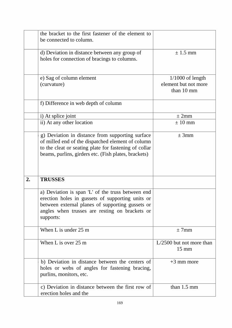
169
the bracket to the first fastener of the element to be connected to column.
d) Deviation in distance between any group of
holes for connection of bracings to columns.
± 1.5 mm
e) Sag of column element (curvature)
1/1000 of length element but not more
than 10 mm
f) Difference in web depth of column
i) At splice joint ± 2mm ii) At any other location
± 10 mm
g) g) Deviation in distance from supporting surface
of milled end of the dispatched element of column to the cleat or seating plate for fastening of collar beams, purlins, girders etc. (Fish plates, brackets)
± 3mm
2. TRUSSES
a) a) Deviation is span 'L' of the truss between end erection holes in gussets of supporting units or between external planes of supporting gussets or angles when trusses are resting on brackets or supports:
When L is under 25 m
± 7mm
When L is over 25 m
L/2500 but not more than 15 mm
b) b) Deviation in distance between the centers of
holes or webs of angles for fastening bracing, purlins, monitors, etc.
+3 mm more
b) c) Deviation in distance between the first row of erection holes and the
than 1.5 mm

170
c) d) Distance between holes for fasteners to top and
bottom chords of trusses on supports.
+3mm
e) Sag of separate elements between node points 1/1500 of length of element But not more than
10 mm
3.
BEAMS
a) a)a) Deviation in span L of beams between bend
erection holes, outer surfaces of end plates:
When L is under 25 m + 10 mm
When L is over 25 m
+ 1/2500 length but not more than 15 mm
b) b) Deviation in the height of beam as measured
from the bearing surface to the top of upper flange.
+3 mm
c) c) Deviation in distance between the group of holes for fastening of purlins, monitors, bracings, bracing grids etc.
+3 mm
d) Sag (curvature) of the girder dispatch member
1/1000 length but not more than 15 mm
4.
ELEMENTS OF FRAMEWORK BRACING, PURLINS ETC.
a) Deviation in distance between end
erection holes, determining span of element.
± 3mm
b) Sag of dispatch members
1/1000 length but not more than 15 mm
c) Deviation in distance between the groups of ± 3mm
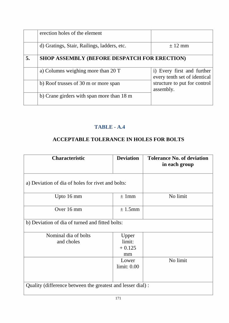
171
erection holes of the element
d) Gratings, Stair, Railings, ladders, etc.
± 12 mm
5.
SHOP ASSEMBLY (BEFORE DESPATCH FOR ERECTION)
a) Columns weighing more than 20 T
i) Every first and further every tenth set of identical structure to put for control assembly.
b) Roof trusses of 30 m or more span
b) Crane girders with span more than 18 m
TABLE - A.4
ACCEPTABLE TOLERANCE IN HOLES FOR BOLTS
Characteristic
Deviation
Tolerance No. of deviation in each group
a) Deviation of dia of holes for rivet and bolts:
Upto 16 mm ± 1mm No limit
Over 16 mm
± 1.5mm
b) Deviation of dia of turned and fitted bolts:
Nominal dia of bolts and choles
Upper limit:
+ 0.125 mm
Lower limit: 0.00
No limit
Quality (difference between the greatest and lesser dial) :

172
Up to 16 mm hole dia +1 mm No limit
Upto 16 mm hole dia
+ 1.5 mm
Deformity in size greater that 1.5mm Not permitted mm and cracks in the edge of holes.
Misalignment of holes in Separate plates in the joints:
i) Upto 1 mm
Upto 50%
4. Distance between groups of erection holes (in finished members): a) Formed during machining of Separate parts installed when assembling as per marking.
3.0 3.0 3.0 3.0 3.0 3.0
b) Formed during machining of parts, installed when assembling with the help of fixtures.
2.0 2.0 2.0 2.0 2.0 2.0
c) Drilled with the help of templates in finished members.
0.5 1.0 1.0 1.0 1.0 1.0
Note: Burrs in the holes shall be removed, the depth and width of countersunk shall not deviate from the standard by more than 1.5 mm.

173
TABLE - A.5 ACCEPTABLE FABRICATION TOLERANCE OF STRUCTURAL STEEL COMPONENTS Sr. No.
Type of Structures and constructions
Name of Deviations
Deviation /Tolerance
1.
Column
Assembly fits
a) Base plate and column 0.1 b) Frame Joints 2.0mm c) Web and flange 1.5 mm d) Web & stiffeners 1.5 mm e) Flange & stiffeners Intermediate
stiffeners & Bearing stiffeners 1.5 mm
f) Cap plate & column 0.1mm
g) XXXXX girder seat 0.1mm h) Beam brackets
2.0mm
2. Beams
(c), (d) (e) of S. No.1 Above 1.5mm
3. Girders
(c), (d) (e) of S. No.1 Above and knife edge supports
0.1mm
4. Purlin
Deviation in distance between purlins.
5mm

174
ERECTION CHECK LIST
TABLE - A.6 ACCEPTABLE TOLERANCES IN ERECTED STEEL STRUCTURES Sr. No.
Description Tolerance
i) Deviation of column axis at Foundation top level with respect to true axis:
a) in longitudinal direction ± 5mm b) in lateral direction ± 5mm
ii) ii) Deviation in the level of bearing surface of
columns at foundation top with respect to true level
± 5 mm
a) For columns without any special requirements:
1) Upto and including 30 mm height
± H or ± 25 mm 1000 whichever is less
2) over 30 m height
± H or ± 40 mm
1200 whichever is less a) For column with special requirements like
cranes or such similar requirements:
1) upto and including 30 m height
+H or ±25 mm 1000 whichever is less
2) over 30 m height
+ H or ± 30 mm 1200 whichever is less
ii) iii) Deviation in straightness in longitudinal
and transverse column at any point along the height.
+ H or ± 10 mm 1500 whichever is less

175
I iv) Difference in the erected positions of adjacent pairs of columns along length or across width of building prior to | connecting trusses/ beams with respect to true distance.
± 5 mm
v) Deviation in any bearing or seating level with respect to true level.
± 5 mm
vi) Deviation in difference in bearing levels of a member on adjacent pair of columns both across and along the building.
± 5 mm
NOTES
1 a. Tolerance specifies under iii (a) and iii (b) should be read in conjunction with iv and v.
b. 'H' is the column height in mm.
2. Erected Steel Trusses/Gantry Sections
i) i) Shift at the center of span of top chord member with respect to vertical plane passing through the center of bottom chord.
+ 1 of height of 250 trusses in mm at center of span or ± 15 mm whichever is less
ii) ii) Lateral shift of top chord truss at the center
of span for the vertical plane passing through the center of supports of the truss.
+1 of span of 1500 truss in mm or ± 10
mm whichever is less
iii) Lateral shift in location of purlin from true position.
+5mm
I iv) Deviation of difference of bearing levels of trusses from the true difference.
+ 1/1200 of span of truss in mm or ± 20 mm

176
Whichever is less.
3.
Erected Portals / Structures.
i) Shift in the center line of crane rail with respect to center line of web crane girder.
+ (Web thk in mm) + 2 mm2
Ii ii) Shift in plan of alignment of crane rail with
respect to true axis of crane rail at any point.
+5 mm
iii) Deviation in the level at any point from true level
+ 10 mm
iv) Difference in levels between crane track rails at :
a) Supports of girders 15 mm b) Mid span of girders
20mm
v) Relative shift of surface at a joint plan and
elevation.
2 mm subject to grinding of surfaces

177
6.6 Structural Dimensioning
In addition to the requirements governed by loads and forces the minimum structural dimensions are also governed by other considerations like size of aggregates, reinforcement detailing and NDMG - 2016 guidelines for Hospital safety etc.
Minimum thickness of structures components irrespective of design thickness:
Structural RCC walls - 200 mm
Roof slab, floor slab, walk ways, canopies, waste slab etc. - 150 mm Precast roof slab, walls of cable/ pipe trenches, chajjas, folded plate roofs/thin shells
- 100 mm
Column, column footings - 300 mm
Precast trench covers - 75 mm
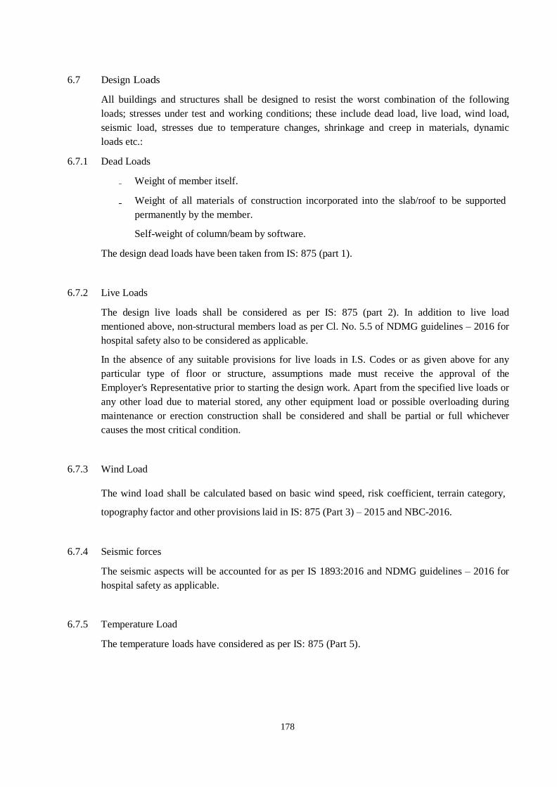
178
6.7 Design Loads
All buildings and structures shall be designed to resist the worst combination of the following loads; stresses under test and working conditions; these include dead load, live load, wind load, seismic load, stresses due to temperature changes, shrinkage and creep in materials, dynamic loads etc.:
6.7.1 Dead Loads
Weight of member itself.
Weight of all materials of construction incorporated into the slab/roof to be supported permanently by the member.
Self-weight of column/beam by software.
The design dead loads have been taken from IS: 875 (part 1). 6.7.2 Live Loads
The design live loads shall be considered as per IS: 875 (part 2). In addition to live load mentioned above, non-structural members load as per Cl. No. 5.5 of NDMG guidelines – 2016 for hospital safety also to be considered as applicable.
In the absence of any suitable provisions for live loads in I.S. Codes or as given above for any particular type of floor or structure, assumptions made must receive the approval of the Employer's Representative prior to starting the design work. Apart from the specified live loads or any other load due to material stored, any other equipment load or possible overloading during maintenance or erection construction shall be considered and shall be partial or full whichever causes the most critical condition.
6.7.3 Wind Load
The wind load shall be calculated based on basic wind speed, risk coefficient, terrain category,
topography factor and other provisions laid in IS: 875 (Part 3) – 2015 and NBC-2016.
6.7.4 Seismic forces
The seismic aspects will be accounted for as per IS 1893:2016 and NDMG guidelines – 2016 for hospital safety as applicable.
6.7.5 Temperature Load
The temperature loads have considered as per IS: 875 (Part 5).
179
6.7.6 Dynamic Load
The Dynamic loads due to working of plant items such as medical equipments, AHUs, cooling towers, electrical equipments, pumps, blowers, compressors, cranes, etc. shall be considered in the design of structure, wherever it is applicable.
6.7.6 Load Combinations
Load combinations shall be decided keeping in view the probability of:
a) their acting together, and
b) Their disposition in relation to other loads and severity of stress or deformation caused by combinations of the various loads necessary to ensure the required safety in the designing of structure.
c) Relevant code provisions 6.8 Analysis and Design
The seismic aspects will be accounted as per IS: 1893 which shall be applicable for Indian conditions. Earthquake resistance shall be offered by dual framing system as applicable.
6.8.1 Analysis
Well known analysis and design computer software i.e. ETAB, STAAD, SAFE, RCDC etc. may be used.
6.8.2 Detailing for Ductility
The ductility provision as per IS: 13920 and IS: 4326 as applicable shall be followed. 6.8.3 Structural Serviceability Limit State
Permissible sway/Drift: As per IS 456, the lateral sway due to wind at the top of the structure
shall not exceed 0.002 H where H is the height of the building.
As per IS 1893: 2016 (part-1) the story drift due to minimum specified lateral force with partial
load factor of 1.0 shall not exceed 0.004 hs where hs is the story height under consideration.
The vertical deflection under imposed load should be limited as follows:
L/250 taking into accounts all imposed loading, including temperature and creep/shrinkage.
180
L/350 t a ki n g i nt o a cc ou nt s al l i mpo s e d l oa d i ng, i n c l ud i ng t e m p e r a t ur e a nd
creep/shrinkage after erecting the finishes or 20mm whichever is less.
6.9 Expansion Joint
Expansion joints are recommended when structure exceeds 45m length. The width of the joints is being calculated as per IS-1893-2016, clause 7.11.3. However even though the length of building this project is more than 45m, the expansion joints are not provided but thermal analysis shall be carried out to ascertain their effect and accordingly the design shall be carried out. Shrinkage Strip in sub and super structure shall be provided at suitable locations
6.10 Design conditions for underground or partly underground liquid retailing structures:
All underground or partly underground liquid containing structures shall be designed as per IS:3370 for the following conditions:
i) For Water tanks and Underground sumps, crack width shall be limited to 0.2mm;
ii) liquid depth up to full height of wall : no relief due to soil pressure from outside to be considered;
iii) structure empty (i.e. empty of liquid, any material, etc.) : full earth pressure and surcharge pressure wherever applicable, to be considered;
iv) partition wall between dry sump and wet sump: to be designed for full liquid depth up to full height of wall;
v) partition wall between two compartments: to be designed as one compartment empty and other full;
vi) structures shall be designed for uplift in empty conditions with the water table as indicated in geo technical report/ defined to be taken for design purpose whichever is higher;
vii) walls shall be designed under operating conditions to resist earthquake forces from earth pressure mobilization and dynamic
viii) underground or partially underground structures shall also be checked against stresses developed due to any combination of full and empty compartments with appropriate ground/uplift pressures from below to base slab. The design shall be such that the minimum gravity weight exceeds the uplift pressure at least by 20%
6.11 Foundations
i) The minimum depth of foundations for all structures, equipments, buildings and frame foundations and load bearing walls shall be as per IS 1904.
ii) Bearing capacity of shallow foundations shall be determined as per IS: 6403 iii) Care shall be taken to avoid the foundations of adjacent buildings or structure
foundations, either existing or not within the scope of this contract. Suitable

181
adjustments in depth, location and sizes may have to be made depending on site conditions. No extra claims for such adjustments shall be accepted by the Employer.
iv) A structure subjected to groundwater pressure shall be designed to resist floatation. The dead weight of empty structure shall provide a factor of safety of 1.2 against uplift during construction and service.
v) Where there is level difference between .the natural ground level and the foundations of structure or f1oor slabs this difference shall be filled up in the following ways.
In case of non-liquid retaining structures the natural top soil shall be removed till a firm stratum is reached (minimum depth of soil removed shall be 500 mm) and the level difference shall be made up by compacted backfill as per specifications. However the thickness of each layer shall not exceed 150 mm. The area of backfilling for floor slabs shall be confined to prevent soil from slipping out during compaction.
In case of liquid retaining structures, the natural top soil shall be removed as described above and the level difference shall be made up with Plain Cement Concrete not leaner than M 10.
7.0 MATERIAL IN GENERAL
The term "materials" shall mean all materials, goods and articles of every kind whether raw, processed or manufactured and equipment and plant of every kind to be supplied by the Contractor for incorporation in the Works.
Except as may be otherwise specified for particular parts of the works the provision of clauses in "Materials and Workmanship" shall apply to materials and workmanship for any part of the works.
All materials shall be new and of the kinds and qualities described in the Contract and shall be at least equal to approved samples.
Materials shall be transported, handled and stored in such a manner as to prevent deterioration, damage or contamination failing which such damaged materials will be rejected and shall not be used on any part of the Works under this contract.

182
7.1 Reinforcement Steel
All reinforcement shall confirm to IS: 1786 – 2008 having minimum yield strength of 500 N/sq mm (Fe-500D).
Young’s Modulus : Es = 200,000 N/Sq mm
Yield Stress : Fy = 500 N/Sq mm
Diameter of Bars (in mm) : 8, 10, 12, 16, 20, 25 & 32
Density : 78.5kN/cum 7.1 Structural Steel
All structural steel : Confirm to IS - 2062
All hollow section : Confirm to IS – 4923
BUILT-UP MEMBERS Fy = 350 MPa & Fy = 450 MPa (or) relevant Euro standards
HOT ROLLED SECTIONS Fy =250 MPa & Fy = 350MPa
MS BARS & PLATES (PL) Fy = 250 MPa (or) Fy = 350 MPa & Fy = 450 MPa
HIGH-STRENGTH BOLTS Gr. 8.8/ASTM A325, IS EQUIVALENT IS: 4000 Gr. 8 / IS EQUIVALENT
WASHERS (FLATOR BELELED) Gr. 4 & GR. 8 (or) Equivalent Euro standards
ANCHOR RODS (ANCHOR BOLTS) ASTM F 1554, GRADE 36, Fy=245 MPa(or) relevant Euro odes
METAL DECK SHEET Fy =340 MPa (MINIMUM)
WELDING ELECTRODES E70, FUTS = 485 MPa (CONFORMING TO IS: 814) (or) relevant Euro standards
Young’s Modulus (E) : 200,000 N/mm2
Density : 78.5kN/m3,
Poisson’s Ratio : 0.30
Thermal Expansion Coefficient : 1.2x10⁻⁵/°C 7.3 Concrete
Keeping the durability and structural requirement, the proposed strength of various elements of

IPT Tower and Institute of Cardiology 183
structure will be as follows:
o Durability provisions for structures shall be as per “Moderate” conditions of
environment in accordance with IS 456:2000.
Minimum structural concrete for RCC work shall have characteristic compressive strength as mentioned below:
o Footing, foundation etc. - M25 to M30 o All other structural elements - M30 to M35 o UG sump - M30 o Plain cement concrete - M20 o Lean / leveling concrete - M7.5 (1:4:8 volume mix)
8.0 Mechanical Couplers
As per the tall building code IS:16700 - 2016 there is no lapping of bars shall be allowed in RC
Columns and shear walls, when diameter 16 mm (or) higher, mechanical couplers as per IS:16172
shall be used to extend bars.
9.0 CODE & STANDARDS
Materials and workmanship shall comply with the current relevant Indian Standards (with amendments) on the date of submission of the tender,
Where the relevant standard provides for the furnishing of a certificate to the Employer's Representative, at his request, stating that the materials supplied comply in all respects with the standard, the Contractor shall obtain the certificates and forward it to the Employer's Representative.
The specifications relevant latest edition of codes & the latest edition of references mentioned below are considered to be part of this Bid specification. All standards, specifications, codes of practices referred to herein shall be the latest editions including all applicable official amendments and revisions.
In case of discrepancy between the Bid Specification and the latest edition of code, the latest edition of code shall govern.
9.1 Loadings
IS: 875 Code of Practice for Design Loads (Other than Earthquake) for Building and Structures
- Unit Weights of Buildings Materials and Stored Material.
PART 1 – Dead Loads (IS: 875 -1987)

IPT Tower and Institute of Cardiology 184
PART 2 – Live loads or Imposed Loads (IS: 875-1987)
PART 3 – Wind Loads (IS: 875 -2015)
PART 4 – Snow Loads (IS: 875 -2015)
PART 5 –Special Loads and Load Combinations (IS: 875 1987)
9.2 Design of Earthquake Resistance
IS:1893 (Part-1)-2016 : Indian Standard Criteria for Earthquake Resistant Design of Structures
IS: 4326 -2013 : Earthquake resistant design and construction of
buildings code of practice.
9.3 Design of Reinforced Concrete Elements
IS: 456-2000 : Code of Practice for Plain and Reinforced Concrete
IPT Tower and Institute of Cardiology 185
IS: 1786 - 2008 : Specification for High Strength Deformed Steel bars
and Wires for Concrete Reinforcement
SP: 16 : Design aid for reinforced concrete to IS:456
SP: 23 : Hand book on concrete mixes
SP: 24 : Explanatory hand books on code of practice for PCC
SP: 34 : Hand book on Concrete reinforcement and Detailing
9.4 Design of Ductile Detailing
IS: 13920-2017 : Ductile design & detailing of reinforced concrete structures subjected to seismic forces-Code of practice
9.5 Structural Steel Elements
IS: 800-2007 :
Code of practice for general construction in steel
IS: 4000, ASTM A325 :
Bolts, Nuts and Tightening method
IS: 9595, AWS :
Welding procedures
ASTM A325 :
Structural Bolt
IS: 7215 :
Fabrication tolerance for steel
IS: 2062, ASTMA572 :
Material for steel
IS: 7205 :
Safety during erection of steel work
IS: 814 :
Covered electrodes for welding
SP: 6-(1)-1964 :
Hand book on structural steel sections
IS: 432(Part-1)-1982 :
Specification of Mild Steel and Medium Tensile Steel bars and Hard drawn Steel Wire for concrete reinforcement – Mild Steel and Medium Tensile Steel Bars.
IS: 816 : Metal Arc Welding
IS: 817 :
Training of welders
IS: 1395 :
Code for manual metal arc welding

IPT Tower and Institute of Cardiology 186
IS: 1641 : Fire safety grading & classification
IS: 1642 : Fire safety: Detail of construction
IS: 1643 : Fire safety: Exposure hazard
IS: 6560 : Bare electrode for gas shielded welding
IS: 6610 : Bare electrode for gas shielded welding
IS: 6623 : High strength structural nuts
IS: 6639 : Hexagonal bolts for steel structures
IS: 6649 : Washers for high strength bolts and nuts
IS: 12843 : Tolerances for erection of steel structures
IS:7307(Part-1) : Approval test for welders
IS:7318(Part-1) : Approval test of welders for WPS
9.6 Earthwork:
IS: 3764 : Code of safety for Excavation work
9.7 Soil and Foundation:
IS: 3764 : Code of safety for Excavation work
IS: 8009 – 1976 : Code of practice for calculation of settlements of foundation
IS: 1904 – 1986 : Indian Standard Code of practice for Design & Construction foundations in Soil: General Requirements
IS: 2950 (Part 1) – 1981 : Indian Standard Code of Practice for Design & Construction of raft foundation (Part –1)
IS: 3370 (Part 2) – 2009 : Concrete Structures for Storage of Liquids – code of Practice
IPT Tower and Institute of Cardiology 187
9.8 Fire Safety:
IS: 1642 – 1989 : Indian Standard Code of practice for Fire Safety of Buildings (General): Details of construction
ANSI/UL263 : Fire resistance rating
9.9 Others:
NDMG-2016 : National Disaster Management Guideline for Hospital Safety – 2016 issued by NDMA, Govt. of India
NBC - 2016 : National Building Code of India
Wherever appropriate, if any Indian regulation does not exist or not available or not clear for any particular criteria, appropriate Euro standards shall be followed.
Possible Euro codes to be referred as below in case of insufficient of information in IS codes:
Structural Steel:
BS EN 7668:1994 - Specification for weld able structural steels
Structural steel design:
BS 449: - Specification for the use of structural steel in building
BS 5395: - Code of practice for the design of stairs for limited access
DD ENV1994: Euro code 4: - Design of composite steel and concrete structures
Testing and examination:
BS 709 - methods of destructive testing fusion welded joints and weld metal in steel
BS 2600 - radiographic examination of fusion welded butt joints in steel
BS 3923 - methods for ultrasonic examination of welds
BS 4872 - specification for approval testing of welders when welding
procedure approval is not required

IPT Tower and Institute of Cardiology 188
BS 6072 - method for magnetic practice flaw detection
BS EN 288 - general rules for fusion welding
Welding materials and processes:
BS EN 29692 - specification for metal arc welding covered electrode, gas shielded metal arc –welding and gas welding joint preparation for steel.
Bolts and fasteners:
BS 4395 - specification for high strength friction grip bolts and associated nuts and washers for structural engineering
BS 4604 - specification for the use of high strength friction grip bolts in structural
steel work
BS 7419 - specification for holding down bolts BS
EN 20898 - mechanical properties of fasteners
Fire Resistance:
BS 476: part 20-23 - fire tests on building materials and structures
BS 1950: part 8 - Structural use of steel work in building and fire-resistant design
BS 8202: part 1-2 - Coatings for fire protection of building elements
Steel fabrication and erection:
BS 4604 - specification for the use of high strength friction grip bolts in structural steel work.
BS 5400- part 6: - Specification for materials and workmanship, steel
BS 5531 - code of practice for safety in erecting structural frames
BS 5950 - Structural use of steel work in building
BS 5950 part 2 - Specification for materials, fabrication and erection, hot rolled sections
IPT Tower and Institute of Cardiology 189
Corrosion Prevention:
BS 729:1971(1994) - Specification for hot dip galvanized coatings on iron and steel articles
BS 2569 - Specification for sprayed coatings
BS 2569 - Protection of iron and steel against corrosion and oxidation at Elevated temperatures
BS 3900 - methods of test for paints
BS 4147 - Specification for bitumen based hot-applied coating materials for Protecting iron and steel, including suitable primers where required
BS 5493 - Code of practice for protective coating of iron and steel structures
against corrosion
BS 7079 - preparation of steel substrates before application of paints and related products
BS 7361 - cathodic protection
Quality Assurance:
BS EN ISO 9000 - Quality management and quality assurance standards
*Any other relevant codes as per requirement shall be followed as per requirements from Indian
& Euro standards

IPT Tower and Institute of Cardiology 190
VI. CIVIL WORK FOR CONSTRUCTION OF IPD TOWER AND INSTITUTE OF
CARDIOLOGY AT S.M.S HOSPITAL, JAIPUR
IPT Tower and Institute of Cardiology 191
TECHNICAL SPECIFICATIONS IPD TOWERS AND INSTITUTE OF CARDIOLOGY AT SMS HOSPITAL, JAIPUR
CIVIL WORKS
1.0 GENERAL:-
1.01 The specifications and mode of measurements for Civil and other works shall
be in accordance with as per latest relevant standards/codes published by B.I.S. (formerly ISI) Specifications with up to date correction slips unless otherwise specified in the nomenclature of individual item or in the specifications.
1.02 The work shall be executed as per latest relevant standards/codes
published by B.I.S. (formerly ISI) inclusive of all amendments issued thereto or revision thereof, if any, upto the date of opening of tenders.
1.03 In case of B.I.S. (formerly I.S.I) codes/specifications are not available, the decision
of the Engineer based on acceptable sound engineering practice and local usage shall be final and binding on the contractor.
1.04 However, in the event of any discrepancy in the description of any item as given
in the specifications appended with the tender and the specifications relating to the relevant item as per latest relevant standards/codes published by B.I.S. (formerly ISI) specifications mentioned above, or in drawings the former shall prevail.
1.05 DELETED
1.06 The work shall be carried out in accordance with the architectural, structural,
plumbing and electrical drawings etc. The drawings shall have to be properly co- related before executing the work. In case of any difference noticed between the drawings, final decision, in writing of the Engineer shall be obtained by the contractor. For items, where so required, samples shall be prepared before starting the particular items of work for prior approval of the Engineer and nothing extra shall be payable on this account.
1.07 All materials to be used on works shall bear I.S. certification mark unless
specifically permitted otherwise in writing. In case I.S. marked materials are not available (not produced), the materials used shall conform to I.S. Code or specifications, as applicable in this contract.
IPT Tower and Institute of Cardiology 192
In such cases the Engineer shall satisfy himself about the quality of such materials and give his approval in writing. Only articles classified as "First Quality" by the manufacturers shall be used unless otherwise specified. All materials shall be tested as per provisions of the Mandatory Tests in LATEST RELEVANT STANDARDS/CODES PUBLISHED BY B.I.S(FORMERLY I.S.I) specifications . The Engineer may relax the condition regarding testing if the quantity of materials required for the work is small. Proper proof of procurement of materials from authentic manufacturers shall be provided by the contractor to the satisfaction of Engineer. Grade of cement used shall be OPC 43Grade unless otherwise specified . The contractor shall get the Design Mix for RCC done by the labs approved by department only. Reinforcement Steel used shall be of TMT Fe-500 unless otherwise specified.
1.08 In respect of the work of the sub-agencies deployed for doing work of
electrification, air-conditioning, external services, other building work, horticulture work, etc. for this project and any other agencies simultaneously executing other works, the contractor shall afford necessary coordination and facilities for the same. The contractor shall leave such necessary holes, openings, etc. for laying / burrying in the work pipes, cables, conduits, clamps, boxes and hooks for fan clamps, etc. as may be required for the electric, sanitary air- conditioning, fire fighting, PA system, telephone system, C.C.T.V. system, etc. and nothing extra over the agreement rates shall be paid for the same.
1.09 The rates for all work shall be considered as inclusive of pumping out or bailing
out water if required for which no extra payment will be made. This will include water encountered from any source such as rains, floods, or due to any other cause whatsoever.
1.10 DELETED 1.11 DELETED 1.12 The contractor shall clear the site thoroughly of all scaffolding materials and
rubbish etc. left out of his work and dress the site around the building to the satisfaction of the Engineer before the work is considered as complete.
1.13 DELETED 1.14 DELETED 1.15 DELETED 1.16 DELETED 1.17 The drawing(s) attached with the tender documents are for the purpose of tender
only, giving the tenderer a general idea of the nature and the extent of works to be executed. The rates quoted by the tenderer shall be deemed to be for the execution of works taking into account the "Design Aspect" of the items and in accordance with the "Construction Drawings" to be supplied by the Contractor during execution of the works.
1.18 The quoted rate shall be for finished items and shall be complete in all respects
including the cost of all materials, labour, tools & plants, machinery etc., all taxes,

IPT Tower and Institute of Cardiology 193
duties, levies, octroi, royalty charges, statutory levies etc. applicable from time to time and any other item required but not mentioned here involved in the operations described above. The client/department/Employer shall not be supplying any material, labour, plant etc. unless mentioned so.
1.19 On account of security consideration, there could be some restrictions on the
working hours, movement of vehicles for transportation of materials and location of labour camp. The contractor shall be bound to follow all such restrictions and adjust the programme for execution of work accordingly.
1.20 The contractor has to ensure co-ordination with Institute authorities to maintain the
smooth functioning / operation of existing Institute without disruption during the execution of work. This may require working rescheduling the normal working hours, working in restricted period etc. Nothing extra shall be payable on this account.
He shall also ensure that all work sites within the Institute complex are properly cordoned off by means of barricades and screens upto a height of 3.0 m above ground level. The contractor shall use painted CGI sheets which are in good condition mounted on steel props.
1.21 Stacking of materials and excavated earth including its disposal shall be done as per
the directions of the Engineer-in-Charge. Double handling of materials or excavated earth if required shall have to be done by the contractor at his own cost.
1.22 The agency will have to take prior approval of the Engineer/ Architect for the make
of materials before procurement of the same. It may also be noted that if any of the makes given in the List of Makes does not comply with Standards, it will not be allowed to use. No claim what so ever shall be entertained on this account.

IPT Tower and Institute of Cardiology 194
2.00 Signages and associated works General
1. The sign board shall be in both English and Hindi language 2. Suitable pictogram to be provided as per approved samples 3. The colour of signages to be as per discretion of Engineer. 4. All signages details including sizes of sheet, letters, pictogram and border
allround to be submitted and got approved priorly 5. The quoted rate shall be for all heights and floor levels. 6. The scope of work include providing and fixing base frame with removable/
interchangeable signages. Which will be paid in respective items PVC sheet / sun board
1. Sheet to be best available brand of minimum thickness 3mm. 2. Top vinyl film to be best available brands of LG, Samsung or equivalent. 3. The thickness of film without adhesive to be around 75 microns and with
adhesive to be 100 microns. 4. The fixing to be done with screws / hanging chains/pipes/rods of approved make
& material as per discretion of Engineer. 5. The rates to be quoted per square inch inclusive of pictogram & fixing up to
any floor and height, wall fixing or hanging on ceiling. MS
1. The make of material to be as approved by engineer. 2. The thickness of GI sheet should be as per approved drawing/design . 3. The shop drawings of supporting structural frame and its foundation for
signages to be submitted for approval by JDA. 4. The welding joints to be rubbed and grinded to give a smooth finish. No
undulations shall be visible. 5. The MS frame and sheets to be primered and painted with approved make material.
Stainless steel
1. The thickness of sheet to be as per approved drawing/design . 2. The same to be fixed with SS screws. 3. The engraving of letters to be as per standard norms and colours. 4. The individual alphabets/ letters, wherever required to have an inbuilt
arrangement for fixing to support base with stainless steel screws complete for all heights and levels. All corners to be smoothly finished & SS welding.
5. The sheet/letters may be shining or mat finish as approved by engineer. Aluminum
The thickness of sheet to be as per approved drawing/design . 1. Fixing to be done with SS or appropriate screws to avoid bimetallic action with aluminum.

IPT Tower and Institute of Cardiology 195
2. The hanging aluminum hollow section to be of 100mm and 150mm width & make to be got approved. The powder coating of approved colour to be done and letters of approved specs and design to be pasted on such hanging aluminium hollow sections.
3. The hanging will be done by adjustable MS/GI rods of approved diameter and painting thereafter
Neon Glow signages
1. The diameter of tube to be got approved. 2. Make to be got approved. 3. Matter to be got approved. 4. To be made from100% handcraft glass.
SAMPLES OF ALL MATERIALS, LETTERS MATTERS AND DESIGNS TO BE GOT APPROVED by ARCHITECT/ CLIENT BEFORE EXECUTION OF WORK.
3.00 LIST OF APPROVED MAKES : CIVIL WORKS
S.No
Material
Recommended Makes
1 Doors & Windows fixtures/ Fittings Dorma, Godrej, Dorset, Arkay, Ozone, Hettich
2 Door Closer / Floor spring Dorma, Godrej, Dorset, D-Line, Hardwyn
3 Aluminium Sections. Hindalco, JSPL, Indal, equivalent
4 Clear Glass/ Clear Float Glass/ Toughened Glass
Saint Gobain, Asahi, Modi Guard, ALSTONE
5 Laminates Greenlam, Merino, Kitply, Century
6 Synthetic Enamel Paints Asian, Berger, DULUX, Nerolac
7 Oil Bound Distemper Asian, Berger, DULUX, Nerolac
8 Cement Paint Snowcem plus, Asian, Berger
9 Plastic Emulsion Paint Asian, Berger, DULUX, Nerolac
10 Other Paints/Primers Asian, Berger, DULUX, Nerolac, Shalimar
11
OPC 43 Grade Cement (Conforming to IS 8112)
ACC, Ultratech, Jaypee Cement, Century Cement, J.K. Cement & Shree &Wander
12 Reinforcement Steel (TMT Bars) SAIL, RINL, TISCO, JSPL
13
Glass Mosaic Tiles
Bissazza, Mridul, OpioMosaica, Paladio, Italia
14 MS Pipe/ Sections JSPL, Tata, SAIL, Bhushan
15 Polycarbonate Sheets GE Plastic, Gallina (USA), Macrolux (UK), equivalent
16 Wooden Fire Check Doors Navair, Pacific, Sukriti
17
Metal Fire Check Doors Navair. Shaktimet, Godrej, Pacific, Sukriti,Chempharm

IPT Tower and Institute of Cardiology 196
18
Admixtures for concrete.
CICO, Fosroc, Sika, MC-Bouchemie, Pidilite, BASF, STP Ltd
19 Ceramic Tiles Kajaria, Somany, Johnson, Orient
20
Pre-Laminated Particle Board
Greenlam, Duro, Merino, Kitlam, Century
21 a)Flush Door Shutters Duro, Kitply, Century, Equivalent b)WPC Flush Doors ALSTONE and equivalent
22 White Cement JK White, Birla White
23
Powder Coating Material Pure Polyester
Nerolac, Berger, J&N
24
Stainless Steel Screws For Fabrication and fixing of Windows.
IS: Grade 202
25 Dash Fasteners./Anchor bolts, Cramps Hilti, Fischer, Bosch, Canon
26 Stainless Steel Friction Stay Earl-Bihari, Securistyle, Hafele, Hettich equivalent
27 Weather Silicon Dow Corning, Wacker, G.E.
28 Structural Silicon at butt joints Dow Corning, Wacker, G.E.STP Ltd
29 Water proofing Compound CICO, Fosroc, MC-Bouchemie, Pidilite, Sika, STP Ltd
30 Reflective Glass Saint Gobain, Asahi, Modiguard
31 Door Locks/Latches Dorma, D-Line, Harrison, Yale, Hettich, Godrej
32 Aluminium Grill Hindalco, JSPL, Bhoruka, equivalent
33 Vitrified Tiles Kajaria, Somany, Johnson, Orient
34 Aluminium Cladding sheets ALSTONE or equivalent
35
Stainless steel D-handles
D-Line, Dorma, Dorset, Giesse, Ozone, Hettich, Hafele
36 Stainless Steel Railing/ pipe/ sheet JSPL, SAIL, TATA
37 Structural Steel TATA, SAIL, RINL, JSPL, Bhushan
38 Epoxy Flooring/ wall coating Fosroc, BASF, STP LTD, Sika, Dr Beck
39 Acoustic Mineral Fibre Armstrong, USG, Hunter Douglas, Dexune, STP Ltd
40 Fire Panic bar/ hinges Dorma, D-Line, Briton, Becker FS
41 Plywood/ Block Board Greenply, Kitply, Merino, Duro, Century
42 PVC Flooring Gerflor, Tarkett, Armstrong, equivalent
43 Fire Seal Pemco, Lorient, Astroflame
44
Fire rated door closer/Mortice Lock/ Door Co-ordinator
Dorma, D-Line, Briton, Becker FS
45 Gypsum Board System Gyproc (Saint Gobain), USG, Boral
46 Adhesive for Wood Work Fevicol, Vemicol, Dunlop, Pidilite
47
Epoxy/PU Paint Fosroc, Pidilite, Cico, BASF, Sika, Berger, Nerolac, STP LTD
48 Glass Doors (Motorised) Dorma, Hafele, Ozone, Besam, Hettich
49
Automaticaaly Hermetically Sealed Sliding (OT) Door
Metaflex, SHD Italia, Stryker, Chempharm

IPT Tower and Institute of Cardiology 197
50 Calcium silicate boards/ Tiles Hilux, Aerolite, Armstrong,Dexon
51 Texture Paints Asian, Berger, Nerolac, DULUX Dulux, Snowcem
52 Wall care putty JK, Birla, STP Ltd
53 Frameless glass partition fixtures/ Spider fittings/ patch fittings
Dorma, Sevax, Geze, Ozone, Hafele, Hettich
54 U-PVC Windows Fenesta, Aluplast or approved equivalent
55 Toilet Cubicles GreenlamSturdo, Merino,
56
Agencies for PT Slab work
Utracon Structural Systems Pvt. Ltd., GP Spiro Duct & Tube Gurgaon, BBR (India)Pvt. Ltd Bangalore, VSL India Pvt ltd Chennai
57 Fire rated Glass Saint Gobain, Pilkington, Schott, Pyroguard
58 Fibre Glass Rigid Board FGP Ltd., UP Twiga, Kimmco
59 Mineral Wool/ Rockwool Rockwool India Pvt. Ltd., Lloyd
60 Heat Resistance Tile Thermatek, National
61 Bitumen Indian Oil, Hindustan Petroleum, STP Ltd
62
Stainless Steel Door Handles, Locks and Fittings
Dorma, Hafele, Geze, Hettich, Ozone, Godrej,D-line
63 Acid/ Alkali Resistant Tile Somany, Kajaria, Johnson
64 Acrylic Exterior Paint Asian, Berger, DULUX Dulux, Nerolac, J&N
65 WPC Door frame and Shutters ALSTONE and equivalant
66 Metal False Ceiling Armstrong, Durlum, Saint Gobain, Dexon
67 Tendons for PT slab TATA, Usha Martin
68 Expansion joint Kohinoor Enterprises, equivalent
69 Silicon ALSTONE or equivalent
70
AAC Block, Fly ash brick, pavers, kerb stone,
3D wall
Harmony, Megiccrete, Hyderabad ind ltd
38 Ready Mix Concrete ACC, Ultratech, L&T, Lafarge
Note
Final choice of make specified or not specified above shall remain with the Engineer in charge
equivalent makes can also be added or deleted, subject to price adjustment if any.

IPT Tower and Institute of Cardiology 198
1. Building Story 3B+G+21 2. Building Location Jaipur, Rajasthan 3. Building Occupancy Hospital 4. Building Type RCC + Composite (Steel + RCC) 5. Building Life 100 Year 6. Structural System Ductile Shear wall withSpecial moment resisting
frame- Dual structural system 7. Material Grade Concrete
Foundation – M40 Column concrete Grade – M30 to M-70 Beam – M30 to M50 Slab – M30 to M50 RW and Water Retaining structure – M30 Reinforcement All reinforcement- Fe550D Structural Steel All Rolled Section – E450 Built-up Section – E450 Tubes and Pipes – E410 Bolts Foundation Bolts – 4.6 Grade Structural bolts – 10.9 Grade Deck Sheet TR 60, 1mm Thick of JSW or SR D-60, 1 mm
thick of Netverk steel with Min. Grade 350 Mpa and Min. galvanization 275 gsm for 3hr fire rating.
Shear Stud M19, M22 and M25 dia with grade 350
Mpa. Welding electrodes shall be E8018 conforming to AWS D1.1.
8. Loading 8.1 Dead Load As per IS: 875(Part-1) 8.2 Live Load As per IS: 875(Part-2) 8.3 Wall Load AAC block or Dry wall partition to be considered. 8.4 Wind Load As per IS: 875(Part-3)-2015
Basic Wind Speed- 47 m/s K1 to K3 – As per Code K4 -1.3 for Hospital building Max. Hor. Displacement- H/500
8.5 Seismic As per IS: 1893-2016 and IS:13920-2016 Zone III for Jaipur

IPT Tower and Institute of Cardiology 199
Z- 0.32 or site specific IF – 1.5 R – 5 DM – 5% Soil Type – Medium Story Drift - H/250
8.6 Temperature and
Shrinkage Consider daily temperature variation in design with long term shrinkage.
9.0 Load Combination As per latest relevant Indian standard: IS 456 IS 800 IS 875 IS 1893
10. Analysis Structural Analysis shall be carried out with
latest Etab version. Foundation analysis shall be done in Safe
model. 11. Design RCC Element – Accordance with IS 456
Steel Member - As per IS 800 Connection – As per IS 800 Composite Column – As per AISC 360 Composite Beam – As per AISC 360 Composite Deck – As per BS 5990 Liquid Retaining structure- As per IS 3370 Design shall be accepted either in software or calculation excel sheet.
12. Fire Rating 3hr for composite beam and slab 4hr for composite column Medium density cement based coating shall be used for fire rating as per specification.
13. Cover Consider maximum cover of “Moderate exposure
condition” or “as fire rating specified in point no.
12”. 14. Vibration Vibration shall be limited as per AISC 360 for
Hospital occupancy. 15. Serviceability Vertical deflection for composite Beam –
L/240 Vertical deflection limit for RCC Beam –
L/250 Crack width for RCC element – 0.2 mm Crack width for STP – 0.1 mm

IPT Tower and Institute of Cardiology 200
16. Codes and standard Loads: IS:875 -1987/2015 Code of Practice for design
loads (other than earthquake) for Buildings and structure(All parts).
IS: 1893-2016 Criteria for earthquake resistant design of structure.
Foundations:
IS:1080-1985(2016) Code of Practice for design and construction of shallow foundations on soils (other than raft, ring and shell)
IS:1904-1986(2015) Code of Practice for design and construction of foundations in soils general requirement
IS:2950-1981(2013) Code of Practice for design and construction of raft foundations
IS:2974-1998(2013/2015) Code of Practice for design and construction of machine foundations (All parts )
IS:8009-1976/1980(2013/2015) Code of Practice for calculation of settlement of foundations (All parts)
RCC:
IS:456 -2000(2016) Code of Practice for plain and reinforced concrete.
IS:458 -1988 Specification for precast concrete pipes.
IS:3370-2009 Code of Practice for concrete structures for the storage of liquids:(All parts).
IS:4326-2013 Code of Practice for earthquake resistant design and construction of buildings.
IS:5525-1969(2013) Recommendation for detailing of reinforced concrete works.
IS: 1786-2008 Specification for high strength deformed steel bars and wires for concrete reinforcement.
IS:10262-2009 Recommended guidelines for concrete mix design.
IS: 1893 (Part-1)-2016 Criteria for earthquake resistant design of structures (General provisions

IPT Tower and Institute of Cardiology 201
and building).
IS: 13920-2017 ductile design & detailing of RC structures subjected to seismic forces.
Structural Steel & Composite Construction:
IS: 800 -2007(2012) Code of Practice for general construction in steel.
IS:806 -1968(2013) Code of Practice for use of steel tubes in general building construction.
IS:808 -1989 Dimensions for hot rolled steel beam, column channel and angle section.
IS:816 -1998 Code of Practice for use of metal arc welding for general construction in mild steel.
IS:1161-1998 Steel tubes for structural purposes.
IS:4000-1998 High Strength bolts in steel structures – Code of Practice.
IS:7215 -1995 Tolerances for fabrication of steel structures.
AISC:360-10 Specification for Structural Building (Only Chapter-I refer for composite beam and column design).
AISC:341-2016-Seismic provisions for Structural steel Buildings
Miscellaneous:
IS: 432(part 2)-1995 Specification for mild steel and medium tensile steel bars and hard-drawn steel wire for concrete reinforcement
IS: 6313(part II)-2001 Standards for anti-termite treatment
IS:1905-1998 Code of Practice for structural use of unreinforced masonry
IS: 3067-1995 Code of Practice for general design details and preparatory works for damp proofing and water proofing of buildings.
SP:6 -1998 Handbook for structural engineers (all parts)
SP:7 -2016 National Building Code of India
SP:16-1999 Design Aids for reinforced concrete

IPT Tower and Institute of Cardiology 202
to IS:456-1978
SP:22-1982 Explanatory handbook on codes for earthquake engineering (IS:19821975
and IS:4326-1976 ) SP:24-1983 Explanatory handbook on Indian
Standard code of Practice for plain and reinforced concrete
SP:34-1987 Handbook of concrete reinforcement and detailing (SCIP)
Material:
IS: 269 -2015 Specification for Ordinary, rapid hardening and low heat Portland cement.
IS: 455 -1995 Specification for Portland blast furnace slag cement.
IS: 1489-1991 Specification for Portland pozzolana cement
IS: 4031-1991 Method of physical tests for Portland cement.
IS: 383 - 2016 Specification for coarse and fine aggregates from natural sources for concrete.
IS: 516 – 1999 Method of test for strength of concrete.
IS: 1199-1999 Method of sampling and analysis of concrete.
IS: 1566-2000 Specification for plain hard drawn steel wire fabric for concrete reinforcement.
IS: 4990-1998 Specification for plywood for concrete shuttering works.
IS: 2645-1999 Specification for integral cement water proofing compounds.
Soil and Foundation:
IS: 8009:1976 Code of practice for calculation of settlements of foundation.
IS:1904-1986 Indian Standard Code of practice for Design & Construction foundations in Soil: General Requirements.
IS:2950(Part1)-1981 Indian Standard Code of
IPT Tower and Institute of Cardiology 203
NOTE- Any changes or deviation will be subject to approval by the architect of SMS hospital.
Practice for Design & Construction of raft foundation – (Part –1)
IS: 3370 (Part-2)-2009 Concrete Structures for Storage of Liquids –code of Practice.
Welding standards
AWS D1.1 - American Welding Society (AWS): Structural Welding (Steel).
ASME Sec II –Part C Specifications for welding Rods, Electrodes and Filler Metals.
Many of above listed standards may not be directly used in detailed design; however, the comprehensive list is captured so that an approval for their use is obtained at DBR stage itself. Wherever appropriate Indian standard does not exist for any item, appropriate British standards/American standards will be used.

IPT Tower and Institute of Cardiology 204
VII. PLUMBING REPORT FOR CONSTRUCTION OF IPD TOWER AND
INSTITUTE OF CARDIOLOGY AT S.M.S HOSPITAL, JAIPUR

IPT Tower and Institute of Cardiology 205
A. Plumbing (Water Supply and Sanitary Installation)
1.0 General:
The water supply and sewerage demand has been estimated, based on the population as required by NBC norms, Local bye Laws & statutory norms. Planning of PHE system has been done taking into account various topographical, meteorological, hydrological etc. reports, identifying the source & quality of water, interaction with local bodies, conducting survey of existing water supply system, drainage system etc. The different components related to services are listed as below: -
1.1 Internal Plumbing Works
Sanitary fixtures & C.P brass fittings
Soil, waste & rain water piping system
Internal water supply system
Disposal of soil, waste & rain water pipe to manhole.
1.3 Garden Hydrant System
External garden hydrant system to supply the water for horticulture purpose to all landscaping/green area of the building.
1.4 Pumps & Water Treatment Equipements
Water supply pumps for Hospital, College, Hostels and residential units & flushing water supply system etc.
1.5 Basic Objectives
The basic objective is to provide all sanitary engineering services and specification in relation to:
High standards of materials and workmanship.
Leak proof plumbing.
Reliable and dependable engineering systems.
Plan the system in such a way as to minimize the energy requirements.
Create minimum nuisance and disturbance to the environment.
1.8 List of Codes and Manuals
The following codes of practice and design manuals are being referred for designing the Sanitary Plumbing and Fire -Fighting Systems:
National Building Code 2016
Hand Book on Water Supply & Drainage (with Special Emphasis on Plumbing), Bureau of Indian
Standards SP-35
Manual on Water Supply & Treatment (Ministry of Urban Development)
Manual on Sewerage & Sewage Treatment (Ministry of Urban Development)
LATEST RELEVANT STANDARDS/CODES PUBLISHED BY B.I.S(FORMERLY I.S.I) Specifications
National Building Code 2016 (Part-IV — Fire Protection)

IPT Tower and Institute of Cardiology 206
1.9 Proposed Water Management System: -
Reduce, Re-use, Re-cycle Model has been adopted for meeting the water requirement.
The following measures are proposed for reducing water consumption:
Discipline use of water
Installing water saving toilet fixtures and faucets and flow regulators
Installing water conserving cooling towers
2.0 Water Supply System
Water requirements has been estimated on the basis of present acceptable standards, references from various sources such the National Building Code of India, Public Health Manuals, Ministry of Environment, Forests Guidelines, and LATEST RELEVANT STANDARDS/CODES PUBLISHED BY B.I.S(FORMERLY I.S.I) Specification as well as Inputs from other services consultants involved on the projects.
2.1 Design for Water Supply Distribution System Pipes
For continuous water supply at adequate pressure, complete water supply system is designed with following three type of pipe-lines-
2.1.1 Ductile iron Class K-9 Pipe confirming to I.S.8329
The main water supply lines from treated water underground tank shall be connected with designed pipe line grids for buildings which shall be ductile iron class K-9 pipes confirming to IS 8329. The water supply lines have been designed with ductile iron class K-9 pipes of different diameters with push on joints, as per requirements. All the operational valves/fittings also designed with same D.I. Specials of class K-12 as per I.S 9523 material as per IS Code and shall be fixed in clay bricks/fly ash masonry chambers as per specification.
2.1.2 Galvanized Iron Pipes
DI pipe grids all around the buildings shall be connected to overhead tanks (rising main) by GI pipes, conforming to the requirements of IS 1239 Part-I for medium grade. To regulate the water supply, valves and fittings, at required places, shall be fixed as per specification.
Lying of these pipe lines up to building shafts shall be underground and in shafts, supported with standard clamps up to the overhead tanks complete as per specification. These G.I Pipe line shall be used for domestic flushing and AC water supply system.
2.1.3 Chlorinated Polyvinyl Chloride (CPVC) Pipes
All concealed Water supply lines shall be of CPVC pipes & fittings used in hot & cold potable water distribution system shall conform to requirement of IS 15778. These CPVC pipe lines shall be for domestic and flushing water supply systems.

IPT Tower and Institute of Cardiology 207
3.0 SANITARY WORKS
3.1 Sanitary Fixtures & C.P Brass Fittings
Plumbing fixtures, Chrome Fittings and accessories will be as per IS: 781-1984.
Porcelain fixtures of fairly high quality as given below.
WCs - Low volume dual flushing system comprising concealed cistern are proposed as per IS: 2556.
Lavatory Basins available in all size and shapes including wall hung, over or under counter
types etc with infra-red sensor as per IS: 2256 (Part 7) 1995.
Urinals shall be provided with Infra-red sensor battery operated as per IS: 2556 part.
Accessories - Soap dispensers, toilet paper holders, hand drier, etc. shall be of Stainless Steel.
Chrome Fittings Provision for additional and special hospital fittings where required shall be made
as per IS: 781 - 1984.
3.2 Soil, Waste Pipe System
Above ground piping shall be designed on the basis of two pipe system as recommended in
code of practice for soil and waste Hubless centrifugally cast (Span) iron pipes epoxy coated in sides and side as per IS code 15905.
Soil pipes shall carry the wastes from WC ‘s & urinals etc. Soil pipes shall connect directly to
the 1st manhole outside the building.
Internal buildings sanitary disposal system will be under the RCC slab (By core cutting RCC slab
and suspended at bottom) for hospital zone and with sunken floor in residential buildings.
Waste pipes shall carry the wastes from waste appliances (lavatory basins, kitchen sinks etc.).
Waste pipes shall connect to Gully Traps outside the buildings and shall be connected to the external manholes.
3.2.1 Design Parameters
Piping system has been designed in accordance with Code of Practice for Installation of Soil &
Waste Pipes up to the 1st manhole with Hubless centrifugally cast (Span) iron pipes epoxy coated in sides and outside as per IS code 15905.
All vertical stacks will terminate as vent pipes at terrace level.
All Vertical Stacks in the buildings will terminate at the ground floor level and connected to the external sewer. Pipe dia. and slope will be as per connected load.
3.2.2 Pipe Work
All vertical stacks will be installed in pipe shafts on the external face of the buildings or in internal
shafts within the building according to the architectural planning of the toilets.
Provision has been made to provide cleanout doors and plugs for Roding and maintenance
where necessary and required. 3.2.3 Materials for Soil, Waste & Vent Pipe System

IPT Tower and Institute of Cardiology 208
Pipes used for Soil, Waste and Vent system shall be Hubless centrifugal cast (Span) iron pipes epoxy coated in-sides and out-side as per IS: 15905. The pipes and fitting are jointed with SS 304 grade coupling with EPDM rubber gasket joints as per requirement and specifications.
4.0 SEWERAGE SYSTEM
4.1 Design Parameters
Flow of Sewage = 80% of daily water requirement.
PeakFlow = 3 x Average Flow.
SubSoil Infiltration = 25% of Average Flow
Velocity of flow in pipes = 0.75 m/sec. flowing half full Min.
Velocity of flow in pipes = 2.0 m/sec. Max.
4.2 Flow Conditions in pipe
Pipes up to 250 mm dia. = 0.75 m/sec. flowing half full Min.
Pipes From 400-900 mm dia. = 2.0 m/sec. Max.
4.3 Min. depth for sewers
For branches = 1 M.
For lateral, main & trunk sewers = 1.5 M./ as per required gradient
4.4 Type of Distribution
Sewer flow shall be by gravity up to the final disposal point. The external sewer shall be connected to centralized sewage treatment plant.
4.5 Kitchen Effluent
Kitchen waste shall be passed through grease trap / oil separator before discharging in to the external sewer line.
4.6 Manholes
The manholes are to be constructed with brick/fly ash masonry as per standard specifications of NBC 2016 and shall have details as follows:
Rectangular manhole of size 900 x 800 mm upto 1.0 mtr depth.
Circular manhole of size 910 mm dia for 1.0 to 1.67 mtr depth.
Circular manhole of size 1220 mm dia for 1.68 to 2.29 mtr depth
Circular manhole of size 1520 mm dia for 2.3 mtr depth and above.
4.7 Spacing of Manholes
Manhole shall be provided with all the junctions, change of directions, change in diameters and as per connection requirement from every unit.
A distance of 20 meters on the main sewer line depending on dia of pipes and local conditions. 4.8 Manholes Covers

IPT Tower and Institute of Cardiology 209
Medium duty S.F.R.C. manhole covers for manholes on service roads, gully traps and manholes /chambers not following in the road / pedestrian ways.
Heavy duty S.F.R.C. manhole covers for manholes on main roads.
6.0 Irrigation system for lawns and gardens at various Terraces
Gardens and lawns shall be irrigated in combination of Garden Hydrant System and Sprinkler Irrigation System.
It is proposed to provide a separate and independent captive garden hydrant system to supply
water for horticultural operations to all landscaped areas.
The distribution grid for garden mains will be by a separate grid of HDPE pressure pipes and connected to a separate pumping set obtaining its water supply from STP & raw water tank.
The Main Distribution grid shall be with HDPE and balance distribution system will be with UPVC
pressure pipes confirming to specifications.
Garden hydrant points will be of 25 mm outlets and located approximately 45-50 m apart.
The garden hydrant pumping system is proposed to be planned so that the grid is sized to cater for a maximum of 6 outlets operated at the same time.
6.2 Sprinkler Irrigation System, Network System
Sprinkler Irrigation is a method of applying irrigation water which is similar to rainfall. Water
is distributed through a system of pipes usually by pumping. It is then sprayed into the air and irrigated entire soil surface through spray heads so that it breaks up into small water drops which fall to the ground.
Sprinklers provide efficient coverage for small to large areas and are suitable for use on all
types of properties.
It shall be designed to ensure maximum water saving, combining high quality, affordability and ease of installation. All the products are made out of high strength & chemical resistance engineering plastics to achieve functional satisfaction and to maintain cost economics.
All sprinklers undergo extensive quality testing in our well-equipped state of the art lab.
Performances of the products shall also be tested, as per relevant specifications, in the field to ensure uniform water distribution and higher efficiency.

IPT Tower and Institute of Cardiology 210
8.0 List of IS Codes for Reference of Plumbing Design
S. No ISI No. Description
1 I.S: 1536: 1989 Specification for centrifugally cast (spun) iron pressure pipes for water, gas and sewage(3rdRev.) (Amendment2)
2 I.S: 1538: 1993 Specification for cast iron fittings for Pressure Pipes for water, gas and sewage (3rd Rev.)
3 I.S: 3114: 1994 Code of Practice for laying of C.I. pipes (2nd Rev.)
4 I.S.: 782: 1978 Specification for caulking lead (3rd Rev.)
5 I.S.: l239 (Part 2):1992
Specification for mild steel tubes; tubular & other wrought steel fittings: Part 2 Mild steel tubular and other wrought steel pipe fittings (4th Rev.) (Amendment 1)
6 I.S.: 1879:1987 Specification for malleable cast iron pipe fittings (2nd Rev.) (Amendment 5)
7 I.S.: 4984:1995 High density polyethylene pipe for water supplies (4th Rev.) (Amendment1)
8 I.S.: 783: 1985 Code of practice for laying of concrete pipes (1stRev.) (Amendment 1)
9 I.S.: 4127:1983 Code of practice for laying of Glazed Stoneware pipes (1st rev.)
10 I.S: 780: 1984 Specification for sluice valve for water works purposes (6th rev) (50
to 300 mm size) (Amendment 3)
11 I.S: 651: 1992 Specification for salt glazed stoneware pipes and Fittings (5th rev.) (Amendment 1)
12 I.S.: 456: 1978 Code of practice for plain and reinforced concrete (3rdRev. ) (Amendment2)
13 I.S.: 12820: 1989
Code of practice for dimensional requirements of rubber gaskets for mechanical joints and push on joints for use with cast iron pipes and fittings for carrying water, gas & sewage.
14 I.S.: 1172:1993 Code of basic requirements for water supply, drainage & sanitation
(4th Rev.)
15 I.S.: 1200 (Part- 16) 1979
Code of practice for methods or measurements of building and Civil Engineering works: Part 16 Laying of water and sewer lines including appurtenant items (3rdRev.)
16 I.S.: 1200 (Part- 19) 1981
Code of practice for methods or measurements of building and Civil Engineering works: Part 19 Water supply, plumbing and drains (3rd Rev.)
17 I.S: 1729:1979 Specification for sand cast iron spigot and socket soil, waste and ventilating pipes, fittings and accessories (1st rev.) (Amendment 4)
18 I.S: 1742:1983 Code of practice for building drainage (2nd Rev.)
19 I.S: 3989:1984 Centrifugally cast (spun) iron spigot and socket soil, waste and ventilating pipes, fittings and accessories (2nd rev.) (Amendment 2)
S. No ISI No. Description

IPT Tower and Institute of Cardiology 211
20 I.S: 778: 1984 Copper alloy gate, globe and check valves for water works purposes (4th rev.) (Amendment 2)
21 I.S: 13095: 1991 Butterfly valves for general purposes
22 I.S:5312(part1) : 1984
Swing check type Reflux valve (non-return valve): Part 1 Single door pattern (1st Rev.) (Amendment 1)
23 I.S: 5312(part2) Swing check type Reflux valve (non-return valve): Part2
: 1986 Multi door pattern
24 I.S:1239(part1) : 1990
M. S. tubes, tubular and other wrought steel fittings: Part 1 Mild steel tube (5th Rev.)
25 I.S: 1879: 1987 Malleable Cast Iron pipe fittings (2nd rev.) (Amendment 5)
26 I.S: 651: 1992 Salt glazed Stoneware pipes & fittings (5th Rev.) (Amendment 1)
27 I.S: 458: 1988 Precast Concrete pipes (with or without reinforcement) (3rd rev.)
(Amendment 2)
28 I.S: 1726: 1991 C.I. Manhole covers & frames (3rd rev.)

IPT Tower and Institute of Cardiology 212212
29 I.S: 1916: 1989 Steel cylinder pipe with concrete lining and coating (1st rev.)
30 I.S: 12592 (part1): 1988
Pre-cast concrete manhole covers and frames: Part 1 Covers
(Amendment3)
31 I.S: 12592 (part2): 1991
Pre-cast concrete manhole covers and frames: Part 2 Frames
32 I.S: 6392: 1971 Steel pipe flanges (Amendment 1)
33 I.S: 6418: 1971 C.I & malleable flanges for general Eng. Purposes.
34 I.S: 4985: 1988 Unplasticized PVC pipes for potable water supplies (2nd Rev) (Amendment2)
35 I.S: 7181: 1986 Horizontally cast double flanged pipes for water, gas and sewage. (1st Rev.) (Amendment 1)
36 I.S: 210: 1993 Grey iron casting. (4th Rev.)
37 I.S: 4985: 1988 Unplasticized PVC pipes for potable water supply.
38 I.S: 7558-1974 Code of practice for domestic hot water installation.
39 I.S: 2064-1973 Code of practice for selection, installation and maintenance of Sanitary appliances
40 I.S: 2065-1983 Code of practices for water supply in building
41 I.S: 2183 (Part- I)- 1987
Code of practice for Plumbing in multistoried buildings.
42 I.S: 8329-2000 Code of practice for Ductile iron class K9 pipes for water supply system
43 I.S: 15905-2011 Code of practice for Hubless centrifugal cast (Span) iron pipes epoxy coated in sides and out side

IPT Tower and Institute of Cardiology 213213
B. Design Bases Report of Water Treatment Plant (WTP)
1.0 The EPC Contractor shall carry out Design, Engineering, Supply, Installation, Testing & Commissioning for WTP.
The construction of IPD Tower and Institute of Cardiology complex spread over 240 acres, is planned in phases. For providing WTP & Hot Water System, the entire Complex is proposed to be divided into 2 Primary Zones as following:
Zone-1 IPD TOWER Zone-2 INSTITUTE OF CARDIOLOGY For IPD Tower and Institute of Cardiology, individual Plumbing and Fire protection water tanks, pump rooms, water treatment, RO System, Solar Hot Water System etc. have been proposed.
STP/ETP for entire campus shall be centralized and located at one place.
1.1 Population
Estimation of population is most critical element in identifying the infrastructure requirements for any development. All the demand estimations are based on the population or maximum expected capacity of the proposed development. The norms adopted for population estimation for entire campus is as per NBC 2016.
2.0 Concept Planning
It is proposed to provide:
Water Treatment Plant
Centralized RO System (catering to critical areas in Hospital like Dialysis Rooms, Labs etc.)
Portable RO System (catering to Drinking facility in Hospital/ Medical & Nurses College/Auditorium/All Hostels/Guest House etc.).
Sewerage Treatment Plant
Effluent Treatment Plant
Hot Water System for Hospital by Heat Pumps.
Hot Water System for Pantry at academic block, Director Residence, Night Shelter, Guest House, club etc. by Energy Efficient BEE min. 3 star rated Geysers.
Hot Water System for Hostels, staff residences by Solar Hot Water System with Electric Back Up.
All water distribution pipelines from WTP/STP/ETP to various buildings shall be laid underground at suitable depth as per latest relevant standards/codes published by B.I.S(formerly I.S.I) specifications.
WTP/STP/ETP Rooms shall be provided with safety equipment/items like suitable elastomeric mat (as per relevant IS codes) for Panels, fire buckets, fire extinguishers, hand gloves, safety charts, framed Schematic / SLD etc.
2.1 Water Treatment Plant
It is proposed to provide Water Treatment Plant of suitable Capacity to meet the specified outlet parameters of water. The system shall consist of following components but not limited to: -
Water supply/lifting Pumps/filter feed pumps/non-Clogging type submersible sump pumps etc. – Moc preferably should be -SS-304/C. I casing, SS-304 /Brass /Bronze impeller & SS shaft suitable for operation
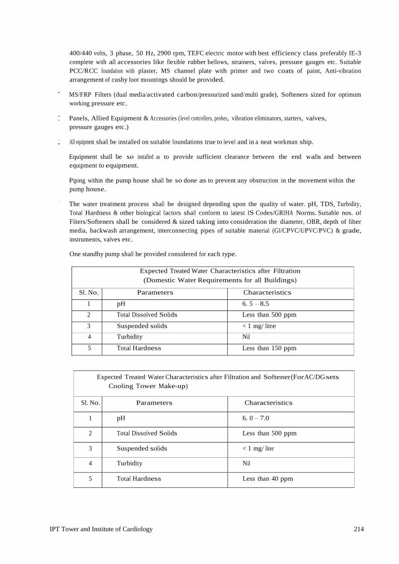
IPT Tower and Institute of Cardiology 214
400/440 volts, 3 phase, 50 Hz, 2900 rpm, TEFC electric motor with best efficiency class preferably IE-3 complete with all accessories like flexible rubber bellows, strainers, valves, pressure gauges etc. Suitable PCC/RCC foundation with plaster, MS channel plate with primer and two coats of paint, Anti-vibration arrangement of cushy foot mountings should be provided.
MS/FRP Filters (dual media/activated carbon/pressurized sand/multi grade), Softeners sized for optimum
working pressure etc.
Panels, Allied Equipment & Accessories (level controllers, probes, vibration eliminators, starters, valves, pressure gauges etc.)
All equipment shall be installed on suitable foundations true to level and in a neat workman ship.
Equipment shall be so installed as to provide sufficient clearance between the end walls and between
equipment to equipment.
Piping within the pump house shall be so done as to prevent any obstruction in the movement within the pump house.
The water treatment process shall be designed depending upon the quality of water. pH, TDS, Turbidity,
Total Hardness & other biological factors shall conform to latest IS Codes/GRIHA Norms. Suitable nos. of Filters/Softeners shall be considered & sized taking into consideration the diameter, OBR, depth of filter media, backwash arrangement, interconnecting pipes of suitable material (GI/CPVC/UPVC/PVC) & grade, instruments, valves etc.
One standby pump shall be provided considered for each type.
Expected Treated Water Characteristics after Filtration (Domestic Water Requirements for all Buildings)
Sl. No. Parameters Characteristics
1 pH 6. 5 – 8.5
2 Total Dissolved Solids Less than 500 ppm
3 Suspended solids < 1 mg/ litre
4 Turbidity Nil
5 Total Hardness Less than 150 ppm
Expected Treated Water Characteristics after Filtration and Softener(ForAC/DG sets Cooling Tower Make-up)
Sl. No. Parameters Characteristics
1 pH 6. 0 – 7.0
2 Total Dissolved Solids Less than 500 ppm
3 Suspended solids < 1 mg/ liter
4 Turbidity Nil
5 Total Hardness Less than 40 ppm

IPT Tower and Institute of Cardiology 215
2.2 Source of Water Supply
The main sources of water are from the state water supply network. Water received from state wate supply network shall be stored in a UG water Tank. Domestic water requirements will be fulfilled from Under Ground Tank for all Buildings. Flushing water requirements of all buildings shall be fulfilled from STP treated water. Irrigation water requirements for entire campus & AC Cooling Tower make up & Flushing water requirements shall be met with STP treated water.
2.3 Pumps & Water Treatment Equipment
It is proposed to provide all type of pumps required for proper water supply of buildings shall be installed.
Water Treatment Plant is being considered with various types of Filters and Softening Plant to ensure proper quality of water within acceptable limits of hardness, as well as bacteriological limits.
Activated Carbon Filter/Pressurized Sand Filter/Dual Media Filters/Chlorinators for catering Domestic Water
Requirements for all Buildings. Softeners will be installed only where soft water requirement is there like for AC Make up (For Cooling Towers, DG Sets etc.), other critical areas etc.
Sufficient maintenance space shall be provided inside the water treatment plant room for accessibility
of various pumps, panels etc. during repair & maintenance activities.
Water Treatment Plant Room shall be suitably ventilated considering adequate ACPH as per NBC
2016 code.
In hospital minimum 1.5 bar pressure shall be maintained at each outlet for both hot and cold-water supply.
Suitable size Sumps with sufficient sized submersible pumps & level controllers to be considered in plant room for drainage. Also, proper slope to be provided in Water Treatment Pump room so that there is no stagnancy of water during any leakage & it is properly channelized to nearest drainage sump.
Water treatment Pump Room shall be provided with safety equipment/items like suitable elastomeric
mat (as per relevant IS codes) for Panels, fire buckets, fire extinguishers, hand gloves, safety charts, framed Schematic/SLD etc.
2.4 Basic Objectives
It is proposed to provide all sanitary engineering services and specification which are:
High standards of materials and workmanship.
Provide leak proof plumbing.
Reliable and dependable engineering systems.
Provide adequate safety and means to egress easily in case of fire.
To plan the system in such a way as to minimize the energy requirements.
To create minimum nuisance and disturbance to the environment
2.5 Water Supply System
Water requirements has been estimated on the basis of present acceptable standards, References from various sources such the National Building 2016 Code of India, Public Health Manuals, Ministry of Environment, Forests Guidelines, and Latest relevant standards/codes published by B.I.S(formerly I.S.I) etc.
2.6 Water Demand Projection
As per the estimated population and water demand norms discussed above, Total water demand is required to be catered as per the prevailing norms.
IPT Tower and Institute of Cardiology 216
2.7 Water Storage
2.7.1 Under Ground/Overhead Water Storage: -
It is proposed to have underground storage of water equal to minimum one day requirement in case of Raw/Domestic/Flushing /Soft Water Tank/ Irrigation Water Tank .The Over Head Tanks at Terrace level shall be half day capacity.
Tube well water supply is collected in underground storage reservoirs with firefighting storage capacity. It is proposed to provide adequate static Storage for firefighting as per the norms of National Building Code 2016 and Local Fire Services. To prevent the stagnation of the water in the static storage tank, water would be made to circulate through overflow into the storage chamber for the domestic requirement.
Over flow from fire water tank will fill the raw water tank. After treatment of raw water up to portable water condition with the aid of water treatment plant water shall be stored in treated water tanks. Treated water will be further directed to Softener for catering needs of Filter back wash, AC/DG Set make up demand & shall be stored in soft water tanks.
2.7.2 Sizing of Pumps: -
The Flow Rate of Pumps shall be suitably selected to meet each building ‘s water demand & of Sufficient Head depending upon Building Height, Pipe Friction losses, Bends etc. and other relevant Site Conditions. One Standby Pump to be considered in each & every variant. The Pumps shall be sized so as to ensure approximately 4 hours of operation time to fill the overhead tanks.
2.7.3 Construction of WTP:
It is proposed that all Underground Tanks of required capacities catering to various purposes shall be constructed during Phase-I itself. Filters and Softeners of required size shall also be installed during Phase-I catering to requirements of all BuildingsC. of Reverse Osmosis Plant (RO Plant)

IPT Tower and Institute of Cardiology 217
1. General
The EPC Contractor shall carry out Design, Engineering, Supply, Installation, Testing & Commissioning for RO System.
For meeting the requirements of laboratories, dialysis needs, OT scrubs & other critical areas of Hospital, Centralized Reverse Osmosis Plant is proposed at the terrace level of Hospital. Portable type R.O System is proposed for Hostels/ Medical & Nursing Colleges/Hostels/Guest House/Auditorium/Night Shelter etc. for meeting drinking water requirements in common areas (corridors etc.), kitchen, pantry etc. The Output of RO Water should comply with the minimum requirement specified as per BIS 10,500 for Drinking Water.
2. Concept Planning
The Centralized RO shall comprise of RO High Pressure Feed Pumps (HPP), RO Raw Water Pumps (RWP) of Vertical multistage centrifugal type and suitable head to generate permeate flow as per requirements. The pump casing construction shall be preferably of SS-316 & impeller shall be also SS 316. The motor shall be TEFC with min. IE-2/IE-3 efficiency suitable for a supply of 415V / 3 Phase at 50 Hz. Supply. The pump shall be supplied complete with base channel, coupling foundation bolts, pressure gauge, valves at inlet and outlet of each pump. One standby pump needs to be considered for each type.
Central R.O Plant shall be preferably placed at Hospital ‘s Terrace.
Capacity of Centralized R.O Plant shall be selected based on meeting functional requirement (RO water demand of each building/day) as stated above within minimum operating hours (preferably 10 hrs./day).
It shall consist of Package type RO module capable of giving a net treated water output as per requirement, Special Anti-sealant dosing system consisting of suitable no. HDPE tank of capacity as per requirement with a positive displacement diaphragm dosing pump having variable flow rate, Micron cartridge filter (shall be made of FDA compliant high quality poly propylene or some other suitable material) suitable for a flow rate as per requirements, CIP system (Cleaning in Place) consisting of HDPE tank with agitator complete with inlet/outlet, drain overflow etc. along with SS pump of capacity and cartridge filter of 10-micron, PH correction dosing system consisting of one HDPE tank with a positive displacement diaphragm dosing pump having variable flow rate, High pressure side piping from the RO high pressure pumps to the rejects stream control valves shall be of SS 316 using all SS fittings ball valves of suitable pressure rating shall be used till 50 mm size, above 50 mm, flanged globe / water butterfly valves in SS construction shall be used. Rejects pressure control valves shall be globe valve and feed flow control valve shall be of SS 316, SS 316 RO Water storage tank (Capacity as per requirements) of required thickness. Tank shall be provided with water flow meter at inlet & outlet, inlet / outlet valves, overflow / drain connection with MH cover.
Centralized control panel made out of CRCA sheet min. 2mm thick having main contactors for all pumps.
All control and power cabling along with double earthing between the panel shall be provided. An emergency stop push button shall be provided in the panel.
3. Portable RO Unit
Portable RO water unit shall be of suitable Flow rate (preferably 9 to 18 LPH) with min. 10-12 lit water storage or as per OEM standards meeting each building ‘s drinking/cooking water requirement. The R.O Units shall be placed at different locations with minimum two Units on each floor or as per requirement. It should be complete with all interconnecting piping, valves, cartridge filters, diaphragm

IPT Tower and Institute of Cardiology 218
type pumps, RO membranes, cable, drain pipe & other related accessories. It shall be with UV unit. The system shall be suitable for a supply of 240 V AC / 50 Hz.
For Hospitals, the R.O Water requirement per bed is being considered at approximately 40 Liters. With the number of beds being 720, the total requirement comes out to be 28,800 Liters/day. Considering 10 Hours of operation, the capacity of Centralized R.O Plant comes out at around 3000 LPH net flow after rejection of waste water (approx. 2000 LPH) for which 5000 LPH capacity should be proposed. The waste rejected water from RO will be discharged to STP.
RO capacity (portable & centralized) mentioned above indicative only. During detailed designing, if required and found necessary, the capacity / rating of the equipment may be upgraded/ revised subject to concurrence of Engineer-In- Charge.
4. DESIGN BASIS (RO Plant)
Expected Treated Water Characteristics after RO (Reverse Osmosis Plant)
Parameters Characteristics
PH 6. 0 – 7.0
Total Dissolved Solids <50 ppm
Suspended solids Nil
Turbidity As per IS:10500
Iron as Fe Nil
Total Hardness Less than 5 ppm
The Output of RO Water should comply with the BIS 10500 for Drinking Water.
5. INSTRUMENTS LIST including but not limited to (Provision to be considered in the Centralized R.O Plant)
Sr. No. INSTRUMENT
1 Flow Indicator
2 Pressure Gauge
3 Pressure Switch (Low & High)
4 Conductivity Indicator
5 PH Meter etc.
IPT Tower and Institute of Cardiology 219
D. - Fire Fighting System
1.0 GENERAL
The EPC Contractor shall carry out Design, Engineering, Supply, Installation, and Testing & Commissioning of Fire Fighting Works.
Fire Fighting system shall comprise of Wet Riser /Hydrant (Internal & External), Sprinkler system, Down comer System, Gas flooding system for panels, Computer Rooms & other sensitive areas, Fire Extinguishers, Fire Signage ‘s near Fireman ‘s lift, Fire Exits, Fire Brigade Inlet/Draw Out Connections etc. proposed for various Buildings.
Suitable size shafts, cutouts, Niche, openings etc. shall be provided to facilitate installation of Pipelines etc. in all floor slabs of various buildings for various service areas, as required. All shafts, cutouts, Niche, openings etc provided on floor slabs shall be suitably closed after laying of services lines as per fire safety norms as per NBC 2016. Doors shall be provided for all shafts at all floors as per fire safety norms as per NBC 2016.
The ratings and capacities of various equipment are based on NBC 2016 Part - IV and subject to revision during detailed designing stage.
The firefighting system is proposed on basis of type of occupancy as per NBC 2016 Part -IV and building Height. The system proposed are water based and gas based. Water based Fire suppression system is having piping network inside and outside the building with internal and external Hydrants, First Aid Hose reel at regular intervals according to various type of occupancy. The distribution system is finally connected to ring main system for firefighting.
Sprinkler system with water distribution pipes sprinkler heads above and below false ceiling is designed to actuate automatically to extinguish the fire by discharge of water when room temperature crosses 68˚ C in case of fire.
The following standards, bye-law, manual has been followed in designing the firefighting system: -
Relevant IS codes published by Bureau of Indian Standards.
National Building code Part IV for fire Protection System 2016.
All Accessories shall be of UL listed and FM approved
latest relevant standards/codes published by B.I.S(formerly I.S.I) general specifications for electrical
works-part v (wet riser & sprinkler system-2006).
2.0 WATER REQUIREMENTS:
Water services for Hydrants and sprinkler system shall be stored in underground / overhead tanks.
2.1 Underground Static fire tank: -
Underground reservoir shall be provided as per latest NBC-2016 requirement/ Local Fire Authority Bye laws.
2.2 Overhead storage fire tank: -
Overhead fire water tanks on the terrace will be provided for down comer system and as supplementary fire storage as per NBC requirement/ Bye laws.

IPT Tower and Institute of Cardiology 220
The effective capacity of reservoir for various type of occupancy as per Table 7 of NBC 2016 Part – 4.
2.3 SYSTEM DESCRIPTION
The Fire Fighting System shall consist of Diesel Fire Pumps, Electrical Driven Fire Hydrant pump, Electrical Driven Sprinkler pump , Water Curtain pump, Jockey Pumps, Fire hydrant (Internal & External), Air Cushion Tank with air release valves for all risers, Down comer system with /without terrace pumps, Pressure vessel, ,associated instruments, cabling, piping (internal & external), valves, Fire Brigade inlet connections, draw out connections for each wet riser, fire signage‘s, extinguishers, Gas based fire suppression system, Fire detectors, Discharge Nozzles, control panel etc. has to be provided as per NBC 2016 requirements. Jockey pumps shall maintain pressure in all water lines for Hydrants & Sprinklers fully charged under pressure for fully Automatic operation in case of fire. In case of slow pressure loss, jockey pump will start and at about 1 kg/cm2 pressure loss in the system, jockey pump will not start and main pump will start automatically.
2.4 Shafts/Cut Outs & Room Provisions: -
Minimum size of shafts to be provided to accommodate sprinkler/wet riser/down comer /drain pipes etc. will be 1200 X 600 MM (approx.) and to be provided at suitable locations as per relevant codes & standards.
Shafts & Inspection doors shall be minimum of 120 minutes fire rated or as desired by relevant codes.
Fire Control Room to be provided In Ground Floor which shall be easily accessible & shall accommodate all fire alarm system panel/public address system panel etc.
2.5 Egress components: -
Egress components to be considered are the no. of exits to which access is provided, capacity of exit access, travel distance to an exit, directional exit etc.
The width of corridors, aisles/ramps required for exit access shall be sufficient to ensure smooth flow of occupants to exit. Exits shall be so located that the travel distance on the floor shall not exceed distance as mentioned in NBC 2016.
No exit doorway shall be less than 1000 mm in width except in assembly buildings where door width shall not be less than 2000 mm in width. All exit doorways shall not be less than 2000 mm in height.
The requirements of nos. of staircases shall supplement the requirements of different occupancies as per NBC 2016 norms.
2.6 Pressurization & Compartment System: -
Pressurization of enclosed Staircase/Lift Lobby/Lift well provisions to be considered as per NBC 2016 requirements.
Mechanical ventilation system for basement to be designed to permit min. 12 ACPH or as per relevant codes in case of fire or distress call.
All floors shall be compartmented / zoned with area of each compartment conforming to NBC 2016 provisions depending upon usage & area/building type.
Smoke exhaust fans in mechanical ventilation system shall be fire rated &shall withstand 250 degree Celsius for 120 minutes.
IPT Tower and Institute of Cardiology 221
2.7 Access to Fire Tenders: -
For access to fire tenders, a clear motorable approach of at least 6 meters shall be kept for movement of fire tenders all around the building. The width of the main entrance to the complex shall not be less than 6.0 meters.
2.8 Location & size of Fire Pump House: -
The fire pump house shall be located adjacent to underground fire tanks. The slab of UGT shall be designed structurally to take the load of fire rescue tender (if coming in the drive way area).
The base of the water tank shall be kept at a level preferably 450 mm to 600 mm (or as desired as per codes) above the level of base of fire pump room so that pumps operate under positive suction conditions & the entire water capacity is above the body of the fire pumps as per best fire engineering practice.
Fire Pump House shall be separated by fire walls all around & doors shall be protected by fire doors (120 mins rated).
The size of Fire pump house & distance between pumps, pumps & walls, panel & wall etc. shall be as per latest IS codes/NBC 2016.
Sufficient maintenance space shall be provided inside the fire plant room for accessibility of various pumps, panels etc. during repair & maintenance activities.
Fire Plant Room shall be suitably ventilated considering adequate ACPH as per NBC 2016 code.
Suitable size Sumps with sufficient sized submersible pumps & level indicators to be considered in plant room for drainage. Also, proper slope to be provided in Fire Pump room so that there is no stagnancy of water during any leakage & it is properly channelized to nearest drainage sump.
Fire Fighting pipes from Fire Pump Room to various buildings shall be laid underground at suitable depth as per latest relevant standards/codes published by B.I.S(formerly I.S.I) specs. Adequate no. of Hume pipes having suitable dia. with spare shall be laid across the roads/pathways etc.
Fire Pump Room shall be provided with safety equipment/items like suitable elastomeric mat (as per relevant IS codes) for Panels, fire buckets, fire extinguishers, hand gloves, safety charts, framed Schematic/SLD etc.
2.9 Pumps & related Equipment/Piping & Related Accessories: -
Quantity & Type of Fire Pumps (Electric driven Jockey/ Electric driven Terrace Booster/ Electric driven Hydrant/ Electric driven Sprinkler/ Diesel driven Pumps) shall conform to NBC 2016/relevant IS codes.
All fire pumps shall be with positive suction arrangements.
Capacity of the Pumps shall be selected as per latest NBC 2016 /IS codes & Head as per Building Height & Frictional losses due to bends, pipe lengths etc.
Horizontally mounted split case single/multi stage, single/multi outlet energy efficient centrifugal pump, suitable for operation on 415 volts ± 10%, 3 phase, 50 HZ A.C supply, IE-2 Class efficiency motor, complete with flexible coupling (double arch) and coupling guard as required. Fire pump having C.I. body, bronze/gunmetal impeller and S.S. Shaft with mechanical seal to be considered. Casing shall be designed to withstand 1.5 times the working pressure.
Diesel driven pump with engine (Min. 4 Cylinders), water cooled radiator-based cooling & shall be complete with cooling system, fuel system, fuel tank (to cater for min. 2 hours), inter connecting piping, starting system, governing system, PRV, exhaust system with residential silencer suitable for outdoor installation & silencer piping shall be extended up to 1 m, outside pump house duly insulated with 50 mm thick glass wool/ rock wool & 1

IPT Tower and Institute of Cardiology 222
mm thick aluminum cladding. Flexible connection in between exhaust pipe & pump needs to be provided to suppress vibrations.
All the fire pumps shall cut-in automatically based on the pressure settings in pressure switch, so as to ensure that the entire fire main line, risers etc. are pressurized on a continuous basis.
The jockey pump shall automatically cut-out based on the pressure settings of pressure switch. However, the remaining fire pumps shall cut off only in the manual mode.
All Foundation (PCC/RCC) for Equipment including foundation bolts & vibration isolation springs/pads to be provided.
Mild steel/GI class ‗C‘pipes confirming to IS: 1239/3589 including all ductile iron fittings like bends, elbows, tees, couplings etc. shall be used in Fire Fighting system.
GI Suspenders, Brackets & Floor/Wall supports for suspending / supporting pipes to be provided.
Till 50 mm dia. Pipe, screwed joints with DI Threaded Fittings shall be provided & 65 mm dia. & above, DI Grooved Fittings joints to be considered. Suction dia. & discharge dia. of pumps shall be as per pump discharge as per OEM standards.
The entire pipe work (above ground), pump etc. shall be painted with one coat of primer & two or more coat of red color shade no. 536 of IS:5 (Post Office synthetic enameled red paint) as per directions of Engineer- in-Charge.
At terrace/Remote level hydrant, minimum 3.5 kg/sq.cm pressure shall be maintained.
The pipeline shall be designed with suitable flow velocity & friction factor as per relevant standards.
All pipes below ground will be protected against soil corrosion by wrapping & coating material as per IS: 10221.
Pipes of 150 mm dia. & below, will conform to IS: 1239. Pipes of 200 mm dia. & above will conform to IS: 3589.
Suitable Nos. of Installation control Valve (ICVs) to be considered conforming to latest IS codes depending upon no. of sprinklers.
All necessary valves of PN 16 rating (min.) like butterfly/ globe/ gate/ non return/ sluice, Y/Pot Strainers, pressure gauges etc. to be considered as per requirement (controlling flow/ isolating/one way flow etc.) & meeting the functionality.
Pressure vessels shall be provided with all the terrace pumps & at plant room also.
All Pumps shall be provided with flexible bellows (double arch, PN-16 Rating) to dampen vibration/noise at source.
Vibration Isolators/Anti Vibration Pads needs to be provided for all pumps to absorb vibration at source. Orifice
Plate shall be considered to reduce pressure on individual hydrant to maintain operating pressure of 3.5 kg/sq.cm.
Air vessel/Pressure vessel of suitable size need to be provided in fire plant room & near terrace pump. To compensate for slight losses of pressure in the system and to provide an air cushion for counteracting pressure surges / water hammer in the pipe work air vessel conforming to IS: 3844 shall be furnished in the pump room near pump. The air vessel shall normally be half full with water and remaining filled with air which shall be under compression when the system is in normal operation.
Air cushion tanks with air release valves needs to be provided for all risers of sprinkler/hydrant pipes.
3.0 Wet Riser & Hydrants System: -
3.1 External Yard Hydrants

IPT Tower and Institute of Cardiology 223
External yard hydrants shall be of ‗Stand Post‘ type conforming to IS: 908 and comprising of stand post for single or double (conforming to NBC 2016) outlet with oblique pattern hydrant valve, Controlled Percolating (CP) Hose ISI marked (IS:8423) 63 mm dia. x 15 m long complete with instantaneous type Stainless Steel 63 mm dia. ISI marked Male & Female couplings, 63mm dia. Stainless Steel branch pipe with Stainless Steel l nozzle of 20 mm nominal bore outlet with instantaneous type 63 mm dia. coupling M.S. fire hose weather proof cabinet (750x600x250mm approx. or as per requirement) made out of 16 gauge M.S. sheet capable of accommodating landing valve, hose pipes, branch pipe, nozzle, fittings & accessories. The box shall have a front glass door with lock and key arrangement & shall be painted with one coat of primer & two coat of finished stove enameled post office red color paint & "External Fire Hydrant" written on front.
The ring main around the building will be laid min. 1 m below ground level, 2 m away, within 15 m from face of the building.
The distance between the external hydrant post shall be considered as per hazard classification conforming to relevant IS codes. However, maximum distance shall be 45 m.
3.2 Internal Hydrants
It shall consists of Type -A- single headed, Stainless Steel ISI marked oblique pattern hydrant landing valve with 80 mm dia. flange inlet and 63 mm dia. instantaneous type female out let, swinging type First Aid hose reel in red color drum with 36 mtr long and 20 mm dia. heavy duty rubber water hose, 20 mm dia. globe valve stop cock, terminating with Stainless Steel coupling & nozzle of 5mm outlet with shut off valve, 63mm dia. Stainless Steel branch pipe with Stainless Steel nozzle of 20 mm nominal bore outlet with instantaneous type 63 mm dia. coupling, fireman‘s axe with heavy duty insulated rubber handle, 2 Nos. of 15 m long Non Percolating Hose Pipe, suitable size of MS door made up of 16 gauge MS Sheet capable of accommodating fire hose reel, landing valve, hose pipes, fittings. The door shall have a front glass with lock and key arrangement & shall be painted with one coat of primer & two coat of finished stove enameled post office red color paint & "Internal Fire Hydrant" written on front.
Quantity for the same need to conform to NBC 2016/relevant IS codes.
One no. pressure gauge & 80 mm dia CI Butterfly Valve to be provided in each internal hydrant riser per floor.
No. of risers/floor in each building shall be governed by the max. Travel distance as specified in NBC 2016.
3.3 Fire Brigade Inlet Connections/ Draw Out Connection
4 Way Fire Brigade Inlet connection complete with all accessories (sluice valve/NRV etc.) shall be provided for connection to Ring mains, Wet riser/down comer system, underground tank.
2 ways draw out connection to be considered near fire Pump House.

IPT Tower and Institute of Cardiology 224
3.4 Sprinkler System: -
Automatic sprinkler system shall be provided as per requirements of NBC 2016 or relevant IS codes.
As per hazard classifications, maximum/minimum distance between sprinklers, between sprinkler & walls to be maintained. Coverage area of each sprinkler & assumed maximum area of operation shall conform to relevant IS codes.
Side wall/pendant/upright sprinklers to be provided as per requirements, shall be UL & FM certified, complete with rosette plate, glass bulb temperature rating of 68 degree Celsius (red color), Quick response type, chrome plated finish & in compliance with NBC 2016 & relevant IS codes.
Suitable Nos. of Installation control Valve (ICVs) to be considered consisting all accessories (Butterfly valve, Y strainer, water gong, Alarm Valve, drain valve, Pressure gauge etc.) conforming to latest IS codes.
Sprinkler shall be selected as per temperature rating which shall be based on usage type. Color code shall be in conformance to relevant IS codes.
Inspection test assembly/zonal control valve complete with flow switch & other related accessories (NRV/Butterfly, drain valve, Pressure gauge, sight glass etc.) to be provided in each floor sprinkler riser.
Flexible pipe for connecting sprinklers (braided type) & UL & FM certified to be considered of various sizes as per site conditions to maintain symmetry & crossing of ducts & other utilities.
3.5 Portable Fire Extinguishers: -
The sufficient qty. of portable/trolley mounted type fire extinguishers (Gas Based stored pressure type CO2 type /Ammonium Phosphate Type/ Mechanical Foam etc.) shall be provided at all levels of the building, plant room, basement, substation etc. at strategic locations as per requirements, generally to follow NBC- 2016 and IS – 2190: 1992 to extinguish fire of class A, B, C.
Location of the Fire Extinguishers shall be considered near all the Internal Hydrants, HT Panel Room, LT Panel Room, Lift Machine Room, Fire Pump House, Server Room, UPS Room, Fire Control Room, Security Control Room, Car Parking etc.
Clean agent fire extinguishers to be provided in laboratories & other critical areas.
All Fire Extinguishers shall be Halon Free.
4.0 Gas based Fire Suppression System: -
4.1 For Server Rooms & Data Centre:
The Total Room Flooding system of fire detection and quenching is proposed in all Low Voltage Equipment rooms where Water sprinklers cannot be used. The Gas cylinder assembly should be UL/FM approved with seamless CCOE approved cylinder and will be connected to discharge nozzles through metal Piping. The master cylinder Kit fitted on Gas cylinder will be operated through separate Fire detection Panel and will release zero Ozone depletion potential Gas through the nozzles in case of fire.
4.2 For Electrical panels:
Tube based Fire protection system is used in the Electrical Panels to be installed in substations. The detection Tube shall be installed throughout the compartment of panels. The location and spacing of tube shall be above the hazard to be protected. Cylinder equipped with brass valve, pressure Gauge isolation valve will be fitted on the wall of the panel with suitable brackets and will be connected to the detection tube. in case of fire the tube shall rupture at a point. The rupture Tube shall result in formation of discharge point and release Gas Agent in Uniform pattern.

IPT Tower and Institute of Cardiology 225
5.0 Fire Signage: -
Various types of signage are proposed in the complex as per NBC 2016 Part -4. Material of signage shall be of acrylic/aluminum of required dimensions. At every floor near Lift landing diagram showing stairways shall be provided mentioning instructions - 'IN CASE OF FIRE USE STAIRS UNLESS INSTRUCTED OTHERWISE'.
The signage shall be above call push button in Lift Lobby. Floor Signage will be provided in each floor within the staircase & should easily readable. Each corridor of every floor will have directional signage indicating Fire Escape route. These Signage may be LED lit with UPS power backup or of photo Luminescent paint. So that they will be visible in dark in case of power failure.
6.0 Electrical Works related to Fire Fighting System: -
Firefighting panel of suitable size incomer & sufficient nos. of outgoing feeders for all pumps along with spares/spaces to be provided.
Power cabling of suitable size to be laid from LT panel to firefighting panel. Power cabling of suitable size from firefighting panel to fire pumps to be laid. Control cabling from fire pumps to firefighting panel &Firefighting panel to pressure switch to be done.
Suspenders and/or cable trays for laying cables to be used.
For sprinkler system, fire annunciation panel needs to be considered.
Motor shall be TEFC squirrel cage AC induction type. The motor shall be suitable for continuous duty & rating necessary to drive the pump at 150% of its rated discharge with at least 65% rated head. Motor shall be with class F insulation & IE-2 class efficiency. DOL/star delta starter to be provided as per
H.P rating of motors.
Adequate no. of NO/NC contacts for interlocks, indicating lamps, remote operation etc. shall be provided on starter/contactor.
Metallic body of all motors, medium voltage equipment etc. shall be connected by 2 separate & distinct earth conductors to the earth stations of the installations. Looping of such body earth conductors is acceptable from one equipment to another.
7.0 Design Calculation
7.1 PUMPING HEAD CALCULATION: As per design
7.2 HYDRAULIC CALCULATIONS
Sprinkler System shall be designed/calculate as per NBC-2016, local fire bye laws & IS:15105.
IPT Tower and Institute of Cardiology 226
TECHNICAL SPECIFICATIONS
PHE & FIRE FIGHTING WORKS
1.00 PLUMBING & SANITARY INSTALLATIONS
1.01 Special condition for PHE work: The plumbing work shall be carried out by
specialized plumbing agency who has licensed plumber and experience of similar works. For supervising the plumbing work at least one engineer who has rich experience in executing plumbing work shall be engaged full time. Approval of specialized agency shall be obtained from JDA.
1.02 The provision of adequate sanitary and safety facilities as per the norms of NBC and
good engineering practice shall be compliance during construction for construction workers and staff.
1.03 The water use for construction shall be suitable for the same and should be used efficiently
and checks and control valves shall be provided to avoid the wastage and leakage. 1.04 To reduce the water consumption of the building, the flushing system of water closet
shall be of dual flushing cistern type and plumbing fixture shall be provided which require GRIHA compliance for low flow rate.
1.05 Lab service related to plumbing & firefighting will be executed by specialized agency
who has experience of carrying out similar work earlier. All the lab item shall be detailed out & redesign as per requirement of client , WHO, CDC norms, items given in BOQ are indicative but covered the cost as per the latest requirement of client, WHO, CDC and required approval of client before execution.
1.06 Wall Caps
Wall caps shall be provided on all walls, floors, columns etc. wherever supply and disposal pipes pass through them. These wall caps shall be chromium plated brass snugly fittings and shall be large enough to cover the puncture properly and shall conform to IS: 4291.
1.07 Pipes, Hangers, Brackets, etc.
Sturdy hangers, brackets and caddles of approved design shall be installed to support all pipe lengths, which are not embedded over their entire runs. The hangers and brackets shall be of adjustable heights and painted with red oxide primer, and two coats of enamel paint of approved make and shade. Clamps, coils and saddles shall be provided to hold pipes with suitable gaskets of approved quality. The brackets and hangers shall be designed to carry the weights of pipes safely. Wherever required pipes may run along ceiling level in suitable gradient and supported on structural clamps. Spacing for clamps for such pipes shall be as follows:

IPT Tower and Institute of Cardiology 227
Vertical Horizontal
G.I. Pipes
300 cms
240 cms
H.C.I. Pipes
180 cms
120 cms
1.08 Pipe sleeve
Adequate number of sleeves (pipe inserts) of Cast Iron or Mild Steel shall be provided where pipes cross through concrete, masonry and similar work. The pipe inserts shall be provided with removable timber plugs to keep foreign matter out till installation of the services pipe cross the sleeve. The diameter of sleeve should be one size higher than the proposed dia or as instructed by the Engineer.
1.09 Floor trap inlet
Bath room traps and connections shall ensure free and silent flow of discharging water. Where specified, contractor shall have a special type G.I. / M.S. inlet hopper without or with one, two or three inlet sockets to receive the waste pipe. Joint between waste and hopper inlet socket shall be lead caulked/welded/threaded. Hopper shall connect to a C.I. P or S trap with at least 50mm water seal. Floor trap inlet hoppers and traps shall be set in cement concrete 1:2:4 blocks without any extra cost.
1.10 C.P. gratings
Floor trap and urinal trap shall be provided with 110mm square or round C.P. /Stainless steel grating, with rim of approved design and shape. Minimum thickness shall be 3 mm.
1.11 Hot Water Supply
The chase will be closed in cement mortar 1:2 (1 cement: 2 coarse sand). Pipes shall be clamped to the wall inside the chase.
1.12 Making Connections
Contractor shall connect the new sewer line to the existing manhole by cutting the walls, benching and restoring them to the original condition. A new channel shall be cut in the benching of the existing manholes for the new connection. Contractor shall remove all sewage and water if encountered in making the connection without additional cost.
1.13 Water Heater
Water heater shall be automatic pressure type water heater (with pressure release valve) with heavy gauge copper container duly tinned, thermostats, indicator lamp and glass wool insulator. the water heaters shall be fitted with pressure release valve, non-return valve and inlet and outlet stop valves as required. Water heaters to conform to IS: 2082, in case the solar hot water has also provided in the building the supply of same shall be connected to inlet of water heater.
1.14 FULLWAY BALL VALVE

IPT Tower and Institute of Cardiology 228
The valves shall be of full-bore type and of quality approved by the Engineer. The body and ball shall be of copper alloy and stem seat shall be of Teflon.
1.15 CPVC PIPES: CPVC pipes shall be used in the internal water supply if specified in the
Bill of Quantities. These may require to be connected to the existing/ new GI pipes. The pipe and fitting approved make solvent shall be used as per approved manufacture specification.
1.16 SAMPLE AND SHOP DRAWINGS;
All plumbing items shall be provided as per approved sample/data sheet approved by the JDA. Before placing the order, the contractor shall submit the shop drawings prepared based on tender drawings and BOQ alongwith samples for approval of JDA. The shop drawings shall have all the details. The contractor has to obtain the approval of external plumbing drawings from DJB/MCD before start of work.
1.17 SS pipe: The SS pipe shall be provided in lab. And specific water supply as per
drawings and BOQ. The jointing shall be press type fittings with S-C contour in accordance with DVGW regulation W-524 with fittings for payment only centre to centre total length of composite pipe and fitting shall be measured. A press joint is made by mechanical deformation of the tube and fitting means of special hydraulic tool and cutting of pipe shall also be carried by later cutting tools by authorized agency. An elastomer o-ring is inserted in the recess at the end of the fitting for sealing. When the joint is made, the cross section of the tube becomes hexagonal. A calibration tool is used to ensure that the joint made is up to standard, Clearances from wall, floor and ceiling should be allowed for making the joint refer to the manual of the press tool for clearance requirements.

IPT Tower and Institute of Cardiology 229
20.00 FIRE FIGHTING SYSTEM
GENERAL 20.01 Work under this contract shall be executed as shown on the drawings and given
in the specifications and required at site whether explicitly shown or not. 20.02 Not-withstanding the sub-division of the documents into separate sections and
volumes every part of each shall be deemed to be supplementary to and complementary of every other part and shall be read with and in to the contract so far as it may be practicable to do so.
20.03 Where it is mentioned in the specifications that the contractor shall perform
certain work or provide certain facilities, it is understood that the contractor shall do so without any extra cost to the Employer/JDA.
20.04 The material, design and workmanship shall satisfy the local fire regulations.
The job specifications contained herein and codes referred to where the job specifications stipulate in addition to these contained in the standard codes and specifications; these additional requirements shall also be satisfied.
20.05 Portable fire extinguisher shall be provided in the building as per BOQ which
should not contain halogen to minimize the use of ozone depleting substance as per GRIHA.
21.00 SCOPE OF WORK
21.01 Work under this contract consist of furnishing labour, materials, equipment and
appliances necessary and required to completely do all works relating to the fire protection system as described here-in-after and shown and the drawings, consisting of:
i) Supply, installation, testing and commissioning of:
Fire hydrant system including requisite fire pumps and ancillary equipment’s –As per design
Fire sprinkler system, as per design
Portable Fire Extinguishers
ii) Preparation of plans and getting pre-installation approval by the Local Fire Authority.
Getting tested by and approval of the installation by the Local Fire Authority during the fabrication/construction stage as well as after completion. It will be the responsibility of the Contractor to get all approval and completion certificate from the Local Fire Department without which the work will not be taken over by the department. Fee payable to the local bodies for such activities shall be borne by the Department on production of receipts for money paid and the all other expenses barring the fee will be borne by the Contractor.
iii) Supply of necessary spare parts during the commissioning stage.

IPT Tower and Institute of Cardiology 230
iv) Supply of any other item or services not specifically mentioned anywhere but
required by the Local Fire Authority or essential for the completion & operation.
22.00 INTERPRETATION
22.01 In interpretation of specifications, the following order of decreasing
importance shall be followed:
a. Statutory Rules & Regulation
b. Schedule of quantities
c. Additional specifications
d. List of approved make of materials e. General rules and conditions
22.02 Matters not covered by the specifications given in this contract, as a whole shall
be covered by relevant and latest LATEST RELEVANT STANDARDS/CODES PUBLISHED BY B.I.S(FORMERLY I.S.I) specifications / Indian Standard Codes. If such codes on a particular subject have not been framed, the decision of the engineer shall be final and binding.
23.00 SPECIFICATIONS
23.01 Work shall be carried out strictly in accordance with the specifications
attached to the tender. 23.02 Works not covered in the specifications shall be carried out as per relevant latest
LATEST RELEVANT STANDARDS/CODES PUBLISHED BY B.I.S(FORMERLY I.S.I) specifications/ Indian standard Code of practice specifications of materials.
24.00 EXECUTION OF WORK
24.01 The work shall be carried out in conformity with the contract drawings and
within the requirements of architectural, AC, plumbing, electrical, structural and other specialized services drawings.
25.00 TENDER DRAWINGS
25.01 For guidance of the bidder, drawings as listed are enclosed with these tender
documents. These drawings are broadly indicative of the work to be carried out. The Contractor on award of work will furnish shop drawings based on the working drawings issued to him, as required in advance for approval of Engineer and get the same approved by Local Fire Authority/other statutory bodies. No claim whatsoever shall be admissible on account of changes that may be introduced by the Engineer /Local Fire Authority.
25.02 The Contractor shall examine all specifications, tender conditions and
drawings before tendering for the work.

IPT Tower and Institute of Cardiology 231
25.03 Information, levels and dimensions given in the tender drawings are
supposed to be correct but the contractor shall make independent inquiries and verify the same. No claims for extras shall be admissible in case of any deviations for incorrectness of the information, levels or dimensions.
25.04 The contractor shall obtain all information relating to the local regulations,
bylaws, and application of any and all laws relating to him work or profession. No additional claims shall be admissible on this account.
26.00 SHOP DRAWINGS
26.01 The Contractor shall prepare and furnish all shop drawings in quadruplicate at no
extra cost for approval by the Engineer before commencing fabrication/manufacture of the equipment. Such shop drawings shall be based on the Architectural & Firefighting drawings and requirements laid
down in the specifications and as per site conditions. The manufacture of equipment shall be commenced only after the shop drawings are approved in writing by the Engineer. Such drawings shall be co-ordinated with all disciplines of work.
26.02 Contractor shall verify all dimensions at site and bring the notice of the JDA
any or all discrepancy or deviations notices. The decision of the JDA in the regard shall be final.
26.03 Large size details and manufacturer’s dimensions for materials to be
incorporated shall take precedence over small-scale drawings. 26.04 All drawings issued by the consultants for the work are the property of the
Consultants and shall not be lent, reproduced or used on any other works than intended, without the written permission of the Consultants.
26.05 Working drawings shall be approved by the consultant. Four sets of shop
drawings shall be submitted for approval showing:
a) Any change in layout from the contract drawings.
b) Equipment layout, piping, wiring diagram and instrumentation.
c) Manufacturers or contractor’s fabrication drawings for any material or equipment.
27.00 COMPLETION DRAWINGS
On completion of the work and before issuance of certificate of virtual completion, the Contractor shall submit to the Engineer. General layout drawings, drawn at approved scale indicating layout of pump house piping and its accessories “As installed ". These drawings shall in particular give the following:
a. General layout of pump house.

IPT Tower and Institute of Cardiology 232
b. Panels and other equipment location and sizes etc. c.
Complete Schematic as installed.
d. Location of Hydrants, Earth pipes, route of earthling conductors etc.
e. Route of all cables and pipes run along with detail sizes and mode of installation.
28.00 DOCUMENTS
The Contractor shall submit to the Engineer, the following documents on completion of the work and before issuance of virtual completion.
i. Warranty for equipment installed.
ii. Test certificates.
iii. History sheets of the equipments.
iv. Catalogues.
v. Operation and Maintenance manuals.
vi. List of recommended spares and consumables.
vii. Reconciliation statement.
viii. All approvals and sanctions. 29.00 MATERIALS
29.01 All materials used on this work shall be new, conforming to the
specifications. 29.02 Materials shall conform to the technical specification and/or the Latest
relevant standards/codes published by B.I.S(formerly I.S.I) /Indian Standards Specifications as amended up to date and carry certification mark, wherever so required.
29.03 Only approved make of material shall be used. The contractor shall get the
samples of all the items approved from the Engineer before commencing the supply.
30.00 TESTING OF MATERIALS
30.01 Contractor shall be required to produce manufacturer’s test certificates for
the particular batch of materials supplied to him. The test carried out shall be as per the relevant Latest relevant standards/codes published by B.I.S(formerly I.S.I)/Indian Standards.
30.02 Any weights of sizes given in the tender having changed due to metric
conversion, the nearest equivalent sizes accepted by Indian Standards shall

IPT Tower and Institute of Cardiology 233
be acceptable without any additional cost. The decision of the JDA shall be final and binding on the contractor.
30.03 The Engineer shall have full power to get any material of work to be tested
by an independent agency at Contractor's expense in order to prove the soundness and adequacy.
31.00 INSPECTION AND TESTING
31.01 All equipment shall be inspected and tested as per an agreed quality
Assurance Plan before the same is packed and dispatched from the Contractor's Works. The Contractor shall carry out tests as speci- fied/directed by Engineer.
31.02 Contractor shall perform all such tests as may be necessary to meet
requirements of Local Authorities, Municipal or other statutory laws/ bye- laws in force. No extra shall be paid for these.
31.03 The Engineer may, at his sole discretion, carry out inspection at different stages during manufacturing and final testing after manufacturing.
31.04 Approvals or passing of any inspection by the engineer or his authorized
representative shall not, however, prejudice the right of the Engineer to reject the plan if it does not comply with the specification when erected or give complete satisfaction in service.
31.05 All materials and equipment found defective shall be replaced and the
whole work again tested to meet the requirements of the specifications, at the cost of the contractor. Contractor has to obtain a performance certificate/approval for the complete layout of piping/equipment erected.
32.00 WELDING
32.01 The welding procedure, types of electrodes etc. shall be in accordance with
the following IS specifications.
Welding Procedures IS: 823
Welding Electrodes IS: 814, but of approved makes only
Testing of Welders IS: 817 32.02 Only Welders fulfilling the requirements of IS: 817 and approved by the
JDA shall be employed by the Contractor. 33.00 JOINING MATERIAL (GASKET)
Gasket, for use in between flanged joints, to be of CAF as per IS-2712, thickness as specified in S.O.Q.
34.00 PAINTING
34.01 All above ground pipes, pipe fittings, hose cabinets structural steel work
pipe supports etc. shall be painted as per specifications given below.

IPT Tower and Institute of Cardiology 234
34.02 Painting shall be done only after the completion of fabrication work and testing.
34.03 The instructions of paint manufacturer shall be followed as far as possible
otherwise the work is to be done as directed by the JDA. 34.04 All cleaning materials, brushes, tools and tackles, painting, material etc.
shall be arranged by the Contractor at site in sufficient quantity. 34.05 All rust, dust shall scales, welding slag or any other foreign materials shall
be removed fully so that a clean and dry surface is obtained prior to painting. Any other oily containment shall be removed by use of a solvent prior to surface cleaning.
34.06 First coat of primer paint must be applied by brush on dry clean surface
immediately or in any case within 3 hours of such cleaning. 34.07 Primer paints - one coat (minimum thickness 100 microns) self-priming
epoxy mastic. 34.08 Finishing coats:
a) For Pump Rooms - 2 coats (thickness minimum 50 microns each) of epoxy
paint, fire red shade as per IS: 4.
b) For other than Pump Rooms - 2 coats of synthetic enamel paint, fire red shade as per IS: 4.
35.00 COATING WRAPPING FOR UNDERGROUND PIPES
35.01 All underground piping shall be protected by coating and wrapping as per
the following procedure. 35.02 The materials and workmanship shall in general conform to IS: 10221, 1982 or
as directed by the JDA. 35.03 Cleaning - The pipes shall be thoroughly cleaned by dust, rust will scale,
oil, grease etc. by stiff wire brush and scrappers. The surface shall be coated with the primer immediately after cleaning.
35.04 Priming – Suitable primer shall be applied as an undercoat. The
manufacturers recommended procedure would be followed for applying the primer.
35.05 Paste Application - Paste shall be applied to fill up uneven surfaces in order to
ensure smoothness for subsequent wrapping with multi-layer tape. 35.06 Tape Wrapping - The tape is to wrap while the second coat of primer is still
tacky. Winding is to be done with 50% overlap so that the total thickness of 2.0mm tape would become 4.0mm. It should be ensured while wrapping that air bubbles are not trapped. The ends of tape shall be secured with nylon binding to ensure that the tape doesn’t get loosened while handling.

IPT Tower and Institute of Cardiology 235
35.07 The total thickness including 2 coats of primer, 50% overlap of tape etc. should not be less than 4.5mm or as per manufacturer recommendations.
35.08 The ‘Holiday Test’ is to be conducted as per IS: 10221 for detecting any
entrapped air or any other defect. The Contractor is to arrange for the Holiday Test and to rectify the defects if found any.
36.00 TRAINING OF DEPARTMENT PERSONNEL
36.01 The Contractor shall train the Department’s personnel to become proficient in
operating the equipment installed. Training shall be done before the expiry of the defects liability period.
36.02 The period of training shall be adequate and mutually agreed upon by the
Engineer and Contractor.
IPT Tower and Institute of Cardiology 236
36.03 The Department’s personnel shall also be trained for routine maintenance work and lubrication, overhauling, adjustments, testing, minor repairs and replacement.
36.04 Nothing extra shall be paid to the Contractor for training
Department’s personnel. 37.00 PERFORMANCE GUARANTEE
At the close of the work and before issue of final certificate of virtual completion by the Engineer, the Contractor shall furnish a written guarantee indemnifying the Department against defective materials and workmanship for a period of one year after completion and handing over. The Contractor shall hold himself fully responsible for reinstallation or replace free of cost to the Department.
a. Any defective material or equipment supplied by the Contractor.
b. Any material or equipment supplied by the Department which is proved to be
damaged or destroyed as a result of defective workmanship by the Con0ractor.
1102 SPECIFICATIONS FOR PUMPS AND ANCILLARY EQUIPMENT
38.00 SCOPE OF WORK
38.01 Work under this section shall consist of furnishing all labour, materials,
equipment and appliances necessary and required to completely install electrically/diesel engine operated pumps for fire hydrant installations as required by the drawings and specified hereinafter or given in the schedule of quantities.
38.02 Without restricting to the generality of the foregoing the pumps and the
ancillary equipment and shall include the following:
Electrically/diesel operated pumps with motors/diesel engine, base plate and accessories.
Pump suction and delivery headers, valves, air vessel and connections.
a) Alarm system, Pressure gauges/Pressure switch.
b) Electrical switchboards, wiring, cabling, cable tray, control panel and properly connecting to earthing system of the Factory.
c) Foundations, vibration eliminator pads and foundation bolts.
39.00 GENERAL REQUIREMENTS
39.01 Pumps shall be installed true to level on suitable concrete foundations. Base plate
shall be firmly fixed by foundation bolts properly grouted in the concrete foundations.

IPT Tower and Institute of Cardiology 237
39.02 Pumps and motors shall be truly aligned with suitable instruments. 39.03 All pump connections shall be standard flanged type with appropriate
number of bolts. 39.04 Manufacturer instructions regarding installation connections and
commissioning shall be followed with respect to all pumps, switchgear and accessories.
40.00 QUALITY CONTROL
40.01 These shall comply with the IS Codes as specified.
41.00 SUBMISSIONS
41.01 Product Manuals
41.02 Hydraulic Details
42.00 STORAGE
These shall be stored as delivered in original packings. 43.00 FIRE AND JOCKEY PUMPS
43.01 Pump Sets
i) Centrifugal, split casing, horizontal pump should be selected as per IS. Pump
should have following specification. Materials of Construction
PARTS
CASING CAST IRON
IMPELLER SS/BRONZE IS:318, GR. LTBJ/LTB 2 SS-410
CASING WEARING CAST IRON
SHAFT STAINLESS STEEL
SHAFT SLEEVE SS-410
SHAFT SEAL MECHANICAL
THRUST BEARING ANTI-FRICTION OF TITLING PAD TYPE
ii) Pumps shall be connected to the drive by means of spacer type love joy couplings,
which shall be individually balanced dynamically and statically. iii) The coupling joining the prime movers with the pump shall be provided with a sheet
metal guard.

IPT Tower and Institute of Cardiology 238
iv) Pumps shall be provided with approved type of mechanical seals. v) Pumps shall be capable of delivering not less than 150% of the rated capacity of
water at a head of not less than 65% of the rated head. The shut off head shall not exceed 120% of the rated head.
vi) The pump shall meet the requirements of the Tariff Advisory Committee and the unit
shall be design proven in fire protection services. vii) Pumps shall be provided with pressure gauge with isolation cock on the delivery side.
viii) In case of motor driven pump, the motor rating should be adequate to drive the
pump at 150% of rated discharge.
Waterproof PVC coated windings. 43.02 Electric Drive
i) Electrically driven pumps shall be provided with totally enclosed fan cooled
induction motors. For fire pumps the motors should be rated not to draw starting current more than 3 times normal running current.
ii) Motors for fire protection pumps shall be at least equivalent to the horse power
required to drive the pump at 150% of its rated discharge and shall be designed for continuous full load duty and shall be design proven in similar service.
iii) Motors shall be wound for class B insulation and winding shall be vacuum
impregnated with heat and moisture resistant varnish glass fibre insulated. iv) Motors for fire pumps shall meet all requirements and specifications of the Tariff
Advisory Committee. v) Motors shall be suitable for 415 volts, 3 phase 50 cycles a/c supply and shall be
designed for 38 deg. C ambient temperature. Motors shall conform to I.S. 324. vi) Motors shall be designed for two start system.
vii) Motors shall be capable of handling the required starting torque of the pumps.
viii) Contractor shall provide inbuilt heating arrangements for the motors for main
pumps to ensure that motor windings shall remain dry. ix) Speed of the motors shall be compatible with the speed of the pump.
x) The fire pumps shall operate on drop of pressure in the mains as given below. The
pump operating sequence shall be arranged in a manner to start the pump automatically but should be stopped manually by starter push buttons only.
43.03 Operating Conditions for Fire & Sprinkler Pumps
CUT IN CUT OUT REMARKS

IPT Tower and Institute of Cardiology 239
Operating Pressure ------------- (10M+Head of pump as per BOQ in M). ie 1.0+(H)Kg/Sq m
--------
Jockey Pump (H-0.5) Kg/Sqcm.
H Kg/Sqcm. Jockey pump to stop when main fire pumps start
Main Fire Pump (One No)
(H-1.0) Kg/Sqcm.
Push button manual
To start by pressure switch No. 2 on air vessel
Common Diesel Engine ( One NO)
(H-2.0) Kg/Sqcm.
Push button manual
To start by pressure switch No. 3
44.00 Vibration Eliminators
44.01 Provide on all suction and delivery lines double flanged reinforced neoprene flexible
pipe connectors. Connectors should be suitable for a working pressure of each pump and tested to the test pressure given in the relevant head. Length of the connector shall be as per manufacturer details.
45.00 Installation
45.01 Pumps shall be installed true to level on suitable concrete foundations. Base
plate shall be firmly fixed by foundation bolts properly grouted in the concrete foundations.
45.02 Pumps and motors shall be truly aligned by suitable instruments.
45.03 All pump connections shall be standard flanged type with appropriate number of
bolts. In case of non-standard flanges companion flanges shall be provided with the pumps.
45.04 Manufacturer’s instructions regarding installation, connections and commissioning
shall be followed with respect to all pumps and accessories. 45.05 Contractor shall provide necessary test certificates and performance charts with
NPSH requirement of the pumps from the manufacturer. The contractor shall provide facilities to the Architect or their authorised representative for inspection of equipment during manufacturing and also to witness various tests at the manufacturer’s works without any cost to the departments.
47.00 BASE PLATE
Pumps and motors shall be mounted on a common structural base plate and installed as per manufacturer instructions.
48.00 AIR VESSEL
The contractor shall provide one air vessel fabricated from 8mm M.S. plates with

IPT Tower and Institute of Cardiology 240
10mm dished ends and suitable supporting legs. Each air vessel shall be provided with an 80mm dia, flanged connection from pump, one 25mm dia, drain with valve, one gun metal water level gauge and 25mm sockets for pressure switches. The vessel shall be 450mm dia x 1800mm high and tested to 20 Kgs./Sq.cm. pressure.
49.00 CUBICLE TYPE SWITCH BOARDS/L.T. PANEL
49.01 Cubicle type switch boards and components shall conform to the requirements of the
latest revision including amendments of the following codes and standards.
IS:8623 : Specification for factory-built built assemblies of switch- gear and control gear for voltage up to and including 1000-V AC/1200 V-DC.
IS:4237 : General requirements for switchgear and control-gear
for voltage not exceeding 1000-V.
IS:2147 : Degree of protection provided by enclosures for low voltage switchgear and control-gear.
IS:1018 : Switchgear and control-gear selection/installation
and maintenance.
IS:6005 : Code of practice for phosphating of iron and steel. IS:13947-1993/ IE:C947-1989
: Air circuit breaker/Moulded case circuit breaker.
IS:1248 : Direct acting indicating analogue electrical measuring
instruments and testing accessories.
IS:2705 : Current transformers for metering & protection with

IPT Tower and Institute of Cardiology 241
Part I, II & III 1964 classification burden & insulation.
The board shall be metal enclosed single front, indoors, floor mounted free-standing type or wall mounting type as mentioned in BOQ. The panel shall be designed for a degree of protection of IP-52. The panel height shall not exceed 2350 mm including horizontal main bus bar at top. Keeping in view the operating height of the top switch 1750mm from finish floor. 400-mm clear space shall be left through out the panel at bottom. The cold rolled sheet steel will be of 2mm thick.
All cutouts and covers shall be provided with synthetic rubber gaskets. (Preferably neoprene).
The panel shall be divided into distinct vertical sections each comprising of:
i) Complete enclosed bus bar compartment for running horizontal and vertical bus
bars. ii) Complete enclosed switchgear compartment one for each circuit for housing air
circuit breaker, MCCB etc. iii) Compartmentally for power and control cables of at least 300mm width covering
entire height provided.
All cable alley must be provided with threaded nipples for CO2 flooding system and shall be connected to all compartment with centralized CO2 system
vi) The panel shall have 20% spare space duly wired for future use.
The front of each compartment shall be provided with hinged single lead door with locking facilities. Panel shall be provided with suitable lifting facilities. Isolators & MCCB/ACBs shall be of fixed/drawout type as described later.
Each feeder shall have compartmentalized construction cable entry shall be from top/bottom (3mm thick gland plate shall be provided) as required.
The panel shall be provided with three phase buses and neutral bus bars of aluminum sections throughout the length of the panel and shall be adequately supported and braced to withstand the stresses due to the short circuit current of 50 KA rms. For 1 sec. Maximum temperature rise of bus bars and bus bar connection while carrying rated current shall not exceed 40 amp. over an ambient temperature of 50 deg.C.
The minimum clearance in air between phases and between phases and earth for the entire run of the bus bar connections shall be 25mm minimum bus bars support insulators shall be made of non-hydroscopic non-combustible track resistant and high strength type porcelain or polyester fibber glass moulded material.
All bus bars shall be colour coded as per IS: 375 and the current density shall be 1 amp/sq.mm.
G.I. earth bus of 50x6mm size shall be provided at the bottom of the panel through out the length. Similarly 40x6mm G.I. strip in each vertical section for earthing the

IPT Tower and Institute of Cardiology 242
individual equipment/accessories shall be provided and connected to main horizontal bus.
Contractors shall be electro-magnetic types with interrupted duty as per IS: 2959. The main contacts shall be of Silver or silver alloy, provided with minimum 2 NO and 2 NC auxiliary contacts. The push button should be of shrouded type and each should be provided with 1 NO and 1 NC contact. Colour coding shall be as per IS: 6875 (Part II).
50.00 ACB
The circuit breaker shall be of air break type in order to eliminate fire and explosion risk and shall comply with the IS: 13947-1993 with a rupturing capacity of not less than 50 MVA at 415 volts or as specified elsewhere (The service short circuit breaking capacity shall be as specified and equal to the short circuit with stand value). The breaker shall be provided with microprocessor based releases for over load and short circuit protection.
The breaker shall consist of a horizontal drawout pattern triple pole, fully interlocked, independent manual spring operated mechanism. The mechanism should be such that the circuit breaker is at all times free to open immediately. The trip coil is energized. Current carrying parts should be silver plated and suitable arcing contacts shall be provided to protect the main contact arc-chutes for each pole shall be provided and shall be lifted out for the inspection of main and arching contact.
Self-aligning cluster type isolating contacts shall be provided on breaker for interlocking protection metering and for any other purposes.
Breaker shall be provided with automatic safety shutters to screen the main live contact when the breaker is withdrawn. The frame of the circuit breaker should be positively earthen when the breaker is racked into the cubicle.
The following safety arrangements shall be provided for the safety of the personnel to preventnal-operation.
i) Interlock to prevent the truck from being withdrawn or replaced except in the fully
isolated position. ii) Interlock to prevent earth connection from being made by the earthing device except
breaker is open. iii) Interlock to prevent the breaker from being made alive without its rack in position.
51.00 Moulded Case Circuit Breaker (MCCB)
MCCB shall conform to the latest IS: 13947-1993/IEC 947-1989. The Service Short Circuit Breaking Capacity (ICS at 415 VAC) should be 50 KA.
MCCB shall be Current Limiting and comprise of Quick Make - Break switching mechanism preferably Double Break Contact system are extinguishing device and the tripping unit contained in a compact, high strength, heat resistant, flame
IPT Tower and Institute of Cardiology 243
retardant, insulating moulded case with high withstand capability against thermal and mechanical stresses. All MCCBs shall be capable of defined variable overload adjustment. All MCCBs rated 200 Amps and above shall have adjustable magnetic short circuit pick up.
The trip command shall over ride all other commands. MCCB shall employ maintenance free double break contact system to minimize the let thru’ energies and capable of achieving discrimination upto the full short circuit capacity of downstream MCCB. The manufacturer shall provide both the discrimination tables and let thru’ energy curves. The MCCB shall not be restricted to Line/Load connections. The handle position shall give positive indication of ‘ON’, ‘OFF’ or ‘Tripped’ thus qualifying to disconnection as per the IS/TEC indicating the true position of all the contacts. In case of 4 poles MCCB the neutral shall be defined and capable of offering protection.
The general-purpose control switch shall be provided for ON/OFF Auto/Manual. The switch shall be provided with engraving plates on the front with the complete inscription.
The switch shall be normally a fixed control box type heavy-duty unit.
Indicating lamps shall be of the panel mounting, LED type and shall have execution plates marked with its function wherever necessary. The colour of the lamp cover shall be red for ‘ON’ and green for ‘OFF.
52.00 Motors and Starters for Fire Pumps
The starters shall be of DOL type. The motors should have double sq. cage or other provision to limit the starting current to 4 times the full load current.
53.00 Name Plates & Lables
i) Panel and all modules shall be provided with prominent engraved identification
plates. The module identification designation. For single front switchboards, similar panel and board identification lables shall be provided at the rear also.
ii) All nameplates shall be of non-rusting metal or 3-ply lamicold, with white engraved
lettering on black background. Inscription and lettering sizes shall be subject to Department’s approval.
iii) Suitable stenticilled paint marks shall be provided inside the panel/module
identification of all equipment in addition to the plastic sticker lables, if provided. These labels shall be partitioned so as to be clearly visible and shall have the device number, as mentioned in the module wiring design.
54.00 Painting of all Steel Work
The steel used for fabrication of electrical/panels/equipment should be stove enameled as per the detailed specifications given below:
a) Degreasing: All the steel components, to be painted, should be effectively cleaned by
alkaline degreasing.
IPT Tower and Institute of Cardiology 244
b) Pickling: Oxide scale rust formation are to be removed in a hot bath of sulphuric acid. Pitting of the surface is to be prevented by the use of pickling in habitors.
c) Cold Rinsing: The parts are then to be washed with cold water to remove all traces of
acidic solution. d) Phosphating: In order to attain durable paint coating the metal surface is to be given
phosphating treatment by development a phosphate layer on the surface. Preferably hot grenadine solution is to be used in the phosphating plant.
e) Pessivating: This process is to be carried out by using deodilate solution.
f) Drying: The treated parts should then be dried in a hot chamber in dust free
atmosphere to ensure that they are absolutely clear and dry before the paint is applied.
g) Primer Coating: The treated and dried parts are to be sprayed with high corrosion
resistance primer. h) Stove Drying: The primer coating is to be backed in an electrically heated, air
circulated area type storing oven. i) Finishing Coat: The finishing paint coat is to be applied by spraying two coats of 15
micron thickness powder coated paint of approved shade. 55.00 Wiring
Control and protective wiring shall be done with copper conductor PVC insulated 1100 volts grade multi-stranded flexible wire of 2.5 sq.mm 2 cross section. The colour coding shall be as per latest edition of IS: 374.
Each wire shall be identified by plastic ferrule. All wire termination shall be made with type connection. Wire shall not be taped or splied between terminal points.
Terminal blocks shall preferably by grouped according to circuit function and each terminal block group shall have at least 20% spare capacity.
Not more than 1 (one) wire shall be connected to any terminal block.
56.00 Current Transformer
Current transformers shall be of ratio, burden (shall be worked out by panel supplier), class/accuracy specified in Single Line Diagram.
Current transformers shall conform to latest edition to relevant standards. Current transformers shall be epoxy resins cast with bar Primary or ring type.
The design and construction shall be sufficiently robust to withstand thermal and dynamic stresses due to the maximum short circuit current of the circuit.
IPT Tower and Institute of Cardiology 245
The current transformer shall preferably be capable of being left open circuited on the secondary side with primary carrying rated full load current, without overheating or damage. Short time current rating and rated withstands time shall be same as corresponding C.B.
CT core laminations shall be of high-grade silicon steel.
Secondary terminals of CT shall be brought out to a terminal block, which will be easily accessible for testing and external connections. Facility shall be provided for short-circuiting and earthing of CT secondary leads through a removable and accessible link with provision for attaching test link.
Rating plate details and terminal markings shall be according to the latest edition of relevant Indian Standard specification.
Generally separate current transformers (core) shall be used for metering and protection.
57.00 CABLES
a) Contractor shall provide all power and control cables from the motor control center
to various motors and control devices, of ratings as per IS: 3961. b) All power and wiring cables shall be FRLS with (inner and outer sheath) aluminium
conductor PVC insulated armoured and PVC sheathed of 1.1 KV grade. Control cables and power cables of 2.5 sq.mm or less shall be of copper, FRLS, armoured. Cables and wires shall comply with requirements of IS: 5831, 694, 8130, 7098 (I) & 1554 as the case may be.
c) All cables shall have stranded conductors. The cables shall be supplied in drums as
far as possible and hear the manufacturer’s identification mark. d) All cable joints shall be made in an approved manner as per accepted practice.
58.00 CABLE TRAYS
58.01 Cable trays shall be 2mm thick GI/CRCA powder coated as per approved shade of
client. Sheet steel, ladder type/perforated cable trays including fixing along wall/ceiling complete with M.S. rod/flat hangers directly grouted in walls/ceiling etc as required.
58.02 The sizes shall be as follows and as directed by the
Department. A. PERFORATED CABLE TRAY
a) 150 mm wide 75 mm deep b) 300 mm wide 75 mm deep
B. LADDER TYPE CABLE TRAY
a) 150 mm wide b) 300 mm wide
59.00 EARTHING

IPT Tower and Institute of Cardiology 246
59.01 Fire Fighting Contractors shall have to provide earthing strips (G.I. 25x3mm) or earthing wires (G.I. 8 SWG) as may be required for proper earthing of the equipments supplied by him. Thickness of galvanization to be 75 microns (minimum). Each electrical equipment is to be earthen at 2 points.
1103 SPECIFICATIONS FOR FIRE HYDRANT SYSTEM
60.00 SCOPE OF WORK
60.01 Work under this section shall consist of furnishing all labour, materials, equipment
and appliances necessary and required to completely install wet riser fire hydrant system as required by the drawings and specified hereinafter or given in this schedule of quantities.
60.02 Without restricting to the generality of the foregoing, the fire hydrant system shall
include the following: -
Mild steel mains including valves, hydrants and all other accessories.
Mild steel pipe fire risers within the building.
Landing valves, synthetic hose pipes, hose reels, hose cabinets, fire brigade connections, connection to pumps, appliances and pressure reducing devices.
Excavation, anchor blocks and valve chambers.
61.00 GENERAL REQUIREMENTS
61.01 All materials shall be of the best quality conforming to the specifications and subject
to the approval of the employer. The wet riser system shall remain pressurized at all times during operation, and as such the piping work shall be carried out to withstand the same.
61.02 Pipes and fittings shall be fixed truly vertical, horizontal or in slopes as required in a
neat workmanlike manner. 61.03 Pipes shall be fixed in a manner as to provide easy accessibility for repair and
maintenance and shall not cause obstruction in shafts, passages, etc. 61.04 Pipes shall be securely fixed to walls and ceilings by suitable clamps at intervals
specified. Only approved type of anchor fasteners shall be used for RCC ceilings and walls.
61.05 Valves and other appurtenances shall be so located that they are easily accessible for
operations, repairs and maintenance. 62.00 PIPES AND FITTINGS
FOR INTERNAL WORK:
a. All pipes within the building in exposed locations and shafts including connections buried under floor shall be GI/ERW mild steel tubes conforming to IS: 1239 (Heavy

IPT Tower and Institute of Cardiology 247
class) up to 150mm AB and IS 3589 above 150 NB’s with screwed or welded joints as specified by the engineer in charge at least 10% of welded joints shall be radiographically tested.
b. Fittings of 50mm or below shall be forged steel with socket weld ends of approved
makes. For 65mm and above shall be W.I./M.S. with butt weld ends. 63.00 JOINTING
Gasket, for use in between flanged joints, to be of CAF as per IS-2712, thickness as specified in S.O.Q.
64.00 EXCAVATION
64.01 Excavations for pipeline shall be in open trenches to levels and grades shown on the
drawings or as required at site. Pipelines shall be buried to a minimum depth of 1 to 1.5 meter or as shown on the drawings.
64.02 Wherever required contractor shall support all trenches or adjoining structures with
adequate supports to prevent land slides. 64.03 On completion of testing and painting, trenches shall be refilled with excavated
earth in 15-cm layers and compacted. 64.04 Contractor shall dispose off all surplus earth within the site.
65.00 ANCHOR BLOCKS
65.01 Contractor shall provide suitable cement concrete anchor blocks as may be necessary
for overcoming pressure trusts in under ground/external pipes. Anchor blocks shall be of cement concrete 1:2:4 mix.
66.00 VALVES
66.01 Butterfly valves above 65mm shall be of cast iron body and bronze/gunmetal seat.
They shall conform to type PN 1.0 of IS: 13095. 66.02 Non return valves shall be of cast iron body and bronze / gunmetal seat. They shall
be swing conform to Class 1 of IS: 5312 and have flanged ends. They shall be swing check type in horizontal runs and lift check type in vertical runs of piping. They shall not be spring loaded type.
66.03 Check valves shall be cast iron double flanged conforming to IS 5312-1975 with cast
iron steel body and stainless steel internal trims.
Valves on pipes 65mm and below shall be heavy pattern gunmetal valves with cast iron wheel seat tested to 20kg/sqcm pressure. Valves shall conform to IS:778.
67.00 FIRE HYDRANTS
67.01 EXTERNAL HYDRANTS

IPT Tower and Institute of Cardiology 248
Contractor shall provide external hydrants. The hydrants shall be controlled by a cast iron sluice valve. Hydrants shall have instantaneous type 63-mm dia outlets. The hydrants shall be of gunmetal and flange inlet and single outlet conforming to I.S.5290-1983 with G.I. duck foot bend and flanged riser of required height to bring the hydrant to correct level above ground.
67.02 Contractor shall provide for each external fire hydrant two nos. of 63 mm dia 15
meter long synthetic fibre non perculating hose pipe with gunmetal male and female instantaneous type couplings machine wound with copper wire hose to I.S. 636 type B and couplings to IS 903 with IS certification), gunmetal branch pipe with 16 mm nozzle to I.S. 903-1984.
68.00 INTERNAL HYDRANTS
68.01 Contractor shall provide on each landing and other locations as shown on the
drawings one single headed gunmetal landing valve with 63 mm dia outlets and 80 mm inlet (I.S. 5290-1969) with individual shut off valves and cast iron wheels. Landing valves shall have flanged inlet and instantaneous type outlet as shown on the drawings.
68.02 Instantaneous outlets for fire hydrants shall be of standard pattern approved and
suitable for fire brigade hoses. Contractor shall provide for each internal fire hydrant station four numbers of 63 mm dia 7.5 meter long synthetic non perculating hose pipes with gunmetal male and female instantaneous type coupling machine wound with G.I. wire (Hose to I.S. 636 type B and couplings to I.S. 903 with I.S. certification), fire hose reel, gunmetal branch pipe with nozzle I.S. 903 fireman’s axe.
68.03 Each hose box shall be, after thorough cleaning of surface, painted as per Section 28
of General Technical Specifications. The words FIRE HOSE to be painted on the inner face of the glass.
69.00 FIRST AID HOSE REELS
69.01 Contractor shall provide standard fire hose reels with 20 mm dia high pressure
rubber hose of 36 meters length with gunmetal nozzle with 5mm bore, and control valve, shut of nozzle connected wall mounted on circular hose reel of heavy duty mild steel construction and cast iron brackets. Hose reel shall conform to IS: 884- 1969. The hose reel shall be connected directly to the M.S pipe riser through an independent connection.
70.00 PRESSURE GAUGES
70.01 All pressure gauges shall be of dial type with bourdon tube element of SS 316. The
gauge shall be of reputed make. The dial size shall be 150-mm dia and scale division shall be in metric units marked clearly in black on a white dial. The range of pressure gauge shall be 0 to 12 kg/sq.cm.
70.02 All pressure gauges shall be complete with isolation cock, nipples, tail pipes etc.
71.00 PRESSURE SWITCHES
71.01 The pressure switch shall be industrial type single pole double throw electric
pressure switch designed for starting or stopping of equipment when the pressure in

IPT Tower and Institute of Cardiology 249
the system drops or exceeds the pre-set limits. It shall comprise of a single pole changeover switch, below element assembly and differential sprindle.
71.02 All the pressure switches shall have 1/4" B.S.P (f) inlet connection and screwed cable
entry for fixing cable gland. 71.03 The electric rating of the switch shall be as under:
Type of supply Voltage Non –Inductive Inductive A.C. 110-380 10 Amp 6 Amp D.C. 24-250 12 Watts 12 Watts
72.00 FIRE BRIGADE CONNECTION 72.01 The contractor shall provide as shown on drawing gunmetal four ways collecting
head with 63mm dia instantaneous type inlets with built in check valve and 100/150 mm dia. Outlet connection to the fire main grid and for tank filling, collecting head shall conform to IS: 904-1964.
73.00 AIR VALVES
73.01 The contractor shall provide 25 mm dia screwed inlet cast iron single acting air valve
on all high points in the system or as shown on drawings. 74.00 DRAIN VALVE
80/50mm dia GI / black steel pipe conforming to IS:1239 heavy class with 50mm gunmetal full way valve for draining and water in the system in low pockets.
Pressure gauge of suitable range shall be installed on the discharge side of each pump vacuum gauge shall be provided on suction side for pumps with negative suction. The dial size shall be 250mm. The gauges shall have brass cocks.
Orifice plates shall be of 6mm thick stainless steel to reduce pressure on individual hydrants to operating pressure of 3.5kg/sq.cm. Design of the same shall be given by the Contractor as per location and pressure condition of each hydrant.
75.00 VALVE CHAMBERS
75.01 Contractor shall provide suitable brick masonry chambers in cement mortar 1:5 (1
cement: 5 coarse sand) on cement concrete foundations 150 mm thick 1:5:10 mix (1 cement: 5 fine sand 10 graded stone aggregate 40 mm nominal size) 15 mm thick cement plaster inside and outside finished with a floating coat of neat cement inside with cast iron surface box approved by fire brigade including excavation, back filling, complete.
75.02 Valve chamber shall be of the following size:
For depths 130 cm and beyond 120x120 cms Weight of C.I. frame and cover shall be 38 kg.
76.00 PIPE PROTECTION
IPT Tower and Institute of Cardiology 250
See Clause 15.0 & 16.0 on ‘Painting’ and ‘Coating/wrapping’ under General Technical Specifications).
77.00 PIPE SUPPORTS
77.01 All pipes shall be adequately supported from ceiling or walls by means of anchor
fasteners by drilling holes with electrical drill in an approved manner as recommended by manufacturer of the fasteners.
77.02 All supports/clamps fabricated from M.S. structural e.g. roads, channels, angles and
flats shall be painted as described in specifications for “Painting” under General Technical Specifications.
77.03 Where inserts are not provided the contractor shall provide anchor fasteners. Anchor
fasteners shall be fixed to walls and ceilings by drilling holes with electrical drill in an approved manner as recommended by the manufacturer of the fasteners.
Pipe Support Spacing Horizontal Vertical
Pipe upto 50 mm 2 Mtr 3 Mtr Pipe 65 - 100 mm 1.75 Mtr 3 Mtr Pipe above 100mm 1.50 Mtr 3 Mtr
78.00 AIR VESSEL AND AIR RELEASE VALVE
Air vessel on top of each wet riser piping shall be installed before execution for approval fabricated out of at least 8mm thick steel to withstand the pressure, with dished ends and supporting legs. This shall be of 300 mm dia and 1m high. This shall be completed with necessary flange connection to the wet riser piping and air release valve with necessary piping to meet the functional requirement of the system. The air vessel shall be of continuous welded construction and galvanized to IS: 4736-1968. This shall be tested for twice the working pressure.
79.00 TESTING
79.01 All piping in the system shall be tested to a hydrostatic pressure of 11.0 kg/sq.cm
without drop in pressure for at least 2 hours.
Rectify all leakages, make adjustments and reset as required and directed. 80.00 HOSE CABINETS
80.01 Provide doors/hose cabinets for internal/external hydrants respectively fabricated
from 16 gauge M.S. sheet with double glass front door and locking arrangement, with breakable glass key access arrangement, duly painted red as per specifications given on page 12 para 28.8 fixed to wall/floor as per site conditions. The cabinet shall have a separate chamber to stove a key with breakable glass as per approved design. Hose cabinets shall be hinged double door partially glazed with locking arrangement, painted as per Section 28 of General Technical Specifications with ‘FIRE HOSE’ written on it prominently. Samples of hose cabinet for indoor and outdoor works shall be got approved from JDA before production/delivery at site.
IPT Tower and Institute of Cardiology 251
80.02 For external hydrants the hose cabinets shall be fabricated from 16 gauge thick M.S. sheet with double shutter glass front door and locking arrangement with breakable glass key access arrangement. The cabinet shall have ‘FIRE HOSE” written on it prominently. Sample of hose cabinet shall be got approved from the JDA before installation at the site.
81.00 MEASUREMENT
81.01 Mild steel pipes shall be measured per linear meter of the finished length along the
center line and shall include all fittings (including flanges), welding, jointing, clamps for fixing to walls or hangers, anchor fasteners and testing.
81.02 Butterfly valves, check valves and full way valves shall be measured by numbers
and shall include all items necessary and required for fixing and as given in the specifications/schedule of quantities.
81.03 Landing valves hose cabinets, synthetic non-perculating fire hose pipes, First-aid fire
hose reels (with gunmetal full way valves) and gunmetal branch pipes shall be measured by numbers and shall include all items necessary and required for fixing as given in the specifications/schedule of quantities.
81.04 Suction and delivery headers shall be measured per linear meter or finished length
and shall include all items as given in the schedule of quantities. 81.05 Painting/wrapping/coating of headers, pipes shall be included in the rate for pipes
and no separate payment shall be made. 81.06 Brick masonry chambers shall be measured by number and shall include all items as
given in the schedule of quantities/specifications. 81.07 No additional payment shall be admissible for cutting holes or chases in walls or
floors, making connections to pumps, equipment and appliances.
1104 SPECIFICATIONS FOR SPRINKLER SYSTEM 82.00 SCOPE OF WORK
82.01 Work under this section shall consist or furnishing all labour, materials, equipment
and appliances necessary and required to completely install the sprinkler system as required by the drawings and specified herein after or given in the schedule of quantities.
a) Sprinkler mains, branch and external piping complete with valves, alarm, hangers
and appurtenances and painting. b) Sprinkler heads with spare sprinklers
c) Connections to risers, pumps and appliances
82.02 GENERAL REQUIREMENTS
82.01 All materials shall be of the best quality conforming to specifications and subject to
the approval of the engineer.

IPT Tower and Institute of Cardiology 252
82.02 Pipes and fittings shall be fixed truly vertical horizontal or in slopes as required in neat workman like manner.
82.03 Pipes shall be fixed in a manner as to provide easy accessibility for repair and
maintenance and shall not cause obstruction in shafts, passages, etc. 82.04 Pipes shall be supported from walls and ceiling by suitable clamps at intervals
specified. Only approved type of anchor fasteners shall be used for RCC ceilings and walls.
82.05 Valves and other appurtenances shall be so located that they are easily accessible for
operations, repairs and maintenance. 82.06 Sprinkler heads shall be approved by the underwriters Laboratories (U.L.) or Fire
officers Committee (FOC). The finish shall be as specified in the schedule of quantities. The contractor shall give required tools for removing and fixing of different types of sprinklers free of cost as directed by the JDA.
83.00 SPRINKLER HEADS
a) Sprinkler heads shall be of quartzoid bulb type with bulb, valve assembly yoke and
the deflector. The sprinklers shall be of approved make and type.
b) Types:
i) Conventional Pattern:
The sprinklers shall be designed to produce a spherical type of discharge with a portion of water being thrown upwards to the ceiling. The sprinklers shall be suitable for erection in upright position or pendant position.
ii) Spray Pattern:
The spray type sprinkler shall produce a hemispherical discharge below the plane of the deflector.
iii) Ceiling (flush) Pattern:
These shall be designed for use with concealed pipe work. These shall be installed pendant with plate or base flush to the ceiling with below the ceiling.
c) Constructions:
i) Bulb: - Bulb shall be made of corrosion free material strong enough to with stand any
water pressure likely to occur in the system. The bulb shall shatter when the temperature of the surrounding air reaches a predetermined level.
ii) Valve Assembly:-Water passage of the sprinkler shall be closed by a valve assembly
of flexible construction. The valve assembly shall be held in position by the quartzoid bulb. The assembly be stable and shall withstand pressure surges or external vibration without displacement.

IPT Tower and Institute of Cardiology 253
iii) Yoke: - The yoke shall be made of high quality gun metal. The arms of yoke shall be so designed as to avoid interference with discharge of water from the deflector. The sprinkler body shall be coated with an approved anti-corrosive treatment if the same is to used in corrosive conditions.
iv) Deflector:-The deflector shall be suitable for either upright or pendent erection. The
deflector shall be designed to give an even distribution of water over the area protected by each sprinkler.
d) Colour Code:
The following colour code shall be adopted for classification of sprinkler according to nominal temperature ratings:
e) Size of Sprinklers Orifices:
The following sizes of sprinklers shall be selected for various classes or hazards.
Extra light hazard 10/15 mm nominal bore Ordinary light hazard 15 mm nominal bore Extra high hazard 15/20 mm nominal bore
f) Stock of replacement sprinkler:
The following spare sprinklers shall be supplied along with the system:
Extra high hazard systems 6 sprinklers Ordinary hazard systems 24 sprinklers
g)
Extra high hazard systems
Temperature Rating:
36 sprinklers
For normal conditions in temperature climates rating of 68/74 deg. C shall be used. However the temperature rating shall be as closed as possible to, but not less than 30 deg. C above the highest anticipated temperature conditions.
84.00 Installation Control Valve:- Installation control valves shall comprise of the
following: a. One man stop valve of full way pattern with gunmetal pointer to indicate where
open/shut. b. One automatic alarm valve, fitted with handle and cover.
c. One hydraulic alarm motor and gong for sounding a continuous alarm upon out-
break of fire. d. One combined waste and testing valve including 5mtr of tubing and fittings.
e. Alarm stop valve
f. Strainer
IPT Tower and Institute of Cardiology 254
g. Drain plug h. Padlock & strap
i. Wall box for installation of valve
85.00 Pressure Gauges:-Burden type pressure gauges conforming to IS/BS specifications
shall provide at the following locations. a. Just above alarm valve.
b. Just below alarm valve, on the installation stop valve.
c. One pressure gauge on delivery side of each pump.
d. Required number of pressure gauges on pressure tank. 86.00 INSTALLATION OF PIPING
86.01 Below ground piping: - Under ground piping shall be installed in masonry trenches
with cover or reinforced concrete. The pipe work shall be supported at regular intervals of 2.5m with masonry or RCC supports. Wherever pipes pass through roads/pavements suitable size hue pipes shall be provided for protection of piping. Underground pipes shall be protected against corrosion with two coats of bituminous painting and wrapped with tarfelt or similar covering. If the piping is to be buried in ground with back filling of earth, a coat of epoxy painting shall be given.
86.02 Above ground piping:-
a. All above ground piping shall be installed on suitable to pipe hangers/supports as
required. The hangers shall be made of MS angles, channels etc. and painted to the required finish (with suitable synthetic enamel Paint). The spacing of piping supports shall be as follows:
i) 20mm to 32mm dia 2 mtr ii) 40mm to 65mm dia 2 mtr iii) 65mm to 100mm dia 1.75 mtr iv) above 150mm dia 1.50 mtr
b. Piping shall be so installed that the system can be thoroughly drained. All the pipes
shall be arranged to drain to the installation drain valve. In case of basement and other areas where the pipe work, is below the installation drain valve/auxiliary valves of the following sizes shall be provided.
i) 20mm dia valve for pipes upto 50mm dia ii) 25mm dia valve for 65mm dia pipes iii) 32mm dia valves for pipes larger than 65mm dia
c. Piping shall be screwed type upto 50mm dia. Welding of joints will be allowed for
pipes of 50mm of larger diameters.

IPT Tower and Institute of Cardiology 255
d. The piping shall be pressure tested by the hydrostatic method upto a pressure of 1.5 times the working pressure the piping shall be slowly charged with water so that all the air is expelled from the piping by providing a 25mm inlet with a stop cock. The piping shall be allowed to stand full of water for a period of 2 hours and then the piping shall be put under pressure by means of manually operated test pump or by a power driven test pump. The pressure gauges used for testing shall be accurate and shall preferably the calibrated before the testing is carried out. All the leakages and defects in joints revealed during the testing shall be rectified to the entire satisfaction of the Consultant. The system may be tested in sections parts as the work of erection of piping proceeds. The piping shall withstand 1.5 times the working pressure for at least 2 hours.
87.00 FLOW SWITCH
87.01 Provide one electrically operated flow switch of appropriate dia, at the head of each
circuit. Flow switches should be capable of the required flow in the circuit. The electrical cabling for the flow switches and control panel shall be provided by the contractor.
88.00 PUMP SETS
Same as wet riser & Hydrant system specification.
89.00 ANNUNCIATION SPRINKLER PANEL
The equipment for control panel should be compact neatly wired and enclosed in a suitable 14 gauge M.S. sheet/16 CRCA sheet Metal Box which is suitably treated against corrosion. The control panel should be painted with over banked enamel paint. The panel shall consist of:
a) Panel should be made in a modules of 10 zones e.g. Each module will have audible
and visual indications and will monitor the circuit conditions.
A.C. Power Supply Fault and Fire indication lamp. Alarm acknowledgment push buttons.
b) The circuits provided in the control panel for each zone shall indicate the following
conditions:
i) Open Circuit in zone wiring
ii) Short Circuit in zone wiring
iii) Normal conditions iv) Power failure v) Low battery
c) The Automatic annunciation panel shall suitable for operation on 24V DC and shall
be provided with power supply unit suitable to operate on A.C. mains of 230V with a variation of 10%. The system shall be so designed that in case of failure of A.C. main supply it shall automatically change over to battery supply.

IPT Tower and Institute of Cardiology 256
d) Suitable protection may be provided against charging of the battery over and above the specified values.
90.00 BATTERY UNIT
i) The system shall be powered by lead acid storage stationery complete with
automatic duel rate charger boost and trick operating from 220V, 50 Hz, single phase, mains supply. The battery capacity should be adequate for operation of the system connected to it for at least 24 hours in the non-alarm state followed by 30 minutes operation of all sounders and other connected equipments after a power (mains) failure.
ii) The automatic charger should operate at the boost charge when the battery terminal
voltage is less than about 2.1V 20 per cell, and operate at a trickle charge rate of 100 to 200 HA, when the battery terminal voltage exceeds about 2.25 per cell.
iii) The power unit should have the following:
a) Voltmeter 0-30 V
b) Ammeter of suitable range
c) Indicator lights for mains
d) Indicator lights for DC output iv) The preferred nominal DC voltage shall be 24 V and shall preferably be isolated. (IF
an isolated supply is provided a line earthing indicator should also be provided). v) The DC system and the detection and sounder circuits shall be protected against
their attaining a voltage to earth exceeding 50V. vi) The connection to the 220V, 50Hz, single phase system shall be through a three pin
plug socket especially provided for the connection to the annunciation panel. This connection should in addition utilized for earthling all non-current carrying metal parts of the sprinkler system, except those that are either doubly insulated or mounted at a height exceeding 2.2 meters.
vii) The battery unit shall be housed in a steel cabinet with suitable mounting at least
2.5mm thick suitably painted with two coats of Post Office Red, Enamel necessary vent holes should be provided for proper ventilation.
viii) One battery unit complete with battery charger shall be provided for each control
panel. 91.00 TESTING
91.1 All pipes in the system shall be tested to a hydrostatic pressure of 11.0 kg/sq.cm
without drop in pressure for at least 2 hours. Rectify all leak ages, make adjustments and retest as required.

IPT Tower and Institute of Cardiology 257
92.00 MEASUREMENT 92.01 Black steel pipes shall be measured per linear meter of the finished length and shall
include all fittings including flanges, welding, jointing clamps for fixing to walls or hangers and testing.
92.02 Butterfly valves, check valves and full way valve and flow indicating switches shall
be measured by numbers and shall include all items necessary and required for fixing as given in specifications.
92.03 Cabinet and the spare sprinkler heads, with spanner etc. shall be measured as per
actual item given in the schedule of quantities. 92.04 Sprinkler heads shall be measured by numbers.
92.05 No additional payment shall be admissible for cutting holes, or chases in the wall or
floors, making connections to pumps, equipment and appliances. 92.06 Painting and coating/wrapping of pipes shall be included in the rates for pipes and
no extra payment shall be made.
1105 COMMISSIONING OF FIRE FIGHTING SYSTEM
93.00 SCOPE OF WORK
93.01 Work under this section shall consist of pre commissioning, commissioning testing
and providing guarantees for all equipment, appliances and accessories supplied and installed by the contractor under this contract.
94.00 GENERAL REQUIREMENTS
94.10 Work under this section shall be executed without any additional cost. The rates
quoted in this tender shall be inclusive of the works given in this section. 94.20 Contractor shall provide all tools, equipment, metering and testing devices required
for the purpose. 94.30 All inspection and testing for gauging the efficacy of all equipment would be as per
the TAC regulations.
A survey of the site of the work shall be made by the Contractor before preparation of the detailed drawings for submission to the department for approval. The installation shall be carrier out strictly in accordance with the approved drawing.
94.40 The scope of installation work shall include the following, where or not expressly
mentioned in the schedule of work. i. Cement concrete (1:2:4mix) foundation for all pump sets.
ii. Vibration isolation arrangement for all pump sets.
iii. Filling up the hole in flooring with cement concrete, after laying the wet riser pipes.
IPT Tower and Institute of Cardiology 258
iv. Necessary supports and clamps for wet riser pump room. v. Necessary supports and clamps for wet riser plumbing the building.
vi. Supporting bracket/frame work for the fuel oil tank of the engine.
vii. Excavation of the earth, consolidation and refilling after laying of wet riser piping in ground.
viii. Provision of necessary brick base or intermediate support as required in approved
manner in case of soils which are no strong enough to support the pipes, thereby likely to case different settlement.
ix. Necessary anchor block of ample dimensions in 1:2:4 cement concrete at all bends,
tee connections, foot of the wet riser, and other places as required to stand the pressure thrust in pipes.
x. Necessary masonry work/steel work for supporting hose cabinets near external
(yard) hydrants. xi. Valve chambers of approved design with external (yard) hydrant.
xii. Ground level hydrants of approved design, where specifies.
xiii. Cutting and making good the damages for the installation work of the riser system xiv. Strainers and foot valves for pumps with negative suction and strainers for pumps
with positive suction. xv. All the required control piping, exhaust piping (5m long) from engine, oil piping for
fuel oil and lubricating oil for the engine, drain piping from the pumps to the drain pint in the pump room, overflow piping from priming tank to the sump. The piping work shall include all necessary fittings, valve and accessories for effective functional requirements.
xvi. Inter-connecting cable work with controls, control panel, batteries etc. including
battery leads. xvii. Orifice plates at individual hydrants, as required.
Where provision of GI/MS pipe shall below ground become inescapable, it shall be protected from soil corrosion by 2 coats of coal tar hot enamel paint and 2 wraps of reinforced fiber glass tissue or bituminized horizon.
Each CI pipe/GI pipe shall be subjected to hydraulic pressure test before installation, in presence of the Engineer or his authorized representative.
External (yard) hydrants shall be located at least 2m away from the face of the buildings but not more than 15m and be accessible.
Where external hydrants below ground level are specifically indicated in tender specifications, there shall be enclosed in masonry or cast iron structure of size 75cm2

IPT Tower and Institute of Cardiology 259
and 8cm above ground level. The hydrant shall be with in 8cm from the top of the enclosure.
Necessary facility for draining the rise pipe shall be provided at ground floor level with 40mm size sluice valve.
Internal hydrants at each floor shall be located at about 1m above floor level.
Valve chambers shall be of 1sqm meter in size, with cover.
All hoses shall be numbered and a record submitted with completion plane. The number and length shall be easily recognizable on each hose pipe.
External hose boxes shall be installed such that the hose is not exposed to sun rays.
94.50 PRECOMMISSIONING
On completion of the installation of all required pumps, piping, valves, pipe connections, electrical wiring motor control panels and water level controlling devices the contractor shall proceed as follows:
94.60 TESTING OF M.C.C
Tests to be carried out for motor control centers shall be : 94.60.1 Insulation resistance test with 500 volt merger, before and after high voltage
test, on all power and control wiring. 94.60.2 High voltage test at 2000 volts A.C. for one minute on all power and control
wiring. 94.60.3 Low voltage continuity test (6 volts) on power wiring of each feeder, between
bus bars and outgoing terminals with switches and contractors in closed position.
94.60.4 Low voltage continuity test (6 volts) on all control wiring.
94.60.5 Operation test for all feeders with only control supply made “ON” to ensure
correctness of control wiring, operation of the various equipment used, such as push buttons, protective devices, indicating lamps and relays, etc. All contractors shall be checked for the presence of humming and chattering.
94.60.6 Earth continuity test with voltage not exceeding 6 volts between various non-
current metallic of equipment, steel work, etc. and the earth bus provided in the M.C.C.
94.60.7 Operation of all instruments and meters provided on the M.C.C.
95.00 FIRE PROTECTION SYSTEM
95.01 Check all hydrant valves and close if any valve is open. Check that all suction and
delivery connections are properly made. 95.02 Test run and check rotations of each motor and correct the same if required.

IPT Tower and Institute of Cardiology 260
96.00 PIPE WORK 96.01 Check all clamps, supports and hangers provided for the pipes.
96.02 Fill up pipes with water and apply hydrostatic pressure to the system as given in the
relevant section of the specifications if any leakage is found. Rectify the same and reset the pipes.
97.00 COMMISSIONING AND TESTING
97.10 FIRE HYDRANT SYSTEM
97.10.1 Pressurize the fire hydrant system by running the main fire pump and after
attaining the required pressure shutoff the pump. 97.10.2 Open by-pass valve and allow the pressure to drop in the system. Check that
the jockey pump cuts-in and cuts-out at the pre-set pressure. If necessary adjust the pressure switch for the jockey pump. Close by-pass valve.
97.10.3 Open bye-pass valve and allow the water to flow into the fire water tank in
order to avoid wastage of water. The main fire pump should cut-in at the preset pressure and should not cut-out automatically on reaching the normal line pressure. The main fire pump should stop only by manual push button. However, the jockey pump should cut out as soon as the main pump starts.
97.10.4 Switch off the main fire pump and test check the diesel engine driven pump
in the same manner as the electrically driven pump. 97.10.5 When the fire pumps have been checked for satisfactory working on
automatic controls, open fire hydrant simultaneously and allow the hose pipe to discharge water into the fire tank to avoid wastage. The electrically driven pump should run continuously for eight hours so that its performance can be checked.
97.10.6 Diesel engine driven pump should also be checked in the same manner as
given in para above by running for 8 hours. 97.10.7 After laying and jointing, the entire piping shall be tested to hydrostatic test
pressure. The pipes shall be slowly charged with water so that the air is expelled from the pipes. The pipes shall be allowed to stand full of water for a period of not less than 24 hours and then tested under pressure. The test pressure shall be 10kg/cm2. The test pressure shall be applied by means of manually operated test pump or by a power driven test pump to be provided by the Contractor. In either case precautions shall be taken to ensure that the required test pressure is not exceeded.
97.10.8 The open end of the piping shall be temporarily closed for testing.
97.10.9 Test shall be conducted on each pump set after completion of the installation
with respect of delivery head, flow and B.H.P. The test shall be carried out by the Contractor at his own cost.

IPT Tower and Institute of Cardiology 261
97.10.10 All leaks and defects in different joints noticed during the testing and before commissioning shall satisfaction of Engineer.
97.10.11 Check each landing valve, male and female couplings and branch pipes for
compatibility with each other. Any fitting, which is found to be incompatible and does not fit into the other properly, shall be replaced by the contractor. Landing valves shall also be checked by opening and closing under pressure.
97.10.12 Testing of fittings/equipments shall be carried out either at site or at works in
the presence of a representative of the Engineer. Test certificates shall also be furnished by the Contractor.
97.10.13 The automatic operation of the system for the various functional re-
quirements and alarms as laid down in his specification shall be satisfactory carried out on as described above.
97.20 HANDING OVER
97.20.1 All commissioning and testing shall be done by the contractor to the complete
satisfaction of the engineer /consultants, and the job handed over to the client.
Contractor shall also hand over to the client all maintenance and operation manuals and all items as per the terms of the contract.
1106 SPECIFICATIONS FOR ELECTRICAL PANEL PROTECTION SYSTEM
Electrical Panel Protection System: This includes Supply, Installation, Testing and Commissioning of FK-5-1-12 (Dodecafluoro-2-Methylpentan-3one), Novec-1230 gas Suppression system in accordance with the Contract Documents.
98.00 Scope of Work:
98.01 Supply, Installation, Testing and Commissioning of clean Agent (Novec 1230)
Fire Suppression system designed to provide a uniform concentration within the electrical panels in accordance with NFPA 2001 and requirements of the contract documents).
98.02 Provide all engineering design and materials for a complete agent
suppression system including FK-5-1-12 storage cylinders with steel bracket, extinguishing agent, detection tube, cylinder valve and associated accessories including but not limit to; adaptors, pressure switch, tube fittings etc, required for complete operation of system.
98.03 All necessary safety requirements such as warning signs, discharge alarm
shall be part of system. 98.04 The necessary nomenclature such as pressurization level, agent volume,
gross/net weight of cylinder shall be clearly marked on cylinder.
IPT Tower and Institute of Cardiology 262
98.05 Prior to supply of material at site. Contractor must submit following documents for approval of Engineer-in-charge.
a. Drawing in A-4 size, clearly showing the panel, routing of tube inside the
panel, location and fixing arrangement of cylinder & system components. 98.06 All doors and holes in the enclosed/equipments should be closed or sealed to
maintain the tightness of enclosure. 99.00 System Description: 99.10
a) The detection tube shall be fixed with cylinder valve at top of cylinder. The tube shall be pressurized with dry nitrogen. In case of reach of pre-determined temperature (100-120oC), the tube shall rupture gas shall be released from tube over the protected area.
b) The pressure switch shall be provided for necessary indication of discharge of gas.
c) The Extinguishing Agent shall be stored in cylinder as liquefied compressed gas,
super pressurized with dry nitrogen at 195 psi.
d) The cylinder shall be equipped with brass valve, pressure gauge (to monitor agent pressure) and isolation valve for maintenance purposes. The cylinder bracket shall be of steel construction with quick release clamp.
e) The detection tube shall be installed throughout the compartments of panel. The
location and spacing of tube shall be above the hazard, to be protected.
f) In case of fire, the tube shall rupture at a point. The rupture of tube shall result in formation of discharge point and release the agent in uniform pattern.
g) With system activation, a signal should be generated via Audio Visual Alarm
installed at convenient location as per Engineer-in-Charge.
99.20 System Components:
The bidder shall provide an under taking from Principle Manufacturer of CE marked product they intent to install, that manufacturer will fully support the bidder for this specific project.
a) Cylinder of steel construction with standard red epoxy paint finish. Cylinders shall
be accompanied by original manufacturers test certificate confirming the contents of the cylinder.
b) The cylinders shall be from reputed Manufacturers only. Cylinders shall be super
pressurized with dry nitrogen to an operating pressure and temperature as per manufacturer recommendations.
c) Each cylinder shall have pressure gauze and low pressure switch to provide visual
and electrical supervision of the cylinder pressure. The low pressure switch shall be wired to the Audio Visual Alarm to provide audible and visual trouble alarm in the event of drop of pressure. The pressure gauze shall be color coded to provide an easy, visual indication of cylinder pressure.

IPT Tower and Institute of Cardiology 263
d) Furnish a welded steel bracket with each cylinder assembly for holding the cylinders in a saddle with a front bracket piece that secures the cylinders.
e) Cylinder shall be provided with a certificate provided by the company who charge
with the FK-5-1-12 gas mixture. The certificate shall be secured around the cylinder with chain fastener.
f) The Detection Tube, CE marked to be Red Colour and pressurized at 195 Bar. The
Detection Tube to rupture between (100-120oC).
g) The Pressure Switch should be CE Marked having NO/NC contact.
99.30 Extinguishing Agent FK-5-1-12 (Dedecafluoro-2-Methylpentan-3 One – CF2CF2C (O) CF (CF3)2
(a) The agent shall not contain any Hydroflurocarbons (HFC).
(b) The ozone depletion potential should be zero.
(c) The Global warming potential should be equal to or less than 1.
(d) The Extinguishing Agent should be UL Listed/ FM approved.
(e) The extinguishing agent should be filled in an UL Listed or FM approved filling station.
99.40 Installation
a) The system shall be installed on basis of approved drawing.
b) The installation / final connections shall carry out in direct supervision of
representative of Manufacturer/authorized distributors. c) Cylinder shall be located so that they are not subjected to mechanical, chemical or
other damage.
d) All system components shall be capable of withstanding heat of fire and severe weather conditions.
e) Detection Tube to be properly secured inside the panel by Clips/Tie etc.
f) The Detection Tube outside the panel should be protected in flexible conduit.
g) Inspection certificate should be pasted on cylinder clearly marking next due date of
inspection. 99.50 Approved Make: Siemens / Sevo Flex/FireTrex/ Tyco
100.00 HAND APPLIANCES

IPT Tower and Institute of Cardiology 264
100.10 SCOPE OF WORK 100.10.1 Work under the section shall consist of furnishing all labour, material,
appliances and equipments necessary and required to install fire extinguishing hand appliances.
100.10.2 Without restricting to the generality of the foregoing the work shall consist of
the following:
Installation of fully charged and tested fire extinguishing hand appliances CO2, Foam, Dry chemical powder type as required by these specifications and drawings.
100.20 GENERAL REQUIREMENTS
100.20.1 Fire extinguishers shall conform to the following Indian Standard
Specifications and shall be with ISI approved stamp as revised and amended upto date: -
a) Water gas type I.S. 940 b) Dry powder type I.S. 2171-1962 c) Mechanical Foam I.S. 10204 d) ABC I.S. 13849
100.20.2 Fire extinguishers shall be installed as per Indian Standard "Code of practice
for selection, installation and maintenance of portable first aid appliances “I.S. 2190-1962”.
100.20.3 Hand appliances shall be installed in readily accessible locations with the
appliance brackets fixed to wall by suitable anchor fasteners. 100.20.4 Each appliance shall be provided with an inspection card indicating the date
of inspection, testing, change of charge and other relevant data. 100.20.5 All appliances shall be fixed in a true workman like manner truly vertical and
at correct locations. 100.20.6 The contractor has to obtain approval of Fire Department for all fire fighting
installations.
STANDARDS AND CODES 1. IS 1648 Code of practice for fire safety of building (general ) fire fighting equipment
and maintenance. 2. IS 3844 Code of practice for installation of internal fire hydrant in multistorey
buildings

IPT Tower and Institute of Cardiology 265 [Type text ] [Type text ]
3. IS 2217 Recommendations for providing first aid and fire fighting arrangement in public buildings.
4. IS 2190 Code of practice for selection, installation and maintenance of portable first aid fire
appliances.
5. Part IV, fire fighting National building code
6. IS 5290 External fire hydrants
7. IS 5290 Internal landing valves
8. IS 904 2 & 3 way suction collecting heads
9. IS 884 First aid hose reel
10. IS 5132 High pressure rubber pipe
11. IS 1537 C.I. Double flanged pipes
12. IS 1538 C.I. Double flanged fittings
13. IS 780 C.I. Sluice valves and Gunmetal valves
14. IS 934 Specifications for portable chemical fire extinguisher soda acid type.
15. IS 2873 Specifications for fire extinguisher of Carbon-di-oxide.

IPT Tower and Institute of Cardiology 266 [Type text ] [Type text ]
LIST OF APPROVED MAKES: PLUMBING WORKS
Sl.N o
Material Relevant IS Code
MANUFACTURERS
1 Vitreous China Sanitary ware 2556 Kohler, Roca, American Standards TOTO, Falcon, Jaquar, Hindware
2 Vitreous China Sanitary ware - lower End
771 Parryware, Hindware, Cera Kohler, Roca, American Standards TOTO, Falcon, Jaquar
3 Stainless Steel Sink Jayna, Cera, Nirali, Selam Steel, NeelKanth
4 Plastic Seat Cover Kohler, Roca, American Standards, TOTO, Falcon, Parryware, Hindware, Cera, Jaquar 5 Geyser Racold, Usha Lexus, Jaquar,Venus
5 C.P. Fittings Mixer/Pillar taps Washers, C.P. brass accessories ,CP Angle Valve, Bibcocks, CP waste
1795/4291/4 827
Kohler, Roca, American Standards TOTO, Jaquar, Hindware
5(a) C.P. Fittings Mixer/Pillar taps Washers, C.P. brass accessories ,CP Angle Valve, Bibcocks, CP waste ware - lower End
1795/4291/4 827
Jaquar, Cera, Kohler, American Standards , Parryware, Hindware
6 Centrifugally /Sand cast iron pipes & fittings
3989/1729 Neco, SKF, HEPCO
7 G.I. Pipes 1239 Part I JSPL-Hissar, Tata, Prakash-Surya
8 G.I. Fittings 1239 Part I Unik, K.S., Zoloto, UU
10 Gunmetal Valves 778 Zoloto, Leader, Castle,Sant,Jai 11 Brass stop & Bib Cock/Pressure
Release valve 781 Kohler, Roca, American Standards
TOTO, Falcon,Zoloto,Leader, Jai 11(a) Brass stop & Bib Cock/Pressure
Release valve-Lower End Jaquar, Cera, Kohler, American
Standards, Parryware, Hindware, Falcon,Zoloto,Leader, Jai
12 Ball valve with floats 1703 Zoloto, Leader, Sant,
13 Stoneware pipes & Gully Traps 651 IS Marked pipes, as approved by Engineer
14 R.C.C. pipes 458 IS Marked pipes, as approved by Engineer
15 C.I. Manhole Covers 1726 SKF, Neco, BIC, HEPCO 16 Water Tank Sintex, ISI marked
17 Mirror Atul, Modi guard, Asahi, Saint Gobain
18 Hand drier Kopal, Euronics, Utech, Jaquar 20 Insulation of Hot water pipes Vidoflex Insulation, Superlon,
Thermaflex, Kaiflexkaimenn 21 PVC Rain Water Pipes. Supreme, Finolex, AKG
22 D.I pipes JSPL, Tata, Electrosteel, Prince

IPT Tower and Institute of Cardiology 267 [Type text ] [Type text ]
23 Sluice valve / NRV Kilburn, Zoloto, Leader, L&T, Castle, Kartar AVK
24 Water supply pumps Crompton (CG), GRUNDFOS, KSB, Mather & Platt, Kirloskar
25 DI Manhole Cover SKF,NECO,BIC, Swastik, Govind steel
IPD Tower and Institute of Cardiology67
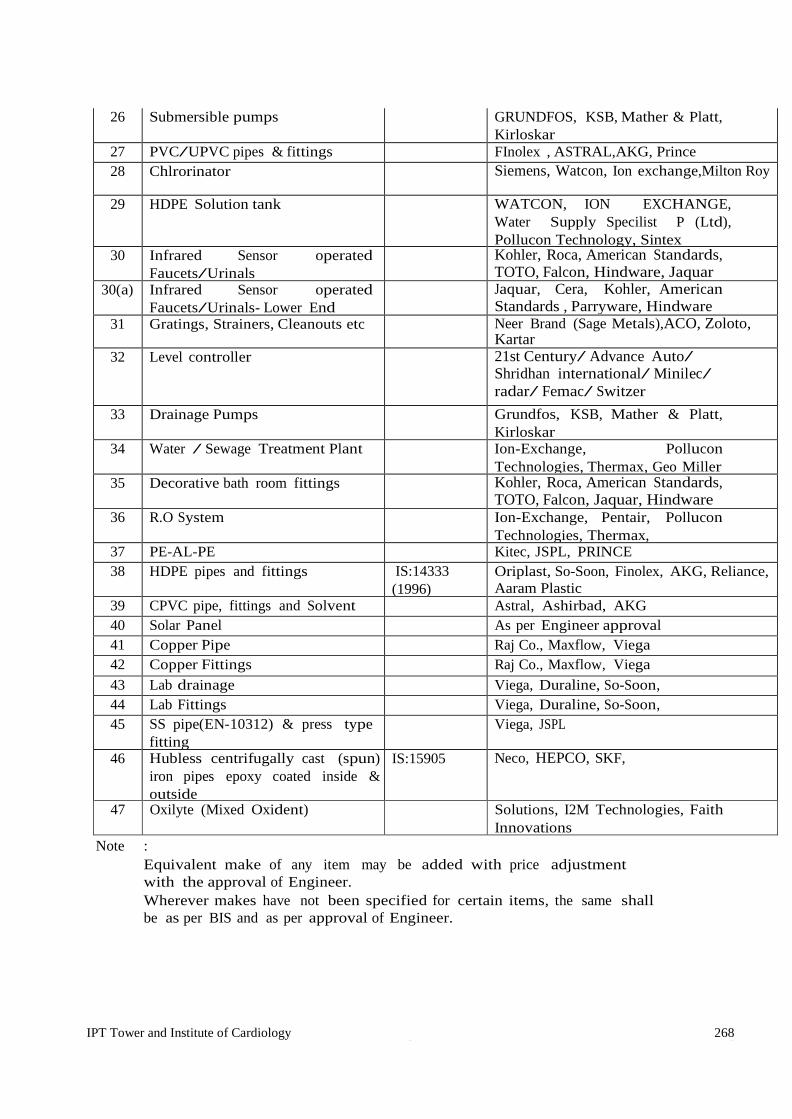
IPT Tower and Institute of Cardiology 268 [Type text ] [Type text ]
26 Submersible pumps GRUNDFOS, KSB, Mather & Platt, Kirloskar
27 PVC/UPVC pipes & fittings FInolex , ASTRAL,AKG, Prince 28 Chlrorinator Siemens, Watcon, Ion exchange,Milton Roy
29 HDPE Solution tank WATCON, ION EXCHANGE, Water Supply Specilist P (Ltd), Pollucon Technology, Sintex
30 Infrared Sensor operated Faucets/Urinals
Kohler, Roca, American Standards, TOTO, Falcon, Hindware, Jaquar
30(a) Infrared Sensor operated Faucets/Urinals- Lower End
Jaquar, Cera, Kohler, American Standards , Parryware, Hindware
31 Gratings, Strainers, Cleanouts etc Neer Brand (Sage Metals),ACO, Zoloto, Kartar
32 Level controller 21st Century/ Advance Auto/ Shridhan international/ Minilec/ radar/ Femac/ Switzer
33 Drainage Pumps Grundfos, KSB, Mather & Platt, Kirloskar
34 Water / Sewage Treatment Plant Ion-Exchange, Pollucon Technologies, Thermax, Geo Miller
35 Decorative bath room fittings Kohler, Roca, American Standards, TOTO, Falcon, Jaquar, Hindware
36 R.O System Ion-Exchange, Pentair, Pollucon Technologies, Thermax,
37 PE-AL-PE Kitec, JSPL, PRINCE 38 HDPE pipes and fittings IS:14333
(1996) Oriplast, So-Soon, Finolex, AKG, Reliance, Aaram Plastic
39 CPVC pipe, fittings and Solvent Astral, Ashirbad, AKG 40 Solar Panel As per Engineer approval 41 Copper Pipe Raj Co., Maxflow, Viega 42 Copper Fittings Raj Co., Maxflow, Viega 43 Lab drainage Viega, Duraline, So-Soon, 44 Lab Fittings Viega, Duraline, So-Soon, 45 SS pipe(EN-10312) & press type
fitting Viega, JSPL
46 Hubless centrifugally cast (spun) iron pipes epoxy coated inside & outside
IS:15905 Neco, HEPCO, SKF,
47 Oxilyte (Mixed Oxident) Solutions, I2M Technologies, Faith Innovations
Note : Equivalent make of any item may be added with price adjustment
with the approval of Engineer. Wherever makes have not been specified for certain items, the same shall
be as per BIS and as per approval of Engineer.

IPT Tower and Institute of Cardiology 269 [Type text ] [Type text ]
LIST OF APPROVED MAKES : FIRE FIGHTING WORKS
Sl.No Material Relevant ISI Code
MANUFACTURERS
1 G.I./M.S. Heavy class pipe
1239/3589 JSPL-Hissar, Tata, Surya- Prakash
2 Gate Air Valve Leader, Zoloto, Castle, Sant, Kartar 3 Butterfly valves 13095 Audco, KSB, C & R, Zoloto, Castle,
Kartar 4 Portable Fire
Extinguisher 2171 Minimax, Safex, Safefire , Ceasefire,
Newage, Safe guard, Kartar 5 First aid Fire hose
reels 884 Minimax, Safex, Safefire , Ceasefire,
Newage, Safe guard, Kartar 6 Fire hose pipes 636 Newage, Minimax, Safex, Ceasefire,
Safe guard, Kartar 7 Fire Hydrant valves 5290 Minimax, Newage, Safex, Safefire,
Ceasefire, Safe guard, Kartar 8 Sprinkler Heads
A Pendent type IS Tyco, Viking, HD, Grinnel, Kartar B Side wall type IS Tyco, Viking,HD, Grinnel, Kartar C Sprinkler Side wall
extended through IS Tyco, Viking,HD, Grinnel, Kartar
9 Sluice and non return/ check valve foot valve strainer
IS I.V.C., Kilburn, Zoloto, castle,Sant ,KSB, Kartar
10 Thermoplastic fire hose pipe
1258 Minimax, safex, Safefire, Newage, , Safe guard
11 Rubber hose 12/20mm dia
Dunlop, Good year, Jyoti Eversafe,
12 Reinforced rubber lined/canvas
Newage, Jayshree, Safe guard
13 Standby battery lead acid
Exide, Standard, Amco
14 Horizontal centrifugal/Fire pumps
Mather& platt(WILO), GRUNDFOS, Kirloskar.
15 Diesel engine Cummins, Ashok Leyland, Caterpillar, Kirloskar
16 Electric motors GEC, Siemens, NGEF, ABB,Crompton, Kirloskar
17 Electrical switch gear & starters
As per Electrical Works
18 Cables As per Electrical Works
19 Flow meter Scientific Equipment (P) Ltd. Hyderabad ,System Sensor / A s p e r r e l e v a n t S t a n d a r d s
20 Suction strainer Leader, ZOLOTO, AUDCO, Castle

IPT Tower and Institute of Cardiology 270 [Type text ] [Type text ]
21 Vibration eliminator connectors
Resistoflex , Kanwal, D.wren
IPD Tower and Institute of Cardiology

IPT Tower and Institute of Cardiology 271
22 Single phase preventor
L & T, GEC, SIEMENS
23 G.I. Fittings 1239 Part I Unik, K.S., Zoloto, R, UU 24 Yard Hydrant Stand
Post,4 way suction Eversafe, Safefire ,Minimax, Newage,
Safe guard 25 DI pipes JSPL, TATA, Electrosteel, 26
Pipe coat material (Pipe protection)
Pypkote Integrated water proofing co. Madras/ coaltek Rustech products (P) Ltd. Syndcate Enclave, Dabri/Makphall
27 Fire Man's Axe
Safeguard/safex/Newage/Gunnebo, Getech
28 Pressure guage
IS:C3624 (cl-I) H.GURU/Fiebig/BRC/HD
29
Flow switch
Potter/Safex system sensor/Jhonson control/Rapid flow/
30 Pressure switch
Indfoss/switzer, Equivalent make approval of Engineer
31 Fire suppression system
SVS Buildwel (p) ltd , Equivalent make approval of Engineer,
Note
Final choice of make specified or not specified above shall remain with the Engineer in charge
equivalent makes can also be added or deleted, subject to price adjustment if any.

IPT Tower and Institute of Cardiology 272
VIII. ELECTRICAL REPORT FOR CONSTRUCTION OF IPD TOWER AND
INSTITUTE OF CARDIOLOGY AT S.M.S HOSPITAL, JAIPUR

IPT Tower and Institute of Cardiology 273
DESIGN BASIS REPORT-ELECTRICAL
A: ELECTRICAL AND LV WORKS 1. GENERAL
The EPC Contractor shall carry out Design, Engineering, Supply, Installation, Testing & Commissioning
of complete Internal & External Electrification works including Low Voltage (LV) and other works as required for smooth functioning of the proposed construction of IPD Towers & Institute of Cardiology at SMS Hospital, Jaipur. All Electrical & LV works shall be designed and executed as per latest codes of practice for Electrical installations and meeting the requirements of Indian Electricity Rules/ Act, applicable I.S. Codes/ Rules and Latest relevant standards/codes published by B.I.S(formerly I.S.I), Special requirements of Electricity Board, CPCB norms, GRIHA-V amended up to date.
IPD Tower building is GHRIHA-V building needs to implemented amended upto date. The rating and capacity of equipment indicated herein below are minimum to be provided. However, during
detailed designing, if required, and found necessary, the capacity/rating of the equipment may be upgraded by the EPC Contractor.
2. SCOPE OF WORK
Electrical & Allied Services’ required for proposed construction of IPD Towers and Institute of Cardiology at SMS Hospital, Jaipur covers Expansion of existing Electric Sub Station( Expansion of existing HT Panel, Expansion of existing LT Panels) Transformer, APFC Panels, AHF Panels, D.G. Set & Accessories Installation work, Rising Mains, MV/Floor Panels Internal Electrical Installations, Per phase Isolation Distribution Boards, UPS System, Light fixtures and fan, IP-based Telephones System, MATV System(Master Antenna TV), Addressable Fire Alarm system, PA system, CCTV System (CCTV and PA system will also cover external area), Nurse call Bell System, Audio visual system, Access Control system, Boom barrier PIR sensor and DALI control system, Boom Barrier system, Integrated Building Management system, Parking Management system, earthing , Lightning Protection, External Electrical Installations, HT and LT Cables, outdoor lighting , Lifts ,Dumbwaiters , Grid interactive Solar PV cell System etc. Any item missed out but essential for work will also be consider.
Suitable size shafts, cutouts, Niche, openings etc. shall be provided to facilitate installation of Rising mains, Cable Trays etc. in all floor slabs of various buildings for various service areas, as required. All shafts, cut outs, Niche, openings etc. provided on floor slabs shall be suitably closed after laying of services lines as per fire safety norms & as per NBC 2016 amended upto date. Doors shall be provided for all shafts at all floors as per fire safety norms as per NBC 2016 amended upto date. All services as required like electrical power point, telephone points, UPS points Shall be provided by the EPC Contractor as per actual site requirement.
3. ELECTRICAL POWER REQUIREMENT
The Electrical Load requirement has been calculated on the basis of covered area of various buildings/blocks as per NBC 2016 amended upto date considering lighting load @ 13 W/Sq.m & power load @55W/Sq.m. Load for the Central Air Conditioning Plant, Basement Ventilation, Lifts, Medical Equipments & medical Services i.e., CSSD, Kitchen, Gas Manifold, PST, Pumps, External Lightning, STP, WTP etc. has also been taken into account. Peak Electrical Connected load before overall diversity factor to be calculated by the executing agency and approved by the client works out to 6MVA. Considering over all diversity factor of and load factor, Peak Load Demand will be calculated by the executing agency and approved by the client will be 4MVA.

IPT Tower and Institute of Cardiology 274
4. SOURCE OF SUPPLY
Electric supply on 11kV from the existing substation for meeting electrical load requirements by expansion of existing 11kV HT panel Board.
5. ELECTRIC SUB-STATIONS
The expansion of existing Substations will be done by the EPC Contractor to meet the Electrical Load of maximum demand will be calculated by the executing agency and approved by the client 4MVA.
As per projected peak load demand requisite quantity of transformers will be calculated by the executing agency and approved by the client 1 Nos. Oil Transformers with On Load Tap Changer, ONAN, outdoor type of capacity requisite quantity will be calculated by the executing agency and approved by the client 2500KVA are proposed with RTCC Panels and remaining load requirement will be fulfil from the existing transformer by expanding the existing LT panels. Expansion of existing 11KV HT Panel board will be done by 1 incomer one bus coupler and 1 outgoing. DG Set Capacity for backup supply will be the requisite quantity will be calculated by the executing agency and approved by the client 2X10¹⁰ KVA proposed along with PLC based synchronization panel connected to LT panel. Synchronization panel also capable the sync requisite quantity will be calculated by the executing agency and approved by the client 2 no. 1010kVA existing DG sets along with the proposed DG sets. DG should have automatic changeover on LT panel at the time of power failure and vice-a-versa. Synchronization panel shall have auto load sharing arrangement.
All the incomer and outgoing of suitable rating to be provided by expansion of existing Main LT panels in the substation.
SUBSTATIONS GUIDLINES
Expansion of the proposed substation shall be complete with indoor type 11KV panel board, outdoor type Transformer, outdoor DG Sets, indoor and outdoor Sandwich bus-ducts, indoor LT Switch Board, APFC Panels, Active Harmonic filter and all other accessories as required. DG Sets shall have facility for auto& manual start/stop, auto changeover, auto load sharing management and Synchronization. The transformers &DG Sets shall be connected to respective LT Panels through suitable size indoor/outdoor sandwich busducts and cables in the substation. Indoor type sandwich Bus duct shall be IP 65, and outdoor installation busduct shall be of IP-65 in canopy of GI/ Aluminium as per OEM and busduct in trenches / tunnel will be IP 68 with cast resin.
AC Load shall be fed directly from Main LT Panels (by expanding of existing Main LT Panels) of the ESS to AC power Panel through sandwich Bus ducts.
All Panels with incomers more than or equal to 800 Amp shall be type tested Assembly as per IEC 61439 and as per technical specifications. All Incoming & outgoing of LT panels shall be with suitable measuring and protection CTs and intelligent multifunction meter with RS 485 port for BMS connectivity.
APFC, AHF panel shall be Top/bottom openable type for cable entry/outgoing. Substation shall comprise of all ancillary equipment like Battery Charger etc. Suitable size MS Chequered Plates, duly painted of minimum thickness 6mm shall be provided for trenches inside the panel room as required. Hot Dip Galvanized Cable tray or wire mesh type cable tray of suitable size shall be used as required.
All armoured HT/LT power cables, control cables, telephone cables, signal cables etc. shall be laid in cable tray, bulk underground cables will be tranches, one or two cables can be laid underground without tranches. as per site requirement as per Latest relevant standards/codes published by B.I.S(formerly I.S.I).

IPT Tower and Institute of Cardiology 275
Adequate no. of Hume pipes/DWCHDPE Pipes having suitable diameter with spare shall be laid across the roads/pathways etc.
Maximum allowable transformer losses at 50% & 100% load shall comply to Latest IS-1180 and efficiency level as prevalent at the time of supply. Substation/HT/LT Panel Rooms/Floor panel Rooms shall be provided with safety equipment/items like suitable elastomeric mat (as per relevant IS codes), fire buckets, fire extinguishers, hand gloves, danger plates (HT/LT rating), safety charts, framed Schematic/SLD etc. Suitable civil foundation/ trenches etc. for all substation equipment shall be provided as per design load of respective equipment. All LT Panels shall have 40% spare outgoing feeders for different rating of feeders. For 2.5MVA transformer LT Panel, APFC panel have 65kA for 1sec fault level and for 2MVA and below will be of 50kA for 1sec. All ACB shall be Ics+Icu=Icw=50kA/65kA for 1sec. Depending on transformer rating. All MCCB shall have Ics=Icu All meter will be of digital meter. All incomer ACB shall be four pole EDO type and all outgoing ACB & MCCB of Main LT panel will be four pole types. All incomer MCCB of floor panel will be four pole type. All MCCB upto 200A & below will be thermal magnetic released with variable current setting. 250A and above MCCB will be microprocessor based variable current setting. Temperature rise calculation for busbar shall be as per IEC 61439 according bus bar will be provided. Room temperature to be taken max 40deg C and temperature rise as per IEC according busbar to be calculated. All bus bar upto 4000A will be of aluminium and above 4000A will be of copper Neutral will be 100% for computer power distribution system. Preferably 1250A and above rating feeder shall be provided with bus duct arrangement. Gas flooding system to be provided in HT/LT Panels as per requirement as per NBC/LATEST RELEVANT STANDARDS/CODES PUBLISHED BY B.I.S(FORMERLY I.S.I).
Soak-pits to be provided as required.
Reactive Power Management To achieve power factor 0.99 (lagging) from existing power factor APFC panels to be installed in the substation. And to control Harmonics Active Harmonic Filter to be installed separately. APFC with 14% detuned filter with suitable capacity to be installed at 433V Bus. BMS connectivity through RS-485. Sensing will be from HT 11kV side so that entire transformer also gets compensated.
Active Harmonic filter of suitable capacity to be installed at 433V Bus to control harmonics 5% or below. It should BMS connectivity also. All the panels should be work on both Main as well as DG power.
5.5 DG Set for Backup Supply Diesel Generator sets are proposed to be provided for backup supply in case of electricity failure. Provision of DG Backup supply shall be as mentioned below but not limited to, are as follows:
Internal and external lighting, medical equipment, MGMS system, PTS, ETP, STP, WTP, Fire & water pumps, Lifts AC Loads (50% Chillers & All AHUs), Basement Ventilation, HSD pumping System etc.-100% Load on DG Backup Supply. Emergency Services, if any
All DG Sets (Proposed and existing) shall be provided with suitable PLC and Synchronizing relay/PCCM controller for achieving automatic start/stop, Auto change over on LT panel, automatic load sharing and auto synchronization function. Additional provision for manual start/stop of DG Sets shall also be provided. Transformer Incomer ACBs, DG Incomer ACBs and Bus Couplers shall be electro- mechanically interlocked with provision of auto and manual mode operation. Required control cabling/wiring in HT Panel, Transformers, DG Sets, LT Panels etc. shall be provided as per requirement. All the DG set have water cool radiator types.

IPT Tower and Institute of Cardiology 276
Exhaust Stack of the DG Sets shall be as per CPCB/LATEST RELEVANT STANDARDS/CODES PUBLISHED BY B.I.S(FORMERLY I.S.I)/Local Bye-Laws standards and self- supporting/building support MS Exhaust stack structure duly synthetic enamel paint of suitable height to support the exhaust pipes with expansion bellows at required location has to be provided as per actual site condition. All DG sets shall have individual Day Oil tank of 990Ltr capacity to be provided. Diesel Buffer tank with each DG Set at suitable height for gravity feeding of diesel supply to each DG day oil tank(Float valve arrangement for controlling) to be provided .Automatic diesel feeding system from HSD Pump in system to diesel buffer tank shall be considered. Day oil tanks for the DG sets shall be incompliance with The Petroleum Act,1934. Reliable & Continuous Power Supply/control supply to following Emergency & Life safety Systems shall be provided, as required: Power supply to above emergency & life safety equipment shall be through fireproof enclosures or circuit integrity cables or through alternate route in the adjoining fire compartments to ensure that supply of power is reliable, installation to be got approved.
5.6. HSD (High Speed Diesel) UG Storage Tank &Pumping System:
HSD Storage Tank &Pumping System shall be provided by the EPC Contractor for continuous pumping of HSD to the DG Sets installed in substations. Underground HSD tanks shall be located as per CPCB/NFPA/LATEST RELEVANT STANDARDS/CODES PUBLISHED BY B.I.S(FORMERLY I.S.I)/Local by laws. Underground Diesel storage tank of 1X 10 KL capacity along with Auto fuel transfer system comprising of suitable number and capacity of fuel pumps (working & standby) with underground pipe line from underground diesel tank upto the buffer diesel tanks in ESS shall be provided. Fuel Transfer Pumps shall be flame proof, rotary gear, positive displacement type or as required for HSD pumping application. Underground tanks, buffer tanks, piping, fuel pumps, valves, cabling, control /level switches, earthing etc. has to be provided as per CPCB/NFPA/LATEST RELEVANT STANDARDS/CODES PUBLISHED BY B.I.S(FORMERLY I.S.I)/Local by laws. The supply of first fill of HSD Tanks, Buffer Diesel Tanks and DG Set fuel tank shall be included in scope of works. First fill of HSD fuel shall be provided upto rated capacities of all diesel tanks. Suitable level Transmitter shall be fitted on top of each tank to give continuous level status to IBMS. Necessary licenses or approvals for diesel storage shall be obtained before installation of UG diesel storage tank and pumping station from Local Administration and Chief Controller of Explosives, Petroleum& Explosives Safety Organization.
6. ELECTRICAL POWER DISTRIBUTION
a. The Electrical Power Distribution for electric supply shall be as detailed below. Indoor/Outdoor type Aluminum Sandwich Bus Duct totally type tested as per IEC61439 including adaptor box, Tap-offs and other plugin system, of suitable capacity shall be provided from Client Transformers and DG Sets to Main LT Panel, Main LT Panel to AC Panel & all Capacitor Panels. Adequate runs of XLPE insulated armoured Aluminium conductor cables shall be laid from Main LT Panel to LT Panels of the building. Sensing will be from HT 11kV side so that entire transformer also gets compensated.
b. The separate distribution system shall be provided for Lighting load, Power &AC Load & UPS load.
Each distribution system shall be with Electrical panels, rising mains, Floor panels, Double door MCB Type DB’s. The main building panels, equipment panels, medical services panels, shall be suitable for dual source incomer supply.
c. The building shall have a Electrical room to receive power from the substation through armoured cable/busduct and distribute power to the entire building.
d. Rising mains for catering to loads of Lighting, Power, AHU, Power & Medical Equipments, UPS etc. connected to Main Building Panel through main LT Panel, as applicable. Rising mains (Working +Standby) shall be provided for Light and Power supply. Light and power floor panels shall be suitable for dual source supply.
e. Each rising main shall have Tap off at every floor, feeding the floor panels with in coming & outgoing MCCBs of required capacities and numbers feeding the double door DBs.
f. False ceiling area floor panel to DBs shall be connected with armoured cable on surface/cable tray. Non false ceiling area submain from floor panel to DB shall be FRLS copper wire in MS conduit.

IPT Tower and Institute of Cardiology 277
g. The power cabling shall be sized so that the distribution losses do not exceeds 3% of the total power uses in buildings. Voltage drop for feeders shall not exceed 02%at design load and for branch circuit; it shall not exceed 3% at design load.
h. Energy meters to be provided in the panels as per GRIHA-V requirement.
7. EARTHING NETWORK
Earthing with Maintenance free Chemical earthing system consisting of one Number UL listed CPRI tested copper bonded steel electrode (as per IE C62561-2) With a minimum. coating thickness of 250 microns and length of 3 meters. 25 kg/Electrode of earth enhancing compound (tested as per IEC-62561-7) fill the 100mm augured hole surrounding to the electrode, SS Universal Clamp of Size 175X50X3 m for terminal Connection including Poly Propylene Heavy Duty Pit cover including all accessories/ GI Earthing System/Copper Earthing system, as required, shall be provided by the EPC Contractor for earthing substations equipment’s, Electrical Panel boards, UPS and other Equipment/installations in each building. Earing electrode dia shall be of 13mm, 19mm and 25mm as per requirement to maintain earth resistance as per IS. Earthing shall be in conform it with provisions of rule 32,61,61, 67&68 of Indian Electricity Rules 1956 & as per IS-3043 as amended upto date. Copper/GI earth strips shall be used for connecting the Electrical equipments and Medical equipments with Earth pits as required. Earth Leakage circuit breakers shall be provided in per phase of the DBs. Separate and distinct earth stations shall be provided for the following but not limited to:
• HT Panels
• Main LT, APFC, AHF & MV Distribution Panels
• UPS system– Body & Neutral
• EPABX & LAN Server
• Transformers–Neutral, Body, fency etc.
• DG Sets- Neutral &Body
• Laboratory
• Modular OT’s
• Lifts
• All types of Medical Equipment
• LV Equipments
• Any other equipment as required. The earth station with insulated electrode to be provide as per the requirement. However neutral earthing will be with insulated electrode in all places. The above items are indicative. Earthing shall be provided as requirement. All three phase electrical installations shall be provided with double Earth connection and single-p h a s e electrical installations with one Earth connection as per Latest relevant standards/codes published by B.I.S(formerly I.S.I) & NBC 2016 amended upto date. Over all earth resistance shall be as per IS.
8. LIGHTNING PROTECTION SYSTEM:
Lighting protection of the building & DG chimney shall be provided as per IS/IEC62305-1:2010. (Latest as amended), Latest relevant standards/codes published by B.I.S(formerly I.S.I) and NBC 2016 norms amended upto date. The main and most effective measure for protection of structures against physical damage is considered to be the lightning protection system (LPS). An external LPS which consists of air-termination system, down-conductor system and earthing system is intended to:
a) Intercept a lightning flash to the structure (with an air-termination system),

IPT Tower and Institute of Cardiology 278
b) Conduct the lightning current safely towards earth (using a down-conductor system), and c) Disperse the lightning current into the earth (using an earth-termination system).
Accordingly, a standard lighting protection system will be provided in all the buildings as per NBC 2016 Standards, using single prone finials, horizontal and down comer earthing strips of suitable size, terminating in the Earth Pits. Aviation Obstruction Light (AOL)shall be provided in various buildings, DG chimney as per Civil Aviation regulations, NBC norms & Latest relevant standards/codes published by B.I.S(formerly I.S.I) as applicable. All Aviation Obstruction Lights shall be fed with UPS supply only.
9. INTERNAL ELECTRIFICATION, LV& ALLIED WORKS: Following works shall be carried out in coordination with the civil work within the buildings complete in all respects as per latest IS Codes and Latest relevant standards/codes published by B.I.S(formerly I.S.I)
i. Wiring& Conduiting (MS Conduits) for internal electrification, LV& Allied works. ii. LED Light fixtures, Fan (Ceiling & Wall) & Exhaust Fans.
iii. 6A Light Point &UPS Modular Switch & Socket Outlets. iv. 16A, 20A Power, UPS Modular Switch & Socket Outlets v. Each general ward Bed have power point 2X6A +2X16 Socket with individual switch on normal. Three
such bed power point will be provided in ICU, Pre-OT, Post-OT, if bed head panel are provided then only wiring will be done upto bed head panel.
vi. L.T. Cables and Sub main wiring, circuit wiring. vii. Cable Tray & Raceways.
viii. Rising Mains / Bus Trunking sandwich type ix. Floor Panels, Distribution Boards. x. Earthing
xi. Extra Low Voltage system like Telephone/ IPBAX, LAN & Wi-Fi, Fire Detection & Alarm System, CCTV System, MATV, Public Address system, Access control system, Boom Barriers etc.
xii. Audio Visual system for conference Room, Seminar Hall, Lecture Hall etc. xiii. Nurse Call system. Following points shall be generally followed for internal and external electrification of various areas:
a) Internal areas like rooms, corridors, lobbies, staircases, terraces, washrooms etc. of all buildings and blocks shall be adequately illuminated conforming to provisions stipulated in NBC 2016, ECBC and LATEST RELEVANT STANDARDS/CODES PUBLISHED BY B.I.S(FORMERLY I.S.I) technical specifications maintaining the indicated Lux levels and Light Power Density.
b) The Internal Electrification work shall be carried out in recessed/surface mounted MS conduits in accordance with LATEST RELEVANT STANDARDS/CODES PUBLISHED BY B.I.S(FORMERLY I.S.I) General Specifications for Electrical Works Part-I (Internal)-2013 and Part-II (External)-1994 with upto date amendments
c) Wiring for lighting/power LV shall be done in MS Conduits. PVC conduit will be used only if requirement of system with the approval of Engineer in-charge. d) FRLS PVC insulated Copper conductor wires will be used for points, circuit, sub-main wiring &motor supply wiring conforming to IS-694.
e) Agency shall execute the work after obtaining necessary approval of the layout for internal electrification of all building. The stair case lighting shall be in group control system.
f) Modular type switches, sockets and stepped type electronic fan regulators, bell push button along with matching mounting boxes of same make shall be used. g) Colour coding or any indication of the conduits, switches, sockets shall be provided for Normal, UPS power, ELV and FDA supply as per NBC 2016.
h) TV outlet point wiring shall be terminated in suitable size of G.I. box along with splitter at every floor. The interconnections of all splitter boxes fixed at all floors shall be done properly with conduits to form proper distribution system with the prior approval of Engineer-in- charge. i) LED Type Lighting fixtures with higher lumen efficiency to be used.
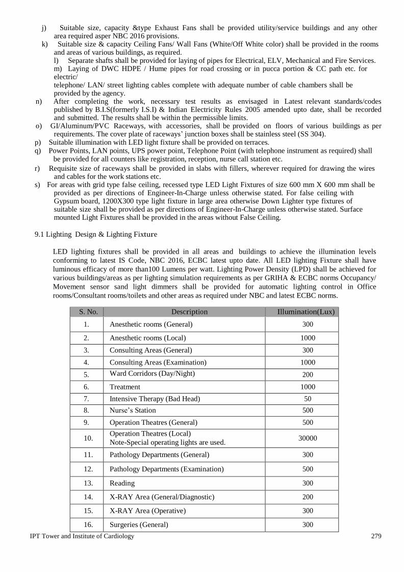
IPT Tower and Institute of Cardiology 279
j) Suitable size, capacity &type Exhaust Fans shall be provided utility/service buildings and any other area required asper NBC 2016 provisions.
k) Suitable size & capacity Ceiling Fans/ Wall Fans (White/Off White color) shall be provided in the rooms and areas of various buildings, as required. l) Separate shafts shall be provided for laying of pipes for Electrical, ELV, Mechanical and Fire Services. m) Laying of DWC HDPE / Hume pipes for road crossing or in pucca portion & CC path etc. for electric/ telephone/ LAN/ street lighting cables complete with adequate number of cable chambers shall be provided by the agency.
n) After completing the work, necessary test results as envisaged in Latest relevant standards/codes published by B.I.S(formerly I.S.I) & Indian Electricity Rules 2005 amended upto date, shall be recorded and submitted. The results shall be within the permissible limits.
o) GI/Aluminum/PVC Raceways, with accessories, shall be provided on floors of various buildings as per requirements. The cover plate of raceways’ junction boxes shall be stainless steel (SS 304).
p) Suitable illumination with LED light fixture shall be provided on terraces. q) Power Points, LAN points, UPS power point, Telephone Point (with telephone instrument as required) shall be provided for all counters like registration, reception, nurse call station etc. r) Requisite size of raceways shall be provided in slabs with fillers, wherever required for drawing the wires
and cables for the work stations etc. s) For areas with grid type false ceiling, recessed type LED Light Fixtures of size 600 mm X 600 mm shall be
provided as per directions of Engineer-In-Charge unless otherwise stated. For false ceiling with Gypsum board, 1200X300 type light fixture in large area otherwise Down Lighter type fixtures of suitable size shall be provided as per directions of Engineer-In-Charge unless otherwise stated. Surface mounted Light Fixtures shall be provided in the areas without False Ceiling.
9.1 Lighting Design & Lighting Fixture
LED lighting fixtures shall be provided in all areas and buildings to achieve the illumination levels conforming to latest IS Code, NBC 2016, ECBC latest upto date. All LED lighting Fixture shall have luminous efficacy of more than100 Lumens per watt. Lighting Power Density (LPD) shall be achieved for various buildings/areas as per lighting simulation requirements as per GRIHA & ECBC norms Occupancy/ Movement sensor sand light dimmers shall be provided for automatic lighting control in Office rooms/Consultant rooms/toilets and other areas as required under NBC and latest ECBC norms.
S. No. Description Illumination(Lux)
1. Anesthetic rooms (General) 300
2. Anesthetic rooms (Local) 1000
3. Consulting Areas (General) 300
4. Consulting Areas (Examination) 1000
5. Ward Corridors (Day/Night) 200
6. Treatment 1000
7. Intensive Therapy (Bad Head) 50
8. Nurse’s Station 500
9. Operation Theatres (General) 500
10. Operation Theatres (Local) Note-Special operating lights are used.
30000
11. Pathology Departments (General) 300
12. Pathology Departments (Examination) 500
13. Reading 300
14. X-RAY Area (General/Diagnostic) 200
15. X-RAY Area (Operative) 300
16. Surgeries (General) 300

IPT Tower and Institute of Cardiology 280
17. Surgeries (Waiting rooms) 200
18. Laboratories 500
19. Consulting rooms (General) 300
20. Consulting rooms (Desk/ Examination) 500
21. Pharmacies/Reception/Enquiry/Recovery rooms 300
22. Ward-circulation (Day/Morning/Evening) 100
23. Ward-circulation (Night) 10
Note: - The above lux level shall go under change as per interior designer.

IPT Tower and Institute of Cardiology 281
S. No. UN 1.0 LED Batten with Optical PC material for excellent and smooth light output,
CRI>80, uniform distribution, lumen output should be 2000-2200, luminous efficiency of luminaire 100lm/W, Life time of 30,000 burning hours@L70, comply to 3KV surge test, Color Temperature
Each
2.0 Supply, Installation, Testing & Commissioning of Surface mounted Weather proof battens with IP65 ratings for industrial and other applications in exposed climates requiring higher degree of ingress protection. Best in class LEDs, with Luminaire luminous flux3600lm, connected load 36W, luminous efficiency of luminaire 100lm/W. Light Colour neutral white, Colour temperature 6000K, Colour rendering index Ra > 80. Operating Temperature range-20 C to 50 C. IP65, Impact Protection IK-10, Service Life of 50,000 Hours shall be as per tender.
Nos.
3.0 Supply, Installation, Testing & Commissioning of Surface Mounted LED Down light with cylindrical construction, Housing Dia109mm, height 75mm, Luminaire luminous flux 1400 Lm, Nominal Input Power14W, Luminous efficiency of 100Lm/W. Colour rendering index >80. Service life 50,000Hrs.shallbe as per tender.
Nos.
4.0 Supply, Installation, Testing &Commissioning of recessed LED Downlighter incompliance of relevant standard & power consumption not more than 12W and lumen Output not less than 1200 lumen with luminous efficiency of 100lm/W &CRI>80&CCT 5700K. The heat sink of the Fixture is die cast aluminium for ceiling recessed applications etc. The fixture has an operating voltage range220-240VAC 50Hz, Constant Current, withstand300Voltinputforcontinuous operation & driver designed to with stand casing temp.85 degree C&85% Driver efficiency. Driver Casing made of FR rated bay blend material to withstand 260 Degree C. Complete with all accessories shall be as per tender.
Nos.
5.0 Supply, Installation, Testing & Commissioning of recessed LED Downlighter in compliance of relevant standard & power consumption not more than 18W and lumen Output not less than 1800 lumen with luminous efficiency of 100lm/W & CRI >80 & CCT 5700K. The heat sink of the fixture is die cast aluminum for ceiling recessed applications etc. The fixture has an operating voltage range 220-240V AC 50 Hz, Constant Current, withstand 300Volt input for continuous operation & driver designed to withstand casing temp. 85 degree C & 85% Driver efficiency. Driver Casing made of FR rated bay blend material to withstand 260 Degree C. Complete with all accessories shall be as per tender.
Nos.
6.0 Supply, Installation, Testing & Commissioning of Bulkhead LED Wall/Surface mounted LED bulk head light of connected load 10W shall be as per tender.
Each
7.0 Supply, Installation, Testing & commissioning of Batten LED 800 mirror light shall be as per tender.
Each
9.2 Indicative Design Specification for Lighting Fixture

IPT Tower and Institute of Cardiology 282
8.0 Supply, Installation, Testing & commissioning of PIR based occupancy cum day light standalone sensor as complete as required shall be as per tender.
Each
9.0 Supply, Installation, Testing & Commissioning 2'x2' IP20 LED light fixture suitable for ceiling recessed for office purpose. The fixture has a power consumption of 36W and producing a system lumen output of minimum 3600 lumen in 5700K CCT. The fixture is designed for 50, 000 hrs of operational life at L70, Construction of fixture is Housing made of Metallic CRCA powder coated body and Diffuser is a high efficiency Lumio Diffuser. Electronic Dali Dimming control gear having a PF > 0.95, and low THD. Low output current tolerance (<10%) ensuring uniform Light output. Withstands 400Volt fast transit & Surge Protection 3KV. The fixture has an operating voltage range 220-240V AC 50 Hz, Constant Current, withstand 300Volt input for continuous operation & driver designed to withstand casing temp. 85 degree C & 85% Driver efficiency. Driver Casing made of FR rated bay blend material to withstand 260 Degree C. Complete with all accessories as per specification. Color Rendering Index Ra >80 shall be as per tender.
10.0 Supply of LED wall Bed Side luminaire LED wall luminaire with indirect-direct light distribution. For direct wall fixing. With direct-indirect light distribution. With translucent PMMA cover. Harmonious light effect due to homogeneously illuminated light emission. With 2 LED systems. Luminaire luminous flux 2600 lm, luminaire efficiency 25 W, luminous efficiency of luminaire 104 lm/W. Light colour neutral white, correlated colour temperature (CCT) 4000 K, general colour rendering index (CRI) Ra > 80. Mean rated service life L80 (tq 25 °C) = 70,000 h, mean rated service life L85 (tq 25 °C) = 50,000 h. Luminaire body of aluminium, Upper cover of sheet steel. Colour white (RAL 9016). Dimensions (L x W): 190 mm x 700 mm, luminaire height 96 mm. Permissible ambient temperature (ta): -20 °C - +25 °C. Safety class (EN 61140): I, protection rating (DIN EN 60529): IP40, impact resistance level in accordance with IEC 62262: IK02/0, 2 J, testing temperature of wire glow test in accordance with IEC 60695-2-11: 650 °C. With two electronic control units, switchable. The luminaire complies with fundamental requirements of applicable EU regulations and product safety legislation and bears the CE symbol. The luminaire is also ENEC-certified by an independent testing authority
11.0 Supply of 40W LED Recessed Mounted Spot Downlighter made of pressure diecast
aluminum housing with high gloss aluminum reflector, LED Used shall be COB type and fixture should have minimum efficacy at System level (Not Chip Level)>=100lumens/W, With mid beam optics & Life of fixture (Including Driver):50KHrs.@L70B50Lumen maintenance, CCT upto 4000, CRI>80, PF>0.95 & THD<10%, an operating Voltage Range of 180-264V. Minimum Internal Surge Protection 2.5KV. The fixture design should comply with IS10322, EMC/EMI compliance maintaining driver leakage current as per as per IEC60598, Minimum system Lumens 5000 etc. complete shall be as per tender.
Nos
12.0 Supplying, installation, testing & Commissioning of Self-contained emergency light units 1x9 watt double sided for wall/ceiling mounting with suspension/mounting kit, lamps, Inbuilt standby battery (for2hours backup) and battery charger etc. in suitable enclosure shall be as per tender.
Each

IPT Tower and Institute of Cardiology 283
9.3 Computer/Telephone/CCTV Points
RJ 45 data outlets points will be provided for Telephones, CCTV, Information Display system, IBMS, etc. as per requirement in rooms and other areas at various floors in all the blocks / buildings.
The Data Outlet points shall be connected to Rack Panel/Computer hub with 4 pair CAT-6A wiring in Raceways, recessed/ surface conduit as required. UPS Power supply shall be provided to Network Rack, Servers & Computers wherever required.
The maximum length of the CAT-6A cable from end user point to the Hub or Edge switches shall not be more than 90 M. Beyond 90 M length Fibre Optic Cable shall be used.
The Rack Panel/computer hub at various floors will be connected to Main rack of the building/ block with Fibre Optic Cable through conduit or raceways on surface/ recess.
LAN Infrastructure at different Floors of various building shall be used commonly for IPABX, BMS, Access Control System, CCTV, Nurse Call System etc. along with LAN.
The bidder is required to prepare a design of the proposed CAT 6A cabling that should include network layouts floor-wise detailed shop drawings as per the proposed network design.
The bidder should take into consideration all the possible items which may be required for the completeness of the system including conduits, CAT 6A for proper cabling.
9.5 IPABX System
RJ-45 Telephone socket outlets with suitable IP Phones instruments shall be provided in all blocks/ buildings at convenient locations, as required. CAT-6A wiring shall be provided in recessed/surface conduits/raceways from each telephone point upto the Rack panel (Patch Panel & Switch) at each floor or nearest Rack Panel of all buildings/Blocks. The Maximum length of the CAT-6A cable shall be 90M. IPABX with minimum capacity of 560 Telephones & expandable upto 2000 telephones shall be located at Server Room in the block. And other blocks (if any) should be connected through gateway/IPBX under distributed architecture. The PRI lines for IPABX shall be terminated in the separate Rack in server room of Block. This Rack will be connected to the IPABX system. The Rack Panel (comprising of jack/Patch panels, Network switches, patch cords, power supply units, Cooling Fans, Wire managers, LIUs, Trans receivers, Fiber patch cord etc.) of individual buildings/ Blocks (if any) shall be connected to the main IPABX Server Rack with optical Fiber cables to be laid underground in DWCHDPE Pipe of suitable size. Manholes with covers shall be provided in the underground DWCHDPE pipes at suitable lengths for easy pulling & maintenance of cables.
9.6 Fire Detection/Alarm System
Addressable Intelligent fire detection and Alarm system of latest technology with Fire alarm panels, Repeater panel (if required), multi-Sensor detectors, smoke detectors, heat detectors, beam detectors, response indicators, manual call point and hooters, light strobe etc. shall be provided. It shall meet the requirement of NBC2016/Latest relevant standards/codes published by B.I.S(formerly I.S.I)/State Bye-laws. License/Approval of Local Fire Authorities shall be provided for the building. There shall be the proper Zoning of the building considering the Non-Critical & Critical. There shall be independent fire panel in the buildings etc. and all fire control panels (if any) shall be interconnected with each other. The monitoring of whole building shall be in the Main Fire Control Room of the building. For Central Monitoring of all the Fire Panels, necessary devices like PC, Printer modules &Software etc. of latest technology with minimum 1TB hard disk shall be provided in the Control room. Fire Alarm control Panel shall not have more than 159 devices and 159 detectors in one loop.

IPT Tower and Institute of Cardiology 284
The details of the system proposed shall be as follows:
a) Addressable intelligent dual type photo-thermal Fire Detectors is suggested. b) Detectors should be having individual addressing. Detectors should be installed as per coverage defined in
u. c) NFPA72. It should include all rooms, halls, storage areas, basements, attics lifts, and spaces above
suspended ceilings including plenum areas utilized as part of the AC system. In addition, coverage should include all closets, elevator shafts, enclosed stairways, dumbwaiter shafts, chutes, and other subdivisions and accessible spaces.
d) Fault isolators to be installed as per requirement e) Suitable numbers of input/output (C/M) relay modules are suggested for connecting other equipment
like Electrical Panels, lifts, firefighting system, AHUs etc. f) Spacing between two detectors shall be as per IS 2189 amended upto date or it shall be as per relevant
code & Manufacture standards. g) Cabling shall be with Fire Survival Armoured copper cable or FRLS PVC sheathed wire in MS conduits. h) Suitable addressable loop powered sounders/hooters for100db sound level are suggested. Directional
sounder to be installed at Exit Point. i) Addressable manual call boxes shall be provided near all exits, staircases, lift lobbies etc. as per
relevant Norms. j) The Response Indicators shall be used in the waiting areas, Corridors, Common Area, conference Hall
or in large room etc. k) UL Listed Microprocessor fire alarm control panel for number of required loops with 24hrs. Battery
backup with LCD display, printer etc. shall be located in the fire control room. Fire Alarm Panels shall be integrated with BMS also.
l) Fire Alarm Panel shall have integrated Digital Voice command system with suitable no. of digital amplifiers placed at suitable location of buildings. The speakers should be both ceiling mounted and wall mounted type connected to the amplifiers. Speakers should have multiple taping for different power output setting.
m) Two Way communication Fire Fighters Telephone Jack & Handset with necessary accessories are to be provided in all the buildings as required.
9.6 Indoor/Outdoor Public Address System
IP Based Digital PA System shall be provided. Speakers in the Ceiling/Wall shall be provided in corridors, lift lobbies and other common areas as per NBC2016/relevant IS codes amended upto date.
a) Box type speaker shall be provided in the entrance lobby. b) Horn type speakers are suggested in the basement.
b) Horn type speaker are suggested in the basement. c) Recessed speakers in the false ceiling areas. d) Landscape Garden Speaker of high frequency to be installed in outdoor area. e) Proper zoning is to be done considering the user requirement, critical areas & floor etc. f) Control console shall be located in the fire control room with pre amplifiers, amplifiers, CD, DVD/Pen-
drive, FM Player & gooseneck microphone. g) System shall have the facility to make announcement on all zone simultaneously or on individual zones. h) Wiring shall be done with twin twisted tinned copper wire in the conduit. i) The system shall be integratable with Fire alarm panel and with the BMS also.
9.7 Closed Circuit Television System (CCTV System)
The CCTV and Surveillance System shall control and monitor of building & outside area as per NBC2016/relevant IS codes/Local by laws. The building shall have IP Based Dome Cameras, Bullet Cameras and PTZ Cameras for surveillance. The types of cameras &locations of various Cameras indicated herein are minimum to be provided. However, during detailed designing if required and found necessary the type/rating of the Cameras shall be upgraded
a) Dome/ Bullet Cameras (Indoor Type) + PTZ Cameras on pole or Roof top (Outdoor). b) Entry/ Exit Gates- Bullet Cameras (Outdoor Type). c) Substation/Plant Room/Pump Room Building/Parking/Laundry/Mortuary etc. - Bullet Cameras (Outdoor
Type)/ PTZ Cameras on pole or Roof top (Outdoor). d) Waiting area, reception, conference room, Crowded area-360-degree panoramic camera.
IPT Tower and Institute of Cardiology 285
The indoor Dome Cameras and Bullet Cameras are proposed to be installed at all Entry & Exit Points, main corridor, Lift lobbies &waiting areas of the building. CCTV in ICU also to be provided with viewing facility so that the attended can see his/her patient on TV without disturbing the ICU.
All the outdoor cameras shall be in IP-66 Housing with Junction box, media converter etc. is proposed in weather proof housing. The existing LAN network switches would be used for CCTV connectivity and will be connected to central CCTV server & cameras shall have POE connectivity ports. Network connectivity for outdoor cameras having distance more than 75 metres, shall be on optical fiber. Suitable provision shall be provided to connect with existing LAN infrastructure. The power supply to LAN switches and Monitors will be on UPS. The video recording shall be non-embedded based recording server with video management software. 1. Bullet/Dome camera: - These cameras shall be minimum 3 mega pixel Quad stream camera with
minimum 30mtr IR suitable for Day and night operations. All the cameras shall be operative on automotive manual & scheduled mode. The cameras shall be UL/FM Listed. RJ- 45 Cable connectors will be used for Network/POE connectivity. Cameras shall have inbuilt slot for memory card for local storage.
2. PTZ outdoor cameras: - The true IP day and night viewing PTZ cameras proposed should have at least 26 x opticalzoom,12Xdigital zoom, 2- megapixel resolution, Auto iris & auto focus lens with focal length 4.7 mm to 94 mm or better. The PTZ camera shall automatically track the object to use its Pan/Tilt/Zoom feature and record 30 frames/ sec. The cameras shall be UL/FM Listed. RJ- 45 Cable connectors will be used for Network/POE connectivity.
3. 360- degree Panoramic Camera: - True IP based panoramic fish eye camera capable to have 360-degree view having minimum 5-megapixel resolution with inbuilt IR for day/night operation. Should have all basic feature of dewarping digital zoom, etc.
4. Network Video Recorder: - The NVRs should have capability to record, playback and view the
video streams of all the cameras on MPEG4, H.264/H.265 protocols. NVRS should be at least RAID5 capable and should be having at least 8 ports for upto 8 TB Hard disks. With 30 days minimum recording memory/ Storage. NVRs should have VGA/HDMI outputs and at least two Ethernet ports. NVRs should have all standard analytic features like motion detection, privacy masking, Disk full alarm, NVRs should be placed in 42u racks having 2kVA online UPS with at least 15 minutes backup.
5. LED Display Monitor:- The sufficient no.of Full HD LED Monitors with high resolution screen size of 40” (Diagonal) are to be provided for viewing all live/recorded camera proceedings. The resolutions of 1920(H)x1080(v)pixels with comfortable viewing angle is proposed for all monitors suitable for operation on 220-240V AC 50Hz power for the display panel should be equipped with all standard features such as video in, Audio in, HDMI/DVI, RJ45 Port etc.
6. Core Switched and Access Switch: - At least two no. of 24 port Layer3 core switches to be installed in the control room. All the ports of core switches should have at least 1Gbps/10Gbps fibre ports with adequate SFP/SFP+ modules. Sufficient no. of LIUs to be installed for fibre termination. Sufficient no. of 24 port Gigabit POE Managed switches to be installed at strategic locations, housed in 9u racks. Switches should have at least two no. of optical fibre uplink ports. Multimode fibre to be used for distances up to 300mtr and Single mode fibre to be used for distances more than 300mtr. CAT6 cable to be used for cameras upto 75 mtr only. The CAT6 cables should terminate on the 24 port Jack panel from where, 1mtr CAT6 patch cords should be used to connect the LAN switch. LAN switch should have independent 1 KVA online UPS with inbuilt battery to provide at least 15 minutes backup. LAN switches should be EAL/NDPP certified and from OEM listed as leaders in Gartner Magic Quadrant for Data Centre switching. OEM should have at least 8 RMA depots in India.
Control Room shall be located in the Security/Control Room of the block. The wiring inside the building shall be with CAT-6 cable in conduit and for Outdoor connectivity Armoured fiber Optic cable shall be used. Optical fiber cable shall be laid underground in HDPE pipes with suitable Man holes for easy pulling and proper Maintenance. PTZ cameras will be placed on rooftop and on Street light Poles with necessary mounting arrangements in external areas. The video management server/NVR should have minimum 30 days storing capacity.

IPT Tower and Institute of Cardiology 286
9.8. Access Control System:
At least two no. of 24 port Layer3 core switches to be installed in the control room. All the ports of core switches should have at least 1Gbps/10Gbps fibre ports with adequate SFP/SFP+ modules. Sufficient no. of LIUs to be installed for fibre termination. Sufficient no. of 24 port Gigabit POE Managed switches to be installed at strategic locations, housed in 9u racks. Switches should have at least two no. of optical fibre uplink ports. Multimode fibre to be used for distances up to 300mtr and Single mode fibre to be used for distances more than 300mtr. CAT6 cable to be used for cameras upto 75 mtr only. The CAT6 cables should terminate on the 24 port Jack panel from where, 1mtr CAT6 patch cords should be used to connect the LAN switch. LAN switch should have independent 1 KVA online UPS with inbuilt battery to provide at least 15 minutes backup. LAN switches should be EAL/NDPP certified and from OEM listed as leaders in Gartner Magic Quadrant for Data Centre switching. OEM should have at least 8 RMA depots in India. The system will be capable to record the biometric attendance of the authorized personnel and the records will be stored in server.
9.9 MATV System:
The system shall include supply and installation of Centralized MATV System in the block as directed by Engineer-In-Charge. The system comprises of a shared coaxial cable network that transmits analog television signals to downstream subscribers. The specifications of the same are listed below: a) Conduiting- Conduiting for MATV system shall be carried out in M.S. Conduit. b) Outlets - All MATV outlets shall be provided with modular range of cover plate, box and coaxial
outlet. Cover plate shall match in shape & finish with other light and power accessories. c) Junction Box: Suitable size of GI box shall be provided for termination of conduit for MATV system. d) MATV Line Amplifiers: The MATV Amplifier shall be housed in a high frequency resistant
Aluminium housing at the highest level (terrace level). The MATV Amplifier shall have an in-built variable equalizer and Alternator for site signal condition adjustments.
e) Coaxial Cables: The coaxial cable shall be of wideband type. f) Tap Off / Splitter: These shall be of ultra-wide bandwidth and of hybrid type. These shall have a flat
frequency response over the entire operating range. These shall have an aluminium cast housing for high frequency radiation resistance. The Tap offs shall be in one way, two way and four-way configurations.
9.10 UPS: UPS units suitable for 3-phase power supply shall be provided. Suitable capacity of Centralized UPS in (N+1) configuration shall be installed for, Operation theatres, ICU, Pre-OT and Post-OT Bed and others essential loads. UPS for emergency lighting, Computer load, Exit Signage, LV works and other essential load as required shall be installed. Microprocessor Based True Online Dual conversion UPS with latest IGBT technology & inbuilt isolation transformer are to be provided for uninterrupted power supply for all Emergency requirements. UPS with separate Power distribution system (comprising of distribution panels, rising mains, distribution boards etc.) shall be provided for each block. The UPS System shall have minimum efficiency of 93.8% as per ECBC and THD less than 5%. The UPS power Supply to OT’s & ICU shall be with isolation transformers. The UPS System shall be for 30Min Backup with Maintenance Free batteries and Bypass system. The system shall have the incoming and outgoing switchgear panel. The system shall include the interconnection of UPS Input/output power supply Panels & UPS units, UPS &Batteries through flexible copper cables of suitable size. UPS shall be equipped with communication card for data monitoring on IBMS System.
9.11 SOLAR PHOTOVOLTAIC POWER SYSTEM:
Direct Online Grid connected Solar Photo Voltaic Power system of suitable capacity shall be provided as per ECBC/NBC2016.The generated power will be directly connected to the Power grid/ Distribution Panel of respective Building/ Block for load sharing during day time. The total Capacity of Solar Power System to be provided as per GRIHA norms.
If the clear area is not available on rooftop, space frame of suitable level to be provided for solar panel.

IPT Tower and Institute of Cardiology 287
9.12 BOOM BARRIERS: Boom Barriers shall be provided at all Entry and Exit Gates of the Complex. Push Button Type Control for open & Close the Boom Barrier through high Torque motors operated through 230 V AC Supply. In case of power failure, the barrier can be raised/lower manually. The Boom length shall be as per the requirement of the road Width. The Opening time varies from 3 sec. to 6 sec. The Control Unit shall be IP 54 protected against rough weather. Boom barriers should be integrated with Main Access Control System and should have provision of control through Long Range readers. Boom barriers should have traffic light signals - red, green and yellow.
9.13 EXTERNAL/STREETLIGHTING High efficiency LED lighting fixtures shall be provided for external road lighting, compound/landscape lighting. The lighting control/operation for external Lighting shall be automatically controlled with digital timer control switch through outdoor type Feeder Panels. External Lighting proposed shall be the combination of conventional wired external lighting Poles. 4M,6M, 9M single and double arm, Special pole with multiple light fixtures, High mast lighting towers shall be provided for external lighting of large open areas and parking area. Road/Compound Lighting/Landscape Lighting/Façade Lighting shall be designed as per NBC& ECBC Codes. Road/compound lightings hall be provided with outdoor type light fittings (IP-65).6M and above Poles shall be made out of Galvanized Iron (GI) Octagonal tubes. Poles will be suitable for single/double side arms or as required. Poles shall have a service window at the bottom comprising connect or terminal &MCB. Poles can be mounted on foundation with Anchor bolts of suitable size & quantity. Post Top light fixtures to be provided on Gate. The height & spacing of the street light poles pole will be designed to achieve illumination Lux levels. The height & spacing of pole and illumination Lux level should be as per Latest relevant standards/codes published by B.I.S(formerly I.S.I), NBC-2016 and other relevant norms. Suitable outdoor type feeder panel with digital time controlling shall be provided for power distribution of various circuits of Street Lighting Poles/High Mast/Bollard/Façade light etc.
9.14. AUDIO-VISUAL SYSTEM:
There shall be a provision of Audio-Visual System in all the seminar room and demo rooms. Each room should have a gooseneck microphone on the wooden lectern, podium along with a wireless handheld microphone and a wireless lapel microphone. Each room should have compact two-way speakers connected to digital amplifier and mixer. Each room to have a ceiling mounted projector having at least 5000 lumen capacity with at least WUXGA resolution. The projector should have at least one input port for VGA, HDMI and Analog Video. A motorized screen of at least 6' x 8' size should be installed in front. Conference room have individual microphone for each seating. All equipments to be housed properly in a lockable floor mountable Rack and a separate 2kVA online UPS with 30 minutes backup, should power all the equipments. All the cables should be as per standards.
9.15 NURSE CALL SYSTEM
Building shall be provided with an “IP based Nurse Call System”. The System shall be approved in accordance with VDE guidelines/ UL guidelines. It is proposed that Nurse Call System shall be provided for approximately 400 Beds or as per actual at time of execution and other areas with Speech and without Speech facility as required.
The “System” shall be designed in such a way that the most effective communication between Patient, Nursing Staff, Doctor & management staff can be provided in the least possible time.

IPT Tower and Institute of Cardiology 288
Locations of Nurse Call Points:
Nurse Call System shall be provided in the wards/ rooms where patient will stay. Some areas mentioned below but not limited to, are as follows:
a) IPD Wards
b) IPD Rooms (Single Bed/ Double Bed/Deluxe Suite/ Super Deluxe Suite)
c) Recovery Rooms d) MICU/ ICU/ HDU e) Emergency Rooms
f) Pre/ Post operation & Cath,
g) Ward (Chemo, multipurpose, observation, Triage, Day Care) etc. h) Attached toilet of single/ double
bed room and patient toilets.
i) Any other area as required.
The Nurse Call System with voice facility shall be provided for Private rooms (Single Bed/ Double Bed/Deluxe Suite/ Super Deluxe Suite rooms) having attached toilet. The other wards shall be provided with nurse call system without voice facility.
Main Controllers/ System switch:
Controller shall be IP based & all the nurse station/ patient handset & other equipment shall be connected to main controller through CAT6 cable. Main controllers shall be networkable with other controllers through IP. Fault in one controller shall not have the effect on working of another controller. Each controller shall be able to work independently in case there is problem in network.
Nurse Station:
Nurse station shall have large LC display minimum 6” (Minimum 4 calls can be displayed at a time in LC display. In case of smaller LC display, vendor needs to provide external larger display) capable of showing multiple patient call at a time with bed/ ward no., type of call, date & time. There shall be scroll down feature as well in case no. of patient call increase at a given time i.e. there shall not be any chance of missing any patient call. There shall be feature to priorities patient call depending upon patient condition, type of call & location (Bed or WC). Nurse station shall have voice facility. It shall be user friendly & have good aesthetic looks. All Nurse Stations shall be networked with other nurse station with facility of call forwarding/ diverting/ escalating calls in between nurse station. Nurse station shall be programmable so that emergency calls shall always be on top priority. There shall be option of displaying patient call on external monitors through VGA/ HDMI/ DVI output from the nurse call system. The system shall be interfaced with IPBX through to use with voice patient handset as a telephone system
Patient Handset without voice facility with Connection Module/ Bed Head Unit:
Whenever the patient needs the attention of any “Nurse”, patient just press the button provided at his/ her bedside. On pressing the button, the alarm shall be enunciated at the Nurse Station by local sounder having volume & tone adjustment informing the nursing staff about the bed no. / Room no. along with type of call (Bed call or WC call or Doctor call) for their necessary action. Patient handset shall have call button (red colour button/ indication with nurse symbol) and shall be connected to bed head unit through plug in cable. For safety reason, handset shall have antimicrobial coating to avoid infection transfer, shall be shock & spill proof & having suitable colour & symbol for nurse call button on the handset. The patient handset shall have connection cord to connect with connection module. There shall be call cancel/ reset button either on bed head unit or separate button. The additional nurse help request should be available on bed head unit. The finder light & reassurance light should be available on patient handset & bed head unit. The cancel button should not be available on patient handset to avoid the self-cancellation by patient.
IPT Tower and Institute of Cardiology 289
Patient Handset with voice facility with Connection Module/ Bed Head Unit:
Patient handset shall be connected to whenever the patient needs the attention of any “Nurse”, patient just press the button provided at his/ her bedside. On pressing the button, the alarm shall be enunciated at the Nurse Station informing the nursing staff about the bed no. / Room no. along with type of call (Bed call or WC call or Doctor call) for their necessary action. Patient handset shall have call button (red colour button/indication with nurse symbol) and shall be connected to bed head unit through plug in cable. The patient handset shall have connection cord to connect with connection module. There shall be “voice over IP” speech facility in both patient handset & nurse station with suitable inbuilt microphone & speaker. Nursing staff shall receive the call from nurse station itself & respond to the patient queries. It will reduce the nurse staff movement to patient room. However, if required, nurse staff shall visit the patient room as & when needed by patient. Patient handset shall be connected to bed head unit through plug in cable. For safety reason, handset shall have antimicrobial coating to avoid infection transfer, shall be shock & spill proof & having suitable colour & symbol for nurse call button on the handset. The finder light & reassurance light should be available on patient handset.
Lamp Module:
Lamp module shall be installed outside the room/ ward above the door for visual indication of different type of call. There shall be different colour of indication for different type of calls.
Once the patient annunciates the alarm, the signal shall go to the nurse station. The lamp outside the patient room/ ward shall also glow simultaneously red provide a visual alarm. Lamp shall have different colours light to inform about the type of call like red light for bed call, blue light for code blue call, green light for nurse presence, white light for WC call etc.
Doctor Call & Cancel Button:
Each ward shall have code blue button (Doctor Call). Doctor call button shall be used only by nurse staff & programmed in such a way to avoid direct code blue call by patient. It shall be a separate programmable button with cancel button. It shall not be in patient handset with nurse call button & shall have separate cancel button. Once nurse press code blue button, call shall go to every nurse station of the hospital or as programmed as per site requirements with room no. & bed no. information so that code blue team available at any nurse station shall be informed & they can reach the patient room on immediate basis.
Pull cord call and Cancel Button: For WC/ Shower area.
There shall be nurse call button with suitable length of pull cord with colour/ symbol for nurse call from the toilet. It shall be installed above shower head preferably in such a way to access from bath area as well as WC. Pull cord shall be detachable & replaceable without changing the unit. The buttons shall be moisture protected & suitable for bath areas.
Room terminal with LC display– For Private Rooms
The room terminal should be installed in each private room having patient handset with speech facility. The room terminal shall have
Membrane keypad for operation, comprising of:
Call button (red with nurse symbol) with integrated finder and reassurance light Doctor call button (blue with doctor call symbol) with integrated reassurance light, Presence button (green) with control LED, Presence button (blue for the doctor) with control LED, LC Display Room terminal shall display the nurse call from other rooms/ patients, in case nurse acknowledge the call from room terminal.

IPT Tower and Institute of Cardiology 290
Central Monitoring Station
Complete nurse call system shall be centrally connected to a PC having a software recording of all the different type of call & cancel with date & time. The vendor needs to consider server/ back bone / network switches etc. As the nurse call system is on IP, it should work on client existing LAN infrastructure as well. The server/ network switches shall be standard IT component and should not be proprietary items. The software shall record the date & time of call generated by patient & call cancel by nurse with type of call. Software shall be able to generate report on daily, weekly or monthly basis as per requirement. It shall also be possible to put reminder/ highlighted on calls if nursing staff do not attend/ cancel the patient call with in specific time decided by the hospital management. The fault in central monitoring station shall not affect the working of nurse call system in the hospital.
Please note the following important point from operational/ functional point. Vendor has to provide this feature as inbuilt or using additional module, if require. There shall be no compromise on the following functional requirement.
1. The complete system design shall be decentralise system. It must not happen that any fault in any component like server, software, controller etc. causes the working of nurse call system in complete hospital. A hospital cannot afford that the complete nurse call system shut down due to fault in one component. For this, each controller should not be connected with more than 30 beds or one ward.
2. There shall be particular colour of button for nurse call, cancel, code blue so that it is easy for patient/ hospital staff to understand easily.
3. The patient handset shall have antimicrobial coating. The infection from one patient to another patient/ attended/ hospital staff is concern in hospital and we need to put restriction at every level.
4. Code blue/ additional nurse requirement shall be programmed in such a way that patient shall not be able to activate themselves. Only nursing staff should be able to activate it.
5. There shall be no cancel or code blue button on patient handset. It shall be separate or on the connection module at bed head panel.
6. Additional nurse help request button shall be available on each bed either inbuilt programmable or a. external.
7. The patient handset with voice shall be Voice over IP with SIP protocol. 8. Since the complete system is on IP, it should also work with hospital existing LAN infrastructure. 9. There shall be reassurance light in patient handset & bed head unit to inform patient that call has been
generated. 10. The patient handset clips must be provided with each handset to clip with bed to avoid damage of patient
handset due to fall of handset. 11. The patient handset shall be spill & shock proof to avoid damage of handset due to fall of water/ food by
the patient and for patient safety. 12. If someone pull the patient handset cord with high pressure, it should not damage the handset & bed head
unit. The patient handset should be disconnected and emergency call should be initiated. It will help to reduce the maintenance cost and also avoid theft of patient handset.
13. There shall be no license fee for any software. The software provided shall be provided for life time. 14. The OEM authorisation certificate (not through their dealer) must be provided by the vendor for the
specific project. 15. The OEM should also submit certificate that 2 nos. operational training shall be provided directly by
OEM (not through their dealer/ vendor) as per client requirement on site to hospital staff without any additional cost.
16. The OEM should also submit the organizational chart with contact details of concerned person in India to be contacted for required support during execution/ training or after sales services.
17. The bidder needs to consider any additional item require to complete the nurse call system as per the
system offered by them.
IPT Tower and Institute of Cardiology 291
B: LIFTS and Escalator
The EPC Contractor shall carry out Design, Engineering, Supply, Installation, and Testing & Commissioning of Lift and Escalator Works.
I) Lifts Passenger cum Bed lifts, Passenger lifts, service lifts etc. shall be provided in the Block. The voltage and frequency of the supply shall subject to variation permissible under Indian Electricity Act and Rules. Hospital Lifts should have minimum following features:
o Type: with Machine room at top or without machine room as per architectural plan/requirement & Gearless
o Controller: A.C. variable voltage & variable frequency o Lift Panel with Bacnet /Mod Bus for for its integration with IBMS o Automatic rescue device complete with dry maintenance free batteries o Operation: Microprocessor based single automatic push button/ simplex selective
collective/duplex collective selective with / without attendant. o Type of doors: a) Car: Power operated, (Side opening for Bed left and central opening for
passenger lift) horizontal sliding Powder coated (b) Landing doors: Powder coated Hairline Mat finish. Lift landing doors shall have a fire resistance of one hour.
o SS Plate finishing on all around the lift Jamb opening including over lapping of front facia all LOP (Local operating Panel) alarm, fire man switch, will be on landing frame the finishing of frame will be as that of door.
o Car Enclosure: Powder coated - Hairline Mat finish o CCTV in lift car o All push buttons will have Brail also. o A hand rail & Mirror of suitable size in car. o Voice announcement system in the car to announce the position of the elevator in the hoistway as
the car passes or stops at a floor served. o Telephone with minimum two connections one at operator's room and other at guard/ security
room and the emergency signal with re-chargeable batteries as source of supply be made in the lift car.
o Toe guard, IR curtain on full height, two phase fireman's drive control/ switch and potential free contacts etc.
o Floor of lift will be pvc mat. Passenger cum Bed lifts, service lifts for building shall be provided, as per details given below which is indicative: -
SUMMARY OF LIFT Buildings Floor No. of
Lifts Stretcher/Bed Lifts
1500kg Service [email protected]
15Passenger Hospital Lift @1.5MPS
20 Passenger Hospital Lift
@1.5 MPS
IPD Tower & Institute of Cardiology
3B+G+21 14 6 4 2 2

IPT Tower and Institute of Cardiology 292
Note: 1. Lift Well, Car Size, Lift Pit Depth, Overhead, and Clear Entrance Width & Height dimensions
shall conform to NBC 2016 amended upto date or OEM Standards/ recommendations. 2. The work shall be done in accordance with regulation of any local code and following IS code
which govern the requirements of installations. IS: 1860-1980 code of practice for installation, operation and maintenance IS: 3534-1976 outline dimensions of electric Lift. IS: 4666-1980 Specifications for Electrical passenger and Goods Lift. Indian Electricity Act 2003 Delhi Lift rules 1942 Indian Electricity Rule 1956 NBC Part-2-Building service section-2 -electrical allied installation. NBC-2016 Part-4 fire and safety
3. The elevator steel wire rope have a tensile strength of not less than 12.5/=Ton/Cm2.. The lift rope shall conform to IS 14655.

IPT Tower and Institute of Cardiology 293
Escalators: 4 escalators will be provided on GF with powder coated finish
C: Integrated Building Management System
The EPC Contractor shall carry out Design, Engineering, Supply, Installation, and Testing &Commissioning of BMS Works. The system shall be provided to monitor & control all parameters of all Utilities. Building Automation System shall not only help in conserving energy by making it possible to plan and execute various energy conservation control schemes but also help in reducing scarce trained man power requirement for operating and maintaining the building services without compromising on quality of services. It shall also act as a Management Information System (MIS) by keeping the management informed about the critical operation of various equipment and make available data required for analyzing the working of, and possibilities of conserving the energy. The system shall be based on Micro Processor Control System, using the various Energy Management Programmers to save the energy with the latest techniques of controlling the environment. All DDC controller shall be IP based. 32Bit UL Listed networkable type should be capable either direct sitting on IP/LAN or peer to peer communication with lockable MS mounting cabinet duly powder coated. Any mux/AI to DI converter shall not be permitted. Maximum two AHU per DDC and 8 ventilation fans per DDC can be acceptable. There will be 20% spare I/O’s after executing work for future expansion.
BMS DELIVERABLES-
The deliverables expected from the BMS in broadly defined here under. However, it is understood that the I / O summary detailed in these specifications will be reckoned while designing the system.
Ventilation:
1. Timed scheduled operation ventilation fans. 2. Facility to bring into any of the additional fans into operation in the event of maintenance on any of
the main in-line fans. 3. Status of fans 4. Status of Toilet Room and Basement ventilation fans 5. Status of lift well pressurization fans 6. Run Time Reports for above equipment
Chiller Plant Room:
The chiller supplier shall provide Chiller Plant Manager for software interface by providing linking of all Chiller Microprocessor panel for communication between panels. Additionally, he shall provide single point gateway for high level integration with read/write capability to the BMS system.
1. Automatic time based - off temperature setting on direct production and Night charge modes. 2. Data logging of Chillers – operating parameters. 3. Fault history. 4. Cycle operation of Chillers on standby mode whenever applicable during night charge cycle. 5. Chiller sequencing and load sharing. 6. Status. 7. Customized Trends/Schedules etc. pertaining to various Chiller parameters 8. Maintenance Alarm Pop up
Primary pumps:
1. Control and Status 2. Time totalizing- led/lag for standby operation. 3. Data logging 4. Pump status 5. Run Time of the pumps

IPT Tower and Institute of Cardiology 294
Secondary Chilled water pumps:
1. Loading history 2. Pump Status 3. Run Time of the pumps
Cooling Towers:
1.Fan status 2.Sump water low level alarm 3.Water IN / OUT temperatures 4.Run Time
Air handling Units:
1.Fan on/off status 2.Run Time for the Fan/Motors 3.AHU ON/ OFF Control
Plumbing system:
1.Monitoring of water levels in under ground tanks and overhead tanks 2.Pumps run hours 3.Pump on-off status 4.Run Time 5.Monitoring of Fire Fighting System
DG System:
1. Bulk Storage Tank level Monitoring actual liters 2. Fuel Consumption per DG 3. Flow Meters at Day Oil Tanks 4. Calculate Power Generation Cost
Electrical monitoring and data logging:
Parameters relevant to Automatic Transfer Switches (ATS) at the origin of utility supply and standby sources and Multi Data Meters (MDM) in outgoing feeders of all HT panels, LT Panels as per following. (Through integration as all MDMs shall be provided with communication ports) Data Points to be monitored & trended for MDMs: kW, kWh, kV Ar.p.f, V, A, Power outages, DG run Data Points to be monitored & trended for KWH Meters: kW, kWh
OTHER UTILITIES
Water management: Automatic level control & Water Metering Lift monitoring: Floor position, alarm and maintenance modes. Firefighting system: Monitoring hydrant line pressure, Monitoring status of the firefighting system. Monitoring of Fire Alarm Control Panel on BMS through software integration UPS System All other services are monitored as per requirement.

IPT Tower and Institute of Cardiology 295
Benefits: -
1.Reduce Energy Costs through Energy Efficient Building operations 2.Increase Operational Efficiency 3.Enhance Occupant Comfort 4.Centralize monitoring, controlling operations and management of utilities 5.Reduce Maintenance & Enhanced equipment life by Run Time Equalization 6.Time Based On/Off Control of Utilities, thus saving energy, maintenance cost 7.Monitoring & control of all ventilation fans, exhaust fans, staircase pressurization fans in the building
with necessary interlocks with the fire detection system 8.Scheduled / timed operation of equipments based on week day, week end and holidays schedulers, thus
saving energy & increased equipment life. 9.Monitoring and trip status of on various panels of HT/ LT side, to have better maintenance 10.Monitoring the quality of power with respect to Voltage, Frequency and power factor – maintain data
logs & carry out load management. 11.Intelligent monitoring of critical parameters, run time and alarm outputs of DG sets (such as low fuel
level) 12.Effective monitoring run times of various electrical and mechanical equipment to generate preventive
maintenance schedules. 13.The system keeps a record of all maintenance requirements of all equipment and the action taken to
attend them, reduces down time of critical equipment considerably. 14.Trend data analysis & management 15.Monitoring all elevators in the building 16.In case of fire, all the elevators brought to the ground floor 17.To know the locations of elevators to provide information to maintenance team to only those floors
where there had any alarms occurred.
Building Management System is in accordance with the latest international standards. Controllers are distributed throughout the building as per the requirement to allow maximum flexibility and performance. The controllers are linked to each other via a communication cable as per Bacnet Protocol. Software integration with Lighting Control System, Chillers, Lifts, Energy Meter and Diesel Generators has been envisaged. A computer loaded with the advanced graphical Software which can provide information to several users through standard web browsers.
Buildings are subjected to changeable and at times extreme weather conditions.
Providing departments with the satisfactory data that enables them to control and monitor their building, whilst at the same time providing a suitable working environment for those within, becomes a difficult requirement to fulfill.
Building Management Systems monitor and control services such as heating, ventilation and air- conditioning, ensuring they operate at maximum levels of efficiency and economy. This is achieved by maintaining the optimum balance between design conditions, energy usage and operating requirements.

IPT Tower and Institute of Cardiology 296
Microcomputer controllers receive signals from field devices and per their programmed operating parameters, act to control plant equipment. Supervisor’s view or amend the system data as well as providing a wide range of energy analysis and maintenance functions.
Networks allow devices to communicate across a physical distance either locally, across a wide area network, or remotely by using standard browser technology. This means information can be accessed from anywhere in the world, ensuring total building continuity.
Utilities Management
Only with the correct measurement of utility consumption, will you be able to manage your costs and remove energy waste.
Monitoring and targeting
The utility consumption of many premises often follows a regular profile. The system can record actual consumption data and then compare it against the regular profile.
Remote Monitoring
Whether it is reacting to alarms or investigating the system, communication with the site remotely provides the opportunity to evaluate and respond accordingly.
24 / 7 Back-up
Remote access allows support 24 hours a day, 7 days a week removing the need for dedicated on-site engineer.

IPT Tower and Institute of Cardiology 297
D. Parking Management and Parking Guidance System
The EPC Contractor shall carry out Design, Engineering, Supply, Installation, and Testing &Commissioning of Parking Management and Parking Guidance System Works.
Part-I Parking Management System The Parking Management System will comprise the following:
1. Parking Ticketing/Revnue Management System (PMS) 2. Parking Bay Management/ Guidance System (PGS)
There are Two entry way and two exit lanes. The parking facility is spread over two levels. The payment collection is proposed to be thru manned payment collections at lift lobbies.
The EPC contractor has to Design, Supply, Install, Integrate, Test and Commission the project and provide necessary training to client. The scope of the work includes all the items required to complete the project even if it is not explicitly mentioned in the tender. Necessary document preparation and license procurement pertaining to the project will also come under the scope of the contractor. The entire work has to be finished to the complete satisfaction of the client engineer in charge
Requirement
Each entry lane shall be provided with a ticket vending machine and a boom barrier system integrated with the ticket vending machine. The mechanism shall be such that the boom barrier remains closed always. At the entry lane, when a vehicle approaches the ticket vending machine, the driver shall press the button on the vending machine and tickets shall be issued automatically. The ticket shall have a barcode printed on it along with the ticket number, date and time of entry. The barcode shall be a combination of ticket number, date and time of entry. The ticket shall be paper based tickets. Reusable RFID cards/ tokens also are recommended. In case of reusable RFID card/ tokens, the token number, date and type of entry shall be tagged/ saved on to the card/ token at the time of issue. Once the ticket is issued and driver collects the ticket, the boom barrier opens are vehicle is permitted inside. The barrier opens only when the ticket is taken from the vending machine. Once the vehicle passes, the boom barrier is automatically closed. There shall be provision for manual override for opening the boom barrier for allowing VIP entry, entry of exempted vehicles etc. This opening shall be based on remote devices as well as push button switch wired to the appropriate position. The boom barrier shall be closed manually after the entry of VIP vehicles and the system shall be able to continue the normal operation. Number plate image capturing camera & driver image capturing camera shall also be installed at each entry lane so as to capture the images of the vehicle and driver.
Office staff shall be provided with proximity cards/ RFID tags. The system shall detect the proximity cards/ RFID tags and open the boom barriers. Validity period/ permission can be provided for proximity cards/ RFID tags on time/day/month wise manner. Once the validity period expires, the system shall block the cards/ tags from further entry/exit. The validity period shall be extended on requirement basis. Blocking/ Unblocking facility for smart card and RFID tags shall be available.
While coming back to get the vehicle, the driver shall produce the entry bar coded parking ticket to the operator at Manned Payment POS, located near the lift lobby, who shall scan the bar code to compute the parking duration and hence the total parking charges to be collected. The fare is calculated based on the duration of stay and type of vehicle. It is displayed for the passenger in LED/LCD display. On receipt of the payment, the operator shall issue a bar-coded payment receipt which shall have a grace period of 15-20 minutes (configurable) for the driver to drive out the vehicle from final exit lane.
At the exit lane, the boom barrier remains closed on each lane. Each lane will be provided with a Automatic Ticket Verifier. The bar-coded payment receipt is shown at the Verifier and read by barcode reader. If the duration of stay is within the allotted grace time, the barrier will automatically

IPT Tower and Institute of Cardiology 298
open and the vehicle is permitted outside. Else the manned hand held operator shall collect the balance payment along with applicable penalty charges is entered in the machine/software. Once the vehicle passes, the barrier is closed automatically.
There shall be provision at the exit lane for staff vehicle to exit using smart card reader and RFID tag reader. The boom barrier shall open automatically once the proximity/ RFID card is read and shall be closed after the vehicle moves out.
For the exit of VIP vehicles, exempted vehicles, vehicles on official visit etc, the POS counter staff shall have the provision to exit the vehicle without collecting the parking fee. However, all the free exit transactions shall be captured and the system shall not allow any free exit without capturing it. The counter staff shall mention the reason for free exit. The same can be selected from a drop down window or can be manually entered.
All the machines are networked to Central Management Software (CMS). The entry and exit points shall be interfaced with the CMS. When the tickets are issued at the entry point, the data is updated in real time in the CMS. At the exit counter based on this data the systems calculate the duration of stay and fare. The parking rates for different vehicles are normally calculated in the following format: free time allotted, hourly/ daily charge etc. This is based on the type of vehicle.
The system shall be scalable so that the same can be extended to additional lanes in the future with additional hardware for the lanes. The consumable paper roll for issuing ticket, receipt etc shall be of standard size easily available in the market. No proprietary material shall be used.
The system shall consist of the following:
Automated ticket dispenser with proximity card, RFID tag readers Boom barrier with loop sensor Automatic Number Plate Image Capturing & Recognition System Cashier POS Station with proximity card, RFID tag readers Automatic Ticket Verifier System Server with Central Management Software Accessories (Data & power cabling, UPS Systems etc)
Part-II Parking Bay/Guidance System System Description:
1. The presence of car shall be detected using ultrasonic sensor wired with RS-485 to zonal
controller for car. 2. Each car parking slot will have a visible LED lamp which glow RED when occupied and
GREEN when free. 3. Each Zone controller will be connected to sensors of its zone, master controller and zonal display
units using suitable interface. 4. Zonal display unit for driver guidance shall be installed with 4 in height LED, 3-digit display. 5. The master unit will be connected to PGS Server through TCP-IP or USB. It will calculate the
parking slot availability based on the information received for both type of vehicle and pass the information to master display unit. Two-wheeler slot availability will be calculated by taking information from Entry Dispenser and Exit Verifier.
6. The PGS server shall be connected to internet to show available slot on exported excel file for onward usage in mobile app.
7. Suitable UPS tp provide power to PGS server, master controller, zone controllers etc. 8. Necessary cable (4-core) cables to be provided for connecting ultrasonic detectors with zone
controllers.

IPT Tower and Institute of Cardiology 299
Detailed Load Requirement of electricity will be calculated by the executing agency and approved by the client.
End of the Electrical Design Basis Report
Detail Load Requirement A Electrical Lighting Load Requirement Emergency Load
Discription
Floor
Area
Lighting Load in kW @ 13W/Sq.m
D.F
Max Demand in KW
1 IPD Tower 3B+G+6 49667 645.671 0.8 516.5368 516.5368
Total Lighting Load in [email protected] PF 759.61 607.6903529 607.6903529
B Electrical Power Load Requirement
Discription
Floor
Area
Power Load in kW @ 55W/Sq.m
D.F
Max Demand Considering Div. (0.8)
1 IPD Tower 3B+G+6 49667 2731.685 0.5 1365.8425 C Electrical Equipments Load Requirement
Lifts 13 Nos. (kW) 130 0.7 91 91
Dumbwaiters 4 no.s (250kg) (kW) 20 0.7 14 14
AC 2X800Tr working+1X800Tr standby (1kW/Tr) (kW)
1600
0.7
1120
560
AHU Load 322 0.7 225.4 225.4
Basment Ventilation 169.7 0.7 118.79 118.79
Water Pump 20 0.7 14 14
Fire Pump 25 0.7 17.5 17.5
Kitchen 200 0.7 140 CSSD 200 0.7 140 MGMS System 170 0.7 119 119
PST ( Prenumeric Tube system) 25 0.7 17.5 17.5
Equipment Load ( MRI-1, CT-Scan-2, X-ray-2) 433.5 0.7 303.45 303.45
External Lighting 10 0.7 7 7
Total Power Load in kW 6056.885 3693.4825 1487.64
Total Power Load in [email protected] PF 7125.747059 4345.274 1750.164706
Total Light and Power Load in KVA 7885.36 4952.96 2357.855059
Overall Diversity @ 80%
6308.288
3962.371106
1886.284047
Say kVA 4000 2000

IPT Tower and Institute of Cardiology 300
GENERAL SCOPE OF WORK
The scope of work shall cover internal and external electrical works for CONSTRUCTION OF IPD TOWERS AND INSTITUTE OF CARDIOLOGY AT SMS HOSPITAL, JAIPUR. The scope of work covers electrical equipments as per BOQ. Also, supply, installation, testing and commissioning of electrical works of the project including the following main items/systems:
i. H.T. Sub-station including VCB panel, Transformers, bus ducts, HT cables etc ii. Main LT, Capacitor panels (APFC), AHF Panel, Rising mains, MV Panels iii. DG sets including AMF panels / Synchronizing panel etc. iv. Rising mains, MV Panels. v. MCB Distribution Boards. vi. UPS
vii. Internal electrification through concealed MS conduit and provide light points, fan points, socket outlets etc. including supplying, installation, testing and commissioning of light fixtures, fans etc.
viii. Conduiting and wiring for telephone points including Main Telephone Distribution Boards (Tag Blocks), telephone outlets etc. complete with telephone cabling from tag blocks to telephone & telephone instruments etc.
ix. Addressable Fire Detection & Alarm System consisting of Main Fire Control & Indicator Panel, Smoke & Heat Detectors, Manual Call Points Hooter etc. including conduiting/wiring & cabling complete.
x. Conduiting and wiring for cable TV. xi. Conduiting for computer networking. xii. Public Address System
xiii. CCTV. xiv. Nurse Call System. xv. Lifts,
xvi. LT Cabling. xvii. Earthling, safety equipments and misc items required for electrical installation complete in all
respect. xviii. Lightning protection system consisting of lightning arrestor, finial, horizontal and vertical
strips, test joints, earth electrodes etc. xix. Audio Visual System. xx. Integrated Building Management System. xxi. Parking Management System
xxii. Light Control. xxiii. Access Control xxiv. Solar PV cell xxv. External Electrification
xxvi. Any other items/ works required for the completion of electrical work. xxvii. Enhancement/Sanctioning Electrical Load from State Electricity Board.
xxviii. Submission of GA drawings of electrical equipments and getting approvals from Client/JDA/Department before manufacturing/fabrication.
xxix. Obtaining approvals from Chief Electrical Inspectors, Local Electricity Supply Authority, Telecom Department, and any other statutory authorities for the complete scope.
xxx. Contractor shall submit equipment drawing from manufacturer along with the layout etc. and working drawings for approval from JDA Electrical Engineer before manufacture / commencement of work at site.
xxxi. Contractor has to submit the working drawing of internal & external electrification based on our tender drawings for the approval of JDA Electrical Engineer before commencement of work.
xxxii. Contractor has to take the approval of DB schedule/drawing of each DB from JDA.
xxxiii. If, details of any electrical item/ system are left out, then kindly refer the LATEST RELEVANT STANDARDS/CODES PUBLISHED BY B.I.S(FORMERLY I.S.I)
specifications & approval from Engineer. xxxiv. If any item describe in DBR or specifications are favoring particular make the equivalent
model of approved make in the list of approved makes can be accepted.

IPT Tower and Institute of Cardiology 301
2.0 REGULATIONS AND STANDARDS
2.1 All equipments their installation, testing and commissioning shall conform latest LATEST RELEVANT
STANDARDS/CODES PUBLISHED BY B.I.S(FORMERLY I.S.I)/ IS specifications in all respects. Indian Standard Code of Practice for Electrical Wiring Installation IS:732-1989. It shall also be in conformity with Indian electricity Rules and the Regulations, National Electric Code, National Building Code, latest relevant standards/codes published by B.I.S(formerly I.S.I) amended up to date and requirements of the Local Electric Supply Authority. In general, all materials equipment and workmanship shall conform to the Indian Standards specifications and code. Mode of all measurement will be as per latest LATEST RELEVANT STANDARDS/CODES PUBLISHED BY B.I.S(FORMERLY I.S.I) norms/ specifications Some of the applicable codes/standards are as under:
a) b) c)
LATEST RELEVANT STANDARDS/CODES PUBLISHED BY B.I.S(FORMERLY I.S.I) General specifications for electrical works
LATEST RELEVANT STANDARDS/CODES PUBLISHED BY B.I.S(FORMERLY I.S.I) General specifications for electrical works
LATEST RELEVANT STANDARDS/CODES PUBLISHED BY B.I.S(FORMERLY I.S.I) General specifications for electrical works
Part-I (Internal)- 2013
Part-II(External)-1995
Part-III (Lifts
&
Escalators)-2003
d)
LATEST RELEVANT STANDARDS/CODES PUBLISHED BY B.I.S(FORMERLY I.S.I) General specifications for electrical works
Part-IV (Substation)- 2007
e)
LATEST RELEVANT STANDARDS/CODES PUBLISHED BY B.I.S(FORMERLY I.S.I) General specifications for electrical works
Part VII (DG Sets) 2006
f)
LATEST RELEVANT STANDARDS/CODES PUBLISHED BY B.I.S(FORMERLY I.S.I) Specification/norms for measurement
Latest revision
g)
Guide for marking of insulated conductors
IS 5578
h)
Guide for uniform system of marking and identification of conductor and apparatus terminals.
IS 11353
i)
Low voltage switchgear and control gear assemblies
S 8623 Part-1 to 3
j)
Specification for low voltage switchgear and control gear
IS 13947
k)
Enclosed distribution fuse boards and cutouts for voltages not exceeding 1000V AC and 1200 V DC
IS 2675
l)
Code of practice for selection, Installation and maintenance of switchgear and control gear.
ISI 10118 Part – 1 - 4
m)
Low-voltage fuses for voltages not exceeding 1000V AC or 1500V DC
ISI13703 Part-1&2
n)
XLPE PVC insulated electric cables
IS 7098
o)
PVC insulated cables for working voltages upto and including 1100V.
IS 694
p)
Conduit for electrical installations
IS 9537
IPT Tower and Institute of Cardiology 302
q) Accessories for rigid steel conduits for electrical wiring
IS 3837
r) Boxes for the enclosure of electrical accessories IS 14772
s) General and safety requirements for luminaries IS 1913
t) Code of practice for earthing IS 3043 u) Electrical accessories – circuit breakers for over
current protection for household and similar installations.
IS 8828
v) Low voltage switchgear and control gear IS 13947 part 1 – 5
w) Residual current operated circuit beakers IS 12640
x) Current Transformers IS 2705
y) Voltage Transformers IS 3156 z) Direct acting indicating analogue electrical
measuring instruments and their accessories IS 1248 part – 1 to 9
A1) Control Switches (switching device for control and auxiliary circuits including contactor relays) for voltages upto and including 1000V ac and 1200V DC.
IS 13947 & IS 1336
B1) ONAN Transformer IS 1180
C1) Energy Conservation Building code (Latest)
In case of contradiction in specification the priority of the documents shall be as follows: LATEST
RELEVANT STANDARDS/CODES PUBLISHED BY B.I.S(FORMERLY I.S.I)/ IS specification,
BOQ, drawings, Technical specifications

IPT Tower and Institute of Cardiology 303
INDEX
1.
HT Panel
2.
Transformers
3.
Capacitor Panel/AHF
4.
LT, MV Panels
5.
LT Switchgear
6.
DG Set
7.
Bus Trunking and Rising Mains
8.
Internal Electrifications
9.
EPABX & Telephone System
10.
Addressable Fire Alarm System
11.
Nurse Call Bell System
12.
Lifts
13.
LT Cable
14.
Cable Tray
15.
Earthing
16.
Safty Equipment
17.
UPS
18.
Access Control System
19.
Building Management System
20.
Parking Management System
21. Procurement, Inspection of Equipment & Approvals
22. List of approved Make
IPT Tower and Institute of Cardiology 304
H.T. PANEL 1.0 11KV VACUUM CIRCUIT BREAKER PANEL BOARD
1.1 GENERAL:
Vacuum Circuit Breaker shall be incorporated in H.T. Panel wherever specified. VCB’s shall conform to IEC 298 and 694 IS 3427, BS 5227 and VDE 0670, part 6 as well as the regulations mentioned therein. VCB’s shall be suitable for operation on 11kV 3 phase, 50Hz, AC supply. Vacuum Bottle of VCB should be of same make as of VCB. Life of CB shall confine to M2E2. Panel shall be internal Arc tested as per IEC/ IS Standards.
1.1.2 TYPE AND CONSTRUCTION:
The metal clad panel shall be fully extensible and compartmentalized to give.
a. Circuit Breaker Compartment b. Busbar Compartment c. CT and Cable Compartment
1.2.1 The compartments shall be safe to touch and compartments thus formed shall be dust proof &
vermin proof. A separate metering chamber for fixing the necessary instrumentation metering and protective equipment shall be provided panel on the front.
1.2.2. The VCB shall consist of three air insulated poles incorporating mechanism of interrupters. The
body of interrupters shall be made of nickel chromium steel supported on insulators made out of metalised aluminum oxide. The contacts shall be of chromium copper and butt shaped.
1.2.3 Vacuum circuit breaker shall be mounted on truck or a carriage mechanism. In case of truck
mechanism, the breaker shall be on a trolley while in a carriage mechanism, shall be separate door and it shall be possible to perform all operations with front door closed. The draw out carriage shall have two positions for the circuit breaker viz isolated/test & service position. Bus bars shall be insulated type made of high conductivity copper supported on cast epoxy monobloc designed to withstand full short circuit currents and shall be provided all along the length of the H.T. board.
1.2.4 It shall be horizontal isolation, horizontal draw out type, fully interlocked, with dust and vermin
proof construction, suitable for indoor instillation. The panel shall be supplied with the manufacturer’s test certificates.
1.2.5 Certificates with date of manufacture and shall be complete in all respects as per details in the
schedule of quantities. The steel work should have undergone a rigorous rust proofing process comprising alkaline degreasing, descaling in dilute sulphuric acid and recognized phosphate process and shall then be given power coating (Electrostatic) paint of manufacturer’s standard shade.
1.2.6 The switchgear constructions shall be such that breaker operation and internal explosions do not
endanger the operating personnel, and the front of the panel shall be specially designed to withstand these. Pressure relief flaps shall be provided for safely venting out gases produced inside the high voltage compartment, bus bar compartment and termination compartment. These flaps shall be vented upwards and cannot be opened from outside. These relief flaps shall be of such construction as not to permit ingress of dust/water in harmful quantities under normal working conditions. Enclosure shall be constructed with sheet steel of at least 2.0mm thickness. It shall have a rigid, smooth, leveled, flawless finish.
1.2.7 Voltage transformer of burden not less than 100VA and of proper ratio as specified shall be provided. the accuracy class for the VT shall be 0.5 as per is 3156 part 1 to III for incomer and
class I for outgoing panels. The PT shall be of cast epoxy resin construction. It shall be fixed/withdraw able type. HRC fuses circuit Breaker shall be provided on both HV and LV side.

IPT Tower and Institute of Cardiology 305
Adequate space at the rear of the panel shall be provided for the termination of power & control cables. The panel shall be provided with suitable terminating arrangement for the termination of cables .Burden of PT should match with the requirement of client.
1.2.8 The making contact arms (upper & lower) of the circuit breaker shall be encased in polyprolene
tubes. Penetration type bushings shall be provided in the busbars & cable compartment for the fixed contacts.
1.2.9 Safety shutters shall be provided to cover up the fixed high voltage contacts on busbar and cable
sides when the carriage is moved to Isolated/Disconnected position. The shutters shall move automatically with the movement of the draw out carriage. It shall, however, be possible to open the shutters of busbars side and cable side individually.
1.2.10 Mechanically operated circuit breaker auxiliary switches of minimum 5 NO + 5 NC ways, shall be
provided for control and indication purposes. Control wiring shall be done by 1.5 sq. mm; 1.1kV grade stranded copper PVC insulated cable. All control fuses shall be HRC link type.
1.2.11 Terminal blocks shall be clamp type suitable for connection of only 2 wires per terminal and shall
be 650 V grade. The L.T. control circuit shall be routine tested to withstand 1.5kV for one minute.
1.2.12 Busbar compartment shall be provided at the rear. Electrolytic copper busbars shall be of
rectangular cross section and insulated. Busbars shall be supported properly by cast epoxy resin insulators so as to withstand thermal and dynamic stresses during system short circuits. Busbars shall be provided with necessary color coding for phases indication. The busbars shall be designed to withstand a temperature rise of 60 deg. C above and ambient temperature of 45 deg. C.
1.3 BUSBAR AND REGULATORS
1.3.1 All busbars and jumper connections shall be of electrolytic copper conforming to relevant IS
standards. They shall be adequately supported on epoxy insulators to withstand electrical and mechanical stresses due to specified short circuit currents. Busbar cross section shall be uniform throughout the length of switch board.
1.3.2 Contact surface at all joints shall be properly cleaned and No-oxide grease applied to ensure an
efficient and trouble free connections. All bolted joints shall have necessary washers for maintaining adequate contact pressure. All connection hardware shall have high corrosion resistance.
1.3.3 Busbar insulators shall be of track-resistance, high strength, and non-hygroscopic, non-
combustible type & shall be suitable to withstand stresses due to over voltages and short circuit current. Busbar shall be supported on the insulator such that the conductor expansion and contraction are allowed without straining the insulators. The temperatures of the busbars and all other equipments, when carrying the rated of relevant Indian Standards, duly considering the specified ambient temperature.
1.3.4 EARTHING AND PROTECTIVE EARTHING
Copper earthing bus shall be provided. It shall be bolted/ welded to the framework of each panel. The earth bus shall have sufficient cross time fault currents to earth without exceeding the allowable temperature rise. Suitable arrangement shall be provided at each end of the earth for bolting. Earthing conductors and earth bus shall run inside at the back of the panel for entire length. Facilities shall be provided for integral earthing of busbars & feeder circuit. Earthing rod

IPT Tower and Institute of Cardiology 306
consisting of 16 Sq.mm. stranded/flexible copper cable 15 Mtr. long and connectors shall be supplied. Cost of this earthing rod is deemed to be included in the cost of VCB Panel.
1.3.5 METERING AND PROTECTION
The VCB Panel Board shall be provided with epoxy resin current transformers for metering and protection. The protection CT’s shall be of accuracy class 5P 10 of 2705- part –III- 1992. The metering CTs shall confirm to the metering ratio and accuracy class 0.5 of is 2705-1992 for the incomer and class I for the outgoing panels. Ammeter and voltmeter to be installed on panel shall be digital type. Voltmeter transformer of burden not less than 100VA shall be 0.5 as per IS 3156 part -1 to part III for incomer and class I for outgoing panels. The PT shall be fixed /withdraw able type. HRC fuses/ MCB shall be provided on both HV and LV side. All meters shall be 96mm squire pattern, flush mounting type necessary selector switches. Necessary lamps of low voltage type with built in resistors shall be provided (maximum wattage 2.5watt. Burden of CT should match with the requirement of the client. Fault Level of CT should be equal to fault of HT Circuit Breaker for 1sec.
1.3.6 OPERATING MECHANISM
1.3.6.1 Vacuum Circuit Breaker shall be equipped with motorized spring charge. These operating
mechanisms shall be of the stored energy type. In the closed state of the breaker, the energy stored in the springs shall be suitable for O-C-O duty.
1.3.6.2 Interlocking and Safety Arrangement
1.3.6.3 Vacuum Circuit Breaker shall be provided with the following safety and interlocking
arrangements: i. The draw out carriage cannot be moved from either test/disconnected to service position or vice
versa, when the circuit breaker is ‘On’. ii. The circuit breaker cannot be switched ‘ON’ when the carriage is in any position between test &
service position. iii. The front door of the panel cannot be opened when the breaker is in service position or in an
intermediated position. iv. The low voltage plug & socket cannot be disconnected in any position except test/isolated
position. v. The door cannot be closed unless the LV plug has been fitted.
vi. It shall be possible to mechanically close and trip the circuit breaker through push buttons with
the circuit breaker in service position and the door closed.
vii. Individual explosion vents shall be provided for breaker, busbar, cable chambers on the top of the panel to let out the gases under pressure generated during an unlikely event of a fault inside the panel.
viii. Circuit Breaker & sheet metal enclosure shall be fully earthed.
ix. Self locking shutters shall be provided which close automatically and shall be interlocked with
the movement of the draw out carriage mechanism.
1.3.7 RATING:
The rating of the vacuum circuit breaker shall be as per the drawings and schedule of quantities.

IPT Tower and Institute of Cardiology 307
The rated/breaking capacity of the breaker shall be 500MVA (26.3 KA RMS) at 11 kV. rated making capacity shall be as per the relevant standards.
The
1.3.8
ACCESSORIES:
1.3.8.1
Circuit Breakers shall be provided with the following accessories.
i. ii. iii. iv.
Auxiliary Switch with minimum 5 NO+ 5 NC auxiliary contacts. Tripping Coil Mechanical Operation Counter Spring Charging Handle
1.3.9
ADDITIONAL ACCESSORIES
1.3.9.1
The loose items to be supplied with the VCB Panel Board shall comprise of the following:
a.
Instruction Book.
b.
Maintenance Manual.
c.
Reaching in/out handle.
d.
Handle for spring charging mechanism.
e.
Foundation bolts.
f.
Busbar Earthing & Circuit Earthing Trolley.
1.3.10
Mounting
1.3.10.1Vacuum Circuit Breakers shall be mounted as per manufacturer’s standard practice.
1.3.3.11Auxiliary Supply
a. The tripping shall be at 24 Volt D.C. through a power pack unit or Battery Charger as directed by Engineer or as given in BOQ.
b. Space heater indication & other auxiliary supply requirement shall be at 230 V AC. Necessary
termination arrangements complete with isolating switch, control fuse & link shall be provided at one place in the panel for receiving the purchaser’s cable.

IPT Tower and Institute of Cardiology 308
1.3.12 TESTS 1.3.12.1Factory Tests
The circuit breakers panel shall be subjected to routine tests at manufacturer’s works in accordance with the details specified in the relevant IS specifications. These shall however necessarily comprise of the following.
a. Power frequency voltage test on the main power circuit. b. Verification of the correct wiring/Functional Test. c. Dielectric test at 1.5kV on the control circuit. Apart form above, the vendor shall submit the
routine test certificates for the following equipment. i. Circuit Breakers ii. Current Transformers iii. Voltage Transformers
The vendor shall submit the type test certificate for following along with the offer. a. Temperature rise test. b. Impulse & power frequency voltage test c. Short time current test on circuit breaker.
1.3.13 Site Test
1.3.13.1General
1. Verification for completion of equipment, physical damage/deformities. 2. Alignment of panel, interconnection of busbars & tightness of bolts & connection etc. 3. Interconnection of panel earth busbar with plant earthing grid. 4. Inter panel wiring between transport sections. 5. Cleanliness of insulators and general Cleanliness of panel to remove traces of dust, water etc.
1.3.13.2Circuit Breaker & Panel
1. Check for free movement of circuit breaker, lubrication of moving part & other parts as per
manufacturers manual. 2. Manual/Electrical operations of the breaker and Functional test as per drawings. 3. Meggar before the Hi Pot test. 4. H.T. Test - Hi Pot test (Power frequency withstand test for one minute at 28kV RMS). At site Hi
Pot test is carried out at 80% of 28kV RMS value. 5. Meggar after the Hi Pot test. 6. CT/PT ratio/polarity primary injection test. 7. Secondary injection test on relays to practical characteristics. 1.4 HT CABLES
1.4.1 Construction
H.T cables shall be of 11kV grade XLPE earthed insulated & PVC sheathed flat steel wires (strips) armored electrical purity aluminum conductor cables shall be manufactured & tested in accordance with IS Specification.
1.4.2 TERMINATION JOINTS
Terminal joints shall be carried out as per IS specifications. Heat shrink cable termination kit shall be used for terminations.
1.4.3 INSTALLATION OF CABLES
Cable laying shall be carried out as per Latest relevant standards/codes published by B.I.S(formerly I.S.I).

IPT Tower and Institute of Cardiology 309
1.4.4 CABLE TRAY
Cable tray is manufactured at Indian Standard Specification. laying is done as per IS & LATEST RELEVANT STANDARDS/CODES PUBLISHED BY B.I.S(FORMERLY I.S.I) specification.
1.4.5 EARTHING
Earthing specified in BOQ is done as per IS & LATEST RELEVANT STANDARDS/CODES PUBLISHED BY B.I.S(FORMERLY I.S.I) specification.

IPD Tower and Institute of Cardiology 310
2.0 11 KV TRANSFORMERS
GENERAL The transformer shall be double wound core type with low loss, non ageing, high permeability, Prime Grade, CRGO with M4 grade or better , perfectly insulated and clamped to minimized noise and vibrations.
Major civil work such as foundations, trenches, etc will be paid as per civil works.
Minor civil work like cutting and making good all damages caused during installation and restoring the same to their original finish will be inclusive in the price.
2.01 (OLTC TYPE) Transformer shall be outdoor duty type. The transformer shall be fabricated as per IS 1180 specification amended up to date and having voltage ratio as 11kV/0.433kV. The Transformer loss will be as per 1180 Amended up to Date.
SPECIFICATION STANDARD-:
Unless otherwise stated below, transformer & transformer oil shall conform to IS 1180 & 335 respectively. SYSTEM OF SUPPLY:- KV 3 phase, 50 Hz system NO LOAD RATIO:- 11000/433 volts KVA RATING:- Transformer shall be suitable for continuous rating as stated in BOQ. TYPE:- Outdoor
WINDING:- The transformer shall be copper wound. CORE:-The magnetic core shall be made up of cold rolled grain oriented low loss steel stampings. COOLING:- Natural oil cooling by means of pressed/round tubes around transformer tank (ONAN) FREQUENCY:- 50Hz plus minus 3% RATED VOLTAGE:-Transformer shall operate at its rated KVA at any voltage plus minus 10% of rated voltage of that particular tap. VECTOR GROUP:- Corresponding to the vector symbol Dyn-11. CONNECTIONS H.V side of transformer shall be provided with suitable size cable box for 3 core XLPE cable. Indoor heat shrinkable termination kit shall be used for termination of HV Cable.MV side of transformer shall be suitable for bus duct connection arrangement. TAPPING ON load tap changing arrangement on 11kv side. The range for circuit taps, which shall be provided on H.V. side, shall be plus 5% & minus 15% in steps of 1.25%

IPD Tower and Institute of Cardiology 311
TEMPERATURE RISE The transformer shall conform to the requirements of temperature rise specified in IS: 1180.Continuously rated for full load, temp. rise not to exceed 50 degree C by thermometer in oil ( 55degree C by resistance) INSULATION LEVELS
The insulation levels shall be in accordance with IS 2076 (Part III) 1977 . TERMINAL MARKINGS,
TAPPING & CONNECTIONS
The terminal marking, tapings 7 connections shall be in accordance with IS 2026(Part1V) 1977.
REQUIREMENTS WITH REGARDS TO ABILITY TO WITHSTAND SHORT CIRCUIT.
As per IS 2026 (part I) 1977
IMPEDANCE VOLTAG As per table 3 of IS 1180
ON LOAD TAP CHANGING SWITCH On load tap changer with RTCC panel and AVR PARALLEL OPERATION
Transformer shall be suitable for parallel operation with similar unit of same rates. GENERAL
REQUIREMENTS OF TRANSFORMERS
Transformer shall be suitable for operating at rated capacity continuously at any of the taps under ambient conditions and with the voltage and frequency variations indicated without exceeding permissible temperature rise and without any detrimental effect to any part. Transformer shall be designed to be loaded as per IS:6600. On Load tap changer shall be provided in the transformer with RTCC panel. The range of OLTC will be -15% to +5% in the steps of 1.25% as per BOQ. All windings shall have uniform insulation resistance to earth. Disconnecting chamber shall be air filled. Suitable cable end box shall be provided for termination of cables. Gland plate for single core cables shall be non-magnetic. Transformer shall be able to withstand electro dynamic and thermal stresses due to terminal short circuit of the secondary, assuming the primary side is being fed from an infinite bus. All leads and windings in cores shall be properly supported. Short circuits withstand and duration shall be 2 secs. As per IS: 1180. Short circuit test results for similar transformers shall be furnished. There shall be a marshalling box for gathering all alarm signals. All alarm shall be wired up to terminal strip provided in marshalling box. 20% spare terminals shall be provided. Armoured cable of 2.5 sqmm cu shall be provided along with suitable size glands for terminating these contacts in marshalling box. Guides shall be provided to facilitate tanking and untanking of the core with the coil assembly. The details of anchoring of core and coils assembly of tank shall be furnished. Radiators shall be provided on the tank to facilitate cooling. These shall be detachable type and shall be provided with isolating valves at ends, drain plugs and air release plug. Radiators of 1.2 mm thickness seamless steel tubing or pressed sheet steel. Means for lifting and jacking of transformer shall be provided.

IPD Tower and Institute of Cardiology 312
Class-A insulating material specified in IS:1271 shall be used. Paper insulation shall be new and free from punctures. Wood insulation, wherever used, shall be well seasoned and treated. The mineral oil shall comply with IS: 335. 10% extra oil in seal tins/ drums shall be supplied. All
valves shall be of globe type. Valve body of carbon steel and trim of 135 cr. Steel.
Oil temp. Indicator for measuring top oil temp. Shall comprise 150mm dial type thermometer pocket and capillary tube jacketed with PVC sleeve. Thermo-meter shall have 2 sets of contacts, one for alarm and the other for trip, and set points can be set by hand. Contacts shall be wired up to marshalling box. Buchholz relay shall be provided as per IS: 3637. It shall be double float type with two sets of contacts for alarm and trip with facility for testing by injection of air by hand pump and with cock for draining and venting of air. Relay shall be provided with shut off valves on conservator side as well as on tank side. Alarm and trip contacts shall be suitable for 1A 230 AC. A marshalling box shall be provided to accommodate all auxiliary devices except those which are to be located directly on transformer. It shall be of dust, weather and vermin proof type of sheet steel 2mm thick and shall have sufficient apace for ease of cabling. 20%extra terminals shall be provided. All steel surfaces exposed shall be treated with suitable anti –trust, anti –corrosive paints Bushing insulator shall be rated for max. System voltage and shall be as per IS. Bushing shall be enclosed in terminal box and shall be detachable from outside the tank. Separate neutral bushing shall be provided for earthing the neutral. When LT cable box is provided, a neutral bushing shall be brought out for solid earthing. Transformers shall have same percentage impedance & other characteristics with foundation plan parallel operation as per IS: 10028 FITTINGS The following accessories and fittings shall be provided with the transformer
i. LIFTING LUGS: The arrangement of lifting the active part of the transformer along with the cover of the tank by means of lifting lugs without disturbing the connections. Also complete transformer lifting lugs shall be provided.
ii. ROLLERS: The transformer to be provided with 4 Nos. rollers fitted on cross channels to facilitate the movement of transformer.
iii. OIL CONSERVATOR: The transformer to be provided with a conservator with welded end plates. It is to be bolted to the cover and can be dismounted for purposes of transport. It has to be provided with oil gauge with marking for minimum level and an oil filling hole with a cap which can be used for filtering of oil. For draining purposes a plug is to provide. A connection pipe between the conservator and tank is to be provided, which projects inside the conservator.
iv. AIR RELEASE VALVE: An air release valve shall be provided on top of the tank cover to facilitate of the entrapped air while filling of oil.
v. BREATHER: The transformer shall be provided with an indicating dehydrating silica gel breather of sufficient capacity.
vi. DRAIN VALVE WITH PLUG: The transformer to be provided with drain valve with plug at the bottom of the tank.
vii. DIAGRM WITH RATING PLATE: One diagram and rating plate indicating the details of transformer connection diagram vector group tap changing diagram etc.
viii. THERMOMETER: Dial type thermometer (150mm dia ) with maximum set pointer 75 degree C electrical contacts for electrical contacts for electrical alarm at high temp.
ix. EXPLOSION VENT: Explosion vent or pressure relief device shall be provided of sufficient size of rapid release of any pressure that may be generated within the tank and which might result in damage in the equipment. The device shall operate at a static pressure less than the hydraulic test pressure for transformer tank.

IPD Tower and Institute of Cardiology 313
x. FILTER VALVE: Filter valve on the top of the tank. xi. BUCHOLTZ: Oil actuated relay equipment shall confirm to IS 3637-1966(amended up to date) and
shall be double float type having contacts which close following oil surge or under incipient fault condition. Bucholtz relay shall have contacts for alarm / trip.
xii. WINDING TEMPERATURE INDICATOR : xiii. Winding temperature indicator with electrical contact for alarm/ trip xiv. OIL TEMPERATURE INDICETOR: Oil temp. Indicator with alarm & trip contacts. xv. MARSHALLING BOX: the transformer shall be provided with suitable size marshalling box to
terminate the control cables of thermometer and bucholtz relay. xvi. CONTROL CABLING: all control cables required from Marshalling box to H.T panel board for
Trip/alarm of winding temp. Indicator, oil temp indicator, Buckholz relay etc. shall be provided and deemed to be included in the rate of transformer equipments.
xvii. TRANSFORMER OIL: First filling of oil. xviii. EARTHING: Two separate earthing terminals are to be provided at the sides of the tank on both the
sides for earthing. xix. ON LOAD TAP CHANGER; High speed resister type OLTC shall be provided along with RTCC
and AVR. SOAK PIT Soak pit for oil filled transformer shall be made are per IS 10028 (Part II) 1981 with up to dated amendments. Sump shall be formed in the transformer room and shall be connected to soak pit outside the transformer room with a pipe. All the civil works required for the soak pit shall be done by the contractor and the cost shall deemed to be included in quoted rates of the transformer item. INSTRUMENTATION MANUAL The successful bidder shall submit three copies of manual of complete instructions for the installations, operations, maintenance and repair, circuit diagrams, foundations and trenching details shall be provided with the transformer. SHOP DRAWINGS The selected supplier shall prepare and furnish shop drawings for the approval by the consultant/client before commencing fabrications/ manufacture of the equipment. Shop drawing shall be based on the requirement laid down in the specifications. The manufacture of the equipment shall be commencing only after the shop drawings have been approved in writing by the consultant. Transformer shall be manufactured conforming to specification of Local supply authority. INSPECTION
i. The transformer shall be inspected on arrival as per the inspection manual of the supplier ii. Shall be examined of any sign of damage and special attention shall be given to the following parts.
Oil tank and cooling tubes Bushes crakes or broken Oil sight glass INSTALLATION
i) The transformer shall be installed as per transformer manual of the transformer supplier and conforming to Indian standards.
ii) The transformer is to be erected on suitable size M.S channels embedded in the cement concrete flooring including providing & fixing the channel. The transformer supplied shall be lifted by all lifting lugs for the purpose of avoiding imbalance in transit.
iii) The transformer wheels shall be locked by suitable locking arrangement to avoid accidental movement of the transformer.
iv) The transformer cable end boxes shall be sealed to prevent absorption of moisture. v) The transformer natural earthing and body earthing shall confirm to Indian Standard. FACTORY TEST
The transformer shall be subjected to test as laid down in IS 2026 (Part I) 1977 at factory/manufacturing unit prior to dispatch of the transformer to the site.
IPD Tower and Institute of Cardiology 314
All original test certificates shall be furnished.
TESTING AT SITE
Prior to commissioning of the transformer the following tests shall be performed i. Insulation resistance of the winding between phases and earth of H.V and M.V side.
ii. Winding resistance of all the winding on all tap positions shall be taken. iii. The supplier gives sufficient advance information about the test schedule to enable
the department to appoint his representative.

IPT Tower and Institute of Cardiology 315
HIGH SPEED RESISTOR ON LOAD TAP CHANGER
GENERAL
High speed resistor on load tap changer shall be provided with the transformer wherever specified. The high speed resistor OLTC shall be for rated voltage up to 11KV rating current of 100 Amp, 3phase, 17step conforming to Indian standard with AVR & RTCC panel. TYPE
AND CONSTRUCTION
OLTC shall be a compact unit for use with three phase distribution transformer. It shall be completely self contained and designed to bolt directly to a part flange on the transformer. The assembly comprise of 1. Tank 2. Selector Switch 3. Driving Mechanism 4. Barrier Board 5. Local control Gear 6. Control cable Terminations 7. AVR & RTCC panel TANK The complete tap changer shall be housed in a single tank of welded sheet steel construction. The tank shall be divided into two separate compartments to house the selector switch, driving mechanism and Local control gear. Access to the compartments shall be made easy by means of removable covers and a weather proof door. Anti- condensation heater shall be provided in the compartment which houses driving mechanism and control gear. OPERATION MECHANISM An impulse is received either from a remote control panel or from a local manual operation switch, which energies the appropriate raise/lower contactor to initiate a tap changer in the required direction. The contactor when energized seals itself via its own contact and the driving motor commences to run. At a predetermined point a directional sequence switch closes, taking over the handling duties of the contactor whose original hold circuit shall be isolated. At the completion of the tap changer the directional sequence switch opens and de- energizes the driving motor. The arrangement ensures that a short period initiating pulse shall be accepted by the control gear. CONTROL CABLE TERMINATION A detachable undrilled gland plate and the terminal station for all the external connections shall be provided in the driving mechanism compartment of the tap changer. AUTOMATIC VOLTAGE REGULATOR Solid state automatic voltage regulator shall be provided for the regulation of the secondary voltage of the power transformer with on load tap changer (OLTC). The band width control shall allows the dead band to be set in the terms of upper (LOWER VOLTS) and lower (RAISE VOLTS) voltage limit around a particular nominal value with a specified sensivity. AVR shall be provided with time delay control to allow the regulator to respond only to voltage fluctuations lasting for period greater than a selected time delay. Where the voltage correction requires more than one tap change, the time delay shall be reinitiated before further tap changes. Regulations shall reset automatically after voltage correction. Solid state lamps (LED) shall be provided to indicate voltage outside the preset limit & control relay operation. RTCC PANEL RTCC panel shall be provided to operate OLTC from control room located in substation. RTCC shall be provided with main switch, a sequence selector switch. RTCC shall be provided with lower push button & raise push button, tap change in progress & complete. A.C supply ON/OFF lamp indicator & AVR relay

IPT Tower and Institute of Cardiology 316
operated operation indication. Cubical panel shall be totally enclose, floor mounting and fabricated with a framed structure with rolled/folded sheet steel channel section of minimum 2mm thickness. All the sheet steel work forming the exterior of RTCC panel shall be smoothly finished and all steel work used in construction of RTCC panel shall undergone a regrious metal treatment process consisting of effective cleaning by hot alkaline degreasing solution followed by the cold water rinsing, pickling in dilute sulphuric acid to remove scales and rust formation, a recognized phosphating process , passivating in deoxidize to retain & augment the effects of phosphating, drying with compressed air and dust free atmosphere, primer coating with two coats of highly corrosion resistant primer applied under strictly controlled conditions and finished coat of stoving 3.00 CAPACITOR PANEL 3.01 SCOPE Supply, installation, testing and commissioning of medium voltage capacitors and Automatic Power Factor Correction Panel (APFC) for improvement in power factor of electrical system. It will be connected to main LT panel. It shall improve power factor up to 0.98 legging from initial power factor. Capacitor panel shall be provided with day/ night mode selector switch and double ratio C.Ts, for day/ night mode. Day/ night mode shall be selected based on estimated day / night load requirement. The panel shall include all the specified capacitor banks, switchgears, controller, filter reactors, control gears, busbars, meters, earthing, interconnections etc 3.02 RATING Capacitor units as specified in the BOQ shall be used to form a bank of capacitors. 3.03 ENCLOSURE The panel shall be indoor, floor mounted and free standing type with IP-42 degree of protection. It shall be completely made of CRCA sheet steel. The enclosure shall have sturdy support structure and shall be finished with powder coating in the approved colour shade. Suitable provisions shall be made in the panel for proper heat dissipation. Air aspiration louvers for heat dissipation shall be provided. The front portion shall house the switchgear and the rear portion shall house capacitors and series reactors (14%). The enclosure is to be suitably sized to accommodate all the components, providing necessary air clearance between live and non-live parts, providing necessary working clearance. 3.04 APFC Relay Microprocessor based APFC relay, (intelligent VAR controller) of suitable steps as mentioned in the BOQ, shall sense the PF in the system and automatically switch ON/OFF the capacitor unit or bank to achieve the preset target PF. The controller shall have digital settings of parameters like PF, switching time delay, step limit etc, indication of PF, preset parameter, minimum threshold setting of 1% of CT current. 3.05 CAPACITORS The capacitor shall generally confirm to IS: 13585:1994 and IEC 60931:2002 General specification: three phase, delta connected, 50 Hz.
i. Voltage: Must be designed to with stand system over voltage, increased voltage due to series reactor and harmonics. It should be rated for 525V for 14% detuned reactor. The KVAR of Capacitor banks should be increased proportionately for combination of Capacitor + reactor.
ii. Capacitor type: The capacitor unit shall be Heavy Duty MPP resin filled, copper wound type. The dielectric should be made of polypropylene. Capacitor Impregnation shall be Oil Type. Capacitor should be fitted with safety device for each capacitor units. The capacitor should be low loss type (total losses should not exceed 0.45 W/ KVAR).
iii. Temperature category: -25 degree C to 70 degree C.
iv. Over voltage +10% (12h in 24 hours), +15%( 30 minutes in 24 hours), +20% (5 minutes) and
30% for I minute as per clause 6.1 of IEC 60931

IPT Tower and Institute of Cardiology 317
v. Over current: 2.5x In vi. Peak inrush current withstand: 400 x In
vii. Capacitor shall be provided with permanently connected discharge resistors so that residual voltage of capacitors is reduced to 50 volts or less within one minute after the capacitors are disconnected from the source of supply.
viii. Each capacitor bank shall be provided with a terminal chamber and cable glands suitable for AYFY cable as specified.
ix. Separate earthing terminal shall be provided for earth connection of each bank.
De-tuned Filter
o Detuned filter reactor shall be used along with power capacitors to mitigate harmonics, improve power factor and to avoid electrical resonance in LV electrical networks.
o The low voltage filter Copper reactor shall be series type having a three phase, iron core construction suitable for indoor use. The reactor shall be air cooled and the layout shall be in accordance with IEC 60076.
o The permitted tolerance of inductance shall be + 3% of rated inductance value. o The limit of linearity of inductance of the filter reactor shall be as follows 1.8*In with
L=0.95*LN. o The reactor shall be fitted with a temperature sensitive micro-switch in the centre coil
(normally open) for connection to trip circuits in case of high operating temperatures.

IPT Tower and Institute of Cardiology 318
3.06 SWITCHGEAR & PROTECTION: Incomer switchgear will be as specified in BOQ. Suitable rated Power Contactors or Special Capacitor duty contactor for each step shall be used and must be capable of capacitor switching duty. Busbars shall be suitably colour coded and must be mounted on appropriate insulator supports. Power cable used shall have superior mechanical, electrical and thermal properties. Internal wiring between main bus bars, contactor, capacitor etc shall be made with 1100 volt grade PVC insulated FRLS copper conductor of appropriate size by using suitable copper crimping terminal ends etc suitable bus links for input supply cable termination shall be provided. Control circuit shall be duly protected by using suitable rating MCB. An emergency stop push button shall be provided to trip thru entire system (22.5 mm dia, mushroom type, press to stop and turn to reset). 440 Volt caution board shall be provided on the panel. 3.07 TESTS AT AMNUFACTURER’S WORKS: All routine and type tests as per IS:2834 relevant to capacitor bank s as amended upto date shall be carried out at manufacturer’s works and test certificates to be submitted to JDA. 3.08 TESTS AT SITE: Insulation resistance with 500 V DC Megger shall be carried out and test results should be recorded. Residual voltage shall be measured after switching of the capacitors and the same shall not be more than 50 volts after one minute. Each discharge resister shall be tested for its working. Drawings and Instruction manual: 3.09 INSTALLATION: Capacitor bank shall be installed at least 30 CM away from the walls on suitable frame work of welded construction. The earth terminals provided on the body of capacitor bank shall be bonded to main capacitor panel earth bus with 2 nos 8 SWG copper or 6 SWG GI earth wire. Contractor shall submit four copies of the following certified drawings:
i. General arrangement of capacitor bank and control panel indicating main dimensions, type of mounting, location of various devices etc., including foundation details.
ii. Schematic diagram for automatic sequential switching with terminals and ferrules numbers. iii. Wiring diagram of control panel indicating terminal blocks and various apparatus. iv. Final list of components of control panel.
Contractor shall also submit four sets of installation and maintenance manual.
IPT Tower and Institute of Cardiology 319
3.1 Active Harmonic Filter
1. General
1. DESCRIPTION Design, manufacture, testing & supply of 3-phs/4-wire, 440 V, 300 A( Multiple of 60A module i.e 60X5), IP20, active harmonic filter. AHF shall implement the following. 1. Eliminate the harmonics up to the 50th order. 2. Offer dynamic var compensation. 3. Balance the load actively to all phase. 4. Should have 3 level topology 5. Should have integrated overload, overvoltage &under voltage protection etc. 6. Ensure low losses.
2. Detail Description.
1.1 AHF shall have capability to eliminate harmonic from 2nd up to 50th order with
facility to Select any individual harmonic up to 50th order. It should also provide flicker compensation for pure sine wave & rate of harmonic reduction should be equal to or greater than 97% 1.2 AHF shall provide reactive power compensation for both leading & lagging Current
1.3 AHF should have provision to balance the load in all phases & unloaded the neutral wire.
1.4 AHF Shall have 3 level topology ( 12 IGBTs) to ensure low losses & higher quality voltage output ( ripple should be very low).
1.5 AHF should have following inbuilt safety features.
a) Overload protection b) Internal short-circuit protection c) Overheating protection d) Overvoltage &under voltage protection e) Inverter bridge protection f) Grid Resonance protection g) Fan fault protection
1.6 AHF shall have low losses (less than or equal to 25 watt/Amp for typical signature
spectrum)
1.7 Reaction time shall be less than or equal to 5o microsecond.
1.8 Steady state response time shall be less than or equal to 5 millisecond
1.9 Switching frequency shall not be less than 20 Khz
4.0 Main LT, MV & FLOOR PANELS 4.1 GENERAL
Main/Sub Distribution Panels shall be indoor type, metal clad, floor mounted, free standing, totally enclosed, extensible type, air insulated, cubicle type for use on 415 Volts, 3 phase, 50 cycles system.

IPT Tower and Institute of Cardiology 320
4.2 CONSTRUCTION
Main/Sub Panels shall be:
i. Of metal enclosed, indoor, floor mounted, free standing construction (unless otherwise specified) type.
ii. Made up of the requisite vertical sections, which when coupled together shall form
continuous dead front switchboards.
iii. Provide dust and damp protection.
iv. Be readily extensible on both sides by the addition of vertical sections after removal of the end covers in case of Main Panels.
v. All panels shall be front access type.
Main/Sub Panels shall be constructed only of materials capable of withstanding the mechanical, electrical and thermal stresses, as the effects of humidity, which are likely to be encountered in normal service.
Each vertical section shall comprise of the following:
i. A front-framed structure of rolled/folded sheet steel channel section, of minimum 2 mm
thickness, rigidly bolted together. This structure shall house the components contributing to the major weight of the equipment, such as circuit breaker cassettes, moulded case circuit breaker, main horizontal busbars, vertical risers and other front mounted accessories. The structure shall be mounted on a rigid base frame of folded sheet steel of minimum 2 mm thickness and 100 mm height. The design shall ensure that the weight of the components is adequately supported without deformation or loss of alignment during transit or during operation.
ii. A cable chamber housing the cable end connections, and power/control cable
terminations. The design shall ensure generous availability of space for ease of installation and maintenance of cabling, and adequate safety for working in one vertical section without coming into accidental contact with live parts in an adjacent section.
iii. A cover plate at the top of the vertical section, provided with a ventilating hood where
necessary. Any aperture for ventilation shall be covered with a perforated sheet having less than 1 mm diameter perforations to prevent entry of vermin.
iv. Front and rear doors fitted with dust excluding neoprene gaskets with fasteners designed
to ensure proper compression of the gaskets. When covers are provided in place of doors, generous overlap shall be assured between sheet steel surfaces with closely spaced fasteners to preclude the entry of dust.
The height of the panels should not be more than 2400 mm for MV Panels. Operating handle of breaker in top most compartments shall not be higher than 1800 mm. The total depth of the panel should be adequate to cater to proper cabling space and should not be less than 350mm.
Doors and covers shall be of minimum 2mm thick sheet steel. Sheet steel shrouds and partitions shall be of minimum 1.6 mm thickness. All sheet panels shall be smoothly finished, leveled and free from flaws. The corners should be rounded. The apparatus and circuits in the power control centers (panels) shall be so arranged as to facilitate their operation and maintenance and at the same time to ensure the necessary degree of safety.
Apparatus forming part of the Main/Sub Panels shall have the following minimum clearances.
i. Between phases - 32 mm ii. Between phases and neutral - 26 mm iii. Between phases and earth - 26 mm

IPT Tower and Institute of Cardiology 321
iv. Between neutral and earth - 26 mm
When, for any reason, the above clearances are not available, suitable insulation shall be provided. Clearances shall be maintained during normal service conditions.
Creepage distances shall comply with those specified in relevant standards.
All insulating material used in the construction of the equipment shall be of non-hygroscopic material, duly treated to withstand the effects of the high humidity, high temperature tropical ambient service conditions.
Functional units such as circuit breakers and moulded case circuit breakers shall be arranged in multi-tier formation, except that not more than two air circuit breakers shall be housed in a single vertical section. Cable entry for various feeders shall be from the rear. Panel shall be suitable for termination of bus duct for incoming breakers.
Metallic/insulated barriers shall be provided within vertical sections and between adjacent sections to ensure prevention of accidental contact with:
i. Main busbars and vertical risers during operation, inspection or maintenance of functional
units and front mounted accessories.
ii. Cable termination of one functional unit, when working on those of adjacent unit/units.
All doors/covers providing access to live power equipment/ circuits shall be provided with tool operated fasteners to prevent unauthorized access.
Provision shall also be made for permanently earthing the frames and other metal parts of the switchgear by two independent connections.
4.3 METAL TREATMENT & FINISH
All steel work used in the construction of the Main/Sub Panels should have undergone a rigorous metal treatment process as follows:-
i. Effective cleaning by hot alkaline degreasing solution followed by cold water rinsing to
remove traces of alkaline solution.
ii. Pickling in dilute sulphuric acid to remove oxide scales & rust formation, if any, followed by cold water rinsing to remove traces of acidic solution.
iii. A recognized phosphating process to facilitate durable coating of the paint on the metal
surfaces and also to prevent the spread of rusting in the event of the paint film being mechanically damaged. This again, shall be followed by hot water rinsing to remove traces of phosphate solution.
iv. Passivating in de-oxalite solution to retain and augment the effects of phosphating.
v. Drying with compressed air in a dust free atmosphere.
vi. Panel shall be powder coated with epoxy based powder paint after the above process so as to render the material suitable for corrosive environment.
vii. Paint shade shall be Pebble (light) grey, shade no RAL 7032 unless otherwise specified.
4.4 BUSBARS
The busbars shall be air insulated and made of high conductivity, high strength aluminum alloy complying with the requirement of IS-5082.

IPT Tower and Institute of Cardiology 322
The busbars shall be suitable braced with non-hygroscopic SMC supports to provide a through fault withstand capacity of 25kA RMS symmetrical for one second. The neutral as well as the earth bar should be capable of withstanding the above level. Ridges shall be provided on the SMC supports to prevent tracking between adjacent busbars. Large clearances and Creepage distances shall be provided on the busbar system to minimize possibilities of fault.
The Main/Sub Panels shall be designed that the cables are not directly terminated on the terminals of breaker etc. but on cable termination links. Capacity of aluminum busbars shall be considered as 0.8 Amp per sqmm. of cross sectional area of the busbar. The main busbars shall have continuous current rating throughout the length of Panels. The cross section of neutral busbars shall be same as that of phase busbar for busbars of capacity up to 200Amp; for higher capacity the neutral busbar shall not be less than half (50%) the cross section of that the phase busbars. The busbar system shall consist of main horizontal busbar and auxillary vertical busbars run in busbar alley/chamber on either side in which the circuit could be arranged/connected with front access.
Connections from the main busbars to functional circuit shall be arranged and supported to withstand without any damage or deformation the thermal and dynamic stresses due to short circuit currents. Busbars to be colour coded with PVC sleeves.
4.5 SWITCHGEARS
Refer subhead 4.00 – LT switchgears
4.6 CABLE TERMINATIONS
Cable entries and terminals shall be provided in the Main/Sub Distribution Panels to suit the number, type and size of aluminium conductor power cables and copper conductor control cable specified.
Provision shall be made for top or bottom entry of cables as required. A cable chamber 150 mm. high shall be provided at the bottom through out the length and depth of the MDB/SDB. Generous size of cabling chambers shall be provided, with the position of cable gland and terminals such that cables can be easily and safely terminated.
Barriers or shrouds shall be provided to permit safe working at the terminals of one circuit without accidentally touching that of another live circuit.
Cable risers shall be adequately supported to withstand the effects of rated short circuit currents without damage and without causing secondary faults.
4.7 LABELS
Labels shall be anodised aluminium with white engraving on black background shall be provided for each incoming and outgoing feeder of Main/Sub Distribution and all Panels.
4.8 TEST AT MANUFACTURES WORK
All routine tests specified in IS: 8623-1977 shall be carried out and test certificates submitted.
4.9 TESTING AND COMMISSIONING
Commissioning checks and tests shall be included all wiring checks and checking up of connections. Primary/secondary injection tests for the relays adjustment/setting shall be done before commissioning in addition to routine meggar test. Checks and tests shall include the following.

IPT Tower and Institute of Cardiology 323
a) Operation checks and lubrication of all moving parts.
b) Interlocking function check.
c) Insulation test: As per Latest relevant
standards/codes published by B.I.S(formerly I.S.I).
d) Trip tests & protection gear test.

IPT Tower and Institute of Cardiology 324
5.0 L.T. SWITCHGEARS 5.1 AIR CIRCUIT BREAKERS
5.1.1 GENERAL
Air circuit breakers shall be incorporated in Main Distribution Panels wherever specified. ACBs shall conform to IS 13947 (Part 2) & IEC 947 (2) in all respects. ACBs shall be suitable for operation on 415 volts, 3 phase, 50Hz, AC supply. Electrical/ Mechanical endurance of the ACB shall be as per IS/ IEC 60497.
5.1.2 TYPE AND CONSTRUCTION
Air Circuit Breakers shall be of enclosed pattern, dead front type with 'trip free' operating mechanism. It shall have microprocessor based electronic release. Air Circuit Breakers shall be EDO type (Electrically drawout type unless otherwise specified) with horizontal drawout carriage. The ACBs shall be strong and robust in construction with suitable arrangements for anchoring when in fully engaged or fully drawn-out positions. The carriage or cradle on which the breakers are mounted shall be robust design made of fabricated steel, supported on rollers. Cradle shall also comprise of main and secondary separable contacts and all draw out mechanism in a completely fig welded assembly. There shall be no dependence upon the switchboard frame for any critical alignment. The withdrawal arrangement shall be such as to allow smooth and easy movement.
All the current carrying parts of the circuit breakers shall be silver plated, suitable arcing contacts shall be provided to protect the main contacts. The contacts shall be of spring loaded design. The sequence of operation of the contacts shall be such that arcing contacts 'make before' and break after' the main contacts. Arcing contacts shall be provided with efficient arc chutes on each pole and these shall be such suitable for being lifted out for inspection of main as well as arcing contacts. The contact tips and arc chutes shall be suitable for ready replacement. Self aligning isolating contacts shall be provided. The design of the breaker shall be such that all the components are easily accessible to inspection, maintenance and replacement. Interphase barriers shall be provided to prevent flashover between phases.
5.1.3 OPERATING MECHANISM.
Air Circuit breaker shall be provided with a quick-make, trip free operating mechanism, the operating mechanism shall be 'strain-free' spring operated. The operating handle shall be in front of the panel type. The design shall be such that the circuit breaker compartment door need not be opened while moving the breaker from completely connected, through test, into the disconnected position. Electrical operated breakers shall have a motor wound spring charged closing mechanism. Breaker operation shall be independent of the motor, which shall be used solely for charging the closing spring. The operating mechanism shall be such that the breaker is at all times free to open immediately and the trip coil is energised. Mechanical operation indicator shall be provided to show open and closed position of breaker. Electrically operated breakers shall be additionally provided with mechanical indication to show charged and discharged condition of charging spring. 24 volt DC supply through battery backup for closing and opening for tripping circuit.
Means shall be provided for slow closing and opening of the breaker for maintenance purposes and for manual charging and closing of electrically operating breakers during emergencies.
5.1.4 INTERLOCKING AND SAFETY ARRANGEMENT
Air Circuit Breakers shall be provided the following safety and interlocking arrangements:
i. It shall not be possible for breaker to be withdrawn when in "ON" position.

IPT Tower and Institute of Cardiology 325
ii. It shall not be possible for the breaker to be switched on until it is either in fully inserted position or for testing purposes it is in fully isolated position.
iii. The breaker shall be capable of being racked into 'testing', 'isolated' and ‘maintenance’
positions and kept locked in any of these positions.
iv. A safety catch to ensure that the movement of the breaker, as it is withdrawn is checked before it is completely out of the cubicle.
v. The operating mechanism shall provide for racking the breaker into connected, test and
disconnected positions without operating compartment door. When cubicle door shall be open position, the breaker can be pulled out to a fourth position, maintenance, where free access shall be possible to all parts of the breaker.
5.1.5 RATING
The rating of the circuit breaker shall be as per the drawings and schedule of quantities. Rated service breaking capacity (Ics) of the breakers shall be 50kA unless otherwise specified at 415 volts. The rated making capacity shall be as per the relevant standard.
5.1.6 ACCESSORIES
The breaker shall be equipped with electronic microprocessor based release to provide over current & earth fault protection. The breaker shall be fitted with following accessories for control, signal and interlocking.
i. Auxillary contacts 6 NO + 6 NC, of rating 16Amp at 415 volts 50Hz.
ii. Shunt release for tripping the breaker remotely and shall be suitable for 240 volt/415 volt
50Hz with range of operation from 10% to 130% of rated voltage.
iii. Micro switches shall be mounted on the cradle of draw out breaker to indicate the position of the breaker on the cradle.
a. Kit for test/isolated indication. b. Kit for service position indication. c. Kit for shutter assembly.
iv. Accessories for following interlocking schemes shall be provided.
a. Accessory kit for locking the breaker in isolated position. This kit is useful for
interlocking scheme as well as keeping personnel and equipment safe.
b. Door interlock kit: Panel or cubicle door cannot be opened with the ACB in Test or Service position.
c. Lockable trip push button.
5.1.7 MOUNTING
Circuit Breakers shall be mounted as per manufacturers’ standard practice. 5.1.8 TESTING
Testing of each circuit breaker shall be carried out at the works as per IS 2516 and the original test certificate shall be furnished in triplicate. The tests shall incorporate at least the following.
i. Impulse withstand test.

IPT Tower and Institute of Cardiology 326
ii. Power frequency withstand test.
iii. Short circuit test.
iv. Temperature - rise test under rated conditions. 5.2 MOULDED CASE CIRCUIT BREAKERS.
GENERAL
Moulded Case Circuit Breaker shall be incorporated in the Main/Sub Distribution Boards wherever specified. MCCBs shall conform to IS 13947 (Part 2) & IEC 947 (2) in all respects. MCCBs shall be suitable for three phase 415 volts. MCCBs shall have microprocessor based over current and short circuit releases with adjustable current setting or Thermal Magnetic with variable current setting as per BOQ.
5.2.1 Technical Specifications
MCCB should be suitable for 100% isolation.
Electrical/ Mechanical endurance shall be as per IS/ IEC 60497.
Fault identification of O/L, S/C, E/F shall be indicated on panel door.
The MCCB should be current limiting type with trip time of less than 10 milli sec under short circuit conditions. The MCCB should be either 3 or 4 poles as specified in BOQ.
MCCB shall comply with the requirements of the relevant standards IS13947 – Part 2 /IEC 60947-2 and should have test certificates for breaking capacities from independent test authorities CPRI / ERDA
MCCB shall comprise of Quick Make -break switching mechanism, arc extinguishing device and the tripping unit shall be contained in a compact, high strength, heat resistant, flame retardant, insulating moulded case with high withstand capability against thermal and mechanical stresses.
The breaking capacity of MCCB shall be minimum 35KA / 50 KA or as specified in BOQ. The rated service breaking capacity should be equal to rated ultimate breaking capacities (Ics=Icu).
All MCCBs upto 200A ratings should be provided with Thermal Magnetic type release with adjustable Overload and fixed short circuit protections or specified as BOQ. MCCBs of ratings 250A & above shall be provided with Microprocessor based having inbuilt adjustable protections against Over Load (L), Short Circuit (S) and Ground Faults (G)] with time delay. All MCCBs should be provided with the Rotary Operating Mechanism. The ROM should be with door interlock (with defeat feature) & padlock facility
MCCB should have Spreader links & Phase barriers as standard feature. Superior quality of engineering grade plastics confirming to glow wire Tests as Per IEC 60695-2-1 should be used for insulation purpose.
The handle position shall give positive indication of ‘ON’, ‘OFF’ or ‘Tripped’ thus qualifying to disconnection as per the IS/IEC indicating the true position of all the contacts.
5.2.2 FRAME SIZES
The MCCBs shall have the following frame sizes subject to meeting the fault level or as per manufacturer’s standard practice.
a. Upto 100A rating ...... 100A frame.

IPT Tower and Institute of Cardiology 327
b. Above 100A upto 200A ...... 200A frame. c. Above 200A up to 250A ...... 250A frame. d. Above 250A up to 400A ...... 400A frame. e. Above 400A up to 630Aq ...... 630A frame. f. Above 630A to 800A ...... 800A frame.
5.2.3 CONSTRUCTIONS
The MCCB's cover and case shall be made of high strength heat treatment and flame retardant thermo-setting insulating material. Operating handle shall be quick make/quick break, trip-free type. The operating handle shall have suitable "ON", "OFF" "and" "tripped" indicators. Three phase MCCBs shall have common operating handle for simultaneous operation and tripping of all the three phases. MCCBS shall be provided with rotary handle.
Suitable extinguishing device shall be provided for each contact. Tripping unit shall be of thermal magnetic or static release type provided in each pole & connected by a common trip bar such that tripping of any pole operates all three poles to open simultaneously. MCCB shall be current limiting type.
Contact trips shall be made of suitable air resistant, silver alloy for long electrical life. Terminals shall be of liberal design with adequate clearance.
5.2.4 BREAKING CAPACITY
Unless otherwise specified, rated service breaking capacity of the Moulded Case Circuit Breakers shall be minimum 35kA.
5.2.5 TESTING
a. Original test certificate of the MCCB as per Indian Standards (IS) 315-C-8370 shall be furnished.
b. Pre-commissioning tests on the Main Distribution/Sub Distribution Board incorporating
the MCCB shall be done as per standard.
5.3 SWITCH DISCONNECTOR FUSE UNITS
The Switch Disconnector Fuse Units shall be double break type suitable for load break duty (AC 23) quick make and break action. Hinged doors shall be duly interlocked with operating mechanism so as to prevent opening of the door when the switch is in 'ON' position and also prevent closing of the switch when the door is not properly secured. All contacts incoming and outgoing terminals of switch shall be adequately sized to receive proper size of cables. High rupturing capacity (HRC) fuse links shall be provided with switch fuse units and shall be in accordance with IS 13703-1&2-1993 and having rupturing capacity of not less than 31 MVA at 415 volts. HRC fuse links shall be provided with visible indicators to so that they have operated. The switch disconnector fuse units shall be manufactured in accordance with IS 13947-3-1993.
FUSE
Fuse shall be of the high rupturing capacity (HRC) fuses links and shall be in accordance with IS 13703-1&2-1993 and having rupturing capacity of not less than 31 MVA at 415 volts. The backup fuse rating for each motor/equipment shall be chosen as the fuse does not operate on starting of motors/equipments.
5.4 MEASURING INSTRUMENTS, METERING & PROTECTION
5.4.1 GENERAL

IPT Tower and Institute of Cardiology 328
Direct reading electrical instruments shall be in conformity with IS 1248. The accuracy of direct reading shall be 1.0 for voltmeter and 1.5 for ammeters. Other type of instruments shall have accuracy of 1.5. The errors due to variations in temperature shall be limited to a minimum. The meter shall be suitable for continuous operation between-10 degree Centigrade to + 50 degree Centigrade. All meters shall be of flush mounting type of 96mm square or circular pattern. The meter shall be enclosed in a dust tight housing. The housing shall be of steel or phenolic mould. The design and manufacture of the meters shall ensure the prevention of fogging of instrument glass. Instruments meters shall be sealed in such a way that access to the measuring element and to the accessories within the case shall not be possible without removal of the seal. The meters shall be provided with white dials and black scale markings.
The pointer shall be black in colour and shall have zero position adjustment device which could be operated from outside. The direction of deflection shall be from left to right.
Suitable selector switches shall be provided for all ammeters and voltmeters intended to be used on three-phase supply.
The specifications herein after laid down shall also cover all the meters, instrument and protective devices required for the electrical work. The ratings type and quantity of meters, instruments and protective devices shall be as per the schedule of quantities.
5.4.2 DIGITAL AMMETERS
Ammeters shall be standard digital type or specified i n BOQ the ammeters shall be calibrated as per the latest edition of IS: 1248. Ammeters shall be instrument transformer operated, and shall be suitable for 5A secondary of instrument transformer. The scales shall be calibrated to indicate primary current, unless otherwise specified. The ammeters shall be capable of carrying sustained overloads during fault conditions without damage or loss of accuracy.
5.4.3 DIGITAL VOLTMETERS
Voltmeters shall be standard digital type or specified in BOQ the ammeters shall be calibrated as per the latest edition of IS: 1248. The range for 415 volts, 3 phase voltmeters shall be 0 to 500 volts. Suitable selector switch shall be provided for each voltmeter to read voltage between any two lines of the system. The voltmeter shall be provided with protection fuse of suitable capacity.
5.4.4 CURRENT TRANSFORMERS
Current transformers shall be in conformity with IS: 2705 (Part I, II & III) in all respects. All current transformers used for medium voltage applications shall be rated for 1kV. Current transformers shall have rated primary current, rated burden and class of accuracy as required. However, the rated acceptable minimum class of various applications shall be as given below:
Measuring : Class 0.5 to 1
Protection : Class 5P10.
Current transformers shall be capable of withstanding without damage, magnetic and thermal stresses due to short circuit fault of 50KA on medium voltage system. Terminals of the current transformers shall be marked permanently for easy identification of poles. Separate CT shall be provided for measuring instruments and protection relays. Each C.T. shall be provided with rating plate.
Current transformers shall be mounted such that they are easily accessible for inspection, maintenance and replacement. The wiring for CT's shall be copper conductor, PVC insulated

IPT Tower and Institute of Cardiology 329
wires with proper termination lugs and wiring shall be bunched with cable straps and fixed to the panel structure in a neat manner.
All Current Transformer shall be Cast resin type.
5.5 MISCELLANEOUS
Control switches shall be of the heavy-duty rotary type with escutcheon plates clearly marked to show the operating position. They shall be semi-flush mounting with only the front plate and operating handle projecting.
Indicating lamps shall be of the filament type of low watt consumption, provided with series resistor where necessary, and with translucent lamp covers, bulbs & lenses shall be easily replaced from the front.
Push buttons shall be of the momentary contact, push to actuate type fitted with self-reset contacts & provided with integral escutcheon plates marked with its functions.

IPT Tower and Institute of Cardiology 330
6.0 DIESEL GENERATOR SETS 6.1 INTENT OF SPECIFICATION
6.1.1 This specification covers the Supply, Installation Testing Commissioning of Diesel Gen-Sets
with Acoustic Enclosure, complete in all respects with all equipment, fitting and accessories for efficient and trouble free operation as specified here under.
6.2 SCOPE OF WORK:
6.2.1 Scope of Supply & Services:
General Scope of work shall include, supply, erection, testing and commissioning of the following:
a) Diesel engine complete with all accessories, an Alternator directly coupled to the engine
through flexible/rigid coupling complete with all accessories for starting, regulation and control, including base frame etc. interconnecting piping and accessories, power and control cable glands and lugs.
b) Diesel Local/Remote control panel including cables between bidders local equipment and
special cables if any.
c) Equipment necessary for engine cooling system, radiators, pumps, valves, inter connecting pipes etc.
d) Equipment necessary for fuel storing and distribution, day oil tank (990 Lt.), pipings, pumps,
valves, level indicators etc.
e) Flexible connections and residential type silencer of exhaust system, including thermal lagging.
f) Batteries with iron battery stand and battery charging equipment, including their connections
as necessary along with tools & accessories for battery maintenance.
g) Anti Vibration Mountings etc.
h) Preparing all related shop drawings for approval from client/consultant and statutory bodies.
i) Obtaining approval of the installation of Diesel Generators by the Electrical Inspectorate and Pollution Control bodies and any other statutory bodies.
j) Minor civil works like chasing, grouting etc. for execution of jobs.
k) Carrying out performance and guarantee test at site available load but not more than the
capacity of D.G. Set.
l) Acoustic enclosure as per CPCB norms and type approved.
m) All control Cabling between alternator & Panel will be in the scope of work and will be inclusive in the price.
n) Major civil work such as foundations, trenches, etc will be paid as per civil works.
o) Minor civil work like cutting and making good all damages caused during installation and restoring the same to their original finish will be inclusive in the price.
IPT Tower and Institute of Cardiology 331
6.2.2 Specific Exclusions:
Following items of works are excluded from the scope of works under this specification:
a) All civil works relating to DG foundation etc.
b) All cables between contractors and departments equipment other than special cables external to the equipment.
6.3.2 The installation work shall conform to Indian Electricity act and Indian Electricity Rules as
amended up to the date of installation.
The fuel oil installation shall meet all statutory requirements of Govt. of India as amended up to the date of installation. Any approval required from statutory authorities shall be obtained by the Contractor. Nothing in this specification shall be construed to relieve the contractor of these responsibilities.
6.3.3 Equipment conforming to any other National/International Standard which ensures equal or better
quality may be accepted. In such case the bidder shall furnish copies of the standards in English along with his bid and shall clearly bring out the salient features of comparison with corresponding listed standards.
6.3.4 The equipment furnished under this specification has to operate in a tropical climate and shall be
given tropical and fungicidal treatment as per relevant specification 6.3.5 Period of Operation/Duty Cycle:
The sets are intended to supply power only during an emergency for essential services and may be idle for long periods except for periodic routine tests once in a week. When there is a total failure of main power supply, the sets shall be required to operate continuously at full load for a period which at times may exceed even 24 hours.
The set shall be capable of running at full load for not less than 300 hrs continuously or as per manufactures recommendations. The change period both for the lube oil, lube oil filters shall be minimum 300 Hours of operations or as per manufactures recommendations.
The time to Top overhaul, major overhaul & maintenance schedules shall be specified by the bidders.
6.04 CODES & STANDARDS
The design, construction, manufacture, inspection, testing and performance shall comply with all the currently applicable statutes, safety codes, relevant Bureau of Indian Standard (BIS), British Standards (BS), International Electro Technical Commission (IEC) publication, NEMA & VDE standards amended upto date.
Some of the applicable standards are listed below :
BS– 5514/ISO 3046/DIN 6271 Reciprocating internal combustion engines
BS – 4613 Electrical performance of rotating electrical machine
BS – 4999/5000 Applicable parts of BS 4999/5000
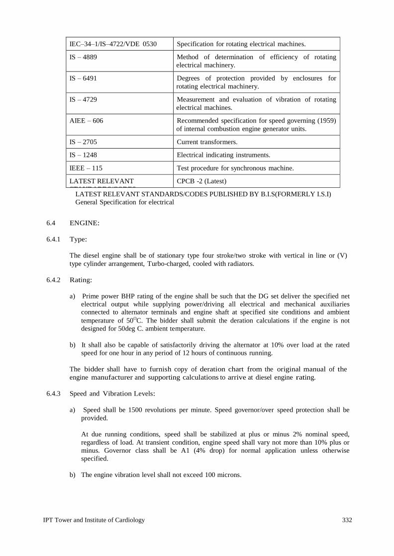
IPT Tower and Institute of Cardiology 332
IEC–34–1/IS–4722/VDE 0530 Specification for rotating electrical machines.
IS – 4889 Method of determination of efficiency of rotating electrical machinery.
IS – 6491 Degrees of protection provided by enclosures for rotating electrical machinery.
IS – 4729 Measurement and evaluation of vibration of rotating electrical machines.
AIEE – 606 Recommended specification for speed governing (1959) of internal combustion engine generator units.
IS – 2705 Current transformers.
IS – 1248 Electrical indicating instruments.
IEEE – 115 Test procedure for synchronous machine.
LATEST RELEVANT STANDARDS/CODES PUBLISHED BY B.I.S(FORMERLY I.S.I) Norms CPCB NORMS
CPCB -2 (Latest)
LATEST RELEVANT STANDARDS/CODES PUBLISHED BY B.I.S(FORMERLY I.S.I) General Specification for electrical
6.4 ENGINE:
6.4.1 Type:
The diesel engine shall be of stationary type four stroke/two stroke with vertical in line or (V) type cylinder arrangement, Turbo-charged, cooled with radiators.
6.4.2 Rating:
a) Prime power BHP rating of the engine shall be such that the DG set deliver the specified net
electrical output while supplying power/driving all electrical and mechanical auxiliaries connected to alternator terminals and engine shaft at specified site conditions and ambient temperature of 50OC. The bidder shall submit the deration calculations if the engine is not designed for 50deg C. ambient temperature.
b) It shall also be capable of satisfactorily driving the alternator at 10% over load at the rated
speed for one hour in any period of 12 hours of continuous running.
The bidder shall have to furnish copy of deration chart from the original manual of the engine manufacturer and supporting calculations to arrive at diesel engine rating.
6.4.3 Speed and Vibration Levels:
a) Speed shall be 1500 revolutions per minute. Speed governor/over speed protection shall be
provided.
At due running conditions, speed shall be stabilized at plus or minus 2% nominal speed, regardless of load. At transient condition, engine speed shall vary not more than 10% plus or minus. Governor class shall be A1 (4% drop) for normal application unless otherwise specified.
b) The engine vibration level shall not exceed 100 microns.

IPT Tower and Institute of Cardiology 333
6.4.4 Lubrications:
a) The engine shall have a closed cycle forced & splash lubricating system with positive oil pressure and a crank chamber for collection/storage of the lubricating oil during circulation.
b) A lubricating oil filter shall be provided for operation under normal conditions for a period of
300 hours without the necessity of its replacement or cleaning.
c) In case lubricating oil coolers are required it shall be supplied as an integral part of the Diesel Generator Set.
d) Necessary temperature and pressure gauges and other instruments shall be supplied and fitted
on the lubrication system.
e) A lubricating oil level dipstick suitably graduated shall be provided and located in the accessible position.
6.4.5 Fuel System:
a) The engine shall be capable of running on all types of diesel fuel oil normally available in
India.
b) The fuel consumption of the engine at full, three quarters and half of its rated power output shall be indicated by the Contractor in the bid.
c) A fuel service tank of 990 litres capacity with each D.G. Set shall be provided on a suitably
fabricated steel platform. The tank shall be complete with level indicator marked in litres, filling inlet with removable screen, an outlet, a drain plug, an air vent and necessary piping. The fuel tank shall be painted with oil resistant paint. All pipe joints should be brazed/welded.
6.4.6 Air Intake System:
The diesel engine shall be provided with special dry type air filters having low resistance to air passage, high dust retaining efficiency and provision for easy cleaning. Filters shall be suitable for achieving satisfactory engine operation and ensuring the engine life under tropical humid conditions, with sulphur dioxide fumes, abrasive dust and coal particles of 5 to 100 microns present in the atmosphere. The minimum efficiency of filters shall be 90% down to 5 micron size.
6.4.7 Cooling:
The diesel engine should be water cooled with radiator heat exchanger system. The cooling system should include temperature gauge with high temp., alarm/trip corrosion resistor etc.
6.4.8 Engine Governor:
The governor shall be Electronic ISO-Chronous type to maintain zero speed rate or regulation and shall be Al type as per BS:5514 in order to take care of heavy motor starting. It shall have necessary characteristics to maintain the speed substantially constant even with sudden variation in load. However, a tripping shall be provided if speed exceeds maximum permissible limit. The governor shall be suitable for operation without external power supply.
6.4.9 Turbo Charger:
It shall be of a robust construction, suitable of being driven by engine exhaust having a common shaft for the turbine and blower. It shall draw air from filter of adequate capacity to suit the requirements of the engine.

IPT Tower and Institute of Cardiology 334
6.4.10 Quietness of Operation:
a) The engine shall be designed to achieve maximum quietness of operation.
b) Efficient residential silencer shall be provided as per engine manufacturer’s approved make
only for the exhaust.
c) Noise level of the set shall not exceed 115-120dbA at one meter distance of the engine. 6.4.11 Engine Starting:
a) Engine starting shall be by electric starting motor complete with manual/automatic starting
arrangement. The starter motor shall conform to IS:4722 and shall be of adequate power for its duty and be of inertia or pre-engaged type. The pinion shall positively disengage when the engine starts up or when the motor is de-energized. The engine cranking shall be only from the panel both for AMF & DG sets (Manual) and any engine starting devices etc. that are given as original fitment on the engine by engine manufacturers shall be either removed or padlocking arrangement given for this so that all normal start/stop operations could be done only from panel whether the set is AMF or manual.
The engine wiring shall be appropriately modified, ferruled to totally match with schematic drawings of the panel.
b) Time for Run-up to Speed:
From the initial operation of the starting device, the engine shall start, run up to normal speed and be capable of accepting 60% of full load within a maximum time of 20 seconds, and full load within a further 20 second.
6.4.12 Starter Battery:
a) The battery shall conform to the requirement of IS:1651. Starting battery each of 12 V, heavy
duty high performance approved make/quality shall be provided to enable crank & start the engine even in cold/winter morning conditions. Type/voltage/AH capacity of same on 20 hour rated discharge period shall be indicated in the offer. The battery set shall be capable of performing at least (5) five normal starts without recharging.
b) The battery shall be provided with good quality teakwood stand painted with acid proof black
paint with min 3mm thick rubber mat below the batter.
c) Batteries shall be of load container type only and not with PVC moulded sealed container so that each individual cells are available for individual monitoring during its life span. Each cell shall be provided with electrolyte filling cap with level floats for easy monitoring of electrolytic level.
d) The battery shall be provided with 2 Nos. cables, minimum 1.5m long heavy duty
rubber/PVC insulated cabling with brazed tinned lug at one end and with brazed tinned brass terminal lug at battery end - for connecting batteries to cranking system - with 0.25 m long inter battery connecting cable.
e) The lugs shall be clearly stamped (+) or (-) and positive cable also red sleeved for easy identification.
f) The batteries Set shall be supplied fully filled and first charged ready to use.
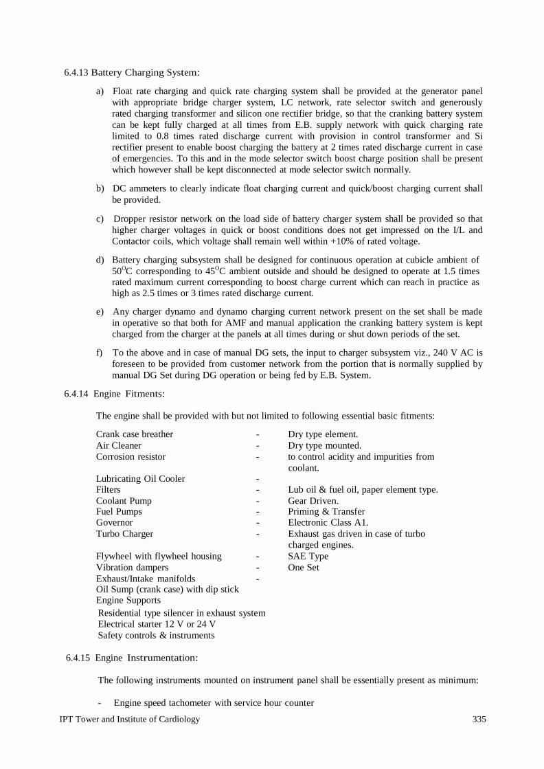
IPT Tower and Institute of Cardiology 335
6.4.13 Battery Charging System:
a) Float rate charging and quick rate charging system shall be provided at the generator panel
with appropriate bridge charger system, LC network, rate selector switch and generously rated charging transformer and silicon one rectifier bridge, so that the cranking battery system can be kept fully charged at all times from E.B. supply network with quick charging rate limited to 0.8 times rated discharge current with provision in control transformer and Si rectifier present to enable boost charging the battery at 2 times rated discharge current in case of emergencies. To this and in the mode selector switch boost charge position shall be present which however shall be kept disconnected at mode selector switch normally.
b) DC ammeters to clearly indicate float charging current and quick/boost charging current shall
be provided.
c) Dropper resistor network on the load side of battery charger system shall be provided so that higher charger voltages in quick or boost conditions does not get impressed on the I/L and Contactor coils, which voltage shall remain well within +10% of rated voltage.
d) Battery charging subsystem shall be designed for continuous operation at cubicle ambient of
50OC corresponding to 45OC ambient outside and should be designed to operate at 1.5 times rated maximum current corresponding to boost charge current which can reach in practice as high as 2.5 times or 3 times rated discharge current.
e) Any charger dynamo and dynamo charging current network present on the set shall be made
in operative so that both for AMF and manual application the cranking battery system is kept charged from the charger at the panels at all times during or shut down periods of the set.
f) To the above and in case of manual DG sets, the input to charger subsystem viz., 240 V AC is
foreseen to be provided from customer network from the portion that is normally supplied by manual DG Set during DG operation or being fed by E.B. System.
6.4.14 Engine Fitments:
The engine shall be provided with but not limited to following essential basic fitments:
Crank case breather - Dry type element. Air Cleaner - Dry type mounted. Corrosion resistor - to control acidity and impurities from
coolant. Lubricating Oil Cooler - Filters - Lub oil & fuel oil, paper element type. Coolant Pump - Gear Driven. Fuel Pumps - Priming & Transfer Governor - Electronic Class A1. Turbo Charger - Exhaust gas driven in case of turbo
charged engines. Flywheel with flywheel housing - SAE Type Vibration dampers - One Set Exhaust/Intake manifolds - Oil Sump (crank case) with dip stick Engine Supports
Residential type silencer in exhaust system Electrical starter 12 V or 24 V Safety controls & instruments
6.4.15 Engine Instrumentation:
The following instruments mounted on instrument panel shall be essentially present as minimum:
- Engine speed tachometer with service hour counter

IPT Tower and Institute of Cardiology 336
- Lub oil pressure gauge - Coolant water temperature gauge
The instrument panel shall be mounted on engine using rubber dampers for vibration isolation.
The gauges shall have clear red marking to identify the limiting dangerous levels, `Zone Markings’ on the scale to indicate the normal healthy & abnormal operating zones for the parameters concerned.
The metering could be either normal electro-mechanical analogue type or electronic digital type, latter being preferred as manufacturers fitment only.
The engine control panel must be supplied by the engine manufacturer only.
6.5 ALTERNATOR:
6.5.1 The alternator shall have brushless type with rotating field and static excitation circuit controlled
by field control unit suitably compounded for voltage and load current for a self excited self regulated system.
6.5.2 The alternator shall be in SP-DP enclosure, foot mounted with ball and roller bearings on end
shields.
6.5.3 The alternator shall conform to IS:4722/BS:2613 and shall be suitable for tropical conditions.
6.5.4 The alternator shall comply with the following specifications:
Rating - As per BOQ (Shall be capable of 10% over loading at the
rated speed
For one hour of 12 hours continuous running).
Voltage - 415 V
Speed - 1500 RPM Frequency - 50 Hz. P.F. - 0.8 lag Enclosure - IP:23 Insulation - H Execution -Self excited, self regulated with brushless system and static
voltage control unit suitably compounded for voltage and current to maintain terminal voltage constant at ± 5% at all load for p.f. not less than 0.8. lag.
The winding of the alternator shall be star-connected. 6.5.6 Terminal Box and Connection:
The alternator output terminals shall be enclosed in a terminal box mounted in an accessible position on the alternator frame. As far as possible, connections between the exciter and alternator shall be contained within the machine frame and connections carrying A.C. and D.C. shall be segregated from each other. The terminal box shall be of sufficient size to conveniently terminate the size and number of the Department’s cables, which shall be intimated during detailed engineering. Suitable tinned copper pads shall be provided for power cable termination along with all necessary hardware and
Terminal Box - As desired by Engineer 6.5.5
Earthing Studs
Neutral Point:
- 2 Nos. in each DG

IPT Tower and Institute of Cardiology 337
cable lugs. Glands and lugs shall be provided for control cables also. For single phase cables, gland plate shall be of non-magnetic material. Gland plate shall be removable type.
6.5.7 The generating set shall be so designed that it is capable of reaching its full voltage and
frequency and shall be ready to take full load within 30 seconds of a remote starting impulse being received.
6.5.8 Acoustic Enclosure:
Thickness of Sheet High Class sheet metal fabricated enclosure for reducing the noise level of DG Set and also acts as weather proof housing. Genset will be an integral part of acoustic enclosure and whole construction will be on multi-fold sheet channels and ISMC sections. Enclosure construction is fully bolted keeping in view the major service requirements all doors are provided with specially designed hinges and lockable handles, battery, fuel tank is housed inside the enclosure.
Acoustic Materials:
Rock wool in the form of slabs of 75 – 100 mm thickness and 48 KG/Metric cube density (Specification of Rock wool conforms to IS:8183).
Further to increase the life of Acoustic material resin coated fiber glass cloth is provided on exposed surface of Rock wool slabs and the panels are supported by perforated sheets.
Ventilation:
Acoustic enclosure is designed in such a way that there are no hot pockets around engine and it is provided with suitable designed engine radiator/or additional axial flow fan and does not allow the temperature to rise more than 7OC.
To achieve optimal output and minimum sound level from the DG Set, suitable openings with acoustic hoods are provide for increasing the inflow of air required for combustion and forced ventilation. Air intake system as per the recommendations and engine requirement are provided.
- Acoustic hoods with noise splitters provided to block and reduce the sound leakage.
- The sound control system designed to suppress the sound level to 75 db maximum at 1 meters
distance in open environment.
Silencer:
Specially designed low noise silencer is provided. Silencer & engine exhaust outlet, connected with flexible SS below.
Vibration Isolation:
To avoid transfer of vibration from Genet to enclosure & surrounding specially designed vibration isolators are used.
COOLING TOWERS
Cooling Tower if required as per BOQ shall be as per Standard manufacturers recommendations/ Practice . The cooling towers of adequate capacity to be installed at the terrace of the complex from where the common header of the cooling towers shall be brought down to the DG room in the basement. Soft water is required to be filled up in make up water tank for closed circuit cooling of engine. The contractor has to obtained the data from the Manufacturer for the requirement of the cooling tower capacity of the DG sets.

IPT Tower and Institute of Cardiology 338
6.6 AMF PANEL:
6.6.1 General:
a) The control panel shall be sheet steel enclosed and shall be dust and vermin proof providing a
degree of protection of IP-42. Sheet steel used shall be cold rolled and at least 2.0mm thick and properly braced and stiffened.
b) Control panel shall be provided with hidden hinged door(s) with pad locking arrangement and
suitable brackets/channels shall be provided for floor mounting.
c) All doors, removable covers and plates shall be casketed all around with neoprene gaskets. All accessible live connections shall be shrouded and it shall be possible to change individual switches, fuses, MCCBS without danger of contact with live metal.
d) All live parts shall be provided with at least phase to phase and phase to earth clearances in
air of 25mm and 20mm respectively.
e) Adequate interior cabling space and suitable removable cable gland plate shall be provided. Necessary number of cable glands shall be supplied and fitted on to this gland plate. Cable glands shall be screwed on type and made of brass.
f) Two number of earthling terminals shall be provided.
g) All sheet steel work shall be degreased, pickled, phosphate and then applied with two coats of
zinc chromate primer and powder coat finishing both inside and outside of shade 631 (gray). 6.6.2 AMF Control of Diesel Generating Sets:
a) All DG Sets shall be controlled independently.
b) Diesel Generator shall be capable of being stopped manually from remote as well as local.
However, interlock shall be provided in the DG local control panel to prevent shutting down operations as long as circuit breaker is closed.
c) Auto Operation:
When mains power is available, the healthiness of this power will be monitored through a mains voltage monitor. If voltages on the 3 phases are within limits, the monitor will send a closing signal to the mains breaker and mains power will be connected to the load.
If the voltage drops on any phase or on all phases, the monitor will sense this drop through a timer, and if this drop persists for more than a pre-adjusted period of time (say 1 to 20 seconds) a signal is sent to the engine starting circuit while at the same time opening the mains supply breaker and disconnecting load from mains as voltage is below acceptable limits.
The engine starting control monitor will send a signal to the D.C. battery supply for starting the engine through the starting solenoid. When the engine is healthy, it starts up in a few seconds and the generator develops voltage. The generator voltage monitor, monitors the voltage and when the voltage is developed, this give a signal to the generator breaker which closes and connects the diesel generator to the load. Simultaneously, it sends a signal to de- energize the engine starting circuit and the starter motor is disengaged. The engine protection circuits for high water temperature and low lubricating oil pressure are also energized.
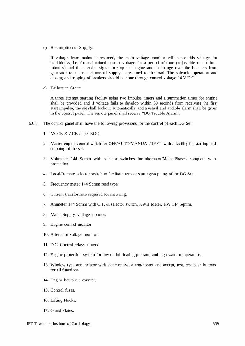
IPT Tower and Institute of Cardiology 339
d) Resumption of Supply:
If voltage from mains is resumed, the main voltage monitor will sense this voltage for healthiness, i.e. for maintained correct voltage for a period of time (adjustable up to three minutes) and then send a signal to stop the engine and to change over the breakers from generator to mains and normal supply is resumed to the load. The solenoid operation and closing and tripping of breakers should be done through control voltage 24 V.D.C.
e) Failure to Start:
A three attempt starting facility using two impulse timers and a summation timer for engine shall be provided and if voltage fails to develop within 30 seconds from receiving the first start impulse, the set shall lockout automatically and a visual and audible alarm shall be given in the control panel. The remote panel shall receive “DG Trouble Alarm”.
6.6.3 The control panel shall have the following provisions for the control of each DG Set:
1. MCCB & ACB as per BOQ.
2. Master engine control which for OFF/AUTO/MANUAL/TEST with a facility for starting and
stopping of the set.
3. Voltmeter 144 Sqmm with selector switches for alternator/Mains/Phases complete with protection.
4. Local/Remote selector switch to facilitate remote starting/stopping of the DG Set.
5. Frequency meter 144 Sqmm reed type.
6. Current transformers required for metering.
7. Ammeter 144 Sqmm with C.T. & selector switch, KWH Meter, KW 144 Sqmm.
8. Mains Supply, voltage monitor. 9. Engine control monitor.
10. Alternator voltage monitor.
11. D.C. Control relays, timers.
12. Engine protection system for low oil lubricating pressure and high water temperature.
13. Window type annunciator with static relays, alarm/hooter and accept, test, rest push buttons
for all functions.
14. Engine hours run counter.
15. Control fuses.
16. Lifting Hooks.
17. Gland Plates.

IPT Tower and Institute of Cardiology 340
18. Power/Control Contactors.
19. Earthing Studs.
20. Antivibration pads.
21. IDMT relays [CDG – 31]
22. Under Voltage Relays
23. Over Voltage Relays
6.6.4 Indication/Annunciation:
Pilot indicating lamps/shall be provided for the following:
1. Charger - ON/OFF 2. Earth Fault 3. Set shutdown due to `Engine high water temp.’ 4. Set shutdown due to `Low oil pressure’ 5. Set shut down due to `Lock of fuel’ 6. Over speed trip
Indicating lamp shall be of the panel mounting filament type with series resistors.
6.6.5 The DG Sets would normally be controlled from remote for which following provisions are being
made on the remote control panel. The necessary control devices/contacts for these external connections shall be wired out to the DG control panel terminal blocks.
1. Starting and stopping of the DG Set 2. DG running indication 3. Watt hour meter, Wattmeter, Voltmeter, Ammeter and Frequency meter.
6.7 ENGINE SAFEGUARDS:
Safeguards shall be provided and arranged when necessary to stop the engine automatically by the following:
a) Energising a solenoid coupled to the stop lever on the fuel injection pump rack. b) De-energising the “fuel on” solenoid
c) Energising the “fuel - cut off” solenoid.
The operation of the safeguard shall at the same time give individual warning of the failure by illuminating an appropriate local visual indicator and remote alarm at generator panel.
The contactors, relays and other devices necessary for signal and control, for above purposes shall be provided at Generator panel.
At the set at a easily accessible place an “EMERGENCY STOP” mushroom head stay put type P.B shall provided to stop the set in emergency mode.
The safe guard to “STOP THE SET” shall stop the set irrespective of mode selection of the set viz Auto, Manual or test for following cases, with simultaneous isolation of alternator ckt.
a) Emergency stop P.B’s operation b) Over speed. c) Low lube oil pressure. d) Earth fault

IPT Tower and Institute of Cardiology 341
6.8 SYNCHRONISING PANEL
6.8.1 The technical specification and details of the microprocessor based PLC controller for the DG set
synchronizing and load sharing shall be as follows 6.8.2 The microprocessor based PLC panel shall be suitable for use with AVR and electronic speed
governor to protect and monitor DG sets. 6.8.3 Double Frequency Meter and Double Voltmeter shall be provided in synchronizing panel. 6.8.4 Synchro check relay also shall be provided. 6.8.5 The PLC shall be provided with following features and audible alarm:
o Engine pre glow control o Fuel solenoid control o Engine starter control o KVA controlled cool-down timer o Speed monitoring o Over speed protection o Oil pressure monitoring, alarm and shutdown of the engine. o Water temperature monitoring, alarm and shutdown of the engine o Battery voltage monitoring o Over speed monitoring and alarm. o 3 attempt start failure alarm o Under/Over Frequency o Reserve Power (Inverse time delay) o Loss of excitation o Over current (inverse time delay) o Loss of utility power detection o Load surge o Current unbalance o Voltage unbalance o Mains Protection (vector shift, df/dt ROCOl) o True RMS power calculations accurate control o Configurable loading/unloading ramp rates o Isochronous load sharing of up to 4 units using percentage based load sharing o Base load control for optimum fuel efficiency o Import export control using a watt transducer o Soft utility transfer function o Digital signal processing to eliminate harmonic issues o Adjustable phase window, Voltage and dwell time o Safe dead bus closing logic internal to the control o Synchronization across generator and mains breakers o Multiple short re-closing with adjustable time delay o Manual voltage and speed adjusts for manual synchronizing o VAR sharing on isolated busses using percentage based reactive load sharing o Power factor or VAR control when base loaded o Externally adjustable VAR or PF set point levels. o The DG set shall start and stop automatically based on plant bus demand. A) The PLC system shall be provided with built in relays for protection of the following:

IPT Tower and Institute of Cardiology 342
o Reverse Power o Reverse KVAR o Over current o Under and over voltage o Under and over frequency o Synchronization check and earth fault relay.
B) The PLC system shall be suitable for load sharing by sensing active and reactive power.
The PLC system shall comprises of the following:
o Main processor unit o Power module for power supply to the processor and the system o Power monitor to monitor voltage, KVA, KVAR, KW, KWH, KVAH, KVARH. o 16/32 channel Digital input module o 16/32 channel Digital output module o EEPROM for main processor unit o Computer to PLC communication card with necessary cables. o Window based operator interface Software Package o Mounting chassis for the equipment
The microprocessor based main processor of the system shall be suitable for 128 digital I/P and 128 O/P and comprises of the following:
The main processor unit shall be suitable for operation on 24 Volts DC with integrated memory. The integrated Ram memory shall be 20 K Words for program, data and constants plus data memory and flash EP ROM of 16 K works for backup application program, communication card and real time clock.
4 Nos. discrete combination module (Input/output Module) shall be provided and the same shall be suitable for operation on 24 volts DC system. Combination module shall be with 16/32 inputs and 16/32 output channels as per the actual requirement.
o 1 No. 2 slot extension rack
o 1 No. Ram back up battery unit
o 8/4 Nos. digital input module
o 8/4 Nos. digital output module
The CPU display unit shall be suitable for 4 lines of 40 characters. The display shall be with back lit LCD. Clarity shall be not less than 5 x 7 pixels. The height of the characters shall be not less than 5 mm. The data entry shall be with the help of 24 function keys. In addition to this there shall be 10 service keys and 12 alphanumeric keys.
The system shall be provided with RS 232 communication port.

IPT Tower and Institute of Cardiology 343
6.9 OPERATION AND COMMUNICATION
7.9.1 The PLC shall monitor the bus bar load continuously. In event of mains failure the
PLC shall give signal to select and start the generator, which is closer to the load sensed during the last 60 seconds. In case the load at the time of main failure is more than the highest rating DG set, the PLC shall give command to start 2 Nos. DG sets to suit the load, synchronize the sets and give command to close the breaker on the main LV panel.
7.9.2 If load starts reducing the PLC shall give command to turn off the DG sets
through cool down timer. On restoration of main power supply, the PLC shall check the voltage and frequency and if they are stabilized and with in the permissible tolerances, the PLC shall give command to shut down the DG sets through cool down timer.
7.9.3 The control and monitoring of the cooling tower and fan and feed pump shall be
done through PLC control system. Necessary control wiring between cooling tower, pumps and PLC panel shall be carried out within the scope of work.
6.10 SYNCHRONIZING MODULE
6.10.1 The synchronizing module shall be a microprocessor based intelligent unit, which
shall monitor the electrical parameters and shall able to communication with the PLC control unit in the process of synchronizing and load management. The system shall be suitable for dynamic synchronization. The synchronizing module shall be suitable for programming and set the preferred difference between DG set and bus bar.
6.10.2 The synchronization module shall monitor and fulfill the following conditions before
the system synchronizes the DG set to mains.
6.10.3 Feed bank signal from the DG breaker on main LV panel that the breaker is in open condition.
o Bus bar
voltage is present o Generator voltage is present
6.10.4 The frequency regulator in the system shall start when the generator voltage and
the bus bas voltage is over 50% of normal voltage. The voltage regulator in the system shall start when the frequency is within 90% of the normal system frequency.
The system shall close the breaker on the power panel with out carrying out synchronization when all the below mentioned conditions are fulfilled.
Feed back signal from the DG breaker on main LV panel that the breaker is in closed condition.
o Bus bar
voltage is present o Generator voltage is present

IPT Tower and Institute of Cardiology 344
The synchronizing module shall transmit all monitored electrical parameters to the PLC unit and the PLC unit shall start controlling the synchronization of the DG sets and its load management. The data logging, monitoring and controlling shall be through a PC based SCADA station.
6.11 TESTS:
The alternator of each type and rating shall be type tested for the following tests as per IS:4722, IEEE 115 & BS:5000. Test certificates to be provided for routine and type tests from the manufacturers.
6.12 ERECTION, TESTING, COMMISSIONING AND PERFORMANCE &
GUARAANTEE TESTS/PROCEDURE AT SITE:
The entire work of erection, testing and commissioning of equipment supplied under this package shall be carried out by contractor and performance and guarantee tests to be conducted at site are also included under the scope of this specification. For this purpose the contractor shall depute suitable qualified technical supervisor to site on advance intimation to the Department along with all special testing equipment required for testing and performance and guarantee tests. The supervisor(s) shall be responsible for the installation, testing, commissioning checks and performance & guarantee tests mentioned in relevant clauses of this volume and the checks recommend by the contractor.
The contractor shall ensure that the equipment supplied by him is installed in a neat workman like manner such that they are leveled, properly aligned and well oriented. The tolerances shall be established in Contractors drawings and/or as stipulated by the Department.
All special tools and tackles and spares required for erection, testing and commissioning of equipment shall be supplied by the contractor.
Erection, testing and commissioning manuals and procedures shall be supplied, prior to dispatch of the equipment.
The contractor shall ensure that the drawings, instruction and recommendations are correctly followed while handling, setting, testing and commissioning the equipment.
6.13 Commissioning Check Tests/Performance and Guarantee Test:
In addition to the checks and test recommended by the manufacturer, the contractor shall supervise the following acceptance tests to be carried out on each test at site.
i. Load Test:
The DG Set shall be given load test at site for a period of at least 6 hours depending upon the actual power factor of the load and set shall be subjected to the maximum achievable load without exceeding the engine or alternator capacity.
This full load test is to be followed immediately by a 10% overload run for one hour. The performance of the engine, alternator shall be satisfactory at the end of this overload run.
During the load test half hourly records of the following shall be taken:
a) Ambient temperature b) Cooling water temp. c) Lubricating oil pressure. d) Speed e) Voltage, wattage and current output. f) Oil tank level

IPT Tower and Institute of Cardiology 345
ii. Speed and Governing:
The speed of the engine shall be verified to ensure that it conforms to the requirement of BS:5514.
iii. Check of Fuel Consumption:
A check of the fuel consumption shall be made through out the test run of full load and overload.
iv. Noise Level:
The equivalent `A’ weighted sound level measured at a distance of 1 meter horizontally from the base of any equipment furnished and installed under these specifications expressed in decibels to a reference of 0.0002 microbar, shall not exceed the limit given as per CPCB norms. 75 dbA average at 1 mtr. distance from acoustic enclosure.
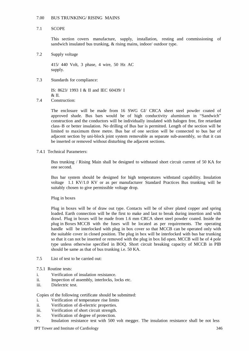
IPT Tower and Institute of Cardiology 346
7.00 BUS TRUNKING/ RISING MAINS 7.1 SCOPE
This section covers manufacture, supply, installation, resting and commissioning of sandwich insulated bus trunking, & rising mains, indoor/ outdoor type.
7.2 Supply voltage
415/ 440 Volt, 3 phase, 4 wire, 50 Hz AC supply.
7.3 Standards for compliance:
IS: 8623/ 1993 I & II and IEC 60439/ I & II.
7.4 Construction:
The enclosure will be made from 16 SWG GI/ CRCA sheet steel powder coated of approved shade. Bus bars would be of high conductivity aluminium in “Sandwich” construction and the conductors will be individually insulated with halogen free, fire retardant class–B or better insulation. No drilling of Bus bar is permitted. Length of the section will be limited to maximum three metre. Bus bar of one section will be connected to bus bar of adjacent section by uni-block joint system removable as separate sub-assembly, so that it can be inserted or removed without disturbing the adjacent sections.
7.4.1 Technical Parameters:
Bus trunking / Rising Main shall be designed to withstand short circuit current of 50 KA for one second. Bus bar system should be designed for high temperatures withstand capability. Insulation voltage 1.1 KV/1.0 KV or as per manufacturer Standard Practices Bus trunking will be suitably chosen to give permissible voltage drop.
Plug in boxes
Plug in boxes will be of draw out type. Contacts will be of silver plated copper and spring loaded. Earth connection will be the first to make and last to break during insertion and with drawl. Plug in boxes will be made from 1.6 mm CRCA sheet steel powder coated. Inside the plug in Boxes MCCB with the fuses will be located as per requirements. The operating handle will be interlocked with plug in box cover so that MCCB can be operated only with the suitable cover in closed position. The plug in box will be interlocked with bus bar trunking so that it can not be inserted or removed with the plug in box lid open. MCCB will be of 4 pole type unless otherwise specified in BOQ. Short circuit breaking capacity of MCCB in PIB should be same as that of bus trunking i.e. 50 KA.
7.5 List of test to be carried out:
7.5.1 Routine tests: i. Verification of insulation resistance. ii. Inspection of assembly, interlocks, locks etc. iii. Dielectric test. Copies of the following certificate should be submitted: i. Verification of temperature rise limits ii. Verification of di-electric properties. iii. Verification of short circuit strength. iv. Verification of degree of protection. v. Insulation resistance test with 500 volt megger. The insulation resistance shall be not less

IPT Tower and Institute of Cardiology 347
than 100 mega ohm.

IPT Tower and Institute of Cardiology 348
8.0 INTERNAL ELECTRIFICATION OF BUILDING 8.1 SCOPE
As specified in subhead 1.00
8.2 GENERAL
The electrical Installation work shall be carried out in accordance with Indian Standard Code of Practice for Electrical Wiring Installation IS: 732-1989 and IS: 2274-1963. It shall also be in conformity with the current Indian Electricity rules and regulations and requirements of the Local Electricity Supply Authority and Fire Insurance regulations, so far as these become applicable to the installation. Electrical work in general shall be carried out as per following Latest relevant standards/codes published by B.I.S(formerly I.S.I) with up to date amendment.
- Specifications for Electrical Works Part-I (Internal) by LATEST RELEVANT STANDARDS/CODES PUBLISHED BY B.I.S(FORMERLY I.S.I)
Wherever these specifications calls for a higher standard of material and or workmanship than those required by any of the above mentions regulations and specification then the specification here under shall take precedence over the said regulations and standards.
8.3 DISTRIBUTION BOARDS.
As a general practice only MCB type double door DB shall be used or as specified in BOQ.
Distribution Board shall be standard type. Distribution boards shall contain miniature circuit breakers of rating specified in BOQ/DB Schedule.
Miniature circuit breakers shall be quick make and quick break type with trip free mechanism. MCB shall have thermal and magnetic short circuit protection. All miniature circuit breakers shall be of minimum 9 KA rated rupturing capacity unless otherwise specified.
Neutral busbars shall be provided with the same number of terminals, as there are single ways on the board, in addition to the terminals for incoming mains. An earth bar of similar size as the neutral bar shall also be provided. All live parts shall be screened from the front. Ample clearance shall be provided between all live metal and the earth case and adequate space for all incoming and outgoing cables. A circuit identification card in clear plastic cover shall be provided for each distribution board.
MCB's shall be provided on the phase of each circuit. The individual banks of MCB's shall be detachable. There shall be ample space behind the banks of MCB's to accommodate all the wiring. All the distribution boards shall be completely factory wired, ready for connections. All the terminals shall have adequate current rating and size to suit individual feeder requirements. Each circuit shall be clearly numbered from left to right to correspond with wiring diagram. All the switches and circuits shall be distinctly marked with a small description of the service installed.
Earth Leakage Circuit Breaker shall be current operated type and of 30mA sensitivity unless otherwise specified. It shall also provide over-current and short circuit protection i.e. it shall be MCB-cum-RCCB (Residual Current Circuit Breaker). In case ELCB doesn’t have inbuilt short circuit protection, same rating MCB have to be provided for short circuit protection along with ELCB. Cost of this MCB is deemed to be included in the cost of ELCB. ELCB shall be housed within the Distribution Board.
Distribution Boards shall be ready for connections and shall be inspected in the factory by JDA Electrical Engineer before dispatch.

IPT Tower and Institute of Cardiology 349
Before procurement of Distribution Boards, MCB’s, ELCB’s (incomer and outgoings) etc., the contractor has to take approval of the DB Schedule/Drawings of each DB from the JDA Electrical Engineer. The whole unit i.e. Distribution Board, MCB’s, ELCB’s etc. shall come from the manufactures premises/workshop. After inspection and clearance from the JDA Electrical Engineer the same may be dispatched to site for installation. However if a single component (such as ELCB or MCB or DB) is required for any reason such as replacement, increase in no. of circuits in the DB, change in the load of existing circuit, change in the total load on a particular DB etc., the same may be ordered separately but after the approval of JDA Electrical Engineer.
8.4 METALLIC CONDUIT WIRING SYSTEM.
8.4.1 TYPE AND SIZE OF CONDUIT.
All conduit pipes shall be of approved gauge (not less than 16 SWG for conduits of sizes up to 32 mm diameter and not less than 14 SWG for conduit of size above 32mm diameter) solid drawn or reamed by welding finished with black stove enameled surface. All conduit accessories shall be of threaded type and under no circumstances pin grip type accessories shall be used. The maximum number of PVC insulated 650/1100 volts grade copper conductor cable that can be drawn in conduit of various sizes shall be as per IS Code. No steel conduit less than 20mm in diameter shall be used.
8.4.2 CONDUIT JOINTS.
Conduit pipes shall be joined by means of threaded couplers, and threaded accessories only. In long distance straight run of conduits, inspection type couplers at reasonable intervals shall be provided or running threads with couplers and jam nuts shall be provided. In the later case the bare threaded portion shall be treated with anti-corrosive preservative. Threads on conduit pipes in all cases shall be between 13 mm to 19 mm long sufficient to accommodate pipes to full threaded portion of couplers or accessories.
Cut ends of conduit pipe shall have neither sharp edges nor any burrs left to avoid damage to the insulation of conductor while pulling them through such pipes.
8.4.3 PROTECTION AGAINST CONDENSATION.
The layout of conduit should be such that any condensation or sweating inside the conduit is drained out. Suitable precaution should also be taken to prevent entry of insects inside the conduit.
8.4.4 PROTECTION OF CONDUIT AGAINST RUST.
The outer surface of conduit including all bends, unions, tees, junction boxes etc. forming part of conduit system shall be adequately protected against rust when such system is exposed to weather by being painted with two coats of oxide paint applied before they are fixed. In all cases, no bare threaded portion of conduit pipe shall be allowed. Unless such bare thread portion of conduit is treated with anticorrosive preservative or covered with approved plastic compound.
8.4.5 PAINTING OF CONDUIT AND ACCESSORIES.
After installation, all accessible surface (if any) of conduit pipes, fittings etc. shall be painted with two coats of approved enameled paint or aluminium paint as required to match the finish of surrounding wall, trusses etc.
8.4.6 RECESS CONDUIT.
The chase in the wall shall be neatly made and of ample dimensions to permit the conduit to be fixed in the manner desired. In the case of building under construction, conduit shall be buried in the wall before plastering and shall be finished neatly after erection of conduit. Incase of exposed brick/rubble masonry work, special care shall be taken to fix the conduit and accessories in

IPT Tower and Institute of Cardiology 350
position along with the building work. Entire work of chasing the wall, fixing the conduit in chases, and burring the conduit in mortar before plastering shall form part of point wiring work.
The conduit pipe shall be fixed by means of staples or by means of saddles not more than 60cm apart or by any other approved means of fixing. Fixing of standard bends and elbows shall be avoided as far as practicable and all curves maintained by bending the conduit pipe itself with the long radius, which shall permit easy drawing in of conductors. All threaded joints of conduit pipe shall be treated with some approved preservative compound to secure protection against rust. Suitable inspection boxes to the barest minimum requirements shall be provided to permit periodical inspection and of facilitate replacement of wires, if necessary. These shall be mounted flush with the wall. Suitable ventilating holes shall be provided in the inspection box covers. Wherever the length of conduit run is more than 10 meters, then circular junction box shall be provided.
8.4.7 METAL OUTLET BOXES & COVERS.
The switch box shall be made of modular metal boxes with suitable size modular cover plates. Modular metal box shall be made of mild steel on all sides except on the front.
The metal box (other than modular type) shall be made of metal on all sides except on the front. Boxes shall be hot dip galvanized mild steel. Metal boxes upto 20 x 30 cm size M.S. box shall have wall thickness of 18 SWG and MS boxes above 20 x 30 cm size shall be of 16 SWG. The metallic boxes shall be painted with anticorrosive paint before erection. Clear depth of the box shall not be less than 60mm. All boxes shall be covered from top with Phenolic laminated sheet of approved shade. These shall be of 3 mm thick synthetic phenolic resin bonded laminated sheet as base material and conform to grade P-I of IS: 2036-1994.
8.4.8 ERECTION AND EARTHING OF CONDUITS.
The conduit of each circuit or section shall be completed before conductors are drawn in. The entire system of conduit after erection shall be tested in presence of JDA Electrical Engineer for mechanical and electrical continuity throughout and permanently connected to earth conforming to the requirement by means of special approved type of earthing clamp effectively fastened to conduit pipe in a workmen like manner for a perfect continuity between the earth and conduit.
8.4.9 SWITCHES.
All 5 and 15 Amp switches shall be modular type of 240 volts A.C. grade. All switches shall be fixed on modular metal boxes. All 5 Amp socket shall be 3 pin type and 15 Amp socket shall be 5/6 pin type (unless otherwise specified) suitable for 15/5 Amp. All modular switches, sockets, telephone outlets, TV outlet etc. shall be in off white finish unless otherwise specified. The switches controlling the lights or fans shall be connected to the phase wire of the circuit. Switch boards shall be located at 1200 mm above finished floor level unless otherwise indicated on drawings or directed by Engineer-In-Charge.
In case of computer power points, power points, telephone points etc. to be fixed on laminated partition board (furniture), same shall be fixed on laminated board (portion of laminated board meant for fixing power points) with base plate/cover plate as applicable, duly fixed with screws.
8.4.10 COVER PLATE.
All modular switches, sockets, telephone outlets etc. shall be fixed modular metal boxes with modular base plates and modular cover plates on top.
8.4.11 WALL SOCKET PLATE.
Each outlet shall have a switch located beside the socket preferably on the same cover plate/modular base. The earth terminal of the socket shall be connected to the earth wire.

IPT Tower and Institute of Cardiology 351
area of in Sq.mm.
8.5 WIRING.
All PVC insulated copper conductor wires shall conform to relevant IS Codes. All wires/cables shall be stranded type irrespective of its size. Cable conductor size and material shall be specified in BOQ.
All internal wiring shall be carried out with PVC insulated wires of 650/1100 volts grade. The circuit wiring for points shall be carried out in looping in system and no joint shall be allowed in the length of the conductors. Circuit wiring shall be laid in separate conduit originating from distribution board to switch board for light/fan. A light/fan switchboard may have more than one circuit but shall have to be of same phase.
Looping circuit wiring shall be drawn in same conduit as for point wiring. Each circuit shall have a separate neutral wire. Neutral looping shall be carried out from point to point or in light/fan switchboards. A separate earth wire shall be provided along with circuit wiring for each circuit. For point wiring red/yellow/blue colour wire shall be used for phase and black colour wire for neutral. Circuit wiring shall be carried out with red, yellow or blue colour PVC insulated wire for RYB phase wire respectively and black colour PVC insulated wire for the neutral wires. Bare copper wire shall be used as earth continuity conductor and shall be drawn along with other wires. No wire shall be drawn into any conduit until all work of any nature, that may cause injury to wire is completed. Care shall be taken in pulling the wires so that no damage occurs to the insulation of the wire.
Before the wires are drawn into the conduit, the conduits shall be thoroughly cleaned of moisture, dust and dirt. Drawing and jointing of copper conductor wires and cables shall be as per Latest relevant standards/codes published by B.I.S(formerly I.S.I).
Maximum number of PVC insulated 650/1100 V grade aluminium/copper conductor cable conforming to IS : 694 - 1990
------------------------------------------------------------------------------------------------------- 1 4 5 6 7 8 9 10 11 12 13
------------------------------------------------------------------------------------------------------- 1.5 10 8 18 12 - - - - - - 2.5 8 6 12 10 - - - - - - 4 6 5 10 8 - - - - - - 6 5 4 8 7 - - - - - - 10 4 3 6 5 8 6 - - - - 16 2 2 3 3 6 5 10 7 12 8 25 - - 3 2 5 3 8 6 9 7 35 - - - - 3 2 6 5 8 6 50 - - - - - - 5 3 6 5 70 - - - - - - 4 3 5 4 -------------------------------------------------------------------------------------------------------
NOTE :
1. The above table shows the maximum capacity of conduits for a simultaneous drawing in of
cables. 2. The columns headed `S' apply to runs of conduits which have distance not exceeding 4.25m
between draw in boxes and which do not deflect from the straight by an angle of more than 15 degrees. The columns headed `B' apply to runs of conduit which deflect from the straight by an angle of more than 15 degrees.

IPT Tower and Institute of Cardiology 352
3. Conduit sizes are the nominal external diameters.
8.5.1 JOINTS.
All joints shall be made at main switches, distribution board socket and switch boxes only. No joint shall be made in conduits and junction boxes. Conductors shall be continuous from outlet to outlet.
8.5.2 LOAD BALANCING
Balancing of circuits in three-phase installation shall be planned before the commencement of wiring and shall be strictly adhered to.
8.5.3 COLOUR CODE FOR CIRCUIT WIRING.
Colour code for circuit and sub main wiring installation shall be Red, Yellow, and Blue for three phases. Black for neutral and yellow/green or green only for earth incase of insulated earth wire.
8.5.4 CLASSIFICATION OF POINTS.
8.5.4.1 General
Classification and measurement of Point wiring shall be as per LATEST RELEVANT STANDARDS/CODES PUBLISHED BY B.I.S(FORMERLY I.S.I) specification for Electrical Works.
8.5.4.2 Point Wiring (Modular)
Definition of point wiring
A point (other than socket outlet point) shall include all work necessary in complete wiring to the light points/fan/exhaust fan/call bell point from the controlling switch/MCB. The scope of wiring for a point shall, however, include the wiring work necessary in tapping from another point in the same distribution circuit i.e. from first switch board (wiring from distribution board to first switch box is covered in the circuit wiring and is not in the scope of point wiring) to subsequent switch board(s) in the same distribution circuit. The point wiring includes all materials specified below including chasing the wall (in case of recessed wiring in wall), fixing the conduit and making the wall good as it originally was. It also includes supply, drawing, testing and commissioning of wires.
Scope of point wiring
Following shall be deemed to be included in point wiring.
(a) Supply & fixing conduit & conduit accessories for the same and wiring cables (including
supplying and drawing wires) between the switch box and the point outlet. [See also (i) below]
(b) All fixing accessories such as clips, nails, screws, phil plug, rawl plug etc. as required. (c) Modular Metal boxes for control switches, regulators, sockets etc. recessed or surface
type, modular base plates and modular cover plates over the same. (d) Outlet boxes, junction boxes, pull-through boxes etc. but excluding modular metal boxes
if any, provided the switchboards for loose wires/conduit terminations. (e) In case of recessed wiring in wall the scope includes chasing of wall, fixing the conduit
and making the wall good as it originally was. (f) Control modular switch (5/6A) as specified. (g) Ceiling rose or connector (in case of points for ceiling/exhaust fan point, prewired light
fittings and call bells). (h) Connections to ceiling rose, connector, socket outlet, lamp holder, switch etc.

IPT Tower and Institute of Cardiology 353
(i) Interconnecting wiring between points on the same circuit, in the same switch box or from another. Interconnecting wiring from first switchboard to subsequent switch board(s).
(j) Protective (loop earthing) conductor (as specified in the BOQ) from one metallic switch box to another in the distribution circuits, and from switchboard to each point (light/fan/exhaust fan/call bell etc).
(k) Bushed conduit where wiring cables pass through wall etc. (l) Ceiling rose (in the case of pendants except stiff pendants). m) Lamp holder (in the case of goose neck type wall bracket, batten holder and
fittings which are not pre-wired).. n) Back Plate (in the case of stiff pendants).
Note :- In the case of call bell points the words “from the controlling switch or MCB” shall be
read as “from the ceiling rose meant for connection to bell push”.
Measurement of Point Wiring (other than socket outlet points)
i) There shall be no linear measurement for point wiring for light points, fan points, exhaust fan points and call bell points. These shall be measured on unit basis by counting,
ii) No separate measurement shall be made for interconnections between points in the same
distribution circuit and for the circuit protective (loop earthing) conductors between metallic switch boxes.
8.5.5. Circuit and Submain Wiring
Circuit Wiring
Circuit wiring shall mean the wiring from the distribution board upto the tapping point for the nearest first point of that distribution circuit i.e. up to the nearest first switch box.
Submain Wiring
Submain wiring shall mean the wiring from one main/distribution switchboard to another.
Measurement of circuit wiring and submain wiring
(i) Circuit and submain wiring shall be measured on linear basis along the run of the wiring. The measurement shall include all lengths from end to end of conduit, exclusive of interconnections inside the switchboard etc. The increase on account of diversion or slackness shall not be included in the measurement.
(ii) The length of circuit wiring with two wires shall be measured from the distribution board to the first nearest switch box in the circuit irrespective of whether neutral conductor is taken to switch box or not.
(iii) When wires of different circuits are grouped in a single conduit, the same shall be measured on linear basis depending on the actual number and size of wires run.
(iv) When circuit wires and wires of point wiring are run in the same conduit, circuit wiring shall be measured on linear basis depending on the actual number and sizes of wires run in the existing conduit.
(v) Protective (loop earthing) conductors, which are run along the circuit wiring and submain wiring, shall be measured on linear basis and paid separately. This is not applicable if protective conductor is clubbed with the BOQ item of circuit and submain wiring.
8.5.6 Power Plug Wiring
5A Plug Wiring
Wiring for all 5 A Socket Outlets shall be done with 2X1.5 sqmm PVC insulated copper wire in suitable size MS Conduit (including supplying and fixing MS Conduit) along with the earth wire as specified in the BOQ/Drawings, from the switchboard or 15A power point as the case may be.

IPT Tower and Institute of Cardiology 354
Measurement of 5A point wiring shall be done on Linear basis from switchboard/15A power point to 5A point. Conduit of power SOCKET wiring can also be used for 5A socket outlet wiring, but both phase and neutral wires shall come directly from switchboard/power socketoutlet. Looping of neutral shall not be done.
15A Power Plug Wiring
Wiring for all 15 A Socket Outlets/Gyser point shall be done with 2X4 sqmm PVC insulated copper wire in suitable size MS Conduit (including supplying and fixing MS Conduit) along with the earth wire as specified in the BOQ/Drawings, directly from the MCB-Distribution Board or from one power socket outlet to another in case of computer power points. Looping shall not be done in general 15A power points (other than computer power points).
Measurement of power socket outlet wiring shall be done on basis under following two subheads:
i) Directly from MCB-Distribution Board to the Socket Outlets
ii) From One power socket outlet/computer power point to another (looping)
Wiring for 20A Metal Clad Socket Outlets
Wiring for all 20A Metal Clad Socket Outlets shall be done with 2X6 sqmm PVC insulated copper wire in suitable size MS Conduit (including supplying and fixing MS Conduit) along with the earth wire as specified in the BOQ/Drawings, directly from the MCB-Distribution Board. Measurement of wiring for 20A Metal Clad Socket outlet shall be done on linear basis i.e. complete wiring directly from MCB-Distribution Board to the socket outlet.
No extra payment shall be made on account of minor changes in location of power points (15A or 20A or computer power points) due to change in the architectural layout or change due to any other reason. Height of the power socket outlets shall be 300mm from the finished floor level unless otherwise specified.
8.5.7 CONDUCTOR SIZE.
Wiring shall be carried out with following sizes of PVC insulated stranded single core copper conductor wire/cable.
i. Light point. - 1.5Sq.mm
ii. Ceiling /Cabin/Exhaust Fan Point - 1.5Sq.mm
iii. Call Bell Point - 1.5Sq.mm
iv. Plug Point (5 A Outlet) - 1.5Sq.mm
v. Circuit Wiring - 2.5Sq.mm
vi. General Power Point - 4Sq.mm
vii 20A Industrial Socket Outlet – 6 Sqmm
viii Special Power Point – 6 Sqmm
ix A/C Box with 32A MCB- 6 Sqmm

IPT Tower and Institute of Cardiology 355
8.5.8 LIGHTING FIXTURE AND FANS
8.5.8.1 GENERAL
a. Normally all light fixture will be LED type and shall be with driver etc, ready to use condition.
The Contractor shall supply and install lighting fixtures including but not limited to lamps, driver /ballasts, accessories fixing hardware necessary for installations, as shown on the Drawings, as required, and as herein specified.
b. All fixtures shall be delivered to the building complete with suspension accessories, canopies,
hanging devices, sockets, holders, reflectors, ballasts, diffusing material, louvers, plaster frames, recessing boxes, etc. all wired and assembled as indicated.
c. Full size shop detail drawings of special fixture or lighting equipment, where called for in the
fixtures schedule, shall be submitted to the JDA Electrical Engineer for approval. d. Fixtures, housing, frame or canopy, shall provide a suitable cover for fixture outlet box or fixture
opening. e. Fixtures shall comply with all applicable requirements as herein outlined unless otherwise
specified or shown on the Drawings. f. Manufacturer's name and catalogue number of light fixtures, fans, switchgears etc. shall be
strictly adhered. g. Fixtures shall bear manufacturer's name and the factory inspection label.
h. Fixtures shall be completely wired and constructed to comply with the IEE wiring regulations
requirements for lighting fixtures, unless otherwise specified. i. Revamping the fixture shall be possible without having to remove the fixture from its place.
j. Lamps of the proper type, wattage and voltage rating shall be furnished and installed in each
fixture. 8.5.9 INSTALLATION
Fixtures shall be installed at mounting heights as detailed on the Drawings or as instructed on site by the Engineer-In-charge.
Pendent fixtures within the same room or area shall be installed plumb and at a uniform height from the finished floor. Adjustment of height shall be made during installation.
Flush mounted recessed fixtures, shall be installed so as to completely eliminate leakage of light within the fixture and between the fixture and adjacent finish.
Fixtures mounted outlet boxes shall be rigidly secured to a fixture stud in the outlet box. Hickeys or extension pieces shall be installed where required to facilitate proper installation.
Fixtures located on the exterior of the building shall be installed with non-ferrous metal screws finished to match the fixtures.
8.5.10 LAMPS-GENERAL
LED will be used
Lamp shall be supplied and installed in all lighting fixtures listed in the BOQ.
IPT Tower and Institute of Cardiology 356
Lamp shall be the part of Fitting no extra Payment will be made
Lamps used for temporary lighting service shall not be used in the final fixture units.
Lamps shall be of wattage and type as shown in the BOQ.
Lamps for permanent installation shall not be placed in the fixtures, until so directed by the Engineer In-charge.
8.5.11 FIXTURE SAMPLES
Detailed catalogue for all fixtures or if so required by the JDA Electrical Engineer sample fixtures shall be submitted for prior approval of the JDA Electrical Engineer before orders for the fixtures are placed.
8.5.12 TESTING
After all lighting fixtures are installed and are connected their respective switches, test all fixtures to ensure operation on their correct switch in the presence of the engineer.
All non-operating fixtures or ones connected to the wrong or inconveniently located switch shall be correctly connected as directed by the Engineer In-charge.
8.5.13 CEILING FANS
All ceiling fans shall be provided with suspension arrangement in the concrete/slab/roof members. Contractor to ensure that provision are kept at appropriate stage at locations shown on the drawing. Fan box with MS hook shall be as per LATEST RELEVANT STANDARDS/CODES PUBLISHED BY B.I.S(FORMERLY I.S.I) specification. Ceiling fan shall be double ball bearing type, copper wound motor complete with canopy, down rod, blades etc. and shall conform to relevant IS standards ceiling fan shall be white in colour. Ceiling fan shall be provided with electronic regulator. Electronic Regulator shall be suitable for 240 volts A.C supply 50 Hz and shall be of continuous duty type
8.5.14 EXHAUST FANS
Exhaust fans shall be heavy-duty type with double ball bearing and conforming to IS 2312 (latest revision). Exhaust fan shall be complete with copper wound motor, capacitor, Louver/shutter, frame and mounting bracket. Exhaust fan shall be suitable fan operation on 240 volts single phase A.C supply.

IPT Tower and Institute of Cardiology 357
9.00 TELEPHONE SYSTEM
9.1 Telephone point wiring
(a) The point wiring shall be carried out with two pair telephone wire/cable, unarmoured, PVC
insulated, 0.61 mm dia annealed tinned copper conductor (IS: 2532-1965)in suitable size conduit (one pair always remaining spare for one point)
Minimum Diameter of Conduit for Internal/External Telephone Wiring - 20mm.
If more than one telephone point has to be provided at one point, multicore, unarmoured telephone cable shall be used (pairs required are equal to 2 No.of points) in suitable size of conduit.
(b) The point shall commence from the main telephone tag box/sub tag box and would terminate at
outlet box of point. Connection at both ends included in point wiring. (c) Fixing of conduit, conduit accessories draw out boxes and outlet box etc. in concealed/surface
conduit works as that of wiring for light fixtures shall be applicable for telephone wiring conduit system also.
(d) Joint in telephone wiring (between main tag box/sub tag box and outlet box of point) shall not be
allowed and the contractor should bear the wastages of wire if resulted due to this special requirement of telephone system.
(e) External/Internal telephone and intercom wiring can be drawn in the same conduit, provided after
drawing wires, 50% of conduit cross sectional area is free. However, independent PVC insulated telephone wire of suitable pairs shall be used for external, internal and intercom.
(f) To identify each pair of multipair telephone wire/cable, PVC indication numbers shall be put on
both ends of pair just before termination. 10.02 Telephone Tag Boxes
These shall be of MS sheet 2 mm thick with connector suitable for telephone connection (as approved by ITI). It shall have hinged MS sheet cover.
9.2 EPABX SYSTEM
10.2.1.1Scope:
This specification covers the design, manufacture, testing and supply of digital Electronic Private Automatic Branch Exchange (EPABX), Telephone Sets, MDF, Back-up Power supply system, Voice Mail System etc.
10.2.1.2 Code and Standards:
The telephone system and the components shall conform to the latest edition of the "The International Telegraph and Telephone Consultative Committee (CCITT)" and other Indian and International standards as applicable.
9.2.1.3 Site Condition:
All the equipments shall be designed and tropicalised to withstand the site conditions as specified in the schedule of quantities.

IPT Tower and Institute of Cardiology 358
9.2.1.4 Technical Requirements
Calling line identification display on all extension (external line as well as intercom)
In built SMDR (Minimum1500calls)
In built USB port for programming on system /CPU
Memory backup based on SD card with at least 5 years duration
At least 2 in built ports for external music source connectivity
Power voltage Ac 100v-240v
In built interface for connecting optional External battery bank-36v(12vx3)
AUTO ATTENDENT-04 CHANNEL
In skin, of same brand as EPABX. Expandable to 08/12 channels
UPS Suitable for above configuration or optional External Battery bank-36 v(12x3)
System should be-
100% non –blocking Digital Hybrid IP PBX employing PCM/TDM principles
Based on universal Slot Architecture
Capable of supporting connection of additional Digital phone from another digital phone without need for any other adaptor or hardware
Supporting optional CLI on analogue P&T line
Supporting optional multiple 4 channel DISA cards
Supporting ISDN BRI (4line & 8 line) and PLI
Supporting optional IP Gateway/ Extension card
Supporting optional CTI card
Supporting Floating extension
Supporting major networking protocols such as FXO, FXS , E &M ( 8 channel), E1 & QSIG ( PRI/ BRI)
Supporting Background music on Key Telephone
Supporting Background music on Key Telephone
Supporting 3 to * party conference supporting unattended conference.
Supporting 32 party broadcast feature
Supporting internal and external paging interface with different paging groups
Supporting multiple call hop forwarding facility
Supporting off hook Call Announcement on high end Digital Key phone

IPT Tower and Institute of Cardiology 359
Supporting the facility of DISA, DDSA, external call forwarding, Trunk –to –Trunk Transfer and walking class of service
Supporting voice calling on intercom
Supporting Boss Secretary function
Supporting direct connectivity or Digital extension port
Supporting CTI
Supporting call budget management
Supporting CLI based routing
Supporting Mobile Integration
Absent message capability in – built Speed Dial- At least 1000 on system and 10 per extension
Should have extension personal Identification Number (PIN)/ password- up to 10 digits per extension
Should give call log of at least 10 outgoing numbers and 100 incoming numbers per key phone extensions
Having Message/ Ringer Lamp on Digital phone (dual colour) to indicate the following distinct status on High Mid Key phone: i. Internal call ii. External Call iii. message
10.2.1.5 Main Distribution Frame (MDF) A Krone MDF mounted in sheet steel enclosure shall be supplied along with the exchange. I.P.M. shall be provided in the MDF for all junction lines and external one. All cables coming from field will be terminated on the MDF.
9.2.1.6 Operator’s Console
The operator’s console shall be digital, desk top type, compact in design and electronic based. Electronics switching shall be used to make various connections, cord connections shall not be accepted. The operator console should work on single pair. Status of all the analog extensions and digital extensions shall be indicated on LED display. Suitable Add on module shall be provided for this.
9.2.1.7 The console shall provide the following facilities:
i) Answering an incoming call Operator can answer an incoming call, whether from an internal extension or from External Junction line.
ii) Call Waiting An unattended call waiting for more than a predetermined time shall automatically go to standby operator.
iii) Setting up External calls It shall be possible for an operator to set up external calls.
iv) Automatic Recall
Incoming calls will be automatically returned to the operator if the called extension does not
answer within a predetermined time or called extension is busy.

IPT Tower and Institute of Cardiology 360
10.0 ADDRESSABLE FIRE DETECTION AND ALARM SYSTEM
10.1 GENERAL
The Contractor shall supply and install the Addressable Fire Detection & Alarm System as per schedule of quantities are as herein specified. The system shall include Addressable Main Fire Alarm Control Panel, battery charger, batteries, addressable heat detectors, addressable smoke detectors, manual fire alarm station, fire alarm bells/hooters, response indicators, conduiting, wiring and all necessary accessories required to complete fire alarm system installation as per IS: 2189-1988. Equipment like control panel, smoke detector, heat detectors etc shall be UL approved or as specified in BOQ.
10.2 FEATURES
The system shall be general alarm electrically supervised type activation of manual fire alarm station or any of the automatic alarm initiating devices shall sound the general alarm bells on all floors and shall give indication on the control panel. The signal shall be continuous unit the station from which it is originated is restored to normal and a reset button on the control unit is operated.
The system shall be electrically supervised against open and ground on both the stations and signal device wiring. Open and ground in the system shall cause a trouble bell to ring at the fire alarm control panel and a trouble lamp to light. It shall be possible to silence the bell but the lamp shall remain lit until the fault is rectified. Incase of power failure the system shall automatically changeover to the battery standby.
10.3 CONDUITING & WIRING
Conduiting & Wiring for FDA system shall be carried out in M.S Conduit with copper conductor PVC insulated wires.
10.4 CONTROL PANEL
The fire control panel has to be addressable type.
The Main Fire Control Panel shall be constructed to sheet steel of red colour, and provided with windows for the alarm and trouble lights. All components shall be of the plug in type, for simple replacement and extension in the future. Control panel shall be wall mounting type conforming to IS 513-1986.
The number of loops is mentioned in B.O.Q. Each loop shall be able to support at least 128 any device addressable analog/digital (as the case may be) sensors and control module etc. or as specified in BOQ. The control panel shall have alphanumeric display. The Main Fire control panel shall be provided with all necessary relays, resistors, fuses, transformers, rectifiers and all other components to assure full and proper functioning of the system. All relays shall conform to the relevant IS Standards. Control panel shall include power include power on lamps, system trouble lamps, audible trouble signal, trouble silence switch with ring back, alarm silence push button with repeat alarm capability, low battery indicator with reset, ground detection indicator, alarm reset, milli ammeter, supervised alarm lamps, zone "Open" test pushbutton, zone alarm test push button, end of line resistors etc.
Each zone shall be equipped with an auxiliary contact for control of a remote annunciation.

IPT Tower and Institute of Cardiology 361
Main control panel shall include a power supply model to provide a filtered and regulated source of power to provide additional power wherever supplementary power is required within the system. It shall include an output fuse, key reset switch, provision for automatic transfer to standby power upon primary power failure.
Main control panel shall in addition have audible signal and lamp to indicate as failure of the charge of battery.
Two stages general Alarm shall be provided in which a continuous evacuation alarm is immediately given in zone of fire and its adjoining zones. In other zone intermittent alarm signal shall be provided as per IS 2189-1988.
Repeater Panel shall be of same specification as main control panel and shall have fire/fault indication with audio device.
10.5 CHARGER AND BATTERY
Unit shall comprise a ventilated cabinet supplied complete with charger, meters, high rate charge switch and lock and key in a sheet metal enclosure.
10. 6 ELECTRONIC HOOTERS
Hooter shall be electronic solid-state speaker type having tone for fire, which shall be wailing. Hooter should be loop powered having an output of approximately 6 watt. The audible range shall be around 100m under normal condition. Cable for this in our system shall be 2 cores. The switching shall be provided on the control panel. The outer enclosure of the speaker shall be of MS sheet and shall be suitably oven baked and painted. The speaker shall be 4" heavy magnet type. All hooters shall be on one or more circuits.
10.7 MANUAL ALARM CALL POINT FOR SURROUNDINGS (ADDRESSABLE)
The manual call point shall be electrically compatible with the standard range of automatic detectors so that it can be connected directly into a supervised two-wire zone of the manufacturer's standard range of control units. The manual call point shall be of pleasant, streamlined and flat appearance permitting its use as flush and surface mounted unit. The manual call point shall consist of base plate, insert and cover. The push button shall have minimum one normally closed plus one normally open contacts. The push button shall not be shrouded and the same shall be projected out from the surface of the MS Box. The whole assembly of push button shall be enclosed in the 16 SWG MS Box except from the front side. The front side shall be sealed with breakable glass covering neoprene or equivalent gasket. The glass cover shall be fixed in such a way that the actuating push button is kept depressed (with NC contact open) so long as the glass cover is in contact. In case of fire, when the glass cover is broken to give the fire warning the push button shall be released due the spring action hence giving remote fire alarm through the NC contact. The breaking of the glass must release an alarm. All inscriptions, texts and marks must be on the manual call point front plate, not on the glass, so that the glass can easily be replaced anywhere. The alarm contacts shall be of self-cleaning design to prevent failure after a prolonged period of inactivity in unclean environments.
It shall be possible to test the call point without destroying the seal or removing the cover. The manual call point shall be equipped with a self-holding device to maintain the alarm condition until reset by an authorized person. The complete unit and the push button shall be painted signal Red. The internal surface of the MS enclosure of the box shall painted white colour. The external painting shall be of synthetic enameled paint. Aluminium hammer shall be suspended on

IPT Tower and Institute of Cardiology 362
a hook fixed to the external MS enclosure by means of a non-corrodible easy breaking of the glass cover.
Manual alarm call point located on the outer walls of the building and/or exposed to weather conditions shall be weather proof type and satisfying the requirement of APB.
10.8 OPTICAL (PHOTOELECTRIC) TYPE SMOKE DETECTORS (ADDRESSABLE TYPE)
The optical type smoke detectors shall be based on light attenuation by smoke/ or light scattering by smoke particles. Smoke detectors shall have an inherently stable sensor with built-in automatic compensation for changes in ambient conditions. All electronic circuits must be solid-state devices and virtually hermetically sealed to prevent their operation from being impaired by dust, dirt or humidity. All circuitry must be protected against usual electrical transients and electromagnetic interference. Reversed polarity or faulty zone wiring shall not damage the detector. The detector shall have no moving parts or components subject to wear. The response sensitivity of each detector shall be factory set. A built-in barrier shall prevent entry of insects into the sensor. The detector shall be designed for fast and simple laboratory cleaning.
The detector shall be inserted into or removed from the base by a simple push-twist mechanism to facilitate exchange for cleaning and maintenance. The manufacturer shall produce and provide test equipment allowing to test and exchange smoke detectors upto 7m (23ft) above floor level. The detector shall connect to the control unit via a fully supervised two-wire circuit.
The detector shall be capable of being remotely tested from control panel.
10.9 HEAT DETECTOR (ADDRESSABLE TYPE)
Heat detector shall be combined rate of rise and fixed temperature type. Heat detectors shall consist of two independent thermistors, designed to automatically compensate virtually hermetically sealed to prevent their operation from being impaired by dust, dirt of humidity. All circuitry must be protected against usual electrical transients and protected against usual electrical transients and electromagnetic interference. Reversed polarity or faulty electromagnetic interference. Reversed polarity or faulty zone wiring shall not damage the detector. The detector shall have no moving parts or components subject to wear. It shall be possible to test the detector in the field. The response (activation) of a detector shall be clearly visible from the outside by a flashing light of sufficient brightness. The e detector shall be installed into the base by a simple push-twist mechanism to facilitate exchange for cleaning and maintenance. The detector shall connect to the control unit via a fully supervised two-wire circuit.
The manufacturer shall produce land provide test equipment allowing to test and exchange rate-of rise/fixed temperature hear detectors up to 7m (23ft) above floor level.
10.10 PLUG-IN BASES
The smoke & heat detectors shall fit into a common type of standard base. Once a bases has been installed, it shall be possible to insert, remove and exchange different types of detectors by a simple push-twist movement. The standard base shall be equipped with crewels wiring terminals capable of securing wire sizes upto formation and weakening of contact pressure. The standard base shall be supplied with a sealing plate, preventing dirt, dust, condensation or water from the conduit reaching the wire terminals or the detector contact points. All standard bases shall be supplied with a removable dust cover to protect the contact area during installation and construction phase of the building. It must allow the check out and certification of the zone wiring before insertion of any detectors. The standard base shall feature a built-in mechanism,
IPT Tower and Institute of Cardiology 363
which allows mechanical locking of as installed detector head, thus preventing unauthorized removal or tempering while maintaining.
The detector contact points shall be designed to retain the detector safely and to ensure uninterrupted contact also when exposed to continuous severe vibration. All electronic components of base and modules must be solid state and virtually hermetically sealed to prevent their operation from being impaired by but, dirt or humidity. All circuitry must be protected against usual electrical transients and electromagnetic interference. Reversed polarity or faulty zone wiring shall not damage the detector. The standard base shall allow snap-on insertion of an (optional) electronic module, it shall be possible to turn a standard base part into an individually addressable detector base with its own unique identification address at the control unit. The standard base shall have a built in alarm indicator which is repeatable by connecting a simple 2 core wire to the base. No changes in the zone wiring shall e required to operate the additional alarm indicator. Removal and insertion of dust covers or detectors shall be feasible by a simple push twist movement, even if the locking device has been activates. Special base assemblies shall be available for use in air ducts and aspiration air-sampling system wherever required.
Contractor is required to submit samples and get approved from JDA Electrical Engineer of all above mentioned items including Response Indicators, Hooters, manual call points.
.

IPT Tower and Institute of Cardiology 364
11.0 NURSE CALL SYSTEMS & AND COMMUNICATION SYSTEM
11.01 NURSE CALL SYSTEM Nurse Call System shall be designed for patient in the Hospital to call for assistance in case of emergency and reduce the critical time for receiving medical attention by pressing a button which shall belocated on the bed side of the patient
General Information:
The complete system must satisfy the criteria of the standards UL/ VDE0834 part 1 and part 2 in full that apply for call systems and all other standards and regulations mentioned therein. As proof of this, the issuing party must supply on request a valid certificate obtained from an independent and accredited testing centre.
11.02 General System Characteristics
11.02.1 Applicable standards:
The system components, functional procedures and data relevant for ensuring the security of the entire system must all conform to the relevant applicable regulations and standards:
- VDE 0834 – Call systems in hospitals, care homes and similar establishments, valid from 1
April 2000
- DIN-VDE 0834 / Part 1 – Device specifications, installation and operation, valid from 1 April 2000
- DIN-VDE 0834 / Part 2 – Environmental conditions and electromagnetic compatibility, valid from 1 April 2000
- Provision of electricity in accordance with EN60950, EN61000-4-2 to -4-6 as well as EN61000-3-2 and EN55011 (Class B), Discharge current and isolation voltage in accordance with EN60601-1 (DIN750 part 1)
- UL approved
as well as all standards and regulations referred to in these standards.
11.02.2 System architecture
Superordinate and/or centralised controller devices are not permitted for safety reasons. In the event of a system component failing, all other system components and functions must remain available in their entirety.
The network must guarantee a data transfer rate of 100Mb/s to end devices when a conventional network topology is used. Data packets must be prioritised to ensure the safe and rapid transfer of critical data e.g. call or alarm messages.
11.02.3 Centralised configuration
In the event that system extensions or modifications are made, the entire system must not need to be reconfigured in full, and software and firmware upgrades must be carried out in a centralised manner over the network.
11.02.4 Remote Maintenance
It must also be possible to set up remote maintenance access from the system server, which allows the manufacturer to carry out various services in agreement with the system operator:
- Modification of configuration of individual system components;
- Modification of configuration of the entire system;
- Execution of software updates as far as the individual system devices;
- Downloading of various log files for evaluation in the event of a fault;
- Checking for system faults and failures within the system.

IPT Tower and Institute of Cardiology 365
11.02.5 Automatic Software Upload
If, during system operation, it becomes necessary to replace a system module, then this must be automatically detected by the permanently connected system server. The relevant firmware, software and configuration data are then automatically sent to the module and saved there.
11.02.6 Autarchic Computer systems
All system devices must, as necessity dictates, be equipped with autarchically functioning computer systems and software for the entire scope of functions. All speech connections must also be established autarchically. The required storage media must use FlashProm technology, which allows a software upgrade to be made during operation.
11.02.7 Enhanced Device Intelligence
12.02.7.1 Communications and patient terminals should be equipped for receiving up to 32 audio streams (e.g. radio programmes or in-house programmes). Furthermore, every system switch should contain an interface to an external TV device, which can be assigned to a specific room via the configuration.
11.02.7.2 Faults or failures which may occur must be automatically recognised by this
technological platform, and indicated and automatically forwarded.
11.02.8 Indicator Displays and Membrane Keypads
11.02.8.1 Communications terminals, staff terminals and ward terminals must be equipped with a graphic display for plain text indication of the call area (ward), call location and type of call. Plain texts and various indicating signals as operator hints should be used for optimizing the functional process.
11.02.8.2 All system devices must be fitted with membrane keypads for hygiene reasons or to
permit simple cleaning. Patient terminals must be supplied in a splash resistant version.
11.02.9 Patient terminal plug connection
The plug and socket connections between the patient terminal and the accompanying connection sockets in the wall or in the media duct must be done in such a way, that the plug is automatically released regardless of which direction the cable is pulled in. Neither the plugs, nor the plug sockets nor any other components should sustain any form of damage in the process. The disconnection of the plug and socket connection must be automatically recognised by the system, and a relevant message to be sent.
11.02.10 Surfaces of plastic components and membrane keypads
The membrane keypads of the communications terminals and the patient terminals as well as the plastic case of the patient terminal must be fitted with anti-microbial surfaces. Antimicrobial surfaces reduce the risk of an outbreak of infections transmitted by contact with the surfaces of the unit. This preventive measure increased hygiene conditions and minimises the spread of infections.
11.02.11 Self-monitoring
Constant self-monitoring of all the components in the system as well as constant self- monitoring of all data and call circuitsensures that failures or faults are automatically detected. At the same time, fault indications are generated automatically and safety functions carried out.
11.03 Integration with Other Systems
There should be possibility to integrate nurse call system with other system like fire alarm, EPBAX, HIS etc.

IPT Tower and Institute of Cardiology 366
11.04.0 Functional Requirements
The system to be deployed must be able to contain the following functions, which must be realised without used superordinated controllers.
11.04.1 The server connected to the nurse call network must automatically recognise the system
components that are connected such as system switches, patient, and communications and ward terminals as well as all connected call and cancellation buttons
11.04.2 System devices must communicate with one another via the network and make the
relevant functional decisions autarchically.
11.04.3 Light signals, call signs and intervals between signals etc. must conform to the currently applicable VDE standards. In the explanation of functions and system parts, the terms mentioned therein are to be observed.
11.04.4 Presence marking – Green Color
11.04.4.1Rooms where members of the nursing staff are present are to be indicated using light signals
in the corridor and at the location of the query. The marking must be carried out by using presence keys on the communications terminal. These presences are to be indicated by the presence key pressed being permanently lit, in the accompanying room signal lights in the relevant colour on the corridor on the ward terminal and on the control panel.
11.04.4.2 By pressing the presence buttons, calls and reminders are also cancelled and emergency
calls, doctor calls, calls forwarded and secondary queries initiated by the same process.
11.04.5 Call types and priorities:
All types of calls are ranked according to priority within the entire system. The ranking is based on the wishes of the customer, and it must be possible to change this order at any time using the system configuration.
11.05.0 Switches:
11.05.1 Management Server
For uploading the firmware and the system configuration, for operating interfaces to foreign systems, for logging of all system events and as a central location for system configuration and remote maintenance and is an interface to all other foreign systems.CPU: Intel Xeon Dual core 2.3 GHz RAM: 4GB DDR2-800 1xSATA HDD 300 GB 2xPCI 2x1GB LAN Supply voltage: 115/230 VAC Operating system: Linux (SUSE Server 10.x) Electrical safety conforming to EN 60950-1Software
11.05.2 Event Data Base Recording Software
Software pack installed on the system server for automatically logging all eventsin the entire communications system, such as, e.g., calls, presence markings,call acknowledgements, reminders.
11.05.2.1 Software for integration with IPBX system
This interface used Voice over IP technology in accordance with the standard H.323 or SIP and is used for telecommunications between the patient terminals and the public telephone network as well as to other in-house extensions.

IPT Tower and Institute of Cardiology 367
11.05.3 Backbone Switch
This switch is used to connect the system server to the communications network, for connecting all the other servers and foreign systems to be connected to the network, which exchange data with the network via an IP interface. Furthermore, backbone switches are also to be used for bridging large distances between the individual servers, foreign systems and peripheral modules. General requirements for all the types should be as per manufacturer recommendation and it should be minimum Layer 3 Switch with DTP and VLAN trunking layer 2 protocol.
11.05.4 System Switch
The system switch forms a decentralised communications node for exchanging data between the connected system devices and the rest of the communications system, must be equipped for redundant operation, and is supplied with 24V DC by the ward power supply. It contains both a row of IP ports for connecting IP capable end devices, as well as a connection for another data bus for all other system modules. Furthermore, the system switch acts as the data and audio interface to a room TV device and is fitted in a shielded metal case for surface mounting in the distribution case or in a false ceiling. This system switch may not contain any moving parts and must not contain a ventilator fan. consisting of,
Metal case RJ45 socket, IP Port galvanically isolated conforming to EN 60950 and VDE 0834, UL; RJ45 sockets, each for a IP system port for connecting all IP capablesystem modules;
RJ45 socket, IP Port for connecting communications, staff and ward terminals as well as control panel PCs;or for redundant use as listed above;
Control LEDs for indicating the current operating state RJ45 sockets for connection of the external data bus
All IP system modules are supplied with power usingPower over LAN technology 2 screw-type terminals for connecting the 24V DC supply voltage;
11.06.0 Nurse Call Components:
11.06.1 Nurse Station Terminal:
For use as a communications and information centre within a ward and for use in the relevant staff area or Nurse Stations. Range of functions:
Minimum 6” touch screen large LC display with 2way speech facility, inbuilt
speaker, microphone.
Displays date and time
Permanent indication of the quantity of calls,reminders and occurring faults, outstanding at the time
Displays all presences that are marked, depending on staff category listed on a desk
(in the corresponding colours in accordance with VDE 0834/ UL and witha unique symbol),
Displays all calls with their relevant colours inaccordance with VDE 0834/ UL and
clear symbols foreach type of call, all call indications are automatically shown inaccordance with the priorities for
indication which are stored in the system, starting with the highest priority call: The following information must be able to be imparted in this case: the exact type of
call with information about the bed number or WC call, doctor call etc. the exact call location with information about theindividual room name and the care group to which.

IPT Tower and Institute of Cardiology 368
It might have been assigned to, for calls across more than one ward the relevant ward name must also be indicated
Emergency calls must always be shown flashing, Colour graphic LC display, for displaying all details describe
integrated SIP VOIP telephone a smash-resistant glass panel placed in front of the display, Microphone and loudspeaker for hands-free speaking(incl. volume adjustment),
11.06.2 Connection module for Nurse Station Terminal& Patient Handset with Speech
For installation in a double switchbox or in a media duct, both for connecting for connecting nurse station terminals; consisting of:
Mounting rail, Connection circuit board with an RJ45 socket for the uplink from the system switch,
RJ45 socket marked in colour and with measures to ensure that the patient terminal is correctly connected, including the mechanical parts required for the auto disconnect mechanism,
RJ45 for connecting a laptop belonging to the patient: The patient thereby has access to the WWW via the system’s Internet server. DIN socket for connecting a diagnostic device
Fastening frame made of plastic for attaching the connection module without needing screws
11.06.3 Patient Handset with Speech
Patient Handset with speech for communications, consist of:
- Splash resistant case
– Call button with nurse symbol with integrated finder and reassurance light
– Loudspeaker, microphone, headphones socket,
- Integrated contact-free smart card reader,
- Mechanism for inserting a smart card,
- Controlling 2 independent lighting circuits,
- Plastic case and membrane keypad in anti-microbial material,
11.06.4 Patient Handset push button type: Without Speech
It should consist of a plastic case in antimicrobial finish
Call button with nurse symbol with integrated finder and reassurance light on the top end
of the unit, Membrane keypad in antimicrobial finish with integrated LEDS for operation, consisting
of: o 1 call key with o 2 lighting keys
2.80 metre connection cable with auto-disconnecting RJ45 connector plug,
IPT Tower and Institute of Cardiology 369
11.06.5 Connection module with Call / Cancel Buttons: Patient bed Head Unit for non-speech
For installation in a double switchbox or in a media duct for connecting a patient handset and a diagnostic device, can also act as a Room controller comprising of:
Mounting rail controller circuit board with flash prom with RJ45 sockets connecting the data circuits RJ12 sockets for connecting the external buttons mentioned in 7.6
RJ45 socket with measures to ensure that the Patient handset is correctly connected, including the mechanical parts required for the auto disconnect mechanism,
DIN socket for connecting a diagnostic device with disconnection call. The connection module automatically recognises the external device that is connected using this socket and automatically triggers the relevant call in the event of an alarm.
1 membrane keypad with: o 1 call button (red with nurse symbol) including a finder/reassurance light, o 1 presence key (green) including a control LED,
Fastening frame made of plastic for attaching the control module without using screws
11.06.6 Pull Cord Button – For Bath area
For installation in a switchbox, consisting of, mounting rail with circuit board, on which there are the functional and monitoring electronic circuits with:
integrated finder lights or reassurance light 1 presence key (green) including control LED, micro switch a 2 metre pull cord and aluminous grip with a nurse symbol printed on it, RJ12 socket for connecting the data circuits; With a plastic cover Including installation frame for screw less attachment on an installation case. Pull cord characteristics:
o Max. force at break: 120N (ca. 12 kg) o for hygiene reasons it must also be possible to change the pull cord very easily using
a snap hook;
11.06.7 Connection interface to the external monitor via DVI/ HDMI port This interface displays text messages of nurse call system on standard computer monitors/ LCD/ LED screen. The module shall provide 2 inputs DVI or HDMI to connect any 3rd party LCD/LED screen to display nurse call indication along with dedicated nurse station for easy viewing by nursing staff.
11.06.8 Light module
For optical indication of calls, presences and reminders in the relevant colours conforming to VDE0834 and suitable for fitting on to an installation case, consisting of:
5 light chambers with light reflectors for homogeneous illumination 1 light chamber fitted with 3 ultra-bright red LEDs, 1 light chamber fitted with 3 ultra-bright white LEDs, 1 light chamber fitted with 3 ultra-bright green LEDs, 1 light chamber fitted with 3 ultra-bright blue LEDs, 1 light chamber fitted with 3 ultra-bright yellow LEDs, Every light chamber conforms to the light strengthset out by VDE0834, the LED life expectancy is approximately100,000 operating hours, Opal-coloured, translucent lamp cap

IPT Tower and Institute of Cardiology 370
Room terminal – For Single Bed Rooms
For installation in all important rooms in the ward in which the possibility to communicate is required or desired, with integrated functional components and operating membrane keypad with coloured fields, LC display and symbols; consisting of: Membrane keypad for operation, comprising of:
Call button (red with nurse symbol) with integrated finder and reassurance light Doctor call button (blue with doctor call symbol) with integrated reassurance light, Presence button (green) with control LED, Presence button (blue for the doctor) with control LED, LC Display
Room terminal shall display the nurse call from other rooms/ patients, in case nurse acknowledge the call from room terminal.
Doctor Call & Cancel Button with sounder - for Wards
It shall consist of:
1 doctor call button (Blue) with a finder light 1 cancel button Integrated piezo buzzer

IPT Tower and Institute of Cardiology 371
12.0 LIFT INSTALLATION
12.1 The scope of work shall cover design, supply delivery, installation, testing and commissioning of
passenger lifts/bed lifts. The scope of work shall also include the following item of civil works. a) Necessary scaffolding temporary barricade in the hoistway required during the erection of the
elevators. b) Minor building work comprising of cutting holes and making good the car and counterweight rail
brackets, hall buttons and indicators including laying of sills in position. c) Steel items such as machine beams, bearing plates buffer support channels, sill angles and fascia
plates etc. d) Suitable trap doors with steel chequered plate covers.
e) Providing and install a suitable vertical iron ladder for access to the pit.
f) Any other item required for successful completion and commissioning of lifts. (including the
hoisting beam in the machine room) 12.2 The work shall be done in accordance with regulations of any local code and following ISI codes
which govern the requirements of installations.
IS: 1860-1980 code of practice for installation, operation and maintenance of Electric Passenger and Goods Lifts.
IS: 3534-1976 Outline dimensions of Electric Lifts.
IS: 4666-1980 Specifications for Electric passenger and Goods Elevators.
Indian Electricity Act 2003.
Indian Electricity Rules, 1956.
Delhi Lifts Rules, 1942.
NBC-Part-B – Building service section-2 Electrical allied installation.
NBC-2016 part-4 Fire & safety
12.3 SHOP DRAWINGS AND APPROVAL OF ELECTRICAL INSTALLATIONS :
The selected tenderer shall prepare a furnish shop drawings for approval by The Client, such shop drawings shall be based on the Architectural drawings and requirements laid down in specifications, local laws and regulations etc.
The detailed drawings shall be submitted within one month of placement of order. The successful tenderer shall obtain the approval of electrical Inspector and other local authorities as per requirements before submitting the drawings to Client/ Engineer. The contractor shall not proceed with in installation work till the drawings are approved by the Engineer-in-Charge. Expenses incurred such as license fee etc. towards obtaining the approval of Electrical Inspector, local authority shall be reimbursed to the contractor as per actual on production of documentary proof.

IPT Tower and Institute of Cardiology 372
Approval of contractor's drawings shall not absolve the contractor of any of his obligations to meet the requirements of specification under this contract
Five sets of completion drawings operation manual, maintenance manual, spare parts details shall be submitted to the Client/ Engineer after completion of work.
12.4 GUARANTEE
The tenderer shall guarantee the equipment against all defects of materials and workmanship for a period of one year from the date of commissioning of the equipment as certified by the department. Any defects arising during the guarantee period shall be rectified and replaced by the tenderer, at his own expense, to the satisfaction of the department.
12.5 PERMITS, INSPECTION & LICENSE FEE
The contractor shall arrange all necessary local, provincial or national government permit and shall make arrangements for inspection and tests required thereby. Expenses to be borne by purchaser.
12.6 MAINTENANCE
DLP will be for 12 months duration. After the completion of the installation and handling over of each elevator by the elevator contractor, DLP for the equipment furnished shall be provided for a period of twelve (12) months. This service shall include regular examination of the installation by trained employees, and shall include all necessary adjustments, greasing oiling, cleaning supplies and genuine standard parts to keep the equipment in proper operation, except any parts made necessary by misuse, accident or neglect caused by other. Contractor shall provide 24 hours Emergency local call back service facility and shall furnish full details of such facilities available.
12.7 POWER SUPPLY
The apparatus shall be designed to operate on 415 + 10% - 20% Volts, 3 Phase, 4 wires, 50 Hz A.C. Supply for illumination signal equipment shall be 240 Volts single phase 50Hz A.C..
12.8 ELECTRICAL WIRING
The necessary A.C. supply of 3 Phase, 415 Volts 50 HZ shall be made available in the main control switch unit to be provided by the contractor in the machine room. All the electrical works beyond the main supply switch shall be carried out by the contractor i.e. supply and installations of panels for drive motors, switches and control complete with wiring as per system requirement and approval of the Engineer. The wiring shall be carried out strictly in accordance with Indian Electricity Rules and Indian code of Practice for Electrical Wiring Installation IS-732-1963 System Voltage not exceeding 650 V). For works not covered under any of the above wiring rules, the 13th edition of Electrical Engineers (Condense) shall apply. The cable and conduits to be used shall be of suitable size and grade conforming to relevant IS specification. Wiring for LT switchboard to the motor terminal shall be with heavy duty 1.1 KV grade PVC insulated PVC sheathed, FRLS aluminium cable. All the trailing cables used for control and safety device shall conform to IS: 4289-1967, Specifications for lifts cables. The trailing cable circuits for controls, safety devices, lighting and signaling shall be separate and distinct.
Power wiring between controller and main board to various landings shall be drawn in suitable size heavy gauge conduit stove enameled/painted conforming to I.S specifications.

IPT Tower and Institute of Cardiology 373
The Voltage and frequency of the supply shall be subjected to variations permissible under Indian Electricity Acts and Rules.
12.9 PARTICULAR SPECIFICATIONS
12.9.1 TYPE : Bed Lifts/Passenger Lifts.
12.9.2 NO. OF ELEVATORS : As Per Bill of Quantities.
12.9.3 CAPACITY : As Per Bill of Quantities.
12.9.4 SPEED : As Per Bill of Quantities.
12.9.5 FLOORS SERVED/RISE : As Per Bill of Quantities.
12.9.6 STOP : As Per Bill of Quantities.
12.9.7 OPENINGS : (All Openings on same side).
As Per Bill of Quantities. 12.9.8 OPERATION : Duplex/Simplex Collective as per BOQ.
12.9.9 CAR FRAME:
The car frame, which supports the car platform and enclosures, shall be made of structural steel and equipped with suitable guides and a car safety device mounted underneath the car platform. The hoist ropes shall include adjustable self/ aligning hinges. The car shall be so mounted on the frame that vibration and noise transmitted to the passenger is minimized.
12.9.10 CAR SAFETY AND GOVERNER :
Suitable car safety to stop the car whenever excessive descending speed is attained shall be operated by a centrifugal speed governor connected to the governor through a continuous steel rope.
The governor shall be provided with self tensioning device to keep governor rope in proper tension even after rope stretch. Suitable means shall be supplied to cut off power from the motor and apply the brake on application of the safety.
12.9.11 COUNTER BALANCE :
A Suitable guided structural steel frame with appropriate filler weights of cast iron shall be furnished to promote smooth and economic operation.
12.9.12 TERMINAL AND FINAL LIMITS :
Terminal limit switches shall be provided to slow down and stop the car automatically at the terminal landings within permissible over travel and final limit switches shall be provided to automatically cut off the power and apply the brake, should the car travel beyond the permissible over travel. They shall act independently of the operating devices and buffers.
12.9.13 TERMINAL BUFFERS :
Heavy duty spring buffers shall be installed as a means of stopping the car and counterweight at the extreme limits of travel. Buffers in the pit shall be mounted on steel channels which shall extend between both the car and counterweight rails. Clearance between pit floor and buffer striker will be as per BIS norms.

IPT Tower and Institute of Cardiology 374
12.9.14 CONTROLLER :
A Controller shall be provided to control starting stopping and speed of the elevator motor and also be automatically able to apply the brake if any of the safety devices operate or if power fails from any cause. In case of power failure and again restore of power the lift shall land to next floor and shall not go to basement/lowest level. Suitable software/hardware or rescue device shall be provided.
12.9.15 REVERSE PHASE RELAY :
A reverse phase relay shall be provided on the controller which is designed to protect the lift equipment against phase reversal and phase failure.
12.9.16 GUIDES :
Machined steel tee guides shall be furnished for the car and counterweight. The guide rails should be of steel solid and shall have tongued and grooved joints. Sliding clips shall be used for fastening the guides to allow building settlement without distorting the guide rails. To keep down the noise level and to reduce wear and tear of the sections, only Nylon Ribs shall be used in the guide shoes, after smoothening of the rails. The flanges shall be machined for the fish plate mounting such that rail alignment at joints almost remain constant.
12.9.17 FOUNDATIONS :
The machine shall be placed directly above the hoistway upon the machine room slab provided by the Department.
12.9.18 ROPES :
The elevator shall be provided with traction steel ropes. Steel wire rope having a tensile strength of not less that 12.5 Ton/cm2 of good flexibility shall be used for lift. The lift rope shall conform to IS: 14665 – (Part-4- Sec-8):2001.
12.9.19 MACHINE :
The Gearless machine shall be of the single wrap traction type and shall include a motor, electromechanical brake, steel worm, bronze gear, gear less or as per manufacture standard ,steel sheave shaft and Farrow-Molybdenum sheave all compactly mounted on a single base or bed plate. The worm shaft shall be provided with ball bearings to take the end trust and roller bearings shall be furnished for the sheave shaft to ensure alignment and ling bearing life. The driving sheave shall be grooves to ensure sufficient traction and minimize rope wear. Shall be provided for all bearings and the worm gear.
12.9.20 BRAKE :
The direct current brake shall be spring applied and electrically released and designed to provide smooth stop under variable loads. The brake should be capable of operation automatically by various safety devices, current failure, and by normal stopping of car. It should be possible to release the brake manually, such releases brake manually, such releases requiring the permanent application of manual force so as to move the lift car in short sties. For this purpose one set of brake release equipment shall be supplied.
12.9.21 MOTOR :
The motor shall be suited to the service proposed and arranged for adequate lubrication. The motor shall be class F insulation and one (1) hour rated squirrel cage induction type having high starting torque. It shall also be provided with Thermisters embedded in the stator windings for the highest degree of thermal motor protection.
IPT Tower and Institute of Cardiology 375
12.9.22 CONTROL
The control shall be variable voltage variable frequency A.C. variable voltage, closed loop control system using solid state devices and electronic speed pattern generator to command the motor from a velocity transducer and load compensation circuits for a comfortable ride.
In Normal operation, the electromagnetic brake shall only be applied when the lift has come to a complete standstill. The brake shall only be meant for holding the lift in position at every landing, providing stopping without any jerking effect.
Each controller cabinet containing memory equipment shall be properly shielded from the pollution.
MICROPROCESSOR
The control shall employ a microprocessor working on a program such that precision leveling and highly efficient handling of passengers for least possible waiting and reduced travel time is ensured. The microprocessor system should be designed to accept programming with minimum downtime. It should be able to monitor the state of input calls (such as car calls from COP and hall calls from hall fixtures) and output commands such as starting, decelerating and stopping the elevator. It should be able to generate floor location data, thereby, providing a reference position to establish the safety zones for door opening and closing, and also to initiate leveling slowdown.
12.9.23 DUPLEX COLLECTIVE OPERATION
The operation shall be duplex collective with/without attendant for each elevator and shall consist of the following:- IN THE CAR There shall be furnished a flush type attractively finished stainless steel panel which contains a series of luminous buttons numbered to correspond to the landings served, an emergency stop switch and an emergency call button connected to a bell which serves as an emergency signal. AT HOISTWAY LANDINGS There shall be provided an UP luminous push button and a DOWN luminous push button at each intermediate landing and a single button at the terminal landings. The car shall not start unless the door is in the closed position and all hoistway doors are closed in the locked position. If the car is idle and one or more car or landing buttons above the landing at which the car is standing are pressed, the car shall start in the UP direction and proceed to the highest landing for which any button is pressed and stops at intermediate landing for which a car button or up landing button is pressed sufficiently in advance of the car's arrival at such landings to permit these stops to be made. After each stop, the car shall proceed in the UP direction until it reaches the highest landing for which a call is registered. The car shall not stop on the UP trip at any landing in response to a DOWN call.
Similarly, if the car is idle and one or more car or landing buttons below the landing at which the car is standing are pressed, the car shall start in the DOWN direction, proceed to the lowest landing for which any button is pressed and stop at each intermediate landing for which a car button is pressed.
When the car is idle and a button for a landing above the car and a landing below the car are pressed, the car shall start towards the landing corresponding to the button pressed first. The call registered for the landing in the opposite direction from the car shall be answered after the car has responded to the farthest call in the direction established by the button pressed first.

IPT Tower and Institute of Cardiology 376
A time relay shall hold the car for an adjustable interval of few seconds at the landings at which stops are made to enable passengers to enter or leave the car.
OPERATION WITH AN ATTENDANT
The regular car operating panel shall include buttons, switches, etc. for the collective-automatic control and shall also include. A two-position key-operated switch marked to indicate ATT (attendant operation)
A buzzer: UP and DOWN direction light jewels and A non-stop button.
A car operating panel shall also include an UP and DOWN button.
When the key-switch is in the position of WITH ATTENDANT, the direction light and buzzer shall become operative and the UP and DOWN direction button in the regular car operating panel shall be made effective for the attendant operation.
When an attendant operation, the car and hoistway doors shall open automatically at each stop but the closing of the doors shall be subject to the UP or DOWN direction buttons. As a visual signal to the attendant, the UP and DOWN direction jewel shall illuminate upon registration of either car or landing calls to indicate the direction of the travel of the car. The attendant shall operate the elevator normally in the direction indicated by the direction jewel but, if desired, opposite direction travel may be realized by pressure of a car button for a landing in that direction from the car.
The pressure of a direction button shall cause the doors to close and the car to start in the direction desired, provided a call is registered for that direction. If pressure of the direction button is released before the car starts, the doors will re-open and car shall not travel. It shall so arrange the pressure on direction button can be released, once the car has started.
Continuous pressure of the nonstop button shall cause the car to by-pass all landing calls and respond only to registered car calls.
12. 9.24 CAR ENCLOSURES :
The car enclosures shall be of Mild steel sheet steel and shall be of an elegant design comprising of the following:
a) Suspended ceiling with light diffuser Perspex ceiling and LED light.
b) Concealed pressure fan with grille in suspended ceiling. The lift shall have sensor so that
the fan is operation only when if there is at least one person inside the lift.
c) Ceiling steel painted white.
d) Complete stainless steel car enclosure in plain finish for passenger and Bed Lifts
a) PVC flooring (with 3mm thick tiles of approved shade) for Bed Lifts b) Mirror on one face (front face when we enter the car)
12.9.25 CAR DOOR
The car entrance shall be provided with stainless steel sliding doors in plain finish giving a clear opening of 1200mm wide by 2000mm high for bed lift. The lift car door shall have a fire resistance rating of one hour.
12.9.26 HOISTWAY DOORS :
At each landing, a center/ telescopic opening , stainless steel sliding door in plain finish giving a clear opening as per LATEST RELEVANT STANDARDS/CODES PUBLISHED BY B.I.S(FORMERLY I.S.I) general specifications for electrical works –Part-III – Lifts & Escalators, shall be provided.

IPT Tower and Institute of Cardiology 377
12.9.27 SIGNAL AND OPERATIVE FIXTURES :
The following signal and operative fixtures shall be provided for each lift in stainless steel face plates except in fireman's switch which shall have a glass face plate.
a) CAR OPERATING PANEL
There shall be one (1) No. panel in car, with hinged stainless steel face plate and shall comprise illuminated floor buttons, door open and emergency stop controls emergency call buttons, door open and emergency stop controls emergency call button, two position key operated switch, a Buzzer, UP and DOWN direction light panels, a non stop button, and an integral interphone. The jewels and accentuator shall be of modular construction, face plate mounted, rewired using snap on lugs.
b) HALL BUTTONS AND HALL POSITION INDICATOR
There shall be provided combined signal fixture (one riser) of compact design and of attractive hairline stainless steel face plate at the elevator entrance on each floor which for terminal landings shall have a single luminous push button and for intermediate landings shall have an UP luminous push button and a DOWN luminous push button. The jewels shall be of modular construction mounted on a stainless steel face plate. Whenever a button is pressed, the jewel shall light up to indicate registration of the call and shall remain enlighted till the car arrives.
c) CAR POSITION INDICATOR IN CAR
This shall be of compact design and of attractive hairline finish stainless steel face plate with easy to read digital display of the floors, indicating through which floor the elevator is passing or on which floor the elevator is stopped. This shall also incorporate illuminated arrows showing the direction of travel.
d) BATTERY OPERATED ALARM BELL AND EMERGENCY LIGHT
A solid state siren type alarm unit operated by 2 Nos. 9 volt rechargeable Nickel Cadmium batteries shall be provided which shall give a waxing and waning siren when alarm bell in the car is pressed momentarily.
An emergency light unit using a 9 volt dry battery power pack and incandescent lamp with stainless steel face plate shall be provided inside the car which shall operate automatically in the case of power failure.
e) OVERLOAD WARNING
Overload warning radars with audio-visual indication (visual indication shall show OVERLOADED) with stainless steel face plate shall be installed in the elevator car, so that when there is overload in the car the sign shall light up a flash indicating OVERLOADED and a buzzer shall operate during this period and the doors shall remain open unit the overload is removed. Over load capacity will be 10% over and above the specified load capacity.
f) FIREMAN'S SWITCH
A toggle switch covered by a glass cover shall be provided on the ground floor for each elevator which shall permit a fireman to call the elevator to the ground floor by canceling all car and landing calls. The elevator shall then stop at the ground floor with the door open to permit the fireman to have exclusive use of the elevator without any interference from the landing calls.
g) INTERPHONE
Interphone shall have one master unit in each machine room, one master unit on the ground floor for each 1 (outside hoistway) and one slave unit in each elevator car.

IPT Tower and Institute of Cardiology 378
12.9.28 ELECTRIC DOOR OPERATOR FOR CAR DOOR AND HOISTWAY DOOR :
An electric door operator for opening and closing the car door shall b e provided. The opening of a car and hoistway doors shall be such that the doors shall start opening meant for so that by the time the elevator stops completely, the elevator and hoistway doors shall be fully open.
The equipment shall consist of a machine on the elevator car operating the car door when the car is stopping at a landing.
The car door and hoistway door shall be mechanically connected and shall move simultaneously in opening and closing.
The car and hoistway doors shall be power opened and closed and shall be checked in opening and closing with an oil cushioning mechanism built into the gear unit.
Each hoistway door shall be provided with an interlock which will prevent movement of the car away from the landing unit.
The doors are closed in the closed position as defined in the ISI codes.
An electric contact for the car door shall be provided which shall prevent car movement from the landing unless the door is in the closed position as defined in the ISI codes. The locking arrangement shall be so designed that the electrical circuit cannot be completed unless the doors are in the closed position and mechanical latching is effected.
Necessary switches shall be provided in the elevator machine room to control the operation of the doors.
The car and hoistway, doors shall open automatically as the car is stopping at a landing. The closing of the car and hoistway door must occur before the car can be started. Doors can be stopped and reversed during their closing motion.
12.9.29 DOOR HANGER AND TRACKS :
For the car and each landing door, sheave type two point suspension hangers complete with tracks shall be provided. Means shall be provided to prevent the door from jumping off the track and for vertical and literal adjustment of doors.
Sheaves and rollers shall be of steel and shall include shielded ball bearing to retain grease lubrication. Adjustable ball bearings rollers shall be provided to take the upward thrust of the doors. Tracks shall be of suitable steel section with smooth surface. The locking of the two leaf parting type doors should be positive.
12.9.30 SAFETY SHOE :
A safety shoe (one on each door panel) shall extent to the full height of and project beyond the front edge of the car door.
Should this shoe touch a person or an object while the car door is closing, the car and hoistway doors shall return to the open position. The doors shall remain open until the expiration of a pre- determined interval and then close automatically.
12.9.31 LANDING ENTRANCE MATERIAL'S :
These shall consist of headers, extruded aluminium sills and strut angles.
12.9.32 WIRING :
Complete wiring in the equipment.

IPT Tower and Institute of Cardiology 379
12.9.33 AUTOMATIC RESCUE DEVICE :
Automatic Rescue Device to be provided for all the lifts with battery backup so that it can land to the nearest level in case of power failure. Automatic Rescue Device shall have suitable battery backup so that it can operate minimum seven times in a day provided the duration between usage is at least 30 minutes.
13.0 LT CABLES
13.1 GENERAL
L.T. Cables shall be supplied, inspected, laid tested and commissioned in accordance with drawings, specifications, relevant Indian Standards specifications and cable manufacturer's instructions. The cable shall be delivered at site in original drums with manufacturer's name clearly written on the drums. The recommendations of the cable manufacturer with regard to jointing and sealing shall be strictly followed.
13.2 MATERIAL
The L.T. power cable shall be XLPE Cable PVC insulated PVC sheathed type aluminium conductor armoured cable and L.T. control cable shall be PVC insulated PVC sheathed type copper conductor unarmoured cable conforming to IS: 7098: 1988 (Part-I) with up to date amendments.
13.3 INSTALLATION OF CABLES
Cables shall be laid directly in ground, pipes, masonary ducts, on cable tray, surface of wall/ceiling etc. as indicated on drawings and/or as per the direction of JDA Electrical Engineer. Cable laying shall be carried out as per Latest relevant standards/codes published by B.I.S(formerly I.S.I).
13.4 INSPECTION
All cables shall be inspected at site and checked for any damage during transit. 13.5 JOINTS IN CABLES
The Contractor shall take care to see that the cables received at site are apportioned to various locations in such a manner as to ensure maximum utilisation and avoiding of cable joints. This apportioning shall be got approved from Engineer-in-Charge before the cables are cut to lengths.
13.6 LAYING CABLES IN GROUND
Cables shall be laid by skilled experienced workmen, using adequate rollers to minimize stretching of the cables. The cable drums shall be placed on jacks before unwinding the cable. With great care it shall be unrolled on over wooden rollers placed in trenches at intervals not exceeding 2 metre. Cables shall be laid at depth of 0.75 metres below ground level for LT Cables and 1 metre below ground level for HT cable. A cushion of sand total of 250mm shall be provided both above and below the cable, joint boxes and other accessories. Cable shall not be laid in the same trench or along side a water main.
The cable shall be laid in excavated trench over 80mm layer of sand cushion. The relative position of the cables, laid in the same trench shall preserved. At all changes in direction in horizontal and vertical planes, the cables shall be bent smooth with a radius of bent not less than 12 times the diameter of cables. Minimum 3 metre long loop shall be provided at both end of cable.
Distinguishing marks may be made on the cable ends for identifications of phases. Insulation, tapes of appropriate voltage and in red, yellow and blue colours shall be wrapped just below the sockets for phase identifications.

IPT Tower and Institute of Cardiology 380
Cable route marker shall be provided as per Latest relevant standards/codes published by B.I.S(formerly I.S.I). Cost of cable route markers is deemed to be included in the cost of cables/cable laying.

IPT Tower and Institute of Cardiology 381
PROTECTION OF CABLES
The cables shall be protected by bricks laid on the top layer of the sand for the full length of underground cable. Where more than one cable is laid in the same trench, the bricks shall cover all the cables and shall project a minimum of approximately 80mm on either side of the cables. Cable under road crossings and any other places subject to heavy traffic shall be protected by running them through Hume Pipes of suitable size. Pipes for cable crossing the road shall be laid at a depth of 1000 mm.
EXCAVATION & BACK FILL
All excavation and back fill required for the installation of the cables shall be carried out by the Contractor in accordance with the drawings and requirements laid down elsewhere. Trenches shall be dug true to line and grades. Back fill for trenches shall be filled in layer not exceeding 150mm. Each layer shall be properly rammed and consolidated before laying the next layer.
The Contractor shall restore all surfaces, road ways, side walks, curbs, wall or the works cut by excavation to their original condition to the satisfaction of the Engineer-in -Charge.
LAYING OF CABLES ON CABLE TRAY/SURFACE OF WALL/ CEILING
Cable shall be laid on perforated M.S. Cable tray/ladders. Cables shall be properly dressed before cable ties/clamps are fixed. Wherever cable tray is not proposed, cables shall be fixed on surface of wall or ceiling slab by suitable MS clamps/saddles. Care shall be taken to avoid crossing of cable.
CABLES ON HANGERS OR RACKS
The Contractor shall provide and install all iron hangers racks or racks with die cast cleats with all fixings, rag bolts or girder clamps or other specialist fixing as required.
Where hangers or racks are to be fixed to wall sides, ceiling and other concrete structures, the Contractor shall be responsible for cutting away, fixing and grouting in rag bolts and making good.
The hangers or racks shall be designed to leave at least 25mm clearance between the cables and the face to which it is fixed. Multiple hangers shall have two or more fixing holes. All cables shall be saddled at not more than 150mm centres. These shall be designed to keep provision of some spare capacity for future development.
CABLES TAGS
Cable tags shall be made out of 2mm thick aluminium sheets, each tag 1-1/2 inch in dia with one hole of 2.5mm dia, 6mm below the periphery. Cable designations are to be punched with letter/number punches and the tags are to be tied inside the panels beyond the glanding as well as below the glands at cable entries. Tray tags are to be tied at all bends. On straight lengths, tags shall be provided at every 5 metres.
13.7 TESTING OF CABLES
Prior to installation burying of cables, following tests shall be carried out. Insulation test between phases, phase & neutral, phase & earth for each length of cable.
a. Before laying. b. After laying. c. After jointing.

IPT Tower and Institute of Cardiology 382
Along with the test as prescribed in IS Code, cross sectional area shall also be checked. On completion of cable laying work, the following tests shall be conducted in the presence of the Engineer in Charge.
a. Insulation Resistance Test (Sectional and overall).
b. Continuity Resistance Test.
c. Earth Test.
All tests shall be carried out in accordance with relevant Indian Standard code of practice and Indian Electricity Rules. The Contractor shall provide necessary instruments, equipments and labour for conducting the above tests & shall bear all expenses of conducting such tests.

IPT Tower and Institute of Cardiology 383
14.0 CABLE TRAY
14.1 Ladder Type Cable Tray
Ladder type cable tray shall be fabricated out of double bended channel section longitudinal members with single bended channel section rungs of cross members welded to the base of the longitudinal members at a centre to centre spacing of 250 mm. The channel sections shall be supplied in convenient lengths and assembled at site to the desired lengths. These may be galvanised or painted to the desired lengths.
14.2 Perforated Type Cable Tray
The cable tray shall be fabricated out of slotted/perforated M.S. Sheet as channel section single or double bended. The channel section shall be supplied in convenient length and assembled at site to the desired lengths. These shall be galvanised or painted as specified. Alternatively, where specified, the cable tray may be fabricated by two angle irons of 50mm x 50mm x 6mm as two longitudinal members, with cross-bracings between them by 50mm x 5mm flats welded/bolted to the angles at 1 m spacing. 2mm thick MS perforated sheet shall be suitably welded/bolted to the base as well as on the two sides.
14.3 Typically, the dimensions, fabrication details etc. are shown in LATEST RELEVANT STANDARDS/CODES PUBLISHED BY B.I.S(FORMERLY I.S.I) General Specification for Electrical Works - Part II -External, 1994.
14.4 The jointing between the sections shall be made with coupler plates of the same material and
thickness as the channel section. Two coupler plates, each of minimum 200mm length, shall be bolted on each of the two sides of the channel section with 8mm dia round headed bolts, nuts and washers. In order to maintain proper earth continuity bond, the paint on the contact surfaces between the coupler plates and cable tray shall be scraped and removed before the installation.
14.5 The maximum permissible uniformly distributed load for various sizes of cables trays and for
different supported span are as per LATEST RELEVANT STANDARDS/CODES PUBLISHED BY B.I.S(FORMERLY I.S.I) General Specification of Electrical Work. The sizes shall be specified considering the same.
14.6 The width of the cable tray shall be chosen so as to accommodate all the cable in one tier,
plus 30 to 50% additional width for future expansion. This additional width shall be minimum 100mm. The overall width of one cable tray shall be limited to 800mm.
14.7 Factory fabricated bends, reducers, tee/cross junctions, etc. shall be provided as per good
engineering practice. (Details are typically shown in figure 3 of LATEST RELEVANT STANDARDS/CODES PUBLISHED BY B.I.S(FORMERLY I.S.I) General Specification of Electrical Work). The radius of bend, junctions etc. shall not be less than the minimum permissible radius of bending of the largest size of cable to be carried by the cable tray.
14.8 The cable tray shall be suspended from the ceiling slab with the help of 10mm dia MS rounds
or 25mm x 5mm flats at specified spacing as per LATEST RELEVANT STANDARDS/CODES PUBLISHED BY B.I.S(FORMERLY I.S.I) General Specification of Electrical Work. Flat type suspenders may be used for channels upto 450mm width bolted to cable trays. Round suspenders shall be threaded and bolted to the cable trays or to independent support angles 50mm x 50mm x 5mm at the bottom end as specified. These shall be grouted to the ceiling slab at the other end through an effective means, as approved by the PMC/Consultant to take the weight of the cable tray with the cables.
14.9 The entire tray (except in the case of galvanised type) and the suspenders shall be painted
with two coats of red oxide primer paint after removing the dirt and rust, and finished with two coats of spray paint of approved make synthetic enamel paint.
14.10 The cable tray shall be bonded to the earth Terminal of the switch bonds at both ends.

IPT Tower and Institute of Cardiology 384
14.11 The cable trays shall be measured on unit length basis, along the center line of the cable tray,
including bends, reducers, tees, cross-joints, etc, and paid for accordingly.

IPT Tower and Institute of Cardiology 385
15.0 EARTHING
15.1 GENERAL
All the non-current metal parts neutral of transformers & DG set etc of electrical installation shall be earthed properly. All metal conduits trunking, switchgear, distribution boards, switch boxes, outlet boxes, and all other parts made of metal shall be bonded together and connected by means of specified earthing conductors to an efficient earthing system. Earthing work shall conform to LATEST RELEVANT STANDARDS/CODES PUBLISHED BY B.I.S(FORMERLY I.S.I) General Specifications for Earthing work).
15.2 EARTHING CONDUCTOR
Earth continuity conductor along with submain wiring from Main/Sub Distribution boards to various distribution boards shall be of copper. Earth continuity conductor from distribution board onward up to outlet point shall also be of bare copper. Earth continuity conductor connecting Main & Sub Distribution boards to earth electrode shall be with galvanised MS strip.
15.3 SIZING OF EARTHING CONDUCTOR
Single phase distribution board shall have one earth continuity conductor while three phase distribution board shall be provided with two earth continuity conductors. Earthing of main switch board and sub switch boards shall be earthed with two independent earth electrodes or as indicated elsewhere. Earth conductor laid in ground shall be protected for mechanical injury & corrosion by providing GI pipe.
15.4 Earthing System – specification
Earthing system should comply to the requirements specified below. Earthing system should offer a resistance less than 5 ohms throughout the year. In places where Soil resistivity is more, multiple earth electrodes are to be installed to get the required value. Length of the earthing rod also can be increased to achieve low and stable resistance value.
Solid rods are recommended as earth electrode than a pipe due to the fact that solid rods can be easily driven by hydraulic hammers. Deep driven rods provide more stable and less Earth Resistance. Doubling the length of the rod will reduce earth resistance up to 40 %, where as doubling the diameter will reduce the resistance by only 10 %, but may increase the cost by 4 times. Lower earth resistance can also be achieved by increasing the number of earth rods. E.g. 40 % reduction in earth resistance is possible if the rods are increased from 1 to 2. The minimum spacing between earth pits should be equal to the length of the rod. Increasing the spacing between earth pits also reduces the earth resistance significantly.
Need and importance of Earthing:
Human and Personnel safety. Equipment protection. Provides low impedance path for fault currents. To ensure good quality power. Protection against lightning and transient currents, noise reductions, Limitation of EMI.
References: IEC 60364: Low Voltage Electrical Installations-Part 5-54: Selection & Erection of Electrical equipment- Earthing arrangement & protective conductors. IEC 62561: Lightning Protection system Components.

IPT Tower and Institute of Cardiology 386
IEC 62305: Protection Against Lightning –Part 3: Protection of structures & life Hazards UL 467: Grounding and Bonding Equipments UL96: Lightning Protection System – Components IS 2309: Code of practice for protection of buildings & allied structures from lightning IS 3043: Code of practice for earthing.
Components of earthing system:
Earth electrode Couplers and Connectors Inspection Chamber (Earth Pit) Earth enhancement material Connecting cable/tape/strip with accessories.
Earth Electrode: Copper coated Solid steel Rods shall be made of high tensile low carbon steel rod, with molecular bonded with 99.9% electrolytic copper with minimum coating thickness of 250 microns. The minimum length of the earth rod shall be 3 meters which is either a single rod or smaller rods with couplers or similar arrangement. For dry areas, length of the rods can go up to 9 meters. The vendor should quote price of the rod in length of 3 meters. The rod as well as the couplers should satisfy the requirements as per the above- referred standards. For Lightning protection application rods should have a diameter of 14.2 mm or 17.2 mm. In order to carry fault current, earth rods used in Power networks should be of diameter 20 mm or 25 mm. In case of applications more than 3 meters, diameter of the rod should be 20 or 25 mm. These rods also should have facility to drive with an electric/hydraulic hammer.
Interconnecting Strips / Earthing Conductor: Copper coated steel strips / tapes should be used to interconnect different earthing rods as well as horizontal earthing (Ring earthing). These strips should have a coating thickness of minimum 70 microns and have minimum cross sectional area of 90 Sqmm. (Eg 30 X 3 strip)
Couplers / Connecting clamps: Couplers for interconnecting rods should be made of Brass or any other copper alloy, which is resistant to corrosion. For rods with diameters larger than 20 mm self locking arrangements are preferable instead of couplers. Connectors for connecting Electrode with Earthing conductor/strip should be of Brass/copper alloy or copper coated steel. Fasteners should be made of Stainless steel. Size should be selected according to the electrode and earthing conductor dimensions. Different arrangements should be as per the below fig.
Inspection Chamber : Should have an inner dimension of 250 mmX 250 mm X 250 mm made of FRP material. Flush Mounted,

IPT Tower and Institute of Cardiology 387
removable and lockable cover of the earth pit should be able to withstand 15KN. The area inside the inspection chamber should be such that, the UNIVERSAL CLAMP/EBB/Bus bar is not too deep inside the inspection chamber or projecting out of inspection chamber. The chamber should have facility for marking earth resistance and latest testing date by paint at the cover and previous recorded values inside the cover. Earth Enhancement material: This is a conductive compound producing low resistance of an earth termination system. Earth enhancing compound shall be so designed and constructed that in normal use their performance is reliable and without danger to persons and the surroundings. The material shall be chemically inert to sub soil and shall not pollute the environment. It shall provide a stable environment in terms of physical and chemical properties and exhibit low resistivity. It shall not be corrosive to the earth electrode itself. The material should have a resistivity less than 50 Ohm meter
Installation: Normal soil in Marsh land: Electrodes can be hand driven or hammered into earth for the required length.
Semi Hard Soil: Electrodes can be hammered electrically or hydraulically for the required length.
Hard Soil: Bore a hole with a minimum diameter of 100 MM with at a depth of up to 3 meters. Place the electrode at the centre of the hole in such a way that bottom 100 mm of the electrode is in bond with the mother soil. For deep driven rods with depth more than 3 meters, remaining length of the rod should be driven into the mother soil. (ref fig)Fill the hole with earth enhancement compound.
Inspection & maintenance: Maintenance of the earthing system has to be done at least once in 6 months, preferably before the monsoon period and a record should be maintained to verify earthing system conductors and components, electrical continuity, earth resistance value, re-fastening of components viz-nuts, bolts etc.
Drawing: Layout of the complete earthing system with dimensions shall be submitted.
Warranty: Earthing system should provide stable resistance for a period of 18 months after installation as well as for full season. During this period monthly readings are to be recorded by the end user.
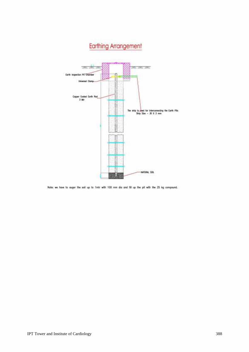
IPT Tower and Institute of Cardiology 388

IPT Tower and Institute of Cardiology 389
16.0 SAFETY EQUIPMENTS
16.1 DANGER NOTICES
Danger notices shall be affixed permanently in a conspicuous position in Hindi or English and the local language of the district with sign of skull and bones at every overhead lines, transformer, electrical equipments motors, etc.
16.2 FIRST AID BOX
Standard first aid box with all standard contents shall be supplied.
16.3 FIRE BUCKETS
The fire bucket unit shall consist of our galvanised iron baskets, which shall be with round bottom, and of 13 liters capacity. They shall be filled with dry sand. Arrangement shall be made to hang them on GI pipe stand comprising of at least 2 vertical and one horizontal members of 50 mm GI pipe. The stands shall have hooks and locking chain arrangement. The buckets and stand shall be painted with epoxy red paint.
16.4 FIRE EXTINGUISHER
Foam type Fire extinguishers of 9 Kg. capacity and Dry Chemical type Fire Extinguishers of 10 Kg capacity shall be of approved make. It shall be filled with carbon tetrachloride. It shall have horns. Extinguishers shall be fixed on walls/columns with necessary clamps made out of 50 mm x 6mm MS flat and coated bolts and nuts grouted in wall/column.
16.5 RUBBER MAT
Corrugated rubber insulating matting shall be provided in front of all power & motor control centers, push button station and distribution board in the electrical rooms. The width of matting shall be one meter. It shall be as ISI mark.
16.6 INSTRUCTION CHART
Printed instruction chart both in English and Hindi and duly framed with front glass, prescribing treatment to be given to persons having Electric shock, shall be supplied.
IPT Tower and Institute of Cardiology 390
17.0 UPS System
PART 1 - GENERAL
18.01 SUMMARY A. This specification describes a three-phase continuous duty, on-line, double conversion,
solid-state uninterruptible power system, hereafter referred to as the UPS. The UPS shall operate in conjunction with the existing building electrical system to provide power conditioning, back-up and distribution for critical electrical loads. The UPS system shall consist of, as required by the project, the UPS module, battery racks, static or maintenance bypass, and other features as described in this specification.
B. UPS level redundancy: All the UPS systems should operate in parallel redundant load sharing mode and all UPS systems should share the load equally. In case any UPS fails, the other UPS should take over 100% load instantaneously without break. Apart from above there are some UPS Units which are standalone units, all standalone UPS Should have static or maintenance bypass as inbuilt. Please refer BOQ for details on redundancy / standalone units.
17.02 UPS SYSTEM DESCRIPTION
A. The System Components: it shall be consist of the following main components:
1. Rectifier, Inverter, and Battery Charger.
2. Battery string(s) in Battery Racks.
3. Battery Breaker
4. Battery to Battery Interconnects / Battery to UPS Connections.
B. UPS: Each UPS shall operate as an on-line, fully automatic system in the following modes:
1. Normal: Utilizing commercial AC power, the critical load shall be continuously supplied by the Inverter. The Inverter shall power the load while regulating both voltage and frequency. The Rectifier shall derive power from the commercial AC source and shall supply DC power to the Inverter. Simultaneously, the Battery Charger shall charge the battery.
2. Battery: Upon failure of the commercial AC power, the critical load shall continue to be supplied by the Inverter, which shall obtain power from the batteries without any operator intervention. There shall be no interruption to the critical load upon failure or restoration of the commercial AC source.
3. Recharge: Upon restoration of the AC source, the Charger shall recharge the batteries and simultaneously the Rectifier shall provide power to the Inverter. This shall be an automatic function and shall cause no interruption to the critical load.
4. Bypass: If the UPS must be taken out of the Normal mode for overload, load fault, or internal failures, the static bypass switch shall automatically transfer the critical load to the commercial AC power. Return from Bypass mode to Normal mode of operation shall be automatic. No-break transfer to and from Bypass mode shall be capable of being initiated manually from the front panel.
17.03 REFERENCES

IPT Tower and Institute of Cardiology 391
A. UL 1778 (Underwriters Laboratories) – Standard for Uninterruptible Power Supply Equipment.
B. IEC 62040-1-1 (International Electrotechnical Commission) – Uninterruptible power systems (UPS) – Part 1-1: General and safety requirements for UPS used in operator access areas.
C. IEC 62040-1-2 (International Electrotechnical Commission) – Uninterruptible power systems (UPS) – Part 1-2: General and safety requirements for UPS used in restricted access locations.
D. IEC 62040-3 (International Electrotechnical Commission) – Uninterruptible power systems (UPS) – Part 3: Method of specifying the performance and test requirements.
E. NEMA PE-1 – (National Electrical Manufacturers Association) – Uninterruptible Power Systems standard.
F. IEEE 587 (ANSI C62.41) Category A& B (International Electrical and Electronics Engineers) – Recommended practices on surge voltages in low voltage power circuits.
18.04 SUBMITTALS
A. The UPS system shall be supplied with sufficient documentation, including the following
manuals:
1. Installation and Operation Manual: One copy of the installation and operation manual shall be furnished. It shall possess sufficient detail and clarity to enable the department’s technicians or representatives to install and operate the UPS equipment and accessories. The manual shall include the following major items:
a) UPS description
b) UPS site planning and unpacking
c) UPS installation
d) Optional accessory installation
e) UPS theory of operation
f) Operating procedures
g) System events
h) UPS maintenance
i) Performance and technical specifications
j) Wiring requirements and recommendations
k) Physical features and requirements
17.05 QUALIFICATIONS
A. The UPS manufacturer shall have ISO 9001 certification for engineering/R&D,
manufacturing facilities and service organization.
B. The UPS manufacturer shall maintain a staffed 7x24x365 service availability for technical and emergency support.
C. Field Engineering Support: The UPS manufacturer shall directly employ a field service department staffed by factory-trained field service engineers dedicated to startup, maintenance, and repair of UPS equipment. Third-party maintenance will not be accepted.
D. Spare Parts Support: Parts supplies shall be located in the field to provide all emergency needs.

IPT Tower and Institute of Cardiology 392
17.06 ENVIRONMENTAL REQUIREMENTS
A. The UPS shall withstand any combination of the following external environmental conditions without operational degradation.
1. Operating Temperature: 0 degrees C to + 40 degrees C without de-rating (excluding batteries).
2. Storage Temperature: - 25 degrees C to + 50 degrees C.
3. Relative Humidity (operating and storage): 95% maximum non-condensing.
4. Elevation: Operational: 1000 meters maximum without de-rating.
17.07 SAFETY
CE & IEC 62040-1
17.08 UPS STANDARD FEATURES
The UPS configuration shall consist of the following standard components and features: A. Each UPS should consist of:
1. Rectifier/Charger: Each rectifier/charger shall convert incoming AC power to regulated DC output for supplying the inverter and for charging the battery. The rectifier/charger shall be a high-frequency PWM design, using Insulated Gate Bi- polar Transistors (IGBTs). The modular design of the UPS shall permit safe and fast removal and replacement of the rectifier/charger module. The rectifier/charger module shall also provide the following:
a) The rectifier shall be capable of drawing power from the utility with a power factor of 0.99 under nominal conditions.
b) The rectifier shall feature protection circuitry that prevents the IGBTs from sourcing current in excess of their published ratings.
2. Inverter: Each inverter shall feature an IGBT pulse-width-modulation (PWM) design with high speed switching. The inverter shall also have the following features:
a) The inverter shall be capable of providing the specified quality output power while operating from any DC source voltage (rectifier or battery) within the specified DC operating range.
b) The modular design of the UPS shall permit safe and fast removal and replacement of the inverter module.
c) The inverter shall feature protection circuitry that prevents the IGBTs from sourcing current in excess of their published ratings.
B. STATIC BYPASS: The bypass shall serve as an alternative source of power for the critical load when an abnormal condition prevents operation in normal mode. The bypass shall consist of a fully rated, continuous duty, naturally commutated static switch for high-speed transfers. The bypass shall feature the following transfer and operational characteristics.
1. Transfers to bypass shall be automatically initiated for the following conditions:
a) Output overload period expired.

IPT Tower and Institute of Cardiology 393
b) Critical bus voltage out of limits.
c) Internal over temperature period expired.
d) Total battery discharge.
e) UPS failure.
2. Uninterrupted automatic re-transfer shall take place whenever the inverter is capable of assuming the critical load.
3. Uninterrupted automatic re-transfers shall be inhibited for the following conditions:
a) When transfer to bypass is activated manually or remotely.
b) In the event of multiple transfers/re-transfer operations the control circuitry shall limit “cycling” to three (3) operations in any ten-minute period. The fourth transfer shall lock the critical load on the bypass source.
c) UPS failure.
4. Uninterrupted manual transfers shall be initiated from the control panel. Uninterrupted manual transfers to bypass and from bypass shall be possible with the inverter logic. During manual transfers to bypass mode, the inverter must verify proper bypass operations before transferring the critical load to the bypass.
5. All transfers to bypass shall be inhibited for the following conditions:
a) Bypass voltage out of limits (+/- 10% of nominal)
b) Bypass frequency out of limits (+/- 3 Hz, adjustable, factory set)
c) Bypass out of synchronization
d) Bypass phase rotation / installation error
6. Static transfer time: No break, complete in less than 4ms.
7. The bypass shall be manually energized using the control panel
C. Monitoring and control components: The following components shall provide monitor and control capability:
1. Control panel with status indicators.
2. Alarm and metering display.
3. Building alarm monitoring.
4. Communication ports.
D. Battery management system: The UPS shall contain a battery management system which has the following features:
1. The battery management system shall provide battery time remaining while operating in normal mode and battery mode. Battery time available information shall be displayed real-time, even under changing load conditions. Upon commissioning, battery runtime information shall be available.
E. Wiring Terminals: The UPS module shall contain mechanical compression terminals for securing user wiring to the following locations:
IPT Tower and Institute of Cardiology 394
1. Rectifier/charger input connections (3-wire plus ground)
2. Bypass input connections (3-wire plus ground for 3-wire plus ground output configuration (415Vac), or 4-wire plus ground for 4-wire plus ground output configuration)
3. DC link connections for battery cabinets (positive and negative).
4. AC output connections (3 or 4 wires plus ground). 17.09 UPS SYSTEM OPTIONS AND ACCESSORIES
The UPS system shall consist of the following options and accessories as required:
A. SNMP Network Adapter and UPS Power Monitoring Software (OPTIONAL): SNMP adapters shall provide a communications interface between the UPS module and SNMP- compatible network management systems. This capability shall allow the unit to be monitored remotely over an Ethernet network using a standard web browser.
B. MODBUS CARD – Required with each UPS.
C. Battery Rack: The battery rack shall house valve regulated, high-rate discharge, lead-acid batteries which provide energy to the support the critical load during a momentary loss of input power to the rectifier. The battery rack shall have the following features:
1. Power wiring internal to each battery cabinet shall be using Nyvin cables.
2. Each battery rack shall feature a DC rated circuit breaker (inbuilt or wall mount). The circuit breaker within the battery rack shall only provide protection to the battery string within that battery
3. Power and Control wiring between the battery rack and the UPS
4. BATTERY TYPE: 12V, VRLA SMF batteries
5. Battery Back-up: As per BOQ 17.10 UNINTERRUPTIBLE POWER SUPPLY RATINGS AND OPERATING CHARACTERISTICS
A Each UPS Continuous Ratings. Please refer BOQ for ratings.
A. Rectifier/charger input:
1. Nominal three phase input voltage: 415 VAC:
3-wire plus ground input
2. Operating input voltage range: + 10%, - 15% of average nominal input voltage without battery discharge.
3. For 50Hz systems, operating input frequency range shall be 45 to 55Hz.
4. Input power factor 0.99 lagging.
5. IGBT Based Technology
6. Normal input current limit: The UPS shall have the following programmable input current limit settings while operating in normal mode:

IPT Tower and Institute of Cardiology 395
a) Rectifier/charger input current limit shall be adjustable from 100 to 115% of full-load input current.
b) Battery input current limit shall be adjustable from 10% to 15% of the UPS full load input current regardless of the actual load on the UPS.
7. On generator input current limit: The UPS shall have the following programmable input current limit settings while operating in normal mode on generator:
a) Rectifier/charger input current limit shall be adjustable from 100% to 115% of full-load input current.
b) Battery recharge input current limit shall be adjustable from 10% to 15% of the UPS full load input current regardless of the actual load on the UPS.
8. Input current total harmonic distortion (THD) shall be less than 5.0% @ 100% linear load condition.
9. Power walk-in: Ramp-up to full utility load adjustable from 3 seconds to 60 seconds.
10. Each UPS should be offered with Output Isolation Transformer, external to UPS. Isolation Transformer should be 1:1 Winding, H Insulation Class, Indoor Type, Air Cooled, Delta / Star Type.
B. Bypass input:
1. Synchronizing bypass voltage range shall be +/- 10% of average nominal input voltage.
2. Synchronizing bypass frequency range is centered on the nominal frequency.
3. Bypass and rectifier inputs can be supplied from out of phase sources if required.
4. Input surge withstand capability: The UPS shall be in compliance with IEEE 587 (ANSI C62.41), category A & B (6kV) or better
C. Rectifier/charger output:
1. Nominal DC voltage shall be as per vendor design.
2. Steady state voltage regulation shall be +/- 0.5%.
3. Voltage ripple shall be less that 0.5% (peak-to-peak).
4. Capacity: The rectifier/charger shall support a fully loaded inverter and recharge the battery to 90% of its full capacity within 10 times the discharge when input current limit is set at maximum.
5. Low line operation: The rectifier/charger shall be capable of sharing the DC load with the battery when the input voltage falls below the specified operation input voltage range, the on battery indicator shall enunciate operation in this mode.
6. DC sensing: Redundant DC voltage sensing methods shall be incorporated for providing battery over-voltage protection.
7. Battery charger characteristics: The UPS battery charging system shall have the following characteristics:

IPT Tower and Institute of Cardiology 396
a) The charger shall be capable of being configured for several charge modes including:
(1) A charging mode that increases battery life by allowing the battery to rest, reducing positive plate corrosion
(2) A charging mode floating the battery at a set level, which can be adjusted via software, used for flooded cell applications
(a) Nominal Float Voltage: 2.25 V per cell.
(b) Equalizing Voltage: 2.38 V maximum per cell (adjustable).
(c) Automatic (time based) or manual (user initiated) equalization available
b) UPS will automatically adjust battery shutdown based upon loading and battery capacity.
(1) The UPS shall automatically adjust the final discharge voltage between 1.67 and 1.75 Volts per cell based on the existing load and the rate and length of discharge.
(2) The absolute minimum operational voltage is 1.67 V per cell (adjustable).
8. The UPS will automatically disconnect the battery system in case of full battery discharge followed by prolonged utility AC voltage failure. The time window before battery disconnection occurs shall be programmable for both time and voltage.
D. UPS output in normal mode
1. 415V, 3-phase, 3-wire or 4 wire plus ground. Output wiring configuration is based upon input wiring configuration for systems without internal transformers.
2. Steady-state voltage regulation (in inverter) shall be within +/- 1% average from nominal output voltage.
3. Transient voltage response shall be < +/- 5% from nominal voltage for 100% load step, full load re-transfers and full load drop on battery.
4. Transient voltage recovery shall be 25ms to within +/- 1% of steady state.
5. Linear load harmonic distortion capability: Output voltage THD of less than 3% for 100% linear load.
6. Non-linear load harmonic distortion capability: Output voltage THD of less than 5% for 100% non-linear load when tested using the non-linear load described in IEC 62040-3 connected line to neutral.
7. Manual output voltage adjustment shall be +/- 3% from nominal.
8. Line synchronization range shall be +/- 3Hz, adjustable to +/- 5Hz.
9. Frequency regulation shall be +/- 0.01Hz free running.
10. Frequency slew rate shall be 1 Hz/second maximum (adjustable).
11. Static transfer time: No break, completed in less than 4ms.
12. EMI Suppression: The UPS shall meet IEC 62040-2, EN50091 Class A restricted limits
13. Efficiency: The UPS efficiency in Online Mode should be
>= 92% for UPS Rating <= 60 KVA

IPT Tower and Institute of Cardiology 397
>=94% for UPS Rating >60 KVA 17.11 MECHANICAL DESIGN
A. Ventilation: The UPS shall be designed for forced-air cooling. Air inlets shall be on the
front of the unit. Air outlets shall be on the top / back as per OEM.
B. Cable entry: Standard cable entry for the UPS cabinet shall be through either the enclosure bottom or top. A dedicated wireway shall be provided within the UPS cabinet for routing user input and output wiring.
C. Front access: All serviceable subassemblies shall be modular and capable of being replaced from the front of the UPS (front access only required). Side or rear access for installation, service, repair or maintenance of the UPS system shall not be required.
17.12 CONTROLS AND INDICATORS
A. Microprocessor controlled circuitry: The UPS controls shall have the following design
and operating characteristics:
1. Fully automatic operation of the UPS shall be provided through the use of microprocessor controlled Digital Signal Processing. DSP shall eliminate variances from component tolerance or drift, and provide consistent operational responses.
2. All operating and protection parameters shall be firmware controlled, thus eliminating a need for manual adjustments. The logic shall include system test capability to facilitate maintenance and troubleshooting. Printed circuit board replacement shall be possible without requiring calibration.
3. Start-up and transfers shall be automatic functions.
B. Digital Front Panel Display: The LCD shall display UPS status, metering, battery status, alarm/event queue, active alarms and UPS configurations. The front panel display shall show a system mimic diagram with an outlined power path, current operating mode and event logs.
C. Control Panel Indicators: The UPS control panel shall provide the following monitoring functions with indicator LED’s:
1. NORMAL: This shall indicate that the commercial AC utility or generator source is supplying power to the rectifier and the inverter is supporting the critical load. A text message shall indicate if the bypass line is not within tolerance.
2. BYPASS: This shall indicate that the UPS has transferred the load to the bypass circuit.
3. BATTERY: This shall indicate that the commercial AC utility or generator source has failed and the battery is supplying power to the inverter, which is supporting the load. A text message shall indicate if the battery charge is low or if the battery is installed but disconnected.
4. ALARM: This shall indicate that the UPS detects an alarm condition, outlined in detail in the operator’s manual.

IPT Tower and Institute of Cardiology 398
D. Control Panel Controls: The UPS control panel shall provide the following functions from front panel push buttons:
1. EVENTS: Displays the list of Active System Events and a historical log of system events. Historical logs shall include a detailed time stamped list.
2. METERS: Displays performance meters for the system or critical load. When selected, the front display shall show individual screens of input parameters, output parameters or bypass parameters including; voltage, current and frequency. In addition, the battery display shall show runtime remaining.
3. CONTROLS: Displays a System Controls screen. Allows selection of operating mode, normal, bypass, charger on/off and Power Module on/off.
4. SETUP: Allows display contrast, date and time information serial communication port configuration and display of firmware revision numbers.
5. RETURN: Confirms selection or returns to previous screen. 17.13 COMMUNICATIONS
A. MODBUS Card (Mandatory) is required with each UPS for integration with Building Management System
B. SNMP Card – (Optional) Should be available for monitoring UPS on LAN/WAN Network
17.14 UPS PROTECTION
A. Rectifier/Charger and Bypass protection shall be provided through fusing.
B. Battery protection shall be provided by molded-case circuit for an external battery bank.
C. Electronic current limiting circuitry and fuses in the Inverter circuit shall provide output protection.
D. To comply with agency safety requirements, the UPS shall not rely upon any disconnect devices outside of the UPS to isolate the battery rack from the UPS.
PART 3 - EXECUTION
18.15 INSTALLATION
A. Install in accordance with manufacturer’s instructions.
17.15.01 COMMISSIONING
A. The following procedures and tests shall be performed by Field Service personnel during the UPS startup “as minimum activities”
1. Visual Inspection:
a) Visually inspect all equipment for signs of damage or foreign materials.

IPT Tower and Institute of Cardiology 399
b) Observe the type of ventilation, the cleanliness of the room, the use of proper signs, and any other safety related factors.
2. Mechanical Inspection:
a) Check all the power connections for tightness.
b) Check all the control wiring terminations and plugs for tightness or proper seating.
3. Electrical Pre-check:
a) Check the DC bus for a possible short circuit.
b) Check input and Bypass power for proper voltages and phase rotation.
c) Check all lamp test functions.
4. Initial UPS Startup:
a) Verify that all the alarms are in a “go” condition.
b) Energize the UPS module and verify the proper DC, walkup, and AC phase on.
c) Check the DC link holding voltage, AC output voltages, and output waveforms.
d) Check the final DC link voltage and Inverter AC output. Adjust if required.
e) Check for the proper synchronization.
f) Check for the voltage difference between the Inverter output and the Bypass source.
5. Operational Training: Before leaving the site, the field service engineer shall familiarize responsible personnel with the operation of the UPS. The UPS equipment shall be available for demonstration of the modes of operation.
17.16 WARRANTY
All components of the UPS system shall be covered by a standard one-year warranty.
Manufacturer shall also include On-site user training, installation.
IPT Tower and Institute of Cardiology 400
18. 00 ACCESS CONTROL SYSTEM I. Software
1. System Overview
1.1. The Integrated Security Management System (ISMS) shall be a modular, networked access
control system capable of handling large proprietary corporations with multiple remote sites, alarm monitoring, video imaging, badging, paging, guard tour. The system shall allow for easy expansion or modification of inputs, outputs, and remote control stations.
1.2. The system control at the central computer location shall be under a single software program
control, shall provide full integration of all components, and shall be alterable at any time, depending upon the facility requirements. Reconfiguration shall be accomplished online through system programming, without hardware changes.
1.3. The software program shall be a true 32-bit, 3-tier client/server, ODBC compliant application
based on Microsoft tools and standards. The software program shall operate in one of the following environments; Windows 2003 Server, Windows Vista Business, Windows XP Professional SP2, Windows 2000 Professional or Server using Service Pack 4.
1.4. The system shall support multiple communication servers on a LAN/WAN, to provide distributed
networking capabilities, which significantly improve system performance.
1.5. The database architecture shall be MSDE 2000 as standard with the capability to utilize Microsoft SQL Server 2005; SQL Server 2005 Express Edition or SQL Server 2000.
1.6. The system shall have the capability to communicate with the control panels via LAN/WAN
connections utilizing industry standard communication protocol.
1.7. The software program shall use Abstract Devices (ADV) for representing hardware devices in the system. The ADVs shall be used in Floor Plans to provide the user interface to control and monitor the system, and shall also be used in the Data Trees to organize, display, and control system information.
1.8. The system shall support both manual and automatic responses to alarms entering the system.
Each alarm shall be capable of initiating a number of different actions, such as activation of remote devices, door control, and activation of WAV files.
1.9. The system shall provide both supervised and non-supervised alarm point monitoring. Upon
recognition of an alarm, the system shall be capable of arming or disarming alarm points both manually and automatically, by time of day, and by day of week.
1.10. Access control functions shall include validation based on time of day, day of week, holiday
scheduling, site code and card number verification, automatic or manual retrieval of cardholder photographs, and access validation based on positive verification of card, card and PIN, card or pin, pin only and Site Code only.
1.11. Alarm events with defined priorities shall be able to pop-up automatically in an Alarm event
window for operator attention. The pop-up shall display the name of the event (reader, alarm point, cardholder or system alarm), time, date, site, account, if a card event the card number, type of event and cardholder name. An event counter shall also display the number of times the event

IPT Tower and Institute of Cardiology 401
was reported to the Alarm event monitor prior to Acknowledgement or Clearing the event. Event instructions shall be made available by double clicking on the event.
1.12. The Alarm event window shall allow the operator to initiate a physical response to the event as
well as a written response. Responses shall include but not be limited to: acknowledge, clear, open a pre-programmed floor plan, energize, de-energize, pulse, time pulse, add comment, shunt or un- shunt.
1.13. Assigned passwords shall be possible to define the levels of system operation for each individual
operator. System operation for individual operators shall include, but not be limited to, restricted time periods for login, available accounts and default language selection at login. Operator actions range from no view or control rights to basic monitoring including the ability to block the viewing of card and or personal identification numbers, to full control of the system including programming.
1.14. The system programming shall be user friendly, and capable of being accomplished by personnel
with no prior computer experience. A quick start wizard shall allow the operator to easily program a system including basic time zones, access panels (IP connection, Modem Pools or direct connections to an RS-232 port), card activation to a general purpose access area and deactivation date. The software shall utilize drop boxes for all previously entered system-required data. The programming shall be MENU driven and include online “Help” or “Tutorial” information, as well as online data entry examples. The Help shall be available by using the F1 key. When using the F1 help access, the help menu will provide detailed information relative to the operation that the user is performing without the need to key in additional search parameters. An operation Tutorial shall also be provided with the access control software. The contents of the Tutorial shall include, but not be limited to: Floor plan setup and control, Visitor management integration, and Intrusion integration and operation.
1.15. After installation, the Customer shall be able to perform hardware configuration changes. These
hardware configuration changes shall include, but not be limited to, door open time, door contact shunt time, point and reader names, when and where a cardholder is valid, and the ability to add or modify card databases as desired; For the intrusion system, any function that can be programmed from a physical keypad shall also be available from the system’s virtual keypad, without the services of the Contractor or Manufacturer.
1.16. Equipment repair shall be able to be accomplished on site, by module replacement, utilizing spare
components.
Basic System Capabilities The following functional capabilities are considered essential for the system described in this specification. The capabilities are to be considered standard, without the need for add-on software or hardware.
o General
i. All databases will have the ability to ADD, DELETE, REPORT, VIEW or EDIT information.
ii. Provide storage of all system transactions in a retrievable file. iii. Log all events by time and date with reference to GMT. iv. Provide capability to store all or selected system transactions to a disk file.

IPT Tower and Institute of Cardiology 402
v. Provide ability for CUSTOMER to make system configuration changes such as, but not limited to door open time, door contact shunt time, point and reader names, when and where a cardholder is valid, and the ability to add or modify card databases at any time.
vi. Support “Global Anti-passback”, allowing cardholder to enter/exit any card reader on the same RS485 drop line.
vii. Duress feature where when a PIN is used in conjunction with a card read, the number of digits are selected at the keypad where the PIN number is a value of one different from the normal PIN.
viii. Provide mode of system operation that stores system commands that were not accepted by the hardware.
ix. Provide mode of system operation that requires the operator to enter a response to an event when acknowledging it from the alarm view window.
x. Provide mode of system operation that allows acknowledged alarms to be automatically cleared. xi. Provide mode of system operation where un-acknowledged events will cause the computer to
continuously emit a pulsating beep until all un-acknowledged alarms are acknowledged. A momentary silence feature shall allow the beeping to cease for up to 60 seconds. The silence feature shall also provide a visual count down to when the beeping will begin again.
xii. Provide mode of system operation where when an acknowledged, but not cleared event will be reissued requiring acknowledgement when the event changes to an alarm or trouble state.
xiii. Provide mode of system operation that does not allow the operator to clear an alarm prior to it being restored to normal.
xiv. Provide ability for manual operator control of system output relays. The manual functions shall include the ability to energise, de-energise, return to time zone, or pulse the output relay. The pulse time shall be a programmable setting.
xv. Provide ability for manual operator control of system doors. The manual functions shall include the ability to Lock, Un-Lock, Shunt, Un-Shunt and Return to Time Zone.
xvi. Provide ability to automatically display stored “video image” of cardholder xvii. The cardholder “video image” pop-up shall be activated based on a priority level set to the
cardholder or reader. Information in the pop-up shall include, but not be limited to the cardholder’s primary image a live video pop-up showing the person who initiated the pop-up, entrance name, time, date, cardholder name, and status. User shall be able to display up to 40 note fields. The size of the pop-up(s) shall be adjustable by the operator.
xviii. Support multiple card reader technology including Proximity, Wiegand effect, Biometrics, Magnetic stripe, Bar Code, Keypad, Card/keypad (PIN), High-speed long range Vehicle ID, Smart Card
xix. Provide a means for scheduled automatic backups of any or all database system files. A means to restore these files from a simple menu shall exist.
xx. Provide the ability to address up to 2 serial communication ports, where each port can be configured for either hardwired or dial-up. When configured for dial-up, any one port can support multiple dial-up locations.
xxi. Communication from the access control server to the remote control panels shall be selectable. Communication options shall be via RS-485 converter, dial-up, leased line from a defined communication port or by LAN/WAN using an IP address for direct connection to the remote RS-485 converter via network interface card. When using IP addressing it shall be un-acceptable to use a communication port converter device on the communication server side of the transmission. A minimum of 64 such IP connections shall be allowed.
xxii. All commands and updates to the panels shall be verified and shall automatically retry if communications have failed.
xxiii. Provide the ability to select ACK/NAK communication feature by communications port for either dial-up or hardwire.
xxiv. Provide a system scheduler that shall automatically: 1. Call remote locations to retrieve history transactions and update panel information,
including time and date. 2. Activate or deactivate cards locally or at remote dial-up sites. 3. Initiate a pre-programmed command event/action.
IPT Tower and Institute of Cardiology 403
4. Synchronize system to controller time.
xxv. Provide the ability to initiate an alarm based on a transaction state. A transaction state shall be defined as but not limited to Normal, Alarm, Trouble, Ajar, Trace, Not Found, Anti-Passback Violation, PIN Violation, Time Zone Violation, Site Code Violation and System Alarms including Panel Com, Panel Power Failure, Modem Pool, Guard Tour, and Tamper.
xxvi. A host grant mode of operation shall exist that requires the host computer to grant accesses to “valid” cards. An alternate host grant mode shall allow the card access information to be downloaded along with unlocking the door for “valid” cards.
o Card Database
i. Provide a simple card and card holder database import utility. The utility shall be password
protected and accessible only to administrators of the access control system. Information that can be imported shall include but not be limited to: First Name, Last Name, card number, activation date, de-activation date, status, up to 40 note fields and photo images. A simple CSV (comma separated value) file shall be used for the importing of data and image file names.
ii. Cardholder information shall include unique card number up to 15 digits and optional Personal Identification Number.
iii. Allow multiple cards per cardholder. iv. Allow for up to 32 access levels to be assigned to a card, or a single “precision” access level.
When using “precision” access levels it shall be possible to create a unique access level per card using an existing access level as a baseline template. This customized card access level shall have both beginning and ending dates.
v. Provide 40 user definable fields. vi. Each card holder note filed shall allow the option to be entered as free form data or structured
data. Structured data shall be by use of a template or drop list. The template and drop list shall be created by the operator. The capacity of the template shall allow for up to 65,000 characters.
vii. Provide special card options that include, but are not limited to: 1. Time zone reference, which defines valid time. 2. Visitor use, which provides a specified activation date and expiration date (spanning years). 3. Trigger control value, which can initiate a predefined procedure at the intelligent control
independent from any control function from the system computer.
viii. Provide a card “Trace” function. The Trace function shall allow normal access control, but will provide a tracking alarm at the system monitor.
ix. Provide ability to store digital images and written signature of cardholder. x. Provide the ability to prioritise specific card usage from 1 to 99 with separate priority options
for Anti-passback, Trace, PIN Violation, Normal, Not Found, Expired, Host Grant, Site Code and Time Zone card activities or violations.
xi. Allow the user the ability to assign an operator message per card event state. xii. Upon editing card information, the updated information shall be sent automatically to the
appropriate access control panel, when hardwired, with no other user intervention. If the port is dial-up, the entry will be stored on disk and shall be updated when connection is made to the remote loop. If the scheduler is used, then card updates shall be sent based on scheduling.
xiii. In a traditional (Wiegand) 5-digit card database, the numbers 0 and 65,535 shall not be valid card numbers as some devices transmit these numbers on an improper read.
xiv. In a 15-digit card database, the number 0 shall not be a valid card number as some devices transmit this number on an improper read.
xv. A card shall have the ability to be allowed to access one or selected accounts up to all available accounts.

IPT Tower and Institute of Cardiology 404
o Access Levels
i. It shall provide the ability to define specific times of access, specific readers for access, provide
a template of a defined access level detail, where changes can be made to the template and saved as a new access level detail and provide an access control tree structure that allows groupings of entrances. User shall have the ability to group program all entrances on the branch or make specific changes to individual entrances.
o Alarm Monitoring – Alarms Only View
i. Report alarm point activity. ii. Provide colour for each specific alarm point action of “Alarm”, “Normal” and “Trouble”,
conditions. iii. Provide the ability to access the default floor plan graphic for any active alarm point by a
right click option, to acknowledge any alarm, card, or reader activity based on priority and to bypass alarms in the system
iv. Execute alarm notification in all modes of operation. v. Provide display of system activity with the higher priorities displayed at the top of the list
with identical points stacked with a frequency count of each point’s change of state. vi. Provide ability for the operator to acknowledge and clear alarms from display. Prior to
acknowledgment, the user shall be allowed to enter a response per alarm. The system shall offer a means to require acknowledgement of an alarm before it can be cleared.
vii. Provide a display of the most current transactions in real time. viii. Provide the ability for dynamic alarm monitoring of alarm points in real time on the system
computer’s video display terminal. ix. Provide an alarm view filter that is structured as a tree allowing the operator to select
individual devices or groups of devices to be viewed. x. Provide a “Panel Not Responding” alarm if communication to a panel is lost.
xi. Provide real time printing of alarms as they occur by line printing with a dot matrix printer or provide printing of alarms, one page at a time, using typical Windows page printing.
o Alarm Monitoring/System Control – Tree View
i. Provide the ability for dynamic alarm monitoring of alarm points in real time on the system
computer’s video display terminal ii. Provide colour and icon shapes for each specific alarm point action of “Alarm”, “Normal” and
“Trouble”, and “Shunted”. iii. Access control panels in the alarm tree, like alarm points, shall also indicate if they are in the
buffered mode of operation as well as any “system” related alarm such as “Tamper” or “Primary Power Loss” or Loss of communication.
iv. Devices connected to the communication server shall provide additional popup information as to the communication port or IP connection the device is programmed for.
v. Provide a means to launch a Virtual keypad from an intrusion panel partition to monitor the physical keypad remotely and to administer programming changes via the Virtual keypad.
o Operator Database
i. The software shall allow the assignment of operator levels to define the system components that
each operator has access to view, operate, change or delete. ii. The ability to view, edit or delete cardholder sensitive information such as note fields, card
number and PIN shall be definable by field per operator.
IPT Tower and Institute of Cardiology 405
iii. Define the accounts that the operator has access to. iv. Provide the ability to log operator actions in the history files. v. Provide default language to be used based on operator’s login.
vi. Provide specified time periods that the operator can log in. o Reports
i. Provide reporting capability for printing of selected system transactions from the disk files by
specific time and date selection, range from time and date to time and date, or from start time to end time each day of the selected date range.
ii. Provide feature to generate a history report for an alarm point(s) state. An alarm point state shall be defined as Normal, Alarm, Trouble, or Ajar.
iii. Provide feature to generate a history report of system alarms. A system alarm state shall be defined by panel and include any of the following information: communication, ground fault, power, panel reset, low voltage, panel tamper, and loop communication.
iv. Provide feature to generate a history report for a card(s) state. A card state shall be defined as Normal, Trace, Not Found, Anti-Passback Violation, PIN Violation, Time Zone Violation, Site Code Violation, or Expired card. Additional search criteria shall include cardholders that meet up to at least 3-note field restriction and filter the report with defined reader location(s).
v. Provide feature to generate a history report for system operator(s) activities. The report shall include time, date, operator name the device associated with the action and the type of action performed by the operator. Activities shall include but not limited to: acknowledged and cleared transactions, door and relay control such as unlock, lock; door and input control such as shunt, unshunt; login, logout, panel initialisation, panel buffer and panel unbuffer.
vi. Provide complete database reporting of all data programmed into the system data files. vii. Provide a means to define how long a card holder has been in a defined area. This report shall
allow the time to be accumulated representing an attendance report. The definable filters shall include time/date range, reader(s) definition, card number, card holder and note field. The output of the report shall allow sort options to include First Name, Last Name, Event Time, and Card Number. The sorted data shall be selectable as Alpha or Numeric sorting and Ascending or Descending.
viii. Provide feature to generate a report based on the frequency of usage of a card. The report shall allow the operator to define a time/date period, a minimum and maximum usage limit, a means to define which reader or readers should be used to filter the report and the ability to further define the type of card to be reported on based on note field selections. This report shall also provide a disposition function. The cards meeting the filtering criteria shall be acted upon based on the disposition setting. Disposition settings shall include but not be limited to: Report only, De-activate the card or Re-assign to a specified an access level. This report shall be available in the event scheduler. When defining when to run the report an option to select the number of previous days to run the report against shall be provided. As an example a scheduled weekly report for the last 14 days could generate allowing for an overlap of time if desired.
ix. Provide a means to create report templates. Report templates shall include, but not be limited to, History and Card Holder information. The templates shall be able to be assigned to a scheduler to run automatically per the scheduler settings.
o Tracking/Muster Report
i. A tracking feature shall allow the system operator to identify an area and the person(s) in that
area, which shall be defined by readers representing an IN or OUT read status. ii. Defined areas shall provide an automatic update of how many cardholders are in the area.
iii. A view displaying all card holders in a defined tracking or muster area shall have the ability to be sorted in columns where by clicking on the column the data in the column shall be

IPT Tower and Institute of Cardiology 406
sorted. At a minimum, the columns can be sorted by: Card Number, Status, Card Holder, Reader, and Time/Date.
iv. A Muster area shall be defined by a reader(s) used to “muster” individuals in the event of an emergency.
v. Reports shall be generated for all muster or tracking areas in the system. vi. Tracking areas shall include “nested” areas. Nesting allows for various reports from a large
area to smaller areas within the large area. vii. A Tracking and Muster area screen shall be continually updated with the most recent card
activity, therefore minimizing the time required generating a report. viii. A history-priming feature shall load history activities for the defined amount of hours when
the software is started. This priming feature shall be implemented in the event that the system computer is offline when a muster call is initiated, thereby allowing the implementation of the tracking and muster features of the software. The history priming time shall be operator selectable in 1-hour increments up to 99 hours.
o Time Zones
i. Time zone definitions shall include Starting time, Ending time, Days of the week, and
Holiday override. ii. Minimum time zones that can be assigned to a panel shall be 63 and maximum unlimited.
iii. Holidays shall be definable in two different time zones allowing different time schedule to be programmed for each holiday type.
o Floor Plan Graphic
i. Provide the ability to import floor plan graphics stored in a WMF format and to associate all
hardware devices (access, intrusion) to floor plan graphics allowing the user to control and monitor the system.
ii. Provide the ability to link floor plan graphics together in a hierarchy fashion and allow multiple floor plan views to be displayed simultaneously.
o Special System Functions
The manufacturer of the system shall provide in the system software the following unique applications as standard:
i. Guard Tour
Guard Tour shall allow the operator to program a series of guard check points that must be activated to accomplish the task of a Guard Tour.
The check point shall be either reader points or alarm contact points or a mixture. The Guard Tour can be timed sequential allowing travel time between points with +/- tolerance. This type of tour shall allow alarms to be generated for early, missed or late events.
The Guard Tour can be un-sequenced with no time parameters. The Guard Tour shall be started by two methods, Manual or Scheduled by the access control system scheduler.
ii. ID Badging System/Video Image System
Allow any card data fields to be assigned to a badge. Allow a stored cardholder image to be associated to any background. Each cardholder shall have any one of the background layouts associated to it.
Provide the ability to create temporary or permanent badges.

IPT Tower and Institute of Cardiology 407
Badges shall be printed without the need to assign an access level or access control card number. Numbers and access levels may be assigned after the print process.
Provide image export capability. Image shall be exported utilizing the cardholder’s name as the file name in .jpg format.
Provide unlimited custom badge layouts (only limited by the hard disk capacity). Provide 24-bit (16.7 Million) color palette for background design or foreground text and all fonts supported by Windows.
Provide import capabilities of background information by video camera or via BMP, JPG, or TGA files.
Provide for multiple bitmap images to be imported onto the badge layout. Provide video capture capability from a compatible TWAIN device, DirectX device or from a compatible video capture device, such as a high-resolution color camera.
Provide ability for multiple card enrollment/badging stations on networked system. Provide signature capture or import capability for up to 99 signatures that can be previewed in the cardholders badge or printed on the cardholder’s card.
Provide the capability to have a front and back layout selected for a cardholder and the ability to print the card in one step (requires suitable printer) without the need to reinsert the card.
Provide the capability to encode a magnetic stripe with information from any of the card data fields to include, but not be limited to: First Name, Last Name, Card Number, Activation date, Expiration Date or any data from the card holders note field.
iii. Networking
Provide networking capabilities (LAN or WAN) as allowed by the computer’s operating system license.
The access control software shall support two networking methods. By default, Domain controlled networks shall be the standard configuration providing secure networking communications. The ability to work on less secure peer-to-peer (Workgroup) networks shall be allowed for lower security installations. The functionality shall be one or the other and not run in both modes at the same time.
Provide the ability for a network system to support concurrent users up to the license limit, i.e., one station adding cards and making badges, another station monitoring alarms, yet another running data base report, another controlling door openings and alarm shunting, and so on.
The workstation shall have the same UI (user interface) functionality as the Server, except the workstation shall not be able to perform database maintenance functions.
2. System Products
o Communication Ports And Loops
The computer shall have two serial communication ports. If additional ports are required, they shall be provided by installing additional compatible multi-port cards. Instead of communication ports a LAN/WAN solution is acceptable using standard 10/100/1000 Ethernet connections. System communication ports shall be expandable up to a maximum of 255 ports. Each communication port shall support one of the following configurations. Local direct connect loop or multiple remote loops via modem. A local RS485 multi-drop communication loop shall support up to eight intelligent controllers, 128 readers or 1024 output relays or monitor up to 1024 alarm points. Remote configuration shall be supported.
o Video Image/ID Badging System

IPT Tower and Institute of Cardiology 408
The Video Image/ID Badging System shall include a personal computer running the badging software, camera, SVGA monitor, Video/Badge Printer, and Signature Capture Pad (optional).
o Front End Software Specifications
i. Databases: The software shall provide edit, add, delete, search, sort, and print options for
records in selected databases.
ii. Printer Output: The software shall direct user-selected activity to the Windows supported printer.
iii. Monitor Display: The software shall display all system activity on a colour monitor in real time,
except for remote locations configured as dial-up. The software shall allow a WAV file to be played upon all alarm conditions. The software shall provide an acknowledge function for all incoming alarm messages that are defined for alarm acknowledgment.
iv. Disk Storage: The software shall store user-selected activity on the hard disk. Report options
shall recall selected history information from the hard disk. The user may request report information based on selected cardholders, specific areas and/or specific times. The software shall allow archiving by defined dates.
v. English Descriptions: The software shall support descriptive names for all database entries. The
card database shall include name, number, PIN, access level, status, activation, and expiration date or limited usage and 40 user-defined fields.
o Front End Software Requirements
i. Password Protection: The software shall provide multi-level password protection, with user-
defined operator name/password combinations. Name/password log-on shall restrict operators to selected areas of the program. The software shall allow the assignment of operator levels to define the system components that each operator has access to view, operate, change or delete.
ii. Action Messages: The software shall allow recall of user created text messages upon any condition.
s.
iii. Manual Panel Control: The software shall allow manual control of selected inputs, outputs and
groups of outputs. Manual panel control shall include pulse, timed pulse, and energize/de- energize or return to time zone options for output points and shunt/unshunt or return to time zone options for input points. For entrances and readers manual control shall include but be limited to Lock, Un-Lock, Disable, Card only, Card-Pin only, Pin only, exit only and site code only. For partitions monitored by the intrusion panel the control shall include but not be limited to arm away, arm stay, disarm, refresh and provide a virtual keypad for the partition. For zones monitored by the intrusion panel the control shall include but not be limited to bypass, unbypass and refresh. Intrusion panel output control shall included activate, deactivate and refresh.
iv. Video Imaging/ID Badging:

IPT Tower and Institute of Cardiology 409
a The Video Image/ID Badging software shall store cardholder images on hard disk. Stored images shall be displayed upon request.
b Custom card backgrounds shall be displayed upon request.
II. ACCESS CONTROL FIELD HARDWARE DEVICES
The security management system shall be equipped with access control field hardware required to receive alarms and administer all access granted/denied decisions. All field hardware shall meet FCC CE C-Tick requirements. The system shall include the 2-reader intelligent controller.
The IP-enabled controller is an advanced access control panel capable of providing solutions for medium to large applications. The controller provides power and flexibility with its 32-bit CPU architecture, TCP/IP protocol support, flash memory for firmware and large local card holder database. The controller is designed to operate off-line, making access control decisions independently from a PC or other controlling device. It can also be connected to a host computer for system configuration, alarm monitoring and direct control. Connectivity to the host computer is accomplished via TCP/IP network connection. The board combines intelligent controller and reader interface into one complete unit. It connects for two readers via Wiegand controlling two doors. The controller can support up to 62 doors via RS485 multi-drop communication where 30 downstream controllers are connected to the gateway controller. This architecture can reduce the usage on LANs by using only one TCP/IP address to 62 doors. It accommodates a card database of 55,000 cards, and a transaction buffer of 45,000 transactions. It is designed with tile mounting configuration.
Specifications
Database: • Cardholder capacity: 55,000 • Transaction storage: 45,000 • Flash programming for firmware revision updates • Access level: 128 • Holidays: 255 • Time zone: 127 • Card reader formats: 128 Wiegand format support • Credential facility codes: 8 • Dedicated tamper alarm • Dedicated power fail alarm • Real time clock: - Geographic time zone support - Leap year support • Embedded web server to configure network attributes
Environment: • Temperature: 0 to 50° C operational
-55 to 85° C storage • Humidity: 0 to 85% RHNC
Communication: • Ethernet port connected to TCP/IP network as master panel • RS485 multi-drop connection for downstream panels

IPT Tower and Institute of Cardiology 410
Onboard I/O: • 2 Readers, expandable to 62 readers per gateway controller • 8 Supervised inputs • 4 Relay outputs
Operational Functionality: • Operational modes:
- Card only - Card and PIN
• Maximum site codes: 8 digit • Anti-Passback support:
- Local - Global - Forgiveness
• Interlocks: 256
Approvals: • CE/FCC/C-TICK
III. Proximity Card: Access cards shall be used with access readers to gain entry to access controlled areas / zones(e.g.; doors, gates, etc.) and to hold information specific to the user. Provide (specify quantity) (badge protectors with clips or other accessories), of a type acceptable to
the Architect. IV. Biometric Finger Print Reader
Biometric Reader with Enrollment Kit & Enrollment Software (To be used for Entry purpose), Finger Print with Mifare , Support 2K fingerprint (Included application software support max. 4 readers),
V. Proximity Reader
Proximity Reader shall be compatible with all standard access control system. Available with either wiegand or clock and data output.
Shall be Read HID card with formats up to 85 bits. Read range 22 inches. Or depends on cards
Boom Barrier :-
Boom barrier Shall be High speed Hydraulic Type and having following specification:-
Automatic Barrier for Beams up to 7 meter. Use Frequency 100%. Opening and closing time from 4 to 8 sec. Load bearing housing in steel protected by cataphoresis treatment and powder paint Ral 2004. Protection class- IP44. Electric Motor Power 220W. Thermal Protection at 120degree centigrade built into motor winding. Single phase motor with two rotation directions. Electric motor power supply 230Vac(+6%-10%), 50(60) Hz Die-Cast Distribution Flange. Adjustable Deceleration angle by cams. Automatically activated cooling Ventilation. Designed to accommodate Rectangular with skirt Beams.

IPT Tower and Institute of Cardiology 411
Built in electronic control Equipment. Motor rotation speed 1400-2800rpm.

IPT Tower and Institute of Cardiology 412
19.00 BULDING AUTOMATION SYSTEM 1.0 OPEN, INTEROPERABLE, INTEGRATED ARCHITECTURES: 1.1 SPECIFICATION NOMENCLATURE A. Acronyms used in this specification are as follows: BMS Building Management System GUI Graphical User Interface POT Portable Operator’s Terminal DDC Direct Digital Controls LAN Local Area Network PICS Product Interoperability Compliance Statement
1.2 ARCHITECTURE:
A. The intent of this specification is to provide a peer-to-peer networked, stand-alone, distributed
control system with the capability to integrate both the ANSI/ASHRAE Standard 135-1995 BACnet, and Modbus technology communication protocols in an interoperable system.
B. The supplied computer software shall employ object-oriented technology (OOT) for representation of all data and control devices within the system. In addition, adherence to industry standards including ANSI / ASHRAE™ Standard 135-1995, BACnet TCP to assure interoperability between all system components is required. For each BACnet device, the device supplier must provide a PICS document showing the installed device’s compliance level. Minimum compliance is Level 3; with the ability to support data read and write functionality. Physical connection of BACnet devices shall be via Ethernet at all levels.
C. All components and controllers supplied under this contract shall be true “peer-to-peer”
communicating devices. Components or controllers requiring “polling” by a Master / Global / Host to pass data shall not be acceptable.
D. Structured Query Language (SQL) or Java Database Connectivity (JDBC) or ORACLE compliant server database is required for all system database parameter storage. This data shall reside on a server for all database access. Systems requiring proprietary database and user interface programs shall not be acceptable.
E. Two (2) level hierarchical topology is required to assure fast system response times and to manage the flow and sharing of data. Systems Requiring Router, Gateways are not acceptable.
1.3 WEB BROWSER CLIENTS
The system shall be capable of supporting an unlimited number of users using a standard Web browser such as Internet Explorer™ or Netscape Navigator™. Systems requiring additional software (to enable a standard Web browser) to be resident on the DDC / client machine, or manufacture-specific browsers shall not be acceptable. The Web browser software shall run on any operating system and system configuration that is supported by the Web browser.
The Web browser shall provide the same view of the system, in terms of graphics, schedules, calendars, logs, etc., and provide the same interface methodology as is provided by the Graphical User Interface. Systems that require different views or that require different means of interacting with objects such as schedules, or logs, shall not be permitted.

IPT Tower and Institute of Cardiology 413
The Web browser client shall support at a minimum, the following functions:
User log-on identification and password shall be required. If an unauthorized user attempts access, a blank web page shall be displayed. Security using Java authentication and encryption techniques to prevent unauthorized access shall be implemented.
Graphical screens developed for the GUI shall be the same screens used for the Web browser client.
HTML programming shall not be required to display system graphics or data on a Web page. HTML editing of the Web page shall be allowed if the user desires a specific look or format.
Storage of the graphical screens (Static) shall be stored in DDC directly and should not depend on any other hardware.
The Web page shall get automatically refreshed without any user intervention.
Users shall have administrator-defined access privileges. Depending on the access privileges assigned, the user shall be able to perform the following:
Modify common application objects, such as schedules, calendars, and set points in a graphical manner. Schedule times will be adjusted using a graphical slider, without requiring any keyboard entry from the operator and set holidays
View logs and charts
View and acknowledge alarms
The system shall provide the capability to specify a user’s (as determined by the log-on user identification) home page. Provide the ability to limit a specific user to adjust their defined home page. From the home page, links to other views, or pages in the system shall be possible, if allowed by the system administrator.
Graphic screens on the Web Browser client shall support hypertext links to other locations on the Internet or on Intranet sites, by specifying the Uniform Resource Locator (URL) for the desired link. 1.4 SYSTEM DESCRIPTION & INPUT OUTPUT SUMMARY
The proposed system shall be a Direct Distributed Digital Control (DDC) system. It shall be a PC based system and shall combine latest state of the art technology with simple operating techniques. The entire Monitoring of Building Management System (BMS) shall be comprise of a network of interoperable, stand-alone digital controllers communicating on an open protocol communication network to a host computer within the facility and communicating via the Internet to a host computer in a remote location. The BMS shall communicate to third party systems such as Chillers, VAVs, Energy meters, UPS, DG, Lifts, VFDs & HT/LT circuit breakers, access control systems, fire-life safety systems and other building management related devices with open, interoperable communication capabilities. The BMS framework shall utilize built-in Internet connectivity to a broad range of distribution partners in the building automation, energy services, power/utility, and industrial sectors. The Framework shall bring together the ongoing computerization of control applications under single integrated system architecture. The features shall be distributed both physically and functionally over the field controllers. Microprocessor based Direct Digital Distributed Controllers (DDC) shall interface with sensors, actuators and environmental control systems (i.e. AC units, chillers, pumps, fans, lighting etc.) and carry out followings functions:
a. Individual input/output point scanning, processing and control. b. Centralize operation of the plant (remote control).
c. Static / Dynamic graphic details of plant and building.
IPT Tower and Institute of Cardiology 414
d. Energy Management through optimization of all connected electrical and mechanical plants.
e. Alarm Detection and early recognition of faults.
f. Time, event and holiday scheduling as well as temporary scheduling.
g. Prevention of unauthorized or unwanted access.
h. Communication interface and control.
i. Suggestive preventive maintenance for all equipment as well as own error diagnosis.
j. Report generation.
k. Optimum support of personnel.
l. Data Visualization Tool
These Controllers shall be capable of functioning on a stand-alone mode i.e. in case of loss of communication with the central control station / Server, these shall function independently. DDC shall have microprocessors built-in as standard, which control the respective operation centers based on the required logic and also offer fast communication of data via the network communication system. The local access to these shall be either through an in-built display with keypad for each outstation or through a portable operator’s terminal. The controllers shall be capable of executing advanced control algorithms like Optimum Start stop, PID control, auto PID tuning and schedule management. They shall also execute logic functions based on time and/or event. Totalization and averaging functions shall be an inherent feature of the controller. Each stand-alone intelligent DDC Controller shall have a single 32 bit processor, on board Ethernet connectivity. These shall also control any other operations on the floor and shall be sized to suit the operation centres or system requirement. This shall help in reducing the site electrical installation.
The number of controllers for central plant room equipments shall be decided by the contractor. Overall, the system shall be provided with 15% spare capacity, with spare of at least 15% points on each controller.
There shall be one BMS control station located in Control Room. The Operator Station should use a simple Web Browser in conjunction with the BMS Server software. The Computer shall be sized to cover the graphic display memory, planning information, software & data storage requirement. The display shall be in the form of dynamic color graphics and text format with menu driven pop-up windows and help facility.
The following software packages shall be loaded into the system as minimum standard:-
a. Complete system operational software
b. Site specific data manipulation software
c. Graphics software
d. Alarm indication software
e. Internet Enabled Remote Monitoring Package.
IPT Tower and Institute of Cardiology 415
DI=DIGITAL INPUT; AI=ANALOG INPUT; DO=DIGITAL OUTPUT; AO=ANALOG OUTPUT
2.0 CENTRAL STATIONS SOFTWARE AND HARDWARE
2.1 CENTRAL STATION SOFTWARE
A. A central server, located at Control Room, shall be provided. The server shall support all
DDC’s connected to the customer’s network whether local or remote. B. Local connections shall be via an Ethernet LAN. Remote connections can be via ISDN,
PSTN or dial-up connection. C. It shall be possible to provide access to all DDC & 3rd party integration units via a single
connection to the server. In this configuration, each DDC can be accessed from the Graphical User Interface (GUI) or from a standard Web browser (WBI) by connecting to the Local Area network.
D. The server software shall provide the following functions, at a minimum: Complete control and monitoring of IBMS system from colour graphics pages on the machine, or
from a remote web browser. Full client-server operation. SQL / JDBC / ORACLE Database. Comprehensive alarm handling with alarm retransmission and logging. Scheduled recording of logged data from DDC. Management of multiple controller occupation times. Multilevel security system. International language support Display of HTML pages from company Intranet, or Internet. Display of live, logged, or recorded data in multi-trace graphs. Simple engineering path using drag and drop operations. Self-learning of all local networks. Help file in PDF format for viewing or printing. Access to the configuration mode of devices. Display all devices on the system connected via LANs, internet works, autodialed links and Ethernet Network connections.
Customised program creation environment. The BMS software shall be simple, flexible and convenient to use such that an operator with minimal programming knowledge can use it to perform control / monitoring and to build programs for control applications, graphics to generate management information systems (MIS) reports. As well, on higher end it shall be possible to create customized programs to suite the site requirement by a software programmer. All necessary documents required to make customization possible should be available along with the software without any additional charge.
The operating system shall be the Microsoft Windows XP / Windows 7 / Windows 2008 Server / Enterprise /Professional 32 / 64 bit multitasking environment. The networking software shall use the TCP / IP LAN protocol. The system shall be capable of supporting up to 25 simultaneous operator workstation connections but however presently we need Five User Option.
2.2 Monitoring and control functions
Monitoring:
The system shall support data acquisition using periodic scanning, exception reporting or on operator request. The system shall support a range of scan intervals, ranging from less than 5 second up to several

IPT Tower and Institute of Cardiology 416
minutes as desired / required. The system shall allow certain selected points to be scanned more often / faster than other points.
The communication techniques shall be optimized to minimize network traffic while providing good system response and reliability. The system shall also provide utilities to compile aggregate statistics on communication link usage.
Control:
Control transactions issued by the operator shall be communicated to control devices using a write followed by read to ensure the integrity of the transaction. If the read following the write to the device indicates that the control action has failed, the operator shall be informed by means of a control failure alarm. The priority of the control failure alarm shall be configurable by the user
2.3 System Database
The system shall provide a real-time database incorporating data from analogue, logical or pulse inputs. The database shall be configurable by the end user without the need for any programming and shall be able to modify on-line without interrupting operation of the system. In addition to point based information, the database shall also provide historization capabilities for analogue, digital, pulse; event based information and calculated values. This information shall be accessible by all facilities of the system such as custom displays, reports, trends, user written application, etc.,
The real-time database shall use suitable data structures to collect and store the following categories of data, as minimum.
Access points Analogue points Status points Accumulator points Historical data Event data
The facility shall also exist to accommodate user defined data structures.
Each of the point database structures shall be comprised as a composite point with a number of associated parameters that may be referenced relative to a single tag name. Specifically, each of these parameters shall be accessible by various sub-systems such as the graphical operator interface, report generation system and application program interface in a simple format without the need to know any internal storage mechanism.
The system shall maintain portions of the data base requiring frequent high-speed access as memory resident information and other less frequently accessed data as disk resident data.
Database backup shall be possible with the system on-line including backup of historical based data. The database backup shall be part of GUI software & shall be possible to configure automatic backup at regular interval without any user interference / attention. All other backup such as graphic pages / drawing etc can be windows based where simple copy & paste should be enough for taking backup other than database. Long term storage of this data shall be possible using the zip drive. The system shall have the provisions for importing this data at later date for analysis and long terms MIS reports.

IPT Tower and Institute of Cardiology 417
Point data shall be stored in a composite point database structure that provides a wide range of configurable information including but not limited to:
Point name and description Multiple locations for data storage and device scanning addresses. Scan period Multiple dead-band or hysteresis settings Monitoring and control access restriction information. Location of operator alarm handling instructions Location of ancillary information associated with the point.
2.4 Historical data storage
Collection of historical point data shall be configurable as part of the point definition. Once configured, this data shall be collected automatically. Historical data collection shall be provided for both snapshots and averages with intervals ranging from 5 seconds to several hours.
The system shall provide the necessary means to easily locate the particular value of interest for any of the historical points. The graphical operator interface, trend, report generation and application interfaces shall be able to access historical data.
2.5 Trending
The system shall provide flexible trending allowing real-time, historical or achieved data to be trended in a variety of formats. In addition, trend data types shall be able to combine to allow for comparisons between data e.g. current real-time data versus archived data. The system shall provide trending capability with following functions.
Real time trending Historical trending Archived history trending Trend scrolling Trend zoom Export option / Copying of currently displayed trend data to the clipboard for pasting into spreadsheet or document.
The system shall allow the trending of a minimum of 5 points in a single trend display set. For each trend set display it shall be possible for operators to configure the number of historical samples and ranges displayed. Points configured in trend sets shall be changeable on-line.
Operators shall be able to zoom in on information displayed on trend sets for closer inspection by dragging out an area of interest with the mouse or other pointing devices. From such a selection, it shall be possible to copy the underlying data to the windows clipboard for subsequent pasting into spreadsheet application such as Microsoft excel
2.6 Alarm Management
The software shall include a well organized alarm management facility to enable the operator to react quickly and efficiently to alarm conditions. Apart from the specific points identified for alarm annunciation in the I/O points schedule, the alarm types supported shall included:

IPT Tower and Institute of Cardiology 418
Very high value alarm Very low value alarm Large deviation alarm Rate of change alarm Unreasonable value alarm Delay to avoid nuisance alarm / short time change in value
The system shall permit any of these alarm types to be applied to the analog and accumulated points.
The software shall permit at least 90 levels of alarm priorities to be assigned to each alarm ranging from the lowest to the highest. These levels shall be easily distinguished by the manner in which they are presented such as the color of the alarm message, blinking of the alarm message, varying audible alarms, etc., All alarm shall be logged in the event / alarm file and / or on the alarm printer. On acknowledgement of an alarm, it shall be possible to automatically issue a reset command to the controller so as to attempt to reset the alarm point.
2.7 Reporting
The system shall support a flexible reporting package to allow easy generation of report data. The reports provided shall include pre-configured standard reports for common requirements such as alarm / event reports and custom report generation facilities that are configurable by the user.
The following pre-formatted reports shall be available on the system:
Alarm / event report Operator trail report Point trail report Alarm duration report All point report Point attribute report Lockout summary Over-ride summary
Configuration of these reports shall only require entry of the schedule information, and other parameters such as point name or wildcard, filter information, time interval for search and destination printer to fully configure the report. No programming shall be required
The requirement of the above mentioned reports shall be as follows:
Alarm/Event Report
This report shall be summary of all events of a specified type for nominated points occurring in a time period. The time period may be specified as an absolute start and end date and time, or as a period to the current time.
Operator trail report
This report shall be a summary of all operator actions relating to a specific operator in a specified period.
Point trail report

IPT Tower and Institute of Cardiology 419
This report shall be provided to produce a summary of all events of a specified type occurring in a period on nominated points.
Alarm duration report
This report shall be provided to calculate the total amount of time a nominated point or group of points has been in an alarm condition over a given time period.
All point report
A report shall be provided to produce a list of point information, including point name, description, point type, engineering units, and current values.
Point attributes report
A report shall be provided for summaries of the points selected as per the following criteria:
Out of service Alarm suppressed Abnormal input levels In manual mode.
Over-ride summary
This report shall be used to provide the summary of all points / commands that have been over-ridden by the operator.
2.8 Time Schedules:
The system shall include the facility for time scheduling activities on both a periodic and one-off basis. All time schedules shall be configurable via the Operator workstation. Each time schedule entry shall consist of:
Date Time
Point name Point Parameter Target Value Type of scheduling
The available time schedule type shall include:
Daily – to be executed everyday
Workday – to be executed on the week days
Holidays – to be executed on holidays
Individual days – to be executed on a particular day

IPT Tower and Institute of Cardiology 420
The system shall also have the provision for programming temporary schedules that over-ride the normal schedule.
2.9 Energy Monitoring & Analysis:
Energy Monitoring & Analysis should be integral part of GUI. It shall support minimum of 50 Energy points for analysis purpose. The software shall provide the following feature but are not limited to,
a) It shall be possible to generate & view detailed Daily, Weekly & monthly graphs of the energy meter
/ point identified. b) It shall be possible to see and analyze the total energy usage in a building and also shall be possible to
identify by which system is major user of the energy. c) It shall be possible to compare the energy points week against week, day against day in a month,
identify Maximum, Minimum & average daily values & Energy usage for different periods of time of the day.
d) It shall be possible to make cost and consumption analysis or CO2 reports on consumption. e) Based on the energy consumed it shall be possible to rank the systems or building (in case of multi
location buildings) f) Software shall allow the user to compare the predicted / forecasted energy or based on historic
performance with current performance. g) It shall be possible to create energy signature with respect to ambient / outside temperature of the day h) Software shall allow the user to identify the exceptions happened in the system due to which energy
consumption was increased. i) It shall be possible to compare the energy consumption after introducing a energy saving strategy for
further fine tuning or to visualize the savings achieved. 2.10 Operator Interface:
The operator interface provided by the system shall through an intuitive graphical user interface and shall allow for efficient communication of operational data and abnormal conditions. It shall provide a consistent frame work for viewing of information. Critical areas (such as alarm icons) shall be visible all the times. A predefined area on the screen shall provide operator messaging, and this area shall also be visible at all times.
The operator interface shall be interactive and based on graphics and / or icons. Standard tool bar icons and drop-down menus shall be available on all standard and custom display to allow easy access to common functions.
The system shall provide an operator interface with the following minimum capabilities:
Window re-size, zoom in, zoom out. Dedicated icons and pull down menus to perform the following: Associated display Alarm summary Alarm acknowledgement Previous display recall Graphic call-up Trend call-up Point detail Current security level

IPT Tower and Institute of Cardiology 421
Alarm annunciation Communication fail annunciation Operator message zone.
2.11 Area assignment / area profile
Each operator shall be assigned one or more specific areas / functions of the facility with the appropriate monitoring and control responsibility. An area shall be defined in this context as a logical entity comprising of a set of points in the system. This is turn may represent a physical space in the facility or a particular utility or a particular equipment.
The system shall provide the facility to create area profiles, which combine areas and time periods, and which can be assigned to operators with the same area access requirements. By using area profiles in this way, area access can be specified to apply during certain time periods, allowing different areas of access at different times of the day or week.
2.12 Command partitioning
It shall be possible to assign to each operator a set of allowed commands / operating for each assigned area. With this feature, it shall for example be possible to configure an operator to set a digital point to On, but to disallow the same operator from setting the same digital point to OFF.
2.13 Standard system displays
The following displays shall be included as part of the system:
Alarm summary display Event summary display Point detail template displays Trend set template displays Communication status displays System status displays Operator scratch-pad display.
2.14 System Status Displays
These shall display the following information
Points in alarm condition pending acknowledgement Points which remain in an alarm condition state but which have been acknowledged. Communication failure Printer Status Operator workstation status Controller status
2.15 Administrative Displays
The system shall provide the following full screen display
Master system menu Report summary

IPT Tower and Institute of Cardiology 422
Alarm summary Event summary Display summary. Area assignment Holiday assignment History assignment Push-button assignment Operator definition Operator message board Events archive and retrieval Time period summary
2.16 Other requirements
It shall be possible to launch any windows based applications, such as Microsoft word or Microsoft excel, from within the operator interface.
2.17 Help Facility Software shall be provided to facilitate programming and storage of the system operation manuals in the hard-disk. The operation manual shall be retrieved by On Line Help mode so as to enable the operator to self learn the system operation, command, or function as and when needed.
This `help’ facility shall be made available to the operator by use of a dedicated key or a single key click on the mouse. A minimum help shall be available for every menu item and dialogue box.
The facility shall contain both text and graphics to provide information about the selected function directly.
The information provided shall be in simple clear language and shall be possible to search the help based on typical word included in the process.
When a point is overridden by operator command from an operator workstation or a local workstation, an alarm message shall be output to the appropriate alarm printer and to respective operator workstation. Alarm messages shall require operator acknowledgement.
When a point returns to normal, the event shall be recorded in control stations as ‘Return to Normal’.
The Operator workstations shall be capable of displaying a list of all points in alarm for the building in a single summary. Systems which require the operator to make a separate summary for alarms shall not be acceptable. The software shall also provide details of particular alarm occurred on a point.
2.18 21 CFR Part 11 The computer system software and hardware should be 21 CFR part 11 compliant.
Therefore, vendor to carry out system qualifications accordingly
All instruments, software supplied shall be validated, tested and certified complying to 21 CFR Part – 11. Contractor shall strictly follow the procedures as laid down in the necessary guidelines.
3.0 3rd Party System Integrator Units:

IPT Tower and Institute of Cardiology 423
A. The 3rd party Integration unit shall provide the interface between Ethernet LAN and the 3rd
party field control devices such as DDC or PLC or any other devices which need to be integrated. These shall also provide supervisory capability of functions over the devices connected to it. The purpose of using these units should be limited to integrate devices only, not for any DDC interface with GUI, provided by others.
B. The Unit must provide the following hardware features as a minimum: a. One no. on board RS-232 port b. One No. on Board RS-485 port c. Provision to include / add additional communication card d. Battery Backup e. Minimum RAM of 128 MB & Flash of 64MB
C. The Unit must communicate over TCP/IP with communication speed of 10/100MBPS. D. The Integration unit shall have built in drivers for open protocol such as
a. Bacnet over MSTP b. Bacnet over IP c. Modbus over MSTP d. Modbus over IP e. Lon FTT f. Lon IP g. Mbus over TCP h. Mbus Serial i. SNMP
If the above drivers are add-on products, it shall be made available / considered while selecting the unit & the same to be confirmed in writing.
E. The Integration unit shall provide flexibility of adding communication ports (RS485) by
adding communication cards, minimum one slot, when required rather than adding additional unit itself.
F. The Integration unit shall have inbuilt JAVA engine and it shall be possible to configure the IO, if required, of the 3rd party devices.
G. The Integration unit should be capable of handling multiple protocol simultaneously and should not be restricted to single protocol.
H. The Integration unit should have inbuilt memory for program storage. I. The Integration unit should automatically backup its database for the user defined interval. j. User authentication should be integral part of the unit. K. All vendors are required to provide the documentation highlighting the capabilities
mentioned above. L. All units shall have LEDs for fault / status identification such as
a. LAN active (one per port in case of multiport units) b. LED to display proper functionality / Status of the unit. c. LED to display healthiness of CPU of the unit.
4.0 DIRECT DIGITAL CONTROLLER
4.1 DIRECT DIGITAL CONTROLLER (DDC) HARDWARE REQUIREMENT :
1) DDC controllers shall be capable of fully “stand- alone” operation i.e. In the event of loss of
communication with other DDC’s or Control Station, they shall be able to function on their own.
IPT Tower and Institute of Cardiology 424
2) The controllers shall consist of single 32 bit microprocessors for reliable throughput, with EEPROM based operating system on BACNET
3) The memory available to the controller board should serve as working space and there should not be any
limitation of using particular function block other than the memory. 4) The controllers shall be UL listed and conforming to CE.
5) The controller shall have support programs built in RAM for minimum of 120 hours in the event of a
power failure and it shall be possible to fit any battery thus expanding the time limit to 5 years. An alarm shall be generated on low battery voltage. The battery shall not be required to supply power to actuators, valves, dampers etc.
6) DDC shall have embedded TCP/IP connectivity so that it can be hooked into the Local Area Network
(LAN) provided by the client / can be on dedicated network created by the vendor. Each DDC can be accessed from the Graphical User Interface (GUI) or from a standard Web browser (WBI) by connecting to the server.
7) Controller shall have capability to communicate with other controllers for any interlock or data sharing
using peer to peer technology. The Controller which route the messages or data sharing through the system or any intermediate hard ware / controller shall not be acceptable.
Vendor to demonstrate this capability during the commissioning time and the same shall be verified at the time of handing over.
8) Each controller shall have RS232 port built on to it so that any trouble shooting required at field level can be carried out without removing the controller from the network (LAN).
9) All controllers shall accept 230V, 50Hz Uninterrupted power supply, provided by end user, directly so that the in between hardware such as transformers and SMPS are avoided.
10) Controller shall support DHCP addressing over Local Area Network (LAN) so that the static IP requirements are reduced however a single static IP shall be provided for system so that it can be hosted on to internet in consultation with end user / consultant.
11) All controllers shall have capability to provide 24V DC auxiliary power supply for the sensor which requires power, however the same shall not be required to high power consuming devices / equipments such as actuators, dampers etc.
Vendors to provide details on the same at the time of offer.
12) The Controllers shall have proportional control, Proportional + Integral (PI) Control, Proportional plus Integral plus Derivative (PID) Control, Two Position Control and Time Proportioning Control and algorithms etc, all in its memory and all available for use by the user, i.e. all the control modes shall be software selectable at any time and in any combination. The analog output of Proportional Control, PI Control, and PID Control shall continuously be updated and output by the program shall be provided. Between cycles the analog output shall retain its last value. Enhanced integral action in lieu of Derivative function shall not be acceptable. Automatic loop tuning facility should be available to tune the loop at regular interval and adjust the gain or the integral / derivative time.

IPT Tower and Institute of Cardiology 425
13) The controllers shall have a resident real time clock for providing time of day, day of week, date, month and year. These shall be capable of being synchronized with system / time master clocks in the network.
Upon power restoration all clocks shall be automatically synchronized to the time master controller which will be set during the commissioning phase.
14) The microprocessor based DDC’s shall be provided with power supply, A/D and D/A converters, memory and capacity to accommodate a maximum of 128 input/output (I/O) hardware points (with or without an expansion board).
15) If the controllers provided by the contractor have the configurable plug in function cards, then the following minimum specifications shall have to be met :
i) The cards shall provide for analog or digital, input or output, hardwired connections to the installed plant.
ii) The quantity and combination of these cards shall be determined by the requirements of the plant in that location with the concurrence of the Department/ Consultant.
16) The DDC’s shall have 15% spare capacity for each type of point (digital/analog input/output) to give flexibility for future expansion.
17) All DDC controllers shall have 10 / 12 bit A/D resolution and be capable of handling voltage, milli- ampere, resistance or open and closed contacts inputs in any mix, if required.
Analog inputs/outputs of the following minimum types shall be supported:
a. 4-20 mA. b. 0-10 volts. c. 2-10 volts. d. Resistance Signals (either PTC or NTC such as PT 100, PT 1000, PT 3000, NTC20K)
Digital input/output types to be supported shall be, but not limited to the following:
i) Normally-open contacts.
ii) Normally-closed contacts.
iii) Pulse inputs
Modulating outputs shall be true proportional outputs and not floating control type.
18) It shall be possible to change the analog inputs to accept any of the above depending upon the site condition or system requirement using a jumper. The DDC which is configured using software trigger / switch shall not be acceptable.
19) Controller’s packaging shall be such that, complete installation and check out of field wiring can be done prior to the installation of electronic boards.=
20) All board terminations shall be made via plug-in connectors to facilitate trouble-shooting, repair and replacement. Soldering of connections shall not be permitted.
IPT Tower and Institute of Cardiology 426
21) Controllers shall preferably be equipped with diagnostic LED indicators with at least indication for Power up Test OK, Watch dog and Bus Error. All LED’s shall be visible without opening the DDC cover.
22) It shall be possible for the controllers to accept regulated uninterrupted power supply to maintain full operation of the controller functions (control, logging, monitoring and communications) in the event of a localized mains failure.
23) Controllers requiring fan cooling are not acceptable.
24) There shall be the facility for accessing controller data information locally, via a portable plug-in color LCD display which will be common to all controllers and normally removed to prevent unauthorized tampering. In either case, access to the system thus provided shall be restricted by passwords in the same way as at the main operator terminal.
25) In case the Portable operator Terminals (POT) are required to programmed the controllers, sockets shall be provided for same. Attachment of POT shall not interrupt or disable normal panel operation or bus connection in any way.
26) The controllers shall be housed in vandal proof boxes to protect them from tampering by any unauthorized personnel. All DDC controllers used in plant room spaces and external application shall be housed IP66/IP54 rating enclosures.
27) It shall be possible to add new controllers to the system without taking any part of the system off-line.
28) All DDC should have XML web service option which can be enabled in later stage for any higher interface with IT infrastructure or any other service.
29) Individual DDC should be BTL (Bacnet Testing Lab) tested.
4.2 DIRECT DIGITAL CONTROLLERS CAPABILITIES :
1) The Controllers shall have a self analysis feature and shall transmit any malfunction messages to the
Control Station. For any failed chip the diagnostic tests, printout shall include identification of each and every chip on the board with the chip number/location and whether the chip “Passed” or “Failed” the diagnostic test. This is a desired requirement as it would facilitate trouble-shooting and ensure the shortest possible down time of any failed controller. Controllers without such safety feature shall be provided with custom software diagnostic resident in the EEPROM. The tenderer shall confirm in writing that all controllers are provided with this diagnostic requirement.
2)
Operating system (O.S.) software for controllers shall be EPROM resident.
Controllers shall have resident in its memory and available to the programs, a relevant library of algorithms, intrinsic control operators, arithmetic, logic and relational operators for implementation of control sequences.

IPT Tower and Institute of Cardiology 427
3) In the event of failure of communication between the controllers and/or Control Station terminal, alarms, reports and logs shall be stored at the controllers and transmitted to the terminal on restoration of communication.
4) In the event of memory loss of a Controller or the expiration of back-up power, on start-up of the unit the necessary data-base shall be downloaded manually so that the logic built are verified by the user. However, controllers requiring a manual intervention for the re-boot of software are not desired.
5)
Where information is required to be transmitted between controllers for the sharing of data such as outside air temperature, it shall be possible for global points to be allocated such that information may be transmitted either on change of incremental value or at specific time intervals.
6) Controllers must be able to perform the following energy management functions as a minimum,
a. Time & Event programs b. Holiday Scheduling c. Maximum and Distributed power demand d. Optimum start and stop program e. Night purge f. Load reset g. Zero energy band h. Duty cycle i. Enthalpy analysis and control j. Run Time Totalization k. Sequencing and Optimization l. Exception scheduling
Detailed description of software features and operating sequence of all available energy management
software shall be submitted with the tender for evaluation by the consultant.
7) The DDC Controllers shall have Adaptive Control capability whereby the control software measures response time and adjusts control parameters accordingly to provide optimum control. The software shall allow self-tuning of the variable control loops (all or any of P, P+I, P+I+D) of the AHU’s and chiller system so as to provide the most efficient and optimized controls at different load conditions. The energy management programs shall update their parameters based on past experience & current operating conditions.
8) Alarm Lockout shall be provided to prevent nuisance alarms. On the initial start up of air
handler and other mechanical equipment a “timed lockout” period shall be assigned to analog points to allow them to reach a stable condition before activating an alarm comparison logic. Tenderers shall indicate their proposed system alarm handling capability & features. 9) Run time shall be accumulated based on the status of a digital input point. It shall be possible to total either ON time or OFF time. Run time counts shall be resident in non-volatile memory.
10) It shall be possible to accommodate Holiday and other planned exceptions to the normal time programs. Exception schedules shall be operator programmable up to one year in advance.
11) All DDC shall have trend / log storing capacity in built into it. It shall be possible to have stored the data for at least 40 days @ 1 hour sampling time for all the points of the DDC (used or unused).
IPT Tower and Institute of Cardiology 428
12) Minimum communication should be 10MBPS for each of the controller.
13) DDC should be forward compatible type so that any expansion or upgrade of the system required in the future is easily taken care off without scrapping / removing / disturbing the existing working system.
14) DDC Should allow user to include graphics, if required, however it shall be of static in nature.
15) All DDC Should be capable of sending email to specific user in the event of alarm, identified by end user / consultants.
5.0 PORTABLE OPERATORS TERMINAL (POT)
1) POT shall be provided to allow operator readout of system variables, override control and adjustment
of control parameters. The POT shall be portable and plug directly into individual controllers for power and data.
2) The minimum functionality of POT shall include :
Set points to a fixed value or state. Display diagnostic results. Display sequentially all point summary and sequentially alarm summary. Display/change digital point state, analog point value. Display/change time and date. Display/change analog limits. Display/change time schedule. Display/change run time counts and run time limits. Display/change time and/or event initiation. Display/change programmable offset values. Access DDC initialization routines and diagnostics. Enable/disable points, initiators and programs. Display/change minimum ON/OFF and maximum OFF times.
3) The POT shall be complete with command keys, data entry keys, cursor control keys or liquid crystal
display (LCD). Access shall be via self prompting menu selection with arrow key control of next menu/previous menu and step forward/backward within a given menu.
4) Connection of a POT to a controller shall not interrupt or interfere with normal network operation in any way, prevent alarms from being transmitted, or interfere with Control Station commands and system modifications.
5) Connection of POT at any controller shall provide display access to all controllers on that bus. In case the controller has a fixed LCD display and entry keyboard, then the display access shall be available on each screen.

IPT Tower and Institute of Cardiology 429
6) It should be possible to override the commands given through POT by the Operator Control Station.
7) POT shall have touch screen color display and it shall possible to hook this to Local area Network so
that the entire system data can be visualized. 8) POT shall have self learning capability so that it can recognize the DDCs on the network and update
all points without any manual programming. 6.0 DATA COMMUNICATION
The communication between controllers shall be via a dedicated or customer provided Ethernet communication network as per standards. Controller’s microprocessor failures shall not cause loss of communication of the remainder of any network. All networks shall support global application programs, without the presence of a host PC.
Each controller shall have equal rights for data transfer. There shall be no separate device designated as the communication’s master. Those systems using dependent controllers shall be pointed out by the contractor and a dual Hot redundant transmission media with automatic switching and reporting in the event of line faults will have to be provided.
The communication network shall be such that:
1) Every DDC must be capable of communicating with all DDC’s on its own.
2) Network connected devices shall be capable of sending message after successive retries shall
constitute a communication or device failure. 3) Each controller is to be provided with a communication watchdog to assure that the
failure is reported to central station. 4) Error recovery and communication initialization routines are to be resident in each network
connected device. 5) The communication protocol shall incorporate CRC (Cyclic Redundancy Check) to detect
transmission errors. Single or multiple standalone controller failures shall not cause loss of communication between active DDCs connected on the communication network. Full communication shall be sustained as long as there are at least two operational stand alone control panels active on the communication network.
All the System Integration Units shall be linked together on a Local Area Network.
The communication network shall include provision for automatically reconfiguring itself to allow
all operational equipment to perform as efficiently as possible in the event of single or multiple failures.
The BAS supplier shall be required to provide details of standards to which their system conforms.

IPT Tower and Institute of Cardiology 430
7.0 FIELD DEVICES
7.1 ELECTRIC AND ELECTRONIC CONTROLS RELATED EQUIPMENT
General Requirements
All controls shall be capable of operating in ambient conditions varying between 0-55 deg. C and 90% R.H. non-condensing.
All Control devices shall have a 20 mm conduit knockout. Alternatively, they shall be supplied with adaptors for 20 mm conduit.
Ancillary Items When items of equipment are installed in the situations listed below, the BAS contractor shall include the following ancillary items:
(i) Weather Protection
All devices required to be weatherproofed are detailed in the Schedule of Quantities. IP ratings for the equipment are mentioned in the respective section.
(ii) Pipework Immersion
Corrosion resisting pockets of a length suitable for the complete active length of the device, screwed ½” (13 mm) or ¾” (20 mm) NPT suitable for the temperature, pressure and medium.
(iii) Duct Mounting (Metal or Builders Work)
Mounting flanges, clamping bushes, couplings, locknuts, gaskets, brackets, sealing glands and any special fittings necessitated by the device.
7.2 TEMPERATURE SENSOR
Temperature sensors for space, pipes and ducts, shall be of the Resistance Temperature detector (RTD) type or thermistor. These shall be two wire type and shall conform to the following specifications :
1) Immersion sensors shall be high accuracy type with a high resistance versus temperature change. The
accuracy shall be at least ± 1.33 deg C. 2) Immersion sensors shall be provided with separate Brass thermo well. These shall be
manufactured from bar stock with hydrostatic pressure rating of at least 10 kgf/cm2. 3) The connection to the pipe shall be screwed type. An aluminum sleeve shall be provided to ensure
proper heat transfer from the well to the sensor. Terminations to be provided on the head. Flying leads shall not be acceptable.
4) The sensor housing shall plug into the base so that the same can be easily removed without disturbing
the wiring connections.

IPT Tower and Institute of Cardiology 431
5) Duct temperature sensors shall be with rigid stem and of averaging type. These shall be suitable for
duct installation. 6) Outdoor air temperature sensor shall be provided with a sun shield.
7) The sensors shall not be mounted near any heat source such as windows, electrical appliances etc.
The temperature sensors may be of any of the following types :
1) PT 100, PT 1000, PT 3000
2) Thermistor 7.3 HUMIDITY SENSOR
Space and duct humidity sensors shall be of capacitance type with an effective sensing range of 10% to 90% RH. Accuracy shall be + 3% or better. Duct mounted humidity sensors shall be provided with a sampling chamber. Wall mounted sensors shall be provided with a housing. The sensor housing shall plug into the base so that the same can be easily removed without disturbing the wiring connections. The sensors shall not be mounted near any heat source such as windows, electrical appliances etc.
7.4 FLOW METER
Water flow meters shall be either Electro magnetic or ultra sonic type. For electromagnetic flow meter, teflon lining with 316 SS electrodes must be provided. The housing shall have IP 55 protection. Vendors shall have to get their design/ selection approved by the Consultant, prior to the supply.
The exact ranges to be set shall be determined by the contractor at the time of commissioning. It should be possible to ‘zero’ the flow meter without any external instruments, with the overall accuracy of at least ± 1% full scale.
7.5 PRESSURE TRANSMITTER FOR WATER
Pressure transmitters shall be piezo-electric type or diaphragm type. (Bourdon Tube type shall not be acceptable). Output shall be 4-20mA or 0-10V DC and the range as specified in the data sheet depending on the line pressure. Power supply shall be either 24 V AC, 24 V DC or 230 V AC. Connection shall be as per manufacturer’s standards. The pressure detector shall be capable of withstanding a hydraulic test pressure of twice the working pressure. The set point shall fall within 40%-70% of the sensing range and detector shall have sensitivity such that change of 1.5% from the stabilized condition shall cause modulation of the corrective element. The sensor must be pressure compensated for a medium temperature of -10 o C to 60o C with ambient ranging between 0 o C to 55 o C.
7.6 DIFFERENTIAL PRESSURE SWITCH FOR PIPE WORK
These shall be used to measure pressure differential across suction and discharge of pumps. The range shall be as specified in the data sheet. Switch shall be ON with increase in differential. Housing for these shall be weather proof with IP 55 protection. The pressure switch shall be capable of withstanding a hydraulic test pressure of 1.5 times the working pressure. The set point shall fall in 40-70% of the scale range and shall have differentials adjustable over 10%-30% of the scale range. The switches shall be provided with site adjustable scale and with 1 NO/NC contacts.

IPT Tower and Institute of Cardiology 432
7.7 DIFFERENTIAL PRESSURE SWITCH FOR AIR SYSTEMS
These shall be diaphragm operated. Switches shall be supplied with air connections permitting their use as static or differential pressure switches.
The switch shall be of differential pressure type complete with connecting tube and metal bends for connections to the duct. The housing shall be IP 54 rated. The pressure switches shall be available in minimum of 3 ranges suitable for applications like Air flow proving, dirty filter, etc. The set point shall be concealed type. The contact shall be SPDT type with 230 VAC, 1A rating.
The switch shall be supplied suitable for wall mounting on ducts. It should be mounted in such a way that the condensation flow out of the sensing tips. Proper adaptor shall be provided for the cables.
The set point shall fall within 40%-70% of the scale range and l has differentials adjustable over 10%- 30% of the scale range.The switches shall be provided with site adjustable scale and with 1 NO/NC contacts.
7.8 AIR FLOW SWITCHES
Air flow switches shall be selected for the correct air velocity, duct size and mounting attitude. If any special atmospheric conditions are detailed in the Schedule of Quantity the parts of the switches shall be suitably coated or made to withstand such conditions. These shall be suitable for mounting in any plane. Output shall be 1 NO/NC potential free. Site adjustable scale shall also be provided.
7.9 AIR PRESSURE SENSOR
The pressure sensor shall be differential type. The construction shall be spring loaded diaphragm type. The movement of the membrane in relation to the pressure should be converted by an inductive electromagnet coupling which would give an output suitable for the controller. The pressure sensor shall be in a housing having IP 54 ratings in accordance with IEC 529. Suitable mounting arrangement shall be available on the sensor. The sensor shall come complete with the PVC tubes & probes.
7.10 WATER FLOW SWITCH
These shall be paddle type and suitable for the type of liquid flowing in the line. Output shall be 1NO/1NC potential free.
7.11 CO SENSOR
CO Sensor shall be integrated Surface mounted type on the field. These shall work on 24V AC/DC supply with the output being standard type i.e. 4-20 mA / 0- 10 Volts etc. Response time of the detector shall be <10 minutes
7.12 AIR VELOCITY SENSOR
Air Velocity Sensor shall be integrated Surface / Duct mounted type on the field. These shall work on 24V AC/DC supply with +/- 10% variation the output being standard type i.e. 4-20 mA / 0- 10 Volts etc with an accuracy of +/- 3%. It shall be possible to select the different ranges by changing the jumpers on the sensor. At least 3 selection ranges on the sensors are required. 7.13 CO2 SENSOR – Space Type CO2 Sensor shall be wall / Surface mounted type on the field. These shall work on 24V AC/DC supply with the output being standard type i.e. 4-20 mA / 0- 10 Volts etc. The sensing range required shall be 0- 2000 PPM with good resolution. The preferred type of sensing element / method is NDIR type with accuracy of +/-30PPM or +/-5% of measured value. Warm up time of sensor shall be <2 minutes & response time is better than 150 seconds. Sensor shall be suitable to fix & operate at 1500 to 1750mm above the finished floor level.

IPT Tower and Institute of Cardiology 433
7.14 LEVEL SWITCH
The level switches shall have to meet the following requirement:
Type : Float Type/Capacitance type/Conductivity type
Mounting : To suit application. Connection : Flanged ANSI 150 lbs RF Carbon steel
Float material : 316 SS Stem Material : 316 SS
Output : 1 NO, 1 NC potential free Switch Enclosure : IP 55
8.0 ENCLOSURES FOR CONTROLLERS AND ELECTRICAL PANELS
All the controllers shall be housed in Lockable Vandal proof boxes which shall either be floor mounted or wall mounted. These shall be free standing, totally enclosed, dust and vermin proof and suitable for tropical climatic conditions.
The panel shall be metal enclosed 18 SWG CRCA sheet steel cubicle with gaskets between all adjacent units and beneath all covers to render the joints dust proof. All doors and covers shall be hinged and latched and shall be folded and braced as necessary to provide a rigid support. Joints of any kind in sheet metal shall be seam welded with welding slag grounded off and welding pits wiped smooth with plumber metal.
All panels and covers shall be properly fitted and secured with the frame and holes in the panels correctly positioned. Fixing screws shall enter into holes tapped into an adequate thickness of metal or provided with nuts. Self threading screws shall not be used in the construction of control panels. Knockout holes of approved size and number shall be provided in the panels in conformity with the location of incoming and outgoing conduits/cables. Lamps shall be provided to support the weight of the cables. The dimension of the boxes shall depend on the requirement with the colour decided in consultation with the Architect/Consultant.
Note: All panel enclosures used in plant room spaces and external to building shall be suitable for outdoor application (IP 54 protection).
9.0 CONDUITS AND WIRING
Prior to laying and fixing of conduits, the contractor shall carefully examine the drawings indicating the layout, satisfy himself about the sufficiency of number and sizes of conduits, sizes and location of conduits and other relevant details. Any discrepancy found in the drawings shall be brought to the notice of Architect/Engineers any modifications suggested by the Contractor shall be got approved by the Architect /Engineers before the actual laying of conduits is commenced.
9.1 CONDUITS/TRUNKER
Conduits and accessories shall conform to relevant BS Standards. PVC conduits of required dia shall be used as called for in the schedule of quantities. Joints between conduits and accessories shall be securely made, with help of adhesive.
The conduits shall be delivered to the site of construction in original bundles and each length of conduit shall bear the label of the manufacturer.
9.2 CONNECTIONS
All jointing methods shall be subject to the approval of the Architect/Engineer. Separate conduits shall run for all power wiring.

IPT Tower and Institute of Cardiology 434
The threads and sockets shall be free from grease and oil. Connections between conduit and controller metal boxes shall be by means of brass hexagon smooth bore bush, fixed inside the box and connected through a coupler to the conduit. The joints in conduits shall be smooth to avoid damage to insulation of conductors while pulling them through the conduits.
9.3 BENDS IN CONDUIT
Where necessary, bends or diversions may be achieved by means of bends and/or circular inspection boxes with adequate and suitable inlet and outlet screwed joints. In case of recessed system each junction box shall be provided with a cover properly secured and flush with a finished wall surface. No bends shall have radius less than 2-1/2 times the outside diameter of the conduit.
9.4 FIXING CONDUITS
The conduits, junction boxes, outlet boxes and controller boxes once installed in position, shall have their outlets properly plugged or covered so that water, mortar, insects or any other foreign matter does not enter into the conduit system. Surface conduits shall be fixed by means of spacer bar saddles at intervals not more than 500 mm.
The saddles shall be 2 mm x 19 mm galvanized steel flat, properly treated, primer coated & painted, securely fixed to supports by means of nuts and bolts/rawl bolts and brass machines screws.
9.5 DRAWING OF CONDUCTORS
While drawing insulated wires/cable into the conduits, care shall be taken to avoid scratches and kinks which may cause breakage of conductors. No joint shall be allowed in case of breakage of any conductor. No joint shall be shaved off like length of the conductors. Insulation shall be shaved off like sharpening of a pencil and it shall not be removed by cutting it square to avoid depression/cutting of conducting material. Strands of wires shall not be cut to accommodate & connect to the terminals. Terminals shall have sufficient cross-sectional area to take all the strands.
No wire shall be drawn into any conduit until all work of any nature that may cause injury to wire is completed. Before the wires are drawn into the conduit, the conduits shall be thoroughly cleaned of moisture, dust, dirt or any other obstruction. Where wires are connected to detectors, or panel, sufficient extra length of wires shall be provided to facilitate easy connections and maintenance.
Only licensed supervisors/wiremen shall be employed for cabling and other connected work. Only approved make of cables shall be used. The cables shall be brought to the site in original packing.
9.6 MODE OF MEASUREMENT Signal Cable
The cabling running between DDC controllers to the field devices shall be termed as signal cabling. This cabling along with conduits shall be payable on per I/O point basis.
LAN Cable
The cable connecting various system integration units to the control station shall be termed as

IPT Tower and Institute of Cardiology 435
LAN cable. These cable alongwith conduits shall be measurable on unit length basis. 10.0 SIGNAL CABLING & COMMUNICATION CABLING
The signal cable shall be of the following specifications:
a. Wire : Annealed Tinned Copper
b.
Size :
1.0 sq. mm, stranded type
c.
No. of conductors :
Two (One pair)
d.
Shielding :
Overall beld foil Aluminium polyester shield.
e.
Jacket :
Chrome PVC
f.
Nominal DCR :
17.6 ohm/km for conductor 57.0 ohm/km for shield
g.
Nominal capacitance : at 1 KHz
130 pF/m between conductors 180 pF/m between one conductor and other Conductors connected to shield.
11.0 LOCAL AREA NETWORK CABLE Depending on the type of LAN system being used by the contractor, standard, manufacturer’s specification shall apply.
12.0 BMS DELIVERABLES-
The deliverables expected from the BMS in broadly defined here under. However it is understood that the I / O summary detailed in this specifications will be reckoned while designing the system.
Ventilation: 1. Timed scheduled operation ventilation fans. 2. Facility to bring into any of the additional fans into operation in the event of maintenance on
any of the main in-line fans. 3. Status of fans 4. Status of Generator room, and toilet ventilation fans 5. Status of staircase pressurization and kitchen exhaust fans 6. Run Time Reports for above equipment 7. Trending of CO concentration levels.
Chillers:
The chiller supplier shall provide software interface by providing linking of all Chiller Microprocessor panel for communication between panels. Additionally, he shall provide single point gateway for high level integration with read/write capability to the BMS system.
1. Data logging of Chillers – operating parameters. 2. Fault history. 3. Cycle operation of Chillers on standby mode whenever applicable during night charge cycle. 4. Chiller sequencing and load sharing. 5. Status. 6. Customized Trends/Schedules etc. pertaining to various Chiller parameters

IPT Tower and Institute of Cardiology 436
7. Maintenance Alarm Pop up Pumps:
Primary and secondary Brine pumps: 1. Control and Status 2. Time totalizing- led/lag for standby operation. 3. Data logging 4. Pump status 5. Run Time of the pumps
Secondary Chilled water pumps with VFD: 1. Loading history 2. Pump Status 3. Run Time of the pumps
Air handling units (Standard AHU’s) 1. Space Temperature Set point control 2. Actual space / RA Temperature 3. Filter status 4. Fan status 5. Auto/Manual operation status 6. Fan on/off status 7. Control valve status 8. Run Time for the Fan/Motors 9. PID Control for Valves Air handling units (AHU’s with return air fans, if applicable):
1. Emergency smoke evacuation: 2. Fans and damper control on actuation of smoke sensor. 3. Night purge / Free cooling: 4. Fans, Dampers and control valve control on ambient temperature sensing. 5. Balance deliverables as under iii. Above 6. PID Control for Valves 7. Run Time for Fan/Motors 8. Customized Control Strategy & Switching Logic
Plumbing system: 1. Monitoring of water levels in under ground tanks and overhead tanks 2. Pumps run hours 3. Pump on-off status 4. Run Time STP:
1. Run hours pumps in the system 2. High water level alarm
Electrical monitoring and data logging:
Parameters relevant to Automatic Transfer Switches (ATS) at the origin of utility supply and standby sources and Multi Data Meters (MDM) in outgoing feeders as per following. (Through integration as all MDMs shall be provided with communication ports) Data Points to be monitored & trended for MDMs: kW, kWh, kV Ar.p.f, V, A, Power outages, DG run
IPT Tower and Institute of Cardiology 437
Data Points to be monitored & trended for KWH Meters: kW, kWh
20. AUTOMATED PARKING MANAGEMENT & GUIDANCE SYSTEM
Scope of the Work
The Parking Management System will comprise the following: 1. Parking Ticketing/Revnue Management System (PMS) 2. Parking Bay Management/ Guidance System (PGS)
There are Two entry way and two exit lanes. The parking facility is spread over two levels. The payment collection is proposed to be thru manned payment collections at lift lobbies.
This is a turnkey project. The contractor has to Design, Supply, Install, Integrate, Test and Commission the project and provide necessary training to client. The scope of the work includes all the items required to complete the project even if it is not explicitly mentioned in the tender. Necessary document preparation and license procurement pertaining to the project will also come under the scope of the contractor. The entire work has to be finished to the complete satisfaction of the client engineer in charge.
Requirement
Each entry lane shall be provided with a ticket vending machine and a boom barrier system integrated with the ticket vending machine. The mechanism shall be such that the boom barrier remains closed always. At the entry lane, when a vehicle approaches the ticket vending machine, the driver shall press the button on the vending machine and tickets shall be issued automatically. The ticket shall have a barcode printed on it along with the ticket number, date and time of entry. The barcode shall be a combination of ticket number, date and time of entry. The ticket shall be paper based tickets. Reusable RFID cards/ tokens also are recommended. In case of reusable RFID card/ tokens, the token number, date and type of entry shall be tagged/ saved on to the card/ token at the time of issue. Once the ticket is issued and driver collects the ticket, the boom barrier opens are vehicle is permitted inside. The barrier opens only when the ticket is taken from the vending machine. Once the vehicle passes, the boom barrier is automatically closed. There shall be provision for manual override for opening the boom barrier for allowing VIP entry, entry of exempted vehicles etc. This opening shall be based on remote devices as well as push button switch wired to the appropriate position. The boom barrier shall be closed manually after the entry of VIP vehicles and the system shall be able to continue the normal operation. Number plate image capturing camera & driver image capturing camera shall also be installed at each entry lane so as to capture the images of the vehicle and driver.
Office staff shall be provided with proximity cards/ RFID tags. The system shall detect the proximity cards/ RFID tags and open the boom barriers. Validity period/ permission can be provided for proximity cards/ RFID tags on time/day/month wise manner. Once the validity period expires, the system shall block the cards/ tags from further entry/exit. The validity period shall be extended on requirement basis. Blocking/ Unblocking facility for smart card and RFID tags shall be available.

IPT Tower and Institute of Cardiology 438
While coming back to get the vehicle, the driver shall produce the entry bar coded parking ticket to the operator at Manned Payment POS, located near the lift lobby, who shall scan the bar code to compute the parking duration and hence the total parking charges to be collected. The fare is calculated based on the duration of stay and type of vehicle. It is displayed for the passenger in LED/LCD display. On receipt of the payment, the operator shall issue a bar-coded payment receipt which shall have a grace period of 15-20 minutes (configurable) for the driver to drive out the vehicle from final exit lane.
At the exit lane, the boom barrier remains closed on each lane. Each lane will be provided with a Automatic Ticket Verifier. The bar-coded payment receipt is shown at the Verifier and read by barcode reader. If the duration of stay is within the allotted grace time, the barrier will automatically open and the vehicle is permitted outside. Else the manned hand held operator shall collect the balance payment along with applicable penalty charges is entered in the machine/software. Once the vehicle passes, the barrier is closed automatically.
There shall be provision at the exit lane for staff vehicle to exit using smart card reader and RFID tag reader. The boom barrier shall open automatically once the proximity/ RFID card is read and shall be closed after the vehicle moves out.
For the exit of VIP vehicles, exempted vehicles, vehicles on official visit etc, the POS counter staff shall have the provision to exit the vehicle without collecting the parking fee. However, all the free exit transactions shall be captured and the system shall not allow any free exit without capturing it. The counter staff shall mention the reason for free exit. The same can be selected from a drop down window or can be manually entered.
All the machines are networked to Central Management Software (CMS). The entry and exit points shall be interfaced with the CMS. When the tickets are issued at the entry point, the data is updated in real time in the CMS. At the exit counter based on this data the systems calculate the duration of stay and fare. The parking rates for different vehicles are normally calculated in the following format: free time allotted, hourly/ daily charge etc. This is based on the type of vehicle.
The system shall be scalable so that the same can be extended to additional lanes in the future with additional hardware for the lanes. The consumable paper roll for issuing ticket, receipt etc shall be of standard size easily available in the market. No proprietary material shall be used.
The system shall consist of the following:
Automated ticket dispenser with proximity card, RFID tag readers Boom barrier with loop sensor Automatic Number Plate Image Capturing & Recognition System Cashier POS Station with proximity card, RFID tag readers Automatic Ticket Verifier System
erver with Central Management Software Accessories (Data & power cabling, UPS Systems etc)

IPT Tower and Institute of Cardiology 439
Process Flow
Vehicle report at the ticket dispenser and driver press the button in the ticket dispenser
Ticket is issued with the barcode printed on it. In case of RFID tokens/ cards, the same shall be issued. Cameras captures driver & vehicle images. Once the ticket is issued, barrier opens and vehicle enters inside. After vehicle crosses the barrier, the barrier is automatically closed.
The details are stored in the database in real time.
Floor-wise parking availability is displayed on the multi-line LED display at the main gate. Driver drives in the vehicle to parking floors, each floor guided by the floor LED display. Further each parking bay has Ultrasonic Detector & 2-Color LED indicators. GREEN indicating “vacant” and RED indicating “occupied”. Thus driver easily finds vacant bay and parks his vehicle.
While collecting the vehicle, driver makes payment at the Manned POS station, located near the lift lobby in basement & one at ground floor, the ticket is shown to the counter staff and scanned by bar code reader/ RFID reader. System calculates the duration of stay and calculates the parking fee based on the rate slab & type of vehicle and the same is displayed
At the final exit lane, the bar-coded payment receipt is shown to the Ticket Verifier. If the stay of vehicle is within the allotted free time, the barrier automatically opens and vehicle is permitted outside. After the exit of vehicle, barrier is closed automatically.
All transaction data, parking availability data and vehicle/driver images are stored in the centralized data base for subsequent reporting & analysis purpose. Summary collection reports etc is generated and may be transmitted to pre- decided e-mail IDs or mobile numbers.
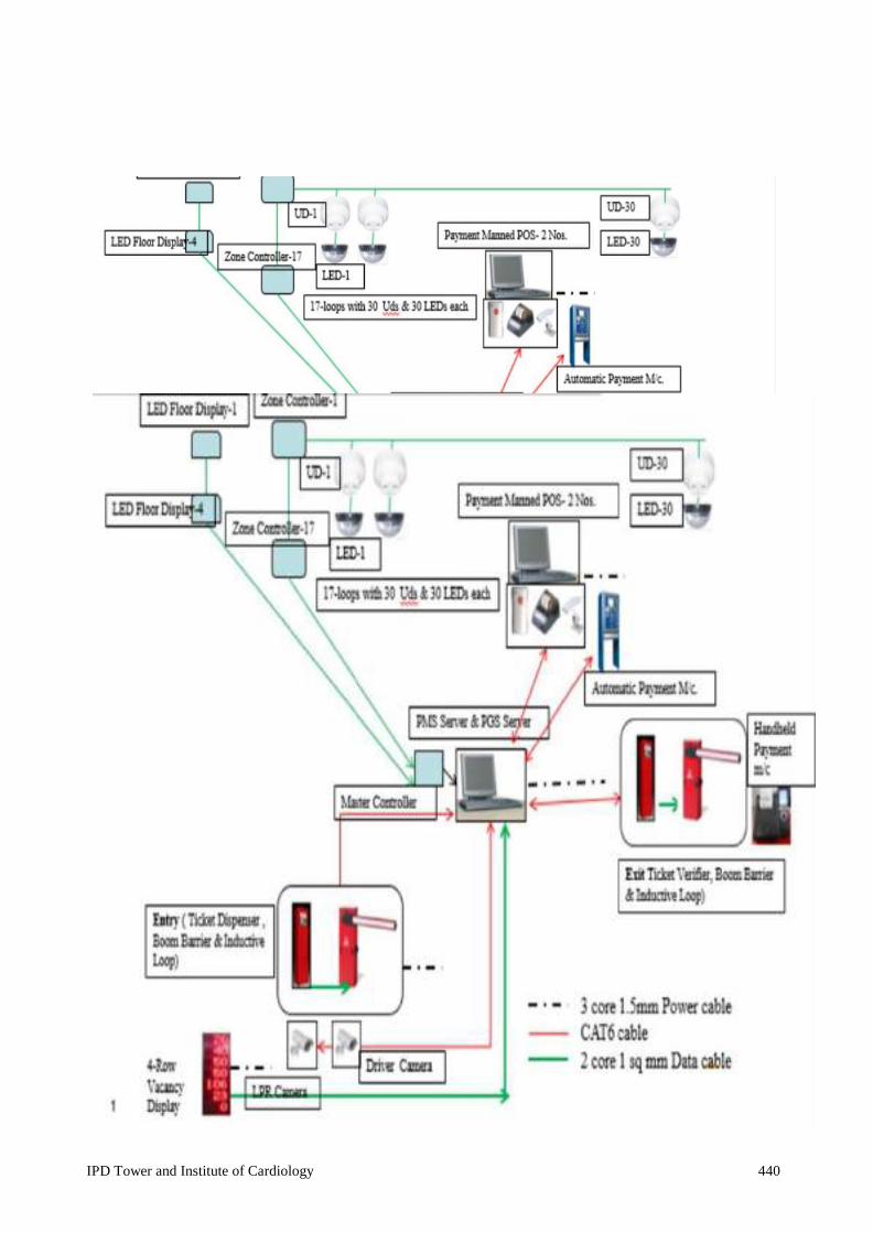
IPD Tower and Institute of Cardiology 440
SYSTEM- LINE
Parking Management System –Line Diagram

IPD Tower and Institute of Cardiology 441
Specification Ticket Automatic Ticket Dispenser with in-build universal compatible proxy card Options for wired systems and capable to communicate via RS485/ TCP-IP link. dispenser should have programing ability for configurating date, time, terminal etc. Entry level bar-code ticket dispenser printer. 125kHz proximity ISO card reader, 2 channel loop detectors included, blinking high-visibility pushbutton (flush mounted + Anchor with all required mounting connectors and its accessories.etc all
Technical
Voltage 230 Current
Power Proxy Card Contact less Reader of passive Card detection Card Entry Barcoded with date time & parking lane Printing Consist of thermal printer with Printing
Loop Dual Push Communication
315Lx310Wx1265H
Cabinet protective
Camera, Monthly/weekly
Multiple Vehicle Vehicle Identification Intercom SOS
ITEM WISE SPECIFICATIONS: Automatic Ticket Dispenser:
1. Ticket exit is such a way that ticket does not fall down after auto cutting. 2. Ticket to be issued only if:
(i) Vehicle category button press is same as sensor sensing, otherwise audible warning and message on LCD.
(ii) Vacant slot is available to the category of the vehicle.

IPD Tower and Institute of Cardiology 442
Voltage Power 100
Direct movement on the reduction gear
Opening & Closing
Power 230V Electronics (Torque
Approaching at the end of the With slowing Safety on Sensors Photo cell, loop Duty Reaction to Reversal of
Fe 360 - Pickled 2 plates mm;
320Lx220Px1010H
Hand From outdoor with Protection
Aluminum with LED light on Road
Voltage Current Power Max. IR LEDs
Auto (ICR) /Color/ Focal 2.7mm ~ Max Focus
Image 1/2.7" 2 mega Overall
Operating -20 to
Boom Barrier
NPR (Number Plate/License Plate) Camera

IPD Tower and Institute of Cardiology 443
Voltage Current Power 280
Intel Dual Core
Key
Handheld Zebra Smart Card 125khz ISO card
RS485 to LCD Posiflex Thermal Epson Operating
IP Grade IP67 Certification CE
Manned POS Station
Automatic Ticket Verifier:
Technical Specification
Voltage rating 230 Vac Current Rating 1A
Power Consumption 230W Proxy Card Reader Contact less Reader of passive transponders Card detection frequency 125khz Card format ISO Bar Code Scanner Built-In Loop sensors Dual channel Push button Illuminated Communication port TCP-IP Size 315Lx310Wx1265H mm Weight 55kg Cabinet protective treatment Cataphoresis Certification CE Intercom Facility Built-In

IPD Tower and Institute of Cardiology 444
Voltage Current Power 280
Intel i3
Key
To Ticket Dispenser, NPR Camera,
Barrier, Exit Ticket Verifier via
Smart Card 125khz ISO card LCD Posiflex Thermal Epson Operating
Custom Made Software: Central Server connect to ticket machine, NPR camera boom barrier. It also shares information PGS server about vehicle in transit and verifier about vehicle exit details. Also details of proximity cards and their access along with new issue & recharge options. It open the barrier and give command to dispenser to print ticket depending upon rights or card use classification of detected and corresponding button pressed ticket machine. In case of error, a message be sent to ticket dispenser machine manned booth and barrier shall not
Input 230V, -20% +15% single Input 50Hz Output 220/230V AC Single Voltage Output 50Hz ±0.05Hz (Crystal
Harmonic <
SOS Alert Yes Central PMS Server
UPS

IPD Tower and Institute of Cardiology 445
Voltage DC 15 - Current 2.0 Power Operational Communication RS Detection 0.3 – 4.5 Detection range Range tolerance Max Detection 1 Baud Response Overall
Power Factor 0.08 Battery 12V Battery Capacity 17AH No. Of the Batteries 12 Backup time 10-12Minutes
Part-B Parking Bay/Guidance System System Description:
1. The presence of car shall be detected using ultrasonic sensor wired with RS-485 to zonal controller for car.
2. Each car parking slot will have a visible LED lamp which glow RED when occupied and GREEN when free.
3. Each Zone controller will be connected to sensors of its zone, master controller and zonal display units using suitable interface.
4. Zonal display unit for driver guidance shall be installed wth 4 in height LED, 3 digit display.
5. The master unit will be connected to PGS Server through TCP-IP or USB. It will calculate the parking slot availablity based on the information received for both type of vehicle and pass the information to master display unit. Two wheeler slot availability will be calculated by taking infromation from Entry Dispenser and Exit Verifier.
6. The PGS server shall be connected to internet to show available slot on exported excel file for onward usage in mobile app.
7. Suitable UPS tp provide power to PGS server, master controller, zone controllers etc. 8. Necessary cable (4-core) cables to be provided for connecting ultrasonic detectors with
zone controllers.
ITEM WISE SPECIFICATIONS:
Ultrasonic Detectors

IPD Tower and Institute of Cardiology 446
Voltage DC 15 - Current 1.7 Power LED 4 RED, 4
Single LED Point
Red 60cd/m2~80cd/m2;
Blue Visual Visual > 50 Overall
Operating -20 to Shell
Voltage AC 220V - Output Power DC Current 45 Power Communication RS Baud Maximum Load 32 units of Maximum
Display LCD and LED Overall
Operating -20 to
Powder Coated MS
Voltage AC 220V - Current 45 Power
Weight 300gms Operating Temp -20 to +60°C Shell material ABS Certification CE
LED Bay Indicator
Zone Controllers
Master Controller

IPD Tower and Institute of Cardiology 447
Voltage AC 230V - Current Power
No. Of No. Of Dynamic 3 Height of LED LED 5mm single row oval
bright RED No. Of the Fix Configurable, 3M reflective
48"x30" Pole/Wall mounting -
Operating 20 to
MS powder coated
Communication USB-RS232/RS485 Baud Rate 9600bps Rate Half Duplex Display Indicator Red power, Green Output ON Input port Upto 16 Channels (16
devices/channel); RS 485/ TCP-IP interface.
MS Enclosure 300x400x140mm Mounting Wall mount/Desktop Operating Temp -20 to +60°C Enclosure Powder Coated MS Enclosure Master Display
PGS Server 1. PC i3 Processor, 4 GB DRAM, 500 GB HDD with 19” TFT and Windows 7 or higher OS. 2. PGS Server software to show vehicle occupancy in graphical mode for cars. 3. Suitable software and hardware for web interface for showing parking availability on
different client nodes. 4. Connection to PMS server through TCP/IP and software support to extract information
for vehicle in transit. 5. MIS Report generation as per requirment.

IPD Tower and Institute of Cardiology 448
21.0 PROCUREMENT, INSPECTION OF EQUIPMENT & APPROVALS
Approved list of makes and vendors are given in the end of technical specifications. The makes of equipment/materials supplied shall be strictly as mentioned therein. For items not specially mentioned, prior approval shall be taken before procurement of the same. All equipments/material supplied shall be brand new and shall be procured directly from the manufacturers, dealers or authorised agents.
JDA Electrical Engineer shall have access to the manufacturer’s premises for stage inspection/final inspection of any item during its design, manufacturing, and assembly and testing. After carrying out the necessary factory tests and routine tests as per IS Standards, a copy of the routine test certificate shall be forwarded along with the call for carrying out the inspection at the manufacturer’s works.
Based on the inspection certificate, JDA Electrical Engineer reserves the right to carry out the inspection at a mutually agreed date and/or give inspection waiver. A minimum of two weeks will be needed after receipt of complete shop inspection report and other details to depute our inspector for inspection. It is the responsibility of the contractor to ensure that all electrical works are carried out as per the IE Rules & regulations, National Building Code and IS Codes & Standards. All necessary drawings and details as required by Electricity Board, Electrical Inspector, Fire Department and other Local Statutory agencies, shall be prepared by the contractor. The contractor is responsible to submit the drawings and other details as required to the Local Authorities (refer above) and obtain necessary approvals including sanction of load/enhancement of electrical load from SEB before energizing and commissioning. All official fee required for getting the approval will be reimbursed on account of Client on submission of original documents.
IPD Tower and Institute of Cardiology 449
23. LIST OF APPROVED MAKES FOR ELCTRICAL SYSTEM Contractor shall use the materials of approved make as indicated below or as approved by the JDA engineer in charge. The contractor shall ensure the correct selection of the approved make meeting the specifications and application duties. Before placing order for procurement, the sample of approved make shall be got verified for its suitability to the specification and application duty. However, JDA engineer in charge reserves the right to opt for the best preferred listed make.
Note- Approved Main LT Panel, Main AC Panel, APFC Panel, Active Harmonic Filter Panel will be fabricated in the workshop of OEM only.
S.No. ITEM MAKE
1 HT VCB Panel Board/ RMU Siemens/L&T/ABB/Schneider
2 Transformer I n d o t e c h T r a n s f o r m e r L i m i t e d
( p r o l a c p a r t n e r ) , C r o m p t o n ( C G ) ( ABB/GE prolac/ Schneider/Alstom
3 Main LT Panel/Main HVAC Panel / APFC panels / Active Harmonic Filter (AHF)
Siemens/L&T/ABB/Schneider/Legrand
4 Additional makes for APFC Panel/ AHF
EPCOS, Ducati
5 Synchronization Panel/AMF Panel
OEM of the DG set or above panel manufacturer as mentioned against s.no.-3
6 Diesel Engine: Cummins/ Caterpillar/MTU/ Perkins- Sterling
/Kirloskar Oil Engine Ltd 7 Alternator: Stamford/AVK/ Leroysomer/ Kirloskar
8 Fastener Hilti/ Fisher or equivalent
9 Anti-vibration mounting: Dunlop, Gerb, resistoflex 10 Bus Duct/Rising man L&T/ABB/Siemens/Schneider/GE/ Legrand/C&S

IPD Tower and Institute of Cardiology 450
11. Battery: Panasonic/Hitachi/Cummins/Exide/Amar Raja 11a Automatic Battery Charger Max Power/Amara raja Batteries ltd./Chhabi
Electrical/Statcon power control ltd.12. MV panels/Fire panel/AHU
Panel CMKL, Kalyani Switch Gear, Tricolite/Adlec. /Sterling &Wilson / Control & Switchgear/SPC Electrotech /Risha Control Engineers Pvt. Ltd.
13. ACB L &T ‘U’ Power (Omega)/ S i e m e n s 3WL/ ABB/ Legrand(DMX)/ Schneider (NW- Master Pact)
14.
Moulded Case Circuit Breaker
L &T – (D sine/DL) / Siemens-VA/ ABB-TMA/ Schneider – (Compact-NSX/NS) /Legrand-DPX
15.
Power/auxiliary Contactors, timers, Relay, starters
ABB/ Schneider/ L&T/ Siemens
16.
AMF Relay
wood ward
17.
SFU with HRC
L&T/ Siemens/ ABB/ Schneider/GE
18.
Change over switches/Isolators
Schneider / Siemens/ABB/GE/L&T
19. 20.
Instruments (Analog & Digital)
Timers
L&T/ AE/ Siemens/ Schneider/ ABB/Rishab /Conzerve Legrand/ L&T/ Siemens/ ABB
21.
Cast resin current Transformers:
AE/L&T/Rishab/Kappa
22.
Selector Switches:
L&T /KAYCEE/ Siemens
23. 24.
Push b u t t o n , I n d i c a t i n g Lamps LED: Auto manual changeover
L&T /Siemens/Schinder/Rishab Kaycee/L&T/ Schnieder/Siemens
switches (3Way)
IPD Tower and Institute of Cardiology 451
25 MCB distribution Boards L &T/Hager/Legrand/ Siemens/ Schneider/GE / Philips
26
RCCB/MCB
L & T / Legrand-DX3/ Siemens / Schenider –Acti 9/GE/ Hager/Philips
27
HT/LT- XLPE cables
CCI/Universal/Finolex/Rallison/Havells
28
Copper Control cable
CCI/ Universal/Finolex/ Rallison/Havells/Bonton
29
Compression Glands & Lugs
Comet/ Dowells
30
PVC Tape
Steel Grip
31
Cable Jointing kit
Raychem / 3M
32.
Cable Trays/ Raceways
RMCON/OBO/ Legrand/ BEC/AKG
33
Terminal Strips
Elmex/ Connect well/ Technoplast
34
LED light fitting & Fixture
Philips / GE/ Crompton Greaves/WIPRO
35
MS conduit
BEC/ AKG/ Steel Kraft/AKG/BEC

IPD Tower and Institute of Cardiology 452
36 PVC conduit Supreme/Prince/Finolex/AKG/BEC
37
Conduit accessories MS & PVC
RMCON/BEC/AKG/Steel Kraft/Supreme
38 Solar Power system (PV Cell) TATA Power Solar, CEL, BHEL, BEL
39 Copper conductor PVC insulated wires, Co-axial, Telephone wires & cables
L&T / AKG / Batra Henlay / Bonton / Havells
40 41
Additional make for telephone & LV wires and Cable Modular Switches & sockets
Delton/Fusion polymer/Bonton/Legrand
Legrand-Myrius or Anti-bacterial/L&T Oris/ Outlets Schneider -Livia / Philips -Sleek
42
Metal clad Socket outlets With boxes
L & T /Hager/ Siemens/ Schneider/ ABB/Legrand /HPL
43
Lighting protection
Erico/Galaxy electrode /Earth plus/OBO/JMV
44
UPS system
Schneider- MG, APC/ Eaton Power ware/ Emerson/Eaton
45
High Mast poles & special Pole
Crompton Greaves /Phillips /Bajaj/Valmont
46
Ceiling fans
Crompton Greaves/ Orient/ Usha
47
Auto Transfer switch
Cummins/Emerson-Asco/GE/ Russ electric
48
Public address system
Bosch/ Bose/ Honey well /Harman
49
CCTV camera
Pelco /Bosch/Sony/Axis/Honeywell/GVD
50
Fire Detection System Addressable
Honeywell-Notifier/Edward/Bosch/ Siemens
IPD Tower and Institute of Cardiology 453
51 FDA Conventional Honeywell/Bosch or equivalent
52
Portable fire extinguisher
Minimax/Ceasefire/
53
EPABX system
Avaya / Siemens-unify / Alcatel / Cisco / MiTEL / AAstra
54 Nurse Call bell system Honeywell/Schreck/ Raul land
55
Capacitor
Epcos, Schenider, L&T, Ducati, ABB
56
APFC Relay
Epcos, L&T, Biluk, Ducati, Schneider
57
Occupancy Sensor
Philips/ Honeywell/ Schneider/Lutron/Legrand
58 Lifts/ Dumb Waiters/Escalators Kone/ Mitsubishi/ Schindler / Johnson / ThyssenKrupp
59
BMS, field devices etc
Honeywell /L&T-Atmos/Siemens/Schneider
60 Lighting Control Lutron/ Philips/ ABB/ Schneider/ Legrand
61
Chemical Earthing
OBO Bettermann / Erico/Furse / Ingesco/JMV
62 Access Control System Honeywell-Pro-3000/Schneider/Lenel/Cardex
63
CAT 6 UTP, CAT 6A UTP/STP, Optical Fibre-cable
Molex/SYSTIMAX/Panduit/D-Link/Legrand
END OF TECHNICAL SPECIFICATION

IPD Tower and Institute of Cardiology 454
IX. AC SYSTEM REPORT FOR CONSTRUCTION OF IPD TOWER AND
INSTITUTE OF CARDIOLOGY AT S.M.S HOSPITAL, JAIPUR

IPD Tower and Institute of Cardiology 455
SCOPE OF WORK & PROJECT SPECIFIC DETAILS-AC SYSTEM 1. General The Specific Conditions of the Contract - AC System shall be read in conjunction with the Specific Conditions of the Contract-Scope of Work and Specific Condition of the Contract-General. In case of variations / deviations, if any, the Specific conditions of the Contract- AC System shall prevail.
2. Scope of Contract The scope of works to be carried out under this section comprises of Design, Supply, Installation, Testing and Commissioning of Heating, Ventilation and Air-conditioning works as illustrated in Tender Drawings, Schematic Diagram, Technical Specifications etc. As per Final Calculation of the contractor’s design team and as approved by contractor’s proof check consultant, final design may vary from as specified in Project Report. The change in design shall need to be approved from JDA. Nothing Extra shall be payable on this ground.
3. Stores and Materials The contractor shall provide everything necessary for the proper execution of the work according to the intent and meaning of the drawings and specifications etc. taken together whether the same may or may not be particularly shown or described therein provided that the same can be reasonably inferred there from.
4. Supply of Equipment Equipments shall be strictly as per the list of approved makes/ manufacturers given in the Bid documents subject to approval of the Engineer-in-charge. The Contractor shall submit manufacturer’s test certificates of equipments supplied.
5. Shop / Working Drawings etc. 5.1. To achieve the desired parameters/requirements as specified in Technical Specifications/Tender Drawings etc., the Contractor shall prepare detailed Heat Load Sheets of all rooms/occupancies of Air conditioned areas, CFM sizing of Fans (ventilation/pressurization) & submit to Engineer-in-charge for approval.
5.2. Subsequent to approval of the scheme as above, the Contractor shall prepare and submit to the Engineer-in-charge for approval, requisite sets of detailed shop drawings/layouts of various rooms/floors, Plant Room, External Layout.GA drawing of various equipment like Chillers/Cooling Towers /pumps /AHUs /FCUs /Panels along with foundation & other relevant details etc., equipment characteristics, pump curves and capacity details of all equipment, accessories and devices etc. as per specifications shall be submitted well in advance or as required for approval of Engineer-in-charge. The structure works should not be affected due to delay on this account. No claims for extension of time shall be entertained because of any delay in the work due to failure on part of the contractor to produce shop drawings in time.
5.3. If the Engineer-in-charge makes any amendment in the above drawings, the contractor shall supply requisite sets of fresh drawings with the amendments duly

IPD Tower and Institute of Cardiology 456
incorporated, along with the drawings on which corrections were made. After final approval has been obtained from the Engineer - in- Charge, the Contractor shall submit further requisite sets of shop drawings for the exclusive use of and retention by the Engineer-in-charge.
5.4. Approval of shop drawings shall not be considered as a guarantee of measurement or of building condition. It will in no way relieve the contractor from his responsibility of furnishing materials or performing work as required by the contract.
6. Completion Drawings (As Built Drawings):- Following "AS BUILT" drawings shall be submitted by the Contractor on completion of the work:
a. Plant Room/ AHU Room installation drawings giving complete details of the entire equipment including Chillers, Cooling Towers, Pumps, Hot Water Generators, AHU’s and their foundations.
b. Ducting layout drawings showing all sizes, damper (Fire/VCD) locations and sizes of all air outlets and intakes with sectional details, for all floors.
c. Electrical drawings master SLD showing cable sizes, equipment capacities, control components and control wiring.
d. Schematic control drawings giving detailed sequence of operation and notes to explain the operation of the all control circuits.
e. Piping drawings showing all pipe sizes, valves and fittings etc.
f. IBMS architecture, control logic details, conduits, and connection drawings.
g. Any other drawings to be supplied as per instructions of the Engineer-in- charge.
7. Operation and Service Manuals 7.1. The Contractor shall submit requisite sets of operation and service manuals in respect of the air-conditioning plant including salient details of plant including internal circuit diagrams. Following minimum details shall be furnished: i. Detailed equipment data as approved by the Engineer-in-charge. ii. Manufacturer's maintenance and operating instruction. iii. Approved test readings.
7.2. The Contractor shall also submit requisite sets of technical literature on all automatic controls and complete technical literature on all equipment and materials. The Contractor shall frame under glass, in the Air conditioning plant room all consolidated control diagrams and all piping diagrams.
7.3. Coloured Layouts of all electrical lines in A-1 size properly laminated to be fixed at various locations at the time of handing over of building.

IPD Tower and Institute of Cardiology 457
8. Inspection at Work / Contractor's Premises 8.1. The CLIENT & JDA or their representatives shall at all reasonable time have free access to the Contractor's premises/works. The Contractor shall give every facility to them and necessary help for inspection and examinations and test of the materials and workmanship.
8.2. These representatives shall have full powers to inspect drawings of any portion of the work or examine the materials and workmanship of the plant at the contractor's works or at any other place from where the material or equipment is to be obtained. Acceptance of any material or equipment shall in no way, relieve the contractor of his responsibility for meeting the requirement of the specifications.
9. Sub-contracting The Contractor may sub-contract part of the works with the written approval of the Engineer-in-charge. Sub-contractors as approved by the Engineer - in-Charge shall be appointed for carrying out the entire work of supplying, installation, testing and commissioning of all the equipment covered under this package. However, the overall responsibility for compliance of the Contract lies with the Contractor. The agency/ sub-contractor so chosen shall be got approved from the Engineer-in-charge.
10. Technical Submittals The Contractor shall submit Technical Submittals for all materials, equipment and machinery for approval in writing of the Engineer-in-charge before placing orders. The material submittals shall comprise of at least the following:
i. Manufacturer's original technical catalogues and brochures, material data sheets dully signed by manufacture, GA drawings by manufacturer, foundation drawings by manufacturer, installation manual of manufacturer, performance curves, pump curves, dully signed certifications by manufacturer etc. giving technical data about performance and other parameters.
ii. Manufacturers drawings / sketches showing construction, dimensional and installation details.
iii. Rating charts and performance curves clarifying rating of equipment proposed.
11. Samples and Prototypes The Contractor shall submit samples of items such as grilles/ diffusers, controls and/ or any other parts or equipment as required by the Engineer-in-charge for prior approval in writing before placing the order. The Contractor shall also construct prototype or samples of work as laid down in the Contract or as instructed by the Engineer-in-charge.
12. Testing and Commissioning 12.1. Tests on equipment as called for in the specifications shall be carried out by the Contractor in accordance with the specifications, the relevant Bureau of Indian Standard Codes (BIS) and International Standards.

IPD Tower and Institute of Cardiology 458
12.2. The initial tests shall include but not be limited to the following:
i. To operate and check the proper functioning of all electrically operated components viz., compressor motor, pumps, blowers, air handling units, rotating machine, fans, boilers, etc. ii. To operate and check the proper functioning of all electrical panels, switch gears, safety and other controls iii. To adjust and balance air, water, steam and gas quantities to provide the designed flow rates by adjusting valves, dampers, diverters etc. iv. To check the systems against leaks in different circuits, alignment of motor, `V' Belt adjustments etc. v. To check the vibration and noise levels of equipments. vi. Setting of all control and all such other tests which are essential for smooth functioning of the entire AC plant.
12.3. The Contractor shall pay for and arrange without any cost, all necessary balancing and testing equipment, instruments, materials, accessories, power, water, fuel and the requisite labour for testing. Any defects in materials and/or in workmanship detected in the course of testing shall be rectified by the Contractor entirely at his own cost, to the satisfaction of the Engineer-in-charge. The installation shall be tested again after removal of defects if any and shall be commissioned only after approval by the Engineer-in-charge. All tests shall be carried out in the presence of the Engineer-in-charge or his representative.
13. Provisional Taking Over After completion of the AC system, the same shall be put to a continuous running test for a period of 72 (Seventy Two) hours. All adjustments should be made prior to this test so that proper conditions / working are achieved during this testing.
The Contractor shall pay for and arrange at his own cost for materials, accessories, power, water, fuel and the requisite manpower/ labour for this testing the test readings shall be noted in the Testing format approved by the Engineer-in-charge.
The plant will be provisionally taken over after successful completion of the above test and the defects liability period shall commence after provisional taking over of the system.
14. Final Performance and Capacity Test In addition to the above testing, final performance and capacity tests shall be carried out on the equipment as per the "Testing Schedules" during the defects liability period as follows: i. Peak summer / monsoon test during the period from 15th may to 31st July on the dates decided by JDA/ CLIENT. The installations should be able to maintain the specified inside temperature/conditions within the tolerance limits prescribed in the Contract and the duration of the test shall be 72 hours.
ii. Peak winter test during the period from 1st December to 15th February on the dates decided by JDA/ CLIENT. The installations should be able to maintain the

IPD Tower and Institute of Cardiology 459
specified inside temperature within the tolerance limits permitted in the Contract. The duration of the test shall be 72 hours.
All the arrangements required for making the entire system operational /running, for the performance test as above, including cost of manpower, and fuel (diesel, Gas etc.), electricity etc. will be borne by the Contractor.
14.1. After provisional taking over of the plant, CLIENT shall provide staff for operation. Staff will work under the supervision of the Contractor for proper operation of the plant. This responsibility of the Contractor shall continue till completion of test liabilities with respect to the plant or the defect liability period (60 months), whichever is later.
14.2. The user shall have the right to operate all equipment, if these are in the operating condition if such equipment, have been accepted as complete and satisfactory. Repairs and alterations if required shall be carried out as and when directed by the CLIENT/JDA. In special circumstances, CLIENT/ JDA may request air conditioning of some areas even before the completion of whole of AC work. The Contractor shall co-operate fully under such circumstances.
15. Guarantee and Defects Liability Period The guarantee of AC works shall be valid for a period of 12 (twelve) months from the date of completion of the project as accepted by CLIENT /JDA. In case the contractor is not able to carry out the seasonal tests (summer/ monsoon & winter) within the stipulated period as mentioned above, the same can be carried out even after defects liability period. The Defect Liability period for AC shall be deemed to be extended till satisfactory completion of seasonal tests.
16. Performance Guarantee from Sub-contractor The Contractor shall submit a performance guarantee certificate from the agency which executed the AC work, counter signed by the Contractor that the system shall maintain the desired parameters within tolerance limit of the specified parameters who shall also guarantee that the capacity of various components as well as the whole system covered under the scope of work, technical schedules and requirements etc., shall not be less than the specified capacities. The guarantee of the specific equipment supplied alone with regard to the performance of the system shall not be acceptable and overall responsibility of the Contractor for performance of AC work & its compliance with the Contract terms and conditions remains unchanged.
17. Maintenance The Contractor shall carry out routine and special maintenance of the plant and attend to any defects that may arise in operation of the plant during the Defects Liability Period.
18. Validation: -Validation of Classified Areas (such as OTs/ICUs/Labs & other Critical Areas etc.) shall be in the scope of AC contractor & nothing extra will be paid in this regard.

IPD Tower and Institute of Cardiology 460
It shall include as follows:- Documentation for DQ/IQ/OQ with certificates of all brought items Duct leakage testing, pipe pressure testing during duct & piping installation as and
when required. Air flow velocity test Air borne particulate test Temperature & RH monitoring test. Area recovery test Room pressure balancing & any other test as required.
19. Painting All equipment and ancillary items such as pipes, supports etc. will be painted in an Approved manner, using standard primer & paints as approved by JDA / Engineer-in- charge
20. Safe Custody and Storage The contractor shall be responsible for safe custody of all machinery and equipment supplied and installed till the final taking over by the CLIENT/JDA.
21. Training of Personnel The Contractor shall arrange to train the JDA/CLIENT's personnel on the following aspects prior to provisional takeover of the plant:
a) Operation of plant, Plant room manager. b) Gas charging and pumping down of the system c) Adjustments of settings for controls and protective devices. d) Preventive maintenance. e) Disassembling and assembling of compressor including identification and replacement. f) Complete BMS system
22. Operation and Running of entire system The contractor shall pay for and arrange for operation & running of entire AC system for a minimum period of one year after satisfactory completion of installation including testing & commissioning of work as desired by Engineer-in-charge. Cost of operation & running of entire system including required material e.g. consumables, water, electricity, refrigerant, tools & tackles, requisite manpower etc. shall be deemed to be included in the contract price and nothing extra shall be paid on this account.
23. Maintenance during Defect liability period For AC Works defect liability period will be 12 months. The Agency shall maintain and operate all AC assets created through this agreement:-
Scope of work shall include the following but not limited to:-
i. Monthly maintenance services as per the manufacturer’s Guidelines / maintenance Manuals shall be provided. In Emergency breakdown, troubleshooting to be

IPD Tower and Institute of Cardiology 461
provided and breakdown to be attended immediately& submit service report to Engineer in charge. ii. Required spare parts, consumables shall be made available immediately. Adequate stock of all spare part, consumables are to be kept at Hospital premises.
iii. The rate of Comprehensive Maintenance Contract (CMC) shall be inclusive of following but not limited to:- a. All Equipment and electrical panels of the AC Plant must be running at the design efficiency without any interruption during 24 hrs operation. b. All consumable shall be included in this CMC offer. c. The contractor has to check at regular interval for filter clogging and clean, replace same as per the filtration requirement. d. The contractor shall carry out routine maintenance and shall attend any break down immediately. e. Particle Count (twice in a year) and DOP test in all Operation Theatres and Critical Care areas shall be carried out once in a year. f. Contractor shall provide cooling tower chemical and chemical treatment to keep cooling tower Water quality as per required quality after virtual completion and for entire CMC period.
iv. Work to be done on daily basis for AC:-
a. The reading of the suction and discharging pressure, oil pressure, oil and gas level, suction and discharging pressure of pumps, voltmeter & Ammeters etc. shall be checked and recorded in the LOG BOOK (Provided by the contractor) on hourly basis. Necessary action is to be taken if the reading is not normal. b. To check all electrical motors and their bearing for abnormal noise/heating and to take necessary action if found abnormal. c. To check water level in the make- up water tank on terrace and check functioning of float valve. See proper function of the circulation pumps. d. To drain out water and clean the AC plant room/cooling tower/AHU’s etc. as and when required/scheduled. e. The inside ambient conditions i.e. DB, WB, & RH of all the AHU’s shall be recorded on hourly basis. Filters of the AHU’s/fresh air inlet etc. is to be cleaned regularly as per schedule. f. Any other work required for the equipment for proper functioning.
v. Work to be done on weekly basis for AC:
a. To check refrigerant system. b. To clean all the strainers and the filters. c. To check the alignment/looseness of all the belt driven equipment and rectify if required. d. Filters of AHU’s/fresh Air inlet etc. are to be cleaned regularly as per service maintenance schedule. e. To check water inside the make-up tank for hardness/dirty and fill with soften water if required f. Clean of grills and diffusers.

IPD Tower and Institute of Cardiology 462
vi. Work to be done on monthly basis for AC:-
a. To check the gland /seal, coupling of pumps. b. Checking the alignment & conditions of all rubber couplings between pumps. c. Checking all bolts, nuts for tightness. d. To check the solenoid valve, safety controls mechanical, Electrical/ Electronics and inter-locking of the various equipment. e. To check all AHU ducts/insulation/proper positioning/damage and rectifying the same where ever required. f. Purging of air from all water coils. g. Coil to be cleaned by a) spray of high pressure clean water or with chemical spray if necessary, as per the manufacture guidelines. h. Cleaning of condensate pans, trays & drains. i. Checking the tension of all belts drives & adjust as necessary. j. Checking of all fan bearings & lubricate with grease as necessary. k. Checking all operating pressure & temperature of Chillers. l. Checking of refrigerant level, leak test with electronic leak detector of Chillers.
vii. Work to be done after every three month for AC:-
a. To check and lubricant (if required) the bearing of the pumps/motors and keep the proper record. b. The check the foundation bolts of the pumps / motors and to take the necessary action if required. c. Check the quantity of Air flow from various out lets in each room/ Area as per drawings and do adjustment of dampers etc as and when required. d. Check the performance of each equipment of AC plant for proper functioning. viii. All the equipment/installations shall always be kept in good and trouble free operating conditions. ix. All the required record for break-downs/repairs and maintenance etc. shall be maintained in the form of history books and logbooks etc. as per directions.
24. Minimum suggested Manpower for maintenance during DLP: AC Plant Room Operator –Mechanical Engineer (Graduate Engineer with 2 years ‘experience or diploma holder with 5 years ‘experience in operation and maintenance of Chilled Water Plants/ AC System) BMS operator (2 years’ experience in BMS System)
Sl No.
Particulars
AC Expert
Maintenance Mechanic
Maintenance Electrician
Per day for three shift
1 Per shift 1 1 1 3
TOTAL per
Day
1
3
3
7
Helper as required (should be physically and mentally fit to work, should be able to read and write and three years experience in assisting the operator.

IPD Tower and Institute of Cardiology 463
PROJECT REPORT
AC SYSTEM
1. Scope of Work:
The EPC Contractor shall carry out Design, Engineering, Supply, Installation and Testing & Commissioning of Complete AC system works for the proposed Hospital (…….) as detailed.
Air Conditioning System shall include validation of entire AC areas for the Hospital building.
The entire AC works should conform to specifications provided & as per directions of Engineer-in-Charge.
The ratings and capacities of various equipments are indicative and subject to up gradation/ revision during detailed designing stage.
The scope shall include below mentioned features but not limited to:-
i) The design shall be done in accordance with latest ASHRAE standards,
guidelines. The norms established by GRIHA 2015 for AC system design, NBC 2016, latest ECBC 2017 and NABH /LATEST RELEVANT STANDARDS/CODES PUBLISHED BY B.I.S(FORMERLY I.S.I) Standards shall be followed.
ii) Objective of AC System Design is to ensure proper Indoor Air Quality,
Energy Efficiency, Flexibility of Operation, Cost Optimization, BMS Compatibility and GRIHA Rating Compliances.
iii) Detailed heat load is to be computed for individual rooms of required
buildings which are to be air conditioned. All required parameters /factors like geographical location, orientation of building, ambient conditions, glazing U- factor, lighting & equipment load, occupancy load, area & height of room, fresh air ACPH, CFM/person, ADP of coil, shall be considered as per latest ASHRAE standards /ISHRAE/NBC 2016/ECBC 2017 / GRIHA standards.
iv) Equipment sizing of AC system shall take into account factors such as
ASHRAE90.1, ECBC-2017, latest GRIHA, geographical location, climatic conditions, water availability & quality etc.
v) Chilled water pipes from AC plant room to hospital building shall be laid
underground at suitable depth as per Latest relevant standards/codes published by B.I.S(formerly I.S.I). Adequate no. of Hume pipes having suitable dia. with spare shall be laid across the roads/pathways etc.

IPD Tower and Institute of Cardiology 464
vi) AC plant room shall be provided with safety equipments/items like suitable elastomeric mat (as per relevant IS codes) for all electrical panels, fire buckets, fire extinguishers, hand gloves, safety charts, framed complete Schematic, Electrical master SLD etc.
vii)Suitable size shafts, cut-outs, niches, openings etc. shall be provided to
facilitate installation of pipelines, ducts etc. in all floor slabs of various buildings for various service areas as required. All shafts, cut-outs, niche, openings etc. provided on floor slabs shall be suitably closed after laying of services lines as per fire safety norms as per NBC 2016. Doors shall be provided for all shafts at all floors as per fire safety norms as per NBC 2016.
viii)All services and plants as required like raw/ soft/ hot water supply,
drainage, plumbing, AC provisions, ducting etc. shall be adequately provided by the EPC Contractor for all Medical Equipments, Modular OT Rooms, CSSD, Laundry, Kitchen, MGPS etc.
2) Indoor Air Quality :
i. Emphasis on maintaining desirable Indoor Air Quality as per ASHRAE/NABH/ by setting and controlling parameters of temperature, air filtration, air flow, humidity levels and air changes per hour (total & fresh air) for each room, zone, area.
ii. Conformity of Indoor Quality parameters with ASHRAE and NABH
Standards.
3) Special Considerations for Critical areas:-
i. All critical areas shall be designed on air recirculation and outside air intake system as per standards specified by latest ASHRAE 170, ASHRAE 62.1 and NABH etc.
ii. At least 02 OTs shall be designed as septic OTs on 100% fresh air with suitable energy recovery devices like heat pipe heat recovery, heat recovery wheel etc.
iii. Compartmentalizing and zoning of areas in hospitals to restrict air
movement and prevent cross contamination dully coordinated with architecture.
iv. Air filtration to dilute and remove contamination in the form of odour,
airborne microorganisms and viruses, hazardous chemical and radioactive substances. To ensure the same, UL listed UVGI /Ozone system shall be considered. Magnehelic gauges, electronic pressure gauges compatible with BMS to be installed across Fine (MERV-14) and HEPA (MERV-17) filters and in critical areas for measuring differential pressure across filters and between zones.

IPD Tower and Institute of Cardiology 465
4) High efficiency filtration system to prevent bacterial contamination whether it is from outdoor air or from re-circulated air within space as per ASHRAE 52.2 and ASHRAE guidelines i.e 02 stage filtration comprising MERV-14 and HEPA Filters MERV-17 for critical areas.
Space Destination (According to Function) Filter
Banks#1, MERV a
Filter Bank#2, MERV a
Class B and C surgery, inpatient and ambulatory diagnostic and therapeutic radiology; inpatient delivery and recovery spaces
7 14
Inpatient care, treatment and diagnosis, and those spaces providing direct service or clean supplies and clean processing ( except as noted below); AII (rooms)
7 14
Protective environment rooms(PE) 7 17(HEPA) c
Laboratories; Class A surgery and associated semiristricted spaces
13 b N/R d
Administrative; bulk storage, soiled holding spaces; food preparation spaces; and laundaries
7 N/R
All other outpatient spaces 7 N/R
Skilled nurses facilities 7 N/R
Souce: ANSI/ASHRAE/ASHE 170-2008
Notes:
a. Minimum efficiency reporting value(MERV) is based on method of testing described in ANSI/ASHRAE Standard 52.2-2007
b. Additional pre filters may be used to reduce maintenance for filters with
efficiencies higher than MERV-7
c. Filter bank #2 may be MERV- 14 if MERV -17 tertiary terminal filter is provided for these spaces
d. N/R= Not required
vi. Aluminium ducting shall be used for supplying air to operation theatres,
inside OTs, the supply and installation of HEPA filters at terminals, laminar flow diffusers and inside OT supply/return ducting shall lie within the scope of Modular OT vendor.
vii. All the buildings shall be fully air-conditioned including corridors and
waiting areas etc.
5) Air Conditioning:

IPD Tower and Institute of Cardiology 466
i. Centralized chilled water air conditioning system (district cooling with primary, variable secondary for Hospital block and variable tertiary for Library & Admin, Medical college, Medical labs) being considered for Hospital, Library & Admin, Medical College, Medical Lab building etc. in all areas. Hot Water Generators will be used for winter heating & for monsoon reheat of critical areas of hospital like OTs, ICUs, recovery, emergency, private wards etc. All hospital areas will have 4 pipe systems (separate cooling & heating pipe networks) & other buildings shall be with AHU with 2 pipe system (combined cooling & heating pipe network).
ii. Variable Refrigerant Volume/Flow System for UPS room etc shall be
considered.
iii. Electrical load provisions for DX type AC shall be considered in sizing of electrical equipments etc.
iv. All the equipments etc. shall be suitable for 415 V, three phases or 220 V, single phase, 50 Hz A.C. supply.
v. Chilled water system Centrifugal Chillers with VFD and active harmonic filter (THDi less than 5%) are proposed for summer/ monsoon cooling.
The chilling machines shall be AHRI certified with R-134a refrigerant. The Minimum COP of 6.5 and IPLV ≥ 9.25 at ARI conditions should be complied as per latest ECBC 2107. NPLV less than 0.37 and IKW/TR less than 0.64 at duty conditions. Automatic tube cleaning system designed for automatic continuous cleaning of heat exchangers (make as per chiller manufacturer) with injector, ball trap, drain valves, injection valves, manual ball valves, check valve, drain valve etc.
Plant room manager cum optimiser for sequencing, remote monitoring, controlling and report generation of all equipments in AC plant room/high side shall be provided. Plant room optimiser shall be of same make as Chiller. This must have software integration on chillers with 3rd party interface available on BACNET including cabling & conduit work as required with card.
Cooling tower shall be CTI Certified with VFD driven fan. Ventilation Fans shall be AMCA certified for fan efficiency, sound & Noise. Fire dampers shall be as per UL-555 & CBRI Roorkee certified for min. 02 hrs fire rating.
vi. The VRV/VRF system considered for UPS room etc. must be latest generation/version with capability of summer and monsoon cooling and winter heating as well. COP shall be as per Latest ASHRAE std 90.1
vii. Hot water pumps, Secondary chilled water pumps shall be with variable speed drives circulating water in the chilled and hot water circuits. Primary chilled water and condenser water pumps will be constant speed pumps.

IPD Tower and Institute of Cardiology 467
viii. Provision of specialized equipment like Vacuum Degasser, Air and Dirt Separator in the AC Plant Room to ensure smoother operation, enhanced efficiency of system and longevity.
ix. Chilled water circuit comprising of MS pipes (Heavy duty “C” class as per Latest relevant standards/codes published by B.I.S(formerly I.S.I)) with TF quality EPS insulation for centralized chilled water system.
x. GI pipes (Class B) for drain pipe with suitable insulation for chilled water system.
xi. u-PVC Pipe for VRV/VRF/DX Split drain pipe to be provided.
xii. Floor mounted AHRI/EUROVENT certified air handling units in hospital shall be considered.
xiii. Fresh air provision for ceiling suspended AHUs/FCUs/VRV/VRF Indoor units shall be considered as per relevant codes & standards. TFA (Treated Fresh Air Units) to be provided to supply treated fresh air to these units/feeding areas with vertical riser up to the terrace.
xiv. Pressurized Expansion tanks of suitable capacity with dosing pumps (1w+1s) and controller to adjust and regulate the pressure of water in the chilled and hot water circuits shall be provided separately.
xv. Ducting System comprising of GI /Al ducting with insulation depending upon the requirement. Duct Construction and suspension Standards must conform to ISHRAE/SMACNA, IS 655 and LATEST RELEVANT STANDARDS/CODES PUBLISHED BY B.I.S(FORMERLY I.S.I) specs 2017.
xvi. CTI certified Cooling Tower with VFD driven Fan Motors for Chilled Water System.
xvii. Chilled Water flow modulation and automatic balancing by means of automatic balancing valve, 2 way PIBCV with insulation and manual motorized butterfly valves, non return valves, ball valves. All the valves must be minimum PN16 rated and suitable for Chilled water and hot water applications. Insulation of valves shall be the same as that of pipe.
xviii. Air flow modulation by means of air distribution devices like volume control dampers, collar dampers, CAV/VAV Boxes conforming to UL / international standards.
xix. Colour scheme for equipment like Chillers/Pumps/AHUs/Cooling Tower etc. shall be as per manufacturer’s standard colour scheme or as per directions of E-I-C.
xx. The scheme of colour code painting of pipe work services for AC installation shall be as per latest NBC/Latest relevant standards/codes published by B.I.S(formerly I.S.I).

IPD Tower and Institute of Cardiology 468
xxi. Provision of trap door of suitable material & size shall be considered for easy accessibility of moving parts of the concerned equipment/dampers and duct cleaning..

IPD Tower and Institute of Cardiology 469
xxii. BMS compatibility to all air conditioning (3 phase equipment) high side and low side equipments with communication cards.
xxiii. Touch screen types central controller to be provide for VRV/VRF system of UPS rooms with provision to ingrate the same on BMS.
6) Ventilation System:
i. Mechanical Ventilation System to be considered for basements, toilets,
kitchens, laundry, dirty area of CSSD as per NBC 2016 and Hospital guidelines.
Individual floor smoke extraction as per NBC2016 through smoke riser shafts, makeup fresh air to be provided through riser shafts or fresh air dampers.
Ventilation of AC plant room, MGPS, Fire/WTP Pump House, STP/ETP plant & other areas shall be as per requirements of NBC 2016 and hospital guidelines.
ii. Emphasis on maintaining adequate fresh air supply, removal/exhaust of
stale air, particulate matter, fumes and noxious gases.
iii. Fan design, selection and sizing in accordance with provisions stated in NBC 2016, ASHRAE, ECBC 2017 and local fire bye-laws.
7) Heating System:
i. Comfort heating for all areas and additional monsoon reheating for
humidity control for hospital areas like OTs, ICUs, post operative, recovery, MRI, CT etc is to be provided.
ii. Conformity of Indoor Air Quality parameters pertaining to comfort and
critical areas with ISHRAE, ASHRAE and NABH Standards.
8) Design and Layout Considerations:
The design and layout considerations for AC System in a building must strictly conform to the provisions stated in latest ASHRAE, NBC, ECBC and LATEST RELEVANT STANDARDS/CODES PUBLISHED BY B.I.S(FORMERLY I.S.I).
i. Plant Room Layout :-
AC Plant Room shall be provided adjacent to existing AC plant room in the
basement of basement. Cooling tower shall be placed outside on the ground. Cooling tower foundation shall be structurally designed to take loads of cooling towers, piping’s etc. Proper integration of the AC plant room to be done with existing AC plant room of Cardio building. Also, dimensions of plant room shall conform to LATEST RELEVANT

IPD Tower and Institute of Cardiology 470
STANDARDS/CODES PUBLISHED BY B.I.S(FORMERLY I.S.I) norms & other relevant codes so as to have proper distance between chillers/pumps primary &

IPD Tower and Institute of Cardiology 471
secondary, air separator, vacuum degasser, plant room optimiser, all chiller VFDs and main and secondary AC panel and other equipments.
The AC plant room layout must be planned in such a manner so that it enables easy movement of personnel to conduct daily routine and maintenance procedures. Additional space for circulation shall be considered as per relevant codes. Provision shall also be kept for anticipated future requirements. Minimum clear height of plant room (approx. 5 m) shall be maintained as per relevant codes. The entrance to A.C plant room shall be preferably through rolling shutters having minimum width as per relevant codes.
Proper spacing must be ensured between the foundations of Pumps, Chillers and other equipment to enable repairs and easy replacement of parts.
The AC plant room must be adequately ventilated with fans maintaining optimum air flow and ACPH level. The design and sizing of fan must be in conformity with the LATEST RELEVANT STANDARDS/CODES PUBLISHED BY B.I.S(FORMERLY I.S.I) & NBC latest norms for the same.
Floor loading of approx. 2000 kg/sqm shall be considered for AC Plant Room. The AC plant room should have a fresh water connection & drain trap. The floor shall have suitable drain with grating. Adequate level of illumination must be ensured to enable smooth maintenance and repair procedures.
AC Shafts:-
Sufficient number of shafts shall be provided so that piping length is optimized.
The AC Shaft must be adequately sized to enable smooth passage of pipes and ducts with insulation along with its supporting arrangement through it.
The walls of the AC Shaft must be lined with fire rated material capable of withstanding 250 degree celsius for a period of 2 hours.
Inspection doors must be provided in AC Shaft wherever necessary. The door must be Fire rated capable of withstanding 250 degree Celsius for a period of 2 hours.
ii. AHU Rooms :-
AHU Room slab shall be structurally designed to take loads of various equipments.
The AHU Room Layout must be planned in such a manner so that it allows easy movement of personnel to conduct daily routine and maintenance procedures.

IPD Tower and Institute of Cardiology 472
AHU foundation shall be proper (PCC/RCC/Steel frame) in conformance to relevant standards. All measures shall be taken including providing vibration isolation pads etc. should be used to dampen noise generated at source itself.
AHU Room shall be acoustically insulated with suitable material (as per hospital guidelines) as per LATEST RELEVANT STANDARDS/CODES PUBLISHED BY B.I.S(FORMERLY I.S.I) provisions & site requirements.
Floor loading of approx. 800 kg/sqm shall be considered for AHU Room.
AHU Room should have a fresh air opening, water connection & drain trap. Arrangements for adequate Natural Ventilation must be made in the AHU Rooms conforming to LATEST RELEVANT STANDARDS/CODES PUBLISHED BY B.I.S(FORMERLY I.S.I) and NBC norms.
9) Basis of Design
This system is designed to cater air conditioning requirement to the different areas of various the buildings. The brief design concept report for AC works in the buildings is as below: -
9.1. General
This report outlines the Design Considerations Basis of Design for estimating Heat load and AC system design.
Site location. : IPD Tower, Jaipur
Latitude. : 26.91° N Longitude : 75.78° E Altitude. : 431meters
9.2. Basis of Design
The Air conditioning system has been designed on the following design parameters
9.2.9.2.1. Outside design conditions
Season Dry Bulb temp Wet Bulb temp.
SUMMER:
110 deg F DB
75 deg F WB
MONSOON:
95 deg F DB
83 deg F WB
WINTER:
45 deg F DB
41 deg F WB

IPD Tower and Institute of Cardiology 473
9.2.2. Inside design conditions
IPD Tower and Institute of Cardiology 474
2. Design conditions
Central air conditioning system shall be provided to maintain the specified inside design conditions during summer, monsoon and winter for the proposed buildings. Classification of various spaces in terms of temperature, humidity control, Occupancy, air filtration, air changes & pressurization requirements of various departments shall be done as per following
Design Parameters to be considered for AC system design:-
Hospital Area: ASHRAE AC design Manual for Hospital and
Clinics 2013 table 3-3. ASHRAE Std. 170-2013 or latest.
Institutional Areas: As per ASHRAE std. 62.1 latest.
The IPD Tower building is fully air conditioned buildings:-
Minimum filtration efficiencies as per ASHRAE (latest).
Pressure relationships with adjacent areas shall be as per ASHRAE Guidelines for Hospital 2013.
Lighting load shall be as per ECBC / Actual.
Equipment loads shall be as per actual.
Acceptable indoor noise level for Hospital: 35-40 dBA as per ASHRAE/NBC
Acoustic insulating material shall not be used as duct lining for hospital. Supply air ducts shall be externally insulated.
Non critical spaces not having downstream terminal filters will have internal acoustic lining till first bend or 2 metre length of duct from inside in the Air Handling Units and Treated Fresh Air Units.
10) Building Construction Data
The building/ AC system shall be designed for GRIHA Version 2015 for 5star rating. For ECBC compliance following are the details :
Climate Zone as per ECBC 2017

IPD Tower and Institute of Cardiology 475
All U value, SHGC, VLT etc of Glazing, Roof/Wall Insulation etc. shall conform to ECBC 2017 norms for achieving GRIHA 5 star rating.
Active smoke control systems shall be used along with fire and smoke partitions to limit the spread of smoke in the event of fire. Smoke and fire management shall be done in accordance with Part 4 Fire and Life Safety as per NBC 2016/ Local bylaws.
11) Mechanical ventilation system / basement ventilation system/ lift lobby
and lift well pressurization system shall be as per NBC 2016.
Separate exhaust duct shall be provided for toilets, pantries, and dirty utility areas. These shall not be combined with each other or with any other exhaust ducts of AC System.
S. No. Description Type of equipment
1. Basement/ smoke management system for escape route - fresh air intake
Long casing Tube / Vane Axial fans with Class F motor insulation & with BMS compatible with VFD capable of receiving signal from fire panel / CO sensor controller.
2. Basement / smoke management system for escape route – exhaust
Long casing Tube / Vane Axial fans with Class H motor insulation & with BMS compatible with VFD capable of receiving signal from fire panel / CO sensor controller.
3.
Lift well pressurization
Long casing Tube / Vane Axial fans with Class F motor insulation.
4. Lift lobby pressurization
Long casing Tube / Vane Axial fans with Class F motor insulation.
5. Stair well pressurization
Long casing Tube / Vane Axial fans with Class F motor insulation
Basement Ventilation (Fresh Air/exhaust) Fans shall be with IE-3 Rating. Pressurization Fans (Lift
Description Fan type 1. Basement fresh air
and smoke exhaust system
Long casing Tube / Vane Axial fans with Class H motor insulation
2.
Toilet Exhaust
Centrifugal Inline/Propeller as per requirement
3.
DU / Isolation Room Exhaust
Centrifugal Inline.
4.
Service / Utility area
Wall mounted propeller type

IPD Tower and Institute of Cardiology 476
5. Air Washer /Dry Scrubber
Plug Fan
6. Bio Medical Waste Room
Cabinet Type with SISW Blower
7. Plant Room/Pump Room/ STP/ ETP etc.
Cabinet Type Blower (SISW/DIDW meeting functional requirement)
DU Isolation, Bio Medical waste fans, air washer, scrubber, pump room fans shall be with IE-3 motors. Pressurization Fans /smoke exhaust shall be with min. IE2 rated motors.
12.0 Estimated Load
Detailed heat load estimation sheet shall be prepared during detailed engineering stage for all the seasons (Summer/Monsoon/winter) in which, the specified conditions are to be maintained based on above design parameters considering diversity of 85% for sizing of chillers etc. Based on ASHRAE Load Calculation Manual (Heating & Cooling),
Cooling Load for Hospital, Library and Admin, medical college, medical Lab building after diversity will be 1600 TR (Water Cooled Central Plant)
1 Chiller capacity AHRI Certified with VFD starter and active harmonic filter. The Minimum COP of 6.5 and IPLV ≥ 9.25 at ARI conditions should be complied. NPLV less than 0.37. Tender condition IKW/TR less than 0.64. With automatic tube cleaning system.
3 x 800TR (2W+1S)
2 Cooling tower CTI certified multicell (@3GPM/TR) Basis of selection 98-88 deg F and wet bulb temp 83 deg F.
Flow rate 2400 USGPM.
3 Primary Pumps (@2.4GPM/TR) 3 Nos. 1920 USGPM (2W+1S)
4 Secondary Pumps with variable speed pumping system 3 Nos. 1920
for chilled water(@2.4GPM/TR) USGPM (2W+1S) 7 Secondary Pumps with variable speed pumping syatem
for hot water 3 Nos. 450 USGPM (2W+1S)
8 Condenser Water Pumps (@3GPM/TR) 3 Nos. 2400 USGPM (2W+1S)
9 Electric Hot Water Generator -450 KW (For Winter Heating) Suitable capacity HWG with circulation pumps for monsoon reheating.
3No. (2W+1S) 2 Nos. ( 1 w+1s)
IPD Tower and Institute of Cardiology 477
12. Brief Equipment Specifications (High Side):
All the equipments shall be compatible with BMS with BACNET/MODBUS protocol and RS 485 connectivity. All equipment foundations shall be proper and as per manufacturer’s standards and GA drawings.
i) Chillers: Factory assembled and tested (AHRI citified) centrifugal chillers using
R134a/1233zd refrigerant. The compressor shall have mechanism for stable operation at part loads. Cooling equipment shall meet or exceed the minimum equipment efficiency requirements (COP, IPLV and IKW/TR) as per ECBC 2017 and ASHRAE 90.1. Chiller motors shall be with VFDs with active harmonic filters suitable for hospital applications( IEEE 519, THDi<5% at equipment level) complete with ammeter with CTs, overload protection ,under voltage protection, protection against phase reversal & independent single phase preventers etc complete as required. VFD shall be the same make and model which will be used for the testing at manufacturer's works for the AHRI certification. The power and control wiring of the VFD starter to chiller shall be done by the manufacturer . Total capacity of chillers shall be 2400 TR (3nosX 800 TR, 2W and 1S). Walked out by Contractor and shall be approved by client. ASME stamped matching shell and tube water cooled condenser and evaporator with maximum head loss with 8m in each. Advanced Microprocessor based control panel with automatic controls, coloured & graphical display, complete with accessories and BMS compatible BACNET/MODBUS Protocol with BMS cards. Necessary spring heavy duty isolators with 25 mm deflection from OEM for the chilling unit shall be provided. Automatic tube cleaning system designed for automatic continuous cleaning of heat exchangers with injector, ball trap, drain valves, injection valves, manual ball valves, check valve, drain valve etc.
Chiller capacity shall be as per following parameters: Chilled water inlet/outlet temperature of 54°F /44°F Condenser water inlet/outlet temperature of 88°F /98°F

IPD Tower and Institute of Cardiology 478
Chiller water flow rate: 2.4 USGPM/TR. Condenser water flow rate: 3 USGPM/TR. Chiller Fouling Factor : 0.0005 (FPS Unit) Condenser Fouling Factor : 0.001 (FPS Unit)
The Minimum COP at AHRI conditions of 6.5 and IPLV ≥ 9.25 at ARI conditions should be complied. NPLV shall be less than 0.37. The IKW/TR should be less than 0.64 (inclusive of all losses) at duty conditions. One randomly selected chilling machine shall be tested as per conditions stipulated in tender for points 25%, 50%, 75% and 100% and test report shall be submitted. Refrigerant shall be CFC free, zero ODP & as per ASHRAE safety classification of A1.
ii) Plant Room Manager cum Optimiser
Plant room manager shall be of same make as chillers. Plant Room Manager shall be suitable for sequencing & remote monitoring, controlling and report generation of all equipments in AC plant room/high side. Selected controller shall have capacity to meet detailed IO summary mentioned under specifications. Supervisory controller for management level interface in MS Enclosure, SWG thickness, powder coated Siemens grey for Supervisory Controller, IO Cards (with accessories like Transformer, MCBs, internal wiring and Relays with bases). Workstation PC i7 computer 3000 Mhz with 1 TB hard disk, 21" TFT monitor, 104 windows key board, mouse, serial and parallel ports with laser colour printer. This must have software integration on chillers with 3rd party interface available on BACNET including cabling & conduit work as required with card.
iii) Pumps
Primary, chilled water, hot water, condenser water pumps shall be vertical split casing type or inline centrifugal type for ease of maintenance and rugged usage. Secondary pumps shall be preferably Inline sensor less pumps with pump mounted VFDs. Suitable pump head shall be selected while sizing of pumps depending upon the piping length, fittings, friction factor etc. and other requirements. Both working and stand-by provisions for pumps has to be considered for each set of pumps. Minimum one standby pump shall be considered in addition to the no. of working pumps as per requirements (n+1 configuration). Pump casing shall be cast iron, impeller shall be bronze/gunmetal, and shaft shall be of stainless steel with S.S mechanical seal.
The thermal insulation of chilled/hot water pumps shall be with same material & thickness as that of pipe. Pumps shall be complete with all accessories like pressure gauge, valves (butterfly, NRV etc.), reducers (if reqd.), strainers, flexible bellows (heavy duty double arch PN 16 rating min.) etc.
All variable flow pumps including hot water & secondary chilled water pumps

IPD Tower and Institute of Cardiology 479
will be with VFD (IP-54, THDi less than 5%) and variable flow system with separate control panels for each set of secondary circulating water in the chilled/hot water circuit. To regulate the flow of chilled water as per the variation in the air conditioning load inside the building, the secondary chilled water pumps shall be with variable frequency drive (VFD) and Logic/PLC controllers, differential pressure sensors or sensor less and integrated software. Pump efficiencies shall not be less than 80%. Suitable foundation as per OEM standards and GA drawings needs to be constructed for mounting of these pumps along with anti-vibration spring isolators /pads.
Efficiency of pumps shall be more than 80% or best efficiency as per OEM standards. Motor shall be TEFC Type, IE-3 efficiency class with Class F insulation and suitable for continuous duty. Operating speed shall not be more than 1500 RPM.
iv) Cooling Towers
Cooling towers must be CTI Certified low noise model. The Cooling tower fan motors shall be IE-3 rated, IP-55 suitable for outdoor installation and equipped with VFDs and controller. Each VFD shall be installed in a dedicated external IP-65 enclosure with earthing if required. Tower shall be selected on the basis of water temperature 98 -88 degree F, ambient wet bulb 83 deg F. Cooling towers shall be compatible for working with BMS. Cooling towers shall have fan controls based on wet bulb logic.
Cooling Tower shall be designed in such a manner that the total losses (drift + evaporation + bleed off etc.) are minimized.
Cooling Tower shall be located at a well ventilated space either at ground floor/terrace of plant room/terrace of building. In case cooling towers are located on the terrace of the building, the structural loading of terrace shall be considered. Cooling towers shall be installed preferably on columns (raised by 3 feet at terrace) so that load is transferred directly to columns. For this, MS sections/beams shall be provided. Sufficient space shall be left all around for efficient operation & maintenance of cooling tower.
Depending upon suitability and applicability, induced type, counter/cross flow type may be selected. It should be complete with FRP (Fiber Reinforced Plastic) water basin, FRP casing, distribution system, PVC filling with integral louvers, drift eliminators, spray nozzles or self-rotating sprinklers, statically, dynamically balanced axial flow type fan, HDG supporters and MS painted ladders, make up quick fill arrangement, overflow & drain connections with necessary valves. It should be complete with cement concrete foundation, steel/masonry supporting structure, anti-vibration mountings etc.
IPD Tower and Institute of Cardiology 480
Minimum one cooling tower shall be considered in addition to the no. of working cooling towers as per requirements (n+1 configuration).
v) Hot Water Generator
Electrically operated ‘Hot water generators’ for winter heating & monsoon reheating will be provided in AC plant room. The hot water will be supplied through pumps with VFD. Separate electric Hot water generators will be provided in hospital buildings for reheating of OT AHUs to control humidity. Both Working and stand-by provisions for hot water generators have to be considered. Hot water vessel construction must conform to relevant standards and must be insulated with fiberglass/rock wool of suitable density and thickness and shall be suitably cladded. HWG must have sufficient number of heat banks. Hot water generator shall be compatible for working with BMS including BMS cards.
vi) Brief Equipment Specifications (Low Side):-
Factory fabricated double skinned construction with thermal break profile with GI sheet of thickness (0.8 mm) pre plasticized outside & plain GI (0.8 mm) on inside with PUF insulation of suitable thickness (40 mm) and density (min. 32 kg/cum) between them. AHU may be floor mounted/ceiling suspended & should be of sufficient tonnage, CFM & static pressure as per requirements.
Maximum air flow velocity across filters, fans, coils shall be as per relevant ASHRAE/ISHRAE standards. Motor, fan speed etc. shall be in conformance to relevant standards. Velocity & friction factor for pipe sizing shall be in conformance to relevant ASHRAE/ISHRAE standards.
Volume control dampers to be provided in ducts as per requirements and standards.
Fire dampers must be provided in the supply and return duct at AHU’s room fire walls and wherever the duct is crossing the fire zone as per NBC 2016.
Motor must be squirrel cage induction type IP 55 TEFC, insulation class 'F', Duty S1 (continuous duty), IE-3 drive motor, drive arrangement, guard etc. All AHUs shall be fitted with suitable capacity VFD starters with bypass starter.
Centrifugal blower shall be backward curved aerofoil design direct/belt driven. Fans must be selected for suitable static pressure & CFM & shall be AMCA certified for sound, noise & performance. Efficiency shall be more than 70%.
Fine and HEPA filters with filter section wherever required as per ASHRAE guidelines for hospitals and other buildings. Filters shall be fitted in factory fabricated double skin section of same specifications as AHU panels and complete

IPD Tower and Institute of Cardiology 481
with filter frameworks. Fresh air intake arrangement, necessary water drain & air purge valves etc. wherever required.
Pre Filter: 90% down to 10 micron (MERV-7), Fine filter: 99% down to 3 micron (MERV-14), HEPA filter 99.97% down to 0.3 micron (MERV-17).
All the AHU's shall be with IP-54 rated suitable capacity VFD starter and isolator switch. The VFDs shall be UL listed with THDi less than 5%.
On/Off/trip/run/standby/fault/trip display. O/L, S/C and single phase protection. Interlocking of AHUs with FDA system for tripping.
Complete AC system shall be BMS compatible.
Cooling Coil of required OD & thickness preferably made of Copper with Fins preferably made of aluminium with suitable fins/inch. Cooling coils row deep should be considered meeting the functional requirements.
Coil section with AHRI/Eurovent certified cooling coil, heating coils as per specifications, minimum 2 bend PVC eliminators. Drain Pan of AHUs must be made of Stainless Steel of Suitable thickness (18 G) duly insulated with required thickness & density of insulating material & drain slope on both sides.
Suitable number of modulating valves like Butterfly/ Ball/ PICB/Drain etc. must be positioned at the inlet and Outlet along with other accessories like Thermometer, Pressure Gauge, Thermostat, and Humidistat etc. Strainers shall also be considered at the inlet of AHUs.
Suitable Foundation for Floor Mounted AHUs /Hanging Arrangement for Ceiling Mounted AHUs should be considered with anti vibration pads. Water Supply provision must be considered for AHUs with Built-in Humidifier wherever required.
Fireproof double canvass connection should be considered. The air handling units shall be powder coated in approved colour as per OEM standards or as per directions of E-I-C.
All OT/ICU AHUs shall be double tier with separate fans for supply & return. The AHUs shall be fitted with dampers for supply air, return air fresh air intake and exhaust air. Maximum air flow velocity across filters, fans, coils. Motor and fan speed etc. shall be in conformance to relevant standards.
Velocity & friction factor for Pipe Sizing shall be in conformance to relevant standards of ASHRAE. Volume control dampers to be provided in ducts as per requirements for balancing etc. Fire Damper must be provided at the Supply and Return ducts of AHUs. Motor must conform to IE-3 class efficiency and must be

IPD Tower and Institute of Cardiology 482
squirrel cage induction TEFC motor. All AHUs shall be equipped with VFDs (Separately for supply & exhaust fans).
Drain Pan of AHUs must be made of stainless steel of suitable thickness (18 G) duly insulated with required thickness & density of insulating material & drain slope on both sides. Suitable number of modulating valves like Butterfly/ Ball/ PICB/Drain etc. must be positioned at the inlet and Outlet along with other accessories like Thermometer, Pressure Gauge, Thermostat, and Humidistat etc. Strainers shall also be considered at the inlet of AHUs.
Suitable foundation for floor mounted AHUs, hanging arrangement for ceiling mounted AHUs should be considered with anti vibration springs/pads/spring isolators. Water supply provision must be considered for AHUs with built-in humidifier wherever required. Fireproof double canvass connection should be considered. All OT’s/ICU shall be designed for re-circulatory system with 5 air changes fresh air except OTs/ICU which are on 100% fresh air for septic application.
Heat recovery wheels (HRW) will be provided for all AHUs for 100% fresh air units to be considered for Septic applications. Pressure differential Operating rooms where highly infectious patients are treated and isolation is required, all air from operating rooms and from all airborne infection isolation rooms, shall be exhausted directly to outdoors and if this is not possible, the room shall be ventilated with re-circulated air supplied through HEPA filters. Such rooms shall be maintained at a minimum negative pressure of 15 Pa with respect to surrounding areas.
Protective environment rooms, such as bone marrow transplants and organ transplants, shall be maintained at a positive pressure of 15 Pa with respect to surrounding spaces. All operation theatres shall have independent air handling unit to prevent cross contamination. The laminar flow air distribution system shall be followed. Air shall be supplied from ceiling level to flow unidirectional up to the operation table. The return air shall be collected from four corners of the room to prevent the contamination from recirculation in space as per ASHRAE guidelines. Both supply and return air shall be ducted.
All AHUs will have cooling & heating coils (for heating and reheat) (4 pipe system). All OT AHUs will have 30% Air bypass damper at cooling coil.
HEPA Filters to be provided at terminals, required static pressure to be considered in AHUs.
IPD Tower and Institute of Cardiology 483
DETAILED TECHNICAL SPECIFICATIONS AC WORKS
PROJECT REPORT WILL SUPERCEDE THE TECHNICAL SPECIFICATIONS IN CASE OF DIFFERENCE IN SPECIFICATIONS.
CENTRAL AIR CONDITIONING PLANT 1.0 SCOPE
This chapter describes central Air-conditioning plant with factory assembled & tested chilling units (ARI certified) comprising of Centrifugal / Screw compressor, as the case may be, direct driven with electric motor, water cooled condenser, chiller, micro computer control centre and all interconnecting unit piping and wiring and tested and complete in all respects and shall generally comply with specifications as given in subsequent paragraphs. Control panel box with controls, starter for motor as specified and MODBUS/ BACNET connectivity.
Performance will be certified in accordance with ARI Standard 550/590 (latest) and ECBC 2017. Only chillers that are listed in the ARI Certification Program are acceptable.
AHRI certified selection sheets should mention VFD with active harmonic filter and sound level at 100%, 75%, 50% and 25% load as per AHRI standard and sound level at part load should not exceed full load.
1.1 CENTRIFUGAL COMPRESSORS
1.1.1 Type
Centrifugal compressor shall be open/ semi-sealed/ totally sealed type. It shall be working on refrigerant 134a / 1233zd. The impeller shall be of shrouded design and made of cast aluminium alloy of high strength and protected against corrosion. This shall be statically and dynamically balanced and over speed tested so as to ensure vibration free operation. The impeller shaft or drive end of the gear shaft, as the case may be, shall be connected with the motor through a flexible coupling in case of open design and rotor shaft in case of hermetic design. The compressor casing shall be of high strength ductile casting and of such design that servicing can be carried out without disturbing connections.
1.1.2 Drive gear
Where the impeller is designed for operation at speed higher than the drive motor, necessary speed increasing gear shall be connected to the impeller shaft in a self aligning and balanced way. The gears and pinion shall be pressure lubricated.
1.1.3 Bearings:

IPD Tower and Institute of Cardiology 484
The compressor shall incorporate the necessary design features to take both axial and radial thrusts. The bearings shall be of self aligning type. The bearing shall be pressure lubricated during operation and shall be completely sequenced and interlocked with the start up of the machine in such a way that oil pump should start earlier than the machine and the machine should start after some time, provided the required oil temperature and pressure is maintained during the start up period.
1.1.4 Shaft seal:
The compressor shaft seal (in case of open type machines) shall be as per manufacturer's standard design. The seal should have small face area and low rubbing speed. It should provide an efficient seal under both vacuum and pressure lubricated during compressor operation. The seal must effectively prevent the leakage of refrigerant along the shaft during shut down periods. During operation an oil film should prevent outward leakage of refrigerant.
1.1.5 Lubrication system:
Lubrication system must ensure complete forced and speed lubrication (at a pressure and controlled temperature) to all bearing surfaces under any speed conditions, at start up, at shut down and during operation at various loads. Adequate arrangement shall be provided to take care of lubrication during failure of power or abnormal shutdown. Full lubrication must be available to the machine during acceleration and deceleration periods through an automatic auxiliary motor driven pump. The lubrication system should include the following:
a) Filter mesh size shall be as per manufacturer’s standard.. b) Oil level indicator c) Oil coolers and oil heaters (with built-in thermostat to aid maintaining constant temperature)
1.1.6 The compressor shall be complete with all accessories such as drive arrangement
(for open drive machines), capacity control and safety controls. 1.1.7 Capacity Control:
a) The compressor shall be equipped for modulating the capacity from 100% up to the 20% for stable operation without surging. The pre rotation vanes located at the impeller inlet for controlling the capacity shall be aerofoil shaped and shall be made as per manufacturer's standard. The vane position shall be controlled through hydraulic / linkage system. The unit shall be designed to unload up to 25% of its rated capacity at Constant Condenser Entering Water Temperature without surging and hot gas bypass.
b) The positioning of the vane shall be through microprocessor-based controller with its sensing elements in the outgoing chilled water lines. The automatic damper will enable maintenance of specified chilled water temperature within ±0.11 deg C/0.2 deg F.
1.1.8 Safety Control:

IPD Tower and Institute of Cardiology 485
Safety controls shall be provided as per details given under "Controls”. 1.1.9 Interlocking
The compressor motor shall be interlocked with the following:
i) Differential pressure switch in the chilled water line(s) in case of chilled water system, and air flow switch in the evaporator fan discharge in the case of direct expansion system.
ii) Differential pressure switch in the condenser water line(s) in case of water cooled condenser and air flow switch in the condenser fan discharge in the case of air cooled condenser.
iii) Anti-freeze thermostat in case of chiller.
iv) Condenser water pump in case of water cooled condenser and condenser fan in case of air cooled condenser.
v) Chilled water pump. The interlocks shall be provided with indicating lamps or flags in the control panel in the refrigeration plant room.
vi) The interlocking of the motor with Differential pressure switch can be done at site.
1.1.10 Drive motor:
i) The drive motor shall be an independent and coupler type or semi-hermetic / hermetic type depending on the design adopted by the manufacturer. The motor shall be suitable for continuous duty.
ii) The electric motor shall be of squirrel cage type and shall be suitable for operation on 400/415 V±10%, 3 phase, 50 Hz, Ac supply.
iii) Synchronous speed of the motor shall not exceed 3000 RPM.
iv) Continuous BHP rating of the motor shall not be less than the maximum power requirement of the compressor and drive under specified design conditions.
v) The motor shall be fan cooled for open type chiller unit and refrigerant cooled for hermetic / semi hermetic type chiller unit. Space heaters with necessary controls shall be provided for open type motors.
vi) Motor protection during over current shall be provided through winding temperature sensor in case of refrigerant cooled motors / current sensing in each phase through microprocessor in case of open type air cooled motors.
vii) Power factor correction capacitors as required to maintain a displacement power factor of 95% at all load conditions shall be provided.

IPD Tower and Institute of Cardiology 486
1.1.11 Motor starter
A variable speed drive will be factory fitted and supplied with the chiller. It will vary the compressor motor speed by controlling the frequency and voltage of the electrical power to the motor. The capacity control logic shall automatically adjust motor speed and compressor pre-rotation vane position independently for maximum off design efficiency by analyzing information fed to it by sensors located throughout the chiller. Drive will be PWM type utilizing IGBT’s with a power factor of 0.95 or better at all loads and speeds. The entire VFD will be UL listed. The following features will be provided:
a) Door interlocked circuit breaker capable of being padlocked. b) UL /EN listed for safety c) Ground fault protection. d) Over voltage and under voltage protection. e) 3-phase sensing motor over current protection. f) Single phase protection. g) Insensitive to phase rotation. h) Over temperature protection. i) Digital readout at the chiller unit control panel of output frequency, output voltage, 3-phase output current, input Kilowatts and Kilowatt-hours. Separate meters for this information will not be acceptable. j) KW Meter, KWh Meter, Ammeter, Voltmeter & Elapsed Time Meter –Digital readout of all of them must be displayed via the main chiller control panel.
1.1.12 COP shall not be less than 6.5 while IPLV should be greater than 9.25, IKW/TR at
design condition shall be less than 0.64. The chiller shall be ECBC compliant. 1.2 SCREW TYPE COMPRESSOR
1.2.1 The screw compressor shall have a rotary mono / twin screw, and may be of open /
Semi sealed / totally (hermetic) sealed type. It shall be using refrigerant R-134a. 1.2.2 The mono/ twin rotary screw shall be manufactured from forged steel. The profile
of screws shall permit safe operation up to a speed of 5000 RPM for 50 Hz operation. The compressor shall unload from fully loaded to the minimum capacity by means of hydraulically actuated slide valve positioned over the screw rotor/pilot operated solenoid valve.
1.2.3 The compressor housing shall be of high grade cast iron, machined with precision,
to provide a very close tolerance between the rotor(s) and the housing. 1.2.4 The rotor(s) shall be mounted on antifriction bearings designed to reduce friction
and power input. There shall be multiple cylindrical bearings to handle the radial and axial loads.
1.2.5 There shall be built in oil reservoir to ensure full supply of lubricants to all bearings
and a check valve to prevent backspin during shut down.

IPD Tower and Institute of Cardiology 487
1.2.6 There shall be oil pump or other means of differential pressure inside the compressor for forced lubrication of all parts during startup, running and during shut down. An oil sump header shall be provided.
1.2.7 The open type compressor shall also have a suitable shaft seal, to prevent leakage of
refrigerant. 1.2.8 The units shall be complete with automatic step-less capacity control mechanism to
permit modulations between 20% to 100% of capacity range. 1.2.9 Interlocking It shall be as per details given in Para 1.1.9.
1.2.10 The driving motor shall be squirrel cage type hermetic/ Semi hermetic/ Open type
as required, protected against damage by means of built in protection devices. 1.2.11 Compressor motor
i) The electrical motor driving the compressor shall be squirrel cage induction motor class 'F' insulation, fan cooled open type unit and totally enclosed (refrigerant cooled) for hermetic/ semi-hermetic unit. The motor shall be suitable continuous duty for operation on 415 ±-10% volts, 3 phase, 50 HZ alternating current supply, unless otherwise specified. The motor synchronous speed shall not exceed 3000 r.p.m.
ii) Continuous BHP rating of the motor shall not be less than the maximum power requirement of the compressor and drive under specified design conditions.
1.2.12 Motor starter
The starter shall be mounted on the main electrical control panel / unit mounted/ self mounted as specified. The starter for the motor shall be Star Delta close transition type. Starters shall be rated for intermittent duty. Starting current should not exceed two times the full load current.
The following protective devices will be factory mounted and wired to the starter:
i. 3-leg sensing electronic overloads with indicating lights and reset button ii. Phase rotation protection circuit and indicating light iii. Single-phase failure protection circuit and indicating light iv. High temperature safety protection system with indicating light and reset button v. Hinged access door with lock and vi. High and low line voltage protection.
The following convenience items will be factory mounted and wired to the starter:
a. Auxiliary 1-1/2 KVA transformer b. Digital Elapsed Time Meter c. Power Fault Protection, Electrical lugs d. 3-phase digital ammeter and digital voltmeter readout via control panel, KW Meter, KWh Meter & Ammeter
IPD Tower and Institute of Cardiology 488
e. Voltmeter Elapsed Time Meter 1.2.13 The COP shall not be less than 6.5. The chiller shall be ECBC compliant.
2.0 CONDENSER
2.1 Scope
This chapter covers the requirements of water cooled condensers suitable for screw and centrifugal types of refrigeration machines for central air-conditioning. The refrigerant side will be designed, tested and stamped in accordance with ASME Boiler and Pressure Vessel Code, Section VIII- Division 1. The condenser shall have a refrigerant relief device to meet the requirements of the ASHRAE 15 safety code for mechanical refrigeration.
2.2 Type: This section covers the following types of condensers:
Water cooled condensers, and Air cooled condensers.
2.3 Water Cooled Condensers 2.3.1 Rating
i) Where a water chilling unit is required, the condenser capacity shall match the compressor capacity specified in the tender specifications. The condenser shall be selected for 4.2 degree C temperature rise of water through the condenser unless otherwise specified in the tender specifications.
ii) The condenser shall be designed for a fouling factor of 0.001 (FPS) unless otherwise specified in the tender specifications.
Unless otherwise specified, the condenser shall be designed for entering water temperature of 32.2 degree C.
iii) Marine Water boxes shall be provided on condenser. Water boxes will be removable to permit tube cleaning and replacement. Stub out water connections having Victaulic grooves will be provided. Vent and drain connections with plugs will be provided on each water box.
2.3.2 Material and Construction
i) The condenser shall be Horizontal shell and tube type, designed, constructed and tested for the refrigerant specified in the tender specifications.
ii) The shell of the condenser shall be made of MS of thickness not less than 8mm, with electric fusion welded seams. The shell capacity shall be such as to hold 1.25 times the refrigerant charge in the machine of which the condenser is a part, under pumped down conditions.
iii) The end plates of condenser shall be made of MS of thickness not less than

IPD Tower and Institute of Cardiology 489
25mm.
iv) The condenser shall be designed for a working pressure on the refrigerant side suitable for the refrigerant offered, and on the water side for 10 kg./sq.cm. Gauge.
v) The tubes shall be of seamless hard drawn copper and finned, unless otherwise specified. The minimum wall thickness shall be 1.0 mm with root thickness of 0.63 mm below the fins.
vi) Intermediate tube supports of steel shall be provided at no more than 1250 mm intervals to prevent sagging and vibration of the tubes. The condensers shall have water boxes designed for multi pass flow.
vii) The tubes may be provided with special tabulating arrangement to improve heat transfer where such an arrangement is a standard design of the manufacturer.
viii) The condensers shall be provided with removable heads on either side made of cast iron or mild steel with neatly machined surface for effective jointing with the shell for easy accessibility for leaning/replacement of the tubes. Suitable baffles shall be incorporated to achieve the required number of passes. It should be possible to de-scale the tubes without disconnecting the water line connections, wherever marine water boxes have been specified in the tender documents.
ix) The condenser shall be provided with baffle arrangement for preventing direct impingement of hot gas over the tubes and to enable even distribution of the gas over the tube bundles.
x) The condenser shall include necessary provision for sub-cooling of the refrigerant where the refrigerating machine is selected with such sub-cooling requirement. The arrangement shall be such that the cold water entering the condenser first cools the liquid refrigerant in the sub-cooler.
xi) The condenser shall be sand blasted from both inside & outside.
xii) Sight glass to check the level of refrigerant
2.3.3 Connections and Accessories
The condenser shall be provided with the following connections and accessories and conforming to Section "Refrigerant Piping" where applicable:
a) Hot gas inlet and liquid outlet connections. The liquid line connections shall be provided with isolating valves. b) Water inlet and outlet connections c) Pressure relief device, d) Drain connection with valve for water side. e) Differential flow switch pressure switch/flow switch/ flow sensor in the water line(s).
2.3.4 Pressure Testing

IPD Tower and Institute of Cardiology 490
a) The condenser shall be tested at the works to 1.5 times the maximum working pressure for the refrigerant specified in the tender specifications or 15 kg/sq.cm. (Pneumatic) for refrigerant R-134a, whichever is higher. b) The water side of the condenser shall also be tested to a hydraulic pressure of 10 kg./sq.cm.in the works. c) Pressure test certificates shall be produced in respect of each condenser.
2.4 CHILLER
2.4.1 Scope
This chapter covers the requirements of chillers suitable for centrifugal and screw types of refrigerating machines for air-conditioning. The refrigerant side shall be designed in accordance with ASME standards (Boiler and pressure vessel) code, Section VIII - Division 1. The evaporator shall have a refrigerant relief device to meet the requirements of the ASHRAE 15 safety code for mechanical refrigeration.
2.4.2 Types
This section covers the shell and tube type water chillers.
2.4.3 Flooded type shell and tube Type Water Chillers
2.4.3.1 Rating
i) In a package water chilling machine, the chiller shall match the compressor capacity specified in the tender specifications. The chiller shall be selected for 5.5 deg C temperature drop of water through the chiller.
ii) The fouling factor shall be 0.0005(FPS) unless otherwise specified in tender specifications.
2.4.3.2 Material and Construction
i) The water chiller shall be horizontal, shell end tube type, designed, constructed and tested for the refrigerant specified in the tender specifications.
ii) The chiller shall be designed for a working pressure on the refrigerant side suitable for the refrigerant offered, and on the water side for 10 kg./sq.cm. Gauge.
iii) The end plates of chiller shall be made of MS of thickness not less than 25mm.
iv) The shell of the chiller shall be made of MS of thickness not less than 8 mm with electric fusion welded seams.
v) The tubes shall be of seamless, hard drawn copper. The minimum tube wall thickness shall be 0.71 mm for plain tubes and minimum 0.63 mm at the root of fins. vi) The tubes may be either plain or internally finned as per manufacturer's design.

IPD Tower and Institute of Cardiology 491
vii) The tubes shall be rolled into grooves in the tube sheets and flared at ends.
viii) Intermediate tube supports of steel or polypropylene shall be provided at spacing not less than 1250 mm to prevent sagging / vibration of tubes.
ix) The flooded chillers shall have water boxes designed for multi-pass flow.
x) The chiller shall be smooth finished with one coat of paint as per manufacturing practice before the insulation is applied.
xi) The chiller shall be sand blasted from both inside (before insertion of tubes) & outside.
xii) Sight glass to check the level of refrigerant
2.4.3.3 Connections and Accessories
The Chiller shall be provided with the following connections and accessories and conforming to section "Refrigeration Piping" where applicable
a) Refrigeration inlet and outlet connections. b) Liquid refrigerant float for level control expansion valve/ fixed or variable orifice. c) Pressure relief device. d) Charging connection with valve. e) Eliminator plate. f) Drain and vent connections with valves g) Water inlet and outlet connections .Water boxes will be removable to permit tube cleaning and replacement. Stub out water connections having Victaulic grooves will be provided. Vent and drain connections with plugs will be provided on each water box. h) Proper oil return system. i) Flow switch/pressure switch/differential flow switch/ flow sensor in the water line (s).
2.4.3.4 Pressure Testing
a) The chiller shall be tested in the works to 1.5 times the maximum working pressure for the refrigerant specified in the tender specifications or 21 kg./sq.cm. (Pneumatic), whichever is higher.
b) The water side of the chiller shall also be tested to a hydraulic pressure of 10 kg./sq.cm. at the works. c) Pressure test certificates shall be produced in respect of each chiller.
2.4.3.5 Insulation
The insulation shall be done as per manufacturer standard.

IPD Tower and Institute of Cardiology 492
2.5 REFRIGERANT PLUMBING 2.5.1 Design aspects of Refrigerant Plumbing
i) Refrigerant piping shall be designed and installed so as to: a) Ensure circulation of adequate refrigerant at all loads. b) Ensure oil return to crank case of compressor positively and continuously. c) Keep pressure losses within limits, especially in suction lines. d) Prevent oil/liquid refrigerant from entering the compressor when the compressor is working as well as when it has stopped. e) Prevent trapping of oil in evaporator or suction lines, which may return to the compressor in the form of slug.
ii) Hot gas lines: Oil shall be entrained and carried by hot gas under all load conditions likely to be encountered in normal operation.
iii) Liquid Lines: a) Liquid lines shall be designed to ensure that flashing of liquid refrigerant does not occur by minimizing the pressure drop suitably, by avoiding long vertical risers, and appropriate sub cooling. b) Each liquid line shall be provided with a permanently installed refrigerant drier of throw away or rechargeable type. The drier shall be installed in a valved line. c) Flow indicator (moisture indicating type) shall be installed on all liquid lines.
iv) Suction Lines: a) Oil shall be entrained and carried by the suction gas under all conditions of load likely to be encountered in normal operation. b) Piping shall be designed for a suitable velocity of refrigerant (similar to hot gas line) to ensure that oil will not separate from the gas and drain to the compressor in slugs. c) The refrigeration system shall be equipped with controls for pump down system so that the evaporator and suction line are emptied before the compressor shuts off, thus preventing liquid refrigerant and oil from entering the compressor when restarted.
d) Refrigerant lines shall be sized to limit pressure drop between evaporator and condensing unit to less than 0.2 kg. per sq.cm.(3 psi).
v) Isolating valve shall be provided to enable isolation of each compressor in case of multiple compressor units (as built in valves), strainer, drier and any other components as may be required for proper operation and maintenance.
vi) Thermostatic expansion valve/float valve shall be provided in refrigerant circuit.
2.5.2 Material
i) Fittings like bends, tees, sockets etc. shall be of wrought copper or forged brass and shall be suitable for the duty involved. Flare type compression fittings of forged brass shall be allowed up to 15 mm piping size. Tubes up to and including 15 mm

IPD Tower and Institute of Cardiology 493
size may be bent to form 90 degree bends with inside radius not less than 3 tube diameters. For bigger sizes, bend fittings as mentioned above must be used.
ii) Where specified in the tender specification, mild steel may be provided for refrigeration piping, with seamless MS tubes and fittings of heavy class conforming to IS: 1239. All liquid lines and instruments lines shall however be of copper only.
iii) Refrigerant plumbing for centrifugal/screw type chilling machine shall be of mild steel or wrought iron/copper to manufacturer's standards.
iv) Valves shall be of the packed, back-seating type for both copper and MS refrigerant plumbing work, and these shall be of forged or cast brass construction.
2.5.3 Pressure Testing
i) After completion of the piping installation, the entire chilling unit shall be pressure tested with dry nitrogen or any other inert gas at the following pressures: Pressure (Kg./Sq.cm.) High pressure side Low pressure side
20 8
This test shall be carried out as follows: a) The system shall be charged with nitrogen or inert gas to 1.0 Kg.lsq.cm. gauge and all joints shall be checked for leakage with a mixture of four part water, one part liquid soap and a small amount of glycerin. Leaks shall be marked, pressure released and repairs done. Brazed joints, which leak, shall be opened and redone. These shall not be repaired by addition of brazing alloy to the joints.
b) The system shall now be charged with nitrogen or the inert gas to the pressure specified in the above table and the process of locating leaks and repairs shall be repeated. c) Final pressure test: After all the leaks have been repaired, the system shall be retested with the test pressure maintained for a period of not less than 8 hours. No measurable drop in pressure should be detected after the pressure readings are adjusted for temperature changes. Pressure gauges, controls and compressors may be valved off during pressure testing.
2.6 MICROPROCESSOR CONTROLLER 2.6.1 Each chilling unit shall be complete with a microprocessor based interactive control
console in a locked enclosure factory mounted (directly on the unit), prewired with all operating and safety controls and tested.
2.6.2 It will provide start, stop, safety, interlock, capacity control and indications for
operation of the chiller units through alphanumeric/graphical display. 2.6.3 Controls shall provide to view and change digital programmable essential set
points, cause of shutdown and type of restart required. a) Leaving chilled water temperature, b) Percent current limit.

IPD Tower and Institute of Cardiology 494
c) Remote reset temperature range. 2.6.4 All safety and cycling shutdowns shall be enunciated through the alphanumeric/
graphical display and consist of day, time, cause of shutdown and type of restart required.
2.6.5 Cycling shutdown shall include low leaving chilled water temperature, chiller/
condenser water flow interruption, power fault, internal time clock and anti-recycle. 2.6.6 Safety shutdowns shall include low oil pressure, high compressor discharge
temperature, low evaporator pressure, motor controller fault and sensor malfunctions.
2.6.7 The default display screen shall indicate the following minimum information i) Date and time ii) Return and leaving chilled water temperatures iii) Return and leaving condenser water temperatures iv) Differential oil pressure v) Percent motor rated current vi) Evaporator & condenser refrigerant saturation temperatures vii) Chiller operating hours (hour run) and viii) Number of compressor starts ix) Oil sump temperature x) Status message
2.6.8 Security access shall be provided to prevent unauthorized change of set points, to
allow local or remote control of the chiller and to allow manual operation of the prorogation vanes and oil pump.
2.6.9 The chiller shall be provided with ports compatible with any building management
system offered, to output all system operating information, shutdown/cycling message and a record of last four cycling or safety shutdowns to a remote printer (option) . The control centre shall be programmable to provide data logs to the printer at a set time interval.
2.6.10 Control centre shall be able to interface with an automatic control system to provide
remote chiller Start/stop; reset of chilled water temperature, reset of current limit, and status messages indicating chiller is ready to start, chiller is operating, chiller is shut down on a safety requiring reset and chiller is shut down on a recycling safety.
2.6.11 The microprocessor control system shall include the interlocking of compressor
motor with chilled and condenser water flows, guide vane position of compressor in case of centrifugal units and lubricating oil pump pressure.
2.6.12 On initiation of start, the microprocessor control system shall check all prestart
safeties to verify that all prestart safeties are within limits. (If one is not, an indication of the fault will be displayed and the start aborted).
2.7 INSTALLATION
i) The complete chilling unit shall be installed over a RCC foundation and shall be

IPD Tower and Institute of Cardiology 495
adequately isolated against transmission of vibrations to the building structure. MS angle 50*50*6 mm shall be fixed all around top edges of such foundation. Where spring mountings are used for vibration isolation, these shall be complete with leveling screws and lock nuts and shall be placed over a concrete plinth for distribution of the mass of the assembly over the plant room floor.
Special attention shall be paid to the alignment of the driving and driven shaft. Final alignment shall be checked at site in presence of the Engineer-in-charge using a dial indicator. Necessary foundation bolts, nuts, leveling screws etc wherever required for mounting the unit shall be provided by the contractor.
2.8 PAINTING
The equipment shall be supplied as per manufacturer's standard finish painting.
IPD Tower and Institute of Cardiology 496
1. General:
AIR HANDLING UNITS
The air handling system shall be complete in all respects and shall generally comply with the specifications as given in the following paragraphs.
2. Air Handling Units: (Double skin type)
The air handling units shall be double skin, fully enclosed, sectionalised type construction, draw thru type and shall include mixing section, coil section, fan section, filter section with filters etc. The unit shall be of floor mounted design installed on spring/vibration isolators/mountings for limiting vibration to the civil structures.
2.1 Fan Section
Fan shall be centrifugal with backward inclined blades direct shaft driven or belt driven. Fan casing shall be made of galvanised steel sheet. Fan wheels shall be made of galvanised steel. Fan shaft shall be ground C40 carbon steel and supported in pre-greased ball bearings operating less than 75% of first critical speed. Fan wheels and pulleys shall be individually tested and precision balanced dynamically. The fan shall be selected for a fan speed not exceeding 1000 rpm for fan dia of more than 350 mm and fan outlet velocity shall not exceed 1800 fpm. The fan outlet shall be connected with casing with the help of fire retardant canvas.
2.2 Coil Section
The cooling coil shall be of seamless copper tubes, not less than 0.5 mm thick and 12 mm dia with aluminium fins firmly bonded to copper tubes assembled in zinc coated steel frame. Face and surface areas shall be such as to ensure rated capacity from each unit and such that the air velocity across the coil shall not exceed 150 MPM. The coil shall be pitched in the unit casing for proper drainage. The fins shall be spaced by collars forming integral part of the fins. The tubes shall be staggered in the direction of air flow. The fins shall be uniformly bonded to the tubes by hydraulic mechanical expansion of the tubes. For coastal areas the fins shall be phenolic coated and for 100% fresh air application fins shall be hydrophilic type. Fin spacing shall not exceed 5 fins per cm. The cooling coil shall be AHRI / Eurovent certified. The coiling coil assembly shall be on aluminium rails and nylon rollers for easy withdrawal from either side.
The coils shall be tested against leaks at 21 kg/sq.cm air pressure under water. This pressure shall be maintained for a period of at least 2 hours. No drop should be observed indicating any leaks. Min.250 mm spacing shall be maintained between the coils. 8 row shall be 4+4 construction.
The water headers shall be of copper to connect all the tubes. The headers shall be complete with water in/out connections, vent plug on top and drain at the bottom.

IPD Tower and Institute of Cardiology 497
The coil shall be designed to provide water velocity between 0.6 to 1.8 m/s (2 to 6 fps).
2.3 Filter
Each unit shall be provided with a factory assembled filter sections containing washable synthetic type air filters. Filter framework shall be duly sealed and constructed from aluminium alloy. The media shall be supported with hdp mesh on one side and aluminium frame mesh on other side. Filters face velocity shall not exceed 500 fpm. Filters shall fit so as to prevent by pass. Holding frames shall be provided for installing a number of filters cells in bank. These cells shall be held within the frames by sliding the cells between guiding channels.
2.4 Housing/ Casing
The casing shall be of sandwich panels fixed on modular frame design The frame work shall be of extruded aluminium hollow section duly powder coat painted/ anodized fitted with extruded Aluminum corner pieces and insulated with 25 mm PUF pressure injected having density 38-40 Kg/m3 insulation. The structure shall be having thermal break profile for total unit. Panels shall be made of 25 mm thick (overall) sandwich type with injected polyurethane foam insulation for rigid non-vibrating construction. For units installed outdoor, the thickness of double skin panels shall be minimum 40 mm. The insulation shall not absorb moisture and should be rot resistant. The panels shall be flush mounted to the casing with no sharp edges/corners. They shall be rapid access type fitted from inside with Allen screws to have flush finish from outside. The sealing of frame to panel shall be by means of non-hygroscopic seal compressed between the panel and the aluminum frame channels to prevent cold tracking and air leakage between panel & frame. The outer wall shall be of pre coated CRC sheet of 0.8 mm thickness chemically treated, having scratch free pre plasticized coating and 0.8 mm GI inner sheet. The AHU shall be provided with electrical power/control junction box on external side of the unit conveniently mounted for cable connections.
Frame work for each section shall be bolted together with non hygroscopic gasket in between to make the joints air tight, suitable doors with chrome plated hinges and latches shall be provided for access to various panels for maintenance. The entire housing shall be mounted on steel channel frame work.
Units shall have hinged, quick operating access door in the fan section etc. The access doors shall also be double skin type similar to the casing.
Drain pan shall be constructed of 1.25 mm thick SS 304 sheet with necessary dual slope to facilitate fast removal of condensate. It shall be isolated from the bottom floor panels through 15 mm thick PUF insulation.

IPD Tower and Institute of Cardiology 498
2.5 Mixing Box
The construction of this section is same as unit but will have airfoil blade design opposed blade dampers for Return Air, Fresh Air and Exhaust Air as may be required. The casing and frame shall be same as the casing of AHU. The insulation shall not absorb moisture and should be rot resistant. The panels shall be flush mounted to the casing with no sharp edges/corner. They shall be rapid access type fitted from inside with Allen screws to have flush finish from outside. The sealing of frame to panel shall be by means of non-hygroscopic seal compressed between the panel and the aluminum frame channels to prevent cold tracking and air leakage between panel & frame. The outer wall shall be of galvanized sheet chemically treated, having scratch free pre plasticized coating and pre coated GI inner sheet.
2.6 Fan Motor and Starter
The totally enclosed fan cooled squirrel cage fan motor shall have a minimum rating as given under "Schedule of Equipments and the starter rating shall match the motor rating and both control panel shall conform to the specifications under "Motors and Switchgears". Drive to fan shall be provided through belt-drive arrangement. Belts shall be of oil resistant type.
2.6 Controls
Each air handling unit shall be provided with a modulating valve motor and modulating thermostat, conforming to specifications under "Controls".
2.7 Fresh Air Controls
An adjustable motorised damper of aluminium sheet along with bird screen air inlet louvers shall be provided for fresh air entry.
2.8 Accessories
Each air handling unit shall be complete with: -
-Stem type thermometer at coil inlet and outlet. (Included in AHU’s)
-Pressure gauges with cocks at inlet and outlet of the coil. (Included in AHU’s)
-Balancing valves at coil outlet and butterfly valves at coil inlet & outlet. (priced separately)
-Drain line from unit to drain trap. (priced separately)

IPD Tower and Institute of Cardiology 499
-Flexible connection between fan outlet and duct.
-Vibration isolators of high efficiency.
-Ports shall be provided across fine and HEPA filter with Magnehlic gauges to measure pressure drop with bibcock. (Included in AHU’s)
2.9 Testing
Air handling units shall be tested to measure air quantity and coil performance by measuring temperature difference and then calculating capacity by using the above measurements.
2.10 Limitations
The air velocity across the cooling coil shall not exceed 500 fpm.
The fan outlet velocity shall not exceed 1800 fpm
The air velocity across the filters shall not exceed 500 fpm. 3. Ceiling Suspended Air Handling Units: (CSU)
The unitary type air handling unit shall be compact, double skin, self contained and shall consist of blower assembly, cooling coil, air filter, drive and motor all enclosed in an attractive sheet steel housing
The blower assembly shall consist of forward curved, double inlet, double width impeller, blower housing of mild steel with smooth air inlet volutes, self aligning bearing block and supports for mounting the bearing on the blower housing.
The cooling or heating coil shall be of seamless copper tubes not less than 12 mm o.d. and 0.5 mm thickness. The coil shall have continuous aluminium plate fins. The fins shall be spaced by collars forming a integral part of the fins. The tube shall be staggered in the direction of air flow. The coil circuit should be sized for adequate water velocity but not exceeding 1.8 m/s (6 F.P.S.). The fins shall be uniformly bonded to the tubes by hydraulic expansion of the tubes. The water headers shall be of copper pipe to connect all the tubes. The header shall be complete with water in/out connection vent plug on top and drain at the bottom.
The air filter shall be of metallic viscous type with a minimum depth of 50 mm. The air filter shall consist of 24 gauge wire mesh in at least five layers with outer casing of 20 ga m.s. sheet formed into channels. Both side of filter shall have expanded metal screans.

IPD Tower and Institute of Cardiology 500
The fan motor shall be squirrel cage totally enclosed fan cooled type with suitable starter conforming to specification under "Motor and Switchgears".
The fan drive shall consist of grooved motor pulley, blower pulley and v belt, along with adjustable mounting for the motor.
All the above components shall be housed in a G.I. sheet steel housing made of 1.2 mm (20 ga) sheets, suitably reinforced to provide rigidity. Access panel to coil and fan areas shall be hinged for ease of maintenance.
3.1 Controls
Each unitary unit shall be provided with a heating/cooling snap acting thermostat and a 3 way water solenoid valve, conforming to specifications (wherever given in schedule of prices).
3.2 Fresh Air Control
An adjustable manual damper of aluminium sheet along with a bird screen on the outside wall shall be fixed in the opening provided for this purpose in the air handling unit room.
3.3 Accessories
Each air handling unit shall be complete with
One stem type thermometer for coil inlet and outlets, with tubing and gauge cocks. (Included in AHU’s)
One pressure gauge with cock for inlets and outlets of the coil, with tubing and gauge cocks. (Included in AHU’s)
Balancing valve at coil outlet and butterfly valves at coil inlet & outlet (priced separately)
Drain line from unit to drain trap (priced separately)
Flexible connection between fan outlet and duct.
Vibration isolators of atleast high efficiency.
3.4 Testing:
The air handling unit shall be tested to measure air quantity and coil performance by

IPD Tower and Institute of Cardiology 501
measuring temperature difference, water pressure drop across coil and then calculating the capacity by using the above measurements.
3.5. Limitations:
The air velocity across the cooling coil shall not exceed 500 FPM.
The fan outlet velocity shall not exceed 1800 FPM.
The air velocity across the filters shall not exceed 500 fpm. 4.0 FILTERS
4.1 General
This section covers the general requirements for special type of filters to be installed in air moving equipment or air ducts.
4.2 Pre-filters (fabric type)
Synthetic fibre Pre-filters shall be in light weight aluminium framed with non woven synthetic fibre replaceable media minimum 50 mm thick, shall be provided on suction side of AHU as standard equipment with the unit. These filters shall have the efficiency of 90 percent down to 10 microns particles size when tested as per B.S.2831 standards. The filter frame shall be of aluminium and shall be suitable for mounting in Air handling units or ducts as required at site. The velocity across the face of the filter shall not exceed 500 FPM and the pressure drop across the filter shall not exceed 4mm. The filters shall be suitable for operation under 100 percent relative humidity and 120 deg.C temperature conditions.
4.3 Fine filters (MERV-14)
Microvee filters shall be of dry type. Filters media shall be made from washable non woven synthetic fibre replaceable media reinforced with HDPE cloth & Aluminum mesh, specially treated with antifungal and bactericidal agents to prevent growth of micro organisms. The filter media shall be treated to permit washing with water several times before discharged. The media shall be properly supported and spaced so that air flow through the filter is uniform. The filter shall be housed in aluminium frame work after the coils. Filters shall be designed to remove particle down to 3 micron size and with efficiently of 99 percent tested as per BS 2831 using Test Dust II. The filters shall be installed in the air handling units after the chilled water coils and fan section and are always backed by pre-filters provided on the section side of the AHU. Face velocity across these filters shall not exceed 500 FPM. They shall be capable of being replaced or removed for servicing without the use of special tools.

IPD Tower and Institute of Cardiology 502
4.4 High Efficiency Particulate Absolute (HEPA) Filters (MERV-17)
HEPA filters shall be made in extended surface configuration of deep space folds of sub micron glass fibers. The filter media shall be housed in an aluminium sheet frame provided with double turned flanges and closed cell neoprene gasket. The filter media shall not absorb moisture, stretch, swell or undergo chemical change with moisture. The filter shall be resistant to fungus and bacterial growth. Filters shall be free from pin holes and other leaks.
The housing shall be designed to install the HEPA filters in the terminal locations in the false ceiling or in the Filter section of the AHU after fan section so that it is removed easily without risking the infiltration of dust whatsoever. The arrangement for filters shall be strictly in accordance with the manufacturer’s recommendations and shall be approved by the engineer prior to fabrication and installation. The filters shall be protected with aluminium slotted protective grille from the bottom in case of installation of filters in false ceiling air terminals. All MS parts shall be de rusted and shall be epoxy painted. The aluminium grilles shall be made from 1.6 mm aluminium sheets with minimum clear area of 60 percent. The grilles shall be anodised stove enamel painted as approved by the Engineer. Face velocity across these filters shall not exceed 500 FPM.

IPD Tower and Institute of Cardiology 503
DUCTABLE SPLIT UNITS WITH AIR COOLED CONDENSERS 1.0 Scope
The scope of this section comprises the supply, installation, testing and commissioning of factory built self contained air cooled condenser type ductable split air conditioners complete in all respects and generally in conformity with these specifications, requirements of drawings Schedules of equipment and Bill of Quantities.
2.0 Components of Machines
Each ductable split air conditioners shall be complete with hermetic type compressor/s, DX type air cooled condenser, evaporator/ chiller, compressor motor, interconnecting refrigerant piping with valves and strainers etc. refrigerant controls and accessories, gauge panel, motor starters and electrical controls, safety controls and devices and first charge of refrigerant, oil etc.
3.0 Condensing Units
3.1 Each condensing units shall be complete unit with hermetic compressor/s, air
cooled condenser, condenser fans with motors, internal piping , switches and internal wiring and shall be enclosed in a weather proof outdoor type housing.
3.2 The compressor shall be hermetic, with enclosed gas cooled motor. The
compressors shall be suitable for R-134a / R-410a. 3.3 The condenser coil shall be air cooled type with aluminium fins and copper tubes
and necessary refrigerant connections. The copper tubes shall not be less than 3/8”
O.D. 3.4 The condenser air fans shall be propeller type direct driven, each complete with
motor. The air quantity and area of the condenser shall be adequate for working in the specified out door conditions.
3.5 The casing shall be fabricated from galvanized steel, zinc phosphated and finished
with baked enamel paint. The casing shall make the whole unit fully weather proof suitable for outdoor installation.
3.6 The unit shall include a remote control assembly with thermostat and starting and
speed switches. 3.7 The necessary charge of refrigerant gas and lubricated oil shall be provided to run
the system. 4.0 Ductable Cooling Unit:
4.1 The cooling unit shall be matched to the respective condensing unit and shall
consist of cooling coil, blower, filters, outer casing, drain pan, accessories etc.

IPD Tower and Institute of Cardiology 504
4.2 The cooling coil shall have copper tubes of not less than 3/8” o.d. and continuous aluminium plate fins with integral collars. The tubes shall be staggered in the direction of the air flow.
4.3 The fan section shall comprise of aluminium centrifugal blower/s, statically and dynamically balanced, motor, drive package, mounting arrangement etc.
4.4 The unit casing shall be made of galvanized steel, the casing shall be insulated to
lower the noise level and eliminate condensation. 5.0 Refrigerant Piping
5.1 The condensing unit and evaporator unit shall be interconnected by type’1’
seamless copper refrigerant liquid and suction lines using flared or brazed fittings. Necessary accessories shall be incorporated in the circuit.
5.2 Valves used in the Refrigerant piping shall be of the packed, back seated type and
shall be of forged /cast brass/bronze construction. All joints of steel to steel piping shall be welded and steel to Brass/Copper shall be silver brazed. Care shall be taken to remove the burr and dirt from the pipe ends and form proper `V' at the mating ends before welding.
5.3 Flare type compression fittings shall be allowed upto 15mm piping diameter only
for which annealed copper tubing shall be used. 5.4 Refrigerant piping shall be complete with the following accessories (but not limited
to)
5.4.1) Hot Gas line muffler.
5.4.2) Liquid line strainer cum drier with disposable type of cover, with a bypass line with valve.
5.4.3) Liquid line sight glass.
5.4.4) Liquid Line solenoid valve.
5.4.5) Thermostatic expansion valve.
5.4.6) Liquid line Refrigerant Grade valves as required.
5.4.7) Shut off valves on compressor.
5.5 Refrigerant Suction Gas to liquid heat exchanger, if provided, shall be tube in tube
type fabricated out of M.S. heavy class seamless pipes conforming to IS 1239. 5.6 The suction line shall be insulated with 6mm rubber foam insulation.
6.0 Fresh Air Intake Arrangement

IPD Tower and Institute of Cardiology 505
An adjustable manual damper of M.S. sheet along with bird screen, air inlet louvers shall be provided for fresh air entry.
7.0 Miscellaneous
7.1 The unit shall have control panel, housing the starting switches, contactor, relays
etc. 7.2 Isolation pads shall be provided under the units
7.3 Drain line shall be provided from indoor unit upto drain point
7.4 Suitable M.S. angle iron supporting frame shall be provided for the condensing
units and supporting arrangement for the indoor units. 7.5 Interconnecting power and control cabling shall be provided between condensing
unit and evaporator unit and cabling between the main control panels to the units 8.0 Testing and Commissioning
8.1 The refrigeration system shall be thoroughly tested for any leaks by pressurising
with dry nitrogen to a pressure of 350 PSIG. Each joint and flare connection shall be checked for any leakage with soap solution. Any leaks shall be rectified and the above process shall be repeated till no leak is detected. The pressure in the system should stand for 1 day.
8.2 The system shall then be vacuumized to 7.6mm Hg absolute and maintained at this
level for 4 - 6 hours. Thereafter the vacuum pump shall be stopped and vacuum maintained for 24 hours. Pressure rise should not exceed 2.5mm of water absolute.
8.3 The vacuum shall then be broken with dry nitrogen and system again vacuumized to
7.6mm Hg maintained for 4 hours. This procedure shall be repeated for a third time before charging refrigerant gas.
8.4 The contractor shall set all safety and capacity controls and interlocks, properly and
a record of all settings shall be furnished before commissioning the plants. 8.5 Testing and commissioning shall be carried out in the presence of
Architect/Consultant or his representative to his entire satisfaction. 9.0 Painting
All equipments, including mounting frames and interconnected piping etc shall be painted with two coats of approved enamel paint.

IPD Tower and Institute of Cardiology 506
DX TYPE AIR COOLED PRECISION UNITS 1.1General:-
The room air-conditioning system shall be a floor discharge unit designed specifically for high sensible heat ratio applications such as Server, Computer rooms and UPS room etc.
Each unit shall be capable of providing sensible cooling capacities at rated ambient temperatures with adequate airflow. Each unit shall be capable of providing actual cooling capacity as mentioned in the schedule of quantities.
Inside Conditions: - 22+ 1 0C and relative humidity is 50 + 5% RH.
The system shall contain Scroll compressor, Evaporator, Humidifier, Condenser and an Externally Equalized Thermostatic expansion valve (TXV) all of which shall be contained within the cabinet of the unit.
1.2Cabinet Construction:-
The frame shall be constructed of Galvanised steel & shall be double skin type. The external panel shall be constructed of 1.2mm zinc coated sheet steel. Front, rear and end panels shall be fitted with 25mm glass fibre insulation, fire rated .The cabinet shall be powder coated and have a textured finish. The hinged front panel shall be removable and include captive ¼ turn fasteners. The cabinet shall be assembled with pop rivets providing ease of disassembly.
1.3 Filtration:-
The filter chamber shall be an integral part of the system and withdraw able from the front of the unit. Filtration shall be provided by deep V form G4 performance dry disposable media to AS1324.
1.4 Fans:-
The fan section shall be designed for an external static pressure of 25 Pa. The fans shall be located downstream of the evaporator coil and be of the forward curved centrifugal type, double width, double inlet and statically and dynamically balanced to G6.3DIN ISO 1940 part I. Each fan shall be separately driven by a high efficiency electric motor with an IP55 enclosure rating. The drive arrangement shall be self-tensioning and provide for belt replacement without the use of tools. The motor base plate shall include locators to ensure optimum axial alignment of the motor.
1.5 Humidifier:-
Humidification shall be provided by boiling water in a high temperature polypropylene steam generator. The steam shall be distributed evenly into the bypass airstreams of the environment control system to ensure full integration of the water vapor into the supply air without condensation. The humidifier shall be capable of providing 7.5 kg of steam per hour. The humidifier shall have an efficiency of not less the 1.3 kg/kw and be fitted with an auto flush cycle activated on demand from the microprocessor control system. The

IPD Tower and Institute of Cardiology 507
humidifier shall be fully serviceable with replacement electrodes. Wastewater shall be flushed from the humidifier by the initiation of the water supply solenoid water valve via a U-pipe overflow system. Drain solenoid valves will not be used.
1.6 Electrical Heating:-
The electric heating elements shall operate at a heat density level not exceeding 60 kW/ m2. The low watt density elements shall be of finned tubular steel construction finished in high temperature paint.
The heating circuit shall include dual safety protection through loss of air and manual reset high temperature controls.
1.7 Compressorised systems:-
a. Scroll Compressor:-
The compressor shall be of the high efficiency complaint scroll design with an E.E.R. (energy efficiency ratio) of not less than 3.25) at ARI rating conditions. The compressor shall be charged with mineral oil and designed for operation on HCFC R407c. Each compressor shall have internal motor protection and be mounted on vibration isolators.
b. Refrigeration Circuit:-
The refrigeration system shall be of the twin circuit direct expansion type and incorporate hermetic scroll compressors, complete with crankcase heaters. Cooling steps shall be a maximum of 50% of total unit cooling capacity for one and two compressor models. The system shall include a manual reset high pressure control; auto reset low temperature switch, externally equalized thermal expansion valve, high sensitivity refrigerant sight glass, large capacity filter drier and charging/access ports in each circuit. Each refrigeration circuit shall include rigidly mounted isolation valves in the discharge and liquid lines to aid servicing and installation (air cooled units only).
1.8 Evaporator Coil:-
The evaporator coil shall be A-shape coil (for down flow) incorporating draw-through air design for uniform air distribution. The coil shall be constructed of rifled bore copper tubes and louvered aluminum fins, with the frame and drip tray fabricated from heavy gauge aluminum. All metal parts in contacts with condensate shall be the same material to prevent electrolytic corrosion. The drip trays shall ensure the collection of condensate and be accessible for cleaning.
1.9 Dehumidification:-
A specific dehumidification cycle (split-liquid) shall operate by reducing the operating surface temperature in a section of one of the refrigeration coils by means of a solenoid valve in the liquid line. Full airflow of the unit will be maintained at all times to ensure consistent air distribution to the conditioned space.
1.10 Remote Air Cooled Condenser:-

IPD Tower and Institute of Cardiology 508
The air cooled condenser shall be the low profile, weatherproof type incorporating high efficiency, direct drive, external rotor motors with axial blade fans. The condenser shall be constructed from heavy-duty aluminums and corrosion resistant components. Heavy duty mounting legs and all assembly hardware shall be included. Condensers shall be suitable for 24-hour operation and be capable of providing vertical or horizontal discharge. The condenser shall be fully factory wired and require a 230-volt I phase 50 hz electrical service.
1.11 Fan Speed Control Condenser:-
The condenser fans shall be directly driven by 4 pole, 230 volt, 50 htz electric motors with an IP55 enclosure rating and class F insulation. The motor shall be equipped with permanently sealed ball bearing and high temperature grease. The motors shall be speed controlled to ensure stable operating conditions from –5oC to 45 oC ambient by a factory fitted, direct acting pressure actuated fan speed controller. The control system shall be complete with input isolation switch, transducers and pressure switches.
The high performance heat exchanger shall include mechanically expanded crosshatched copper tubes and louvered aluminum form maximum heat transfer. The coil shall be finished in a high temperature modified epoxy coating to offer increased protection in aggressive environments. the coil shall be have maximum of 3 rows and adequate fins per meter and the face velocity shall not be more than 500 FPM.
1.12 Unit Size:-
The maximum footprint area of the unit shall not exceed 1.5 m 2 . The unit shall require front access (600 mm) only for routine service and installation work.
1.13 Unit Controller:-
The unit controller shall be microprocessor based and include a large .LCD backlit graphic display for clear visibility of text and graphics. The display and control buttons shall be accessible from the unit front without removing any external panels. The controller shall feature ISP (In-system- Programming) technology to support program upload via a PC.
Control strategies shall be P-I-D with dew point compensation for accurate temperature and humidity control. A selection of return or supply air control shall be provided to suit the application. The controller shall have a user friendly menu driven interface with supporting help screens and shall use multi protocol data communications. Access to the controller settings to prevent against unauthorized access. In normal operating mode screen shall display unit number, temperature and relative humidity set points and actuals, graphs, time, date and operating status. Dynamic icons identify the systemoperating mode. A 48-hour real time log of temperature and humidity data shall be retained by the control system. All parameters and data shall be protected in memory by an onboard battery. An EIA- 232 communications interface shall provide the capability of remote monitoring with the option of EIA-485 interface on 2 or 4 wire connection.
1.14 Control:-
IPD Tower and Institute of Cardiology 509
The control system shall allow programming of the following conditions:
Temperature set point Humidity Set point High Temperature Alarm Low temperature Alarm High Humidity Alarm Low Humidity Alarm
The control system shall include the following settable features: Unit identification number. Startup Delay, Cold start Delay and Fan Run on timers Sensor Calibration. Remote shutdown & general Alarm management Compressor Sequencing. Return temperature control. Choice of Modulating output types.
1.15 Alarms:-
The microprocessor shall activate an audible, visual and general alarm in the event of any of the following conditions:
High Temperature Low Temperature High Humidity Low Humidity Loss of Air High Pressure Low Pressure Humidifier Low Water Water Under Floor Spare Alarm 1 and 2 (Customized text)
The unit shall also incorporate the following protections: Single phasing preventors. Reverse phasing Phase imbalancing Phase failure
Overload tripping ( MPCB ) of all components

IPD Tower and Institute of Cardiology 510
KITCHEN AHU WITH ACTIVATED CARBON FILTER
AHU SECTION
The ductable unit shall be ceiling mounted type. The housing/casing of the air handling unit shall be double skin construction. The framework shall be of extruded aluminium hollow sections. The entire frame shall be assembled using pressure die cast aluminium joints to make a sturdy, strong & self supporting frame work for various sections.
25mm thick double skin panels shall be made of 0.63 mm pre-plasticised GSS sheet on outside and 0.63 mm galvanized sheet inside with P.U. insulation injected in between. These panels shall be screwed on to the framework with soft rubber gasket on aluminium frame to make the joints air tight. Insulation material shall be of 38 Kg./m3 density minimum. Detachable steel drain pan with necessary slope to facilitate fast removal of condensate shall be provided. Necessary outlet from the drain pan shall be provided. The unit shall be suitably insulated from inside to avoid condensation on outer surface. Necessary provision for ceiling suspension shall be provided.
FAN AND MOTOR
The fan shall be DIDW centrifugal backward curved fan having three phase motor as specified. The fan shall be in 100% galvanized construction and shall be statically and dynamically balanced.
The fan motor shall be three phase squirrel cage suitable for 415 +/-10% V Ac supply fan and motor shall be belt driven.
COIL
The chilled water coil shall be of seamless copper tubes not less than 0.5 mm thick and 12mm OD. Coil face areas shall be such as to ensure rated capacity from each unit and such that air velocity across each coil shall not exceed 150 meters per minute. The coil shall be pitched in the unit casing for proper drainage. The fins shall be spaced by collars forming integral part of the fins. The tubes shall be staggered in the direction of airflow.
The fins shall be uniformly bonded to the tubes by mechanical expansion of the tube for minimum thermal contact resistance with fins. Fin spacing shall be 11to 13 FPI & shall be 0.17 to 0.2 mm thick. The coils shall be tested against leaks at a hydraulic pressure of 21 kg/sqcm. This pressure shall be maintained for period of 2 hours. No drop should be observed indicating any leaks .the water headers shall be completed with water in /out connections, vent plug on top and drain at bottom and designed to provide water velocity between 2 to 6 FPS. The coils exceeding 6 rows depth should be in two equal parts.
ELECTROSTATIC SECTION
Made of 16 gauge galvanized sheet, High bake epoxy powder coated, Washable type aluminum mesh pre-filter, Washable type aluminum mesh post filter, Stainless steel spiked

IPD Tower and Institute of Cardiology 511
ionizers to create high voltage DC field, aluminum collector plates which should be alternatively charged positive & negative with large collecting area with 14” deep cell, to work as magnet for charged smoke & oil particles. The system should be fitted with adsorber module having activated carbon granules of minimum thickness of 18mm, witch can be accommodated inside the ESP Section, with slide in and slide out facility.
Average efficiency of 90-95% in single pass as per DOP test method. Electrostatic Precipitator should be able to charge particles from 0.01 micron to 10 micron through solid state power supply. Collector cell should be of permanent type and slide out facility for easy removal for cleaning. Operating Voltage: 220V/1Ph/ 50Hz, Power consumption: 50 watts per unit/module upto 7500 cfm. Ionizing Voltage: 12.5 – 13.0 kVDC, Collector Cell Voltage: 6.0 – 6.5 kVDC, System should be fitted with interlock switch for safety; the system should be able connected to a fan section to achieve airflow of 500 FPM across the air cleaner.
The filter should have a constant pressure drop.

IPD Tower and Institute of Cardiology 512
FAN COIL UNITS
1. General
The fan coil units shall be complete in all respects and shall generally comply with the specifications as given hereunder.
2. Fan Coil Units
2.1 The fan coil units shall be ceiling suspended horizontal /vertical type complete with
finned coil, fan section with motor, drain pans, air filters, filter box, fan speed regulator and other controls.
2.2 Cooling Coil
The coil shall be of seamless copper tubes not less than 9 mm O.D. 0.41 mm thick and shall have continuous aluminium plate fins. The fins shall be spaced by collars forming integral part of the fins. The tubes shall be staggered in the direction of air flow. The coil circuit should be sized for adequate water velocity but not exceeding 1.8 M/s (6 F.P.S) the air velocity across coil shall not exceed 500 FPM or 155 MPM the fins shall be uniformly bonded to the tubes by hydraulic expansion of the tubes.
The coils shall be tested against leaks at a hydraulic pressure of 10 kg/sq.cm. This pressure shall be maintained for a period of 2 hours. No drop should be observed indicating any leaks.
2.3 Fan Section
2.3.1 This shall consist of (2) two light weight aluminium impellers of forward curved
type, both statically and dynamically balanced, along with properly designed G.I. sheet casings.
2.3.2 The two impellers shall be directly mounted on to a double shaft, single phase
multiple winding motor capable of running at (3) three speeds. 2.4 Drain pans
2.4.1 The drain pan shall be of double skin construction made of 1.00 mm stainless steel
(AISI 304) covering the whole of coil section and extended on one side for accommodating coil connection, valve etc and complete with a 25 mm drain connection. The drain pan shall be insulated with 25 mm expanded polystyrene and covered with second G.I. tray.
2.5 Filter Plenum (Horizontal Type)
2.5.1 The Plenum shall be part of unit ceiling housing the fans and the coils.

IPD Tower and Institute of Cardiology 513
2.5.2 Each unit will have a 15 MM thick washable air Filter made of Nylon mesh filter media in an aluminium frame with 85% efficiency down to 20 micron.
3. FCU casing
The Vertical type fan coil units will be provided with plastic cover with a steel casing to house the coil, filter and have space for piping & controls.
4. Speed Control
A sturdy switch shall be provided with the unit complete with wiring, for off and with minimum (3) three speed control, of the fan.
5. Painting
The fan coil units should be powder coated in suitable colors.
6. Automatic Controls
6.1 Each unit shall have a room type thermostat and a 2 way motorized water valve. The
valve shall be fixed at a convenient location. The thermostat shall have pre-calibrated thermistor sensors for operation of room temperature between 150C – 350C with a switching differential of 10C. The thermostat shall be suitable for heat cool modes. Thermostat shall have a provision for “temperature set point reset” facility for occupied and unoccupied functions. The thermostat shall be mounted along with the speed control switch on a common plate. The plate shall clearly indicate the fan positions. The controls should be as per specifications under ‘controls’.
6.2 The water valves on inlet line shall be of gun metal ball type with integral water
strainers, having BSP(FPT) inlet and flare type mpt outlet connection. The valve on return line shall be as above, but without the water strainer.
7. Water Connections
The water lines shall be finally connected to the coil of the fan coil unit, by at least 300 mm long, type l seamless solid drawn copper tubing with flare fittings and connections.

IPD Tower and Institute of Cardiology 514
HEATING SYSTEM
1. General:
The electric heating system and hot water heating system shall comply with the specifications as laid down.
Hot Water Generator 1.1 Hot water generator shall be the electric water heater consisting of a vertical tubular
shell, closed to both the ends with bolted end covers. The shell shall be fabricated from M.S. sheet of thickness not less than 10 mm and joints shall be welded. It shall be mounted on a rigid chain iron tripod stand. A drain shall be provided at the lower and outlet and inlet connections with flanges shall be on upper end lower side. Connections for safety wall and controls shall be provided on the top. A required no. of sockets for heater elements shall be provided. The construction shall conform to the Indian standards/international standards. It shall be designed for a working pressure of 21 Kg/cm2 and tested accordingly.
1.2 Sheathed tabular electric resistance type heater elements shall be used and
connected for equal loading. 1.3 The heater shall be connected in a manner to provide capacity control as under:
Upto 100 KW - 2 Steps
101 KW to 300 KW - 3 Steps
301 KW to 600 KW - 4 Steps
Upto 2 sets, a remote bulb 2 step thermostat shall be used in conjunction with contactors of same size and fire 3 or more steps. A modulating type thermostat, modulation motor and step controller shall be used.
1.4 The electric water heater shall be equipped with a safety thermostat to cut off the
power in case the temperature of water exceeds the normal limits. A safety valve shall be provided on the top of the heater and the outlet of the same be piped out of the plant room. The drain shall be connected to the nearest drain point. Stem type thermometer & pressure gauge at inlet & outlet of the boiler shall be provided.
1.5 The elctric heater shall be insulated with 50 mm thick resin bonded fibre glass or
equivalent material. The thermal conductivity of the insulating material shall not exceed 0.03 Kcal. per m/hr. at 10 deg. C mean temperature and density shall not be less than 24 Kg/Cum for fibre glass and 48 Kg/Cum for mineral wool. The insulation shall be cladded with 1 mm thick aluminium sheet.
1.6 The electric hot water heater shall be installed as per the manufacturer’s instruction and as shown on drawings.

IPD Tower and Institute of Cardiology 515
PAN TYPE HUMIDIFIER
Type:
The pan type humidifier shall be closed type and connected to the supply air duct for introduction of steam when required.
Construction
The body of the humidifier shall be fabricated out of stainless steel sheet at least 2mm thick with all joints welded with stainless steel welding rods and all edges rounded off. The pan shall be made completely air tight and leak proof. On top of the pan an openable cover shall be provided for maintenance of internal components.
The humidifier shall be externally insulated with Resin bonded fibreglass of density not less than 32 Kg/cub.m and then cladded with 0.8 mm thick aluminium sheet.
The humidifier shall have two chambers with two banks of heaters. One bank of heaters shall always remain ON when the AHU is in operation to maintain the temperature of water between 60 - 70 deg. C and the other bank should come on when there is signal from the humidistat for humidification.
The electric heaters shall be submersible type made out of incloy sheeth and brass/bronze flanges. The heaters shall be of suitable rating to produce instant steam when required.
Electrical panel (For Hot Water Generator/Boiler and Pan type Humidifier)
The electrical panel box shall be made of 16 GCRC sheet and painted with heat and water resistant paint. All switchgears and internal components of the panel shall be of L&T/ Seimens / EE make only.
Controls and accessories:
The humidifier shall be complete with following controls and accessories:
a. Water proof light in the tank b. Water level indicator
c. Low water level cutoff switch d. Float valve with bronze ball
e. Make up , quick fill and drain connections
f. Safety thermostats.
g. Fault indication lamp.
IPD Tower and Institute of Cardiology 516
WATER CIRCULATION EQUIPMENTS
A COOLING TOWERS
SCOPE
This chapter covers the general requirements of cooling towers for packaged units, central air-conditioning plants and cold rooms.
TYPE
The cooling tower shall be of Mechanical draft type. Fan on Mechanical draft towers may be on the inlet air side or exit air side. In case of former it is called forced draft type and in case of later it is called Induced draft type. On the basis of direction of air flow and water flow, Mechanical draft cooling tower can be counter flow or cross flow type as per the manufacturer design. This may be of any of the following construction as may be specified in the tender specifications:-
a) In wooden construction with wood or PVC fill and RCC basin.
b) In fibre glass reinforced plastic (FRP) construction with PVC fill and FRP basin.
c) In masonry construction.
The mechanical draft cooling towers of wooden construction and masonry construction, being un-common now, have been excluded from the scope of these specifications.
DESIGN
i) Rating:
The cooling tower shall be rated for the heat rejection capacity specified in the tender specifications. All cooling towers shall be certified by CTI (Cooling Tower Institute).
ii) Range:
The Cooling tower shall be designed to cool the requisite quantity of water through 4.2 degree C or as specified in the tender specifications, against the prevailing wet bulb temperature.
iii) Wet Bulb approach:
The cooling tower shall be selected for a wet bulb approach of not more than 2.77 degree C.
iv) Outlet temperature:
The cold water temperature from the cooling tower shall match the entering temperature for which the condenser selection is made.

IPD Tower and Institute of Cardiology 517
v) Flow rate: The water flow rate through the cooling tower shall match that through the condenser.
vi) Multi cell design:
The induced draft cooling tower shall be of one or more cells. vii) Drive Motor: The fan motor shall be premium efficiency IE3 class, as per IS 12615.
MATERIAL AND CONSTRUCTION
Fibreglass Reinforced Plastic (FRP) cooling tower i) The structural framework of the cooling tower including all members shall be designed for the load encountered during the normal operation of the cooling tower and its maintenance. The structure shall be rugged and rigid to prevent distortion and shall include tie arrangements as may be necessary.
ii) The cooling tower shall be induced draft type, with FRP casing in square/ rectangular/ octagonal/ circular shape, and with an FRP basin to match the shape of the casing.
iii) The air intake shall be from openings all along the circumference of the casing near its base in case of circular shape. Air Intake shall be along the sides in case of square or octagonal/ rectangular cooling tower. These openings shall be covered with hot dip galvanised expanded metal mesh screens.
iv) The basin shall have a holding capacity adequate for operation for at least 30 minutes without addition of make-up water to the basin. The construction should be such as to eliminate the danger of drawing air into the pump when operating with minimum water in the basin.
v) The basin fittings shall include the following: -
a) Bottom /side outlet,
b) Drain connection with valve, c) Ball type automatic make-up connection with valve,
d) Overflow connection,
e) Bleed off with valve, from inlet header to overflow pipe. vi) The supporting framework for the tower casing and the water basin shall be made of hot dip galvanised steel and it shall be further protected with epoxy painting.

IPD Tower and Institute of Cardiology 518
vii) The filling shall be of PVC. Thickness of PVC fills shall not be less than 0.2mm. These shall be of such construction as to provide low air resistance, large wetted surface for a high heat transfer efficiency, and easy replace ability.
viii) The water distribution may be either through self-rotating or fixed type sprinklers or through balancing, sub balancing and spreader troughs (unpressurised system) “open gravity type with polypropylene nozzle‖”, ensuring uniform water loading and distribution of water over the fill. All pipes and fittings shall be of PVC. The sprinklers shall operate from the residual velocity head at the headers. Due care shall be taken with regard to corrosive effects and maintainability in the design of the water distribution system.
ix) Drift eliminators of PVC shall be provided for maximum removal of entrained water droplets. The spacers and tie rods used shall be of plastic material.
x) The fan shall be multi-blade axial flow type, made of aluminium alloy or FRP. The fan assembly shall be statically and dynamically balanced.
xi) The fan drive shall be from a three phase induction motor of efficiency class IE3 as per IS 12615, either direct or through a spiral gear work. The entire drive arrangement shall be designed for a minimum noise and it shall be rigidly supported to the tower structure.
xii) The motor starter shall be as following:-
The motor starter shall conform to IS: 1822 ―Motor starters of voltage not exceeding 1000 volts‖ and shall be air insulated and suitable for 415 volts, + 10%, 50 Hz., 3 phase AC supply. Enclosures shall have protection of IP 55 for outdoor applications.
Starter for the motor shall be direct on line (D.O.L) for motors up to and including 7.5 H.P. rating and automatic star-delta close transition type for motors of higher ratings unless otherwise specified in the BOQ. Starters shall be rated for continuous duty. Starting current should not exceed two times the full load current.
Each starter shall be provided with the following protections: -
a) Thermal overload on all the three phases with adjustable settings.
b) Under voltage protection.
c) Independent single phasing preventor. (Current sensing type) Adequate number of extra NO/ NC contacts for interlocks, indicating lamps etc. shall be provided on the starter/ contactor.
xiii) To ensure safety of personnel at the time of working on cooling tower a steel ladder shall be provided in such a manner and location as necessary to give safe and complete access to all the parts of the cooling tower requiring inspection or adjustments. The ladder shall be bolted to the tower at the top and grouted in masonry at the bottom end.
INSTALLATION
IPD Tower and Institute of Cardiology 519
The cooling tower shall be installed on M.S. girders fixed in masonry foundations with cement concrete footing or as per manufacture standards. Second class brick work and cement mortar having one part cement & six parts sand shall be used for the masonry work 12mm sand cement plaster shall be provided over the brickwork.
These may be located at a well-ventilated place either at ground level and contiguous to the plant room, or on the terrace of the building in consultation with the Architect. In case the cooling towers are located on the terrace of the building, the structural loading of the terrace shall be considered. For this respective columns are to be raised by two feet at the terrace. Cooling towers shall be installed in such a way that their load is transferred directly to the columns for which necessary Mild steel-I sections shall be provided by the air-conditioning contractor. The cooling towers shall be rested on Mild Steel-I sections & not on terrace slab. Sufficient free space shall be left all around for efficient operation of the cooling tower.
Cooling tower shall be not less than 75cm above the ground/ floor level unless otherwise stated in the tender specifications. 6mm neoprene pads shall be placed between the tower and the girder for vibration isolation whereas directed by the Engineer-in-charge. Guy-wires of suitable sized shall be used to secure firmly to its base wherever necessary.
PAINTING
The cooling towers shall be supplied with the manufacturer‘s standard finish painting.

IPD Tower and Institute of Cardiology 520
B SPLIT CASING PUMPS
The centrifugal pumps shall be used for chilled water re-circulation in the air conditioning system. The pump shall be back pull out top discharge split casing type as per the requirements given in the schedule of equipments and bill of quantities. The capacity of the driving motor shall be at least 25% in excess of the BHP requirement of the pump.
1.1 Construction.
The split casing pumps shall conform to ISI 1520 and the construction of the pumps shall be as follows.
-----------------------------------------------------------------------------------------------------------------------
S.NO. DESCRIPTION OF MATERIAL / TYPE OF
COMPONENT CONSTRUCTION
-----------------------------------------------------------------------------------------------------------------------
1. Pump Casing Close grained cast iron of heavy section, end suction back pull out type and machined to close tolerance.
2. Impellar Bronze/Gunmetal machined to close tolerance.
3. Pump Shaft High quality alloysteel EN8 grade.
4. Pump Bearings Heavy duty/ball/roller/ journal bearings.
5. Shaft sleeves Gun metal.
6. Base frame Cast iron/fabricated out of MS channel in all welded construction.
7. Flanges As per ISI standards.
8. Stuffing box Mechanical seal.
9. Pump coupling Flexible steel pin and rubber bushing type protected by guard.

IPD Tower and Institute of Cardiology 521
1.2 CONSTRUCTION DETAILS.
The pump casing shall be end suction vertical back pull out type and the pump shall be installed such that the internal parts of the pump like impeller, mechanical seal and bearing etc can be serviced without disconnecting the pipes or disturbing the motor and pump alignment. The joining faces of the pump casing shall be machined and ground to smooth finish and sealed with leak proof gasket. The suction passages of the pump shall be volute in form thereby allowing smooth entry of water to the impeller. The impeller shall be double suction, enclosed type, statically and dynamically balanced. The impeller water passages shall be smoothly finished to ensure minimum friction loss and maximum efficiency. The pump shall be supported by two precision bearings grease or oil lubricated. The pump casing and the internal components shall be designed to withstand the discharge pressure plus the static water head + additional 50% of the total pressure.
1.3 Pumps for Variable Speed Drive
1.3.1 The pumps for variable Speed Drive should be similar to the Vertical Split Casing
given above.
1.3.2 However, the pump selected for variable speed drive shall be capable of performing satisfactorily over a wide range of speed, allowing a speed variation between 30% to 100%.
1.3.3 The pump motor shall be controlled by Variable Frequency Drive (VFD), instead of
standard starters. 2. Variable Frequency Drive (VFD)
2.1 The variable frequency drive shall be micro-processor controlled design complete with
a controller suitable for automatic control of operation based on an external signal from sensor or BMS.
2.2 Each pump shall have an independent VFD.
2.3 However, the Microprocessor based controller shall be common for each set of pumps
in a particular application. 2.4 The drive shall have a key pad control and a LED display module, alongwith a manual
ON/OFF and bypass switch. 2.5 The drive shall have a diode bridge rectifier to convert 3-phase AC to fixed DC voltage
power factor shall remain above 0.98. 2.6 The drive shall be capable of displaying the following information, such as, frequency,
voltage, current, KWH, percent torque, percent power RPM etc. 3.0 PUMP ACCESSORIES.

IPD Tower and Institute of Cardiology 522
The following accessories and fixture will be provided with each pump along with other standard accessories.
a. Air vent valves.
b. Drain Plug.
c. Seal Connections.
d. Lubrication fixture & mechanical seal.
e. Suction & delivery shut off valves.
f. Non return valve.
g. Water pressure gauges on inlet and outlet pipes. (Included in pumps)
h. Y-type strainer on suction pipe. 4.0 PUMP MOTOR & STARTER
The driving motor shall be totally enclosed fan cooled type with class `B' insulation. The motor shall be designed for quite operation and its speed shall not exceed 1450 RPM. The motor starter shall be star-delta type. The starter shall have thermal overload on all the 3 phases and single phase preventor. The starter shall have spare NO/NC contacts for interlocking and indication lamps.
5.0 INSTALLATION OF PUMPS.
The installation of pumps shall be carried out by the contractor as per the manufacturer's - recommendations.
The pumps shall be installed on concrete foundations with at least 25mm thick vibration isolation pads or any other vibrating isolation fittings. The pump and the motor shall be installed on a common steel frame and properly aligned. The alignment of the pump and the motor and the base plate level shall be checked at site and the result submitted to the Engineer in charge. As far as possible the pumps sets shall be factory aligned and if site alignment is necessary it shall be done by experienced and trained personnel. The pumps shall be installed in a manner that the maintenance can be done conveniently. The chilled water circulation pumps shall be insulated in a manner specified under section `Insulation'. The insulation shall be done in such a manner that maintenance can be done on the pumps without causing damage to the insulation.

IPD Tower and Institute of Cardiology 523
6.0 TESTING
The contractor shall submit the manufacturer's performance curves for the pumps supplied by him. Tests shall be conducted on each pump set after completion of the
installation to check and confirm the delivery load, water flow rate and the BHP. The test results shall correspond to the performance curves. The pumps performance shall be computed from the manufacturer's pump curves.
All equipment instruments and labour required for testing shall be furnished by the contractor at no extra cost.
7.0
PAINTING
The pumps along with the base, motor and accessories shall be painted with two coats of synthetic enamel paint of approved colour after testing and commissioning.
C
EXPANSION TANK
Unless mentioned otherwise, an expansion tank of PVC double layered ( Sintex or equivalent) , contain twice the maximum expansion likely to place in the system, shall be provided. The bottom of the tank shall be at least 600mm above the highest point of the system. Tank shall be insulated, if required and be complete with float valve, gauge glass, drain, overflow and make up connections, with gate valves and vent piping as required

IPD Tower and Institute of Cardiology 524
VENTILATION FANS The design, materials, construction, manufacture, inspection, testing and field performance of the centrifugal fans shall comply with all currently applicable international / national codes / safety regulations. In particular the equipment shall conform to latest editions of all applicable codes and standards listed below.
AMCA-201 - Fans and systems - Application guide AMCA-203 - Field performance measurement of fan systems AMCA-210 -Laboratory Methods of testing Fans for Aerodynamic performance rating. AMCA-2404 - Drive arrangements for centrifugal fans
2.0 Centrifugal Fans:-
2.1 Design Requirements:-
The design parameters for the centrifugal fans shall be as below.
2.2 Design and Constructional Features:- a. General
a.i Centrifugal fans shall be DIDW / SISW in simply supported arrangement (i.e. Bearings on both the sides) construction complete with access door, squirrel cage induction motor, outlet damper, base frame, canvass connection, V belt drive set, belt guard, foundation bolts, nuts, slide rail and vibration isolators. Direction of discharge / rotation and motor position shall be as per the good for construction shop drawings. All centrifugal ventilation fans shall be AMCA (Air Movement and Control Associates Incorporation of USA) certified for air performance & sound. Critical speed of the fan shall be minimum 125 % higher than the operating speed. Centrifugal Exhaust fans / motor and other accessories for toilet exhaust system shall be suitable for outdoor applications.
a.ii The Fans shall be AMCA Certified and performance certificate for the particular model of fans being supplied shall be submitted by the contractor.
b. Housing:-
b.i Housing shall be of welded construction, fabricated from carbon steel material with suitable reinforcement for rigidity. It shall be rigidly reinforced and supported by structural angles. Split casings shall be provided for large size fans, however neoprene packing shall be provided through split joints to make it airtight. Cut-off shall be designed to give smooth and quiet airflow from the outlet. Fan housing shall be of welded construction and provided with flanges at outlet for duct connection. Thickness of casing shall be as per manufacturer’s standard & factory practices.
b.ii The distance between blade tips and cut-off shall be optimally fixed to reduce pressure pulsation. Inlet and outlet shall be flanged.
b.iii Housing shall be provided with standard clean out door with handles and neoprene
IPD Tower and Institute of Cardiology 525
gasket. b.iv Inlet cone shall be spun to have deep smooth contour. Close tolerance shall be maintained between inlet edge and the impeller shroud. Inlet cone profile shall ensure a smooth flow of air to blades. Inlet screens shall be provided for open inlet fans. Inlet guards shall be of 18 gauge galvanized wire mesh with 5 mm sieves. Inlet guards shall allow access for lubrication as required.
c. Impeller (Rotor):-
c.i The impeller shall be backward curve or aerofoil sectioned blades of non – over loading type. The Impeller blades shall be welded to back plate/center and shroud all along the length. Shroud shall be spun to have a smooth contour. Shaft sleeves shall be furnished as required. The impeller, pulley, and shaft sleeves shall be positively secured to the shaft. The locking device shall be designed to take the full torque due to momentum of impeller when the shaft suddenly gets arrested while running at operating speed. Air passages shall be free of interference.
c.ii Maximum operating speed of the fans shall be selected to maintain the fan outlet velocity of 2000 FPM (10.15m/s) and Noise level shall not exceed 75 db(A) at 1 mt. Distance from the equipment. The impeller along with driven pulley shall be balanced statically and dynamically after assembly. Balancing shall conform to minimum G 2.5 grade (as per ISO-1940) or Superior grade.
d. Shaft:-
d.i Shaft shall be properly sized for single piece hollow or solid construction of hot rolled steel and it shall be turned, ground and polished. Fan shaft shall not pass through its first critical speed at rated speed.
d.ii Fan shaft shall be of EN8, SAE-1040, SAE-1035 or equivalent .
e. Bearings:-
Fans shall be equipped with amply sized taper roller or ball or spherical roller anti friction or self aligning pillow block type bearings with integral dust and grease seals. Bearings shall be charged with grease. The grease capacity of the bearings shall be such that the fans are suitable for continuous operation for at least 12 months before re-greasing is required. Bearings shall be selected for a life of 50,000 hours and same shall be as per IS-3824. Grease fittings shall be 6mm button head type.
f. Drive Motor:-
The fan motor, suitable for the centrifugal fan drive shall be supplied by the contractor and the same shall be as per the specification. Motors shall be designed for continuous duty operation and shall have high efficiency. Drive motor shall have minimum 20 % margin over the fan limit load horse power. Motor shall be designed especially for quiet operation and motor speed shall not exceed 1440 rpm. The same shall be capable of accelerating to the rated rpm within safe stall time. The contractor shall submit the motor and fan torque characteristic curves along with other details for fan and motor in support of the selection.

IPD Tower and Institute of Cardiology 526
The fan and motor combination selected for particular required performance shall be of most efficient and shall be for quiet running characteristics and high efficiency. Fan motor selected shall be in such a way that sound level is lowest (max. 75 db) while running. The power and efficiency factor for all motors shall be submitted along with offer. Motor shall be capable of running continuously with a 5 % drop in rated phase to phase voltage at 15 % increase in design power. Motor of 0.75 KW and over shall be fitted with integral positive temperature coefficient thermistors selected to afford class 1 protection. Motors below 0.75 KW shall be fitted with inherent over heat protection. The Motors shall be TEFC type with IP-55 Protection & Class ‘F’ Insulation. Motors shall be designed for 415 V +/- 10% & 50 HZ +/- 3 %.
g. Drives:-
Fans may be direct or belt driven. In case of belt driven fans, there shall be a minimum number of two belts per drive. All belt driven fans shall be equipped with fully enclosed belt guards with speed measurement openings and shall be easily removable. Belts shall be of oil resistant type. Belt guards shall not impede the airflow to the fan inlet. All belts shall be selected based on a service factor of 1.5 as applied to the drive motor kW rating. Should one belt fail the remaining belt(s) should be capable of carrying the full load. All belts shall be sized for 150% rated horsepower. The minimum number of belts to be provided will be as follows:
In case of direct drive, a hypoid gear coupling or flexible coupling of standard design shall be used. Pulleys shall be selected to provide the required speed. They shall be multi-groove type, with section and grooves selected to transmit 33% more load than the required power and shall be statically balanced. The belt guards shall be of M.S. sheet with angle iron reinforcements and 18 gauge expanded metal screen
2.3 Accessories:-
a. Common Base Frame:-
Mounting skid of structural steel shall be provided for supporting the fan & motor base frames. Mounting skid shall be bolted / welded with the embedded plates provided on the floor. Fans shall be fixed on mounting skid with vibrations isolators mounted in between.
b. Access Door and Drain Connection:-
Access door shall be provided for periodic inspection or cleaning. The door can be either toggle clamp fixed or as per manufacturer's standard design. Drain point with plugs or valves shall be provided if specified.
c. Outlet Damper:-
Fan shall be provided with a damper at outlet. Dampers at outlet of centrifugal fan shall be manually operated multi-louvered type with neoprene edging on blades for tight shut off. Each blade shall be provided with bronze/gun metal bearing at each end of spindle. Operating lever along with the necessary linkage shall be provided at an accessible position for operating the dampers. Suitable fixing device for locking the damper at desired position should be provided.

IPD Tower and Institute of Cardiology 527
d. Flexible Connection:- Flexible connections shall be provided on the suction / discharge ends of the fan as specified. The flexible connection shall be of heavy gauge double canvas / Neoprene impregnated glass fiber of length not less than 150mm.
e. Nuts & Bolts:-
All bolts, nuts & locknuts shall conform to IS: 1367. Self-tapping screws shall not be used.
2.4 NOISE & VIBRATION:-
a. The vibrations measured at bearings in both radial and axial direction shall not exceed the specified range in the "Good to very good region" of general machinery vibration chart of VDI-2056. The vendor shall furnish along with their offer the overall fan sound power level for each fan and motor operating at the duty conditions.
b. Vibration isolators of proven design for specified isolation efficiency shall be provided. Double deflection rubber in U shear or cushy foot vibration isolator or spring type isolators shall be provided for each fan. Rubber bushes, washers, wherever needed for the vibration isolators shall be included in the supply. Sufficient number of such isolators shall be provided to ensure isolation of foundation from vibration of the equipment. At the commissioning stage the vibration amplitudes shall be measured to ensure that the vibrations are within the permissible limit of 30 microns. Generally fans / motors shall be selected to run at very minimum vibration level in accordance with the standards and the fans which are to be mounted on the terrace floor should be selected in such a way that it will not transmit any vibration and sound to the office floors below.
2.5 Painting:-
Fans shall be painted on exterior and interior with two coats of red – oxide zinc chrome primer confirming to IS: 2074 or superior, over which 2 coats of synthetic enamel of approved shade shall be applied on all surfaces. Centrifugal fans / accessories which are to be installed on the terrace floor shall be suitably painted on exterior and interior surface to avoid corrosion, these fans / accessories are to be specially treated to take care of the adverse weather condition.
2.6 Accessories All necessary accessories shall be provided for proper operation and shall also include (As part of Unit Price).
a. Dunlop cushy foot vibration isolators for the blowers. b. Double canvass connections at the outlet of each fan. c. Nuts, bolts, shims etc. as required for the grouting of the equipment. d. Slide rails for mounting the motor and belt adjustments. e. 18 gauge galvanized wire mesh bird screens in the Inlet. f. Outlet damper.

IPD Tower and Institute of Cardiology 528
3.0 Axial Flow Fan:-
All fans shall be AMCA (Air Movement and Control Associates Incorporation of USA) certified for air performance & sound.
a. Impeller:
The impeller shall be of die cast aluminium alloy with integrally cast aerofoil sectioned blades and hub. Impeller shall be fixed to motor shaft by a thrust plate and bolt reverse to direction of rotation, in addition to key lock. The critical speed of impeller shall be minimum 1.5 times of the operating speed. The impeller shall be statically and dynamically balanced to G 2.5 grade as per ISO: 1940.
b. Casing:-
Casing shall be of 2mm thick MS for impeller dia up to 600mm and 2.5mm thick MS for impeller dia above 600mm or as per manufacturer’s standard and factory practices. Casing shall have flanged connection on both ends for ducted application. It shall be provided with suitable supports. Access door shall be provided in the casing for easy access to motor and impeller. Suitable arrangement for mounting of motor shall be provided.
c. Guide Vanes:-
In case of vane axial fans guide vane shall be provided on the discharge side.
d. Guards:-
Suitably designed guards shall be supplied.
e. Drive Motor:-
Motor shall be of totally enclosed fan cooled type squirrel cage induction of IP-55 protection and class-F insulation suitable to run on 415+/-10% Volts, 50+/-3% Cycles, 3-phase AC power supply. Motor conduit box shall be mounted on exterior of fan casing, and lead wires from the motor to the conduit box shall be protected from the air stream by enclosing in a flexible metal conduit. Fan motor shall be selected in such a way that sound level is lowest (max. 75 db at 3 m distance) while running. The motor shall be rated for continuous duty. The power and efficiency factor for all motors shall be submitted along with the offer. Motors shall be capable of running continuously with 5 % drop in rated phase to phase voltage at 15 % increase in design power. Motors shall be fitted with inherent over heat protection.
f. Speed:-
The speed of the fan shall not exceed 960 RPM for fan with impeller diameter above 1000 mm and 1440 RPM for fan with impeller diameter 1000 mm and less.
g. Painting:-

IPD Tower and Institute of Cardiology 529
Fans and accessories shall be painted with two coats of red-oxide primer zinc chrome primer confirming to IS: 2074 or superior, over which two coats of synthetic enamel of approved shade shall be applied.
4.0 Propeller Fan:-
Propeller fans shall be direct driven, three or four blade type, mounted on a steel mounting plate with orifice ring. The blades shall be of steel and designed such as to give maximum volume at minimum noise level for minimum power consumption. The impellor shall be directly coupled to a purpose designated motor for efficient operation. Fan / motor shall be suitable for continuous duty and shall perform satisfactorily in ambient temperature of above 50 deg. C. The contractor shall furnish along with their offer the overall fan sound power level for each fan and motor operating at the duty conditions.
a. Mounting Plate:
Mounting plate shall be of steel construction, square with stream lined venturi inlet (reversed for supply applications) coated with backed enamel paint. Mounted plate shall be of standard size, constructed of 12 to 16 gauge sheet depending up on the fan size. Orifice ring shall be correctly formed by spinning or stamping to provide easy passage of air without turbulence and to direct the air stream.
b. Fan Blades:-
Fan blades shall be constructed of mild steel. Fan hub shall be of heavy welded steel construction with blades to the hub. Fan blades and hub assembly shall be statically and dynamically balanced at the manufacturer’s works. Impellor hubs and blades, fan supports, wire guards and internal surfaces of fan chambers shall have smooth finish.
c. Shaft:-
Shaft shall be of steel, accurately ground and shall be of ample size for the load transmitted and shall not pass through first critical speed through the full range of specified fan speeds.
d. Motor:-
Motor shall be standard (easily replaceable) permanent split capacitor or shaded pole for small sizes, totally enclosed with pre – lubricated sleeve or ball bearings, designed for quiet operation with a maximum speed of 1000 rpm for fans 38 cm dia or larger and 1440 rpm for fans 30 cm dia and smaller. Motor for larger fans shall be suitable for 415 +/- 10% volts, 50 cycles +/- 3%, 3 phase power supply and smaller fans shall be suitable for 220V +/-10%, 50 cycles +/- 3 % single phase power supply. Motors shall be suitable for either horizontal or vertical services as indicated on drawings / Schedule of quantities. Motor selected shall fully comply with the specifications mentioned elsewhere. Fan / Motor selection shall be for continuous and quiet operation and the measured noise level shall not exceed 50 db (A) at 1 meter distance from the equipments. Motors shall be TEFC type with IP-55 protection & class ‘F’ Insulation.
e. Accessories:-
IPD Tower and Institute of Cardiology 530
The following accessories may be required and provided with propeller fans, as indicated in Schedule of quantities.
Wire guard on inlet side and bird screen at the outlet. Fixed louvers built in to a steel frame. Regulators for controlling fan speed for single phase fan motors.
5.0 Inline Fans:-
a. Inline fans shall be complete with centrifugal impeller, casing, direct driven motor, vibration isolators, direction of discharge and rotation position shall be as per the job requirement and shall be marked on the fan assembly.
b. Housing shall be constructed of hot rolled GSS sheet metal construction of suitable thickness. Housing metal parts shall be either spot-welded or screwed or mounted together with rivets. Indication showing rotation arrow and make, model number and duty conditions of the fan shall be available on the housing.
c. Casing shall be with wide hinged doors which open easily inspection doors with handle and neoprene gasket shall also provided. Casing shall have flanged connection on both ends for ducted applications. Casing shall be primed and finish coated with synthetic enamel paint. Extended grease leads for external lubrication shall be provided.
d. Fan wheel shall be forward curved type, statically and dynamically balanced.
e. The fan shall be provided with ball bearings can be used in any mounting position at maximum indicated temperature. The bearing lubricant shall be suitable for a minimum ambient temperature of minus 150C (admissible for a short time without reaching dew point at minus 300C). For applications at maximum indicated ambient temperature life expectancy shall be 40000 hours minimum.
f. Fan motor, fans shall be supplied with built-in-thermal contact (TK) at the critical high temperature point (“B” = 1300C. The thermal contact shall open and break the power supply to the fan.
g. Motor shall be squirrel cage, totally enclosed, fan cooled standard round frame, constant speed, continuous duty, single winding, suitable for single phase supply (220V +/- 10%, 50 Hz +/- 3%). Motor shall be specially designed for quiet operation and lead wires from the motor to be conduit box shall be protected from the air stream by enclosing in a flexible metal conduit. h. Fans shall be direct driven type.
i. All fans are hot dipped galvanized.
j. The assembly of fan and motor shall be suspended from the ceiling by spring type vibration isolators.
6.0 Fire Rated Smoke Exhaust Axial Fan:
a. The fire rated smoke exhaust fans generally shall be as described above suitable for

IPD Tower and Institute of Cardiology 531
250oC for minimum 2 hours. b. The blades shall be of aluminum alloy fixed on an aluminium hub-flange assembly suitable for multiple blades which shall be adjustable when the fan is stationary.
c. The collar shall be constructed of rolled steel and joints welded. The flanges shall have suitable holes for fixing the fans, ducts etc. The collar and flanges shall be galvanized for protection.
d. The collar shall be long to cover fan and motor.
e. The fan shall be supplied with factory mounted TEFC motor suitable for 250oC for minimum 2 hours. The motor shall be foot mounted.
f. The fan shall be approved for 250oC for 2 hours by international / national authorized agency.
g. The speed of the fan shall not exceed 960 RPM for fan with impeller diameter above 1000 mm and 1440 RPM for fan with impeller diameter 1000 mm and less.
7.0 Fire Rated Centrifugal Fan:-
a. Fire rated centrifugal fan generally shall be as described above and may have varied construction features as required.
b. The fan shall be supplied with factory mounted TEFC motor suitable for 250oC for minimum 2 hours. The motor shall be foot mounted.
c. The fan shall be approved for 250oC for minimum 2 hours by International / National authorized agency.
8.0 Limitation:-
The air velocity limits shall be as below:-.
Velocity at blower outlet shall not exceed 12 M/S
Inlet Velocity shall be limited to 5.08 M/S (1000 FPM). 8.1 Life of Ventilation & Smoke Exhaust Fans:-
Ventilation & Smoke Exhaust Fans shall be capable of providing average service life of 25 years.

IPD Tower and Institute of Cardiology 532
DRY TYPE SCRUBBER Electrostatic Precipitation Based Dry Type Scrubber Unit:
Electrostatic Section:
Electrostatic Precipitator should be able to charge particles from 0.01 micron to 10 micron through solid state power supply
Manufacturer:
Type of Filters: Electronic Precipitator
Operating Voltage: 220V/1Ph/ 50Hz
Power consumption: 50 watts per module/unit upto 7500 cfm. (+/- 10% Voltage Variation)
Construction: Made of 16 gauge galvanized sheet, High bake epoxy powder coated.
Pre Filter: Washable type aluminum mesh pre-filter
Post Filter: Washable type aluminum mesh.
Ionizer: Stainless steel spiked ionizers to create high voltage DC field.
Collector Plate: Aluminum collector plates which should be alternatively charged positive & negative with large collecting area. Collector cell should be of permanent type and slide out facility for easy removal for cleaning.
Average efficiency: 90-95% in single pass as per ASHRAE test method.
Pressure Drop across filters (mm of water): 7mm (ESP and pre filter section w/o activated carbon)(Clean/Dirty) 15mm (ESP section and pre filter section with activated carbon)

IPD Tower and Institute of Cardiology 533
Kitchen Scrubber
1. General
The kitchen scrubber shall be complete in all respects and shall generally comply with the following specifications given below :
2. Air Washers
2.1 The scrubber shall be of 16G G.I. Sheet metal fan section, mixing box and SS-304
made spray section, filter section and eliminators. 2.2 Enclosure/Housing
2.2.1 Enclosure shall be made of powder coated 18 gauge GI sheet with riveted and
soldered lap joints casing angles shall also be of 40mm x 40mm. Angle shall be riveted and soldered to the casing.
2.2.2 The front panels shall be easily open-able for servicing the fan sections. It should
provide easy access to remove air filters for cleaning. 2.2.3 The opening for access doors and gaps between sections shall be provided with the
neoprene rubber T-gaskets fixed in grooves in the extruded sections. 2.2.4 The panels shall be fixed to the frame work with self tapping stainless steel screws
and both ends of the screw shall be provided with rubber caps. 2.2.5 The access door to fan section is to be provided with a switch to shut the fan when
the door is open. 2.3 Fan Section
2.3.1 The impellers of the fan or fan shall be of GI sheets, double inlet forward curved
centrifugal design, both statically and dynamically balanced. The fan housing shall be of sturdy construction made from 16G (1.6mm) GI sheet with smooth air inlets. The fan shall be mounted on properly aligned shaft and mounted on self aligning bearing blocks. The casing of the cab section shall be made of 16G (1.6mm) GI sheets suitably reinforced to provide rigidity. The frame work shall be either be folded GI sheets or of hot dipped galvanized iron.
2.4 Spray Section
2.4.1 Spray section and tank shall be fabricated from 18 G 304 A stainless steel sheets
with bolted construction having suitable stiffners. 2.4.2 The section shall be complete with SS 304 water distribution header having ports
and sized for uniform and adequate water flow through perforated SS 304 pipes. The spray nozzles shall be of brass construction.

IPD Tower and Institute of Cardiology 534
2.4.3 The tank shall be fitted 3/4” (20 MM) float valve of commercial grade brass. 2.4.4 The spray section shall have provision for fixing one or two sets of air filters as
specified later. 2.5 Water Sump
2.5.1 The water sump below the spray section shall be of 3mm MS plate with welded
joints. The tank shall be complete with makeup, overflow and drain connections. A float valve shall be provided for makeup water line. The tank shall be given 2 coats of corrosion resistance paint and final coat of black enamel paint.
2.6 Drift Eliminators
2.6.1 Drift eliminators shall be of PVC supported at the top and bottom fixed to the spray
section by means of GI notched bars. Eliminators shall be a set of vertical plates with a series of bends and deflections to give large surface area on which water drops and dust shall be impinge. Eliminators shall be properly stiffened at the sides.
2.7 Distribution Plate
2.7.1 Distribution plate shall be GI 18G with sufficient number of circular opening
uniformly spaced for even distribution of air for spray type air washer. 3. Pumps
3.1 The water distribution pumps shall be of heavy duty, vertical type mounted inside
the tank. It shall be complete with adjustable bleed of arrangement to prevent concentration of undesirable salts.
4. Grease Filter & Carbon filter
4.1 The standard pre-filters shall be with 5 layers of SS-304 wire mesh, fixed in a 22 G
GI frame with handles for ease of removal. 4.2 The above set of filters shall be fixed in filter frames made of 22 G.I. sheets, shaped
to prevent air leakage. The filters shall be easily removable. The filter section may from part of the spray section or may be bolted separately to the spray section.
4.3 Carbon filter shall be installed to eliminate the particles in the smoke.
5. Motors and Starters
5.1 The motor for each blower, shall be totally enclosed, fan cooled, squirrel cage
induction type and conform to specifications as given under section 3. 5.2 The starters shall be “direct on line” type up to 7.5 H.P. All larger starters shall be
of fully automatic star delta type. 5.3 The pumps shall be provided with single phase, self tripping starter of “North West”
make.

IPD Tower and Institute of Cardiology 535
6. Miscellaneous
Necessary accessories shall be provided wherever necessary for proper operation and shall also include.
6.1 PVC eliminator fixed to the spray section to avoid water spillage.
6.2 Necessary piping for water circulation.
6.3 Vibration isolators for the blowers and pumps.
6.4 Canvass connections at the outlet of each fan.
6.5 Nuts, bolts, shims etc., as required for the grouting of the equipment.
6.6 Float valve in the spray tank, along with quick fill connection.
6.7 Gate valves in drain; make up, quick fill line etc, as required.
6.8 Built in isolator switches for the fan and pump motor and wiring from the isolators
up to the respective motors. 7. Limitation
7.1 The air velocity limits are as follows:-
7.1.1 Velocity across scrubber not exceeding 2.54 M/s (500 FPM).
7.1.2 Velocity at blower outlet-not exceeding 10.16 M/s (2000) FPM.

IPD Tower and Institute of Cardiology 536
1. SCOPE CONTROLS
This chapter covers the requirements of equipment safety controls, refrigerant flow controls and system controls.
AS PER LATEST RELEVANT STANDARDS/CODES PUBLISHED BY B.I.S(FORMERLY I.S.I) “GENERAL SPECIFICATIONS FOR AC WORKS 2017” CHAPTER 12.

IPD Tower and Institute of Cardiology 537
ELECTRICAL WORKS
1. SCOPE
This chapter covers the requirements of equipment safety controls, refrigerant flow controls and system controls.
AS PER LATEST RELEVANT STANDARDS/CODES PUBLISHED BY B.I.S(FORMERLY I.S.I) “GENERAL SPECIFICATIONS FOR AC WORKS 2017” CHAPTER 13.
IPD Tower and Institute of Cardiology 538
DUCT WORK AND OUTLETS
1. General:
1.1 The work under this part shall consist of furnishing labour materials, equipment and appliances as specified necessary and required to install all sheet metal and other allied work to make the air conditioning supply, ventilating, exhaust system ready for operation as per drawings.
1.2 Except as otherwise specified all duct work and related items shall be in accordance
with these specifications.
1.3 Duct work shall mean all ducts, casings, dampers, access doors, joints, stiffeners and hangers.
2 Duct materials
2.1 The ducts shall be fabricated from galvanized steel sheets class VIII GSS sheets
(120 gm/sqm) conforming to IS:277-1962 (revised) or aluminium sheets conforming to IS:737-1955(with latest amendments) (wherever aluminium ducts are specified).
2.2 All duct work, sheet metal thickness and fabrication unless otherwise directed, shall
strictly meet requirements, as described in IS: 655-1963 with amendment-i (1971 edition)
The thickness of the sheet shall be as follows: -
size of duct sheet thickness type of bracing if GI Aluminium joints any
2.2.1 Upto 750mm 0.63 mm 0.80 mm GI flange
2.2.2
751 mm to
1000 mm 0.80 mm 1.00 mm 25x25x3 mm Angle iron
25x25x3 mm at
Frame the rate of With 8 mm 1 dia.nuts & bolts.
2.2.3
1001 mm to
0.80 mm
1.00 mm
40x40x5 mm
40x40x3mm 1500 mm angle iron at the rate frame with of 1 8 mm dia. Nuts & bolts.
2.2.4
1501 mm to
1.00 mm
1.50 mm
50x50x5 mm
40x40x3mm 2250 mm angle iron at the rate of to be cross 1.2 braced

IPD Tower and Institute of Cardiology 539
2.2.5 2251 mm and
diagonally with 10 mm dia nuts & bolts at 125 mm centre.
above 1.25 mm 1.80 mm 50x50x6 mm 40x40x3 mm angle iron at the rate frame with of 1.6 10 mm nuts & bolts at 125 mm centre.
2.3 The gauges, joints and bracings for sheet metal duct work shall further conform
with the provisions as shown on the drawings. 2.4 Ducts larger than 450 mm shall be cross broken, duct sections upto 1200 mm length
may be used with bracing angles omitted. 2.5 Changes in section of duct work shall be affected by tapering the ducts with as long
a taper as possible. All branches shall be taken off at not more than 45 deg. Angle from the axis of the main duct unless otherwise approved by the engineer-in-charge.
2.6 All ducts shall be supported from the ceiling/slab by means of fully threaded GI
rods of 10-12 mm dia with m.s. angle at the bottom. 3. Installations
3.1 During the construction, the contractor shall temporarily close duct openings with
sheet metal covers to prevent debris entering ducts and to maintain opening straight and square, as per direction of engineer-in-charge.
3.2 Great care should be taken ensure that the duct work does not extend outside and
beyond height limits as noted on the drawings. 3.3 All duct work shall be of high quality approved galvanized sheet steel guaranteed
not to crack or peel on bending or fabrication of ducts. all joints shall be tight and shall be made in the direction of air flow.
The ducts shall be re-inforced where necessary, and must be secured in place so as to avoid vibration of the duct on its support.
3.4 All air turns of 45 degrees or more shall include curved metal blades or vanes
arranged so as to permit the air to make the abrupt turns without an appreciable turbulence. Turning vanes shall be securely fastened to prevent noise or vibration. All ducts shall be fabricated and installed in accordance with modern design practice. The sheet metal gauges and fabrication procedures as given in i.s.s specifications shall be adhered to and shall be considered as an integral part of these specifications.
3.5 The duct work shall be varied in shape and position to fit actual conditions at

IPD Tower and Institute of Cardiology 540
building. All changes shall be in accordance with accepted airconditioning duct design and subject to the approval of the engineer-in-charge. The contractor shall verify all measurements at building and shall notify the engineer-in-charge of any difficulty in carrying out his work before fabrication.
3.6 Sponge rubber of approved equal gaskets shall be installed between duct flanges as
well as between all connections of sheet metal ducts to walls, floor columns, heater casings and filter casings. sheet metal connections shall be made to walls and floors by means of galvanized steel angles anchored to the building structure with anchor bolts and with the sheet bolted to the angles. sheet metal connections shall be as shown in the drawings or as directed by engineer-in-charge.
3.7 The ducts shall be supported from the structure by means of suitable supports
grouted in the r.c.c. work. The type of support should meet the approval of the engineer-in-charge and should involve minimum damage or breakage. In no case the duct will be rested upon the false ceiling/boxing or on supports grouted in the wall.
3.8 Flanges and supports are to be black, mild steel and are to be primer coated on all
surfaces before erection and painted with aluminium thereafter accessories such as damper blades and access panels are to be of materials of appropriate thickness and the finish similar to the adjacent ducting as specified.
3.9 Joints, seams, sleeves, splitters, branches, takeoffs and supports are to be as per duct
details as specified, or as decided by engineer-in-charge. 3.10 Joints requiring bolting or riveting may be fixed by hexagon nuts and bolts, stove
bolts or buck bolts, rivets or closed centre top rivets or spot welding. Self tapping screws must not be used. all fixing must have a permanently non-corrosive finish such as cadmium plating or galvanizing as appropriate. Spot welds and bronze welds are to be coated on all surfaces with zinc rich paint, as approved by engineer-in-charge.
3.11 The flexible joints are to be fitted to the suction and delivery of all fans. The
material is to be normally double heavy canvass or as directed by engineer-in- charge. On all circular spigots the flexible materials are to be screwed or clipband with adjustable screws or toggle fitting. For rectangular ducts the material is to be flanged and bolted with a backing flat or bolted to mating flange with backing flat.
3.12 The flexible joints are to be not less than 75 mm and not more than 250 mm
between faces. 3.13 The duct work should be carried out in a manner and at such time as not to hinder or
delay the work of the other agencies especially the boxing or false ceiling contractors.
4. Dampers
4.1 At the junction of each branch duct with main duct and split of main duct, volume

IPD Tower and Institute of Cardiology 541
dampers must be provided. Dampers shall be two gauges heavier than gauge of the large duct, and shall be rigid in construction to the passage of air.
4.2 The volume dampers shall be of an approved type, lever operated and complete
with locking devices which will permit the dampers to be adjusted and locked in any positions.
4.3 The dampers shall be of splitter, butterfly or louver type. The damper blade shall
not be less than 1.25 mm (18) gauge, reinforced with 25 mm angles 3 mm thick along any unsupported side longer than 250 mm angles shall not interface with the operation of dampers, nor cause any turbulence.
4.4 Automatic and manual volume opposed blade dampers shall be complete with
frames and bronze bearings as per drawings. Dampers and frames shall be constructed of 1.5 mm aluminium and blades shall not be over 225 mm wide. The dampers for fresh air inlet shall additionally be provided with fly mesh screen, on the outside, of 0.8 mm thickness with fine mesh spacking.
4.5 Wherever required for system balancing, provide a volume balancing opposed
blade damper with quadrant and thumb screw lock. Provide damper rod and damper block with upset screws.
4.6 After completion of the duct work, dampers are to be adjusted and set to deliver the
required amounts of air as specified on the drawings. 4.7 Motorised Combined Smoke & Fire dampers:
The fire dampers shall be provided at all supply and return air ducts at AHU room crossings and at all floor crossings or wherever shown on the drawings. The fire & smoke dampers shall be of atleast 90 minutes fire rating certified by CBRI, Roorkee as per UL 555 : 1973. Fire damper blade & outer frame shall be formed of 1.6 mm galvanized sheet steel. The damper blade shall be in pivoted on both ends using chrome plated spindles in self lubricated bronze bushes. Stop seals will be provided on top & bottom of the damper housing made of 16 G galvanized sheet steel. For preventing smoke leakage side seals will be provided. In normal position damper blade shall be held in open position with the help of a 24 V operated electric actuators thereby providing maximum air passage without creating any noise or chatter. The damper shall be actuated through electric actuator. The actuator shall be energised with the help of a signal from smoke detector installed in AHU room. The fire damper shall also close due to temperature rise in SA ducts through the electric temperature sensor factory set at 165 deg F micro switches with bakelite base will be provided to stop fan motor and give open & close signal at remote panel in case of motorised actuator.
Each fire dampers shall have its own panel which will incorporate necessary circuit required to step down voltage available from power supply to shown status of the damper ( open or close ), to allow remote testing of damper & indication in event of damper closure due to signal from smoke sensor/ temperature sensor & reset button. Additional terminal will be provided to have signal (sound beep or visual) in Central Control Room

IPD Tower and Institute of Cardiology 542
Damper actuator shall be spring return so as to close the damper in the event of power failure automatically and open the same in case of power being restored. Spring return action of the actuator shall be an in built mechanism and not mount externally.
The fire damper shall be mounted in fire rated wall with a duct sleeve 600 mm long. The sleeve shall be factory fitted on fire damper. The joints at sleeve end shall be slip on type. Minimum thickness of GI sheet shall be 18 G.
5. Access panel
5.1 A hinged and gasketed access panel shall be provided on duct work before each
reheat coil and at each control device that may be located inside the duct work. 6. Miscellaneous
6.1 All ducts above 450 mm are to be cross broken to provide rigidity to the ducts.
6.2 All duct work joints are to be true right angle or approaching with all sharp edges
removed. 6.3 Sponge rubber gaskets also to be provided behind the flange of all grilles.
6.4 Each shoot from the duct, leading to a grille, shall be provided with an air deflector
to divert the air into the grille through the shoot. 6.5 Inspection doors measuring at least 450 mm x 450 mm are to be provided in each
system at an appropriate location, as directed by engineer-in-charge. 6.6 Diverting vanes must be provided at the bends exceeding 600 mm and at branches
connected into the main duct without a neck. 6.7 Proper hangers and supports should be provided to hold the duct rigidly, to keep
them straight and to avoid vibrations additional supports are to be provided where required for rigidity or as directed by engineer-in-charge.
6.8 The ducts should be routed directly with a minimum of directional change.
6.9 The duct work shall be provided with additional supports/hangers, wherever
required or as directed by the engineer-in-charge, at no extra cost. 6.10 All duct supports, flanges, hangers and damper boxes etc. shall be given 2 coats
of red oxide paint before installation and one coat of aluminium paint after the erection, at no extra cost.
6.11 All angle iron flanges to be welded electrically and holes to be drilled.
6.12 All the angle iron flanges to be connected to the gss ducts by rivets at 100 mm
centres.

IPD Tower and Institute of Cardiology 543
6.13 All the flanged joints, to have a 4 mm thick felt packing stack to the flanges with shellac varnish. the holes in the felt packing are to be burnt through.
6.14 The g.s.s. ducts should be lapped 6 mm across the flanges.
6.15 The ducts should be supported by approved type supports at a distance not
exceeding 2.4 metres. 6.16 Sheet metal connection pieces, partitions and plenums required, shall be
constructed of 1.25 (18 gauge) sheet thoroughly stiffened with 25 mm x 25 mm angle iron braces and fitted with access doors.
7. Grilles
7.1 The supply and return air grilles shall be fabricated from aluminium extruded
sections and the supply air grilles shall have single louvers and the return air grille shall have single horizontal extruded section fixed louvers the grilles may or may not be with an outer frame.
7.2 The grilles shall have opposed blade dampers of m.s. black sheets, which shall be
key operated from the grille face wherever required. 7.3 The damper blades shall be of 1.25 mm (18 gauge) m.s. black sheets and shaped to
form air tight joints the frame work for dampers shall be fabricated from 1.00 mm (18 gauge) m.s. black sheet the grill flange shall be fabricated out of 25 x 25 x1.5 mm aluminium angle grilles longer than 450 mm shall have intermediate supports for the horizontal louvers.
7.4 Linear Grille
The linear grille shall be of 1.25 mm (18 G) aluminium extruded section with flush mounted with single louvers for air flow direction adjustment.
8. Diffusers
8.1 The ceiling type round or square diffusers shall be of 1.25 mm (18 gauge)
aluminium extruded sections with flush or step down face, as specified with fixed pattern and round neck.
8.2 The diffusers shall be die formed for proper air diffusion.
8.3 All supply diffusers shall be provided with m.s. sheet dampers, with knurled knobs
for adjustment from the bottom. 9. Painting
9.1 All grilles, and diffusers shall be anodised or powder coated, as required, before
installation.

IPD Tower and Institute of Cardiology 544
9.2 All ducts immediately behind the grilles/diffusers etc.are to be given two coats of black paint in matt finish.
9.3 All grilles, diffusers & registers shall be provided with rubber gasket between
flanges and the wall or ceiling. 10. Testing
10.1 After completion, all duct system shall be tested for air leakage.
10.2 The entire air distribution system shall be balanced to supply the air quantity as
required in various areas and the final balance of air quantity through each outlet shall be submitted to the engineer-in-charge for approval.
11.0 Fire Rated Duct:-
All fire rated duct shall be fabricated from 1.25mm thick GI sheet irrespective of duct size. Ducts shall be painted with fire resistant paint and shall be suitable for 250 deg 2 hrs rating. All accessories shall be suitably fire rated for 250 deg 2 hours.

IPD Tower and Institute of Cardiology 545
PIPE WORK 1. General:
All piping work shall conform to quality standards and shall be carried out as per specifications and details given hereunder: -
2. Pipes:
2.1 All pipes in sizes upto 50 mm dia shall be m.s. e.r.w tube (black steel) heavy class
as per i.s. 1239-79 (with latest amendments) 2.2 All pipes in sizes 65 mm to 150 mm dia shall be m.s. e.r.w. tube (black steel) heavy
class, as per i.s. 1239/79 (with latest amendments). 2.3 All pipes in sizes above 150 mm dia shall be m.s. e.r.w. tube (black steel) of
minimum 6 mm thickness as per i.s. 3589 with amendment (latest). 3. Fittings :
3.1 The dimensions of the fittings shall conform to i.s. 1239/69 part-ii unless otherwise
indicated, in the specifications. 3.2 All bends in sizes upto and including 150 mm dia, shall be ready, made of heavy
duty, wrought steel of appropriate class. 3.3 All bends in sizes 200 mm and larger dia, shall be fabricated from pipes of the same
dia and thickness, with a minimum of 4 sections, and having a minimum centre line radius of 1.5 diameter of pipes.
3.4 All fittings such as branches reducers etc. in all sizes shall be fabricated from pipes
of the same dia and thickness, and its length should be at least twice the dia of the pipe.
3.5 The branches may be welded straight to the main line, without making a separate
fitting, where specified on drawings or required by engineer-in-charge. 3.6 Blank ends are to be formed with flanged joints and 6 mm thick blank between
flange pair for 150 mm and over, in case where, a future extension is to be made otherwise blank end discs of 6 mm thickness are to be welded on, with additional cross stiffeners from 50 mm x 50 mm m.s. heavy angles, for sizes upto 350 mm. All ends larger than 400 mm dia shall have dished ends.
3.7 Auto air vent valves (included in piping) shall be provided at all high points in the
piping system for venting with a size of 25mm for pipes up to 100 mm and 40mm for larger pipes
4. Flanges:

IPD Tower and Institute of Cardiology 546
4.1 All flanges shall be of mild steel as per i.s. 6392/71 and shall be steel slip-on-type, welded to the pipes, flange thickness shall be to suit class-ii pressures.
4.2 Flanges may be tack welded into position, but all final welding shall be done with
joints dismounted 3 mm thick gaskets shall be used with all flanged joints. The gaskets shall be fibre re-inforced rubber as approved by the engineer-in-charge. Special adhesive compound shall be used between flanges of steam, air and gas lines.
4.3 Flanges shall be used as follows: -
4.3.1 Counter flanges for equipment having flanged connections.
4.3.2 Flanged pairs shall be used on all such equipment, which may require be isolating
or removing for service e.g. pumps, refrigeration machines, air handling units etc. 4.3.3 All threaded valves shall be provided with nipples and flanged pairs on both sides to
permit flange connections, for removal of valves from main lines for repair/replacement.
5. Valves:
5.1 Butterfly Valves
5.1.1 The butterfly valve shall consist of cast iron body preferably in two piece
construction. 5.1.2 The disc shall consist of disc pivot and driving stem shall be in one piece centrally
located. 5.1.3 The valve seat shall be synthetic material suitable for water duty it shall line the
whole body. 5.1.4 The disc should move in slide bearings on both ends with `O' ring to prevent
leakage. 5.1.5 The handle should have arrangement for locking in any set position.
5.1.6 The valve should be suitable for 16 kg/sq.cm working pressure with PN 16 rating.
5.2 Motorized Butterfly Valves with actuator
5.2.1 Butterfly Valves
5.2.1 The butterfly valve shall consist of cast iron body preferably in two piece
construction. 5.2.2 The disc shall consist of disc pivot and driving stem shall be in one piece centrally
located. Material: Cast bronze or Stainless steel.
IPD Tower and Institute of Cardiology 547
5.2.3 The valve seat shall be synthetic material suitable for water duty. It shall line the whole body.
5.2.4 The disc should move in slide bearings on both ends with ‘o’ ring to prevent leakage.
5.2.5 The handle should have arrangement for locking in any set position.
5.2.6 The valve should be suitable for 16 Kg/cm2 working pressure with PN 1.6 rating.
5.2.7 The actuators of motorized butterfly valve shall be BMS compatible.
5.3 ON/OFF Motorized butterfly valve with actuator for Chillers, condenser& Cooling
Towers 5.3.1 Motorized valve for chillers, cooling towers shall be 2 position ON/OFF type
Butterfly valve with standard train. The valve shall be controlled by an electric actuator mounted directly on the valve. The actuator shall have a reversible synchronous motor and generate the desired stoke by gear train. It shall be suitable for hook up to any major BMS.
5.4 Actuator 5.4.1 Each actuator shall have current limiting circuitry incorporated in its design to
prevent damage to the actuator. 5.4.2 Actuators shall provide the minimum torque required for proper valve close-off
against the system pressure for the required flow. 5.4.3 Two-position or open/closed actuators shall accept 24 or 120 VAC power supply and
be UL listed. Butterfly isolation and other valves, as specified in the sequence of operations, shall be furnished with adjustable end switches to indicate open/closed position or be hard wired to start/stop the associated pump or chiller.
5.5 The check valves shall be wafer type. The body shall be of cast iron and the plate of
aluminium bronze. The valve shall have plain face and shall have a synthetic seal. The valve shall be suitable for 16 kg /cm2 pressure.
5.6 All gauge cocks shall be of gunmetal plug type, complete with siphon (brass
chrome plated). 5.7 All drain valves shall be of gunmetal with a hose union connection of one hand.
5.8 All valves on the return line of fan coil units shall be as in 5.6 but without integral
water strainer. 6. Balancing Valves:
6.1 The balancing valves upto 80 mm dia shall be of gun mental screwed type
confirming to b.s. 5154 or equivalent specifications. 6.2 The valve shall be cast gunmetal astm b-62 and complete with non rising spindle.
ptfe disc seal cast metal hand wheel.

IPD Tower and Institute of Cardiology 548
6.3 The port opening shall permit precise regulation of flow rate, by accurately measuring the pressure drop across the port.
6.4 The valve shall be complete with two ports for connections to a mercury manometer
to measure the pressure drop, as well as a drain port. 6.5 The spindle shall have a shielded screw to set the flow at the desired level.
6.6 This valve shall be used wherever specified.
7. Strainers:
7.1 The strainers shall either be pot type or `y' type with cast iron or fabricated steel
body tested upto pressure applicable for the valves as shown on the drawings. 7.2 The strainers shall have a perforated bronze sheet screen with 3 mm perforation and
with a permanent magnet to catch iron fillings. 7.3 Pot strainers shall be provided with flanged connections and `y' strainers shall be
provided with flanged ends. 7.4 The strainers shall be designed to facilitate easy removal of filter screen for
cleaning, without disconnection of pipe line. 8. Jointing:
8.1 All pipe lines shall be welded type.
8.2 Square cut plain ends will be welded for pipes upto and including 100 mm dia.
8.3 All pipes 125 mm dia or larger will be bevelled by 35 deg before welding.
9. Miscellaneous:
9.1 Provide all pipe work as required to make the apparatus connected complete and
ready for regular and safe operation. Unless otherwise noted connect all apparatus and equipment in accordance with manufacturer's standard details, as approved by engineer-in-charge.
9.2 Unless otherwise specified, pitch the lines of piping as follows: -
All condensation drainage, including air handling unit and fan coil unit shall be pitched in the direction of flow to ensure adequate drainage, with an adequate trap seal to prevent leakage of air due to static pressure developed by air conditioning units. Pitch, 20 mm per metre wherever possible, but not less than 10 mm per metre.
Drains from other equipment shall be pitched similarly without trap seal.
9.3 Provide necessary valves (included in piping) and capped connections for all low
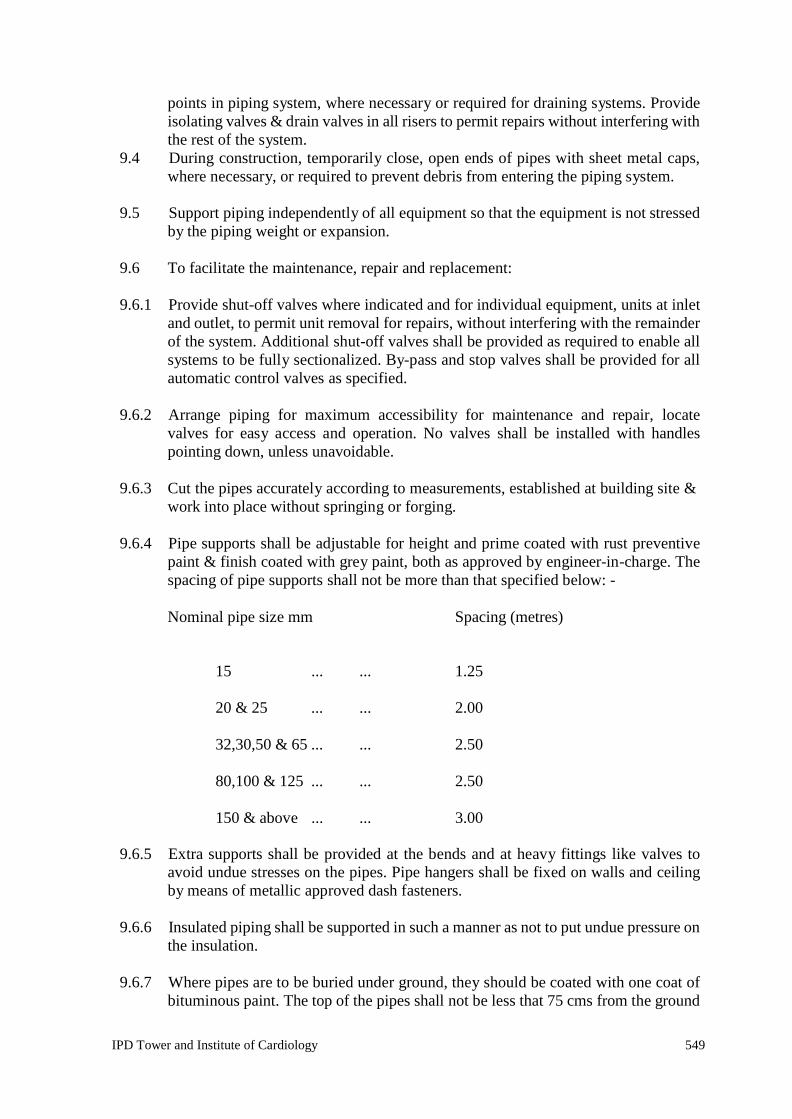
IPD Tower and Institute of Cardiology 549
points in piping system, where necessary or required for draining systems. Provide isolating valves & drain valves in all risers to permit repairs without interfering with the rest of the system.
9.4 During construction, temporarily close, open ends of pipes with sheet metal caps, where necessary, or required to prevent debris from entering the piping system.
9.5 Support piping independently of all equipment so that the equipment is not stressed
by the piping weight or expansion. 9.6 To facilitate the maintenance, repair and replacement:
9.6.1 Provide shut-off valves where indicated and for individual equipment, units at inlet
and outlet, to permit unit removal for repairs, without interfering with the remainder of the system. Additional shut-off valves shall be provided as required to enable all systems to be fully sectionalized. By-pass and stop valves shall be provided for all automatic control valves as specified.
9.6.2 Arrange piping for maximum accessibility for maintenance and repair, locate
valves for easy access and operation. No valves shall be installed with handles pointing down, unless unavoidable.
9.6.3 Cut the pipes accurately according to measurements, established at building site &
work into place without springing or forging. 9.6.4 Pipe supports shall be adjustable for height and prime coated with rust preventive
paint & finish coated with grey paint, both as approved by engineer-in-charge. The spacing of pipe supports shall not be more than that specified below: -
Nominal pipe size mm Spacing (metres)
15 ... ... 1.25
20 & 25 ...
...
2.00
32,30,50 & 65 ...
...
2.50
80,100 & 125 ...
...
2.50
150 & above ...
...
3.00
9.6.5 Extra supports shall be provided at the bends and at heavy fittings like valves to avoid undue stresses on the pipes. Pipe hangers shall be fixed on walls and ceiling by means of metallic approved dash fasteners.
9.6.6 Insulated piping shall be supported in such a manner as not to put undue pressure on
the insulation. 9.6.7 Where pipes are to be buried under ground, they should be coated with one coat of
bituminous paint. The top of the pipes shall not be less that 75 cms from the ground

IPD Tower and Institute of Cardiology 550
level. Where this is not practical permission of engineer-in-charge shall be obtained for burying the pipes at lesser depth. The pipes shall be surrounded on all sides by sand cushions of not less than 15 cms. After the pipes have been laid and top sand cushions provided, the trench shall be refilled with the excavated soil, excess soil shall be removed from the site of work by the contractor.
9.6.8 The following supporting arrangements for two piping shall be provided as below.
Sr. No.
Nominal pipe Size (mm)
MS rod for ceiling support (mm)
Floor Support (mm)
Base Support
1
Upto 65 mm
10 mm
80 mm MS pipe 40x40x5 thick angle
2
80 mm to 125 mm
10 mm
80 mm MS pipe 50x50x5 thick angle
3
150 mm to 250 mm
12 mm or 50x50x6 thick angle
80 mm MS pipe
75x75x5 thick angle or 80x40 channel
4
300 mm to 350 mm 16 mm or 80x40 channel
80 mm MS pipe 100x50 channel
5
400 mm to 500 mm 16 mm or 100x50 channel
100 mm MS pipe 70x40 channel (box) []
6
600 mm to 700 mm 20 mm or 100x50 channel
100 mm MS pipe
ISMC 200
Wherever more than two pipes shall be hanged, the spacing of supports shall be taken as for minimum dia pipe. and piping support arrangement shall be got approved with submitting of shop drawing.
10. Hangers & Supports:
10.1 Hangers and supports shall be provided and installed for all piping and tubing
wherever indicated, required or otherwise specified. Wherever necessary, additional hangers and supports shall be provided to prevent vibration or excessive deflection of piping and tubing.
10.2 All hangers and supports shall be made of steel or other durable and
non-combustible materials, galvanized or plated. Wood wire or perforated strap iron shall not be used as permanent hangers or supports.
10.3 Hangers shall be supported from structural steel, concrete inserts & pipe racks, as
specifically approved. 10.4 No hangers shall be secured to underside of light weight roof decking and light
weight floor glass. 10.5 Mechanical equipment shall be suspended midway between steel joists and panel
points. 10.6 Drilling or punching of holes in steel joist members will not be permitted.

IPD Tower and Institute of Cardiology 551
11. Sleeves: 11.1 Where pipes pass through floors, walls, etc provide galvanized steel pipe sleeves 50
mm larger than outside diameter of pipe. Where pipes are insulated, sleeves shall be large enough to ample clearance for insulation.
11.2 Where pipes pass through outside walls or foundations, the space between pipe and
sleeve shall be caulked with lead wool and oakum. 11.3 The centre of pipes shall be in the centre of sleeves, and sleeves shall be flush with
the finished surface. 12. Expansion or Contraction:
12.1 The contractor shall provide for expansion and contraction of all piping installed by
the use of swing connections and expansion loops. 13. Arrangement and Alignment of Piping:
13.1 All piping shall be arranged and aligned in accordance with the drawings as
specified. Where special conditions are encountered in the field, the arrangement and alignment of piping shall be as directed by the engineer-in-charge.
13.2 The piping shall be installed in a uniform manner, parallel to or perpendicular to
walls or ceilings, and all changes in directions shall be made with fittings. The horizontal piping shall be run at right angles and shall not run diagonally across rooms or other piping. Wherever possible all piping shall be arranged to provide maximum head room.
13.3 All piping shall be installed as directly as possible between connecting points in so far as the work of other trades permits. Where interference occurs with another trade whose work is more difficult to route this contractor shall reroute his pipes as required to avoid interference, at the discretion of the engineer-in-charge.
13.4 All piping shall be carefully installed to provide for proper alignment, slope and
expansion. 13.5 The stresses in pipe lines shall be guided and pipes shall be supported in such a
manner that pipe lines shall not creep, sag or buckle. 13.6 Anchors and supports shall be provided wherever necessary to prevent any
misalignment of piping. 13.7 Small tubing gauges, controls or other equipment installed on any apparatus, shall
not be coiled nor excessive in length, but shall be installed neatly, carefully bent at all changes in direction, secured in place and properly fastened to equipment at intervals to prevent sagging.
13.8 The piping shall be grouped wherever practical and shall be installed uniformly in
straight parallel lines in either vertical or horizontal positions.

IPD Tower and Institute of Cardiology 552
14. Testing: 14.1 In general, tests shall be applied to piping before connection of equipment and
appliances. In no case shall the piping, equipment or appliances be subjected to pressures exceeding their test ratings.
14.2 The tests shall be completed and approved before any insulation is applied. Testing
of segments of pipe work will be permitted, provided all open ends are first closed, by blank-offs or flanges.
14.3 After tests have been completed the system shall be drained and flushed 3 to 4 times
and cleaned of all dust and foreign matter. All strainers, valves and fittings shall be cleaned of all dirt, fillings and debris.
14.4 All piping shall be tested to hydraulic test pressure of at least one and half times the
maximum operating pressure but not less than 10 kg/sq.cm for a period of not less than 12 hours. All leaks and defects in the joints revealed during the testing shall be rectified to the satisfaction of the engineer-in-charge, without any extra cost.
14.5 All the piping systems shall be tested in the presence of the engineer-in-charge or
their authorised representative. Advance notice of test dates shall be given and all equipments, labour, materials required for inspection, and repairs during the test shall be provided by the contractor. A test shall be repeated till the entire systems are found to be satisfactory to the above authority. The tests shall be carried out for a part of work if required by engineer-in-charge in order to avoid hinderance in the work of the insulation contractor.
14.6 All steam and condensate pipes shall be tested and proven tight under hydrostatic
pressure of 20 kg/sq.cm, unless otherwise stated, for a minimum period of 4 hours without drop in pressure.
14.7 Miscellaneous piping, tests with air at 10.5 kg/sq.cm for a minimum of 24 hours without drop in pressure.
14.8 The contractor shall make sure that proper noiseless circulation is achieved through
all piping systems. If due to poor bond, proper circulation is not achieved, the contractor shall bear all expenses for carrying out the rectification work including finishing of floors, walls and ceiling damaged in the process of rectifications.
14.9 The contractor shall provide all labours and materials to make provision for
removing water and throwing it at the proper place, during the testing or/and after the testing to avoid damages to employer or other contractors ' properties. Any damages caused by the contractor to the employer or other contractors’ properties, shall be borne by the contractor.
15.0 Copper Piping:
15.1 Heavy gauge soft copper tubing, type m shall be used to make connections to
equipment, wherever required or specified by engineer-in-charge.

IPD Tower and Institute of Cardiology 553
15.2 Flare fittings e.g. flare nuts, tees, elbows, reducers etc. shall all be of brass. 16. Refrigerant Piping:
16.1 The refrigerant circuit piping shall be heavy class m.s the fittings shall be heavy
class. The pipes and fittings shall be connected by means of welded joints. The connections to gauges, controls etc. shall be with soft copper tubing and flare fittings.
16.2 The refrigerant valves, required in the circuit shall be as follows.
Valve Size Valve Material Type of Connections
16.2.1 upto 12 mm brass/packless type flare fittings
16.2.2 16mm & above brass/steel packed type brazed/welded
note :- all valves shall be tested against leaks upto 20 kg/sq.cm.
16.3 The strainers for the refrigerant liquid line shall be `y' type with gun metal body and bronze filter screen of fine mesh. The filter screen shall be easily removable type without dismantling the strainer from the circuit.
16.4 The moisture indicator in the liquid line shall have leak proof glass on opposite
sides to permit easy inspection of the liquid refrigerant. 17. Drain Piping:
17.1 The drain piping shall be medium class galvanised steel as per is 1239/1979.
17.2 The fittings shall be of `R' brand or equal forged with screwed connections.
17.3 The gate valves (included in piping) shall be of gun metal as described earlier. 17.4 Pipe crosses shall be provided at bends, to permit easy cleaning of drain line.
17.5 The drain line shall be provided upto the nearest drain trap and pitched towards the
trap. 17.6 Drain lines shall be provided at all the lowest points in the system, as well as at
equipments, where leakage of water is likely to occur, or to remove condensate and water from pump glands.
18. Painting:
18.1 All pipes supports, hangers, etc., shall be given two coats of red oxide primer.
18.2 All pipes, which are not to be insulated, shall then be given one coat of finish paint,
of a type and colour, as approved by the engineer-in-charge.

IPD Tower and Institute of Cardiology 554
INSULATION 1. General:
The insulation of water piping, air handling units, ducting, chillers etc., shall be carried out as per specifications given below:
2. Materials:
The materials to be used for insulation shall be as follows, unless some other material is specifically mentioned elsewhere.
2.1 Pipe Insulation:
2.1.1 The insulation for chilled water and drain piping, chillers, pump etc. shall be
carried out from `TF' quality expanded polystyrene having a `K' value as per Latest relevant standards/codes published by B.I.S(formerly I.S.I) 2017.
2.2 Other Insulation
2.2.1 The material for acoustic treatment of ducts, rooms, roofs etc. shall be resin bonded
fibre glass, as described earlier, conforming to i.s. 8183 of 1976. The density of fibre glass shall be 32-48 kg/cub.m and the material shall be in the form of slabs of uniform density. The `K' value at 10oc. shall not be less than 0.028 kcal/mhr/oc. Facing shall be provided with 0.5 mm perforated aluminium sheet held with G.I. nuts bolts or nailed to the batten work as required.
2.2.2 The materials for duct insulation (Option A) shall be fire retardant, self
extinguishing aluminium foil faced closed cell crossed linked polyethylene. Material shall be class1 as per BS 476 part 7 The density of insulation shall not be less than 32 kg./cub m. And material shall be in the form of blankets/rolls of uniform thickness. The ‘K’ value at 10 C shall not exceed 0.032 W/m K. It shall be factory faced with aluminium foil on one side reinforced and fused to the insulation material (µ ≥ 10000, water vapour diffusion resistance).
2.2.3 The material for duct insulation (Option B) shall be aluminium foil faced closed cell
elastomeric nitrile rubber. The thermal conductivity shall not exceed 0.038 W/m k at an average temperature of 30 deg C. The density of nitrile rubber shall be 40-60 Kg/m3.The insulation material shall be fire rated for class ‘O’as per BS 476 part 6 for fire propagation test and class ‘1’ as per BS 476 part 7 for surface spread of flame test. Water vapour permeability shall not be less than .024 per m inch (µ ≥ 10000, water vapour diffusion resistance).
Thickness of insulation shall be as specified for the individual applications. Each lot of insulation material delivered at site shall be accompanied with manufacturer test certificate for thermal conductivity value and density.
3. Cold Equipment Insulation:
3.1 The complete shell of the chiller (factory insulated) as well as its two heads, the

IPD Tower and Institute of Cardiology 555
chilled water pumps, and AHUs shall all be insulated. 3.2 The insulation shall be `TF' quality expanded polystyrene for chilled water pipes
(thickness as per ECBC to achieve R values). 3.3 All insulation except chiller heads shall be covered with glass cloth and fire
retardant epoxy coating with UV protection. 3.4 The insulation on the two end heads of the chiller shall be covered with 0.80 mm g.i.
casing to permit easy removal. 4. Chilled Water Piping/Drain Piping:
4.1 For EPS (TF quality)
4.1.1 The chilled water and drain pipes shall be insulated with `TF' quality expanded
polystyrene. Thickness of the insulation shall be as specified for the individual application as per ECBC 2007 requirement. Samples of insulation material shall be approved, and test certificates for the same shall be submitted for approval before application. Adhesives used if any shall be suitable for both and cold application for the temperature range mentioned above or as per the manufacturer’s
recommendations. 4.1.2 Preformed pipe sections shall be used for pipes upto and including 350 mm dia.
4.1.3 Pipes above 350 mm dia.shall be insulated with insulation slabs cut in mitred
sections. 4.1.4 Installation
Chilled Water and Drain Piping
The pipe shall be thoroughly cleaned with a wire brush and rendered free from all rust and grease.
The pipes shall be treated with a coat of cold setting compound.
The insulation preformed section shall be fixed tightly to the surface taking care to seal all joints.
All joints along the circumference of the pipe sections shall be sealed with adhesive.
The insulation than shall be covered with glass cloth and fire retardant epoxy coating and UV protection for exposed areas.
Insulation on pipes in areas exposed to weather or underground shall additionally be covered with tar-felt sheets and fixed with G.I. wires of 1.0 mm. The tar felt sheet shall be stuck with bitumen r 85/25.

IPD Tower and Institute of Cardiology 556
5. Refrigerant Piping: 5.1 The suction line of refrigerant piping shall be insulated with class O elastomeric
insulation. 6. Ducting:
6.1 The air handling ducts shall be insulated with nitrile rubber class ‘O’ as per BOQ.
6.2 Duct insulation thickness shall be as follows:
Duct in conditioned space - 19 mm thick
Duct in unconditioned space - 25 mm thick
Duct with treated fresh air - 25 mm thick
6.3 Installation 6.3.1 Clean the surface with a wire brush and make it free from rust and oil.
6.3.2 Apply two coats of cold setting adhesive (CPRX compound).
6.3.3 Wrap the duct with insulation blankets of the thickness mentioned elsewhere.
6.3.4 The joints shall be sealed with 50 mm wide and 3 mm thick self adhesive nitrile
rubber tape insulation complete and as required 7. Walls and Ceiling Acoustic Treatments of Plant Rooms and A.H.U. Room
7.1 Material
Resin bonded glass wool of density 32 kg/cub m of 50mm thickness.
8. Installation:
8.1 Fix 40 mm x 50 mm g.i. sheet channel at 0.5 mtr interval longitudinally then fix
cross battens at1.0 mtr centre using suitable gutties, and brass screws. The battens & gutties shall be treated with fire retardant chemical before fixing.
8.2 Fill each rectangle with 50 mm glass wool wrapped in glass cloth.
8.3 Tie with 24 gauge G.I. wires at 300 mm intervals.
8.4 Then cover with 26 gauge (0.50 mm) perforated g.i.sheet having 3mm perforations
at 6 mm centres. Overlap all joints and provide beading of 25 mm by 2 mm flats.

IPD Tower and Institute of Cardiology 557
ELECTRICAL WIRING
AS PER LATEST A SPECIFICATIONS 2017 for AC Works.

IPD Tower and Institute of Cardiology 558
TESTS AT SITE 1. General:
The contractor must perform all inspection and tests of the system as a whole and of components individually as required, under the supervision of the architect, in accordance with the provisions of the applicable ASHRAE standards or approved equal and furnish necessary test certificates from manufacturers.
2. Compressors/Condensers/Chillers/Evaporators/Pumps etc.
2.1 Identification of materials in accordance with test certificates.
2.2 Inspection of various laboratory test certificates for physical properties and
technical composition conducted on test samples of materials to be used for fabrication, forgings etc. for all important components of various equipment.
2.3 Hydraulic test for various components and assembled equipments at 1.5 times
design pressure or double the operating pressure whichever is higher. 2.4 Pneumatic leak test after assemblies at design pressure
2.5 Static and dynamic balancing on electronic precision machine for rotating parts,
links, impellor/crank shaft assemblies etc. 2.6 Inspection of assemblies and dis-assemblies of various parts of equipments and
complete equipments themselves as desired by inspection engineer. 2.7 Noise level test for various rotating/reciprocating equipments.
2.8 Pressure drop test for condenser, chiller and evaporator.
2.9 Inspection of manufacturer's test certificates shall be supplied for all electrical
motors. 2.10 Inspection of welding including welders qualifications as desired by inspection
engineers. 2.11 For compressor assembly, electronic leak, air running test, pneumatic test with dry
nitrogen and leak test in water. 3. Air Handling Units :
3.1 Blowers
3.1.1 Identification of material in accordance with test certificates.
3.1.2 Dynamic/static balancing of impeller.

IPD Tower and Institute of Cardiology 559
3.1.3 Performance test as per applicable codes. 3.2 Coils
3.2.1 Identification of material in accordance with test certificates.
3.2.2 Pneumatic test.
3.3 Filters
3.3.1 Manufacturer's test certificates also to be produced for the assembled A.H.U. final
dimensional check will be done. Inspection will be done during assembly of components for quality of workmanship, painting etc.
Piping : materials check for specifications and size.
3.4 Valves
Hyd./Pneumatic test certificates.
3.5 Motors
Manufacturer's test certificate as per motor data sheet.
3.6 Instruments and Controls
Visual examination.
4. For Associates Works at Site:
4.1 All electrical items will be subjected to inspection at any stage during
manufacturing activity. Routine electrical test as per relevant codes. Inspection of manufacturer's test certificates.
4.2 Inspection of raw materials to be used for fabrication and assembly and inspection
of manufacturer's certificates. 4.3 Inspection of welding including welders qualification as desired by inspection
engineers. Inspection of fabricated items. 4.4 Pressure testing of pipe fit used for the refrigerant and water services.
4.5 Pressure testing,leak testing of complete piping network for chilled water.
Condenser water and refrigerant/services. 4.6 Vacummissing and gas/oil charging for refrigeration system.
4.7 Checking of electrical circuits (power & controls) and checking functioning of
controls of refrigerant systems and other circuits of air conditioning plant.

IPD Tower and Institute of Cardiology 560
4.8 Checking of calibration of controls and instrumentation 4.9 Checking of assemblies for electrical control panel, instruments panels, local
panels (dimensional and functional) annunciator panels etc. 4.10 Inspection of complete electrical installation at site.
4.11 Installation of main equipments like compressor, condenser, chiller, evaporator.
4.12 Performance testing of complete A/C plant as per specifications.
5. The above inspection procedure is given for general guidance and information of
vendors and inspection of purchaser/consultant is strictly not limited to these and inspection engineer of purchaser/consultant will have full right to have detailed inspection at any stage right from placement of order to completion of project as desired by inspection engineer, co-ordination of inspection agency of purchaser/consultant with his factory/sub-vendor's factory/erection site will be the sole responsibility of successful vendor after placement of order for complete air conditioning plant covered under these technical specifications.
6. Piping System:
6.1 In general pressure tests shall be applied to piping only before connection of
equipment and appliances. In no case shall piping, equipment or appliances be subjected to pressure exceeding their test ratings.
6.2 Tests shall be completed and approved before any insulation is applied.
6.3 After tests have been completed, the system shall be drained and cleaned of all dust
and foreign matter. All strainers, valves and fittings shall be cleaned of all dirt, fittings, and debris.
6.4 Water Piping
All water piping shall be tested and proven tight under hydrostatic pressure of 1 1/2 times the design pressure unless stated otherwise in the specifications. Prescribed pressure shall be maintained for four hours.
7. Duct Work:
7.1 All branches and outlets shall be tested for air quantity, and the total of the air
quantities shall be within plus five percent (5%) of fan capacity. 7.2 Fire dampers, volume dampers and splitter dampers shall be tested for proper
operation. 8. Balancing and Adjustment:
All air handling ventilation equipment, duct work and outlets shall be adjusted and

IPD Tower and Institute of Cardiology 561
balanced to deliver the specified air quantities indicated, at each inlet and outlet, on the drawings. If these air quantities cannot be delivered without exceeding the speed range of the sheaves or the available horse power, the architect shall be notified before proceeding with the balancing of air distribution system.
9. Electrical Equipment:
9.1 All electrical equipment shall be cleaned and adjusted on site before application of
power. 9.2 The following tests shall be carried out:
9.2.1 Wire and cable continuity tests.
9.3 Insulation resistance tests, phase to phase and phase to earth, on all circuits and
equipment, using a 500 volt meggar. The meggar reading shall be not less than one mega ohm.
9.4 Earth resistance between conduit system and earth must not exceed half (1/2) chm.
9.5 Phasing out and phase rotation tests.
9.6 Operating tests on all protective relays to prove their correct operation before
energising the main equipment. 9.7 Operating tests on all starters, circuit breakers, etc.
10. Performance Tests :
10.1 The installation as a whole shall be balanced and tested upon completion, and all
relevant information, including the following shall be submitted to the architects. 10.1.1 Air volume passing through each unit, duct, grilles, apertures.
10.1.2 Differential pressure readings across each filter, fan and coil, and through each
pump. 10.1.3 Static pressure in each air duct.
10.1.4 Electrical current readings, in amperes of full and average load running, and starting,
together with name plate current of each electrical motor. 10.1.5 Continuous recording over a specified period, of ambient wet and dry bulb
temperatures under varying degrees of internal heat loads and use and occupation, in each zone of each part of the building.
10.2 Daily records should be maintained of hourly readings, taken under varying
degrees of internal heat load and use and occupation, of wet and dry bulb temperatures, upstream "on-coil" of each cooling coil. Also suction temperatures and pressures for each refrigerating unit. The current and voltage drawn by each machine.

IPD Tower and Institute of Cardiology 562
10.3 Any other readings shall be taken which may subsequently be specified by the architect.
11. Miscellaneous:
11.1 The above tests are mentioned herein for general guidance and information only but
not by way of limitation to the provisions of conditions of contract and specification.
11.2 The date of commencement of all tests listed above shall be subject to the approval
of the architect, and in accordance with the requirements of this specification. 11.3 The contractor shall supply the skilled staff and all necessary instruments and carry
out any test of any kind on a piece of equipment, apparatus, part of system or on a complete system if the architect requests such a test for determining specified or guaranteed data as given in the specification or on the drawings.
11.4 Any damage resulting from the tests shall be repaired and/or damaged material
replaced, all the the satisfaction of the Engineer. 11.5 In the event of any repair or any adjustment having to be made, other than normal
running adjustment, the tests shall be void and shall be recommended after the adjustment or repairs have been completed.
11.6 The contractor must inform the architect when such tests are to be made, giving
sufficient notice, in order that the architect or his nominated representative may be present.
11.7 Complete records of all tests must be kept and 3 copies of these and location
drawings must be furnished to the architect. 11.8 The contractor may be required to repeat the test as required, should the ambient
conditions at the time not given, in the opinion of the architect, sufficient and suitable indication of the effect and performance of the installation as a whole or of any part, as required.

IPD Tower and Institute of Cardiology 563
MODE OF MEASUREMENTS 1. Unit Prices in the Schedule of Quantities:
1.1 The item description in the schedule of quantities is in the form of a condensed
resume. The unit price shall be held to include every thing necessary to complete the work covered by this item in accordance with the specifications and drawings. The sum total of all the individual item prices shall represent the total price of the installation ready to be handed over.
1.2 The unit price of the various items shall include the following:
1.2.1 All equipment, machinery, apparatus and materials required as well as the cost of
any tests which the consultant may request in addition to the tests generally required to prove quality and performance of equipment.
1.2.2 All the labour required to supply and install the complete installation in accordance
with the specifications. 1.2.3 Use of any tools, equipment, machinery, lifting tackle, scaffolding, ladders etc.
Required by the contractor to carry out his work. 1.2.4 All the necessary measures to prevent the transmission of vibration.
1.2.5 The necessary material to isolate equipment foundations from the building structure,
wherever necessary. 1.2.6 Storage and insurance of all equipment apparatus and materials.
1.3 The contractor's unit price shall include all equipment, apparatus, material and
labour indicated in the drawings and/or specifications in conjunction with the item in question, as well as all additional equipment, apparatus, material and labour usual and necessary to make in question on its own (and within the system as a whole) complete even though not specifically shown, described or otherwise referred to.
2. Measurements of Sheet Metal Ducts, Grilles/Diffusers etc.
2.1 Sheet Metal Ducts
2.1.1 All duct measurements shall be taken as per actual outer duct surface area including
bends, tees, reducers, collars, vanes & other fittings. Gaskets, nuts, bolts, vibration rotation pads are included in the basic duct items of the boq.
2.1.2 The unit of measurements shall be the finished sheet metal surface area in metres
squares. No extra shall be allowed for lapse and wastages.

IPD Tower and Institute of Cardiology 564
2.1.3 All the guide vanes, deflectors in duct elbows, branches, grille collars quadrant dampers etc. shall be measured for actual sheet metal surface and paid for at the same rate as duct of same thickness.
2.1.4 The unit duct price shall include all the duct hangers and supports, exposing of concrete reinforcement for supports and making good of the same as well as any materials and labour required to complete the duct frame.
2.2 Grilles/Diffusers
All grilles/diffusers as per tender requirements shall be treated as a lump sum item. Where extra grilles diffusers are ordered upto award of work, they should be measured as follows:
2.2.1 All measurements of grilles/diffusers shall be the actual neck size excluding the
outer flanges. 2.2.2 The square or rectangular grilles/diffusers shall be measured in plain sq.m.
2.2.3 All round diffusers shall be measured by their diameters in cm.
2.2.4 All linear diffusers shall be measured as per actual length in metres.
3. Measurements of Piping, Fittings,Valves, Fabricated Items :
3.1 Pipe
Including water piping, steam piping and all other piping required to be executed at site for completion of the works.
3.1.1 All pipes shall be measured in linear metre (to the nearest cm) along the axis of the
pipes and rates shall be inclusive of all fittings e.g. tees, bends, reducers, elbows etc. deduction shall be made for valves in the line.
3.1.2 Exposing reinforcement in wall and ceiling and floors of posible and making good
the same or installing anchor fasteners and inclusive of all items as specified in specifications and schedule of quantities.
3.1.3 Rates quoted shall be inclusive of providing and fixing vibration pads and wooden
pieces, wherever specified or required by the project co-ordinator. 3.1.4 Flexible connections, wherever required or specified shall be measured as part of
straight length of same diameter, with no additional allowance being made for providing the same.
3.1.5 The length of the pipe for the purpose of payment will be taken through the
centreline of the pipe and all fittings (e.g. tees, bends, reducers, elbows, etc.) as through the fittings are also presumed to be pipe lengths. Nothing extra whatsoever will be paid for over and above for the fittings for valves and flanges, section 3.2 below applies.

IPD Tower and Institute of Cardiology 565
3.2 Valves and Flanges 3.2.1 All the extra ci & cm flanged valves shall be measured according to the nominal
size in mm and shall be measured by number. Such valves shall not be counted as part of pipe length hence deduction in pipe length will be made wherever valves occur.
3.2.2 All gun metal (gate & globe) valves shall include two Nos. of flanges and two
numbers 150 mm long ms nipples, with one side threaded matching one of the valves, and other welded to the M.S. slip-on-flange. Rate shall also include the necessary number of bolts, nuts and washers, 3 mm thick insertion gasket of required temp, grade and all items specified in the specifications.
3.2.3 The rates quoted shall be inclusive of making connections to the equipment, tanks,
pumps etc. and the connection made with an installed pipe line shall be included in the rates as per the BOQ.
3.3 Structural Supports
Structural supports including supports fabricated from pipe lengths for pipes shall be measured as part of pipe line and hence no separate payment will be made. Rates shall be inclusive of hoisting, cutting, jointing, welding, cutting of holes and chases in walls, slabs or floors, painting supports and other items as described in specifications, drawings and schedule of quantities or as required at site by project co-ordinator.
3.4 Copper Connections for Fan Coil Units
3.4.1 Copper connection assembly for making connections to the fan coil units shall be
measured, as part of the fan coil unit price and shall include brass flare nuts, brass straight connector, brass tees, brass reducting fittings, fixing of automatic 3 way valve, making connections and leak testing, complete assembly as per specifications and drawings. Nothing extra shall be payable on account of any variation in the length of copper pipe.
4. Insulation:
4.1 The measurement for vessels, piping, and ducts shall be made over the bare
uninsulated surface area of the metal. 4.2 Pipes, Ducts & Vessels
4.2.1 Pipes
The measurements for installation of piping shall be made in linear metres through all valves, flanges, and fittings. Pipes/bends shall be measured along the centreline radius between tangent points. If the outer radius is r1 and the inner radius is r2 the centre line radius shall be measured as (r1+r2)/2. Measurement of all valves, flanges and fittings shall be measured with the running metre of pipe line as if they

IPD Tower and Institute of Cardiology 566
are also pipe lengths. Nothing extra over the above shall be payable for insulation over valves, flanges and fittings in pipe line/routings. Fittings that connect two or more different sizes of pipe shall be measured.
4.2.2 Ducts
The measurements for insulation of ducts shall be made in actual square metres of bare uninsulated duct surface through all dampers, flanges and fittings. In case of bends the area shall be worked out by taking an average of inner and outer lengths of the bends. Measurements for the dampers, flanges, fittings shall be for the surface dimension for the connecting duct, nothing extra over the above shall be payable for insulation over dampers, flanges and fittings in duct routing.
4.2.3 Vessels
The area of standard dished and flat ends of vessels shall be the square of the diameter of the uninsulated body of the shell. Areas for other shapes shall be the actual calculated area. There shall be no deduction or additions for nozzles, handles ribs, dampers, expansion joints etc. All projections on vessels or tanks shall be measured separately as pipe/duct.
4.3 Accessories Insulation
4.3.1 The unit of measurement for accessories such as expansion tank, pumps, chiller
heads etc. shall be uninsulated are in square metres. 4.3.2 In case of curved or irregular surfaces, measurements shall be taken along the
curves. 4.3.3 The unit insulation price shall include all necessary adhesives, vapour proofing and
finishing materials as well as additional labour and material required for fixing the insulation.
4.4 Acoustic Duct Lining
4.4.1 In case of acoustic lining of air ducts, measurements of the bare inside duct surface
in square metres, shall be final for billing purposes. 4.4.2 The insulation/acoustic panels shall include cost of battens, supports, adhesives,
vapour proofing, finished tiles/boards/sheets as well as additional labour and materials required for completing the work.

IPD Tower and Institute of Cardiology 567
LIST OF APPROVED MAKES AND MANUFACTURERS
The makes/brands of equipment listed below are approved for installation.
For all items to be used in the work samples, catalogues and specifications are to be submitted by the contractor for approval of the Engineer In charge. Only approved makes shall be used in the works. Equivalent makes may be added with price adjustment with approval of Engineer In charge. The approved samples shall be kept in the custody of the Engineer for comparison.
AIR CONDITIONING List of Approved Makes
S. No. Item / Material Approved Makes High Side Equipment
1 Centrifugal / Screw / Scroll Chiller Carrier / Johnson / Daikin / Climaveneta / Danhum Bush
2 Cooling Towers Paharpur / Bell / Mihir / Flow Tech
3 Chilled / Condenser Water Pumps Xylem / Grundfos / Wilo / Armstrong
4 VFD for Pumps Xylem / Grundfos / Wilo / Armstrong / Danfoss / ABB / Fuji / Scneider / Siemens
5 Low Side Equipment
6
Air Handling Unit / Ceiling Suspended Unit / Fan Coil Unit Caryaire / Zeco / VTS / Edgetech / Waves
7 VFD for AHU / CSU / FCU ABB / Siemens / Schneider / Fuji / Danfoss
8 Ultraviolet Germicidal Irradiation Ruks / Trimed / Sterile Air
9 Air Washer Ambassador / Humidin / Roots / Ambiator / Tristar
10 Scrubber Wet Caryaire / Zeco / VTS / Edgetech / Waves / Tristar
11 Scrubber Dry Espair / Trion / Thermax / Rydair
12 Humidifier Rapid Cool / Emerald / Khokhar / Bry Air
13 Centrifugal / Axial Fan Kruger / Nicotra / Comferi / Flakt / Maico
14 Inline Fan Kruger / Nicotra / Comferi / Flakt / Ostberg
15 Propeller Fan GEC / Crompton / Khaitan / Marathon / Bajaj
16 Precision AC Emerson / Blue Box / Stulz / Hiross / Climaveneta
17 Window / Split / Cassette AC O-General / Daikin / Hitachi / LG / Voltas
18 VRF Mitsubishi / Hitachi / Toshiba / Daikin / Voltas
19 Heat Recovery Unit Flaktwoods / Novelaire / DRI / Greenheck / Bry Air
20 Heat Exchanger Alfa Lavel / Heat X / Mark
21 GI Sheet / Coil Tata / JSPL / Sail
22 Aluminium Sheet Balco / Nalco / Hindalco
23 Factory Fabricated Duct Rolastar / Metal Joint / Zeco / Ductofab / Technofab
24 Spiral Duct Atco / Seven Star / Metal Joint
25 Grill / Diffuser / VCD Caryaire / Mapro / Ruskin-Titus / Systemair / Metal Joint

IPD Tower and Institute of Cardiology 568
26 Fire Damper Caryaire / Ravistar / Ruskin-Titus / Systemair
27 Sound Attenuator Caryaire / Ravistar / Trox / Airflow
28 MS / GI Pipes Tata / JSPL / Sail / Surya
29 Ball Valve Zoloto / Sant / Sir / Falco / Leader
30 Butterfly Valve Audco / Advance / Honeywell / Sir / Falco
31 Motorised Butterfly Valve (actuator) Audco / Advance / Honeywell / Belimo / Siemens
32 Gate / Globe Valve Leader / Sant / Zoloto / Sir / Falco
33 PIC Valve Honeywell / Belimo / Siemens / Danfoss / Oventrop
34 Non Return Valve Audco / Advance / Honeywell / Sir / Falco
35 Balancing Valve Audco / Advance / Honeywell / Danfoss / Oventrop
36 Bellow Dunlop / Kanwal / Resistoflex
37 2/3-Way Motorised Valve JCI / Danfoss / Siemens / Honeywell / Belimo
38 Strainer Emerald / Sant / Rapid Cool / Falco
39 Pressure Gauge Fiebig / Emerald / H Guru
40 Thermometer Fiebig / Emerald / H Guru
41 Flow Switch Rapid Control / Emerald / Anergy / Danfoss / Honeywell
42 Automatic Air Vent Rapid Control / Anergy / Emerald
43 Suction Guide Rapid Control / Anergy / Emerald / Flowcon
44 Filters (pre / fine HEPA) Thermadyne / Spectrum / Dynafilter / AAF / Klenzoid
45 Expanded Polystyrene Beardsell / Lloyd / Styrene Packaging
46 Glass Wool FGP / UP Twiga / Kinmco / Aeroform
47 Polyeurethene Foam Mallanpur / Superurithane / Aeroform
48 XLPE Foam Trocellene / Superlon / Paramount / Aeroform
49 Nitrile Rubber K-Flex / Vidoflex / Armacell / Aeroflex / Aeroform
50 Closed Cell Elastomeric Insulation K-Flex / Vidoflex / Armacell / Aeroflex / Aeroform
51 Non Woven Fibre Material Mikron / Du Pont / Dow
52 Mineral Wool Rockwool / Lloyd / Aeroform
53 Aluminium Tape Johnson / Birla 3M / Metal Joint
54 Expansion Tank / Air Separator Anergy / Grundfoss / ITT
55 Thermostat Honeywell / Belimo / Siemens / Danfoss / JCI
56 Humidistat Honeywell / Belimo / Siemens / Danfoss / JCI
57 Electric Strip Heater Escorts / Daspass
58 Thermostat for Heater Honeywell / Belimo / Siemens / Danfoss / JCI
59 Cooling / Heating Mode Changer Honeywell / Belimo / Siemens / Danfoss / JCI
60 DDC Controller Honeywell / ABB / Siemens / Schneider / JCI
61 Sensor (Pressure / Temperature) Honeywell / ABB / Siemens / Schneider / JCI
62 VAV Trox / JCI / Caryaire / Belimo / Ruskin-Titus
63 Airflow Switch (air and water) Trox / JCI / Honeywell / Siemens
64 V Belt Dunlop / Fanner
65 Anchor Fastner Hilti / Fisher / Klimas
66 Welding Rod Advani / Esab / L&T
67 Electrical Equipment

IPD Tower and Institute of Cardiology 569
68 ACB / MCCB ABB / Siemens / Schneider / L&T
69 MCB ABB / Siemens / Schneider / L&T / Legrand
70 Distribution Boards / Panels Adlec / Risha / KEPL / CMKL / Tricolite
71 Electric Motors Siemens / Kirloskar / ABB / Crompton / Bharat Bijli
72 Push Button Station ABB / Siemens / Schneider / L&T / GE
73 Relays / Contactors ABB / Siemens / Schneider / L&T / GE
74 Fuse ABB / Siemens / Schneider / L&T / GE
75 Timer ABB / Siemens / Schneider / L&T / GE
76 Terminal Block Elmex / Wago
77 Voltmeter / Ammeter / Energy Meter / MFM ABB / Siemens / Schneider / L&T / GE
78 Indication Lamp ABB / Siemens / Schneider / L&T / GE
79 Change Over Switch ABB / Siemens / Schneider / L&T / GE
80 CT / PT ABB / Siemens / Schneider / L&T / Kappa
81 Selector Switch ABB / Siemens / Schneider / L&T / GE
82 Power Cables / Control Cables CCI / Finolex / Havells / Rallison / Gemscab
83 Cable Tray OBO / Legrand / Cooper / BEC / Rmcon
84 Cable Lugs HMI / Comet / Dowells / Jainson
85 Cable Glands HMI / Comet / Dowells / Jainson

IPD Tower and Institute of Cardiology 570
Certified)
20 Propeller Fans GEC (Alsthom)/ Crompton Greaves/ Khaitan/ Marathon
21 Precision AC units Emerson/ Blue box/ Stulz/ Hiross 22 Window/split AC Hitachi/ Daikin/ O-general 23 VRV/VRF Daikin/ Toshiba/Mitsubishi 24 Cassette Units-Chilled water
based Daikin/ETA/Midea
25 Inline Fans Flakt/Nicotra/Comefri/Kruger/SystemAir/Ostberg/Greenheck
26 Heat recovery unit complete with Heat recovery wheel
Flaktwoods/ Novelaire/ DRI/ Greenheck/ Bryair
27 Heat Exchanger Heat X/ Mark/ Alfa lavel 28 Thermal storage tank Crystopia/ Dunhambush/ Calmac
Electrical Equipment
29 Main AC Panel L&T/ Siemens / ABB/ Schneider/Legrand 30 AHU/ventilation electrical
panels Tricolite/ Adlec/ Sterling & Wilson/ C&S/ Jackson Engineers/ Milestone/ SPC/ Risha/ KEPL
31 Electric Motors Siemens/ Kirloskar/ ABB/ Crompton Greaves.
32 ACB L&T-U power(Omega)/ GE-Entelliguard/ Siemens-3WL/ ABB/ Legrand-DMS/ Schneider-NW master pact
33 MCCB L&T-(D shine/DL) / GE-Record Plus / Siemens-VA/ ABB-TMA/ Schneider- compact NSX/NS/ Legrand-DPX
34 MCB L&T/ Legrand-DX3/ Hager / Seimens-VA/ ABB/ MDS Lexic
35 PVC Tape Steelgrip or equivalent as approved by engineer in-charge. 36 Push button starter L&T/ GE / Siemens/ ABB/ Schneider 37 Auxiliary Relays/Contactors L&T/GE/ Siemens/ ABB/ Schneider
38 Line Type Fuse L&T/GE/ Siemens/ ABB/ Schneider 39 Timer L&T/GE/ Siemens/ ABB/ Schneider/ Legrand 40 Terminal Block Elmex or equivalent as approved by engineer in-charge. 41 Voltmeter/Ammeter L&T/GE/ Siemens/ ABB/ Schneider 42 Indicating lamps L&T/GE/ Siemens/ ABB/ Schneider 43 Selector Switches L&T/GE/ Siemens/ ABB/ Schneider 44 Change Over Switch L&T/GE/ Siemens/ ABB/ Schneider 45 CT/PT L&T/GE/ Siemens/ ABB/ Schneider
Cables
46 Power Cables / Control Cables CCI/ Universal/ Finolex / Rallison/Havells

IPD Tower and Institute of Cardiology 571
47 Cable tray OBO/ Legrand/ Cooper/ BEC
48 Cable lugs Dowells/ Comet/HAX/Jainson Dcting
49 Factory fabricated duct Ductofab/ Rolastar/ Technofab/Zeco/Ecoduct 50 G.I. Sheet TATA/ SAIL/ JSPL 51 Spiral duct Atco/ Seven Star 52 Grilles/Diffusers/Volume
Control damper Systemair/ Caryaire/ Mapro/Ruskin-titus
53 Fire Dampers UL listed Caryaire/ Ravistar/ Ruskin-titus 54 Sound Attenuator Caryaire/ Ravistar/Trox/Airflow 55 Aluminium Sheets Balco/ Nalco/ Hindalco
Pipes
56 G.I. JSPL Hissar/ Tata/ SAIL
57 M.S. upto 150 mm JSPL Hissar/ Tata/ SAIL
58 M.S. 200 mm and above dia factory rolled
JSPL Hissar/ Tata/ SAIL
Valves
59 Butterfly Valves Audco/ Advance/ Honeywell 60 Motorised butterfly
valve(actuator) Belimo/ Honeywell/ Siemens
61 Non Return Valve Advance/ Kirloskar/ Audco 62 Balancing Valves Advance/ Audco/ Danfoss/ Honeywell 63 Gate/Globe Valves Leader/ Sant/ Bankim Sarkar / Zoloto 64 GM valve upto 40mm Leader/ Sant/ Bankim Sarkar /Zoloto 65 Ball Valve with Y strainer Rapid Control/ Sant/ Leader/ Zoloto 66 Pressure independent
Balancing valve Danfoss/ Flowcon/ TA /Oventrop
Accessories
67 Pot & Y-strainer Emerald/ Sant/ Rapid cool 68 Pressure Gauge Fiebig/ Emerald/ H Guru 69 Thermometer Fiebig/ Emerald/ H Guru 70 Flow Switch Rapid Control/ Anergy/ Danfoss/Emerald 71 Automatic Air Vent Rapid Control/ Anergy 72 Suction Guide Anergy/ Rapid Control/ Flowcon/Emerald 73 Filters (pre,fine Hepa) Thermadyne/ Spectrum/ Dynafilter /AAF/ klenzoid
Insulation
74 Expanded Polystyrene Beardsell Ltd./ Lloyd/ Styrene packaging

IPD Tower and Institute of Cardiology 572
75 Glass Wool FGP Ltd./UP Twiga/ Kimmco
76 Polyurethene Foam Malanpur /Superurethane 77 Crossed linked Polyethylene
Foam Trocellene / Superlon
78 Closed Cell Elastomeric Insulation
K-flex /Vidoflex/ Armacell/ Aeroflex
79 Non woven fibre material Mikron/ Du pont 80 Mineral wool Rockwool India Pvt Ltd/ Lloyd 81 Pre-moulded PUF section for
pipe & pipe supports Malanpur/ Lloyd
82 Fibreglass rigid Board/ Pipe section
FGP Ltd./ UP Twiga/ Kimmco /Owens Corning
83 Aluminium Tape Johnson/ Birla 3M/ Garware 84 Expansion tank(pressurized)
and Air Separator Anergy/ Grundfoss/ ITT
85 Bellows Dunlop/ Kanwal/ Resistoflex 86 2/3-Way motorized valve for
AHU/FCU Johnson control/ Danfoss/ Siemens/ Belimo/Honeywell
87 Thermostats Honeywell/ Johnson controls/ Belimo/ Danfoss/ Siemens
88 Humidistat Honeywell/ Johnson control/ Belimo/ Danfoss /Siemens 89 Electric Strip Heaters Escorts/ Daspass 90 Safety Thermostat for Heaters Honeywell/ Siemens/ Danfoss/ Belimo /Siemens 91 Cooling/heating Mode
Changer Honeywell/ Siemens/ Danfoss/ Belimo/ Siemens
Paints
92 Enamel ICI/ Asian/ Nerolac/ Berger 93 Bituminus Indian Oil / HP 94 Tarfelt ( for underground
chilled water pipe insulation) Indian Oil / HP
95 IBMS Approved vendor Siemens/ Honeywell/ Johnson controls/ ABB/Schneider
96 DDC Controllers Siemens/ Honeywell/ Johnson controls/ ABB/Schneider
97 Sensors(Pressure/Temperature) Siemens/ Honeywell/ Johnson controls/ ABB/Schneider
98 VAV Trane/ Trox/ Johnson Controls/ Caryaire/ Belimo 99 Airflow Switch (Air & water) Johnson control/ Honeywell/ Siemens
Miscellaneous
100 V Belt Dunlop/ Fenner 101 Anchor fastners Fischer/ Hilti 102 Dash fastner Fischer/ Hilti
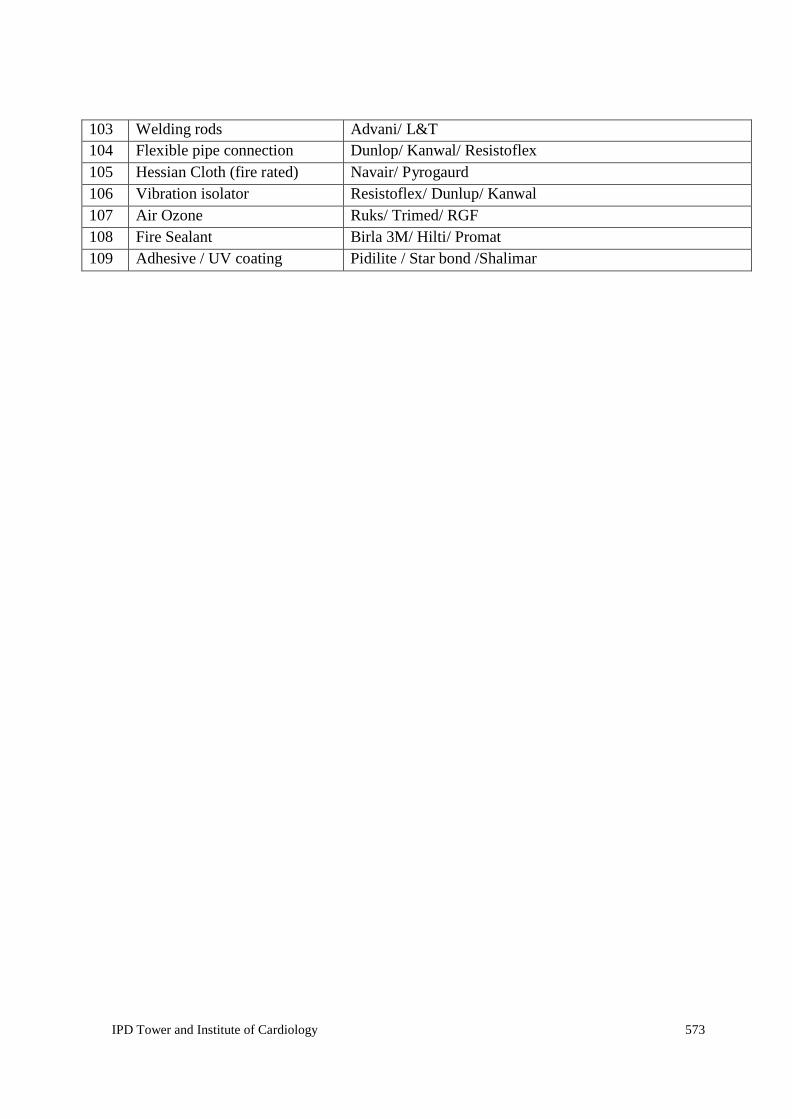
IPD Tower and Institute of Cardiology 573
103 Welding rods Advani/ L&T 104 Flexible pipe connection Dunlop/ Kanwal/ Resistoflex 105 Hessian Cloth (fire rated) Navair/ Pyrogaurd 106 Vibration isolator Resistoflex/ Dunlup/ Kanwal 107 Air Ozone Ruks/ Trimed/ RGF 108 Fire Sealant Birla 3M/ Hilti/ Promat 109 Adhesive / UV coating Pidilite / Star bond /Shalimar

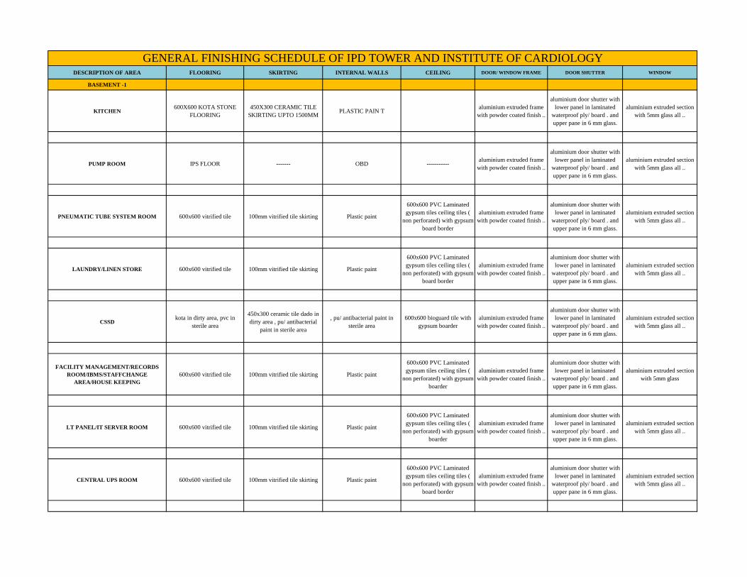
DESCRIPTION OF AREA FLOORING SKIRTING INTERNAL WALLS CEILING DOOR/ WINDOW FRAME DOOR SHUTTER WINDOW
BASEMENT -1
KITCHEN600X600 KOTA STONE
FLOORING450X300 CERAMIC TILE
SKIRTING UPTO 1500MMPLASTIC PAIN T
aluminium extruded frame with powder coated finish ..
aluminium door shutter with lower panel in laminated
waterproof ply/ board . and upper pane in 6 mm glass.
aluminium extruded section with 5mm glass all ..
PUMP ROOM IPS FLOOR ------- OBD -----------aluminium extruded frame
with powder coated finish ..
aluminium door shutter with lower panel in laminated
waterproof ply/ board . and upper pane in 6 mm glass.
aluminium extruded section with 5mm glass all ..
PNEUMATIC TUBE SYSTEM ROOM 600x600 vitrified tile 100mm vitrified tile skirting Plastic paint
600x600 PVC Laminated gypsum tiles ceiling tiles (
non perforated) with gypsum board border
aluminium extruded frame with powder coated finish ..
aluminium door shutter with lower panel in laminated
waterproof ply/ board . and upper pane in 6 mm glass.
aluminium extruded section with 5mm glass all ..
LAUNDRY/LINEN STORE 600x600 vitrified tile 100mm vitrified tile skirting Plastic paint
600x600 PVC Laminated gypsum tiles ceiling tiles (
non perforated) with gypsum board border
aluminium extruded frame with powder coated finish ..
aluminium door shutter with lower panel in laminated
waterproof ply/ board . and upper pane in 6 mm glass.
aluminium extruded section with 5mm glass all ..
CSSDkota in dirty area, pvc in
sterile area
450x300 ceramic tile dado in dirty area , pu/ antibacterial
paint in sterile area
, pu/ antibacterial paint in sterile area
600x600 bioguard tile with gypsum boarder
aluminium extruded frame with powder coated finish ..
aluminium door shutter with lower panel in laminated
waterproof ply/ board . and upper pane in 6 mm glass.
aluminium extruded section with 5mm glass all ..
FACILITY MANAGEMENT/RECORDS ROOM/IBMS/STAFFCHANGE
AREA/HOUSE KEEPING600x600 vitrified tile 100mm vitrified tile skirting Plastic paint
600x600 PVC Laminated gypsum tiles ceiling tiles (
non perforated) with gypsum boarder
aluminium extruded frame with powder coated finish ..
aluminium door shutter with lower panel in laminated
waterproof ply/ board . and upper pane in 6 mm glass.
aluminium extruded section with 5mm glass
LT PANEL/IT SERVER ROOM 600x600 vitrified tile 100mm vitrified tile skirting Plastic paint
600x600 PVC Laminated gypsum tiles ceiling tiles (
non perforated) with gypsum boarder
aluminium extruded frame with powder coated finish ..
aluminium door shutter with lower panel in laminated
waterproof ply/ board . and upper pane in 6 mm glass.
aluminium extruded section with 5mm glass all ..
CENTRAL UPS ROOM 600x600 vitrified tile 100mm vitrified tile skirting Plastic paint
600x600 PVC Laminated gypsum tiles ceiling tiles (
non perforated) with gypsum board border
aluminium extruded frame with powder coated finish ..
aluminium door shutter with lower panel in laminated
waterproof ply/ board . and upper pane in 6 mm glass.
aluminium extruded section with 5mm glass all ..
GENERAL FINISHING SCHEDULE OF IPD TOWER AND INSTITUTE OF CARDIOLOGY

PHARMACY/STORE 600x600 vitrified tile 100mm vitrified tile skirting Plastic paint
600x600 PVC Laminated gypsum tiles ceiling tiles (
non perforated) with gypsum board border
aluminium extruded frame with powder coated finish ..
aluminium door shutter with lower panel in laminated
waterproof ply/ board . and upper pane in 6 mm glass.
aluminium extruded section with 5mm glass all ..
COLD STORAGE 600x600 vitrified tile 100mm vitrified tile skirting Plastic paint
600x600 PVC Laminated gypsum tiles ceiling tiles (
non perforated) with gypsum board border
aluminium extruded frame with powder coated finish ..
aluminium door shutter with lower panel in laminated
waterproof ply/ board . and upper pane in 6 mm glass.
aluminium extruded section with 5mm glass all ..
DRIVEWAY TRIMIX FLOOR PLASTER OBD
LIFT LOBBYGranite marble with dark
Granite inserts
lift facade in Granite marble , s.s. strips , s.s. sheret in jamb and lintel, + laquered glass
above 1200mm
Plastic paint600x600 GI metallic ceiling
in center with border of gypsum board around
LIFT FACADE
lift facade in Granite marble , s.s. strips , s.s. sheret in jamb and lintel, + laquered glass
above 1200mm
fire rated door frame .
ALL STAIRCASES granite150mm granite skirting , 1000mm high s.s. railing
OBD plaster fire rated door frame . fire door .
SERVER ROOM 600x600 vitrified tile 100mm vitrified tile skirting Plastic paint
600x600 PVC Laminated gypsum tiles ceiling tiles (
non perforated) with gypsum board border
aluminium extruded frame with powder coated finish ..
aluminium door shutter with lower panel in laminated
waterproof ply/ board . and upper pane in 6 mm glass.
aluminium extruded section with 5mm glass all ..
BASEMETN 2 ,3
DRIVEWAY TRIMIX FLOOR PLASTER OBD
STORES 600x600 vitrified tile 100mm vitrified tile skirting OBD
600x600 PVC Laminated gypsum tiles ceiling tiles (
non perforated) with gypsum board border
aluminium extruded frame with powder coated finish ..
aluminium door shutter with lower panel in laminated
waterproof ply/ board . and upper pane in 6 mm glass.
aluminium extruded section with 5mm glass all ..
BLOWER ROOMS IPS FLOOR -------- OBD FIRE DOOR FIRE DOOR
VEHICULAR RAMPCEMENT CHEQUERED
TILE FLOOR150MM GRANITE
SKIRTINGOBD

PEDESTRAIN RAMP300X300 CEMENT CHEQUERED TILE
150MM GRANITE SKIRTING
OBDaluminium extruded frame
with powder coated finish ..
aluminium door shutter with lower panel in laminated
waterproof ply/ board . and upper pane in 6 mm glass.
aluminium extruded section with 5mm glass all ..
LIFT LOBBYGranite marble with dark
Granite inserts
lift facade in Granite marble , s.s. strips , s.s. sheret in jamb and lintel, + laquered glass
above 1200mm
Plastic paint600x600 GI metallic ceiling
in center with border of gypsum board around
LIFT FACADE
lift facade in Granite marble , s.s. strips , s.s. sheret in jamb and lintel, + laquered glass
above 1200mm
fire rated door frame .
ALL STAIRCASES granite150mm granite skirting , 1000mm high s.s. railing
OBD plaster fire rated door frame . fire door .
GROUND FLOOR
ALL WAITING AREAScombination of light granite
and dark granite inserts
wall dado upto 1300mm (1200 vitrified +100 granite top
border)Plastic paint
600x600 GI metallic ceiling in center with border of gypsum board around
aluminium extruded frame with powder coated finish ..
aluminium extruded section with 5mm glass all ..
COUNCELLING ROOM/BUSINESS CENTRE/MEETING/INSURANCE
600x600 vitrified tile
100mm vitrified tile skirting = 450x300mm ceramic tile dado
behind washbasin upto 1200mm
Plastic paint
600x600 PVC Laminated gypsum tiles ceiling tiles (
non perforated) with gypsum board border
aluminium extruded frame with powder coated finish ..
32mm Thick Flush Door
REGISTRATION COUNTER 600x600 vitrified tile 100mm vitrified tile skirting Plastic paint
600x600 PVC Laminated gypsum tiles ceiling tiles (
non perforated) with gypsum board border
aluminium extruded frame with powder coated finish ..
32mm Thick Flush Door
ALL DOCTORS CORRIDORScombination of light granite
and dark granite inserts
wall dado upto 1300mm (1200 vitrified +100 granite top
border)Plastic paint
600x600 GI metallic ceiling in center with border of gypsum board around
aluminium extruded frame with powder coated finish ..
32mm Thick Flush Door
ALL CORRIDORScombination of light granite
and dark granite inserts
wall dado upto 1300mm (1200 vitrified +100 granite top
border)Plastic paint
600x600 GI metallic ceiling in center with border of gypsum board around
aluminium extruded frame with powder coated finish ..
32mm Thick Flush Door

ADMIN/REGISTRATION/CLOAK ROOM 600x600 vitrified tile
100mm vitrified tile skirting = 450x300mm ceramic tile dado
behind washbasin upto 1200mm
Plastic paint
600x600 PVC Laminated gypsum tiles ceiling tiles (
non perforated) with gypsum board border
32mm Thick Flush Door
DOCTORS DINNING 600x600 vitrified tile 100mm vitrified tile skirting Plastic paint
600x600 PVC Laminated gypsum tiles ceiling tiles (
non perforated) with gypsum board border
aluminium extruded frame with powder coated finish ..
aluminium door shutter with lower panel in laminated
waterproof ply/ board . and upper pane in 6 mm glass.
aluminium extruded section with 5mm glass all ..
KITCHEN/ PANTRY/FOOD OUTLET 600x600 vitrified tile450x300mm ceramic tile dado
upto 1200mm on wall + Granite Counter
Plastic paint
600x600 PVC Laminated gypsum tiles ceiling tiles (
non perforated) with gypsum board border
aluminium extruded frame with powder coated finish ..
aluminium door shutter with lower panel in laminated
waterproof ply/ board . and upper pane in 6 mm glass.
aluminium extruded section with 5mm glass all ..
DOCTORS ROOM 600x600 vitrified tile 100mm vitrified tile skirting Plastic paint
600x600 PVC Laminated gypsum tiles ceiling tiles (
non perforated) with gypsum board border
aluminium extruded frame with powder coated finish ..
32mm Thick Flush Door
COMMITTEE ROOM 600x600 vitrified tile 100mm vitrified tile skirting Plastic paintaluminium extruded frame
with powder coated finish ..
aluminium door shutter with lower panel in laminated
waterproof ply/ board . and upper pane in 6 mm glass.
aluminium extruded section with 5mm glass all ..
TOILETS/UTILITIES Ceramic Tile450x300 ceramic tile dado
upto 2100mmPlastic paint
600x600 calcium silicate ceilign tiles with calcium
silicate border
aluminium extruded frame with powder coated finish ..
aluminium door shutter with lower panel in laminated
waterproof ply/ board . and upper pane in 6 mm glass.
aluminium extruded section with 5mm glass all ..
PANTRY 600x600 vitrified tile450x300 ceramic tile dado
upto 1500MMPlastic paint
600x600 PVC Laminated gypsum tiles ceiling tiles (
non perforated) with gypsum board border
aluminium extruded frame with powder coated finish ..
aluminium door shutter with lower panel in laminated
waterproof ply/ board . and upper pane in 6 mm glass.
aluminium extruded section with 5mm glass all ..
1ST FLOOR
PANTRY 600x600 vitrified tile450x30mm ceramic tile dado
upto 1200mm on walls.+ counter in granite
OBD
600x600 PVC Laminated gypsum tiles ceiling tiles (
non perforated) with gypsum board border
aluminium extruded frame with powder coated finish ..
32mm Thick Flush Door

WAITING AREA/GRAND ATRIUMGranite flooring with dark
granite inserts
wall dado upto 1300mm (1200 vitrified +100 granite top
border)Plastic paint
600x600 GI metallic ceiling in center with border of gypsum board around
aluminium extruded frame with powder coated finish ..
aluminium door shutter with lower panel in laminated
waterproof ply/ board . and upper pane in 6 mm glass.
aluminium extruded section with 5mm glass all ..
CONSULTANT ROOM/OPD 600x600 vitrified
100mm vitrified tile skirting = 450x300mm ceramic tile dado
behind washbasin upto 1200mm
Plastic paint
600x600 PVC Laminated gypsum tiles ceiling tiles (
non perforated) with gypsum board border
aluminium extruded frame with powder coated finish ..
32mm Thick Flush Door
MEDICAL COUNCELLING/SEMINAR ROOM
600x600 vitrified tile600+600 vitrified tile dado on
wallsPlastic paint
600x600 PVC Laminated gypsum tiles ceiling tiles (
non perforated) with gypsum board border
aluminium extruded frame with powder coated finish ..
aluminium door shutter with lower panel in laminated
waterproof ply/ board . and upper pane in 6 mm glass.
aluminium extruded section with 5mm glass all ..
RESEARCH FACILITY 600x600 vitrified tile 100mm vitrified tile skirting Plastic paint
600x600 PVC Laminated gypsum tiles ceiling tiles (
non perforated) with gypsum board border
aluminium extruded frame with powder coated finish ..
aluminium door shutter with lower panel in laminated
waterproof ply/ board . and upper pane in 6 mm glass.
aluminium extruded section with 5mm glass all ..
GALLERY 600x600 vitrified tile 100mm vitrified tile skirting Plastic paint
600x600 PVC Laminated gypsum tiles ceiling tiles (
non perforated) with gypsum board border
aluminium extruded frame with powder coated finish ..
aluminium door shutter with lower panel in laminated
waterproof ply/ board . and upper pane in 6 mm glass.
aluminium extruded section with 5mm glass all ..
ALL CORRIDORSGranite floorign with dark
granite inesrts
wall dado upto 1300mm (1200 vitrified +100 granite top
border)Plastic paint
600x600 GI metallic ceiling in center with border of gypsum board around
aluminium extruded frame with powder coated finish ..
aluminium door shutter with lower panel in laminated
waterproof ply/ board . and upper pane in 6 mm glass.
aluminium extruded section with 5mm glass all ..
COMMON TOILETS Ceramic TilesCeramic tile cladding upto
modular partition / cubicle ht.OBD
600x600 calcium silicate ceiling with calcium silicate
board border around
aluminium extruded frame with powder coated finish ..
32mm Thick Flush Door
LIFT LOBBYGranite marble with dark
Granite inserts
lift facade in Granite marble , s.s. strips , s.s. sheret in jamb and lintel, + laquered glass
above 1200mm
Plastic paint600x600 GI metallic ceiling
in center with border of gypsum board around
LIFT FACADE
lift facade in Granite marble , s.s. strips , s.s. sheret in jamb and lintel, + laquered glass
above 1200mm
fire rated door frame .

ALL STAIRCASES granite150mm granite skirting , 1000mm high s.s. railing
OBD plaster fire rated door frame . fire door .
ELECTRICAL ROOM ipc floor --- OBD plasteraluminium extruded frame
with powder coated finish ..32mm Thick Flush Door
2ND FLOOR
DUTY ROOM 600x600 vitrified tile 100mm vitrified tile skirting Plastic paint
600x600 PVC Laminated gypsum tiles ceiling tiles (
non perforated) with gypsum board border
aluminium extruded frame with powder coated finish ..
32mm Thick Flush Door
CU 600x600 vitrified tile 100mm vitrified tile skirting Plastic paint600x600 PVC Laminated
gypsum tiles ceilingaluminium extruded frame
with powder coated finish ..32mm Thick Flush Door
DIAGNOSTIC 600x600 vitrified tile450x300mm ceramic tile dado
upto 1200mm on wallPlastic paint
600x600 PVC Laminated gypsum tiles ceiling
aluminium extruded frame with powder coated finish ..
32mm Thick Flush Door
WAITING AREA/GRAND ATRIUMGranite flooring with dark
granite inserts
wall dado upto 1300mm (1200 vitrified +100 granite top
border)Plastic paint
600x600 GI metallic ceiling in center with border of gypsum board around
aluminium extruded frame with powder coated finish ..
aluminium door shutter with lower panel in laminated
waterproof ply/ board . and upper pane in 6 mm glass.
aluminium extruded section with 5mm glass all ..
ALL CORRIDORSGranite floorign with dark
granite inesrts
wall dado upto 1300mm (1200 vitrified +100 granite top
border)Plastic paint
600x600 GI metallic ceiling in center with border of gypsum board around
aluminium extruded frame with powder coated finish ..
aluminium door shutter with lower panel in laminated
waterproof ply/ board . and upper pane in 6 mm glass.
aluminium extruded section with 5mm glass all ..
COMMON TOILETS Ceramic TilesCeramic tile cladding upto
modular partition / cubicle ht.OBD
600x600 calcium silicate ceiling with calcium silicate
board border around
aluminium extruded frame with powder coated finish ..
32mm Thick Flush Door
LIFT LOBBYGranite marble with dark
Granite inserts
lift facade in Granite marble , s.s. strips , s.s. sheret in jamb and lintel, + laquered glass
above 1200mm
Plastic paint600x600 GI metallic ceiling
in center with border of gypsum board around
LIFT FACADE
lift facade in Granite marble , s.s. strips , s.s. sheret in jamb and lintel, + laquered glass
above 1200mm
fire rated door frame .

ALL STAIRCASES granite150mm granite skirting , 1000mm high s.s. railing
OBD plaster fire rated door frame . fire door .
ELECTRICAL ROOM ipc floor --- OBD plasteraluminium extruded frame
with powder coated finish ..32mm Thick Flush Door
PANTRY 600x600 vitrified tile450x30mm ceramic tile dado
upto 1200mm on walls.+ counter in granite
OBD
600x600 PVC Laminated gypsum tiles ceiling tiles (
non perforated) with gypsum board border
aluminium extruded frame with powder coated finish ..
32mm Thick Flush Door
3RD FLOOR
ICU anti-static PVC flooringpvc coving upto 100mm with
pu paint finish abovePU PAIN T
600x600 bioguard tile with gypsum board border.
aluminium extruded frame with powder coated finish ..
aluminium door shutter with lower panel in laminated
waterproof ply/ board . and upper pane in 6 mm glass.
aluminium extruded section with 5mm glass all ..
ICU EQUIPMENT ROOM anti-static PVC flooringpvc coving upto 100mm with
pu paint finish abovePU PAIN T
600x600 bioguard tile with gypsum board border.
aluminium extruded frame with powder coated finish ..
aluminium door shutter with lower panel in laminated
waterproof ply/ board . and upper pane in 6 mm glass.
aluminium extruded section with 5mm glass all ..
ICU ROUTINE LAB anti-static PVC flooring450x300 ceramic tile dado
upto 1200MMPU PAIN T
600x600 bioguard tile with gypsum board border.
aluminium extruded frame with powder coated finish ..
aluminium door shutter with lower panel in laminated
waterproof ply/ board . and upper pane in 6 mm glass.
aluminium extruded section with 5mm glass all ..
ICU CLEAN ROOM anti-static PVC flooringpvc coving upto 100mm with
pu paint finish abovePU PAIN T
600x600 bioguard tile with gypsum board border.
aluminium extruded frame with powder coated finish ..
aluminium door shutter with lower panel in laminated
waterproof ply/ board . and upper pane in 6 mm glass.
aluminium extruded section with 5mm glass all ..
ICU HAND WASH AND SLIPPER CHANGE anti-static PVC flooring450x300 ceramic tile dado
upto 1200MMPU PAIN T
600x600 bioguard tile with gypsum board border.
aluminium extruded frame with powder coated finish ..
aluminium door shutter with lower panel in laminated
waterproof ply/ board . and upper pane in 6 mm glass.
aluminium extruded section with 5mm glass all ..
ICU DOC ROOM 600x600 vitrified tile 100mm vitrified tile skirting Plastic paint
600x600 PVC Laminated gypsum tiles ceiling tiles (
non perforated) with gypsum board border
aluminium extruded frame with powder coated finish ..
aluminium door shutter with lower panel in laminated
waterproof ply/ board . and upper pane in 6 mm glass.
aluminium extruded section with 5mm glass all ..

ICU NURSES ROOM 600x600 vitrified tile 100mm vitrified tile skirting Plastic paint
600x600 PVC Laminated gypsum tiles ceiling tiles (
non perforated) with gypsum board border
aluminium extruded frame with powder coated finish ..
aluminium door shutter with lower panel in laminated
waterproof ply/ board . and upper pane in 6 mm glass.
aluminium extruded section with 5mm glass all ..
TOILETS/UTILITIES Ceramic TilesCeramic tile cladding upto
modular partition / cubicle ht.OBD
600x600 calcium silicate ceiling with calcium silicate
board border around
aluminium extruded frame with powder coated finish ..
32mm Thick Flush Door
NURSE STAFF ROOM/HOUSEKEEPING 600x600 vitrified tile 100mm vitrified tile skirting Plastic paint
600x600 PVC Laminated gypsum tiles ceiling tiles (
non perforated) with gypsum board border
aluminium extruded frame with powder coated finish ..
32mm Thick Flush Door
PANTRY/LOUNGE 600x600 vitrified tile 100mm vitrified tile skirting Plastic paint
600x600 PVC Laminated gypsum tiles ceiling tiles (
non perforated) with gypsum board border
aluminium extruded frame with powder coated finish ..
32mm Thick Flush Door
COUNCELLING 600x600 vitrified tile
100mm vitrified tile skirting = 450x300mm ceramic tile dado
behind washbasin upto 1200mm
Plastic paint
600x600 PVC Laminated gypsum tiles ceiling tiles (
non perforated) with gypsum board border
aluminium extruded frame with powder coated finish ..
32mm Thick Flush Door
CONFERENCE ROOM WOODEN FLOORINGWOODEN DADO UPTO
LVL OF 3 FTPlastic paint POP CEILING
aluminium extruded frame with powder coated finish ..
32mm Thick Flush Door
SERVICES IPC Plaster OBD
LIFT LOBBYGranite marble with dark
Granite inserts
lift facade in Granite marble , s.s. strips , s.s. sheret in jamb and lintel, + laquered glass
above 1200mm
Plastic paint600x600 GI metallic ceiling
in center with border of gypsum board around
LIFT FACADE
lift facade in Granite marble , s.s. strips , s.s. sheret in jamb and lintel, + laquered glass
above 1200mm
fire rated door frame .
ALL STAIRCASES granite150mm granite skirting , 1000mm high s.s. railing
OBD plaster fire rated door frame . fire door .
ELECTRICAL ROOM ipc floor --- OBD plasteraluminium extruded frame
with powder coated finish ..32mm Thick Flush Door

4TH & 5TH FLOOR
CHANGE ROOMS 600x600 vitrified tile 100mm vitrified tile skirting Plastic paint
600x600 PVC Laminated gypsum tiles ceiling tiles (
non perforated) with gypsum board border
aluminium extruded frame with powder coated finish ..
32mm Thick Flush Door
EXIT AND ENTRY CORRIDORcombination of light granite
and dark granite inserts
wall dado upto 1300mm (1200 vitrified +100 granite top
border)Plastic paint
600x600 GI metallic ceiling in center with border of gypsum board around
aluminium extruded frame with powder coated finish ..
32mm Thick Flush Door
PREOPERATIVE WARD anti-static PVC flooringpvc coving upto 100mm with
pu paint finish abovePU PAIN T
600x600 bioguard tile with gypsum board border.
aluminium extruded frame with powder coated finish ..
aluminium door shutter with lower panel in laminated
waterproof ply/ board . and upper pane in 6 mm glass.
aluminium extruded section with 5mm glass all ..
POST OPERATIVE WARD anti-static PVC flooringpvc coving upto 100mm with
pu paint finish abovePU PAIN T
600x600 bioguard tile with gypsum board border.
aluminium extruded frame with powder coated finish ..
aluminium door shutter with lower panel in laminated
waterproof ply/ board . and upper pane in 6 mm glass.
aluminium extruded section with 5mm glass all ..
STERILE CORRIDOR anti-static PVC flooringpvc coving upto 100mm with
pu paint finish abovePU PAIN T
600x600 bioguard tile with gypsum board border.
aluminium extruded frame with powder coated finish ..
aluminium door shutter with lower panel in laminated
waterproof ply/ board . and upper pane in 6 mm glass.
aluminium extruded section with 5mm glass all ..
SCRUB anti-static PVC flooringpvc coving upto 100mm with
pu paint finish abovePU PAIN T
600x600 bioguard tile with gypsum board border.
aluminium extruded frame with powder coated finish ..
aluminium door shutter with lower panel in laminated
waterproof ply/ board . and upper pane in 6 mm glass.
aluminium extruded section with 5mm glass all ..
SICU anti-static PVC flooringpvc coving upto 100mm with
pu paint finish abovePU PAIN T
600x600 bioguard tile with gypsum board border.
aluminium extruded frame with powder coated finish ..
aluminium door shutter with lower panel in laminated
waterproof ply/ board . and upper pane in 6 mm glass.
aluminium extruded section with 5mm glass all ..
MINOR PROCEDURE ROOM anti-static PVC flooringpvc coving upto 100mm with
pu paint finish abovePU PAIN T
600x600 bioguard tile with gypsum board border.
aluminium extruded frame with powder coated finish ..
aluminium door shutter with lower panel in laminated
waterproof ply/ board . and upper pane in 6 mm glass.
aluminium extruded section with 5mm glass all ..
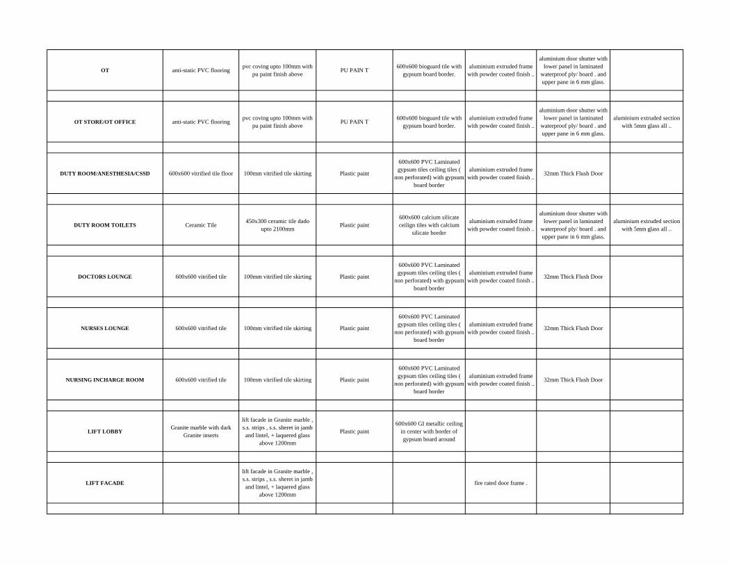
OT anti-static PVC flooringpvc coving upto 100mm with
pu paint finish abovePU PAIN T
600x600 bioguard tile with gypsum board border.
aluminium extruded frame with powder coated finish ..
aluminium door shutter with lower panel in laminated
waterproof ply/ board . and upper pane in 6 mm glass.
OT STORE/OT OFFICE anti-static PVC flooringpvc coving upto 100mm with
pu paint finish abovePU PAIN T
600x600 bioguard tile with gypsum board border.
aluminium extruded frame with powder coated finish ..
aluminium door shutter with lower panel in laminated
waterproof ply/ board . and upper pane in 6 mm glass.
aluminium extruded section with 5mm glass all ..
DUTY ROOM/ANESTHESIA/CSSD 600x600 vitrified tile floor 100mm vitrified tile skirting Plastic paint
600x600 PVC Laminated gypsum tiles ceiling tiles (
non perforated) with gypsum board border
aluminium extruded frame with powder coated finish ..
32mm Thick Flush Door
DUTY ROOM TOILETS Ceramic Tile450x300 ceramic tile dado
upto 2100mmPlastic paint
600x600 calcium silicate ceilign tiles with calcium
silicate border
aluminium extruded frame with powder coated finish ..
aluminium door shutter with lower panel in laminated
waterproof ply/ board . and upper pane in 6 mm glass.
aluminium extruded section with 5mm glass all ..
DOCTORS LOUNGE 600x600 vitrified tile 100mm vitrified tile skirting Plastic paint
600x600 PVC Laminated gypsum tiles ceiling tiles (
non perforated) with gypsum board border
aluminium extruded frame with powder coated finish ..
32mm Thick Flush Door
NURSES LOUNGE 600x600 vitrified tile 100mm vitrified tile skirting Plastic paint
600x600 PVC Laminated gypsum tiles ceiling tiles (
non perforated) with gypsum board border
aluminium extruded frame with powder coated finish ..
32mm Thick Flush Door
NURSING INCHARGE ROOM 600x600 vitrified tile 100mm vitrified tile skirting Plastic paint
600x600 PVC Laminated gypsum tiles ceiling tiles (
non perforated) with gypsum board border
aluminium extruded frame with powder coated finish ..
32mm Thick Flush Door
LIFT LOBBYGranite marble with dark
Granite inserts
lift facade in Granite marble , s.s. strips , s.s. sheret in jamb and lintel, + laquered glass
above 1200mm
Plastic paint600x600 GI metallic ceiling
in center with border of gypsum board around
LIFT FACADE
lift facade in Granite marble , s.s. strips , s.s. sheret in jamb and lintel, + laquered glass
above 1200mm
fire rated door frame .

ALL STAIRCASES granite150mm granite skirting , 1000mm high s.s. railing
OBD plaster fire rated door frame . fire door .
ELECTRICAL ROOM ipc floor OBD plasteraluminium extruded frame
with powder coated finish ..32mm Thick Flush Door
GENERAL WARD FLOORS
WARD BED AREA 600x600 vitrified tile600+600 vitrified tile dado
+19mm granite coping on top of partition wall
Plastic paint
600x600 PVC Laminated gypsum tiles ceiling tiles (
non perforated) with gypsum board border
aluminium extruded frame with powder coated finish ..
aluminium door shutter with lower panel in laminated
waterproof ply/ board . and upper pane in 6 mm glass.
aluminium extruded section with 5mm glass all ..
WARD CORRIDOR AREAcombination of light granite
and dark granite inserts
wall dado upto 1300mm (1200 vitrified +100 granite top
border)Plastic paint
600x600 GI metallic ceiling in center with border of gypsum board around
aluminium extruded frame with powder coated finish ..
32mm Thick Flush Door
MEDICINE ROOM 600x600 vitrified tile 100mm vitrified tile skirting Plastic paint
600x600 PVC Laminated gypsum tiles ceiling tiles (
non perforated) with gypsum board border
aluminium extruded frame with powder coated finish ..
aluminium door shutter with lower panel in laminated
waterproof ply/ board . and upper pane in 6 mm glass.
aluminium extruded section with 5mm glass all ..
DUTY ROOM 600x600 vitrified tile 100mm vitrified tile skirting Plastic paint
600x600 PVC Laminated gypsum tiles ceiling tiles (
non perforated) with gypsum board border
aluminium extruded frame with powder coated finish ..
32mm Thick Flush Door
UTILITIES/TOILETS Ceramic Tile450x300 ceramic tile dado
upto 2100mmPlastic paint
600x600 calcium silicate ceilign tiles with calcium
silicate border
aluminium extruded frame with powder coated finish ..
aluminium door shutter with lower panel in laminated
waterproof ply/ board . and upper pane in 6 mm glass.
aluminium extruded section with 5mm glass all ..
CU 600x600 vitrified tile 100mm vitrified tile skirting Plastic paint600x600 PVC Laminated
gypsum tiles ceilingaluminium extruded frame
with powder coated finish ..32mm Thick Flush Door
DU 600x600 vitrified tile450x300mm ceramic tile dado
upto 1200mm on wallPlastic paint
600x600 PVC Laminated gypsum tiles ceiling
aluminium extruded frame with powder coated finish ..
32mm Thick Flush Door
STORES 600x600 vitrified tile 100mm vitrified tile skirting OBD
600x600 PVC Laminated gypsum tiles ceiling tiles (
non perforated) with gypsum board border
aluminium extruded frame with powder coated finish ..
aluminium door shutter with lower panel in laminated
waterproof ply/ board . and upper pane in 6 mm glass.
aluminium extruded section with 5mm glass all ..

HOUSEKEEPING 600x600 vitrified tile 100mm vitrified tile skirting OBD
600x600 PVC Laminated gypsum tiles ceiling tiles (
non perforated) with gypsum board border
aluminium extruded frame with powder coated finish ..
aluminium door shutter with lower panel in laminated
waterproof ply/ board . and upper pane in 6 mm glass.
aluminium extruded section with 5mm glass all ..
ALL CORRIDORSGranite floorign with dark
granite inesrts
wall dado upto 1300mm (1200 vitrified +100 granite top
border)Plastic paint
600x600 GI metallic ceiling in center with border of gypsum board around
aluminium extruded frame with powder coated finish ..
aluminium extruded section with 5mm glass all ..
aluminium extruded section with 5mm glass all ..
COMMON TOILETS Ceramic TilesCeramic tile cladding upto
modular partition / cubicle ht.OBD
600x600 calcium silicate ceiling with calcium silicate
board border around
aluminium extruded frame with powder coated finish ..
32mm Thick Flush Door
LIFT LOBBYGranite marble with dark
Granite inserts
lift facade in Granite marble , s.s. strips , s.s. sheret in jamb and lintel, + laquered glass
above 1200mm
Plastic paint600x600 GI metallic ceiling
in center with border of gypsum board around
LIFT FACADE
lift facade in Granite marble , s.s. strips , s.s. sheret in jamb and lintel, + laquered glass
above 1200mm
fire rated door frame .
ALL STAIRCASES granite150mm granite skirting , 1000mm high s.s. railing
OBD plaster fire rated door frame . fire door .
ALL WAITING AREAScombination of light granite
and dark granite inserts
wall dado upto 1300mm (1200 vitrified +100 granite top
border)Plastic paint
600x600 GI metallic ceiling in center with border of gypsum board around
aluminium extruded frame with powder coated finish ..
aluminium extruded section with 5mm glass all ..
ELECTRICAL ROOM ipc floor --- OBD plasteraluminium extruded frame
with powder coated finish ..32mm Thick Flush Door
PANTRY 600x600 vitrified tile450x30mm ceramic tile dado
upto 1200mm on walls.+ counter in granite
OBD
600x600 PVC Laminated gypsum tiles ceiling tiles (
non perforated) with gypsum board border
aluminium extruded frame with powder coated finish ..
32mm Thick Flush Door
PREMIUM ROOM FLOORS
ROOM 600x600 vitrified tile 100mm vitrified tile skirting Plastic paint
600x600 PVC Laminated gypsum tiles ceiling tiles (
non perforated) with gypsum board border
aluminium extruded frame with powder coated finish ..
32mm Thick Flush Door

ROOM TOILETCeramic Tiles combination of light granite and dark granite
inserts
300x300ceramic tile dado upto false ceilin g
Plastic paintplain calcium silicate tile
ceilingaluminium extruded frame
with powder coated finish ..32mm Thick Flush Door
DUTY ROOM 600x600 vitrified tile 100mm vitrified tile skirting Plastic paint
600x600 PVC Laminated gypsum tiles ceiling tiles (
non perforated) with gypsum board border
aluminium extruded frame with powder coated finish ..
32mm Thick Flush Door
DUTY ROOM TOILETS Ceramic Tile450x300 ceramic tile dado
upto 2100mmPlastic paint
600x600 calcium silicate ceilign tiles with calcium
silicate border
aluminium extruded frame with powder coated finish ..
aluminium door shutter with lower panel in laminated
waterproof ply/ board . and upper pane in 6 mm glass.
aluminium extruded section with 5mm glass all ..
CU 600x600 vitrified tile 100mm vitrified tile skirting Plastic paint600x600 PVC Laminated
gypsum tiles ceilingaluminium extruded frame
with powder coated finish ..32mm Thick Flush Door
DU 600x600 vitrified tile450x300mm ceramic tile dado
upto 1200mm on wallPlastic paint
600x600 PVC Laminated gypsum tiles ceiling
aluminium extruded frame with powder coated finish ..
32mm Thick Flush Door
STORES 600x600 vitrified tile 100mm vitrified tile skirting OBD
600x600 PVC Laminated gypsum tiles ceiling tiles (
non perforated) with gypsum board border
aluminium extruded frame with powder coated finish ..
aluminium door shutter with lower panel in laminated
waterproof ply/ board . and upper pane in 6 mm glass.
aluminium extruded section with 5mm glass all ..
ALL CORRIDORSGranite floorign with dark
granite inesrts
wall dado upto 1300mm (1200 vitrified +100 granite top
border)Plastic paint
600x600 GI metallic ceiling in center with border of gypsum board around
aluminium extruded frame with powder coated finish ..
aluminium door shutter with lower panel in laminated
waterproof ply/ board . and upper pane in 6 mm glass.
aluminium extruded section with 5mm glass all ..
COMMON TOILETS Ceramic TilesCeramic tile cladding upto
modular partition / cubicle ht.OBD
600x600 calcium silicate ceiling with calcium silicate
board border around
aluminium extruded frame with powder coated finish ..
32mm Thick Flush Door
LIFT LOBBYGranite marble with dark
Granite inserts
lift facade in Granite marble , s.s. strips , s.s. sheret in jamb and lintel, + laquered glass
above 1200mm
Plastic paint600x600 GI metallic ceiling
in center with border of gypsum board around

LIFT FACADE
lift facade in Granite marble , s.s. strips , s.s. sheret in jamb and lintel, + laquered glass
above 1200mm
fire rated door frame .
ALL STAIRCASES granite150mm granite skirting , 1000mm high s.s. railing
OBD plaster fire rated door frame . fire door .
ALL WAITING AREAScombination of light granite
and dark granite inserts
wall dado upto 1300mm (1200 vitrified +100 granite top
border)Plastic paint
600x600 GI metallic ceiling in center with border of gypsum board around
aluminium extruded frame with powder coated finish ..
aluminium door shutter with lower panel in laminated
waterproof ply/ board . and upper pane in 6 mm glass.
aluminium extruded section with 5mm glass all ..
ELECTRICAL ROOM ipc floor --- OBD plasteraluminium extruded frame
with powder coated finish ..32mm Thick Flush Door
PANTRY 600x600 vitrified tile450x30mm ceramic tile dado
upto 1200mm on walls.+ counter in granite
OBD
600x600 PVC Laminated gypsum tiles ceiling tiles (
non perforated) with gypsum board border
aluminium extruded frame with powder coated finish ..
32mm Thick Flush Door
VVIP ROOM FLOORS
VVIP ROOM 600x600 vitrified tile 100mm vitrified tile skirting Plastic paint
600x600 PVC Laminated gypsum tiles ceiling tiles (
non perforated) with gypsum board border
aluminium extruded frame with powder coated finish ..
32mm Thick Flush Door
VVIP ROOM TOILETCeramic Tiles combination of light granite and dark granite
inserts
300x300ceramic tile dado upto false ceilin g
Plastic paintplain calcium silicate tile
ceilingaluminium extruded frame
with powder coated finish ..32mm Thick Flush Door
DUTY ROOM 600x600 vitrified tile 100mm vitrified tile skirting Plastic paint
600x600 PVC Laminated gypsum tiles ceiling tiles (
non perforated) with gypsum board border
aluminium extruded frame with powder coated finish ..
32mm Thick Flush Door
DUTY ROOM TOILETS Ceramic Tile450x300 ceramic tile dado
upto 2100mmPlastic paint
600x600 calcium silicate ceilign tiles with calcium
silicate border
aluminium extruded frame with powder coated finish ..
aluminium door shutter with lower panel in laminated
waterproof ply/ board . and upper pane in 6 mm glass.
aluminium extruded section with 5mm glass all ..
CU 600x600 vitrified tile 100mm vitrified tile skirting Plastic paint600x600 PVC Laminated
gypsum tiles ceilingaluminium extruded frame
with powder coated finish ..32mm Thick Flush Door

DU 600x600 vitrified tile450x300mm ceramic tile dado
upto 1200mm on wallPlastic paint
600x600 PVC Laminated gypsum tiles ceiling
aluminium extruded frame with powder coated finish ..
32mm Thick Flush Door
STORES 600x600 vitrified tile 100mm vitrified tile skirting OBD
600x600 PVC Laminated gypsum tiles ceiling tiles (
non perforated) with gypsum board border
aluminium extruded frame with powder coated finish ..
aluminium door shutter with lower panel in laminated
waterproof ply/ board . and upper pane in 6 mm glass.
aluminium extruded section with 5mm glass all ..
DOCTORS LOUNGE/ATTENDENT LOUNGE
600x600 vitrified
100mm vitrified tile skirting = 450x300mm ceramic tile dado
behind washbasin upto 1200mm
Plastic paint
600x600 PVC Laminated gypsum tiles ceiling tiles (
non perforated) with gypsum board border
aluminium extruded frame with powder coated finish ..
32mm Thick Flush Door
ALL CORRIDORSGranite floorign with dark
granite inesrts
wall dado upto 1300mm (1200 vitrified +100 granite top
border)Plastic paint
600x600 GI metallic ceiling in center with border of gypsum board around
aluminium extruded frame with powder coated finish ..
aluminium door shutter with lower panel in laminated
waterproof ply/ board . and upper pane in 6 mm glass.
aluminium extruded section with 5mm glass all ..
COMMON TOILETS Ceramic TilesCeramic tile cladding upto
modular partition / cubicle ht.OBD
600x600 calcium silicate ceiling with calcium silicate
board border around
aluminium extruded frame with powder coated finish ..
32mm Thick Flush Door
LIFT LOBBYGranite marble with dark
Granite inserts
lift facade in Granite marble , s.s. strips , s.s. sheret in jamb and lintel, + laquered glass
above 1200mm
Plastic paint600x600 GI metallic ceiling
in center with border of gypsum board around
LIFT FACADE
lift facade in Granite marble , s.s. strips , s.s. sheret in jamb and lintel, + laquered glass
above 1200mm
fire rated door frame .
ALL STAIRCASES granite150mm granite skirting , 1000mm high s.s. railing
OBD plaster fire rated door frame . fire door .
ALL WAITING AREAScombination of light granite
and dark granite inserts
wall dado upto 1300mm (1200 vitrified +100 granite top
border)Plastic paint
600x600 GI metallic ceiling in center with border of gypsum board around
aluminium extruded frame with powder coated finish ..
aluminium door shutter with lower panel in laminated
waterproof ply/ board . and upper pane in 6 mm glass.
aluminium extruded section with 5mm glass all ..
ELECTRICAL ROOM ipc floor --- OBD plasteraluminium extruded frame
with powder coated finish ..32mm Thick Flush Door

PANTRY 600x600 vitrified tile450x30mm ceramic tile dado
upto 1200mm on walls.+ counter in granite
OBD
600x600 PVC Laminated gypsum tiles ceiling tiles (
non perforated) with gypsum board border
aluminium extruded frame with powder coated finish ..
32mm Thick Flush Door
TERRACE FLOOR
HELIPAD
SERVICE FLOOR
HEAVY EQUIPMENT AREA TRIMIX FLOOR PLASTER OBD
NORMAL EQUIPMENT AREA 600x600 vitrified tile PLASTER OBD
COMMON AREAS
RAMP Chequered tiles 150mm granite skirting OBD
LIFT MACHINE ROOMS IPC floor OBD Plaster
STAIR MUMTY Kota stone 100mm kota stone skirting OBD Plaster
External pedestian pathway Concrete path ways
MISCELLENEOUS FINISHES
• EXTERNAL FACADES : COMBINATION OF ALUMINIUM CLADDING PANELS(ACP), ALL AS PER FINALIZED ELEVATIONS.
• TERRACES:INTERMEDIATE TERRACE S TO BE TERRACE GARDENS WITH PROVISION FOR PLANTATION.
• PORCH FLOORING : IMMIDIATE AREA UNDER PORCH SHALL BE IN SANDBLASTED GRANITE
• ALL PEDESTRAIN PATHWAYS TO BE CONCRETE PATHWAYS .
• ALL TOILETS SHALL HAVE LAMINATED BOARD PARTITION SYSTEM , WITH FLOOR MOUNTED WC ,
• ALL URINALS TO HAVE FROSTED TOUGHENED GLASS SPARTITION
• RAILING: ALL RAILINGS TO BE STAINLESS STEEL RAILINGS AS PER APPROVAL
• ALL INTERNAL COUNTERS (LAB , UTILITY ,NURSING,RECEPTION ETC) TO BE IN GRANITE FINISH AND AS PER DETAILED DRAWINGS.
AS PER DESIGN AND SPECIFICATIONS
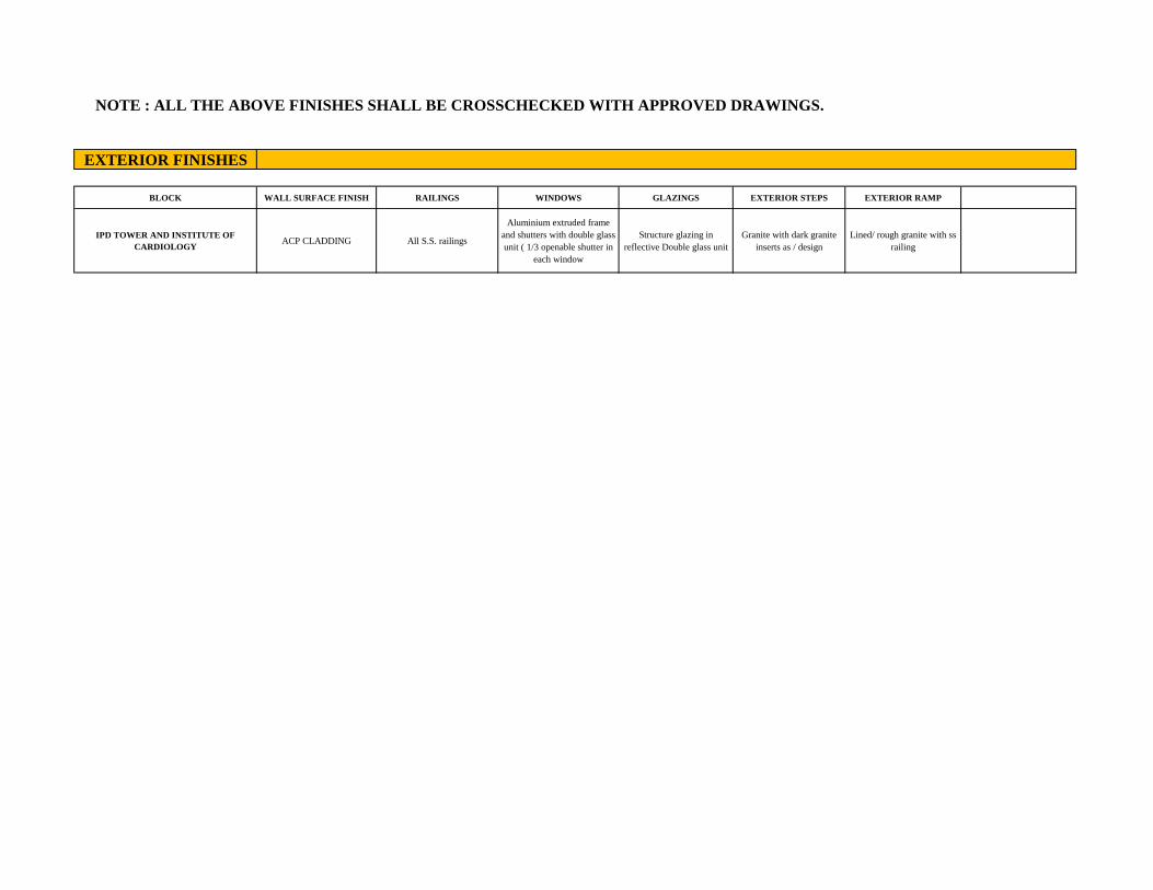
EXTERIOR FINISHES
BLOCK WALL SURFACE FINISH RAILINGS WINDOWS GLAZINGS EXTERIOR STEPS EXTERIOR RAMP
IPD TOWER AND INSTITUTE OF CARDIOLOGY
ACP CLADDING All S.S. railings
Aluminium extruded frame and shutters with double glass unit ( 1/3 openable shutter in
each window
Structure glazing in reflective Double glass unit
Granite with dark granite inserts as / design
Lined/ rough granite with ss railing
NOTE : ALL THE ABOVE FINISHES SHALL BE CROSSCHECKED WITH APPROVED DRAWINGS.


O LVL +0.75 m
uNTY
a BAY
10 REGISTRATION HALL A
X39285
- OTS
19MwOC
ESCA STAMRCA
& LVL +0.75 mSROUNC
ME
mo
LVL +0.75 m
LVL +4.20 m
LVL 4.6 m
UNDERGROUND SERVICES
LVL +0.75m
ERAYER SROUND
LVL +0.00 m LVL #0.00 m
151203-
SITE PLAN
JLN MARG
AkAtAL SHARM CA/2012/5794
AR ASHMITH, BHRTARIE cERE HOUSE AND IS NOT
Sincers SAE PVT LTD
CONSTRUCTION OF IPO TOWER AND E CARDOLOGY BULDING C
ASMS HOSPTAL JAIPUR DATE OF ISS DESCRIPTION
DENLT B(NHOA) Con MUNDRA
JAIPUR CUENT CK Y ASHAK JAAN T
SMS/APL-GF/07 SAS MEDICAL COLLEGE & HOSPITA SIGNED BY
ANOOP 5ARTARIA DRG TIMLE EV NO FOR STUDY 00 STATUS
an SCALEOM 5M 10M 15M FOToWER 5cERt RONECTS E
FSE 06/07/21 GROUND FLOOR PLAN

73000
STRETCHER CHAIR BAYY
ENTRY1 ENTRY 1 ENTRY1
x 9640
7970
CLOAK 7170 X 910
REGISTRATION HALL AREA
970 57010X39285 CENTER
DMINISTRATIO cUT OUT 7170 25055
COUNCELLNG ELPING DES 7100 x 4770
710 COUNSERUNG
iNSURACE STHATI 7100 X 4770
CORRIOCR CORRIDOR
7100 X 4T7o
uT LOY
INSURANCE7100 X 7900 ELTLOY
FIRE
STAIRCASEF PATIRT LT LO -7100
-7100
ATENT LPTLY
ENTRY TO LVL +0.75 mGROUND
PO REGISTRATION
DOUBLE HEKALT
11300 x 25770 DRU VP DINING
srTs T LoY rons LiT LoeY
S000
SITTING
IN SIAR DOVE
8040 19309 FOOD
UTILITIES
LVL +0.75m
LVL 20000
+4.20 m EN ENTRY LVL +4.6m GROUND sROND
EOOR
AREA V +0.75 m
KKKKKAKKA
AR ASMMI1A BARRIA4 CA 2011/uso2GROUND FLOOR PLAN
ER SHAO
TION OF IPO TÖWER AND
INSTITUTE OF CARDIOLOGY BUILDING o S A BHE RIY O SNCERE HOUSE AND SNOT
LTOBE USE Sincere DESCRIPTION
MS HOSPITAL JAPUR DEALT BYMOH) NO. RNO DATE OF
SAE PVT LTD CHK BY AS K AN
AR. KAAL SHARMas cLE. CA/2012/57946 SMS/A/PLFF/07 DRG TITLE
OOP BARTARIA
FOToWER E *OECSENNEERe 0
FOR STUDY 00 FRST FLDOK PLAN
AT O S 06/07/21

3000
7540 90640
ak40XAS40o 6000Y6SA 20640XE
900X16040
PO
Ou wo
wATING EA
215 4215
OPD PO 1216X170 4216X170
WATINGAREA
14410X44
7900X19515
25620 SA0X19770
25829X:3125
3000MM WIDE CORRIDOR TING
14410X4450
16140
PD nnE LST LOY
WAT NG AREA
WATINGAREA PATENT LPT LO00Y
A OPD
ATENT LFT LOBY
OPD LVL +0.75 m
ESEARCH AND DEVELPMEN wNG FOR MEDCAL FACHLITES 11300x25770 THEATRE 4M wDE
sTORS LIFT LOoeaY
L 21040X10720 "sTLOBr
x4155
EMINAR ROOM 47000-
10310X6516
SEMINAR ROOM
10310X65166
MEDICAL
GALLERY 12540X20945
ADMIN E LOCK
CEREMONIAL ENTRANCE
SLOPE RATIO- 1:9 VEHICULAR RAMP
ORCH SLOPE RATIO-1:9VEHICULAR RAMP
LVL +4.55 m LVL
+4.55 m LVL +7.55 m
DDDDRDDDDDEDDDODDEDDDDE
LVL +0.75 m
FIRST FLOOR PLAN AASHMITA BARIAR CA/ 2019/ 11sO22|
CA COUSE PEER SHA TO USEDcA RECOUCED WITHOUT OUR PERMISON Sincer CONSTRUCTION OF IPO TOWER AND
* eOF CARDIOLOGY BUILDING HOA HASHA NN
LASMS HOSPITAL JAPUR .KAMA NORNODATE OF ISSuE DESGRU
JAAPUR BYIARO) SAE PT LTD
SMS/APL-FF/07 A/2012/57Z8 cALEGE & OSAT
oor DARIARA STATLS
ONTECTS FOR STUOY 00
FRST FLOOR PLAN 0607/21

MAAKKATKS
DOY
11270K714RA
1270M417
WAITING AREA
NUCLEAR
1270X14087
41300
WAITING AREA WAITING AREA
L CUT OUT
PATENT T LoY
ATENT LT L
HEL 270x14755
LVL +0.75 m 12770 1270 x18310
WATING AREA NAITING AREA
vsans uT LOAY wroS LT L
RVIC ROOM
LVL LVL +4.55 m
+4.55 m LVL +7.55 m
DDODEDDPPESDDEDRDODSEE
SECOND FLOOR PLAN
LVL +0.75 m
AR ASHMMA BAR1ARIA
CA|2019/uso22 PROJECT
CONSTRUCTON OF PO TOWER AND OC PROU ARCHGHOUSE PEER SHAKH
THS DRAWO S THE PROPERTY OF SNCERE HOUSE AND IS NOT
ENG Sincere9 NO RNODATE OF ISSUE DESCRIPTION
A SMS HOSPITAL, JAPUR
MUNDRA
SA
JAIPUR AR. KAMAL {HARAs CA/2012/579F5
SAEPVT. LTD. RG NO SMS/A/PL-SF/07
ANOOP BARTARIA ONIS PO TOWER FOR STUD 0O
ONECTIRE STACTRN DESEN NTENORS LANOSCWE LAN ENES SECOND FLOORPLAN oN141 242042/2 PAN
DATE OF ISSE 06/07/21

UTILITIES 2 4770X9655 12040-
25000 12040
BEDS ICU
WARD 2
17 BEDS 17 BEDS
WARD 1 3000MM WIDE STERLIZED CORRIDOR WARD 3
12040K27270 12040X24155
4000 546 8383 NURSE 4840 X 3830-
TORS lIEQUIPME 5467x3790 STORES terzau 4000X7810
x3790
area
B38J
KEEPING PANTRY
6383X3790 s467x3790
3000MM WIDE GENERAL CORRIDOR
4840 STAFF AND SERVICE LIFT LOBBY
1300- JO0-
040 HE4770 (040
UTILITIES-17040x3825 3000 UTILITIES-3
7040X4540 RE LIFT LOBBY
12270- 12270
PATIENT LIFT LOBBYY _
ORS
UNG DO
SLOPE aENDEN LOUNGEE
12270X10000 gPATIENT UFT LOBBY 12270X10000
5010 UTILITIES
5010X3825
5010
JTIL LITIES-6
7040X4540 4770 7040 4570- VISITORS LIFT LOBBY ViSITORS LIFT LOBBY
3000MM WIDE GENERAL CORRIDOR
NG B383 5467 HE4000-HL
HOUSE 993y3790 KEEPINGB
5467K3TS0 EQUME
on stenizabon
area C00x3Sto 4000X7810
5467 H DOCTOR S467X3790
NURSE STAFF ROOM
8383x3790
12040X2727O 12040X27270
17, BEDS 3000MM WIDE STERLIZED CORRIDOR
17 BEDS ICU
ICU WARD 1
WARD 3
25000X96655 15 BEDS
ICU
WARD -25000-
2
JTILITIES-577OX96555
-12040- -12040
alDlalnn 55000F
ICU FLOOR PLAN N R: SHM7A BARIAR
AR We SHAR CAj2911j isa22Z d20A AA rwERA
HsDRA S TE PROPERTY OF SINCERE KOUSE AND SNOT Sincere gS ENG ROJ RCH
WER AND AT SMs HC BULDING|CeA
SNORNO DATE OF ISSUE DESCRIPTION SAE PVT LTD JAIPUR
SMS/A/PL-TH/07 LENT D SHANK JAIN PRINT SMS MEDICAL COLLEGE & HOSPITADESIG
REV. NO FOR STUDY
TATU
00 DRG TTTLE ANOOP BARTARIA
F SSUE 06/072 EN ERS PNT WAOOR PW

B6
55
2
51
70
2170
MM
WID
E D
IRT
Y C
OR
RID
OR
-721
3
1881
0 o
00
5
3.0M
WID
E B
LA
CK
CO
RR
IDO
R
2577
0 12
040
EE
ET
3.
0M W
IDE
BA
LC
K C
OR
RID
OR
54
25
I
3.0M
WID
E S
TE
RL
IZE
D C
OR
RID
OR
40
5
L
54
3
21
2170
AIM
WID
E D
IRTY
cO
RR
IDO
R
12
04
0
B6
55
B
000
16
50
3
-7
50
00

5240-
IH 5240 H| TOILET 5240X3500
TOILET 5240X3500
5420
CU/DU P5420X3500 CUbU
5420x350
22655 16 BEDS
22655 16 BEDS
WARD 1 22655X14425
WARD 2 22655X14425
OLAn.nulnn.n.DOmndl 2.40MM WIDE CORRIDOR 8140
2400
STORE 5890x3000 DOCTORS LOUNGE NURSE LOUNGE HOUSEKEEPINGS
5535X3000o 8BEDS WARD8
8140X12515
5535X3000 5890x3000 8 BEDS WARD 3
8140X12515 5890 5535- 5535 5890
11B00 STAFF AND SERVICE LIFT LOBBY
FIRE EXIT FIRE LIFT LOBBY RAMP
OL 4640KZ4O0 TONAO0 540X2
404U PATIENT LIFT LOBBY -4640
ATTENDANT LOUNGE
SLOPESCOPE A 2 `PATIENT LIFT LOBBYY
ATTENDANT LOUNGE
4640 4640
TOILET 4640X2400
TOILET 4640X2400 4640XZ40
VISITORS LIFT LOBBY VISITORS LIFT LOBBY
8 BEDS
WARD 7 R 8140X12515-
8 BED^$
WARD 4 B140X12515
PANTRY 5890x3000
ocTORSTOUNGE NURSERdINGE5535X3000 StORE
5890x30005535x3000
TT TUT 16 BEDS 16 BEDS
WARD 5 22655X14425
WARD 6 22655X14425
22655- -22655-H
5420X3500 5420X350
5650 TOILET TOILET 5240X350o 5240X3500 5240
5240
GENERAL WARDSTYPICAL FLOOR PLAN 6TH 7TH, 8TH, 10TH, 11TH AND 13H FLOOR PLAN
R.SHMI14 BAe1AR CAL2dls/IDE-
Sincer SAEAM TOb
TRUCT NSTITUTE OF CNROLDGY B
AT SMS RUSTAA*
ARKAMAL sHAR COiEE AHOSATA SMSAPL-F7-16/07
CA/2012/57946 mLE
FOR STUO
aa 0607/21

240
I 5240 TOILET
5240X3500 TOILET 5240X3500
5420
-10085 10085-
CUDu 5420X350t5 S5420x350
-22655 6 BEDS BEDS
WARD 1 22655X14425
WARD 2 22655X14425
8140 .40MM WIDE CORRIDOR
2400
8BEDS U WARD8. BT40X12515
STORE 5890X3000
ooCTORS LOUNGE NURSE LOUNGE 5535X3000
[HOUSEKEEPINGE 5890X3000
5890 5535X3000 BEDS
5890- -5535 - 5535 WARD3 8140X12515 1B00 STAFF AND SERVICE
LIFT LOBBY
FIRE LIFT LOBBY
TOILET 4640X2400
4640 PATIENT LIFT LOBBY 4640
REFUGE REFUGE AREA
gPATIENT LIFT LOBBY AREA
4640- 4640
TOILET
4640X24000 ILET TOAO0 4640A2400
VISITORS LIFT LOBBY VISITORS LIFT LOBBY
8 BEDS WARD 7 814pX125145
8 BEDS
WARD 4 8140X12515 PANTY
5890x3000 DoCTORSLOUNGE NURSET8UNGE
5535X30000 STORE 5890x30000 5535X30000
YE
8140-
16| BEDS WARD 6
22655X14425
BEDS WARD 5
22655X14425
6
-22655- 265
5420X3500 5420X3508
Esps0EH| 10085 10085-
5650 TOILE 5240X3500
TOILE C35240X3500
5240-
AR:ASHMATA BARTARIA
CA/a0/1D GENERAL WARDS TYPICAL FLOOR PLAN 9H, 12 FLOOR PLAN
KAM sHARN C201257945.
Sincere PROECT CONSTRUCnoN OF IPO TOWER ANDD
OE USED CR KEHOOUCED wITOUT OUR PERAMISSION PRO EOIS
JAIPUR SMS HOsPITAL JAIPUR SAE PVT LTO C GO MUNI
CIENT SMS/A/PL-F7-16/07 O EDCAL COLLEGE & HOSPITA JU SMS MEDICAL GOE E ANOOP BARIARIA TITLE FOR STUD 00
DATE 06/07/21 GENERAL WAROS ALOOR PLAN
"*"**
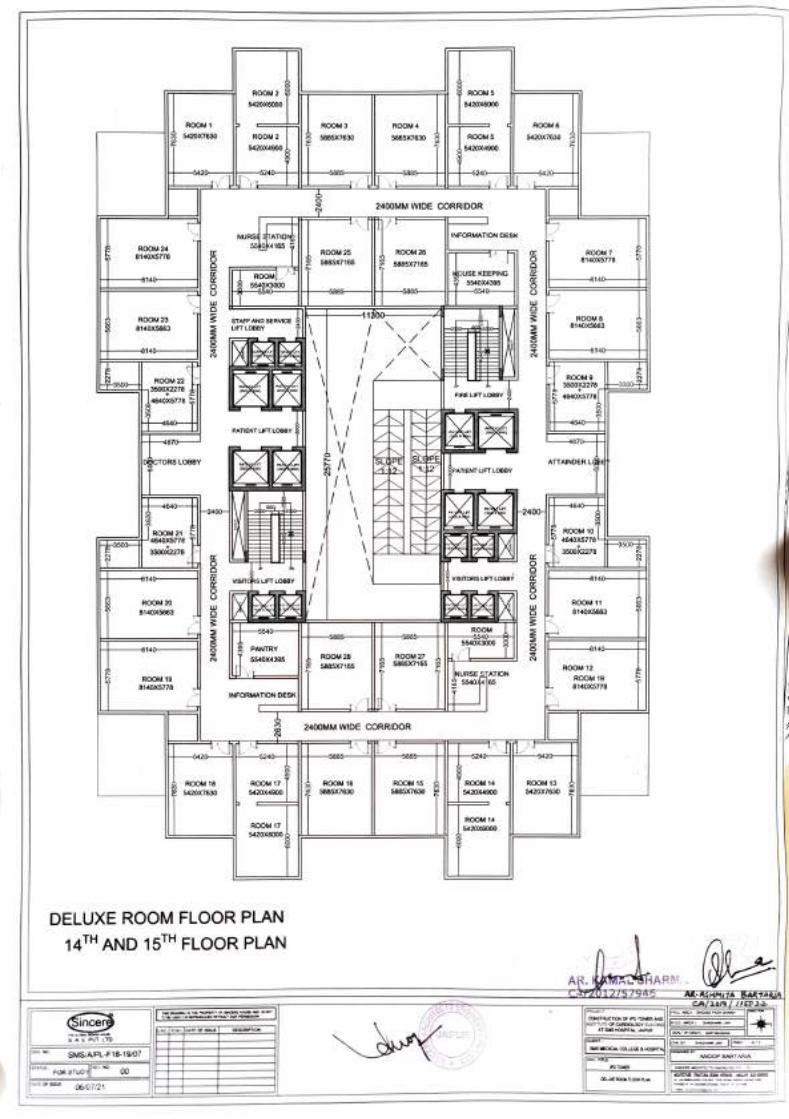
ROOM 2 ROOM 6 5420X6000 5420X6000
ROOM 1 ROOM 3 ROOM 4 ROOM 6
5420X7630 ROOM 2 5885X76300 5885X7630 ROOM5 5420X7630
5420X4900 5420X4900
5420 -5240 5885 5885 5240 5420
2400MM WIDE CORRIDOR
INFORMATION DESK NURS STATIONB 5540K4 165 ROOM 24
8140X5778 ROOM 5885X7 165
ROOM 26 ROOM 7 8140X5778 5885X7165
ROOM OUSE KEEPING 8140 8140
5540X3000 5540
5540X4395 5540 b885 5885-
1B00- ROOM 8
8140X5663 ROOM 23 STAFF AND SERVICE
LIFT LOBBY 8140X5663
8140 8140
ROOM 9 3500X221
4640X5778
ROOM 22
3500X2278 L4640X5778
FIRE LIFT LOBBY
M 4640 4640
PATIENT LIFT LOBBY
4870 8/0 J
|DCTORS LOBBY ATTAINDERL PATIENT LIFT LOBBY
4640 464U 2400 2400|
OM 2 ROOX5118 ROOM 10 4640X5778- -3500 35005
3500X2278 3500x2278
8140 VISITGRS LUFT LOBBY IsITORS LIFT LOBBY 8140
ROOM 20 ROOM 11
140X5663 8140X5663
ROOM 5540X3000
5540 5885 5885-
8140 PANTRY 8140
5540X4395 ROOM 28
R 5885X7165 ROOM 12
ROOM 1 8140X5778
NURSE STATION 5540%4 ROOM
8140X5778 9
INFORMATION DESK
2400MM wIDE CORRIDOR
5420 5240 5885 5885 5240 5420
ROOM 17 5420X4900
ROOM 15
5885X7630
ROOM 18 ROOM 1 ROOM 13 ROOM 16S 5885X7630
4 5420X4900 5420X76 5420X7630
ROOM 14 ROOM 17 5420X6000
5420X6000,
DELUXE ROOM FLOOR PLAN
14TH AND 15TH FLOOR PLAN
AR. KAMMALSHARM CAFZ0TZ/57945 Ak ASHMI7A BARTARIA
EC HOUE N NOT
Sincer CONSTRUCTiON OF PO TOWER AND
AIPUR DESCRIPTION
AE PVT LTD GUENT sSuS MEDICAL COLEGE & HOSPTAp DANOOP BARTARIA L SMS/APL-F18-19/07
TTLE TOWEK
DRG
FOR STUDY 00 OELLE ROCMAOOR PLAN
aA OF S 06/07/21

240 6240
2000T 8000 2000
ROOM 19 s240X3600 7240XAABA
ROOM 20
2740 6240x3500 7240X4MA
-7240- PANTRY
2740X131 7240-
HOAM ROOM 1E 2AOXS700 ROOM 21
7240X57000 5420 6420-
ROOM 22 5420X7620
-7240 7240- ROOM 17 5420X7620
2400MM wIDE CORRIDOR
ROOM 1 8726X4000
6 ROOM 15 8725X4000
8725- 8725 40- 8140
11800 LIET1O SERVICE
ROOM 14 8140X4955
o140X4955
2400- TOILET TOILET erOxzo00
1 3270X2000
ROOM00 ROOM 13 4640X55000
FIRE LIFT LOBBY 3270 3270 4640X550
4640 4640 PATIENT LIFT LOBBY
4870
ATTENDANTT 8ATTENDANT LOUNGE
LPESLOPE| LOUNGE
PATIENT LIFT LOBBY
4870- 4870-
-4640 4640
ROOM 1 640X5500
ROOM 12 4640X5500 327
3270x2000 J 2009 3270X2000 TOILET
VISITORS LIFT LOBBY VISITORS LIFT LOBBY
ROOM 2 8140X49555
ROOM 1 1 8140X4955
8140- 8140
ROO n0 R ADU
2400MM WIDE CORRIDOR
ROOM 3 ROOM 10 5420X7620 MURSE STATION 5420X7620
-7240 7240
ROUSE EEPING
2740X200 5420 ROOMg D420
(240K5/00
RANTRY 2740X3310 7240
RO 7
X486 5240X3500
ROOM8 7240X4866 5240X3500 L2740
2000- 8000 20001
5240 5240
PREMIUM ROOM FLOOR PLAN
16TH TO 18"H FLOOR PLAN lAR. KAMAL SHARR VCA/2012/57946
ROJEC
wSTRLuCTION OF IPO TOWER CED wTHOUT OUR PERMSSION EPEER SHAIG4 T
Sincere iNSTTUE O CARDIOLOGY BUILDING A SMS FOSPITAL, JAPUR NO RNO.DATE OF ISSUE DESCRPTION
JAIPUR )| S.AE PVT LTO.
SMS/A/PL-20-24/07| CUENT SMS MEDICAL COLLEGE& HOSPITA DESIGNED OY A
CHK BY SHASANK JAN PRINT NTS
DRG NO
ONIS L
sTATGSFOR STUDL PREMUN ROON FLDOR PUN
GATE OF SS 06/07/21
AR ASHMLIA BARTARIA CAlaD1 7nSD2

5240 240
ROOM 1 5240X6022 2230X2522
ROOM 4 3655 5240x6022
2230x2522 3655
ROOM 2
3655x877 ROOM 3
656X8776 ROOM 6
6240X6022 ROOM 5 6240X6022
5420-
5420 5240- HOUSE KEEPING 5240
URSE STATION 999.2589
1955 3000MM WIDE CORRIDOR
7490- 11800- /49
ROOM 14 7490X3477
STAFF AND SERVICE LIFT LOBBY ROOM 15
7490%3477
3050
ROO9, ROOM 16 7490x3477 3990X3500 3990ASS 3990xa50O
-7490 49
FIRE LIFT LOBBY
3990- V 3990 PATIENT LIFT LOBBY
4220
EFUGE
AREA 3990
REFUGE AREA
SLOPE SLOPE PATIENT LIFT LOBBYY
3990 -3990
490 ROOM 12 7490
ROOM 1 7490X3477 3990x3500
3050
2990X3500 VISITORS LIFT LOBBY z VISITORS LIFT LOBBY
ROOM 11 ROOM 18 7490X3477 7490X3477
-7490- 7490
3000MM wIDE CORRIDOR
19651 NURSE STATI
PANTRY 195525855
9740 9740 5420 ROOM 7 ROOM 8
5420- 9740X4272 9740X4272
9740- 9740
ROOM 9 9740X4272 5240X350
ROOM 1
9740X4272 5240X3500
5240 5240
AR. ASHM1A BAR1ARIA
PRESIDENTIAL ROOMS FLOOR PLAN CA/2o1/ 1So2
19TH FLOOR PLAN AR. WAWAHARM CAZ0IZ/57946
PROJECT TO B USEDCR REPROOcD WTHOUT OUR PERSSO
Sincere HO.D (ARCH SHASHANK JAIN
SNO.RNO DATE OF ISSUE DESCRPON LA MS HOSPITAL, JAPUR CLIENT
DEALT 8YIARCH). cooL O.
SAEPVT LTD JAIPUR BY.
S MEDICAL COLLEGE & HOSPITA JC
SMS/A/PL-25-27/07 ANOOP BARTARIA
STATUS FOR STUDY 00 DRG TITLE PO TOWER REV NO SINCERE ARCTECTS ENGNEERS PVT LTD
OTECTURE STRUT DE NENR OSCVE ANES PRESIDENTAL ROOM FLODR PLAN OATE OF SSUE
06/07/21 A a

5240 5240
ROA022 ROOM 4 40X6
2230x2522 3655H-3655 5240X6022 2230x2522
ROOM 2 B655X87743655X8775
ROOM 3
ROOM 6 5240X6022
ROOM 5 5240X6022
5420
5420- 5240- 5240 2HOUSE KEEPING 1999Az09
URSE STATION
95 3000MM WIDE CORRIDOR
-7490- /490 11800-
STAFF AND SERVICE ROOM 14 7490X347 7
OM 15 749 0x3477 LIFT LOBBY
3050
ROOM 13 7490X3477 3990x3500
ROOM 16 7490X3477 3990x3500
490- 7490
FIRE LIFT LOBBY
H-3990 V 3990 4220HI
PATIENT LIFT LOBBY
DOCTORS LOUNGE
ATTENDANTS LOUNGE
PATIENT LIFT LOBBY
-2cpo 0dbo-
-7490
ROOM 12 7490X3477 3990x3500
7490 ROOM 17
7490X34777 3990X3500
VIsiTGRS LIFT LOBBY VISITORS LIFT LOBBY
RO 7 9OX3477
-7490
ROOM 18 7490X347T7
-7490-
3000MM WIDE CORRIDOR
1955 NURSE STATIC
PANTRY 5420x2011955Xz88
9740 5420
ROOM 7 ROOM 8 -5420 9740X4272 9740X4272
9740 9740 ROOM 100 9200M 9
5240X350 5240X3500
5240 5240
AR ASHMna BAR1ARU
PRESIDENTIAL ROOMS FLOOR PLAN
20TH AND 21ST FLOOR PLAN AiAcMARM EAH¥042/57945-
ROUECT CONSTRDCTION OF POTowER AND
AT SAS HOSPITA
'THIS DRAWINO IS THE PROPERTY OF SINCERE HOUSE ANDDI ARC%. aOuSE PEER SH
Sincere S.NO.RNO DATE OF ISSUE DESCRIPTION
SAE PT. LTD.
SMS/APL-25-27/07 JAIPUR S EDICA cOLEGE & HOSPITA|o ED G
ANO woorDARIARA
STATUS FOR sTUDY 00
0607/21 OowER
GATE OF KESDENTAL R0OM FLOOR PLAN
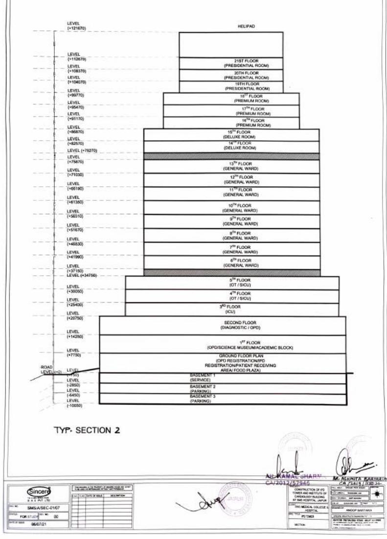
LEVEL HELIPAD
(+121670)
LEVEL (+112670)
LEVEL (+108370)
21ST FL0OR
(PRESIDENTIAL ROOM) 20TH FLOOR
(PRESIDENTIAL ROOM) 19TH FLoOR
(PRESIDENTIAL ROOM)
LEVEL (104070)
LEVEL (+99770) 18 FLoOR
(PREMIUM ROOM) LEVEL (+95470) 17TH FLOOR
(PREMIUM ROOM) LEVEL (+91170) 16 FLOOR
(PREMIUM ROOM) 15TH FLOOR
(DELUXE ROOM)
14 FLOOR (DELUXE ROOM)
LEVEL (+86870)
LEVEL (+82570)
LEVEL (+78270) LEVEL (+75870) 13TH FLOOR
(GENERAL WARD) LEVEL
(71030) 12TH FLOOR (GENERAL WARD) LEVEL
(+66190) 11 FLOOR(GENERAL WARD) LEVEL
(+61350) 10TH FLOOR (GENERAL WARD) LEVEL
(+56510) 9TH FLOOR (GENERAL WARD) LEVEL
51670) 8TH FLOOR
(GENERAL WARD) EVEL (+46830) 7TH FLOOR
(GENERAL WARD) LEVEL +41990)
6H FLOOR (GENERAL WARD) LEVEL
(+37150) LEVEL(+34750)
5 FLOOR (OT/SICU) LEVEL
(+30050) 4TH FLOOR (OT/SICU) LEVEL
(+25400) 3RD FLOOR (ICU) LEVEL
(+20750) SECOND FLOOR
(DIAGNOSTIC/ OPD) LEVEL (+14250)
ST FLOOR (OPD/SCIENCE MUSEUMIACADEMIC BLOCK)
LEVEL (+7750) GROUND FLOOR PLAN
(OPD REGiSTRATION/IPD REGISTRATION/PATIENT RECEIVING ROAD
LEVELK+0)EVE AREA FOOD PLAZA) BASEMENI (SERVICE) LEVEL
(-2850) LEVEL (-6450)
BASEMENT 2
(PARKING) BASEMENT 3
LEVEL (PARKINGS) (-10050)
TYP. SECTION 2
ARK SHAR ASHMITA ARIARI CAI20177946 HIS DAWM STHE PROPERTY OF SINCERE HOUSE AND IS NOT R ARCH GaousE PEER SUwo Sincer SAE PT LTD
CONSTRUCTION OF IPO D (M
No. RNO AN INSTTUTE OF DATE OF ISS DESCRIPTION
JAIPUR AT SMS HoSPITAL, JAIPUR eUENT
SMS MEDiCAL COLLEGE &DESCNED BY
HOSPITAL PO TOWER
-
SMS/ASEC-01/07
FOR STUDY 00 ATT S 06/07/21
EORTECTSENEERS O
ECTION

LEVEL HELIPAD (121670)
LEVEL
21ST FLOOR (PRESIDENTIAL ROOM)
(+112670)
EVEL (108370) 20TH FLOOR
(PRESIDENTIAL ROOM) 19TH FLOOR
(PRESIDENTIAL ROOM) 18 FLOOR
(PREMIUM ROOM) 17T FLOOR
(PREMIUM ROOM 16 FLOOR
(PREMIUM ROOM)
LEVEL (104070)
LEVEL (+99770) LEVEL
(+95470) LEVEL
(+91170)
LEVEL 15H FLOOR
(DELUXE ROOM)
14 FLOOR (DELUXE ROOM)
(+86870)
LEVEL +82570)
LEVEL (78270)
LEVEL
(+75870) 13 FLOOR (GENERAL WARD) LEVEL
(71030) 12TH FLOOR (GENERAL WARD) EVEL
(+66190) 11 H FLOOR (GENERAL WARD) LEVEL
(+61350) 10TH FLOOR (GENERAL WARD) LEVEL
(+56510) 9TH FLOOR (GENERAL WARD) LEVEL
51670) 8TH FLOOR (GENERAL WARD) EVEL
(+46830) 7TH FLOOR (GENERAL WARD) LEVEL
(41990) 6TH FLOOR
(GENERAL WARD) LEVEL
(+37150) LEVEL(+34750}
5TH FLOOR
(OT/SICU) LEVEL (+30050) 4TH FLOOR
(OT/SICU) LEVEL (+25400) 3RD FLOOR
LEVEL (+20750)
SECOND FLOOR (DIAGNOSTIC/ OPD) LEVEL
(14250) 1ST FLOOR
(OPD/SCIENCE MUSEUM/ACADEMIc BLOCK) LEVEL (+7750) GROUND FLOOR PLAN
(OPD REGISTRATION/IPD REGISTRATION/PATIENT RECEIVING -ROAD
LEVELH+0)EVL AREA/ FOOD PLAZA BASEMENI T (SERVICE)
50) LEVEL (-2850)
LEVEL (-6450)
LEVEL (-10050)
BASEMENT 2
(PARKING BASEMENT 3
(PARKING)
TYP SECTION JAIPU
ARRA SHARM CAT2012/579f#o
ARASAMIIA AARTARA Sincere LTOEuSED CR HEPROOuCED WITHOUT OUR PEesso
ONSTRUCTION OF IPD A ADINSUJE OF|Bao ARCH SHASHANK JAIN .
SNO
K AT SMS HOco ING
ELIENT dAPUR|IS
SMS MEDICAL COLLEGE &DESIGED BY
DEALT BYIANCH) GOPI MUNDRA
SMS/A/SEC-01/07 JAIPUR aK BY SHASHANK JAN PRINT. NTS
STATUS FOR STUDY 00 DATE OF ISSUE
REV.NO. PRG. TIE AL
POTOWER L ANOOP BARTARIA
06/07/21 SINCERE AROHE CIS ENNEERS N S0
SECTON
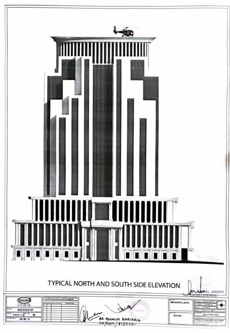
TYPICAL NORTH AND SOUTH SIDE ELEVATION j KAAL SHARM AZ0tZÍ57945
SMS HOSPITAL JAPYR Sincer S AE PVT LD
JAIPUR HELE ANOOP ARTARA
SMS/AELE-07 ELEVATON FOR STUD 00
AR ASHMITA BARIARIA A2oTtisozz
30/ 06/21
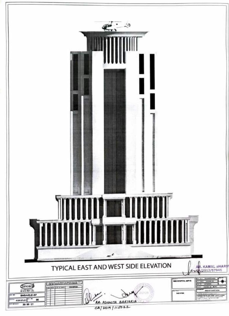
KAMAL SHAR AL2012/57946
TYPICAL EAST AND WEST SIDE ELEVATION
SMS HOSPITAL JAPYR
ENG lNs Sincere ANOOP BARTARIA
-
AIPUR ELEVATON
SMS/AVELE07
A ASHMI1A BARIARIA CA 2011 SDL2
00 FOR STUDY 30/ 06/21


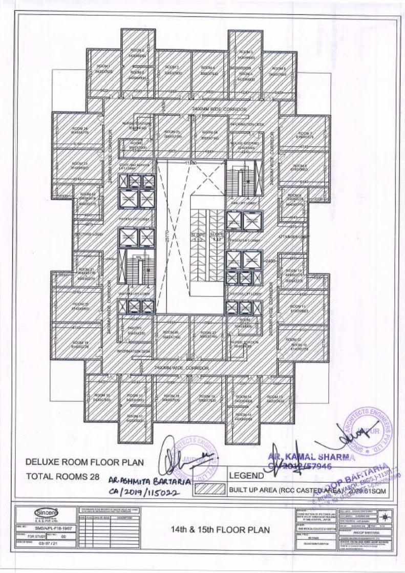


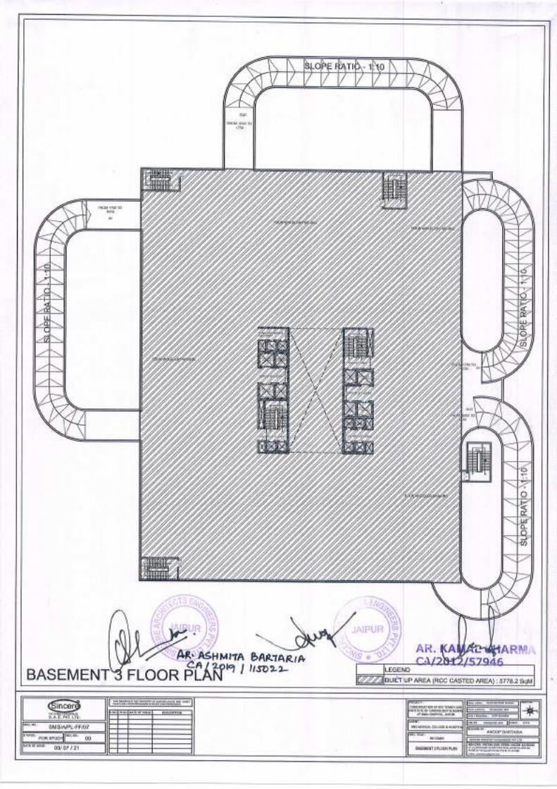

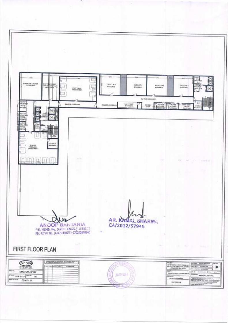


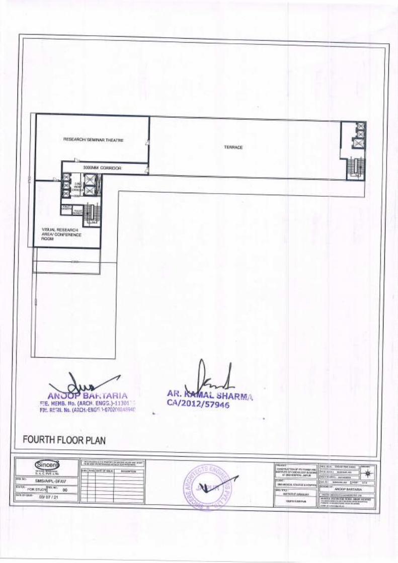


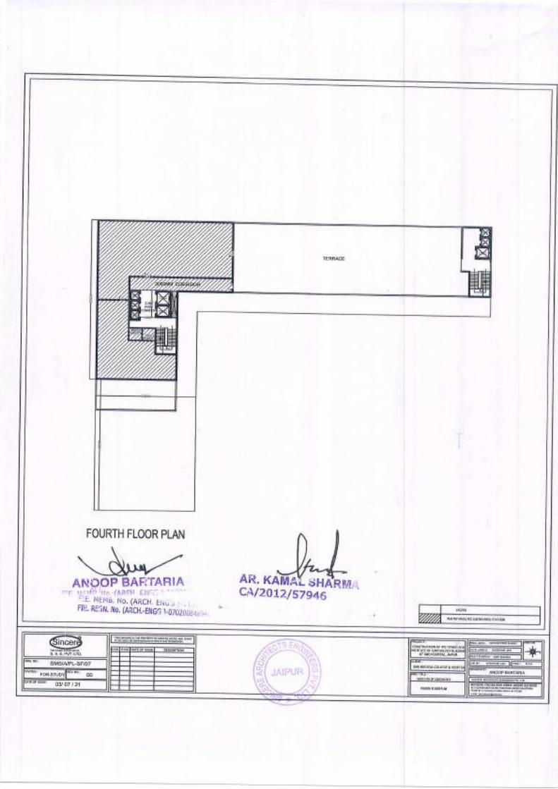


SAFETY, HEALTH&ENVIORMENTAL MANAGEMENT
VOLUME- V

General Conditions of Contract - Section - 4 J.D.A
Sign of Contractor 1 J.D.A
Volume V
SAFETY , HEALTH and ENVIRONMENT MANAGEMENT
CLAUSE

General Conditions of Contract - Section - 4 J.D.A
Sign of Contractor 2 J.D.A
LABOUR SAFETY PROVISIONS
1.0 Suitable scaffolds should be provided for workmen for all works that cannot safely be done from the ground, or from solid construction except such short period work as can be done safely from ladders. When a ladder is used an extra mazdoor shall be engaged for holding the ladder and if the ladder is used for carrying materials as well, suitable footholds and hand holds shall be provided on the ladder and the ladder shall be given an inclination not steeper than ¼ to 1 (1/4 horizontal and 1 vertical).
2.0 Scaffolding or staging more than 3.6m (12 feet) above the ground or floor,
swung or suspended from an overhead support or erected with stationery support shall have a guard rail properly attached or bolted, braced and otherwise secured at least 90 cm. (3 feet) high above the floor or platform of such scaffolding or staging and extending along the entire length of the outside and ends thereof with only such opening as may be necessary for the delivery of materials. Such scaffolding or staging shall be so fastened as to prevent it from swaying from the building or structure.
3.0 Working platforms, gangways, and stairways should be so constructed
that they should not sag unduly or unequally, and if the height of the platform or the gangway or the stairway is more that 3.6m (12 feet) above ground level or floor level, they should be closely boarded, should have adequate width & should be suitable fastened as described in (2.0) above.
4.0 Every opening in the floor of a building or in a working platform shall be
provided with suitable means to prevent the fall of persons or materials by providing suitable fencing or railing whose minimum height shall be 90 cm (3 feet).
5.0 Safe means of access shall be provided to all working platforms and other working places. Every ladder shall be securely fixed. No portable single ladder shall be over 9m. (30 feet) in length while the width between side rails in rung ladder shall in no case be less than 29 cm. (11.5”) for ladder up to and including 3m (10 feet) in length. For longer ladders this width should be increased at least 1/4" for each additional 30 cm (1 ft.) of length. Uniform step spacing shall not exceed 30 cm (12"). Adequate precautions shall be taken to prevent danger from electrical equipment. No materials on any of the sites of the work shall be so stacked or placed as to cause danger or inconvenience to any person or the public. The contractor shall provide all necessary fencing and lights to protect the public from accident, and shall be bound to bear the expenses of defense of every suit, action or other proceeding at law that may be brought by any person for injury sustained owing to neglect of the above precautions and to pay any damages and cost which may be awarded in any such suit, action or proceedings to any such person or which may, with the consent of the Contractor, be paid to compensate any claim by any such person.
6.0 EXCAVATION AND TRENCHING
All trenches, 1.2mts. (four feet) or more in depth, shall at all times be supplied with at least one ladder for each 30m. (100 feet) in length or fraction thereof, ladder shall be extended from bottom of the trench to at least 90cm (3feet) above the surface of the ground. The side of the trenches, which are 1.5 m. (5feet) or more in depth shall be stepped back to give suitable slope or securely held by timber bracing, so as to avoid the danger or sides to collapsing. The excavated materials shall not be placed within 1.5m (5 feet) of the edges of the trench or half of the depth of the trench whichever is more. Cutting shall be done from top to bottom. Under no circumstances undermining or undercutting shall be done.
General Conditions of Contract - Section - 4 J.D.A
Sign of Contractor 3 J.D.A
7.0 Demolition - Before any demolition work is commenced and also during
the progress of the work following precautions shall be observed:
7.1 All roads and open areas adjacent to the work site shall either be closed or suitably protected.
7.2 No electric cable or apparatus which is likely to be a source of danger or a
cable or apparatus used by the operator shall remain electrically charged.
7.3 All practical steps shall be taken to prevent danger to persons employed from risk or fire or explosion or flooding. No floor, roof or other part of the building shall be overloaded with debris or materials as to render it unsafe.
8.0 All necessary personal safety equipments as considered adequate by
the Engineer-in-charge should be kept available for the use of persons employed on the site and maintained in a condition suitable for immediate use, and the contractor should take adequate step to ensure proper use of equipment by those concerned. The following safety equipment shall be invariably provided.
8.1 Workers employed on mixing asphaltic materials, cement and lime
mortars shall be provided with protective footwear and protective goggles.
8.2 Those engaged in white washing and mixing or stacking of cement bags or any materials which are injurious to the eye shall be provided with protective goggles.
8.3 Those engaged in welding works shall be provided with welders protective eye
shields.
8.4 Stone breakers shall be provided with protective goggles and protective clothing and seated at sufficiently safe interval.
8.5 When workers are employed for works in sewers and manholes, which are in
active use, the Contractors shall ensure that the manhole covers are opened and ventilated at-least for an hour before the workers are allowed t o get into the manholes, and the manholes so opened shall be cordoned off with suitable railing and provided with warning signals or boards to prevent accident the public. In addition, the contractor shall ensure that the following safety measures are adhered to:
a. Entry for workers into the sewer line shall not be allowed except under
supervision of the JE or any other higher officer.
b. At least 5 to 6 manholes upstream and downstream should be kept open for at least 2 to 3 hours before any man is allowed to enter into the manholes for working inside.
c. Before entry, presence of Toxic gases should be tested by inserting wet
lead acetate paper which changes color in the presence of such gases and gives indication of their presence.
d. Presence of Oxygen should be verified by lowering a detector lamp into the
manhole. In case, no Oxygen is found inside the sewer line, workers should be sent only with Oxygen kit.
General Conditions of Contract - Section - 4 J.D.A
Sign of Contractor 4 J.D.A
e. Safety belt with rope should be provided to the workers. While working
inside the manholes such rope should be handled by two men standing outside to enable him to be pulled out during emergency.
f. The area should be barricaded or cordoned off by suitable means to avoid
mishaps of any kind. Proper warning signs should be displayed for the safety of the public whenever cleaning works are undertaken during night or day.
g. No smoking or open flames shall be allowed near the blocked manhole
being cleaned.
h. The malba obtained on account of cleaning of blocked manholes and sewer lines should be immediately removed to avoid accidents on account of slippery nature of the malba.
i. Workers should not be allowed to work inside the manhole continuously. He should be given rest intermittently. The Engineer-In-charge may decide the time up to which a worker may be allowed to work continuously inside the manhole.
j. Gas masks with Oxygen Cylinder should be kept at site for use in emergency.
k. Air-blowers should be used for flow of fresh air through the manholes. Whenever called for, portable air-blowers are recommended for ventilating the manholes. The Motors for these shall be vapour proof and of totally enclosed type. Non sparking gas engines also could be used but they should be placed at-least 2 metres away from the opening and on the leeward side protected from wind so that they will not be a source of friction on any inflammable gas that might be present.
l. The workers engaged for cleaning the manholes / sewers should be properly trained before allowing to work in the manhole.
m. The workers shall be provided with Gumboots or non-sparking shoes, bump helmets and gloves non sparking tools, safety lights and gas masks and portable air blowers (when necessary). They must be supplied with barrier cream for anointing the limbs before working inside the sewer lines.
n. Workmen descending a manhole shall try each ladder step or rung carefully before putting his full weight on it to guard against insecure fastening due to corrosion of the rung fixed to manhole well.
o. If a man has received a physical injury, he should be brought out of the sewer immediately and adequate medical aid should be provided to him.
p. The extent to which these precautions are to be taken depend on individual situation but the decision of the Engineer-In-charge regarding the steps to be taken in this regard in an individual case will be final.
8.6 The Contractor shall not employ men and women below the age of 18 years
on the work of painting with products containing lead in any form wherever men above the age of 18 are employed on the work of lead painting the following precautions should be taken.
8.6.1 No paint containing lead or lead products shall be used except in the form of
paste or readymade paint.

General Conditions of Contract - Section - 4 J.D.A
Sign of Contractor 5 J.D.A
8.6.2 Suitable face masks should be supplied for use by the workers when paint is
applied in the form of spray or a surface having lead paint is dry rubbed and scrapped.
8.6.3 Overalls shall be supplied by the Contractor to the workmen and
adequate facilities shall be provided to enable the working painters to wash during the cessation of work.
8.6.4.1a) White lead, sulphate or lead work products containing those pigments shall
not be used in painting operation except in the form of paste or of paints ready for use.
b) Measures shall be taken whenever required in order to prevent danger
arising from the application of paint in the form of spray.
c) Measures shall be taken, whenever practicable to prevent danger arising out of dust caused by dry rubbing down and scrapping.
8.6.4.2a) adequate facilities shall be provided to enable working painter to wash
during and on cessation of work.
b) Suitable arrangements shall be made to prevent clothing put off during working hours being spoiled by painting materials.
8.6.4.3a) Cases of lead poisoning and of suspected lead poisoning shall be notified
and shall be subsequently verified by a medical man appointed by the competent authorities of J.D.A.
b) The J.D.A may require when necessary a medical examination of workers.
c) Instructions with regard to the special hygienic precautions to be taken in the painting trade shall be distributed to working painters.
9.0 When the work is done near any place where there is risk of drowning,
all necessary equipments should be provided and kept ready for use and all necessary steps taken for prompt rescue of any person in danger and adequate provisions should be made for prompt first aid treatment for all injuries likely to be sustained during the course of the work.
10.0 Use of hoisting machines and tackle including their attachment encourage
and supports shall conform to the following standard of conditions.
10.1 a) these shall be of good mechanical construction, sound material and adequate strength and free from patent, defects and shall be kept in good working order.
b) Every rope used in hoisting or lowering materials or as a means of suspension shall be of durable quality and adequate strength, and free from patent defects.
10.2 Every crane driver or hoisting appliance operator shall be properly qualified
and no person under the age of 21 years should be in-charge of any hoisting machine including any scaffolding, winch or giving signals to operator.
10.3 In case of every hoisting machine and of every chain ring hook, shackle
swivel and pulley block used in hoisting or as means of suspension the safe working load shall be ascertained by adequate means. Every hoisting machine and all gear referred to above shall be plainly marked with the safe working load. In case of a hoisting machine having a variable safe working load, each
General Conditions of Contract - Section - 4 J.D.A
Sign of Contractor 6 J.D.A
safe working load and the conditions under which it is applicable shall be clearly indicated. No part of any machine or any gear referred to above in this clause shall be loaded beyond the safe working load except for the purpose of testing.
10.4 In case of J.D.A machines, the safe working load shall be notified by the
Engineer-in-Charge. As regards Contractor‟s machines the Contractor shall notify the safe working load of the machine to the Engineer-in-charge whenever he brings any machinery to site of work and get verified by the Engineer-in-Charge.
11.0 Motors gearing, transmission electric wiring and other dangerous parts
of hoisting appliances should be provided with efficient safeguard. Hoisting appliances should be provided with such means as will reduce to the minimum the risk of accidental descent of the load. Adequate precautions should be taken to reduce the minimum the risk of any part of a suspended load becoming accidentally displaced. When workers are employed on electrical installations, which are already energized, insulating mats, wearing apparel, such as gloves sleeves and boots as may be necessary be provided. The worker should not wear any rings, watches and carry keys or other materials, which are good conductors of electricity.
12.0 All scaffold, ladders, and other safety devices mentioned or described
herein shall be maintained in safe condition and no scaffold ladder or equipment shall be altered or removed while it is in use. Adequate washing facilities should be provided at or near places of work.
13.0 These safety provisions should be brought to the notice of all concerned
by display on a notice board at a prominent place of work spot. The person responsible for compliance of the safety codes shall be named therein by the contractor.
14.0 To ensure effective enforcement of the rules and regulations relating
to safety precautions the arrangements made by the Contractor shall be open to inspection by J.D.A Official or their representatives.
15.0 Notwithstanding the above Clauses from (i) to (xiv) there is nothing in these
to exempt the contractor from the operations of any other Act or Rule in force in the Republic of India.

General Conditions of Contract - Section - 4 J.D.A
Sign of Contractor 7 J.D.A
MODEL RULES FOR THE PROTECTION OF HEALTH AND
SANITARY ARRANGEMENTS FOR WORKERS
1.0 APPLICATION These rules shall apply to all building and construction works in which 20 (twenty) or more workers are ordinarily employed or are proposed to be employed in any day during the period during which the contractor work is in progress.
2.0 DEFINITION
Work place means a place where twenty or more workers are ordinarily employed or are proposed to be employed in connection with construction work on any day during the period during which the contract work is in progress.
3.0 FIRST-AID FACILITIES 3.1 At every work place first aid facilities shall be provided and maintained, so
as to be easily accessible during working hours, First-Aid boxes at the rate of not less than one box per 150 contract labour or part thereof ordinarily employed.
3.2 The First-Aid boxes shall be distinctly marked with a red cross on white
background and shall contain the following equipments:
3.2.1 a) For work places in which number of contract labour employed does not exceed 50, Each First-Aid box shall contain the following equipments: i. Small sterilized dressings.
ii. Medium size sterilized dressings.
iii. Large size sterilized dressings.
iv. Large sterilized burn dressings.
v. 1 (30 ml) bottle containing a two percent alcoholic solution of iodine.
vi. 1 (30 ml) bottle containing salvolatile having the dose and mode of administration indicated on the label.
vii. 1 snakebite lancet.
viii. 1 (30 gms) bottle of potassium permanganate crystals.
ix. 1 pair of scissors.
x. 1 copy of the First-Aid leaf-let issued by the Director General, Factory Advise Service & Labour Institute, Government of India.
xi. 1 bottle containing 100 tablets (each of 5 grams) of aspirin.
xii. Ointment for burns.
xiii. A bottle of suitable surgical antiseptic solution.
General Conditions of Contract - Section - 4 J.D.A
Sign of Contractor 8 J.D.A
3.2.2 For work places in which the number of contract labour exceed 50. Each First-
Aid box shall contain the following equipments:
i) 12 small sterilized dressings.
ii) 6 medium size sterilized dressings.
iii) 6 large size sterilized dressings.
iv) 6 large size sterilized burn dressings.
v) 6 (15 gms) packet sterilized cotton wool.
vi) 1 (60 ml.) bottle containing a two percent iodine alcoholic solution.
vii) 1 (60 ml.) bottle containing salvolatile having the dose and mode of administration indicated on the label.
viii) 1 - roll of adhesive plaster.
ix) 1 snake - bite lancet.
x) 1 (30 gms.) Bottle of potassium permanganate crystals.
xi) 1 pair of scissors.
xii) 1 copy of the First-Aid leaf-let issued by the Director General, Factory Advice Service and Labour Institutes, Government of India.
xiii) A bottle containing 100 tablets (each of 5 grams) of aspirin.
xiv) Ointment for burns.
xv) A bottle of suitable surgical antiseptic solution.
3.3 Adequate arrangements shall be made for immediate recoupment of the equipment when necessary.
3.4 Nothing except the prescribed contents shall be kept in the First Aid box.
3.5 The First Aid box shall be kept in charge of a responsible person who shall
always be readily available during the working hours of the work place.
3.6 A person in charge of the First-Aid box shall be a person trained in First-Aid treatment in work places where the number of labour employed is 150 or more.
3.7 In work places where the number of labour employed is 500 or more
and hospital facilities are not available within easy distance of the works, first- Aid Posts shall be established and run by a trained Compounder. The Compounder shall be on duty and shall be available at all hours when the workers are at work.
3.8 Where work places are situated in places, which are not towns of cities,
a suitable motor transport shall be kept readily available to carry injured person or persons suddenly taken ill to the nearest hospital.
4.0 DRINKING WATER 4.1 In every work place, there shall be provided and maintained at
suitable places, easily accessible to labour, a sufficient supply of cold water fit for drinking.

General Conditions of Contract - Section - 4 J.D.A
Sign of Contractor 9 J.D.A
4.2 Where drinking water is obtained from an intermittent public water
supply, each work place shall be provided with storage where such drinking water shall be stored.
4.3 Every water supply of storage shall be at a distance of not less than 50 feet
from any latrines drain or other source of pollution, where water has to be drawn from an existing well which is within such proximity of latrine, drain or any other source of pollution, the well shall be properly chlorinated before water is drawn from it for drinking. All such wells shall be entirely closed in and be provided with a trap-door which shall be dust and water-proof.
4.4 A reliable pump shall be fitted to each covered well, trap-door shall be kept
locked and opened only for cleaning or inspection which shall be done at least once a month.
5.0 WASHING FACILITIES 5.1 In every work place adequate and suitable facilities for washing shall be
provided and maintained for the use of labour employed herein.
5.2 Separate and adequate screening facilities shall be provided for the use of male and female workers.
5.3 Such facilities shall be conveniently accessible and shall be kept clean and
hygienic condition.
6.0 LATRINES AND URINALS 6.1 Latrines shall be provided in every work place on the following scale, namely:
a) Where females are employed there shall be at least one latrine for every
25 females.
b) Where males are employed, there shall be at least one latrine for every 25 males.
Provided that where the number of males or females exceeds 100, it shall be sufficient if there is one latrine for 25 males or females, as the case may be, upto the first 100, and one for every 50 thereafter.
6.2 Every latrine shall be under cover and so partitioned off as to secure privacy,
and shall have a proper door and fastenings.
6.3 Construction of Latrines: The inside walls shall be constructed of masonry or some suitable heat resisting non-absorbent materials and shall be cement washed inside and outside at least once a year. Latrine shall not be a standard lower than bore-hole system.
6.4 (a)Where workers of both sexes are employed, there shall be displayed
outside each block of latrine and urinal, a notice in the language understood by the majority of the workers "For Men only" or "For Women only" as the case may be.
(b)The notice shall also bear the figure of man or of a woman, as the case may be.
6.5 There shall be at least one urinal for male workers upto 50 and one
for female workers upto 50 employed at a time. Provided that where the number of male or female workmen, as the case may be, exceeds 500, it shall be sufficient if there is one urinal for every 50 males or females upto the first 500 and one for every 100 or part thereof, thereafter.
General Conditions of Contract - Section - 4 J.D.A
Sign of Contractor 10 J.D.A
6.6 a) The latrines and urinals shall be adequately lighted and shall
be maintained in a clean and sanitary condition at all times.
b) Latrines and urinals other than those connected with a flush sewerage system shall comply with the requirements of the Public Health Authorities.
6.7 Water shall be provided by means of a tap or otherwise so as to be
conveniently accessible in or near the latrines and urinals.
6.8 Disposal of Excreta Unless otherwise arranged for by the local sanitary authority arrangements for proper disposal of excreta by incineration at the work place shall be made by means of a suitable incinerator. Alternatively, excreta may be disposed off by putting a layer of night soil at the bottom of a pucca tank prepared for the purpose and covering it with a 15 cm layer of waste or for refuse and then covering it with a layer of earth for fortnight (when it will turn into manure).
6.9 The Contractor shall, at his own expense, carry out all instruction issued to
him by the Engineer-in-Charge to effect proper disposal of night soil and other conservancy work in respect of the Contractor's workmen or employees on the site. The Contractor shall be responsible for payment of any charges which may be levied by Municipal or Cantonment Authority for execution of such work on his behalf.
7.0 PROVISION OF SHELTER DURING REST
At every place, there shall be provided, free of cost, four suitable sheds, two for males and the other two for rest separately for the use of man and women labour. The height of each shelter shall not be less than 3 meters from the floor level to the lowest part of the roof. These shall be kept clean and the space provided shall be on the basis of 0.6 sqm. per head.
Provided that the Engineer-in-Charges may permit, subject to his satisfaction, a portion of the building under construction or other alternative accommodation to be used for the purpose.
8.0 CRECHES 8.1 A every work place, at which 20 or more women workers are ordinarily
employed, there shall be provided two rooms of reasonable dimensions for the use of their children under the age of six years. One room shall be used as a play room for the children and the other as their bedrooms.
The rooms shall be constructed on standard not lower than the following: i) Thatched roof
ii) Mud floor and walls.
iii) Planks spread over the mud floor and covered with matting
8.2 The rooms shall be provided with suitable and sufficient openings for light
and ventilation. There shall be adequate provision of sweepers to keep the places clean.
8.3 The Contractor shall supply adequate number of toys and games in the
playroom and sufficient number of cots and beddings in the bed-room.
General Conditions of Contract - Section - 4 J.D.A
Sign of Contractor 11 J.D.A
8.4 The Contractor shall provide one Ayaa to look after the children in the crèche
when the number of women workers does not exceed 50; and two when, the number of women workers exceed 50.
8.5 The use of the rooms/earmarked as creches shall be restricted to children, their attendant and mother of the children.
9.0 CANTEENS 9.1 In every work place where the work regarding the employment of contract
labour is likely to continue for six months and wherein contract labour numbering one hundred or more are ordinarily employed, an adequate canteen shall be provided by the Contractor for the use of such labour.
9.2 The canteen shall be maintained by the Contractor in an efficient manner.
9.3 The canteen shall consist of at least a dining hall, kitchen, and storeroom, pantry and washing places separately for workers and utensils.
9.4 The canteen shall be sufficiently lighted at all times when any person has access to it.
9.5 The floor shall be made of smooth and impervious material and inside walls
shall be lime washed or colour washed at least once in each year.
Provided that the inside walls of the kitchen shall be lime-washed every four months.
9.6 The premises of the canteen shall be maintained in a clean and sanitary condition.
9.7 Waste Water shall be carried away in suitable covered drains and shall not be allowed to accumulate so as to cause a nuisance.
9.8 Suitable arrangements shall be made for the collection and disposal of garbage.
9.9 The dining hall shall accommodate at a time 30 persons of the labour working at time.
9.10 The floor area of the dining hall, excluding the area occupied by the service counter and any furniture except tables and chair shall not be less than one square metre per dinner to be accommodated.
9.11 a) A portion of the dining hall, and service counter shall be partitioned off
and reserved for women workers in proportion to their number.
b) Washing places for women shall be separate and screened to secure privacy.
9.12 Sufficient tables, stool, chairs or benches shall be available for the number
of dinners to be accommodated.
9.13.1 a) There shall be provided and maintained sufficient utensils, crockery, furniture and any other equipment necessary for the efficient running of the canteen.
b) The furniture, utensils and other equipment shall be maintained in a clean and hygienic condition.
9.13.2 a) Suitable clean clothes for the employees serving in the canteen shall be provided and maintained. b) A service counter, if provided, shall have top of smooth and impervious material.

General Conditions of Contract - Section - 4 J.D.A
Sign of Contractor 12 J.D.A
c) Suitable facilities including an adequate supply of hot water shall be provided for the cleaning of utensils and equipment.
9.14 The food stuffs and other items to be served in the canteen shall be in
conformity with the normal habits of the labour.
9.15 The charge for food stuffs, beverages and any other items served in the canteen shall be based on 'No profit' No loss' and shall be conspicuously displayed in the canteen.
9.16 In arriving at price of food stuffs, and other articles served in the canteen,
the following items shall not be taken into consideration as expenditure, namely: a) The rent of land building;
b) The depreciation and maintenance charges for the building and equipment
provided for the canteen;
c) The cost of purchase, repair and replacement of equipment including furniture, crockery, cutlery and utensils;
d) The water charges and other charges incurred for lighting and ventilation;
e) The interest and amounts spent on the provision and maintenance and
equipment provided for in the canteen;
9.17 The accounts pertaining to the canteen shall be audited once every 12 months by registered accountants and auditors.
10.0 ANTI MALARIAL PRECAUTIONS
The Contractor shall at his own expense, conform to all anti-malarial instructions given to him by the Engineer-in-Charge including the filling up of any borrows pits which may have been dug by him.
11.0 AMENDMENTS
J.D.A may from time to time, add to or amend these rules and issue such directions as it may consider necessary for the purpose of removing any difficulty which may arise in the administration hereof.

General Conditions of Contract - Section - 4 J.D.A
Sign of Contractor 13 J.D.A
CONTRACTOR‟S LABOUR REGULATIONS
1.0 SHORT TITLE
These regulations may be called the Contractor "Labour Regulations".
2.0 Definitions 2.1 “Workman" means any person employed by the J.D.A or its Contractor
directly or indirectly through a sub-contractor, with or without the knowledge, of the J.D.A to do any skilled, semi-skilled, un-skilled, manual, supervisory, technical or clerical work for hire or reward, whether, the terms of employment are expressed or implied but does not include any person-
a) Who is employed mainly in a managerial or administrative capacity; or
b) Who being employed in a supervisory capacity draws wages exceeding Rupees Two Thousand Five hundred per person or exercises either by the nature of the duties attached to the office or by reason of powers vested to him, functions mainly of managerial nature.
c) Who is an out worker, that is to say, a person to whom any articles or materials are given out by or on behalf of the principal employer to be made up cleaned, washed, altered, ornamental finished, repaired, adopted or otherwise processed for sale for the purpose of the trade or business of the principal employer and the process is to be carried out either in the home of the out worker or in some other premises, not being premises under the control and management of the principal employer.
2.2 "Fair Wages" means wages whether for time or piece work fixed and notified under the provisions of the minimum Wages Act from time to time.
2.3 "Contractor" shall include every person who undertake to produce a given
result other than a mere supply of goods or articles of manufacture through labour or who supplies labour for any work and includes a sub-contractor.
2.4 "Wages" shall have the same meaning as defined in the Payment of Wages
Act.
2.4.1 Normally working hours of an adult employee should not exceed 9 hours a day. The working day shall be so arranged that inclusive of interval for rest, if any, it shall not spread over more than 12 hours on any day.
2.4.2 When an adult worker is made to work for more than 9 hours on any day or
for more than 48 hours in any week he shall be paid overtime for the extra hours put in by him at double the ordinary rate of wages.
2.4.3.1 Every worker shall be given a weekly holiday on a Sunday, in accordance
with the provisions of the Minimum Wages (Central) Rules 1960 as amended from time to time, irrespective of whether such worker is governed by the Minimum Wages Act or not.
2.4.3.2 Whether the Minimum Wages prescribed by the Government under the
Minimum Wages Act are not inclusive of the wages for the weekly day of rest, the worker shall be entitled to rest day wages at the rate applicable to the next preceding day, provided he has worked under the same contractor for a continuous period of not less than 6 days.
General Conditions of Contract - Section - 4 J.D.A
Sign of Contractor 14 J.D.A
2.4.3.3 Where a contractor is permitted by the Engineer-in-Charge to allow a worker
to work on a normal weekly holiday, he shall grant a substitute holiday to him for the whole day on one of the five days immediately before or after the normal weekly holidays and pay wages to such worker for the work performed on the normal weekly holiday at overtime rate.
3.0 DISPLAY OF NOTICE REGARDING-WAGES, ETC.
The contractor shall before he commences his work on contract, display and correctly maintain and continue to display and correctly maintain in a clean and legible condition in conspicuous places on the work, notices in English and in the local Indian languages spoken by the majority of the workers, giving the minimum rates of wages fixed under the Minimum Wages Act, the actual wages being paid, the hours of work for which such wages are earned, wage period, dates of payment of wages and other relevant information as per Appendix 'A'.
4.0 PAYMENT OF WAGES 4.1 The contractor shall fix wage periods in respect of which wages shall be
payable.
4.2 No wage period shall exceed one month.
4.3 The wages of every person employed as labour in an establishment or by a contractor where less than one thousand, such persons are employed shall be paid before the expiry of the seventh day and in other cases before the expiry of tenth day after the last day of the wage period in respect of which the wages are payable.
4.4 Where the employment of any worker is terminated by or on behalf of the
contractor the wages earned by him shall be paid before the expiry of the second working day from the date on which his employment is terminated.
4.5 All payments of wages shall be made on a working day at the work premises
and during the working time and on a date notified in advance and in case the work is completed before the expiry of the wage period, final payment shall be made within 48 hours of the last working day.
4.6 Wages due to every worker shall be paid to him direct or to other
person authorized by him in this behalf.
4.7 All wages shall be paid in current coin or currency or in both.
4.8 Wages shall be paid without any deductions of any kind except those specified by the Central Government by general or special order in this behalf or permissible under the Payment of Wages Act 1956.
4.9 A notice showing the wage period and the place and time of disbursement of
wages shall be displayed at the place of work and a copy sent by the contractor to the Engineer-in-Charge under acknowledgment.
4.10 It shall be the duty of the contractor to ensure the disbursement of wages in
the presence of the Engineer or any other authorized representatives of the Engineer-in-Charge who will be required to be present at the place and time of disbursement of wages by the contractor to workmen.
4.11 The contractor shall obtain from the Engineer or any other authorized
representative of the Engineer-in-Charge as the case may be, a certificate under his signature at the end of the entries in the "Register of Wages" or the "Wage-cum-Muster Roll" as the case may be in the following form:
General Conditions of Contract - Section - 4 J.D.A
Sign of Contractor 15 J.D.A
"Certified that the amount shown in column No. 14(net Amount paid) has been paid to the workmen concerned in my presence on................ at ............".
5.0 FINES AND DEDUCTIONS, WHICH MAY BE MADE FROM WAGES 5.1 The wages of a worker shall be paid to him without any deduction of any
kind except the following –
a) Fines
b) Deductions for absence from duty i.e. from the place or the places where by the terms of his employment he is required to work. The amount of deduction shall be in proportion to the period for which he was absent.
c) Deduction for damage to or loss of goods expressly entrusted to the employed persons for custody, or from loss of money or any other deduction which he is required to account where such damage or loss is directly attributable to his neglect or default.
d) Deduction for recovery of advances or for adjustment of over payment of wages, advances granted shall be entered in a register.
e) Any other deduction, which the Central Government may from time to time allow.
5.2 No fines should be imposed on any worker save in respect of such acts and
omissions on his part as have been approved by the Chief Labour Commissioner.
NOTE: An approved list of Acts and Omissions for which fines can be imposed is
enclosed at Appendix-I. 5.3 No fine shall be imposed on a worker and no deduction for damage or loss
shall be made from his wages until the worker has been given an opportunity of showing cause against such fines or deductions.
5.4 The total amount of fine which may be imposed in any one wage period on a
worker shall not exceed an amount equal to three paisa in a Rupee of the total wages, payable to him in respect of that wage period.
5.5 No fine imposed on any worker shall be recovered from him in installment,
or after the expiry of sixty days from the date on which it was imposed. 5.6 Every fine shall be deemed to have been imposed on the day of the act or
omission in respect of which it was imposed. 6.0 LABOUR RECORDS 6.1 The contractor shall maintain a "Register of persons employed" on work on
contract in form XIII of the CL (R&A) Central Rules 1971 (Appendix-B). 6.2 The contractor shall maintain a "Muster Roll" register in respect of
all workmen employed by him on the work under contract in from XVI of the CL (R&A) Rules 1971 (Appendix-C).

General Conditions of Contract - Section - 4 J.D.A
Sign of Contractor 16 J.D.A
6.3 The contractor shall maintain a "Wage Register" in respect of all workmen
employed by him on the work in form (Appendix-D). 6.4 Register of accidents - The contractor shall maintain a register of accidents
in such form as may be convenient at the work place but the same shall include the following particulars:
a) Full particulars of the labourers who met with accident.
b) Rate of wages
c) Sex
d) Age
e) Nature of accident and cause of accident.
f) Time and date of accident.
g) Date and time when he/she admitted in Hospital
h) Date of discharge from the Hospital
i) Period of treatment and result of treatment
j) Percentage of loss of earning capacity and disability as assessed by Medical Officer.
k) Claim required to be paid under Workmen's Compensation Act.
l) Date of payment of compensation.
m) Amount paid with details of the person to whom the same was paid.
n) Authority by whom the compensation was assessed.
o) Remarks.
6.5 Register of Fines - The contractor shall maintain a "Register of Fines" in the form (Appendix-H).
The contractor shall display in a good condition and in a conspicuous place of work the approved list of Acts and Omission for which fines can be imposed (Appendix-I).
6.6 Register of Deductions – The contractor shall maintain Deductions" for damage or loss in form (Appendix-J).
a "Register of
6.7 Register of Advances – The contractor shall maintain Advances" in form (Appendix-K).
a "Register of
6.8 Register of Overtime - The contractor shall maintain a "Register of
Overtime" in form (Appendix-L). 7.0 ATTENDANCE CARD-CUM WAGE SLIP: 7.1 The contractor shall issue an attendance card-cum-wage slip to each
workman employed by him in the specimen form at (Appendix-E). 7.2 The card shall be valid for each wage period.
7.3 The contractor shall mark the attendance of each workman on the card
twice each day, once at the commencement of the day and again after the rest interval, before he actually starts work.

General Conditions of Contract - Section - 4 J.D.A
Sign of Contractor 17 J.D.A
7.4 The card shall remain in possession of the worker during the wage period
under reference. 7.5 The contractor shall complete the wage slip portion on the reverse of the
card at least a day prior to the disbursement of wages in respect of the wage period under reference.
7.6 The contractor shall obtain the signature or thump impression of the worker
on the wage slip at the time of disbursement of wages and retain the card with himself.
8.0 EMPLOYMENT CARD
The contractor shall issue an Employment Card in form to each worker within three days of the employment of the worker (Appendix-F).
9.0 SERVICE CERTIFICATE
On termination of employment for any reason whatsoever the contractor shall issue to the workman whose services have been terminated, a service certificate in from Appendix-G.
10.0 PRESERVATION OF LABOUR RECORDS
All records required to be maintained under Regulations Nos. 6 and 7 shall be preserved in original for a period of three years from the date of last entries made in them and shall be made available for inspection by the Engineer-in-Charge, Labour Officer.
11.0 POWER OF LABOUR OFFICERS TO MAKE INVESTIGATIONS INQUIRY
The Labour Officer or any other person authorized by J.D.A on its behalf shall have power to make inquire with a view to ascertaining and enforcing due and proper observance of the Fair Wage Clauses and the Provisions of Regulations. He shall investigate into any complaint regarding the default made by the contractor or sub-contractor in regard to such provision.
12.0 INSPECTION OF BOOK AND SLIPS
The contractor shall allow inspection of all the prescribed labour records to any of his workers or to his agent at a convenient time and place after due notice is received or to the Labour officer or any other person, authorized by the Central Government on his behalf.
13.0 SUBMISSION OF RETURNS
The contractor shall submit periodical returns as may be specified from time to time.
14.0 AMENDMENTS
The J.D.A may from to time, add or amend the regulations and on any question as to the application, interpretation or effect of these regulations the decision of the Zonal Chief concerned shall be final.

General Conditions of Contract - Section - 4 J.D.A
Sign of Contractor 18 J.D.A
Appendix - 'A'
LABOUR BOARD
Name of work
Name of Contractor
Address of Contractor
Name and Address of Unit
Name of Labour Enforcement Officer
Address of Labour Enforcement Officer
Date:
S. No.
Category Minimum wage fixed
Actual wages paid
Number present Remarks
Weekly Holiday
Wage Period
Date of Payment of wages
Working hours
Rest interval

General Conditions of Contract - Section - 4 J.D.A
Sign of Contractor 19 J.D.A
Appendix - 'B'
FORM 13
See rule 75
REGISTER OF WORKMEN EMPLOYED BY CONTRACTOR
Name and Address of Contractor
Name and Address of Establishment in under which contract is carried on
Nature and location of work
Name & Address of Principal Employer
Sl. No. Name and surname
of workman
Age & sex
Father‟s Husbands
Name
Nature of employment /
designation
Permanent home address of the
workman (village and Tehsil Taluk
and District)
Local address
1. 2. 3. 4. 5. 6. 7.
Date of commencement of
Employment
Signature or thumb
impression of the
workman
Date of termination of employment
Reasons for termination
Remarks
1. 2. 3. 4. 5.

General Conditions of Contract - Section - 4 J.D.A
Sign of Contractor 20 J.D.A
FORM XVI
(See Rule 78(2) (193)
MUSTER ROLL Name and address of contractor
Name and address of establishment in/under which contract is carried on
Nature and location of work
Name and Address of Principal Employer
For the month / fortnight
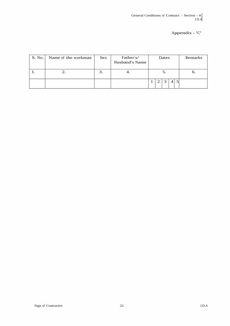
General Conditions of Contract - Section - 4 J.D.A
Sign of Contractor 21 J.D.A
Appendix - 'C'
S. No. Name of the workman Sex Father‟s/ Husband‟s Name
Dates Remarks
1. 2. 3. 4. 5. 6.
1 2 3 4 5

General Conditions of Contract - Section - 4 J.D.A
Sign of Contractor 22 J.D.A
Appendix - 'D'
FORM XVII (See Rule)
78(2) (03) REGISTER OF
WAGES
Name and address of contractor
Name and address of establishment in/under which contract is carried on
Nature and location of work
Name and Address of Principal Employer
Wage period: per month/ fortnightly
S. No. Name of Workman
Serial No. in the
register of workman
Designation nature of
work done
Nos. of days
worked
Units of work done
Daily rate of wages/ piece rate
Basic Wages
1. 2. 3. 4. 5. 6. 7. 8.
Dearness allowance
Overtime Other cash payments (Nature of payments
to be indicated)
Total Deduction if any
(indicate nature)
Net Amt paid
Signature thumb
impression of the
workman
Initial contractor or
his representative
9. 10. 11. 12. 13. 14. 15. 16.

General Conditions of Contract - Section - 4 J.D.A
Sign of Contractor 23 J.D.A
Appendix - 'E‟
FORM XIX
[ SEE RULE 78 (2) (B) ]
W A G E S L I P
Name and address of contractor
Name and Father's/Husband/s Name of workman
Nature and location of work
For the Week/Fortnight/Month ending
1. No. of days worked
2. No. of Units worked in case of piece rate workers
3. Rate of daily wags/piece rate
4. Amount of overtime wages
5. Gross wages payable
6. Deductions if any
7. Net amount of wages paid
Sign of the Contractor

General Conditions of Contract - Section - 4 J.D.A
Sign of Contractor 24 J.D.A
Appendix - 'F'
WAGE CARD Wage Card No.
Name and address of Contractor Date of Issue
Nature of work with location Designation
Name of workman Month/Fortnight
Rate of Wages
1 2 3 4 5 6 7 8 9 10 11 12 13 14 15 16 17 18 19 20 21 22 23 24 25
26 27 28 29 30 31
Morning Rate
Evening Amount
Initial
Received from the sum of Rs. On account
of my wagon.
Signature
The wage card is valid for one month from the date of issue.

General Conditions of Contract - Section - 4 J.D.A
Sign of Contractor 25 J.D.A
Appendix 'F'
FORM XIV
(See Rule 76)
EMPLOYMENT CARD
Name and address of contractor
Name and address of establishment under which The contract is carried out
Nature and location of work
Name and address of Principal Employer
1. Name of the workman
2. S. Name in the register of workman employed
3. Nature of Employment/Designation
4. Wage rate (with
particulars of unit in case of piece work)
5. Wage Period
6. Tenure of employment
7. Remarks
Signature of Contractor
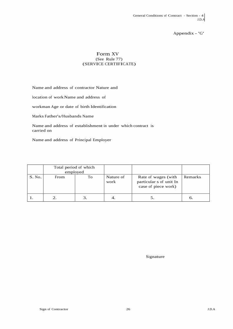
General Conditions of Contract - Section - 4 J.D.A
Sign of Contractor 26 J.D.A
Appendix - 'G'
Form XV (See Rule 77)
(SERVICE CERTIFICATE)
Name and address of contractor Nature and
location of work Name and address of
workman Age or date of birth Identification
Marks Father's/Husbands Name
Name and address of establishment in under which contract is carried on
Name and address of Principal Employer
Total period of which employed
S. No. From To Nature of work
Rate of wages (with particular s of unit In case of piece work)
Remarks
1. 2. 3. 4. 5. 6.
Signature

General Conditions of Contract - Section - 4 J.D.A
Sign of Contractor 27 J.D.A
Appendix 'H
Form XII
[See Rule 78 (2) (d)]
REGISTER OF FINES
Name and address of contractor
Name and address of establishment in/ under which contract is carried on
Nature and location of work
Name and address of workman
Name and address of Principal Employer
S. No. Name of workman
Father‟s/Husband Name
Designation/nature of employment
Act/Omission for which
fine imposed
Date of offence
1.
2.
3.
4.
5.
6.
Whether workman showed cause
against fine
Name of person in whose presence
employees explanation was
heard
Wage period and wages
payable
Amount of fine Imposed
Date on which fine realized
Remarks
7.
8.
9.
10.
11.
12.
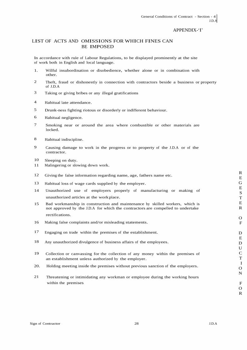
General Conditions of Contract - Section - 4 J.D.A
Sign of Contractor 28 J.D.A
APPENDIX-„I‟
LIST OF ACTS AND OMISSIONS FOR WHICH FINES CAN
BE IMPOSED
In accordance with rule of Labour Regulations, to be displayed prominently at the site of work both in English and local language.
1. Willful insubordination or disobedience, whether alone or in combination with
other.
2
Theft, fraud or dishonestly in connection with contractors beside a business or property of J.D.A
3
Taking or giving bribes or any illegal gratifications
4
Habitual late attendance.
5
Drunk-ness fighting riotous or disorderly or indifferent behaviour.
6
Habitual negligence.
7
Smoking near or around the area where combustible or other materials are locked.
8
Habitual indiscipline.
9
Causing damage to work in the progress or to property of the J.D.A or of the contractor.
10
Sleeping on duty. 11 Malingering or slowing down work.
12
Giving the false information regarding name, age, fathers name etc. REGESTER
OF
DEDUCTI
ON
FOR
13 Habitual loss of wage cards supplied by the employer.
14 Unauthorized use of employers properly of manufacturing or making of
unauthorized articles at the work place.
15 Bad workmanship in construction and maintenance by skilled workers, which is not approved by the J.D.A for which the contractors are compelled to undertake
rectifications.
16 Making false complaints and/or misleading statements.
17
Engaging on trade within the premises of the establishment. 18 Any unauthorized divulgence of business affairs of the employees.
19 Collection or canvassing for the collection of any money within the premises of
an establishment unless authorized by the employer.
20. Holding meeting inside the premises without previous sanction of the employers.
21
Threatening or intimidating any workman or employee during the working hours
within the premises
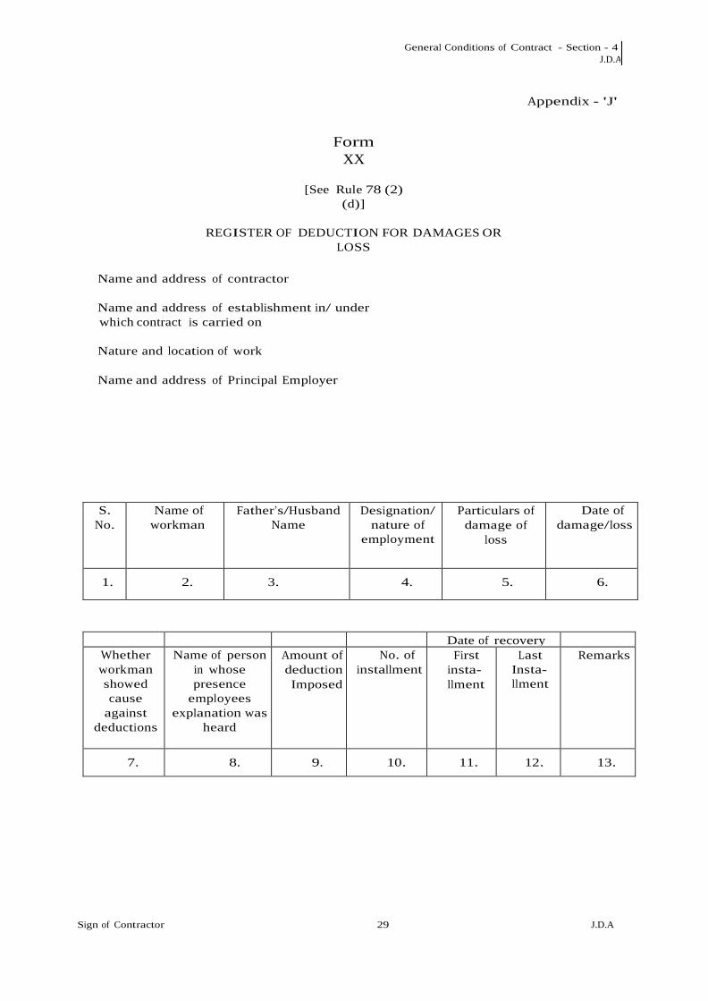
General Conditions of Contract - Section - 4 J.D.A
Sign of Contractor 29 J.D.A
Appendix - 'J'
Form XX
[See Rule 78 (2)
(d)]
REGISTER OF DEDUCTION FOR DAMAGES OR LOSS
Name and address of contractor
Name and address of establishment in/ under which contract is carried on
Nature and location of work
Name and address of Principal Employer
S. No.
Name of workman
Father‟s/Husband Name
Designation/ nature of
employment
Particulars of damage of
loss
Date of damage/loss
1.
2.
3.
4.
5.
6.
Date of recovery Whether workman showed cause
against deductions
Name of person in whose presence
employees explanation was
heard
Amount of deduction Imposed
No. of installment
First insta- llment
Last Insta- llment
Remarks
7.
8.
9.
10.
11.
12.
13.

General Conditions of Contract - Section - 4 J.D.A
Sign of Contractor 30 J.D.A
Appendix - 'K'
Form XXII
(See Rule 78(2))
REGISTER OF ADVANCES
Name and address of contractor
Name and address of establishment in/ under which contract is carried on
Nature and location of work
Name and address of Principal Employer
S. No. Name of workman
Father‟s/ Husband‟s
Name
Designation/ nature of
employment
Wages period and wages
payable
Date and amount of advance
given
1.
2.
3.
4.
5.
6.
Purpose / for which advance
made
No. of installments by
which advance is to be paid
Date and amount of each
installment repaid
Date on which last installment
was repaid
Remarks
7.
8.
9.
10.
11.

General Conditions of Contract - Section - 4 J.D.A
Sign of Contractor 31 J.D.A
Appendix - 'L'
Form XXIII [See Rule 78(2)
(e)] REGISTER OF
OVERTIME
Name and address of contractor
Name and address of establishment in/ under which contract is carried on
Nature and location of work
Name and address of Principal Employer
S. No. Name of workman
Father‟s/ Husband‟s
Name
Sex Designation/ nature of
employment
Date on which
overtime worked
1.
2.
3.
4.
5.
6.
Total overtime worked or
production in case of piece
rated
Normal rate of wages
Overtime rate of wages
Overtime earning
Rate on which
overtime wages paid
Remarks
7 8 9 10 11 12

END OF VOLUME

Bidder
Name :
NUMBER
#
TEXT # NUMBER # TEXT # NUMBER # NUMBER # TEXT #
Sl.
No.
Item Description Quantity Units BASIC RATE
In
Figures To be
entered by the
Bidder
Rs. P
TOTAL AMOUNT
Without Taxes
TOTAL AMOUNT
In Words
1 2 3 4 5 6 71.0
1.00 Job
0.0000 INR Zero Only
Total in Figures 0.0000 INR Zero Only
Quoted Rate in Words INR Zero Only
PRICE SCHEDULE
(This BOQ template must not be modified/replaced by the bidder and the same should be uploaded after filling the relevent columns, else the bidder is
liable to be rejected for this tender. Bidders are allowed to enter the Bidder Name and Values only )
Item Rate BoQ
Tender Inviting Authority: JAIPUR DEVELOPMENT AUTHORITY, JAIPUR
Name of Work: Construction of IPD Tower and Institute of Cardiology at SMS Hospital, Jaipur on Engineering, Procurement & Construction (EPC) basis
Contract No: JDA/EE (ROB/RUB-IV)/01/2021-22
The Engineering Design, Procurement and
Construction (EPC) finishing works & internal
finishing works, flooring, false roofing, wall finishing,
flooring processing etc of Framed Structure building
based on architectural design given by Consultant
(Architect) appointed by SMS Hospital including civil
works, external (façade) internal electrical works,
internal plumbing works, firefighting work Air
conditioning works, Horticulture, Landscaping and
external development etc. as per scope of work and
tender documents including preparation of coordinated
drawings for all services and make all necessary
coordination for satisfactory execution of all
works/activities in time bound manner. Develop
various activities including Air ambulance land
platform (helicopter). 3D animation and model of the
buildings.
(FOR IPD TOWER Building and Institute of
Cardiology Building Both)
Validate Print HelpValidate Print Help
Copyright © 2022 FDOKUMEN