


MANUEL DU FILTRE D'ÉCHANGE D'IONS AVEC RÉSINES ...
93
MANUEL DU FILTRE D'ÉCHANGE D'IONS AVEC RÉSINES DE DÉMINÉRALISATION Image représentative Manuel G¶XWLOLVDWHXU x DMI135 x DMI175 x DMI225 x DMI300 x DMI350
-
Upload
khangminh22 -
Category
Documents
-
view
0 -
download
0
Transcript of MANUEL DU FILTRE D'ÉCHANGE D'IONS AVEC RÉSINES ...

MANUEL DU FILTRE D'ÉCHANGE D'IONS AVEC RÉSINES DE DÉMINÉRALISATION
Image représentative
Manuel G¶XWLOLVDWHXU� x DMI135 x DMI175 x DMI225 x DMI300 x DMI350

DMI135-DMI350_Aqua-Ionic_V2.0
1
Contenu
1. PRÉSENTATION ««««««««««««««««««««««««««««««.2 2. RECOMMANDATIONS ET AVERTISSEMENT͙͙͙͙͙͙͙͙͙͙͙͙͙͙͙͙͙͙͙͙͙͙͙͙..͙2 ���,1752'8&7,21«««««««««««««««««««««««� «««««««.3 4. DESCRIPTION DE L'ÉQUIPEMENT ««««««««««««««���...........................5 5. CONSIDÉRATIONS PRÉALABLES ««««««««««««««««««««««..5 6. INSTALLATION «««««««««««««««««««««««««««««««.6 7. SYSTÈME D'EXPLOITATION «««««««««««««««««««««««««.7 8. DÉMARRAGE �««««««««««««««««««««««««««««««««8 ���63e&,),&$7,216�7(&+1,48(6�'(6�5e6,1(6�&$7,21,48(6�(7�$1,21,48(6�«11 10. TABLEAU DES FLUX ««««««««««««««««««««««««««««.21 11. FICHES DE SUIVI ««��«««««««««««««««««««���............................23 12. DÉCLARATION DE CONFORMITÉ ««««««««««««««���............................28 13. GARANTIE DE L'ÉQUIPEMENT ««««««««««««««««««««««««30 14. ANNEXE I : PANNEAU D'ALIMENTATION ET DE PROTECTION ÉLECTRIQUE ««����� 15. ANNEXE II : MONTAGE, UTILISATION ET ENTRETIEN DU CINTROPUR NW25͙͙͙. 34 16. ANNEXE III : FICHE TECHNIQUE VALVE SIATA V132 ««�«««««««««««...37 17. ANNEXE IV : MANUEL DE LA VALVE SIATA 9�«««««««««««««««««40 18. ANNEXE V : MANUEL DU PROGRAMMEUR AQUA ,21,48(««««���.......................66

DMI135-DMI350_Aqua-Ionic_V2.0
2
1. PRÉSENTATION
Nous vous souhaitons la bienvenue et vous remercions de faire confiance à nos produits de déminéralisation automatisée et filtrants industriels par résine échangeuse d'ions.
IMPORTANT: CONSERVEZ CE MANUEL.
2. RECOMMANDATIONS ET AVERTISSEMENTS
Avant d'utiliser l'appareil pour la première fois, lisez attentivement ce manuel et les documents qui l'accompagnent. Toute utilisation non conforme à ce qui est indiqué dans ce manuel éliminera toute responsabilité de la part d'OSMOFILTER S.L.
Il faut être particulièrement attentif à la manipulation des agents chimiques nécessaires à la régénération des résines, tels que l'acide chlorhydrique (HCl) et la soude (NaOH). L'utilisation de matériaux de protection est nécessaire. Ne pas pénétrer dans une pièce fermée s'il y a un risque de vapeurs chimiques.
La qualité de l'eau d'alimentation des équipements est directement liée à la performance du système. L'augmentation et la diminution des ions dans l'eau modifient les paramètres de fonctionnement de l'équipement.
La pression dynamique d'entrée dans l'installation doit être d'au moins 2,5 bars. Si la pression est inférieure à 2 bars, une unité de pression est probablement nécessaire en aval du filtre automatique.
Ne réduisez pas la section du tuyau d'alimentation de l'équipement, installez un diamètre égal ou supérieur à la connexion incorporée dans l'équipement.
La pression maximale de fonctionnement de l'équipement est de 6 bars. Débranchez l'équipement si cette pression est dépassée.
Ne fermez en aucun cas le robinet de vidange. Toutes les vannes doivent être actionnées par du personnel qualifié.
Oja Solutions

DMI135-DMI350_Aqua-Ionic_V2.0
3
La tension d'alimentation du tableau de distribution est monophasée à 230 V ± 10V et possède une fréquence de 50 Hz.
L'emplacement du filtre de déminéralisation automatique doit être correct, en tenant compte des distances adéquates par rapport aux murs, aux alimentations hydrauliques et électriques, aux drains et autres équipements éventuels, il nécessite un espace suffisant pour l'entretien requis par l'équipement.
Vérifier l'existence d'un drain à proximité de l'emplacement de l'équipement, avec une capacité suffisante pour évacuer le flux du rejet et les irrégularités par rapport à ce même équipement.
L'équipement nécessite un circuit d'air comprimé pour alimenter le système de distribution SIATA qui commande les vannes pneumatiques, NON INCLUS DANS L'EQUIPEMENT.
3. INTRODUCTION
Filtres échangeurs d'ions automatiques à base de résines cationiques et anioniques pour la réduction ou l'élimination des sels dans l'eau directe comme traitement de l'eau ou après traitement d'un autre système existant, régénération avec un produit acide pour la résine cationique et alcalin pour la résine anionique, montés sur une structure métallique et contrôle de la conductivité du sel selon les besoins et les exigences de l'installation.
Déminéralisation automatique VALVES SIATA
DMI135 Déminéralisation automatique SIATA 132 150L
DMI225
DMI350
Déminéralisation automatique SIATA 132 225 L
Déminéralisation automatique SIATA 132 350 L
Réf. Description Charge totale
DM 175 Déminéralisation automatique SIATA 132 175 L
DM 300 Déminéralisation automatique SIATA 132 300 L

DMI135-DMI350_Aqua-Ionic_V2.0
4
Cationic charge:
Connection:
DMI135 DMI175 DMI225 DMI300 DMI350
Anionic charge:
Dimensions:
Image représentative
75 L 100 L 125 L 175 L 200 L
Dimensions DMI135 DMI175 DMI225 DMI300 DMI350 A (mm) 460 460 675 675 675 B (mm) 410 410 790 790 1.070 H (mm) 1.750 2.000 2.000 2.000 2.250
Unités en millimètres.
Charge cationique: 75 L 75 L 100 L 125 L 150 L
Connexion: �´ �´ �´ �´ �´
Vol. 500 ppm: 7 m3 9 m3 12 m3 15 m3 19 m3
Vol. 500 ppm: 7 m3 9 m3 12 m3 15 m3 19 m3
Vol. 1.000 ppm: 3,60 m3 4,40 m3 5,50 m3 8,10 m3 9 m3
Vol. 1,000 ppm: 3.60 m3 4.40 m3 5.50 m3 8.10 m3 9 m3
Vol. 1.500 ppm: 2,40 m3 3,20 m3 3,50 m3 5,20 m3 6,10 m3
Vol. 1,500 ppm: 2.40 m3 3.20 m3 3.50 m3 5.20 m3 6.10 m3

DMI135-DMI350_Aqua-Ionic_V2.0
5
4. DESCRIPTION DE L'ÉQUIPEMENT
L'usine de déminéralisation est principalement composée de :
- Pré-filtration composée d'un filtre manuel Cintropur NW25 et d'un tissu avec une filtration
allant jusqu'à 25 microns.
- Alimentation électrique et panneau de protection à une tension électrique de 230V ± 10V -50Hz.
- Kit de vannes SIATA 132 de 1" pour la déminéralisation, composé de :
*Microprocesseur Aqua Ionic.
*132 Corps de vanne anionique/cathiotique.
*Programmeur 7 pilotes pour les deux valves de déminéralisation (seulement 6 pilotes effectifs)
*Capteur de conductivité pour une mesure continue.
*Vanne pneumatique pour l'acide chlorhydrique et l'hydroxyde de sodium
*Panneau électrique pour l'alimentation et la protection.
- Colonne de résine cationique, composée d'une bouteille enroulée en GRP et d'une forte
charge de résine cationique.
- Colonne de résine anionique, composée d'une bouteille enroulée en GRP et d'une forte
charge de résine anionique.
- Réservoirs de dosage en polyéthylène pour le produit chimique régénérateur
de la résine, normalement de l'acide HCl et du NaOH alcalin.
- Rotamètre et vannes.
- Socles en acier inoxydable 316.
REMARQUE: Les régénérants ne seront pas fournis avec l'équipement, ils doivent donc
être fournis avant la mise en service.
TRÈS IMPORTANT: Tout l'équipement comptera l'eau fournie pour le service pendant le
cycle de régénération. Si l'on veut éviter cela et avoir de l'eau brute disponible pour le service
pendant la phase de régénération de l'équipement, celui-ci doit être équipé d'un by pass
automatique.
5. CONSIDÉRATIONS PRÉALABLES
5.1. Le drainage de chaque colonne de déminéralisation doit être conduit à un réservoir de neutralisation avant le rejet ou la gestion (selon la réglementation applicable).
Il faut s'assurer qu'il n'y a pas de possibilité de retour par ce drainage qui pourrait affecter le bon fonctionnement de l'équipement. Le niveau du drain sera toujours en dessous de la sortie de la vanne de déminéralisation. Si ce n'est pas le cas, veuillez

DMI135-DMI350_Aqua-Ionic_V2.0
6
nous consulter.
5.2. Il est très important que l'installation soit protégée des agressions du temps, principalement de l'action directe du soleil, des températures extrêmes, de la pluie et de l'humidité, il est donc conseillé de l'installer dans des espaces fermés et correctement ventilés. Le lieu d'installation de l'équipement doit avoir des dimensions minimales qui permettent d'accéder à toutes les parties de l'équipement avec confort, afin de faciliter l'entretien et le rechargement des réservoirs de produits chimiques de régénération de la résine. La surface du sol sur laquelle l'équipement est installé doit être parfaitement plane et doit comporter une sortie pour l'évacuation des eaux.
5.3. La régénération se fait à l'aide d'acide chlorhydrique et de soude. Ces produits sont dangereux. Le stockage et la manipulation doivent être effectués par du personnel spécialisé. Utilisez des lunettes de protection, des gants et d'autres moyens de protection personnelle. Identifier clairement les produits chimiques et tenez à jour les fiches de données de sécurité.
5.4. Le contrôleur Aqua Ionic peut fonctionner avec de l'air comprimé ou de l'eau. Nous recommandons d'utiliser de l'air comprimé à une pression de +0,5 bar au- dessus de la pression de fonctionnement.
5.5. Assurez-vous que l'alimentation en eau soit adaptée au débit de l'eau à traiter, avec une pression comprise entre 3 et 3,5 kg/cm2. En cas de pressions inférieures, il sera nécessaire d'installer un système de pompage qui assure le débit et la pression adéquats. Pour des pressions plus élevées, il sera nécessaire d'installer un réducteur de pression. Pour un fonctionnement correct, l'alimentation en eau doit être constante 24 heures sur 24.
5.6. Raccordez l'équipement à l'alimentation électrique 230V ± 10V -50Hz sur une ligne séparée avec une alimentation constante 24 heures sur 24. Il suffit d'amener la ligne électrique au panneau d'alimentation et de protection.
6. INSTALLATION
x L'installation des équipements doit être conforme à la réglementation en vigueur
sur les installations électriques et hydrauliques à basse tension. x Il est toujours conseillé d'installer un filtre clarificateur préliminaire pour protéger
la vanne et les résines de l'équipement et de l'installation en général contre les matières en suspension, les impuretés, les gravillons, etc. fréquents dans le réseau de distribution ou les eaux de forage de surface ou souterraines.
x Tous les composants du système de traitement seront installés en général ou individuellement via des by-pass pour chacun d'eux, afin de faciliter les opérations de maintenance et de pouvoir les isoler si nécessaire, sans couper l'alimentation en eau de l'installation.
x Les raccords d'entrée et de sortie de la vanne de déminéralisation sont indiqués par les flèches directionnelles correspondantes. S'il y a un élément chauffant dans l'installation, un clapet anti-retour doit être installé pour éviter que l'eau chaude n'endommage accidentellement le déminéralisateur.
x Vérifiez l'état du tube de distribution de la bouteille. L'extrémité supérieure du tube doit être biseautée pour éviter de pincer le joint torique d'étanchéité de la valve.
x Placez le tube à l'intérieur de la bouteille, en vous assurant qu'il atteigne bien le fond. De cette façon, le tube doit être au niveau du goulot de la bouteille ou de la réduction en PVC.
x Couvrez la partie supérieure du tube distributeur pour qu'il ne se remplisse pas

DMI135-DMI350_Aqua-Ionic_V2.0
7
de résine. x Remplissez chaque bouteille avec la résine correspondante, cationique pour la
première colonne et anionique pour la seconde. x Lorsque la résine est épuisée, terminez le remplissage de toute la bouteille avec
de l'eau et nettoyez la résine qui reste sur le filetage de la bouteille. x Débouchez le tube distributeur. Prenez la valve et faites coïncider le tube
distributeur avec la crêpine supérieure de la valve. Vissez la valve. x Remplissez les réservoirs de régénérant dans chaque colonne et raccordez les
tubes d'aspiration du régénérant des soupapes de sécurité aux douilles situées sur le dessus des soupapes.
x Vérifiez que tous les raccordements hydrauliques et pneumatiques ont été effectués correctement.
x L'alimentation électrique sera ininterrompue 24 heures sur 24 pour assurer le bon fonctionnement de l'équipement.
x La sortie prévue dans le banc de déminéralisation sera dirigée vers le drain correspondant.
7. SYSTÈME D'EXPLOITATION
Dans les conditions de SERVICE, l'eau entre dans l'équipement de déminéralisation d'abord dans la colonne CATHIONIQUE, où les cations de l'eau sont échangés contre des ions H+, puis elle entre dans la colonne ANIONIQUE où les anions de l'eau sont échangés contre des anions OH-, ce qui permet d'obtenir une eau déminéralisée d'une grande pureté. L'équipement dispose d'une sonde de mesure de la conductivité de l'eau traitée, située à la sortie de la deuxième colonne de l'équipement avant les deux électrovannes (Service et Rinçage), afin de contrôler la qualité de l'eau traitée au moyen du programmateur à microprocesseur dont il est équipé.
Si la qualité de l'eau est supérieure à la valeur programmée dans le point de consigne, le programmateur ouvrira l'électrovanne de service et l'équipement fonctionnera normalement.
En raison du fonctionnement du déminéralisateur lui-même, les résines seront progressivement saturées jusqu'à ce que l'on obtienne une eau de qualité inférieure à celle souhaitée. Lorsque cette circonstance se produit, le programmateur fermera l'électrovanne de service et ouvrira celle de lavage pendant 5 minutes. Si après ce temps, la qualité de l'eau traitée a été rétablie, le programmateur ouvrira à nouveau l'électrovanne de service et fermera la vanne de lavage. Si, par contre, après ce délai, la qualité de l'eau n'a pas été rétablie, l'unité procédera à la régénération.

DMI135-DMI350_Aqua-Ionic_V2.0
8
8. DEMARRAGE
Lorsque l'équipement est connecté hydrauliquement, pneumatiquement et électriquement, procédez comme suit:
- La première étape consiste à introduire les données dans le programmateur logique (PROGRAMMATION FACTORIELLE, AJUSTEMENT AUX CONDITIONS PARTICULIÈRES DE L'INSTALLATION)
- Ensuite, la régénération des résines dans les colonnes sera effectuée manuellement. Comme ceci: - Pressuriser le système et corriger les éventuelles fuites d'eau si nécessaire - Le programmateur AQUA IONIC est déjà installé et alimenté électriquement par le panneau électrique de l'équipement, appuyez sur le bouton de régénération manuelle
NOTE IMPORTANTE: 2 À 3 RÉGÉNÉRATIONS DE L'ÉQUIPEMENT PEUVENT ÊTRE NÉCESSAIRES POUR GARANTIR QUE LES RÉSINES SONT COMPLÈTEMENT RÉGÉNÉRÉES POUR UN FONCTIONNEMENT CORRECT.
Assurez-vous que le travail est effectué par un personnel compétent.
- L'équipement est programmé en usine avec des paramètres de démarrage, qui doivent être vérifiés et réajustés au démarrage. Principalement ceux liés à la valeur de consigne, au délai de temporisation pour le démarrage automatique de la régénération, aux temps de cycle 2 et 6 correspondant à l'aspiration de l'acide et de la soude.
- Pendant le cycle 2, la colonne cationique doit aspirer les litres de régénérant du réservoir d'acide selon le tableau des paramètres de fonctionnement de la page suivante, selon le modèle d'équipement, tout comme, pendant le cycle 6, la colonne anionique doit aspirer les litres du réservoir de soude comme indiqué sur le tableau.
- Les temps doivent être ajustés en fonction de l'installation, du débit à traiter par l'équipement et de la pression de l'eau en entrée (limitée à 6 bars maximum)
- Contre lavage et lavage rapide. - Aspiration de la colonne cationique. - Aspiration de la colonne anionique.
Une fois la régénération terminée, analyser la conductivité, le pH d'entrée et de sortie de l'équipement et les enregistrer dans le tableau de suivi. Il est possible que la première régénération ne donne pas des résultats totalement satisfaisants, avant de lancer une autre régénération, il est conseillé de saturer légèrement les résines.

DMI135-DMI350_Aqua-Ionic_V2.0
9
cationic
(m3/h)
pilotage
Valeur du point de consigne
PARAMÈTRES DE FONCTIONNEMENT:
DMI135 DMI175 DMI225 DMI300 DMI350
Volume sur la Résine Anonymisée
anionic 75 L
100 L 125 L 175 L 200 L
Pression minimale 2.5 bar 2,5 bar 2,5 bar 2,5 bar 2,5 bar Pression minimale de 2.5 bar 2,5 bar 2,5 bar 2,5 bar 2,5 bar
Consommation d'acide régénérant
21 L 21 L 28 L 35 L 42 L
Consommation de régénérateurs alcalins
soda [NaOH] 50%
10 L 14 L 17 L 24 L 27 L
Mode de régénération Automatique Automatique Automatique Automatique Automatique NOTE
REMARQUE: .Le processus de régénération doit être supervisé par un technicien compétent ڰ La consommation de régénérant doit être contrôlée avec un intérêt particulier ڰ
et doit être ajustée en fonction de la particularité de l'installation.
Volume de la résine 75 L 75 L 100 L 125 L 150 L
Débit de service 1 - 1.5 2-2.5 2.5-3 3 ± 4 5-6
[HCl] 33%
Consommation de produits
Consommation de produits alcalins [NaOH] [NaOH]
en %

DMI135-DMI350_Aqua-Ionic_V2.0
10
DMI135 DMI175 DMI225 DMI300 DMI350
Cycle 1 lavage (min)
: Contre- cationique
Cycle 2 : Aspiration cationique (min)
Cycle 3 : Lavage cationique lent (min)
Cycle 4 cationique (min)
: Lavage rapide
Cycle 5 : Rétrolavage anionique (min)
Cycle 6 : Aspiration anionique (min)
Cycle 7 : Lavage anionique lent (min)
Cycle 8 anionique (min)
: Lavage rapide
Temps de régénération: (à fixer lors de la mise en service sur site) Veuillez vous assurer
que cette tâche soit effectuée par un technicien qualifié.

DMI135-DMI350_Aqua-Ionic_V2.0
9. SPÉCIFICATIONS TECHNIQUES DES RÉSINES CATIONIQUES ET ANIONIQUES
RÉSINE ÉCHANGEUSE D'IONS CATIONIQUE
RÉSINE ÉCHANGEUSE D'IONS AIONIQUE (Pages suivantes)

1/5
This document contains important informationand must be read in its entirety.
Edition: 2019-10-08
Previous Edition: 2018-08-01
Lewatit® MonoPlus S 108 H is a strongly acidic, gelular cation exchange resin with beads of uniform size(monodisperse) based an a styrene-divinylbenzene copolymer, in fully regenerated form . Due to a specialmanufacturing process this resin type is extremely resistant to chemical, osmotic and mechanical stress.That leads to very low leachables even under critical conditions like higher temperatures, presence ofoxidants (02, Fe-oxides) and external regeneration processes. Even at very short cycle times (one cycle =service + regeneration) the special ion exchange resin matrix leads to long life cycles in demineralizationprocesses.
The high total capacity results in high operating capacities with a very low ionic leakage and a very highregenerant utilization. The extremely high monodispersity and very low fines content results in particularlylow pressure losses paired with an efficient and cost optimized operation of demineralization plants.
Lewatit® MonoPlus S 108 H is especially suitable for:
» demineralization of water for industrial steam generation operated with co-current or modern counter-current systems like e.g. Lewatit WS System, Lewatit Liftbed System or Lewatit Rinsebed System» polishing using the Lewatit Multistep System or a conventional mixed bed arrangement in combinationwith the following anion components: Lewatit® MonoPlus M 500 MB, Lewatit® MonoPlus M 800, Lewatit®
MonoPlus M 600, Lewatit® MonoPlus MP 500, Lewatit® MonoPlus MP 800 and Lewatit® MonoPlus MP600.
Lewatit® MonoPlus S 108 H adds special features to the resin bed:
» high flow rates during regeneration and loading» a high operating capacity at low regenerant consumption» a low demand for rinse water» a homogeneous throughput of regenerants, water and solutions, resulting in a homogeneous operatingzone» a virtually linear pressure drop gradient across the entire bed depth, allowing operation with higher beddepths» a low TOC emission and high resistance to oxidative stress» good separation of the components in mixed bed applications.
The special properties of this product can only be fully utilized if the technology and process usedcorrespond to the current state-of-the-art. Further advice in this matter can be obtained from Lanxess,Business Unit Liquid Purification Technologies.
PRODUCT INFORMATION/(:$7,7p�0RQR3OXV�6�����+

2/5
This document contains important informationand must be read in its entirety.
Edition: 2019-10-08
Previous Edition: 2018-08-01
Common DescriptionDelivery form H+
Functional group Sulfonic acid
Matrix Styrenic
Structure Gel
Appearance Black
Specified DataUniformity coefficient max. 1.1
Mean bead size d50 mm 0.65 (+-0.05)
Total capacity (deliveryform)
min. eq/L 2.0
PRODUCT INFORMATION/(:$7,7p�0RQR3OXV�6�����+

3/5
This document contains important informationand must be read in its entirety.
Edition: 2019-10-08
Previous Edition: 2018-08-01
Typical Physical and Chemical PropertiesBulk density for shipment (+/- 5%) g/L 790
Density approx. g/mL 1.22
Water retention (deliveryform)
approx. weight % 47-53
Volume change (H+ -Na+)
max. approx. % -10
Stability pH range 0-14
Storage time (afterdelivery)
max. years 2
Storage temperaturerange
°C -20 - +40
Operation
PRODUCT INFORMATION/(:$7,7p�0RQR3OXV�6�����+

4/5
This document contains important informationand must be read in its entirety.
Edition: 2019-10-08
Previous Edition: 2018-08-01
Operating temperature max. °C 140
Operating pH range during exhaustion 2-14
Bed depth for singlecolumn
min. mm 800
Bed depth percomponent in mixed bed
min. mm 500
Back wash bedexpansion per m/h(20°C)
% 4.5
Specific pressure losskPa*h/m2 (15°C)
kPa*h/m2 (15°C) 1
Max. pressure lossduring operation
kPa 250
Specific flow rate max. BV/h 60
RegenerationHCl regeneration concentration approx. wt. % 4-6
HCl regeneration quantity co-current min. g/L resin 100
HCl regeneration quantity counter-current min. g/L resin 55
H2SO4 regeneration concentration approx. wt. % 1.5-8
H2SO4 regeneration quantity co-current min. g/L resin 120
H2SO4 regeneration quantity counter-current min. g/L resin 80
Regeneration contacttime
min. minutes 20
Slow rinse atregeneration flow rate
min. BV 2
Fast rinse at service flowrate
min. BV 2
PRODUCT INFORMATION/(:$7,7p�0RQR3OXV�6�����+

5/5
This information and our technical advice – whether verbal, in writing or by way of trials –
are given in good faith but without warranty, and this also applies where proprietary rights
of third parties are involved. Our advice does not release you from the obligation to check
its validity and to test our products as to their suitability for the intended processes and
uses. The application, use and processing of our products and the products manufactured
by you on the basis of our technical advice are beyond our control and, therefore, entirely
your own responsibility. Our products are sold in accordance with the current version of
our General Conditions of Sale and Delivery.
This document contains important informationand must be read in its entirety.
Edition: 2019-10-08
Previous Edition: 2018-08-01
LANXESS Deutschland GmbHLiquid Purification TechnologiesKennedyplatz 150569 KoelnGermany
www.lanxess.comwww.lpt.lanxess.com
Additional Information & Regulations
Safety precautionsStrong oxidants, e.g. nitric acid, can cause violent reactions if they come into contact with ion exchangeresins.
ToxicityThe safety data sheet must be observed. It contains additional data on product description, transport,storage, handling, safety and ecology.
DisposalIn the European Community Ion exchange resins have to be disposed, according to the European wastenomenclature which can be accessed on the internet-site of the European Union.
StorageIt is recommended to store ion exchange resins at temperatures above the freezing point of water underroof in dry conditions without exposure to direct sunlight. If resin should become frozen, it should not bemechanically handled and left to thaw out gradually at ambient temperature. It must be completely thawedbefore handling or use. No attempt should be made to accelerate the thawing process.
PackagingThe experience has shown that the packaging stability for reliable resin containment is limited to 24 monthsunder the storage conditions described above. It is therefore recommended to use the product within thistime frame; otherwise the packaging condition should be checked regularly.
PRODUCT INFORMATION/(:$7,7p�0RQR3OXV�6�����+

1/4
This document contains important informationand must be read in its entirety.
Edition: 2019-07-02
Previous Edition: 2018-10-23
Lewatit® MonoPlus M 600 is a strongly basic, gelular anion exchange resin (type II) with beads of uniformsize (monodisperse) based on a styrene-divinylbenzene copolymer, designed for all demineralizationapplications. The monodisperse beads have high chemical and osmotic stability. The extremely highmonodispersity and very low fines content result in particularly low pressure losses compared with standardresins.
Due to the excellent regeneration efficiency and high operating capacity Lewatit® MonoPlus M 600 isgenerally used for waters in which silica and carbon dioxide concentrations are moderate. For higher silicafeeds, a type I anion exchange resin such as Lewatit® MonoPlus M 500 is recommended.
Lewatit® MonoPlus M 600 is especially suitable for:
» the demineralization of water for industrial steam generation operated with co-current or modern counter-current systems like e.g. Lewatit® WS System, Lewatit® Liftbed System or Lewatit® Rinsebed System» polishing using the Lewatit Multistep System in combination with Lewatit® MonoPlus S 108 H or Lewatit®
MonoPlus S 200 KR
Lewatit® MonoPlus M 600 adds special features to the resin bed:
» high flow rates during regeneration and loading» good utilization of the total capacity» low rinse water requirement» homogeneous throughput of regenerants, water and solutions, resulting in a homogeneous operating zone» virtually linear pressure drop gradient across the entire bed depth, allowing operation with higher beddepths
The special properties of this product can only be fully utilized if the technology and process usedcorrespond to the current state-of-the-art. Further advice in this matter can be obtained from Lanxess,Business Unit Liquid Purification Technologies.
PRODUCT INFORMATION/(:$7,7p�0RQR3OXV�0����

2/4
This document contains important informationand must be read in its entirety.
Edition: 2019-07-02
Previous Edition: 2018-10-23
Common DescriptionDelivery form Cl-
Functional group Quaternary ammoniumType 2
Matrix Styrenic
Structure Gelular
Appearance Yellow, translucent
Specified DataUniformity coefficient max. 1.1
Mean bead size d50 mm 0.62 (+/- 0.05)
Total capacity (deliveryform)
min. eq/L 1.3
PRODUCT INFORMATION/(:$7,7p�0RQR3OXV�0����

3/4
This document contains important informationand must be read in its entirety.
Edition: 2019-07-02
Previous Edition: 2018-10-23
Typical Physical and Chemical PropertiesBulk density for shipment (+/- 5%) g/L 680
Density approx. g/mL 1.1
Water retention (deliveryform)
approx. weight % 45-50
Volume change (Cl- -OH-) max. approx. % 16
Stability pH range 0-14
Storage time (afterdelivery)
max. years 2
Storage temperaturerange
°C -20 - +40
OperationOperating temperature max. °C 30
Operating pH range during exhaustion 0-12
Bed depth for singlecolumn
min. mm 800
Back wash bedexpansion per m/h(20°C)
% 10
Specific pressure losskPa*h/m2 (15°C)
kPa*h/m2 (15°C) 1
Max. pressure lossduring operation
kPa 200
Specific flow rate max. BV/h 60
RegenerationNaOH regeneration concentration approx. wt. % 2-6
NaOH regeneration quantity co-current min. g/L resin 80
NaOH regeneration quantity counter-current min. g/L resin 40
Regeneration contacttime
min. minutes 20
Slow rinse atregeneration flow rate
min. BV 2
Fast rinse at service flowrate
min. BV 2
PRODUCT INFORMATION/(:$7,7p�0RQR3OXV�0����

4/4
This information and our technical advice – whether verbal, in writing or by way of trials –
are given in good faith but without warranty, and this also applies where proprietary rights
of third parties are involved. Our advice does not release you from the obligation to check
its validity and to test our products as to their suitability for the intended processes and
uses. The application, use and processing of our products and the products manufactured
by you on the basis of our technical advice are beyond our control and, therefore, entirely
your own responsibility. Our products are sold in accordance with the current version of
our General Conditions of Sale and Delivery.
This document contains important informationand must be read in its entirety.
Edition: 2019-07-02
Previous Edition: 2018-10-23
LANXESS Deutschland GmbHLiquid Purification TechnologiesKennedyplatz 150569 KoelnGermany
www.lanxess.comwww.lpt.lanxess.com
Additional Information & Regulations
Safety precautionsStrong oxidants, e.g. nitric acid, can cause violent reactions if they come into contact with ion exchangeresins.
ToxicityThe safety data sheet must be observed. It contains additional data on product description, transport,storage, handling, safety and ecology.
DisposalIn the European Community Ion exchange resins have to be disposed, according to the European wastenomenclature which can be accessed on the internet-site of the European Union.
StorageIt is recommended to store ion exchange resins at temperatures above the freezing point of water underroof in dry conditions without exposure to direct sunlight. If resin should become frozen, it should not bemechanically handled and left to thaw out gradually at ambient temperature. It must be completely thawedbefore handling or use. No attempt should be made to accelerate the thawing process.
PackagingThe experience has shown that the packaging stability for reliable resin containment is limited to 24 monthsunder the storage conditions described above. It is therefore recommended to use the product within thistime frame; otherwise the packaging condition should be checked regularly.
PRODUCT INFORMATION/(:$7,7p�0RQR3OXV�0����

DMI135-DMI350_Aqua-Ionic_V2.0
12
10. TABLEAU DES FLUX
(Page suivante)

&�?5
$)$?���'(60
,1(5
$/,=$&,2
1?���)2
726�'
(60,1?9���B��SQJ
&�?5
$)$?���'(60
,1(5
$/,=$&,2
1?���)2
726�'
(60,1?9���B��SQJ
'0,�������B5
HY�����GZJ
&�?5
DID?���)272
6�,0$*
(1(6?ORJRBRVP
RILOWHU�MSJ
3ROtJRQR�,QGXVWULDO�9,,��$YGD��3LFDVVHQW����
�������6LOOD��9DOHQFLD�
7HOHI�����������������)D[�������������(�P
DLO��RVPRVILOWHU#
RVPRILOWHU�FRP
ZZZ�RVP
RILOWHU�FRP
5+$
5+$
�
��������������
6�(
'LE
XMDG
R�SRU�
'UDZ
Q�E\�'HVVLQp�SDU�
$SUR
EDG
R�S
RU�$SSURYHG�E\�
$SSURXYp�SDU�
3ODQ
R�3ODQ�3ODQ�
'HVFULS
FLyQ�
'HVFULSWLRQ�
'HVFULSWLRQ�
1RP
EUH�DUFK
LYR�)LOHQDP
H�1RP
�GX�ILFKLHU�
5HYLVDG
R�S
RU�5HYLVHG�E\�
9pULILp�SDU�
)HFKD�
'DWH�
'DWH�
5HYLVLyQ
�5HYLVLRQ�
5pYLVLRQ�
(VFDOD�
(VFDOH�eFKHOOH�j�
',$
*5$0
$�+
,'5È8
/,&2
�'0,����'
0,����'
0,����'
0,����'
0,���
'0,����'
0,����'
0,����'
0,����'
0,����)/2
:�&
+$5
725*$1,*
5$00(�'
0,����'
0,����'
0,����'
0,����'
0,���
5+$
&$7,2
1,&
$1,2
1,&
9���'
39&���
39&���
39&���
&(
9)����
52
����
%$����
'3����
7XELQJ� �� �
39&�������
.����;�������������
.����;�������������
'$����
3(','
2�91
��������&
/,(17(�2
-$'
0,���
'3����
0$��
%%����%%����
(175
$'$
6$/,'$
'(6$*
h(
(9������9$&�1
&�$�9(���
(9������9$&�1
&�$�9(���

DMI135-DMI350_Aqua-Ionic_V2.0
13
11. FICHE DE SUIVI
FICHE DE SUIVI DU MATÉRIEL DE DÉMINÉRALISATION DMI135 COLONNE CATIONIQUE 75 L COLONNE ANIONIQUE 75 L
PROGRAMMATION DES VALEURS PAR DÉFAUT
Valeur du point déterminé: Temporisation du point déterminé : Cycles: 1º 2º
3º 4º PARAMÈTRES DE TRAVAIL
Flux de services: Température de l'eau: Conductivité d'entrée: Conductivité de sortie: Ph d'entrée: Ph de Sortie: Pression d'entrée: Pression de sortie:
COLONNE CATIONIQUE COLONNE ANIONIQUE Contre-lavage Contre-lavage Débit Aspiration Débit Aspiration Flux de lavage rapide Flux de lavage rapide Régénérer la consommation
Régénérer la consommation
OBSERVATIONS:
Régénération nº: Cycle en m3: Homogénéisation du pH: Technique:

DMI135-DMI350_Aqua-Ionic_V2.0
14
12. DÉCLARATION DE CONFORMITÉ
(Page suivante)

DÉCLARATION DE CONFORMITÉ. /D��VRFLpWp�GpFODUH�TXH�O¶pTXLSH�
MODÈLE��«DMI135�������«������������������������������������������������������������������������������������
SERIE Nº: «F-2012-749..............................................................................
ANNÉE DE FABRICATION: ...2020««������������������������������������..............................
Tel que décrit dans la documentation ci-jointe, il est conforme aux exigences essentielles de la Directive Communataire:
- 2006/42/CE Directive sur la sécurite des machines
que dans sa conception et sa fabrication, les aspects entonces dans les normes harmonisées suivants ont été pris en compte à la fois en tout et en partie:
- UNE-(1�,62�������������³6pFXULWp�GH�OD�PDFKLQH��3ULQFLSHV�JpQpUDX[�SRXU�la conception. Évaluation des risques et réducion des risques´�
- UNE-EN 60204-1:������³6pFXUWLp�GH�OD�PDFKLQH��(TXLSHPHQW�pOHFWULTXH�GH�
machines.
Partie 1: Exigences générales. ayant constitué le fichier de construction technique correspondant et consigné aux fins appropriées, émet cette declaration de conformité.
VALENCIA, 30 / 12 / 2020
José Santos-Gerente

DMI135-DMI350_Aqua-Ionic_V2.0
15
13. GARANTIE SUR LE MATÉRIEL
Données du client : Nom : ................................... Adresse : ............................................................... Code postal et ville.............................................................................................. Téléphone : ................................. Courriel : .....................................
Date de la vente du matériel : .................................................. Détails du vendeur : Nom de l'entreprise : ................................................................ Adresse : ............................ Code postal et ville ................................................................................... Téléphone : ............................... FAX : ............................. Courrier électronique : .......................................
TOUS NOS PRODUITS SONT GARANTIS PENDANT UN AN À COMPTER DE LA DATE D'ACHAT (NON APPLICABLE À LA LOI 23/2003 SELON LA LOI 26/1984). SI UNE RÉPARATION EST EFFECTUÉE, ELLE AURA UNE GARANTIE DE 3 MOIS, ÉTANT INDÉPENDANTE DE LA GARANTIE GÉNÉRALE. POUR LA COUVERTURE DE CETTE GARANTIE, LA DATE D'ACHAT DU PRODUIT DOIT ÊTRE ACCRÉDITÉE.
L'entreprise s'engage à garantir les pièces défectueuses de fabrication, à condition qu'elles nous soient envoyées pour examen dans nos locaux aux frais du client.
Afin de faire valoir la garantie, la pièce défectueuse doit être accompagnée du présent bon de garantie, dûment complété et visé par le vendeur. La garantie sera toujours donnée dans nos entrepôts.
Dans tous les cas, notre responsabilité est exclusivement de remplacer ou de réparer les matériaux défectueux, et non de payer des indemnités ou autres frais.
Aucun retour ou réclamation de matériel ne sera accepté après 15 jours de réception
En cas d'accord dans ce délai, le matériel doit nous être ENVOYÉ PARFAITEMENT EMBALLÉ A L'ADRESSE DE NOTRE ENTREPÔT.

DMI135-DMI350_Aqua-Ionic_V2.0
16
LA GARANTIE N'EST PAS VALABLE POUR:
1. Le remplacement, la réparation de pièces ou d'organes causés par l'usure, due à l'utilisation normale de l'équipement, tels que les résines, les polyphosphates, les cartouches de sédiments, etc. comme indiqué dans le manuel d'instructions de l'équipement.
2. Dommages causés par une utilisation incorrecte de l'appareil et dommages causés par le transport.
3. Manipulation, modifications ou réparations par des tiers.
4. Les défauts ou dysfonctionnements qui résultent d'une installation incorrecte, non réalisée par le service technique lui-même, ou si les instructions de montage n'ont pas été correctement suivies.
5. L'utilisation incorrecte de l'équipement ou le fait que les conditions d'utilisation ne soient pas celles indiquées par le fabricant.
6. L'utilisation de pièces de rechange non d'origine de l'entreprise.
Cachet du vendeur autorisé

DMI135-DMI350_Aqua-Ionic_V2.0
17
14. ANNEXE I : PANNEAU D'ALIMENTATION ET DE PROTECTION ÉLECTRIQUE.
(Page suivante)


DMI135-DMI350_ Aqua-Ionic_V2.0
15. ANNEXE II : MONTAGE, UTILISATION ET ENTRETIEN DU CINTROPUR NW25
(Pages suivantes)

1
NW 18 - 25 - 32 & 25 TE (-CTN) + NW 32TE + DUO (-CTN) + TIO Informations sur le montage, l'utilisation et l'entretien
1. Applications possibles
La gamme de filtres à eau CINTROPUR® NW 18 - 25 - 32 a été conçue pour filtrer des eaux claires peu chargées en matières en suspension telles que l'eau publique, l'eau de pluie, l'eau de puits, l'eau de source. D'autres types de liquides non agressifs peuvent également être filtrés. Les domaines d'utilisation possibles se retrouvent dans les environnements domestique, industriel, collectif et agricole. Les matériaux utilisés pour fabriquer le filtre sont compatibles avec la filtration des liquides alimentaires. L'utilisation de 25 TE-CTN + NW32 TE + DUO-CTN + TIO avec du charbon actif est bien connue pour la déchloration, l'élimination des odeurs, l'amélioration du goût et le traitement des pesticides et des herbicides.
2. Description technique
Pour la mise en place et l'utilisation des filtres NW 18 - 25 - 32 - 25 TE (-CTN) - 32 TE - DUO (-CTN) - TIO, les prescriptions techniques décrites dans le tableau suivant doivent être respectées:
NW 18 NW 25 NW 32 25TE-
CTN 32TE DUO-
CTN TIO
Diamètre de connexion 3/4’’ ¾ & 1’’ 5/4’’ 1’’ 5/4’’ ¾’’ & 1’’ 1’’ Débit moyen (M³ / H) avec ∆P = 0,2 bar 3.5 5.5 6.5 0.5* 0.5* 0.5* 0.5*
Pression de service (bar) 10 10 10 10 10 10 10 Pression max utilisation (bar) 16 16 16 16 16 16 16 Température de fonctionnement maximale 50°C 50°C 50°C 50°C 50°C 50°C 50°C
Poids (kg) 0.9 1.2 1.7 1.3 1.6 2.4 1.8 Tamis filtrant 25µ 25µ 25µ --- 25µ 25µ Volume du bol (litre) --- --- --- 0.57 1.7 0.57 0.57 Surface de filtration (cm²) 190 450 840 --- 450 335
* Valeur avec charbon actif CINTROPUR
3. Montage et manipulation
• Les filtres doivent être montés correctement par un personnel qualifié, sans charge mécanique et avec un alignement des lignes en amont et en aval. La longueur entre les connexions doit être respectée afin de ne pas générer de traction ou de compression sur celles-ci.
• L'emplacement idéal du filtre à eau CINTROPUR® est situé directement à l'entrée de l'installation (après le compteur ou la pompe). Le sens de l'écoulement de l'eau doit être observé par rapport au sens de la flèche sur la tête du filtre.
• Un réducteur de pression réduira efficacement la pression du réseau s'il dépasse la pression de fonctionnement. Il est essentiel d'éviter les coups de bélier si l'on sait qu'ils se produisent dans le système.
• Le filtre est livré complet et d'origine, prêt à être installé. Votre équipement se compose d'un jeu de 2 raccords filetés (sauf pour le DUO où il y a 2 raccords sur ¾" + 2 raccords sur 1"), d'un tamis filtrant de 25 µ (sauf pour tous les modèles TE) et d'une clé de démontage.
• Les seules options possibles sont le montage mural, les manomètres et la vanne de vidange (sur tous les modèles équipés d'un tamis filtrant).
• Les manomètres à sec (0 - 10 bar) livrés en option ont un filetage standard de 1/8", le

2
montage se fait avec une clé (le cadran n'est pas une poignée pour visser) après avoir complètement percé les orifices du manomètre dans la tête et les avoir taraudés. Dans ce cas, le support mural ne peut plus être installé. Dans tous les cas, les manomètres ne peuvent jamais être utilisés pour fixer le support mural!
• Le support mural doit être fixé à la tête du filtre à l'aide des deux vis (tête Allen M8) fournies. Un léger resserrement de ces derniers suffit pour un bon entretien.
• L'étanchéité des raccords filetés peut être obtenue avec tous les produits disponibles dans le commerce. Cependant, vous devriez préférer le chanvre + la pâte de Kolmat. Laissez un tour de filetage dans le raccord du filtre pour bien amorcer la vanne ou le raccord de votre installation.
• L'utilisation des connexions amovibles vous permettra, si nécessaire, de retirer facilement le filtre de l'installation.
• L'étanchéité entre le raccord et la tête de filtre est assurée par un joint torique ; • Un serrage à main nue est suffisant. L'étanchéité entre la tête et le bol est assurée par un
joint torique ; un serrage à main nue suffit. La clé est utilisée pour le démontage. • Si vous choisissez de monter la vanne, l'adaptateur en laiton nickelé de la vanne est muni en
usine d'un joint en téflon. Cet ensemble (adaptateur + valve de ¼") doit être monté à mains nues sur le fond du bol. L'étanchéité entre le filetage mâle de l'adaptateur et la cuve du filtre est assurée par un joint torique. Le serrage de cet assemblage (adaptateur + valve ¼ ") sera au maximum de ¼ de tour là où le joint torique s'arrête contre le bol.
• Le support cylindrique du tamis filtrant est équipé aux deux extrémités d'une hélice centrifuge et d'un couvercle d'étanchéité. Cette dernière a pour fonction d'assurer l'étanchéité entre l'eau non filtrée et l'eau filtrée.
• Il est conseillé d'installer des vannes d'isolement en amont et en aval du filtre pour en faciliter l'entretien.
• Le remplissage de la cuve des modèles TE - DUO - TIO avec le produit de traitement (charbon actif, polyphosphate ...) sera facilité en respectant les prescriptions établies en annexe.
• Le modèle NW18TE n'existe pas.
4. Maintenance
Avant de démonter le bol, fermez les vannes en amont et en aval et relâchez la pression. Il est conseillé d'entretenir et de changer le tamis du filtre dans l'eau potable au moins deux fois par an. Les tamis de 5, 10, 25, 50 et 100 µ sont destinés à un usage unique. Leur nettoyage modifierait la structure de la fibre, dégradant ainsi la finesse de la filtration choisie et affaiblissant le tamis, ce qui pourrait entraîner d'éventuelles fissures. Les tamis en nylon de 150 et 300 µ ont été conçus pour être nettoyés et réutilisés. Le renouvellement de la charge de charbon actif dans l'eau potable pour les modèles TE - DUO - TIO doit être effectué tous les 12m³ ; dans les autres cas, au moins tous les 6 mois. Le filetage du bol doit être propre et graissé pour faciliter le montage et le démontage du bol au fil du temps. Le joint torique entre la tête et le bol doit également être propre et graissé pour une bonne étanchéité. Prévoyez de le changer tous les 5 ans. Toutes les rainures des joints toriques et le siège doivent être propres et nets. Tous les composants du filtre, même partiellement endommagés, doivent être remplacés immédiatement pour assurer une bonne pression et une bonne étanchéité de l'ensemble du filtre.
5. Garantie
La sélection d'excellentes matières premières pour produire chaque composant de filtre est la meilleure des garanties pour vous donner entière satisfaction durant de nombreuses années d'utilisation. Dans tous les cas, si un problème est détecté avec un composant associé à un défaut de fabrication, il sera couvert par le remplacement sous garantie dudit composant.
Pour plus d'informations sur les produits CINTROPUR, consultez notre site web www.cintropur.com

DMI135-DMI350_ Aqua-Ionic_V2.0
16. ANNEXE III : FICHE TECHNIQUE DE LA VALVE SIATA V132
(Pages suivantes)

SIATASPÉCIFICATIONS TECHNIQUES
APPLICATIONSSPÉCIFICATIONS TECHNIQUESV132A Adoucissement
V132F Filtration
V132E Adoucissement duplex
V132D Demineralitzation
Pression de travail
Débit maximum
Débit de détassage
Débit de rinçage lent
Débit de rinçage rapide(co-courant)
Résistance a la pression statiquee
Maximum de résine a régénérer
Température de travail
Liaison avec la bouteille
Liaisons entrée/sortie
Material des principaux éléments
De 1,3 a 9 bar
7 m3/h
Max 3 m3/h
De 0,05 a 0,35 m3/h
Max 2.5 m3/h
22 bar
200 lr
De 5º a 40º C
21/2” - 8 NPSM
Liaison rápide o 2” gas mâle
ABS + Fibre de verre
V132

V132 SIATASPÉCIFICATIONS TECHNIQUES

DMI135-DMI350_ Aqua-Ionic_V2.0
17. ANNEXE IV: MANUEL DE LA VALVE SIATA V132
(Pages suivantes)

SIATAMANUAL DE INSTRUCCIONESV132
www.blaulain.com [email protected]
86(5·6�*8,'(
'RFXPHQW� 5HYLVLRQ� 5HYLVLRQ�1RWHV� 'DWH�MAN0020 A
3DJ� �

SIATAMANUAL DE INSTRUCCIONESV132
www.blaulain.com [email protected]
86(5·6�*8,'(
Index ¾�General Features – Technical Specification 4 ¾�Dimension 5 ¾�Softening Function Schemes 6 ¾�Softening Version Schemes 7-8 ¾�Demineralisation Version Schemes 9 ¾�Variation of Use = Controller/Pilot Valves Connections 10 ¾�Injectors& Flow Controls 13 ¾�Components of Standard Base Valve 14 ¾�Standard Volume Version & Filtration Version 15 ¾�Duplex and Demineralisation Valve Version 16 ¾�Table for Controllers Selection 17 ¾�Automatic Remote By-pass for Softners &for Filter 18 ¾�Automatic Remote By-pass Components 19 ¾�Automatic By-pass Function 20 ¾�Chlorine producer Components 21 ¾�Tips and Suggestions 22 ¾�Spare Parts Kit 23 ¾�Accessoiries and Spare Parts 24 ¾�Intervention of ordinary maintenance 25
3DJ� �

SIATAMANUAL DE INSTRUCCIONESV132
www.blaulain.com [email protected]
86(5·6�*8,'(
GENERAL FEATURES "V132" valves are the essential elements in building the following systems: a) simplex, duplex or multi-tank softening (decalcification) systems for domestic, laboratory and
industrial use; b) simplex or duplex demineralisation and dealkalisation systems for laboratory and industrial use
and all other uses requiring water with characteristics of guaranteed quality; c) simplex or duplex filtering systems for all of the previous applications. The valves are made with materials that guarantee utmost resistance and quality. They are available with a vast range of controllers for every operation phase of service and regeneration, starting from the simplest electronic basic controller with weekly clock to the sophisticated electronic controllers in various models which enable volume, volume-time control and salinity control in MicroSiemens/cm, etc. In the electronic systems, all the intervention times of operation phases can be programmed in relation to system type and dimension. For specific controller features, see the relative manual.
TECHNICAL SPECIFICATIONS
Operating Pressure : da 1.5 a 6 bar Maximum water flow with load of 1 bar : 7 mc/h See table 1 for value variables : - Backwash water flow : max 3 mc/h Slow rinse water flow : da 46 a 350 lt./h Fast rinse water flow (down-flow) : max 2,5 mc/h Static resistance to pressure : 22 bar Maximun quantity of regenerative resin : 200 lt. Operating temperature : da 5 a 40° c Materials of main components : abs + fv Tank connection : 2”1/2 8 filetti / “ Input output connections In-out Port connections
: 2” gas : See page 24
Table 1 Pressure Drop �
3DJ� �

SIATAMANUAL DE INSTRUCCIONESV132
www.blaulain.com [email protected]
86(5·6�*8,'(
DIMENSIONS
For cod. 494-* see page 24
3DJ� �

SIATAMANUAL DE INSTRUCCIONESV132
www.blaulain.com [email protected]
86(5·6�*8,'(
FUNCTION SCHEMES SOFTENING
3DJ� �

SIATAMANUAL DE INSTRUCCIONESV132
www.blaulain.com [email protected]
86(5·6�*8,'(
SOFTENING VERSIONS SCHEMES
A) Duplex softening scheme with two brine measure valves, slow rinse,3V output valve. 5 pilot valve controller.
B) Duplex softening scheme with brine measure valve, slow rinse and automatic/dynamic device to determine brine-draw line. 5 pilot valve controller. 3V valve.
C) Duplex softening scheme without slow rinse, (salt-brine container fed separately), without brine-measure valve. 5 pilot valve controller. 3V valve.
3DJ� �

SIATAMANUAL DE INSTRUCCIONESV132
www.blaulain.com [email protected]
86(5·6�*8,'(
SOFTENING VERSIONS SCHEMES E) Duplex softening scheme with slow rinse (Salt/brine container fed separately) without brine-
measure valve. 7 pilot valve controller. 3V valve.
F) Duplex softening scheme without slow rinse (Salt/brine container fed separately) Two output
valves "A" and "B". 5 pilot valve controller. Without brine measure valve.
G) Duplex softening scheme with slow rinse (Salt/brine container fed separately) Two output
valves "A" and "B". 7 pilot valve controller. Without brine measure valve.
3DJ� �

SIATAMANUAL DE INSTRUCCIONESV132
www.blaulain.com [email protected]
86(5·6�*8,'(
DEMINERALISATION VERSIONS SCHEMES H) Demineralisation scheme without valves for slow rinse, 5 pilot valve controller.Attention!
Dissuaded application
I) Demineralisation scheme with valves for slow rinse, 7 pilot valve controller.Attention!
Application Recommended
3DJ� �

SIATAMANUAL DE INSTRUCCIONESV132
www.blaulain.com [email protected]
86(5·6�*8,'(
VARIATION OF USE Duplex softening connections referring to schemes “A”, “B”, “C” .
Duplex softening connections referring to schemes “F”.
3DJ� �

SIATAMANUAL DE INSTRUCCIONESV132
www.blaulain.com [email protected]
86(5·6�*8,'( Duplex softening connections referring to schemes “E”.
Duplex softening connections referring to schemes “G”.
3DJ� �

SIATAMANUAL DE INSTRUCCIONESV132
www.blaulain.com [email protected]
86(5·6�*8,'( Deionisation connections referring to schemes “H”.
Deionization connections referring to schemes “I” .
3DJ� �

SIATAMANUAL DE INSTRUCCIONESV132
www.blaulain.com [email protected]
86(5·6�*8,'(
IINJECTOR AND FLOW CONTROLS
3DJ� �

SIATAMANUAL DE INSTRUCCIONESV132
www.blaulain.com [email protected]
86(5·6�*8,'(
COMPONENTS OF STANDARD BASIC VALVE
3DJ� �

SIATAMANUAL DE INSTRUCCIONESV132
www.blaulain.com [email protected]
86(5·6�*8,'(
STANDARD VOLUME VERSION
3DJ� �

SIATAMANUAL DE INSTRUCCIONESV132
www.blaulain.com [email protected]
86(5·6�*8,'(
VARIATION DUPLEX AND DEMINERALISATION VALVES
3DJ� �

SIATAMANUAL DE INSTRUCCIONESV132
www.blaulain.com [email protected]
86(5·6�*8,'(
AUTOMATIC BY-PASS FOR DECALCIFIERS
3DJ� �
AUTOMATIC BY-PASS FOR DECALCIFIERS

SIATAMANUAL DE INSTRUCCIONESV132
www.blaulain.com [email protected]
86(5·6�*8,'(
REMOTE AUTOMATIC BY-PASS COMPONENTS
3DJ� �

SIATAMANUAL DE INSTRUCCIONESV132
www.blaulain.com [email protected]
86(5·6�*8,'(
AUTOMATIC BY-PASS FUNCTIONS Proportional automatic by-pass functions consist in performances that facilitate system service with the following functions: a) delivery of untreated water during regeneration phases; b) partial delivery of water under use and service when withdrawals momentarily are higher than
normal; Example: a momentary increase in water consumption creates a drop in pressure after the softening tank. The drop in water pressure as it comes out of the softener causes the automatic by-pass valve to open partially, making up for the increased demand.
c) the by-pass has a mixer which, regulated to system functioning, obtains a residual hardness value in treated water in conformity with norms.
d) in the event the system is equipped with a chlorine producer, it is advised to use a BVRPOD by-pass with incoming and outgoing withdrawal, so as to perform the checks set out in DPR 443.
e) the by-pass makes it possible to exclude the valve or the entire system without interrupting water delivery.
3DJ� �

SIATAMANUAL DE INSTRUCCIONESV132
www.blaulain.com [email protected]
86(5·6�*8,'(
CHLORINE PRODUCER COMPONENTS
CHLORINE PRODUCER FUNCTIONS
The chlorine producer is characterised by the possibility to automatically sterilise resin with each regeneration. For this function, of course, the valve must be equipped with the appropriate "cloro" electronic timer. This controller feeds electrically, during the phase of regeneration 2C, the cell electrolytic, producing so for the duration of the phase chlorine or is mixtures. The duration of the phase 2C rule so the quantity of chlorine that is necessary for the sterilisation of the resins.
3DJ� �

SIATAMANUAL DE INSTRUCCIONESV132
www.blaulain.com [email protected]
86(5·6�*8,'(
PRECAUTIONS IN DISASSEMBLING "C" COLLECTOR
In disassembling the "C" collector, unscrew the screws slowly to avoid gripping between materials and screws. Before remounting, carefully clean the hole and screws. Insert the screw in the hole and by hand, slowly turn it in direction "A" until reaching the beginning of the thread, then turn the screw in direction "B," still by hand, without forcing it. Using a screwdriver, slowly screw in direction "B" until tight; do not force. Always perform these operations using normal screwdrivers; do not use automatic screwdrivers. MODIFICATION TO PERFORM IN CASE OF DAMAGE TO THREADED HOUSING OF "F" SELF-THREADING SCREWS If during disassembly and reassembly of the "C" collector, the threads of the "F" screw housing, make a hole as indicated in "E," using a flat or squared large-grain file, 3 or 4 mm thick. Insert a 3M nut in this hole and replace the "F" screws with M3 "D" screws of the proper length (minimum 15 mm).
3DJ� �

SIATAMANUAL DE INSTRUCCIONESV132
www.blaulain.com [email protected]
86(5·6�*8,'(
KIT RICAMBI
RIF . CODE DESCRIPTION 1 2256-K01 Standard Body Valve 2256-K02 Volumeriic standard Body Valve 1a 2256-K03 External threads Standard Body Valve 2256-K04 External Threads Volumeric Body Valve 2 2230 V132/240/230 Valve Piston Service Kit 3 1916-B Piston cover 3b 1916 Piston cover with 1/8” threaded Hole 4 2265-A Conn. E/U ¾” female threaded 2265-B Conn. E/U 1” female threaded 2265-C Conn. E/U 1 1/4”” female threaded 2265-K Conn. E/U 1 1/2”” female threaded 2265-D Conn.E/U O iso 32 female weld-on 2265-E Conn.E/U ¾” npt female threaded 2265-F Conn. E/U 1”npt female threaded 2265-G Conn. E/U 1” ¼ NPT female threaded 2265-H Conn. E/U 1” ½ male threaded 2265-I Conn. E/U 2” male threaded 5 2250 Twin pilot assembly for V132/240/230 6 2231-M Brown injector 2231-B Elue injector 2231-R Red injector 2231-N Black injector 2231-G Grey injector 7 2249 Drain manfold for valve V132 8 2249-C Closed drain manifold for valve V132 9 2252 V132/240/230 motive assembly connection
3DJ� �

SIATAMANUAL DE INSTRUCCIONESV132
www.blaulain.com [email protected]
86(5·6�*8,'(
ACCESSORIES AND SPARE PARTS
Code Description 5 -590-A Chlorine producer O 3/8” m/m 6 -590-B Chlorine producer 3/8” f/m 7 -494-B PVC Connection kit 2”x1” ¼ 8 -494-C PVC Connection kit 2”x iso 40 9 -494-F Brass Connection Kit 2”x1” ½ 10 -494-S Kit raccordo pvc 2” gas 1” ¼ npt 11 -494-J 1” ½ gas 1” npt PVC Connection kit ( for By-Pass ) 12 -2222 Complete turbine body 13 -2296 1” ½ Turbine water meter 13 -2163 Conductivity sensor 15 -2162-A Anti-corrosion retaining valve black (NAOH) 16 -2162-K1 Antiacid retaining valve red (HCl) 17 -2216 Overflowsafety valve (injector) 18 -2161 Pin regulator 19 -2238 V132 internal maintenance kit
3DJ� �

SIATAMANUAL DE INSTRUCCIONESV132
www.blaulain.com [email protected]
86(5·6�*8,'(
INTERVENTIONS OF ORDINARY MAINTENANCE
drawback cause corrective action leakage from drain during the service
leakage from the pilot
1) - to close water in entrance 2) - to close water in exit. 3) - to detach the tube of connection between the pilot and the drain collector . 4) - to remove the three screws that keep down the collector code 022 page. 14. To remove the two O-R 058 page. 14 and to replace them with two diskettes in soft rubber, thickness around 2mm. Or closing the passage with a thin sheet of plastic. 5) - to reassemble the collector 022, tightening the three screws taking care not to force. 6) - to reopen the inlet and the outlet of the water. Completed the procedure, if the leakage to drain has disappeared, the drawback is due to the pilot. In this case it’s necessary a substitution. If the leakage persists, the cause could be owed to a leakage of the chambers of the main cylinders. To identify the defective chamber, to proceed as to the 4 point , to close only one of the two O-R 058 beginning from the left one. the same operation will be effected, eventually, also for the right chamber. The indication of what chamber is defective is the disappearance of the leakage, in relationship to the closed side of the pilot. To eliminate the defect, it is necessary to take a part the defective chamber, proceeding as below: a) to -close water inlet and outlet b) to –unscrew the cap of the defective chamber using the special tool or seeger pliers. The maintenance kit contains the right tools for the interventions of maintenance. c) - to remove the stem of the pilot of the side related to the chamber. d) - to extract the piston with a pliers, take out the inside pivot. e) -to -verify that there are not scratches or other damages on the stem of the piston. f) -if evident defects are not found on the piston, to unscrew the blockage ferrule of the spacer package , and to verify the state of the O-R 043-044-048 pag.14. If there isn't damage, it’s advisable to replace all the gaskets O-R, verifying carefully the state of all. In the case to proceed is necessary to the complete removal of the spacer package, take care at the moment of the reassembly, to check the exact position page. 14.
Leakage from external command pilot
Also this may be detected through a simple test: 1) Disconnect, in service position, pressure connectors 2 and 4
alternatively. 2) In case some water should leak from one of the pressure connectors
from the pilot body, it means that the related pilot has some leaks and must be replaced. If the leakage is not due to the pilots, its cause has to be ascribed to a possible leakage of valve piston.
leakage of her
valve through the system of the pistons
In the case the leakage is found to originate only from the collector of draining, it is possible to determine easily in what chamber / piston there is the leakage. 7) -if the water of leakage to drain is hard water, it is due probably to the O-R of the ferrule 012 (043-044-048), inlet side, page. 14. Phase service pag.6. 8) - if the water of leakage to drain it results soft water, to replace the third O-R after the ferrule, page. 6 phase service. To effect this intervention, to proceed as suitable to the point 6 paragraphs “a,b,c,d,e,f.”
�
3DJ� �

DMI135-DMI350_ Aqua-Ionic_V2.0 18. ANNEXE V: MANUEL DU PROGRAMMEUR AQUA IONIQUE
(Pages suivantes)

SIATAESPECIFICACIONES TÉCNICAS
www.blaulain.com [email protected]
AQUA IONIC
APLICACIONESESPECIFICACIONES TÉCNICAS
CONEXIONES
Tensión alimentación (*)
Potencia absorbida
Dimensiones (mm)
Frecuencia (*)
Temperatura de trabajo
Peso
(*) Versiones especiales bajo demanda
Señales de entrada
Impulsos del contador
Inhibición
Inicio remoto de la regeneración
230 Vac ± 10%
4.6 VA
165 x 127 x 70
50 Hz ± 3%
0 °C - 55 °C
0.8 to 1.5 Kg
Desmineralización
Señales de salida
Impulso fi nal de ciclo (contacto abierto)
Impulso durante la regeneración(contacto abierto)
Set Point (contacto abierto)
Alarma (contacto abierto)

www.blaulain.com [email protected]
SIATAESPECIFICACIONES TÉCNICASAQUA IONIC
SISTEMAS DE INICIO DE LA REGENERACIÓN
Auto Set Point Inicio inmediato de la regeneración al terminarse el tiempo de retardo programado.
Auto Volumen Inmediata al alcanzar el ciclo.
Auto Set Point+Auto Volumen Los dos sistemas activados.
Manual La regeneración solo se inicia pulsando “Manual Regen”.
Auto Set Point + Manual La regeneración solo se inicia manualmente. Se ignora el volumen.
Auto Volumen + Manual La regeneración solo se inicia manualmente. Si se ha terminado el ciclo, se activa
la alarma.
Independientemente del sistema de inicio de la regeneración elegido, la lectura de la conductividad esta siempre activada. Los tiempos de la regeneración son programables.
FIG. 1 FIG. 2
Fig. 1: AQUA IONIC electrical connections.
Fig. 2: Open Collector signal output using mode. The device shown in the picture is a relay which absorbed 20 mA maximum.
DESCRIPCIÓN DEL CÓDIGO DEL PRODUCTOFamilia a la que pertenece el programador (AI=Aqua Ionic).
Nº de pilotos del programador (5=5 pilotos, 7=7pilotos)
Tipo conector (02=Conector DIN, 01=cable sensor preinstalado)
Versión del programador (05=standard)
La Ofi cina Técnica lo defi ne para la estandarización
AI 7 - 02 / 05

www.blaulain.com [email protected]
APPLICATIONSTECHNICAL SPECIFICATIONS
CONNECTIONS
Voltage supply (*)
Power absorption
Case size (mm)
Network frequency (*)
Operating temperature
Weight
(*) Special versions are available upon request.
Input signals:
Countermeter probe
Inhibit
Remote starter
230 Vac ± 10%
4.6 VA
165 x 127 x 70
50 Hz ± 3%
0 °C - 55 °C
0.8 to 1.5 Kg
Demineralization
Output signals:
Limit cycle impulse (Open Collector)
During regeneration impulse(Open Collector)
Set point (Open Collector)
Alarm (Open Collector)
SIATATECHNICAL GUIDEAQUA IONIC

www.blaulain.com [email protected]
SIATATECHNICAL GUIDEAQUA IONIC
REGENERATION CYCLE STARTING MODE
Auto Set Point Immediate start when the set point delay time programmed is exhausted.
Auto Volume Immediate start when the volume is exhausted.
Auto Set Point+Auto Volume They are both active.
Manual The regeneration cycle starts only by pressing the Manual Regen key.
Auto Set Point + Manual Regeneration cycle start by hand. The volume is ignored.
Auto Volume + Manual Regeneration cycle start by hand. If the volume is exhausted, the alarm will be switched on.
Wichever is the selected mode, the conductivity test is always active.The regeneration cycle lengths are fully programmable.
FIG. 1 FIG. 2
Fig. 1: AQUA IONIC electrical connections.
Fig. 2: Open Collector signal output using mode. The device shown in the picture is a relay which absorbed 20 mA maximum.
PRODUCT CODEFamily to which the controller belongs to (AI = Aqua Ionic).
Number of installed pilots (5 = 5 pilots, 7 = 7 pilots and so on.).
Typology of electric connections (02 = DIN socket, 01 = preinstalled sensor cable).
Controller version. (05 = standard).
It is assigned by the Technical Offi ce for customisations.
AI 7 - 02 / 05

www.blaulain.com [email protected]
SIATASPÉCIFICATIONS TECHNIQUESAQUA IONIC
APPLICATIONSDONNÉES TECHNIQUES
RACORDÉMENTS
Voltage (*)
Consommation
Dimensions (mm)
Fréquence du réseau (*)
Température
Poids
(*) Sou demande outres voltages et fréquences
Signaux d’entrée
Signal du compteur
Inhibition
Déclenchage éloigné de larégénération
230 Vac ± 10%
4.6 VA
165 x 127 x 70
50 Hz ± 3%
0 °C - 55 °C
0.8 to 1.5 Kg
Demineralitzation
Signal de sortie
Signal a la fi n de la régénération(contact ouvert)
Signal pendant la régénératon(contact overt)
“Set point” (contact ouvert)
Alarme (contact ouvert)

www.blaulain.com [email protected]
SIATASPÉCIFICATIONS TECHNIQUESAQUA IONIC
MÉTHODE POUR AMORCER UNE RÉGÉNÉRATION
Auto Set Point Amorçage de la régénération apres la fi n du retard du Set Point.
Auto Volume Immédiate en atteignat le volume programé.
Auto Set Point+Auto Volume Les deux sont activés.
Manuel La régénérationseulement commence poussant la touche “Manual Regen”.
Auto Set Point + Manuel La régenératins s’amorce manuelment. Le volum est ignoré.
Auto Volume + Manuel La régenératins s’amorce manuelment. Si le cycle est termine,s’active l’alarme.
N’importe le sisteme seleccioné, la conductivité est toujour dans le “Display”. Les temps de la régénération sont touts programables.
FIG. 1 FIG. 2
Fig. 1: Racordements electronics de l’AQUA IONIC.
Fig. 2: Si on use les signeaux de sortie. Le dessin est un relais avec une consommation de 20 mA au maximum.
PRODUCT CODEFamille à la quelle appartien le programmateur (AI= Aqua Ionic)
Nombre de pilots du programmateur (5=5 pilots, 7=7 pilots)
Connecteur typer (02 = Connecteur DIN, 01 = Câble capteur preinstallé)
Version du programmeur (05 = standard)
L’Ofi cine Technique donne un numero pour la standaritzation.
AI 7 - 02 / 05

FRQIRUPLW\
x�x�
SIATAMANUAL DE INSTRUCCIONES
AQUAIONIC
FRQIRUPLW\
x�x�
www.blaulain.com [email protected]
86(5·6�*8,'(
EC DECLARATION OF CONFORMITY
Manufacturer S.I.A.T.A. S.r.l.
Address Via Virginio 370/372 50025 Montespertoli-Florence (ITALY) Herewith declares that:
PN AJ7-02/05 Description
AQUA JONIC CONTROLLER WITH PROBE is in conformity with the provision of the following EEC directives:
x Elettromagnetic Compatibilty 89/336/EEC, 93/68/EEC x Low Voltage 73/23/EEC,93/68/EEC
and that the following harmonized standards have been applied:
EN 50081-1 Generic Emission Standard-Part 1:residential,commercial and light industrial premises.
EN 50082-1 Generic Immunity Standard-Part 1:residential,commercial and light industrial premises. EN 60742 Directions concerning isolation and security trasformers.
S.I.A.T.A. S.r.l. has a quality system in accordance with the requirements of
ISO 9001/ UNI EN ISO 9001-ed.1994 (Certificate n° 95.022 SGS ICS)
Date Managing Director
LUIGI FERRALI
18.09.1998 TEN0044.doc

FRQIRUPLW\
x�x�
SIATAMANUAL DE INSTRUCCIONES
AQUAIONIC
FRQIRUPLW\
x�x�
www.blaulain.com [email protected]
86(5·6�*8,'(
Table of contents
1 – GENERAL CHARACTERISTICS ........................................................................4 2 – TECHNICAL DATA ................................................................................................4 4 – CODE MEANING.....................................................................................................7 5 - GENERAL INFORMATION ..................................................................................8
5.1 – Packaging and storage ...................................................................................................... 8 5.2 – Installation......................................................................................................................... 8 5.3 – Maintenance ...................................................................................................................... 9 5.4 – Safety devices..................................................................................................................... 9
6 – INSTRUCTIONS FOR USE................................................................................. 10 6.1 – Powering on..................................................................................................................... 10 6.2 – Working........................................................................................................................... 10
6.2.1 – Auto Set Point............................................................................................................. 11 6.2.2 – Auto Volume .............................................................................................................. 12 6.2.3 – Auto Set Point + Auto Volume.................................................................................... 12 6.2.4 – Manual........................................................................................................................ 12 6.2.5 – Auto Set point + Manual ............................................................................................. 12 6.2.6 – Auto Volume + Manual............................................................................................... 13
6.3 – Checking the regeneration efficiency ............................................................................. 13 6.4 – Programming .................................................................................................................. 14 6.5 – Starting operations.......................................................................................................... 15 6.6 – Managing the volume ...................................................................................................... 15 6.7 – Installing the probe. ........................................................................................................ 16 6.8 – Connections ..................................................................................................................... 17
6.8.1 – Connection of this version to 3 DIN sockets................................................................ 18
7 – TROUBLESHOOTING ........................................................................................ 19 8 – SPARE PARTS ....................................................................................................... 21

FRQIRUPLW\
x�x�
SIATAMANUAL DE INSTRUCCIONES
AQUAIONIC
FRQIRUPLW\
x�x�
www.blaulain.com [email protected]
86(5·6�*8,'(
1 – GENERAL CHARACTERISTICS Aqua Ionic manages SIATA multi-way valves for the creation of water treatment devices. The regenerative cycle, which is completely programmable, can be activated in either of the following ways: ¾ after a programmable time during which the probe detects that the water is not good; ¾ immediately when the treatable volume is exhausted; ¾ manually, using the Manual Regen key; ¾ immediately by means of the Remote Start external signal. Aqua Ionic is provided with an eeprom memory where the programming is stored, and of a buffer battery allowing to keep the working parameters in the memory in the event of a supply voltage failure. Aqua Ionic, as well as all the other SIATA controllers, is compliant with the EEC Directives and is built in the SIATA factory in Montespertoli, Florence (Italy) working with the Quality System certified according to the following standard
ISO 9001 / UNI EN ISO 9001.
2 – TECHNICAL DATA Supply voltage 230 Vac r 10% (*) Mains frequency 50 Hz r 3% (*) Absorbed power 4.6 VA Working temperature 4° C – 40° C Case size 165 mm x 127 mm x 70 mm Total weight from 1 to 1.7 Kg (*) Special versions available upon request.

FRQIRUPLW\
x�x�
SIATAMANUAL DE INSTRUCCIONES
AQUAIONIC
FRQIRUPLW\
x�x�
www.blaulain.com [email protected]
86(5·6�*8,'(
3 – MEANING OF LEDs AND KEYS
LED functionality (Tab. 1) SET POINT (yellow case) It is on during the set point value setting.
SET POINT (blue case) It is on when the conductivity value surpasses the set point value.
ALARM (blue case) SET POINT DELAY
(yellow case)
It goes on during programming when setting the set point intervention time. During operation, it illuminates to indicate an alarm condition.
EXT. ALARM It is on when the inhibition signal is present. AUTO SET POINT It is on when the regeneration must start because water is not good. AUTO VOLUME It is on when the regeneration must start because of exhausted volume.
MANUAL It is on when the regeneration must not start automatically. INT. ALARM It is on when regeneration is not successful.
Fig. 1

FRQIRUPLW\
x�x�
SIATAMANUAL DE INSTRUCCIONES
AQUAIONIC
FRQIRUPLW\
x�x�
www.blaulain.com [email protected]
86(5·6�*8,'(
Key functionality (Tab. 2)
X 0.1 When pressed during operation, it changes the setting of the X 1 or X 10 probes.
When pressed at the end of the programming phase, it allows to access the programming of the regeneration cycle phases.
PROGRAM MODE It allows to access the programming functions of the working parameters.
ADVANCE When pressed during programming or time setting, it allows to increase the digit
blinking on the display. When pressed during operation, it allows to display the residual volume.
SELECT It allows to change the regeneration start mode. MAN. REGEN It allows to activate the regeneration manually.
RESET During programming, it allows to quit without saving the parameter being
modified when the key is pressed. During regeneration it ends it.
HIDDEN KEY Placed below the 6 keys, in the middle between Advance and Volume/Clock, it
allows to start a test regeneration. When pressed during some programming phases, it zeroes the digit blinking on the display.

FRQIRUPLW\
x�x�
SIATAMANUAL DE INSTRUCCIONES
AQUAIONIC
FRQIRUPLW\
x�x�
www.blaulain.com [email protected]
86(5·6�*8,'(
4 – CODE MEANING
On the case rear panel a label as in Fig. 2 indicates: AI7-02/05 the controller code 12705 the order number (which is the same as the lot number) SN 110/98 the serial number with reference to the code In particular, the controller code is composed as follows: AI 7 – 02 / 05 Controller version, assigned by the Technical Office for customizations (05 = standard). Typology of the electric connections (02 = DIN sockets). Number of drivers (7 = 7 drivers). Family to which the controller belongs (AI = Aqua Ionic).
Fig. 2
Fig. 2

FRQIRUPLW\
x�x�
SIATAMANUAL DE INSTRUCCIONES
AQUAIONIC
FRQIRUPLW\
x�x�
www.blaulain.com [email protected]
86(5·6�*8,'(
5 - GENERAL INFORMATION Please find herewith below some instructions to be followed during the controller usage and maintenance in order to ensure its long-term operativity. 5.1 – Packaging and storage The package consists in a box with a product identification label. The device must be stored in environments compliant with the following characteristics:
- temperature within +4°C e +40°C; - relative humidity within 30 % and 95 %.
5.2 – Installation The controller installation must be performed by qualified technical staff; the installation procedures must be performed when the device is off power. The device consists in an ABS case closed on front by a cover blocked with 4 screws. As an optional, a transparent cover is available that can be used as a keyboard protection. The controller is supplied by a 230 / 12 Vac transformer. Upon request, other types of transformer are available (Es. 115 / 12 Vac – 60 Hz). The right hand side of the case is opened where the DIN sockets are placed (Fig. 9).
Fig. 3 Fig. 4

FRQIRUPLW\
x�x�
SIATAMANUAL DE INSTRUCCIONES
AQUAIONIC
FRQIRUPLW\
x�x�
www.blaulain.com [email protected]
86(5·6�*8,'(
In the event you would like to supply the controller external drivers (see Fig. 3 and 4) with compressed air, please make sure that: x The air pressure be within 1 and 6 bar, and however not higher than the input water pressure; x an air humidification system (with water or proper silicone lubricant) is mounted on the air line,
in order to prevent the driver internal seals from getting dry; SIATA always recommends to supply the drivers with water. In this case it is necessary to use an input filter to avoid impurities. Please be particularly careful when installing the controller in environments that are not compliant with the EN 50082-1 standard (electromagnetic compatibility). 5.3 – Maintenance Mind to check the battery efficiency about every 12 months as follows: x Switch off the timer for at least 15 minutes. x The timer disconnected from the supply voltage, check the battery voltage using a multimeter. If
the measured voltage is less than 3,2 Vdc, replace the battery with the spare part code 867. The following servicing operations must always be performed when the controller is off power. In case of replacement of the electronic board only and each time you operate on the open case, please avoid as much as possible touching the components and the welded parts with your hands, above all in the microprocessor area, since possible electrostatic discharges could seriously damage the controller. Furthermore, we recommend not to place the electronic board on a metal surface, unless it is properly isolated (a couple of paper sheets will be sufficient). To store the electronic boards, please always use the anti-static envelopes that come with the replacement kits. Avoid the electronic board to come in contact with liquids. In case it happens, please dry it with an air jet. 5.4 – Safety devices The controller is provided with the following safety devices : x Safety and isolation transformer. x Safety electronic circuit against voltage peaks and disturbances.

FRQIRUPLW\
x�x�
SIATAMANUAL DE INSTRUCCIONES
AQUAIONIC
FRQIRUPLW\
x�x�
www.blaulain.com [email protected]
86(5·6�*8,'(
6 – INSTRUCTIONS FOR USE 6.1 – Powering on Aqua Ionic is not provided with power switches. Powering on is obtained by connecting the power transformer to the outlet. 6.2 – Working After powering on, the display placed on the front panel will display the conductivity value read by the probe. The regeneration starting modalities are the following:
Auto Set Point The regeneration starts at the expiration of the programmed delay time that begins to be counted when the conductivity value read by the probe exceeds the programmed threshold limit.
Auto Volume Immediate start when the available volume is exhausted.
Auto Set Point + Auto Volume
The timer performs both the above mentioned checks and will activate the regeneration as soon as either of the two checks will indicate that the foreseen conditions have been reached.
Manual The regeneration starts only when pressing the proper key. Auto Set Point + Manual
The timer performs the checks requested by the Auto Set point mode, but it is not able to perform the regeneration in the automatic mode.
Auto Volume + Manual
The timer performs the checks requested by the Auto Volume mode, but it is not able to perform the regeneration in the automatic mode.
Event What happens Display
Powering on The display shows the conductivity value read by the probe. 0 0 5 0
Start of operation
At the end of a regeneration, or pressing the reset key, the working parameters are restored with the programmed values. The display shows the conductivity.
0 0 5 0
The impulses issued by the counter allow to decrease the treatable volume. The display is still showing the conductivity.
0 0 5 0 Exhausting volume The regeneration will start when the volume
reaches value 0 and the timer is programmed in the Auto Volume mode.
1 C 2 6

FRQIRUPLW\
x�x�
SIATAMANUAL DE INSTRUCCIONES
AQUAIONIC
FRQIRUPLW\
x�x�
www.blaulain.com [email protected]
86(5·6�*8,'(
Exhausting volume
When the volume reaches value 0 and the timer is programmed in the Manual or in the Auto Set Point mode, the volume value remains 0. The display is still showing the conductivity.
0 0 5 0
Conductivity beyond the set point value.
The conductivity value read by the probe exceeds the set point value which has been set. The Set Point LED placed on the left hand side of the panel will illuminate. The set programmed delay time begins to elapse.
0 1 0 0
When the programmed delay time for the set point value has elapsed and the controller is programmed to be working in the Auto Set Point mode, the regeneration will start.
1 C 2 6
The set point delay time has elapsed.
When the programmed delay time for the set point value has elapsed and the controller is not programmed to be working in the Auto Set Point mode, the Alarm LED placed on the left hand side of the panel will illuminate indicating an alarm condition.
0 1 0 0
The inhibit indication appears on the DIN 180° socket (fig. 16).
The Ext. Alarm LED placed on the panel left-hand side illuminates. The display is still indicating the conductivity.
0 0 5 0
Pressure of the Manual Regen key during operation.
The regeneration cycle starts even if the controller is inhibited (see previous point). 1 C 2 6
6.2.1 – Auto Set Point When Aqua Ionic is programmed in the Auto Set Point mode (this condition must be confirmed by the illumination of the corresponding LED on the panel), there is a comparison between the conductivity value and the programmed set point value (steps 1 and 2 in tab. 3). When the conductivity exceeds the set point value, the device begins counting the set delay time (step 6 tab. 3). If the conductivity value does not decrease before expiration of the delay time, the regeneration will start. If the inhibition signal is present on pin 4 of the DIN 180° socket when the delay time exhausts (the Ext. Alarm LED is on), Aqua Ionic will not start regeneration and will activate the alarm (Alarm LED on the panel and output signal on the DIN 360° socket). At the same moment when the inhibition signal is deactivated, the alarm will also be deactivated (Alarm LED on the panel and output signal on the DIN 360° socket) and the regeneration will start. The Ext. Alarm LED will remain on to indicate the situation that has occurred until the end of the regenerative cycle.

FRQIRUPLW\
x�x�
SIATAMANUAL DE INSTRUCCIONES
AQUAIONIC
FRQIRUPLW\
x�x�
www.blaulain.com [email protected]
86(5·6�*8,'(
6.2.2 – Auto Volume When Aqua Ionic is programmed in the Auto Volume mode (this condition must be confirmed by the illumination of the corresponding LED on the panel), the regeneration will be performed when the set volume exhausts. No reserve calculation or programming functions are available. If the inhibition signal is present on the proper pin of the DIN 180° socket when the volume exhausts (Ext. Alarm LED on), Aqua Ionic will not start regeneration. The Alarm output on the DIN 360° socket is NOT activated. At the same moment when the inhibition signal is deactivated, the Ext. Alarm LED will be deactivated and the regeneration will start. During operation, the controller always performs a comparison between the conductivity and the set point values, even though it cannot start regeneration. If the value read by the probe exceeds the programmed set point value and remains above that threshold for the whole set time, the alarm will activate (Alarm LED on the panel and proper output on the DIN 360° socket). 6.2.3 – Auto Set Point + Auto Volume When Aqua Ionic is programmed in the Auto Set Point + Auto Volume mode (both LEDs on the panel are on), both checks indicated in par. 6.2.1 and 6.2.2 are carried out. The regeneration is activated by the check which as first satisfies the conditions required for the cycle to be started. 6.2.4 – Manual When Aqua Ionic is programmed in the Manual mode (this condition must be confirmed by the corresponding LED on the panel), the regeneration can be activated only using the Manual Regen key placed on the panel. In this operation mode, too, the checks concerning the volume and the conductivity are performed according to what described in the previous paragraphs. Only the check on conductivity activates the alarm both on the panel and on the proper output placed in the DIN 360° socket. 6.2.5 – Auto Set point + Manual When Aqua Ionic is programmed in the Auto Set Point + Manual mode (this condition must be confirmed by the illumination of both LEDs on the panel), the regeneration can be activated only using the Manual Regen key placed on the panel. At the same moment when the conductivity value read by the probe exceeds the programmed set point value and remains above that threshold for the whole time that has been set, the alarm will be activated (Alarm LED on the panel and output signal on the DIN 360° socket). Any volume exhausting will be ignored.
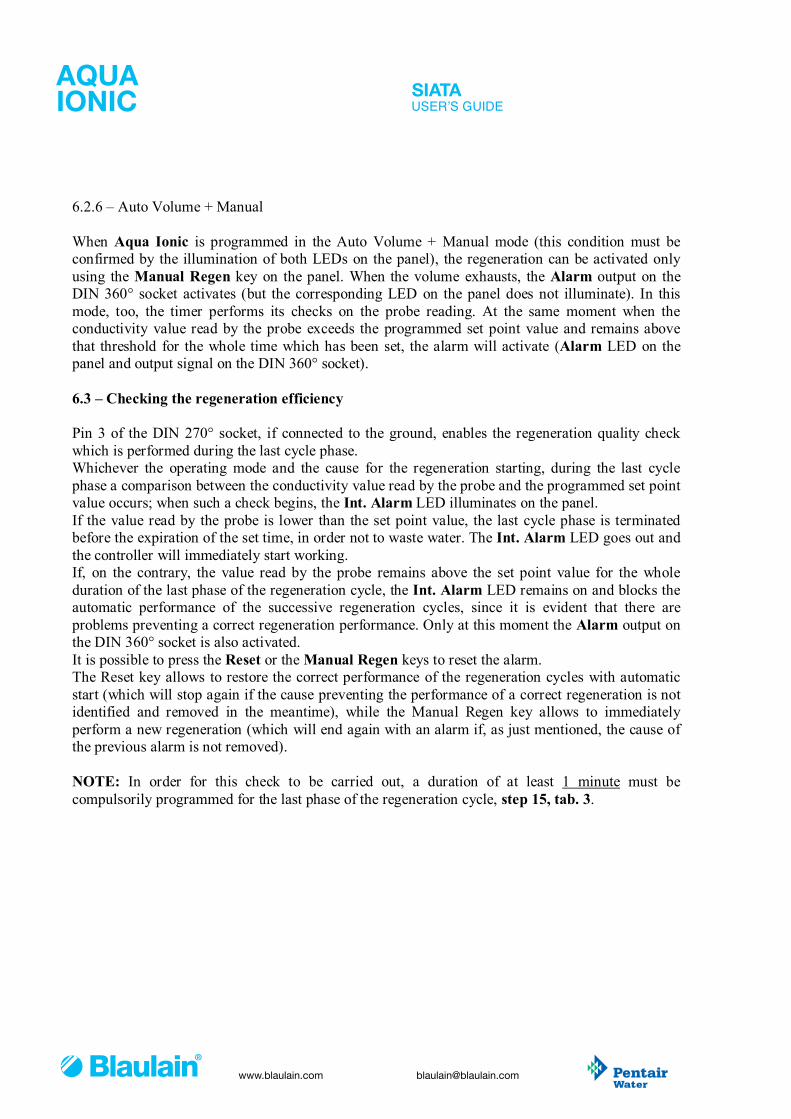
FRQIRUPLW\
x�x�
SIATAMANUAL DE INSTRUCCIONES
AQUAIONIC
FRQIRUPLW\
x�x�
www.blaulain.com [email protected]
86(5·6�*8,'(
6.2.6 – Auto Volume + Manual When Aqua Ionic is programmed in the Auto Volume + Manual mode (this condition must be confirmed by the illumination of both LEDs on the panel), the regeneration can be activated only using the Manual Regen key on the panel. When the volume exhausts, the Alarm output on the DIN 360° socket activates (but the corresponding LED on the panel does not illuminate). In this mode, too, the timer performs its checks on the probe reading. At the same moment when the conductivity value read by the probe exceeds the programmed set point value and remains above that threshold for the whole time which has been set, the alarm will activate (Alarm LED on the panel and output signal on the DIN 360° socket). 6.3 – Checking the regeneration efficiency Pin 3 of the DIN 270° socket, if connected to the ground, enables the regeneration quality check which is performed during the last cycle phase. Whichever the operating mode and the cause for the regeneration starting, during the last cycle phase a comparison between the conductivity value read by the probe and the programmed set point value occurs; when such a check begins, the Int. Alarm LED illuminates on the panel. If the value read by the probe is lower than the set point value, the last cycle phase is terminated before the expiration of the set time, in order not to waste water. The Int. Alarm LED goes out and the controller will immediately start working. If, on the contrary, the value read by the probe remains above the set point value for the whole duration of the last phase of the regeneration cycle, the Int. Alarm LED remains on and blocks the automatic performance of the successive regeneration cycles, since it is evident that there are problems preventing a correct regeneration performance. Only at this moment the Alarm output on the DIN 360° socket is also activated. It is possible to press the Reset or the Manual Regen keys to reset the alarm. The Reset key allows to restore the correct performance of the regeneration cycles with automatic start (which will stop again if the cause preventing the performance of a correct regeneration is not identified and removed in the meantime), while the Manual Regen key allows to immediately perform a new regeneration (which will end again with an alarm if, as just mentioned, the cause of the previous alarm is not removed). NOTE: In order for this check to be carried out, a duration of at least 1 minute must be compulsorily programmed for the last phase of the regeneration cycle, step 15, tab. 3.

FRQIRUPLW\
x�x�
SIATAMANUAL DE INSTRUCCIONES
AQUAIONIC
FRQIRUPLW\
x�x�
www.blaulain.com [email protected]
86(5·6�*8,'(
6.4 – Programming Aqua Ionic is programmed using the Program Mode key, and the values can be modified using the Advance key. Proceed as follows to perform programming:
Programming table (Tab. 3)
Step ) Display Meaning
1 PROG. MODE 0 1 0 0 Set point value. The digits on the right-hand side blink.
2 PROG. MODE 0 1 0 0 Set point value. The digits on the left-hand side blink.
3 PROG. MODE 0.1 0 0 Volume value. The digits on the right-hand side blink.
4 PROG. MODE 0.1 0 0 Volume value. The digits on the left-hand side blink.
5 PROG. MODE A A.0 1 The counter divider.
6 PROG. MODE A A 0 8 The delay time for the activation of the set point alarm..
7 PROG. MODE A A 0 8 End of programming. Pressing again quits.
8 X 0.1 1 C 0 0 The stop of the regenerative cycle first phase.
9 PROG. MODE 2 C 0 0 The stop of the regenerative cycle second phase.
10 PROG. MODE 3 C 0 0 The stop of the regenerative cycle third phase.
11 PROG. MODE 4 C 0 0 The stop of the regenerative cycle fourth phase.
12 PROG. MODE 5 C 0 0 The stop of the regenerative cycle fifth phase.
13 PROG. MODE 6 C 0 0 The stop of the regenerative cycle sixth phase.
14 PROG. MODE 7 C 0 0 The stop of the regenerative cycle seventh phase.
15 PROG. MODE 8 C 0 0 The stop of the regenerative cycle eighth phase.
15 PROG. MODE 8 d 0 0 End of programming. It quits after 3 seconds.
16 0 0 3 0 The display shows the conductivity again. Pressing the Program Mode key instead of the X 0.1 key at step 8 of tab. 3, will quit programming without accessing the regenerative cycle phases. The latter is the recommended procedure It is possible to press the Reset key at any time to quit programming without storing any changes made to the value flashing on the display. At step 15 of tab. 3 the programmed parameters are written in the eeprom.

FRQIRUPLW\
x�x�
SIATAMANUAL DE INSTRUCCIONES
AQUAIONIC
FRQIRUPLW\
x�x�
www.blaulain.com [email protected]
86(5·6�*8,'(
IMPORTANT !! The programming which is set according to the tab. 3 steps becomes operational only when the user presses the Reset key or performs a regeneration using the Manual Regen key. Neglecting this simple procedure will result in a behavior compliant with the previous programming, not with the new one. 6.5 – Starting operations Aqua Ionic, as well as all SIATA controllers, is considered as operational when able to perform resins regeneration. This is possible ONLY when the controller “senses” that the cam is correctly positioned at the stop. In order to perform a few tests before installation, it is necessary to connect Aqua Ionic to its case in order that the limit switch input be correctly closed. Aqua Ionic does not allow to perform any operations until the limit switch input is closed. With reference to what already stated in par. 6.3, once the Aqua Ionic programming has been modified, it is necessary to press the Reset key or to perform a regeneration in order to load the new parameters into the memory.
6.6 – Managing the volume Steps 3 and 4 of tab. 3 describe how to program the treatable volume. Using the SIATA Hall effect liter counter, the value of the divider (AA14, step 5 tab. 3) must be set to 14, which means that the available volume is reduced in a not adjustable way by one liter every 14 impulses issued by the sensor. In this way the maximum treatable volume that can be programmed is 10.000 liters. If you need to use a larger volume, it is possible to do a simple arithmetical operation, that is to multiply by two, by three, by four, etc. the divider and at the same time divide by two, by three, by four, etc. the treatable volume. Examples: You have to treat 15.000 liters water. Volume / 2 15.000 / 2 7500 in steps 4 and 5 of tab. 3 Divider x 2 AA14 x 2 AA28 in step 8 of tab. 3 When starting operations the treatable volume will be 7500 liters. You have to treat 50.000 liters water. Volume / 5 50.000 / 5 0000 in steps 4 and 5 of tab. 3 Divider x 5 AA14 x 5 AA70 in step 8 of tab. 3 When starting operations the treatable volume will be 0000 liters (10000).

FRQIRUPLW\
x�x�
SIATAMANUAL DE INSTRUCCIONES
AQUAIONIC
FRQIRUPLW\
x�x�
www.blaulain.com [email protected]
86(5·6�*8,'(
Please note that programming the volume by setting the 0000 value, means programming 10.000, while setting the AA00 value for the divider means programming the divider as 100. You can treat maximum 70.000 liters water with the SIATA Hall effect liter counter by programming 10.000 liters for the treatable volume and AA98 for the divider. If you use a counter issuing one impulse every liter (or cubic meter), the maximum treatable volume will be 1.000.000 liters (or cubic meters) if you set to 10.000 liters the treatable volume and to AA00 the divider (corresponding to 100 impulses every liter or cubic meter). Please note that, because of the Reed counters characteristics, we recommend not to use 1imp./1m3 or similar counters. 6.7 – Installing the probe. The conductivity probe is the most important element of Aqua Ionic and its installation must be performed with the highest care. A screened cable is always the best choice to connect the controller to the probe. This choice is compulsory when the distance between the controller and the probe is over 2 meters and/or when the environment where the controller is being installed is subject to strong electromagnetic interferences. Nonetheless, it is possible to use normal cables if the distance between the controller and the probe is short or if there are not great electric interference sources in the immediate neighborhoods. In any case, it is advisable not to wire the probe cable near power cables.
Fig. 5

FRQIRUPLW\
x�x�
SIATAMANUAL DE INSTRUCCIONES
AQUAIONIC
FRQIRUPLW\
x�x�
www.blaulain.com [email protected]
86(5·6�*8,'(
6.8 – Connections
Fig. 6 shows the correct usage of the signals issued by Aqua Ionic in the Open Collector mode. The relay indicated in the figure must be connected between the terminal of the +12 Vdc and the terminal of the signal concerned (in the example it is the cycle-end impulse). Please refer to the table of par. 6.8.1 to learn which signals are issued by the controller in the Open Collector mode. The maximum relay absorbency for the trip coil excitation must be 20mA. Here below follow the codes of a few relays that can be used to this purpose, all of them with a trip coil to be supplied with 12 Vcd. Manufacturer Model OMRON G5V-1 12Vdc TAKAMISAWA MZ-12HS-U MATSUSHITA JQ1-12V or JQ1a-12V or HD1-M-DC12V
Fig. 6

FRQIRUPLW\
x�x�
SIATAMANUAL DE INSTRUCCIONES
AQUAIONIC
FRQIRUPLW\
x�x�
www.blaulain.com [email protected]
86(5·6�*8,'(
6.8.1 – Connection of this version to 3 DIN sockets
Fig. 7 shows the connections of the 3 DIN sockets, to be used as follows:
Contacts Function DIN A, 1 – 3 Volume, Reed counter or with make, not supplied. DIN A, 1 – 3 – 5 Volume, Hall effect magnetic counter supplied by a +12 Vdc voltage. DIN A, 1 – 4 Inhibition signal input (when closed). DIN A, 2 – 5 Output of the Cycle End Impulse in the Open Collector mode. DIN B, 4 – 2 Input of the Remote start signal (when closed). DIN B, 3 – 2 Input of the regeneration quality control activation signal. DIN C, 1 – 4 Output of the Set Point signal in the Open Collector mode. DIN C, 3 – 4 Output of the Impulse During Regeneration signal in the Open Collector mode. DIN C, 5 – 4 Output of the Alarm signal in the Open Collector mode.
Fig. 7

FRQIRUPLW\
x�x�
SIATAMANUAL DE INSTRUCCIONES
AQUAIONIC
FRQIRUPLW\
x�x�
www.blaulain.com [email protected]
86(5·6�*8,'(
7 – TROUBLESHOOTING Here follow some basic operations that will help solving those little problems that could arise when using the Aqua Ionic. As a general rule, if the suggested remedies do not give any results and independently from the type of controller, we suggest to check the anomaly by replacing only the electronic board with a new one or anyway with one that is certainly in a good state (obviously to the extent of your possibilities). It is important to be able to identify whether the cause of the malfunction is to be found in electronics, mechanic part, or the harness wiring. Replacing the electronic board may be already a precious help to identify the real cause of the defect. If our suggestions are not sufficient to solve your problems, please contact the SIATA assistance service.
DEFECT POSSIBLE CAUSE REMEDY Failure of the supply outlet. Failure of the transformer plug. Failure of the transformer.
Connect any other kind of device to the same outlet and the controller to another outlet.
Problem in the cable connection. Open the case and check that the wires be properly inserted in the 7-pole connector.
The controller does not power on.
The controller is blocked. If you use the side DIN socket, check for any short-circuited terminals in the connector cap. Follow instructions given in par. 6.8.
Damages in the plastic components.
Open the case and check whether the plastic components supporting the micro switch are integer (Fig. 10).
The micro switch is damaged.
Open the case and check whether (Fig. 10): the micro switch is integer; it is placed correctly; the terminals are placed correctly; the connection wires are integer; the micro switch starting lever is integer.
The motor does not stop at the limit stop.
The cam is out of place.
Open the case (Fig. 10) and check that the metal seeger holding the cam be integer and correctly placed in its casing. Turn the cam with your hand to check whether it activates the micro switch lever.
The controller is not correctly programmed.
Check that the programming has been performed correctly and that the regeneration start corresponds to the really necessary one.
The controller does not perform regeneration. The controller is inhibited. If you are using the DIN socket (Fig. 9), check for
any short-circuited terminals in the connector cap. Wrong parameters are displayed. The controller is out of program. Reset the controller following instructions given in
par. 6.8.

FRQIRUPLW\
x�x�
SIATAMANUAL DE INSTRUCCIONES
AQUAIONIC
FRQIRUPLW\
x�x�
www.blaulain.com [email protected]
86(5·6�*8,'(
Fig. 10 clearly shows the micro switch, its block and command mechanical details, and the terminals for connection to the controller.
Fig. 10
Seeger

FRQIRUPLW\
x�x�
SIATAMANUAL DE INSTRUCCIONES
AQUAIONIC
FRQIRUPLW\
x�x�
www.blaulain.com [email protected]
86(5·6�*8,'(
8 – SPARE PARTS Attachments DA0189 and DA0191 describe the assembling schemes of the spare parts of a timer provided with external drivers (the scheme shows 2 drivers, but there can be up to 9), and of a timer without external drivers (this model is usually named 132). The items indicated in the schemes refer to tab. 4, Table of items, among which there are explicit and implicit variants. Among implicit variants we have: 1. The cam group. Items from 1 to 5 and item 12 (external drivers group) shown in attachment
DA0189 are replaced only by item 22 (132 cam group) in attachment DA0191. 2. The turbine sensor cable. Items 20 and 21 indicated in both attachments are present in the
volumetric type timers only, independently from the presence of any external driver. 3. Second microswitch. Item 19 in both attachments shows the ring controlling a second
microswitch during the cam rotation. Please contact the SIATA sales department for further information about the performances that can be obtained with such a modification.
4. The plug-shaped transformer (item 6) can be provided in two ways: chlorine timer, transformer code 95-STC1, and non chlorine timer, transformer code 95-STD.
The explicit variants concern only the timers with external drivers (attachment DA0189), which in the table are marked with an asterisk (*). 1. The number of pass-through drivers (item 2). Their quantity varies according to the number
of drivers mounted on the timer. Therefore, if a timer is provided with 4 external drivers, 3 out of them will be pass-through drivers (item 2) and one driver only will be closed (item 3).
2. The coupling bars (item 4), the length of which varies according to the number of drivers mounted on the timer. The bar code is obtained by associating the number of drivers to the base code (468-), therefore, for a 2-driver timer the code will be 468-2, for a 5-driver timer it will be 468-5, and so on.
3. Programming cam (item 12) for external drivers. It changes according to the device type.

FRQIRUPLW\
x�x�
SIATAMANUAL DE INSTRUCCIONES
AQUAIONIC
FRQIRUPLW\
x�x�
www.blaulain.com [email protected]
86(5·6�*8,'(
Tab. 4 – Table of items shown in attachments DA0189 and DA0191 Item Description Code
1 Complete driver shoulder 433-KIT 2 Complete driver (terminal) 2253-A 3 Complete pass-through driver 2253-B* 4 Coupling bar for external drivers 468-* 5 M5 nut for threaded bar 468-D 6 Plug-shaped transformer 230V – 12 V 95-STD Plug-shaped transformer 230V – 12 V / 6 V (CHLORINE) 95-STC1
7 Ratiomotor 94-R7 8 Timer case kit 81-KIT 9 7-pole connector 93-7 10 Timer supply cable lock 90 11 Micro-switch wire 97 12 External cam kit 2221-2* 13 Micro-switch blocking plate 88-A 14 Microswitch 92-F 15 Microswitch holder 88 16 Aqua Ionic electronic board kit 892-K 17 Cover blocking screw 120 18 Timer case transparent cover 82 19 Stop ring on power takeoff 84-AS 20 Black cable lock 90-XP 21 Turbine sensor cable, 50 cm length 2223-50 22 New driver timer programming cam kit 2229

FRQIRUPLW\
x�x�
SIATAMANUAL DE INSTRUCCIONES
AQUAIONIC
FRQIRUPLW\
x�x�
www.blaulain.com [email protected]
86(5·6�*8,'(
GR
UP
PO
VIS
TO
SOC
IETA
ITAL
IAN
A AP
PAR
ECC
HIA
TUR
E TR
ATTA
MEN
TO A
CQ
UA
RE
VIS
ION
EP
OS
.17
MASCHERINA
PO
S.1
6
SO
STI
TUIS
CE
S.r.l
CO
DIC
E
DE
NO
MIN
AZI
ON
E
SC
ALA
FIR
MA
DA
TA
PO
S.1
8P
OS
.15
PO
S. 1
1P
OS
.14
PO
S.1
3
PO
S.1
9
PO
S.7
PO
S.1
2
PO
S.9
PO
S.1
0
PO
S.8
PO
S.4 P
OS
.3P
OS
. 6P
OS
.5
PO
S.2
PO
S.1
SC
HE
MA
GE
NE
RA
LE T
IME
R E
LETT
RO
NIC
O C
ON
N. P
ILO
TI E
STE
RN
I
Fogl
io 1
di 1
DA0
189
Ing.
P.M
eozz
i
25.0
5.98
08A
PO
S.2
0
PO
S.2
1

FRQIRUPLW\
x�x�
SIATAMANUAL DE INSTRUCCIONES
AQUAIONIC
FRQIRUPLW\
x�x�
www.blaulain.com [email protected]
86(5·6�*8,'(
SOC
IETA
ITAL
IAN
A AP
PAR
ECC
HIA
TUR
E TR
ATTA
MEN
TO A
CQ
UA
PO
S.1
7
PO
S.1
6
DE
NO
MIN
AZI
ON
E
CO
DIC
E
S.r.l
SO
STI
TUIS
CE
MASCHERINA
FIR
MA
SC
ALA
VIS
TO
GR
UP
PO
DA
TA
RE
VIS
ION
E
Fogl
io 1
di 1
SC
HE
MA
GE
NE
RA
LE T
IME
R E
LETT
RO
NIC
OC
ON
CA
MM
A 1
32
DA0
191
Ing.
P.M
eozz
i
25.0
5.98
08A
PO
S.1
3
PO
S.1
8P
OS
.15
PO
S. 1
1P
OS
.14
PO
S.7
PO
S.9
PO
S.8
PO
S.1
0
PO
S. 6
PO
S.2
1
PO
S.2
0
PO
S.1
9
PO
S.2
2