Development of CFRP Tubes for the Light-Weight Propeller ...
Upload
khangminh22Category
view
1download
0
Manual No. 48061-00-80Revision 1 April 2017
Propeller Owner's Manual and Logbook
Raptor Reciprocating Propeller Series with Composite Blades
Constant Speed, Non-counterweighted3C1-( )( )( )
Hartzell Propeller Inc.One Propeller PlacePiqua, OH 45356-2634 U.S.A.Ph: 937-778-4200 (Hartzell Propeller Inc.)Ph: 937-778-4379 (Product Support)Product Support Fax: 937-778-4215

Propeller Owner's Manual480
61-00-80 COVERInside Cover
Rev. 1 Apr/17
© 2016, 2017 - Hartzell Propeller Inc. - All rights reserved

Page 1 Jul/16
Propeller Owner's Manual 480
MESSAGE 61-00-80
As a fellow pilot, I urge you to read this Manual thoroughly. It contains a wealth of information about your new propeller.
The propeller is among the most reliable components of your airplane. It is also among the most critical to flight safety. It therefore deserves the care and maintenance called for in this Manual. Please give it your attention, especially the section dealing with Inspections and Checks.
Thank you for choosing a Hartzell propeller. Properly maintained it will give you many years of reliable service.
Jim Brown Chairman, Hartzell Propeller Inc.

Page 2 Jul/16MESSAGE 61-00-80
Propeller Owner's Manual 480
WARNINGPeople who fly should recognize that various types of risks are involved; and they should take all precautions to minimize them, since they cannot be eliminated entirely. The propeller is a vital component of the aircraft. A mechanical failure of the propeller could cause a forced landing or create vibrations sufficiently severe to damage the aircraft, possibly causing it to become uncontrollable.
Propellers are subject to constant vibration stresses from the engine and airstream, which are added to high bending and centrifugal stresses.
Before a propeller is certified as being safe to operate on an airplane, an adequate margin of safety must be demonstrated. Even though every precaution is taken in the design and manufacture of a propeller, history has revealed rare instances of failures, particularly of the fatigue type.
It is essential that the propeller is properly maintained according to the recommended service procedures and a close watch is exercised to detect impending problems before they become serious. Any grease or oil leakage, loss of air pressure, unusual vibration, or unusual operation should be investigated and repaired, as it could be a warning that something serious is wrong.

Page 3 Jul/16
Propeller Owner's Manual 480
MESSAGE 61-00-80
For operators of uncertified or experimental aircraft an even greater level of vigilance is required in the maintenance and inspection of the propeller. Experimental installations often use propeller-engine combinations that have not been tested and approved. In these cases, the stress on the propeller and, therefore, its safety margin is unknown. Failure could be as severe as loss of propeller or propeller blades and cause loss of propeller control and/or loss of aircraft control.
Hartzell Propeller Inc. follows FAA regulations for propeller certification on certificated aircraft. Experimental aircraft may operate with unapproved engines or propellers or engine modifications to increase horsepower, such as unapproved crankshaft damper configurations or high compression pistons. These issues affect the vibration output of the engine and the stress levels on the propeller. Significant propeller life reduction and failure are real possibilities.
Frequent inspections are strongly recommended if operating with a non-certificated installation; however, these inspections may not guarantee propeller reliability, as a failing device may be hidden from the view of the inspector. Propeller overhaul is strongly recommended to accomplish periodic internal inspection.
Visually inspect composite blades for cracks. Inspect hubs, with particular emphasis on each blade arm for cracks. Eddy current equipment is recommended for hub inspection, since cracks are usually not apparent.

Page 4 Jul/16MESSAGE 61-00-80
Propeller Owner's Manual 480
(This page is intentionally blank.)

Propeller Owner's Manual 480
Page 5 Rev. 1 Apr/17 REVISION HIGHLIGHTS 61-00-80
REVISION HIGHLIGHTSRevision 1, dated April 2017, incorporates the following:
• COVER• Revised to match the manual revision
• REVISION HIGHLIGHTS• Revised to match the manual revision
• LIST OF EFFECTIVE PAGES• Revised to match the manual revision
• TABLE OF CONTENTS• Revised to match the manual revision
• INSTALLATION AND REMOVAL• Made other language/format changes
• INSPECTION AND CHECK• Revised the section, “Periodic Inspections”• Removed the section, "Tachometer Inspection"• Revised Figure 5-2, "Blade Play"• Revised the section, "Loose Blades"• Made other language/format changes
• MAINTENANCE PRACTICES• Revised the section, “Lubrication Intervals”• Revised the section, "Painting of Composite Blades"• Added the section, "Tachometer Calibration"• Made other language/format changes

Page 6 Rev. 1 Apr/17 REVISION HIGHLIGHTS 61-00-80
Propeller Owner's Manual 480
(This page is intentionally blank.)
Propeller Owner's Manual 480
Page 7 Rev. 1 Apr/17 REVISION HIGHLIGHTS 61-00-80
REVISIONS HIGHLIGHTS
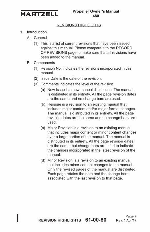
1. IntroductionA. General
(1) This is a list of current revisions that have been issued against this manual. Please compare it to the RECORD OF REVISIONS page to make sure that all revisions have been added to the manual.
B. Components(1) Revision No. indicates the revisions incorporated in this
manual.(2) Issue Date is the date of the revision.(3) Comments indicates the level of the revision.
(a) New Issue is a new manual distribution. The manual is distributed in its entirety. All the page revision dates are the same and no change bars are used.
(b) Reissue is a revision to an existing manual that includes major content and/or major format changes. The manual is distributed in its entirety. All the page revision dates are the same and no change bars are used.
(c) Major Revision is a revision to an existing manual that includes major content or minor content changes over a large portion of the manual. The manual is distributed in its entirety. All the page revision dates are the same, but change bars are used to indicate the changes incorporated in the latest revision of the manual.
(d) Minor Revision is a revision to an existing manual that includes minor content changes to the manual. Only the revised pages of the manual are distributed. Each page retains the date and the change bars associated with the last revision to that page.

Page 8 Rev. 1 Apr/17 REVISION HIGHLIGHTS 61-00-80
Propeller Owner's Manual 480
Revision No. Issue Date Comments Original Jul/16 New Issue Revision Apr/17 Minor Revision

RECORD OF REVISIONS
Rev. No. Issue Date Date Inserted Inserted By
Propeller Owner's Manual 480
Page 9 Jul/16RECORD OF REVISIONS 61-00-80
Original Jul/16 Jul/16 HPI
Page 10 Jul/16RECORD OF REVISIONS 61-00-80
RECORD OF REVISIONS
Rev. No. Issue Date Date Inserted Inserted By
Propeller Owner's Manual 480

RECORD OF TEMPORARY REVISIONS TR Issue Date Inserted Date Removed No. Date Inserted By Removed By
Propeller Owner's Manual 480
RECORD OF TEMPORARY REVISIONS 61-00-80Page 11
Jul/16

Page 12 Jul/16RECORD OF TEMPORARY REVISIONS 61-00-80
RECORD OF TEMPORARY REVISIONS TR Issue Date Inserted Date Removed No. Date Inserted By Removed By
Propeller Owner's Manual 480

Page 13 Jul/1661-00-80 SERVICE DOCUMENTS LIST
Propeller Owner's Manual 480
SERVICE DOCUMENTS LIST
CAUTION 1: DO NOT USE OBSOLETE OR OUTDATED INFORMATION. PERFORM ALL INSPECTIONS OR WORK IN ACCORDANCE WITH THE MOST RECENT REVISION OF THE SERVICE DOCUMENT. INFORMATION CONTAINED IN A SERVICE DOCUMENT MAY BE SIGNIFICANTLY CHANGED FROM EARLIER REVISIONS. FAILURE TO COMPLY WITH INFORMATION CONTAINED IN A SERVICE DOCUMENT OR THE USE OF OBSOLETE INFORMATION MAY CREATE AN UNSAFE CONDITION THAT MAY RESULT IN DEATH, SERIOUS BODILY INJURY, AND/OR SUBSTANTIAL PROPERTY DAMAGE.
CAUTION 2: THE INFORMATION FOR THE DOCUMENTS LISTED INDICATES THE REVISION LEVEL AND DATE AT THE TIME THAT THE DOCUMENT WAS INITIALLY INCORPORATED INTO THIS MANUAL. INFORMATION CONTAINED IN A SERVICE DOCUMENT MAY BE SIGNIFICANTLY CHANGED FROM EARLIER REVISIONS. REFER TO THE APPLICABLE SERVICE DOCUMENT INDEX FOR THE MOST RECENT REVISION LEVEL OF THE SERVICE DOCUMENT.
Service Document Number Incorporation Rev/Date

Page 14 Jul/1661-00-80 SERVICE DOCUMENTS LIST
Propeller Owner's Manual 480
SERVICE DOCUMENTS LIST
Service Document Number Incorporation Rev/Date

Propeller Owner's Manual 480
61-00-80 Page 15
Jul/16AIRWORTHINESS LIMITATIONS
AIRWORTHINESS LIMITATIONS
Rev. No. Description of Revision
The Airworthiness Limitations section is FAA approved and specifies maintenance required under 14 CFR §§ 43.16 and 91.403 of the Federal Aviation Regulations unless an alternative program has been FAA approved.
FAA APPROVED
by: ______________________________ date: ____________
Manager, Chicago Aircraft Certification Office, ACE-115C Federal Aviation Administration

Propeller Owner's Manual480
61-00-80 Page 16
Jul/16AIRWORTHINESS LIMITATIONS
AIRWORTHINESS LIMITATIONS
1. Replacement Time (Life Limits)A. The FAA establishes specific life limits for certain component
parts, as well as the entire propeller. Such limits require replacement of the identified parts after a specified number of hours of use.
B. The following data summarizes all current information concerning Hartzell Propeller Inc. life limited parts as related to propeller models affected by this manual. These parts are not life limited on other installations; however, time accumulated toward life limit accrues when first operated on aircraft/engine/propeller combinations listed, and continues regardless of subsequent installations (which may or may not be life limited).(1) The propeller models affected by this manual currently
do not have any life limited parts.
FAA APPROVED
by: ______________________________ date: ____________
Manager, Chicago Aircraft Certification Office, ACE-115C Federal Aviation Administration

LIST OF EFFECTIVE PAGESPage 17
Rev. 1 Apr/17
LIST OF EFFECTIVE PAGES
Propeller Owner's Manual 480
Chapter Page Revision Date
61-00-80
Cover/Inside Cover Cover/Inside Cover Rev. 1 Apr/17Message 1 thru 4 Original Jul/16Revision Highlights 5 thru 8 Rev. 1 Apr/17Record of Revisions 9 and 10 Original Jul/16Record of Temporary Revisions 11 and 12 Original Jul/16Service Documents List 13 and 14 Original Jul/16Airworthiness Limitations 15 and 16 Original Jul/16List of Effective Pages 17 and 18 Rev. 1 Apr/17Table of Contents 19 and 20 Original Jul/16Table of Contents 21 thru 25 Rev. 1 Apr/17Table of Contents 26 Original Jul/16Introduction 1-1 thru 1-18 Original Jul/16Description and Operation 2-1 thru 2-14 Original Jul/16Installation and Removal 3-1 Original Jul/16Installation and Removal 3-2 Rev. 1 Apr/17Installation and Removal 3-3 thru 3-40 Original Jul/16Testing and Troubleshooting 4-1 thru 4-12 Original Jul/16Inspection and Check 5-1 and 5-2 Rev. 1 Apr/17Inspection and Check 5-3 thru 5-7 Original Jul/16Inspection and Check 5-8 and 5-9 Rev. 1 Apr/17Inspection and Check 5-10 thru 5-14 Original Jul/16Inspection and Check 5-15 thru 5-19 Rev. 1 Apr/17Inspection and Check 5-20 thru 5-30 Original Jul/16Maintenance Practices 6-1 Original Jul/16Maintenance Practices 6-2 Rev. 1 Apr/17Maintenance Practices 6-3 and 6-4 Original Jul/16Maintenance Practices 6-5 Rev. 1 Apr/17Maintenance Practices 6-6 thru 6-20 Original Jul/16Maintenance Practices 6-21 Rev. 1 Apr/17Maintenance Practices 6-22 thru 6-36 Original Jul/16Maintenance Practices 6-37 and 6-38 Rev. 1 Apr/17Anti-ice and De-ice Systems 7-1 thru 7-8 Original Jul/16Records 8-1 thru 8-10 Original Jul/16

LIST OF EFFECTIVE PAGESPage 18
Rev. 1 Apr/17
Propeller Owner's Manual 480
61-00-80
(This page is intentionally blank.)

TABLE OF CONTENTSPage 19
Jul/16
Propeller Owner's Manual 480
61-00-80
TABLE OF CONTENTSMESSAGE .........................................................................................1REVISION HIGHLIGHTS ..................................................................5RECORD OF REVISIONS ................................................................9RECORD OF TEMPORARY REVISIONS ....................................... 11SERVICE DOCUMENTS LIST ........................................................13AIRWORTHINESS LIMITATIONS ...................................................15LIST OF EFFECTIVE PAGES .........................................................17TABLE OF CONTENTS ...................................................................19INTRODUCTION ............................................................................1-11. Purpose ....................................................................................1-32. Airworthiness Limitations .........................................................1-33. AirframeOrEngineModifications ............................................1-44. RestrictionsAndPlacards ........................................................1-55. General ....................................................................................1-5
A. Personnel Requirements ...................................................1-5B. MaintenancePractices ......................................................1-5C. Continued Airworthiness ....................................................1-8D. PropellerCriticalParts .......................................................1-8
6. ReferencePublications ............................................................1-97. Definitions ..............................................................................1-118. Abbreviations .........................................................................1-169. HartzellPropellerInc.ProductSupport ..................................1-1710.WarrantyService ....................................................................1-1711. HartzellPropellerInc.RecommendedFacilities ....................1-18DESCRIPTION AND OPERATION .................................................2-11. DescriptionofPropellerandSystems ......................................2-3
A. SystemOverview ...............................................................2-32. FunctionalDescriptionofConstantSpeedPropellerTypes .....2-5
A. 3C1-( )( )( ) Series Propellers with Composite Blades .......2-5

TABLE OF CONTENTSPage 20
Jul/16
Propeller Owner's Manual 480
61-00-80
3. Model Designation ...................................................................2-74. Governors ..............................................................................2-11
A. Theory of Operation .........................................................2-11B. GovernorTypes ...............................................................2-11C. IdentificationofHartzellPropellerInc.Governors ...........2-12
5. PropellerIceProtectionSystems ...........................................2-13A. PropellerAnti-iceSystem ................................................2-13B. PropellerDe-iceSystem ..................................................2-14
INSTALLATION AND REMOVAL ....................................................3-11. Tools,Consumables,andExpendables ...................................3-3
A. Tooling ...............................................................................3-3B. Consumables .....................................................................3-3C. Expendables ......................................................................3-3
2. Pre-Installation .........................................................................3-4A. InspectionofShippingPackage ........................................3-4B. Uncrating ...........................................................................3-4C. InspectionafterShipment ..................................................3-4D. ReassemblyofaPropellerDisassembledforShipment ...3-4
3. Spinner Pre-Installation ............................................................3-7A. General ..............................................................................3-7B. InstallationofaMetalSpinnerBulkheadona
PropellerHub ...................................................................3-124. Propeller Installation ..............................................................3-15
A. FlangeDescription ...........................................................3-15B. Installation of “F” Flange Propellers .................................3-16C. Installation of “L” Flange Propellers .................................3-21D. Installation of “R” Flange Propellers ................................3-25
5. Spinner Installation ................................................................3-28A. SinglePieceSpinnerDome .............................................3-28
6. Post-InstallationChecks ........................................................3-29
TABLE OF CONTENTS, CONTINUED

TABLE OF CONTENTSPage 21
Rev. 1 Apr/17
Propeller Owner's Manual 480
61-00-80
TABLE OF CONTENTS, CONTINUED
7. Spinner Removal ...................................................................3-30A. Removal of Single Piece Spinner ....................................3-30B. Hub Mounted Spinner Bulkhead Removal ......................3-30C. Starter Ring Gear Spinner Adapter Removal ..................3-30
8. Propeller Removal .................................................................3-31A. Removal of “F” Flange Propellers ....................................3-31B. Removal of “L” Flange Propellers ....................................3-34C. Removal of “R” Flange Propellers ...................................3-37
TESTING AND TROUBLESHOOTING ..........................................4-11. Operational Tests .....................................................................4-3
A. General ..............................................................................4-3B. Initial Run-Up .....................................................................4-3C. Static RPM Check - Mechanically Actuated
Governor Only ...................................................................4-4D. Post-Run Check ................................................................4-5
2. Propeller Ice Protection Systems .............................................4-5A. Electric De-ice System ......................................................4-5B. Anti-ice System ..................................................................4-5
3. Troubleshooting .......................................................................4-6A. Hunting and Surging ..........................................................4-6B. Engine Speed Varies with Flight Attitude (or Airspeed) .....4-7C. Loss of Propeller Control - 3C1-( )( )( ) propellers only: ....4-7D. Vibration ............................................................................4-8E. Propeller Overspeed ........................................................4-10F. Overspeed Avoidance (Operational) -
3C1-( )( )( ) Series Propellers ..........................................4-10G. Propeller Underspeed ......................................................4-10H. Oil or Grease Leakage ....................................................4-11

TABLE OF CONTENTSPage 22
Rev. 1 Apr/17
Propeller Owner's Manual 480
61-00-80
INSPECTION AND CHECK ............................................................5-11. Pre-Flight Checks ....................................................................5-32. Operational Checks .................................................................5-53. Required Periodic Inspections and Maintenance .....................5-7
A. Periodic Inspections ..........................................................5-7B. Periodic Maintenance ........................................................5-9C. Airworthiness Limitations ...................................................5-9D. Overhaul Periods ...............................................................5-9
4. Inspection Procedures ...........................................................5-10A. Blade Damage .................................................................5-10B. Grease or Oil Leakage ....................................................5-11C. Vibration ..........................................................................5-13D. Blade Track ......................................................................5-15E. Loose Blades ...................................................................5-17F. Corrosion .........................................................................5-17G. Spinner Damage ..............................................................5-18H. Electric De-ice System ....................................................5-18I. Anti-ice System ................................................................5-18
5. Special Inspections ................................................................5-21A. Overspeed/Overtorque ....................................................5-21B. Lightning Strike - Propeller ..............................................5-23C. Foreign Object Strike/Ground Strike ................................5-26D. Sudden Stoppage ............................................................5-28E. Engine Oil Contamination ................................................5-29F. Fire Damage or Heat Damage ........................................5-29
6. Long Term Storage.................................................................5-30
TABLE OF CONTENTS, CONTINUED
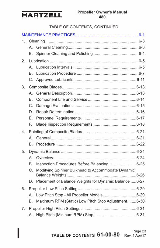
TABLE OF CONTENTSPage 23
Rev. 1 Apr/17
Propeller Owner's Manual 480
61-00-80
TABLE OF CONTENTS, CONTINUED
MAINTENANCE PRACTICES ........................................................6-11. Cleaning ...................................................................................6-3
A. General Cleaning ...............................................................6-3B. Spinner Cleaning and Polishing ........................................6-4
2. Lubrication ...............................................................................6-5A. Lubrication Intervals ..........................................................6-5B. Lubrication Procedure .......................................................6-7C. Approved Lubricants ........................................................6-11
3. Composite Blades ..................................................................6-13A. General Description .........................................................6-13B. Component Life and Service ...........................................6-14C. Damage Evaluation .........................................................6-15D. Repair Determination .......................................................6-16E. Personnel Requirements .................................................6-17F. Blade Inspection Requirements .......................................6-18
4. Painting of Composite Blades ................................................6-21A. General ............................................................................6-21B. Procedure ........................................................................6-22
5. Dynamic Balance ...................................................................6-24A. Overview ..........................................................................6-24B. Inspection Procedures Before Balancing ........................6-25C. Modifying Spinner Bulkhead to Accommodate Dynamic
Balance Weights ..............................................................6-26D. Placement of Balance Weights for Dynamic Balance .....6-27
6. Propeller Low Pitch Setting ....................................................6-29A. Low Pitch Stop - All Propeller Models ..............................6-29B. Maximum RPM (Static) Low Pitch Stop Adjustment ........6-30
7. Propeller High Pitch Settings .................................................6-31A. High Pitch (Mininum RPM) Stop ......................................6-31

TABLE OF CONTENTSPage 24
Rev. 1 Apr/17
Propeller Owner's Manual 480
61-00-80
8. Propeller Ice Protection Systems ...........................................6-31A. Electric De-ice System ....................................................6-31B. Anti-ice System ................................................................6-31
9. Installation of Erosion Tape CM158 .......................................6-32A. General ............................................................................6-32B. Materials Required ..........................................................6-33C. Installation Procedure ......................................................6-34
10. Tachometer Calibration ..........................................................6-37
ANTI-ICE AND DE-ICE SYSTEMS ................................................7-11. Introduction ..............................................................................7-3
A. Propeller De-ice System ....................................................7-3B. Propeller Anti-ice System ..................................................7-3
2. System Description ..................................................................7-4A. De-ice System ...................................................................7-4B. Anti-ice System ..................................................................7-5
3. De-ice System Functional Tests ...............................................7-54. Anti-ice System Functional Tests .............................................7-65. De-ice and Anti-ice System Inspections ...................................7-6
A. De-ice System Inspections ................................................7-6B. Anti-ice System Inspections ..............................................7-7
6. De-ice and Anti-ice System Troubleshooting ...........................7-7A. De-ice System Troubleshooting .........................................7-7B. Anti-ice System Troubleshooting .......................................7-7
RECORDS ......................................................................................8-11. Introduction ..............................................................................8-32. Record Keeping .......................................................................8-3
A. Information to be Recorded ...............................................8-3B. Blade Damage Repair Sheets ...........................................8-3 76C03-2( ) .........................................................................8-5 76C03-7( ) .........................................................................8-8
TABLE OF CONTENTS, CONTINUED

TABLE OF CONTENTSPage 25
Rev. 1 Apr/17
Propeller Owner's Manual 480
61-00-80
Propeller Flange Description .........................Figure 2-1 ............. 2-6
Governor in Onspeed Condition ....................Figure 2-2 ........... 2-10
Governor in Underspeed Condition ...............Figure 2-3 ........... 2-10
Governor in Overspeed Condition .................Figure 2-4 ........... 2-10
Governor Model Designation .........................Figure 2-5 ........... 2-12
Hub Clamping Bolt Location ..........................Figure 3-1 ............. 3-6
Determining Torque Value When Using Torquing Adapter ........................................Figure 3-2 ............. 3-8
Diagram of Torquing Sequence for Propeller Mounting Hardware .....................Figure 3-3 ........... 3-10
Metal Bulkhead and Spinner Mounting (Hub Mounted Spinner) ..............................Figure 3-4 ........... 3-11
F Flange Propeller Mounting .........................Figure 3-5 ........... 3-14
R Flange Propeller Mounting .........................Figure 3-6 ........... 3-20
Checking Blade Track....................................Figure 5-1 ........... 5-15
Blade Play .....................................................Figure 5-2 ........... 5-16
Reciprocating Engine Overspeed Limits .......Figure 5-3 ........... 5-20
Evidence of Lightning Strike Damage to Composite Blade ....................................Figure 5-4 ........... 5-22
Lubrication Fitting Location............................Figure 6-1 ............. 6-6
Lubrication Label ...........................................Figure 6-2 ............. 6-8
Section of Typical Composite Blade ....................Figure 6-3 ........... 6-12
Basic Components of a Composite Blade .....Figure 6-4 ........... 6-12
Low Pitch Stop Adjustment - ( )( )1 Series.....Figure 6-5 ........... 6-28
LIST OF FIGURES

TABLE OF CONTENTSPage 26
Jul/16
Propeller Owner's Manual 480
61-00-80
Propeller Model Designations........................Table 2-1 .............. 2-8
Blade Type and Blade Model Designations ...Table 2-2 .............. 2-9
Torque Table ..................................................Table 3-1 .............. 3-9
Metal Spinner Bulkhead Mounting Hardware ....................................Table 3-2 ............ 3-12
Propeller/Engine Flange O-rings and Hardware .............................................Table 3-3 ............ 3-15
Spinner Dome Mounting Hardware ...............Table 3-4 ............ 3-24
Approved Touch-up Paints ............................Table 6-1 ............ 6-20
Erosion Tape ..................................................Table 6-2 ............ 6-32
LIST OF TABLES

Propeller Owner’s Manual 480
INTRODUCTION 61-00-80Page 1-1
Jul/16
INTRODUCTION - CONTENTS
1. Purpose ................................................................................. 1-3
2. Airworthiness Limitations ....................................................... 1-3
3. AirframeorEngineModifications .......................................... 1-4
4. RestrictionsandPlacards ...................................................... 1-5
5. General .................................................................................. 1-5A. Personnel Requirements .................................................. 1-5B.MaintenancePractices ..................................................... 1-5C. Continued Airworthiness ................................................... 1-8D.PropellerCriticalParts ...................................................... 1-8
6. ReferencePublications ......................................................... 1-9
7. Definitions ............................................................................ 1-11
8. Abbreviations ....................................................................... 1-16
9. HartzellPropellerInc.ProductSupport ............................... 1-17
10.WarrantyService ................................................................. 1-17
11.HartzellPropellerInc.RecommendedFacilities .................. 1-18

Propeller Owner’s Manual 480
INTRODUCTION 61-00-80Page 1-2
Jul/16
(Thispageisintentionallyblank.)
Propeller Owner’s Manual 480
INTRODUCTION 61-00-80Page 1-3
Jul/16
1. PurposeA. ThismanualhasbeenreviewedandacceptedbytheFAA.
Additionally,theAirworthinessLimitationschapterofthismanualhasbeenapprovedbytheFAA.
CAUTION: KEEP THIS MANUAL WITH THE PROPELLER ORTHEAIRCRAFTUPONWHICHITISINSTALLED AT ALL TIMES. THE LOGBOOK RECORD WITHIN THIS MANUAL MUST BE MAINTAINED, RETAINED CONCURRENTLY, ANDBECOMEAPARTOFTHEAIRCRAFTAND ENGINE SERVICE RECORDS.
B. Thepurposeofthismanualistoenablequalifiedpersonneltoinstall,operate,andmaintainaHartzellPropellerInc. 3C1-()()()Raptorseriesaluminumhubpropeller.Separatemanualsareavailableconcerningoverhaulproceduresandspecificationsforthepropeller.
C. ThismanualincludesRaptorseriesaluminumhubpropellers.(1) Samplepropellerandblademodeldesignations
withineachdesignareincludedintheDescriptionandOperationchapterofthismanual.(a) Parenthesesshowninthepropellermodel
designationsinthisorotherHartzellPropellerInc.publicationsindicateletter(s)and/ornumber(s)thatmayormaynotbepresentbecauseofdifferentconfigurationspermittedonthevariousaircraftinstallations.
(b) DefinitionsofpropellermodeldesignationsandfurtherdetailsoflettersthatmaybepresentareshownintheDescriptionandOperationchapterofthis manual.
(2) Allpropellermodelsincludedinthismanualusecompositepropellerblades.
2. Airworthiness LimitationsA. RefertotheAirworthinessLimitationschapterofthismanual
for Airworthiness Limits information.

Propeller Owner’s Manual 480
INTRODUCTION 61-00-80Page 1-4
Jul/16
3. AirframeorEngineModificationsA. Propellersareapprovedvibrationwiseonairframeand
enginecombinationsbasedontestsoranalysis of similar installations. This data has demonstrated that propeller stresslevelsareaffectedbyairframeconfiguration,airspeed,weight,power,engineconfiguration,andapprovedflightmaneuvers.Aircraftmodificationsthatcaneffectpropellerstressinclude,butarenotlimitedto:aerodynamicchangesaheadoforbehindthepropeller,realignmentofthethrustaxis,increasingordecreasingairspeedlimits,increasingordecreasingweightlimits(lesssignificantonpistonengines),theadditionofapprovedflightmaneuvers(utilityandaerobatic).
B. Enginemodificationscanalsoaffectthepropeller.Thetwoprimarycategoriesofenginemodificationsarethosethataffectstructureandthosethataffectpower.Anexampleofa structuralenginemodificationisthealterationofthecrankshaftordamperofapistonengine.Anychangetothe weight,stiffness,ortuningofrotatingcomponentscouldresultinapotentiallydangerousresonantconditionthatisnotdetectablebythepilot.Mostcommonenginemodificationsaffectthepowerduringsomephaseofoperation.Somemodificationsincreasethemaximumpoweroutput,whileothersimprovethepoweravailableduringhotandhighoperation(flatrating)oratoff-peakconditions.Examplesofsuchenginemodificationsinclude,butarenotlimitedto:changestothecompressor,powerturbineorhotsectionofaturbopropengine;andonpistonengines,theadditionoralterationofaturbochargerorturbonormalizer,increasedcompressionratio,increasedrpm,alteredignitiontiming,electronicignition,full authority digital electroniccontrols(FADEC),ortunedinductionorexhaust.
C. Allsuchmodificationsmustbereviewedandapprovedbythepropellermanufacturerbeforeobtainingapprovalontheaircraft.

Propeller Owner’s Manual 480
INTRODUCTION 61-00-80Page 1-5
Jul/16
4. RestrictionsandPlacardsA. Thepropellersincludedinthismanualmayhavearestricted
operatingrangethatrequiresacockpitplacard.(1) Therestrictions,ifpresent,willvarydependingonthe
propeller,blade,engine,and/oraircraftmodel.(2) Reviewthepropellerandaircrafttypecertificatedata
sheet(TCDS),PilotOperatingHandbook(POH),andanyapplicableAirworthinessDirectivesforspecificinformation.
5. GeneralA. Personnel Requirements
(1) Inspection,Repair,andOverhaul(a) Compliancetotheapplicableregulatory
requirementsestablishedbytheFederalAviationAdministration(FAA)orforeignequivalentismandatoryforanyoneperformingoracceptingresponsibilityforanyinspectionand/orrepairand/oroverhaulofanyHartzellPropellerInc.product.
(b) Personnelperformingmaintenanceonaluminumhubpropellersareexpectedtohavesufficienttrainingandcertifications(whenrequiredbytheapplicableAviationAuthority)toaccomplishtheworkrequiredinasafeand airworthy manner.
B. MaintenancePractices(1) Thepropelleranditscomponentsarehighlyvulnerable
todamagewhiletheyareremovedfromtheengine.Properlyprotectallcomponentsuntiltheyarereinstalledon the engine.
(2) Neverattempttomovetheaircraftbypullingonthepropeller.
(3) Avoidtheuseofbladepaddles.Donotputthebladepaddleintheareaofthede-icebootwhenapplying torquetoabladeassembly.Putthebladepaddleinthethickestareaoftheblade,justoutsideofthede-iceboot.Useonebladepaddleperblade.
(4) Useonlytheapprovedconsumables,e.g.,cleaningagents,lubricants,etc.

Propeller Owner’s Manual 480
INTRODUCTION 61-00-80Page 1-6
Jul/16
(5) SafeHandlingofPaintsandChemicals(a) Alwaysusecautionwhenhandlingorbeingexposed
topaintsand/orchemicalsduringpropelleroverhaulandmaintenanceprocedures.
(b) Beforeusingpaintorchemicals,alwaysreadthemanufacturer’slabelonthecontainerandfollowspecifiedinstructionsandproceduresforstorage,preparation,mixing,andapplication.
(c) Refertotheproduct’sMaterialSafetyDataSheet(MSDS)fordetailedinformationaboutphysicalproperties,health,andphysicalhazardsofanychemical.
(6) Observeapplicabletorquevaluesduringmaintenance.(7) Approvedpaintmustbeappliedtoallcompositeblades.
Forinformationabouttheapplicationofpaint,refertotheMaintenancePracticeschapterofthismanual.Operation ofbladeswithoutthespecifiedfinishesisnotpermitted.
(8) Beforeinstallingthepropellerontheengine,thepropellermustbestaticbalanced.NewpropellersarestaticallybalancedatHartzellPropellerInc.Overhauledpropellersmustbestaticallybalancedbyacertifiedpropellerrepairstationwiththeappropriateratingbeforereturntoservice.(a) Dynamicbalanceisrecommended,butmaybe
accomplishedatthediscretionoftheoperator,unlessspecificallyrequiredbytheairframeorenginemanufacturer.1 Performdynamicbalancinginaccordancewith
theMaintenancePracticeschapterofthismanual.
2 Additionalproceduresmaybefoundintheaircraftmaintenancemanual.
(9) Asnecessary,useasoft,non-graphitepencil,crayon,orfelt-tippedpentomakeidentifyingmarksoncomponents.
(10)Asapplicable,followmilitarystandardNASM33540forsafety-wire,safetycable,andcotterpingeneralpractices.Use0.032inch(0.81mm)diameterstainlesssteelsafetywireunlessotherwiseindicated.
Propeller Owner’s Manual 480
INTRODUCTION 61-00-80Page 1-7
Jul/16
WARNING: DO NOT USE OBSOLETE OR OUTDATEDINFORMATION.PERFORMALL INSPECTIONS OR WORK IN ACCORDANCE WITH THE MOST RECENTREVISIONOFTHISMANUAL.INFORMATIONCONTAINEDINTHISMANUALMAYBESIGNIFICANTLYCHANGEDFROMEARLIERREVISIONS.FAILURETOCOMPLYWITHTHISMANUAL OR THE USEOFOBSOLETEINFORMATIONMAYCREATEANUNSAFECONDITION THAT MAY RESULT IN DEATH, SERIOUS BODILY INJURY, AND/OR SUBSTANTIAL PROPERTY DAMAGE. FORTHEMOSTRECENTREVISIONLEVELOFTHISMANUAL,REFERTOTHEHARTZELL PROPELLER INC. WEBSITE AT WWW.HARTZELLPROP.COM.
(11)Theinformationinthismanualsupersedesdatainallpreviouslypublishedrevisionsofthismanual.
(12)Refertotheairframemanufacturer’smanualsinadditiontotheinformationinthismanualbecauseofpossiblespecialrequirementsforspecificaircraftapplications.
(13)Ifthepropellerisequippedwithaniceprotection systemthatusescomponentssuppliedbyHartzellPropellerInc.,applicableinstructionsandtechnicalinformationforthecomponentssuppliedbyHartzellPropellerInc.canbefoundinthefollowingpublicationsavailableontheHartzellPropellerInc.websiteat www.hartzellprop.com:(a) HartzellPropellerInc.Manual180(30-61-80)-
PropellerIceProtectionSystemManual(b) HartzellPropellerInc.Manual181(30-60-81)-
PropellerIceProtectionSystemComponentMaintenanceManual
(c) HartzellPropellerInc.Manual182(61-12-82)- PropellerElectricalDe-iceBootRemovalandInstallation Manual

Propeller Owner’s Manual 480
INTRODUCTION 61-00-80Page 1-8
Jul/16
(d) HartzellPropellerInc.Manual183(61-12-83)-PropellerAnti-icingBootRemovalandInstallationManual
(14)PropellericeprotectionsystemcomponentsnotsuppliedbyHartzellPropellerInc.arecontrolledbytheapplicableTCorSTCholder’sInstructionsforContinuedAirworthiness(ICA).
C. Continued Airworthiness(1) OperatorsareurgedtostayinformedofAirworthiness
informationusingHartzellPropellerInc.ServiceBulletinsandServiceLettersthatareavailablefromHartzellPropellerInc.distributors,orfromtheHartzell PropellerInc.factorybysubscription.SelectedinformationisalsoavailableontheHartzellPropellerInc.websiteatwww.hartzellprop.com.
D. PropellerCriticalParts(1) Thefollowingmaintenanceproceduresmayinvolve
propellercriticalparts.TheseprocedureshavebeensubstantiatedbasedonEngineeringanalysisthatexpectsthisproductwillbeoperatedandmaintainedusingtheproceduresandinspectionsprovidedintheInstructionsforContinuedAirworthiness(ICA)forthisproduct.RefertotheIllustratedPartsListchapteroftheapplicablemaintenancemanualfortheapplicablepropellermodelfortheidentificationofspecificCriticalParts.
(2) NumerouspropellersystempartscanproduceapropellerMajororHazardouseffect,eventhoughthosepartsmaynotbeconsideredasCriticalParts.TheoperatingandmaintenanceproceduresandinspectionsprovidedintheICAforthisproductare,therefore,expectedtobeaccomplishedforallpropellersystemparts.

Propeller Owner’s Manual 480
INTRODUCTION 61-00-80Page 1-9
Jul/16
6. ReferencePublicationsHartzell PropellerInc.ManualNo.127(61-16-27) - Metal SpinnerAssemblyMaintenanceManual -AvailableontheHartzellPropellerInc.websiteatwww.hartzellprop.comHartzellPropellerInc.ManualNo.130B(61-23-30) - MechanicallyActuatedGovernorMaintenanceManualHartzellPropellerInc.ManualNo.135F(61-13-35) - Composite PropellerBladeMaintenanceManual.HartzellPropellerInc.ManualNo.137(61-23-37)-ElectricallyActuatedGovernorMaintenanceManualHartzellPropellerInc.ManualNo.159(61-02-59) - ApplicationGuide-AvailableontheHartzellPropellerInc.website atwww.hartzellprop.comHartzellPropellerInc.ManualNo.165A(61-00-65) - Illustrated Tool and Equipment Manual -AvailableontheHartzell PropellerInc.websiteatwww.hartzellprop.comHartzellPropellerInc.ManualNo.170(61-13-70) - Composite PropellerBladeFieldMaintenanceandMinorRepair-AvailableontheHartzellPropellerInc.websiteatwww.hartzellprop.comHartzellPropellerInc.ManualNo.173(61-10-73) - Composite spinnerFieldMaintenanceandMinorRepairManual-AvailableontheHartzellPropellerInc.websiteatwww.hartzellprop.com
Hartzell PropellerInc.ManualNo.180(30-61-80)-PropellerIceProtectionSystemManual-AvailableontheHartzell PropellerInc.websiteatwww.hartzellprop.comHartzell PropellerInc.ManualNo.181(30-60-81)-PropellerIceProtectionSystemComponentMaintenanceManual -Availableon the Hartzell PropellerInc.websiteatwww.hartzellprop.com
Hartzell PropellerInc.Manual No. 182(61-12-82)- Propeller ElectricalDe-iceBootRemovalandInstallationManual-AvailableontheHartzellPropellerInc.websiteat www.hartzellprop.com
Hartzell PropellerInc.Manual No. 183(61-12-83) - Propeller Anti-icingBootRemovalandInstallationManual-Availableonthe Hartzell PropellerInc.websiteat www.hartzellprop.com

Propeller Owner’s Manual 480
INTRODUCTION 61-00-80Page 1-10
Jul/16
HartzellPropellerInc.ManualNo.202A(61-01-02) - Standard PracticesManual,Volumes1through11 (Volume7,ConsumableMaterialsandPackagingandStorageisavailableontheHartzellPropellerInc.websiteat www.hartzellprop.com)HartzellPropellerInc.ManualNo.490(61-10-90) - ThreeBladeRaptorSeriesReciprocatingPropellerOverhaulManual-3C1-()()()HartzellPropellerInc.ServiceLetterHC-SL-61-61Y-OverhaulPeriodsandServiceLifeLimitsforHartzellPropellerInc.AviationComponents-Propellers,Governors,andPropellerDamperAssemblies-AvailableontheHartzellPropellerInc.websiteatwww.hartzellprop.com
Propeller Owner’s Manual 480
INTRODUCTION 61-00-80Page 1-11
Jul/16
7. DefinitionsAbasicunderstandingofthefollowingtermswillassistinmaintainingandoperatingHartzellPropellerInc.propellersystems.
Term DefinitionAnnealed . . . . . . . . . . . Softening of material due to
overexposuretoheatAviationCertified . . . . . IntendedforFAAorinternational
equivalenttypecertificatedaircraftapplications.ATCandPCnumbermustbestampedonthehub,andaPCnumbermustbestampedonblades
AviationExperimental . . Intendedforaircraft/propellerapplicationsnotcertifiedbytheFAAorinternationalequivalent.Productsmarkedwithan“X”atorneartheendofthemodelnumber,partnumber,orserialnumberarenotcertifiedbytheFAAorinternationalequivalentandarenotintendedtouseoncertificatedaircraft
Blade Angle . . . . . . . . . Measurementofbladeairfoillocationdescribedastheanglebetweenthebladeairfoilandthesurfacedescribedbypropellerrotation
Brinelling . . . . . . . . . . . . Adepressioncausedbyfailureofthematerialincompression
Chord . . . . . . . . . . . . . . Astraightlinebetweentheleadingand trailing edges of an airfoil
Composite Material . . . . Kevlar®(yellow)orgraphite(black)fibersboundtogetherwithorencapsulatedwithinanepoxyresin
ConstantForce . . . . . . . Aforcewhichisalwayspresentinsome degree when the propeller is operating

Propeller Owner’s Manual 480
INTRODUCTION 61-00-80Page 1-12
Jul/16
Constant Speed . . . . . . ApropellersystemwhichemploysagoverningdevicetomaintainaselectedengineRPM
Corrosion . . . . . . . . . . . Gradualmaterialremovalordeteriorationduetochemicalaction
Crack . . . . . . . . . . . . . . Irregularly shaped separation within amaterial,sometimesvisibleasanarrowopeningatthesurface
Debond . . . . . . . . . . . . . Separation of two materials that wereoriginallybondedtogetherinaseparate operation
Delamination . . . . . . . . . Internal separation of the layers of compositematerial
Depression . . . . . . . . . . Surfaceareawherethematerialhasbeencompressedbutnotremoved
Distortion . . . . . . . . . . . Alteration of the original shape or sizeofacomponent
Erosion . . . . . . . . . . . . . Gradual wearing away or deteriorationduetoactionoftheelements
Exposure . . . . . . . . . . . Leavingmaterialopentoactionofthe elements
Feathering . . . . . . . . . . Thecapabilityofbladestoberotatedparalleltotherelativewind,thusreducingaerodynamicdrag
Gouge . . . . . . . . . . . . . . Surfaceareawherematerialhasbeenremoved
Hazardous Propeller . . . ThehazardouspropellereffectsEffect . . . . . . . . . . . . . . aredefinedinTitle14CFR
section35.15(g)(1)HorizontalBalance . . . . Balancebetweenthebladetipand
thecenterofthehubImpactDamage . . . . . . Damagethatoccurswhenthe
propellerbladeorhubassemblystrikes,orisstruckby,anobjectwhileinflightorontheground
Term Definition
Propeller Owner’s Manual 480
INTRODUCTION 61-00-80Page 1-13
Jul/16
MajorPropellerEffect . . Themajorpropellereffects aredefinedinTitle14CFR section35.15(g)(2)
Nick . . . . . . . . . . . . . . . Removalofpaintandpossiblyasmall amount of material
Onspeed . . . . . . . . . . . . ConditioninwhichtheRPMselectedbythepilotthroughthepropellercontrolleverandtheactualengine(propeller)RPMareequal
Overhaul . . . . . . . . . . . . Theperiodicdisassembly,inspection,repair,refinish,andreassemblyofapropellerassembly
Overspeed . . . . . . . . . . ConditioninwhichtheRPMofthepropellerorengineexceedspredeterminedmaximumlimits;theconditioninwhichtheengine(propeller)RPMishigherthantheRPMselectedbythepilotthroughthepropellercontrollever
OverspeedDamage . . . Damagethatoccurswhenthepropellerhubassemblyrotatesata speed greater than the maximum limitforwhichitisdesigned
Pitch . . . . . . . . . . . . . . . Sameas“BladeAngle”Pitting . . . . . . . . . . . . . . Formationofanumberofsmall,
irregularlyshapedcavitiesinsurfacematerialcausedbycorrosionorwear
Porosity . . . . . . . . . . . . . Anaggregationofmicrovoids.See“voids”
PropellerCriticalParts . A part on the propeller whose primaryfailurecanresultinahazardouspropellereffect,asdeterminedbythesafetyanalysisrequiredbyTitle14CFR section35.15
Term Definition

Propeller Owner’s Manual 480
INTRODUCTION 61-00-80Page 1-14
Jul/16
Reversing . . . . . . . . . . . Thecapabilityofrotatingbladestoapositiontogeneratereversethrusttoslowtheaircraftorbackup
Scratch . . . . . . . . . . . . . See“Nick”SingleActing . . . . . . . . . Hydraulicallyactuatedpropeller
whichutilizesasingleoilsupplyforpitchcontrol
Split . . . . . . . . . . . . . . . . Delaminationofbladeextendingtothebladesurface,normallyfoundnear the trailing edge or tip
Superseded . . . . . . . . . Partsthatareconsideredairworthyforcontinuedflightbutmaynolongerbeavailable
Synchronizing . . . . . . . . AdjustingtheRPMofallthepropellersofamulti-engineaircraftto the same RPM
Synchrophasing . . . . . . AformofpropellersychronizationinwhichnotonlytheRPMoftheengines(propellers)areheldconstant,butalsothepositionofthepropellersinrelationtoeachother
Track . . . . . . . . . . . . . . . Inanassembledpropeller,ameasurementofthelocationofthebladetipwithrespecttotheplaneofrotation,usedtoverifyfacealignmentandtocomparebladetiplocationwithrespecttothelocationsoftheotherbladesintheassembly
Underspeed . . . . . . . . . Theconditioninwhichtheactualengine(propeller)RPMislowerthantheRPMselectedbythepilotthroughthepropellercontrollever
VariableForce . . . . . . . Aforcethatmaybeappliedorremovedduringpropelleroperation
Term Definition
Propeller Owner’s Manual 480
INTRODUCTION 61-00-80Page 1-15
Jul/16
VerticalBalance . . . . . . Balancebetweentheleadingandtrailingedgesofatwo-bladepropellerwiththebladespositionedvertically
Voids . . . . . . . . . . . . . . . Airorgasthathasbeentrappedandcuredintoalaminate
Windmilling . . . . . . . . . . Therotationofanaircraftpropellercausedbyairflowingthroughitwhiletheengineisnotproducingpower
Term Definition

Propeller Owner’s Manual 480
INTRODUCTION 61-00-80Page 1-16
Jul/16
8. Abbreviations
Abbreviation Term
AMM . . . . . . . . . . . . . . . AircraftMaintenanceManualAN . . . . . . . . . . . . . . . . . AirForce-Navy(orArmy-Navy)AOG . . . . . . . . . . . . . . . AircraftonGroundFAA . . . . . . . . . . . . . . . . FederalAviationAdministrationFt-Lb . . . . . . . . . . . . . . . Foot-PoundICA . . . . . . . . . . . . . . . . InstructionsforContinued
AirworthinessID . . . . . . . . . . . . . . . . . Inside DiameterIn-Lb . . . . . . . . . . . . . . . Inch-PoundIPS . . . . . . . . . . . . . . . . InchesPerSecondkPa . . . . . . . . . . . . . . . . KilopascalsLbs . . . . . . . . . . . . . . . . Pounds MIL-X-XXX . . . . . . . . . . MilitarySpecificationMPI . . . . . . . . . . . . . . . . MajorPeriodicInspectionMS . . . . . . . . . . . . . . . . Military StandardMSDS . . . . . . . . . . . . . . Material Safety Data SheetNAS . . . . . . . . . . . . . . . NationalAerospaceStandardsNASM . . . . . . . . . . . . . . NationalAerospaceStandards,
MilitaryN•m . . . . . . . . . . . . . . . . Newton-MetersOD . . . . . . . . . . . . . . . . Outside DiameterPOH . . . . . . . . . . . . . . . Pilot’sOperatingHandbookPSI . . . . . . . . . . . . . . . . PoundsperSquareInchRPM . . . . . . . . . . . . . . . RevolutionsperMinuteSTC . . . . . . . . . . . . . . . SupplementalTypeCertificateTBO . . . . . . . . . . . . . . . TimeBetweenOverhaulTC . . . . . . . . . . . . . . . . . TypeCertificateTSN . . . . . . . . . . . . . . . TimeSinceNewTSO . . . . . . . . . . . . . . . TimeSinceOverhaulUID . . . . . . . . . . . . . . . . UniqueIdentification
NOTE: TSN/TSOisconsideredasthetimeaccumulatedbetweenrotationandlanding,i.e.,flighttime.

Propeller Owner’s Manual 480
INTRODUCTION 61-00-80Page 1-17
Jul/16
9. HartzellPropellerInc.ProductSupportA. HartzellPropellerInc.isreadytoassistyouwithquestions
concerningyourpropellersystem.HartzellPropellerInc.productsupportmaybereachedduringbusinesshours (8:00amthrough5:00pm,UnitedStatesEasternTime)at(937)778-4379orat(800)942-7767,tollfreefromtheUnitedStatesandCanada.HartzellPropellerInc.ProductSupportcanalsobereachedbyfaxat(937)778-4215,andbye-mailat [email protected].
B. Afterbusinesshours,youmayleaveamessageonour 24hourproductsupportlineat(937)778-4376orat (800)942-7767,tollfreefromtheUnitedStatesandCanada.Atechnicalrepresentativewillcontactyouduringnormalbusinesshours.UrgentAOGsupportisalsoavailable24hoursperday,sevendaysperweekviathismessageservice.
C. Additionalinformationisavailableonthe Hartzell PropellerInc.websiteatwww.hartzellprop.com.NOTE: WhencallingfromoutsidetheUnitedStates,dial
(001)beforedialingtheabovetelephonenumbers.
10. WarrantyServiceA. Ifyoubelieveyouhaveawarrantyclaim,itisnecessary
tocontactHartzellPropellerInc.’sWarrantyAdministrator.HartzellPropellerInc.’sWarrantyAdministratorwillprovideablankWarranty Application form. It isnecessarytocompletethis form and return it to the Warranty Administrator for evaluationbefore proceeding with repair or inspection work.Uponreceiptofthisform,theWarrantyAdministratorwillprovideinstructionsonhowtoproceed.Hartzell PropellerInc.Warrantymaybereachedduringbusinesshours(8:00a.m.through5:00p.m.,UnitedStatesEasternTime)at778-4379, or toll free from the United States and Canada at (800)942-7767.HartzellPropellerInc.WarrantyAdministrationcanalsobereachedbyfaxat (937)778-4215,[email protected]: WhencallingfromoutsidetheUnitedStates,dial
(001)beforedialingtheabovetelephonenumbers.

Propeller Owner’s Manual 480
INTRODUCTION 61-00-80Page 1-18
Jul/16
11. HartzellPropellerInc.RecommendedFacilitiesA. HartzellPropellerInc.recommendsusingHartzell
PropellerInc.approveddistributorsandrepairfacilitiesforthepurchase,repair,andoverhaulofHartzellPropellerInc.propellerassembliesorcomponents.
B. InformationabouttheHartzellPropellerInc.worldwidenetworkofaftermarketdistributorsandapprovedrepairfacilitiesisavailableontheHartzellPropellerInc.websiteat www.hartzellprop.com.
Propeller Owner's Manual 480
DESCRIPTION AND OPERATION 61-00-80Page 2-1
Jul/16
DESCRIPTION AND OPERATION - CONTENTS
LIST OF FIGURES
LIST OF TABLES
Propeller Model Designations........................Table 2-1 .............. 2-8
Blade Type and Blade Model Designations ...Table 2-2 .............. 2-9
1. Description of Propeller and Systems ......................................2-3
A. System Overview ...............................................................2-32. Functional Description of Constant Speed Propeller Types .....2-5
A. 3C1-( )( )( ) Series Propellers with Composite Blades .......2-53. Model Designation ...................................................................2-7
4. Governors ..............................................................................2-11
A. Theory of Operation .........................................................2-11B. Governor Types ...............................................................2-11C. IdentificationofHartzellPropellerInc.Governors ...........2-12
5. Propeller Ice Protection Systems ...........................................2-13
A. Propeller Anti-ice System ................................................2-13B. Propeller De-ice System ..................................................2-14
Propeller Flange Description .........................Figure 2-1 ............. 2-6
Governor in Onspeed Condition ....................Figure 2-2 ........... 2-10
Governor in Underspeed Condition ...............Figure 2-3 ........... 2-10
Governor in Overspeed Condition .................Figure 2-4 ........... 2-10
Governor Model Designation .........................Figure 2-5 ........... 2-12

Propeller Owner's Manual 480
DESCRIPTION AND OPERATION 61-00-80Page 2-2
Jul/16
(This page is intentionally blank.)

Propeller Owner's Manual 480
DESCRIPTION AND OPERATION 61-00-80Page 2-3
Jul/16
1. Description of Propeller and SystemsA. System Overview
The propellers covered in this manual are constant speed, single-acting, hydraulically actuated propellers. These propellers are designed for use with reciprocating engines. A constant speed propeller system is controlled by an engine/propeller speed sensing device (governor) to maintain a constant engine/propeller RPM by changing blade angle.The governor uses an internal pump that is driven by the engine. This pump increases engine oil pressure for supply to the propeller. Engine speed sensing hardware within the governor controls the supply of oil to the propeller, supplying or draining oil as appropriate to maintain constant engine speed.Propeller blade angle change is actuated by a hydraulic piston/cylinder combination mounted on the forward end of the propeller hub. The linear motion of the hydraulic piston is transmitted to each blade through a pitch change rod and a fork. A pitch change knob, located at the base of the blade, connects the blade to the fork. Each blade root is supported in the hub by a retention bearing. The retention bearing system holdsthebladefirmlyinthehub,butalsoallowsthebladeangleto change.Propeller forces, consisting of: 1) mechanical spring action, 2) counterweight centrifugal twisting moment (if applicable), 3) centrifugal and aerodynamic twisting moment of the blades, and 4) an air charge on some propellers, in various combinations, are constantly present while the propeller is operating. The summation of these forces is opposed by a variable hydraulic force (oil pressure from the engine driven governor). Oil pressure is metered by the governor to oppose these constant forces and maintain a constant engine RPM.
Propeller Owner's Manual 480
DESCRIPTION AND OPERATION 61-00-80Page 2-4
Jul/16
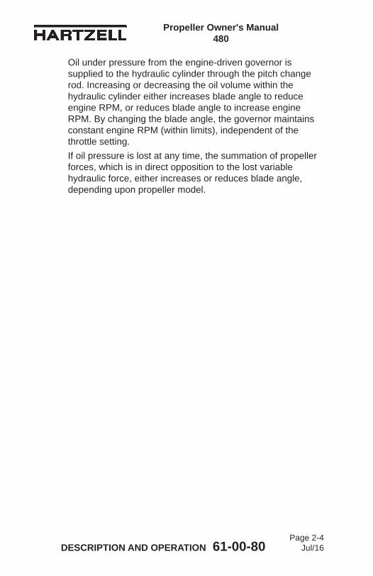
Oil under pressure from the engine-driven governor is supplied to the hydraulic cylinder through the pitch change rod. Increasing or decreasing the oil volume within the hydraulic cylinder either increases blade angle to reduce engine RPM, or reduces blade angle to increase engine RPM. By changing the blade angle, the governor maintains constant engine RPM (within limits), independent of the throttle setting. If oil pressure is lost at any time, the summation of propeller forces, which is in direct opposition to the lost variable hydraulic force, either increases or reduces blade angle, depending upon propeller model.

Propeller Owner's Manual 480
DESCRIPTION AND OPERATION 61-00-80Page 2-5
Jul/16
2. Functional Description of Constant Speed Propeller TypesA. 3C1-( )( )( ) Series Propellers with Composite Blades
These propeller model series are constant speed, non-counterweighted propellers. The propellers are capable of blade angles between a low positive pitch (low pitch) and high positive pitch (high pitch). Centrifugal twisting moment acting on the blades moves the blades to a low blade angle (low pitch) to increase RPM. Since the centrifugal twisting moment is only present when the propeller is rotating, a mechanical spring is installed within the propeller to assist movement of the blades to a lower pitch position as RPM declines, and to reduce the propeller pitch to the low pitch stop when the propeller is static. With the blades at low pitch, the load on the starter whenstartingtheengineisreducedsignificantly.Oil pressure opposes the spring and centrifugal twisting moment to move the blades to a high blade angle (high pitch), reducing engine RPM.If oil pressure is lost at any time, the propeller will move to low pitch. This occurs because the spring and blade centrifugal twisting moment are no longer opposed by hydraulic oil pressure. The propeller will then reduce blade pitch to the low pitch stop.

Propeller Owner's Manual 480
DESCRIPTION AND OPERATION 61-00-80Page 2-6
Jul/16
Propeller Flange Description Figure 2-1
F Flange
L and R Flange
Dowel PinHoleDowel PinHole
TI-0
050
TI-0
051
Bolt Circle No. of Dowels No. of Bolts or Studs
Typical Engine
4.00 inch 2 (1/2 inch)
6 (0.50 inch)
Continental
Flange Bolt Circle No. of Dowels
No. of Bolts or Studs
Typical Engine
L 4.75 inch N/A 6 (7/16 inch)
Lycoming
R 4.75 inch N/A 6 (1/2 inch)
Lycoming

Propeller Owner's Manual 480
DESCRIPTION AND OPERATION 61-00-80Page 2-7
Jul/16
3. Model DesignationThe following pages illustrate sample model designations for HartzellPropellerInc.propellerhubassembliesandblades.A. Refer to Table 2-1 for the propeller model designations for
HartzellPropellerInc.3C1SeriesRaptorpropellers.B. RefertoTable2-2forCompositeBladeModelIdentification
(1) HartzellPropellerInc.usesamodeldesignationtoidentifyspecificpropellerandbladeassemblies. Example: 3C1-R919A( )/76C03-2( ).
(2) A slash mark separates the propeller and blade designations. The propeller model designation is impression stamped on the propeller hub. The blade designation is impression stamped on the blade butt end (internal) and may be on a label on the propeller cylinder (external).
Propeller Owner's Manual 480
DESCRIPTION AND OPERATION 61-00-80Page 2-8
Jul/16
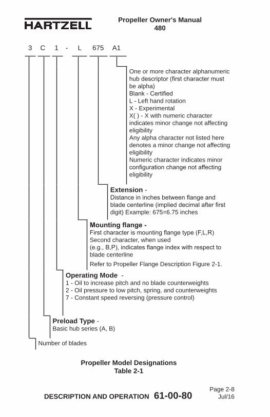
Propeller Model Designations Table 2-1
3 C 1 - L 675 A1
One or more character alphanumeric hubdescriptor(firstcharactermustbe alpha) Blank-Certified L - Left hand rotation X - Experimental X( ) - X with numeric character indicates minor change not affecting eligibility Any alpha character not listed here denotes a minor change not affecting eligibility Numeric character indicates minor configurationchangenotaffectingeligibility
Extension - Distanceininchesbetweenflangeandbladecenterline(implieddecimalafterfirstdigit) Example: 675=6.75 inches
Mounting flange - Firstcharacterismountingflangetype(F,L,R) Second character, when used (e.g.,B,P),indicatesflangeindexwithrespecttoblade centerlineRefer to Propeller Flange Description Figure 2-1.
Operating Mode - 1 - Oil to increase pitch and no blade counterweights 2 - Oil pressure to low pitch, spring, and counterweights 7 - Constant speed reversing (pressure control)
Preload Type - Basic hub series (A, B)
Number of blades

Propeller Owner's Manual 480
DESCRIPTION AND OPERATION 61-00-80Page 2-9
Jul/16
Blade Type and Blade Model Designations Table 2-2
H 76 C 03 B - 5 X( )
Blank or more characters Blank - Original design, no changes X - experimental X( ) - X with numeric character indicates minor change not affecting eligibility Any alpha character not listed here denotes a minor change not affecting eligibility
Blank - Basic diameter Number when used indicates the difference in inches from (or added to if +) basic diameter
B or K - De-ice or anti-ice boots
Basic blade model (two character numeric)
First character: Basic blade series for hub model (must match basic hub series) Second character when used: Major blade characteristic
Basic diameter in inches
Denotesbladeconfiguration: Blank - Right-hand tractor C - Counterweighted H-Right-handpusher J - Left-hand tractor L - Left-hand pusher

Propeller Owner's Manual 480
DESCRIPTION AND OPERATION 61-00-80Page 2-10
Jul/16
Governor in Overspeed Condition Figure 2-4
Governor in Onspeed Condition Figure 2-2
Governor in Underspeed Condition Figure 2-3
Pilot Control
Speeder SpringFlyweights
Pilot Valve
Pilot Control
Speeder SpringFlyweights
Pilot Valve
Pilot Control
Speeder SpringFlyweights
Pilot Valve
AP
S61
49A
PS
6150
AP
S61
51

Propeller Owner's Manual 480
DESCRIPTION AND OPERATION 61-00-80Page 2-11
Jul/16
4. GovernorsA. Theory of Operation
(1) A governor is an engine RPM sensing device and high pressure oil pump. In a constant speed propeller system, the governor responds to a change in engine RPM by directing oil under pressure to the propeller hydraulic cylinder or by releasing oil from the hydraulic cylinder. The change in oil volume in the hydraulic cylinder changes the blade angle and maintains the propeller system RPM to the set value. The governor is set for aspecificRPMviathecockpitpropellercontrol,thatcompresses or releases the governor speeder spring.
(2) When the engine is operating at the RPM set by the pilot using the cockpit control, the governor is operating onspeed. Refer to Figure 2-2. In an onspeed condition, thecentrifugalforceactingontheflyweightsisbalancedby the speeder spring, and the pilot valve is neither directing oil to nor from the propeller hydraulic cylinder.
(3) When the engine is operating below the RPM set by the pilot using the cockpit control, the governor is operating underspeed. Refer to Figure 2-3. In an underspeed condition,theflyweightstiltinwardbecausethereisnotenoughcentrifugalforceontheflyweightstoovercomethe force of the speeder spring. The pilot valve, forced downbythespeederspring,metersoilflowtodecreasepropeller pitch and raise engine RPM.
(4) When the engine is operating above the RPM set by the pilot using the cockpit control, the governor is operating overspeed. Refer to Figure 2-4. In an overspeed condition,thecentrifugalforceactingontheflyweightsisgreaterthanthespeederspringforce.Theflyweightstilt outward, and raise the pilot valve. The pilot valve thenmetersoilflowtoincreasepropellerpitchandlowerengine RPM.
B. Governor Types(1) ThegovernorscommonlyusedinHartzellPropellerInc.
Constant Speed propeller systems are supplied either byHartzellPropellerInc.orseveralothermanufacturers.These governor types function in a similar manner.

Propeller Owner's Manual 480
DESCRIPTION AND OPERATION 61-00-80Page 2-12
Jul/16
C. IdentificationofHartzellPropellerInc.Governors(1) HartzellPropellerInc.governorsmaybeidentifiedbya
model number. Refer to Figure 2-5.(2) All other series governors are hydro-mechanical
governors.
Governor Model DesignationFigure 2-5
S-1 - 1
Specificmodelapplication( ) - special attributes
Model Series (refer to NOTE)
NOTE: RefertoHartzellPropeller Inc. Mechanically Actuated Governor Maintenance Manual 130B (61-23-30)orHartzellPropeller Inc. Turbine Governor Maintenance Manual 138 (61-23-38) for maintenance and overhaul instructions for HartzellPropellerInc.governors.

Propeller Owner's Manual 480
DESCRIPTION AND OPERATION 61-00-80Page 2-13
Jul/16
5. Propeller Ice Protection SystemsSomeHartzellPropellerInc.propellersmaybeequippedwithananti-ice or a de-ice system. A short description of each of these systems follows:A. Propeller Anti-ice System
(1) A propeller anti-ice system prevents ice from forming on propeller surfaces. The system dispenses a an anti-icing liquid(usuallyisopropylalcohol)thatmixeswithmoistureonthepropellerblades,reducingthefreezingpointofthewater.Thiswater/alcoholmixtureflowsoffthebladesbefore ice forms. This system must be in use before ice forms. It is ineffective in removing ice that has already formed.(a) System Overview
1 Atypicalanti-icesystemconsistsofafluidtank,pump, and distribution tubing.
2 Therateatwhichtheanti-icingfluidisdispensedis controlled by a pump speed rheostat in the cockpit.
3 Theanti-icingfluidisdispensedthroughairframemounted distribution tubing and into a rotating slinger ring mounted on the rear of the propeller hub.Theanti-icingfluidisthendirectedthroughblade feed tubes from the slinger ring onto the bladesviacentrifugalforce.Theanti-icingfluidis directed onto anti-icing boots that are securely attached to the inboard leading edge of each blade. These anti-icing boots evenly distribute and directthefluidalongthebladeleadingedge.

Propeller Owner's Manual 480
DESCRIPTION AND OPERATION 61-00-80Page 2-14
Jul/16
B. Propeller De-ice System(1) A propeller de-ice system permits ice to form, and then
removes it by electrically heating the de-ice boots. The ice partially melts and is thrown from the blade by centrifugal force.(a) System Overview
1 A de-ice system consists of one or more on/off switches, a timer or cycling unit, a slip ring, brush blocks, and de-ice boots. The pilot controls the operation of the de-ice system by turning on one or more switches. All de-ice systems have a master switch, and may have another toggle switch for each propeller. Some systems also have a selector switch to adjust for light or heavy icing conditions.
2 The timer or cycling unit determines the sequenceofwhichblades(orportionthereof)are currently being de-iced, and for what length of time. The cycling unit applies power to each de-icebootorbootsegmentinasequentialorder.
3 A brush block, which is normally mounted on the engine just behind the propeller, is used to transfer electricity to the slip ring. The slip ring rotates with the propeller, and provides a current path to the blade de-ice boots.
4 De-ice boots contain internal heating elements. These boots are securely attached to the inboard leading edges of each blade with adhesive.

Propeller Owner’s Manual 480
INSTALLATION AND REMOVAL 61-00-80 Page 3-1
Jul/16
INSTALLATION AND REMOVAL - CONTENTS
1. Tools, Consumables, and Expendables .................................... 3-3A. Tooling ................................................................................... 3-3B. Consumables ........................................................................ 3-3C. Expendables ......................................................................... 3-3
2. Pre-Installation ........................................................................... 3-4A. Inspection of Shipping Package ............................................ 3-4B. Uncrating ............................................................................... 3-4C. Inspection after Shipment ..................................................... 3-4D. Reassembly of a Propeller Disassembled for Shipment ....... 3-4
3. Spinner Pre-Installation ............................................................. 3-7A. General ................................................................................. 3-7B. Installation of a Metal Spinner Bulkhead on a Propeller Hub ........................................................................3-12
4. Propeller Installation ................................................................ 3-15A. Flange Description .............................................................. 3-15B. Installation of “F” Flange Propellers .................................... 3-16C. Installation of “L” Flange Propellers .................................... 3-21D. Installation of “R” Flange Propellers .................................... 3-25
5. Spinner Installation .................................................................. 3-28A. Single Piece Spinner Dome ................................................ 3-28
6. Post-Installation Checks .......................................................... 3-29
7. Spinner Removal ..................................................................... 3-30A. Removal of Single Piece Spinner ....................................... 3-30B. Hub Mounted Spinner Bulkhead Removal .......................... 3-30C. Starter Ring Gear Spinner Adapter Removal ...................... 3-30
8. Propeller Removal ................................................................... 3-31A. Removal of “F” Flange Propellers ....................................... 3-31B. Removal of “L” Flange Propellers ....................................... 3-34C. Removal of “R” Flange Propellers ....................................... 3-37

Propeller Owner’s Manual 480
INSTALLATION AND REMOVAL 61-00-80 Page 3-2
Rev. 1 Apr/17
LIST OF FIGURES
LIST OF TABLES
Hub Clamping Bolt Location ..........................Figure 3-1 ............. 3-6
Determining Torque Value When Using Torquing Adapter ........................................Figure 3-2 ............. 3-8
Diagram of Torquing Sequence for Propeller Mounting Hardware .....................Figure 3-3 ........... 3-10
Metal Bulkhead and Spinner Mounting (Hub Mounted Spinner) ..............................Figure 3-4 ........... 3-11
F Flange Propeller Mounting .........................Figure 3-5 ........... 3-14
L Flange Propeller Mounting .........................Figure 3-6 ........... 3-20
R Flange Propeller Mounting .........................Figure 3-7 ........... 3-24
Torque Table ..................................................Table 3-1 .............. 3-9
Metal Spinner Bulkhead Mounting Hardware ....................................Table 3-2 ............ 3-13
Propeller/Engine Flange O-rings and Hardware .............................................Table 3-3 ............ 3-15
Spinner Dome Mounting Hardware ...............Table 3-4 ............ 3-28
Propeller Owner’s Manual 480
INSTALLATION AND REMOVAL 61-00-80 Page 3-3
Jul/16
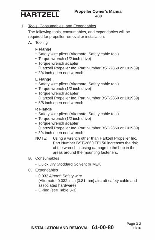
1. Tools, Consumables, and ExpendablesThe following tools, consumables, and expendables will be required for propeller removal or installation:A. Tooling
F Flange • Safety wire pliers (Alternate: Safety cable tool) • Torque wrench (1/2 inch drive) • Torque wrench adapter (Hartzell Propeller Inc. Part Number BST-2860 or 101939) • 3/4 inch open end wrenchL Flange • Safety wire pliers (Alternate: Safety cable tool) • Torque wrench (1/2 inch drive) • Torque wrench adapter (Hartzell Propeller Inc. Part Number BST-2860 or 101939) • 5/8 inch open end wrenchR Flange • Safety wire pliers (Alternate: Safety cable tool) • Torque wrench (1/2 inch drive) • Torque wrench adapter (Hartzell Propeller Inc. Part Number BST-2860 or 101939) • 3/4 inch open end wrenchNOTE: Using a wrench other than Hartzell Propeller Inc.
Part Number BST-2860 TE150 increases the risk of the wrench causing damage to the hub in the areas around the mounting fasteners.
B. Consumables• Quick Dry Stoddard Solvent or MEK
C. Expendables• 0.032 Aircraft Safety wire (Alternate: 0.032 inch [0.81 mm] aircraft safety cable and associated hardware) • O-ring (see Table 3-3)
Propeller Owner’s Manual 480
INSTALLATION AND REMOVAL 61-00-80 Page 3-4
Jul/16
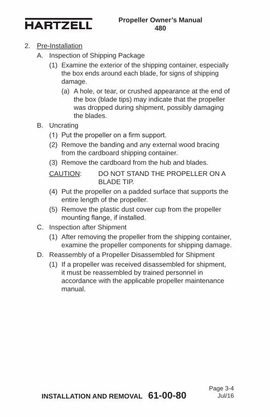
2. Pre-InstallationA. Inspection of Shipping Package
(1) Examine the exterior of the shipping container, especially the box ends around each blade, for signs of shipping damage. (a) A hole, or tear, or crushed appearance at the end of
the box (blade tips) may indicate that the propeller was dropped during shipment, possibly damaging the blades.
B. Uncrating(1) Putthepropelleronafirmsupport.(2) Remove the banding and any external wood bracing
from the cardboard shipping container. (3) Remove the cardboard from the hub and blades. CAUTION: DO NOT STAND THE PROPELLER ON A
BLADE TIP.(4) Put the propeller on a padded surface that supports the
entire length of the propeller. (5) Remove the plastic dust cover cup from the propeller
mountingflange,ifinstalled.C. Inspection after Shipment
(1) After removing the propeller from the shipping container, examine the propeller components for shipping damage.
D. Reassembly of a Propeller Disassembled for Shipment(1) If a propeller was received disassembled for shipment,
it must be reassembled by trained personnel in accordance with the applicable propeller maintenance manual.
Propeller Owner’s Manual 480
INSTALLATION AND REMOVAL 61-00-80 Page 3-5
Jul/16
(This page is intentionally blank.)

Propeller Owner’s Manual 480
INSTALLATION AND REMOVAL 61-00-80 Page 3-6
Jul/16
Hub Clamping Bolt Location Figure 3-1
TI-0
0118
HUB CLAMPING BOLTS
HUB CLAMPING BOLTS
HUB CLAMPING BOLTS

Propeller Owner’s Manual 480
INSTALLATION AND REMOVAL 61-00-80 Page 3-7
Jul/16
3. Spinner Pre-InstallationA. General
(1) The spinner bulkhead must be installed before the propeller can be installed. The spinner will mount to a bulkhead installed on the propeller hub. Follow the applicable directions in this section.
CAUTION: DO NOT REMOVE THE BOLTS ON THE BLADE SHANK.
(2) Remove the nuts from the hub clamping bolts that are located on either side of the blade shank. Refer to Figure 3-1. Do not remove the bolts. The remaining nuts/bolts should not be disturbed.
(3) The spinner may be supplied with long hub clamping bolts. Refer to Figure 3-1. If the bolts were supplied with the spinner, remove the bolts on either side of the blade shank and replace them with the bolts supplied with the spinner. The supplied hub clamping bolts will be longer than those removed from the hub.NOTE: Depending upon the installation, the propeller
hub may have been shipped from the factory with the longer hub clamping bolts installed. In this case, the hub clamping bolts will not be supplied with the spinner.
Propeller Owner’s Manual 480
INSTALLATION AND REMOVAL 61-00-80 Page 3-8
Jul/16
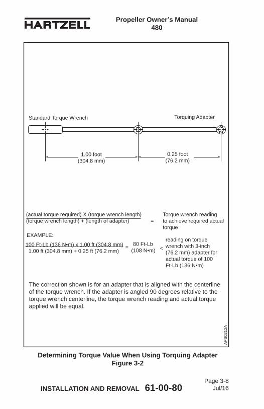
(actual torque required) X (torque wrench length) Torque wrench reading (torque wrench length) + (length of adapter) = to achieve required actual torque
Determining Torque Value When Using Torquing Adapter Figure 3-2
AP
S02
12A
0.25 foot(76.2 mm)
1.00 foot(304.8 mm)
Standard Torque Wrench Torquing Adapter
100 Ft-Lb (136 N•m) x 1.00 ft (304.8 mm) 1.00 ft (304.8 mm) + 0.25 ft (76.2 mm)
reading on torque wrench with 3-inch (76.2 mm) adapter for actual torque of 100 Ft-Lb (136 N•m)
EXAMPLE:
= < 80 Ft-Lb(108 N•m)
The correction shown is for an adapter that is aligned with the centerline of the torque wrench. If the adapter is angled 90 degrees relative to the torque wrench centerline, the torque wrench reading and actual torque applied will be equal.
Propeller Owner’s Manual 480
INSTALLATION AND REMOVAL 61-00-80 Page 3-9
Jul/16
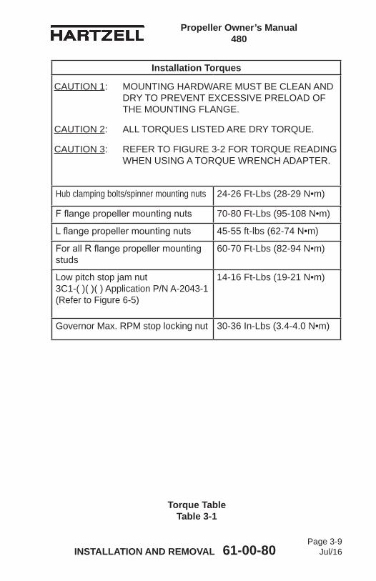
Torque Table Table 3-1
Installation Torques
Hub clamping bolts/spinner mounting nuts 24-26 Ft-Lbs (28-29 N•m)
Fflangepropellermountingnuts 70-80 Ft-Lbs (95-108 N•m)
Lflangepropellermountingnuts 45-55 ft-lbs (62-74 N•m)
ForallRflangepropellermountingstuds
60-70 Ft-Lbs (82-94 N•m)
Low pitch stop jam nut 3C1-( )( )( ) Application P/N A-2043-1 (Refer to Figure 6-5)
14-16 Ft-Lbs (19-21 N•m)
Governor Max. RPM stop locking nut 30-36 In-Lbs (3.4-4.0 N•m)
CAUTION 1: MOUNTING HARDWARE MUST BE CLEAN AND DRY TO PREVENT EXCESSIVE PRELOAD OF THE MOUNTING FLANGE.
CAUTION 2: ALL TORQUES LISTED ARE DRY TORQUE.
CAUTION 3: REFER TO FIGURE 3-2 FOR TORQUE READING WHEN USING A TORQUE WRENCH ADAPTER.
Propeller Owner’s Manual 480
INSTALLATION AND REMOVAL 61-00-80 Page 3-10
Jul/16
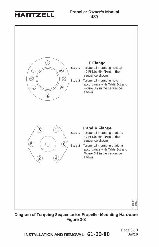
Diagram of Torquing Sequence for Propeller Mounting Hardware Figure 3-3
F FlangeStep 1 - Torque all mounting nuts to
40 Ft-Lbs (54 N•m) in the sequence shown
Step 2 - Torque all mounting nuts in accordance with Table 3-1 and Figure 3-2 in the sequence shown
1
2
3
45
6
1
2
3
4
5 6
L and R FlangeStep 1 - Torque all mounting studs to
40 Ft-Lbs (54 N•m) in the sequence shown
Step 2 - Torque all mounting studs in accordance with Table 3-1 and Figure 3-2 in the sequence shown
TI-0
050
TI-0
051
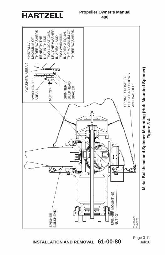
Propeller Owner’s Manual 480
INSTALLATION AND REMOVAL 61-00-80 Page 3-11
Jul/16
Met
al B
ulkh
ead
and
Spin
ner M
ount
ing
(Hub
Mou
nted
Spi
nner
) Fi
gure
3-4
SP
INN
ER
B
ULK
HE
AD
SP
INN
ER
B
ULK
HE
AD
S
PAC
ER
SP
INN
ER
MO
UN
TIN
G
NU
T “G
”
SP
INN
ER
DO
ME
TO
B
ULK
HE
AD
SC
RE
WS
A
ND
WA
SH
ER
TI-4
80-0
01TI
-001
76
NU
T “G
”*WA
SH
ER
, AR
EA
2*I
NS
TALL
A
MA
XIM
UM
OF
THR
EE
WA
SH
ER
S
BE
NE
ATH
TH
E
NU
T IN
TH
ES
E
TWO
LO
CAT
ION
S,
I.E.,
ON
E W
AS
HE
R
IN A
RE
A 1
AN
D
TWO
WA
SH
ER
S
IN A
RE
A 2
EQ
UA
L TH
E M
AX
IMU
M O
F TH
RE
E W
AS
HE
RS
.
*WA
SH
ER
“F”,
AR
EA
1
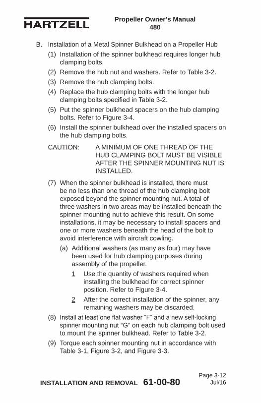
Propeller Owner’s Manual 480
INSTALLATION AND REMOVAL 61-00-80 Page 3-12
Jul/16
B. Installation of a Metal Spinner Bulkhead on a Propeller Hub (1) Installation of the spinner bulkhead requires longer hub
clamping bolts.(2) Remove the hub nut and washers. Refer to Table 3-2.(3) Remove the hub clamping bolts.(4) Replace the hub clamping bolts with the longer hub
clampingboltsspecifiedinTable3-2.(5) Put the spinner bulkhead spacers on the hub clamping
bolts. Refer to Figure 3-4. (6) Install the spinner bulkhead over the installed spacers on
the hub clamping bolts.
CAUTION: A MINIMUM OF ONE THREAD OF THE HUB CLAMPING BOLT MUST BE VISIBLE AFTER THE SPINNER MOUNTING NUT IS INSTALLED.
(7) When the spinner bulkhead is installed, there must be no less than one thread of the hub clamping bolt exposed beyond the spinner mounting nut. A total of three washers in two areas may be installed beneath the spinner mounting nut to achieve this result. On some installations, it may be necessary to install spacers and one or more washers beneath the head of the bolt to avoid interference with aircraft cowling.(a) Additional washers (as many as four) may have
been used for hub clamping purposes during assembly of the propeller. 1 Use the quantity of washers required when
installing the bulkhead for correct spinner position. Refer to Figure 3-4.
2 After the correct installation of the spinner, any remaining washers may be discarded.
(8) Installatleastoneflatwasher“F”andanew self-locking spinner mounting nut “G” on each hub clamping bolt used to mount the spinner bulkhead. Refer to Table 3-2.
(9) Torque each spinner mounting nut in accordance with Table 3-1, Figure 3-2, and Figure 3-3.

Propeller Owner’s Manual 480
INSTALLATION AND REMOVAL 61-00-80 Page 3-13
Jul/16
“L” FlangeSpinner Mounting Kit A-2476-47
A-3203 Hub Clamping BoltA-2246-5 Aluminum SpacerB-3599 NutB-3834-0663 Washer
“R” FlangeMounting Kit A-2476-30
102691 Hub Clamping BoltA-2246-3 Aluminum SpacerB-3599 NutB-3834-0663 Washer
Metal Spinner Bulkhead Mounting Hardware Table 3-2
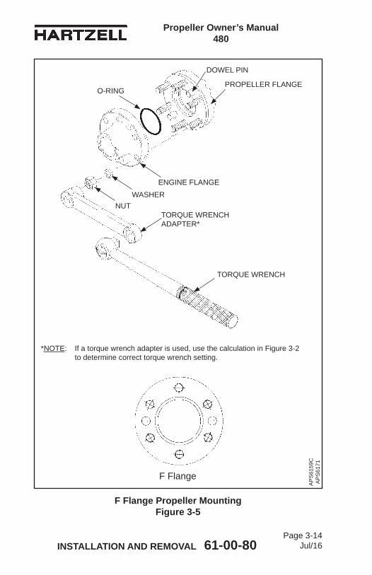
Propeller Owner’s Manual 480
INSTALLATION AND REMOVAL 61-00-80 Page 3-14
Jul/16
F Flange Propeller Mounting Figure 3-5
O-RINGPROPELLER FLANGE
ENGINE FLANGE
NUTTORQUE WRENCH ADAPTER*
TORQUE WRENCH
DOWEL PIN
AP
S61
59C
A
PS
6171
F Flange
*NOTE: If a torque wrench adapter is used, use the calculation in Figure 3-2 to determine correct torque wrench setting.
WASHER
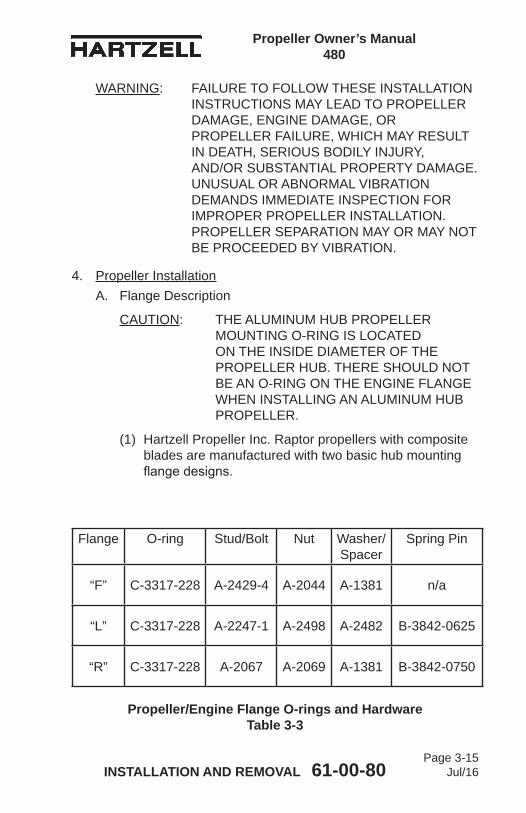
Propeller Owner’s Manual 480
INSTALLATION AND REMOVAL 61-00-80 Page 3-15
Jul/16
WARNING: FAILURE TO FOLLOW THESE INSTALLATION INSTRUCTIONS MAY LEAD TO PROPELLER DAMAGE, ENGINE DAMAGE, OR PROPELLER FAILURE, WHICH MAY RESULT IN DEATH, SERIOUS BODILY INJURY, AND/OR SUBSTANTIAL PROPERTY DAMAGE. UNUSUAL OR ABNORMAL VIBRATION DEMANDS IMMEDIATE INSPECTION FOR IMPROPER PROPELLER INSTALLATION. PROPELLER SEPARATION MAY OR MAY NOT BE PROCEEDED BY VIBRATION.
4. Propeller InstallationA. Flange Description
CAUTION: THE ALUMINUM HUB PROPELLER MOUNTING O-RING IS LOCATED ON THE INSIDE DIAMETER OF THE PROPELLER HUB. THERE SHOULD NOT BE AN O-RING ON THE ENGINE FLANGE WHEN INSTALLING AN ALUMINUM HUB PROPELLER.
(1) Hartzell Propeller Inc. Raptor propellers with composite blades are manufactured with two basic hub mounting flangedesigns.
Propeller/Engine Flange O-rings and Hardware Table 3-3
Flange O-ring Stud/Bolt Nut Washer/Spacer
Spring Pin
“F” C-3317-228 A-2429-4 A-2044 A-1381 n/a
“L” C-3317-228 A-2247-1 A-2498 A-2482 B-3842-0625
“R” C-3317-228 A-2067 A-2069 A-1381 B-3842-0750

Propeller Owner’s Manual 480
INSTALLATION AND REMOVAL 61-00-80 Page 3-16
Jul/16
(2) Theflangetypedesignatorsare“F”,“L”,or“R”.Theflangetypeusedonaparticularpropellerinstallationisindicated in the propeller model stamped on the hub. For example, 3C1-R919indicatesan“R”flange.
(3) Refer to the Propeller Flange Description in the Description and Operation chapter of this manual.
B. Installation of “F” Flange Propellers(1) General
(a) An“F”flangepropellerhassix1/2inchdiameterstudsconfiguredinafourinchcircle.
(b) Two dowel pins are also supplied to transfer torque and index the propeller with respect to the engine crankshaft. See Figure 3-5.
(c) The dowel pin locations used on a particular propeller installation are indicated in the propeller model stamped on the hub. Refer to the Propeller Flange Description in the Description and Operation chapterofthismanual.Sampleflangesarealsoshown in Figure 3-3 and Figure 3-5.
(2) Perform the applicable steps in the section “Spinner Pre-Installation” in this chapter.
WARNING: ADHESIVES AND SOLVENTS ARE FLAMMABLE AND TOXIC TO THE SKIN, EYES, AND RESPIRATORY TRACT. SKIN AND EYE PROTECTION ARE REQUIRED. AVOID PROLONGED CONTACT AND BREATHING OF VAPORS. USE SOLVENT RESISTANT GLOVES TO MINIMIZE SKIN CONTACT AND WEAR SAFETY GLASSES FOR EYE PROTECTION. USE IN A WELL VENTILATED AREA AWAY FROM SPARKS AND FLAME. READ AND OBSERVE ALL WARNING LABELS.
(3) CleantheengineflangeandpropellerflangewithQuickDry Stoddard Solvent or MEK.

Propeller Owner’s Manual 480
INSTALLATION AND REMOVAL 61-00-80 Page 3-17
Jul/16
(4) RefertoFigure3-5.LubricatethemountingflangeO-ringwith unused engine oil. (a) Install the O-ring in the O-ring groove in the hub
bore. Refer to Table 3-3 for the applicable O-ring and mounting hardware.NOTE: When the propeller is received from the
factory, the O-ring has been installed and should be lubricated with unused engine oil before propeller installation on the aircraft.
WARNING: MAKE SURE THAT ANY EQUIPMENT USED TO INSTALL THE PROPELLER IS RATED UP TO 800 LBS (363 KG) TO SUPPORT THE WEIGHT OF THE PROPELLER ASSEMBLY DURING INSTALLATION. ONE PERSON MUST NEVER ATTEMPT TO INSTALL AN UNSUPPORTED PROPELLER BY HIMSELF, REGARDLESS OF THE SIZE OR WEIGHT OF THE PROPELLER. MANUALLY LIFTING THE PROPELLER ONTO THE ENGINE CAN RESULT IN PERSONAL INJURY.
CAUTION 1: A PROPELLER MUST BE CORRECTLY SUPPORTED DURING INSTALLATION ON THE ENGINE. AVOID ANY ROCKING OR SHIFTING OF THE PROPELLER WHEN IT IS PARTIALLY ENGAGED WITH THE ENGINE. ROCKING OF THE PROPELLER DURING PROPELLER INSTALLATION CAN DAMAGE THE PROPELLER HUB MOUNTING FACE, CAUSING ACTUATION OIL LEAKAGE OR DAMAGE THAT MAY SCRAP THE HUB. HUB DAMAGE CAN ALSO INTRODUCE METAL INTO THE PROPELLER OIL ACTUATION SYSTEM, WHICH COULD POSSIBLY DAMAGE THE ENGINE.

Propeller Owner’s Manual 480
INSTALLATION AND REMOVAL 61-00-80 Page 3-18
Jul/16
CAUTION 2: WHEN INSTALLING THE PROPELLER ON THE AIRCRAFT, DO NOT DAMAGE THE ICE PROTECTION SYSTEM COMPONENTS, IF APPLICABLE.
CAUTION 3: INSTRUCTIONS AND PROCEDURES IN THIS SECTION MAY INVOLVE PROPELLER CRITICAL PARTS. REFER TO THE INTRODUCTION CHAPTER OF THIS MANUAL FOR INFORMATION ABOUT PROPELLER CRITICAL PARTS. REFER TO THE ILLUSTRATED PARTS LIST CHAPTER OF THE APPLICABLE OVERHAUL MANUAL(S) FOR THE IDENTIFICATION OF SPECIFIC PROPELLER CRITICAL PARTS.
(5) With a suitable support, such as a crane hoist or similar equipment, carefully move the propeller assembly to theaircraftenginemountingflangeinpreparationforinstallation.
(6) Installthepropellerontheengineflange.(a) Make sure to align the dowel pins in the propeller
flangewiththecorrespondingholesintheenginemountingflange.
(b) The propeller may be installed on the engine flangeinagivenposition,or180degreesfromthatposition.
(c) Check the engine and airframe manuals to determineifeithermanualspecifiesapropellermounting position.
CAUTION 1: MOUNTING HARDWARE MUST BE CLEAN AND DRY TO PREVENT EXCESSIVE PRELOAD OF THE MOUNTING FLANGE.
CAUTION 2: TIGHTEN NUTS EVENLY TO AVOID HUB DAMAGE.
(7) Install the 1/2 inch propeller mounting nuts (dry) with spacers. Refer to Table 3-3.

Propeller Owner’s Manual 480
INSTALLATION AND REMOVAL 61-00-80 Page 3-19
Jul/16
(8) Torque the 1/2 inch propeller mounting nuts (dry) in accordance with Table 3-1, Figure 3-2, and Figure 3-3.
(9) Safety wire the studs in pairs (alternate: 0.032 inch [0.81 mm] aircraft safety cable and associated hardware) (if required by aircraft maintenance manual) at the rear of thepropellermountingflange.RefertoFigure3-4.
(10) If the propeller is equipped with an ice protection system that uses components supplied by Hartzell Propeller Inc., applicable instructions and technical information for the components supplied by Hartzell Propeller Inc. can be found in the following publications available on the Hartzell Propeller Inc. website at www.hartzellprop.com: (a) Hartzell Propeller Inc. Manual 180 (30-61-80) -
Propeller Ice Protection System Manual(b) Hartzell Propeller Inc. Manual 181 (30-60-81) -
Propeller Ice Protection System Component Maintenance Manual
(c) Hartzell Propeller Inc. Manual 182 (61-12-82) - Propeller Electrical De-ice Boot Removal and Installation Manual
(d) Hartzell Propeller Inc. Manual 183 (61-12-83) - Propeller Anti-icing Boot Removal and Installation Manual
(11) Propeller ice protection system components not supplied by Hartzell Propeller Inc. are controlled by the applicable TC or STC holder’s Instructions for Continued Airworthiness (ICA).
(12) Install the propeller spinner dome in accordance with the section “Spinner Installation” in this chapter.

Propeller Owner’s Manual 480
INSTALLATION AND REMOVAL 61-00-80 Page 3-20
Jul/16
L Flange Propeller Mounting Figure 3-6
O-RING
PROPELLER FLANGE
ENGINE FLANGE
TORQUE WRENCH
TORQUE WRENCH ADAPTER*
L Flange
*NOTE: If a torque wrench adapter is used, use the calculation in Figure 3-1 to determine correct torque wrench setting
AP
S61
72
AP
S61
60D
SPRING PINNUT
WASHER
STARTER RING GEAR

Propeller Owner’s Manual 480
INSTALLATION AND REMOVAL 61-00-80 Page 3-21
Jul/16
C. Installation of “L” Flange Propellers(1) General
(a) An“L”flangeisanSAENo.2flangethathassix 7/16inchdiameterstudsconfiguredina4.75inchcircle.
(b) Four drive bushings transfer torque and index the propeller with respect to the engine crankshaft. The bushingsarelocatedontheengineflangeandfitintocounterboredholesonthepropellerflange.Refer to Figure 3-6.
(c) The bushing locations used on a particular propeller installation are indicated in the propeller model stamped on the hub. Refer to the Propeller Flange Description in the Description and Operation chapter of this manual.
(2) Perform the applicable steps in “Spinner Pre-Installation” in this chapter.
WARNING: ADHESIVES AND SOLVENTS ARE FLAMMABLE AND TOXIC TO THE SKIN, EYES, AND RESPIRATORY TRACT. SKIN AND EYE PROTECTION ARE REQUIRED. AVOID PROLONGED CONTACT AND BREATHING OF VAPORS. USE SOLVENT RESISTANT GLOVES TO MINIMIZE SKIN CONTACT AND WEAR SAFETY GLASSES FOR EYE PROTECTION. USE IN A WELL VENTILATED AREA AWAY FROM SPARKS AND FLAME. READ AND OBSERVE ALL WARNING LABELS.
(3) CleantheengineflangeandpropellerflangewithQuickDry Stoddard Solvent or MEK.
(4) Install the O-ring in the O-ring groove in the rear of the hub. Refer to Figure 3-6. NOTE: When the propeller is received from the
factory, the O-ring has been installed.(a) Lubricate the O-ring with unused engine oil before
propeller installation on the aircraft.(b) For the applicable O-ring and mounting hardware,
refer to Table 3-3.

Propeller Owner’s Manual 480
INSTALLATION AND REMOVAL 61-00-80 Page 3-22
Jul/16
WARNING: MAKE SURE THAT ANY EQUIPMENT USED TO INSTALL THE PROPELLER IS RATED UP TO 800 LBS. (363 KG) TO SUPPORT THE WEIGHT OF THE PROPELLER ASSEMBLY DURING INSTALLATION. ONE PERSON MUST NEVER ATTEMPT TO INSTALL AN UNSUPPORTED PROPELLER BY HIMSELF, REGARDLESS OF THE SIZE OR WEIGHT OF THE PROPELLER. MANUALLY LIFTING THE PROPELLER ONTO THE ENGINE CAN RESULT IN PERSONAL INJURY.
CAUTION 1: A PROPELLER MUST BE CORRECTLY SUPPORTED DURING INSTALLATION ON THE ENGINE. AVOID ANY ROCKING OR SHIFTING OF THE PROPELLER WHEN IT IS PARTIALLY ENGAGED WITH THE ENGINE. ROCKING OF THE PROPELLER DURING PROPELLER INSTALLATION CAN DAMAGE THE PROPELLER HUB MOUNTING FACE, CAUSING ACTUATION OIL LEAKAGE OR DAMAGE THAT MAY SCRAP THE HUB. HUB DAMAGE CAN ALSO INTRODUCE METAL INTO THE PROPELLER OIL ACTUATION SYSTEM, WHICH COULD POSSIBLY DAMAGE THE ENGINE.
CAUTION 2: WHEN INSTALLING THE PROPELLER ON THE AIRCRAFT, DO NOT DAMAGE THE ICE PROTECTION SYSTEM COMPONENTS, IF APPLICABLE.
(5) With a suitable support, such as a crane hoist or similar equipment, carefully move the propeller assembly to theaircraftenginemountingflangeinpreparationforinstallation.
(6) Installthepropellerontheengineflange.(a) Aligntheengineflangebushingswiththe
correspondingholesinthepropellerflange.

Propeller Owner’s Manual 480
INSTALLATION AND REMOVAL 61-00-80 Page 3-23
Jul/16
CAUTION 1: MOUNTING HARDWARE MUST BE CLEAN AND DRY TO PREVENT TOO MUCH PRELOAD OF THE MOUNTING FLANGE
CAUTION 2: TIGHTEN NUTS EVENLY TO PREVENT HUB DAMAGE
(7) Torque the 7/16 inch diameter propeller mounting studs (dry) in accordance with Table 3-1, Figure 3-2, and Figure 3-3.
(8) If required by the aircraft maintenance manual, safety wire the mounting studs in pairs at the rear of the propellermountingflange.RefertoFigure3-6.
(9) If the propeller is equipped with an ice protection system that uses components supplied by Hartzell Propeller Inc., applicable instructions and technical information for the components supplied by Hartzell Propeller Inc. can be found in the following publications available on the Hartzell Propeller Inc. website at www.hartzellprop.com: (a) Hartzell Propeller Inc. Manual 180 (30-61-80) -
Propeller Ice Protection System Manual(b) Hartzell Propeller Inc. Manual 181 (30-60-81) -
Propeller Ice Protection System Component Maintenance Manual
(c) Hartzell Propeller Inc. Manual 182 (61-12-82) - Propeller Electrical De-ice Boot Removal and Installation Manual
(d) Hartzell Propeller Inc. Manual 183 (61-12-83) - Propeller Anti-icing Boot Removal and Installation Manual
(10) Propeller ice protection system components not supplied by Hartzell Propeller Inc. are controlled by the applicable TC or STC holder’s Instructions for Continued Airworthiness (ICA).
(11) Install the propeller spinner dome in accordance with the section “Spinner Installation” in this chapter.

Propeller Owner’s Manual 480
INSTALLATION AND REMOVAL 61-00-80 Page 3-24
Jul/16
R Flange Propeller Mounting Figure 3-7
O-RING
PROPELLER FLANGE
ENGINE FLANGE
TORQUE WRENCH
TORQUE WRENCH ADAPTER*
R Flange
*NOTE: If a torque wrench adapter is used, use the calculation in Figure 3-1 to determine correct torque wrench setting
AP
S61
72
AP
S61
60D
SPRING PINNUT
WASHER
STARTER RING GEAR
Propeller Owner’s Manual 480
INSTALLATION AND REMOVAL 61-00-80 Page 3-25
Jul/16
D. Installation of “R” Flange Propellers(1) General
(a) An“R”flangeisanSAENo.2flangethathassix 1/2inchdiameterstudsconfiguredina4.75inchcircle.
(b) Five drive bushings transfer torque and index the propeller with respect to the engine crankshaft. The bushingsarelocatedontheengineflangeandfitintocounterboredholesonthepropellerflange.Refer to Figure 3-7.
(c) The bushing locations used on a particular propeller installation are indicated in the propeller model stamped on the hub. Refer to the Propeller Flange Description in the Description and Operation chapter of this manual.
(2) Perform the applicable steps in “Spinner Pre-Installation” in this chapter.
WARNING: ADHESIVES AND SOLVENTS ARE FLAMMABLE AND TOXIC TO THE SKIN, EYES, AND RESPIRATORY TRACT. SKIN AND EYE PROTECTION ARE REQUIRED. AVOID PROLONGED CONTACT AND BREATHING OF VAPORS. USE SOLVENT RESISTANT GLOVES TO MINIMIZE SKIN CONTACT AND WEAR SAFETY GLASSES FOR EYE PROTECTION. USE IN A WELL VENTILATED AREA AWAY FROM SPARKS AND FLAME. READ AND OBSERVE ALL WARNING LABELS.
(3) CleantheengineflangeandpropellerflangewithQuickDry Stoddard Solvent or MEK.
(4) Install the O-ring in the O-ring groove in the rear of the hub. Refer to Figure 3-7. NOTE: When the propeller is received from the
factory, the O-ring has been installed.(a) Lubricate the O-ring with unused engine oil before
propeller installation on the aircraft.(b) For the applicable O-ring and mounting hardware,
refer to Table 3-3.

Propeller Owner’s Manual 480
INSTALLATION AND REMOVAL 61-00-80 Page 3-26
Jul/16
WARNING: MAKE SURE THAT ANY EQUIPMENT USED TO INSTALL THE PROPELLER IS RATED UP TO 800 LBS. (363 KG) TO SUPPORT THE WEIGHT OF THE PROPELLER ASSEMBLY DURING INSTALLATION. ONE PERSON MUST NEVER ATTEMPT TO INSTALL AN UNSUPPORTED PROPELLER BY HIMSELF, REGARDLESS OF THE SIZE OR WEIGHT OF THE PROPELLER. MANUALLY LIFTING THE PROPELLER ONTO THE ENGINE CAN RESULT IN PERSONAL INJURY.
CAUTION 1: A PROPELLER MUST BE CORRECTLY SUPPORTED DURING INSTALLATION ON THE ENGINE. AVOID ANY ROCKING OR SHIFTING OF THE PROPELLER WHEN IT IS PARTIALLY ENGAGED WITH THE ENGINE. ROCKING OF THE PROPELLER DURING PROPELLER INSTALLATION CAN DAMAGE THE PROPELLER HUB MOUNTING FACE, CAUSING ACTUATION OIL LEAKAGE OR DAMAGE THAT MAY SCRAP THE HUB. HUB DAMAGE CAN ALSO INTRODUCE METAL INTO THE PROPELLER OIL ACTUATION SYSTEM, WHICH COULD POSSIBLY DAMAGE THE ENGINE.
CAUTION 2: WHEN INSTALLING THE PROPELLER ON THE AIRCRAFT, DO NOT DAMAGE THE ICE PROTECTION SYSTEM COMPONENTS, IF APPLICABLE.
(5) With a suitable support, such as a crane hoist or similar equipment, carefully move the propeller assembly to theaircraftenginemountingflangeinpreparationforinstallation.
(6) Installthepropellerontheengineflange.(a) Aligntheengineflangebushingswiththe
correspondingholesinthepropellerflange.

Propeller Owner’s Manual 480
INSTALLATION AND REMOVAL 61-00-80 Page 3-27
Jul/16
CAUTION 1: MOUNTING HARDWARE MUST BE CLEAN AND DRY TO PREVENT TOO MUCHPRELOAD OF THE MOUNTING FLANGE.
CAUTION 2: TIGHTEN NUTS EVENLY TO PREVENT HUB DAMAGE.
(7) Torque the 1/2 inch diameter propeller mounting studs (dry) in accordance with Table 3-1, Figure 3-2, and Figure 3-3.
(8) Safety wire the mounting studs in pairs (if required by the aircraft maintenance manual) at the rear of the propellermountingflange.RefertoFigure3-6.
(9) If the propeller is equipped with an ice protection system that uses components supplied by Hartzell Propeller Inc., applicable instructions and technical information for the components supplied by Hartzell Propeller Inc. can be found in the following publications available on the Hartzell Propeller Inc. website at www.hartzellprop.com: (a) Hartzell Propeller Inc. Manual 180 (30-61-80) -
Propeller Ice Protection System Manual(b) Hartzell Propeller Inc. Manual 181 (30-60-81) -
Propeller Ice Protection System Component Maintenance Manual
(c) Hartzell Propeller Inc. Manual 182 (61-12-82) - Propeller Electrical De-ice Boot Removal and Installation Manual
(d) Hartzell Propeller Inc. Manual 183 (61-12-83) - Propeller Anti-icing Boot Removal and Installation Manual
(10) Propeller ice protection system components not supplied by Hartzell Propeller Inc. are controlled by the applicable TC or STC holder’s Instructions for Continued Airworthiness (ICA).
(11) Install the propeller spinner dome in accordance with the section “Spinner Installation” in this chapter.
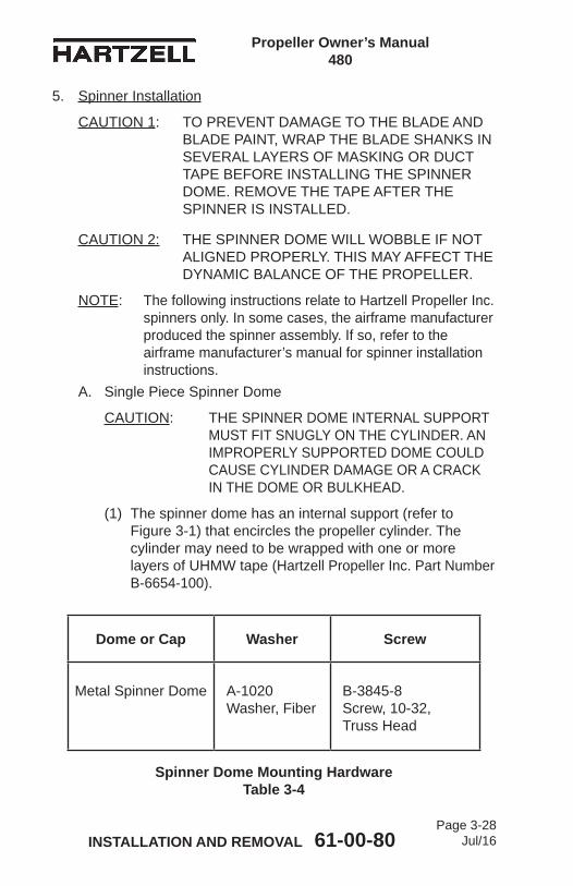
Propeller Owner’s Manual 480
INSTALLATION AND REMOVAL 61-00-80 Page 3-28
Jul/16
5. Spinner Installation
CAUTION 1: TO PREVENT DAMAGE TO THE BLADE AND BLADE PAINT, WRAP THE BLADE SHANKS IN SEVERAL LAYERS OF MASKING OR DUCT TAPE BEFORE INSTALLING THE SPINNER DOME. REMOVE THE TAPE AFTER THE SPINNER IS INSTALLED.
CAUTION 2: THE SPINNER DOME WILL WOBBLE IF NOT ALIGNED PROPERLY. THIS MAY AFFECT THE DYNAMIC BALANCE OF THE PROPELLER.
NOTE: The following instructions relate to Hartzell Propeller Inc. spinners only. In some cases, the airframe manufacturer produced the spinner assembly. If so, refer to the airframe manufacturer’s manual for spinner installation instructions.
A. Single Piece Spinner Dome
CAUTION: THE SPINNER DOME INTERNAL SUPPORT MUST FIT SNUGLY ON THE CYLINDER. AN IMPROPERLY SUPPORTED DOME COULD CAUSE CYLINDER DAMAGE OR A CRACK IN THE DOME OR BULKHEAD.
(1) The spinner dome has an internal support (refer to Figure 3-1) that encircles the propeller cylinder. The cylinder may need to be wrapped with one or more layers of UHMW tape (Hartzell Propeller Inc. Part Number B-6654-100).
Dome or Cap Washer Screw
Metal Spinner Dome A-1020 Washer, Fiber
B-3845-8 Screw, 10-32, Truss Head
Spinner Dome Mounting Hardware Table 3-4

Propeller Owner’s Manual 480
INSTALLATION AND REMOVAL 61-00-80 Page 3-29
Jul/16
(2) Install the spinner.(3) Checkthespinnerforasnugfitwheretheinternal
support contacts the cylinder. (a) Ifthesupportdoesnotfitsnuglyonthecylinder,
apply a layer of tape and recheck. Repeat until the spinnersupportfitssnuglyonthecylinder.
CAUTION: MAKE SURE OF PROPER THREAD ENGAGEMENT FOR THE SCREWS IN THE NUTPLATES. APPROXIMATELY 1 TO 1 1/2 THREADS MUST EXTEND PAST THE BULKHEAD NUTPLATES. TO AVOID DAMAGING THE AIRCRAFT COWLING, THE SCREWS MUST NOT EXTEND MORE THAN THREE THREADS PAST THE BULKHEAD NUTPLATES.
(4) Attach the spinner to the spinner bulkhead with the supplied screws and washers. Refer to Table 3-4.(a) If correct thread engagement cannot be achieved:
1 The B-3845-8 screws are supplied with the spinner assembly. The B-3845-8 is 0.500 inch (12.70 mm) in length.
2 The B-3845-9 screw may be used if correct thread engagement cannot be achieved. The B-3845-9 screw is 0.562 inch (14.27 mm) in length.
(5) When the spinner dome has been removed to facilitate maintenance,checkthespinner-to-cylinderfit.Ifthespinner loosens in service, add one or more layers of UHMWtapetothecylinderuntilthespinnerfitssnugly.
6. Post-Installation ChecksA. Refer to the airframe manufacturer’s instructions for
post-installation checks.B. Perform a Maximum RPM (Static) Hydraulic Low Pitch
Stop Check as outlined in the Testing and Troubleshooting chapter of this manual.

Propeller Owner’s Manual 480
INSTALLATION AND REMOVAL 61-00-80 Page 3-30
Jul/16
7. Spinner Removal
CAUTION: TO PREVENT DAMAGING THE BLADE AND BLADE PAINT, WRAP THE BLADE SHANKS IN SEVERAL LAYERS OF MASKING OR DUCT TAPE BEFORE REMOVING THE SPINNER DOME.
A. Removal of Single Piece Spinner(1) Remove the screws and washers that attach the spinner
to the spinner bulkhead or adapter ring.(2) Remove the spinner dome.
B. Hub Mounted Spinner Bulkhead Removal(1) Remove the propeller. Refer to “Propeller Removal” in
this chapter.(2) Removetheflatwashersandself-lockingnutsthat
attach the spinner bulkhead to the propeller hub.(3) Remove the spinner bulkhead.(4) Reinstalltheflatwashersandself-lockingnutsthatwere
removed during the removal of the spinner bulkhead.C. Starter Ring Gear Spinner Adapter Removal
(1) Remove the propeller. Refer to Propeller Removal in this chapter.
(2) Remove the spinner adapter by removing the hardware that attaches the spinner adapter to the starter ring gear.

Propeller Owner’s Manual 480
INSTALLATION AND REMOVAL 61-00-80 Page 3-31
Jul/16
8. Propeller RemovalA. Removal of “F” Flange Propellers
CAUTION: INSTRUCTIONS AND PROCEDURES IN THIS SECTION MAY INVOLVE PROPELLER CRITICAL PARTS. REFER TO THE INTRODUCTION CHAPTER OF THIS MANUAL FOR INFORMATION ABOUT PROPELLER CRITICAL PARTS. REFER TO THE ILLUSTRATED PARTS LIST CHAPTER OF THE APPLICABLE OVERHAUL MANUAL(S) FOR THE IDENTIFICATION OF SPECIFIC PROPELLER CRITICAL PARTS.
(1) Remove the spinner dome in accordance with the section “Spinner Removal” in this chapter.
(2) If the propeller is equipped with an ice protection system that uses components supplied by Hartzell Propeller Inc., applicable instructions and technical information for the components supplied by Hartzell Propeller Inc. can be found in the following publications available on the Hartzell Propeller Inc. website at www.hartzellprop.com: (a) Hartzell Propeller Inc. Manual 180 (30-61-80) -
Propeller Ice Protection System Manual(b) Hartzell Propeller Inc. Manual 181 (30-60-81) -
Propeller Ice Protection System Component Maintenance Manual
(c) Hartzell Propeller Inc. Manual 182 (61-12-82) - Propeller Electrical De-ice Boot Removal and Installation Manual
(d) Hartzell Propeller Inc. Manual 183 (61-12-83) - Propeller Anti-icing Boot Removal and Installation Manual
(3) Propeller ice protection system components not supplied by Hartzell Propeller Inc. are controlled by the applicable TC or STC holder’s Instructions for Continued Airworthiness (ICA).

Propeller Owner’s Manual 480
INSTALLATION AND REMOVAL 61-00-80 Page 3-32
Jul/16
WARNING 1: DURING ENGINE INSTALLATION OR REMOVAL, USING THE PROPELLER TO SUPPORT THE WEIGHT OF THE ENGINE IS NOT AUTHORIZED. UNAPPROVED INSTALLATION AND REMOVAL TECHNIQUES MAY CAUSE DAMAGE TO THE PROPELLER THAT MAY LEAD TO FAILURE AND RESULT IN AN AIRCRAFT ACCIDENT.
WARNING 2: DURING PROPELLER REMOVAL, AIRFRAME MANUFACTURER’S MANUALS AND PROCEDURES MUST BE FOLLOWED BECAUSE THEY MAY CONTAIN ISSUES VITAL TO AIRCRAFT SAFETY THAT ARE NOT CONTAINED IN THIS MANUAL OR THE HARTZELL PROPELLER INC. OVERHAUL MANUAL 490 (61-10-96).
WARNING 3: MAKE SURE THE SLING IS RATED UP TO 800 LBS (363 KG) TO SUPPORT THE WEIGHT OF THE PROPELLER ASSEMBLY DURING REMOVAL.
(4) Cut and remove the safety wire (if installed) on the propeller mounting stud nuts.
(5) Support the propeller assembly with a sling.(a) Supporting the propeller with the sling may be
delayed until all but two mounting nuts and spacers have been removed.
(b) If the propeller will be reinstalled and it has been dynamically balanced, make an identifying mark (with a felt-tipped pen only) on the propeller hub and amatchingmarkontheengineflangetomakesureof proper orientation during re-installation to prevent dynamic imbalance.

Propeller Owner’s Manual 480
INSTALLATION AND REMOVAL 61-00-80 Page 3-33
Jul/16
CAUTION: DISCARD THE PROPELLER MOUNTING STUDS AND SPACERS IF THEY ARE DAMAGED OR CORRODED, OR WHEN THE PROPELLER IS REMOVED FOR OVERHAUL.
(6) Remove the six 1/2 inch diameter mounting nuts.(a) If the propeller is removed between overhaul
intervals, mounting studs, nuts, and spacers may be reused if they are not damaged or corroded.
CAUTION: USE ADEQUATE PRECAUTIONS TO PROTECT THE PROPELLER ASSEMBLY FROM DAMAGE WHEN IT IS REMOVED FROM THE AIRCRAFT ENGINE AND WHEN IT IS STORED.
(7) Using the support sling, lift the propeller from the mountingflange.
(8) Remove and discard propeller mounting O-ring.(9) Install suitable covers on the pitch change rod opening,
propellermountingflange,andengineflangetopreventtheintroduction of contamination.
(10) Put the propeller on a suitable cart for transportation.

Propeller Owner’s Manual 480
INSTALLATION AND REMOVAL 61-00-80 Page 3-34
Jul/16
B. Removal of “L” Flange Propellers
CAUTION: INSTRUCTIONS AND PROCEDURES IN THIS SECTION MAY INVOLVE PROPELLER CRITICAL PARTS. REFER TO THE INTRODUCTION CHAPTER OF THIS MANUAL FOR INFORMATION ABOUT PROPELLER CRITICAL PARTS. REFER TO THE ILLUSTRATED PARTS LIST CHAPTER OF THE APPLICABLE OVERHAUL MANUAL(S) FOR THE IDENTIFICATION OF SPECIFIC PROPELLER CRITICAL PARTS.
(1) Remove the spinner dome in accordance with the section “Spinner Removal” in this chapter.
(2) If the propeller is equipped with an ice protection system that uses components supplied by Hartzell Propeller Inc., applicable instructions and technical information for the components supplied by Hartzell Propeller Inc. can be found in the following publications available on the Hartzell Propeller Inc. website at www.hartzellprop.com: (a) Hartzell Propeller Inc. Manual 180 (30-61-80) -
Propeller Ice Protection System Manual(b) Hartzell Propeller Inc. Manual 181 (30-60-81) -
Propeller Ice Protection System Component Maintenance Manual
(c) Hartzell Propeller Inc. Manual 182 (61-12-82) - Propeller Electrical De-ice Boot Removal and Installation Manual
(d) Hartzell Propeller Inc. Manual 183 (61-12-83) - Propeller Anti-icing Boot Removal and Installation Manual
(3) Propeller ice protection system components not supplied by Hartzell Propeller Inc. are controlled by the applicable TC or STC holder’s Instructions for Continued Airworthiness (ICA).

Propeller Owner’s Manual 480
INSTALLATION AND REMOVAL 61-00-80 Page 3-35
Jul/16
WARNING 1: DURING ENGINE INSTALLATION OR REMOVAL, USING THE PROPELLER TO SUPPORT THE WEIGHT OF THE ENGINE IS NOT AUTHORIZED. UNAPPROVED INSTALLATION AND REMOVAL TECHNIQUES MAY CAUSE DAMAGE TO THE PROPELLER THAT MAY LEAD TO FAILURE AND RESULT IN AN AIRCRAFT ACCIDENT.
WARNING 2: DURING PROPELLER REMOVAL, AIRFRAME MANUFACTURER’S MANUALS AND PROCEDURES MUST BE FOLLOWED BECAUSE THEY MAY CONTAIN ISSUES VITAL TO AIRCRAFT SAFETY THAT ARE NOT CONTAINED IN THIS MANUAL OR THE HARTZELL PROPELLER INC. OVERHAUL MANUAL 490 (61-10-96).
WARNING 3: MAKE SURE THE SLING IS RATED UP TO 800 LBS (363 KG) TO SUPPORT THE WEIGHT OF THE PROPELLER ASSEMBLY DURING REMOVAL.
(4) If installed, cut and remove the safety wire on the propeller mounting stud nuts.
(5) Support the propeller assembly with a sling.(a) Supporting the propeller with the sling may be
delayed until all but two mounting nuts and spacers have been removed.
(6) If the propeller will be reinstalled and it has been dynamically balanced, make an identifying mark (with a felt-tipped pen only) on the propeller hub and a matching markontheengineflangetomakesureofproperorientation during re-installation to prevent dynamic imbalance.

Propeller Owner’s Manual 480
INSTALLATION AND REMOVAL 61-00-80 Page 3-36
Jul/16
CAUTION: DISCARD THE PROPELLER MOUNTING STUDS AND SPACERS IF THEY ARE DAMAGED OR CORRODED, OR WHEN THE PROPELLER IS REMOVED FOR OVERHAUL.
(7) Remove the six 7/16 inch diameter mounting nuts.(a) If the propeller is removed between overhaul
intervals, mounting studs, nuts, and spacers may be reused if they are not damaged or corroded.
CAUTION: USE ADEQUATE PRECAUTIONS TO PROTECT THE PROPELLER ASSEMBLY FROM DAMAGE WHEN IT IS REMOVED FROM THE AIRCRAFT ENGINE AND WHEN IT IS STORED.
(8) Using the support sling, lift the propeller from the mountingflange.
(9) Remove and discard the propeller mounting O-ring.(10) Install suitable covers on the pitch change rod opening,
propellermountingflange,andengineflangetopreventtheintroduction of contamination.
(11) Put the propeller on a suitable cart for transportation.

Propeller Owner’s Manual 480
INSTALLATION AND REMOVAL 61-00-80 Page 3-37
Jul/16
C. Removal of “R” Flange Propellers
CAUTION: INSTRUCTIONS AND PROCEDURES IN THIS SECTION MAY INVOLVE PROPELLER CRITICAL PARTS. REFER TO THE INTRODUCTION CHAPTER OF THIS MANUAL FOR INFORMATION ABOUT PROPELLER CRITICAL PARTS. REFER TO THE ILLUSTRATED PARTS LIST CHAPTER OF THE APPLICABLE OVERHAUL MANUAL(S) FOR THE IDENTIFICATION OF SPECIFIC PROPELLER CRITICAL PARTS.
(1) Remove the spinner dome in accordance with the section “Spinner Removal” in this chapter.
(2) If the propeller is equipped with an ice protection system that uses components supplied by Hartzell Propeller Inc., applicable instructions and technical information for the components supplied by Hartzell Propeller Inc. can be found in the following publications available on the Hartzell Propeller Inc. website at www.hartzellprop.com: (a) Hartzell Propeller Inc. Manual 180 (30-61-80) -
Propeller Ice Protection System Manual(b) Hartzell Propeller Inc. Manual 181 (30-60-81) -
Propeller Ice Protection System Component Maintenance Manual
(c) Hartzell Propeller Inc. Manual 182 (61-12-82) - Propeller Electrical De-ice Boot Removal and Installation Manual
(d) Hartzell Propeller Inc. Manual 183 (61-12-83) - Propeller Anti-icing Boot Removal and Installation Manual
(3) Propeller ice protection system components not supplied by Hartzell Propeller Inc. are controlled by the applicable TC or STC holder’s Instructions for Continued Airworthiness (ICA).
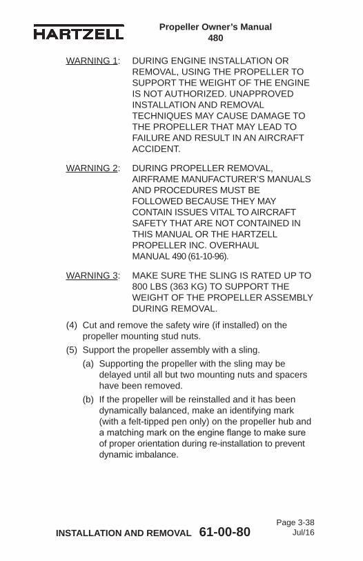
Propeller Owner’s Manual 480
INSTALLATION AND REMOVAL 61-00-80 Page 3-38
Jul/16
WARNING 1: DURING ENGINE INSTALLATION OR REMOVAL, USING THE PROPELLER TO SUPPORT THE WEIGHT OF THE ENGINE IS NOT AUTHORIZED. UNAPPROVED INSTALLATION AND REMOVAL TECHNIQUES MAY CAUSE DAMAGE TO THE PROPELLER THAT MAY LEAD TO FAILURE AND RESULT IN AN AIRCRAFT ACCIDENT.
WARNING 2: DURING PROPELLER REMOVAL, AIRFRAME MANUFACTURER’S MANUALS AND PROCEDURES MUST BE FOLLOWED BECAUSE THEY MAY CONTAIN ISSUES VITAL TO AIRCRAFT SAFETY THAT ARE NOT CONTAINED IN THIS MANUAL OR THE HARTZELL PROPELLER INC. OVERHAUL MANUAL 490 (61-10-96).
WARNING 3: MAKE SURE THE SLING IS RATED UP TO 800 LBS (363 KG) TO SUPPORT THE WEIGHT OF THE PROPELLER ASSEMBLY DURING REMOVAL.
(4) Cut and remove the safety wire (if installed) on the propeller mounting stud nuts.
(5) Support the propeller assembly with a sling.(a) Supporting the propeller with the sling may be
delayed until all but two mounting nuts and spacers have been removed.
(b) If the propeller will be reinstalled and it has been dynamically balanced, make an identifying mark (with a felt-tipped pen only) on the propeller hub and amatchingmarkontheengineflangetomakesureof proper orientation during re-installation to prevent dynamic imbalance.

Propeller Owner’s Manual 480
INSTALLATION AND REMOVAL 61-00-80 Page 3-39
Jul/16
CAUTION: DISCARD THE PROPELLER MOUNTING STUDS AND SPACERS IF THEY ARE DAMAGED OR CORRODED, OR WHEN THE PROPELLER IS REMOVED FOR OVERHAUL.
(6) Remove the six 1/2 inch diameter mounting nuts.(a) If the propeller is removed between overhaul
intervals, mounting studs, nuts, and spacers may be reused if they are not damaged or corroded.
CAUTION: USE ADEQUATE PRECAUTIONS TO PROTECT THE PROPELLER ASSEMBLY FROM DAMAGE WHEN IT IS REMOVED FROM THE AIRCRAFT ENGINE AND WHEN IT IS STORED.
(7) Using the support sling, lift the propeller from the mountingflange.
(8) Remove and discard propeller mounting O-ring.(9) Install suitable covers on the pitch change rod opening,
propellermountingflange,andengineflangetopreventtheintroduction of contamination.
(10) Put the propeller on a suitable cart for transportation.

Propeller Owner’s Manual 480
INSTALLATION AND REMOVAL 61-00-80 Page 3-40
Jul/16
(This page is intentionally blank.)

Propeller Owner's Manual 480
TESTING AND TROUBLESHOOTING 61-00-80Page 4-1
Jul/16
TESTING AND TROUBLESHOOTING - CONTENTS
1. Operational Tests ....................................................................... 4-3A. General ................................................................................. 4-3B. Initial Run-Up ........................................................................ 4-3C. Static RPM Check - Mechanically Actuated Governor Only ....................................................................... 4-4D. Post-Run Check .................................................................... 4-5
2. Propeller Ice Protection Systems .............................................. 4-5A. Electric De-ice System .......................................................... 4-5B. Anti-ice System ..................................................................... 4-5
3. Troubleshooting ......................................................................... 4-6A. Hunting and Surging ............................................................. 4-6B. Engine Speed Varies with Flight Attitude (or Airspeed) ......... 4-7C. Loss of Propeller Control - 3C1-( )( )( ) propellers only: ........ 4-7D. Vibration ................................................................................ 4-8E. Propeller Overspeed ........................................................... 4-10F. Overspeed Avoidance (Operational) - 3C1-( )( )( ) Series Propellers .............................................. 4-10G. Propeller Underspeed ......................................................... 4-10H. Oil or Grease Leakage .........................................................4-11
Propeller Owner's Manual 480
TESTING AND TROUBLESHOOTING 61-00-80Page 4-2
Jul/16
(This page is intentionally blank.)

Propeller Owner's Manual 480
TESTING AND TROUBLESHOOTING 61-00-80Page 4-3
Jul/16
1. Operational TestsA. General
(1) The propeller may be installed on an application that uses an electrically actuated governor or a mechanically actuated governor. (a) The test procedures are applicable based on the
type of governor. (2) Perform the appropriate test following propeller
installation and before every flight. (3) The propeller hydraulic system must be purged of air
and proper operation verified.
WARNING: REFER TO THE AIRCRAFT MAINTENANCE MANUAL FOR ADDITIONAL PROCEDURES THAT MAY BE REQUIRED AFTER PROPELLER INSTALLATION.
CAUTION: INSTRUCTIONS AND PROCEDURES IN THIS SECTION MAY INVOLVE PROPELLER CRITICAL PARTS. REFER TO THE INTRODUCTION CHAPTER OF THIS MANUAL FOR INFORMATION ABOUT PROPELLER CRITICAL PARTS. REFER TO THE ILLUSTRATED PARTS LIST CHAPTER OF THE APPLICABLE OVERHAUL MANUAL(S) FOR THE IDENTIFICATION OF SPECIFIC PROPELLER CRITICAL PARTS.
B. Initial Run-Up(1) Perform engine start and warm-up in accordance with
the Pilot's Operating Handbook (POH).
CAUTION: AIR TRAPPED IN THE PROPELLER HYDRAULIC SYSTEM WILL CAUSE THE PITCH CONTROL TO BE IMPRECISE AND MAY RESULT IN PROPELLER SURGING.
(2) Cycle the propeller control throughout its operating blade angle range from low to high (or as directed by the POH).

Propeller Owner's Manual 480
TESTING AND TROUBLESHOOTING 61-00-80Page 4-4
Jul/16
(3) Repeat this procedure at least three times to purge air from the propeller hydraulic system and to introduce warmed oil to the cylinder.NOTE: Pitch change response on the first operation
from low to high blade pitch may be slow, but should speed up on the second and third cycles.
(4) Verify proper operation from low pitch to high pitch and throughout the operating range.
(5) Shut down the engine in accordance with the POH.C. Static RPM Check - Mechanically Actuated Governor Only
NOTE: This operational check should be performed after installation, maintenance, or propeller adjustment.
CAUTION: A CALIBRATED TACHOMETER MUST BE USED TO MAKE SURE OF THE ACCURACY OF THE RPM CHECK.
(1) Set the brakes and chock the aircraft or tie the aircraft down.
(2) Back the governor Maximum RPM Stop out one turn.(3) Start the engine.(4) Advance the propeller control lever to MAX (max RPM),
then retard the control lever one inch (25.4 mm).(5) SLOWLY advance the throttle to maximum manifold
pressure.(6) Slowly advance the propeller control lever until the engine
speed stabilizes.(a) If engine speed stabilizes at the maximum RPM
specified by the TC or STC holder, then the low pitch stop is set correctly.
(b) If the engine speed stabilizes above or below the rated RPM, the low pitch stop may require adjustment. Refer to the Maintenance Practices chapter of this manual.
(7) Stop the engine.

Propeller Owner's Manual 480
TESTING AND TROUBLESHOOTING 61-00-80Page 4-5
Jul/16
(8) Return the governor maximum RPM stop to the original position.
(9) Test fly the aircraft to confirm the maximum rated RPM is achieved in accordance with the aircraft TC or STC.
(10) Adjust the governor high RPM screw as necessary.(11) Refer to the Aircraft Maintenance Manual for additional
procedures that may be required after propeller installation.
D. Post-Run Check(1) After engine shutdown, visually examine the propeller for
signs of engine oil leakage.
2. Propeller Ice Protection SystemsA. Electric De-ice System
(1) Consult the Pilot Operating Handbook (POH) (including all supplements) regarding flight into conditions of known icing. The aircraft may not be certificated for flight in known icing conditions, even though propeller de-ice equipment is installed.
(2) Refer to the Anti-ice and De-ice Systems chapter of this manual for functional tests of the de-ice system.
B. Anti-ice System(1) Consult the Pilot Operating Handbook (POH) (including
all supplements) regarding flight into conditions of known icing. The aircraft may not be certificated for flight in known icing conditions, even though propeller anti-ice equipment is installed.
(2) Refer to the Anti-ice and De-ice Systems chapter of this manual for functional tests of the anti-ice system.

Propeller Owner's Manual 480
TESTING AND TROUBLESHOOTING 61-00-80Page 4-6
Jul/16
3. Troubleshooting
CAUTION: INSTRUCTIONS AND PROCEDURES IN THIS SECTION MAY INVOLVE PROPELLER CRITICAL PARTS. REFER TO THE INTRODUCTION CHAPTER OF THIS MANUAL FOR INFORMATION ABOUT PROPELLER CRITICAL PARTS. REFER TO THE ILLUSTRATED PARTS LIST CHAPTER OF THE APPLICABLE OVERHAUL MANUAL(S) FOR THE IDENTIFICATION OF SPECIFIC PROPELLER CRITICAL PARTS.
A. Hunting and SurgingHunting is characterized by a cyclic variation in engine speed above and below desired speed. Surging is characterized by a large increase/decrease in engine speed, followed by a return to set speed after one or two occurrences. (1) If the propeller is hunting, a repair station should check:
(a) Governor(b) Fuel control
(2) If the propeller is surging:(a) Perform Steps 1.B.(1) through 1.B.(5) under
"Operational Tests," in this chapter to release trapped air from the propeller. 1 If surging reoccurs, it is most likely due to a
faulty governor. a Have the governor tested at a certified
propeller repair station with the appropriate rating.
(3) Hunting and/or surging may also be caused by friction or binding within the governor control, or by internal propeller corrosion, which causes the propeller to react slower to governor commands. (a) To isolate these faults, the propeller must be tested
on a test bench at a certified propeller repair station with the appropriate rating.

Propeller Owner's Manual 480
TESTING AND TROUBLESHOOTING 61-00-80Page 4-7
Jul/16
B. Engine Speed Varies with Flight Attitude (or Airspeed)(1) Small variances in engine speed are normal and are no
cause for concern.(2) Increase in engine speed while descending or increasing
airspeed:(a) Non-feathering 3C1-( )( )( ) propeller:
1 Governor is not increasing oil volume in the propeller.
2 Engine transfer bearing leaking excessively3 Excessive friction in the blade bearings or pitch
changing mechanism(3) Decrease in engine speed while increasing airspeed:
(a) Non-feathering 3C1-( )( )( ) propeller:1 Governor pilot valve is stuck and is excessively
increasing oil volume.(4) Increase in engine speed while decreasing airspeed:
(a) Non-feathering 3C1-( )( )( ) propeller:1 Governor pilot valve is stuck and is excessively
decreasing oil volume.(5) Decrease in engine speed while decreasing airspeed:
(a) Non-feathering 3C1-( )( )( ) propeller:1 Governor is not reducing oil volume in propeller.2 Excessive friction in blade bearings or pitch
changing mechanismC. Loss of Propeller Control - 3C1-( )( )( ) propellers only:
(1) Propeller goes to uncommanded low pitch (high RPM)(a) Loss of propeller oil pressure - check:
1 Governor pressure relief valve for proper operation
2 Governor drive for damage3 Adequate engine oil supply4 Engine transfer bearing leaking excessively
(b) Internal oil leakage to opposite side of piston and into hub

Propeller Owner's Manual 480
TESTING AND TROUBLESHOOTING 61-00-80Page 4-8
Jul/16
(2) Propeller goes to uncommanded high pitch (low RPM)(a) Governor pilot valve sticking
(3) RPM increases with power and airspeed, propeller RPM control has little or no effect(a) Excessive friction in the blade bearings or pitch
changing mechanism(b) Internal oil leakage to opposite side of piston and
into hubD. Vibration
CAUTION 1: ANY VIBRATION THAT OCCURS SUDDENLY, OR IS ACCOMPANIED BY UNEXPLAINED OIL LEAKAGE SHOULD BE INVESTIGATED IMMEDIATELY BEFORE FURTHER FLIGHT.
CAUTION 2: VIBRATION PROBLEMS BECAUSE OF PROPELLER SYSTEM IMBALANCE ARE NORMALLY FELT THROUGHOUT THE RPM RANGE, WITH THE INTENSITY OF VIBRATION INCREASING WITH RPM. VIBRATION PROBLEMS THAT OCCUR IN A NARROW RPM RANGE ARE A SYMPTOM OF RESONANCE THAT IS POTENTIALLY HARMFUL TO THE PROPELLER. AVOID OPERATION UNTIL THE PROPELLER CAN BE CHECKED BY A CERTIFIED PROPELLER REPAIR STATION WITH THE APPROPRIATE RATING.
(1) Check:(a) Control surfaces, cowl flaps, exhaust system, landing
gear doors, etc. for excessive play that may be causing vibration that is unrelated to the propeller
(b) Isolation of engine controls and lines(c) Engine mount wear(d) Uneven or over lubrication of propeller(e) Proper engine/propeller flange mating

Propeller Owner's Manual 480
TESTING AND TROUBLESHOOTING 61-00-80Page 4-9
Jul/16
(f) Blade track: 1 Refer to Blade Track in the Inspection and Check
chapter of this manual.(g) Blade angles:
1 Blade angle must be within tolerance between blades and on the propeller as a whole. a For the blade angle check procedure, refer to
Propeller Overhaul Manual 490 (61-10-96). (h) Spinner for cracks, improper installation, or "wobble"
during operation(i) Static balance(j) Propeller installation
1 Remove and reinstall the propeller 180 degrees from the original installation position.a "R" flange propellers installed on an
engine that has an R flange cannot be reinstalled 180 degrees from the original installation position.
(k) Hub damage or cracking(l) Grease or oil leakage(m) Blade deformation
NOTE: Dynamic balancing is recommended after installing or performing maintenance on a propeller. While this is normally an optional task, it may required the engine or airframe manufacturer to make certain the propeller/engine combination is balanced properly before operation. Refer to the engine or airframe manuals, and the Maintenance Practices chapter of this manual.

Propeller Owner's Manual 480
TESTING AND TROUBLESHOOTING 61-00-80Page 4-10
Jul/16
E. Propeller Overspeed(1) Check:
(a) Tachometer error(b) Low pitch stop adjustment(c) Governor Maximum RPM set too high(d) Loss of oil pressure - 3C1-( )( )( ) propellers only
1 Oil starvation2 Governor failure
(e) Oil leaking past the piston causing the hydraulic lock of the piston in the cylinder - 3C1-( )( )( ) propeller only
F. Overspeed Avoidance (Operational) - 3C1-( )( )( ) Series Propellers(1) Hartzell Propeller Inc. 3C1-( )( )( ) series propellers are
designed to reduce blade angle in the event of a loss of oil pressure. This reduction in blade angle permits all available engine power to be utilized in the event of an oil system failure. This reduction in blade angle also can permit the engine to overspeed, especially at higher airspeeds.
G. Propeller Underspeed(1) Check:
(a) Tachometer error(b) Excessive transfer bearing oil leakage(c) Governor oil pressure low(d) Governor oil passage clogged

Propeller Owner's Manual 480
TESTING AND TROUBLESHOOTING 61-00-80Page 4-11
Jul/16
H. Oil or Grease LeakageNOTE: A new propeller may leak slightly during the first
several hours of operation. This leakage may be caused by the seating of seals and O-rings and the slinging of lubricants used during assembly. Such leakage should cease within the first ten hours of operation.
CAUTION: GREASE LEAKAGE THAT CAN BE DESCRIBED AS EXCESSIVE AND APPEARING SUDDENLY, ESPECIALLY WHEN ACCOMPANIED BY VIBRATION SHOULD BE INVESTIGATED IMMEDIATELY BEFORE FURTHER FLIGHT.
(1) Grease Leakage - Probable Cause:(a) Improperly torqued or loose lubrication fitting(b) Defective lubrication fitting(c) Damaged blade shank to hub O-ring seal(d) Damaged hub seal (at hub parting line)(e) Damaged hub/engine flange interface O-ring(f) Cracked hub.
1 A cracked hub is often indicated by grease emerging from a seemingly solid surface, especially in the blade arm area.
(2) If the grease leak is determined to be from a source other than a lubrication fitting, blade O-ring, or the hub parting line:(a) Remove the propeller before further flight.(b) The propeller must be disassembled and inspected
at a certified propeller repair station with the appropriate rating for the cause of the grease leak.

Propeller Owner's Manual 480
TESTING AND TROUBLESHOOTING 61-00-80Page 4-12
Jul/16
(3) If the grease leak is determined to be from the lubrication fitting, the blade O-ring, or the hub parting line:(a) Continued operation, not to exceed 10 hours, until
the propeller can be removed for inspection and reseal is permitted.
(b) The propeller must be disassembled and inspected at a certified propeller repair station with the appropriate rating for the cause of the grease leak.

Propeller Owner's Manual 480
INSPECTION AND CHECK 61-00-80Page 5-1
Rev. 1 Apr/17
INSPECTION AND CHECK - CONTENTS
1. Pre-Flight Checks ................................................................... 5-3
2. Operational Checks ................................................................ 5-5
3. Required Periodic Inspections and Maintenance ................... 5-7A. Periodic Inspections ........................................................... 5-7B. Periodic Maintenance ........................................................ 5-9C. Airworthiness Limitations ................................................... 5-9D. Overhaul Periods ............................................................... 5-9
4. Inspection Procedures .......................................................... 5-10A. Blade Damage ................................................................. 5-10B. Grease or Oil Leakage ..................................................... 5-11C. Vibration ........................................................................... 5-13D. Blade Track ...................................................................... 5-15E. Loose Blades ................................................................... 5-17F. Corrosion ......................................................................... 5-18G. Spinner Damage .............................................................. 5-18H. Electric De-ice System ..................................................... 5-18I. Anti-ice System ................................................................ 5-18
5. Special Inspections ............................................................... 5-21A. Overspeed/Overtorque .................................................... 5-21B. Lightning Strike - Propeller ............................................... 5-23C. Foreign Object Strike/Ground Strike ................................ 5-26D. Sudden Stoppage ............................................................ 5-28E. Engine Oil Contamination ................................................ 5-29F. Fire Damage or Heat Damage ......................................... 5-29
6. Long Term Storage ............................................................... 5-30

Propeller Owner's Manual 480
INSPECTION AND CHECK 61-00-80Page 5-2
Rev. 1 Apr/17
LIST OF FIGURES
Checking Blade Track....................................Figure 5-1 ........... 5-15
Blade Play .....................................................Figure 5-2 ........... 5-16
Reciprocating Engine Overspeed Limits .......Figure 5-3 ........... 5-20
Evidence of Lightning Strike Damage to Composite Blade ....................................Figure 5-4 ........... 5-22

Propeller Owner's Manual 480
INSPECTION AND CHECK 61-00-80Page 5-3
Jul/16
1. Pre-Flight Checks
CAUTION: INSTRUCTIONS AND PROCEDURES IN THIS SECTION MAY INVOLVE PROPELLER CRITICAL PARTS. REFER TO THE INTRODUCTION CHAPTER OF THIS MANUAL FOR INFORMATION ABOUT PROPELLER CRITICAL PARTS. REFER TO THE ILLUSTRATED PARTS LIST CHAPTER OF THE APPLICABLE OVERHAUL MANUAL(S) FOR THE IDENTIFICATION OF SPECIFIC PROPELLER CRITICAL PARTS.
Follow propeller preflight inspection procedures as specified in the Pilot Operating Handbook (POH). In addition, perform the following inspections:A. Blades
(1) Visually inspect the entire blade and the erosion shield for nicks, gouges, looseness of material, erosion, cracks, and debonds. (a) For composite blade airworthy damage limits, refer
to the Maintenance Practices chapter of this manual.(2) Visually inspect the blades for lightning strike.
(a) For a description of damage, refer to the Lightning Strike section in this chapter.
(3) Defects or damage discovered during preflight inspection must be evaluated in accordance with allowables outlined in the Maintenance Practices chapter of this manual to determine if repairs are required before further flight.

Propeller Owner's Manual 480
INSPECTION AND CHECK 61-00-80Page 5-4
Jul/16
CAUTION 1: FAILURE TO INSTALL THE EROSION TAPE CM158 ON A BLADE THAT DOES NOT HAVE AN ANTI-ICING OR DE-ICE BOOT INSTALLED WILL CAUSE THE INBOARD LEADING EDGE OF THE BLADE TO ERODE PREMATURELY.
CAUTION 2: DO NOT INSTALL EROSION TAPE CM158 ON A BLADE THAT USES AN ALCOHOL ANTI-ICING BOOT. INSTALLATION OF EROSION TAPE CM158 WILL PREVENT PROPER FUNCTION OF THE ANTI-ICING BOOT.
(4) A composite blade that does not have an anti-icing or de-ice boot installed must have erosion tape CM158 installed on the leading edge. (a) For erosion tape installation instructions, refer to the
Maintenance Practices chapter of this manual.B. Inspect the spinner and visible blade retention components for
damage or cracks. (1) Repair or replace components, as required, before
further flight.C. Check for loose/missing hardware. Retighten or reinstall as
necessary.
WARNING: ABNORMAL GREASE LEAKAGE CAN BE AN INDICATION OF A FAILING PROPELLER BLADE OR BLADE RETENTION COMPONENT. AN IN-FLIGHT BLADE SEPARATION CAN RESULT IN A CATASTROPHIC AIRCRAFT ACCIDENT.
D. Using an appropriate light source, examine the propeller through the spinner blade cut-outs.(1) Visually inspect for signs of leakage.(2) Spinner removal is not required for this inspection.
E. Visually inspect the face and camber side of the blade for evidence of grease.

Propeller Owner's Manual 480
INSPECTION AND CHECK 61-00-80Page 5-5
Jul/16
F. If sudden or significant grease leakage is found, contact Hartzell Propeller Inc. Product Support.
G. If sudden or significant propeller imbalance is noticed, contact Hartzell Propeller Inc. Product Support.
H. Check the blades for radial play or movement of the blade tip (in and out, fore and aft, and end play). (1) For blade play limits, refer to Loose Blades in the
Periodic Inspections section in this chapter.I. Inspect the anti-icing or de-ice boots (if installed) for damage.
(1) For inspection information, refer to the Anti-ice and De-ice Systems chapter of this manual.
J. For additional inspection information and possible corrections to any discrepancies discovered as a result of preflight checks, refer to the Periodic Inspections section in this chapter.
2. Operational Checks
CAUTION: INSTRUCTIONS AND PROCEDURES IN THIS SECTION MAY INVOLVE PROPELLER CRITICAL PARTS. REFER TO THE INTRODUCTION CHAPTER OF THIS MANUAL FOR INFORMATION ABOUT PROPELLER CRITICAL PARTS. REFER TO THE ILLUSTRATED PARTS LIST CHAPTER OF THE APPLICABLE OVERHAUL MANUAL(S) FOR THE IDENTIFICATION OF SPECIFIC PROPELLER CRITICAL PARTS.
A. Following propeller installation and before flight, perform initial run-up as outlined in Operational Tests in the Testing and Troubleshooting chapter of this manual.
B. Check the propeller speed control and operation from low pitch to high pitch, using the procedure specified in the Pilot Operating Handbook (POH) for the aircraft.(1) Perform all ground functional, feathering, and cycling
checks with the minimum propeller RPM drop required to demonstrate function.
(2) A typical RPM drop is 100 to 300 RPM for non-feathering propellers.

Propeller Owner's Manual 480
INSPECTION AND CHECK 61-00-80Page 5-6
Jul/16
WARNING: ABNORMAL VIBRATION CAN BE AN INDICATION OF A FAILING PROPELLER BLADE OR BLADE RETENTION COMPONENT. AN INFLIGHT BLADE SEPARATION MAY RESULT IN DEATH, SERIOUS BODILY INJURY, AND/OR SUBSTANTIAL PROPERTY DAMAGE.
C. Check for any abnormal vibration during this run-up. (1) If vibration occurs, shut the engine down, determine
the cause, and correct it before further flight. Refer to the Vibration section in the Testing and Troubleshooting chapter of this manual.
D. For additional inspection information and possible corrections to any discrepancies discovered as a result of Pre-Flight Checks, refer to Periodic Inspections in this chapter.
E. For additional operational checks, refer to the airframe manufacturer’s manual.

Propeller Owner's Manual 480
INSPECTION AND CHECK 61-00-80Page 5-7
Jul/16
3. Required Periodic Inspections and Maintenance
CAUTION: INSTRUCTIONS AND PROCEDURES IN THIS SECTION MAY INVOLVE PROPELLER CRITICAL PARTS. REFER TO THE INTRODUCTION CHAPTER OF THIS MANUAL FOR INFORMATION ABOUT PROPELLER CRITICAL PARTS. REFER TO THE ILLUSTRATED PARTS LIST CHAPTER OF THE APPLICABLE OVERHAUL MANUAL(S) FOR THE IDENTIFICATION OF SPECIFIC PROPELLER CRITICAL PARTS.
A. Periodic Inspections (1) Perform the following inspection procedures at intervals
between 80 to 120 hours, not to exceed twelve (12) calendar months. Procedures involved in these inspections are detailed below.(a) Inspectionandmaintenancespecifiedbyanairframe
manufacturer's maintenance program and approved by the applicable airworthiness agency may not coincidewiththeinspectiontimeintervalsspecified.In this situation, the airframe manufacturer's schedule may be applied with the exception that the calendar limit for the inspection interval may not exceed twelve (12) months.
(b) For additional inspection information and possible corrections to any discrepancies discovered as a result of the Periodic Inspection, refer to the Inspection Procedures section in this chapter.
(2) Remove the spinner dome.
CAUTION: DO NOT ATTEMPT TO REPAIR A CRACKED BLADE.
(3) Visually examine the blade and the erosion shield for nicks, gouges, looseness of material, erosion, cracks and debonds. (a) Refer to the Composite Blade Repairs section in the
Maintenance Practices chapter of this manual for additional information.

Propeller Owner's Manual 480
INSPECTION AND CHECK 61-00-80Page 5-8
Rev. 1 Apr/17
(b) If any damage is discovered, refer to the Blade Repairs section in the Maintenance Practices chapter of this manual for additional information.
(c) Acrackedblademustbereferredtoacertifiedpropeller repair station with the appropriate rating.
CAUTION: DO NOT ATTEMPT TO REPAIR A CRACKED HUB.
(4) Visually inspect the hub parts for cracks or wear. (a) Refer to Grease and Oil Leaks in the Inspection
Procedures section of this chapter. (b) A cracked hub must be referred to acertifiedpropeller
repair station with the appropriate rating. (5) Visually inspect all propeller parts for cracks, wear, or
unsafe conditions.(6) Check for grease and oil leaks. Refer to Grease and Oil
Leaks in the Inspection Procedures section of this chapter.(7) If a blade track problem is suspected, check the blade
track. Refer to Blade Track in the Inspection Procedures section of this chapter.
(8) Hartzell Propeller Inc. recommends that propeller owners/operators calibrate the engine tachometer in accordance with the National Institute of Standards and Technology (NIST) or similar national standard (traceable). Refer to the section, "Tachometer Calibration" in the Maintenance Practices chapter of this manual.
(9) If an anti-ice system is installed, refer to the Anti-ice and De-ice Systems chapter of this manual for inspection information.
(10) If a de-ice system is installed, refer to the Anti-ice and De-ice Systems chapter of this manual for inspection information.
(11) Make an entry in the propeller logbook about completion of these inspections.
Propeller Owner's Manual 480
INSPECTION AND CHECK 61-00-80Page 5-9
Rev. 1 Apr/17
B. Periodic Maintenance(1) Lubricate the propeller assembly.
(a) For intervals and procedures, refer to the Lubrication section in the Maintenance Practices chapter of this manual.
C. Airworthiness Limitations(1) Certain components, as well as the entire propeller may
havespecificlifelimitsestablishedaspartofthe certificationbytheFAA.Suchlimitsrequiremandatoryreplacementofspecifiedpartsafteradefinednumberofhours and/or cycles and/or calendar time of use.
(2) Life limited component times may exist for the propeller models included in this manual. Refer to the Airworthiness Limitations chapter of this manual.
(3) Operators are urged to keep informed of airworthiness information via Hartzell Propeller Inc. Service Bulletins and Service Letters, which are available from Hartzell Propeller Inc. distributors or from Hartzell Propeller Inc. by subscription. Selected information is also available on the Hartzell Propeller Inc. website at www.hartzellprop.com.
D. Overhaul PeriodsNOTE: SpecificHartzellPropellerInc.manualsand
service documents are available on the Hartzell Propeller Inc. website at www.hartzellprop.com. Refer to the Required Publications section in the Introduction chapter of this manual for the identificationofthesepublications.
(1) Inflight,thepropellerisconstantlysubjectedtovibrationfrom the engine and the airstream, as well as high centrifugal forces.
(2) The propeller is also subject to corrosion, wear, and general deterioration due to aging. Under these conditions, metal fatigue or mechanical failures can occur.
(3) To protect your safety, your investment, and to maximize the safe operating lifetime of your propeller, it is essential that a propeller be properly maintained and overhauled according to the recommended service procedures.
Propeller Owner's Manual 480
INSPECTION AND CHECK 61-00-80Page 5-10
Jul/16
CAUTION 1: OVERHAUL PERIODS LISTED BELOW, ALTHOUGH CURRENT AT THE TIME OF PUBLICATION, ARE FOR REFERENCE PURPOSES ONLY. OVERHAUL PERIODS MAY BE INCREASED OR DECREASED AS A RESULT OF EVALUATION.
CAUTION 2: CHECK THE LATEST REVISION OF HARTZELL PROPELLER INC. SERVICE LETTER HC-SL-61-61Y FOR THE MOST CURRENT INFORMATION.
(a) Propellers must be overhauled at 2400 hours or 72months,whicheveroccursfirst.
4. Inspection Procedures
CAUTION: INSTRUCTIONS AND PROCEDURES IN THIS SECTION MAY INVOLVE PROPELLER CRITICAL PARTS. REFER TO THE INTRODUCTION CHAPTER OF THIS MANUAL FOR INFORMATION ABOUT PROPELLER CRITICAL PARTS. REFER TO THE ILLUSTRATED PARTS LIST CHAPTER OF THE APPLICABLE OVERHAUL MANUAL(S) FOR THE IDENTIFICATION OF SPECIFIC PROPELLER CRITICAL PARTS.
The following inspections must be made on a regular basis, either beforeflight,duringrequired periodic inspection as described in this chapter, or if a problem is noted. Possible corrections to problems discovered during inspections, additional inspections, and limits are detailed in the following inspection procedures.A. Blade Damage
(1) For information regarding blade damage, refer to the Composite Blade section of the Maintenance Practices chapter of this manual.
Propeller Owner's Manual 480
INSPECTION AND CHECK 61-00-80Page 5-11
Jul/16
B. Grease or Oil Leakage
WARNING 1: UNUSUAL OR ABNORMAL GREASE LEAKAGE, WHEN THE CONDITION INITIATED SUDDENLY, CAN BE AN INDICATION OF A FAILING PROPELLER HUB. A FAILED PROPELLER HUB MAY LEAD TO AN INFLIGHT BLADE SEPARATION WHICH COULD RESULT IN DEATH, SERIOUS BODILY INJURY, AND/OR SUBSTANTIAL PROPERTY DAMAGE. UNUSUAL OR ABNORMAL GREASE LEAKAGE DEMANDS IMMEDIATE INSPECTION FOR A POSSIBLE CRACKED HUB.
WARNING 2: ONE SOURCE OF GREASE LEAKAGE MAY BE AT THE HUB AND BLADE PARTING LINE. A GREASE LEAK AT THIS LOCATION MAY INDICATE EITHER AN O-RING FAILURE OR A HUB FRACTURE. CAREFUL INSPECTION MUST BE PERFORMED TO PROPERLY DETERMINE THE SOURCE OF THE LEAK BEFORE FURTHER FLIGHT.
NOTE: A new or newly overhauled propeller may leak slightly during the first several hours of operation. This leakage may be caused by the seating of seals and O-rings, and the slinging of lubricants used during assembly. Such leakage should cease within the first ten hours of operation.
Leakage that persists beyond the first ten hours of operation on a new or newly overhauled propeller, or that occurs on a propeller that has been in service for some time, will require repair. A determination should be made as to the source of the leak. The only leakage that is field repairable is the removal and replacement of the O-ring seal between the engine and propeller flange. All other leakage repairs should be referred to a certified propeller repair station with the appropriate rating. An instance of abnormal grease leakage should be inspected following the procedure:(1) Remove the spinner dome.
Propeller Owner's Manual 480
INSPECTION AND CHECK 61-00-80Page 5-12
Jul/16
CAUTION: PERFORM A VISUAL INSPECTION WITHOUT CLEANING THE PARTS. A TIGHT CRACK IS OFTEN EVIDENT DUE TO TRACES OF GREASE EMANATING FROM THE CRACK. CLEANING CAN REMOVE SUCH EVIDENCE AND MAKE A CRACK VIRTUALLY IMPOSSIBLE TO SEE.
(2) Visually examine for cracks in the hub. A crack may be readily visible, or may be indicated by grease leaking from a seemingly solid surface. (a) Extra attention should be given to the blade retention
area of the hub.(b) If grease leakage is found, proceed to the Testing
and Troubleshooting chapter of this manual.(3) Visually examine the blade retention areas of the hub for
grease seeping past the blade O-ring.(a) If grease leakage is found, proceed to the Testing
and Troubleshooting chapter of this manual.(4) Visually examine the face and camber side of the blade
for evidence of grease.(a) If grease leakage is found, proceed to the Testing
and Troubleshooting chapter of this manual.(5) Contact Hartzell Propeller Inc. Product Support if sudden
or significant grease leakage is found.(6) Contact Hartzell Propeller Inc. Product Support if sudden
or significant propeller imbalance is noticed. Inspect for grease leakage and determine its source.
(7) If cracks are suspected, additional inspections must be performed before further flight. (a) These inspections must be performed by qualified
personnel at a certified propeller repair station with the appropriate rating to verify the condition.
(b) Such inspections typically include disassembly of the propeller followed by inspection of the parts, using non-destructive methods in accordance with Hartzell Propeller Inc. Three Blade Raptor Series Reciprocating Propeller Overhaul Manual 490 (61-10-90).

Propeller Owner's Manual 480
INSPECTION AND CHECK 61-00-80Page 5-13
Jul/16
(8) If cracks or failing components are found, these parts must be replaced before further flight. Report such incidents to the FAA or appropriate airworthiness authorities and Hartzell Propeller Inc. Product Support.
C. VibrationInstances of abnormal vibration should be investigated immediately. If the cause of the vibration is not readily apparent, the propeller may be inspected by following the procedure below:NOTE: It may sometimes be difficult to readily identify the
cause of abnormal vibration. Vibrations may originate in the engine, propeller, or airframe. Troubleshooting procedures typically begin with an investigation of the engine. Airframe components, such as engine mounts or loose landing gear doors, can also be the source of vibration. When investigating an abnormal vibration, the possibility of a failing blade or blade retention component should be considered as a potential source of the problem.
(1) Perform troubleshooting and evaluation of possible sources of vibration in accordance with engine or airframe manufacturer's instructions.
(2) Refer to the Vibration section in the Testing and Troubleshooting chapter of this manual. Perform the checks to determine possible cause of the vibration. If no cause is found, then consider that the origin of the problem could be the propeller and proceed with steps 4.C.(3) through 4.C.(8) in this chapter.
(3) Remove the spinner dome.(4) Visually inspect for cracks in the hub and blades.
(a) Pay particular attention to the blade retention areas of the hub.
(b) A crack may be readily visible, or may be indicated by grease leaking from a seemingly solid surface.

Propeller Owner's Manual 480
INSPECTION AND CHECK 61-00-80Page 5-14
Jul/16
(5) If cracks are suspected, additional inspections must be performed to evaluate the condition before further flight. (a) These inspections must be performed at a certified
propeller repair station with the appropriate rating. (b) Such inspections typically include disassembly
of the propeller, followed by inspection of parts, using nondestructive methods in accordance with published procedures.
(6) Check the blades and compare blade-to-blade differences:(a) Inspect the propeller blades for unusual looseness or
movement. Refer to the Loose Blade section of this chapter.
(b) Check blade track. Refer to the Blade Track section of this chapter.
CAUTION: DO NOT USE BLADE PADDLES TO TURN THE BLADES.
(c) Manually (by hand) attempt to turn the blades (change pitch). Do not use blade paddles.
(d) Visually check for damaged blades (delaminations, debonds, cracks, etc.).
(7) If abnormal blade conditions or damage are found, additional inspections must be performed by a certified propeller repair station with the appropriate rating to evaluate the condition before further flight. Refer to the Composite Blade section in the Maintentance Practices chapter of this manual.
(8) If cracks or failing components are found, parts must be replaced before further flight. Report such occurrences to airworthiness authorities and Hartzell Propeller Inc. Product Support.

Propeller Owner's Manual 480
INSPECTION AND CHECK 61-00-80Page 5-15
Rev. 1 Apr/17
Checking Blade Track Figure 5-1
TI-4
01-0
019
D. Blade Track(1) Check blade track as follows:
(a) Chock the aircraft wheels securely.(b) Putafixedreferencepointbeneaththepropeller,
within 0.250 inch (6.35 mm) of the lowest point of the propeller arc. Refer to Figure 5-1. NOTE: Thisreferencepointmaybeaflatboard
with a sheet of paper attached to it. The board may then be blocked up to within 0.250 inch (6.35 mm) of the propeller arc.
WARNING: MAKE SURE THAT THE ENGINE MAGNETO IS GROUNDED (OFF) BEFORE ROTATING THE PROPELLER.
(c) Rotate the propeller by hand (opposite the direction of normal rotation) until a blade points directly at the paper.
(d) Mark the position of the blade tip in relation to the paper.
(e) Repeat this procedure with the remaining blades.(f) Tracking tolerance is ± 0.125 inch (± 3.17 mm) or
0.250 inch (6.35 mm) total.

Propeller Owner's Manual 480
INSPECTION AND CHECK 61-00-80Page 5-16
Rev. 1 Apr/17
(2) Possible Correction(a) Remove foreign matter from the propeller mounting
flange.1 Examinetheengineandpropellerflangesfor
damage.2 Repair any damage to the engine or propeller
flange.Ifnecessary,refertoanappropriatelyratedpropellerrepairstationthatiscertifiedbythe Federal Aviation Administration (FAA) or international equivalent.
(b) Ifnoforeignmatterispresent,refertoacertifiedpropeller repair station with the appropriate rating.
Blade Play Figure 5-2
Radial Play
Fore-and-Aft Movement
End Play
TI-4
11-0
26
In-and-Out Play

Propeller Owner's Manual 480
INSPECTION AND CHECK 61-00-80Page 5-17
Rev. 1 Apr/17
E. Loose Blades(1) Refer to Figure 5-2. Limits for blade looseness are as
follows: (a) Radial Play: ± 0.5 degree
1 degree total - measured at reference station
(b) In-and-Out Play: 0.020 inch (0.50 mm)(c) End play and Fore-and-Aft Movement:
NOTE 1: Hartzell Propeller Inc. Raptor-series propellers use specially designed spacers within the propeller to achieve the required bladefit.Thebladesmayfeellooseinthehub when compared to Hartzell Compact-series propellers. During propellerrotation,thebladefitwithinthepropeller is the same as other Hartzell propeller models.
NOTE 2: Blade tip movement is affected by the fitofthebladewithinthepropeller,andalso by movement of components within the engine and the aircraft. The following checkwillevaluateonlythefitofthebladewithin the propeller.
1 Usingonefingerandthumb,applyalightloadofapproximately 5 lbs. (0.45 kg) to the blade in the direction of the check being performed.a Apply the load at the mid-span of the blade
approximately in line with the blade decal.2 Measure the blade movement at the tip of the
blade.a The maximum permitted blade movement is
0.25 inch (6.3 mm).(d) If the blade movement is greater than the permitted
limit, contact the Hartzell Propeller Inc. Product Support Department.

Propeller Owner's Manual 480
INSPECTION AND CHECK 61-00-80Page 5-18
Rev. 1 Apr/17
F. Corrosion
WARNING: REPAIR THAT INVOLVES COLD WORKING THE METAL, RESULTING IN CONCEALMENT OF A DAMAGED AREA, IS NOT PERMITTED.
(1) Light corrosion on the counterweights may be removed byqualifiedpersonnelinaccordancewiththeBladeRepairs section in the Maintenance Practices chapter of this manual.
(2) Heavy corrosion that results in severe pitting must be referredtoacertifiedpropellerrepairstationwiththeappropriate rating.
G. Spinner DamageNOTE: SpecificHartzellPropellerInc.manualsand
service documents are available on the Hartzell Propeller Inc. website at www.hartzellprop.com. Refer to the Required Publications section in the Introduction chapter of this manual for the identificationofthesepublications.
(1) Inspect the spinner for cracks, missing hardware, or other damage.
(2) For spinner damage acceptance and repair information, refer to Hartzell Propeller Inc. Metal Spinner Assembly Maintenance Manual 127 (61-16-27), Hartzell Propeller Inc. Composite Spinner Field Maintenance and Minor RepairManual173(61-10-73),oracertifiedpropellerrepair station with the appropriate rating.
(3) For repair approval, contact the FAA or appropriate local airworthiness authority.
H. Electric De-ice System(1) For inspection procedures, refer to the Anti-ice and
De-ice Systems chapter of this manual.I. Anti-ice System
(1) For inspection procedures, refer to the Anti-ice and De-ice Systems chapter of this manual.

Propeller Owner's Manual 480
INSPECTION AND CHECK 61-00-80Page 5-19
Rev. 1 Apr/17
(This page is intentionally blank.)

Propeller Owner's Manual 480
INSPECTION AND CHECK 61-00-80Page 5-20
Jul/16
Percent Overspeed -- Reciprocating Engines Only
Dur
atio
n of
Ove
rspe
ed
105%
20 S
ec1
min
3 m
in5
min
Rec
ipro
catin
g En
gine
Ove
rspe
ed L
imits
Fi
gure
5-3
110%
103%
RequiresEvaluationbyaCertified
Pro
pelle
r Rep
air S
tatio
n w
ith th
e A
ppro
pria
te R
atin
g.
No
Act
ion
Req
uire
d

Propeller Owner's Manual 480
INSPECTION AND CHECK 61-00-80Page 5-21
Jul/16
5. Special Inspections
CAUTION: INSTRUCTIONS AND PROCEDURES IN THIS SECTION MAY INVOLVE PROPELLER CRITICAL PARTS. REFER TO THE INTRODUCTION CHAPTER OF THIS MANUAL FOR INFORMATION ABOUT PROPELLER CRITICAL PARTS. REFER TO THE ILLUSTRATED PARTS LIST CHAPTER OF THE APPLICABLE OVERHAUL MANUAL(S) FOR THE IDENTIFICATION OF SPECIFIC PROPELLER CRITICAL PARTS.
A. Overspeed/OvertorqueAn overspeed occurs when the propeller RPM exceeds the maximum RPM stated in the applicable Aircraft Type Certificate Data Sheet. An overtorque condition occurs when the engine load exceeds the limits established by the engine, propeller, or airframe manufacturer. The duration of time at overspeed/overtorque for a single event determines the corrective action that must be taken to make sure no damage to the propeller has occurred.The criteria for determining the required action after an overspeed are based on many factors. The additional centrifugal forces that occur during overspeed are not the only concern. Some applications have sharp increases in vibratory stresses at RPMs above the maximum rated for the airframe/engine/propeller combination.(1) When a propeller installed on a reciprocating engine
has an overspeed event, refer to the Reciprocating Engine Overspeed Limits (Figure 5-3) to determine the appropriate corrective action.
(2) For a governor, manufactured by Hartzell Propeller Inc., any overspeed at a severity level and/or duration sufficient to require at minimum a search inspection for the propeller, will require the governor to be disassembled and inspected in accordance with the applicable maintenance manual.
(3) Make an entry in the propeller logbook about the overspeed event.

Propeller Owner's Manual 480
INSPECTION AND CHECK 61-00-80Page 5-22
Jul/16
Brown stain on the erosion shield from lightning strike.
TI-4
80-li
ghtn
ing
Evidence of Lightning Strike Damage to Composite Blade Figure 5-4

Propeller Owner's Manual 480
INSPECTION AND CHECK 61-00-80Page 5-23
Jul/16
B. Lightning Strike - Propeller
CAUTION 1: A COMPOSITE BLADE SUSPECTED OF A LIGHTNING STRIKE MUST BE INSPECTED AND MAY REQUIRE OVERHAUL.
CAUTION 2: CONSULT AIRFRAME MANUFACTURER'S MANUALS. THERE MAY BE ADDITIONAL REQUIREMENTS, SUCH AS ICE PROTECTION SYSTEM CHECKS TO PERFORM IN THE EVENT OF PROPELLER LIGHTNING STRIKE.
NOTE 1: Lightning usually enters the propeller through the metal erosion shield of a blade. The charge typically enters at the tip of the blade and travels through the erosion shield toward the hub. The charge exits the erosion shield at the inboard end and enters the next conductive element in the path.
NOTE 2: Specific Hartzell Propeller Inc. manuals and service documents are available on the Hartzell Propeller Inc. website at www.hartzellprop.com. Refer to the Required Publications section in the Introduction chapter of this manual for the identification of these publications.
(1) Visual Inspection(a) If a lightning strike is suspected, perform a thorough
visual inspection, looking for the indications of a lightning strike.
(b) If a lightning strike is present, a darkened area and possible pitting, usually in proximity of the tip and at the most inboard end of the metal erosion shield, will be noticeable. Refer to Figure 5-4.
(c) If the blade has a anti-icing or de-ice boot installed, it may be debonded from the erosion shield due to the strike. In any case, the propeller ice protection system may be damaged.

Propeller Owner's Manual 480
INSPECTION AND CHECK 61-00-80Page 5-24
Jul/16
(d) Lightning strikes may also cause one or all of the following: 1 debonding2 lifting and buckling of the metal erosion shield3 delamination and splitting of the laminate
(e) If no evidence of a lightning strike exists, then further maintenance action is not required.
(2) Additional InspectionCAUTION: IF EVIDENCE OF A LIGHTNING
STRIKE IS DISCOVERED, FURTHER INSPECTION IS REQUIRED BEFORE FURTHER FLIGHT.
(a) A propeller may be permitted to be operated for an additional ten (10) hours before disassembly and inspection in accordance with the applicable overhaul manual. The additional ten (10) hours are permitted if the propeller and blades are not severely damaged, and if the blades meet airworthiness criteria specified in Hartzell Propeller Inc. Composite Propeller Blade Field Maintenance and Minor Repair Manual 170 (61-13-70).
CAUTION: CONSULT AIRFRAME MANUFACTURER'S MANUALS. THERE MAY BE ADDITIONAL REQUIREMENTS, SUCH AS PROPELLER ICE PROTECTION SYSTEM CHECKS, TO PERFORM IN THE EVENT OF PROPELLER LIGHTNING STRIKE.
(b) Procedure for Temporary Operation1 Remove the spinner dome and perform a visual
inspection of the propeller, spinner, and propeller ice protection system, looking for evidence of significant damage that would require repair before flight (such as broken de-ice wires or arcing damage to the propeller hub).
Propeller Owner's Manual 480
INSPECTION AND CHECK 61-00-80Page 5-25
Jul/16
CAUTION: IF THE PROPELLER EXPERIENCES A LIGHTNING STRIKE, THE COMPOSITE BLADES MUST BE WITHIN AIRWORTHY LIMITS FOR ANY ADDITIONAL FLIGHT.
2 Perform visual and coin-tap inspections of the composite blades that have indications of arcing in accordance with Hartzell Propeller Inc. Composite Propeller Blade Field Maintenance and Minor Repair Manual 170 (61-13-70).
3 If the damage is minor and does not exceed airworthy damage limits specified in Hartzell Propeller Inc. Composite Propeller Blade Field Maintenance and Minor Repair Manual 170 (61-13-70), then operation for ten (10) hours is permitted before disassembly and inspection in accordance with the applicable overhaul manual.
(c) Required inspection in the event of a lightning strike.1 Disassemble the propeller and inspect it in
accordance with the applicable overhaul manual. This procedure must be performed by qualified personnel at a certified propeller repair station with the appropriate rating.

Propeller Owner's Manual 480
INSPECTION AND CHECK 61-00-80Page 5-26
Jul/16
C. Foreign Object Strike/Ground StrikeNOTE: Specific Hartzell Propeller Inc. manuals and
service documents are available on the Hartzell Propeller Inc. website at www.hartzellprop.com. Refer to the Required Publications section in the Introduction chapter of this manual for the identification of these publications.
(1) General(a) A foreign object strike can include a broad spectrum of
damage, from a minor stone nick to severe ground impact damage. A conservative approach in evaluating the damage is required because there may be hidden damage that is not readily apparent during an on-wing, visual inspection.
(b) A foreign object strike is defined as:1 Any incident, whether or not the engine is
operating, that requires repair to the propeller other than minor dressing of the blades.a Examples of a foreign object strike include
situations where an aircraft is stationary and the landing gear collapses, causing one or more blades to be significantly damaged, or where a hangar door (or other object) strikes the propeller blade. These cases should be handled as foreign object strikes because of potentially severe side loading on the propeller hub, blades, and retention bearings.
2 Any incident during engine operation in which the propeller impacts a solid object that causes a drop in revolutions per minute (RPM) and also requires structural repair of the propeller (incidents requiring only paint touch-up are not included). This is not restricted to propeller strikes against the ground.
3 A sudden RPM drop while impacting water, tall grass, or similar yielding medium, where propeller blade damage is not normally incurred.

Propeller Owner's Manual 480
INSPECTION AND CHECK 61-00-80Page 5-27
Jul/16
(2) Procedure(a) In the event of a foreign object strike, an inspection is
required before further flight. If the inspection reveals one or more of the following indications, the propeller must be removed from the aircraft, disassembled, and repaired or overhauled in accordance with the applicable propeller and blade maintenance manuals.1 A loose blade in the hub2 Any noticeable or suspected damage to the
pitch change mechanism3 A blade out of track or angle4 Any diameter reduction5 A bent, cracked, or failed engine shaft6 Vibration during operation that was not present
before the event(b) Unairworthy damage on composite blade surfaces or
the leading and trailing edges must be repaired before flight. Refer to Hartzell Propeller Inc. Composite Propeller Blade Field Maintenance and Minor Repair Manual 170 (61-13-70).
(c) For engine mounted accessories (for example, governors, pumps, and propeller control units) manufactured by Hartzell Propeller Inc., if the foreign object strike resulted in a sudden stop of the engine, the unit must be disassembled and inspected in accordance with the applicable maintenance manual.
(d) Regardless of the degree of damage, make an entry in the propeller logbook to document the foreign object strike incident and any corrective action(s) taken.

Propeller Owner's Manual 480
INSPECTION AND CHECK 61-00-80Page 5-28
Jul/16
D. Sudden StoppageNOTE: Specific Hartzell Propeller Inc. manuals and
service documents are available on the Hartzell Propeller Inc. website at www.hartzellprop.com. Refer to the Required Publications section in the Introduction chapter of this manual for the identification of these publications.
(1) General(a) When there is a propeller sudden stoppage because
of an event such as a catastrophic engine failure or seizure, remove the propeller and any engine driven/powered accessory.
(b) If the sudden stoppage is because of a foreign object strike, follow the steps in the Foreign Object Strike section of this chapter.
(2) Procedure(a) When there is a propeller sudden stoppage, make
the following inspections before further flight.1 Remove the spinner dome.2 Visually examine the hub.3 Visually examine each blade.4 Make a thorough visual examination and coin
tap inspection of the exposed portion (de-ice boot or anti-icing boot removal is not required) of each blade, including the metal erosion shield (leading edge) in accordance with Hartzell Propeller Inc. Composite Propeller Blade Field Maintenance and Minor Repair Manual 170 (61-13-70).
5 For governors manufactured by Hartzell Propeller Inc., disassemble and inspect the unit in accordance with the applicable maintenance manual.
Propeller Owner's Manual 480
INSPECTION AND CHECK 61-00-80Page 5-29
Jul/16
E. Engine Oil Contamination(1) Following an incident of oil contamination, the
components of the propeller that were exposed to oil contamination must be removed, cleaned, and inspected. Refer to the applicable propeller maintenance manual for cleaning and inspection criteria.
(2) A propeller suspected to be contaminated should be removed and sent to a certified propeller repair station with the appropriate rating for disassembly, cleaning, and inspection.
(3) Following an incident of oil contamination, the governor that was exposed to oil contamination must be disassembled and inspected. Refer to the applicable maintenance manual for inspection criteria.
F. Fire Damage or Heat Damage
WARNING 1: EXPOSING COMPOSITE BLADES TO HIGH TEMPERATURES MAY LEAD TO FAILURE THAT MAY CAUSE PERSONAL INJURY AND DEATH. COMPOSITE BLADES ARE SUBJECT TO DELAMINATIONS DUE TO HIGH TEMPERATURES.
WARNING 2: HUBS ARE MANUFACTURED FROM HEAT TREATED FORGINGS AND ARE SHOT PEENED. EXPOSURE TO HIGH TEMPERATURES CAN DESTROY THE FATIGUE RESISTANCE BENEFITS OBTAINED FROM THESE PROCESSES.
(1) On rare occasions propellers may be exposed to fire or heat damage, such as an engine or hangar fire. In the event of such an incident, an inspection by a certified propeller repair station with the appropriate rating is required before further flight.
(2) For governors, manufactured by Hartzell Propeller Inc., that have been exposed to high temperatures (in excess of 200° F [93° C]), the governor must be assumed to be unairworthy unless it can be proven that there have been no adverse affects from the incident.

Propeller Owner's Manual 480
INSPECTION AND CHECK 61-00-80Page 5-30
Jul/16
6. Long Term StorageA. Parts shipped from the Hartzell Propeller Inc. are not
shipped or packaged in a container that is designed for long term storage.
B. Long term storage procedures may be obtained by contacting a Hartzell Propeller Inc. distributor, or Hartzell Propeller Inc. via the Product Support number listed in the Introduction chapter of this manual. Storage information is also detailed in Hartzell Propeller Inc. Standard Practices Manual 202A (61-01-02).
C. In addition to the long term storage requirements specified in Hartzell Propeller Inc. Standard Practices Manual 202A (61-01-02), the maximum permitted storage temperature for Hartzell Propeller Inc. composite blades is 180° F (82° C).
D. Information regarding the return of a propeller assembly to service after long term storage may be obtained by contacting a Hartzell Propeller Inc. distributor or Hartzell Propeller Inc. via the Product Support number listed in the Introduction chapter of this manual. This information is also detailed in Hartzell Propeller Inc. Standard Practices Manual 202A (61-01-02).

Propeller Owner's Manual 480
Page 6-1 Jul/16 MAINTENANCE PRACTICES 61-00-80
MAINTENANCE PRACTICES - CONTENTS1. Cleaning ................................................................................ 6-3
A. General Cleaning .............................................................. 6-3B. Spinner Cleaning and Polishing........................................ 6-4
2. Lubrication ............................................................................. 6-5A. Lubrication Intervals.......................................................... 6-5B. Lubrication Procedure....................................................... 6-7C. Approved Lubricants ....................................................... 6-11
3. Composite Blades ............................................................... 6-13A. General Description ........................................................ 6-13B. Component Life and Service .......................................... 6-14C. Damage Evaluation ........................................................ 6-15D. Repair Determination ...................................................... 6-16E. Personnel Requirements ................................................ 6-17F. Blade Inspection Requirements ...................................... 6-18
4. Painting of Composite Blades ............................................. 6-21A. General ........................................................................... 6-21B. Procedure ....................................................................... 6-22
5. Dynamic Balance ................................................................ 6-24A. Overview ......................................................................... 6-24B. Inspection Procedures Before Balancing........................ 6-25C. Modifying Spinner Bulkhead to Accommodate Dynamic Balance Weights ............................................................. 6-26D. Placement of Balance Weights for Dynamic Balance ..... 6-27
6. Propeller Low Pitch Setting ................................................. 6-29A. Low Pitch Stop - All Propeller Models ............................. 6-29B. Maximum RPM (Static) Low Pitch Stop Adjustment ....... 6-30
7. Propeller High Pitch Settings ............................................... 6-31A. High Pitch (Mininum RPM) Stop ..................................... 6-31

Propeller Owner's Manual 480
MAINTENANCE PRACTICES 61-00-80 Page 6-2
Rev. 1 Apr/17
LIST OF FIGURES
LIST OF TABLES
Lubrication Fitting Location............................Figure 6-1 ............. 6-6
Lubrication Label ...........................................Figure 6-2 ............. 6-8
Section of Typical Composite Blade ....................Figure 6-3 ........... 6-12
Basic Components of a Composite Blade .....Figure 6-4 ........... 6-12
Low Pitch Stop Adjustment - ( )( )1 Series.....Figure 6-5 ........... 6-28
Approved Touch-up Paints ............................Table 6-1 ............ 6-20
Erosion Tape ..................................................Table 6-2 ............ 6-32
MAINTENANCE PRACTICES - CONTENTS (CONTINUED)8. Propeller Ice Protection Systems ........................................ 6-31
A. Electric De-ice System .................................................... 6-31B. Anti-ice System ............................................................... 6-31
9. Installation of Erosion Tape CM158 ..................................... 6-32A. General ........................................................................... 6-32B. Materials Required.......................................................... 6-33C. Installation Procedure ..................................................... 6-34
10. Tachometer Calibration ....................................................... 6-37

Propeller Owner's Manual 480
Page 6-3 Jul/16 MAINTENANCE PRACTICES 61-00-80
1. Cleaning
CAUTION 1: INSTRUCTIONS AND PROCEDURES IN THIS SECTION MAY INVOLVE PROPELLER CRITICAL PARTS. REFER TO THE INTRODUCTION CHAPTER OF THIS MANUAL FOR INFORMATION ABOUT PROPELLER CRITICAL PARTS. REFER TO THE ILLUSTRATED PARTS LIST CHAPTER OF THE APPLICABLE OVERHAUL MANUAL(S) FOR THE IDENTIFICATION OF SPECIFIC PROPELLER CRITICAL PARTS.
CAUTION 2: DO NOT USE PRESSURE WASHING EQUIPMENT TO CLEAN THE PROPELLER OR CONTROL COMPONENTS. PRESSURE WASHING CAN FORCE WATER AND/OR CLEANING SOLVENTS PAST SEALS, AND CAN LEAD TO INTERNAL CORROSION OF PROPELLER COMPONENTS.
A. General Cleaning
CAUTION 1: WHEN CLEANING THE PROPELLER, DO NOT PERMIT SOAP OR SOLVENT SOLUTIONS TO RUN OR SPLASH INTO THE HUB AREA.
CAUTION 2: DO NOT CLEAN THE PROPELLER WITH CAUSTIC OR ACIDIC SOAP SOLUTIONS. IRREPARABLE CORROSION OF PROPELLER COMPONENTS MAY OCCUR.
(1) Using a noncorrosive soap solution, wash the propeller.

Propeller Owner's Manual 480
MAINTENANCE PRACTICES 61-00-80 Page 6-4
Jul/16
WARNING: ADHESIVES AND SOLVENTS ARE FLAMMABLE AND TOXIC TO THE SKIN, EYES, AND RESPIRATORY TRACT. SKIN AND EYE PROTECTION ARE REQUIRED. AVOID PROLONGED CONTACT AND BREATHING OF VAPORS. USE SOLVENT RESISTANT GLOVES TO MINIMIZE SKIN CONTACT AND WEAR SAFETY GLASSES FOR EYE PROTECTION. USE IN A WELL VENTILATED AREA AWAY FROM SPARKS AND FLAME. READ AND OBSERVE ALL WARNING LABELS.
CAUTION : DO NOT USE ANY SOLVENT DURING CLEANING THAT COULD SOFTEN OR DESTROY THE BOND BETWEEN CHEMICALLY ATTACHED PARTS.
(2) To remove grease or oil from propeller surfaces, apply Stoddard Solvent or equivalent to a clean cloth and wipe the part clean.
(3) Thoroughly rinse with water.(4) Permit the part to dry.
B. Spinner Cleaning and Polishing(1) Clean the spinner using the General Cleaning
procedures in this section.(2) If the dome is a Hartzell Propeller Inc. aluminum dome,
polish the dome, if necessary, with an automotive-type aluminum polish.

Propeller Owner's Manual 480
MAINTENANCE PRACTICES 61-00-80 Page 6-5
Rev. 1 Apr/17
2. Lubrication
CAUTION 1: INSTRUCTIONS AND PROCEDURES IN THIS SECTION MAY INVOLVE PROPELLER CRITICAL PARTS. REFER TO THE INTRODUCTION CHAPTER OF THIS MANUAL FOR INFORMATION ABOUT PROPELLER CRITICAL PARTS. REFER TO THE ILLUSTRATED PARTS LIST CHAPTER OF THE APPLICABLE OVERHAUL MANUAL(S) FOR THE IDENTIFICATION OF SPECIFIC PROPELLER CRITICAL PARTS.
A. Lubrication Intervals(1) The propeller must be lubricated at intervals not to
exceed 100 hours or at 12 calendar months, whichever occurs first.(a) If propeller operation in a six month period from the
last lubrication interval is less than 50 hours, the propeller must be re-lubricated.
(b) If the aircraft is operated or stored under adverse atmospheric conditions, e.g., high humidity, salt air, calendar lubrication intervals should be reduced to six months.
(2) Owners of high use aircraft may wish to extend their lubrication interval. Lubrication interval may be gradually extended after evaluation of previous propeller overhauls with regard to bearing wear and internal corrosion.
(3) Hartzell Propeller Inc. recommends that new or newly overhauled propellers be lubricated after the first one or two hours of operation because centrifugal loads will pack and redistribute grease, which may result in a propeller imbalance. Redistribution of grease may also result in voids in the blade bearing area where moisture can collect. (a) Purchasers of new aircraft should check the
propeller logbook to verify whether the propeller was lubricated by the manufacturer during flight testing. If it was not lubricated, the propeller should be serviced at the earliest convenience.

Propeller Owner's Manual 480
MAINTENANCE PRACTICES 61-00-80 Page 6-6
Jul/16
Lubrication Fitting Location Figure 6-1
LUBRICATION FITTING OR LUBRICATION HOLE PLUG (CYLINDER SIDE HUB HALF)
TI-4
80-0
02Lu
beFi
tting
LUBRICATION FITTING OR LUBRICATION HOLE PLUG (ENGINE SIDE HUB HALF)

Propeller Owner's Manual 480
Page 6-7 Jul/16 MAINTENANCE PRACTICES 61-00-80
B. Lubrication Procedure
WARNING 1: FOLLOW LUBRICATION PROCEDURES CORRECTLY TO MAINTAIN ACCURATE BALANCE OF THE PROPELLER ASSEMBLY.
WARNING 2: PITCH CONTROL DIFFICULTY COULD RESULT IF THE PROPELLER IS NOT CORRECTLY LUBRICATED.
(1) Remove the propeller spinner.(2) Each blade socket has one lubrication fitting and one
lubrication hole plug. Refer to Figure 6-1. (3) Remove the lubrication fitting caps from the lubrication
fittings.(4) Remove the lubrication hole plugs.
(a) For all tractor or pusher propellers with clockwise (standard) rotation when viewed from BEHIND the aircraft, the lubrication hole plugs P/N 106545 are in the CYLINDER-SIDE hub half.
(b) For all tractor or pusher propellers with counter-clockwise (backward) rotation when viewed from BEHIND the aircraft, the lubrication hole plugs P/N 106545 are in the ENGINE-SIDE hub half.
(c) The propeller uses an internal blade seal that prevents grease from entering the hub cavity. It is important to remove the opposite lubrication hole plug.
(5) Using a piece of safety wire, loosen any blockage or hardened grease at the threaded holes where the lubrication plug was removed.

Propeller Owner's Manual 480
MAINTENANCE PRACTICES 61-00-80 Page 6-8
Jul/16
WARNING: WHEN MIXING AEROSHELL GREASES 5 AND 6, AEROSHELL GREASE 5 MUST BE INDICATED ON THE LABEL (HARTZELL PROPELLER INC. P/N A-3594-( )) AND THE AIRCRAFT MUST BE PLACARDED TO INDICATE THAT FLIGHT IS PROHIBITED IF THE OUTSIDE AIR TEMPERATURE IS LESS THAN -40° F (-40° C).
CAUTION: USE HARTZELL PROPELLER INC. APPROVED GREASE ONLY. EXCEPT IN THE CASE OF AEROSHELL GREASES 5 AND 6, DO NOT MIX DIFFERENT SPECIFICATIONS AND/OR BRANDS OF GREASE.
(6) Aeroshell greases 5 and 6 both have a mineral oil base and have the same thickening agent; therefore, mixing of these two greases is permitted in Hartzell Propeller Inc. propellers.
(7) A label, Hartzell Propeller Inc. P/N A-3594-( ), is normally applied to the propeller to indicate the type of grease previously used. Refer to Figure 6-2. (a) This grease type should be used during re-lubrication
unless the propeller has been disassembled and the old grease removed.
(b) It is not possible to purge old grease through lubrication fittings.
Lubrication Label Figure 6-2
A-3
594
Propeller Owner's Manual 480
Page 6-9 Jul/16 MAINTENANCE PRACTICES 61-00-80
(c) To completely replace one grease with another, the propeller must be disassembled in accordance with the applicable overhaul manual.
CAUTION 1: OVER LUBRICATING AN ALUMINUM HUB PROPELLER MAY CAUSE THE GREASE TO ENTER THE HUB CAVITY, LEADING TO EXCESSIVE VIBRATION AND/OR SLUGGISH OPERATION. THE PROPELLER MUST THEN BE DISASSEMBLED TO REMOVE THIS GREASE.
CAUTION 2: IF A PNEUMATIC GREASE GUN IS USED, EXTRA CARE MUST BE TAKEN TO AVOID EXCESSIVE PRESSURE BUILDUP.
CAUTION 3: GREASE MUST BE APPLIED TO ALL BLADES OF A PROPELLER ASSEMBLY AT THE TIME OF LUBRICATION.
CAUTION 4: DO NOT ATTEMPT TO PUMP MORE THAN 1 FL. OZ. (30 ML) OF GREASE INTO THE LUBRICATION FITTING. USING MORE THAN 1 FL. OZ. (30 ML) OF GREASE COULD RESULT IN OVER SERVICING OF THE PROPELLER.
(8) Pump a maximum of 1 fl. oz. (30 ml) grease into the lubrication fitting, or until grease emerges from the hole where the lubrication hole plug was removed - whichever occurs first. NOTE: 1 fl. oz. (30 ml) is approximately 6 pumps with
a hand-operated grease gun.(a) For all tractor or pusher propellers with clockwise
(standard) rotation when viewed from BEHIND the aircraft, the lubrication fitting is in the ENGINE-SIDE hub half.
(b) For all tractor or pusher propellers with counter-clockwise (backward) rotation when viewed from BEHIND the aircraft, the lubrication fitting is in the CYLINDER-SIDE hub half.

Propeller Owner's Manual 480
MAINTENANCE PRACTICES 61-00-80 Page 6-10
Jul/16
(9) Reinstall the removed lubrication hole plug.(a) Tighten until finger-tight, then tighten one additional
360 degree turn.(10) Make sure that the ball of each lubrication fitting is
correctly seated.(11) Reinstall a lubrication fitting cap on each lubrication
fitting.

Propeller Owner's Manual 480
Page 6-11 Jul/16 MAINTENANCE PRACTICES 61-00-80
C. Approved LubricantsThe following lubricants are approved for use in Hartzell Propeller Inc. compact propellers:Aeroshell 6 - Recommended "all purpose" grease. Used in most new production propellers since 1989. Higher leakage/oil separation than Aeroshell 5 at higher temperatures (approximately 100° F [38° C]).Aeroshell 5 - Good high temperature qualities, very little oil separation or leakage. Cannot be used in temperatures colder than -40° F (-40° C). Aircraft serviced with this grease must be placarded to indicate that flight is prohibited if the outside air temperature is less than -40° F (-40° C). Aeroshell 7 - Good low temperature grease, but high leakage/oil separation at higher temperatures. This grease has been associated with sporadic problems involving seal swelling.Royco 22CF - Not widely used. Qualities similar to Aeroshell 22.NOTE: A label (Refer to Figure 6-2) indicating the type of
grease used for previous lubrication is installed on the propeller cylinder. If the propeller must be lubricated with another type of grease, the propeller must be disassembled and cleaned of old grease before relubricating.

Propeller Owner's Manual 480
MAINTENANCE PRACTICES 61-00-80 Page 6-12
Jul/16
Section of Typical Composite Blade Figure 6-3
Trailing Edge Foam Core
Blade Shell
Main Spar Foam Core
Main Spar
TI-0
0057
Basic Components of a Composite Blade Figure 6-4
ErosionShield
Blade Shank Foam Core
CompositeMaterial
Trailing Edge Foam
TPI-1
3502
0

Propeller Owner's Manual 480
Page 6-13 Jul/16 MAINTENANCE PRACTICES 61-00-80
3. Composite BladesA. General Description
(1) The composite blade is a monocoque construction consisting of composite material over a foam core.(a) For information about blade types, refer to Table 2-2,
"Blade Type and Blade Model Designations" in the Description and Operation chapter of this manual.
(2) The composite material is round at the inboard station sections, transitioning to an airfoil shape outboard on the blade. A typical airfoil section is shown in Figure 6-3. (a) The bulk of the composite material is truncated
toward the trailing edge with foam material forming the remainder of the trailing edge.
(b) The entire structure is contained in a shell constructed of composite material.
(3) An erosion shield of electroformed nickel is incorporated in the fabrication to protect the leading edge of the blade from impact and erosion damage.
(4) The shank is constructed of aluminum.1 The outer shank contains a integral knob similar
to a Hartzell Propeller Inc. "Y" shank and uses blade shank tape, also similar to a Hartzell Propeller Inc. "Y" shank. Refer to Figure 6-4.
(5) The composite blade is balanced in the horizontal plane during production by the addition of lead wool to a centrally located balance tube in the metal blade shank, which may protrude into the foam core of the blade.
(6) A finish covering of polyurethane paint protects the entire blade from erosion and ultraviolet damage.
(7) Aircraft that require ice protection use an external boot.(8) Aircraft that do not require ice protection are required to
have erosion tape CM158 installed on the blade.(a) Refer to the section "Installation of Erosion Tape
CM158" in this chapter.

Propeller Owner's Manual 480
MAINTENANCE PRACTICES 61-00-80 Page 6-14
Jul/16
B. Component Life and Service(1) Overhaul or Major Periodic Inspection (MPI)
(a) Overhaul, or MPI, is the periodic disassembly, inspection, repair, refinish, and reassembly of the composite blade assembly.NOTE: The term “overhaul” is used throughout
the text of this manual.(b) At such specified periods, the propeller hub
assembly and the blade assemblies are completely disassembled and inspected for cracks, wear, corrosion, and other unusual or abnormal conditions. As specified, some blades are refinished, and other blades are replaced. The blades can then be reassembled and balanced.
(c) Overhaul procedures must be performed in accordance with the latest revision of Hartzell Propeller Inc. Composite Propeller Blade Maintenance Manual 135F (61-13-35) and other applicable publications.
(d) Overhaul must be performed only by a propeller repair station that is certified by Hartzell Propeller Inc. for composite blade overhaul.
(2) Blade Life(a) Blade life is expressed in terms of total hours of
service (TT, or Total Time), time between overhauls (TBO), and in terms of service since overhaul (TSO, or Time Since Overhaul). All references are necessary in defining the life of the propeller.

Propeller Owner's Manual 480
Page 6-15 Jul/16 MAINTENANCE PRACTICES 61-00-80
C. Damage EvaluationNOTE: Specific Hartzell Propeller Inc. manuals and
service documents are available on the Hartzell Propeller Inc. website at www.hartzellprop.com. Refer to the Required Publications section in the Introduction chapter of this manual for the identification of these publications.
(1) Airworthy Damage
CAUTION: DAMAGE THAT IS WITHIN THE AIRWORTHY LIMITS DOES NOT REQUIRE REPAIR BEFORE FURTHER FLIGHT, BUT SHOULD BE REPAIRED AS SOON AS PRACTICABLE TO PREVENT DEGRADATION OF THE DAMAGE.
(a) Airworthy damage is a specific condition to a blade that does not affect the safety or flight characteristics of the propeller blade and conforms to its type design by meeting the condition inspection criteria limitations found in Hartzell Propeller Inc. Composite Propeller Blade Field Maintenance and Minor Repair Manual 170 (61-13-70).1 The maximum limits of airworthy damage are
specified in Hartzell Propeller Inc. Composite Propeller Blade Field Maintenance and Minor Repair Manual 170 (61-13-70).
2 Hartzell Propeller Inc. Composite Propeller Blade Field Maintenance and Minor Repair Manual 170 (61-13-70) provides inspection criteria and direction to evaluate damage to determine continued airworthiness.
3 For ice protection system inspections, refer to the Anti-ice and De-ice Systems chapter of this manual.
Propeller Owner's Manual 480
MAINTENANCE PRACTICES 61-00-80 Page 6-16
Jul/16
(b) Although a blade may continue in service with airworthy damage, this type of damage should be repaired at the earliest practical time to prevent the damage from progressing to a condition that could require more extensive repair to the blade.
(2) Unairworthy Damage
CAUTION: UNAIRWORTHY DAMAGE MUST BE REPAIRED BEFORE THE NEXT FLIGHT.
(a) Unairworthy damage is damage that exceeds the airworthy damage limits as specified in Hartzell Propeller Inc. Composite Propeller Blade Field Maintenance and Minor Repair Manual 170 (61-13-70). 1 Unairworthy damage can affect the safety or
flight characteristics of the propeller blade and does not conform to its type design.
2 This condition deems the blade unairworthy, requiring appropriate corrective action to repair or remove it from service, as applicable.
D. Repair DeterminationNOTE: Specific Hartzell Propeller Inc. manuals and
service documents are available on the Hartzell Propeller Inc. website at www.hartzellprop.com. Refer to the Required Publications section in the Introduction chapter of this manual for the identification of these publications.
(1) Minor Repair(a) Minor repair is correction of damage that may
be safely performed in the field by elementary operations.
(b) For complete description of minor repair and allowable procedures, refer to Hartzell Propeller Inc. Composite Propeller Blade Field Maintenance and Minor Repair Manual 170 (61-13-70).

Propeller Owner's Manual 480
Page 6-17 Jul/16 MAINTENANCE PRACTICES 61-00-80
(2) Major Repair(a) Major repair is correction of damage that cannot be
performed by elementary operations.(b) Major repair must be accepted by a certified aircraft
mechanic with an appropriate rating, preferably one that holds a Factory Training Certificate from Hartzell Propeller Inc.
(c) All major repairs must be performed by a propeller repair station that is certified by Hartzell Propeller Inc. and is an appropriately rated propeller repair station certified by the Federal Aviation Administration (FAA) or international equivalent.
E. Personnel RequirementsNOTE: Specific Hartzell Propeller Inc. manuals and
service documents are available on the Hartzell Propeller Inc. website at www.hartzellprop.com. Refer to the Required Publications section in the Introduction chapter of this manual for the identification of these publications.
(1) Anyone performing or accepting responsibility for an inspection, repair and/or overhaul of a Hartzell Propeller Inc. product must comply with the applicable regulatory requirements established by the appropriate Aviation Authority.
(2) Any person signing for or performing inspections and/or repairs to Hartzell Propeller Inc. composite parts should be familiar with the objectives and procedures associated with the inspection and/or repair of composite parts.
(3) For personnel requirements for repair of Hartzell Propeller Inc. composite blades, are specified in Hartzell Propeller Inc. Composite Propeller Blade Field Maintenance and Minor Repair Manual 170 (61-13-70).
Propeller Owner's Manual 480
MAINTENANCE PRACTICES 61-00-80 Page 6-18
Jul/16
F. Blade Inspection Requirements
CAUTION: MAINTAINING A GOOD LOGBOOK RECORD IS PARTICULARLY IMPORTANT FOR COMPOSITE PROPELLER BLADES. DAMAGE AND/OR REPAIRS MAY SUFFER FURTHER DEGRADATION AFTER CONTINUED USE. SUCH DEGRADATION MAY BE EASILY OVERLOOKED. IT IS IMPORTANT FOR INSPECTORS TO HAVE ACCESS TO ACCURATE HISTORICAL DATA WHEN PERFORMING SUBSEQUENT INSPECTIONS.
NOTE: Specific Hartzell Propeller Inc. manuals and service documents are available on the Hartzell Propeller Inc. website at www.hartzellprop.com. Refer to the Required Publications section in the Introduction chapter of this manual for the identification of these publications.
(1) Required Record-Keeping(a) Composite blade damage and a description of the
repair must be recorded in the composite blade logbook.
(2) Preflight Inspection(a) Follow propeller preflight inspection procedures
as specified in the aircraft maintenance manual, or an air carrier’s operational specifications, or this manual. In addition, perform the following inspections:1 Visually inspect each entire blade for nicks,
gouges, loose material, erosion, cracks, and debonds.
2 Visually inspect each blade for lightning strike. Refer to “Lightning Strike Damage” in the Inspection and Check of this manual for a description of damage.
Propeller Owner's Manual 480
Page 6-19 Jul/16 MAINTENANCE PRACTICES 61-00-80
(b) Defects or damage discovered during preflight inspection must be evaluated in accordance with Hartzell Propeller Inc. Composite Propeller Blade Field Maintenance and Minor Repair Manual 170 (61-13-70).
(3) Maintenance Inspections(a) Inspection procedures must be performed in
accordance with this manual. 1 Perform a thorough visual inspection.2 Perform a coin-tap test to the exposed section
of the blade not to exceed 1200 hours and the erosion shield surface not to exceed 600 hours. a Coin-tapping will indicate a delamination or
debond by an apparent audible change.b For the coin-tap procedure for composite
blades, refer to Hartzell Propeller Inc. Composite Propeller Blade Field Maintenance and Minor Repair Manual 170 (61-13-70).
3 Review blade logbook records and carefully inspect areas of airworthy damage and previously repaired areas for growth. If damage is growing, estimate if the damaged area will be greater than the permitted airworthy damage limits before the next overhaul. If this is the case, make arrangements to repair the damage at the earliest practical time to prevent further damage to the blade.

Propeller Owner's Manual 480
MAINTENANCE PRACTICES 61-00-80 Page 6-20
Jul/16
4 Defects or damage discovered during scheduled inspections must be evaluated in accordance with Hartzell Propeller Inc. Composite Propeller Blade Field Maintenance and Minor Repair Manual 170 (61-13-70) to determine if repairs are required before further flight. a Although repair of “airworthy damage” is not
essential before further flight, such damage should always be repaired as soon as possible, to avoid further degradation.
b Unairworthy damage must be repaired before further flight.
5 Make a record of the details of all damage or repairs in the propeller logbook.
Approved Touch-up Paints Table 6-1
Vendor Color/Type Vendor P/N
Hartzell Propeller Inc.
P/NTempo Epoxy Black A-150 A-6741-145-2
Tempo Epoxy Gray A-151 A-6741-146-2
Tempo Epoxy White (tip stripe) A-152 A-6741-147-2
Tempo Epoxy Red (tip stripe) A-153 A-6741-149-2
Tempo Epoxy Yellow (tip stripe) A-154 A-6741-150-2
Sherwin-Williams Black F75KXB9958-4311 A-6741-145-1
Sherwin-Williams Gray F75KXA10445-4311 A-6741-146-1
Sherwin-Williams Gray Metallic F75KXM9754-4311 A-6741-148-1
Sherwin-Williams White (tip stripe) F75KXW10309-4311 A-6741-147-1
Sherwin-Williams Red (tip stripe) F75KXR12320-4311 A-6741-149-1
Sherwin-Williams Yellow (tip stripe) F75KXY11841-4311 A-6741-150-1
Sherwin-Williams Silver Metallic F75KXS13564-4311 A-6741-163-1
Sherwin-Williams Silver F75KXS13564-4311 A-6741-190-1
Sherwin-Williams Bright Red 1326305 A-6741-200-5
Sherwin-Williams Bright Yellow 1326313 A-6741-201-5
Sherwin-Williams Bright Silver 1334259 A-6741-203-5
Sherwin-Williams Prop Gold F63TXS17221-4311 A-6741-204-5

Propeller Owner's Manual 480
MAINTENANCE PRACTICES 61-00-80 Page 6-21
Rev. 1 Apr/17
4. Painting of Composite Blades
CAUTION: INSTRUCTIONS AND PROCEDURES IN THIS SECTION MAY INVOLVE PROPELLER CRITICAL PARTS. REFER TO THE INTRODUCTION CHAPTER OF THIS MANUAL FOR INFORMATION ABOUT PROPELLER CRITICAL PARTS. REFER TO THE ILLUSTRATED PARTS LIST CHAPTER OF THE APPLICABLE OVERHAUL MANUAL(S) FOR THE IDENTIFICATION OF SPECIFIC PROPELLER CRITICAL PARTS.
A. General(1) Propeller blades are painted with a durable specialized
coating that is resistant to abrasion. If this coating becomes eroded over an area of more than 10 square inches (6451.6 square mm), it is necessary to repaint the blades to provide proper environmental and erosion protection. Painting should be performed by a certified propeller repair station with the appropriate rating in accordance with Hartzell Propeller Inc. Standard Practices Manual 202A (61-01-02).
(2) For paint erosion over an area of less than 10 square inches (6451.6 square mm) it is permissible to perform a blade touch-up with aerosol paint in accordance with the procedures in section 4.B of this chapter.
(3) Refer to Table 6-1 for paints that are approved for blade touch-up.
(4) The paint manufacturers may be contacted using the following information:Tempo Products Co. Sherwin Williams Co. A Plasti-kote Company Refer to the Sherwin-Williams 1000 Lake Road Product Finishes Global Finishes Medina, OH 44256 Group website at Tel: 800.321.6300 http://oem.sherwin-williams.com Fax: 216.349.4241 to find the nearest location. Cage Code: 07708

Propeller Owner's Manual 480
MAINTENANCE PRACTICES 61-00-80 Page 6-22
Jul/16
B. Procedure
WARNING: CLEANING AGENTS (ACETONE, #700 LACQUER THINNER, AND MEK), ARE FLAMMABLE AND TOXIC TO THE SKIN, EYES AND RESPIRATORY TRACT. SKIN AND EYE PROTECTION ARE REQUIRED. AVOID PROLONGED CONTACT. USE IN WELL VENTILATED AREA.
CAUTION: ANY REFINISHING PROCEDURE CAN ALTER PROPELLER BALANCE. PROPELLERS THAT ARE OUT OF BALANCE MAY EXPERIENCE EXCESSIVE VIBRATIONS WHILE IN OPERATION.
(1) Using a clean cloth moistened with acetone, #700 lacquer thinner, or MEK, wipe the surface of the blade to remove any contaminants.
(2) Permit the solvent to evaporate.
CAUTION: EXCESSIVE SANDING WILL CAUSE "FUZZING" OF THE KEVLAR® MATERIAL, RESULTING IN A ROUGH FINISH.
(3) Using 120 to 180 grit sandpaper, sand to feather the existing coatings away from the eroded or repaired area.(a) Erosion damage is typically very similar on all blades
in a propeller assembly. If one blade has more extensive damage, e.g. in the tip area, sand all the blades in the tip area to replicate the repair of the most severely damaged blade tip. This practice is essential in maintaining balance after refinishing.
(4) Using lacquer thinner #700 or MEK, wipe the surface of the blade.
(5) Permit the solvent to evaporate.(6) Apply masking material to the erosion shield, anti-icing
or de-ice boot, and tip stripes, as needed.

Propeller Owner's Manual 480
Page 6-23 Jul/16 MAINTENANCE PRACTICES 61-00-80
WARNING: FINISH COATINGS ARE FLAMMABLE AND TOXIC TO THE SKIN, EYES AND RESPIRATORY TRACT. SKIN AND EYE PROTECTION ARE REQUIRED. AVOID PROLONGED CONTACT. USE IN A WELL VENTILATED AREA.
CAUTION: APPLY FINISH COATING ONLY TO THE DEGREE REQUIRED TO UNIFORMLY COVER THE REPAIR/EROSION. AVOID EXCESSIVE PAINT BUILDUP ALONG THE TRAILING EDGE TO AVOID CHANGING THE BLADE PROFILE AND/OR P-STATIC CHARACTERISTICS.
(7) Apply a sufficient amount of finish coating to achieve 2 to 4 mils thickness when dry. (a) Re-coat before 30 minutes, or after 48 hours.(b) If the paint is permitted to dry longer than
four (4) hours, it must be lightly sanded before another coat is applied.
(8) Remove masking material from the tip stripes and re-apply masking material for the tip stripe refinishing if required.
(9) Apply sufficient tip stripe coating to achieve 2 to 4 mils thickness when dry. (a) Re-coat before 30 minutes, or after 48 hours.(b) If the paint is permitted to dry longer than
four (4) hours, it must be lightly sanded before another coat is applied.
(10) Remove the masking material immediately from the anti-icing or de-ice boot and tip stripes, if applicable.
(11) Optionally, perform dynamic balancing in accordance with the procedures and limitations specified in the Dynamic Balance section of this chapter.
Propeller Owner's Manual 480
MAINTENANCE PRACTICES 61-00-80 Page 6-24
Jul/16
5. Dynamic Balance
CAUTION: INSTRUCTIONS AND PROCEDURES IN THIS SECTION MAY INVOLVE PROPELLER CRITICAL PARTS. REFER TO THE INTRODUCTION CHAPTER OF THIS MANUAL FOR INFORMATION ABOUT PROPELLER CRITICAL PARTS. REFER TO THE ILLUSTRATED PARTS LIST CHAPTER OF THE APPLICABLE OVERHAUL MANUAL(S) FOR THE IDENTIFICATION OF SPECIFIC PROPELLER CRITICAL PARTS.
A. Overview
CAUTION: IF REFLECTIVE TAPE IS USED FOR DYNAMIC BALANCING, REMOVE THE TAPE IMMEDIATELY AFTER BALANCING IS COMPLETED.
NOTE: Dynamic balance is recommended to reduce vibrations that may be caused by a rotating system (propeller and engine) imbalance. Dynamic balancing can help prolong the life of the propeller, engine, airframe, and avionics.
(1) Dynamic balance is accomplished by using an accurate means of measuring the amount and location of the dynamic imbalance.
(2) The number of balance weights installed must not exceed the limits specified in this chapter.
(3) Follow the dynamic balance equipment manufacturer’s instructions for dynamic balance in addition to the specifications in this chapter.NOTE: Some engine manufacturers' instructions also
contain information about dynamic balance limits.

Propeller Owner's Manual 480
Page 6-25 Jul/16 MAINTENANCE PRACTICES 61-00-80
B. Inspection Procedures Before Balancing(1) Visually inspect the propeller assembly before dynamic
balancing.NOTE: The first run-up of a new or overhauled
propeller assembly may leave a small amount of grease on the blades and inner surface of the spinner dome.
WARNING: ADHESIVES AND SOLVENTS ARE FLAMMABLE AND TOXIC TO THE SKIN, EYES, AND RESPIRATORY TRACT. SKIN AND EYE PROTECTION ARE REQUIRED. AVOID PROLONGED CONTACT AND BREATHING OF VAPORS. USE SOLVENT RESISTANT GLOVES TO MINIMIZE SKIN CONTACT AND WEAR SAFETY GLASSES FOR EYE PROTECTION. USE IN A WELL VENTILATED AREA AWAY FROM SPARKS AND FLAME. READ AND OBSERVE ALL WARNING LABELS.
(a) Using Stoddard solvent (or equivalent), completely remove any grease on the blades or inner surface of the spinner dome.
(b) Visually examine each propeller blade assembly for evidence of grease leakage.
(c) Visually examine the inner surface of the spinner dome for evidence of grease leakage.
(2) If there is no evidence of grease leakage, lubricate the propeller in accordance with the Lubrication section of this chapter.
(3) If grease leakage is evident, determine the location of the leak and correct before re-lubricating the propeller and dynamic balancing.
(4) Before dynamic balancing, record the number and location of all balance weights.

Propeller Owner's Manual 480
MAINTENANCE PRACTICES 61-00-80 Page 6-26
Jul/16
C. Modifying Spinner Bulkhead to Accommodate Dynamic Balance Weights
CAUTION: ALL HOLE/BALANCE WEIGHT LOCATIONS MUST TAKE INTO CONSIDERATION, AND MUST AVOID, ANY POSSIBILITY OF INTERFERING WITH THE ADJACENT AIRFRAME, PROPELLER ICE PROTECTION SYSTEM, AND ENGINE COMPONENTS.
(1) It is recommended that the placement of balance weights be in a radial location on the aluminum spinner bulkheads that have not been previously drilled.
(2) The radial location should be outboard of the de-ice slip ring or bulkhead doubler and inboard of the bend where the bulkhead creates the flange surface to attach the spinner dome.
(3) Twelve equally spaced locations are recommended for weight attachment.
(4) Installing nut plates (10-32 thread) of the type used to attach the spinner dome will permit convenient balance weight attachment on the engine side of the bulkhead.
(5) Alternatively, drilling holes for use with the AN3-( ) type bolts with self-locking nuts is permitted.
(6) Chadwick-Helmuth Manual AW-9611-2, “The Smooth Propeller”, specifies several generic bulkhead repair procedures. These are permitted if they comply with the conditions specified herein.

Propeller Owner's Manual 480
Page 6-27 Jul/16 MAINTENANCE PRACTICES 61-00-80
D. Placement of Balance Weights for Dynamic Balance(1) The preferred method of attachment of dynamic balance
weights is to add the weights to the spinner bulkhead.NOTE: Many spinner bulkheads have factory installed
self-locking nut plates provided for this purpose.(2) If the location of static balance weights has not been
altered, subsequent removal of the dynamic balance weights will return the propeller to its original static balance condition.
(3) Use only stainless or plated steel washers as dynamic balance weights on the spinner bulkhead.
(4) Do not exceed a maximum weight per location of 0.9 oz. (25.5 g). NOTE: This is approximately equal to six AN970 style
washers (0.188 inch ID, 0.875 inch OD, 0.063 inch thickness) (4.78 mm ID, 22.23 mm OD, 1.60 mm thickness).
(5) Install weights using aircraft quality #10-32 or AN-3( ) type screws or bolts.
(6) Balance weight screws attached to the spinner bulkhead must protrude through the self-locking nuts or nut plates a minimum of one thread and a maximum of four threads.(a) It may be necessary to alter the number and/or
location of static balance weights to achieve dynamic balance.
(7) Unless otherwise specified by the engine or airframe manufacturer, Hartzell Propeller Inc. recommends that the propeller be dynamically balanced to a reading of 0.2 IPS, or less.
(8) If reflective tape is used for dynamic balancing, remove the tape immediately after balancing is completed.
(9) Make a record in the propeller logbook of the number and location of dynamic balance weights, and static balance weights if they have been reconfigured.

Propeller Owner's Manual 480
MAINTENANCE PRACTICES 61-00-80 Page 6-28
Jul/16
Low Pitch Stop Adjustment - ( )( )1 Series Figure 6-5
Washer Seal
Jam Nut
Low Pitch Stop
W10
215.
eps

Propeller Owner's Manual 480
Page 6-29 Jul/16 MAINTENANCE PRACTICES 61-00-80
6. Propeller Low Pitch Setting
WARNING 1: RPM ADJUSTMENTS MUST BE MADE WITH REFERENCE TO A CALIBRATED TACHOMETER. AIRCRAFT MECHANICAL TACHOMETERS DEVELOP ERRORS OVER TIME, AND SHOULD BE PERIODICALLY RECALIBRATED TO MAKE SURE THE PROPER RPM IS DISPLAYED.
WARNING 2: LOW PITCH BLADE ANGLE ADJUSTMENTS MUST BE MADE IN ACCORDANCE WITH THE APPLICABLE TYPE CERTIFICATE OR SUPPLEMENTAL TYPE CERTIFICATE HOLDER'S MAINTENANCE DATA.
A. Low Pitch Stop - All Propeller Models(1) The propeller low pitch stop is set at Hartzell
Propeller Inc. in accordance with the aircraft TC or STC Holder's requirements and should not require any additional adjustment.
(2) The TC or STC Holder provides the required low pitch stop blade angle and may also provide the acceptable RPM range for a maximum power static condition. (a) Be aware that the aircraft TC or STC holder may
specify the static RPM to be less than the RPM to which the engine is rated.
(3) An overspeed at the maximum power static condition may indicate that the propeller low-pitch blade angle is set too low and that the governor is improperly adjusted.
(4) An underspeed during the maximum power static condition may be caused by any one or a combination of the following: (a) The propeller low pitch blade angle is too high(b) The governor is improperly adjusted(c) The engine is not producing rated power

Propeller Owner's Manual 480
MAINTENANCE PRACTICES 61-00-80 Page 6-30
Jul/16
B. Maximum RPM (Static) Low Pitch Stop Adjustment
WARNING: SIGNIFICANT ADJUSTMENT OF THE LOW PITCH STOP TO ACHIEVE THE SPECIFIED STATIC RPM MAY MASK AN ENGINE POWER PROBLEM.
(1) Refer to the following applicable procedure for accomplishing an adjustment to the low pitch angle:(a) Non-Feathering ( )( )1 Series Low Pitch Stop
Adjustment 1 Loosen the jam nut while holding the low
pitch stop with an allen wrench to prevent the low pitch stop from turning as the jam nut is loosened. Refer to Figure 6-5.
2 Turning the low pitch stop in will increase blade pitch to reduce RPM, and turning the low pitch stop out will lower blade pitch and increase RPM. The low pitch stop has 24 threads per inch.a Turning the stop 3/4 of a turn (0.030 inch
[0.76 mm] of linear travel) will change the blade pitch by approximately one degree. One degree of blade pitch will change engine RPM by approximately 140-150 RPM.
b Turning the low pitch stop screw one revolution equals 0.042 inch (1.06 mm) of linear travel, and results in approximately 1.4 degree blade angle change. This blade angle change results in an RPM increase/decrease of approximately 200 RPM.
WARNING: A MINIMUM OF FIVE THREADS IN THE CYLINDER MUST ENGAGE THE LOW PITCH STOP AFTER ADJUSTMENT IS COMPLETED.
3 When the low pitch stop is adjusted, torque the low pitch stop jam nut in accordance with Torque Table 3-1.
4 Repeat the Static RPM Check in the Testing and Troubleshooting chapter of this manual.

Propeller Owner's Manual 480
Page 6-31 Jul/16 MAINTENANCE PRACTICES 61-00-80
7. Propeller High Pitch SettingsA. High Pitch (Mininum RPM) Stop
(1) The high pitch stops are set at Hartzell Propeller Inc. in accordance with the aircraft manufacturer's recommendations. These stops are adjustable only by a certified propeller repair station with appropriate rating or the Hartzell Propeller Inc.
8. Propeller Ice Protection SystemsA. Electric De-ice System
(1) Consult the Pilot Operating Handbook (including all supplements) regarding flight into conditions of known icing. The aircraft may not be certificated for flight in known icing conditions, even though propeller de-ice equipment is installed.
(2) For functional tests of the de-ice system, refer to the Anti-ice and De-ice Systems chapter of this manual.
B. Anti-ice System(1) Consult the Pilot Operating Handbook (including all
supplements) regarding flight into conditions of known icing. The aircraft may not be certificated for flight in known icing conditions, even though propeller anti-ice equipment is installed.
(2) For functional tests of the anti-ice system, refer to the Anti-ice and De-ice Systems chapter of this manual.

Propeller Owner's Manual 480
MAINTENANCE PRACTICES 61-00-80 Page 6-32
Jul/16
9. Installation of Erosion Tape CM158A. General
(1) This section provides the procedures for the installation of erosion tape CM158 on a blade that will not have an anti-icing or de-ice boot installed. (a) For the installation of erosion tape CM158 on a
blade that has a de-ice boot installed, refer to Hartzell Propeller Inc. Propeller Electrical De-ice Boot Removal and Installation Manual 182 (61-12-82).
(b) For the installation of erosion tape CM158 on a blade that has an anti-icing boot installed, refer to Hartzell Propeller Inc. Propeller Anti-icing Boot Removal and Installation Manual 183 (61-12-83).
(2) Application of erosion tape CM158 is required for the blade models listed in Table 6-2.
(3) Application of erosion tape CM158 is optional but highly recommended for all other models of composite blades.
(4) A minimum temperature of 60° F (10° C) is required for erosion tape CM158 application.
(5) Keep hands clean at all times.(6) Paint must cure for a minimum of eight (8) hours before
installing erosion tape CM158.
Blade Model (That does not have a de-ice or
anti-icing boot installed)
Tape Length (per Blade)
76C03-2 15.6 inches (396.24 mm)
Erosion Tape Table 6-2

Propeller Owner's Manual 480
Page 6-33 Jul/16 MAINTENANCE PRACTICES 61-00-80
B. Materials RequiredNOTE: Specific Hartzell Propeller Inc. manuals and
service documents are available on the Hartzell Propeller Inc. website at www.hartzellprop.com. Refer to the Required Publications section in the Introduction chapter of this manual for the identification of these publications.
(1) ConsumablesNOTE: For additional information about CM numbers
or materials refer to the Consumable Materials chapter of Hartzell Propeller Inc. Standard Practices Manual 202A (61-01-02) or contact the Hartzell Propeller Inc. Product Support Department.
(a) Erosion Tape CM158, Hartzell Propeller Inc. part number A-6741-168
(b) Methyl-Ethyl-Keytone (MEK) CM106, Methyl Propyl Ketone (MPK) CM219, or Acetone CM173
(c) Cheesecloth, Grade 90 CM159, locally procured(d) Masking Tape, locally procured (e) 3M Adhesive Promoter 86A,CM124, optional
(2) ToolsNOTE: For additional information about TE numbers
or materials in this manual refer to the Hartzell Propeller Inc. Illustrated Tool and Equipment Manual 165A (61-00-65).
(a) Ball Point Pen or Pencil, locally procured(b) Measuring Tape, locally procured(c) Rubber Roller TE330 or Silicon Roller TE331

Propeller Owner's Manual 480
MAINTENANCE PRACTICES 61-00-80 Page 6-34
Jul/16
C. Installation ProcedureCAUTION: DO NOT INSTALL EROSION TAPE CM158
ON A BLADE THAT HAS PAINT THAT HAS CURED LESS THAN EIGHT (8) HOURS.
(1) Preparation(a) Cut the appropriate length of erosion tape CM158 in
accordance with Table 6-2.(b) Radius the corners of the erosion tape CM158 to
0.5 inch (13 mm) to remove any sharp corners.(c) Using a pencil or a ball point pen, measure and make
a mark on the nonadhesive side of the erosion tape CM158 to indicate the centerline of the erosion tape.
(d) Using a non-graphite pencil CM162 or equivalent, measure and make a mark on the blade 1.00 inch (25.4 mm) outboard of the metal blade shank near the leading edge.1 This alignment mark on the blade will be used
to align the inboard edge of the erosion tape at installation.
WARNING: ADHESIVES AND SOLVENTS ARE FLAMMABLE AND TOXIC TO THE SKIN, EYES, AND RESPIRATORY TRACT. SKIN AND EYE PROTECTION ARE REQUIRED. AVOID PROLONGED CONTACT AND BREATHING OF VAPORS. USE SOLVENT RESISTANT GLOVES TO MINIMIZE SKIN CONTACT AND WEAR SAFETY GLASSES FOR EYE PROTECTION. USE IN A WELL VENTILATED AREA AWAY FROM SPARKS AND FLAME. READ AND OBSERVE ALL WARNING LABELS.
(e) Using a clean cloth dampened with solvent MEK CM106, MPK CM219, or toluene CM41, thoroughly clean the area of the blade where the erosion tape CM158 will be installed.

Propeller Owner's Manual 480
Page 6-35 Jul/16 MAINTENANCE PRACTICES 61-00-80
1 Using a clean, lint-free cloth, immediately wipe the area dry.
2 Permit the area to air dry. 3 Repeat the cleaning and drying of the area.
(2) Application of Optional Adhesive Promoter CM124NOTE: Adhesive promoter CM124 will increase the
adhesion between the erosion tape CM158 and the blade.
(a) Using masking tape or equivalent as masking material, apply the masking material to the perimeter of the area where the erosion tape CM158 will be installed.
(b) Apply a thin, uniform layer of adhesive promoter CM124 to the area of the blade where the erosion tape CM158 will be installed.
(c) Remove the masking material.
CAUTION: THE ADHESIVE PROMOTER CM124 WILL BEGIN TO LOSE ADHESION AFTER 60 MINUTES AT ROOM TEMPERATURE.
(d) Permit the adhesive promoter CM124 to dry at room temperature for a minimum of 15 minutes and a maximum of 60 minutes.
(3) Installation of the Erosion Tape CM158(a) Peel the backing material from the erosion tape
CM158.(b) Holding the erosion tape CM158 with the adhesive
side toward the blade, align the end of the erosion tape with the alignment mark on the blade (outboard of the metal shank and near the leading edge), while aligning the centerline that was marked on the erosion tape with the leading edge of the blade.
(c) Press the erosion tape CM158 into position on the leading edge of the blade while maintaining light tension on the erosion tape to minimize air bubbles and keep the tape straight.

Propeller Owner's Manual 480
MAINTENANCE PRACTICES 61-00-80 Page 6-36
Jul/16
(d) Using a roller, such as TE330 or TE331, or fingers, press the erosion tape CM158 down onto the leading edge of the blade.
(e) Using a roller, such as TE330 or TE331, or fingers, work the erosion tape CM158 into position on one side of the blade. 1 Starting at the outboard end of the blade and
working toward the shank, use a hard rubber or nylon roller, such as TE330 or TE331, or fingers to firmly seat the erosion tape CM158 to the blade.
2 Make sure that there are no wrinkles and that no air is trapped under the erosion tape CM158.
CAUTION: DO NOT DAMAGE THE BLADE WHEN REMOVING AIR BUBBLES.
3 Remove air bubbles under the erosion tape by carefully puncturing the erosion tape CM158 with a sharp pin and pressing out the trapped air.
(f) Repeat the procedure on the other side of the blade.

Propeller Owner's Manual 480
MAINTENANCE PRACTICES 61-00-80 Page 6-37
Rev. 1 Apr/17
10. Tachometer Calibration
WARNING: OPERATION WITH AN INACCURATE TACHOMETER CAN CAUSE RESTRICTED RPM OPERATION AND DAMAGING HIGH STRESSES. PROPELLER LIFE WILL BE SHORTENED AND COULD CAUSE CATASTROPHIC FAILURE.
A. All engine/propeller combinations have operating conditions at which the propeller blade stresses begin to reach design limits. (1) In most cases, these conditions occur above the
maximum rated RPM of the engine. (2) Some engine/propeller combinations have certain
ranges of RPM that are less than maximum engine speed, where stresses are at a level considered too high for continuous operation. This results in a restricted operating range where continuous operation is not permitted. A placard on the instrument panel or yellow arc on the tachometer will inform the pilot to avoid operation in this range.
(3) In other cases, the limiting condition occurs at an RPM only slightly above the maximum engine RPM.
(4) For these reasons, it is very important to accurately monitor engine speed.
B. The accuracy of the tachometer is critical to the safe operation of the aircraft. (1) Some tachometers have been found to be in error by as
much as 200 RPM. (2) Operating the aircraft with an inaccurate tachometer
could cause continued operation at unacceptably high stresses, including repeatedly exceeding the maximum engine RPM.
(3) Continuous operation in a restricted RPM range subjects the propeller to stresses that are higher than the design limits.
(4) Stresses that are higher than the design limits will shorten the life of the propeller and could cause a catastrophic failure.

Propeller Owner's Manual 480
MAINTENANCE PRACTICES 61-00-80 Page 6-38
Rev. 1 Apr/17
C. Tachometer Calibration(1) Hartzell Propeller Inc. recommends that propeller
owners/operators calibrate the engine tachometer in accordance with the National Institute of Standards and Technology (NIST) or similar national standard (traceable).
(2) Contact Hartzell Propeller Inc. if it is determined that a propeller was operated in a restricted RPM range because of a tachometer error.

Propeller Owner’s Manual 480
ANTI-ICE AND DE-ICE SYSTEMS 61-00-80Page 7-1
Jul/16
ANTI-ICE AND DE-ICE SYSTEMS - CONTENTS
1. Introduction ............................................................................. 7-3A. Propeller De-ice System .................................................... 7-3B. Propeller Anti-ice System ................................................... 7-3
2. System Description ................................................................. 7-4A. De-ice System .................................................................... 7-4B. Anti-ice System .................................................................. 7-5
3. De-ice System Functional Tests ............................................. 7-5
4. Anti-ice System Functional Tests ............................................ 7-6
5. De-ice and Anti-ice System Inspections ................................. 7-6A. De-ice System Inspections ................................................ 7-6B. Anti-ice System Inspections ............................................... 7-7
6. De-ice and Anti-ice System Troubleshooting .......................... 7-7A. De-ice System Troubleshooting ......................................... 7-7B. Anti-ice System Troubleshooting ....................................... 7-7

Propeller Owner’s Manual 480
ANTI-ICE AND DE-ICE SYSTEMS 61-00-80Page 7-2
Jul/16
(This page is intentionally blank.)

Propeller Owner’s Manual 480
ANTI-ICE AND DE-ICE SYSTEMS 61-00-80Page 7-3
Jul/16
1. IntroductionA. Propeller De-ice System
(1) A propeller de-ice system is a system that removes ice after it forms on the propeller blades. A de-ice system uses electrical heating elements to melt the ice layer next to the blades, permitting the ice to be thrown from the blade by centrifugal force. The de-ice system timer controls the application of current to the blades, alternately heating them and permitting them to cool.
(2) System components include a timer or cycling unit, electrical slip ring(s), brush block assembly, and blade mounted de-ice boots.
B. Propeller Anti-ice System(1) A propeller anti-ice system is a system that prevents
formation of ice on propeller surfaces. An anti-ice system dispenses a fluid that mixes with, and reduces the freezing point of, moisture on the propeller blades. The mixture may then flow off the blades before it forms ice.
(2) System components include a fluid tank, pump, slinger ring, and blade mounted anti-icing boot.

Propeller Owner’s Manual 480
ANTI-ICE AND DE-ICE SYSTEMS 61-00-80Page 7-4
Jul/16
2. System DescriptionA. De-ice System
NOTE: Because of the many differences in various de-ice systems, the following description is general in nature. Consult the airframe manufacturer’s manual for a description of your specific de-ice system and controls.
The de-ice system is controlled by the pilot via a cockpit control switch. This switch applies power to the de-ice system, which will operate as long as the switch is in the ON position. Depending upon the system, another set of cockpit controls may be available. One of these controls is a mode selector, which permits the pilot to select two cycling speeds, for heavy or light icing conditions. Some systems on twin engine aircraft have a switch that provides a full de-ice mode, which permits the pilot to de-ice both propellers simultaneously. This switch may only be used for short periods and is used when ice builds up on the propeller before the system is turned on.(1) An ammeter, which indicates current drawn by the
system, is normally located near the de-ice system switches. This ammeter may indicate total system load, or a separate ammeter may be supplied for each propeller.
(2) A timer, which is turned off and on by the cockpit control, is used to sequence the de-ice system. This timer turns the de-ice system on and off in proper sequence, controlling the heating interval for each propeller blade and making sure of even de-icing.
(3) A brush block mounted on the engine immediately behind the propeller supplies electric current to the de-ice boot on each propeller blade via a slip ring. The slip ring is normally mounted on the spinner bulkhead.
(4) When the pilot places the de-ice system cockpit control switch in the ON position, the system timer begins to operate. As the timer sequences, power is delivered to a power relay. The power relay delivers high current through the brush block and slip ring to the de-ice boot. Each propeller blade is de-iced in turn by the timer.

Propeller Owner’s Manual 480
ANTI-ICE AND DE-ICE SYSTEMS 61-00-80Page 7-5
Jul/16
B. Anti-ice System(1) The anti-ice system is controlled by the pilot via a cockpit
mounted rheostat. This rheostat operates a pump that pumps anti-ice fluid from the tank at a controlled rate.
(2) The anti-ice fluid is delivered through a filter, a check valve, and then through tubing to a slinger ring located at the rear of the spinner bulkhead. The anti-ice fluid is dispensed into the rotating slinger ring, which holds the fluid in a curved channel by centrifugal force. The fluid then flows out of the slinger ring through feed tubes which are welded to the slinger ring, and then out onto the blade anti-icing boot.
(3) The blade anti-icing boots are ridged rubber sheets that are glued to the leading edge of the blades. The ridges in the anti-icing boots direct the fluid out onto the blades and permit for an even distribution of the anti-ice fluid across the blades.
3. De-ice System Functional TestsA. Functional tests of the de-ice system should be performed
in accordance with the following Hartzell Propeller Inc. Manuals, that are available on the Hartzell Propeller Inc. website at www.hartzellprop.com:(1) Hartzell Propeller Inc. Manual 181 (30-60-81) -
Propeller Ice Protection System Component Maintenance Manual
(2) Hartzell Propeller Inc. Manual 182 (61-12-82) - Propeller Electrical De-ice Boot Removal and Installation Manual

Propeller Owner’s Manual 480
ANTI-ICE AND DE-ICE SYSTEMS 61-00-80Page 7-6
Jul/16
4. Anti-ice System Functional TestsA. Operational Checks of the anti-ice system should be
performed in accordance with the following Hartzell Propeller Inc. Manuals, that are available on the Hartzell Propeller Inc. website at www.hartzellprop.com:(1) Hartzell Propeller Inc. Manual 181 (30-60-81) -
Propeller Ice Protection System Component Maintenance Manual
(2) Hartzell Propeller Inc. Manual 183 (61-12-83) - Propeller Anti-icing Boot Removal and Installation Manual
5. De-ice and Anti-ice System InspectionsThe following inspections are made on a regular basis, either before flight, during the 100 hour inspection, or if a problem is found. Possible corrections to problems discovered during inspections, additional inspections, and limits are detailed in the following Hartzell Propeller Inc. manuals.A. De-ice System Inspections
(1) Perform inspections in accordance with the following Hartzell Propeller Inc. Manuals, which are available on the Hartzell Propeller Inc. website at www.hartzellprop.com:(a) Hartzell Propeller Inc. Manual 181 (30-60-81) -
Propeller Ice Protection System Component Maintenance Manual
(b) Hartzell Propeller Inc. Manual 182 (61-12-82) - Propeller Electrical De-ice Boot Removal and Installation Manual

Propeller Owner’s Manual 480
ANTI-ICE AND DE-ICE SYSTEMS 61-00-80Page 7-7
Jul/16
B. Anti-ice System Inspections(1) Perform inspections in accordance with the following
Hartzell Propeller Inc. Manuals, which are available on the Hartzell Propeller Inc. website at www.hartzellprop.com:(a) Hartzell Propeller Inc. Manual 181 (30-60-81) -
Propeller Ice Protection System Component Maintenance Manual
(b) Hartzell Propeller Inc. Manual 183 (61-12-83) - Propeller Anti-icing Boot Removal and Installation Manual
6. De-ice and Anti-ice System TroubleshootingA. De-ice System Troubleshooting
(1) Perform troubleshooting in accordance with the following Hartzell Propeller Inc. Manuals, which are available on the Hartzell Propeller Inc. website at www.hartzellprop.com:(a) Hartzell Propeller Inc. Manual 181 (30-60-81) -
Propeller Ice Protection System Component Maintenance Manual
(b) Hartzell Propeller Inc. Manual 182 (61-12-82) - Propeller Electrical De-ice Boot Removal and Installation Manual
B. Anti-ice System Troubleshooting(1) Perform troubleshooting in accordance with the following
Hartzell Propeller Inc. Manuals, which are available on the Hartzell Propeller Inc. website at www.hartzellprop.com:(a) Hartzell Propeller Inc. Manual 181 (30-60-81) -
Propeller Ice Protection System Component Maintenance Manual
(b) Hartzell Propeller Inc. Manual 183 (61-12-83) - Propeller Anti-icing Boot Removal and Installation Manual
Propeller Owner’s Manual 480
ANTI-ICE AND DE-ICE SYSTEMS 61-00-80Page 7-8
Jul/16
(This page is intentionally blank.)

Propeller Owner’s Manual 480
RECORDS 61-00-80Page 8-1
Jul/16
RECORDS - CONTENTS
1. Introduction ............................................................................. 8-3
2. Record Keeping ...................................................................... 8-3A. Information to be Recorded ............................................... 8-3B. Blade Damage Repair Sheets ........................................... 8-3 76C03-2( ) .......................................................................... 8-5 76C03-7( ) .......................................................................... 8-8

Propeller Owner’s Manual 480
RECORDS 61-00-80Page 8-2
Jul/16
(This page is intentionally blank.)

Propeller Owner’s Manual 480
RECORDS 61-00-80Page 8-3
Jul/16
1. IntroductionFederal Aviation Regulations require that a record be kept of any repairs, adjustments, maintenance, or required inspections performed on a propeller or propeller system.This chapter provides a method for maintaining these records. It also provides a location for recording information that can aid the service technician in maintaining the propeller system.
2. Record KeepingA. Information to be Recorded
(1) Information which is required to be recorded is listed in Part 43 of the U.S. Federal Aviation Regulations.
(2) The logbook may also be used to record:(a) Propeller position (on aircraft)(b) Propeller model(c) Propeller serial number(d) Blade design number(e) Blade serial numbers(f) Spinner assembly part number(g) Propeller pitch range(h) Aircraft information (aircraft type, model, serial
number and registration number)B. Blade Damage Repair Sheets
NOTE: The use of the Blade Damage Repair Sheets in this chapter is at the discretion of the user.

Propeller Owner’s Manual 480
RECORDS 61-00-80Page 8-4
Jul/16
(This page is intentionally blank.)
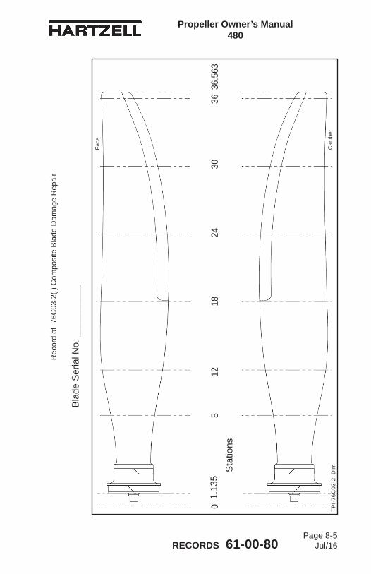
Propeller Owner’s Manual 480
RECORDS 61-00-80Page 8-5
Jul/16
Rec
ord
of 7
6C03
-2( )
Com
posi
te B
lade
Dam
age
Rep
air
Bla
de S
eria
l No.
___
____
___
1218
2430
360
36.5
638
1.13
5
Cam
ber
Face
Sta
tions
TPI-
76C
03-2
_Dim

Propeller Owner’s Manual 480
RECORDS 61-00-80Page 8-6
Jul/16
Rec
ord
of 7
6C03
-2( )
Com
posi
te B
lade
Dam
age
Rep
air
Bla
de S
eria
l No.
___
____
___
1218
2430
360
36.5
638
1.13
5
Cam
ber
Face
Sta
tions
TPI-
76C
03-2
_Dim

Propeller Owner’s Manual 480
RECORDS 61-00-80Page 8-7
Jul/16
Rec
ord
of 7
6C03
-2( )
Com
posi
te B
lade
Dam
age
Rep
air
Bla
de S
eria
l No.
___
____
___
1218
2430
360
36.5
638
1.13
5
Cam
ber
Face
Sta
tions
TPI-
76C
03-2
_Dim
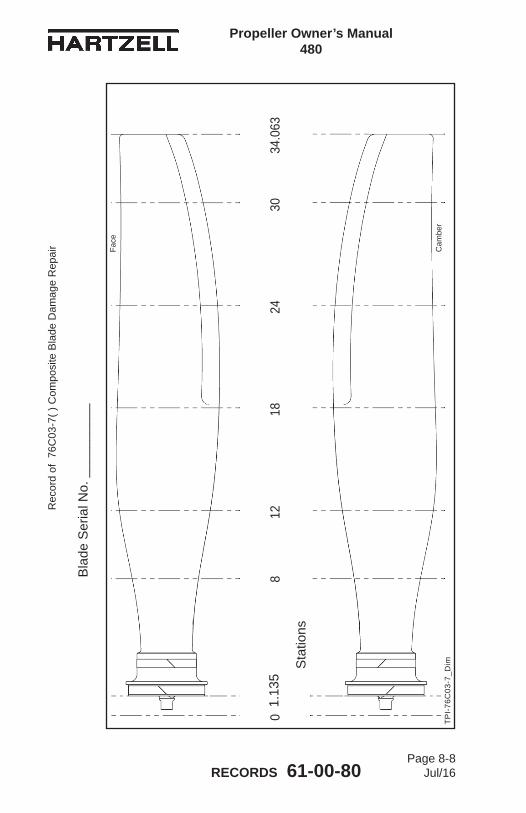
Propeller Owner’s Manual 480
RECORDS 61-00-80Page 8-8
Jul/16
Rec
ord
of 7
6C03
-7( )
Com
posi
te B
lade
Dam
age
Rep
air
Bla
de S
eria
l No.
___
____
___
TPI-
76C
03-7
_Dim
1218
2430
034
.063
81.
135
Cam
ber
Face
Sta
tions

Propeller Owner’s Manual 480
RECORDS 61-00-80Page 8-9
Jul/16
Rec
ord
of 7
6C03
-7( )
Com
posi
te B
lade
Dam
age
Rep
air
Bla
de S
eria
l No.
___
____
___
TPI-
76C
03-7
_Dim
1218
2430
034
.063
81.
135
Cam
ber
Face
Sta
tions

Propeller Owner’s Manual 480
RECORDS 61-00-80Page 8-10
Jul/16
Rec
ord
of 7
6C03
-7( )
Com
posi
te B
lade
Dam
age
Rep
air
Bla
de S
eria
l No.
___
____
___
TPI-
76C
03-7
_Dim
1218
2430
034
.063
81.
135
Cam
ber
Face
Sta
tions
Copyright © 2022 FDOKUMEN