BE (ECE) -II SEMESTER BE (ECE) -III SEMESTER BE (ECE) -V SEMESTER
Upload
khangminh22Category
view
0download
0
ECE 480
Team 17
Ian Bacus, Anishpal Gill, Yousef Gtat,
Yujie Hao, Anna Little, Craig
Stoddard Facilitator: Dr. Mukkamala
This report describes a smart health monitoring device for use in personal daily health and
hospital nurseries. A data acquisition circuit housing an infrared thermopile is described, as well
as software components for transmitting, correcting, and displaying temperature measurements to
users. The design is intended to be an external sensor package for smartphones which allow them
to take noncontact temperature readings of human subjects and obtain temperature measurements.
By using a smartphone as the foundation of the device, network connectivity and device
recharging are taken care of. The use of the smartphone to power and collect data from external
circuit is based on the “Hijack” concept out of the University of Michigan. Compensating for
distance to retrieve an accurate temperature measurement has been studied by Yildizyan et al.
Their work will be referenced often it this design. This distance method employed by the
proposed device is advantageous over traditional contact based temperature sensors because it
requires no sanitation between uses. The design provides a faster way of collecting data than
traditional means, and it allows patient information to be analyzed programmatically. For
personal daily health, this design could be extended to allow personal data to be recorded in the
cloud system, where it is easier for checking in the future. In a hospital setting, this results in less
training being required for employees, and less time spent testing each patient for problems.

1
Non-Contact Temperature Sensor for the iPhone

2
Table of Contents:
Chapter 1: Introduction and Background∙∙∙∙∙∙∙∙∙∙∙∙∙∙∙∙∙∙∙∙∙∙∙∙∙∙∙∙∙∙∙∙∙∙∙∙∙∙∙∙∙∙∙∙∙∙∙∙∙∙∙∙∙∙∙∙∙∙∙∙∙∙∙∙∙
Introduction∙∙∙∙∙∙∙∙∙∙∙∙∙∙∙∙∙∙∙∙∙∙∙∙∙∙∙∙∙∙∙∙∙∙∙∙∙∙∙∙∙∙∙∙∙∙∙∙∙∙∙∙∙∙∙∙∙∙∙∙∙∙∙∙∙∙∙∙∙∙∙∙∙∙∙∙∙∙∙∙∙∙∙∙∙∙∙∙∙∙∙∙∙∙∙∙∙∙∙∙∙
Background∙∙∙∙∙∙∙∙∙∙∙∙∙∙∙∙∙∙∙∙∙∙∙∙∙∙∙∙∙∙∙∙∙∙∙∙∙∙∙∙∙∙∙∙∙∙∙∙∙∙∙∙∙∙∙∙∙∙∙∙∙∙∙∙∙∙∙∙∙∙∙∙∙∙∙∙∙∙∙∙∙∙∙∙∙∙∙∙∙∙∙∙∙∙∙∙∙∙∙∙∙∙
Chapter 2: Exploring the Solution Space and Selecting a Specific Approach∙∙∙∙∙∙∙∙∙∙∙∙
Decomposition of the Problem∙∙∙∙∙∙∙∙∙∙∙∙∙∙∙∙∙∙∙∙∙∙∙∙∙∙∙∙∙∙∙∙∙∙∙∙∙∙∙∙∙∙∙∙∙∙∙∙∙∙∙∙∙∙∙∙∙∙∙∙∙∙∙∙∙∙∙∙∙∙∙∙
Critical Customer Requirements∙∙∙∙∙∙∙∙∙∙∙∙∙∙∙∙∙∙∙∙∙∙∙∙∙∙∙∙∙∙∙∙∙∙∙∙∙∙∙∙∙∙∙∙∙∙∙∙∙∙∙∙∙∙∙∙∙∙∙∙∙∙∙∙∙∙∙∙∙∙
Design Decisions∙∙∙∙∙∙∙∙∙∙∙∙∙∙∙∙∙∙∙∙∙∙∙∙∙∙∙∙∙∙∙∙∙∙∙∙∙∙∙∙∙∙∙∙∙∙∙∙∙∙∙∙∙∙∙∙∙∙∙∙∙∙∙∙∙∙∙∙∙∙∙∙∙∙∙∙∙∙∙∙∙∙∙∙∙∙∙∙∙∙∙∙∙∙∙
Budget∙∙∙∙∙∙∙∙∙∙∙∙∙∙∙∙∙∙∙∙∙∙∙∙∙∙∙∙∙∙∙∙∙∙∙∙∙∙∙∙∙∙∙∙∙∙∙∙∙∙∙∙∙∙∙∙∙∙∙∙∙∙∙∙∙∙∙∙∙∙∙∙∙∙∙∙∙∙∙∙∙∙∙∙∙∙∙∙∙∙∙∙∙∙∙∙∙∙∙∙∙∙∙∙∙∙∙∙∙∙
GANTT Charts∙∙∙∙∙∙∙∙∙∙∙∙∙∙∙∙∙∙∙∙∙∙∙∙∙∙∙∙∙∙∙∙∙∙∙∙∙∙∙∙∙∙∙∙∙∙∙∙∙∙∙∙∙∙∙∙∙∙∙∙∙∙∙∙∙∙∙∙∙∙∙∙∙∙∙∙∙∙∙∙∙∙∙∙∙∙∙∙∙∙∙∙∙∙∙∙∙∙∙
Chapter 3: Technical Description of the Work Performed∙∙∙∙∙∙∙∙∙∙∙∙∙∙∙∙∙∙∙∙∙∙∙∙∙∙∙∙∙∙∙∙∙∙∙∙∙∙∙∙
Hardware Design∙∙∙∙∙∙∙∙∙∙∙∙∙∙∙∙∙∙∙∙∙∙∙∙∙∙∙∙∙∙∙∙∙∙∙∙∙∙∙∙∙∙∙∙∙∙∙∙∙∙∙∙∙∙∙∙∙∙∙∙∙∙∙∙∙∙∙∙∙∙∙∙∙∙∙∙∙∙∙∙∙∙∙∙∙∙∙∙∙∙∙∙∙
Hardware Implementation∙∙∙∙∙∙∙∙∙∙∙∙∙∙∙∙∙∙∙∙∙∙∙∙∙∙∙∙∙∙∙∙∙∙∙∙∙∙∙∙∙∙∙∙∙∙∙∙∙∙∙∙∙∙∙∙∙∙∙∙∙∙∙∙∙∙∙∙∙∙∙∙∙∙∙∙∙∙∙
Software Design∙∙∙∙∙∙∙∙∙∙∙∙∙∙∙∙∙∙∙∙∙∙∙∙∙∙∙∙∙∙∙∙∙∙∙∙∙∙∙∙∙∙∙∙∙∙∙∙∙∙∙∙∙∙∙∙∙∙∙∙∙∙∙∙∙∙∙∙∙∙∙∙∙∙∙∙∙∙∙∙∙∙∙∙∙∙∙∙∙∙∙∙∙∙∙∙
Software Implementation∙∙∙∙∙∙∙∙∙∙∙∙∙∙∙∙∙∙∙∙∙∙∙∙∙∙∙∙∙∙∙∙∙∙∙∙∙∙∙∙∙∙∙∙∙∙∙∙∙∙∙∙∙∙∙∙∙∙∙∙∙∙∙∙∙∙∙∙∙∙∙∙∙∙∙∙∙∙∙∙
Chapter 4: Test Data with Proof of Functional Design∙∙∙∙∙∙∙∙∙∙∙∙∙∙∙∙∙∙∙∙∙∙∙∙∙∙∙∙∙∙∙∙∙∙∙∙∙∙∙∙∙∙∙∙∙
PCB Testing∙∙∙∙∙∙∙∙∙∙∙∙∙∙∙∙∙∙∙∙∙∙∙∙∙∙∙∙∙∙∙∙∙∙∙∙∙∙∙∙∙∙∙∙∙∙∙∙∙∙∙∙∙∙∙∙∙∙∙∙∙∙∙∙∙∙∙∙∙∙∙∙∙∙∙∙∙∙∙∙∙∙∙∙∙∙∙∙∙∙∙∙∙∙∙∙∙∙∙∙∙∙
Temperature Sensor Testing∙∙∙∙∙∙∙∙∙∙∙∙∙∙∙∙∙∙∙∙∙∙∙∙∙∙∙∙∙∙∙∙∙∙∙∙∙∙∙∙∙∙∙∙∙∙∙∙∙∙∙∙∙∙∙∙∙∙∙∙∙∙∙∙∙∙∙∙∙∙∙∙∙∙∙
Microcontroller Testing∙∙∙∙∙∙∙∙∙∙∙∙∙∙∙∙∙∙∙∙∙∙∙∙∙∙∙∙∙∙∙∙∙∙∙∙∙∙∙∙∙∙∙∙∙∙∙∙∙∙∙∙∙∙∙∙∙∙∙∙∙∙∙∙∙∙∙∙∙∙∙∙∙∙∙∙∙∙∙∙∙∙∙
iPhone Testing∙∙∙∙∙∙∙∙∙∙∙∙∙∙∙∙∙∙∙∙∙∙∙∙∙∙∙∙∙∙∙∙∙∙∙∙∙∙∙∙∙∙∙∙∙∙∙∙∙∙∙∙∙∙∙∙∙∙∙∙∙∙∙∙∙∙∙∙∙∙∙∙∙∙∙∙∙∙∙∙∙∙∙∙∙∙∙∙∙∙∙∙∙∙∙∙∙
Chapter 5: Design Issues∙∙∙∙∙∙∙∙∙∙∙∙∙∙∙∙∙∙∙∙∙∙∙∙∙∙∙∙∙∙∙∙∙∙∙∙∙∙∙∙∙∙∙∙∙∙∙∙∙∙∙∙∙∙∙∙∙∙∙∙∙∙∙∙∙∙∙∙∙∙∙∙∙∙∙∙∙∙∙∙∙∙∙∙∙∙∙∙∙∙
Chapter 6: Final Cost, Schedule, Summary, and Conclusion∙∙∙∙∙∙∙∙∙∙∙∙∙∙∙∙∙∙∙∙∙∙∙∙∙∙∙∙∙∙∙∙∙∙∙∙
Appendix 1 – Technical Roles, Responsibilities, and Work Accomplished∙∙∙∙∙∙∙∙∙∙∙∙∙∙∙
Appendix 2 – Literature and Website References∙∙∙∙∙∙∙∙∙∙∙∙∙∙∙∙∙∙∙∙∙∙∙∙∙∙∙∙∙∙∙∙∙∙∙∙∙∙∙∙∙∙∙∙∙∙∙∙∙∙∙
Appendix 3 – Detailed technical attachments∙∙∙∙∙∙∙∙∙∙∙∙∙∙∙∙∙∙∙∙∙∙∙∙∙∙∙∙∙∙∙∙∙∙∙∙∙∙∙∙∙∙∙∙∙∙∙∙∙∙∙∙∙∙∙∙∙

3
Chapter 1: Introduction and Background
Introduction
One of the most common symptoms of disease or infection is an abnormal body temperature.
This can be detected using a temperature sensor of some kind. The most ubiquitous tool for
clinical temperature measurement for the past half century has been the contact-based digital
thermometer, dating back to circa 1952. The procedure involved for safely using this type of
temperature sensor presents notable weaknesses in clinical settings. It require sanitation between
uses, and in some cases a wasteful disposable cap is utilized. The information collected from this
type of sensor must be copied manually into a record. The invasive nature of some temperature
measuring procedures can create discomfort for patients as well. This report discusses a proposed
design that integrates a clean, light-based temperature sensor with a smartphone application. The
device will be referred to as THERM for the rest of this document. THERM eases the
temperature measuring process by directly addressing each of the previously mentioned
weaknesses of contact-based digital thermometers: it does not require sanitation or disposable
components, it can automatically communicate with digital record-keeping systems, and it
minimizes patient discomfort. It also is marketable in a commercial setting, because it is easy to
share with others and it allows users to detect maladies. Personal health devices are of growing
interest nowadays, as is evident from the success of consumer items such as as Fitbit or the
Apple Watch. Data from these electronic devices can be collected passively from a smartphone
through the data, and shared with medical institutions and hospitals to be accessible online. If the
use of such devices became more widespread, given their ease of use, data brokers could make
use of and sell the information to hospitals to help in determining “illness forecasts” by
observing the distribution of abnormal temperatures in different regions. Upon encountering a
medical condition, a patient’s health information is only a few clicks away, which helps
clinicians and doctors to make better treatment decisions by accessing continuous data
throughout the day, week, month, or even years.

4
Background
Not many advances in temperature measuring technology have been made in clinical temperature
measuring procedure since the invention of the liquid filled contact-based thermoscope in 1602.
The invention of the electronic thermometer did not affect the measurement procedure much.
Infrared temperature measurement systems are typically concentrated in industrial settings, due
to the necessity for careful calibration and historically high prices. The design objective is to
create a fast, contactless temperature measuring device that can interact with a remote database.
The primary digital components used in this system are the TMP007 infrared temperature
sensor, the MSP430 F-family microcontroller, and the Apple A5-based iPhone smartphone. The
TMP007 is a thermopile sensor from Texas Instruments that is able to measure the temperature
of an object without direct contact. It absorbs infrared energy from objects at wavelengths
between 4 micrometers and 16 micrometers, using a special window that acts as a bandpass filter
for light. It also contains an internal math engine to calculate the target temperature, as well as a
non-volatile memory for storing calibration settings. The sensor package is 1.9 millimeters by
1.9 millimeters. The TMP007 was designed to be distant from resistors, capacitors, and other
components that may dissipate heat to ensure an accurate temperature reading. The MSP430 is a
microcontroller from Texas Instruments that allows digital processing of input signals, as well as
hardware interfaces that comply with different protocols or interface with timers for the
transmission and reception of data. A smartphone is a device factor that provides an ergonomic
and feedback-rich user environment for interacting with a system-on-a-chip (SOC). This SOC
provides many useful sensing functions, such as audio and video codecs, memory management
hardware, MEMS-based motion sensors and compasses, and capacitive touch interface
controllers. This allows the creation of user-friendly UIs that can interact with diverse sensing
elements. Integrating the TMP007 temperature sensor and MSP430 microcontroller allows
utilization of the phone’s auxiliary jack to power up the MCU and sensor and at the same time to
transmit the sensor results. The temperature sensor is only accurate at close distances due to the
TMP007’s wide angle of measurement. This effect can be overcome with the use of a positive

5
focal length lens, with a narrower field of view, which can be used to focus light onto the
temperature sensor. This will potentially allow the design to be used from a greater distance.
Prior work from related projects assisted in efforts to meet the design goals. University of
Michigan’s Hijack project describes how to create an interface between a smartphone and digital
or analog based sensors over an audio-jack based interface. A patent from Yildizyan et al1
describes how to compensate for the effects of distance in infrared temperature measurement
using distance compensating functions. There are other models such as the ‘Mendipweather’2
which involve the interfacing of a sensory circuit with a smartphone for temperature
measurement, but the thermometer used is contact based.
Chapter 2 – Exploring the Solution Space and Selecting a Specific Approach
Decomposition of the Problem
Currently more and more people are relying on smartphone applications to handle common
tasks. This is understandable since approximately two-thirds3 of Americans use smartphones,
and more applications means more convenience and less other items which must be carried
around or kept track of. The thermometer application described in this report fits well with this
trend.
The project specifications required the device to be compatible with a smartphone application
and to conduct temperature reading within seconds. The device was to be attachable to the back
of the phone, and small enough to fit in the user’s pocket. This provides doctors, nurses, and
health inspectors the flexibility to take temperature measurements of their patients quickly and
conveniently thus replacing the old medical temperature toolkit in hospitals. The target accuracy
was within ±0.1F degrees in an ambient temperature range of 60F to 90F degrees. This range
1 See Appendix 2.a and 2.b 2 See Appendix 2.a 3 http://www.pewresearch.org/fact-tank/2015/04/01/6-facts-about-americans-and-their-smartphones/

6
includes the normal room temperature of approximately 70F degrees. Estimated manufacturing
cost was planned to be approximately $40 per chip.
Looking at the FAST diagram in (Figure 1) the main components for this design were the
infrared temperature sensor, the iPhone interface, and the microcontroller system. The last two
components were further divided into the subsystems. The iPhone interface was composed of an
Figure 1, FAST Diagram
audio interface to handle the three channels of the audio jack, one for powering the circuit, one
for transmitting commands, and one for receiving data; an camera interface to provide a distance
to the target; and a motion sensor interface for improving the accuracy of the distance
measurement. The MCU system was divided into subsystems to process the sensor result, to
receive commands and power from the audio jack, and to send the processed temperature signal
to the iPhone.
Critical Customer Requirements
Since the main purpose of this project is to improve upon the standard in-ear thermometer it is
important that this thermometer design has equivalent or better accuracy. There are several other

7
critical customer requirements (CCRs). The second most important is power efficiency. Since
this design requires a smartphone interface and a nurse more than likely needs the phone to last
an entire work day, the device and application must not use very much power. Furthermore the
application needs to be intuitive so that it is not confusing for users who lack experience with
newer technology, such as elderly patients who would be benefited by maintaining personal
health records.
Design Decisions
The idea of attaching a thermometer to a smartphone is not unique, nor is the use of a contactless
infrared thermometer for taking body temperature. However, in combining these components
the proposed solution has the potential to change the industry standard. Extensive research
revealed many applications which contain components of the described design and proved the
feasibility of the design (Table 1) but this project is unique in combining all of them into a
compact chip and application.
The choice of device had little impact on the overall design. Upon implementing a functional
application for any device porting it to other devices would be trivial, and considering that
iPhones and Android phones make up over ninety percent4 of the smartphones in the US, with
Application Non-contact Temperature Phone-based form factor Audio Jack Distance sensor
Temperature gun X
Mendipweather x
Yildizyan et al x x
HiJack x x
Us x x x
Table 1, Components of the Design and Prior Works It Is Based On
4 http://techland.time.com/2013/04/16/ios-vs-android/

8
Android only slightly more prevalent, either one would have been a good choice for application
development. The decision was to use iPhone because of convenience.
The key design decision was what form factor would be most practical and easy to use. Since
smartphones have limited I/O the interface choices were USB or audio jack. Both choices were
considered and—as shown in Table 2—the USB interface with the smartphone form factor was
most compatible with our CCRs. It would provide a faster and potentially slightly more accurate
result. However, the higher score of the USB was not significant enough to outweigh the
complexity and inconvenience of using the only USB jack on the phone. The lower price and
complexity of the audio jack interface were beneficial from a design standpoint. More
importantly the fact that choosing the audio jack interface allows the smartphone to be charged
and allows the phone to be connected to a computer without having to remove the thermometer
attachment, thus the audio jack was chosen.
The hardware requirements for this design, besides the smaller circuit components, were an
infrared temperature sensor which would allow accuracy within ±0.1F and a low power
microcontroller. The solution matrix for these components is shown in Table 3. The TMP007
was chosen because of its base accuracy and because the built in non-volatile memory allows for
storing calibration coefficients which can further improve the accuracy. The MSP430 series was
chosen because the iPhone audio jack generates less than 16mW of power at ideal output.5 The
430 requires very low power, only 16.8 mw for typical active mode at full speed.6
5 See Appendix 2.a 6 See Appendix 2.a

9
Table 2, Form Factor Solution Matrix
Table 3, Hardware Solution Matrix
GANTT Charts

10
The GANTT Chart proposed in week 4 of development is shown in Figure 2. In contrast the
chart for the actual schedule is shown in Figure 3. The differences are due to issues that occurred
during development, as well as a lack in budget, and time constraints. In particular there was not
enough time to make two prototypes. These issues are discussed further in Chapter 5 of this
report.
Figure 2, Original GANTT Chart

11
Chapter 3 – Technical Description of the Work Performed
Hardware Design
The hardware design efforts consisted of creating a Printed Circuit Board (PCB) using the
schematic from the ‘hijack’ paper as seen in Figure 4, selecting a lens to augment the
temperature sensor, and designing a case. The PCB was designed to be the link between the
iPhone’s audio jack, the MSP430F1611IPMR microcontroller, and TMP007 infrared thermopile.
The original PCB files from the Hijack project were publicly available, but they did not
incorporate any external sensors. The available files provided and schematic layout for a power
harvesting circuit, a low-pass filter for the microcontroller output to smartphone microphone
input interface, and an AC-coupler for interfacing between the smartphone’s left audio output
and the microcontroller’s input capture pin. This made the design addition straightforward, since
only one 6-pin component (the TMP007 sensor) needed to be imported and added to the existing
schematic and layout. Thermal considerations had to be respected when placing the temperature
sensor, complicating the implementation.
Figure 3, Final GANTT Chart

12
The circuit received power from the left channel of the audio jack. An inductor pair was used to
implement a step up transformer, and a full wave diode bridge rectifier was used to convert AC
voltages from the phone to a DC power supply for THERM’s inhabitants. This rectifier is
included in a circuit schematic from the Hijack project as seen in Figure 5.
Figure 4: Hijack mainboard
Figure 4, MSP430 Schematic
Figure 5, AC to DC Voltage Rectifier

13
Focusing Lens
A focusing lens was planned to be implemented to reduce the field of vision of the temperature
sensor. The accurate measuring distance of the temperature sensor was determined as a limitation
based on the following calculations. First, it must be noted that a triangle is formed between the
temperature sensor, a point centered with the temperature sensor and the target, and a point at the
edge of a target. Trigonometry can be used to determine the maximum measuring range as a
function of the field of view, assuming a fixed target radius of 4.5 cm (half the width of a typical
face).
To achieve a range of 0.75m, meeting the objective, the field of view must be narrowed to a
miniscule 5.4°.
An optical collector was proposed as a component of the system for increasing the
accurate measuring range of the temperature sensor. The TMP007 thermopile works by
measuring a wide conic section of incident infrared light from the temperature sensor. This
section fans out 110° from approximately the center of the sensor. Although the majority of the
measured energy is contributed by a narrower region within the first 90° of the field of view, this
section was still determined to be much too large for the application’s requirements. The
TMP007 sensor is most sensitive to wavelengths between 4um and 16um, in the mid to deep
14
infrared range. For a positive focal length collector, the focal length is what determines where
incident light converges onto. For this application, the lens needs to collect light and focus it onto
the 0.33mm x 0.33mm square temperature sensor. This indicates that the temperature sensor
should be spaced apart from the lens, slightly within the focal length. Additionally, the thickness
of the lens increases the total distance that our device must extend from the temperature sensor.
It was decided that the thickness summed with the focal length of the selected lens should be not
exceed 10mm, since this would interfere with the ability of a user to keep the device comfortably
in their pocket. Lens diameter was another attribute that was of concern for the implementation.
The lens needed to be large enough to focus infrared light onto the total area of the sensor,
providing a minimum size. The maximum size was more of a constraint, due to the fact that most
available on-stock lenses exhibited a positive correlation between lens diameter and focal length
(there is no actual relationship between focal length and lens diameter). The acceptable lens
diameter was determined to be anywhere from 2mm to 50mm, since sizes any larger than that
would require increasingly inconvenient positionings of THERM within the designed case.
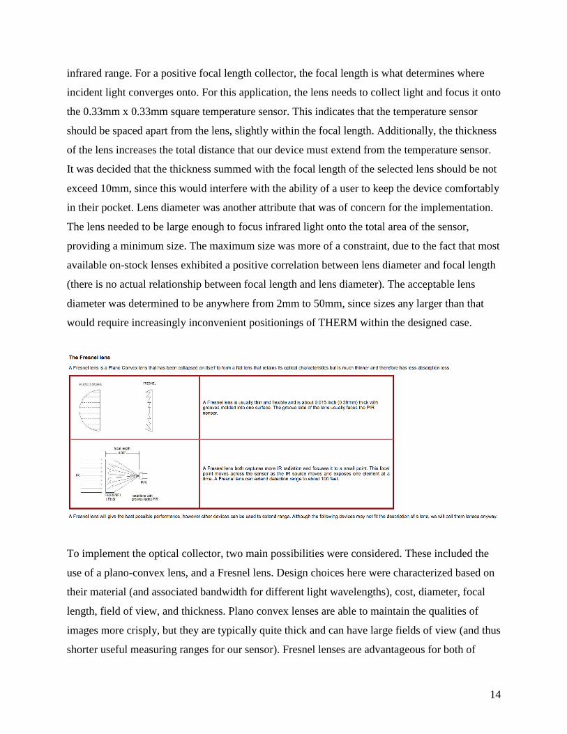
To implement the optical collector, two main possibilities were considered. These included the
use of a plano-convex lens, and a Fresnel lens. Design choices here were characterized based on
their material (and associated bandwidth for different light wavelengths), cost, diameter, focal
length, field of view, and thickness. Plano convex lenses are able to maintain the qualities of
images more crisply, but they are typically quite thick and can have large fields of view (and thus
shorter useful measuring ranges for our sensor). Fresnel lenses are advantageous for both of
15
these criteria, at the cost of the irrelevant parameter of image quality. When used as collectors,
they are essentially inward-folded plano-convex lenses. This allows them to have the same
diameter and focal length as the other lens type, with a much reduced thickness. Another major
advantage of Fresnel lenses is that they have an extremely narrow field of view, allowing for
very accurate temperature readings over large distances.
Hardware Implementation
Thanks to the University of Michigan’s open source project ‘hijack’7, utilization of a previous
schematic and board file was made available. However, it is believed that the researches at
University of Michigan used a different program than the ones available on the engineering lab
computers as modifications could not be made easily. Therefore, a new board was made from
scratch. Using one of the provided programs called ‘Eagle’, the schematic file provided from
University of Michigan was modified to incorporate a pad for the TMP007 sensor.
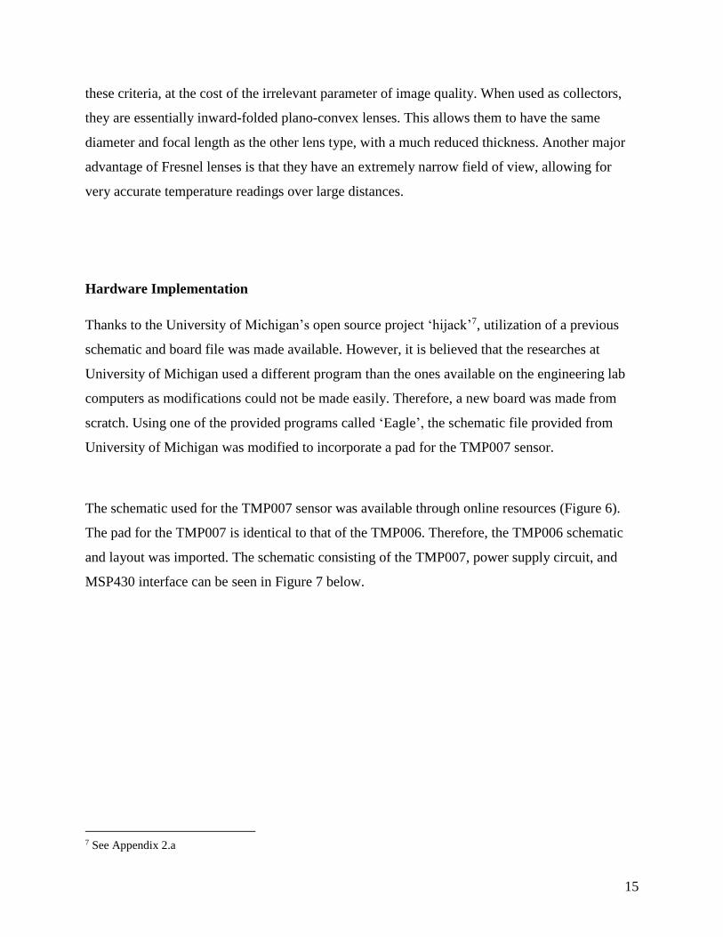
The schematic used for the TMP007 sensor was available through online resources (Figure 6).
The pad for the TMP007 is identical to that of the TMP006. Therefore, the TMP006 schematic
and layout was imported. The schematic consisting of the TMP007, power supply circuit, and
MSP430 interface can be seen in Figure 7 below.
7 See Appendix 2.a

16
Figure 6, TMP007 Schematic
Figure 7, Hijack Schematic with Added TMP007

17
The components were first placed on the board layout to allow for simple wiring with minimal
vias, which are drill holes that link the two sides of the board. The components in the hijack and
power supply schematic were to reflect the hijack board in a one inch by one inch area, and the
TMP007 components in the other one inch by one inch area. This process made the placement of
components much simpler than originally anticipated.
Difficulties were encountered when creating layers in the PCB layout, so grounding was
accomplished using routes instead of a ground plane for the design. This modification resulted in
a slightly wider board to allow room for additional wiring, but it allowed us the possibility of
fabricating a prototype locally in the ECE shop. It is easy to see the differences between the two
designs. (Figures 7 and 8).
Figure 8, Open Source Hijack Board from U of M

18
However, the ECE Shop was unable to print our circuit board due to the proximity of the pins of
the microcontroller. Therefore, the completed files for the new board were then sent to PCB
manufacturer Advanced Circuits. The board file needed multiple modifications for route and via
spacing design rule errors. These errors were resolved with the reduction of wire width, or by
readjusting the problematic sections slightly. Shipping and manufacturing took approximately
five business days.
The TMP007 (“U2” in the diagram above with eight pins) and the MSP430 (64 small pins)
soldering was accomplished with the aid of a company called Lectronix. All components
besides the MSP430 and TMP007 were soldered as part of the design effort of Team 17. Most
components ranged from 0.06 inches by 0.03 inches to 0.08 inches by 0.05 inches. Some of the
components used were substitutes for the ones used in the Hijack project, based on their
availability. In one particular case, a SMD pad had to be replaced with a through-hole pad to
accommodate our available parts. For instance, one component that was not in our inventory and
needed to be replaced was a 100 microfarad tantalum (surface-mount) capacitor. This was
replaced with a 100 microfarad ceramic capacitor. The capacitor was in the power supply circuit,
Figure 8, Modified Hijack board with TMP007
Figure 9, Open Source Hijack Board from U of M

19
and its primary function was to filter the signal. Therefore, a ceramic capacitor could be
mounted instead.
One of the more difficult component to solder was an indicator LED for the power supply
circuit. Other difficult soldering points included the four three-pin transistors of the rectifier and
the five-pin voltage regulator. The complication of these components arose from the close
proximity to other components or close spacing of pins on the same device package. The last
thing to mount was the audio jack. A simple but noticeable difference between the UofM board
and the THERM board is the use of the flexible audio jack cord for the latter versus the 180° stiff
jack for the hijack board. This will allow us to orient the cord in any manner to accommodate
different iPhone versions. The audio jack consisted of four copper wire connectors; ground, left,
right, and microphone These connections were challenging as the copper was vulnerable to
movement because of the pliability of wiring as opposed to the rigidity of a surface mount
component.
Figure 10 The completed THERM PCB, Top Side

20
Figure 11 The completed THERM PCB, Bottom Side
The 3D printed case was designed to fit an iPhone 4S. The design consisted of a prototypical
phone case with a slot for the PCB. The space designated for the PCB had a window cut-out for
the TMP007 to receive data, and a hole so the audio cord would be able to wrap around the
phone and be inputted into the audio jack of the iPhone. Initially the slot for the PCB was around
8 mm; however, when the tantalum capacitor was replaced, the depth needed to be increased to
more than double to account for the size of the ceramic capacitor. The case was first printed by
DECS because it was less expensive and to confirm the measurements. It was then printed by the
ECE shop so the case could be of a rubber-like substance. The device name “THERM” was also
printed on the bottom back of the case, see Figure 9 below.

21
Software Design
The software design consisted of an Objective C iOS application and microcontroller firmware
in C. The microcontroller would reside on the PCB as shown in Figure 10, which shows the
Figure 12, “THERM” 3D Printed Case
Figure 13, Layout of software and hardware interactions, and data flow
22
original design concept. It receives information from the TMP007 thermopile and transmits it to
the iPhone. The iPhone acts as the power supply, main computational area, and user
interface for the temperature sensing apparatus. The iPhone design originally contained
subsystems for controlling audio, motion-sensing, video capturing hardware, although this
design needed to be modified in the final implementation.
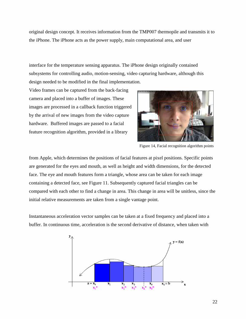
Video frames can be captured from the back-facing
camera and placed into a buffer of images. These
images are processed in a callback function triggered
by the arrival of new images from the video capture
hardware. Buffered images are passed to a facial
feature recognition algorithm, provided in a library
from Apple, which determines the positions of facial features at pixel positions. Specific points
are generated for the eyes and mouth, as well as height and width dimensions, for the detected
face. The eye and mouth features form a triangle, whose area can be taken for each image
containing a detected face, see Figure 11. Subsequently captured facial triangles can be
compared with each other to find a change in area. This change in area will be unitless, since the
initial relative measurements are taken from a single vantage point.
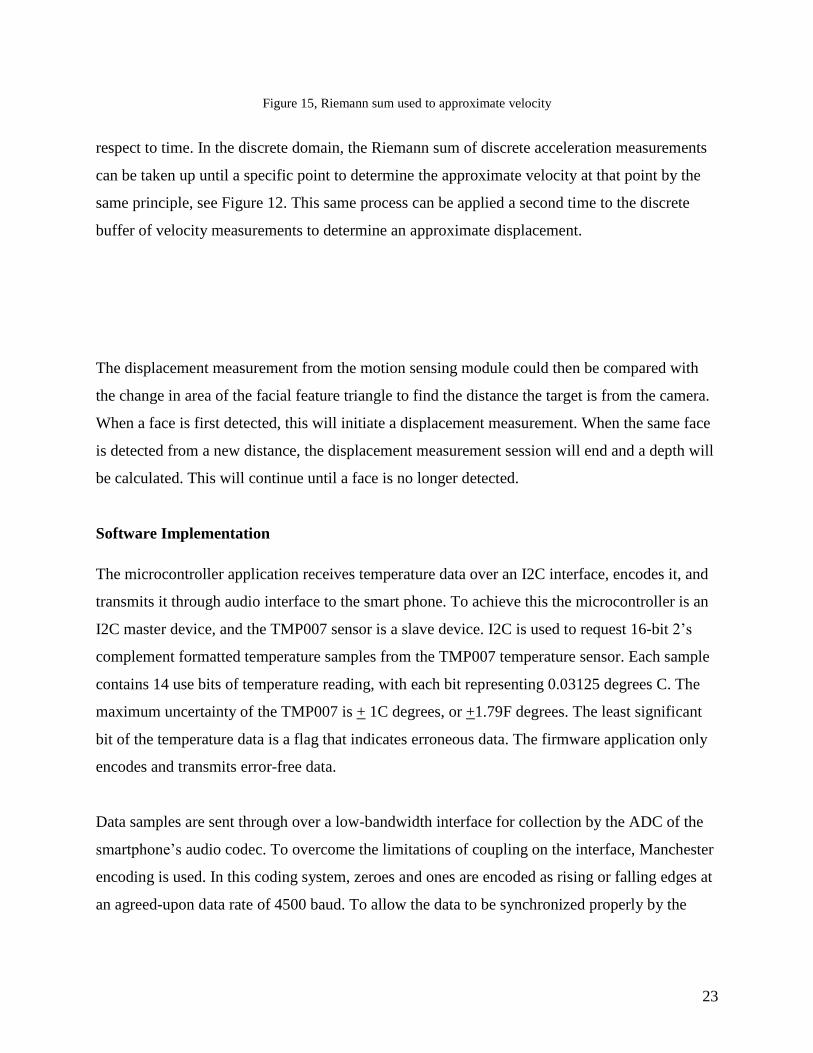
Instantaneous acceleration vector samples can be taken at a fixed frequency and placed into a
buffer. In continuous time, acceleration is the second derivative of distance, when taken with
Figure 14, Facial recognition algorithm points
23
Figure 15, Riemann sum used to approximate velocity
respect to time. In the discrete domain, the Riemann sum of discrete acceleration measurements
can be taken up until a specific point to determine the approximate velocity at that point by the
same principle, see Figure 12. This same process can be applied a second time to the discrete
buffer of velocity measurements to determine an approximate displacement.
The displacement measurement from the motion sensing module could then be compared with
the change in area of the facial feature triangle to find the distance the target is from the camera.
When a face is first detected, this will initiate a displacement measurement. When the same face
is detected from a new distance, the displacement measurement session will end and a depth will
be calculated. This will continue until a face is no longer detected.
Software Implementation
The microcontroller application receives temperature data over an I2C interface, encodes it, and
transmits it through audio interface to the smart phone. To achieve this the microcontroller is an
I2C master device, and the TMP007 sensor is a slave device. I2C is used to request 16-bit 2’s
complement formatted temperature samples from the TMP007 temperature sensor. Each sample
contains 14 use bits of temperature reading, with each bit representing 0.03125 degrees C. The
maximum uncertainty of the TMP007 is + 1C degrees, or +1.79F degrees. The least significant
bit of the temperature data is a flag that indicates erroneous data. The firmware application only
encodes and transmits error-free data.
Data samples are sent through over a low-bandwidth interface for collection by the ADC of the
smartphone’s audio codec. To overcome the limitations of coupling on the interface, Manchester
encoding is used. In this coding system, zeroes and ones are encoded as rising or falling edges at
an agreed-upon data rate of 4500 baud. To allow the data to be synchronized properly by the

24
smartphone, all transmissions begin with a start bit. Start bits consist of a long one signal
followed by a short zero.
The iOS application consists of two main modules: audio control, video capture with facial
recognition. Each of these applications runs one or two threads associated with receiving data
from the hardware-based audio codecs, and the camera image buffer respectively. Both of these
modules are sources of real time data. The audio interface is used to obtain temperature
measurements sent by the microcontroller application. Additionally, the audio module provides
the 18kHz oscillating signal to power the PCB circuit.
The audio sub-module buffers Manchester-encoded data as linear PCM samples from an ADC,
parses and decodes the data, and then converts it to a temperature reading. Samples are obtained
at 38400 Hz, four times the frequency used to transmit data over the microphone line. These
samples correspond to linear PCM data, so time-indexed samples can be parsed.
This interface consists of a playback thread and a recording thread of execution, both of which
are callback functions invoked by system events in response to audio buffers changing state. For
the playback system, freshly emptied buffers are refilled with new linear PCM samples to be
played back. For the playback function, a sinusoid is generated one sample at a time and
delivered as a mono signal to the default audio output interface, determined by the presence (or
lack thereof) of an audio jack connector in the audio jack port. The generated sinusoid has a
frequency of 18 kHz and amplitude of 500mV. The signal is generated with a sampling
frequency of 44.1 kHz to respect the Nyquist rate, where each sample goes into the cell of a
buffer that is converted to audio using the linear PCM system.
In the video sub-module video frames are captured from the back-facing camera and placed into
a buffer of images. These images are processed in a callback function triggered by the arrival of
new images from the video capture hardware. Buffered images are passed to a facial feature
recognition algorithm, provided in a library from Apple, which determines the positions of facial
features at pixel positions. Specific points are generated for the eyes and mouth, as well as height
and width dimensions, for the detected face. The eye and mouth features form a triangle, whose

25
area can be taken for each image containing a detected face. Subsequently captured facial
triangles can be compared with each other to find a change in area. This change in area is unit-
less, since the initial relative measurements are taken from a single vantage point. This video
capture feature could be used to calculate the distance from the target to the phone. However,
due to issues discussed in Chapter 5 of this report this has not yet been implemented.
Chapter 4 – Test Data with Proof of Functional Design
Testing was carried out on the PCB circuit, the temperature sensor, the microcontroller, and on
the iPhone.
PCB Testing
When testing the board, the LED power indicator did not turn on. This is an indication that the
power supply circuit is not in working order. This may be due to a resistor accidentally being
connected to a via during the soldering process; this would essentially create a ground. The
resistor in question is the 698 ohm resistor, which leads into the LED. One pad of this resistor
was very close to a series of vias. If time permits, the excess solder on this joint can be removed,
the resistor re-soldered, and the PCB retested. Also the iPhone application did not produce any
temperature read out. The PCB design is a good idea in practice, future teams should have the
company that produces the board solder the board as well, this way they can acquire the correct
stamp outs for the miniscule soldering points.
Temperature Sensor Testing
26
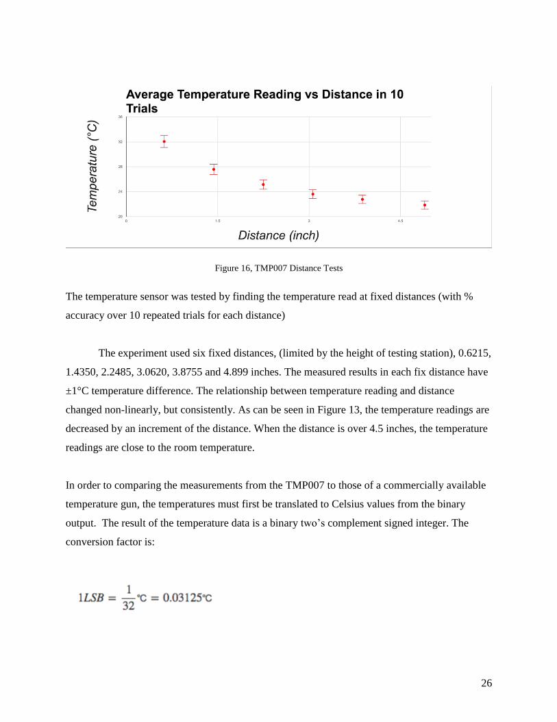
The temperature sensor was tested by finding the temperature read at fixed distances (with %
accuracy over 10 repeated trials for each distance)
The experiment used six fixed distances, (limited by the height of testing station), 0.6215,
1.4350, 2.2485, 3.0620, 3.8755 and 4.899 inches. The measured results in each fix distance have
±1°C temperature difference. The relationship between temperature reading and distance
changed non-linearly, but consistently. As can be seen in Figure 13, the temperature readings are
decreased by an increment of the distance. When the distance is over 4.5 inches, the temperature
readings are close to the room temperature.
In order to comparing the measurements from the TMP007 to those of a commercially available
temperature gun, the temperatures must first be translated to Celsius values from the binary
output. The result of the temperature data is a binary two’s complement signed integer. The
conversion factor is:
Figure 16, TMP007 Distance Tests

27
To convert the temperature digital output to degrees Celsius, two bits of the digital output must
be right-shifted. The conversions are shown in Table 6. For instance, a measured value of 0100
1011 0000 0000 would yield a result of:
(0100 1011 0000 0000 >> 2) = 0001 0010 1100 0000 = 0x12C0 = 4800(dec)
Microcontroller Testing
The microcontroller was exposed to the rest of the system at two key interfaces: the I2C
connection with the temperature sensor, and the audio jack connection with the iPhone.
To test the I2C interface functionality, first, it had to be determined that there was communicate
with the temperature sensor, with the microcontroller acting as a master. Using the oscilloscope,
the response of the temperature sensor to queries on its register address 0 (the contents of which
Table 6, Conversion from Binary Output to Celsius Degrees

28
represent an instantaneous temperature measurement) could be detected by noting the presence
of acknowledgement bits, and the existence of non-zero temperature responses in the “read”
portion of the I2C message transmission. The binary temperature values captured here at fixed
distances were translated and evaluated using the method described in the temperature sensor
testing section as seen in the figure below:
Figure 17 I2C communication confirmed
Secondly, the received temperature values needed to be confirmed as correct. This was done by
inspecting the outputs of samples in a Code Composer debugger interface for five captured
signals. Correct ncoding of data was verified using the debugger for some 8 bit data samples.
The program was written in terms of a bit length for input and output data types.

29
iPhone Testing
There were many different aspects of the iPhone application that needed to be tested. Memory
leaks were tested for using the Instruments tool, which is part of the Xcode IDE. Data collection
was tested by sending a square wave at a set frequency to the audio units. The received signal
was classified as high and low bits based on their sign and the average bit lengths of contiguous
groups of ones or zeroes were measured generating the distribution shown in Figure 14.
Figure 18, Contiguous bit length parsing test
Chapter 5 – Design Issues
One of the significant issues was the PCB design and manufacture process. The PCB team had to
run two versions of THERM in parallel, one to be manufactured by the ECE shop for testing

30
purposes and the other is for the final prototype, which was more compact PCB with much size
and dimensions. Running two versions of the PCB consumed a significant portion of the team’s
effort and time due to the limitation of resources and budget constraints to manufacture several
PCBs for testing purposes. It is evident that the manufacturing costs adds to the budget, however,
the time it takes to manufacture the final circuit from a PCB company is estimated to be 2-3
weeks, thus limiting the team's ability to create multiple versions of the final product for
inspection and testing the PCB design.
In terms of PCB design, the PCB team had to merge the temperature sensor circuit interface with
the hijack circuit into one new circuit interface to be connected with the iPhone application
through the audio jack. The thermopile range of the TMP007, however, is 3.5cm with maximum
range for normal human face with 10cm wide. In other words, the TMP007 can take accurate
measurement of the patient or target within 3.5cm distance. Any further distance of reading the
temperature would include the ambient temperature of the room or objects, which result in
incorrect temperature reading. This issue required the PCB team to look for a lens with a very
short focal length to be placed on top of the temperature sensor to properly focus on target. The
size of the required lens was very small, which put constraints on the project because the team
speculated that the lens might have to be custom made or manufactured by a third party
company. As a result, the team’s budget was not sufficient to cover cost of custom lens. Since
the facial recognition and distance algorithm portion of the iPhone application was designed to
compensate for the long distance results of the temperature sensor this portion of the project
could not be finished without the lens to allow for long distance temperature readings.
The temperature sensor feeds data back to the MSP430, which is a low power IC used to
communicate with the iPhone application. The MSP430 IC was specifically chosen due to some
circuit power consumption constraints of a maximum of 15mW. This limited the team’s choices
to use low power IC thus limiting the computational power and algorithm complexity
implemented on the embedded circuit. The hijack circuit bit rate with microphone bandwidth (20
KHz) was estimated to be a maximum of 800Hz sampling frequency. As a result, the hijack

31
circuit has constraints when it comes to real time signal processing algorithm for pattern
recognition of the temperature health record.
The custom PCB board is very compact therefore soldering all the components was time
consuming to the team. In addition, the temperature sensor TMP007 and the MSP430 footprints
were extremely small and the team did not have the appropriate soldering tools. As a result, the
team had to pay a third party company to solder those two components properly, which cost the
team extra $75 to the budget and two days of delay to get the custom PCB back from this
company. The soldering tools available at the capstone lab were somewhat cumbersome to the
team because most of the PCB components had very tiny footprints. Plus, the PCB subteam
haven’t had the previous experience to solder such small components on a small embedded PCB.
Chapter 6 Final Cost, schedule, summary, and conclusions
Final Cost Estimated Cost:
Component MSP430xG TMP007 Case PCB Lens Total
Price $4.50 $4.67 $11.00 $100.00 $15.00
Quantity 3 2 2 1 2
Total $13.50 $9.34` $22.00 $100.00 $30.00 $174.84
Final Cost:
Component MSP430xF TMP007 Case PCB Lens PCB parts PCB services
Price $17.65 $4.53 $4, $37.91 $69.91 $33 Varies $75
Quantity 1 1 2 3 1 Numerous 1

32
Total $17.65 $4.53` $41.91 $209.73 $33 $111.93 $75
Final Total: $499.75
The goal of the project was to create a smart-phone based contactless thermometer. The cost of
buying components, fabricating a custom PCB, and printing a 3D case were all within the budget
of $500. The design efforts consisted mainly of software design. This included designing an iOS
application that interacted with the iOS Audio Unit, Core Motion, and Core Image APIs. It was
determined that infrared temperature sensors exhibit a strong dependence on distance, and for the
application of variable-range temperature measurement it becomes essential to be able to control
the field of view of such a device.
The project was successful in accessing information from all of the sensors and processing their
data as was intended from the beginning. This involved the collection of binary data from the
TMP007 over the I2C interface, its transmission over an audio channel, its collection,
synchronization, parsing, and display by the smartphone application. This resulted in the
successful interaction of the phone’s interface with the temperature sensor through the MSP430,
which was one of our most important design goals for the project. Accessing and performing
integration with time of acceleration data as well as using facial feature recognition frameworks
to measure facial areas with time were successful, although these systems were not calibrated or
integrated with each other for the final design and as a result these efforts were not used for the
final demonstration.
The project was unsuccessful in implementing the system for determining distances, creating a
working PCB, and finding a lens that was appropriate for our project and within our budget. The
distance determining system only required the extra stage of noise reduction in accelerometer
data, but this was a deceptively difficult task. Some research indicated that a kalman filter was
the ideal solution to removing the noise that the accelerometer exhibited, and this
implementation became a low priority since range-based detection would not work without a
lens. The PCB design was a learning experience for the designers, and the addition of the sensor
to the Hijack schematic took unexpectedly long. This prevented us from testing the PCB circuit
or customizing it. Thermal considerations were not taken into account in the placement of the

33
temperature sensor, and the development environment for the PCB design was not a full-featured
version.
To extend this work, testing could be carried out by purchasing or reconstructing the power
harvesting and interfacing circuits for the microcontroller, temperature sensor, and phone. The
most important steps would be to add the distance-related systems to the hardware and software.
This would involve the purchase and testing of a correctly chosen lens that would pass infrared
light from a narrow field of view, to increase detection range of the sensor. Next, some form of
distance measurement would need to be implemented. This could be done more simply with the
addition of a range detecting sensor, or by extending the system which utilizes the iPhone’s
camera and motion sensing capabilities. The utilization of the camera could be extended to
automatically modify the calibration settings of the temperature sensor based on observed
orientations of the target’s face, or estimated emissivities based on the color of the target’s skin.
Appendix 1 – Technical Roles, Responsibilities, and Work Accomplished
Craig Stoddard:
My overall job for the team was the hardware
implementer and presentation manager. The
presentation manager entailed getting powerpoints
organized as well as assembling the poster for
design day. In terms of the technical review and oral
proposal and our final presentation, I was in charge
of the visual content of all of them. In the beginning days, I spent a bit of time researching
objective C code on the software side and ways we could implement the Kalman filter but
reassignment of tasks placed me on the hardware side. I assisted with the various assignments
throughout the semester like the selection matrix and GANTT chart and during presentations I
was a speaker at one point or another either talking about the background and introduction or the
PCB. For the proposal and final report, I was in charge of writing the introduction and
background sections as well as the technicalities behind the PCB design in the technical portion

34
of the final report as well as the PCB testing section. I helped assemble a list of components
needed for the PCB and made decisions on substituting parts that were unattainable as well as
proposing a flexible aux cord. I made multiple trips to Lectronix Corporation, located in Lansing,
during our days of communicating with them about soldering the smaller chips onto the board.
Communication with other business professionals from different PCB manufactures and
soldering companies was also conducted. Lastly, for the more hands on technical role, I carried
out PCB Design with Anish where we redesigned the hijack board. This proved to be the most
time consuming and took nearly the whole semester as a complete redesign of the board was
required. Once the Board was designed, both me and Anish soldered half the board each along
with the help from Lectronix with the smaller chips. Soldering proved to be a challenge with
some very small soldering points required. In the future it may be best to have a company like
Lectronix do all of the soldering as we were prone to more errors as discussed previously.
35
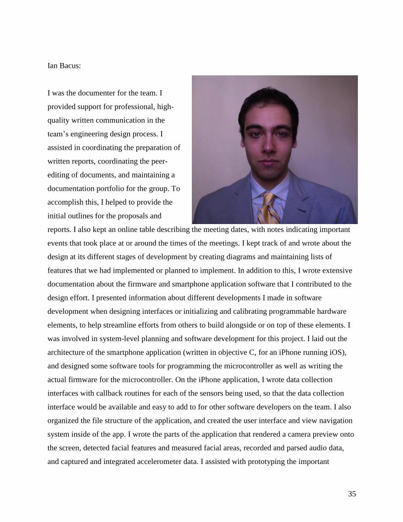
Ian Bacus:
I was the documenter for the team. I
provided support for professional, high-
quality written communication in the
team’s engineering design process. I
assisted in coordinating the preparation of
written reports, coordinating the peer-
editing of documents, and maintaining a
documentation portfolio for the group. To
accomplish this, I helped to provide the
initial outlines for the proposals and
reports. I also kept an online table describing the meeting dates, with notes indicating important
events that took place at or around the times of the meetings. I kept track of and wrote about the
design at its different stages of development by creating diagrams and maintaining lists of
features that we had implemented or planned to implement. In addition to this, I wrote extensive
documentation about the firmware and smartphone application software that I contributed to the
design effort. I presented information about different developments I made in software
development when designing interfaces or initializing and calibrating programmable hardware
elements, to help streamline efforts from others to build alongside or on top of these elements. I
was involved in system-level planning and software development for this project. I laid out the
architecture of the smartphone application (written in objective C, for an iPhone running iOS),
and designed some software tools for programming the microcontroller as well as writing the
actual firmware for the microcontroller. On the iPhone application, I wrote data collection
interfaces with callback routines for each of the sensors being used, so that the data collection
interface would be available and easy to add to for other software developers on the team. I also
organized the file structure of the application, and created the user interface and view navigation
system inside of the app. I wrote the parts of the application that rendered a camera preview onto
the screen, detected facial features and measured facial areas, recorded and parsed audio data,
and captured and integrated accelerometer data. I assisted with prototyping the important

36
elements of the UI for the application. I also designed the microcontroller firmware from scratch,
to implement the I2C interface for requesting data from the temperature sensor, manchester
encoding of received temperature samples, and transmission to the audio interface of the iPhone.
To test the iPhone’s ability to synchronize and receive data, I wrote firmware for a
TM4C123GHPM6 board that utilized a state machine for translating captured ADC values into
manchester data, and subsequently decoding this data. I ported this firmware onto the objective C
app and verified that it was working correctly by testing it with the infrared temperature sensor. I
assisted in partitioning the work based on my understanding of the system requirements. I helped
in determining some of the data rate requirements and calibration settings for the various sensors
involved, and in linking these with our high-level project goals. I tried to develop foundational
elements such as data collection interfaces early on, so that others could utilize these to
manipulate the data in the iOS application.

37
Anna Little:
My technical responsibility was to work with Yousef
and Ian on the software implementation of the
iPhone interface for this prototype. I began by doing
research on the various algorithms and API’s we
would need for the application, and I started studying
Objective-C because I have never used that
programming language before.
My first task was to work on the distance algorithm
which would work with the facial recognition portion of the app. I researched various distance
algorithms, but most were more complicated than we required. The algorithm which I decided to
use is based on the focal point of the camera as well as the size of the image on the screen as a
ratio of inches (or centimeters) to pixels. At this time we discovered implementing the distance
algorithm was not necessary because we could not purchase a lens within our budget so the
temperature sensor would not be accurate at distance even with a compensation algorithm.
Meanwhile, I was researching a simple, efficient sensor fusion algorithm as well, because
implementing the Kalman filter as we had originally planned was beyond the scope of this
project. I found out there is a flaw with the iPhone sensors which would make it complicated to
clean up the result in a simple manner. At this point, I was tasked with assisting on the audio jack
interface. I started looking at the Aurio Touch sample project and integrating it with our design
along with Yousef and Ian. We were struggling with a malloc error so I looked at different
sample projects which passed a buffer to a processing function. I managed to remove the error by
altering the data structure being passed to the processing function.
Finally I worked on the final version of the user interface. I combined two of the debugging
interfaces to create a more streamlined application.

38
Yujie Hao:
I was the manager for the team. I managed the
sponsor’s meetings and arranged the duties of team
members. My technical role on team was
components selection, circuit testing and firmware
development on the micro-controller and IR
temperature sensor side.
For the hardware and software components
selection, I chose the different integrated circuits,
phones to use. I compared the Android and iOS development and made most of the decisions
that got the project started. I found the HiJack project from University of Michigan. This had
many great designs that could directly be used on our project. Then I started to do the research of
the Hijack project. Because of the power and measurement range constraints, I chose the
TMP007 as the external sensor for our project. I also researched different lens types, and decided
to use the Fresnel lens. This lens could transfer temperature signal waves to the temperature
sensor more accurately.
I laid out the system level project planning with another team member, and we decided to use the
iPhone camera and gyroscope to act as a distance sensor. Then I assembled a prototype and
programmed it by Arduino launch board. I decided to separate the whole team into two sub-
teams: a software developing team and hardware developing team. This was to increase the
efficiency of our project development. For the circuit testing and hardware development section,
I worked on receiving the temperature results from TMP007 temperature sensor and transferring
the binary temperature values to the iPhone’s microphone port. I helped the I2C and ADC coding
development on the micro-controller side, and designed a band-pass filter to convert the output
signal of the circuit design part into a sinusoid to help with modulation.
39
After I finished the hardware design part, I helped with researching the communication tunnel of
the iPhone side and the transformation between TMP007 temperature binary result to a celsius
and fahrenheit result which showed on the iPhone user’s interface.
40
Yousef Gtat:
My technical role on the team was heavily software
development on the iPhone side for the iOS app. One
of the main software challenges was setting up a
communication tunnel between the iPhone and hijack
circuit to send data through the right channel, receive
data from the microphone, and power up the hijack
circuit using the left channel. Our iPhone application
has to be presentable and therefore I helped on
developing a user friendly Application Interface (AI)
that allows the user to control powering up the hijack
circuit, sending commands from pre-made command
menu, and enabling recording session to be able to get temperature measurements of patients. I
have also advised the PCB team with my previous experience throughout the design stages, from
layout design to soldering the components on the custom PCB. My nontechnical role is
webmaster. I have started working on developing a web page for our project since the second
week of class. I choose this role because I wanted to gain some experience with web design and
learn new programming language such as JavaScript. The web includes all information regarding
the team progress, the overall project, sponsors, teammates bio, and contact information. I have
communicated with my teammates to provide me with feedback regarding the website and I have
successfully indicated the changes throughout the semester.
41
Anishpal Gill:
My technical role began in the hardware subgroup
of the team. The hardware team’s goal was
primarily to create the Printed Circuit Board based
on the findings in the hijack paper. To prepare for
my role on the team, I needed to read through the
hijack document, as well as become familiar with
the TMP007 temperature sensor and creating
PCBs. I needed to become proficient navigating
the Eagle software.
After learning about what is possible in the realms of Eagle, I proceeded to create the board file
of our PCB based on the schematic at hand. I figured out that the schematic of the TMP007 can
be placed in the existing hijack schematic, but the board cannot be placed. This resulted in the
board file needing to be constructed from scratch. Using the hijack board file as a template for
those components, Craig and I worked together to place components in their respective places,
discuss the best place for the new components, and route the wires between components.
During the ordering process, I learned the differences between surface-mount device sizings. For
example, I learned that “0603” referred to 0.06 inches by 0.03 inches; this was very crucial to
ensure the correct parts were ordered and put in the right place when soldered. The soldering
process saw Craig and I each mounting components on one side of the PCB. The components
were small and required a great deal of attention and care. We then encountered the issue of a
missing capacitor; therefore, I conducted some preliminary research and found that a ceramic
capacitor may be able to be used instead. I proceeded to ask the ECE shop to make sure my
findings were correct and they confirmed that it would work in place of a tantalum capacitor.
I also created the 3D iPhone case in CAD software using a template of an iPhone from an open
source website (GrabCad.com) and modifying it to fit our iPhone and our PCB dimensions. I had
experience with CAD software, so this process was fairly simple for me.

42
In all during the course of this project, the technical work I took part in consisted of:
designing/creating the PCB, soldering the PCB to completion, and creating the 3D iPhone CAD
model (and submitting it to be printed).
43
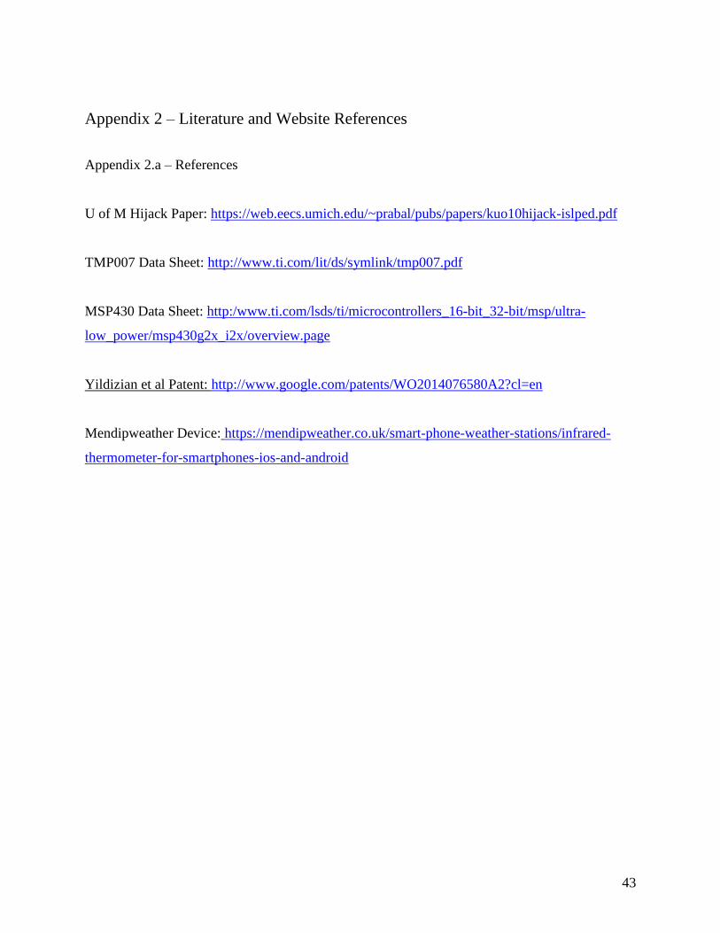
Appendix 2 – Literature and Website References
Appendix 2.a – References
U of M Hijack Paper: https://web.eecs.umich.edu/~prabal/pubs/papers/kuo10hijack-islped.pdf
TMP007 Data Sheet: http://www.ti.com/lit/ds/symlink/tmp007.pdf
MSP430 Data Sheet: http:/www.ti.com/lsds/ti/microcontrollers_16-bit_32-bit/msp/ultra-
low_power/msp430g2x_i2x/overview.page
Yildizian et al Patent: http://www.google.com/patents/WO2014076580A2?cl=en
Mendipweather Device: https://mendipweather.co.uk/smart-phone-weather-stations/infrared-
thermometer-for-smartphones-ios-and-android

44
Appendix 2.b: Summary of patented device similar to proposed design from Yildizyan
“A non-contact IR thermometer according to various embodiments of the present invention includes, among other things, an IR sensor, a
distance sensor, a microprocessor, a memory configured to communicate with the microprocessor, and a user interface device configured to
receive inputs from the microprocessor. The memory includes compensation information, e.g., a look-up table or mathematical equation that may
be used to determine a compensated temperature of a body part based on a measurement of the same or another body part. For example, the
compensation information may be used to determine a compensated temperature of a forehead based on a measured temperature of a forehead.
Or, the compensation information may be used to determine a compensated oral or oral-equivalent temperature based on a measured
temperature of a forehead. The IR thermometer may be configured to simultaneously or in sequence measure a temperature of the target object,
the ambient temperature, or temperature of the thermometer, and a distance between the IR thermometer and the target. The microprocessor may
use these values and the compensation information to determine a compensated temperature and communicate this temperature to the user
interface device, which may further communicate the compensated temperature to a user. “

45
Appendix 2.c: Email describing proposed project
Our project focuses on interfacing an infra-red temperature sensor with the audio jack interface of an iPhone to create a low power non-contact
temperature sensor for biomedical applications. The iPhone will run an application that utilizes sensor fusion and image processing to correct for
the effects of distance on the IR temperature sensor's readings. Powering of the device and communication with the iPhone app will be facilitated
through the audio jack and some additional interfacing circuitry of our own design. This device is intended to aid hospital clinicians in taking
temperature measurements and documenting patient information more easily.
The temperature sensor will be fastened onto the phone in a fixed position with a case, so its position relative to the camera will be fixed.
Measurements from the accelerometer, magnometer, and gyroscope will be used to measure the phone's absolute orientation and relative
displacement. Relative displacements will be measured against "feature shrinkage" (in the next paragraph) to determine depth. The orientation
could also be used to determine the distance seen by the temperature sensor if it is necessary, although in the final design they will be placed very
close together.
The compensation function will utilize ambient temperature and depth measurements to correct sampled temperature readings. The depth
calculation will use the facial recognition API from Apple's Core Image framework to determine a feature triangle between the mouth and eyes of
a target's face. This triangle will shrink by very small amounts when the phone is moved away from the target's face, and this can be compared
with a displacement measurement (along the axis of the back facing camera, determined by the phone's orientation in space) to determine depth.
The temperature sensor will encode each temperature sample (average temperature over circular projection, onto the target, of a cone originating
from the sensor) with 32 bits, and if we send this over a UART line (with extra bits for start, stop, parity on each byte) this would allow us to send
somewhere around 800 samples per second at the maximum transmission rate of 20khz (2 bits per cycle) while streaming. This is a much higher
rate than the frames per second recorded by the camera on the iPhone.
Regards, x

46
Appendix 3 – Detailed technical attachments
Appendix 3.a
Appendix 3.b - Printed Circuit Board Components Lists
• CBL ASSY 3.5MM SLIM 6' 4C BLK
• DIODE SCHOTTKY 20V 1A POWERDI123
• LED RED CLEAR 0603 SMD
• CAP THIN FILM 0.1UF 50V 0603
• 32.768kHz ±20ppm Crystal Oscillator 12.5pF 70 kOhm -40°C ~ 85°C Surface Mount 2-
SMD
• MOSFET P-CH 30V 1.1A SOT23-3
• MOSFET N-CH 30V 1.4A SOT23-3
• Thin Film Resistors 1Kohms .1% 25ppm
• Thin Film Resistors 10Kohms .1% 25ppm
• Tantalum Capacitors - Solid SMD 2.2uF 16volts 20% M case MAP
• Tantalum Capacitors - Solid SMD 1uF 25volts 20% M case MAP
• Tantalum Capacitors - Solid SMD 10uF 10volts 20% M case ESR 2 MAP
• Multilayer Ceramic Capacitors MLCC - SMD/SMT 4.7nF 50V 10% X8R 0603
• Tantalum Capacitors - Solid SMD 10uF 16volts 20% R case MAP
• Coilcraft Step-Up/Flyback Transformer 1:20 Turn
• MSP430F1611IPMR 16-bit Microcontroller - MCU 16-bit Ultra-Lo-Pwr
• TMP007 Board Mount Temperature Sensors IR Sensor
• LDO Voltage Regulators
• Thin Film Resistors 698ohms .1% 25ppm
• Thin Film Resistors 100Kohms .1% 25ppm
• Thick Film Resistors 1/10watt 5.1Mohms 1%
• Thick Film Resistors 1/10watt 3Mohms 1%

47
• Thin Film Resistors .1W 1Mohm 1% 0603 50ppm Auto
• Thin Film Resistors 10Kohms .1% 25ppm
• 100 uF Capacitor (Tantalum or Ceramic--the ceramic was used for this project)
Copyright © 2022 FDOKUMEN