M MASTE EROPP PGAV E - UiS Brage
102
Studiep Konstru Forfatte Milad A Fagansv Veilede Tittel på Duktilit Engelsk Ductilit Studiep Emneor Lightwe Ductilit Fiber re DE rogram/spe uksjoner og er: Ahmadyar varlig: Kjell er(e): Kjell T å masteropp tet i Lettbeto k tittel: ty in Lightw oeng: 30SP rd: Steel-fib eight concre ty, einforced co T TEKNIS M sialisering: materialer l Tore Fosså Tore Fosså pgaven: ong med Fib weight Conc P ber, ete, oncrete SK-NATUR MASTE å ber crete with Fi RVITENSK EROPP iber KAPELIGE PGAV Vår Mil ( Sidetall: 8 + vedlegg Stavanger E FAKULT E r semestere Åpen ilad Ahm (signatur forfa 86 g , 15.06.201 dato/år TET t, 2011 madyar atter) 1 r
-
Upload
khangminh22 -
Category
Documents
-
view
0 -
download
0
Transcript of M MASTE EROPP PGAV E - UiS Brage

Studiep Konstru
ForfatteMilad A
Fagansv Veilede Tittel påDuktilit Engelsk Ductilit Studiep EmneorLightweDuctilitFiber re
DE
rogram/spe
uksjoner og
er: Ahmadyar
varlig: Kjell
er(e): Kjell T
å masteropptet i Lettbeto
k tittel:
ty in Lightw
oeng: 30SP
rd: Steel-fibeight concrety, einforced co
T TEKNIS
M
sialisering:
materialer
l Tore Fosså
Tore Fosså
pgaven: ong med Fib
weight Conc
P
ber, ete,
oncrete
SK-NATUR
MASTE
å
ber
crete with Fi
RVITENSK
EROPP
iber
KAPELIGE
PGAV
Vår
Mil(
Sidetall: 8
+ vedlegg
Stavanger
E FAKULT
E
r semestere
Åpen
ilad Ahm(signatur forfa
86
g
, 15.06.201 dato/år
TET
t, 2011
madyar
atter)
1 r

Master Thesis Spring 2011Ductility in Lightweight Concrete with Fiber
AbstractThis master thesis presents the influence of different fiber in high-performance lightweight concrete
and the ductility capacity of reinforced lightweight concrete beam. Twelve beams with length of 2.2m
and reinforcement ratio 0.24 have been tested under 4 point bending, three of them were made by
normal density aggregates as references beams. The target concrete compressive strength for all beams
were 50MPa.
Three different types of fibers such as steel fiber, Polypropylene macrofiber and Polypropylene
microfiber (PP-fiber)with two different fraction volume has been used to study the influence of fibers
on high-performance concrete.
Two types end-hooked steel fibers with a length/diameter 50mm/1mm (N50) and 35mm/0.55mm (N35)
has been evaluated. The behavior of plastic-fiber with a length/diameter 50mm/1mm and
Polypropylene fiber with length/diameter 12mm/0.22mm have been also investigated. Steel-fibers and
plastic-fiber were studied by two volume fraction 1 and 2%. The volume fraction of PP-fibers were
decided to be 0.4 and 0.6% because of low volume density.
Test results showed that use of plastic-fiber and PP-fiber has no influence on crack-width development.
Beams with plastic-fiber showed the same crack-width comparing to concrete beams without fibers.
PP-fiber give negative results specially by increasing the volume fraction from 0.4% to 0.6%. End-
hooked steel fibers decreased the crack opening under loading compering to references beams. Test
result showed that use of N50 in a volume fraction greater than 1% will decrease the crack-width at
beam under same loading conditions comparing to beam with 1% volume fraction.
All beams failed due flexural failure under loading. The lightweight concrete showed brittle failure and
sudden fracture. Beams with end-hooked steel fibers had a ductile behavior during failure, increasing in
volume fraction of steel fiber from 1 to 2% increased the flexural moment capacity of beam under
loading. Both type of steel-fiber with a 1 and 2% volume fraction showed the highest increasing in
ductility and moment capacity during loading to failure.
Plastic-fiber resulted in to increasing ductility of beams, volume fraction greater than 1% had better
influence on beam ductility and moment capacity of beam. The plastic-fiber beam with volume
fraction 2% failed at the same load as normal density concrete beam but with higher ductility capacity.
1

Master Thesis Spring 2011Ductility in Lightweight Concrete with Fiber
PP-fiber with higher volume fraction than 0.4% caused segregation by swallow cement pasta, and
caused bleeding by releasing the water after casting of concrete. Bleeding and segregation caused low
concrete compressive strength and low moment capacity for beam during loading.
2

Master Thesis Spring 2011
Ductility in Lightweight Concrete with Fiber
Table of Contents
Abstract.......................................................................................................................................................1 I. Symbols..................................................................................................................................................5II. Preface...................................................................................................................................................8Chapter 1....................................................................................................................................................9
1.1 Introduction to concrete.......................................................................................................................9
1.2 Types of concrete.............................................................................................................................9
1.3 Strength classes of concrete.........................................................................................................10
1.4 Aggregate......................................................................................................................................10
1.5 Cement...........................................................................................................................................11
1.6 Chemical Admixtures....................................................................................................................13
1.7 Plasticizers/Superplasticizers........................................................................................................13
1.8 Pozzolan........................................................................................................................................14
1.8.1 Fly Ash...................................................................................................................................14
1.8.2 Silica Fume............................................................................................................................14
1.9 Self-compacting concrete (SCC)...................................................................................................16
Chapter 2: Ductility of High Performance Lightweight Concrete ..........................................................18
2.1 introduction to Lightweight concrete ...........................................................................................18
2.2 High Performance lightweight aggregates Concrete.....................................................................19
2.3 Lightweight self-compacting concrete..........................................................................................19
2.4 Mechanical properties of LWC.....................................................................................................20
2.4.1 Compressive strength ............................................................................................................20
2.4.2 E-modulus..............................................................................................................................21
2.4.3 Cracking and shrinkage ........................................................................................................21
2.5 Non-steel reinforcement................................................................................................................24
2.6 Steel Fiber Concrete......................................................................................................................25
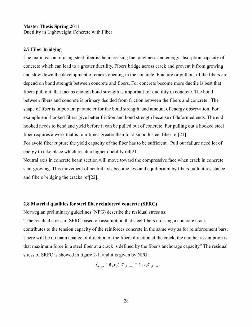
2.6.1 Mechanical properties of steel-fiber concrete........................................................................27
2.7 Fiber bridging................................................................................................................................28
2.8 Material qualities for steel fiber reinforced concrete (SFRC).......................................................28
2.8.1 Calculation of the residual strength in fiber reinforced concrete(FRC).............................29
2.9 Concrete Reinforced composites...................................................................................................31
2.10 Shear in concrete reinforced composites.....................................................................................32
2.11 Crack Width Analysis for normal reinforced concrete................................................................33
2.12 Crack Width Analysis for fiber and conventional reinforcing ...................................................34
2.13 Ductility of concrete ...................................................................................................................36
2.14 Curvature ductility.......................................................................................................................38
2.15 Concrete fracture mechanical......................................................................................................41
2.16 Fracture energy in concrete.........................................................................................................42
Chapter 3 : EXPERIMENTAL PROGRAMME......................................................................................44
3.1. Mix Proportions............................................................................................................................44
3.2 Fiber types.....................................................................................................................................45
3

Master Thesis Spring 2011
Ductility in Lightweight Concrete with Fiber
3.3 Specimen Details ..........................................................................................................................46
3.4 Mixing and casting........................................................................................................................48
3.5 Beam testing..................................................................................................................................49
Chapter 4: Experimental Result ..............................................................................................................49
4.1 Compressive strength....................................................................................................................49
4.1.1 discussion ..............................................................................................................................51
4.2 Tensile strength .............................................................................................................................51
4.2.1 discussion of split test result..................................................................................................55
4.3 E-modulus ...................................................................................................................................57
4.4 Stress-strain diagram ....................................................................................................................59
4.5 Behavior of beam specimens.........................................................................................................61
4.5.1 Lightweight concrete beam without fiber (LWC_UF)..........................................................63
4.5.2 Reference beam self-compacting concrete without fiber (SCC_UF)....................................65
4.5.3 Reference beams self-compacting and vibrator-compacting concrete (SCC_MF, VBB_MF)
........................................................................................................................................................66
4.5.4 Beam specimens with steel-fiber N50 (LWC_N50) and N35 (LWC_N35)..........................70
4.5.5 Beam specimens with polypropylene microfiber M12(PP-fiber) and Plastic-fiber M50 (PF)
........................................................................................................................................................73
4.6 Analysis of results.........................................................................................................................74
4.6.1 Proposal for crack width analysis .........................................................................................76
4.6.2 Deflection of beam specimens...............................................................................................78
5. Conclusion ..........................................................................................................................................80
6. References............................................................................................................................................82
4

Master Thesis Spring 2011Ductility in Lightweight Concrete with Fiber
I. SymbolsLatin upper case letters
Latin lower case letters
5
,min
Cross sectional area of concrete Cross sectional area of tensile reinforcement
Minimum cross sectional area of reinforcementModulus of elasticity of normal weight concrete
E Se
c
s
s
c
cm
AAAE
cant Modulus of elasticity of concrete E Young's modulus of the fibers
E Young's modulus of reinforced bar Length of fiber
Design value of the applied internal bending momentV D
f
s
f
Ed
Ed
lM
esign value of the applied shear forceV Fiber volume fraction
Crack widthf
kw
Effective depth of a cross-section Compressive strength of concrete Design value of concrete compressive strength Characteristisc compressive cylinder strength of concrete at
c
cd
ck
dfff 28 days
Mean value of concrete cylinder cylinder compressive stregth Characteristic axial tensile strength of concrete Mean value of axial tensile strength of concrete
Yield st
cm
ctk
ctm
y
ffff
,
rength of reinforcement
Design yield strength of reinforcement
The residual stress of fiber reinforced concrete Partial factor Partial factor for concrete Partial fact
yd
tk res
C
S
ff
γγγ or for steel reinforcement
Partial factor for fiber property Compressive strain in the concrete Ultimate compressive strain in the concrete The main strain in the reinforceme
m
c
cu
sm
γεεε nt

Master Thesis Spring 2011Ductility in Lightweight Concrete with Fiber
Abbreviations
6
The main strain in the concrete First crack strain of plain concrete
Strain of reinforcement Compressive stress in the concrete Compressive stress in the concrete at
cm
mu
u
c
cu c
εεεσσ ε
,max
,
Maximum stress of fiber
Avrage stress in all fibers bridging a crack
u
fk
fk mid
σσ
ACI American concrete institute EC2 Eurocode 2FA Fly ashFRC Fiber reinforced concrete LWC Lightweight concrete M12 Fiber with length 12 mmNDC Normal density concrete
SelfSCC -compacting concreteSFRC Steel fiber reinforced concreteVCC Vibrator-compacting concreteN50 End-hooked steel fiber with ( / )50 /1
N35 End-hooked steel fiber with ( / )35 / 0.55
M50
f
f
l d mm mml d mm mm
Polypropylene plastic fiber with ( / ) 50 /1
M12 Polypropylene microfiber with ( / ) 12 / 22f
f
l d mm mml d mm mµ

Master Thesis Spring 2011Ductility in Lightweight Concrete with Fiber
Abbreviations of beams and concrete ID
7
Ref_SCC_MF Referance beam with self-compacting concrete with 2% N50 steel fiberRef_VCC_MF Referance beam with vibrator-compacting concrete with 2% N50 steel fiber Ref_SCC_UF Referance beam with self-compacting concrete without fiberRef_LWC_UF Referance beam with lightweight concrete without fiberLWC_N50_2% Lightweight concrete beam with 2% N50 steel fiber LWC_N50_1% Lightweight concrete beam with 1% N50 steel fiberLWC_N35_2% Lightweight concrete beam with 2% N35 steel fiberLWC_N35_1% Lightweight concrete beam with 1% N50 steel fiberLWC_PF_2% Lightweight concrete beam with 2% M50 polypropylene plastic fiber LWC_PF_1% Lightweight concrete beam with 1% M50 polypropylene plastic fiberLWC_PPF_2% Lightweight concrete beam with 2% M12 polypropylene microfiberLWC_PPF_1% Lightweight concrete beam with 1% M12 polypropylene microfiber

Master Thesis Spring 2011Ductility in Lightweight Concrete with Fiber
II. PrefaceThe Popularity of high rise buildings with great design has explored in the last two decades. The title of
highest building does not last more than few years, since 1996 which Willis tower was highest building
with 442m height, the title of highest building have been beaten 6 times. Today’s record holder is Burj
Khalifa (828m tall). Use of normal concrete in such a high building will give a very high dead load
which is a big challenge for design engineering. A secondary use of lightweight concrete which is 25 %
lighter than normal concrete can reduce use of reinforcement bars and support work which leads to
considerable cost saving and less dead load design.
Use of lightweight concrete specially high-performance lightweight concrete has been founded
challenges in seismic zones because of low ductility capacity. The ductility has to be increased to
satisfy the minimum seismic design requirements. Use of fiber-reinforced concrete can be one of
solutions for improved ductility.
The purpose of this thesis is to study the influence of fibers on ductility behaviors in high-performance
lightweight concrete. The funds for this thesis provided by Mechanical and Structural Engineering
Institute of University of Stavanger. The author would like to extend his gratitude to his supervisor
PhD. Kjell Tore Fosså for his time dedication and his support and guidance in the process of testing and
writing this thesis.
The author would like to express his gratitude to Samdar Kakay, John Grønli and Einar Holven for
laboratory and technical support during casting and testing of beams.
8
brickstone
Typewritten Text
Stavnager, June 15th 2011,
brickstone
Typewritten Text
brickstone
Typewritten Text
brickstone
Typewritten Text
brickstone
Typewritten Text
brickstone
Typewritten Text
brickstone
Typewritten Text
brickstone
Typewritten Text
Milad Ahmadyar
brickstone
Typewritten Text

Master Thesis Spring 2011Ductility in Lightweight Concrete with Fiber
Chapter 1
1.1 Introduction to concreteUse of cement and concrete went back to 2000 year B.C. Roman Empire used quicklime, pozzolana
and aggregate of pumice to build pantheon and Baths of Caracalla. The name “concrete” comes from
Latin concretus, which means to grow together.
First modern concrete was made in 1756 by British engineer John Smeaton. He defined his concrete as
mixture of hydraulic cement and pebbles as a coarse aggregate. The most important year for concrete
industry is 1824 when Joseph Aspdin invented Portland Cement. He burned ground limestone and clay
together. He knew that he can change the chemical properties of the ground limestone by burning it, the
process create a stronger cement.
Today is concrete most used material in construction business. It is because of properties such as high
compressive strength, durability, flexibility of shape and fire resistance. In 2009 produced worldwide
cement factories about 2,800,000,000,000 tons Portland cement ref.[1].
Concretes strength mostly controls by w/c ratio, low w/c ratio give higher strength and lower
permeability. Normally w/c ratio starts from 0.4 up to 0.8.
Hydration process starts between water and cement and result of this reaction is cement paste. Cement
paste glues the aggregate together. Aggregate has normally higher strength compare cement paste but it
depends on strength of concrete. In normal strength concrete will cement paste fail due compressive
pressure. Hydration process is a critical phase for strength of concrete.
Concrete weakness is in tension, cement pasta will crack fast when concrete is under tension. To solve
these problems used Joseph Monier in 1849 steel reinforcing bars. Today they use steel fibers, glass
fiber, or plastic fiber to increase strength in tension.
1.2 Types of concrete
Concrete is divided into three categories based on unit weight. Normal weight concrete which contains
natural sand and gravel or crushed rock aggregates, has a density around 2400 kg/m³. Lightweight
concrete(LWC) which contains lightweight aggregates with lower bulk density, has a density around
1800 kg/m³. The third type of concrete is heavyweight concrete with a density higher than 2400 kg/m³.
9
brickstone
Typewritten Text

Master Thesis Spring 2011Ductility in Lightweight Concrete with Fiber
1.3 Strength classes of concreteStrength of concrete is classified into three strength classes. Strength lower than 20MPa knows as low-
strength concrete. It is used in structures member such as floor-system, facade etc. Main reason of
using low strength concrete is saving in project cost.
Moderate-strength concrete has a strength between 20 to 40MPa. It is also referred to as normal
concrete and most used in structural work ref.[2].
Concrete with a strength higher than 40MPa is called high strength concrete or high-performance
concrete. It is used for structures, offshore, oil and gas industry. In case of saving in material cost, it is
possible to replace normal concrete by high-performance concrete to reduce the size of structural
member and the use of reinforcement.
Table 1-1: Strength classes for concrete [Table 3.1 En1992-1-1:2004E]
1.4 AggregateAggregate occupies between 65 and 75% of the concrete volume. Manufacturers produce usually
aggregates with grading 0-8, 8-16 or 8-22. Optimized packing and minimal voids in concrete depends
on how well aggregates are graded.
There are two types aggregates, coarse aggregate and fine aggregate.
Coarse aggregate are such as Natural crushed stone which is produced by crushing natural stone,natural
gravel, Artificial coarse aggregates and Heavyweight aggregates.
Artificial coarse are mainly slag and expanded shale and it can be used for lightweight concrete.
Heavyweight aggregates produce from barites, limonites and magnatites.
10

Master Thesis Spring 2011Ductility in Lightweight Concrete with Fiber
The size of coarse aggregate is larger than 5mm. Fine aggregate is smaller than 5mm and made of sand
and it helps to get better well graded aggregates and reduce use of the cement paste. Adding adequate
fine material in a concrete mixture will avoid segregation and bleeding. Addition more than necessary
fine material will make concrete sticky and unworkable.
Bulk density of aggregates determine the weight and category of concrete whether it is lightweight,
normal or heavyweight concrete.
1.5 CementFor describe cement in general sense, can say that it is a binder which used for adhesive other material
together. Revolution in cement industry start in early years of industry age.
Cement divides in two categories, Hydraulic cement and non-hydraulic cement.
Hydraulic cement is also called water resistance cement or Portland cement. Non-hydraulic cements are
gypsum and lime cement.
Portland cement is the most used cement in structural concrete. The main Portland clinker is limestone.
The limestone is mixed with bauxite, quartz and gypsum to provide the correct composition of oxides.
The production of Portland cement is depend on the resource and local availabilities to materials.
Limestone is a calcium silicates product and can be replace by chalk, marl and sea shell. They are all
common material sources of calcium silicate. The Portland cement clinker also contains iron,
aluminates, and aluminoferrites of calcium.
Table 1-2: Oxides and clinker compound of Portland cement ref[2]
11
Abbrevation Oxid Name Compound AbbrevaitionC CaO 3 CaO • SiO2 C3SS SiO2 2 CaO • SiO2 C2SA Al2O3 3 CaO • Al2O3 C3AF Fe2O3 Iron oxide C4AFM MgO Magnesium oxide C4A3S
Calcium oxide, or limeSilicon dioxide, or silicaAluminium oxide, or alumina
4 CaO • Al2O3 • Fe2O34 CaO • 3Al2O3 • SO3

Master Thesis Spring 2011Ductility in Lightweight Concrete with Fiber
Table 1-3: Notation and mechanical properties of different cement ref[3]
12
Product Name Norcem Standard Norcem S tandard FA Norcem Industri Norcem Anlegg Norcem Anleggsement FA
CEM I 42,5 R CEM II/A-V 42,5 R CEM I 42,5 R CEM I 52,5 N CEM II/A-V 42,5 NCompressive strength MpaSetting time(min) 130(B)/125(K) 130 100 120 1651day 21 21 32 18 132days 32 31 40 30 227days 42 40 49 46 3528 days 52 52 57 60 53
Nation accordingNS-EN197-1
Figure 1-1: overview over the cement production process ref[4].

Master Thesis Spring 2011Ductility in Lightweight Concrete with Fiber
1.6 Chemical AdmixturesAdmixtures are used as ingredients of concrete and are added to the batch immediately before or during
the mix operation. The purpose of using admixtures is for change the properties of concrete such as
increasing the strength, workability, plasticity, durability of concrete. Admixture can be used for
reducing water demand and accelerating the cement hydration reaction.
Types of admixtures can be summarized such as:
• Accelerating admixtures
• Air-entraining admixtures
• Water-reducing admixtures
• Superplasticizers
• Polymers and latexes
• Antifreeze admixtures
• Anti-washout admixtures for underwater concreteing
• Anti-shrinkage admixtures
1.7 Plasticizers/SuperplasticizersSuperplasticizers admixture is most used admixture in Norway, approximately 95% of all admixtures
sold in Norway[7]. This admixture has ability to reduce three to four times the mixing water in given
concrete mixture compared to normal water-reducing admixtures[2]. Workability and slump retention
would be approved by adding superplasticizers admixture at batching plants without any refreshing of
the concrete at work site. Adding of superplasticizers requires experience, by overdosing will concrete
start segregation and can be described as like as soup.
13
Figure 1-2: overdosing of superplasticizers admixture

Master Thesis Spring 2011Ductility in Lightweight Concrete with Fiber
1.8 PozzolanPozzolan is type of active mineral additions which can be added to cement in manufacturing or during
concrete mixing. The important effect of pozzolan is increasing the long-term strength of concrete.
There are two types of pozzolans used in Norway, Fly Ash and Silica Fume.
1.8.1 Fly AshFly Ash is added directly under cement production, Norcem produces two types FA cement in Norway,
NORCEM STD-FA with 20% FA and ANLEGG FA with 30%FA.
Particle size of FA is around 10-20μm which is the same size as Portland cement.
FA in Portland cement will increase the long term strength of concrete and reduce cement consumption.
Anlegg-FA cement is usually used for producing high strength concrete. The benefits of Anlegg-FA can
be named such as:
• Reducing alkali contents in concrete
• Low temperature development
• Excellent workability and permeability
• reducing risk of bleeding
Compressive strength of concrete with FA will be low at early age (3-7days) because of low
temperature development.
FA is an industrial byproduct from Coal industry and since there is no
1.8.2 Silica Fume
Silica Fume has a particle size of 0,1μm and it is a byproduct of smelting process of silicon metal (SiO)
and ferrosilicon alloys. SF has become a very efficient filler because of the small size and it effect
directly on fresh concrete properties. The benefits of using SF in concrete is depend on volume
percentage of cement replacing which is normally up to 20%. ref[5]
14

Master Thesis Spring 2011Ductility in Lightweight Concrete with Fiber
Benefits can be summarized such as:
• increasing compressive Strength
• increasing workability
• reducing permeability
• reducing reinforcement corrosion
• more coherent
• eliminate bleeding
• homogenous concrete
• increasing frost resistance
• finer pore structures
15
Figure 1-3: Effects of increasing silica fume.ref[6]

Master Thesis Spring 2011Ductility in Lightweight Concrete with Fiber
1.9 Self-compacting concrete (SCC)Durable concrete structure requires professional compaction by skilled workers. The reduction in the
number of skilled workers and increasing the cost of construction's site in Japan, made Japanese
engineers to find a new concreting method in early 1980s. The research led them to self-compacting
concrete (SCC) which is a durable concrete and can reach every corner of a form-work without
vibrating compacting. SCC is made of exactly same material as normal concrete with different in
matrix volume, often higher than 340 l/m³. SCC is a matrix dominated concrete.
SCC must have high deformability and good resistance to segregation between coarse aggregate and
mortar when the concrete flows through the confined zone of reinforcing.
NS-EN 206-9:2010 is the European standard for SCC and requirement for slump-flow has been given
in 3 classes which shows in table 1-4.
Table 1-4: Slump-flow classes [table 1:NS-EN 206-9:2010]
Water/binder (w/b) ratio in SCC is normally lower than 0.45 which gives a matrix dominated concrete.
With higher w/b ratio than 0.45 is necessary to change the concrete composition for increasing the
matrix volume. Increasing in matrix volume can cause separation because of low viscosity in matrix, it
need more attention to keep matrix viscosity high enough to avoid separation.
Norwegian experience recommended to keep w/b ratio lower than 0.45 and higher than 0.3. Low w/b
ratio can cause poor stability, more plastic shrinkage and drying shrinkage and gives higher strength
than was planned. With w/ b ratio lower than 0.3 will concrete become very tough and flows heavily
because of high matrix volume. [7]
Superplasticizers admixture is a important aids for given better flow and slump result in low
water/cement ratio. Using of air-entrained admixture will increase the level of cohesion and stability of
the final product and it will protect SCC against freezing.
SCC may show more plastic shrinkage and creep than normal concrete because of higher cement pasta
16
Class Slump-flow in mmSF1 550 to 650SF2 660 to 750SF3 760 to 850

Master Thesis Spring 2011Ductility in Lightweight Concrete with Fiber
to aggregate ratio. Adding silica fume in SCC gives a better stability but it is depend on the amount of
addition.
Benefits of using SCC can be summarized such as:
• Decrease construction's time
• Improved durability
• Better surface finish
• Reduction of site manpower
• Better safety working environment
17

Master Thesis Spring 2011Ductility in Lightweight Concrete with Fiber
Chapter 2: Ductility of High Performance Lightweight Concrete
2.1 Introduction to lightweight concrete The density of normal concrete is 2400 kg/m3, with replacing normal aggregate with lightweight
aggregate will density of concrete decrease to 1750 kg/m3. Reducing of dead load up to 35%, will
allowing greater design flexibility, reducing size of structure, longer spans and decrease reinforcing
steel bars. The density class of LWC is showed in table 2-5.
Table 2-5: Density class for LWC
There are two types lightweight aggregate, manufacture which are produced by expanding products
such as Vermiculite or perlite, calcining, blast-fumace slag, clay, fly ash, shale or slate. Second type is
from natural materials, such as pumice, tuff or scoria.
The shape of particles can be rounded, angular or irregular. It is depend on source and production
process. The lightweight aggregate which are produced in Norway have rounded shape and called
Leca. Lightweight aggregates is barley used in structural concrete in Norway. The production of Leca is
depending of each projects.
The southwestern Bell Telephone office building [8]in Kansas City is a great example of how effective
lightweight concrete can be. Building was built originally 14 storeys structure but in 1928 the owner
wished to add more storeys on the same foundation. After study the building they found out that
foundation would support eight more storey with using normal density concrete. But if they replace
concrete with lightweight concrete would be able to add 14 storeys on the same foundation. That was
start of using lightweight concrete. The first structural lightweight concrete was built in 1929 in St.
Louis, they designed both frame and floor systems by lightweight concrete.
18
Density class 1 1.2 1.4 1.6 1.8 2
801-1000 1001-1200 1201-1400 1401-1600 1601-1800 1801-2000Density(kg/m³)

Master Thesis Spring 2011Ductility in Lightweight Concrete with Fiber
2.2 High performance lightweight aggregates concreteThe proportioning of high performance lightweight concrete is based on cementitious material content
such as cement type, chemical admixture and pozzolanic. The recommended slump is between 76
to100 mm for workability to be proved ref.[18].
The water/cementitious ratio is essential for the compressive strength and need extra attention. Because
of larger cellular structure of lightweight coarse aggregate, it is important to remember that it has a
high degree of water adsorption (up to 20%, depend on aggregates type). In case of Leca it is 10%
water absorption in first 24 hours and up to 25% after 28 days ref[appendix 1a].
2.3 Lightweight self-compacting concrete
The trial batch tests by Ben C. Gerwick in California [9] showed that lightweight concrete with a slump
flow below 430 mm is not likely to have full compacting performance. Lightweight concrete with a
slump flow over 660 mm often leads to severe segregation. Slump flow in the range of 460 mm to 560
mm provided the required workability[9]. European standard for SCC [NS-EN 206-9:2010] does not
applies to lightweight SCC because of limited experience. However, it requires a slump flow between
550 to 650 mm for class SF1 as it showed in table 2-5 ref [NS-EN 206-9:2010].
The most challenge to produce self-compacting lightweight concrete is the workability, low density of
lightweight aggregates make flowability and cohesion low. For concrete become self compacting it
needs to be able to flow under the own weight without any need for vibration or additional compaction.
Separation of concrete depends on stability of concrete. Stability increases with high flow resistance of
the matrix. Higher workability decrease flow resistance, which results decreasing in the stability and
risk for separation.
Flow resistance of the matrix λQ determined by FlowCyl-tests, experience shows when flow resistance
become larger than approximately 0.75 may concrete become too viscous or tough which will cause
low flowability. Flow resistance lower than approximately 0.5 may cause concrete bleeding and
segregating. Ref.[7]
The shape and size of lightweight aggregate affects the workability and strength of concrete. Leca
which is manufactured in Norway, have rounded particle shape and the density is lower than angular
aggregate which results lower strength but better workability.
19

Master Thesis Spring 2011Ductility in Lightweight Concrete with Fiber
The total cementitious materials content should be approximately 550 kg/m³ based on researches has
been done on self-compacting lightweight concrete. ref [9]
2.4 Mechanical properties of LWC
2.4.1 Compressive strength
Normal aggregates has a higher strength and stiffness than cement pasta in normal concrete, which
means that aggregate carry most part of tension in concrete. That will cause a tensile stress between
mortar and aggregate which will occur micro-crack after a while. When aggregates capacity exceeded
will tension in micro-cracks become larger and cracks grow. In that phase concrete capacity is
exceeded and crack go through cement pasta. ref[10]
However, lightweight aggregate and mortar has almost the same stiffness, and produce a higher elastic
compatibility leading to reduces stress concentrations in the mortar-aggregate interface. Low w/c ratio
and using of admixtures will make sure a good mortar-aggregate interface which can also prevent
bleeding. When tensile stress in LWC become larger, lightweight aggregate can not handle the stress
and it will cause a suddenly crack and fracture which will go through mortar and aggregates. That make
compressive strength of LWC a function of lightweight aggregate and cement paste strength and
stiffness.
When strength of concrete become larger than lightweight aggregates strength, mortar has to carry most
part of concrete tensile stress. For high-performance LWC increases the mortar stiffness and strength.
Table 2-6: Strength classes for LWC table 11.3.1 EC2
20
12 16 20 25 30 35 40 45 50 55 60 70 8013 18 22 28 33 38 44 50 55 60 66 77 8817 22 28 33 38 43 48 53 58 63 68 78 88
flck(MPa)
flck,cube(MPa)
flcm

Master Thesis Spring 2011Ductility in Lightweight Concrete with Fiber
2.4.2 E-modulusLWC has a linear loading curve and faster fall curve compare to NDC. LWC give more strain in
maximum stress than NWC which cause lower E-modulus compare to NDC. Low E-modulus and
higher strain in LWC will prevent shrinkage. ref[10]
2.4.3 Cracking and shrinkage
The most critical time for concrete is when concrete starts hardening. Most properties of concrete
develops during this phase. Hardening process is between 1 to 2 weeks and it start between 6 to 12
hours after casting.
C-S-H adsorbs amount of water, when a hydrated cement paste is under sustained stress will C-S-H
loss a most part of physical adsorbed water and it cause a creep strain in cement paste.
Reducing of cement paste volume during hardening of concrete will cause cracking and shrinkage in
concrete ref.[5].
High strength concrete has a tendency to develop early age cracking. Early ages defines as minutes
after casting when the concrete is in plastic age and some hours after casting when concrete is in early
hardening age. The typical cracking problem will be caused of plastic settlement and plastic shrinkage.
21
Figure 2-4: Stress-strain diagram LWC & NDC

Master Thesis Spring 2011Ductility in Lightweight Concrete with Fiber
It has been assumed that LWC crack development behaves the same as NWC in early ages. It should be
noted that Leca which has a particle density of 1300 kg/m³ have a water absorption about 40 liter per
m³ concrete, which corresponds to a volumetric shrinkage of 40 000 μstrain. ref[11]
The creep coefficient φ for LWC is equal to creep coefficient φ of normal density concrete (NDC)
multiplied by (ρ/2200)².
The creep strains is the same as NDC by strength classes higher than LC16/18, but the final drying
shrinkage value for LWC increases 20% compare to NDC.[ref.EC2 11.3.3]
Type of shrinkage can summarized as:
• Plastic shrinkage: It occurs in fresh phase of concrete. The cause is water evaporating from the
surface of the concrete. Plastic shrinkage can be expected in hot summer days and by strong
wind.
• Plastic settlement: when concrete start bleeding in plastic phase, the solid particles move
downward and water stays on top and cover the surface. The mechanism is as same as plastic
shrinkage but in higher degree and depth.
22
3
3
,0
is a coefficient for determining creep coefficient 1.5 for 16 /181.2 for 16 /18
In case of relative humidity 40%:The drying shrinkage values for NDC 0.46The drying shri
lck
lck
ooocd
f LCf LC
η
η
ε
≤ = ≥
=
,0nkage values for LWC 0.46 1.2 0.552 ooocdε = × =
Figure 2-6: Plastic settlement ref[13]Figure 2-5: Plastic shrinkage,ref[12]

Master Thesis Spring 2011Ductility in Lightweight Concrete with Fiber
• Autogenous shrinkage: Hydration process starts when cement react with water. The absolute
volume will decrease when cement paste is in a liquid state. The macroscopic volume change
occurring with no moisture transferred to the exterior surrounding environment cause
Autogenouse shrinkage which is an external volume change ref[24].
• Chemical shrinkage: It starts at same time with autogenous shrinkage. Pores in the binder phase
start growing because of volume loss, which also increases air volume in the capillary pores.
That means that shrinkage turns into air voids within hardened cement paste. Chemical
shrinkage is an interval volume reduction ref[24].
• Drying shrinkage: The mechanism is the same as plastic shrinkage but it expected in a stiff
concrete. The shrinkage cracks on surface start after evaporation of surface's water and the
pressure of negative pore develops crack and shrinkage on surface of concrete.
23
Figure 2-8: Drying shrinkage ref[15]
Illustration 2-7: Reactions causing autogenous and chemical shrinkage. [24] C = unhydrated cement, W = unhydrated water, Hy = hydration products,and V = voids generated by hydration.

Master Thesis Spring 2011Ductility in Lightweight Concrete with Fiber
2.5 Non-steel reinforcementNon-steel reinforcement can be categories as fiber reinforced polymer(FRP) which can also called fiber
reinforced plastic(FRP) and Glass reinforced plastic(GRP).
Plastic fiber were used since 1960s in some structure elements but not as main reinforcement bar. The
important development of plastic fiber started in 1980s. The new development of medical equipment
such as magnetic resonance imaging (MRI) become main reason for focus on use of plastic fiber as
main reinforcement bar in concrete. MRI can not tolerate the presence of any steel reinforcement.
Engineers found a solution which were using of glass fiber reinforcement for surrounding and
supporting MRI.
Environmental and chemical attacks become new consideration for using glass fiber as composite
reinforcement in construction such as sea walls, industrial roof decks, chemical industry floor slaps and
reactor equipment.
The major consideration in using plastic reinforcement as main reinforcement is the bond between fiber
rods and concrete. The transformation of stress from the reinforcement to concrete is depend mainly on
the bond interaction between those two materials.
Four types of bond failure are identified ref[18]:
1. Shearing off failure of the road windings
2. Local mechanical frictional pull-out( the rods are ribbed, and frictional resistance covers only a
part of the surface)
3. full frictional pull-out where failure resistance is long the entire rod length
4. Plain frictional resistance in isolated strand rods
These four types of bond failure shows that the bond strength is depend on rod surface configuration
and deformation.
24

Master Thesis Spring 2011Ductility in Lightweight Concrete with Fiber
Benefits of using PP fiber:
• Increasing fire resistance
• Increasing concrete density and durability
• Reducing amount of cracks from plastic shrinkage forces
• Reducing risk of separation/bleeding
• Faster and better construction
Type of non-steel reinforcement:
• Polyolefin
• Polypropylene (twisted, fibrilated and monofilament)
• PVA
• Nylon
• Ar-glass
• Wollastonite
2.6 Steel fiber concrete
Concrete has high compressive strength but very low tensile strength capacity. Steel reinforcing bar
carry the tensile strength in concrete and it prevent development of cracks under loading. Concrete
structural members under loading develop crack before reinforcement take over the tensile forces. The
cracks occur because of low tensile strain capacity of concrete. Cracks will reduce service life of
concrete by reducing durability of concrete. Low durability will reduce the ability of concrete to resist
weathering action and chemical attack. Development of cracks could be limited by using of steel-fiber.
Steel-fiber has high tensile strength and would take over the concrete tensile stress at early crack
development phase. Fibers over the crack in concrete will decrease moment, shear and punching
resistance. When a crack start growing, the fibers will transmit tensile force over the crack into the
surrounding concrete ref.[17].
Steel bar reinforcement can be replaced by steel fiber and be added direct into the concrete at batching
plant. Steel fiber-reinforced concrete(SFRC) is most used for slabs on grade, it reduce work time on
construction and it reduce cracks compare to steel bar reinforcement.
25

Master Thesis Spring 2011Ductility in Lightweight Concrete with Fiber
The quality of SFRC is depend on how good fibers are distribute in concrete.
Self compacting concrete improve the homogenous distribution of fiber in concrete. Vibrator
compacted concrete (VCC) may cause poor distribution of fiber and give critical and weak points in
concrete.
The volume fraction of fibers added to a concrete mix is measured as a percentage of the total volume
of the concrete and fibers. The respect ratio of fiber is measured by dividing fiber length by fiber
diameter.
Volume percentage of steel fiber is usual between 0.2%(20kg/m³) to 2%(157kg/m³). By adding more
than 2% volume fraction, may cause poor concrete workability and reducing fiber dispersion.
26
Figure 2-9: Type of steel fiber ref[17]

Master Thesis Spring 2011Ductility in Lightweight Concrete with Fiber
2.6.1 Mechanical properties of steel-fiber concreteThe steel-fibers have little or no effect on compressive strength and E-modulus of concrete, in some
cases it may increase the compressive strength but it is not mentionable. The E-modulus and
compressive strength should be determined experimentally when volume fraction of steel-fiber is
greater than 1%.
Tensile strength of concrete increase by adding steel-fiber ref[16]. The effect of fiber on direct tensile
strength is depend on the direction and distribution of fibers. Measurement of the direct tensile strength
of SFRC is not given in any standard and it has no agreement how it can be tested by experiment.
Earlier researches where distribution of fiber were randomly, showed that the tensile strength increase
up to 60%, but it is depend on how homogenous is the distribution ref[16].
Steel-fibers have most effect on the flexural strength of concrete, increasing up to 100% has been
reported by earlier experiments ref[16]. Aspect ratio of the fibers and the fraction volume of fibers are
important parameters for increasing the flexural strength.
The post-crack tensile strength of SFRC is depend on the distribution and orientation of fibers, as
earlier been mentioned the casting process, workability and the size of specimen are important
parameters.
27
Figure 2-10: The influence of steel fiber content on tensile strength
Master Thesis Spring 2011Ductility in Lightweight Concrete with Fiber
2.7 Fiber bridgingThe main reason of using steel fiber is the increasing the toughness and energy absorption capacity of
concrete which can lead to a greater ductility. Fibers bridge across crack and prevent it from growing
and slow down the development of cracks opening in the concrete. Fracture or pull out of the fibers are
depend on bond strength between concrete and fibers. For concrete become more ductile is best that
fibers pull out, that means enough bond strength is important for ductility in concrete. The bond
between fibers and concrete is primary decided from friction between the fibers and concrete. The
shape of fiber is important parameter for the bond strength and amount of energy observation. For
example end-hooked fibers give better friction and bond strength because of deformed ends. The end
hooked needs to bend and yield before it can be pulled out of concrete. For pulling out a hooked steel
fiber requires a work that is four times greater than for a smooth steel fiber ref[21].
For avoid fiber rupture the yield capacity of the fiber has to be sufficient. Pull out failure need lot of
energy to take place which result a higher ductility ref[21].
Neutral axis in concrete beam section will move toward the compressive face when crack in concrete
start growing. This movement of neutral axis become less and equilibrium by fibers pullout resistance
and fibers bridging the cracks ref[22].
2.8 Material qualities for steel fiber reinforced concrete (SFRC)Norwegian preliminary guidelines (NPG) describe the residual stress as:
“The residual stress of SFRC based on assumption that steel fibers crossing a concrete crack
contributes to the tension capacity of the reinforces concrete in the same way as for reinforcement bars.
There will be no main change of direction of the fibers direction at the crack, the another assumption is
that maximum force in a steel fiber at a crack is defined by the fiber's anchorage capacity” The residual
stress of SRFC is showed in figure 2-11and it is given by NPG:
28
, 0 1 ,max 0 ,mtk res f fk f fk idf v vη η σ η σ= =

Master Thesis Spring 2011Ductility in Lightweight Concrete with Fiber
where
vf Fiber volume ratio (fiber volume)/(concrete volume)
σ fk ,max Maximum stress of fiber with anchorage length lb = lf /2 at a crack, decided by bond and upper yield limit
σ fk ,mid Average stress in all fibers bridging a crack, with random embedded length and orientation,based on experience and experimental, SINTF recommended 500MPa for steel fiber and 250MPa for PP fiber
η1 Aspect ratio, σ fk ,mid /σ fk ,max
η0 approximate 1/3 for randomly 3D distribution and orientation of fibers,1/2for fibers in planes parallel to tension direction
2.8.1 Calculation of the residual strength in fiber reinforced concrete(FRC)
Residual strength of steel-fiber and PP-fiber in case of FRC has been calculated based on NPG
formulation, this calculation is for steel-fiber with 2 % volume fraction ref[17]:
29
, 0 ,
,
,
,
,
/ 0.02
500
This value is given by SINTEF, it is based on experimental result.
1/ 3 0.02 500 3.33/ 3.33 /1.55 2.15
tk res f fk mid
f f c
fk mid
fk mid
tk res
ftd res tk m
f vv V V
f MPaf f MPa
η σ
σ
σ
γ
=
= =
=
= × × == = =
Figure 2-11: Typical tension behavior for SFRC ref. [17]

Master Thesis Spring 2011Ductility in Lightweight Concrete with Fiber
The residual strength for steel-fiber will be 2.15MPa. The residual strength in PP-fiber decrease
approximate half part residual strength than steel-fiber, calculation shows residual strength for plastic
fiber with 2% volume fraction:
Strain and Stress distribution over a SFRC cross-section has been described in (NPG) as showed in
figure2-11.
The stress and strain illustration is only for concrete with fiber reinforcement FRC. It has to be noted
that when residual stress ftk,res become larger than 2.5 N/mm², the cross-section's compression zone
height has to be determined.
The moment capacity of SFRC can be determined by this equation:
30
2, ,0,4ftd res ftd resM f p e b h= × × × ×
, , / 1.55ftd res tk res m mf f γ γ= =
, 0 ,
,
,
,
/ 0.02
250
1/ 3 0.02 250 1.67/ 3.33 /1.55 1.1
tk res f fk mid
f f c
fk mid
tk res
ftd res tk m
f vv V V
MPaf MPaf f MPa
η σ
σ
γ
=
= =
=
= × × == = =
Figure 2-12: Strain and Stress distribution over a SFRC cross-section ref[17]

Master Thesis Spring 2011Ductility in Lightweight Concrete with Fiber
Here p presents scale factor for load carrying capacity of SFRC which is depend on dimension of
beams and e is yield factor for residual strength for self-compacting concrete (SCC).
p=1,1-0,7h>0,75e=0,9 in upper parts of the element for SCCe=1,2 in lower parts of the element for SCCe=1 when the residual strength is determined by bending tests of beams made of SCC
2.9 Concrete Reinforced compositesDefinition of a composite material has been defined in ASTM 3878-95c as:
“Composite Material. A substance consisting of two or more materials, insoluble in on other, which are
combined to form a useful engineering material possessing certain properties not possessed by the
constituents.”
The difference between fiber reinforced concrete (FRC) and concrete reinforced composite is that FRC
has no steel bar reinforcement in concrete.
NPG requires that all structures with safety level 2 or higher has to used reinforced composites, to
make sure that conventional bars transfer all external forces in addition to the fibers. Because of using
conventional bars all safety factor for fiber can be changed to γm=1.
The requirement is because of limited experience with fiber reinforced concrete.
Strain and stress distribution over a cross-section reinforced with both reinforced bar and steel fibers is
showed in figure 2-13.
31
Figure 2-13: Strain and stress of concrete reinforced composite ref.(17)

Master Thesis Spring 2011Ductility in Lightweight Concrete with Fiber
By removing the safety factor, will the residual strength of concrete reinforced composite for steel fiber
with 2% volume fraction be 3.33Mpa and for plastic fiber with 2% volume fraction be 1.67MPa.
2.10 Shear in concrete reinforced compositesShear strength increase with using steel fibers in concrete. Calculation of shear strength in SFRC can be determined by:
Shear strength because of conventional reinforcement can be determined by EURO CODE2:
Total concrete's shear strength :
Shear capacity of beam with SFRC by volume fraction 2% will increase 34% compare to a beam
without fiber. [apandix2]
Diagonal cracks can be reduced and controlled by adding stirrup reinforcement in beam. Reason of
using stirrup reinforcement is to carry the redistributed shear stresses, mainly through tension after the
formation of diagonal cracks. Tension will be transferred back to the concrete. [21] This will cause
more diagonal cracks, and cracks opening will grows slowly compare with no stirrup reinforcement.
Addition of stirrup reinforcement will prevent the shear failure in beam. The steel-fibers increase shear
capacity and by calculation can reduce use of stirrup.
32
,0,8fd ftd resV f p b d= × × ×
sw,
A cotsRd s ywdV z f θ= × × ×
d ,cd Rd s fdV V V V= + +
, ,ftd res tk resf f=
Figure 2-14: Shear forces on beam ref[17]

Master Thesis Spring 2011Ductility in Lightweight Concrete with Fiber
2.11 Crack Width Analysis for normal reinforced concreteTheoretical analysis of crack width of beam with a bar reinforcement is given in EC2 7.3.4 as:
Sr,max present the average final crack spacing. where
33
r,max 3 1 2 4 ,s / p effk c k k k φ ρ= × + ×
,max ( )k r sm cmW s ε ε= −
1
2
3
is bar diameter c is the cover to the longitudinal reinforcement
0,8 for high bond bars1,6 for bars with an effectively plain surface
0,5 for bending1,0 for pure tension
3,4
k
k
k
φ
=
=
= 4 ; 0, 425k =
,max
sm
cm
,,
,
maximum crack spacing the mean strain in the reinforcement the mean strain in the concrete
(1 )0,6
the stress in the tens
r
ct effs t e p eff
p eff ssm cm
s s
s
s
fk
E E
εε
σ α ρρ σε ε
σ
− +− = ≥
e2
s 1,
c,eff
, , ,
1
ion reinforcement assuming a cracked section is the ratio /
A '
A; min{2,5( ); ( ) / 3; / 2}
0,6 for short term loading 0,4 for long term loadi
cm
pp eff
c eff c ef c ef
E EA
A b h h h d h d h
k
α
ξρ
α
+=
= × = − −
=ng

Master Thesis Spring 2011Ductility in Lightweight Concrete with Fiber
Table 2-7 shows the maximal crack width in all exposure class.
Table 2-7: Values of wmax(mm)(table 7.1N EC2)
It is important to be noted that crack spacing in SFRC is depend on bond between concrete and steel
fibers. If steel fiber's bond with the concrete is stronger than permitted will it cause brittle crack on
steel fibers and if bond is poor, fiber will have no effect.
2.12 Crack width analysis for fiber and conventional reinforcing
Analysis of mechanical behavior of concrete become complicated by adding fiber to concrete mix.
There are parameters such as fiber substrate, fiber geometry, fiber volume concentration, type of fiber,
the distribution and orientation of fibers which are important to be in consideration in analysis of
concrete members. The problem is that before adding fibers, a concrete structure member has already
lot of design parameters such as stiffness, concrete strength, conventional reinforcement type, structural
geometry and reinforcement type which it can be difficult to connect all those design parameters.
The orientation and distribution of fibers are depend on workability and type of concrete such as self
compacting concrete or vibrate compacting concrete. Use of vibrator can have negative effect on
distribution of fibers. The each point where vibrator has been pocked can be empty of fibers and make
it the weakest point in concrete. However, it has been done lot of studies on how crack width can be
decrease by adding fiber to concrete mix.
To show how fiber affect crack width can use stress-crack width model. To calculate it theoretical it
34

Master Thesis Spring 2011Ductility in Lightweight Concrete with Fiber
need to drive a micromechanical to find the stress-crack width relationship. [23]
There are few guidelines for crack width analysis for concrete reinforced composite, RILEM TC 1622-
TDF is one of few guidelines for determine the crack width. The problem with this formulation is that
it does not take the effect of fibers volume fraction and rotation in consideration.
As it showed in formula Sr,max multiplied by new parameter which take fiber length and diameter in
perspective not volume fraction. The new parameter has to be equal or less than 1, this is depend on the
aspect ratio of fiber. This parameter shows that use of fiber will decrease the crack spacing which will
cause increasing the number of cracks and decreasing of crack opening.
To be noted that steel fiber with aspect ratio 50 will have no effect on crack spacing based on this
parameter. Polypropylene microfiber (PP-fiber) have a high aspect ratio which cause error in this
calculation.
35
,max 1 2
1
2
5050 0,25/
k is coefficient which takes account of the bond proerties of the barsk is coefficient which takes account of the form of the strain distribution
is
reff f f
S k kL
φρ φ
φ
= + × × ÷ ÷ ÷ ÷
s
c.eff
s
c.eff
bar sizeA is effective reinforcement ratio
AA is the area of the reinforcement contained A is the effective tension areaL is the fiber length
is the fiber diameter
eff
f
f
ρ
φ

Master Thesis Spring 2011Ductility in Lightweight Concrete with Fiber
COIN-rapport (may 2011) has present new guidelines for calculation of crack width for fiber-
reinforced concrete. Formulation is principle identical to EC2 7.3.4 (section 2.11) except addition of a
factor k5 to calculation of maximum crack spacing. This factor takes the fiber additive into the
consideration.
Calculation of the residual strength in fiber reinforced concrete is showed in section 2.8.1.
2.13 Ductility of concrete Ductility is an important property in reinforced structure in seismic zones.
It allowed the structure to deform when the maximum bearing capacity is exceeded and response to in-
elasticity in server earthquake. Ductility may be defined as the ability to undergo deformation without a
substantial reduction in the flexural capacity of the member (Park & Ruitong 1988). High ductility will
cause high deflection when structural member were loaded until failure which will be a warning before
total collapse.
Figure 2-15: Load-deflection behavior of a flexural member
36
,max
,max 3 1 2 4 5,
5 , 2,5
( )
(1 / )
k r sm cm
rs eff
ftk res ctm
w s
s k c k k k k
k f f
ε εφ
ρ
= −
= × + × × × ×
= −

Master Thesis Spring 2011Ductility in Lightweight Concrete with Fiber
The ductile failure is initiated by yielding of steel reinforcement, concrete will crush when steel
reinforcement begins to plastic deformation and loss the carrying properties.
Ductility is measured in terms of strain, displacement and rotation. [ref.18].
Strain ductility:
Curvature ductility:
Displacement ductility
For inelastic behavior to be sustainable it should all these ductility factor be grater than 1,0.
Concrete is known as a brittle material with low tensile strain capacity and poor fracture toughness.
With increasing concrete strength expecting more brittleness and decreasing in the concrete strain, ɛcu.
In this study will get a concrete strain:
37
is maximum sustainable strainis the yield strain ductility
ey
y
εµε
εε
=
is the maximum sustainable curvature is the yield curvature
m
y
m
y
φφµφ
φφ
=
is the sum of yield displacement and plastic displacementy
µ ∆∆=
∆∆
4
58
2.8 27[(98 ) /100] 0,0035cm
cu cm
ffε
=
= + − =

Master Thesis Spring 2011Ductility in Lightweight Concrete with Fiber
In case of concrete reinforced with both steel fiber and reinforcement bars the maximum strain of steel
can not exceed 2.5‰(0.0025) ref[17]. This limitation give a higher compression zone and lower
internal torque arm. By increasing the maximum strain in reinforcement will capacity increase too.
Brittle behavior of high-performance concrete make lot of engineers skeptical to use it in seismic
region. It should be mentioned that ductility is not only depend on strength of concrete. Most part of the
ductility performance dependent on reinforcement details and other parameters such as the material
characteristics of the concrete, the geometry of structure, the material characteristics of reinforcement
and the amount of longitudinal compressive reinforcement.
High strength concrete improved the bond between the reinforcement and concrete which can limited
the deformation capacity of reinforcement and decrease ductility.
Ductility can increase by adding compression reinforcement bar in beams. In the case of seismic zones,
concretes member should have better ductility performance than normal ductility. It is required more
analysis on each structural member geometry and reinforcement design specially when high strength
concrete is used.
For seismic zones is important that failure in structural member occurs by ductile flexural failure,
instead of shear brittle failure. For avoid shear brittle failure it need to increase shear resistance of
structural members by adding secondary shear steel reinforcements bar.
Ductility has relationship with crack of concrete, when cracks occur in concrete because of overloading
will fibers bridge the cracks, in that way fibers decrease crack width and increase ductility of concrete .
2.14 Curvature ductilityCurvature ductility (μΦ) describes the ductility of reinforced concrete section and it is a ratio between
curvature of concrete strain when it reach the ultimate strain and curvature of yield strength of tension
reinforcement at start point of yielding. The moment and curvature at first reinforcement yield can be
determined by assuming an under-reinforced section which has been suggest by Park and Paulay
(1975). ref[20]
38

Master Thesis Spring 2011Ductility in Lightweight Concrete with Fiber
The curvature at ultimate of reinforced concrete section can be calculated by finding the maximum
value of concrete strain at the compressive fiber ref[20].
The value of concrete strain for normal concrete and lightweight concrete has been given in EC2 which
is 0.0035.
39
''
''
2 2
(1 ) (1 )where
is the distance from centroid of compressive forces in the steel and concrete to the centroid of tensile
( ') 2( ' / ) ( ') is the tensil
y s y
sy yy
s
M A f df
k d E k d
d
k n d d n n
εφ
ρ ρ ρ ρ ρ ρρ
=
= =− −
= + + + × − +e reinforcement ratio /
' is the compression ratio ' /s
s
A bdA bdρ
'
1
'
1
0.85 ( ) ( ')2
where
0.85 is the depth of the equivalent rectangular stress block
u c s y
c cu
s y s y
c
aM f ab d A f d d
c a
A f A fa
f b
ε ε βφ
β
= × − + −
×= =
−=
×

Master Thesis Spring 2011Ductility in Lightweight Concrete with Fiber
When the steel tension increase, will both k and a increase which will result a higher Ҩy and a lower
Ҩu . That means decreasing the ductility. According to curvature formulation will ductility increase by
increasing the concrete strength because k and a will decrease.
Study of lightweight concrete curvature ductility by adding fiber become more complicated.
Lightweight concrete has lower E-modulus compare to normal density concrete and by adding fiber to
the concrete it will influence on the E-modulus.
40
Figure 2-16: Beam section analysis and moment-curvature diagram

Master Thesis Spring 2011Ductility in Lightweight Concrete with Fiber
2.15 Concrete fracture mechanicalDuctility can be studied from fracture mechanical parameters such as fracture energy, brittleness
number and characteristics length. By study the relationship between the accumulated elastic energy
and the fracture energy in the structure can define brittleness number B (bache 1989).
By study Brittleness number formula can understand that ductility of beam is depend on length of beam
and maximum stress, when a length or maximum stress increase will get higher brittleness number
which means ductility decrease. For increasing ductility in a specific beam length and maximum stress
must increase fracture energy and the elastic modulus.
The maximum stress can be replaced by concrete tensile strength to find the brittleness number and by
rewriting formula can get the characteristics length too, in that case can brittleness by length.
41
230
2
20
0
Elastic energy
Fracture energy =G
Elastic energyBrittleness number Fracture energy
Where: is maximum stress
L is beam lengthG is fracture energy
E is modulus of e
f
f
f
LE
L
LBG E
σ α β
α β
σ
σ
=
= =
lasticity
2
2ft
chf t
EGLfB lG E f
= =

Master Thesis Spring 2011Ductility in Lightweight Concrete with Fiber
2.16 Fracture energy in concrete Besides tensile strength and modulus of elasticity, fracture energy should also be in consideration in
ductility analysis. The fracture energy can be measured by three point beam bending test.
Fracture energy of concrete can be measured by:
Aggregates quality (size, shape and hardness) and interface between aggregate and mortar are two
important parameters which influence the fracture energy of concrete. A research by RILM-TC50
concluded that when the size of aggregate become larger, will fracture energy increase. ref[22] while
the interface between aggregates and mortar has direct effect on the tensile properties of concrete.
Strong matrix-aggregates interface increase the area of broken particles, but it is depend on how weak
or strong the aggregates are. By having a strong aggregates will the particles just debonded not broken.
In theory can say that because of strong bond and strong aggregates in concrete will crack path wander
around aggregates which will result increasing the fracture area and fracture energy of concrete.
In case of using weak aggregates such as lightweight aggregate which has almost same stiffness as
mortar, will crack path go through mortar and aggregates. It will cause a sudden fracture. The breaking
42
0
0
0
( ) is the thikness of beam
D- is the ligament length2
Ff
F m
WGB D a
Ba
W W u P
=−
= + ×∆ ∆
Figure 2-17: load displacement curve ref.[22]

Master Thesis Spring 2011Ductility in Lightweight Concrete with Fiber
aggregates take place when the interface is strong enough, and by having a weak matrix-aggregates
interface will aggregates just be debonded not broken, that will result a lower fracture energy.
Study on strong and weak aggregates shows that fracture energy is first of all depend on how strong is
matrix-aggregates interface and than how strong or weak is the aggregates. A various of researches
shows that fracture energy of weak aggregates with strong aggregates bond will give lower fracture
energy than a strong aggregates with strong aggregate bond ref.[22].
Also for increasing the ductility of lightweight concrete, it should increase the strength of the matrix-
aggregates interface which will give increasing in fracture energy in concrete. For reaching the highest
value of fracture energy in lightweight concrete, the percentage of broken lightweight aggregates has to
be 100%.
43

Master Thesis Spring 2011Ductility in Lightweight Concrete with Fiber
Chapter 3 : EXPERIMENTAL PROGRAMME
3.1. Mix Proportions
Three type concrete mixes have been evaluated in the tests, normal density self compacting concrete,
normal density vibrator compacting concrete and lightweight vibrator compacting concrete mix for all
lightweight beams. The Concrete is a high strength concrete with target strength of 50MPa. The w/b
ratio is constant for all LWC mixes.
In this experiment test for LWC has been used Anlegg-FA cement which contain 30% fly ash. The
cement has been replaced by 6% Elkem silica fume. For normal density concrete has been used Anlegg
cement with 8% silica fume replacement.
Table 3-8: SCC mix proportions (kg/m³)
Table 3-9: Normal concrete mix proportions (kg/m³)
Table 3-10: LWC mix proportions (kg/m³)
Workability of the mix has been kept constant. Because of use of different fiber types, amount of
superplastcizer become adjusted.
Moisture of Leca and sand has been measured before each mix and since they stored outside of
building, they gave variable value which has been noted and changed in proportion.
44
Cement Silica fume Water w/b ratio Sand Coarse aggregate 311 24,9 165,9 0,46 894 952 4,7
Superplasticizer
Cement Silica fume Water w/b ratio Sand395,5 23,7 186 0,42 826,6 453,2 5,9
Leca Superplasticizer
Cement Silica fume Water w/b ratio Sand Coarse aggregate Superplasticizer387,6 31 188,8 0,46 853,3 908,8 7,8

Master Thesis Spring 2011Ductility in Lightweight Concrete with Fiber
3.2 Fiber types
There were made one pair beams of each type of fibers. Beams from each pair were identical except the
volume fraction of fibers. These fibers were manufactured by Resconmapei. In this study steel fibers,
plastic fibers and polypropylene microfiber has been used.
Steel fibers are end hooked at their ends and has been used 2 type of them, DE 50/1N (N50) and DE
35/0,55N (N35). Steel fibers are made of normal strength wire with a tensile strength of 1100MPa ref.
[appendix 1]
Two single reference beams which contains 2% fiber of type DE 50/1N and are NDC, were cast by
self-compacting and vibrator-compacting method. While two LWC consist of fiber with volume
fraction 1 and 2%.
Table 3-11: Properties of hooked steel fibers
Plastic fiber is a macrofiber which is made of plastic polypropylene. The properties of this fiber helps to
control shrinkage and crack in concrete ref.[appendix 1]. Two beams were cast with 1% and 2%
volume fraction.
PP-fiber M12 is a multifilament Polypropylene fiber. It were cast two beams with M12-fiber with
volume fraction 0,4% and 0,6%. Normal dosage of PP-fiber is 1 kg/m³(0,1%), and for a fire resistance
45
Fiber type Material Length mm Nominal diameter Aspect ratio Tensile strength(MPa)DE 50/1N Steel 50 1 50 1100DE 35/0,55N Steel 35 0,55 63,5 1100
Figure 3-18: DE 35/0,55N DE 50/1N
Master Thesis Spring 2011Ductility in Lightweight Concrete with Fiber
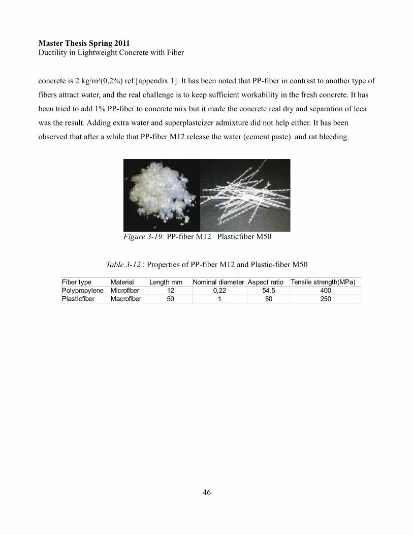
concrete is 2 kg/m³(0,2%) ref.[appendix 1]. It has been noted that PP-fiber in contrast to another type of
fibers attract water, and the real challenge is to keep sufficient workability in the fresh concrete. It has
been tried to add 1% PP-fiber to concrete mix but it made the concrete real dry and separation of leca
was the result. Adding extra water and superplastcizer admixture did not help either. It has been
observed that after a while that PP-fiber M12 release the water (cement paste) and rat bleeding.
Table 3-12 : Properties of PP-fiber M12 and Plastic-fiber M50
46
Fiber type Material Length mm Nominal diameter Aspect ratioPolypropylene Microfiber 12 0,22 54.5 400
50 1 50 250
Tensile strength(MPa)
Plasticfiber Macrofiber
Figure 3-19: PP-fiber M12 Plasticfiber M50

Master Thesis Spring 2011Ductility in Lightweight Concrete with Fiber
3.3 Specimen details 12 beams with and without fiber has been made in this experiment program. Three beams are casted by
normal density concrete(NDC) and 9 beams with LWC. Fibers type which has been used in this
experimental program is listed in table 3-13.Two beams of NDC are self compacting concrete
(Ref_SCC_MF and Ref_SCC_UF). The last NDC beam is vibrator-compacting concrete with 2% steel
fibers (Ref_VCC_MF). All LWC beam specimens are VCC. The Beam (Ref_LWC_UF) has no fiber
content.
Table 3-13: Overview of beams and the volume fraction of fibers
All beams have same dimension of 2,2m long and with cross section of 0,3m height and 0,25m width.
All beams has been design based on normal density concrete.
Calculation of reinforced bars from EC2:(complete calculation appendix 2)
Detail of reinforcement of beam is given in figure 3-20 and 3-21. The beam was reinforced with three
20 mm diameter bars in yield strength section and two 12mm bar in the compression section. The
stirrup reinforcement were 8 mm diameter with c/c 130 mm.
47
Beam ID Type of Fiber Fiber volume fractionRef_SCC_MF DE 50/1 N 2.00%Ref_VCC_MF DE 50/1 N 2.00%Ref_SCC_UF None 0Ref_LWC_UF None 0LWC_N50_2% DE 50/1 N 2.00%LWC_N50_1% DE 50/1 N 1.00%LWC_N35_2% DE 35/0,55N 2.00%LWC_N35_1% DE 35/0,55N 1.00%LWC_PF2% M50 2.00%LWC_PF1% M50 1.00%LWC_PPF0.6% M12 0.60%LWC_PPF0.4% M12 0.40%
6 62
2
0,84 259 217,510 63 10 666
435 217,5
:3 20 942
Eds
yd
s
zMA mm
f zUse
ø A mm
= × =× ×= = =× ×
=

Master Thesis Spring 2011Ductility in Lightweight Concrete with Fiber
Calculation of stirrups based on EC2:(complete calculation appendix 2)
For finding the influence of each fibers on beams ductility, it was decided to use the same type of
reinforcement and stirrups for all beams in order to get less parameters.
3.4 Mixing and casting
Concrete mixing took place at the Engineering laboratory of University of Stavanger. The mixer drum
has a capacity of 110 liter concrete mix. Each beam including cylinders and cubes needed 230 liter
fresh concrete. The mixing was divided in 3 mixes, one 70 liters and two 80 liters concrete mix.
Cement, sand and Leca were mixed in approximate 3 min and than the water was added in to the
48
2sw
minsww
max
min 2
max
max max
A 90000 0,356 /s cot 233 434 2,5
A( ) 0,1s
0,6
28( ) 0,1 250 0,265 /500
190220
0,6 220 130 so use s
Ed
ywd
ck
yk
sw
V mm mmz f
fb
fS h
A mm mms
s mmhs mms s
θ≥ = =
× × × ×
= × ×
′= ×
= × × =
=′ =
= × =<
Figure 3-20: Reinforcement detail
Figure 3-21: Reinforcement detail and test setup

Master Thesis Spring 2011Ductility in Lightweight Concrete with Fiber
mixing drum. This way mixed together in one minute before adding superplasticizer admixture. Fibers
were added after admixtures because of the high volume fraction. The reason that fibers were added
after admixture is that rotating drum hadn't enough power to mix the fibers in high cohesive and dry
concrete.
Beam specimens were cast by two layers, each layer had approximately 150 mm thickness and was
compacted by vibrator. It has been noted that use of vibrator can give weak point and less fiber in those
area vibrator was used.
The fresh concrete test process followed NS-EN 12350-2:2009. For each beam specimen concrete mix
were cast 8 cylinders with a 150 mm diameter and 300 mm height and 6 cubes with dimension
100x100x100. Cylinders and cubes were sampled following NS-EN 12390-1:2009. Compacting and
curing of specimens followed NS-EN 12390-2:2009. Cubes were covered with plastic sheet and
cylinders were covered by lid for 24 hours and than moved to a tank of water where the temperature
were kept constant 20 degree. Specimens were pulled out from water 30 min before testing.
3.5 Beam testingAll beams were tested by 4 point bending test. The beams were supported on two points. The length
between support points were 2 meters. Beams were loaded with two concentrated loads with arm length
of 0.7m from support points. The test machine is a type of Toni Technick with a maximum 400 kN
pressure force. Each beam has been present by a load-deflection curves. Elasticity, plasticity and
ductility has been highlighted in each curve. Concrete beams are under-reinforced by design which
means steel reinforcement would yield before failure. This area is highlighted as plasticity area.
Concrete crushing will initiate after yielding and beams will loss carrying load capacity. A brittle failure would
give a low deflection after yielding right
before reaching the ultimate failure. The
deflection area after initiation of concrete
crushing were highlighted as ductility area.
49
Figure 3-22: Concrete reinforced behavior under loading ref.[22]

Master Thesis Spring 2011Ductility in Lightweight Concrete with Fiber
Chapter 4: Experimental Result
4.1 Compressive strengthThe strength class of concrete for each beam has been decided based on the obtained compressive
strength tests of 6 cubes (3 at age 7 and 3 at age 28days) and one cylinder specimen. The compressive
test is performed according to NS-EN 12390-3-2009. The strength classes in EC2 which is showed in
table 1-1 and table 2-2 are based on the characteristic cylinder strength fck. Strength class for each
concrete is decided from characteristic compressive cube since the value is more precise than the
characteristic compressive cylinder strength.
Each specimen has been evaluated after failure to satisfy the requirement according NS-EN 12390-3-
2009. The volume density of each cube has been determined by following EN-12390-7 and the average
is showed in table 4-15. Calculation of density of cube specimens follows this formula:
The characteristic cube strength is calculated based on the values fcm and the standard deviation s.The
standard value is assumed to be 4. Calculation is fallowed by NS-EN 206-1:2000+NA:2007.
Table 4-14: Criteria for compressive strength (NS-EN 206-1)
50
is the volume of the specimenm is the mass of the specimen in airm is the apparent mass of the immersed specimen
is the density of water
a w
w
a
w
w
m mV
mDV
V
Production Number of testsPreliminary 3Continuous more than 15
Criterium 1 Criterium 2Average of test results
fcm All individual test
results>fck+4 >fck-4
>fck+1.48Ơ >fck+4

Master Thesis Spring 2011Ductility in Lightweight Concrete with Fiber
Test result from compressive strength test is present in table 4-15 and strength classed are chosen from
NS-EN 206-1.
Table 4-15:Strength class
4.1.1 Discussion By studying the experimental results, it can be concluded that compressive strength of steel fiber-
reinforced concrete and plastic fiber-reinforced concrete have not been increased by presence of fiber
in the concrete. The only change that has been noted, is that the cubic specimens did not crush in failure
because of the fibers bridging which change failure mode from fragile to ductile.
Results shows that lightweight PP-fiber reinforced concrete with 0.6% volume fraction
(LWC_PPF0.6%) give half strength class compared to lightweight concrete without fiber (LWC_UF).
By considering that all lightweight concrete has been made of the same receipt with constant w/c ratio
the deviation of LWC_PPF_0.6% is considerable large. The strength decreasing is most likely because
of high volume addition of polypropylene microfiber (PP-fiber). The manufacture description has
recommended the maximum addition of 0.2% in case of fire resistance concrete. During the casting of
LWC_PPF_0.6% it has been noted a very low workability and disappearing of cement paste in to the
PP-fiber which cause a separation of Leca and cement paste. It has also been noted that PP-fiber release
amount of water after 30 minutes which cause bleeding in concrete. All these incidents seems to cause
reduction in quality and strength of concrete.
51
Beam ID density(kg/l) Strength classRef_SCC_MF 2.48 78 4.0 72 61 C55/67Ref_VCC_MF 2.54 94 4.0 88 82 C70/85Ref_SCC_UF 2.38 80 4.0 74 65 C60/75Ref_LWC_UF 1.96 74 4.0 68 65 LC60/66LWC_N50_2% 1.85 71 4.0 65 57 LC60/66LWC_N50_1% 1.92 49 4.0 43 46 LC40/44LWC_N35_2% 1.89 66 4.0 60 55 LC55/60LWC_N35_1% 1.94 68 4.0 62 59 LC55/60LWC_PF2% 2 72 4.0 66 57 LC60/66LWC_PF1% 2.04 56 4.0 50 43 LC45/50LWC_PPF0.6% 1.99 31 4.0 25 21 LC20/22LWC_PPF0.4% 2.01 53 4.0 47 49 LC40/44
Mean value fcm(MPa) std.division fck,cube(MPa) fck,cy linder

Master Thesis Spring 2011Ductility in Lightweight Concrete with Fiber
4.2 Tensile strength The splitting tensile strength is measured as the average of 2 cylinder by split cylinder test fct,sp.
According to EC2 the axial tensile strength (fct) is equal to 90% of splitting tensile strength (fct,sp).
Test method and calculating of tensile strength followed NS-EN 12390-6:2009.
The mean value of axial tensile strength of concrete has been given in table 1-1 for normal density
concrete.
For lightweight concrete has EC2 given the formula where
Test results of split test is reported in table 4-16 and diagram of each fiber has been present in figure
4-24, 4-25.
52
Figure 4-23: Split test
1lctm ctmf f η= × 1 0.45 0.6 / 2200η ρ= +
,
,
2
0.9
ct sp
ct ct sp
Ffl b
f fπ
×=× ×
= ×

Master Thesis Spring 2011Ductility in Lightweight Concrete with Fiber
Table 3-16: split test result by cylinder test
Figure 4-24 Split test steel fiber
53
Cylinder IDSplit test
Ref_VCC_MF 724 10.24 9.22314 4.44 4.00224 3.17 2.85
LWC_N50_2% 348 4.92 4.43LWC_N50_1% 271 3.83 3.45LWC_N35_2% 540 7.64 6.88LWC_N35_1% 288 4.07 3.67LWC_PF2% 209 2.96 2.66LWC_PF1% 224 3.17 2.85LWC_PPF0.6% 148 2.09 1.88LWC_PPF0.4% 240 3.40 3.06
F(kN) fct,sp(MPa)fct(MPa)
Ref.SCC.UFRef.LWC_UF

Master Thesis Spring 2011Ductility in Lightweight Concrete with Fiber
Figure 4-25 Split test PP- and Plastic-fiber
Figure 4-26: Split test references with normal and lightweight concrete
54

Master Thesis Spring 2011Ductility in Lightweight Concrete with Fiber
4.2.1 Discussion of split test resultTable 4-17 shows the result from split test and characteristic axial tensile strength for each strength class. The result of tensile test is compared with characteristic axial tensile strength which is given i EC2.
Table 4-17: Tensile strength (result from split test and EC2)
Results of two split test has been suspected to be somehow wrong and incorrect. By comparing the
results of Ref_VBB_MF and LWC_N35_2% by others split test results will see the difference between
them are unrealistic high. Test method of those 2 cylinder have been followed correctly as it has been
described earlier, but the cause of this deviation can be that the test machine could not record the first
crack because of high presents of steel fiber. The diagram which is shown in figure 4-26 shows that it is
a double strain compare to another results. From diagram can find the real value of axial tensile
strength since the correct value is in the end of the elastic curve. New tensile strength is suggest in table
4-18 by analysis the diagram from earlier result.
Table 4-18:New value of tensile strength
Improvement of the tensile strength compare to given tensile strength value in EC2, has been noted in
all type of fibers reinforced concrete except in one case which is plastic-fiber 2%. Lightweight concrete
without any fiber has the same tensile strength as expected in EC2. The test results shows that tensile
55
Cylinder IDSplit test EC2
strength classRef_VCC_MF 724 10.24 9.22 11.24% C70/85 4.60 3.22Ref_SCC_UF 314 4.44 4.00 6.83% C60/75 4.08 3.22Ref_LWC_UF 224 3.17 2.85 4.88% LC60/66 4.08 2.86LWC_N50_2% 348 4.92 4.43 8.63% LC60/66 4.08 2.86LWC_N50_1% 271 3.83 3.45 8.33% LC40/44 3.24 2.86LWC_N35_2% 540 7.64 6.88 12.51% LC55/60 3.89 2.27LWC_N35_1% 288 4.07 3.67 6.90% LC55/60 3.89 2.72LWC_PF2% 209 2.96 2.66 5.19% LC60/66 4.08 2.72LWC_PF1% 224 3.17 2.85 7.37% LC45/50 3.52 2.86LWC_PPF0.6% 148 2.09 1.88 9.95% LC20/22 2.04 2.46LWC_PPF0.4% 240 3.40 3.06 7.01% LC40/44 3.24 1.43
fct/fcmF(kN) fct,sp(MPa) fct(MPa) fctm fck0.05
Cylinder IDSplit test EC2
strength class fck0.05Ref_VCC_MF 400 5.66 5.09 C70/85 4.60 3.22 58LWC_N35_2% 340 4.81 4.33 LC55/60 3.89 2.72 59
Percentageincreasing F(kN) fct,sp(MPa) fct(MPa) fctm

Master Thesis Spring 2011Ductility in Lightweight Concrete with Fiber
strength in lightweight concrete is increased by using steel-fiber. PP-fiber with 0.4 % volume fraction
shows improvement in tensile strength.
The result from LWC_PP_0.6% gave the lowest tensile strength in this experiment, as it is already
discussed earlier, adding more then 0.4% fiber will cause bleeding and segregation under casting.
The tensile strength of normal density concrete is 4.0MPa, the table 4-19 shows the percentage of
increasing/decreasing of each tensile strength compare to SCC_UF.
Table 4-19: comparing tensile strength of SCC_UF with LWC
the impact of replacing normal density concrete with lightweight concrete, is that the tensile strength
must increase by adding steel fiber. According to the result of this experiment it should not be less than
2% volume percent. Both type of steel fiber with N35 and N50 with 2% fraction volume give a positive
increasing compare to normal density concrete.
56
Cylinder IDSplit test
Ref_VCC_MF 400 5.66 5.09 27.4%Ref_SCC_UF 314 4.44 4.00 0.0%Ref_LWC_UF 224 3.17 2.85 -28.7%LWC_N50_2% 348 4.92 4.43 10.8%LWC_N50_1% 271 3.83 3.45 -13.7%LWC_N35_2% 340 4.81 4.33 8.3%LWC_N35_1% 288 4.07 3.67 -8.3%LWC_PF2% 209 2.96 2.66 -33.4%LWC_PF1% 224 3.17 2.85 -28.7%LWC_PPF0.6% 148 2.09 1.88 -52.9%LWC_PPF0.4% 240 3.40 3.06 -23.6%
PercentageVS Ref.SCC.UF F(kN) fct,sp(MPa) fct(MPa)

Master Thesis Spring 2011Ductility in Lightweight Concrete with Fiber
4.3 E-modulus The E-modulus of each concrete has been identified by pressure testing of two cylinders. The test
method and calculation is performed according NS-3676. Strain in concrete is measured by using 2
strain sensors which was installed on a stand. The equipment is special made for E-modulus test which
give a precise strain on each test. The figure 4-27 shows a cylinder during testing by cycles pressure
system according to NS-3676.
Figure 4-27:E-modulus testing
The mean value of cylinder compressive strength fcm is given in table 4-15 and ơ1, ơ2 is calculated for
each cylinder base on earlier results. Strain at ơ1, ơ2 and ơ0 from digital measurement was noted and the
result of E-modulus was calculated by:
57
1 0 1 2 0 1
1 0 2 0
( ) ( )( ) ( )o c
L LE Eσ σ σ σε ε ε ε
− × − ×= =− −

Master Thesis Spring 2011Ductility in Lightweight Concrete with Fiber
Results of E-modulus test is present in table 4-20. The result is the average of two cylinder test.
Table 4-20:Result of E-modulus test
The result shows that E-modulus of LWC is lower than normal density concrete which has been
expected. E-modulus for each concrete strength class is given in EC2. Table 4-21 compare the
experimental result by theoretical standard value.
Table 4-21:E-modulus base on strength class
The result from experimental E-modulus shows a approximate10GPa difference between E-modulus
which is given in EC2 and the test results. LWC_ N50 with 1 and 2% volume fraction are the only
concrete that have a higher E-modulus compare to LWC_UF.
58
Concrete IDSCC_UF 32.1 32.0VCC_2% 33.0 33.5LWC_UF 22.6 22.6LWC_N35_1% 19.3 19.4LWC_N35_2% 21.5 22.0LWC_N50_1% 22.9 23.0LWC_N50_2% 24.0 24.0LWC_PF1% 21.0 21.4LWC_PF_2% 22.4 22.1LWC_PP_0.4% 17.6 17.6LWC_PP_0.6% 13.5 13.3
Eo(GPa) Ec(GPa)
Concrete ID Strength ClassSCC_UF 32.1 C60/75 39VCC_2% 33.0 C70/85 41LWC_UF 22.6 LC60/66 30.03LWC_N35_1% 19.3 LC60/66 30.03LWC_N35_2% 21.5 LC55/60 29.26LWC_N50_1% 22.9 LC40/44 26.95LWC_N50_2% 24.0 LC55/60 29.26LWC_PF1% 21.0 LC45/50 27.77LWC_PF_2% 22.4 LC60/66 30.03LWC_PP_0.4% 17.6 LC40/44 29.95LWC_PP_0.6% 13.5 LC20/22 23.1
Eo(GPa) EC2 (Gpa)

Master Thesis Spring 2011Ductility in Lightweight Concrete with Fiber
4.4 Stress-strain diagram Three cylinders have been tested for stress-strain diagram for each beam specimen. The test has been
followed by SINTEF quality control for stress-strain diagram by pressure load ref[19]. The pressure
load controlled by deformation speed 0.3 ‰ per min. The pressure on cylinders continues until that
specimens collapse. Studying stress-strain diagram can give a basic understanding of the ductility
ability of concrete. A ductile concrete would not have a brittle fracture and it can be decided when it
have plastic behavior. Brittle concrete will break at rather low strain.
59
Figure4-28: Stress-strain diagram for ref. beams
Figure 4-29: Stress-strain diagram for N50
Figure 4- 30: Stress-strain diagram for N35
Figure 4-31: Stress-Strain diagram for Plastic fiber

Master Thesis Spring 2011Ductility in Lightweight Concrete with Fiber
SCC_UF and LWC_UF are references concrete without any fibers and figure 4-28 shows that they got
suddenly fall after the strength capacity is reached. The behavior in plasticity area shows the ductility
capacity for each specimen.
The strain ductility coefficient μe can be identified as maximum sustainable strain (Ɛy) divided by the
yield strain (Ɛ) ref.[19]
Table 4-22: Ductility coefficient for stress-strain diagram
LWC_PP_0.4% and 0.6% which contain polypropylene microfiber show high ductility capacity but
lower ultimate stress compare to SCC_UF and LWC_UF.
60
Figure 4-32: Stress-Strain diagram for PP-fiber
Cylinder ID ƐRef_VCC_MF 1200 3500 2.92Ref_SCC_UF 1200 1600 1.33Ref_LWC_UF 1400 1900 1.36LWC_N50_2% 1600 2750 1.72LWC_N50_1% 1200 1620 1.35LWC_N35_2% 1400 4200 3.00LWC_N35_1% 1600 1800 1.13LWC_PF2% 1450 2100 1.45LWC_PF1% 1200 3400 2.83LWC_PP_0.6% 1400 4600 3.29LWC_PP_0.4% 800 5000 6.25
strain(μm) Ductility coeff.Ɛy μy

Master Thesis Spring 2011Ductility in Lightweight Concrete with Fiber
LWC_N50 and LWC_N35 cylinders with a 2% volume fraction have a higher ductility coefficient
compare to the references concrete. Steel-fiber in normal density concrete VCC (2%) shows increasing
in ductility ratio compare to normal density concrete without fiber (SCC_UF) which will confirm that
addition of steel fiber improves the ductile behavior. Concrete reinforced by plastic-fiber M50 also
improves the ductility coefficient compare to LWC_UF but it has lower ultimate stress compare to
SCC_UF.
4.5 Behavior of beam specimensAll beam specimens were covered by plastic sheets right after casting. Each beam specimen was
stripped and stored outside the laboratory for 3 days after casting for 28 days. No type of shrinkage or
crack was observed on specimens during this period. The weather condition was humid climate. For
better observation of crack were all beams painted before testing at 28 days age. The testing method
was 4 point bending. The speed of load decided to be 100 N/s. The maximum allowed crack width
decided to be 0.4mm which is shown in table 2-7. The load on beam specimens continued until fracture
stage. Each diagram is the elasticity, plasticity and ductility highlighted.
In this section result and discussion of each beam will be present in a single section.
A general result of relation between Crack width, force and deflection for each beam specimen is
presented in table 4-23 and result from calculation of ductility coefficient ( μ ) which is based on
deflection parameters ( Δ ) from laboratory test is presented in table 4-24.
61
is the deflection of beam at ultimaite fracture load
is the deflection of beam when yield of reinforcment start
uf
uf
µ∆
=∆
∆
∆

Master Thesis Spring 2011Ductility in Lightweight Concrete with Fiber
Table 4-23:Overview of results from beam specimens
Table 3-24:Ductility ratio μ regarding deflection
62
Beam ID
Deflection(mm)
265 459 6.9 70280 464.7 7.93 74220 392.31 6.84 35220 384.31 7.72 25.8
LWC_N50_2% 260 414.68 8.25 60.2LWC_N50_1% 230 385.89 8 54.2LWC_N35_2% 255 414.44 8.8 76LWC_N35_1% 260 406.55 7.8 63.5LWC_PF2% 235 392.24 8.83 66LWC_PF1% 225 381.65 7.5 55LWC_PPF0.6% 195 315.15 10.77 43LWC_PPF0.4% 230 342.97 10 45
Force(kN) Crack width (0,4mm)
UltimateLoad
Crack width (0.4 mm)
Ultimate failure (mm)
Ref.SCC.MFRef.VBB.MFRef.SCC.UFRef.LWC_UF
Beam IDDeflection(mm) Ductility coefficientΔ15 70 4.6710 74 7.4015 35 2.3313 25.8 1.98
LWC_N50_2% 14 60.2 4.30LWC_N50_1% 14 54.2 3.87LWC_N35_2% 14.5 76 5.24LWC_N35_1% 14.5 63.5 4.38LWC_PF2% 13.5 66 4.89LWC_PF1% 13 55 4.23LWC_PPF0.6% 21 43 2.05LWC_PPF0.4% 18 45 2.50
Δuf μRef.SCC.MFRef.VBB.MFRef.SCC.UFRef.LWC_UF

Master Thesis Spring 2011Ductility in Lightweight Concrete with Fiber
4.5.1 Lightweight concrete beam without fiber (LWC_UF)The specimen LWC_UF is a reference beam specimen without fiber. Figure 4-34 and figure 4-35 show
crack width development versus load and the load versus deflection of beam specimen.
First crack on beam become visible at 60kN and the flexural cracks developed in region of maximum
moment from bottom of surface. The crack width grow faster in felt of maximum moment which
caused at end a flexural failure. As it was expected the high strength lightweight concrete had a brittle
63
Figure 4-33: Crack width development for LWC_UF
0.05 0.1 0.15 0.2 0.23 0.3 0.3 0.40
50100150200250
Referance LWC_UF
Crack Width (mm)
Forc
e (k
N)
Figure 4-34: Load-deflection diagram for LWC_UF

Master Thesis Spring 2011Ductility in Lightweight Concrete with Fiber
failure. LWC_UF had a strength class LC60/66 and it was designed for a maximum load 180kN but as
result show the failure took place at load 384kN. The ductility was very low because of high brittleness
and maximum deflection was registers at 26 mm right before flexural failure.
Figure 4-35:Crack pattern before failure LWC_UF
Figure 4-36: Brittle flexural failure LWC_UF
64

Master Thesis Spring 2011Ductility in Lightweight Concrete with Fiber
4.5.2 Reference beam self-compacting concrete without fiber (SCC_UF)The beam specimen SCC_UF had a concrete strength class C60/70, the first crack was observed at load
60kN. Figure 4-37 and fig. 4-38 show crack width development versus load and the load versus
deflection of the specimen by compering with LWC_UF.
Figure 4-37: Development of crack width for SCC_UF
Figure 4-38: load versus deflection for SCC_UF and LWC_UF
The deflection of beam specimen at crash point was 35 mm which is 10 mm higher than LWC_UF.
LWC_UF and SCC_UF have same concrete strength class and they are designed for same load. Figure
4-38 shows that the lightweight concrete become more brittle and less ductile compare to normal
65
0.1 0.15 0.18 0.2 0.23 0.25 0.3 0.35 0.40
50
100
150
200
250
SCC_UF LWC_UF
CRACK WIDTH (mm)
FOR
CE
(kN
)

Master Thesis Spring 2011Ductility in Lightweight Concrete with Fiber
density concrete. The beam specimen crashed due flexural failure. The crack width development was
similar to LWC_UF. The horizontal cracks grows faster than diagonal cracks and it is the horizontal
cracks which cause failure in maximum moment zone. Figure 4-39 shows the cracks pattern and the
failure mode.
Figure 4-39: Crack pattern before and after failure SCC_UF
4.5.3 Reference beams self-compacting and vibrator-compacting concrete (SCC_MF, VBB_MF)Testing of these two beam specimens were a challenge. The hydraulic of the laboratory machine had a
maximum load pressure up to 400kN. These two beam specimens were tested after lightweight
concrete beam specimens and by study results from lightweight beams could see that the failure load is
will be higher than 400kN. Since the failure was expected to be a flexural failure, it was decided to
increase the torque arm from 0.7m to 0.9m which increase the maximum moment. Figure 4-40 shows
the beam test setup for both beam specimens. In order to study the relation between load and crack
width, it was decided to run the test as similar as the other beam specimens and they were loaded under
identical conditions until the crack width of 0.4mm was detected.
Result of these two beams are present in the same diagram. Concrete strength class of SCC_MF is
C50/60 and VBB_MF is C70/85. Figure 4-41 shows the load versus deflection relationship and figure
4-41 shows the development of crack width versus load.
66

Master Thesis Spring 2011Ductility in Lightweight Concrete with Fiber
Figure 4-40:beam setup for SCC_MF and VCC_MF
Figure 4-41:Load -deflection relation
Figure 4-42:Crack development for VCC_MF and SCC_MF
VCC_MF beam specimen had a higher strength class compare to SCC_MF beam specimen. Figure
4.41 shows that the normal density concrete VCC_MF and SCC_MF which both have 2% volume
fraction end-hooked steel fiber, have approximated same ductility range. Difference between those two
67
0.1 0.15 0.18 0.2 0.23 0.25 0.3 0.35 0.40
50100150200250300
SCC_UF LWC_UF SCC_MF VCC_MF
CRACK WIDTH (mm)
FOR
CE
(kN
)

Master Thesis Spring 2011Ductility in Lightweight Concrete with Fiber
beams are the compacting method, one self-compacting (SCC) and the other vibrator-
compacting(VCC).
The failure load has been calculated by moment calculation in order to approximate value
corresponding to test setup when running as similar as another beam specimens. The beam specimen
VCC_MF failed at a maximum moment of 162.65kNm with 0.9 torque arm. By assuming that the
beam specimen would have a flexural failure of approximate same moment of a 0.7 torque arm, than
the load will be 459kN. Note that maximum moment area decrease in 0.9m torque arm, which will
cause a earlier failure and more concentrated load at a smaller area. Shear failure is not in consideration
even it will be decreased by increasing the torque arm. Figure 4-43 shows the difference between
moment and shear diagram by 0.7 and 0.9 torque arm.
Figure 4-43:Moment and shear diagram for SCC-MF
68

Master Thesis Spring 2011Ductility in Lightweight Concrete with Fiber
Figure 4-44:Crack pattern for VCC_MF and SCC_MF
Figure 4-45 shows the behavior of steel-fibers inside the cracks after failure. A few fracture failure in
the steel fibers was observed but the most part of fibers failed by pull-out failure. In pull-out failure
which is desirable for the test results, occur after yielding the end of steel fibers. Note that the steel
fibers in references beam is of type end-hooked N50 with aspect ratio 50 which is given in table 3-13.
Figure 4-45:Bottom of VCC_MF beam, pull-out and fracture of steel-fiber
69

Master Thesis Spring 2011Ductility in Lightweight Concrete with Fiber
4.5.4 Beam specimens with steel-fiber N50 (LWC_N50) and N35 (LWC_N35)Four lightweight beam specimens with 1% and 2% steel-fiber of type N50 and N35 were loaded until
the ultimate failure occurred. The figure 4-46 shows load and crack width relation of LWC_N50 and
LWC_N35 beams including LWC_UF and SCC_UF, which are the reference beams. Figure 4-47 shows
load-deflection diagram for beams with N50 and N35 fibers.
Figure 4-46:load-crack width diagram for N50 and N35
Figure 4-47:Load-deflection diagram of beams LWC_N50
70
0.1 0.15 0.18 0.2 0.23 0.25 0.3 0.35 0.40
50
100
150
200
250
300
N50_2% N50_1% LWC_UF SCC_UF
CRACK WIDTH (mm)
FOR
CE
(kN
)
0.1 0.15 0.18 0.2 0.23 0.25 0.3 0.35 0.40
50
100
150
200
250
300
N35
N35_1% N35_2% LWC_UF SCC_UF CRACK WIDTH(mm)
FOR
CE
(kN
)

Master Thesis Spring 2011Ductility in Lightweight Concrete with Fiber
The ductility behavior of beam specimens LWC_N50 and N35 began approximated at 26mm deflection
where the reference lightweight concrete beam had a flexural failure. LWC_UF, LWC_N50_2% and
LWC_N35_1% have identical concrete strength class (LC60/66) which give a better understanding of
steel-fiber's influence on ductility.
Crack width of 0.4mm on LWC beams with 2% N50 and N35(1% and 2%) were discovered when load
was 260kN. The result shows 18% load increasing compare to both reference beams and 13% compare
to presents of 1% N50steel-fiber. It shows that presents of fiber controlled the crack opening up to 18%
load increasing.
Deflection at crash point increases by 77% for LWC_N50_2% and 117% for LWC_N35_2% comparing
to SCC concrete without fiber.
Figure 4-48 shows crack pattern at load 300kN. Fiber failure on crack opening were smiler to SCC_MF
and VCC_MF. Pull-out failure was the failure mode for the most part of fibers. Diagonal cracks
opening grew slower compared to cracks in middle of beam which shows increasing in shear capacity
in beam specimen because of presents of steel fiber.
71

Master Thesis Spring 2011Ductility in Lightweight Concrete with Fiber
Figure 4-48:Crack pattern beam LWC_N50 (2% and 1%).
Figure 4-49:Flexural failure in beam LWC_N50_2%
72

Master Thesis Spring 2011Ductility in Lightweight Concrete with Fiber
4.5.5 Beam specimens with polypropylene microfiber M12(PP-fiber) and Plastic-fiber M50 (PF)Result of microfiber M12 (PP-fiber) and plastic-fiber beam specimens is showed by figure 4-50 and 4-
51.
Figure 4-50:Load - crack width for PP- and plastic-fiber
Figure 4-51:load-deflection relation for PP- and Plastic-fiber beams
73
0.1 0.15 0.18 0.2 0.23 0.25 0.3 0.35 0.40
50
100
150
200
250
PF1% PF2% LWC_UF SCC_UF PP_0.4 PP_0.6 Crack Width(mm)
Forc
e(kN
)

Master Thesis Spring 2011Ductility in Lightweight Concrete with Fiber
The beam specimen LWC_PF_1% was the first beam specimen which tested . There were some
confusing with wizard and programming of the test setup which cause that test stopped right after
plasticity zone was over. The ductility behavior is not registered.
The crack width development were almost similar in all beam specimens comparing with reference
beam except beam PP_0.6%.
PF_2% beam specimen start the plasticity behavior at almost same deflection point as SCC_UF beam
specimen but the deflection at flexural failure had 88% increasing.
Figure 4-52:crack pattern on PP- and Plastic-fiber on load 300kN
4.6 Analysis of results
Failure mode of beams were flexural failure, cracks were mainly vertical in middle of the beam span.
In brittle concrete this failure is very unfortunate, the collapse of beam will be suddenly without any
warning. This brittle failure has been observed in lightweight concrete without fiber-reinforced. The
failure occurred as like as a explosive force.
74

Master Thesis Spring 2011Ductility in Lightweight Concrete with Fiber
In general, all steel fiber reinforced beams exhibited elastic behavior through approximately 129 kN-m
of applied moment beside PP-fiber reinforced beams which maximum reached 105 kn-m.
The crack was discovered on all beam specimens approximated on load 60kN, and a few very fine
crack started to develop in the midspan area of beam where the bending moment was maximum.
The load and crack width on each beam specimens has been recorded. Table 4-25 shows the load on
beam specimens when the crack width of 0.4mm were observed.
Table 4-25: Load on crack width 0.4mm
The result which is present in table 4-25 shows that steel-fiber has most effect on decreasing of crack
width during loading of the beams. The difference between N50 1% and N50 2% steel-fiber content is
significant regarding to control of crack width due stress on cracks. In beam specimens LWC_N35_1%
and 2% has been noted that 1% had better result compare to N35_2%. The result from table 4-25 is the
crack width from the critical and the weakest point which reach the width of 0.4 mm first. The
weakness in beam N35_2% can be explain by bad distribution of fibers and using of vibrator which can
make a weak point with no fiber or the bond between fiber and concrete is not strong enough to get a
maximum utilization at early stage of crack development. Polypropylene microfiber M12 (PP-fiber)
has showed no reduction on crack width during loading.
Plastic-fiber has not much contributions to decrease crack-width at early age but in ultimate load it
control the crack opening which cause the ductile behavior.
75
Figure 4-53: Flexural failure described in ACI
CRACK WIDTH 0.4 PF1% PF2% N50_2% N50_1% LWC_UF N35_1% N35_2% PP_0.4 SCC_UF SCC_N50 PP_0.6 VCC_N50 2%225 230 260 230 220 260 255 230 220 265 195 280
2.3% 4.5% 18.2% 4.5% 0.0% 18.2% 15.9% 4.5% 0.0% 20.5% -11.4% 27.3%
Load(kN)Comparing beams to LWC_UF & SCC_UF

Master Thesis Spring 2011Ductility in Lightweight Concrete with Fiber
4.6.1 Proposal for crack width analysis Determining of crack width for concrete reinforced composites is given in RILEM TC 1622-TDF, as it
mentioned in previous section, this formulation does not take the volume fraction and direction of
fibers in concrete. The main change in calculation is that the crack spacing become added a factor
which will decrease the crack spacing.
Theoretical crack width calculation in this thesis are based on formulation from EC2.
In EC2 is given that ɛcm is the mean strain in the concrete between cracks, and ɛsm is the mean strain in
the reinforcement under loading. By assuming that the mean strain in the concrete is equal to strain in
first crack, it is possible to calculate a new strain which take the volume fraction of fiber and random
rotation in consideration. Crack strain can be identified by calculate the crack tensile strength and
elastic modulus of fiber reinforced concrete ref[21].
76
,max ( )k r sm cmW s ε ε= −
r,max 3 1 2 4 ,s / p effk c k k k φ ρ= × + ×
1
: is the tensial strength of fiber
is the volume variation of fiber
is the the matrix tensial strength at first crackE is the fiber modulus
E is the matrix modulusis fiber length
f
f
mu
f
m
where
Vσ
σ
η
2
factor is the fiber orientation factor(1/5 for 3D)η
1 2
1 2
Composite tensial strength at first crack(1 )
Stiffness:E (1 )
cc f f mu f
c f f m f
ccc
c
V V
E V E V
E
σ η η σ σ
η η
σε
= + −
= + −
=

Master Thesis Spring 2011Ductility in Lightweight Concrete with Fiber
The mean strain in the reinforcement under loading is assumed to be equal to strain in the tension
reinforcement on crack section.
The theoretical crack width is calculated based on this formulation. The formula is similar to EC2 crack
width expression by difference in calculation of strain in concrete and reinforcement.
The result from calculation of crack width showed in table 4-26 and calculation sheet is presented in
appendix 2. The value of concrete E-modulus and load on each beam in this calculation were used the
value from the earlier experiment tests.
Table 4-26:theoretical and experimental result of crack width
The proposed approach of crack-width analysis has been checked by experiment test result. Table 4-26
and table 4-27 verify that result obtained with the proposed model are compared with crack-width
observed in the test.
77
is stress in tension reinforcement based on a crack section
ss
s
s
Eσε
σ
=
,max ( )k r s cW s ε ε= −
beam ID285 0.4 0.37 0.32280 0.4 0.39 0.32220 0.4 0.33 0.33220 0.4 0.29 0.29
LWC_N50_2% 260 0.4 0.38 0.29LWC_N50_1% 230 0.4 0.33 0.29LWC_N35_2% 255 0.4 0.35 0.28LWC_N35_1% 260 0.4 0.36 0.32LWC_PF2% 230 0.4 0.34 0.26LWC_PF1% 225 0.4 0.34 0.29LWC_PPF0.6% 195 0.4 0.28 0.25LWC_PPF0.4% 230 0.4 0.34 0.3
load(kN) Crack width (exp) mm
Crack width(mm) (proposed formula)
Crack width(mm)(COIN,2011)
Ref.SCC_MFRef.VBB_MFRef.SCC_UFRef.LWC_UF

Master Thesis Spring 2011Ductility in Lightweight Concrete with Fiber
Table 4-27:Crack width for beam LWC_N50_2%
Theoretical Crack-width calculation for LWC_N50_2% which is showed in table 4-27, shows that
proposed crack width calculation give approximate same value as experimental crack-width during
loading.
4.6.2 Deflection of beam specimensDeflection of beam should be limited, it is given in EC2 that deflection in beam may not excesses
span/250 or in some sensitive situation should be consider a limit value span/500. The stiffness and
deflection of each beam specimens on service load 200kN has been calculated and compared to the
deflection result from experiment. It has to be mentioned that the data such as E-modulus and strength
class which are used in calculation of beam deflection are based on cylinder test result. Deflection of
beam depend of beam stiffness and the concrete E-modulus, by increasing the E-modulus will result in
decreased deflection.
78
2
2 3
2 2max
2(1 )(1 ) 1 1'(1 )
1 (1 )2 3
(3 4 )2 24
c
c c
d
d
I b d
EI E I
a FL a
EI
LWC_N50_2%
80 0.1 0.06130 0.15 0.14160 0.2 0.19200 0.25 0.259230 0.3 0.308240 0.35 0.324260 0.4 0.36
Load on beam (kN)
Crack width(observation)mm
Crack widthPorposed Theo (mm)

Master Thesis Spring 2011Ductility in Lightweight Concrete with Fiber
Table 4-28:result from beam test
Table 4-28 shows the result of deflection and curvature ductility coefficient calculation which are based
on theoretical calculation. Curvature ductility coefficient do not take consideration the influence of
fibers directly. The deflection ductility coefficient give more accurate results compared to curvature
ductility coefficient as it is presented in table 4-28. Deflection and curvature ductility calculation sheet
is presented in appendix 2d.
By comparing the deflection ductility coefficient of each beam to SCC-UF and LWC_UF will shows
that ductility has been increased in all type fiber reinforced concrete except Polypropylene microfiber
M12 (PP-fiber).
79
Beam IDDeflection(mm)
Theoretical(200kN) 4.23 6.9 3 4.67 100.0% 135.7%4.22 7 3.05 7.40 217.6% 273.7%4.26 7 3.01 2.33 0.0% 17.8%4.8 6 1.82 1.98 -18.9% 0.0%
LWC_SF2%_N50 4.67 6.5 2.6 4.30 84.5% 117.2%LWC_SF1%_N50 4.75 7.5 2.54 3.87 66.1% 95.5%LWC_SF2%_N35 4.85 6.8 2.46 5.24 124.9% 164.7%LWC_SF1%_N35 5.05 7.5 2.33 4.38 88.0% 121.2%LWC_PF2% 4.78 7.5 2.49 4.89 110.0% 146.9%LWC_PF1% 4.89 7.6 2.43 4.23 81.5% 113.7%LWC_PPF0.6% 5.8 10.5 1.9 2.05 -12.0% 3.4%LWC_PPF0.4% 5.22 9 2.2 2.50 7.3% 26.3%
Curvature Ductility coeff
Ductility coeff. % VSSCC
%VSLWC_UFExp.test(200kN) Deflection μ
Ref.SCC.MFRef.VBB.MFRef.SCC.UFRef.LWC_UF

Master Thesis Spring 2011Ductility in Lightweight Concrete with Fiber
5. Conclusion
Concrete become more brittle and less ductile by increasing the compressive strength of concrete. This
become more obvious with lightweight concrete since the strength of cement paste is similar than
lightweight aggregates. This combination will cause a sudden fracture through aggregates and cement
paste.
Fiber-reinforced concrete has been tested for compressive strength, E-modulus, tensile strength and
beams cracks behavior during loading. The following conclusions can be made from this thesis:
1. The use of end hooked steel fibers and plastic fibers in volume fraction 1 and 2% did not
influenced the compressive strength of lightweight concrete. Polypropylene microfiber
(PP-fiber) decreased the compressive strength of lightweight concrete because of high volume
fraction which caused segregation and low workability.
2. The tensile strength of LWC and NDC were improved by using steel-fiber. Increasing of
volume fraction of steel-fiber caused increasing in tensile strength. Polypropylene microfiber
M12 (PP-fiber) and plastic macrofiber M50 showed no effect on tensile strength.
3. The lightweight concrete with 2% end-hook steel fiber was the only SFRC which showed
improvement of ductility with high ultimate stress under stress-strain diagram test. All SFRC
had improvement in ductility but with low ultimate stress compare to SCC without
fiber(SCC_UF).
4. Steel-fibers showed high resistance to crack development, end-hooked N50 by 2% volume fraction
showed better ability to arrest cracks compare to 1% volume fraction. Plastic-fiber and microfiber
showed similar crack-width development as references beam. Polypropylene microfiber M12
(PP-fiber) with volume fraction greater than 0.4% caused segregation and bleeding in fresh
concrete which resulted lower resistance to crack development in beam with 0.6%
volume fraction PP-fiber.
5. The result showed that all type of fibers improved the ductility behavior for concrete beam
specimens compare to beam specimens without fiber. Increasing in volume fraction of end
hock steel-fiber and plastic-fiber increased the flexurale moment capacity and ductility of beam
80

Master Thesis Spring 2011Ductility in Lightweight Concrete with Fiber
specimens. Polypropylene microfiber M12 (PP-fiber) result higher deflection on beam and
better ductility but the failure moment capacity deceased compared to others beam specimen.
6. The results from beam specimens under loading showed that brittleness of a high performance
lightweight concrete can be modified by using additional reinforcement such as fibers.
Following fibers with given volume fraction would improve the ductility behavior of beams
compare to a NDC beam without fiber and could be considered as an option to replace
NDC in seismic zones: lightweight concrete reinforced by end-hooked steel
fibers (1 and 2% volume fractions) and Lightweight concrete reinforced by polypropylene
plastic-fiber with 2% volume fraction.
81

Master Thesis Spring 2011Ductility in Lightweight Concrete with Fiber
6. References[1]U.S. Geological Survey, Mineral Commodity Summaries, January 2010 http://minerals.usgs.gov/minerals/pubs/commodity/cement/mcs-2010-cemen.pdf
[2]Mehta, P., Monteiro, P. & MyiLibrary Concrete: microstructure, properties, and materials McGraw-Hill, 2006
[3]Norcem declared values of cements http://www.heidelbergcement.com/no/no/norcem/sementtyper/Kvalitetsinfo/Deklarerte_verdier.htm
[4] Heidelbergcement manufacture illustration of cement productionlink:http://www.heidelbergcement.com/NR/rdonlyres/689A0852-283B-4E14-A3F8-09F5B87A5CCE/0/2105Illustrajonsementprod_H%C3%98Y.pdf
[5]Nawy, E. Fundamentals of high-performance concrete Wiley, 2001
[6] Figure: http://www.silicafume.org/slideshow.cgi?p=5&c=2&l=73
[7]S.jacobsen TKT 4215 Concrete Technology 1 NTNU
[8]STEIGER, R.W. HISTORICAL VIGNETTE: Development of lightweight aggregate concrete Strength joined with durability in the evolution of lightweight aggregate
[9]Yao, S.X. & Gerwick, B.C. Development of Self-Compacting Lightweight Concrete For RFP Reinforced Floating Concrete Structures Ben C. Gerwick, Inc., , pp. 6
[10]Norsk betongforening publikasjon nr.23 lettbetong prosjekteringsveileding,1999
[11]Hammer, T. Early Age Cracking Risk of High Strength Lightweight Aggregate Concrete Special Publication, 2006, Vol. 234, pp. 641-660
[12] figure of plastic shrinkage: http://www.ultratechconcrete.com/PlasticShrinkageCracks.html
[13] figure of plastic settlement: www.concrete.net.au
[14] graph of chemical and autogenouse shrinkage : http://www.hucc.hokudai.ac.jp/~m16120/coe/workshop/nawa4.pdf
[15] figure of drying shrinkage:http://www.cement.org/tech/faq_cracking.asp
[16]Van Chanh, N.Steel Fiber Reinforced Concrete Faculty of Civil Engineering Ho chi minh City university of Technology. Seminar Material 2004, pp. 108-116
[17]Klausen, A.B.E. Steel fibres in load – carrying concrete structures. Guideline survey and practical examples COIN Project report 17 - 2009, 2009, pp. 85
82

Master Thesis Spring 2011Ductility in Lightweight Concrete with Fiber
[18]Nawy, E. Fundamentals of high-performance concrete Wiley, 2001
[19]Olav Skjølsvold, N.B. Arbeidsdiagram ved trykkbelastning SINTEF, 1996
[20]Monita Olivia, P.M. Curvature ductility of reinforced concrete beam Teknik Sipil, 2005
[21]Dinh, H.H. Shear behavior of steel fiber reinforced concrete beams without stirrup reinforcement The University of Michigan, 2009, pp. 309
[22] Rashid, M. & Mansur, M. Reinforced high-strength concrete beams in flexure ACI structural journal, ACI, 2005, Vol. 102(3), pp. 462-471
[23]Henrik S, Victor C. LI, Herbert Krenchel Design and structural applications of stress-crack width relations in fibre reinforced concrete the university of Lyngby and the university of Michigan,1995
[24]Erika E. Holt Early age autogenous shrinkage of concrete technical research center of Finland,2001
[25]NS-EN 1992-1-1:2004+NA:2008 Eurokode 2: Prosjektering av betongkonstruksjoner - Del 1-1: Allmenne regler og regler for bygninger
83

Master Thesis Spring 2011Ductility in Lightweight Concrete with Fiber
Illustration IndexFigure 1-1: overview over the cement production process ref[4]. ............................................................9Figure 1-2: overdosing of superplasticizers admixture............................................................................10Figure 1-3: Effects of increasing silica fume.ref[6].................................................................................12Figure 2-4: Stress-strain diagram LWC & NDC......................................................................................18Figure 2-5: Plastic shrinkage,ref[12].......................................................................................................20Figure 2-6: Plastic settlement ref[13].......................................................................................................20Figure 2-7: Different between chemical and autogenous shrinage ref[14].............................................20Figure 2-8: Drying shrinkage ref[15].......................................................................................................20Figure 2-9: Type of steel fiber ref[17]......................................................................................................23Figure 2-10: The influence of steel fiber content on tensile strength......................................................24Figure 2-11: Typical tension behavior for SFRC ref. [17].......................................................................26Figure 2-12: Strain and Stress distribution over a SFRC cross-section ref[17].......................................27Figure 2-13: Strain and stress of concrete reinforced composite ref.(17)...............................................28Figure 2-14: Shear forces on beam ref[17]..............................................................................................29Figure 2-15: Load-deflection behavior of a flexural member..................................................................33Figure 2-16: Beam section analysis and moment-curvature diagram......................................................36Figure 2-17: load displacement curve ref.[22]........................................................................................38Figure 3-18: DE 35/0,55N DE 50/1N.....................................................................................41Figure 3-19: PP-fiber M12 Plasticfiber M50.........................................................................................42Figure 3-20: Reinforcement detail ..........................................................................................................44Figure 4-21: Split test ..............................................................................................................................48Figure 4-22 Split test steel fiber ..............................................................................................................49Figure 4-23 Split test PP- and Plastic-fiber .............................................................................................49Figure 4-24: Split test references with normal and lightweight concrete................................................50Figure 4-25:E-modulus testing ................................................................................................................53Figure4-26: Stress-strain diagram for ref. beams.....................................................................................55Figure 4-27: Stress-strain diagram for N50.............................................................................................55Figure 4- 28: Stress-strain diagram for N35............................................................................................55Figure 4-29: Stress-Strain diagram for Plastic fiber................................................................................55Figure 4-30: Stress-Strain diagram for PP-fiber .....................................................................................56Figure 4-31: crack width development for LWC_UF.............................................................................59Figure 4-32: Load-deflection diagram for LWC_UF...............................................................................59Figure 4-33:Crack pattern before failure LWC_UF.................................................................................60Figure 4-34: brittle flexural failure LWC_UF..........................................................................................60Figure 4-35: Development of crack width for SCC_UF......................................................................... 61Figure 4-36: load versus deflection for SCC_UF and LWC_UF.............................................................61Figure 3-37: Crack pattern before and after failure SCC_UF..................................................................62Figure 4-38:beam setup for SCC_MF and VCC_MF..............................................................................63Figure 4-39:Load versus deflection relation ...........................................................................................63Figure 4-40:Crack development for VCC_MF and SCC_MF.................................................................63Figure 4-41:Moment and shear diagram for SCC-MF.............................................................................64
84

Master Thesis Spring 2011Ductility in Lightweight Concrete with Fiber
Figure 4-42:crack pattern for VCC_MF and SCC_MF...........................................................................65Figure 4-43:bottom of VCC_MF beam, pull-out and fracture of steel-fiber .........................................65Figure 4-44:load-crack width diagram for N50 and N35.........................................................................66Figure 4-45:Load-deflection diagram of beams LWC_N50....................................................................66Figure 4-46:crack pattern beam LWC_N50 (2% and 1%). .....................................................................67Figure 4-47:flexural failure in beam LWC_N50_2% .............................................................................68Figure 4-48:Load versus crack width for PP- and plastic-fiber ..............................................................68Figure 4-49:load-deflection relation for PP- and Plastic-fiber beams.....................................................69Figure 4-50:crack pattern on PP- and Plastic-fiber on load 300kN ........................................................70Figure 4-51: Flexural failure described in ACI .......................................................................................70
85

Master Thesis Spring 2011Ductility in Lightweight Concrete with Fiber
Index of Tables Table 1-1: Strength classes for concrete [Table 3.1 En1992-1-1:2004E].................................................7Table 1-2: Oxides and clinker compound of Portland cement ref[2].........................................................8Table 1-3: Notation and mechanical properties of different cement ref[3]................................................9Table 1-4: slump-flow classes [table 1:NS-EN 206-9:2010]...................................................................13Table 2-5: Density class for LWC............................................................................................................15Table 2-6: Strength classes for LWC table 11.3.1 EC2 ...........................................................................17Table 2-7: Values of wmax(mm)(table 7.1N EC2)..................................................................................31Table 3-8: SCC mix proportions (kg/m³).................................................................................................40Table 3-9: Normal concrete mix proportions (kg/m³) .............................................................................40Table 3-10: LWC mix proportions (kg/m³)..............................................................................................40Table 3-11:properties of hooked steel fibers............................................................................................41Table 3-12 : Properties of PP-fiber M12 and Plasticfiber M50...............................................................42Table 3-13: Overview of beams and the volume fraction of fibers..........................................................43Table 4-14: value of w..............................................................................................................................46Table 4-15:Strength class.........................................................................................................................47Table 3-16: split test result by cylinder test.............................................................................................49Table 4-17: Tensile strength (result from split test and EC2) .................................................................51Table 4-18:New value of tensile strength ...............................................................................................51Table 4-19: comparing tensile strength of SCC_UF with LWC..............................................................52Table 4-20:Result of E-modulus test........................................................................................................54Table 4-21:E-modulus base on strength class .........................................................................................54Table 4-22: Ductility coefficient for stress-strain diagram......................................................................56Table 4-23:overview of results from beam specimens.............................................................................58Table 3-24:Ductility ratio μ regarding deflection....................................................................................58Table 4-25: Load on crack width 0.4mm ...............................................................................................71Table 4-26:theoretical and experimental result of crack width ..............................................................73Table 4-27:crack width for beam LWC_N50_2%....................................................................................74Table 4-28:result from beam test..............................................................................................................75
86

Appendix 11.a Leca 700 4-8mm
1.b Leca 3-6mm
1.c Plastic fiber M50
1.d PP-fiber M12
1.e Steel-fiber N35
1.f Steel-fiber N50
Appendix 22.a Beam design
2.b Calculation of crack width based on COIN 2011
2.c Calculation of crack width based on proposed formula
2.d Calculation of curvature ductility coefficient

Postboks 216 Alnabru N-0614 Oslo
04
1111-CPD-0003
EN 13055-1
Lette tilslag til betong, mørtel og injeksjonsmørtel
Produktnavn: Leca 700, 4-8 mm
Varenummer: 1029,1
Egenskap Analyse-metode
Deklarert verdi
Kornform Rund
Kornstørrelsesfordeling EN 933-1 4-8 mm Overkorn ≤ 10%, Underkorn ≤ 15% %
Finstoff (<63 µm) EN 933-1 ≤ 2 %
Bulkdensitet EN 1097-3 7002) ± 5 % kg/m3
Andel knuste korn NPD1) %
Renhet NPD1)
Egenfasthet EN 13055-1, annex A, proc. 1 Vibrasjonstid: 20 sek
Minimumsverdi ≥ 7,0 N/mm2
Klorid EN 1744 -1 ≤ 0,04 % CL-
Syreoppløselig sulfat EN 1744 -1 NPD % SO3
Totalt svovelinnhold EN 1744 -1
Uttrykt som S: Gjennomsnittsverdi 0,05, maksimumsverdi ≤ 0,32. Uttrykt som SO3: Gjennomsnittsverdi 0,15, maksimumsverdi ≤ 0,80.
% S
Volumstabilitet EN 13055-1, annex B Holdbar ifølge lang tids erfaring %
Vannabsorpsjon EN 1097-6, Annex C
< 10% etter 1 time < 20% etter 24 timer For bruk i lettbetong bør eksakt 1 timers verdi måles på hvert enkelt parti.
%
Emisjon av radioaktivitet NPD1)
Utlekking av tungmetaller NPD1)
Utlekking av polyaromatiske karboner NPD1)
Utlekking av andre farlige stoffer NPD1)
Holdbarhet overfor frysing / tining. EN 13055-1, annex C Holdbar ifølge lang tids erfaring %
Holdbarhet over for alkaliereaksjoner Holdbar ifølge lang tids erfaring
1) NPD: No Performed Data, Ikke relevant informasjon, 2) Ordreproduksjon, densitet fastsettes sammen med kunde, kan avvike fra deklarert verdi. Supplerende deklarasjon (utenfor CE - merkning):
Egenskap Analyse-metode
Deklarert verdi
Partikkeldensitet EN 1097-6, annex C 12002) ± 10 % Kg/m3
Version 01 GNO/11/6/2006
brickstone
Typewritten Text
1.a
brickstone
Typewritten Text
brickstone
Typewritten Text
brickstone
Typewritten Text

Hjem > Filtralite > Filtralite > FILTRALITE HR 3-6 mm
FILTRALITEHR 3-6 mm
Filtralite egner seg godt til vannrensing, enten det er drikkevann, avløpsvann eller forbehandling før avsaltning. Høy
densitet og runde leireaggregater.
Enkel å installere i filtre
Stor overflate for bakterier å vokse på
Effektiv partikkelfiltrering
Åpne / Lukke
FILTRALITE HR 3-6 MM
Commercial name FILTRALITE HR 3-6 mm
Density Bulk density: 825 kg/m3 particle density: 1450 kg/m3
Type of material Expanded clay
Appearance Round particles, smooth surface structure
Manufactured by Weber Leca Rælingen, Norw ay
SIZE AND WEIGHT
Size/weight Value Deviation Comments
Effective size 3,5 mm ± 0,3 mm d10
Particle size range 3-6 mm < 2,5 mm max 3 % + ∆ < 0,125 mm
> 6,0 mm max. 5 %
Coeff icient of uniformity < 1,5 d60 / d10
Bulk density, dry 825 kg/m³ ± 75 kg/m³ EN 1097-3
Particle density, dry (PDD) 1450 kg/m³ ± 100 kg/m³ Exclay Norm
OTHER PROPERTIES
Other properties Value Comments
Floating particles < 2% Maximum volume f loating particles after 2 days in w ater.
3/8/2011 FILTRALITE HR 3-6 mm - Weber Saint-G…
weber-norge.no/…/filtralite-hr-3-6-mm.… 1/2
brickstone
Typewritten Text
1.b

Produsent:Rescon Mapei ASVallsetvegen 6, 2120 Sagstua, NorwayTlf: +47 62 97 20 00 Fax: +47 62 97 20 [email protected]. resconmapei.com
Plasticfibre M50 11.10
PRODUKTBESKRIVELSE
Plasticfibre M50 er en makrofiber lageti plastmaterialet polypropylen.Plasticfibre M50 er en strukturell fiberfor armering av betong. Fiberen hargode mekaniske og kjemiske egenskaperfor bruk i betong.
KVALITETER
• Lav egenvekt og dermed lavere dosering sammenlignet med stålfiber.
• Kjemisk inaktiv.• Godt egnet for bruk i korrosivt miljø.• Kjemikaliebestandig, angripes ikke av
syrer eller løsemidler.• Alkali-resistent.• Ingen kjent helserisiko.• Leveres ferdig buntet i bunter av 250 g,
som løses opp ved innblanding i betong
BRUKSOMRÅDE
Plasticfibre M50 er godt egnet til arme-ring av betongdekker på grunn for å hindre svinnriss og oppsprekking avbetong. Vær klar over at betong somstøpes på dekker bør beskyttes motuttørking uavhengig av fibertype ogdosering. Dette kan være påføring avmembranherder, ettervanning og til-dekking.
Plasticfibre M50 er meget godt egnet idekker, og konstruksjoner der man harstadig varierende laster som må tåle støt-belastning men ikke har moment-belast-ning over lang tid tid:
• Verkstedgulv / biloppstillingsplasser• Kaier, anker• Stableblokker• Betongbrystinger og støpte sikker-
hetsgjerder.
INNBLANDING OG DOSERING
Det beste er å tilsette fiber i betongen iblanderen. Alternativt kan den tilsettes ibetongbilen. Plasticfibre M50 leveres i
bunter på 250 gram. Fibrene entrer der-for betongen orientert parallelt medhverandre, og dette hindrer risikoen fordannelse av fiberballer. Rundt hver buntmed 250 gram fiber er det er plastbåndsom er vannløselig, og som løses oppved innblanding i betong.
Ved tilsetting av fiber i betongbil, sørgfor at trommel går på maksimal hastig-het under dosering, og la trommel gå påmaksimal hastighet i ytterligere 5 minut-ter etter at siste fiber er tilsatt.
For bruk i betongdekker på grunn anbe-fales det å dosere 3,5 – 5,0 kg/m3
betong.
LAGRING OG HOLDBARHET
Må lagres tørt og beskyttet mot direktesollys.
VERNETILTAK
For helse-, miljø- og sikkerhets-informasjon - se eget sikkerhetsdatablad.Sikkerhetsdatabladene finnes påwww.resconmapei.com.
MERK
De tekniske anbefalinger og detaljer somfremkommer i denne produktbeskrivelserepresenterer vår nåværende kunnskapog erfaring om produktene. All ovenstående informasjon må likevelbetraktes som retningsgivende og gjenstand for vurdering.
Enhver som benytter produktet må påforhånd forsikre seg om at produktet er egnet for tilsiktet anvendelse.Brukeren står selv ansvarlig dersom produktet blir benyttet til andre formålenn anbefalt eller ved feilaktig utførelse.
Alle leveranser fra Rescon Mapei AS skjeri henhold til de til enhver tid gjeldendesalgs- og leveringsbetingelser, som anses akseptert ved bestilling.
TEKNISKE SPESIFIKASJONER
Material: Polypropylen
Fiberlengde, mm: 50 (+ 10 %)
Fiberbredde/tykkelse mm: 1,28/0,81 (gjennomsnitt: 1,1) (+ 10 %)
Materialdensitet, g/cm3: 0,91
E-modul, N/mm2: 754
Smeltepunkt, °C: 160
Strekkfasthet, N/mm2: 250
Forpakning: Bunter á 250 gram, 12 kg pr. eske, 81 esker pr. pall.
brickstone
Typewritten Text
1.c

Produsent:Rescon Mapei ASVallsetvegen 6, 2120 Sagstua, NorwayTlf: +47 62 97 20 00 Fax: +47 62 97 20 [email protected]. resconmapei.com
PP-fibre M12Polypropylen mikrofiber
11.10
PRODUKTBESKRIVELSE
PP-fiber M12 er en multifillament-propylenfiber med optimale mekaniske,fysiske og kjemiske egenskaper for bruk i mørtel og betong.
KVALITETER
• Stor overflate pr mengde fiber• Høy bindings-/ heftevne• Kjemisk inaktiv• Problemfri innblanding• Lett å pumpe, ingen slitasje på rør
og slanger• 100 % alkali-resistent• Ingen kjent helserisiko• Angripes ikke av syrer eller løsemidler
Spesielt effektiv i de første kritiske timene i størkning og herdefasenUnder den første tiden i størknings- ogherdefasen utvikles betongens styrkelangsommere enn sammentrekkings-kreftene. Dette plastiske svinnet kommerprimært av avdamping fra overflaten,samt den kjemiske reaksjonen mellomsement og vann. Som en konsekvens avplastisk svinn vil betongen risse opp.Ved å tilføre PP-fiber M12 i ferskbetong, vil betongens mulighet til å taopp strekk-kreftene som oppstår i deførste kritiske timene etter utstøping øke betydelig.
Betong med PP-fiber• Økt brannmotstand• Reduserer forekomsten av riss pga av plastisk svinn
• Reduserer risikoen for ”bleeding” • Øker betongens tetthet• Øker holdbarheten ved temperatur-endringer
• Forbedrer betongens motstand mot slag, forhindrer skader på hjørner og kanter
• Reduserer skader ved avforming og under transport av elementer
• Raskere og bedre konstruksjon pga økt kohesjon (sammenholdning) i betongen
Tilsetning • PP-fiber M12 kan tilsettes i tørre materialer eller i fersk betong i blanderen, eller den kan tilsettes direkte i automikseren
• Betong med PP-fiber M12 kan pumpes og sprøytes
• Betong med PP-fiber M12 reduserer betongens synk. Kombineres derfor med bruk av superplastiserende stoffer(Dynamon-produkter).
• Blandingstid:- I betongblanderen: normal blandetid er tilstrekkelig
- I betongbil: blandingstiden økes med1 minutt pr m3 med høy hastighet påtrommelen.
Dosering Normaldosering 1 pose a 910 g pr m3
Antall poser pr kartong: 20Antall kartonger pr pall: 30PP-fiber M12 er pakket i vannløseligeposer
LAGRING OG HOLDBARHET
Må lagres tørt og beskyttet mot direktesollys.
VERNETILTAK
For helse-, miljø- og sikkerhets-informasjon - se eget sikkerhetdatablad.Sikkerhetsdatabladene finnes påwww.resconmapei.com.
MERK
De tekniske anbefalinger og detaljer som fremkommer i denne produktbeskrivelse representerer vår nåværende kunnskap og erfaring om produktet. All ovenstående informasjon må likevelbli betraktet som retningsgivende oggjenstand for vurdering. Enhver sombenytter produktet må på forhånd forsikre seg om at produktet er egnet for tilsiktet anvendelse. Brukeren stårselv ansvarlig dersom produktet blirbenyttet til andre formål enn anbefalt,eller ved feilaktig utførelse.
Alle leveranser fra Rescon Mapei AS skjeri henhold til de til enhver tid gjeldendesalgs- og leveringsbetingelser som ansesakseptert ved bestilling.
TEKNISKE SPESIFIKASJONER
Materialtype: Polypropylen
Vekt pr pose (kg): 0,91
Lengde (mm): 12 ± 2
Diameter (µm): 22 ± 3
Densitet (g/dm2): 0,91
Antall fibre (mill/kg): 224
E-modul (N/mm2): 3500 - 3900
Strekkstyrke (N/mm2): 400
Kjemisk reaksjon: Inert
Farge: Hvit/gjennomsiktig
Emballasje: Poser à 910 g, 20 poser per kartong. Vannløselige
Lagring: Lagres tørt
brickstone
Typewritten Text
1.d

Produsent:Rescon Mapei ASVallsetvegen 6, 2120 Sagstua, NorwayTlf: +47 62 97 20 00 Fax: +47 62 97 20 [email protected]. resconmapei.com
Steelfibre DE 35/0,55 N
12.10
PRODUKTBESKRIVELSE
Steelfibre DE 35/0,55 N er en høy-pres-terende stålfiber til armering av betong.Fiberlengden er 35 mm og er derformeget godt egnet for tynnere betong-skikt og sprøytebetong. Steelfibre DE35/0,55 N leveres magnetisk orientert i20 kg pappkartonger. Magnetisk orien-tering sikrer effektiv innblanding ibetongen. Fiberen er trådbasert og harendeforankring i begge ender. Steelfibre DE 35/0,55 N har strekkfast-het på 1100 (± 15 %) MPa.
ANBEFALINGER
Det anbefales alltid å tilsette fiber påbetongfabrikk.
I betongblander:• Tilsett aldri fiber som første kompon-
ent. Tilsett fiber under omrøring i til-slag eller i ferdig blandet betong.
• Bland betongen til fibrene er homo-gent fordelt.
I betongbil:• Tilsett fiber under maksimal om-
dreining på trommel (12 – 18 rpm).• Betongens synk skal være minst 120 mm.• Ikke tilsett mer enn 60 kg/min.• Etter endt tilsats, la trommel gå på
maksimal hastighet i 5 min.
DOSERING I SPRØYTEBETONG
Dosering er avhengig av ønsket energi-absorpsjonsklasse. Målinger er utført avSINTEF Byggforsk etter NB Publikasjon nr. 7.
LAGRING OG HOLDBARHET
Ved tørr lagring i uåpnet original embal-lasje, beskyttet mot fukt, er holdbarhe-ten minst ett år. Fuktskadet produkt medbegynnende korrosjon kan ikke lengerpåregnes å oppfylle de tekniske spesifi-kasjonene.
VERNETILTAK
For helse-, miljø- og sikkerhets-informasjon - se eget sikkerhetsdatablad.Sikkerhetsdatabladene finnes påwww.resconmapei.com
MERK
De tekniske anbefalinger og detaljer somfremkommer i denne produktbeskrivelserepresenterer vår nåværende kunnskapog erfaring om produktene. All ovenstående informasjon må likevelbetraktes som retningsgivende og gjenstand for vurdering.
Enhver som benytter produktet må påforhånd forsikre seg om at produktet er egnet for tilsiktet anvendelse.Brukeren står selv ansvarlig dersom produktet blir benyttet til andre formålenn anbefalt eller ved feilaktig utførelse.
Alle leveranser fra Rescon Mapei AS skjeri henhold til de til enhver tid gjeldendesalgs- og leveringsbetingelser, som anses akseptert ved bestilling.
TEKNISKE SPESIFIKASJONER
Energiabsorpsjonsklasse: E700 E1000
Fiberdosering (kg/m3): 20 Dokumenteres i prosjekt
Produktspesifikasjoner:
Lengde: 35 mm (± 10 %)
Diameter: 0,55 mm (± 10 %)
Strekkfasthet: 1100 MPa (± 15 %)
Slankhetstall (l/d): 63,5
brickstone
Typewritten Text
1.e

Produsent:Rescon Mapei ASVallsetvegen 6, 2120 Sagstua, NorwayTlf: +47 62 97 20 00 Fax: +47 62 97 20 [email protected]. resconmapei.com
Steelfibre DE 50/1,0 N
11.10
PRODUKTBESKRIVELSE
Steelfibre DE 50/1,0 N er en høy-presterende stålfiber til armering avbetong. Fiberlengden er 50 mm.Steelfibre DE 50/1,0 N leveres som løsfiber i 20 kg pappkartonger. Fiberen blirorientert ved hjelp av magnet før pak-king, så alle fibrene ligger parallelt ipappkartongen. Dette gjør tilsetting oginnblanding i betong enklere. Fiberen ertrådbasert og har endeforankring ibegge ender. Steelfibre DE 50/1,0 N har strekkfast-het på 1100 (± 15%) MPa.
ANBEFALINGER
Det anbefales alltid å tilsette fiber påbetongfabrikk.
I betongblander:• Tilsett aldri fiber som første kompon-
ent. Tilsett fiber under omrøring i til-slag eller i ferdig blandet betong.
• Bland betongen til alle fibre er homogent fordelt.
I betongbil:• Tilsett fiber under maksimal om-
dreining på trommel (12 – 18 rpm).• Betongens synk skal være minst 120
mm.• Ikke tilsett mer enn 60 kg/min.• Etter endt tilsats, la trommel gå på
maksimal hastighet i 5 min.
LAGRING OG HOLDBARHET
Ved tørr lagring i uåpnet original embal-lasje, beskyttet mot fukt, er holdbarhe-ten minst ett år. Fuktskadet produkt medbegynnende korrosjon kan ikke lengerpåregnes å oppfylle de tekniske spesifi-kasjonene.
VERNETILTAK
For helse-, miljø- og sikkerhets-informasjon - se eget sikkerhetsdatablad.Sikkerhetsdatabladene finnes påwww.resconmapei.com
MERKDe tekniske anbefalinger og detaljer somfremkommer i denne produktbeskrivelserepresenterer vår nåværende kunnskapog erfaring om produktene. All ovenstående informasjon må likevelbetraktes som retningsgivende og gjenstand for vurdering.
Enhver som benytter produktet må påforhånd forsikre seg om at produktet er egnet for tilsiktet anvendelse.Brukeren står selv ansvarlig dersom produktet blir benyttet til andre formålenn anbefalt eller ved feilaktig utførelse.
Alle leveranser fra Rescon Mapei AS skjeri henhold til de til enhver tid gjeldendesalgs- og leveringsbetingelser, som anses akseptert ved bestilling.
TEKNISKE SPESIFIKASJONER
Produktspesifikasjoner:
Lengde: 50 mm (± 10 %)
Diameter: 1,0 mm (± 10 %)
Strekkfasthet: 1100 MPa (± 15 %)
Slankhetstall (l/d): 50
brickstone
Typewritten Text
1.f

2.a
ED
2 2 2ck ctm yk
5
:beam width/hights b/h= 250/300mmnom_c= 25mm
V 90 63:
concrete: C50/60f 50 / 4,1 / f 500 /
2 10 /
ED
s
Design of beamSection properties
design valueskN M kNm
Materials and characteristic strengths
N mm f N mm N mm
E N
= =
= = =
= × 2
2 2
1,5 1,15 10,85
0,8for strength class B50
1:
/ 435 / / 28,3 /
/ 0,00217
300 25 8 16 0,5 259
c s
cc
yd yk s cd cc ck c
yd yd s
R
mmPartial safty factor
Characteristic strengthsf f N mm f f N mm
f Ed mmAnalysisM
γ γ γαλη
γ α γ
ε
= = ==
= ≤ ÷=
= = = × =
= =
= − − − × =
2
2,
,
6
0,275 1300,0035 0,617
0,0035 0,00217
0,8 1 28,3 250 259 0,617 2079435
reinforcement yield before concrete crush0,84 259 217,5
10 63
d cd
cub
cu yd
cd bs b
sd
s s b
Eds
yd
f bd kNm
f b dA mmf
A Az
MAf z
εαε ε
λ η α
= =
= = =+ +
× × × × × × × × × ×= = =
<= × =
×= =×
62
2
10 666435 217,5
:3 20 942s
mm
Useø A mm
× =×
=
2,min
2,min 2
,min ,min ,min 2
Control of minimum reinforcement0,26 0,26 2,8 250 259 94
500
0,0013 84,17( ; ) 94 666 . .
ctm ts
yk
s t
s s s
f b dA mmf
A b d mmA MAX A A O K
× × × × × ×= = =
= × × == = <

(2b)
alcul Calculation of the residual strength in fiber reinforced concrete(FRC)
This value has been suggestet by SINTEF for steel fiberσfk 500MPa
η013
vf 0.02 Volume fraction of fibers
γm 1.55
ftk.res η0 vf σfk 3.333 MPa
fftd.resftk.res
γm2.151 MPa
Calculation of crack width for lightweight concrete beam with steel-fiber(LWC_N50_2%).
This calculation is based on EC2 and result of beam each is showed in table 4-26
Max force on beams Fmax 260kN lt 2mp
Fmax2
lm 0.7m
Max Moment on beam
MmaxFmax lm
2
Mmax 91m kN
Tensile strength of concrete fctm 4.43MPa
Matrial data:
Es 200GPa b 250mm
k1 0.8 d 257mm
k2 0.5
k3 3.4
k5 1fftd.res
fctm
0.515k4 0.425
ϕ 20mmd1 28mm 10mm 6mm
As 942mm2

ρp.eff 0.051 As1 226mm2
ϕb 8mm
cm 25mm ϕb 33 mm
Crack spacingSrmax k3 cm k1 k2 k4 k5
ϕ
ρp.eff
146.503 mm
For findind strain in reinforcement need to calculatethe stifness of beam
Ecm 24GPaE concrete
E modulus( )for steel Es 200 GPa
matrial stifness:
ηEs
Ecm8.333
reinforced ratioρ
Asb d
0.015 ρ1As1b d
3.518 10 3
ηρ η ρ 0.122
For finding EIα ρ η 1
ρ1ρ
12 1
ρ1 d1
ρ d
ρ η 1ρ1ρ
2
1
0.375Ic 0.5 α
2 1
α
3
b d3
EI Ecm Ic
reinforcement stress: σs Es Mmax 1 α( )dEI 466.106 MPa
kt 0.6fct.eff 4.4N
mm2
Δε
σs ktfct.eff 1 η ρp.eff
ρp.eff
Es
Δε 1.962 10 3
Srmax 146.503 mm
Crack width: wk Srmax Δε 0.287 mm

Crack width analysis for concrete reinforcedcomposites steel fiber N35 2% volume fraction
2.c
Max force on beams Fmax 260kN lt 2m pFmax
2
lm 0.7m
Max Moment on beam MmaxFmax lm
2 Mmax 91m kN
Matrial data:distance from compression reinforcement
Es 200GPa b 250mm d1 28mm 10mm 6mmd 259mm
Ec 24GPa E-modulus of concrete
k1 0.8 k2 0.5 k3 3.4 k4 0.425
ϕ 20mm Reinforcement diameter
As 942mm2 As1 226mm2
ρp.eff 0.051
cm 35mm
fiber lengdelf 50mm
df 1mm
Crack spacing Srmax k3 cm k1 k2 k4ϕ
ρp.eff
Srmax 185.667 mm

Composite tensile strength at first crack
Vf 0.02 volume of fiber
σmu 5MPa for high strength concrete ref.[21]
σf 1100MPa Tensile stress of fiber
η21( )5
Value from earlier reaserch ref[21]
η1 1
E modulus( )of fiberEf 200GPa
σcc η1 η2 σf Vf σmu 1 Vf σcc 9.3 MPa
Ecm η1 η2 Ef Vf Ec 1 Vf Ecm 2.432 104 MPa
tensile strain at first crack in concrete will be
εcmσccEcm
3.824 10 4
For findind strain in reinforcement need to find stifness
E modulus( )for steel Es 200 GPa
matrial stifness:η
EsEcm
8.224
ρ1As1b d
3.49 10 3reinforcement ratio ρ
Asb d
0.015

For beam by compression reinforcementcan find the α by this formulaα ρ η 1
ρ1ρ
12 1
ρ1 d1
ρ d
ρ η 1ρ1ρ
2
1
0.372
For finding EI
Ic 0.5 α2
1α
3
b d3
EI Ecm Ic
σs Es Mmax 1 α( )dEI EI 6.411 106
m2 N
σs 461.524 MPareinforcement stress:
The main strain in reinforcement:
εsmσsEs
2.308 10 3 εcm 3.824 10 4
crack width: wk Srmax εsm εcm wk 0.357 mm
This calculation is runned for all beams and results is showed in table 4-26
Deflection of beam is calculated on load 200 kN and result is showed in table 4-28
a 0.7m
P 200kN L1 2m
δmaksa P 3L1
2 4 a2
2 24 EI4.567 mm

2.d Calculation of curvature ductility coefficient This is an example of curvature ductility calculation for beam SCC_UF. Result of calculation for eachbeam is given in table 4-28.
Reinforcment and beam data:
As 942mm2 As1 226mm2
h 300mmb 250mm
d1 28mm 10mm 6mmd 257mm
Concrete data:C6075fyd 434
N
mm2
fck 60N
mm2
εcm 0.0035
Ec 32GPa
Es 200GPa
fcd fck0.851.5
34 MPa
εydfyd
200GPa2.17 10 3
ρAs
b d0.015
ρ1As1
b d3.518 10 3
nEs
Ec6.25
For beam by compression reinforcement can find the α that way:
α ρ n 1ρ1
ρ
12 1
ρ1 d1
ρ d
ρ n 1ρ1
ρ
2
1
0.338
x1 α d 86.794 mm
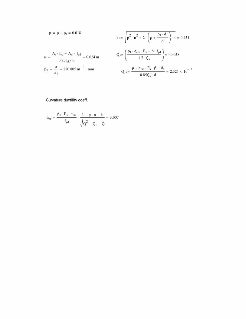
p ρ ρ1 0.018k p2 n2
2 ρρ1 d1
d
n 0.451
Qρ1 εcm Es ρ fyd
1.7 fck
0.038aAs fyd As1 fyd
0.85fck b0.024 m
β1ax1
280.805 m 1 mm Q1ρ1 εcm Es β1 d1
0.85fck d2.321 10 3
Curvature ductility coeff.
ϕuβ1 Es εcm
fyd
1 p n k
Q2 Q1 Q
3.007