LynTec AC Power Sequencing Products
33
LynTec AC Power Sequencing Products A composite document of Brochures • Installation Instructions • AppNotes Document Description Document Part No. Page (last 2 numbers [-xx] = revision, .x = page General Operators Instructions (all Sequencing Systems) Operator’s Instructions .......................................................... 139-0139-xx...........................02 Wiring Diagrams and accessories for all LynTec sequencers Multiple Sequencer Hookup Diagram.............................................. 139-0252-xx.2 ............................ 03 Enlarged Daisy-Chain Hookup Diagram ......................................... 139-0252-xx.3 ............................ 04 Series - Parallel Hookup Diagram ................................................... 139-0277-xx ............................... 05 Emergency Shut Down & ZipOff (PANIC) switch ............................ 139-0256-xx.1 ............................ 06 SS-2 & ZOS-5K Switch Set wiring & mechanical ............................ 139-0256-xx.2 ............................ 07 PV-110 Power Voucher Brochure...Not for new designs - Discontinued 5/05..... 139-0113-xx ............................... 08 PDS-10 series (Latching Relay Sequencer, 4 to 10 circuits) How It Works ................................................................................... 139-0512-xx.1 ............................ 9 Interior and Wiring ........................................................................... 139-0512-xx.2 ............................ 10 PDS-10 Mechanical Outline ........................................................... 139-0512-xx.3 ............................ 11 PDS-10 Specifications ................................................................... 139-0512-xx.4.............................12 Modular Sequencing Systems — Square D panels using motorized circuit breakers MSLC series Sequencing Load Centers — Cabinets hold 26, 29 or 41 breakers — Sequencer/s control 12, 24, 36 or 48 motorized breakers (Replaces SLC series - See LynTec.com for Discontinued product archive). and MSP series Sequencing Panelboards — Cabinet holds 41 breakers — Sequencer/s control 12, 24, 36, 48 or 60 motorized breakers (Replaces SP series - See LynTec.com for Discontinued product archive). All Panel Brochure — How it works................................................. 139-0357-xx.1 ............................ 13 Available Models ............................................................................. 139-0357-xx.2 ............................ 14 Load Center Main Breakers, Q Frame ............................................ 139-0343-xx ............................... 15 Panelboard Main Breakers, H & J Frame ........................................ 139-0394-xx ............................... 16 Series Ratings ................................................................................. 139-0407-xx ............................... 17 Typical Panel schedule — others @LynTec.com ........................... 139-0357-xx.3 ............................ 18 Control system and Panelboard photos .......................................... 139-0357-xx.4-5 ......................... 19-20 Specifier’s Guide — Part Number Selector ..................................... 139-0357-xx.6 ............................ 21 Motorized Breakers — Cutaway photo & model numbers............... 139-0357-xx.7 ............................ 22 Modular Sequencer Specifications.................................................. 139-0357-xx.8 ............................ 23 Architect’s & Engineer’s Specifications — Load Centers ................ 139-0345-xx ............................... 24 Architect’s & Engineer’s Specifications — Panelboards .................. 139-0339-xx ............................... 25 MRTS Series — Raintight — Sequences any Square D QO panel 139-0312-xx ............................... 26 Modular Sequencer Timing diagram ............................................... 139-0266-xx ............................... 27 Motorized Circuit Breakers Motorized Breaker Specifications & Emergency Actuation ............. 139-0216-xx ............................... 28-30 Warranty Statement ........................................................................ 139-0187-xx ............................... 31 Job List ............................................................................................ 139-0163-xx ............................... 32 Application Note Index — links to AppNotes AppNotes for Modular sequencing systems .................................... 139-0362-xx ............................... 33 139-0233-38.w 11/16/10 PDF Adobe Looks interesting — download complete 3.1M file Click to download individual document PDF Adobe
-
Upload
khangminh22 -
Category
Documents
-
view
0 -
download
0
Transcript of LynTec AC Power Sequencing Products

LynTec AC Power Sequencing ProductsA composite document of Brochures • Installation Instructions • AppNotes
Document Description Document Part No. Page
(last 2 numbers [-xx] = revision, .x = page
General Operators Instructions (all Sequencing Systems) Operator’s Instructions .......................................................... 139-0139-xx ...........................02
Wiring Diagrams and accessories for all LynTec sequencers Multiple Sequencer Hookup Diagram.............................................. 139-0252-xx.2 ............................03
Enlarged Daisy-Chain Hookup Diagram ......................................... 139-0252-xx.3 ............................04
Series - Parallel Hookup Diagram ................................................... 139-0277-xx ...............................05
Emergency Shut Down & ZipOff (PANIC) switch ............................ 139-0256-xx.1 ............................06
SS-2 & ZOS-5K Switch Set wiring & mechanical ............................ 139-0256-xx.2 ............................07
PV-110 Power Voucher Brochure...Not for new designs - Discontinued 5/05 ..... 139-0113-xx ...............................08
PDS-10 series (Latching Relay Sequencer, 4 to 10 circuits) How It Works ................................................................................... 139-0512-xx.1 ............................9
Interior and Wiring ........................................................................... 139-0512-xx.2 ............................10
PDS-10 Mechanical Outline ........................................................... 139-0512-xx.3 ............................11
PDS-10 Specifi cations ................................................................... 139-0512-xx.4.............................12
Modular Sequencing Systems — Square D panels using motorized circuit breakersMSLC series Sequencing Load Centers — Cabinets hold 26, 29 or 41 breakers — Sequencer/s control 12, 24, 36 or 48 motorized breakers (Replaces SLC series - See LynTec.com for Discontinued product archive). and MSP series Sequencing Panelboards — Cabinet holds 41 breakers — Sequencer/s control 12, 24, 36, 48 or 60 motorized breakers (Replaces SP series - See LynTec.com for Discontinued product archive).
All Panel Brochure — How it works ................................................. 139-0357-xx.1 ............................13
Available Models ............................................................................. 139-0357-xx.2 ............................14
Load Center Main Breakers, Q Frame ............................................ 139-0343-xx ...............................15
Panelboard Main Breakers, H & J Frame ........................................ 139-0394-xx ...............................16
Series Ratings ................................................................................. 139-0407-xx ...............................17
Typical Panel schedule — others @LynTec.com ........................... 139-0357-xx.3 ............................18
Control system and Panelboard photos .......................................... 139-0357-xx.4-5 .........................19-20
Specifi er’s Guide — Part Number Selector ..................................... 139-0357-xx.6 ............................21
Motorized Breakers — Cutaway photo & model numbers ............... 139-0357-xx.7 ............................22
Modular Sequencer Specifi cations .................................................. 139-0357-xx.8 ............................23
Architect’s & Engineer’s Specifi cations — Load Centers ................ 139-0345-xx ...............................24
Architect’s & Engineer’s Specifi cations — Panelboards .................. 139-0339-xx ...............................25
MRTS Series — Raintight — Sequences any Square D QO panel 139-0312-xx ...............................26
Modular Sequencer Timing diagram ............................................... 139-0266-xx ...............................27
Motorized Circuit Breakers
Motorized Breaker Specifi cations & Emergency Actuation ............. 139-0216-xx ...............................28-30
Warranty Statement ........................................................................ 139-0187-xx ...............................31
Job List ............................................................................................ 139-0163-xx ...............................32
Application Note Index — links to AppNotes AppNotes for Modular sequencing systems .................................... 139-0362-xx ...............................33139-0233-38.w 11/16/10
AdobeLooks interesting — download complete 3.1M fi le
Click to downloadindividual document
Adobe

SOUND SYSTEM A.C. POWER
OPERATING INSTRUCTIONSfor
LynTec A.C. Power Sequencing Systems
SOUND SYSTEMA.C. POWER
FLASHES DURING SEQUENCINGON
Ly
nT
ec
SOUND SYSTEMA.C. POWER
OFFLy
nT
ec
139-0139-02 9/23/99
www. LynTec .com8401 Melrose Dr. • Lenexa, KS 66214 U.S.A.
Voice 800-724-4047 • (913) 529-2233Fax 888-722-4157 • (913) 529-4157
To turn ON the sound system press this button.
The ON light will start flashing and continue until the system is fully ON.
This sequence will take from 16 seconds to over a minute depending on how many circuits are being sequenced.
The light will stay on constantly when the system is fully powered.
AC Power failure scenario
The sequencer will ZIP-OFF the system 2 seconds after power fails. System will automatically re-sequence ON when power resumes
To turn OFF thesound system
press this button.
The ON light will start flashing and continue
until the system is OFF.
This sequence will take from 16 seconds to over a minute depending on how
many circuits are being sequenced.
The ON light will extinguish at the end of
the OFF sequence.
The OFF button is not illuminated.
Return to Table of Contents

KS-2L Lock
Switch
SS-2 ON Switch
SS-2 OFF Switch
146-
0231
-08
3/2
5/05
0.625"
0.750"
0.625"
1.000"
1.000"
Switch layout for field constructed panel mounting. 1/4" max. panel thickness.
0.640"
LynTec Model SS-2PL Locking Swich Set.
(Optional)
ON
First
Last Last Sequencer
Board (Bottom)
Sequencer Board (Top)
Parallel connect additional SS-2 switch sets for multiple remote control locations. 4 conductors, 24 ga., 5,000 ft. loop max.
Maximum number of switch sets:
All LynTec sequencers support 6 switch sets.
+ –
connections, rear view
NO C
NC NO C
One set of the ON and OFF switches shown below are supplied
unmounted as a SS-2 Switch Set with each LynTec sequencer cabinet.
Mount in 5/8" dia. round holes in panels up to 1/4" thick.
LynTec Lenexa, KS (Central time zone) U.S.A. Voice 800-724-4047 or 913-529-2233 Fax 888-722-4157 or 913-529-4157
www.LynTec.com
NC
3 OSLO
8 Lock switch
shown in unlocked position
Hold Borrow Pilot Com Carry Com Busy +5v
Logic Kill V+ V– OFF Com Pilot ON
Low voltage control wire: 24 gauge minimum, 5,000 ft. loop max.
Test button
Install Jumper in LAST sequencer board only if POWER VOUCHERs
are not installed.
Hold Pilot Com Carry Com Busy +5v
Logic Kill V+ V– OFF Com Pilot ON
OFF Test button
PILOT LED
(green)
+ +
+ +
Borrow
1
Multiple Sequencer Hookup DiagramFor LynTec MSLC and MSP MODULAR and PDS-10 Power Sequencing Products
Showing Low-Voltage Remote ON/OFF Control and Daisy-Chain Wiring
For single sequencer board hookup connect OFF switch normally open to OFF.
Com
V-
OFF
Carry
Busy
Kill
Com
V-
OFF
Carry
Busy
Kill
OFF
Com
V+
V-
Com
Pilot
Borrow
ON
Hold
Kill
Com
Pilot
Borrow
ON
Hold
Kill
ON
Com
Pilot
+5v Logic
Com
Kill
Cabinet A Sequencer
boards 1 & 2.
Cabinet B Sequencer
boards 3, 4 & 5.
Cabinet C Sequencer
boards 6 & 7.
TOP BOARD
FIRST BOTTOM BOARD
BOTTOM BOARD
BOTTOM BOARD
LAST TOP
BOARD TOP
BOARD
C
NO
C NO ON
OFF Lock C NO
C
NO ON OFF Lock
Fire Alarm N.O. contact.
Closure kills all sequenced power.
Opening resumes
ON sequence.
Daisy-chain connections
within a cabinet are made via Cascade
Connector.
A typical three panel, daisy-chained, system with two locking control locations.
Connect V+ to V– on LAST sequencer if Power Vouchers are not used.
ON LED
+
–
ON LED
+
–
To touch panel. (mimics Pilot output)
Kill — Fire alarm shutdown External contact closure lights the red Kill LEDs and
kills all sequenced power. Contact opening restarts the ON sequence.
For multiple control points add SS-2's or SS-2PL's.
Parallel connect lines.
P
OFF Busy
Kill Carry Com 24v AC
V–
Hold Com Kill ON
Pilot
+5v CMOS Logic output. Mimics Pilot LED.
3.3KΩ source impedance. (For touch panel drive)
When sequencers are daisy-chained avoid using these test switches.
Use the first ONON test switch and the last OFFOFF test switch to avoid confusing operation.
Borrow
24v AC N
/C
N/C
Cascade Connector
(4 pin)
Power & Kill Connector
(4 pin)
Cascade Connector
(4 pin)
Power & Kill Connector
(4 pin)
Cage clamp terminal blocks. Press white levers back with
small straight-blade screwdriver to insert stripped wires.
P
P P P
P
139-0252-12.2B-W SS-2/SS-2PL Insert 8/13/08See http://www.lyntec.com/139-0252.pdf for latest version.
Custom switch legends you can print on your laserprinter
See http://www.lyntec.com/139-0309_CSLF-1_Film.pdf
To isolate the Hurry-Off and Kill functions, unplug left Power & Kill Connector and move to the left one step,
mis-mating to eliminate the board-to-board Kill connection.
These expansion terminals on the bottom board are only used for daisy-chain connections when more than one cabinet is used.
These expansion terminals on the top or middle boards are NOT used when the cascade connectors are used to
daisy-chain boards within a cabinet.
To run each sequencer board as a separate system, remove the right Cascade Connector. Connect ON, Pilot, Com & OFF to switch set.
NOT in PDS-10See daisy-chain
connections below for wiring between
PDS-8s or multiple cabinets.
Last LastSequencer
Board (Bottom)
+5vLogic
+5vLogic
OFFBusy
Kill Carry Com24vAC
V–
Hold Com Kill ON
Pilot
+5v CMOS Logic output.Mimics Pilot LED.
3.3KΩ source impedance. (For touch panel drive)
Borrow
24vAC N
/CN
/C
CascadeConnector
(4 pin)
Power & KillConnector
(4 pin)
CascadeConnector
(4 pin)
Power & KillConnector
(4 pin)
To isolate the Hurry-Off and Kill functions, unplug leftPower & Kill Connector and move to the left one step,
mis-mating to eliminate the board-to-board Kill connection.
To run each sequencer board as a separatesystem, remove the right Cascade Connector. tConnect ON, Pilot, Com & OFF to switch set.
NOT in PDS-10See daisy-chain
connections below for wiring between
ets.PDS-8s or multiple cabin
Return to Table of Contents

139-0252-11.3 Daisy Chain Hookup 4/12/05
Com
V-
OFF
Carry
Busy
Kill
Com
V-
OFF
Carry
Busy
Kill
OFF
Com
V+
V-
Com
Pilot
Borrow
ON
Hold
Kill
Com
Pilot
Borrow
ON
Hold
Kill
ON
Com
Pilot
+5v Logic
Com
Kill
Cabinet ASequencer
boards 1 & 2.
Cabinet BSequencer
boards 3, 4 & 5.
Cabinet CSequencer
boards 6 & 7.
TOPBOARD
FIRSTBOTTOMBOARD
BOTTOMBOARD
BOTTOMBOARD
LASTTOP
BOARDTOP
BOARD
C
NO
CNO ON
OFFOFFLockCNO
C
NOONOFFOFF Lock
Fire AlarmN.O. contact.
Closure kills allsequenced power.
Opening resumes
ON sequence.
Daisy-chainconnections
within a cabinet are made via Cascade
Connector jumper plug.
Power Voucher
LynTec
Power Voucher
LynTec
Power Voucher
LynTec
Power Voucher
LynTec
Power Voucher
LynTec
Power Voucher
LynTec
Power Voucher
LynTec
NOTE The quantity of Power Vouchers illustrated in this series-string is NOT typical.
A typical string has one PV-110 for each breaker-fed circuit in the audio system to verify all circuits are hot.
Connect V+ to V–
ONLY on LAST sequencer if
Power Vouchersare not used.
Remove factory installed V+ to V–jumpers from the
bottom board of each daisy-chained cabinet.
V+ to V– contact-closure keeps
ON led lit at the end of the on sequence.
ONLED
+
–
ONLED
+
–
To touch panel.(mimics Pilot output)
Wire Requirements for Remote ControlsBasic system ON/OFF Control from one panel only....4 conductorsBasic + Kill Add Kill function ....................................6 conductors2 conductors to Kill control location
Remote control at both ends ............................................9 conductorsKill, Remote control both ends, full power verification .....11 conductors
Low voltage control wire: 24 gauge minimum, 5,000 ft. loop max.
C
NOON
ONLED
+
–CCC
NO ON
+
–
ONLED
C1
831
8
3
For Timing Diagram and Logic levelsSee http://www.lyntec.com/139-0266_Seq_Timing.pdf
A typical LynTec three panel, daisy-chained system
with two locking control locations.
Return to Table of Contents

Cabinet ASequencer
boards 1 & 2.
Cabinet C1Sequencer
boards 9, 10 & 11.
Cabinet C2Sequencer
boards 12 & 13.
TOPBOARD
FIRSTBOTTOMBOARD
BOTTOMBOARD
BOTTOMBOARD
LASTTOP
BOARD
C
NO
CNO ONON
OFFOFFLock CNO
C
NOONONOFFOFF Lock
Fire AlarmN.O. contact.
Closure kills allsequenced power.
Opening resumes
ON sequence.
Daisy-chainconnections
within a cabinet are made via Cascade
Connector jumper plug.
Power Voucher
LynTec
Power Voucher
LynTec
Power Voucher
LynTec
Power Voucher
LynTec
Power Voucher
LynTec
Power Voucher
LynTec
Power Voucher
LynTec
NOTE The quantity of Power Vouchers illustrated in this series-string is NOT typical.
A typical string has one PV-110 for each breaker-fed circuit in the audio system to verify all circuits are hot.
ON
LED
+
–
ONLED
+
–
To touch panel.(mimics Pilot output)
Cabinet B1Sequencer
boards 3, 4 & 5.
TOPBOARD
BOTTOMBOARD
Cabinet B2Sequencer
boards 6,7 & 8.
TOPBOARD
BOTTOMBOARD
LAST
TOPBOARD
FIRST
ON
Com
Pilot
+5v Logic
Com
Kill
ComV–
OFFCarryBusyKill
ComPilot
BorrowON
HoldKill
OFF
ComV+V–
ComV–
OFFCarryBusyKill
ComPilot
BorrowON
HoldKill
ComPilot
BorrowON
HoldKill
ComPilot
BorrowON
HoldKill
OFF
ComV+V–
Each board's expansion outputs can drive up to4 boards in parallel.Borrow and Pilot are taken from the first board of the parallel system which takes the longest time to sequence off.Power Vouchers, ifused, should beconnected to V+ andV– of the last boardof the same system.
www.LynTec.com
800-724-4047
LynTec MSLC or MSP Modular series Power Sequencing SystemA five panel, series-parallel system with two locking control locations.
Advantage: Faster cycling time for large systems.
On cycle time of this system at 1/8 sec. per step is 6 seconds plus any user set Time Delay. Off cycle time is 6 seconds.
Low voltage control wire: 24 gauge minimum, 5,000 ft. loop max.
Latest revision: HTTP://www.lyntec.com/139-0277_Series-Parallel.pdf
This optionalV+ to V– jumper
helps troubleshoot the C1-C2 panels by providing local on-board ON LED indication.
ComV–
OFFCarryBusyKill
139-0277-03 Series-Parallel Hookup 3/31/06
Connect V+ to V–on LAST
sequencer if Power Vouchers are not used.
1N4002 Isolation diodes
required in each ON line
to prevent OFF
interaction.
1N4002 Isolation diodes
required in each OFF
line to prevent interaction.
Return to Table of Contents
To Kill line (all connected within each cabinet by Power & Kill jumpers) or to all Kill lines requiring a common kill
function if not daisy-chained.
NC
What to specify or order
For ZipOff switch order ZOS-5K. (services up to 5 Kill equipped boards)Includes switch with ZipOff fi lm legend and fl ip up security cover. Switch mounts in 5/8" round hole in panels up to 3/16" thick.ZOS-5K Contractor C.O.D. price: $34.Delivery: Stock.
139-0256-07 8/11/08 See http://www.lyntec.com/139-0256_ZOS-5K.pdf for latest version.
Built-in Kill, Hurry-Off and ZipOff (PANIC) switch optionfor MSLC and MSP and PDS-10 series AC SEQUENCING SYSTEMS
What the functions doKill — EMERGENCY SHUTDOWN Provides an IMMEDIATE shut down method for the sound system at the command of a fi re alarm, emer-gency announcement system, or ZipOff switch.
Optional ZipOff switch, ZOS-5KProvides a full AC Power shutdown within 200 milli- seconds after the ZipOff button is pushed. In case of a runaway oscillation or other unexpectedsignal which could damage the loudspeakers if sustained...Lift the protective cover and press the ZipOff button... it latches down and lights red. The AC powersequencing system immediately zips off. Press again to unlatch... the light goes out and the sequencer restarts to repower the system.
or Use the new Hurry-Off function at any OFF switch.
Hurry-OffThe MS-12 Modular & PDS-10 Sequencing boards have a new Hurry-Off function. If you hold down any OFF switch for two seconds, a "Kill without restore" function is triggered. The system shuts down within 200 milliseconds and doesn't restart until you give it a new ON command.
How they workAll LynTec sequencing systems have the ZipOff load shedding feature. The older SLC, SP and PDS-8'simplemented it by interrupting 24v ac power.
The newer Modular sequencers, the MSLC and MSP series and the PDS-10, load shed when power fails, but also have a Kill function that is triggered by grounding the Kill line.
The red Kill LED, adjacent to the Kill terminal on the board, lights and Zip-Off is immediate. The kill line is a low current line. Long control wiring may be used without concern for loop resistances up to 32Ω. (22 gauge, up to a 1,000 ft. run [2,000 ft. loop] or a 680 ft. run of 24 ga).
The microprocessor remembers that the sequencer was ON. When the Kill line is opened, the ON sequence repeats, bringing the AC power back on.
For the Modular series control boards the ZipOff switch connects the Kill line to common, through the Zip-Off switch's LED, initiating the Kill function.
LynTec.c
om
SOUND SYSTEMA.C. POWER
ZipOffPush to SHUT DOWN.
Push AGAIN to restart sequence.
120-6012-03 ± LED± LED
NO
C
ZOS-5KZipOffSwitch
NC
NO
CPush to latchPush to unlatch
Wiring pictorial
on reverse side
To Common
SHUNT R (for more than 5 boards)
Normally open fi re alarm contact. Close to turnoff
all sequenced circuit breakers (Kill). Open to resume power-up
sequence.
For multiple ZipOff switches connect in
parallel across Kill and Common.
MULTI-BOARD SHUNT R
The Kill line is an 11 ma. current source from each MS-12 Modular Se-quencer or PDS-10 board
A voltage sensor on the Kill line determines the Kill threshold.
The Kill line has an open circuit voltage of 28 volts which must be pulled down to less than 10.5 volts to generate a Kill function. Grounding the Kill line to Common will always kill the system instantly. This current source may also be used to light the Zip-Off switch's, red LED.
The red ZipOff LED only requires 10 ma. For systems where multiple-board system's Kill lines are paralleled, a 9 v. voltage regulator chip is installed in the ZOS-5K which will automatically shunt the excess source current of up to 5 boards. For more than 5 boards an additional resistor must be used in parallel with the ZipOff switch LED. To prevent damage due to overheating the voltage regulator chip, the resistor should be installed as shown with full length leads to get the heat source away from the switch.
Total Number Shunt Resistor of boards required 1-5 .........................none 6 ......................820Ω, 1/4w 7 ......................430Ω, 1/4w 8 ......................270Ω, 1/2w 9 ......................200Ω, 1/2w 10 .....................150Ω, 1/2w 11 ...................... 150Ω, 1w 12 ...................... 120Ω, 1w 13 ...................... 100Ω, 1w 14 ....................... 92Ω, 1w 15 ....................... 82Ω, 1w
16 ...............75Ω, 2w 17 ................68Ω, 2w 18 ................62Ω, 2w 19 ................56Ω, 2w 20 ................56Ω, 2w 21 ................51Ω, 2w 22 ................47Ω, 2w 23 ................47Ω, 2w 24 ................43Ω, 2w 25 ................39Ω, 2w
9v voltageregulator
www.LynTec.com8401 Melrose Drive • Lenexa, KS 66214 • Voice 800-724-4047 or 913-529-2233 • Fax 888-722-4157 or 913-529-4157
☛
Return to Table of Contents

ON
LynTec.com OFF
0.930"
0.710"
1.000"
NC
NO
C
NC
NO
C
+ –
ONOFF
COM
OFF
PILOT LED +
ON To FIRST sequencer if daisy chained.
.625" dia. hole. (5/8")Maximum panel thickness: .188" (3/16")
139-0256-07.2 8/11/08
Wiring pictorial - Rear view
idecAL6–M
idecAB6–M
Wire requirementsSwitch set to sequencer: 4 conductors.Between daisy chained Modular sequencers:9 conductors, 11 if Power Vouchers are used.Up to 5,000 ft run: 22 ga., 5,000 to 7500 ft. run: 20 ga.7,500 to 10,000 ft. run: 18 ga.See other side for ZipOff wire sizing.
Optional Key-Lock Switch(see SS-2PL Sequencer Switch
with Locking Switch on single gangstainless steel wall plate)
12v LED
Rubber anti-rotation
gasket
Press to SHUT DOWN.Push AGAIN to restart sequence.
1.000"
0.930"
1.171"
NC
NO
C
+ –
ZipOff
Flip-upsecurity
cover
To PDS-10 series or MSLC, MSP series sequencer
GREENlit when
ONRED
lit whenZipped Off
REDnot illuminated
LynTec.com
LynTec.com
FLASHES DURING SEQUENCINGON
LynTec.com OFF Press to SHUT DOWN.Push AGAIN to restart sequence.
LynTec.com
LynTec.com
To FIRST sequencer if daisy chained.
To LAST sequencer if daisy chained.
To Kill on Modular or PDS-10 sequencer board.
See other side for wire sizing requirements.
(Max. loop resistance: 32 ohms).
LynTecfor Modular A.C. Sequencing Systems, models MSLC, MSP & PDS-10.
ON , OFF and ZipOff switch mounting & wiring
S S - 2Switch Set
1 set supplied with each sequencing
system.
Optional
ZOS-5KZipOff Switch
includes flip-up security cover
ZipOff
ZipOff
Film Legends
For older PDS-8E series or SLC, SP series sequencers
seehttp://www.lyntec.com/139-0137_ZOS-1.pdf
SHUNT R
LynTecZOS-5K
146-0259-00
SOUND SYSTEMA.C. POWER
SOUND SYSTEMA.C. POWER
SOUND SYSTEMA.C. POWER
SOUND SYSTEMA.C. POWER
SOUND SYSTEMA.C. POWER
SOUND SYSTEMA.C. POWER
FLASHES DURING SEQUENCING
Voltage regulatorchip for 1 to 5
sequencer boards.
SHUNT Resistorrequired for more than 5
sequencer boards.See reverse side.
Leave full leads on resistorto keep heat away from
switch body.
Voltage regulatorchip for 1 to 5
sequencer boards.
Return to Table of Contents

Power Voucher™.....from LynTec• Used to verify the presence of power at all AC circuits of a sound system• A safe, solid-state AC power sensor• Replaces labor-intensive relay assembly • Cost effective • Optically isolated from AC line • Visual indication on rack power strips, green LED when power is on.
When used with any LynTec power sequencer, the PV-110's complete a closed loop system.The operator is assured of a fully powered sound system when his AC control switch ON lightstays on at the end of the turn-on sequence. If any circuit is un-powered due to breaker trip or unauthorized shut-off, that PV-110's LED will extinguish and signal the sequencer to extinguishthe sound system AC ON light, warning the operator that the system is not all ON.
www.LynTec.com8401 Melrose Drive • Lenexa, KS 66214 (suburb of Kansas City)
Voice 800-724-4047 or 913-529-2233 • Fax 888-722-4157 or 913-529-4157
Actual size
LOW PROFILE1.5" heightminimizes
mechanicalinterference.
Offset 3 conductorplug covers only
one receptacle in aquad box, leavingthe other 3 free.
Who Needs it?Any sound system with more than 2 AC circuits.Why? If a circuit breaker is tripped, you need to know.Part of the system can be off and no one knows whythe sound system isn't operating properly.
139-0113-09 5/24/05
Because the LynTec sequencer'sverification input is high impedance,
up to 200 PV-110's may be connected in series.Wire run: 100,000 ft. max., #22.
Model PV-110AC Power Confirmation Module
AC ON
LynTec
To LynTecSLC, SP & PDS-8's: V+& V- terminals.
or PDS-16: PILOT & SENSE terminals.
120v
INTERNALSCHEMATIC
Maximum number of PV-110'sconnected in series is dependent on
LED current desired. See table.Wire run: 1,000 ft . max., #22.
TYPICAL CONNECTIONSwhen used with a LynTec AC Power Sequencer.
PDS-8 series, PDS-16, SLC or SP series power sequencing systems.
ACPOWER
ON
+
R1Current limit
resistor.See table for
value
Typical screw mount red LEDassy. for up to 3/16" thickpanel, .193 hole.Chicago Minature "Astrolite"6039-004-304
28v., 20 ma.D.C. supply
LED current# of PV-110's 10 ma. 20 ma.
1.................... 2.4K ......1.1KΩ, 1/2w.2 ................... 2.2K .......910Ω, 1/2w.3 ................... 2.0K .......680Ω, 1/2w.4 ....................1.8K .......470Ω5 ....................1.6K .......330Ω6 ....................1.4K .........N.R.7 ....................1.2K .........N.R.8 ....................1.0K .........N.R.9 .................... 810Ω .......N.R.10 .................. 620Ω .......N.R.11 .................. 390Ω .......N.R.12 .................. none .......N.R.
N.R. = Not Recommended.
RESISTOR SELECTION TABLE
TYPICAL CONNECTIONSwhen used with other sequencers or non-sequenced systems.
USER INDICATION: Pilot lamp will not light if any PV-110 is un-powered.Requires an external LED power supply for the remote LED pilot lamp.
HotNeutral
For FULL verification use a PV-110 in every AC circuit, sequenced or not.
USER INDICATION:Any un-powered PV-110prevents a constant ONpilot lamp once the ONsequence is completed.
Pilots flash during the ONor OFF sequence.
For FULL verification use a PV-110 in every AC circuit, sequenced or not.
R1 Value,1/4 watt unless noted
NOT for new designs - Discontinued 5/05 - No replacement
NOT for new designs - Discontinued 5/05 - No replacement
Model PV-110AC Power Confirmation Module
AC ON
LynTec
TM
Model PV-110AC Power Confirmation Module
AC ON
LynTec
TM
Model PV-110AC Power Confirmation Module
AC ON
LynTec
TM TM
800-724-4047LynTec
Model PV-110AC Power Confirmation Module
Photocell optically isolated from AC line. Power consumption: 1.5 watts @ 120vac.
FOR INDOOR USE ONLY
AC ON AC ON: <200Ω.
AC OFF: >1 megΩPhotocell maximums:
40 volts, 20 ma.
TM
146-0064-05
6-32 screwterminals
Securitylock-down tabfor permanentattachment.
AC ON
Optical isolation.2500 voltLED to photocellrating.
Green LED Provides visualindication of AC power.
Speeds troubleshooting.Just look for the unlit LED.
AC ON: <200, AC OFF: >1 megPhotocell maximum ratings: 40 volts, 20 ma.
Power Voucher Power VoucherPower VoucherPower Voucher
Power Voucher
Return to Table of Contents

139-0512-00.1 Page 1 of 4
Relay based power sequencer for sound systems — Turns on front-end gear fi rst, power amplifi ers lastProtects expensive loudspeaker systems from damaging power-on or power-off click & pop transients
❏❏ Tested, complete package — low labor — mount next to any circuit breaker panel to sequence AC power "hot" lines
❏❏ Time proven, reliable, G-E RR7P3 latching relays snap in and have low voltage plug-in connectors
❏❏ Low power consumption — no continuous relay coil current — runs cool for long life
❏❏ Diagnostic LEDs and internal ON - OFF test switches speed installation for testing and troubleshooting
❏❏ Cabinet and all components connected to high voltage are UL listed — low voltage electronics are isolated.
❏❏ 4, 8 or 10 20/30 A circuits — 120 or 240 volt models available
❏❏ Up to 6 One Touch remote control locations possible
❏❏ Kill function uses external contact for instantaneous shutdown.
❏❏ HurryOff function shuts down immediately if you hold down any OFF button for 2 seconds. Great for Ohh.... no........ situations.
❏❏ Daisy-chains for unlimited circuit count. Interfaces with LynTec MSLC, MSP, SLC, SP or multiple PDS sequencing systems.
LynTec PDS-10 series Power Delay Sequencer
ONE TOUCHREMOTE POWER CONTROL
SHOWN ACTUAL SIZE
Green LED illuminated Red
SS-2 Sequencer Switch SetOne SS-2 switch set is supplied with each panel.
How they work
Applies AC to low level, front-end electronics... waits for them to stabilize... (clicks and pops are ignored by un-powered power amplifi ers)...
AC is then sequenced to power amplifi ers spreading high inrush currents over time.
Protects valuable loudspeaker systems by delaying turn-on until all low level equipment has stabilized.
New Features❏❏ Multiple delay options.
❏❏ Variable step rate
❏❏ Completion contact option on last step can be used for additional indicators or to trigger more equipment.
Return to Table of Contents

AC circuit #1 2 3 4 5 6 7 8 9 10
4 second delayallows front end stabilization
ON
Shaded area indicates ON LED illumination
Power Amplifiers Front End Electronics
2 secondCOMPLETION
CONTACTdelay
139-
0512
-00.
2c ti
min
g.e
ps
Optional RR9 auxiliary
COMPLETION CONTACTS
close.
How it worksWhen an ON button is activated, the on LED starts flashing. Steps 1 to 10 are activated with delays as determined by selected jumpers. The process is reversed when the OFF button is pressed.
ZipOff2 seconds after power fails, all relays will zip-off, shedding the load. System will automatically re-sequence when power resumes.
KILLConnecting the KILL terminal to common will light the KILL LED and trigger ZipOff, turning off all relays. When the KILL contact is opened the KILL LED will extinguish and the on sequence will resume.
HurryOffHolding down the OFF button for 2 seconds will invoke ZipOff without an automatic restart. Press ON to restart.
1 2 3 4 5 6FirstDelay
SecondDelay
STEPRATE
TIMING DIAGRAM
STARTPressONswitch
DELAY TIME and STEP RATE are1 second if no jumpers are installed.
PDS-10www.LynTec.com 800-724-4047
146-
0328
-00e
1 2 3 4 109875 6
Relay Relay
A B
STEP Relay
___ = J
STEP Relay
___ = I
STEP Relay
___ = H
STEP Relay
___ = G
STEP Relay
___ = F
STEP Relay
___ = E
STEP Relay
___ = D
STEP Relay
___ = C
as-built R ELAY
STEP order
146-0149-02 PDS-810 Relay Cap
STEP STEP
idec
This circuit breaker panel is shown for illustration purposes and is not sold by LynTec.
To avoid nuisance circuit breaker tripping on high inrush current devices, specify High Magnetic circuit breakers.
High Magnetic type breakers typically have the HM suffix such as Square D QO120HM, Cutler Hammer CH120HMor G-E THQL1120HM.
Easily selectable Circuit jumpers
set field adjustable programming
24 V — 40 VA Power transformer.Connect to 10A circuit breaker.
Mark
SEQUENCER POWERwith supplied label.
Supplied SS-2 remote Switch Set — Actual Size
Wiring: Typically "half" of a Cat 5 cable.4 conductors - 22-26 ga. - 5,000 ft. max.
Test switches provide local
control for troubleshootingremote switch
wiring.
Lever actuated cage-clamp
terminal strips.
Press white levers toward
board to insert stripped wire.
ON ledFlashes during
sequencing,stays lit at end of
on sequence.
Expansionterminals for
daisy-chainingto other LynTec
sequencers
Connect Kill line to Common with external switch for immediate shutdown.
Kill led lights to indicate external switch closure. Sequence resumes operation when switch opens.
Switches mount in 5/8" dia. round holes on 1" centersin material up to 1/4" thick. Solder wire connections.
GE RR7P3 Latching Relay
POWER led
15A or 20Acircuit
breaker"hots"feed
sequencedrelays
Sequenced "hots" to receptacles
Relaystilted 15° for
easy wire insertion
Plenty of gutter space eases
wiring
HIGH VOLTAGE SECTIONLOW VOLTAGE SECTION
-CC optionRR9 Replaces RR7 to add
Completion Contacts.
PDS-10 series INTERIOR and WIRING
HOW ITWORKS
Sequencer pulses on and off coils of latching
power relays.
V+ to V- jumper must be in LAST sequencer in system to guarantee ON led stays on at the end of the on sequence.
GE RR7 and RR9 Relay ratingsPower Contacts: Latching
20A Tungsten, 125Vac 1/2HP motor at 110-125Vac30A Ballast, 277Vac 1 1/2 HP motor at 277Vac30A Resistive, 277Vac20A Ballast, 347Vac 1 1/2 HP motor at 220-277VAC20A Resistive, 347Vac
FOR COPPER WIRE ONLYThis product is NEC 110 Compliant when used in accordance with the following: Suitable For Use On A Circuit Capable Of Delivering Not More Than 10 kA Sym. Amps., 277 Volts Maximum.UL Listed 508G Industrial Control Equipment — CSA certifi ed
Low voltage characteristics — RR7P3 and RR9P5P3 and P5 suffi xes denote a 3 pin and 5 pin, .156" AMP or Molex connector respectively.
RR9 pilot contact rating: (COMPLETION CONTACTS) Normally open, 1A, 24 VAC isolated, close at end of on sequence.
Actuating coils: 21-30 Vac (class 2) Momentary. OFF (1-black),ON (2-red), Common (3-Blue) 55-60 Ohms DCR, each coil.
DIVIDINGDIVIDINGWALLWALL
Return to Table of Contents

139-0512-00.3 Page 3 of 4
10.00"
10.00"
4 - mounting holes .25" dia.
Mounting Surface
KNOCKOUTS SYMBOL A B C D
.50 .75 1.00 1.25 IN
A
C, D
A, B
A, B
A
A
A
A
A
A A A A A A A, B A, B
KNOCKOUT PATTERN IN TOP & BOTTOM
KNOCKOUT PATTERN IN BOTH SIDES
1.00"
2.63"
4.00"
5.38"
6.75"
8.13"
9.50"
10.94"
12.10"
1.13"
1.30"
3.52"
2.21"
1.39"
1.11"
FACE VIEW WITH COVER REMOVED
.80"
1.56"
2.30"
4.40"
6.05"
7.70"
9.80" 10.54"
11.30"
1.05"
1.05"
139-
0434
-00
PD
S-8
Mec
hani
cal
3/4/
07
1.31
HIGH VOLTAGE
SECTION Low Voltage
Control Section
12.100
PDS-10 series MECHANICAL
OTHER LynTec SEQUENCING PRODUCTSIdeal for new construction that requires a breaker panel anyway.
• MSLC series Modular Sequencing Load Centers
• MSP series Modular Sequencing PanelboardsOne-panel solution combines a circuit breaker panel with up to 5 AC power sequencers.
ONE TOUCH controls - wide range of fi eld-selected time delays and sequence step rates
Utilize Square D panels and motorized, remotely operated, circuit breakers
12, 24, 36 or 41 circuits — cascade (daisy chain) for more circuits
Unlimited circuit design fl exibility — One, two or three pole motorized (QOPL) or un-motorized (QO) circuits —15, 20 or 30 Amps per circuit
Available in Single Phase, 3 wire, 120/240v., 3 Phase, 4 wire, 208Y/120v., or60v—0—60v Balanced Power.
Interface with PDS-8EK sequencer and earlier LynTec sequencers
• MRTS Modular Rain Tight SequencerAdd One Touch sequential control of motorized breakers
to any Square D QO series panel.
• LynTec also makes DMX and Ethernet controlled panels for individualized control of non-dimmed lighting circuits.
Switch SetOPTIONS
SS-2PL is an SS-2 Switch Set and a KS-2L mounted on a single gang stainless steel PLate.
The SS-2 switches are momentary SPDT.The KS-2L Key Switch is SPDT.
SS-32PL is an SS-32 Switch Set and a KS-2L mounted on a single gang stainless steel PLate.
The SS-32 switches are momentary DPDTwith a spare set of contacts for control of other
equipment.
SS-2PL or SS-32PL Locking Switch Set
http://www.lyntec.com/AllPanel.pdf
SS-2LRP or SS-32LRP Locking Switch Set
SS-2LRP is an SS-2 Switch Set and a KS-2L mounted on a single rack plate.
The SS-2 switches are momentary SPDT.The KS-2L Key Switch is SPDT.
SS-32LRP is an SS-32 Switch Set and a KS-2L mounted on a single rack plate.
The SS-32 switches are momentary DPDTwith a spare set of contacts for control of other
equipment.
Adobe
Return to Table of Contents

139-0512-00.4 Page 4 of 4
In the interest of product improvement, specifi cations are subject to change without notice — see web site for the most current data.
www.LynTec.comVoice 800-724-4047 • 913-529-2233 — Fax 888-722-4157 • 913-529-4157
SPECIFICATIONS — LOW VOLTAGE SECTION — Class 2
RELAY CONTROL CIRCUITS
10 ON and 10 OFF RR7P3 relay coil drivers.
RELAY DRIVER CHARACTERISTICS
Each 3 pin header is connected to ON and OFF open collector NPN transistors. Built-in reverse EMF snubber diodes connect from the collector to the sequencer’s built-in +35 volt supply.
Relay drive capacity: One RR7 coil (530 mA. max.) NEVER parallel relay coils!
Relay ON/OFF pulse width and spacing: Variable
RELAY SOURCE — ZIP-OFF LOAD SHEDDINGThe +35 volt internal dc relay supply has a PULSE CURRENT indicator for visual as well as aural troubleshooting. Each time the LED fl ashes a relay should click.
All latched-on relays are zipped-off 2 seconds after power fails, shedding the load. ZIP-OFF minimizes the surge load when power resumes.
The sequencer remembers if the system was ON and automatically re-sequences when power resumes. No manual reset is required.Short protection: A 0.75A Fuse protects in the event of a short.
REMOTE CONTROL CHARACTERISTICS
A momentary contact from ON or OFF to COMmon is required to tactivate the ON or OFF function in the sequencer.
The SS-2 Sequencer Switch Set (one set supplied, up to 6 supported) provides easy-to-mount switches, with built-in fi lm legends, to remote control the AC power. Switches are IDEC AL6 series.
Mount in 5/8" diameter round holes on ≥1" centers.
Typical remote switch current: 9 milliamperes.
Minimum closure time to initiate sequence: 25 milliseconds.
Open circuit voltage appearing at ON and OFF terminals: +30 to +35 volts.
REMOTE PILOT LED OUTPUT
Pulsed 12 volts DC will drive remote pilot ON LEDs up to 200 ma. or 6 - SS-2's.
All pilot LEDs fl ash once per second during the sequence cycle.
All pilot LEDs glow continuously at the end of the ON cycle if the POWER VERIFICATION terminals are bridged by a resistance lower than 100KΩ.
Output protection: Short circuit protected, automatically resets after fault clears.
LOW VOLTAGE CONNECTIONS
Relays: 3 position, .156" center male headers to mate with GE RR7P3 relays. 5 position, .156" center male headers to mate with GE RR9P5 relays for CR option.
Remote Control Wiring: 4 conductor, 22-26 gauge wire, solder to SS-2 Switch Set and connect to spring-lever actuated, cage-clamp terminals in the sequencer.
LOCATING RR7 RELAYS REMOTELY
In some instances it is desirable to locate one or two RR7 relays at a location other than the PDS-10 cabinet. Example: Control room electronics need to be sequenced but they are located several hundred feet from the power amplifi er racks. The PDS-10 is located near the power amp racks. RR7's may be driven remotely via a 3 wire, low voltage cable for one or a 5 wire cable for two relays.
Wire sizing minimums: ≤75 ft. run, use 22 ga., ≤125 ft. run, use 20 ga., ≤200 ft., use 18 ga., ≤300 ft. run, use 16 ga. RULE: Keep loop resistance ≤2.5Ω.
Connect to PDS-10 board mounted plugs with AMP or Molex 3 pin housing: Digi-Key WM2123-ND & 3 crimp pins per relay: Digi-Key WM2300-ND. Five pin connector for CR option is Digi-Key part # WM2103-ND.
Digi-Key: 800-344-4539. Independent control of these remote relays is also possible. Example: Turn on control room only. Call LynTec for details.
PDS-10 POWER SOURCE REQUIREMENT
24 volts AC, 50/60 Hz, ≤ 6 watts.
SPECIFICATIONS — HIGH VOLTAGE SECTION — Class 1
AC POWER CONTROL
GE RR7 and RR9 Relay ratings — see page 2
NOTE Tungsten lamps have high inrush currents similar to power amplifi ers.
SEQUENCER POWER TRANSFORMER
INPUT VOLTAGE Standard PDS-10: 120 volts ±15% overseas PDS-10: 240 volts ±15% FREQUENCY 50/60 HzOUTPUT VOLTAGE 24 volts @ 40 VA., 27 volts, No Load.UL Listed 428L, Class 2 B6 CUL Listed (Canadian) 428L, Class 2 B6 120 volt: (Dormeyer # DCT-40-120) 240 volt: (Dormeyer # DCT-40-240)
The sequencer power transformer should be connected to a separate 10 Amp circuit breaker and labelled SEQUENCER POWER.
CABINET
GE RBS2 REMOTE CONTROL CABINET — surface mount
Type 1 Enclosure "INDOOR USE ONLY" — UL Listing: 508G Industrial Control Equipment
MECHANICALSize: 12.4" square x 3.5" high max. Cover attached with 4 — 10-32 screws.
Mounting: Cabinet has 4 raised mounting dimples with 1/4" holes on 10" vertical and horizontal centers for surface mounting.
Orientation: Any position. Weight: 15 lb.
Shipping Weight: 17 lb. Shipping size: 15.5" x 15.5" x 6.5", .9 cu. ft.G-E & General Electric are registered trademarks of the General Electric Company.
SPECIFYING & ORDERING DETAILS
Any number of LynTec sequencers may be daisy-chain cascaded; PDS-8EK's, MSLC & SLC series Sequencing Load Centers or MSP & SP series Sequencing Panelboards.
PDS-10 Power Sequencing System Includes: Cabinet and cover with the following installed: 120 v, 50/60 Hz power transform-er, sequencer, and 10 ea. GE RR7P3 relays. One SS-2 switch set is supplied.
PDS-10-4Same as above but only loaded with 4 RR7P3 relays for four circuits.
PDS-10-8Same as above but loaded with 8 RR7P3 relays for eight circuits.
PDS-10OV , PDS-10-8KOV PDS10-4OVoverseas part number suffi x for 240v, 50/60 Hz operation.
A GE RR9 relay can be added in the #10 position to provide completion contact capability. Please indicate the CC option when specifying. (ex. PDS-10CC)
SS-2 Switch Set. OFF and illuminated ON switches with built-in fi lm legends. One set included with each PDS-10 system, Up to 6 total supported for multiple location remote control.
SS-2PL Locking Switch Plate (photo on page 3)
A locking key switch to restrict access installed with a SS-2 switch set in a single gang stainless steel wall plate. ON and OFF switches may be fi eld rotated for horizontal mounting. All locks are keyed alike.
SS-2LRP Locking Rack Plate (photo on page 3)
A locking key switch to restrict access installed with a SS-2 switch set in a single rack plate. All locks are keyed alike.
RR7P3 Latching relay. (P3 = 3 pin, .156" Plug). (photo on page 2)
For more than 10 circuits, 208 v. circuits or 30A circuits see
MSLC series Sequencing Load Centers or MSP series Sequencing Panelboards
(photo on page 3).
SPECIFICATIONS PDS-10 SEQUENCING SYSTEM SPECIFICATIONS
Return to Table of Contents
139-0357-02.1 Page 1 of 8
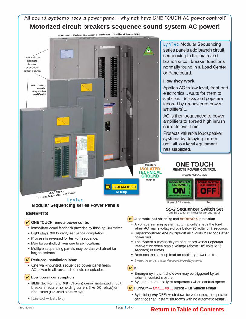
All sound systems need a power panel - why not have ONE TOUCH AC power control?
Motorized circuit breakers sequence sound system AC power!
Low voltage cabinetshouse
sequencer circuit boards
MSLC 326-xx
Modular Sequencing Load Center
MSLC 341-xxModular
Sequencing Load Center
MSP 341-xx Modular Sequencing Panelboard - The Electrician's choice
Separate
ISOLATEDISOLATEDTECHNICAL
GROUNDcabinet
LynTec Modular Sequencing series panels add branch circuit sequencing to the main and branch circuit breaker functions normally found in a Load Center or Panelboard.
How they work
Applies AC to low level, front-end electronics... waits for them to stabilize... (clicks and pops are ignored by un-powered power amplifi ers)...
AC is then sequenced to power amplifi ers to spread high inrush currents over time.
Protects valuable loudspeaker systems by delaying turn-on until all low level equipmenthas stabilized.
LynTec Modular Sequencing series Power Panels
BENEFITS
✔ ONE TOUCH remote power control
• Immediate visual feedback provided by fl ashing ON switch.
• Light stays ON to verify sequence completion.• Process is reversed for turn-off sequence.• May be controlled from one to six locations.• Multiple sequencing panels may be daisy-chained for larger systems.
✔ Reduced installation labor
• One wall-mounted, sequenced power panel feeds AC power to all rack and console receptacles.
✔ Low power consumption
• BMB (Bolt-on) and MB (Clip-on) series motorized circuit breakers require no holding current (like DC relays) or heat sinks (like solid state relays).
• Runs cool — lasts long.
✔ Automatic load shedding and BROWNOUT protection
• A voltage sensing system automatically sheds the load when AC mains voltage drops below 95 volts for 2 seconds. • Capacitor-stored energy zips-off all circuits 2 seconds after power fails. • The system automatically re-sequences without operator intervention when stable voltage (above 105 volts for 5 seconds) resumes.• Reduces the start-up load for auxiliary power units.
• Smart wake-up is ideal for unatt ended systems.
✔ Kill
• Emergency instant shutdown may be triggered by an external contact closure. • System automatically re-sequences when contact opens.
✔ HurryOff — Ohh..... no..... switch – Kill without restart
• By holding any OFF switch down for 2 seconds, the operator can trigger an instant shutdown with no automatic restart.
ONE TOUCHREMOTE POWER CONTROL
SHOWN ACTUAL SIZE
Green LED illuminated Red
SS-2 Sequencer Switch SetOne SS-2 switch set is supplied with each panel.
Return to Table of Contents

139-0357-04.2 Page 2 of 8
MSP 141-xxMSP 141-xx MModular odular SSequencing equencing PPanelboardanelboard
1Ø, 3 wire, 120/240 Vac. All Special Order, NCNR.
(Non Cancelable, Non Returnable)
Panelboard INTERIOR Alternatives Panelboard INTERIOR Alternatives Cabinet outlines same as 3 phase above Cabinet outlines same as 3 phase above
NQOD Panel 225A Copper Bus
#4 — 300 kcmil Al/Cu Main Breakers available
QDL22xxx series — All 25k AIR Part# suffix — Bold face = Amps
-MQD2070, -MQD2080, -MQD2090, -MQD2100, -MQD2110, -MQD2125, -MQD2150, -MQD2175, -MQD2100,
-MQD2200, -MQD2225.
S N
S N /
SEQUENCER POWER 10A supplied installed MAIN
S I N G L E
P H A S E
/
225A Copper
Bus
MSPHH option: QGL22xxx series — All 65k AIR. Any of the above ratings — use -MQG2xxx suffix
MSLC 341-xx or MSLCH 341-xx Modular Sequencing Load Center
3Ø, 208Y/120 Vac, 4 wire. 225 Amp Main Breaker Standard
Cabinet Outline — Surface mount only
Outside dimensions MSLC 341 or MSLC 338 20.9" w., 39.3" h., 3.9" d.
SEQUENCER POWER 10A supplied installed
Square D QO342MQ225 Load Center with LynTec low-voltage sidecar.
Standard Main Breaker: QDL32225. 225 Amp
Main Breaker options — Part# suffix — Bold face=Amps -M3125, -M3150, -M3175 or -M3200
QDL32xxx series (all 25k AIR) [Amps Interrupt Rating] Wire: 350 kcmil Al or 250 kcmil Cu. 100% Neutral has one feed lug
that accepts one 350 kcmil Al or one 250 kcmil Cu wire.
Sequencer
1 Sequencer
2 Sequencer
3 Sequencer
4 Isolated Technical Isolated Technical Ground Bar Ground Bar
Branches: 26 pos., 14 - 4 ga.
Feed: 2/0 max.
AA BB CCS / N
S / N MAIN
225A Copper Bus
All
Panels
MSP 338-xx MSP 338-xx MModular odular SSequencing equencing PPanelboardanelboard
3Ø, 208Y/120 Vac, 4 wire. 30 to 100 Amp QOB3xx series Bolt-on, back-fed Main Breaker
SEQUENCER POWER 10A supplied installed
NQOD-NL Panel 225A Copper Bus 200% Neutrals.
2 — 250 kcmil Cu
MAIN 2/0
max.
MA
IN
2 X N
AABBCC
225A Copper
Bus
If 200% neutrals or bolt-on breakers are required, use MSP 341-xx Panelboard.
AA BB CC
MSLC 338-xx Modular Sequencing Load Center
3Ø, 208Y/120 Vac, 4 wire. 30 to 100 Amp back-fed Main Breaker
Cabinet Outline — Surface mount only
Square D QO342 Load Center with LynTec low-voltage sidecar.
back-fed Main Breaker options
Part# suffix — Bold face=Amps -M3030, -M3035: (10kAIR)
Squared D#: QO30xx
-M3050, -M3060, -M3070 or -M3090 Squared D#: QO3xxVH
(all 22k AIR) [Amps Interrupt Rating]
Wire: #4 - 2/0 kcmil Cu.
Neutral data and Outline Dimensions same as MSLC 341 above.
Sequencer
1 Sequencer
2 Sequencer
3 Sequencer
4 Isolated Technical Isolated Technical Ground Bar Ground Bar
Branches: 26 pos., 14 - 4 ga.
Feed: 2/0 max.
MA
IN
225A Copper
Bus S / N
S / N
SEQUENCER POWER 10A supplied installed
Square D NQOD-NL MB Panel with LynTec sidecars.Standard Main Breaker: JGP36225YL — 225 Amp
Main Breaker options — Part# suffix — Bold face = Amps-MHG3125, -MJG3150, -MJG3175 or -MJG3200
HGP36xxx or JGP36xxx series (all 65k AIR) [Amps Interrupt Rating]
All Panelboards — Outside dimensions — 36" w., 50" h., 6.13" d.High voltage interior may be field inverted for top feed.
Knockout panels supplied in both ends.
MSP 341-xxMSP 341-xx oror MSP MSPHH 341-xx 341-xx MModular odular SSequencing equencing PPanelboardanelboard
3Ø, 208Y/120 Vac, 4 wire. 225 Amp Main Breaker Standard
Cabinet Outline — Surface mount only
Feed 4/0 max.
Iso-Tech Ground
Branches: 46 position 14 - 4 ga. NQOD-NL Panel
200% Neutrals. 2 — 250 kcmil Cu
MAIN 2 X N
SEQUENCER POWER
AABBCC
Isolated Isolated Technical Technical Ground Ground
Bar Bar
Feed 2/0 max.
High voltage interior may be field inverted for top feed
225A Copper
Bus
Sequencer
1 Sequencer
2 Sequencer
3 Sequencer
4 Sequencer
5
MSLC 129-xx Modular Sequencing Load Center
1Ø, 3 wire, 120/240 Vac. 200 Amp Main Breaker Standard
Cabinet Outline — Surface mount only
Square D QO130M200 Load Center with LynTec low-voltage sidecar.
Standard Main Breaker: QOM2200VH.
200A, 22k AIR. [Amps Interrupt Rating]
Main Breaker option — Part# suffix
-M1150 Amp
Square D#: QOM2xxxVH, All 22k AIR. Wire: #4 - 350 kcmil Al/Cu.
Other back-fed main options Uses positions 2 & 4 for back-fed main breaker
resulting in a MSLC 127-xx-Mxxx part #.
Main Options — Part# suffix — Bold face=Amps -M1030, -M1040, -M1060,
-M1080 & -M1100 available. Square D QO2xxxVH, all 22k AIR.
Wire: #4 - 2/0 kcmil Cu. Outside dimensions
20.9" w., 29.8" h., 3.9" d.
Isolated Technical Isolated Technical Ground Bar Ground Bar Feed: 2/0 max. Branches: 29 positions, 14 - 4 ga.
SEQUENCER POWER 10A supplied installed
S I N G L E
P H A S E
Sequencer
1 Sequencer
2 Sequencer
3
S / N
S / N MAIN
These two positions used for back fed
main breaker in
MSLC 127-xx. (For main breakers 100 Amps or less.)
MSLC 326-xx Modular Sequencing Load Center
3Ø, 208Y/120 Vac, 4 wire. 100 Amp Main Breaker Standard
Cabinet Outline — Surface mount only
Isolated Technical Isolated Technical Ground Bar Ground Bar Feed: 2/0 max. Branches: 26 positions, 14 - 4 ga.
SEQUENCER POWER 10A supplied installed
Square D QO327M100 Load Center with LynTec low-voltage sidecar.
Standard back-fed Main Breaker: Squared D#: QO3100VH. 100A,
(VH = 22k AIR) [Amps Interrupt Rating].
Main Breaker options
Main Lug Only -MLO option Feed this panel with appropriate protected disconnect.
Panel Mains Rating is 200A. Provides access to branch breaker positions 1, 3, & 5. Becomes MSLC 329-xx-MLO (may hold up to 29 breakers)
Outside dimensions: 20.9" w., 29.8" h., 3.9" d.
MLO option Back fed main may be
replaced by a protected disconnect, allowing up to
29 breakers.
Model no. becomes a
MSLC-329-xx-MLO
Sequencer
1 Sequencer
2 Sequencer
3
S / N
S / N
MA
IN
AABBCC
139-
0357
-03.
2.ep
s
LynTec — AVAILABLE MODELS — LynTecPanel electrical specifi cations and confi gurations — Outline dimensions
The base model -xx suffi x is the number of motorized breakers the control system will drive: -12, -24, -36, -48 or -60.
Click on icon to download model specifi c Panel Planners for submittals. — Full AllPanel brochure.
Return to Table of Contents

Derived from Digest 173 — page 6-21
Thermal-magnetic Molded Case Circuit Breakers
250 Ampere FrameClass 734
6
CIR
CU
IT B
RE
AK
ER
S
© 2004 Schneider ElectricAll Rights Reserved4/1/04
www.SquareD.comFor the most up-to-date information
Accessories . . . . . . . . . . . . . . . . . . . . . . . . . . pages 6-36–6-38Optional Lugs . . . . . . . . . . . . . . . . . . . . . . . . . pages 6-43, 6-44Dimensions . . . . . . . . . . . . . . . . . . . . . . . . . . . pages 6-49, 6-50Enclosures. . . . . . . . . . . . . . . . . . . . . . . . . . . . pages 6-51–6-54
Interrupting Ratings (kA)
QD QG
240 V 25 65
Replacement lugs are not available for POWERPACT Q-frame circuit breakers.Lugs for the POWERPACT Q-frame circuit breakers accept (1) #4–300 kcmil.
POWERPACT Q-frame
—250 A, Thermal-magnetic (240 Vac)
Current Rating @ 40°C
AC Magnetic Trip Settings D Interrupting G Interrupting
Hold Trip Catalog Number
Catalog Number
2-pole, 240 Vac
70 1000 1800
QDL22070
QGL22070
80 1000 1800
QDL22080
QGL22080
90 1000 1800
QDL22090
QGL22090
100 1200 2400
QDL22100
QGL22100
110 1200 2400
QDL22110
QGL22110
125 1200 2400
QDL22125
QGL22125
150 1200 2400
QDL22150
QGL22150
175 1200 2400
QDL22175
QGL22175
200 1200 2400
QDL22200
QGL22200
225 1200 2400
QDL22225
QGL22225
250 1200 2400
3-pole, 240 Vac
70 1000 1800
QGL32070
80 1000 1800
QGL32080
90 1000 1800
QGL32090
100 1200 2400
QGL32100
110 1200 2400
QGL32110
125 1200 2400
QGL32125
150 1200 2400
QDL32150
QGL32150
175 1200 2400
QDL32175
QGL32175
200 1200 2400
QDL32200
QGL32200
225 1200 2400
QDL32225
QGL32225
250 1200 2400
QDL & QGL 2 and 3-pole
70–250 Amperes
▲
▲
LynTec 139-0343-03 Q Frame Mains 10/31/06
Current Rating @ 40°C
AC Magnetic Trip Settings D Interrupting G Interrupting
Hold Trip Catalog Number
Catalog Number
LynTecMSP 119MSP 141
✚✚ All models70-225A
Special order, NCNRNon Cancelable Non Returnable
LynTecMSLCH 341
✚ Optional from stock
LynTecLCLC 341MSLC 341➤Standard
✚ Optional from stock
✚
✚✚
✚
✚✚✚✚✚✚✚✚✚✚
✚✚✚✚✚✚✚✚✚✚
➤
}
} }
LynTecMSP 139
Use a 2 pole, back-fedmain breaker, rated at
100 AMPS or less.
QO2xxxVH Series22kAIR
For Branch Breaker Series Ratingssee http://www.lyntec.com/139-0407_Series_Ratings.pdf
LynTecLCLC 326MSLC 326MSLC 338MSP 338
Use a 3 pole, back-fedmain breaker, rated at
100 AMPS or less.
QO3xxxVH Series22kAIR
Return to Table of Contents
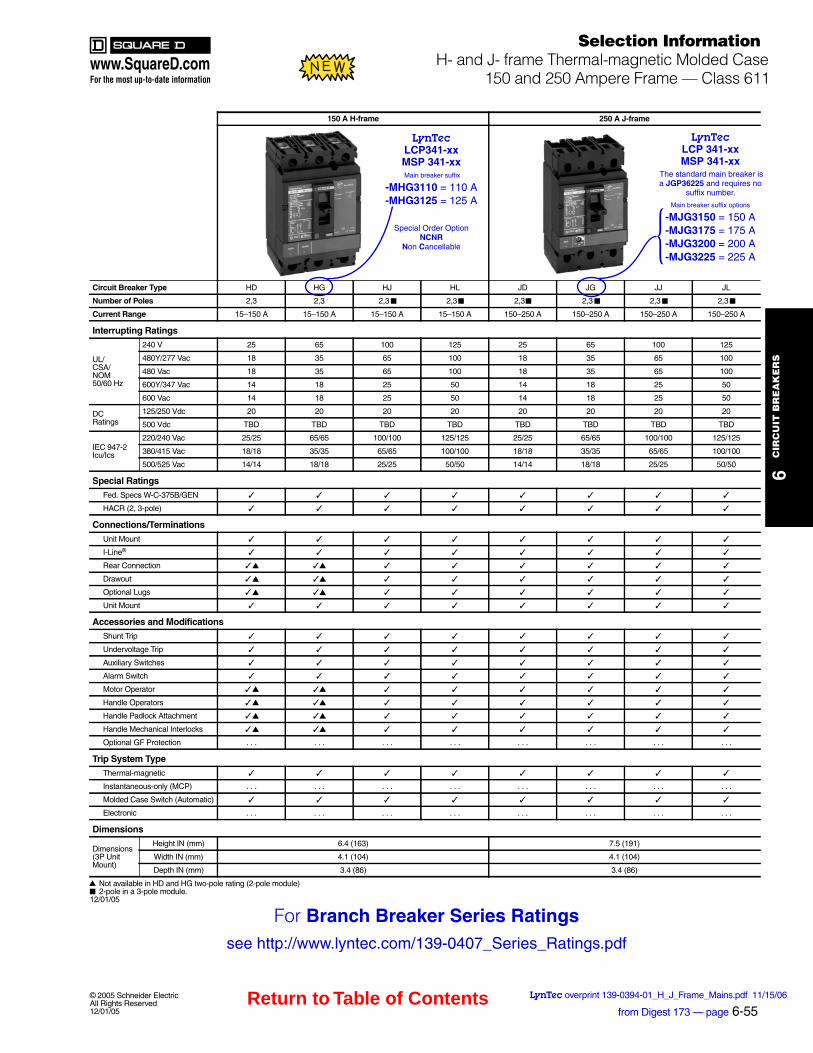
Selection InformationH- and J- frame Thermal-magnetic Molded Case
150 and 250 Ampere Frame — Class 611
6C
IRC
UIT
BR
EA
KE
RS
© 2005 Schneider ElectricAll Rights Reserved12/01/05
www.SquareD.comFor the most up-to-date information
Not available in HD and HG two-pole rating (2-pole module)2-pole in a 3-pole module.
12/01/05
emarf-J A 052emarf-H A 051
Circuit Breaker Type HD HG HJ HL JD JG JJ JL
Number of Poles 2,3 2,3 2,3 2,3 2,3 2,3 2,3 2,3
Current Range 15–150 A 15–150 A 15–150 A 15–150 A 150–250 A 150–250 A 150–250 A 150–250 A
Interrupting Ratings
UL/CSA/NOM50/60 Hz
52100156525210015652V 042
480Y/277 Vac 18 35 65 100 18 35 65 100
480 Vac 18 35 65 100 18 35 65 100
600Y/347 Vac 14 18 25 50 14 18 25 50
600 Vac 14 18 25 50 14 18 25 50
DCRatings
125/250 Vdc 20 20 20 20 20 20 20 20
500 Vdc TBD TBD TBD TBD TBD TBD TBD TBD
IEC 947-2Icu/Ics
220/240 Vac 25/25 65/65 100/100 125/125 25/25 65/65 100/100 125/125
380/415 Vac 18/18 35/35 65/65 100/100 18/18 35/35 65/65 100/100
500/525 Vac 14/14 18/18 25/25 50/50 14/14 18/18 25/25 50/50
Special Ratings
Fed. Specs W-C-375B/GEN
HACR (2, 3-pole)
Connections/Terminations
Unit Mount
I-Line®
Rear Connection
Drawout
Optional Lugs
Unit Mount
Accessories and ModificationsShunt Trip
Undervoltage Trip
Auxiliary Switches
Alarm Switch
Motor Operator
Handle Operators
Handle Padlock Attachment
Handle Mechanical Interlocks
Optional GF Protection . . . . . . . . . . . . . . . . . . . . . . . .
Trip System TypeThermal-magnetic
Instantaneous-only (MCP) . . . . . . . . . . . . . . . . . . . . . . . .
Molded Case Switch (Automatic)
. . .. . .. . .. . .. . .. . .. . .. . .cinortcelE
Dimensions
Dimensions(3P Unit Mount)
)191( 5.7)361( 4.6)mm( NI thgieH
)401( 1.4)401( 1.4)mm( NI htdiW
)68( 4.3)68( 4.3)mm( NI htpeD
▲ ▲
▲ ▲
▲ ▲
▲ ▲
▲ ▲
▲ ▲
▲ ▲
■ ■ ■ ■ ■ ■
▲■
from Digest 173 — page 6-55LynTec overprint 139-0394-01_H_J_Frame_Mains.pdf 11/15/06
LynTecLCP341-xxMSP 341-xx Main breaker suffix
-MHG3110 = 110 A-MHG3125 = 125 A
Special Order OptionNCNR
Non Cancellable
LynTecLCP 341-xxMSP 341-xx
The standard main breaker is a JGP36225 and requires no
suffix number.
Main breaker suffix options -MJG3150 = 150 A-MJG3175 = 175 A-MJG3200 = 200 A-MJG3225 = 225 A}
For Branch Breaker Series Ratingssee http://www.lyntec.com/139-0407_Series_Ratings.pdf
Return to Table of Contents
www.SquareD.comFor the most up-to-date information
8-2
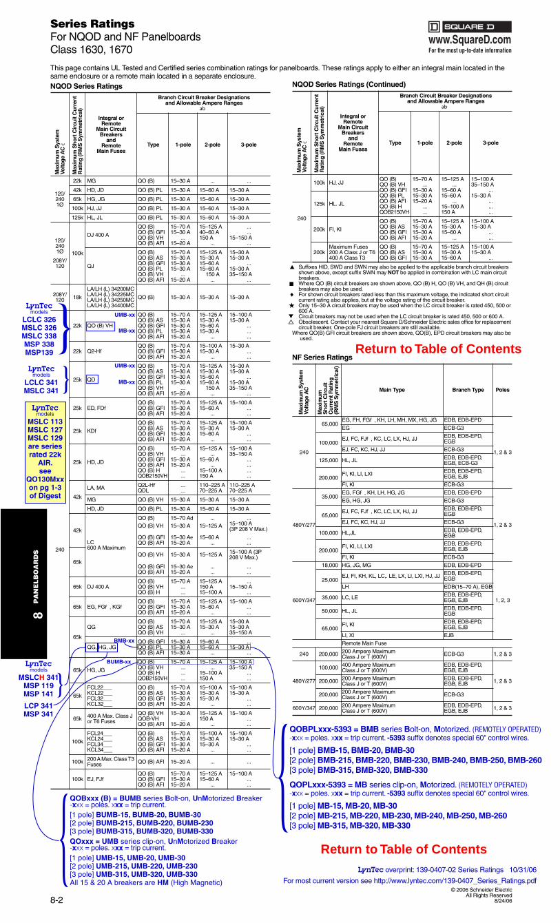
Series RatingsFor NQOD and NF PanelboardsClass 1630, 1670
8P
AN
EL
BO
AR
DS
© 2006 Schneider ElectricAll Rights Reserved
8/24/06
This page contains UL Tested and Certified series combination ratings for panelboards. These ratings apply to either an integral main located in the same enclosure or a remote main located in a separate enclosure.
Suffixes HID, SWD and SWN may also be applied to the applicable branch circuit breakers shown above, except suffix SWN may NOT be applied in combination with LC main circuit breakers.Where QO (B) circuit breakers are shown above, QO (B) H, QO (B) VH, and QH (B) circuit breakers may also be used.For shown circuit breakers rated less than this maximum voltage, the indicated short circuit current rating also applies, but at the voltage rating of the circuit breaker.Only 15–30 A circuit breakers may be used when the LC circuit breaker is rated 450, 500 or 600 A.Circuit breakers may not be used when the LC circuit breaker is rated 450, 500 or 600 A.Obsolescent. Contact your nearest Square D/Schneider Electric sales office for replacement circuit breaker. One-pole FJ circuit breakers are still available.
Where QO(B) GFI circuit breakers are shown above, QO(B), EPD circuit breakers may also be used.
8/24/06
NQOD Series Ratings
Max
imum
Sys
tem
Volta
ge
AC
c
Max
imum
Sho
rt C
ircu
it C
urre
nt
Rat
ing
(RM
S S
ymm
etri
cal)
Integral orRemote
Main CircuitBreakers
andRemote
Main Fuses
Branch Circuit Breaker Designations and Allowable Ampere Ranges
ab
Type 1-pole 2-pole 3-pole
120/2401Ø
22k MG QO (B) 15–30 A ... ...
42k HD, JD QO (B) PL 15–30 A 15–60 A 15–30 A
65k HG, JG QO (B) PL 15–30 A 15–60 A 15–30 A
100k HJ, JJ QO (B) PL 15–30 A 15–60 A 15–30 A
125k HL, JL QO (B) PL 15–30 A 15–60 A 15–30 A
120/2401Ø
208Y/120
100k
DJ 400 A
QO (B) 15–70 A 15–125 A ...QO (B) GFI 15–30 A 40–60 A ...QO (B) VH ... 150 A 15–150 AQO (B) AFI 15–20 A ... ...
QJ
QO (B) 15–70 A 15–125 A 15–30 AQO (B) AS 15–30 A 15–30 A 15–30 AQO (B) GFI 15–30 A 15–60 A ...QO (B) PL 15–30 A 15–60 A 15–30 AQO (B) VH ... 150 A 35–150 AQO (B) AFI 15–20 A ... ...
208Y/120 18k
LA/LH (L) 34200MCLA/LH (L) 34225MCLA/LH (L) 34250MCLA/LH (L) 34400MC
QO (B) 15–30 A 15–30 A 15–30 A
240
22k QO (B) VH
QO (B) 15–70 A 15–125 A 15–100 AQO (B) AS 15–30 A 15–30 A 15–30 AQO (B) GFI 15–30 A 15–60 A ...QO (B) PL 15–30 A 15–30 A ...QO (B) AFI 15–20 A ... ...
22k Q2-HfQO (B) 15–70 A 15–100 A 15–30 AQO (B) GFI 15–30 A 15–30 A ...QO (B) AFI 15–20 A ... ...
25k QD
QO (B) 15–70 A 15–125 A 15–30 AQO (B) AS 15–30 A 15–30 A 15–30 AQO (B) GFI 15–30 A 15–60 A ...QO (B) PL 15–30 A 15–60 A 15–30 AQO (B) VH ... 150 A 35–150 AQO (B) AFI 15–20 A ... ...
25k ED, FDfQO (B) 15–70 A 15–125 A 15–100 AQO (B) GFI 15–30 A 15–60 A ...QO (B) AFI 15–20 A ... ...
25k KDfQO (B) 15–70 A 15–125 A 15–100 AQO (B) AS 15–30 A 15–30 A 15–30 AQO (B) GFI 15–30 A 15–60 A ...QO (B) AFI 15–20 A ... ...
25k HD, JD
QO (B) 15–70 A 15–125 A 15–100 AQO (B) VH ... ... 35–150 AQO (B) GFI 15–30 A 15–60 A ...QO (B) AFI 15–20 A ... ...QO (B) H ... 15–100 A ...QOB2150VH ... 150 A ...
42k
LA, MA Q2L-Hf ... 110–225 A 110–225 AQDL ... 70–225 A 70–225 A
MG QO (B) VH 15–30 A 15–30 A 15–30 A
HD, JD QO (B) PL 15–30 A 15–60 A 15–30 A
42k
LC600 A Maximum
QO (B) 15–70 Ad ... ...QO (B) VH 15–30 A 15–125 A 15–100 A
(3P 208 V Max.)
QO (B) GFI 15–30 Ae 15–60 A ...QO (B) AFI 15–20 A ... ...
65kQO (B) VH 15–30 A 15–125 A 15–100 A (3P
208 V Max.)
QO (B) GFI 15–30 Ae ... ...QO (B) AFI 15–20 A ... ...
65k DJ 400 AQO (B) 15–70 A 15–125 A ...QO (B) VH ... 150 A 15–150 AQO (B) H ... 15–100 A ...
65k EG, FGf , KGfQO (B) 15–70 A 15–125 A 15–100 AQO (B) GFI 15–30 A 15–60 A ...QO (B) AFI 15–20 A ... ...
65k
QGQO (B) 15–70 A 15–125 A 15–30 AQO (B) AS 15–30 A 15–30 A 15–30 AQO (B) VH ... ... 35–150 A
QG, HG, JGQO (B) GFI 15–30 A 15–60 A ...QO (B) PL 15–30 A 15–60 A 15–30 AQO (B) AFI 15–30 A ... ...
65k HG, JG
QO (B) 15–70 A 15–125 A 15–100 AQO (B) VH ... ... 35–150 AQO (B) H ... 15–100 A ...QOB2150VH ... 150 A ...
65k
FCL22___ QO (B) 15–70 A 15–100 A 15–100 AKCL22___ QO (B) AS 15–30 A 15–30 A 15–30 AFCL32___ QO (B) GFI 15–30 A 15–30 A ...KCL32___ QO (B) AFI 15–20 A ... ...
65k 400 A Max. Class J or T6 Fuses
QO (B) VH 15–30 A 15–125 A 15–100 AQOB-VH ... 150 A ...QO (B) AFI 15–20 A ... ...
100k
FCL24___ QO (B) 15–70 A 15–100 A 15–100 AKCL24___ QO (B) AS 15–30 A 15–30 A 15–30 AFCL34___ QO (B) GFI 15–30 A 15–30 A ...KCL34___ QO (B) AFI 15–20 A ... ...
100k 200 A Max. Class T3 Fuses QO (B) AFI 15–20 A ... ...
100k EJ, FJfQO (B) 15–70 A 15–125 A 15–100 AQO (B) GFI 15–30 A 15–60 A ...QO (B) AFI 15–20 A ... ...
240
100k HJ, JJQO (B) 15–70 A 15–125 A 15–100 AQO (B) VH ... ... 35–150 AQO (B) GFI 15–30 A 15–60 A ...
125k HL. JL
QO (B) PL 15–30 A 15–60 A 15–30 AQO (B) AFI 15–20 A ... ...QO (B) H ... 15–100 A ...QOB2150VH ... 150 A ...
200k FI, KI
QO (B) 15–70 A 15–125 A 15–100 AQO (B) AS 15–30 A 15–30 A 15–30 AQO (B) GFI 15–30 A 15–60 A ...QO (B) AFI 15–20 A ... ...
200kMaximum Fuses200 A Class J or T6400 A Class T3
QO (B) 15–70 A 15–125 A 15–100 AQO (B) AS 15–30 A 15–30 A 15–30 AQO (B) GFI 15–30 A 15–60 A ...
NF Series Ratings
Max
imum
Sys
tem
Vo
ltag
e A
C
Max
imum
S
hort
Cir
cuit
Cur
rent
Rat
ing
(R
MS
Sym
met
rica
l)
Main Type Branch Type Poles
240
65,000EG, FH, FGf , KH, LH, MH, MX, HG, JG EDB, EDB-EPD
1, 2 & 3
3G-BCEGE
100,000EJ, FC, FJf , KC, LC, LX, HJ, JJ EDB, EDB-EPD,
EGB
3G-BCEJJ ,JH ,CK ,CF ,JE
125,000 HL, JL EDB, EDB-EPD, EGB, ECB-G3
200,000FI, KI, LI, LXI EDB, EDB-EPD,
EGB, EJB
3G-BCEIK ,IF
480Y/277
35,000EG, FGf , KH, LH, HG, JG EDB, EDB-EPD
1, 2 & 3
3G-BCEGJ ,GH ,GE
65,000EJ, FC, FJf , KC, LC, LX, HJ, JJ EDB, EDB-EPD,
EGB
3G-BCEJJ ,JH ,CK ,CF ,JE
100,000 HL,JL EDB, EDB-EPD, EGB
200,000FI, KI, LI, LXI EDB, EDB-EPD,
EGB, EJB
3G-BCEIK ,IF
600Y/347
DPE-BDE ,BDEGM ,GJ ,GH000,81
1, 2, 3
25,000EJ, FI, KH, KL, LC,. LE, LX, LI, LXI, HJ, JJ EDB, EDB-EPD,
EGB
BGE ,)A 07–51(BDEHL
35,000 LC, LE EDB, EDB-EPD, EGB, EJB
50,000 HL, JL EDB, EDB-EPD, EGB
65,000FI, KI EDB, EDB-EPD,
EGB, EJB
BJEIX ,IL
Remote Main Fuse
240 200,000 200 Ampere Maximum Class J or T (600V) ECB-G3 1, 2 & 3
480Y/277
100,000 400 Ampere Maximum Class J or T (600V)
EDB, EDB-EPD, EGB, EJB
1, 2 & 3200,000 200 Ampere Maximum Class J or T (600V)
EDB, EDB-EPD, EGB, EJB
200,000 200 Ampere Maximum Class J or T (600V) ECB-G3
600Y/347 200,000 200 Ampere Maximum Class J or T (600V)
EDB, EDB-EPD, EGB, EJB 1, 2 & 3
NQOD Series Ratings (Continued)
Max
imum
Sys
tem
Volta
ge
AC
c
Max
imum
Sho
rt C
ircu
it C
urre
nt
Rat
ing
(RM
S S
ymm
etri
cal)
Integral orRemote
Main CircuitBreakers
andRemote
Main Fuses
Branch Circuit Breaker Designations and Allowable Ampere Ranges
ab
Type 1-pole 2-pole 3-pole
▲
■
★
▼▲
♦
LynTecmodels
MSLCH 341MSP 119MSP 141
LCP 341MSP 341
}
LynTecmodels
LCLC 341MSLC 341
}
LynTecmodels
LCLC 326MSLC 326MSLC 338MSP 338MSP139
}LynTec
models
MSLC 113MSLC 127MSLC 129are series rated 22k
AIR.see
QO130Mxxon pg 1-3 of Digest
LynTec overprint: 139-0407-02 Series Ratings 10/31/06
For most current version see http://www.lyntec.com/139-0407_Series_Ratings.pdf
QOBxxx (B) = BUMB series Bolt-on, UnMotorized Breaker-xxx = poles. xxx = trip current. [1 pole] BUMB-15, BUMB-20, BUMB-30 [2 pole] BUMB-215, BUMB-220, BUMB-230 [3 pole] BUMB-315, BUMB-320, BUMB-330QOxxx = UMB series clip-on, UnMotorized Breaker-xxx = poles. xxx = trip current.[1 pole] UMB-15, UMB-20, UMB-30 [2 pole] UMB-215, UMB-220, UMB-230 [3 pole] UMB-315, UMB-320, UMB-330All 15 & 20 A breakers are HM (High Magnetic)
QOBPLxxx-5393 = BMB series Bolt-on, Motorized. (REMOTELY OPERATED) -xxx = poles. xxx = trip current. -5393 suffix denotes special 60" control wires.
[1 pole] BMB-15, BMB-20, BMB-30[2 pole] BMB-215, BMB-220, BMB-230, BMB-240, BMB-250, BMB-260[3 pole] BMB-315, BMB-320, BMB-330
QOPLxxx-5393 = MB series clip-on, Motorized. (REMOTELY OPERATED) -xxx = poles. xxx = trip current. -5393 suffix denotes special 60" control wires.
[1 pole] MB-15, MB-20, MB-30[2 pole] MB-215, MB-220, MB-230, MB-240, MB-250, MB-260[3 pole] MB-315, MB-320, MB-330{ {
MB-xx
UMB-xx
MB-xx
UMB-xx
BMB-xx
BUMB-xx
Return to Table of Contents
Return to Table of Contents

139-0357-04.3 Page 3 of 8
Typical Panel Planner and Layout Worksheet — As-built door label
See at LynTec.com for model specifi c Panel Planners for submittals
To p Board 1.
1 boar d model :
MSLC 326-12 Modular
SequencingLoad Center
Board 2. 2 boar d model :
MSLC 326-2 4Modular
SequencingLoad Center
Board 3. 3 boar d model :
MSLC 326-36 Modular
SequencingLoad Center
Which board?
g yLynTec MSLC 326-xx Modular Sequencing Load Center
(One-Touch, sequential AC po wer control f or Sound & AV Systems)
Breaker types, sizes, positions and connection s
Phase
Phase
Phase
Pa nel ____________________________________
Comments________________________________
_________________________________________
by________________________ Date___________
MS-12 Sequencer cir cuit boar ds in left-hand, low vo ltage cabinet .
_____Amp. ^Un-motorized. ^Motorized-Step # ____(2b)
_____Amp. ^Un-motorized. ^Motorized-Step # ____(3b )
_____Amp. ^Un-motorized. ^Motorized-Step # ____(4b )
_____Amp. ^Un-motorized. ^Motorized-Step # ____(5b )
_____Amp. ^Un-motorized. ^Motorized-Step # ____(6b )
_____Amp. ^Un-motorized. ^Motorized-Step # ____(1b )
_____Amp. ^Un-motorized. ^Motorized-Step # ____(1a )
_____Amp. ^Un-motorized. ^Motorized-Step # ____(1b)
_____Amp. ^Un-motorized. ^Motorized-Step # ____(2a)
_____Amp. ^Un-motorized. ^Motorized-Step # ____(3a )
_____Amp. ^Un-motorized. ^Motorized-Step # ____(4a )
_____Amp. ^Un-motorized. ^Motorized-Step # ____(5a )
_____Amp. ^Un-motorized. ^Motorized-Step # ____(6a )
_____Amp. ^Un-motorized. ^Motorized-Step # ____(1a )
LynTecLynTec
MSLC 326-xx -xx = Maximum number of sequenced break ers.
See r ight side of page f ormodel number ex planation.
Modular SequencingLoad Center
10A un-motorized br eaker supplied installed.
MAIN
Each moto rized break er is controlled by a sequence r.As-built door label e xample:Step #_______ (1a) (# in parenthesis is suggested break er connection in sequencer) .Bold line around bo x = suggested sequencer board: #1(T op), #2 or #3 .Fill in bo x to indicate which sequencer board this break er is connected to .
1a1a
AAAA BBBBBCCCCC
Square D QO327M100 Load Center with L ynTec lo w-voltage sidecar .
Standard bac k-fed Main Brea ker:QO3100VH. 100A, (VH = 22kAIR).
Main options — Pa r t# suffix BOLD FA CE =Amps
-M3030, -M3035 [10kAIR]QO3xx
-M3050, -M3060, -M3070 or -M3090QO3xxVH [all 22k AIR]
[Amps Inter rupt Rating ]
Wire: #4 - 2/0 kcmil Cu .
Outside dimensions 20.9" w ., 29.8" h., 3.9" d. Surface mount onl y.
Isolated Te chnical Ground Ba rFe ed : 2/0 max.
Branches: 26 positions , 14 - 4 ga.
Cabinet Outline
Sequencer
1Sequencer
2Sequencer
3
S/N
S/N
MA
IN
ocument # 139-0245-14 MSLC 326 Planner 10/28/06
Tr ansfer as-built formation to the doorabel upon completion.
Keep this sheet fors-built documentatio n
ailable as PDF download w.lyntec.com/139-0245_MSLC326Plnr.pdf
111
333
555
777
999
111111
131313
151515
171717
191919
212121
232323
252525
272727
292929
AAA
BBB
CCC
AAA
BBB
CCC
AAA
BBB
CCC
AAA
BBB
CCC
AAA
BBB
CCC
282828
262626
242424
222222
202020
181818
161616
141414
121212
101010
888
666
444
222
SEQUENCER POWERSEQUENCER POWER
Each 6 step sequencer board control sup to 12 break ers by tur ning on and offtwo break ers per step .
The circuit boards are f actorydaisy-chained, top-to-bottom, with theCascade Connector (4 pin) set.
The Power & Kill Connector (4 pin) setcarries po wer, common and Kill signal s.
ZIP-OFF load shedding
2 seconds after a po wer f ailure, thesequencer tur ns off all sequenced break ers.When po wer resumes the sequencerautomatically re-sequences the system on .
ZIP-OFF ma y be demonstrated by tur ningoff the SEQUENCER POWER break ermomentarily.
www.LynTec.com
800-724-40478-5 Central Time
146-0208-04 MSLC 32 6
303030
Low voltage controlWiring Diagram located inside
left cover. www.lyntec.com/139-0327_SequencerLV_Wiring.pdf
How it worksThe SEQUENCER POWE R circuitbreaker po wers the sequencer circuitboards via a 24 volt transf ormer.
Motorized circuit break ers (mar kedREMOTELY OPERA TED ) are time sequenced by rela ys in the adjacent, left-sid e,low voltage sequencer cabinet.
The ON or OFF sequence is initiated at remote sound system locationsand ma y be locally tested with thetop green ON and bottom red OFF buttons on the circuit board s.
Sequenced break ers are sequencedon (Steps 1 to 6) and off (Steps 6 to 1) at 1/8 to 1 second inte rvals andmay ha ve a programmed PA USE DELAY of up to 8 minutes du ring the sequence. These STEP RA TE,DELAY TIME and DELAY POSITION settings are set by mo veable jumpers inside the sequencer cabinet.
Seehttp://www.lyntec.com/139-0245_MSLC326Plnr.pdf
for latest version.
Return to Table of Contents

139-0357-00.4 Page 4 of 8 Return to Table of Contents

139-0357-01.5 Page 5 of 8
Bottom end view
6.13"
50.00"
36.00"
2.00"15.00"
32.00"
44.00"
3.00"
PANELBOARD MSP 341 series LynTec
Feeder lug6 – 2/0
46 Branches
14 – 4
Low Voltage Sequencing sidecar Isolated Technical Isolated Technical
GroundGround sidecar
QDL32225[25k AIR] or QGL 32225 [65k AIR]225 A Main Breaker Standard (65 kVA)
See pages 2 & 6 for main options.
Interior factory installed for bottom feed. May be fi eld reversed for top feed.
Reverse interior, then reverse the main breaker and main breaker bracket position to maintain a
"up-is-on" main breaker handle.
MB series (clip-on)BMB series (bolt-on)
Motorized Branch Breakers
Branch Breakers are NOT included in MSP 341 — order separately — page 7
200% Neutral.Requires two - 4/0 Cu
feeders.
Top end view
24v, 40VA power
transformer
Feeder lug6 – 4/0
Morephotos
@LynTec.com
Model shown
MSP 341-48 41/20
Field connect to SEQUENCER
POWERbreaker.
Branch breakers are installed for illustration only.
Branch breakers are fi eld installed and low-voltage wired to appropriate sequencer boards in left sidecar per
sound system requirements.
See typical Panel Planner on page 3
Return to Table of Contents

139-0357-04.6 Page 6 of 8 Return to Table of Contents
1224364860
panelboard only
Sequencercapacity—will drive up to this
number of motorizedbreakers
MSP 341 -36 21/BMB-20 8/BMB-30 5/BUMB-20 -MJG3150
LoadCenters
127✧129✤326338♦341Number ofavailablecircuitbreakerspaces
1 = 1 phase120/240v, 3 wire
or
3 = 3 phase208/120v, 4 wire
MSLC 326
Factory options — add suffi x to part number-CR-x: Completion Relay option.
Provides SPDT (form C) relay contact that changes state at the completion of any fi eld selectable step.Add -CR-x for each board requiring CR option at time of manu-facture. -x is the board position where CR option is desired.Example: MSP 341-36 28/20 4/30 9/UMB20 M150 -CR-3 would have the CR relay in the 3rd board from the top.
Front-end remote control
Several options are now available for the remote control of ac for the F.O.H, mix position, booth or control room.See http://www.lyntec.com/boothoptions.pdf
Specifi er's Guide for LynTec Modular Sequencing PanelsLoad Center and Panelboard part number explanation
PanelboardsOptional fi eld installed branch circuit breaker numbers
BUMB = Bolt-onor
UMB = Clip-on Quantity of single pole Un-Motorized circuit breakers
BMBBolt-on
Motorized breakers
or
MBClip-on
Motorized breakers
BMBBolt-on
Motorized breakers
or
MBClip-on
Motorized breakers
-Main breaker&
-Main Lug Onlyoptions
SEE BELOW
10152030
Currentrating
Quantity ofhigher current
sequencedcircuit breakers
152030
Currentrating
Quantity oflowest current
sequencedcircuit breakers
2030
Current rating
41
38 ♦
Number of available
circuit breaker spaces
Blue type items only available for Panelboards.
3 = 3 phase208/120v, 4 wire
or
1 = 1 phase120/240v, 3 wire
Single Phase Panelboards areSpecial Order,
NCNR.
Load Center — Panelboard
What's the difference?Panelboards are the electrician's
choice because they have over 250% more wiring space. Panelboards are used when bolt-on breakers, 200% neutrals or high circuit counts with
heavy isolated technical ground wires are required.
Load Centers are typically used where the circuit count isn't high.
They offer the lowest cost.
Load CenterMain Breaker Options
Single Phase Load CenterThe standard Single PhaseMSLC 129-xx has a factory installed, two pole, ✤ 200 Amp main breaker. [22kAIR] (AIR = Amps Interrupt Rating)Optional main breakers [All 22kAIR]
125A .... -M1125
150A .... -M1150 (25 kVA transformer)
175A .... -M1175.
✧Smaller main sizes are also available by replacing the large block type main breaker with a bracket-retained, clip-on, back-fed, 2 pole, main breaker.[All 10kAIR Amps Interrupt Rating] 30A ...... -M1030 (5 kVA transformer)40A ...... -M1040 (7.5 kVA)60A ...... -M1060 (10 kVA)80A ...... -M1080 (15 kVA)
✧Note This modifi cation reduces the number of available branch breaker spaces from 29 to 27, hence aMSLC 129-xx becomes a MSLC 127-xx.
Small 3 Phase Load CenterThe standard MSLC 326-xx has a bracket-retained, clip-on, back-fed, 3 pole, 100 Amp main breaker.
In some instances a smaller isolation trans-former feeding the panel requires the use of a smaller main breaker.See ♦ below for optional main breaker sizes available.
Large 3 Phase Load CenterThe standard MSLC 341-xx has a factory installed, 3 pole, 225 Amp main breaker (65 kVA transformer) [25kAIR Amps Interrupt Rating].Optional main breakers [All 25kAIR]125A ..... -MQD3125 (36 kVA transformer)150A ..... -MQD3150 (45 kVA)175A ..... -MQD3175 (50 kVA)200A ..... -MQD3200 (60 kVA)
♦ Smaller main sizes are also available by replacing the large block type main breaker with a bracket-retained, clip-on, back-fed, 3 pole, main breaker.
❂ 30A & 35A: 10kAIR✙ 50A up: 22kAIR (Amps Interrupt Rating)❂ 30A .......-M3030 (7.5 kVA transformer)❂ 35A .......-M3035 (10 kVA)
✙ 50A .......-M3050 (15 kVA)✙ 70A .......-M3070 (20 kVA)✙ 90A .......-M3090 (25 kVA)✙ 100A .....-M3100 (30 kVA)Note This modifi cation reduces the number of available branch breaker spacesfrom 41 to 38, hence aMSLC 341-xx becomes a MSLC 338-xx.
-MLO (Main Lug Only) option:We only stock MSLC panels with main breakers. If your specifi cation requires a-MLO we will provide it at the same priceas the standard panel.
PanelboardMain Breaker Options
The standard MSP 341-xx has a JGP36225, 3 pole, 225 Amp main breaker (65 kVA). 65k AIR [Amps Interrupt Rating].
Optional main breakers [All 25kAIR]
125A ..... -MHG3125 (36 kVA transformer)
150A ..... -MJG3150 (45 kVA)
175A ..... -MJG3175 (50 kVA)
200A ..... -MJG3200 (60 kVA)
Feed thru lugs are NOT available on 3Ø NL (Non- Linear) panelboards with 200% neutrals.
♦ Smaller main sizes are also available by replacing large main breaker with a3 pole, bolt-on, back-fed breaker.
❂ 30A ...... -BM3030 (7.5 kVA transformer)❂ 35A ...... -BM3035 (10 kVA)✙ 50A ...... -BM3050 (15 kVA)✙ 70A ...... -BM3070 (20 kVA)✙ 90A ...... -BM3090 (25 kVA)✙ 100A .... -BM3100 (30 kVA)
❂ 30A & 35A: 10kAIR
✙ 50A up: 22kAIR (Amps Interrupt Rating)
Note This modifi cation reduces the number of available branch breaker spaces from 41 to 38, hence a MSP 341-xx becomes a MSP 338-xx.-MLO (Main Lug Only) is an option.
Single Phase Panelboard
The special order MSP 141 or MSPH 141have the following main breaker options:
MSP 141 -MQD2xxx series — 25k AIR MSPH 141 -MQG2xxx series — 65k AIR
Ratings available: 70A, 80A, 90A, 100A, 125A, 150A, 175A, 200A or 225A.
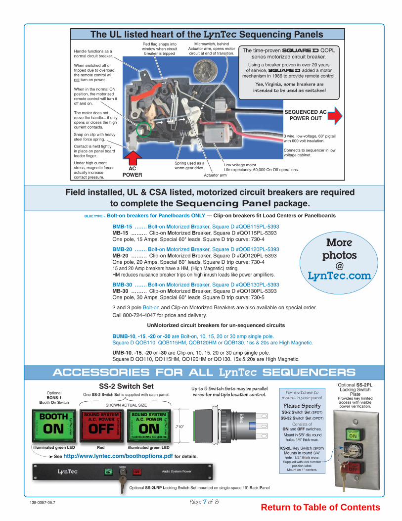
139-0357-05.7 Page 7 of 8
ACCESSORIES FOR ALL LynTec SEQUENCERS
➞
➞
➞➞
ACCESSORIES FOR ALL LynTec SEQUENCERS
Field installed, UL & CSA listed, motorized circuit breakers are requiredto complete the Sequencing Panel package.
BLUE TYPE = Bolt-on breakers for Panelboards ONLY — Clip-on breakers fi t Load Centers or Panelboards
BMB-15 ....... Bolt-on Motorized Breaker, Square D #QOB115PL-5393MB-15 ......... Clip-on Motorized Breaker, Square D #QO115PL-5393One pole, 15 Amps. Special 60" leads. Square D trip curve: 730-4
BMB-20 ....... Bolt-on Motorized Breaker, Square D #QOB120PL-5393MB-20 ......... Clip-on Motorized Breaker, Square D #QO120PL-5393One pole, 20 Amps. Special 60" leads. Square D trip curve: 730-4 15 and 20 Amp breakers have a HM, (High Magnetic) rating. HM reduces nuisance breaker trips on high inrush loads like power amplifi ers.
BMB-30 ....... Bolt-on Motorized Breaker, Square D #QOB130PL-5393MB-30 ......... Clip-on Motorized Breaker, Square D #QO130PL-5393One pole, 30 Amps. Special 60" leads. Square D trip curve: 730-5
2 and 3 pole Bolt-on and Clip-on Motorized Breakers are also available on special order.
Call 800-724-4047 for price and delivery.
UnMotorized circuit breakers for un-sequenced circuits
BUMB-10, -15, -20 or -30 are Bolt-on, 10, 15, 20 or 30 amp single pole. Square D QOB110, QOB115HM, QOB120HM or QOB130. 15s & 20s are High Magnetic.
UMB-10, -15, -20 or -30 are Clip-on, 10, 15, 20 or 30 amp single pole.Square D QO110, QO115HM, QO120HM or QO130. 15s & 20s are High Magnetic.
idec
.710"
OptionalBONS-1
Booth On Switch
illuminated green LED
The UL listed heart of the LynTec Sequencing Panels
SS-2 Switch SetOne SS-2 Switch Set is supplied with each panel.
SHOWN ACTUAL SIZE
Red illuminated green LED
See http://www.lyntec.com/boothoptions.pdf for details.
Morephotos
@LynTec.com
3 wire, low-voltage, 60" pigtail with 600 volt insulation.
Connects to sequencer in low voltage cabinet.
Low voltage motor. Life expectancy: 60,000 On-Off operations.
Red fl ag snaps into window when circuit
breaker is trippedHandle functions as a normal circuit breaker.
When switched off or tripped due to overload, the remote control will not turn on power.
When in the normal ON position, the motorized remote control will turn it off and on.
The motor does not move the handle... it only opens or closes the high current contacts.
Actuator arm
Spring used as a worm gear drive
Snap on clip with heavy steel force spring.
Contact is held tightly in place on panel board feeder fi nger.
Under high current stress, magnetic forces actually increase contact pressure.
AC POWER
SEQUENCED AC POWER OUT
The time-proven SQUARE D QOPL series motorized circuit breaker.
Using a breaker proven in over 20 years of service, SQUARE D added a motor
mechanism in 1986 to provide remote control.
Yes, Virginia, some breakers are intended to be used as switches!
Optional SS-2PLLocking Switch
PlateProvides key limited access with visible power verifi cation.
Microswitch, behind Actuator arm, opens motor circuit at end of transition.
For switches to mount in your panel,
Please SpecifySS-2 Switch Set (SPDT)
SS-32 Switch Set (DPDT)
Consists of and switches.
Mount in 5/8" dia. round holes. 1/4" thick max.
KS-2L Key Switch (SPDT)Mounts in round 3/4" hole. 1/4" thick max.
Supplied with lock tumbler position label.
Mount on 1" centers.
Up to 5 Switch Sets may be parallel wired for multiple location control.
Optional SS-2LRP Locking Switch Set mounted on single-space 19" Rack Panel
Return to Table of Contents

139-0357-00.8 Page 8 of 8
���
�����
SPECIFICATIONS SEQUENCING SYSTEM SPECIFICATIONS
ON/OFF Switch Set Supplied
The one supplied SS-2 Sequencer ON and OFF Switch set provides switches with built-in film legends. The ON switch is backlit by an internal 12v @ 10 ma. green LED. The SS-2 switches mount in 5/8" round holes on 1" centers.
Additional switch sets may be parallel wired for up to 5 remote control loca-tions. See Page 7 for other switch options.
Remote Pilot LED Output60 Hz Half-wave pulsed +18 volts (7.5v rms) flashed at a 50%, 1 Hz rate, will drive remote pilot ON LEDs up to 200 milliamperes. Incandescent indicator lamps are not recommended.
All ON LEDs flash once per second during the on or off sequence cycle.All ON LEDs glow continuously at the end of the ON cycle if the last board in a daisy-chained system has its VOUCHER SUPPLY [V+] and VOUCHER SENSE [V–] terminals bridged by a resistance of less than 100 KΩ.
Power Verification – POWER VOUCHER SenseThe V–, VOUCHER SENSE input annunciates a completed sequence by switching the flashing ON LED to constant, indicating a full ON condition.
This AND type input is utilized when LynTec POWER VOUCHERs are used to prove all sequenced receptacles have AC power present. (No circuit breakers are off, all receptacles are live)
Typically, one POWER VOUCHER™ is plugged into a receptacle for each sequenced circuit and each un-sequenced circuit that must be powered for proper system operation.
The POWER VOUCHER contains an indicator LED and an opto-isolator. The opto-isolator's output resistance drops to ≤200Ω when AC line voltage is present.
The POWER VOUCHER output terminals are all connected in series and then back to the last LynTec sequencer's VOUCHER SUPPLY [V+] and VOUCHER SENSE [V–] terminals.
When the ON sequence is completed AND all POWER VOUCHERs are energized from the receptacles, the pilot ON LEDs glow continuously. Any un-energized POWER VOUCHERs will prevent a continuous pilot ON light, indicating to the operator that the system is not ON. Visually scanning all POWER VOUCHERs for a green light will quickly locate the dead circuit.
Jumper the V+ and V– terminals on the last board if power verification is not used.
+5v Logic OutputA clean logic level output that mimics the ON LED for touch screen drive.Pulses during sequencing, high at end of on sequence. Source: +3.3 KΩ from +5v.
For detailed Timing Diagram see http://www.lyntec.com/139-0266_Seq_Timing.pdf
ON/OFF Low Voltage ConnectionsLever actuated cage clamp terminals accept wire sizes from 18 to 24 gauge.
Motorized Circuit Breaker Low Voltage ConnectionsEach motorized breaker is powered by a 3 wire low voltage field connection to the screw terminal strips on sequencer circuit board/s.
Control Wire RequirementsFrom ON/OFF switch location to one LynTec sequencing panel: 4 conductors, 24 gauge, 5,000 ft. maximumBetween multiple MSLCs, MSPs, SLCs, SPs or PDS-8s when daisy chained: 7 conductors, 24 gauge, 5,000 ft. maximum 9 conductors if ON/OFF switches are required at each sequencer location.
11 conductors if POWER VOUCHERs are used.
SEQUENCER POWERThe SEQUENCER POWER circuit breaker, mounted in the lower right position in the high voltage section of the panel, is connected to a UL listed 120v to 24v, 40 VA transformer mounted inside the low voltage cabinet.This 10 amp un-motorized breaker should be left on continuously. This circuit breaker is used as an approved, switchable connection method to the high voltage. The, UL & ULC listed, transformer is impedance protected with an internal thermal fuse.
Each sequencer board is protected by an on-board AGC 1/2 amp fuse.
Power required: 50/60 Hz, 4 watts per board with one external ON LED load. 20 watts maximum per panel.
ARCHITECTS & ENGINEERS SPECIFICATIONSfor PDF and Word file links
see http://www.lyntec.com/139-0354_A&E_Specs.pdf
Circuits controlled by one or more MS-12 Modular Sequencer boardsEach MS-12 board has 6 drivers capable of simultaneously driving two each of the 1, 2 or 3 pole MB series motorized circuit breakers. Step 1 drives breakers 1a and 1b. Step 2 drives breakers 2a and 2b and so on through step 6. The motorized breakers may be located in any open slot in the panel.
Sequence timing is field programmed by installing push-on jumpers.
STEP RATEsDefault, with no program jumpers, is one second per step with no delays.One jumper selects 1/2 or 1/4 second per step.Two jumpers in the 1/2 and 1/4 sec. positions set the step rate at 1/8 second.DELAY TIME and DELAY POSITION jumpers and timingLow level or front-end equipment sometimes generates pops or clicks during power-up. Delaying the application of power to the power amplifiers eliminates potential loudspeaker damage due to turn-on transients.
Normally, the low level equipment such as preamps, mixing consoles, tuners, CD players, tape decks and EQ's are powered from the first few A.C. circuits.
Bold face type = legends printed on MS-12 boards.
One (First) or two (Second) programmable DELAY TIMEs provide stabilization time for the computers to boot or DSPs to settle.
DELAY TIMEs
1 sec, (no jumper), 2, 4, 8, 16 or 30 seconds or 2, 4, or 8 minutes.
Programmable DELAY POSITION settings allow selection of a sufficient number of steps to sequence the breakers required. The First delay may be positioned before or between any of the 6 steps depending on the first DELAY POSITION jumper.
The Second delay position is determined by, you guessed it, the second DELAY POSITION jumper. Additional delays may be added between higher steps, but their delay times will all be the same as the Second.
Energy Storage — Brownout protection — ZipOff Load Shedding
A distributed power supply stores sufficient energy to ZipOff 12 motorized circuit breakers 2 seconds after power falls below 95 volts. This load shedding ZipOff is delayed 2 seconds to prevent power-glitch induced sequencing.
Automatic Restart after power failure or Kill command.Five seconds after power stabilizes above 105 volts, the on sequence resumes the orderly turn on. A fast flashing ON LED indicates the power hasn't been above 105 volts for the last 5 seconds and the sequencer is waiting for the power to stabilize before restarting the on sequence.
KillA Kill terminal on each MS-12 board provides an instant shutdown(within 100 milliseconds) when connected to common.Opening the connection restarts the on sequence as described above.
HurryOff — the Ohh.... no.... switch
When you REALLY want to shut the system down in a hurry, due to system oscillation or other problem, a HurryOff command may be invoked by holding any OFF button down for at least 2 seconds. HurryOff shuts the system off com-pletely in 2.1 seconds. To provide the operator time to isolate and correct the problem, there is no automatic restart after a HurryOff command. The system must be manually restarted by pressing the ON switch.
Indicator LEDsPower to each MS-12 circuit board is indicated by the amber POWER LED.
Green cylinder LEDs, adjacent to each terminal block, light when the ON control voltage is available to the circuit breaker motor.
Red FAULT LEDs glow temporarily at initial SEQUENCER POWER breaker turn-on and when the breaker motor actuates. This glow indicates normal capacitor charging or motor current. Any incorrectly connected breaker or a breaker that fails to complete the switch function will cause the FAULT LED to light continuously. When the fault is cleared, the FAULT LED extinguishes.
This distributed power supply isolates and indicates faults while the rest of the breakers sequence normally.
Remote Control CharacteristicsTo begin the ON or OFF sequence, a momentary contact to common of at least 30 milliseconds is required to initiate an ON or OFF function of the sequencer. Momentary contacts are necessary when more than one control location is re-quired. ON and OFF line characteristics: +35 volts DC fed through 6900Ω (ON) and 4700Ω (OFF)
In the interest of product improvement, specifications are subject to change without notice — see web site for the most current data.
www.LynTec.comLynTec, Inc. • 8401 Melrose Drive • Lenexa, KS 66214 (a Kansas City suburb)
Voice 800-724-4047 • 913-529-2233 • Fax 888-722-4157 • 913-529-4157
Return to Table of Contents

ARCHITECT'S and ENGINEER'S SPECIFICATIONS Sound system A.C. power Sequencing Load Center All A.C. power for the sound system shall be supplied from a time sequenced source capable of being remote controlled from multiple locations. A means of visual operator feedback shall provide an indication of the progress of the power turn-on or turn-off sequence at each control point. Time between sequence steps shall be adjustable from 1/8 second to 1 second. Sequencing shall have a time delay adjustable between the low-level equipment circuits and the power amplifier circuits. The delay time shall have a field adjustable range from 1 second to 8 minutes. The sequencing system shall be capable of shedding the load within 3 seconds after a power failure and automatically re-sequencing when power resumes and remains above 105 volts for more than 5 seconds without operator intervention. The sequencing system shall have brownout protection; monitoring the line voltage and triggering an automatic shutdown if the line voltage drops below 95 volts for more than 2 seconds. The sequencing system shall have emergency shutdown capability triggered by external contacts or the sound system operator. Un-sequenced circuits, as required, shall be supplied from the same A.C. source so that a single lever main circuit breaker is dedicated to the sound system. All Sequencing Load Centers shall have an isolated technical ground bar. The sound system power sequencing shall be the LynTec model MSLC xxx series Sequencing Load Center LynTec — 800-724-4047 — www.lyntec.com Models: Single Phase, 22k AIR: MSLC 129-12, MSLC 129-24, MSLC 129-36 Balanced Power, 60v — 0 — 60v, 22k AIR: MSLC 119-12, MSLC 119-24
Three Phase, 22k AIR: MSLC 326-12, MSLC 326-24, MSLC 326-36 Three Phase, 25k AIR: MSLC 341-12, MSLC 341-24, MSLC 341-36, MSLC 341-48 Three Phase, 65k AIR: MSLCH 341-12, MSLCH 341-24, MSLCH 341-36, MSLCH 341-48 This document available in Word format: http://www.lyntec.com/139-0345_LdCntr_A&E_Spec.doc Most recent version pdf http://www.lyntec.com/139-0345_LdCntr_A&E_Spec.pdf 139-0345-02_LdCntr_A&E _Spec 12/23/06
Return to Table of Contents

ARCHITECT'S and ENGINEER'S SPECIFICATIONS Sound system A.C. power Sequencing Panelboard All A.C. power for the sound system shall be supplied from a time sequenced source capable of being remote controlled from multiple locations. A means of visual operator feedback shall provide an indication of the progress of the power turn-on or turn-off sequence at each control point. Time between sequence steps shall be adjustable from 1/8 second to 1 second. Sequencing shall have a time delay adjustable between the low-level equipment circuits and the power amplifier circuits. The delay time shall have a field adjustable range from 1 second to 8 minutes. The sequencing system shall be capable of shedding the load within 3 seconds after a power failure and automatically re-sequencing when power resumes and remains above 105 volts for more than 5 seconds without operator intervention. The sequencing system shall have brownout protection; monitoring the line voltage and triggering an automatic shutdown if the line voltage drops below 95 volts for more than 2 seconds. The sequencing system shall have emergency shutdown capability triggered by external contacts or the sound system operator. Un-sequenced circuits, as required, shall be supplied from the same A.C. source so that a single lever main circuit breaker is dedicated to the sound system. Three phase sequenced panelboards shall have 200% neutrals. Single phase sequenced panelboards shall have a single neutral. All sequenced panelboards shall have a separate and attached isolated technical ground section. All branch circuit breakers shall be bolt-on. The sound system power sequencing shall be the LynTec model MSP xxx or MSPH xxx series Sequencing Panelboard. LynTec — 800-724-4047 — www.lyntec.com Models: Single Phase, 65k AIR: MSP 141-12, MSP 141-24, MSP 141-36, MSP 141-48, MSP 141-60
Balanced Power, 60v-0-60v, 65k AIR: MSP 119-12, MSP 119-24 Three Phase, 65k AIR: MSP 341-12, MSP 341-24, MSP 341-36, MSP 341-48, MSP 341-60 This document available in Word format: http://www.lyntec.com/139-0339_PnlBrd_A&E_Spec.doc Most recent version pdf: http://www.lyntec.com/139-0339_PnlBrd_A&E_Spec.pdf 139-0339-05_PnlBrd_A&E _Spec 10/31/06
Return to Table of Contents

SS-2 Switch Set — mount in 5/8”round holes on 1” centers.
60” low voltage control wiresconnect to screw terminalstrips on sequencer boards.
MRTS-24
1 2 3 4 5 6
1 2 3 4 5 6FirstDelay
SecondDelay
STEPRATE
TIMING DIAGRAM
STARTPressONswitch
BeforeBeforeBetween StepsBetween Steps
DELAY TIME and STEP RATE are1 second if no jumpers are installed.
This sequencer serves:
RED
WHITE
BLACK
RED
WHITE
BLACK
ON 6A & 6B
ON 5A & 5B
RED
WHITE
BLACK
RED
WHITE
BLACK
ON 4A & 4B
ON 3A & 3B
RED
WHITE
BLACK
RED
WHITE
BLACK
ON 2A & 2B
ON 1A & 1B
UPPER
A
UPPER
A
BLOWER
UPPER
A
UPPER
A
UPPER
A
UPPER
A
Each Sequencer Step controls two breakers,
one upper set of terminals (A)and
one lower set of terminals (B).
www.LynTec.com
BLOWER
BLOWER
BLOWER
BLOWER
BLOWER
The red FAULT LEDs are current indicators and should only light when initial power is applied (capacitor charging) and when motorized breakers are sequenced. A constantly lit red LED indicates a mis-wiring (Red/Black reversal) or a breaker that has failed to motor actuate.
800-724-4047M–F, 8-5 Central Time
Circuit breakerlead preparation
5/16" Strip length. (18 ga.)Twist wire ends tightly.
Recheck terminal tightnessafter all lead dress is
completed.
DO NOT tin with solder.Solder
COLD FLOWSunder pressure and will
eventually loosen.
LynTec MRTS-12 and MRTS-24 Modular Rain Tight Sequencers
Sound system AC Power Sequencer for Square D QO Load Centers & PanelboardsUsing the new flexible MS-12 Modular Sequencer control boards
The MRTS sequencer provides a solution for contrac-tors needing sound system sequencing using anySquare D cabinet that accepts QO circuit breakers.
Consists of a lockable, rain tight, Hoffman UL & CSAlisted cabinet with the proven LynTec MS-12 Modularsequencer boards and power transformer mounted onan iridited aluminum subchassis.
The subchassis allows the interior to be easilyremoved for rough-in. Just loosen 4 nuts and lift thesubchassis to clear the keyhole slots.
The smooth walled cabinet provides full flexibility offield mounting and piping options.
SQUARE DQO series load center
or panelboardsupplied by others
www.LynTec.com8401 Melrose Drive, Lenexa, KS 66214Voice 800-724-4047 • Int’l 913-529-2233Fax 888-722-4157 • Int’l 913-529-4157
See AllPanel.pdf brochurefor sequencer technical
specifications.
AVAILABLE MODELS
MRTS-12 Drives up to 12 motorized breakers
MRTS-24 Drives up to 24 motorized breakers
What is included
The MRTS-12 or -24 includes the UL/CSA listedcabinet, a 10 amp unmotorized breaker (UMB-10) tofeed SEQUENCER POWER to the 24v transformer powering thesequencer board/s. A SEQUENCER POWER label is supplied.
One 27 position isolated ground bar is supplied for theaudio technical ground system. (Typically located in theSquare D panel supplied by others).
One SS-2 Switch Set.The SS-2PL Locking Switch Plate is optional.
Additional LynTec components required
MB-15, MB-20 or MB-30 Branch Motorized circuitBreakers — one per sequenced circuit. (Square D QOPL1xx-5393)
For Bolt-on breakers order BMB-15, BMB-20 or BMB-30.
MotorizedCircuit Breaker
18.25” High — 12.5” Wide — 6.5” Deep
Low voltage ON/OFF control wiring4 conductors, 22 ga., 5,000’ max.
139-0312-01 MRTS Brochure 3/17/04 — See http://www.lyntec.com/139-0312.pdf for latest revision.
120v to 24v.,40 VAtransformer(UL & CSA listed.Impedance protected)
Connect 120 voltprimary to supplied10 Amp. unmotorizedbreaker.
Attach supplied label
SEQUENCER POWER
Click green box for board tour
Return to Table of Contents

1
2
3
4
5
BUSY (An output. Connected to next board's HOLD. Low holds next sequencer until this board's on sequence is complete).
CARRY (An open collector, NPN darlington with a 1N4004 diode and a 200 Ohm transient current limiting resistor. Connect to next ON. Toggles next board on).
ONSwitch.
For daisy-chain, connect to previous board's CARRY.Use only the first ON switch in daisy-chained systems - turn ON first board - turn OFF last board.
ONONSwitch.
For daisy-chain, connect to previous board's CARRY.Use only the first ON switch in daisy-chained systems - turn ON first board - turn OFF last board.
Sequencefinished.All ON
Sequencefinished.All OFF
Sequencefinished.All ON
Sequencefinished.All OFF
ON
2 sec. DELAY TIMEAdjustable up to 8 min.May be set before orbetween any step.
PressON
button
PressOFF
button
Press ON button
PressOFF
button
ON LED flashes at 1 second interval regardless of step rate
SequencerStepnumber
ONON switch LED Flashes during sequencing for operator feedback
TIMING and LOGIC LEVEL DIAGRAMLynTec LynTec MS-12 series Modular Sequencer
Timing Diagram is shown for a one board system with only one jumper in the First 2 sec. position. Step rates default at 1 sec.All boards within each panel are factory daisy-chain connected with 4 pin board-to-board cascade connectors.
Remove cascade connectors to separate into multiple systems.
OFFOFF Switch. For daisy-chain, connect to next board's BORROW.Use only the last OFF switch in daisy-chained systems - turn ON first board - turn OFF last board.
+35v
Common —
+35v
Common —
+12v
— Common
Motorized Breakers 1a and 1b ON
Motorized Breakers 2a and 2b ON
Motorized Breakers 3a and 3b ON
Motorized Breakers 4a and 4b ON
Motorized Breakers 5a and 5b ON
Motorized Breakers 6a and 6b ON
+35v supplied from next ON. Source resistance is 3720 to 6900 Ohms depending on model.
— — Common
6
PILOT (An output. Connect to all external ON switch LEDs).For daisy-chained systems all ON LEDs + connect to the first board's PILOT.Power Verification and sequencing completion uses each subsequent board's PILOT output. The last sequencer uses a V+ to V— jumper or series connected Power Vouchers to light the ON LED at end of sequence.
— +16v60 Hz
pulses.7.5v rms
Com
+35v supplied from previous OFF. Source resistance is 3720 to 4700 ohms depending on model.
— — Common
Control line TIMING, FUNCTIONS and LEVELS139-0266-08 MS-12 Timing Diagram 2/23/05
+5v Logic
(Clean CMOS 5v logic for touch panel interface. 3.3 kOhm source impedance).
56 msec.
56 msec.
30 msec. minimum500 msec. maximum
30 msec. minimum1500 msec. maximum(2 sec. will invoke HurryOff — a Kill without automatic restart)
BORROW low state voltage: +0.75v due to series 82 Ohm. (one daisy-chain load)
———— CARRY low state voltage is +2.5v due to series 200 ohm resistor, diode and VCEsat of darlington transistor. (one daisy-chain load)
same DELAY TIMEon turn off.Only on Rev. 14 up boards >8/03.
— Common
Source resistance is 3720 to 4700 Ohms depending on model.
Source resistance is 3720 to 6900 Ohms depending on model.
BORROW (An open collector NPN output with an 82 Ohm transient current limiting resistorConnect to previous OFF. Toggles previous board off).
Overlaybutton
images andalternate with
+5v Logic
Download jpegbutton images
Return to Table of Contents

48840-496-0411/2003
Cedar Rapids, IA, USA
ECN N353
Instruction Bulletin
REQUIREMENTS
QO-PL (Plug-on), QOB-PL (Bolt-on) Powerlink® RemotelyOperated Circuit Breakers(Use in Type QO Load Centers and Type NQO, NQOB, and NQOD Panelboards)Retain for future use.
POWERLINK® QO(B)-PL Remotely Operated Circuit Breakersrequire a power supply capable of delivering at least two amperes at24 Vdc for a minimum of 50 milliseconds. One-, two-, and three-polecircuit breakers all have one internal motor, and power requirementsare the same regardless of the number of poles and ampere ratings.
The required power supply ampacity and control device contact ratingare determined by the number of circuit breakers to be switchedsimultaneously (i.e., four circuit breakers switched simultaneouslyrequire a power supply and a control device contact rated 8 amperesminimum). The control device may be either a normally-open (NO)/normally-closed (NC) contact; a single-pole, double-throw switch(SPDT); or other three-wire control device.
Remotely Operated Circuit Requirements
DANGERHAZARD OF ELECTRIC SHOCK, BURN,OR EXPLOSION.
When servicing a branch circuit fed by aremotely operated circuit breaker, movehandle of remotely operated circuit breakerto OFF position. Do not rely on remoteoperation to open circuit breaker.
Failure to follow these instructions willresult in personal injury or death. Turn off all power supplying this equipment before working on or inside
equipment.
Before installing circuit breaker turn circuit breaker handle to OFFposition.
Remove panelboard cover and deadfront. Verify power is off withvoltage meter before proceeding.
1.
2.
3.
Installation of circuit breaker into panelboard/load center (refer tofigure below)
CIRCUIT BREAKERINSTALLATION
HAZARD OF ELECTRIC SHOCK,EXPLOSION, OR ARC FLASH
• Apply appropriate personal protective equipment (PPE) and follow safe electrical work practices. See NFPA 70E.
• This equipment must be installed and serviced only by qualified electrical personnel.
• Turn off all power supplying this equipment before working on or inside equipment.
• Always use a properly rated voltage sensing device to confirm power is off.
• Replace all devices, doors, and covers before turning on power to this equipment.
Failure to follow these instructions willresult in death, or serious injury.
DANGER
Connection of remotely operated circuit (refer to the figure on next page)
Assure that power supply and control device meet requirements listedunder "Remotely Operated Circuit Requirements."
5.
Except for remotely operated connections, QO(B)-PL remotelyoperated circuit breakers are installed in a panelboard/load centerthe same as conventional QO(B) circuit breakers.2
4.
PL1
099A
.0
40°CPlug-on orBolt-on
Connector
Bus Bar Connector(s)
Mounting Clip
Mounting Rail
BlackWhiteRed
ControlWires
Wire BindingScrew
Load Wire
VISI-TRIP® Indicator
LynTec overprint document # 139-0216-08.1
See page 2 forLynTec
part number explanation
All LynTec supplied breakers
have special 60” control
wires.(Square D standards are 18”.)
1
Return to Table of Contents

48840-496-0411/2003
2
CIRCUIT BREAKER INSTALLATION
CAUTION
PL1
100A
.1
Panelboard/Load Center
RemotelyOperated
Circuit Breaker
Black
White
Red
(Class 1 Wiring)NC
NO
ON
OFF24 VdcPower Supply
+
Splice Connection
6. All wiring and splicing must comply with applicable code requirements for Class 1 circuits. Refer to paragraph 373-8 and article 725 of the National Electrical Code.
7. Three #18 AWG control wires are attached to the remotely operated circuit breaker for connection to the power supply and remote control device and should be cut to the required length to reach the splice connections. Use #18 AWG or larger conductors with 600 V insulation and approved wire connectors for splices.
8. Connect the black lead of the remotely operated circuit breaker to the negative (-) terminal of the 24 Vdc power supply. Connect the red lead of the remotely operated circuit breaker to the positive (+) terminal of the 24 Vdc power supply. Connect the white lead of the remote control device. The remote control device provides connections between either positive or negative potential of the power supply and the white wire of the remotely operated circuit breaker, as appropriate.
9. Applying the positive potential of the power supply to the white wire (contact closure between the red wire and white wire) will operate the remote mechanism of the circuit breaker to the OFF position. Applying the negative potential of the power supply to the white wire (contact closure between the black wire and the white wire) will operate the remote mechanism of the circuit breaker to the ON position. A control circuit utilizing a normally open (NO)/normally closed (NC) contact is illustrated below.
NOTE: The remote mechanism will not move the circuit breaker handle. Also, the remote mechanism cannot turn power ON when the circuit breaker is tripped (VISI-TRIP® flag indicator showing) or when the circuit breaker handle is in the OFF position.
Installation of the trim and operational checks
10. Remove corresponding twist-out from panelboard trim and replace trim.
11. Turn power to panelboard on.
12. Turn remotely operated circuit breaker handle to the ON position.
13. Turn power to the remotely operated circuit on and test this circuit, turning remotely operated circuit breaker off remotely, then on remotely. If power to remote controlled circuit breaker load does not switch off and on, turn off power to remotely operated circuit and panelboard and check wiring.
NOTE: A power supply is available from Square D Company, Cat. No. QOPLPS (plug-on) or QOBPLPS (bolt-on).
HAZARD OF CIRCUIT BREAKER DAMAGE.
Connect the 24 Vdc remote control wiring as shown on this page.
Failure to follow these instructions can permanently damage the remotely operated circuit breaker.
Square D Company3700 Sixth Street SWCedar Rapids IA 52404 USA1-888-SquareD (1-888-778-2733)www.SquareD.com
LynTec part numbers
MB series motorized circuit breakers (Snap-On)May be used in LCLC, LCP, MSLC, MSP, SLC or SP series panels.
BMB series motorized circuit breakers (Bolt-On)Use only in LCP, MSP or SP Panelboards
All BMB & MB series breakers have Square D part number suffix of -5393 indicating a special 60 inch lead length for remote control wires required to connect to LynTec control boards in low voltage cabinet.
** = Stocked items
**MB-15 = 15 Amp. Square D QO-115PL-5393
**BMB-15 = 15 Amp. Square D QOB-115PL-5393
**MB-20 = 20 Amp. Square D QO-120PL-5393
**BMB-20 = 20 Amp. Square D QOB-120PL-5393
**MB-30 = 30 Amp. Square D QO-130PL-5393
**BMB-30 = 30 Amp. Square D QOB-130PL-5393
Two pole motorized - call for pricing & delivery
MB-215 = 15 Amp. Square D QO-215PL-5393
BMB-215 = 15 Amp. Square D QOB-215PL-5393
**MB-220 = 20 Amp. Square D QO-220PL-5393
**BMB-220 = 20 Amp. Square D QOB-220PL-5393
MB-230 = 30 Amp. Square D QO-230PL-5393
BMB-230 = 30 Amp. Square D QOB-230PL-5393
40A, 50A or 60A, Two pole also available on Special Order
Three pole motorized - call for pricing & delivery
MB-315 = 15 Amp. Square D QO-315PL-5393
BMB-315 = 15 Amp. Square D QOB-315PL-5393
MB-320 = 20 Amp. Square D QO-320PL-5393
BMB-320 = 20 Amp. Square D QOB-320PL-5393
MB-330 = 30 Amp. Square D QO-330PL-5393
BMB-330 = 30 Amp. Square D QOB-330PL-5393
LynTec also stocks UMB & BUMB (un-motorized) QO series circuit breakers including HM (High Magnetic). Recommended for eliminating nuisance trips in high inrush applications.
[ All BMB & MB-x15's and BMB & MB-x20's are HM breakers.]
800-724-4047LynTec • www.LynTec.com
8401 Melrose Dr., Lenexa, KS 66214, USA
Voice 913-529-2233 • Fax 888-722-4157 or 913-529-4157
In LynTec Sequencer or DMX controller
LynTec overprint 139-0216-08.2 9/23/06
Electrical equipment should be installed, operated, serviced and maintained only byqualified personnel. No responsibility is assumed by Schneider Electric for anyconsequences arising out of the use of this material.
© 1991-2003 Schneider Electric All Rights Reserved
QO-PL (Plug-on), QOB-PL (Bolt-on) POWERLINK® Remotely Operated Circuit BreakersInstruction Bulletin
Splice not normally required with LynTec supplied breakers with 60” leads.
Return to Table of Contents

9 volt
9 volt
9 volt
9 volt
9 volt
9 volt
LynTec800-724-4047
3 conductor low voltage
control wires.
RED
BLACK
WHITE
NOTE The motor inside the REMOTELY OPERATED breaker only opens the circuit if the handle is in the ON position. The breaker handle is not moved by the motor.The breaker handle only moves when tripped due to overload.
POWER SUPPLY for Emergency actuationof motorized circuit breakers
Connect Red and Black wires as shown.
Touch WHITEWHITE wire to BLACK to cycle breaker motor ONor
Touch WHITEWHITE wire to RED to cycle breaker motor OFF
NOTE DO NOT connect batteries to screw terminal strips. Wires MUST be disconnected from sequencer screw terminal strips or control relays will be damaged.
MOTORIZEDCIRCUIT
BREAKER
9 volt alkaline batteries
Emergency RR7 relay activation for LCRP or PDS-8 series
POWER SUPPLY for Emergency actuationof RR7 Latching Relays
NOTE DO NOT connect batteries to sequencer board. Yellow Plugs MUST be disconnected from sequencer or control ICs will be damaged.
RR7 P3Latching Relay
RED
BLACK
BLUE
139-0286-02 Emergency activate 1/25/06
Three 9 volt alkaline batteriessnapped together in series.
Battery+
Battery —
Touch BLACK wire (— battery) to BLACK to latch RR7 OFFor
Touch BLACK wire (— battery) to RED to latch RR7 ON
OR for all systems using motorized
circuit breakers.
Emergency circuit breaker activation
forMSLC or MSP systems using
motorized circuit breakers.
ON
off
Return to Table of Contents

LIMITED WARRANTY
All LynTec manufactured products are warranted to be free from defects in workmanship and materials for a period of 5 years from the original invoice date. This warranty shall be limited to the repair, adjustment and/or replacement of defective parts. LynTec will repair or replace defective LynTec products only at the factory at 8401 Melrose, Lenexa, KS 66214, U.S.A. 800-724-4047. All returns are to be prepaid. LynTec will pay return UPS surface freight charges within the continental United States on warranty repairs. All customs expenses and excess transportation charges will be borne by the customer. All Square D and General Electric products that are resold as part of a LynTec equipment package are warranted to be free from defects in workmanship and materials for a period of 15 months from the original invoice date. This warranty shall be limited to the repair, adjustment and/or replacement of defective parts.
LynTec will not be responsible for inconveniences or consequential damages occasioned by LynTec equipment, or by breach of any express or implied warranty with respect thereto. Implied warranties on this product shall be in effect only for the duration of the express warranty set forth above. After the warranty expiration date shown on the serial number label, there shall be no warranties, express or implied on the product. This warranty becomes void if the product shows evidence of mishandling, tampering, battery or chemical corrosion, fire, water or lightning damage or other acts of nature, use contrary to the applicable instruction manual, shipping damage or repair performed by others.
Return to Table of Contents

Job ListA partial list of users and their applications of the LynTec AC power sequencing systems
Supplying reliable sequencing solutions to mission-critical venues since 1989
139-0163-10 Sequencing Job List
LDS Assembly Hall — Salt Lake City, Utah — Full sound system AC control of 21,000 seat auditorium.
National Cathedral — Washington, D.C. — Full sound system AC control.
Autzen Stadium — Home of Oregon Ducks —Eugene Oregon —54,000 seat football stadium - Full sound system AC control.
NCAA Hall of Champions — Indianapolis, Indiana — Full AV system AC control.
Kentucky Speedway — Sparta, Kentucky — Full sound system AC control.
Gillette Stadium — Foxborough, MA— Home of the New England Patriots — Full sound system AC control.
Madison Square Garden — New York, New York — Full sound system AC control.
Kennedy Center — Washington, D.C. — AC control of Opera House and Concert Hall sound systems.
PNC Park — Home of the Pittsburgh Pirates — Full sound system AC control.
Sun Theater — Anaheim, California — Full sound system AC control.
Breslin Center Arena & Spartan Stadium — Michigan State — East Lansing, Michigan — Full sound system AC control.
Benaroya Concert Hall — Seattle, Washington — Full sound system AC control, balanced power system.
Tennessee Titans Stadium — Nashville, Tennessee — Full sound system AC control
War Memorial Opera House — San Francisco, California — Full sound system AC control.
SBC Center— Home of San Antonio Spurs— San Antonio, TX —18,500 seat arena — Full sound system AC control.
Jordan Hare Stadium — Auburn University, Alabama — 85,214 seat football stadium — Full sound system AC control.
Lookingglass Theatre & Millenium Park — Chicago, Illinois — Full sound system AC control.
Alltel Stadium — Home of Jacksonville Jaguars — Jacksonville, Florida — Full sound system AC control.
Memorial Stadium — Home of Nebraska Cornhuskers — Lincoln, Nebraska — Full sound system AC control.
Quad Discovery Center, Smithsonian — Washington, D.C. — Sound system AC control.
Dale Halton Arena — University of North Carolina, Charlotte — Charlotte, North Carolina — Full sound system AC control.
New England Conservatory of Music — Boston, Massachusetts — Full sound system AC control.
Galveston Convention Center — Galveston, TX — Full sound system AC control.
Ralph Wilson Stadium — Home of the Buffalo Bills — Buffalo, New York — Sound system AC control.
Creative & Performing Arts High School — Philadelphia, Pennsylvania — Full sound system AC control.
University of Georgia Coliseum — Athens, Georgia — 10,000 seat multipurpose arena — Full sound system AC control.
Fremont Street Experience — Las Vegas, Nevada — Sequential control of 80 — 6,000 watt power amplifiers.
Popejoy Hall Performing Arts Facility — University of New Mexico — Full sound system AC control.
Shakespeare Theatre —Chicago, Illinois —Full sound system AC power control.
Conte Forum Arena, Boston College — Boston, Massachusetts — Full sound system AC control.
Vivian Beaumont Theater — Lincoln Center — New York, New York — Full sound system AC control.
Network Associates Coliseum — Home of Oakland Raiders — Oakland, California — Full sound system AC control.
Dollywood — Pigeon Forge, Tennessee — Full sound system AC control.
Texas Instruments Boardroom — Dallas, Texas — Full sound system AC control.
Circle Center Mall at Artsgarden — Indianapolis, Indiana — Full sound system AC control.
Baum Stadium at George Cole Field —University of Arkansas — Fayetteville, Arkansas — Full sound system AC control.
Westlake Ohio City Hall — Westlake, Ohio — Full sound system AC control.
High Street Baptist Church — Springfield, Missouri — Full sound system AC control.
Hugh Hodgson Concert Hall —University of Georgia — Athens, Georgia — Full sound system AC control.
Schubert Theater — Boston, Massachusetts — Full sound system AC control.
World Changers Church — Atlanta, Georgia — Full sound system AC control.
Germain Ampitheater — Columbus, Ohio — Full sound system AC control.
Madam Tussauds Wax Museum — Las Vegas, Nevada — Full sound system AC control.
Roxy Roller Disco — New York, New York — Full sound system AC control.
Qualcom Stadium — Home of San Diego Chargers — San Diego, California — Full sound system AC control.
"The Groove" Dance Club — Universal City Walk, Orlando, Florida — Full sound system AC control.
St. James Church — Madison Avenue, New York City — Full sound system AC control.
Lancaster Municipal Stadium — Home of the Lancaster Jethawks — Lancaster, California — Full sound system AC control.
Mission Planning Center — MacDill AFB — Tampa, FL — Full sound system AC control.
Starlight Theater — 12,000 seat ampitheater — Kansas City, Missouri — Full sound system AC control.
Cleveland Browns Stadium & Gund Arena, Home of Cleveland Cavaliers — Cleveland, Ohio — Full sound system AC control.
Return to Table of Contents

Sequencing APPLICATION NOTE IndexThese sequencing system Application Notes are available as PDFs
Document # Description
139-0266- Touch-Screen control — Timing diagramFor AMX or Crestron touch-screen control of Modular sequencing systems. Virtual ON & OFF screen images.
139-0270- Stadium + ClubA typical three panel, daisy-chained, system with two locking control locations. An additional independent CLUB panel sequences separately or with the MAIN system.
139-0271- Remote RR7 Latching relays for MS-12 Modular SequencerRemote front-end control of two RR7 power relays from LynTec Modular Sequencer.
139-0272- Auxiliary Modular ControlAuxiliary control of motorized breakers 1A, 1B, 2A & 2B.
139-0277- Series-Parallel Hookup — or — PDS-8 & MSLC/MSP Parallel HookupA five panel, series-parallel system with two locking control locations for faster sequencing — or — Parallel connection of PDS-8 series & MS series systems
139-0284- Motorized Breaker remote wire sizingWire sizing tables for remotely mounted motorized breakers.
139-0292- Shared Theatre SequencersAllows a single front end to be used for either a BLACK BOX or main theatre.
139-0293- Arena 2 mode sequencerProvides separate control of power amplifi ers feeding the upper seating in an arena.
139-0304- Extra 2 or 4 circuitsTwo separate sound systems. Main room has 26 circuits. Room 2 has 10 circuits.
139-0309- Custom Switch Legend FilmField print custom switch legends on Laser Transparency fi lm or paper.
139-0316- Opera House 2 mode sequencer Provides separate control of power amplifi ers.When the Opera House is in normal use the house power amps are used. It is desirable to turn off the power amps, leaving the Front End on during pre-show production work or when touring shows provide their own systems. Reduces power amplifi er wear and tear and minimizes wasted power.
139-0317- Phase Leg ProtectionProtecting Sound Systems from POPS caused by Phase Leg and Partial System power failures.
139-0319- Auditorium 3 mode sequencerProvides 3 scenarios for Auditorium sound system AC power control.
139-0323- Dual Booth SystemDual booth club sound system.
139-0335- Function reversal - sound off / work lights onReversing sequencing action to turn on work lights when sound system is turned off .
139-0356- AUTOMIX — MAIN power sequencer with 3 control positionsA two function system using either a STAGE AUTOMIX or the full MAIN system with 3 control positions.
139-0360- AUTOMIX — MAIN power sequencer with 2 control positionsA two function system using either a STAGE AUTOMIX or the full MAIN system.
139-0404- Front Of House - Lecture, 2 function sequencerA two function system using either a full FOH or a Lecture front end.
139-0436- Two separate room power sequencers share a DSPSeparate rooms share a DSP with off lockout to guarantee DSP power control for either / or both situations.
139-0445- UPS Control for Modular Sequencers using CR optionProvides sequencer control for turn off of UPS powered devices when the system is shut off to prevent UPS discharge.
Your application diff erent? — We’ll be glad to help, just ask for Applications Engineering.
www.LynTec.com • Voice 800-724-4047 • Fax 888-722-4157M-F — 8 - 5 Central Time
139-0362-07 AppNote Index 8/7/07See http://www.lyntec.com/139-0362_AppNote_Index.pdf for latest revision.